Lecture 2 Electro-Mechanical Fundamentals 1 Electric machines and Power Systems
1. Electric machines and Power Systems - Lamar University ...
1. Electric machines and Power Systems - Lamar University ...

You also want an ePaper? Increase the reach of your titles
YUMPU automatically turns print PDFs into web optimized ePapers that Google loves.
1/16/2008<br />
<strong>Lecture</strong> 2: <strong>Electro</strong>-<strong>Mechanical</strong><br />
<strong>Fundamentals</strong><br />
1<br />
Instructor:<br />
Dr. Gleb V. Tcheslavski<br />
Contact:<br />
gleb@ee.lamar.edu<br />
Office Hours:<br />
TBD; Room 2030<br />
Class web site: MyLamar<br />
ELEN 3441 <strong>Fundamentals</strong> of <strong>Power</strong> Engineering Spring 2008<br />
1. <strong>Electric</strong> <strong>machines</strong> <strong>and</strong> <strong>Power</strong> <strong>Systems</strong><br />
2<br />
An electric machine is a devise that can convert<br />
electrical energy to mechanical or/<strong>and</strong> mechanical<br />
energy to electrical.<br />
A power system is a network of components<br />
designed to efficiently transmit <strong>and</strong> distribute the<br />
energy.<br />
ELEN 3441 <strong>Fundamentals</strong> of <strong>Power</strong> Engineering Spring 2008<br />
1
1/16/2008<br />
1. <strong>Electric</strong> <strong>machines</strong> <strong>and</strong> <strong>Power</strong> <strong>Systems</strong><br />
3<br />
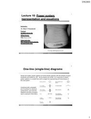
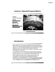
1.1. Generators convert mechanical energy from a prime mover to<br />
electrical energy through the action of the magnetic field.<br />
ELEN 3441 <strong>Fundamentals</strong> of <strong>Power</strong> Engineering Spring 2008<br />
1. <strong>Electric</strong> <strong>machines</strong> <strong>and</strong> <strong>Power</strong> <strong>Systems</strong><br />
4<br />
1.2. Transformers convert AC electrical energy at one voltage level to AC<br />
electrical energy at (an)other voltage level(s).<br />
ELEN 3441 <strong>Fundamentals</strong> of <strong>Power</strong> Engineering Spring 2008<br />
2
1/16/2008<br />
1. <strong>Electric</strong> <strong>machines</strong> <strong>and</strong> <strong>Power</strong> <strong>Systems</strong><br />
5<br />
1.3. <strong>Power</strong> lines connect generators to loads transmitting electrical<br />
power over long distance with minimal losses. There are two categories:<br />
transmission lines <strong>and</strong> distribution lines.<br />
ELEN 3441 <strong>Fundamentals</strong> of <strong>Power</strong> Engineering Spring 2008<br />
1. <strong>Electric</strong> <strong>machines</strong> <strong>and</strong> <strong>Power</strong> <strong>Systems</strong><br />
6<br />
1.4. Loads are all types of electricity consuming devises: motors, electric<br />
lighting, computers, TVs, phones…<br />
ELEN 3441 <strong>Fundamentals</strong> of <strong>Power</strong> Engineering Spring 2008<br />
3
1/16/2008<br />
1. <strong>Electric</strong> <strong>machines</strong> <strong>and</strong> <strong>Power</strong> <strong>Systems</strong><br />
7<br />
1.5. Protective devices: current, voltage, power sensors, relays, fuses,<br />
circuit breakers.<br />
ELEN 3441 <strong>Fundamentals</strong> of <strong>Power</strong> Engineering Spring 2008<br />
2. Rotational motion, Newton’s law<br />
8<br />
Majority of electric <strong>machines</strong> rotate about an axis called a shaft of the machine.<br />
2.1. Angular position θ - an angle at which the object is oriented with respect<br />
to an arbitrary reference point.<br />
2.2. Angular velocity (speed) ω - a rate of change of the angular position.<br />
ω =<br />
dθ<br />
dt<br />
[ rad s]<br />
ω m – angular velocity in radians per second<br />
f m – angular velocity in revolutions per second<br />
n m – angular velocity in revolutions per minute<br />
f<br />
n<br />
m<br />
m<br />
ωm<br />
=<br />
2π<br />
= 60 f<br />
m<br />
(2.8.1)<br />
(2.8.2)<br />
(2.8.3)<br />
ELEN 3441 <strong>Fundamentals</strong> of <strong>Power</strong> Engineering Spring 2008<br />
4
1/16/2008<br />
2. Rotational motion, Newton’s law<br />
9<br />
2.3. Angular acceleration α - a rate of change of angular velocity.<br />
dωω<br />
2<br />
α = ⎡rad s<br />
⎤<br />
dt ⎣ ⎦<br />
2.4. Torque (moment) τ - a “rotating force”.<br />
r<br />
axis<br />
F<br />
ϕ<br />
τ = r× F = rFsinϕ<br />
[ Nm]<br />
(2.9.1)<br />
(2.9.2)<br />
Here F is an acting force, r is the vector pointing from the axis of rotation to the<br />
point where the force is applied, ϕ is the angle between two vectors.<br />
τ = Jα<br />
Newton’s law of rotation: (2.9.3)<br />
J is a moment of inertia (a mass equivalent).<br />
ELEN 3441 <strong>Fundamentals</strong> of <strong>Power</strong> Engineering Spring 2008<br />
2. Rotational motion, Newton’s law<br />
10<br />
2.5. Work W – amount of energy transferred by a force.<br />
W<br />
=<br />
∫<br />
τ dθ [ J ]<br />
(2.10.1)<br />
If the torque is constant:<br />
W<br />
= τθ<br />
(2.10.2)<br />
2.6. <strong>Power</strong> P – increase in work per unit time.<br />
dW<br />
P =<br />
dt<br />
[ W ]<br />
(2.10.3)<br />
For a constant torque:<br />
dW d( τθ)<br />
dθ<br />
P = = = τ = τω<br />
dt dt dt<br />
(2.10.4)<br />
ELEN 3441 <strong>Fundamentals</strong> of <strong>Power</strong> Engineering Spring 2008<br />
5
1/16/2008<br />
3. The magnetic field<br />
11<br />
Basic principles underlying usage of magnetic field<br />
1. A wire caring a current produces a magnetic field<br />
around it.<br />
2. A time-changing magnetic field induces a voltage in a<br />
coil of wire if it passes through that coil (transformer<br />
action).<br />
3. A wire caring a current in the presence of a magnetic<br />
field experiences a force induced on it (motor action).<br />
4. A wire moving in a presence of magnetic field has a<br />
voltage induced in it (generator action).<br />
ELEN 3441 <strong>Fundamentals</strong> of <strong>Power</strong> Engineering Spring 2008<br />
3. The magnetic field<br />
12<br />
3.1. Production of magnetic field<br />
The Ampere’s law:<br />
∫<br />
H idl = I net<br />
(2.12.1)<br />
Where H [A-turns/m] is the intensity of the magnetic field produced by the current I net<br />
For the ferromagnetic cores, almost all<br />
the magnetic field produced by the<br />
current remains inside the core,<br />
therefore the integration path would be<br />
l c <strong>and</strong> the current passes it N times.<br />
Ni<br />
= ⇒ = (2.12.2)<br />
Inet<br />
Ni H l<br />
c<br />
ELEN 3441 <strong>Fundamentals</strong> of <strong>Power</strong> Engineering Spring 2008<br />
6
1/16/2008<br />
3. The magnetic field<br />
13<br />
Magnetic flux density:<br />
where<br />
μ<br />
μ = μμ<br />
μNi<br />
B= μH<br />
= (2.13.1)<br />
l<br />
is the magnetic permeability of a material.<br />
0 r<br />
−7<br />
0<br />
= 4π<br />
⋅ 10 H m − the permeability of free space<br />
μ r – the relative permeability<br />
The total flux in a given area:<br />
l c<br />
Φ=∫ BdA i (2.13.2)<br />
If the magnetic flux density vector B is perpendicular to a plane of the area:<br />
∫<br />
A<br />
μNiA<br />
Φ= BA = (2.13.3)<br />
l<br />
c<br />
ELEN 3441 <strong>Fundamentals</strong> of <strong>Power</strong> Engineering Spring 2008<br />
3. The magnetic field<br />
14<br />
3.2. Magnetic circuits<br />
Similarly to electric circuits, there<br />
are magnetic circuits …<br />
Instead of electromotive force (voltage) magnetomotive force (mmf) is<br />
what drives magnetic circuits.<br />
ELEN 3441 <strong>Fundamentals</strong> of <strong>Power</strong> Engineering Spring 2008<br />
F = Ni<br />
Direction of mmf is determined by RHR…<br />
Like the Ohm’s law, the Hopkinson’s Law:<br />
F= φR<br />
φ −<br />
F-mmf; magnetic flux;<br />
R-reluctance<br />
(2.14.1)<br />
(2.14.2)<br />
7
1/16/2008<br />
3. The magnetic field<br />
15<br />
Permeance:<br />
1<br />
P= R<br />
(2.15.1)<br />
Magnetic flux:<br />
Therefore, the reluctance:<br />
μNiA<br />
μ A<br />
φ =FP= BA = = F<br />
l l<br />
c<br />
lc<br />
R =<br />
μ A<br />
Serial connection: R = R1+ R2 + ... + R<br />
eq<br />
N<br />
c<br />
(2.15.2)<br />
(2.15.3)<br />
(2.15.4)<br />
Parallel connection:<br />
1 1 1 1<br />
= + + ... +<br />
R R R R<br />
eq<br />
1 2<br />
N<br />
(2.15.5)<br />
ELEN 3441 <strong>Fundamentals</strong> of <strong>Power</strong> Engineering Spring 2008<br />
3. The magnetic field<br />
16<br />
Calculations of magnetic flux are always approximations!<br />
1. We assume that all flux is confined within the<br />
magnetic core but a leakage flux exists outside the<br />
core since permeability of air is non-zero!<br />
2. A mean path length <strong>and</strong> cross-sectional area are<br />
assumed…<br />
3. In ferromagnetic materials, the permeability varies<br />
with the flux.<br />
4. In air gaps, the cross-sectional area is bigger due to<br />
the fringing effect.<br />
ELEN 3441 <strong>Fundamentals</strong> of <strong>Power</strong> Engineering Spring 2008<br />
8
1/16/2008<br />
3. The magnetic field<br />
17<br />
Example 1: A ferromagnetic core with a<br />
mean path length of 40 cm, an air gap of<br />
0.05 cm, a cross-section 12 cm 2 , <strong>and</strong> μ r =<br />
4000 has a coil of wire with 400 turns.<br />
Assume that fringing in the air gap increases<br />
the cross-sectional area of the gap by 5%,<br />
find (a) the total reluctance of the system<br />
(core <strong>and</strong> gap), (b) the current required to<br />
produce a flux density of 0.5 T in the gap.<br />
The equivalent circuit<br />
ELEN 3441 <strong>Fundamentals</strong> of <strong>Power</strong> Engineering Spring 2008<br />
3. The magnetic field<br />
18<br />
(a) The reluctance of the core:<br />
lc<br />
lc<br />
0.4<br />
Rc<br />
= = = = 66300 A −turns / Wb<br />
−7<br />
μA<br />
μ μ A 4000⋅4π<br />
⋅10 ⋅0.0012<br />
c 0 r c<br />
Since the effective area of the air gap is 1.05 x 12 = 12.6 cm 2 , its reluctance:<br />
R<br />
a<br />
la<br />
0.0005<br />
= = = 31600 A−turns/<br />
Wb<br />
μ A π ⋅ ⋅<br />
0<br />
a<br />
−7<br />
4 10 0.00126<br />
The total reluctance:<br />
Req = Rc + Ra = 66300 + 316000 = 382300 A −turns / Wb<br />
The air gap contribute most of the reluctance!<br />
ELEN 3441 <strong>Fundamentals</strong> of <strong>Power</strong> Engineering Spring 2008<br />
9
1/16/2008<br />
3. The magnetic field<br />
19<br />
(b) The mmf:<br />
F = φ R =<br />
Ni =<br />
BAR<br />
Therefore:<br />
BAR<br />
0.5⋅0.00126⋅383200<br />
i = = = 0.602 A<br />
N<br />
400<br />
Since the air gap flux was required, the effective area of the gap was used.<br />
ELEN 3441 <strong>Fundamentals</strong> of <strong>Power</strong> Engineering Spring 2008<br />
3. The magnetic field<br />
20<br />
Example 2: In a simplified rotor <strong>and</strong> stator<br />
motor, the mean path length of the stator is<br />
50 cm, its cross-sectional area is 12 cm 2 ,<br />
<strong>and</strong> μ r = 2000. The mean path length of the<br />
rotor is 5 cm <strong>and</strong> its cross-sectional area is<br />
also 12 cm 2 , <strong>and</strong> μ r = 2000. Each air gap is<br />
0.05 cm wide, <strong>and</strong> the cross-section of each<br />
gap (including fringing) is 14 cm 2 . The coil<br />
has 200 turns of wire. If the current in the<br />
wire is 1A, what will the resulting flux density<br />
in the air gaps be?<br />
The equivalent circuit<br />
ELEN 3441 <strong>Fundamentals</strong> of <strong>Power</strong> Engineering Spring 2008<br />
10
1/16/2008<br />
3. The magnetic field<br />
21<br />
The reluctance of the stator is:<br />
l s<br />
0.5<br />
R<br />
s<br />
= = = 166000 A −<br />
turns /<br />
Wb<br />
− 7<br />
μ μ A 2000⋅4π<br />
⋅10 ⋅0.0012<br />
The reluctance of the rotor is:<br />
r<br />
r<br />
0<br />
0<br />
s<br />
lr<br />
0.05<br />
Rr<br />
= = = 16600 A −turns / Wb<br />
−7<br />
μμA<br />
2000⋅4π<br />
⋅10 ⋅0.0012<br />
The reluctance of each gap is:<br />
r<br />
l 0.0005<br />
R<br />
a<br />
= = = 284000 A −turns / Wb<br />
μ<br />
a<br />
−<br />
7<br />
0<br />
A a<br />
4π<br />
⋅10 ⋅0.0014<br />
The total reluctance is:<br />
Req = Rs + Ra 1+ Rr + Ra2 = 751000 A −turns / Wb<br />
ELEN 3441 <strong>Fundamentals</strong> of <strong>Power</strong> Engineering Spring 2008<br />
3. The magnetic field<br />
22<br />
The net mmf is:<br />
F =<br />
Ni<br />
The magnetic flux in the core is:<br />
F<br />
φ = =<br />
R<br />
Ni<br />
R<br />
Finally, the magnetic flux density in the gap is:<br />
φ Ni 200⋅1<br />
B = = = = 0.19T<br />
A RA<br />
751000⋅0.0014<br />
ELEN 3441 <strong>Fundamentals</strong> of <strong>Power</strong> Engineering Spring 2008<br />
11
1/16/2008<br />
3. The magnetic field<br />
23<br />
3.3. Magnetic behavior of ferromagnetic materials<br />
Magnetic permeability can be defined as:<br />
B<br />
μ =<br />
H<br />
<strong>and</strong> was previously assumed as constant. However, for the ferromagnetic<br />
materials (for which permeability can be up to 6000 times the permeability of<br />
air), permeability is not a constant…<br />
(2.23.1)<br />
A saturation (magnetization) curve for<br />
a DC source<br />
ELEN 3441 <strong>Fundamentals</strong> of <strong>Power</strong> Engineering Spring 2008<br />
3. The magnetic field<br />
24<br />
The magnetizing intensity is:<br />
The magnetic flux density:<br />
Ni F<br />
H = = (2.24.1)<br />
l l<br />
c<br />
c<br />
φ = BA<br />
(2.24.2)<br />
Therefore, the magnetizing intensity is directly proportional to mmf <strong>and</strong> the<br />
magnetic flux density is directly proportional to magnetic flux for any magnetic core.<br />
Ferromagnetic materials are essential since they allow to produce much more<br />
flux for the given mmf than when air is used.<br />
ELEN 3441 <strong>Fundamentals</strong> of <strong>Power</strong> Engineering Spring 2008<br />
12
1/16/2008<br />
3. The magnetic field<br />
25<br />
3.4. Energy losses in a ferromagnetic core<br />
If instead of a DC, a sinusoidal current is<br />
applied to a magnetic core, a hysteresis loop<br />
will be observed…<br />
If a large mmf is applied to a core <strong>and</strong> then<br />
removed, the flux in a core does not go to<br />
zero! A magnetic field (or flux), called the<br />
residual field (or flux), will be left in the<br />
material. To force the flux to zero, an amount<br />
of mmg (coercive mmf) is needed.<br />
ELEN 3441 <strong>Fundamentals</strong> of <strong>Power</strong> Engineering Spring 2008<br />
3. The magnetic field<br />
26<br />
Ferromagnetic materials consist<br />
of small domains, within which<br />
magnetic moments of atoms<br />
are aligned. However, magnetic<br />
moments of domains are<br />
oriented r<strong>and</strong>omly.<br />
When an external magnetic field is applied, the domains pointing in the direction of<br />
that field grow since the atoms at their boundaries physically switch their orientation<br />
<strong>and</strong> align themselves in the direction of magnetic field. This increases magnetic flux<br />
in the material which, in turn, causes more atoms to change orientation. As the<br />
strength of the external field increases, more domains change orientation until almost<br />
all atoms <strong>and</strong> domains are aligned with the field. Further increase in mmf can cause<br />
only the same flux increase as it would be in a vacuum. This is a saturation.<br />
ELEN 3441 <strong>Fundamentals</strong> of <strong>Power</strong> Engineering Spring 2008<br />
13
1/16/2008<br />
3. The magnetic field<br />
27<br />
When the external field is removed, the domains do not completely<br />
r<strong>and</strong>omize again. Realigning i the atoms would require energy! Initially,<br />
such energy was provided by the external field.<br />
Atoms can be realigned by an external mmf in other direction,<br />
mechanical shock, or heating.<br />
The hysteresis loss in the core is the energy required to reorient<br />
domains during each cycle of AC applied to the core.<br />
Another type of energy losses is an eddy currents loss, which h will be<br />
examined later.<br />
ELEN 3441 <strong>Fundamentals</strong> of <strong>Power</strong> Engineering Spring 2008<br />
4. The Faradays law<br />
28<br />
If a flux passes through a turn of a coil of wire, a voltage<br />
will be induced in that turn that is directly proportional to<br />
the rate of change in the flux with respect to time:<br />
dφ<br />
eind<br />
=−<br />
dt<br />
(2.28.1)<br />
Or, for a coil having N turns:<br />
e<br />
ind<br />
dφφ<br />
= −N dt<br />
(2.28.2)<br />
e ind – voltage induced in the coil<br />
N – number of turns of wire in the coil<br />
φ - magnetic flux passing through the coil<br />
ELEN 3441 <strong>Fundamentals</strong> of <strong>Power</strong> Engineering Spring 2008<br />
14
1/16/2008<br />
4. The Faradays law<br />
29<br />
The “minus” sign in the equation is a consequence of the Lentz’s law<br />
stating that the direction of the voltage buildup in the coil is such that if<br />
the coil terminals were short circuited, it would produce a current that<br />
would cause a flux opposing the original flux change.<br />
If the initial flux is increasing,<br />
the voltage buildup in the<br />
coil will tend to establish a<br />
flux that will oppose the<br />
increase. Therefore, a<br />
current will flow as indicated<br />
<strong>and</strong> the polarity of the<br />
induced voltage can be<br />
determined.<br />
The minus sign is frequently omitted since the polarity is easy to figure out.<br />
ELEN 3441 <strong>Fundamentals</strong> of <strong>Power</strong> Engineering Spring 2008<br />
4. The Faradays law<br />
30<br />
The equation (2.28.2) assumes that the same flux is passing through each turn<br />
of the coil. If the windings are closely coupled, this assumption almost holds.<br />
In most cases, a flux leakage occurs. Therefore, more accurately:<br />
dφi<br />
ei<br />
=<br />
dt<br />
N N N<br />
dφi<br />
d ⎛ ⎞<br />
For N turns : eind = ∑ei = ∑ = φi<br />
i= 1 i= 1 dt dt<br />
⎜∑<br />
⎟<br />
⎝ i=<br />
1 ⎠<br />
λ - a flux linkage of the coil:<br />
dλ<br />
⇒ eind<br />
=<br />
dt<br />
λ =<br />
N<br />
∑<br />
i=<br />
1<br />
φ [ Wb −turns]<br />
i<br />
(2.30.1)<br />
(2.30.2)<br />
(2.30.3)<br />
(2.30.4)<br />
ELEN 3441 <strong>Fundamentals</strong> of <strong>Power</strong> Engineering Spring 2008<br />
15
1/16/2008<br />
4. The Faradays law<br />
31<br />
A nature of eddy current losses:<br />
Voltages are generated within a ferromagnetic core by a time-changing<br />
magnetic flux same way as they are induced in a wire. These voltages<br />
cause currents flowing in the resistive material (ferromagnetic core)<br />
called eddy currents. Therefore, energy is dissipated by these currents in<br />
the form of heat.<br />
The amount of energy lost to eddy<br />
currents is proportional to the size of<br />
the paths they travel within the core.<br />
Therefore, ferromagnetic cores are<br />
frequently laminated: core consists of<br />
a set of tiny isolated strips. Eddy<br />
current losses are proportional to the<br />
square of the lamination thickness.<br />
ELEN 3441 <strong>Fundamentals</strong> of <strong>Power</strong> Engineering Spring 2008<br />
5. Production of induced force on a wire<br />
32<br />
A second major effect of a magnetic field is<br />
that it induces a force on a wire caring a<br />
current within the field.<br />
F = I×<br />
B<br />
Where I is a vector of current, B is the magnetic<br />
flux density vector.<br />
(2.32.1)<br />
For a wire of length l caring a current i in a magnetic field with a flux density B that<br />
makes an angle θ to the wire, the magnitude of the force is:<br />
This is a basis for a motor action.<br />
F = ilBsinθ<br />
(2.32.2)<br />
ELEN 3441 <strong>Fundamentals</strong> of <strong>Power</strong> Engineering Spring 2008<br />
16
1/16/2008<br />
6. Induced voltage on a conductor<br />
moving in a magnetic field<br />
33<br />
The third way in which a magnetic field interacts<br />
with its surrounding is by an induction of voltage<br />
in the wire with the proper orientation moving<br />
through a magnetic field.<br />
ind<br />
( )<br />
e = v× B l<br />
(2.33.1)<br />
Where v is the velocity of the wire, l is its length in the magnetic field, B – the<br />
magnetic flux density<br />
This is a basis for a generator action.<br />
ELEN 3441 <strong>Fundamentals</strong> of <strong>Power</strong> Engineering Spring 2008<br />
7. Real, reactive, <strong>and</strong> apparent power<br />
34<br />
In a DC circuit, the power is:<br />
P<br />
= VI<br />
(2.34.1)<br />
In an AC circuit, an instantaneous power is a<br />
product of an instantaneous voltage <strong>and</strong><br />
an instantaneous current.<br />
The voltage applied to an AC load is:<br />
vt () 2Vcosωt<br />
= (2.34.2)<br />
Where V is the root mean square (rms) value of a voltage applied to the load.<br />
ELEN 3441 <strong>Fundamentals</strong> of <strong>Power</strong> Engineering Spring 2008<br />
17
1/16/2008<br />
7. Real, reactive, <strong>and</strong> apparent power<br />
35<br />
The current flowing through the AC load will be<br />
it<br />
() = 2Ι cos( ωt−<br />
θ<br />
)<br />
(2.35.1)<br />
Where I is an rms value of the current <strong>and</strong> θ is the impedance angle.<br />
Therefore, the instantaneous power will be:<br />
pt () = vtit ()() = 2VIcosωtcos( ωt−θ)<br />
(2.35.2)<br />
For inductive loads, θ is positive <strong>and</strong> the current lags the voltage.<br />
( )<br />
pt () = VIcosθ 1+ cos2ωt + VIsinθsin2ωt<br />
(2.35.3)<br />
ELEN 3441 <strong>Fundamentals</strong> of <strong>Power</strong> Engineering Spring 2008<br />
7. Real, reactive, <strong>and</strong> apparent power<br />
36<br />
The first component of (2.35.3) is in<br />
phase with the voltage while the second<br />
term is due to the current that is 90 0 out<br />
of phase.<br />
The average value of the first term is<br />
the average or real power:<br />
P VI θ<br />
= cos [ W ] (2.36.1)<br />
The average power supplied by the second term is zero.<br />
The second term represents an reactive power: power that is transmitted to the<br />
load <strong>and</strong> then reflected back to the power source either through electric energy<br />
stored in a capacitor or through magnetic energy stored in an inductor.<br />
ELEN 3441 <strong>Fundamentals</strong> of <strong>Power</strong> Engineering Spring 2008<br />
18
1/16/2008<br />
7. Real, reactive, <strong>and</strong> apparent power<br />
37<br />
The reactive power of a load is given by:<br />
Q=<br />
VIsin<br />
θ [var]<br />
(2.37.1)<br />
By the convention, Q is positive for inductive loads <strong>and</strong> negative for capacitive<br />
loads. Units are volt-amperes reactive (var).<br />
The power that “appears” to be supplied to the load is called the<br />
apparent power:<br />
S = VI [VA]<br />
(2.37.2)<br />
ELEN 3441 <strong>Fundamentals</strong> of <strong>Power</strong> Engineering Spring 2008<br />
7. Real, reactive, <strong>and</strong> apparent power<br />
38<br />
7.1. Alternative forms of power equations<br />
The magnitude of voltage across the load Z is: V =<br />
IZ<br />
Therefore: 2<br />
P=<br />
I Zcosθ<br />
Q=<br />
2<br />
I Z<br />
S =<br />
Z is the magnitude of the impedance<br />
sinθ<br />
2<br />
I Z<br />
reactance<br />
Since the impedance of the load Z is Z = R+ jX = Zcosθ<br />
+ Zcosθ<br />
P =<br />
Q=<br />
2<br />
I R<br />
2<br />
I X<br />
(2.38.1)<br />
(2.38.2)<br />
(2.38.3)<br />
(2.38.4)<br />
(2.38.5)<br />
(2.38.6)<br />
ELEN 3441 <strong>Fundamentals</strong> of <strong>Power</strong> Engineering Spring 2008<br />
19
1/16/2008<br />
7. Real, reactive, <strong>and</strong> apparent power<br />
39<br />
7.2. Complex power<br />
For a simplicity of computer calculations, real <strong>and</strong> reactive power are<br />
sometimes represented together as a complex power S:<br />
*<br />
S= P+ jQ=<br />
VI (2.39.1)<br />
jα<br />
jβ<br />
We assume that V Ve <strong>and</strong> Ι Ie <strong>and</strong><br />
= = θ = α − β<br />
ELEN 3441 <strong>Fundamentals</strong> of <strong>Power</strong> Engineering Spring 2008<br />
7. Real, reactive, <strong>and</strong> apparent power<br />
40<br />
7.3. The relationship between impedance angle, current angle, <strong>and</strong> power<br />
If the impedance angle of the load is positive,<br />
the phase angle of the current flowing through<br />
the load will lag the phase angle of voltage.<br />
If the impedance angle is positive, the load is<br />
said to consume both real <strong>and</strong> reactive power<br />
from the source (the reactive power is positive)<br />
j0<br />
V<br />
Ve V j<br />
j e<br />
− θ<br />
I= = =<br />
(2.40.1)<br />
Z<br />
θ<br />
Ze Z<br />
Inductive<br />
load<br />
Capacitive loads have a negative impedance<br />
angle <strong>and</strong> are said to consume real power<br />
<strong>and</strong> supply reactive power to the source.<br />
Capacitive<br />
load<br />
ELEN 3441 <strong>Fundamentals</strong> of <strong>Power</strong> Engineering Spring 2008<br />
20
1/16/2008<br />
7. Real, reactive, <strong>and</strong> apparent power<br />
41<br />
7.3. The power triangle<br />
The real, reactive, <strong>and</strong> apparent power supplied to a load are related<br />
by the power triangle.<br />
cos θ is usually called a power factor of the load:<br />
PF = cosθ<br />
(2.41.1)<br />
Questions???<br />
ELEN 3441 <strong>Fundamentals</strong> of <strong>Power</strong> Engineering Spring 2008<br />
21