M16 Maintenance Manual TM9-1005-319-23.pdf - CombatRifle.net
M16 Maintenance Manual TM9-1005-319-23.pdf - CombatRifle.net
M16 Maintenance Manual TM9-1005-319-23.pdf - CombatRifle.net

Create successful ePaper yourself
Turn your PDF publications into a flip-book with our unique Google optimized e-Paper software.
ARMY TM 9-<strong>1005</strong>-<strong>319</strong>-23&P<br />
AIR FORCE TO 11 W3-5-5-42<br />
Supersedes Copy Dated August 1987<br />
TECHNICAL MANUAL<br />
UNIT AND DIRECT SUPPORT MAINTENANCE MANUAL<br />
(INCLUDING REPAIR PARTS AND SPECIAL TOOLS LIST)<br />
INTRODUCTION 1-1<br />
UNIT MAINTENANCE<br />
INSTRUCTIONS 2-1<br />
DIRECT SUPPORT<br />
MAINTENANCE<br />
INSTRUCTIONS 3-1<br />
MAINTENANCE OF<br />
AUXILIARY EQUIPMENT 4-1<br />
REFERENCES A-1<br />
MAINTENANCE<br />
ALLOCATION CHART B-1<br />
REPAIR PARTS AND SPECIAL<br />
TOOLS LIST C-1<br />
EXPENDABLE/DURABLE<br />
SUPPLIES AND<br />
MATERIALS LIST D-1<br />
ILLUSTRATED LIST OF<br />
MANUFACTURED ITEMS E-1<br />
ALPHABETICAL INDEX<br />
Index-1<br />
DISTRIBUTION STATEMENT. Approved for public release; distribution is unlimited.<br />
DEPARTMENTS OF THE ARMY AND AIR FORCE<br />
MAY 1991
ARMY TM 9-<strong>1005</strong>-<strong>319</strong>-23&P<br />
AIR FORCE TO 11W3-5-5-42<br />
CHANGE<br />
NO. 5<br />
HEADQUARTERS<br />
DEPARTMENTS OF THE ARMY<br />
AND AIR FORCE<br />
Washington D.C., 9 April 1997<br />
TM 9-<strong>1005</strong>-<strong>319</strong>-23&P, May 1991, is changed as follows:<br />
UNIT AND DIRECT SUPPORT MAINTENANCE MANUAL<br />
(INCLUDING REPAIR PARTS AND SPECIAL TOOLS LIST)<br />
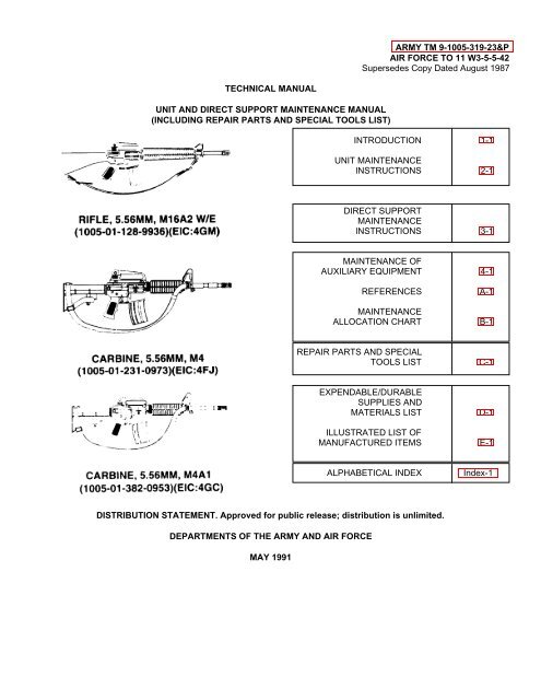
RIFLE, 5.56MM, <strong>M16</strong>A2 W/E<br />
(<strong>1005</strong>-01-128-9936) (EIC:4GM)<br />
1. Remove old pages and insert new pages as indicated below.<br />
2. New or changed material is indicated by a vertical bar adjacent to the material.<br />
3. New or changed illustrations are indicated by a miniature pointing hand highlighting the change.<br />
Remove Pages<br />
Insert Pages<br />
a thru ii<br />
a thru ii<br />
1-1 and 1-2 1-1 and 1-2<br />
1-4.1 thrul-6 1-4.1 thru 1-6<br />
2-12 2-12<br />
2-15 and 2-16 2-15 and 2-16<br />
2-31 and 2-32 2-31 and 2-32<br />
2-35 thru 2-36.1/(2-36.2 blank) 2-35 thru 2-36.1/(2-36.2 blank)<br />
2-49 and 2-50 2-49 and 2-50<br />
2-57 and 2-58 2-57 and 2-58<br />
3-25 and 3-26 3-25 and 3-26<br />
3-29 and 3-30 3-29 and 3-30<br />
3-45 and 3-46 3-45 and 3-46<br />
3-57 thru 3-62 3-57 thru 3-62<br />
3-82 thru 3-84 3-82 thru 3-84<br />
4-1 and 4-2 4-1 and 4-2<br />
A-1 and A-2 A-1 and A-2<br />
C-5 thru 1-12 C-5 thru 1-7/(I-8 blank)<br />
E-1 and E-2 E-1 and E-2<br />
None<br />
E-7/(E-8 blank)<br />
4. File this change sheet in the front of the publication for reference purposes.
By Order of the Secretary of the Army:<br />
DENNIS J. REIMER<br />
General, United States Army<br />
Chief of Staff<br />
Official:<br />
JOEL B. HUDSON<br />
Administrative Assistant to the<br />
Secretary of the Army<br />
03287<br />
DISTRIBUTION:<br />
9-<strong>1005</strong>-<strong>319</strong>-23&P.<br />
To be distributed in accordance with the initial distribution number (IDN) 400020, requirements for TM
ARMY TM 9-<strong>1005</strong>-<strong>319</strong>-23&P<br />
AIR FORCE TO 11W3-5-5-42<br />
CHANGE<br />
No. 4<br />
HEADQUARTERS<br />
DEPARTMENTS OF THE ARMY<br />
AND AIR FORCE<br />
Washington D.C., 5 May 1995<br />
TM 9-<strong>1005</strong>-<strong>319</strong>-23&P, May 1991, is changed as follows:<br />
UNIT AND DIRECT SUPPORT MAINTENANCE MANUAL<br />
(INCLUDING REPAIR PARTS AND SPECIAL TOOLS LIST)<br />
RIFLE, 5.56MM, <strong>M16</strong>A2 W/E<br />
(<strong>1005</strong>-01-128-9936) (EIC:4GM)<br />
1. Remove old pages and insert new pages as indicated below.<br />
2. New or changed material is indicated by a vertical bar adjacent to the material.<br />
3. New or changed illustrations are indicated by a miniature pointing hand highlighting the change.<br />
Remove Pages<br />
Insert Pages<br />
a thru iv<br />
a thru iv<br />
1-0.1/(1-0.2 blank) thru 1-6 1-0.1/(1-0.2 blank) thru 1-6<br />
2-1 thru 2-8 2-1 thru 2-8<br />
2-11 and 2-12 2-11 and 2-12<br />
2-17 thru 2-20 2-17 thru 2-20<br />
2-31 thru 2-34 2-31 thru 2-34<br />
None<br />
2-36.1/(2-36.2 blank)<br />
2-48 thru 2-50 2-48 thru 2-50<br />
2-53 thru 2-54 2-53 thru 2-54<br />
2-59 thru 2-62 2-59 thru 2-62<br />
2-69 thru 2-72 2-69 thru 2-73/(2-74 blank)<br />
3-1 and 3-2 3-1 and 3-2<br />
3-5 thru 3-8 3-5 thru 3-8<br />
3-11 thru 3-16 3-11 thru 3-16<br />
3-19 and 3-20 3-19 and 3-20<br />
3-39 and 3-40 3-39 and 3-40<br />
3-43 and 3-44 3-43 and 3-44<br />
3-47 thru 3-48 3-47 thru 3-48<br />
3-55 and 3-56 3-55 and 3-56<br />
3-65 thru 3-70 3-65 thru 3-70.1/(3-70.2 blank)<br />
3-73 thru 3-76 3-73 thru 3-76.1/(3-76.2 blank)<br />
3-83 thru 3-88 3-83 thru 3-88<br />
3-93 thru 3-96 3-93 thru 3-96<br />
3-101 thru 3-103/(3-104 blank) 3-101 thru 3-103/(3-104 blank)
Remove Pages<br />
Insert Pages<br />
4-1 and 4-2 4-1 and 4-2<br />
4-9 thru 4-11/(4-12 blank) 4-9 thru 4-11/(4-12 blank)<br />
A-1 and A-2 A-1 and A-2<br />
B-5 thru B-8 B-5 thru B-8<br />
C-1 and C-2 C-1 and C-2<br />
C-7 and C-8/(C-9 blank) C-7 and C-8/(C-9 blank)<br />
Fig C-1 thru Fig C-2 Fig C-1 thru Fig C-2<br />
C-5-1 thru Fig C-9 C-5-1 thru Fig C-9<br />
C-10-1 thru C-11-2<br />
C-10-1 thru C-11-2<br />
C-12-1 thru Fig C-17-1<br />
C-12-1 thru Fig C-17-1<br />
I-1 thru 1-10 1-1 thru 1-12<br />
D-3 and D-4 D-3 thru D-5/(D-6 blank)<br />
E-5/(E-6 blank) E-5 and E-6<br />
Cover<br />
Cover<br />
4. File this change sheet in the front of the publication for reference purposes.
By Order of the Secretary of the Army:<br />
GORDON R. SULLIVAN<br />
General, United States Army<br />
Chief of Staff<br />
Official:<br />
JOEL B. HUDSON<br />
Acting Administrative Assistant to the<br />
Secretary of the Army<br />
00175<br />
DISTRIBUTION: To be distributed in accordance with DA Form 12-40-E, block 0020 requirements for TM 9-<strong>1005</strong>-<strong>319</strong>-<br />
23&P.
ARMY TM 9-<strong>1005</strong>-<strong>319</strong>-23&P<br />
AIR FORCE TO 11W3-5-5-42<br />
CHANGE<br />
No. 3<br />
HEADQUARTERS<br />
DEPARTMENTS OF THE ARMY<br />
AND AIR FORCE<br />
Washington D.C., 3 February 1994<br />
TM 9-<strong>1005</strong>-<strong>319</strong>-23&P, May 1991, is changed as follows:<br />
UNIT AND DIRECT SUPPORT MAINTENANCE MANUAL<br />
(INCLUDING REPAIR PARTS AND SPECIAL TOOLS LIST)<br />
RIFLE, 5.56MM, M1 6A2 W/E<br />
(<strong>1005</strong>-01-128-9936) (EIC:4GM)<br />
1. Remove old pages and insert new pages as indicated below.<br />
2. New or changed material is indicated by a vertical bar adjacent to the material.<br />
3. New or changed illustrations are indicated by a miniature pointing hand highlighting the change.<br />
Remove Pages<br />
a thru iv/v(blank)<br />
Insert Pages<br />
a thru iv/v(blank)<br />
1-0.1/(1-0.2 blank)<br />
1-3 thru 1-6 1-3 thru 1-6<br />
2-3 and 2-4 2-3 and 2-4<br />
2-13 thru 2-18 2-13 thru 2-18.2<br />
2-21 thru 2-24 2-21 thru 2-24<br />
2-27 and 2-28 2-27 and 2-28<br />
2-47 and 2-48 2-47 thru 2-48<br />
2-53 and 2-54 2-53 and 2-54<br />
2-57 thru 2-60 2-57 thru 2-60<br />
2-63 thru 2-71/(2-72 blank) 2-63 thru 2-72<br />
3-39 and 3-40 3-39 and 3-40<br />
3-57 and 3-58 3-57 and 3-58<br />
3-77 thru 3-82 3-77 thru 3-82<br />
4-1 and 4-2 4-1 and 4-2<br />
4-5 thru 4-10 4-5 thru 4-10<br />
B-5 thru B-8 B-5 thru B-8<br />
C-7 and C-8/(C-9 blank) C-7 and C-8/(C-9 blank)<br />
Fig C-1 thru Fig C-2 Fig C-1 thru Fig C-2<br />
C-5-1 thru Fig C-9 C-5-1 thru Fig C-9<br />
C-10-1 thru Fig C-14 C-10-1 thru Fig C-14<br />
C-15-1 thru C-17-1<br />
I-1 thru 1-10 I-1 thru I-10<br />
Cover<br />
Cover<br />
C-15-1 thru C-17-1<br />
4. File this change sheet in the front of the publication for reference purposes.
By Order of the Secretary of the Army:<br />
GORDON R. SULLIVAN<br />
General. United States Army<br />
Chief of Staff<br />
Official<br />
MILTON H HAMILTON<br />
Administrative Assistant to the<br />
Secretary of the Army<br />
05909<br />
DISTRIBUTION: To be distributed in accordance with DA Form 12-40-E, Block 0020, requirements for TM 9-<strong>1005</strong>-<strong>319</strong>-<br />
23&P.
ARMY TM 9-<strong>1005</strong>-<strong>319</strong>-23&P<br />
AIR FORCE 11W3-5-5-42<br />
CHANGE<br />
No. 2<br />
HEADQUARTERS<br />
DEPARTMENTS OF THE ARMY<br />
AND AIR FORCE<br />
Washington, DC 17 AUGUST 1992<br />
UNIT AND DIRECT SUPPORT MAINTENANCE MANUAL<br />
(INCLUDING REPAIR PARTS AND SPECIAL TOOLS LIST)<br />
RIFLE, 5.56MM, <strong>M16</strong>A2 W/E<br />
(<strong>1005</strong>-01-1 28-9936) (EIC:4GM)<br />
TM 9-<strong>1005</strong>-<strong>319</strong>-23&P, May 1991, is changed as follows:<br />
1. Remove old pages and insert new pages as indicated below.<br />
2. New or changed material is indicated by a vertical bar adjacent to the material.<br />
3. New or changed illustrations are indicated by a miniature pointing hand highlighting the change.<br />
Remove Pages<br />
Insert Pages<br />
1-3 and 1-4 1-3 and 1-4<br />
4. File the change sheet in the front of the publication for reference purposes.
By Order of the Secretary of the Army:<br />
GORDON R. SULLIVAN<br />
General. United States Army<br />
Chief of Staff<br />
Official<br />
MILTON H HAMILTON<br />
Administrative Assistant to the<br />
Secretary of the Army<br />
By Order of the Secretary of the Air Force:<br />
MERRILL A. McPEAK, General USAF<br />
Chief of Staff<br />
Offical:<br />
CHARLES C. McDONALD, General, USAF<br />
Commander, Air Force Logistics Command<br />
DISTRIBUTION:<br />
TO BE DISTRIBUTED IN ACCORDANCE WITH DA FORM 12-40-E, (BLOCK 0020), REQUIREMENTS FOR<br />
TM 9-<strong>1005</strong>-<strong>319</strong>-23&P.
ARMY TM 9-<strong>1005</strong>-<strong>319</strong>-23&P<br />
AIR FORCE TO 11W3-5-5-42<br />
CHANGE<br />
NO. 1<br />
HEADQUARTERS<br />
DEPARTMENTS OF THE ARMY<br />
AND AIR FORCE<br />
TM 9-<strong>1005</strong>-<strong>319</strong>-23&P, May 1991, Is changed as follows:<br />
UNIT AND DIRECT SUPPORT MAINTENANCE MANUAL<br />
(INCLUDING REPAIR PARTS AND SPECIAL TOOLS LIST)<br />
RIFLE, 5.68MM, <strong>M16</strong>A2 W/E<br />
(<strong>1005</strong>-01-128-9936) (EIC:4GM)<br />
1. Remove old pages and Insert new pages as indicated below.<br />
2. New or changed material is indicated by a vertical bar adjacent to the material.<br />
3. New or changed Illustrations are Indicated by a miniature pointing hand highlighting the change.<br />
Washington, DC 2 April 1992<br />
Remove Pages<br />
Insert Pages<br />
2-7 and 2-8 2-7 and 2-8<br />
2-57 thru 2-60 2-57 thru 2-60<br />
3-35 and 3-36 3-35 and 3-36<br />
3-65 and 3-66 3-65 and 3-66<br />
3-69 and 3-70 3-69 and 3-70<br />
3-87 and 3-88 3-87 and 3-88<br />
3-93 thru 3-96 3-93 thru 3-96<br />
C-2-1 and Figure C-3 C-2-1 and Figure C-3<br />
C-6-1 thru Figure C-8 C-6-1 thru Figure C-8<br />
C-10-1 and Figure C-11 C-10-1 and Figure C-11<br />
C-17-1<br />
C-17-1<br />
I-1 thru 1-4 1-1 thru 1-4<br />
1-7 and 1-8 1-7 and 1-8<br />
4. File this change sheet In the front of the publication for reference purposes.
By Order of the Secretary of the Army:<br />
Official<br />
GORDON R. SULLIVAN<br />
General. United States Army<br />
Chief of Staff<br />
MILTON H HAMILTON<br />
Administrative Assistant to the<br />
Secretary of the Army<br />
DISTRIBUTION:<br />
To be distributed in accordance with DA Form 12-40-E, (Block 0020), Unit, Direct and General Support<br />
<strong>Maintenance</strong> requirements for TM-9-<strong>1005</strong>-<strong>319</strong>-23&P.
ARMY TM 9-<strong>1005</strong>-<strong>319</strong>-23&P<br />
AIR FORCE TO 11W3-5-5-42<br />
WARNING<br />
ALL WARNINGS in this technical manual pertain to both the rifle and the carbines unless otherwise specified.<br />
Before starting an inspection, be sure to clear the rifle. Do not pull the trigger until the rifle has been cleared. Inspect the<br />
chamber to ensure that it is empty and no ammunition is in position to be chambered.<br />
Do not keep live ammunition near work area.<br />
To avoid injury to your eyes, use care when removing and installing spring-loaded parts.<br />
All M1 6A2 rifles and M4 carbines must be inspected and gaged at least once annually for safety and serviceability. Initial<br />
gaging is required 1 year from receipt of the weapons. Air Force users refer to inspection requirements in Air Force<br />
<strong>Manual</strong> (AFM) 36-2227, Volume 1.<br />
All Army Reserve and Army National Guard <strong>M16</strong>A2 rifles and M4 carbines must be inspected and gaged at least once<br />
every 2 years, after the initial inspection/gaging procedures have been accomplished. This initial gaging procedure is<br />
required 1 year from receipt of the weapons. This 2 year interval may be maintained unless preventive maintenance<br />
checks and services (PMCS) or other physical evidence indicates that an individual unit’s <strong>M16</strong>A2 rifles and M4 carbines<br />
require inspection/ gaging at a more frequent interval. If it is determined that a yearly inspection is necessary for an<br />
individual unit, only that unit will be affected. This will not affect other units in regard to the interval of inspection.<br />
It is recommended that training units inspect/gage all rifles and carbines at the end of each training cycle. Training units<br />
will inspect/gage all rifles and carbines at least once annually.<br />
Below direct support maintenance, DO NOT interchange bolt assemblies from one rifle/carbine to another. Doing so may<br />
result in injury to, or death of, personnel.<br />
Bolt cam pin must be installed or rifle/carbine will blow up while firing the first round. If the bolt cam pin is not installed,<br />
injury to or death of, personnel may result.<br />
Dry cleaning solvent is flammable and toxic and should be used in a well ventilated area. The use of rubber gloves is<br />
necessary to protect the skin when washing rifle parts.<br />
When using solid film lubricant or dichloromethane, be sure the area is well ventilated.<br />
When using carbon removing compound (item 8, app D), avoid skin contact. If carbon removing compound comes In<br />
contact with the skin, wash thoroughly with running water. using a good lanolin base cream after exposure to the<br />
compound is helpful. Using gloves and protective equipment is required.<br />
The lock plate prevents the selector lever from being placed in BURST and will be installed at the discretion of the unit<br />
commander. It is mandatory for use in civil disturbance (riot control).<br />
Only blank cartridge M200 is to be used when the blank firing attachment is attached to the rifle/carbine.<br />
Change 5 a
ARMY TM 9-<strong>1005</strong>-<strong>319</strong>-23&P<br />
AIR FORCE TO 11W3-5-5-42<br />
WARNING (CONT)<br />
Do not fire blank ammunition at a representative enemy at distances of less than 20 feet (6.10 Om). The unburned<br />
propellant grains can cause injury within this distance.<br />
For further information on safety, care, and handling of ammunition: Army and Air Force users refer to <strong>M16</strong>A2 Rifle<br />
Operator’s <strong>Manual</strong>.<br />
For additional first aid data, see Field <strong>Manual</strong> (FM) 21-11.<br />
b
ARMY TM 9-<strong>1005</strong>-<strong>319</strong>-23&P<br />
AIR FORCE TO 11W3-5-5-42<br />
TECHNICAL MANUAL<br />
ARMY NO. 9-<strong>1005</strong>-<strong>319</strong>-23&P<br />
AIR FORCE TO 11W3-5-5-42<br />
*ARMY TM 9-<strong>1005</strong>-<strong>319</strong>-23&P<br />
AIR FORCE TO 11W3-5-5-42<br />
DEPARTMENTS OF THE ARMY<br />
AND AIR FORCE<br />
Washington, DC, 1 May 1991<br />
Unit and Direct Support <strong>Maintenance</strong> <strong>Manual</strong><br />
(Including Repair Parts and Special Tools List)<br />
For<br />
RIFLE, 5.56MM, <strong>M16</strong>A2, W/E<br />
(<strong>1005</strong>-01-128-9936)<br />
CARBINE, 5.56MM, M4<br />
(<strong>1005</strong>-01-231-0973)<br />
AND<br />
CARBINE, 5.56MM, M4A1<br />
(<strong>1005</strong>-01-382-0953)<br />
Current as of December 1996<br />
DISTRIBUTION STATEMENT. APPROVED FOR PUBLIC RELEASE; DISTRIBUTION IS UNLIMITED.<br />
REPORTING ERRORS AND RECOMMENDING IMPROVEMENTS<br />
You can help improve this manual. If you find any mistakes or if you know of a way to improve<br />
the procedures please let us know.<br />
Army users mail your letter, DA Form 2028 (recommended Changes to Publications and<br />
Blank Forms), or DA Form 2028-2 located in the back of this manual direct to: Director,<br />
Armament and Chemical Acquisition and Logistics Activity, ATTN: AMSTA-AC-NML, Rock<br />
Island, IL 61299-7630.<br />
Air Force users submit AFTO Form 22, Technical Order System Publication Improvement<br />
Report and Reply, to: WR-ALC/MMDET, Robins AFB, GA 31098-5609.<br />
A reply will be furnished to you.<br />
HOW TO USE THIS MANUAL..........................................................................<br />
Page<br />
iii<br />
CHAPTER 1 INTRODUCTION................................................................................................ 1-1<br />
External View of 5.56mm Rifle, <strong>M16</strong>A2.............................................................. 1-0<br />
External View of 5.56mm Carbine, M4............................................................... 1-0.1<br />
External View of 5.56mm Carbine, M4A1.......................................................... 1-0.1<br />
Chapter Overview............................................................................................... 1-1<br />
Section I General Information ........................................................................................... 1-1<br />
Section II Equipment Description and Data........................................................................ 1-3<br />
Section III Principles of Operation....................................................................................... 1-6<br />
*This manual supersedes ARMY TM 9-<strong>1005</strong>-<strong>319</strong>-23&P dated 28 August 1987, including all changes.<br />
Change 5 i
ARMY TM 9-<strong>1005</strong>-<strong>319</strong>-23&P<br />
AIR FORCE TO 11W3-5-5-42<br />
Page<br />
CHAPTER 2 UNIT MAINTENANCE INSTRUCTIONS................................................... 2-1<br />
Chapter Overview...................................................................................... 2-1<br />
Section I Repair Parts, Special Tools, TMDE, and Support Equipment................... 2-1<br />
Section II Service Upon Receipt................................................................................ 2-1<br />
Section III Preventive <strong>Maintenance</strong> Checks and Services (PMCS)........................... 2-3<br />
Section IV Troubleshooting......................................................................................... 2-20<br />
Section V <strong>Maintenance</strong> Procedures........................................................................... 2-33<br />
Section VI Preparation for Storage or Shipment......................................................... 2-70<br />
Illus<br />
Figure<br />
CHAPTER 3 DIRECT SUPPORT MAINTENANCE INSTRUCTIONS........................... 3-1<br />
Chapter Overview...................................................................................... 3-1<br />
Section I Repair Parts, Special Tools, TMDE, and Support Equipment................... 3-1<br />
Section II Troubleshooting......................................................................................... 3-2<br />
Section III <strong>Maintenance</strong> Procedures for the <strong>M16</strong>A2 Rifle, M4 and M4A1 Carbine..... 3-15<br />
Section IV Preembarkation Inspection of Materiel in Units Alerted for Overseas<br />
Movement (A.F. Only)................................................................................ 3-95<br />
CHAPTER 4 MAINTENANCE OF AUXILIARY EQUIPMENT....................................... 4-1<br />
Chapter Overview...................................................................................... 4-1<br />
Section I Auxiliary Equipment Repair....................................................................... 4-1<br />
APPENDIX A. REFERENCES.......................................................................................... A-1<br />
APPENDIX B. MAINTENANCE ALLOCATION CHART.................................................. B-1<br />
APPENDIX C. REPAIR PARTS AND SPECIAL TOOLS LIST......................................... C-1<br />
Section I Introduction................................................................................................ C-1<br />
Section II Repair Parts List........................................................................................ C-1-1<br />
Group 00 5.56MM Rifle, <strong>M16</strong>A2, Carbine, M4 and M4A1......................................... C-1-1 C-1<br />
00.1 M4 and M4A1 Carrying Handle Assembly................................................. C-1A-1 C-1A<br />
00.101 M4 and M4A1 Rear Sight Assembly.......................................................... C-1B-1 C-1B<br />
Group 01 Bolt carrier assembly................................................................................. C-2-1 C-2<br />
0101 Bolt assembly............................................................................................ C-3-1 C-3<br />
0102 Key and bolt carrier assembly................................................................... C-4-1 C-4<br />
Group 02 Handle assembly....................................................................................... C-5-1 C-5<br />
Group 03 Upper receiver and barrel assembly.......................................................... C-6-1 C-6<br />
0301 Barrel assembly, <strong>M16</strong>A2............................................................................ C-7-1 C-7<br />
0301 Replacement Barrel & Front Sight Assembly, M4/M4A1........................... C-7-1 C-7<br />
0302 Upper receiver assembly........................................................................... C-8-1 C-8<br />
030201 Forward assist assembly........................................................................... C-9-1 C-9<br />
030202 Rear sight assembly, <strong>M16</strong>A2..................................................................... C-10-1 C-10<br />
Group 04 Lower receiver and buttstock assembly .................................................... C-11-1 C-11<br />
0401 Buttstock assembly, <strong>M16</strong>A2...................................................................... C-12-1 C-12<br />
0401A Buttstock assembly, M4/M4A1.................................................................. C12A-1 C12A<br />
0402 Hammer assembly..................................................................................... C-13-1 C-13<br />
0403 Trigger assembly....................................................................................... C-14-1 C-14<br />
040301 Trigger subassembly,<strong>M16</strong>A2 and M4........................................................ C-15-1 C-15<br />
0404 Lower receiver and receiver extension assembly, <strong>M16</strong>A2........................ C-16-1 C-16<br />
0404A Lower receiver and receiver extension assembly, M4 and M4A1............. C16A-1 C16A<br />
ii Change 4
ARMY TM 9-<strong>1005</strong>-<strong>319</strong>-23&P<br />
AIR FORCE TO 11W3-5-5-42<br />
Illus<br />
Page Figure<br />
APPENDIX C. REPAIR PARTS AND SPECIAL TOOLS LIST--Cont.<br />
Section III Special Tools List....................................................................................... C-17-1 C-17<br />
Section IV National Stock Number and Part Number Index....................................... I-1<br />
APPENDIX D. EXPENDABLE/DURABLE SUPPLIES AND MATERIALS LIST.............. D-1<br />
APPENDIX E. ILLUSTRATED LIST OF MANUFACTURED ITEMS............................... E-1<br />
ALPHABETICAL INDEX........................................................................... Index-1<br />
Change 4 ii.1/(ii.2 blank)
ARMY TM 9-<strong>1005</strong>-<strong>319</strong>-23&P<br />
AIR FORCE TO 11W3-5-5-42<br />
HOW TO USE THIS MANUAL<br />
Read this manual carefully before performing required maintenance. This manual will be referred to for<br />
Inspection/<strong>Maintenance</strong> and Repair procedures.<br />
GENERAL<br />
There are several things you need to know to use this manual efficiently.<br />
1. All references in the manual are to pages only. Reference to maintenance procedures is to the page where the<br />
respective initial setup appears.<br />
2. Illustrations for the maintenance procedures show only those parts affected by the operation being performed.<br />
3. Whenever the male gender is mentioned in the manual (i.e., crewman, repairman), it also pertains to females.<br />
4. When the term “evacuate to support maintenance” is used, the entire rifle must be evacuated.<br />
5. When a procedure is common to <strong>M16</strong>A2 rifle, and M4/M4A1 carbine, ONLY the <strong>M16</strong>A2 configuration will be<br />
depicted. If a procedure is not common to both weapons, the procedure will be incorporated.<br />
6. When the word rifle is referenced in text, it will reference the rifle and the carbines.<br />
INDEXES<br />
This manual is organized to help you find the information you need quickly. There are several useful indexes.<br />
1. Table of Contents. Lists in order all chapters, sections, and appendixes. Gives page references.<br />
2. Nomenclature Cross-References List.<br />
3. Chapter Overviews. Summarize material covered in the chapter. Are located at the beginning of each chapter.<br />
4. Symptom Index. Located just before the troubleshooting table in each maintenance chapter. Lists, in alphabetical<br />
order, parts of the rifle with possible malfunctions. References pages of the troubleshooting table.<br />
5. Alphabetical Index. Located at the end of the manual. An extensive subject index for everything in the manual.<br />
Gives page references.<br />
MAINTENANCE PROCEDURES<br />
There are two maintenance chapters:<br />
Army personnel use chapter two for unit maintenance procedures and chapter three for direct support maintenance<br />
procedures.<br />
Change 4 iii
ARMY TM 9-<strong>1005</strong>-<strong>319</strong>-23&P<br />
AIR FORCE TO 11 W3-5-5-42<br />
Air Force personnel: Only Air Force Specialty Code 753XX Combat Arms Training and <strong>Maintenance</strong> (CATM) specialists,<br />
technicians, and gunsmiths are authorized to perform maintenance procedures contained in this manual.<br />
Each maintenance task has an initial setup containing a list of the following things you will need in order to do your<br />
maintenance task.<br />
1. Tools and Special Tools. For standard and special tools, see appendixes B and C. Army users are to use the Tool<br />
Set, Gage Set, and/or Shop Set listed in the initial setup.<br />
2. Materials/Parts. Lists expendable materials and 100 percent replaceable parts. Each material or part is followed by<br />
a part number or appendix reference.<br />
3. References. Lists other publications containing necessary information.<br />
4. Equipment Condition. Lists conditions to be met before starting the procedure. The reference on the left of the<br />
condition is a page reference to instructions for setting up the condition.<br />
5. General Safety Instructions. Lists safety instructions to follow before performing maintenance procedures.<br />
iv/(v blank) Change 3
ARMY TM 9-<strong>1005</strong>-<strong>319</strong>-23&P<br />
AIR FORCE TO 11 W3-5-5-42<br />
EXTERNAL VIEW OF 5.56 MM RIFLE <strong>M16</strong>A2<br />
1-0
ARMY TM 9-<strong>1005</strong>-<strong>319</strong>-23&P<br />
AIR FORCE TO 11W3-5-5-42<br />
EXTERNAL VIEW OF 5.56MM CARBINE, M4/M4A1<br />
Change 4 1-0.1/(1-0.2 blank)
ARMY TM 9-<strong>1005</strong>-<strong>319</strong>-23&P<br />
AIR FORCE TO 11W3-5-5-42<br />
CHAPTER 1<br />
INTRODUCTION<br />
CHAPTER OVERVIEW<br />
This chapter contains general information, equipment description and data, and principles of operation for the <strong>M16</strong>A2 rifle<br />
and M4/M4A1 carbines.<br />
1-1. SCOPE.<br />
Section I. GENERAL INFORMATION<br />
a. Type of <strong>Manual</strong>: Unit and Direct Support <strong>Maintenance</strong>.<br />
b. Model Number and Equipment Name: 5.56mm Rifle <strong>M16</strong>A2, M4 and M4A1 Carbines.<br />
c. Purpose of Equipment. Provides personnel an offensive/defensive capability to engage targets with small arms fire.<br />
1-2. MAINTENANCE FORMS, RECORDS, AND REPORTS. Department of the Army forms and procedures used for<br />
equipment maintenance will be those prescribed by DA PAM 738-750, The Army <strong>Maintenance</strong> Management System.<br />
Air Force users refer to TO 11W-1-10 for applicable forms and records.<br />
1-3. DESTRUCTION OF ARMY MATERIEL TO PREVENT ENEMY USE. See TM 750-244-7.<br />
1-4. PREPARATION FOR STORAGE OR SHIPMENT. Refer to page 2-70.<br />
Air Force users refer to Special Package Instruction (SPI) 00-856-6885.<br />
1-5. OFFICIAL NOMENCLATURE, NAMES AND DESIGNATIONS.<br />
NOMENCLATURE CROSS-REFERENCE LIST<br />
Common Name<br />
Action Spring ...................................................................<br />
Ball Bearing .....................................................................<br />
Bolt Catch Spring.............................................................<br />
Bolt Carrier Key Tool .......................................................<br />
Burst Disconnector ..........................................................<br />
Cam Clutch Spring ..........................................................<br />
Carbine............................................................................<br />
Charging Handle Assembly.............................................<br />
Official Nomenclature<br />
Compression Helical Spring<br />
Bearing Ball<br />
Compression Helical Spring<br />
Machine Key<br />
Lock-Release Lever<br />
Helical Spring<br />
M4/M4A1 Carbine<br />
Handle Assembly<br />
Change 5 1-1
ARMY TM 9-<strong>1005</strong>-<strong>319</strong>-23&P<br />
AIR FORCE TO 11 W3-5-5-42<br />
1-5. OFFICIAL NOMENCLATURE, NAMES AND DESIGNATIONS (CONT).<br />
NOMENCLATURE CROSS-REFERENCE LIST<br />
Common Name<br />
Disconnector Springs ......................................................<br />
Ejector Spring..................................................................<br />
Extractor Spring Assembly ..............................................<br />
Hammer Spring ...............................................................<br />
Lower Receiver Extension...............................................<br />
Magazine.........................................................................<br />
Magazine Catch Spring ...................................................<br />
Peel Washer....................................................................<br />
Pistol Grip........................................................................<br />
Pivot Pin Detent...............................................................<br />
Rifle .................................................................................<br />
Rifle Barrel Assembly ......................................................<br />
Selector Lever .................................................................<br />
Semiautomatic Disconnector...........................................<br />
Sling.................................................................................<br />
Trigger Spring..................................................................<br />
Upper Receiver................................................................<br />
Official Nomenclature<br />
Compression Helical Spring<br />
Helical Spring<br />
Spring Assembly<br />
Torsion Helical Spring<br />
Spring Receiver Holder<br />
Cartridge Magazine<br />
Compression Helical Spring<br />
Shim<br />
Rifle Grip<br />
Takedown Pin Detent<br />
Rifle, 5.56mm, <strong>M16</strong>A2<br />
Barrel Assembly<br />
Fire Control Selector<br />
Lock-Release Lever<br />
Small Arms Sling<br />
Torsion Helical Spring<br />
Upper Cartridge Receiver<br />
1-6. REPORTING EQUIPMENT IMPROVEMENT RECOMMENDATIONS (EIR). If your <strong>M16</strong>A2 rifle needs<br />
improvement, let us know. Send us an EIR. You, the user, are the only one who can tell us what you don’t like about your<br />
equipment. Let us know why you don’t like the design.<br />
Army users submit SF 368 (Product Quality Deficiency Report) to: Commander, U.S. Army Armament Research,<br />
Development and Engineering Center, ATTN: AMSTA-AR-QAW (R)/Customer Feedback Center, Rock Island, IL 61299-<br />
7300.<br />
Air Force users submit Materiel Deficiency Report (MDR) to: DIR MAT MGT ROBINS AFB GA//MMIBTC// and Product<br />
Quality Deficiency Report to: DIR MAT MGT ROBINS AFB GA//MMQA// IAW Technical Order 00-35D-54.<br />
A reply will be sent to you.<br />
1-7. CORROSION PREVENTION AND CONTROL (CPC). CPC of Army materiel is a continuing concern. It is<br />
important that any corrosion problems with this item be reported so that the problem can be corrected and improvements<br />
can be made to prevent the problem in future items,<br />
While corrosion is typically associated with rusting of metals, it can also include deterioration of other materials such as<br />
rubber and plastic. Unusual cracking, softening, swelling, or breaking of these materials may be a corrosion problem.<br />
1-2 Change 4
ARMY TM 9-<strong>1005</strong>-<strong>319</strong>-23&P<br />
AIR FORCE TO 11W3-5-5-42<br />
If a corrosion problem is identified, it can be reported using Standard Form 368, Product Quality Deficiency Report. Use of<br />
key words such as "corrosion", "rust", " deterioration", or "cracking" will assure that the information is identified as a CPC<br />
problem.<br />
Army users submit Product Quality Deficiency Report (SF 368) to:<br />
Commander<br />
U.S. Army Armament Research, Development and Engineering Center<br />
ATTN: AMSTA-AR-QAW (R)<br />
Rock Island, IL 61299-7300<br />
Air Force users submit Materiel Deficiency Report (MDR) to:<br />
DIR MAT MGT<br />
ATTN: MMIBTC<br />
Robins AFB, GA<br />
and Product Quality Deficiency Report to:<br />
DIR MAT MGT<br />
ATTN: MMQA<br />
Robins AFB, GA<br />
Section II. EQUIPMENT DESCRIPTION AND DATA<br />
1-8. EQUIPMENT CHARACTERISTICS, CAPABILITIES, AND FEATURES.<br />
a. Characteristics.<br />
(1) Light weight (4) Magazine-fed<br />
(2) Air-cooled (5) Semiautomatic or burst fire<br />
(3) Gas-operated<br />
b. Capabilities. Provides personnel an offensive/defensive capability to engage targets with direct small arms fire.<br />
c. Features.<br />
(1) Receivers are made of light-weight aluminum alloys; however, the safety , durability, and function of the rifles<br />
are in no way reduced. The portability and logistical values are greatly increased, particularly when air transport is used.<br />
(2) The bolt locking action is one of the mechanical features of the rifle. The bolt assembly and barrel extension<br />
contain locking lugs which engage and lock the bolt assembly firmly in the barrel extension. The initial force of the<br />
explosion of the cartridge is absorbed by the barrel, barrel extension, and bolt assembly.<br />
Change 4 1-3
ARMY TM 9-<strong>1005</strong>-<strong>319</strong>-23&P<br />
AIR FORCE TO 1 1W3-5-5-42<br />
1-8. EQUIPMENT CHARACTERISTICS, CAPABILITIES, AND FEATURES (CONT).<br />
(3) The trigger guard is easily adaptable to winter operations. A spring-loaded retaining pin is depressed to allow<br />
ready access to the trigger when wearing arctic mittens.<br />
(4) The ejection port cover prevents dirt or sand from getting into the ejection port. The ejection port cover must<br />
be closed during periods when firing is not anticipated. It opens automatically by the forward or rearward movement of the<br />
bolt carrier assembly.<br />
1-9. LOCATION AND DESCRIPTION OF MAJOR COMPONENTS.<br />
(A)<br />
(B)<br />
(C)<br />
(D)<br />
(E)<br />
(F)<br />
(G)<br />
(H)<br />
MAGAZINE. 30 cartridge capacity.<br />
SLING. The sling is adjustable and provides a means to carry the weapon.<br />
BOLT CARRIER ASSEMBLY. Carries bolt assembly to chamber and fires the weapon. Contains the firing pin,<br />
cartridge extractor, bolt assembly, cartridge ejector, and bolt cam pin.<br />
CHARGING HANDLE ASSEMBLY. Provides a means of charging the weapon.<br />
<strong>M16</strong>A2 UPPER RECEIVER AND BARREL ASSEMBLY. Upper receiver contains rear sight assembly, ejection<br />
port, ejection port cover, and a housing for the key and bolt carrier assembly and bolt assembly. Rifle barrel<br />
assembly is air-cooled, contains compensator and front sight assembly, and holds the two handguard assemblies<br />
and the sling swivel.<br />
LOWER RECEIVER AND BUTTSTOCK ASSEMBLY. Lower receiver contains the trigger assembly, sear,<br />
hammer assembly, selector lever, rifle grip, bolt catch, and buttstock assembly. The buttstock assembly houses<br />
the action spring, buffer assembly, and extension assembly.<br />
M4/M4A1 CARRYING HANDLE. Provides a means of carrying carbine.<br />
M4/M4A1 UPPER RECEIVER AND BARREL ASSEMBLY. Upper receiver contains, ejection port, ejection port<br />
cover, a housing for key and bolt carrier assembly and bolt assembly, and mounting surface for the carrying<br />
handle assembly. Carbine barrel assembly is air-cooled, contains compensator and front sight assembly, and<br />
holds the two handguard assemblies and the sling swivel.<br />
1-4 Change 4
ARMY TM 9-<strong>1005</strong>-<strong>319</strong>-23&P<br />
AIR FORCE TO 11W3-5-5-42<br />
Change 4 1-4.1
ARMY TM 9-<strong>1005</strong>-<strong>319</strong>-23&P<br />
AIR FORCE TO 11W3-5-5-42<br />
1-10. EQUIPMENT DATA.<br />
US CUSTOMARY<br />
METRIC<br />
Weight:<br />
Carbine, M4/M4A1 without magazine and sling ...... 6 lb 7 oz 2.91 kg<br />
Rifle, Ml 6A2 without magazine and sling................ 7 lb 8 oz 3.40 kg<br />
Sling, adjustable ...................................................... 4 oz 0.11 kg<br />
Empty magazine...................................................... 4 oz 0.11 kg<br />
Loaded magazine .................................................... 1 lb 1 oz 0.48 kg<br />
Carbine, M4/M4A1 w/sling and loaded magazine ... 7 lb 12 oz 3.51 kg<br />
Rifle <strong>M16</strong>A2 w/sling and loaded magazine.............. 8 lb 13 oz 4.00 kg<br />
Bayo<strong>net</strong>-Knife M7 .................................................... 10.5 oz 0.30 kg<br />
Scabbard M10 o ...................................................... 5 oz 0.14 kg<br />
Length:<br />
Carbine with compensator, buttstock extended....... 33.0 in 83.82 cm<br />
Carbine with compensator, buttstock closed ........... 29.75 in 75.57 cm<br />
Rifle with compensator ............................................ 39.63 in 100.66 cm<br />
Barrel (Carbine) ....................................................... 14.5 in 36.83 cm<br />
Barrel (Rifle)............................................................. 20 in 50.8 cm<br />
Barrel with compensator (Carbine).......................... 15.5 in 39.37 cm<br />
Barrel with compensator (Rifle) ............................... 21 in 53.34 cm<br />
Mechanical features:<br />
Rifling....................................................................... right-hand twist 6 grooves, 1 turn<br />
................................................................................. in 7 inches (17.78 cm)<br />
Method of operation................................................. direct gas<br />
Type of breech mechanism ..................................... rotating bolt<br />
Method of feeding.................................................... magazine<br />
Cooling..................................................................... air<br />
Trigger pull (<strong>M16</strong>A2 & M4)....................................... 5.5 to 9.5 lb 2.49 to 4.31kg<br />
Trigger pull (M4A1).................................................. 5.5 to 8.5 lb 2.49 to 3.86 kg<br />
Ammunition:<br />
Caliber ..................................................................... 223 5.56mm<br />
Type......................................................................... ball, blank, dummy, and tracer<br />
Firing characteristics:<br />
Muzzle velocity (Carbine) (approximate) ................. 2,970 fps 905.85 mps<br />
Muzzle velocity (Rifle) (approximate)....................... 3,100 fps 945.5 mps<br />
Chamber pressure................................................... 52,000 psi 358,540<br />
kPa<br />
Cyclic rate of fire (Carbine) (approximate)............... 700-970 rds/m<br />
Cyclic rate of fire (Rifle) (approximate) .................... 700-900 rds/m<br />
1-4.2 Change 5
ARMY TM 9-<strong>1005</strong>-<strong>319</strong>-23&P<br />
AIR FORCE TO 11W3-5-5-42<br />
1-10. EQUIPMENT DATA (CONT).<br />
US CUSTOMARY<br />
METRIC<br />
Maximum rate of fire:<br />
Semiautomatic......................................................... 45 rds/m<br />
Burst ........................................................................ 90 rds/m<br />
Sustained rate of fire ............................................... 12/15 rds/m<br />
Maximum range....................................................... 3,938 yards Approximately<br />
3,600 meters<br />
Maximum effective range:<br />
Individual/point targets (Carbine)............................. 547 yards 500 meters<br />
Individual/point targets (Rifle) .................................. 602 yards 550 meters<br />
Area targets (Carbine) ............................................. 650 yards 600 meters<br />
Area targets (Rifle) .................................................. 875 yards 800 meters<br />
Section III. PRINCIPLES OF OPERATION<br />
1-11. GENERAL. The 5.56mm <strong>M16</strong>A2 and M4/M4A1 carbine:<br />
a. Is gas-operated. It fires in either the semiautomatic or burst mode.<br />
b. Has positive locking of the bolt. Firing pin is part of the bolt carrier assembly and cannot strike the primer until<br />
the bolt assembly is fully locked.<br />
Change 4 1-5
ARMY TM 9-<strong>1005</strong>-<strong>319</strong>-23&P<br />
AIR FORCE TO 11W3-5-5-42<br />
1-12. PRINCIPLES OF OPERATION.<br />
Section III. PRINCIPLES OF OPERATION (CONT).<br />
(A)<br />
(B)<br />
(C)<br />
(D)<br />
(E)<br />
(F)<br />
(G)<br />
(H)<br />
MAGAZINE. Holds cartridges ready for feeding and provides a guide for positioning cartridges for stripping.<br />
Provides quick reload capabilities for sustained firing.<br />
SLING. Provides the means for carrying the weapon.<br />
BOLT CARRIER ASSEMBLY. Provides stripping, chambering, locking, firing, extraction, and ejection of<br />
cartridges using the drive springs and projectile propelling gases for power.<br />
CHARGING HANDLE ASSEMBLY. Provides initial charging of the weapon. The handle latch locks the<br />
charging handle assembly in the forward position during sustained fire to prevent injury to the operator.<br />
<strong>M16</strong>A2 UPPER RECEIVER AND BARREL ASSEMBLY. Provides support for the bolt carrier assembly.<br />
The barrel chambers the cartridge for firing and directs the projectile.<br />
LOWER RECEIVER AND BUTTSTOCK ASSEMBLY. Provides firing control for the rifle and carbine.<br />
<strong>M16</strong>A2 ONLY provides storage for basic cleaning materials.<br />
M4/M4A1 CARRYING HANDLE ASSEMBLY. Provides a means of carrying the carbine, contains rear<br />
sight assembly, and can be removed for mounting various optics.<br />
M4/M4A1 UPPER RECEIVER AND BARREL ASSEMBLY. Provides support for the bolt carrier assembly.<br />
The barrel chambers the cartridge for firing and directs the projectile.<br />
1-6 Change 5
ARMY TM 9-<strong>1005</strong>-<strong>319</strong>-23&P<br />
AIR FORCE TO 11W3-5-5-42<br />
CHAPTER 2<br />
UNIT MAINTENANCE INSTRUCTIONS<br />
CHAPTER OVERVIEW<br />
This chapter provides information and Instructions to help keep the rifle in good repair and contains the following sections:<br />
a. Repair Parts, Special Tools, TMDE, and Support Equipment<br />
b. Service Upon Receipt<br />
c. Preventive <strong>Maintenance</strong> Checks and Services (PMCS)<br />
d. Troubleshooting<br />
e. <strong>Maintenance</strong> Procedures<br />
Section I. REPAIR PARTS, SPECIAL TOOLS, TMDE,<br />
AND SUPPORT EQUIPMENT<br />
2-1. COMMON TOOLS AND EQUIPMENT. For authorized common tools and equipment, refer to the Modified Table<br />
of Organization and Equipment (MTOE) applicable to your unit.<br />
Air Force users must maintain the following common tools:<br />
3-ounce soft-brass hammer<br />
Vise<br />
Flat tip screwdriver<br />
Punch<br />
Tweezers/round nose pliers<br />
Hammer<br />
Needle nose pliers<br />
2-2. SPECIAL TOOLS, TMDE, AND SUPPORT EQUIPMENT. Special tools required for unit<br />
support are listed in appendixes B and C. Fabricated tools are listed and illustrated in appendix E.<br />
2-3. REPAIR PARTS. Repair parts are listed and illustrated in appendix C of this manual.<br />
2-4. GENERAL.<br />
Section II. SERVICE UPON RECEIPT<br />
a. Inspect the rifle for damage Incurred during shipment. If rifle has been damaged, report the damage on SF 364,<br />
Report of Discrepancy (ROD).<br />
b. Check the rifle against the packing slip to see If shipment is complete. Army users report all discrepancies in<br />
accordance with DA PAM 738-750.<br />
Air Force users submit Materiel Deficiency Report (MDR) to: DIR MAT MGT ROBINS AFB<br />
GA//MMIBTC// and Product Quality Deficiency Report to: DIR MAT MGT ROBINS AFB<br />
GA//MMQA//. IAW Technical Order 00-35D-54.<br />
c. Check to see whether the equipment has been modified.<br />
2-1
ARMY TM 9-<strong>1005</strong>-<strong>319</strong>-23&P<br />
AIR FORCE TO 11W3-5-5-42<br />
2-5. SERVICE UPON RECEIPT OF MATERIEL.<br />
WARNING<br />
Before starting an inspection, be sure to clear the rifle. Do not actuate the trigger before clearing the rifle.<br />
Inspect the chamber to make sure it is empty and free of obstructions. Check to see there are no<br />
obstructions in the barrel and no ammunition is in position to be chambered.<br />
SERVICE UPON RECEIPT<br />
LOCATION ITEM ACTION REMARKS<br />
1. Container a. <strong>M16</strong>A2 rifle or a. Remove rifle from containers.<br />
M4/M4A1 carbine<br />
b. Inspect the equipment for dam- If the equipment has<br />
age incurred during shipment<br />
been damaged, report<br />
the damage on SF<br />
Form 364, Report of<br />
Discrepancy (ROD).<br />
c. Check the equipment against Report all discrepthe<br />
packing list to see if the<br />
ancies in accordance<br />
shipment is complete<br />
with the instructions of<br />
DA PAM 738-750.<br />
b. Basic issue Check for missing items Refer to TM 9-<strong>1005</strong>-<br />
items<br />
<strong>319</strong>-10 (operator’s<br />
manual).<br />
2. <strong>M16</strong>A2 a. Barrel assembly If volatile corrosion inhibitor (VCI)<br />
rifle or<br />
is in barrel, remove and discard.<br />
M4/M4A1<br />
carbine b. All parts a. Field-strip rifle and inspect for Refer to operator’s<br />
missing, damaged, and rusted<br />
manual.<br />
or corroded parts.<br />
b. Clean and lubricate Refer to operator’s<br />
manual.<br />
c. Reassemble Refer to operator’s<br />
manual.<br />
d. Function check Refer to page 2-69.<br />
2-2 Change 4
ARMY TM 9-<strong>1005</strong>-<strong>319</strong>-23&P<br />
AIR FORCE TO 11W3-5-5-42<br />
SERVICE UPON RECEIPT (CONT)<br />
LOCATION ITEM ACTION REMARKS<br />
e. Check to see whether the equipment has Refer to DA PAM<br />
been modified 25-30.<br />
c. Magazine Check for positive retention and functioning of bolt Refer to operator’s<br />
catch<br />
manual.<br />
Section III. PREVENTIVE MAINTENANCE CHECKS AND SERVICES (PMCS)<br />
2-6. GENERAL This section contains the procedures and instructions necessary to perform unit preventive maintenance<br />
checks and services. These services are to be performed by unit maintenance personnel with the assistance of the<br />
operator where practical.<br />
2-7. PREVENTIVE MAINTENANCE CHECKS AND SERVICES<br />
WARNING<br />
Before starting an inspection, be sure to clear the rifle. Do not keep live ammunition near the work area.<br />
a. General. The PMCS procedures are contained in the table following. They are arranged in logical sequence<br />
requiring a minimum amount of time and motion on the part of the persons performing them and are arranged so that<br />
there will be minimum interference between persons performing checks simultaneously on the same end item.<br />
b. Item No. Column. Checks and services are numbered in disassembly sequence. This column shall be used as a<br />
source of item numbers for the "TM Number" column on DA Form 2404, Equipment Inspection and <strong>Maintenance</strong><br />
Worksheet, in recording results of PMCS.<br />
c. Interval Column. This column gives the designated interval when each check is to be performed.<br />
d. Item To Be Checked Or Serviced Column. This column lists the items to be checked or serviced.<br />
e. Procedure Column. This column contains a brief description of the procedure by which the check is to be<br />
performed. It contains all the information required to accomplish the checks and services. Information marked SH<br />
Indicates a specific equipment shortcoming and the procedure needed to correct the shortcoming.<br />
NOTE<br />
For the purpose of this technical manual, the following definition is supplied. This definition is not intended<br />
to apply to any other document<br />
Shortcoming (SH): A fault that requires maintenance or supply action on a piece of equipment, but does<br />
not render equipment Not Mission Capable<br />
f. Not Fully Mission Capable If: Column. This column contains a brief statement of the condition (e.g.,<br />
malfunction, shortage) that would cause the covered equipment to be less than fully ready to perform its assigned mission.<br />
Change 3 2-3
ARMY TM 9-<strong>1005</strong>-<strong>319</strong>-23&P<br />
AIR FORCE TO 11W3-5-5-42<br />
2-7. PREVENTION MAINTENANCE CHECKS AND SERVICES (CONT).<br />
PREVENTIVE MAINTENANCE CHECKS AND SERVICES FOR <strong>M16</strong>A2 RIFLE (CONT)<br />
Item Interval Item to be Not Fully Mission<br />
No. Checked or Procedure Capable if:<br />
Serviced<br />
2-4 Change 4<br />
WARNING<br />
Before starting an inspection, be sure to clear the weapon. Do not pull the trigger until the weapon has<br />
been cleared. Inspect the chamber to ensure that it is empty and no ammunition is in position to be<br />
chambered. Do not keep live ammunition near work area.<br />
NOTE<br />
An inactive weapon is a weapon which has been stored in an arms room for a period of 90 days without<br />
use. The weapon may or may not have been assigned to an individual.<br />
Inactive weapons shall receive quarterly PMCS unless inspection reveals more frequent servicing is<br />
necessary.<br />
Normal cleaning (PMCS) of an inactive weapon will be performed every 90 days. Should the unit armorer<br />
detect corrosion on a weapon prior to the end of the 90-day period, the PMCS should be performed<br />
immediately.<br />
Solid Film Lubricant (SFL) is the authorized touch up for the <strong>M16</strong>A2 Rifle and M4/M4A1 Carbine and may<br />
be used on up to one third of the exterior finish of the weapon.<br />
FOR ARMY CONUS USE ONLY AND AIR FORCE TRAINING WEAPONS ONLY: Solid Film Lubricant<br />
may be used as a touch up without limitation on the upper receiver and barrel assembly. This is to say that<br />
units which DO NOT fall under the category of Divisional Combat Units or rapid deployment type units<br />
may have up to 100 percent of the exterior surface of the upper receiver and barrel assembly protected<br />
with SFL.. Prior to application of SFL, the surface must be thoroughly cleaned and inspected for corrosion<br />
and/or damage. If corroded or damaged, the part must be repaired or replaced prior to application of SFL.<br />
Continued use under combat conditions would result in an unprotected surface when the SFL wears off.<br />
This would result in a large light reflecting surface and accelerated deterioration of the unprotected<br />
surface. Therefore, Divisional Combat Units and units which fall under the definition of Rapid Deployment<br />
type must adhere to the limitation of NOT over one third of their exterior surface covered by SFL.<br />
When determining mission capability, deadline if it is a deficiency.
PREVENTIVE MAINTENANCE CHECKS AND SERVICES FOR <strong>M16</strong>A2 RIFLE (CONT)<br />
ARMY TM 9-<strong>1005</strong>-<strong>319</strong>-23&P<br />
AIR FORCE TO 11W3-5-5-42<br />
Item Interval Item to be Not Fully Mission<br />
No. Checked or Procedure Capable if:<br />
Serviced<br />
1 Quarterly Magazine Disassemble as In TM 9- A magazine is<br />
(serviceability <strong>1005</strong>-<strong>319</strong>-10 (operator’s not available fu;<br />
check) manual). Inspect tube (1) use with the<br />
for bulges, dents, or dam-<br />
rifle.<br />
aged feeder lips (2). Inspect<br />
spring (3) and follower (4)<br />
for kinks or damage. SH-<br />
Replace the magazine if any<br />
of these conditions exist.<br />
Reassemble magazine and<br />
check for binding during<br />
operation of follower (4).<br />
SH-Replace the magazine<br />
if the follower binds.<br />
2 Quarterly Charging handle WARNING<br />
assembly and If the rifle falls any<br />
selector lever of the following<br />
selector lever tests,<br />
evacuate It to support<br />
maintenance.<br />
Continued use of the<br />
rifle could result In<br />
injury to, or death<br />
of, personnel.<br />
2-5
ARMY TM 9-<strong>1005</strong>-<strong>319</strong>-23&P<br />
AIR FORCE TO 11W3-5-5-42<br />
2-7. PREVENTIVE MAINTENANCE CHECKS AND SERVICES (CONT).<br />
PREVENTIVE MAINTENANCE CHECKS AND SERVICES FOR <strong>M16</strong>A2 RIFLE (CONT)<br />
Item Interval Item to be Not Fully Mission<br />
No. Checked or Procedure Capable if:<br />
Serviced<br />
2 Quarterly Charging handle Pull charging handle (1) to rear. Check Charging handle<br />
(cont) assembly and that chamber is clear. Let bolt carrier does not lock in<br />
selector lever assembly (2) close. Leave hammer in place when in the<br />
(cont) cocked position. Do not pull trigger forward position.<br />
Place selector lever (3) in SAFE position<br />
Pull trigger. Place selector lever (3) in<br />
SEMI position.<br />
Hammer falls.<br />
NOTE<br />
For the purpose of the<br />
following test, "SLOW" is<br />
defined as 1/4 to 1/2 the<br />
normal rate of trigger<br />
release.<br />
Pull trigger<br />
Hold trigger to the rear, charge<br />
weapon, and release the trigger with<br />
a slow, smooth motion, without hesitations<br />
or stops, until the trigger is<br />
fully forward (an audible click should<br />
be heard).<br />
The weapon mal-<br />
functions during<br />
any of these five<br />
tests.<br />
Repeat the above SEMI position test<br />
five times<br />
Hammer does not<br />
fall.<br />
Hammer falls.<br />
2-6 Change 4
PREVENTIVE MAINTENANCE CHECKS AND SERVICES FOR <strong>M16</strong>A2 RIFLE (CONT)<br />
ARMY TM 9-<strong>1005</strong>-<strong>319</strong>-23&P<br />
AIR FORCE TO 11W3-5-5-42<br />
Item Interval Item to be Not Fully Mission<br />
No. Checked or Procedure Capable if:<br />
Serviced<br />
<strong>M16</strong>A2 and M4 ONLY<br />
2 Quarterly Charging handle Place selector lever (3) in BURST Hammer does not<br />
(cont) assembly and position. Charge weapon and squeeze fall.<br />
selector lever trigger.<br />
(cont)<br />
Hold trigger to the rear, pull the charging Hammer does not<br />
handle to the rear and release it three<br />
fall.<br />
times. Release trigger. Squeeze trigger.<br />
NOTE<br />
The burst disconnector should<br />
have held the hammer to the<br />
rear when it engaged the deep<br />
notch of the burst cam.<br />
M4A1 ONLY<br />
Place selector lever (3) in AUTO position<br />
Charge carbine and squeeze trigger<br />
Hammer should fall.<br />
Hold trigger to the rear, charge carbine,<br />
and release trigger. Squeeze trigger.<br />
Hammer should not fall.<br />
Hammer does not<br />
fall.<br />
Hammer falls.<br />
2-7 Change 4
ARMY TM 9-<strong>1005</strong>-<strong>319</strong>-23&P<br />
AIR FORCE TO 11W3-5-5-42<br />
2-7. PREVENTIVE MAINTENANCE CHECKS AND SERVICES (CONT).<br />
PREVENTIVE MAINTENANCE CHECKS AND SERVICES FOR <strong>M16</strong>A2 RIFLE (CONT)<br />
Item Interval Item to be Not Fully Mission<br />
No. Checked or Procedure Capable if:<br />
Serviced<br />
NOTE<br />
2 Quarterly Charging handle Automatic sear should have<br />
(cont) assembly and released hammer while holding<br />
selector lever<br />
(cont)<br />
trigger in the squeezed position<br />
before releasing and resqueezing<br />
the trigger.<br />
All weapons<br />
With hammer in forward position, using<br />
moderate finger/thumb pressure attempt<br />
to place the selector lever (3) in SAFE<br />
position<br />
Moderate finger/<br />
thumb pressure<br />
moves selector<br />
lever to SAFE position.<br />
2-7.1/(2-7.2 blank) Change 4
ARMY TM 9-<strong>1005</strong>-<strong>319</strong>-23&P<br />
AIR FORCE TO 11W3-5-5-42<br />
2-7. PREVENTIVE MAINTENANCE CHECKS AND SERVICES (CONT).<br />
PREVENTIVE MAINTENANCE CHECKS AND SERVICES FOR <strong>M16</strong>A2 RIFLE (CONT)<br />
Item Interval Item to be Not Fully Mission<br />
No. Checked or Procedure Capable if:<br />
Serviced<br />
3 Quarterly Upper receiver CAUTION<br />
and barrel as- Do not use screwsembly<br />
(hand- driver or any other<br />
guard assem- tool when removing<br />
blies)<br />
the handguard assemblies,<br />
doing so<br />
may damage the<br />
handguard assemblies<br />
and/or slip.<br />
NOTE<br />
Refer to operator’s<br />
manual for "buddy<br />
system" procedure<br />
on removing handguard<br />
assemblies.<br />
Handguard miss-<br />
ing or unservice-<br />
able.<br />
Remove and Inspect handguard<br />
assemblies (1) internally<br />
and externally for cracks<br />
and/or damage. Cracks are<br />
acceptable providing they<br />
do not extend into the<br />
handguard retaining flange,<br />
or adversely affect rifle<br />
operation or operator safety<br />
or proper retention of handguard<br />
assembly. Discard<br />
and replace the handguard<br />
assembly (1) If the heatshield<br />
is loose enough to<br />
rattle when Installed on rifle.<br />
2-8
PREVENTIVE MAINTENANCE CHECKS AND SERVICES FOR <strong>M16</strong>A2 RIFLE (CONT)<br />
ARMY TM 9-<strong>1005</strong>-<strong>319</strong>-23&P<br />
AIR FORCE TO 11W3-5-5 42<br />
Item Interval Item to be Not Fully Mission<br />
No. Checked or Procedure Capable if:<br />
Serviced<br />
4 Quarterly Upper receiver WARNING<br />
and barrel as- Dry cleaning solvent<br />
sembly (service- is flammable and<br />
ability check) toxic and should be<br />
used in a well ventilated<br />
area The use<br />
of rubber gloves is<br />
necessary to protect<br />
the skin when washing<br />
rifle parts<br />
CAUTION<br />
Damage may occur<br />
if excessive force is<br />
used to release takedown<br />
pin or pivot<br />
pin. Use hand pressure<br />
ONLY.<br />
Release takedown pins and<br />
open and separate receivers<br />
Hand check compensator<br />
(1) for looseness on barrel<br />
(2), then hand check barrel<br />
(2) for looseness on upper<br />
receiver (3). Check center<br />
slot of compensator for<br />
alignment (p 2-50). If compensator<br />
or barrel is loose,<br />
evacuate to support maintenance<br />
Compensator or<br />
barrel is loose<br />
Check gas tube (4), forward<br />
assist assembly (5), and<br />
rear sight assembly (6) for<br />
damage, The rear sight<br />
spring should retain the rear<br />
sight assembly (6) In either<br />
position with firmness<br />
SH - If damaged, evacuate<br />
to support maintenance.<br />
2-9
ARMY TM 9-<strong>1005</strong>-<strong>319</strong>-23&P<br />
AIR FORCE TO 11W3-5-5-42<br />
2-7. PREVENTIVE MAINTENANCE CHECKS AND SERVICES (CONT).<br />
PREVENTIVE MAINTENANCE CHECKS AND SERVICES FOR <strong>M16</strong>A2 RIFLE (CONT)<br />
Item Interval Item to be Not Fully Mission<br />
No. Checked or Procedure Capable if:<br />
Serviced<br />
4 Quarterly Upper receiver NOTE<br />
(cont) and barrel as If front or rear sight<br />
sembly (service is moved, return to<br />
ability check) original position<br />
(cont)<br />
Check front sight post, de<br />
tent, and spring (7) for dam<br />
age and corrosion Clean<br />
and lubricate Check charg<br />
ing handle (8) and election<br />
port cover (9) for defects<br />
and proper function Check<br />
sling swivel (10) and rivet<br />
(11) for damage and proper<br />
function SH Other corn<br />
ponents are defective, re<br />
place as necessary.<br />
Charging handle<br />
(8) is defective.<br />
CAUTION<br />
Do not use a wire brush to roughen surfaces Use a well ventilated area during cleaning and<br />
application of solid film lubricant. If solid film lubricant comes in contact with moving parts or<br />
functioning surfaces of the rifle, remove lubricant immediately by washing with dry cleaning solvent.<br />
NOTE<br />
Shiny metal exterior surfaces of the rifle should be recoated with solid film lubricant (Item 21, app<br />
D). Clean surface with dry cleaning solvent (item 16, app D); dry, roughen with abrasive cloth<br />
(Item 13, app D) and apply solid film lubricant.<br />
2-10
PREVENTIVE MAINTENANCE CHECKS AND SERVICES FOR <strong>M16</strong>A2 RIFLE (CONT)<br />
ARMY TM 9-<strong>1005</strong>-<strong>319</strong>-23&P<br />
AIR FORCE TO 11W3-5-5-42<br />
Item Interval Item to be Not Fully Mission<br />
No. Checked or Procedure Capable if:<br />
Serviced<br />
4 Quarterly Upper receiver Inspect upper receiver (3)<br />
(cont) and barrel finish for scratches or worn<br />
assembly shiny spots.<br />
(serviceability<br />
check) (cont) If scratched or worn shiny in<br />
spots, disassemble and remove<br />
all lubricant from surface<br />
with dry cleaning solvent<br />
(item 16, app D). Wear<br />
rubber gloves (item 18, app<br />
D) and use a wash pan (item<br />
24, app D) to apply solvent.<br />
Let parts dry thoroughly.<br />
Roughen the surface using<br />
abrasive cloth (item 1 3, app<br />
D) and apply solid film lubricant<br />
(item 16, app D). Allow<br />
16 to 24 hours to dry before<br />
handling.<br />
Hold barrel (2) at 40-degree<br />
angle (muzzle down). Pull<br />
charging handle (8) to rear.<br />
Hold bolt carrier assembly<br />
(12) to rear and push charging<br />
handle forward. Release<br />
bolt carrier assembly (12).<br />
The bolt carrier assembly<br />
should close and lock under<br />
its own weight. If It does<br />
not, remove the bolt assembly<br />
(13) from the key and<br />
bolt carrier assembly (14)<br />
and slide the key and bolt<br />
carrier assembly (without<br />
bolt) back and forth In the<br />
upper receiver and barrel assembly.<br />
If the gas tube (4)<br />
hits the carrier key (1 5), or If<br />
the gas tube binds in the<br />
carrier key, try to correct the<br />
malfunction by adjusting<br />
(slightly bending) the gas<br />
tube In the area of the handguard<br />
assemblies. If unable<br />
to adjust, evacuate to support<br />
maintenance.<br />
Adjustment does<br />
not correct the<br />
malfunction.<br />
2-11
ARMY TM 9-<strong>1005</strong>-<strong>319</strong>-23&P<br />
AIR FORCE TO 11W3-5-5-42<br />
2-7. PREVENTIVE MAINTENANCE CHECKS AND SERVICES (CONT).<br />
PREVENTIVE MAINTENANCE CHECKS AND SERVICES FOR <strong>M16</strong>A2 RIFLE (CONT)<br />
Item Interval Item to be Not Fully Mission<br />
No. Checked or Procedure Capable if:<br />
Serviced<br />
M4/M4A1<br />
4 Quarterly Upper receiver Inspect carrying handle assembly (16)<br />
(cont) and barrel assem- and mounting surface (17) of upper<br />
bly (serviceability) receiver for damage. If the carrying<br />
check) (cont) handle is missing or can not be<br />
correctly mounted, repair as authorized<br />
or evacuate to support maintenance.<br />
Inspect carrying handle assembly (16)<br />
to insure unit applied identification<br />
(ID) code matches unit applied ID code<br />
on carbine. If it doesn’t match locate<br />
correct carrying handle assembly and<br />
match up to correct M4/ M4A1 carbine.<br />
If a match can not be found, the<br />
weapon should be re-zeroed by the<br />
operator.<br />
2-11.1/(2-11.2 blank) Change 4
ARMY TM 9-<strong>1005</strong>-<strong>319</strong>-23&P<br />
AIR FORCE TO 11W3-5-5-42<br />
2-7. PREVENTIVE MAINTENANCE CHECKS AND SERVICES (CONT).<br />
PREVENTIVE MAINTENANCE CHECKS AND SERVICES FOR <strong>M16</strong>A2 RIFLE (CONT)<br />
Item Interval Item to be Not Fully Mission<br />
No. Checked or Procedure Capable if:<br />
Serviced<br />
WARNING<br />
Below direct support maintenance, do not interchange bolt assemblies from one rifle to<br />
another. Doing so may result in injury to, or death of, personnel.<br />
5 Quarterly Key and bolt Remove and disassemble. Visually Defects are<br />
carrier assem- inspect bolt assembly (1) for cracks, found.<br />
bly and bolt especially in the area of the bolt cam pin<br />
assembly hole (2). Check for cracks on locking<br />
(serviceability lugs (3), for a cluster of pits or chipped<br />
check)<br />
bolt face (4), and for an elongated firing<br />
pin hole (5). If cracked or broken,<br />
evacuate to support maintenance for<br />
repair.<br />
Check for worn or missing bolt rings (6)<br />
Check for proper staggering of bolt rings<br />
Insert the bolt assembly (1) into the key<br />
and bolt carrier assembly (7). Turn key<br />
and bolt carrier assembly (7) so the bolt<br />
assembly (1) points down. The bolt assembly<br />
must not drop out. Remove bolt<br />
assembly (p 2-35). Check for broken or<br />
missing firing pin retaining pin (8) and<br />
bolt cam pin (9); replace as necessary.<br />
The bolt assembly<br />
drops out of<br />
the key and bolt<br />
carrier assembly<br />
due to its own<br />
weight. Missing or<br />
broken firing pin<br />
retaining pin or<br />
bolt cam pin.<br />
2-12 Change 5
PREVENTIVE MAINTENANCE CHECKS AND SERVICES FOR <strong>M16</strong>A2 RIFLE (CONT)<br />
ARMY TM 9-<strong>1005</strong>-<strong>319</strong>-23&P<br />
AIR FORCE TO 11W3 5-5-42<br />
Item Interval Item to be Not Fully Mission<br />
No. Checked or Procedure Capable if:<br />
Serviced<br />
5 Quarterly Key and bolt Check cartridge extractor (10), Parts are missing<br />
(cont) carrier assembly extractor spring assembly (11), or unserviceable<br />
and bolt assem- cartridge ejector (12), and<br />
bly (serviceability ejector spring (13) for dirt and<br />
check) (cont) serviceability. If dirty, clean,<br />
lubricate and assemble. If<br />
unserviceable, replace as<br />
necessary.<br />
Check key and bolt carrier<br />
Key and bolt<br />
assembly (7) and carrier key<br />
carrier assembly<br />
(14) for damage and loose- or carrier key<br />
ness. If damaged or loose,<br />
is damaged, or<br />
evacuate to support mainte-<br />
carrier key is<br />
nance<br />
loose.<br />
NOTE<br />
If carrier key Is dented,<br />
evacuate to support<br />
maintenance.<br />
Check firing pin 15) for<br />
chips or breaks If damaged,<br />
evacuate to support maintenance.<br />
Firing pin is<br />
damaged.<br />
Pits or wear in area Illustrated<br />
(16) is permissable<br />
2-13 Change 3
ARMY TM 9-<strong>1005</strong>-<strong>319</strong>-23&P<br />
AIR FORCE TO 11W3-5-5-42<br />
2-7. PREVENTIVE MAINTENANCE CHECKS AND SERVICES (CONT).<br />
PREVENTIVE MAINTENANCE CHECKS AND SERVICES FOR <strong>M16</strong>A2 RIFLE (CONT)<br />
Item Interval Item to be Not Fully Mission<br />
No. Checked or Procedure Capable if:<br />
Serviced<br />
6 Quarterly Lower receiver Remove buffer assembly (1) and<br />
and buttstock action spring (2) Check buffer<br />
assembly assembly for cracks<br />
(serviceability SH - Buffer assembly is cracked<br />
check)<br />
Check action spring (2) for kinks and<br />
free length Free length should be<br />
RIFLE: 11 3/4 Inches (29 85 cm)<br />
minimum to 13 1./2 inches (34 29 cm)<br />
maximum<br />
SH - If action spring is kinked or<br />
does not meet free length requirements<br />
CARBINE: 10 1/16 inches (25.56 cm)<br />
minimum to 11 1/4 inches (28.58 cm)<br />
maximum. Do not attempt to adjust<br />
spring length<br />
SH - If action spring is kinked or<br />
does not meet free length requirements<br />
2-14 Change 3
PREVENTIVE MAINTENANCE CHECKS AND SERVICES FOR <strong>M16</strong>A2 RIFLE (CONT)<br />
ARMY TM 9-<strong>1005</strong>-<strong>319</strong>-23&P<br />
AIR FORCE TO 11W3-5-5-42<br />
Item Interval Item to be Not Fully Mission<br />
No. Checked or Procedure Capable if:<br />
Serviced<br />
6 Quarterly Lower receiver Remove pistol grip screw (3), lockwasher Components are<br />
(cont) and buttstock (4), pistol grip (5), helical spring (6), defective/damaged.<br />
assembly safety detent (7), pivot pin (8), pivot pin<br />
(serviceability detent (9), and helical spring (10). Clean<br />
check) (cont) and lubricate metal components. Also<br />
clean and generously lubricate pivot pin<br />
holes and spring/detent holes. Replace<br />
defective/damaged components as<br />
necessary.<br />
Disengage takedown pin (11) and pull<br />
out, push back in to re-engage takedown<br />
pin (an audible click should be heard).<br />
If an audible click is not heard, see page<br />
2-57 for repair.<br />
Components are<br />
defective/damaged.<br />
Change 5 2-15
ARMY TM 9-<strong>1005</strong>-<strong>319</strong>-23&P<br />
AIR FORCE TO 11W3-5-5-42<br />
2-7. PREVENTIVE MAINTENANCE CHECKS AND SERVICES (CONT).<br />
PREVENTIVE MAINTENANCE CHECKS AND SERVICES FOR <strong>M16</strong>A2 RIFLE (CONT)<br />
Item Interval Item to be Not Fully Mission<br />
No. Checked or Procedure Capable if:<br />
Serviced<br />
6 Quarterly Lower receiver Lubricate helical compression spring and<br />
(cont) and buttstock takedown pin detent (11 ) by placing one<br />
assembly drop of lubricant on takedown pin detent<br />
(serviceability and lowering the buttstock assembly (12)<br />
check) (cont) to vertical position. Allow the lubricant to<br />
work Its way around the helical compression<br />
spring and takedown pin detent (11).<br />
Check buttstock assembly(12) components<br />
for damage.<br />
RIFLE ONLY<br />
Under the following conditions, hairline<br />
cracks (no chipped away material<br />
allowed) originating from the buttplate<br />
end of the buttstock are acceptable.<br />
Components are<br />
damaged.<br />
2-16 Change 5
PREVENTIVE MAINTENANCE CHECKS AND SERVICES FOR <strong>M16</strong>A2 RIFLE (CONT)<br />
ARMY TM 9-<strong>1005</strong>-<strong>319</strong>-23&P<br />
AIR FORCE TO 11W3-5-5-42<br />
Item Interval Item to be Not Fully Mission<br />
No. Checked or Procedure Capable if:<br />
Serviced<br />
RIFLE ONLY<br />
6 Quarterly Lower receiver a. One hairline crack, not to exceed The buttstock is<br />
(cont) and buttstock 1 in. (2.54 cm) in length, per side of cracked in the<br />
assembly (serv- buttstock critical area or<br />
iceability check)<br />
does not meet the<br />
(cont)<br />
crack criteria.<br />
b. Two additional hairline cracks up<br />
to 0.25 in. (0.64 cm) in length, per<br />
side<br />
of buttstock.<br />
c. A total of three cracks per side<br />
of the buttstock, originating from the<br />
buttplate end, are allowable.<br />
Cracks in the critical area at the front<br />
end of the buttstock are not acceptable.<br />
Check buttstock assembly (12) for<br />
Lower receiver<br />
forward to rear movement and/or a<br />
extension cannot<br />
1/32 in. (0.079 cm) gap between the be tightened.<br />
buttstock assembly (12) and the<br />
lower receiver (13). If forward to rear<br />
movement and/or a 1/32 in. (0.079<br />
cm) gap appears, tighten self-locking<br />
screw. If still not tight, remove buttstock<br />
assembly and check for loose<br />
lower receiver extension. If loose<br />
evacuate to support maintenance.<br />
If not loose, replace buttplate (14).<br />
Change 4 2-17
ARMY TM 9-<strong>1005</strong>-<strong>319</strong>-23&P<br />
AIR FORCE TO 11W3-5-5-42<br />
2-7. PREVENTIVE MAINTENANCE CHECKS AND SERVICES (CONS).<br />
PREVENTIVE MAINTENANCE CHECKS AND SERVICES FOR <strong>M16</strong>A2 RIFLE (CONT)<br />
Item Interval Item to be Not Fully Mission<br />
No. Checked or Procedure Capable if:<br />
Serviced<br />
RIFLE ONLY<br />
6 Quarterly Lower receiver Small amounts of side-to-side, up-<br />
(cont) and buttstock and-down or rotational movement of<br />
assembly<br />
(serviceability<br />
check) (cont)<br />
the buttstock assembly is acceptable.<br />
(1) Cracks visible around the buttplate<br />
mounting holes while screws<br />
are mounted<br />
SH - Cracks are visible around mounting<br />
holes when installed on rifle.<br />
(2) Cracks or separations around<br />
the door assembly are visible when<br />
the door assembly is closed<br />
SH - Cracks are visible when door<br />
assembly is closed.<br />
(3) If buttplate is cracked in excess<br />
of 0.25 in (O 64 cm) in length and extends<br />
through the buttplate (14). see<br />
pg. 2-64 for repair<br />
SH - If cracked in excess of 0 25 in.<br />
extends thru buttplate<br />
(4) The buttplate (14) should not be<br />
removed other than for repair or replacement<br />
of parts at which time a<br />
new self-locking screw, NSN 5305-<br />
01-147-8585, must be used.<br />
2-18 Change 3
PREVENTIVE MAINTENANCE CHECKS AND SERVICES FOR <strong>M16</strong>A2 RIFLE (CONT)<br />
ARMY TM 9-<strong>1005</strong>-<strong>319</strong>-23&P<br />
AIR FORCE TO 11W3-5-5-42<br />
Item Interval Item to be Not Fully Mission<br />
No. Checked or Procedure Capable if:<br />
Serviced<br />
6 Quarterly Lower receiver NOTE<br />
(cont) and buttstock If a weapons lower reassembly<br />
ceiver is missing one<br />
(serviceability third or more of its excheck)<br />
(cont) terior protective finish,<br />
resulting in an unprotected/light<br />
reflecting surface,<br />
it is candidate for overhaul.<br />
This missing finish<br />
will be considered a<br />
shortcoming.<br />
This shortcoming requires<br />
action to obtain<br />
a replacement weapon.<br />
Once a replacement has<br />
been received, evacuate<br />
the original weapon to<br />
depot for overhaul.<br />
If scratched or worn shiny in spots,<br />
repair in the same manner as outlined<br />
for upper receiver (see item 4<br />
above).<br />
7 Quarterly <strong>M16</strong>A2 Rifle Assemble as in TM 9-<strong>1005</strong>-<strong>319</strong>-10<br />
(operator’s manual).<br />
Check sling for damage. If damaged,<br />
replace.<br />
Check for improperly assembled,<br />
broken, missing, or damaged parts.<br />
Check over all general appearance.<br />
Replace parts as required and<br />
authorize evacuation to support maintenance<br />
for repair.<br />
Change 4 2-19
ARMY TM 9-<strong>1005</strong>-<strong>319</strong>-23&P<br />
AIR FORCE TO 11W3-5-5-42<br />
2-7. PREVENTIVE MAINTENANCE CHECKS AND SERVICES (CONT).<br />
PREVENTIVE MAINTENANCE CHECKS AND SERVICES FOR <strong>M16</strong>A2 RIFLE (CONT)<br />
Item Interval Item to be Not Fully Mission<br />
No. Checked or Procedure Capable if:<br />
Serviced<br />
8 Quarterly Annual DS safety Check to ensure annual DS safety and Annual gaging<br />
and serviceability serviceability inspection and gaging has has not been<br />
inspection and been done and that the next gaging performed.<br />
gaging<br />
and inspection is scheduled. If annual<br />
gaging has not been performed within<br />
the last year, notify support maintenance.<br />
2-8. GENERAL.<br />
Section IV. TROUBLESHOOTING<br />
a. This section contains unit level troubleshooting information for locating and correcting most of the operating troubles<br />
which may develop in the <strong>M16</strong>A2 rifle, M4/M4A1 carbine. Each malfunction for the individual part or assembly is followed<br />
by a list of tests or inspections which will help you to determine the corrective actions in the order listed.<br />
b. This manual cannot list all malfunctions that may occur, nor all tests or inspections and corrective actions. If a<br />
malfunction is not listed or is not corrected by listed corrective actions, see individual repair sections in the maintenance<br />
procedures on each major assembly.<br />
2-9. TROUBLESHOOTING PROCEDURES. Refer to troubleshooting table for malfunctions, tests, and corrective<br />
actions. The symptom index is provided for a quick reference of the malfunctions covered in the table.<br />
2-20 Change 4
ARMY TM 9-<strong>1005</strong> <strong>319</strong>-23&P<br />
AIR FORCE TO 11W3 5-5-42<br />
SYMPTOM INDEX<br />
Troubleshooting<br />
Procedures<br />
Page<br />
Failure of magazine to lock in rifle................................................................................................................... 2-21<br />
Failure to feed.................................................................................................................................................. 2-22<br />
Failure to chamber .......................................................................................................................................... 2-22<br />
Failure to lock .................................................................................................................................................. 2-23<br />
Failure to fire.................................................................................................................................................... 2-24<br />
Failure to unlock .............................................................................................................................................. 2-26<br />
Failure to extract.............................................................................................................................................. 2-26<br />
Failure to eject................................................................................................................................................. 2-27<br />
Failure to cock ................................................................................................................................................. 2-28<br />
Short recoil ...................................................................................................................................................... 2-28<br />
Rifle cannot be zeroed..................................................................................................................................... 2-30<br />
Failure to cycle with selector lever set on BURST........................................................................................... 2-31<br />
Fires two rounds with one pull of trigger with selector lever set on SEMI<br />
(double firing)................................................................................................................................................... 2-31<br />
Fires with selector lever on SAFE or when trigger is released with selector<br />
lever on SEMI.................................................................................................................................................. 2-31<br />
Bolt assembly falls to lock to rear after firing last round.................................................................................. 2-32<br />
TROUBLESHOOTING<br />
MALFUNCTION<br />
TEST OR INSPECTION<br />
CORRECTIVE ACTION<br />
1. FAILURE OF MAGAZINE TO LOCK IN RIFLE.<br />
Step 1. Dirty or corroded magazine catch (1).<br />
Disassemble and clean.<br />
Step 2 Defective magazine catch spring (2)<br />
Evacuate to support maintenance.<br />
Step 3 Worn or broken magazine catch (1).<br />
Evacuate to support maintenance<br />
2-21
ARMY TM 9-<strong>1005</strong>-<strong>319</strong>-23&P<br />
AIR FORCE TO 11W3-5-5-42<br />
2-9. TROUBLESHOOTING PROCEDURES (CONT).<br />
TROUBLESHOOTING (CONT)<br />
MALFUNCTION<br />
TEST OR INSPECTION<br />
CORRECTIVE ACTION<br />
2. FAILURE TO FEED<br />
Step 1.<br />
Step 2.<br />
Step 3.<br />
Step 4.<br />
Magazine catch spring weak or broken<br />
Evacuate to support maintenance<br />
Magazine catch (1) defective.<br />
Evacuate to support maintenance<br />
Magazine catch (1) out of adjustment (will not retain magazine)<br />
Refer to operator’s manual.<br />
Short recoil.<br />
Refer to page 2-28<br />
3. FAILURE TO CHAMBER.<br />
Step 1. Weak or broken action spring (1), RIFLE ONLY (free length 11 3/4 inches (29.85<br />
cm) minimum to 13 1.’2 Inches (34 29 cm) maximum) CARBINE ONLY<br />
(10 1 16 inches (2S 56 cm) minimum to 11 1,4 inches (28 58 cm) maximum)<br />
Replace action spring (p 2-57)<br />
2-22 Change 3
ARMY TM 9-<strong>1005</strong>-<strong>319</strong>-23&P<br />
AIR FORCE TO 11W3-5-5-42<br />
TROUBLESHOOTING (CONT)<br />
MALFUNCTION<br />
TEST OR INSPECTION<br />
CORRECTIVE ACTION<br />
Step 2. Short recoil<br />
Refer to page 2-28<br />
4. FAILURE TO LOCK<br />
Step 1. Bolt cam pin (1) missing<br />
Replace (p 2-35)<br />
Step 2. Loose or damaged bolt carrier key (2).<br />
a. Evacuate to support maintenance.<br />
b. Dented bolt carrier key may be repaired (p 2 35).<br />
Step 3. Improperly assembled extractor spring assembly (3)<br />
Assemble correctly (p 2-38).<br />
2-23
ARMY TM 9-<strong>1005</strong>-<strong>319</strong>-23&P<br />
AIR FORCE TO 11W3-5-5-42<br />
2-9. TROUBLESHOOTING PROCEDURES (CONT).<br />
TROUBLESHOOTING (CONT)<br />
MALFUNCTION<br />
TEST OR INSPECTION<br />
CORRECTIVE ACTION<br />
4. FAILURE TO LOCK (CONT)<br />
Step 4. Bent gas tube 14J<br />
a Adjust to Its original configuration by bending in area of handguard<br />
assembly.<br />
b If the gas tube cannot be returned to Its original configuration,<br />
evacuate the rifle to support maintenance<br />
Step 5 Weak or broken action spring (5); RIFLE ONLY: (free length 11 3/4 inches (29,85<br />
cm) minimum to 13 1,/2 Inches (34 29 cm) maximum). CARBINE ONLY<br />
(10 1/16 Inches (25 56 cm) minimum to 11 1,4 inches (28 58 cm) maximum<br />
Replace action spring (p 2-571<br />
5. FAILURE TO FIRE.<br />
Step 1 Broken or chipped firing pin (1).<br />
Evacuate to support maintenance.<br />
2-24 Change 3
ARMY TM 9-<strong>1005</strong>-<strong>319</strong>-23&P<br />
AIR FORCE TO 11W3-5-5-42<br />
TROUBLESHOOTING (CONT)<br />
MALFUNCTION<br />
TEST OR INSPECTION<br />
CORRECTIVE ACTION<br />
Step 2 Carbon buildup in firing pin recess inside bolt assembly<br />
Remove cartridge extractor and clean recess with pipe cleaner<br />
(Item 11, app D), refer to operator’s manual.<br />
Step 3. Firing mechanism (2) and or lower receiver assembly (31 improperly<br />
assembled or has worn, broken, or missing parts.<br />
Evacuate to support maintenance<br />
Step 4. Broken, defective, or missing firing pin retaining pin (4).<br />
Replace (p 2-35)<br />
Step 5. Selector lever (5) frozen on SAFE position.<br />
Evacuate to support maintenance<br />
2-25
ARMY TM 9-<strong>1005</strong>-<strong>319</strong>-23&P<br />
AIR FORCE TO 11W3-5-5-42<br />
2-9. TROUBLESHOOTING PROCEDURES (CONT).<br />
TROUBLESHOOTING (CONT)<br />
MALFUNCTION<br />
TEST OR INSPECTION<br />
CORRECTIVE ACTION<br />
6. FAILURE TO UNLOCK.<br />
Step 1. Burred locking lugs (1) on bolt assembly.<br />
Remove burrs.<br />
Step 2. Burred lugs (2) on barrel extension<br />
Remove burrs.<br />
Step 3 Short recoil.<br />
Refer to page 2-28.<br />
2-26<br />
7. FAILURE TO EXTRACT.<br />
Step 1. Defective extractor pin (1), cartridge extractor (2), and or extractor spring<br />
assembly (3).<br />
Replace extractor pin (1), cartridge extractor (2), and or extra(:tor<br />
spring assembly (3) (p 2-381<br />
Step 2. Short recoil<br />
Refer to page 2-28<br />
NOTE<br />
Rubber insert and spring are an assembly Illustration shows Insert out of assembly for clarification only<br />
Do not remove the rubber Insert from the extractor spring assembly.
ARMY TM 9-<strong>1005</strong>-<strong>319</strong>-23&P<br />
AIR FORCE TO 11W3-5-5-42<br />
TROUBLESHOOTING (CONT)<br />
MALFUNCTION<br />
TEST OR INSPECTION<br />
CORRECTIVE ACTION<br />
8. FAILURE TO EJECT.<br />
Step 1. Broken cartridge ejector (1).<br />
Replace (p 2-38).<br />
Step 2. Cartridge ejector (1) stuck in bolt body (2).<br />
Disassemble and clean (p 2-38).<br />
Step 3. Weak or broken ejector spring (3).<br />
Replace (p 2-38)<br />
Step 4. Short recoil<br />
Refer to page 2-28.<br />
2-27
ARMY TM 9-<strong>1005</strong>-<strong>319</strong>-23&P<br />
AIR FORCE TO 11W3-5-5-42<br />
2-9. TROUBLESHOOTING PROCEDURES (CONT).<br />
TROUBLESHOOTING (CONT)<br />
MALFUNCTION<br />
TEST OR INSPECTION<br />
CORRECTIVE ACTION<br />
9. FAILURE TO COCK<br />
Step 1 Worn, broken, or missing parts of firing mechanism<br />
Evacuate to support maintenance.<br />
Step 2 Short recoil<br />
Refer to below<br />
10 SHORT RECOIL<br />
Step 1 Broken or damaged action spring (1).<br />
Replace action spring (p 2-57).<br />
Step 2 Unlubricated or dirty action spring and receiver extension<br />
Clean and lubricate<br />
Step 3 Improper gap space or worn, missing, or broken bolt rings (2)<br />
a. Stagger bolt ring gaps (approximately 13 turn apart}<br />
b. Evacuate to support maintenance if bolt rings are worn,<br />
broken, or missing.<br />
2-28 Change 3
ARMY TM 9-<strong>1005</strong>-<strong>319</strong>-23&P<br />
AIR FORCE TO 11W3-5-5-42<br />
TROUBLESHOOTING (CONT)<br />
MALFUNCTION<br />
TEST OR INSPECTION<br />
CORRECTIVE ACTION<br />
Step 4.<br />
Carbon build-up or foreign matter In the narrow passage of the bolt carrier<br />
key (3).<br />
Clean with CLP (Item 9, app D) and a pipe cleaner (Item 11, app<br />
D).<br />
Step 5.<br />
Gas leakage caused by broken or loose gas tube (4) around front sight<br />
base.<br />
Evacuate to support maintenance.<br />
Step 6.<br />
Improper alignment of gas tube and carrier key.<br />
a. Adjust gas tube alignment by bending in area of handguard<br />
assembly to Its original configuration<br />
b. If gas tube cannot be returned to Its original configuration,<br />
evacuate the rifle to support maintenance.<br />
2-29
ARMY TM 9-<strong>1005</strong>-<strong>319</strong>-23&P<br />
AIR FORCE TO 11W3-5-5-42<br />
2-9. TROUBLESHOOTING PROCEDURES (CONT).<br />
TROUBLESHOOTING (CONT)<br />
MALFUNCTION<br />
TEST OR INSPECTION<br />
CORRECTIVE ACTION<br />
11. RIFLE CANNOT BE ZEROED.<br />
Step 1. Defective barrel assembly (1).<br />
Evacuate to support maintenance<br />
Step 2. Barrel assembly out of alignment with rear sight assembly (2) on upper<br />
receiver.<br />
Evacuate to support maintenance<br />
Step 3. Defective front sight (3).<br />
Remove front sight post (4), front sight detent (5), and helical<br />
spring (6). If damaged, replace.<br />
Step 4. Defective -ear sight assembly (2).<br />
Evacuate to support maintenance.<br />
2-30
ARMY TM 9-<strong>1005</strong>-<strong>319</strong>-23&P<br />
AIR FORCE TO 11W3-5-5-42<br />
TROUBLESHOOTING (CONT)<br />
MALFUNCTION<br />
TEST OR INSPECTION<br />
CORRECTIVE ACTION<br />
12. FAILURE TO CYCLE WITH SELECTOR LEVER SET ON BURST (<strong>M16</strong>A2 AND M4).<br />
Faulty selector lever or broken cam, cam clutch spring, or burst disconnector.<br />
Evacuate to support maintenance.<br />
12.1. FAILURE TO CYCLE WITH SELECTOR LEVER SET ON AUTO (M4A1).<br />
Faulty selector lever.<br />
Evacuate to support maintenance.<br />
13. FIRES TWO ROUNDS WITH ONE PULL OF TRIGGER WITH SELECTOR LEVER SET ON<br />
SEMI (DOUBLE FIRING).<br />
Perform function test.<br />
If any part of function test (p 2-68) fails, evacuate to support maintenance.<br />
14. FIRES WITH SELECTOR LEVER ON SAFE OR WHEN TRIGGER IS RELEASED WITH<br />
SELECTOR LEVER ON SEMI.<br />
Worn, broken, or missing parts of firing mechanism.<br />
Evacuate to support maintenance.<br />
Change 4 2-31
ARMY TM 9-<strong>1005</strong>-<strong>319</strong>-23&P<br />
AIR FORCE TO 11W3-5-5-42<br />
2-9. TROUBLESHOOTING PROCEDURES (CONT).<br />
TROUBLESHOOTING (CONT)<br />
MALFUNCTION<br />
TEST OR INSPECTION<br />
CORRECTIVE ACTION<br />
15 BOLT ASSEMBLY FAILS TO LOCK TO REAR AFTER FIRING LAST ROUND.<br />
Step 1. Magazine follower (1) worn or broken.<br />
Replace magazine.<br />
Step 2. Magazine catch spring (2) weak or broken.<br />
Replace magazine.<br />
Step 3. Magazine feeder lips (3) bent or broken.<br />
Replace magazine.<br />
Step 4. Magazine follower (1) binds during operation.<br />
Replace magazine.<br />
Step 5. Broken bolt catch (4) and/or spring.<br />
Evacuate to support maintenance.<br />
2-32 Change 5
ARMY TM 9-<strong>1005</strong>-<strong>319</strong>-23&P<br />
AIR FORCE TO 11W3-5-5-42<br />
Section V. MAINTENANCE PROCEDURES<br />
2-10. INITIAL SETUP. The following information will reduce the space required for the initial setup portion of the<br />
maintenance procedures.<br />
a. Materials/Parts required are not listed unless they apply to the procedure<br />
b. Personnel Required is listed only if the task requires more than one person If Personnel Required Is not listed, It<br />
means one person can do the job.<br />
c. The normal standard equipment condition Is that the item is removed from the en(1 Item or next higher assembly<br />
and is in the assembled condition. Equipment Condition is not listed unless some other condition is required.<br />
d. The approximate time required Is listed on the applicable <strong>Maintenance</strong> Allocation Chart (MAC).<br />
e. When the term evacuate to support maintenance is used, the entire rifle must be evacuated.<br />
2-11. LUBRICATION GENERAL.<br />
a. Whenever the term "cleaner, lubricant, and preservative (CLP)" or the words "lubricant", "lube", "LSA", or "LAW" are<br />
cited In this TM, they are to be interpreted to mean CLP (Item 9, app D), weapons lubricating oil (LSA) (Item 23, app D), or<br />
weapons lubricating oil (LAW) (Item 22, app D) can be utilized as applicable The following constraints must be adhered to:<br />
b. Under all but the coldest arctic conditions, LSA or CLP are the lubricants to use on the rifle. Either may be used at<br />
100F (230C) and above. However, do not use both on the same rifle at the same time.<br />
c. LAW is the lubricant to use during cold arctic conditions, + 100F (12C) and below<br />
d. Any of the lubricants may be used from 10°F to + 100F (230C to 12°C)<br />
e. ARMY ONLY: Do not mix lubricants on the same rifle The rifle must be thoroughly cleaned during change from one<br />
lubricant to another Dry Cleaning Solvent (SD) (Item 16, app D) is recommended for cleaning during change from one<br />
lubricant to another.<br />
f. Rifle Bore Cleaner (RBC) (item 12, app D) may be used to remove carbon buildup In the bore and other portions of<br />
the rifle.<br />
2-33
ARMY TM 9-<strong>1005</strong>-<strong>319</strong>-23&P<br />
AIR FORCE TO 11W3-5-5-42<br />
2-12. MAJOR COMPONENTS OF <strong>M16</strong>A2 RIFLE AND CARBINES.<br />
This task covers disassembly<br />
INITIAL SETUP:<br />
References<br />
TM 9-<strong>1005</strong>-<strong>319</strong>-10 (operator’s manual)<br />
Equipment Conditions<br />
Rifle and Carbines assembled<br />
General Safety Instructions<br />
Before starting an inspection, be sure to<br />
clear the weapon. Do not keep live<br />
ammunition near the work area.<br />
To avoid injury to your eyes, use care when<br />
removing and installing spring-loaded<br />
parts.<br />
Below direct support maintenance, do not interchange<br />
bolt assemblies from one weapon<br />
to another. Doing so may result in injury to,<br />
or death of, personnel.<br />
DISASSEMBLY<br />
a. Refer to operator’s manual.<br />
b. Remove magazine (1), sling (2), bolt carrier assembly (3), charging handle assembly (4), and upper receiver and<br />
barrel assembly (5), carrying handle assembly (5.1), from lower receiver and buttstock assembly (6).<br />
NOTE<br />
Solid Film Lubricant (SFL) is the only authorized touchup for the Ml 16A2 rifle and M4/M4A1 carbines and<br />
may be used on up to one third of the exterior finish of the weapon. FOR ARMY CONUS USE ONLY AND<br />
AIR FORCE TRAINING WEAPONS ONLY: SFL may be used as touchup without limitation on the upper<br />
receiver and barrel assembly. This is to say that units which DO NOT fall under the category of Divisional<br />
Combat Units or rapid deployment type units may have up to 100 percent of the exterior surface of the<br />
upper receiver and barrel assembly protected with SFL if necessary.<br />
2-34 Change 4
ARMY TM 9-<strong>1005</strong>-<strong>319</strong>-23&P<br />
AIR FORCE TO 11W3-5-5-42<br />
12-13. BOLT CARRIER ASSEMBLY.<br />
This task covers:<br />
a. Disassembly d. Lubrication<br />
b. Cleaning e. Reassembly<br />
c. Inspection/Repair<br />
INITIAL SETUP:<br />
Tools<br />
(ARMY) Small Arms Repairman Tool Kit<br />
(item 3, app B)<br />
Bolt Carrier Key Tool (item 11, figure C-17)<br />
References<br />
TM 9-<strong>1005</strong>-<strong>319</strong>-10 (operator’s manual)<br />
General Safety Instructions<br />
Bolt cam pin must be installed or rifle will<br />
blow up while firing the first round. If the<br />
bolt cam pin is not installed, injury to, or<br />
death of, personnel may result.<br />
Do not interchange bolt assemblies from one<br />
Equipment Conditions<br />
rifle to another. Doing so may result in injury<br />
2-34 Bolt carrier assembly removed to, or death of, personnel.<br />
a. DISASSEMBLY<br />
CAUTION<br />
Do not spread or close legs of firing<br />
pin retaining pin (1).<br />
1. Remove firing pin retaining pin (1). Tilt key and<br />
bolt carrier assembly (2) and catch firing pin<br />
(3) as it drops out.<br />
2. Rotate bolt cam pin (4) one quarter turn and lift<br />
straight up to remove.<br />
3. Remove bolt assembly (5) from key and bolt<br />
carrier assembly (2).<br />
NOTE<br />
For disassembly of bolt assembly<br />
(5), see page 2-38.<br />
Change 5 2-35
ARMY TM 9-<strong>1005</strong>-<strong>319</strong>-23&P<br />
AIR FORCE TO 11W3-5-5-42<br />
12-13. BOLT CARRIER ASSEMBLY (CONT).<br />
b. CLEANING<br />
Clean all items (operator’s manual). Remove carbon deposits.<br />
c. INSPECTION/REPAIR<br />
1. Inspect bolt assembly (1) as follows:<br />
a. Check to see that the bolt ring (2) gaps are staggered.<br />
b. Install bolt assembly (1) into key and bolt carrier assembly (3). Check for worn rings by holding the key and bolt<br />
carrier assembly (3) with the bolt assembly facing down. If bolt assembly falls out after firing pin retaining pin (4) and<br />
bolt cam pin (5) are removed, the rings are worn. Evacuate to support maintenance.<br />
2.Inspect carrier key (6) for dents, distortion, or looseness. If dented or loose, evacuate to support maintenance.<br />
3. Inspect firing pin retaining pin (4) and bolt cam pin (5) for cracks, damage, or excessive wear. Replace if<br />
unserviceable.<br />
4. Inspect firing pin (7) for damage or If tip is chipped. Evacuate rifle to support maintenance if unserviceable<br />
5. Inspect key and bolt carrier assembly (3) for damage or wear. If unserviceable, evacuate to support maintenance.<br />
2-36
ARMY TM 9-<strong>1005</strong>-<strong>319</strong>-23&P<br />
AIR FORCE TO 11W3-5-5-42<br />
CAUTION<br />
Extreme care must be exercised during the following procedure to assure that the striking force is not<br />
directed to the attaching screws and that the tube portion is not enlarged or flared beyond original<br />
requirement. Such enlargement would permit loss of gas pressure when the key and gas tube come<br />
together during functioning.<br />
6. Repair small dents and/or distortions in carrier key (6) using bolt carrier key tool as follows:<br />
a. Place the key and bolt carrier assembly (3) in a vertical position, supported In a manner that contact is made with the<br />
rear surface of the carrier key (6).<br />
b. Insert the small end of the key tool (8) into the tube portion of the carrier key (6).<br />
c. Strike the large end of the key tool (8) lightly with a 3 ounce, soft-brass hammer.<br />
d. Repeat striking (gently) until carrier key (6) is reformed to original configuration.<br />
e. If carrier key (6) cannot be reformed to original configuration, evacuate the weapon to support maintenance.<br />
Change 5 2-36.1/(2-36.2 blank)
ARMY TM 9-<strong>1005</strong>-<strong>319</strong>-23&P<br />
AIR FORCE TO 11W3-5-5-42<br />
d. LUBRICATION<br />
Lubricate all Items (p 2 33) (operator’s manual)<br />
e. REASSEMBLY<br />
WARNING<br />
Do not Interchange bolt assemblies from one rifle to another Doing so may result In Injury, or death of,<br />
personnel.<br />
Bolt cam pin must be Installed or rifle will blow up while firing the first round. If the bolt cam pin is not<br />
Installed, Injury to, or death of, personnel may result<br />
NOTE<br />
Before installing bolt assembly, check to see that the bolt ring gaps are staggered to prevent loss of gas<br />
pressure<br />
1. Install bolt assembly (1) In key and bolt carrier assembly (2)<br />
2.Install bolt cam pin (3) and rotate one quarter turn<br />
2-37
ARMY TM 9-<strong>1005</strong>-<strong>319</strong>-23&P<br />
AIR FORCE TO 11W3-5-5-42<br />
2-13. BOLT CARRIER ASSEMBLY (CONT).<br />
e. REASSEMBLY (CONT)<br />
3. Hold key and bolt carrier assembly (2) with bolt assembly (1) down and drop in firing pin (4).<br />
4. Install firing pin retaining pin (5) from left side only to ensure proper installation Check for proper installation by holding<br />
key and bolt carrier assembly (2) with bolt assembly (1) up, then attempt to shake out firing pin.<br />
5. Reassemble rifle, refer to page 2-68.<br />
2-14. BOLT ASSEMBLY.<br />
This task covers:<br />
a. Removal d. Lubrication<br />
b. Cleaning e. Reassembly<br />
c. Inspection<br />
INITIAL SETUP:<br />
Tools<br />
(ARMY) Small Arms Repairman Tool Kit<br />
(item 3, app B)<br />
Equipment Conditions<br />
2-35 Bolt assembly removed<br />
General Safety Instructions<br />
Do not Interchange bolt assemblies from<br />
one rifle to another. Doing so may<br />
result in injury to, or death of,<br />
personnel.<br />
To avoid injury to your eyes, use care<br />
when removing and installing springloaded<br />
parts.<br />
2-38
ARMY TM 9-<strong>1005</strong>-<strong>319</strong>-23&P<br />
AIR FORCE TO 11W3-5-5-42<br />
a. DISASSEMBLY<br />
NOTE<br />
Do not separate cartridge extractor<br />
and extractor spring assembly<br />
unless replacement of either or both<br />
is required<br />
Do not remove the rubber Insert<br />
from the extractor spring assembly<br />
1. Push out extractor pin (1) and remove cartridge extractor (2) and extractor spring assembly (3) as a unit<br />
2. If required, twist extractor spring assembly (3) counterclockwise to remove from cartridge extractor (2).<br />
CAUTION<br />
Be sure to use vise law protective<br />
caps<br />
3. Hold bolt body In vise and remove spring pin<br />
(4) using 1 16 Inch punch and hammer<br />
2-39
ARMY TM 9-<strong>1005</strong>-<strong>319</strong>-23&P<br />
AIR FORCE TO 11W3-5-5-42<br />
2-14. BOLT ASSEMBLY (CONT).<br />
a. DISASSEMBLY (CONT)<br />
WARNING<br />
To avoid injury to your eyes, use care<br />
when removing and installing springloaded<br />
parts.<br />
4. Remove punch, be sure to catch cartridge<br />
elector (5) and ejector spring (6) to prevent loss<br />
b. CLEANING<br />
CAUTION<br />
Do not distort extractor spring assembly during cleaning.<br />
Clean all Items (operator’s manual). Remove carbon deposits.<br />
c. INSPECTION/REPAIR<br />
1. Check bolt rings (1) for damage and proper stagger<br />
(gaps approximately 3 turn apart).<br />
2. Inspect for cracks or damage, especially around bolt<br />
cam pin hole (2) and locking lugs (3). If cracked or<br />
damaged evacuate to support maintenance.<br />
3. Inspect cartridge extractor (4), extractor spring<br />
assembly (5), and extractor pin (6) for cracks,<br />
breaks, chips, and other damage. Pay close<br />
attention to cartridge extractor lip (7). If damaged,<br />
replace.<br />
4. Inspect cartridge ejector (8) and ejector spring (9) for<br />
cracks, breaks, and chips If damaged, replace.<br />
2-40
ARMY TM 9-<strong>1005</strong>-<strong>319</strong>-23&P<br />
AIR FORCE TO 11W3-5-5-42<br />
d. LUBRICATION<br />
Lightly lubricate all items (p 2 33) (operator’s manual)<br />
e. REASSEMBLY<br />
WARNING<br />
To avoid Injury to your eyes, use care<br />
when removing and Installing spring<br />
loaded parts.<br />
Do not Interchange bolt assemblies<br />
from one rifle to another Doing so<br />
may result In injury to, or death of,<br />
personnel.<br />
CAUTION<br />
Be sure to use vise jaw protective caps<br />
1. Place bolt body (1) in a vise and start spring pin (2) In hole.<br />
2. Install ejector spring (3) and cartridge ejector (4). Align groove on cartridge ejector (4) so that spring pin 12) can be<br />
Installed<br />
3. Compress and hold ejector spring and cartridge<br />
ejector In place with a 3 8 inch punch.<br />
4. Using hammer and 1 16 Inch punch, complete<br />
Installation of spring pin (2) so that the ends are<br />
flush with the out side of bolt body (1).<br />
2-41
ARMY TM 9-<strong>1005</strong>-<strong>319</strong>-23&P<br />
AIR FORCE TO 11W3-5-5-42<br />
2-14. BOLT ASSEMBLY (CONT).<br />
e. REASSEMBLY (CONT)<br />
NOTE<br />
Do not disassemble rubber Insert from<br />
extractor spring assembly.<br />
5. If removed, Insert large end of extractor spring<br />
assembly (5) into cartridge extractor (6) and seat<br />
by pushing and turning clockwise.<br />
6 Position cartridge extractor (6) and ex tractor<br />
spring assembly (5) on bolt body (1).<br />
7 Compress extractor spring assembly (5) and<br />
cartridge extractor (6) to align holes.<br />
8. Install extractor pin (7) by hand.<br />
9. Reassemble rifle, refer to page 2-68.<br />
2-42
ARMY TM 9-<strong>1005</strong>-<strong>319</strong>-23&P<br />
AIR FORCE TO 11W3-5-5-42<br />
2-15. CHARGING HANDLE ASSEMBLY.<br />
This task covers:<br />
a. Disassembly c. Inspection/Repair e. Reassembly<br />
b. Cleaning d. Lubrication<br />
INITIAL SETUP:<br />
Tools<br />
(ARMY) Small Arms Repairman Tool Kit<br />
(item 3, app B)<br />
Equipment Conditions<br />
2-34 Charging handle assembly removed<br />
References<br />
TM 9-<strong>1005</strong>-<strong>319</strong>-10 (operator’s manual)<br />
a. DISASSEMBLY<br />
WARNING<br />
To avoid injury to eyes, use care when removing and installing spring-loaded parts.<br />
1. Remove spring pin (1) from charging handle (2) using a hammer and 1/16 inch punch.<br />
2. As punch is withdrawn, catch charging handle latch (3) and helical spring (4) to prevent loss.<br />
2-43
ARMY TM 9-<strong>1005</strong>-<strong>319</strong>-23&P<br />
AIR FORCE TO 11W3-5-5-42<br />
2-15. CHARGING HANDLE ASSEMBLY (CONT).<br />
b. CLEANING<br />
Clean all Items (operator’s manual) Remove carbon deposits.<br />
c. INSPECTION/REPAIR<br />
Inspect all Items for breaks, cracks, or damage Replace all unserviceable Items<br />
d. LUBRICATION<br />
Lightly lubricate all Items (p 2-33) (operator’s manual)<br />
e. REASSEMBLY<br />
1. Position helical spring I1) and charging handle latch (2) in chdrgiin(J handle 13) Align holes and hold In position<br />
2. Install spring pin (4) using a hammer Make sure spring pin is flush<br />
3. Reassemble rifle, refer to page 2 68<br />
2-44
2-16. UPPER RECEIVER AND BARREL ASSEMBLY, RIFLE BARREL ASSEMBLY, AND<br />
UPPER RECEIVER ASSEMBLY.<br />
This task covers:<br />
a. Disassembly e. Lubrication<br />
b. Cleaning f. Reassembly<br />
c. Inspection<br />
d. Repair<br />
ARMY TM 9-<strong>1005</strong>-<strong>319</strong>-23 & P<br />
AIR FORCE TO 11W3-5-5-42<br />
INITIAL SETUP<br />
Tools<br />
References<br />
(ARMY) Small Arms Repairman Tool Kit<br />
TM 9-<strong>1005</strong>-<strong>319</strong>-10 (operator’s manual)<br />
(item 3, app B)<br />
Front sight post removal and installation<br />
Equipment Conditions<br />
tool (fig. E-2, app E) 2-34 Upper receiver and barrel assembly<br />
Front sight detent depressor (fig. E-1,<br />
removed from lower receiver<br />
app E)<br />
General Safety Instructions<br />
Materials/Parts<br />
To avoid injury to your eyes, use care<br />
Lubricants (app D)<br />
when removing and installing springloaded<br />
parts.<br />
a. DISASSEMBLY<br />
CAUTION<br />
Do not use a screwdriver or any other tool when removing the handguard assemblies. Doing so may<br />
damage the handguard assemblies and/or slip ring. Do not remove heat shield for any reason. Doing<br />
so will damage the heat shield and the handguard assemblies will have to be replaced.<br />
NOTE<br />
Refer to operator’s manual for "buddy system" procedure on removing handguard assemblies.<br />
2-45
ARMY TM 9-<strong>1005</strong> <strong>319</strong> 23&P<br />
AIR FORCE TO 1 1W3 5-5 42<br />
2-16. UPPER RECEIVER AND BARREL ASSEMBLY, RIFLE BARREL ASSEMBLY, AND<br />
UPPER RECEIVER ASSEMBLY (CONT).<br />
a. DISASSEMBLY (CONT)<br />
1. Push down on handguard slip ring (1) and lift upper<br />
handguard assembly (2) up and out.<br />
2. Push down on handguard slip ring (1) and lift the<br />
lower handguard assembly (3) up and out.<br />
2-46
ARMY TM 9-<strong>1005</strong>-<strong>319</strong>-23 & P<br />
AIR FORCE TO 1 1W3-5-5 42<br />
NOTE<br />
Remove front sight posts only if parts are damaged.<br />
3. Using a dummy cartridge or a font sight post<br />
removal and installation tool (4).removed front<br />
sight post (6) by turning counter clockwise.<br />
NOTE<br />
Disassemble small sling swivel<br />
only if repair is necessary.<br />
4. Catch front sight detent(7) and heli- 5. If necessary, knock out tubular rivet<br />
cal spring (8) to prevent loss.<br />
(9) with a hammer and punch and<br />
remove small sling swivel (10).<br />
Discard tubular rivet (9).<br />
Change 3 2-47
ARMY TM 9-<strong>1005</strong>-<strong>319</strong>-23 & P<br />
AIR FORCE TO 1 1W3-5-5-42<br />
2-16. UPPER RECEIVE AND BARREL ASSEMBLY, RIFLE BARREL ASSEMBLY, AND<br />
UPPER RECEIVER ASSEMBLY (CONT).<br />
a. DISASSEMBLY (CONT)<br />
5A. Remove two spring pins (10 1)<br />
5B. Lift swivel locking bar (10 2) up and out of swivel<br />
mount (10 3)<br />
5C. Remove swivel mount (10.3). 5D. Remove rivet (10 4) Separate front swivel (10 5)<br />
from swivel blank) mount (10 3)<br />
2-47.1 (2-47.2 blank) Change 3
ARMY TM 9-<strong>1005</strong>-<strong>319</strong>-23&P<br />
AIR FORCE TO 1 1W3-5-5-42<br />
2-16. UPPER RECEIVER AND BARREL ASSEMBLY, RIFLE BARREL ASSEMBLY, AND UPPER RECEIVER<br />
ASSEMBLY (CONT).<br />
a. DISASSEMBLY (CONT)<br />
NOTE<br />
Do not disassemble further unless repair is necessary. Headless grooved pin (11) may bind may bind<br />
against the forward assist housing and require some additional force to remove.<br />
6. Remove retaining ring (12) and slide headles grooved pin (11) out to the rear.<br />
7. Catch cover spring (13) and ejection port cover (14) to prevent loss as headless grooved pin is with-drawn.<br />
2-48 Change 4
ARMY TM 9-<strong>1005</strong>-<strong>319</strong>-23&P<br />
AIR FORCE TO 11W3-5-5-42<br />
M4/M4A1 ONLY<br />
NOTE<br />
Do not remove the carrying handle assembly nut (2 each) or clamp for normal maintenance. If carrying handle assembly<br />
nut or clamp are missing or the clamp is damaged to the point of being non-functional they may be replaced.<br />
7.1. Disassemble as follows only if required to replace damaged or missing carrying handle assembly nut or clamp.<br />
a. Observe the position of the clamp (15) in relation to the carrying handle (16).<br />
b. Using care not to damage the surface finish, remove carrying handle assembly nut(s) (17) and clamp as required.<br />
c. Inspect mating surfaces of the carrying handle (16) and the clamp (15) for damage. If damaged replace the<br />
damaged<br />
part.<br />
d. Inspect for other damage, rust, etc. Repair or replace as required.<br />
e. Apply a light coat of lubricant to all mating surfaces.<br />
f. Install clamp (15) paying close attention to ensure that it is installed in its original position. The forward end of the<br />
clamp (15) must not extend past the forward end of the carrying handle (16).<br />
g. Taking care not to cross thread, install handle assembly nut (17).<br />
b. CLEANING<br />
Clean all items (operator’s manual).<br />
Change 4 2-48.1/(2-48.2 blank)
c. INSPECTION<br />
ARMY TM 9-<strong>1005</strong>-<strong>319</strong>-23&P<br />
AIR FORCE TO 11W3-5-5-42<br />
1.Inspect handguard assemblies for breaks separation, and cracks using the following guidelines:<br />
a. Breaks and separations of material which prevent proper retention or interfere with functioning of the rifle will be<br />
cause for handguard assembly rejection and replacement.<br />
b. <strong>M16</strong>A2 handguard assemblies may have up to two of the three front retaining tabs missing (1). M4/M4A1 may not<br />
have any front retaining tabs (1) missing. If all front retaining tabs for the M1 6A2 are missing, or any of the tabs for<br />
the M4/M4A1 are missing, handguard assemblies must be replaced.<br />
c. Cracks up to one inch in length are acceptable provided they do not extend into the retaining flange (CRITICAL<br />
AREA) (2).<br />
d. Replace severely cracked or damaged handguard assemblies. Handguard assemblies which have a heat shield<br />
which is loose enough to rattle when installed on the rifle must be replaced.<br />
2. Inspect front sight assembly for chips, breaks, and cracks. Evacuate to support maintenance if broken, cracked, or<br />
bent.<br />
3. Inspect front sight area for evidence of gas leakage around gas tube. Evacuate to support maintenance if short recoil<br />
results from gas leakage.<br />
4. Inspect front sight post, front sight detent, and helical spring for damage. If damaged, replace.<br />
Change 5 2-49
ARMY TM 9-<strong>1005</strong>-<strong>319</strong>-23&P<br />
AIR FORCE TO 11 W3-5-5-42<br />
2-16. UPPER RECEIVER AND BARREL ASSEMBLY, RIFLE BARREL ASSEMBLY, AND UPPER RECEIVER<br />
ASSEMBLY (CONT).<br />
c.INSPECTION (CONT)<br />
5. Inspect barrel for pits in bore, burrs, broken or worn locking lugs, and surface cracks and defects.<br />
a. Pits no wider than a land or groove and 3/8 inch (0.953 cm) or less in length are allowable in the bore.<br />
b. Uniformly fine pits in a densely pitted area of the bore are allowable.<br />
c. Lands that appear dark due to coating of gliding metal from projectiles are allowable.<br />
d. Striping of lands and grooves shall not be cause for rejection unless support maintenance determines by use of the<br />
barrel erosion gage.<br />
e. For pits other than mentioned above, broken or burred locking lugs, or surface cracks, evacuate to support<br />
maintenance.<br />
6. Inspect bore for ringing. Definitely ringed bores or bores ringed sufficiently to bulge the outside surfaces of the barrel<br />
are causes for rejection. Evacuate to support maintenance.<br />
7. Inspect chamber for pitting. Fine pits, or fine pits in a densely pitted area, are allowable. Pits 1/8 inch (0.318 cm) in<br />
length are cause for rejection. Evacuate to support maintenance.<br />
8. Hand check compensator (3) for looseness on barrel. The<br />
third (middle) slot (4) must be straight up at top dead center<br />
(TDC). The alignment may vary as much as one half the<br />
width of the slot either direction. If loose or out of alignment,<br />
evacuate to support maintenance.<br />
9. Inspect all items for serviceability in and tightness of latch<br />
assembly on ejection port cover. If items are damaged or<br />
nonfunctional, they are unserviceable.<br />
2-50
ARMY TM 9-<strong>1005</strong>-<strong>319</strong>-23&P<br />
AIR FORCE TO 11W3-5-5-42<br />
10. Rotate and test elevation index (5) and windage knob (6) for ease of functioning and legibility of markings.<br />
11. Inspect elevation knob zero as follows:<br />
a. Rotate elevation knob (7) counterclockwise until the rear sight assembly is all the way down. If a whole click is not felt<br />
as the rear sight assembly stops, the rear sight assembly has bottomed out and will not pivot freely.<br />
b. Position elevation knob back slightly to Its last whole click so the rear sight assembly base (8) is under tension of the<br />
ball bearing (9) and helical spring (10). The 300 meter mark should align with the mark on the receiver.<br />
c. If the 300 meter mark is not aligned with the mark on receiver, slip the range scale in the following manner:<br />
(1) Position the 300 meter mark with the mark on the receiver.<br />
(2) Insert a 1/16 inch allen wrench through the access hole of the rear sight assembly base and into the Index screw<br />
(11).<br />
(3) Loosen the index screw three turns and leave the wrench in place.<br />
(4) Rotate lower portion of elevation knob counterclockwise until it stops (range scale should not have moved).<br />
Elevation knob should be positioned on its last whole click.<br />
(5) Tighten index screw and remove wrench.<br />
(6) Check for proper setting.<br />
2-51
ARMY TM 9-<strong>1005</strong> <strong>319</strong> 23&P<br />
AIR FORCE TO 1 1W3-5-5 42<br />
2-16. UPPER RECEIVER AND BARREL ASSEMBLY, RIFLE BARREL ASSEMBLY, AND<br />
UPPER RECEIVER ASSEMBLY (CONT).<br />
d. REPAIR e. LUBRICATION<br />
1. Replace all authorized unserviceable<br />
parts<br />
2. Evacuate to support maintenance.<br />
Lightly lubricate all Items (p 2 311 (oper<br />
ator’s manual)<br />
f. REASSEMBLY<br />
1. If previously disassembled, position election port cover 11) and helical spring (2) on Lip per receiver (3) with short leg<br />
of helical spring to the rear on Inside of ejection port cover<br />
NOTE<br />
Long legs of helical spring must be positioned and pretensioned before the headless grooved pin is installed<br />
2. Hold helical spring (2) short leg In this position and turn long leg one half turn (180 degrees) with fingers of right hand<br />
3. Position long leg of helical spring (21 against election port cover (1) Hold helical spring and election port cover in this<br />
position and Install headless grooved pin (4) Check for proper spring tension during installation of retaining ring (5)<br />
2-52
ARMY TM 9-<strong>1005</strong>-<strong>319</strong>-23 & P<br />
AIR FORCE TO 1 1W3-5-5-42<br />
RIFLE ONLY<br />
4. If previously disassembled, position small sling swivel<br />
(6) and install new tubular rivet (7) using center punch<br />
and hammer to spread and flare the hollow head of<br />
the tubular rivet.<br />
CARBINE ONLY<br />
4A. Install front swivel (7.1) to swivel mount (7.2) with<br />
new rivet (7.3) using center punch and hammer to<br />
spread and flare the hollow head of the tubular<br />
rivet.<br />
CARBINE ONLY<br />
NOTE<br />
It is recommended that the swivel mount be<br />
placed on the left side of the carbine for right<br />
handed operators and on the right side for left<br />
handed operators. This will keep the sling out of<br />
the way when the carbine is used.<br />
4B. Install swivel mount (7.2).<br />
CARBINE ONLY<br />
4C. Place swivel locking bar (7.4) in swivel mount<br />
(7.2).<br />
Change 4 2-53
ARMY TM 9-<strong>1005</strong>-<strong>319</strong>-23&P<br />
AIR FORCE TO 11 W3-5-5-42<br />
2-16. UPPER RECEIVER AND BARREL ASSEMBLY, RIFLE BARREL ASSEMBLY, AND UPPER RECEIVER<br />
ASSEMBLY (CONT).<br />
f. REASSEMBLY (CONT)<br />
CARBINE ONLY<br />
4D. Install two spring pins (7 5)<br />
5. Position helical spring (8) and front sight detent (9).<br />
2-53.1/(2-53.2 blank) Change 3
ARMY TM 9-<strong>1005</strong>-<strong>319</strong>-23&P<br />
AIR FORCE TO 11 W3-5-5-42<br />
2-16. UPPER RECEIVER AND BARREL ASSEMBLY, RIFLE BARREL ASSEMBLY, AND UPPER RECEIVER<br />
ASSEMBLY (CONT).<br />
t. REASSEMBLY (CONT)<br />
7. Mechanical Zero Procedures (A.F. Only).<br />
a. Mark a piece of plastic card stock or rigid paper<br />
with lines from 1 to 5mm in 1 mm increments Set<br />
the card on the front sight frame and check the<br />
height of the top of the front sight post.<br />
b. Using a dummy round or front sight post tool<br />
adjust the front sight so the top of the front sight<br />
post is 5mm above the machined surfaces of the<br />
front sight frame.<br />
2-54 Change 4
ARMY TM 9-<strong>1005</strong>-<strong>319</strong>-23 & P<br />
AIR FORCE TO 1 1W3-5-5-42<br />
c. Visually check the front sight post top height by using the marked plastic or paper card. Card must set level on the<br />
machined surfaces of the front sight frame to obtain an accurate reading<br />
NOTE<br />
This procedure, when used In conjunction with rear sight mechanical zero adjustment. will give an<br />
approximate battle sight zero to most <strong>M16</strong>A2 rifles The above steps can also be used before firing a new<br />
or newly assigned rifle Use the procedures to check rifles stored In preferred packaging during routine<br />
Inspections This will help ensure people armed with the rifles will stand a better chance of hitting an<br />
enemy If the rifles must be used before a live fire zero can be made Whenever possible, zeroing of the<br />
rifle should be accomplished using ball ammunition on a 25 meter zeroing target using the "L" aperture.<br />
2-55
ARMY TM 9 <strong>1005</strong> <strong>319</strong> 23&P<br />
AIR FORCE TO 11 W3 5-5 42<br />
2-16. UPPER RECEIVER AND BARREL ASSEMBLY, RIFLE BARREL ASSEMBLY, AND UPPER RECEIVER<br />
ASSEMBLY (CONT).<br />
f. REASSEMBLY (CONT)<br />
NOTE<br />
Refer to operator’s manual for ’buddy system" procedure on installing hand guard assemblies<br />
8. Install top of upper handguard assembly (12) In tube<br />
cap (13) while pushing down on handguard slip ring<br />
(14). Push bottom of upper handguard assembly<br />
(12) in place and release handguard slip ring (14) to<br />
lock handguard assembly In place<br />
9. Install top of lower handguard assembly 1 5) In tube<br />
cap (13) while pushing down on handguard slip ring<br />
(14) Push bottom of lower handguard assembly (15)<br />
In place and release handguard slip ring {14) to lock<br />
both handguard assemblies In place<br />
10. Reassemble rifle, refer to page 2-68<br />
2-56
ARMY TM 9-<strong>1005</strong>-<strong>319</strong>-23&P<br />
AIR FORCE TO 11 W3-5-5-42<br />
2-17. LOWER RECEIVER AND BUTTSTOCK ASSEMBLY.<br />
This task covers:<br />
a. Disassembly d. Repair<br />
b. Cleaning e. Lubrication<br />
c. Inspection f. Reassembly<br />
INITIAL SETUP<br />
Tools<br />
(ARMY) Small Arms Repairman Tol Kit<br />
(item 3, app B)<br />
Pivot Pin Removal Tool (fig. E-3, app E)<br />
Pivot Pin Installation Tool (fig. E-4, app E)<br />
Equipment Conditions<br />
2-34 Lower receiver and buttstock assembly<br />
removed<br />
General Safety Instructions<br />
To avoid injury to your eyes, use care when<br />
removing and installing spring-loaded parts.<br />
When using solid film lubricant or dichloro-<br />
methane, be sure the area is well ventilated.<br />
Materials/Parts<br />
Lubricant, solid film (SFL) (item 21,<br />
app D)<br />
Screw, self-locking (item 6, p C-1 1)<br />
References<br />
TM 9-<strong>1005</strong>-<strong>319</strong>-10 (operator’s manual)<br />
a. DISASSEMBLY<br />
1. Remove screw (1) and lockwasher (2).<br />
WARNING<br />
To avoid injury to you eyes, use care when removing<br />
and installing spring-loaded parts.<br />
2. Carefully remove pistol grip (3) and catch helical<br />
spring (4) and safety detent (5) to prevent loss.<br />
Change 5 2-57
ARMY TM 9-<strong>1005</strong>-<strong>319</strong>-23&P<br />
AIR FORCE TO 11 W3-5-5-42<br />
2-17. LOWER RECEIVER AND BUTTSTOCK ASSEMBLY (CONT).<br />
a. DISASSEMBLY (CONT)<br />
RIFLE ONLY<br />
NOTE<br />
If the self-locking screw is removed, it must be<br />
discarded and replaced with a new one<br />
3. Remove self-locking screw (6).<br />
RIFLE ONLY<br />
WARNING<br />
To avoid injury to your eyes, use care when<br />
removing and installing spring-loaded parts.<br />
4. Remove buttstock assembly (7) carefully and catch<br />
helical spring (8), takedown pin detent (9), takedown pin<br />
(10), and stepped spacer (11 ) to prevent loss.<br />
NOTE<br />
If detent (9) will not come out, use a wire to<br />
push it out.<br />
CARBINE ONLY<br />
4A. Extend buttstock assembly (11.1).<br />
4B Grasp the lock release lever (11.2) in the area of the<br />
retaining nut (11.3), pull down-ward, and slide buttstock<br />
to the rear to separate the buttstock assembly from the<br />
lower receiver extension<br />
2-58 Change 3
ARMY TM 9-<strong>1005</strong>-<strong>319</strong>-23&P<br />
AIR FORCE TO 11W3-5-5-42<br />
WARNING<br />
To avoid injury to your eyes, use care when<br />
removing and installing spring-loaded parts<br />
NOTE<br />
Catch pivot pin detent and helical spring as pivot<br />
pin is removed (see step 6 on next page)<br />
5. Depress pivot pin detent and spring and remove pin<br />
or Insert fabricated pivot pin removal tool (12) to<br />
compress pivot pin detent Turn pivot pin (13) a<br />
quarter turn Remove tool and pivot pin<br />
Change 3 2-58.1/(2-58.2 blank)
ARMY TM 9-<strong>1005</strong>-<strong>319</strong>-23&P<br />
AIR FORCE TO 11W3-5-5-42<br />
6. Be sure to hold cupped hand in front of pivot pin<br />
detent (14) and helical spring (15) to prevent loss of<br />
pivot pin detent and helical spring.<br />
NOTE<br />
If helical spring (15) will not come out, use a<br />
wire to pull it out.<br />
NOTE<br />
Make sure the hammer is cocked and the<br />
selector lever is not set on BURST or<br />
AUTOMATIC before removing the buffer<br />
assembly.<br />
7. Press buffer assembly (16) in about 1/4 inch (0.635<br />
cm). Depress buffer retainer (17) and release buffer<br />
assembly (16) and action spring (18). Remove buffer<br />
assembly(16) and action spring (18) from receiver<br />
while depressing buffer retainer (17).<br />
b. CLEANING<br />
Clean all items (operator’s manual). Remove carbon deposits<br />
Change 4 2-59
ARMY TM 9-<strong>1005</strong>-<strong>319</strong>-23&P<br />
AIR FORCE TO 11W3-5-5-42<br />
1 2-17. LOWER RECEIVER AND BUTTSTOCK ASSEMBLY (CONT).<br />
c. INSPECTION I<br />
1. Inspect buffer assembly (1, 2. 3, or 3 1) for cracks or<br />
damage<br />
RIFLE ONLY<br />
a. Some old buffers (1) have a hole with pin installed<br />
which protrudes equally on each side approximately<br />
1/32 inch (O 08 cm)<br />
b. Some buffers (2) have a hole In the housing but no<br />
pin<br />
c. New buffers (3) do not have a hole In buffer body or a<br />
pin.<br />
BOTH WEAPONS<br />
2. If cracked or damaged, replace.<br />
3. Check free length of action spring (4). The free length<br />
FOR RIFLE ONLY must be between 11 3/4 inches<br />
(29.85 cm) mini- mum and 13 1/2 inches (34 29 cm)<br />
maximum, FOR CARBINE ONLY must be between<br />
10 1’/16 inches (25,56 cm) minimum and 11 114<br />
Inches (28.58 cm) maximum, If not, replace Do not<br />
attempt to adjust the length by stretching the action<br />
spring<br />
4. Inspect lower receiver (5) (without further<br />
disassembly) for legibility of serial number ARMY<br />
ONLY: If the serial number is hard to read, evacuate<br />
to direct support maintenance AIR FORCE ONLY: If<br />
the serial number is hard to read, evacuate to depot<br />
maintenance<br />
2-60 Change 3
NOTE<br />
AIR FORCE ONLY: Only depot maintenance is authorized to restamp the serial number.<br />
ARMY TM 9-<strong>1005</strong>-<strong>319</strong>-23&P<br />
AIR FORCE TO 11W3-5-5-42<br />
5. Inspect for missing or damaged parts. Inspect finish of lower receiver for shiny spots. Touch up with solid film lubricant<br />
as required (p 2-34).<br />
NOTE<br />
If a <strong>M16</strong>A2 rifle or M4/M4A1 carbine lower receiver is missing one third or more of its exterior protective<br />
finish, resulting in an unprotected, light reflecting surface, it is candidate for overhaul. This missing finish will<br />
be considered a shortcoming. This shortcoming requires action to obtain a replacement weapon. Once a<br />
replacement has been received, evacuate the original weapon to depot maintenance for overhaul.<br />
d. REPAIR<br />
Replace all authorized unserviceable parts. If repair is not authorized at this level, evacuate to support maintenance.<br />
e. LUBRICATION<br />
Lightly lubricate all metal components (p 2-33) (operator’s manual).<br />
Change 4 2-61
ARMY TM 9 <strong>1005</strong> <strong>319</strong> 23&P<br />
AIR FORCE TO 1 1W3 5 5 42<br />
2-17. LOWER RECEIVER AND BUTTSTOCK ASSEMBLY (CONT).<br />
f. REASSEMBLY<br />
WARNING<br />
To avoid Injury to your eyes, use care when removing and Installing spring loaded parts.<br />
NOTE<br />
Make sure the hammer Is cocked and the selector lever is not set on BURST before Installing the buffer<br />
assembly.<br />
1. Press action spring (1) and buffer assembly (2) In until buffer retainer (3) snaps up and holds them In place.<br />
2. Install fabricated pivot pin installation tool (4) Insert helical spring 151 and pivot pin detent (6) Compress pivot pin<br />
detent in recess with 3 32 inch punch and rotate tool Remove 3’32 Inch punch<br />
2-62
ARMY TM 9-<strong>1005</strong>-<strong>319</strong>-23&P<br />
AIR FORCE TO 11W3-5-5-42<br />
NOTE<br />
Rounded end of pivot pin detent must be In the<br />
groove of the pivot pin (7) when assembly is<br />
complete.<br />
3. Install pivot pin (7) while removing fabricated pivot<br />
pin Installation tool (4) Maintain pressure while<br />
sliding pivot pin (7) into hole Rotate pivot pin until<br />
pivot pin detent is inserted Into pivot pin groove<br />
CAUTION<br />
Do not kink helical spring (8) during assembly<br />
4. Install takedown pin (9) with groove toward the rear Install takedown pin detent (10)and helical spring (8) from the rear<br />
5. Install stepped spacer (11) on receiver extension (12) and carefully slide buttstock assembly (13) on to compress<br />
helical spring (8)<br />
NOTE<br />
Self-locking screw (14), If removed must be discarded and replaced with a new one 6. Install self-locking screw (14) to<br />
secure buttstock assembly (13)<br />
6. Install self-locking screw (14) to secure buttstock assembly (13)<br />
Change 3 2-63
ARMY TM 9-<strong>1005</strong>-<strong>319</strong>-23&P<br />
AIR FORCE TO 11 W3-5-5-42<br />
1 2-17. LOWER RECEIVER AND BUTTSTOCK ASSEMBLY (CONT).<br />
f. REASSEMBLY (CONT)<br />
CARBINE ONLY<br />
6A. Grasp the lock release lever (14 1) In the area of<br />
the retaining nut (14 2) and pull to reinstall the<br />
buttstock assembly (14.3) onto the lower receiver<br />
extension (14 3) onto the lower receiver extension<br />
(14 4)<br />
2-63.1/(2-63.2 blank) Change 3
ARMY TM 9 <strong>1005</strong> <strong>319</strong> 23&P<br />
AIR FORCE TO 11W3 5-5 42<br />
2-17. LOWER RECEIVER AND BUTTSTOCK ASSEMBLY (CONT).<br />
f. REASSEMBLY (CONT)<br />
WARNING<br />
When utilizing the enhanced rifle grip (it has a bump between the second third finger for a better grip) PN<br />
9349127, rifle grip screw. PN AN 501D416 18 (1-1/8 in.) or AN 501 D416 16 (1 in ), is authorized to be( used with<br />
the enhanced grip Any screw longer than 1-1 8 In used with 9349127 could cause a hazardous situation Also,<br />
ensure the washer Is in 11place<br />
CAUTION<br />
Do not kink helical spring (15) during assembly<br />
7. Install safety detent (16), pointed end first, and helical<br />
spring (1 5) into bottom of lower receiver (17)<br />
NOTE<br />
A portion of the helical spring will fit In a hole in<br />
the pistol grip<br />
8. Carefully install pistol grip (18) to compress helical<br />
spring 115). Secure pistol grip 118) in place with<br />
lockwasher (19) and screw 120)<br />
9. Reassemble rifle, refer to page 2 68<br />
2-18. BUTTSTOCK ASSEMBLY.<br />
This task covers:<br />
a. Disassembly d. Repair<br />
b. Cleaning e. Lubrication<br />
c. Inspection f. Reassembly<br />
INITIAL SETUP<br />
Tools<br />
Equipment Conditions<br />
(ARMY) Small Arms Repairman Tool Kit 2-57 Buttstock assembly removed from<br />
(item 3, app B)<br />
lower receiver and buttstock assembly<br />
2-64
ARMY TM 9-<strong>1005</strong> <strong>319</strong>-23&P<br />
AIR FORCE TO 11W3-5 5 42<br />
a. DISASSEMBLY<br />
RIFLE ONLY<br />
1. Remove self-locking screw (1), small sling swivel (2),<br />
and buttplate group (3) from buttstock (4)<br />
RIFLE ONLY<br />
2. Push down on plunger (5) and lift door assembly (6)<br />
out of buttplate (7).<br />
RIFLE ONLY<br />
3. Remove straight pin 181 and separate hinge (9) and<br />
door assembly (61<br />
Change 3 2-65
ARMY TM1 9 1 005 31 9 23&P<br />
AIR FORCE TO 11 WV3-5-5-42<br />
2-18. BUTTSTOCK ASSEMBLY (CONT).<br />
a. DISASSEMBLY (CONT)<br />
CARBINE ONLY<br />
4. Disassemble the buttstock assembly by tapping<br />
out the spring pin (10) located in ,he oval slot of<br />
the retaining nut (1 1) This is done using a 1 16<br />
Inch punch<br />
5. Insert your Index finger into the forward end of the<br />
buttstock 112) and push down on the locking pin (<br />
13 Unscrew the retaining nut 11 and remove the<br />
release lever (14) locking pin (13) and spring (15)<br />
b. CLEANING (RIFLE ONLY)<br />
Clean all parts with CLP (operator s manual) Use brush to clean knurled surface of door assembly<br />
2-65.1/(2-65.2 blank) Change 3
ARMY TM 9 <strong>1005</strong> <strong>319</strong> 23&P<br />
AIR FORCE TO 11W3 5-5 42<br />
2-18. BUTTSTOCK ASSEMBLY (CONT).<br />
c. INSPECTION<br />
NOTE<br />
<strong>M16</strong>A2 buttstocks, PN 9349121, with unauthorized markings may be used under the following conditions:<br />
a. The only authorized markings are those which are temporary In nature, i e , paint, tape, etc<br />
b. When marking a buttstock, only use temporary markings<br />
c. Buttstocks with unauthorized markings that have been stamped into the surface of the buttstock will not be used<br />
d. Unauthorized markings that have previously been scratched, etched, carved, etc may continue In use if the<br />
marks do not extend Into the fiber of the buttstock Cutting Into the fiber of the buttstock may weaken it<br />
e. These marks may be at any location on the buttstock Unauthorized markings are not desirable. However, if<br />
previously applied, they will be allowed to continue In use due to the cost of the buttstock.<br />
1. Inspect buttstock for cracks using the following guidelines:<br />
a. Under the following conditions, hairline cracks (no chipped away material allowed) originating from buttplate end<br />
of buttstock are acceptable.<br />
(1) One hairline crack, not to exceed 1 in. 12.54 cm) In length, per side of buttstock.<br />
(2) Two additional hairline cracks up to 0 25 in (0 64 cm) In length, per side of buttstock<br />
(3) A total of three cracks per side of buttstock, originating from buttplate end, are allowable.<br />
b. Cracks In the critical area at the front end of the buttstock are not acceptable and these buttstocks must be<br />
replaced.<br />
2. While buttplate Is Installed on rifle, Inspect for cracks around the mounting holes Check for cracks In excess of 0 25<br />
In. (O 64 cm) In length which extend through the buttplate Replace If cracked.<br />
3. Inspect door assembly for cracks, corrosion, stuck plunger, separations on outer face, or other damage Replace If<br />
defective.<br />
2-66
ARMY TM 9 <strong>1005</strong><strong>319</strong>-23&P<br />
AIR FORCE TO 11W3-5-542<br />
d. REPAIR e. LUBRICATION<br />
Replace all authorized unserviceable<br />
Items Unserviceable Items are those Lubricate all metal components (p 2-33)<br />
Items which are damaged.<br />
(operator’s manual)<br />
f. REASSEMBLY<br />
RIFLE ONLY<br />
1. Position hinge (1) on door assembly (2) and Install<br />
straight pin (3)<br />
RIFLE ONLY<br />
2. Install door assembly (2) into buttplate (4) and press<br />
plunger (5) to lock<br />
RIFLE ONLY<br />
3. Position buttplate group (6) and small sling swivel (7)<br />
to the buttstock (8) and secure with self-locking<br />
screw (9).<br />
NOTE<br />
See page 2-62, reassembly, for reassembly of<br />
buttstock assembly to lower receiver<br />
Change 3 2-67
ARMY TM 9-<strong>1005</strong>-<strong>319</strong>-23&P<br />
AIR FORCE TO 11 W3-5-5-42<br />
2-18. BUTTSTOCK ASSEMBLY (CONT).<br />
f. REASSEMBLY (CONT)<br />
CARBINE ONLY<br />
4. Insert locking pin spring (10) onto locking pin (11)<br />
5. Insert locking pin (11) and spring (10) Into the hole<br />
on top of the buttstock (12), threaded end first<br />
6. Insert your index finger into the forward end of the<br />
buttstock (12) and push down on locking pin (11)<br />
7. Install the release lever (13) onto the threaded<br />
portion of the locking pin (11) protruding through the<br />
bottom of the buttstock (12)<br />
8. Screw on the locking nut (14) until flush with locking<br />
pin (11) Align the slot In locking nut (14) with the<br />
spring pin hole in the locking pin (11)<br />
9. Lightly tap in spring pin (15) until flush on both sides<br />
of the retaining nut (14)<br />
2-67.1/(2-67.2 blank) Change 3
ARMY TM 9 <strong>1005</strong> <strong>319</strong> 23&P<br />
AIR FORCE TO 11W3 5-5 42<br />
2-19. MAJOR COMPONENTS OF <strong>M16</strong>A2 RIFLE.<br />
This task covers<br />
a. Reassembly c. Stowage<br />
b. Inspection<br />
INITIAL SETUP<br />
References<br />
TM 9 <strong>1005</strong>-<strong>319</strong> 10<br />
Equipment Conditions<br />
Rifle disassembled into major components<br />
General Safety Instructions<br />
To avoid injury to eyes, use care when<br />
removing and installing spring-loaded<br />
parts<br />
Do not Interchange bolt assemblies from<br />
one rifle to another Doing so may<br />
result In Injury to, or death of.<br />
personnel<br />
Do not keep live ammunition near the<br />
work area<br />
a. REASSEMBLY<br />
Refer to operator’s manual and assemble lower receiver<br />
and buttstock assembly (1) upper receiver and barrel<br />
assembly (2). charging handle assembly (3), bolt carrier<br />
assembly (4), sling (5), and magazine(6).<br />
2-68
ARMY TM 9-<strong>1005</strong>-<strong>319</strong>-23&P<br />
AIR FORCE TO 11W3-5-5-42<br />
b. INSPECTION<br />
Perform the following function checks on assembled weapon:<br />
1. Remove magazine if installed. Pull charging handle assembly to rear. Check that chamber is clear. Let bolt and bolt<br />
carrier close. Do not pull trigger. Leave hammer in cocked position.<br />
WARNING<br />
If rifle fails any of the following tests, continued use of the rifle could result in injury to, or death of,<br />
personnel.<br />
2. Place selector lever in SAFE position and pull trigger. Hammer should not fall.<br />
3. Place selector lever in SEMI position. Pull trigger. Hammer should fall.<br />
<strong>M16</strong>A2 and M4 ONLY<br />
NOTE<br />
For the purpose of the following check "SLOW" is defined as 1/4 to 1/2 the normal rate of trigger release.<br />
4. Hold trigger to the rear, charge weapon, and release the trigger with a slow, smooth motion, without hesitations or<br />
stops, until the trigger is fully forward; an audible click should be heard. Hammer should not fall.<br />
5. Repeat the SEMI position test five times. The weapon must not malfunction during any of these five tests. If the<br />
weapon malfunctions during any of these five tests, evacuate rifle to support maintenance for repair.<br />
6. Place selector lever in BURST position. Charge weapon and pull trigger. Hammer should fall.<br />
7. Hold trigger to the rear, pull charging handle assembly to rear and release three times. Release trigger. Hammer<br />
should not fall. The burst disconnector should have held the hammer to the rear while the trigger was in the pulled<br />
position.<br />
8. Pull trigger. Hammer should fall. This should be the first round of a three round burst.<br />
9. With hammer in forward position, attempt to place the selector lever in the SAFE position. If selector lever can be<br />
placed on SAFE, evacuate the weapon to support maintenance.<br />
M4A1 ONLY<br />
10. Place selector lever in AUTO position. Charge weapon and pull trigger. Hammer should fall.<br />
11. Hold trigger to the rear, charge weapon and release trigger. Pull trigger. Hammer should not fall. AUTO sear should<br />
have released hammer while holding trigger in the squeezed position before releasing and resqueezing the trigger.<br />
12. With hammer in forward position, attempt to place the selector lever in the SAFE position. If selector lever can be<br />
placed on SAFE, evacuate the weapon to support maintenance.<br />
Change 4 2-69
ARMY TM 9-<strong>1005</strong>-<strong>319</strong>-23&P<br />
AIR FORCE TO 11W3-5-5-42<br />
1 2-19. MAJOR COMPONENTS OF <strong>M16</strong>A2 RIFLE (CONT).<br />
c. STOWAGE<br />
Prior to stowing the weapon in arms room, perform the following procedures:<br />
NOTE<br />
Weapon passed into arms room issue window should be passed butt first with the bolt locked to the rear.<br />
1. Clear. Refer to operator’s manual.<br />
2. Place selector lever in SEMI position.<br />
3. Pull trigger. Hammer should fall.<br />
4. Close ejection port (dust) cover.<br />
5. Place weapon in rack.<br />
6. M4/M4A1 Carbine Only, use M12 Arms Rack.<br />
a. The M12 arms rack is the correct arms rack in which to store the M4/M4A1 Carbine. The carbine must be stored<br />
with buttstock extended. When storing the M4/M4A1 Carbine in the M12 arms rack a mounting bracket, NSN<br />
5340-01-230-3181, (app D, item 23.1) may be used for each M4/M4A1 Carbine being stored. This option is for<br />
the convenience of the person who opens and closes the arms rack to store the carbines.<br />
b. To install the mounting bracket on the M12 arms rack, for use with the M4/M4A1 Carbine, install the bracket with<br />
the hooks of the bracket facing toward the carbine, so that the lower receiver extension will contact the bent end<br />
of the bracket. The bent end of the bracket will hold the carbine upright when the arms rack is opened. The<br />
bracket can be turned around when not in use for the carbine to allow storage of the <strong>M16</strong>A2 rifle.<br />
c. When storing the M4/M4A1 Carbine in the M12 arms rack, an adapter bar (fig E-6, app E), MUST be used for<br />
security reasons. To install the adapter bar to the M12 arms rack:<br />
(1) Remove all weapons from the rack and position the rack to gain access to the back.<br />
2-70 Change 4
ARMY TM 9-<strong>1005</strong>-<strong>319</strong>-23&P<br />
AIR FORCE TO 1 1W3-5-5-42<br />
(2) The side of the adapter bar with the corners (1) cut off is the top and the side with square corners (2) is the back.<br />
The portion of the bar must be placed so the cut off corners (1) face the front of the rack.<br />
(3) Holding the adapter bar at an angle, place one end into position inside the rear leg of the arms rack. Lower the<br />
other end of the bar into position. Allow the adapter bar to rest on the rack.<br />
(4) Clamp both ends of the adapter bar into position. Mark the center line of the leg and adapter bar where they meet<br />
(see illustration) Using a center punch, mark the location of the holes to be drilled where the center lines cross.<br />
The holes must be centered on both the leg and the adapter bar. Drill a 1/8 inch pilot hole through both arms rack<br />
legs and the ends of the adapter bar. Drill a 3/8 inch hole through both arms rack legs and the ends of the adapter<br />
bar using the pilot hole as a guide. Remove the adapter bar. File the edges of all holes smooth Paint all bare<br />
metal surfaces with olive drab enamel paint, NSN 8010-01-350-5249, or equivalent.<br />
Change 4 2-71
ARMY TM 9-<strong>1005</strong>-<strong>319</strong>-23&P<br />
AIR FORCE TO 11W3-5-5-42<br />
2-19. MAJOR COMPONENTS OF <strong>M16</strong>A2 RIFLE (CONT).<br />
c. STOWAGE (CONT)<br />
(5) Reinsert the adapter bar into position on the arms rack. Using two 3/8 inch x 2 inch machine screws (MS35206-<br />
315, NSN 5305-00-984-5695) or equivalent, four washers (MS21306-1C, NSN 5310-01- 327-9713) or equivalent<br />
and two nuts (MS35649-2382, NSN 5310-00-056-3395) or equivalent assemble adapter bar to arms rack and<br />
tighten securely. The bolts can be inserted from either the back or the front to meet your requirements. If the<br />
rack is placed close to a wall or another rack It is recommended that the bolts be inserted from the back<br />
(6) Tack weld, braze, or peen the threaded end of the bolt to the nut to prevent easy removal<br />
(7) Place rack back into position and replace the weapons<br />
NOTE<br />
Adapter bar must be removed from arms rack prior to turning in the arms rack to the supply system.<br />
d. To remove the adapter bar from the arms rack, remove the head of the bolt (or the nut), using a hand held grinder or<br />
file to avoid damage to the aluminum arms rack legs. A hammer and cold chisel may be used If no other way to<br />
remove the adapter exist<br />
e. It is recommended that the rail protector NSN <strong>1005</strong>-01-394-7677, (app D, item 26.1) be used during storage of the<br />
carbines when the carrying handle assembly or some other accessory is not installed on the upper receiver to prevent<br />
damage to the mounting surface on the upper receiver.<br />
2-20. PREPARATION FOR STORAGE OR SHIPMENT.<br />
Section VI. PREPARATION FOR STORAGE OR SHIPMENT<br />
a. Packaging of the <strong>M16</strong>A2 Rifle and the M4/M4A1 Carbine shall be in accordance with the following<br />
ARMY ONLY: Army users shall package the rifle and the carbine in accordance with each respective Packaging Data<br />
Sheet (PDS) for shipment or storage which may exceed 90 days The PDS is part of the Army Master Data File<br />
Retrieval Microform System (ARMS) Packaging<br />
File<br />
AIR FORCE ONLY: Air Force users shall package the rifle in accordance with each respective Special Packaging<br />
Instruction (SPI) 00-856-6885 for shipment or storage which may exceed 90 days The SPIs are part of the Army Master<br />
Data File Retrieval Microform System (ARMS) Packaging File<br />
b. Packaging, if required, for shipping/storage which will not exceed 90 days shall be as follows<br />
(1) Clean in accordance with operator’s manual<br />
2-72 Change 4
ARMY TM 9-<strong>1005</strong>-<strong>319</strong>-23&P<br />
AIR FORCE TO 11W3-5-5-42<br />
(2) Wrap with MIL-B-121 waterproof material.<br />
(3) Place in barrier bag MIL-B-117, Type I, Class C, or wrap with MIL-B-121, Type I, Grade A, and seal with tape,<br />
PPP-T-76.<br />
(4) Place one or more of item in minimum size container. Block and brace in accordance with MIL-STD-1186.<br />
Cushion the <strong>M16</strong> and similar weight items with PPP-C-843, and use PPP-F-320 as filler, to create a tight pack.<br />
(a) Fiber board containers shall be in accordance with PPP-B-636 and may be Class Domestic. Gross weight<br />
and size of material shall determine grade of fiberboard container. PPP-B-640 may also be used.<br />
(b) Wood containers shall be in accordance with PPP-B-601 or PPP-B-621.<br />
(5) Equivalent materials may be used.<br />
c. NSNs are not assigned to all the specified material. If it is necessary to specify an NSN in the TMs, the packing<br />
materials will have to be spared and part numbers and NSNs assigned.<br />
d. The specifications used are:<br />
(1) MIL-B-121 Barrier Material, Greaseproofed, Waterproofed, Flexible (NSN<br />
8135-00-753-4661)<br />
(2) MIL-B-117 Bag, Sleeve and Tubing -- Interior Packaging (NSN 8135-00-543-6574)<br />
(3) PPP-B-636 Boxes, Shipping, Fiberboard<br />
(4) PPP-B-601 Boxes, Wood, Cleated Plywood<br />
(5) MIL-STD-129 Marking for Shipment and Storage<br />
(6) PPP-T-76 Tape, Packaging, Paper<br />
(7) MIL-STD-1186 Cushioning, Anchoring, Bracing, Blocking and Waterproofing; with Appropriated<br />
Test Methods<br />
(8) PPP-C-843 Cushioning Material, Cellulosic<br />
(9) PPP-F-320Fiberboard, Corrugated and Solid Sheet Stock (Container Grade), and Cut<br />
Shapes<br />
(10) PPP-B-640 Boxes, Fiberboard, Corrugated, Triple-Wall<br />
(11) PPP-B-621 Boxes, Wood, Nailed and Locked -- Corner<br />
Change 4 2-73/(2-74 blank)
ARMY TM 9-<strong>1005</strong>-<strong>319</strong>-23&P<br />
AIR FORCE TO 11 W3-5-5-42<br />
CHAPTER 3<br />
DIRECT SUPPORT MAINTENANCE INSTRUCTIONS<br />
CHAPTER OVERVIEW<br />
This chapter provides information and instructions to keep the weapon in good repair and contains the following sections:<br />
a. Repair Parts and Special Tools<br />
b. Direct Support Troubleshooting<br />
c. Direct Support <strong>Maintenance</strong> Procedures for the M1 6A2 Rifle and M4/M4A1 Carbine<br />
d. Preparation for Storage or Shipment<br />
e. Preembarkation Inspection of Material in Units Slated for Overseas Movement<br />
Section I. REPAIR PARTS, SPECIAL TOOLS, TMDE,<br />
AND SUPPORT EQUIPMENT<br />
3-1. COMMON TOOLS AND EQUIPMENT. For authorized common tools and equipment, refer to the Modified Table of<br />
Organization and Equipment (MTOE) applicable to your unit. Air Force users must maintain the following common tools:<br />
Flat tip screwdriver Torque wrench 5/64-inch drive pin<br />
Socket wrench handle Retaining ring pliers punch<br />
and socket head screw (Two) 8-inch 1/8-inch drive pin punch<br />
socket wrench adjustable wrenches 1/16-inch drive pin<br />
Vise jaw caps Flat file punch<br />
Machinist’s vise Ball-peen hammer 3/32-inch drive pin<br />
Solid center punch Trigger pull test punch<br />
Hammer<br />
fixture rod and<br />
Combination wrench<br />
weights<br />
3-2. SPECIAL TOOLS, TMDE, AD SUPPORT EQUIPMENT. Special tools required for direct support maintenance are<br />
listed in appendixes B and C. Fabricated tools are listed and illustrated in appendix E.<br />
3-3. REPAIR PARTS. Repair parts are listed and illustrated in appendix C of this manual.<br />
NOTE<br />
Bolt assemblies, and/or barrel assemblies may be interchanged , at the Direct Support <strong>Maintenance</strong><br />
level, from one rifle to another, under the provisions of the note on page C-3: If these parts are<br />
interchanged the rifle must be checked/inspected as depicted on pages 3-17, 3-21, and 3-33. While<br />
performing these checks and inspections, pay special attention to the headspace requirements on page<br />
3-47.<br />
Change 4 3-1
ARMY TM 9-<strong>1005</strong>-<strong>319</strong>-23&P<br />
AIR FORCE TO 11W3-5-5-42<br />
Section II. TROUBLESHOOTING<br />
3-4. GENERAL.<br />
a. This section contains direct support level troubleshooting information for locating and correcting most of the<br />
operating troubles which may develop in the <strong>M16</strong>A2 rifle and M4/M4A1 carbine. Each malfunction for the individual part or<br />
assembly is followed by a list of tests or inspections which will help you to determine the corrective action to take. You<br />
should perform the tests/inspections and corrective actions in the order listed.<br />
b. This manual cannot list all malfunctions that may occur, nor all tests or inspections and corrective actions. If a<br />
malfunction is not listed or is not corrected by listed corrective actions, see individual repair sections in the maintenance<br />
procedures on each major assembly.<br />
3-5. TROUBLESHOOTING PROCEDURES. Refer to troubleshooting table for malfunctions, tests, and corrective<br />
actions. The symptom index is provided for a quick reference of the malfunctions covered in the table.<br />
SYMPTOM INDEX<br />
Troubleshooting<br />
Procedures<br />
Page<br />
Failure of magazine to lock in rifle................................................................................................................... 3-3<br />
Failure to feed.................................................................................................................................................. 3-3<br />
Failure to chamber .......................................................................................................................................... 3-3<br />
Failure to lock .................................................................................................................................................. 3-4<br />
Failure to fire.................................................................................................................................................... 3-5<br />
Failure to unlock .............................................................................................................................................. 3-6<br />
Failure to extract.............................................................................................................................................. 3-6<br />
Failure to eject................................................................................................................................................. 3-6<br />
Failure to cock ................................................................................................................................................. 3-7<br />
Short recoil ...................................................................................................................................................... 3-9<br />
Rifle cannot be zeroed..................................................................................................................................... 3-10<br />
Failure to cycle with selector lever set o n BURST.......................................................................................... 3-11<br />
Fires two rounds with one pull of trigger with selector lever set on SEMI<br />
(double firing) ............................................................................................................................................ 3-13<br />
Fires with selector lever on SAFE on when trigger is released with selector<br />
lever on SEMI ........................................................................................................................................... 3-13<br />
Hammer pin "walks" ........................................................................................................................................ 3-14<br />
Bolt assembly fails to lock to rear after firing last round.................................................................................. 3-14<br />
3-2 Change 4
ARMY TM 9-<strong>1005</strong>-<strong>319</strong>-23&P<br />
AIR FORCF TO 1 1W3-5-5-42<br />
MALFUNCTION<br />
TROUBLESHOOTING<br />
TEST OR INSPECTION<br />
CORRECTIVE ACTION<br />
1. FAILURE OF MAGAZINE TO LOCK IN RIFLE.<br />
Step 1. Dirty or corroded magazine catch (1).<br />
Disassemble and clean.<br />
Step 2. Defective magazine catch spring (2).<br />
Replace magazine catch spring (2) (p 3-62).<br />
Step 3. Worn or broken magazine catch (1).<br />
Replace magazine catch (1) (p 3-62).<br />
2 FAILURE TO FEED<br />
Step 1<br />
Magazine catch spring (1) weak or broken.<br />
Replace magazine catch spring I1) (p 3-62)<br />
Step 2<br />
3 FAILURE TO CHAMBER<br />
Short recoil.<br />
Short recoil<br />
Refer to page 3-9<br />
Refer to page 3-9.<br />
3-3
ARMY TM 9 <strong>1005</strong> <strong>319</strong>-23&P<br />
AIR FORCE TO 11W3-5 5 42<br />
3-5. TROUBLESHOOTING PROCEDURES (CONT).<br />
TROUBLESHOOTING (CONT)<br />
MALFUNCTION<br />
TEST OR INSPECTION<br />
CORRECTIVE ACTION<br />
4. FAILURE TO LOCK.<br />
Step 1. Damaged bolt carrier key (1).<br />
Repair or replace bolt carrier key (1) (p 3-25)<br />
Step 2 Loose screws (2) on bolt carrier key (1).<br />
a. Disassemble and repair (p 3-25)<br />
b. Reassemble using new screws.<br />
Step 3 Bent gas tube (3).<br />
a Adjust by bending gas tube 13) In area of handguards<br />
b Replace gas tube (3) and check alignment (p 3-29)<br />
Step 4.<br />
Short recoil<br />
Refer to page 3 9<br />
3-4
TROUBLESHOOTING (CONT)<br />
ARMY TM 9-<strong>1005</strong>-<strong>319</strong>-23&P<br />
AIR FORCE TO 11W3-5-5-42<br />
MALFUNCTION<br />
TEST OR INSPECTION<br />
CORRECTIVE ACTION<br />
5. FAILURE TO FIRE.<br />
Step 1. Broken hammer (1).<br />
Replace hammer (1) (p 3-73).<br />
Step 2. Weak or broken hammer spring (2).<br />
Replace hammer spring (2) (p 3-73).<br />
Step 3. Hammer spring (2) improperly assembled.<br />
Assemble properly.<br />
Step 4. (<strong>M16</strong>A2 and M4 ONLY) Burst cam (3) and/or cam spring (4) frozen or improperly<br />
assembled<br />
Disassemble, clean, lubricate, and reassemble correctly (p 3-73).<br />
Step 5.<br />
Step 6.<br />
Selector lever (5) frozen on SAFE position.<br />
Disassemble and clean (p 3-62)<br />
Broken firing pin (6) or firing pin does not meet gage protrusion requirement.<br />
Replace firing pin (6) (p 3-16).<br />
Change 4 3-5’
ARMY TM 9-<strong>1005</strong>-<strong>319</strong>-23&P<br />
AIR FORCE TO 11W3-5-5-42<br />
3-5. TROUBLESHOOTING PROCEDURES (CONT).<br />
TROUBLESHOOTING (CONT)<br />
MALFUNCTION<br />
TEST OR INSPECTION<br />
CORRECTIVE ACTION<br />
6. FAILURE TO UNLOCK.<br />
Step 1 Burred locking lugs (1) on bolt assembly.<br />
Remove burrs.<br />
Step 2 Burred lugs (2) on barrel extension.<br />
Remove burrs.<br />
Step 3. Short recoil.<br />
Refer to page 3-9.<br />
7. FAILURE TO EXTRACT<br />
Step 1.<br />
Inspect cartridge extractor and extractor spring assembly.<br />
Replace if cracked or broken (p 2-35).<br />
Step 2. Inspect badly pitted chamber with reflector tool (Item 2, fig. C-1 7).<br />
Replace barrel assembly If chamber Is badly pitted (p 3-29).<br />
8 FAILURE TO EJECT.<br />
Short recoil.<br />
Refer to page 3-9.<br />
3-6
ARMY TM 9-<strong>1005</strong>-<strong>319</strong>-23&P<br />
AIR FORCE TO 11 W3-5-5-42<br />
TROUBLESHOOTING (CONT)<br />
MALFUNCTION<br />
TEST OR INSPECTION<br />
CORRECTIVE ACTION<br />
9. FAILURE TO COCK.<br />
Step 1. Worn or broken trigger nose (1) or trigger spring (2).<br />
Replace trigger (3) or defective trigger spring (2) (p 3-62).<br />
Step 2. Worn or broken hammer trigger notch (4).<br />
Replace hammer (5) (p 3-62).<br />
Step 3. Worn or broken hammer disconnector hook (6).<br />
Replace hammer (5) (p 3-62).<br />
Step 4. Worn or broken hammer automatic sear hook (7).<br />
Replace hammer (5) (p 3-62).<br />
<strong>M16</strong>A2 and M4 ONLY M4A1 ONLY<br />
Change 4 3-7
ARMY TM 9-<strong>1005</strong>-<strong>319</strong>-23&P<br />
AIR FORCE TO 11 W3-5-5-42<br />
3-5. TROUBLESHOOTING PROCEDURES (CONT).<br />
TROUBLESHOOTING (CONT)<br />
MALFUNCTION<br />
TEST OR INSPECTION<br />
CORRECTIVE ACTION<br />
Step 5 (M4A1 has only 1 disconnector) Worn or broken disconnector hooks (8).<br />
Replace defective disconnectors (9) (p3-62).<br />
Step 6 (M4A1 has only 1 spring) Weak, broken, or missing disconnector springs (10).<br />
Replace disconnector springs (10) (p 3-62).<br />
Step 7. Worn, broken, or missing automatic sear (11).<br />
Replace automatic sear (11) (p 3-62).<br />
Step 8 Weak or broken automatic sear spring (12).<br />
Replace automatic sear (11) (p 3-62).<br />
Step 9. Long leg (13) of automatic sear spring incorrectly assembled in receiver.<br />
Remove automatic sear assembly (11) and install correctly (p 3-62).<br />
Step 10. (<strong>M16</strong>A2 and M4 ONLY) Burst cam (14) or clutch spring (15) frozen or improperly<br />
assembled.<br />
Disassemble, inspect, clean, lubricate, or replace as required (p 3-73).<br />
3-8 Change 4
ARMY TM 9-<strong>1005</strong>-<strong>319</strong>-23&P<br />
AIR FORCE TO 11W3-5-5-42<br />
TROUBLESHOOTING (CONT)<br />
MALFUNCTION<br />
TEST OR INSPECTION<br />
CORRECTIVE ACTION<br />
10. SHORT RECOIL.<br />
Step 1. Improper gap space or worn, missing, or broken bolt rings (1).<br />
a. Stagger bolt ring gaps (p 3-21).<br />
b. Replace bolt rings (1) and stagger gaps (p 3-21).<br />
Step 2. Broken or bent gas tube (2).<br />
Adjust by bending in area of handguards or replace gas tube (2)<br />
(p 3-29).<br />
Step 3. Gas tube spring pin (3) missing from front sight (4).<br />
Replace gas tube spring pin (3) (p 3-29).<br />
Step 4. Partially plugged gas system because of carbon build-up in the gas<br />
tube (2).<br />
Replace gas tube (2) (p 3-29).<br />
3-9
ARMY TM 9-<strong>1005</strong>-<strong>319</strong>-23&P<br />
AIR FORCE TO 1 1W3-5-5-42<br />
3-5. TROUBLESHOOTING PROCEDURES (CONT).<br />
TROUBLESHOOTING (CONT)<br />
MALFUNCTION<br />
TEST OR INSPECTION<br />
CORRECTIVE ACTION<br />
10 SHORT RECOIL (CONT).<br />
WARNING<br />
When using carbon removing compound (Item 8, app D), avoid skin contact. If it comes in contact with the skin,<br />
wash off thoroughly with running water. The use of a good lanolin base cream after exposure to compound Is<br />
helpful. The use of gloves and protective equipment Is required. Step 5. Carbon build-up in barrel gas port (5).<br />
Remove carbon build-up by soaking barrel In carbon removing compound (item 8, app D). Use rubber gloves<br />
(Item 18, app D) with carbon removing compound. Use a bore small arms cleaning brush (Item 4, app D).<br />
11. RIFLE CANNOT BE ZEROED.<br />
Step 1 Inspect for defective or bent barrel assembly (1) (p 3-29).<br />
Replace barrel assembly (1) (p 3-29).<br />
Step 2 (For windage) barrel assembly (1) out of alignment with rear sight on up<br />
per receiver.<br />
Align barrel assembly (1) and upper receiver (p 3-291<br />
3-10
ARMY TM 9-<strong>1005</strong>-<strong>319</strong>-23&P<br />
AIR FORCE TO 1 l1W3-5-5-42<br />
TROUBLESHOOTING (CONT)<br />
MALFUNCTION<br />
TEST OR INSPECTION<br />
CORRECTIVE ACTION<br />
Step 3. (For elevation) defective front sight (2) or rear sight (3).<br />
Repair as required (p 3-48).<br />
12. FAILURE TO CYCLE WITH SELECTOR LEVER SET ON BURST (<strong>M16</strong>A2 and M4 ONLY).<br />
Step 1. Broken automatic sear (1) or spring (2).<br />
Replace automatic sear assembly (1) (p 3-62).<br />
Step 2. Faulty selector lever (3).<br />
Replace selector lever (3) (p 3-62).<br />
Step 3. Broken tooth on burst cam (4).<br />
Replace burst cam (4) (p 3-73).<br />
Change 4 3-11
ARMY TM 9-<strong>1005</strong>-<strong>319</strong>-23&P<br />
AIR FORCE TO 11W3-5-5-42<br />
3-5. TROUBLESHOOTING PROCEDURES (CONT).<br />
TROUBLESHOOTING (CONT)<br />
MALFUNCTION<br />
TEST OR INSPECTION<br />
CORRECTIVE ACTION<br />
12 FAILURE TO CYCLE WITH SELECTOR LEVER SET ON BURST (<strong>M16</strong>A2 and M4 ONLY) (CONT).<br />
Step 4 Broken cam clutch spring (5) Cam clutch spring should be bent and properly formed without<br />
any sharp edges or corners<br />
Inspect and replace If required.<br />
Step 5<br />
The bend In the cam clutch spring (5) installed backwards (toward outside).<br />
Install cam clutch spring (5) properly with the bend to the inside (p 3-73).<br />
NOTE<br />
When hammer Is rotated back to cocked position, cam should rotate to allow the burst disconnector to latch<br />
in the next notch.<br />
Step 6. Cam clutch spring (5) fails to "clutch" and burst cam (4) fails to rotate back with hammer (6).<br />
Replace cam clutch spring (5) (p 3-73). If problem continues, replace hammer (6)<br />
and cam (4) (p 3-73).<br />
Step 7. Broken front hook (7) on burst disconnector (8).<br />
Replace burst disconnector (8) (p 3-62).<br />
Step 8.<br />
Short recoil.<br />
Refer to page 3-9<br />
3-12 Change 4
ARMY TM 9-<strong>1005</strong>-<strong>319</strong>-23&P<br />
AIR FORCE TO 1 1W3-5-5-42<br />
TROUBLESHOOTING (CONT)<br />
MALFUNCTION<br />
TEST OR INSPECTION<br />
CORRECTIVE ACTION<br />
12.1. FAILURE TO CYCLE WITH SELECTOR LEVER SET ON AUTO (M4A1 ONLY)<br />
Step 1. Broken automatic sear (1) or spring (2).<br />
Replace automatic sear assembly (1).<br />
Step 2. Faulty selector lever (3).<br />
Replace selector lever (3).<br />
Step 3.<br />
Short recoil.<br />
Refer to page 3-9.<br />
13. FIRES TWO ROUNDS WITH ONE PULL OF TRIGGER WITH SELECTOR LEVER SET ON SEMI (DOUBLE<br />
FIRING).<br />
Step 1. Defective semiautomatic disconnector (1). Replace semiautomatic disconnector (1) (p 3-<br />
62).<br />
Step 2 Worn or broken trigger notch (2) of hammer (3) (searing portion). Replace hammer (3) (p<br />
3-62).<br />
Step 3. Worn or broken disconnector notch (4) of hammer (3). Replace hammer (3) (p 3-62).<br />
<strong>M16</strong>A2 and M4<br />
M4A1<br />
Change 4 3-12.1
ARMY TM 9-<strong>1005</strong>-<strong>319</strong>-23&P<br />
AIR FORCE TO 11W3-5-5-42<br />
3-5. TROUBLESHOOTING PROCEDURES (CONT).<br />
TROUBLESHOOTING (CONT)<br />
MALFUNCTION<br />
TEST OR INSPECTION<br />
CORRECTIVE ACTION<br />
13 FIRES TWO ROUNDS WITH ONE PULL OF TRIGGER WITH SELECTOR LEVER SET ON SEMI (DOUBLE<br />
FIRING) (CONT).<br />
Step 4<br />
Worn or broken trigger (5) (searing portion).<br />
Replace trigger (5) (p 3-62).<br />
Step 5 Worn trigger or hammer pin hole (6).<br />
Gage trigger pin hole (7) and hammer pin hole (6) (p 3-62). If test falls, replace<br />
weapon.<br />
3-12.2 Change 4
ARMY TM 9-<strong>1005</strong>-<strong>319</strong>-23&P<br />
AIR FORCE TO 11W3-5-5-42<br />
TROUBLESHOOTING (CONT.)<br />
MALFUNCTION<br />
TEST OR INSPECTION<br />
CORRECTIVE ACTION<br />
14. FIRES WITH SELECTOR LEVER ON SAFE OR WHEN TRIGGER IS RELEASED WITH SELECTOR<br />
LEVER ON SEMI.<br />
Step 1. Defective selector lever (1).<br />
Replace selector lever (1) (p 3-62).<br />
Step 2. Worn or broken trigger (rear portion) (2).<br />
Replace trigger (3) (p 3-62).<br />
Change 4 3-13
ARMY TM 9-<strong>1005</strong>-<strong>319</strong>-23&P<br />
AIR FORCE TO 11W3-5-5-42<br />
3-5. TROUBLESHOOTING PROCEDURES (CONT.).<br />
TROUBLESHOOTING (CONT.)<br />
MALFUNCTION<br />
TEST OR INSPECTION<br />
CORRECTIVE ACTION<br />
15. HAMMER PIN "WALKS".<br />
Hammer pin (1) "walks" or works loose during firing or hammer pin Is very easy to<br />
push out of receiver when hammer Is Installed.<br />
Replace hammer assembly (p 3-62).<br />
16. BOLT ASSEMBLY FAILS TO LOCK TO REAR AFTER FIRING LAST ROUND.<br />
Step 1. Broken bolt catch (1).<br />
Replace bolt catch (1) (p 3 62,.<br />
Step 2. Weak or broken bolt catch spring (2).<br />
Replace bolt catch spring (2) (p 3-62)<br />
Step 3 Restricted movement of bolt catch (1).<br />
Disassemble and clean.<br />
3-14
Section III. MAINTENANCE PROCEDURES FOR THE <strong>M16</strong>A2 RIFLE AND<br />
M4/M4A1 CARBINES<br />
3-6. MAJOR COMPONENTS OF <strong>M16</strong>A2 RIFLE AND M4/M4A1 CARBINES.<br />
ARMY TM 9-<strong>1005</strong>-<strong>319</strong>-23&P<br />
AIR FORCE TO 11W3-5-5-42<br />
This task covers disassembly.<br />
INITIAL SETUP<br />
Tools<br />
(ARMY) Small Arms Repairman Tool Kit<br />
(item 3, app B)<br />
References<br />
TM 9-<strong>1005</strong>-<strong>319</strong>-10 (operator’s manual)<br />
Equipment Conditions<br />
Weapon assembled<br />
General Safety Instructions<br />
Before starting an inspection, be sure to clear the<br />
weapon Do not pull the trigger until the weapon<br />
has been cleared.<br />
Inspect the chamber and receiver to ensure no<br />
ammunition is present Do not keep live ammunition<br />
near work area.<br />
DISASSEMBLY<br />
a. Refer to operator’s manual.<br />
b. Remove magazine (1), sling (2), bolt carrier assembly (3), charging handle assembly (4), and upper receiver<br />
and barrel assembly (5), carrying handle assembly (5.1), from lower receiver and buttstock assembly (6).<br />
NOTE<br />
Solid Film Lubricant (SFL) is the only authorized touchup for the <strong>M16</strong>A2 rifle and M4/M4A1 carbines<br />
and may be used on up to one third of the exterior finish of the weapon. FOR ARMY CONUS USE<br />
ONLY AND AIR FORCE TRAINING WEAPONS ONLY: SFL may be used as touchup without<br />
limitation on the upper receiver and barrel assembly. This is to say that units which DO NOT fall<br />
under the category of Divisional Combat Units or rapid deployment type units may have up to 100<br />
percent of the exterior surface of the upper receiver and barrel assembly protected with SFL if<br />
necessary.<br />
Change 4 3-15
ARMY TM 9-<strong>1005</strong>-<strong>319</strong>-23&P<br />
AIR FORCE TO 11W3-5-5-42<br />
3-7. BOLT CARRIER ASSEMBLY.<br />
This task covers:<br />
a Disassembly d Test<br />
b Cleaning e Repair<br />
c Inspection f Reassembly<br />
INITIAL SETUP<br />
Test Equipment<br />
Materials/Parts<br />
Tool and Gage Set (item 2, app B)<br />
Cleaner, lubricant, and preservative (CLP)<br />
(item 9, app D)<br />
Tools<br />
Cleaning compound, rifle bore (RBC)<br />
(ARMY) Small Arms Repairman Tool Kit (item 12, app D)<br />
(item 3, app B) Pipe cleaner (item 11, app D)<br />
Equipment Conditions<br />
3-1 5 Bolt carrier assembly removed<br />
a. DISASSEMBLY<br />
1. Remove firing pin retaining pin (1).<br />
2. Tip key and bolt carrier assembly (2) allowing<br />
firing pin (3) to drop out. Catch the firing pin.<br />
3. Rotate bolt cam pin (4) one quarter turn and lift<br />
straight up to remove.<br />
4. Remove bolt assembly (5) from key and bolt<br />
carrier assembly (2)<br />
b. CLEANING<br />
Clean carrier key and gas relief ports using CLP or RBC<br />
and pipe cleaner<br />
3-16
ARMY TM 9-<strong>1005</strong>-<strong>319</strong>-23&P<br />
AIR FORCE TO 11W3-5-5-42<br />
c. INSPECTION<br />
1. Inspect bolt carrier assembly using the<br />
following guidelines.<br />
(a)<br />
(b)<br />
Inspect bolt carrier assembly (1) for burrs,<br />
cracks, wear, and evidence of gas loss.<br />
Visually inspect the carrier and key screws<br />
(2) for looseness and proper staking as<br />
shown below.<br />
NOTE<br />
Do not attempt to retorque if there is no<br />
loosening of the screws indicated by the<br />
staking marks.<br />
Surface "A" must not Indicate distortion<br />
or damage which Impairs parallelism.<br />
NOTE<br />
A maximum of 0.025 in. (0.064 cm)<br />
protrusion In an upward direction is<br />
permissible.<br />
NOTE<br />
There are bolts and bolt carriers on fielded rifles, some with chrome-plated exterior surface finishes<br />
and some with phosphate coating Both finishes are acceptable under certain operational requirements<br />
and or restrictions Phosphate-coated bolt carriers are required for divisional combat units Chrome<br />
plated bolt carriers are acceptable for divisional noncombat units and training center units. Chromeplated<br />
and phosphate-coated bolt assemblies, bolt carrier assemblies, and repair parts for these<br />
assemblies may be intermixed In any combination, with the following exception:<br />
Phosphate-coated bolt carriers are required for all deployable and deploying units Chrome-plated bolt<br />
carriers are acceptable for nondeployable and training center units.<br />
3-17
ARMY TM 9 <strong>1005</strong> <strong>319</strong> 23&P<br />
AIR FORCE TO 11W3 5-5 42<br />
3-7. BOLT CARRIER ASSEMBLY (CONT.).<br />
c. INSPECTION (CONT.)<br />
2. Inspect firing pin 131 tip for proper con tour<br />
Inspect for pitting, wear, and burrs Pits or wear in<br />
area (4) Is permissible Replace firing pin If<br />
defective<br />
3. Prior to reassembly, insert bolt assembly (5) Into<br />
key and bolt carrier assembly (6) (do not insert<br />
bolt cam pin) and exercise bolt assembly in and<br />
out of key and bolt carrier assembly Check for<br />
binding<br />
4. Check bolt assembly (5) for proper fit with bolt<br />
cam pin removed Turn key and bolt carrier<br />
assembly (61 and suspend so the bolt assembly<br />
is pointed down<br />
NOTE<br />
The bolt assembly must not drop out If<br />
weight of bolt assembly allows It to drop<br />
out of key and bolt carrier assembly,<br />
replace bolt rings (p 3-21)<br />
3-18
ARMY TM 9-<strong>1005</strong>-<strong>319</strong>-23&P<br />
AIR FORCE TO 11W3-5-5-42<br />
This page is blank. Procedures and figure were moved to page 2-36.<br />
Change 4 3-19
ARMY TM 9-<strong>1005</strong>-<strong>319</strong>-23&P<br />
AIR FORCE TO 11W3-5-5-42<br />
3-7. BOLT CARRIER ASSEMBLY (CONT.).<br />
d. TEST<br />
1. Insert firing pin (1) through bolt (2).<br />
2. Position firing pin protrusion gage (3) PN<br />
7799735 to check for proper firing pin (1)<br />
protrusion (minimum 0.028 in. (0 07 cm)-<br />
maximum 0 036 In. (0.09 cm))<br />
NOTE<br />
Firing pin should touch the gage on<br />
minimum but should not touch on<br />
maximum.<br />
3. Replace a defective firing pin.<br />
e. REPAIR<br />
Replace all authorized unserviceable items. Retest all replaced parts.<br />
f. REASSEMBLY<br />
1. Install bolt assembly (1) into key and bolt carrier<br />
assembly (2).<br />
2 Install bolt cam pin (3) and rotate one quarter turn<br />
to secure bolt assembly (1)<br />
3. Hold key and bolt carrier assembly (2) with bolt<br />
assembly (1) down and drop In firing( pin (4)<br />
4. Install firing pin retaining pin (5) from left side only<br />
to ensure proper Installation Check Installation by<br />
attempting to shake out firing pin<br />
5. Reassemble rifle, refer to page 3-77<br />
3-20
ARMY TM 9-<strong>1005</strong>-<strong>319</strong>-23&P<br />
AIR FORCE TO 11W3-5-5-42<br />
3-8. BOLT ASSEMBLY.<br />
This task covers:<br />
a. Disassembly c. Test<br />
b. Inspection/Repair d. Reassembly<br />
INITIAL SETUP<br />
Test Equipment<br />
Materials/Parts<br />
Tool and Gage Set (Item 2, app B) Pe<strong>net</strong>rant kit (item 25, app D)<br />
Rag, wiping (item 26, app D)<br />
Tools<br />
(ARMY) Small Arms Repairman Tool Kit<br />
Equipment Conditions<br />
(Item 3, app B)<br />
3-16 Bolt assembly removed<br />
a. DISASSEMBLY<br />
NOTE<br />
Do not remove bolt rings unless they<br />
require replacement and three new<br />
replacement bolt rings are on hand.<br />
Using small flat tip jeweler’s screwdriver, remove the<br />
three bolt rings (1) from the bolt (2).<br />
b. INSPECTION/REPAIR<br />
1. Visually Inspect bolt rings for cracks, kinks, and bends. Replace all three bolt rings if one or more bolt rings is<br />
damaged. See page 3-16 for bolt ring wear check.<br />
3-21
ARMY TM 9-<strong>1005</strong>-<strong>319</strong>-23&P<br />
AIR FORCE TO 11W3-5-5-42<br />
3-8.BOLT ASSEMBLY (CONT.).<br />
b. INSPECTION/REPAIR (CONT.)<br />
2. Inspect bolt for pits, burrs, and wear as follows.<br />
(a)<br />
(b)<br />
(c)<br />
(d)<br />
Bolt faces with a cluster of pits which are<br />
touching or tightly grouped, covering an<br />
area measuring approximately 1,8 Inch<br />
across, will be rejected and replaced.<br />
Bolts which contain individual pits or a<br />
scattered pattern will not be cause for<br />
rejection.<br />
Bolts that contain pits extending Into the<br />
firing pin hole will not be rejected unless<br />
firing pin hole gaging check determines<br />
excess wear.<br />
Rings on the bolt face (machine tool<br />
marks), grooves, or ridges less than<br />
approximately 0.010 inch will not be cause<br />
for rejection.<br />
3-22
ARMY TM 9-<strong>1005</strong>-<strong>319</strong>-23&P<br />
AIR FORCE TO 11W3-5-5-42<br />
3. Inspect bolt for cracks In the locking lugs and the bolt cam pin hole area. Use black light If available;<br />
otherwise, use a glass of no more than 3X magnification or use a pe<strong>net</strong>rant kit (item 25, app D). Pay close<br />
attention to the area where the locking lugs meet the body. Replace bolt assembly if bolt is defective.<br />
WARNING<br />
Dry cleaning solvent is flammable and toxic and should be used in a well-ventilated area. The use of<br />
rubber gloves is necessary to protect the skin when washing rifle parts.<br />
4. Use pe<strong>net</strong>rant kit (Item 25, app D) to check for cracks in bolt as follows:<br />
(a)<br />
(b)<br />
(c)<br />
(d)<br />
(e)<br />
The area to be inspected must be clean,<br />
free of oil, etc. Spray a small amount of<br />
remover on the area to be inspected, let dry<br />
and wipe off with a wiping rag.<br />
Spray pe<strong>net</strong>rant (only enough to wet the<br />
area) on the area of the bolt (1) to be<br />
inspected.<br />
Spray developer over the pe<strong>net</strong>rant and let<br />
the developer work. Cracks will be<br />
indicated by a change in color where there<br />
is a crack. If there are cracks, the<br />
component 1’ unserviceable.<br />
Pay close attention to the area where the<br />
locking lugs (2) meet the body.<br />
If there are no cracks, spray remover on<br />
the area; let dry and wipe off with a wiping<br />
rag. Oil the area to prevent corrosion.<br />
(f) Replace bolt assembly If bolt (1) is<br />
defective.<br />
NOTE<br />
Replacement of the bolt assembly will require that the headspace be tested (p 3-45, TEST).<br />
3-23
ARMY TM 9-<strong>1005</strong>-<strong>319</strong>-23&P<br />
AIR FORCE TO 11W3-5-5 42<br />
3-8.BOLT ASSEMBLY (CONT.).<br />
c. TEST<br />
Test bolt (1) for elongated or oversized firing pin hole<br />
using special no-go plug gage (2) PN 12620101.<br />
NOTE<br />
Bolts with firing pin holes which permit<br />
the special no-go plug gage to fully<br />
pe<strong>net</strong>rate at any position on the<br />
circumference will be rejected and<br />
replaced.<br />
d. REASSEMBLY<br />
NOTE<br />
To install a bolt ring, carefully place one<br />
end in the bolt ring groove and hold In<br />
place with the thumb of one hand With<br />
the index finger of the other hand, gently<br />
guide and push the rest of the bolt ring<br />
into the groove a little bit at a time until<br />
the entire bolt ring is in place.<br />
1. Install the three bolt rings (1) one at a time onto<br />
the bolt (2) using care not to bend or "spring" new<br />
bolt rings Stagger the bolt ring gaps<br />
(approximately ’ turn apart).<br />
3-24
ARMY TM 9-<strong>1005</strong>-<strong>319</strong>-23&P<br />
AIR FORCE TO 11W3-5-5-42<br />
NOTE<br />
Make certain bolt ring gaps are<br />
staggered to prevent loss of gas<br />
pressure. New bolt rings will make<br />
installing the bolt assembly difficult.<br />
Lubricate inside key and bolt carrier<br />
assembly and use gentle pressure when<br />
installing.<br />
2. Reassemble rifle, refer to page 3-77.<br />
3-9. KEY AND BOLT CARRIER ASSEMBLY.<br />
This task covers:<br />
a Disassembly c Reassembly<br />
b Repair<br />
INITIAL SETUP<br />
Tools<br />
Materials/Parts<br />
Field <strong>Maintenance</strong> Basic Less Power Carrier and key screws (2) (8448508)<br />
Small Arms Shop Set (item 1, app B)<br />
(ARMY) Small Arms Repairman Tool Kit<br />
Equipment Conditions<br />
(item 3, app B)<br />
3-16 Key and bolt carrier assembly removed<br />
3-25
ARMY TM 9-<strong>1005</strong>-<strong>319</strong>-23&P<br />
AIR FORCE TO 11W3-5-5-42<br />
3-9.KEY AND BOLT CARRIER ASSEMBLY (CONT.).<br />
a. DISASSEMBLY<br />
NOTE<br />
Do not disassemble the key and bolt carrier assembly unless the bolt carrier key is defective as<br />
determined by inspection procedures described in section III, preceding.<br />
1. Using socket wrench handle and tight fitting 1/8 inch socket head screw socket wrench attachment, remove<br />
two carrier and key screws (1).<br />
NOTE<br />
The heads and part of the bolt carrier key may be ground off in order to remove bolt carrier key from<br />
bolt carrier if carrier and key screws cannot otherwise be removed.<br />
2. Remove bolt carrier key (2) from bolt carrier (3).<br />
b. REPAIR<br />
NOTE<br />
Do not retorque carrier and key screws if staking marks do not indicate loosening screws.<br />
Repair by replacing, torquing, and restaking carrier and key screws. Refer to the following reassembly procedures.<br />
3-26 Change 5
ARMY TM 9-<strong>1005</strong>-<strong>319</strong>-23&P<br />
AIR FORCE TO 11W3-5-5-42<br />
c. REASSEMBLY<br />
NOTE<br />
Do not reuse old carrier and key screws<br />
New carrier and key screws must be<br />
used at assembly.<br />
1. If disassembled, place bolt carrier (1) In vise<br />
using vise law caps Install and position bolt<br />
carrier key (2) on bolt carrier ( 1).<br />
2. Install two carrier and key screws (3). Always use<br />
new screws.<br />
3. Use a tight-fitting 1 8 inch socket head screw<br />
wrench attachment and an Inch-pound torque<br />
wrench to torque the carrier and key screws (3) to<br />
35 to 40 Inch-pounds (3 95 to 4 52 N m)<br />
3-27
ARMY TM 9-<strong>1005</strong>-<strong>319</strong>-23&P<br />
AIR FORCE TO 11W3-5- 42<br />
3-9.KEY AND BOLT CARRIER ASSEMBLY (CONT.).<br />
c. REASSEMBLY (CONT.)<br />
NOTE<br />
Field staking method will be used by field<br />
units.<br />
4. Use solid center punch and hand hammer to<br />
stake the two carrier and key screws (3) In three<br />
places.<br />
5. Reassemble rifle, refer to page 3-77<br />
FIELD REPLACEMENT STAKING<br />
CAUTION<br />
If blanks are used, blank firing attachment (BFA) must be attached<br />
NOTE<br />
If the bolt carrier key is replaced, three to eight rounds of blank or ball ammunition must be fired to<br />
ensure a seal is created. <strong>Manual</strong> operation of the rifle may be required. If blank ammunition is<br />
utilized, <strong>M16</strong>A2 Blank Firing Attachment must be adapted<br />
3-28
ARMY TM 9-<strong>1005</strong>-<strong>319</strong>-23&P<br />
AIR FORCE TO 11W3-5-5-42<br />
3-10. UPPER RECEIVER AND BARREL ASSEMBLY.<br />
This task covers:<br />
a Disassembly d Reassembly<br />
b Inspection/Cleaning e Test<br />
c Repair<br />
INITIAL SETUP<br />
Test Equipment<br />
References<br />
Tool and Gage Set (item 2, app B) FM 23-9<br />
TM 9-<strong>1005</strong>-<strong>319</strong>-10<br />
Tools<br />
(ARMY) Small Arms Repairman Tool Kit<br />
(item 3, app B)<br />
Field <strong>Maintenance</strong> Basic Less Power<br />
Small Arms Shop Set (item 1, app B)<br />
Modified Needle Nose Pliers (fig E-7, app E)<br />
Equipment Conditions<br />
3-15 Upper receiver and barrel assembly<br />
removed<br />
2-43 Handguard assemblies removed<br />
Materials/Parts<br />
General Safety Instructions<br />
Brush, cleaning, small (item 3, app D)<br />
To avoid injury to your eyes, use care when<br />
Carbon removing compound (item 8,<br />
removing and installing spring-loaded parts.<br />
app D)<br />
When using solid film lubricant or dichlorometh-<br />
Cloth, abrasive (item 13, app D)<br />
ane, be sure the area is well ventilated.<br />
Dichloromethane, technical (item 15,<br />
When using carbon removing compound, avoid<br />
app D)<br />
skin contact If carbon removing compound<br />
Dry cleaning solvent (item 16, app D)<br />
comes in contact with the skin, wash<br />
Gloves, chemical and oil protective (item<br />
thoroughly with running water Using a good<br />
18, app D) lanolin base cream after exposure to the<br />
Grease, molybdenum disulfide (item 19,<br />
compound is helpful Using gloves and<br />
app D)<br />
protective equipment is required.<br />
Lubricant, solid film (item 21, app D)<br />
Pan, wash (item 24, app D)<br />
Polyethylene (item 32, app D)<br />
Sealing compound (item 28, app D)<br />
Target (item 31, app D)<br />
Change 5 3-29
ARMY TM 9-<strong>1005</strong>-<strong>319</strong>-23&P<br />
AIR FORCE TO 11W3-5-5-42<br />
3-10. UPPER RECEIVER AND BARREL ASSEMBLY (CONT.).<br />
a. DISASSEMBLY<br />
1. Using ball-peen hammer and 5/64 inch diameter<br />
drive pin punch, drive spring pin (1) (which retains<br />
the gas tube) out of front sight assembly (2).<br />
2. Slide gas tube (3) back into upper receiver<br />
assembly (4) to clear front sight assembly (2).<br />
Then lift slightly, pull forward, and remove gas<br />
tube (3).<br />
3-30
ARMY TM 9-<strong>1005</strong>-<strong>319</strong>-23&P<br />
AIR FORCE TO 11W3-5-5-42<br />
3. Position upper receiver and barrel assembly (5) in barrel removal fixture (6) and secure both In machinist’s<br />
vise (7).<br />
4. Using combination wrench (8) and 12 inch drive handle, remove compensator (9).<br />
5. Remove peel washer (10) being careful not to<br />
lose or bend thin sections.<br />
6. Remove upper receiver and barrel assembly (5)<br />
from barrel removal fixture and machinist’s vise.<br />
3-31
ARMY TM 9-<strong>1005</strong> <strong>319</strong> 23&P<br />
AIR FORCE TO 11W3 5-5 42<br />
3-10. UPPER RECEIVER AND BARREL ASSEMBLY (CONT.).<br />
a. DISASSEMBLY (CONT.)<br />
7. Place upper receiver and barrel assembly (5) Into barrel removal fixture (6) and clamp Into machinist’s vise<br />
(7).<br />
NOTE<br />
Be sure all three drive pins on combination wrench are fully engaged with barrel nut assembly.<br />
Wrench must be pushed toward upper receiver assembly to compress the slip ring spring In barrel<br />
nut assembly. Do not use a torque wrench to loosen the barrel nut assembly.<br />
8. Using ’2 Inch drive handle and combination wrench (8), loosen barrel nut assembly (11)<br />
9. Separate upper receiver assembly (4) from barrel assembly (12)<br />
10. Remove barrel assembly (12) from machinist’s vise and barrel removal fixture<br />
3-32
ARMY TM 9-<strong>1005</strong>-<strong>319</strong>-23&P<br />
AIR FORCE TO 11W3-5-5-42<br />
11. Remove retaining ring (13) using retaining ring pliers.<br />
12. Remove slip ring spring (14) and handguard slip ring (15).<br />
13. Do not remove barrel nut (16) from barrel assembly (12).<br />
b. INSPECTION/CLEANING<br />
WARNING<br />
When using carbon removing compound, avoid skin contact. If carbon removing compound comes In<br />
contact with the skin, wash thoroughly with running water. Using a good lanolin base cream after<br />
exposure to compound is help ful. Using gloves and protective equipment is required.<br />
1. Inspect gas tube for cracks. Replace if defective<br />
2. Use carbon removing compound to remove carbon deposits from interior and exterior of gas tube. If a large<br />
amount of carbon is found and cannot be removed, replace the gas tube<br />
NOTE<br />
A small arms cleaning brush (bore) (item 4, app D) may be used to clean Interior of front sight<br />
assembly where gas tube is secured.<br />
3-33
ARMY TM 9-<strong>1005</strong>-<strong>319</strong> 23&P<br />
AIR FORCE TO 11W3-5-5-42<br />
3-10. UPPER RECEIVER AND BARREL ASSEMBLY (CONT.).<br />
b. INSPECTION/REPAIR (CONT.)<br />
3. Inspect bore for burrs, cracks, rust, bulges, and pits using the following guidelines<br />
(a)<br />
(b)<br />
(c)<br />
Pits no wider than a land or groove and no longer than 3’8 inch (0.95 cm) are al lowed in the bore.<br />
Lands that appear dark blue due to coating of gliding metal from projectiles are allowable.<br />
Definitely ringed bores or bores ringed sufficiently to bulge the outside surface of the barrel are cause<br />
for rejection. Replace barrel assembly if defective<br />
4. If the upper receiver is separated from the barrel assembly, Inspect chamber for pits utilizing a flashlight. Pits<br />
1’8 inch 10 32 cm) In length are cause for rejection Replace rifle barrel assembly If defective<br />
5. If upper receiver and barrel assembly is assembled, Inspect chamber using reflector tool (1) and flashlight.<br />
Pits 1 ’8 inch (O 32 cm) In length are cause for rejection. Replace rifle barrel assembly If defective. If rifle<br />
barrel assembly Is replaced, Inspect headspace (p 3-45).<br />
3-34
ARMY TM 9-<strong>1005</strong>-<strong>319</strong>-23&P<br />
AIR FORCE TO 11W3-5-5-42<br />
6. Inspect upper receiver assembly for cracks, corrosion, wear, or damage<br />
(a)<br />
(b)<br />
Small dents or gouges that do not affect functioning will not be cause for rejection.<br />
If upper receiver assembly contains cracks or holes, the upper receiver assembly will be replaced<br />
7. Inspect all parts for damage and wear. Replace all defective parts.<br />
NOTE<br />
Damaged or missing teeth of the barrel nut is not cause for rejection provided the proper torque value<br />
can be obtained during installation using the tools depicted. If removal of the barrel is not possible<br />
with the combination tool, a pipe wrench or other such tool may be used during removal.<br />
8. Inspect front sight guards for bends, if bent see page 3-37 for repair procedures.<br />
c. REPAIR<br />
1. Repair corroded upper receiver assembly<br />
surfaces as follows:<br />
(a)<br />
Sand corroded area with abrasive cloth<br />
and make sure all corrosion has been<br />
removed.<br />
WARNING<br />
When using solid film lubricant or<br />
dichloromethane, be sure the area is<br />
well ventilated<br />
(b)<br />
Wash area with technical dichloromethane<br />
(methylenechloride) to re move all dirt,<br />
grease, and foreign material<br />
(c) Apply sealing compound, mixed In<br />
accordance with manufacturer’s directions,<br />
to areas to be filled<br />
(d)<br />
Spread sealing compound as smoothly as<br />
possible Into defective area using a putty<br />
knife or similar tool<br />
Change 1 3-35
ARMY TM 9-<strong>1005</strong> <strong>319</strong> 23&P<br />
AIR FORCE TO llW3 5-5 42<br />
3-10. UPPER RECEIVER AND BARREL ASSEMBLY (CONT.).<br />
c. REPAIR (CONT.)<br />
NOTE<br />
Do not feather edges<br />
(e) Place a sheet of polyethylene (Item 32,<br />
app D), cut to size, over filled area Rub by<br />
hand to smooth.<br />
2. After curing, remove polyethylene sheet In accordance with Instructions by the manufacturer.<br />
WARNING<br />
When using solid film lubricant or dichloromethane, be sure the area is well ventilated.<br />
CAUTION<br />
Solid film lubricant is to be used only as an exterior surface protective finish and touchup If solid film<br />
lubricant comes in contact with recoiling parts or functional surfaces of the rifle, remove immediately<br />
by washing with technical dichloromethane.<br />
3. Wash area with technical dichloromethane (methylenechloride) ; to remove dirt and grease, and foreign<br />
material.<br />
4. Roughen area to be refinished with abrasive<br />
cloth and clean surface again Do not touch the<br />
area with fingers.<br />
5. Repair shiny surfaces by spraying a coat of solid<br />
film lubricant in accordance with Instructions<br />
supplied by the manufacturer Dry 24 hours<br />
before handling.<br />
SHINY SURFACES (REPARABLE).<br />
3-36
ARMY TM 9-<strong>1005</strong>-<strong>319</strong>-23&P<br />
AIR FORCE TO 11W3-5-5-42<br />
6. Straighten bent front sight guards (1) as follows:<br />
NOTE<br />
Remove spring before heating. (Heat will<br />
damage spring.) The sight post and<br />
plunger may be reused unless damaged.<br />
(a) Remove front sight post, detent, and<br />
helical spring (see p 2-43).<br />
NOTE<br />
Use copper or brass caps (jaw Inserts on<br />
bench vise to prevent damage to front<br />
sight base (2) during clamping.<br />
(b)<br />
(c)<br />
Place front sight base (2) in a bench vise.<br />
Heat front sight guards (1) and bend with<br />
pliers. The front sight guards (1) should<br />
be put back as nearly as possible to the<br />
original position. Allow front sight housing<br />
to air cool.<br />
WARNING<br />
Dry cleaning solvent is flammable and toxic and should be used in a well ventilated area. The use of<br />
rubber gloves is necessary to protect skin when washing rifle parts.<br />
(d)<br />
Roughen any damaged surface of front sight guards with abrasive cloth and clean with dry cleaning<br />
solvent. Always wear rubber gloves when using dry cleaning solvent.<br />
3-37
ARMY TM 9 <strong>1005</strong> <strong>319</strong> 23&P<br />
AIR FORCE TO 11W3 5-5 42<br />
3-10. UPPER RECEIVER AND BARREL ASSEMBLY (CONT.).<br />
c. REPAIR (CONT.)<br />
CAUTION<br />
Do not allow solid film lubricant to flow into front sight post threaded well.<br />
(e)<br />
(f)<br />
Apply solid film lubricant to cover the damaged finish.<br />
If front sight guards cannot be straightened utilizing the above procedures, reduce the rifle barrel<br />
assembly.<br />
7. Slightly bent barrels may be straightened as follows’.<br />
(a)<br />
(b)<br />
Check straightness using straightness gage 8448202 (p 3 45) If the barrel falls the straightness test,<br />
and the gage remains in the barrel In the area of the front sight assembly, perform step (b) to determine<br />
If it may be straightened.<br />
With the gage remaining in the bore, hold the rifle in a vertical position with the end of the barrel into<br />
which the gage was inserted pointing up Ensure that if when the gage passes through the barrel it will<br />
not be damaged Using hand pressure’ ONLY, flex the portion of the barrel between the front sight<br />
assembly and the compensator in all four directions (left, right, forward, and back) If the barrel is only<br />
slightly bent, the gage will drop through when the barrel is flexed in one of these directions Note the<br />
direction which allowed the gage to drop through the’ barrel.<br />
CAUTION<br />
Remove the gage from the barrel before continuing<br />
NOTE<br />
If the gage does not pass through the barrel when it is flexed, replace the rifle barrel assembly.<br />
(c)<br />
Place the barrel in a vise using appropriate protective laws . Clamp the barrel between the front sight<br />
assembly and the compensator approximately 1 inch (2.54 cm) from the front sight assembly The rifle<br />
barrel assembly should be in a horizontal position with the side noted in step (b) toward you.<br />
3-38
ARMY TM 9-<strong>1005</strong>-<strong>319</strong>-23&P<br />
AIR FORCE TO 11W3-5-5-42<br />
CAUTION<br />
Do not apply pressure to the receiver.<br />
(d)<br />
(e)<br />
(g)<br />
(h)<br />
Grasp the BARREL near the receiver so that when force is applied the barrel will flex In the same direction<br />
as noted In step (b).<br />
Give the barrel a sharp jerk of approximately 20 to 40 pounds of force (f) Remove the barrel from the vise<br />
and recheck straightness (step (al).<br />
If gage still will not pass through the barrel, perform step (b) to determine direction of bend If the barrel is<br />
still bent in the same direction as before, perform steps (c) through (f) using slightly more force. If the<br />
barrel Is now bent In the opposite direction, replace the rifle barrel assembly.<br />
If the gage passes freely through the barrel, the barrel shall be considered straight and continue In<br />
service.<br />
(i) If the barrel has been straightened, the rifle must be targeted (p 3-45).<br />
d. REASSEMBLY<br />
1. Position barrel nut (1) by sliding it to the rear of rifle barrel assembly (2) as far as possible<br />
2. Slide handguard slip ring (3) over barrel nut (1).<br />
3. Press slip ring spring (4) from both sides and insert It Into handguard slip ring (3)<br />
4. Install retaining ring (5) against slip ring spring (4) using retaining ring pliers Snap retaining ring (5) to barrel nut<br />
(1).<br />
NOTE<br />
After cleaning, apply molybdenum disulfide grease to threads of barrel nut assembly before Installation.<br />
3-39
ARMY TM 9-<strong>1005</strong>-<strong>319</strong>-23&P<br />
AIR FORCE TO 11W3-5-5-42<br />
3-10. UPPER RECEIVER AND BARREL ASSEMBLY (CONT).<br />
d. REASSEMBLY (CONT)<br />
NOTE<br />
The alignment pin (6) must not show any signs of looseness.<br />
5. Position rifle barrel assembly (2) with alignment pin (6) up. Using barrel remover fixture (7), clamp rifle barrel<br />
assembly (2) in vise.<br />
NOTE<br />
The slot should fit the alignment pin perfectly with very little or no rotational play present. Note the play in a new<br />
rifle barrel assembly and new upper receiver assembly and use this as a guide.<br />
6. Align upper receiver assembly (8) or (8A) using alignment pin (6) and the slot in upper receiver assembly (8) or<br />
(8A). Install over end of rifle barrel assembly (2).<br />
7. Wipe upper receiver threads clean and ensure there are no burrs. Apply molybdenum disulfide grease to the<br />
threads before installation.<br />
3-40 Change 4
ARMY TM 9-<strong>1005</strong>-<strong>319</strong>-23&P<br />
AIR FORCE TO 11W3-5-5-42<br />
8. Engage threads of barrel nut assembly (9) with upper receiver assembly (8).<br />
9. Using combination wrench (10) and torque wrench, torque barrel nut assembly (9) to 30 ft-lb (40.5 N-m).<br />
Torque is measured when both wrenches are used together.<br />
NOTE<br />
Three times torquing procedure provides for a better thread fit and prevents barrel nuts from becoming loose.<br />
Do not use the torque wrench for loosening.<br />
10. Make certain all three drive pins on combination wrench are engaged with barrel nut assembly (91 Loosen and<br />
repeat torque operation. Then loosen the barrel nut again.<br />
3-41
ARMY TM 9-<strong>1005</strong>-<strong>319</strong>-23&P<br />
AIR FORCE TO 11W3-5-5-42<br />
3-10. UPPER RECEIVER AND BARREL ASSEMBLY (CONT).<br />
d. REASSEMBLY (CONT)<br />
11. Front sight post must be Installed. Loosen the vise and align the bore on a distant vertical target Center the<br />
target In the bore from 12 o’clock through 6 o’clock The, front sight post should be on line and vertical with the<br />
target. Tighten vise Adjust the rear sight windage until a proper sight picture is obtained on the vertical target<br />
The rear sight aperture will be approximately In the center of the rear sight base If the rifle barrel assembly is<br />
properly aligned in the upper receiver assembly<br />
NOTE<br />
If rifle barrel assembly (usually new) is not properly aligned In the upper receiver assembly (usually an old part),<br />
excessive windage will be present and the upper receiver assembly will require replacement to obtain the proper<br />
fit between the alignment pin and slot.<br />
3-42
ARMY TM 9-<strong>1005</strong>-<strong>319</strong>-23&P<br />
AIR FORCE TO 11W3-5-5-42<br />
CAUTION<br />
Do not torque over 80 ft-lb (108 N-m) while tightening the barrel nut assembly to the next hole, to allow for<br />
proper alignment of gas tube.<br />
NOTE<br />
Do not attempt to hold the upper receiver assembly with a pry bar, however, If the rifle barrel assembly<br />
turns In the holding fixture, a pry bar may be used through the front sight assembly base to help prevent<br />
the rifle barrel assembly from turning In the holding fixture. Use care not to distort or bend front sight<br />
assembly or retaining pins. Use "buddy system" to hold pry bar.<br />
12. Torque the barrel nut assembly again to 30 ft-lb (40.5 N-m) while maintaining sight alignment. The barrel nut<br />
assembly may be tightened beyond 30 ft-lb (40.5 N-m) to align the barrel nut assembly serrations for proper gas<br />
tube clearance Never loosen the barrel nut assembly to align for gas tube clearance.<br />
13. Check alignment of barrel nut assembly (9) with upper<br />
receiver assembly (8). The front 8 inches (20.32 cm)<br />
of a gas tube may be used as an alignment tool (see<br />
Illustration). This Is Inserted Into the bolt carrier key<br />
and then Inserted into the rear of the receiver. If the<br />
parts of the barrel nut assembly are properly aligned,<br />
the tool will pass freely and lay top dead center along<br />
the top of the barrel. A number 15 twist drill (0.180<br />
inch) may also be needed as an alignment tool. If<br />
necessary, tighten barrel nut assembly to next hole to<br />
allow proper alignment.<br />
3-43
ARMY TM 9-<strong>1005</strong>-<strong>319</strong>-23&P<br />
AIR FORCE TO 11W3-5-5-42<br />
3-10. UPPER RECEIVER AND BARREL ASSEMBLY (CONT).<br />
d. REASSEMBLY (CONT)<br />
NOTE<br />
The peel washer may be heated to remove<br />
thin sections. Always place thin section to<br />
rear.<br />
14. Install peel washer (11) and compensator (12) on<br />
rifle barrel assembly (2).<br />
15. Torque compensator (12) to 15-20 ft-lb (20-27<br />
N-m) using combination wrench (10) and torque<br />
wrench. Torque is measured when both<br />
wrenches are used together. Some portion of<br />
the openIng of the third or middle slot must be<br />
straight up (align with the front sight post) (12.1)<br />
at proper torque level. Thin sections of the peel<br />
washer may be removed or added as required.<br />
Save unused sections.<br />
16. Slide gas tube (13) through the barrel nut assembly<br />
(9) and then slide forward, Inserting gas tube into<br />
hole In the front sight assembly base (14).<br />
3-44 Change 4
ARMY TM 9-<strong>1005</strong>-<strong>319</strong>-23&P<br />
AIR FORCE TO 11W3-5-5-42<br />
17. Align the holes in gas tube (13) and front sight<br />
assembly base (14).<br />
NOTE<br />
To assist in installing spring pin (1) modified nose<br />
pliers may be used.<br />
18. Using ball-peen hammer and 5/64-inch diameter<br />
drive pin punch, drive spring pin (15) into front<br />
sight assembly base (14) to secure gas tube<br />
(13).<br />
19. Install upper and lower handguard assemblies<br />
(16).<br />
e. TEST<br />
1. The following information pertains to the use of breech, bore, and other gages:<br />
(a)<br />
(b)<br />
(c)<br />
All M1 6A2 barrels and chambers are chromed.<br />
Barrel erosion gage, PN 8448496 (normally used on <strong>M16</strong>A1 fully-chromed barrels), can be used to gage<br />
<strong>M16</strong>A2 barrels.<br />
The bore straightness gage, PN 8448202, is required for use on all barrels. The gage must pass through<br />
the barrel without being forced.<br />
Change 5 3-45
ARMY TM 9-<strong>1005</strong>-<strong>319</strong>-23&P<br />
AIR FORCE TO 11W3-5-5-42<br />
3-10. UPPER RECEIVER AND BARREL ASSEMBLY (CONT).<br />
e. TEST (CONT)<br />
2. Use barrel erosion gage (1) PN 8448496. Install key<br />
and bolt carrier assembly with bolt assembly and<br />
firing pin removed. Hold rifle vertical with receiver<br />
up. Insert gage into rear of key and bolt carrier<br />
assembly. The reject line must be read at the rear<br />
edge of the key and bolt carrier assembly.<br />
3. If the reject mark passes beyond the rear surface of<br />
the key and bolt carrier assembly, the barrel is<br />
unserviceable and shall be replaced.<br />
NOTE<br />
Ensure barrel is clean prior to performing the<br />
following test.<br />
4. Check straightness of bore using straightness gage<br />
(2) PN 8448202. Put gage in barrel. Tilt barrel and<br />
allow gage to fall through. Catch gage.<br />
5. Gage must pass freely through barrel. If gage does<br />
not pass through barrel, recheck as follows. Hold<br />
upper receiver and barrel assembly (3) in vertical<br />
position with muzzle pointed down; insert gage into<br />
chamber end of barrel. Release gage and catch it<br />
as it exits muzzle end. If gage passes freely through<br />
the barrel, barrel is acceptable. If it does not, the<br />
barrel must be straightened or replaced. (See page<br />
3-38 for straightening instructions/ procedures.)<br />
3-46
ARMY TM 9-<strong>1005</strong>-<strong>319</strong>-23&P<br />
AIR FORCE TO 11W3-5-5-42<br />
6. Assemble charging handle assembly (4), bolt<br />
assembly, and key and bolt carrier assembly (5)<br />
into upper receiver assembly (6).<br />
7. Insert headspace gage (7) PN 7799734 in<br />
chamber.<br />
NOTE<br />
For the purpose of this test "light finger pressure" is<br />
defined as 8 1/2 to 8 3/4 pounds.<br />
8. Check headspace by pressing key and bolt<br />
carrier assembly (5) and charging handle<br />
assembly (4) forward using light finger<br />
pressure.<br />
9. Bolt should not rotate to locked position. Key<br />
and bolt carrier assembly (5) must protrude<br />
from rear of upper receiver assembly (6) for<br />
proper headspace. If excessive headspace,<br />
first replace old bolt assembly with an unused<br />
bolt assembly and then recheck. If<br />
headspace is not corrected, replace rifle<br />
barrel assembly; then recheck with the<br />
original bolt assembly to determine if the bolt<br />
assembly is still good or if the bolt assembly<br />
should be replaced also.<br />
10. Remove key and bolt carrier assembly, bolt assembly, charging handle assembly, and headspace gage.<br />
11. Reassemble rifle, refer to page 3-77.<br />
NOTE<br />
Rifles which have been rebarreled must be function-fired with seven rounds of 5.56mm ball ammunition.<br />
After rebarreling, the rifle must be targeted with three rounds of 5.56mm ball ammunition at 25 meter<br />
range using target. Refer to TM 9-<strong>1005</strong>-<strong>319</strong>-10 and FM 23-9<br />
Change 4 3-47
ARMY TM 9-<strong>1005</strong>-<strong>319</strong>-23&P<br />
AIR FORCE TO 11W3-5-5-42<br />
3-10. UPPER RECEIVER AND BARREL ASSEMBLY (CONT).<br />
e. TEST (CONT)<br />
12. (a) If the test fails using finger pressure, remove<br />
the gage and perform the test again as follows:<br />
With the muzzle down, stack 8 1/2 to 8 3/4<br />
pounds of trigger weights (8) on a locally<br />
fabricated spacer/weight (9) on the bolt carrier<br />
assembly (10) Insert headspace gage (11 )<br />
and test per above instructions.<br />
(b) Remove trigger weights (8), spacer/weight (9),<br />
bolt carrier assembly (10), charging handle<br />
(12), and headspace gage (11 ).<br />
(c) If excessive headspace, first replace bolt<br />
assembly and then recheck If headspace is<br />
not corrected, replace barrel assembly; then<br />
recheck with the original bolt to determine if the<br />
bolt is still good or If the bolt should be replaced<br />
also.<br />
3-47 1/(3-47 2 blank) Change 4
ARMY TM 9-<strong>1005</strong>-<strong>319</strong>-23&P<br />
AIR FORCE TO 11W3-5-5-42<br />
3-11. UPPER RECEIVER ASSEMBLY AND REAR SIGHT ASSEMBLY.<br />
This task covers:<br />
a. Disassembly d. Lubrication<br />
b. Inspection e. Reassembly<br />
c. Repair f. Mechanical Zero Procedures (A.F.<br />
Only)<br />
INITIAL SETUP:<br />
Tools<br />
(ARMY) Small Arms Repairman Tool Kit<br />
(item 3, app B)<br />
Field <strong>Maintenance</strong> Basic Less Power<br />
Small Arms Shop Set (item 1, app B)<br />
Materials/Parts<br />
Cleaner, lubricant, and preservative (CLP)<br />
(item 9, app D)<br />
Lubricant, solid film (item 21, app D)<br />
Index screw (9349065)<br />
Equipment Conditions<br />
3-29 Upper receiver assembly removed.<br />
General Safety Instructions<br />
To avoid injury to your eyes, use care<br />
when removing and installing springloaded<br />
parts.<br />
When using solid film lubricant or<br />
dichloromethane, be sure the area is<br />
well ventilated.<br />
a. DISASSEMBLY<br />
WARNING<br />
To avoid injury to your eyes, use care when removing and installing springloaded parts.<br />
3-48
ARMY TM 9-<strong>1005</strong>-<strong>319</strong>-23&P<br />
AIR FORCE TO 11W3-5-5-42<br />
CAUTION<br />
Be sure to catch small parts (1, 2, 3, and 4). AIR FORCE ONLY: Use mag<strong>net</strong> to keep from losing small<br />
parts (1, 3, and 4).<br />
1. Drive out spring pin (1) using a hammer and 1/16 inch punch.<br />
2. Catch rear sight assembly windage knob (2), helical spring (3), and ball bearing (4).<br />
3. Using a flat-bladed screwdriver, remove rear sight assembly windage screw (5)<br />
4. Remove sight aperture (6) and flat spring (7) from upper receiver (8).<br />
3-49
ARMY TM 9-<strong>1005</strong>-<strong>319</strong>-23&P<br />
AIR FORCE TO 11W3-5-5-42<br />
3-11. UPPER RECEIVER ASSEMBLY AND REAR SIGHT ASSEMBLY (CONT).<br />
a. DISASSEMBLY (CONT)<br />
WARNING<br />
To avoid injury to your eyes, use care when<br />
removing and installing spring-loaded parts.<br />
5. Drive out spring pin (9) using a 3/32 Inch punch<br />
Catch helical spring (10) when punch is withdrawn.<br />
6. Rotate elevation index (11) until rear sight assembly<br />
base (12) clears upper receiver (8). Catch ball<br />
bearing (13) and helical spring (14) as rear sight<br />
base clears.<br />
7. Push elevation index (11) out with thumb using slight<br />
rotation motion. Catch ball bearing (15) and helical<br />
spring (16).<br />
8. Use 1 16 Inch allen wrench to remove index screw<br />
(17). Discard Index screw (1 7) Separate elevation<br />
index (11) from elevation knob (18) by hand.<br />
3-50
ARMY TM 9-<strong>1005</strong>-<strong>319</strong>-23&P<br />
AIR FORCE TO 11W3-5-5-42<br />
9. Remove pin (1 9) using 3,32 Inch drive pin punch<br />
and hand hammer .<br />
WARNING<br />
To avoid Injury to your eyes, use care when<br />
removing and installing spring-loaded parts.<br />
10. Remove forward assist assembly (20) and helical<br />
spring (21) from upper receiver (8). For further<br />
disassembly of forward assist assembly see page 3-<br />
59.<br />
b. INSPECTION<br />
1. Check rear sight parts for serviceability. Inside of apertures should be round and distinct. Replace If defective<br />
2. Visually inspect rear sight assembly helical springs (1) ball bearings (2), and helical spring (3) for breaks,<br />
bends, and missing parts Ball bearings should be smooth and round. Replace If defective<br />
3. Check upper receiver for cracks, corrosion, and damage Clear drain hole with a piece of wire. Repair (p 3-29)<br />
or replace If defective.<br />
4. Check that flat spring (4) retains sight aperture (5) firmly In either position. Replace flat spring (4) If sight<br />
aperture is not firm.<br />
3-51
ARMY TM 9-<strong>1005</strong>-<strong>319</strong>-23&P<br />
AIR FORCE TO 11W3-5-5-42<br />
3-11. UPPER RECEIVER ASSEMBLY AND REAR SIGHT ASSEMBLY (CONT).<br />
b. INSPECTION (CONT)<br />
5. Check elevation Index 161 and windage knob (71 for<br />
legibility of markings Check underside of windage<br />
knobs for cracks. Detent indexing surfaces should<br />
be well formed.<br />
6. Check rear sight assembly base (81 for serviceability<br />
Clear drain holes for springs Threaded portion of<br />
rear sight assembly base and elevation knob should<br />
be well formed.<br />
7. Inspect rear sight guards for bends, if bent refer to<br />
the following page for repair procedures.<br />
8. Inspect all parts for damage and wear Replace all<br />
defective parts.<br />
3-52
ARMY TM 9-<strong>1005</strong>-<strong>319</strong>-23&P<br />
AIR FORCE TO 11W3-5-5-42<br />
c. REPAIR<br />
1. To straighten bent rear sight assembly guards (1),<br />
remove rear sight assembly components. Place<br />
carrying handle (2) In a vise using jaw clamps. Tighten<br />
vise to firmly hold upper receiver (3).<br />
2. Using two adjustable wrenches, gradually bend guards<br />
(1) to straighten. When bending the guards (1),<br />
gradually bend beyond the straight point as the guard<br />
will partially return when bending pressure is stopped.<br />
3. After straightening, use a flat file to remove any nicks,<br />
kinks, or burrs that remain on the inside of guards (1).<br />
CAUTION<br />
Do not use wire brush on aluminum surfaces<br />
4. Apply solid film lubricant to brightened area for final<br />
protective coating.<br />
5. Replace rear sight assembly components and check that rear sight assembly functions properly. If rear sight<br />
assembly functions check out, return upper receiver assembly to service.<br />
6. If rear sight guards cannot be straightened utilizing the above procedures, replace the upper receiver<br />
d. LUBRICATION<br />
Lubricate upper receiver assembly and rear sight assembly. Apply CLP to helical springs and ball bearings (three<br />
each) and threaded portion of screws before installation. Lubricate helical springs and ball bearings through their<br />
respective drain holes.<br />
3-53
ARMY TM 9-<strong>1005</strong>-<strong>319</strong>-23&P<br />
AIR FORCE TO 11W3-5-5-42<br />
3-11. UPPER RECEIVER ASSEMBLY AND REAR SIGHT ASSEMBLY (CONT).<br />
e. REASSEMBLY<br />
WARNING<br />
To avoid injury to your eyes, use care when<br />
removing and Installing spring-loaded parts.<br />
1. Apply CLP to helical spring (1 ) and forward assist<br />
assembly (2) and Install them into upper receiver (3).<br />
2. Install spring pin (4) using 3, 32 Inch drive pin punch<br />
and hand hammer<br />
3. Assemble elevation knob (5), elevation index (6),<br />
and new index screw (7) using 1 16 Inch alien<br />
wrench. Do not overtighten Index screw as scale will<br />
require adjustment<br />
4. Install ball bearing (8) and helical spring (9) using<br />
needle nose pliers or tweezers<br />
5. Depress ball bearing (8) with a punch Inserted<br />
through access hole, and slide elevation knob<br />
assembly In upper receiver (3) from the side Center<br />
elevation knob assembly<br />
3-54
ARMY TM 9-<strong>1005</strong>-<strong>319</strong>-23&P<br />
AIR FORCE TO 11W3-5-5-42<br />
WARNING<br />
To avoid injury to your eyes, use care when<br />
removing and installing spring-loaded parts.<br />
NOTE<br />
All springs are identical when new. Once<br />
disassembled from the rifle, their free length may<br />
vary due to different amounts of compression when<br />
installed. If the length of springs varies, use longest<br />
as #22, and the shortest as #9<br />
6. Insert threaded portion of rear sight assembly base<br />
(10) into upper receiver (3) and rotate elevation knob<br />
assembly until threads engage.<br />
7. Insert helical spring (11) and ball bearing (12) in their<br />
hole as rear sight assembly base is lowered into<br />
upper receiver as elevation knob assembly is further<br />
rotated. Rotate elevation knob assembly until rear<br />
sight assembly base is all the way down. Then<br />
come up 22 clicks before installing spring pin.<br />
Check spring action of helical spring (11) on upper<br />
receiver.<br />
Change 4 3-55
ARMY TM 9-<strong>1005</strong>-<strong>319</strong>-23&P<br />
AIR FORCE TO 11W3-5-5-42<br />
3-11. UPPER RECEIVER ASSEMBLY AND REAR SIGHT ASSEMBLY (CONT).<br />
e. REASSEMBLY (CONT)<br />
CAUTION<br />
Ensure that spring pin (1 3) passes over helical<br />
spring (14), not through its coils<br />
8. Insert helical spring (14) through underside of upper<br />
receiver (15). Compress helical spring with a small<br />
tip screwdriver (16) to install spring pin (1 3) Spring<br />
pin must pass over helical spring, not through its<br />
coils Rotate elevation knob (17) until rear sight base<br />
(18) Is all the way down.<br />
9. Install flat spring (19) and sight aperture (20) In rear<br />
sight assembly base (10). Install windage screw (21)<br />
with screwdriver.<br />
10. Insert helical spring (22) and ball bearing 123) In<br />
windage knob (24)<br />
NOTE<br />
Tilt upper receiver toward wind age knob during<br />
positioning to prevent loss of ball bearing.<br />
11. Position windage knob on shaft of windage screw<br />
(211 Align holes In windage knob with hole of shaft<br />
In windage screw and hold In alignment with a small<br />
screwdriver or punch Install spring pin (25).<br />
3-56
ARMY TM 9-<strong>1005</strong>-<strong>319</strong>-23&P<br />
AIR FORCE TO 11W3-5-5-42<br />
12. Rotate and test elevation index (6) and windage knob (24) for ease of functioning.<br />
13. Inspect elevation knob zero as follows:<br />
(a)<br />
(b)<br />
(c)<br />
Rotate elevation knob (5) counterclockwise until the rear sight assembly is all the way down. If a whole<br />
click is not felt as the rear sight assembly stops, the rear sight assembly has bottomed out and will not<br />
pivot freely.<br />
Position elevation knob back slightly to its last whole click so the rear sight assembly base is under<br />
tension of the ball bearing (8) and helical spring (14). The 300 meter mark should align with the mark on<br />
to receiver.<br />
If the 300 meter mark is not aligned with the mark on receiver, slip the range scale in the following<br />
manner:<br />
(1) Position the 300 meter mark with the mark on the receiver.<br />
(2) Insert a 1/16 inch allen wrench through the access hole of the rear sight assembly base and into the<br />
index screw (7).<br />
(3) Loosen the index screw three turns and leave the wrench in place.<br />
(4) Rotate lower portion of elevation knob<br />
(5) counterclockwise until it stops (range scale should not have moved). Elevation knob should be<br />
positioned on its last whole click. (5) Tighten index screw (7) and remove wrench.<br />
(6) Check for proper setting.<br />
NOTE<br />
After the rifle is assembled, the rear sight is centered, and placed at the 300 meter mark, perform the owing<br />
check: While looking at a light background, obtain good sight alignment. If the hole in the rear sight aperture<br />
appears oval Instead of round, the rear sight base or upper receiver should be replaced. To determine which<br />
part requires replacement, replace the rear sight base first. If this does not resolve the problem, replace the<br />
upper receiver.<br />
.<br />
14. Assemble rifle, refer to page 3-77<br />
Change 3 3-57
ARMY TM 9-<strong>1005</strong>-<strong>319</strong>-23&P<br />
AIR FORCE TO 11W3-5-5-42<br />
3-11. UPPER RECEIVER ASSEMBLY AND REAR SIGHT ASSEMBLY (CONT).<br />
f. MEACHANICAL ZERO PROCEDURES (A.F. ONLY)<br />
1. Center rear sight by moving windage knob in<br />
the appropriate direction.<br />
2. Always push in on windage screw head after<br />
making rear sight adjustments.<br />
3. Visually check rear sight to ensure it is centered after<br />
making adjustments. Also, ensure the rear sight is<br />
set in the shortrange (unmarked aperture) position.<br />
NOTE<br />
This procedure, when used in conjunction with front sight mechanical zero adjustment (p 2-54), will give<br />
an approximate battle site zero to most <strong>M16</strong>A2 rifles. The above steps can also be used before firing a<br />
new or newly assigned rifle. Use the procedure to check rifles stored in preferred packaging during<br />
routine inspections. This will help ensure people armed with the rifles will stand a better chance of hitting<br />
an enemy if the rifles must be used before a live fire zero can be made. Whenever possible, zeroing of<br />
the rifle should be accomplished using ball ammunition on a 25 meter zeroing target using the "L"<br />
aperture.<br />
After the rifle is assembled, the rear sight is centered, and placed at the 300 meter mark, perform the<br />
following check: While looking at a light background sight through the rear sight and obtain good sight<br />
alignment with the front sight placed in the center of the rear sight aperture. If while performing this check<br />
the hole in the rear sight aperture appears oval instead of round, the rear sight base or upper receiver<br />
should be replaced. To determine which part requires replacement, replace the rear sight base first. If<br />
this does not resolve the problem, replace the upper receiver.<br />
Change 5 3-58
ARMY TM 9-<strong>1005</strong>-<strong>319</strong>-23&P<br />
AIR FORCE TO 11W3-5-5-42<br />
3-12. FORWARD ASSIST ASSEMBLY.<br />
This task covers:<br />
a. Disassembly c. Repair e. Reassembly<br />
b. Inspection d. Lubrication<br />
INITIAL SETUP:<br />
Tools<br />
Equipment Conditions<br />
(ARMY) Small Arms Repairman Tool Kit 3-48 Forward assist assembly removed<br />
(item 3, app B)<br />
Field <strong>Maintenance</strong> Basic Less Power General Safety Instructions<br />
Small Arms Shop Set (item 1, app B) To avoid injury to your eyes, use care when<br />
removing and installing spring-loaded<br />
Materials/Parts<br />
parts<br />
Cleaner, lubricant, and preservative (CLP)<br />
(item 9, app D) | a<br />
a. DISASSEMBLY<br />
WARNING<br />
To avoid injury to your eyes, use care when removing and installing spring-loaded parts.<br />
1. Drive out spring pin (1) using 1/16 inch drive pin punch and hand hammer<br />
2. Remove forward assist pawl (2), pawl detent (3), and helical spring (4) from plunger assembly (5)<br />
3-59
ARMY TM 9-<strong>1005</strong>-<strong>319</strong>-23&P<br />
AIR FORCE TO 11W3-5-5-42<br />
3-12. FORWARD ASSIST ASSEMBLY (CONT)<br />
b. INSPECTION<br />
1. Inspect forward assist pawl (1) for burrs, chips,<br />
and cracks. Minor burrs may be removed<br />
using fine files or stones, as required. Replace<br />
forward assist pawl if defective.<br />
2. Inspect pawl detent (2) for burrs and cracks.<br />
Minor burrs may be removed using fine files or<br />
stones, as required. Replace pawl detent if<br />
defective.<br />
3. Inspect helical spring (3) for kinks, breaks, and<br />
wear. Replace helical spring if defective.<br />
4. Inspect plunger assembly (4) for wear, burrs,<br />
chips, and breaks. Minor burrs may be<br />
removed using fine files or stones, as<br />
required. Replace forward assist assembly if<br />
defective.<br />
5. Inspect spring pin (5) for wear. Replace if<br />
defective.<br />
c. REPAIR<br />
1. Repair forward assist pawl using fine files or stones, as required, to smooth burrs. Do not deform forward assist<br />
pawl.<br />
2. Repair pawl detent using fine files or stones, as required, to smooth burrs. Do not deform pawl detent.<br />
3. Repair plunger assembly using fine files or stones, as required, to smooth burrs. Do not deform plunger<br />
assembly.<br />
3-60 Change 5
ARMY TM 9-<strong>1005</strong>-<strong>319</strong>-23&P<br />
AIR FORCE TO 11W3-5-5-42<br />
d. LUBRICATION<br />
Lubricate helical spring, pawl detent, and forward assist pawl with CLP (p 2-33) before installation.<br />
e. REASSEMBLY<br />
WARNING<br />
To avoid injury to your eyes, use care when removing and installing spring-loaded parts.<br />
1. Install helical spring (1), pawl detent (2), and forward assist pawl (3) into plunger assembly (4).<br />
2. Align holes and install spring pin (5) using 1/16 inch drive pin punch and hand hammer. Spring pin must be<br />
flush or slightly below flush after reassembly.<br />
3. Assemble rifle, refer to page 3-77.<br />
3-61
ARMY TM 9-<strong>1005</strong>-<strong>319</strong>-23&P<br />
AIR FORCE TO 11W3-5-5-42<br />
3-13. LOWER RECEIVER AND BUTTSTOCK ASSEMBLY.<br />
This task covers:<br />
a. Disassembly c. Repair e. Reassembly<br />
b. Inspection d. Test<br />
INITIAL SETUP<br />
Test Equipment Lubricant, solid film (item 21, app D)<br />
Tool and Gage Set (item 2, app B) Screw, self-locking (item 6, p C-11 )<br />
Tools<br />
(ARMY) Small Arms Repairman Tool Kit<br />
(item 3, app B)<br />
Field <strong>Maintenance</strong> Basic Less Power<br />
Small Arms Shop Set (item 1, app B)<br />
Pivot pin removal tool (fig E-3, app E)<br />
Slave pin (fig E-5, app E)<br />
Materials/Parts<br />
Cleaner, lubricant, and preservative (CLP)<br />
(item 9, app D)<br />
Dichloromehtane, technical (item 15,<br />
app D)<br />
Equipment Conditions<br />
3-15 Lower receiver and buttstock assembly<br />
removed<br />
2-57 Buttstock assembly and pistol grip<br />
removed<br />
General Safety Instructions<br />
To avoid injury to your eyes, use care when<br />
removing and installing spring-loaded parts.<br />
When using solid film lubricant or dichloro<br />
methane, be sure the area is well ventilated.<br />
a. DISASSEMBLY<br />
WARNING<br />
To avoid injury to your eyes, use care when removing and installing spring-loaded parts.<br />
3-62 Change 5
ARMY TM 9-<strong>1005</strong>-<strong>319</strong>-23&P<br />
AIR FORCE TO 11W3-5-5-42<br />
1. Remove spring pin (1) using 3/ 32 inch drive pin punch and hand hammer.<br />
2. Remove bolt catch (2), bolt catch plunger (3), and bolt catch spring (4).<br />
WARNING<br />
To avoid injury to your eyes, use care when removing and installing spring-loaded parts.<br />
3. Using drive pin punch, press in on magazine button (5) and turn magazine catch 16) counterclockwise to<br />
unscrew and remove.<br />
4. Remove magazine button (5) and magazine catch spring (7).<br />
3-63
ARMY TM 9-<strong>1005</strong>-<strong>319</strong>-23&P<br />
AIR FORCE TO 11W3-5-5-42<br />
3-13. LOWER RECEIVER AND BUTTSTOCK ASSEMBLY (CONT).<br />
a. DISASSEMBLY (CONT)<br />
5. Use a rounded tip drive pin punch to push automatic sear pin (8) out of lower receiver (9).<br />
NOTE<br />
To remove automatic sear, selector lever must be positioned to BURST (if installed).<br />
6. Remove automatic sear (10) and selector lever (11).<br />
NOTE<br />
To remove (hammer assembly should be forward), place selector lever (if installed) to SEMI position.<br />
7. Use drive pin punch to push hammer pin (12) from lower receiver (9).<br />
8. Remove hammer assembly (13). If further disassembly is required, see page 3-73.<br />
3-64
ARMY TM 9-<strong>1005</strong>-<strong>319</strong>-23&P<br />
AIR FORCE TO 11W3-5-5-42<br />
NOTE<br />
Use of fabricated slave pin will allow removal of the following parts as a unit.<br />
9. Remove trigger pin (14) by pushing from the left side of lower receiver (9) with fabricated slave pin (15) and a drive<br />
pin punch.<br />
10. Remove semiautomatic disconnector (16), burst disconnector (17), and trigger assembly (18). If further<br />
disassembly of trigger assembly is required, see page 3-75.<br />
M4A1 ONLY<br />
11. Remove disconnector (19), disconnector spring (19.1), and trigger assembly (20) from lower receiver and<br />
extension subassembly (21).<br />
Change 4 3-65
ARMY TM 9-<strong>1005</strong>-<strong>319</strong>-23&P<br />
AIR FORCE TO 11W3-5-5-42<br />
3-13. LOWER RECEIVER AND BUTTSTOCK ASSEMBLY (CONT).<br />
b. INSPECTION<br />
NOTE<br />
Refer to page 3-35 for repair of corroded surfaces.<br />
Inspect lower receiver and buttstock assembly for corrosion in the lower receiver lobes of the pivot area or hinge<br />
pin area. If extensive corrosion appears in these areas, the receiver will not be repaired; turn rifle in for<br />
replacement.<br />
3-66
ARMY TM 9-<strong>1005</strong>-<strong>319</strong>-23&P<br />
AIR FORCE TO 11W3-5-5-42<br />
WARNING<br />
When using solid film lubricant or dichloromethane, be sure the area is well ventilated.<br />
CAUTION<br />
Do not use a wire brush on aluminum surfaces.<br />
NOTE<br />
If a weapons lower receiver is missing one third or more of its exterior protective finish,<br />
resulting in an unprotected, light reflecting surface, it is candidate for overhaul. This<br />
missing finish will be considered a shortcoming. This shortcoming requires action to<br />
obtain a replacement weapon. Once a replacement has been received, evacuate the<br />
original weapon to depot for overhaul.<br />
Solid Film Lubricant (SFL) is the only authorized touchup for the weapon and may be<br />
used on up to one third of the exterior finish of the weapon. FOR ARMY CONUS USE<br />
ONLY AND AIR FORCE TRAINING WEAPONS ONLY: SFL may be used as a touchup<br />
without limitation on the upper receiver and barrel assembly. This is to say that units<br />
which DO NOT fall under the category of Divisional Combat Units or rapid deployment<br />
type units may have up to 100 percent of the exterior surface of the upper receiver and<br />
barrel assembly protected with SFL if necessary.<br />
c. REPAIR<br />
Repair or replace all parts of lower receiver and buttstock assembly if defective.<br />
Change 4 3-67
ARMY TM 9-<strong>1005</strong>-<strong>319</strong>-23&P<br />
AIR FORCE TO 11W3-5-5-42<br />
3-13. LOWER RECEIVER AND BUTTSTOCK ASSEMBLY (CONT).<br />
d. TEST<br />
1. With the upper receiver attached to the lower receiver, and the pivot pin and takedown pins in place, perform the<br />
following test:<br />
(a)<br />
Apply hand pressure to push the upper receiver as far to one side as possible.<br />
(b) Attempt to insert a 0.020 inch thickness gage between the pivot pin lugs of the upper and lower<br />
receivers.<br />
(c) If the thickness gage pe<strong>net</strong>rates to the pivot pin at all accessible locations, repair by replacement of the<br />
upper receiver (see (b) below) or replacement of rifle is required.<br />
2. If the rifle fails the above test, remove the upper receiver and install a "NEW" upper receiver and perform the<br />
test again.<br />
3. If the rifle now passes the above test, it shall be considered serviceable and continue in use.<br />
4. If the rifle falls the test with a new upper receiver, this failure shall be considered a shortcoming. This<br />
shortcoming requires action to obtain a replacement rifle. Once a replacement has been received, evacuate the<br />
original rifle to depot for overhaul.<br />
3-68
ARMY TM 9-<strong>1005</strong>-<strong>319</strong>-23&P<br />
AIR FORCE TO 11W3-5-5-42<br />
NOTE<br />
If the lower receiver is not disassembled, visually inspect for broken or damaged parts, and to ensure that<br />
the hammer and trigger springs are correctly installed before beginning this test. It is not necessary to<br />
disassemble the lower receiver for the sole purpose of this visual Inspection. If broken or damaged parts<br />
are found, disassemble (p 3-62) and repair as authorized.<br />
5. Test two hammer pin holes and two trigger pin holes using not-go plug gage PN 12006472. This test may be<br />
conducted by disassembly of the lower receiver (p 3-62) or by pushing the pin far enough to disengage the end of the pin<br />
from the side of the receiver which is being tested. If the lower receiver is not disassembled and the not-go plug<br />
gage enters any hole to first shoulder (A), the lower receiver must be disassembled and all four holes must be tested<br />
again.<br />
6. Gently insert the not-go plug gage and rotate it 180 degrees. If the not-go plug gage passes through any one of<br />
the four pin holes, the rifle is unserviceable and will be turned in for replacement. The gage must extend through the wall<br />
thickness to be unserviceable.<br />
7. After completion of gaging operation, visually inspect hammer and trigger springs to ensure proper location of<br />
spring legs.<br />
Change 1 3-69
ARMY TM 9-<strong>1005</strong>-<strong>319</strong>-23&P<br />
AIR FORCE TO 11W3-5-5-42<br />
3-13. LOWER RECEIVER AND BUTTSTOCK ASSEMBLY (CONT).<br />
e. REASSEMBLY<br />
1. Assemble semiautomatic disconnector (1), burst disconnector (2), and trigger assembly (3). Install as a unit in<br />
lower receiver (4) using slave pin (5).<br />
2. Install trigger pin (6) using drive pin punch. Push in until flush. Push out slave pin (5).<br />
M4A1 ONLY<br />
2.1. Install trigger assembly (6.1), disconnector spring (6.2) and disconnector (6.3) into lower receiver and<br />
extension subassembly (6.4).<br />
2.2. Install trigger pin (6.5) using drive pin punch. Push in until flush.<br />
3-70 Change 4
ARMY TM 9-<strong>1005</strong>-<strong>319</strong>-23&P<br />
AIR FORCE TO 11W3-5-5-42<br />
NOTE<br />
Ends of hammer spring are installed to rear of trigger pin (6), resting in the<br />
annular groove on upper surface of trigger pin (6).<br />
3. Install hammer assembly (7).<br />
4. Install hammer pin (8) using drive pin punch. Push in until flush.<br />
Change 4 3-70.1/(3-70.2 blank)
ARMY TM 9-<strong>1005</strong>-<strong>319</strong>-23&P<br />
AIR FORCE TO 11W3-5-5-42<br />
NOTE<br />
Hammer assembly should be cocked prior to installing the selector lever.<br />
Selector lever (9), if installed, must be positioned to BURST. Long leg of automatic sear (10)<br />
spring must rest on top of selector lever.<br />
5. Install selector lever (9) and automatic sear (10).<br />
6. Install automatic sear pin (11) (install on the right side) into receiver using drive pin punch. Push in until flush.<br />
7. Install magazine catch spring (12) and magazine button (13).<br />
NOTE<br />
Drive pin punch should be larger than hole in magazine button.<br />
8. Install magazine catch (14). Push in on magazine button (13) using a drive pin punch and turn magazine catch<br />
(14) clockwise until threaded end of magazine catch is flush with magazine button head.<br />
3-71
ARMY TM 9-<strong>1005</strong>-<strong>319</strong>-23&P<br />
AIR FORCE TO 11W3-5-5-42<br />
3-13. LOWER RECEIVER AND BUTTSTOCK ASSEMBLY (CONT).<br />
e. REASSEMBLY (CONT)<br />
9. Install bolt catch spring (15), bolt catch plunger (16), and bolt catch (17).<br />
10. Secure by installing spring pin (18) using 3/32 inch drive pin punch and hand hammer.<br />
11. Install fabricated pivot pin installation tool (19). Insert helical spring (20) and pivot pin detent 21). Compress pivot<br />
pin detent in recess with punch and rotate tool. Remove punch.<br />
3-72
ARMY TM 9-<strong>1005</strong>-<strong>319</strong>-23&P<br />
AIR FORCE TO 11W3-5-5-42<br />
WARNING<br />
To avoid injury to your eyes, use<br />
care when removing or installing<br />
spring-loaded parts.<br />
NOTE<br />
Rounded end of pivot pin detent<br />
must be in the groove of the pivot<br />
pin (22) when assembly is complete.<br />
12. Position pivot pin (22) and removing fabricated pivot pin installation tool (19) while maintaining<br />
pressure, slide pivot pin (22) into hole. Rotate pivot pin to receive pivot pin detent.<br />
13. Assemble rifle, refer to page 3-82.<br />
3-14. HAMMER ASSEMBLY<br />
This task covers:<br />
a. Disassembly c. Reassembly<br />
b. Inspection/Repair<br />
INITIAL SETUP<br />
Equipment Conditions<br />
3-62 Hammer assembly removed<br />
a. DISASSEMBLY<br />
NOTE<br />
<strong>M16</strong>A2 burst cam is black. M4 burst cam is nickel colored (shiny).<br />
(<strong>M16</strong>A2/M4) remove hammer spring (1), cam clutch spring (2), and burst cam (3) from hammer and hammer<br />
pin retainer assembly (4). (M4A1) remove hammer spring (5) from hammer (6).<br />
Change 4 3-73
ARMY TM 9-<strong>1005</strong>-<strong>319</strong>-23&P<br />
AIR FORCE TO 11W3-5-5-42<br />
3-14. HAMMER ASSEMBLY (CONT).<br />
b. INSPECTION/REPAIR<br />
1. Inspect hammer spring for deformities, breaks, and bends. Pay special attention to the large coil.<br />
Replace hammer spring if defective.<br />
2. Inspect cam clutch spring and burst cam for deformities, breaks, and bends; replace if defective.<br />
3. Inspect hammer and hammer pin retainer assembly for chips and breaks. Hammer pin should click home under<br />
strong finger pressure. Install hammer pin into hole in hammer to check spring retention of the hammer pin.<br />
Replace hammer and hammer pin retainer assembly if defective.<br />
c. REASSEMBLY<br />
NOTE<br />
<strong>M16</strong>A2 burst cam is black. M4 burst cam is nickel colored (shiny).<br />
Cam clutch spring should be assembled with bend to the inside. The large loop<br />
of the hammer spring should be assembled over the burst cam.<br />
(<strong>M16</strong>A2/M4) install burst cam (1), cam clutch spring (2), and hammer spring (3) on hammer and hammer pin<br />
retainer assembly (4). (M4A1) install hammer spring (5) on hammer (6).<br />
3-74 Change 4
ARMY TM 9-<strong>1005</strong>-<strong>319</strong>-23&P<br />
AIR FORCE TO 11W3-5-5-42<br />
3-15. TRIGGER ASSEMBLY AND TRIGGER SUBASSEMBLY.<br />
This task covers:<br />
a. Disassembly c. Reassembly<br />
b. Inspection/Repair<br />
INITIAL SETUP<br />
Tools<br />
Equipment Conditions<br />
(ARMY) Small Arms Repairman Tool Kit 3-62 Trigger assembly removed<br />
(item 3, app B)<br />
Field <strong>Maintenance</strong> Basic Less Power<br />
General Safety Instructions<br />
Small Arms Shop Set (item 1, app B)<br />
To avoid injury to your eyes, use care<br />
Bolt Carrier Key Tool (item 11, fig C-17)<br />
when removing and installing springloaded<br />
parts.<br />
a. DISASSEMBLY<br />
<strong>M16</strong>A2 AND M4 ONLY<br />
NOTE<br />
Do not remove disconnector springs<br />
(2) unless required for repair.<br />
<strong>M16</strong>A2 and M4 ONLY<br />
1. Remove trigger spring (1) and two disconnector springs (2) from trigger (3).<br />
M4A1 ONLY<br />
2. Remove disconnector spring (4) and trigger spring (5) from trigger (6).<br />
Change 4 3-75
ARMY TM 9-<strong>1005</strong>-<strong>319</strong>-23&P<br />
AIR FORCE TO 11W3-5-5-42<br />
3-15. TRIGGER ASSEMBLY AND TRIGGER SUBASSEMBLY (CONT).<br />
b. INSPECTION/REPAIR<br />
1. Inspect trigger spring for kinks, deformities, and weakness. Replace if defective.<br />
2. Inspect disconnector springs for deformities, bends, breaks, and weakness. Replace if defective.<br />
3. Inspect trigger for chips, wear, and cracks. Inspect for damaged searing surface on the trigger nose. Replace if<br />
defective.<br />
c. REASSEMBLY<br />
<strong>M16</strong>A2 AND M4 ONLY<br />
NOTE<br />
Use bolt carrier key tool to install disconnector springs.<br />
1. Use the following procedures to install two disconnector springs (1) using the bolt carrier key tool:<br />
(a) Secure the trigger (2) in a soft vise jaws or<br />
similar device.<br />
(b) Place one spring (1) firmly on the tool with<br />
large diameter coils outward.<br />
(c) Press spring (1) into recess to solid height.<br />
(d) Hold spring at solid height and slide spring<br />
into one of the holes until the punch is<br />
flush and perpendicular with the recess<br />
wall.<br />
(e) Turn the spring one to two turns opposite<br />
of coil winding of the spring.<br />
(f)<br />
Discontinue winding when an audible click<br />
or snap is heard or felt. This indicates<br />
that the spring is seated.<br />
(g) Hold the spring (1) in place when removing<br />
the tool to avoid unseating or damaging<br />
the spring.<br />
M4 CARBINE ONLY<br />
NOTE<br />
The semi and burst disconnector springs are not the same. The Semi disconnector spring (left side)<br />
(figure C-15, item 1B) is black while the burst disconnector spring (right side) (figure C-15, item 1A) is<br />
nickel (shiny). Ensure that the correct spring is installed on each side for proper functioning.<br />
3-76 Change 4
ARMY TM 9-<strong>1005</strong>-<strong>319</strong>-23&P<br />
AIR FORCE TO 11W3-5-5-42<br />
<strong>M16</strong>A2/M4<br />
M4A1<br />
2. Install trigger spring (3).<br />
<strong>M16</strong>A2 and M4<br />
M4A1 ONLY<br />
3. Install disconnector spring (4) by inserting large end of spring into trigger (5).<br />
4. Install trigger spring (6) on trigger (5).<br />
Change 4 3-76.1/(3-76.2 blank)
ARMY TM 9-<strong>1005</strong>-<strong>319</strong>-23&P<br />
AIR FORCE TO 11W3-5-5-42<br />
3-16. LOWER RECEIVER AND RECEIVER EXTENSION ASSEMBLY.<br />
This task covers:<br />
a. Disassembly c. Repair/Modify<br />
b. Inspection d. Reassembly<br />
INITIAL SETUP<br />
Tool Equipment<br />
Equipment Conditions<br />
Tool and Gage Set (item 2, app B) 3-62 Lower receiver and receiver extension<br />
assembly removed<br />
Tools<br />
(ARMY) Small Arms Repairman Tool Kit<br />
General Safety Instructions<br />
(item 3, app B)<br />
To avoid injury to your eyes, use care<br />
Field <strong>Maintenance</strong> Basic Less Power<br />
when removing and installing spring-<br />
Small Arms Shop Set (item 1, app B)<br />
loaded parts.<br />
When using solid film lubricant or<br />
Materials/Parts<br />
dichloromethane, be sure the area is<br />
Cloth, abrasive (item 13, app D)<br />
well ventilated.<br />
Grease, molybdenum disulfide (item 19,<br />
app D)<br />
Lubricant, solid film (item 21, app D)<br />
a. DISASSEMBLY<br />
1. Remove spring pin (1) from lower receiver (2) using 1/8 inch drive pin punch and hand hammer.<br />
2. Remove trigger guard (3).<br />
3-77
ARMY TM 9-<strong>1005</strong>-<strong>319</strong>-23&P<br />
AIR FORCE TO 11W3-5-5-42<br />
3-16. LOWER RECEIVER AND RECEIVER EXTENSION ASSEMBLY (CONT).<br />
a. DISASSEMBLY (CONT)<br />
3. Use padding between lower receiver and brass vise laws. Grip the solid portion of the lower receiver with brass<br />
vise jaws which conform to the shape of the lower receiver in this area.<br />
RIFLE ONLY<br />
4. Clamp lower receiver (2) in a machinist’s vise<br />
using vise jaw caps and tighten on solid portion<br />
just tight enough to hold.<br />
WARNING<br />
To avoid injury to your eyes, use care<br />
when removing and installing springloaded<br />
parts.<br />
NOTE<br />
As lower receiver extension is removed,<br />
catch buffer retainer and helical spring.<br />
Lower receiver is a serial number<br />
controlled item.<br />
5. Remove lower receiver extension (4) from lower receiver (2) using combination wrench (5) and socket<br />
wrench handle. Catch buffer retainer (6) and helical spring (7).<br />
3-78 Change 3
ARMY TM 9-<strong>1005</strong>-<strong>319</strong>-23&P<br />
AIR FORCE TO 11W3-5-5-42<br />
CARBINE ONLY<br />
6. Clamp lower receiver (8) in vise and tighten on<br />
solid portion just tight enough to hold.<br />
NOTE<br />
Use wooden vise jaws in place of brass<br />
vise jaw caps.<br />
7. Remove the lower receiver extension (9), by<br />
loosening the extension locking nut (10) using<br />
the special tool (item 12, app C). Catch buffer<br />
retainer and spring (11).<br />
CAUTION<br />
While performing the following step,<br />
care should be taken to restrain the pivot<br />
pin spring and detent.<br />
8. Loosen the locking nut (10) to allow the receiver<br />
end plate (12) to disengage from the lower<br />
receiver. Hold the buffer retainer and spring (11)<br />
in position with your index finger and unscrew<br />
the lower receiver extension (9) from the lower<br />
receiver (8).<br />
Change 3 3-78.1/(3-78.2 blank)
ARMY TM 9-<strong>1005</strong>-<strong>319</strong>-23&P<br />
AIR FORCE TO 11W3-5-5-42<br />
b. INSPECTION<br />
1. Inspect lower receiver extension (1) for corrosion, dents, and wear. Repair or replace if defective.<br />
2. Inspect buffer retainer (2) for wear. Replace if defective.<br />
3. Inspect helical springs (3) for deformities and breaks. Replace if defective.<br />
4. Inspect lower receiver (4). See page 3-66, INSPECTION.<br />
5. Inspect trigger guard (5) for deformities and check operation of plunger and spring. Replace trigger guard if<br />
defective.<br />
6. CARBINE ONLY: Inspect receiver end plate (6) and locking nut (7) for damage. Replace if damaged.<br />
c. REPAIR/MODIFY<br />
1. Repair lower receiver extension by using abrasive cloth to remove light corrosion. Retouch using solid film<br />
lubricant.<br />
NOTE<br />
AIR FORCE ONLY: Only depot maintenance is authorized to restamp the serial number<br />
on rifle.<br />
ARMY ONLY: Only direct support level is authorized to restamp serial number.<br />
Change 3 3-79
ARMY TM 9-<strong>1005</strong>-<strong>319</strong>-23&P<br />
AIR FORCE TO 11W3-5-5-42<br />
3-16. LOWER RECEIVER AND RECEIVER EXTENSION ASSEMBLY (CONT).<br />
c. REPAIR/MODIFY (CONT)<br />
2. ARMY ONLY: If serial number is hard to read on rifle, restamp as follows:<br />
(a) Support the receiver In the stamping area to prevent bending and distortion of the receiver.<br />
(b) Exercise extreme care to restamp the same serial number as the original.<br />
(c) Restamp the serial number the same size as the original serial number.<br />
NOTE<br />
Most rifle serial numbers are 1/8 inch (0.31 cm) in height, or close enough that this size is<br />
acceptable for such restamping. In the event that a rifle has a serial number that cannot be<br />
reproduced by the use of the die sets contained In the Set D Field <strong>Maintenance</strong> Post, Camp, and<br />
Station Small Arms Shop Set, local purchase of an appropriate size die set is authorized.<br />
d. REASSEMBLY<br />
RIFLE ONLY<br />
WARNING<br />
To avoid injury to your eyes, use care<br />
when removing and installing springloaded<br />
parts.<br />
1. Install helical spring (1) and buffer retainer (2)<br />
into lower receiver (3).<br />
3-80 Change 3
ARMY TM 9-<strong>1005</strong>-<strong>319</strong>-23&P<br />
AIR FORCE TO 11W3-5-5-42<br />
RIFLE ONLY<br />
2. Lubricate threads of lower receiver (3) and lower<br />
receiver extension (4) with molybdenum disulfide<br />
grease (item 19, app D) before reassembly.<br />
3. Install lower receiver extension (4) into lower<br />
receiver (3) while depressing buffer retainer.<br />
RIFLE ONLY<br />
4. Use padding between lower receiver and brass vise jaws. Use vise jaws in vise and brass vise jaw caps, if<br />
available.<br />
5. Clamp solid portion of lower receiver (3) in a machinist’s vise using vise jaws. Grip the solid portion of the lower<br />
receiver with vise jaws which conform to the shape of the lower receiver in this area.<br />
6. Using combination wrench (5) and torque wrench, torque lower receiver extension to 35-39 ft-lb (47 25 52 65<br />
N•m). Torque is read when both wrenches are used to gether.<br />
Change 3 3-81
ARMY TM 9-<strong>1005</strong>-<strong>319</strong>-23&P<br />
AIR FORCE TO 11W3-5-5-42<br />
3-16. LOWER RECEIVER AND RECEIVER EXTENSION ASSEMBLY (CONT).<br />
d. REASSEMBLY (CONT)<br />
CARBINE ONLY<br />
6A. Lubricate threads of lower receiver (5.1) and lower receiver extension (5.2) with molybdenum disulfide grease<br />
(item 19, app D) before reassembly.<br />
6B. Pre-position the spring (5.3) and buffer retainer (5.4) into the retaining hole of the lower receiver (5.1). Screw the<br />
locking nut (5.5) onto the lower receiver extension (5.1) with the three notches on the locking ring (5.5) facing<br />
forward.<br />
6C. Align the receiver end plate (5.6) onto the lower receiver extension (5.2) with the lug of the receiver end plate<br />
(5.6) facing forward.<br />
6D. Pre-position the takedown pin (5.7), detent (5 8), and spring (5.9) in lower receiver assembly (5.1).<br />
6E. Push down on the buffer retainer (5.4) and spring (5.3) and at the same time, screw the lower receiver extension<br />
(5.2) in until it retains the buffer retainer (5 4) in position.<br />
6F. Align the lug of the receiver end plate (5.6) into the rear of the lower receiver (5.1). Screw the locking nut (5.5)<br />
forward until it contacts the receiver end plate (5.6).<br />
6G. Using the special tool (Item 12, app C) tighten the locking nut (5.5) until snug.<br />
6H. Using the special tool (item 12, app C), and torque wrench, torque locking nut (5.5) to 40 ±2 inch pounds.<br />
6J. Stake the receiver end plate (5.6) in 2 places across from the notches in the locking nut (5.5).<br />
3-81.1/(3-81.2 blank) Change 3
ARMY TM 9-<strong>1005</strong>-<strong>319</strong>-23&P<br />
AIR FORCE TO 11W3-5-5-42<br />
3-16. LOWER RECEIVER AND RECEIVER EXTENSION ASSEMBLY (CONT).<br />
d. REASSEMBLY (CONT)<br />
7. Install trigger guard (6) into lower receiver (3).<br />
8. Install spring pin (7) using 1/8 inch drive pin punch and hand hammer.<br />
9. Deleted.<br />
3-17. MAJOR COMPONENTS OF <strong>M16</strong>A2 RIFLE<br />
This task covers:<br />
a. Reassembly b. Test c. Inspection<br />
INITIAL SETUP<br />
Test Equipment<br />
Tool and Gage Set (item 2, app B)<br />
Tools<br />
(ARMY) Small Arms Repairman Tool Kit<br />
(item 3, app B)<br />
General Safety Instructions<br />
To avoid injury to your eyes, use care when<br />
removing and installing spring-loaded parts.<br />
Live ammunition must not be near the work area.<br />
Reference<br />
TM 9-<strong>1005</strong>-<strong>319</strong>-10<br />
3-82 Change 5
ARMY TM 9-<strong>1005</strong>-<strong>319</strong>-23&P<br />
AIR FORCE TO 11W3-5-5-42<br />
a. REASSEMBLY<br />
1. Refer to TM 9-<strong>1005</strong>-<strong>319</strong>-10.<br />
2. Install charging handle assembly (1) and bolt carrier assembly (2) into upper receiver and barrel assembly (3).<br />
Join upper receiver and barrel assembly (3) and lower receiver and buttstock assembly (4).<br />
3. Snap on sling (5) and install magazine (6).<br />
b. TEST<br />
Test trigger pull as follows:<br />
<strong>M16</strong>A2 and M4 ONLY<br />
(a) Clear the weapon. Place selector to BURST.<br />
Pull the trigger and hold it to the rear. Pull the<br />
charging handle to the rear and return to the bolt<br />
closed position three times. (This will place the<br />
BURST disconnector in the deep notch of the<br />
BURST cam.)<br />
(b) Release the trigger. Place the selector to SEMI.<br />
Hold the rifle in the vertical position. Using<br />
trigger pull measuring fixture, 7274758, add<br />
weights until hammer trips. Determine weight<br />
applied.<br />
(c) Hammer must not trip when 5.5 lbs (2.49 kg)<br />
have been applied, hammer must trip on<br />
applying 9.5 lbs (4.31 kg).<br />
Change 5 3-83
ARMY TM 9-<strong>1005</strong>-<strong>319</strong>-23&P<br />
AIR FORCE TO 11W3-5-5-42<br />
3-17. MAJOR COMPONENTS OF <strong>M16</strong>A2 RIFLE (CONT)<br />
b. TEST (CONT)<br />
M4A1 ONLY<br />
(d) Clear the weapon. Cock weapon. Place weapon in SEMI position and hold weapon in vertical position.<br />
(e) Using trigger pull measuring fixture 7274758 as shown, add weights until hammer trips. Determine weight applied.<br />
(f)<br />
Hammer must not trip when 5.5 lbs (2.49 kg) have been applied. Hammer must trip on applying 8.5 lbs (3.86 kg).<br />
ALL WEAPONS<br />
(g) If weapon fails trigger pull test or excessive creep is present, replace trigger and/or hammer.<br />
NOTE<br />
Always gage trigger and hammer pin holes with not go plug gage 12006472 before replacing parts.<br />
c. INSPECTION<br />
Perform final inspection procedures below.<br />
3-18. <strong>M16</strong>A2 RIFLE FINAL INSPECTION.<br />
This task covers:<br />
a. Final inspection c. Functional theory of threeb.<br />
Test round burst control<br />
INITIAL SETUP<br />
Test Equipment<br />
Tool and Gage Set (item 2, app B)<br />
General Safety Instructions<br />
Live ammunition must not be near the work area.<br />
References<br />
Air Force rifles will be inspected in accordance with<br />
TM 9-<strong>1005</strong>-<strong>319</strong>-10 AFM 36-2227, Vol. 1.<br />
3-84 Change 5
ARMY TM 9-<strong>1005</strong>-<strong>319</strong>-23&P<br />
AIR FORCE TO 11W3-5-5-42<br />
a. FINAL INSPECTION I<br />
1 Visually inspect general appearance of rifle should look almost new. All metal surfaces are to have a dull, rustor<br />
corrosion-resistant finish with no burrs or deep scratches.<br />
2 Visually inspect barrel for serviceability. Barrels must be straight, clean, free of rust, powder fouling, and free of<br />
bulges and rings. Fine pitting is allowable.<br />
Using moderate hand pressure, check for rotational movement of the front sight in relation to the barrel. Also, using<br />
moderate hand pressure, check for rotational movement of the barrel in relation to the upper receiver. If movement<br />
between the front sight and the barrel exist, the barrel assembly must be replaced. If movement between the barrel<br />
and the upper receiver exist, the barrel assembly must be aligned and tightened (page 3-29).<br />
3 Visually inspect rifle for missing parts. All parts must be attached and all modifications must be applies. Steel parts<br />
must be rust free. Spring pins must be secure and screws must be tight.<br />
4 Functionally inspect key and bolt carrier assembly and gas tube alignment. Refer to TM 9-<strong>1005</strong>-<strong>319</strong>-10 and use the<br />
following procedures:<br />
(a)<br />
(b)<br />
(c)<br />
(d)<br />
Disengage the takedown pin and open the receiver.<br />
Remove bolt carrier assembly.<br />
Remove bolt assembly from bolt carrier assembly.<br />
Insert key and bolt carrier assembly into upper receiver and barrel assembly. The bolt assembly must not<br />
be installed while performing test.<br />
(e)<br />
(f)<br />
(g)<br />
(h)<br />
(i)<br />
Slide key and bolt carrier assembly forward to detect binding between key and bolt carrier assembly and gas<br />
tube by feel. Badly bent gas tube could cause damage to both the key and bolt carrier assembly and the<br />
gas tube. A slightly bent gas tube will cause unnecessary wear of the key and bolt carrier assembly and gas<br />
tube.<br />
Correct slight binding by removing handguard assemblies and slightly bending gas tube in the handguard<br />
area while repeating step (e) above until no binding is detected. Badly bent gas tubes will be replaced and<br />
realigned.<br />
Remove key and bolt carrier assembly from upper receiver and barrel assembly.<br />
Reassemble bolt assembly into key and bolt carrier assembly.<br />
Reinstall key and bolt carrier assembly into upper receiver and barrel assembly.<br />
5 Make a functional check on an assembled weapon with selector lever in SAFE, SEMI, and BURST/AUTO positions<br />
Any portion of this check may be used alone to determine the operational condition of any specific firing position<br />
selected<br />
Change 4 3-85
ARMY TM 9-<strong>1005</strong>-<strong>319</strong>-23&P<br />
AIR FORCE TO 11W3-5-5-42<br />
3-18 <strong>M16</strong>A2 RIFLE FINAL INSPECTION (CONT)<br />
a. FINAL INSPECTION (CONT)I<br />
6 Check rear sight assembly as follows:<br />
(a)<br />
(b)<br />
Rotate elevation knob counterclockwise until the rear sight assembly is all the way down. If a whole click Is<br />
not felt as the rear sight assembly stops, the rear sight assembly has bottomed out and will not pivot freely.<br />
Position elevation knob back slightly to its last whole click as the rear sight assembly base is under tension<br />
of the ball bearing and helical spring. The 300 meter mark should align with the mark on the receiver (c) If<br />
the 300 meter mark is not aligned with the mark on receiver, slip the range scale in the following manner:<br />
(1) Position the 300 meter mark with the mark on the receiver.<br />
(2) Insert a 1/16 inch alien wrench through the access hole of the rear sight assembly base and into the<br />
index screw.<br />
(3) Loosen the index screw three turns and leave the wrench in place.<br />
(4) Rotate lower portion of elevation knob counterclockwise until it stops (range scale should not have<br />
moved). Elevation knob should be positioned on its last whole click.<br />
(5) Tighten index screw and remove wrench.<br />
(6) Check for proper setting.<br />
7 Pull charging handle assembly to rear. Check that chamber is clear. Leave hammer in cocked position.<br />
8. Place selector lever is SAFE position and pull trigger. Hammer should not fall.<br />
WARNING<br />
If rifle falls any of the following inspections, continued use of the rifle could result In injury to, or death of,<br />
personnel.<br />
NOTE<br />
For the purpose of the following tests, "SLOW" is defined as 1/4 to 1/2 the normal rate of trigger release<br />
9. Place selector lever in SEMI position.<br />
3-86 Change 4
ARMY TM 9-<strong>1005</strong>-<strong>319</strong>-23&P<br />
AIR FORCE TO 11W3-5-5-42<br />
10 Pull trigger. Hammer should fall.<br />
11 Hold trigger to the rear, charge rifle and release the trigger with a slow, smooth motion without hesitations or stops,<br />
until the trigger is fully forward; an audible click should be heard. Hammer should not fall.<br />
12 Repeat the above selector lever SEMI position test (steps 10 and 11) five times. The rifle must not malfunction<br />
during any of these five repetitions. If the rifle malfunctions during any of these five tests, refer to page 3-7.<br />
<strong>M16</strong>A2 and M4 ONLY<br />
13 Place selector lever in BURST position. Charge rifle and pull trigger. Hammer should fall.<br />
14 While holding the trigger to the rear, pull charging handle assembly to the rear and release it three times. Hammer<br />
should not fall the third time the charging handle assembly is released. It may or may not fall the first and second<br />
time the charging handle assembly is released. When the burst disconnector reached the deep notch of the burst<br />
cam, the burst disconnector should have held the hammer to the rear while the trigger was in the pulled position.<br />
Release the trigger with a slow, smooth motion without hesitations or stops, until the trigger is fully forward. The<br />
hammer should not fall.<br />
15 Pull trigger. Hammer should fall. This would be the first round of a three-round burst.<br />
NOTE<br />
A detailed explanation of the three-round burst control can be found in the following pages.<br />
M4A1 ONLY<br />
15.1 Place selector lever in AUTO position. Charge weapon and pull trigger. Hammer should fall.<br />
15.2 Hold trigger to the rear, charge weapon, and release trigger. Pull trigger. Hammer should not fall. Automatic<br />
assembly sear should have released the hammer as the bolt closed.<br />
ALL WEAPONS<br />
16 With the hammer in the forward position, using moderate finger/thumb pressure, attempt to place the selector lever<br />
in the SAFE position. Selector lever should not go in the SAFE position.<br />
17 Perform the following additional functional checks and adjustments on assembled weapon:<br />
(a)<br />
(b)<br />
(c)<br />
(d)<br />
Press magazine catch button. Make sure it functions properly.<br />
Press bolt catch. Make certain it operates smoothly and holds bolt in open position.<br />
Inspect front sight and rear sight assembly. Make certain they can be adjusted properly.<br />
Actuate forward assist assembly It must work freely.<br />
Change 4 3-87
ARMY TM 9-<strong>1005</strong>-<strong>319</strong>-23&P<br />
AIR FORCE TO 11W3-5-5-42<br />
3-18 <strong>M16</strong>A2 RIFLE FINAL INSPECTION (CONT)<br />
a. FINAL INSPECTION (CONT)<br />
(e)<br />
(f)<br />
Inspect upper receiver and barrel assembly. Barrel assembly should not rotate within upper receiver<br />
assembly.<br />
Check that third or middle slot of compensator is straight up (TDC).<br />
b. TEST<br />
1 Check headspace using headspace gage PN 7799734. See page 3-45, TEST.<br />
2 Check firing pin protrusion using firing pin protrusion gage PN 7799735. See page 3-45, TEST.<br />
3 Check extent of barrel erosion using barrel erosion gage PN 8448496. See page 3-45, TEST.<br />
4 Check barrel straightness using barrel straightness gage PN 8448202. See page 3-45.<br />
c. FUNCTIONAL THEORY OF THREE-ROUND BURST CONTROL (<strong>M16</strong>A2 AND M4 ONLY).<br />
NOTE<br />
First become familiar with the functioning of the firing mechanism especially when in the SAFE and SEMI<br />
positions. You should also understand the role that the automatic sear plays when firing in the BURST<br />
position. Functioning of the mechanism is explained below In a step by step manner. This actually will<br />
seem to complicate something that is really very simple and happens in less than 1 second. The<br />
diagrams below and on the following pages do not show the associated springs for the sake of simplicity<br />
The positioning of the burst cam is shown in detail<br />
Functional check of three-round burst is as follows:<br />
NOTE<br />
Assume the rifle is fully loaded with a<br />
live round in the chamber and the<br />
selector lever on BURST.<br />
(a)<br />
(b)<br />
Hammer is cocked<br />
Front hook of burst lever is in stop notch<br />
3-88 Change 4
ARMY TM 9-<strong>1005</strong>-<strong>319</strong>-23&P<br />
AIR FORCE TO 1 1W3-5-5-42<br />
(c)<br />
Trigger Is pulled.<br />
(d) Trigger nose drops and hammer falls firing<br />
the FIRST ROUND.<br />
(e) Front hook of burst disconnector holds<br />
burst cam In place as hammer falls.<br />
NOTE<br />
Anytime the hammer falls forward, the<br />
clutch spring releases the burst cam and<br />
allows the front hook of the burst<br />
disconnector to keep It In place.<br />
(f) As the key and bolt carrier assembly<br />
moves to the rear, the hammer is forced to the rear.<br />
(g) The clutch spring of the burst cam<br />
clutches the burst cam and causes It to rotate one notch<br />
as the hammer is forced back.<br />
(h) When hammer is fully to the rear, the<br />
automatic sear catches It.<br />
3-89
ARMY TM 9-<strong>1005</strong> <strong>319</strong>-23&P<br />
AIR FORCE TO 1 1W3-5-5-42<br />
3-18 <strong>M16</strong>A2 RIFLE FINAL INSPECTION (CONT).<br />
c. FUNCTIONAL THEORY OF THREE-ROUND BURST CONTROL (CONT)<br />
(i) The front hook of the burst disconnector is<br />
now fully In the second notch.<br />
(j) As the key and bolt carrier assembly<br />
travels forward, the automatic sear releases the hammer<br />
and the hammer falls.<br />
(k) When the hammer falls, the SECOND<br />
ROUND is fired.<br />
(I) As the key and bolt carrier assembly<br />
moves to the rear, the hammer is forced back to the<br />
rear.<br />
3-90
ARMY TM 9-<strong>1005</strong>-<strong>319</strong>-23&P<br />
AIR FORCE TO 1 1W3-5-5-42<br />
(m) The clutch spring of the burst cam clutches<br />
against the burst cam and causes It to rotate one notch<br />
as the haiimmer is forced back<br />
(n) When the hammer is fully to the rear, the<br />
automatic sear catches It<br />
(o) The front hook of the burst disconnector IS now<br />
fully In the third notch<br />
(p) As the key and bolt carrier assembly) travels<br />
forward, the automatic sear releases the hammer and<br />
the hammer falls<br />
3-91
ARMY TM 9 <strong>1005</strong> <strong>319</strong> 23&P<br />
AIR FORCE TO 11W3 5-5-42<br />
3-18. <strong>M16</strong>A2 RIFLE FINAL INSPECTION (CONT).<br />
c. FUNCTIONAL THEORY OF THREE-ROUND BURST CONTROL (CONT)<br />
(q) When the hammer falls, the THIRD ROUND Is<br />
fired<br />
(r) As the key and bolt carrier assembly moves to<br />
the rear, the hammer is forced back to the rear<br />
(s) The clutch spring of the burst cam clutches<br />
against the burst cam and causes it to rotate one notch<br />
as the hammer is forced back.<br />
(t) When the hammer Is fully to the rear, It Is initially<br />
caught the, ;automatic sear However, the front hook of<br />
the first disconnector Is now fully in the next stop notch<br />
which is deeper than the others<br />
3-92
ARMY TM 9-<strong>1005</strong>-<strong>319</strong>-23&P<br />
AIR FORCE TO 1 1W3-5-5-42<br />
(u) Because a stop notch is deeper than the others,<br />
It allows the front hook of the burst disconnector further<br />
forward than before. This allows the rear hook of the<br />
burst disconnector to latch on the rear hammer notch.<br />
This holds the hammer fully to the rear even though the<br />
trigger is still to the rear. This happens when the burst Is<br />
over and the firing Is stopped.<br />
(v) Once the trigger is released, the trigger nose<br />
comes up and holds the hammer back.<br />
NOTE<br />
Pulling the trigger to the rear and holding it back again will fire another three round burst This will continue<br />
until the magazine is empty However the trigger must be released between each burst<br />
3-93
ARMY TM 9-<strong>1005</strong>-<strong>319</strong>-23&P<br />
AIR FORCE TO 1 1W3-5-5-42<br />
3-19 Ml 6A2 RIFLE AND M4/M4A1 CARBINE ANNUAL GAGING REQUIREMENTS.<br />
This task covers.<br />
a Inspection b Gaging<br />
INITIAL SETUP<br />
Test Equipment<br />
• All Army Reserve and Army National Guard<br />
Tool and Gage Set (item 2, app B)<br />
<strong>M16</strong>A2 rifles must be inspected and gaged<br />
at least once every 2 years, after the<br />
Tools<br />
initial inspection/gaging procedures have<br />
(ARMY) Small Arms Repairman Tool Kit<br />
been accomplished. This 2 year interval<br />
(item 3, app B)<br />
may be maintained unless preventive<br />
Field <strong>Maintenance</strong> Basic Less Power<br />
maintenance checks and services (PMCS),<br />
Small Arms Shop Equipment (item 1,<br />
or other physical evidence, indicates that<br />
app B)<br />
an individual unit's rifles require inspection/<br />
gaging at a more frequent interval. If it is<br />
References<br />
determined that a yearly inspection is<br />
DA PAM 738-750<br />
necessary for an individual unit, only that<br />
TM 9-<strong>1005</strong>-<strong>319</strong>-10<br />
unit will be affected. This will not affect other<br />
AFR 50-36<br />
units in regard to the interval of inspection.<br />
AFTO Form 105<br />
• It is recommended that training units inspect/<br />
gage all rifles at the end of each training<br />
General Safety Instructions<br />
cycle. Training units will inspect/gage all<br />
• To avoid injury to your eyes, use care<br />
rifles at least once annually.<br />
when removing and installing spring- • Air Force <strong>M16</strong> rifles will be inspected in accordloaded<br />
parts ance with AFR 50-36, Vol 1, Chapter 5.<br />
• Initial gaging is required 1 year from<br />
receipt of the weapons.<br />
• All rifles and carbines must be gaged at<br />
least once annually for safety.<br />
a. INSPECTION<br />
1 Visually inspect general appearance of weapon Overall appearance will be approximately that of a new weapon. For<br />
inspection criteria refer to final inspection, page 3-84 All visual and functional Inspection requirements must be met.<br />
NOTE<br />
To perform the following tests, disassemble weapon only as far as allowed in chapter 2 (Unit <strong>Maintenance</strong><br />
Instructions). unless a deficiency is uncovered<br />
2 Perform a general inspection of weapon per section III of this chapter Repair as required and authorized<br />
3-94 Change 4
ARMY TM 9-<strong>1005</strong>-<strong>319</strong>-23&P<br />
AIR FORCE TO 11W3-5-5-42<br />
b. GAGING<br />
1 Gage bolt carrier assembly for firing pin protrusion using firing pin protrusion gage PN 7799735. See page 3-20,<br />
TEST.<br />
2. Gage bolt carrier assembly for firing pin hole wear using not-go plug gage PN 12620101. See page 3-24, TEST.<br />
3 Inspect chamber in upper receiver and barrel assembly using chamber reflector tool PN 8448201 See page 3-33,<br />
INSPECTION/CLEANING.<br />
4 Gage barrel in upper receiver and barrel assembly using barrel erosion gage PN 8448496 and bore straightness<br />
gage PN 8448202. See page 3-45, TEST.<br />
5 Check headspace in upper receiver and barrel assembly by inserting headspace gage PN 7799734 in chamber.<br />
See page 3-45, TEST.<br />
6 Gage pivot pin lug area clearance in lower receiver assembly using 0.020 thickness gage. See page 3-68.<br />
7 Gage hammer and trigger pin holes in lower receiver assembly using taper plug gage PN 12006472. See page 3-68,<br />
TEST.<br />
8 Gage trigger pull using trigger pull measuring fixture PN 7274758. See page 3-83, TEST.<br />
9 Document inspection with DA PAM 738-750, AFTO Form 105, or NAVMC 11003 when completed.<br />
Section IV. PREEMBARKATION INSPECTION OF MATERIEL IN UNITS<br />
ALERTED FOR OVERSEAS MOVEMENT<br />
NOTE<br />
This section refers to all the weapons (Ml 16A2 rifle, M4, and M4A1) unless otherwise stated.<br />
3-20 PURPOSE: This section establishes standards for overseas shipment (pre-embarkation in section criteria) for all<br />
weapons. These standards are provided to ensure that the user is furnished equipment which will perform its mission<br />
without early failure or major maintenance problems.<br />
Change 4 3-95
ARMY TM 9-<strong>1005</strong>-<strong>319</strong>-23&P<br />
AIR FORCE TO 11W3-5-5-42<br />
3-21 SCOPE.<br />
a. The standards prescribed provide for a high percentage of remaining life in affected rifles; therefore, rifles<br />
designated for overseas shipment must qualify under the standards contained in the following paragraph, table, and in<br />
referenced DA publications, before they can be approved for shipping action.<br />
b. Provisions of this standard apply to all US Army agencies/activities selecting or preparing rifles for shipment to US<br />
troops overseas. It also applies to CONUS troops preparing rifles for shipment overseas. Provisions do not apply either to<br />
rifles being prepared for shipment to MAP/MAS recipients unless specifically prescribed by MAP/MAS transaction for the<br />
materiel or to rifle being returned to CONUS from overseas. The maintenance instructions and standards contained<br />
herein do not apply to rifles once the material has arrived at the overseas destination. At that time, maintenance<br />
instructions contained in the applicable TM’s will be used.<br />
c. This applies to rifles which are the logistic responsibility of the US Army Armament, Munitions and Chemical<br />
Command.<br />
3-22. GENERAL.<br />
a. Only rifles which have been classified as serviceable condition code A, B, or C under AR 725-50 will be<br />
considered for overseas shipment. All items of equipment for which equipment serviceability criteria have been published<br />
must, as a minimum, be rated green under the ESC as a prerequisite to overseas shipment. In addition to the condition<br />
code standard, as enumerated above, and the required ESC rating prescribed herein, the rifle being considered for<br />
overseas shipment must meet the requirements of this section. The ESC will be discontinued as new operator manuals<br />
are revised which will be used to determine serviceability condition of rifle.<br />
b. Waivers to provisions can only be granted by the gaining command of any particular end Item being considered for<br />
issue, deployment, or shipment. The issuing services may recommend issue or shipment of rifles not meeting the<br />
provisions when all the following conditions exist:<br />
item.<br />
(1) Repair parts in required quantities cannot be obtained from the supply system prior to delivery of the end<br />
(2) The gaining command concurs in the receipt of the end item for storage until required repair parts become<br />
available. The gaining command must also state that capability, facilities, and funds are available to perform the<br />
necessary work when parts become available.<br />
(3) Department of the Army approval is obtained on a case-by-case basis.<br />
(4) Required repair parts are requisitioned by the issuing command for delivery to the Framing command.<br />
3-96
ARMY TM 9-<strong>1005</strong>-<strong>319</strong>-23&P<br />
AIR FORCE TO 1 1W3-5-5-42<br />
c. All Department of the Army MWO’s applicable to the specific rifle being considered for shipment overseas must<br />
have been applied.<br />
d. Refer to SB 746-1 for pertinent publications relating to equipment processing and marking information<br />
e. Refer to AMC-P 310-9 for publications containing applicable overhaul standards.<br />
3-23. SHIPMENT OR ISSUE.<br />
a. Organizational Repair Parts, Tools, and Equipment. Rifles must be complete with all Items required by<br />
applicable Department of the Army publications, including those In the basic Issue items Iist of the appropriate operator’s<br />
manual.<br />
b. Publications. Operator publications applicable to the equipment log book must accompany the equipment. All<br />
log book entries must be complete and up-to-date including those covering any repairs, replacements, or adjustments<br />
made to the rifle In complying with this section.<br />
c. Documentation. Prepare DA Form 2408-9 (Equipment Control Record) at time of overseas shipment or Issue to<br />
another stock record or property book account, in accordance with the provisions of DA PAM 738-750.<br />
d. Preparation. Process rifles for shipment as required by shipping documents and pertinent regulations.<br />
3-24. DISPOSITION. Disqualified rifles which do not qualify for shipment will either be redistributed within the camp, post,<br />
or station, be repaired, or become candidates for overhaul, cannibalization, or other disposition as required by existing<br />
regulations.<br />
3-25. GENERAL INSPECTION CRITERIA.<br />
WARNING<br />
Before starting an Inspection, be sure to clear the rifle Do not actuate the trigger until the rifle has been<br />
cleared. Inspect the bore and chamber to ensure that It is empty and free from obstructions, and check to<br />
see that no ammunition Is In position to be Introduced.<br />
a. Before Inspection, the materiel must be thoroughly cleaned of all grease, dirt, or other foreign matter that might<br />
Interfere with Its proper function or the use of gages and tools during inspection.<br />
b. Materiel must be free of burrs, rust, or corrosion on functional surfaces.<br />
3-97
ARMY TM 9 <strong>1005</strong> <strong>319</strong> 23&P<br />
AIR FORCE TO 1 1W3 5-5-42<br />
3-25. GENERAL INSPECTION CRITERIA (CONT).<br />
c. Parts must not be cracked, bent, distorted, or damaged and must be free of detrimental wear or looseness<br />
d. Minor defects In metal components do not normally affect their acceptability For example, scratches and tool<br />
marks are ordinarily of no Importance<br />
e. Inspect finish of metal surface<br />
(1) General. Satisfactory metal surfaces for rifles range from black to light gray. A worn shiny metal surface is<br />
objectionable only when It is capable of reflecting light No rifle will be reelected unless exterior parts have a shine All rear<br />
sights must have a dull gray or black finish of all surfaces that would cause a glare<br />
(2) <strong>M16</strong>A2 Rifle. Minor loss of finish (shiny spots, nicks, scratches) on exterior surfaces of the barrel and flash<br />
suppressor shall not be cause for rejection of <strong>M16</strong>A2 rifles located In hands of troops at training centers Large shiny<br />
surfaces, nicks, scratches, etc., can be restored by the use of solid film lubricant (Item 21, app D) Rifles (small arms)<br />
missing in excess of one-third or more of the exterior finish resulting In an unprotected, light reflecting surface, are<br />
considered candidates for overhaul The only authorized level of maintenance to phosphate finish small arms Is depot.<br />
f. Plastic components must not be cracked or damaged In such a way as to Interfere with their structural strength<br />
Surface cracks, bruises, or dents that do not affect their strength will not be cause for rejection. Cracks will be cause for<br />
rejection. Criteria for determining which cracks are repairable are on page 2-1 4.<br />
g. Barrels must be clean and free of corrosion such as that caused by moisture and powder fouling Standards of<br />
serviceability are indicated In (1) through (9).<br />
(1) Pits In the chamber are allowable If they do not cause extraction difficulties<br />
(2) Pits as wide as a land and 3’8 Inch (O 95 cm) or less in length are allowable for 5 56-mm barrels Pits not<br />
greater than the width of a land and less than 3 8-inch (O 95 cm) long are permissible<br />
(3) Scattered or uniformly fine pits, or fine pits In a densely pitted area are allowable<br />
(4) Tool marks are acceptable regardless of length They will appear as lines running laterally In the grooves, or<br />
may run spirally across the top of lands<br />
3-98
ARMY TM 9-<strong>1005</strong>-<strong>319</strong>-23&P<br />
AIR FORCE TO 11W3-5-5-42<br />
(5) Ringed bores or bores ringed sufficiently to bulge the outside surface of the barrel are cause for rejection.<br />
However, faint rings or shadowy depressions do not indicate an unserviceable barrel and will not be cause for rejection.<br />
Gap in lined barrels will not be classified as a ringed bore.<br />
(6) Lands that appear dark due to coating of gilding metal from projectiles will not be cause for rejection.<br />
(7) Breech bore diameter will be checked on unlined barrels using the appropriate breech bore gage.<br />
(8) Barrel erosion gages are provided for lined barrels. Bore wear will be checked using barrel erosion gage for<br />
the <strong>M16</strong>A2. For detailed instructions in the use of the above gage and for serviceability limits, refer to page 3-46.<br />
(9) Flaking or checking (fine cracks) of chromium plate in barrels or chambers will not be cause for rejection,<br />
unless accompanied by pitting to the degree that extraction difficulties are encountered or accuracy is unacceptable.<br />
h. Springs must be free of distortion and broken coils. Springs must have sufficient tension to perform their intended<br />
function.<br />
i. Screw heads must be in serviceable condition and threads must not be stripped. Internal threads must not be<br />
stripped.<br />
j. The sear, hammer, and/or cocking notches must be in good condition. Chipped engaging corners will be cause<br />
for rejection. Slight wear on functional surfaces, including engaging corners, shall be acceptable, providing the minimum<br />
trigger pull requirements and selector lever checks are met in accordance with instructions on page 3-83.<br />
k. Chips, flat spots, or bent striker points on firing pins will be cause for rejection.<br />
I. The cartridge engaging surfaces on extractors must not be chipped or deformed.<br />
m. Evidence of any damage to sights will be cause for a sight alignment check. Rear sight bases should have no<br />
movement.<br />
n. Rear sight elevating and windage mechanisms must operate with distinct clicks, without binding. Sights must<br />
have sufficient tension to retain their setting during firing. Graduations and numerals must be legible. Graduation filler Is<br />
not required.<br />
o. Safeties must positively position in both the ON and OFF position. When in the ON or safe position, the rifle must<br />
not fire when the trigger is squeezed; when in the OFF or fire position, the rifle must fire when the trigger is squeezed.<br />
3-99
ARMY TM 9-<strong>1005</strong>-<strong>319</strong>-23&P<br />
AIR FORCE TO 1 1W3-5-5-42<br />
3-25. GENERAL INSPECTION CRITERIA (CONT).<br />
p. All locking devices such as latches, magazine latches, or detents must be positive in action and must not become<br />
disengaged due to normal handling and firing. Retaining pins and similar devices must not be subject to accidental loss<br />
during use or transportation.<br />
q. Each rifle must be hand functioned to check for unusual binding, positive cocking action, and general operation.<br />
Dummy ammunition must be used to assure positive feeding, chambering, extraction, and ejection action.<br />
Table 3-1. 5.56MM Rifle <strong>M16</strong>A2<br />
Item<br />
Standard<br />
RIFLE:<br />
General<br />
Clear rifle of any ammunition and Inspect In accordance<br />
with paragraph 3-25.<br />
Barrel and barrel extension Check barrel erosion. Use barrel erosion gage 8448496<br />
for chrome lined barrels. Stripping of lands and grooves<br />
shall not be cause for rejection unless so determined<br />
by barrel erosion gage.<br />
Visually inspect, using chamber reflector tool 8448201.<br />
Pits 1/8 inch (0.31 cm) In length and those pits large<br />
enough to extend from the body of the chamber into<br />
the shoulder stop area and forcing cone area are cause<br />
for rejection. Large pits are defined as those 1/8 inch<br />
(0.31 cm) or more in diameter as determined by visual<br />
Inspection. Only closed flash suppressors are acceptable.<br />
Check barrel for straightness using bore straightness<br />
gage 8448202. Gage must pass freely through the<br />
bore to be acceptable, either dropped from the muzzle<br />
or chamber end.<br />
Front sight and gas tube<br />
Inspect gas tube for proper alignment with carrier key.<br />
Gas tube must not bind when mating with the key.<br />
Evidence of gas leaks around the front sight connection<br />
of the gas tube shall be cause for rejection until rifle<br />
has been function fired to determine if the loss of gas<br />
is sufficient to cause malfunction.<br />
If function firing malfunctions occur, repairs are necessary.<br />
Inspect front sight for damage.<br />
3-100
Table 3-1. 5.56MM Rifle <strong>M16</strong>A2, M4/M4A1 Carbine - Cont<br />
ARMY TM 9-<strong>1005</strong>-<strong>319</strong>-23&P<br />
AIR FORCE TO 1 l1W3-5-5-42<br />
Bolt carrier group<br />
Item<br />
Bolt locking lugs and bolt<br />
cam pin hole<br />
Standard<br />
Inspect bolt for elongated or oversized firing pin hole using plain<br />
cylinder gage 12620101.<br />
Firing pinholes which permit the plain cylinder plug gage to fully<br />
pe<strong>net</strong>rate at any position on the circumference will be rejected.<br />
Bolt face with a cluster of pits which are touching or tightly grouped,<br />
covering an area measuring approximately 1/8 inch (0.31 cm)<br />
across will be rejected.<br />
Bolts which contain pits extending into the firing pinhole will not be<br />
rejected unless firing pin hole gaging check determines<br />
rejection.<br />
Bolts which contain individual pits or scattered pits will not be<br />
cause for rejection.<br />
Only phosphated bolt carriers are acceptable. Both phosphated and<br />
chrome plated bolts are acceptable.<br />
Inspect for cracks in the locking lugs and cam pin hole area. Use<br />
a black light, if available; otherwise, use a glass of no more than<br />
3X magnification or use inspection pe<strong>net</strong>rant (item 25, app D).<br />
Use instructions contained in kit for application. If cracks are<br />
detected, the bolts will be replaced.<br />
NOTE<br />
Particular attention must be given to the area where<br />
the lugs meet the bolt body and around the side walls<br />
of the cam pin hole.<br />
Bolt rings must not be broken. Ring gaps must be properly spaced<br />
approximately 1/3 turn apart and not in line.<br />
Firing pin protrusion must be not less than 0.028 inch (0.071 cm)<br />
or more than 0.036 inch (0.091 cm). (Use firing pin protrusion<br />
gage 7799735.)<br />
Socket head capscrews must be staked.<br />
Carrier key must not be dented where end mates with gas tube.<br />
Repair or replace damaged carrier keys.<br />
Headspace<br />
Inspect headspace using headspace gage 7799734. Excessive<br />
headspace will be cause for rejection.<br />
Trigger pull Inspect trigger pull using trigger measuring fixture 7274758.<br />
Trigger pull must be minimum 5.5 pounds (2.49 kg), maximum<br />
for <strong>M16</strong>A2 and M4 is 9.5 pounds (4.31 kg) and<br />
maximum for M4A1 is 8.5 pounds (3.86 kg). Test trigger<br />
pull, refer to page 3-83, steps a, b, c, and d.<br />
Change 4 3-101
ARMY TM 9-<strong>1005</strong>-<strong>319</strong>-23&P<br />
AIR FORCE TO 11W3-5-5-42<br />
3-25. GENERAL INSPECTION CRITERIA (CONT). I<br />
Table 3-1. 5.56MM Rifle <strong>M16</strong>A2, M4/M4A1 Carbine - Cont<br />
Item<br />
Standard<br />
Lower receiver group...............................Inspect hammer and trigger pin holes using plain cylinder plug gage<br />
12006472 Pe<strong>net</strong>ration of the gage in any one or more of the<br />
four holes will be cause for rejection.<br />
Inspect for cracks, corrosion, or mutilation which would affect<br />
functioning. Small dents or gouges will not be cause for<br />
rejection.<br />
Inspect receiver for corrosion in the lobes of the pivot or hinge pin<br />
area. Width between lobes shall not exceed 0 515 inch (1.30 cm).<br />
Inspect receiver for break through of metal.<br />
Inspect receiver and receiver extension for initial loss of protective<br />
coating.<br />
Action spring............................................Free length of spring shall be between 11-3/4 and 13-1/2 inches (29.84<br />
and 34.29 cm) <strong>M16</strong>A2 ONLY and 10-1/16 and 11-1/4 inches<br />
(25.56 and 28.58 cm) M4/M4A1 ONLY.<br />
Handguard...............................................Inspect handguard assembly for breaks, separations, and cracks.<br />
Breaks and separations of material which prevent proper retention or<br />
interfere with functioning of the weapon will be cause for handguard<br />
rejection and replacement.<br />
Cracks up to 1 inch (2.54 cm) in length are acceptable provided they<br />
do not extend into the handguard retaining flange (1) (critical area).<br />
<strong>M16</strong>A2 ONLY<br />
Each handguard assembly may have up to two of the three front<br />
retaining tabs (2) missing. If all three front tabs are missing, the<br />
handguard assembly must be replaced.<br />
M4/M4A1 ONLY<br />
No tabs can be missing.<br />
ALL WEAPONS<br />
Replace severely cracked handguards. Handguards that have a heat<br />
shield loose enough to rattle when installed on the weapon must be<br />
replaced.<br />
Stock assembly .......................................Inspect buttstock assembly for dents, cracks, and chips. Check for<br />
breaks and separation of material which could prevent proper functioning<br />
of weapon.<br />
M4/M4A1 inspect for proper functioning. Repair as required<br />
3-102 Change 4
Table 3-1. 5.56MM Rifle <strong>M16</strong>A2, M4/M4A1 Carbine - Cont<br />
ARMY TM 9-<strong>1005</strong>-<strong>319</strong>-23&P<br />
AIR FORCE TO 1 1W3-5-5-42<br />
Item<br />
Standard<br />
<strong>M16</strong>A2 ONLY<br />
Under the following conditions, hairline cracks originating from<br />
buttplate end of buttstock are acceptable. No chipped away<br />
material is allowed.<br />
a. One hairline crack, not to exceed 1 inch (2.54 cm) in length,<br />
per side of buttstock.<br />
b. Two additional hairline cracks up to 0.22 inch (0.55 cm) in<br />
length, per side of buttstock.<br />
Buttstocks with unauthorized markings stamped into their surfaces<br />
will be replaced. Unauthorized markings, scratched, etched,<br />
carved, etc., are acceptable if they do not extend into the fiber of<br />
the buttstock which may weaken it. These marks may lie at any<br />
location on the buttstock.<br />
Cracks in the critical area at the front end of the buttstock are not<br />
acceptable and these buttstocks must be replaced.<br />
Change 4<br />
3-103/(3-104 blank)
ARMY TM 9-<strong>1005</strong>-<strong>319</strong>-23&P<br />
AIR FORCE TO 1 1W3-5-5-42<br />
CHAPTER 4<br />
MAINTENANCE OF AUXILIARY EQUIPMENT<br />
CHAPTER OVERVIEW<br />
This chapter contains information and instructions to keep auxiliary equipment used with your weapon in good repair.<br />
Section I. AUXILIARY EQUIPMENT REPAIR<br />
4-1 GENERAL.<br />
a<br />
The following items of auxiliary equipment are used in conjunction with the Weapons:<br />
(1) 40mm Grenade Launcher M203, NSN 1010-00-179-6447, (<strong>M16</strong>A2 ONLY)<br />
(2) Lock Plate, NSN <strong>1005</strong>-00-233-9031.<br />
(3) Top Sling Adapter, NSN <strong>1005</strong>-00-406-1570.<br />
(4) Blank Firing Attachment M15A2, NSN <strong>1005</strong>-00-118-6192, (<strong>M16</strong>A2 ONLY), Blank Firing Attachment M23,<br />
NSN <strong>1005</strong>-01-361-8208 (M4 ONLY)<br />
Change 4(5) ARMY ONLY: Conversion Kit, M261 (caliber .22 rimfire adapter), NSN <strong>1005</strong>-01-010-1561.<br />
(6) Bayo<strong>net</strong>-Knife M7, NSN <strong>1005</strong>-00-073-9238.<br />
(7) Bayo<strong>net</strong>-Knife Scabbard M10, NSN 1095-00-223-7164.<br />
(8) M9 Multi-Purpose Bayo<strong>net</strong> System, NSN <strong>1005</strong>-01-227-1739.<br />
(9) Night Vision Sight, Individual Served Weapon, AN/PVS-4, NSN 5855-00-629-5334 (<strong>M16</strong>A2 ONLY)<br />
(10) M2 Practice Bolt, NSN <strong>1005</strong>-01-184-4041 (<strong>M16</strong>A2 ONLY)<br />
b Refer to TM 9-1010-221-23&P for unit maintenance for the Grenade Launcher M203.<br />
c ARMY ONLY: Refer to TM 9-6920-363-12&P for unit maintenance for the M261 Conversion Kit (caliber rimfire<br />
adapter ) <strong>M16</strong>, <strong>M16</strong>A1, and <strong>M16</strong>A2 Rifles.<br />
d Refer to TM 9-<strong>1005</strong>-237-23&P for repair instructions and repair parts for Bayo<strong>net</strong>-Knife M7 and Bayo<strong>net</strong> Knife<br />
Scabbard M10 and M9 Multi-Purpose Bayo<strong>net</strong> System.<br />
e<br />
f<br />
Refer to TM 11-5855-213-23&P for maintenance for the Night Vision Sight, Individual Served Weapon, AN/PVS-4.<br />
Refer to TM 9-6920-746-12&P for unit maintenance for the M2 Practice Bolt.<br />
Change 5 4-1
ARMY TM 9-<strong>1005</strong>-<strong>319</strong>-23&P<br />
AIR FORCE TO 1 1W3-5-5-42<br />
4-2. LOCK PLATE<br />
This task covers:<br />
a Installation c Inspection<br />
b Removal<br />
INITIAL SETUP<br />
Tools<br />
(ARMY) Small Arms Repairman Tool Kit<br />
(item 3, app B)<br />
WARNING<br />
The lock plate prevents the selector lever from being placed in BURST and will be installed at the<br />
discretion of the unit commander. It is mandatory for use in civil disturbance (riot control). Do not keep<br />
live ammunition near work area.<br />
a. INSTALLATION<br />
1 Using a screwdriver, reach inside pistol grip (1)<br />
and remove screw (2) and lockwasher (3).<br />
WARNING<br />
To avoid injury to your eyes, use care<br />
when removing and installing springloaded<br />
parts.<br />
2 Carefully remove pistol grip (1). Hold detent helical<br />
spring (4) in place.<br />
4-2
ARMY TM 9 <strong>1005</strong> <strong>319</strong> 23&P<br />
AIR FORCE TO 1 1W3-5-5-42<br />
3 Install lock plate (5) with the detent helical spring<br />
(4) passing through the hole In the right side of<br />
the lock plate and the arm on the outside of the<br />
receiver The selector lever just point to the<br />
SAFE position<br />
4 Carefully compress detent helical grip<br />
(1)<br />
5. Using a screwdriver secure<br />
pistol by Installing lockwasher<br />
131 spring (4) and position pistol<br />
grip (1) and screw 12)<br />
4-3
ARMY TM 9-<strong>1005</strong>-<strong>319</strong>-23&P<br />
AIR FORCE TO 1 1W3-5-5-42<br />
4-2. LOCK PLATE (CONT).<br />
b REMOVAL<br />
1. Using a screwdriver, reach<br />
inside pistol grip (l) and remove<br />
screw (2) and lockwasher (3)<br />
WARNING<br />
To avoid Injury to your eyes, use care<br />
when removing and installing spring<br />
loaded parts<br />
2 Carefully remove pistol grip (1)<br />
Hold detent helical spring (4) In<br />
place<br />
4-4
ARMY TM 9-<strong>1005</strong>-<strong>319</strong>-23&P<br />
AIR FORCE TO 1 1W3-5-5-42<br />
3 Remove lock plate (51 while continuing to hold<br />
detent helical spring (4) In place The selector<br />
lever must point to the SAFE position<br />
4 Carefully compress detent helical grip (l)<br />
5. Using a screwdriver, secure pistol by installing<br />
lockwasher (3) spring (4) and position pistol grip ( 1) and<br />
screw (2)<br />
c. INSPECTION<br />
Inspect lock plate for serviceability and broken arm Replace If unserviceable or if arm is broken off<br />
4-5
ARMY TM 9-<strong>1005</strong>-<strong>319</strong>-23&P<br />
AIR FORCE TO 11 W3-5-5-42<br />
4-3. TOP SLING ADAPTER<br />
This task covers:<br />
a Installation c Inspection<br />
b Removal<br />
INITIAL SETUP<br />
Materials/Parts<br />
Top sling adapter kit PN 8448471<br />
References<br />
TM 9-<strong>1005</strong>-<strong>319</strong>-10<br />
a. INSTALLATION I<br />
1 Refer to TM 9-<strong>1005</strong>-<strong>319</strong>-10 to remove sling.<br />
RIFLE ONLY<br />
2 Install top sling adapter strap (1) through sling<br />
swivel (2) and tie.<br />
CARBINE ONLY<br />
2.1. Install top sling adapter strap (1) through sling<br />
opening (2.1) and tie.<br />
4-6 Change 3
ARMY TM 9-<strong>1005</strong>-<strong>319</strong>-23&P<br />
AIR FORCE TO 11 W3-5-5-42<br />
3 Remove upper handguard assembly.<br />
4 Use pliers to install clamp (3) on front sight base<br />
(4).<br />
5 Attach sling (5) to top sling adapter strap (1) and<br />
to clamp (3).<br />
6 Reinstall upper handguard assembly (6).<br />
7 Adjust sling (5).<br />
Change 3 4-7
ARMY TM 9-<strong>1005</strong>-<strong>319</strong>-23&P<br />
AIR FORCE TO 1 1W3-5-5-42<br />
4-3. TOP SLING ADAPTER (CONT).<br />
b. REMOVAL<br />
1 Remove upper handguard assembly.<br />
2 Remove sling (1) from clamp (2) and top sling<br />
adapter strap (3).<br />
3 Use pliers to remove clamp (2) from front sight<br />
base (4). (5). 4 Reinstall upper handguard assembly<br />
4-7.1 Change 3
ARMY TM 9-<strong>1005</strong>-<strong>319</strong>-23&P<br />
AIR FORCE TO 11 W3-5-5-42<br />
RIFLE<br />
CARBINE<br />
5 Untie top sling adapter strap (3) and remove from buttstock (6).<br />
6 Refer to TM 9-<strong>1005</strong>-<strong>319</strong>-10 and install sling.<br />
Change 3 4-7.2
ARMY TM 9-<strong>1005</strong>-<strong>319</strong>-23&P<br />
AIR FORCE TO 11W3-5-5-42<br />
4-3. TOP SLING ADAPTER (CONT)<br />
c. INSPECTION<br />
Visually Inspect top sling adapter strap and replace If it is badly worn or damaged<br />
4-8 Change 3
ARMY TM 9-<strong>1005</strong>-<strong>319</strong>-23&P<br />
AIR FORCE TO 11W3-5-5-42<br />
4-4. BLANK FIRING ATTACHMENTS M15A2 (<strong>M16</strong>A2) AND M23 (M4/M4A1).<br />
This task covers:<br />
a Installation d Inspection<br />
b Removal e Repainting<br />
c Cleaning f Replacement<br />
INITIAL SETUP<br />
Materials/Parts<br />
Cleaner, lubricant, and preservative (CLP)<br />
(item 9, app D)<br />
Coating compound, enamel (Red -<br />
<strong>M16</strong>A2) (item 23.2, app D)<br />
Coating compound, enamel (Yellow -<br />
M4/M4A1) (item 23.3, app D)<br />
Only blank cartridge M200 is to be used when<br />
the blank firing attachment is attached to<br />
the weapon.<br />
Do not fire blank ammunition at a representative<br />
enemy at distances of less than 20 feet (6.10m).<br />
The unburned propellant grains can cause<br />
injury within this distance.<br />
General Safety Instructions<br />
Do not keep live ammunition near the<br />
work area.<br />
a. INSTALLATION<br />
NOTE<br />
M23 blank firing attachment is stamped "M4<br />
Carbine Only" painted yellow and may be used<br />
on the M4 and M4A1 carbines. M15A2 BFA is<br />
painted red and is used on the <strong>M16</strong>A2 rifle.<br />
1 Unscrew and pull slide (1) all the way out on 2 Hook blank firing attachment (2) behind the<br />
blank firing attachment (2) first groove of the compensator (3).<br />
Change 4 4-9
ARMY TM 9-<strong>1005</strong>-<strong>319</strong>-23&P<br />
AIR FORCE TO 1 1W3-5-5-42<br />
4-4 BLANK FIRING ATTACHMENTS M15A2 (<strong>M16</strong>A2) AND M23 (M4/M4A1)(CONT).<br />
a. INSTALLATION (CONT)<br />
CAUTION<br />
Do not use tools to tighten the blank<br />
firing attachment. USE HANDS ONLY.<br />
3 Push slide (2) into compensator (3) and hand<br />
tighten.<br />
NOTE<br />
Check for tightness after firing<br />
approximately 50 blank rounds.<br />
b. REMOVAL<br />
CAUTION<br />
Do not use tools to tighten the blank<br />
firing attachment. USE HANDS ONLY.<br />
1 Unscrew slide (1) to remove from compensator<br />
(2).<br />
2. Unhook blank firing attachment (3) from behind the<br />
first groove of the compensator (2)<br />
4-10 Change 4
ARMY TM 9-<strong>1005</strong>-<strong>319</strong>-23&P<br />
AIR FORCE TO 1 l1W3-5-5-42<br />
3 Screw slide (1) all the way in on blank firing<br />
attachment (3).<br />
c. CLEANING<br />
Clean blank firing attachment with CLP, wipe dry, and coat with CLP.<br />
d. INSPECTION<br />
Inspect blank firing attachment for cracks or distortion. Be sure the parts in the slide are clear and clean. If blank firing<br />
attachment is cracked or distorted, it is unserviceable.<br />
e. REPAINTING<br />
Repaint blank firing attachment using enamel coating compound (Red for <strong>M16</strong>A2 rifle or Yellow for<br />
M4/M4A1 carbine). Painting is the only repair authorized.<br />
f. REPLACEMENT<br />
Replace blank firing attachment if unserviceable.<br />
Change 4<br />
4-11/(4-12 blank)
ARMY TM 9-<strong>1005</strong>-<strong>319</strong>-23&P<br />
AIR FORCE TO 1 1W3-5-5-42<br />
APPENDIX A<br />
REFERENCES<br />
A-1. TECHNICAL BULLETINSINSTRUCTIONS/MANUALS/ORDERS.<br />
TB 9-1000-247-34 ...................................Standards for Overseas Shipment or Domestic Issue of Small Arms, Aircraft<br />
Armament, Toward Howitzers, Mortars, Recoilless Rifles, Rocker Launchers and<br />
Associated Fire Control Equipment<br />
TB 43-0002-73 ........................................<strong>Maintenance</strong> Expenditures Limits for FSC Group 10; FSC Classes <strong>1005</strong>, 1010,<br />
1015, 1030, 1055, 1090, and 1095<br />
TI 05538A-15/2A .....................................Early Warning Indications of Malfunctions<br />
TI 05538A-35/12A ...................................Checking Muzzle and Breech Erosion in Barrel<br />
TI 8005-24/20 ..........................................Prefire Inspection, Small Arms Weapons, Ordnance Material<br />
TM 9-<strong>1005</strong>-237-23&P..............................Organizational and Direct Support <strong>Maintenance</strong> <strong>Manual</strong> (Including Repair Parts<br />
and Special Tools List) for Bayo<strong>net</strong>-Knife M6 and M7, with Bayo<strong>net</strong>-Knife<br />
Scabbard M10 and M9 Multipurpose Bayo<strong>net</strong> System<br />
TM 9-<strong>1005</strong>-<strong>319</strong>-10...................................Operator’s <strong>Manual</strong> for 5.56mm, <strong>M16</strong>A2 Rifle and M4/M4A1 Carbine<br />
TM 9-1010-221-23&P..............................Organizational, Direct Support and General Support <strong>Maintenance</strong> <strong>Manual</strong><br />
(Including Repair Parts and Special Tools List) for Launcher, Grenade: 40mm<br />
M203 W/E (NSN 1010-00-179-6447)<br />
TM 9-6920-363-12&P..............................M261 Conversion Kit<br />
TM 9-6920-746-12&P..............................M2 Practice Bolt<br />
TM 11-5855-213-23&P............................Night Vision Sight, Individual Served Weapon, AN/PVS-4<br />
TM 750-244-7..........................................Procedures for Destruction of Equipment in Federal Supply Classifications 1000,<br />
<strong>1005</strong>, 1015, 1020, 1025, 1030, 1055, 1090, and 1095 to Prevent Enemy Use<br />
TM 4700-15/1 ..........................................Equipment Record Procedures<br />
TO 00-35D-54 .........................................Materiel Deficiency Reporting and Investigating System<br />
TO 11 A-13-10-7 .....................................Storage and <strong>Maintenance</strong> Procedures for Small Arms Ammunition<br />
TO 11W-1-10 ..........................................Historical Data Recording of Inspection, <strong>Maintenance</strong>, and Firing Data for Ground<br />
Weapons<br />
TO 33K-1-100..........................................(TMDE) Interval Calibration and Repair Reference Guide and Work Unit Code<br />
<strong>Manual</strong><br />
Change 5 A-1
ARMY TM 9-<strong>1005</strong>-<strong>319</strong>-23&P<br />
AIR FORCE TO 1 l1W3-5-5-42<br />
A-2. FIELD MANUALS.<br />
FM 21-11 .................................................First Aid for Soldiers<br />
FM 23-9 ...................................................<strong>M16</strong>A1 and <strong>M16</strong>A2 Rifle and Rifle Marksmanship<br />
A-3 PAMPHLETS.<br />
DA PAM 25-30.........................................Consolidated Index of Army Publications and Blank Forms<br />
DA PAM 738-750.....................................The Army <strong>Maintenance</strong> Management System (TAMMS)<br />
A-4 RELATED PUBLICATIONS.<br />
AFM 36-2227, Vol 1.................................Combat Arms Training Management and Range Operation<br />
AMC-P 310-9...........................................Equipment Publications Listing<br />
AR 725-50 ...............................................Requisitioning, Receipt, and Issue System<br />
AR 750-1 .................................................Army Materiel Policies<br />
CTA 8-100 ...............................................Army Medical Department Expendable/Durable Items<br />
CTA 50-970 .............................................Expendable/Durable Items (Except: Medical, Class V, Repair Parts and Heraldic<br />
Items)<br />
DOD 4160.21-M-1 ...................................Defense Demilitarization <strong>Manual</strong><br />
FMFM 1-3A..............................................Field Firing Techniques<br />
SB 746-1..................................................Publications for Packing Army General Supplies<br />
SPI 00-856-6885 .....................................Special Packaging Instructions for <strong>M16</strong> Rifle<br />
A-5 FORMS.<br />
AFTO Form 22 ........................................Technical Order System Publications Improvement Report<br />
AFTO Form 105 ......................................Inspection, <strong>Maintenance</strong>, and Firing Data for Ground Weapons<br />
DA Form 2028 .........................................Recommended Changes to Publications and Blank Forms<br />
DA Form 2028-2......................................Recommended Changes to Equipment Technical <strong>Manual</strong>s<br />
DA Form 2404 .........................................Equipment Inspection and <strong>Maintenance</strong> Worksheet<br />
DA Form 2408-9......................................Equipment Control Record<br />
DD Form 314...........................................Preventive <strong>Maintenance</strong> Schedule and Record<br />
A-2 Change 5
NAVMC 10772.........................................Recommended Changes to Technical Publications<br />
NAVMC 11003.........................................Ordnance Serialized Items Subsidiary Records<br />
SF 364.....................................................Report of Discrepancy (ROD)<br />
SF 368.....................................................Product Quality Deficiency Report<br />
A-6 SUPPLY CATALOGS/SUPPLY LISTS.<br />
ARMY TM 9-<strong>1005</strong>-<strong>319</strong>-23&P<br />
AIR FORCE TO 1 1W3-5-5-42<br />
SC 4933-95-CL-A11................................Shop Set, Small Arms Field <strong>Maintenance</strong><br />
SC 5180-95-CL-A07................................Tool Kit, Small Arms Repair<br />
A-3/(A-4 blank)
ARMY TM 9 <strong>1005</strong> <strong>319</strong> 23&P<br />
AIR FORCE TO 1 1W3 5-5-42<br />
APPENDIX B<br />
MAINTENANCE ALLOCATION CHART<br />
Section I. INTRODUCTION<br />
B-1. GENERAL.<br />
a. This section provides a general explanation of all maintenance and repair functions authorized at various<br />
maintenance levels<br />
b. The <strong>Maintenance</strong> Allocation Chart (MAC) In section II designates overall authority and responsibility for the<br />
performance of maintenance functions on the identified end Item or component. The application of the maintenance<br />
functions to the end Item or component will be consistent with the capacities and capabilities of the designated<br />
maintenance levels<br />
c. Section III lists the tools and test equipment (both special tools and common tool sets) required for each<br />
maintenance function as referenced from section II.<br />
d. Section IV contains supplemental instructions and explanatory notes for a particular maintenance function.<br />
B-2. MAINTENANCE FUNCTIONS.<br />
<strong>Maintenance</strong> functions will be limited to and defined as follows: (except for ammunition MAC’)<br />
a. Inspect. To determine the serviceability of an Item by comparing Its physical, mechanical, and or electrical<br />
characteristics with established standards through examination leg , by sight, sound, or feel).<br />
b. Test. To verify serviceability by measuring the mechanical, pneumatic, hydraulic, or electrical characteristics of an<br />
Item and comparing those characteristics with prescribed standards<br />
c. Service. Operations required periodically to keep an Item In proper operating condition, I e to clean (includes<br />
decontaminate, when required), to preserve, to drain, to paint, or to replenish fuel, lubricants, chemical fluids. or gases.<br />
d. Adjust. To maintain or regulate, within prescribed limits, by bringing Into proper or exact position, or by setting the<br />
operating characteristics to specified parameters<br />
’Exception is authorized for ammunition MAC to permit the redesignation/redefinition of maintenance function headings to<br />
more adequately identify ammunition maintenance functions The heading designations and definitions will be Included In<br />
the appropriate technical manual for each category of ammunition<br />
B-1
ARMY TM 9-<strong>1005</strong> <strong>319</strong>-23&P<br />
AIR FORCE TO 11W3-5-5-42<br />
B-2. MAINTENANCE FUNCTIONS (CONT).<br />
e. Align. To adjust specified variable elements of an item to bring about optimum or desired performance<br />
NOTE<br />
Air Force Precision Measurement Equipment Laboratory (PMEL) person will calibrate small arms<br />
Inspection gages In accordance with TO 33K-1-100<br />
f. Calibrate. To determine and cause corrections to be made or to be adjusted on Instruments or test, measuring,<br />
and diagnostic equipments used In precision measurement Consists of comparisons of two Instruments, one of which Is a<br />
certified standard of known accuracy, to detect and adjust any discrepancy in the accuracy of the Instrument being<br />
compared<br />
g. Remove/Install. To remove and Install the same item when required to perform service or other maintenance<br />
functions. Install may be the act of emplacing, seating, or fixing Into position a spare, repair part, or module (component or<br />
assembly) In a manner to allow the proper functioning of an equipment or system.<br />
h. Replace. To remove an unserviceable Item and Install a serviceable counterpart In Its place "Replace"’ is<br />
authorized by the MAC and is shown as the 3d position code of the SMR code.<br />
i. Repair. The application of maintenance services2, including fault location troubleshooting3, removal ’installation,<br />
and disassembly’assembly4 procedures, and maintenance actions" to Identify troubles and restore serviceability to an Item<br />
by correcting specific damage, fault, malfunction, or failure In a part, subassembly, module (component or assembly), end<br />
Item, or system.<br />
j. Overhaul. That maintenance effort (service/action) prescribed to restore an item to a completely serviceable<br />
operational condition as required by maintenance standards In appropriate technical publications (i.e , DMWR). Overhaul<br />
is normally the highest degree of maintenance performed by the Army Overhaul does not normally return an Item to like<br />
new condition<br />
k. Rebuild. Consists of those services/actions necessary for the restoration of unserviceable equipment to a like<br />
new condition In accordance with original manufacturing standards Rebuild is the highest degree of materiel maintenance<br />
applied to Army equipment The rebuild operation Includes the act of returning to zero those age measurements (hours<br />
miles, etc ) considered In classifying Army equipment/components.<br />
2 Servlces--lnspect, test, service, adjust, align, calibrate, and or replace<br />
3 Fault locate troubleshoot The process of investigating and detecting the cause of equipment malfunctioning; the act of<br />
isolating a fault within a system or unit under test (UUT).<br />
4 Disassemble assemble encompasses the step-by-step taking apart (or breakdown) of a spare/functional group coded<br />
Item to the level of Its least competency identified as maintenance significant (.e , assigned an SMR code) for the level of<br />
maintenance under consideration ’<br />
5 Actionswelding, grinding, riveting, straightening, facing, remachinery, and or resurfacing<br />
B-2
ARMY TM 9-<strong>1005</strong> <strong>319</strong>-23&P<br />
AIR FORCE TO 11W3-5-5-42<br />
B-3. EXPLANATION OF COLUMNS IN THE MAC, SECTION II.<br />
a. Column 1, Group Number. Column 1 lists functional group code numbers, the purpose of which is to identify<br />
maintenance significant components, assemblies, subassemblies, and modules with the next higher a assembly. End<br />
item group number shall be “OO.”<br />
b. Column 2, Component Assembly. Column 2 contains the names of components. Assemblies, subassemblies,<br />
and modules forwhich maintenance is authorized.<br />
c. Column 3, <strong>Maintenance</strong> Function. Column 3 lists the functions to be performed on the it em listed in Column<br />
21. (for detailes explanation of these functions, see paragraph B-2.)<br />
d. Column 4, <strong>Maintenance</strong> Level. Column 4 specifies, by the list ing of a work time figure in the appropriate<br />
subcolumn(s), the level of maintenance. If the number of complexity of the t asks within the listed maintenance function<br />
vary at different maintenance levels, appropriate work time figures will be shown for each level. The work time figure<br />
represents the average time required to restore an item (assembly, subassembly, component, module, end it4m, or<br />
system) or a serviceable condition under typicalfield operating conditions. This time includes preparation time (including<br />
any necessary disassembly assembly time), troubleshooting fault location time, and quality assurance quality control time<br />
in addition to the time required to perform the specific tasks identified for the maintenance functions authorized i the<br />
maintenance allocation chart. The symbol designations for the varies maintenance levels are as follows:<br />
C.........................................Operator or Crew<br />
O.........................................Unit <strong>Maintenance</strong><br />
F .........................................Direct Support <strong>Maintenance</strong><br />
H.........................................General Support <strong>Maintenance</strong><br />
L .........................................Specialized Repair Activity (SRA) 6<br />
D.........................................Depot <strong>Maintenance</strong><br />
e. Column 5, Tools and Equipment. Column 5 specifies, by code, those common tool sets (not individual tools)<br />
and special tools., TMDE, and support equipment required to perform the designated function.<br />
f. Column 6, Remarks. This column shall, when applicable, contain a lett4er code, in alphabetic order, which shall<br />
be keyed to the remarks contained in Section IV.<br />
6 This maintenance level is not included in Section II, column (4) of the <strong>Maintenance</strong> Allocation Chart. To identify functions<br />
to this level of maintenance, enter a work time figure in the “H” column of section II, column (4), and use an associated<br />
reference code in the Remarks column (6). Key the c ode to Section IV . Remarks, and explain the SRA complete repair<br />
application there. The explanatory remarks)s) shall reference the specific Repair Parts and Special Tools List (RPSTL)<br />
TM which contains additional SRA criteria and the authorized spare/repair parts.<br />
B-3
ARMY TM 9-<strong>1005</strong> <strong>319</strong>-23&P<br />
AIR FORCE TO 11W3-5-5-42<br />
B-4. EXPLANATION OF COLUMNS IN TOOL AND TEST EQUIPMENT REQUIREMENTS, SECTION III.<br />
a. Column 1, Reference Code. The tool and test equipment reference code correlates with a code used In the<br />
MAC, Section II, Column 5.<br />
b. Column 2, <strong>Maintenance</strong> Level. The lowest level of maintenance authorized to use the tool or test equipment.<br />
c. Column 3, Nomenclature. Name or identification of the tool or test equipment.<br />
d. Column 4, National Stock Number. The National stock number of the tool or test equipment.<br />
e. Column 5, Tool Number. The manufacturer’s part number.<br />
B-5. EXPLANATION OF COLUMNS IN REMARKS, SECTION IV.<br />
a. Column 1, Reference Code. The code recorded In column 6, Section II.<br />
b. Column 2, Remarks. This column lists information pertinent to the maintenance function being performed as<br />
indicated In the MAC, Section II.<br />
B-4
ARMY TM 9-<strong>1005</strong> <strong>319</strong>-23&P<br />
AIR FORCE TO 11W3-5-5-42<br />
Section II. MAINTENANCE ALLOCATION CHART<br />
FOR<br />
<strong>M16</strong>A2 RIFLE AND M4/M4A1 CARBINES<br />
(1) (2) (3) (4) (5) (6)<br />
MAINTENANCE LEVEL<br />
GROUP MAINTENANCE TOOLS<br />
NUMBER COMPONENT ASSEMBLY FUNCTION UNIT DS DS DEPOT AND REMARKS<br />
C O F H D EQPT CODE<br />
00 <strong>M16</strong>A2 5.56MM Inspect 0.1 0.3 0.7 2<br />
RIFLE, AND M4/ Test 0.2 2,3<br />
M4A1 5.56MM Service 0.2 0.3 0.3<br />
CARBINES Replace 0.1<br />
Overhaul<br />
00.1 CARRYING Inspect 0.1 0.1 0.1<br />
HANDLE Service 0.1<br />
ASSEMBLY Remove/ 0.1 0.1 0.1<br />
M4/M4A1<br />
Install<br />
Replace 0.3 1,3<br />
Repair 0.1 0.2 1,3<br />
00.101 Rear Sight Inspect 0.1<br />
Assembly M4/ Replace 0.3 1,3<br />
M4A1 Repair 0.2 1,3<br />
01 BOLT CARRIER Inspect 0.1 0.1 0.1<br />
ASSEMBLY Service 0.1 0.1<br />
Remove/ 0.1<br />
Install<br />
Replace 0.1 1,2<br />
Repair 01 0.1 3<br />
0101 Bolt Assembly Inspect 0.1 0.1 0.1<br />
Test 0.1 2<br />
Service 0.1<br />
Remove/ 0.1<br />
Install<br />
Replace 0.1 2<br />
Repair 0.1 0.1 3<br />
*’Worktimes are included in DMWR 9-<strong>1005</strong>-249<br />
Change 4 B-5
ARMY TM 9-<strong>1005</strong> <strong>319</strong>-23&P<br />
AIR FORCE TO 11W3-5-5-42<br />
MAINTENANCE ALLOCATION CHART (CONT)<br />
(1) (2) (3) (4) (5) (6)<br />
MAINTENANCE LEVEL<br />
GROUP MAINTENANCE TOOLS<br />
NUMBER COMPONENT ASSEMBLY FUNCTION UNIT DS DS DEPOT AND REMARKS<br />
C O F H D EQPT CODE<br />
0102 Key and Bolt Inspect 0.1 0.1<br />
Carrier Assembly Service 0.1<br />
Remove/ 0.1<br />
Install<br />
Replace 0.1 1<br />
Repair 0.1 0.1 1,3<br />
02 HANDLE Inspect 0.1<br />
ASSEMBLY Service 0.1<br />
Remove/ 0.1<br />
Install<br />
Replace 0.1 **<br />
Repair 0.1 3<br />
03 UPPER RECEIVER Inspect 0.1 0.2 0.1<br />
AND BARREL Test 0.2 2<br />
ASSEMBLY Service 0.2 0.1 1<br />
Remove/ 0.1<br />
Install<br />
Replace 0.5 1,2<br />
Repair 0.2 0.5 1,2,3 A,B<br />
0301 <strong>M16</strong>A2 Barrel As- Inspect 0.1 0.1<br />
sembly and M4/ Replace 0.3 1,2<br />
M4A1 Replacement Repair 0.1 3<br />
Barrel<br />
0302 Upper Receiver Inspect 0.1<br />
Assembly Replace 0 5 1.2<br />
Repair 0.3 1.3<br />
030201 Forward Assist Inspect 0.1<br />
Assembly Replace 0.1<br />
Repair 0 1 1.3<br />
030202 Rear Sight Assem- Inspect 0 1<br />
bly <strong>M16</strong>A2 Replace 0.3 1,3<br />
Repair 0 2 1,3<br />
B-6 Change 4
ARMY TM 9-<strong>1005</strong> <strong>319</strong>-23&P<br />
AIR FORCE TO 11W3-5-5-42<br />
MAINTENANCE ALLOCATION CHART (CONT)<br />
(1) (2) (3) (4) (5) (6)<br />
MAINTENANCE LEVEL<br />
GROUP MAINTENANCE TOOLS<br />
NUMBER COMPONENT ASSEMBLY FUNCTION UNIT DS DS DEPOT AND REMARKS<br />
C O F H D EQPT CODE<br />
04 LOWER RECEIVER Inspect 0.1 0.1 0.1<br />
AND BUTTSTOCK Test 0.1 2<br />
ASSEMBLY Service 0.2 0.2<br />
Repair 0.2 0.3 1,2,3 C,D,E<br />
0401and Buttstock Assembly Inspect 0.1<br />
0401A Remove/ 0.1 3<br />
Install<br />
Replace 0.1 3<br />
Repair 0.1 3<br />
0402 Hammer Assembly Inspect 0.1<br />
Remove/ 0.1<br />
Install<br />
Replace 0.1<br />
Repair 0.1<br />
0403 Trigger Assembly Inspect 0.1<br />
Remove/ 0.1 1,3<br />
Install<br />
Replace 0.1 1,3<br />
Repair 0.1 1,3<br />
040301 Trigger Subassem- Inspect 0.1<br />
bly <strong>M16</strong>A2 and M4 Replace 0.1 1,3<br />
Repair 0.1 1,3<br />
0404 and Lower Receiver Inspect 0.1<br />
0404A and Receiver Ex- Test 0.1 2<br />
tension Assembly Repair 0.2 1,3<br />
Change 4 B-7
ARMY TM 9-<strong>1005</strong> <strong>319</strong>-23&P<br />
AIR FORCE TO 11W3-5-5-42<br />
Section III. TOOL AND TEST EQUIPMENT REQUIREMENTS<br />
FOR<br />
<strong>M16</strong>A2 RIFLE AND M4/M4A1 CARBINES<br />
(2) (3) (4) (5)<br />
TOOL OR TEST MAINTENANCE TOOL<br />
EQUIPMENT CATEGORY NOMENCLATURE NATIONAL/NATO NUMBER<br />
REF CODE<br />
STOCK NUMBER<br />
1 (ARMY F Shop Set, Small 4933-00-754-0664 SC 4933-<br />
ONLY)<br />
95-CL-A11<br />
2 (ARMY F Tool and gage Set, 4933-00-056-7106 8426685<br />
ONLY)<br />
DS/GS <strong>Maintenance</strong> for<br />
5.56mm Rifle, <strong>M16</strong> Series<br />
3 (ARMY O Tool Kit, Small Arms 5180-00-357-7770 SC 5180-95-<br />
ONLY) Repairman CL-A07<br />
4 (A.F F Torque Wrench, ft-lb 5120-00-640-6365 A-A-411<br />
ONLY)<br />
5 (A.F F Torque Wrench, 5120-00-230-6380 T-E-12A<br />
ONLY) in.-lb<br />
6 A.F F Trigger Weights 4933-00-647-3696 7274758<br />
ONLY)<br />
Section IV. REMARKS<br />
Reference Code<br />
A<br />
B<br />
C<br />
D<br />
E<br />
Remarks<br />
Tool, Front Sight Post Removal and Installation<br />
Depressor, Front Sight Detent<br />
Tool, Pivot Pin Removal<br />
Tool, Pivot Pin Installation<br />
Pin, Slave<br />
B-8 Change 4
ARMY TM 9-<strong>1005</strong>-<strong>319</strong>-23&P<br />
AIR FORCE TO 11W3-5-5-42<br />
APPENDIX C<br />
REPAIR PARTS AND SPECIAL TOOLS LIST<br />
C-1. SCOPE.<br />
Section I. INTRODUCTION<br />
This RPSTL lists and authorizes spares and repair parts; special tools; special test, measurement, and diagnostic<br />
equipment (TMDE); and other special support equipment required for performance of unit and direct support maintenance<br />
of the <strong>M16</strong>A2 rifle and M4/M4A1 carbines. It authorizes the requisitioning, issue, and disposition of spares, repair parts,<br />
and special tools as indicated by the source, maintenance, and recoverability (SMR) codes.<br />
C-2. GENERAL.<br />
In addition to Section I, Introduction, this Repair Parts and Special Tools List is divided into the following sections:<br />
a. Section II Repair Parts List. A list of spares and repair parts authorized by this RPSTL for use in the<br />
performance of maintenance. The list also includes parts which must be removed for replacement of the authorized parts.<br />
Parts lists are composed of functional groups in ascending alphanumeric sequence, with the parts in each group listed in<br />
ascending figure and item number sequence. Bulk materials are listed by item name in FIG BULK at the end of the<br />
section. Repair parts kits or sets are listed separately in their own functional group within Section II. Repair parts for<br />
repairable special tools are also listed in the section.<br />
b. Section III Special Tools List. A list of special tools, special TMDE, and other special support equipment<br />
authorized by this RPSTL (as indicated by Basis of Issue (BOI) information in DESCRIPTION AND USABLE ON CODE<br />
(UOC) column) for the performance of maintenance.<br />
c. Section IV Cross-Reference Indexes. A list, in National item identification number (NIIN) sequence, of all<br />
National stock numbered items appearing in the listings, followed by a list in alphanumeric sequence of all part numbers<br />
appearing in the listing. National stock numbers and part numbers are cross-referenced to each illustration figure and item<br />
number in alphanumeric sequence and cross-references NSN, CAGEC, and part number.<br />
C-3. EXPLANATION OF COLUMNS (SECTIONS II AND III).<br />
a. ITEM NO. (Column (1)). Indicates the number used to identify items called out in the illustration.<br />
b. SMR CODE (Column (2)). The Source, <strong>Maintenance</strong>, and Recoverability (SMR) code is a 5-position code<br />
containing supply/requisitioning information, maintenance level authorization criteria, and disposition instruction, as shown<br />
In the following breakout:<br />
Change 4 C-1
ARMY TM 9-<strong>1005</strong>-<strong>319</strong>-23&P<br />
AIR FORCE TO 11W3-5-5-42<br />
C-3. EXPLANATION OF COLUMNS (SECTION II AND III) (CONT).<br />
*Complete Repair: <strong>Maintenance</strong> capacity, capability, and authority to perform all corrective maintenance tasks of the<br />
"Repair" function in a use/user environment In order to restore serviceability to a failed item.<br />
(1) Source Code. The source code tells you how to get an item needed for maintenance, repair, or overhaul of<br />
an end item/equipment. Explanations of source codes follow:<br />
Code<br />
Explanation<br />
PA<br />
PB<br />
Stocked items; use the applicable NSN to request/requisi-<br />
PC* * tion Items with these source codes They are authorized<br />
PD<br />
to the level indicated by the code entered In the 3d<br />
PE<br />
position of the SMR code.<br />
PF<br />
PG * *NOTE: Items coded PC are subject to deterioration.<br />
KD<br />
KF<br />
KB<br />
Items with these codes are not to be requested/requisitoned<br />
Individually They are part of a kit which is author-<br />
>zed to the maintenance level indicated In the 3d positon<br />
of the SMR code The complete kit must be requisitioned<br />
and applied.<br />
MO-(Made at Unit/<br />
Items with these codes are not to be requested/requisi-<br />
AVUM Level)<br />
tioned Individually They must be made from bulk material<br />
MF- (Made at DS/<br />
which Is identified by the part number In the DESCRIPTION<br />
AVIM Level)<br />
AND USABLE ON CODE (UOC) column and listed In the<br />
MH-(Made at GS Bulk Material group of the repair parts list in this RPSTL If<br />
Level)<br />
the Item Is authorized to you by the 3d position code of<br />
ML- (Made at Spe-<br />
the SMR code, but the source code Indicates It is made at<br />
cialized Repair<br />
a higher level, order the Item from the higher level of<br />
Act (SRA))<br />
maintenance.<br />
MD-(Made at Depot)<br />
C-2
ARMY TM 9-<strong>1005</strong>-<strong>319</strong>-23&P<br />
AIR FORCE TO 11W3-5-5-42<br />
Code<br />
Explanation<br />
Items with these codes are not to be requested/requisi-<br />
tioned Individually. The parts that make up the assembled<br />
Item must be requisitioned or fabricated and assembled at<br />
the level of maintenance indicated by the source code. If<br />
the 3d position code of the SMR code authorizes you to<br />
replace the Item, but the source code Indicates the Item<br />
Is assembled at a higher level, order the Item from the<br />
higher level of maintenance.<br />
AO- (Assembled by<br />
unit/AVUM Level)<br />
AF- (Assembled by<br />
DS/AVIM Level)<br />
AH- (Assembled by<br />
GS Level)<br />
AL- (Assembled by<br />
SRA)<br />
AD- (Assembled by<br />
Depot)<br />
XA-Do not requisition an "XA"-coded item. Order Its next higher assembly. (Also, refer to the NOTE below.)<br />
XB--If an "XB" item is not available from salvage, order It using the CAGEC and part number given.<br />
XC-installation drawing, diagram, instruction sheet, field service drawing, that is identified by manufacturer’s part number.<br />
XD-Item is not stocked. Order an "XD"-coded Item through normal supply channels using the CAGEC and part number<br />
given, If no NSN Is available.<br />
NOTE<br />
Cannibalization or controlled exchange, when authorized, may be used as a source of supply for items<br />
with the above source codes, except for those source coded "XA" or those aircraft support Items restricted<br />
by requirements of AR 750-1.<br />
(2) <strong>Maintenance</strong> Code. <strong>Maintenance</strong> codes tell you the level(s) of maintenance authorized to USE and<br />
REPAIR support items. The maintenance codes are entered In the third and fourth positions of the SMR code as follows:<br />
(a) The maintenance code entered in the third position tells you the lowest maintenance level authorized<br />
to remove, replace, and use an Item. The maintenance code entered In the third position will indicate authorization to one<br />
of the following levels of maintenance<br />
Code<br />
C<br />
O<br />
F<br />
H<br />
L<br />
D<br />
Application/Explanation<br />
-Crew or operator maintenance done within unit or aviation unit maintenance.<br />
-Unit or aviation unit level can remove, replace, and use the Item.<br />
-Direct support or aviation intermediate level can remove, replace, and use the Item.<br />
-General support level can remove, replace, and use the Item.<br />
-Specialized repair activity can remove, replace, and use the Item.<br />
-Depot level can remove, replace, and use the Item<br />
C-3
ARMY TM 9-<strong>1005</strong> <strong>319</strong>-23&P<br />
AIR FORCE TO 11W3-5-5-42<br />
C-3. EXPLANATION OF COLUMNS (SECTIONS II AND III) (CONT).<br />
(b) The maintenance code entered In the fourth position tells whether or not the Item is to be repaired and<br />
Identifies the lowest maintenance level with the capability to do complete repair (I e, perform all authorized repair<br />
functions). (NOTE: Some limited repair may be done on the Item at a lower level of maintenance, If authorized by the<br />
<strong>Maintenance</strong> Allocation Chart (MAC) and SMR codes I This position will contain one of the following maintenance codes<br />
Code<br />
O<br />
F<br />
Application/Explanation<br />
-Unit or aviation unit is the lowest level that can do complete repair of the item<br />
-Direct support or aviation Intermediate is the lowest level that can do complete<br />
repair of the Item<br />
H -General support is the lowest level that can do complete repair of the item .<br />
L<br />
D<br />
Z<br />
B<br />
-Specialized repair activity is the lowest level that can do complete repair of the item<br />
-Depot is the lowest level that can do complete repair of the Item<br />
-Nonreparable. No repair Is authorized<br />
-No repair is authorized. (No parts or special tools are authorized for the<br />
maintenance of a "B" coded item ) However, the Item may be reconditioned by<br />
adjusting, lubricating, etc , at the user level<br />
(3) Recoverability Code. Recoverability codes are assigned to Items to Indicate the disposition action on<br />
unserviceable items The recoverability code is entered In the fifth position of the SMR code as follows.<br />
Recoverability<br />
Codes<br />
Z<br />
O<br />
F<br />
H<br />
Application/Explanation<br />
Nonreparable item unserviceable, condemn and dispose of the item at the level of<br />
maintenance shown In 3d position) of SMR code<br />
Reparable Item. When uneconomically reparable condemn and dispose of the item<br />
at unit or aviation unit level<br />
Reparable Item. When uneconomically reparable, condemn and dispose of the Item<br />
at the direct support or aviation level<br />
Reparable Item. When uneconomically reparable, condemn and dispose of the Item<br />
at the .general support level<br />
C-4
ARMY TM 9-<strong>1005</strong>-<strong>319</strong>-23&P<br />
AIR FORCE TO 11W3-5-5-42<br />
Recoverability<br />
Codes<br />
D<br />
L<br />
A<br />
Application/Explanation<br />
-Reparable item. When beyond lower level repair capability, return to depot.<br />
Condemnation and disposal of item not authorized below depot level.<br />
-Reparable item. Condemnation and disposal not authorized below Specialized<br />
Repair Activity (SRA).<br />
-Item requires special handling or condemnation procedures because of specific<br />
reasons (e.g., precious metal content, high dollar value, critical material, or<br />
hazardous material). Refer to appropriate manuals/directives for specific<br />
instructions.<br />
c. NSN (Column (3)). Indicates the National stock number (NSN) assigned to the item and which will be used for<br />
requisitioning.<br />
d. CAGEC (Column (4)). The Contractor and Government Entity Code (CAGEC) is a 5-digit numeric code which is<br />
used to identify the manufacturer, distributor, or Government agency, etc., that supplies the Item.<br />
e. PART NUMBER (Column (5)). Indicates the primary number used by the manufacturer (individual, company,<br />
firm, corporation, or Government activity), which controls the design and characteristics of the item by means of its<br />
engineering drawings, specifications standards, and inspection requirements to identify an item or range of items.<br />
NOTE<br />
When you use an NSN to requisition an item, the item you receive may have a different part number from<br />
the part ordered.<br />
f. DESCRIPTION AND USABLE ON CODE (UOC) (Column (6)). This column includes the following Information:<br />
(1) The Federal item name and, when required, a minimum description to identify the Item.<br />
(2) The physical security classification of the item is indicated by the parenthetical entry which is a physical<br />
security classification abbreviation, e.g., Phy Sec C1 (C) Confidential, Phy Sec C1 (S) Secret, Phy Sec C1 (T) Top Secret.<br />
(3) Items that are included in kits and sets are listed below the name of the kit or set.<br />
entry.<br />
(4) Spare/repair parts that make up an assembled item are listed immediately following the assembled item line<br />
(5) Part numbers for bulk materials are referenced in this column In the line item entry for the Item to be<br />
manufacture red/fabricated.<br />
(6) When the item is not used with all serial numbers of the same model, the effective serial numbers are<br />
shown on the last line(s) of the description (before UOC).<br />
(7) The usable on code, when applicable (see paragraph 5, Special Information).<br />
Change 5 C-5
ARMY TM 9-<strong>1005</strong> <strong>319</strong>-23&P<br />
AIR FORCE TO 11W3-5-5-42<br />
C-3. EXPLANATION OF COLUMNS (SECTION II AND III) (CONT).<br />
(8) In the Special Tools List section, the basis of issue (BOI) appears as the last line(s) in the entry for each<br />
special tool, special TMDE, and other special support equipment. When density of equipment supported exceeds density<br />
spread indicated in the basis of Issue, the total authorization is increased proportionately.<br />
(9) The statement "END OF FIGURE" appears just below the last item description in Column 5 for a given<br />
figure In both Section II and Section III.<br />
g. Oty (Column (7)) . The Qty (quantity per figure column) indicates the quantity of the item used in the breakout<br />
shown on the illustration figure, which is prepared for a functional group, subfunctional group, or an assembly. A "V"<br />
appearing In this column in lieu of a quantity indicates that the quantity is variable and the quantity may vary from<br />
application to application.<br />
C-4. EXPLANATION OF COLUMNS (SECTION IV).<br />
a. NATIONAL STOCK NUMBER (NSN) INDEX.<br />
(1) STOCK NUMBER column. This column lists the NSN by National Item Identification Number (NIIN)<br />
sequence. The NIIN consists of the last nine digits of the NSN.<br />
NSN<br />
(i.e., 5305-01-674-1467). When using this column to locate an item, ignore the first 4 digits NIIN of the NSN. However,<br />
the complete NSN should be used when ordering items by stock number.<br />
(2) FIG. column. This column lists the number of the figure where the item Is Identified/located. The figures<br />
are in numerical order in Section II and Section III.<br />
(3) ITEM column. The item number identifies the item associated with the figure listed in the adjacent FIG.<br />
column. This item is also identified by the NSN listed on the same line.<br />
b. PART NUMBER INDEX. Part numbers in this index are listed by part number in ascending alphanumeric<br />
sequence (i.e., vertical arrangement of letter and number combination which places the first letter or digit of each group In<br />
order A through Z, followed by the numbers 0 through 9 and each following letter or digit in like order).<br />
(1) CAGEC column. The Contractor and Government Entity Code (CAGEC) is a 5-digit numeric code used to<br />
identify the manufacturer, distributor, or Government agency, etc., that supplies the item.<br />
(2) PART NUMBER column. Indicates the primary number used by the manufacturer (individual, firm,<br />
corporation, or Government activity), which controls the design and characteristics of the item by means of Its engineering<br />
drawings, specifications standards, and inspection requirements to identify an Item or range of Items.<br />
(3) STOCK NUMBER column. This column lists the NSN for the associated part number and manufacturer<br />
identified In the PART NUMBER and CAGEC columns to the left.<br />
C-6 Change 5
ARMY TM 9-<strong>1005</strong>-<strong>319</strong>-23&P<br />
AIR FORCE TO 11W3-5-5-42<br />
and III.<br />
(4) FIG. column. This column lists the number of the figure where the item is identified/located in Sections II<br />
(5) ITEM column. The item number is that number assigned to the item as it appears in the figure referenced<br />
in the adjacent figure number column.<br />
C-5. SPECIAL INFORMATION.<br />
a. ASSEMBLY INSTRUCTION. Detailed assembly instructions for items source coded to be assembled from<br />
component spare/repair parts are found in Chapter 3. Items that make up the assembly are listed immediately following<br />
the assembly item entry or reference is made to an applicable figure.<br />
b. ASSOCIATED PUBLICATIONS. The publications listed below pertain to the <strong>M16</strong>A2 rifle, M4/M4A1 carbine, and<br />
its components:<br />
Publication<br />
TM 9-<strong>1005</strong>-<strong>319</strong>-10<br />
Short Title<br />
<strong>M16</strong>A2 Rifle and M4/M4A1 Carbine<br />
c. USABLE ON CODE. The usable on code appears in the lower left corner of the DESCRIPTION column heading,<br />
Usable on codes are shown as "UOC..." in DESCRIPTION column (justified left) on the first line applicable item<br />
description/nomenclature. Uncoded items are applicable to all models. Identification of the usable on codes used in the<br />
RPSTL are:<br />
Code<br />
AR8<br />
AS1<br />
AY6<br />
Used On<br />
<strong>M16</strong>A2 Rifle<br />
M4 Carbine<br />
M4A1 Carbine<br />
C-6. HOW TO LOCATE REPAIR PARTS.<br />
a. When National Stock Number or Part Number is Not Known.<br />
(1) First. Using the table of contents, determine the assembly group or subassembly group to which the item<br />
belongs. This is necessary since figures are prepared for assembly groups and subassembly groups, and listings are<br />
divided into the same groups.<br />
Change 5 C-7
ARMY TM 9-<strong>1005</strong> <strong>319</strong>-23&P<br />
AIR FORCE TO 11W3-5-5-42<br />
C-6. HOW TO LOCATE REPAIR PARTS (CONT).<br />
(2) Second. Find the figure covering the assembly group or subassembly group to which the item belongs.<br />
(3) Third. Identify the item on the figure and use the Figure and Item Number Index to find the NSN.<br />
b. When National Stock Number or Part Number is Known.<br />
(1) First. Using the National Stock Number or the Part Number Index, find the pertinent National Stock<br />
Number or Part Number. The NSN index is in National Item Identification Number (NIIN) sequence. (See C4.a.(1).) The<br />
pat numbers in the Part Number Index are listed in ascending alpha numeric sequence. (See C4.b.) Both indexes crossreference<br />
you to the illustration/figure and item number of the item you are looking for.<br />
(2) Second. Turn to the figure and item number, verify that the item is the one you’re looking for, then locate<br />
the item number in the repair parts list for the figure.<br />
C-7. ABBREVIATIONS.<br />
Not applicable.<br />
C-8/(C-9 blank) Change 3
SECTION II<br />
ARMY TM 9-<strong>1005</strong>-<strong>319</strong>-23&P<br />
AIR FORCE TO 11W3-5-5-42<br />
Section II. REPAIR PARTS LIST<br />
Figure C-1. (<strong>M16</strong>A2) Rifle 5.56mm 9349000, (M4) Carbine 5.56mm 9390000,<br />
and (M4A1) Carbine 5.56mm 12972700.<br />
Change 5
SECTION II<br />
<strong>TM9</strong>-<strong>1005</strong>-<strong>319</strong>-23LP<br />
(1) (2) (3) (4) (5) (6) (7)<br />
ITEM SMR PART DESCRIPTION AND<br />
NO CODE NSN CAGEC NUMBER USABLE ON CODE (UOC)<br />
QTY<br />
GROUP 00 (<strong>M16</strong>A2) RIFLE 5.56MM<br />
9349000,(M4) CARBINE 5.56MM 9390000,<br />
AND (M4A1) CARBINE 5.56MM 12972700<br />
FIG. C-1. (<strong>M16</strong>A2) RIFLE, (M4) AND<br />
CM4A1) CARBINES<br />
1 PAOOO <strong>1005</strong>000179546 19204 8448517 HANDLE ASSEMBLY,CHA CHARGING...............................1<br />
2 AFFFF 19204 8448501 BOLT CARRIER ASSEMBLY (<strong>M16</strong>A2)..................................1<br />
UOC:AR8<br />
2A AFFFF 19200 12011849 BOLT AND BOLT CARRI ASSEMBLY (M4.....................................1<br />
AND M4A1)............................................................................<br />
UOC:AS1,AY6<br />
3 AFFFF <strong>1005</strong>011879716 19200 9349050 UPPER RECEIVER AND BARREL ASSEMBLY ...................1<br />
(<strong>M16</strong>A2).................................................................................<br />
UOC:AR8<br />
3A AFFFF 19200 12972680 UPPER RECEIVER AND BARREL ASSEMBLY.................................1<br />
(M4 AND M4A1).....................................................................<br />
UOC:AS1,AY6<br />
4 PACZZ <strong>1005</strong>009215004 19200 8448670 MAGAZINE,CARTRIDGE (30 ROUND).................................1<br />
5 PACZZ <strong>1005</strong>012164510 19204 12624561 SLING,SMALL ARMS (<strong>M16</strong>A2)..............................................1<br />
UOC:AR8<br />
5A PACZZ <strong>1005</strong>013689852 19200 12011996 SLING,SMALL ARMS (M4 AND M4A1 ) ...............................1<br />
UOC:AS1,AY6<br />
6 XAFFA 19200 9349100 LOWER RECEIVER AND BUTTSTOCK .............................................1<br />
ASSEMBLY (<strong>M16</strong>A2).............................................................<br />
UOC:AR8<br />
6A XAFFA 19200 9390011 LOWER RECEIVER AND BUTTSTOCK ...............................1<br />
ASSEMBLY (4)......................................................................<br />
UOC:AS1<br />
6B XAFFA 19200 12972690 LOWER RECEIVER AND BUTTSTOCK ...............................1<br />
ASSEMBLY (M4A1 )..............................................................<br />
UOC:AY6<br />
7 AFFFF 19200 12951011 CARRYING HANDLE ASS (M4 AND M4A1).........................1<br />
UOC:AS1,AY6<br />
END OF FIGURE<br />
C-1-1
SECTION II<br />
ARMY TM 9-<strong>1005</strong>-<strong>319</strong>-23&P<br />
AIR FORCE TO 1 1W3-5-5-42<br />
Figure C-1A. (M4 and M4A1) Carrying Handle Assembly 12951011.<br />
Change 4
SECTION II<br />
<strong>TM9</strong>-<strong>1005</strong>-<strong>319</strong>-23LP<br />
(1) (2) (3) (4) (5) (6) (7)<br />
ITEM SMR PART DESCRIPTION AND<br />
NO CODE NSN CAGEC NUMBER USABLE ON CODE (UOC) QTY<br />
GROUP 00.1 (M4 AND M4A1) CARRYING<br />
HANDLE ASSEMBLY 12951011<br />
FIG. C-1A. (M4 AND M4A1) CARRYING<br />
HANDLE ASSEMBLY<br />
1 AFFFF 19200 12951026 REAR SIGHT ASSY ..............................................................1<br />
UOC:AS1,AY6<br />
2 PAFZZ 5305011343622 19200 9349065 SCREW,INDEX .....................................................................1<br />
3 PAFZZ <strong>1005</strong>013827089 19200 12951018 ELEVATING MECHANISM....................................................1<br />
UOC:AS1 ,AY6<br />
4 PAFZZ 5355013826801 19200 12951019 KNOB .................................................................................... 1<br />
UOC:AS1,AY6<br />
5 PAFZZ 5360011343710 19200 9349070 SPRING ,HELICAL,COMP.....................................................1<br />
6 PAFZZ 3110001839175 96906 MS19060-4808 BALL,BEARING.....................................................................1<br />
UOC:AS1,AY6<br />
7 PAFZZ 5360013826802 19200 12951020 SPRING,HELICAL,COMP......................................................1<br />
UOC:AS1,AY6<br />
8 PAFZZ 5315008403812 96906 MS16562-121 PIN,SPRING..........................................................................1<br />
9 PAOZZ 5310013826793 19200 12951023 NUT,PLAIN,KNURLED ..........................................................2<br />
UOC:AS1,AY6<br />
10 PAOZZ 5340013823201 19200 12951017 BRACKET,MOUNTING .........................................................1<br />
UOC:AS1,AY6<br />
11 PAFZZ <strong>1005</strong>013827083 19200 12951021 HANDLE,GUN CARRYING.................................................... 1<br />
UOC:AS1,AY6<br />
END OF FIGURE<br />
C-1A-1
SECTION II<br />
ARMY TM 9-<strong>1005</strong>-<strong>319</strong>-23&P<br />
AIR FORCE TO 11W3-5-5-42<br />
Figure C-1B. (M4 and M4A1) Rear Sight Assembly 12951026.<br />
Change 4
SECTION II<br />
<strong>TM9</strong>-<strong>1005</strong>-<strong>319</strong>-23LP<br />
(1) (2) (3) (4) (5) (6) (7)<br />
ITEM SMR PART DESCRIPTION AND<br />
NO CODE NSN CAGEC NUMBER USABLE ON CODE (UOC) QTY<br />
GROUP 00.101 (M4 AND M4A1) REAR<br />
SIGHT ASSEMBLY 12951026<br />
FIG. C-18. (M4 AND M4A1) REAR SIGHT<br />
ASSEMBLY<br />
1 PAFZZ 5315000586678 96906 MS16562-103 PIN,SPRING..........................................................................1<br />
2 PAFZZ <strong>1005</strong>013827086 19200 12951028 BASE,REAR SIGHT ..............................................................1<br />
UOC:AS1,AY6<br />
3 PAFZZ 5305011441490 19200 9349076 SCREW,EXTERNALLY RE ...................................................1<br />
4 PAFZZ 5360011481751 19200 9349069 SPRING,HELICAL,COMP......................................................2<br />
UOC:AS1,AY6<br />
5 PAFZZ 3110001839175 96906 MS19060-4808 BALL,BEARING.....................................................................2<br />
UOC:AS1,AY6<br />
6 PAFZZ <strong>1005</strong>011353697 19200 9349075 APERTURE,SIGHT ...............................................................1<br />
7 PAFZZ 5360013816183 19200 12011987 SPRING,FLAT .......................................................................1<br />
8 PAFZZ 5355011343627 19200 9349077 KNOB,WINDAGE ..................................................................1<br />
END OF FIGURE<br />
C-1B-1
ARMY TM 9-<strong>1005</strong>-<strong>319</strong>-23&P<br />
AIR FORCE TO 11 W3-5-5-42<br />
SECTION II<br />
Figure C-2. Bolt Carrier Assembly (<strong>M16</strong>A2) 8448501 and (M4 and M4A1) 12011849.<br />
Change 5
SECTION II<br />
<strong>TM9</strong>-<strong>1005</strong>-<strong>319</strong>-23LP<br />
(1) (2) (3) (4) (5) (6) (7)<br />
ITEM SMR PART DESCRIPTION AND<br />
NO CODE NSN CAGEC NUMBER USABLE ON CODE (UOC) QTY<br />
GROUP 01 BOLT CARRIER ASSEMBLY<br />
(<strong>M16</strong>A2) 8448501 AND<br />
(M4 AND M4A1) 12011849<br />
FIG. C-2. BOLT CARRIER ASSEMBLY<br />
1 PAFZZ <strong>1005</strong>000179547 19204 8448503 PIN,FIRING ........................................................................... 1<br />
2 PAOZZ <strong>1005</strong>009991509 19204 8448504 PIN,FIRING PIN RETA RETAINING ...................................... 1<br />
3 PAOZZ 5315009927294 19204 8448502 PIN,GROOVED,HEADED BOLT CAM................................... 1<br />
4 PAFFF <strong>1005</strong>009927285 19200 8448509 BOLT ASSEMBLY (<strong>M16</strong>A2).................................................. 1<br />
UOC:AR8<br />
4A PAFFF <strong>1005</strong>014223770 19200 12972691 BOLT,BREECH ASSEMBLY (M4 AND M4A1)...................... 1<br />
UOC:AS1,AY6<br />
5 AFFFF 19204 8448505 KEY AND BOLT..................................................................... 1<br />
END OF FIGURE<br />
C-2-1
ARMY TM 9-<strong>1005</strong>-<strong>319</strong>-23&P<br />
AIR FORCE TO 1 1W3-5-5-42<br />
SECTION II<br />
Figure C-3. Bolt Assembly (<strong>M16</strong>A2) 8448509 and (M4 and M4A1) 12972691.<br />
Change 5
SECTION II<br />
<strong>TM9</strong>-<strong>1005</strong>-<strong>319</strong>-23LP<br />
(1) (2) (3) (4) (5) (6) (7)<br />
ITEM SMR PART DESCRIPTION AND<br />
NO CODE NSN CAGEC NUMBER USABLE ON CODE (UOC) QTY<br />
GROUP 0101 BOLT ASSEMBLY<br />
(<strong>M16</strong>A2) 8448509 AND<br />
(M4 AND M4A1) 12972691<br />
FIG. C-3. BOLT ASSEMBLY<br />
1 PAFZZ <strong>1005</strong>009927287 19204 8448511 RING,BOLT ........................................................................... 3<br />
2 XAFZZ 19204 8448510 BOLT ..................................................................................... 1<br />
3 PAOZZ <strong>1005</strong>009927290 19204 8448513 PIN,EXTRACTOR.................................................................. 1<br />
4 PAOZZ 5315005975086 96906 MS16562-9B PIN,SPRING EJECTOR ....................................................... 1<br />
5 PAOZZ 5360009927292 19204 8448516 SPRING,HELICAL,COMP COMPRESSION, ........................ 1<br />
EJECTOR..............................................................................<br />
6 PAOZZ <strong>1005</strong>009927291 19204 8448515 EJECTOR,CARTRIDGE ........................................................ 1<br />
7 PAOZZ <strong>1005</strong>009927288 19204 8448512 EXTRACTOR,CARTRIDGE................................................... 1<br />
8 PAOZZ <strong>1005</strong>007603768 19200 8448755 SPRING ASSEMBLY,EXT EXTRACTOR ............................. 1<br />
(<strong>M16</strong>A2).................................................................................<br />
UOC:AR8<br />
9 PAOZZ <strong>1005</strong>014245899 19200 12972692 SPRING ASSEMBLY,EXT EXTRACTOR (M4 ...................... 1<br />
AND M4A1)(BLACK)..............................................................<br />
UOC:AS1 ,AY6<br />
END OF FIGURE<br />
C-3-1
ARMY TM 9-<strong>1005</strong>-<strong>319</strong>-23&P<br />
AIR FORCE TO 11W3-5-5-42<br />
SECTION II<br />
Figure C-4. Key and Bolt Carrier Assembly 8448505.
SECTION II<br />
<strong>TM9</strong>-<strong>1005</strong>-<strong>319</strong>-23LP<br />
(1) (2) (3) (4) (5) (6) (7)<br />
ITEM SMR PART DESCRIPTION AND<br />
NO CODE NSN CAGEC NUMBER USABLE ON CODE (UOC) QTY<br />
GROUP 0102 KEY AND BOLT CARRIER<br />
ASSEMBLY 8448505<br />
FIG. C-4. KEY AND BOLT CARRIER<br />
ASSEMBLY<br />
1 PAFZZ 5305009927284 19204 8448508 SCREW,CARRIER AND K KEY ............................................ 2<br />
2 PAFZZ <strong>1005</strong>009927283 19200 8448506 KEY,BOLT CARRIER ............................................................ 1<br />
3 PAFZZ 19200 8448507 CARRIER,BOLT .................................................................... 1<br />
END OF FIGURE<br />
C-4-1
ARMY TM 9-<strong>1005</strong>-<strong>319</strong>-23&P<br />
AIR FORCE TO 11 W3-5-5-42<br />
SECTION II<br />
Figure C-5. Handle Assembly 8448517.
SECTION II<br />
<strong>TM9</strong>-<strong>1005</strong>-<strong>319</strong>-23LP<br />
(1) (2) (3) (4) (5) (6) (7)<br />
ITEM SMR PART DESCRIPTION AND<br />
NO CODE NSN CAGEC NUMBER USABLE ON CODE (UOC) QTY<br />
GROUP 02 HANDLE ASSEMBLY 8448517<br />
FIG. C-5. HANDLE ASSEMBLY<br />
1 PAOZZ 5315010489372 19204 8448521-2 PIN,SPRING CHARGING HANDLE...................................... 1<br />
2 PAOZZ 5340009990405 19200 8448519 LATCH,CHARGING HAND HANDLE..................................... 1<br />
3 PAOZZ 5360009990404 19204 8448520 SPRING,HELICAL,COMP COMPRESSION, ......................... 1<br />
CHARGING HANDLE............................................................<br />
4 XAOZZ 19204 8448518 HANDLE ,CHARGING .......................................................... 1<br />
END OF FIGURE<br />
C-5-1
ARMY TM 9-<strong>1005</strong>-<strong>319</strong>-23&P<br />
AIR FORCE TO 11W3-5-5-42<br />
SECTION II<br />
M4/M4A1 Carbine<br />
Figure C-6. Upper Receiver and Barrel Assembly (<strong>M16</strong>A2) 9349050,<br />
and (M4 and M4A1) 12972680.<br />
Change 4
SECTION II<br />
<strong>TM9</strong>-<strong>1005</strong>-<strong>319</strong>-23LP<br />
(1) (2) (3) (4) (5) (6) (7)<br />
ITEM SMR PART DESCRIPTION AND<br />
NO CODE NSN CAGEC NUMBER USABLE ON CODE (UOC) QTY<br />
GROUP 03 UPPER RECEIVER AND BARREL<br />
ASSEMBLY (<strong>M16</strong>A2) 9349050,<br />
(M4 AND M4A1] 12972680<br />
FIG. C-6. UPPER RECEIVER AND BARREL<br />
ASSEMBLY<br />
1 AFFFF 19200 9349062 UPPER RECEIVER ASSEMBLY (<strong>M16</strong>A2)......................................... 1<br />
UOC:AR8<br />
1A AFFFF 19200 12972675 UPPER RECEIVER ASSY (M4 AND M4A1) ....................................... 1<br />
UOC:AS1,AY6<br />
2 PAOZZ <strong>1005</strong>011343629 19200 9349059 HANDGUARD ASSEMBLY (<strong>M16</strong>A2) .................................... 2<br />
UOC:AR8<br />
2A PAOZZ <strong>1005</strong>012342297 19200 9390003 GUARD,HAND,GUN (M4 AND M4A1).................................. 2<br />
UOC:AS1,AY6<br />
3 PAFZZ 4710009781038 19200 8448567 TUBE,BENT,METALLIC (<strong>M16</strong>A2)......................................... 1<br />
UOC:AR8<br />
3A PAFZZ 4710012338637 19200 9390016 TUBE,BENT,METALLIC (M4 AND M4A1) ............................ 1<br />
UOC:AS1,AY6<br />
4 PAFFF <strong>1005</strong>011467684 19200 9349124 BARREL ASSEMBLY (<strong>M16</strong>A2)............................................. 1<br />
UOC:AR8<br />
4A PAFFF <strong>1005</strong>012338529 19200 9390007 BARREL AND FRONT SI SIGHT ASSEMBLY, .................... 1<br />
REPLACEMENT (M4 AND M4A1).........................................<br />
UOC:AS1,AY6<br />
5 PAFZZ 5365011441496 19200 9349052 SHIM COMPENSATOR......................................................... 1<br />
6 PAFZZ <strong>1005</strong>011343633 19200 9349051 COMPENSATOR................................................................... 1<br />
7 PAFZZ 5315000586044 96906 MS16562-106 PIN,SPRING ,GAS TUBE ...................................................... 1<br />
8 PAFZZ <strong>1005</strong>000878998 19204 8448712 RING,SLIP,HAND GUAR GUARD......................................... 1<br />
9 PAFZZ 5360009781036 19204 8448555 SPRING,SLIP RING,HA HANDGUARD................................. 1<br />
UPPER RECEIVER ...............................................................<br />
10 PAFZZ 5325009990863 96906 M5S16626-3137 RING,RETAINING ................................................................. 1<br />
END OF FIGURE<br />
C-6-1
ARMY TM 9-<strong>1005</strong>-<strong>319</strong>-23&P<br />
AIR FORCE TO 11W3-5-5-42<br />
SECTION II<br />
Figure C-7. (<strong>M16</strong>A2) Barrel Assembly 9349124 and (M4 and M4A1) Replacement Barrel<br />
and Front Sight Assembly 9390007.<br />
Change 4
SECTION II<br />
<strong>TM9</strong>-<strong>1005</strong>-<strong>319</strong>-23LP<br />
(1) (2) (3) (4) (5) (6) (7)<br />
ITEM SMR PART DESCRIPTION AND<br />
NO CODE NSN CAGEC NUMBER USABLE ON CODE (UOC) QTY<br />
GROUP 0301 (<strong>M16</strong>A2) BARREL ASSEMBLY<br />
9349124, AND (M4 AND M4A1)<br />
REPLACEMENT BARREL AND FRONT SIGHT<br />
ASSEMBLY 9390007<br />
FIG. C-7. (<strong>M16</strong>A2) BARREL ASSEMBLY,<br />
AND (M4 AND M4A1) REPLACEMENT<br />
BARREL AND FRONT SIGHT ASSEMBLY<br />
1 PAOZZ <strong>1005</strong>011343625 19200 9349056 POST,FRONT SIGHT............................................................ 1<br />
2 PAOZZ 5315009793930 19204 8448573 PIN,SHOULDER,HEADLE HEADLESS................................ 1<br />
(DETENT, FRONT SIGHT)....................................................<br />
3 PAOZZ 5360009793931 19204 8448574 SPRING,HELICAL,COMP ,COMPRESSION, ....................... 1<br />
FRONT SIGHT ......................................................................<br />
4 PAOZZ <strong>1005</strong>000179543 19204 8448571 SWIVEL,SLING,SMALL......................................................... 1<br />
5 PAOZZ 5320010637635 19204 8448697 RIVET,TUBULAR .................................................................. 1<br />
6 XAFZZ 19200 9349054 BARREL AND BARREL E EXTENSION............................... 1<br />
ASSEMBLY (<strong>M16</strong>A2).............................................................<br />
UOC:AR8<br />
6A XAFZZ 19200 9390009 BARREL AND BARREL EXTENSION .................................. 1<br />
ASSEMBLY (M4 AND M4A1) ................................................<br />
UOC:AS1,AY6<br />
7 PAOZZ 5340012646530 19200 12598618 CLAMP,RIM CLENCHING (M4 AND M4A1) ......................... 1<br />
UOC:AS1,AY6<br />
8 PAOZZ 5315006900544 96906 MS39086-93 PIN,SPRING (M4 AND M4A1) .............................................. 2<br />
UOC:AS1,AY6<br />
9 PAOZZ 1010012646517 19200 12598617 MOUNT,SWIVEL (M4 AND M4A1) ........................................ 1<br />
UOC:AS1,AY6<br />
END OF FIGURE<br />
C-7-1
ARMY TM 9-<strong>1005</strong>-<strong>319</strong>-23&P<br />
AIR FORCE TO 11W3-5-5-42<br />
SECTION II<br />
Figure C-8. Upper Receiver Assembly (<strong>M16</strong>A2) 9349062, and (M4 and M4A1) 12972675.<br />
Change 4
SECTION II<br />
<strong>TM9</strong>-<strong>1005</strong>-<strong>319</strong>-23LP<br />
(1) (2) (3) (4) (5) (6) (7)<br />
ITEM SMR PART DESCRIPTION AND<br />
NO CODE NSN CAGEC NUMBER USABLE ON CODE (UOC) QTY<br />
GROUP 0302 UPPER RECEIVER ASSEMBLY<br />
(<strong>M16</strong>A2) 9349062, (M4 AND M4A1)<br />
12972675<br />
FIG. C-8. UPPER RECEIVER ASSEMBLY<br />
1 PAFZZ <strong>1005</strong>011343621 19200 9349066 INDEX,ELEVATION (<strong>M16</strong>A2) ................................................ 1<br />
UOC:AR8<br />
2 PAFZZ 5305011343622 19200 9349065 SCREW,INDEX (<strong>M16</strong>A2)....................................................... 1<br />
3 AFFFF 19200 9349072 REAR SIGHT ASSEMBLY (<strong>M16</strong>A2) ................................................ 1<br />
UOC:AR8<br />
4 PAFZZ 3110001839175 96906 MS19060-4808 BALL,BEARING (<strong>M16</strong>A2) ...................................................... 1<br />
UOC:AR8<br />
5 PAFZZ 5360011481751 19200 9349069 SPRING,HELICAL,COMP COMPRESSION, ........................ 1<br />
INDEX (<strong>M16</strong>A2) .....................................................................<br />
UOC:AR8<br />
6 PAFZZ <strong>1005</strong>011343701 19200 9349063 RECEIVER,UPPER (<strong>M16</strong>A2)................................................. 1<br />
UOC:AR8<br />
6A PAFZZ <strong>1005</strong>013826795 19200 12972670 RECEIVER,CARTRIDGE (M4 AND M4A1)........................... 1<br />
UOC:AS1,AY6<br />
7 PAOZZ 5325009990864 96906 MS16632-3012 RING,RETAINING ,COVER.................................................. 1<br />
8 PAOZZ 5315009781023 19204 8448533 PIN,GROOVED,HEADLES COVER ...................................... 1<br />
9 PAOZZ <strong>1005</strong>009781022 19204 8448525 COVER,EJECTION PORT .................................................... 1<br />
10 PAOZZ 5360009781025 19204 8448532 SPRING,HELICAL,TORS ,COVER........................................ 1<br />
11 PAFZZ 5315008403812 96906 M5S16562-121 PIN,SPRING FORWARD ASSIST ......................................... 1<br />
12 PAFZZ 5315008403812 96906 M5S16562-121 PIN,SPRING (<strong>M16</strong>A2) ........................................................... 1<br />
13 PAFZZ 5360000179541 19200 8448540 SPRING,HELICAL,COMP COMPRESSION ......................... 1<br />
FORWARD ASSIST ..............................................................<br />
14 AFFFF 19204 9349086 FORWARD ASSIST ASSY ASSEMBLY ................................ 1<br />
15 PAFZZ 5360011343710 19200 9349070 SPRING,HELICAL,COMP COMPRESSION, ......................... 1<br />
ELEVATION (<strong>M16</strong>A2)............................................................<br />
16 PAFZZ 5355011354972 19200 9349067 KNOB,ELEVATION (<strong>M16</strong>A2) ................................................ 1<br />
UOC:AR8<br />
END OF FIGURE<br />
C-8-1
SECTION II<br />
ARMY TM 9-<strong>1005</strong>-<strong>319</strong>-23&P<br />
AIR FORCE TO 1 11W3-5-5-42<br />
Figure C-9. Forward Assist Assembly 9349086.
SECTION II<br />
<strong>TM9</strong>-<strong>1005</strong>-<strong>319</strong>-23LP<br />
(1) (2) (3) (4) (5) (6) (7)<br />
ITEM SMR PART DESCRIPTION AND<br />
NO CODE NSN CAGEC NUMBER USABLE ON CODE (UOC) QTY<br />
GROUP 030201 FORWARD ASSIST ASSEMBLY<br />
9349086<br />
FIG. C-9. FORWARD ASSIST ASSEMBLY<br />
1 PAFZZ <strong>1005</strong>011441468 19200 9349085 PLUNGER ASSEMBLY ......................................................... 1<br />
2 PAFZZ 5315010489372 19204 8448521-2 PIN,SPRING ,PAWL............................................................. 1<br />
3 PAFZZ 5360005238084 19200 8448542 SPRING,HELICAL,COMP COMPRESSION ......................... 1<br />
PAWL ....................................................................................<br />
4 PAFZZ <strong>1005</strong>000179540 19204 8448544 DETENT,PAWL ..................................................................... 1<br />
5 PAFZZ 3040000179539 19204 8448543 PAWL,FORWARD ASSIST ................................................... 1<br />
END<br />
OF FIGURE<br />
C-9-1
ARMY TM 9-<strong>1005</strong>-<strong>319</strong>-23&P<br />
AIR FORCE TO 11W3-5-5-42<br />
SECTION II<br />
Figure C-10. (<strong>M16</strong>A2) Rear Sight Assembly 9349072.<br />
Change 5
SECTION II<br />
<strong>TM9</strong>-<strong>1005</strong>-<strong>319</strong>-23LP<br />
(1) (2) (3) (4) (5) (6) (7)<br />
ITEM SMR PART DESCRIPTION AND<br />
NO CODE NSN CAGEC NUMBER USABLE ON CODE (UOC) QTY<br />
GROUP 030202 (<strong>M16</strong>A2) REAR SIGHT<br />
ASSEMBLY 9349072<br />
FIG. C-10. REAR SIGHT ASSEMBLY<br />
1 PAFZZ 5315000586678 96906 MS16562-103 PIN,SPRING ,WINDAGE ...................................................... 1<br />
2 PAFZZ <strong>1005</strong>011343631 19200 9349074 BASE,REAR SIGHT .............................................................. 1<br />
UOC:ARB<br />
3 PAFZZ 5305011441490 19200 9349076 SCREW,EXTERNALLY RE ................................................... 1<br />
4 PAFZZ 5360011481751 19200 9349069 SPRING,HELICAL,COMP ,REAR SIGHT ............................. 2<br />
UOC:AR8<br />
5 PAFZZ 3110001839175 96906 M5S19060-4808 BALL,BEARING..................................................................... 2<br />
UOC:AR8<br />
6 PAFZZ <strong>1005</strong>011353697 19200 9349075 APERTURE,SIGHT ............................................................... 1<br />
7 PAFZZ 5360013816183 19200 12011987 SPRING,FLAT REAR SIGHT................................................. 1<br />
8 PAFZZ 5355011343627 19200 9349077 KNOB,WINDAGE .................................................................. 1<br />
END OF FIGURE<br />
C-10-1
ARMY TM 9-<strong>1005</strong>-<strong>319</strong>-23&P<br />
AIR FORCE TO 11W3-5-5-42<br />
SECTION II<br />
Figure C-11. Lower Receiver and Buttstock Assembly (Ml 6A2) 9349100,<br />
(M4) 9390011 and (M4A1) 12972690.<br />
Change 4
SECTION II<br />
<strong>TM9</strong>-<strong>1005</strong>-<strong>319</strong>-23&P<br />
(1) (2) (3) (4) (5) (6) (7)<br />
ITEM SMR NSN PART DESCRIPTION AND<br />
NO CODE CAGEC NUMBER USABLE ON CODE (UOC) QTY<br />
GROUP 04 LOWER RECEIVER AND<br />
BUTTSTOCK ASSEMBLY (<strong>M16</strong>A2) 9349100,<br />
(M4) 9390011, AND (M4A1) 12972690<br />
FIG C-11 LOWER RECEIVER AND<br />
BUTTSTOCK ASSEMBLY<br />
1 PAOZZ 5360009926665 19204 8448629 SPRING, HELICAL, COMP ACTION (<strong>M16</strong>A2)....................... 1<br />
UOC:AR8...............................................................................<br />
1A PAOZZ 5360012338617 19200 9390022 SPRING, HELICAL, COMP COMPRESSION ........................ 1<br />
(M4 AND M4A1).....................................................................<br />
UOC:AS1, AY6 ......................................................................<br />
2 PAOZZ <strong>1005</strong>009373078 19200 8448615 BUFFER ASSEMBLY (Ml6A2)............................................... 1<br />
UOC:AR8...............................................................................<br />
2A PAOZZ <strong>1005</strong>012313138 19200 9390023 BUFFER ASSEMBLY (M4 AND M4Al)................................... 1<br />
UOC:AS1, AY6 ......................................................................<br />
3 AFFFF 19200 9349106 HAMMER ASSEMBLY (<strong>M16</strong>A2) ............................................ 1<br />
UOC:AR8...............................................................................<br />
3A AFFFD 19200 9390032 HAMMER ASSEMBLY (M4) .................................................. 1<br />
UOC:AS1...............................................................................<br />
3B AFFFF 19204 8448610 HAMMER ASSY (M4A1)........................................................ 1<br />
UOC:AY6...............................................................................<br />
4 PAFZZ <strong>1005</strong>009926649 19200 8448595 SEAR..................................................................................... 1<br />
5 PAFZZ 5340012258339 19200 9381367 SELECTOR, FIRE CONTROL ............................................... 1<br />
6 PAFZZ 5360000562246 19204 8448633 SPRING, HELICAL, COMP COMPRESSION, ....................... 1<br />
BOLT CATCH........................................................................<br />
7 PAFZZ <strong>1005</strong>000562247 19204 8448634 PLUNGER, BOLT CATCH..................................................... 1<br />
8 PAFZZ <strong>1005</strong>000179548 19200 8448628 CATCH, BOLT....................................................................... 1<br />
9 PAFZZ 5315008123312 96906119 MS16562-119 PIN, SPRING , BOLT CATCH................................................ 1<br />
10 PAFZZ <strong>1005</strong>000562201 19204 8448638 CATCH, MAGAZINE.............................................................. 1<br />
11 PAOZZ 5360009926655 19204 8448586 SPRING, HELICAL, COMP COMPRESSION, ....................... 2<br />
TAKE DOWN/PIVOT PIN (<strong>M16</strong>A2) ........................................<br />
UOC:AR8...............................................................................<br />
11A PAOZZ 5360009926655 19204 8448586 SPRING, HELICAL, COMP COMPRESSION ........................ 1<br />
(M4 AND M4Al)......................................................................<br />
UOC:AS1...............................................................................<br />
12 PAOZZ 5315009926654 19204 8448585 PIN, STRAIGHT, HEADLE DETENT, .................................... 2<br />
TAKEDOWN PIN (<strong>M16</strong>A2) ....................................................<br />
UOC:ARS ..............................................................................<br />
12A PAOZZ 5315009926654 19204 8448585 PIN, STRAIGHT, HEADLE HEADLESS (M4.......................... 1<br />
AND M4A1)............................................................................<br />
UOC:AS1, AY6 ......................................................................<br />
13 PAFZZ 5360009927301 19204 8448637 SPRING, HELICAL, COMP COMPRESSION, ....................... 1<br />
MAGAZINE CATCH...............................................................<br />
14 PAFZZ <strong>1005</strong>009927302 19204 8448636 BUTTON, MAGAZINE CAT CATCH ...................................... 1<br />
15 PAOZZ 5315000179537 19204 8448621 PIN, GROOVED, HEADED (PIVOT PIN)............................... 1<br />
16 PAFZZ 5340011457910 19200 9349114 LEVER, LOCK-RELEASE SEMI (<strong>M16</strong>A2 AND ...................... 1<br />
M4) ........................................................................................<br />
UOC:AR8, AS1......................................................................<br />
16A PAFZZ <strong>1005</strong>009990406 19200 8448635 DISCONNECTOR (M4A1) ..................................................... 1<br />
UOC:AY6...............................................................................<br />
17 PAFZZ 5340011441499 19200 9349113 LEVER, LOCK-RELEASE , BURST (Ml6A2........................... 1<br />
AND M4)................................................................................<br />
C-11-1
SECTION II<br />
<strong>TM9</strong>-<strong>1005</strong>-<strong>319</strong>-23&P<br />
(1) (2) (3) (4) (5) (6) (7)<br />
ITEM SMR NSN PART DESCRIPTION AND<br />
NO CODE CAGEC NUMBER USABLE ON CODE (UOC) QTY<br />
UOC:AR8, AS1<br />
18 AFFFF 19200 9349115 TRIGGER ASSEMBLY (<strong>M16</strong>A2)............................................ 1<br />
UOC:AR8...............................................................................<br />
18A AFFFF 19200 12972697 TRIGGER ASSEMBLY (M4).................................................. 1<br />
UOC:AS1...............................................................................<br />
18B AFFFF 19200 12972698 TRIGGER ASSEMBLY (M4A1).............................................. 1<br />
UOC:AY6...............................................................................<br />
19 PAOZZ <strong>1005</strong>011484805 19200 9349127 GRIP, RIFLE PLASTIC, BLACK ............................................ 1<br />
20 PAOZZ 5310005273634 96906 MS35335-61 WASHER, LOCK , RIFLE GRIP ............................................ 1<br />
21 PAOZZ 5305012681191 88044 AN501D416-18 SCREW, MACHINE , RIFLE GRIP ........................................ 1<br />
22 PAOZZ 5360009927292 19204 8448516 SPRING, HELICAL, COMP SAFETY..................................... 1<br />
23 PAOZZ <strong>1005</strong>009926667 19204 8448631 DETENT, SAFETY ................................................................ 1<br />
24 PAFZZ 5315009927309 19204 8448609 PIN, GROOVED, HEADLES TRIGGER AND ........................ 2<br />
HAMMER...............................................................................<br />
25 PAFZZ 5315009926650 19204 8448599 PIN, GROOVED, HEADLES , AUTOMATIC SEAR................ 1<br />
26 PAFZZ 5315009926653 19204 8448584 PIN, GROOVED, HEADED (<strong>M16</strong>A2) ..................................... 1<br />
27 PAOZZ 5365012672169 19200 12597640 SPACER, STEPPED (<strong>M16</strong>A2)............................................... 1<br />
UOC:AR8...............................................................................<br />
28 PAOOO <strong>1005</strong>011354973 19200 9349119 BUTTSTOCK ASSEMBLY, (<strong>M16</strong>A2) .................................... 1<br />
UOC:AR8...............................................................................<br />
28A AOOOO 19200 9390012 BUTTSTOCK ASSY (M4 AND M4A1).................................... 1<br />
UOC:AS1, AY6 ......................................................................<br />
29 PAOZZ 5305011478585 19200 9349128 SCREW, MACHINE , BUTTCAP (<strong>M16</strong>A2) ............................. 1<br />
UOC:AR8...............................................................................<br />
30 XAFFA 19200 9349101 LOWER RECEIVER AND RECEIVER................................... 1<br />
EXTENSION ASSEMBLY (<strong>M16</strong>A2) .......................................<br />
UOC:AR8...............................................................................<br />
30A XAFFA 99999 NPN LOWER RECEIVER ASSY ASSEMBLY (M4) ....................... 1<br />
UOC:AS1...............................................................................<br />
30B XAFFA 99999 NPN LOWER RECEIVER ASSY (M4Al) ........................................ 1<br />
UOC:AY6...............................................................................<br />
END OF FIGURE...................................................................<br />
C-11-2
SECTION II<br />
ARMY <strong>TM9</strong>-<strong>1005</strong>-<strong>319</strong>-23&P<br />
AIR FORCE TO 11W3-5-42<br />
Figure C-12. (<strong>M16</strong>A2) Buttstock Assembly 9349119.<br />
Change 3
SECTION II<br />
<strong>TM9</strong>-<strong>1005</strong>-<strong>319</strong>-23&P<br />
(1) (2) (3) (4) (5) (6) (7)<br />
ITEM SMR NSN PART DESCRIPTION AND<br />
NO CODE CAGEC NUMBER USABLE ON CODE (UOC) QTY<br />
GROUP 0401 (<strong>M16</strong>A2) BUTTSTOCK<br />
ASSEMBLY 9349119<br />
FIG C-12 (<strong>M16</strong>A2) BUTTSTOCK<br />
ASSEMBLY<br />
1 PAOZZ <strong>1005</strong>012288504 19200 9381380 DOOR ASSEMBLY, THUMB ................................................. 1<br />
UOC:AR8<br />
2 PAOZZ <strong>1005</strong>011467685 19200 9349130 PLATE, BUTT, SHOULDER GUN STOCK ............................ 1<br />
UOC:AR8<br />
3 PAOZZ 5340004633892 19200 8448653 HINGE, ACCESS DOOR BUTT PLATE................................. 1<br />
UOC:AR8<br />
4 XAOZZ 19200 9349121 BUTTSTOCK......................................................................... 1<br />
UOC:AR8<br />
5 PAOZZ <strong>1005</strong>004030964 19204 8448652 SWIVEL, SLING, SMALL....................................................... 1<br />
UOC:AR8<br />
6 PAOZZ 5315004633894 19204 8448655 PIN, STRAIGHT, HEADLE HEADLESS, 1<br />
ACCESS DOOR ....................................................................<br />
UOC:AR8<br />
7 PAOZZ 5305011441494 19200 9349120 SCREW, MACHINE BUTT PLATE ........................................ 1<br />
UOC:AR8<br />
END OF FIGURE<br />
C-12-1
SECTION II<br />
ARMY TM 9-<strong>1005</strong>-<strong>319</strong>-23&P<br />
AIR FORCE TO 11W3-5-42<br />
Figure C12A. (M4 and M4A1) Buttstock Assembly 9390012.<br />
Change 4
SECTION II<br />
<strong>TM9</strong>-<strong>1005</strong>-<strong>319</strong>-23&P<br />
(1) (2) (3) (4) (5) (6) (7)<br />
ITEM SMR NSN PART DESCRIPTION AND<br />
NO CODE CAGEC NUMBER USABLE ON CODE (UOC) QTY<br />
GROUP 0401A (M4 AND M4A1) 9390012<br />
BUTTSTOCK ASSEMBLY<br />
FIG C12A (M4 AND M4A1) BUTTSTOCK<br />
ASSEMBLY<br />
1 PAOZZ <strong>1005</strong>012338636 19200 9390013 STOCK, GUN, SHOULDER................................................... 1<br />
UOC:AS1, AY6<br />
2 PAOZZ 5315012338608 19200 9390025 PIN, SHOULDER, HEADLE................................................... 1<br />
UOC:AS1, AY6<br />
3 PAOZZ 5360012338616 19200 9390027 SPRING, HELICAL, COMP COMPRESSION ........................ 1<br />
UOC:AS1, AY6<br />
4 PAOZZ 5340012338638 19200 9390014 LEVER, LOCK-RELEASE...................................................... 1<br />
UOC:AS1, AY6<br />
5 PAOZZ 5310012338626 19200 9390026 NUT, SELF-LOCKING, RO.................................................... 1<br />
UOC:AS1, AY6<br />
6 PAOZZ 5315008439487 96906 MS16562-202 PIN, SPRING......................................................................... 1<br />
UOC:AS1, AY6<br />
END OF FIGURE<br />
C12A-1
ARMY <strong>TM9</strong>-<strong>1005</strong>-<strong>319</strong>-23&P<br />
AIR FORCE TO 11W3-5-42<br />
SECTION II<br />
Figure C-13. Hammer Assembly(<strong>M16</strong>A2) 9349106, (M4) 9390032, and (M4A1) 8448610.<br />
Change 4
SECTION II<br />
<strong>TM9</strong>-<strong>1005</strong>-<strong>319</strong>-23&P<br />
(1) (2) (3) (4) (5) (6) (7)<br />
ITEM SMR NSN PART DESCRIPTION AND<br />
NO CODE CAGEC NUMBER USABLE ON CODE (UOC) QTY<br />
GROUP 0402 HAMMER ASSEMBLY<br />
(<strong>M16</strong>A2) 9349106, (M4) 9390032, AND<br />
(M4A1) 8448610<br />
FIG C-13 HAMMER ASSEMBLY<br />
1 PAFZZ 5360011441492 19200 9349107 SPRING, HELICAL, TORS HAMMER (Ml6A2........................ 1<br />
AND M4)................................................................................<br />
UOC:AR8, AS1<br />
1A PAFZZ 5360009926648 19204 8448611 SPRING, HELICAL, TORS (M4A1)........................................ 1<br />
UOC:AY6<br />
2 PAFZZ 5360011365471 19200 9349109 SPRING, HELICAL, TORS BURST CAM............................... 1<br />
(<strong>M16</strong>A2 AND M4)...................................................................<br />
UOC:AR8, AS1<br />
3 PAFZZ <strong>1005</strong>011480172 19200 9349108 CAM, BURST (<strong>M16</strong>A2) (BLACK) ........................................... 1<br />
UOC:AR8<br />
3A PAFZZ 3040012477969 19200 9390031 CAM, CONTROL (M4) (NICKEL/SHINY) ............................... 1<br />
UOC:AS1<br />
4 PAFZZ <strong>1005</strong>011343630 19200 9349110 HAMMER AND HAMMER P PIN RETAINER......................... 1<br />
ASSEMBLY (Ml6A2 AND M4)................................................<br />
UOC:AR8, AS1<br />
4A PAFZZ <strong>1005</strong>000179551 19200 8448612 HAMMER, FIRING, SMALL (M4A1)....................................... 1<br />
UOC:AY6<br />
END OF FIGURE<br />
C-13-1
ARMY <strong>TM9</strong>-<strong>1005</strong>-<strong>319</strong>-23&P<br />
AIR FORCE TO 11W3-5-42<br />
SECTION II<br />
Figure C-14. Trigger Assembly(<strong>M16</strong>A2) 9349115, (M4) 12972697, and (M4A1) 12972676<br />
Change 4
SECTION II<br />
<strong>TM9</strong>-<strong>1005</strong>-<strong>319</strong>-23&P<br />
(1) (2) (3) (4) (5) (6) (7)<br />
ITEM SMR NSN PART DESCRIPTION AND<br />
NO CODE CAGEC NUMBER USABLE ON CODE (UOC) QTY<br />
GROUP 0403 TRIGGER ASSEMBLY<br />
(<strong>M16</strong>A2) 9349115, (M4) 12972697, AND<br />
(M4A1) 12972676<br />
FIG C-14 TRIGGER ASSEMBLY<br />
1 PAFFF <strong>1005</strong>012192402 19200 9392518 TRIGGER SUB ASSEMBL (<strong>M16</strong>A2)...................................... 1<br />
UOC:AR8<br />
1A PAFFF <strong>1005</strong>013954257 19200 12972696 TRIGGER SUBASSEMBLY (M4)........................................... 1<br />
UOC:AS1<br />
2 PAFZZ 5360009927308 19204 8448593 SPRING, HELICAL, TORS TORSION, .................................. 1<br />
TRIGGER (Ml6A2).................................................................<br />
UOC:AR8<br />
2A PAFZZ 5360009927308 19204 8448593 SPRING, HELICAL, TORS (M4) ............................................ 1<br />
UOC:ASI<br />
2B PAFZZ 5360009927308 19204 8448593 SPRING, HELICAL, TORS (M4A1)........................................ 1<br />
UOC:AY6<br />
3 PAFZZ 5360013960256 19200 12972695 SPRING, HELICAL, COMP DISCONNECT ........................... 1<br />
(M4A1)...................................................................................<br />
UOC:AY6<br />
4 PAFZZ <strong>1005</strong>009927307 19204 8448592 TRIGGER (M4A1).................................................................. 1<br />
UOC:AY6<br />
END OF FIGURE<br />
C-14-1
ARMY <strong>TM9</strong>-<strong>1005</strong>-<strong>319</strong>-23&P<br />
AIR FORCE TO 11W3-5-42<br />
SECTION II<br />
Figure C-15. Trigger Subassembly(<strong>M16</strong>A2) 9392518, (M4) 12972696.<br />
Change 4
SECTION II<br />
<strong>TM9</strong>-<strong>1005</strong>-<strong>319</strong>-23&P<br />
(1) (2) (3) (4) (5) (6) (7)<br />
ITEM SMR NSN PART DESCRIPTION AND<br />
NO CODE CAGEC NUMBER USABLE ON CODE (UOC) QTY<br />
GROUP 040301 TRIGGER SUBASSEMBLY<br />
(M6A2) 9392518 AND (M4) 12972696<br />
FIG C-15 TRIGGER SUBASSEMBLY<br />
1 PAFZZ 5360011350353 19200 9349116 SPRING, HELICAL, COMP DISCONNECT ........................... 2<br />
(<strong>M16</strong>A2).................................................................................<br />
UOC:AR8<br />
1A PAFZZ 5360011350353 19200 9349116 SPRING, HELICAL, COMP DISCONNECT ........................... 1<br />
(M4) (NICKEL/SHINY) ...........................................................<br />
UOC:AS1<br />
1B PAFZZ 5360013960256 19200 12972695 SPRING, HELICAL, COMP DISCONNECT ........................... 1<br />
(M4) (BLACK) ........................................................................<br />
UOC:AS1<br />
2 XAFZZ 19200 9390736 TRIGGER (<strong>M16</strong>A2)................................................................ 1<br />
UOC:AR8<br />
3 XAFZZ 19200 9390736 TRIGGER (M4)...................................................................... 1<br />
UOC:AS1<br />
END OF FIGURE<br />
C-15-1
SECTION II<br />
ARMY <strong>TM9</strong>-<strong>1005</strong>-<strong>319</strong>-23&P<br />
AIR FORCE TO 11W3-5-42<br />
Figure C-16. (<strong>M16</strong>A2) Lower Receiver and Receiver extension Assembly 9349101.<br />
Change 3
SECTION II<br />
<strong>TM9</strong>-<strong>1005</strong>-<strong>319</strong>-23&P<br />
(1) (2) (3) (4) (5) (6) (7)<br />
ITEM SMR NSN PART DESCRIPTION AND<br />
NO CODE CAGEC NUMBER USABLE ON CODE (UOC) QTY<br />
GROUP 0404 (<strong>M16</strong>A2) LOWER RECEIVER<br />
AND RECEIVER EXTENSION ASSEMBLY<br />
9349101<br />
FIG C-16 (<strong>M16</strong>A2) LOWER RECEIVER<br />
AND RECEIVER EXTENSION<br />
ASSEMBLY<br />
1 PAFZZ 5340009927297 19200 8448581 EXTENSION, LOWER REC RECEIVER ............................... 1<br />
(LOWER RECEIVER EXTENSION) (M1SA2)........................<br />
UOC:AR8<br />
2 PAFZZ 5315009926651 19204 8448582 PIN, SHOULDER, HEADLE BUFFER.................................... 1<br />
RETAINER (<strong>M16</strong>A2)..............................................................<br />
UOC:AR8<br />
3 PAFZZ 5360009926652 19200 8448583 SPRING, HELICAL, COMP COMPRESSION, ....................... 1<br />
BUFFER RETAINER (Nl6A2) ................................................<br />
UOC:AR8<br />
4 PAFZZ <strong>1005</strong>009927299 19204 8448587 GUARD, TRIGGER (<strong>M16</strong>A2) ................................................. 1<br />
5 PAFZZ 5315000586081 96906 MS16562-129 PIN, SPRING TRIGGER GUARD (<strong>M16</strong>A2)............................ 1<br />
6 XAFDA 19200 9349102 RECEIVER, (<strong>M16</strong>A2)............................................................. 1<br />
UOC:AR8<br />
C-16-1<br />
END OF FIGURE
ARMY <strong>TM9</strong>-<strong>1005</strong>-<strong>319</strong>-23&P<br />
AIR FORCE TO 11W3-5-42<br />
SECTION II<br />
Figure C16A. (M4 and M4A1) Lower Receiver and Receiver extension Assembly, (NPN)<br />
Change 4
SECTION II<br />
<strong>TM9</strong>-<strong>1005</strong>-<strong>319</strong>-23&P<br />
(1) (2) (3) (4) (5) (6) (7)<br />
ITEM SMR NSN PART DESCRIPTION AND<br />
NO CODE CAGEC NUMBER USABLE ON CODE (UOC) QTY<br />
GROUP 0404A (M4 AND M4A1) LOWER<br />
RECEIVER AND RECEIVER EXTENSION<br />
ASSEMBLY (NPN)<br />
FIG C16A (M4 AND M4A1) LOWER<br />
RECEIVER AND RECEIVER<br />
EXTENSION ASSEMBLY<br />
1 PAFZZ <strong>1005</strong>012338531 19200 9390019 EXTENSION, LOWER RECEIVER (M4 AND 1<br />
M4A1)....................................................................................<br />
UOC:AS1, AY6<br />
2 PAFZZ 5310012338625 19200 9390020 NUT, PLAIN, ROUND (M4 AND M4A1) ................................. 1<br />
UOC:AS1, AY6<br />
3 PAFZZ 105012338530 19200 9390021 PLATE, RECEIVER END (M4 AND M4A1)............................ 1<br />
UOC:AS1, AY6<br />
4 PAFZZ 5315009926651 19204 8448582 PIN, SHOULDER, HEADLE (M4 AND M4A1)........................ 1<br />
UOC:AS1, AY6<br />
5 PAFZZ 5360009926652 19200 8448583 SPRING, HELICAL, COMP (M4 AND M4A1)......................... 1<br />
UOC:AS1, AY6<br />
6 XAFDA 19200 9390015 RECEIVER, (M4) .................................................................. 1<br />
UOC:AS1<br />
6A XAFDA 19200 12972652 LOWER RECEIVER (M4A1).................................................. 1<br />
UOC:AY6<br />
7 PAFZZ <strong>1005</strong>009927299 19204 8448587 GUARD, TRIGGER (M4 AND M4A1)..................................... 1<br />
8 PAFZZ 5315000586081 96906 MS16562-129 PIN, SPRING (TRIGGER GUARD PIN) (M4 1<br />
AND M4A1)............................................................................<br />
9 PAFZZ 5315009926653 19204 8448584 PIN, GROOVED, HEADED (TAKE DOWN) (M4 .................... 1<br />
AND M4A1)............................................................................<br />
10 PAFZZ 5315009926654 19204 8448585 PIN, STRAIGHT, HEADLE HEADLESS (M4 1<br />
AND M4A1)............................................................................<br />
UOC:AS1, AY6<br />
11 PAFZZ 5360009926655 19204 8448586 SPRING, HELICAL, COMP COMPRESSION 1<br />
(M4 AND M4A1).....................................................................<br />
UOC:AS1, AY6<br />
END OF FIGURE<br />
C16A-1
ARMY <strong>TM9</strong>-<strong>1005</strong>-<strong>319</strong>-23&P<br />
AIR FORCE TO 11W3-5-42<br />
SECTION II<br />
Figure C-17. Special Tools<br />
Change 3
Section III<br />
<strong>TM9</strong>-<strong>1005</strong>-<strong>319</strong>-23&P<br />
(1) (2) (3) (4) (5) (6) (7)<br />
ITEM SMR NSN PART DESCRIPTION AND<br />
NO CODE CAGEC NUMBER USABLE ON CODE (UOC) QTY<br />
GROUP 9500 SPECIAL TOOLS<br />
FIG C-17 SPECIAL TOOLS<br />
PEFZZ <strong>1005</strong>000567106 19204 8426685 MAINTENANCE KIT, GUN DS/GS SUPPORT<br />
MAINTENANCE FOR 5.S6MM RIFLE, <strong>M16</strong><br />
RIFLE SERIES BOI: 2 PER SUPPORTING<br />
DSU/GSU..............................................................................<br />
1 PAFZZ 4933010355607 19204 12006359 CASE, BORE GAGE PART OF KIT P/N<br />
8426685.................................................................................<br />
2 PAFZZ 4933008007508 19204 8448201 ..REFLECTOR TOOL, CHAMBER, PART OF<br />
KIT P/N 8426685...................................................................<br />
3 PAFZZ 5220010755004 19200 12620101 ..GAGE, PLUG, PLAIN PART OF KIT P/N<br />
8426685.................................................................................<br />
4 PAFZZ 5220010148183 19204 8448496 ..GAGE, BARREL, EROSION BARREL<br />
EROSION PART OF KIT P/N<br />
8426685(CHROME BARREL)................................................<br />
5 PAFZZ 5220002219391 19204 8448202 ..GAGE, STRAIGHTNESS PART OF KIT P/<br />
N 8426685.............................................................................<br />
6 PAFZZ 5220000707814 19204 7799734 ..GAGE, HEADSPACE PART OF KIT P/N<br />
8426685.................................................................................<br />
7 PAFZZ 6695000707815 19204 7799735 ..GAGE, FIRING PIN PROTRUSION PART<br />
OF KIT P/N 8426685.............................................................<br />
8 PAFZZ 4933000709151 19204 11010032 ..FIXTURE, BARREL REMOVAL PART OF<br />
KIT P/N 8426685...................................................................<br />
9 PAFZZ 5120000709152 19204 11010033 ..WRENCH, COMBINATION PART OF KIT P/<br />
N 8426685.............................................................................<br />
10 PAFZZ 5220010439473 19204 12006472 GAGE, PLUG, TAPER CYLINDER PART<br />
OF KIT P/N 8426685.............................................................<br />
11 PAOZZ 5315013100370 19200 12926769 KEY, MACHINE KEY, 2 PER<br />
ORGANIZATIONAL OR DIRECT SUPPORT<br />
SHOP....................................................................................<br />
12 PAFZZ 5120013246631 19200 9390035 WRENCH, SPANNER 2 PER DS/GS SUPPORT<br />
SHOP A/R FOR M4/M4A1 CARBINE....................................<br />
UOC:AS1, AY6<br />
END OF FIGURE<br />
C-17-1
Section IV.<br />
<strong>TM9</strong>-<strong>1005</strong>-<strong>319</strong>-23&P<br />
CROSS-REFERENCE INDEXES<br />
NATIONAL STOCK NUMBER INDEX<br />
STOCK NUMBER FIG ITEM STOCK NUMBER FIG ITEM<br />
5315-00-017-9537 C-11 15 5315-00-979-3930 C-7 2<br />
3040-00-017-9539 C-9 5 5360-00-979-3931 C-7 3<br />
<strong>1005</strong>-00-017-9540 C-9 4 5360-00-992-6648 C-13 1A<br />
5360-00-017-9541 C-8 13 <strong>1005</strong>-00-992-6649 C-11 4<br />
<strong>1005</strong>-00-017-9543 C-7 4 5315-00-992-6650 C-11 25<br />
<strong>1005</strong>-00-017-9546 C-1 1 5315-00-992-6651 C-16 2<br />
<strong>1005</strong>-00-017-9547 C-2 1 C16A 4<br />
<strong>1005</strong>-00-017-9548 C-11 8 5360-00-992-6652 C-16 3<br />
<strong>1005</strong>-00-017-9551 C-13 4A C16A 5<br />
<strong>1005</strong>-00-056-2201 C-11 10 5315-00-992-6653 C-11 26<br />
5360-00-056-2246 C-11 6 C16A 9<br />
<strong>1005</strong>-00-056-2247 C-11 7 5315-00-992-6654 C-11 12<br />
<strong>1005</strong>-00-056-7106 C-17 C-11 12A<br />
5315-00-058-6044 C-6 7 C16A 10<br />
5315-00-058-6081 C-16 5 5360-00-992-6655 C-11 11<br />
C16A 8 C-11 11A<br />
5315-00-058-6678 C-1B 1 C16A 11<br />
C-10 1 5360-00-992-6665 C-11 1<br />
5220-00-070-7814 C-17 6 <strong>1005</strong>-00-992-6667 C-11 23<br />
6695-00-070-7815 C-17 7 <strong>1005</strong>-00-992-7283 C-4 2<br />
4933-00-070-9151 C-17 8 5305-00-992-7284 C-4 1<br />
5120-00-070-9152 C-17 9 <strong>1005</strong>-00-992-7285 C-2 4<br />
<strong>1005</strong>-00-087-8998 C-6 8 <strong>1005</strong>-00-992-7287 C-3 1<br />
3110-00-183-9175 C-8 4 <strong>1005</strong>-00-992-7288 C-3 7<br />
C-1A 6 <strong>1005</strong>-00-992-7290 C-3 3<br />
C-1B 5 <strong>1005</strong>-00-992-7291 C-3 6<br />
C-10 5 5360-00-992-7292 C-3 5<br />
5220-00-221-9391 C-17 5 C-11 22<br />
<strong>1005</strong>-00-403-0964 C-12 5 5315-00-992-7294 C-2 3<br />
5340-00-463-3892 C-12 3 5340-00-992-7297 C-16 1<br />
5315-00-463-3894 C-12 6 <strong>1005</strong>-00-992-7299 C-16 4<br />
5360-00-523-8084 C-9 3 C16A 7<br />
5310-00-527-3634 C-11 20 5360-00-992-7301 C-11 13<br />
5315-00-597-5086 C-3 4 <strong>1005</strong>-00-992-7302 C-11 14<br />
5315-00-690-0544 C-7 8 <strong>1005</strong>-00-992-7307 C-14 4<br />
<strong>1005</strong>-00-738-6213 C-4 3 5360-00-992-7308 C-14 2<br />
<strong>1005</strong>-00-760-3768 C-3 8 C-14 2A<br />
4933-00-800-7508 C-17 2 C-14 2B<br />
5315-00-812-3312 C-11 9 5315-00-992-7309 C-11 24<br />
5315-00-840-3812 C-8 11 5360-00-999-0404 C-5 3<br />
C-8 12 5340-00-999-0405 C-5 2<br />
C-1A 8 <strong>1005</strong>-00-999-0406 C-11 16A<br />
5315-00-843-9487 C12A 6 5325-00-999-0863 C-6 10<br />
<strong>1005</strong>-00-921-5004 C-1 4 5325-00-999-0864 C-8 7<br />
<strong>1005</strong>-00-937-3078 C-11 2 <strong>1005</strong>-00-999-1509 ’C-2 2<br />
<strong>1005</strong>-00-978-1022 C-8 9 5220-01-014-8183 C-17 4<br />
5315-00-978-1023 C-8 8 4933-01-035-5607 C-17 1<br />
5360-00-978-1025 C-8 10 5220-01-043-9473 C-17 10<br />
5360-00-978-1036 C-6 9 5315-01-048-9372 C-5 1<br />
4710-00-978-1038 C-6 3 C-9 2<br />
I-1
SECTION IV<br />
<strong>TM9</strong>-<strong>1005</strong>-<strong>319</strong>-23&P<br />
CROSS-REFERENCE INDEXES<br />
NATIONAL STOCK NUMBER INDEX<br />
STOCK NUMBER FIG ITEM STOCK NUMBER FIG ITEM<br />
5320-01-063-7635 C-7 5 5310-01-233-8626 C12A 5<br />
5220-01-075-5004 C-17 3 <strong>1005</strong>-01-233-8636 C12A 1<br />
<strong>1005</strong>-01-134-3621 C-8 1 4710-01-233-8637 C-6 3A<br />
5305-01-134-3622 C-8 2 5340-01-233-8638 C12A 4<br />
C-1A 2 <strong>1005</strong>-01-234-2297 C-6 2A<br />
<strong>1005</strong>-01-134-3625 C-7 1 3040-01-247-7969 C-13 3A<br />
5355-01-134-3627 C-1B 8 1010-01-264-6517 C-7 9<br />
C-10 8 5340-01-264-6530 C-7 7<br />
<strong>1005</strong>-01-134-3629 C-6 2 5365-01-267-2169 C-11 27<br />
<strong>1005</strong>-01-134-3630 C-13 4 5305-01-268-1191 C-11 21<br />
<strong>1005</strong>-01-134-3631 C-10 2 5315-01-310-0370 C-17 11<br />
<strong>1005</strong>-01-134-3633 C-6 6 5120-01-324-6631 C-17 12<br />
<strong>1005</strong>-01-134-3701 C-8 6 <strong>1005</strong>-01-368-9852 C-1 5A<br />
5360-01-134-3710 C-8 15 5360-01-381-6183 C-1B 7<br />
C-1A 5 C-10 7<br />
5360-01-135-0353 C-15 1 5340-01-382-3201 C-1A 10<br />
C-15 1A 5310-01-382-6793 C-1A 9<br />
<strong>1005</strong>-01-135-3697 C-1B 6 <strong>1005</strong>-01-382-6795 C-8 6A<br />
C-10 6 5355-01-382-6801 C-1A 4<br />
5355-01-135-4972 C-8 16 5360-01-382-6802 C-1A 7<br />
<strong>1005</strong>-01-135-4973 C-11 28 <strong>1005</strong>-01-382-7083 C-1A 11<br />
5360-01-136-5471 C-13 2 <strong>1005</strong>-01-382-7086 C-1B 2<br />
<strong>1005</strong>-01-144-1468 C-9 1 <strong>1005</strong>-01-382-7089 C-1A 3<br />
5305-01-144-1490 C-1B 3 <strong>1005</strong>-01-395-4257 C-14 1A<br />
C-10 3 5360-01-396-0256 C-14 3<br />
5360-01-144-1492 C-13 1 C-15 1B<br />
5305-01-144-1494 C-12 7 <strong>1005</strong>-01-422-3770 C-2 4A<br />
5365-01-144-1496 C-6 5 <strong>1005</strong>-01-424-5899 C-3 9<br />
5340-01-144-1499 C-11 17<br />
5340-01-145-7910 C-11 16<br />
<strong>1005</strong>-01-146-7684 C-6 4<br />
<strong>1005</strong>-01-146-7685 C-12 2<br />
5305-01-147-8585 C-11 29<br />
<strong>1005</strong>-01-148-0172 C-13 3<br />
5360-01-148-1751 C-8 5<br />
C-1B 4<br />
C-10 4<br />
<strong>1005</strong>-01-148-4805 C-11 19<br />
<strong>1005</strong>-01-216-4510 C-1 5<br />
<strong>1005</strong>-01-219-2402 C-14 1<br />
5340-01-225-8339 C-11 5<br />
<strong>1005</strong>-01-228-8504 C-12 1<br />
<strong>1005</strong>-01-231-3138 C-11 2A<br />
<strong>1005</strong>-01-233-8529 C-6 4A<br />
<strong>1005</strong>-01-233-8530 C16A 3<br />
<strong>1005</strong>-01-233-8531 C16A 1<br />
5315-01-233-8608 C12A 2<br />
5360-01-233-8616 C12A 3<br />
5360-01-233-8617 C-11 1A<br />
5310-01-233-8625 C16A 2<br />
I-2
SECTION IV<br />
<strong>TM9</strong>-<strong>1005</strong>-<strong>319</strong>-23&P<br />
CROSS-REFERENCE INDEXES<br />
NATIONAL STOCK NUMBER INDEX<br />
STOCK NUMBER FIG ITEM STOCK NUMBER FIG ITEM<br />
88044 AN5010416-18 5305-01-268-1191 C-11 21<br />
96906 MS16562-103 5315-00-058-6678 C-1B 1<br />
C-10 1<br />
96906 MS16562-106 5315-00-058-6044 C-6 7<br />
96906 MS16562-119 5315-00-812-3312 C-11 9<br />
96906 MS16562-121 5315-00-840-3812 C-8 11<br />
C-8 12<br />
C-1A 8<br />
96906 MS16562-129 5315-00-058-6081 C-16 5<br />
C16A 8<br />
96906 MS16562-202 5315-00-843-9487 C12A 6<br />
96906 MS16562-98 5315-00-597-5086 C-3 4<br />
96906 MS16626-3137 5325-00-999-0863 C-6 10<br />
96906 MS16632-3012 5325-00-999-0864 C-8 7<br />
96906 MS19060-4808 3110-00-183-9175 C-8 4<br />
C-1A 6<br />
C-1B 5<br />
C-10 5<br />
96906 MS35335-61 5310-00-527-3634 C-11 20<br />
96906 MS39086-93 5315-00-690-0544 C-7 8<br />
99999 NPN C-11 30A<br />
C-11 30B<br />
19204 11010032 4933-00-070-9151 C-17 8<br />
19204 11010033 5120-00-070-9152 C-17 9<br />
19204 12006359 4933-01-035-5607 C-17 1<br />
19204 12006472 5220-01-043-9473 C-17 10<br />
19200 12011849 C-1 2A<br />
19200 12011987 5360-01-381-6183 C-1B 7<br />
C-10 7<br />
19200 12011996 <strong>1005</strong>-01-368-9852 C-1 5A<br />
19200 12597640 5365-01-267-2169 C-11 27<br />
19200 12598617 1010-01-264-6517 C-7 9<br />
19200 12598618 5340-01-264-6530 C-7 7<br />
19200 12620101 5220-01-075-5004 C-17 3<br />
19204 12624561 <strong>1005</strong>-01-216-4510 C-1 5<br />
19200 12926769 5315-01-310-0370 C-17 11<br />
19200 12951011 C-1 7<br />
19200 12951017 5340-01-382-3201 C-1A 10<br />
19200 12951018 <strong>1005</strong>-01-382-7089 C-1A 3<br />
19200 12951019 5355-01-382-6801 C-1A 4<br />
19200 12951020 5360-01-382-6802 C-1A 7<br />
19200 12951021 <strong>1005</strong>-01-382-7083 C-1A 11<br />
19200 12951023 5310-01-382-6793 C-1A 9<br />
19200 12951026 C-1A 1<br />
19200 12951028 <strong>1005</strong>-01-382-7086 C-1B 2<br />
19200 12972652 C16A 6A<br />
19200 12972670 <strong>1005</strong>-01-382-6795 C-8 6A<br />
19200 12972675 C-6 1A<br />
19200 12972680 C-1 3A<br />
19200 12972690 C-1 6B<br />
19200 12972691 <strong>1005</strong>-01-422-3770 C-2 4A<br />
I-3
SECTION IV<br />
<strong>TM9</strong>-<strong>1005</strong>-<strong>319</strong>-23&P<br />
CROSS-REFERENCE INDEXES<br />
PART NUMBER INDEX<br />
CAGEC PART NUMBER STOCK NUMBER FIG ITEM<br />
19200 12972692 <strong>1005</strong>-01-424-5899 C-3 9<br />
19200 12972695 5360-01-396-0256 C-14 3<br />
C-15 1B<br />
19200 12972696 <strong>1005</strong>-01-395-4257 C-14 1A<br />
19200 12972697 C-11 18A<br />
19200 12972698 C-11 18B<br />
19204 7799734 5220-00-070-7814 C-17 6<br />
19204 7799735 6695-00-070-7815 C-17 7<br />
19204 8426685 <strong>1005</strong>-00-056-7106 C-17<br />
19204 8448201 4933-00-800-7508 C-17 2<br />
19204 8448202 5220-00-221-9391 C-17 5<br />
19204 8448496 5220-01-014-8183 C-17 4<br />
19204 8448501 C-1 2<br />
19204 8448502 5315-00-992-7294 C-2 3<br />
19204 8448503 <strong>1005</strong>-00-017-9547 C-2 1<br />
19204 8448504 <strong>1005</strong>-00-999-1509 C-2 2<br />
19204 8448505 C-2 5<br />
19200 8448506 <strong>1005</strong>-00-992-7283 C-4 2<br />
19200 8448507 <strong>1005</strong>-00-738-6213 C-4 3<br />
19204 8448508 5305-00-992-7284 C-4 1<br />
19200 8448509 <strong>1005</strong>-00-992-7285 C-2 4<br />
19204 8448510 C-3 2<br />
19204 8448511 <strong>1005</strong>-00-992-7287 C-3 1<br />
19204 8448512 <strong>1005</strong>-00-992-7288 C-3 7<br />
19204 8448513 <strong>1005</strong>-00-992-7290 C-3 3<br />
19204 8448515 <strong>1005</strong>-00-992-7291 C-3 6<br />
19204 8448516 5360-00-992-7292 C-3 5<br />
C-11 22<br />
19204 8448517 <strong>1005</strong>-00-017-9546 C-1 1<br />
19204 8448518 C-5 4<br />
19200 8448519 5340-00-999-0405 C-5 2<br />
19204 8448520 5360-00-999-0404 C-5 3<br />
19204 8448521-2 5315-01-048-9372 C-5 1<br />
C-9 2<br />
19204 8448525 <strong>1005</strong>-00-978-1022 C-8 9<br />
19204 8448532 5360-00-978-1025 C-8 10<br />
19204 8448533 5315-00-978-1023 C-8 8<br />
19200 8448540 5360-00-017-9541 C-8 13<br />
19200 8448542 5360-00-523-8084 C-9 3<br />
19204 8448543 3040-00-017-9539 C-9 5<br />
19204 8448544 <strong>1005</strong>-00-017-9540 C-9 4<br />
19204 8448555 5360-00-978-1036 C-6 9<br />
19200 8448567 4710-00-978-1038 C-6 3<br />
19204 8448571 <strong>1005</strong>-00-017-9543 C-7 4<br />
19204 8448573 5315-00-979-3930 C-7 2<br />
19204 8448574 5360-00-979-3931 C-7 3<br />
19200 8448581 5340-00-992-7297 C-16 1<br />
19204 8448582 5315-00-992-6651 C-16 2<br />
C16A 4<br />
19200 8448583 5360-00-992-6652 C-16 3<br />
C16A 5<br />
I-4
SECTION IV<br />
<strong>TM9</strong>-<strong>1005</strong>-<strong>319</strong>-23&P<br />
CROSS-REFERENCE INDEXES<br />
PART NUMBER INDEX.<br />
CAGEC PART NUMBER STOCK NUMBER FIG ITEM<br />
19204 8448584 5315-00-992-6653 C-11 26<br />
C16A 9<br />
19204 8448585 5315-00-992-6654 C-11 12<br />
C-11 12A<br />
C16A 10<br />
19204 8448586 5360-00-992-6655 C-11 11<br />
C-11 11A<br />
C16A 11<br />
19204 8448587 <strong>1005</strong>-00-992-7299 C-16 4<br />
C16A 7<br />
19204 8448592 <strong>1005</strong>-00-992-7307 C-14 4<br />
19204 8448593 5360-00-992-7308 C-14 2<br />
C-14 2A<br />
C-14 2B<br />
19200 8448595 <strong>1005</strong>-00-992-6649 C-11 4<br />
19204 8448599 5315-00-992-6650 C-11 25<br />
19204 8448609 5315-00-992-7309 C-11 24<br />
19204 8448610 C-11 3B<br />
19204 8448611 5360-00-992-6648 C-13 1A<br />
19200 8448612 <strong>1005</strong>-00-017-9551 C-13 4A<br />
19200 8448615 <strong>1005</strong>-00-937-3078 C-11 2<br />
19204 8448621 5315-00-017-9537 C-11 15<br />
19200 8448628 <strong>1005</strong>-00-017-9548 C-11 8<br />
19204 8448629 5360-00-992-6665 C-11 1<br />
19204 8448631 <strong>1005</strong>-00-992-6667 C-11 23<br />
19204 8448633 5360-00-056-2246 C-11 6<br />
19204 8448634 <strong>1005</strong>-00-056-2247 C-11 7<br />
19200 8448635 <strong>1005</strong>-00-999-0406 C-1l 11A<br />
19204 8448636 <strong>1005</strong>-00-992-7302 C-11 14<br />
19204 8448637 5360-00-992-7301 C-11 13<br />
19204 8448638 <strong>1005</strong>-00-056-2201 C-11 10<br />
19204 8448652 <strong>1005</strong>-00-403-0964 C-12 5<br />
19200 8448653 5340-00-463-3892 C-12 3<br />
19204 8448655 5315-00-463-3894 C-12 6<br />
19200 8448670 <strong>1005</strong>-00-921-5004 C-1 4<br />
19204 8448697 5320-01-063-7635 C-7 5<br />
19204 8448712 <strong>1005</strong>-00-087-8998 C-6 8<br />
19200 8448755 <strong>1005</strong>-00-760-3768 C-3 8<br />
19200 9349050 C-1 3<br />
19200 9349051 <strong>1005</strong>-01-134-3633 C-6 6<br />
19200 9349052 5365-01-144-1496 C-6 5<br />
19200 9349054 C-7 6<br />
19200 9349056 <strong>1005</strong>-01-134-3625 C-7 1<br />
19200 9349059 <strong>1005</strong>-01-134-3629 C-6 2<br />
19200 9349062 C-6 1<br />
19200 9349063 <strong>1005</strong>-01-134-3701 C-8 6<br />
19200 9349065 5305-01-134-3622 C-8 2<br />
C-1A 2<br />
19200 9349066 <strong>1005</strong>-01-134-3621 C-8 1<br />
19200 9349067 5355-01-135-4972 C-8 16<br />
19200 9349069 5360-01-148-1751 C-8 5<br />
I-5
SECTION IV<br />
<strong>TM9</strong>-<strong>1005</strong>-<strong>319</strong>-23&P<br />
CROSS-REFERENCE INDEXES<br />
PART NUMBER INDEX<br />
CAGEC PART NUMBER STOCK NUMBER FIG ITEM<br />
19200 9349069 5360-01-148-1751 C-1B 4<br />
C-10 4<br />
19200 9349070 5360-01-134-3710 C-8 15<br />
C-1A 5<br />
19200 9349072 C-8 3<br />
19200 9349074 <strong>1005</strong>-01-134-3631 C-10 2<br />
19200 9349075 <strong>1005</strong>-01-135-3697 C-1B 6<br />
C-10 6<br />
19200 9349076 5305-01-144-1490 C-1B 3<br />
C-10 3<br />
19200 9349077 5355-01-134-3627 C-1B 8<br />
C-10 8<br />
19200 9349085 <strong>1005</strong>-01-144-1468 C-9 1<br />
19204 9349086 C-8 14<br />
19200 9349100 C-1 6<br />
19200 9349101 C-11 30<br />
19200 9349102 C-16 6<br />
19200 9349106 C-11 3<br />
19200 9349107 5360-01-144-1492 C-13 1<br />
19200 9349108 <strong>1005</strong>-01-148-0172 C-13 3<br />
19200 9349109 5360-01-136-5471 C-13 2<br />
19200 9349110 <strong>1005</strong>-01-134-3630 C-13 4<br />
19200 9349113 5340-01-144-1499 C-11 17<br />
19200 9349114 5340-01-145-7910 C-11 16<br />
19200 9349115 C-11 18<br />
19200 9349116 5360-01-135-0353 C-15 1<br />
C-15 1A<br />
19200 9349119 <strong>1005</strong>-01-135-4973 C-11 28<br />
19200 9349120 5305-01-144-1494 C-12 7<br />
19200 9349121 C-12 4<br />
19200 9349124 <strong>1005</strong>-01-146-7684 C-6 4<br />
19200 9349127 <strong>1005</strong>-01-148-4805 C-11 19<br />
19200 9349128 5305-01-147-8585 C-11 29<br />
19200 9349130 <strong>1005</strong>-01-146-7685 C-12 2<br />
19200 9381367 5340-01-225-8339 C-11 5<br />
19200 9381380 <strong>1005</strong>-01-228-8504 C-12 1<br />
19200 9390003 <strong>1005</strong>-01-234-2297 C-6 2A<br />
19200 9390007 <strong>1005</strong>-01-233-8529 C-6 4A<br />
19200 9390009 C-7 6A<br />
19200 9390011 C-1 6A<br />
19200 9390012 C-11 28A<br />
19200 9390013 <strong>1005</strong>-01-233-8636 C12A 1<br />
19200 9390014 5340-01-233-8638 C12A 4<br />
19200 9390015 C16A 6<br />
19200 9390016 4710-01-233-8637 C-6 3A<br />
19200 9390019 <strong>1005</strong>-01-233-8531 C16A 1<br />
19200 9390020 5310-01-233-8625 C16A 2<br />
19200 9390021 <strong>1005</strong>-01-233-8530 C16A 3<br />
19200 9390022 5360-01-233-8617 C-11 1A<br />
19200 9390023 <strong>1005</strong>-01-231-3138 C-11 2A<br />
19200 9390025 5315-01-233-8608 C12A 2<br />
I-6
SECTION IV<br />
<strong>TM9</strong>-<strong>1005</strong>-<strong>319</strong>-23&P<br />
CROSS-REFERENCE INDEXES<br />
PART NUMBER INDEX<br />
CAGEC PART NUMBER STOCK NUMBER FIG ITEM<br />
19200 9390026 5310-01-233-8626 C12A 5<br />
19200 9390027 5360-01-233-8616 C12A 3<br />
19200 9390031 3040-01-247-7969 C-13 3A<br />
19200 9390032 C-11 3A<br />
19200 9390035 5120-01-324-6631 C-17 12<br />
19200 9390736 C-15 2<br />
C-15 3<br />
19200 9392518 <strong>1005</strong>-01-219-2402 C-14 1<br />
I-7
APPENDIX D<br />
EXPENDABLE/DURABLE SUPPLIES AND MATERIALS LIST<br />
Section I. INTRODUCTION<br />
ARMY TM 9-<strong>1005</strong>-<strong>319</strong>-23&P<br />
AIR FORCE TO 11W3-5-5-42<br />
D-1. SCOPE. This appendix lists expendable durable supplies and materials you will need to operate and maintain the<br />
<strong>M16</strong>A2 Rifle This listing is for informational purposes only and Is not authority to requisition the listed Items. These items<br />
are authorized to you by CTA 50-970, Expendable, Durable Items (Except Medical, Class V, Repair Parts, and Heraldic<br />
Items), or CTA 8-100, Army Medical Department Expendable/Durable Items.<br />
D-2. EXPLANATION OF COLUMNS.<br />
a. Column (1)-Item Number. This number is assigned to the entry in the listing and is referenced In the narrative<br />
instructions to identify the material (e.g., "Use cloth, abrasive, crocus, Item 12, app D").<br />
b. Column (2)-Level. This column identifies the lowest level of maintenance that requires the listed Item.<br />
C - Operator/Crew <strong>Maintenance</strong><br />
O - Unit <strong>Maintenance</strong><br />
F - Direct Support <strong>Maintenance</strong><br />
c. Column (3)-National Stock Number. This is the National stock number assigned to the Item, use It to request or<br />
requisition the Item.<br />
d. Column (4)-Description. Indicates the Federal Item name and, if required, a description to identify the item. The<br />
last line for each Item indicates the Commercial and Government Entity Code (CAGEC) in parentheses followed by the<br />
part number.<br />
e. Column (5)-Unit of Measure (U/M). Indicates the measure used in performing the actual maintenance function.<br />
This measure is expressed by a two-character alphabetical abbreviation (e g., ea, In , pr). If the unit of measure differs<br />
from the unit of issue, requisition the lowest unit of issue that will satisfy your requirements.<br />
D-1
ARMY TM 9-<strong>1005</strong>-<strong>319</strong>-23&P<br />
AIR FORCE TO 11W3-5-5-42<br />
Section II. EXPENDABLE/DURABLE SUPPLIES AND MATERIALS LIST<br />
(1) (2) (3) (4) (5)<br />
NATIONAL DESCRIPTION UNIT<br />
ITEM STOCK OF<br />
NUMBER LEVEL NUMBER PART NUMBER AND CAGE MEAS<br />
D-2<br />
1 F 8040 00-944 7292 ADHESIVE, I
EXPENDABLE/DURABLE SUPPLIES AND MATERIALS LIST (CONT)<br />
ARMY TM 9-<strong>1005</strong>-<strong>319</strong>-23&P<br />
AIR FORCE TO 11W3-5-5-42<br />
(1) (2) (3) (4) (5)<br />
NATIONAL DESCRIPTION UNIT<br />
ITEM STOCK OF<br />
NUMBER LEVEL NUMBER PART NUMBER AND CAGE MEAS<br />
13 0 5350-00-221-0872 CLOTH, ABRASIVE: SH<br />
(58536) A-A-1206<br />
14 Deleted See Item 23.2<br />
15 F DICHLOROMETHANE, TECHNICAL:<br />
(81346) ASTM D 4701<br />
6810-00-244-0290 5 gal (18.93 1) pail CN<br />
6810-00-616-9188 600 lb (272.16 kg) drum DR<br />
16 0 6850-00-281-1985 DRY CLEANING SOLVENT: GL<br />
(58536) A-A-711<br />
1 gal(3.79 I1) can<br />
17 0 8010-00-297-0560 ENAMEL: olive drab no 3407 GL<br />
(81348) TT-E-527<br />
1 gal (3.791) can<br />
18 0 GLOVES, CHEMICAL AND OIL<br />
PROTECTIVE:<br />
(81348) ZZ-G-381<br />
8415-00-823-7455 Size 9 PR<br />
8415-00-823-7456 Size10 PR<br />
8415-00-823-7457 Size 11 PR<br />
19 F 9150-00-754-2595 GREASE, MOLYBDENUM DISULFIDE: LB<br />
(81349) MIL-G-21164<br />
20 C <strong>1005</strong>-01-113-0321 HANDLE SECTION, CLEANING ROD, EA<br />
SMALL ARMS:<br />
(19204)8436776<br />
21 0 9150-01-260-2534 LUBRICANT, SOLID FILM: OZ<br />
(81349) MIL-L-23398<br />
16 OZ (473.18 ml) spray can<br />
22 C 9150-00-292-9689 LUBRICATING OIL, WEAPONS: (LAW) QT<br />
(81349) MIL-L-14107<br />
1 qt (0.95 1) can<br />
Change 4 D-3
ARMY TM 9-<strong>1005</strong>-<strong>319</strong>-23&P<br />
AIR FORCE TO 11W3-5-5-42<br />
EXPENDABLE/DURABLE SUPPLIES AND MATERIALS LIST (CONT)<br />
(1) (2) (3) (4) (5)<br />
NATIONAL DESCRIPTION UNIT<br />
ITEM STOCK OF<br />
NUMBER LEVEL NUMBER PART NUMBER AND CAGE MEAS<br />
23 LUBRICATING OIL, WEAPONS: (LSA),<br />
semifluid (81349) MIL-L-46000<br />
C 9150-00-935-6597 2 oz (59.15 ml) plastic btl OZ<br />
C 9150-00-889-3522 4 oz (118.30 ml) plastic btl OZ<br />
O 9150-00-687-4241 1 qt (0.95 I1) can CN<br />
O 9150-00-753-4686 1 gal(3.79 I1) can CN<br />
23.1 0 5340-01-230-3181 MOUNTING BRACKET (M4/M4A1 ONLY) EA<br />
(19200)12556036<br />
23.2 0 8010-00-087-0102 PAINT, ENAMEL, SEMIGLOSS: EA<br />
paint for blank firing attachment (M1 5A2)<br />
(81348) TT-E-529<br />
1 qt can (RED - <strong>M16</strong>A2)<br />
23.3 0 8010-01-031-1274 PAINT, ENAMEL, SEMIGLOSS: EA<br />
paint for blank firing attachment (M23)<br />
(81348) TT-E-529<br />
1 pt can (YELLOW - M4/M4A1)<br />
24 0 4940-00-795-3595 PAN, WASH: EA<br />
(94453) 1211<br />
25 F 6850-00-826-0981 PENETRANT KIT: KT<br />
(81349) MIL-I-25135<br />
26 F 8135-01-019-1691 POLYETHYLENE SHEET: EA<br />
(84744) PE88-80-2<br />
26.1 0 <strong>1005</strong>-01-394-7677 PROTECTOR, RAIL (M4/M4A1 ONLY) EA<br />
(19200)12972676<br />
27 C 7920-00-205-1711 RAG, WIPING: LB<br />
(58536) A-A-531<br />
50 lb (22.68 kg) bdl<br />
28 C <strong>1005</strong>-00-050-6357 ROD SECTION, CLEANING EA<br />
SMALL ARMS:<br />
(19204) 8436775 (3 REQUIRED)<br />
29 F 8030-00-670-8553 SEALING COMPOUND KT<br />
(16059) DEVCONF<br />
D-4 Change 4
EXPENDABLE/DURABLE SUPPLIES AND MATERIALS LIST (CONT)<br />
ARMY TM 9-<strong>1005</strong>-<strong>319</strong>-23&P<br />
AIR FORCE TO 11W3-5-5-42<br />
(1) (2) (3) (4) (5)<br />
NATIONAL DESCRIPTION UNIT<br />
ITEM STOCK OF<br />
NUMBER LEVEL NUMBER PART NUMBER AND CAGE MEAS<br />
30 C <strong>1005</strong>-00-937-2250 SWAB HOLDER SECTION, CLEANING EA<br />
ROD, SMALL ARMS:<br />
(19204) 11686327<br />
31 C <strong>1005</strong>-00-912-4248 SWAB, SMALL ARMS: SH<br />
(19204)11686408<br />
32 C 6920-01-395-2949 TARGET, 25 METER ZEROING, BX<br />
<strong>M16</strong>A2: (19200)12012024<br />
Change 4 D-5/(D-6 blank)
ARMY TM 9-<strong>1005</strong>-<strong>319</strong>-23&P<br />
AIR FORCE TO 11W3-5-5-42<br />
APPENDIX E<br />
ILLUSTRATED LIST OF MANUFACTURED ITEMS<br />
E-1. INTRODUCTION.<br />
a. This appendix includes complete instructions for making items authorized to be manufactured or fabricated at unit<br />
or direct support maintenance.<br />
b. A part number in alphanumeric order is provided for cross-referencing the part number of the item to be<br />
manufactured to the figure which covers fabrication criteria.<br />
c. All bulk matenals needed for manufacture of an item are listed by part number or specification number In a tabular<br />
list on the illustration.<br />
E-2. MANUFACTURED ITEMS PART NUMBER INDEX.<br />
Item<br />
INDEX<br />
Figure<br />
Number<br />
Front sight detent depressor ........................................................................................................................... E-1<br />
Front sight post removal and installation tool.................................................................................................. E-2<br />
Pivot pin removal tool ...................................................................................................................................... E-3<br />
Pivot pin installation tool.................................................................................................................................. E-4<br />
Slave pin.......................................................................................................................................................... E-5<br />
Adapter bar for M12 arms rack ....................................................................................................................... E-6<br />
Modified needle nose pliers............................................................................................................................. E-7<br />
Change 5 E-1
ARMY TM 9-<strong>1005</strong>-<strong>319</strong>-23&P<br />
AIR FORCE TO 11W3-5-5-42<br />
E-3.<br />
MANUFACTURED ITEMS ILLUSTRATIONS - FORMAT AND CONTENT.<br />
FABRICATE FROM 0.08 IN. MUSIC WIRE OR EQUIVALENT.<br />
FINISH: NO. 5.3.1.2 OR 5.3.2.2 OF MIL-STD 17.<br />
NOTE: ALL DIMENSIONS SHOWN ARE IN INCHES WITH THE METRIC CONVERSION TO<br />
CENTIMETERS IN PARENTHESIS.<br />
Figure E-1. Front sight detent depressor.<br />
FABRICATE FROM 0.375 INCH ROUND METAL BAR,<br />
ASTM A686. FSCM 81346, GRADE C. CLASS W2-09.<br />
NSN 9510-00-640-4407 OR EQUIVALENT.<br />
NOTES:<br />
1. ALL DIMENSIONS SHOWN ARE IN INCHES WITH THE METRIC CONVERSION<br />
TO CENTIMETERS IN PARENTHESIS.<br />
2 TEETH MUST BE HAND FILED TO FIT FRONT SIGHT POST.<br />
Figure E-2. Front sight post removal and Installation tool.<br />
E-2
ARMY TM 9-<strong>1005</strong>-<strong>319</strong>-23&P<br />
AIR FORCE TO 11W3-5-5-42<br />
FABRICATE FROM 1’16 IN. SOCKET HEAD SCREW KEY<br />
NSN 5120-00-198-5398 OR EQUIVALENT.<br />
NOTE: ALL DIMENSIONS SHOWN ARE IN INCHES WITH THE METRIC CONVERSION TO CEN-<br />
TIMETERS IN PARENTHESES<br />
Figure E-3. Pivot pin removal tool.<br />
E-3
ARMY TM 9-<strong>1005</strong>-<strong>319</strong>-23&P<br />
AIR FORCE TO 11W3-5-5-42<br />
E-3.<br />
MANUFACTURED ITEMS ILLUSTRATIONS-FORMAT AND CONTENT (CONT).<br />
FABRICATE FROM 0 245 IN STEEL AISI 1095 OR EQUIVALENT<br />
HARDEN AND TEMPER TO RC-57-61 FOR LENGTH -A-<br />
FINISH 5 3 1.2 OR 5 3.2.2 OF MIL-STD-171<br />
NOTE: ALL DIMENSIONS SHOWN ARE IN INCHES WITH THE METRIC CONVERSION TO CEN-<br />
TIMETERS IN PARENTHESES<br />
E-4<br />
Figure E-4. Pivot pin installation tool.
ARMY TM 9-<strong>1005</strong>-<strong>319</strong>-23&P<br />
AIR FORCE TO 11W3-5-5-42<br />
FABRICATE FROM OLD TRIGGER PIN (VIEW Al P,/N<br />
8448609 OR FABRICATE SLAVE PIN (VIEW B) FROM<br />
MATERIAL BLOCK, WIRE, STEEL ALLOY, GRADE 4140,<br />
ASTM-A547 OR EQUIVALENT<br />
NOTE: ALL DIMENSIONS SHOWN ARE IN INCHES WITH THE METRIC CONVERSION TO CEN-<br />
TIMETERS IN PARENTHESES<br />
Figure E-5. Slave pin.<br />
E-5
ARMY TM 9-<strong>1005</strong>-<strong>319</strong>-23&P<br />
AIR FORCE TO 11W3-5-5-42<br />
E-3.<br />
MANUFACTURED ITEMS ILLUSTRATIONS -- FORMAT AND CONTENT (CONT).<br />
ADAPTER<br />
FABRICATE FROM 1 1/2 INCH BY 1 1/2 INCH<br />
BY 1/8 INCH ANGLE IRON NSN 9520-00-277-4902<br />
OR EQUIVALENT. PAINT WITH OLIVE DRAB<br />
ENAMEL PAINT, NSN 8010-01-350-5249, OR<br />
EQUIVALENT.<br />
NOTE: ALL DIMENSIONS SHOWN ARE IN INCHES WITH THE METRIC CONVERSION TO CENTIMETERS<br />
IN PARENTHESES.<br />
Figure E-6. Adapter bar for M12 arms rack.<br />
PIN: 060514-004<br />
E-6 Change 4<br />
*U S Government Printing Office 1995- 648-378
ARMY TM 9-<strong>1005</strong>-<strong>319</strong>-23&P<br />
AIR FORCE TO 11W3-5-5-42<br />
FABRICATE FROM NEEDLE NOSE PLIERS,<br />
NSN 5120-00-268-3579 OR EQUIVALENT.<br />
NOTE: ALL DIMENSIONS ARE IN INCHES.<br />
Figure E-7. Modified needle nose pliers.<br />
*U. S. GOVERNMENT PRINTING OFFICE 1997 - 545-039/4 077<br />
Change 5 E-7/(E-8 blank)
ARMY TM 9-<strong>1005</strong>-<strong>319</strong>-23&P<br />
AIR FORCE TO 11W3-5-5-42<br />
ALPHABETICAL INDEX<br />
Subject<br />
Page<br />
Auxiliary Equipment............................................................................................................................ 4-1<br />
Barrel Assembly (See Upper Receiver and Barrel Assembly, Barrel Assembly, and<br />
Upper Receiver Assembly)<br />
Blank Firing Attachment M 15A12<br />
Cleaning....................................................................................................................................... 4-11<br />
Inspection..................................................................................................................................... 4-11<br />
Installation.................................................................................................................................... 4-9<br />
Removal....................................................................................................................................... 4-10<br />
Repainting.................................................................................................................................... 4-11<br />
Replacement................................................................................................................................ 4-11<br />
Bolt Assembly<br />
Cleaning....................................................................................................................................... 2-40<br />
Disassembly................................................................................................................................. 2-39, 3-21<br />
Inspection Repair......................................................................................................................... 2-40, 3-21<br />
Lubrication................................................................................................................................... 2-41<br />
Reassembly................................................................................................................................. 2-41 3 24<br />
Test.............................................................................................................................................. 3-24<br />
Bolt Carrier Assembly<br />
Cleaning....................................................................................................................................... 2-36, 3-16<br />
Disassembly................................................................................................................................. 2-35, 3-16<br />
Inspection..................................................................................................................................... 3-17<br />
Inspection Repair......................................................................................................................... 2-36<br />
Lubrication................................................................................................................................... 2-37<br />
Reassembly................................................................................................................................. 2-37, 3-20<br />
Repair.......................................................................................................................................... 3-20<br />
Test.............................................................................................................................................. 3-20<br />
Buttstock Assembly<br />
Cleaning....................................................................................................................................... 2-65<br />
Disassembly................................................................................................................................. 2-65<br />
Inspection..................................................................................................................................... 2-66, 3-66<br />
Lubrication................................................................................................................................... 2-67<br />
Reassembly................................................................................................................................. 2-67<br />
Repair.......................................................................................................................................... 2-67, 3-67<br />
Charging Handle Assembly<br />
Cleaning....................................................................................................................................... 2-44<br />
Disassembly................................................................................................................................. 2-43<br />
Inspection Repair......................................................................................................................... 2-44<br />
Lubrication................................................................................................................................... 2-44<br />
Reassembly................................................................................................................................. 2-44<br />
Common Tools and Equipment.......................................................................................................... 2-1, 3-1<br />
Corrosion Prevention and Control ,CPCI............................................................................................ 1-2<br />
A<br />
B<br />
C<br />
Index-1
ARMY TM 9-<strong>1005</strong>-<strong>319</strong>-23&P<br />
AIR FORCE TO 11W3-5-5-42<br />
ALPHABETICAL INDEX (CONT)<br />
Subject<br />
Page<br />
Destruction of Army Materiel to Prevent Enemy Use......................................................................... 1-1<br />
Equipment Characteristics, Capabilities, and Features...................................................................... 1-3<br />
Equipment Data.................................................................................................................................. 1-5<br />
Equipment Description and Data........................................................................................................ 1-3<br />
Expendable Durable Supplies and Materials List............................................................................... D-1<br />
Forward Assist Assembly<br />
Disassembly................................................................................................................................. 3-59<br />
Inspection..................................................................................................................................... 3-60<br />
Lubrication ................................................................................................................................... 3-61<br />
Reassembly ................................................................................................................................. 3-61<br />
Repair .......................................................................................................................................... 3-60<br />
Functional Theory of Three-Round Burst Control (See <strong>M16</strong>A2 Rifle Final Inspection)<br />
Gauging Requirements (See <strong>M16</strong>A2 Rifle Annual Gauging Requirements)<br />
General Information............................................................................................................................ 1-1<br />
General Inspection Criteria................................................................................................................. 3-97<br />
Hammer Assembly<br />
Disassembly................................................................................................................................. 3-73<br />
Inspection Repair......................................................................................................................... 3-74<br />
Reassembly ................................................................................................................................. 3-74<br />
How to Use This <strong>Manual</strong> .................................................................................................................... iii<br />
Illustrated List of Manufactured Items ................................................................................................ E 1<br />
Initial Setup......................................................................................................................................... 2 33<br />
Key and Bolt Carrier Assembly<br />
Disassembly................................................................................................................................. 3-26<br />
Reassembly ................................................................................................................................. 3-27<br />
Repair .......................................................................................................................................... 3-26<br />
Index 2<br />
D<br />
E<br />
F<br />
G<br />
H<br />
I<br />
K
ARMY TM 9-<strong>1005</strong>-<strong>319</strong>-23&P<br />
AIR FORCE TO 11W3-5-5-42<br />
ALPHABETICAL INDEX (CONT)<br />
Subject<br />
Page<br />
L<br />
Location and Description of Major Components ................................................................................ 1-4<br />
Lock Plate<br />
Inspection..................................................................................................................................... 4-5<br />
Installation.................................................................................................................................... 4-2<br />
Removal....................................................................................................................................... 4-4<br />
Lower Receiver and Buttstock Assembly<br />
Cleaning....................................................................................................................................... 2-59<br />
Disassembly................................................................................................................................. 2-57, 3-62<br />
Inspection..................................................................................................................................... 6-0, 3-66<br />
Lubrication ................................................................................................................................... 2-61<br />
Reassembly ................................................................................................................................. 2-62, 3-70<br />
Repair .......................................................................................................................................... 2-61, 3-67<br />
Test .............................................................................................................................................. 3-68<br />
Lower Receiver and Receiver Extension Assembly...........................................................................<br />
Disassembly................................................................................................................................. 3-77<br />
Inspection..................................................................................................................................... 3-79<br />
Reassembly ................................................................................................................................. 3-80<br />
Repair/Modify............................................................................................................................... 3-79<br />
Lubrication General ............................................................................................................................ 2-33<br />
<strong>Maintenance</strong> Allocation Chart............................................................................................................. B-1<br />
<strong>Maintenance</strong> Forms, Records, and Reports ...................................................................................... 1-1<br />
<strong>Maintenance</strong> Procedures ................................................................................................................... 2-33, 3-15<br />
Major Components of <strong>M16</strong>A2 Rifle (See <strong>M16</strong>A2 Rifle)<br />
Mechanical Zero Procedures ............................................................................................................. 2-54, 3-58<br />
M15A12 Blank Firing Attachment (See Blank Firing Attachment M15A12)<br />
<strong>M16</strong>A2 Rifle........................................................................................................................................<br />
Disassembly................................................................................................................................. 2-34, 3-15<br />
Inspection..................................................................................................................................... 2-69<br />
Reassembly ................................................................................................................................. 2-68, 3-83<br />
Stowage ....................................................................................................................................... 2-70<br />
Test .............................................................................................................................................. 3-83<br />
<strong>M16</strong>A2 Rifle Annual Gauging Requirements...................................................................................... 3-94<br />
<strong>M16</strong>A2 Rifle Final Inspection..............................................................................................................<br />
Final Inspection............................................................................................................................ 3-85<br />
Functional Theory of Three-Round Burst Control........................................................................ 3-88<br />
Test .............................................................................................................................................. 3-88<br />
Official Nomenclature, Names, and Designations.............................................................................. 1-1<br />
Preembarkation Inspection of Materiel in Units Alerted for Overseas<br />
Movement .................................................................................................................................... 3-95<br />
Preparation for Storage or Shipment.................................................................................................. 1-1, 2-70<br />
Preventive <strong>Maintenance</strong> Checks and Services.................................................................................. 2-3<br />
Principles of Operation-...................................................................................................................... 1-6<br />
M<br />
O<br />
P<br />
Index 3
ARMY TM 9-<strong>1005</strong>-<strong>319</strong>-23&P<br />
AIR FORCE TO 11W3-5-5-42<br />
ALPHABETICAL INDEX (CONT)<br />
Subject<br />
Page<br />
Rear Sight Assembly (See Upper Receiver Assembly and Rear Sight Assembly)<br />
References ......................................................................................................................................... A-1<br />
Repair Parts........................................................................................................................................ 2-1, 3-1<br />
Repair Parts and Special Tools List ................................................................................................... C-1<br />
Repair Parts List................................................................................................................................. C-1 1<br />
Repair Parts, Special Tools, TMDE, and Support Equipment............................................................ 2-1, 3-1<br />
Reporting Equipment Improvement Recommendations (EIR) ........................................................... 1-2<br />
Reporting Errors and Recommending Improvements<br />
Service Upon Receipt......................................................................................................................... 2-2<br />
Special Tools List ............................................................................................................................... C-17-1<br />
Special Tools, TMDE, and Support Equipment.................................................................................. 2-1<br />
Symptom Index .................................................................................................................................. 2-21, 3-2<br />
Top Sling Adapter<br />
Inspection..................................................................................................................................... 4-8<br />
Installation.................................................................................................................................... 4-6<br />
Removal....................................................................................................................................... 4-7<br />
Trigger Assembly and Trigger Subassembly<br />
Disassembly................................................................................................................................. 3-75<br />
Inspection Repair......................................................................................................................... 3-76<br />
Reassembly ................................................................................................................................. 3-76<br />
Trigger Subassembly (See Trigger Assembly and Trigger Subassembly)<br />
Troubleshooting.................................................................................................................................. 2-21, 3-2<br />
Unit Level Auxiliary Equipment Repair ............................................................................................... 4-1<br />
Upper Receiver and Barrel Assembly<br />
Disassembly................................................................................................................................. 3-30<br />
Inspection Cleaning ..................................................................................................................... 3-33<br />
Reassembly ................................................................................................................................. 3-39<br />
Repair .......................................................................................................................................... 3-35<br />
Test .............................................................................................................................................. 3-45<br />
Upper Receiver and Barrel Assembly, Rifle Barrel Assembly, and Upper<br />
Receiver Assembly<br />
Cleaning....................................................................................................................................... 2-48<br />
Disassembly................................................................................................................................. 2-45<br />
Inspection..................................................................................................................................... 2-49<br />
Lubrication ................................................................................................................................... 2-52<br />
Reassembly ................................................................................................................................. 2-52<br />
Repair .......................................................................................................................................... 2-52<br />
Index 4<br />
S<br />
T<br />
U<br />
R
ARMY TM 9-<strong>1005</strong>-<strong>319</strong>-23&P<br />
AIR FORCE TO 11W3-5-5-42<br />
Subject<br />
Page<br />
Upper Receiver Assembly (See Upper Receiver and Barrel Assembly, Barrel Assembly, and<br />
Upper Receiver Assembly or Upper Receiver Assembly and Rear Sight Assembly)<br />
Upper Receiver Assembly and Rear Sight Assembly<br />
Disassembly................................................................................................................................. 3-48<br />
Inspection..................................................................................................................................... 3-51<br />
Lubrication ................................................................................................................................... 3-53<br />
Reassembly ................................................................................................................................. 3-54<br />
Repair .......................................................................................................................................... 3-53<br />
W<br />
Warnings ............................................................................................................................................<br />
a<br />
Index 5/(Index 6 blank)
By Order of the Secretary of the Army:<br />
Official:<br />
CARL E. VUONO<br />
General United States Army<br />
Chief of Staff<br />
PATRICIA P. HICKERSON<br />
Brigadier General, United States Army<br />
The Adjutant General<br />
By Order of the Secretary of the Air Force:<br />
MERRILL A. McPEAK<br />
General, United States Air Force<br />
Chief of Staff<br />
CHARLES C. McDONALD<br />
General, United States Air Force<br />
Commander, Air Force Logistics Command<br />
DISTRIBUTION:<br />
To be distributed in accordance with DA Form 12-40E, (0020), Unit and Direct and General Support <strong>Maintenance</strong><br />
requirements for TM 9-<strong>1005</strong>-<strong>319</strong>-23&P.<br />
* U.S. GOVERNMENT PRINTING OFFICE : 1992 0-311-831 (60977)
PIN: 060514-005