The European Electronic Toll Service (EETS)
The European Electronic Toll Service (EETS) - ITS Hungary Egyesület
The European Electronic Toll Service (EETS) - ITS Hungary Egyesület
- No tags were found...

You also want an ePaper? Increase the reach of your titles
YUMPU automatically turns print PDFs into web optimized ePapers that Google loves.
GUIDE FOR THE APPLICATION OF THE DIRECTIVE ON THE INTEROPERABILITY OF ELECTRONIC ROAD TOLL SYSTEMS<br />
2.4. <strong>EETS</strong> general architecture<br />
Based on Annex II (<strong>EETS</strong> stakeholder roles and interfaces) to and Chapter II (General principles) of Decision 2009/750/EC, this<br />
section provides a description of the technical systems and interfaces essential to the <strong>EETS</strong> interoperability scheme.<br />
All other systems and interfaces are implemented under the responsibility of the relevant stakeholder. This allows differentiation of<br />
the services and competition on the market. In particular, the described <strong>EETS</strong> general architecture does not propose a method for<br />
detecting toll events. <strong>EETS</strong> Providers may implement different solutions, e.g. thick or smart clients, which provide geo-referencing<br />
and toll calculation inside the OBE, or so-called thin clients, which only gather elementary time/position data and report them<br />
to at least the <strong>EETS</strong> Providers’ back-office systems for further processing. <strong>Toll</strong> Chargers may require receiving complete toll<br />
transactions in their back-offices.<br />
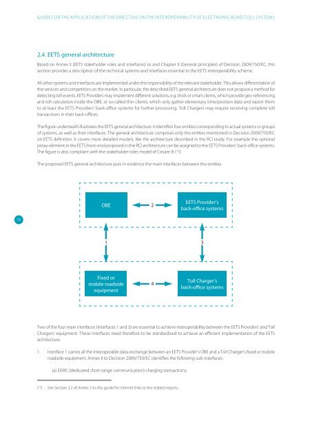
<strong>The</strong> figure underneath illustrates the <strong>EETS</strong> general architecture. It identifies four entities corresponding to actual systems or groups<br />
of systems, as well as their interfaces. <strong>The</strong> general architecture comprises only the entities mentioned in Decision 2009/750/EC<br />
on <strong>EETS</strong> definition. It covers more detailed models, like the architecture described in the RCI study. For example the optional<br />
proxy-element in the <strong>EETS</strong> front-end proposed in the RCI architecture can be assigned to the <strong>EETS</strong> Providers’ back-office systems.<br />
<strong>The</strong> figure is also compliant with the stakeholder roles model of Cesare III ( 12 ).<br />
<strong>The</strong> proposed <strong>EETS</strong> general architecture puts in evidence the main interfaces between the entities.<br />
OBE<br />
2<br />
<strong>EETS</strong> Provider’s<br />
back-office systems<br />
16<br />
1<br />
3<br />
Fixed or<br />
mobile roadside<br />
equipment<br />
4OBE<br />
<strong>Toll</strong> Charger’s<br />
back-office systems<br />
Two of the four main interfaces (interfaces 1 and 3) are essential to achieve interoperability between the <strong>EETS</strong> Providers’ and <strong>Toll</strong><br />
Chargers’ equipment. <strong>The</strong>se interfaces need therefore to be standardised to achieve an efficient implementation of the <strong>EETS</strong><br />
architecture.<br />
1. Interface 1 carries all the interoperable data exchange between an <strong>EETS</strong> Provider’s OBE and a <strong>Toll</strong> Charger’s fixed or mobile<br />
roadside equipment. Annex II to Decision 2009/750/EC identifies the following sub-interfaces:<br />
(a) DSRC (dedicated short-range communication) charging transactions;<br />
( 12 ) See Section 3.2 of Annex 3 to this guide for Internet links to the related reports.