UPS-Management Software Benutzerhandbuch - Generex GmbH
UPS-Management Software Benutzerhandbuch - Generex GmbH
UPS-Management Software Benutzerhandbuch - Generex GmbH

You also want an ePaper? Increase the reach of your titles
YUMPU automatically turns print PDFs into web optimized ePapers that Google loves.
Version: 2012-09-12<br />
<strong>UPS</strong>-<strong>Management</strong> <strong>Software</strong><br />
(<strong>UPS</strong>MAN, <strong>UPS</strong>MON, <strong>UPS</strong> View, UNMS)<br />
User Manual
Copyright Statement for Intellectual Property and Confidential Information<br />
The information contained in this manual is non-conditional and may be changed w ithout<br />
due notice. Although <strong>Generex</strong> has attempted to provide accurate information w ithin this<br />
document, <strong>Generex</strong> assumes no responsibility for the accuracy of this information.<br />
<strong>Generex</strong> shall not be liable for any indirect, special, consequential, or accidental damage<br />
including, w ithout limitations, lost profits or revenues, costs of replacement goods, loss or<br />
damage to data arising out of the use of this document<br />
<strong>Generex</strong> the manufacturer of the BACS products undertakes no obligations with this<br />
information. The products that are described in this brochure are given on the sole basis of<br />
information to its channel partners for them to have a better understanding of the <strong>Generex</strong><br />
products.<br />
<strong>Generex</strong> allows its channel partners to transfer information contained in this document to<br />
third persons, either staff within their ow n Company or their ow n customers, either<br />
electronically or mechanically, or by photocopies or similar means. <strong>Generex</strong> states that the<br />
content must not be altered or adapted in any way without written permission from<br />
<strong>Generex</strong>.<br />
It is agreed that all rights, title and interest in the <strong>Generex</strong>’s trademarks or trade names<br />
(whether or not registered) or goodwill from time to time of <strong>Generex</strong> or in any intellectual<br />
property right including w ithout limitation any copyright, patents relating to the Products,<br />
shall remain the exclusive property of <strong>Generex</strong>.<br />
<strong>Generex</strong> will undertake to deal promptly with any complaints about the content of this<br />
document. Comments or complaints about the document should be address ed to <strong>Generex</strong><br />
Systems <strong>GmbH</strong>.<br />
Copyright of the European Union is effective (Copyright EU).<br />
Copyright (c) 1995-2012 GENEREX <strong>GmbH</strong>, Hamburg, Germany. All rights reserved.
2<br />
Revision History Date<br />
-001 First Release 10/2008<br />
-011 Update: RCCMD with SSL via <strong>UPS</strong>MAN 01/2009<br />
-012 New functions: “Attach log files to mail<br />
events”, Write raw data to file”<br />
-013 Added: <strong>UPS</strong>MAN configuration without<br />
graphical interface (Linux)<br />
02/2009<br />
03/2009<br />
-014 Added: Multiple <strong>UPS</strong>MAN Installations 05/2009<br />
-015 Added: <strong>UPS</strong> Extended Commands 08/2009<br />
-016 Added: Silent Installation 11/2009<br />
-017 Added. Console Installation UNIX 11/2009<br />
-018 Added: Remote <strong>UPS</strong>MAN Configuration 01/2010<br />
-019 Added: Threshold Events 03/2010<br />
-020 Added: NTP time synchronization (UNIX) 06/2010<br />
-021 Added: Installation/configuration on WIN<br />
2008 Server Core x64<br />
-022 Added: Know How Pool: <strong>UPS</strong>MON<br />
Windows PollRate Edit<br />
07/2010<br />
11/2010<br />
-023 Added: FAQ 01/2011<br />
-024 Added: Silent Installation, <strong>UPS</strong><br />
Communication Parameter Preselection<br />
03/2011<br />
-025 Added: <strong>UPS</strong>View Description 04/2011<br />
-026 Added: <strong>UPS</strong>MAN Tray Description 06/2011
Table of contents<br />
1. What is the <strong>UPS</strong>-<strong>Management</strong> <strong>Software</strong>? 5<br />
1.1 <strong>UPS</strong>MAN double function - <strong>UPS</strong> and RCCMD Server 6<br />
2. Quickstart – Installation/Configuration <strong>UPS</strong> <strong>Software</strong> 7<br />
2.1 Preparation of the Installation 7<br />
2.2 Windows 2000/XP/2003/VISTA/7/2008 <strong>UPS</strong>MAN Installation 8<br />
3. Start Installation + Basic configuration of <strong>UPS</strong>MAN 8<br />
3.1 Settings of the Authorization of the <strong>UPS</strong>MAN Service 19<br />
3.2 Silent Installation of the <strong>UPS</strong>MAN Installation 21<br />
3.3 <strong>UPS</strong>MON for Windows 22<br />
3.4 <strong>UPS</strong>VIEW for Windows 29<br />
3.5 Advanced User – Windows <strong>UPS</strong>MAN Configuration 32<br />
3.5.1 Advanced User - DEVICE Page 32<br />
3.5.2 Advanced User – Menu SYSTEM Page 34<br />
3.5.3 Advanced User – Menu FILES Page 38<br />
3.5.4 Advanced User – Menu MAIL SERVER Page 39<br />
3.5.5 Advanced User – Menu EVENTS Page 40<br />
3.6 Avanced User – Special Tools and Configuration Advices 45<br />
3.6.1 Advanced User - <strong>UPS</strong>MAN Debug and Line.raw Tools 45<br />
3.6.2 Email to SMS 45<br />
3.6.3 Save & Load Configurations 46<br />
3.6.4 Examples - Execute Program with Parameters 47<br />
3.6.5 Examples - Send Email Function 50<br />
3.6.6 Examples - RCCMD Mail ID 51<br />
3.6.7 Examples - Send RCCMD execute to remote client 52<br />
3.6.8 Examples – RCCMD with SSL via <strong>UPS</strong>MAN 52<br />
3.6.9 Examples - RCCMD with own SSL certificates 54<br />
3.6.10 Examples - WOL – Wake On LAN 55<br />
3.6.11 Examples - Scripting 55<br />
3.6.12 Start Options of the <strong>UPS</strong>MAN Module 57<br />
3.6.13 <strong>UPS</strong>MON for the command line 58<br />
3.6.14 <strong>UPS</strong> <strong>Management</strong> <strong>Software</strong> for WIN 2008 Server Core x64 60<br />
4. Unix & MAC X 62<br />
4.1. Basic - Installation <strong>UPS</strong>MAN on UNIX and MACX 62<br />
4.1.1 Silent Installation of the <strong>UPS</strong>MAN Installation 73<br />
4.2 Start <strong>UPS</strong>MAN on UNIX and MACX 74<br />
4.3 UNIX WEB-Server 75<br />
4.4.1 Advanced User - DEVICE Page 76<br />
4.4.2 Advanced User – Menu SYSTEM Page 78<br />
4.4.3 Advanced User – Menu Files Page 80<br />
4.4.4 Advanced User – Menu Events Page 81<br />
4.4.5 Remote <strong>UPS</strong>MAN Configuration 86<br />
4.4.6 Older “Install” Script Based Installation with “ups_conf” 87<br />
4.4.7 Unix/MAC commandline <strong>UPS</strong>MON 100<br />
3
4.5 Apple MacIntosh 102<br />
4.5.1 <strong>UPS</strong>MAN for MAC OS 9 – MAC OS 10 102<br />
5. UNMS – <strong>UPS</strong> Network <strong>Management</strong> System 103<br />
6. Simple Network <strong>Management</strong> Protocol (SNMP) 103<br />
6.1 <strong>UPS</strong>MAN with SNMP on Windows 104<br />
6.2 <strong>UPS</strong>MAN with SNMP on LINUX 105<br />
7. FAQ 105<br />
Appendix 107<br />
A. Supported Systems 107<br />
B. Know-How Pool 108<br />
C. Automatic Start of the <strong>UPS</strong>MON after Reboot (Windows) 112<br />
D. NTP time synchronization (UNIX) 113<br />
E. <strong>UPS</strong>MAN configuration without graphical interface (Linux) 118<br />
F. Error codes (<strong>UPS</strong>MAN) 118<br />
G. Cable types 120<br />
H. Picture catalog 120<br />
4
1. What is the <strong>UPS</strong>-<strong>Management</strong> <strong>Software</strong>?<br />
The <strong>UPS</strong>-<strong>Management</strong> <strong>Software</strong> is a client/server application for networks and local<br />
workstations. The server module of the <strong>UPS</strong>-<strong>Management</strong> Softw are is <strong>UPS</strong>MAN, w hich<br />
communicates via RS-232/USB or network cable with the <strong>UPS</strong>. When <strong>UPS</strong>MAN starts, it<br />
collects the protocol messages from the <strong>UPS</strong> as a background program (service).<br />
<strong>UPS</strong>MAN interprets received messages and makes them available to the cli ent module, a<br />
webserver interface <strong>UPS</strong> View , the WINDOWS <strong>UPS</strong>MON, JAVAMON or to any other<br />
SNMP application. The data communication to the client modules is achieved via TCP/IP<br />
or SNMP.<br />
The SNMP protocol of <strong>UPS</strong>MAN w ith <strong>UPS</strong>MAN.MIB is a special private MIB type 1, the<br />
UNIX <strong>UPS</strong>MAN and CS121 w eb adapters use the newer MIB 2 standard RFC 1213 &<br />
1628. All <strong>UPS</strong>MAN clients using TCP/IP may using the GENEREX communication<br />
protocol <strong>UPS</strong>MON, w hich is provided as an API to all OEM customers in order to create<br />
ow n applications.<br />
If <strong>UPS</strong>MAN detects voltage variations or a power loss it can execute different system<br />
event routines (EVENTS), w hich, for example, may shutdown the server or send warnings<br />
to connected users. These system event routines, which are part of the <strong>UPS</strong>-<strong>Management</strong><br />
<strong>Software</strong>, are fully customisable.<br />
The client modules are used for operating and monitoring the active <strong>UPS</strong>MAN software<br />
connected to an <strong>UPS</strong>. You can program <strong>UPS</strong>-Routines (e.g. define dates for automatic<br />
<strong>UPS</strong>-tests, shutdown the system at defined dates, etc.), check the status of the <strong>UPS</strong>,<br />
execute different <strong>UPS</strong>-tests or create power quality statistics. With the client modules you<br />
can also constantly monitor and evaluate the event protocol (log file) that is permanently<br />
updated by <strong>UPS</strong>MAN.<br />
RCCMD ("Remote Console Command") is an additional module w hich executes a<br />
command on a remote system, similar to the Remote Shell-Program (RSH) know n in the<br />
UNIX w orld. RCCMD is used to provide a simultaneous shutdown of several servers that<br />
are all supported by the same <strong>UPS</strong>.<br />
The follow ing listed features depend on the <strong>UPS</strong> model. Please ask your <strong>UPS</strong> dealer<br />
which of these functions are available with your <strong>UPS</strong> model. The follow ing list shows you<br />
the maximum variety of features of the current <strong>UPS</strong>-<strong>Management</strong> <strong>Software</strong>.<br />
Client/server software for heterogeneous networks w ith one and three-phase <strong>UPS</strong>.<br />
"Look & feel" is identical on all platforms.<br />
Support for almost all <strong>UPS</strong> types and <strong>UPS</strong> manufacturers w ith serial (RS-232), USB,<br />
network or dry contact <strong>UPS</strong> protocols.<br />
5<br />
Integrated proxy SNMP agent for WINDOWS and Linux.
Modular structure; optional it is possible to extend the system for multi-<strong>UPS</strong><br />
surveillance via UNMS. External modules (hardware) allow for a variety of system<br />
extensions such as: SENSORMAN, RASDIALER (modem solution), <strong>UPS</strong> SNMP Watch,<br />
JAVAMON, HP OpenView <strong>UPS</strong>MON and others.<br />
Support all important network protocols for the graphical control of the <strong>UPS</strong> from<br />
every Windows station in the network.<br />
Automatic unattended shutdown of local and remote computers in networks<br />
(Master/Slave via RCCMD module)<br />
Low battery warning, on-screen autonomy time, battery time countdown, low battery<br />
warning, <strong>UPS</strong> temperature such as battery and internal temperature, defec t battery<br />
warning, time and data stamp event logging, extensive logging of all <strong>UPS</strong> activity and user<br />
messaging.<br />
6<br />
Battery management, surveillance and counter for power events.<br />
SMTP compatible system w ith messaging service for e-mail, e-mail to SMS or other<br />
external services.<br />
Menu for several <strong>UPS</strong> test functions, such as economy mode, <strong>UPS</strong> temperature,<br />
battery load, power socket switching and <strong>UPS</strong> emergency power-off.<br />
Shutdown and test functions can be executed with a scheduler<br />
Graphical display of quality of incoming power load frequency in minimum/maximum<br />
or average values.<br />
Also monitors <strong>UPS</strong> systems, via SNMP connection.<br />
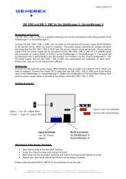
1.1 <strong>UPS</strong>MAN double function - <strong>UPS</strong> and RCCMD Server<br />
The <strong>UPS</strong>MAN module is not only reading and managing the computer where the<br />
<strong>UPS</strong>MAN is running on; it is at the same time the “RCCMD server” – to the computer<br />
which sends RCCMD commands into the netw ork which will start the shutdown procedure<br />
on remote computers. The program RCCMD is designed to execute a command on a<br />
remote system in a TCP/IP network. RCCMD w orks like the Remote Shell (RSH) know n in<br />
the UNIX environment. Inside the <strong>UPS</strong>-<strong>Management</strong> <strong>Software</strong> RCCMD is used to<br />
shutdown several servers that are all pow ered by a single <strong>UPS</strong>. For this job, one of these<br />
computers is configured as <strong>UPS</strong>-master server.<br />
Install the <strong>UPS</strong>-<strong>Management</strong> <strong>Software</strong> <strong>UPS</strong>MAN on your <strong>UPS</strong> server and connect it to the<br />
<strong>UPS</strong>. Alternatively, a SNMP adapter type CS-121 or compatible device can be used for<br />
this as well. The other servers are only connected to the <strong>UPS</strong> pow er supply, no RS-232<br />
connection is necessary. On these remote systems, install RCCMD client software and<br />
create a shutdown routine for every system. This shutdown routine may be a batch or
shell script file, that contains the down and other commands for this system. After that,<br />
add RCCMD to the shutdown job or to the EVENT configuration of the computer running<br />
as <strong>UPS</strong> master server.<br />
7<br />
OS/2<br />
RCCMD 1 client<br />
Shutdown !<br />
Shutdown !<br />
RCCMD 2 client<br />
NOVELL Server<br />
UNIX Server<br />
RCCMD 2 client<br />
Shutdown !<br />
Send Email +<br />
Net send<br />
message +<br />
Shutdown !<br />
RCCMD 2 client RCCMD 1 client<br />
Windows Server<br />
CS 121<br />
<strong>UPS</strong>MAN Server<br />
+ RCCMD 2 Sender<br />
Firewall Firewall<br />
Figure 1: <strong>UPS</strong>MAN and RCCMD in a netw ork environment<br />
<strong>UPS</strong><br />
Shutdown !<br />
Novell Server<br />
<strong>UPS</strong>MAN Server +<br />
RCCMD 2 Sender<br />
Windows<br />
Server<br />
2. Quickstart – Installation/Configuration <strong>UPS</strong> <strong>Software</strong><br />
2.1 Preparation of the Installation<br />
Before you install the <strong>UPS</strong>-<strong>Management</strong> Softw are, please ensure that your <strong>UPS</strong> is<br />
working correctly. Connect the <strong>UPS</strong> to the relevant serial/USB port of your computer using<br />
the original cable coming w ith the <strong>UPS</strong>. Some <strong>UPS</strong> models provide several<br />
connections/interfaces, please check the user manual for detailed information which port<br />
has to be used for the <strong>UPS</strong>MAN software.<br />
Attention: The <strong>UPS</strong> comm. cable is very oftern a special cable, which is<br />
provided by the manufacturer of your <strong>UPS</strong> system. Please see<br />
the corresponding cable configurations in the appendix of your<br />
<strong>UPS</strong> manual.<br />
<strong>UPS</strong>
2.2 Windows 2000/XP/2003/VISTA/7/2008 <strong>UPS</strong>MAN Installation<br />
General<br />
The <strong>UPS</strong>MAN for Windows is a real background service and has no graphical output. The<br />
<strong>UPS</strong>MAN is the only necessary process for all <strong>UPS</strong> management actions. The graphical<br />
client modules (eg. Webinterface or <strong>UPS</strong>MON) are only for viewing the <strong>UPS</strong> data or for<br />
for the graphical administration, but not compulsory for normal operation of a <strong>UPS</strong><br />
software like shutdown, messaging, etc.<br />
Installation<br />
The <strong>UPS</strong>-<strong>Management</strong> <strong>Software</strong> is distributed on a CD-ROM or as full version download<br />
from the w eb site of the <strong>UPS</strong> manufacturer. A license key is required for both distributions.<br />
The Windows part of the software is found in the root directory of the distribution package<br />
and is started automatically or executing the “ INSTALL.EXE” command. This SETUP<br />
process copies the desired <strong>UPS</strong> files to your local hard drive.<br />
Licensing<br />
The first input window is the license key of the CD (license = license key = key code). This<br />
key code is shipped separately (as electronic document, paper document, or in any other<br />
form – please contact your <strong>UPS</strong> dealer for information w here to find the key code).<br />
Every license key allows the customer to install one <strong>UPS</strong>MAN software (suite, consisting<br />
of <strong>UPS</strong>MAN and several graphical client modules). To install RCCMD, another - separate<br />
license key - is required – for every installation a new RCCMD key is needed – DO NOT<br />
install the same license key more than once !<br />
(The RCCMD sender functionality is already integrated into the <strong>UPS</strong>MAN. Only for the<br />
client computers a new RCCMD license is required!) Additional RCCMD installations can<br />
be executed from the same CD ROM or download image, using different license keys.<br />
Beside copy protection, the license key distinguishes the different OEM <strong>UPS</strong> customers<br />
from each other. It is not permitted to use any other license key than the one provided with<br />
the software.<br />
3. Start Installation + Basic configuration of <strong>UPS</strong>MAN<br />
To start, please make sure that you have full administrator rights in order to complete the<br />
installation.<br />
Step 1: Put the CD into the CD-ROM drive of your<br />
computer or download the software into a specific<br />
directory on your computers harddisk.<br />
8
Step 2: Please execute the installation program<br />
install.exe in order to install the files to your<br />
system and choose a desired setup language.<br />
Step 3: Please enter your <strong>UPS</strong>MAN or RCCMD license<br />
key to choose the correct software package. The<br />
license key determines, which module can be<br />
installed. The installation software shows a<br />
progress bar until the software has been<br />
extracted and the installation begins.<br />
You can choose the language of your installation in the welcome screen. Choose your<br />
language and click the “OK” button.<br />
Figure 2: Introduction<br />
In the next menue you can see the progress column where the next steps are visible. Click<br />
the “NEXT” button to continue.<br />
9
Figure 3: Enter your License Key<br />
In the next menue you have to enter your license key – a picture shows an example. Enter<br />
the license key an click the “NEXT” button to continue.<br />
10<br />
Attention: If you enter a wrong license number at this stage, the <strong>UPS</strong>-<br />
<strong>Management</strong> software will be set to a 30 day trial version. You<br />
may enter the correct license in the main window of the<br />
<strong>UPS</strong>MAN configuration at a later stage. (Please see figure<br />
below)<br />
Figure 4: Thirty-Day Trial Version without Key Code
Figure 5: License Agreement<br />
Read and confirm the license agreement and continue with the “NEXT” button.<br />
In the next w indow enter the path where you want to install the software. Default is the<br />
subdirectory “<strong>UPS</strong>” into the program files folder onto the hard disk “C:”.<br />
Figure 6: Choose Install Folder<br />
Click the « Next » button and choose the install set.<br />
11
Figure 7: Choose Install Set<br />
In the Install Set menu you can choose the following modules:<br />
12<br />
<strong>UPS</strong> MANAGER (<strong>UPS</strong>MAN) - This is a background process <strong>UPS</strong>MAN, the core of<br />
the system. The <strong>UPS</strong>MAN is the service, which maintains the direct <strong>UPS</strong> RS-232/USB or<br />
network connection with the computer and the <strong>UPS</strong>.<br />
Support Tools – This is the <strong>UPS</strong> Monitor <strong>Software</strong>. It is used to display a graphical<br />
visualization of the data the <strong>UPS</strong> manager provides. This feature and the gchart software<br />
are disabled by default and will not be installed automatically.<br />
<strong>UPS</strong> View er (<strong>UPS</strong>VIEW) – The webinterface of the <strong>UPS</strong> accessible through<br />
Webbrowser. It shows the most important <strong>UPS</strong> data and alarms.<br />
Help files are provided w ith the software, basicly it’s the user manual w hich you are<br />
reading here and some extra informations which may be added from time to time.<br />
In next menu you can choose to create a new program group (default) or to choose icons<br />
elsewhere or not at all.
Figure 8: Choose Shortcut Folder<br />
In the next menu you see an overview of your installation and you may now press<br />
“INSTALL” to begin.<br />
Figure 9: Pre-Installation Summary<br />
Into the next window, you got the opportunity to open the required firewall ports 960 and<br />
5769 automatically.<br />
13
Figure 10: Firew all Configuration<br />
The port 960 is used by the <strong>UPS</strong>MAN tray.<br />
The <strong>UPS</strong>MAN tray provides the appearance of the <strong>UPS</strong>MAN message box as pop-up into<br />
the foreground. If you do not want to receive messages from the <strong>UPS</strong>MAN, please close<br />
the <strong>UPS</strong>MAN tray via the context menu. To disable the <strong>UPS</strong>MAN tray permanently, you<br />
can disable it into the <strong>UPS</strong>MAN configuration.<br />
The <strong>UPS</strong>MAN tray appears into the taskbar.<br />
From <strong>UPS</strong>MAN version 5.8.75 the <strong>UPS</strong>MAN tray displays the status or rather a change of<br />
the status of the <strong>UPS</strong>MAN as follows :<br />
Green : Output Active, ECO Mode<br />
Yellow : Bypass Mode, <strong>UPS</strong> Test Active, Inverter Warning, Overtemperature, Input High,<br />
Output High, Inverter Failure, Battery Bad<br />
Red : Backup Mode, Battery Low, Shutdown Active<br />
Grey : Communication Lost<br />
Figure 11: <strong>UPS</strong>MAN Tray Icon Status<br />
14
In addition from <strong>UPS</strong>MAN tray version 1.0.0.7 the <strong>UPS</strong>MAN tray provides a context menu<br />
with the following features :<br />
15<br />
About : Opens the <strong>UPS</strong>MAN tray window with its version number, copyright<br />
<strong>UPS</strong>MAN Configuration : Start of the <strong>UPS</strong>MAN configuration directly<br />
Start UpsView : Start of the UpsView directly<br />
Close <strong>UPS</strong>MAN Tray : Close <strong>UPS</strong>MAN tray<br />
Figure 12: <strong>UPS</strong>MAN Tray Context Menu<br />
The USB support of your <strong>UPS</strong> depends on the hardware interface. In some cases (HID<br />
compatible interface) – no additional driver is needed, since HID is already part of<br />
Windows and Linux. In all other cases you receive a USB driver (eg. LibUSB driver) with<br />
the <strong>UPS</strong>MAN software which is installed separately – or you receive a USB-2-serial driver<br />
which creates a new virtual com port on your system. The difference between an USB and<br />
an USB-2-serial driver is that using USB driver you use “USB” as communication port in<br />
<strong>UPS</strong>MAN, and w ith USB-2-serial driver you use a COM port.<br />
The installation of 3 rd party drivers w ill be through in some seconds - after this you may<br />
receive a message to reboot your computer. This may be ignored if you have already a<br />
USB driver from prolific on your system. In other cases please try first to communicate<br />
with the <strong>UPS</strong> through <strong>UPS</strong>MAN and restart your system only if the communication or the<br />
“search <strong>UPS</strong>” does not work at once.<br />
NOTE: If a reboot is necessary, you can continue the configuration by clicking in the<br />
Program group on “<strong>UPS</strong>MAN configuration” – the configuration w ill pop up and you can<br />
continue the configuration – follow ing the instruction on the next pages.
The main configuration page of <strong>UPS</strong>MAN is the DEVICE PAGE:<br />
DEVICE PAGE:<br />
Figure 13: <strong>UPS</strong>MAN Configuration<br />
When the <strong>UPS</strong>MAN configuration starts up, choose from the <strong>UPS</strong> modellist your <strong>UPS</strong> type<br />
– or use “Search <strong>UPS</strong>” to make <strong>UPS</strong>MAN try to identify your <strong>UPS</strong> type. If not clearly<br />
identified, the <strong>UPS</strong>MAN w ill show you a list of <strong>UPS</strong> devices which are corresponding to<br />
the search requests – please pick the right model from the list and confirm w ith OK.<br />
During the auto search process this box will appear, you may stop the search at anytime<br />
and choose the <strong>UPS</strong> from the drop-down list manually to speed up the process.<br />
16
Figure 14: Select <strong>UPS</strong> Model<br />
If the model “SNMP Adapter / RFC1628” is selected, please note that it is required that the<br />
battery installation date is identical in the <strong>UPS</strong>MAN and CS121 configuration.<br />
After having choosen the correct <strong>UPS</strong> type the <strong>UPS</strong>MAN standard installation is finished.<br />
If you press now OK, the <strong>UPS</strong>MAN service w ill ask to start – press YES and if no further<br />
error message appears within 1 minute, the <strong>UPS</strong>MAN w ill now watch the <strong>UPS</strong> and send<br />
messages in case that an alarm occurs. If the <strong>UPS</strong> runs on battery and the battery have<br />
only 3 minutes left, the <strong>UPS</strong>MAN w ill automatically shutdown this computer. In case of<br />
alarms a messagebox w ill pop up similar to the one above and the user can connect with<br />
<strong>UPS</strong> VIEW, <strong>UPS</strong>MON or any other graphical viewer to see the actual <strong>UPS</strong> alarms.<br />
<strong>UPS</strong>MAN runs in windows as “service” -see windows service list how to stop/start the<br />
upsman and related services.<br />
17
Figure 15: Windows Services<br />
Installation and basic configuration FINISHED. Your computer is now <strong>UPS</strong> protected<br />
and w ill be shutdowned automatically in case of an extended Powerfailure.<br />
For a simple <strong>UPS</strong> communication and automatic shutdown of the <strong>UPS</strong>MAN<br />
computer – the configuration is complete!<br />
For further <strong>UPS</strong>MAN configuration issues please continue to read in chapter 3.2 –<br />
Advanced User – <strong>UPS</strong>MAN Windows configuration.<br />
To check your configuration you may use one of the monitoring tools provided w ith your<br />
<strong>UPS</strong>MAN software (<strong>UPS</strong> View, <strong>UPS</strong>MON, UNMS, JAVAMON or other). The moment you<br />
can read <strong>UPS</strong> data from your monitoring interface, the installation w as successful and you<br />
may close the monitoring tool and keep the <strong>UPS</strong>MAN running in the background .<br />
In the follow ing figure is the <strong>UPS</strong> VIEW w ebinterface of a Protect 3.33 <strong>UPS</strong>. It shows the<br />
most important <strong>UPS</strong> data and alarms. The “<strong>UPS</strong>MANHTTP” w indows service running in<br />
the background and provides the data for this webinterface. The follow ing chapters explain<br />
now the various <strong>UPS</strong>MAN monitoring tools, starting w ith most common <strong>UPS</strong> interface for<br />
Windows “<strong>UPS</strong>MON”.<br />
18
Figure 16: Protect 3.33 <strong>UPS</strong> Webinterface<br />
3.1 Settings of the Authorization of the <strong>UPS</strong>MAN Service<br />
This function is used for the commitment of the user authorization of the <strong>UPS</strong>MAN service,<br />
which exceeds the system shutdown, e.g. execution of batch files, script files etc.<br />
Open the menu of the properties w indow for the <strong>UPS</strong>MAN service (via control panel,<br />
administration and services) and click the “Log On” button.<br />
19
Figure 17: <strong>UPS</strong>MAN Properties<br />
Enable « This account », delete the passwords and click the « Browse… » button.<br />
Figure 18: Select User<br />
Enter the object name « Administrator », click the « Check Names » button and click the<br />
« OK » button.<br />
20
Figure 19: <strong>UPS</strong>MAN Properties – This account<br />
Enter the password for the Administrator, confirm it, click the « Apply » button and restart<br />
the RCCMD service.<br />
3.2 Silent Installation of the <strong>UPS</strong>MAN Installation<br />
The <strong>UPS</strong> <strong>Management</strong> <strong>Software</strong> provides a silent installation, but it is required to enter<br />
some settings into the “installer.properties” file. This file is located into the CD folder<br />
\Upsman\Windows\OEM-ID (2 for AEG, 3 for Piller etc.).<br />
21
Figure 20: Content of the „installer.properties“<br />
It is required to remove the hash mark prior of the variable INSTALLER_UI=silent. In<br />
addition the setting of the license key is required behind the variable GXLICENSEKEY=.<br />
The <strong>UPS</strong> <strong>Management</strong> <strong>Software</strong> 5.8.04. or higher provides the parameter preselection<br />
for the <strong>UPS</strong> communication. Remove the hash mark prior of the variable<br />
<strong>UPS</strong>DEVICE=COM20:2400,e,8,1, and adjust the parameters accordingly.<br />
3.3 <strong>UPS</strong>MON for Windows<br />
<strong>UPS</strong>MON for w indows is a graphical interface w hich is individually customized for every<br />
<strong>UPS</strong> maker, for this a large variety of screens exists. Depending on the <strong>UPS</strong> makers<br />
design and functions in the <strong>UPS</strong> the <strong>UPS</strong>MON appear more or less complex. In this<br />
manual w e desribe the basic functions which are part of any <strong>UPS</strong>MON version.<br />
When <strong>UPS</strong>MON starts it w ill ask for a connection to a server. Enter the IP address or<br />
hostname. To start a connection click on the button Connect.<br />
22
NOTE: The <strong>UPS</strong>MON w indows is a monitoring tool for any <strong>UPS</strong>MAN, unregarded on<br />
which OS this <strong>UPS</strong>MAN is running. So you may use this tool to connect via an <strong>UPS</strong>MAN<br />
server at UNIX, MAC or CS121.<br />
To start a connection to different <strong>UPS</strong>MAN processes at the same IP address, enter the<br />
port and the IP-address, or host name respectively separated by a comma (e. g.<br />
5769,192.10.200.6). The port address can also be left out, if a single <strong>UPS</strong>MAN has been<br />
started at the default port. The entry of the IP address (191.10.200.6) is enough. We<br />
recommend using the TCP/IP protocol as a communication protocol.<br />
Once connected with a server, the <strong>UPS</strong>MON responds w ith the main screen, allow ing all<br />
features to be operated.<br />
After a connection has been established, the status main screen shows several w indows.<br />
The menu- and toolbar is at the top of the status chart. The bar contains the buttons<br />
“Open A Connection”, “Close A Connection”, “Searching The LAN For Active <strong>UPS</strong>MAN<br />
Services”, “Get Datalog As Text”, “Get Graphical Datalog”, “Open Scheduler”, “Change Of<br />
Logdata Program”and “Open Remote Configuration”.<br />
The Window s installation of <strong>UPS</strong>MON contains gChart, a graphical log file viewer.<br />
.<br />
Figure 21: <strong>UPS</strong>MON Statuspage of a Protect 3.33 <strong>UPS</strong><br />
23
The Window s <strong>UPS</strong>MON versions and the <strong>UPS</strong> VIEW Webinterface have an inbuilt<br />
Scheduler interface to program actions on the remote <strong>UPS</strong>MAN. This Scheduler interface<br />
is in both applications identical and allow to execute <strong>UPS</strong> tests or regular shutdowns on<br />
certain days or time settings. Follow ing a screenshot of the Scheduler in Windows, the<br />
UNIX version is identical to this.<br />
When connecting to your <strong>UPS</strong>MAN you can choose “SCHEDULER” . If you have<br />
password on your <strong>UPS</strong>MAN configured, a password request will pop-up. After this you w ill<br />
receive a scheduler screen, similar to the one we show below.<br />
Figure 22: Scheduler in <strong>UPS</strong>MON, interface to program actions on your <strong>UPS</strong>MAN<br />
The scheduler allows you to add new jobs which will be executed at the programmed time.<br />
The <strong>UPS</strong>MAN logfile w ill show after the job has been executed about the results of the<br />
programmed action. Generally the Scheduler shows the actual active job and the time or<br />
date when it w ill be executed. Already executed actions are list and automatically removed<br />
from the list if those jobs are expired or not longer recursing. By ADD Entry a new job is<br />
created and added to the list. With DELETE Entry jobs may be removed from the list. With<br />
EDIt entry you can change an already exisiting job. The other functions on the Scheduler<br />
should be self-explanatory and do not require further explanation. Generally we<br />
recommend NOT to program more batterytest jobs than once a month. Especially fulltests<br />
may discharge your <strong>UPS</strong> batteries to a low level which may damage your batteries if this<br />
is made too often. We recommend to do only short battery tests and replace the <strong>UPS</strong><br />
24
atteries in regular terms (interval depends on battery type). If you use BACS (Battery<br />
Analyse and Care System) on your <strong>UPS</strong> batteries, you can see the actual status of the<br />
batteries and decide when change is necessary. Without BACS w e recommend to to this<br />
on a regular basis.<br />
Figure 23: <strong>UPS</strong>MON Statuspage of a Standard <strong>UPS</strong> w ithout OEM Design<br />
Since there are too many <strong>UPS</strong>MON screens we can not show those all in this manual.<br />
<strong>UPS</strong> Functions<br />
To execute tests of your <strong>UPS</strong> system choose <strong>UPS</strong> Functions from the menu Functions.<br />
The results will be displayed in a table. The outcome of the tests depend on the settings of<br />
the manufacturer. Selftest is a <strong>UPS</strong> hardw are check. Battery Test is a short test of the<br />
<strong>UPS</strong> w orking on battery. Custom Test switches the <strong>UPS</strong> on battery mode and w ill keep<br />
discharging the batteries until the "dow ntime" has passed. With this command you may<br />
check your batteries to see if they are still capable of supplying your system w ith the<br />
"downtime" configured autonomy. Full <strong>UPS</strong> test is a deep discharge of the batteries and is<br />
used for calibrating the battery. Tests should only be carried out if no user users are<br />
active. Some tests may be deactivated depending if the <strong>UPS</strong> supports those features.<br />
25
26<br />
Note: Some OEM versions require the default password<br />
„cs121-snmp“, to get access to the <strong>UPS</strong> Functions.<br />
Attention: When running a <strong>UPS</strong> Full test, please note not to<br />
interrupt the test, as long as it is active. If the test<br />
gets interrupted, the software will configure the<br />
autonomy time as the time-span of which the test<br />
has been running on the <strong>UPS</strong> before it has been<br />
interrupted. A test can be re-started after a 8 hour<br />
waiting period.<br />
Note: A manual reset is possible by starting the<br />
upsman.bat.<br />
Figure 24: <strong>UPS</strong>MON Device Command Window<br />
<strong>UPS</strong> Extended Commands – Outlet switching<br />
You can program the switching of the outlets or manually sw itch on or rather off the outlets<br />
into the menu Extended Commands.<br />
Note: Not every <strong>UPS</strong> supports this option.
Figure 25: <strong>UPS</strong>MON Extended Commands Window<br />
Click the „Programmable Outlet Settings...“ button for the configuration of the Outlets.<br />
Figure 26: <strong>UPS</strong>MON Programmable Outlet Settings Window<br />
27
The follow ing configuration options are available for the outlets:<br />
Turn Outlet ON after <strong>UPS</strong> is on – Delayed sw itching on of the outlets in seconds, after<br />
the <strong>UPS</strong> w as switched on.<br />
Turn Outlet OFF after AC failure – Delayed switching off of the outlets in seconds during<br />
a power failure.<br />
Turn Outlet ON after AC recovery – Delayed sw itching on of the outlets in seconds after<br />
a power failure.<br />
Turn outlet OFF w hen battery lower – Definition of the switching off, if the battery<br />
capacity is lower than x in percent.<br />
Turn Outlet OFF w hen <strong>UPS</strong> overload – Switching off of the outlets during <strong>UPS</strong> overload.<br />
Click the “Write settings” button, after you finished the configuration.<br />
Voltage- and Frequence-Chart<br />
Here the input voltage and frequency values of the last 24 hours (default) are displayed in<br />
a bar or line chart/graphic. Depending on the <strong>UPS</strong> system (single or thriple-phased) one<br />
measurement per phase is recorded.<br />
In the menu File choose Get DataLog-File for Charts and wait for the measurements to be<br />
transferred from <strong>UPS</strong>MAN to Ups mon. After the file transfer has been completed, you may<br />
display the measurements of voltage and frequency via the menu Chart.<br />
The menu Chart lets you choose between a chart showing minimum/maximum-results or<br />
mean values.<br />
The bar colours show whether the results have been outside the range of tolerance. The<br />
accepted tolerance of the <strong>UPS</strong>-rectifier is displayed by a blue-line.<br />
To monitor a certain part of the recorded time period, use the command Time Frame from<br />
the menu Chart. After selecting a time period with the desired frame choose a voltage or<br />
frequency chart again to display the measurements. It shows only the measurements<br />
within this range (higher resolution of input data).<br />
Textlog<br />
In the menu File select Get TextLog-File and wait for the measurements to be transferred<br />
from <strong>UPS</strong>MAN to Upsmon. The event-protocol includes all <strong>UPS</strong> events that have occurred<br />
to date. A default <strong>UPS</strong> dump is printed if no errors have occurred. Only messages like<br />
"Power fail", "Alarm", "Overload", "Battery low" etc. show a unusual situtation.<br />
28
The <strong>UPS</strong>MAN log file can also be opened directly from the <strong>UPS</strong>MAN directory, please use<br />
any standard text editor for this.<br />
All other <strong>UPS</strong>MON functions which are not described in this manual come w ith a selfexplanatory<br />
description in the interface itself (“tooltips”). For further questions about those<br />
functions, please contact your <strong>UPS</strong> reseller.<br />
3.4 <strong>UPS</strong>VIEW for Window s<br />
The Unix WEB SERVER offers the possibility to display all <strong>UPS</strong> data w ith a platform<br />
independent WEB-Browser. In order to establish a connection from a WEB-Brow ser to a<br />
UNIX WEB SERVER, please enter the IP address and a port number. Example:<br />
http://192.168.202.91:8081. Port 8081 is used as a standard at the start up of the server.<br />
Enter the follow ing into a web-browser, if you want to get a remote connection to an <strong>UPS</strong>:<br />
http://IP-address of the <strong>UPS</strong>MAN server:8081/cgi-bin/ups_view.exe?-ups_view<br />
Figure 27: <strong>UPS</strong>View Remote Access<br />
Via the « Log file » button, you can get the Data or rather Log files.<br />
29
Figure 28: <strong>UPS</strong>View Log File<br />
Via the menu « Functions », you can execute <strong>UPS</strong> tests.<br />
Figure 29: <strong>UPS</strong>View Functions<br />
To execute tests of your <strong>UPS</strong> system choose <strong>UPS</strong> Functions from the menu Functions.<br />
The results will be displayed in a table. The outcome of the tests depend on the settings of<br />
the manufacturer. Selftest is a <strong>UPS</strong> hardw are check. Battery Test is a short test of the<br />
<strong>UPS</strong> w orking on battery. Custom Test switches the <strong>UPS</strong> on battery mode and w ill keep<br />
discharging the batteries until the "dow ntime" has passed. With this command you may<br />
check your batteries to see if they are still capable of supplying your system w ith the<br />
"downtime" configured autonomy. Full <strong>UPS</strong> test is a deep discharge of the batteries and is<br />
used for calibrating the battery. Tests should only be carried out if no user users are<br />
active. Some tests may be deactivated depending if the <strong>UPS</strong> supports those features.<br />
30<br />
Note: Some OEM versions require the default password<br />
„cs121-snmp“, to get access to the <strong>UPS</strong> Functions.
Attention: When running a <strong>UPS</strong> Full test, please note not to interrupt the test, as<br />
long as it is active. If the test gets interrupted, the software will configure the autonomy<br />
time as the time-span of which the test has been running on the <strong>UPS</strong> before it has been<br />
interrupted. A test can be re-started after a 8 hour waiting period.<br />
Via the menu „Scheduler“, you can schedule appointments for your <strong>UPS</strong>.<br />
Figure 30: <strong>UPS</strong>View Scheduler<br />
The scheduler allows you to add new jobs which w ill be executed at the programmed<br />
time. The <strong>UPS</strong>MAN logfile w ill show after the job has been executed about the results of<br />
the programmed action. Generally the Scheduler shows the actual active job and the time<br />
or date w hen it w ill be executed. Already executed actions are list and automatically<br />
removed from the list if those jobs are expired or not longer recursing. By Add Entry a new<br />
job is created and added to the list. With Delete Entry jobs may be removed from the list.<br />
With Edit Entry you can change an already exisiting job. The other functions on the<br />
Scheduler should be self-explanatory and do not require further explanation. Generally we<br />
recommend NOT to program more batterytest jobs than once a month. Especially fulltests<br />
may discharge your <strong>UPS</strong> batteries to a low level which may damage your batteries if this<br />
is made too often. We recommend to do only short battery tests and replace the <strong>UPS</strong><br />
batteries in regular terms (interval depends on battery type). If you use BACS (Battery<br />
Analyse and Care System) on your <strong>UPS</strong> batteries, you can see the actual status of the<br />
batteries and decide w hen change is necessary. Without BACS w e recommend to to this<br />
on a regular basis.<br />
31
3.5 Advanced User – Window s <strong>UPS</strong>MAN Configuration<br />
The follow ing part of the user manual explains the advance user configuration items,<br />
which are optional.<br />
3.5.1 Advanced User - DEVICE Page<br />
The configuration w indow is opened automatically and the user has to choose the correct<br />
<strong>UPS</strong> model (manual startup of configuration : "<strong>UPS</strong>MAN –CONFIG). This is the most<br />
important part of the configuration, because with the model name the correct <strong>UPS</strong> RS-<br />
232/USB protocol is linked. If a wrong model is chosen from the list, the <strong>UPS</strong>MAN can not<br />
start. If you would like to enter the configuration at a later point in time, you may do so by<br />
logging on as administrator and click on “<strong>UPS</strong>MAN configuration” from the program group<br />
<strong>UPS</strong> software. This icon is only available from the user account from w hich the installation<br />
was performed in the first place (default). From other user accounts the configuration can<br />
be started from the command line calling “upsman_config” in the <strong>UPS</strong>MAN folder.<br />
Automatic start at server boot : The default of every <strong>UPS</strong>MAN is to start automatically at<br />
every new server boot. If you want to change this, go to the control panel, services and<br />
mark the <strong>UPS</strong>MAN Service under "Start". You can now change the start up now from<br />
automatic to manual.<br />
Selecting the <strong>UPS</strong>-Model: To select your <strong>UPS</strong>-model, click w ith the mouse on the scroll<br />
box symbol on the right side of the model list. Next, choose the <strong>UPS</strong> model that you want<br />
to install. All other adjustments w hich correspond with your selected <strong>UPS</strong> model w ill be<br />
done automatically, if the <strong>UPS</strong> has serial or USB communication.<br />
We recommend NOT to change the default settings of communication parameters of the<br />
<strong>UPS</strong> – most <strong>UPS</strong> have a fixed baudrate which must not be changed.<br />
<strong>UPS</strong> models w ith serial connections do not need additional adjustments, because these<br />
models transfer all values to the <strong>UPS</strong>-<strong>Management</strong> software. If you have a <strong>UPS</strong>-model<br />
with a port-type cable which does not transfer the connected Load to the <strong>UPS</strong>-<strong>Management</strong><br />
Softw are, you have to enter the values of the actual load manually. Add the input<br />
pow er requirements in Watts of all connected units and calculate the Watt/0,8 (= VA).<br />
32<br />
ATTENTION: If you use a <strong>UPS</strong>-model with the port-type "cable", please notice<br />
that the values for Hold- and Recharge time are in accordance<br />
with the manufacturers specifications and should only be<br />
altered in special configurations since the <strong>UPS</strong> could be<br />
discharged before the system has been shutdowned.<br />
“Pow er”, “Load”, “Hold Time”, “Recharge Time” are usually only for informative purposes,<br />
but w e strongly recommend to set these values properly, because <strong>UPS</strong>MAN uses these<br />
configuration data whenever the <strong>UPS</strong> can not transmit such informations. We recommend
in any case to set the values for “Hold Time” and “Recharge Time” correctly, because the<br />
user can not know, which <strong>UPS</strong> calculate the autonomy time out of these data.<br />
Figure 31: <strong>UPS</strong>MAN Device Configuration<br />
33<br />
Pow er in VA – Nominal <strong>UPS</strong> voltage output in VA. Please do not change the<br />
default value, unless you w ant to use the dry contacts communication.<br />
Current <strong>UPS</strong> load in VA – Enter here the load currently supplied from your <strong>UPS</strong><br />
in VA. You can read this from the <strong>UPS</strong>MON, the webinterface or from the <strong>UPS</strong><br />
display. E.g.: If your <strong>UPS</strong> shows a load of 25% and has a nominal power of<br />
1000 VA, enter here “250”.<br />
Hold time – <strong>UPS</strong> autonomy time in minutes at 100% load. E.g.: If your <strong>UPS</strong><br />
provide, according to the manufacturer, at 100% load an autonomy time of 30<br />
minutes, than enter here “30”.<br />
Recharge time – Battery recharge time in hours. Please do never change the<br />
default value, unless you get an advice from the manufacturer.<br />
Date of Battery Installation – A w arning for the battery durability w ill be reported<br />
after 4 years (depend of type of the <strong>UPS</strong>).
Some <strong>UPS</strong> models have both port types (cable and serial). To guarantee the correct<br />
function of your <strong>UPS</strong>-<strong>Management</strong> <strong>Software</strong> use the default settings and the cable<br />
provided with the <strong>UPS</strong> or the software. Different cables will be required for different port<br />
types.<br />
34<br />
Set battery health level in % - The <strong>UPS</strong>MAN version 5.8.00 or higher provides<br />
an option for <strong>UPS</strong>s, w hich are not able to give a result after a battery test. The<br />
default is 10%, that means, if the battery voltage got a difference of more than<br />
10% PRIOR of the battery test, an error will be logged. Advice: Always execute<br />
a battery test with load. Please use the nominal load, w hich will be present in<br />
normal mode.<br />
Location: Enter the name or place of your server or where the <strong>UPS</strong> in installed.<br />
(e.g. ”Berlin”).<br />
Port: Selecting the serial port/USB port<br />
To select a serial port (COM port) click with the mouse on the COM check box on the right<br />
side. The communication parameter w ill be set automatically, corresponding to the in step<br />
1 selected <strong>UPS</strong> model. Normally these settings do not have to be changed by the user.<br />
The COM ports are in most cases already installed and activated. See in the Control<br />
Panel if the COM ports exist. The baud rate mentioned here is not important for the<br />
<strong>UPS</strong>MAN, the <strong>UPS</strong>MAN has its own internal baud rate settings which match the <strong>UPS</strong><br />
manufacturer defaults.<br />
OK button and Reset to factory settings.<br />
When you click on the ”OK” button in the dialog w indow; the new configuration settings w ill<br />
be stored in the registration database. The <strong>UPS</strong>MAN configuration w ill ask you, if you wish<br />
to start the <strong>UPS</strong>MAN service now. If you like to return to the old, pre-set configuration<br />
values and to start from scratch - please click the ”Restore factory settings” button. This<br />
will execute in the background the file upsman.bat which resets your configuration and<br />
returns with an empty configuration page.<br />
3.5.2 Advanced User – Menu SYSTEM Page<br />
Beside the <strong>UPS</strong> configuration page, more pages w ill appear if you click the “Advanced<br />
User” button. All configuration data in the menus have "tool tips" in the corresponding<br />
language. Every menu feature will be explained "online", follow ing we start to describe the<br />
SYSTEM page of <strong>UPS</strong>MAN:.
Figure 32: <strong>UPS</strong>MAN System Configuration<br />
35<br />
<strong>UPS</strong>MON Password: Default - no password - The user may enter here a<br />
password, which will be requested whenever any <strong>UPS</strong>MON or other graphical<br />
interface tries to connect.<br />
<strong>UPS</strong> Check Rate (s): Defines the timing (in seconds) of the polling data from<br />
the <strong>UPS</strong>MAN to the <strong>UPS</strong>. The system w ill be slowed down, if this value is too<br />
small, because of continous communication w ith the <strong>UPS</strong>. If the value is too<br />
high, the system w ill react more slowly in case of a power failure. For continous<br />
use we recommend a value between 15 and 30 seconds.<br />
<strong>UPS</strong>MAN/RCCMD2 Traps enabled: When this function is activated, <strong>UPS</strong><br />
events will be send in form of <strong>UPS</strong>MAN text message traps to RCCMD clients.<br />
On the RCCMD client side, the two functions „Check <strong>UPS</strong>MAN alive“ and<br />
„RCCMD2/UNMS traps“ have to be activated to receive such messages. When<br />
a power failure occurs e.g. a message box is displayed on the RCCMD client.
Figure 33: Message on RCCMD client w hen <strong>UPS</strong>MAN trap has been received<br />
36<br />
Enable network broadcast for events: This enables the NET SEND broadcast<br />
(MS Messenger Service has to be enabled) with alarm messages to the<br />
network. If the messenger service is not running, a local message w ill pop up<br />
automatically.<br />
Use SSL as default for all RCCMD events : This will activate that all RCCMD<br />
(Remote Console Commands to client computers) events will use SSL (Secure<br />
Socket Layer) encryption. This requires that ALL your RCCMD clients use SSL<br />
as well !<br />
Enable Local System Shutdown: Defines if the system w ill start the shutdown<br />
routine in the event of a shutdown call from the <strong>UPS</strong> during a pow er failure. If<br />
you disable this function, no shutdown will be performed ! In the case of a<br />
shutdown, the internal event routine will close down all active applications. The<br />
shutdown of the <strong>UPS</strong>MAN computers is follow ing the sript in the file<br />
shutdown.bat (in unix : shutdown.sh) from where the shutdown programs (in<br />
windows “exitwin.exe” and other commands w ill be started.<br />
ATTENTION: Make sure that the check box "System Shutdown enabled" is<br />
always active if you have additionally the “<strong>UPS</strong> Shutdown”<br />
fuction active ! Otherwise the <strong>UPS</strong> might be turned off during a<br />
power failure before the system has been shutdown properly.<br />
Down time: Defines how many minutes before the <strong>UPS</strong> battery is discharged,<br />
that the shutdown procedure begins. This timing has to be large enough to<br />
guarantee a proper shutdown of the system before the <strong>UPS</strong> is turned off.<br />
Ensure that this value is calculated on a large scale: (e.g. with 10 minutes hold<br />
time of the <strong>UPS</strong>, start the shutdown procedure at least 3 minutes (default)<br />
before the batteries are empty (battery low).
37<br />
Enable <strong>UPS</strong> Shutdown: (Default = on) When OFF, the <strong>UPS</strong>MAN computer w ill<br />
not execute the shutdown file.<br />
Initiate shutdown always after x minutes : This enables/disables the<br />
execution of the shutdown after a period of time wherein the <strong>UPS</strong> is w orking on<br />
batteries.<br />
Configure shutdown: The type and sequence of a shutdown can be selected<br />
and edited here. Please note, that the <strong>UPS</strong> can not boot the computer after<br />
pow er returned, when POWEROFF is active (ATX boards). Default is shutdown<br />
windows “Exit – shutdown”. In the shutdown-configuration users can add selfdefined<br />
actions to the shutdown sequence via the “Add custom application”<br />
button. In addition users can determine the shutdown sequence order.<br />
Figure 34: Windows <strong>UPS</strong>MAN Shutdow n Sequence Configuration<br />
Enable <strong>UPS</strong> shutdown: Defines if the <strong>UPS</strong> w ill be turned off after the<br />
completion of the shutdown procedure of the server.The <strong>UPS</strong> shutdow n section<br />
is not supported by all <strong>UPS</strong> manufacturers. In particular, devices w ith the<br />
connection-type cable do not support a schedule-controlled shutdown and<br />
restore function.<br />
<strong>UPS</strong> Dow n Delay (s): Defines how many seconds after beginning the shutdown<br />
procedure (see Down time) the <strong>UPS</strong> w ill turn off.<br />
<strong>UPS</strong> Restore Delay (s): Defines how many seconds after turning off the <strong>UPS</strong><br />
the system is turned on again. For most <strong>UPS</strong> types it is necessary, that the<br />
pow er has been restored before the <strong>UPS</strong> has completely sw itched off. With<br />
some <strong>UPS</strong> devices the entry "0" disables an automatic restart and the <strong>UPS</strong><br />
needs to be switched on manually.<br />
Enable SNMP Support: Enables or disables the SNMP support. Please check<br />
in the event log, if this function is properly started. A message "SNMP
38<br />
communication could not be started" shows, that an error occurs. No message<br />
means, that this function is working. To install SNMP service add this software<br />
function via Microsoft additional software installation.<br />
Restart SNMP Service: This will activate a stop/start of the SNMP service<br />
under Windows. This function avoids start problems of the <strong>UPS</strong>MAN agents,<br />
using older or not maintained systems.<br />
Audible Settings: You can define the audible settings of the <strong>UPS</strong>MAN<br />
message box:<br />
- Beep off<br />
- Beep endless<br />
- Beep (1 to 9 times)<br />
3.5.3 Advanced User – Menu FILES Page<br />
Figure 35: <strong>UPS</strong>MAN Files Configuration<br />
Attach log files to Mail-Events: Enable this function, if you want to attach the<br />
“upslog.csv” and the “UpsData.csv” at all emails that w ill be send by the <strong>UPS</strong>MAN.<br />
Event Logfile Filename: “upslog.csv” is the name of the event/alarm text<br />
protocol. The default is a MS-Excel compatible CSV file format. “Status Dump”<br />
writes regularly (approx. every 10 minutes) the current <strong>UPS</strong> status into the text<br />
log file.
39<br />
Data Log File: “upsdata.csv” – This file contains the logged measurement<br />
values of the <strong>UPS</strong>MAN, like voltages and currents.<br />
Logfile max. Size (kb): Defines the size of the log files in KB.<br />
Write raw data to file: Enable this function for logging of the RS232/USB<br />
communication betw een the <strong>UPS</strong> device and your computer to a file called<br />
“line.raw” into the <strong>UPS</strong>MAN folder. This features w ill be used for the analysis by<br />
the <strong>UPS</strong>MAN support team.<br />
Attention: This file can be very huge in a short time, especially at<br />
USB communications. We recommend to enable this<br />
function for the analysis only.<br />
3.5.4 Advanced User – Menu MAIL SERVER Page<br />
This page is for the Email Server configuration of the email client module “QBLAT”, w hich<br />
is provided w ith your <strong>UPS</strong>MAN installation. This configuration has to be made, if you<br />
want that the <strong>UPS</strong>MAN send emails in case of alarms.<br />
A valid mail server/email address, SMTP authentication has to be entered in the <strong>UPS</strong>MAN<br />
“Mail Server Configuration” in order to use the mail service.<br />
Figure 36: <strong>UPS</strong>MAN Mail Server Configuration
SMTP Authentification is required in networks, where the mail server is not locally, but<br />
elsewhere (eg. at an internet provider). For the correct configuration please contact your<br />
system administrator.<br />
3.5.5 Advanced User – Menu EVENTS Page<br />
Actions and reactions to <strong>UPS</strong> events/alarms w ill be defined in the “<strong>UPS</strong>MAN Event<br />
Manager”. The <strong>UPS</strong>MAN service can execute certain actions (jobs).<br />
40<br />
NOTE: Although the jobs in the joblist of the EVENT manager are<br />
executed top-down – but since every job has its own timer (eg.<br />
delayed, immediately, etc.), the priority of the jobs depend on<br />
the individual timers, not on the rank in the job list. If you want<br />
to change the rank of a job, you can drag & drop the job in this<br />
list, but still the individual timer remains unchanged.<br />
Which events are configurable depends on the type of <strong>UPS</strong>. Every <strong>UPS</strong> contain individual<br />
alarms, large <strong>UPS</strong> have usually more alarms than smaller <strong>UPS</strong>. The follow ing section<br />
explains the pre-settings of such an event list on the example of a 1 phase <strong>UPS</strong>.<br />
Figure 37: <strong>UPS</strong>MAN Event Config.<br />
The event overview displays all available<br />
events of this type of <strong>UPS</strong> and the user<br />
configuration of the corresponding actions.<br />
Every “X” means that this event has at<br />
least 1 job as executable listed. With a<br />
double mouse click the user may open the<br />
event to see, which jobs are already<br />
configured. Now the user may add extra<br />
jobs or actions to this event. The most<br />
important event is “Powerfail” – here the<br />
user has to configure which RCCMD<br />
clients are to be triggered in case of<br />
alarms. In addition it is possible to define<br />
„Threshold Events“ for the variables<br />
„Battery Voltage“, Seconds On Battery“,<br />
Battery Autonomy“, Battery Charge, <strong>UPS</strong><br />
Temperature“, „Input Voltage“ and „Output<br />
Load“. Please also check the follow ing<br />
chapters of the manual.
41<br />
Figure 38: Advanced Buttons<br />
Figure 39: Insert Functions<br />
The follow ing functions are available in most <strong>UPS</strong> :<br />
Send a Shutdown <strong>UPS</strong><br />
Signal<br />
In order to configure the event, click on the<br />
designated event and the “Event Jobs” list<br />
opens. For every event there are presettings,<br />
most of them are log file entries<br />
and RCCMD messages as traps. In the<br />
example there are three jobs configured for<br />
the event „Pow erfail” - 2 jobs will send out<br />
standard text messages, (can be edited in<br />
the "Message.dat" file), whereas the 3 rd<br />
event writes a message into the log-file. In<br />
order to add a job, please click the “Insert”<br />
button and the follow ing functions page<br />
opens.<br />
The “Reset” buttons below are to reset the<br />
alarm counters of <strong>UPS</strong>MAN, visible in the<br />
<strong>UPS</strong>MON or other graphical viewers<br />
(statistical information since the software<br />
has started).<br />
Choose the desired function and set a<br />
timer and define, when and how often this<br />
function should be executed. Any event<br />
that contains a delay will be executed<br />
ONLY, if the alarm is still valid when the<br />
timer has run out. E.g. if you configure to<br />
send an RCCMD shutdown after 30 sec. –<br />
this job w ill be executed ONLY, if the<br />
pow erfail is still the case after the 30 sec.<br />
have run out. If the power has returned at<br />
29 sec. – nothing will happen.<br />
Sw itches the <strong>UPS</strong> output off after a pre-set time.<br />
Please make sure that the <strong>UPS</strong> is not being<br />
switched off before a system shutdown is<br />
executed, as otherwise important data may get<br />
lost.
42<br />
This shutdown signal only executes the output<br />
switch off - but NOT the shutdown of connected<br />
computers! If you define such an action, make<br />
sure that RCCMD is triggered before! The user<br />
can configure a delay (in seconds) before the<br />
switch off is executed.<br />
Send Message box with text Sends a network message using “net send”. The<br />
Windows Messenger Service has to be active to<br />
use this function. Enter a user or a machine<br />
name or use the "*" character in order to send<br />
the message to all users. If you want to add<br />
several addresses, please part them w ith<br />
semicolon and a blank.<br />
Send RCCMD SHUTDOWN to<br />
remote client<br />
This is the most important function in this job<br />
list, it sends a RCCMD shutdown message to<br />
RCCMD clients in the network! RCCMD<br />
(Remote Console Command) is a program used<br />
for the execution of executable files via network,<br />
mainly used for the remote shutdown of<br />
computers w ith different OS using TCP/IP as<br />
common basis. From RCCMD Version 2.0 it is<br />
possible to use the (*) as wildcard to shutdown<br />
complete segments, e.g. 192.168.202.255 will<br />
send the signal to all computers in the network<br />
192.168.202.0 to 255. RCCMD can be used as<br />
client (receive a signal) and a server (transmitting<br />
a signal). So, the syntax to send a shutdown<br />
signal to a specific computer is “RCCMD –s –a<br />
192.168.200.201” - This example w ill send a<br />
shutdown signal to this IP w hich will be executed<br />
if on this IP also an RCCMD client is running and<br />
the sender is in the valid address list of senders.<br />
The entry of a IP address or hostname w ill send<br />
RCCMD only to those named. If it is required to<br />
shutdown more than one client, additional event<br />
jobs can be configured. Note: If the number of<br />
additional RCCMD clients is very large, a batch<br />
file, which contains the RCCMD –s commands<br />
can be used instead (“rccmd relay”). This allows<br />
you to send rccmd calls much faster and is easier<br />
to handle than the executing of a long list of jobs<br />
by the <strong>UPS</strong>MAN. Such a batchfile can be<br />
executed from the “Special” or “Events Execute
Send email<br />
Send RCCMD EXECUTE to<br />
remote client<br />
Send RCCMD MESSAGE ID<br />
to remote client<br />
Start Alarm Beeper with<br />
messagebox<br />
Send RCCMD MAIL ID to<br />
remote client<br />
43<br />
Program” functions.<br />
Please note that RCCMD shutdown calls should<br />
alw ays be configured in the “<strong>UPS</strong> Battery low”<br />
without any further delay.<br />
Sends an individual email text at this event.<br />
Enter an email address and the corresponding<br />
text into the field. Please note that you need a<br />
configured SMTP server on the <strong>UPS</strong>MAN<br />
computer. “Qblat” is the email program w hich is<br />
triggered by <strong>UPS</strong>MAN email configuration.<br />
This action initiates the execute.bat on a defined<br />
RCCMD remote client (IP-address). Through this<br />
function the <strong>UPS</strong>MAN can execute any<br />
command on the remote computer if the correct<br />
path and name of the program is known on this<br />
remote computer w ith RCCMD running.<br />
In this menu the user can send an ID from the<br />
messages.dat to other users. These IDs are predefined<br />
text messages. Open the file<br />
message.dat to see the default text of such<br />
messages. Text entries can be altered with an<br />
editor. The edited text is then given out in a<br />
textbox at the remote client. This is useful if you<br />
want to send a messagebox from Windows<br />
<strong>UPS</strong>MAN to a UNIX system - the problem of<br />
sending messages to different operating systems<br />
can be solved through this.<br />
This function displays a message box with an<br />
audible w arning on the screen of the <strong>UPS</strong>MAN<br />
computer.<br />
Similar to RCCMD message ID, a message ID is<br />
send, which is then forwarded from the RCCMD<br />
client as an email to the corresponding receivers.<br />
This is useful if the <strong>UPS</strong>MAN computer for any<br />
reason can not send emails directly, than the<br />
remote client can do this job. The user can pick<br />
on of the default text messages as ID no. from<br />
the file message.dat or us RCCMD MAIL TXT<br />
instead to create its own text.<br />
Send RCCMD MAIL TXT to Like the send RCCMD mail function, an email is
emote client send from the RCCMD client as relay. The user<br />
may enter here any individual text.<br />
Send RCCMD LOG TXT / LOG<br />
ID to remote client<br />
Send RCCMD MESSAGE (ID<br />
or TEXT) to remote client<br />
Execute Program<br />
Write to Log file<br />
<strong>UPS</strong>LOG.CSV<br />
Send default messages IDs<br />
from file messages.dat<br />
44<br />
This writes a log file text (customized or as<br />
predefined text if you use ID) into the RCCMD<br />
remote clients log file. This maybe useful if a<br />
common log file is w anted, where all <strong>UPS</strong>MAN<br />
computers write into. This log file maybe on any<br />
network computer w ith RCCMD.<br />
The user can configure a text message<br />
(customized or as predefined text if you use ID)<br />
which is transferred to the RCCMD client and<br />
pops up as text box. This is useful if you want to<br />
send a messagebox from Windows <strong>UPS</strong>MAN to<br />
a UNIX system - the problem of sending<br />
messages to different operating systems can be<br />
solved through this.<br />
Executes a configured program on this<br />
computer. Please enter the full path to the<br />
executable file on the <strong>UPS</strong>MAN computer. It is<br />
recommended that the executable file is located<br />
in the <strong>UPS</strong>MAN folder or in any other folder<br />
where a path is set to.<br />
Writes any text into the upslog.csv text file on<br />
this <strong>UPS</strong>MAN computer.<br />
Sends pre-set network messages, using the<br />
receiver name and message ID. This standard<br />
message can be configured in the<br />
"message.dat". Open the file w ith an editor in<br />
order to change or check the text of the<br />
corresponding message ID.<br />
Write to MS Event Viewer When an alarm occurs, this function write to the<br />
MS EVENT LOG called also “Event Viewer”. The<br />
user can now alter the Windows standard event<br />
viewer entries by choosing the type<br />
(informational, w arning and error) and by adding<br />
text to the event viewer entries.<br />
In the “Event View er” you w ill find the <strong>UPS</strong>MAN<br />
events as :<br />
Information 8 Upsman Stopped
Send RCCMD trap message<br />
by ID<br />
45<br />
Information 7 Upsman Started<br />
For further text entries use this function and add<br />
your text and severity.<br />
This function enables <strong>UPS</strong>MAN to send<br />
RCCMD2/UNMS traps, which show s the <strong>UPS</strong><br />
status as a text message on the remote client. If<br />
activated it will display a local message box on<br />
the client whenever the <strong>UPS</strong> status changes.<br />
Please also note that the “RCCMD2/UNMS trap<br />
enabled“ box is activated at the RCCMD client<br />
to receive the trap messages.<br />
Send RCCMD trap message Identical to RCCMD trap messags by ID, but the<br />
user may define his own text.<br />
3.6 Avanced User – Special Tools and Configuration Advices<br />
3.6.1 Advanced User - <strong>UPS</strong>MAN Debug and Line.raw Tools<br />
After the installation the files are found in (default) c:\program files\ups\. Directory. Here<br />
the files of the <strong>UPS</strong>MAN and <strong>UPS</strong>MON, other optional components have subdirectories.<br />
<strong>UPS</strong>MAN DEBUG: Usually <strong>UPS</strong>MAN w indows starts as service in the background. If you<br />
want to start <strong>UPS</strong>MAN as application in the foreground to create tracefiles, than open a<br />
command line, stop any upsman service and enter ”upsman –debug“. Thereby the<br />
<strong>UPS</strong>MAN service will display support information at the command line. This information<br />
may be requested from the <strong>UPS</strong> support service if you encounter communication<br />
problems w ith your <strong>UPS</strong>.<br />
3.6.2 Email to SMS<br />
In order to send a SMS message in case of an alarm, you have to use the “Email to SMS<br />
Service” of your GSM provider. This is a service where the <strong>UPS</strong>MAN sends an email to<br />
the service center of your GSM provider, who converts the email into an SMS. This<br />
service is standard in most GSM netw orks and very reliable compared to modem<br />
solutions. For receiving emails as SMS you have to contact your GSM provider to open<br />
this service. In the follow ing we describe how this works with some GSM providers in<br />
Europe, since these providers change this very often, please refer to the website of your<br />
GSM provider to find out how “Email to SMS” can be activated for your cell phone.<br />
Example:<br />
GSM Provider T-Systems D1
Your D1 email address w ill be D1Nr.@t-d1-SMS.de (e.g.:01711234567@t-d1-sms.de)<br />
Please note that you enable receiving emails on your cell phone. This is done by sending<br />
a SMS w ith the message “OPEN”, to the number 8000.<br />
Only the subject or the text field of the email w ill be transferred as a SMS, 160 characters<br />
from the subject and text field.<br />
Important: If you want to stop receiving emails, please send a SMS to the number 8000,<br />
with the text “CLOSE”.<br />
(If you want to enable the email transfer again, just send a message to the number 8000,<br />
containing the text “OPEN”, as described before.)<br />
GSM Provider Vodafone<br />
In germany the vodafone email-to-SMS server is called „vodafone-sms.de“. Please take a<br />
look onto the vodafone website of your country for the accordant server name.<br />
Please note that you enable receiving emails on your cell phone. This is done by sending<br />
a SMS w ith the message “OPEN”, to the number 3400.<br />
Only the subject or the text field of the email w ill be transferred as a SMS, 160 characters<br />
from the subject and text field.<br />
Important: If you want to stop receiving emails, please send a SMS to the number 3400,<br />
with the text “CLOSE”.<br />
(If you want to enable the email transfer again, just send a message to the number 3400,<br />
containing the text “OPEN”, as described before.)<br />
Other providers<br />
Please ask your cell phone network provider for informations about the email to SMS<br />
settings.<br />
3.6.3 Save & Load Configurations<br />
The number of available events and jobs depend on the type of the <strong>UPS</strong>. Although each<br />
event and job may differ from <strong>UPS</strong> to <strong>UPS</strong>, the general configuration process for each job<br />
is the same as follows. Your configured event files can be saved and loaded for backup<br />
purposes or for simply having alternative configurations available.<br />
46
Figure 40: Load/Save Jobs<br />
Your configuration for this <strong>UPS</strong> model w ill be saved into a file. If you later w ant to use this<br />
configuration again, please make sure that the <strong>UPS</strong> type has NOT changed! Only event<br />
files which have been recorded previously will work when reloaded, if the <strong>UPS</strong> type has<br />
not changed.<br />
3.6.4 Examples - Execute Program with Parameters<br />
The follow ing shows some examples for customized configurations of <strong>UPS</strong>MAN.<br />
Example: How to create a load statistic via <strong>UPS</strong> EV ENTS on Windows:<br />
The log file datalog.csv constantly creates the current MS-Excel compatible log file w ith all<br />
important <strong>UPS</strong> data and can also be extended or adjusted via the messages.dat ID 700<br />
file (single-phased <strong>UPS</strong>) or messages.dat ID 800 (three-phased <strong>UPS</strong>). In the follow ing<br />
example, w e show how the EVENT manager can be used to create a “load” statistic:<br />
47
48<br />
Figure 41: Insert Job Instructions<br />
Figure 42: Execute Program<br />
On the register card “Events”, please<br />
choose the event "<strong>UPS</strong> MAN started“.<br />
This is the only event, which is always<br />
“TRUE” w hen the <strong>UPS</strong> runs normally. So<br />
if you want to start actions, which are<br />
executed anytime, choose the event<br />
“<strong>UPS</strong>MAN started”.<br />
Next click the “Insert” button.<br />
Select the function "Execute Program".<br />
Enter the name of a batch file in the field<br />
(here laststat.bat) “Program”. The field<br />
“Parameter” should be filled w ith the<br />
variables #LOAD (connected to load to<br />
the <strong>UPS</strong>) and #LOCATION. Enter the full<br />
path to the executable file. Is the desired<br />
file in the same directory as the<br />
\<strong>UPS</strong>MAN, no path entry is necessary.<br />
The bottom part of the dialog contains the<br />
buttons for the configuration of the time<br />
and how often the execution of the<br />
configured function should be done. Here,<br />
the load w ill be written to the “laststat” file<br />
every 20 sec.<br />
Please note that w hen entering several parameters, every parameter has to be separated<br />
by a set of quotation marks separated by one space " " “. See the following example:<br />
#LOAD“ “#LOACATION“ “#INVOLT<br />
At the beginning and at the end no " " " are allowed! The " " " are only for separating the<br />
variables.<br />
By clicking the “Ok” button the configured function is allocated to the chosen event.<br />
Before starting the <strong>UPS</strong>MAN service, please create the file "laststat.bat" via e.g.<br />
“NOTEPAD.EXE”.
The content of this example file may look like the follow ing:<br />
Figure 43: Laststat File using a Text Editor<br />
Start the Upsman service. If you have followed the above example, now every 20 seconds<br />
the file "Load statistics.txt”, containing the current values of the <strong>UPS</strong> load, is created and<br />
updated.<br />
49
3.6.5 Examples - Send Email Function<br />
Figure 44: Send Email Configuration<br />
Figure 45: <strong>UPS</strong>MAN Address Book<br />
50<br />
The send email job can send<br />
individual emails to single<br />
receivers or receiver groups.<br />
These users or groups may be<br />
defined in either the <strong>UPS</strong>MAN<br />
address book (for groups) or in<br />
the MS Outlook address book.<br />
Click the “Upsman<br />
Addressbook” button and create<br />
a new group. Enter a list of<br />
email addresses in this group,<br />
which will receive the text<br />
message for this event, if an<br />
alarm occurs.<br />
The <strong>UPS</strong>MAN address book<br />
makes it easy to organize<br />
recipients into groups. The read<br />
and write function allow the user<br />
to make back ups of this <strong>UPS</strong><br />
group address book.
3.6.6 Examples - RCCMD Mail ID<br />
51<br />
Figure 46: RCCMD Email Example<br />
Figure 47: Message ID Example<br />
With this function an email w ill be send<br />
from the RCCMD client as relay. Instead of<br />
an individual text, a pre-defined message<br />
ID w ill be send. Enter the IP address or<br />
hostname of the RCCMD client, w hich you<br />
want to relay this email. Enter the port<br />
parameter into the field “PORT”. The<br />
standard port is 6003 for receiving RCCMD<br />
signals. The message ID can be selected<br />
by clicking the “Browse” button (see next<br />
figure). This function may be useful, if the<br />
<strong>UPS</strong>MAN computer is not able to send<br />
emails directly. Using an RCCMD client as<br />
relay solves this problem.<br />
Using an editor you can modify message<br />
IDs in the default messages.dat file.
3.6.7 Examples - Send RCCMD execute to remote client<br />
52<br />
Figure 48: RCCMD Execute Example<br />
3.6.8 Examples – RCCMD with SSL via <strong>UPS</strong>MAN<br />
This action initiates the execution of a<br />
batchfile “execute.bat” on a defined remote<br />
RCCMD client (IP-address). This bat file is<br />
configured to start programs on the remote<br />
machine.<br />
In this example the “execute.bat file” will be<br />
executed at remote client (IP address<br />
192.168.202.156), at port 6003. The entry<br />
made in the parameter field w ill be sent<br />
from <strong>UPS</strong>MAN as a parameter to<br />
execute.bat and in this way “myprogram.exe”<br />
is started.<br />
The Secure Sockets Layer (SSL) protocol is a cryptographic protocol that provides<br />
security and data integrity for communications over TCP/IP netw orks.<br />
Open the <strong>UPS</strong>MAN configuration. Click the “Advanced User” button on the lower left side,<br />
then the tab “System” and enable the “Use SSL as default for all RCCMD events” box.<br />
Figure 49: SSL Main Activation
The SSL network feature requires correct time settings, so it is required to configure a<br />
correct time at the work station, where the <strong>UPS</strong>MAN software is installed.<br />
It is required to enable SSL for each RCCMD event function. Click the tab „Events“. Click<br />
on the desired event, to add an accordant function. Click the „Insert“ button and select the<br />
desired RCCMD function. Enable the SSL box to activate the SSL feature.<br />
Figure 50: SSL Activation of a single function<br />
Close the configuration windows with the “Ok” button and restart the <strong>UPS</strong>MAN service.<br />
Start the RCCMD Wizard installation and enable the SSL netw ork feature.<br />
Figure 51: SSL Configuration<br />
53
Figure 52: Advanced Netw ork Settings<br />
3.6.9 Examples - RCCMD with own SSL certificates<br />
In this chapter we w ill describe, how to use an own SSL certificate with RCCMD, e. g.<br />
OpenSSL ( http://www.openssl.org ):<br />
Be your own CA<br />
Using OpenSSL it is quite simple to become your own CA. Just run:<br />
CA.pl –newca<br />
Done! Just ensure, that you select a useful CN (common name)!<br />
Create your RCCMD certificate<br />
You need to create your certificate for RCCMD now . As it will use it for verification, it<br />
should contain the same useful common name (CN), that you selected for the CA. The<br />
private key must not be encrypted to let the RCCMD Client (service) start w ithout trouble.<br />
Therefore we use the “–nodes” option and the “-newreq” command:<br />
CA.pl –newreq -nodes<br />
Sign w ith your CA:<br />
CA.pl –sign<br />
Now create an empty file named “rccmd.pem“ and copy the cert information of<br />
newcert.pem (rccmd certificate), newkey.pem (private key) and cacert.pem (CA) into it.<br />
Please note, that the exact copying is required to use it without trouble!<br />
Use your own RCCMD certificate<br />
Do the follow ing steps at the RCCMD Client and every sender (<strong>UPS</strong>MAN default directory:<br />
C:\Programs\<strong>UPS</strong>\Ups man):<br />
54<br />
Backup the existing “rccmd.pem”<br />
Replace the existing “rccmd.pem” w ith your own
55<br />
Restart the RCCMD Client<br />
Restart the RCCMD Sender<br />
3.6.10 Examples - WOL – Wake On LAN<br />
Figure 53: Wake-On-LAN Signal<br />
3.6.11 Examples - Scripting<br />
This function w ill wake up hibernating<br />
or sleeping computers to go back<br />
online. The receiving computers of this<br />
signal must have network cards, and<br />
operating systems that support this<br />
function (“magic packet”). The MAC<br />
address can be determined in dos<br />
consoles by entering the command:<br />
“ipconfig /all” at the DOS prompt. Here<br />
you can find your network card MAC<br />
address. To wake up this computer,<br />
enter the MAC address in this<br />
<strong>UPS</strong>MAN job. A password is not<br />
needed unless you have a BIOS w here<br />
you can define such a password for<br />
WOL magic packets.<br />
The transfer of internal variables of the <strong>UPS</strong>MAN to self-created batch files is possible<br />
with the <strong>UPS</strong>-<strong>Management</strong> software. The normal batch file programming is used for this.<br />
In the batch file the values can be selected w ith %1, %2 etc. as usual. The definition is<br />
created directly in the JOB.<br />
Example l:<br />
”net send GX9 <strong>UPS</strong> autonomy time #AUTONOMTIME”<br />
This entry in the JOB sends a network message to GX9 with the information on<br />
#AUTONOMTIME, w hich is transferred directly from the <strong>UPS</strong>MAN.<br />
Example 2:<br />
”net send GX9 autonomy time #AUTONOMTIME minutes Battery Capacity #BATTCAP<br />
%”
This entry in the JOB sends a network message to GX9 with the information on <strong>UPS</strong><br />
Autonomy time and battery capacity, which are transferred directly from the <strong>UPS</strong>MAN.<br />
The receiver GX9 gets this: ”message from GX 0 to GX 9”: ”Autonomy Time 46 minutes<br />
battery capacity 85.000 %”<br />
Example 3:<br />
JOB Pow er fail: c:\ups\mybatch.bat #AUTONOMTIME #INVOLT #OUTPOWER<br />
This entry defines #AUTONOMYTIME as ”%1”, #INVOLT as ”%2”, #OUTPOWER as ”%3”<br />
etc.. In the batch file itself, the follow ing can be configured:<br />
Mybatch.bat<br />
Net send * ”Pow er fail at <strong>UPS</strong> detected!!”<br />
Net send ”Pow er fail! Inputvoltage %2 Volt, only %1 minutes left!”<br />
Every <strong>UPS</strong>MAN provides at least the follow ing variables<br />
Variable Function<br />
#OUTPOWER Actual load in % at the <strong>UPS</strong><br />
#OUTPOWER Actual load in % at the <strong>UPS</strong><br />
#TEMPDEG Actual <strong>UPS</strong> temperature in Celsius<br />
#AUTONOMTIME Actual autonomy time in minutes<br />
#LASTTSTBUPT Last tested BACKUPTIME (<strong>UPS</strong> test) in minutes<br />
#STATUS Actual <strong>UPS</strong> Status in minutes<br />
#LASTERR Last error<br />
#TIMEUNTILSHTDWN Actual Remaining time (remaining battery time until SD)<br />
#RUNTIME Actual Remaining time (remaining battery time until SD)<br />
#INCURR Voltage input power<br />
#BATTVOLT Battery load in Volt (V)<br />
#INFREQ Input frequency in Hz<br />
#OUTFREQ Output frequency in Hz<br />
#CNT_PF Counter for power failure<br />
#CNT_BL Counter for battery low<br />
56
#CNT_SD Counter for shutdown<br />
#CNT_SA Counter for summary alarms<br />
#CNT_TF Counter for test errors<br />
#INVOLT Current Input voltage in Volt (V)<br />
For the special <strong>UPS</strong> integration into the <strong>UPS</strong>MAN software, more variables can be<br />
provided. Please ask your <strong>UPS</strong> dealer/manufacturer for more information on additional<br />
variables.<br />
3.6.12 Start Options of the <strong>UPS</strong>MAN Module<br />
Upsman.exe is a Windows service application. The configuration parameters are read<br />
from the Windows registration database. By default the <strong>UPS</strong>MAN service is set to start<br />
“automatic” – In the follow ing we describe options to start and configure <strong>UPS</strong>MAN service.<br />
Please start the upsman.exe via the control panel with the help of the service icon.<br />
Alternatively start the <strong>UPS</strong>MAN w ith a command line: net start upsman. To use the<br />
<strong>UPS</strong>MON (graphical interface), please install the TCP/IP protocol on your system.<br />
Upsman.exe can also be started from the command line as foreground process. The<br />
follow ing parameters are supported:<br />
57<br />
-install installs the <strong>UPS</strong>MAN as a service<br />
-remove uninstalls the <strong>UPS</strong>MAN service<br />
-config starts the configuration program<br />
-libver shows the version release of the <strong>UPS</strong>MAN<br />
-debug starts the <strong>UPS</strong>MAN as foreground process (not as service)<br />
and displays a window for error function analysis. In addition a “line.raw” file is<br />
created, which logs the entire communication betw een COM port and end<br />
device. The file can be decoded by our service team in order to track down<br />
errors.<br />
In order to allow an automatic start of the <strong>UPS</strong>MAN module at server boot; please set the<br />
service start-up status in the control panel to automatic.<br />
In case the service needs to be removed or deactivated, please change the start-up status<br />
in the control panel section SERV ICES to manual. In case an automatic start under<br />
Windows is not desired, please enter the command line: Upsman -remove or deactivate<br />
via the corresponding icon "<strong>UPS</strong>MAN Remove".
In order to reinstall the service after removing it, please change to the <strong>UPS</strong>MAN directory<br />
and enter the command line: "<strong>UPS</strong>MAN.BAT". This is a “reset” command w here <strong>UPS</strong>MAN<br />
service is now reinstalled and the configuration program w ill start.<br />
The local <strong>UPS</strong>MAN directory contains “send.bat”, log file entries, “messages.dat”, which<br />
are part of the event configuration, where the file is existing. Using an editor all of these<br />
files can edited and modified. The event configuration however enables a complete<br />
configuration of these files.<br />
Stop the USV-<strong>Management</strong> <strong>Software</strong><br />
In order to stop the <strong>UPS</strong>MAN service, a command line w ith the command: net stop<br />
Upsman can be entered. Also, the control panels (services) in the Windows <strong>UPS</strong>MAN<br />
Icon in the status panel can be used.<br />
3.6.13 <strong>UPS</strong>MON for the command line<br />
The Upsmon for Windows is a command line programm which can be used in batch<br />
programs. All <strong>UPS</strong> values can be displayed and used for programming of batch files and<br />
scripts for the processing <strong>UPS</strong> information further. Also, the Upsmon activates all <strong>UPS</strong><br />
functions and <strong>UPS</strong> tests. Because of this, <strong>UPS</strong> commands can be transferred from other<br />
applications to the <strong>UPS</strong>MAN. This interface allows the access to every <strong>UPS</strong>MAN in the<br />
TCP/IP netw ork and the control of all connected <strong>UPS</strong> devices.<br />
Parameter for the Upsmon<br />
usage: upsmon <br />
-v Program information<br />
-i Query of a <strong>UPS</strong>-measurement<br />
-c Execution of a <strong>UPS</strong>-function<br />
-d Execution of a timed <strong>UPS</strong>-function<br />
-t Execution of a <strong>UPS</strong>-test function<br />
-r Query of a <strong>UPS</strong>-test function result<br />
status (4= OK)<br />
58<br />
inputvolt<br />
battvolt<br />
temperature (in celsius)<br />
autonomietime (in minutes)
59<br />
autotime (in minutes)<br />
battcap (in %)<br />
batterycapacity (in %)<br />
outputpower (in %)<br />
inputfrequenz (in Hz)<br />
outputfrequenz (in Hz)<br />
testbatt<br />
batterytest<br />
fulltest<br />
canceltestbatt<br />
cancelbatterytest<br />
cancelshutdown<br />
alarmreset (Buzzer off)<br />
<br />
<br />
shutdown<br />
restore<br />
customtest<br />
batterytest<br />
selftest<br />
fulltest<br />
shutdownrestore down seconds restore seconds<br />
Please note that the answer depends on the typ of protocol of the <strong>UPS</strong>. Returns with "0"<br />
means that the values are available for this <strong>UPS</strong> model.<br />
Example: Command for the Shutdown <strong>UPS</strong> and Restore:<br />
./upsmon –d shutdownrestore 90 120<br />
Note that <strong>UPS</strong> is controlled directly, a system shutdown is not initiated using the command<br />
"upsmon –t shutdownrestore [x] [x]“ The system needs to initiate its own shutdown routine
after such a command. Please use the corresponding shutcmd.exe program, as in this<br />
example:<br />
; Shutdown Batch for NT:<br />
;<br />
./upsmon -t shutdownrestore 60 90<br />
./shutcmd.exe /L /Y /C /T:05 "Local shutdown now !"<br />
Installation:<br />
The program <strong>UPS</strong>MON.EXE requires a successfull installation of the <strong>UPS</strong>MAN in the<br />
network.<br />
Please copy the program w ith the Dlls MSVCRT.DLL and MSVBD60.DLL into a directory<br />
on your Windows computer. As soon as the <strong>UPS</strong>MAN is active via the TCP/IP connection,<br />
the program is ready for use.<br />
The use of the <strong>UPS</strong>MON API w ith ow n software is possible, please contact your<br />
software support or the <strong>Generex</strong> directly.<br />
3.6.14 <strong>UPS</strong> <strong>Management</strong> <strong>Software</strong> for WIN 2008 Server Core x64<br />
The installation/configuration of the <strong>UPS</strong> <strong>Management</strong> <strong>Software</strong> on a Windows 2008 Core<br />
x64 system got some specifics. The default folder is:<br />
C:\Program Files (x86)\<strong>UPS</strong><br />
Figure 54: Installation Folder<br />
60
Please take a look into chapter 3 on page 7 for further information of the ins tallation<br />
procedure and the basic configuration.<br />
The <strong>UPS</strong>Monitor w ill be started out of the follow ing folder :<br />
C:\Program Files (x86)\<strong>UPS</strong>\upsmon<br />
Figure 55: <strong>UPS</strong>MON Folder<br />
Execute the « upsmon32.exe » to start the <strong>UPS</strong>Monitor.<br />
The <strong>UPS</strong>View enables the remote access to the <strong>UPS</strong> data via web-browser. To be able to<br />
use the <strong>UPS</strong>View , it is required to open the firewall port 8081 as follows :<br />
netsh firewall add portopening tcp 8081 "upsviewport“<br />
Enter the follow ing into your web-browser :<br />
http://IP-AddressCore:8081/<br />
61
Figure 56: <strong>UPS</strong>View<br />
4. Unix & MAC X<br />
4.1. Basic - Installation <strong>UPS</strong>MAN on UNIX and MACX<br />
General<br />
The <strong>UPS</strong>MAN modules installation on UNIX exists in 2 versions: The older command line<br />
based “install” version which is based on the installation script “install” and the new<br />
graphical based “installupsman.bin” installation.<br />
Since the graphical installation “installupsman.bin” is the new standard, we describe this<br />
procedure first. The older scriptbased “install” version is found in chapter 4.4.6 of this<br />
manual.<br />
62<br />
ATTENTION: If the installer is not running on a 64bit Debian/Ubuntu<br />
(GNU/Linux) system, it is required to install the compatibility libraries with the follow ing<br />
command: sudo aptitude install ia32-libs<br />
ATTENTION: If you got an OS w ithout grafical interface, please take a<br />
look into the FAQs, how to mount a USB stick.
INSTALLATION via CD<br />
Open your CD-ROM folder and click the „start.html“ (HTML file, starts a web-browser)<br />
button. Enter your license key (see below, where to find it).<br />
Figure 57: CD-ROM Folder<br />
Click into the dow nload menu the « <strong>UPS</strong>MAN Suite » button and select the accordant<br />
operating system.<br />
Figure 58: Dow nload Menu<br />
A tab w ill appear on the upper left side w ith your OEM ID (<strong>UPS</strong>, inverter, rectifier,<br />
accumulator manufacturers number). This number indicates your device manufacturer.<br />
63
You will find the required data into the accordant folder, e. g. Linux OS : OEM ID 14 is the<br />
manufacturers number, the folder « 14 » contains the accordant files.<br />
Figure 59: Installation Files<br />
The displayed files are your required installation files ! Copy the data into a desired folder<br />
and execute the « installupsman.bin ».<br />
64<br />
Advice : If you want to execute the installer on a 64bit system, please take a look<br />
into the FAQs.<br />
INSTALLATION using ANYWHERE installer “installupsman.bin<br />
Start the “installupsman.bin” (command „./installupsman.bin”). If you get “permission<br />
denied”, use the “chmod 777” on install.bin command to make the file executable.<br />
The installation w ill show the follow ing sequzence of screens, please follow the<br />
instructions during the installation.<br />
Figure 60: Introduction Page
Figure 61: Enter Licence Key Page<br />
Figure 62: License Agreement Page<br />
Press NEXT to continue.<br />
65
Figure 63: Install Custom Page<br />
66<br />
<strong>UPS</strong> MANAGER (<strong>UPS</strong>MAN daemon): This is a background process <strong>UPS</strong>MAN,<br />
the core of the system. The <strong>UPS</strong>MAN is the service, which maintains the direct<br />
<strong>UPS</strong> RS-232/USB or netw ork connection with the computer and the <strong>UPS</strong>.<br />
<strong>UPS</strong> Monitor Web: This is the grafical interface for the <strong>UPS</strong> monitoring.<br />
Help files are provided with the software, additionally this folder contains the<br />
user manual.<br />
Figure 64: Pre-Installation Summary Page
Figure 65: Installing <strong>UPS</strong>MAN<br />
Selection of the <strong>UPS</strong>MAN start:<br />
Figure 66: <strong>UPS</strong>MAN Start Selection<br />
Click the „Next“ button to continue.<br />
67
Press DONE to continue w ith <strong>UPS</strong>MAN graphical configuration. It is required to allocate a<br />
password, which will be requested prior of the calling of the configuration, because a<br />
remote configuration is also available.<br />
Figure 67: J<strong>UPS</strong>CFG – Authorization<br />
The system requires a moment to startup the graphical configuration (“./J<strong>UPS</strong>CFG”).<br />
Figure 68: J<strong>UPS</strong>CFG – <strong>UPS</strong>MAN Configuration Device Page<br />
68
When the <strong>UPS</strong>MAN configuration starts up, choose from the <strong>UPS</strong> modellist your <strong>UPS</strong> type<br />
– or use “Search <strong>UPS</strong>” to make <strong>UPS</strong>MAN try to identify your <strong>UPS</strong> type. If not clearly<br />
identified, the <strong>UPS</strong>MAN w ill show you a list of <strong>UPS</strong> devices which are corresponding to<br />
the search requests – please pick the right model from the list and confirm w ith OK.<br />
Figure 69: Select <strong>UPS</strong> Model Page - call “startupsman –config” for reopening this page<br />
Serial interface<br />
You have to choose now the correct serial or USB interface where the <strong>UPS</strong> cable is<br />
connected. NOTE: If you use a USB-2-serial converter, youre interface will appear as tty –<br />
not as USB.<br />
The identification of the correct serial device name on UNIX is not easy to find . The<br />
follow ing table gives the usual device names for some popular UNIX systems.<br />
69
70<br />
Unix system Normal device name for the<br />
first interface<br />
Linux /dev/ttyS0<br />
HP UX /dev/tty0p0<br />
SPARC For /dev/ttya the first serial<br />
Solaris interface /dev/ttya<br />
Unixw are /dev/tty00<br />
SCO Unix<br />
/dev/tty1a<br />
IRIX /dev/ttyd0<br />
IBM AIX /dev/tty0<br />
Sinix /dev/term/ser0<br />
DEC Unix /dev/tty00<br />
Make sure that that there is no "active" entry (getty process) within your system file inittab<br />
concerning the device which should be connected to the <strong>UPS</strong>. If there is an entry with the<br />
same device name, this entry must be disabled (commented or respawn), otherwise the<br />
<strong>UPS</strong>-<strong>Management</strong> <strong>Software</strong> will not work.<br />
Tip:<br />
If you are not sure if you are connected to the right device(COM port) on your UNIX<br />
system, you can find it out with the follow ing procedure:<br />
Choose cable settings to "Type O"<br />
Plug a serial 1-1 cable to your computer<br />
Start the software at the directory /usr/ups: ./upsman<br />
Shorten the pins 2 and 3 w ith a paper clip. If you don’t see a message like "powerfail ...",<br />
you are using the wrong device. In this case choose another device name and repeate the<br />
procedure above until you see this message. Now youre port has been identified and you<br />
can reconfigure your correct <strong>UPS</strong> model from the drop-down list box.
Using Keyspan´s USB Serial Adapter w ith <strong>UPS</strong>MAN on MACX<br />
1) Use the<br />
Keyspan<br />
Serial<br />
Assistant to<br />
display the<br />
name stub of<br />
the serial port<br />
on the<br />
Keyspan<br />
product (You<br />
can find the<br />
Keyspan<br />
Serial<br />
Assistant in<br />
the Program<br />
Group on your<br />
Mac). Be sure<br />
to use the last<br />
displayed<br />
name in the<br />
list. The name<br />
of the serial<br />
port in our<br />
example<br />
screenshot is:<br />
“KeySerial”.<br />
2) Depending on<br />
your Keyspan<br />
product the<br />
serial port<br />
name maybe<br />
be extended<br />
by additional<br />
characters. To<br />
display the real<br />
device name<br />
that is used by<br />
your Mac:<br />
Open a<br />
Terminal<br />
windows and<br />
execute the<br />
follow ing find<br />
command<br />
“ls<br />
/dev/*Key<br />
Serial*”.<br />
This w ill<br />
display a list<br />
of the<br />
Keyspan<br />
port(s) on<br />
71
72<br />
your Mac.<br />
3) Now type the<br />
device name<br />
from above in<br />
the Port<br />
Configuration<br />
field, in our<br />
example:<br />
“/dev/cu.Ke<br />
ySerial1”.<br />
4) Click the OK<br />
button to save<br />
the<br />
configuration<br />
and restart<br />
<strong>UPS</strong>MAN to<br />
listen on this<br />
Port.<br />
USB interface<br />
If you want to use an USB interface, just enter “USB” into the “Port:” area.
Figure 70: USB configuration<br />
Finishing installation and basic configuration<br />
After having choosen the correct <strong>UPS</strong> type and serial/USB device the <strong>UPS</strong>MAN standard<br />
installation is finished. If you press now OK, the <strong>UPS</strong>MAN daemon w ill ask to start – press<br />
YES to make the service/daemon start. If no further error message appears w ithin 1<br />
minute, the <strong>UPS</strong>MAN w ill now watch the <strong>UPS</strong> and send messages in case that an alarm<br />
occurs. If the <strong>UPS</strong> runs on battery and the battery have only 3 minutes left (“downtime”),<br />
the <strong>UPS</strong>MAN w ill automatically shutdown this computer. In case of alarms a messagebox<br />
will pop up similar to the one above and the user can connect w ith <strong>UPS</strong> VIEW, <strong>UPS</strong>MON<br />
or any other graphical viewer to see the actual <strong>UPS</strong> alarms.<br />
4.1.1 Silent Installation of the <strong>UPS</strong>MAN Installation<br />
The <strong>UPS</strong> <strong>Management</strong> <strong>Software</strong> provides a silent installation, but it is required to enter<br />
some settings into the “installer.properties” file. This file is located into the CD folder<br />
\Upsman\Linux\OEM-ID (2 for AEG, 3 for Piller etc.).<br />
73
Figure 71: Content of the „installer.properties“<br />
It is required to remove the hash mark prior of the variable INSTALLER_UI=silent. In<br />
addition the setting of the license key is required behind the variable GXLICENSEKEY=.<br />
Execute the “installupsman.bin” as root.<br />
If you want to activate the console installation, it is required to remove the hash mark prior<br />
of the variable INSTALLER_UI=console and to set the word console instead of silent.<br />
The <strong>UPS</strong> <strong>Management</strong> <strong>Software</strong> 5.8.04. or higher provides the parameter preselection<br />
for the <strong>UPS</strong> communication. Remove the hash mark prior of the variable<br />
<strong>UPS</strong>DEVICE=/dev/ttyS0:2400,e,8,1, and adjust the parameters accordingly.<br />
4.2 Start <strong>UPS</strong>MAN on UNIX and MACX<br />
General<br />
After the configuration has been done, the installscript will ask to start the <strong>UPS</strong>MAN<br />
service.<br />
74
To start / stop the <strong>UPS</strong>MAN process use always the prepared script ./startupsman. For<br />
starting the <strong>UPS</strong>Man w ith all its necessary processes and services type<br />
“./startupsman start”<br />
To stop the processes call the script with the parameter stop as follows:<br />
“./startupsman stop”<br />
By “./startupsman config” you open the J<strong>UPS</strong>CFG graphical configuration page again.<br />
Automatic Start at Server Boot<br />
Every Unix system has a certain method to start programs at the boot procedure. Us ually<br />
a main start-up script or program reads off specific directories (e.g. /etc/rc1.d, /etc/rc2.d,<br />
etc.) and executes the enclosed shell scripts. If you use this method you can start the<br />
<strong>UPS</strong>-<strong>Management</strong> <strong>Software</strong> at system boot time automatically. The <strong>UPS</strong>MAN installation<br />
will enter a new startup script (and remove older ones) automatically. In the Appendix you<br />
find a section which describes the technical details of such a startup script so that you<br />
may change it yourself.<br />
4.3 UNIX WEB-Server<br />
The Unix WEB SERVER offers the possibility to display all <strong>UPS</strong> data w ith a platform<br />
independent WEB-Browser. In order to establish a connection from a WEB-Browser to a<br />
UNIX WEB SERVER, please enter the IP address and a port number. Example:<br />
http://192.168.202.91:8081. Port 8081 is used as a standard at the start up of the server.<br />
Please adjust the script /usr/ups/startupsman.sh, if you would like to use a different port. It<br />
is possible to start the Web-server w ith different port addresses, if several <strong>UPS</strong> monitor a<br />
Unix server.<br />
Start the WEB-Server by executing the script /usr/ups/upshttpd.sh<br />
When connecting w ith your browser a graphical <strong>UPS</strong> view er will open and show the <strong>UPS</strong><br />
data according to the specifications of the <strong>UPS</strong> maker.<br />
The Webserver interface are varying for every OEM – follow ing some examples for such<br />
interfaces. All interface have in common that they are mainly view ers, so not essential for<br />
a <strong>UPS</strong>/USPMAN installation.<br />
75
Figure 72: Protect 3.33 <strong>UPS</strong> Webinterface<br />
NOTE: For installations w ithout a grafical interface (runtime level 2 or w ithout KDE or other<br />
desktop) – we provide a non grafical <strong>UPS</strong>MON through the commandline. For syntax<br />
please refer to chapter 3.8.7, page 87.<br />
4.4.1 Advanced User - DEVICE Page<br />
The graphical configuration is started by “./startupsman config” – the J<strong>UPS</strong>CFG<br />
windows is opened automatically and the user has to choose the correct <strong>UPS</strong> model –<br />
similar to the w indows configuration described above. You may reopen the configuration<br />
at anytime by entering ” ./startupsman config” again. The DEVICE page shows a dropdow<br />
n list of <strong>UPS</strong> models w hich is the most important part of the configuration, because<br />
with the model name links the correct <strong>UPS</strong> RS-232/USB protocol w ioth each other. If a<br />
wrong model is chosen from the list, the <strong>UPS</strong>MAN can not start.<br />
The configuration may also be started from the user account from w hich the installation<br />
was performed, the install.bin creates a link to startupsman config automatically (default).<br />
From other user accounts the configuration can be started from the command line in the<br />
/usr/ups directory “.startupsman config”.<br />
76
Automatic start at server boot: The default of every <strong>UPS</strong>MAN is to start automatically at<br />
every new server boot. If you want to change this, edit your startup script entries in /etc/rc<br />
directoy.<br />
Selecting the <strong>UPS</strong>-Model: To select your <strong>UPS</strong>-model, click w ith the mouse on the scroll<br />
box symbol on the right side of the model list. Next, choose the <strong>UPS</strong> model that you want<br />
to install. All other adjustments w hich correspond with your selected <strong>UPS</strong> model w ill be<br />
done automatically, if the <strong>UPS</strong> has serial or USB communication.<br />
We recommend NOT to change the default settings of communication parameters of the<br />
<strong>UPS</strong> – most <strong>UPS</strong> have a fixed baudrate which must not be changed.<br />
Set battery health level in % - The <strong>UPS</strong>MAN version 5.7.3 or higher provides an option<br />
for <strong>UPS</strong>s, w hich are not able to give a result after a battery test. The default is 10%, that<br />
means, if the battery voltage got a difference of more than 10% PRIOR of the battery test,<br />
an error w ill be logged. Advice: Always execute a battery test with load. Please use the<br />
nominal load, w hich w ill be present in normal mode.<br />
<strong>UPS</strong> models w ith serial connections do not need additional adjustments, because these<br />
models transfer all values to the <strong>UPS</strong>-<strong>Management</strong> software.<br />
Figure 73: Advanced User – Device Page<br />
77
4.4.2 Advanced User – Menu SYSTEM Page<br />
Beside the <strong>UPS</strong> configuration page, more pages w ill appear if you click the “Advanced<br />
User” button. All configuration data in the menus have "tool tips" in the corresponding<br />
language. Every menu feature will be explained "online", follow ing we start to describe the<br />
SYSTEM page of <strong>UPS</strong>MAN.<br />
Figure 74: Advanced User - System Page<br />
78<br />
<strong>UPS</strong>MON Password: Default - no password - The user may enter here a<br />
password, which will be requested whenever any <strong>UPS</strong>MON or other graphical<br />
interface tries to connect.<br />
<strong>UPS</strong> Check Rate (s): Defines the timing (in seconds) of the polling data from the<br />
<strong>UPS</strong>MAN to the <strong>UPS</strong>. The system w ill be slowed down, if this value is too small,<br />
because of continous communication w ith the <strong>UPS</strong>. If the value is too high, the<br />
system w ill react more slowly in case of a power failure. For continous use we<br />
recommend a value between 15 and 30 seconds.<br />
Enable Local System Shutdow n: Defines if the system w ill start the shutdown<br />
routine in the event of a shutdown call from the <strong>UPS</strong> during a pow er failure. If<br />
you disable this function, no shutdown will be performed ! In the case of a<br />
shutdown, the internal event routine will close down all active applications. The
79<br />
shutdown of the <strong>UPS</strong>MAN computers is follow ing the sript in the file<br />
shutdown.sh from w here the shutdown programs w ill be started.<br />
Dow n time: Defines how many minutes before the <strong>UPS</strong> battery is discharged,<br />
that the shutdown procedure begins. This timing has to be large enough to<br />
guarantee a proper shutdown of the system before the <strong>UPS</strong> is turned off.<br />
Ensure that this value is calculated on a large scale: (e.g. with 10 minutes hold<br />
time of the <strong>UPS</strong>, start the shutdown procedure at least 3 minutes (default)<br />
before the batteries are empty (battery low).<br />
Enable <strong>UPS</strong> Shutdow n: (Default = on) When OFF, the <strong>UPS</strong>MAN computer w ill<br />
not execute the shutdown file.<br />
Initiate shutdown always after x minutes: This enables/disables the execution of<br />
the shutdown after a period of time w herein the <strong>UPS</strong> is w orking on batteries.<br />
<strong>UPS</strong> Dow n Delay (s): Defines how many seconds after beginning the shutdown<br />
procedure (see Down time) the <strong>UPS</strong> w ill turn off.<br />
<strong>UPS</strong> Restore Delay (s): Defines how many seconds after turning off the <strong>UPS</strong><br />
the system is turned on again. For most <strong>UPS</strong> types it is necessary, that the<br />
pow er has been restored before the <strong>UPS</strong> has completely sw itched off. With<br />
some <strong>UPS</strong> devices the entry "0" disables an automatic restart and the <strong>UPS</strong><br />
needs to be switched on manually.<br />
Enable SNMP Support: Enables or disables the SNMP support. Please check in<br />
the event log, if this function is properly started. A message "SNMP<br />
communication could not be started" shows, that an error occurs. No message<br />
means, that this function is working.
4.4.3 Advanced User – Menu Files Page<br />
80<br />
Event Logfile Filename:“upslog.txt” is the name of the event/alarm text protocol.<br />
The default is a MS-Excel compatible CSV file format.<br />
Data Log File: “upsdata.txt” – This file contains all <strong>UPS</strong>MAN variables ID 700 or<br />
800 which are part of the message.dat.<br />
Logfile max. Size (kb): Defines the size of the log files in KB.<br />
Figure 75: Advanced User – Files Page
4.4.4 Advanced User – Menu Events Page<br />
Actions and reactions to <strong>UPS</strong> events/alarms w ill be defined in the “<strong>UPS</strong>MAN Event<br />
Manager”. The <strong>UPS</strong>MAN service can execute certain actions (jobs).<br />
81<br />
NOTE: Although the jobs in the joblist of the EVENT manager are<br />
executed top-down – but since every job has its own timer (eg.<br />
delayed, immediately, etc.), the priority of the jobs depend on<br />
the individual timers, not on the rank in the job list. If you want<br />
to change the rank of a job, you can drag & drop the job in this<br />
list, but still the individual timer remains unchanged.<br />
Which events are configurable depends on the type of <strong>UPS</strong>. Every <strong>UPS</strong> contain individual<br />
alarms, large <strong>UPS</strong> have usually more alarms than smaller <strong>UPS</strong>. The follow ing section<br />
explains the pre-settings of such an event list on the example of a 1 phase <strong>UPS</strong>.<br />
In order to configure the event, click on the designated event and the “Event Jobs” list<br />
opens. For every event there are pre-settings, most of them are log file entries and<br />
RCCMD messages as traps. In the example there are three jobs configured for the event<br />
„Pow erfail” - 2 jobs w ill send out standard text messages, (can be edited in the<br />
"Message.dat" file), whereas the 3 rd event writes a message into the log-file. In order to<br />
add a job, please click the “Insert” button and the f ollowing functions page opens.<br />
The “Reset” buttons below are to reset the alarm counters of <strong>UPS</strong>MAN, visible in the<br />
<strong>UPS</strong>MON or other graphical viewers (statistical information since the software has<br />
started).
Figure 76: Advanced User – Events Page<br />
Choose the desired function and set a timer and define, w hen and how often this function<br />
should be executed. Any event that contains a delay will be executed ONLY, if the alarm is<br />
still valid w hen the timer has run out. E.g. if you configure to send an RCCMD shutdown<br />
after 30 sec. – this job w ill be executed ONLY, if the powerfail is still the case after the 30<br />
sec. have run out. If the power has returned at 29 sec. – nothing w ill happen.<br />
82
Figure 77: Advanced User – Insert Function Page<br />
The follow ing functions are available in most <strong>UPS</strong>:<br />
Send a Shutdown <strong>UPS</strong><br />
Signal<br />
83<br />
Sw itches the <strong>UPS</strong> output off after a pre-set time.<br />
Please make sure that the <strong>UPS</strong> is not being<br />
switched off before a system shutdown is<br />
executed, as otherwise important data may get<br />
lost.<br />
This shutdown signal only executes the output<br />
switch off - but NOT the shutdown of connected<br />
computers! If you define such an action, make<br />
sure that RCCMD is triggered before! The user<br />
can configure a delay (in seconds) before the<br />
switch off is executed.<br />
Send Message box with text Sends a network message to the user at this<br />
terminal. Enter a user or a machine name or use<br />
the "*" character in order to send the message to<br />
all users.<br />
Send RCCMD SHUTDOWN to This is the most important function in this job
emote client<br />
Send email<br />
84<br />
list, it sends a RCCMD shutdown message to<br />
RCCMD clients in the network! RCCMD<br />
(Remote Console Command) is a program used<br />
for the execution of executable files via network,<br />
mainly used for the remote shutdown of<br />
computers w ith different OS using TCP/IP as<br />
common basis. From RCCMD Version 2.0 it is<br />
possible to use the (*) as wildcard to shutdown<br />
complete segments, e.g. 192.168.202.255 will<br />
send the signal to all computers in the network<br />
192.168.202.0 to 255. RCCMD can be used as<br />
client (receive a signal) and a server (transmitting<br />
a signal). So, the syntax to send a shutdown<br />
signal to a specific computer is “RCCMD –s –a<br />
192.168.200.201” - This example w ill send a<br />
shutdown signal to this IP w hich will be executed<br />
if on this IP also an RCCMD client is running and<br />
the sender is in the valid address list of senders.<br />
The entry of a IP address or hostname w ill send<br />
RCCMD only to those named. If it is required to<br />
shutdown more than one client, additional event<br />
jobs can be configured. Note: If the number of<br />
additional RCCMD clients is very large, a batch<br />
file, which contains the RCCMD –s commands<br />
can be used instead (“rccmd relay”). This allows<br />
you to send rccmd calls much faster and is easier<br />
to handle than the executing of a long list of jobs<br />
by the <strong>UPS</strong>MAN. Such a scriptfile can be<br />
executed from the “Special” or “Events Execute<br />
Program” functions.<br />
Please note that RCCMD shutdown calls should<br />
alw ays be configured in the “<strong>UPS</strong> Battery low”<br />
without any further delay.<br />
Sends an individual email text at this event.<br />
Enter an email address and the corresponding<br />
text into the field. Please note that you need a<br />
configured SMTP server on the <strong>UPS</strong>MAN<br />
computer. “sendmail” is the email program which<br />
is triggered by <strong>UPS</strong>MAN email configuration.<br />
Please make sure that sendmail is configured<br />
correctly before using email.<br />
Send RCCMD EXECUTE to This action initiates the execute.bat on a defined
emote client RCCMD remote client (IP-address). Through this<br />
function the <strong>UPS</strong>MAN can execute any<br />
command on the remote computer if the correct<br />
path and name of the program is known on this<br />
remote computer w ith RCCMD running.<br />
Send RCCMD MESSAGE ID<br />
to remote client<br />
Start Alarm Beeper with<br />
messagebox<br />
Send RCCMD MAIL ID to<br />
remote client<br />
Send RCCMD MAIL TXT to<br />
remote client<br />
Send RCCMD LOG TXT / LOG<br />
ID to remote client<br />
Send RCCMD MESSAGE (ID<br />
or TEXT) to remote client<br />
85<br />
In this menu the user can send an ID from the<br />
messages.dat to other users. These IDs are predefined<br />
text messages. Open the file<br />
message.dat to see the default text of such<br />
messages. Text entries can be altered with an<br />
editor. The edited text is then given out in a<br />
textbox at the remote client. This is useful if you<br />
want to send a messagebox from Windows<br />
<strong>UPS</strong>MAN to a UNIX system - the problem of<br />
sending messages to different operating systems<br />
can be solved through this.<br />
This function displays a message box with an<br />
audible w arning on the screen of the <strong>UPS</strong>MAN<br />
computer.<br />
Similar to RCCMD message ID, a message ID is<br />
send, which is then forwarded from the RCCMD<br />
client as an email to the corresponding receivers.<br />
This is useful if the <strong>UPS</strong>MAN computer for any<br />
reason can not send emails directly, than the<br />
remote client can do this job. The user can pick<br />
on of the default text messages as ID no. from<br />
the file message.dat or us RCCMD MAIL TXT<br />
instead to create its own text.<br />
Like the send RCCMD mail function, an email is<br />
send from the RCCMD client as relay. The user<br />
may enter here any individual text.<br />
This writes a log file text (customized or as<br />
predefined text if you use ID) into the RCCMD<br />
remote clients log file. This maybe useful if a<br />
common log file is w anted, where all <strong>UPS</strong>MAN<br />
computers write into. This log file may be on any<br />
network computer w ith RCCMD.<br />
The user can configure a text message<br />
(customized or as predefined text if you use ID)<br />
which is transferred to the RCCMD client and
Execute Program<br />
Write to Log file<br />
<strong>UPS</strong>LOG.CSV<br />
Send default messages IDs<br />
from file messages.dat<br />
Send RCCMD trap message<br />
by ID<br />
86<br />
pops up as text box. This is useful if you want to<br />
send a messagebox from Windows <strong>UPS</strong>MAN to<br />
a UNIX system - the problem of sending<br />
messages to different operating systems can be<br />
solved through this.<br />
Executes a configured program on this<br />
computer. Please enter the full path to the<br />
executable file on the <strong>UPS</strong>MAN computer. It is<br />
recommended that the executable file is located<br />
in the <strong>UPS</strong>MAN folder or in any other folder<br />
where a path is set to.<br />
Writes any text into the upslog.csv text file on<br />
this <strong>UPS</strong>MAN computer.<br />
Sends pre-set network messages, using the<br />
receiver name and message ID. This standard<br />
message can be configured in the "message.dat"<br />
file. Open the file w ith an editor in order to<br />
change or check the text of the corresponding<br />
message ID.<br />
This function enables <strong>UPS</strong>MAN to send<br />
RCCMD2/UNMS traps, which shows the <strong>UPS</strong><br />
status as a text message on the remote client. If<br />
activated it will display a local message box on<br />
the client whenever the <strong>UPS</strong> status changes.<br />
Please also note that the “RCCMD2/UNMS trap<br />
enabled“ box is activated at the RCCMD client<br />
to receive the trap messages.<br />
Send RCCMD trap message Identical to RCCMD trap messags by ID, but the<br />
user may define his own text.<br />
4.4.5 Remote <strong>UPS</strong>MAN Configuration<br />
To accomplish the remote <strong>UPS</strong>MAN configuration onto a system w ithout grafical interface<br />
via web-browser, it is required to start the <strong>UPS</strong>HTTPD onto the system, where the<br />
<strong>UPS</strong>MAN is installed:<br />
/upsman_path# ./upshttpd<br />
Open a w eb-browser on a random system and enter the follow ing into the address line:
http:/IP_Console_System:8081/jupscfg.html<br />
It is required to install the JRE (Java Runtime Environment) PlugIns onto the system,<br />
where you want to start the remote connection and enable the option „Allow Starting Of<br />
Applets“.<br />
4.4.6 Older “Install” Script Based Installation with “ups_conf”<br />
This “install” script runs also without a graphical interface but is not supported for new<br />
UNIX/MACX versions. We recommend to use for new OS the graphical installation, w hich<br />
is almost 100% identical to the windows version, described above.<br />
INSTALL Script based installation<br />
The software is distributed on CD ROM or as dow nloaded TAR file from the internet. In<br />
both cases you find (after mounting CD ROM or having the file unpacked tar –xovf …) you<br />
find a new directory UNIX or GENEREX w hich contains the “install” script and the install<br />
executable for the graphical installation. To start the script installation you have to use<br />
“install” .<br />
Tip: CD Rom instalaltion: On UNIX itself you need a CD-ROM drive and a CDFS<br />
filesystem driver (ISO 9660). If there is no CD-drive on the system w here the software<br />
could be installed from, you can use any other Unix-system or PC w ith a CD driver (via a<br />
network) to install the software.<br />
Other w ay: Use a DOS- or Windows workstation in your netw ork and insert the CD there.<br />
Now you can copy the software (e.g. via FTP) to the hard drive of your Unix -system, /tmp<br />
directory. For that purpose, copy the complete Unix-directory-tree.<br />
The Unix part of the <strong>UPS</strong>MAN modules is found in the Unix directory. As there is no<br />
standard binary executeable format for non graphical installations for all the different Unix<br />
systems, we use a shell script to install the software onto your computer. Usually this<br />
shell script should have executable permissions. If permissions are set correctly on your<br />
CD ROM drive, you can start it directly from CD-ROM. In other cases you have to copy the<br />
UNIX folder on your system and use “chmod” to make the “install” script executable.<br />
Using the install script, only the <strong>UPS</strong>MAN modul command line based version of the<br />
<strong>UPS</strong>MON (scripting tool to read/write to the <strong>UPS</strong>MAN module, eg. for reading variables<br />
like <strong>UPS</strong> batteryvoltage, start tests, etc.) w ill be installed on your Unix system.<br />
Please make sure you have root user rights in order to proceed w ith the installation using<br />
the install script :<br />
Step 1: Insert your CD - If the reading of the CD file<br />
format is not supported by your system, proceed<br />
as described above.<br />
87
Step 2: Mount CD ROM - The first step you have to do<br />
after inserting the CD-ROM into your CD-ROM<br />
drive is to mount this device, i.e. give the system<br />
access to the files at the CD-ROM. The comon<br />
command at Unix systems to mount the CD-ROM<br />
is like this: mount cd-rom-device mount-directory<br />
88<br />
How ever, there are serveral specific options for<br />
this command depending on the used Unix<br />
system. The follow ing table displays these<br />
options, but please check yourself if this matches<br />
also for your system and OS:<br />
Unix Options device name<br />
Linux -o mode=777 -t iso 9660 /dev/cdrom<br />
Sinix -F hs /dev/ios0/sdisk(id)s0<br />
Reliant UNIX -F hs –o dos,ro /dev/ios0/device/cdrom<br />
HP UX -F cdfs -o cdcase,ro /dev/dsk/c0t(id)d0<br />
SCO Unix -oro /dev/cd0<br />
Unixw are -F cdfs –r o fperm=777 /dev/cdrom/c0b0t(id)l0<br />
DEC Unix -f cdfs -o noversion /dev/rz(id)a<br />
SPARC -F hsfs –r /dev/dsk/c0t(id)d0s2<br />
Solaris -F hsfs –r /dev/dsk/c0t(id)d0s2<br />
IBM AIX -o ro -v cdrfs /dev/cdrom<br />
There are two possible case modes of filenames<br />
at your CD-ROM: all file names are upper or<br />
low er case. This has to be noted when you call<br />
the installation programm or w hen you change<br />
the subdirectory at the CD-ROM. The ISO 9660<br />
specification supports also version numbers at<br />
filename, so at some systems you w ill find<br />
suffixes ";" (semicolon) or "." (dot) w ith filenames.<br />
As you can abbrivate filnames with wildcards "*".<br />
After successfully mounting the CD-ROM into<br />
your system, you can start w ith installation by<br />
calling the install script, i.e.<br />
Step 3: Start the instal script - As a next step, please<br />
start the install script install by entering: (”./install”<br />
or ”../install” from the CD/Unix directory). In case<br />
your CD file system does not support the<br />
execution please copy the complete Unix
89<br />
directory tree to e.g. /TMP and change with<br />
CHMOD the execution rights of the install script.<br />
Start the the installation w ith ./install again. The<br />
procedure can look like this for e.g.:<br />
cd /CDROM<br />
cp -pr unix/ /tmp<br />
cd /tmp<br />
chmod +700 inst*<br />
./inst*<br />
Step 4: Enter <strong>UPS</strong>MAN license key - Please enter your<br />
CD-key at this point and choose the desired<br />
operating system from the list. The installscript<br />
tries to recognize your OS and shows a list of OS<br />
versions to choose from. The found system is<br />
already preset and you simply need to confirm<br />
the w ith a “Y” or RETURN.<br />
The installation script will copy all required files<br />
into the default directory /usr/ups. ( If you move<br />
manually the installation directory later, don’t<br />
forget that also the startup scripts have to be<br />
changed ! Edited the scipts in the directory<br />
”/etc/rc2.d” , the start/stop scripts usually carry<br />
the names ”S99upsman” andr ”K99upsman”.<br />
This is necessary because these files contain<br />
reference to the directory ”/usr/ups”.<br />
Step 5: Configuration tools - After the files have been<br />
copied to the system, the configuartion program<br />
starts automatically. Per Default the JAVA based<br />
configuration will be started (“./startupsman<br />
conf”). On as UNIX w ith a grafical shell the JAVA<br />
<strong>UPS</strong>MAN configuation tool starts and the<br />
configuration and look & feel is identical to the<br />
WINDOWS version as described above. If no<br />
grafical interface is present the user may use the<br />
former on CURSES based configuration tool<br />
“./ups_conf” . This tool has a different look and<br />
feel compared to WINDOWS, so w e describe in<br />
the following this tool and not the JAVA based<br />
configuration.
90<br />
NOTE: ups_conf is not longer supported since CURSES<br />
libraries do not exist on most modern UNIX. If<br />
your system does have a GUI – nor supports<br />
CURSES – you may configure your <strong>UPS</strong>MAN via<br />
a network computer (eg. Windows) with a<br />
Webbrowser and JAVA runtime.<br />
The software is now extraced and installed, the basic configuration of <strong>UPS</strong> model and<br />
interface is the next step.<br />
“ups_conf” - Basic - Device Configuration<br />
As described in Step 6 .- the grafical configuration is identical to the Windows <strong>UPS</strong>MAN<br />
configuration described in this manual and is self -explanatory. In the following pages we<br />
focus only on the older CURSES based version “ups_conf” which is no longer supported<br />
but may be needed if no graphical interface is present of if you configure a no longer<br />
supported OS version of <strong>UPS</strong>MAN.<br />
After a successful extraction through the installscript “install” the <strong>UPS</strong>-<strong>Management</strong><br />
<strong>Software</strong> tries to start the graphical configuration “J<strong>UPS</strong>CFG” – if this fails and you can not<br />
use any other computers Webbrowers to connect to this UNIX machine (HTTP://:8081) , you may fall back to the configuration tool “ups_conf” which is found in<br />
the target installation folder (default /usr/ups).You can start this tool again by typing:<br />
“./ups_conf” in the folder /usr/ups.<br />
All configuration tools use the same config file “ups.cfg” which may also be changed by an<br />
Editor, but some technical knowledge is required here and you may need the help of our<br />
support. The ups_conf will ask you to create this file if it does not exists.<br />
The file ups.cfg contains the configuration data and has to be in the same directory as that<br />
in w hich the <strong>UPS</strong>MAN process is started from.<br />
Within the configuration program ups_conf the ?-keyis available to read the help texts and<br />
the Esc-key is available to close the menu. Finally do not forget to save your settings and<br />
restart <strong>UPS</strong>MAN.<br />
We continue w ith the “ups_conf” configuration with Step 7 – configuration of the <strong>UPS</strong><br />
comport and interface. Choose in the ups_conf menu “Set Ups values” to enter youre<br />
Ups model and interface.
Figure 78: Unix Configuration Menu<br />
Figure 79: SUSE Linux “Set <strong>UPS</strong> Values” Menu<br />
91
“ups_conf” - Basic – Set <strong>UPS</strong> Values Menu<br />
The most important entries in this page are : Com port options & <strong>UPS</strong> model name.<br />
For all UNIX and MACX computers you have to enter in this menu at “COM port Options”<br />
the name of your serial device, usually found in the /dev/ directory. Enter here eg. for<br />
Linux: “/dev/ttyS0:2400,n,8,1” if you want to use the first COM port. AS next step choose<br />
the <strong>UPS</strong> model (listbox) which you have connected to this COM port.<br />
These entries have to be correct, otherw ise the <strong>UPS</strong> w ill not start. The entry <strong>UPS</strong> com<br />
port options contains also the information about the settings of the com port, i.e. baud rate,<br />
parity, data bits, etc. Syntax is:<br />
<strong>UPS</strong> Com port options=device:baud,parity,data,stop<br />
Example for serial interface : “/dev/ttyS0:2400,n,8,1”<br />
Example for USB interface : “USB:2400,n,8,12<br />
where device is the device name, parity is either e (=even), o (=odd) or n (=no), data is the<br />
number or data bits (7 or 8) and stop is the number of stop bits respectively.<br />
It is recommended NOT to change the default entries for the serial port parameters<br />
(baudrate, partiy, databits, stopbits) for the <strong>UPS</strong> since these are default settings of the<br />
<strong>UPS</strong> maker.<br />
The devicename depends on the driver on your UNIX/MACX system. Original drivers are<br />
using the name /dev/tty or USB and can be found in the /dev/ folder. Third party drivers<br />
add a new devicename in the folder /dev – these new devicenames have to be identified<br />
by the user and may now be used in the configuration.<br />
92<br />
Attention: The baudrate settings and the corresponding parameters are<br />
changed to the correct settings automatically, by choosing the<br />
correct <strong>UPS</strong> model from the drop-down list. Please do not<br />
changed the baudrate settings of the <strong>UPS</strong> settings, unless you<br />
have changed the pre-programed settings of the <strong>UPS</strong><br />
previously. (<strong>UPS</strong> usually have fixed baudrate settings!)<br />
Attention: Please ensure you have to entered the correct serial port device<br />
name because the <strong>UPS</strong>MAN <strong>Software</strong> cannot identify to which<br />
com port the <strong>UPS</strong> is connected. If a AUTOSEARCH function is<br />
provided, you may use this to find out which interface an <strong>UPS</strong><br />
type is connected.
<strong>UPS</strong> model: Goto the <strong>UPS</strong> model list and choose from the listbox the <strong>UPS</strong> type w hich<br />
you have connected to your interface. If you can not find the <strong>UPS</strong> model in this list, check<br />
if you have installed the correct software OEM version for this <strong>UPS</strong> maker.<br />
Corresponding to the <strong>UPS</strong> model you have selected the <strong>UPS</strong>MAN Softw are has<br />
automatically set the <strong>UPS</strong> parameters and the corresponding “<strong>UPS</strong> cable” type.<br />
<strong>UPS</strong> cable: In general there are three different UpsCables which are automatically<br />
assigned by the <strong>UPS</strong> modelname:<br />
Serial setting: (Default for all modern <strong>UPS</strong> w ith a serial or USB protocol). The <strong>UPS</strong>-<br />
<strong>Management</strong> <strong>Software</strong> uses a data protocol to get status information from and to send<br />
commands to the <strong>UPS</strong>. For such protocol types the original <strong>UPS</strong> cable has to be used.<br />
Cable 2 to 13: With these settings the <strong>UPS</strong>-<strong>Management</strong> Softw are uses modem control<br />
connection to get the status from the <strong>UPS</strong>, e.g. the <strong>UPS</strong> sets a signal "high" or "low". In<br />
this case the software is only able to get the status "Pow erfail" and "Battery Low" and to<br />
shutdown the <strong>UPS</strong> immediatly. The cable settings 2 to 9 are not very appropriate for non<br />
X86/x64 based UNIX because they do not support modem control exploitation. If you use<br />
any x86 based UNIX, w e recommend to use cable logic 2. How ever – supported in every<br />
UNIX are the cables types “C” ”closed” or”O” ”opened”.<br />
Typ O and Typ C: This is the most simple form of a dry contact monitoring - in this case<br />
the software sends a byte to the <strong>UPS</strong> and tries to get it again via the usual send/receive<br />
wires. In the case of Type O (=open) the contact is open, so the the send byte can not<br />
return in normal <strong>UPS</strong> operation. The moment the contact closes (Ups Alarm) the byte<br />
returns and the <strong>UPS</strong>MAN triggers the Pow erfail EVENT. The logic is other way round in<br />
the case of setting cable type to Typ C (=closed).<br />
Other configuration Parameters on page “Set Ups values”<br />
Write to logfile Defines the time-interval (in seconds) the <strong>UPS</strong>-<br />
<strong>Management</strong> Softw are logs the Input Voltage and<br />
Frequency Values. The standard entry to the text<br />
file (Ok status) are done every 15 minutes, if no<br />
unusual Events occur.<br />
Logtime min. Defines the minimum time-range (in hours) of the<br />
Logfile for Input Voltage and Frequency Values.<br />
Logfile Size max. Defines the maximum time-range (in hours) of the<br />
log file for Input Voltage and Frequency Values.<br />
The log file w ill be set back to min. size (value of<br />
logfile size min.) if the log file contains more data<br />
than the configured value.<br />
93
“ups_conf” - Basic – Set System values<br />
Check <strong>UPS</strong> interval Defines the time-interval (in seconds) that the<br />
<strong>UPS</strong>-<strong>Management</strong> <strong>Software</strong> polls the <strong>UPS</strong> for<br />
new data via the serial port. The system w ill be<br />
slowed down due to permanent communication<br />
with the <strong>UPS</strong> if the value is too small. If the value<br />
is too high the system w ill react more slow ly if a<br />
pow er failure occurs.<br />
Enable shutdow n Defines if the system w ill start the shutdown<br />
procedure in case of a power failure.<br />
94<br />
ATTENTION: Make sure that this entry needs to be ”yes” at all times, if there<br />
are no customised shutdown jobs configured. This is to avoid<br />
that the <strong>UPS</strong> switches off before the system has performed a<br />
shutdown proberly.<br />
System downtime Defines how many minutes before the <strong>UPS</strong>battery<br />
is discharged the shutdown procedure is<br />
initiated. This time-interval has to be large<br />
enough to guarantee a graceful shutdown of the<br />
system before the <strong>UPS</strong> is sw itched off. Calculate<br />
the value on a large scale: (e.g. with 10 minutes<br />
hold time of the <strong>UPS</strong> start the shutdown<br />
procedure at least 3 minutes before the discharge<br />
of the battery).<br />
The follow ing functions are not supported by all <strong>UPS</strong> types. In particular, devices with the<br />
connection-type cable do not support a scheduled down and restore command.<br />
Shutdown <strong>UPS</strong> Defines if the <strong>UPS</strong> w ill be turned off on<br />
completion of the server shutdown procedure.<br />
This command w ill turn off the <strong>UPS</strong> before a<br />
complete discharge of the batteries.<br />
<strong>UPS</strong> shutdow n delay Defines how many seconds after beginning the<br />
shutdown procedure (see Dow ntime) that the<br />
<strong>UPS</strong> w ill turn off.<br />
<strong>UPS</strong> restore delay Defines how many seconds after turning off the<br />
<strong>UPS</strong> the system is turned back on again. For<br />
most <strong>UPS</strong> types it is necessary that the power
95<br />
has been restored before the <strong>UPS</strong> has<br />
completely switched off.<br />
Enable fixed shutdown Defines if a shutdown needs to be initiated after a<br />
pow er fail, independent from the remaining time<br />
of the <strong>UPS</strong> and the configured system down time.<br />
Fixed shutdown delay Defines after how many minutes a fixed<br />
shutdown should be initiated.<br />
The basic configuration is now complete. Exit the menu (ESC) and leave config tool by<br />
Save Configuration & Exit. The <strong>UPS</strong>MAN may be started now.<br />
“ups_conf” - Advanced User – Set Job values<br />
Follow ing part of this manual explains the Advanced User configuration items of <strong>UPS</strong>MAN<br />
software, using the “ups_conf” tool.<br />
This analogue to the Windows description “ Special Jobs” and allows the execution of<br />
ow n programs, e.g. shell scripts at a defined point of time during the discharge of the<br />
battery. As soon as the <strong>UPS</strong> transmitts a "Remaining Time" which equal or low er than the<br />
configured value, the corresponding procedure is executed.<br />
As soon as the "Enable Extra Job“ is set to "yes“, the program name or shell script of the<br />
desired job can be entered in the "Extra Job x (Path)“ line. This script is than started at a<br />
certain set Remaining Time of [m] minutes.<br />
Example: Different network servers should be stopped at different times via shutdown<br />
script, depending on the importance. This way it is possible to provide (depending on the<br />
circumstances) more autonomy time for the important components.<br />
Additionally 3 jobs can be executed time controlled.<br />
Path for textfile Defines the filename and path of the event log.<br />
Path for datafile Defines the filename and path of the log file for<br />
Input Voltage and Frequency Values.<br />
Path for custom file Defines the file name and path of the custom file
Figure 80: Defining Paths<br />
“ups_conf” - Advanced User – Set Event Parameter<br />
The <strong>UPS</strong> Events enables the user to utilise and configure the different applications of a<br />
<strong>UPS</strong>. Depending on the matter of use, via Events (Event messages of the <strong>UPS</strong>) certain<br />
actions (Jobs) can be executed w ith the <strong>UPS</strong>-<strong>Management</strong> software. Via an Event it is<br />
possible to transfer measured values, status messages to own processes, in order to<br />
process those even further (e.g. load statistics etc.). The Event configuration starts from<br />
the <strong>UPS</strong>MAN configuration. (see picture)<br />
Figure 81: UNIX ups_conf Events Menu<br />
In this part of the configuration, the event parameter w ill be configured. The user can now<br />
choose a event, which needs configuring. (see picture below)<br />
Which Events are configurable depends on the type of <strong>UPS</strong>. The standard messages,<br />
which can be used, can be found in the file "message.dat" in the <strong>UPS</strong>MAN directory.<br />
96
Figure 82: UNIX ups_conf Event List<br />
In order to process the Events, please go to the Eventlist in the <strong>UPS</strong>MAN configuration.<br />
There is a pre-set (default) for every Event. In the above example, the event “<strong>UPS</strong>/System<br />
shutdown imminent...“ is configured with 3 default jobs. The first will send a standard<br />
message (message id 603), w hich can be edited in the messages.dat file. The second job<br />
will write the event into the log file of the <strong>UPS</strong>-<strong>Management</strong> software, whereas the third<br />
job w ill execute a shutdown after x minutes (default).<br />
Add Event Job:<br />
In order to add a Job to event, please highlight the corresponding event and confirm with<br />
the “Enter” key. In the follow ing w indow, the “Add Job to List” a additional job can be<br />
added. By using “Delete Job from List“, a single event job can be deleted from the list.<br />
“Exit menu” w ill take the user back to the Eventlist w indows. (see picture)<br />
Figure 83: UNIX ups_conf Menu – Add Job Parameter<br />
97
Please choose the desired function and set when and how often this function should be<br />
executed. Please note listed functions depend on the used operating system and not all of<br />
them might be available. In this case please refer to share or freeware programs, which<br />
allow the desired function. The following jobs can be added to a event.<br />
Send a Shutdown <strong>UPS</strong><br />
Signal<br />
98<br />
Sw itches the <strong>UPS</strong> off after a pre-set time. Please<br />
be aware that the <strong>UPS</strong> is not being switched off<br />
before a system shutdown is executed, as<br />
otherwise important data may get lost.<br />
This shutdown signal only executes the switch<br />
off, of the <strong>UPS</strong>, but not the shutdown of<br />
connected computers. The user can configure a<br />
delay (in seconds) before the switch off is<br />
executed. This is recommendable w hen a<br />
switching off of an <strong>UPS</strong> is necessary because of<br />
over-heating etc.<br />
Send Message box with text Sends a network message. Enter a user name or<br />
use the "*" character (not w ith NetWare), in order<br />
to send the message to all users. Please note<br />
that the Windows 95/98 Clients NT message can<br />
only be only received if Winpopup.exe or another<br />
message service is active. Please also consider<br />
that "net send * "with Windows 95/98 does<br />
not function correctly. Instead of the " * " a<br />
respective machine name e.g. "Workstation1"<br />
must be entered. In order to send messages to<br />
several users a "Send Message" job must be<br />
inserted per user. Please note that the Windows<br />
NT user database is not empty and that the<br />
computer belongs to a domain, as otherwise the<br />
network messages can not be sent.<br />
Send RCCMD SHUTDOWN to<br />
remote client<br />
RCCMD (remote console command) is a<br />
program used for the execution of executable<br />
files via network. This tool transmits a TCP/IP<br />
signal that is absorbed of the recipient module<br />
(RCCMD client software) on another computer.<br />
This function is normally used for sending a<br />
shutdown command (call of shutdown.bat) over<br />
the network to another computer, of any<br />
supported operation system. (starting from CD<br />
4.17).<br />
From RCCMD Version 2.0 it is possible to use
Send eMail<br />
Send RCCMD EXEUTE to<br />
remote client<br />
99<br />
the (*) wildcard or other syntax. For example<br />
192.255.255.255 will send the signal to all<br />
computers in the corresponding subnets. A<br />
RCCMD –s –a 192.168.200.255 will send the<br />
signal to all computers in the subnet 200. The<br />
entry of a IP address or hostname w ill send<br />
RCCMD only to those named. If it is required to<br />
shutdown more than one client, additional event<br />
jobs can be configured. Hint: If the number of the<br />
additional RCMD clients is too high, a batch file,<br />
which contains the RCCMD –s commands can<br />
be used instead. This much faster and also<br />
easier to handle than the a long list of event job<br />
list. This batch can be executed from the<br />
SPECIAL or EVENTS EXECUTE PROGRAM<br />
function.<br />
Please note that RCCMD should alw ays be<br />
additionally configured in the “<strong>UPS</strong> Battery low”<br />
Event and if the Event “<strong>UPS</strong>/shutdow n<br />
imminent....” is used, RCCMD must alw ays be<br />
located before the “shutdown <strong>UPS</strong> in default<br />
seconds” command. For moving the command<br />
lines, “click” w ith the left mouse on the line, hold<br />
the button and now move the command.<br />
Sends an E-mail. Here w e use the SMTP email<br />
client of your UNIX system “sendmail”. Configure<br />
SENDMAIL first before you use this function !<br />
Enter the E-mail address and the corresponding<br />
text into the field.<br />
This action initiates the execute.bat on a defined<br />
remote client (IP-address). This bat file can be<br />
configured individually by the user. The user may<br />
execute a random program on the remote client<br />
computer, where the execute.bat is located. It is<br />
also possible to attach parameters, whereas<br />
these parameters must be added to the<br />
execute.bat which is executed as described<br />
above.<br />
Execute Program Executes a configured program. Please enter the
Write to Log file<br />
<strong>UPS</strong>LOG.CSV<br />
100<br />
full path to the executable file. Is the desired<br />
executable the same directory as the<br />
upsman.exe or *. nlm, no path entry is<br />
necessary. The handling of other variables is<br />
explained further on in this chapter.<br />
Writes the Event into the local log file of the<br />
<strong>UPS</strong>MAN computer<br />
ATTENTION: Since ups_conf which is CURSES based is no longer<br />
supported, we recommend to use the graphical configuration<br />
J<strong>UPS</strong>CFG (Java based) for any configuration in the advanced<br />
user area.<br />
4.4.7 Unix/MAC commandline <strong>UPS</strong>MON<br />
The <strong>UPS</strong>MON for Unix is a simple monitoring tool for the display of the current <strong>UPS</strong>MAN<br />
data and for the programming of own scripts for further processsing <strong>UPS</strong> information.<br />
In addition all <strong>UPS</strong> functions and <strong>UPS</strong> tests can be activated by <strong>UPS</strong>MON:<br />
Parameter for <strong>UPS</strong>MON<br />
usage: upsmon {-vicdtrh} [-n start-number]<br />
-v Program information<br />
-i Query of a <strong>UPS</strong>-measurement<br />
-c Execution of a <strong>UPS</strong>-function<br />
-d Execution of a timed <strong>UPS</strong>-function<br />
-t Execution of a <strong>UPS</strong>-test function<br />
-r Query of a <strong>UPS</strong>-test functions result<br />
-h Display of extended help<br />
-n Is a definite number, if more than one <strong>UPS</strong>MAN is running on the<br />
Unix-ma chine (several <strong>UPS</strong> at one computer)<br />
: -i<br />
status<br />
inputvolt<br />
inputcurrency
101<br />
battvolt<br />
temperature<br />
autonomietime<br />
autotime<br />
battcap<br />
batterycapacity<br />
outputpower<br />
inputfrequenz<br />
outputfrequenz<br />
: -c<br />
canceltest<br />
cancelbatterytest<br />
cancelshutdown (only certain <strong>UPS</strong> supporting this command)<br />
alarmreset<br />
bypassmode<br />
shutdownrestore down seconds restore seconds<br />
: -d<br />
: -t<br />
shutdown<br />
restore<br />
cancelbypass<br />
outputoff<br />
customtest<br />
batterytest<br />
selftest<br />
switchoutlet [0=off|1=on] [outlet nr]
102<br />
fulltest<br />
: -r<br />
Example:<br />
customtest<br />
batterytest<br />
selftest<br />
fulltest<br />
Command for read "autonomy time":<br />
"./upson -i autonom"<br />
Response from upsman :<br />
"upsmon: Inquiry (autonomietime) ups answer: 25.48<br />
Command for Shutdown <strong>UPS</strong> and Restore<br />
-/upsmon –c shutdownrestore 90 120<br />
Note: More information about the <strong>UPS</strong>MON modul is given in part III<br />
of this manual.<br />
4.5 Apple MacIntosh<br />
4.5.1 <strong>UPS</strong>MAN for MAC OS 9 – MAC OS 10<br />
MAC OS 9 is no longer supported, only RCCMD should be used on such older MAC<br />
systems. <strong>UPS</strong>MAN is currently only supported for MAC OS X 10.4 and higher. <strong>UPS</strong>MAN<br />
on MAC X 10.4 and higher is identical to the UNIX <strong>UPS</strong>MAN description and installation.<br />
<strong>UPS</strong>MAN for MAC X is designed for MAC OS 10.4 or higher. Its is using the same<br />
installation routine as UNIX and WINDOWS.<br />
<strong>UPS</strong>MAN for MAC OS X is identical regarding installation and configuration as the<br />
<strong>UPS</strong>MAN for UNIX. Please refer to <strong>UPS</strong>MAN user manual for UNIX w hen installing<br />
<strong>UPS</strong>MAN for MAC X.
The only difference in MAC X configuration compared to UNIX is the different device<br />
name for the serial /USB interface. Since the device name for a RS232/USB interface is<br />
created during the installation of eg. a USB to Serial adapter, the user has to find out the<br />
device name for his new COM or USB port in the MAC X device finder.<br />
5. UNMS – <strong>UPS</strong> Network <strong>Management</strong> System<br />
UNMS is an additional view ing tool for <strong>UPS</strong> installations. It’s a <strong>UPS</strong> network monitor<br />
designed to monitor your <strong>UPS</strong> devices on different locations in the network. This tool is<br />
useful if you have more than 1 <strong>UPS</strong>MAN/CS121 to manage. For standalone <strong>UPS</strong> this<br />
software is not needed.<br />
The UNMS may be delivered as a limited versionwith the <strong>UPS</strong>MAN license (depends on<br />
<strong>UPS</strong> makers license regulations). The UNMS Server Service runs intermittent checks on<br />
<strong>UPS</strong> devices you specify. When problems are encountered, the UNMS Server Service can<br />
send notifications out to administrative contacts in a variety of different ways (For<br />
example: Email). Current status information, historical logs, and reports can all be<br />
accessed via a web browser (Web Console).<br />
Figure 84: UNMS II Environment<br />
The UNMS is not described in this manual, a separate UNMS user manual is distributed<br />
with the UNMS software or can be downloaded from WWW. GENEREX.DE<br />
documentation download area.<br />
6. Simple Network <strong>Management</strong> Protocol (SNMP)<br />
The Simple Netw ork <strong>Management</strong> Protocol (SNMP) is a worldwide standard<br />
communication protocol. It is used to monitor any device in the netw ork via simple control<br />
language. The <strong>UPS</strong>-<strong>Management</strong> Softw are also provides its data in this SNMP format.<br />
103
<strong>UPS</strong>MAN supports under Windows the private GENEREX MIB, found as MIB file in the<br />
<strong>UPS</strong>MAN directory (“upsman.mib”). At Linux we support the RFC 1628 standard <strong>UPS</strong><br />
MIB w hich is present in most SNMP software already and does not need to be compiled.<br />
With any SNMP-<strong>Management</strong> software (e.g. HP-OpenView, Novell NMS etc.) capable of<br />
compiling an external MIB (<strong>UPS</strong>MAN.MIB) or having the standard RFC MIBs already<br />
implemented – can now connect to the <strong>UPS</strong>MAN SNMP agent and read <strong>UPS</strong> data<br />
The <strong>UPS</strong>MAN software supports the SNMP interfaces from Windows and Linux ( from<br />
Kernel 2.5 and higher). On all other operating systems the <strong>UPS</strong>MAN does not have an<br />
SNMP interface. For SNMP data on such OS w e recommend to use an SNMP adapter<br />
(eg. CS121) instead. In case you use a CS121, the <strong>UPS</strong>MAN software is obsolete since<br />
already running inside the CS121.<br />
6.1 <strong>UPS</strong>MAN with SNMP on Windows<br />
To be able to connect to the <strong>UPS</strong>MAN via SNMP you have to install and configure the<br />
Windows SNMP service.<br />
Open the Windows Components Wizard (click Start, Control Panel, double-click<br />
Add/Remove programs and then click Add/Remove programs again). In components, click<br />
<strong>Management</strong> and Monitoring Tools (but do not select or clear its check box) and then click<br />
Details.<br />
Select the Simple Netw ork <strong>Management</strong> Protocol check box and click ok.<br />
After the SNMP service has been installed you have to configure the SNMP service via<br />
the control panel icon Administrative Tools/Services. Enter the community string of your<br />
management station and the address of the trap target and enter the system group.<br />
Start the SNMP-service from the command line by net start snmp or start with the help of<br />
the icon Services from the control panel. If the installation has been completed<br />
successfully you should receive a cold boot trap on your management console. In addition<br />
you can access system group data.<br />
In order to connect the <strong>UPS</strong>MAN software and an SNMP adpter is it required to start the<br />
SNMP service. The <strong>UPS</strong>MAN computer needs to be configured in the SNMP adapter.<br />
Please also refer to your SNMP adapter installation manual.<br />
The <strong>UPS</strong>MAN SNMP MIB RFC1356 is located into the „private tree“!<br />
104
Figure 85: SNMP MIB Tree<br />
6.2 <strong>UPS</strong>MAN with SNMP on LINUX<br />
To install the <strong>UPS</strong>MAN SNMP agent under Linux, activate this option in the CUSTOM<br />
installation. No futher configuration is required and you may read the <strong>UPS</strong> data through<br />
SNMP using the RFC 1628 SNMP MIB.<br />
7. FAQ<br />
Problem with SuSE 11.3, x64: <strong>UPS</strong>MAN is running, remote configuration is possible, but<br />
<strong>UPS</strong>View does not start (no error message into web-browser)<br />
Solution: Manually installation of the libstdc++ 32bit w ith the follow ing command:<br />
yast –-install libstdc++-32bit<br />
Problem email transmission on Windows OS: If the <strong>UPS</strong>MAN should not transmit<br />
emails, you can get more information w ith the program qblat into debug mode. Enter the<br />
follow ing command out of the <strong>UPS</strong>MAN default folder C:\Program Files\<strong>UPS</strong>\upsman:<br />
qblat.exe –debug –to (email address of the receiver) (text)<br />
105
Figure 86: qblat Debug<br />
Solution: Send the faulty output to support@generex.de<br />
Problem with Linux syslog messages:<br />
Jan 8 06:25:28 ALIX1D-2 kernel: [664692.312727] usb 1-4: usbfs:<br />
process 27300 (upsman) did not claim interface 0 before use<br />
Solution: Proceed as follows to discard messages from syslog:<br />
Creat the file /var/log/messages/01-blocklist.conf<br />
Add the line :msg, contains, « upsman »<br />
Restart syslog w ith /etc/init.d/syslog restart<br />
Problem with Ubuntu 10.04 syslog messages: Since Ubuntu 10.04 rsyslog is used<br />
instead of plain syslog.<br />
Solution: Proceed as follows to discard messages from syslog:<br />
Create the file /etc/rsyslog.d/01-blocklist.conf (the 01-part into the filename<br />
forces rsyslog to load this config prior it loads anything else)<br />
Add the line :msg,contains,”upsman” ~ (the lines into the file find any messages<br />
containing the text you want to ignore and discard those messages right away<br />
Restart rsyslog with /etc/init.d/rsyslog restart<br />
Problem with the installation of multiple <strong>UPS</strong>MAN services on one PC:<br />
Information: We do no longer support it (05/2011).<br />
Problem with the installation on a 64bit UNIX OS:<br />
Solution: If the installer is not running on a 64bit Debian/Ubuntu (GNU/Linux) system, it is<br />
required to install the compatibility libraries w ith the following command: sudo aptitude<br />
install ia32-libs<br />
106
If the installer is not running on a 64bit Fedora 12 (GNU/Linux) system, please do the<br />
follow ing :<br />
Open an editor, create a new file called „install“ and copy the follow ing lines into it:<br />
107<br />
#!/bin/sh<br />
libs_32=( libXext.i686 libXtst.i686<br />
libstdc++.i686)<br />
for lib in ${libs_32[@]}<br />
do<br />
yum install $lib<br />
done<br />
Call the command (as root), to install the required 32bit libs:<br />
[terminal]:./install<br />
Problem: No communication possible to APC <strong>UPS</strong> SURTD from 2011<br />
Solution: This <strong>UPS</strong> model communicates with a proprietary protocol. It is required to use<br />
the APC slot card Legacy (AP9620) for the establishment of a communication.<br />
Problem: Mount of USB stick via command line<br />
Solution: Change into the directory /dev. Execute ls. There you w ill see the connected<br />
devices. Note the devices like sda, sda1… Connect your USB stick. Execute ls again into<br />
/dev. Now you should see more entries under sda. My stick got the entry sdc1.<br />
Enter the follow ing : mount /dev/sdc1 /mnt<br />
Use this command on FreeBSD OS : mount_msdosfs /dev/da0s1 /mnt/usb<br />
Execute ls –lisa<br />
Now you should the folders of your stick. Change into the accordant directory : cd<br />
/mnt/name of the folder, which contains the installation data.<br />
Extract the the upsinst.tar file : tar –xvf upsinst.tar<br />
Execute the binary file : ./installupsman.bin<br />
Appendix<br />
A. Supported Systems<br />
The <strong>UPS</strong> <strong>Management</strong> <strong>Software</strong> supports all current operating systems. Please use our<br />
internetsite for updates and additional information. http://www.generex.de
B. Know-How Pool<br />
In this section you w ill find a collection of know -how informationof different operating<br />
platforms and operating systems. Please note that an update of to the latest version of the<br />
<strong>UPS</strong>-<strong>Management</strong> software will solve many problems and minor "bugs". Please contact<br />
your <strong>UPS</strong> dealer or visit our w ebs ite under http://www.generex.de The free update to the<br />
latest version of the <strong>UPS</strong>-<strong>Management</strong> software is available from CD version 4.17.<br />
Change <strong>UPS</strong>MAN Window start-up in the registry<br />
This can be done by changing the script, please change the path:<br />
Hkeylocal_machine\system\currentcontrolset\services<br />
in the registry and find the entry start. This enrty should be set to 0x2 (automatic) by<br />
default, 0x3 (manual) and 0x0 means that the driver will be loaded by the Kernel loader at<br />
startup. How ever, 0x1 means that the dribver will be loaded by ethe I/O subsystem at<br />
Kernel startup.<br />
Change <strong>UPS</strong>MON Window PollRate<br />
To change the PollRate of the <strong>UPS</strong>MON to the <strong>UPS</strong>MAN service, it is required to edit the<br />
value (in seconds) into the file „upsmon32.ini“, which is stored into the default folder<br />
C:/Program Files/<strong>UPS</strong>/upsmon:<br />
Figure 87: <strong>UPS</strong>MON32.INI Edit<br />
Example settings SUN Solaris 2.6, 2.7 : TTY configuration<br />
Settngs of the serial interface with the admintool:<br />
108
Figure 88: Example Settings SUN Solaris 2.6, 2.7 : TTY configuration<br />
<strong>UPS</strong>TCP<br />
This program connects the remote Windows or Java <strong>UPS</strong> monitoring software using the<br />
local <strong>UPS</strong>MAN program. It must be started, if the you want to "connect" w ith the <strong>UPS</strong>MON<br />
software to UNIX controlled <strong>UPS</strong>. This can be done w ithin the ups.rc startup script. The<br />
upstcp program is based on the TCP/IP netw ork protocol. Any UNIX system has these<br />
protocol implemented; there is no need to install TCP/IP separatly. <strong>UPS</strong>TCP has to be<br />
started, if <strong>UPS</strong>MON for the graphical <strong>UPS</strong> monitoring is used.<br />
CS122 Network Adapter:<br />
When using the an older CS122 <strong>UPS</strong> netw ork adapter instead of the serial port of the<br />
<strong>UPS</strong> the follow ing procedure must be followed :<br />
Set the IP adress of the CS122 using ar webbrowser or telnet as described in the<br />
Quickstart set-up for the CS122. Start "ups_conf". Go into the "Set <strong>UPS</strong> values" screen.<br />
Replace all of the values in the field "COM port Options" uptil the colon w ith w ith the<br />
CS122 connection:<br />
For example: replace the Linux-Comport "/dev/ttyS0:2400,n,8,1" by the virtual CS122-<br />
Comport "vcom1@192.168.202.122:2400,n,8,1" Note that the values for the baudrate<br />
and other values following the colon will automatically be set when changing the <strong>UPS</strong><br />
model.<br />
109
Figure 89: Settings for a CS122 network TCP/IP to Serial converter (MOXA, or other)<br />
(No longer supported) Virtual comport in the <strong>UPS</strong> values – NOT for CS121 ! The CS121<br />
does not need to communicate w ith any <strong>UPS</strong>MAN software, the <strong>UPS</strong>MAN is part of the<br />
CS121! This is only useful if you use a RS232 to TCP converter like the CS122 or devices<br />
from MOXA.<br />
HP OPENVIEW Bug_ RFC 1628 Trap receiver does not interprete correct<br />
MIB 2 Traps<br />
This bug is know in HP OV 5, 6 for Windows. The moment the trap definition is manually<br />
changed, HP OV transforms the version 2 trap indentifier in to version 1.<br />
How to override: You can manually correct in the trapd.conf file. You will see that the trap<br />
ID has changed from<br />
1.3.6.1.2.1.33.2.1 to 1.3.6.1.2.1.33.0.1 (this is trap 1 ! - not trap 2). Change this string<br />
to 1.3.6.1.2.1.33.2.1 again to correct this problem.<br />
HP OV Version 5 and 6 SNAP IN under HP UNIX:<br />
Configuration for HP-OV-Snap-in:<br />
in /etc/opt/OV/share/registration/C<br />
110
the following file must be present: upsmonov.reg<br />
After the reboot, the process upsmonov must be present in the process list. This process<br />
incorporates normally all objects, which are SNMP supported and also support the<br />
RFC1628-MIB or PPC-MIB.<br />
Please check the follow ing picture:<br />
Figure 90: Configuration for HP-OV Javamon<br />
In /etc/opt/OV/share/registration/C the follow ing file must be present: upsmon.reg.<br />
The follow ing must be configured in the symbol properies for the object:<br />
111
Figure 91: Symbol/ Object Properties<br />
C. Automatic Start of the <strong>UPS</strong>MON after Reboot (Window s)<br />
If the <strong>UPS</strong>MON should start after reboot automatically, it is required to link the supplied<br />
„GO.BAT“ file, w hich is located into the default folder C:\Program Files\<strong>UPS</strong>\Upsmon,<br />
into the startup of Windows.<br />
Figure 92: „GO.BAT“ into startup<br />
112
Figure 93: Properties of the „GO.BAT“ Link<br />
D. NTP time synchronization (UNIX)<br />
The Network Time Protocol is defined in RFC1305 and allows the transfer and<br />
maintenance of time functions over distributed network systems.<br />
Basic Configuration<br />
The follow ing command w ill synchronize the local system time against another server,<br />
ensuring nearest possible time is available before configuring the NTP server:<br />
113<br />
[bash]#ntpd –b<br />
If failed, try the follow ing command:<br />
[bash]#ntp –b
Figure 94: Bash – ntpd –b<br />
Make a backup of the original file (/etx/ntp.conf):<br />
[bash]#cp /etc/ntp.conf /etc/ntp.conf.original<br />
Edit the configuration file and do the follow ing changes :<br />
114<br />
[bash]#vi /etc/ntp.conf<br />
The follow ing declarations into the /etc/ntp.conf file are required :<br />
#Finding a Time Source.<br />
# The default configuration for ntpd servers after version 4.2 uses the NTP<br />
#Pool for the default server sources.<br />
Server 0.pool.ntp.org<br />
server 1.pool.ntp.org<br />
server 2.pool.ntp.org<br />
# Access Controls.<br />
restrict default kod nomodify notrap noquery nopeer<br />
#The NTP Pool servers have been listed as a time source already (ver 4.2<br />
#onwards), and they too need restrictions applied so the local server can
115<br />
#synchronise from them. Ensure the access control parameters are strict<br />
#enough that the remote servers can only be used for queries.<br />
restrict 0.pool.ntp.org mask 255.255.255.255 nomodify notrap noquery<br />
restrict 1.pool.ntp.org mask 255.255.255.255 nomodify notrap noquery<br />
restrict 2.pool.ntp.org mask 255.255.255.255 nomodify notrap noquery<br />
Starting the NTP<br />
# To allow all the workstations inside the internal private network to be able to query the #time<br />
from your server, use the follow ing access control rule (adjust subnet if needed).<br />
restrict 192.168.1.0 mask 255.255.255.0 nomodify notrap<br />
server 127.127.1.0 # local clock<br />
fudge 127.127.1.0 stratum 10<br />
driftfile /var/lib/ntp/drift<br />
broadcastdelay 0.008<br />
keys /etc/ntp/keys<br />
[bash]#ntpd –b<br />
If failed, try the follow ing command:<br />
Figure 95: Bash – ntp –b<br />
[bash]#ntp –b<br />
You should now set the runlevels required for the ntpd service, then restart it:<br />
or<br />
chkconfig --level 2345 ntpd on<br />
/etc/init.d/ntpd restart<br />
chkconfig --level 2345 ntp on<br />
/etc/init.d/ntp restart
Figure 96: Runlevel<br />
You can check which runlevels the service w ill be active with the following command:<br />
or<br />
116<br />
[bash]# chkconfig --list ntpd<br />
[bash]# chkconfig --list ntp<br />
Figure 97: Check config<br />
To see if the service started successfully, you should check the system log file w ith the<br />
follow ing command:<br />
[bash]# grep ntpd /var/log/messages
Figure 98: Log messages<br />
You can now query the NTP server with the ntpq (query) tool:<br />
117<br />
[bash]# ntpq –pn
Figure 99: NTP query<br />
E. <strong>UPS</strong>MAN configuration without graphical interface (Linux)<br />
Perform a “Silent Installation” (text-only output) on the Linux machine. Store the cd-data<br />
into /usr/ups and start the <strong>UPS</strong>MAN w eb-server with the command ./upshttpd<br />
Start a java-compatible web-browser on a machine with graphical interface. Enter the<br />
follow ing address:<br />
http://:8081/jupscfg.html<br />
Enter the desired configuration data and restart the <strong>UPS</strong>MAN daemon. Done!<br />
F. Error codes (<strong>UPS</strong>MAN)<br />
List of the <strong>UPS</strong>MAN Error codes, which consist of 4 digits e.g. 4603 indicates an error at<br />
the serial interface.<br />
Severity information codes:<br />
Error type:<br />
118<br />
0xxx Success information<br />
1xxx Severity informational<br />
2xxx Minor error, warning<br />
4xxx Major error, process stopped<br />
x1xx Unknown error
119<br />
x2xx Out of heapspace<br />
x3xx Module not installed<br />
x4xx <strong>UPS</strong> protocol failure<br />
x5xx Locked, failure during operation<br />
x6xx Connection failure<br />
x7xx Capability failure<br />
x8xx <strong>UPS</strong> database error<br />
Extended error information:<br />
xxx1 Unknown error<br />
xxx2 Error in installation<br />
xxx3 Error at serial interface<br />
xxx4 No communication w ith <strong>UPS</strong>,but COM port opened OK<br />
xxx5 No answer from <strong>UPS</strong> w ithin 3 seconds<br />
xxx6 Incorrect data from <strong>UPS</strong> received<br />
xxx7 Header of <strong>UPS</strong> protocol is missing or defect<br />
xxx8 Checksum error in protocol string of <strong>UPS</strong><br />
xxx9 Unspecified error<br />
xxxA <strong>UPS</strong> did not accept the command<br />
xxxB End of command string or byte was missing<br />
xxxC COM port could not be opened<br />
The follow ing error codes in table are displayed when the <strong>UPS</strong>MAN software fails to start.<br />
Error<br />
code<br />
Error name Description<br />
2 ENOENT No such file or directory<br />
5 or 6 EIO /<br />
ENXIO<br />
This happens if the device name is not found. The<br />
reason can be a missing colon (":") at the end of the<br />
device name<br />
No such device or address. I.e. the device name<br />
exists, but the physical device does not. E.g. the<br />
device name is /dev/ttyS2, but the computer has only
120<br />
tw o serial devices.<br />
22 EINVAL Invalid argument. The serial port driver of the UNIX<br />
system does not support a function call the <strong>UPS</strong>MAN<br />
programm.<br />
25 ENOTTY Not a serial device. Please choose a device name<br />
which is not a serial device.<br />
G. Cable types<br />
For <strong>UPS</strong> communication cable please refer to GENEREX website download<br />
documentation or contact you <strong>UPS</strong> maker.<br />
H. Picture catalog<br />
Figure 1: <strong>UPS</strong>MAN and RCCMD in a netw ork environment .............................................. 7<br />
Figure 2: Introduction.......................................................................................................... 9<br />
Figure 3: Enter your License Key...................................................................................... 10<br />
Figure 4: Thirty-Day Trial Version without Key Code ........................................................ 10<br />
Figure 5: License Agreement............................................................................................ 11<br />
Figure 6: Choose Install Folder ......................................................................................... 11<br />
Figure 7: Choose Install Set ............................................................................................. 12<br />
Figure 8: Choose Shortcut Folder..................................................................................... 13<br />
Figure 9: Pre-Installation Summary .................................................................................. 13<br />
Figure 10: Firew all Configuration ...................................................................................... 14<br />
Figure 11: <strong>UPS</strong>MAN Tray Icon Status .............................................................................. 14<br />
Figure 12: <strong>UPS</strong>MAN Tray Context Menu .......................................................................... 15<br />
Figure 13: <strong>UPS</strong>MAN Configuration ................................................................................... 16<br />
Figure 14: Select <strong>UPS</strong> Model ........................................................................................... 17<br />
Figure 15: Windows Services ........................................................................................... 18<br />
Figure 16: Protect 3.33 <strong>UPS</strong> Webinterface ....................................................................... 19<br />
Figure 17: <strong>UPS</strong>MAN Properties ........................................................................................ 20<br />
Figure 18: Select User ...................................................................................................... 20
Figure 19: <strong>UPS</strong>MAN Properties – This account................................................................ 21<br />
Figure 20: Content of the „installer.properties“.................................................................. 22<br />
Figure 21: <strong>UPS</strong>MON Statuspage of a Protect 3.33 <strong>UPS</strong> .................................................. 23<br />
Figure 22: Scheduler in <strong>UPS</strong>MON, interface to program actions on your <strong>UPS</strong>MAN......... 24<br />
Figure 23: <strong>UPS</strong>MON Statuspage of a Standard <strong>UPS</strong> w ithout OEM Design ...................... 25<br />
Figure 24: <strong>UPS</strong>MON Device Command Window .............................................................. 26<br />
Figure 25: <strong>UPS</strong>MON Extended Commands Window ........................................................ 27<br />
Figure 26: <strong>UPS</strong>MON Programmable Outlet Settings Window .......................................... 27<br />
Figure 27: <strong>UPS</strong>View Remote Access ............................................................................... 29<br />
Figure 28: <strong>UPS</strong>View Log File............................................................................................ 30<br />
Figure 29: <strong>UPS</strong>View Functions ......................................................................................... 30<br />
Figure 30: <strong>UPS</strong>View Scheduler ........................................................................................ 31<br />
Figure 31: <strong>UPS</strong>MAN Device Configuration ....................................................................... 33<br />
Figure 32: <strong>UPS</strong>MAN System Configuration ...................................................................... 35<br />
Figure 33: Message on RCCMD client w hen <strong>UPS</strong>MAN trap has been received............... 36<br />
Figure 34: Windows <strong>UPS</strong>MAN Shutdow n Sequence Configuration................................. 37<br />
Figure 35: <strong>UPS</strong>MAN Files Configuration .......................................................................... 38<br />
Figure 36: <strong>UPS</strong>MAN Mail Server Configuration ................................................................ 39<br />
Figure 37: <strong>UPS</strong>MAN Event Config.................................................................................... 40<br />
Figure 38: Advanced Buttons .......................................................................................... 41<br />
Figure 39: Insert Functions ............................................................................................... 41<br />
Figure 40: Load/Save Jobs............................................................................................... 47<br />
Figure 41: Insert Job Instructions...................................................................................... 48<br />
Figure 42: Execute Program ............................................................................................. 48<br />
Figure 43: Laststat File using a Text Editor....................................................................... 49<br />
Figure 44: Send Email Configuration ................................................................................ 50<br />
Figure 45: <strong>UPS</strong>MAN Address Book .................................................................................. 50<br />
Figure 46: RCCMD Email Example .................................................................................. 51<br />
Figure 47: Message ID Example....................................................................................... 51<br />
121
Figure 48: RCCMD Execute Example .............................................................................. 52<br />
Figure 49: SSL Main Activation ........................................................................................ 52<br />
Figure 50: SSL Activation of a single function................................................................... 53<br />
Figure 51: SSL Configuration ........................................................................................... 53<br />
Figure 52: Advanced Netw ork Settings............................................................................. 54<br />
Figure 53: Wake-On-LAN Signal ...................................................................................... 55<br />
Figure 54: Installation Folder ............................................................................................ 60<br />
Figure 55: <strong>UPS</strong>MON Folder.............................................................................................. 61<br />
Figure 56: <strong>UPS</strong>View ......................................................................................................... 62<br />
Figure 57: CD-ROM Folder............................................................................................... 63<br />
Figure 58: Dow nload Menu............................................................................................... 63<br />
Figure 59: Installation Files ............................................................................................... 64<br />
Figure 60: Introduction Page ............................................................................................ 64<br />
Figure 61: Enter Licence Key Page .................................................................................. 65<br />
Figure 62: License Agreement Page ................................................................................ 65<br />
Figure 63: Install Custom Page ........................................................................................ 66<br />
Figure 64: Pre-Installation Summary Page ....................................................................... 66<br />
Figure 65: Installing <strong>UPS</strong>MAN .......................................................................................... 67<br />
Figure 66: <strong>UPS</strong>MAN Start Selection ................................................................................. 67<br />
Figure 67: J<strong>UPS</strong>CFG – Authorization ............................................................................... 68<br />
Figure 68: J<strong>UPS</strong>CFG – <strong>UPS</strong>MAN Configuration Device Page ......................................... 68<br />
Figure 69: Select <strong>UPS</strong> Model Page - call “startupsman –config” for reopening this page 69<br />
Figure 70: USB configuration............................................................................................ 73<br />
Figure 71: Content of the „installer.properties“.................................................................. 74<br />
Figure 72: Protect 3.33 <strong>UPS</strong> Webinterface ....................................................................... 76<br />
Figure 73: Advanced User – Device Page ........................................................................ 77<br />
Figure 74: Advanced User - System Page........................................................................ 78<br />
Figure 75: Advanced User – Files Page ........................................................................... 80<br />
Figure 76: Advanced User – Events Page ........................................................................ 82<br />
122
Figure 77: Advanced User – Insert Function Page ........................................................... 83<br />
Figure 78: Unix Configuration Menu ................................................................................. 91<br />
Figure 79: SUSE Linux “Set <strong>UPS</strong> Values” Menu .............................................................. 91<br />
Figure 80: Defining Paths ................................................................................................. 96<br />
Figure 81: UNIX ups_conf Events Menu........................................................................... 96<br />
Figure 82: UNIX ups_conf Event List................................................................................ 97<br />
Figure 83: UNIX ups_conf Menu – Add Job Parameter .................................................... 97<br />
Figure 84: UNMS II Environment .................................................................................... 103<br />
Figure 87: <strong>UPS</strong>MON32.INI Edit ...................................................................................... 108<br />
Figure 88: Example Settings SUN Solaris 2.6, 2.7 : TTY configuration .......................... 109<br />
Figure 89: Settings for a CS122 network TCP/IP to Serial converter (MOXA, or other).. 110<br />
Figure 90: Configuration for HP-OV Javamon ................................................................ 111<br />
Figure 91: Symbol/ Object Properties ............................................................................. 112<br />
Figure 92: „GO.BAT“ into startup .................................................................................... 112<br />
Figure 93: Properties of the „GO.BAT“ Link .................................................................... 113<br />
Figure 94: Bash – ntpd –b .............................................................................................. 114<br />
Figure 95: Bash – ntp –b ................................................................................................ 115<br />
Figure 96: Runlevel ........................................................................................................ 116<br />
Figure 97: Check config.................................................................................................. 116<br />
Figure 98: Log messages ............................................................................................... 117<br />
Figure 99: NTP query ..................................................................................................... 118<br />
123