RD 12/16 Operation - Wacker Neuson
RD 12/16 Operation - Wacker Neuson
RD 12/16 Operation - Wacker Neuson

Create successful ePaper yourself
Turn your PDF publications into a flip-book with our unique Google optimized e-Paper software.
www.wackergroup.com<br />
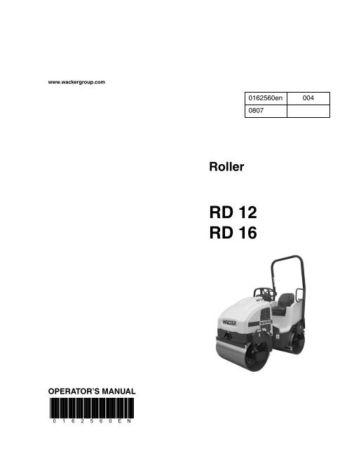
OPERATOR’S MANUAL<br />
0 1 6 2 5 6 0 E N<br />
Roller<br />
<strong>RD</strong> <strong>12</strong><br />
<strong>RD</strong> <strong>16</strong><br />
0<strong>16</strong>2560en 004<br />
0807
<strong>RD</strong> <strong>12</strong>/<strong>16</strong> Table of Contents<br />
1. Foreword 6<br />
2. Safety Information 7<br />
2.1 Operating Safety .................................................................................. 8<br />
2.2 Operator Safety while using Internal Combustion Engines ................ 10<br />
2.3 Service Safety .................................................................................... 11<br />
2.4 Label Locations—<strong>RD</strong> <strong>12</strong> .................................................................... 13<br />
2.5 Label Locations—<strong>RD</strong> <strong>16</strong> .................................................................... 14<br />
2.6 Safety and Operating Labels .............................................................. 15<br />
3. <strong>Operation</strong> 22<br />
3.1 <strong>Operation</strong> and Service Locations—<strong>RD</strong> <strong>16</strong> ......................................... 22<br />
3.2 <strong>Operation</strong> and Service Locations—<strong>RD</strong> <strong>12</strong> ......................................... 24<br />
3.3 Control Panel—<strong>RD</strong> <strong>16</strong> IRH / <strong>RD</strong> <strong>16</strong> ................................................... 26<br />
3.4 Control Panel—<strong>RD</strong> <strong>12</strong> ........................................................................ 28<br />
3.5 Application .......................................................................................... 30<br />
3.6 Roll Over Protection Structure (ROPS) .............................................. 30<br />
3.7 Foldable Roll Over Protection Structure (ROPS) (if equipped) .......... 31<br />
3.8 Rotating Beacon (if equipped) ............................................................ 33<br />
3.9 Backup Alarm (if equipped) ................................................................ 33<br />
3.10 Lighting Equipment (if equipped) ........................................................ 34<br />
3.11 Seat Belt ............................................................................................. 35<br />
3.<strong>12</strong> Operator Presence System ................................................................ 36<br />
3.13 Scraper Bars ...................................................................................... 37<br />
3.14 Anti-Vandalism Protection and Machine Access ................................ 38<br />
3.15 Articulation Joint Lockarm .................................................................. 39<br />
3.<strong>16</strong> <strong>Operation</strong> on Slopes ........................................................................... 40<br />
3.17 Recommended Fuel—<strong>RD</strong> <strong>16</strong> ............................................................. 40<br />
3.18 Recommended Fuel—<strong>RD</strong> <strong>12</strong> ............................................................. 40<br />
3.19 Before Starting ................................................................................... 41<br />
3.20 Starting—<strong>RD</strong> <strong>16</strong> ................................................................................. 42<br />
3.21 Stopping/Parking—<strong>RD</strong> <strong>16</strong> .................................................................. 44<br />
3.22 Parking Brake Button—<strong>RD</strong> <strong>16</strong> ............................................................ 45<br />
3.23 Starting—<strong>RD</strong> <strong>12</strong> ................................................................................. 46<br />
3.24 Stopping/Parking—<strong>RD</strong> <strong>12</strong> .................................................................. 48<br />
3.25 Parking Brake—<strong>RD</strong> <strong>12</strong> ....................................................................... 50<br />
3.26 Parking Brake Adjustment—<strong>RD</strong> <strong>12</strong> .................................................... 51<br />
wc_bo0<strong>16</strong>2560en_004TOC.fm 3
Table of Contents <strong>RD</strong> <strong>12</strong>/<strong>16</strong><br />
3.27 Direction and Speed ............................................................................52<br />
3.28 Transmission .......................................................................................53<br />
3.29 Vibration ..............................................................................................54<br />
3.30 Water Spray System ...........................................................................55<br />
3.31 Battery Disconnect—<strong>RD</strong> <strong>16</strong> ................................................................56<br />
3.32 Auxiliary Battery Positive Terminal ......................................................56<br />
3.33 Panel Indicator Lights—<strong>RD</strong><strong>16</strong> IRH / <strong>RD</strong><strong>16</strong> ..........................................57<br />
3.34 Turn Signal/Hazard Lights (if equipped)—<strong>RD</strong><strong>16</strong> .................................59<br />
3.35 Panel Indicator Lights—<strong>RD</strong><strong>12</strong> .............................................................60<br />
3.36 Adding Ballast to Rear Drum—<strong>RD</strong> <strong>12</strong> .................................................62<br />
4. Maintenance 64<br />
4.1 Honda Engine Maintenance Schedule—<strong>RD</strong> <strong>12</strong> ..................................64<br />
4.2 <strong>Wacker</strong> Engine Maintenance Schedule—<strong>RD</strong> <strong>12</strong> .................................65<br />
4.3 Lombardini Engine Maintenance Schedule—<strong>RD</strong> <strong>16</strong> ...........................66<br />
4.4 Roller Maintenance Schedule .............................................................67<br />
4.5 Rear Frame Access .............................................................................68<br />
4.6 Battery .................................................................................................69<br />
4.7 Fuel Filter—<strong>RD</strong> <strong>12</strong> ...............................................................................71<br />
4.8 Fuel Filter—<strong>RD</strong> <strong>16</strong> ...............................................................................72<br />
4.9 Priming the Fuel System—<strong>RD</strong> <strong>16</strong> .......................................................72<br />
4.10 Engine Oil and Filter—<strong>RD</strong> <strong>12</strong> ..............................................................73<br />
4.11 Engine Oil and Filter—<strong>RD</strong> <strong>16</strong> ..............................................................74<br />
4.<strong>12</strong> Spark Plug—<strong>RD</strong> <strong>12</strong> .............................................................................75<br />
4.13 Honda Engine Air Cleaner—<strong>RD</strong> <strong>12</strong> .....................................................76<br />
4.14 <strong>Wacker</strong> Engine Air Cleaner—<strong>RD</strong> <strong>12</strong> ...................................................77<br />
4.15 Lombardini Engine Air Cleaner—<strong>RD</strong> <strong>16</strong> ..............................................78<br />
4.<strong>16</strong> Grease Fittings ....................................................................................79<br />
4.17 Hydraulic System Cleanliness .............................................................80<br />
4.18 Hydraulic Oil Requirements .................................................................81<br />
4.19 Hydraulic Oil Level ..............................................................................82<br />
4.20 Hydraulic Suction Strainer ...................................................................82<br />
4.21 Changing the Hydraulic Oil & Filter .....................................................83<br />
4.22 Bleeding the Hydraulic System ...........................................................83<br />
4.23 Lifting the Machine ..............................................................................84<br />
4.24 Tying Down and Transporting the Machine .........................................85<br />
4.25 Storage ................................................................................................86<br />
4.26 Towing Bypass Valve—<strong>RD</strong> <strong>12</strong> ............................................................87<br />
4.27 Towing .................................................................................................88<br />
4.28 Manually Releasing Parking Brake—<strong>RD</strong> <strong>16</strong> ........................................90<br />
wc_bo0<strong>16</strong>2560en_004TOC.fm 4
<strong>RD</strong> <strong>12</strong>/<strong>16</strong> Table of Contents<br />
4.29 Troubleshooting .................................................................................. 91<br />
5. Technical Data 92<br />
5.1 Engine ................................................................................................ 92<br />
5.2 Roller .................................................................................................. 93<br />
5.3 Lubrication .......................................................................................... 93<br />
5.4 Dimensions ......................................................................................... 94<br />
5.5 Sound Measurements ........................................................................ 95<br />
5.6 Measurements of Operator Exposure to Vibration ............................. 95<br />
5.7 Hydraulic Schematic—<strong>RD</strong> <strong>12</strong>/<strong>RD</strong> <strong>12</strong>A ............................................... 96<br />
5.8 Hydraulic Schematic Components—<strong>RD</strong> <strong>12</strong>/<strong>RD</strong> <strong>12</strong>A .......................... 97<br />
5.9 Hydraulic Schematic—<strong>RD</strong> <strong>16</strong> ............................................................. 98<br />
5.10 Hydraulic Schematic Components—<strong>RD</strong> <strong>16</strong> ....................................... 99<br />
5.11 Electric Schematic—<strong>RD</strong> <strong>12</strong> .............................................................. 100<br />
5.<strong>12</strong> Electrical Schematic Components—<strong>RD</strong> <strong>12</strong> ...................................... 101<br />
5.13 Electrical Schematic—<strong>RD</strong> <strong>12</strong>A ......................................................... 102<br />
5.14 Electrical Schematic Components—<strong>RD</strong> <strong>12</strong>A ................................... 103<br />
5.15 Electrical Schematic—<strong>RD</strong> <strong>16</strong> ........................................................... 104<br />
5.<strong>16</strong> Electrical Schematic Components—<strong>RD</strong> <strong>16</strong> ...................................... 106<br />
wc_bo0<strong>16</strong>2560en_004TOC.fm 5
WARNING<br />
1. Foreword<br />
wc_tx000001gb.fm 6<br />
CALIFORNIA<br />
Proposition 65 Warning:<br />
Engine exhaust, some of its constituents, and certain vehicle<br />
components, contain or emit chemicals known to the State of<br />
California to cause cancer and birth defects or other reproductive<br />
harm.<br />
This manual provides information and procedures to safely operate<br />
and maintain this <strong>Wacker</strong> model. For your own safety and protection<br />
from injury, carefully read, understand and observe the safety<br />
instructions described in this manual.<br />
Keep this manual or a copy of it with the machine. If you lose this<br />
manual or need an additional copy, please contact <strong>Wacker</strong><br />
Corporation. This machine is built with user safety in mind; however,<br />
it can present hazards if improperly operated and serviced. Follow<br />
operating instructions carefully! If you have questions about operating<br />
or servicing this equipment, please contact <strong>Wacker</strong> Corporation.<br />
The information contained in this manual was based on machines in<br />
production at the time of publication. <strong>Wacker</strong> Corporation reserves the<br />
right to change any portion of this information without notice.<br />
All rights, especially copying and distribution rights, are reserved.<br />
Copyright 2007 by <strong>Wacker</strong> Corporation.<br />
No part of this publication may be reproduced in any form or by any<br />
means, electronic or mechanical, including photocopying, without<br />
express written permission from <strong>Wacker</strong> Corporation.<br />
Any type of reproduction or distribution not authorized by <strong>Wacker</strong><br />
Corporation represents an infringement of valid copyrights and will be<br />
prosecuted. We expressly reserve the right to make technical<br />
modifications, even without due notice, which aim at improving our<br />
machines or their safety standards.
<strong>RD</strong> <strong>12</strong>/<strong>16</strong> Safety Information<br />
2 Safety Information<br />
DANGER<br />
WARNING<br />
CAUTION<br />
This manual contains DANGER, WARNING, CAUTION, NOTICE and<br />
NOTE callouts which must be followed to reduce the possibility of<br />
personal injury, damage to the equipment, or improper service.<br />
This is the safety alert symbol. It is used to alert you to potential<br />
personal injury hazards. Obey all safety messages that follow this<br />
symbol to avoid possible injury or death.<br />
DANGER indicates a hazardous situation which, if not avoided, will<br />
result in death or serious injury.<br />
WARNING indicates a hazardous situation which, if not avoided, could<br />
result in death or serious injury.<br />
CAUTION indicates a hazardous situation which, if not avoided, could<br />
result in minor or moderate injury.<br />
NOTICE: Used without the safety alert symbol, NOTICE indicates a<br />
hazardous situation which, if not avoided, could result in property<br />
damage.<br />
Note: Contains additional information important to a procedure.<br />
wc_si000<strong>16</strong>6gb.fm 7
Safety Information <strong>RD</strong> <strong>12</strong>/<strong>16</strong><br />
2.1 Operating Safety<br />
WARNING<br />
Notice: State Health Safety Codes and Public Resources Codes<br />
specify that in certain locations spark arresters be used on internal<br />
combustion engines that use hydrocarbon fuels. A spark arrester is a<br />
device designed to prevent accidental discharge of sparks or flames<br />
from the engine exhaust. Spark arresters are qualified and rated by<br />
the United States Forest Service for this purpose.<br />
In order to comply with local laws regarding spark arresters, consult<br />
the engine distributor or the local Health and Safety Administrator.<br />
Familiarity and proper training are required for the safe operation of the<br />
machine. Machines operated improperly or by untrained personnel<br />
can be dangerous. Read the operating instructions contained in both<br />
this manual and the Engine Manual and familiarize yourself with the<br />
location and proper use of all controls. Inexperienced operators should<br />
receive instruction from someone familiar with the machine before<br />
being allowed to operate it.<br />
2.1.1 DO NOT drive over curbs or other uneven objects that will result in the<br />
machine and operator being shaken.<br />
2.1.2 DO NOT attempt to start the machine when standing alongside it. Only<br />
start the engine when seated in the driver's seat and with the forward/<br />
reverse control in the neutral position.<br />
2.1.3 NEVER allow anyone to operate this equipment without proper<br />
training. People operating this equipment must be familiar with the<br />
risks and hazards associated with it.<br />
2.1.4 NEVER touch the engine or muffler while the engine is on or<br />
immediately after it has been turned off. These areas get hot and may<br />
cause burns.<br />
2.1.5 NEVER use accessories or attachments that are not recommended by<br />
<strong>Wacker</strong>. Damage to equipment and injury to the user may result.<br />
2.1.6 NEVER leave the machine running unattended.<br />
2.1.7 NEVER operate the machine with the fuel cap loose or missing.<br />
2.1.8 NEVER carry passengers on the machine. Danger of crushing—keep<br />
clear of the articulated steering joint between the front and rear frames.<br />
2.1.9 NEVER use or attempt to repair damaged safety belts or ROPS.<br />
Replace only with <strong>Wacker</strong> spare parts.<br />
2.1.10 ALWAYS disengage and stow the locking bar for the articulated<br />
steering joint before operating the machine. The machine cannot be<br />
steered when the locking bar is engaged.<br />
2.1.11 ALWAYS check that all controls are functioning properly immediately<br />
after start-up! DO NOT operate the machine unless all controls operate<br />
correctly.<br />
wc_si000<strong>16</strong>6gb.fm 8
<strong>RD</strong> <strong>12</strong>/<strong>16</strong> Safety Information<br />
2.1.<strong>12</strong> ALWAYS remain aware of changing positions and the movement of<br />
other equipment and personnel on the job site.<br />
2.1.13 ALWAYS remain seated and wear the seat belt at all times while<br />
operating the machine.<br />
2.1.14 ALWAYS remain aware of changing surface conditions and use extra<br />
care when operating over uneven ground, on hills, or over soft or<br />
coarse material. The machine could shift or slide unexpectedly.<br />
2.1.15 ALWAYS use caution when operating the machine near the edges of<br />
pits, trenches or platforms. Check to be sure that ground surface is<br />
stable enough to support the weight of the machine with operator and<br />
that there is no danger of the roller sliding, falling or tipping.<br />
2.1.<strong>16</strong> ALWAYS wear protective clothing appropriate to the job site when<br />
operating the machine.<br />
2.1.17 ALWAYS keep hands, feet, and loose clothing away from moving parts<br />
of the machine.<br />
2.1.18 ALWAYS read, understand, and follow procedures in the Operator’s<br />
Manual before attempting to operate the machine.<br />
2.1.19 ALWAYS store the machine properly when it is not being used. The<br />
machine should be stored in a clean, dry location out of the reach of<br />
children.<br />
2.1.20 ALWAYS operate the machine with all safety devices and guards in<br />
place and in working order.<br />
2.1.21 ALWAYS be sure that all other persons are at a safe distance from the<br />
machine. Stop the machine if people step into the working area of the<br />
machine.<br />
wc_si000<strong>16</strong>6gb.fm 9
Safety Information <strong>RD</strong> <strong>12</strong>/<strong>16</strong><br />
2.2 Operator Safety while using Internal Combustion Engines<br />
DANGER<br />
Internal combustion engines present special hazards during operation<br />
and fueling. Read and follow the warning instructions in the engine<br />
Owner’s Manual and the safety guidelines below. Failure to follow the<br />
warnings and safety standards could result in severe injury or death.<br />
2.2.1 DO NOT smoke while operating the machine.<br />
2.2.2 DO NOT smoke when refueling the engine.<br />
2.2.3 DO NOT refuel a hot or running engine.<br />
2.2.4 DO NOT refuel the engine near an open flame.<br />
2.2.5 DO NOT spill fuel when refueling the engine.<br />
2.2.6 DO NOT run the engine near open flames.<br />
2.2.7 DO NOT run the machine indoors or in an enclosed area such as a<br />
deep trench unless adequate ventilation, through such items as<br />
exhaust fans or hoses, is provided. Exhaust gas from the engine<br />
contains poisonous carbon monoxide gas; exposure to carbon<br />
monoxide can cause loss of consciousness and may lead to death.<br />
2.2.8 ALWAYS refill the fuel tank in a well-ventilated area.<br />
2.2.9 ALWAYS replace the fuel tank cap after refueling.<br />
2.2.10 ALWAYS keep the area around a hot exhaust pipe free of debris to<br />
reduce the chance of an accidental fire.<br />
2.2.11 ALWAYS check the fuel lines and the fuel tank for leaks and cracks<br />
before starting the engine. Do not run the machine if fuel leaks are<br />
present or the fuel lines are loose.<br />
wc_si000<strong>16</strong>6gb.fm 10
<strong>RD</strong> <strong>12</strong>/<strong>16</strong> Safety Information<br />
2.3 Service Safety<br />
WARNING<br />
A poorly maintained machine can become a safety hazard! In order<br />
for the machine to operate safely and properly over a long period of<br />
time, periodic maintenance and occasional repairs are necessary.<br />
2.3.1 Some service procedures require that the machine’s battery be<br />
disconnected. To reduce the risk of personal injury, read and<br />
understand the service procedures before performing any service to<br />
the machine.<br />
2.3.2 All adjustments and repairs MUST be completed before operation.<br />
NEVER operate the machine with a known problem or deficiency! All<br />
repairs and adjustments should be completed by a qualified<br />
technician.<br />
2.3.3 DO NOT attempt to clean or service the machine while it is running.<br />
Rotating parts can cause severe injury.<br />
2.3.4 <strong>RD</strong> <strong>12</strong> only - DO NOT crank a flooded engine with the spark plug<br />
removed on gasoline-powered engines. Fuel trapped in the cylinder<br />
will squirt out the spark plug opening.<br />
2.3.5 <strong>RD</strong> <strong>12</strong> only - DO NOT test for spark on gasoline-powered engines if<br />
the engine is flooded or the smell of gasoline is present. A stray spark<br />
could ignite the fumes.<br />
2.3.6 DO NOT use gasoline or other types of fuels or flammable solvents to<br />
clean parts, especially in enclosed areas. Fumes from fuels and<br />
solvents can become explosive.<br />
2.3.7 DO NOT modify the machine without the express written approval of<br />
the manufacturer.<br />
2.3.8 <strong>RD</strong> <strong>16</strong> only - DO NOT remove the radiator cap when the engine is<br />
running or hot. The radiator fluid is hot and under pressure and may<br />
cause severe burns!<br />
2.3.9 DO NOT stand under the machine while it is being hoisted or moved.<br />
2.3.10 DO NOT get onto the machine while it is being hoisted or moved.<br />
2.3.11 DO NOT use the machine as a ladder. Use safe ladders and platforms<br />
designed for this purpose.<br />
2.3.<strong>12</strong> DO NOT modify, weld, or drill safety frames (ROPS) fitted as original<br />
equipment. DO NOT loosen or remove bolts. DO NOT weld, drill or<br />
modify a broken safety frame.<br />
wc_si000<strong>16</strong>6gb.fm 11
Safety Information <strong>RD</strong> <strong>12</strong>/<strong>16</strong><br />
2.3.13 DO NOT open the hydraulic lines or loosen the hydraulic connections<br />
while the engine is running! Before dismantling the hydraulic<br />
connectors or hoses, ensure that all pressure has been bled from the<br />
circuit. Hydraulic fluid under pressure can penetrate the skin, cause<br />
burns, blind, or create other potentially dangerous hazards. Set all<br />
controls in neutral, turn engine off, and allow the fluids to cool before<br />
loosening hydraulic fittings or attaching test gauges.<br />
2.3.14 ALWAYS check all external fasteners at regular intervals.<br />
2.3.15 ALWAYS keep the area around the muffler free of debris such as<br />
leaves, paper, cartons, etc. A hot muffler could ignite the debris and<br />
start a fire.<br />
2.3.<strong>16</strong> ALWAYS replace worn or damaged components with spare parts<br />
designed and recommended by <strong>Wacker</strong> Corporation.<br />
2.3.17 ALWAYS disconnect the spark plug on machines equipped with<br />
gasoline engines, before servicing, to avoid accidental start-up.<br />
2.3.18 ALWAYS keep the machine clean and labels legible. Replace all<br />
missing and hard-to-read labels. Labels provide important operating<br />
instructions and warn of dangers and hazards.<br />
2.3.19 ALWAYS do periodic maintenance as recommended in the Operator’s<br />
Manual.<br />
2.3.20 ALWAYS turn the engine off before performing maintenance or making<br />
repairs.<br />
2.3.21 ALWAYS keep hands, feet and loose clothing away from moving parts.<br />
2.3.22 ALWAYS make sure slings, chains, hooks, ramps, jacks and other<br />
types of lifting devices are attached securely and have enough weightbearing<br />
capacity to lift or hold the machine safely. Always remain<br />
aware of the location of other people in the area when lifting the<br />
machine.<br />
2.3.23 ALWAYS make sure hose connections have been reconnected back<br />
to the correct fitting. Failure to do so may result in damage to the<br />
machine and/or injury to person on or near the machine.<br />
2.3.24 ALWAYS secure the articulated steering joint using the locking bar<br />
before lifting, jacking, and servicing the machine. The machine halves<br />
could swing together unexpectedly and cause a serious injury.<br />
2.3.25 ALWAYS lock the lifting cylinders in the open position when the seat<br />
pedestal is raised.<br />
2.3.26 Before you start the machine, ensure that all tools have been removed<br />
from the machine and that replacement parts and adjusters are firmly<br />
tightened.<br />
2.3.27 Fluid leaks from small holes are often practically invisible. DO NOT use<br />
your bare hands to check for leaks. Check for leaks using a piece of<br />
cardboard or wood.<br />
wc_si000<strong>16</strong>6gb.fm <strong>12</strong>
<strong>RD</strong> <strong>12</strong>/<strong>16</strong> Safety Information<br />
2.4 Label Locations—<strong>RD</strong> <strong>12</strong><br />
wc_si000<strong>16</strong>6gb.fm 13
Safety Information <strong>RD</strong> <strong>12</strong>/<strong>16</strong><br />
2.5 Label Locations—<strong>RD</strong> <strong>16</strong><br />
wc_si000<strong>16</strong>6gb.fm 14
<strong>RD</strong> <strong>12</strong>/<strong>16</strong> Safety Information<br />
2.6 Safety and Operating Labels<br />
<strong>Wacker</strong> machines use international pictorial labels where needed.<br />
These labels are described below:<br />
Ref. Label Meaning<br />
A WARNING!<br />
Read and understand the supplied<br />
Operator’s Manual before operating the<br />
machine. Failure to do so increases the<br />
risk of injury to yourself or others.<br />
B DANGER!<br />
Engines emit carbon monoxide; operate<br />
only in well-ventilated area. Read the<br />
Operator’s Manual.<br />
No sparks, flames, or burning objects<br />
near the machine. Shut off the engine<br />
before refueling.<br />
C Tie-down point.<br />
D WARNING!<br />
Pressurized contents. Do not open when<br />
hot!<br />
E CAUTION!<br />
Read and understand the supplied<br />
Operator’s Manuals before operating this<br />
machine. Failure to do so increases the<br />
risk of injury to yourself or others.<br />
wc_si000<strong>16</strong>6gb.fm 15
Safety Information <strong>RD</strong> <strong>12</strong>/<strong>16</strong><br />
Ref. Label Meaning<br />
F WARNING!<br />
Pinch point.<br />
G WARNING!<br />
Hot surface!<br />
H WARNING!<br />
Hot surface!<br />
I Hydraulic oil reservoir fill tube.<br />
Torque nuts to 13.6-14.7 Nm (<strong>12</strong>0-130<br />
in.lbs.) maximum.<br />
J CAUTION!<br />
Lifting point.<br />
K WARNING!<br />
To prevent hearing loss, wear hearing<br />
protection when operating this machine.<br />
L WARNING!<br />
Pinching hazard. Rotating machinery.<br />
wc_si000<strong>16</strong>6gb.fm <strong>16</strong>
<strong>RD</strong> <strong>12</strong>/<strong>16</strong> Safety Information<br />
Ref. Label Meaning<br />
M WARNING<br />
WARNING!<br />
Disconnect battery before servicing.<br />
Read repair manual for instructions.<br />
Battery contains caustic acid and<br />
potentially explosive hydrogen gas.<br />
N WARNING!<br />
Always wear seat belt when operating<br />
roller.<br />
O WARNING!<br />
Avoid crushing area.<br />
P WARNING!<br />
Hand injury if entangled in moving belt.<br />
Q Parking brake is disengaged.<br />
wc_si000<strong>16</strong>6gb.fm 17<br />
Parking brake is engaged.<br />
S Coolant overflow bottle only, not a return<br />
system.<br />
T Choke:<br />
0 = Open<br />
l = Closed
Safety Information <strong>RD</strong> <strong>12</strong>/<strong>16</strong><br />
Ref. Label Meaning<br />
U Grease points: Inspect and lubricate<br />
every 100 hours of operation.<br />
V WARNING!<br />
wc_si000<strong>16</strong>6gb.fm 18<br />
Avoid crushing area.<br />
Articulated steering joint locking location.<br />
Lock the articulated steering joint before<br />
servicing the machine.<br />
Read Repair Manual.<br />
W <strong>RD</strong> <strong>12</strong> only—Engine will stop without<br />
operator seated.<br />
X<br />
<strong>RD</strong> <strong>12</strong> <strong>RD</strong> <strong>16</strong><br />
Guaranteed sound power level in dB(A).<br />
Y A nameplate listing the model number,<br />
item number, revision number, and serial<br />
number is attached to each unit. Please<br />
record the information found on this plate<br />
so it will be available should the<br />
nameplate become lost or damaged.<br />
When ordering parts or requesting<br />
service information, you will always be<br />
asked to specify the model number, item<br />
number, revision number, and serial<br />
number of the unit.
<strong>RD</strong> <strong>12</strong>/<strong>16</strong> Safety Information<br />
Ref. Label Meaning<br />
Z No lift point.<br />
AA <strong>RD</strong> <strong>16</strong> only.<br />
WARNING!<br />
Disconnect battery before servicing.<br />
BB <strong>RD</strong> <strong>16</strong> only.<br />
Lifting of machine to be done with<br />
spreader bar only!<br />
CC CAUTION! Electric shock hazard at<br />
auxiliary battery positive terminal. Never<br />
touch this terminal and a metal portion of<br />
the machine simultanously.<br />
DD WARNING!<br />
Read and understand the supplied<br />
Operator’s Manual before operating the<br />
machine. Failure to do so increases the<br />
risk of injury to yourself or others.<br />
wc_si000<strong>16</strong>6gb.fm 19
Safety Information <strong>RD</strong> <strong>12</strong>/<strong>16</strong><br />
Ref. Label Meaning<br />
EE Water tank<br />
wc_si000<strong>16</strong>6gb.fm 20
<strong>RD</strong> <strong>12</strong>/<strong>16</strong> Safety Information<br />
Notes:<br />
wc_si000<strong>16</strong>6gb.fm 21
<strong>Operation</strong> <strong>RD</strong> <strong>12</strong>/<strong>16</strong><br />
3. <strong>Operation</strong><br />
3.1 <strong>Operation</strong> and Service Locations—<strong>RD</strong> <strong>16</strong><br />
See Graphic: wc_gr002947<br />
Ref. Description Ref. Description<br />
1 Air cleaner 22 Water tank fill cap<br />
2 Articulated joint 23 Lockarm<br />
3 Hand holds 24 Operator’s platform<br />
4 Control panel 25 Engine oil filter<br />
5 Dipstick 27 Rear drum<br />
6 Drain hose—hydraulic tank 28 Scraper bar (4 places)<br />
7 Drive motor (2) 29 Sightglass—hydraulic tank<br />
8 Drive pump 30 Sprinkler tube (2)<br />
9 Engine hood 31 Steering wheel<br />
10 Vibration control button 32 Steering cylinder (under floor panel)<br />
11 Exciter motor (2) 33 Tiedown (2 places)<br />
<strong>12</strong> Exciter/Steering pump 34 Rotating beacon<br />
13 Hydraulic filter—return line 35 Battery (under floor panel)<br />
14 Hydraulic strainer—suction line 36 Hydraulic suction line<br />
15 Forward/Reverse control 37 Grease fitting—exciter (4 places)<br />
<strong>16</strong> Front drum 38 Lifting eye (4 places)<br />
17 Fuel tank fill cap 39 ROPS<br />
18 Fuel filter 40 Adjustable seat with seat belt<br />
19 Grease fittings—articulated joint (4<br />
places)<br />
41 Water drain<br />
20 Hydraulic tank fill port 42 Parking brake button<br />
21 Hydraulic manifold block 45 Auxiliary battery positive terminal<br />
wc_tx0005<strong>16</strong>gb.fm 22
<strong>RD</strong> <strong>12</strong>/<strong>16</strong> <strong>Operation</strong><br />
33<br />
29<br />
30<br />
28<br />
20<br />
13<br />
38<br />
<strong>16</strong><br />
14 36<br />
wc_tx0005<strong>16</strong>gb.fm 23<br />
37 19 37<br />
21 11 <strong>12</strong> 8 2 23 41 24 11<br />
1<br />
7 28<br />
18<br />
37<br />
45<br />
9<br />
38<br />
28<br />
6<br />
5<br />
3<br />
7 27<br />
25<br />
31<br />
4<br />
42<br />
34<br />
22<br />
32<br />
35<br />
10<br />
30<br />
15<br />
33<br />
28<br />
39<br />
40<br />
17<br />
37<br />
33<br />
wc_gr002947
<strong>Operation</strong> <strong>RD</strong> <strong>12</strong>/<strong>16</strong><br />
3.2 <strong>Operation</strong> and Service Locations—<strong>RD</strong> <strong>12</strong><br />
See Graphic: wc_gr002946<br />
Ref. Description Ref. Description<br />
1 Air cleaner 24 Operator’s platform<br />
2 Articulated joint 25 Engine oil filter<br />
3 Hand holds 26 Rear drum fill/drain plug<br />
4 Control panel 27 Rear drum—static<br />
5 Dipstick 28 Scraper bar (4 places)<br />
6 Drain hose—hydraulic tank 29 Sightglass—hydraulic tank<br />
7 Drive motor 30 Sprinkler tube (2)<br />
8 Drive pump 31 Steering wheel<br />
9 Engine hood 32 Steering cylinder (under floor panel)<br />
10 Vibration control button 33 Tiedown (2 places)<br />
11 Exciter motor 34 Beacon light (optional)<br />
<strong>12</strong> Exciter/Steering pump 35 Battery (under floor panel)<br />
13 Hydraulic filter—return line 36 Hydraulic suction line<br />
14 Hydraulic strainer—suction line 37 Grease fitting—exciter (2 places)<br />
15 Forward / Reverse control 38 Lifting eye (4 places)<br />
<strong>16</strong> Front drum—vibratory 39 ROPS<br />
17 Fuel tank fill cap 40 Seat with seatbelt<br />
18 Fuel filter 41 Water drain<br />
19 Grease fittings—articulated joint (4<br />
places)<br />
42 Parking brake<br />
20 Hydraulic tank fill port 43 Tow valve<br />
21 Hydraulic manifold block 44 Choke lever<br />
22 Water tank fill cap 45 Auxiliary battery positive terminal<br />
23 Lockarm - ---<br />
wc_tx0005<strong>16</strong>gb.fm 24
<strong>RD</strong> <strong>12</strong>/<strong>16</strong> <strong>Operation</strong><br />
33<br />
45<br />
14 36<br />
28<br />
38<br />
30<br />
20<br />
37<br />
19<br />
5 13 29 1 11 21 18 25 2 23 41 24<br />
<strong>12</strong> 8 43<br />
wc_tx0005<strong>16</strong>gb.fm 25<br />
37<br />
9<br />
7<br />
<strong>16</strong> 28<br />
28<br />
38<br />
3 31<br />
7<br />
6<br />
27<br />
4<br />
22<br />
26<br />
34<br />
10<br />
44<br />
15<br />
30<br />
32<br />
35<br />
3<br />
33<br />
42<br />
40<br />
17<br />
28<br />
39<br />
wc_gr002946
<strong>Operation</strong> <strong>RD</strong> <strong>12</strong>/<strong>16</strong><br />
3.3 Control Panel—<strong>RD</strong> <strong>16</strong> IRH / <strong>RD</strong> <strong>16</strong><br />
See Graphic: wc_gr004113<br />
Ref. Description Ref. Description<br />
46 Turn signal switch—LEFT and RIGHT<br />
(<strong>RD</strong> <strong>16</strong>IRH only)<br />
56 Low fuel indicator<br />
47 Hour meter 57 Air filter indicator<br />
48 Engine coolant temperature indicator 58 Glow plug indicator<br />
49 Low oil pressure indicator 59 Parking brake ON indicator<br />
50 Vibration ON indicator 60 Battery indicator<br />
51 Hazard lights switch—ON and OFF 61 Water spray switch—ON and OFF<br />
52 Lights switch—multi-position<br />
(<strong>RD</strong> <strong>16</strong>IRH only)<br />
62 Water spray dial<br />
53 Turn signal indicator<br />
63 Vibration switch —BOTH DRUMS and<br />
(<strong>RD</strong> <strong>16</strong>IRH only)<br />
FRONT DRUM ONLY<br />
54 Throttle switch—HIGH and LOW 64 Horn<br />
55 Ignition switch - ---<br />
wc_tx0005<strong>16</strong>gb.fm 26
<strong>RD</strong> <strong>12</strong>/<strong>16</strong> <strong>Operation</strong><br />
<strong>RD</strong> <strong>16</strong> IRH<br />
<strong>RD</strong> <strong>16</strong><br />
53<br />
62<br />
63 61<br />
62<br />
63 61<br />
wc_tx0005<strong>16</strong>gb.fm 27<br />
50 56 58 57 47 52<br />
49 48 59 60<br />
50 56 58 57<br />
49 48 59 60<br />
51<br />
47<br />
55<br />
54<br />
51 54<br />
55<br />
53<br />
64<br />
46<br />
64<br />
wc_gr004113
<strong>Operation</strong> <strong>RD</strong> <strong>12</strong>/<strong>16</strong><br />
3.4 Control Panel—<strong>RD</strong> <strong>12</strong><br />
See Graphic: wc_gr004114<br />
Ref. Description Ref. Description<br />
47 Hour meter 55 Ignition switch<br />
50 Vibration ON indicator 56 Low fuel indicator<br />
53 Lights switch - ON and OFF<br />
(if equipped)<br />
61 Water spray switch - ON and OFF<br />
54 Throttle switch - HIGH and LOW 62 Water spray dial<br />
wc_tx0005<strong>16</strong>gb.fm 28
<strong>RD</strong> <strong>12</strong>/<strong>16</strong> <strong>Operation</strong><br />
<strong>RD</strong> <strong>12</strong><br />
62<br />
61<br />
50<br />
47<br />
wc_tx0005<strong>16</strong>gb.fm 29<br />
56<br />
53<br />
55<br />
54<br />
wc_gr004114
<strong>Operation</strong> <strong>RD</strong> <strong>12</strong>/<strong>16</strong><br />
3.5 Application<br />
This machine is designed as a lightweight roller to be used in the<br />
compaction of sublayers and finish layers of asphalt on roads,<br />
driveways, parking lots, and other types of asphalt-covered surfaces.<br />
Do not use this machine for any other purpose.<br />
3.6 Roll Over Protection Structure (ROPS)<br />
WARNING<br />
The machine is equipped with a Roll Over Protection Structure<br />
(ROPS). The machine is normally delivered to the customer with the<br />
ROPS folded forward to facilitate transport.<br />
Do not use the machine without the ROPS in place. The ROPS is<br />
designed to protect the operator in a rollover accident.<br />
Before using the machine, position the ROPS in the fully upright<br />
position as follows:<br />
3.6.1 Support the ROPS using a crane and suitable rigging capable of<br />
supporting 43 kg (95 lbs.).<br />
NOTICE: Do not use the ROPS to lift the machine.<br />
3.6.2 Remove the shipping strap from both sides of the frame. Save the<br />
washers.<br />
3.6.3 Loosen the bottom mounting bolt on both sides.<br />
3.6.4 Rotate the ROPS into the upright position.<br />
3.6.5 Secure the ROPS to the frame using the saved washers and the<br />
supplied bolts. Torque hardware to 106 Nm (78 ft.lbs.).<br />
Each month, check the torque on all of the screws holding the ROPS<br />
in place. Check that the ROPS frame is not rusty, cracked, broken, or<br />
damaged in any way.<br />
Change the seat belts every 3 years, or any time they have been<br />
subjected to accident-level loads.<br />
If the ROPS has been removed from the machine, it must be<br />
reinstalled before the machine is used. When reinstalling the ROPS,<br />
use the original nuts and bolts and tighten the bolts to the specified<br />
torques.<br />
Do not weld or drill into the ROPS. Drilling or welding on the ROPS will<br />
nullify the ROPS certification.<br />
wc_tx0005<strong>16</strong>gb.fm 30
<strong>RD</strong> <strong>12</strong>/<strong>16</strong> <strong>Operation</strong><br />
3.7 Foldable Roll Over Protection Structure (ROPS) (if equipped)<br />
See Graphic: wc_gr002957<br />
WARNING<br />
The machine is equipped with a Roll Over Protection Structure<br />
(ROPS). The machine is normally delivered to the customer with the<br />
ROPS folded forward to facilitate transport.<br />
Do not use the machine without the ROPS in place. The ROPS is<br />
designed to protect the operator in a rollover accident.<br />
Before using the machine, position the ROPS in the fully upright<br />
position as follows:<br />
3.7.1 Support the upper mass ROPS using a crane and suitable rigging<br />
capable of supporting 19 kg (42 lbs.).<br />
NOTICE: Do not use the ROPS to lift the machine.<br />
3.7.2 Remove the safety pin (a) and pull out the locking pin (b). Do so on<br />
both sides.<br />
3.7.3 Lift the ROPS into the upright position.<br />
3.7.4 Insert the locking pins and secure them with the safety pins.<br />
WARNING<br />
Be aware of pinch points when lowering and raising the ROPS.<br />
To lower the ROPS:<br />
3.7.5 Support the upper mass of the ROPS using a crane and suitable<br />
rigging capable of supporting 19 kg (42 lbs.).<br />
3.7.6 Remove the safety pin (a) and pull out the locking pin (b). Do so on<br />
both sides.<br />
3.7.7 Gently lower the upper mass.<br />
Note: When lowering ROPS, do not allow the upper frame to fall into<br />
the lower position. Allowing the upper mass to slam will weaken the<br />
ROPS system and ultimately compromise its integrity and protection.<br />
3.7.8 Insert the pins in the ROPS in the lower hole setting through the upper<br />
mass to secure it for transport.<br />
Each month, check the torque on all of the screws holding the ROPS<br />
in place. Check that the ROPS frame is not rusty, cracked, broken, or<br />
damaged in any way.<br />
Keep the ROPS in the extended (upright) position when using the<br />
roller, and always use the seat belts provided.<br />
Change the seat belts every 3 years, or any time they have been<br />
subjected to accident-level loads.<br />
wc_tx0005<strong>16</strong>gb.fm 31
<strong>Operation</strong> <strong>RD</strong> <strong>12</strong>/<strong>16</strong><br />
If the ROPS has been removed from the machine, it must be<br />
reinstalled before the machine is used. When reinstalling the ROPS,<br />
use the original nuts and bolts and tighten the bolts to the specified<br />
torques.<br />
Do not weld or drill into the ROPS. Drilling or welding on the ROPS will<br />
nullify the ROPS certification.<br />
wc_tx0005<strong>16</strong>gb.fm 32<br />
b<br />
a<br />
34<br />
wc_gr002957
<strong>RD</strong> <strong>12</strong>/<strong>16</strong> <strong>Operation</strong><br />
3.8 Rotating Beacon (if equipped)<br />
See Graphic: wc_gr002957<br />
The rotating beacon (34) powers up when the ignition switch is turned<br />
to the ON position.<br />
<strong>RD</strong> <strong>12</strong> - The beacon flashes when powered up.<br />
<strong>RD</strong> <strong>16</strong> - The beacon illuminates and rotates when powered up.<br />
3.8.1<br />
To install the beacon (<strong>RD</strong> <strong>16</strong> only):<br />
Slide the rotating beacon onto the light staff.<br />
3.8.2 Tighten the wing nut on the base of the light.<br />
3.9 Backup Alarm (if equipped)<br />
The backup alarm is located on the rear of the machine.<br />
Start the engine and move the forward/reverse control to the reverse<br />
position. The backup alarm should sound immediately. The backup<br />
alarm will continue to sound until the forward/reverse control is moved<br />
to the neutral position or to the forward position.<br />
If the backup alarm does not sound, make the necessary repairs<br />
before using the roller.<br />
wc_tx0005<strong>16</strong>gb.fm 33
<strong>Operation</strong> <strong>RD</strong> <strong>12</strong>/<strong>16</strong><br />
3.10 Lighting Equipment (if equipped)<br />
See Graphic: wc_gr004115<br />
WARNING<br />
When working in the dark or in bad visibility, use all the lights available.<br />
Replace broken bulbs immediately. Only replace bulbs when the<br />
machine is turned off. Remember that your safety and the safety of<br />
others depends on your care and attention when operating this<br />
machine.<br />
Parking lights (A)<br />
On the <strong>RD</strong> <strong>16</strong> IRH only, this switch position turns on the parking lights.<br />
Lights on (B)<br />
On the <strong>RD</strong> <strong>16</strong> IRH, this switch position turns on the rear work lights.<br />
On the <strong>RD</strong> <strong>12</strong> and <strong>RD</strong> <strong>16</strong>, this switch position turns on the front and<br />
rear lights.<br />
Front road lights (C)<br />
On the <strong>RD</strong> <strong>16</strong> IRH only, this switch position turns on the front lights.<br />
Lights off (D)<br />
This switch position turns off all the lights.<br />
51<br />
wc_tx0005<strong>16</strong>gb.fm 34<br />
B<br />
D<br />
52<br />
wc_gr004115<br />
D<br />
B<br />
A<br />
C
<strong>RD</strong> <strong>12</strong>/<strong>16</strong> <strong>Operation</strong><br />
3.11 Seat Belt<br />
a<br />
See Graphic: wc_gr002238<br />
Pull seat belt (c) out of the retractor in a continuous motion.<br />
Fasten seat belt catch (b) into buckle (a). Make sure that the seat belt<br />
is placed low across the lap of the operator.<br />
The retractor will adjust the belt length and the retractor will lock in<br />
place.<br />
Push the release button (d) on the buckle in order to release the seat<br />
belt. The seat belt will automatically retract into the retractor.<br />
Replace the seat belt every three years.<br />
wc_tx0005<strong>16</strong>gb.fm 35<br />
b<br />
c<br />
d<br />
wc_gr002238
<strong>Operation</strong> <strong>RD</strong> <strong>12</strong>/<strong>16</strong><br />
3.<strong>12</strong> Operator Presence System<br />
See Graphic: wc_gr002962<br />
WARNING<br />
The machine is equipped with an “operator presence system”. This<br />
system is part of the driver's seat and senses the weight of an operator<br />
in the seat. If the operator is not sitting in the driver's seat, the roller will<br />
NOT drive. On the <strong>RD</strong> <strong>12</strong>, if the operator leaves the driver's seat and<br />
the forward/reverse control is not in neutral, the engine will be turned<br />
off. On the <strong>RD</strong> <strong>16</strong>, if the operator leaves the driver’s seat, the brakes<br />
will activate. When the operator sits down again, the forward/reverse<br />
control must be placed in the neutral position before the roller can be<br />
driven or the vibration can be started.<br />
Note: A one-half second delay keeps the system from tripping when<br />
the roller passes over a bump.<br />
If the roller is supplied with an adjustable seat, it can be adjusted as<br />
follows:<br />
Knob (a) for adjusting the seat tension to the driver's weight.<br />
Lever (b) for adjusting the distance from the seat to the driving<br />
controls.<br />
Note: Do not change position of the driver’s seat while the machine is<br />
moving. The “OPERATOR PRESENCE” safety device will prevent all<br />
machine movements if an operator is not seated.<br />
Always wear the seat belt provided when operating the roller.<br />
wc_tx0005<strong>16</strong>gb.fm 36<br />
b<br />
a<br />
wc_gr002962
<strong>RD</strong> <strong>12</strong>/<strong>16</strong> <strong>Operation</strong><br />
3.13 Scraper Bars<br />
See Graphic: wc_gr003447<br />
a<br />
Scraper bars, located in front of and behind each drum, are used to<br />
prevent dirt and asphalt from sticking to and accumulating on the drum<br />
surface.<br />
These scrapers are spring loaded. They may be set in the travel<br />
position (a) or the scraping position (b) by flipping the bar up or down.<br />
wc_tx0005<strong>16</strong>gb.fm 37<br />
b<br />
b<br />
a<br />
wc_gr003447
<strong>Operation</strong> <strong>RD</strong> <strong>12</strong>/<strong>16</strong><br />
3.14 Anti-Vandalism Protection and Machine Access<br />
Parts of the machine which may be subject to theft or vandalism when<br />
the vehicle is parked unattended can be padlocked to prevent<br />
unauthorized access or use.<br />
Lockable parts are:<br />
Engine cover.<br />
Control panel.<br />
Fuel cap.<br />
To lock the engine cover, close the cover and attach a padlock to the<br />
fastener.<br />
<strong>RD</strong> <strong>16</strong> only: The control panel cover is stored on the front of the control<br />
column during operation and service. To lock the control panel, place<br />
the cover on the panel and attach a padlock to the fastener.<br />
Note: Padlocks are not supplied with the machine.<br />
To lock the fuel cap, close cap completely and push in the locking tab<br />
on the cap and attach padlock.<br />
wc_tx0005<strong>16</strong>gb.fm 38
<strong>RD</strong> <strong>12</strong>/<strong>16</strong> <strong>Operation</strong><br />
3.15 Articulation Joint Lockarm<br />
See Graphic: wc_gr002956<br />
WARNING<br />
WARNING<br />
A lockarm (23), located below the articulated joint, is provided to<br />
secure the front and rear halves of the roller together. Once secured,<br />
the lockarm prevents the two halves from swinging together.<br />
To avoid being pinched by machine halves, set the lockarm before<br />
lifting the machine for transport or repairs!<br />
To set lockarm, release it from its holder and swing it out from its stored<br />
position. Place the forward end of the arm into the hole provided in the<br />
front frame of the machine. Secure it in this position using the large<br />
hairpin cotter provided.<br />
ALWAYS disengage and stow locking bar for the articulated steering<br />
joint before operating machine. The machine cannot be steered when<br />
the locking bar is engaged.<br />
23<br />
wc_tx0005<strong>16</strong>gb.fm 39<br />
wc_gr002956
<strong>Operation</strong> <strong>RD</strong> <strong>12</strong>/<strong>16</strong><br />
3.<strong>16</strong> <strong>Operation</strong> on Slopes<br />
See Graphic: wc_gr003448<br />
WARNING<br />
When operating on slopes or hills special care must be taken to reduce<br />
the risk of personal injury or damage to the equipment. Always operate<br />
the machine up and down hills rather than from side to side. For safe<br />
operation and for protection of the engine, continuous duty use should<br />
be restricted to front/rear slopes of 17° (30% grade) or less.<br />
NEVER operate machine on side slopes. The machine may roll over,<br />
even on stable ground. Always operate the machine parallel to the<br />
slope; never perpendicular.<br />
3.17 Recommended Fuel—<strong>RD</strong> <strong>16</strong><br />
The engine requires No. 2 diesel fuel. Use only fresh, clean fuel. Fuel<br />
containing water or dirt will damage the fuel system. Consult the<br />
engine owner’s manual for complete fuel specifications.<br />
3.18 Recommended Fuel—<strong>RD</strong> <strong>12</strong><br />
The engine requires regular grade unleaded gasoline. Use only fresh,<br />
clean gasoline. Gasoline containing water or dirt will damage fuel<br />
system. Consult engine Owner’s Manual for complete fuel<br />
specifications.<br />
wc_tx0005<strong>16</strong>gb.fm 40<br />
17˚<br />
30%<br />
wc_gr003448
<strong>RD</strong> <strong>12</strong>/<strong>16</strong> <strong>Operation</strong><br />
3.19 Before Starting<br />
WARNING<br />
Before starting the machine check the following:<br />
Engine oil level<br />
Engine coolant level (<strong>RD</strong> <strong>16</strong> only)<br />
Hydraulic fluid level<br />
Condition of fuel lines<br />
Condition of air cleaner<br />
<strong>Operation</strong> of the brake system<br />
Fuel level<br />
Water level<br />
Condition of safety belt<br />
Scraper bars—clean and properly adjusted<br />
Note: All fluid levels should be checked with the machine on a level<br />
surface.<br />
Ensure that regular maintenance has been carried out.<br />
Ensure that the driver's platform is clean.<br />
Always use the steps and handrails when climbing on and off the<br />
machine.<br />
Always wear the seat belt provided when operating the roller.<br />
wc_tx0005<strong>16</strong>gb.fm 41
<strong>Operation</strong> <strong>RD</strong> <strong>12</strong>/<strong>16</strong><br />
3.20 Starting—<strong>RD</strong> <strong>16</strong><br />
See Graphic: wc_gr002952<br />
WARNING<br />
Exhaust gases are toxic. Do not start the engine in enclosed spaces.<br />
3.20.1 Sit down in the operator’s seat and fasten the seat belt.<br />
3.20.2 Set the forward/reverse control (15) in the NEUTRAL position.<br />
3.20.3 Press the parking brake button in (42) to set parking brake.<br />
Note: The roller will not start unless the forward/reverse control is in<br />
the NEUTRAL position.<br />
3.20.4 Turn the ignition switch (55) to the ON position. The glow plug indicator<br />
(58) will illuminate signifying the glow plugs are on. The glow plug<br />
indicator will stay on; approximately 30 seconds at 0°C (32°F). Do not<br />
start the engine until the glow plug indicator light goes out.<br />
3.20.5 Turn the ignition switch (55) to the START position.<br />
NOTICE: Do not crank the engine starter for more than 15 seconds at<br />
one time. Longer cranking cycles could lead to starter damage.<br />
Note: The ignition switch has an anti-restart feature. If the engine does<br />
not start, the switch will need to be turned to the OFF position before it<br />
will allow the engine to be cranked again.<br />
3.20.6 Allow the engine to warm up for a few minutes before operating the<br />
roller.<br />
3.20.7 Disengage the parking brake by pulling the parking brake button out.<br />
3.20.8 Quickly press and release the upper half of the throttle switch (54) to<br />
bring the engine to high throttle.<br />
WARNING<br />
Prolonged exposure to high noise levels can damage your hearing.<br />
Wear appropriate hearing protection while operating the roller.<br />
wc_tx0005<strong>16</strong>gb.fm 42
<strong>RD</strong> <strong>12</strong>/<strong>16</strong> <strong>Operation</strong><br />
54<br />
58<br />
wc_tx0005<strong>16</strong>gb.fm 43<br />
55<br />
42<br />
15<br />
F N R<br />
wc_gr002952
<strong>Operation</strong> <strong>RD</strong> <strong>12</strong>/<strong>16</strong><br />
3.21 Stopping/Parking—<strong>RD</strong> <strong>16</strong><br />
See Graphic: wc_gr002954<br />
3.21.1 Stop the machine on a flat surface with a suitable load bearing<br />
capacity.<br />
3.21.2 Turn the vibration off by pressing the vibration control button (10) on<br />
the forward/reverse lever (15).<br />
3.21.3 Press the water spray switch (61) to the OFF position.<br />
3.21.4 Set the forward/reverse control (15) to the NEUTRAL position.<br />
3.21.5 Return the engine throttle to idle by pressing the lower half of the<br />
throttle switch (54) and allow the engine to cool down.<br />
3.21.6 Press the parking brake button (42) to set the parking brake. Always<br />
set the parking brake before leaving the machine.<br />
If the vehicle constitutes a hazard or obstacle to traffic when parked, it<br />
should be marked with signs, lights, and other warnings.<br />
If the machine must be parked on a sloping surface, chock the drums<br />
with wedges to prevent any vehicle movement.<br />
3.21.7 Stop the engine by turning the ignition switch to the OFF position (55).<br />
Note: On the <strong>RD</strong> <strong>16</strong>, the parking brake is automatically applied within<br />
the drive motors. The brakes are applied under the following<br />
conditions:<br />
• engine is not running<br />
• engine is running and the operator is not on the seat<br />
• parking brake button is pushed<br />
WARNING<br />
wc_tx0005<strong>16</strong>gb.fm 44
<strong>RD</strong> <strong>12</strong>/<strong>16</strong> <strong>Operation</strong><br />
54<br />
61<br />
3.22 Parking Brake Button—<strong>RD</strong> <strong>16</strong><br />
See Graphic: wc_gr002954<br />
To hold the machine in a stopped position (parked), there is a<br />
mechanical parking brake on each drum drive motor. The mechanical<br />
parking brakes are spring-activated and hydraulically released (SAHR)<br />
type brakes. The brakes are applied when the engine is switched off or<br />
the operator leaves the seat.<br />
When pushed in, the parking brake button (42) stops all travel (either<br />
forward or reverse) and applies the brake. The brakes can be released<br />
by pulling the parking brake button out.<br />
The forward/reverse control (15) must be in the NEUTRAL position to<br />
allow the release of the brakes. If the forward/reverse control is not in<br />
the NEUTRAL position when the parking brake is released, the brakes<br />
will not be released.<br />
NOTICE: Under normal operating conditions, do not use the parking<br />
brakes when the machine is moving. The parking brakes should only<br />
be used in cases of emergency when the machine is moving, e.g.,<br />
following failure of the main hydraulic braking system (moving the<br />
forward/reverse control to the NEUTRAL position) or in a runaway<br />
condition traveling down a slope. Using the parking brake while the<br />
machine is moving may cause damage to the drive motors.<br />
wc_tx0005<strong>16</strong>gb.fm 45<br />
42<br />
55<br />
10<br />
15<br />
F N R<br />
wc_gr002954
<strong>Operation</strong> <strong>RD</strong> <strong>12</strong>/<strong>16</strong><br />
3.23 Starting—<strong>RD</strong> <strong>12</strong><br />
See Graphic: wc_gr002951<br />
WARNING<br />
Exhaust gases are toxic. Do not start the engine in an enclosed space.<br />
3.23.1 Sit down in the operator’s seat and fasten the seat belt.<br />
3.23.2 Set the forward/reverse control (15) in the neutral position.<br />
3.23.3 If the engine is cold, move the choke lever (44) to the left into the<br />
CLOSED position. If the engine is warm, move the choke control to the<br />
right in the OPEN position.<br />
Note: The roller will not start unless the forward/reverse control is in<br />
the NEUTRAL position.<br />
3.23.4 Check that the parking brake (42) is set. To set the brake, pull the<br />
brake lever up until the brake pad engages the drum. To release the<br />
brake lever, lower the lever. Always set the parking brake before<br />
leaving the machine.<br />
3.23.5 Turn the ignition switch (55) to start the engine. If the vibration indicator<br />
light (50) is on, turn the vibration off by pressing the vibration control<br />
button (10).<br />
NOTICE: Do not crank the engine starter for more than 15 seconds at<br />
one time. Longer cranking cycles could lead to starter damage.<br />
Note: The ignition switch has an anti-restart feature. If the engine does<br />
not start, the switch will need to be turned to the OFF position before it<br />
will allow the engine to be cranked again.<br />
3.23.6 Gradually place the choke lever in the OPEN position as the engine<br />
warms up. Allow the engine to warm up for a few minutes before<br />
operating the roller.<br />
3.23.7 Before moving the machine, release the parking brake by lowering the<br />
brake lever.<br />
3.23.8 Quickly press and release the upper half of the throttle switch (54) to<br />
bring the engine to high throttle.<br />
WARNING<br />
Prolonged exposure to high noise levels can damage your hearing.<br />
Wear appropriate hearing protection while operating the roller.<br />
wc_tx0005<strong>16</strong>gb.fm 46
<strong>RD</strong> <strong>12</strong>/<strong>16</strong> <strong>Operation</strong><br />
54<br />
wc_tx0005<strong>16</strong>gb.fm 47<br />
44<br />
55<br />
10<br />
15<br />
42<br />
F N R<br />
wc_gr002951
<strong>Operation</strong> <strong>RD</strong> <strong>12</strong>/<strong>16</strong><br />
3.24 Stopping/Parking—<strong>RD</strong> <strong>12</strong><br />
See Graphic: wc_gr002953<br />
3.24.1 Stop the machine on a flat surface with a suitable load bearing<br />
capacity.<br />
3.24.2 Turn the vibration off by pressing the vibration control button (10) on<br />
the forward/reverse lever (15).<br />
3.24.3 Press the water spray switch to the OFF position (61).<br />
3.24.4 Set the forward/reverse control (15) to the NEUTRAL position.<br />
3.24.5 Return the engine throttle to idle by pressing the lower half of the<br />
throttle switch (54) and allow the engine to cool down.<br />
3.24.6 Set the parking brake (42). To set the parking brake, pull the brake<br />
lever up until the brake pad engages the drum. To release the brake,<br />
lower the brake lever. Always set the parking brake before leaving the<br />
machine.<br />
Note: The parking brake engages the rear drum only.<br />
3.24.7 Stop the engine by turning the ignition switch (55) to the OFF position.<br />
If the vehicle constitutes a hazard or obstacle to traffic when parked, it<br />
should be marked with signs, lights, and other warnings.<br />
If the machine must be parked on a sloping surface, chock the drums<br />
WARNING<br />
with wedges to prevent any vehicle movement.<br />
wc_tx0005<strong>16</strong>gb.fm 48
<strong>RD</strong> <strong>12</strong>/<strong>16</strong> <strong>Operation</strong><br />
54<br />
61<br />
wc_tx0005<strong>16</strong>gb.fm 49<br />
55<br />
10<br />
15<br />
42<br />
F N R<br />
wc_gr002953
<strong>Operation</strong> <strong>RD</strong> <strong>12</strong>/<strong>16</strong><br />
3.25 Parking Brake—<strong>RD</strong> <strong>12</strong><br />
See Graphic: wc_gr002953<br />
To hold the machine in a stopped position (parked), there is a<br />
mechanical parking brake on the rear drive motor. The engine will<br />
automatically shut off when the operator leaves the seat, but the<br />
parking brake must be set manually.<br />
To set the parking brake (42), pull the brake lever up until the brake<br />
pad engages the rear drum. Always set the parking brake before<br />
leaving the machine. To release the parking brake, lower the brake<br />
lever. The forward/reverse control (15) should be in the NEUTRAL<br />
position when the parking brake is released.<br />
The parking brake is connected to the brake pads and can be adjusted<br />
by turning the knob on the end of the handle. See section <strong>RD</strong> <strong>12</strong><br />
Parking Brake Adjustment.<br />
NOTICE: Under normal operating conditions, do not use the parking<br />
brake when the machine is moving. The parking brake should only be<br />
used in cases of emergency when the machine is moving, e.g.,<br />
following failure of the main hydraulic braking system (moving the<br />
forward/reverse control to the NEUTRAL position) or in a runaway<br />
condition traveling down a slope. Using the parking brake while the<br />
machine is moving may cause damage to the drive motor.<br />
wc_tx0005<strong>16</strong>gb.fm 50
<strong>RD</strong> <strong>12</strong>/<strong>16</strong> <strong>Operation</strong><br />
3.26 Parking Brake Adjustment—<strong>RD</strong> <strong>12</strong><br />
See Graphic: wc_gr002953<br />
The parking brake is located on the rear drive motor drum support, and<br />
is used to prevent the roller from moving when the engine is turned off.<br />
Adjust brake for proper holding force as follows:<br />
3.26.1 Unscrew brake lever knob (42) until brake can be applied with<br />
moderate force (approx. 30 lbs.).<br />
3.26.2 Start roller on level ground and try to travel forward and reverse with<br />
brake applied. If roller drives through brake, stop machine, tighten<br />
lever knob one turn and repeat process.<br />
3.26.3 When machine no longer moves with brake set, stop machine, turn<br />
knob one more turn and brake is properly set.<br />
54<br />
61<br />
wc_tx0005<strong>16</strong>gb.fm 51<br />
55<br />
10<br />
15<br />
42<br />
F N R<br />
wc_gr002953
<strong>Operation</strong> <strong>RD</strong> <strong>12</strong>/<strong>16</strong><br />
3.27 Direction and Speed<br />
See Graphic: wc_gr002953, wc_gr002954<br />
The forward/reverse control (15) controls both the direction and speed<br />
of the roller. Use the control lever, rather than the throttle, to control the<br />
speed of the machine while compacting.<br />
Speed is controlled by the amount the lever is moved in the direction<br />
of travel—forward or reverse.<br />
During operation, to run the machine at full throttle, press and release<br />
the upper half of the throttle switch (HIGH) (54). This ensures<br />
maximum travel speeds and will produce the best compaction results.<br />
Operating the machine at slower engine speeds will reduce<br />
compaction, slow down machine functions, and damage hydraulic<br />
components.<br />
wc_tx0005<strong>16</strong>gb.fm 52
<strong>RD</strong> <strong>12</strong>/<strong>16</strong> <strong>Operation</strong><br />
3.28 Transmission<br />
See Graphic: wc_gr002953, wc_gr002954<br />
Both roller drums are fitted with hydraulic motors which are driven by<br />
an infinitely variable displacement pump and hydrostatic transmission.<br />
Forward and reverse travel are selected using a forward/reverse<br />
control (15) located next to the driver’s seat. In order to comply with<br />
safety standards, the machine has a device which only enables<br />
starting of the engine when the forward/reverse control is in the<br />
NEUTRAL position.<br />
Forward/reverse control<br />
Shift the forward/reverse control (15) into FORWA<strong>RD</strong> (F) or REVERSE<br />
(R) according to the direction of travel desired. The further forward or<br />
reverse the control is positioned, the faster the roller will travel.<br />
Road speed is the same in both FORWA<strong>RD</strong> and REVERSE. If you<br />
wish to change direction of travel from FORWA<strong>RD</strong> to REVERSE or<br />
vice versa, move the control to the NEUTRAL position (N), allow the<br />
vehicle to come to a complete stop, then move the control in the<br />
direction desired.<br />
During operation run the machine at high throttle. Quickly press and<br />
release the upper half of the throttle switch (54) to bring the engine to<br />
high throttle.<br />
When negotiating gentle slopes, keep the engine at high throttle and<br />
the forward/reverse control at the minimum speed position.<br />
NOTICE: This vehicle has a hydrostatic transmission which means<br />
that the forward/reverse control can also be used as an engine brake.<br />
Shifting the control to the NEUTRAL position stops the machine travel.<br />
NOTICE: Never drive the machine at low idle speed. Driving the<br />
machine at low idle speed can damage the drive pump.<br />
wc_tx0005<strong>16</strong>gb.fm 53
<strong>Operation</strong> <strong>RD</strong> <strong>12</strong>/<strong>16</strong><br />
3.29 Vibration<br />
See Graphic: wc_gr002955<br />
The vibration is turned ON or OFF by a push button (10) located on the<br />
forward/reverse control (15). Press the button to turn vibration ON;<br />
press it again to turn it OFF. The vibration ON indicator (50) will light<br />
when vibration is on. The vibration can be turned on while operating in<br />
either forward or reverse and will remain on until it is turned off.<br />
On the <strong>RD</strong> <strong>16</strong>, select either the front drum vibration or dual drum<br />
vibration by pressing the vibration switch (63) on the control panel.<br />
CAUTION: If the machine has been turned off with the vibration on, the<br />
vibration will come on as soon as the machine is restarted. Therefore,<br />
for easier starting and to keep the surface finish smooth, be ready to<br />
switch vibration off should it come on while cranking the engine.<br />
Note: The vibration will remain on even when the forward/reverse<br />
control (15) is in NEUTRAL. When operating on asphalt and in order<br />
to keep the surface finish smooth, turn the vibration off before stopping<br />
the roller.<br />
wc_tx0005<strong>16</strong>gb.fm 54<br />
50<br />
<strong>RD</strong> <strong>16</strong><br />
63<br />
10<br />
15<br />
F N R<br />
wc_gr002955
<strong>RD</strong> <strong>12</strong>/<strong>16</strong> <strong>Operation</strong><br />
3.30 Water Spray System<br />
See Graphic: wc_gr002946, wc_gr002947, wc_gr003638<br />
Water from the tank is fed to the spray bars by an electric pump. The<br />
flow of the water is controlled by a switch and a rotary dial.<br />
Press the upper half of the water spray switch (61) to turn the water<br />
pump on. Turn the water spray dial (62) clockwise to increase the<br />
spray frequency. Turn the water spray dial counter-clockwise to<br />
decrease the spray frequency. Press the lower half of the water spray<br />
switch (61) to turn the water pump off.<br />
Only use clean water. Dirty water, even when filtered, will rapidly clog<br />
the tubes of the spraying equipment.<br />
During winter, or when temperatures drop to below 0°C (32°F), drain<br />
the water tank and spraying equipment. Run the water pump to<br />
remove excess water from the system. Drain the water through the<br />
water drain plug (41) located near the bottom of the rear frame,<br />
through the sprayer end plugs, and the water filter. Freezing water may<br />
cause broken hoses, filters and water pumps and may deform the<br />
water tank.<br />
wc_tx0005<strong>16</strong>gb.fm 55<br />
62<br />
61<br />
wc_gr003638
<strong>Operation</strong> <strong>RD</strong> <strong>12</strong>/<strong>16</strong><br />
3.31 Battery Disconnect—<strong>RD</strong> <strong>16</strong><br />
WARNING<br />
This machine is equipped with a battery disconnect switch located in<br />
the engine compartment.<br />
To disconnect and isolate the electrical system from the battery,<br />
remove the wing-nut and remove the cable from the stud.<br />
To reconnect the battery, place the battery cable on the stud and<br />
secure with the wing-nut.<br />
Isolate the battery before performing any maintenance operations on<br />
electrical equipment.<br />
3.32 Auxiliary Battery Positive Terminal<br />
CAUTION<br />
This machine is equipped with an auxiliary battery positive terminal<br />
(45) located on top of the hydraulic tank (<strong>RD</strong> <strong>12</strong>) or above the battery<br />
disconnect stud (<strong>RD</strong> <strong>16</strong>).<br />
CAUTION! Electric shock hazard. Never touch this terminal and a<br />
metal portion of the machine simultaneously.<br />
wc_tx0005<strong>16</strong>gb.fm 56<br />
45<br />
wc_gr004357
<strong>RD</strong> <strong>12</strong>/<strong>16</strong> <strong>Operation</strong><br />
3.33 Panel Indicator Lights—<strong>RD</strong><strong>16</strong> IRH / <strong>RD</strong><strong>16</strong><br />
See Graphic: wc_gr004117<br />
Engine coolant temperature indicator (48)<br />
This warning light illuminates to indicate that the engine has<br />
overheated and the engine will shut down.<br />
NOTICE: Trace the cause of overheating and rectify the situation<br />
before operating the machine.<br />
Low oil pressure indicator (49)<br />
This warning light illuminates when the ignition switch (55) is in the on<br />
position and the engine is not running; it goes out once the engine has<br />
started.<br />
If the light illuminates when the engine is running, it indicates that the<br />
oil pressure is low and the engine will shut down.<br />
Possible causes for the light to illuminate:<br />
Oil level is too low.<br />
Incorrect oil viscosity for the time of year.<br />
Fault in the oil circuit.<br />
Do not operate the machine if the light is illuminated.<br />
Vibration ON indicator (50)<br />
This indicator light illuminates to indicate that the vibration is on.<br />
Low fuel indicator (56)<br />
This indicator light illuminates to indicate that the fuel level is low.<br />
Air filter indicator (57)<br />
This indicator light illuminates to indicate that the air cleaner needs to<br />
be changed.<br />
Glow plug indicator (58)<br />
This indicator light illuminates to indicate that the glow plugs are on.<br />
Parking brake button indicator (59)<br />
This indicator light illuminates to indicate that the parking brake button<br />
is activated.<br />
Battery indicator (60)<br />
This indicator light illuminates when the battery is not charging.<br />
wc_tx0005<strong>16</strong>gb.fm 57
<strong>Operation</strong> <strong>RD</strong> <strong>12</strong>/<strong>16</strong><br />
<strong>RD</strong> <strong>16</strong> IRH<br />
<strong>RD</strong> <strong>16</strong><br />
53<br />
50 56 58 57<br />
49 48 59 60<br />
50 56 58 57<br />
49 48 59 60<br />
wc_tx0005<strong>16</strong>gb.fm 58<br />
51<br />
55<br />
55<br />
53<br />
46<br />
wc_gr004117
<strong>RD</strong> <strong>12</strong>/<strong>16</strong> <strong>Operation</strong><br />
3.34 Turn Signal/Hazard Lights (if equipped)—<strong>RD</strong><strong>16</strong><br />
See Graphic: wc_gr004117<br />
These switches are only available on machines equipped with the<br />
optional roading light package.<br />
Turn Signal Switch<br />
Press the turn signal switch (46) to activate the desired turn signal. The<br />
signal lights (53) will flash when the turn signal switch is operating.<br />
Return the turn signal switch to the middle position to deactivate the<br />
turn signal.<br />
Hazard Lights<br />
Press the hazard light switch (51) to the ON position to activate the<br />
hazard lights. The turn signal lights (53) will flash to indicate function.<br />
Press the hazard light switch to the OFF position to deactivate the<br />
hazard lights.<br />
wc_tx0005<strong>16</strong>gb.fm 59
<strong>Operation</strong> <strong>RD</strong> <strong>12</strong>/<strong>16</strong><br />
3.35 Panel Indicator Lights—<strong>RD</strong><strong>12</strong><br />
See Graphic: wc_gr004118<br />
Vibration on indicator (50)<br />
This indicator light illuminates to indicate that the vibration is on.<br />
Low fuel indicator (56)<br />
This indicator light illuminates to indicate that the fuel level is low.<br />
wc_tx0005<strong>16</strong>gb.fm 60
<strong>RD</strong> <strong>12</strong>/<strong>16</strong> <strong>Operation</strong><br />
<strong>RD</strong> <strong>12</strong><br />
50<br />
wc_tx0005<strong>16</strong>gb.fm 61<br />
56<br />
wc_gr004118
<strong>Operation</strong> <strong>RD</strong> <strong>12</strong>/<strong>16</strong><br />
3.36 Adding Ballast to Rear Drum—<strong>RD</strong> <strong>12</strong><br />
See Graphic: wc_gr002961<br />
On the <strong>RD</strong> <strong>12</strong>, only the rear drum can be filled with ballast to provide<br />
additional weight. Add ballast through plug opening (26).<br />
Drum Capacity: 114 liters (30.2 gal.)<br />
Added Weight (water ballast): 113 Kg (250 lbs.)<br />
If water is used as ballast in areas where temperatures are below<br />
freezing, add antifreeze or drain drum after use.<br />
26<br />
wc_tx0005<strong>16</strong>gb.fm 62<br />
wc_gr002961
<strong>RD</strong> <strong>12</strong>/<strong>16</strong> <strong>Operation</strong><br />
wc_tx0005<strong>16</strong>gb.fm 63
Maintenance <strong>RD</strong> <strong>12</strong>/<strong>16</strong><br />
4 Maintenance<br />
Honda<br />
4.1 Honda Engine Maintenance Schedule—<strong>RD</strong> <strong>12</strong><br />
The chart below lists basic engine maintenance. Refer to the engine<br />
manufacturer’s <strong>Operation</strong> Manual for additional information on engine<br />
maintenance.<br />
Daily<br />
before<br />
starting<br />
Check fuel level. �<br />
Check engine oil level. �<br />
Inspect air filter. Replace as needed. �*<br />
Clean engine head and cylinder fins. �<br />
* Service more frequently in dusty conditions.<br />
**These items should be serviced by an authorized Honda dealer, unless the owner has the proper<br />
tools and is mechanically proficient. See Honda Shop Manual.<br />
wc_tx000728gb.fm 64<br />
After<br />
first<br />
20 hrs.<br />
Every<br />
50<br />
hrs.<br />
Change engine oil and filter. � �<br />
Clean air cleaner. �*<br />
Check and clean spark plug. �<br />
Clean sediment cup. �<br />
Every<br />
100<br />
hrs.<br />
Check and adjust idle speed. �**<br />
Check and adjust valve clearances. �**<br />
Every<br />
300<br />
hrs.<br />
Replace fuel filter. �**
<strong>RD</strong> <strong>12</strong>/<strong>16</strong> Maintenance<br />
4.2 <strong>Wacker</strong> Engine Maintenance Schedule—<strong>RD</strong> <strong>12</strong><br />
<strong>Wacker</strong><br />
The chart below lists basic engine maintenance. Refer to the engine<br />
manufacturer’s <strong>Operation</strong> Manual for additional information on engine<br />
maintenance.<br />
* Service more frequently in dusty conditions.<br />
Daily<br />
before<br />
starting<br />
Check fuel level. �<br />
Check engine oil level. �<br />
wc_tx000728gb.fm 65<br />
After<br />
first<br />
20 hrs.<br />
Every<br />
50<br />
hrs.<br />
Inspect air filter. Replace as needed. �* �<br />
Clean engine head and cylinder fins. �<br />
Change engine oil and filter. �* �<br />
Clean air cleaner. Replace as<br />
needed.<br />
Check and clean spark plug. � �<br />
Clean sediment cup/fuel filter. �<br />
�*<br />
Every<br />
200<br />
hrs.<br />
Check and adjust idle speed �<br />
Check and adjust valve clearances. �<br />
Replace spark plug. �<br />
Every<br />
500<br />
hrs.
Maintenance <strong>RD</strong> <strong>12</strong>/<strong>16</strong><br />
4.3 Lombardini Engine Maintenance Schedule—<strong>RD</strong> <strong>16</strong><br />
Lombardini Engine<br />
The chart below lists basic engine maintenance. Refer to the engine<br />
manufacturer’s <strong>Operation</strong> Manual for additional information on engine<br />
maintenance.<br />
Check engine oil and coolant level. Fill to<br />
correct level.<br />
wc_tx000728gb.fm 66<br />
Daily<br />
before<br />
starting<br />
Replace air filter if indicator light is on. �<br />
Every<br />
100<br />
hrs.<br />
Clean engine head and cylinder fins. �<br />
Change oil in engine crankcase. �<br />
Replace engine oil filter. �<br />
Replace fuel filter cartridge. �<br />
Clean injectors and check injector<br />
pressure.<br />
�<br />
Every<br />
300<br />
hrs.<br />
Check valve clearance. �<br />
�<br />
Every<br />
500<br />
hrs.
<strong>RD</strong> <strong>12</strong>/<strong>16</strong> Maintenance<br />
4.4 Roller Maintenance Schedule<br />
Check external hardware. �<br />
Check level of hydraulic fluid. �<br />
Daily before starting:<br />
Check operation of parking brake, making sure it engages.<br />
Check for leaks around hydraulic hoses and connections.<br />
Check for leaks around fuel lines and connections.<br />
Clean engine exterior, cooling fins, and blower housing.<br />
Check electrical wiring and connections.<br />
Check operation of NEUTRAL safety switch.<br />
Inspect seat belt.<br />
New Machines:<br />
Change engine oil per engine schedule.<br />
Replace hydraulic system return line filter after first month or 100 hours of<br />
operation.<br />
All machines:<br />
Increase air cleaner/filter inspections and cleaning under dusty conditions.<br />
wc_tx000728gb.fm 67<br />
Daily Every<br />
100<br />
hrs.<br />
Grease articulated joint. �<br />
Grease rear drum drive bearings. �<br />
Grease exciter bearings. �<br />
Check scraper bars. �<br />
Check battery. �<br />
Grease steering cylinder ends. �<br />
Change hydraulic system return line filter. �<br />
Clean battery terminals. �<br />
Every<br />
600<br />
hrs.<br />
Change hydraulic oil. �<br />
Every<br />
<strong>12</strong>00<br />
hrs.
Maintenance <strong>RD</strong> <strong>12</strong>/<strong>16</strong><br />
4.5 Rear Frame Access<br />
See Graphic: wc_gr004333<br />
The operator’s platform is mounted on hinges and can be lifted open<br />
to provide access to the water pump, the water filter, the battery, the<br />
hydraulic hoses, and the fuel tank. The platform has lifting cylinders<br />
that hold the platform in the open position.<br />
NOTICE: The lifting cylinders do not have enough force to lift and hold<br />
the platform in the open position when the tank is filled with water. If<br />
there is water in the water tank, drain all water before lifting the<br />
platform.<br />
To open:<br />
4.5.1 Drain water from the water tank. See section Water Spray System.<br />
4.5.2 Remove the two bolts (a) locking the operator’s platform to each side<br />
of the rear frame.<br />
4.5.3 Slowly lift up on the steering column (b).<br />
Note: Lifting the operator’s platform too far can damage the lifting<br />
cylinders and other components.<br />
NOTICE: Do not disconnect the lifting cylinders to open the platform<br />
further. Fuel may leak out of the fuel cap.<br />
To close:<br />
4.5.4 Push down on the platform to return to the operating position.<br />
4.5.5 Replace the two bolts (a) locking the operator’s platform to each side<br />
of the rear frame.<br />
wc_tx000728gb.fm 68
<strong>RD</strong> <strong>12</strong>/<strong>16</strong> Maintenance<br />
4.6 Battery<br />
See Graphic: wc_gr002565<br />
WARNING<br />
WARNING<br />
Before servicing this machine, make sure the ingnition switch is in the<br />
OFF position and that the battery is disconnected. Attach a “DO NOT<br />
START” sign to the machine. This will notify other personnel that the<br />
unit is being serviced and will reduce the chance of someone<br />
inadvertently trying to start the unit.<br />
Explosion hazard. Batteries can emit explosive hydrogen gas. Keep all<br />
sparks and flames away from the battery. Do not short-circuit battery<br />
posts. Do not touch the machine frame or the negative terminal of the<br />
battery when working on the positive terminal.<br />
Battery fluid is poisonous and corrosive. In the event of ingestion or<br />
contact with skin or eyes seek medical attention immediately.<br />
Dispose of dead batteries in accordance with local environmental<br />
regulations.<br />
4.6.1<br />
To disconnect the battery:<br />
Stop the machine and shut down the engine.<br />
4.6.2 Place all electrical switches in the OFF position.<br />
4.6.3 Disconnect the negative (–) battery cable from the battery.<br />
4.6.4 Disconnect the positive (+) battery cable from the battery.<br />
4.6.5<br />
To connect the battery:<br />
Connect the positive (+) battery cable to the battery.<br />
4.6.6 Connect the negative (–) battery cable to the battery.<br />
1 2 3 4<br />
wc_tx000728gb.fm 69<br />
wc_gr002565
Maintenance <strong>RD</strong> <strong>12</strong>/<strong>16</strong><br />
Inspect the battery periodically. Keep the battery terminals clean and<br />
connections tight.<br />
When necessary, tighten the cables and grease the cable clamps with<br />
petroleum jelly.<br />
Maintain the battery at full charge to improve cold weather starting.<br />
NOTICE: Observe the following to prevent serious damage to the<br />
machine’s electrical system:<br />
Never disconnect the battery with the machine running.<br />
Never attempt to run the machine without a battery.<br />
In the event that the machine has a dead battery, either replace<br />
the battery with a fully charged battery or charge the battery<br />
using an appropriate battery charger.<br />
wc_tx000728gb.fm 70
<strong>RD</strong> <strong>12</strong>/<strong>16</strong> Maintenance<br />
4.7 Fuel Filter—<strong>RD</strong> <strong>12</strong><br />
See Graphic: wc_gr000<strong>16</strong>3<br />
4.7.1 Change the in-line fuel filter (a) once a year or every 300 hours of<br />
operation. Check the fuel lines and fittings daily for cracks or leaks.<br />
Replace as needed.<br />
Gasoline is extremely flammable! Turn the engine off and allow the<br />
engine to cool before replacing the fuel filter.<br />
WARNING<br />
wc_tx000728gb.fm 71<br />
a<br />
wc_gr000<strong>16</strong>3
Maintenance <strong>RD</strong> <strong>12</strong>/<strong>16</strong><br />
4.8 Fuel Filter—<strong>RD</strong> <strong>16</strong><br />
See Graphic: wc_gr002999<br />
4.8.1 Change the fuel filter (a) every 300 hours of operation. Remove the<br />
filter (a) from the filter head (c).<br />
4.8.2 Install the new filter. If necessary, prime the fuel lines. See section <strong>RD</strong><br />
<strong>16</strong> Priming the Fuel System.<br />
WARNING<br />
Gasoline is extremely flammable! Turn the engine off and allow the<br />
engine to cool before replacing the fuel filter.<br />
b<br />
4.9 Priming the Fuel System—<strong>RD</strong> <strong>16</strong><br />
See Graphic: wc_gr002999<br />
If the fuel tank has been run completely dry or drained for service, it<br />
may be necessary to manually prime the fuel system.<br />
To prime the fuel system:<br />
4.9.1 Turn the ignition switch to the ON position (60). This will open the fuel<br />
valve.<br />
4.9.2 Pump the lever on the fuel pump (b) until there is an increase in<br />
pumping effort.<br />
wc_tx000728gb.fm 72<br />
a<br />
c<br />
wc_gr002999
<strong>RD</strong> <strong>12</strong>/<strong>16</strong> Maintenance<br />
4.10 Engine Oil and Filter—<strong>RD</strong> <strong>12</strong><br />
See Graphic: wc_gr003000<br />
Drain the oil while the engine is still warm. To drain oil:<br />
4.10.1 Remove the filler cap (a) and drain cap (d) from the end of the drain<br />
hose. Drain oil into a suitable container.<br />
Note: In the interests of environmental protection, place plastic<br />
sheeting and a container under the machine to collect the liquid which<br />
drains off. Dispose of this liquid properly.<br />
4.10.2 Re-insert the drain cap and tighten.<br />
4.10.3 Fill the engine with the recommended oil to the upper limit mark on the<br />
dipstick (b). See section Technical Data for the oil quantity and type.<br />
WARNING<br />
Danger of burns! Care must be taken when draining hot engine oil. Hot<br />
oil can burn!<br />
To change the filter:<br />
4.10.4 Drain the engine oil. Remove used filter.<br />
4.10.5 Before installing the new filter, lightly oil the filter gasket (c) with fresh,<br />
clean engine oil. Screw the filter on by hand until the gasket makes<br />
contact, then tighten an additional 7/8 turn.<br />
4.10.6 Fill the engine with the recommended oil. See section Technical Data<br />
for oil quantity and type.<br />
4.10.7 Start and run the engine to check for leaks. Stop the engine. Recheck<br />
the oil level and add oil if required. Refer to the engine owner’s manual.<br />
a<br />
wc_tx000728gb.fm 73<br />
b<br />
d<br />
c<br />
wc_gr003000
Maintenance <strong>RD</strong> <strong>12</strong>/<strong>16</strong><br />
4.11 Engine Oil and Filter—<strong>RD</strong> <strong>16</strong><br />
See Graphic: wc_gr003780<br />
Change the oil and the oil filter (b) every 250 hours. On new machines,<br />
change the oil after first 50 hours of operation. Drain the oil while<br />
engine is still warm.<br />
Note: In the interests of environmental protection, place a plastic sheet<br />
and a container under the machine to collect any liquid which drains<br />
off. Dispose of this liquid in accordance with environmental protection<br />
legislation.<br />
4.11.1<br />
To change oil:<br />
Remove the oil filler cap (a) and oil drain plug (c). Drain the oil into a<br />
suitable container.<br />
4.11.2 Reinstall the drain plug and tighten.<br />
4.11.3 Remove and replace the oil filter (b).<br />
4.11.4 Remove the oil filler cap (a) and fill the engine crankcase with<br />
recommended oil. See section Technical Data for oil quantity and type.<br />
4.11.5 Install the oil filler cap.<br />
wc_tx000728gb.fm 74
<strong>RD</strong> <strong>12</strong>/<strong>16</strong> Maintenance<br />
4.<strong>12</strong> Spark Plug—<strong>RD</strong> <strong>12</strong><br />
See Graphic: wc_gr000028<br />
WARNING<br />
Clean or replace the spark plug as needed to ensure proper operation.<br />
Refer to the engine owner’s manual.<br />
The exhaust manifold becomes very hot during operation and remains<br />
hot for a while after stopping the engine. Do not touch the exhaust<br />
manifold while it is hot.<br />
Note: Refer to section Technical Data for the recommended spark<br />
plug type and the electrode gap setting.<br />
4.<strong>12</strong>.1 Remove the spark plug and inspect it.<br />
4.<strong>12</strong>.2 Replace the spark plug if the insulator is cracked or chipped.<br />
4.<strong>12</strong>.3 Clean the spark plug electrodes with a wire brush.<br />
4.<strong>12</strong>.4 Set the electrode gap (a).<br />
4.<strong>12</strong>.5 Tighten the spark plug securely.<br />
NOTICE: A loose spark plug can become very hot and may cause<br />
engine damage.<br />
wc_tx000728gb.fm 75
Maintenance <strong>RD</strong> <strong>12</strong>/<strong>16</strong><br />
4.13 Honda Engine Air Cleaner—<strong>RD</strong> <strong>12</strong><br />
See Graphic: wc_gr000154<br />
WARNING<br />
NEVER use gasoline or other types of low-flash point solvents for<br />
cleaning the air cleaner. A fire or explosion could result.<br />
NOTICE: NEVER run the engine without the air cleaner. Severe<br />
engine damage will occur.<br />
The engine is equipped with a dual-element air cleaner. Under normal<br />
operating conditions, the elements should be cleaned once every<br />
week. Under severe, dry and dusty conditions, the elements should be<br />
maintained daily. Replace an element when it is saturated with dirt that<br />
cannot be removed.<br />
4.13.1 Remove the air cleaner cover (a). Remove the filter assembly by<br />
pulling it straight up. Inspect both elements for holes or tears. Replace<br />
damaged elements.<br />
4.13.2 Wash the foam element (b) in a solution of mild detergent and warm<br />
water. Rinse it thoroughly in clean water. Allow the element to dry<br />
thoroughly.<br />
4.13.3 Tap the paper element (c) lightly to remove excess dirt or blow<br />
compressed air through the filter from the inside out. Replace the<br />
paper element if it appears heavily soiled.<br />
wc_tx000728gb.fm 76<br />
b<br />
a<br />
c
<strong>RD</strong> <strong>12</strong>/<strong>16</strong> Maintenance<br />
4.14 <strong>Wacker</strong> Engine Air Cleaner—<strong>RD</strong> <strong>12</strong><br />
See Graphic: wc_gr003002<br />
WARNING<br />
NEVER use gasoline or other types of low flash-point solvents for<br />
cleaning the air cleaner. A fire or explosion could result.<br />
NOTICE: NEVER run the engine without the air cleaner. Severe<br />
engine damage will occur.<br />
The engine is equipped with a dual-element air cleaner. Under normal<br />
operating conditions, elements should be cleaned once every week.<br />
Under severe, dry and dusty conditions, the elements should be<br />
maintained daily. Replace an element when it is saturated with dirt that<br />
cannot be removed.<br />
4.14.1 Remove the wing bolt (a) and cover (b).<br />
4.14.2 To clean the paper element (c), tap it lightly on a flat surface. Replace<br />
the paper element if it is damaged or heavily soiled.<br />
4.14.3 To clean the foam element (d), wash it in liquid detergent and water.<br />
Squeeze it dry in a clean cloth. Once dry, saturate the foam element in<br />
engine oil, then squeeze out excess. Replace the foam element if it is<br />
damaged or heavily soiled. Re-install the foam element and reassemble<br />
the air cleaner.<br />
wc_tx000728gb.fm 77<br />
a<br />
d<br />
c<br />
b<br />
wc_gr003002
Maintenance <strong>RD</strong> <strong>12</strong>/<strong>16</strong><br />
4.15 Lombardini Engine Air Cleaner—<strong>RD</strong> <strong>16</strong><br />
a<br />
See Graphic: wc_gr002963<br />
Replace the air filter cartridge when the air filter warning light<br />
illuminates. See section Control Panel.<br />
The air cleaner assembly contains a one-piece single element air filter<br />
cartridge (a).<br />
To replace the air filter cartridge:<br />
4.15.1 Remove the end cover (b), then discard the entire air filter cartridge.<br />
4.15.2 Insert a new air filter cartridge, then:<br />
4.15.3 Re-install the end cover, making sure that the dust cap (c) is clean and<br />
is pointing downward.<br />
Periodically, make sure the inlet pipe is free from obstructions.<br />
Check all connections and make sure they are snug. An air leak at the<br />
neck clamp or intake pipe can quickly lead to expensive engine<br />
CAUTION repairs.<br />
Make sure that the intake piping is fully engaged over the neck of<br />
the filter to ensure a good seal.<br />
If the filter housing, neck, or inlet pipe are crushed or damaged,<br />
replace them immediately.<br />
b<br />
wc_tx000728gb.fm 78<br />
c<br />
wc_gr002963
<strong>RD</strong> <strong>12</strong>/<strong>16</strong> Maintenance<br />
4.<strong>16</strong> Grease Fittings<br />
See Graphic: wc_gr003457<br />
WARNING<br />
See section Technical Data for oil quantity and type.<br />
Articulation Joint Lockarm:<br />
The articulated joint is equipped with grease fittings (a) for lubrication.<br />
To avoid being pinched by the machine halves, set the lockarm before<br />
greasing the articulating joint!<br />
Rear Drum:<br />
The rear drum drive bearing is equipped with a grease fitting (b)<br />
located at the center of the drum behind the right rear drum support.<br />
Exciter:<br />
The exciter is grease lubricated. There are two grease fittings (c), one<br />
on each side of the machine, located behind the front drum supports.<br />
Steering Cylinder:<br />
The steering cylinder is located under the operator’s platform. There is<br />
a grease fitting near the base and rod ends of the cylinder (d).<br />
b<br />
wc_tx000728gb.fm 79<br />
d<br />
a<br />
a<br />
c<br />
wc_gr003457
Maintenance <strong>RD</strong> <strong>12</strong>/<strong>16</strong><br />
4.17 Hydraulic System Cleanliness<br />
Keeping the hydraulic oil clean is a vital factor affecting the service life<br />
of hydraulic components. Oil in hydraulic systems is used not only to<br />
transfer power, but also to lubricate the hydraulic components used in<br />
the system. Keeping the hydraulic system clean will help avoid costly<br />
downtime and repairs.<br />
Major sources of hydraulic system contamination include:<br />
Particles of dirt introduced when the hydraulic system is opened<br />
for maintenance or repair<br />
Contaminants generated by the mechanical components of the<br />
system during operation<br />
Improper storage and handling of hydraulic oil<br />
Use of the wrong type of hydraulic oil<br />
Leakage in lines and fittings<br />
To minimize hydraulic oil contamination:<br />
CLEAN hydraulic connections before opening the lines. When adding<br />
oil, clean the hydraulic tank filler cap and surrounding area before<br />
removing it.<br />
AVOID opening the pumps, motors, or hose connections unless<br />
absolutely necessary.<br />
PLUG or cap all open hydraulic connections while servicing the<br />
system.<br />
CLEAN and cover the containers, funnels, and spouts used to store<br />
and transfer the hydraulic oil.<br />
CHANGE the hydraulic filters and oils at the recommended service<br />
intervals.<br />
wc_tx000728gb.fm 80
<strong>RD</strong> <strong>12</strong>/<strong>16</strong> Maintenance<br />
4.18 Hydraulic Oil Requirements<br />
<strong>Wacker</strong> recommends the use of a good petroleum-based, anti-wear<br />
hydraulic oil in the hydraulic system of this equipment. Good anti-wear<br />
hydraulic oils contain special additives to reduce oxidation, prevent<br />
foaming, and provide for good water separation.<br />
When selecting hydraulic oil for your machine, be sure to specify antiwear<br />
properties. Most hydraulic oil suppliers will provide assistance in<br />
finding the correct hydraulic oil for your machine.<br />
Avoid mixing different brands and grades of hydraulic oils.<br />
Most hydraulic oils are available in different viscosities.<br />
The SAE number for an oil is used strictly to identify viscosity—it does<br />
not indicate the type of oil (engine, hydraulic, gear, etc.).<br />
When selecting a hydraulic oil be sure it matches the specified SAE<br />
viscosity rating and is intended to be used as a hydraulic oil. See<br />
section Technical Data—Lubrication.<br />
wc_tx000728gb.fm 81
Maintenance <strong>RD</strong> <strong>12</strong>/<strong>16</strong><br />
4.19 Hydraulic Oil Level<br />
See Graphic: wc_gr002959<br />
14<br />
<strong>RD</strong> <strong>12</strong><br />
A hydraulic oil level sightglass (29) is located on the side of the<br />
hydraulic fluid reservoir.<br />
While the machine is turned off, check that the hydraulic oil level is<br />
visible at the middle level or higher in the sightglass. If it is not, add oil<br />
through the filler port (20) inside the engine compartment. Use only<br />
clean hydraulic oil.<br />
Thoroughly clean the top of the filler cap before removing it from the<br />
tank. Care should be taken to prevent small dirt particles from entering<br />
the system.<br />
If hydraulic oil continually needs to be added, inspect hoses and<br />
connections for possible leaks.<br />
<strong>RD</strong> <strong>16</strong><br />
4.20 Hydraulic Suction Strainer<br />
See Graphic: wc_gr002959<br />
A hydraulic strainer (14) is located in the hydraulic tank. This strainer<br />
will not normally require service and does not need to be replaced<br />
when changing the hydraulic oil.<br />
wc_tx000728gb.fm 82<br />
14<br />
20<br />
29<br />
29<br />
<strong>RD</strong> <strong>12</strong><br />
20<br />
wc_gr002959
<strong>RD</strong> <strong>12</strong>/<strong>16</strong> Maintenance<br />
4.21 Changing the Hydraulic Oil & Filter<br />
All oils eventually shear or thin out with use, reducing their lubricating<br />
ability. In addition, heat, oxidation, and contamination may cause the<br />
formation of sludge, gum, or varnish in the system. For these reasons,<br />
it is important to change the hydraulic oil at specified intervals. See<br />
Maintenance Schedule.<br />
4.21.1 Remove the filler cap/filter cartridge from top of the hydraulic tank.<br />
4.21.2 Remove the drain plug on the drain hose and allow the hydraulic fluid<br />
to drain.<br />
Note: In the interests of environmental protection, place plastic<br />
sheeting and a container under the machine to collect the liquid which<br />
drains off. Dispose of this liquid properly.<br />
4.21.3 Unscrew the return line filter and replace the filter cartridge.<br />
4.21.4 Install the drain plug on the drain hose.<br />
4.21.5 Fill the hydraulic tank through the filler port with clean hydraulic fluid.<br />
4.21.6 Bleed the hydraulic system. See section Bleeding the Hydraulic<br />
System.<br />
4.22 Bleeding the Hydraulic System<br />
4.22.1 Fill the hydraulic system with clean hydraulic oil until it is visible at the<br />
middle level or higher in the sightglass. Do not re-use used hydraulic<br />
oil.<br />
4.22.2 On the <strong>RD</strong> <strong>12</strong> only: Disconnect the spark plug wires to prevent the<br />
engine from starting.<br />
4.22.3 On the <strong>RD</strong> <strong>16</strong> only: Disconnect the wire located on the fuel solenoid.<br />
4.22.4 Crank engine 5–10 seconds. This will allow the oil to fill the inlet lines.<br />
4.22.5 On the <strong>RD</strong> <strong>12</strong> only: Reconnect the spark plug wires.<br />
4.22.6 On the <strong>RD</strong> <strong>16</strong> only: Reconnect the fuel solenoid wire.<br />
4.22.7 Place forward/reverse control in the NEUTRAL position. Start the<br />
engine and run the machine at idle for 3–4 minutes.<br />
4.22.8 With the engine still running at idle, move the machine slowly back and<br />
forth from forward to reverse for a short time to bleed air trapped in<br />
drive circuit.<br />
4.22.9 Switch the engine to high idle for 15–20 seconds. Return to low idle for<br />
1 minute. Repeat 2–3 times to bleed the remaining air from the<br />
hydraulic lines.<br />
4.22.10 Check the hydraulic oil level and add oil as required.<br />
Note: If the drive pump chatters or operation is noisy, turn the machine<br />
off and check for air leaks in the inlet line of the charge pump.<br />
wc_tx000728gb.fm 83
Maintenance <strong>RD</strong> <strong>12</strong>/<strong>16</strong><br />
4.23 Lifting the Machine<br />
See Graphic: wc_gr003454<br />
WARNING<br />
Stop the engine.<br />
Locking the articulated joint lockarm (a)<br />
Before lifting the machine, make sure the articulated joint lockarm is in<br />
the LOCKED position. Refer to section Articulation Joint Lockarm for<br />
information.<br />
Lifting<br />
Use lifting ropes or chains with an appropriate amount of load bearing<br />
capacity. Attach the lifting ropes to the lifting eyes (b) on the machine<br />
using hooks or shackles. Attach the other end of the ropes to the hook<br />
of the lifting equipment. The hook must have a lifting capacity which<br />
will support the weight of the machine. Refer to section Technical Data<br />
for weight information. Lift the machine using four ropes, one rope<br />
attached to each lifting eye and a spreader bar that prevents the ropes<br />
from contacting the machine.<br />
Note: The <strong>RD</strong> <strong>16</strong> includes a spreader bar secured to the inside of the<br />
engine hood.<br />
Use only steel ropes or chains for lifting. Ropes or chains must have<br />
the suitable specified lifting capacity and must be at least 2000 mm<br />
(6.5 ft.) long. Do not use improvised ropes or chains.<br />
Do not stand under, or get onto, the machine while it is being lifted or<br />
moved.<br />
wc_tx000728gb.fm 84<br />
b<br />
a<br />
b<br />
wc_gr003454
<strong>RD</strong> <strong>12</strong>/<strong>16</strong> Maintenance<br />
4.24 Tying Down and Transporting the Machine<br />
See Graphic: wc_gr003455<br />
Lock the articulated joint lockarm. Refer to section Articulation Joint<br />
Lockarm for information.<br />
When transporting the machine, place blocks in front of and behind<br />
each drum and use the front and rear tie-down points (a) provided to<br />
securely fasten the machine to the trailer (two places). Secure the<br />
machine by attaching steel ropes or chains to the tie down points (a).<br />
Note: The transmission is normally braked when the engine is off, or<br />
when the hydraulic system is not functioning, unless there is a fault<br />
and/or the parking brakes have been manually disabled.<br />
NOTICE: Do not position ropes or chains across the machine frame or<br />
the articulated joint when tying down the machine. Damage to the<br />
machine may occur.<br />
NOTICE: Do not use complete deflection of shock mounts when tying<br />
down the machine. Damage to the shock mounts may occur.<br />
NOTICE: Do not leave the machine tied down for extended periods of<br />
time (except when transporting the machine). Damage to the shock<br />
mounts may occur.<br />
a a<br />
wc_tx000728gb.fm 85<br />
wc_gr003455
Maintenance <strong>RD</strong> <strong>12</strong>/<strong>16</strong><br />
4.25 Storage<br />
If machine is to be stored for more than 30 days:<br />
wc_tx000728gb.fm 86<br />
Drain the fuel tank and drain the water tank. If ballast was added<br />
to the rear drum, also drain the rear drum.<br />
Change the engine oil.<br />
On machines with Honda or <strong>Wacker</strong> engines, remove the spark<br />
plugs and pour approximately 3 ml (1 ounce) of SAE 30W oil into<br />
each engine cylinder through the spark plug opening. Re-install<br />
the spark plugs. Leave the ignition wires disconnected to prevent<br />
the engine from starting. Crank the engine for one or two seconds<br />
to distribute the oil inside the engine cylinders. Connect the ignition<br />
wires.<br />
Clean the entire roller and engine compartment.<br />
Remove dirt from the cooling fins on the engine cylinders and on<br />
the blower housing.<br />
Set the lockarm to secure the roller halves together.<br />
Remove the battery from the machine and charge it periodically.<br />
Cover the entire machine and place it in a dry, protected area.
<strong>RD</strong> <strong>12</strong>/<strong>16</strong> Maintenance<br />
4.26 Towing Bypass Valve—<strong>RD</strong> <strong>12</strong><br />
See Graphic: wc_gr002960<br />
WARNING<br />
The drive circuit is equipped with a towing valve (43) to allow oil to<br />
bypass the drive motors and let the roller freewheel for towing.<br />
The towing valve should be used in emergency cases where the<br />
machine has become bogged down in loose or muddy soil, or cannot<br />
be driven due to an engine or hydraulic system failure.<br />
With the towing valve open, the drive circuit has no braking action and<br />
the machine will roll freely. Apply the brake or attach the towing device<br />
before opening the towing valve. Close the towing valve immediately<br />
after the towing operation is complete to prevent the machine from<br />
rolling unexpectedly.<br />
To open the bypass, shut the engine off and rotate the shaft on the<br />
towing valve counter-clockwise.<br />
When resuming machine operation, make sure the bypass is closed by<br />
rotating the shaft on the towing valve clockwise.<br />
wc_tx000728gb.fm 87<br />
43<br />
wc_gr002960
Maintenance <strong>RD</strong> <strong>12</strong>/<strong>16</strong><br />
4.27 Towing<br />
WARNING<br />
Improper hookup and towing is dangerous and could result in injury or<br />
death to yourself or others.<br />
The towing connection must be rigid, or towing must be done by two<br />
machines of the same size or larger than the towed machine. Connect<br />
a machine on each end of the towed machine.<br />
Be sure that all necessary repairs and adjustments have been made<br />
before a machine that has been towed to a service area, is put back<br />
into operation.<br />
These towing instructions are for moving a disabled machine for a<br />
short distance at a low speed. Move the machine at a speed of 3 km/<br />
h (1.9 mph) or less to a convenient location for repair. These<br />
instructions are only for emergencies. Always haul the machine if<br />
long distance moving is required.<br />
Shielding must be provided on both machines. This will protect the<br />
operator if the tow line or the tow bar breaks.<br />
Do not allow an operator to be on the machine that is being towed<br />
unless the operator can control the steering and/or the braking.<br />
Before towing, make sure that the tow line or the tow bar is in good<br />
condition. Make sure that the tow line or the tow bar has enough<br />
strength for the towing procedure that is involved. The strength of the<br />
towing line or the tow bar should be at least 150 percent of the gross<br />
weight of the towing machine. This is true for a disabled machine that<br />
is stuck in the mud and for towing on a grade.<br />
Keep the tow line angle to a minimum. Do not exceed a 30 degree<br />
angle from the straight ahead position.<br />
Quick machine movement could overload the tow line or the tow bar.<br />
This could cause the tow line or the tow bar to break. Gradual, steady<br />
machine movement will be more effective.<br />
Normally, the towing machine should be as large as the disabled<br />
machine. Make sure that the towing machine has enough brake<br />
capacity, enough weight, and enough power. The towing machine<br />
must be able to control both machines for the grade that is involved<br />
and for the distance that is involved.<br />
You must provide sufficient control and sufficient braking when you are<br />
moving a disabled machine downhill. This may require a large towing<br />
machine or additional machines that are connected to the rear. This<br />
will prevent the machine from rolling away out of control.<br />
All situation requirements cannot be listed. Minimal towing machine<br />
capacity is required on smooth, level surfaces. On inclines in poor<br />
condition or on surfaces in poor condition, maximum towing capacity<br />
is required.<br />
wc_tx000728gb.fm 88
<strong>RD</strong> <strong>12</strong>/<strong>16</strong> Maintenance<br />
Attach the towing device and machine before you release the brakes.<br />
If the engine is running, the machine can be towed for a short distance<br />
under certain conditions. The power train and steering system must be<br />
operable.<br />
The operator must steer the machine that is towed in the direction of<br />
the tow line.<br />
Ensure that all instructions in this section are followed carefully.<br />
Ensure that all instructions in this section are followed exactly.<br />
When the engine is stopped, additional steps may be required before<br />
the machine is towed. In order to avoid damaging the power train, the<br />
steering system, and the brakes, which may be inoperable, additional<br />
steps may be required.<br />
4.27.1 Block the drums in order to prevent movement of the machine. Do not<br />
remove the blocking until the tow vehicle has been positioned and the<br />
tow lines are in place.<br />
4.27.2 Manually release the parking brake. This will prevent excessive wear<br />
and damage to the braking system when towing.<br />
4.27.3 On the <strong>RD</strong> <strong>16</strong> only, manually release the parking brake. See section<br />
<strong>RD</strong> <strong>16</strong> Manually Releasing Parking Brake.<br />
4.27.4 On the <strong>RD</strong> <strong>12</strong> only, open bypass valve. See section <strong>RD</strong> <strong>12</strong> Bypass<br />
Valve.<br />
4.27.5 Attach the tow line to the machine at the tow points.<br />
4.27.6 Attach the tow line to the vehicle that is used to tow the disabled<br />
machine.<br />
4.27.7 Remove the blocks from the drums.<br />
4.27.8 Tow the disabled machine at a slow rate of speed to the desired<br />
location.<br />
NOTICE: Do not tow the roller long distances or at speeds greater than<br />
3 km/h (1.9 mph). Damage to the drive motors may occur.<br />
4.27.9 Once the machine is at the desired location, securely block the drums.<br />
This will prevent movement of the machine.<br />
4.27.10 On the <strong>RD</strong> <strong>12</strong> only, close the bypass valve.<br />
4.27.11 Manually re-engage the parking brake.<br />
4.27.<strong>12</strong> Detach the tow lines.<br />
wc_tx000728gb.fm 89
Maintenance <strong>RD</strong> <strong>12</strong>/<strong>16</strong><br />
4.28 Manually Releasing Parking Brake—<strong>RD</strong> <strong>16</strong><br />
See Graphic: wc_gr002964<br />
There are two drive motors on the roller—one on each drum. Each<br />
drive motor includes a parking brake that is spring activated and<br />
hydraulically released (SAHR).<br />
To manually release the brakes:<br />
Note: Carry out the procedure on both drums.<br />
4.28.1 Chock each drum to prevent the machine from moving.<br />
4.28.2 Lock the articulated steering joint. See section Articulation Joint<br />
Lockarm.<br />
4.28.3 Remove the plugs (a) in order to access the release screws.<br />
4.28.4 Press and turn each release screw in until its threads catch in the brake<br />
plate. Tighten each screw until the spring on each screw is fully<br />
compressed. You will feel a substantial difference in the amount of<br />
torque required to turn the screw once its spring is fully compressed.<br />
Then, continue to tighten (turn clockwise) the two release screws to<br />
compress the brake plate springs. Alternate back-and-forth between<br />
the two screws, turning approximately 45° at a time, until the drums are<br />
no longer held by the brake plate. The brake plate should release after<br />
turning each screw approximately <strong>12</strong>0° total. To test if the brake is free,<br />
manually turn the drum.<br />
4.28.5 Replace the plugs (a).<br />
Note: After repair, ensure that the releasing screws are back in the<br />
normal operating position.<br />
Note: Replacement drive motors come with the brakes in the ON<br />
position.<br />
NOTICE: Do not tow the roller long distances or at speeds greater than<br />
3 km/h (1.9 mph). Damage to the drive motors may occur.<br />
wc_tx000728gb.fm 90<br />
a e b d<br />
c<br />
wc_gr002964
<strong>RD</strong> <strong>12</strong>/<strong>16</strong> Maintenance<br />
4.29 Troubleshooting<br />
Problem / Symptom Reason / Remedy<br />
ENGINE DOES NOT<br />
START<br />
ENGINE STOPS BY<br />
ITSELF<br />
wc_tx000728gb.fm 91<br />
Fuel tank empty.<br />
Wrong type of fuel.<br />
Old fuel. Drain tank, change fuel filter and fill with fresh fuel.<br />
Fuel system not primed.<br />
Fuel filter restricted or plugged. Replace filter.<br />
Battery connections loose or corroded. Battery dead.<br />
Air cleaner element plugged.<br />
Starter motor defective.<br />
Fuel solenoids on engine inoperative.<br />
Starter relay inoperative.<br />
Electrical connections loose or broken.<br />
Fuel tank empty.<br />
Fuel filter plugged.<br />
Fuel lines broken or loose.<br />
No spark. (<strong>RD</strong> <strong>12</strong> only)<br />
NO VIBRATION Defective switch or poor connection.<br />
Solenoid on vibration valve damaged or disconnected.<br />
Exciter assembly damaged.<br />
Exciter motor coupling damaged or broken.<br />
Exciter motor damaged.<br />
Exciter pump damaged.<br />
Exciter bearings damaged.<br />
NO TRAVEL or<br />
TRAVEL ONLY IN<br />
ONE DIRECTION<br />
Pin sheared on forward/reverse control.<br />
Control cable loose or broken.<br />
Drive motor damaged.<br />
Drive pump damaged.<br />
Defective relief valve or valves.<br />
NO STEERING Steering cylinder damaged.<br />
Steering unit damaged.<br />
Steering relief valve stuck or damaged.<br />
Articulation joint lockarm engaged.
Technical Data <strong>RD</strong> <strong>12</strong>/<strong>16</strong><br />
5 Technical Data<br />
5.1 Engine<br />
Item no. <strong>RD</strong> <strong>12</strong>A<br />
0620058<br />
0620320<br />
0620369<br />
Engine type<br />
Engine<br />
wc_td0002<strong>16</strong>gb.fm 92<br />
<strong>RD</strong> <strong>12</strong><br />
0620059<br />
0620321<br />
4-stroke, 2 cylinder, air cooled<br />
<strong>RD</strong> <strong>16</strong><br />
0620060<br />
0620<strong>12</strong>7<br />
3-cylinder, 4cycle,<br />
liquid-cooled,<br />
diesel engine<br />
Engine make Honda <strong>Wacker</strong> Lombardini<br />
Engine model GX 610 WM 650 LDW 1003<br />
Rated power @ 3100/ kW (Hp) 11.8 (15.8)/ <strong>12</strong>.3 (<strong>16</strong>.5)/ <strong>16</strong>.5 (24.5)/<br />
3600 rpm<br />
13.4 (18.0) 15.3 (20.5) 20.0 (26.8)<br />
Displacement cm³ (in³) 614 (37.5) 653 (39.9) 1028 (62.7)<br />
Spark plug (NGK) BPR6ES<br />
/ (NGK)<br />
BPR6ES<br />
high heat<br />
Electrode gap mm<br />
(in)<br />
0.71-0.79<br />
(0.028-0.031)<br />
NGK-BP6ES --<br />
0.6-0.7<br />
(0.024-0.027)<br />
Engine speed - full load rpm 3100 3000<br />
Engine speed - idle rpm 2000 1300<br />
Valve clearance (cold)<br />
0.10-0.<strong>16</strong> 0.08-0.115<br />
0.15<br />
intake:<br />
mm (0.004-0.006) (0.0031-0.0045) (0.006)<br />
exhaust:<br />
(in.) 0.10-0.<strong>16</strong> 0.08-0.115<br />
0.20<br />
(0.004-0.006) (0.0031-0.0045) (0.008)<br />
Battery V <strong>12</strong>VDC<br />
Air cleaner type<br />
Dual element<br />
--<br />
Dry pleated<br />
paper elements<br />
Fuel type Regular unleaded gasoline Diesel<br />
Fuel tank capacity l (gal.) 23 (6.1)<br />
Fuel consumption l (gal.)/hr. 4.9 (1.3) 6.0 (1.35) 3.6 (0.96)<br />
Engine oil type<br />
l (qt.)<br />
10W30 SG, SF/CC, CD<br />
1.2 (1.3)<br />
SAE 15W40<br />
Class CD rated<br />
2.4 (2.5)<br />
Coolant capacity l (gal.) -- -- 4.75 (1.25)
<strong>RD</strong> <strong>12</strong>/<strong>16</strong> Technical Data<br />
5.2 Roller<br />
Item No. <strong>RD</strong> <strong>12</strong>A<br />
0620058<br />
0620320<br />
0620369<br />
5.3 Lubrication<br />
Roller<br />
wc_td0002<strong>16</strong>gb.fm 93<br />
<strong>RD</strong> <strong>12</strong><br />
0620059<br />
0620321<br />
<strong>RD</strong> <strong>16</strong><br />
0620060<br />
0620<strong>12</strong>7<br />
Dry Weight kg (lb.) 1002 (2171) 1356 (2990)<br />
Curb Clearance:<br />
Right<br />
Left<br />
mm (in.) 400 (15.7)<br />
208 (8.2)<br />
Water Tank Capacity l (gal.) 100 (26.4)<br />
400 (15.7)<br />
400 (15.7)<br />
Outside Turning Radius m (ft.) 2.44 (8.0) 2.87 (9.4)<br />
Forward / Reverse<br />
Speed<br />
km (hr.) /<br />
mph 0-8.7 (0-5.4) 0-9.3 (0-5.8)<br />
Gradeability 30%<br />
Vibration Frequency vpm 4200<br />
Item No. <strong>RD</strong> <strong>12</strong>A<br />
0620058<br />
0620320<br />
0620369<br />
Engine Lubrication<br />
Hydraulic System<br />
type<br />
l (pt.)<br />
type<br />
l (gal)<br />
Lubrication<br />
<strong>RD</strong> <strong>12</strong><br />
0620059<br />
0620321<br />
SAE 10W30 Class SG, SF,or SE<br />
rated 1.6 (3.5)<br />
<strong>RD</strong> <strong>16</strong><br />
0620060<br />
0620<strong>12</strong>7<br />
SAE 15W40<br />
Class SD<br />
rated 2.5(5.3)<br />
Premium grade, Anti-wear hydraulic fluid 10W30<br />
21.6 (5.7)<br />
Exciter type Mobil XHP222<br />
Rear Drum Drive Bearing<br />
Front Drum Drive Bearing<br />
(<strong>RD</strong> <strong>16</strong> only)<br />
Articulated Joint<br />
type<br />
qty<br />
type<br />
type<br />
qty<br />
Mobil XHP222<br />
2-3 shots with hand-held grease gun<br />
Sealed Bearings—No lubrication required<br />
Mobil XHP222<br />
2-3 shots with hand-held grease gun
Technical Data <strong>RD</strong> <strong>12</strong>/<strong>16</strong><br />
5.4 Dimensions<br />
mm (in.)<br />
2300<br />
(90.6)<br />
1806<br />
(71.1)<br />
1824<br />
(71.8)<br />
1950<br />
(76.8)<br />
560<br />
(22)<br />
560<br />
(22)<br />
<strong>RD</strong> <strong>12</strong><br />
<strong>12</strong>65<br />
(49.8)<br />
<strong>RD</strong> <strong>16</strong><br />
1382<br />
(54.4)<br />
wc_td0002<strong>16</strong>gb.fm 94<br />
2547<br />
(100.3)<br />
2289<br />
(90.1)<br />
1035<br />
(40.8)<br />
1002<br />
(39.4)<br />
<strong>RD</strong> <strong>12</strong><br />
<strong>RD</strong> <strong>16</strong><br />
900<br />
(35.4)<br />
900<br />
(35.4)<br />
wc_gr002974
<strong>RD</strong> <strong>12</strong>/<strong>16</strong> Technical Data<br />
5.5 Sound Measurements<br />
The operating sound level, measured per the requirements of<br />
Appendix 1, Paragraph 1.7.4.f of the EC-Machine Regulations, is:<br />
the guaranteed sound power level (L WA ):<br />
<strong>RD</strong> <strong>12</strong> = 102 dB(A), <strong>RD</strong> <strong>16</strong> = 106 dB(A).<br />
wc_td0002<strong>16</strong>gb.fm 95<br />
the sound pressure level at operator’s location (L pA ):<br />
<strong>RD</strong> <strong>12</strong> = 85.6 dB(A), <strong>RD</strong> <strong>16</strong> = 88.1 dB(A).<br />
This sound value was determined according to ISO 3744 for the sound<br />
power level (L WA ).<br />
5.6 Measurements of Operator Exposure to Vibration<br />
The operator of this machine should expect to be exposed to vibration<br />
levels listed below when using the machine in performance of its<br />
normally intended function:<br />
Maximum hand/arm vibration levels are:<br />
<strong>RD</strong> <strong>12</strong> = 1.4 m/s 2 (4.6 ft/s 2 )<br />
<strong>RD</strong> <strong>16</strong> = 2.2 m/s 2 (7.2 ft/s 2 )<br />
These are the representative values of the weighted root mean<br />
square (rms) acceleration to which the hands and arms are<br />
subjected. These weighted rms values are measured according<br />
to ISO 5349-1.<br />
Whole body vibration levels do not exceed:<br />
<strong>RD</strong> <strong>12</strong> = 0.22 m/s2 (0.7 ft/s2 )<br />
<strong>RD</strong> <strong>16</strong> = 0.3 m/s 2 (1 ft/s 2 )<br />
These are the representative values of the weighted root mean<br />
square (rms) acceleration to which the whole body is subjected.<br />
These weighted rms values are measured according to ISO<br />
2631-1.<br />
The results are compliant to the limit and action vibration values (hand/<br />
arm and whole body) as specified in European directive 2002/44/EC.
Technical Data <strong>RD</strong> <strong>12</strong>/<strong>16</strong><br />
5.7 Hydraulic Schematic—<strong>RD</strong> <strong>12</strong>/<strong>RD</strong> <strong>12</strong>A<br />
5<br />
RELIEF = 174 PSI<br />
4<br />
6<br />
RELIEF = 2900 PSI<br />
Max = 4350 psi<br />
7<br />
3 3<br />
wc_td0002<strong>16</strong>gb.fm 96<br />
3200 rpm<br />
Relief = 650–725 psi<br />
R<br />
T<br />
2<br />
8<br />
10<br />
Relief = 2900 psi<br />
1<br />
<strong>12</strong><br />
9<br />
11<br />
P<br />
L<br />
Max = 5000 psi<br />
wc_gr004026<br />
10
<strong>RD</strong> <strong>12</strong>/<strong>16</strong> Technical Data<br />
5.8 Hydraulic Schematic Components—<strong>RD</strong> <strong>12</strong>/<strong>RD</strong> <strong>12</strong>A<br />
Ref. Description Ref. Description<br />
1 Steering cylinder 8 Return filter<br />
2 Steering unit 9 Tank<br />
3 Drive motor 10 Suction strainer<br />
4 Bypass lever 11 Vibration solenoid valve<br />
5 Charge pump <strong>12</strong> Exciter motor<br />
6 Main pump 13 Pressure relief valve<br />
7 Exciter pump - ---<br />
wc_td0002<strong>16</strong>gb.fm 97
Technical Data <strong>RD</strong> <strong>12</strong>/<strong>16</strong><br />
5.9 Hydraulic Schematic—<strong>RD</strong> <strong>16</strong><br />
4<br />
T<br />
2<br />
R<br />
1<br />
wc_td0002<strong>16</strong>gb.fm 98<br />
P<br />
3 3<br />
L<br />
RELIEF 650-725 PSI<br />
5800 PSI<br />
7<br />
3000 RPM<br />
14<br />
6<br />
RELIEF = 4350 PSI<br />
RELIEF = 435 PSI<br />
<strong>12</strong><br />
<strong>12</strong><br />
11<br />
10<br />
8<br />
wc_gr004027<br />
9
<strong>RD</strong> <strong>12</strong>/<strong>16</strong> Technical Data<br />
5.10 Hydraulic Schematic Components—<strong>RD</strong> <strong>16</strong><br />
Ref. Description Ref. Description<br />
1 Steering cylinder 8 Return filter<br />
2 Steering unit 9 Tank<br />
3 Drive motor 10 Suction strainer<br />
4 Bypass 11 Vibration solenoid valve<br />
5 Charge pump <strong>12</strong> Exciter motor<br />
6 Main pump 13 Pressure relief valve<br />
7 Exciter pump 14 Fan<br />
wc_td0002<strong>16</strong>gb.fm 99
Technical Data <strong>RD</strong> <strong>12</strong>/<strong>16</strong><br />
G #206<br />
2<br />
1<br />
<strong>16</strong><br />
R #202<br />
Gr #203<br />
G #203<br />
3<br />
Br<br />
301<br />
5.11 Electric Schematic—<strong>RD</strong> <strong>12</strong><br />
17<br />
P #26 2<br />
G #204<br />
P/R #08<br />
3<br />
Br<br />
302<br />
003<br />
5<br />
2<br />
-<br />
P #37<br />
6<br />
18<br />
G #205<br />
+<br />
15<br />
SWITCH-PUMP<br />
Br<br />
303<br />
P #29 2<br />
P #34<br />
P #06<br />
P #01<br />
3 P #18<br />
PINK #29<br />
PINK #26<br />
(<strong>16</strong> AWG) PINK #09<br />
PINK #30<br />
L<br />
19<br />
B #04<br />
B #33<br />
4<br />
B/W<br />
Br #1<strong>16</strong><br />
101<br />
wc_td0002<strong>16</strong>gb.fm 100<br />
B<br />
#109 BROWN<br />
BROWN #114<br />
5<br />
30 3<br />
R #2<br />
6<br />
SWITCHED POWER I<br />
GLOW PLUG OU<br />
EMERGENCY STOP I<br />
BRAKE/BYPASS (<strong>RD</strong><strong>12</strong> F<br />
PUMP OU<br />
P #36<br />
R #13<br />
R #<strong>16</strong><br />
NEUTRAL SWITCH IN<br />
SEAT SWITCH I<br />
SELECT <strong>RD</strong><strong>12</strong>/<strong>16</strong> (<strong>12</strong>V=R<br />
PUMP SWITCH I<br />
GRO<br />
7<br />
20 2<br />
9<br />
R #3<br />
21 2<br />
R #202<br />
R #201<br />
B #32<br />
B #31<br />
R #21<br />
R #22<br />
R #22<br />
R #<strong>16</strong><br />
R #24<br />
R #24<br />
B #20<br />
87<br />
28<br />
W #03<br />
W #07<br />
9<br />
B #20<br />
P #6<br />
W #23<br />
P/R #08<br />
101<br />
102<br />
Br<br />
Br<br />
Br<br />
22<br />
PINK #11<br />
13<br />
P/W #36<br />
104<br />
105<br />
Br<br />
107<br />
106<br />
107<br />
110<br />
P #27<br />
P #14<br />
P #05<br />
P #25<br />
1<strong>12</strong><br />
113<br />
Br<br />
Br<br />
<strong>12</strong><br />
W #<br />
27<br />
23<br />
301<br />
105<br />
Br<br />
Br<br />
Br<br />
+<br />
302<br />
303<br />
26<br />
25<br />
11<br />
G #0<br />
106<br />
24<br />
G #19<br />
wc_gr004010<br />
29<br />
G #19
<strong>RD</strong> <strong>12</strong>/<strong>16</strong> Technical Data<br />
5.<strong>12</strong> Electrical Schematic Components—<strong>RD</strong> <strong>12</strong><br />
Ref. Description Ref. Description<br />
1 Work light switch <strong>16</strong> Rear light (optional)<br />
2 Throttle switch 17 Left head light (optional)<br />
3 Pump switch 18 Right head light (optional)<br />
4 Key switch 19 To magneto kill<br />
5 Vibration indicator light (green) 20 Crank relay<br />
6 Low fuel indicator light (amber) 21 Neutral relay<br />
7 Alternator (30A) 22 Spray bar pump<br />
8 Starter solenoid 23 Fuel cutoff solenoid<br />
9 Starter motor 24 Reverse switch<br />
10 Battery 25 Vibration switch<br />
11 Fuel lever sensor 26 Neutral switch<br />
<strong>12</strong> Vibration solenoid (front) 27 Seat switch<br />
13 Throttle solenoid 28 Strobe light (optional)<br />
14 Pump timer module 29 Backup alarm (optional)<br />
15 Hourmeter 30 Throttle relay<br />
Wire Colors<br />
B Black R Red Y Yellow Or Orange<br />
G Green T Tan Br Brown Pr Purple<br />
L Blue V Violet Cl Clear Sh Shield<br />
P Pink W White Gr Gray LL Light blue<br />
wc_td0002<strong>16</strong>gb.fm 101
Technical Data <strong>RD</strong> <strong>12</strong>/<strong>16</strong><br />
<strong>16</strong><br />
<strong>12</strong>01 0973<br />
2<br />
Gr #206<br />
R #203<br />
G #203<br />
3<br />
LIGHT--REAR<br />
REAR<br />
Br<br />
303<br />
1<br />
R #202<br />
5.13 Electrical Schematic—<strong>RD</strong> <strong>12</strong>A<br />
2<br />
P #26<br />
17<br />
LL/W #08<br />
3<br />
Gr #204<br />
Br<br />
301<br />
2<br />
-<br />
+<br />
15<br />
3<br />
18<br />
Gr #205<br />
2<br />
P #29<br />
Br<br />
302<br />
P #18<br />
3<br />
P #29<br />
P #26<br />
P #09<br />
P #30<br />
P #09<br />
L<br />
19<br />
B #<strong>12</strong><br />
B/P #10<br />
4<br />
101<br />
wc_td0002<strong>16</strong>gb.fm 102<br />
BA<br />
Br #109<br />
Br #114<br />
5<br />
20<br />
6<br />
R #38<br />
R #13<br />
R #<strong>16</strong><br />
R #35<br />
R #35<br />
SWITCHED POWER INPUT<br />
GLOW PLUG OUTPUT<br />
GLOW PLUG TIMER INPUT<br />
EMERGENCY STOP INPUT<br />
BRAKE/BYPASS (<strong>RD</strong><strong>12</strong> FUEL)<br />
PUMP OUTPUT<br />
CRANK INPUT<br />
NEUTRAL SWITCH INPUT<br />
SEAT SWITCH INPUT<br />
SELECT <strong>RD</strong><strong>12</strong>/<strong>16</strong> (<strong>12</strong>V=<strong>RD</strong><strong>16</strong>)<br />
PUMP SWITCH INPUT<br />
GROUN<br />
7<br />
R/W #21<br />
B #31<br />
B #32<br />
B #20<br />
B #20<br />
21<br />
R #202<br />
R #201<br />
8<br />
R/W #21<br />
R/W #22<br />
R/W #22<br />
R #<strong>16</strong><br />
R #24<br />
R #24<br />
W #03<br />
W #07<br />
9<br />
P #06<br />
W #23<br />
28<br />
101<br />
Br<br />
Br<br />
P #11<br />
LL/W #08<br />
102<br />
104<br />
22<br />
102<br />
13<br />
L<br />
107<br />
105<br />
107<br />
111<br />
P #05<br />
P #25<br />
P #27<br />
P #14<br />
1<strong>12</strong><br />
Br<br />
B/Y #15<br />
10<br />
27<br />
301<br />
+<br />
T<br />
23<br />
<strong>12</strong><br />
302<br />
303<br />
P #<br />
26<br />
25<br />
11<br />
106<br />
24<br />
G #19
<strong>RD</strong> <strong>12</strong>/<strong>16</strong> Technical Data<br />
5.14 Electrical Schematic Components—<strong>RD</strong> <strong>12</strong>A<br />
Ref. Description Ref. Description<br />
1 Work light switch <strong>16</strong> Rear light (optional)<br />
2 Throttle switch 17 Left head light (optional)<br />
3 Pump switch 18 Right head light (optional)<br />
4 Key switch 19 To magneto kill<br />
5 Vibration indicator light (green) 20 Crank relay<br />
6 Low fuel indicator light (amber) 21 Neutral relay<br />
7 Alternator (30A) 22 Spray bar pump<br />
8 Starter solenoid 23 Fuel cutoff solenoid<br />
9 Starter motor 24 Reverse switch<br />
10 Battery 25 Vibration switch<br />
11 Fuel lever sensor 26 Neutral switch<br />
<strong>12</strong> Vibration solenoid (front) 27 Seat switch<br />
13 Throttle solenoid 28 Strobe light (optional)<br />
14 Pump timer module 29 Backup alarm (optional)<br />
15 Hourmeter - ---<br />
Wire Colors<br />
B Black R Red Y Yellow Or Orange<br />
G Green T Tan Br Brown Pr Purple<br />
L Blue V Violet Cl Clear Sh Shield<br />
P Pink W White Gr Gray LL Light blue<br />
wc_td0002<strong>16</strong>gb.fm 103
Technical Data <strong>RD</strong> <strong>12</strong>/<strong>16</strong><br />
5.15 Electrical Schematic—<strong>RD</strong> <strong>16</strong><br />
+<br />
wc_td0002<strong>16</strong>gb.fm 104<br />
R #223<br />
R #217<br />
P #218<br />
P #224<br />
10<br />
B1<br />
R #222 B2<br />
P #219<br />
7<br />
B #66<br />
9<br />
5<br />
6<br />
1<br />
B+<br />
OUTPUT<br />
2<br />
2<br />
5<br />
B+ D+ W<br />
8<br />
1<br />
3<br />
HL<br />
2<br />
3<br />
4<br />
R<br />
3 #225<br />
6 #226<br />
#307 BROWN<br />
G #2<strong>12</strong><br />
G #214<br />
309<br />
Br<br />
Br<br />
Br<br />
Br<br />
G #201<br />
G/L #221<br />
G #214<br />
G #215<br />
301<br />
303<br />
305<br />
Br<br />
Br<br />
Br<br />
Br<br />
Br<br />
Br<br />
Br<br />
Br<br />
Br<br />
Br<br />
Br<br />
Br<br />
Br<br />
Br<br />
Br<br />
Br<br />
Br<br />
302<br />
304<br />
101<br />
103<br />
105<br />
107<br />
110<br />
1<strong>12</strong><br />
114<br />
1<strong>16</strong><br />
118<br />
R #20<br />
R #19<br />
102<br />
104<br />
106<br />
109<br />
111<br />
113<br />
115<br />
117<br />
<strong>12</strong>4<br />
R #14<br />
R #13<br />
R #17<br />
P #45 2<br />
P #72<br />
W #3<br />
W #46<br />
P #44 2<br />
5<br />
P #44<br />
P #72<br />
W #71<br />
P#45 2<br />
15<br />
23<br />
22<br />
17<br />
R #<strong>16</strong><br />
19<br />
G #<strong>12</strong><br />
107<br />
G #08<br />
Br<br />
117<br />
6<br />
3<br />
G #11<br />
G #23<br />
G #06<br />
24<br />
2<br />
P/R #50<br />
P #51<br />
L #31<br />
3 G #49<br />
R #<strong>16</strong><br />
R #15<br />
R #18<br />
Br<br />
2<br />
5<br />
3<br />
6<br />
P #5<br />
P #40<br />
P #30<br />
P #21<br />
B/W #38<br />
3<br />
P #39<br />
P #36<br />
1<br />
18<br />
B #34<br />
Gr #48<br />
W #47<br />
G/Y #52<br />
G/L #53<br />
B #27<br />
20 21<br />
R #32<br />
14<br />
13<br />
<strong>12</strong><br />
11<br />
115<br />
T #57<br />
Br
<strong>RD</strong> <strong>12</strong>/<strong>16</strong> Technical Data<br />
25<br />
ALTERNATOR LAMP (GR SYNC)<br />
PARK BRAKE LAMP (GR SYNC)<br />
VIBRATION (B+ SYNC)<br />
(NOT USED)<br />
SWITCHED POWER<br />
WATER TEMP LAMP (GR SYNC)<br />
GROUND<br />
OIL PSI LAMP (GR SYNC)<br />
HOURMETER ENAB (B+ SYNC)<br />
GLOW PLUG LAMP (B+ SYNC)<br />
AIR FILTER LAMP (GR SYNC)<br />
LOW FUEL LAMP (GR SYNC)<br />
SWITCHED POWER INPUT<br />
GLOW PLUG OUTPUT<br />
GLOW PLUG TIMER INPUT<br />
EMERGENCY STOP INPUT<br />
BRAKE/BYPASS (<strong>RD</strong><strong>12</strong> FUEL)<br />
PUMP OUTPUT<br />
CRANK INPUT<br />
NEUTRAL SWITCH INPUT<br />
SEAT SWITCH INPUT<br />
SELECT <strong>RD</strong><strong>12</strong>/<strong>16</strong> (<strong>12</strong>V=<strong>RD</strong><strong>16</strong>)<br />
PUMP SWITCH INPUT<br />
GROUND<br />
26<br />
P/R #50<br />
P/W #58<br />
111<br />
1<br />
2<br />
3<br />
4<br />
5<br />
6<br />
7<br />
8<br />
9<br />
10<br />
11<br />
<strong>12</strong><br />
1<br />
2<br />
3<br />
4<br />
5<br />
6<br />
7<br />
8<br />
9<br />
10<br />
11<br />
<strong>12</strong><br />
Br<br />
P #59<br />
W #47<br />
Br<br />
104<br />
Gr #48<br />
Br<br />
114<br />
G #01<br />
G #02<br />
W #03<br />
P #05<br />
G #06<br />
Br #119<br />
G #08<br />
P #09<br />
G #10<br />
G #11<br />
G #<strong>12</strong><br />
P #21<br />
G #22<br />
G #23<br />
G #24<br />
T #25<br />
P #26<br />
B #27<br />
G #28<br />
T #29<br />
P #30<br />
L #31<br />
(1) R<br />
(2) W<br />
(3) B<br />
118<br />
H<br />
P<br />
G<br />
T #56<br />
T #57<br />
Br<br />
Br #<strong>12</strong>0<br />
Br #<strong>12</strong>0<br />
Br #119<br />
wc_td0002<strong>16</strong>gb.fm 105<br />
G/W #65<br />
27<br />
28<br />
29<br />
30<br />
May be<br />
in harness<br />
G #24<br />
T #25<br />
G #02<br />
<strong>12</strong>4<br />
P #26<br />
B/W #38<br />
110<br />
40<br />
106<br />
G #49<br />
103<br />
G #10<br />
G #22<br />
Br<br />
G #28<br />
Br<br />
R #18 30<br />
P #51<br />
Br #<strong>12</strong>1<br />
P/W #58<br />
R #19<br />
P #59<br />
R #32<br />
Br #<strong>12</strong>2<br />
B #34<br />
Br #<strong>12</strong>3<br />
P #60<br />
P #60<br />
G #67<br />
G #61<br />
Br #108<br />
G #63<br />
31 Br<br />
1<strong>16</strong><br />
32<br />
Br<br />
B #66<br />
G #62<br />
R<br />
B<br />
86<br />
85<br />
87<br />
30<br />
86<br />
85<br />
87<br />
30<br />
86<br />
85<br />
87<br />
30<br />
86<br />
85<br />
87<br />
102<br />
33<br />
39<br />
38<br />
37<br />
36<br />
35<br />
34<br />
G/L #53<br />
G #64<br />
113<br />
P #41<br />
Br<br />
G/Y #52<br />
G/T #206<br />
101<br />
G/L #54<br />
105<br />
B/L #55<br />
109<br />
G/Pr #207<br />
302<br />
G/T #204<br />
G/W #205<br />
G/T #210<br />
301<br />
B/Pr #211<br />
304<br />
G/W #209<br />
G/T #208<br />
303<br />
T #29 T/R<br />
G #62<br />
P #42<br />
T #56<br />
W #46<br />
P #43<br />
G #63<br />
Br<br />
Br<br />
Br<br />
Br<br />
Br<br />
Br<br />
Br<br />
Br<br />
Br<br />
Br<br />
Br<br />
Br<br />
G/B<br />
Br<br />
Br<br />
G/B<br />
W #1<br />
G #3<br />
B #5<br />
B #6<br />
B #2<br />
R #4<br />
41<br />
42<br />
43<br />
44<br />
45<br />
46<br />
47<br />
48<br />
49<br />
50<br />
51<br />
52<br />
53<br />
54<br />
55<br />
56<br />
57
Technical Data <strong>RD</strong> <strong>12</strong>/<strong>16</strong><br />
5.<strong>16</strong> Electrical Schematic Components—<strong>RD</strong> <strong>16</strong><br />
Ref. Description Ref. Description<br />
1 Light switch (optional) 29 Vibration solenoid (front only)<br />
2 Flasher 30 Vibration solenoid (front & rear)<br />
3 Turn signal switch 31 Brake and bypass solenoid<br />
4 Hazard switch 32 Reverse alarm<br />
5 Left turn signal light 33 Fuel solenoid<br />
6 Right turn signal light 34 Horn<br />
7 Voltage regulator 35 Spray bar pump<br />
8 Engine crank solenoid 36 Neutral relay<br />
9 Starter 37 Crank relay<br />
10 Battery 38 Glowplug relay<br />
11 Dual-function sensor 39 Throttle relay<br />
<strong>12</strong> Oil pressure sensor 40 Parking brake switch<br />
13 Air filter sensor 41 Rear light (left)<br />
14 Fuel level sensor 42 Head light (left)<br />
15 20A fuse 43 Head light (right)<br />
<strong>16</strong> 30A fuse (main) 44 Front parking light (left) (optional)<br />
17 30A fuse (lights) 45 Front turn light (left) (optional)<br />
18 Horn switch 46 Front parking light (right) (optional)<br />
19 Vibration switch 47 Front turn light (right) (optional)<br />
20 Key switch 48 Rear parking light (left) (optional)<br />
21 Power relay 49 Rear turn light (left) (optional)<br />
22 Pump switch 50 Rear parking light (right) (optional)<br />
23 Throttle switch 51 Rear turn light (right) (optional)<br />
24 Work light switch 52 Beacon<br />
25 Display module 53 License light (optional)<br />
26 Pump timer module 54 Seat switch<br />
27 Throttle solenoid 55 Neutral switch<br />
28 Glow plug engine 56 Vibration switch<br />
wc_td0002<strong>16</strong>gb.fm 106
KE40246P2 6/9/05 3:<strong>16</strong> PM Page i<br />
SAFETY ALERT SYMBOL<br />
This Safety Alert Symbol means<br />
ATTENTION is involved!<br />
The Safety Alert Symbol identifies important safety<br />
messages on machines, safety signs, in manuals, or<br />
elsewhere.When you see this symbol, be alert to<br />
the possibility of personal injury or death. Follow<br />
the instructions in the safety message.<br />
NOTICE OF COPYRIGHT PROTECTION<br />
AEM Safety Manuals are protected as a copyrighted work with<br />
ownership duly registered with the Copyright Office,Washington,<br />
D.C.Any reproduction, translation, decompiling or other use of an<br />
AEM Safety Manual, or portion thereof, or the creation of deriv-<br />
Why is SAFETY important to YOU?<br />
3 BIG REASONS:<br />
• Accidents KILL or DISABLE<br />
• Accidents COST<br />
•Accidents CAN BE AVOIDED<br />
ative works based on an AEM Safety Manual, without the prior written<br />
approval of AEM, is expressly prohibited. Copyright infringement<br />
can result in civil and criminal sanctions, damages and other<br />
penalties being imposed.<br />
Copyright © 1978 AEM (Association of Equipment Manufacturers)<br />
Former Copyright © CIMA (Construction Industry Manufacturer Association)<br />
Revised 6/02, 9/04
KE40246P2 6/9/05 3:<strong>16</strong> PM Page 2<br />
2<br />
WO<strong>RD</strong> OF EXPLANATION<br />
The following is a partial list of reference material on safe operating practices:<br />
U.S. Department of Labor publishes safety and<br />
health regulations and standards under the<br />
authority of the Occupational Safety and Health Act<br />
for the general construction and mining industries.<br />
Its address is: U.S. Department of Labor, 200<br />
Constitution Avenue, NW,Washington, DC 20210.<br />
WO<strong>RD</strong> OF EXPLANATION................................................................................ 2<br />
FOREWO<strong>RD</strong>.......................................................................................................... 4<br />
A WO<strong>RD</strong> TO THE USER ...................................................................................... 5<br />
FOLLOW A SAFETY PROGRAM ...................................................................... 6<br />
PREPARE FOR SAFE OPERATION.................................................................... 9<br />
START SAFELY....................................................................................................15<br />
WORK SAFELY .................................................................................................. 18<br />
PARK & SHUTDOWN SAFELY ...................................................................... 23<br />
LOAD & UNLOAD MACHINE SAFELY ........................................................ 25<br />
TRANSPORTING SAFELY .............................................................................. 26<br />
PERFORM MAINTENANCE SAFELY ............................................................ 28<br />
SPECIAL OPERATING AND MAINTENANCE PRECAUTIONS................ 43<br />
TEST YOUR KNOWLEDGE ............................................................................ 47<br />
A FINAL WO<strong>RD</strong> TO THE USER ...................................................................... 48<br />
SAE - Society of Automotive Engineers, Inc., 400<br />
Commonwealth Drive,Warrendale, PA 15096,<br />
publishes a list, "Operator Precautions," SAE J153<br />
MAY, 1987.<br />
Association of Equipment Manufacturers,<br />
111 East Wisconsin Avenue, Milwaukee,WI USA<br />
53202, publishes the Roller Compactor Safety<br />
Manual and other safety-related material.<br />
1
This Safety Manual covers many different types of<br />
roller compactors … including steel wheel rollers,<br />
vibratory rollers, rubber-tired rollers, segmented<br />
pad/sheepsfoot soil compactors and landfill<br />
compactors.These may be either self-propelled<br />
ride-on, walk-behind or towed rollers.They may be<br />
used for the compaction of asphalt, soil, landfill or<br />
other materials. Excluded from coverage are<br />
vibratory plates and hand rammers.<br />
Regardless of which machine you operate, it is<br />
YOUR responsibility to study and understand this<br />
Safety Manual, and to see that a copy remains<br />
with your machine.The manual begins with your<br />
“safety homework,” takes you step-by-step<br />
through your working day, and ends with<br />
maintenance operations.<br />
KE40246P2 6/9/05 3:<strong>16</strong> PM Page 4<br />
4<br />
FOREWO<strong>RD</strong><br />
This safety manual is intended to point out some of<br />
the basic situations which may be encountered<br />
during the normal operation and maintenance of<br />
your machine, and to suggest possible ways of<br />
dealing with these conditions.<br />
Additional precautions may be necessary, depending<br />
on application, machine type, configuration and<br />
attachments used, and conditions at the work-site<br />
or in the maintenance area.The manufacturer has no<br />
direct control over machine application, operation,<br />
inspection, lubrication or maintenance.Therefore, it<br />
is your responsibility to use good safe practices in<br />
these areas.<br />
The information provided in this manual supplements<br />
the specific information about your machine that is<br />
contained in the manufacturer's manual(s). Other<br />
information which may affect the safe operation of<br />
your machine may be contained on safety signs, or in<br />
insurance requirements, employer's safety programs,<br />
safety codes, local, state/provincial and federal laws,<br />
rules and regulations.<br />
WO<strong>RD</strong> OF EXPLANATION<br />
Manufacturers produce machines with many<br />
built-in safety features. Employers provide<br />
accident prevention programs.Yet, the ultimate<br />
responsibility to operate and maintain your<br />
machine with the skill, care and knowledge<br />
essential for safety is YOURS.<br />
Do not operate your machine until you have been<br />
trained in the use of all operating controls and<br />
understand the handling characteristics of the<br />
machine.<br />
REMEMBER — SAFETY … YOURS AND THAT OF<br />
THOSE AROUND YOU … IS UP TO YOU!<br />
If you do not understand any of this information, or<br />
if errors or contradictions seem to exist, consult with<br />
your supervisor before operating your machine.<br />
IMPORTANT: If you do not have the<br />
manufacturer's manual(s) for your particular<br />
machine, get a replacement manual from your<br />
employer, equipment dealer, or manufacturer<br />
of your machine. Keep this safety manual and<br />
the manufacturer's manual(s) with your<br />
machine.<br />
Unauthorized modifications of machines create<br />
hazards. Machines should not be modified or altered<br />
unless prior approval is obtained from the manufacturer.<br />
3
6<br />
It is your responsibility to read and understand this<br />
safety manual and the manufacturer's manual(s)<br />
before operating your machine.This safety manual<br />
takes you step-by-step through your working day.<br />
Remember that YOU are the key to safety. Good<br />
safety practices not only protect you but also<br />
protect the people around you. Study this manual<br />
and the manufacturer's manual(s) for your specific<br />
machine. Make them a working part of your safety<br />
program. Keep in mind that this safety manual is<br />
written for only this type of machine. Practice all<br />
other usual and customary safe working precautions,<br />
and above all — (FIG. 1)<br />
REMEMBER — SAFETY IS UP TO YOU<br />
KE40246P2 6/9/05 3:<strong>16</strong> PM Page 6<br />
KNOW THE RULES<br />
YOU CAN PREVENT<br />
SERIOUS INJURY OR DEATH<br />
FOLLOW A SAFETY PROGRAM<br />
Every employer is concerned about safety. Safe<br />
operation and proper maintenance of your machine<br />
can prevent accidents. KNOW the rules — LIVE by<br />
them. (FIG. 2)<br />
When starting work at a new site, check with the<br />
designated safety coordinator for specific safety<br />
instructions. DON’T LEARN SAFETY THE HA<strong>RD</strong><br />
WAY.<br />
Know the meaning of all hand signals, signal flags,<br />
signs and markings.<br />
Know the traffic rules used at the work site. Know<br />
who the signal person is; watch and obey their signals.<br />
Know where the fire extinguishers and first aid kits<br />
are kept and how to use them. Know where to get<br />
proper aid and assistance when needed.<br />
Use common sense to avoid accidents. If an<br />
accident does occur, be prepared to react to it<br />
quickly and effectively. NEVER PANIC.<br />
Know how to use the emergency communications<br />
system to summon help when necessary.<br />
A WO<strong>RD</strong> TO THE USER<br />
5
8<br />
KNOW WHAT IT IS?<br />
Consult your supervisor for specific instructions on<br />
a job, and the personal safety equipment required.<br />
For instance, you may need:<br />
• Hard Hat<br />
• Safety Shoes<br />
• Eye Protection<br />
• Face Protection<br />
• Heavy Gloves<br />
• Reflector Vests<br />
• Hearing Protection<br />
• Respirators<br />
Do not wear loose clothing or any accessory —<br />
flopping cuffs, untied shoelaces, dangling neckties<br />
and scarves, rings, wrist watches, or other jewelry<br />
— that can catch on protruding or moving parts or<br />
controls. Long hair should be securely bound to<br />
prevent entanglement with moving parts. (FIG. 3)<br />
KE40246P2 6/9/05 3:<strong>16</strong> PM Page 8<br />
FOLLOW A SAFETY PROGRAM<br />
BE ALERT!<br />
Know where to get assistance. Know how to use a<br />
first aid kit and fire extinguisher or fire suppression<br />
system. (FIG. 4)<br />
BE AWARE!<br />
FOLLOW A SAFETY PROGRAM<br />
Take advantage of training programs offered.<br />
Safety programs require that one person at each<br />
jobsite be assigned the overall responsibility and<br />
authority for safety. Know who that person is,<br />
and COMMUNICATE.<br />
Know what the jobsite rules are, and FOLLOW THE<br />
RULES. Be safety conscious, responsible and reliable.<br />
Think about safety BEFORE something happens.<br />
Report unsafe conditions to a supervisor immediately!<br />
BE CAREFUL!<br />
Human error is caused by many factors:<br />
carelessness, fatigue, overload, preoccupation,<br />
incompatibility between operator and the machine,<br />
drugs, and alcohol to name a few. Eliminate these<br />
factors BEFORE accidents occur. Damage to the<br />
machine can be fixed in a short period of time, but<br />
injury, or death has a lasting effect.<br />
FOR YOUR SAFETY AND SAFETY OF<br />
OTHERS, ENCOURAGE YOUR FELLOW<br />
WORKERS TO ACT SAFELY.<br />
7
LEARN TO BE SAFE<br />
KE40246P2 6/9/05 3:17 PM Page 10<br />
10<br />
TIRES<br />
READ the operator’s manual. If one has not been<br />
provided, GET ONE AND STUDY IT BEFORE<br />
OPERATING THE MACHINE. If you have any<br />
questions contact the manufacturer.<br />
Know the positions and understand the functions<br />
of all controls before attempting to operate a<br />
machine. Know the meaning of all identification<br />
symbols on your controls and gauges. (FIG. 5)<br />
Know the location of the emergency shut-down<br />
control if the machine is so equipped.<br />
Know the capabilities and limitations of the<br />
machine … such as speed, breaking and steering.<br />
Know the operational and transport dimensions<br />
of your machine to avoid inadvertently hitting<br />
something during operation or transporting.<br />
Carefully read and follow the instructions on all<br />
safety signs on the machine. Keep safety signs in<br />
good condition. Replace missing or damaged<br />
safety signs.<br />
PREPARE FOR SAFE OPERATION<br />
Inspect pneumatic tires (if so equipped) for<br />
damage, wear, and proper inflation. Never operate<br />
with over-inflated or under-inflated tires. (FIG. 7)<br />
Check that all wheel lug nuts are present and tight.<br />
NEVER START OR OPERATE A MACHINE<br />
KNOWN OR SUSPECTED TO BE DEFECTIVE<br />
OR MALFUNCTIONING.<br />
PREPARE FOR SAFE OPERATION<br />
NEVER operate a machine which is new to you<br />
without first being instructed in its proper operation.<br />
CHECK IT OUT!<br />
Always conduct a pre-shift inspection before operating<br />
any machine. Know what safety devices your machine<br />
is equipped with … and see that each item is securely<br />
in place and in operating condition. (FIG. 6)<br />
For example:<br />
• Safety Blocks and Locks<br />
• Other Locking Devices<br />
• Lights<br />
• Alarms<br />
• Horn<br />
• Guards and Shields<br />
• Shut-Down Devices<br />
• First Aid Kit<br />
• Fire Extinguishers<br />
KNOW YOUR MACHINE<br />
Never operate a machine for which you are not<br />
trained or qualified.<br />
Familiarize yourself with pedals, controls and<br />
instruments – their locations and function.<br />
To handle controls without slipping, wipe them<br />
clean of oil and grease.<br />
Remove tools, supplies and other materials from<br />
the working areas and machine walkways – and<br />
keep these areas free of trash.<br />
Make sure the items you do carry are not loose<br />
or in the way.<br />
ARE REPAIRS MADE?<br />
If your daily check uncovers any item that needs<br />
attention – repair, replacement, or adjustment –<br />
report it to your supervisor and tag the machine<br />
on the start switch and/or other appropriate,<br />
prominent location. A minor malfunction could<br />
be a sign of a more serious problem if the<br />
machine is operated.<br />
9
FIRE PREVENTION<br />
KE40246P2 6/9/05 3:17 PM Page <strong>12</strong><br />
<strong>12</strong><br />
Never allow flammable fluids or materials to<br />
contact hot surfaces.<br />
Never refuel:<br />
• When engine is running<br />
• While smoking<br />
• Near open flames or sparks<br />
• In poorly ventilated area<br />
Never overfill fuel tank or fluid reservoirs.<br />
Clean up spills immediately.<br />
Replace fuel cap securely after filling.<br />
Check for fuel, oil and hydraulic fluid leaks.<br />
Replace worn or damaged hoses/tubes.After<br />
repairs are made, clean the machine before you<br />
operate it.<br />
Inspect electrical wiring for worn or damaged<br />
insulation. Install new wiring if wires are damaged.<br />
PREPARE FOR SAFE OPERATION<br />
PREPARING TO ROAD THE MACHINE<br />
Know what conditions you will likely encounter:<br />
• Insufficient clearances<br />
• Traffic congestion<br />
• Type of surface<br />
• Steep grades<br />
• Restricted visibility<br />
Determine appropriate warnings to be used. (FIG. 9)<br />
Know whether you will need to be escorted.<br />
If the machine is to travel on a road or highway,<br />
refer to the manufacturer’s manual(s) for instructions.<br />
Become familiar with local laws and ordinances affecting<br />
driving on highways. Use “slow moving vehicle” emblem.<br />
Make sure flags, lights, and warning signs are in place.<br />
PREPARE FOR SAFE OPERATION<br />
Because ether or other starting fluids are flammable,<br />
do not smoke when using them.Always follow the<br />
instructions on the container and in the operator’s<br />
manual for your machine. (See page 19.)<br />
Batteries produce explosive gases. Keep open flame<br />
or sparks away. See the manufacturer’s instructions<br />
when servicing the batteries, when using jumper<br />
cables or when using a battery charger. (See pages<br />
36 and 37.)<br />
Remove all trash or debris from the machine. Make<br />
sure that oily rags or other flammable material are<br />
not stored on the machine. (FIG. 8)<br />
Select the proper gear before negotiating steep<br />
grades. (FIG. 10)<br />
11
Before starting, carefully inspect your machine for<br />
any evidence of physical damage such as cracking,<br />
bending or deformation of plates or welds. Check for<br />
cracking or flaking of paint, which may indicate an<br />
excessive strain or dangerous crack in the material<br />
below. Check for loose, broken or missing parts such<br />
as Roll-Over Protective Structure (ROPS) support<br />
brackets, vibration isolators, and nuts and bolts. If<br />
potentially serious problems are found, do not<br />
operate the machine until appropriate repairs are<br />
completed.<br />
Check the level of all fluids … brake, transmission,<br />
power steering, engine coolant, hydraulic system, and<br />
others. Fill low reservoirs only to the proper level.<br />
Check the various systems (hydraulic, cooling, etc.)<br />
for leaks. (FIG. 11) Inspect all plugs, filler caps and<br />
fittings for tell-tale signs of leaks.ALWAYS use a<br />
flashlight or shielded trouble light when checking …<br />
Never an open flame. Repair any leaks, or have them<br />
repaired by authorized service personnel. (See pages<br />
28 through 42 for additional service cautions.)<br />
Check the fuel level and, if low, fill the tank with the<br />
proper grade of clean fuel before extended operation<br />
(following the instructions on page 34).<br />
KE40246P2 6/9/05 3:17 PM Page 14<br />
14<br />
PREPARE FOR SAFE OPERATION<br />
BE SURE THE WORK AREA IS SAFE<br />
Before beginning operation, thoroughly check the<br />
area for any unusual conditions that could be<br />
dangerous. (FIG. <strong>12</strong>) Check for hidden holes,<br />
drop-offs or overhead obstacles that could be<br />
dangerous. Check the clearance under overhead<br />
power and phone lines. LOOK UP AS WELL AS<br />
DOWN.<br />
PREPARE FOR SAFE OPERATION<br />
A stalled or faltering engine can result in a real<br />
hazard when operating on grades, in traffic or in<br />
heavily congested areas.<br />
NEVER smoke when checking fuel level or refueling.<br />
Be observant of other workmen, bystanders and<br />
other machines in the area. Be especially careful if<br />
trenches, lightpoles, tiles, buildings, etc. are within<br />
the effective range of a vibratory compactor.<br />
IMPROPER OPERATION COULD RESULT IN<br />
DAMAGE OR INJURY.<br />
Remember, the danger of sliding and/or tipping on<br />
steep slopes is always present … regardless of<br />
how heavy or “stable” your machine may appear to<br />
be.When operating under these conditions, the<br />
use of ROPS and seat belts reduces the hazard to<br />
operating personnel.<br />
FIG. <strong>12</strong><br />
13
Walk around your machine once more just prior to<br />
mounting it – checking for people and objects that<br />
might be in the way – then MOUNT PROPERLY<br />
USING STEPS AND HANDHOLDS PROVIDED.<br />
Always use seat belts if your machine is equipped<br />
with a ROPS.<br />
Just before starting, check all controls … such as<br />
forward and reverse, steering, transmission and<br />
throttle to be sure they are in the correct start-up<br />
position. (FIG. 13) The parking brake should be<br />
applied during the start-up operation.<br />
Check for proper functioning of all operating and<br />
shut-down controls.<br />
START CORRECTLY<br />
Know the PROPER starting procedure for your<br />
machine. Follow the manufacturer’s operation<br />
manual … to the letter.<br />
Then, start your engine.<br />
KE40246P2 6/9/05 3:17 PM Page <strong>16</strong><br />
<strong>16</strong><br />
START SAFELY<br />
IMMEDIATELY AFTER STARTING<br />
THE ENGINE …<br />
• Observe gauges, instruments, and warning lights to<br />
ensure that they are functioning and their readings<br />
are within the normal operating range. (FIG. 14)<br />
• Be sure work area is safe for test operation of the<br />
various controls and attachments.<br />
• Operate all controls: make certain they operate<br />
properly, and “feel” right.Accustom yourself to the<br />
“feel” of your machine.<br />
• Listen for any unusual noises; smell for any unusual<br />
odors; look for any signs of trouble.<br />
• Check all warning and safety devices and<br />
indicators.<br />
• If safety-related defects or malfunctions are<br />
detected, shut down the machine. Correct it, or<br />
notify your supervisor. DO NOT OPERATE<br />
UNTIL CORRECTED.<br />
Check operation of service and parking brakes on<br />
level ground if possible.<br />
Check service brakes (including hydrostatic brakes,<br />
if so equipped) in both forward and reverse<br />
operation (FIG. 15) ACCO<strong>RD</strong>ING TO THE<br />
MANUFACTURERS INSTRUCTIONS.<br />
START SAFELY<br />
If an unsafe condition cannot be remedied<br />
immediately, notify your supervisor and tag the<br />
machine on the start switch and/or other<br />
appropriate, prominent location. (See page 28 for<br />
Lockout/Tagout procedure.) No machine<br />
should be operated if any part is not in safe<br />
operating condition. Make certain that any unsafe<br />
condition has been satisfactorily remedied.<br />
15
COLD WEATHER OPERATION<br />
Consult the engine manufacturer’s operation manual<br />
for proper cold weather starting procedure.<br />
When using cold weather starting aids, be sure to<br />
follow the engine manufacturer’s instructions.<br />
(FIG. <strong>16</strong>)<br />
After starting, operate all systems slowly and gently<br />
until properly warmed up.<br />
KE40246P2 6/9/05 3:17 PM Page 18<br />
18<br />
WORK SAFELY<br />
REMEMBER THESE RULES<br />
When roading or operating a machine, always stay<br />
in the operator’s station. NEVER mount or dismount<br />
a machine that is moving. Maintain control of your<br />
machine at all times.<br />
ALWAYS operate your machine slowly until fully<br />
familiarized with it’s operation.<br />
Constantly check your total work area for<br />
potential hazards.<br />
Never JUMP on or off your machine. Use the steps<br />
and handholds provided to mount or dismount<br />
safely. Maintain three point contact when mounting<br />
or dismounting.(FIG. 17)<br />
• Never use controls or levers as hand holds.<br />
• Never jump off the machine.<br />
Look, listen and smell for possible malfunctions. If<br />
malfunctioning controls or erratic operation are<br />
detected, correct or report them immediately.<br />
DO NOT OPERATE THE MACHINE UNTIL<br />
CORRECTED.<br />
Prevent asphyxiation. If you must operate in a<br />
building or other enclosed area, or if your<br />
machine is equipped with an enclosed cab, be certain<br />
there is adequate ventilation.<br />
Use extra care when refueling. (See page 34 for<br />
special precautions.)<br />
BOOSTER CABLE INSTRUCTIONS<br />
1. Connect positive (+) cable to positive post of<br />
discharged battery.<br />
2. Connect other end of same cable to same marked<br />
post of booster battery.<br />
3. Connect negative (-) cable to other post of<br />
booster battery.<br />
START SAFELY<br />
4. Make final connection on stalled vehicle away from<br />
battery, either on vehicle frame or engine block.<br />
5. Start vehicle and remove cables in reverse order<br />
of connection.<br />
17
KE40246P2 6/9/05 3:17 PM Page 20<br />
20<br />
WORK SAFELY<br />
WORKING ON SLOPES<br />
When working on slopes, avoid sidehill travel<br />
whenever possible … rather operate up and down<br />
the slope. (FIG. 19 & 20) Remember the danger of<br />
sliding and/or tipping on steep slopes is always<br />
present … regardless of how heavy or “stable” your<br />
machine may appear to be.<br />
ALWAYS use seat belts IF your machine is equipped<br />
with a ROPS.<br />
NEVER allow the engine or machine to overspeed.<br />
When climbing or descending steep grades,ALWAYS<br />
select the proper gear BEFORE starting on the slope,<br />
to assure adequate power or engine breaking.<br />
If your machine has a gear shift, select a low gear.<br />
If your machine has a hydrostatic drive, the speed<br />
control should be in the slow travel position, close<br />
to neutral … NEVER in the fully displaced position.<br />
On machines that have a gear shift AND a hydrostatic<br />
control, BOTH controls must be in their slow travel<br />
position.<br />
ALWAYS be sure that manually operated gear type<br />
transmissions are fully engaged BEFORE starting onto<br />
a grade. DO NOT attempt to change the gear selection<br />
while traveling on a grade. See the manufacturer’s<br />
manual for specific instructions.<br />
WORK SAFELY<br />
For maximum safety on machines with more than<br />
one operator’s position, operate from the position<br />
giving the greatest visibility of potential hazards.<br />
NEVER allow unqualified or unauthorized personnel<br />
to operate your machine.<br />
NEVER allow other personnel to ride on your<br />
machine unless appropriate seating is provided …<br />
and then only if authorized to do so.<br />
NEVER abuse your machine. Misuse or abuse can<br />
cause an accident.<br />
NEVER enter or place any part of your body in the<br />
“hinge area” or other “pinch” areas of an articulated<br />
machine while the engine is running, or when there is<br />
any chance another person might start the machine.<br />
(FIG. 18)<br />
Give the right-of-way to loaded equipment on haul<br />
roads. Maintain a safe distance from personnel, motor<br />
vehicles and other machines.<br />
Your safety, and the safety of those around you, is<br />
determined by the care and judgment YOU use while<br />
operating your machine.<br />
19
KE40246P2 6/9/05 3:17 PM Page 22<br />
22<br />
WORK SAFELY<br />
When traveling on a public road, obey all traffic<br />
regulations and be sure that the proper clearance<br />
flags, lights and warning signs … such as the “slow<br />
moving vehicle” emblem … are used. (FIG. 22)<br />
NEVER speed … and NEVER coast in neutral.<br />
When roading the machine know your approximate<br />
stopping distance at any given speed.<br />
WORK SAFELY<br />
Avoid operating your machine too close to an<br />
overhang, deep ditch or hole. If your machine<br />
inadvertently gets close to a tipping condition<br />
or drop-off, STOP and get off the machine<br />
after applying the parking brake … plan your<br />
moves carefully before proceeding. Reversal is<br />
often the best move.<br />
Be alert to potential caving edges, falling rocks<br />
and slides.<br />
Check for overhead obstacles that could be<br />
dangerous. LOOK UP AS WELL AS DOWN.<br />
(FIG. 21)<br />
Be alert to obstacles and excessively rough<br />
terrain. Back away from them and go around.<br />
Always travel slowly over rough terrain and<br />
hillsides. Maintain a speed consistent with the<br />
working conditions.<br />
NEVER turn corners at excessively high speeds.<br />
(FIG. 23)<br />
Always look in all directions before reversing<br />
your direction of travel.<br />
Use EXTRA caution when working in close<br />
quarters or when traveling through congested<br />
areas. Courtesy pays off.<br />
21
PARK SAFELY<br />
Park in an off the road area, out of traffic, or as<br />
instructed. If necessary to park in a traffic lane, use<br />
the appropriate flags, barriers, flares, lights and<br />
warning signals. Provide advance warning signals in<br />
the traffic lane to warn approaching traffic.<br />
Park on level ground whenever possible. (FIG. 25)<br />
When not possible, position the machine at right<br />
KE40246P2 6/9/05 3:17 PM Page 24<br />
24<br />
PARK AND SHUT DOWN SAFELY<br />
SHUT DOWN PROPERLY<br />
Know the proper shut-down procedure for your<br />
machine.As with the starting procedure, this varies<br />
with the type and model of machine.<br />
Follow the manufacturer’s operation manual for<br />
YOUR machine. Remove the key(s) to prevent<br />
unauthorized starting and movement, and position<br />
and lock any antivandalism devices.<br />
DISMOUNT PROPERLY<br />
NEVER dismount from your machine until it is fully<br />
stopped and the engine is shut off.<br />
NEVER jump off your machine. (FIG. 26) After<br />
stopping, use the steps and handholds provided to<br />
dismount safely. Maintain three point contact when<br />
dismounting.<br />
PARK AND SHUT DOWN SAFELY<br />
angles to the slope. Make sure the machine is on a<br />
firm footing, and that there is no danger of sliding.<br />
Do NOT leave your machine until you are sure it is<br />
safely blocked in both directions and parking<br />
brakes firmly applied. (FIG. 24)<br />
Lower the blade and all other hydraulically<br />
operated attachments (if so equipped ) to the<br />
ground.<br />
23
26<br />
Loading and unloading machines always involves<br />
potential hazards. EXTREME CAUTION SHOULD<br />
BE USED.<br />
Know the correct loading and unloading procedures<br />
for your machine.<br />
All machines are not loaded and unloaded the<br />
same way.The procedures recommended by the<br />
manufacturer should always be followed.<br />
Several precautions are applicable to all machines:<br />
• NEVER load or unload machine by yourself.<br />
• Keep all non-essential personnel clear of loading<br />
and unloading area.<br />
• Load and unload on a level surface.<br />
• ALWAYS use ramps of adequate size and strength.<br />
Be sure ramps are sufficiently wide, and long<br />
enough to provide a safe loading slope.<br />
• NEVER use ramps that are cracked, damaged, or<br />
of questionable strength. (FIG. 27)<br />
• Be sure that the ramps are securely positioned<br />
and fastened, and that the two sides are at the<br />
same level as one another.<br />
KE40246P2 6/9/05 3:17 PM Page 26<br />
TRANSPORTING SAFELY<br />
GENERAL<br />
When towing a machine on a trailer, or a machine<br />
equipped with “portability or transport wheels”,<br />
ALWAYS use a hauling vehicle of sufficient weight,<br />
horsepower and braking capacity to maintain<br />
proper control.<br />
NEVER attempt to tow a trailer or machine if the<br />
hitching devices are of insufficient or questionable<br />
capacity, improperly matched in size or shape, or<br />
positioned at improper heights.<br />
When towing a machine equipped with portability<br />
or transport wheels,ALWAYS follow the<br />
manufacturer’s towing instructions.<br />
BEFORE TOWING<br />
When connecting a trailer to a hauling vehicle,<br />
block under the trailer’s tongue before attempting<br />
to make the connection. NEVER attempt to lift<br />
heavy tongues or move heavy trailers by hand.<br />
NEVER get any part of your body under the<br />
tongue when hitching or unhitching.<br />
LOAD AND UNLOAD MACHINE SAFELY<br />
• The ramp surface must provide adequate traction.<br />
Be sure the surface is clean and free of grease,<br />
oil, ice, and loose material.<br />
• The hauling vehicle should be blocked to prevent<br />
movement during loading or unloading of the<br />
machine.<br />
• For proper tie-down instructions, see the<br />
manufacturer’s manual.<br />
ALWAYS make sure the hitch is properly and<br />
securely locked.<br />
ALWAYS use safety chains between the hauling<br />
vehicle and tailer or towed machine. Be sure the<br />
chains are properly and securely connected … at<br />
BOTH ends. Cross the chains under the tongue<br />
when connecting to the hauling vehicle.<br />
ALWAYS make sure electrical and other<br />
connections between the hauling vehicle and trailer<br />
or towed machine are properly and securely made.<br />
After connecting, check the lights for proper<br />
operation. If the towed trailer or machine is<br />
equipped with brakes operable from the hauling<br />
vehicle, check to make sure they are operating<br />
properly.<br />
ALWAYS be sure the portability or transport<br />
wheels, on machines so equipped, are LOCKED<br />
in the lowered position.<br />
Check ALL tires for proper pressure, excessive<br />
or abnormal wear, and potentially dangerous cuts,<br />
bruises or bulges. Have any problems corrected<br />
before proceeding.<br />
25
28<br />
TOWING<br />
ALWAYS use EXTRA care when towing a trailer or<br />
machine… when maneuvering in tight places, when backing<br />
(visibility is reduced, and jackknifing must be avoided), and<br />
when towing on steep grades.<br />
Know and obey all local, state and federal laws and<br />
regulations.<br />
NEVER travel at speeds above those recommended by<br />
the manufacturer.<br />
KE40246P3 6/9/05 3:19 PM Page 28<br />
PERFORM MAINTENANCE SAFELY<br />
GENERAL<br />
Maintenance work can be hazardous if not done in<br />
a careful manner. All personnel should realize the<br />
hazards and strictly follow safe practices.<br />
NEVER perform any work on the equipment unless<br />
authorized to do so. (FIG. 29) Before performing any<br />
maintenance or repair work, consult the Instruction<br />
Manual. Follow the manufacturer’s recommended<br />
procedures.<br />
BEFORE any maintenance work is begun, review<br />
LOCKOUT/TAGOUT procedures. LOCKOUT<br />
controls and/or energy source and place a warning<br />
label to alert workers of shutdown.<br />
PRIOR to removal of LOCKOUT/TAGOUT, the<br />
equipment must be fully operational and all personnel<br />
accounted for. Except in cases of emergency, the<br />
removal of the LOCKOUT/ TAGOUT should be done<br />
by the initiating person prior to the return to start-up.<br />
BEFORE doing any major work, or work on the<br />
electrical system, disconnect the batteries.<br />
REPLACE all missing or broken guards and panels.<br />
USE proper nonflammable cleaning solvents. Follow<br />
solvent manufacturer’s instructions.<br />
ALWAYS remove all flammable materials in the<br />
vicinity of welding and/or burning operations.<br />
TRANSPORTING SAFELY<br />
NEVER allow anyone to ride on a trailer or towed<br />
machine. (FIG. 28)<br />
When necessary to disconnect and park a trailer or<br />
towed machine,ALWAYS select a location that is level<br />
and, if possible, one where children are unlikely to be<br />
present. BEFORE disconnecting a trailer, chock the front<br />
AND rear of the wheels, and block under the tongue.<br />
See pages 23 through 24 for parking, shut-down<br />
procedures and roading machine for transport.<br />
BURNING OR WELDING in the vicinity of acoustical<br />
material may release hazardous fumes.<br />
27
CLOTHING AND PERSONAL<br />
PROTECTIVE ITEMS<br />
Keep hands and clothing well away from engine<br />
fan and moving parts while engine is running.<br />
ALWAYS wear appropriate safety glasses, goggles<br />
or face shield when working. (FIG. 30) Proper eye<br />
protection can keep flying particles from grinding,<br />
drilling or hammering operations, or fluids such as<br />
fuel, solvents, lubricants and brake fluids, from<br />
damaging your eyes. Normal glasses do NOT<br />
provide adequate protection.<br />
ALWAYS wear a hard hat and safety shoes. (FIG. 30)<br />
ALWAYS wear hearing protectors when exposed to<br />
high noise levels for extended periods.ALWAYS wear<br />
a respirator when painting or exposed to dusty<br />
conditions. ALWAYS keep your pockets free of<br />
loose objects which can fall out and drop into<br />
KE40246P3 6/9/05 3:19 PM Page 30<br />
30<br />
PERFORM MAINTENANCE SAFELY<br />
• Keep machine in proper adjustment at all times.<br />
Serious injury could result if adjustments are<br />
neglected.<br />
• Whenever possible,AVOID working on a machine<br />
with the engine running. If the engine must be run<br />
to make checks or adjustments, put the transmission<br />
in neutral, set the parking brake and chock the<br />
drum and wheels securely ... front and rear ... to<br />
prevent movement in either direction.<br />
• Personnel can be caught by moving parts when the<br />
guards are removed for access in making repairs.<br />
A repair or maintenance job is not complete until<br />
guards, plates and other safety devices have been<br />
replaced.<br />
• NEVER put your fingers in open gears or reach<br />
through the spokes of a gear.<br />
• Before working on the fuel system, close the fuel<br />
shut-off valve. NEVER smoke or use open flames<br />
near the machine while working on the fuel system.<br />
• Remove and store all tools before resuming<br />
operation.<br />
PERFORM MAINTENANCE SAFELY<br />
machinery. (FIG. 31) Heavy gloves should be worn<br />
for many operations.<br />
EXHAUST FUMES<br />
Engine exhaust fumes can cause sickness or death.<br />
If it is necessary to run an engine in an enclosed<br />
area, use an exhaust pipe extension. If you do not<br />
have an exhaust pipe extension, be positive the area<br />
is adequately ventilated. (FIG. 32)<br />
HEAVY PARTS<br />
HEAVY PARTS<br />
Handle tools and heavy parts sensibly – with regard<br />
for yourself and other persons. Lower items – don’t<br />
throw or drop them.<br />
ALWAYS use proper hoisting equipment for lifting<br />
heavy loads.<br />
• Before working in the pivot or “pinch” area of an<br />
articulated machine, securely attach the steering<br />
frame lock to prevent the machine from turning.<br />
(FIG. 33) Enter this area only when necessary.<br />
• Connect any other safety locks provided before<br />
proceeding with the work.<br />
29
Before beginning welding or burning operations, drain<br />
fuel lines and tank and move all flammable material to a<br />
safe distance, and be certain a fire extinguisher is readily<br />
available.When welding fuel tanks, either gasoline OR<br />
diesel,ALWAYS drain the tank, fill with water, and leave<br />
cap off during the welding operation.<br />
All guards, plates and other safety devices must<br />
be properly replaced before the machine is<br />
returned to service or serious injury to you or other<br />
personnel may result.<br />
AVOID burning or welding near acoustical material<br />
whenever possible, as hazardous fumes may be<br />
released. If unavoidable, make sure the area is adequately<br />
ventilated, and that a fire extinguisher is ready available.<br />
ALWAYS use authorized replacement parts that meet<br />
the machine manufacturer’s specifications.<br />
KE40246P3 6/9/05 3:19 PM Page 32<br />
32<br />
PERFORM MAINTENANCE SAFELY<br />
FIRE PREVENTION<br />
Whenever possible use a nonflammable solvent to<br />
clean parts. Do not use gasoline or other fluids that<br />
give off harmful vapors.<br />
If flammable fluids, such as diesel fuel, must be used,<br />
extinguish open flames or sparks and do not smoke.<br />
Store dangerous fluids in a suitable place, in approved<br />
containers which are clearly marked. NEVER smoke<br />
in areas where flammable fluids are used or stored.<br />
(FIG. 35)<br />
Use proper nonflammable cleaning solvents. Follow<br />
solvent manufacturer’s instructions for use.<br />
Always remove all flammable material in the vicinity<br />
of welding and/or burning operations.<br />
ALWAYS keep the floor in the work area clean and<br />
dry. Oily, greasy floors can easily lead to falls. Wet<br />
spots, especially near electrical equipment, can be<br />
hazardous. (FIG. 35)<br />
Know where fire extinguishers are kept – how they<br />
operate – and for what type of fire they are intended.<br />
Check readiness of any fire detectors and fire<br />
suppression systems.<br />
PERFORM MAINTENANCE SAFELY<br />
JACKING AND BLOCKING<br />
ALWAYS lower all movable attachments to the ground<br />
or to their lowest position before servicing a machine.<br />
If a machine must be raised for servicing or repairs,<br />
ALWAYS block the machine securely. Use axle stands or<br />
other rigid supports of ample capacity. NEVER rely solely<br />
on the jacks for support. If necessary to work under a<br />
machine, be absolutely certain it is adequately supported.<br />
(FIG. 34)<br />
WARNING: Never use concrete blocks for<br />
supports.They can collapse under even light loads.<br />
When jacking up a machine, use a SUITABLE jack,<br />
placed in the proper position, on a solid foundation.<br />
Before working on a machine, chock the drum and<br />
wheels securely … front and rear … in such a manner<br />
as to prevent movement in EITHER direction. Securely<br />
attach the steering frame lock to prevent the machine<br />
from turning.<br />
31
34<br />
FIRE PREVENTION CHECKLIST (FIG. 36)<br />
• Remove debris such as rags, coal dust, oil, leaves,<br />
pine needles.<br />
• Check and repair fuel and hydraulic leaks.<br />
• Check and repair damaged wiring.<br />
• Prevent hose and electrical wire harness<br />
abrasion.<br />
• Tighten loose clamps and fittings.<br />
• Secure loose wiring.<br />
• Make sure guards and protective covers are<br />
in place.<br />
• Make sure fire extinguisher is available and<br />
operable.<br />
KE40246P3 6/9/05 3:19 PM Page 34<br />
PERFORM MAINTENANCE SAFELY<br />
REFUELING (FIG. 37)<br />
Precautions<br />
When refueling, the following precautions must be<br />
followed:<br />
• Add proper type and grade of fuel only when<br />
machine is not running and machine is parked with<br />
no one in the cab.<br />
• Fuel in a well-ventilated area.<br />
• Turn off all electrical switches.<br />
• Turn off cab heaters.<br />
• Open lights, lighted smoking materials, flames, or<br />
spark producing devices shall be kept at a safe<br />
distance while refueling.<br />
• Keep fuel nozzle in contact with tank being filled,<br />
or provide a ground to prevent static sparks from<br />
igniting fuel.<br />
• Do not spill fuel on hot surfaces.<br />
• Any spillage shall be cleaned immediately.<br />
PERFORM MAINTENANCE SAFELY<br />
• Do not start engine until fuel cap is secured to<br />
the fuel tank and people are clear of the machine.<br />
• ALWAYS make sure fuel, oil, hydraulic fluid and water<br />
are added to their proper tanks.<br />
33
SERVICING COOLING SYSTEM<br />
When checking coolant level:<br />
• Stop the engine and let the engine and radiator<br />
cool before checking. (FIG. 38)<br />
If an overheated engine requires a shutdown:<br />
• Wait for the radiator to cool. The hot<br />
pressurized coolant can cause burn injuries. Never<br />
add coolant to an overheated system.<br />
• Overheating is a symptom of trouble. Stop<br />
the engine and have the trouble corrected before<br />
serious damage occurs.<br />
• If it is necessary to check an overheated engine<br />
use a heavy cloth, gloves, heavy clothing and safety<br />
glasses or goggles to protect yourself. Stand to<br />
the side, turn your face away, and slightly loosen<br />
the cap.Wait until the sound stops before<br />
removing the cap.<br />
KE40246P3 6/9/05 3:19 PM Page 36<br />
36<br />
PERFORM MAINTENANCE SAFELY<br />
SERVICING BATTERIES<br />
Always wear safety glasses and gloves when<br />
working with batteries.<br />
Before removing a battery, turn off all electrical<br />
equipment, then disconnect the negative (-)<br />
battery cable first. Before installing a battery,<br />
turn off all electrical equipment, then connect<br />
the positive (+) battery cable first.<br />
To prevent sparking at the posts when using<br />
a battery charger, always turn the charger off or<br />
disconnect it from its power source before<br />
connecting or disconnecting charger leads to<br />
battery posts. Caps on all cells should be left<br />
on and the vent caps would be covered with<br />
a wet cloth.<br />
Do not short across the battery terminals.<br />
The spark could ignite the gases.<br />
PERFORM MAINTENANCE SAFELY<br />
BOOSTER CABLE INSTRUCTIONS (FIG. 39)<br />
1.Connect positive (+) cable to positive post of<br />
discharged battery.<br />
2.Connect other end of same cable to same<br />
marked post of booster battery.<br />
3.Connect negative (-) cable to other post of<br />
booster battery.<br />
4.Make final connection on stalled vehicle away<br />
from battery, either on vehicle frame or<br />
engine block.<br />
5.Start vehicle and remove cables in reverse<br />
order of connection.<br />
35
38<br />
BATTERY SERVICING<br />
To prevent a battery explosion: (Fig. 40)<br />
• Maintain the electrolyte at the recommended<br />
level. Check level frequently. Add distilled<br />
water to batteries only before starting up, never<br />
when shutting down.With electrolyte at the<br />
proper level, less space is available for gases to<br />
accumulate in the battery.<br />
• Use a flashlight to check the electrolyte level.<br />
Never use a flame. (Fig. 41)<br />
• Do not short across the battery terminals.<br />
The spark could ignite the gases.<br />
Battery acid will burn skin, eat holes in clothing,<br />
and may cause blindness if splashed into eyes. If<br />
you spill acid on yourself flush skin immediately<br />
with lots of water. Apply baking soda to help neutralize<br />
the acid. If acids gets in your eyes, flush<br />
immediately with large amounts of water and<br />
seek proper medical treatment immediately.<br />
When servicing batteries,remember that a<br />
lead-acid storage battery generates (when charging<br />
or discharging) hydrogen and oxygen – a very<br />
explosive mixture.A spark of flame could ignite<br />
these gases.<br />
KE40246P3 6/9/05 3:19 PM Page 38<br />
PERFORM MAINTENANCE SAFELY<br />
HYDRAULIC SYSTEMS<br />
NOTE: Hydraulic Systems have “special features”.<br />
Some of the features affecting your safety are listed<br />
below.<br />
Pressure can be maintained in hydraulic and air<br />
circuits long after the engine has been shut down.<br />
This pressure can cause hydraulic fluid or items<br />
such as pipe plugs to “shoot out” at high speed if<br />
pressure is not released correctly. Release system<br />
pressure before attempting to make adjustments<br />
or repairs.<br />
Consult the manufacturer’s instructions for correct<br />
procedure.<br />
Before disconnecting hydraulic fluid lines, be sure<br />
you:<br />
• Shut off engine.<br />
• Always release any air pressure (supercharge)<br />
on the hydraulic reservoir.<br />
• Move pedals and control levers repeatedly<br />
through their operating ranges to relieve all<br />
pressures.<br />
PERFORM MAINTENANCE SAFELY<br />
Pressurized hydraulic fluid can penetrate the<br />
skin and cause serious injury. Therefore, be sure<br />
all connections are tight and that lines, pipes, and<br />
hoses are in good condition before starting the<br />
engine.<br />
Fluid escaping from a small hole can be almost<br />
invisible. Use a piece of cardboard or wood,<br />
instead of your hands, to search for suspected<br />
leaks. (FIG. 42)<br />
37
HYDRAULIC SYSTEMS (CONT’D)<br />
If you are struck by escaping hydraulic fluid<br />
under pressure, serious injury can occur if<br />
proper medical treatment is not administered<br />
immediately.<br />
During operation, hydraulic fluid and air in an<br />
unvented hydraulic tank becomes heated<br />
and will tend to expand.This will raise the<br />
pressure inside an unvented hydraulic tank. If<br />
the filler cap is removed rapidly, the pressure in<br />
the tank can force the oil out of the tank very<br />
rapidly. The hydraulic fluid may be very<br />
hot and may cause severe burns. Always<br />
relieve tank pressure before removing the cap<br />
completely. Consult the manufacturer’s<br />
instructions for the correct procedure.<br />
When adding fluid to any system, be sure to<br />
use the fluid recommended by the manufacturer.<br />
Certain fluids, when mixed, may destroy seals<br />
causing loss of control and possible personal<br />
injury.<br />
KE40246P3 6/9/05 3:19 PM Page 40<br />
40<br />
PERFORM MAINTENANCE SAFELY<br />
TIRE INSPECTION<br />
Recommended air pressure must be maintained<br />
in every tire. Daily checks assure that inflation is<br />
correct. If your periodic check discloses a tire that<br />
is continuously losing air, a leak is indicated and<br />
must be repaired. (FIG. 43)<br />
During your pressure checks, also inspect for:<br />
• Objects wedged between or embedded in tires.<br />
• Missing valve caps and wheel lugs.<br />
• Cuts, tears, and breaks that may need repair.<br />
• Abnormal or uneven wear.<br />
• Damaged or poor fitting rim or rim flanges.<br />
• Projecting body hardware, loose fender bolts,<br />
spring clips – anything that could contact a tire.<br />
Do not burn or weld on wheels or rims.<br />
PERFORM MAINTENANCE SAFELY<br />
Keep hydraulic relief valve settings set to<br />
the manufacturer’s recommendations. Excessive<br />
pressures could result in structural or<br />
hydraulic failures. Low pressure could result in<br />
loss of control. Either condition could cause<br />
personal injury or death.<br />
Be sure the engine is stopped and machine is<br />
properly locked out and controls tagged, before<br />
working on a machine. Only run engine when it is<br />
essential, as in the case of pressure adjustments,<br />
lubrication, or tests. Follow the manufacturer’s<br />
recommendations when making adjustments.<br />
Never resume operation until satisfactory<br />
adjustments have been made. The operator<br />
must follow the mechanic’s instructions when<br />
adjustments are being made or machine is<br />
being serviced.<br />
39
42<br />
PNEUMATIC TIRES<br />
Changing tires or adding air can be a hazardous<br />
business. Special tools and procedures are<br />
required for changing off-highway tires.<br />
Explosion and separation of a tire and/or rim parts<br />
can cause serious injury or death. (FIG. 44) Always<br />
follow the manufacturer’s recommendations or<br />
see your tire supplier.<br />
KE40246P3 6/9/05 3:19 PM Page 42<br />
PERFORM MAINTENANCE SAFELY<br />
ROPS (Roll-Over Protective Structures)<br />
Periodically inspect ROPS for cracks and loose mounting<br />
hardware.<br />
Replace all missing, deteriorated or worn rubber parts.<br />
If it becomes necessary to remove a ROPS, reinstall it only<br />
on the same machine, in its original position. (FIG. 46)<br />
NEVER alter the ROPS in any way without the written<br />
approval of the manufacturer.<br />
NEVER cut holes in or weld on ROPS without the<br />
manufacturer’s approval.<br />
NEVER attempt to repair a damaged ROPS – it must be<br />
replaced with a new unit, approved for that machine.<br />
Periodically inspect seat belts for wear, tear, deterioration<br />
or excessive dirt. Replace them if necessary.<br />
AIR CONDITIONERS<br />
NEVER attempt to weld on or near air conditioners.<br />
Poisonous gas may be formed when refrigerant gas is<br />
exposed to a flame or excessive heat.<br />
Maintenance and repair of air conditioners … except for<br />
very minor repairs or servicing … must be done only by<br />
an experienced air conditioner or refrigeration technician.<br />
(FIG. 47)<br />
PERFORM MAINTENANCE SAFELY<br />
TIRE PRESSURE<br />
Check tire pressure before starting operation.<br />
An air pressure rise during operation is normal<br />
and should NOT be reduced. Overloads or overspeeds<br />
may produce increased tire pressures due<br />
to heat. Never bleed tires. Reduce your load – or<br />
speed – or stop until tires cool.<br />
ADD AIR<br />
From a distance – with air chuck clipped on the<br />
tire valve – and with extension hose that permits<br />
you to stand behind tread. (FIG. 45) Always use a<br />
tire cage or equivalent for protection.<br />
41
44<br />
PARKING AND TRANSPORTING<br />
ALWAYS select a level area to park in and, if<br />
possible, one where children are unlikely to be<br />
present.ALWAYS chock the front AND rear of<br />
the roller … even if leaving the machine unattended<br />
for short periods.<br />
ALWAYS use EXTRA care when towing a roller …<br />
when maneuvering in tight places, when backing<br />
(visibility is reduced, and jackknifing must be<br />
avoided), and when operating on grades. NEVER<br />
operate a towed roller on steep grades or side<br />
slopes, as the possibility of tipping or loss of control<br />
is greater when towing a roller.<br />
NEVER allow anyone to ride on a towed roller.<br />
And, unless absolutely necessary, never permit<br />
anyone in the “pinch” area between the towing<br />
vehicle and the towed roller.<br />
When necessary to disconnect and park a towed<br />
roller,ALWAYS select a location which is level<br />
and, if possible, one where children are unlikely<br />
to be present. BEFORE disconnecting, ALWAYS<br />
chock the front AND rear of the roll, and block<br />
under the tongue.<br />
KE40246P3 6/9/05 3:19 PM Page 44<br />
FOR TOWED ROLLERS<br />
Most general safety precautions covered earlier in<br />
this manual are also applicable to towed roller<br />
operation. Many other SPECIAL precautions must,<br />
however, be taken. Study your manufacturer’s<br />
manual(s) relative to special considerations when<br />
towing. If you have questions or concerns, consult<br />
the manufacturer or your dealer.<br />
ALWAYS use a tow tractor of sufficient weight,<br />
drawbar horsepower and braking capacity to<br />
properly control the towed roller. Proper weight<br />
balance and distribution is also essential.<br />
ALWAYS block under the tongue of the towed<br />
roller BEFORE attempting to connect it to the<br />
towing vehicles or machine. NEVER attempt to<br />
lift heavy tongues or move towed rollers by hand.<br />
NEVER get any part of your body under the tongue<br />
when hitching or unhitching.<br />
ALWAYS make sure the hitch pin is of the proper<br />
size, and securely locked in place before towing.<br />
(FIG. 48) If safety chains are provided, make sure<br />
they are properly and securely connected … at<br />
BOTH ends. Cross the chains under the tongue<br />
when connecting to the towing vehicle. If electrical<br />
or hydraulic connections are required, make sure<br />
the connections are properly and securely made.<br />
SPECIAL OPERATING AND MAINTENANCE PRECAUTIONS<br />
Extreme care should be exercised when loading<br />
or unloading a walk-behind roller. It is generally<br />
best to stand behind and to one side rather than<br />
directly behind a machine being propelled up or<br />
down a ramp.<br />
If the roller is designed to hang from the tailgate<br />
of a vehicle when being transported, ALWAYS be<br />
certain the hook brackets meet the roller<br />
manufacturer’s specifications.<br />
Special precautions must also be exercised when<br />
loading or unloading, transporting or servicing a<br />
towed roller. Consult your manufacturer’s<br />
manual for specific details.<br />
SPECIAL OPERATING AND MAINTENANCE PRECAUTIONS<br />
43
FOR LANDFILL COMPACTORS<br />
General<br />
Operators of landfill compactors should carefully<br />
handle fill materials that could be picked up and<br />
thrown by the wheels, become lodged in the<br />
machine, or that are highly flammable.<br />
Frequent checks should be made for wire, cable or<br />
other material wound around the axle members.<br />
Remove them immediately.<br />
Travel with the blade as low as possible.<br />
Maintain good operator visibility – keep all mesh<br />
and windows free of accumulated materials that<br />
reduce visibility.<br />
When parking the machine,ALWAYS lower the blade.<br />
FIRE PROTECTION<br />
Maintain fire extinguishers and fire protective<br />
systems in good working order. ALWAYS recharge<br />
extinguishers, or replace with a fully charged unit<br />
immediately after use.<br />
Check for, and remove, any waste material<br />
accumulation above belly pans and behind<br />
protective doors and grills.Accumulations are<br />
a fire hazard. (FIG. 49)<br />
KE40246P3 6/9/05 3:19 PM Page 46<br />
46<br />
FOR WALK-BEHIND ROLLERS<br />
Start-Up<br />
NEVER attempt to operate a walk-behind roller<br />
before being thoroughly familiar with the<br />
manufacturer’s operating instructions. If you<br />
have any questions or uncertainty, consult the<br />
manufacturer and/or his dealer BEFORE attempting<br />
to operate it.<br />
ALWAYS follow the manufacturer’s instructions<br />
for starting the engine.All controls MUST be in<br />
the correct position BEFORE attempting to start<br />
the engine ( for example, the shift lever must be<br />
in neutral).<br />
Starting fluid is NOT recommended when hand<br />
starting an engine.The engine may kick back.<br />
OPERATION<br />
When operating a walk-behind roller, ALWAYS<br />
exercise extreme care to avoid having your feet or<br />
clothing caught under the dolly wheels or roll.<br />
When possible, stand behind and to one side of<br />
the machine rather than directly behind it.<br />
Particular care must be exercised when operating<br />
near obstructions, on slippery surfaces, grades and<br />
side slopes. (ALWAYS wear slip resistant safety<br />
shoes or boots.)<br />
SPECIAL OPERATING AND MAINTENANCE PRECAUTIONS<br />
SPECIAL OPERATING AND MAINTENANCE PRECAUTIONS<br />
NEVER ride on a walk-behind roller unless it is<br />
designed to accommodate riders and an<br />
appropriate seat is provided.<br />
NEVER attempt to shift on a grade if the roller<br />
has a mechanical transmission.<br />
NEVER operate a walk-behind roller in unshored<br />
trenches or near steep, unsupported banks.The<br />
vibrations could cause a cave-in.<br />
Uneven grades can cause the handle to raise or<br />
lower unexpectedly, striking the unwary operator.<br />
(FIG. 50)<br />
45
Do you understand this AEM SAFETY MANUAL AND<br />
ITEMS SUCH AS …<br />
• Your safety program?<br />
• Your machine manufacturer’s manual(s)?<br />
• Proper clothing and personal safety equipment?<br />
• Your machine’s controls, warning signs and devices,<br />
and safety equipment?<br />
• How to properly inspect, mount, and start your<br />
machine?<br />
• How to check your machine for proper operation?<br />
• Your work area and any special hazards that may exist?<br />
KE40246P3 6/9/05 3:19 PM Page 48<br />
48<br />
A FINAL WO<strong>RD</strong> TO THE USER<br />
Remember that YOU are the key to safety. Good<br />
safety practices not only protect you but protect the<br />
people around you.<br />
You have read this safety manual and the manufacturer’s<br />
manual(s) for your specific machine. Make them a working<br />
part of your safety program. Keep in mind that this safety<br />
manual is written for only this type of machine.<br />
Practice all other usual and customary safe working<br />
precautions, and above all –<br />
REMEMBER<br />
SAFETY IS UP TO YOU<br />
YOU CAN PREVENT SERIOUS<br />
INJURY OR DEATH<br />
TEST YOUR KNOWLEDGE<br />
• Proper operating procedures?<br />
• Proper parking, shutdown, and dismounting<br />
procedures?<br />
• Proper maintenance procedures?<br />
• Proper loading and unloading procedures for<br />
transporting?<br />
• Under what conditions you should not operate<br />
your machine?<br />
If you do not understand any of these items, consult<br />
with your supervisor BEFORE operating your machine!<br />
47
KE40246P1 6/9/05 3:14 PM Page 1
2007-CE-<strong>RD</strong><strong>16</strong>-Q.fm<br />
Date / Datum / Fecha / Date<br />
EC DECLARATION OF CONFORMITY<br />
CE-KONFORMITÄTSERKLÄRUNG<br />
DECLARACIÓN DE CONFORMIDAD DE LA CE<br />
DÉCLARATION DE CONFORMITÉ C.E.<br />
WACKER CORPORATION, N92 W15000 ANTHONY AVENUE, MENOMONEE FALLS, WISCONSIN USA<br />
AUTHORIZED REPRESENTATIVE IN THE EUROPEAN UNION<br />
BEVOLLMÄCHTIGTER VERTRETER FÜR DIE EUROPÄISCHE GEMEINSCHAFT<br />
REPRESENTANTE AUTORIZADO EN LA UNIÓN EUROPEA<br />
REPRÉSENTANT AGRÉÉ AUPRÈS DE L’UNION EUROPÉENNE<br />
hereby certifies that the construction equipment specified hereunder / bescheinigt, daß das Baugerät / certifica que la máquina de<br />
construcción / atteste que le matériel :<br />
1. Category / Art / Categoría / Catégorie<br />
Vibrating Ride-On Rollers<br />
Fahrergesteuerte Vibrationswalzen<br />
Rodillos Vibrantes con Conductor Montado<br />
Rouleaux Compacteurs Vibrants à Conducteur Porté<br />
2. Type / Typ / Tipo / Type <strong>RD</strong> <strong>16</strong><br />
3. Item number of equipment / Artikelnummer / Número de referencia de la máquina / Numéro de référence du matériel :<br />
0620060, 0620<strong>12</strong>7<br />
4. Net installed power / Absolute installierte Leistung / Potencia instalada neta / Puissance installée nette :<br />
20 kW<br />
Has been sound tested per Directive 2000/14/EC / In Übereinstimmung mit Richtlinie 2000/14/EG bewertet worden ist / Ha sido<br />
ensayado en conformidad con la norma 2000/14/CE / A été mis à l’épreuve conforme aux dispositions de la directive 2000/14/CEE :<br />
Conformity Assessment Procedure /<br />
Konformitätsbewertungsverfahren /<br />
Procedimiento para ensayar<br />
conformidad / Procédé pour l’épreuve<br />
de conformité<br />
Annex VIII / Anhang VIII<br />
Anexo VIII / Annexe VIII<br />
and has been produced in accordance with the following standards:<br />
und in Übereinstimmung mit folgenden Richtlinien hergestellt worden ist:<br />
y ha sido fabricado en conformidad con las siguientes normas:<br />
et a été produit conforme aux dispositions des directives européennes ci-après :<br />
2000/14/EC<br />
2002/88/EC<br />
89/336/EEC<br />
98/37/EEC<br />
EN 500-1<br />
EN 500-4<br />
10.01.07<br />
Name and address of notified<br />
body / Bei folgender<br />
einbezogener Prüfstelle /<br />
Oficina matriculadora /<br />
Organisme agrée<br />
BSI, 389 Chiswick High<br />
Road, London W4 4AL<br />
United Kingdom<br />
WACKER CONSTRUCTION EQUIPMENT AG<br />
Preußenstraße 41<br />
80809 München<br />
Measured sound power level /<br />
Gemessener Schallleistungspegel<br />
/ Nivel de potencia<br />
acústica determinado / Niveau de<br />
puissance acoustique fixé<br />
William Lahner Greg Orzal<br />
Vice President of Engineering Manager, Product Engineering<br />
WACKER CORPORATION<br />
Guaranteed sound power level /<br />
Garantierter Schallleistungspegel /<br />
Nivel de potencia acústica<br />
garantizado / Niveau de puissance<br />
acoustique garanti<br />
105 dB(A) 106 dB(A)
<strong>Wacker</strong> Construction Equipment AG · Preußenstraße 41 · D-80809 München · Tel.: +49-(0)89-3 54 02 - 0 · Fax: +49 - (0)89-3 54 02-3 90<br />
<strong>Wacker</strong> Corporation · P.O. Box 9007 · Menomonee Falls, WI 53052-9007 · Tel. : (262) 255-0500 · Fax: (262) 255-0550 · Tel. : (800) 770-0957<br />
<strong>Wacker</strong> Asia Pacific <strong>Operation</strong>s · Skyline Tower, Suite 2303, 23/F · 39 Wang Kwong Road, Kowloon Bay, Hong Kong · Tel. +852 2406 60 32 · Fax: +852 2406 60 21