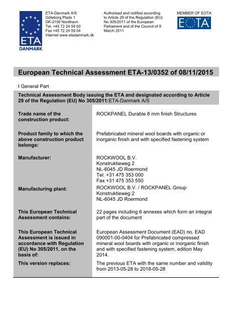
European Technical Assessment ETA-13/0352 of 08/11/2015
ETA130352 ROCKPANEL Structure 8 mm - ETA-Danmark
ETA130352 ROCKPANEL Structure 8 mm - ETA-Danmark

Create successful ePaper yourself
Turn your PDF publications into a flip-book with our unique Google optimized e-Paper software.
<strong>ETA</strong>-Danmark A/S<br />
Göteborg Plads 1<br />
DK-2150 Nordhavn<br />
Tel. +45 72 24 59 00<br />
Fax +45 72 24 59 04<br />
Internet www.etadanmark.dk<br />
Authorised and notified according<br />
to Article 29 <strong>of</strong> the Regulation (EU)<br />
No 305/20<strong>11</strong> <strong>of</strong> the <strong>European</strong><br />
Parliament and <strong>of</strong> the Council <strong>of</strong> 9<br />
March 20<strong>11</strong><br />
MEMBER OF EOTA<br />
<strong>European</strong> <strong>Technical</strong> <strong>Assessment</strong> <strong>ETA</strong>-<strong>13</strong>/<strong>0352</strong> <strong>of</strong> <strong>08</strong>/<strong>11</strong>/<strong>2015</strong><br />
I General Part<br />
<strong>Technical</strong> <strong>Assessment</strong> Body issuing the <strong>ETA</strong> and designated according to Article<br />
29 <strong>of</strong> the Regulation (EU) No 305/20<strong>11</strong>:<strong>ETA</strong>-Danmark A/S<br />
Trade name <strong>of</strong> the<br />
construction product:<br />
ROCKPANEL Durable 8 mm finish Structures<br />
Product family to which the<br />
above construction product<br />
belongs:<br />
Prefabricated mineral wool boards with organic or<br />
inorganic finish and with specified fastening system<br />
Manufacturer:<br />
Manufacturing plant:<br />
This <strong>European</strong> <strong>Technical</strong><br />
<strong>Assessment</strong> contains:<br />
ROCKWOOL B.V.<br />
Konstruktieweg 2<br />
NL-6045 JD Roermond<br />
Tel. +31 475 353 000<br />
Fax +31 475 353 550<br />
ROCKWOOL B.V. / ROCKPANEL Group<br />
Konstruktieweg 2<br />
NL-6045 JD Roermond<br />
22 pages including 6 annexes which form an integral<br />
part <strong>of</strong> the document<br />
This <strong>European</strong> <strong>Technical</strong><br />
<strong>Assessment</strong> is issued in<br />
accordance with Regulation<br />
(EU) No 305/20<strong>11</strong>, on the<br />
basis <strong>of</strong>:<br />
This version replaces:<br />
<strong>European</strong> <strong>Assessment</strong> Document (EAD) no. EAD<br />
090001-00-0404 for Prefabricated compressed<br />
mineral wool boards with organic or inorganic finish<br />
and with specified fastening system, edition May<br />
2014.<br />
The previous <strong>ETA</strong> with the same number and validity<br />
from 20<strong>13</strong>-05-28 to 2018-05-28
Page 2 <strong>of</strong> 22 <strong>of</strong> <strong>European</strong> <strong>Technical</strong> <strong>Assessment</strong> no. <strong>ETA</strong>-<strong>13</strong>/<strong>0352</strong>, issued on <strong>2015</strong>-<strong>08</strong>-<strong>11</strong><br />
Translations <strong>of</strong> this <strong>European</strong> <strong>Technical</strong> <strong>Assessment</strong> in<br />
other languages shall fully correspond to the original<br />
issued document and should be identified as such.<br />
Communication <strong>of</strong> this <strong>European</strong> <strong>Technical</strong><br />
<strong>Assessment</strong>, including transmission by electronic<br />
means, shall be in full (excepted the confidential<br />
Annex(es) referred to above). However, partial<br />
reproduction may be made, with the written consent <strong>of</strong><br />
the issuing <strong>Technical</strong> <strong>Assessment</strong> Body. Any partial<br />
reproduction has to be identified as such.
Page 3 <strong>of</strong> 22 <strong>of</strong> <strong>European</strong> <strong>Technical</strong> <strong>Assessment</strong> no. <strong>ETA</strong>-<strong>13</strong>/<strong>0352</strong>, issued on <strong>2015</strong>-<strong>08</strong>-<strong>11</strong><br />
II<br />
SPECIFIC PART OF THE<br />
EUROPEAN TECHNICAL<br />
ASSESSMENT<br />
1 <strong>Technical</strong> description <strong>of</strong> product and<br />
intended use<br />
<strong>Technical</strong> description <strong>of</strong> the product<br />
General<br />
ROCKPANEL Durable 8 mm finish Structure is<br />
prefabricated compressed mineral wool boards with<br />
thermo-setting synthetic binders. The boards are<br />
fastened to timber, aluminum or steel subframes.<br />
Fastening to the timber subframe is carried out with<br />
corrosion resistant nails or screws. Fastening to<br />
aluminum or steel subframe is carried out with corrosion<br />
resistant rivets.<br />
Mechanical fasteners, gaskets and aluminum pr<strong>of</strong>iles<br />
are specified by the <strong>ETA</strong>-holder.<br />
The ROCKPANEL Durable Structure panels are<br />
surface treated with a three-layer water-borne polymer<br />
emulsion paint on one side, in a limited range <strong>of</strong><br />
colours.<br />
The physical properties <strong>of</strong> the panels are indicated in<br />
table 1.<br />
Table 1<br />
Property<br />
Value<br />
Thickness and tolerances 8 ± 0,5mm<br />
Length, max<br />
3050 mm<br />
Width, max<br />
1250 mm<br />
Density, nominal and tolerances 1050 ±150 kg/m 3<br />
Bending strength, length and width f 05 27 N/mm 2<br />
Modulus <strong>of</strong> elasticity m(E) ≥ 4015<br />
N/mm 2<br />
Thermal conductivity EN 10456 0,37 W/(m • K)<br />
Cumulative dimensional change<br />
according to EN 438-2<br />
Length: ≤ 0,<strong>08</strong>5<br />
%<br />
Width: ≤ 0,<strong>08</strong>4 %<br />
Coefficient <strong>of</strong> thermal expansion, = 10,5<br />
length and width<br />
Coefficient <strong>of</strong> moisture expansion<br />
23 C/50 %RH to 95 %RH<br />
10 -6 °K -1<br />
≤ 0,302 mm/m<br />
after 4 days<br />
Finishes<br />
The finish is indicated in table 2. The coatings are<br />
provided in a number <strong>of</strong> colours.<br />
Table 2 Finish ROCKPANEL Durable boards<br />
ROCKPANEL Durable Structure: Organic colour<br />
(water-borne polymer emulsion coating<br />
paint)<br />
The colourfastness <strong>of</strong> the panels is indicated in table 3.<br />
Table 3 Colourfastness ROCKPANEL Colours<br />
Property Value (ISO 105 A02)<br />
Colour fastness after RAL 7005, 7016, 7021,<br />
5000 hours artificial 7024, 7035 and 9010: 3-4<br />
weathering<br />
or better<br />
(TR010 Class S)<br />
Subframes<br />
The panels are attached to the building by fixing to a<br />
sub-frame <strong>of</strong> aluminum, steel or wood.<br />
The vertical battens should have a minimum thickness<br />
<strong>of</strong> 28 mm (solid wood).<br />
Also LVL battens (Laminated Veneer Lumber) with a<br />
minimum thickness <strong>of</strong> 27 mm, according to EN 14374,<br />
can be used (Ultralam R, CE 0672-CPD-I)<br />
Appropriate preservative treatment <strong>of</strong> subframes<br />
Use the appropriate part <strong>of</strong> EN 335 to identify the "use class"<br />
<strong>of</strong> a given service environment and geographical location.<br />
Table 1 in EN 335 will assist in determining the biological<br />
agents that can attack timber in certain situations. The user<br />
can then consider the type and duration <strong>of</strong> performance<br />
required select an appropriate level <strong>of</strong> durability and ensure<br />
that the timber or wood-based product specified has either, as<br />
a natural (see EN 350-2) or an acquired characteristic<br />
durability as the result <strong>of</strong> appropriate preservative treatment<br />
(see EN 351-1).<br />
The minimum thickness <strong>of</strong> the vertical aluminum<br />
pr<strong>of</strong>iles is 1,5 mm. The aluminum is AW-6060<br />
according to EN 755-2. The R m/R p0,2 value is 170/140<br />
for pr<strong>of</strong>ile T6 and 195/150 for pr<strong>of</strong>ile T66.<br />
The minimum thickness <strong>of</strong> the vertical steel pr<strong>of</strong>iles is<br />
either 1,0 mm [a] ( steel quality is S320GD +Z EN<br />
10346 number 1.0250 , or equivalent for cold forming),<br />
or 1,5 mm [a] (steel quality EN 10025-2:2004 S235JR<br />
number 1.0038).<br />
[a] The minimum coating thickness (Z or ZA) is determined<br />
by the corrosion rate (amount <strong>of</strong> corrosion loss in thickness<br />
per year) which depends on the specific outdoor atmospheric<br />
environment.<br />
The Zinc Life Time Predictor can be used to calculate the<br />
Corrosion Rate in m/y for a Z coating:<br />
http://www.galvinfo.com:8<strong>08</strong>0/zclp/ [copyright The International Zinc<br />
association].<br />
The coating designation (classification which determines the<br />
coating mass) shall be agreed between the contractor and the<br />
building owner.<br />
Alternatively a hot dip galvanized coating according to EN<br />
ISO 1461 can be used.
Page 4 <strong>of</strong> 22 <strong>of</strong> <strong>European</strong> <strong>Technical</strong> <strong>Assessment</strong> no. <strong>ETA</strong>-<strong>13</strong>/<strong>0352</strong>, issued on <strong>2015</strong>-<strong>08</strong>-<strong>11</strong><br />
Joints<br />
Aluminum pr<strong>of</strong>iles<br />
The horizontal joints between the panels can be open in<br />
the case <strong>of</strong> ROCKPANEL strips or EPDM foam gasket.<br />
The horizontal joints between the panels are made with<br />
a ROCKPANEL “A” extruded aluminum chair pr<strong>of</strong>ile<br />
or equivalent in the case <strong>of</strong> panels mechanically fixed<br />
on timber battens. The chair pr<strong>of</strong>ile has an overlap <strong>of</strong> at<br />
least 15 mm on the board above the pr<strong>of</strong>ile. See annex<br />
1.<br />
Foam gasket<br />
A 3 mm thick EPDM foam gasket (self-adhering<br />
backside) is fixed to the timber battens. If the horizontal<br />
joint is closed with an aluminum chair pr<strong>of</strong>ile, the<br />
vertical joint is backed with the 60 mm wide gasket and<br />
for the intermediate battens the 36 mm gasket is used.<br />
In the case <strong>of</strong> open horizontal joints the width <strong>of</strong> the<br />
gasket 15 mm at both sides wider than the batten.<br />
Fasteners<br />
The panels are mechanically fixed either to vertical<br />
timber or metal subframe. The mechanical fastening to<br />
timber battens is carried out with either ROCKPANEL<br />
stainless steel screws 4,5 35 mm no 1.4401 or 1.4578<br />
(EN 10<strong>08</strong>8) with heads in the colour <strong>of</strong> the panels or<br />
ROCKPANEL ring shank nails 2,7/2,9 32 mm or 40<br />
mm no 1.4401 or 1.4578 (EN 10<strong>08</strong>8) with heads in the<br />
colour <strong>of</strong> the panels.<br />
Fastening to aluminum is carried out with aluminum EN<br />
AW-5019 (AIMg5) rivets, head diameter 14 mm, shank<br />
diameter 5 mm, head colour coated. The mechanical<br />
fastening to steel subframe is carried out with either EN<br />
10<strong>08</strong>8 (no 1.4578) rivets, head diameter 15 mm, body<br />
diameter 5 mm, head colour coated, or EN 10<strong>08</strong>8 (no<br />
1.4567) rivets, head diameter 14 mm, body diameter 5<br />
mm, head colour coated.<br />
For correct fixing, a riveting tool with rivet spacer<br />
must be used, see Annex 2 Table 7 and Annex 3 Table<br />
8.3.<br />
The installation method with the use <strong>of</strong> fixed points and<br />
moving points appears from table 7 and figure 8.<br />
2 Specification <strong>of</strong> the intended use in<br />
accordance with the applicable EAD<br />
The boards are intended for external cladding and for<br />
fascias and s<strong>of</strong>fits. The cladding on vertical timber<br />
battens with mechanically fixed boards can be carried<br />
out with or without ventilated cavities at the back. The<br />
cladding on vertical aluminum or steel support shall be<br />
carried out with a ventilated cavity at the back. See<br />
annex 1.<br />
The provisions made in this <strong>European</strong> <strong>Technical</strong><br />
<strong>Assessment</strong> are based on an assumed intended working<br />
life <strong>of</strong> the kit <strong>of</strong> 50 years.<br />
In additition, for aluminum support systems intended to<br />
be used for facades:<br />
In some member states national climate conditions may<br />
reduce the service life <strong>of</strong> the aluminum support system<br />
to 35 years or more.<br />
An additional assessment <strong>of</strong> the aluminum support<br />
system might be necessary to comply with Member<br />
State regulations or administrative provisions.<br />
The indications given on the working life cannot be<br />
interpreted as a guarantee given by the producer or<br />
<strong>Assessment</strong> Body, but are to be regarded only as a<br />
means for choosing the right products in relation to the<br />
expected economically reasonable working life <strong>of</strong> the<br />
works.<br />
Fastening to steel is carried out with stainless steel EN<br />
10<strong>08</strong>8 no 1.4578 rivets head diameter 15 mm or EN<br />
10<strong>08</strong>8 no. 1.4567 rivets, head diameter 14 mm, shank<br />
diameter 5 mm, head colour coated. (for correct fixing,<br />
a riveting tool with rivet spacer must be used), see<br />
Annex 2 Table 7 and Annex 3 Table 8.3<br />
The maximum fixing distances, edge distances, hole<br />
diameter and design value <strong>of</strong> the axial load appear from<br />
annex 2, tables 5, 6 and 7.
Page 5 <strong>of</strong> 22 <strong>of</strong> <strong>European</strong> <strong>Technical</strong> <strong>Assessment</strong> no. <strong>ETA</strong>-<strong>13</strong>/<strong>0352</strong>, issued on <strong>2015</strong>-<strong>08</strong>-<strong>11</strong><br />
3 Performance <strong>of</strong> the product and references to the methods used for its assessment<br />
Characteristic<br />
<strong>Assessment</strong> <strong>of</strong> characteristic<br />
3.2 Safety in case <strong>of</strong> fire (BWR 2)<br />
Reaction to fire<br />
The aluminum pr<strong>of</strong>iles are classified as Euroclass A1<br />
Classification <strong>of</strong> panels: See table 4<br />
3.3 Hygiene, health and the environment<br />
(BWR 3)<br />
Content, emission and/or release <strong>of</strong><br />
dangerous substances<br />
Water vapour permeability<br />
Water permeability incl. joints for nonventilated<br />
applications<br />
Use category: Outdoor S/W2<br />
The kit does not contain/release dangerous substances<br />
specified in TR 034, dated April 20<strong>13</strong>*), except<br />
Formaldehyde concentration 0,0105 mg/m 3 Formaldehyde<br />
class E1<br />
The used fibres are not potential carcinogenic<br />
No biocides are used in the ROCKPANEL boards<br />
No flame retardant is used in the boards<br />
No cadmium is used in the boards.<br />
Durable Structure: S d < 1,30 m at 23C and 85 %RH<br />
The designer shall consider the relevant needs for ventilation,<br />
heating and insulation to minimise condensation in service.<br />
No Performance determined<br />
3.4 Safety and accessibility in use (BWR 4)<br />
In absence <strong>of</strong> national regulations the design values X d may be calculated as indicated in the <strong>ETA</strong> (see tables<br />
6-1 up to and including 6-4). Below is mentioned the safety factors which has been used in the calculation <strong>of</strong><br />
the design values.<br />
Fixing position and design value X d <strong>of</strong> the<br />
axial load M/E/C (Middle/Edge/Corner) <strong>of</strong><br />
mechanical fixings corresponding to the<br />
wind load resistance (load acting<br />
perpendicular to the façade)<br />
Remark:<br />
Design value X d obtained by dividing the<br />
characteristic value X k by a<br />
partial factor M : X d = X k / M<br />
The design value X d <strong>of</strong> a material property<br />
can be expressed in general terms as X d =<br />
× X k / m ; m ROCKPANEL = 1,6;<br />
conversion factor = 0,8 (aged bending<br />
strength divided by the f 05 (Table 9, Annex<br />
4))<br />
ROCKPANEL rivets:<br />
To an aluminum subframe:<br />
design value X d : 654/309/156 N,<br />
see Annex 2 Table 6-1 row (16)<br />
ROCKPANEL screws:<br />
Design value X d depends on the modification factor k mod , the<br />
strength class <strong>of</strong> the wood and the different material factors<br />
γ M .<br />
Boards to a solid timber subframe: see Annex 2 Tables 6-2<br />
and 6-3, row (25), (26) and (27).<br />
ROCKPANEL nails:<br />
Design value X d depends on the modification factor k mod , the<br />
strength class <strong>of</strong> the wood and the different material factors<br />
γ M .<br />
Boards to a solid timber subframe see Annex 2 Table 6-4,<br />
row (25), (26) and (27).<br />
Shear strength mechanical fixings<br />
Characteristic values<br />
ROCKPANEL nails:<br />
Failure load: <strong>13</strong>25 N Deformation: 15 mm<br />
ROCKPANEL rivets:<br />
Failure load: 1722 N Deformation: 1,7 mm<br />
ROCKPANEL screws:<br />
Failure load: 1549 N Deformation: 9 mm
Page 6 <strong>of</strong> 22 <strong>of</strong> <strong>European</strong> <strong>Technical</strong> <strong>Assessment</strong> no. <strong>ETA</strong>-<strong>13</strong>/<strong>0352</strong>, issued on <strong>2015</strong>-<strong>08</strong>-<strong>11</strong><br />
Characteristic<br />
<strong>Assessment</strong> <strong>of</strong> characteristic<br />
Impact resistance<br />
For definition <strong>of</strong> use category see Annex 6<br />
Table 12<br />
Panels without a horizontal joint<br />
Panels with a horizontal joint ready<br />
accessible and vulnerable to impacts<br />
Dimensional stability<br />
Cumulative dimensional change %<br />
Coefficient <strong>of</strong> thermal expansion 10 -6 °K -1<br />
Coefficient <strong>of</strong> moisture expansion 42% RH<br />
difference after 4 days mm/m<br />
Hard body impact - steel ball 0,5 kg (1J): Categoy IV<br />
Hard body impact – steel ball 0,5 kg (3J): Category III, II<br />
and I<br />
Hard body impact – steel ball 1 kg (10J): Category II and I<br />
S<strong>of</strong>t body impact 3 kg (10J): Category IV and III<br />
S<strong>of</strong>t body impact 3 kg (60J): Category II and I<br />
S<strong>of</strong>t body impact 50 kg (300J): Category II<br />
Hard body impact - steel ball 0,5 kg (1J): Category IV<br />
Hard body impact – steel ball 0,5 kg (3J): Category III, II and<br />
I<br />
Length: 0,<strong>08</strong>5 / Width: 0,<strong>08</strong>4<br />
Length: 10,5 / Width: 10,5<br />
Length: 0,288 / Width: 0,317<br />
Wind load resistance M/E/C<br />
Average strength, N Rivets: 1449 / 617 / 3<strong>11</strong>(according to Annex 2 Table 6-1)<br />
Screws: <strong>11</strong>05 / 482 /236 (according to Annex 2 Table 6-2 and<br />
Annex A-3 Table 6-3)<br />
Nails: 1009 / 627 / 397 (according to Annex 2 Table 6-4)<br />
Average failure load N/m² Rivets: 2567 / 2769 / 2958 (according to Annex 2 Table 6-1)<br />
Screws: 1992 / 2161 / 2243 (according to Annex 2 Table 6-<br />
2)<br />
Nails : 2637 / 4<strong>13</strong>1 / 5162 (according to Annex 2 Table 6-4)<br />
Mechanical resistance <strong>of</strong> panels See section 1, table 1<br />
Resistance to Hygrothermal cycles<br />
Pass<br />
3.7 Sustainable use <strong>of</strong> natural resources<br />
(BWR 7)<br />
No performance determined<br />
3.8 Aspects <strong>of</strong> durability<br />
Resistance to Xenon Arc exposure<br />
Pass<br />
*) In addition to the specific clauses relating to dangerous substances contained in this <strong>European</strong> technical <strong>Assessment</strong>, there may be other requirements applicable<br />
to the products falling within its scope (e.g. transposed <strong>European</strong> legislation and national laws, regulations and administrative provisions). In order to meet the<br />
provisions <strong>of</strong> the Construction Products Regulation, these requirements need also to be complied with, when and where they apply.
Page 7 <strong>of</strong> 22 <strong>of</strong> <strong>European</strong> <strong>Technical</strong> <strong>Assessment</strong> no. <strong>ETA</strong>-<strong>13</strong>/<strong>0352</strong>, issued on <strong>2015</strong>-<strong>08</strong>-<strong>11</strong><br />
Table 4 Reaction to fire classification<br />
The panels have been classified in accordance with EN <strong>13</strong>501-1 with the following parameters:<br />
Table 4 Euroclass classification <strong>of</strong> different constructions with ROCKPANEL Durable Structure boards<br />
Fixing<br />
method<br />
Ventilated or non-ventilated vertical wooden subframe vertical metal subframe<br />
Non-ventilated.<br />
Cavity filled with mineral wool<br />
Ventilated with EPDM gasket on<br />
the battens [a]<br />
mechanically Ventilated with 6 or 8 mm<br />
fixed ROCKPANEL strips on the battens<br />
[b]<br />
Ventilated with 8 mm<br />
ROCKPANEL strips on the battens<br />
[b]<br />
[a] width <strong>of</strong> the gasket 15 mm at both sides wider than the batten<br />
[b] width <strong>of</strong> the strip 15 mm at both sides wider than the batten<br />
[c] also valid for a mixture <strong>of</strong> the colours white and black<br />
B-s1,d0<br />
Closed 6 mm horizontal joint<br />
B-s2,d0<br />
open 6 mm horizontal joint<br />
B-s2,d0<br />
open 6 mm horizontal joint<br />
B-s1,d0<br />
open 6 mm horizontal joint<br />
for finish white and black [c]<br />
See ‘Subframe’ in ‘Field <strong>of</strong><br />
Application’<br />
Field <strong>of</strong> application<br />
Further to the limitations described in section 1 <strong>of</strong> the<br />
<strong>ETA</strong>, the following field <strong>of</strong> application applies.<br />
Euroclass classification<br />
The classification mentioned in table 4 is valid for the<br />
following end use conditions:<br />
Mounting:<br />
Mechanically fixed as described in table 4, which<br />
are attached to the subframe mentioned below<br />
The panels are backed with min. 50 mm mineral<br />
wool insulation with density 30-70 kg/m³ according to<br />
EN <strong>13</strong>162 with a cavity between the panels and the<br />
insulation (mechanically fixed)<br />
The panels are backed with min. 40 mm mineral<br />
wool insulation with density 30-70 kg/m³ according<br />
to EN <strong>13</strong>162 without an air gap between the wooden<br />
subframe (mechanically fixed – non ventilated)<br />
Substrates:<br />
Concrete walls, masonry walls, timber framing<br />
Insulation:<br />
Ventilated constructions: The battens are backed<br />
with min. 50 mm mineral wool insulation with<br />
density 30-70 kg/m³ according to EN <strong>13</strong>162 with a cavity<br />
<strong>of</strong> min. 28 mm between the panels and the insulation<br />
Non-ventilated constructions: The panels are<br />
backed with min. 40 mm mineral wool insulation<br />
with 30-70 kg/m³ between the battens and min. 50<br />
mm with density 30-70 kg/m³ behind the battens<br />
without air gap<br />
Results are also valid for all greater thickness <strong>of</strong><br />
mineral wool insulation layer with the same density<br />
and the same or better reaction to fire classification<br />
The test result <strong>of</strong> a test with mineral wool insulation<br />
shall be valid, without test, for the same type <strong>of</strong><br />
panel used without insulation, if the substrate<br />
chosen according to EN <strong>13</strong>238 is made <strong>of</strong> panel with<br />
Euro-class A1 or A2 (e.g. fibres-cement panel).<br />
Subframe:<br />
Vertical s<strong>of</strong>twood battens without fire retardant<br />
treatment, thickness minimum 28 mm<br />
Test results are also valid for the same type <strong>of</strong> panel<br />
with aluminum or steel frame (without the use <strong>of</strong><br />
strips)<br />
Test results are also valid for the same type <strong>of</strong> panel<br />
with vertical LVL battens, without fire retardant<br />
treatment, thickness minimum 27 mm<br />
Fixings:<br />
Results are also valid with higher density <strong>of</strong> the<br />
fixing devices<br />
Test results are also valid for the same type <strong>of</strong> panel<br />
fixed by rivets made <strong>of</strong> the same material <strong>of</strong> screws<br />
and vice versa<br />
Cavity:<br />
Unfilled or filled with insulation <strong>of</strong> stone wool with<br />
a nominal density 30-70 kg/m³ according to EN<br />
<strong>13</strong>162<br />
The depth <strong>of</strong> the cavity is minimum 28 mm<br />
Test results are also valid for other higher thickness<br />
<strong>of</strong> air space between the back <strong>of</strong> the board and the<br />
insulation<br />
Joints:<br />
Vertical joints are with an EPDM foam gasket<br />
backing or ROCKPANEL strip backing as<br />
described in table 4 and horizontal joints can be<br />
open (ventilated constructions) or with an aluminum<br />
pr<strong>of</strong>ile (ventilated and non-ventilated constructions)<br />
The result from a test with an open horizontal joint<br />
is also valid for the same type <strong>of</strong> panel used in<br />
applications with horizontal joints closed by steel or<br />
aluminum pr<strong>of</strong>iles
Page 8 <strong>of</strong> 22 <strong>of</strong> <strong>European</strong> <strong>Technical</strong> <strong>Assessment</strong> no. <strong>ETA</strong>-<strong>13</strong>/<strong>0352</strong>, issued on <strong>2015</strong>-<strong>08</strong>-<strong>11</strong><br />
The classification is also valid for the following product<br />
parameters:<br />
Thickness:<br />
Nominal 8mm, individual tolerances ± 0,5 mm<br />
Density<br />
Nominal 1050 kg/m 3 , individual tolerances± 150<br />
kg/m 3<br />
Aspects related to the performance <strong>of</strong> the product<br />
All materials shall be manufactured by ROCKWOOL<br />
B.V. or by subcontractors under the responsibility <strong>of</strong><br />
ROCKWOOL B.V.<br />
The <strong>European</strong> <strong>Technical</strong> <strong>Assessment</strong> is issued for the<br />
product on the basis <strong>of</strong> agreed data/information,<br />
deposited with <strong>ETA</strong>-Danmark, which describes the<br />
product that has been assessed and judged. Changes to<br />
the product or production process, which could result in<br />
this deposited data/information being incorrect, should<br />
be notified to <strong>ETA</strong>-Danmark before the changes are<br />
introduced. <strong>ETA</strong>-Danmark will decide whether or not<br />
such changes affect the <strong>ETA</strong> and consequently the<br />
validity <strong>of</strong> the CE marking on the basis <strong>of</strong> the <strong>ETA</strong> and<br />
if so whether further assessment or alterations to the<br />
<strong>ETA</strong>, shall be necessary.<br />
Installation details and application details for the man on<br />
site are given by ROCKWOOL B.V. / ROCKPANEL<br />
Group in the manufacturer’s application guide technical<br />
dossier which forms part <strong>of</strong> the documentary material<br />
for this <strong>ETA</strong>. On every pallet label and/or on the<br />
protective film <strong>of</strong> every board the website is printed<br />
which guides the end user to the most actual<br />
information.<br />
The boards for external cladding shall not be fixed over<br />
building or settlement joints. Where settlement joints are<br />
located in the building the same movements <strong>of</strong> the<br />
building and substructure shall be possible in the<br />
external cladding.<br />
The water diffusion resistance <strong>of</strong> the boards is declared<br />
as a means for the designer to decide whether they are<br />
sufficiently vapour permeable, especially when used for<br />
cladding without ventilated cavities at the back. The<br />
designer can then establish that condensation in the<br />
entire wall as a result <strong>of</strong> water vapour diffusion will not<br />
occur or will occur only to an extent where damage is<br />
not caused during the condensation period and the wall<br />
will dry out again during the evaporation period. The<br />
designer shall consider the critical moisture content for<br />
all the integrated materials.<br />
For non-ventilated intended use, the pressure level<br />
preceding the pressure level where leakage occurs is<br />
declared as a means for the designer to decide on the<br />
necessity <strong>of</strong> the use <strong>of</strong> a vapour control membrane.<br />
The panels should not be taken into account when<br />
designing a timber stud wall to resist racking forces.<br />
The holes for the fixings are drilled into the panels not<br />
less than 15 mm from a vertical edge and 50 mm from a<br />
horizontal edge (see Annex 2). The panels are fixed<br />
making sure that the screws are not over-tightened.<br />
For non-ventilated use, the substrate shall be airtight.<br />
The boards are in general mounted with a joint width <strong>of</strong><br />
between 5 and 8 mm.<br />
If the joints are to be sealed, only durable sealants should<br />
be used with a good adhesion on the edges <strong>of</strong> the boards<br />
and a good UV-stability. To prevent sticking to the<br />
subframe, a PE-film or tape can be used.<br />
The cladding kit shall be designed and installed so that<br />
water which penetrates in the air space or condensation<br />
water shall be drained out <strong>of</strong> the installed kit without<br />
accumulation or moisture damage or leakage into the<br />
substrate or the wall cladding kit
Page 9 <strong>of</strong> 22 <strong>of</strong> <strong>European</strong> <strong>Technical</strong> <strong>Assessment</strong> no. <strong>ETA</strong>-<strong>13</strong>/<strong>0352</strong>, issued on <strong>2015</strong>-<strong>08</strong>-<strong>11</strong><br />
4 Attestation and verification <strong>of</strong> constancy<br />
<strong>of</strong> performance (AVCP)<br />
4.1 AVCP system<br />
According to the decision 2003/640/EC <strong>of</strong> the <strong>European</strong><br />
Commission as amended, the system(s) <strong>of</strong> assessment<br />
and verification <strong>of</strong> constancy <strong>of</strong> performance (see Annex<br />
V to Regulation (EU) No 305/20<strong>11</strong>) is 1, since there is a<br />
clearly identifiable stage in their production which results<br />
in an improvement <strong>of</strong> fire performance due to the limiting<br />
<strong>of</strong> organic material.<br />
5 <strong>Technical</strong> details necessary for the<br />
implementation <strong>of</strong> the AVCP system, as<br />
foreseen in the applicable EAD<br />
<strong>Technical</strong> details necessary for the implementation <strong>of</strong> the<br />
AVCP system are laid down in the control plan deposited<br />
at <strong>ETA</strong>-Danmark<br />
Issued in Copenhagen on <strong>2015</strong>-<strong>08</strong>-<strong>11</strong> by<br />
Thomas Bruun<br />
Managing Director, <strong>ETA</strong>-Danmark
Page 10 <strong>of</strong> 22 <strong>of</strong> <strong>European</strong> <strong>Technical</strong> <strong>Assessment</strong> no. <strong>ETA</strong>-<strong>13</strong>/<strong>0352</strong>, issued on <strong>2015</strong>-<strong>08</strong>-<strong>11</strong><br />
Annex 1<br />
Pre-fabricated compressed mineral wool boards with organic or inorganic finish<br />
Figure 1a. Ventilated intended use on vertical timber battens<br />
1<br />
7<br />
7<br />
5b<br />
6<br />
5a<br />
1. Compressed mineral wool board with<br />
organic or inorganic finish<br />
2. EPDM foam gasket<br />
3. Timber beam<br />
4. Vapour barrier<br />
5. Batten: a - joint and b - intermediate<br />
6. Insulation<br />
7. ROCKPANEL “A” – 8 mm extruded<br />
aluminum chairpr<strong>of</strong>ile or equivalent<br />
2<br />
3<br />
Figure 1b. Non ventilated intended use on vertical timber battens<br />
1<br />
6<br />
4<br />
7<br />
6<br />
5a<br />
2<br />
3
Page <strong>11</strong> <strong>of</strong> 22 <strong>of</strong> <strong>European</strong> <strong>Technical</strong> <strong>Assessment</strong> no. <strong>ETA</strong>-<strong>13</strong>/<strong>0352</strong>, issued on <strong>2015</strong>-<strong>08</strong>-<strong>11</strong><br />
Figure 2. Ventilated intended use on vertical metal subframe<br />
1. Compressed mineral wool<br />
board with organic or<br />
inorganic finish<br />
2. Rivet fixing
Page 12 <strong>of</strong> 22 <strong>of</strong> <strong>European</strong> <strong>Technical</strong> <strong>Assessment</strong> no. <strong>ETA</strong>-<strong>13</strong>/<strong>0352</strong>, issued on <strong>2015</strong>-<strong>08</strong>-<strong>11</strong><br />
Annex 2<br />
a 1 b<br />
b a 1<br />
C<br />
E<br />
a 2<br />
a<br />
C: Fixing in corner<br />
E: Fixing at edge<br />
M: Fixing at intermediate position<br />
See Figure 8 for examples <strong>of</strong> possible<br />
installation methods<br />
E<br />
M<br />
Remark<br />
Rivet fixing only with a riveting tool with rivet<br />
spacer<br />
Table 5: Minimum edge distances and maximum distances between fastenings in mm<br />
Fixing type b max a max a 1 a 2<br />
Screw 600 600 15 50<br />
Nail 600 400 15 50<br />
Rivet 600 600 15 50<br />
Adhesive 600 Continuously applied triangular adhesive ridge <strong>of</strong> 9 mm<br />
Table 6: Design axial load X d = X k / M for 8 mm board fixings<br />
The characteristic wind load must be multiplied with F = 1,5<br />
Fixing type<br />
Position M Position E Position C<br />
Rivet [a] according to table 6.1 654 N 309 N 156 N<br />
Screw and board fixing see Table 6-2 row (25), (26), (27)<br />
Screw and the use <strong>of</strong> a 8 mm ROCKPANEL strip [b] see Table 6-3 row (25), (26), (27)<br />
Nail see Table 6-4 row (25), (26), (27)<br />
[a] For correct fixing, a riveting tool with rivet spacer must be used<br />
[b] With reduced withdrawal capacity because <strong>of</strong> the effective length l eff <strong>of</strong> the threaded part
Page <strong>13</strong> <strong>of</strong> 22 <strong>of</strong> <strong>European</strong> <strong>Technical</strong> <strong>Assessment</strong> no. <strong>ETA</strong>-<strong>13</strong>/<strong>0352</strong>, issued on <strong>2015</strong>-<strong>08</strong>-<strong>11</strong><br />
Table 6-1: Characteristic axial load X k and design value <strong>of</strong> the axial load X d = X k / γ M<br />
for the combination rivet and 8 mm boards<br />
board thickness 8 mm (1)<br />
location <strong>of</strong> the fixing in the board M-middle E-edge C-corner (2)<br />
pull-through N (3)<br />
characteristic pull-through N <strong>13</strong><strong>08</strong> 810 540 (4)<br />
material factor ROCKPANEL γ M 2,0 2,0 2,0 (5)<br />
design value X d <strong>of</strong> the pull-through N 654 405 270 (6)<br />
wind suction (7)<br />
average wind load in N/m² 2567 2769 2958 (8)<br />
average strength N 1449 617 3<strong>11</strong> (9)<br />
material factor ROCKPANEL γ M 2,0 2,0 2,0 (10)<br />
design value X d <strong>of</strong> the pull-through N 725 309 156 (<strong>11</strong>)<br />
pull-out strength (12)<br />
manufacturer’s declaration N <strong>13</strong>00 <strong>13</strong>00 <strong>13</strong>00 (<strong>13</strong>)<br />
material factor aluminum γ M 1,3 1,3 1,3 (14)<br />
design value X d <strong>of</strong> the pull-out N 1000 1000 1000 (15)<br />
design value <strong>of</strong> the axial load X d = X k / γ M for the<br />
combination rivet and 8 mm boards<br />
654 309 156 (16)<br />
board span b 600 (17)<br />
fixing distance a 600 (18)<br />
[a] For correct fixing, a riveting tool with rivet spacer must be used
Page 14 <strong>of</strong> 22 <strong>of</strong> <strong>European</strong> <strong>Technical</strong> <strong>Assessment</strong> no. <strong>ETA</strong>-<strong>13</strong>/<strong>0352</strong>, issued on <strong>2015</strong>-<strong>08</strong>-<strong>11</strong><br />
Table 6-2: Characteristic axial load X k and design value <strong>of</strong> the axial load X d = X k / γ M for the combination solid<br />
timber, screw and 8 mm boards (with the use <strong>of</strong> gaskets), with α ≥ 30° [e]<br />
board thickness 8 mm (with the use <strong>of</strong> a gasket) (1)<br />
location <strong>of</strong> the fixing in the board M-middle E-edge C-corner (2)<br />
pull-through N (3)<br />
characteristic pull-through N 1066 850 617 (4)<br />
material factor ROCKPANEL γ M (manufacturers<br />
declaration)<br />
2,0 2,0 2,0 (5)<br />
design value X d <strong>of</strong> the pull-through N 533 425 309 (6)<br />
wind suction (7)<br />
average wind load in N/m² 1992 2161 2243 (8)<br />
average strength N <strong>11</strong>05 482 236 (9)<br />
material factor ROCKPANEL γ M (manufacturers<br />
declaration)<br />
2,0 2,0 2,0 (10)<br />
design value X d <strong>of</strong> the pull-through N 553 241 <strong>11</strong>8 (12)<br />
withdrawal capacity (<strong>13</strong>)<br />
characteristic withdrawal capacity F ax,k,Rk [b] [c] [d] (14)<br />
strength class C18 ρ k = 320 kg/m 3 858 [b] 858 [b] 858 [b] (15)<br />
wood (EN 338) C24 ρ k = 350 kg/m 3 922 [b] 922 [b] 922 [b] (16)<br />
modification factor for k mod k mod [a] (17)<br />
axial withdrawal capacity F ax,k,Rk . k mod [a] [b] [c] [d] (18)<br />
strength class C18 ρ k = 320 kg/m 3 858 • k mod 858 • k mod 858 • k mod (19)<br />
wood (EN 338) C24 ρ k = 350 kg/m 3 922 • k mod 922 • k mod 922 • k mod (20)<br />
material factor (NA to) EN 1995-1-<br />
1:2004+A1:20<strong>08</strong><br />
γ M = 1,30 [withdrawal capacity] (21)<br />
design value X d <strong>of</strong> the axial withdrawal<br />
capacity N<br />
(22)<br />
strength class C18 ρ k = 320 kg/m 3 660 • k mod 660 • k mod 660 • k mod (23)<br />
wood (EN 338) C24 ρ k = 350 kg/m 3 709 • k mod 709 • k mod 709 • k mod (24)<br />
design value <strong>of</strong> the axial load X d= X k / γ M N minimum value <strong>of</strong> the rows: (25)<br />
strength class C18 ρ k = 320 kg/m 3 (6) (12) (23) (6) (12) (23) (6) (12) (23) (26)<br />
wood (EN 338) C24 ρ k = 350 kg/m 3 (6) (12) (24) (6) (12) (24) (6) (12) (24) (27)<br />
board span b 600 (28)<br />
fixing distance a 600 (29)<br />
[a]: modification factor kmod depends on the serviceclass (humidity conditions) and the load-duration class according to the National Annex<br />
<strong>of</strong> EN 1995-1-1<br />
[b]: with reduced thread diameter to fulfil the minimum lef demand ( d = lef / 6 = 24,75/6 =4,12 mm ) ;<br />
[c]: angle α between shaft and the wood grain: α ≥ 30°<br />
[d]: calculation in accordance with EN 1995-1-1:2004 + AC:2006 + A1:20<strong>08</strong> (D) formula (8.38), (8.39) and (8.40)<br />
[e]: α is the angle between the screw axis and the grain direction
Page 15 <strong>of</strong> 22 <strong>of</strong> <strong>European</strong> <strong>Technical</strong> <strong>Assessment</strong> no. <strong>ETA</strong>-<strong>13</strong>/<strong>0352</strong>, issued on <strong>2015</strong>-<strong>08</strong>-<strong>11</strong><br />
Table 6-3: Characteristic axial load X k and design value <strong>of</strong> the axial load X d = X k / γ M for the combination solid<br />
timber, screw and 8 mm boards (with the use <strong>of</strong> ROCKPANEL strips nominal 8 mm), with α ≥ 30° [e]<br />
board thickness 8 mm (with the use <strong>of</strong> a gasket) (1)<br />
location <strong>of</strong> the fixing in the board M-middle E-edge C-corner (2)<br />
pull-through N (3)<br />
characteristic pull-through N 1066 850 617 (4)<br />
material factor ROCKPANEL γ M (manufacturers<br />
declaration)<br />
2,0 2,0 2,0 (5)<br />
design value X d <strong>of</strong> the pull-through N 533 425 309 (6)<br />
wind suction (7)<br />
average wind load in N/m² 1992 2161 2243 (8)<br />
average strength N <strong>11</strong>05 482 236 (9)<br />
material factor ROCKPANEL γ M (manufacturers<br />
declaration)<br />
2,0 2,0 2,0 (10)<br />
design value X d <strong>of</strong> the pull-through N 553 241 <strong>11</strong>8 (12)<br />
withdrawal capacity (<strong>13</strong>)<br />
characteristic withdrawal capacity F ax,k,Rk [b] [c] [d] (14)<br />
strength class C18 ρ k = 320 kg/m 3 336 [b] 336 [b] 336 [b] (15)<br />
wood (EN 338) C24 ρ k = 350 kg/m 3 361 [b] 361 [b] 361 [b] (16)<br />
modification factor for k mod k mod [a] (17)<br />
axial withdrawal capacity F ax,k,Rk . k mod [a] [b] [c] [d] (18)<br />
strength class C18 ρ k = 320 kg/m 3 336 • k mod 336 • k mod 336 • k mod (19)<br />
wood (EN 338) C24 ρ k = 350 kg/m 3 361 • k mod 361 • k mod 361 • k mod (20)<br />
material factor (NA to) EN 1995-1-<br />
1:2004+A1:20<strong>08</strong><br />
γ M = 1,30 [withdrawal capacity] (21)<br />
design value X d <strong>of</strong> the axial withdrawal capacity N (22)<br />
strength class C18 ρ k = 320 kg/m 3 258 • k mod 258 • k mod 258 • k mod (23)<br />
wood (EN 338) C24 ρ k = 350 kg/m 3 278 • k mod 278 • k mod 278 • k mod (24)<br />
design value <strong>of</strong> the axial load X d= X k / γ M N minimum value <strong>of</strong> the rows: (25)<br />
strength class C18 ρ k = 320 kg/m 3 (6) (12) (23) (6) (12) (23) (6) (12) (23) (26)<br />
wood (EN 338) C24 ρ k = 350 kg/m 3 (6) (12) (24) (6) (12) (24) (6) (12) (24) (27)<br />
board span b 600 (28)<br />
fixing distance a 600 (29)<br />
[a]: modification factor k mod depends on the serviceclass (humidity conditions) and the load-duration class according to the National Annex<br />
<strong>of</strong> EN 1995-1-1<br />
[b]: with reduced thread diameter to fulfil the minimum l ef demand ( d = l ef / 6 = 16,75/6 =2,79 mm ) ;<br />
[c]: angle α between shaft and the wood grain: α ≥ 30°<br />
[d]: calculation in accordance with EN 1995-1-1:2004 + AC:2006 + A1:20<strong>08</strong> (D) formula (8.38), (8.39) and (8.40)<br />
[e]: α is the angle between the screw axis and the grain direction
Page 16 <strong>of</strong> 22 <strong>of</strong> <strong>European</strong> <strong>Technical</strong> <strong>Assessment</strong> no. <strong>ETA</strong>-<strong>13</strong>/<strong>0352</strong>, issued on <strong>2015</strong>-<strong>08</strong>-<strong>11</strong><br />
Table 6-4: Characteristic axial load X k and design value <strong>of</strong> the axial load X d = X k / γ M for the combination solid<br />
timber, nail 32 mm and 8 mm boards (with the use <strong>of</strong> gaskets) , with α ≥ 80° [e]<br />
board thickness 8 mm (with the use <strong>of</strong> a gasket) (1)<br />
location <strong>of</strong> the fixing in the board M-middle E-edge C-corner (2)<br />
pull-through N (3)<br />
characteristic pull-through N 752 674 577 (4)<br />
material factor ROCKPANEL γ M (manufacturers<br />
declaration)<br />
2,0 2,0 2,0 (5)<br />
design value X d <strong>of</strong> the pull-through N 376 337 289 (6)<br />
wind suction (7)<br />
average wind load in N/m² 2637 4<strong>13</strong>1 5162 (8)<br />
average strength N 1009 627 397 (9)<br />
material factor ROCKPANEL γ M (manufacturers<br />
declaration)<br />
2,0 2,0 2,0 (10)<br />
design value X d <strong>of</strong> the pull-through N 505 314 199 (12)<br />
withdrawal capacity (<strong>13</strong>)<br />
characteristic withdrawal capacity F ax,k,Rk [c] [d] (14)<br />
strength class C18 ρ k = 320 kg/m 3 168 168 168 (15)<br />
wood (EN 338) C24 ρ k = 350 kg/m 3 201 201 201 (16)<br />
modification factor for k mod k mod [a] (17)<br />
axial withdrawal capacity F ax,k,Rk . k mod [a] [c] [d] (18)<br />
strength class C18 ρ k = 320 kg/m 3 168 • k mod 168 • k mod 168 • k mod (19)<br />
wood (EN 338) C24 ρ k = 350 kg/m 3 201 • k mod 201 • k mod 201 • k mod (20)<br />
material factor (NA to) EN 1995-1-<br />
1:2004+A1:20<strong>08</strong><br />
γ M = 1,30 [withdrawal capacity] (21)<br />
design value X d <strong>of</strong> the axial withdrawal capacity N (22)<br />
strength class C18 ρ k = 320 kg/m 3 129 • k mod 129 • k mod 129 • k mod (23)<br />
wood (EN 338) C24 ρ k = 350 kg/m 3 155 • k mod 155• k mod 155 • k mod (24)<br />
design value <strong>of</strong> the axial loadX d = X k / γ M N minimum value <strong>of</strong> the rows: (25)<br />
strength class C18 ρ k = 320 kg/m 3 (6) (12) (23) (6) (12) (23) (6) (12) (23) (26<br />
wood (EN 338) C24 ρ k = 350 kg/m 3 (6) (12) (24) (6) (12) (24) (6) (12) (24) (27)<br />
board span b 600 (28)<br />
fixing distance a 600 (29)<br />
[a]: modification factor k mod depends on the serviceclass (humidity conditions) and the load-duration class according to the National Annex<br />
<strong>of</strong> EN 1995-1-1<br />
[c]: angle α between shaft and the wood grain: α ≥ 80°<br />
[d]: calculation in accordance with EN 1995-1-1:2004 + AC:2006 + A1:20<strong>08</strong> (D) formula (8.23-a) and DIN EN 1995-1-1/NA:2010-12 Table<br />
NA.15<br />
[e]: α is the angle between the screw axis and the grain direction
Page 17 <strong>of</strong> 22 <strong>of</strong> <strong>European</strong> <strong>Technical</strong> <strong>Assessment</strong> no. <strong>ETA</strong>-<strong>13</strong>/<strong>0352</strong>, issued on <strong>2015</strong>-<strong>08</strong>-<strong>11</strong><br />
The characteristic loads which may be taken for the combination boards and fixings (rivet, screw and nail fixing), are<br />
given in table 6-1, 6-2, 6-3 and 6-4 (position M, E and C)<br />
Table 7. Hole dimensions [mm] for ROCKPANEL boards mechanically fixed<br />
Fixing type Fixed point Moving point Slotted points Board dimension considered<br />
Screw 3,2 6,0 3,4 x 6,0 1200*3050<br />
Nail 2,5 3,8 2,8 x 4,0 1200*1750 [b]<br />
Rivet [a] 5,2 8,0 5,2 x 8,0 1200*3050<br />
Edge distances: a 1 ≥ 15 mm and a 2 ≥ 50 mm<br />
[a] For correct fixing, a riveting tool with rivet spacer must be used<br />
[b]: In the case <strong>of</strong> a larger panel length, and certain climatic conditions, a tension between shaft and panel-hole may occur.<br />
Fig. 8 : Examples <strong>of</strong> possible installation methods with the use <strong>of</strong> fixed points and slotted points<br />
FP – fixed point<br />
SP – slotted point<br />
MP – moving point<br />
All the other fixing points are ‘moving<br />
points’<br />
b max : see Table 5<br />
FP<br />
SP<br />
SPM<br />
Fixed points may be<br />
realized by the use <strong>of</strong> a<br />
metal (aluminum or<br />
stainless steel) sleeve in a<br />
hole with the diameter <strong>of</strong> a<br />
moving point.<br />
Slotted points may be<br />
realized by the use <strong>of</strong> a<br />
metal (aluminum or<br />
stainless steel) side sleeve<br />
in a hole with the diameter<br />
<strong>of</strong> a moving point.<br />
Maximum distance between<br />
slide sleeve and fixed point<br />
amounts 600 mm.<br />
Slotted point with the use <strong>of</strong><br />
a slide sleeve (see also SP)
Page 18 <strong>of</strong> 22 <strong>of</strong> <strong>European</strong> <strong>Technical</strong> <strong>Assessment</strong> no. <strong>ETA</strong>-<strong>13</strong>/<strong>0352</strong>, issued on <strong>2015</strong>-<strong>08</strong>-<strong>11</strong><br />
Annex 3<br />
Fastener specification for wooden subframes<br />
Table 8.1<br />
Ring-shank nail 2,7/2,9 x 32 and 2,7/2,9 x 40 mm<br />
Stainless steel in accordance with EN 10<strong>08</strong>8 - Material number 1.4401 or 1.4578<br />
Definitions in accordance with EN 14592:20<strong>08</strong>+A1:2012<br />
d = 2,6 – 2,8<br />
d2 = 2,8 – 3,0<br />
l for nail 32 = 31 – 32,5<br />
l for nail 40 = 39 – 40,5<br />
l2 for nail 32 = 24 – 26<br />
l2 for nail 40 = 32 – 34<br />
lp = ≤ 4,8<br />
lg = l2 - lp<br />
dh = 5,8 – 6,3<br />
ht = 0,8 – 1,0<br />
d h<br />
d<br />
l g<br />
h t<br />
l p<br />
d 2<br />
l 2<br />
l<br />
Table 8.2<br />
Torx screws 4,5 x 35 mm<br />
Stainless steel in accordance with EN 10<strong>08</strong>8 - Material number 1.4401 or 1.4578<br />
Definitions in accordance with EN 14592:20<strong>08</strong>+A1:2012<br />
d = 4,3 – 4,6<br />
ds = 3,3 – 3,4<br />
dh = 9,6 - 0,4<br />
l = 35 -1,25<br />
lg = 26,25 – 28,5
Page 19 <strong>of</strong> 22 <strong>of</strong> <strong>European</strong> <strong>Technical</strong> <strong>Assessment</strong> no. <strong>ETA</strong>-<strong>13</strong>/<strong>0352</strong>, issued on <strong>2015</strong>-<strong>08</strong>-<strong>11</strong><br />
Table 8.3 - Fastener specification for metal sub-frames<br />
Rivet aluminum or stainless steel<br />
SFS<br />
Aluminum<br />
SFS Stainless<br />
steel A4 [a]<br />
MBE<br />
Aluminum<br />
MBE stainless<br />
steel [b]<br />
Code AP14-50180-S SSO-D15-50180 1290406 129<strong>08</strong>06<br />
Body aluminum EN<br />
AW-5019<br />
(AlMg5) in<br />
accordance with<br />
EN 755-2<br />
stainless steel<br />
material number<br />
1.4578 in<br />
accordance with<br />
EN 10<strong>08</strong>8<br />
aluminum EN AW-<br />
5019<br />
(AlMg5) in<br />
accordance with<br />
EN 755-2<br />
stainless steel<br />
material number<br />
1.4567 in<br />
accordance with<br />
EN 10<strong>08</strong>8<br />
Mandrel<br />
Pull-out<br />
strength<br />
stainless steel<br />
material number<br />
1.4541 in<br />
accordance with<br />
EN 10<strong>08</strong>8<br />
stainless steel<br />
material number<br />
1.4541 in<br />
accordance with<br />
EN 10<strong>08</strong>8<br />
stainless steel<br />
material number<br />
1.4541 in<br />
accordance with<br />
EN 10<strong>08</strong>8<br />
stainless steel<br />
material number<br />
1.4541 in<br />
accordance with<br />
EN 10<strong>08</strong>8<br />
Fmean,n = 2038 Fmean,n = 1428 Fmean,10 = 2318 Fmean,10 = 3212<br />
s = 95 s = 54 s = 85 s = 83<br />
Fu,5 = 1882 Fu,5 = <strong>13</strong>39 Fu,5 = 2155 Fu,5 = 3052<br />
d 1 5 5 5 5<br />
d 2 14 15 14 14<br />
d 3 2,7 2,7 2,7 2,95<br />
l 18 18 18 16<br />
k 1,5 1,5 1,5 1,5<br />
pr<strong>of</strong>ile<br />
aluminum<br />
t ≥ 1,5 mm<br />
steel<br />
t ≥ 1,0 mm [a]<br />
aluminum<br />
t ≥ 1,8 mm<br />
steel<br />
t ≥ 1,5 mm [b]<br />
[a] : The minimum thickness <strong>of</strong> the vertical steel pr<strong>of</strong>iles is 1,0 mm. The steel quality is S320GD +Z EN 10346 number 1.0250<br />
(or equivalent for cold forming). For minimum coating thickness see [c]<br />
[b]: The minimum thickness <strong>of</strong> the vertical steel pr<strong>of</strong>iles is 1,5 mm. The steel quality is EN 10025-2:2004 S235JR number 1.0038.<br />
For minimum coating thickness see [c]<br />
[c] :<br />
The minimum coating thickness (Z or ZA) is determined by the corrosion rate (amount <strong>of</strong> corrosion loss in thickness per<br />
year) which depends on the specific outdoor atmospheric environment (the Zinc Life Time Predictor can be used to<br />
calculate the Corrosion Rate in m/y for a Z coating: http://www.galvinfo.com:8<strong>08</strong>0/zclp/ (copyright The International Zinc<br />
association).<br />
The coating designation (classification which determines the coating mass) shall be agreed between the contractor and the<br />
building owner.<br />
Alternatively a hot dip galvanized coating according to EN ISO 1461 can be used.
Page 20 <strong>of</strong> 22 <strong>of</strong> <strong>European</strong> <strong>Technical</strong> <strong>Assessment</strong> no. <strong>ETA</strong>-<strong>13</strong>/<strong>0352</strong>, issued on <strong>2015</strong>-<strong>08</strong>-<strong>11</strong><br />
Table 9 - Control plan for the manufacturer<br />
Nr<br />
Subject/type <strong>of</strong><br />
control<br />
Test or control<br />
method<br />
Annex 4<br />
Criteria,<br />
if any<br />
Minimum<br />
number <strong>of</strong><br />
samples<br />
Minimum<br />
frequency<br />
<strong>of</strong> control<br />
(1) (2) (3) (4) (5) (6)<br />
1<br />
2<br />
3<br />
4<br />
5<br />
6<br />
Factory production control (FPC)<br />
[including testing <strong>of</strong> samples in accordance with a prescribed test plan]<br />
Board thickness EN 325 8 ± 0,5 mm 40 [a] One board<br />
for every<br />
200 boards<br />
produced<br />
Density EN 323 1050 ±150 kg/m 3 40 [a] One board<br />
for every<br />
200 boards<br />
Bending strength<br />
dry parallel and<br />
perpendicular to<br />
the production<br />
direction<br />
Bending strength<br />
after ageing<br />
parallel and<br />
perpendicular to<br />
the production<br />
direction<br />
Water absorption<br />
after 4 days<br />
Organic material<br />
content (resin<br />
binder)<br />
EN 310 f 05 ≥ 27 N/mm² 20 (length) +<br />
20 (width)<br />
[a]<br />
EN 310 Ageing in<br />
accordance with<br />
description in table<br />
10<br />
lowest individual<br />
strength<br />
f ≥ 22 N/mm²<br />
see table 10 ≤ 2 weight % after 4<br />
days; if sample fails, the<br />
2 nd sample must be<br />
tested.<br />
Glowing at 650°<br />
for at least 60 min.<br />
Remark: time<br />
depends on the type<br />
<strong>of</strong> oven<br />
3 (length) +<br />
2 (width)<br />
1 (2 in the<br />
case <strong>of</strong> fail)<br />
produced<br />
One board<br />
for every<br />
200 boards<br />
produced<br />
One board<br />
for every<br />
200 boards<br />
produced<br />
One board<br />
for every<br />
200 boards<br />
produced<br />
12,0 ± 1,5 weight % 40 [a] One board<br />
for every<br />
200 boards<br />
produced<br />
Reaction to fire EN <strong>13</strong>162 loss on Table 1 EN <strong>13</strong>501-1 Three every two<br />
7<br />
[b]<br />
ignition Table B.2<br />
specimens [b] years<br />
The below mentioned controls are carried out by the sub-supplier and the documentation is<br />
maintained by the board manufacturer as part <strong>of</strong> his FPC<br />
Dowel-type fasteners for timber<br />
8<br />
structures<br />
EN 14592, Annex ZA.2<br />
Procedure for attestation <strong>of</strong> conformity<br />
Every 3 years<br />
9 EPDM foam gasket Manufacturers declaration Every 3 years<br />
[a] amount <strong>of</strong> samples from four different boards<br />
[b] Small components, e.g. gaskets and seals shall be considered on the basis <strong>of</strong> EOTA <strong>Technical</strong><br />
Report TR 021
Page 21 <strong>of</strong> 22 <strong>of</strong> <strong>European</strong> <strong>Technical</strong> <strong>Assessment</strong> no. <strong>ETA</strong>-<strong>13</strong>/<strong>0352</strong>, issued on <strong>2015</strong>-<strong>08</strong>-<strong>11</strong><br />
Annex 5<br />
Table 10 - Special methods <strong>of</strong> control and testing used for the evaluation<br />
Bending strength after ageing<br />
Ageing <strong>of</strong> the 5 test pieces in (tab)water from 70ºC ( with surface tension changing additives :<br />
for instance 0,5 ml Triton per litre) for 30 minutes.<br />
Determination <strong>of</strong> the bending strength in accordance with EN-310 within 20 minutes after the<br />
ageing period in a test room with an air temperature between 17 and 23°C.<br />
Water absorption<br />
The water absorption by the edges must be determined on test pieces W1 in the size 50*400 mm.<br />
The dimensions and the weight <strong>of</strong> the test pieces is determined.<br />
The sample is wrapped with aluminum foil with the exception <strong>of</strong> one 50 mm edge.<br />
The test pieces are vertically placed in a bucket with tab water, with the 50 mm size without<br />
aluminum foil horizontally in the water. The edge must be 1 to 5 mm in the water (without<br />
additives).<br />
Test conditions:<br />
Water temperature 17 - 23 °C<br />
Room temperature 17 - 23 °C<br />
water<br />
test piece W1<br />
alu-foil<br />
50 mm edge not<br />
covered<br />
depth 1 to 5 mm<br />
Table <strong>11</strong> - Control plan for the notified body; corner stones<br />
Nr<br />
Subject/type <strong>of</strong> control<br />
Test or<br />
control<br />
method<br />
Criteria,<br />
if any<br />
Minimum<br />
number <strong>of</strong><br />
samples<br />
Minimum<br />
frequency<br />
<strong>of</strong> control<br />
(1) (2) (3) (4) (5) (6)<br />
Initial type-testing <strong>of</strong> the product (ITT)<br />
1 Testing to determine the product performance has been carried out under the<br />
responsibility <strong>of</strong> the TAB as part <strong>of</strong> the procedure to issue the <strong>ETA</strong><br />
Initial inspection <strong>of</strong> factory and factory production control (FPC)<br />
1 See table 9<br />
Continuous surveillance, judgment and assessment <strong>of</strong> factory production control (FPC)<br />
1 See table 9
Page 22 <strong>of</strong> 22 <strong>of</strong> <strong>European</strong> <strong>Technical</strong> <strong>Assessment</strong> no. <strong>ETA</strong>-<strong>13</strong>/<strong>0352</strong>, issued on <strong>2015</strong>-<strong>08</strong>-<strong>11</strong><br />
Annex 6<br />
Table 12 – Impact resistance: Definition <strong>of</strong> use categories<br />
Use category<br />
I<br />
II<br />
III<br />
IV<br />
Description<br />
A zone readily accessible at ground level to the public and vulnerable to hard body<br />
impacts but not subjected to abnormally rough use.<br />
A zone liable to impacts from thrown or kicked objects, but in public locations<br />
where the height <strong>of</strong> the kit will limit the size <strong>of</strong> the impact; or at lower levels where<br />
access to the building is primarily to those with some incentive to exercise care.<br />
A zone not likely to be damaged by normal impacts caused by people or by thrown<br />
or kicked objects.<br />
A zone out <strong>of</strong> reach from ground level<br />
The hard body impact with steel ball represents the action from heavy, non-deformable objects, whichaccidentally hit the kit.