Design and Analysis of a Rocker Arm

You also want an ePaper? Increase the reach of your titles
YUMPU automatically turns print PDFs into web optimized ePapers that Google loves.
ISSN (e): 2250 – 3005 || Volume, 05 || Issue, 09 ||September – 2015 ||<br />
International Journal <strong>of</strong> Computational Engineering Research (IJCER)<br />
<strong>Design</strong> <strong>and</strong> <strong>Analysis</strong> <strong>of</strong> a <strong>Rocker</strong> <strong>Arm</strong><br />
Jafar Sharief 1 , K.Durga Sushmitha 2<br />
1 Mtech student, Nimra College <strong>of</strong> engineering & technology, Ibrahimpattanam, AP, INDIA,<br />
2 Guide (Asst.Pr<strong>of</strong>essor), Nimra College <strong>of</strong> engineering & technology, Ibrahimpattanam, AP, INDIA.<br />
ABSTRACT<br />
<strong>Rocker</strong> arms are part <strong>of</strong> the valve-actuating mechanism. A rocker arm is designed to pivot on a pivot<br />
pin or shaft that is secured to a bracket. The bracket is mounted on the cylinder head. One end <strong>of</strong> a<br />
rocker arm is in contact with the top <strong>of</strong> the valve stem, <strong>and</strong> the other end is actuated by the camshaft.<br />
In installations where the camshaft is located below the cylinder head, the rocker arms<br />
are actuated by pushrods. The lifters have rollers which are forced by the valve springs to follow the<br />
pr<strong>of</strong>iles <strong>of</strong> the cams. Failure <strong>of</strong> rocker arm is a measure concern as it is one <strong>of</strong> the important<br />
components <strong>of</strong> push rod IC engines.Present work finds the various stresses under extreme load<br />
condition. For this we are modeling the arm using design s<strong>of</strong>tware <strong>and</strong> the stressed regions are<br />
found out usingAnsys s<strong>of</strong>tware. Here in this thesis we are observing that by changing different<br />
materials how the stresses are varying in the rocker arm under extreme load condition. And after<br />
comparing results we are proposing best suitable material for the rocker arm under extreme load<br />
conditions.<br />
Key words:Ansys, camshaft, pro-e <strong>and</strong> rocker arm<br />
I. INTRODUCTION<br />
1.1 Introduction <strong>and</strong> working <strong>of</strong> <strong>Rocker</strong> arm<br />
<strong>Rocker</strong> arm is an important part <strong>of</strong> the valve train in fuel injection system providing not only the means <strong>of</strong><br />
actuating the valves through a fulcrum utilizing the lifter <strong>and</strong> the push rod but also provide a means <strong>of</strong><br />
multiplying the lift ratio. Cam shaft design has advanced in leaps <strong>and</strong> bounds over last three decades but<br />
overhead valve engines with centrally located camshafts still use lifters <strong>and</strong> push rod <strong>and</strong> rocker arms as a<br />
means <strong>of</strong> opening <strong>and</strong> closing the intake <strong>and</strong> exhaust valves in fuel injection pumps. Advancement in materials<br />
used in construction <strong>of</strong> rocker arm for reducing the noise, weight <strong>and</strong> higher strength for efficient operation is<br />
going on throughout the globe since long. The usual materials used for such purpose are Steel, Aluminum, <strong>and</strong><br />
Forged steel to Stainless steel, alloys <strong>and</strong> composites. The success to investigate the possibility creating a light<br />
weight rocker arm that could provide a friction reducing fulcrum using needle bearings <strong>and</strong> a roller tip for<br />
reduced friction between the rocker <strong>and</strong> the valve stem but still be less expensive than steel lies in the<br />
development <strong>of</strong> composite rocker arms. Lighter mass at the valve is also allowed for increased speed while<br />
strength <strong>of</strong> the material caters to durability. The rocker arm usually operates at 40-500 C <strong>and</strong> the maximum<br />
pressure is exerted by the gas. Therefore in this investigation it has been thought proper to analyze a composite<br />
rocker arm <strong>of</strong> high density polyethylene (HDPE) reinforced with short S-glass fibers <strong>of</strong> 10% volume fraction.<br />
Finite element analysis may be carried out to determine the stresses <strong>and</strong> make a comparison between steel <strong>and</strong><br />
composite to predict the failure modes.<br />
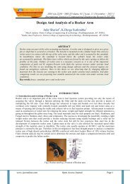
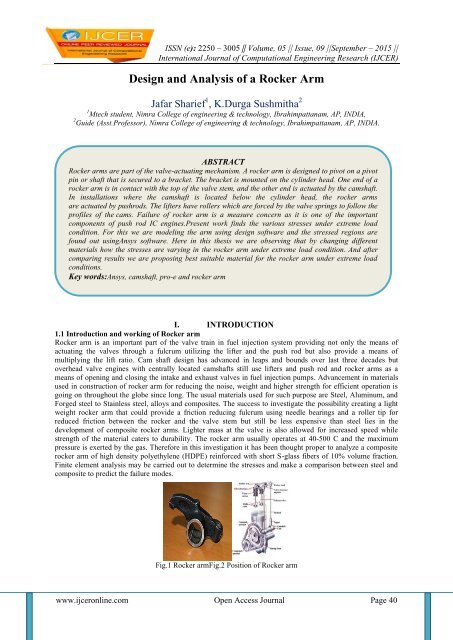
Fig.1 <strong>Rocker</strong> armFig.2 Position <strong>of</strong> <strong>Rocker</strong> arm<br />
www.ijceronline.com Open Access Journal Page 40
<strong>Design</strong> And <strong>Analysis</strong> <strong>of</strong> a <strong>Rocker</strong>…<br />
II.<br />
MODELLING BY USING PRO-E<br />
Fig.3 Solid model<br />
Fig .4 Wire frame model<br />
III.<br />
ANALYSIS BY ANSYS<br />
Fig.5 Imported model<br />
Fig.6 Meshed model<br />
Fig.7 Load distribution at endFig.8 Load distribution at pin<br />
Fig.9 Load distribution at pin <strong>and</strong> end<br />
IV.<br />
4.1 Structural analysis<br />
4.1.1 Load distribution at end<br />
a) Alloy steel -1<br />
RESULTS AND DISCUSSION<br />
Fig.10 Total deformation<br />
Fig.11 Stress intensity<br />
b) Alloy steel -2<br />
Fig.12 Total deformation<br />
Fig.13 Stress intensity<br />
www.ijceronline.com Open Access Journal Page 41
<strong>Design</strong> And <strong>Analysis</strong> <strong>of</strong> a <strong>Rocker</strong>…<br />
c) Composite material<br />
Fig.14 Total deformation<br />
Fig.15 Stress intensity<br />
d) Steel<br />
Fig.16 Total deformation<br />
Fig.17 Stress intensity<br />
4.1.2 Load distribution at pin<br />
a) Alloy steel -1<br />
Fig.18 Total deformation<br />
Fig.19 Stress intensity<br />
b) Alloy steel -2<br />
Fig.20 Total deformation<br />
Fig.21 Stress intensity<br />
c) Composite material<br />
Fig.22 Total deformation<br />
Fig.23 Stress intensity<br />
www.ijceronline.com Open Access Journal Page 42
<strong>Design</strong> And <strong>Analysis</strong> <strong>of</strong> a <strong>Rocker</strong>…<br />
d) Steel<br />
Fig.24 Total deformation<br />
Fig.25 Stress intensity<br />
4.1.3 Load distribution atboth pin <strong>and</strong> end<br />
a) Alloy steel -1<br />
Fig.26 Total deformation<br />
Fig.27 Stress intensity<br />
b) Alloy steel -2<br />
Fig.28 Total deformation<br />
Fig.29 Stress intensity<br />
c) Composite material<br />
d) Steel<br />
Fig.30 Total deformation<br />
Fig.31 Stress intensity<br />
Fig.32 Total deformation<br />
4.2 Results <strong>and</strong> comparisons<br />
4.2.1 Load at pin<br />
SNO MATERIAL TOTAL<br />
DEFORMATION<br />
Fig.33 Stress intensity<br />
STRESS<br />
INTENSITY<br />
1 Alloy steel-1 .2262 4246<br />
2 Alloy steel -2 .2364 4254<br />
3 Composite .1785 4236<br />
4 Steel .2476 4261<br />
Table no.1 Load deformation at pin<br />
www.ijceronline.com Open Access Journal Page 43
<strong>Design</strong> And <strong>Analysis</strong> <strong>of</strong> a <strong>Rocker</strong>…<br />
4.2.2 Load at end<br />
SNO MATERIAL TOTAL<br />
DEFORMATION<br />
STRESS<br />
INTENSITY<br />
1 Alloy steel-1 2.451 4295<br />
2 Alloy steel -2 2.566 424<br />
3 Composite 1.928 4317<br />
4 Steel 2.692 4274<br />
Table no.2 Load deformation at end<br />
4.2.3 Load at both pin <strong>and</strong> end<br />
SNO MATERIAL TOTAL<br />
STRESS<br />
INTENSITY<br />
DEFORMATION<br />
1 Alloy steel-1 2.451 4295<br />
2 Alloy steel -2 2.566 4284<br />
3 Composite 1.928 4317<br />
4 Steel 2.693 4274<br />
Table no.3 Load deformation at pin <strong>and</strong> end<br />
V. CONCLUSION<br />
The modeling <strong>of</strong> the rocker arm is done by using pro-e <strong>and</strong> the analysis is performed by Ansys. The project<br />
consists <strong>of</strong> structural analysis <strong>of</strong> rocker arm which is done to find the strength <strong>of</strong> the model. To find the strength<br />
<strong>of</strong> the model in structural analysis we are taken 4 different materials <strong>and</strong> taken 3 load points on the model. We<br />
did analysis on the model by applying loads at pin <strong>and</strong> end side by varying different 4 materials.By the results<br />
we observed that the stress values <strong>of</strong> steel <strong>and</strong> alloy steel materials are nearer to each other <strong>and</strong> also for the total<br />
deformation the values <strong>of</strong> the steel <strong>and</strong> alloy steel got nearly same values. But only composite material got the<br />
better values in stress intensity <strong>and</strong> total deformation when compared to other materials.So by the investigation<br />
we conclude that by using composite material the stress values are reduced by that the life time <strong>of</strong> the rocker<br />
arm increases.<br />
Future scope<br />
1. By changing the model design <strong>and</strong> reducing the thickness we may get better values.<br />
2. And also by using advanced smart materials we can increase the performance <strong>of</strong> the model.<br />
REFERENCES<br />
[1] Z.W. Yu, X.L. Xu “Failure analysis <strong>of</strong> diesel engine rocker arms” Engineering Failure <strong>Analysis</strong>, Volume 13, Issue 4, June 2006,<br />
Pages 598-605<br />
[2] Chin-Sung Chung, Ho-Kyung Kim "Safety evaluation <strong>of</strong> the rocker arm <strong>of</strong> a diesel engine” Materials & <strong>Design</strong>,<br />
Volume 31, Issue 2, February 2010, Pages 940-945`<br />
[3] Dong-Woo Lee, Soo-Jin Lee, Seok-Swoo Cho , Won-Sik Joo “Failure <strong>of</strong> rocker arm shaft for 4-cylinder SOHC engine”<br />
[4] Dong Woo Lee, Seok Swoo Cho <strong>and</strong> Won Sik Joo “An estimation <strong>of</strong> failure stress condition in rocker arm shaft through FEA<br />
<strong>and</strong> microscopic fractography”<br />
[5] Giovanni Scire Mammano <strong>and</strong> Eugenio Dragoni (2013), “<strong>Design</strong> <strong>and</strong> Testing <strong>of</strong> an Enhanced Shape Memory Actuator<br />
Elastically Compensated by a Bistable <strong>Rocker</strong> <strong>Arm</strong>”, Structures Journal <strong>of</strong>Intelligent Material Systems <strong>and</strong>Structures.<br />
[6] Hendriksma N, Kunz T <strong>and</strong> Greene C (2007), “<strong>Design</strong> <strong>and</strong> Development <strong>of</strong> a 2-Step <strong>Rocker</strong> <strong>Arm</strong>”, SAE International, USA.<br />
[7] Satpathy, Sukanya, Jose, Jobin, Nag, Ahin <strong>and</strong> N<strong>and</strong>o, G.B.,” Short Glass Fiber Filled Waste Plastic (PE) Composites- Studies<br />
on Thermal <strong>and</strong> Mechanical Properties, “Progress in Rubber, Plastics <strong>and</strong> Recycling Technology, Vol.24, No.3, pp.199-218,<br />
2008.<br />
[8] Chung, Chin-Sung <strong>and</strong> Kim Ho-Kyung, “Safety Evaluation <strong>of</strong> the <strong>Rocker</strong> <strong>Arm</strong> <strong>of</strong> a Diesel Engine,” Materials <strong>and</strong> <strong>Design</strong>,<br />
Vol.31 (2), pp.940-945, 2010.<br />
[9] Kun Cheng, “Finite element analysis <strong>of</strong> <strong>Rocker</strong> <strong>Arm</strong> <strong>of</strong> Vertical Roller Mill on ANSYS work Bench “Advanced Materials<br />
Research, Vol.230-232, pp.824-828, 2011.<br />
[10] Yang, Changxing., Li, Guan, Qi, Rongrong <strong>and</strong> Huang, Mark,” Glass Fibre/Wood Flour Modified High Density Polyethylene<br />
Composites,” Jou. <strong>of</strong> Applied Polymer Science, Vol.123, pp.2084-2089, 2012.<br />
www.ijceronline.com Open Access Journal Page 44