Lab #3 – FIR Filter Design
Lab #3 – FIR Filter Design
Lab #3 – FIR Filter Design

Create successful ePaper yourself
Turn your PDF publications into a flip-book with our unique Google optimized e-Paper software.
<strong>Lab</strong> <strong>#3</strong> <strong>–</strong> <strong>FIR</strong> <strong>Filter</strong> <strong>Design</strong><br />
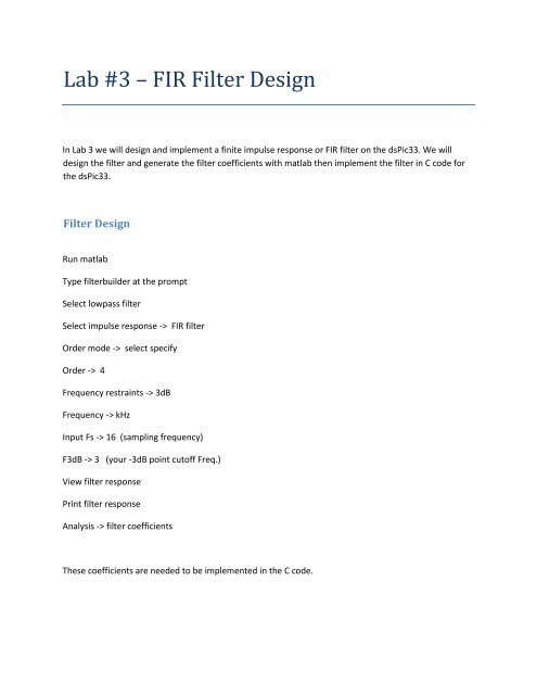
In <strong>Lab</strong> 3 we will design and implement a finite impulse response or <strong>FIR</strong> filter on the dsPic33. We will<br />
design the filter and generate the filter coefficients with matlab then implement the filter in C code for<br />
the dsPic33.<br />
<strong>Filter</strong> <strong>Design</strong><br />
Run matlab<br />
Type filterbuilder at the prompt<br />
Select lowpass filter<br />
Select impulse response -> <strong>FIR</strong> filter<br />
Order mode -> select specify<br />
Order -> 4<br />
Frequency restraints -> 3dB<br />
Frequency -> kHz<br />
Input Fs -> 16 (sampling frequency)<br />
F3dB -> 3 (your -3dB point cutoff Freq.)<br />
View filter response<br />
Print filter response<br />
Analysis -> filter coefficients<br />
These coefficients are needed to be implemented in the C code.
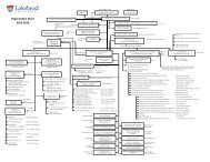
Back to the lowpass design window<br />
Click the Code generation tab<br />
Simulink model -> generate model<br />
This model diagram may help you with implementing the filter into code.<br />
<strong>Filter</strong> Implementation<br />
Place microstick on breadboard and place capacitor (10uF) between Vcap and Vss (pins 20 and 19).<br />
Connect the microstick II starter kit to the USB port<br />
Run mplab X<br />
<br />
<br />
<br />
<br />
<br />
<br />
<br />
<br />
<br />
<br />
<br />
<br />
<br />
<br />
<br />
<br />
File -> new project<br />
Microchip embedded stand alone<br />
Next<br />
Family -> 16 bit dsc’s (dsPic33)<br />
Device -> dsPIC33FJ06GS202<br />
Next<br />
Select tool -> starter kits(pkob) -> select the serial number<br />
Next<br />
Select compiler -> XC16<br />
Next<br />
Project Name -> lab3<br />
Right click on source files<br />
Add new c main file<br />
Call it lab3.c<br />
Select all code in new file and delete it<br />
Paste lab 3 code from website into file<br />
Edit the code to suit your needs. Your coefficients will be placed the initvals subroutine in the b array<br />
and your transfer function equation will be coded into the _ADCP0Interrupt service routine.
Next set your function generator to have a 1kHz sine wave with a peak to peak voltage of 3.2 Volts and<br />
an offset of 1.65 volts.<br />
Apply this signal to pin 2 of the microstick II. Make sure the programming switch is set to position B.<br />
With the scope monitor the input signal.<br />
Next compile and download your program to the dsPIC by clicking the Run -> Run Project<br />
Test Your <strong>Filter</strong><br />
Measure on pin 12 of the microstick and measure the sample rate. The bit is toggled every sample so<br />
the rate is twice the frequency. You should measure 8kHz.<br />
Measure on pin 11 and view the output waveform.<br />
Make peak to peak voltage readings of your output as you move through the frequency range. Go from<br />
10Hz to 8kHz making readings 5 points per decade. Plot your frequency response.