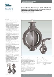
Hilok High Performance Butterfly Valve
Hilok High Performance Butterfly Valve
Hilok High Performance Butterfly Valve

You also want an ePaper? Increase the reach of your titles
YUMPU automatically turns print PDFs into web optimized ePapers that Google loves.
www.tycovalves-eu.com<br />
HiLok <strong>High</strong> <strong>Performance</strong> <strong>Butterfly</strong> <strong>Valve</strong><br />
Installation and Maintenance Instructions<br />
1. General information on the installation and maintenance instructions<br />
These installation and maintenance instructions contain the information necessary for safe and<br />
correct installation and operation of the fitting. If any difficulties are encountered during installation<br />
or operation which cannot be solved with the aid of the installation and maintenance instructions,<br />
please contact the supplier/manufacturer for more information. These installation and<br />
maintenance instructions comply with the relevant applicable EN safety standards. When installing<br />
the fitting, the operator or the person responsible for the design of the installation must ensure that<br />
applicable national regulations are complied with. The manufacturer reserves all rights to make<br />
technical changes and improvements at any time. We recommend that all maintenance,<br />
installation and operation personnel will understand these instructions, which are accessible via<br />
www.tycovalves-eu.com<br />
2. Safety<br />
Please also read through these notes carefully.<br />
2.1. Meaning of the symbols<br />
This symbol in the operating instructions indicates danger.<br />
2.2. General potential danger due to:<br />
a. Failure to observe the instructions<br />
b. Improper use<br />
c. Insufficiently qualified personnel<br />
2.3. Correct use<br />
2.3.1. Area of application<br />
HiLok valves are valves that are used for the isolation, throttling and regulation liquids,<br />
together with gases, pastes and powdery products in pipelines, vessels, apparatus etc. The<br />
area of use of the fitting is the responsibility of the system designer. Special characteristics of<br />
the fitting must be taken into account. A very wide selection of product-wetted components<br />
parts is available which allows suitable combination for the optimal solution to your specific<br />
application. Always consult the manufacturer when the fitting is to be used with media that<br />
require or preclude the use of certain materials.<br />
2.3.2. Method of operation<br />
The valve is opened or closed by turning the valve spindle. The angle of rotation is 90°.<br />
2.3.3. <strong>Performance</strong> data<br />
Pressure range: see table<br />
Temperature range: see table<br />
Nominal diameter range: DN 50-900<br />
Test pressure: 1.5 x PN<br />
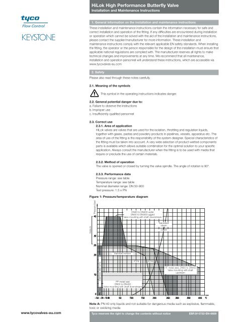
Figure 1: Pressure/temperature diagram<br />
Note A<br />
Pressure (bar)<br />
Stainless steel only<br />
Standard version<br />
DN50 to DN400 wafer<br />
DN50 to DN300 lugged<br />
<strong>Valve</strong> mounting with shaft downstream<br />
PP metal seat<br />
DN50 to DN400<br />
<strong>Valve</strong> mounting with shaft downstream<br />
PTFE RTFE<br />
Saturated<br />
steam<br />
Liquid<br />
HT metal seat, DN50 to DN400<br />
<strong>Valve</strong> mounting with shaft<br />
upstream<br />
Note A: PN 40 only liquids and not suitable for dangerous media such as explosive, flammable,<br />
toxic or oxidizing media<br />
Tyco reserves the right to change the contents without notice EBPJV-0722-EN-0609
HiLok <strong>High</strong> <strong>Performance</strong> <strong>Butterfly</strong> <strong>Valve</strong><br />
Installation and Maintenance Instructions<br />
2.3.4. Usage restrictions<br />
The product-wetted components must be classified as resistant to the product to be<br />
conveyed. Refer to appropriate literature or consult the manufacturer or distributor for advice<br />
on this.<br />
2.3.5. Modification prohibition<br />
Mechanical modifications to the valves or the use of other manufacturers’ parts for repair<br />
purposes are not permissible. Safety is not guaranteed if this requirement is disregarded.<br />
Repair work must only be carried out by the manufacturer’s trained personnel.<br />
2.3.6. Warning about foreseeable misuse<br />
<strong>Valve</strong>s and their accessories (e.g. operating elements) must not be misused as climbing aids.<br />
2.3.7. Duty to comply with the instructions for operation, maintenance and servicing<br />
These instructions are part of the delivery package and must be kept clean and made<br />
accessible to the user.<br />
2.4. Sources of danger<br />
2.4.1. Mechanical<br />
When using the hand lever, it should be ensured that there is still sufficient clearance for the<br />
hands at the end position of the handle, so that there is no risk of trapping. Excessive<br />
oscillation and vibration should be avoided, to prevent the bolts loosening.<br />
2.4.2. Electrical<br />
None for a bare shafted valve<br />
2.4.3. Thermal<br />
Due to the range of operating temperatures between -50°C and +400°C, surface<br />
temperatures from -20°C to over +400°C can be present on the valve body. Suitable<br />
precautions should be taken to protect against burns due to high or freezing temperatures. In<br />
particular, insulated gloves should be worn when using the hand lever, for example.<br />
3. Transport/Storage<br />
The valve is supplied with protective covers. Do not remove the protective covers until immediately<br />
prior to installation.<br />
3.1. Transport<br />
• Transport temperature -20°C to +65°C<br />
• Protect against external force (impact, shock, vibration)<br />
3.2. Storage<br />
• Storage temperature -20°C to +65°C, dry and dust-free<br />
• A drying agent or heating is required in damp storage areas to protect against condensation<br />
• Keep the valve disc in a closed position<br />
3.3. Handling prior to installation<br />
• With versions with protective covers, only remove the covers immediately prior to installation!<br />
• Protect against the effects of weather, such as dampness (or else use a drying agent)<br />
• Proper treatment prevents damage<br />
4. Identification<br />
Additional identification on the valve in accordance with EN 19, such as: DN, PN, manufacturer’s<br />
logo. The valve body material is cast onto the valve.<br />
Figure 2: Tagplate<br />
Trim<br />
W = wafer, L = lugged<br />
Product<br />
Body material<br />
JOB number<br />
Manufacturing in<br />
Category<br />
0038 Lloyd’s notified body number<br />
Tyco reserves the right to change the contents without notice<br />
Diameter<br />
Working pressure and limit temperature<br />
Flange connection<br />
Face to face<br />
Maximum working pressure onto pipework<br />
Maximum working pressure in<br />
end of line (seat installed<br />
upstream only)
<strong>Valve</strong> dimensions<br />
HiLok <strong>High</strong> <strong>Performance</strong> <strong>Butterfly</strong> <strong>Valve</strong><br />
Installation and Maintenance Instructions<br />
5. Dimensions and weight<br />
Refer to the product documentation for dimensions and weights.<br />
6 Installation in the pipeline<br />
The recommended installation position is with the spindle horizontal, with the lower sealing strip<br />
opening in the direction of flow. A butterfly valve is not a crowbar! Please do not use it to force the<br />
flanges apart, as this would lead to damage to the ring bellows and seat. To avoid damage to the<br />
disc and bellows, the protective covers should only be removed immediately prior to installation. It<br />
is not advisable to use the valve for positioning pipelines in new systems. Sparks which occur<br />
during spot welding can damage the seat. Use adjusting pieces instead. Final welding of the<br />
flange with the valve in position will lead to severe damage to the valve seat due to the high<br />
temperature. Always use all flange bolts, even on low pressure systems. The valve should never<br />
be pressurized if one of the flange bolts is missing. The pipe flanges should comply with the<br />
dimensions as indicated in the below mentioned table.<br />
50 65 80 100 125 150 200 250 300 350 400 450 500 600 700<br />
ø D min 49 59 74 97 122 146 194 243 289 333 381 428 477 574 676<br />
ø D1 in accordance with EN 1092-1<br />
ø D1<br />
ø D min.<br />
6.1 Step-by-step valve installation<br />
1. Check that the distance between flanges matches the face-to-face dimension of the butterfly<br />
valve. Before installing the valve, spread the flanges sufficiently apart using a suitable tool.<br />
2. Ensure that the disc is fully closed.<br />
3. Put the gaskets between flanges and body.<br />
4. Center the valve by bolting the 4 locators first.<br />
5. Progressively tighten bolts by alternating sides until you have full compression of flange gaskets.<br />
6. Check: operate valve from fully open position to fully closed position to ensure that nothing<br />
obstructs the disc.<br />
7. Unidirectional end of line service with seat mounted upstream.<br />
6.2 Final checks<br />
Inspection of the valve position as far as the fully open position. Cleaning and flushing the pipeline<br />
before the first closure.<br />
Repeated opening and closing of the valve to ensure unrestricted movement of the valve disc.<br />
Tyco reserves the right to change the contents without notice
HiLok <strong>High</strong> <strong>Performance</strong> <strong>Butterfly</strong> <strong>Valve</strong><br />
Installation and Maintenance Instructions<br />
7 Repair instructions<br />
Seat and packing maintenance can be conducted on site based on the following instructions.<br />
(part numbers refer to the drawing)<br />
7.1 Seat replacement<br />
1. Remove valve from line (closed disc).<br />
2. Remove retaining ring (3).<br />
3. Extract the seat (6).<br />
4. Gently clean:<br />
• disc edge (2)<br />
• seat pocket.<br />
5. Put new seat in position (still closed disc).<br />
6. Rescrew retaining ring.<br />
7. Reset valve between flanges and wait 15 minutes before any operations.<br />
8. <strong>Valve</strong> is now ready.<br />
7.2 Packing replacement<br />
Remove all pipeline pressure from the valve. The operation can be done directly on the valve<br />
without removing it from line.<br />
Procedure<br />
1. Unscrew gland follower (8) and lift packing gland (7).<br />
2. Extract packing rings (10).<br />
3. Clean upper stem (4) and packing chamber.<br />
4. Reinstall packing rings.<br />
5. Reset gland follower and packing gland.<br />
6. Adjust packing compression to avoid leakage.<br />
8. Cause and remedy of operating faults<br />
If the valve function or operating action is faulty, a check should be made to ensure that the<br />
assembly and installation work has been carried out and completed in accordance with the<br />
installation and maintenance instructions.<br />
The information relating to material, pressure, temperature and direction of flow should be<br />
compared with the installation diagram of the pipeline system. Furthermore, it should be checked<br />
whether the installation conditions correspond to the technical data given in the data sheet or on<br />
the rating plate.<br />
The safety regulations should always be observed when troubleshooting.<br />
9. Decommissioning<br />
Removal of the valve for repair or servicing is often carried out carelessly, as the valve has to be<br />
repaired or replaced in any case. However, it is recommended that the valve be removed with<br />
care, so that the possible cause of damage can be determined after removal.<br />
Warning<br />
Check that the pipe is depressurized and drained.<br />
With corrosive, inflammable, aggressive or toxic media, ventilate the pipeline system.<br />
1. Only allow assembly work to be carried out by qualified personnel (see section 2.3)<br />
2. Almost completely close the butterfly valve (the disc is in line with the flat faces of the operating<br />
shaft).<br />
3. Loosen all flange bolts and withdraw them until the valve can be removed.<br />
4. Spread the flanges apart using a suitable tool and withdraw the valve.<br />
10. Disposal<br />
Hand in the correctly cleaned valve to the scrap material recycling plant. Badly cleaned valves can<br />
cause severe burning of the hands and other parts of the body. If the valve is passed on to a third<br />
party, the manufacturer does not guarantee the safety of the valve.<br />
11. Validity of the Installation and Maintenance Instructions<br />
These instructions are valid until the next revision of these instructions.<br />
12. Customer service<br />
For further information or technical advice, please contact your local Tyco sales organization see<br />
www.tycovalves-eu.com<br />
Tyco reserves the right to change the contents without notice<br />
9<br />
8<br />
7<br />
1<br />
4<br />
3<br />
2<br />
6<br />
5<br />
Part nb. designation<br />
16<br />
10<br />
11<br />
11<br />
15<br />
15<br />
11<br />
11<br />
14<br />
12<br />
13<br />
1. 1 Body<br />
2. 1 Disc<br />
3. 1 Seat retaining ring<br />
4. 1 Upper stem<br />
5. 1 Lower stem<br />
6. 1 Seat<br />
7. 1 Gland<br />
8. 1 Gland follower<br />
9. 1 Position indicator<br />
10. 3/4/5 Packing (depending on size)<br />
11. 4 Bearing<br />
12. 1 Disc locating shoulder<br />
13. 1 Bottom end cover<br />
14. 1 Bottom seal<br />
15. 2/3 Pin (depending on size)<br />
16. 1 Circlip/bolt