Fast microbolometer-based infrared camera system 1 Introduction 2 ...
Fast microbolometer-based infrared camera system 1 Introduction 2 ...
Fast microbolometer-based infrared camera system 1 Introduction 2 ...

You also want an ePaper? Increase the reach of your titles
YUMPU automatically turns print PDFs into web optimized ePapers that Google loves.
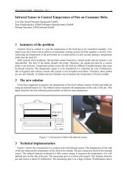
DIAS Infrared GmbH – Publications – No. 20 1<br />
<strong>Fast</strong> <strong>microbolometer</strong>-<strong>based</strong> <strong>infrared</strong> <strong>camera</strong> <strong>system</strong><br />
Helmut Budzier 1,2 , Volker Krause 1 , Stephan Böhmer 1 , Gerald Gerlach 1 , Uwe Hoffmann 2<br />
1 TU Dresden, Institute for Solid State Electronics, Helmholtzstraße 18, D-01062 Dresden<br />
2 DIAS Infrared GmbH, Gostritzer Straße 63, D-01217 Dresden<br />
Until now <strong>microbolometer</strong>-<strong>based</strong> <strong>camera</strong>s have been operated only at 50/60 Hz. Since <strong>microbolometer</strong>s<br />
are now available with faster read out integrated circuits (ROIC) and with a low thermal time<br />
constant of the <strong>microbolometer</strong> pixel, they are getting more and more interesting for high speed applications.<br />
In this paper, a fast high-performance IR <strong>camera</strong> equipped with a state-of-the-art <strong>microbolometer</strong><br />
focal plane array is presented.<br />
The newly developed <strong>camera</strong> <strong>system</strong> is <strong>based</strong> on a long-wave <strong>infrared</strong> range (LWIR) <strong>microbolometer</strong><br />
<strong>camera</strong> <strong>system</strong> with 384 × 288 pixels. The <strong>camera</strong> operates at 100 Hz. The <strong>camera</strong> <strong>system</strong><br />
consists of a <strong>camera</strong> head and a PC frame grabber plug-in board with CameraLink interface.<br />
The <strong>camera</strong> <strong>system</strong> is suitable for stationary use in harsh industrial environments. The robust housing<br />
can be completed by integrated water-cooling and air purge for the lens <strong>system</strong>. The <strong>camera</strong> is<br />
equipped with trigger inputs for the synchronization with the process to be measured.<br />
The high resolution and sensitivity values of the presented IR <strong>camera</strong> allow its use for sophisticated<br />
temperature measurement tasks. The IR <strong>camera</strong> is especially suited for long-time process monitoring<br />
or quality control in industrial facilities.<br />
1 <strong>Introduction</strong><br />
So far <strong>microbolometer</strong> focal plane arrays (FPA) are being used only with a frame rate of 50 Hz. The<br />
maximum frame rate depends on the thermal time constant of the <strong>microbolometer</strong> pixel, the speed of<br />
the read-out integrated circuit (ROIC) and the read-out mode. In chapter 2 these limits are described. It<br />
is shown that <strong>microbolometer</strong>s on the basis of amorphous silicon are usable for a radiometric <strong>infrared</strong><br />
<strong>camera</strong> <strong>system</strong> with a frame rate of 100 Hz. Subsequently such a <strong>system</strong> is presented in chapter 3.<br />
2 Time limits of a <strong>microbolometer</strong><br />
2.1 Thermal time constant<br />
The thermal time constant τth of a bolometer is determined by the thermal mass C and by the thermal<br />
conductance G between the pixel and its enviroment:<br />
C<br />
τ th = .<br />
(1)<br />
G<br />
It depends on the bolometer construction and the resistor material used. Typical values for commercial<br />
<strong>microbolometer</strong>s are given in table 1.<br />
Material Time constant in ms Response time in ms<br />
Vanadium oxide VOX 15 45<br />
Amorphous silicon a:Si 7 21<br />
Table 1: Typical values for thermal time constants [1], [2]
DIAS Infrared GmbH – Publications – No. 20 2<br />
The frequency dependence of the responsivity R(ω) of a bolometer can simply be expressed by /3/:<br />
( ω)<br />
R<br />
R<br />
=<br />
1<br />
1 + ω τ<br />
2 2<br />
0 th<br />
where R0 is the DC responsivity. That means that the output voltage U(t) of a pixel follows an input<br />
step exponentially:<br />
U() t<br />
( →∞)<br />
U t<br />
= 1 −e<br />
t<br />
−<br />
τ th<br />
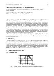
Figure 1 shows the output signal after an input step. After a time > 3τth the output becomes 95 % of<br />
its final value. This time is usually called response time (see table 1). The response time is the minimum<br />
time to be waited for after the object temperature is changed. After t > 6τth 99 % of the final<br />
value are reached.<br />
output<br />
1<br />
0,9<br />
0,8<br />
0,7<br />
0,6<br />
0,5<br />
0,4<br />
0,3<br />
0,2<br />
0,1<br />
2.2 Frame rate<br />
7 ms<br />
15 ms<br />
0<br />
0 10 20 30 40 50<br />
time in ms<br />
Figure 1: Output signal after an input step (Parameter: time constant τth)<br />
The maximum of the frame rate is specified by the ROIC. Usually, the analog output amplifier of<br />
the ROIC gives the maximum of the pixel frequency. Typical pixel frequencies for different frame<br />
rates and usable focal plane array sizes are given in table 2. Practically, the pixel frequencies are<br />
slightly higher due to extra clocks for the ROIC. For large FPAs, two analog outputs are usable.<br />
Frame rate<br />
Size 50 Hz 100 Hz 200 Hz<br />
320 × 240 3.84 MHz 7.68 MHz 15.36 MHz<br />
384 × 288 5.53 MHz 11.1 MHz 22.1 MHz<br />
640 × 480 15.36 MHz 30.72 MHz 61.44 MHz<br />
Table 2: Pixel frequency<br />
(2)<br />
(3)
DIAS Infrared GmbH – Publications – No. 20 3<br />
The frame rate is the sampling rate of the scene. A signal must be sampled at a rate greater then<br />
twice its maximum frequency in order to ensure unambiguous data (Nyquist’s criterion). So the<br />
maximum permissible scene frequency is the half of the frame rate. For example, the maximum scene<br />
frequency of an a:Si-bolometer and 100 Hz frame rate is 50 Hz. That corresponds to a cycle duration<br />
of 20 ms. This value is in good agreement with the response time of an a:Si-bolometer (see 2.1).<br />
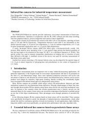
2.3 Read-out mode<br />
The read-out of the pixels is organized row by row (Fig. 2). Therefore, the object will be sampled<br />
one row after another. By this read-out procedure, the object appears chopped if it is moving, since<br />
every following row is shifted to the preceding one. The maximum shift and hence the maximum object<br />
speed is limited by the measurement task.<br />
3 Camera design<br />
preclocks<br />
row 3<br />
row 2<br />
row 1<br />
row<br />
382<br />
row<br />
383<br />
row<br />
384<br />
postclocks<br />
0 0.1 9.9<br />
10<br />
time<br />
in ms<br />
Figure 2: Read out row by row (1 frame, 384 rows, 100 Hz frame rate)<br />
The intention of this work was to develop a fast high-performance uncooled <strong>infrared</strong> <strong>camera</strong> for<br />
non-contact temperature measurement. The <strong>camera</strong> design was <strong>based</strong> on universal electronic components,<br />
which can be adapted inexpensively to different sensor types and various industrial applications<br />
/4/. The <strong>camera</strong> <strong>system</strong> was developed primarily for the use with <strong>microbolometer</strong> arrays. Figure 3<br />
shows the overall <strong>system</strong> set-up.<br />
sensor +<br />
analog<br />
electronics<br />
shutter<br />
controller<br />
power<br />
supply<br />
digital electronics with<br />
embedded controller<br />
and signal processing<br />
unit<br />
I/O-driver<br />
Camera Link<br />
Camera Link<br />
frame grabber<br />
Figure 3: Set-up of the <strong>camera</strong> <strong>system</strong><br />
trigger IO<br />
to process
DIAS Infrared GmbH – Publications – No. 20 4<br />
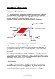
For internal signal corrections, a shutter is used. The shutter cycle is given by temperature changes<br />
of the optical channel. The shutter can be synchronized to an external process.<br />
Figure 4: Camera head<br />
The <strong>camera</strong> <strong>system</strong> is designed for stationary use in harsh industrial environments. The robust<br />
housing (Fig. 4) may be completed by an air purge for the lens <strong>system</strong> and an integrated watercooling.<br />
The <strong>camera</strong> <strong>system</strong> is equipped with trigger inputs to synchronize the <strong>camera</strong> <strong>system</strong> to an<br />
industrial process. For visualization, a computer is used. The <strong>camera</strong> <strong>system</strong> is connected with a computer<br />
via a standard interface (CameraLink). Table 3 shows the performance data of the <strong>camera</strong> <strong>system</strong>.<br />
Spectral band 8 µm to 14 µm<br />
Measured temperature range –20 °C to 500 °C (two ranges)<br />
Detector 384 × 288 pixel uncooled bolometer<br />
NETD < 120 mK (30 °C)<br />
Field of view 30°× 23°<br />
Frame rate 100 Hz<br />
Camera operating temperature range 0 °C to 50 °C<br />
4 References<br />
Table 3: Selected technical data of the <strong>camera</strong> <strong>system</strong><br />
/1/ P. Capper, C.T. Elliott: Infrared Detectors and Emitters: Materials and Devices, Kluwer Academic<br />
Publishers, 2001<br />
/2/ J.L. Tissot, O. Legras, C. Trouilleau, A. Crastes, B. Fieque: Uncooled <strong>microbolometer</strong> detector:<br />
recent development at ULIS, Proc. SPIE Vol. 5987, 2005, pp 200-210<br />
/3/ P. W. Kruse: Uncooled thermal imaging, SPIE Press, 2001<br />
/4/ H. Budzier, B. Vollheim, V. Krause, G. Hofmann, G. Gerlach: High-performance <strong>infrared</strong> 2D<br />
<strong>camera</strong>s <strong>based</strong> on various <strong>microbolometer</strong> focal plane arrays, 8 th Int’l Conference for Infrared<br />
Sensors and Systems, Proceedings, Erfurt: AMA 2004, pp 201-206