Configuring a Net2 plus using TCP/IP
Installing remote sites using TCP/IP - Paxton Access Ltd
Installing remote sites using TCP/IP - Paxton Access Ltd

You also want an ePaper? Increase the reach of your titles
YUMPU automatically turns print PDFs into web optimized ePapers that Google loves.
12V<br />
Red LED<br />
Amber LED<br />
Green LED<br />
Data/D0<br />
Clock/D1<br />
Media Detect<br />
0V<br />
12V<br />
Red LED<br />
Amber LED<br />
Green LED<br />
Data/D0<br />
Clock/D1<br />
Media Detect<br />
0V<br />
12V<br />
Red LED<br />
Amber LED<br />
Green LED<br />
Data/D0<br />
Clock/D1<br />
Media Detect<br />
0V<br />
12V<br />
Red LED<br />
Amber LED<br />
Green LED<br />
Data/D0<br />
Clock/D1<br />
Media Detect<br />
0V<br />
12V<br />
Red LED<br />
Amber LED<br />
Green LED<br />
Data/D0<br />
Clock/D1<br />
Media Detect<br />
0V<br />
12V<br />
Red LED<br />
Amber LED<br />
Green LED<br />
Data/D0<br />
Clock/D1<br />
Media Detect<br />
0V<br />
12V<br />
Red LED<br />
Amber LED<br />
Green LED<br />
Data/D0<br />
Clock/D1<br />
Media Detect<br />
0V<br />
12V<br />
Red LED<br />
Amber LED<br />
Green LED<br />
Data/D0<br />
Clock/D1<br />
Media Detect<br />
0V<br />
Expansion<br />
Expansion<br />
Expansion<br />
Expansion<br />
Server Connected<br />
10<br />
Server Link 100<br />
10/100 Ethernet<br />
Server Connected<br />
10<br />
Server Link 100<br />
10/100 Ethernet<br />
Server Connected<br />
10<br />
Server Link 100<br />
10/100 Ethernet<br />
Server Connected<br />
10<br />
Server Link 100<br />
10/100 Ethernet<br />
Arm<br />
Set<br />
Intruder Alarm<br />
0V<br />
PLACE SERIAL<br />
NUMBER<br />
LABEL HERE<br />
End of Line Termination<br />
ON<br />
OFF<br />
RS485 Network<br />
CAT5 Cable Coding<br />
Tx<br />
Rx<br />
Arm<br />
Set<br />
Intruder Alarm<br />
PLACE SERIAL<br />
NUMBER<br />
LABEL HERE<br />
End of Line Termination<br />
ON<br />
OFF<br />
RS485 Network<br />
CAT5 Cable Coding<br />
Tx<br />
Rx<br />
Arm<br />
Set<br />
Intruder Alarm<br />
0V<br />
PLACE SERIAL<br />
NUMBER<br />
LABEL HERE<br />
End of Line Termination<br />
ON<br />
OFF<br />
RS485 Network<br />
CAT5 Cable Coding<br />
Tx<br />
Rx<br />
Arm<br />
Set<br />
Intruder Alarm<br />
0V<br />
0V<br />
PLACE SERIAL<br />
NUMBER<br />
LABEL HERE<br />
End of Line Termination<br />
ON<br />
OFF<br />
RS485 Network<br />
CAT5 Cable Coding<br />
Tx<br />
Rx<br />
elay<br />
xit<br />
elay<br />
xit<br />
elay<br />
xit<br />
elay<br />
xit<br />
12V<br />
0V<br />
12V<br />
Green LED<br />
Exit<br />
0V<br />
N.C.<br />
N.O.<br />
COM<br />
N.C.<br />
N.O.<br />
COM<br />
Alarm<br />
Contact<br />
0V<br />
0V<br />
Tamper<br />
PSU<br />
12V<br />
0V<br />
12V<br />
Green LED<br />
Exit<br />
0V<br />
N.C.<br />
N.O.<br />
COM<br />
N.C.<br />
N.O.<br />
COM<br />
Alarm<br />
Contact<br />
0V<br />
0V<br />
Tamper<br />
PSU<br />
12V<br />
0V<br />
12V<br />
Green LED<br />
Exit<br />
0V<br />
N.C.<br />
N.O.<br />
COM<br />
N.C.<br />
N.O.<br />
COM<br />
Alarm<br />
Contact<br />
0V<br />
0V<br />
Tamper<br />
PSU<br />
12V<br />
0V<br />
12V<br />
Green LED<br />
Exit<br />
0V<br />
N.C.<br />
N.O.<br />
COM<br />
N.C.<br />
N.O.<br />
COM<br />
Alarm<br />
Contact<br />
0V<br />
0V<br />
Tamper<br />
PSU<br />
12V<br />
Red LED<br />
Amber LED<br />
Green LED<br />
Data/D0<br />
Clock/D1<br />
Media Detect<br />
0V<br />
12V<br />
Red LED<br />
Amber LED<br />
Green LED<br />
Data/D0<br />
Clock/D1<br />
Media Detect<br />
0V<br />
12V<br />
Red LED<br />
Amber LED<br />
Green LED<br />
Data/D0<br />
Clock/D1<br />
Media Detect<br />
0V<br />
12V<br />
Red LED<br />
Amber LED<br />
Green LED<br />
Data/D0<br />
Clock/D1<br />
Media Detect<br />
0V<br />
12V<br />
Red LED<br />
Amber LED<br />
Green LED<br />
Data/D0<br />
Clock/D1<br />
Media Detect<br />
0V<br />
12V<br />
Red LED<br />
Amber LED<br />
Green LED<br />
Data/D0<br />
Clock/D1<br />
Media Detect<br />
0V<br />
12V<br />
Red LED<br />
Amber LED<br />
Green LED<br />
Data/D0<br />
Clock/D1<br />
Media Detect<br />
0V<br />
12V<br />
Red LED<br />
Amber LED<br />
Green LED<br />
Data/D0<br />
Clock/D1<br />
Media Detect<br />
0V<br />
Expansion<br />
Expansion<br />
Expansion<br />
Expansion<br />
Server Connected<br />
10<br />
Server Link 100<br />
10/100 Ethernet<br />
Server Connected<br />
10<br />
Server Link 100<br />
10/100 Ethernet<br />
Server Connected<br />
10<br />
Server Link 100<br />
10/100 Ethernet<br />
Server Connected<br />
10<br />
Server Link 100<br />
10/100 Ethernet<br />
Arm<br />
Set<br />
Intruder Alarm<br />
0V<br />
PLACE SERIAL<br />
NUMBER<br />
LABEL HERE<br />
Set<br />
Intruder Alarm<br />
End of Line Termination<br />
ON<br />
OFF<br />
RS485 Network<br />
CAT5 Cable Coding<br />
Tx<br />
Rx<br />
Arm<br />
0V<br />
PLACE SERIAL<br />
NUMBER<br />
LABEL HERE<br />
Set<br />
Intruder Alarm<br />
End of Line Termination<br />
ON<br />
OFF<br />
RS485 Network<br />
CAT5 Cable Coding<br />
Tx<br />
Rx<br />
Arm<br />
0V<br />
PLACE SERIAL<br />
NUMBER<br />
LABEL HERE<br />
Set<br />
Intruder Alarm<br />
End of Line Termination<br />
ON<br />
OFF<br />
RS485 Network<br />
CAT5 Cable Coding<br />
Tx<br />
Rx<br />
Arm<br />
0V<br />
PLACE SERIAL<br />
NUMBER<br />
LABEL HERE<br />
End of Line Termination<br />
ON<br />
OFF<br />
RS485 Network<br />
CAT5 Cable Coding<br />
Tx<br />
Rx<br />
<strong>Net2</strong><br />
AN1006<br />
elay<br />
xit<br />
elay<br />
xit<br />
elay<br />
xit<br />
elay<br />
xit<br />
12V<br />
0V<br />
12V<br />
Green LED<br />
Exit<br />
0V<br />
12V<br />
Green LED<br />
Exit<br />
0V<br />
N.C.<br />
N.O.<br />
COM<br />
N.C.<br />
N.O.<br />
COM<br />
Alarm<br />
Contact<br />
0V<br />
0V<br />
Tamper<br />
PSU<br />
12V<br />
0V<br />
N.C.<br />
N.O.<br />
COM<br />
N.C.<br />
N.O.<br />
COM<br />
Alarm<br />
Contact<br />
0V<br />
0V<br />
Tamper<br />
PSU<br />
12V<br />
0V<br />
12V<br />
Green LED<br />
Exit<br />
0V<br />
N.C.<br />
N.O.<br />
COM<br />
N.C.<br />
N.O.<br />
COM<br />
Alarm<br />
Contact<br />
0V<br />
0V<br />
Tamper<br />
PSU<br />
12V<br />
0V<br />
12V<br />
Green LED<br />
Exit<br />
0V<br />
N.C.<br />
N.O.<br />
COM<br />
N.C.<br />
N.O.<br />
COM<br />
Alarm<br />
Contact<br />
0V<br />
0V<br />
Tamper<br />
PSU<br />
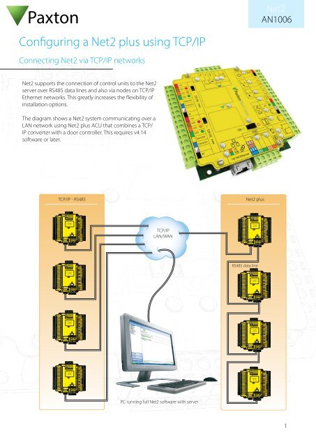
<strong>Configuring</strong> a <strong>Net2</strong> <strong>plus</strong> <strong>using</strong> <strong>TCP</strong>/<strong>IP</strong><br />
Connecting <strong>Net2</strong> via <strong>TCP</strong>/<strong>IP</strong> networks<br />
<strong>Net2</strong> supports the connection of control units to the <strong>Net2</strong><br />
server over RS485 data lines and also via nodes on <strong>TCP</strong>/<strong>IP</strong><br />
Ethernet networks. This greatly increases the flexibility of<br />
installation options.<br />
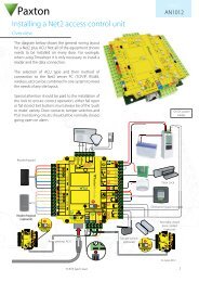
The diagram shows a <strong>Net2</strong> system communicating over a<br />
LAN network <strong>using</strong> <strong>Net2</strong> <strong>plus</strong> ACU that combines a <strong>TCP</strong>/<br />
<strong>IP</strong> converter with a door controller. This requires v4.14<br />
software or later.<br />
<strong>TCP</strong>/<strong>IP</strong> - RS485<br />
<strong>Net2</strong> <strong>plus</strong><br />
N.O.<br />
COM<br />
Sense<br />
Reader 1<br />
Reader 2<br />
C aution:<br />
y<br />
For 12V DC readers onl<br />
<strong>Net2</strong> <strong>plus</strong><br />
Wht/Grn<br />
Screen or spare<br />
cores from data<br />
cable<br />
Green<br />
Wht/Orng<br />
Orange<br />
I nputs<br />
Output s<br />
Power<br />
P SU/Tamper C ontac t E Butto n<br />
R 2 Relay 1<br />
<strong>TCP</strong>/<strong>IP</strong><br />
LAN/WAN<br />
Reader 1<br />
Reader 2<br />
C aution:<br />
y<br />
For 12V DC readers onl<br />
N.O.<br />
COM<br />
Sense<br />
<strong>Net2</strong> <strong>plus</strong><br />
Wht/Grn<br />
Screen or spare<br />
cores from data<br />
cable<br />
Green<br />
Wht/Orng<br />
Orange<br />
I nputs<br />
Output s<br />
Power<br />
P SU/Tamper C ontac t E Butto n<br />
R 2 Relay 1<br />
RS485 data line<br />
C aution: For 12V DC readers onl y<br />
Reader 1<br />
Reader 2<br />
N.O.<br />
COM<br />
Sense<br />
<strong>Net2</strong> <strong>plus</strong><br />
Wht/Grn<br />
Screen or spare<br />
cores from data<br />
cable<br />
Green<br />
Wht/Orng<br />
Orange<br />
I nputs<br />
Output s<br />
Power<br />
P SU/Tamper C ontac t E Butto n<br />
R 2 Relay 1<br />
N.O.<br />
COM<br />
Sense<br />
Power<br />
Reader 1<br />
Reader 2<br />
C aution:<br />
y<br />
For 12V DC readers onl<br />
<strong>Net2</strong> <strong>plus</strong><br />
Wht/Grn<br />
Screen or spare<br />
cores from data<br />
cable<br />
Green<br />
Wht/Orng<br />
Orange<br />
I nputs<br />
Output s<br />
P SU/Tamper C ontac t E Butto n<br />
R 2 Relay 1<br />
Reader 1<br />
Reader 2<br />
C aution:<br />
y<br />
For 12V DC readers onl<br />
N.O.<br />
COM<br />
Sense<br />
<strong>Net2</strong> <strong>plus</strong><br />
Wht/Grn<br />
Screen or spare<br />
cores from data<br />
cable<br />
Green<br />
Wht/Orng<br />
Orange<br />
I nputs<br />
Output s<br />
Power<br />
P SU/Tamper C ontac t E Butto n<br />
R 2 Relay 1<br />
N.O.<br />
COM<br />
Sense<br />
Power<br />
Reader 1<br />
Reader 2<br />
C aution:<br />
y<br />
For 12V DC readers onl<br />
<strong>Net2</strong> <strong>plus</strong><br />
Wht/Grn<br />
Screen or spare<br />
cores from data<br />
cable<br />
Green<br />
Wht/Orng<br />
Orange<br />
I nputs<br />
Output s<br />
P SU/Tamper C ontac t E Butto n<br />
R 2 Relay 1<br />
PC running full <strong>Net2</strong> software with server<br />
Reader 1<br />
Reader 2<br />
C aution:<br />
y<br />
For 12V DC readers onl<br />
N.O.<br />
COM<br />
Sense<br />
<strong>Net2</strong> <strong>plus</strong><br />
Wht/Grn<br />
Screen or spare<br />
cores from data<br />
cable<br />
Green<br />
Wht/Orng<br />
Orange<br />
I nputs<br />
Output s<br />
Power<br />
P SU/Tamper C ontac t E Butto n<br />
R 2 Relay 1<br />
1
1<br />
2<br />
S<br />
1<br />
1<br />
2<br />
S<br />
1<br />
<strong>Net2</strong><br />
AN1006<br />
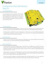
What hardware do I need?<br />
The <strong>Net2</strong> server PC can communicate with its' door controllers over the users network via a LAN, WAN or VPN<br />
connection.<br />
The <strong>Net2</strong> 485 <strong>TCP</strong>/<strong>IP</strong> Ethernet Interface is a complete unit with power supply that converts <strong>TCP</strong>/<strong>IP</strong> data into RS485<br />
allowing for the connection of a <strong>Net2</strong> data line to a network.<br />
The <strong>Net2</strong> <strong>plus</strong> control unit plugs directly into a standard <strong>TCP</strong>/<strong>IP</strong> network connection. It can run as a standalone<br />
controller and also drive an RS485 data line of other <strong>Net2</strong> units.<br />
Up to 200 control units can be connected to the RS485 data line. This data line must be terminated with 120 ohm<br />
resistors switched or wired across both data pairs at each end.<br />
The interface unit may be located at any position along the RS485 data line.<br />
<strong>Net2</strong> <strong>plus</strong> control unit<br />
12V<br />
Red LED<br />
Amber LED<br />
Green LED<br />
Data/D0<br />
Clock/D1<br />
Media Detect<br />
0V<br />
12V<br />
Red LED<br />
Amber LED<br />
Green LED<br />
Data/D0<br />
Clock/D1<br />
Media Detect<br />
0V<br />
Reader<br />
Reader<br />
Expansion<br />
C aution:<br />
For<br />
12V DC<br />
readers<br />
onl<br />
y<br />
N.O.<br />
N.O.<br />
COM<br />
Set Set<br />
Intruder Intruder Alarm Alarm<br />
Server Connected<br />
Server Connected<br />
10<br />
Server Link 100<br />
COM<br />
10<br />
Server Link 100<br />
10/100 Ethernet<br />
Sense<br />
ns<br />
<strong>Net2</strong> <strong>plus</strong><br />
http://paxton.info/107<br />
PLACE SERIAL<br />
2345612<br />
NUMBER<br />
LABEL 123456 HERE<br />
00-01-02-03-04-05<br />
End of Line Termination<br />
ON<br />
OFF<br />
RS485 Network<br />
CAT5 Cable Coding<br />
Tx<br />
Rx<br />
cores<br />
cable<br />
cores<br />
cable<br />
Screen or spare<br />
from data<br />
Arm<br />
Screen or spare<br />
from data<br />
Arm<br />
Wht/Grn<br />
Wht/Grn<br />
0V<br />
0V<br />
Green<br />
Green<br />
Wht/Orng<br />
Wht/Orng<br />
Orange<br />
Orange<br />
I nputs<br />
O u tputs<br />
r<br />
Powe<br />
I nputs<br />
Ou tputs<br />
Power<br />
DC Only<br />
Relay<br />
P SU/Tamper<br />
C ontac<br />
t<br />
E xit<br />
Butto<br />
n<br />
R<br />
elay<br />
2<br />
12V<br />
12-24V<br />
0V<br />
0V<br />
N.C.<br />
N.O. .<br />
COM<br />
N.C.<br />
N.O.<br />
COM<br />
Alarm<br />
12V<br />
Green LED<br />
Exit<br />
0V<br />
Contact<br />
0V<br />
0V<br />
Tamper<br />
PSU<br />
12V<br />
Red LED<br />
Amber LED<br />
Green LED<br />
Data/D0<br />
Clock/D1<br />
Media Detect<br />
0V<br />
12V<br />
Red LED<br />
Amber LED<br />
Green LED<br />
Data/D0<br />
Clock/D1<br />
Media Detect<br />
0V<br />
Reader<br />
Reader<br />
Expansion<br />
C aution:<br />
For<br />
12V DC<br />
readers<br />
onl<br />
y<br />
N.O.<br />
N.O.<br />
COM<br />
Set Set<br />
Intruder Intruder Alarm Alarm<br />
Server Connected<br />
Server Connected<br />
10<br />
Server Link 100<br />
COM<br />
10<br />
Server Link 100<br />
10/100 Ethernet<br />
Sense<br />
ns<br />
<strong>Net2</strong> <strong>plus</strong><br />
http://paxton.info/107<br />
PLACE SERIAL<br />
2345612<br />
NUMBER<br />
LABEL 123456 HERE<br />
00-01-02-03-04-05<br />
End of Line Termination<br />
ON<br />
OFF<br />
RS485 Network<br />
CAT5 Cable Coding<br />
Tx<br />
Rx<br />
cores<br />
cable<br />
cores<br />
cable<br />
Screen or spare<br />
from data<br />
Arm<br />
Screen or spare<br />
from data<br />
Arm<br />
Wht/Grn<br />
Wht/Grn<br />
0V<br />
0V<br />
Green<br />
Green<br />
Wht/Orng<br />
Wht/Orng<br />
Orange<br />
Orange<br />
I nputs<br />
O u tputs<br />
r<br />
Powe<br />
I nputs<br />
Ou tputs<br />
Power<br />
DC Only<br />
Relay<br />
P SU/Tamper<br />
C ontac<br />
t<br />
E xit<br />
Butto<br />
n<br />
R<br />
elay<br />
2<br />
12V<br />
12-24V<br />
0V<br />
0V<br />
N.C.<br />
N.O. .<br />
COM<br />
N.C.<br />
N.O.<br />
COM<br />
Alarm<br />
12V<br />
Green LED<br />
Exit<br />
0V<br />
Contact<br />
0V<br />
0V<br />
Tamper<br />
PSU<br />
Switchable 120 ohm resistors<br />
The interface plugs directly into<br />
the <strong>TCP</strong>/<strong>IP</strong> Ethernet network via a<br />
standard RJ45 connection box<br />
to next ACU<br />
2
For earlier designs, see the following:<br />
<strong>Net2</strong><br />
AN1006<br />
Instruction: Ins-30032 - Paxton <strong>Net2</strong> Ethernet Interface. < http://paxton.info/819 ><br />
Instruction: Ins-30029 - <strong>Net2</strong> 485 <strong>TCP</strong>/<strong>IP</strong> Lantronix UDS10B Ethernet Interface. < http://paxton.info/820 ><br />
Software configuration<br />
The <strong>TCP</strong>/<strong>IP</strong> Ethernet interface is configured <strong>using</strong> the <strong>Net2</strong> Server Configuration Utility, by selecting the <strong>TCP</strong>/<strong>IP</strong> nodes<br />
tab. Depending on the specific details of the Ethernet network, you may be able to detect the Ethernet interface,<br />
simply by clicking Detect. If this doesn't find it, then you will have to Click 'Add' and enter the MAC Address manually.<br />
The unit supports DHCP, which means that a DHCP server can issue its <strong>IP</strong> address. A static <strong>IP</strong> should be assigned<br />
once the device has been allocated an <strong>IP</strong> address via DHCP. A reservation should be made in the DHCP server, to<br />
ensure that the same <strong>IP</strong> address is issued each time, should the unit be reset. Consult your network administrator on<br />
detail of how to reserve <strong>IP</strong> addresses. The unit's MAC address can be read from inside the plastic enclosure, and will<br />
be required by the Network administrator to enter the reservation.<br />
The list box, at the top of the <strong>TCP</strong>/<strong>IP</strong> nodes tab, will list all of the units that have either been found or manually<br />
entered. There is a check box next to each entry, which allows each unit to be enabled or disabled.<br />
You can test that the units are responding, by selecting them and clicking the Ping button.<br />
3
<strong>Net2</strong><br />
AN1006<br />
How to assign a static <strong>IP</strong> address to an ACU<br />
If the Ethernet network does not have a DHCP server, then the <strong>IP</strong> address must be set manually, <strong>using</strong> the <strong>Net2</strong><br />
Server Configuration Utility. Select the <strong>IP</strong> address configuration tab. The network administrator should be able to<br />
advise you on suitable values to use. Check the 'Use the following <strong>IP</strong> address' button and enter the chosen address in<br />
the box. This will fix the <strong>IP</strong> address of the interface.<br />
Naming <strong>TCP</strong>/<strong>IP</strong> Ethernet interfaces<br />
The rename button can be used to give an interface a meaningful name in the system. This can be especially useful<br />
when more than one interface is used, as the name will appear in the doors screen within <strong>Net2</strong> showing which<br />
ACU's are connected to which data line, helping in any future fault finding process.<br />
Advanced tab of config utility<br />
Network latency can be amended for sites with slow or busy <strong>TCP</strong>/<strong>IP</strong> networks. The advanced options should only be<br />
changed following advice from Paxton Technical Support<br />
4
<strong>Net2</strong><br />
AN1006<br />
VLAN recommended<br />
On sites with high levels of broadcast traffic (CCTV, etc) this option is highly recommended and should be<br />
implemented wherever possible. VLAN's allow administrators to set up their networks by logically grouping devices.<br />
<strong>IP</strong> addresses, subnet masks, and local network protocols require fewer local server resources in this environment.<br />
Services can be more effectively deployed when they span buildings within a single VLAN. See also: AN1085 -<br />
Recommendations for <strong>using</strong> <strong>Net2</strong> with LAN and WAN networks. < http://paxton.info/970 ><br />
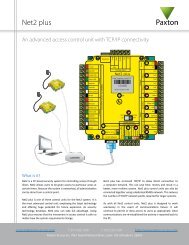
Connection over a Wide-Area Network (WAN)<br />
If you are connecting the interface to a WAN or to a network with a different subnet from the server running the<br />
<strong>Net2</strong> database, you must first fix the remote <strong>IP</strong> address, subnet mask and return gateway in the unit before taking it<br />
to the remote site.<br />
The PC that has the <strong>Net2</strong> server installed must be able to access the <strong>IP</strong> address range on the WAN\remote site. This<br />
may require the routers and gateways to be configured between the networks. Again, this would be done by the<br />
I.T\Network administrator of that site.<br />
Once installed, use the add button to create a record in the nodes table (if none was created during the initial setup)<br />
and the device can be assigned it appropriate <strong>IP</strong> information as designated at the remote site.<br />
Connecting to the PC directly<br />
The <strong>Net2</strong> <strong>plus</strong> unit can be connected to the PC via a standard network patch cable.<br />
Troubleshooting<br />
If you detect the MAC address but the device now shows 'Not Responding', check the <strong>IP</strong> address to make sure it<br />
is still in range with the PC or network. If it is not, you should either change the PC's <strong>IP</strong> address or the Ethernet<br />
interface's <strong>IP</strong> address so they are both again in the same range. Our Technical team can talk you through this if you<br />
need help.<br />
If the MAC address does not appear when you click 'Detect' then you will need to check that the following ports are<br />
open:-<br />
9999 <strong>TCP</strong><br />
10001 <strong>TCP</strong><br />
30718 UDP<br />
If you still cannot detect the MAC address of the Ethernet interface then connect it directly to your PC via a patch<br />
cable and call our Technical Help line.<br />
5