

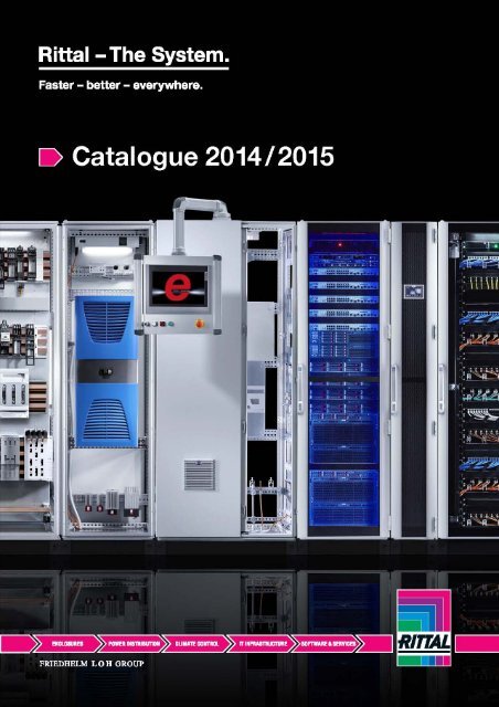
livebook

Create successful ePaper yourself
Turn your PDF publications into a flip-book with our unique Google optimized e-Paper software.
Dear Sir or Madam,<br />
Here at the Friedhelm Loh Group, one of our corporate principles is:<br />
“We view our customers as partners who determine the success of the company”.<br />
Our goal is to solve your challenges. Our products and services are uncompromising in terms<br />
of quality, technical execution, range and availability. Our dedicated employees around the<br />
globe are fully committed to this principle on a daily basis.<br />
With us as market leaders on your side, you benefit from our innovative strength.<br />
We can make you faster and better.<br />
As well as launching a slew of new products, we have also consistently refined the unique<br />
Rittal value chain. Act now to rationalise your planning with engineering software and a data<br />
portal from Eplan, and use “Rittal – The System.” for fast, efficient generation of your power<br />
distribution systems and controllers.<br />
Our software will help you to calculate climate control data and select the most appropriate<br />
cooling unit, and we now offer support with intelligent machine tools from Kiesling.<br />
We are committed to making your processes more efficient in every respect, from A to Z.<br />
Rittal is also unveiling another world first for your success – the standardised data centre<br />
RiMatrix S. True to our motto “Faster – better – everywhere.”, it eliminates the need for long<br />
planning and installation times. We can install a TÜV-tested data centre in a matter of weeks<br />
rather than months.<br />
The Rittal Catalogue is here to help you compile products and corresponding system<br />
accessories quickly and successfully.<br />
Thank you for your invaluable feedback and suggestions, and we look forward to developing<br />
more innovations together.<br />
Wishing you every success<br />
Yours<br />
Friedhelm Loh<br />
Owner and CEO<br />
Friedhelm Loh Group<br />
2
3
4 Rittal Catalogue 34
Enclosures from page 15<br />
Small enclosures............................................................ 23<br />
Compact enclosures...................................................... 41<br />
Enclosure systems ......................................................... 55<br />
IT enclosure systems/housings...................................... 85<br />
Console systems/PC enclosure systems/IW................ 107<br />
Operating housings/support arm/stand systems......... 123<br />
Hygienic Design........................................................... 169<br />
Stainless steel .............................................................. 175<br />
Ex enclosures............................................................... 191<br />
Power distribution from page 197<br />
Busbar systems ........................................................... 205<br />
RiLine ........................................................................... 211<br />
Ri4Power ...................................................................... 267<br />
Ri4Power distribution enclosures................................. 297<br />
Climate control from page 307<br />
Cooling with ambient air .............................................. 315<br />
Cooling units ................................................................ 333<br />
Cooling with water........................................................ 353<br />
Enclosure heaters ........................................................ 366<br />
Climate control accessories......................................... 369<br />
IT infrastructure from page 387<br />
RiMatrix S ..................................................................... 397<br />
IT enclosure systems/housings.................................... 405<br />
IT power ....................................................................... 407<br />
IT cooling ..................................................................... 427<br />
IT monitoring ................................................................ 445<br />
IT security solutions ..................................................... 465<br />
Software & services from page 477<br />
Value chain .................................................................. 479<br />
Software ....................................................................... 495<br />
Service ......................................................................... 501<br />
Quality management.................................................... 504<br />
System accessories from page 507<br />
Technical information................................................... 722<br />
List of model numbers ................................................. 725<br />
Index ............................................................................ 735<br />
Rittal Catalogue 34<br />
5
6 Rittal Catalogue 34
nextlevel<br />
Step one in the value chain<br />
Eplan are global providers of high-tech, software-based<br />
engineering solutions. Use Eplan to optimise your engineering<br />
and accelerate your product generation process.<br />
Eplan – efficient engineering.<br />
◾ EPLAN Engineering Center<br />
◾ EPLAN PPE<br />
◾ EPLAN Fluid<br />
◾ EPLAN electric P8<br />
◾ EPLAN Pro Panel<br />
◾ EPLAN Harness proD<br />
◾ EPLAN Data Portal<br />
Rittal Catalogue 34<br />
7
The System.<br />
8 Rittal Catalogue 34
nextlevel<br />
Step two in the value chain<br />
With Eplan and Rittal, you benefit from integrated<br />
engineering solutions based on top-quality system<br />
components, component data, system know-how<br />
and design expertise throughout every aspect of<br />
“Rittal – The System.”<br />
+<br />
Rittal – The System.<br />
◾ Enclosure systems<br />
◾ Ri4Power power distribution to IEC 61 439<br />
◾ TopTherm cooling units, TÜV-tested<br />
◾ RiMatrix S – The mass-produced data centre<br />
Rittal Catalogue 34<br />
9
10 Rittal Catalogue 34
nextlevel<br />
Step three in the value chain<br />
Three powerful companies have joined forces to form<br />
an integrated trio of excellence, covering all aspects<br />
of enclosures. With Kiesling as international machine<br />
tool specialists, we can automate your success in<br />
equipping your enclosure.<br />
+ +<br />
◾ Kiesling Perforex – Machining of enclosure solutions<br />
◾ Kiesling Secarex – Cable ducts and support rails cut to length without delay<br />
◾ Kiesling Athex – Automated terminal block configuration<br />
◾ Kiesling Averex – Mounting plate wiring<br />
Rittal Catalogue 34<br />
11
Make<br />
easy.<br />
12 Rittal Catalogue 34
nextlevel<br />
for data centres<br />
With RiMatrix S, Rittal unveils the first pre-planned, pre-configured concept with<br />
defined efficiency and power ratings for fully standardised data centre production.<br />
The revolutionary alternative to individual data centre construction: RiMatrix S<br />
◾ Standardised, mass-produced data centre modules<br />
◾ Only one model number<br />
◾ Short delivery times – Delivered by HGV<br />
◾ TÜV-tested<br />
Rittal Catalogue 34<br />
13
14 Rittal Catalogue 34/Enclosures
Enclosures<br />
Small enclosures<br />
Polycarbonate enclosures PK .......................................................................24<br />
Cast aluminium enclosures GA .....................................................................28<br />
Terminal boxes KL........................................................................................30<br />
E-Box EB .....................................................................................................34<br />
Bus enclosures BG.......................................................................................36<br />
Compact enclosures<br />
Compact enclosures AE ...............................................................................46<br />
Compact system enclosures CM..................................................................50<br />
Plastic enclosures KS ...................................................................................52<br />
Enclosure systems<br />
Baying systems TS 8 ....................................................................................62<br />
System enclosures SE 8...............................................................................81<br />
IT enclosure systems/housings<br />
Network/server enclosures TS-IT..................................................................90<br />
Distributor racks ...........................................................................................96<br />
IT enclosures ................................................................................................97<br />
Console systems/PC enclosure systems/IW<br />
TopConsole system TP...............................................................................110<br />
One-piece consoles TP ..............................................................................115<br />
Universal consoles TP.................................................................................116<br />
PC enclosure systems ................................................................................118<br />
Enclosure for tower PC...............................................................................119<br />
Industrial Workstations................................................................................120<br />
Operating housings/support arm systems/<br />
stand systems<br />
Comfort Panel ............................................................................................124<br />
Optipanel....................................................................................................126<br />
Operating housings ....................................................................................130<br />
Compact Panel...........................................................................................133<br />
Support arm systems .................................................................................135<br />
Stand systems............................................................................................164<br />
Hygienic Design<br />
Terminal boxes HD .....................................................................................170<br />
Compact enclosures HD.............................................................................171<br />
Stainless steel<br />
Support arm system CP 40 ........................................................................140<br />
Small enclosures ........................................................................................176<br />
Compact enclosures...................................................................................179<br />
Enclosure systems......................................................................................182<br />
Operating housings ....................................................................................188<br />
Ex enclosures<br />
Stainless steel Ex enclosures ......................................................................192<br />
Plastic Ex enclosures..................................................................................194<br />
Rittal Catalogue 34/Enclosures<br />
15
nextlevel<br />
for industry<br />
The Eplan engineering platform and the extensive system solutions from Rittal<br />
are perfectly interlinked. In this way, you can benefit from a unique system and<br />
effortlessly take value creation to the next level.<br />
Rittal – The System.<br />
◾ Eplan – Efficient engineering<br />
◾ Rittal – Type-tested enclosure systems<br />
◾ Kiesling – Machining of enclosures<br />
and mounting plate wiring<br />
16 Rittal Catalogue 34/Enclosures
Rittal Catalogue 34/Enclosures<br />
17
Enclosures from the smallest<br />
to the largest<br />
◾ Small and compact enclosures<br />
◾ Enclosure systems<br />
◾ Console and PC enclosure systems<br />
◾ Support arm systems and operating housings<br />
◾ Stainless steel housing and enclosure systems<br />
18 Rittal Catalogue 34/Enclosures
◾ Over 9 million already in use – the Top enclosure system TS 8<br />
◾ Rittal’s expertise is acquired from 15,000 enclosures and housings per day<br />
Rittal Catalogue 34/Enclosures<br />
19
20 Rittal Catalogue 34/Enclosures
Your benefits<br />
As a system provider, Rittal is the world's leading supplier of innovative enclosure technology.<br />
Rittal meets very high standards of security, ergonomics, energy and cost efficiency.<br />
Faster – Software tools for efficient engineering and a huge range of products available<br />
for immediate delivery<br />
Better – A comprehensive range of system accessories for individual installation and fast assembly<br />
Everywhere – A contiguous global delivery and service network<br />
Rittal Catalogue 34/Enclosures<br />
21
22 Rittal Catalogue 34/Enclosures
Small enclosures<br />
Polycarbonate enclosures PK<br />
Polycarbonate enclosures PK .......................................................................24<br />
Accessories..................................................................................................27<br />
Cast aluminium enclosures GA<br />
Cast aluminium enclosures GA .....................................................................28<br />
Accessories..................................................................................................29<br />
Terminal boxes KL<br />
Terminal boxes KL........................................................................................30<br />
E-Box EB<br />
E-Box EB .....................................................................................................34<br />
Bus enclosures BG<br />
Bus enclosures BG.......................................................................................36<br />
Rittal Catalogue 34/Enclosures<br />
23
Polycarbonate enclosures PK<br />
PK accessories Page 27 System accessories Page 507 Cable gland, polyamide Page 658<br />
Material:<br />
– Housing: Fibre-glass<br />
reinforced polycarbonate<br />
– Cover grey: Fibreglass-reinforced<br />
polycarbonate, all-round<br />
foamed-in PU seal<br />
– Cover transparent: Polycarbonate,<br />
all-round foamed-in PU<br />
seal<br />
– Cover screws: Polyamide<br />
– Insulating bungs: Polyethylene<br />
Colour:<br />
– RAL 7035<br />
Protection category IP to<br />
IEC 60 529:<br />
– IP 66<br />
Supply includes:<br />
– Enclosure with cover<br />
– Cover screws<br />
– Insulating bungs for wall<br />
mounting screws<br />
Approvals:<br />
– UL<br />
– cUL<br />
Technical details:<br />
Available on the Internet<br />
without knockouts<br />
Width mm 65 94 94 94 110 110 Page<br />
Height mm 65 65 94 94 110 110<br />
Depth mm 57 57 57 81 66 90<br />
Model No. 9500.000 9502.000 9504.000 9505.000 9506.000 9507.000<br />
Packs of 12 pc(s). 8 pc(s). 6 pc(s). 6 pc(s). 6 pc(s). 6 pc(s).<br />
Cover Grey ◾ ◾ ◾ ◾ ◾ ◾<br />
Accessories<br />
Mounting plate – – – – – –<br />
Wall mounting brackets 1 pack(s) 9583.000 9583.000 9583.000 9583.000 9583.000 9583.000 27<br />
Hinges – – – – – –<br />
without knockouts<br />
Width mm 130 130 130 130 180 180 Page<br />
Height mm 94 94 130 130 94 94<br />
Depth mm 57 81 75 99 57 81<br />
Model No. 9508.000 9509.000 9510.000 9511.000 9512.000 9513.000<br />
Packs of 4 pc(s). 4 pc(s). 4 pc(s). 4 pc(s). 2 pc(s). 2 pc(s).<br />
Cover Grey ◾ ◾ ◾ ◾ ◾ ◾<br />
Accessories<br />
Mounting plate – – – – – –<br />
Wall mounting brackets 1 pack(s) 9583.000 9583.000 9583.000 9583.000 9583.000 9583.000 27<br />
Hinges – – – – – –<br />
24 Rittal Catalogue 34/Enclosures
without knockouts<br />
without knockouts<br />
without knockouts<br />
without knockouts<br />
Polycarbonate enclosures PK<br />
Width mm Packs of 180 180 180 180 180 180 Page<br />
Height mm 110 110 110 110 110 110<br />
Depth mm 90 90 111 111 165 165<br />
Model No. 2 pc(s). 9514.000 9514.100 9515.000 9515.100 9516.000 9516.100<br />
Cover<br />
Grey ◾ – ◾ – ◾ –<br />
Transparent – ◾ – ◾ – ◾<br />
Accessories<br />
Mounting plate – – – – – –<br />
Wall mounting brackets 1 pack(s) 9583.000 9583.000 9583.000 9583.000 9583.000 9583.000 27<br />
Hinges 10 set(s) 9581.000 9581.000 9581.000 9581.000 9581.000 9581.000 27<br />
Width mm Packs of 182 182 182 182 182 182 Page<br />
Height mm 180 180 180 180 180 180<br />
Depth mm 90 90 111 111 165 165<br />
Model No. 1 pc(s). 9517.000 9517.100 9518.000 9518.100 9519.000 9519.100<br />
Cover<br />
Grey ◾ – ◾ – ◾ –<br />
Transparent – ◾ – ◾ – ◾<br />
Accessories<br />
Mounting plate 10 pc(s). 9548.000 9548.000 9548.000 9548.000 9548.000 9548.000 27<br />
Wall mounting brackets 1 pack(s) 9583.000 9583.000 9583.000 9583.000 9583.000 9583.000 27<br />
Hinges 10 set(s) 9581.000 9581.000 9581.000 9581.000 9581.000 9581.000 27<br />
Width mm Packs of 254 254 254 254 254 254 Page<br />
Height mm 180 180 180 180 180 180<br />
Depth mm 90 90 111 111 165 165<br />
Model No. 1 pc(s). 9520.000 9520.100 9521.000 9521.100 9522.000 9522.100<br />
Cover<br />
Grey ◾ – ◾ – ◾ –<br />
Transparent – ◾ – ◾ – ◾<br />
Accessories<br />
Mounting plate 8 pc(s). 9549.000 9549.000 9549.000 9549.000 9549.000 9549.000 27<br />
Wall mounting brackets 1 pack(s) 9583.000 9583.000 9583.000 9583.000 9583.000 9583.000 27<br />
Hinges 10 set(s) 9581.000 9581.000 9581.000 9581.000 9581.000 9581.000 27<br />
Width mm Packs of 360 360 360 360 Page<br />
Height mm 254 254 254 254<br />
Depth mm 111 111 165 165<br />
Model No. 1 pc(s). 9523.000 9523.100 9524.000 9524.100<br />
Cover<br />
Grey ◾ – ◾ –<br />
Transparent – ◾ – ◾<br />
Accessories<br />
Mounting plate 4 pc(s). 9550.000 9550.000 9550.000 9550.000 27<br />
Wall mounting brackets 1 pack(s) 9583.000 9583.000 9583.000 9583.000 27<br />
Hinges 10 set(s) 9581.000 9581.000 9581.000 9581.000 27<br />
Rittal Catalogue 34/Enclosures<br />
25
Polycarbonate enclosures PK<br />
PK accessories Page 27 System accessories Page 507 Cable gland, polyamide Page 658<br />
Material:<br />
– Housing: Fibre-glass<br />
reinforced polycarbonate<br />
– Cover: Fibreglass-reinforced<br />
polycarbonate, all-round<br />
foamed-in PU seal<br />
– Cover screws: Polyamide<br />
– Insulating bungs: Polyethylene<br />
Colour:<br />
– RAL 7035<br />
Protection category IP to<br />
IEC 60 529:<br />
– IP 66<br />
Supply includes:<br />
– Enclosure with cover<br />
– Cover screws<br />
– Insulating bungs for wall<br />
mounting screws<br />
Approvals:<br />
– UL<br />
– cUL<br />
Technical details:<br />
Available on the Internet<br />
with knockouts<br />
Width mm 130 180 254 Page<br />
Height mm 94 110 180<br />
Depth mm 57 90 111<br />
Model No. 9508.050 9514.050 9521.050<br />
Packs of 4 pc(s). 2 pc(s). 1 pc(s).<br />
Cover Grey ◾ ◾ ◾<br />
No. of metric knockouts<br />
10 x M16/M20<br />
16 x M20<br />
2 x M20/M25<br />
2 x M32/M40<br />
24 x M20<br />
4 x M25/M32<br />
4 x M32/M40<br />
Accessories<br />
Mounting plate 8 pc(s). – – 9549.000 27<br />
Wall mounting brackets 1 pack(s) 9583.000 9583.000 9583.000 27<br />
26 Rittal Catalogue 34/Enclosures
Polycarbonate enclosures PK<br />
Accessories<br />
Mounting plate<br />
For individual interior installation<br />
Material:<br />
– 2.5 mm melamine phenol-coated laminated<br />
paper<br />
Colour:<br />
– RAL 7035<br />
Supply includes:<br />
– Mounting plate<br />
– Self-tapping assembly screws<br />
For enclosure<br />
Width Height<br />
mm mm<br />
Packs of Model No.<br />
9517.000/.100, 9518.000/.100, 9519.000/.100 150 150 10 pc(s). 9548.000<br />
9520.000/.100, 9521.000/.100, 9521.050, 9522.000/.100 220 150 8 pc(s). 9549.000<br />
9523.000/.100, 9524.000/.100 331 220 4 pc(s). 9550.000<br />
Hinges<br />
For hinged attachment of covers. The supplied drilling<br />
template ensures problem-free assembly.<br />
Colour:<br />
– Similar to RAL 7035<br />
Supply includes:<br />
– 1 set =<br />
2 hinges<br />
4 assembly screws<br />
4 polyethylene sealing bungs<br />
1 drilling template<br />
For enclosure Material Packs of Model No.<br />
9514.000/.100 – 9524.000/.100 Polystyrene 10 set(s) 9581.000<br />
Wall mounting brackets<br />
The enclosure can be screwed to the wall using four<br />
wall mounting brackets. The wall mounting bracket<br />
is securely attached to the enclosure by simply<br />
using pins.<br />
Material:<br />
– Polyamide, grey<br />
Colour:<br />
– Similar to RAL 7035<br />
Packs of Model No.<br />
For all enclosures 1 pack(s) 9583.000<br />
Supply includes:<br />
– 1 pack = 40 pieces<br />
Rittal Catalogue 34/Enclosures<br />
27
Cast aluminium enclosures GA<br />
GA accessories Page 29 System accessories Page 507<br />
Material:<br />
– Enclosure: Cast aluminium<br />
– Cover: Cast aluminium, allround<br />
foamed-in PU seal<br />
Surface finish:<br />
– Textured paint<br />
Colour:<br />
– RAL 7001<br />
Protection category IP to<br />
IEC 60 529:<br />
– IP 66<br />
Protection category NEMA:<br />
– NEMA 4<br />
Supply includes:<br />
– Enclosure with cover<br />
– Cover screws, captive<br />
– Screws for attaching support<br />
rails<br />
– Screw for connection of the PE<br />
conductor<br />
Technical details:<br />
Available on the Internet<br />
Width mm 58 98 75 125 175 250 122 220 Page<br />
Height mm 64 64 80 80 80 80 120 120<br />
Depth mm 34 35 57 57 57 57 80 91<br />
Model No. 9101.210 9102.210 9104.210 9105.210 9106.210 9107.210 9108.210 9110.210<br />
Packs<br />
of<br />
5 pc(s). 3 pc(s). 1 pc(s). 1 pc(s). 1 pc(s). 1 pc(s). 1 pc(s). 1 pc(s).<br />
Accessories<br />
– – – 9105.700 – – 9108.700 9110.700 29<br />
Mounting plate<br />
Packs<br />
of<br />
– – – 10 pc(s). – – 2 pc(s). 2 pc(s).<br />
Wall mounting bracket 2 pc(s). – – – – – – 9121.122 9121.122 29<br />
Hinge, exterior 2 pc(s). – – – – – – 9123.000 9123.000 29<br />
Earth straps see page see page see page see page see page see page see page see page 644<br />
Cable glands from page from page from page from page from page from page from page from page 658<br />
Width mm<br />
Packs<br />
of<br />
360 160 260 360 202 280 334 330 Page<br />
Height mm 120 160 160 160 232 232 233 230<br />
Depth mm 82 91 91 91 111 111 111 181<br />
Model No. 1 pc(s). 9111.210 9112.210 9113.210 9114.210 9116.210 9117.210 9118.210 9119.210<br />
Accessories<br />
– 9112.700 9113.700 9114.700 9116.700 9117.700 9118.700 9118.700 29<br />
Mounting plate<br />
Packs<br />
of<br />
– 2 pc(s). 2 pc(s). 1 pc(s). 1 pc(s). 1 pc(s). 1 pc(s). 1 pc(s).<br />
Wall mounting bracket 2 pc(s). 9121.122 9121.160 9121.160 9121.160 9121.230 9121.230 9121.230 9121.230 29<br />
Hinge, exterior 2 pc(s). 9123.000 9123.000 9123.000 9123.000 9123.000 9123.000 9123.000 9123.000 29<br />
Earth straps see page see page see page see page see page see page see page see page 644<br />
Cable glands from page from page from page from page from page from page from page from page 658<br />
28 Rittal Catalogue 34/Enclosures
Cast aluminium enclosures GA<br />
Accessories<br />
Mounting plate<br />
For individual interior installation, with mounting<br />
holes.<br />
Material:<br />
– Sheet steel<br />
Surface finish:<br />
– Zinc-plated<br />
Exterior dimensions mm<br />
Width<br />
Height<br />
For GA enclosures Packs of Model No.<br />
114 69 9105.210 10 pc(s). 9105.700<br />
109 107 9108.210 2 pc(s). 9108.700<br />
207 107 9110.210 2 pc(s). 9110.700<br />
144 142 9112.210 2 pc(s). 9112.700<br />
245 142 9113.210 2 pc(s). 9113.700<br />
346 142 9114.210 1 pc(s). 9114.700<br />
183 214 9116.210 1 pc(s). 9116.700<br />
264 214 9117.210 1 pc(s). 9117.700<br />
314 214 9118.210/9119.210 1 pc(s). 9118.700<br />
Wall mounting bracket<br />
For external mounting on surfaces – no need to<br />
dismantle the cover if pre-assembled.<br />
Material:<br />
– Sheet steel<br />
Surface finish:<br />
– Zinc-plated<br />
For GA enclosures Packs of Model No.<br />
9108.210/<br />
9110.210/<br />
2 pc(s). 9121.122<br />
9111.210<br />
9112.210/<br />
9113.210/<br />
2 pc(s). 9121.160<br />
9114.210<br />
9116.210/<br />
9117.210/<br />
9118.210/<br />
9119.210<br />
2 pc(s). 9121.230<br />
Hinge, exterior<br />
For fastening the cover to the enclosure base.<br />
Material:<br />
– Die-cast aluminium<br />
Colour:<br />
– RAL 7001<br />
For GA enclosures Packs of Model No.<br />
9108.210/<br />
9110.210/<br />
9111.210/<br />
9112.210/<br />
9113.210/<br />
9114.210/<br />
9116.210/<br />
9117.210/<br />
9118.210/<br />
9119.210<br />
2 pc(s).<br />
+ 8 screws<br />
9123.000<br />
Rittal Catalogue 34/Enclosures<br />
29
Terminal boxes KL<br />
System accessories Page 507 KL stainless steel Page 177 KL for potentially explosive areas Page 192 KL Hygienic Design Page 170<br />
Material:<br />
– Enclosure: Sheet steel<br />
– Cover: Sheet steel, all-round<br />
foamed-in PU seal<br />
Surface finish:<br />
– Enclosure and cover: Dipcoatprimed,<br />
powder-coated on the<br />
outside, textured paint<br />
Colour:<br />
– RAL 7035<br />
Protection category IP to<br />
IEC 60 529:<br />
– IP 66<br />
Protection category NEMA:<br />
– NEMA 4<br />
Supply includes:<br />
– Enclosure with cover<br />
– Quick-release fastener including<br />
plastic bushes<br />
Approvals:<br />
– UL<br />
– CSA<br />
– TÜV<br />
– Germanischer Lloyd<br />
– Russian Maritime Register of<br />
Shipping<br />
– Lloyds Register of Shipping<br />
– Bureau Veritas<br />
– VDE<br />
Technical details:<br />
Available on the Internet<br />
without gland plate<br />
Width mm Packs of 150 200 200 300 300 400 Page<br />
Height mm 150 150 200 150 200 200<br />
Depth mm 80 80 80 80 80 80<br />
Material thickness - enclosure mm 1.25 1.25 1.25 1.25 1.25 1.25<br />
Material thickness - cover mm 1.25 1.25 1.25 1.25 1.25 1.25<br />
Model No. 1 pc(s). 1514.510 1528.510 1516.510 1515.510 1517.510 1518.510<br />
Weight kg 1.4 1.6 1.9 2.1 2.6 3.2<br />
Accessories<br />
Mounting plates 1 pc(s). 1560.700 1575.700 1562.700 1561.700 1563.700 1564.700 591<br />
Support rails TS 35/7.5 10 pc(s). 2314.000 2315.000 2315.000 2316.000 2316.000 2317.000 614<br />
Support rails TS 35/15 – – – – – –<br />
Cover retainer 3 pair(s) 1591.000 1591.000 1591.000 1591.000 1591.000 1591.000 574<br />
Cover hinge 6 pc(s). 1592.000 1592.000 1592.000 1592.000 1592.000 1592.000 574<br />
Earthing kit 5 pc(s). 2570.100 2570.100 2570.100 2570.100 2570.100 2570.100 646<br />
Wall mounting bracket 4 pc(s). 1590.000 1590.000 1590.000 1590.000 1590.000 1590.000 587<br />
Spare quick-release fastener 12 pc(s). 1593.000 1593.000 1593.000 1593.000 1593.000 1593.000<br />
30 Rittal Catalogue 34/Enclosures
without gland plate<br />
without gland plate<br />
without gland plate<br />
Terminal boxes KL<br />
Width mm Packs of 600 150 200 200 300 300 Page<br />
Height mm 200 150 150 200 150 200<br />
Depth mm 80 120 120 120 120 120<br />
Material thickness - enclosure mm 1.25 1.25 1.25 1.25 1.25 1.25<br />
Material thickness - cover mm 1.25 1.25 1.25 1.25 1.25 1.25<br />
Model No. 1 pc(s). 1519.510 1500.510 1529.510 1502.510 1501.510 1503.510<br />
Weight kg 4.6 1.6 1.8 2.3 2.6 3.0<br />
Accessories<br />
Mounting plates 1 pc(s). 1566.700 1560.700 1575.700 1562.700 1561.700 1563.700 591<br />
Support rails TS 35/7.5 10 pc(s). – 2314.000 2315.000 2315.000 2316.000 2316.000 614<br />
Support rails TS 35/15 10 pc(s). 2319.000 – – – – – 614<br />
Cover retainer 3 pair(s) 1591.000 1591.000 1591.000 1591.000 1591.000 1591.000 574<br />
Cover hinge 6 pc(s). 1592.000 1592.000 1592.000 1592.000 1592.000 1592.000 574<br />
Earthing kit 5 pc(s). 2570.100 2570.100 2570.100 2570.100 2570.100 2570.100 646<br />
Wall mounting bracket 4 pc(s). 1590.000 1590.000 1590.000 1590.000 1590.000 1590.000 587<br />
Spare quick-release fastener 12 pc(s). 1593.000 1593.000 1593.000 1593.000 1593.000 1593.000<br />
Width mm Packs of 300 400 400 400 400 500 Page<br />
Height mm 300 150 200 300 400 200<br />
Depth mm 120 120 120 120 120 120<br />
Material thickness - enclosure mm 1.38 1.25 1.25 1.38 1.38 1.25<br />
Material thickness - cover mm 1.25 1.25 1.25 1.25 1.25 1.25<br />
Model No. 1 pc(s). 1507.510 1589.510 1504.510 1508.510 1511.510 1505.510<br />
Weight kg 4.0 3.2 3.6 4.8 6.2 4.4<br />
Accessories<br />
Mounting plates 1 pc(s). 1567.700 1576.700 1564.700 1568.700 1571.700 1565.700 591<br />
Support rails TS 35/7.5 10 pc(s). 2316.000 2317.000 2317.000 2317.000 2317.000 – 614<br />
Support rails TS 35/15 10 pc(s). – – – – – 2318.000 614<br />
Cover retainer 3 pair(s) 1591.000 1591.000 1591.000 1591.000 1591.000 1591.000 574<br />
Cover hinge 6 pc(s). 1592.000 1592.000 1592.000 1592.000 1592.000 1592.000 574<br />
Earthing kit 5 pc(s). 2570.100 2570.100 2570.100 2570.100 2570.100 2570.100 646<br />
Wall mounting bracket 4 pc(s). 1590.000 1590.000 1590.000 1590.000 1590.000 1590.000 587<br />
Spare quick-release fastener 12 pc(s). 1593.000 1593.000 1593.000 1593.000 1593.000 1593.000<br />
Width mm Packs of 500 600 600 600 800 800 Page<br />
Height mm 300 200 300 400 200 400<br />
Depth mm 120 120 120 120 120 120<br />
Material thickness - enclosure mm 1.38 1.25 1.38 1.38 1.25 1.38<br />
Material thickness - cover mm 1.25 1.25 1.25 1.25 1.25 1.25<br />
Model No. 1 pc(s). 1509.510 1506.510 1510.510 1512.510 1527.510 1513.510<br />
Weight kg 5.8 5.7 6.8 8.4 6.8 11.0<br />
Accessories<br />
Mounting plates 1 pc(s). 1569.700 1566.700 1570.700 1572.700 1574.700 1573.700 591<br />
Support rails TS 35/7.5 – – – – – –<br />
Support rails TS 35/15 10 pc(s). 2318.000 2319.000 2319.000 2319.000 – – 614<br />
Cover retainer 3 pair(s) 1591.000 1591.000 1591.000 1591.000 1591.000 1591.000 574<br />
Cover hinge 6 pc(s). 1592.000 1592.000 1592.000 1592.000 1592.000 1592.000 574<br />
Earthing kit 5 pc(s). 2570.100 2570.100 2570.100 2570.100 2570.100 2570.100 646<br />
Wall mounting bracket 4 pc(s). 1590.000 1590.000 1590.000 1590.000 1590.000 1590.000 587<br />
Spare quick-release fastener 12 pc(s). 1593.000 1593.000 1593.000 1593.000 1593.000 1593.000<br />
Rittal Catalogue 34/Enclosures<br />
31
Terminal boxes KL<br />
System accessories Page 507 KL stainless steel Page 177 KL for potentially explosive areas Page 192 KL Hygienic Design Page 170<br />
Material:<br />
– Enclosure: Sheet steel<br />
– Cover: Sheet steel, all-round<br />
foamed-in PU seal<br />
Surface finish:<br />
– Enclosure and cover: Dipcoatprimed,<br />
powder-coated on the<br />
outside, textured paint<br />
Colour:<br />
– RAL 7035<br />
Protection category IP to<br />
IEC 60 529:<br />
– IP 55<br />
Protection category NEMA:<br />
– NEMA 12<br />
Supply includes:<br />
– Enclosure with cover<br />
– Quick-release fastener including<br />
plastic bushes<br />
– Sheet steel gland plates with<br />
seals and assembly parts<br />
Approvals:<br />
– UL<br />
– CSA<br />
– TÜV<br />
– Germanischer Lloyd<br />
– Russian Maritime Register of<br />
Shipping<br />
– Lloyds Register of Shipping<br />
– Bureau Veritas<br />
– VDE<br />
Technical details:<br />
Available on the Internet<br />
with gland plate<br />
Width mm Packs of 300 300 300 400 400 400 500 Page<br />
Height mm 150 200 300 200 300 400 200<br />
Depth mm 120 120 120 120 120 120 120<br />
Material thickness - enclosure mm 1.25 1.25 1.38 1.25 1.38 1.38 1.25<br />
Material thickness - cover mm 1.25 1.25 1.25 1.25 1.25 1.25 1.25<br />
Model No. 1 pc(s). 1530.510 1531.510 1535.510 1532.510 1536.510 1539.510 1533.510<br />
Weight kg 2.7 3.3 4.5 4.0 5.2 6.7 4.9<br />
Gland plate (top + bottom), size 2 2 2 2 2 2 2<br />
Gland plate (top + bottom), qty. 1 + 1 1 + 1 1 + 1 1 + 1 1 + 1 1 + 1 2 + 2<br />
Gland plate (left + right), size – – 2 – 2 2 –<br />
Gland plate (left + right), qty. – – 1 + 1 – 1 + 1 1 + 1 –<br />
Accessories<br />
Mounting plates 1 pc(s). 1561.700 1563.700 1567.700 1564.700 1568.700 1571.700 1565.700 591<br />
Plastic cable gland plates see page see page see page see page see page see page see page 653<br />
Support rails TS 35/7.5 10 pc(s). 2316.000 2316.000 2316.000 2317.000 2317.000 2317.000 – 614<br />
Support rails TS 35/15 10 pc(s). – – – – – – 2318.000 614<br />
Cover retainer 3 pair(s) 1591.000 1591.000 1591.000 1591.000 1591.000 1591.000 1591.000 574<br />
Cover hinge 6 pc(s). 1592.000 1592.000 1592.000 1592.000 1592.000 1592.000 1592.000 574<br />
Earthing kit 5 pc(s). 2570.100 2570.100 2570.100 2570.100 2570.100 2570.100 2570.100 646<br />
Wall mounting bracket 4 pc(s). 1590.000 1590.000 1590.000 1590.000 1590.000 1590.000 1590.000 587<br />
Spare quick-release fastener 12 pc(s). 1593.000 1593.000 1593.000 1593.000 1593.000 1593.000 1593.000<br />
32 Rittal Catalogue 34/Enclosures
with gland plate<br />
Terminal boxes KL<br />
Width mm Packs of 500 600 600 600 800 800 Page<br />
Height mm 300 200 300 400 200 400<br />
Depth mm 120 120 120 120 120 120<br />
Material thickness - enclosure mm 1.38 1.25 1.38 1.38 1.25 1.38<br />
Material thickness - cover mm 1.25 1.25 1.25 1.25 1.25 1.25<br />
Model No. 1 pc(s). 1537.510 1534.510 1538.510 1540.510 1542.510 1541.510<br />
Weight kg 5.2 5.9 7.7 9.0 7.2 12.0<br />
Gland plate (top + bottom), size 2 2 2 2 2 2<br />
Gland plate (top + bottom), qty. 2 + 2 2 + 2 2 + 2 2 + 2 3 + 3 3 + 3<br />
Gland plate (left + right), size 2 – 2 2 – 2<br />
Gland plate (left + right), qty. 1 + 1 – 1 + 1 1 + 1 – 1 + 1<br />
Accessories<br />
Mounting plates 1 pc(s). 1569.700 1566.700 1570.700 1572.700 1574.700 1573.700 591<br />
Plastic cable gland plates see page see page see page see page see page see page 653<br />
Support rails TS 35/7.5 – – – – – –<br />
Support rails TS 35/15 10 pc(s). 2318.000 2319.000 2319.000 2319.000 – – 614<br />
Cover retainer 3 pair(s) 1591.000 1591.000 1591.000 1591.000 1591.000 1591.000 574<br />
Cover hinge 6 pc(s). 1592.000 1592.000 1592.000 1592.000 1592.000 1592.000 574<br />
Earthing kit 5 pc(s). 2570.100 2570.100 2570.100 2570.100 2570.100 2570.100 646<br />
Wall mounting bracket 4 pc(s). 1590.000 1590.000 1590.000 1590.000 1590.000 1590.000 587<br />
Spare quick-release fastener 12 pc(s). 1593.000 1593.000 1593.000 1593.000 1593.000 1593.000<br />
Accessories<br />
Earthing set<br />
see from page 644<br />
Rittal Catalogue 34/Enclosures<br />
33
E-Box EB<br />
System accessories Page 507<br />
Material:<br />
– Enclosure and door: Sheet<br />
steel, all-round foamed-in PU<br />
seal<br />
Surface finish:<br />
– Enclosure and door: Dipcoatprimed,<br />
powder-coated on the<br />
outside, textured paint<br />
– Mounting plate: Zinc-plated<br />
Colour:<br />
– RAL 7035<br />
Protection category IP to<br />
IEC 60 529:<br />
– IP 66<br />
Protection category NEMA:<br />
– NEMA 4<br />
Supply includes:<br />
– Enclosure with hinged door<br />
– 180° hinge<br />
– Cam lock with 3 mm double-bit<br />
insert<br />
– Mounting plate<br />
Approvals:<br />
– UL<br />
– CSA<br />
– TÜV<br />
– Germanischer Lloyd<br />
– Russian Maritime Register of<br />
Shipping<br />
– Lloyds Register of Shipping<br />
– Bureau Veritas<br />
– VDE<br />
Technical details:<br />
Available on the Internet<br />
H<br />
T<br />
F<br />
G<br />
B<br />
Depth 80 mm<br />
Width (B) mm Packs of 150 150 200 200 200 Page<br />
Height (H) mm 150 300 200 300 400<br />
Depth (T) mm 80 80 80 80 80<br />
Mounting plate width (F) mm 125 125 175 175 175<br />
Mounting plate height (G) mm 135 285 185 285 385<br />
Material thickness - enclosure mm 1.25 1.25 1.25 1.25 1.25<br />
Material thickness - door mm 1.25 1.25 1.25 1.25 1.25<br />
Model No. 1 pc(s). 1551.500 1545.500 1546.500 1552.500 1547.500<br />
Weight kg 1.7 2.6 2.4 3.2 4.4<br />
Accessories<br />
Wall mounting bracket 4 pc(s). 1590.000 1590.000 1590.000 1590.000 1590.000 587<br />
Pole clamp 1 set(s) 2584.000 2584.000 2584.000 2584.000 2584.000 589<br />
Mounting clip 30 pc(s). 2309.000 2309.000 2309.000 2309.000 2309.000 614<br />
Support rails see page see page see page see page see page 613<br />
Cable glands from page from page from page from page from page 658<br />
Earth straps see page see page see page see page see page 644<br />
Lock cover 2 pc(s). 2476.000 2476.000 2476.000 2476.000 2476.000 571<br />
Lock systems from page from page from page from page from page 564<br />
34 Rittal Catalogue 34/Enclosures
Depth 120 mm<br />
Depth 155 mm<br />
E-Box EB<br />
Width (B) mm Packs of 150 150 200 200 200 200 300 300 Page<br />
Height (H) mm 150 300 200 300 400 500 300 400<br />
Depth (T) mm 120 120 120 120 120 120 120 120<br />
Mounting plate width (F) mm 125 125 175 175 175 175 275 275<br />
Mounting plate height (G) mm 135 285 185 285 385 485 285 385<br />
Material thickness - enclosure mm 1.25 1.25 1.25 1.25 1.25 1.25 1.38 1.38<br />
Material thickness - door mm 1.25 1.25 1.25 1.25 1.25 1.25 1.25 1.25<br />
Model No. 1 pc(s). 1553.500 1548.500 1549.500 1554.500 1550.500 1557.500 1555.500 1556.500<br />
Weight kg 2.0 3.0 2.8 3.6 5.0 6.2 5.0 6.4<br />
Accessories<br />
Wall mounting bracket 4 pc(s). 1590.000 1590.000 1590.000 1590.000 1590.000 1590.000 1590.000 1590.000 587<br />
Pole clamp 1 set(s) 2584.000 2584.000 2584.000 2584.000 2584.000 2584.000 2584.000 2584.000 589<br />
Mounting clip 30 pc(s). 2309.000 2309.000 2309.000 2309.000 2309.000 2309.000 2309.000 2309.000 614<br />
Support rails see page see page see page see page see page see page see page see page 613<br />
Cable glands from page from page from page from page from page from page from page from page 658<br />
Earth straps see page see page see page see page see page see page see page see page 644<br />
Lock cover 2 pc(s). 2476.000 2476.000 2476.000 2476.000 2476.000 2476.000 2476.000 2476.000 571<br />
Lock systems from page from page from page from page from page from page from page from page 564<br />
Width (B) mm Packs of 300 300 300 Page<br />
Height (H) mm 400 600 800<br />
Depth (T) mm 155 155 155<br />
Mounting plate width (F) mm 275 275 275<br />
Mounting plate height (G) mm 385 585 785<br />
Material thickness - enclosure mm 1.38 1.38 1.38<br />
Material thickness - door mm 1.25 1.25 1.25<br />
Model No. 1 pc(s). 1577.500 1578.500 1579.500<br />
Weight kg 7.1 11.0 13.2<br />
Accessories<br />
Wall mounting bracket 4 pc(s). 1590.000 1590.000 1590.000 587<br />
Pole clamp 1 set(s) 2584.000 2584.000 2584.000 589<br />
Mounting clip 30 pc(s). 2309.000 2309.000 2309.000 614<br />
Support rails see page see page see page 613<br />
Cable glands from page from page from page 658<br />
Earth straps see page see page see page 644<br />
Lock cover 2 pc(s). 2476.000 2476.000 2476.000 571<br />
Lock systems from page from page from page 564<br />
Accessories<br />
Wall mounting bracket<br />
see from page 587<br />
Rittal Catalogue 34/Enclosures<br />
35
Bus enclosures BG<br />
System accessories Page 507 BG stainless steel Page 178<br />
Material:<br />
– Enclosure: Sheet steel<br />
– Door: Sheet steel with polycarbonate<br />
viewing window,<br />
4mm<br />
Surface finish:<br />
– Enclosure and door: Dipcoatprimed,<br />
powder-coated,<br />
textured paint<br />
Colour:<br />
– RAL 7035<br />
Protection category IP to<br />
IEC 60 529:<br />
– IP 65<br />
NEMA protection category:<br />
– NEMA 12<br />
Supply includes:<br />
– Enclosure with door<br />
– Viewing window in the door<br />
Please note the product-specific<br />
scope of supply.<br />
Approvals:<br />
– TÜV<br />
– Lloyds Register of Shipping<br />
– VDE<br />
– UL<br />
– cUL<br />
Technical details:<br />
Available on the Internet<br />
Width mm Packs of 200 300 400 500 Page<br />
Height mm 300 300 300 300<br />
Depth mm 80 80 80 80<br />
Model No. 1 pc(s). 1583.520 1584.520 1585.520 1586.520<br />
Material thickness mm<br />
Enclosure 1.25 1.25 1.25 1.25<br />
Door 1.25 1.25 1.25 1.25<br />
Product-specific scope of supply<br />
Door hinge Left Left Left Left<br />
Cam lock with double-bit insert 1 1 1 1<br />
Support rail TS 35/7.5 2 2 2 2<br />
M12 2 2 2 3<br />
Number of metric holes<br />
M20 5 9 13 24<br />
M25 2 2 3 –<br />
Accessories<br />
Lock cover 1 pc(s). 2476.000 2476.000 2476.000 2476.000 572<br />
Wall mounting bracket 4 pc(s). 1590.000 1590.000 1590.000 1590.000 587<br />
Pole clamp 1 pc(s). 2584.000 2584.000 2584.000 2584.000 589<br />
Lock inserts, type A see page 570<br />
Lock cylinder inserts, type B see page 571<br />
Plastic handles, type B see page 569<br />
36 Rittal Catalogue 34/Enclosures
Bus enclosures BG<br />
Width mm Packs of 200 400 Page<br />
Height mm 300 300<br />
Depth mm 120 120<br />
Model No. 1 pc(s). 1605.520 1606.520<br />
Material thickness mm<br />
Enclosure 1.25 1.38<br />
Door 1.25 1.25<br />
Product-specific scope of supply<br />
Door hinge Right Right<br />
Cam lock with double-bit insert 1 1<br />
Support rail TS 35/7.5 1 1<br />
M12 2 –<br />
Number of metric holes<br />
M20 – 2<br />
M32 5 9<br />
M50 – 1<br />
Accessories<br />
Lock cover 1 pc(s). 2476.000 2476.000 572<br />
Wall mounting bracket 4 pc(s). 1590.000 1590.000 587<br />
Pole clamp 1 pc(s). 2584.000 2584.000 589<br />
Lock inserts, type A see page 570<br />
Lock cylinder inserts, type B see page 571<br />
Plastic handles, type B see page 569<br />
Width mm Packs of 400 600 Page<br />
Height mm 200 200<br />
Depth mm 125 125<br />
Model No. 1 pc(s). 1558.510 1559.510<br />
Material thickness mm<br />
Enclosure 1.25 1.25<br />
Door 1.25 1.25<br />
Product-specific scope of supply<br />
Door hinge Bottom Bottom<br />
Quick-release fastener 2 3<br />
Support rail TS 35/7.5 1 1<br />
Gland plate in the base 1 1<br />
Accessories<br />
Wall mounting bracket 4 pc(s). 1590.000 1590.000 587<br />
Pole clamp 1 pc(s). 2584.000 2584.000 589<br />
Width mm Packs of 400 500 Page<br />
Height mm 500 300<br />
Depth mm 160 120<br />
Model No. 1 pc(s). 1611.510 1609.510<br />
Material thickness mm<br />
Enclosure 1.38 1.38<br />
Door 1.5 1.25<br />
Product-specific scope of supply<br />
Door hinge Right Bottom<br />
Cam lock with double-bit insert 1 –<br />
Quick-release fastener – 2<br />
Support rail TS 35/7.5 3 1<br />
Number of drilled holes for PG 13.5 or M20 33 48<br />
Accessories<br />
Lock cover 1 pc(s). 2476.000 – 572<br />
Wall mounting bracket 4 pc(s). 1590.000 1590.000 587<br />
Pole clamp 1 pc(s). 2584.000 2584.000 589<br />
Lock inserts, type A see page 570<br />
Lock cylinder inserts, type B see page 571<br />
Plastic handles, type B see page 569<br />
Rittal Catalogue 34/Enclosures<br />
37
Bus enclosures BG<br />
Width mm Packs of 400 400 400 Page<br />
Height mm 300 300 300<br />
Depth mm 155 155 155<br />
Mounting plate width 385 385 385<br />
Mounting plate height 275 275 275<br />
Model No. 1 pc(s). 1577.500 1577.530 1577.450<br />
Material thickness mm<br />
Enclosure 1.38 1.38 1.38<br />
Door 1.25 1.25 1.25<br />
Product-specific scope of supply<br />
Door hinge Bottom Bottom Bottom<br />
Cam lock with double-bit insert 1 1 1<br />
Viewing window<br />
Size mm – 340 x 190 340 x 155<br />
Position 1) mm – 42 92<br />
Mounting plate 1 1 1<br />
Gland plate in the base – – –<br />
Accessories<br />
Lock cover 1 pc(s). 2476.000 2476.000 2476.000 572<br />
Wall mounting bracket 4 pc(s). 1590.000 1590.000 1590.000 587<br />
Pole clamp 1 pc(s). 2584.000 2584.000 2584.000 589<br />
Lock inserts, type A see page 570<br />
Lock cylinder inserts, type B see page 571<br />
Plastic handles, type B see page 569<br />
1)<br />
Bottom edge of window to bottom edge of door<br />
Width mm Packs of 600 600 600 Page<br />
Height mm 300 300 300<br />
Depth mm 155 155 155<br />
Mounting plate width 585 585 585<br />
Mounting plate height 275 275 275<br />
Model No. 1 pc(s). 1578.500 1578.530 1578.450<br />
Material thickness mm<br />
Enclosure 1.38 1.38 1.38<br />
Door 1.25 1.25 1.25<br />
Product-specific scope of supply<br />
Door hinge Bottom Bottom Bottom<br />
Cam lock with double-bit insert 2 2 2<br />
Viewing window<br />
Size mm – 540 x 190 540 x 155<br />
Position 1) mm – 42 92<br />
Mounting plate 1 1 1<br />
Gland plate in the base – – –<br />
Accessories<br />
Lock cover 1 pc(s). 2476.000 2476.000 2476.000 572<br />
Wall mounting bracket 4 pc(s). 1590.000 1590.000 1590.000 587<br />
Pole clamp 1 pc(s). 2584.000 2584.000 2584.000 589<br />
Lock inserts, type A see page 570<br />
Lock cylinder inserts, type B see page 571<br />
Plastic handles, type B see page 569<br />
1)<br />
Bottom edge of window to bottom edge of door<br />
38 Rittal Catalogue 34/Enclosures
Bus enclosures BG<br />
Width mm Packs of 800 800 800 Page<br />
Height mm 300 300 300<br />
Depth mm 155 155 155<br />
Mounting plate width 785 785 785<br />
Mounting plate height 275 275 275<br />
Model No. 1 pc(s). 1579.500 1579.530 1579.450<br />
Material thickness mm<br />
Enclosure 1.38 1.38 1.38<br />
Door 1.25 1.25 1.25<br />
Product-specific scope of supply<br />
Door hinge Bottom Bottom Bottom<br />
Cam lock with double-bit insert 2 2 2<br />
Viewing window<br />
Size mm – 740 x 190 740 x 155<br />
Position 1) mm – 42 92<br />
Mounting plate 1 1 1<br />
Gland plate in the base – – –<br />
Accessories<br />
Lock cover 1 pc(s). 2476.000 2476.000 2476.000 572<br />
Wall mounting bracket 4 pc(s). 1590.000 1590.000 1590.000 587<br />
Pole clamp 1 pc(s). 2584.000 2584.000 2584.000 589<br />
Lock inserts, type A see page 570<br />
Lock cylinder inserts, type B see page 571<br />
Plastic handles, type B see page 569<br />
1)<br />
Bottom edge of window to bottom edge of door<br />
Accessories<br />
Metal gland plates<br />
see page 655<br />
Rittal Catalogue 34/Enclosures<br />
39
40 Rittal Catalogue 34/Enclosures
Compact enclosures<br />
Compact enclosures AE<br />
Compact enclosures AE ...............................................................................46<br />
Compact system enclosures CM<br />
Width 600 – 800 mm....................................................................................50<br />
Width 1000 – 1200 mm................................................................................51<br />
Plastic enclosures KS<br />
Plastic enclosures KS ...................................................................................52<br />
Rittal Catalogue 34/Enclosures<br />
41
Compact enclosures AE<br />
42 Rittal Catalogue 34/Enclosures
New<br />
interior installation rail<br />
◾ Retrospective interior installation without<br />
machining<br />
◾ Allows time-saving mounting on the sides,<br />
base and roof areas<br />
◾ Variable with two rows of TS 8 system<br />
punchings, creates additional mounting<br />
space<br />
◾ TS 8 system punchings allow TS 8 accessories<br />
to be used<br />
◾ Automatic potential equalisation<br />
◾ May still be fitted after installation of the<br />
mounting plates<br />
◾ Mounting option for door-operated switch<br />
and door stay<br />
Conductive mounting plate<br />
◾ Simple one-person assembly even with<br />
free-standing enclosures, via a slot in the<br />
mounting plate<br />
◾ Zinc-plated surface finish for direct contact<br />
between assemblies and optimum EMC<br />
properties<br />
Interchangeable gland plate<br />
◾ Sheet steel for simple machining, supplied<br />
loose<br />
◾ Integrated, automatic potential equalisation<br />
by mounting screws<br />
◾ Other gland plates with metal or plastic<br />
knock-outs for simple, fast cable entry are<br />
available as accessories<br />
Rittal Catalogue 34/Enclosures<br />
43
Compact enclosures AE<br />
44 Rittal Catalogue 34/Enclosures
Optimum surface protection<br />
Triple surface treatment provides optimum<br />
protection against corrosion.<br />
Maximum quality is achieved in three stages:<br />
1st phase: Nanoceramic primer<br />
2nd phase: Electrophoretic dipcoat-priming<br />
3rd phase: Textured powder-coating<br />
1<br />
Metal with triple surface treatment<br />
(Rittal standard) following a 180-hour<br />
salt spray mist test<br />
Metal powder-coated only following a<br />
180-hour salt spray mist test<br />
2<br />
Integral perforated door strips<br />
◾ For universal door installations<br />
◾ For secure cable routing from the door<br />
to the enclosure<br />
Interchangeable door hinge<br />
◾ The door hinge is easily swapped over in<br />
single-door enclosures<br />
◾ No machining required, since the holes are<br />
pre-integrated and sealed with stoppers<br />
Practical<br />
wall mounting bracket<br />
◾ For fast, time-saving attachment to the<br />
enclosure from the outside<br />
◾ Simply insert the expandable dowel into<br />
the enclosure hole from the outside, and<br />
screw-fasten the wall bracket from the<br />
outside. In this way, the pre-configured<br />
enclosure may be transported to the<br />
installation site and the wall bracket<br />
secured without opening the enclosure.<br />
Rittal Catalogue 34/Enclosures<br />
45
Compact enclosures AE<br />
System accessories Page 507 AE stainless steel Page 179 Hygienic Design Page 171<br />
Material:<br />
– Enclosure: Sheet steel<br />
– Door: Sheet steel, all-round<br />
foamed-in PU seal<br />
Surface finish:<br />
– Enclosure and door: Dipcoatprimed,<br />
powder-coated on the<br />
outside, textured paint<br />
– Mounting plate: Zinc-plated<br />
Colour:<br />
– RAL 7035<br />
Supply includes:<br />
– Enclosure with hinged door(s),<br />
of all-round solid construction<br />
– Gland plate(s) in enclosure<br />
base<br />
– Mounting plate<br />
Please note the product-specific<br />
scope of supply.<br />
Approvals:<br />
– UL<br />
– CSA<br />
– TÜV<br />
– Germanischer Lloyd<br />
– Russian Maritime Register of<br />
Shipping<br />
– Lloyds Register of Shipping<br />
– Bureau Veritas<br />
– VDE<br />
Technical details:<br />
Available on the Internet<br />
T<br />
B<br />
H<br />
F<br />
G<br />
Width (B) mm<br />
Packs<br />
of<br />
200 200 300 300 300 380 Page<br />
Height (H) mm 300 300 300 300 400 300<br />
Depth (T) mm 120 155 155 210 210 155<br />
Mounting plate width (F) mm 162 162 254 254 254 334<br />
Mounting plate height (G) mm 275 275 275 275 375 275<br />
Material thickness - enclosure mm 1.25 1.25 1.38 1.38 1.38 1.38<br />
Material thickness - door mm 1.5 1.5 1.5 1.5 1.5 1.5<br />
Mounting plate thickness mm 2.0 2.0 2.5 2.0 2.0 2.0<br />
Model No. 1 pc(s). 1032.500 1035.500 1036.500 1033.500 1034.500 1030.500<br />
Weight kg 4.0 4.5 6.1 7.0 8.8 7.4<br />
Protection category IP to IEC 60 529 IP 55 IP 55 IP 66 IP 66 IP 66 IP 66<br />
Protection category NEMA NEMA 12 NEMA 12 NEMA 4 NEMA 4 NEMA 4 NEMA 4<br />
Product-specific scope of supply<br />
Door(s) 1 1 1 1 1 1<br />
Door hinged on the right, may be swapped to the left – – ◾ ◾ ◾ ◾<br />
Gland plate, size 1 1 – 1 – 3<br />
Gland plates, qty. 1 1 1 1 1 1<br />
Cam lock 1 1 1 1 1 1<br />
Accessories<br />
Gland plates from page from page from page from page from page from page 653<br />
Rails for interior installation 4 pc(s). – – – 2383.210 2383.210 – 605<br />
Wall mounting bracket 4 pc(s). 2508.100 2508.100 2508.100 2508.100 2508.100 2508.100 587<br />
Baying kit 1 set(s) 1199.100 1199.100 1199.100 1199.100 1199.100 1199.100 548<br />
Door stay 5 pc(s). – – 2519.000 2519.000 2519.000 2519.000 578<br />
180° hinges 2 pc(s). 2449.000 2449.000 2449.000 2449.000 2449.000 2449.000 574<br />
Earth straps see page see page see page see page see page see page 644<br />
LED system light 1 pc(s). 4140.810 4140.810 4140.810 4140.810 see page see page 637<br />
Plastic wiring plan pocket from page from page from page from page from page from page 577<br />
Dust guard trim 1 pc(s). 2426.500 2426.500 2426.500 2426.500 2426.500 2426.500 581<br />
Lock systems from page from page from page from page from page from page 560<br />
46 Rittal Catalogue 34/Enclosures
Compact enclosures AE<br />
Width (B) mm<br />
Packs<br />
of<br />
380 380 380 380 400 400 Page<br />
Height (H) mm 300 380 600 600 500 800<br />
Depth (T) mm 210 210 210 350 210 300<br />
Mounting plate width (F) mm 334 334 334 334 354 349<br />
Mounting plate height (G) mm 275 355 570 570 475 770<br />
Material thickness - enclosure mm 1.38 1.38 1.38 1.5 1.38 1.5<br />
Material thickness - door mm 1.5 1.5 1.5 1.5 1.5 2.0<br />
Mounting plate thickness mm 2.0 2.0 2.5 2.5 2.0 3.0<br />
Model No. 1 pc(s). 1031.500 1380.500 1038.500 1338.500 1045.500 1037.500<br />
Weight kg 7.5 9.8 15.6 19.4 13.0 26.2<br />
Protection category IP to IEC 60 529 IP 66 IP 66 IP 66 IP 66 IP 66 IP 66<br />
Protection category NEMA NEMA 4 NEMA 4 NEMA 4 NEMA 4 NEMA 4 NEMA 4<br />
Product-specific scope of supply<br />
Door(s) 1 1 1 1 1 1<br />
Door hinged on the right, may be swapped to the left ◾ ◾ ◾ ◾ ◾ ◾<br />
Gland plate, size 3 3 3 4 4 4<br />
Gland plates, qty. 1 1 1 1 1 1<br />
Cam lock 1 1 2 2 2 2<br />
Accessories<br />
Gland plates from page from page from page from page from page from page 653<br />
Rails for interior installation 4 pc(s). 2383.210 2383.210 2383.210 2383.350 2383.210 2383.300 605<br />
Wall mounting bracket 4 pc(s). 2508.100 2508.100 2508.100 2508.100 2508.100 2508.100 587<br />
Baying kit 1 set(s) 1199.100 1199.100 1199.100 1199.100 1199.100 1199.100 548<br />
Door stay 5 pc(s). 2519.000 2519.000 2519.000 2519.000 2519.000 2519.000 578<br />
180° hinges 2 pc(s). 2449.000 2449.000 2449.000 2449.000 2449.000 2449.000 574<br />
Earth straps see page see page see page see page see page see page 644<br />
LED system light see page see page see page see page see page see page 637<br />
Plastic wiring plan pocket from page from page from page from page from page from page 577<br />
Dust guard trim 1 pc(s). 2426.500 2426.500 2426.500 2426.500 2426.500 2426.500 581<br />
Lock systems from page from page from page from page from page from page 564<br />
Width (B) mm<br />
Packs<br />
of<br />
500 500 500 600 600 600 Page<br />
Height (H) mm 500 500 700 380 380 600<br />
Depth (T) mm 210 300 250 210 350 210<br />
Mounting plate width (F) mm 449 449 449 549 549 549<br />
Mounting plate height (G) mm 470 470 670 355 355 570<br />
Material thickness - enclosure mm 1.38 1.5 1.5 1.38 1.5 1.38<br />
Material thickness - door mm 1.75 1.75 2.0 1.5 1.5 1.75<br />
Mounting plate thickness mm 2.5 2.5 2.5 2.5 2.5 2.5<br />
Model No. 1 pc(s). 1050.500 1350.500 1057.500 1039.500 1339.500 1060.500<br />
Weight kg 16.8 19.6 31.2 15.4 20.0 22.8<br />
Protection category IP to IEC 60 529 IP 66 IP 66 IP 66 IP 66 IP 66 IP 66<br />
Protection category NEMA NEMA 4 NEMA 4 NEMA 4 NEMA 4 NEMA 4 NEMA 4<br />
Product-specific scope of supply<br />
Door(s) 1 1 1 1 1 1<br />
Door hinged on the right, may be swapped to the left ◾ ◾ ◾ ◾ ◾ ◾<br />
Gland plate, size 4 4 4 5 5 5<br />
Gland plates, qty. 1 1 1 1 1 1<br />
Cam lock 2 2 2 1 1 2<br />
Accessories<br />
Gland plates from page from page from page from page from page from page 653<br />
Rails for interior installation 4 pc(s). 2383.210 2383.300 2383.250 2383.210 2383.350 2383.210 605<br />
Wall mounting bracket 4 pc(s). 2508.100 2508.100 2508.100 2508.100 2508.100 2508.100 587<br />
Baying kit 1 set(s) 1199.100 1199.100 1199.100 1199.100 1199.100 1199.100 548<br />
Door stay 5 pc(s). 2519.000 2519.000 2519.000 2519.000 2519.000 2519.000 578<br />
180° hinges 2 pc(s). 2449.000 2449.000 2449.000 2449.000 2449.000 2449.000 574<br />
Support strips<br />
20<br />
pc(s).<br />
2325.000 2325.000 2325.000 2326.000 2326.000 2326.000 575<br />
Earth straps see page see page see page see page see page see page 644<br />
LED system light see page see page see page see page see page see page 637<br />
Plastic wiring plan pocket from page from page from page from page from page from page 577<br />
Dust guard trim 1 pc(s). 2426.500 2426.500 2426.500 2426.500 2426.500 2426.500 581<br />
Lock systems from page from page from page from page from page from page 560<br />
Rittal Catalogue 34/Enclosures<br />
47
Compact enclosures AE<br />
Width (B) mm<br />
Packs<br />
of<br />
600 600 600 600 600 600 Page<br />
Height (H) mm 600 600 760 760 800 1000<br />
Depth (T) mm 250 350 210 350 250 250<br />
Mounting plate width (F) mm 549 549 549 549 549 539<br />
Mounting plate height (G) mm 570 570 730 730 770 955<br />
Material thickness - enclosure mm 1.5 1.5 1.38 1.5 1.5 1.5<br />
Material thickness - door mm 1.75 1.75 2.0 2.0 2.0 2.0<br />
Mounting plate thickness mm 2.5 2.5 3.0 3.0 3.0 3.0<br />
Model No. 1 pc(s). 1054.500 1360.500 1076.500 1376.500 1058.500 1090.500<br />
Weight kg 24.8 28.4 32.1 36.0 33.6 50.5<br />
Protection category IP to IEC 60 529 IP 66 IP 66 IP 66 IP 66 IP 66 IP 66<br />
Protection category NEMA NEMA 4 NEMA 4 NEMA 4 NEMA 4 NEMA 4 NEMA 4<br />
Product-specific scope of supply<br />
Door(s) 1 1 1 1 1 1<br />
Door hinged on the right, may be swapped to the left ◾ ◾ ◾ ◾ ◾ ◾<br />
Gland plate, size 5 5 5 5 5 5<br />
Gland plates, qty. 1 1 1 1 1 1<br />
Cam lock 2 2 2 2 2 2<br />
Accessories<br />
Gland plates from page from page from page from page from page from page 653<br />
Rails for interior installation 4 pc(s). 2383.250 2383.350 2383.210 2383.350 2383.250 2383.250 605<br />
Wall mounting bracket 4 pc(s). 2508.100 2508.100 2508.100 2508.100 2508.100 2508.100 587<br />
Baying kit 1 set(s) 1199.100 1199.100 1199.100 1199.100 1199.100 – 548<br />
Door stay 5 pc(s). 2519.000 2519.000 2519.000 2519.000 2519.000 2519.000 578<br />
180° hinges 2 pc(s). 2449.000 2449.000 2449.000 2449.000 2449.000 2449.000 574<br />
Support strips<br />
20<br />
pc(s).<br />
2326.000 2326.000 2326.000 2326.000 2326.000 2326.000 575<br />
Earth straps see page see page see page see page see page see page 644<br />
LED system light see page see page see page see page see page see page 637<br />
Plastic wiring plan pocket from page from page from page from page from page from page 577<br />
Dust guard trim 1 pc(s). 2426.500 2426.500 2426.500 2426.500 2426.500 2426.500 581<br />
Lock systems from page from page from page from page from page from page 560<br />
Width (B) mm<br />
Packs<br />
of<br />
600 760 760 800 800 800 Page<br />
Height (H) mm 1200 760 760 600 1000 1200<br />
Depth (T) mm 300 210 300 300 300 300<br />
Mounting plate width (F) mm 540 704 704 749 739 740<br />
Mounting plate height (G) mm 1155 730 730 570 955 1155<br />
Material thickness - enclosure mm 1.5 1.5 1.5 1.5 1.5 1.5<br />
Material thickness - door mm 2.0 2.0 2.0 2.0 2.0 2.0<br />
Mounting plate thickness mm 3.0 3.0 3.0 2.5 3.0 3.0<br />
Model No. 1 pc(s). 1260.500 1077.500 1073.500 1055.500 1180.500 1280.500<br />
Weight kg 55.0 40.0 44.5 33.9 57.0 70.0<br />
Protection category IP to IEC 60 529 IP 66 IP 66 IP 66 IP 66 IP 66 IP 66<br />
Protection category NEMA NEMA 4 NEMA 4 NEMA 4 NEMA 4 NEMA 4 NEMA 4<br />
Product-specific scope of supply<br />
Door(s) 1 1 1 1 1 1<br />
Door hinged on the right, may be swapped to the left ◾ ◾ ◾ ◾ ◾ ◾<br />
Gland plate, size 5 5 5 5 5 5<br />
Gland plates, qty. 1 1 1 1 1 1<br />
Cam lock – 2 2 2 2 –<br />
3-point lock system ◾ – – – – ◾<br />
Accessories<br />
Gland plates from page from page from page from page from page from page 653<br />
Rails for interior installation 4 pc(s). 2383.300 2383.210 2383.300 2383.300 2383.300 2383.300 605<br />
Wall mounting bracket 4 pc(s). 2508.100 2508.100 2508.100 2508.100 2508.100 2508.100 587<br />
Baying kit 1 set(s) – 1199.100 1199.100 1199.100 – – 548<br />
Door stay 5 pc(s). 2519.000 2519.000 2519.000 2519.000 2519.000 2519.000 578<br />
180° hinges 2 pc(s). 2449.000 2449.000 2449.000 2449.000 2449.000 2449.000 574<br />
Support strips<br />
20<br />
pc(s).<br />
2326.000 2327.000 2327.000 2328.000 2328.000 2328.000 575<br />
Eyebolts 4 pc(s). 2509.000 – – – – 2509.000 586<br />
Earth straps see page see page see page see page see page see page 644<br />
LED system light see page see page see page see page see page see page 637<br />
Plastic wiring plan pocket from page from page from page from page from page from page 577<br />
Dust guard trim 1 pc(s). 2426.500 2426.500 2426.500 2426.500 2426.500 2426.500 581<br />
Lock systems from page from page from page from page from page from page 560<br />
48 Rittal Catalogue 34/Enclosures
Compact enclosures AE<br />
Width (B) mm<br />
Packs<br />
of<br />
1000 1000 1000 1000 1000 Page<br />
Height (H) mm 760 760 1000 1200 1400<br />
Depth (T) mm 210 300 300 300 300<br />
Mounting plate width (F) mm 944 944 939 940 940<br />
Mounting plate height (G) mm 730 730 955 1155 1355<br />
Material thickness - enclosure mm 1.5 1.5 1.5 1.5 1.5<br />
Material thickness - door mm 2.0 2.0 2.0 2.0 2.0<br />
Mounting plate thickness mm 3.0 3.0 3.0 3.0 3.0<br />
Model No. 1 pc(s). 1100.500 1130.500 1110.500 1213.500 1114.500<br />
Weight kg 52.0 56.0 71.0 85.0 97.0<br />
Protection category IP to IEC 60 529 IP 55 IP 55 IP 55 IP 55 IP 55<br />
Protection category NEMA NEMA 12 NEMA 12 NEMA 12 NEMA 12 NEMA 12<br />
Product-specific scope of supply<br />
Door(s) 2 2 2 2 2<br />
Door hinged on the right, may be swapped to the left – – – – –<br />
Gland plate, size 4 4 4 4 4<br />
Gland plates, qty. 2 2 2 2 2<br />
Cam lock 2 2 2 – –<br />
3-point lock system – – – ◾ ◾<br />
Accessories<br />
Gland plates from page from page from page from page from page 653<br />
Rails for interior installation 4 pc(s). 2383.210 2383.300 2383.300 2383.300 2383.300 605<br />
Wall mounting bracket 4 pc(s). 2508.100 2508.100 2508.100 2508.100 2508.100 587<br />
Baying kit 1 set(s) 1199.100 1199.100 – – – 548<br />
Door stay 5 pc(s). 2519.000 2519.000 2519.000 2519.000 2519.000 578<br />
180° hinges 2 pc(s). 2449.000 2449.000 2449.000 2449.000 2449.000 574<br />
Support strips<br />
20<br />
pc(s).<br />
2325.000 2325.000 2325.000 2325.000 2325.000 575<br />
Eyebolts 4 pc(s). – – – 2509.000 2509.000 586<br />
Earth straps see page see page see page see page see page 644<br />
LED system light see page see page see page see page see page 637<br />
Plastic wiring plan pocket from page from page from page from page from page 577<br />
Dust guard trim 1 pc(s). 2426.500 2426.500 2426.500 2426.500 2426.500 581<br />
Lock systems from page from page from page from page from page 560<br />
Accessories<br />
Rain canopies<br />
see page 580<br />
Rittal Catalogue 34/Enclosures<br />
49
Compact system enclosures CM<br />
System accessories Page 507 System lights Page 634 Cable duct Page 673 Climate control Page 307<br />
Material:<br />
– Enclosure: Sheet steel 1.5 mm<br />
– Door: Sheet steel, 2.0 mm, allround<br />
foamed-in PU seal<br />
– Mounting plate: Sheet steel<br />
3.0 mm<br />
Surface finish:<br />
– Enclosure and door: Dipcoatprimed,<br />
powder-coated on the<br />
outside, textured paint<br />
– Mounting plate: Zinc-plated<br />
Colour:<br />
– RAL 7035<br />
Protection category IP to<br />
IEC 60 529:<br />
– IP 55 with selection of the<br />
appropriate gland plates or trim<br />
panel<br />
Protection category NEMA:<br />
– NEMA 12 with selection of the<br />
appropriate gland plates or trim<br />
panel<br />
Supply includes:<br />
– Enclosure with hinged door(s)<br />
– 3-point locking system with<br />
double-bit insert<br />
– Mounting plate<br />
– Open base for individual cable<br />
entry<br />
Approvals:<br />
– UL<br />
– CSA<br />
– TÜV<br />
– Lloyds Register of Shipping<br />
Technical details:<br />
Available on the Internet<br />
F<br />
B<br />
T<br />
H<br />
G<br />
Width 600 – 800 mm<br />
Width (B) mm Packs of 600 600 600 600 800 800 800 800 Page<br />
Height (H) mm 800 1000 1200 1200 1000 1000 1200 1200<br />
Depth (T) mm 400 400 300 400 300 400 300 400<br />
Mounting plate width (F) mm 540 540 540 540 740 740 740 740<br />
Mounting plate height (G) mm 755 955 1155 1155 955 955 1155 1155<br />
Model No. 1 pc(s). 5110.500 5111.500 5112.500 5113.500 5114.500 5115.500 5116.500 5117.500<br />
Weight kg 39.0 49.0 52.0 56.0 57.0 61.0 65.0 71.0<br />
Door(s) 1 1 1 1 1 1 1 1<br />
Door hinged on the right, may be swapped to the left ◾ ◾ ◾ ◾ ◾ ◾ ◾ ◾<br />
Accessories<br />
Base/plinth from page from page from page from page from page from page from page from page 510<br />
Trim panel 1 pc(s). 5001.130 5001.130 – 5001.130 – 5001.140 – 5001.140 117<br />
Gland plates see page see page see page see page see page see page see page see page 525<br />
Rails for interior installation, for height 4 pc(s). – 5001.052 5001.053 5001.053 5001.052 5001.052 5001.053 5001.053 605<br />
Rails for interior installation, for width 4 pc(s). 5001.050 5001.050 5001.050 5001.050 5001.051 5001.051 5001.051 5001.051 605<br />
TS punched section with mounting flange,<br />
17 x 73 mm, for depth<br />
4 pc(s). 8612.140 8612.140 8612.130 8612.140 8612.130 8612.140 8612.130 8612.140 606<br />
TS punched section with mounting flange,<br />
17 x 73 mm, for width<br />
4 pc(s). 8612.060 8612.060 8612.060 8612.060 8612.080 8612.080 8612.080 8612.080 606<br />
Base configuration rail 2 pc(s). 5001.370 5001.370 5001.371 5001.370 5001.371 5001.370 5001.371 5001.370 608<br />
TS support strips 20 pc(s). 4596.000 4596.000 4596.000 4596.000 4598.000 4598.000 4598.000 4598.000 575<br />
Cable clamp rails 1 pc(s). 5001.080 5001.080 5001.080 5001.080 5001.081 5001.081 5001.081 5001.081 665<br />
Sheet steel wiring plan pockets 1 pc(s). 4116.500 4116.500 4116.500 4116.500 4118.500 4118.500 4118.500 4118.500 578<br />
Rain canopies, sheet steel 1 pc(s). 5001.310 5001.310 – 5001.310 – 5001.330 – 5001.330 580<br />
Rail systems from page from page from page from page from page from page from page from page 605<br />
Lock systems from page from page from page from page from page from page from page from page 560<br />
50 Rittal Catalogue 34/Enclosures
Width 1000 – 1200 mm<br />
Compact system enclosures CM<br />
Width (B) mm Packs of 1000 1000 1000 1000 1000 1200 Page<br />
Height (H) mm 1000 1200 1200 1400 1400 1200<br />
Depth (T) mm 300 300 400 300 400 400<br />
Mounting plate width (F) mm 940 940 940 940 940 1140<br />
Mounting plate height (G) mm 955 1155 1155 1355 1355 1155<br />
Model No. 1 pc(s). 5118.500 5119.500 5120.500 5121.500 5122.500 5123.500<br />
Weight kg 70.0 82.0 86.0 95.0 100.0 102.0<br />
Door(s) 2 2 2 2 2 2<br />
Door hinged on the right, may be swapped to the left – – – – – –<br />
Accessories<br />
Base/plinth from page from page from page from page from page from page 510<br />
Trim panel 1 pc(s). – – 5001.150 – 5001.150 5001.160 117<br />
Gland plates see page see page see page see page see page see page 525<br />
Rails for interior installation, for height 4 pc(s). 5001.052 5001.053 5001.053 5001.054 5001.054 5001.053 605<br />
Rails for interior installation, for width – – – – – 5001.053 605<br />
TS punched section with mounting flange,<br />
17 x 73 mm, for depth<br />
4 pc(s). 8612.130 8612.130 8612.140 8612.130 8612.140 8612.140 606<br />
TS punched section with mounting flange,<br />
17 x 73 mm, for width<br />
4 pc(s). 8612.000 8612.000 8612.000 8612.000 8612.000 8612.020 606<br />
Base configuration rail 2 pc(s). 5001.371 5001.371 5001.370 5001.371 5001.370 5001.370 608<br />
TS support strips 20 pc(s). 4309.000 4309.000 4309.000 4309.000 4309.000 4596.000 575<br />
Cable clamp rails 1 pc(s). 5001.082 5001.082 5001.082 5001.082 5001.082 5001.083 665<br />
Sheet steel wiring plan pockets 1 pc(s). 4115.500 4115.500 4115.500 4115.500 4115.500 4116.500 578<br />
Rain canopies, sheet steel 1 pc(s). – – 5001.350 – 5001.350 5001.360 580<br />
Rail systems from page from page from page from page from page from page 605<br />
Lock systems from page from page from page from page from page from page 560<br />
Accessories<br />
TS punched section with<br />
mounting flange<br />
see page 606<br />
Rittal Catalogue 34/Enclosures<br />
51
Plastic enclosures KS<br />
System accessories Page 507 KS for potentially explosive areas Page 194<br />
Material:<br />
– Enclosure and door: Fibreglass-reinforced<br />
unsaturated<br />
polyester<br />
– Door: All-round foamed-in PU<br />
seal<br />
– Mounting plate: Sheet steel<br />
– Viewing window: Glazed<br />
acrylic, 3.0 mm with all-round<br />
rubber cable clamp strip<br />
Surface finish:<br />
– Enclosure and door: Dyed<br />
plastic with no after-treatment<br />
– Mounting plate: Zinc-plated<br />
Colour:<br />
– Similar to RAL 7035<br />
Supply includes:<br />
– Enclosure with hinged door, of<br />
all-round solid construction,<br />
3 mm double-bit lock<br />
– Mounting plate<br />
– Twin seal on the top and bottom<br />
edges of the door as integral<br />
rain protection strip<br />
– Press-fitted C sections at the<br />
sides for infinitely variable<br />
mounting plate depth adjustment<br />
Please note the product-specific<br />
scope of supply.<br />
Note:<br />
– Under the influence of longterm<br />
UV radiation (sunlight) in<br />
conjunction with wind and rain,<br />
the surface finish may become<br />
visually impaired. This does not<br />
affect the protection of the<br />
installed electrical components<br />
in any way. If the enclosures<br />
cannot be protected from UV<br />
radiation, we recommend that<br />
they should be painted with a<br />
PUR paint. Ambient temperature<br />
-30°C...+75°C.<br />
Approvals:<br />
– TÜV<br />
– Germanischer Lloyd<br />
– Russian Maritime Register of<br />
Shipping<br />
– Lloyds Register of Shipping<br />
– Bureau Veritas<br />
Technical details:<br />
Available on the Internet<br />
T<br />
B<br />
H<br />
F<br />
G<br />
Width (B) mm Packs of 200 250 300 400 400 400 400 500 Page<br />
Height (H) mm 300 350 400 400 400 600 600 500<br />
Depth (T) mm 150 150 200 200 200 200 200 300<br />
Mounting plate width (F) mm 145 195 245 345 345 345 345 417<br />
Mounting plate height (G) mm 250 300 350 350 350 550 550 450<br />
Mounting plate thickness mm 2.0 2.0 2.0 2.5 2.5 2.5 2.5 2.5<br />
Model No. 1 pc(s). 1423.500 1432.500 1434.500 1444.500 1448.500 1446.500 1449.500 1453.500<br />
Weight kg 3.4 4.3 5.9 7.9 8.0 11.5 11.2 13.5<br />
Protection category IP to IEC 60 529 IP 66 IP 66 IP 66 IP 66 IP 56 IP 66 IP 56 IP 66<br />
Protection category NEMA NEMA 4X NEMA 4X NEMA 4X NEMA 4X NEMA 12 NEMA 4X NEMA 12 NEMA 4X<br />
Product-specific scope of supply<br />
Door(s) 1 1 1 1 1 1 1 1<br />
Door hinged on the right, may be swapped to the left ◾ ◾ ◾ ◾ ◾ ◾ ◾ ◾<br />
Removable centre bar, lockable door on right – – – – – – – –<br />
Viewing window – – – – ◾ – ◾ –<br />
Cam lock 1 1 2 2 2 2 2 2<br />
3-point lock system – – – – – – – –<br />
Accessories<br />
Mounting plate adjustment bracket 4 pc(s). 1481.000 1481.000 1481.000 1481.000 1481.000 1481.000 1481.000 1491.000 594<br />
Threaded inserts M6 20 pc(s). 1482.000 1482.000 1482.000 1482.000 1482.000 1482.000 1482.000 1482.000 625<br />
Pole clamp 1 set(s) 2584.000 2584.000 2584.000 2584.000 2584.000 2584.000 2584.000 2584.000 589<br />
Wall mounting bracket 4 pc(s). 1483.010 1483.010 1483.010 1483.010 1483.010 1483.010 1483.010 1483.010 588<br />
Lock systems from page from page from page from page from page from page from page from page 560<br />
52 Rittal Catalogue 34/Enclosures
Plastic enclosures KS<br />
Width (B) mm Packs of 500 600 600 600 600 800 800 1000 Page<br />
Height (H) mm 500 600 600 800 800 1000 1000 1000<br />
Depth (T) mm 300 200 200 300 300 300 300 300<br />
Mounting plate width (F) mm 417 545 545 517 517 717 717 917<br />
Mounting plate height (G) mm 450 550 550 750 750 950 950 950<br />
Mounting plate thickness mm 2.5 2.5 2.5 3.0 3.0 3.0 3.0 3.0<br />
Model No. 1 pc(s). 1454.500 1466.500 1467.500 1468.500 1469.500 1479.500 1480.500 1400.500<br />
Weight kg 13.4 15.9 15.6 26.5 26.0 39.9 41.7 51.6<br />
Protection category IP to IEC 60 529 IP 56 IP 66 IP 56 IP 66 IP 56 IP 56 IP 66 IP 56<br />
Protection category NEMA NEMA 12 NEMA 4X NEMA 12 NEMA 4X NEMA 12 NEMA 12 NEMA 4X NEMA 12<br />
Product-specific scope of supply<br />
Door(s) 1 1 1 1 1 1 1 2<br />
Door hinged on the right, may be swapped to the left ◾ ◾ ◾ ◾ ◾ ◾ ◾ –<br />
Removable centre bar, lockable door on right – – – – – – – ◾<br />
Viewing window ◾ – ◾ – ◾ ◾ – –<br />
Cam lock 2 2 2 – – – – –<br />
3-point lock system – – – ◾ ◾ ◾ ◾ ◾<br />
Accessories<br />
Mounting plate adjustment bracket 4 pc(s). 1491.000 1481.000 1481.000 1491.000 1491.000 1491.000 1491.000 1491.000 594<br />
Threaded inserts M6 20 pc(s). 1482.000 1482.000 1482.000 1482.000 1482.000 1482.000 1482.000 1482.000 625<br />
Pole clamp 1 set(s) 2584.000 2584.000 2584.000 2584.000 2584.000 2584.000 2584.000 2584.000 589<br />
Wall mounting bracket 4 pc(s). 1483.010 1483.010 1483.010 1483.010 1483.010 1483.010 1483.010 1483.010 588<br />
Lock systems from page from page from page from page from page from page from page from page 560<br />
Accessories<br />
Spare filter mats<br />
see page 371<br />
Rittal Catalogue 34/Enclosures<br />
53
54 Rittal Catalogue 34/Enclosures
Enclosure systems<br />
Baying systems TS 8<br />
Height 1200/1400 mm, depth 500 mm ........................................................63<br />
Height 1600 mm, depth 500 mm..................................................................64<br />
Height 1800 mm, depth 400 mm..................................................................65<br />
Height 1800 mm, depth 500 mm..................................................................66<br />
Height 1800 mm, depth 600 mm..................................................................67<br />
Height 2000 mm, depth 400 mm..................................................................68<br />
Height 2000 mm, depth 500 mm..................................................................69<br />
Height 2000 mm, depth 600 mm..................................................................70<br />
Height 2000 mm, depth 800 mm..................................................................71<br />
Height 2200 mm, depth 600 mm..................................................................72<br />
Electronic enclosures....................................................................................73<br />
IP 66/NEMA 4 ..............................................................................................74<br />
Distribution enclosures..................................................................................75<br />
Modular enclosures, height 2000 mm...........................................................76<br />
Modular enclosures, height 2200 mm...........................................................77<br />
Fuse-switch-disconnector enclosures...........................................................78<br />
Busbar enclosures........................................................................................79<br />
EMC enclosures ...........................................................................................80<br />
System enclosures SE 8<br />
Width 600 – 800 mm....................................................................................81<br />
Width 1000 – 1800 mm................................................................................82<br />
IP 66/NEMA 4 ..............................................................................................83<br />
Rittal Catalogue 34/Enclosures<br />
55
Baying systems TS 8<br />
System enclosures SE 8<br />
56 Rittal Catalogue 34/Enclosures
Improved mounting plate<br />
◾ Simple, one-person assembly<br />
◾ The mounting plate slides easily on slide<br />
rails with plastic skids, slide rails may also<br />
be used for interior installation<br />
◾ Easy positioning of the mounting plate on<br />
a 25 mm pitch pattern<br />
New Flex-Block base/<br />
plinth system<br />
◾ Fast assembly by simply clipping together<br />
the base/plinth components<br />
◾ The enclosure is easily transported, both<br />
when empty and fully configured, by<br />
removing the base/plinth trim panel<br />
◾ Space-saving cable management in<br />
the base/plinth means more space for<br />
enclosure configuration<br />
Comprehensive<br />
potential equalisation<br />
◾ All panels and gland plates in standard<br />
enclosures may be conductively connected<br />
via assembly components<br />
Rittal Catalogue 34/Enclosures<br />
57
Baying systems TS 8<br />
58 Rittal Catalogue 34/Enclosures
Versatile baying options<br />
◾ Around corners, forwards, backwards,<br />
to the left or right or even upwards; the<br />
baying options are unlimited<br />
◾ Baying connection technology for fast<br />
assembly and stable, permanent baying<br />
◾ Bayed TS 8 enclosures may be transported<br />
Symmetrical frame<br />
◾ Symmetrical layout supports access from<br />
all sides<br />
◾ Identical system accessories in the width<br />
and depth for interior installation<br />
◾ Accessible from all sides, due to hinged<br />
side panels<br />
Universal interior installation<br />
◾ Two symmetrical levels with identical pitch<br />
patterns in the width and depth.<br />
◾ Interior installation with two mounting<br />
levels<br />
◾ Up to 15% better space utilisation due to<br />
consistent use of the outer mounting level<br />
◾ Extensive system accessories tailored to<br />
the frame section for individual interior<br />
installation<br />
Rittal Catalogue 34/Enclosures<br />
59
System enclosures SE 8<br />
60 Rittal Catalogue 34/Enclosures
Smart design<br />
◾ High stability thanks to a self-supporting,<br />
integral construction technique, roof and<br />
sides from a single piece with extruded<br />
“frame”<br />
◾ High protection category<br />
◾ Sheet steel and stainless steel versions for<br />
almost every application area<br />
Time-saving interior<br />
installation<br />
◾ Identical mounting plate and compatibility<br />
with the TS 8 baying system for uniform<br />
engineering<br />
◾ Minimal assembly work due to the<br />
extruded side panels<br />
Unlimited<br />
installation options<br />
◾ Automatic potential equalisation<br />
◾ Optimum cable entry<br />
◾ Wide range of accessories with TS 8<br />
system platform<br />
◾ Different base/plinth variants:<br />
Flex-Block, cable chamber or standard<br />
base/plinth in sheet steel or stainless steel<br />
Rittal Catalogue 34/Enclosures<br />
61
Baying systems TS 8<br />
System accessories Page 507 TS 8 stainless steel Page 182 TS 8 EMC-shielded Page 80 TS 8 IP 66/NEMA 4X Page 183<br />
Material and surface finish:<br />
– Enclosure frame: Sheet steel,<br />
1.5 mm, dipcoat-primed<br />
– Roof: Sheet steel, 1.5 mm,<br />
dipcoat-primed, powdercoated<br />
on the outside,<br />
textured paint<br />
– Door: Sheet steel, 2 mm,<br />
dipcoat-primed, powdercoated<br />
on the outside,<br />
textured paint<br />
– Rear panel: Sheet steel,<br />
1.5 mm, dipcoat-primed,<br />
powder-coated on the outside,<br />
textured paint<br />
– Gland plates: Sheet steel,<br />
1.5 mm, zinc-plated<br />
– Mounting plate: Sheet steel,<br />
3 mm, zinc-plated<br />
Colour:<br />
– RAL 7035<br />
Protection category IP to<br />
IEC 60 529:<br />
– IP 55<br />
Protection category NEMA:<br />
– NEMA 12<br />
Supply includes:<br />
– Enclosure frame with door(s)<br />
– Roof plate<br />
– Gland plates<br />
– Rear panel<br />
– Mounting plate<br />
– 4 eyebolts<br />
– Lock: 3 mm double-bit<br />
Note:<br />
– Design enclosure width<br />
400 mm: Without tubular door<br />
frame, mounting plate and<br />
gland plates. Protection category<br />
IP 55 and NEMA 12 are<br />
not met<br />
Approvals:<br />
– UL<br />
– CSA<br />
– TÜV<br />
– Norske Veritas<br />
– Germanischer Lloyd<br />
– Russian Maritime Register of<br />
Shipping<br />
– Lloyds Register of Shipping<br />
– Bureau Veritas<br />
– VDE<br />
Technical details:<br />
Available on the Internet<br />
T<br />
B<br />
H<br />
F<br />
G<br />
T<br />
B<br />
H<br />
F<br />
G<br />
62 Rittal Catalogue 34/Enclosures
Height 1200/1400 mm, depth 500 mm<br />
Baying systems TS 8<br />
Width (B) mm Packs of 600 800 1200 600 800 1200 Page<br />
Height (H) mm 1200 1200 1200 1400 1400 1400<br />
Depth (T) mm 500 500 500 500 500 500<br />
Mounting plate width (F) mm 499 699 1099 499 699 1099<br />
Mounting plate height (G) mm 1096 1096 1096 1296 1296 1296<br />
Model No. 1 pc(s). 8615.500 8815.500 8215.500 8645.500 8845.500 8245.500<br />
Door(s) 1 1 2 1 1 2<br />
Weight kg 74.5 92.1 140.0 86.0 107.5 163.5<br />
2 support strips fitted in the enclosure depth – – – – – –<br />
Accessories<br />
Side panels, screw-fastened, sheet steel 2 pc(s). 8115.235 8115.235 8115.235 8145.235 8145.235 8145.235 534<br />
Divider panel – – – – – –<br />
Divider panel for module plates – – – – – –<br />
Glazed door – – – – – –<br />
Flex-Block corner pieces, 100 mm 1 set(s) 8100.000 8100.000 8100.000 8100.000 8100.000 8100.000 511<br />
Flex-Block trim panels, 100 mm, sealed, for width 1 set(s) 8100.600 8100.800 8100.120 8100.600 8100.800 8100.120 511<br />
Flex-Block trim panels, 100 mm, sealed, for depth 1 set(s) 8100.500 8100.500 8100.500 8100.500 8100.500 8100.500 511<br />
Flex-Block corner pieces, 200 mm 1 set(s) 8200.000 8200.000 8200.000 8200.000 8200.000 8200.000 511<br />
Flex-Block trim panels, 200 mm, sealed, for width 1 set(s) 8200.600 8200.800 8200.120 8200.600 8200.800 8200.120 511<br />
Flex-Block trim panels, 200 mm, sealed, for depth 1 set(s) 8200.500 8200.500 8200.500 8200.500 8200.500 8200.500 511<br />
Base/plinth components, front and rear, 100 mm 1 set(s) 8601.600 8601.800 8601.200 8601.600 8601.800 8601.200 513<br />
Base/plinth trim panels, side, 100 mm 1 set(s) 8601.050 8601.050 8601.050 8601.050 8601.050 8601.050 514<br />
Base/plinth components, front and rear, 200 mm 1 set(s) 8602.600 8602.800 8602.200 8602.600 8602.800 8602.200 513<br />
Base/plinth trim panels, side, 200 mm 1 set(s) 8602.050 8602.050 8602.050 8602.050 8602.050 8602.050 514<br />
Levelling feet 4 pc(s). 4612.000 4612.000 4612.000 4612.000 4612.000 4612.000 520<br />
Cable clamp rails 2 pc(s). 4191.000 4192.000 4196.000 4191.000 4192.000 4196.000 665<br />
C rails 30/15 6 pc(s). 4944.000 4945.000 4947.000 4944.000 4945.000 4947.000 612<br />
Section for cable entry, rear<br />
8802.065 8802.085 8802.125 8802.065 8802.085 8802.125 652<br />
Packs of 1 set(s) 1 set(s) 2 set(s) 1 set(s) 1 set(s) 2 set(s)<br />
Cable entry plates<br />
8800.060 8800.080 8800.120 8800.060 8800.080 8800.120 650<br />
Packs of 2 pc(s). 2 pc(s). 4 pc(s). 2 pc(s). 2 pc(s). 4 pc(s).<br />
Snap-on nut TS see page see page see page see page see page see page 618<br />
TS support strips see page see page see page see page see page see page 609<br />
Rail systems from page from page from page from page from page from page 605<br />
Baying system from page from page from page from page from page from page 542<br />
Sheet steel wiring plan pockets see page see page see page see page see page see page 578<br />
180° hinges see page see page see page see page see page see page 574<br />
Door stay for escape routes 1 pc(s). 4583.500 4583.500 4583.500 4583.500 4583.500 4583.500 578<br />
Ride-up roller 10 pc(s). 4538.000 4538.000 4538.000 4538.000 4538.000 4538.000 579<br />
Cable duct for vertical TS section see page see page see page see page see page see page 663<br />
Cable duct see page see page see page see page see page see page 673<br />
Mounting plate – – – – – –<br />
System lights from page from page from page from page from page from page 634<br />
Earth straps see page see page see page see page see page see page 644<br />
Lock systems from page from page from page from page from page from page 561<br />
Rittal Catalogue 34/Enclosures<br />
63
Baying systems TS 8<br />
Height 1600 mm, depth 500 mm<br />
Width (B) mm Packs of 600 800 1200 Page<br />
Height (H) mm 1600 1600 1600<br />
Depth (T) mm 500 500 500<br />
Mounting plate width (F) mm 499 699 1099<br />
Mounting plate height (G) mm 1496 1496 1496<br />
Model No. 1 pc(s). 8665.500 8865.500 8265.500<br />
Door(s) 1 1 2<br />
Weight kg 100.0 103.0 159.3<br />
2 support strips fitted in the enclosure depth – – –<br />
Accessories<br />
Side panels, screw-fastened, sheet steel 2 pc(s). 8165.235 8165.235 8165.235 534<br />
Divider panel – – –<br />
Divider panel for module plates – – –<br />
Glazed door – – –<br />
Flex-Block corner pieces, 100 mm 1 set(s) 8100.000 8100.000 8100.000 511<br />
Flex-Block trim panels, 100 mm, sealed, for width 1 set(s) 8100.600 8100.800 8100.120 511<br />
Flex-Block trim panels, 100 mm, sealed, for depth 1 set(s) 8100.500 8100.500 8100.500 511<br />
Flex-Block corner pieces, 200 mm 1 set(s) 8200.000 8200.000 8200.000 511<br />
Flex-Block trim panels, 200 mm, sealed, for width 1 set(s) 8200.600 8200.800 8200.120 511<br />
Flex-Block trim panels, 200 mm, sealed, for depth 1 set(s) 8200.500 8200.500 8200.500 511<br />
Base/plinth components, front and rear, 100 mm 1 set(s) 8601.600 8601.800 8601.200 513<br />
Base/plinth trim panels, side, 100 mm 1 set(s) 8601.050 8601.050 8601.050 514<br />
Base/plinth components, front and rear, 200 mm 1 set(s) 8602.600 8602.800 8602.200 513<br />
Base/plinth trim panels, side, 200 mm 1 set(s) 8602.050 8602.050 8602.050 514<br />
Levelling feet 4 pc(s). 4612.000 4612.000 4612.000 520<br />
Cable clamp rails 2 pc(s). 4191.000 4192.000 4196.000 665<br />
C rails 30/15 6 pc(s). 4944.000 4945.000 4947.000 612<br />
Section for cable entry, rear<br />
8802.065 8802.085 8802.125 652<br />
Packs of 1 set(s) 1 set(s) 2 set(s)<br />
Cable entry plates<br />
8800.060 8800.080 8800.120 650<br />
Packs of 2 pc(s). 2 pc(s). 4 pc(s).<br />
Snap-on nut TS see page see page see page 618<br />
TS support strips see page see page see page 609<br />
Rail systems from page from page from page 605<br />
Baying system from page from page from page 542<br />
Sheet steel wiring plan pockets see page see page see page 578<br />
180° hinges see page see page see page 574<br />
Door stay for escape routes 1 pc(s). 4583.500 4583.500 4583.500 578<br />
Ride-up roller 10 pc(s). 4538.000 4538.000 4538.000 579<br />
Cable duct for vertical TS section see page see page see page 663<br />
Cable duct see page see page see page 673<br />
Mounting plate – – –<br />
System lights from page from page from page 634<br />
Earth straps see page see page see page 644<br />
Lock systems from page from page from page 561<br />
64 Rittal Catalogue 34/Enclosures
Height 1800 mm, depth 400 mm<br />
Baying systems TS 8<br />
Width (B) mm Packs of 600 800 1000 1000 1200 Page<br />
Height (H) mm 1800 1800 1800 1800 1800<br />
Depth (T) mm 400 400 400 400 400<br />
Mounting plate width (F) mm 499 699 899 899 1099<br />
Mounting plate height (G) mm 1696 1696 1696 1696 1696<br />
Model No. 1 pc(s). 8684.500 8884.500 8080.500 8084.500 8284.500<br />
Door(s) 1 1 2 1 2<br />
Weight kg 91.3 113.5 140.0 136.4 170.6<br />
2 support strips fitted in the enclosure depth – – – – –<br />
Accessories<br />
Side panels, screw-fastened, sheet steel 2 pc(s). 8184.235 8184.235 8184.235 8184.235 8184.235 534<br />
Divider panel 1 pc(s). 8609.840 8609.840 8609.840 8609.840 8609.840 537<br />
Divider panel for module plates – – – – –<br />
Glazed door 1 pc(s). 8610.685 8610.885 – – – 549<br />
Flex-Block corner pieces, 100 mm 1 set(s) 8100.000 8100.000 8100.000 8100.000 8100.000 511<br />
Flex-Block trim panels, 100 mm, sealed, for width 1 set(s) 8100.600 8100.800 8100.010 8100.010 8100.120 511<br />
Flex-Block trim panels, 100 mm, sealed, for depth 1 set(s) 8100.400 8100.400 8100.400 8100.400 8100.400 511<br />
Flex-Block corner pieces, 200 mm 1 set(s) 8200.000 8200.000 8200.000 8200.000 8200.000 511<br />
Flex-Block trim panels, 200 mm, sealed, for width 1 set(s) 8200.600 8200.800 8200.010 8200.010 8200.120 511<br />
Flex-Block trim panels, 200 mm, sealed, for depth 1 set(s) 8200.400 8200.400 8200.400 8200.400 8200.400 511<br />
Base/plinth components, front and rear, 100 mm 1 set(s) 8601.600 8601.800 8601.000 8601.000 8601.200 513<br />
Base/plinth trim panels, side, 100 mm 1 set(s) 8601.040 8601.040 8601.040 8601.040 8601.040 514<br />
Base/plinth components, front and rear, 200 mm 1 set(s) 8602.600 8602.800 8602.000 8602.000 8602.200 513<br />
Base/plinth trim panels, side, 200 mm 1 set(s) 8602.040 8602.040 8602.040 8602.040 8602.040 514<br />
Levelling feet 4 pc(s). 4612.000 4612.000 4612.000 4612.000 4612.000 520<br />
Cable clamp rails 2 pc(s). 4191.000 4192.000 4336.000 4336.000 4196.000 665<br />
C rails 30/15 6 pc(s). 4944.000 4945.000 4946.000 4946.000 4947.000 612<br />
Section for cable entry, rear<br />
8802.065 8802.085 8802.105 8802.105 8802.125 652<br />
Packs of 1 set(s) 1 set(s) 2 set(s) 2 set(s) 2 set(s)<br />
Cable entry plates<br />
8800.060 8800.080 8800.100 8800.100 8800.120 650<br />
Packs of 2 pc(s). 2 pc(s). 4 pc(s). 4 pc(s). 4 pc(s).<br />
Snap-on nut TS see page see page see page see page see page 618<br />
TS support strips 20 pc(s). 4596.000 see page see page see page see page 609<br />
Rail systems from page from page from page from page from page 605<br />
Baying system from page from page from page from page from page 542<br />
Sheet steel wiring plan pockets 1 pc(s). see page see page see page 4124.000 see page 578<br />
180° hinges see page see page see page see page see page 574<br />
Door stay for escape routes 1 pc(s). 4583.500 4583.500 4583.500 4583.500 4583.500 578<br />
Ride-up roller 10 pc(s). 4538.000 4538.000 4538.000 4538.000 4538.000 579<br />
Cable duct for vertical TS section see page see page see page see page see page 663<br />
Cable duct see page see page see page see page see page 673<br />
Mounting plate – – – – –<br />
System lights from page from page from page from page from page 634<br />
Earth straps see page see page see page see page see page 644<br />
Lock systems from page from page from page from page from page 561<br />
Rittal Catalogue 34/Enclosures<br />
65
Baying systems TS 8<br />
Height 1800 mm, depth 500 mm<br />
Width (B) mm Packs of 400 600 800 800 1200 Page<br />
Height (H) mm 1800 1800 1800 1800 1800<br />
Depth (T) mm 500 500 500 500 500<br />
Mounting plate width (F) mm – 499 699 699 1099<br />
Mounting plate height (G) mm – 1696 1696 1696 1696<br />
Model No. 1 pc(s). 8485.510 8685.500 8880.500 8885.500 8285.500<br />
Door(s) 1 1 2 1 2<br />
Weight kg 49.2 93.8 122.5 115.8 173.3<br />
2 support strips fitted in the enclosure depth – – – – –<br />
Accessories<br />
Side panels, screw-fastened, sheet steel 2 pc(s). 8185.235 8185.235 8185.235 8185.235 8185.235 534<br />
Divider panel 1 pc(s). 8609.850 8609.850 8609.850 8609.850 8609.850 537<br />
Divider panel for module plates 1 pc(s). 8609.100 8609.100 8609.100 8609.100 8609.100 538<br />
Glazed door 1 pc(s). – 8610.685 – 8610.885 – 549<br />
Flex-Block corner pieces, 100 mm 1 set(s) 8100.000 8100.000 8100.000 8100.000 8100.000 511<br />
Flex-Block trim panels, 100 mm, sealed, for width 1 set(s) 8100.400 8100.600 8100.800 8100.800 8100.120 511<br />
Flex-Block trim panels, 100 mm, sealed, for depth 1 set(s) 8100.500 8100.500 8100.500 8100.500 8100.500 511<br />
Flex-Block corner pieces, 200 mm 1 set(s) 8200.000 8200.000 8200.000 8200.000 8200.000 511<br />
Flex-Block trim panels, 200 mm, sealed, for width 1 set(s) 8200.400 8200.600 8200.800 8200.800 8200.120 511<br />
Flex-Block trim panels, 200 mm, sealed, for depth 1 set(s) 8200.500 8200.500 8200.500 8200.500 8200.500 511<br />
Base/plinth components, front and rear, 100 mm 1 set(s) 8601.400 8601.600 8601.800 8601.800 8601.200 513<br />
Base/plinth trim panels, side, 100 mm 1 set(s) 8601.050 8601.050 8601.050 8601.050 8601.050 514<br />
Base/plinth components, front and rear, 200 mm 1 set(s) 8602.400 8602.600 8602.800 8602.800 8602.200 513<br />
Base/plinth trim panels, side, 200 mm 1 set(s) 8602.050 8602.050 8602.050 8602.050 8602.050 514<br />
Levelling feet 4 pc(s). 4612.000 4612.000 4612.000 4612.000 4612.000 520<br />
Cable clamp rails 2 pc(s). 4193.000 4191.000 4192.000 4192.000 4196.000 665<br />
C rails 30/15 6 pc(s). – 4944.000 4945.000 4945.000 4947.000 612<br />
Section for cable entry, rear<br />
– 8802.065 8802.085 8802.085 8802.125 652<br />
Packs of – 1 set(s) 1 set(s) 1 set(s) 2 set(s)<br />
Cable entry plates<br />
– 8800.060 8800.080 8800.080 8800.120 650<br />
Packs of – 2 pc(s). 2 pc(s). 2 pc(s). 4 pc(s).<br />
Snap-on nut TS see page see page see page see page see page 618<br />
TS support strips – see page see page see page see page 609<br />
Rail systems from page from page from page from page from page 605<br />
Baying system from page from page from page from page from page 542<br />
Sheet steel wiring plan pockets – see page see page see page see page 578<br />
180° hinges see page see page see page see page see page 574<br />
Door stay for escape routes 1 pc(s). – 4583.500 4583.500 4583.500 4583.500 578<br />
Ride-up roller 10 pc(s). 4538.000 4538.000 4538.000 4538.000 4538.000 579<br />
Cable duct for vertical TS section see page see page see page see page see page 663<br />
Cable duct see page see page see page see page see page 673<br />
Mounting plate 1 pc(s). 8614.180 – – – – 591<br />
System lights from page from page from page from page from page 634<br />
Earth straps see page see page see page see page see page 644<br />
Lock systems from page from page from page from page from page 561<br />
66 Rittal Catalogue 34/Enclosures
Height 1800 mm, depth 600 mm<br />
Baying systems TS 8<br />
Width (B) mm Packs of 400 600 800 800 1200 Page<br />
Height (H) mm 1800 1800 1800 1800 1800<br />
Depth (T) mm 600 600 600 600 600<br />
Mounting plate width (F) mm – 499 699 699 1099<br />
Mounting plate height (G) mm – 1696 1696 1696 1696<br />
Model No. 1 pc(s). 8486.510 8686.500 8881.500 8886.500 8286.500<br />
Door(s) 1 1 2 1 2<br />
Weight kg 51.7 96.8 125.8 120.3 179.9<br />
2 support strips fitted in the enclosure depth ◾ ◾ ◾ ◾ ◾<br />
Accessories<br />
Side panels, screw-fastened, sheet steel 2 pc(s). 8186.235 8186.235 8186.235 8186.235 8186.235 534<br />
Divider panel 1 pc(s). 8609.860 8609.860 8609.860 8609.860 8609.860 537<br />
Divider panel for module plates 1 pc(s). 8609.110 8609.110 8609.110 8609.110 8609.110 538<br />
Glazed door 1 pc(s). – 8610.685 8610.885 8610.885 – 549<br />
Flex-Block corner pieces, 100 mm 1 set(s) 8100.000 8100.000 8100.000 8100.000 8100.000 511<br />
Flex-Block trim panels, 100 mm, sealed, for width 1 set(s) 8100.400 8100.600 8100.800 8100.800 8100.120 511<br />
Flex-Block trim panels, 100 mm, sealed, for depth 1 set(s) 8100.600 8100.600 8100.600 8100.600 8100.600 511<br />
Flex-Block corner pieces, 200 mm 1 set(s) 8200.000 8200.000 8200.000 8200.000 8200.000 511<br />
Flex-Block trim panels, 200 mm, sealed, for width 1 set(s) 8200.400 8200.600 8200.800 8200.800 8200.120 511<br />
Flex-Block trim panels, 200 mm, sealed, for depth 1 set(s) 8200.600 8200.600 8200.600 8200.600 8200.600 511<br />
Base/plinth components, front and rear, 100 mm 1 set(s) 8601.400 8601.600 8601.800 8601.800 8601.200 513<br />
Base/plinth trim panels, side, 100 mm 1 set(s) 8601.060 8601.060 8601.060 8601.060 8601.060 514<br />
Base/plinth components, front and rear, 200 mm 1 set(s) 8602.400 8602.600 8602.800 8602.800 8602.200 513<br />
Base/plinth trim panels, side, 200 mm 1 set(s) 8602.060 8602.060 8602.060 8602.060 8602.060 514<br />
Levelling feet 4 pc(s). 4612.000 4612.000 4612.000 4612.000 4612.000 520<br />
Cable clamp rails 2 pc(s). 4193.000 4191.000 4192.000 4192.000 4196.000 665<br />
C rails 30/15 6 pc(s). – 4944.000 4945.000 4945.000 4947.000 612<br />
Section for cable entry, rear<br />
– 8802.065 8802.085 8802.085 8802.125 652<br />
Packs of – 1 set(s) 1 set(s) 1 set(s) 2 set(s)<br />
Cable entry plates<br />
– 8800.060 8800.080 8800.080 8800.120 650<br />
Packs of – 2 pc(s). 2 pc(s). 2 pc(s). 4 pc(s).<br />
Snap-on nut TS see page see page see page see page see page 618<br />
TS support strips – see page see page see page see page 609<br />
Rail systems from page from page from page from page from page 605<br />
Baying system from page from page from page from page from page 542<br />
Sheet steel wiring plan pockets – see page see page see page see page 578<br />
180° hinges see page see page see page see page see page 574<br />
Door stay for escape routes 1 pc(s). – 4583.500 4583.500 4583.500 4583.500 578<br />
Ride-up roller 10 pc(s). 4538.000 4538.000 4538.000 4538.000 4538.000 579<br />
Cable duct for vertical TS section see page see page see page see page see page 663<br />
Cable duct see page see page see page see page see page 673<br />
Mounting plate 1 pc(s). 8614.180 – – – – 591<br />
System lights from page from page from page from page from page 634<br />
Earth straps see page see page see page see page see page 644<br />
Lock systems from page from page from page from page from page 561<br />
Rittal Catalogue 34/Enclosures<br />
67
Baying systems TS 8<br />
Height 2000 mm, depth 400 mm<br />
Width (B) mm Packs of 600 800 1000 1200 Page<br />
Height (H) mm 2000 2000 2000 2000<br />
Depth (T) mm 400 400 400 400<br />
Mounting plate width (F) mm 499 699 899 1099<br />
Mounting plate height (G) mm 1896 1896 1896 1896<br />
Model No. 1 pc(s). 8604.500 8804.500 8004.500 8204.500<br />
Door(s) 1 1 2 2<br />
Weight kg 99.0 124.0 152.8 184.5<br />
2 support strips fitted in the enclosure depth – – – –<br />
Accessories<br />
Side panels, screw-fastened, sheet steel 2 pc(s). 8104.235 8104.235 8104.235 8104.235 534<br />
Divider panel 1 pc(s). 8609.040 8609.040 8609.040 8609.040 537<br />
Divider panel for module plates – – – –<br />
Glazed door 1 pc(s). 8610.605 8610.805 – – 549<br />
Flex-Block corner pieces, 100 mm 1 set(s) 8100.000 8100.000 8100.000 8100.000 511<br />
Flex-Block trim panels, 100 mm, sealed, for width 1 set(s) 8100.600 8100.800 8100.010 8100.120 511<br />
Flex-Block trim panels, 100 mm, sealed, for depth 1 set(s) 8100.400 8100.400 8100.400 8100.400 511<br />
Flex-Block corner pieces, 200 mm 1 set(s) 8200.000 8200.000 8200.000 8200.000 511<br />
Flex-Block trim panels, 200 mm, sealed, for width 1 set(s) 8200.600 8200.800 8200.010 8200.120 511<br />
Flex-Block trim panels, 200 mm, sealed, for depth 1 set(s) 8200.400 8200.400 8200.400 8200.400 511<br />
Base/plinth components, front and rear, 100 mm 1 set(s) 8601.600 8601.800 8601.000 8601.200 513<br />
Base/plinth trim panels, side, 100 mm 1 set(s) 8601.040 8601.040 8601.040 8601.040 514<br />
Base/plinth components, front and rear, 200 mm 1 set(s) 8602.600 8602.800 8602.000 8602.200 513<br />
Base/plinth trim panels, side, 200 mm 1 set(s) 8602.040 8602.040 8602.040 8602.040 514<br />
Levelling feet 4 pc(s). 4612.000 4612.000 4612.000 4612.000 520<br />
Cable clamp rails 2 pc(s). 4191.000 4192.000 4336.000 4196.000 665<br />
C rails 30/15 6 pc(s). 4944.000 4945.000 4946.000 4947.000 612<br />
Section for cable entry, rear<br />
8802.065 8802.085 8802.105 8802.125 652<br />
Packs of 1 set(s) 1 set(s) 2 set(s) 2 set(s)<br />
Cable entry plates<br />
8800.060 8800.080 8800.100 8800.120 650<br />
Packs of 2 pc(s). 2 pc(s). 4 pc(s). 4 pc(s).<br />
Snap-on nut TS see page see page see page see page 618<br />
TS support strips see page see page see page see page 609<br />
Rail systems from page from page from page from page 605<br />
Baying system from page from page from page from page 542<br />
Sheet steel wiring plan pockets see page see page see page see page 578<br />
180° hinges see page see page see page see page 574<br />
Door stay for escape routes 1 pc(s). 4583.500 4583.500 4583.500 4583.500 578<br />
Ride-up roller 10 pc(s). 4538.000 4538.000 4538.000 4538.000 579<br />
Cable duct for vertical TS section see page see page see page see page 663<br />
Cable duct see page see page see page see page 673<br />
Mounting plate – – – –<br />
System lights from page from page from page from page 634<br />
Earth straps see page see page see page see page 644<br />
Lock systems from page from page from page from page 561<br />
68 Rittal Catalogue 34/Enclosures
Height 2000 mm, depth 500 mm<br />
Baying systems TS 8<br />
Width (B) mm Packs of 400 600 800 1000 1200 Page<br />
Height (H) mm 2000 2000 2000 2000 2000<br />
Depth (T) mm 500 500 500 500 500<br />
Mounting plate width (F) mm – 499 699 899 1099<br />
Mounting plate height (G) mm – 1896 1896 1896 1896<br />
Model No. 1 pc(s). 8405.510 8605.500 8805.500 8005.500 8205.500<br />
Door(s) 1 1 1 2 2<br />
Weight kg 60.7 101.3 126.3 157.1 190.6<br />
2 support strips fitted in the enclosure depth – – – – –<br />
Accessories<br />
Side panels, screw-fastened, sheet steel 2 pc(s). 8105.235 8105.235 8105.235 8105.235 8105.235 534<br />
Divider panel 1 pc(s). 8609.050 8609.050 8609.050 8609.050 8609.050 537<br />
Divider panel for module plates 1 pc(s). 8609.120 8609.120 8609.120 8609.120 8609.120 538<br />
Glazed door 1 pc(s). – 8610.605 8610.805 – – 549<br />
Flex-Block corner pieces, 100 mm 1 set(s) 8100.000 8100.000 8100.000 8100.000 8100.000 511<br />
Flex-Block trim panels, 100 mm, sealed, for width 1 set(s) 8100.400 8100.600 8100.800 8100.010 8100.120 511<br />
Flex-Block trim panels, 100 mm, sealed, for depth 1 set(s) 8100.500 8100.500 8100.500 8100.500 8100.500 511<br />
Flex-Block corner pieces, 200 mm 1 set(s) 8200.000 8200.000 8200.000 8200.000 8200.000 511<br />
Flex-Block trim panels, 200 mm, sealed, for width 1 set(s) 8200.400 8200.600 8200.800 8200.010 8200.120 511<br />
Flex-Block trim panels, 200 mm, sealed, for depth 1 set(s) 8200.500 8200.500 8200.500 8200.500 8200.500 511<br />
Base/plinth components, front and rear, 100 mm 1 set(s) 8601.400 8601.600 8601.800 8601.000 8601.200 513<br />
Base/plinth trim panels, side, 100 mm 1 set(s) 8601.050 8601.050 8601.050 8601.050 8601.050 514<br />
Base/plinth components, front and rear, 200 mm 1 set(s) 8602.400 8602.600 8602.800 8602.000 8602.200 513<br />
Base/plinth trim panels, side, 200 mm 1 set(s) 8602.050 8602.050 8602.050 8602.050 8602.050 514<br />
Levelling feet 4 pc(s). 4612.000 4612.000 4612.000 4612.000 4612.000 520<br />
Cable clamp rails 2 pc(s). 4193.000 4191.000 4192.000 4336.000 4196.000 665<br />
C rails 30/15 6 pc(s). – 4944.000 4945.000 4946.000 4947.000 612<br />
Section for cable entry, rear<br />
– 8802.065 8802.085 8802.105 8802.125 652<br />
Packs of – 1 set(s) 1 set(s) 2 set(s) 2 set(s)<br />
Cable entry plates<br />
– 8800.060 8800.080 8800.100 8800.120 650<br />
Packs of – 2 pc(s). 2 pc(s). 4 pc(s). 4 pc(s).<br />
Snap-on nut TS see page see page see page see page see page 618<br />
TS support strips – see page see page see page see page 609<br />
Rail systems from page from page from page from page from page 605<br />
Baying system from page from page from page from page from page 542<br />
Sheet steel wiring plan pockets – see page see page see page see page 578<br />
180° hinges see page see page see page see page see page 574<br />
Door stay for escape routes 1 pc(s). – 4583.500 4583.500 4583.500 4583.500 578<br />
Ride-up roller 10 pc(s). 4538.000 4538.000 4538.000 4538.000 4538.000 579<br />
Cable duct for vertical TS section see page see page see page see page see page 663<br />
Cable duct see page see page see page see page see page 673<br />
Mounting plate 1 pc(s). 8614.200 – – – –<br />
System lights from page from page from page from page from page 634<br />
Earth straps see page see page see page see page see page 644<br />
Lock systems from page from page from page from page from page 561<br />
Rittal Catalogue 34/Enclosures<br />
69
Baying systems TS 8<br />
Height 2000 mm, depth 600 mm<br />
Width (B) mm Packs of 400 600 800 1000 1200 Page<br />
Height (H) mm 2000 2000 2000 2000 2000<br />
Depth (T) mm 600 600 600 600 600<br />
Mounting plate width (F) mm – 499 699 899 1099<br />
Mounting plate height (G) mm – 1896 1896 1896 1896<br />
Model No. 1 pc(s). 8406.510 8606.500 8806.500 8006.500 8206.500<br />
Door(s) 1 1 1 2 2<br />
Weight kg 55.7 104.0 130.5 161.2 194.6<br />
2 support strips fitted in the enclosure depth ◾ ◾ ◾ ◾ ◾<br />
Accessories<br />
Side panels, screw-fastened, sheet steel 2 pc(s). 8106.235 8106.235 8106.235 8106.235 8106.235 534<br />
Divider panel 1 pc(s). 8609.060 8609.060 8609.060 8609.060 8609.060 537<br />
Divider panel for module plates 1 pc(s). 8609.130 8609.130 8609.130 8609.130 8609.130 538<br />
Glazed door 1 pc(s). – 8610.605 8610.805 – – 549<br />
Flex-Block corner pieces, 100 mm 1 set(s) 8100.000 8100.000 8100.000 8100.000 8100.000 511<br />
Flex-Block trim panels, 100 mm, sealed, for width 1 set(s) 8100.400 8100.600 8100.800 8100.010 8100.120 511<br />
Flex-Block trim panels, 100 mm, sealed, for depth 1 set(s) 8100.600 8100.600 8100.600 8100.600 8100.600 511<br />
Flex-Block corner pieces, 200 mm 1 set(s) 8200.000 8200.000 8200.000 8200.000 8200.000 511<br />
Flex-Block trim panels, 200 mm, sealed, for width 1 set(s) 8200.400 8200.600 8200.800 8200.010 8200.120 511<br />
Flex-Block trim panels, 200 mm, sealed, for depth 1 set(s) 8200.600 8200.600 8200.600 8200.600 8200.600 511<br />
Base/plinth components, front and rear, 100 mm 1 set(s) 8601.400 8601.600 8601.800 8601.000 8601.200 513<br />
Base/plinth trim panels, side, 100 mm 1 set(s) 8601.060 8601.060 8601.060 8601.060 8601.060 514<br />
Base/plinth components, front and rear, 200 mm 1 set(s) 8602.400 8602.600 8602.800 8602.000 8602.200 513<br />
Base/plinth trim panels, side, 200 mm 1 set(s) 8602.060 8602.060 see page 8602.060 8602.060 514<br />
Levelling feet 4 pc(s). 4612.000 4612.000 4612.000 4612.000 4612.000 520<br />
Cable clamp rails 2 pc(s). 4193.000 4191.000 4192.000 4336.000 4196.000 665<br />
C rails 30/15 6 pc(s). – 4944.000 4945.000 4946.000 4947.000 612<br />
Section for cable entry, rear<br />
– 8802.065 8802.085 8802.105 8802.125 652<br />
Packs of – 1 set(s) 1 set(s) 2 set(s) 2 set(s)<br />
Cable entry plates<br />
– 8800.060 8800.080 8800.100 8800.120 650<br />
Packs of – 2 pc(s). 2 pc(s). 4 pc(s). 4 pc(s).<br />
Snap-on nut TS see page see page see page see page see page 618<br />
TS support strips – see page see page see page see page 609<br />
Rail systems from page from page from page from page from page 605<br />
Baying system from page from page from page from page from page 542<br />
Sheet steel wiring plan pockets – see page see page see page see page 578<br />
180° hinges see page see page see page see page see page 574<br />
Door stay for escape routes 1 pc(s). – 4583.500 4583.500 4583.500 4583.500 578<br />
Ride-up roller 10 pc(s). 4538.000 4538.000 4538.000 4538.000 4538.000 579<br />
Cable duct for vertical TS section see page see page see page see page see page 663<br />
Cable duct see page see page see page see page see page 673<br />
Mounting plate 1 pc(s). 8614.200 – – – –<br />
System lights from page from page from page from page from page 634<br />
Earth straps see page see page see page see page see page 644<br />
Lock systems from page from page from page from page from page 561<br />
70 Rittal Catalogue 34/Enclosures
Height 2000 mm, depth 800 mm<br />
Baying systems TS 8<br />
Width (B) mm Packs of 600 800 1200 Page<br />
Height (H) mm 2000 2000 2000<br />
Depth (T) mm 800 800 800<br />
Mounting plate width (F) mm 499 699 1099<br />
Mounting plate height (G) mm 1896 1896 1896<br />
Model No. 1 pc(s). 8608.500 8808.500 8208.500<br />
Door(s) 1 1 2<br />
Weight kg 111.3 137.0 203.0<br />
2 support strips fitted in the enclosure depth ◾ ◾ ◾<br />
Accessories<br />
Side panels, screw-fastened, sheet steel 2 pc(s). 8108.235 8108.235 8108.235 534<br />
Divider panel 1 pc(s). 8609.080 8609.080 8609.080 537<br />
Divider panel for module plates – – –<br />
Glazed door 1 pc(s). 8610.605 8610.805 – 549<br />
Flex-Block corner pieces, 100 mm 1 set(s) 8100.000 8100.000 8100.000 511<br />
Flex-Block trim panels, 100 mm, sealed, for width 1 set(s) 8100.600 8100.800 8100.120 511<br />
Flex-Block trim panels, 100 mm, sealed, for depth 1 set(s) 8100.800 8100.800 8100.800 511<br />
Flex-Block corner pieces, 200 mm 1 set(s) 8200.000 8200.000 8200.000 511<br />
Flex-Block trim panels, 200 mm, sealed, for width 1 set(s) 8200.600 8200.800 8200.120 511<br />
Flex-Block trim panels, 200 mm, sealed, for depth 1 set(s) 8200.800 8200.800 8200.800 511<br />
Base/plinth components, front and rear, 100 mm 1 set(s) 8601.600 8601.800 8601.200 513<br />
Base/plinth trim panels, side, 100 mm 1 set(s) 8601.080 8601.080 8601.080 514<br />
Base/plinth components, front and rear, 200 mm 1 set(s) 8602.600 8602.800 8602.200 513<br />
Base/plinth trim panels, side, 200 mm 1 set(s) 8602.080 8602.080 8602.080 514<br />
Levelling feet 4 pc(s). 4612.000 4612.000 4612.000 520<br />
Cable clamp rails 2 pc(s). 4191.000 4192.000 4196.000 665<br />
C rails 30/15 6 pc(s). 4944.000 4945.000 4947.000 612<br />
Section for cable entry, rear<br />
8802.065 8802.085 8802.125 652<br />
Packs of 1 set(s) 1 set(s) 2 set(s)<br />
Cable entry plates<br />
8800.060 8800.080 8800.120 650<br />
Packs of 2 pc(s). 2 pc(s). 4 pc(s).<br />
Snap-on nut TS see page see page see page 618<br />
TS support strips see page see page see page 609<br />
Rail systems from page from page from page 605<br />
Baying system from page from page from page 542<br />
Sheet steel wiring plan pockets see page see page see page 578<br />
180° hinges see page see page see page 574<br />
Door stay for escape routes 1 pc(s). 4583.500 4583.500 4583.500 578<br />
Ride-up roller 10 pc(s). 4538.000 4538.000 4538.000 579<br />
Cable duct for vertical TS section see page see page see page 663<br />
Cable duct see page see page see page 673<br />
Mounting plate – – –<br />
System lights from page from page from page 634<br />
Earth straps see page see page see page 644<br />
Lock systems from page from page from page 561<br />
Rittal Catalogue 34/Enclosures<br />
71
Baying systems TS 8<br />
Height 2200 mm, depth 600 mm<br />
Width (B) mm Packs of 600 800 1200 Page<br />
Height (H) mm 2200 2200 2200<br />
Depth (T) mm 600 600 600<br />
Mounting plate width (F) mm 499 699 1099<br />
Mounting plate height (G) mm 2096 2096 2096<br />
Model No. 1 pc(s). 8626.500 8826.500 8226.500<br />
Door(s) 1 1 2<br />
Weight kg 113.1 139.3 208.0<br />
2 support strips fitted in the enclosure depth ◾ ◾ ◾<br />
Accessories<br />
Side panels, screw-fastened, sheet steel 2 pc(s). 8126.235 8126.235 8126.235 534<br />
Divider panel 1 pc(s). 8609.260 8609.260 8609.260 537<br />
Divider panel for module plates – – – 538<br />
Glazed door 1 pc(s). 8610.625 8610.825 – 549<br />
Flex-Block corner pieces, 100 mm 1 set(s) 8100.000 8100.000 8100.000 511<br />
Flex-Block trim panels, 100 mm, sealed, for width 1 set(s) 8100.600 8100.800 8100.120 511<br />
Flex-Block trim panels, 100 mm, sealed, for depth 1 set(s) 8100.600 8100.600 8100.600 511<br />
Flex-Block corner pieces, 200 mm 1 set(s) 8200.000 8200.000 8200.000 511<br />
Flex-Block trim panels, 200 mm, sealed, for width 1 set(s) 8200.600 8200.800 8200.120 511<br />
Flex-Block trim panels, 200 mm, sealed, for depth 1 set(s) 8200.600 8200.600 8200.600 511<br />
Base/plinth components, front and rear, 100 mm 1 set(s) 8601.600 8601.800 8601.200 513<br />
Base/plinth trim panels, side, 100 mm 1 set(s) 8601.060 8601.060 8601.060 514<br />
Base/plinth components, front and rear, 200 mm 1 set(s) 8602.600 8602.800 8602.200 513<br />
Base/plinth trim panels, side, 200 mm 1 set(s) 8602.060 8602.060 8602.060 514<br />
Levelling feet 4 pc(s). 4612.000 4612.000 4612.000 520<br />
Cable clamp rails 2 pc(s). 4191.000 4192.000 4196.000 665<br />
C rails 30/15 6 pc(s). 4944.000 4945.000 4947.000 612<br />
Section for cable entry, rear<br />
8802.065 8802.085 8802.125 652<br />
Packs of 1 set(s) 1 set(s) 2 set(s)<br />
Cable entry plates<br />
8800.060 8800.080 8800.120 650<br />
Packs of 2 pc(s). 2 pc(s). 4 pc(s).<br />
Snap-on nut TS see page see page see page 618<br />
TS support strips see page see page see page 609<br />
Rail systems from page from page from page 605<br />
Baying system from page from page from page 542<br />
Sheet steel wiring plan pockets see page see page see page 578<br />
180° hinges see page see page see page 574<br />
Door stay for escape routes 1 pc(s). 4583.500 4583.500 4583.500 578<br />
Ride-up roller 10 pc(s). 4538.000 4538.000 4538.000 579<br />
Cable duct for vertical TS section see page see page see page 663<br />
Cable duct see page see page see page 673<br />
Mounting plate – – –<br />
System lights from page from page from page 634<br />
Earth straps see page see page see page 644<br />
Lock systems from page from page from page 561<br />
72 Rittal Catalogue 34/Enclosures
Baying systems TS 8<br />
System accessories Page 507 482.6 mm (19") installation accessories Page 678 482.6 mm (19") climate control Page 307<br />
Material and surface finish:<br />
– Enclosure frame: Sheet steel,<br />
1.5 mm, dipcoat-primed<br />
– Roof: Sheet steel, 1.5 mm,<br />
dipcoat-primed, powdercoated<br />
on the outside,<br />
textured paint<br />
– Front frame: Extruded aluminium<br />
section with die-cast<br />
corner pieces, powder-coated<br />
– Rear door: Sheet steel, 2 mm,<br />
dipcoat-primed, powdercoated<br />
on the outside,<br />
textured paint<br />
– Gland plates: Sheet steel,<br />
1.5 mm, zinc-plated<br />
– Adaptor sections: Aluminium<br />
Colour:<br />
– RAL 7035<br />
Supply includes:<br />
– Enclosure frame<br />
– Front frame (r/h hinge, opening<br />
angle 130°, held on the left via<br />
mechanical snap fasteners)<br />
– Rear door (r/h hinge, may be<br />
swapped to opposite side)<br />
– Roof<br />
– Adaptor sections, 482.6 mm<br />
(19") attachment level<br />
– Gland plates<br />
Approvals:<br />
– UL<br />
– cUL<br />
Technical details:<br />
Available on the Internet<br />
Electronic enclosures<br />
Units U Packs of 33 33 42 42 Page<br />
Width mm 600 600 600 600<br />
Height mm 1600 1600 2000 2000<br />
Depth mm 600 800 600 800<br />
Model No. 1 pc(s). 8410.510 8418.510 8430.510 8438.510<br />
Door(s) 1 1 1 1<br />
Accessories<br />
Side panels, screw-fastened, sheet steel 2 pc(s). 8166.235 8168.235 8106.235 8108.235 534<br />
Flex-Block corner pieces, 100 mm 1 set(s) 8100.000 8100.000 8100.000 8100.000 511<br />
Flex-Block trim panels, 100 mm, sealed, for width 1 set(s) 8100.600 8100.600 8100.600 8100.600 511<br />
Flex-Block trim panels, 100 mm, sealed, for depth 1 set(s) 8100.600 8100.800 8100.600 8100.800 511<br />
Flex-Block corner pieces, 200 mm 1 set(s) 8200.000 8200.000 8200.000 8200.000 511<br />
Flex-Block trim panels, 200 mm, sealed, for width 1 set(s) 8200.600 8200.600 8200.600 8200.600 511<br />
Flex-Block trim panels, 200 mm, sealed, for depth 1 set(s) 8200.600 8200.800 8200.600 8200.800 511<br />
Base/plinth components, front and rear, 100 mm 1 set(s) 8601.600 8601.600 8601.600 8601.600 513<br />
Base/plinth trim panels, side, 100 mm 1 set(s) 8601.060 8601.080 8601.060 8601.080 514<br />
Base/plinth components, front and rear, 200 mm 1 set(s) 8602.600 8602.600 8602.600 8602.600 513<br />
Base/plinth trim panels, side, 200 mm 1 set(s) 8602.060 8602.080 8602.060 8602.080 514<br />
Levelling feet 4 pc(s). 4612.000 4612.000 4612.000 4612.000 520<br />
Cable clamp rails 2 pc(s). 4191.000 4191.000 4191.000 4191.000 665<br />
C rails 30/15 6 pc(s). 4944.000 4944.000 4944.000 4944.000 612<br />
Baying system from page from page from page from page 542<br />
Section for cable entry, rear 1 set(s) 8802.065 8802.065 8802.065 8802.065 652<br />
Adaptor sections, 482.6 mm (19") 2 pc(s). 8613.360 8613.360 8613.300 8613.300 684<br />
LED system light 1 pc(s). 4140.830 4140.830 4140.830 4140.830 637<br />
Compact light 1 pc(s). 4140.010 4140.010 4140.010 4140.010 636<br />
Lock systems from page from page from page from page 561<br />
Rittal Catalogue 34/Enclosures<br />
73
Baying systems TS 8<br />
System accessories Page 507 Cable entry Page 650<br />
Material and surface finish:<br />
– Enclosure frame: Sheet steel,<br />
1.5 mm, dipcoat-primed and<br />
powder-coated, textured paint<br />
– Roof: Sheet steel, 1.5 mm,<br />
dipcoat-primed and powdercoated,<br />
textured paint<br />
– Door: Sheet steel, 2 mm,<br />
dipcoat-primed and powdercoated,<br />
textured paint<br />
– Rear panel: Sheet steel,<br />
1.5 mm, dipcoat-primed and<br />
powder-coated, textured paint<br />
– Base: Sheet steel, 1.5 mm,<br />
dipcoat-primed, powdercoated<br />
on the outside,<br />
textured paint<br />
– Mounting plate: Sheet steel,<br />
3 mm, zinc-plated<br />
Colour:<br />
– RAL 7035<br />
Protection category IP to<br />
IEC 60 529:<br />
– IP 66<br />
Protection category NEMA:<br />
– NEMA 4<br />
Supply includes:<br />
– Enclosure frame with door<br />
– Roof plate<br />
– Base, solid<br />
– Rear panel<br />
– Mounting plate<br />
– 4 eyebolts<br />
– Lock: 3 mm double-bit<br />
Approvals:<br />
– UL<br />
– cUL<br />
T<br />
B<br />
H<br />
F<br />
G<br />
IP 66/NEMA 4<br />
Width (B) mm Packs of 800 Page<br />
Height (H) mm 2000<br />
Depth (T) mm 600<br />
Mounting plate width (F) mm 699<br />
Mounting plate height (G) mm 1896<br />
Model No. 1 pc(s). 8806.580<br />
Accessories<br />
Side panels, screw-fastened, sheet steel 2 pc(s). 8106.235 534<br />
Quick-fit baying clamp, one-piece 6 pc(s). 8800.500 543<br />
Baying clamp, horizontal 4 pc(s). 8800.400 543<br />
Baying frame IP 66/NEMA 4, NEMA 4X 1 pc(s). 8700.010 535<br />
Angular baying bracket 4 pc(s). 8800.430 545<br />
Base/plinth components, front and rear, 100 mm 1 set(s) 8601.800 513<br />
Base/plinth trim panels, side, 100 mm 1 set(s) 8601.060 514<br />
Base/plinth components, front and rear, 200 mm 1 set(s) 8602.800 513<br />
Base/plinth trim panels, side, 200 mm 1 set(s) 8602.060 514<br />
Cable clamp rails 2 pc(s). 4192.000 665<br />
Rail systems from page 605<br />
Sheet steel wiring plan pockets 1 pc(s). 4118.000 578<br />
Cable duct see page 664<br />
System lights from page 634<br />
Lock systems from page 561<br />
74 Rittal Catalogue 34/Enclosures
Baying systems TS 8<br />
System accessories Page 507 ISV assembly modules Page 299 TS enclosure (WxD 600 x 400/600 mm) Page 62<br />
Material and surface finish:<br />
– Enclosure frame: Sheet steel,<br />
1.5 mm, dipcoat-primed<br />
– Roof: Sheet steel, 1.5 mm,<br />
dipcoat-primed, powdercoated<br />
on the outside,<br />
textured paint<br />
– Door: Sheet steel, 2 mm,<br />
dipcoat-primed, powdercoated<br />
on the outside,<br />
textured paint<br />
– Rear panel: Sheet steel,<br />
1.5 mm, dipcoat-primed,<br />
powder-coated on the outside,<br />
textured paint<br />
– Gland plates: Sheet steel,<br />
1.5 mm, zinc-plated<br />
Colour:<br />
– RAL 7035<br />
Basis of test:<br />
– IEC 61 439-1/-2<br />
Protection category IP to<br />
IEC 60 529:<br />
– IP 55<br />
Protection category NEMA:<br />
– NEMA 12<br />
Supply includes:<br />
– Enclosure frame with door(s)<br />
– Three-piece gland plates<br />
– Rear panel<br />
– Roof plate<br />
– 4 eyebolts<br />
– Lock: 3 mm double-bit<br />
Distribution enclosures<br />
Width mm Packs of 850 850 1100 1100 Page<br />
Height mm 2000 2000 2000 2000<br />
Depth mm 400 600 400 600<br />
Model No. 1 pc(s). 9666.955 9666.915 9666.965 9666.925<br />
Door(s) 1 1 2 2<br />
Weight kg 111.0 117.0 146.0 156.0<br />
Also required<br />
Mounting angle 2 pc(s). 9666.712 9666.712 9666.712 9666.712<br />
Installation kit 1 pc(s). 9666.910 9666.910 9666.920 9666.920<br />
Depth stay 2 pc(s). – – 9666.730 9666.730<br />
Accessories<br />
Side panels, screw-fastened, sheet steel 2 pc(s). 8104.235 8106.235 8104.235 8106.235 534<br />
Base/plinth components, front and rear, 100 mm 1 set(s) 8601.850 8601.850 8601.300 8601.300 513<br />
Base/plinth trim panels, side, 100 mm 1 set(s) 8601.040 8601.060 8601.040 8601.060 514<br />
Base/plinth components, front and rear, 200 mm 1 set(s) 8602.850 8602.850 8602.100 8602.100 513<br />
Base/plinth trim panels, side, 200 mm 1 set(s) 8602.040 8602.060 8602.040 8602.060 514<br />
Levelling feet 4 pc(s). 4612.000 4612.000 4612.000 4612.000 520<br />
Roof plates 1 pc(s). 9665.953 9665.913 9665.963 9665.923 583<br />
Cable entry glands see page see page see page see page 584<br />
Lock systems from page from page from page from page 560<br />
Angular baying bracket 4 pc(s). 8800.430 8800.430 8800.430 8800.430 545<br />
Baying connector, external 6 pc(s). 8800.490 8800.490 8800.490 8800.490 544<br />
Rittal Catalogue 34/Enclosures<br />
75
Baying systems TS 8<br />
System accessories Page 507 Installation accessories for TS modular front design Page 552 Compartment configuration Page 283<br />
Material and surface finish:<br />
– Enclosure frame: Sheet steel,<br />
1.5 mm, dipcoat-primed<br />
– Rear panel: Sheet steel,<br />
1.5 mm, dipcoat-primed,<br />
powder-coated on the outside,<br />
textured paint<br />
– Gland plates: Sheet steel,<br />
1.5 mm, zinc-plated<br />
Colour:<br />
– RAL 7035<br />
Basis of test:<br />
– IEC 61 439-1/-2<br />
– IEC 61 641<br />
Protection category IP to<br />
IEC 60 529:<br />
– Up to IP 54, depending on the<br />
panels<br />
Supply includes:<br />
– Enclosure frame<br />
– Rear panel<br />
– Three-piece gland plates<br />
Technical details:<br />
Available on the Internet<br />
Modular enclosures, height 2000 mm<br />
Width mm Packs of 400 600 800 400 600 800 Page<br />
Height mm 2000 2000 2000 2000 2000 2000<br />
Depth mm 600 600 600 800 800 800<br />
Model No. 1 pc(s). 9670.406 9670.606 9670.806 9670.408 9670.608 9670.808<br />
Weight kg 43.8 51.0 61.0 46.0 53.7 64.2<br />
Accessories<br />
Side panels, screw-fastened, sheet steel 2 pc(s). 8106.235 8106.235 8106.235 8108.235 8108.235 8108.235 534<br />
Flex-Block corner pieces, 100 mm 1 set(s) 8100.000 8100.000 8100.000 8100.000 8100.000 8100.000 511<br />
Flex-Block trim panels, 100 mm, sealed, for width 1 set(s) 8100.400 8100.600 8100.800 8100.400 8100.600 8100.800 511<br />
Flex-Block trim panels, 100 mm, sealed, for depth 1 set(s) 8100.600 8100.600 8100.600 8100.800 8100.800 8100.800 511<br />
Flex-Block corner pieces, 200 mm 1 set(s) 8200.000 8200.000 8200.000 8200.000 8200.000 8200.000 511<br />
Flex-Block trim panels, 200 mm, sealed, for width 1 set(s) 8200.400 8200.600 8200.800 8200.400 8200.600 8200.800 511<br />
Flex-Block trim panels, 200 mm, sealed, for depth 1 set(s) 8200.600 8200.600 8200.600 8200.800 8200.800 8200.800 511<br />
Base/plinth components, front and rear, 100 mm 1 set(s) 8601.400 8601.600 8601.800 8601.400 8601.600 8601.800 513<br />
Base/plinth trim panels, side, 100 mm 1 set(s) 8601.060 8601.060 8601.060 8601.080 8601.080 8601.080 514<br />
Base/plinth components, front and rear, 200 mm 1 set(s) 8602.400 8602.600 8602.800 8602.400 8602.600 8602.800 513<br />
Base/plinth trim panels, side, 200 mm 1 set(s) 8602.060 8602.060 8602.060 8602.080 8602.080 8602.080 514<br />
Levelling feet 4 pc(s). 4612.000 4612.000 4612.000 4612.000 4612.000 4612.000 520<br />
Angular baying bracket 4 pc(s). 8800.430 8800.430 8800.430 8800.430 8800.430 8800.430 545<br />
Baying connector, external 6 pc(s). 8800.490 8800.490 8800.490 8800.490 8800.490 8800.490 544<br />
Roof plates see page see page see page see page see page see page 583<br />
Partial doors see page see page see page see page see page see page 552<br />
Front trim panels, top see page see page see page see page see page see page 553<br />
Front trim panels, bottom see page see page see page see page see page see page 553<br />
76 Rittal Catalogue 34/Enclosures
Modular enclosures, height 2200 mm<br />
Baying systems TS 8<br />
Width mm Packs of 400 600 800 400 600 800 Page<br />
Height mm 2200 2200 2200 2200 2200 2200<br />
Depth mm 600 600 600 800 800 800<br />
Model No. 1 pc(s). 9670.426 9670.626 9670.826 9670.428 9670.628 9670.828<br />
Weight kg 43.2 54.0 59.4 46.1 55.8 66.0<br />
Accessories<br />
Side panels, screw-fastened, sheet steel 2 pc(s). 8126.235 8126.235 8126.235 8128.235 8128.235 8128.235 534<br />
Flex-Block corner pieces, 100 mm 1 set(s) 8100.000 8100.000 8100.000 8100.000 8100.000 8100.000 511<br />
Flex-Block trim panels, 100 mm, sealed, for width 1 set(s) 8100.400 8100.600 8100.800 8100.400 8100.600 8100.800 511<br />
Flex-Block trim panels, 100 mm, sealed, for depth 1 set(s) 8100.600 8100.600 8100.600 8100.800 8100.800 8100.800 511<br />
Flex-Block corner pieces, 200 mm 1 set(s) 8200.000 8200.000 8200.000 8200.000 8200.000 8200.000 511<br />
Flex-Block trim panels, 200 mm, sealed, for width 1 set(s) 8200.400 8200.600 8200.800 8200.400 8200.600 8200.800 511<br />
Flex-Block trim panels, 200 mm, sealed, for depth 1 set(s) 8200.600 8200.600 8200.600 8200.800 8200.800 8200.800 511<br />
Base/plinth components, front and rear, 100 mm 1 set(s) 8601.400 8601.600 8601.800 8601.400 8601.600 8601.800 513<br />
Base/plinth trim panels, side, 100 mm 1 set(s) 8601.060 8601.060 8601.060 8601.080 8601.080 8601.080 514<br />
Base/plinth components, front and rear, 200 mm 1 set(s) 8602.400 8602.600 8602.800 8602.400 8602.600 8602.800 513<br />
Base/plinth trim panels, side, 200 mm 1 set(s) 8602.060 8602.060 8602.060 8602.080 8602.080 8602.080 514<br />
Levelling feet 4 pc(s). 4612.000 4612.000 4612.000 4612.000 4612.000 4612.000 520<br />
Angular baying bracket 4 pc(s). 8800.430 8800.430 8800.430 8800.430 8800.430 8800.430 545<br />
Baying connector, external 6 pc(s). 8800.490 8800.490 8800.490 8800.490 8800.490 8800.490 544<br />
Roof plates see page see page see page see page see page see page 583<br />
Partial doors see page see page see page see page see page see page 552<br />
Front trim panels, top see page see page see page see page see page see page 553<br />
Front trim panels, bottom see page see page see page see page see page see page 553<br />
Accessories<br />
Drawer<br />
see page 554<br />
Rittal Catalogue 34/Enclosures<br />
77
Baying systems TS 8<br />
System accessories Page 507 Compartment configuration Page 283<br />
Material and surface finish:<br />
– Enclosure frame: Sheet steel,<br />
1.5 mm, dipcoat-primed<br />
– Roof: Sheet steel, 1.5 mm,<br />
dipcoat-primed, powdercoated<br />
on the outside,<br />
textured paint<br />
– Door: Sheet steel, 2 mm,<br />
dipcoat-primed, powdercoated<br />
on the outside,<br />
textured paint<br />
– Rear panel: Sheet steel,<br />
1.5 mm, dipcoat-primed,<br />
powder-coated on the outside,<br />
textured paint<br />
– Gland plates: Sheet steel,<br />
1.5 mm, zinc-plated<br />
– Punched section without<br />
mounting flange: Sheet steel,<br />
zinc-plated<br />
Colour:<br />
– RAL 7035<br />
Basis of test:<br />
– IEC 61 439-1/-2<br />
– IEC 61 641<br />
Protection category IP to<br />
IEC 60 529:<br />
– Up to IP 3X, depending on the<br />
panels<br />
Supply includes:<br />
– Enclosure frame with r/h door<br />
hinge, left side open<br />
– Roof<br />
– Rear panel<br />
– Three-piece gland plates<br />
– Punched sections without<br />
mounting flanges 23 x 73 mm<br />
for enclosure height<br />
– Lock: 3 mm double-bit<br />
Technical details:<br />
Available on the Internet<br />
Fuse-switch-disconnector enclosures<br />
Width mm Packs of 1000 1200 1200 Page<br />
Height mm 2000 2000 2000<br />
Depth mm 600 600 800<br />
Model No. 1 pc(s). 9670.006 9670.106 9670.108<br />
Weight kg 97.0 116.0 123.0<br />
Accessories<br />
Side panels, screw-fastened, sheet steel 2 pc(s). 8106.235 8106.235 8108.235 534<br />
Flex-Block corner pieces, 100 mm 1 set(s) 8100.000 8100.000 8100.000 511<br />
Flex-Block trim panels, 100 mm, sealed, for width 1 set(s) 8100.010 8100.120 8100.120 511<br />
Flex-Block trim panels, 100 mm, sealed, for depth 1 set(s) 8100.600 8100.600 8100.800 511<br />
Flex-Block corner pieces, 200 mm 1 set(s) 8200.000 8200.000 8200.000 511<br />
Flex-Block trim panels, 200 mm, sealed, for width 1 set(s) 8200.010 8200.120 8200.120 511<br />
Flex-Block trim panels, 200 mm, sealed, for depth 1 set(s) 8200.600 8200.600 8200.800 511<br />
Base/plinth components, front and rear, 100 mm 1 set(s) 8601.000 8601.200 8601.200 513<br />
Base/plinth trim panels, side, 100 mm 1 set(s) 8601.060 8601.060 8601.080 514<br />
Base/plinth components, front and rear, 200 mm 1 set(s) 8602.000 8602.200 8602.200 513<br />
Base/plinth trim panels, side, 200 mm 1 set(s) 8602.060 8602.060 8602.080 514<br />
Levelling feet 4 pc(s). 4612.000 4612.000 4612.000 520<br />
Angular baying bracket 4 pc(s). 8800.430 8800.430 8800.430 545<br />
Baying connector, external 6 pc(s). 8800.490 8800.490 8800.490 544<br />
Front trim panels 1 set(s) 9674.340 9674.340 9674.340 290<br />
Contact hazard protection cover plate 1 set(s) 9674.362 9674.366 – 291<br />
Divider panel 1 pc(s). 9674.306 9674.306 9674.308 291<br />
Roof plates 1 pc(s). 9660.255 9660.265 9659.555 583<br />
78 Rittal Catalogue 34/Enclosures
Baying systems TS 8<br />
System accessories Page 507 Base/plinth Page 512 Compartment configuration Page 283<br />
Material and surface finish:<br />
– Enclosure frame: Sheet steel,<br />
1.5 mm, dipcoat-primed<br />
– Roof: Sheet steel, 1.5 mm,<br />
dipcoat-primed, powdercoated<br />
on the outside,<br />
textured paint<br />
– Front trim panel: Sheet steel,<br />
1.5 mm, dipcoat-primed,<br />
powder-coated on the outside,<br />
textured paint<br />
– Rear panel: Sheet steel,<br />
1.5 mm, dipcoat-primed,<br />
powder-coated on the outside,<br />
textured paint<br />
– Gland plate: Sheet steel,<br />
1.5 mm, dipcoat-primed,<br />
powder-coated on the outside,<br />
textured paint<br />
Colour:<br />
– RAL 7035<br />
Basis of test:<br />
– IEC 61 439-1/-2<br />
– IEC 61 641<br />
Protection category IP to<br />
IEC 60 529:<br />
– IP 55<br />
Supply includes:<br />
– Enclosure frame<br />
– Front trim panel<br />
– Roof<br />
– Rear panel<br />
– Gland plate<br />
Note:<br />
– The busbar enclosure is on one<br />
base/plinth together with the<br />
main enclosure, i.e. please<br />
select a base/plinth for the<br />
main enclosure which is<br />
200 mm wider.<br />
Technical details:<br />
Available on the Internet<br />
Busbar enclosures<br />
Width mm Packs of 200 200 200 Page<br />
Height mm 2000 2200 2000<br />
Depth mm 600 600 800<br />
Model No. 1 pc(s). 9670.206 9670.226 9670.208<br />
Weight kg 34.0 36.6 37.5<br />
Accessories<br />
Side panels, screw-fastened, sheet steel 2 pc(s). 8106.235 8126.235 8108.235 534<br />
Angular baying bracket 4 pc(s). 8800.430 8800.430 8800.430 545<br />
Baying connector, external 6 pc(s). 8800.490 8800.490 8800.490 544<br />
Coupling set mounting kit 1 set(s) 9674.196 9674.196 9674.198 288<br />
Rittal Catalogue 34/Enclosures<br />
79
Baying systems TS 8<br />
System accessories Page 507 Baying systems TS 8 Page 62 Baying system TS 8, stainless steel Page 182<br />
The large enclosures in the TS 8<br />
series offer a good level of shielding<br />
across a broad frequency<br />
range, even in the standard version.<br />
For increased EMC requirements,<br />
Rittal offers the TS 8<br />
enclosure in a version certified by<br />
the VDE with high RF attenuation.<br />
Material:<br />
– Enclosure frame: Sheet steel<br />
with aluminium zinc coating,<br />
1.5 mm<br />
– Roof: Sheet steel with aluminium<br />
zinc coating, 1.5 mm<br />
– Door: Sheet steel with aluminium<br />
zinc coating, 2.0 mm<br />
– Rear panel: Sheet steel with<br />
aluminium zinc coating,<br />
1.5 mm<br />
– Gland plates: Sheet steel,<br />
1.5 mm<br />
– Mounting plate: Sheet steel<br />
3.0 mm<br />
Surface finish:<br />
– Enclosure frame: Uncoated<br />
– Door, rear panel and roof:<br />
Spray-finished on the outside<br />
and paint-free on the inside<br />
– Gland plates: Zinc-plated<br />
– Mounting plate: Zinc-plated<br />
Colour:<br />
– RAL 7035<br />
Supply includes:<br />
– Enclosure frame with door<br />
– Rear panel and roof plate<br />
detachable<br />
– Gland plates, divided<br />
– Door hinged on the right, may<br />
be swapped to the left<br />
– Mounting plate<br />
– 4 eyebolts<br />
Note:<br />
– For bayed enclosures, the EMC<br />
baying seal is required<br />
Approvals:<br />
– VDE<br />
EMC enclosures<br />
Width mm Packs of 800 800 Page<br />
Height mm 2000 2000<br />
Depth mm 600 800<br />
Model No. 1 pc(s). 8806.750 8808.750<br />
Accessories<br />
EMC side panels 2 pc(s). 8106.750 8108.750 640<br />
EMC baying seal 1 pc(s). 8800.690 8800.690 640<br />
EMC divider panel seal 1 pc(s). 4348.000 4348.000 640<br />
Base/plinth from page from page 510<br />
Rail for EMC shielding bracket and strain relief 1 pc(s). 2388.800 2388.800 641<br />
EMC shielding bracket see page see page 641<br />
EMC shield bus see page see page 642<br />
EMC gland plates 1 set(s) 8800.680 8800.680 641<br />
EMC earth clamps see page see page 642<br />
EMC cable glands see page see page 642<br />
Baying system from page from page 542<br />
Cable duct for vertical TS section see page see page 663<br />
Cable duct see page see page 673<br />
Snap-on nut TS see page see page 618<br />
Rail systems from page from page 605<br />
System lights from page from page 634<br />
Earth straps see page see page 644<br />
Earthing strap see page see page 644<br />
Lock systems from page from page 561<br />
80 Rittal Catalogue 34/Enclosures
System enclosures SE 8<br />
System accessories Page 184 SE 8 stainless steel Page 185<br />
Free-standing enclosure system<br />
based on the TS 8 platform. System<br />
accessories for TS 8 interior<br />
installation can be used without<br />
restriction.<br />
Material and surface finish:<br />
– Enclosure: Sheet steel,<br />
1.5 mm, dipcoat-primed,<br />
powder-coated on the outside,<br />
textured paint<br />
– Door: Sheet steel, 2 mm,<br />
dipcoat-primed, powdercoated<br />
on the outside,<br />
textured paint<br />
– Rear panel: Sheet steel,<br />
1.5 mm, dipcoat-primed,<br />
powder-coated on the outside,<br />
textured paint<br />
– Mounting plate: Sheet steel,<br />
3 mm, zinc-plated<br />
– Gland plates: Sheet steel,<br />
1.5 mm, zinc-plated<br />
Colour:<br />
– RAL 7035<br />
Protection category IP to<br />
IEC 60 529:<br />
– IP 55<br />
Protection category NEMA:<br />
– NEMA 12<br />
Supply includes:<br />
– Enclosure, solid top and sides<br />
– Door(s)<br />
– R/h door hinge with single-door<br />
enclosures, may be swapped<br />
to opposite side<br />
– Mounting plate<br />
– Gland plates<br />
– Rear panel, detachable<br />
– Lock: 3 mm double-bit<br />
Approvals:<br />
– UL<br />
– cUL<br />
Technical details:<br />
Available on the Internet<br />
T<br />
B<br />
H<br />
F<br />
G<br />
Width 600 – 800 mm<br />
Width (B) mm Packs of 600 800 800 800 800 Page<br />
Height (H) mm 1800 1800 2000 2000 2000<br />
Depth (T) mm 400 400 400 500 600<br />
Mounting plate width (F) mm 499 699 699 699 699<br />
Mounting plate height (G) mm 1696 1696 1896 1896 1896<br />
Model No. 1 pc(s). 5830.500 5831.500 5832.500 5833.500 5834.500<br />
Door(s) 1 1 1 1 1<br />
Rear panel, one-piece ◾ ◾ ◾ ◾ ◾<br />
Weight kg 99.0 118.0 131.0 134.0 142.0<br />
Accessories<br />
Base/plinth from page from page from page from page from page 510<br />
Levelling feet 4 pc(s). 4612.000 4612.000 4612.000 4612.000 4612.000 520<br />
Eyebolts 4 pc(s). 4568.000 4568.000 4568.000 4568.000 4568.000 586<br />
Rail systems from page from page from page from page from page 605<br />
TS punched section with mounting flange, 23 x 73 mm 4 pc(s). 8612.560 8612.580 8612.580 8612.550 8612.560 607<br />
Cable entry plates 2 pc(s). 8800.060 8800.080 8800.080 8800.080 8800.080 650<br />
Section for cable entry, rear 1 set(s) 8802.065 8802.085 8802.085 8802.085 8802.085 652<br />
Cable clamp rails 2 pc(s). 4191.000 4192.000 4192.000 4192.000 4192.000 665<br />
C rails 30/15 6 pc(s). 4944.000 4945.000 4945.000 4945.000 4945.000 612<br />
Sheet steel wiring plan pockets see page see page see page see page see page 578<br />
180° hinges see page see page see page see page see page 574<br />
System lights from page from page from page from page from page 634<br />
Earth straps see page see page see page see page see page 644<br />
TS punched section without mounting flange, 45 x 88 mm 2 pc(s). 8612.660 8612.680 8612.680 see page see page 608<br />
TS punched rail 25 x 38 mm 2 pc(s). 8612.760 8612.780 8612.780 see page see page 608<br />
TS punched rail 18 x 38 mm see page see page see page see page see page 609<br />
Door stay for escape routes 1 pc(s). 4583.500 4583.500 4583.500 4583.500 4583.500 578<br />
Lock systems from page from page from page from page from page 561<br />
Rittal Catalogue 34/Enclosures<br />
81
System enclosures SE 8<br />
Width 1000 – 1800 mm<br />
Width (B) mm Packs of 1000 1200 1200 1200 1200 1600 1800 Page<br />
Height (H) mm 1800 1800 2000 2000 2000 1800 2000<br />
Depth (T) mm 400 400 400 500 600 400 500<br />
Mounting plate width (F) mm 899 1099 1099 1099 1099 1499 1699<br />
Mounting plate height (G) mm 1696 1696 1896 1896 1896 1696 1896<br />
Model No. 1 pc(s). 5840.500 5841.500 5843.500 5844.500 5845.500 5842.500 5846.500<br />
Door(s) 2 2 2 2 2 2 2<br />
Rear panel, one-piece ◾ ◾ ◾ ◾ ◾ – –<br />
Rear panel, two-piece – – – – – ◾ ◾<br />
Weight kg 145.0 175.0 193.0 195.0 210.0 222.0 273.0<br />
Accessories<br />
Base/plinth from page from page from page from page from page from page from page 510<br />
Levelling feet 4 pc(s). 4612.000 4612.000 4612.000 4612.000 4612.000 4612.000 4612.000 520<br />
Eyebolts 4 pc(s). 4568.000 4568.000 4568.000 4568.000 4568.000 4568.000 4568.000 586<br />
Rail systems from page from page from page from page from page from page from page 605<br />
TS punched section with mounting flange, 23 x 73 mm 4 pc(s). 8612.500 8612.520 8612.520 see page see page – 8612.550 607<br />
Cable entry plates 4 pc(s). 8800.100 8800.120 8800.120 8800.120 8800.120 – – 650<br />
Section for cable entry, rear 2 set(s) 8802.105 8802.125 8802.125 8802.125 8802.125 8802.165 – 652<br />
Cable clamp rails 2 pc(s). 4336.000 4196.000 4196.000 4196.000 4196.000 4338.000 4339.000 665<br />
C rails 30/15 6 pc(s). 4946.000 4947.000 4947.000 4947.000 4947.000 – – 612<br />
Sheet steel wiring plan pockets 1 pc(s). see page see page see page see page see page see page 4123.000 578<br />
180° hinges see page see page see page see page see page see page see page 574<br />
System lights from page from page from page from page from page from page from page 634<br />
Earth straps see page see page see page see page see page see page see page 644<br />
TS punched section without mounting flange,<br />
45 x 88 mm<br />
2 pc(s). – – – 8612.650 8612.660 – 8612.650 608<br />
TS punched rail 25 x 38 mm 2 pc(s). – – – 8612.750 8612.760 – 8612.750 608<br />
TS punched rail 18 x 38 mm 4 pc(s). 8612.240 8612.240 8612.240 8612.250 8612.260 8612.240 8612.250 609<br />
Door stay for escape routes 1 pc(s). 4583.500 4583.500 4583.500 4583.500 4583.500 4583.500 4583.500 578<br />
Lock systems from page from page from page from page from page from page from page 561<br />
Perforex<br />
see page 488<br />
New<br />
82 Rittal Catalogue 34/Enclosures
System enclosures SE 8<br />
System accessories Page 507 SE 8 stainless steel Page 185<br />
The system enclosure is based on<br />
the TS 8 platform. System accessories<br />
for interior installation in the<br />
TS 8 design can be used without<br />
restrictions.<br />
Material and surface finish:<br />
– Enclosure: Sheet steel,<br />
1.5 mm, dipcoat-primed,<br />
powder-coated on the outside,<br />
textured paint<br />
– Door: Sheet steel, 2 mm, dipcoat-primed,<br />
powder-coated<br />
on the outside, textured paint<br />
– Rear panel: Sheet steel,<br />
1.5 mm, dipcoat-primed,<br />
powder-coated on the outside,<br />
textured paint<br />
– Mounting plate: Sheet steel,<br />
3 mm, zinc-plated<br />
– Base: Sheet steel, 1.5 mm,<br />
dipcoat-primed and powdercoated,<br />
textured paint<br />
Colour:<br />
– RAL 7035<br />
Protection category IP to<br />
IEC 60 529:<br />
– IP 66<br />
Protection category NEMA:<br />
– NEMA 4<br />
Supply includes:<br />
– Enclosure, solid top and sides<br />
– Door(s)<br />
– Door hinged on the right, may<br />
be swapped to the left<br />
– Mounting plate<br />
– Base, solid<br />
– Rear panel<br />
– Lock: 3 mm double-bit<br />
Approvals:<br />
– UL<br />
– cUL<br />
Technical details:<br />
Available on the Internet<br />
T<br />
B<br />
H<br />
F<br />
G<br />
IP 66/NEMA 4<br />
Width (B) mm Packs of 600 800 800 Page<br />
Height (H) mm 1800 1800 2000<br />
Depth (T) mm 400 400 600<br />
Mounting plate width (F) mm 499 699 699<br />
Mounting plate height (G) mm 1696 1696 1896<br />
Model No. 1 pc(s). 5830.580 5831.580 5834.580<br />
Door(s) 1 1 1<br />
Accessories<br />
Base/plinth components, front and rear, 100 mm 1 set(s) 8601.600 8601.800 8601.800 513<br />
Base/plinth trim panels, side, 100 mm 1 set(s) 8601.040 8601.040 8601.060 514<br />
Base/plinth components, front and rear, 200 mm 1 set(s) 8602.600 8602.800 8602.800 513<br />
Base/plinth trim panels, side, 200 mm 1 set(s) 8602.040 8602.040 8602.060 514<br />
Eyebolts 4 pc(s). 4568.000 4568.000 4568.000 586<br />
Rail systems from page from page from page 605<br />
TS punched section with mounting flange, 23 x 73 mm 4 pc(s). 8612.560 8612.580 see page 607<br />
Cable entry plates 2 pc(s). 8800.060 8800.080 8800.080 650<br />
Section for cable entry, rear 1 set(s) 8802.065 8802.085 8802.085 652<br />
Cable clamp rails 2 pc(s). 4191.000 4192.000 4192.000 665<br />
C rails 30/15 6 pc(s). 4944.000 4945.000 see page 612<br />
Sheet steel wiring plan pockets see page see page see page 578<br />
180° hinges see page see page see page 574<br />
System lights from page from page from page 634<br />
Earth straps see page see page see page 644<br />
TS punched section without mounting flange, 45 x 88 mm 2 pc(s). 8612.660 8612.680 see page 608<br />
TS punched rail 25 x 38 mm 2 pc(s). 8612.760 8612.780 see page 608<br />
TS punched rail 18 x 38 mm see page see page see page 609<br />
Door stay for escape routes 1 pc(s). 4583.500 4583.500 4583.500 578<br />
Lock systems from page from page from page 561<br />
Rittal Catalogue 34/Enclosures<br />
83
84 Rittal Catalogue 34/Enclosures
IT enclosure systems/housings<br />
Network/server enclosures TS-IT<br />
TS-IT with vented door for room climate control ...........................................90<br />
TS-IT with glazed door for rack climate control .............................................92<br />
TS-IT with glazed door for rack climate control, pre-configured ....................94<br />
TS-IT with glazed door for rack climate control, IP 55 ...................................95<br />
Distributor racks<br />
Data Rack ....................................................................................................96<br />
IT enclosures<br />
VerticalBox ...................................................................................................97<br />
FlatBox with 482.6 mm (19˝) mounting angles...............................................98<br />
FlatBox with 482.6 mm (19˝) mounting frame................................................99<br />
Wall-mounted enclosure EL, 3-part,<br />
pre-configured with mounting angles ..........................................................100<br />
Wall-mounted enclosure EL, 3-part,<br />
pre-configured with punched rails and mounting angles .............................101<br />
Wall-mounted enclosure EL, 3-part,<br />
with mounting plate and mounting angles...................................................102<br />
Wall-mounted enclosures AE with 482.6 mm (19˝) mounting angles............104<br />
Small fibre-optic distributor with mounting plate<br />
and splicing cassette accommodation........................................................105<br />
Rittal Catalogue 34/Enclosures<br />
85
Network/server enclosures TS-IT<br />
86 Rittal Catalogue 34/Enclosures
Fast and secure<br />
◾ Fast: Loosen the 482.6 mm (19˝) quickrelease<br />
fastener, slide into the correct<br />
position with infinite adjustment, and latch<br />
◾ Secure: Maximum load capacity<br />
up to 15,000 N<br />
Convenience in perfection<br />
◾ Interior installation – Side offset and<br />
alternative mounting dimensions are<br />
easily achieved<br />
◾ Distance between levels – directly identified,<br />
thanks to integral pitch pattern<br />
◾ U labelling – front and rear, legible on both<br />
sides from the front<br />
Convincing door concept<br />
◾ Glazed or vented door<br />
◾ Doors with 180° hinges and comfort<br />
handle prepared for individual locks<br />
◾ Divided rear door for space-optimised<br />
positioning<br />
◾ Optimised air throughput ~ 85% perforated<br />
open surface area<br />
Multi-functional roof<br />
◾ Brush strips for cable entry across the<br />
entire enclosure depth<br />
◾ Cable clamping directly behind the brush<br />
strip<br />
◾ Fan mounting plate or spacer for active<br />
and passive climate control<br />
Rittal Catalogue 34/Enclosures<br />
87
Network/server enclosures TS-IT<br />
88 Rittal Catalogue 34/Enclosures
Tool-free installation<br />
◾ Tool-free installation of all slide rails,<br />
component shelves, telescopic slides<br />
and much more<br />
◾ Simply locate into the rear mounting angle,<br />
extend to the required size, and secure at<br />
the front<br />
Quick-assembly side panel<br />
◾ Divided side panel for simple one-person<br />
assembly<br />
◾ Locate side panel at the top, slot in at<br />
the bottom, snap shut – and it’s done,<br />
no screw-fastening required<br />
◾ Quick-release fasteners with integral lock,<br />
additionally with internal latch for<br />
enhanced security<br />
Built-in added value<br />
◾ Prepared for Dynamic Rack Control or<br />
cable management<br />
◾ Ready to use for space-saving, clip-on<br />
mounting of the Rittal PDU busbar; on<br />
both sides in the zero-U space between<br />
the mounting angle and side panel<br />
Ingenious climate control<br />
concept<br />
◾ Fully suitable for rack/suite and room<br />
cooling<br />
◾ Variable termination at the sides with<br />
all-round brush strip<br />
◾ 6 U mounting space additionally integrated<br />
into the compartmentalisation<br />
Rittal Catalogue 34/Enclosures<br />
89
Network/server enclosures TS-IT<br />
IT power Page 387 System accessories Page 507 Monitoring Page 445 Climate control Page 307<br />
Material:<br />
– Sheet steel<br />
Surface finish:<br />
– Enclosure frame: Dipcoatprimed<br />
– Interior installation: Primed<br />
– Doors and roof: Dipcoatprimed,<br />
powder coated<br />
Colour:<br />
– Enclosure frame and panels:<br />
RAL 7035<br />
– Interior installation: RAL 9005<br />
Load capacity of the 482.6 mm<br />
(19") mounting angles:<br />
– 15000 N<br />
Supply includes:<br />
– TS 8 enclosure frame with<br />
doors and roof plate<br />
Please note the product-specific<br />
scope of supply.<br />
Note:<br />
– Depending on the siting type<br />
and location, the door opening<br />
may vary for selected applications<br />
Approvals:<br />
– UL<br />
– cUL<br />
Technical details:<br />
Available on the Internet<br />
with vented door for room climate control<br />
Units U Packs of 24 42 42 42 42 Page<br />
Width mm 800 600 600 800 800<br />
Height mm 1200 2000 2000 2000 2000<br />
Depth mm 1000 1000 1200 1000 1200<br />
Distance between levels, pre-configured mm 745 745 745 745 745<br />
Model No. 1 pc(s). 5504.110 5508.110 5510.110 5509.110 5511.110<br />
Product-specific scope of supply<br />
Sheet steel door at the front, vented (vented surface area<br />
approx. 85% perforated), 180° hinges<br />
1 pc(s). ◾ ◾ ◾ ◾ ◾<br />
Sheet steel door at the rear, vented (vented surface area<br />
approx. 85% perforated), 180° hinges<br />
1 pc(s). ◾ – – – –<br />
Lock front and rear: Comfort handle for semi-cylinders and<br />
security lock 3524 E<br />
1 pc(s). ◾ ◾ ◾ ◾ ◾<br />
Two 482.6 mm (19") mounting sections front and rear, variably<br />
mounted on support strips with quick-release fasteners<br />
◾ ◾ ◾ ◾ ◾<br />
Roof plate, multi-piece, removable, with side cable entry in<br />
the depth and covered cut-out for fan mounting plate<br />
1 pc(s). ◾ ◾ ◾ ◾ ◾<br />
Spacers to raise the fan cover plate, for passive cooling<br />
(supplied loose)<br />
4 pc(s). ◾ ◾ ◾ ◾ ◾<br />
Potential equalisation with earthing point (supplied loose) 1 set(s) ◾ ◾ ◾ ◾ ◾<br />
Multi-tooth screws M5, cage nuts M5, conductive<br />
(supplied loose)<br />
50 pc(s). ◾ ◾ ◾ ◾ ◾<br />
Sheet steel door at the rear, vertically divided, vented<br />
(vented surface area approx. 85% perforated), 180° hinges<br />
1 pc(s). – ◾ ◾ ◾ ◾<br />
Accessories<br />
Side panels, divided 1 pc(s). – 5501.030 5501.040 5501.030 5501.040 536<br />
Side panel, lockable 2 pc(s). 7824.120 7824.200 – 7824.200 – 536<br />
Base mount 2 pc(s). 5501.320 5501.320 5501.350 5501.320 5501.350 524<br />
Gland plates 1 set(s) 5502.550 5502.540 5502.560 5502.550 5502.570 528<br />
Base/plinth from page from page from page from page from page 510<br />
Fan mounting plates 1 pc(s). 5502.020 5502.010 5502.010 5502.020 5502.020 437<br />
Air baffle plates 1 set(s) – 5501.805 5501.805 5501.815 5501.815 692<br />
Cable route 1 pc(s). – 5502.120 5502.120 5502.120 5502.120 672<br />
Cable duct 1 pc(s). – 5502.105 5502.105 5502.105 5502.105 673<br />
Component shelves from page from page from page from page from page 627<br />
Slide rails from page from page from page from page from page 687<br />
90 Rittal Catalogue 34/Enclosures
with vented door for room climate control<br />
Network/server enclosures TS-IT<br />
Units U Packs of 47 47 47 47 Page<br />
Width mm 600 600 800 800<br />
Height mm 2200 2200 2200 2200<br />
Depth mm 1000 1200 1000 1200<br />
Distance between levels, pre-configured mm 745 745 745 745<br />
Model No. 1 pc(s). 5513.110 5515.110 5514.110 5516.110<br />
Product-specific scope of supply<br />
Sheet steel door at the front, vented (vented surface area<br />
approx. 85% perforated), 180° hinges<br />
1 pc(s). ◾ ◾ ◾ ◾<br />
Sheet steel door at the rear, vertically divided, vented<br />
(vented surface area approx. 85% perforated), 180° hinges<br />
1 pc(s). ◾ ◾ ◾ ◾<br />
Lock front and rear: Comfort handle for semi-cylinders<br />
and security lock 3524 E<br />
1 pc(s). ◾ ◾ ◾ ◾<br />
Two 482.6 mm (19") mounting sections front and rear, variably<br />
mounted on support strips with quick-release fasteners<br />
◾ ◾ ◾ ◾<br />
Roof plate, multi-piece, removable, with side cable entry in the<br />
depth and covered cut-out for fan mounting plate<br />
1 pc(s). ◾ ◾ ◾ ◾<br />
Spacers to raise the fan cover plate, for passive cooling<br />
(supplied loose)<br />
4 pc(s). ◾ ◾ ◾ ◾<br />
Potential equalisation with earthing point (supplied loose) 1 set(s) ◾ ◾ ◾ ◾<br />
Multi-tooth screws M5, cage nuts M5, conductive<br />
(supplied loose)<br />
50 pc(s). ◾ ◾ ◾ ◾<br />
Accessories<br />
Side panels, divided 1 pc(s). 5501.060 5501.070 5501.060 5501.070 536<br />
Side panel, lockable 2 pc(s). 7824.220 – 7824.220 – 536<br />
Base mount 2 pc(s). 5501.320 5501.350 5501.320 5501.350 524<br />
Gland plates 1 set(s) 5502.540 5502.560 5502.550 5502.570 528<br />
Base/plinth from page from page from page from page 510<br />
Fan mounting plates 1 pc(s). 5502.010 5502.010 5502.020 5502.020 437<br />
Air baffle plates 1 set(s) 5501.825 5501.825 5501.835 5501.835 692<br />
Cable route 1 pc(s). 5502.120 5502.120 5502.120 5502.120 672<br />
Cable duct 1 pc(s). 5502.145 5502.145 5502.145 5502.145 673<br />
Component shelves from page from page from page from page 627<br />
Slide rails from page from page from page from page 687<br />
PDU –<br />
Power Distribution Unit<br />
see page 416<br />
New<br />
Rittal Catalogue 34/Enclosures<br />
91
Network/server enclosures TS-IT<br />
IT power Page 387 System accessories Page 507 Monitoring Page 445 Climate control Page 307<br />
Material:<br />
– Sheet steel<br />
– Glazed door: Single-pane<br />
safety glass, 3 mm<br />
Surface finish:<br />
– Enclosure frame: Dipcoatprimed<br />
– Interior installation: Primed<br />
– Doors and roof: Dipcoatprimed,<br />
powder coated<br />
Colour:<br />
– Enclosure frame and panels:<br />
RAL 7035<br />
– Interior installation: RAL 9005<br />
Load capacity of the 482.6 mm<br />
(19") mounting angles:<br />
– 15000 N<br />
Supply includes:<br />
– TS 8 enclosure frame with<br />
doors and roof plate<br />
Please note the product-specific<br />
scope of supply.<br />
Note:<br />
– Depending on the siting type<br />
and location, the door opening<br />
may vary for selected applications<br />
Approvals:<br />
– UL<br />
– cUL<br />
Technical details:<br />
Available on the Internet<br />
with glazed door for rack climate control<br />
Units U Packs of 24 24 38 42 42 Page<br />
Width mm 800 800 800 600 600<br />
Height mm 1200 1200 1800 2000 2000<br />
Depth mm 800 1000 800 1000 1200<br />
Distance between levels, pre-configured mm 545 745 545 745 745<br />
Model No. 1 pc(s). 5503.120 5504.120 5505.120 5508.120 5510.120<br />
Product-specific scope of supply<br />
Glazed aluminium door at the front, 180° hinges 1 pc(s). ◾ ◾ ◾ ◾ ◾<br />
Sheet steel door at the rear, 180° hinges 1 pc(s). ◾ ◾ – – –<br />
Lock front and rear: Comfort handle for semi-cylinders and<br />
security lock 3524 E<br />
1 pc(s). ◾ ◾ ◾ ◾ ◾<br />
Two 482.6 mm (19") mounting sections front and rear, variably<br />
mounted on support strips with quick-release fasteners<br />
◾ ◾ ◾ ◾ ◾<br />
Roof plate, multi-piece, removable, with side cable entry in<br />
the depth and covered cut-out for fan mounting plate<br />
1 pc(s). ◾ ◾ ◾ ◾ ◾<br />
Spacers to raise the fan cover plate, for passive cooling<br />
(supplied loose)<br />
4 pc(s). ◾ ◾ ◾ ◾ ◾<br />
Potential equalisation with earthing point (supplied loose) 1 set(s) ◾ ◾ ◾ ◾ ◾<br />
Multi-tooth screws M5, cage nuts M5, conductive<br />
(supplied loose)<br />
50 pc(s). ◾ ◾ ◾ ◾ ◾<br />
Sheet steel door at the rear, vertically divided, 180° hinges 1 pc(s). – – ◾ ◾ ◾<br />
Accessories<br />
Side panels, divided 1 pc(s). – – 5501.000 5501.030 5501.040 536<br />
Side panel, lockable 2 pc(s). 7824.128 7824.120 7824.188 7824.200 – 536<br />
Base mount 2 pc(s). 5501.310 5501.320 5501.310 5501.320 5501.350 524<br />
Gland plates 1 set(s) 5502.530 5502.550 5502.530 5502.540 5502.560 528<br />
Base/plinth from page from page from page from page from page 510<br />
Fan mounting plates 1 pc(s). 5502.020 5502.020 5502.020 5502.010 5502.010 437<br />
Air baffle plates 1 set(s) – – – 5501.805 5501.805 692<br />
Cable route 1 pc(s). – – – 5502.120 5502.120 672<br />
Cable duct 1 pc(s). – – – 5502.105 5502.105 673<br />
Component shelves from page from page from page from page from page 627<br />
Slide rails from page from page from page from page from page 687<br />
92 Rittal Catalogue 34/Enclosures
with glazed door for rack climate control<br />
Network/server enclosures TS-IT<br />
Units U Packs of 42 42 42 42 47 Page<br />
Width mm 800 800 800 800 800<br />
Height mm 2000 2000 2000 2000 2200<br />
Depth mm 600 800 1000 1200 800<br />
Distance between levels, pre-configured mm 545 545 745 745 745<br />
Model No. 1 pc(s). 5506.120 5507.120 5509.120 5511.120 5512.120<br />
Product-specific scope of supply<br />
Glazed aluminium door at the front, 180° hinges 1 pc(s). ◾ ◾ ◾ ◾ ◾<br />
Sheet steel door at the rear, vertically divided, 180° hinges 1 pc(s). ◾ ◾ ◾ ◾ ◾<br />
Lock front and rear: Comfort handle for semi-cylinders and<br />
security lock 3524 E<br />
1 pc(s). ◾ ◾ ◾ ◾ ◾<br />
Two 482.6 mm (19") mounting sections front and rear, variably<br />
mounted on support strips with quick-release fasteners<br />
◾ ◾ ◾ ◾ ◾<br />
Roof plate, multi-piece, removable, for horizontal cable entry<br />
at the rear and covered cut-out for fan mounting plate<br />
1 pc(s). ◾ – – – –<br />
Spacers to raise the fan cover plate, for passive cooling<br />
(supplied loose)<br />
4 pc(s). ◾ ◾ ◾ ◾ ◾<br />
Potential equalisation with earthing point (supplied loose) 1 set(s) ◾ ◾ ◾ ◾ ◾<br />
Multi-tooth screws M5, cage nuts M5, conductive<br />
(supplied loose)<br />
50 pc(s). ◾ ◾ ◾ ◾ ◾<br />
Roof plate, multi-piece, removable, with side cable entry<br />
in the depth and covered cut-out for fan mounting plate<br />
1 pc(s). – ◾ ◾ ◾ ◾<br />
Accessories<br />
Side panels, divided 1 pc(s). 5501.010 5501.020 5501.030 5501.040 5501.050 536<br />
Side panel, lockable 2 pc(s). 7824.206 7824.208 7824.200 – 7824.228 536<br />
Base mount 2 pc(s). 5501.300 5501.310 5501.320 5501.350 5501.310 524<br />
Gland plates 1 set(s) 5502.510 5502.530 5502.550 5502.570 5502.530 528<br />
Base/plinth from page from page from page from page from page 510<br />
Fan mounting plates 1 pc(s). 5502.010 5502.020 5502.020 5502.020 5502.020 437<br />
Air baffle plates 1 set(s) 5501.815 5501.815 5501.815 5501.815 5501.835 692<br />
Cable route 1 pc(s). 5502.120 5502.120 5502.120 5502.120 5502.120 672<br />
Cable duct 1 pc(s). 5502.105 5502.105 5502.105 5502.105 5502.145 673<br />
Component shelves from page from page from page from page from page 627<br />
Slide rails from page from page from page from page from page 687<br />
LCP –<br />
Liquid Cooling Package<br />
see page 429<br />
New<br />
Rittal Catalogue 34/Enclosures<br />
93
Network/server enclosures TS-IT<br />
IT power Page 387 System accessories Page 507 Monitoring Page 445 Climate control Page 307<br />
Material:<br />
– Sheet steel<br />
– Glazed door: Single-pane<br />
safety glass, 3 mm<br />
Surface finish:<br />
– Enclosure frame: Dipcoatprimed<br />
– Interior installation: Primed<br />
– Doors and roof: Dipcoatprimed,<br />
powder coated<br />
Colour:<br />
– Enclosure frame and panels:<br />
RAL 7035<br />
– Interior installation: RAL 9005<br />
Load capacity of the 482.6 mm<br />
(19") mounting angles:<br />
– 15000 N<br />
Supply includes:<br />
– TS 8 enclosure frame with<br />
doors and roof plate<br />
Please note the product-specific<br />
scope of supply.<br />
Note:<br />
– Depending on the siting type<br />
and location, the door opening<br />
may vary for selected applications<br />
Technical details:<br />
Available on the Internet<br />
with glazed door for rack climate control, pre-configured<br />
Units U Packs of 42 Page<br />
Width mm 800<br />
Height mm 2100<br />
Depth mm 800<br />
Distance between levels, pre-configured mm 545<br />
Model No. 1 pc(s). 5507.150<br />
Product-specific scope of supply<br />
Glazed aluminium door at the front, 180° hinges 1 pc(s). ◾<br />
Sheet steel door at the rear, vertically divided, 180° hinges 1 pc(s). ◾<br />
Lock front and rear: Comfort handle for semi-cylinders and security<br />
lock 3524 E<br />
1 pc(s). ◾<br />
Two 482.6 mm (19") mounting sections front and rear, variably<br />
mounted on support strips with quick-release fasteners<br />
◾<br />
Roof plate, multi-piece, removable, with side cable entry in the depth<br />
and covered cut-out for fan mounting plate<br />
1 pc(s). ◾<br />
Spacers to raise the fan cover plate, for passive cooling<br />
(supplied loose)<br />
4 pc(s). ◾<br />
Potential equalisation incl. central earthing point, pre-configured 1 set(s) ◾<br />
Multi-tooth screws M5, cage nuts M5, conductive (supplied loose) 50 pc(s). ◾<br />
Base mount 1 pc(s). ◾<br />
Base module mounted at front as infill panel 1 pc(s). ◾<br />
Flex-Block base/plinth 100 mm, vented 1 set(s) ◾<br />
Side panels, one-piece, lockable 2 pc(s). ◾<br />
Levelling feet incl. base/plinth adaptor sleeve (supplied loose) 1 set(s) ◾<br />
Accessories<br />
Gland plates 1 set(s) 5502.530 529<br />
Fan mounting plates 1 pc(s). 5502.020 437<br />
Air baffle plates 1 set(s) 5501.815 692<br />
Cable route 1 pc(s). 5502.120 672<br />
Cable duct 1 pc(s). 5502.105 673<br />
Component shelves from page 627<br />
Slide rails from page 687<br />
94 Rittal Catalogue 34/Enclosures
Network/server enclosures TS-IT<br />
IT power Page 387 System accessories Page 507 Monitoring Page 445 Climate control Page 307<br />
Material:<br />
– Sheet steel<br />
– Glazed aluminium door with<br />
3 mm single-pane safety glass<br />
Surface finish:<br />
– Enclosure frame: Dipcoatprimed<br />
– Interior installation: Primed<br />
– Doors and roof: Dipcoatprimed,<br />
powder coated<br />
Colour:<br />
– Enclosure frame and panels:<br />
RAL 7035<br />
– Interior installation: RAL 9005<br />
Protection category IP to<br />
IEC 60 529:<br />
– IP 55<br />
Load capacity of the 482.6 mm<br />
(19") mounting angles:<br />
– 15000 N<br />
Supply includes:<br />
– TS 8 enclosure frame with<br />
doors and roof plate<br />
Please note the product-specific<br />
scope of supply.<br />
Note:<br />
– Depending on the siting type<br />
and location, the door opening<br />
may vary for selected applications<br />
Approvals:<br />
– UL<br />
– cUL<br />
Technical details:<br />
Available on the Internet<br />
with glazed door for rack climate control, IP 55<br />
Units U Packs of 42 42 47 Page<br />
Width mm 800 800 800<br />
Height mm 2000 2000 2200<br />
Depth mm 800 1000 1000<br />
Distance between levels, pre-configured mm 545 745 745<br />
Model No. 1 pc(s). 5507.130 5509.130 5514.130<br />
Product-specific scope of supply<br />
Glazed aluminium door at the front, 180° hinges 1 pc(s). ◾ ◾ ◾<br />
Sheet steel door at the rear, 180° hinges 1 pc(s). ◾ ◾ ◾<br />
Lock front and rear: Comfort handle for semi-cylinders and<br />
security lock 3524 E<br />
1 pc(s). ◾ ◾ ◾<br />
Base tray and gland plate, multi-piece, solid 1 pc(s). ◾ ◾ ◾<br />
Roof plate, one-piece, solid 1 pc(s). ◾ ◾ ◾<br />
Two 482.6 mm (19") mounting sections front and rear, variably<br />
mounted on support strips with quick-release fasteners<br />
◾ ◾ ◾<br />
Potential equalisation with earthing point (supplied loose) 1 pc(s). ◾ ◾ ◾<br />
Multi-tooth screws M5, cage nuts M5, conductive (supplied<br />
loose)<br />
50 pc(s). ◾ ◾ ◾<br />
Baying seal and sealing kit for gland plates (supplied loose) 1 pc(s). ◾ ◾ ◾<br />
Accessories<br />
Side panels, screw-fastened, sheet steel 2 pc(s). 8108.235 8100.235 – 534<br />
Base/plinth from page from page from page 510<br />
Air baffle plates 1 set(s) 5501.815 5501.815 5501.835 692<br />
Cable route 1 pc(s). 5502.120 5502.120 5502.120 672<br />
Component shelves, depth-variable see page see page see page 630<br />
Component shelves, pull-out see page see page see page 630<br />
Cable duct 1 pc(s). 5502.105 5502.105 5502.145 673<br />
Slide rails, static installation 2 pc(s). 5501.400 5501.400 5501.400 687<br />
Slide rails, depth-variable 2 pc(s). 5501.460 5501.480 5501.480 687<br />
Rail systems from page from page from page 602<br />
Cable management from page from page from page 663<br />
PDU international from page from page from page 416<br />
Rittal Catalogue 34/Enclosures<br />
95
Distributor racks<br />
482.6 mm (19") installation system Page 678 Monitoring Page 445 Power System Module Page 409 Accessories for Data Rack Page 682<br />
Material:<br />
– Profile frame, base/plinth:<br />
Sheet steel<br />
– Feet: Die-cast zinc<br />
Colour:<br />
– Profile frame, base/plinth:<br />
RAL 7035<br />
– Trim panel, feet: RAL 5018<br />
Load capacity:<br />
– Max. 150 kg, static/level<br />
Supply includes:<br />
– Torsionally stiff profile frame<br />
with 482.6 mm (19") punchings<br />
– Stable base/plinth with integral<br />
feet, with the option of floor<br />
anchoring without base trim<br />
panels<br />
– Levelling feet<br />
– Assembly parts<br />
Note:<br />
– Order second mounting level<br />
separately<br />
Technical details:<br />
Available on the Internet<br />
Photo shows a configuration<br />
example with equipment not<br />
included in the scope of supply<br />
H<br />
B<br />
T2<br />
T1<br />
Data Rack<br />
Units U Packs of 31 36 40 45 Page<br />
Width (B) mm 550 550 550 550<br />
Height (H) mm 1499.5 1721.8 1899.5 2121.8<br />
Depth (T1) mm 750 750 750 750<br />
Distance from the second mounting level, 50 mm pitch<br />
pattern (T2) mm<br />
150 - 350 150 - 350 150 - 350 150 - 350<br />
Model No. 1 pc(s). 7391.000 7396.000 7400.000 7445.000<br />
Accessories<br />
Second pair of mounting angles 1 pc(s). 7296.000 7297.000 7298.000 7299.000 682<br />
Twin castors 1 set(s) 7495.000 7495.000 7495.000 7495.000 522<br />
Component shelf 2 U, static installation see page see page see page see page 631<br />
Cable duct 1 pc(s). 5502.105 5502.105 5502.105 5502.145 673<br />
Cable routing across the 482.6 mm (19") mounting level<br />
6 pc(s). 7016.100 7016.100 7016.100 7016.100 677<br />
6 pc(s). 7016.110 7016.110 7016.110 7016.110 677<br />
Slide rails see page see page see page see page 687<br />
Baying connector 3 pc(s). 7494.000 7494.000 7494.000 7494.000 682<br />
Depth stays 2 pc(s). 7401.000 7401.000 7401.000 7401.000 682<br />
Continuous slide rail 2 pc(s). 7402.000 7402.000 7402.000 7402.000 682<br />
Keyboard drawer 2 U 1 pc(s). 7281.035 7281.035 7281.035 7281.035 712<br />
96 Rittal Catalogue 34/Enclosures
VerticalBox<br />
System accessories Page 507<br />
Compact 482.6 mm (19") enclosure<br />
for small networks.<br />
Benefits:<br />
– May be used as wall-mounted,<br />
under-desk or desktop enclosure<br />
– Free access from three sides<br />
for interior installation<br />
– Passive ventilation with vent<br />
slots<br />
– Rear panel prepared to accommodate<br />
a fan<br />
– Freely selectable door hinging<br />
Material:<br />
– Sheet steel<br />
– Viewing window: Single-pane<br />
safety glass, 3 mm<br />
Surface finish:<br />
– Powder-coated<br />
Colour:<br />
– RAL 7035<br />
Supply includes:<br />
– Enclosure with glazed door<br />
– Side panels (1 x fixed,<br />
1 x slot-in) with vent slots<br />
– Knockouts for cable entry<br />
via roof or base<br />
– Slot-in rear panel with knockouts<br />
for cable entry and fan<br />
accommodation<br />
– 482.6 mm (19") mounting level,<br />
5 U, horizontal front and rear,<br />
depth-variable, distance<br />
between levels 434 – 489 mm<br />
– Security lock 12321 on the<br />
door, side and rear panel<br />
– 4 plastic feet, self-adhesive<br />
Technical details:<br />
Available on the Internet<br />
Units U Packs of 5 Page<br />
Width mm 300<br />
Height mm 540<br />
Depth mm 600<br />
Model No. 1 pc(s). 7501.000<br />
Accessories<br />
Brush strip 1 pc(s). 7072.200 657<br />
Wall mounting bracket see page 587<br />
Fan expansion kit 1 set(s) 7980.100 438<br />
Socket strips 1 pc(s). 7240.220 422<br />
Blanking panel, 482.6 mm (19") 2 pc(s). 7151.035 696<br />
Cable management panel see page 674<br />
Cable entry panel see page 677<br />
Rittal Catalogue 34/Enclosures<br />
97
FlatBox<br />
System accessories Page 507<br />
For flexible use as a wall-mounted<br />
or floor-standing enclosure.<br />
Benefits:<br />
– Tool-free quick assembly<br />
– System assembly on the open<br />
482.6 mm (19") frame<br />
Material:<br />
– Sheet steel<br />
– Viewing window: Single-pane<br />
safety glass, 3 mm<br />
Surface finish:<br />
– Powder-coated<br />
Colour:<br />
– RAL 7035<br />
Supply includes:<br />
– Flat-packed enclosure<br />
– 1 wall section<br />
– 2 basic supports<br />
– 2 roof/base plates, with cutouts<br />
for cable entry via brush<br />
strips<br />
– 2 side panels, lockable<br />
– 1 glazed door, lockable, security<br />
lock 3524 E, door hinge<br />
point selectable<br />
– Connection components for<br />
tool-free, fast assembly<br />
– Earthing kit for system-compatible<br />
earthing of all enclosure<br />
parts<br />
Please note the product-specific<br />
scope of supply.<br />
Note:<br />
– Max. installation depth:<br />
Depth – 112 mm<br />
– Max. distance between two<br />
482.6 mm (19") levels:<br />
Depth – 126 mm<br />
Technical details:<br />
Available on the Internet<br />
Photo shows a configuration<br />
example with equipment not<br />
included in the scope of supply<br />
Design with 482.6 mm (19") mounting angles<br />
Units U Packs of 6 6 9 9 Page<br />
Width mm 600 600 600 600<br />
Height mm 358 358 492 492<br />
Depth mm 400 600 400 600<br />
Model No. 1 pc(s). 7507.000 7507.100 7507.010 7507.110<br />
Product-specific scope of supply<br />
482.6 mm (19") mounting angles 2 pc(s). ◾ ◾ ◾ ◾<br />
Accessories<br />
Mounting angles, 482.6 mm (19") 2 pc(s). 7507.706 7507.706 7507.709 7507.709 686<br />
Levelling feet 4 pc(s). 7507.740 7507.740 7507.740 7507.740 520<br />
Cover plates for fan panels 6 pc(s). 7507.760 7507.760 7507.760 7507.760 440<br />
Earth rail, horizontal 1 pc(s). 7113.000 7113.000 7113.000 7113.000 646<br />
Cable clamp, variable see page see page see page see page 669<br />
Fan expansion kit see page see page see page see page 438<br />
Enclosure internal thermostat 1 pc(s). 3110.000 3110.000 3110.000 3110.000 379<br />
Cable management panel 1 pc(s). 5502.205 5502.205 5502.205 5502.205 674<br />
Component shelf 2 U, static installation 1 pc(s). 7119.250 see page 7119.250 see page 631<br />
Component shelves, pull-out 1 set(s) – 5501.675 – 5501.675 630<br />
98 Rittal Catalogue 34/Enclosures
Design with 482.6 mm (19") mounting frame<br />
FlatBox<br />
Units U Packs of 12 12 15 15 18 21 Page<br />
Width mm 600 600 600 700 700 700<br />
Height mm 625 625 758 758 892 1025<br />
Depth mm 400 600 400 700 700 700<br />
Model No. 1 pc(s). 7507.020 7507.120 7507.030 7507.200 7507.210 7507.220<br />
Product-specific scope of supply<br />
482.6 mm (19") mounting frame 1 pc(s). ◾ ◾ ◾ ◾ ◾ ◾<br />
Levelling feet 4 pc(s). ◾ ◾ ◾ ◾ ◾ ◾<br />
Accessories<br />
Mounting angles, 482.6 mm (19") 2 pc(s). 7507.712 7507.712 7507.715 7507.715 7507.718 7507.721 686<br />
Levelling feet 4 pc(s). 7507.740 7507.740 7507.740 7507.740 7507.740 7507.740 520<br />
Cover plates for fan panels 6 pc(s). 7507.760 7507.760 7507.760 7507.760 7507.760 7507.760 440<br />
Earth rail, horizontal 1 pc(s). 7113.000 7113.000 7113.000 7113.000 7113.000 7113.000 646<br />
Cable clamp, variable see page see page see page see page see page see page 669<br />
Fan expansion kit see page see page see page see page see page see page 438<br />
Enclosure internal thermostat 1 pc(s). 3110.000 3110.000 3110.000 3110.000 3110.000 3110.000 379<br />
Cable management panel 1 pc(s). 5502.205 5502.205 5502.205 5502.205 5502.205 5502.205 674<br />
Component shelf 2 U, static installation 1 pc(s). 7119.250 see page 7119.250 see page see page see page 631<br />
Component shelves, pull-out 1 set(s) – 5501.675 – 5501.675 5501.675 5501.675 630<br />
Accessories<br />
Socket strips<br />
see from page 422<br />
Rittal Catalogue 34/Enclosures<br />
99
Wall-mounted enclosures EL, 3-part<br />
System accessories Page 507 Socket strips Page 422 Wall mounting bracket Page 587 Cable clamps Page 666<br />
Wall-mounted enclosure with<br />
optimum accessibility due to<br />
hinged part.<br />
Material:<br />
– Wall and hinged part:<br />
Sheet steel, 1.5 mm<br />
– Viewing window: Single-pane<br />
safety glass, 3 mm<br />
Surface finish:<br />
– Powder-coated<br />
Colour:<br />
– Wall and hinged part:<br />
RAL 7035<br />
– Glazed door: RAL 7035/7015<br />
(slate grey)<br />
Supply includes:<br />
– Wall section<br />
– Hinged part with 25 mm pitch<br />
pattern of holes in the front and<br />
rear frame<br />
– Designer glazed door<br />
Please note the product-specific<br />
scope of supply.<br />
Note:<br />
– Protection category IP 54 in<br />
conjunction with solid gland<br />
plate, top and bottom<br />
– Enclosure 673 mm deep with<br />
reinforced wall mounting<br />
bracket<br />
Approvals:<br />
– UL<br />
– cUL<br />
Technical details:<br />
Available on the Internet<br />
T1<br />
T3 T2<br />
T4<br />
B2<br />
H2<br />
B1<br />
H1<br />
pre-configured with mounting angles, depth-variable<br />
Units U Packs of 9 9 15 15 21 21 Page<br />
Width (B1) mm 600 600 600 600 600 600<br />
Height (H1) mm 478 478 746 746 1012 1012<br />
Depth (T1) mm 573 673 573 673 573 673<br />
Clearance width (B2) mm 502 502 502 502 502 502<br />
Clearance height (H2) mm 415 415 683 683 949 949<br />
Depth of wall section (T2) mm 135 135 135 135 135 135<br />
Depth of hinged part (T3) mm 416 516 416 516 416 516<br />
Max. installation depth (T4) mm 520 620 520 620 520 620<br />
Load capacity of hinged part (static) kg 45 45 75 75 75 75<br />
Model No. 1 pc(s). 7709.735 7709.535 7715.735 7715.535 7721.735 7721.535<br />
Product-specific scope of supply<br />
Wall section: Gland plate, solid, top ◾ ◾ ◾ ◾ ◾ ◾<br />
Wall section: Gland plate with brush strip, bottom ◾ ◾ ◾ ◾ ◾ ◾<br />
Wall section: 2 vertical punched rails ◾ ◾ ◾ ◾ ◾ ◾<br />
Wall section: C rail mounted horizontally for cable<br />
clamping<br />
◾ ◾ ◾ ◾ ◾ ◾<br />
Hinged part with two 482.6 mm (19") mounting<br />
angles, fully depth adjustable<br />
◾ ◾ ◾ ◾ ◾ ◾<br />
Hinged part: Side outlet filters left and right ◾ ◾ ◾ ◾ ◾ ◾<br />
Earth rail with star earthing ◾ ◾ ◾ ◾ ◾ ◾<br />
4 wall mounting brackets 10 mm ◾ ◾ ◾ ◾ ◾ ◾<br />
Mini-comfort handle ◾ ◾ ◾ ◾ – –<br />
Security lock 3524 E ◾ ◾ ◾ ◾ ◾ ◾<br />
Comfort handle and 2-point locking – – – – ◾ ◾<br />
Accessories<br />
Gland plate for metric cable glands 1 pc(s). 7705.235 7705.235 7705.235 7705.235 7705.235 7705.235 656<br />
Fan expansion kit 1 set(s) 7980.100 7980.100 7980.100 7980.100 7980.100 7980.100 438<br />
Spare filter mats 5 pc(s). 3322.700 3322.700 3322.700 3322.700 3322.700 3322.700 371<br />
Wall mounting bracket see page – see page – see page – 587<br />
Component shelf 2 U, static installation 1 pc(s). 7119.250 see page 7119.250 see page 7119.250 see page 631<br />
Cable management panel 1 pc(s). 7257.200 7257.200 7257.200 7257.200 7257.200 7257.200 674<br />
100 Rittal Catalogue 34/Enclosures
Wall-mounted enclosures EL, 3-part<br />
System accessories Page 507 Socket strips Page 422 Wall mounting bracket Page 587 Earthing Page 644<br />
Wall-mounted enclosure with<br />
optimum accessibility due to<br />
hinged part.<br />
Material:<br />
– Wall and hinged part:<br />
Sheet steel, 1.5 mm<br />
– Viewing window: Single-pane<br />
safety glass, 3 mm<br />
Surface finish:<br />
– Powder-coated<br />
Colour:<br />
– Wall and hinged part:<br />
RAL 7035<br />
– Glazed door: RAL 7035/7015<br />
(slate grey)<br />
Protection category IP to<br />
IEC 60 529:<br />
– IP 55<br />
Supply includes:<br />
– Wall section<br />
– Hinged part with 25 mm pitch<br />
pattern of holes in the front and<br />
rear frame<br />
– Designer glazed door<br />
Please note the product-specific<br />
scope of supply.<br />
Approvals:<br />
– UL<br />
– cUL<br />
T1<br />
T3 T2<br />
T4<br />
B2<br />
H2<br />
B1<br />
H1<br />
Technical details:<br />
Available on the Internet<br />
with punched rails and mounting angles, depth-variable<br />
Units U Packs of 6 9 12 15 21 Page<br />
Width (B1) mm 600 600 600 600 600<br />
Height (H1) mm 345 478 612 746 1012<br />
Depth (T1) mm 473 473 473 473 473<br />
Clearance width (B2) mm 502 502 502 502 502<br />
Clearance height (H2) mm 282 415 549 683 949<br />
Depth of wall section (T2) mm 135 135 135 135 135<br />
Depth of hinged part (T3) mm 316 316 316 316 316<br />
Max. installation depth (T4) mm 420 420 420 420 420<br />
Load capacity of hinged part (static) kg 30 45 60 75 75<br />
Model No. 1 pc(s). 7706.135 7709.135 7712.135 7715.135 7721.135<br />
Product-specific scope of supply<br />
Wall section: Gland plate, solid, top and bottom ◾ ◾ ◾ ◾ ◾<br />
Wall section: 2 vertical punched rails ◾ ◾ ◾ ◾ ◾<br />
Wall section: C rail mounted horizontally for cable<br />
clamping<br />
◾ ◾ ◾ ◾ ◾<br />
Hinged part with two 482.6 mm (19") mounting<br />
angles, fully depth adjustable<br />
◾ ◾ ◾ ◾ ◾<br />
4 wall mounting brackets 10 mm ◾ ◾ ◾ ◾ ◾<br />
Mini-comfort handle ◾ ◾ ◾ ◾ –<br />
Security lock 3524 E ◾ ◾ ◾ ◾ ◾<br />
Comfort handle and 2-point locking – – – – ◾<br />
Accessories<br />
Gland plate with brush insert 1 pc(s). 7705.035 7705.035 7705.035 7705.035 7705.035 657<br />
Gland plate for metric cable glands 1 pc(s). 7705.235 7705.235 7705.235 7705.235 7705.235 656<br />
Wall mounting bracket see page see page see page see page see page 587<br />
Earth rail, horizontal 1 pc(s). 7113.000 7113.000 7113.000 7113.000 7113.000 646<br />
Component shelf 2 U, static installation 1 pc(s). 7119.250 7119.250 7119.250 7119.250 7119.250 631<br />
Cable management panel 1 pc(s). 7257.200 7257.200 7257.200 7257.200 7257.200 674<br />
Lock systems from page from page from page from page from page 560<br />
Rittal Catalogue 34/Enclosures<br />
101
Wall-mounted enclosures EL, 3-part<br />
System accessories Page 507 Socket strips Page 422 Wall mounting bracket Page 587 Cable clamps Page 666<br />
Wall-mounted enclosure with<br />
optimum accessibility due to<br />
hinged part.<br />
Material:<br />
– Wall and hinged part:<br />
Sheet steel, 1.5 mm<br />
– Viewing window: Single-pane<br />
safety glass, 3 mm<br />
Surface finish:<br />
– Powder-coated<br />
Colour:<br />
– Wall and hinged part:<br />
RAL 7035<br />
– Glazed door: RAL 7035/7015<br />
(slate grey)<br />
Protection category IP to<br />
IEC 60 529:<br />
– IP 55<br />
Supply includes:<br />
– Wall section<br />
– Hinged part with 25 mm pitch<br />
pattern of holes in the front and<br />
rear frame<br />
– Designer glazed door<br />
Please note the product-specific<br />
scope of supply.<br />
Approvals:<br />
– UL<br />
– cUL<br />
Technical details:<br />
Available on the Internet<br />
T1<br />
T3 T2<br />
T4<br />
B2<br />
H2<br />
B1<br />
B3<br />
H1<br />
H3<br />
with mounting plate and mounting angles, static installation<br />
Units U Packs of 3 3 6 6 9 9 12 Page<br />
Width (B1) mm 600 600 600 600 600 600 600<br />
Height (H1) mm 212 212 345 345 478 478 612<br />
Depth (T1) mm 373 473 373 473 373 473 373<br />
Clearance width (B2) mm 502 502 502 502 502 502 502<br />
Clearance height (H2) mm 149 149 282 282 415 415 549<br />
Depth of wall section (T2) mm 135 135 135 135 135 135 135<br />
Depth of hinged part (T3) mm 216 316 216 316 216 316 216<br />
Max. installation depth (T4) mm 320 420 320 420 320 420 320<br />
Mounting plate width (B3) mm 485 485 485 485 485 485 485<br />
Mounting plate height (H3) mm 165 165 299 299 432 432 565<br />
Load capacity of hinged part (static) kg 15 15 30 30 45 45 60<br />
Model No. 1 pc(s). 2243.605 2253.605 2246.605 2256.605 2249.605 2259.605 2252.605<br />
Product-specific scope of supply<br />
Wall section: Gland plate, solid, top and bottom ◾ ◾ ◾ ◾ ◾ ◾ ◾<br />
Wall section: Mounting plate supplied loose ◾ ◾ ◾ ◾ ◾ ◾ ◾<br />
Hinged part with two 482.6 mm (19") mounting angles ◾ ◾ ◾ ◾ ◾ ◾ ◾<br />
Mini-comfort handle ◾ ◾ ◾ ◾ ◾ ◾ ◾<br />
Security lock 3524 E ◾ ◾ ◾ ◾ ◾ ◾ ◾<br />
Accessories<br />
Gland plate with brush insert 1 pc(s). 7705.035 7705.035 7705.035 7705.035 7705.035 7705.035 7705.035 657<br />
Gland plate for metric cable glands 1 pc(s). 7705.235 7705.235 7705.235 7705.235 7705.235 7705.235 7705.235 656<br />
Wall mounting bracket see page see page see page see page see page see page see page 587<br />
Cable glands from page from page from page from page from page from page from page 658<br />
Component shelf 2 U, static installation 1 pc(s). – 7119.250 – 7119.250 – 7119.250 – 631<br />
Blanking plates, 482.6 mm (19") – – see page see page see page see page see page 692<br />
Lock systems from page from page from page from page from page from page from page 560<br />
102 Rittal Catalogue 34/Enclosures
with mounting plate and mounting angles, static installation<br />
Wall-mounted enclosures EL, 3-part<br />
Units U Packs of 12 15 15 21 21 Page<br />
Width (B1) mm 600 600 600 600 600<br />
Height (H1) mm 612 746 746 1012 1012<br />
Depth (T1) mm 473 373 473 373 473<br />
Clearance width (B2) mm 502 502 502 502 502<br />
Clearance height (H2) mm 549 683 683 949 949<br />
Depth of wall section (T2) mm 135 135 135 135 135<br />
Depth of hinged part (T3) mm 316 216 316 216 316<br />
Max. installation depth (T4) mm 420 320 420 320 420<br />
Mounting plate width (B3) mm 485 485 485 485 485<br />
Mounting plate height (H3) mm 565 699 699 965 965<br />
Load capacity of hinged part (static) kg 60 75 75 75 75<br />
Model No. 1 pc(s). 2262.605 2255.605 2265.605 2261.605 2271.605<br />
Product-specific scope of supply<br />
Wall section: Gland plate, solid, top and bottom ◾ ◾ ◾ ◾ ◾<br />
Wall section: Mounting plate supplied loose ◾ ◾ ◾ ◾ ◾<br />
Hinged part with two 482.6 mm (19") mounting angles ◾ ◾ ◾ ◾ ◾<br />
Mini-comfort handle ◾ ◾ ◾ – –<br />
Security lock 3524 E ◾ ◾ ◾ ◾ ◾<br />
Comfort handle and 2-point locking – – – ◾ ◾<br />
Accessories<br />
Gland plate with brush insert 1 pc(s). 7705.035 7705.035 7705.035 7705.035 7705.035 657<br />
Gland plate for metric cable glands 1 pc(s). 7705.235 7705.235 7705.235 7705.235 7705.235 656<br />
Wall mounting bracket see page see page see page see page see page 587<br />
Cable glands from page from page from page from page from page 658<br />
Component shelf 2 U, static installation 1 pc(s). 7119.250 – 7119.250 – 7119.250 631<br />
Blanking plates, 482.6 mm (19") see page see page see page see page see page 692<br />
Lock systems from page from page from page from page from page 560<br />
Accessories<br />
Energy-Box,<br />
482.6 mm (19˝)<br />
see page 425<br />
Rittal Catalogue 34/Enclosures<br />
103
Wall-mounted enclosures AE<br />
System accessories Page 507 Socket strips Page 422 Cage nuts Page 624 Glazed doors Page 556<br />
Wall-mounted enclosure for small<br />
networks with a high protection<br />
category.<br />
Material:<br />
– Enclosure: Sheet steel<br />
Surface finish:<br />
– Enclosure: Powder-coated<br />
– Mounting angles: Zinc-plated<br />
Colour:<br />
– RAL 7035<br />
Protection category IP to<br />
IEC 60 529:<br />
– Up to IP 66 (depending on the<br />
selected gland pate)<br />
Supply includes:<br />
– Enclosure with hinged door<br />
– Door hinged on the right, may<br />
be swapped to the left<br />
– Cam lock with 3 mm double-bit<br />
insert<br />
– Gland plate with brush strip for<br />
cable entry in the enclosure<br />
base<br />
– Mounting angles, 482.6 mm<br />
(19"), fully depth adjustable<br />
– C rail, for cable clamping on the<br />
rear panel<br />
– Metal bracket for optional<br />
accommodation of an earth rail<br />
or 482.6 mm (19") socket strip<br />
Approvals:<br />
– UL<br />
– CSA<br />
– TÜV<br />
– Germanischer Lloyd<br />
– Lloyds Register of Shipping<br />
– VDE<br />
Technical details:<br />
Available on the Internet<br />
with 482.6 mm (19") mounting angles, depth-variable<br />
Units U Packs of 8 13 16 Page<br />
Width mm 600 600 600<br />
Height mm 380 600 760<br />
Depth mm 350 350 350<br />
Max. installation depth mm 310 310 310<br />
Cam locks 1 2 2<br />
Model No. 1 pc(s). 7641.000 7643.000 7645.000<br />
Gland plate, size 5 5 5<br />
Gland plates, qty. 1 1 1<br />
Accessories<br />
Wall mounting bracket see page see page see page 587<br />
Viewing window see page see page see page 556<br />
Component shelf 2 U, static installation 1 pc(s). 7119.250 7119.250 7119.250 631<br />
Earth rail, horizontal 1 pc(s). 7113.000 7113.000 7113.000 646<br />
Lock systems from page from page from page 560<br />
104 Rittal Catalogue 34/Enclosures
Small fibre-optic distributors<br />
System accessories Page 507<br />
Benefits:<br />
– Mounting plate with variable<br />
accommodation for up to two<br />
splicing cassettes (cassette<br />
width variable from 92 to<br />
120 mm) and integral anti-twist<br />
guard<br />
– Dividing plate with comb strip<br />
for cable clamping, to cover the<br />
splicing cassette, and to<br />
accommodate 2 patch panels<br />
– Cable entry via prepunched<br />
knockouts using cable glands<br />
(2 x 22.5 mm and<br />
12 x 12.5 mm)<br />
Material:<br />
– Enclosure with cover: Fibreglass-reinforced<br />
polycarbonate<br />
– Cover screws: Polyamide<br />
– Insulating bungs: Polyamide<br />
– Foamed-in PU seal<br />
Colour:<br />
– RAL 7035<br />
Protection category IP to<br />
IEC 60 529:<br />
– IP 66<br />
Supply includes:<br />
– Enclosure with knockouts for<br />
cable glands<br />
– Hinged cover with seal<br />
– 2 cover screws, prepared for a<br />
lead seal<br />
– Insulating bungs for wall<br />
mounting<br />
– Mounting plate<br />
– Dividing plate<br />
– 12 cable glands PG 7<br />
– 1 cable gland PG 16<br />
Technical details:<br />
Available on the Internet<br />
H<br />
T<br />
B<br />
145<br />
170<br />
169.5<br />
244<br />
with mounting plate and splicing cassette accommodation<br />
Width (B) mm Packs of 180 Page<br />
Height (H) mm 254<br />
Depth (T) mm 90<br />
Maximum number of fibres (when using patch panels) 24<br />
Model No. 1 pc(s). 7451.000<br />
Accessories<br />
Patch panels for small fibre-optic distributors see page 698<br />
Wall mounting brackets 1 pack(s) 9583.000 27<br />
Rittal Catalogue 34/Enclosures<br />
105
106 Rittal Catalogue 34/Enclosures
Console systems/<br />
PC enclosure systems/<br />
Industrial Workstations<br />
TopConsole system TP<br />
Overview of mounting components.............................................................109<br />
Combination options ..................................................................................110<br />
600 mm wide .............................................................................................111<br />
800 mm wide .............................................................................................112<br />
1200 mm wide ...........................................................................................113<br />
1600 mm wide ...........................................................................................114<br />
Accessories................................................................................................117<br />
One-piece consoles TP<br />
One-piece consoles TP ..............................................................................115<br />
Universal consoles TP<br />
Universal consoles TP.................................................................................116<br />
PC enclosure systems<br />
PC enclosure systems ................................................................................118<br />
Enclosure for tower PC...............................................................................119<br />
Industrial Workstations<br />
Combination options ..................................................................................120<br />
IW enclosures and worktops.......................................................................121<br />
Rittal Catalogue 34/Enclosures<br />
107
3<br />
4<br />
2<br />
1<br />
4 1<br />
4 1<br />
1<br />
5<br />
4<br />
6<br />
5<br />
5<br />
108 Rittal Catalogue 34/Enclosures
TopConsole system TP<br />
Overview of mounting components<br />
TS punched section with mounting flange, 17 x 73 mm<br />
Support strips<br />
Partial mounting plates<br />
Rail for interior installation<br />
Gland plates<br />
Cable entry grommets<br />
2<br />
Rittal Catalogue 34/Enclosures<br />
109
TopConsole system TP<br />
System accessories Page 507 Monitors, keyboards From page 706/707 Climate control Page 307<br />
Material:<br />
– Enclosure: Sheet steel 1.5 mm<br />
– Door and console cover: Sheet<br />
steel, 2.0 mm, all-round<br />
foamed-in PU seal<br />
– Mounting plate: Sheet steel<br />
2.5 mm (depth 500 mm),<br />
3.0 mm (depth 400 mm)<br />
Surface finish:<br />
– Enclosure, cover and door:<br />
Dipcoat-primed, powdercoated<br />
on the outside,<br />
textured paint<br />
– Mounting plate: Zinc-plated<br />
Colour:<br />
– RAL 7035<br />
Protection category IP<br />
to IEC 60 529<br />
– IP 55 provided gland plates are<br />
selected<br />
NEMA protection category:<br />
– NEMA 12 provided suitable<br />
gland plates are selected<br />
Supply includes:<br />
Console<br />
– Enclosure<br />
– Cover hinged at bottom,<br />
including cover retainer<br />
– Open base for individual cable<br />
entry<br />
Desk section<br />
– Enclosure<br />
– Hinged lid,<br />
2 stays with automatic latching,<br />
automatic unlatching on<br />
the left and manual unlatching<br />
on the right<br />
– Opening for cable entry into the<br />
enclosure base<br />
Pedestal<br />
– Enclosure open at top<br />
– Door or double door with locking<br />
rod (with depth 400 mm at<br />
the front, with depth 500 mm<br />
at the front and rear)<br />
– Depth-adjustable mounting<br />
plate (with depth 500 mm)<br />
– Open base for individual cable<br />
entry<br />
Also required:<br />
Gland plates, see page 525<br />
Approvals:<br />
– CE<br />
– UL<br />
– cUL<br />
Technical details:<br />
Available on the Internet<br />
Photo shows a configuration<br />
example with equipment not<br />
included in the scope of supply<br />
T<br />
T<br />
B<br />
T<br />
H<br />
H<br />
H<br />
Combination options<br />
1-part 2-part 3-part<br />
Consoles<br />
Desk sections<br />
Pedestals<br />
Base/plinth<br />
110 Rittal Catalogue 34/Enclosures
TopConsole system TP<br />
600 mm wide<br />
Configuration 3-part 2-part 1-part<br />
Depth of pedestal in mm 400 500 400 500 400 500<br />
Consoles 700 mm high<br />
Height (H) mm<br />
Packs<br />
of<br />
700 – – Page<br />
Depth (T) mm 240 – –<br />
Model No. 1 pc(s). 6720.500 – –<br />
Accessories<br />
Partial mounting plates, Width 200 mm 1 pc(s). 6730.310 – – 597<br />
locatable into rails<br />
Width 500 mm 1 pc(s). 6730.330 – – 597<br />
Rails for interior installation For width 4 pc(s). 5001.050 – – 605<br />
Desk sections<br />
Height (H) mm<br />
Packs<br />
of<br />
235 235 – Page<br />
Depth (T) mm 700 700 –<br />
Model No. 1 pc(s). 6714.500 6710.500 –<br />
Accessories<br />
Rails for interior installation For width 4 pc(s). 5001.050 5001.050 – 605<br />
Trim panel 1 pc(s). – – 5001.130 – 117<br />
Pedestals<br />
Height (H) mm<br />
Packs<br />
of<br />
675 675 675 675 675 675 Page<br />
Depth (T) mm 400 500 400 500 400 500<br />
Model No. 1 pc(s). 6700.500 6704.500 6700.500 6704.500 6700.500 6704.500<br />
Accessories<br />
Base/plinth components<br />
front and rear<br />
Height 100 mm 1 set(s) 8601.600 8601.600 8601.600 8601.600 8601.600 8601.600 513<br />
Height 200 mm 1 set(s) 8602.600 8602.600 8602.600 8602.600 8602.600 8602.600 513<br />
Height 100 mm 1 set(s) 8601.040 8601.050 8601.040 8601.050 8601.040 8601.050 514<br />
Base/plinth trim panels, side<br />
Height 200 mm 1 set(s) 8602.040 8602.050 8602.040 8602.050 8602.040 8602.050 514<br />
Cross member 2 pc(s). 8601.450 8601.450 8601.450 8601.450 8601.450 8601.450 520<br />
1-part 1 pc(s). 5001.222 – 5001.222 – 5001.222 – 525<br />
1 pc(s). 5001.214 5001.214 5001.214 5001.214 5001.214 5001.214 525<br />
Gland plates<br />
2-part<br />
+ + + + + +<br />
1 pc(s). 5001.218 5001.222 5001.218 5001.222 5001.218 5001.222 525<br />
Individual For more gland plate variants, see page 532<br />
Rails for interior installation For height 4 pc(s). 5001.050 5001.050 5001.050 5001.050 5001.050 5001.050 605<br />
Punched section with<br />
mounting flange, 17 x 73 mm<br />
In the depth 4 pc(s). 8612.140 8612.150 8612.140 8612.150 8612.140 8612.150 606<br />
Punched rail 18 x 38 mm In the depth 4 pc(s). 8612.240 8612.250 8612.240 8612.250 8612.240 8612.250 609<br />
Support strips<br />
In the depth<br />
20<br />
pc(s).<br />
4694.000 4695.000 4694.000 4695.000 4694.000 4695.000 609<br />
Punched section with<br />
mounting flange, 17 x 73 mm<br />
For door 4 pc(s). 8612.050 8612.050 8612.050 8612.050 8612.050 8612.050 606<br />
Support strips<br />
For door<br />
20<br />
pc(s).<br />
4596.000 4596.000 4596.000 4596.000 4596.000 4596.000 609<br />
Cable clamp rail 1 pc(s). 5001.080 5001.080 5001.080 5001.080 5001.080 5001.080 665<br />
Sheet steel wiring plan pockets 1 pc(s). 4116.500 4116.500 4116.500 4116.500 4116.500 4116.500 578<br />
TP aluminium strip 1 pc(s). 6731.120 6731.120 6731.120 6731.120 – – 117<br />
Lock systems from page 562<br />
Rittal Catalogue 34/Enclosures<br />
111
TopConsole system TP<br />
800 mm wide<br />
Configuration 3-part 2-part 1-part<br />
Depth of pedestal in mm 400 500 400 500 400 500<br />
Consoles 700 mm high<br />
Height (H) mm<br />
Packs<br />
of<br />
700 – – Page<br />
Depth (T) mm 240 – –<br />
Model No. 1 pc(s). 6721.500 – –<br />
Accessories<br />
Width 200 mm 1 pc(s). 6730.310 – – 597<br />
Partial mounting plates,<br />
locatable into rails<br />
Width 500 mm 1 pc(s). 6730.330 – – 597<br />
Width 700 mm 1 pc(s). 6730.340 – – 597<br />
Rails for interior installation For width 4 pc(s). 5001.051 – – 605<br />
Desk sections<br />
Height (H) mm<br />
Packs<br />
of<br />
235 235 – Page<br />
Depth (T) mm 700 700 –<br />
Model No. 1 pc(s). 6715.500 6711.500 –<br />
Accessories<br />
Rails for interior installation For width 4 pc(s). 5001.051 5001.051 – 605<br />
Trim panel 1 pc(s). – – 5001.140 6730.110 117<br />
Pedestals<br />
Height (H) mm<br />
Packs<br />
of<br />
675 675 675 675 675 675 Page<br />
Depth (T) mm 400 500 400 500 400 500<br />
Model No. 1 pc(s). 6701.500 6705.500 6701.500 6705.500 6701.500 6705.500<br />
Accessories<br />
Base/plinth components<br />
front and rear<br />
Height 100 mm 1 set(s) 8601.800 8601.800 8601.800 8601.800 8601.800 8601.800 513<br />
Height 200 mm 1 set(s) 8602.800 8602.800 8602.800 8602.800 8602.800 8602.800 513<br />
Height 100 mm 1 set(s) 8601.040 8601.050 8601.040 8601.050 8601.040 8601.050 514<br />
Base/plinth trim panels, side<br />
Height 200 mm 1 set(s) 8602.040 8602.050 8602.040 8602.050 8602.040 8602.050 514<br />
Cross member 2 pc(s). 8601.450 8601.450 8601.450 8601.450 8601.450 8601.450 520<br />
1-part 1 pc(s). 5001.223 – 5001.223 – 5001.223 – 525<br />
1 pc(s). 5001.215 5001.215 5001.215 5001.215 5001.215 5001.215 525<br />
Gland plates<br />
2-part<br />
+ + + + + +<br />
1 pc(s). 5001.219 5001.223 5001.219 5001.223 5001.219 5001.223 525<br />
Individual For more gland plate variants, see page 532<br />
Rails for interior installation For height 4 pc(s). 5001.050 5001.050 5001.050 5001.050 5001.050 5001.050 605<br />
Punched section with<br />
mounting flange, 17 x 73 mm<br />
In the depth 4 pc(s). 8612.140 8612.150 8612.140 8612.150 8612.140 8612.150 606<br />
Punched rail 18 x 38 mm In the depth 4 pc(s). 8612.240 8612.250 8612.240 8612.250 8612.240 8612.250 609<br />
Support strips<br />
In the depth<br />
20<br />
pc(s).<br />
4694.000 4695.000 4694.000 4695.000 4694.000 4695.000 609<br />
Support strips<br />
For door<br />
20<br />
pc(s).<br />
4598.000 4598.000 4598.000 4598.000 4598.000 4598.000 609<br />
Cable clamp rail 1 pc(s). 5001.081 5001.081 5001.081 5001.081 5001.081 5001.081 665<br />
Sheet steel wiring plan pockets 1 pc(s). 4118.500 4118.500 4118.500 4118.500 4118.500 4118.500 578<br />
TP aluminium strip 1 pc(s). 6731.120 6731.120 6731.120 6731.120 – – 117<br />
Lock systems from page 562<br />
112 Rittal Catalogue 34/Enclosures
TopConsole system TP<br />
1200 mm wide<br />
Configuration 3-part 2-part 1-part<br />
Depth of pedestal in mm 400 500 400 500 400 500<br />
Consoles 700 mm high<br />
Height (H) mm<br />
Packs<br />
of<br />
700 – – Page<br />
Depth (T) mm 240 – –<br />
Model No. 1 pc(s). 6722.500 – –<br />
Accessories<br />
Width 200 mm 1 pc(s). 6730.310 – – 597<br />
Partial mounting plates,<br />
locatable into rails<br />
Width 500 mm 1 pc(s). 6730.330 – – 597<br />
Width 700 mm 1 pc(s). 6730.340 – – 597<br />
Rails for interior installation For width 4 pc(s). 5001.053 – – 605<br />
Desk sections<br />
Height (H) mm<br />
Packs<br />
of<br />
235 235 – Page<br />
Depth (T) mm 700 700 –<br />
Model No. 1 pc(s). 6716.500 6712.500 –<br />
Accessories<br />
Rails for interior installation For width 4 pc(s). 5001.053 5001.053 – 605<br />
Trim panel 1 pc(s). – – 5001.160 6730.120 117<br />
Pedestals<br />
Height (H) mm<br />
Packs<br />
of<br />
675 675 675 675 675 675 Page<br />
Depth (T) mm 400 500 400 500 400 500<br />
Model No. 1 pc(s). 6702.500 6706.500 6702.500 6706.500 6702.500 6706.500<br />
Accessories<br />
Base/plinth components<br />
front and rear<br />
Height 100 mm 1 set(s) 8601.200 8601.200 8601.200 8601.200 8601.200 8601.200 513<br />
Height 200 mm 1 set(s) 8602.200 8602.200 8602.200 8602.200 8602.200 8602.200 513<br />
Height 100 mm 1 set(s) 8601.040 8601.050 8601.040 8601.050 8601.040 8601.050 514<br />
Base/plinth trim panels, side<br />
Height 200 mm 1 set(s) 8602.040 8602.050 8602.040 8602.050 8602.040 8602.050 514<br />
Cross member 2 pc(s). 8601.450 8601.450 8601.450 8601.450 8601.450 8601.450 520<br />
1-part 1 pc(s). 5001.225 – 5001.225 – 5001.225 – 525<br />
1 pc(s). 5001.217 5001.217 5001.217 5001.217 5001.217 5001.217 525<br />
Gland plates 1)<br />
2-part<br />
+ + + + + +<br />
1 pc(s). 5001.221 5001.225 5001.221 5001.225 5001.221 5001.225 525<br />
Individual For more gland plate variants, see page 532<br />
Rails for interior installation For height 4 pc(s). 5001.050 5001.050 5001.050 5001.050 5001.050 5001.050 605<br />
Punched section with<br />
mounting flange, 17 x 73 mm<br />
In the depth 4 pc(s). 8612.140 8612.150 8612.140 8612.150 8612.140 8612.150 606<br />
Punched rail 18 x 38 mm In the depth 4 pc(s). 8612.240 8612.250 8612.240 8612.250 8612.240 8612.250 609<br />
Support strips<br />
In the depth<br />
20<br />
pc(s).<br />
4694.000 4695.000 4694.000 4695.000 4694.000 4695.000 609<br />
Punched section with<br />
mounting flange, 17 x 73 mm<br />
For door 4 pc(s). 8612.050 8612.050 8612.050 8612.050 8612.050 8612.050 606<br />
Support strips<br />
For door<br />
20<br />
pc(s).<br />
4596.000 4596.000 4596.000 4596.000 4596.000 4596.000 609<br />
Cable clamp rail 1 pc(s). 5001.083 5001.083 5001.083 5001.083 5001.083 5001.083 665<br />
Sheet steel wiring plan pockets 1 pc(s). 4116.500 4116.500 4116.500 4116.500 4116.500 4116.500 578<br />
TP aluminium strip 1 pc(s). 6731.120 6731.120 6731.120 6731.120 – – 117<br />
Lock systems from page 562<br />
1)<br />
With the two-door pedestal, the base opening is divided in two, and 2 sets of gland plates are required.<br />
Rittal Catalogue 34/Enclosures<br />
113
TopConsole system TP<br />
1600 mm wide<br />
Configuration 3-part 2-part 1-part<br />
Depth of pedestal in mm 400 500 400 500 400 500<br />
Consoles 700 mm high<br />
Height (H) mm<br />
Packs<br />
of<br />
700 – – Page<br />
Depth (T) mm 240 – –<br />
Model No. 1 pc(s). 6723.500 – –<br />
Accessories<br />
Width 200 mm 1 pc(s). 6730.310 – – 597<br />
Partial mounting plates,<br />
locatable into rails<br />
Width 500 mm 1 pc(s). 6730.330 – – 597<br />
Width 700 mm 1 pc(s). 6730.340 – – 597<br />
Rails for interior installation For width 4 pc(s). 5001.054 – – 605<br />
Desk sections<br />
Height (H) mm<br />
Packs<br />
of<br />
235 235 – Page<br />
Depth (T) mm 700 700 –<br />
Model No. 1 pc(s). 6717.500 6713.500 –<br />
Accessories<br />
Rails for interior installation For width 4 pc(s). 5001.054 5001.054 – 605<br />
Trim panel 1 pc(s). – – 6730.030 6730.130 117<br />
Pedestals<br />
Height (H) mm<br />
Packs<br />
of<br />
675 675 675 675 675 675 Page<br />
Depth (T) mm 400 500 400 500 400 500<br />
Model No. 1 pc(s). 6703.500 6707.500 6703.500 6707.500 6703.500 6707.500<br />
Accessories<br />
Base/plinth components<br />
front and rear<br />
Height 100 mm 1 set(s) 8601.920 8601.920 8601.920 8601.920 8601.920 8601.920 513<br />
Height 200 mm 1 set(s) 8602.920 8602.920 8602.920 8602.920 8602.920 8602.920 513<br />
Height 100 mm 1 set(s) 8601.040 8601.050 8601.040 8601.050 8601.040 8601.050 514<br />
Base/plinth trim panels, side<br />
Height 200 mm 1 set(s) 8602.040 8602.050 8602.040 8602.050 8602.040 8602.050 514<br />
Cross member 2 pc(s). 8601.450 8601.450 8601.450 8601.450 8601.450 8601.450 520<br />
1-part 1 pc(s). 5001.236 – 5001.236 – 5001.236 – 525<br />
1 pc(s). 5001.234 5001.234 5001.234 5001.234 5001.234 5001.234 525<br />
Gland plates 1)<br />
2-part<br />
+ + + + + +<br />
1 pc(s). 5001.235 5001.236 5001.235 5001.236 5001.235 5001.236 525<br />
Individual For more gland plate variants, see page 532<br />
Rails for interior installation For height 4 pc(s). 5001.050 5001.050 5001.050 5001.050 5001.050 5001.050 605<br />
Punched section with<br />
mounting flange, 17 x 73 mm<br />
In the depth 4 pc(s). 8612.140 8612.150 8612.140 8612.150 8612.140 8612.150 606<br />
Punched rail 18 x 38 mm In the depth 4 pc(s). 8612.240 8612.250 8612.240 8612.250 8612.240 8612.250 609<br />
Support strips<br />
In the depth<br />
20<br />
pc(s).<br />
4694.000 4695.000 4694.000 4695.000 4694.000 4695.000 609<br />
Support strips<br />
For door<br />
20<br />
pc(s).<br />
4598.000 4598.000 4598.000 4598.000 4598.000 4598.000 609<br />
Cable clamp rail Width 800 mm 1 pc(s). 5001.081 5001.081 5001.081 5001.081 5001.081 5001.081 665<br />
Sheet steel wiring plan pockets 1 pc(s). 4118.500 4118.500 4118.500 4118.500 4118.500 4118.500 578<br />
TP aluminium strip 1 pc(s). 6731.120 6731.120 6731.120 6731.120 – – 117<br />
Lock systems from page 562<br />
1)<br />
With the two-door pedestal, the base opening is divided in two, and 2 sets of gland plates are required.<br />
114 Rittal Catalogue 34/Enclosures
One-piece consoles TP<br />
System accessories Page 507 Monitors, keyboards Page 706/707 Climate control Page 307 One-piece consoles, stainless steel Page 186<br />
Material:<br />
– Enclosure: Sheet steel 1.5 mm<br />
– Door and console cover:<br />
Sheet steel, 2.0 mm, all-round<br />
foamed-in PU seal<br />
– Mounting plate: Sheet steel<br />
3.0 mm<br />
Surface finish:<br />
– Enclosure, cover and door:<br />
Dipcoat-primed, powdercoated<br />
on the outside,<br />
textured paint<br />
– Mounting plate: Zinc-plated<br />
Colour:<br />
– RAL 7035<br />
Protection category IP to<br />
IEC 60 529:<br />
– IP 55 with selection of the<br />
appropriate gland plates<br />
Protection category NEMA:<br />
– NEMA 12 with selection of the<br />
appropriate gland plates<br />
Supply includes:<br />
– Enclosure, solid back and sides<br />
– Door or double door at front,<br />
with locking rod<br />
– Mounting plate<br />
– Cover hinged at rear, 2 stays<br />
with automatic locking. Automatic<br />
unlocking on the left,<br />
manual unlocking on the right<br />
– Open base for individual cable<br />
entry<br />
Note:<br />
– With the two-door variant, the<br />
base opening is divided in two,<br />
and two sets of gland plates<br />
are required.<br />
Approvals:<br />
– UL<br />
– cUL<br />
Technical details:<br />
Available on the Internet<br />
B<br />
T2<br />
T1<br />
F<br />
H<br />
G<br />
Width (B) mm Packs of 600 800 1000 1200 Page<br />
Height (H) mm 960 960 960 960<br />
Depth, bottom (T1) mm 400 400 400 400<br />
Depth, top (T2) mm 520 520 520 520<br />
Mounting plate width (F) mm 530 730 930 1130<br />
Mounting plate height (G) mm 900 900 900 900<br />
Model No. 1 pc(s). 6746.500 6748.500 6740.500 6742.500<br />
Door(s) 1 1 2 2<br />
Accessories<br />
Base/plinth components, front and rear, 100 mm 1 set(s) 8601.600 8601.800 8601.000 8601.200 513<br />
Base/plinth trim panels, side, 100 mm 1 set(s) 8601.040 8601.040 8601.040 8601.040 514<br />
Base/plinth components, front and rear, 200 mm 1 set(s) 8602.600 8602.800 8602.000 8602.200 513<br />
Base/plinth trim panels, side, 200 mm 1 set(s) 8602.040 8602.040 8602.040 8602.040 514<br />
Cross member 2 pc(s). 8601.450 8601.450 8601.450 8601.450 520<br />
Gland plates see page see page see page see page 525<br />
Rails for interior installation 4 pc(s). see page 5001.051 see page see page 598<br />
TS punched section with mounting flange, 17 x 73 mm see page see page see page see page 606<br />
TS punched rail 18 x 38 mm 4 pc(s). 8612.240 8612.240 8612.240 8612.240 609<br />
Cable clamp rails 1 pc(s). 5001.080 5001.081 5001.082 5001.083 665<br />
Sheet steel wiring plan pockets 1 pc(s). 4116.500 4118.500 4115.500 4116.500 578<br />
TP aluminium strip 1 pc(s). 6731.120 6731.120 6731.120 6731.120 117<br />
Lock systems from page from page from page from page 562<br />
Rittal Catalogue 34/Enclosures<br />
115
Universal consoles TP<br />
System accessories Page 507 Monitors, keyboards Page 706/707 Climate control Page 307<br />
Material:<br />
– Enclosure, gland plates: Sheet<br />
steel 1.5 mm<br />
– Door: Sheet steel, 2.0 mm<br />
– Mounting plate: Sheet steel<br />
3.0 mm<br />
Surface finish:<br />
– Enclosure and door: Dipcoat<br />
primed, powder-coated on the<br />
outside, textured paint<br />
– Mounting plate and gland<br />
plates: Zinc-plated<br />
Colour:<br />
– RAL 7035<br />
Protection category IP to<br />
IEC 60 529:<br />
– IP 55<br />
Protection category NEMA:<br />
– NEMA 12<br />
Supply includes:<br />
– Enclosure with door(s)<br />
– Mounting plate<br />
– Gland plates<br />
Note:<br />
– For universal console with short<br />
front door: The drawer or desk<br />
section should be fitted in order<br />
to preserve the protection category.<br />
The keyboard drawer<br />
may be installed without a<br />
mounting plate.<br />
Approvals:<br />
– UL<br />
– CSA<br />
– TÜV<br />
– Germanischer Lloyd<br />
– Russian Maritime Register of<br />
Shipping<br />
– Lloyds Register of Shipping<br />
– VDE<br />
Technical details:<br />
Available on the Internet<br />
F<br />
B<br />
T2<br />
T1<br />
H<br />
G<br />
Design Packs of with short front door with tall front door Page<br />
Width (B) mm 600 600<br />
Height (H) mm 1300 1300<br />
Depth, bottom (T1) mm 500 500<br />
Depth, top (T2) mm 417.5 417.5<br />
Mounting plate width (F) mm 499 499<br />
Mounting plate height (G) mm 1196 1196<br />
Model No. 1 pc(s). 2694.500 2695.500<br />
Weight kg 77.0 80.0<br />
Also required<br />
Drawer 1 pc(s). – – 4757.500 – 117<br />
Desk section 1 pc(s). 2696.500 2696.500 – – 117<br />
Accessories<br />
Base/plinth, complete see page see page 519<br />
Cross member 2 pc(s). 8601.450 8601.450 520<br />
Support strips 20 pc(s). 2325.000 2325.000 575<br />
Cable clamp rails 2 pc(s). 4191.000 4191.000 665<br />
Lock systems from page from page 562<br />
116 Rittal Catalogue 34/Enclosures
TopConsole system TP<br />
Accessories<br />
Trim panel<br />
for pedestal<br />
For covering the complete top opening when using<br />
the pedestal on its own.<br />
Material:<br />
– Sheet steel<br />
Surface finish:<br />
– Textured paint<br />
Colour:<br />
– RAL 7035<br />
Protection category IP to IEC 60 529:<br />
– IP 55<br />
NEMA protection category:<br />
– NEMA 12<br />
For pedestal<br />
Width mm Depth mm<br />
Model No.<br />
600<br />
5001.130<br />
800 5001.140<br />
400<br />
1200 5001.160<br />
1600 6730.030<br />
600<br />
6730.100<br />
800 6730.110<br />
500<br />
1200 6730.120<br />
1600 6730.130<br />
Supply includes:<br />
– Assembly parts<br />
TP aluminium strip<br />
For retrospective external mounting on:<br />
◾ TP three-part/two-part<br />
◾ TP one-piece console<br />
◾ May be mounted on all enclosures/covers with<br />
20 mm fold height (max. metal thickness 2 mm)<br />
Length: 1750 mm<br />
(Easily cut to length for other dimensions)<br />
Sufficient for desk sections and consoles:<br />
– 3 x width 600 mm<br />
– 2 x width 800 mm<br />
– 1 x width 1000 mm + 1 x width 600 mm<br />
– 1 x width 1200 mm<br />
– 1 x width 1600 mm<br />
Length mm<br />
Model No.<br />
1750 6731.120<br />
Material:<br />
– Aluminium strip: Extruded aluminium section<br />
– Cover caps: Plastic<br />
Surface finish:<br />
– Aluminium strip: Natural anodised<br />
Colour:<br />
– Cover caps: RAL 7035<br />
Supply includes:<br />
– 1 aluminium section<br />
– 6 plastic cover caps<br />
– Drilling template<br />
– Assembly parts<br />
Drawer<br />
for TP universal console<br />
For mouse and keyboard with a maximum width of<br />
500 mm. A high level of protection is retained, even<br />
with the flap open.<br />
Material:<br />
– Sheet steel<br />
Surface finish:<br />
– Textured paint<br />
Colour:<br />
– RAL 7035<br />
Protection category IP to IEC 60 529:<br />
– IP 55<br />
NEMA protection category:<br />
– NEMA 12<br />
Supply includes:<br />
– Assembly parts<br />
Height mm<br />
Model No.<br />
200 4757.500<br />
Accessories:<br />
– Standard double-bit lock insert may be<br />
exchanged for other 27 mm lock inserts, type A,<br />
see page 570 or plastic handle, type B,<br />
see page 569<br />
Desk section<br />
For installing display and control components and a<br />
keyboard. Closed at the side and front. Trim panels<br />
for top and bottom.<br />
Material:<br />
– Sheet steel<br />
Surface finish:<br />
– Dipcoat-primed, powder-coated on the outside,<br />
textured paint<br />
Colour:<br />
– RAL 7035<br />
Height mm<br />
Model No.<br />
200 2696.500<br />
Protection category IP to IEC 60 529:<br />
– IP 55<br />
NEMA protection category:<br />
– NEMA 12<br />
Supply includes:<br />
– Assembly parts<br />
Rittal Catalogue 34/Enclosures<br />
117
PC enclosure systems<br />
System accessories Page 507 Monitors, keyboards Page 706/707 Climate control Page 307 PC enclosure system, stainless steel Page 187<br />
Secure accommodation of all PC<br />
components, from monitors, to<br />
PCs, to keyboards. For ultimate<br />
ease of operation in a modern<br />
design. Perfect protection from<br />
humidity and dirt, temperature<br />
fluctuations and unauthorised<br />
access.<br />
Material:<br />
– Enclosure, door, mounting<br />
compartment, supports: Sheet<br />
steel<br />
– Handles, decorative trim<br />
panels: Plastic<br />
– Door trim panels: Aluminium<br />
– Viewing window: Single-pane<br />
safety glass<br />
Surface finish:<br />
– Enclosure and door: Dipcoatprimed,<br />
powder-coated on the<br />
outside, textured paint<br />
– Mounting compartment, support:<br />
Powder-coated<br />
Colour:<br />
– Enclosure, door, decorative trim<br />
panels, supports: RAL 7035<br />
– Handle: Similar to RAL 9006<br />
– Monitor field, central door section:<br />
RAL 7015<br />
Protection category IP to<br />
IEC 60 529:<br />
– IP 55<br />
Protection category NEMA:<br />
– NEMA 12<br />
Supply includes:<br />
– Enclosure, door, rear door<br />
Please note the product-specific<br />
scope of supply.<br />
Approvals:<br />
– UL<br />
– cUL<br />
Technical details:<br />
Available on the Internet<br />
Width mm Packs of 600 600 600 600 600 600 Page<br />
Height mm 1600 1600 1600 1600 1600 1600<br />
Depth mm 636 636 636 636 636 836<br />
Product-specific scope of supply<br />
Glazed door, top ◾ ◾ ◾ ◾ – ◾<br />
Keyboard drawer ◾ – – ◾ ◾ ◾<br />
Component shelf ◾ ◾ ◾ ◾ – ◾<br />
Folding keyboard – ◾ – – – –<br />
Desk section – – ◾ – – –<br />
Mounting compartment, small – – – ◾ – –<br />
Mounting compartment, large – – – – ◾ –<br />
Model No. 1 pc(s). 5366.000 5366.100 5366.200 5366.300 5366.400 5368.000<br />
Max. keyboard dimensions (WxHxD) mm<br />
475 x 50 x 250<br />
480 x 70 x 260 540 x 40 x 175 480 x 70 x 260 480 x 70 x 260 480 x 70 x 260<br />
475 x 60 x 200<br />
Accessories<br />
Base/plinth, stationary 1 pc(s). 8800.920 8800.920 8800.920 8800.920 8800.920 – 517<br />
Base/plinth components, front and rear, 100 mm 1 set(s) 8601.600 8601.600 8601.600 8601.600 8601.600 8601.600 513<br />
Base/plinth components, front and rear, 200 mm 1 set(s) 8602.600 8602.600 8602.600 8602.600 8602.600 8602.600 513<br />
Base/plinth trim panels, side, 100 mm 1 set(s) 8601.060 8601.060 8601.060 8601.060 8601.060 8601.080 514<br />
Base/plinth trim panels, side, 200 mm 1 set(s) 8602.060 8602.060 8602.060 8602.060 8602.060 8602.080 514<br />
Partial mounting plates 1 pc(s). 8614.675 8614.675 8614.675 8614.675 8614.675 8614.675 596<br />
Component shelf, pull-out 1 pc(s). 6902.960 6902.960 6902.960 6902.960 6902.960 6902.980 627<br />
Drawer tray 1 pc(s). 6902.700 6902.700 6902.700 6902.700 6902.700 6902.700 628<br />
Paper removal flap 1 pc(s). 6903.200 6903.200 6903.200 6903.200 6903.200 6903.200 713<br />
Socket strips in an aluminium duct see page see page see page see page see page see page 422<br />
Lock systems from page from page from page from page from page from page 562<br />
118 Rittal Catalogue 34/Enclosures
PC enclosure systems<br />
System accessories Page 507 Comfort Panel Page 124 Optipanel Page 126 TFT monitor Page 706<br />
Compact enclosure, ready to<br />
connect. Standard commercially<br />
available tower PCs, up to W/H/<br />
D: 250 x 530 x 600 mm (max.<br />
20 kg) may be attached securely<br />
to the base screw fastened to the<br />
door using the retaining strap<br />
supplied loose. The rear interfaces<br />
of the PC are readily accessible<br />
with the door open. Because<br />
the socket strip and fan-and-filter<br />
unit are already pre-installed, the<br />
enclosure is ready for immediate<br />
use.<br />
Roof prepared for mounting<br />
◾ worktop<br />
◾ beneath surfaces<br />
Base prepared for mounting<br />
◾ cast feet<br />
◾ on surfaces<br />
Material:<br />
– Enclosure: Sheet steel<br />
– Door: Sheet steel<br />
– Design strips: Aluminium<br />
Surface finish:<br />
– Enclosure: Powder-coated,<br />
textured paint<br />
– Door: Powder-coated<br />
Colour:<br />
– Enclosure: RAL 7035<br />
– Door: RAL 7015<br />
– Design strips: RAL 7035<br />
Protection category IP to<br />
IEC 60 529:<br />
– IP 54 in conjunction with connector<br />
gland supplied loose<br />
Protection category NEMA:<br />
– NEMA 12 in conjunction with<br />
connector gland supplied loose<br />
Supply includes:<br />
– Enclosure of all-round solid<br />
construction<br />
– R/h door hinge<br />
– Door with base screw-fastened<br />
on the inside<br />
– Side cam lock<br />
– Rear panel with two cut-outs<br />
for use of the connector gland<br />
supplied loose<br />
– Cable gland M20, brass, nickelplated<br />
– Outlet filter fitted in left side<br />
panel<br />
– Fan-and-filter unit fitted in right<br />
side panel<br />
– Door-operated switch, supply<br />
socket for 230 V power supply,<br />
socket strip with 3 sockets<br />
and overvoltage protection<br />
Please note the product-specific<br />
scope of supply.<br />
Enclosure for tower PC<br />
Width mm Packs of 760 Page<br />
Height mm 760<br />
Depth mm 300<br />
Model No. 1 pc(s). 6900.300<br />
Weight kg 55.0<br />
Also required<br />
Connection cable 5 pc(s). 4315.100 639<br />
Accessories<br />
Cast feet 2 pc(s). 6902.920 519<br />
Twin castors 1 set(s) 7495.000 522<br />
Worktop 1 pc(s). 6902.310 165<br />
Optipanel 1 pc(s). 6380.040 126<br />
TFT monitor 1 pc(s). 6450.020 706<br />
TopTherm fan-and-filter units from page 316<br />
Lock systems from page 561<br />
Rittal Catalogue 34/Enclosures<br />
119
Industrial Workstations<br />
System accessories Page 507 Comfort Panel Page 124 Optipanel Page 126 TFT monitor Page 706<br />
Material:<br />
– Enclosure, roof, drawer tray,<br />
designer door, rear wall and<br />
rear door: Sheet steel<br />
– Worktop:<br />
Chipboard, plastic-laminated<br />
on both sides (edging)<br />
– Handle: Aluminium, powdercoated<br />
Surface finish:<br />
– Enclosure: Dipcoat-primed,<br />
powder-coated on the outside,<br />
textured paint<br />
Colour:<br />
– Enclosure, worktop:<br />
RAL 7035<br />
– Worktop edge strip:<br />
RAL 7015<br />
– Worktop handle:<br />
RAL 9006<br />
Protection category:<br />
– See table<br />
Supply includes:<br />
Available on the Internet<br />
Technical details:<br />
Available on the Internet<br />
B<br />
H<br />
Photo shows a configuration<br />
example with equipment not<br />
included in the scope of supply<br />
T<br />
B<br />
T<br />
H<br />
Combination options<br />
21˝ monitor housing<br />
Model No. 6902.500<br />
Optipanel<br />
Custom-manufactured<br />
for TFT monitors or other<br />
display and input units<br />
Support arm system<br />
CP 60<br />
Worktop<br />
Small, solid<br />
Model No. 6902.300<br />
Worktop<br />
Solid<br />
Model No. 6902.100<br />
Worktop<br />
Prepared for tilting enclosure<br />
attachment<br />
Model No. 6902.310,<br />
see page 165.<br />
Designer door, rear<br />
panel screw-fastened<br />
from the inside<br />
Height 900 mm<br />
Model No. 6900.000<br />
Designer door, rear door<br />
Height 900 mm<br />
Model No. 6900.100<br />
Drawer section,<br />
designer door,<br />
rear door<br />
Height 900 mm<br />
Model No. 6900.400<br />
Drawer section for<br />
keyboard and mouse,<br />
designer door, rear door<br />
Height 900 mm<br />
Model No. 6900.410<br />
Worktop, keyboard<br />
drawer, designer door,<br />
rear door<br />
Height 1000 mm<br />
Model No. 6901.100<br />
Pedestal<br />
Model No. 6141.200<br />
Base/plinth, stationary<br />
Model No. 8800.920<br />
Twin castors<br />
Model No. 7495.000<br />
Twin castors<br />
Model No. 7495.000<br />
or 6148.000<br />
120 Rittal Catalogue 34/Enclosures
Industrial Workstations<br />
IW enclosures and worktops<br />
Enclosure<br />
Page<br />
Version<br />
Designer door,<br />
rear panel<br />
screw-fastened<br />
from the inside<br />
Designer door,<br />
rear door<br />
Drawer section,<br />
designer door,<br />
rear door<br />
Drawer section<br />
for keyboard<br />
and mouse,<br />
designer door,<br />
rear door<br />
Worktop,<br />
keyboard drawer,<br />
designer door,<br />
rear door<br />
Width (B) mm 600 600 600 600 600<br />
Height (H) mm 900 900 900 900 1000<br />
Depth (T) mm 600 600 600 (890) 600 (890) 645<br />
Weight (kg) 54.9 59.9 73 73 91<br />
Model No. 6900.000 6900.100 6900.400 6900.410 6901.100<br />
Protection category IP to IEC 60 529 IP 55 IP 54<br />
Protection category NEMA NEMA 12 NEMA 12<br />
Worktops<br />
Width (B) Height (H) Depth (T)<br />
mm mm mm<br />
Weight<br />
kg<br />
Model No.<br />
610 38 645 11.6 6902.300 6902.300 – – ◾<br />
1000 38 895 24 6902.100 6902.100 6902.100 6902.100 –<br />
Monitor housing<br />
600 600 600 42.5 6902.500 6902.500 6902.500 6902.500 –<br />
Accessories<br />
Packs of<br />
Base/plinth, stationary 1 pc(s). 8800.920 8800.920 8800.920 8800.920 8800.920 517<br />
Cross member, adjustable 2 pc(s). 8601.680 8601.680 8601.680 8601.680 – 520<br />
Twin castors 1 set(s) 7495.000 7495.000 7495.000 7495.000 7495.000 522<br />
Handle adaptor for comfort handle 1 pc(s). 8611.300 8611.300 – – – 549<br />
Cable gland 1 pc(s). 6902.770 6902.770 6902.770 6902.770 6902.770 660<br />
Mounting plate for enclosure width 600 mm 1 pc(s). 8614.675 8614.675 8614.675 8614.675 8614.680 596<br />
Component shelf, static installation 1 pc(s). 8800.900 8800.900 8800.900 8800.900 8800.900 628<br />
Component shelf, pull-out 1 pc(s). 6902.960 6902.960 6902.960 6902.960 6902.960 627<br />
Drawer tray 1 pc(s). 6902.700 6902.700 6902.700 6902.700 6902.700 628<br />
Paper removal flap 1 pc(s). 6903.200 6903.200 6903.200 6903.200 6903.200 713<br />
Support arm systems see page 135<br />
Command panels see page 130<br />
Rittal Catalogue 34/Enclosures<br />
121
122 Rittal Catalogue 34/Enclosures
Operating housings/support<br />
arm systems, stand systems<br />
Comfort Panel<br />
Comfort Panel ............................................................................................124<br />
Comfort Panel, configuration examples.......................................................125<br />
Optipanel<br />
Optipanel....................................................................................................126<br />
Optipanel, configuration examples ..............................................................127<br />
Operating housings<br />
Operating housing with handle strips ..........................................................130<br />
Operating housing for desktop TFT up to 24˝..............................................132<br />
Compact Panel...........................................................................................133<br />
Support arm systems<br />
Support arm systems, overview..................................................................135<br />
Support arm system CP 40, steel ...............................................................137<br />
Support arm system CP 40, stainless steel.................................................140<br />
Support arm system CP 60 ........................................................................145<br />
Support arm system CP 120 ......................................................................149<br />
Support arm system CP 180 ......................................................................153<br />
Accessories................................................................................................156<br />
Stand systems<br />
Pedestal, modular.......................................................................................164<br />
Pedestal, complete.....................................................................................165<br />
Pedestal, open, pillar, small ........................................................................166<br />
Accessories................................................................................................167<br />
Rittal Catalogue 34/Enclosures<br />
123
Comfort Panel<br />
System accessories Page 507 Support arm systems Page 135 Stand systems Page 164 Industrial Workstations Page 120<br />
Material:<br />
– Enclosure:<br />
Extruded aluminium section<br />
– Corner pieces:<br />
Die-cast zinc<br />
– Corner protectors:<br />
Plastic<br />
Colour:<br />
– Enclosure: Natural anodised<br />
– Corner pieces: RAL 7035<br />
– Corner protectors: Similar to<br />
RAL 7024<br />
Protection category IP to<br />
IEC 60 529:<br />
– IP 65<br />
Supply includes:<br />
– Seals and assembly parts for<br />
front panels<br />
Note:<br />
– The support arm connection<br />
may be swapped over by rotating<br />
the enclosure<br />
Approvals:<br />
– UL<br />
Technical details:<br />
Available on the Internet<br />
H<br />
B<br />
For front panel width (B) mm Packs of 520 520 520 Page<br />
For front panel height (H) mm 400 500 600<br />
Installation depth mm 74 152 191 74 152 191 74 152 191<br />
Model No. 1 pc(s). 6372.541 6372.542 6372.543 6372.551 6372.552 6372.553 6372.561 6372.562 6372.563<br />
Weight kg 7.8 11.7 13.8 8.8 12.3 15.2 9.7 13.5 16.7<br />
Version<br />
Support arm connection<br />
▭ 120 x 65 mm<br />
◾ – – ◾ – – ◾ – –<br />
Support arm connection<br />
Ø 130 mm<br />
– ◾ ◾ – ◾ ◾ – ◾ ◾<br />
Hinged rear panel<br />
with screw lock<br />
◾ – – ◾ – – ◾ – –<br />
Hinged rear panel<br />
with cam 1) – ◾ – – ◾ – – ◾ –<br />
Screw-fastened rear panel 2) – – ◾ – – ◾ – – ◾<br />
Accessories<br />
Front panel 1 pc(s). 6028.014 6028.014 6028.014 6028.015 6028.015 6028.015 6028.016 6028.016 6028.016 704<br />
Mounting bracket for interior<br />
installation<br />
4 pc(s). 6205.100 6205.100 6205.100 6205.100 6205.100 6205.100 6205.100 6205.100 6205.100 617<br />
Spring nut M5 50 pc(s). 6108.000 6108.000 6108.000 6108.000 6108.000 6108.000 6108.000 6108.000 6108.000 625<br />
Earthing plate 1 pc(s). 2570.500 2570.500 2570.500 2570.500 2570.500 2570.500 2570.500 2570.500 2570.500 645<br />
1)<br />
With 3 mm double-bit lock insert, may be exchanged for 41 mm lock inserts, type C, see page 570,<br />
plastic handles and T handles, type C, see page 569.<br />
2)<br />
Enclosure folds down at the front with side double-bit lock insert, may be exchanged for 41 mm lock inserts, type C, see page 570,<br />
plastic handles and T handles, type C, see page 569.<br />
124 Rittal Catalogue 34/Enclosures
Configuration examples<br />
Front panel height<br />
mm<br />
Cut-out dimensions<br />
Comfort Panel<br />
B<br />
H<br />
7 HE<br />
8 HE<br />
400<br />
1<br />
53.7<br />
W = 484 mm<br />
H = 364 mm<br />
= 18 mm all-round for attaching the adaptor plate<br />
B<br />
H<br />
7 HE<br />
8 HE<br />
9 HE<br />
500<br />
1<br />
153.7<br />
109.2<br />
65<br />
W = 484 mm<br />
H = 464 mm<br />
= 18 mm all-round for attaching the adaptor plate<br />
B<br />
H<br />
7 HE<br />
8 HE<br />
9 HE<br />
7 HE<br />
8 HE<br />
9 HE<br />
600<br />
3.5 HE<br />
3.5 HE<br />
3.5 HE<br />
1<br />
253.7 209.2<br />
165<br />
98.7<br />
54.2<br />
W = 484 mm<br />
H = 564 mm<br />
= 18 mm all-round for attaching the adaptor plate<br />
Free space, available for individual installed equipment such as rows of switches etc.<br />
HE = U<br />
Rittal Catalogue 34/Enclosures<br />
125
Optipanel<br />
System accessories Page 507 Support arm systems Page 135 Stand systems Page 164 Industrial Workstations Page 120<br />
Material:<br />
– Enclosure:<br />
Extruded aluminium section<br />
– Corner pieces:<br />
Die-cast zinc<br />
– Corner protectors:<br />
Plastic<br />
Colour:<br />
– Enclosure:<br />
Natural anodised<br />
– Corner pieces:<br />
RAL 7035<br />
– Corner protectors:<br />
Similar to RAL 7024<br />
Protection category IP to<br />
IEC 60 529:<br />
– IP 65<br />
Supply includes:<br />
– Seals<br />
Note:<br />
– The support arm connection<br />
may be swapped over by<br />
rotating the enclosure<br />
Approvals:<br />
– UL<br />
Technical details:<br />
Available on the Internet<br />
H<br />
B<br />
For front panel width (B) mm Packs of 430 482.6 482.6 520 520 520 Page<br />
For front panel height (H) mm 343 310.3 354.8 400 500 600<br />
Installation depth mm 100 100 100 100 150 150 150<br />
Model No. 1 pc(s). 6380.020 1) 6380.000 6380.040 1) 6380.400 6380.410 6380.510 6380.610<br />
Weight kg 5.3 6.2 6.6 5.8 7.3 8.3 9.2<br />
Version<br />
Support arm connection ▭ 120 x 65 mm ◾ ◾ ◾ ◾ – – –<br />
Support arm connection Ø 130 mm – – – – ◾ ◾ ◾<br />
Hinged rear panel 2) ◾ ◾ ◾ ◾ ◾ ◾ ◾<br />
Seals and assembly parts for front panels – – – ◾ ◾ ◾ ◾<br />
Accessories<br />
Front panel 1 pc(s). – 6028.010 – 6028.014 6028.014 6028.015 6028.016 704<br />
Handle set, horizontal 1 pc(s). – 6385.010 6385.010 – – – – 700<br />
Mounting bracket for interior installation 4 pc(s). 6205.100 6205.100 6205.100 6205.100 6205.100 6205.100 6205.100 617<br />
Mounting bracket 4 pc(s). 4597.000 4597.000 4597.000 4597.000 4597.000 4597.000 4597.000 617<br />
Earthing plate 1 pc(s). 2570.500 2570.500 2570.500 2570.500 2570.500 2570.500 2570.500 645<br />
Spring nut M5 50 pc(s). 6108.000 6108.000 6108.000 6108.000 6108.000 6108.000 6108.000 625<br />
1) To fit TFT monitors, see page 706.<br />
2)<br />
With 3 mm double-bit lock insert, may be exchanged for 41 mm lock inserts, type C, see page 570,<br />
plastic handles and T handles, type C, see page 569.<br />
126 Rittal Catalogue 34/Enclosures
Configuration examples<br />
Front panel height<br />
mm<br />
Cut-out dimensions<br />
Optipanel<br />
B<br />
H<br />
7 HE<br />
8 HE<br />
400<br />
1<br />
53.7<br />
W = 484 mm<br />
H = 364 mm<br />
= 18 mm all-round for attaching the adaptor plate<br />
B<br />
H<br />
7 HE<br />
8 HE<br />
9 HE<br />
500<br />
1<br />
153.7<br />
109.2<br />
65<br />
W = 484 mm<br />
H = 464 mm<br />
= 18 mm all-round for attaching the adaptor plate<br />
B<br />
H<br />
7 HE<br />
8 HE<br />
9 HE<br />
7 HE<br />
8 HE<br />
9 HE<br />
600<br />
3.5 HE<br />
3.5 HE<br />
3.5 HE<br />
1<br />
253.7 209.2<br />
165<br />
98.7<br />
54.2<br />
W = 484 mm<br />
H = 564 mm<br />
= 18 mm all-round for attaching the adaptor plate<br />
Free space, available for individual installed equipment such as rows of switches etc.<br />
HE = U<br />
Rittal Catalogue 34/Enclosures<br />
127
Operating housing with<br />
handle strips<br />
128 Rittal Catalogue 34/Enclosures
Uniform<br />
design and function<br />
Modern design, adapted to support arm<br />
system CP 60/120/180<br />
Convenience in perfection<br />
◾ Shaped interior installation bracket with<br />
TS system punchings, to match<br />
TS system accessories<br />
◾ Fast, safe, simple servicing access from<br />
the front or rear<br />
◾ Lock with integral door runners for easy<br />
locking<br />
Built-in added value<br />
◾ Support arm connection for one-person<br />
assembly<br />
◾ Support arm connection Ø 130 mm,<br />
preformed off-centre in the reinforcement<br />
plate, easily drilled out<br />
Ergonomic design<br />
◾ Design strip including handle function<br />
◾ Aluminium front panel, easily dismantled<br />
for machining<br />
Rittal Catalogue 34/Enclosures<br />
129
Operating housing with handle strips<br />
System accessories P. 507 Support arm systems P. 135 Stand systems P. 164 Command panel housing with door, stainless steel P. 189<br />
Material:<br />
– Enclosure and door: Sheet<br />
steel<br />
– Handle strips: Aluminium<br />
– Front panel: Aluminium<br />
– Cover caps: Plastic<br />
Surface finish:<br />
– Enclosure and door: Dipcoatprimed,<br />
powder-coated on the<br />
outside, textured paint<br />
– Handle strip: Natural anodised<br />
– Front panel: Natural anodised<br />
Colour:<br />
– Enclosure and door: RAL 7035<br />
– Handle strip: Natural anodised<br />
– Front panel: Natural anodised<br />
– Cover caps: similar to<br />
RAL 7024<br />
Protection category IP to<br />
IEC 60 529:<br />
– IP 55<br />
Supply includes:<br />
– Enclosure with cut-out and<br />
reinforcement for support arm<br />
connection Ø 130 mm<br />
– Front with maximum cut-out,<br />
covered with easily machinable<br />
3 mm aluminium front panel<br />
– Side handle strips and cover<br />
caps<br />
– Cam lock with 3 mm double-bit<br />
insert<br />
– Integral interior installation<br />
bracket with TS system punchings<br />
Note:<br />
– The support arm connection<br />
and door hinge may be<br />
swapped over by rotating the<br />
enclosure<br />
– Optional: Support arm connection<br />
Ø 130 mm, preformed offcentre<br />
in the reinforcement<br />
plate, easily drilled out<br />
T<br />
B<br />
H<br />
– Lock systems for servicing<br />
access from the front: 41 mm<br />
lock inserts, lock cylinder,<br />
plastic handles and T-handles,<br />
type C<br />
– Lock systems for servicing<br />
access from the rear: 41 mm<br />
lock inserts, type A, lock<br />
cylinder, plastic handles and<br />
T-handles, type B<br />
T<br />
Approvals:<br />
– CSA<br />
Technical details:<br />
Available on the Internet<br />
B<br />
H<br />
Width (B) mm Packs of 300 300 380 380 380 Page<br />
Height (H) mm 200 300 300 380 380<br />
Depth (T) mm 155 210 210 210 210<br />
Model No. 1 pc(s). 6320.000 6315.100 6315.200 6315.300 6320.300<br />
Weight kg 4.5 7.0 7.5 9.8 9.8<br />
Servicing access<br />
from the front – ◾ ◾ ◾ –<br />
from the rear ◾ – – – ◾<br />
Accessories<br />
TS punched section with mounting flange, 17 x 73 mm 4 pc(s). – 8612.130 8612.130 – – 606<br />
TS punched rail 18 x 38 mm – – – – – 609<br />
TS support strips 20 pc(s). – – – 4594.000 4594.000 609<br />
Mounting bracket<br />
4 pc(s). 4597.000 4597.000 4597.000 4597.000 4597.000 617<br />
4 pc(s). 6205.100 6205.100 6205.100 6205.100 6205.100 617<br />
Mini-comfort handle – – – – see page 567<br />
130 Rittal Catalogue 34/Enclosures
Operating housing with handle strips<br />
Width (B) mm Packs of 500 500 600 600 600 Page<br />
Height (H) mm 500 500 380 600 600<br />
Depth (T) mm 210 210 210 210 210<br />
Model No. 1 pc(s). 6315.400 6320.400 6320.500 6315.600 6320.600<br />
Weight kg 16.8 16.8 15.4 22.8 22.8<br />
Servicing access<br />
from the front ◾ – – ◾ –<br />
from the rear – ◾ ◾ – ◾<br />
Accessories<br />
TS punched section with mounting flange, 17 x 73 mm 4 pc(s). 8612.150 8612.150 – 8612.160 8612.160 606<br />
TS punched rail 18 x 38 mm 4 pc(s). 8612.250 8612.250 – 8612.260 8612.260 609<br />
TS support strips 20 pc(s). 4695.000 4695.000 4594.000 4696.000 4696.000 609<br />
Mounting bracket<br />
4 pc(s). 4597.000 4597.000 4597.000 4597.000 4597.000 617<br />
4 pc(s). 6205.100 6205.100 6205.100 6205.100 6205.100 617<br />
Mini-comfort handle – see page see page – see page 567<br />
Support arm system<br />
CP 60/120/180<br />
see page 135<br />
New<br />
Rittal Catalogue 34/Enclosures<br />
131
Operating housing for desktop TFT up to 24"<br />
System accessories Page 507 Support arm systems Page 135 Stand systems Page 164<br />
For the installation of commercially<br />
available desktop TFTs with<br />
a screen diagonal of up to 24" in<br />
the formats 16:9/16:10.<br />
Design:<br />
– Viewing window with singlepane<br />
safety glass<br />
Material:<br />
– Enclosure and door: Sheet<br />
steel<br />
– Handle strips: Aluminium<br />
– Cover caps: Plastic<br />
– Viewing window: Single-pane<br />
safety glass<br />
– TFT holder: Sheet steel<br />
Surface finish:<br />
– Enclosure and door: Dipcoat<br />
primed, powder-coated on the<br />
outside, textured paint<br />
– Handle strip: Natural anodised<br />
Colour:<br />
– Enclosure and door: RAL 7035<br />
– Handle strip: Natural anodised<br />
– Cover caps: similar to<br />
RAL 7024<br />
Protection category IP to<br />
IEC 60 529:<br />
– IP 55<br />
Supply includes:<br />
– Enclosure with cut-out and<br />
reinforcement for support arm<br />
connection Ø 130 mm<br />
– Viewing window<br />
– Holder for desktop TFT with<br />
VESA 75/100 locator<br />
– Side handle strips and cover<br />
caps<br />
– Rear door with r/h hinge<br />
– Cam lock with 3 mm double-bit<br />
insert<br />
Note:<br />
– The support arm connection<br />
and door hinge may be<br />
swapped over by rotating the<br />
enclosure<br />
– Optional: Support arm connection<br />
Ø 130 mm, preformed offcentre<br />
in the reinforcement<br />
plate, easily drilled out<br />
– Lock insert may be exchanged<br />
for 27 mm lock inserts, type A,<br />
lock cylinder, plastic handles<br />
and T-handles, type B<br />
Approvals:<br />
– CSA<br />
Technical details:<br />
Available on the Internet<br />
T<br />
B<br />
H<br />
Width (B) mm Packs of 650 Page<br />
Height (H) mm 450<br />
Depth (T) mm 155<br />
Model No. 1 pc(s). 6321.000<br />
Weight kg 18.0<br />
Cam lock 1<br />
Accessories<br />
Lock systems from page 560<br />
132 Rittal Catalogue 34/Enclosures
Compact Panel<br />
System accessories Page 507 Support arm systems Page 135 Stand systems Page 164<br />
For small operating units built into<br />
front panels. The front panel is<br />
inserted from the rear and<br />
secured with screw clamps. Special<br />
front panels with a material<br />
thickness of between 2 and 6 mm<br />
are possible. Rear panel optionally<br />
hinged on the left or right.<br />
Roof tray with cut-out and reinforcement<br />
for support arm system<br />
CP 40, steel.<br />
Design:<br />
– With support arm connection<br />
CP 40, steel<br />
Material:<br />
– Roof tray, base tray, rear panel:<br />
Aluminium<br />
– Side parts: Extruded aluminium<br />
section<br />
– Screw cover: Plastic<br />
Surface finish:<br />
– Roof tray, base tray, side parts:<br />
Powder-coated<br />
– Rear panel: natural anodised<br />
Colour:<br />
– RAL 7024<br />
Protection category IP to<br />
IEC 60 529:<br />
– IP 65<br />
Supply includes:<br />
– Roof tray<br />
– Base tray<br />
– Rear panel<br />
– Side parts<br />
– Screw cover<br />
– Seal and screw clamp<br />
Technical details:<br />
Available on the Internet<br />
Width mm Packs of 241 241 315 315 Page<br />
Height mm 238 388 238 388<br />
Depth mm 87 87 87 87<br />
To fit front panel width mm 178 178 252 252<br />
To fit front panel height mm 200 350 200 350<br />
Model No. 1 pc(s). 6340.000 6340.100 6340.300 6340.400<br />
Weight kg 2.8 3.8 3.4 4.5<br />
Accessories<br />
Front panels 1 pc(s). 6028.500 6028.510 6028.530 6028.540 704<br />
Wall mounting bracket 1 set(s) 6341.000 6341.000 6341.000 6341.000 590<br />
Spring nut M5 50 pc(s). 6108.000 6108.000 6108.000 6108.000 625<br />
Cover plate 1 set(s) 6505.200 6505.200 6505.200 6505.200 704<br />
Rittal Catalogue 34/Enclosures<br />
133
134
Support arm systems<br />
Support arm system CP 40<br />
Component overview, steel.........................................................................137<br />
Support section CP 40, steel ......................................................................138<br />
Components CP 40, steel...........................................................................139<br />
Component overview, stainless steel ..........................................................140<br />
Support section CP 40, stainless steel........................................................140<br />
Components CP 40, stainless steel ............................................................141<br />
Support arm system CP 60<br />
Component overview..................................................................................145<br />
Support section CP 60 ...............................................................................146<br />
Components CP 60....................................................................................147<br />
Support arm system CP 120<br />
Component overview..................................................................................149<br />
Support section CP 120 .............................................................................150<br />
Components CP 120..................................................................................151<br />
Support arm system CP 180<br />
Component overview..................................................................................153<br />
Support section CP 180 .............................................................................154<br />
Components CP 180..................................................................................155<br />
Load information<br />
Comparison of support arm systems<br />
1800<br />
Permissible static load [N]<br />
(Enclosure and vertical support arm section)<br />
1200<br />
600<br />
0<br />
0 500 1000 1500 2000 2500 3000<br />
Jib length (mm)<br />
CP 40 CP 60 CP 120 CP 180<br />
Support arm configurator<br />
The support arm configurator determines the correct support arm system<br />
according to user-specific parameters.<br />
More detailed information can be found at: www.rittal.com<br />
Rittal Catalogue 34/Enclosures<br />
135
9<br />
11<br />
7<br />
12<br />
6<br />
8<br />
1<br />
2<br />
7<br />
3<br />
4<br />
136
10<br />
Support arm system CP 40, steel<br />
Component overview<br />
Tilting adapter +100/-60° for support arm connection ▭ 120 x 65 mm/<br />
▭ 90 x 71 mm (6206.460)<br />
Attachment CP 40, steel, for support arm connection ▭ 90 x 71 mm<br />
(6501.070)<br />
Coupling CP 40, steel, for support arm connection ▭ 90 x 71 mm<br />
(6501.050)<br />
Coupling CP 40, steel, for support arm connection ▭ 120 x 65 mm<br />
(6501.130)<br />
Connection console Vesa 75/100 for support arm connection<br />
▭ 120 x 65 mm (6206.480)<br />
Angle coupling 90° CP 40, steel<br />
(6501.120)<br />
Support section CP 40, steel<br />
(6501.000, 6501.020)<br />
Angle piece 90° CP 40, steel<br />
(6501.140)<br />
Wall-mounted hinge CP 40, steel<br />
(6501.150)<br />
Top-mounted joint CP 40, steel<br />
(6501.160)<br />
Wall/base mounting bracket, CP 40, small<br />
(6501.110)<br />
Mounting components CP 40, steel, for signal pillar<br />
(2375.030)<br />
Load information<br />
When using support arm system CP 40, steel in conjunction with support arm<br />
system CP 60 (in the horizontal path of the machine), the load diagram for<br />
support arm system CP 60 shall apply.<br />
800<br />
600<br />
Permissible static load [N]<br />
(Enclosure and vertical support arm section)<br />
400<br />
200<br />
0<br />
0 500 1000 1500<br />
Jib length (mm)<br />
5<br />
Rittal Catalogue 34/Enclosures<br />
137
Support arm system CP 40, steel<br />
Comfort Panel Page 124 Optipanel Page 126 Compact Panel Page 133 Operating housing with handle strips Page 130<br />
Support section CP 40, steel<br />
Attached to the connection components<br />
via 2 clamping screws.<br />
Size:<br />
– External diameter: 48.3 mm<br />
– Wall thickness: 4.0 mm<br />
Material:<br />
– Steel conduit, powder coated<br />
Colour:<br />
– RAL 7035<br />
Supply includes:<br />
– Support section, steel<br />
Note:<br />
– Stainless steel, see page 140<br />
Technical details:<br />
Available on the Internet<br />
48.3<br />
Integral adjustment facility<br />
Combination with support arm system<br />
CP 60<br />
Also available in stainless steel,<br />
see page 140<br />
1<br />
7<br />
10<br />
4<br />
8<br />
11<br />
3<br />
2<br />
6<br />
2<br />
9<br />
12<br />
5<br />
5<br />
13<br />
Support section CP 40, steel, 1000 mm (6501.020)<br />
Support section CP 40, steel, 500 mm (6501.000)<br />
Wall-mounted hinge CP 40, steel (6501.150)<br />
Angle piece 90° CP 40, steel (6501.140)<br />
Coupling CP 40, steel (6501.050)<br />
Wall-mounted hinge CP 60 (6206.740)<br />
Support section CP 60, 1000 mm (6206.100)<br />
Angle adaptor 90° for support arm combination CP 60/40 (6206.640)<br />
Wall/base mount, rigid, CP 40, stainless steel (6663.000)<br />
Support section CP 40, stainless steel, 1000 mm (6660.010)<br />
Angle piece 90° CP 40, stainless steel (6664.300)<br />
Support section CP 40, stainless steel, 500 mm (6660.050)<br />
Housing coupling CP 40, stainless steel (6664.000)<br />
138 Rittal Catalogue 34/Enclosures
Support arm system CP 40, steel<br />
Enclosure section Desk section Wall section<br />
Rotating/tilting<br />
Rigid<br />
Length mm<br />
Weight kg<br />
Colour RAL<br />
Tilting adaptor +100/-60° for support arm connection ▭ 120 x 65 mm/▭ 90 x 71 mm<br />
Model No.<br />
see page 162 ◾ – – 0.8<br />
7035/<br />
7024<br />
6206.460 – –<br />
Attachment CP 40, steel, for support arm connection ▭ 90 x 71 mm<br />
– ◾ – 1.0 7024 6501.070 – –<br />
Coupling CP 40, steel, for support arm connection ▭ 90 x 71 mm<br />
◾ – – 1.1 7024 6501.050 – –<br />
Coupling CP 40, steel, for support arm connection ▭ 120 x 65 mm<br />
◾ – – 1.5 7024 6501.130 – –<br />
Connection console VESA 75/100 for support arm connection ▭ 120 x 65 mm<br />
see page 156 – ◾ – 1.1<br />
7035/<br />
7024<br />
6206.480 – –<br />
Angle coupling 90° CP 40, steel, for support arm connection ▭ 90 x 71 mm<br />
◾ – – 1.6 7024 6501.120 – –<br />
Support section CP 40, steel<br />
– –<br />
500<br />
1000<br />
2.1<br />
4.2<br />
7035<br />
7035<br />
6501.000<br />
6501.020<br />
Angle piece 90° CP 40, steel<br />
– ◾ – 1.1 7024 6501.140 – 6501.140<br />
Top-mounted joint CP 40, steel<br />
◾ – – 1.8 7024 – – 6501.160<br />
Wall-mounted hinge CP 40, steel<br />
◾ – – 2.2 7024 – – 6501.150<br />
Wall/base mounting bracket, CP 40, steel<br />
– ◾ – 0.7 7024 – – 6501.110<br />
Mounting component CP 40, steel, for signal pillar<br />
see page 720 – ◾ – 0.3 7024 2375.030 – –<br />
Accessories<br />
Angle adaptor 90° for support arm combination CP 60/40 6206.640 see page 158<br />
Rittal Catalogue 34/Enclosures<br />
139
Support arm system CP 40, stainless steel<br />
Command panel housing with door, stainless steel Page 189 Premium Panel, stainless steel Page 188 Support section CP 40, steel Page 137<br />
Support section CP 40,<br />
stainless steel<br />
Attached to the connection components<br />
via 2 clamping screws.<br />
Size:<br />
– External diameter: 48.3 mm<br />
– Wall thickness: 3.6 mm<br />
Material:<br />
– Stainless steel<br />
Surface finish:<br />
– Brushed, grain 240 (support<br />
section and wall console only)<br />
Protection category IP to<br />
DIN 40 050-9:<br />
– IP 69K (resistant to high-pressure<br />
cleaning)<br />
Supply includes:<br />
– Support section, stainless steel<br />
Technical details:<br />
Available on the Internet<br />
48.3<br />
140 Rittal Catalogue 34/Enclosures
Support arm system CP 40, stainless steel<br />
Enclosure section Desk section Wall section<br />
Tilting adaptor 10° CP 40, stainless steel<br />
Rotating/tilting<br />
Rigid<br />
Length mm<br />
Weight kg<br />
Material<br />
Model No.<br />
– ◾ – 0.7<br />
1.4305<br />
(AISI<br />
303)<br />
6664.100 – –<br />
Mounting bracket CP 40, stainless steel<br />
– ◾ – 1.3<br />
1.4305<br />
(AISI<br />
303)<br />
6664.500 – –<br />
Coupling CP 40, stainless steel<br />
◾ – – 1.1<br />
1.4305<br />
(AISI<br />
303)<br />
6664.000 – –<br />
Support section CP 40, stainless steel<br />
– ◾<br />
500<br />
1000<br />
2.0<br />
3.9<br />
1.4301<br />
(AISI<br />
304)<br />
6660.050<br />
6660.010<br />
Angle piece 90° CP 40, stainless steel<br />
– ◾ – 1.3<br />
Wall/base mounting bracket, rigid, CP 40, stainless steel<br />
– ◾ – 1.7<br />
Wall/base mounting bracket, swivel, CP 40, stainless steel<br />
1.4305<br />
(AISI<br />
303)<br />
1.4305<br />
(AISI<br />
303)<br />
6664.300 – 6664.300<br />
– – 6663.000<br />
Rear, M8 thread<br />
Front, hole Ø 9 mm<br />
◾ – –<br />
3.9<br />
4.5<br />
1.4305<br />
(AISI<br />
303)<br />
– –<br />
6663.500<br />
6663.400<br />
Wall console CP 40, stainless steel<br />
Rear, M8 thread<br />
Front, hole Ø 9 mm<br />
– ◾ –<br />
1.5<br />
1.8<br />
1.4301<br />
(AISI<br />
304)<br />
– –<br />
6665.000<br />
6665.500<br />
Load information<br />
Permissible load depending on system configuration<br />
800<br />
600<br />
Permissible static load [N]<br />
(Enclosure and vertical support arm section)<br />
400<br />
200<br />
0<br />
0 500 1000 1500<br />
Jib length (mm)<br />
Rittal Catalogue 34/Enclosures<br />
141
Support arm system CP 60/120/180<br />
142
Uniform engineering<br />
◾ All load levels from 600 to 1,800 N<br />
◾ One system<br />
◾ Simple system replacement in the vertical<br />
axis to cut costs and weight<br />
◾ Consistent combination options<br />
Multi-functional assembly<br />
◾ Uniform adjustment principle, also possible<br />
retrospectively without dismantling<br />
◾ Perfect limitation of rotation ranges<br />
◾ Simple, one-person installation<br />
◾ Sections are easily cut to the required<br />
length<br />
Efficient cable management<br />
◾ Cross-section sufficient for large<br />
connectors<br />
◾ Simple separation between data and<br />
power cables is supported<br />
◾ Flexible cable entry and routing options<br />
◾ Automatic, consistent potential equalisation<br />
of all support arm components<br />
◾ Open support section for easy upgrade<br />
and servicing access<br />
Rittal Catalogue 34/Enclosures<br />
143
19<br />
17<br />
20<br />
16<br />
21<br />
11<br />
15<br />
10<br />
11<br />
5<br />
12<br />
11<br />
3<br />
6<br />
8<br />
13<br />
14<br />
9<br />
144
Support arm system CP 60<br />
18<br />
Component overview<br />
Tilting adaptor 10° for support arm connection Ø 130 mm<br />
(6206.400)<br />
Tilting adaptor 10° for support arm connection ▭ 120 x 65 mm<br />
(6206.440)<br />
Tilting adaptor +/-45° for support arm connection Ø 130 mm<br />
(6206.420)<br />
Tilting adaptor +100/-60° for support arm connection ▭ 120 x 65 mm<br />
(6206.460)<br />
Connection console VESA 75/100 for support arm connection<br />
▭ 120 x 65 mm (6206.480)<br />
Attachment CP 60, for support arm connection Ø 130 mm<br />
(6206.320)<br />
Attachment CP 60, for support arm connection ▭ 120 x 65 mm<br />
(6206.360)<br />
Coupling CP 60, for support arm connection Ø 130 mm<br />
(6206.300)<br />
Coupling CP 60, for support arm connection ▭ 120 x 65 mm<br />
(6206.340)<br />
Angle coupling 90° CP 60 for support arm connection Ø 130 mm<br />
(6206.380)<br />
Support section CP 60, solid<br />
(6206.025, 6206.050, 6206.100, 6206.200)<br />
Angle adaptor 90° for support arm combination CP 60/40<br />
(6206.640)<br />
Support section CP 40, steel (6501.000)<br />
Coupling CP 40, steel, for support arm connection ▭ 90 x 71 mm<br />
(6501.050)<br />
Angle piece 90° CP 60 (6206.600)<br />
Intermediate hinge CP 60 (6206.620)<br />
Top-mounted joint CP 60, horizontal outlet (6206.700)<br />
Wall-mounted hinge CP 60, horizontal outlet (6206.740)<br />
Wall/base mounting bracket CP 60, small (6206.820)<br />
Wall/base mounting bracket CP 60, large (6206.800)<br />
Mounting component CP 60 for signal pillar (6206.900)<br />
Load information<br />
Permissible load depending on system configuration<br />
4<br />
Permissible static load [N]<br />
(Enclosure and vertical support arm section)<br />
800<br />
600<br />
400<br />
200<br />
500 1000 1500 2000<br />
1<br />
2<br />
Jib length (mm)<br />
1<br />
System layout without intermediate hinge 6206.620<br />
System layout with intermediate hinge 6206.620<br />
7<br />
2<br />
Note:<br />
– Wall/base mounting bracket, small 6206.820 must not be used<br />
in conjunction with intermediate hinge 6206.620!<br />
– Intermediate hinge 6206.620 should only be used once per system!<br />
145
Support arm system CP 60<br />
Comfort Panel Page 124 Optipanel Page 126 Compact Panel Page 133 Operating housing with handle strips Page 130<br />
Support section CP 60<br />
Attachment to the connection<br />
components with 4 self-tapping<br />
screws in the screw channel.<br />
May be cut to any required length,<br />
no thread-tapping required.<br />
Closed cable duct with a large<br />
cross-section.<br />
Size:<br />
– External dimensions:<br />
59 x 85 mm<br />
Material:<br />
– Support section:<br />
Extruded aluminium section<br />
Colour:<br />
– Support section: RAL 7035<br />
Supply includes:<br />
– Support section<br />
Technical details:<br />
Available on the Internet<br />
85<br />
59<br />
Combination with support arm system CP 40<br />
Combination with support arm system CP 120<br />
2<br />
7<br />
3<br />
8<br />
1<br />
9<br />
4<br />
6<br />
10<br />
5<br />
11<br />
Wall-mounted hinge CP 60, horizontal outlet (6206.740)<br />
Support section CP 60, 1000 mm (6206.100)<br />
90° angle adaptor for support arm combination CP 60/40 (6206.640)<br />
Support section CP 40, steel, 500 mm (6501.000)<br />
Coupling CP 40, steel, for support arm connection ▭ 120 x 65 mm (6501.130)<br />
Wall-mounted hinge CP 120, horizontal outlet (6212.740)<br />
Support section CP 120, 1000 mm (6212.100)<br />
90° angle piece CP 120 (6212.600)<br />
Adaptor for support arm combination CP 120/60 (6212.640)<br />
Support section CP 60, 500 mm (6206.050)<br />
Coupling CP 60 for support arm connection ▭ 120 x 65 mm (6206.340)<br />
146 Rittal Catalogue 34/Enclosures
Support arm system CP 60<br />
Enclosure<br />
section<br />
CP 60<br />
Enclosure<br />
section<br />
CP 60/40<br />
Desk section<br />
CP 60<br />
Wall section<br />
CP 60<br />
Rotating/tilting<br />
Rigid<br />
Length mm<br />
Weight kg<br />
Colour RAL<br />
Model No.<br />
Tilting adaptor 10° for support arm connection<br />
Ø 130 mm<br />
0.6<br />
6206.400<br />
–<br />
–<br />
–<br />
– ◾ –<br />
7035<br />
▭ 120 x 65 mm<br />
0.4<br />
6206.440<br />
–<br />
–<br />
–<br />
Tilting adaptor +/-45°/tilting adaptor +100°/-60° for support arm connection see page 161/162<br />
Ø 130 mm<br />
▭ 120 x 65 mm<br />
▭ 90 x 71 mm<br />
◾ – –<br />
1.2<br />
0.8<br />
0.8<br />
7024<br />
7035/<br />
7024<br />
6206.420<br />
6206.460<br />
–<br />
–<br />
6206.460<br />
6206.460<br />
–<br />
–<br />
–<br />
–<br />
–<br />
–<br />
Connection console VESA 75/100 for support arm connection see page 156<br />
▭ 120 x 65 mm – ◾ – 1.1<br />
7035/<br />
7024<br />
6206.480 – – –<br />
Attachment CP 60/40 for support arm connection<br />
Ø 130 mm<br />
0.7<br />
7035<br />
6206.320<br />
–<br />
–<br />
–<br />
▭ 120 x 65 mm<br />
– ◾ –<br />
1.0<br />
7035<br />
6206.360<br />
–<br />
–<br />
–<br />
▭ 90 x 71 mm<br />
1.0<br />
7024<br />
–<br />
6501.070<br />
–<br />
–<br />
Coupling CP 60/40 for support arm connection<br />
Ø 130 mm<br />
2.1<br />
7035<br />
6206.300<br />
–<br />
–<br />
–<br />
▭ 120 x 65 mm<br />
◾ – –<br />
1.2<br />
7035<br />
6206.340<br />
6501.130<br />
–<br />
–<br />
▭ 90 x 71 mm<br />
1.1<br />
7024<br />
–<br />
6501.050<br />
–<br />
–<br />
Angle coupling 90° CP 60/40 for support arm connection<br />
Ø 130 mm ◾ – – 1.8<br />
7035/<br />
7024<br />
6206.380 –<br />
–<br />
–<br />
–<br />
–<br />
Support section CP 60/40 CP 60 CP 40 1) CP 60 CP 60<br />
Solid – –<br />
250<br />
500<br />
1000<br />
2000<br />
1.25<br />
2.5<br />
5.0<br />
10.0<br />
7035<br />
6206.025<br />
6206.050<br />
6206.100<br />
6206.200<br />
–<br />
6501.000<br />
6501.020<br />
–<br />
6206.025<br />
6206.050<br />
6206.100<br />
6206.200<br />
6206.025<br />
6206.050<br />
6206.100<br />
6206.200<br />
Angle adaptor 90° for support arm combination CP 60/40 see page 158<br />
– ◾ – 1.0<br />
7035/<br />
7024<br />
– 6206.640 – –<br />
Angle piece 90°, CP 60<br />
– ◾ – 0.5<br />
Intermediate hinge CP 60<br />
◾ – – 2.2<br />
Top-mounted joint CP 60<br />
Horizontal outlet ◾ – – 2.2<br />
Wall-mounted hinge CP 60<br />
Horizontal outlet ◾ – – 2.85<br />
Wall/base mounting bracket CP 60, small<br />
7035/<br />
7024<br />
7035/<br />
7024<br />
7035/<br />
7024<br />
7035/<br />
7024<br />
6206.600 – – 6206.600<br />
– – 6206.620 –<br />
– – – 6206.700<br />
– – – 6206.740<br />
– ◾ – 0.35 7035 – – – 6206.820<br />
Wall/base mounting bracket CP 60, large<br />
– ◾ – 1.4<br />
7035/<br />
7024<br />
– – – 6206.800<br />
Mounting component CP 60 for signal pillar see page 720<br />
– ◾ – 0.1 7024 6206.900 6206.900 6206.900 6206.900<br />
Accessories<br />
Adaptor CP 120/60 Ø 130 mm to ▭ 120 x 65 mm 6212.500 see page 157<br />
1)<br />
Weight information and diagrams for CP 40, see page 139<br />
Rittal Catalogue 34/Enclosures<br />
147
17<br />
15<br />
16<br />
13<br />
6<br />
11<br />
18<br />
6<br />
10<br />
5<br />
7<br />
7<br />
9<br />
1<br />
6<br />
8<br />
2<br />
3<br />
148<br />
4
Support arm system CP 120<br />
10<br />
12<br />
6<br />
14<br />
Component overview<br />
Adaptor CP 120 from support arm connection Ø 130 mm to<br />
▭ 120 x 65 mm (6212.500)<br />
Attachment CP 120 for support arm connection Ø 130 mm<br />
(6212.320)<br />
Coupling CP 120 for support arm connection Ø 130 mm<br />
(6212.300)<br />
Coupling CP 60 for support arm connection ▭ 120 x 65 mm<br />
(6206.340)<br />
Angle coupling 90° CP 120 for support arm connection Ø 130 mm<br />
(6212.380)<br />
Support section CP 120, solid<br />
(6212.025, 6212.050, 6212.100, 6212.200)<br />
Support section CP 120, open<br />
(6212.150, 6212.110, 6212.210)<br />
Support section CP 60, solid<br />
(6206.025, 6206.050, 6206.100, 6206.200)<br />
Adaptor for support arm combination CP 120/60 (6212.640)<br />
Angle piece 90° CP 120 (6212.600)<br />
Intermediate hinge CP 120 (6212.620)<br />
Top-mounted joint CP 120, vertical outlet (6212.720)<br />
Top-mounted joint CP 120, horizontal outlet (6212.700)<br />
Wall-mounted hinge CP 120, vertical outlet (6212.760)<br />
Wall-mounted hinge CP 120, horizontal outlet (6212.740)<br />
Wall/base mounting bracket CP 120, small (6212.820)<br />
Wall/based mounting bracket CP 120, large (6212.800)<br />
Mounting component CP 120/180 for signal pillar (6212.900)<br />
Load information<br />
Permissible load depending on system configuration<br />
Permissible static load [N]<br />
(Enclosure and vertical support arm section)<br />
1200<br />
1100<br />
1000<br />
800<br />
500<br />
300<br />
200<br />
1<br />
2<br />
3<br />
2<br />
1<br />
Jib length (mm)<br />
500 1000 1500 2000 2500<br />
System layout without intermediate hinge 6212.620,<br />
with solid or open support section<br />
System layout with intermediate hinge 6212.620<br />
with solid support section<br />
System layout with intermediate hinge 6212.620<br />
and open support section<br />
¬ Maximum system length 2500 mm for systems<br />
with horizontal outlet at the start of the system.<br />
¬ Maximum system length 1500 mm for systems with<br />
a vertical outlet at the start of the system.<br />
The overall height with a vertical system start<br />
must not exceed 500 mm.<br />
Note:<br />
– Wall/base mounting bracket, small 6212.820 must not be used in<br />
conjunction with intermediate hinge 6212.620!<br />
– Intermediate hinge 6212.620 should only be used once per system!<br />
Rittal Catalogue 34/Enclosures<br />
149
Support arm system CP 120<br />
Comfort Panel Page 124 Optipanel Page 126 Operating housing with handle strips Page 130 Operating housing for desktop TFT Page 132<br />
Support section CP 120<br />
Attachment to the connection<br />
components with 4 self-tapping<br />
screws in the screw channel. May<br />
be cut to any required length, no<br />
thread-tapping required. Closed<br />
cable duct with a large crosssection.<br />
Open cable duct for easy<br />
servicing access and for preassembled<br />
cables with connectors;<br />
lockable via cover section.<br />
X-shaped profiling for greater<br />
load capacity, large cable routing<br />
channels. Upper channel<br />
adequate for cables with large<br />
connectors (e.g. DVI or VGA)<br />
and available/usable throughout<br />
the entire system.<br />
Size:<br />
– External dimensions:<br />
75 x 120 mm<br />
Material:<br />
– Support section:<br />
Extruded aluminium section<br />
Colour:<br />
– Support section: RAL 7035<br />
Supply includes:<br />
– Support section<br />
120<br />
75 75<br />
Technical details:<br />
Available on the Internet<br />
Combination with support arm, height adjustable<br />
3<br />
2<br />
3<br />
2<br />
2<br />
4<br />
2<br />
4<br />
5<br />
6<br />
8<br />
1<br />
7<br />
1<br />
9<br />
1<br />
8 10<br />
2<br />
3<br />
2<br />
4<br />
8<br />
9<br />
Wall-mounted hinge CP 120, horizontal outlet (6212.740)<br />
Adaptor CP 120 to support arm, height-adjustable<br />
(6071.600)<br />
Support arm, height-adjustable, see page 160<br />
Angle piece 90° CP 120 (6212.600)<br />
Adaptor for support arm combination CP 120/60<br />
(6212.640)<br />
Support section CP 60, L = 500 mm (6206.050)<br />
Coupling CP 60 for support arm connection<br />
▭ 120 x 65 mm (6206.340)<br />
Support section CP 120, solid, L = 500 mm (6212.050)<br />
Coupling CP 120 for support arm connection Ø 130 mm<br />
(6212.300)<br />
Intermediate hinge CP 120 (6212.620)<br />
150 Rittal Catalogue 34/Enclosures
Support arm system CP 120<br />
Enclosure<br />
section<br />
CP 120<br />
Enclosure<br />
section<br />
CP 120/60<br />
Desk section<br />
CP 120<br />
Wall section<br />
CP 120<br />
Rotating/tilting<br />
Rigid<br />
Length mm<br />
Weight kg<br />
Colour RAL<br />
Adaptor CP 120/60 from support arm connection Ø 130 mm to ▭ 120 x 65 mm<br />
Model No.<br />
see page 157 – ◾ – 0.5 7035 6212.500 6212.500 – –<br />
Attachment CP 120/60 for support arm connection<br />
Ø 130 mm<br />
–<br />
◾<br />
–<br />
0.7<br />
7035<br />
6212.320<br />
6206.320<br />
–<br />
–<br />
▭ 120 x 65 mm<br />
–<br />
◾<br />
–<br />
0.7<br />
7035<br />
–<br />
6206.360<br />
–<br />
–<br />
Coupling CP 120/60 for support arm connection<br />
Ø 130 mm<br />
▭ 120 x 65 mm<br />
◾ – – 2.0 7035<br />
6212.300<br />
–<br />
6206.300<br />
6206.340<br />
–<br />
–<br />
–<br />
–<br />
Angle coupling 90° CP 120 for support arm connection<br />
Ø 130 mm ◾ – – 2.1<br />
7035/<br />
7024<br />
6212.380 – – –<br />
Support section CP 120/60 CP 120 CP 60 1) CP 120 CP 120<br />
Solid<br />
–<br />
–<br />
–<br />
–<br />
–<br />
–<br />
–<br />
–<br />
250<br />
500<br />
1000<br />
2000<br />
2.0<br />
3.9<br />
7.8<br />
15.6<br />
7035<br />
6212.025<br />
6212.050<br />
6212.100<br />
6212.200<br />
6206.025<br />
6206.050<br />
6206.100<br />
6206.200<br />
6212.025<br />
6212.050<br />
6212.100<br />
6212.200<br />
6212.025<br />
6212.050<br />
6212.100<br />
6212.200<br />
Open<br />
–<br />
–<br />
–<br />
–<br />
–<br />
–<br />
500<br />
1000<br />
2000<br />
4.6<br />
9.2<br />
18.4<br />
7035/<br />
7024<br />
6212.150<br />
6212.110<br />
6212.210<br />
–<br />
–<br />
–<br />
6212.150<br />
6212.110<br />
6212.210<br />
6212.150<br />
6212.110<br />
6212.210<br />
Adaptor for support arm combination CP 120/60<br />
see page 159 – ◾ – 0.7 7035 – 6212.640 – –<br />
Angle piece 90°, CP 120<br />
Intermediate hinge CP 120<br />
– ◾ – 1.1<br />
7035/<br />
7024<br />
6212.600 – – 6212.600<br />
◾ – – 4.4<br />
7035/<br />
7024<br />
– – 6212.620 –<br />
Top-mounted joint CP 120<br />
Vertical outlet ◾ – – 3.8 7035 – – – 6212.720<br />
Horizontal outlet ◾ – – 4.3<br />
Wall-mounted hinge CP 120<br />
Vertical outlet ◾ – – 5.5<br />
Horizontal outlet ◾ – – 6.1<br />
Wall/base mounting bracket CP 120, small<br />
7035/<br />
7024<br />
7035/<br />
7024<br />
7035/<br />
7024<br />
– – – 6212.700<br />
– – – 6212.760<br />
– – – 6212.740<br />
– ◾ – 0.5 7035 – – – 6212.820<br />
Wall/base mounting bracket CP 120, large<br />
– ◾ – 2.5<br />
7035/<br />
7024<br />
– – – 6212.800<br />
Mounting component CP 120/180 for signal pillar<br />
see page 720 – ◾ – 0.1 7024 6212.900 6212.900 6212.900 6212.900<br />
Tilting adaptor<br />
For support arm connection Ø 130 mm and ▭ 120 x 65 mm see page 147<br />
Accessories<br />
Adaptor CP 120 to support arm, height-adjustable 6071.600 see page 159<br />
1)<br />
Weight information and diagrams for CP 60, see page 147<br />
Rittal Catalogue 34/Enclosures<br />
151
10<br />
11<br />
8<br />
12 3<br />
3<br />
7<br />
4<br />
5<br />
6<br />
1<br />
2<br />
152 Rittal Catalogue 34/Enclosures
Support arm system CP 180<br />
9<br />
Component overview<br />
Attachment CP 120 for support arm connection Ø 130 mm<br />
(6212.320)<br />
Coupling CP 120 for support arm connection Ø 130 mm<br />
(6212.300)<br />
Support section CP 180, solid<br />
(6218.050, 6218.100, 6218.200)<br />
Support section CP 180, open<br />
(6218.150, 6218.110, 6218.210)<br />
Adaptor for support arm combination CP 180/120 (6218.640)<br />
Support section CP 120, solid<br />
(6212.025, 6212.050, 6212.100, 6212.200)<br />
Angle piece 90° CP 180 (6218.600)<br />
Intermediate hinge CP 120 (6218.620)<br />
Top-mounted joint CP 180, horizontal outlet (6218.700)<br />
Wall-mounted hinge CP 180, horizontal outlet (6218.740)<br />
Wall/base mounting bracket CP 180, small (6218.820)<br />
Mounting component CP 120/180 for signal pillar (6212.900)<br />
Load information<br />
Permissible load depending on system configuration<br />
Permissible static load [N]<br />
(Enclosure and vertical support arm section)<br />
2000<br />
1800<br />
1500<br />
1300<br />
1000<br />
800<br />
500<br />
300<br />
1<br />
2<br />
3<br />
500<br />
1000 1500 2000 2500 3000<br />
Jib length (mm)<br />
System layout without intermediate hinge 6218.620<br />
with solid or open support section<br />
System layout with intermediate hinge 6218.620<br />
with solid support section<br />
System layout with intermediate hinge 6218.620<br />
and open support section<br />
Note:<br />
– Intermediate hinge 6218.620 should only be used once per system!<br />
– Where possible, Rittal recommends that the support section between<br />
components 6218.700, 6218.740, 6218.820 and intermediate hinge<br />
6218.620 should be of a solid design<br />
Rittal Catalogue 34/Enclosures<br />
153
Support arm system CP 180<br />
Comfort Panel Page 124 Optipanel Page 126 Operating housing with handle strips Page 130 Operating housing for desktop TFT Page 132<br />
Support section CP 180<br />
Attachment to the connection<br />
components with 4 self-tapping<br />
screws in the screw channel.<br />
May be cut to any required length,<br />
no thread-tapping required.<br />
Closed cable duct with a large<br />
cross-section. Open cable duct<br />
for easy servicing access and<br />
for pre-assembled cables with<br />
connectors; lockable via cover<br />
section.<br />
X-shaped profiling for greater<br />
load capacity, large cable routing<br />
channels. Upper channel<br />
adequate for cables with large<br />
connectors (e.g. DVI or VGA)<br />
and available/usable throughout<br />
the entire system.<br />
Size:<br />
– External dimensions:<br />
90 x 160 mm<br />
Material:<br />
– Support section:<br />
Extruded aluminium section<br />
Colour:<br />
– Support section: RAL 7035<br />
Supply includes:<br />
– Support section<br />
160<br />
90 90<br />
Technical details:<br />
Available on the Internet<br />
Combination with support arm system CP 120<br />
2<br />
3<br />
1<br />
4<br />
5<br />
6<br />
Wall-mounted hinge CP 180, horizontal outlet (6218.740)<br />
Support section, solid CP 180, 1000 mm (6218.100)<br />
Angle piece 90° CP 180 (6218.600)<br />
Adaptor for support arm combination CP 180/120 (6218.640)<br />
Support section CP 120, solid, L = 500 mm (6212.050)<br />
Coupling CP 120 for support arm connection Ø 130 mm (6212.300)<br />
154 Rittal Catalogue 34/Enclosures
Support arm system CP 180<br />
Enclosure section<br />
CP 180/120<br />
Desk section<br />
CP 180<br />
Wall section<br />
CP 180<br />
Rotating/tilting<br />
Rigid<br />
Attachment CP 120 for support arm connection Ø 130 mm<br />
Length mm<br />
Weight kg<br />
Colour RAL<br />
Model No.<br />
– ◾ – 0.7 7035 6212.320 – –<br />
Coupling CP 120 for support arm connection Ø 130 mm<br />
◾ – – 2.0 7035 6212.300 – –<br />
Support section CP 180/120 CP 120 1) CP 180 CP 180<br />
Solid<br />
–<br />
–<br />
–<br />
–<br />
–<br />
–<br />
–<br />
–<br />
250<br />
500<br />
1000<br />
2000<br />
2.6<br />
5.2<br />
10.5<br />
21<br />
7035<br />
6212.025<br />
6212.050<br />
6212.100<br />
6212.200<br />
–<br />
6218.050<br />
6218.100<br />
6218.200<br />
–<br />
6218.050<br />
6218.100<br />
6218.200<br />
Open<br />
–<br />
–<br />
–<br />
–<br />
–<br />
–<br />
500<br />
1000<br />
2000<br />
5.8<br />
11.6<br />
23.2<br />
7035/<br />
7024<br />
6212.150<br />
6212.110<br />
6212.210<br />
6218.150<br />
6218.110<br />
6218.210<br />
6218.150<br />
6218.110<br />
6218.210<br />
Adaptor for support arm combination CP 180/120<br />
see page 159 – ◾ – 1.5 7035 6218.640 – –<br />
Angle piece 90° CP 180<br />
– ◾ – 3.6<br />
7035/<br />
7024<br />
6218.600 – 6218.600<br />
Intermediate hinge CP 180<br />
◾ – – 10.3<br />
7035/<br />
7024<br />
– 6218.620 –<br />
Top-mounted joint CP 180<br />
Horizontal outlet ◾ – – 18.0 7035/<br />
7024<br />
– – 6218.700<br />
Wall-mounted hinge CP 180<br />
Horizontal outlet ◾ – – 13.0<br />
7035/<br />
7024<br />
– – 6218.740<br />
Wall/base mounting bracket CP 180, small<br />
– ◾ – 5.0 7035 – – 6218.820<br />
Mounting component CP 120/180 for signal pillar<br />
only for 6218.600, 6218.700,<br />
see page 720<br />
– ◾ – 0.1 7024 6212.900 – 6212.900<br />
1) Weight information and diagrams for CP 120, see page 151<br />
Rittal Catalogue 34/Enclosures<br />
155
Support arm system CP 40/60/120/180<br />
Connection console<br />
VESA 75/100<br />
For rear connection of<br />
◾ Slimline operating housings<br />
◾ Commercially available TFTs<br />
◾ Industrial PCs<br />
with VESA 75/100 connection<br />
Connection to Rittal support arm systems<br />
◾ CP 40<br />
◾ CP 60<br />
◾ CP 120 via adaptor from support arm connection<br />
Ø 130 mm to ▭ 120 x 65 mm<br />
Benefits:<br />
◾ Fast, simple one-person assembly using<br />
machined keyholes<br />
◾ More space for installation and servicing<br />
◾ Cables may be routed to devices outside and<br />
inside the console<br />
◾ Removable cover for simple cable routing and<br />
access to interior device connections<br />
◾ Integral cable clamping facilities<br />
◾ Cover with captive screws<br />
Material:<br />
– Cast aluminium<br />
Colour:<br />
– Connection console: RAL 7035<br />
– Cover: RAL 7024<br />
Supply includes:<br />
– Seals and assembly parts<br />
– Cable ties for cable clamping<br />
Weight kg<br />
Model No.<br />
1.1 6206.480<br />
Also required:<br />
– Attachment CP 60, for support arm connection<br />
▭ 120 x 65 mm, 6206.360<br />
– Coupling CP 60 for support arm connection<br />
▭ 120 x 65 mm, 6206.340<br />
– Tilting adaptor 10° for support arm connection<br />
▭ 120 x 65 mm, 6206.440<br />
– Coupling CP 40 for support arm connection<br />
▭ 120 x 65 mm, 6501.130<br />
– Tilting adaptor +/-45° for support arm connection<br />
▭ 120 x 65 mm, 6206.460<br />
– Adaptor from support arm connection Ø 130 mm<br />
to<br />
▭ 120 x 65 mm, 6212. 500<br />
Technical details:<br />
Available on the Internet<br />
VESA connection hole pattern<br />
100<br />
75<br />
75<br />
100<br />
Connection console<br />
◾ For rear connection of slimline operating<br />
housings<br />
◾ Removable lid for simple cable entry<br />
Connection to Rittal support arm systems<br />
◾ CP 40<br />
◾ CP 60<br />
◾ CP 120 via adaptor from support arm connection<br />
Ø 130 mm to ▭ 120 x 65 mm<br />
Material:<br />
– Cast aluminium<br />
Supply includes:<br />
– Seals and assembly parts<br />
– Cable ties for cable clamping<br />
Colour RAL Weight kg Model No.<br />
7024 0.7 6508.010<br />
Technical details:<br />
Available on the Internet<br />
156 Rittal Catalogue 34/Enclosures
Support arm system CP 40/60/120/180<br />
Adaptor<br />
from support arm connection Ø 130 mm to<br />
▭ 120 x 65 mm<br />
For external mounting of operating housings with<br />
support arm cutout ▭ 120 x 65 mm and connection<br />
console VESA 75/100 to<br />
◾ Coupling CP 120, 6212.300<br />
◾ Mounting bracket CP 120, 6212.320<br />
◾ Angle coupling 90° CP 120, 6212.380<br />
◾ Pivot with jib, 6016.600<br />
◾ Pivot for machine-integrated installation,<br />
6016.700<br />
Material:<br />
– Cast aluminium<br />
Colour:<br />
– RAL 7035<br />
Supply includes:<br />
– Seals<br />
– Assembly parts<br />
Height mm Weight kg Model No.<br />
40 0.5 6212.500<br />
Technical details:<br />
Available on the Internet<br />
Adaptor<br />
from support arm connection Ø 180 mm to<br />
Ø 130 mm<br />
For mounting between:<br />
◾ Enclosures with support arm connection<br />
Ø 180 mm<br />
and<br />
◾ Coupling CP 60/120 for support arm connection<br />
Ø 130 mm, 6206.300, 6212.300<br />
◾ Mounting bracket CP 60/120 for support arm<br />
connection Ø 130 mm, 6206.320, 6212.320<br />
◾ Pivot, 6016.600, 6016.700<br />
Material:<br />
– Cast aluminium<br />
Colour:<br />
– RAL 7035<br />
Supply includes:<br />
– Seals<br />
– Assembly parts<br />
Height mm Weight kg Model No.<br />
20 0.6 6212.520<br />
Technical details:<br />
Available on the Internet<br />
Adaptor<br />
for Siemens Pro-Panel<br />
For the external mounting of Siemens Simatic<br />
◾ MP 377 15˝ Pro<br />
◾ Thin Client 15˝ Pro<br />
◾ Flat-Panel Monitor 15˝, 19˝ Pro<br />
◾ HMI IPC477C 15˝ Pro<br />
to support arm system<br />
◾ CP 40, steel<br />
◾ CP 60/120 with support arm connection<br />
▭ 120 x 65 mm<br />
Material:<br />
– Aluminium<br />
Colour:<br />
– RAL 7035<br />
Supply includes:<br />
– Seals<br />
– Assembly parts<br />
Weight kg<br />
Model No.<br />
0.3 6206.500<br />
Technical details:<br />
Available on the Internet<br />
Rittal Catalogue 34/Enclosures<br />
157
Support arm system CP 40/60/120/180<br />
Connection plates<br />
with reinforcement plate<br />
◾ For easy location of the command panel onto<br />
the support arm or pedestal.<br />
◾ More space for cable entry<br />
For mounting command panels<br />
◾ Comfort Panel from a front panel width of<br />
247 mm and installation depth of 152 mm<br />
◾ Optipanel from a front panel width of 220 mm<br />
and installation depth of 150 mm<br />
◾ Sheet steel from 135 mm installation depth<br />
For mounting on support arm system components<br />
◾ Mounting bracket CP 60/120 for support arm<br />
connection Ø 130 mm, 6206.320, 6212.320<br />
◾ Coupling CP 60/120 for support arm connection<br />
Ø 130 mm, 6206.300, 6212.300<br />
◾ Angle coupling 90° CP 60/120 for support arm<br />
connection Ø 130 mm, 6206.380, 6212.380<br />
◾ Tilting adaptor 10° CP 60/120 for support arm<br />
connection Ø 130 mm, 6206.400<br />
◾ Tilting adaptor +/–45°, system 60/120 for<br />
support arm connection Ø 130 mm, 6206.420<br />
Weight kg<br />
Model No.<br />
1.4 6212.540<br />
Material:<br />
– Connection plate: Cast aluminium<br />
– Reinforcement plate: Sheet steel, 6 mm<br />
Colour:<br />
– RAL 7035<br />
Supply includes:<br />
– Reinforcement plate<br />
– Seals<br />
– Assembly parts<br />
Technical details:<br />
Available on the Internet<br />
Angle adaptor 90°<br />
for support arm combination CP 60 to CP 40<br />
Application:<br />
◾ Connection component from CP 60 horizontal to<br />
CP 40 vertical<br />
◾ For external mounting of small, slimline operating<br />
housings with CP 40 components, if the greater<br />
load capacity of CP 60 is needed for large jib<br />
lengths or if an intermediate hinge is required for<br />
the application.<br />
Benefits:<br />
◾ With integral adjustment facility<br />
◾ Removable cover for simple cable entry<br />
Material:<br />
– Angle adaptor 90°: Cast aluminium<br />
– Cover: Plastic<br />
Colour:<br />
– Angle adaptor 90°: RAL 7035<br />
– Cover: RAL 7024<br />
Supply includes:<br />
– Seals<br />
– Adjusting screws<br />
– Self-tapping screws and clamping screws for<br />
support section attachment<br />
Weight kg<br />
Model No.<br />
1.0 6206.640<br />
Accessories:<br />
– Mounting component for signal pillars (6206.900),<br />
for external mounting on the cover, see page 720<br />
Technical details:<br />
Available on the Internet<br />
158 Rittal Catalogue 34/Enclosures
Support arm system CP 40/60/120/180<br />
Adaptor<br />
For support arm combination<br />
◾ CP 120 to 60<br />
◾ CP 180 to 120<br />
Application:<br />
◾ Connection component between large and small<br />
support arm systems, where this arrangement is<br />
chosen for static, visual or cost reasons<br />
◾ For mounting small, flat command panels if the<br />
load capacity of a larger system is needed horizontally<br />
for long jib lengths<br />
Benefits:<br />
◾ Integral adjustment facility<br />
Material:<br />
– Cast aluminium<br />
Colour:<br />
– RAL 7035<br />
Supply includes:<br />
– Seals<br />
– Self-tapping screws for support section<br />
attachment<br />
For support arm system Weight kg Model No.<br />
CP 120 to 60 0.7 6212.640<br />
CP 180 to 120 1.5 6218.640<br />
Technical details:<br />
Available on the Internet<br />
Adaptor CP 120 to support<br />
arm, height-adjustable<br />
Application:<br />
◾ For integration of the height-adjustable support<br />
arm to the support arm system CP 120<br />
Benefits:<br />
◾ Integral adjustment facility<br />
Material:<br />
– Cast aluminium<br />
Colour:<br />
– RAL 7035<br />
Supply includes:<br />
– Seals<br />
– Self-tapping screws for support section attachment<br />
Weight kg<br />
Model No.<br />
0.6 6071.600<br />
Technical details:<br />
Available on the Internet<br />
Rittal Catalogue 34/Enclosures<br />
159
Support arm system CP 40/60/120/180<br />
Support arm, height adjustable<br />
for support arm system CP 120<br />
Offers enhanced ergonomics thanks to<br />
◾ Adjustment range<br />
– for tall and short operators<br />
– for seated and standing work<br />
– adjustable to a maximum of 800 mm as<br />
required via an adjusting screw at the front of<br />
the support arm<br />
◾ Precise coordination of the compression spring<br />
to the enclosure weight via an adjusting screw at<br />
the rear of the support arm<br />
◾ Complete functional reliability – if the compression<br />
spring breaks, the arm will remain in position<br />
◾ Clip-off plastic panels for access to integral cable<br />
routing<br />
◾ Tilting angle of the mounted enclosure is identical<br />
in every height position<br />
For 6510.330 and 6510.340<br />
◾ More space for cable routing<br />
◾ Cables with connectors such as DVI,<br />
VGA are also easily inserted<br />
◾ Integral locking in three stages<br />
◾ Superior load capacity<br />
Supply includes:<br />
– Assembly parts<br />
Overall length<br />
Weight range<br />
Colour RAL<br />
mm<br />
kg 1) Model No.<br />
962 9006 10 – 20 6510.210<br />
1090 9006 15 – 32 6510.330<br />
1090 9006 20 – 40 6510.340<br />
1)<br />
For populated enclosure and vertical support section<br />
Note:<br />
Maximum cross-section for cable entry:<br />
– 6510.210 = 8 x 15 mm<br />
Maximum no. of cables<br />
that may be inserted<br />
8<br />
54<br />
1<br />
2<br />
Max. Ø 7 mm (3 x)<br />
Max. Ø 8.5 mm (2 x)<br />
6510.330, 6510.340<br />
12<br />
Maximum<br />
connector dimensions<br />
39<br />
18<br />
Technical details:<br />
Available on the Internet<br />
Housing coupling<br />
for desktop mounting<br />
The stable, rotating connection with extra space for<br />
cable routing.<br />
For additional stability of the roof and base with<br />
heavy installed equipment.<br />
For mounting<br />
◾ Command panels from 150 mm installation<br />
depth on<br />
◾ IW worktops<br />
◾ Horizontal surfaces (floors or ceilings)<br />
Attachment<br />
◾ of command panels: With one-person assembly<br />
via machined keyholes<br />
◾ on surfaces: Via external screws with cover<br />
Rotation range:<br />
– Max. 350°, lockable via clamping levers<br />
– By using additional M6 cheese-head screws,<br />
the rotation range may be limited to ±28°, ±73°,<br />
±118°, ±163°<br />
Material:<br />
– Housing coupling: Cast aluminium/die-cast zinc<br />
– Reinforcement plate: Sheet steel, 6 mm<br />
Surface finish:<br />
– Housing coupling: Powder-coated, textured<br />
– Reinforcement plate: Zinc-plated<br />
Colour:<br />
– Housing coupling: RAL 7024<br />
Supply includes:<br />
– Reinforcement plate<br />
– Seals<br />
– Assembly parts<br />
Version Optipanel<br />
Comfort<br />
Panel<br />
Weight kg Model No.<br />
B =<br />
418 mm<br />
432 1) 435 1) 4.2 6528.410<br />
1) From front panel width mm without keyboard housing,<br />
with keyboard housing on request<br />
Note:<br />
– With the Comfort Panel and Optipanel enclosures,<br />
the rectangular support arm cut-out<br />
may be selected, ordered and prepared using the<br />
command panel configurators at www.rittal.com<br />
Technical details:<br />
Available on the Internet<br />
160 Rittal Catalogue 34/Enclosures
Support arm system CP 40/60/120/180<br />
Pivot<br />
with/without jib<br />
◾ For direct, vertically hinged integration into<br />
machines and systems<br />
◾ Enclosure suspended or top-mounted<br />
◾ With integral rotation range restrictor<br />
◾ To fit enclosures with mounting cut-out<br />
Ø 130 mm<br />
Jib length<br />
Load capacity<br />
Colour RAL<br />
mm<br />
N<br />
Model No.<br />
– 7024 700 6016.700<br />
200 7024/7035 700 6016.600<br />
Technical details:<br />
Available on the Internet<br />
Tilting adaptor +/–45°<br />
for command panels with support arm<br />
connection Ø 130 mm<br />
For mounting between:<br />
◾ Coupling CP 60, 6206.300<br />
◾ Coupling CP 120, 6212.300<br />
or<br />
◾ Mounting bracket CP 60, 6206.320<br />
◾ Mounting bracket CP 120, 6212.320<br />
or<br />
◾ Angle coupling 90°, CP 60, 6206.380<br />
◾ Angle coupling 90°, CP 120, 6212.380<br />
and the command panel<br />
Tilt angle:<br />
– Adjustable in 7.5° increments<br />
Material:<br />
– Tilting adaptor: Cast aluminium<br />
– Concertina section: Plastic<br />
Colour:<br />
– Tilting adaptor: RAL 7035<br />
– Concertina section: RAL 7024<br />
Supply includes:<br />
– Seals<br />
– Concertina section<br />
– Assembly parts<br />
Weight kg<br />
Model No.<br />
1.2 6206.420<br />
Technical details:<br />
Available on the Internet<br />
Rittal Catalogue 34/Enclosures<br />
161
Support arm system CP 40/60/120/180<br />
Tilting adaptor +100°/–60°<br />
for command panels with support arm<br />
connection ▭ 120 x 65 mm<br />
For mounting on<br />
◾ IW worktop, prepared for enclosure attachment<br />
Ø 130 mm<br />
◾ Surfaces<br />
◾ Attachment/coupling with support arm connection<br />
▭ 120 x 65 mm<br />
To fit enclosures up to 20 kg with support arm connection<br />
◾ ▭ 90 x 71 mm<br />
◾ Ø 130 mm<br />
◾ ▭ 120 x 65 mm<br />
◾ VESA Standard 75<br />
With cable tube for protected cable entry.<br />
Tilt angle:<br />
– Adjustable in 7.2° increments via clamping lever<br />
and may be limited to +100°/-15° using the stop<br />
screw supplied loose.<br />
Material:<br />
– Tilting adaptor: Sheet steel, spray-finished<br />
– Concertina section: Plastic<br />
Colour:<br />
– Tilting adaptor: RAL 7035<br />
– Concertina section: RAL 7024<br />
Supply includes:<br />
– Concertina section<br />
– Assembly parts<br />
Weight kg<br />
Model No.<br />
0.8 6206.460<br />
Technical details:<br />
Available on the Internet<br />
162 Rittal Catalogue 34/Enclosures
Stand systems for<br />
support arm system CP 60/120<br />
163
Stand systems<br />
Comfort Panel Page 124 Optipanel Page 126 Compact Panel Page 133 Operating housing with handle strips Page 130<br />
Pedestal, modular, consisting of:<br />
◾ Pedestal base plate/cross<br />
member<br />
◾ Support section<br />
◾ Enclosure connection<br />
Colour:<br />
– RAL 7035<br />
Technical details:<br />
Available on the Internet<br />
Photo shows a configuration<br />
example with equipment not<br />
included in the scope of supply<br />
Pedestal, modular<br />
3<br />
2<br />
1<br />
Weight load kg 15 18 35 1) 35 1) Page<br />
Pedestal base plate<br />
Model No.<br />
Pedestal base plate/cross member 6146.100 6106.100 6106.200 6106.400<br />
Width 400 400 490 600<br />
Dimensions mm<br />
Height 10 108 100 205<br />
Depth 400 400 600 550<br />
Support section<br />
Model No.<br />
Height-adjustable (adjustment range 732 – 1122 mm) 6146.200 – – –<br />
Closed, length 1000 mm – 6206.100 6206.100 1) 6206.100 1)<br />
Enclosure connection<br />
Model No.<br />
Enclosure reinforcement, rigid – 6106.110 – –<br />
Attachment CP 40, steel, for support arm connection ▭ 90 x 71 mm 6501.070 – – –<br />
Coupling CP 40, steel, for support arm connection ▭ 90 x 71 mm 6501.050 – – –<br />
Coupling CP 40, steel, for support arm connection ▭ 120 x 65 mm 6501.130 – – –<br />
Attachment CP 60, for support arm connection Ø 130 mm – – 6206.320 6206.320<br />
Attachment CP 60, for support arm connection ▭ 120 x 65 mm – – 6206.360 6206.360<br />
Coupling CP 60, for support arm connection Ø 130 mm – – 6206.300 –<br />
Coupling CP 60, for support arm connection ▭ 120 x 65 mm – – 6206.340 –<br />
Tilt adjustment 6146.300 – – –<br />
Accessories<br />
Twin castors 6148.000 – 6148.000 ◾ 522<br />
Levelling feet – – 4612.000 – 521<br />
Base mounting bracket – – 1590.000 – 587<br />
1) Alternative: Support arm system CP 120 may also be used by simply drilling a hole. Weight capacity 50 kg.<br />
164 Rittal Catalogue 34/Enclosures
Stand systems<br />
Comfort Panel Page 124 Optipanel Page 126 Compact Panel Page 133 Operating housing with handle strips Page 130<br />
The right system to suit any application:<br />
◾ A range of design variants<br />
◾ Weight load from 15 – 25 kg<br />
◾ Reliable protection of cable<br />
management<br />
Colour:<br />
– RAL 7035<br />
Technical details:<br />
Available on the Internet<br />
Photo shows a configuration<br />
example with equipment not<br />
included in the scope of supply<br />
Pedestal, complete<br />
Weight capacity kg 25 25 15 Page<br />
Model No. 6106.300 6141.200 6135.000<br />
Width mm 600 600 360<br />
Height mm 1093 946 995<br />
Depth mm 660 660 500<br />
Supply includes<br />
Cross member ◾ ◾ –<br />
Base plate – – ◾<br />
Support section ◾ – ◾<br />
Vertical aluminium panel moulding, may be opened ◾ ◾ –<br />
Worktop attachment – ◾ –<br />
Accessories<br />
Twin castors 6148.000, 7495.000 6148.000, 7495.000 – 522<br />
Levelling feet 4612.000 4612.000 – 521<br />
Base mounting bracket 6147.000 6147.000 – 167<br />
Trim panel for pedestal 6144.100 6144.100 – 167<br />
Attachment CP 60, for support arm connection Ø 130 mm 6206.320 – – 147<br />
Attachment CP 60, for support arm connection ▭ 120 x 65 mm 6206.360 – – 147<br />
Coupling CP 60, for support arm connection Ø 130 mm 6206.300 – – 147<br />
Coupling CP 60, for support arm connection ▭ 120 x 65 mm 6206.340 – – 147<br />
Worktop without handle 1) – 6902.310 –<br />
1)<br />
W x H x D 950 x 38 x 600 mm<br />
Rittal Catalogue 34/Enclosures<br />
165
Stand systems<br />
Comfort Panel Page 124 Optipanel Page 126 Compact Panel Page 133 Operating housing with handle strips Page 130<br />
The welded alternatives to the<br />
pedestal, complete<br />
◾ Open pedestal for retrospective<br />
cable entry with preassembled<br />
connectors<br />
◾ Pillar, small:<br />
For heavy installed equipment<br />
Material:<br />
– Steel<br />
Surface finish:<br />
– Spray-finished<br />
Colour:<br />
– RAL 7035<br />
Technical details:<br />
Available on the Internet<br />
Photo shows a configuration<br />
example with equipment not<br />
included in the scope of supply<br />
Pedestal, open/pillar, small<br />
Weight load kg 40 80 Page<br />
Model No. 6106.500 6112.500<br />
Supply includes<br />
Width 400 500<br />
Base plate cross section mm<br />
Height 10 12<br />
Depth 400 500<br />
Overall height mm 1095 1150<br />
Accessories<br />
Attachment CP 60, for support arm connection Ø 130 mm 6206.320 – 147<br />
Attachment CP 60, for support arm connection ▭ 120 x 65 mm 6206.360 – 147<br />
Coupling CP 60, for support arm connection Ø 130 mm 6206.300 – 147<br />
Coupling CP 60, for support arm connection ▭ 120 x 65 mm 6206.340 – 147<br />
Attachment CP 120, for support arm connection Ø 130 mm – 6212.320 151<br />
Coupling CP 120, for support arm connection Ø 130 mm – 6212.300 151<br />
166 Rittal Catalogue 34/Enclosures
Stand systems<br />
Accessories<br />
Base mounting bracket<br />
Brackets for screw-fastening from below to the cast<br />
feet with posidrive raised countersunk screws M12.<br />
Optionally with projection at the front, interior or<br />
sides, with Ø 11 mm hole for screw-fastening to the<br />
base.<br />
Material:<br />
– Steel<br />
Surface finish:<br />
– Zinc-plated<br />
Supply includes:<br />
– Posidrive raised countersunk screws M12<br />
Packs of<br />
Model No.<br />
4 pc(s). 6147.000<br />
Trim panel<br />
Material:<br />
– Cast aluminium<br />
Supply includes:<br />
– Assembly parts for screw-fastening between the<br />
cast feet at the front or rear<br />
Colour RAL<br />
Model No.<br />
7035 textured 6144.100<br />
Enclosure reinforcement<br />
For external or internal reinforcement of enclosures<br />
of a corresponding size. Smaller enclosures may<br />
also be mounted directly without reinforcement.<br />
Supply includes:<br />
– Assembly parts for the enclosure and support<br />
section plus 2 seals<br />
Technical details<br />
Available on the Internet<br />
1<br />
<br />
<br />
For enclosure<br />
B1 ≥ 300 mm,<br />
T1 ≥ 150 mm<br />
B1 ≥ 300 mm,<br />
T1 ≥ 150 mm<br />
Support arm<br />
connection<br />
Material<br />
Weight<br />
kg<br />
Model No.<br />
CP 40, stainless steel Stainless steel 1.4301 0.9 6143.310<br />
CP 60 Sheet steel 0.9 6106.110<br />
2<br />
Rittal Catalogue 34/Enclosures<br />
167
168 Rittal Catalogue 34/Enclosures
Hygienic Design<br />
Small and compact enclosures HD<br />
Terminal boxes HD .....................................................................................170<br />
Compact enclosures HD.............................................................................171<br />
Accessories................................................................................................172<br />
Rittal Catalogue 34/Enclosures<br />
169
Hygienic Design<br />
HD accessories Page 172 System accessories Page 507 KL stainless steel Page 177<br />
Material:<br />
– Enclosure and cover: Stainless<br />
steel 1.4301 (AISI 304) 1.5 mm<br />
– Mounting bracket: Sheet steel,<br />
zinc-plated, passivated,<br />
2.0 mm<br />
– Quick-release fasteners:<br />
Stainless steel<br />
– Seal: Silicone, compliant with<br />
FDA Guideline<br />
21 CFR 177.2600<br />
Surface finish:<br />
– Enclosure and cover: Brushed,<br />
grain 400, peak-to-valley height<br />
< 0.8 μm<br />
– Seal: Blue, dyed (RAL 5010)<br />
– Mounting plate: Zinc-plated<br />
Protection category IP to<br />
IEC 60 529:<br />
– IP 66<br />
Protection category IP to<br />
DIN 40 050-9:<br />
– IP 69K<br />
Protection category NEMA:<br />
– NEMA 13<br />
– NEMA 3R<br />
– NEMA 4X<br />
Supply includes:<br />
– Enclosure of all-round solid<br />
construction<br />
– Cover<br />
– Mounting bracket (pre-assembled)<br />
– Seal and quick-release locks<br />
(supplied loose)<br />
Technical details:<br />
Available on the Internet<br />
H1<br />
T<br />
B1<br />
B2<br />
H2<br />
Terminal boxes HD<br />
Width (front) (B1) mm Packs of 150 150 200 300 400 400 Page<br />
Width (rear) (B2) mm 172 177 227 327 427 427<br />
Height (front) (H1) mm 150 150 200 200 200 300<br />
Height (rear) (H2) mm 172 177 227 227 227 327<br />
Depth (T) mm 80 120 120 120 120 120<br />
Model No. 1 pc(s). 1670.600 1671.600 1672.600 1674.600 1675.600 1676.600<br />
Accessories<br />
Wall spacer bracket HD 1 pc(s). 4000.100 4000.100 4000.100 4000.100 4000.100 4000.100 172<br />
Mounting plates 1 pc(s). 1560.700 1560.700 1562.700 1563.700 1564.700 1568.700 591<br />
Support rails TS 35/7.5 10 pc(s). 2314.000 2314.000 2315.000 2316.000 2317.000 2317.000 614<br />
Cable gland HD see page see page see page see page see page see page 659<br />
170 Rittal Catalogue 34/Enclosures
Hygienic Design<br />
HD accessories Page 172 System accessories Page 507 AE stainless steel Page 179 Rails for interior installation HD Page 173<br />
Material:<br />
– Enclosure and door: Stainless<br />
steel 1.4301 (AISI 304)<br />
– Mounting plate: Sheet steel<br />
– Lock inserts HD: Stainless steel<br />
1.4404 (AISI 316L)<br />
– Seal: Silicone, compliant with<br />
FDA Guideline<br />
21 CFR 177.2600<br />
Surface finish:<br />
– Enclosure and door: Brushed,<br />
grain 400, peak-to-valley height<br />
< 0.8 μm<br />
– Mounting plate: Zinc-plated<br />
– Seal: Blue, dyed (RAL 5010)<br />
Protection category IP to<br />
IEC 60 529:<br />
– IP 66<br />
Protection category IP to<br />
DIN 40 050-9:<br />
– IP 69K<br />
Protection category NEMA:<br />
– NEMA 13<br />
– NEMA 4X<br />
Supply includes:<br />
– Enclosure of all-round solid<br />
construction<br />
– Door with press-fitted seal<br />
– Interchangeable door hinge<br />
– Mounting plate<br />
Approvals:<br />
– UL<br />
– cUL<br />
Technical details:<br />
Available on the Internet<br />
H1<br />
B<br />
T<br />
H2<br />
F<br />
G<br />
Compact enclosures HD<br />
Width (B) mm Packs of 220 390 390 510 610 610 810 810 Page<br />
Height (front) (H1) mm 350 430 650 550 430 650 1050 1250<br />
Height (rear) (H2) mm 437 549 769 669 601 769 1221 1421<br />
Depth (T) mm 155 210 210 210 300 210 300 300<br />
Mounting plate width (F) mm 162 334 334 449 549 549 739 740<br />
Mounting plate height (G) mm 275 355 570 470 355 570 955 1155<br />
Model No. 1 pc(s). 1302.600 1306.600 1308.600 1307.600 1320.600 1310.600 1316.600 1317.600<br />
Accessories<br />
Wall spacer bracket HD 1 pc(s). 4000.100 4000.100 4000.100 4000.100 4000.100 4000.100 4000.100 4000.100 172<br />
Cable gland HD see page see page see page see page see page see page see page see page 659<br />
Rittal Catalogue 34/Enclosures<br />
171
Hygienic Design<br />
Accessories<br />
Levelling feet HD<br />
Benefits:<br />
◾ Minimal cleaning time, due to fully covered,<br />
permanently sealed threads<br />
◾ Compensation of floor inclines up to an angle of<br />
10° thanks to flexible base plate<br />
◾ Baying is even possible on sloping floors, thanks<br />
to a large levelling range of 55 mm<br />
Load capacity:<br />
– Max. 5000 N static per levelling foot<br />
Material:<br />
– Stainless steel 1.4301 (AISI 304)<br />
Supply includes:<br />
– Assembly parts and seals<br />
Thread<br />
Levelling<br />
range<br />
mm<br />
M12 120 – 175<br />
Base mount<br />
Packs<br />
of<br />
Model No.<br />
without 4 pc(s). 4000.200<br />
with 4 pc(s). 4000.210<br />
Wall spacer bracket HD<br />
Benefits:<br />
◾ Creates space for cleaning behind the enclosure<br />
◾ Shorter assembly times by eliminating the need<br />
for an all-round seal<br />
◾ Greater hygiene safety by avoiding an uncontrollable<br />
dead space or gap between the enclosure<br />
and wall<br />
Functional principle:<br />
◾ Mounting on the wall optionally from the enclosure<br />
interior via a through-hole (max. M8) or from<br />
the rear via an integral M10 thread<br />
Material:<br />
– Stainless steel 1.4301 (AISI 3304)<br />
Supply includes:<br />
– Assembly parts and seals<br />
Wall distance<br />
mm<br />
Packs of Model No.<br />
50 1 pc(s). 4000.100<br />
Mounting alternatives:<br />
Attachment from inside<br />
M8 x ...<br />
50<br />
Ø 34<br />
64<br />
Attachment from outside<br />
15<br />
M10 x ...<br />
Enclosure key HD Packs of Model No.<br />
1 pc(s). 2549.600<br />
Bit HD<br />
for universal key 2549.500<br />
See page 573<br />
Packs of<br />
Model No.<br />
1 pc(s). 2549.510<br />
Cam lock HD<br />
Hygienic Design variant for easy, safe cleaning.<br />
Applications:<br />
◾ Compact enclosures AE stainless steel (except<br />
1017.XXX and 1019.XXX).<br />
◾ May be integrated into customised applications,<br />
e.g. covers of machine panels<br />
Material:<br />
– Stainless steel 1.4404 (AISI 316L)<br />
Packs of<br />
Model No.<br />
1 pc(s). 2304.010<br />
Accessories:<br />
– Enclosure key HD, see page 172<br />
172 Rittal Catalogue 34/Enclosures
Hygienic Design<br />
Accessories<br />
Rails for interior installation<br />
for compact enclosures HD<br />
For mounting on the existing threaded bolts. With<br />
TS system punchings on three sides.<br />
Material:<br />
– Sheet steel, zinc-plated<br />
Supply includes:<br />
– Assembly parts<br />
Length<br />
mm<br />
Packs of Model No. Page<br />
510 4 pc(s). 5001.050 605<br />
710 4 pc(s). 5001.051 605<br />
910 4 pc(s). 5001.052 605<br />
1110 4 pc(s). 5001.053 605<br />
2<br />
1<br />
Interior installation, door<br />
Enclosure <br />
Model No.<br />
Model No.<br />
1316.600 5001.052 5001.050 5001.050<br />
1317.600 5001.053<br />
5001.051<br />
5001.050<br />
5001.051<br />
5001.050<br />
Interior installation, enclosure<br />
Enclosure<br />
<br />
Rails for interior<br />
installation<br />
<br />
TS punched<br />
section with<br />
mounting flange<br />
17 x 73 mm<br />
<br />
Mounting<br />
plates<br />
Model No. Model No. Model No.<br />
3<br />
1308.600<br />
1310.600<br />
1316.600 5001.052<br />
1317.600 5001.053<br />
5001.050 – –<br />
8612.130<br />
(only on<br />
lock side)<br />
8612.130<br />
(only on<br />
lock side)<br />
8612.400<br />
8612.410<br />
8612.400<br />
8612.410<br />
Rittal Catalogue 34/Enclosures<br />
173
174 Rittal Catalogue 34/Enclosures
Stainless steel<br />
Small enclosures<br />
Switch housings .........................................................................................176<br />
Terminal boxes KL......................................................................................177<br />
Bus enclosures BG.....................................................................................178<br />
Compact enclosures<br />
Compact enclosures AE .............................................................................179<br />
Enclosure systems<br />
Baying systems TS 8 ..................................................................................182<br />
Baying systems TS 8, IP 66/NEMA 4X........................................................183<br />
System enclosures SE 8.............................................................................184<br />
System enclosures SE 8, IP 66/NEMA 4X...................................................185<br />
One-piece consoles....................................................................................186<br />
PC enclosure systems ................................................................................187<br />
Command panels<br />
Premium Panel IP 69K................................................................................188<br />
Command panel housings with door ..........................................................189<br />
Support arm system<br />
Support arm system CP 40 ........................................................................140<br />
Rittal Catalogue 34/Enclosures<br />
175
Switch housings<br />
System accessories Page 507<br />
Material:<br />
– Enclosure: Stainless steel<br />
1.4301 (AISI 304)<br />
– Cover: Stainless steel 1.4301<br />
(AISI 304), all-round foamed-in<br />
PU seal<br />
Surface finish:<br />
– Enclosure and cover: Brushed,<br />
grain 240<br />
Protection category IP to<br />
IEC 60 529:<br />
– IP 66<br />
Protection category NEMA:<br />
– NEMA 4X<br />
Supply includes:<br />
– Enclosure with cover<br />
– Quick-release fasteners<br />
Technical details:<br />
Available on the Internet<br />
R R<br />
Stainless steel<br />
Width mm Packs of 100 160 220 280 Page<br />
Height mm 100 100 100 100<br />
Depth mm 90 90 90 90<br />
Material thickness - enclosure mm 1.25 1.25 1.25 1.25<br />
Material thickness - cover mm 1.25 1.25 1.25 1.25<br />
Model No. 1 pc(s). 2384.010 2384.020 2384.030 2384.040<br />
Pitch pattern (R) mm – 60 60 60<br />
No. of switch cut-outs Ø 22.5 mm 1 2 3 4<br />
Number of quick-release fasteners 2 4 4 4<br />
Accessories<br />
Wall mounting bracket 4 pc(s). 1594.000 1594.000 1594.000 1594.000 587<br />
Pressure relief stoppers 5 pc(s). 2459.500 2459.500 2459.500 2459.500 533<br />
Cable gland HD see page see page see page see page 659<br />
Earthing kit 5 pc(s). 2570.100 2570.100 2570.100 2570.100 646<br />
Earth straps see page see page see page see page 644<br />
Support rails TS 35/7.5 10 pc(s). – 2314.000 2315.000 2315.000 614<br />
176 Rittal Catalogue 34/Enclosures
Terminal boxes KL<br />
System accessories Page 507 KL sheet steel Page 30 KL for potentially explosive areas Page 192 KL Hygienic Design Page 170<br />
Material:<br />
– Enclosure: Stainless steel<br />
1.4301 (AISI 304)<br />
– Cover: Stainless steel 1.4301<br />
(AISI 304), all-round foamed-in<br />
PU seal<br />
Surface finish:<br />
– Enclosure and cover: Brushed,<br />
grain 180<br />
Protection category IP to<br />
IEC 60 529:<br />
– IP 66<br />
Protection category NEMA:<br />
– NEMA 4X<br />
Supply includes:<br />
– Enclosure with cover<br />
– Quick-release fastener including<br />
plastic bushes<br />
Approvals:<br />
– UL<br />
– CSA<br />
– TÜV<br />
– Germanischer Lloyd<br />
– Russian Maritime Register of<br />
Shipping<br />
– Lloyds Register of Shipping<br />
– Bureau Veritas<br />
– VDE<br />
Technical details:<br />
Available on the Internet<br />
Stainless steel<br />
Width mm Packs of 150 150 300 200 200 Page<br />
Height mm 150 150 150 200 200<br />
Depth mm 80 120 80 80 120<br />
Material thickness - enclosure mm 1.25 1.25 1.25 1.25 1.25<br />
Material thickness - cover mm 1.25 1.25 1.25 1.25 1.25<br />
Model No. 1 pc(s). 1521.010 1527.010 1522.010 1523.010 1528.010<br />
Weight kg 1.3 1.6 1.8 1.8 2.2<br />
Number of quick-release fasteners 4 4 4 4 4<br />
Accessories<br />
Mounting plates 1 pc(s). 1560.700 1560.700 1561.700 1562.700 1562.700 591<br />
Wall mounting bracket 4 pc(s). 1594.000 1594.000 1594.000 1594.000 1594.000 587<br />
Wall angle 4 pc(s). 2583.010 2583.010 2583.010 2583.010 2583.010 588<br />
Pole clamp 1 set(s) 2584.000 2584.000 2584.000 2584.000 2584.000 589<br />
Support rails TS 35/7.5 10 pc(s). 2314.000 2314.000 2316.000 2315.000 2315.000 614<br />
Cover hinge 2 pc(s). 1592.010 1592.010 1592.010 1592.010 1592.010 574<br />
Pressure relief stoppers 5 pc(s). 2459.500 2459.500 2459.500 2459.500 2459.500 533<br />
Stainless steel<br />
Width mm Packs of 300 300 400 300 400 Page<br />
Height mm 200 200 200 300 300<br />
Depth mm 80 120 120 120 120<br />
Material thickness - enclosure mm 1.25 1.25 1.25 1.25 1.25<br />
Material thickness - cover mm 1.25 1.25 1.25 1.25 1.25<br />
Model No. 1 pc(s). 1524.010 1529.010 1525.010 1526.010 1530.010<br />
Weight kg 2.4 2.9 3.6 3.9 4.6<br />
Number of quick-release fasteners 4 4 4 4 4<br />
Accessories<br />
Mounting plates 1 pc(s). 1563.700 1563.700 1564.700 1567.700 1568.700 591<br />
Wall mounting bracket 4 pc(s). 1594.000 1594.000 1594.000 1594.000 1594.000 587<br />
Wall angle 4 pc(s). 2583.010 2583.010 2583.010 2583.010 2583.010 588<br />
Pole clamp 1 set(s) 2584.000 2584.000 2584.000 2584.000 2584.000 589<br />
Support rails TS 35/7.5 10 pc(s). 2316.000 2316.000 2317.000 2316.000 2316.000 614<br />
Cover hinge 2 pc(s). 1592.010 1592.010 1592.010 1592.010 1592.010 574<br />
Pressure relief stoppers 5 pc(s). 2459.500 2459.500 2459.500 2459.500 2459.500 533<br />
Rittal Catalogue 34/Enclosures<br />
177
Bus enclosures BG<br />
System accessories Page 507 BG sheet steel Page 36<br />
Material:<br />
– Enclosure: Stainless steel<br />
1.4301 (AISI 304)<br />
– Cover: Stainless steel 1.4301<br />
(AISI 304), all-round foamed-in<br />
PU seal<br />
– 180° hinges: Die-cast zinc<br />
Surface finish:<br />
– Enclosure and cover: Brushed,<br />
grain 240<br />
– 180° hinges: chrome-plated<br />
Protection category IP to<br />
IEC 60 529:<br />
– IP 66<br />
Protection category NEMA:<br />
– NEMA 4X<br />
Supply includes:<br />
– Enclosure with cover<br />
– 180° hinges (2)<br />
– Support rail TS 35/7.5<br />
Approvals:<br />
– UL<br />
– cUL<br />
– CSA<br />
– TÜV<br />
– Lloyds Register of Shipping<br />
– Bureau Veritas<br />
– VDE<br />
Technical details:<br />
Available on the Internet<br />
Stainless steel<br />
Width mm Packs of 200 300 400 400 600 Page<br />
Height mm 300 300 300 200 200<br />
Depth mm 80 80 80 123 123<br />
Material thickness - enclosure mm 1.25 1.25 1.25 1.25 1.25<br />
Material thickness - door mm 1.25 1.25 1.25 1.25 1.25<br />
Model No. 1 pc(s). 1583.010 1584.010 1585.010 1558.010 1559.010<br />
Weight kg 2.8 3.7 4.5 4.5 6.0<br />
Design support rail<br />
adjustable on profile strip – – – ◾ ◾<br />
attached to studs ◾ ◾ ◾ – –<br />
Door hinge<br />
bottom – – – ◾ ◾<br />
right/left ◾ ◾ ◾ – –<br />
Number of quick-release fasteners 2 2 2 2 3<br />
Accessories<br />
Wall mounting bracket 4 pc(s). 1594.000 1594.000 1594.000 1594.000 1594.000 587<br />
Pole clamp 1 set(s) 2584.000 2584.000 2584.000 2584.000 2584.000 589<br />
Condensate discharge 6 pc(s). 2459.000 2459.000 2459.000 2459.000 2459.000 533<br />
Pressure relief stoppers 5 pc(s). 2459.500 2459.500 2459.500 2459.500 2459.500 533<br />
178 Rittal Catalogue 34/Enclosures
Compact enclosures AE<br />
System accessories Page 507 AE sheet steel Page 46 Hygienic Design Page 171<br />
Material:<br />
– Enclosure: Stainless steel<br />
– Door: Stainless steel, all-round<br />
foamed-in PU seal<br />
– Mounting plate: Sheet steel<br />
Surface finish:<br />
– Enclosure and door: Brushed,<br />
grain 240<br />
– Mounting plate: Zinc-plated<br />
Supply includes:<br />
– Enclosure with door(s)<br />
– Mounting plate<br />
Please note the product-specific<br />
scope of supply.<br />
Approvals:<br />
– UL<br />
– CSA<br />
– TÜV<br />
– Germanischer Lloyd<br />
– Russian Maritime Register of<br />
Shipping<br />
– Lloyds Register of Shipping<br />
– Bureau Veritas<br />
– VDE<br />
T<br />
B<br />
H<br />
F<br />
G<br />
Technical details:<br />
Available on the Internet<br />
Stainless steel<br />
Width (B) mm Packs of 200 200 200 300 380 380 Page<br />
Height (H) mm 300 300 300 300 300 300<br />
Depth (T) mm 120 155 155 210 155 210<br />
Mounting plate width (F) mm 162 162 162 254 344 334<br />
Mounting plate height (G) mm 275 275 275 275 275 275<br />
Material<br />
Stainless steel 1.4301 (AISI 304) ◾ – ◾ ◾ ◾ ◾<br />
Stainless steel 1.4404 (AISI 316L) – ◾ – – – –<br />
Material of lock<br />
Die-cast zinc, nickel-plated ◾ – ◾ ◾ ◾ ◾<br />
Stainless steel 1.4404 (AISI 316L) – ◾ – – – –<br />
Model No. 1 pc(s). 1001.600 1002.500 1002.600 1003.600 1004.600 1011.600<br />
Weight kg 3.6 4.1 4.1 6.9 7.4 8.4<br />
Protection category IP to IEC 60 529 IP 66 IP 66 IP 66 IP 66 IP 66 IP 66<br />
Protection category NEMA NEMA 4X NEMA 4X NEMA 4X NEMA 4X NEMA 4X NEMA 4X<br />
Product-specific scope of supply<br />
Door(s) 1 1 1 1 1 1<br />
Cam lock 1 1 1 1 1 2<br />
3-point lock system – – – – – –<br />
Accessories<br />
Rails for interior installation 4 pc(s). – – – 2383.210 – 2383.210 605<br />
Rain canopies, stainless steel 1 pc(s). – 2470.000 2470.000 2361.000 2471.000 2472.000 580<br />
Wall mounting bracket 4 pc(s). 2433.000 2433.500 2433.000 2433.000 2433.000 2433.000 587<br />
Wall angle 4 pc(s). 2583.010 2583.010 2583.010 2583.010 2583.010 2583.010 588<br />
Pole clamp 1 set(s) 2584.000 2584.000 2584.000 2584.000 2584.000 2584.000 589<br />
Cam locks 1 pc(s). 2304.000 2304.000 2304.000 2304.000 2304.000 2304.000 570<br />
Cam lock HD 1 pc(s). 2304.010 2304.010 2304.010 2304.010 2304.010 2304.010 172<br />
Lock systems from page from page from page from page from page from page 563<br />
Rittal Catalogue 34/Enclosures<br />
179
Compact enclosures AE<br />
Stainless steel<br />
Width (B) mm Packs of 300 300 380 380 600 400 Page<br />
Height (H) mm 380 380 380 380 380 500<br />
Depth (T) mm 210 210 210 210 210 210<br />
Mounting plate width (F) mm 275 275 334 334 549 354<br />
Mounting plate height (G) mm 334 334 355 355 355 475<br />
Material<br />
Stainless steel 1.4301 (AISI 304) – ◾ – ◾ ◾ ◾<br />
Stainless steel 1.4404 (AISI 316L) ◾ – ◾ – – –<br />
Material of lock<br />
Die-cast zinc, nickel-plated – ◾ – ◾ ◾ ◾<br />
Stainless steel 1.4404 (AISI 316L) ◾ – ◾ – – –<br />
Model No. 1 pc(s). 1005.500 1005.600 1006.500 1006.600 1009.600 1015.600<br />
Weight kg 8.4 8.4 9.8 9.8 14.6 12.9<br />
Protection category IP to IEC 60 529 IP 66 IP 66 IP 66 IP 66 IP 66 IP 66<br />
Protection category NEMA NEMA 4X NEMA 4X NEMA 4X NEMA 4X NEMA 4X NEMA 4X<br />
Product-specific scope of supply<br />
Door(s) 1 1 1 1 1 1<br />
Cam lock 1 1 1 1 1 2<br />
3-point lock system – – – – – –<br />
Accessories<br />
Rails for interior installation 4 pc(s). 2383.210 2383.210 2383.210 2383.210 2383.210 2383.210 605<br />
Rain canopies, stainless steel 1 pc(s). 2361.000 2361.000 2472.000 2472.000 2473.000 – 580<br />
Wall mounting bracket 4 pc(s). 2433.500 2433.000 2433.500 2433.000 2433.000 2433.000 587<br />
Wall angle 4 pc(s). 2583.010 2583.010 2583.010 2583.010 2583.010 2583.010 588<br />
Pole clamp 1 set(s) 2584.000 2584.000 2584.000 2584.000 2584.000 2584.000 589<br />
Cam locks 1 pc(s). 2304.000 2304.000 2304.000 2304.000 2304.000 2304.000 570<br />
Cam lock HD 1 pc(s). 2304.010 2304.010 2304.010 2304.010 2304.010 2304.010 172<br />
Lock systems from page from page from page from page from page from page 563<br />
Stainless steel<br />
Width (B) mm Packs of 500 500 380 600 600 600 Page<br />
Height (H) mm 500 500 600 600 600 760<br />
Depth (T) mm 210 300 210 210 210 210<br />
Mounting plate width (F) mm 449 449 334 549 549 549<br />
Mounting plate height (G) mm 470 470 570 570 570 730<br />
Material<br />
Stainless steel 1.4301 (AISI 304) ◾ ◾ ◾ – ◾ ◾<br />
Stainless steel 1.4404 (AISI 316L) – – – ◾ – –<br />
Material of lock<br />
Die-cast zinc, nickel-plated ◾ ◾ ◾ – ◾ ◾<br />
Stainless steel 1.4404 (AISI 316L) – – – ◾ – –<br />
Model No. 1 pc(s). 1007.600 1013.600 1008.600 1010.500 1010.600 1012.600<br />
Weight kg 15.7 18.4 15.1 23.5 23.5 30.2<br />
Protection category IP to IEC 60 529 IP 66 IP 66 IP 66 IP 66 IP 66 IP 66<br />
Protection category NEMA NEMA 4X NEMA 4X NEMA 4X NEMA 4X NEMA 4X NEMA 4X<br />
Product-specific scope of supply<br />
Door(s) 1 1 1 1 1 1<br />
Cam lock 2 2 2 2 2 2<br />
3-point lock system – – – – – –<br />
Accessories<br />
Rails for interior installation 4 pc(s). 2383.210 2383.300 2383.210 2383.210 2383.210 2383.210 605<br />
Rain canopies, stainless steel 1 pc(s). 2362.000 – 2472.000 2473.000 2473.000 2473.000 580<br />
Wall mounting bracket 4 pc(s). 2433.000 2433.000 2433.000 2433.500 2433.000 2433.000 587<br />
Wall angle 4 pc(s). 2583.010 2583.010 2583.010 2583.010 2583.010 2583.010 588<br />
Pole clamp 1 set(s) 2584.000 2584.000 2584.000 2584.000 2584.000 2584.000 589<br />
Cam locks 1 pc(s). 2304.000 2304.000 2304.000 2304.000 2304.000 2304.000 570<br />
Cam lock HD 1 pc(s). 2304.010 2304.010 2304.010 2304.010 2304.010 2304.010 172<br />
Lock systems from page from page from page from page from page from page 563<br />
180 Rittal Catalogue 34/Enclosures
Stainless steel<br />
Compact enclosures AE<br />
Width (B) mm Packs of 760 800 1000 800 1000 1000 Page<br />
Height (H) mm 760 1000 1000 1200 1200 1200<br />
Depth (T) mm 300 300 300 300 300 300<br />
Mounting plate width (F) mm 704 739 939 740 940 940<br />
Mounting plate height (G) mm 730 955 955 1155 1155 1155<br />
Material<br />
Stainless steel 1.4301 (AISI 304) ◾ ◾ ◾ ◾ – ◾<br />
Stainless steel 1.4404 (AISI 316L) – – – – ◾ –<br />
Material of lock<br />
Die-cast zinc, nickel-plated ◾ ◾ ◾ – – –<br />
Stainless steel 1.4301 (AISI 304) – – – ◾ ◾ ◾<br />
Model No. 1 pc(s). 1014.600 1016.600 1018.600 1017.600 1019.500 1019.600<br />
Weight kg 42.5 52.9 71.0 61.5 76.0 76.0<br />
Protection category IP to IEC 60 529 IP 66 IP 66 IP 55 IP 66 IP 55 IP 55<br />
Protection category NEMA NEMA 4X NEMA 4X NEMA 12 NEMA 4X NEMA 12 NEMA 12<br />
Product-specific scope of supply<br />
Door(s) 1 1 2 1 2 2<br />
Cam lock 2 2 2 – – –<br />
3-point lock system – – – ◾ ◾ ◾<br />
Accessories<br />
Rails for interior installation 4 pc(s). 2383.300 2383.300 2383.300 2383.300 2383.300 2383.300 605<br />
Rain canopies, stainless steel 1 pc(s). 2474.000 2475.000 2363.000 2475.000 2363.000 2363.000 580<br />
Wall mounting bracket 4 pc(s). 2433.000 2433.000 2433.000 2433.000 2433.500 2433.000 587<br />
Wall angle 4 pc(s). 2583.010 2583.010 2583.010 2583.010 2583.010 2583.010 588<br />
Pole clamp – – – – – – 589<br />
Cam locks 1 pc(s). 2304.000 2304.000 2304.000 – – – 570<br />
Cam lock HD 1 pc(s). 2304.010 2304.010 2304.010 – – – 172<br />
Lock systems from page from page from page from page from page from page 563<br />
Accessories<br />
Cable gland HD<br />
see page 659<br />
Rittal Catalogue 34/Enclosures<br />
181
Baying systems TS 8<br />
System accessories Page 507 Baying systems TS 8, sheet steel Page 62 EMC baying systems TS 8 Page 80<br />
Material and surface finish:<br />
– Enclosure frame: Stainless steel<br />
1.4301 (AISI 304), 1.5 mm,<br />
uncoated<br />
– Roof: Stainless steel 1.4301<br />
(AISI 304), 1.5 mm, exterior<br />
brushed, grain size 400<br />
– Door: Stainless steel 1.4301<br />
(AISI 304), 2 mm, exterior<br />
brushed, grain size 400<br />
– Rear panel: Stainless steel<br />
1.4301 (AISI 304), 1.5 mm,<br />
exterior brushed, grain size 400<br />
– Gland plates: Stainless steel<br />
1.4301 (AISI 304), 1.5 mm,<br />
uncoated<br />
– Mounting plate: Sheet steel,<br />
3 mm, zinc-plated<br />
Protection category IP to<br />
IEC 60 529:<br />
– IP 55<br />
Protection category NEMA:<br />
– NEMA 12<br />
Supply includes:<br />
– Enclosure frame with door(s)<br />
– Roof<br />
– Gland plates<br />
– Rear panel<br />
– Mounting plate<br />
– 4 eyebolts<br />
– Lock: 3 mm double-bit<br />
Note:<br />
– Due to the hardness of the<br />
material, we recommend using<br />
metal multi-tooth screws for<br />
the interior installation.<br />
Approvals:<br />
– UL<br />
– CSA<br />
– TÜV<br />
– TÜV Mark<br />
– Germanischer Lloyd<br />
– Russian Maritime Register of<br />
Shipping<br />
– Lloyds Register of Shipping<br />
– Bureau Veritas<br />
– VDE<br />
Technical details:<br />
Available on the Internet<br />
T<br />
B<br />
H<br />
F<br />
G<br />
Stainless steel<br />
Width (B) mm Packs of 800 1200 1200 800 600 800 1200 600 Page<br />
Height (H) mm 1800 1800 1800 1800 1800 2000 2000 2000<br />
Depth (T) mm 400 400 500 500 500 600 600 600<br />
Mounting plate width (F) mm 699 1099 1099 699 499 699 1099 499<br />
Mounting plate height (G) mm 1696 1696 1696 1696 1696 1896 1896 1896<br />
Model No. 1 pc(s). 8454.600 8456.600 8453.600 8455.600 8457.600 8450.600 8451.600 8452.600<br />
Door(s) 1 2 2 1 1 1 2 1<br />
Weight kg 112.9 170.4 174.9 116.3 92.5 129.7 194.7 104.4<br />
2 support strips fitted in the enclosure depth – – – – – ◾ ◾ ◾<br />
Accessories<br />
Side panels, screw-fastened, stainless steel 2 pc(s). 8700.840 8700.840 8700.850 8700.850 8700.850 8700.060 8700.060 8700.060 534<br />
Divider panel 1 pc(s). 8609.840 8609.840 8609.850 8609.850 8609.850 8609.060 8609.060 8609.060 537<br />
Divider panel for module plates 1 pc(s). – – 8609.100 8609.100 8609.100 8609.130 8609.130 8609.130 538<br />
Base/plinth trim panels, side, 100 mm 1 set(s) 8701.040 8701.040 8701.050 8701.050 8701.050 8701.060 8701.060 8701.060 518<br />
Base/plinth components, front and rear, 100 mm 1 set(s) 8701.800 8701.200 8701.200 8701.800 8701.600 8701.800 8701.200 8701.600 518<br />
Base/plinth trim panels, side, 200 mm 1 set(s) 8702.040 8702.040 8702.050 8702.050 8702.050 8702.060 8702.060 8702.060 518<br />
Base/plinth components, front and rear, 200 mm 1 set(s) 8702.800 8702.200 8702.200 8702.800 8702.600 8702.800 8702.200 8702.600 518<br />
Base/plinth trim, modular 4 pc(s). 2907.000 2907.000 2908.000 2908.000 2908.000 2913.000 2913.000 2913.000 518<br />
Cable clamp rails 2 pc(s). 4192.000 4196.000 4196.000 4192.000 4191.000 4192.000 4196.000 4191.000 665<br />
Sheet steel wiring plan pockets 1 pc(s). 4118.000 4116.000 4116.000 4118.000 4116.000 4118.000 4116.000 4116.000 578<br />
Metal multi-tooth screws 300 pc(s). 2486.300 2486.300 2486.300 2486.300 2486.300 2486.300 2486.300 2486.300 625<br />
System lights from page from page from page from page from page from page from page from page 634<br />
Rail systems from page from page from page from page from page from page from page from page 605<br />
Levelling feet 4 pc(s). 4612.000 4612.000 4612.000 4612.000 4612.000 4612.000 4612.000 4612.000 521<br />
Baying system from page from page from page from page from page from page from page from page 542<br />
Door stay from page from page from page from page from page from page from page from page 578<br />
Lock systems from page from page from page from page from page from page from page from page 563<br />
182 Rittal Catalogue 34/Enclosures
Baying systems TS 8<br />
System accessories Page 507 Cable entry Page 650<br />
Material and surface finish:<br />
– Enclosure frame: Stainless steel<br />
1.4301 (AISI 304), 1.5 mm,<br />
uncoated<br />
– Roof: Stainless steel 1.4301<br />
(AISI 304), 1.5 mm, exterior<br />
brushed, grain size 400<br />
– Door: Stainless steel 1.4301<br />
(AISI 304), 2 mm, exterior<br />
brushed, grain size 400<br />
– Rear panel: Stainless steel<br />
1.4301 (AISI 304), 1.5 mm,<br />
exterior brushed, grain size 400<br />
– Base: Stainless steel 1.4301<br />
(AISI 304), 1.5 mm, uncoated<br />
– Mounting plate: Sheet steel,<br />
3 mm, zinc-plated<br />
Protection category IP to<br />
IEC 60 529:<br />
– IP 66<br />
Protection category NEMA:<br />
– NEMA 4X<br />
Supply includes:<br />
– Enclosure frame with door<br />
– Roof<br />
– Base, solid<br />
– Rear panel<br />
– Mounting plate<br />
– 4 eyebolts<br />
– Lock: 3 mm double-bit<br />
T<br />
B<br />
H<br />
F<br />
G<br />
IP 66/NEMA 4X<br />
Width (B) mm Packs of 800 Page<br />
Height (H) mm 2000<br />
Depth (T) mm 600<br />
Mounting plate width (F) mm 699<br />
Mounting plate height (G) mm 1896<br />
Model No. 1 pc(s). 8450.680<br />
Door(s) 1<br />
Accessories<br />
Side panels, screw-fastened, stainless steel 2 pc(s). 8700.060 534<br />
Baying frame IP 66/NEMA 4, NEMA 4X 1 pc(s). 8700.010 535<br />
Base/plinth trim panels, side, 100 mm 1 set(s) 8701.060 518<br />
Base/plinth components, front and rear, 100 mm 1 set(s) 8701.800 518<br />
Base/plinth trim panels, side, 200 mm 1 set(s) 8702.060 518<br />
Base/plinth components, front and rear, 200 mm 1 set(s) 8702.800 518<br />
Base/plinth trim, modular 4 pc(s). 2913.000 518<br />
Quick-fit baying clamp, one-piece 6 pc(s). 8800.500 543<br />
Baying clamp, horizontal 4 pc(s). 8800.400 543<br />
Angular baying bracket 4 pc(s). 8800.430 545<br />
Rail systems from page 605<br />
Cable duct for vertical TS section see page 663<br />
Cable duct see page 673<br />
Cable clamp rails 2 pc(s). 4192.000 665<br />
Sheet steel wiring plan pockets 1 pc(s). 4118.000 578<br />
System lights from page 634<br />
Lock systems from page 563<br />
Rittal Catalogue 34/Enclosures<br />
183
System enclosures SE 8<br />
System accessories Page 507 SE 8 sheet steel Page 81<br />
The system enclosure is based on<br />
the TS 8 platform. System accessories<br />
for interior installation in the<br />
TS 8 design can be used without<br />
restrictions.<br />
Material and surface finish:<br />
– Enclosure: Stainless steel<br />
1.4301 (AISI 304), 1.5 mm,<br />
exterior brushed, grain size 400<br />
– Door: Stainless steel 1.4301<br />
(AISI 304), 2 mm, exterior<br />
brushed, grain size 400<br />
– Rear panel: Stainless steel<br />
1.4301 (AISI 304), 1.5 mm,<br />
exterior brushed, grain size 400<br />
– Mounting plate: Sheet steel,<br />
3 mm, zinc-plated<br />
– Gland plates: Stainless steel<br />
1.4301 (AISI 304), 1.5 mm,<br />
uncoated<br />
Protection category IP to<br />
IEC 60 529:<br />
– IP 55<br />
Protection category NEMA:<br />
– NEMA 12<br />
Supply includes:<br />
– Enclosure, solid top and sides<br />
– Door(s)<br />
– R/h door hinge with single-door<br />
enclosures, may be swapped<br />
to opposite side<br />
– Rear panel, one-piece, detachable<br />
– Mounting plate<br />
– Gland plates<br />
– Lock: 3 mm double-bit<br />
Note:<br />
– Due to the hardness of the<br />
material, we recommend using<br />
metal multi-tooth screws for<br />
the interior installation.<br />
Approvals:<br />
– UL<br />
– cUL<br />
Technical details:<br />
Available on the Internet<br />
T<br />
B<br />
H<br />
F<br />
G<br />
Stainless steel<br />
Width (B) mm Packs of 600 600 800 800 1000 1200 Page<br />
Height (H) mm 1600 1800 1800 2000 1800 2000<br />
Depth (T) mm 400 500 500 600 400 500<br />
Mounting plate width (F) mm 499 499 699 699 899 1099<br />
Mounting plate height (G) mm 1496 1696 1696 1896 1696 1896<br />
Model No. 1 pc(s). 5850.500 5851.500 5852.500 5853.500 5854.500 5855.500<br />
Door(s) 1 1 1 1 1 2<br />
Weight kg 87.0 99.0 121.0 139.0 133.0 196.0<br />
Accessories<br />
Base/plinth trim panels, side, 100 mm 1 set(s) 8701.040 8701.050 8701.050 8701.060 8701.040 8701.050 518<br />
Base/plinth components, front and rear, 100 mm 1 set(s) 8701.600 8701.600 8701.800 8701.800 8701.000 8701.200 518<br />
Base/plinth trim panels, side, 200 mm 1 set(s) 8702.040 8702.050 8702.050 8702.060 8702.040 8702.050 518<br />
Base/plinth components, front and rear, 200 mm 1 set(s) 8702.600 8702.600 8702.800 8702.800 8702.000 8702.200 518<br />
Eyebolts 4 pc(s). 4568.500 4568.500 4568.500 4568.500 4568.500 4568.500 586<br />
Rail systems from page from page from page from page from page from page 605<br />
Cable clamp rails 2 pc(s). 4191.000 4191.000 4192.000 4192.000 4336.000 4196.000 665<br />
Levelling feet 4 pc(s). 4612.000 4612.000 4612.000 4612.000 4612.000 4612.000 521<br />
Sheet steel wiring plan pockets 1 pc(s). 4116.000 4116.000 4118.000 4118.000 4124.000 4116.000 578<br />
Metal multi-tooth screws 300 pc(s). 2486.300 2486.300 2486.300 2486.300 2486.300 2486.300 625<br />
System lights from page from page from page from page from page from page 634<br />
Earth straps see page see page see page see page see page see page 644<br />
Snap-on nut TS see page see page see page see page see page see page 618<br />
Cable duct for vertical TS section see page see page see page see page see page see page 663<br />
Door stay from page from page from page from page from page from page 578<br />
Lock systems from page from page from page from page from page from page 563<br />
184 Rittal Catalogue 34/Enclosures
System enclosures SE 8<br />
System accessories Page 507 SE 8 sheet steel Page 81<br />
The system enclosure is based on<br />
the TS 8 platform. System accessories<br />
for interior installation in the<br />
TS 8 design can be used without<br />
restrictions.<br />
Material and surface finish:<br />
– Enclosure: Stainless steel<br />
1.4301 (AISI 304), 1.5 mm,<br />
exterior brushed, grain size 400<br />
– Door: Stainless steel 1.4301<br />
(AISI 304), 2 mm, exterior<br />
brushed, grain size 400<br />
– Rear panel: Stainless steel<br />
1.4301 (AISI 304), 1.5 mm,<br />
exterior brushed, grain size 400<br />
– Mounting plate: Sheet steel,<br />
3 mm, zinc-plated<br />
– Base: Stainless steel 1.4301<br />
(AISI 304), 1.5 mm, uncoated<br />
Protection category IP to<br />
IEC 60 529:<br />
– IP 66<br />
Protection category NEMA:<br />
– NEMA 4X<br />
Supply includes:<br />
– Enclosure, solid top and sides<br />
– Door(s)<br />
– Door hinged on the right, may<br />
be swapped to the left<br />
– Rear panel<br />
– Mounting plate<br />
– Base, solid<br />
– Lock: 3 mm double-bit<br />
Note:<br />
– Due to the hardness of the<br />
material, we recommend using<br />
metal multi-tooth screws for<br />
the interior installation.<br />
Approvals:<br />
– UL<br />
– cUL<br />
Technical details:<br />
Available on the Internet<br />
T<br />
B<br />
H<br />
F<br />
G<br />
IP 66/NEMA 4X<br />
Width (B) mm Packs of 600 800 800 Page<br />
Height (H) mm 1600 1800 2000<br />
Depth (T) mm 400 500 600<br />
Mounting plate width (F) mm 499 699 699<br />
Mounting plate height (G) mm 1496 1696 1896<br />
Model No. 1 pc(s). 5850.580 5852.580 5853.580<br />
Accessories<br />
Base/plinth trim panels, side, 100 mm 1 set(s) 8701.040 8701.050 8701.060 518<br />
Base/plinth components, front and rear, 100 mm 1 set(s) 8701.600 8701.800 8701.800 518<br />
Base/plinth trim panels, side, 200 mm 1 set(s) 8702.040 8702.050 8702.060 518<br />
Base/plinth components, front and rear, 200 mm 1 set(s) 8702.600 8702.800 8702.800 518<br />
Eyebolts 4 pc(s). 4568.500 4568.500 4568.500 586<br />
Rail systems from page from page from page 605<br />
Cable clamp rails 2 pc(s). 4191.000 4192.000 4192.000 665<br />
Sheet steel wiring plan pockets 1 pc(s). 4116.000 4118.000 4118.000 578<br />
System lights from page from page from page 634<br />
Earth straps see page see page see page 644<br />
Metal multi-tooth screws 300 pc(s). 2486.300 2486.300 2486.300 625<br />
Snap-on nut TS see page see page see page 618<br />
Cable duct for vertical TS section see page see page see page 663<br />
Door stay for escape routes 1 pc(s). 4583.500 4583.500 4583.500 578<br />
Lock systems from page from page from page 563<br />
Rittal Catalogue 34/Enclosures<br />
185
One-piece consoles<br />
System accessories Page 507 Monitors, keyboards Page 706/707 Climate control Page 307 One-piece consoles, sheet steel Page 115<br />
Material:<br />
– Enclosure: Stainless steel<br />
1.4301 (AISI 304), 1.5 mm<br />
– Door or double door and console<br />
lid: Stainless steel 1.4301<br />
(AISI 304), 2.0 mm<br />
– Mounting plate: Sheet steel,<br />
3.0 mm<br />
Surface finish:<br />
– Enclosure, door, console lid<br />
and gland plates: Brushed,<br />
grain 120<br />
– Mounting plate: Zinc-plated<br />
Protection category IP to<br />
IEC 60 529:<br />
– IP 55<br />
Protection category NEMA:<br />
– NEMA 12<br />
Supply includes:<br />
– Enclosure, solid back and sides<br />
– Door or double door at front,<br />
with locking rod<br />
– Console lid with lid stay and<br />
cam lock latched in the enclosure<br />
– Locks with double-bit insert<br />
– Gland plates, divided<br />
– Mounting plate<br />
Approvals:<br />
– UL<br />
– CSA<br />
– TÜV<br />
– Germanischer Lloyd<br />
– Russian Maritime Register of<br />
Shipping<br />
– Lloyds Register of Shipping<br />
– VDE<br />
Technical details:<br />
Available on the Internet<br />
B<br />
T2<br />
T1<br />
F<br />
H<br />
G<br />
Stainless steel<br />
Width (B) mm Packs of 600 800 1000 1200 Page<br />
Height (H) mm 960 960 960 960<br />
Depth, bottom (T1) mm 400 400 400 400<br />
Depth, top (T2) mm 480 480 480 480<br />
Mounting plate width (F) mm 530 730 930 1130<br />
Mounting plate height (G) mm 780 780 780 780<br />
Model No. 1 pc(s). 2683.600 2684.600 2685.600 2686.600<br />
Door(s) 1 1 2 2<br />
Weight kg 52.0 65.2 79.5 90.3<br />
Accessories<br />
Base/plinth, complete, 100 mm 1 pc(s). 2865.000 2869.000 2867.000 2870.000 519<br />
Cable clamp rails 2 pc(s). 4191.000 4192.000 4336.000 4196.000 665<br />
Support rails TS 35/15 6 pc(s). 4934.000 4935.000 4933.000 4937.000 614<br />
Hose-proof hood see page see page see page see page 372<br />
Lock systems from page from page from page from page 563<br />
186 Rittal Catalogue 34/Enclosures
PC enclosure systems<br />
System accessories Page 507 Monitors, keyboards Page 706/707 PC enclosure system, sheet steel Page 118<br />
PC enclosure systems based on<br />
SE, stainless steel 1.4301<br />
(AISI 304), for the secure accommodation<br />
of all your computer<br />
equipment, from the monitor,<br />
computer system, printer, keyboard<br />
to the mouse.<br />
Material:<br />
– Enclosure: Stainless steel<br />
1.4301 (AISI 304), 1.5 mm<br />
– Rear door: Stainless steel<br />
1.4301 (AISI 304), 2.0 mm<br />
– Gland plates: Stainless steel<br />
1.4301 (AISI 304), 1.5 mm<br />
– Monitor field: Single-pane<br />
safety glass, 4 mm<br />
Surface finish:<br />
– Brushed, grain 400<br />
Protection category IP to<br />
IEC 60 529:<br />
– IP 55<br />
Supply includes:<br />
– Enclosure, solid top and sides<br />
– Rear door with locking rod<br />
– Glazed door at the top, latched<br />
from the inside<br />
– Component shelf<br />
– Keyboard drawer with swingdown<br />
front for handrest and<br />
mouse pad support<br />
– Lock insert, lock no. 3524 E<br />
– Bottom door with locking rod<br />
– Cam lock with 3 mm double-bit<br />
insert<br />
– Gland plates, divided<br />
Approvals:<br />
– UL<br />
– cUL<br />
Technical details:<br />
Available on the Internet<br />
Protection category NEMA:<br />
– NEMA 12<br />
Stainless steel<br />
Width mm Packs of 600 Page<br />
Height mm 1600<br />
Depth mm 630<br />
Model No. 1 pc(s). 4650.100<br />
Weight kg 115.0<br />
Accessories<br />
Base/plinth components, front and rear, 100 mm 1 set(s) 8701.600 518<br />
Base/plinth trim panels, side, 100 mm 1 set(s) 8701.060 518<br />
Levelling feet 4 pc(s). 2859.000 521<br />
Base/plinth trim, modular 4 pc(s). 2913.000 518<br />
Adaptor pieces, 482.6 mm (19") 4 pc(s). 8613.010 684<br />
Component shelf, pull-out 1 pc(s). 6902.960 627<br />
Cable clamp rails 2 pc(s). 4191.000 665<br />
System lights from page 634<br />
Lock systems from page 563<br />
Rittal Catalogue 34/Enclosures<br />
187
Premium Panel IP 69K<br />
System accessories Page 507 Support arm system CP 40 stainless steel Page 140 Hygienic Design Page 169<br />
Benefits:<br />
– Resistant to high-pressure<br />
cleaning: (protection category<br />
IP 69K). The seal lies between<br />
two seals and is optimally compressed<br />
by the screw fastening.<br />
– Suitable for clean room use:<br />
Screw fastening to comply with<br />
high standards in the food<br />
industry. With plastic stoppers<br />
on the inside or hex screws on<br />
the outside.<br />
– Optimum EMC conditions:<br />
The labyrinth seal achieves a<br />
particularly high level of RF<br />
shielding of the enclosure.<br />
Material:<br />
– Stainless steel 1.4301 (AISI<br />
304)<br />
Surface finish:<br />
– Brushed, grain 240<br />
Protection category IP to<br />
DIN 40 050-9:<br />
– IP 69K<br />
Clean room class:<br />
– Air purity class 1 to<br />
DIN EN ISO 14 644-1<br />
Technical details:<br />
Available on the Internet<br />
Stainless steel<br />
Width mm Packs of 530 Page<br />
Height mm 360<br />
Depth mm 120<br />
Operating housing for panel width mm 482.6<br />
Operating housing for panel height mm 310<br />
Installation depth mm 115<br />
Model No. 1 pc(s). 6681.000<br />
Support arm connection<br />
Top or bottom (by rotating the enclosure)<br />
188 Rittal Catalogue 34/Enclosures
Command panel housings with door<br />
System accessories Page 507 Support arm system CP 40 stainless steel Page 140 Hygienic Design Page 169<br />
Material:<br />
– Enclosure and door: Stainless<br />
steel 1.4301 (AISI 304)<br />
– Handle strips: Plastic approved<br />
for use with foodstuffs<br />
Surface finish:<br />
– Brushed, grain 240<br />
Colour:<br />
– Handle strips: similar to<br />
RAL 5002<br />
Protection category IP to<br />
IEC 60 529:<br />
– IP 66<br />
Supply includes:<br />
– Enclosure of all-round solid<br />
construction<br />
– Cut-out and reinforcement for<br />
support arm system CP 40<br />
stainless steel<br />
– Fastener with guide plate<br />
– Door with sealing frame and<br />
side handle strips<br />
– Lock: 3 mm double-bit<br />
Note:<br />
– The support arm connection<br />
and door hinge may be<br />
swapped over by rotating the<br />
enclosure<br />
– Matching mounting plates from<br />
compact enclosures AE may<br />
be used<br />
– 3 mm double-bit lock insert<br />
may be exchanged for 41 mm<br />
lock inserts, plastic handles<br />
and T handles, type C<br />
Approvals:<br />
– UL<br />
– cUL<br />
– TÜV<br />
T<br />
B<br />
H<br />
Technical details:<br />
Available on the Internet<br />
Stainless steel<br />
Width (B) mm Packs of 300 400 400 600 Page<br />
Height (H) mm 300 300 400 400<br />
Depth (T) mm 150 150 150 150<br />
Model No. 1 pc(s). 6535.010 6536.010 6538.010 6539.010<br />
Weight kg 6.3 7.5 8.8 12.1<br />
Accessories<br />
Support rails TS 35/7.5 10 pc(s). 2316.000 2317.000 2317.000 – 614<br />
Lock systems from page from page from page from page 563<br />
Rittal Catalogue 34/Enclosures<br />
189
190 Rittal Catalogue 34/Enclosures
Ex enclosures<br />
Ex enclosures<br />
Stainless steel, empty enclosure with screw-fastened cover .......................192<br />
Stainless steel, empty enclosure with hinged door ......................................193<br />
Plastic, empty enclosure with hinged door..................................................194<br />
Rittal Catalogue 34/Enclosures<br />
191
Ex enclosures<br />
System accessories Page 507<br />
Applications:<br />
– Zone 1 and 2 or 21 and 22 to<br />
94/9/EC<br />
– Ambient temperature range:<br />
-30°C...+80°C<br />
– Protection type to EN 60 079:<br />
Equipment protection due to<br />
increased safety, equipment<br />
protection due to enclosure<br />
Material:<br />
– Enclosure: Stainless steel<br />
1.4301 (AISI 304)<br />
– Cover: Stainless steel 1.4301<br />
(AISI 304), all-round foamed-in<br />
silicone seal<br />
Surface finish:<br />
– Enclosure: Brushed, grain 240<br />
Protection category IP to<br />
IEC 60 529:<br />
– IP 66<br />
Supply includes:<br />
– Enclosure<br />
– Cover<br />
Certificates:<br />
– PTB 03 ATEX 1013U<br />
– IEC Ex PTB 09.0033U<br />
Approvals:<br />
– ATEX<br />
– IEC<br />
Technical details:<br />
Available on the Internet<br />
T<br />
B<br />
H<br />
Stainless steel, empty enclosure with screw-fastened cover<br />
Width (B) mm Packs of 150 200 300 300 300 400 Page<br />
Height (H) mm 150 200 150 200 300 200<br />
Depth (T) mm 80 80 80 80 120 120<br />
Model No. 1 pc(s). 9301.000 9303.000 9302.000 9304.000 9306.000 9305.000<br />
Weight kg 1.3 1.8 1.8 2.4 3.9 3.6<br />
Accessories<br />
Mounting plates 1 pc(s). 1560.700 1562.700 1561.700 1563.700 1567.700 1564.700 591<br />
Wall mounting bracket 4 pc(s). 1594.000 1594.000 1594.000 1594.000 1594.000 1594.000 587<br />
Support rails TS 35/7.5 10 pc(s). 2314.000 2315.000 2316.000 2316.000 2316.000 2317.000 614<br />
Earth straps see page see page see page see page see page see page 644<br />
192 Rittal Catalogue 34/Enclosures
Ex enclosures<br />
System accessories Page 507<br />
Applications:<br />
– Zone 1 and 2 or 21 and 22 to<br />
94/9/EC<br />
– Ambient temperature range:<br />
-30°C...+80°C<br />
– Protection type to EN 60 079:<br />
Equipment protection due to<br />
increased safety, equipment<br />
protection due to enclosure<br />
Material:<br />
– Enclosure: Stainless steel<br />
1.4301 (AISI 304)<br />
– Door: Stainless steel 1.4301<br />
(AISI 304), all-round foamed-in<br />
silicone seal<br />
– Mounting plate: Sheet steel<br />
Surface finish:<br />
– Enclosure: Brushed, grain 240<br />
– Mounting plate: Zinc-plated<br />
Protection category IP to<br />
IEC 60 529:<br />
– IP 66<br />
Supply includes:<br />
– Enclosure<br />
– Door<br />
– Mounting plate<br />
Certificates:<br />
– PTB 02 ATEX 1082U<br />
– IEC Ex PTB 09.0035U<br />
Approvals:<br />
– ATEX<br />
– IEC<br />
Technical details:<br />
Available on the Internet<br />
T<br />
B<br />
H<br />
F<br />
G<br />
Stainless steel, empty enclosure with hinged door<br />
Width (B) mm Packs of 200 300 380 380 380 600 600 760 800 Page<br />
Height (H) mm 300 380 300 380 600 600 760 760 1000<br />
Depth (T) mm 155 210 155 210 210 210 210 300 300<br />
Mounting plate width (F) mm 162 334 334 334 334 549 549 704 739<br />
Mounting plate height (G) mm 275 275 275 355 570 570 730 730 955<br />
Model No. 1 pc(s). 9401.600 9409.600 9402.600 9403.600 9404.600 9405.600 9406.600 9407.600 9408.600<br />
Cam lock with 3 mm double-bit insert 1 1 1 1 2 2 2 2 2<br />
Reinforcement section in the door – – – – – ◾ ◾ ◾ ◾<br />
Weight kg 3.8 7.7 7.4 9.7 13.3 15.6 22.3 30.5 36.3<br />
Accessories<br />
Wall mounting bracket 4 pc(s). 2433.000 2433.000 2433.000 2433.000 2433.000 2433.000 2433.000 2433.000 2433.000 587<br />
Support rails TS 35/7.5 10 pc(s). 2315.000 2316.000 – – – – – – – 614<br />
Rails for interior installation 4 pc(s). – 2383.210 – 2383.210 2383.210 2383.210 2383.210 2383.300 2383.300 605<br />
Support rails TS 35/15 10 pc(s). – – – – – 2319.000 2319.000 – – 614<br />
Earth straps see page see page see page see page see page see page see page see page see page 644<br />
Rittal Catalogue 34/Enclosures<br />
193
Ex enclosures<br />
System accessories Page 507<br />
Applications:<br />
– Zone 1 and 2 or 21 and 22 to<br />
94/9/EC<br />
– Ambient temperature range:<br />
-30°C...+80°C<br />
– Protection type to EN 60 079:<br />
Equipment protection due to<br />
increased safety, equipment<br />
protection due to enclosure<br />
Material:<br />
– Fibre-glass-reinforced unsaturated<br />
polyester, surface resistance:<br />
< 10 9 Ω<br />
– Door: Fibre-glass-reinforced<br />
unsaturated polyester, surface<br />
resistance: < 10 9 Ω all-round<br />
foamed-in silicone seal<br />
– Mounting plate: Sheet steel,<br />
zinc-plated<br />
Colour:<br />
– RAL 9011<br />
Protection category IP to<br />
IEC 60 529:<br />
– IP 66<br />
Supply includes:<br />
– Enclosure<br />
– Door<br />
– Mounting plate<br />
Certificates:<br />
– PTB 03 ATEX 1011U<br />
– IEC Ex PTB 10.0011U<br />
Approvals:<br />
– ATEX<br />
– IEC<br />
Technical details:<br />
Available on the Internet<br />
T<br />
B<br />
H<br />
F<br />
G<br />
Plastic, empty enclosure with hinged door<br />
Width (B) mm Packs of 200 250 300 400 400 500 600 600 800 Page<br />
Height (H) mm 300 350 400 400 600 500 600 800 1000<br />
Depth (T) mm 150 150 200 200 200 300 200 300 300<br />
Mounting plate width (F) mm 145 195 245 345 345 417 545 517 717<br />
Mounting plate height (G) mm 250 300 350 350 550 450 550 750 950<br />
Model No. 1 pc(s). 9201.600 9202.600 9203.600 9204.600 9205.600 9207.600 9206.600 9208.600 9209.600<br />
Cam lock with 3 mm double-bit insert 1 2 2 2 2 2 2 – –<br />
3-point locking rod – – – – – – – ◾ ◾<br />
Reinforcement section in the door – – – – – ◾ ◾ – –<br />
Weight kg 3.7 4.6 6.0 6.5 11.5 12.9 15.9 24.3 39.0<br />
Accessories<br />
Wall mounting bracket 4 pc(s). 9266.000 9266.000 9266.000 9266.000 9266.000 9266.000 9266.000 9266.000 9266.000 588<br />
Threaded inserts M6 20 pc(s). 1482.000 1482.000 1482.000 1482.000 1482.000 1482.000 1482.000 1482.000 1482.000 625<br />
Mounting plate adjustment bracket 4 pc(s). 1481.000 1481.000 1481.000 1481.000 1481.000 1491.000 1481.000 1491.000 1491.000 594<br />
Support rails TS 35/7.5 10 pc(s). 2315.000 – 2316.000 2317.000 2317.000 – – – – 614<br />
Support rails TS 35/15 10 pc(s). – – – – – 2318.000 2319.000 2319.000 – 614<br />
Earth straps see page see page see page see page see page see page see page see page see page 644<br />
194 Rittal Catalogue 34/Enclosures
Simple, one-person installation<br />
with the TS 8<br />
195
196 Rittal Catalogue 34/Power distribution
Power distribution<br />
Busbar systems<br />
Overview ....................................................................................................205<br />
Mini-PLS busbar system (40 mm) ...............................................................206<br />
RiLine shrouded busbar systems (60 mm) ..................................................212<br />
RiLine fuse elements...................................................................................236<br />
RiLine accessories......................................................................................251<br />
Ri4Power Form 1-4<br />
Overview ....................................................................................................267<br />
Baying systems TS 8 ....................................................................................76<br />
Installation accessories for modular front design .........................................552<br />
Maxi-PLS busbar systems ..........................................................................268<br />
Flat-PLS busbar systems............................................................................271<br />
Connection components for Maxi-PLS/Flat-PLS.........................................274<br />
Busbar systems (100/185/150 mm)............................................................278<br />
Cover systems Form 1................................................................................281<br />
Compartment configuration Form 1-4.........................................................283<br />
Ri4Power accessories ................................................................................289<br />
Ri4Power ISV distribution enclosures<br />
Overview ....................................................................................................297<br />
Baying systems TS 8 ....................................................................................75<br />
Installation kits for TS, SE ...........................................................................298<br />
Installation kits for AE..................................................................................298<br />
Installation modules ....................................................................................299<br />
Accessories................................................................................................304<br />
Rittal Catalogue 34/Power distribution<br />
197
nextlevel<br />
for industry<br />
Automate your processes. Computer-assisted switchgear engineering with<br />
Eplan and Power Engineering allows you to plan your switchgear in next to no time,<br />
and order the required components at the push of a button.<br />
Rittal – The System.<br />
◾ Eplan – Efficient engineering<br />
◾ Rittal – Power Engineering<br />
◾ Rittal – Tested power distribution systems<br />
198 Rittal Catalogue 34/Power distribution
Rittal Catalogue 34/Power distribution<br />
199
Power distribution from<br />
the smallest to the largest<br />
The tried-and-trusted, super-flexible power distribution system for individual requirements.<br />
From small power distribution, to individual switchgear and controlgear, through to heavy-current<br />
power distribution for infrastructure and industry applications.<br />
◾ RiLine – Busbar systems and components for switchgear and controlgear<br />
◾ Ri4Power – The modular system for low-voltage switchgear<br />
◾ Ri4Power ISV – The modular distribution enclosure system for infrastructure<br />
power supply<br />
200 Rittal Catalogue 34/Power distribution
◾ Design certificate to IEC 61 439 – Made easy with tested system solutions<br />
◾ Increased planning confidence – Power Engineering ensures optimised designs<br />
Rittal Catalogue 34/Power distribution<br />
201
Your benefits<br />
As a system supplier, Rittal is a leading global provider of tested system engineering solutions.<br />
Planning<br />
◾ Eplan – Engineering tools<br />
◾ Power Engineering<br />
with heat loss<br />
calculation<br />
◾ Therm – Climate control<br />
design<br />
Enclosures<br />
◾ Strength requirements<br />
(IEC 61 439) tested<br />
◾ IP protection category<br />
tested<br />
◾ Verified PE conductor<br />
function<br />
Busbars<br />
◾ Short-circuit withstand<br />
strength<br />
◾ Current carrying capacity<br />
◾ Dielectric properties<br />
◾ Clearance and creepage<br />
distances<br />
◾ All verified in conjunction with<br />
the enclosure<br />
202 Rittal Catalogue 34/Power distribution
Climate control<br />
◾ Cooling units<br />
◾ Air cooling<br />
◾ Liquid cooling<br />
Switchgear<br />
◾ Rittal fuse technology<br />
◾ Protection devices, switchgear<br />
and controlgear from all<br />
well-known manufacturers<br />
Simple generation:<br />
Design certificates<br />
to IEC 61 439<br />
Rittal Catalogue 34/Power distribution<br />
203
204 Rittal Catalogue 34/Power distribution
Busbar systems<br />
Mini-PLS busbar system (40 mm)<br />
Busbar supports.........................................................................................206<br />
Special busbars E-Cu.................................................................................206<br />
Contact hazard protection ..........................................................................206<br />
Busbar connection adaptor ........................................................................206<br />
Bus-mounting fuse base.............................................................................207<br />
NH fuse-switch disconnector, size 000.......................................................207<br />
Component adaptor up to 25 A..................................................................208<br />
Component adaptor up to 100 A................................................................209<br />
Allocation of switchgear..............................................................................209<br />
RiLine busbar systems (60 mm)<br />
Flat copper bar system ...............................................................................212<br />
PLS busbar system ....................................................................................214<br />
Busbar connection adaptor ........................................................................216<br />
Busbar connection adaptor add-on kit........................................................218<br />
OM adaptor up to 65 A, with connection cables .........................................219<br />
OM adaptor up to 65 A, with tension spring clamps ...................................222<br />
OM adaptor up to 25 A, with plug-in cable outlet........................................224<br />
OM support ................................................................................................225<br />
CB component adaptor up to 630 A, 3-pole...............................................226<br />
CB component adaptor up to 500 A, 4-pole...............................................229<br />
Allocation of switchgear..............................................................................231<br />
Bus-mounting fuse bases ...........................................................................236<br />
NH fuse-switch disconnector, size 000.......................................................238<br />
NH fuse-switch disconnector, size 00 to 3..................................................240<br />
– with electronic fuse monitoring.................................................................242<br />
– with electromechanical fuse monitoring....................................................244<br />
NH slimline fuse-switch disconnectors, sizes 00 to 3 ..................................246<br />
– with electronic fuse monitoring.................................................................248<br />
Fuse holder 30 A to 400 A..........................................................................249<br />
RiLine accessories......................................................................................251<br />
Rittal Catalogue 34/Power distribution<br />
205
Mini-PLS busbar system (40 mm)<br />
Component adaptors Page 208 Fuse components Page 207<br />
Busbar supports,<br />
busbar connection adaptors<br />
Material:<br />
– Polyamide (PA 6.6)<br />
– Fire protection corresponding<br />
to UL 94-V0<br />
Colour:<br />
– RAL 7035<br />
– RAL 9011 (busbar connection<br />
adaptor chassis)<br />
Contact hazard protection<br />
Material:<br />
– Thermally modified hard PVC<br />
– Fire protection corresponding<br />
to UL 94-V0<br />
Colour:<br />
– RAL 7035<br />
Technical details:<br />
Available on the Internet<br />
Mini-PLS busbar supports (3-pole)<br />
Busbar support, suitable for top mounting Packs of ◾<br />
Bar centre distance mm 40<br />
Approvals<br />
Model No. 4 pc(s). 9600.000<br />
A Mini-PLS special busbars E-Cu, bar thickness 3 mm, bar cross-section 120 mm 2<br />
Length mm Packs of 500 700 1100 1500<br />
Approvals<br />
A<br />
Model No. 3 pc(s). 9601.000 9602.000 9603.000 9624.000<br />
B Accessories<br />
B Busbar connectors<br />
Approvals<br />
Model No.<br />
3 pc(s). 9611.000<br />
Mini-PLS contact hazard protection<br />
Components Approvals Length mm Packs of Model No.<br />
C<br />
D<br />
500 1 pc(s). 9605.000<br />
C Base tray<br />
700 1 pc(s). 9606.000<br />
1100 1 pc(s). 9607.000<br />
250 1 pc(s). 9608.000<br />
D Cover section<br />
E<br />
500 1 pc(s). 9609.000<br />
E End cover – 2 pc(s). 9610.000<br />
Mini-PLS busbar connection adaptors (3-pole)<br />
Page<br />
Rated current max. A Packs of 63 250<br />
Rated operating voltage V, ~ 690, 3~ 690, 3~<br />
Cable outlet Top/bottom Top/bottom<br />
Connection of round conductors mm² 1.5 – 35 10 – 120<br />
Clamping area for laminated copper bars, W x H mm 10 x 8 17 x 15<br />
Width mm 54 115<br />
Height mm 160 182<br />
Approvals<br />
Model No. 1 pc(s). 9613.000 9612.000<br />
Accessories<br />
Laminated copper bars ◾ ◾ 255<br />
206<br />
Rittal Catalogue 34/Power distribution
Mini-PLS fuse elements<br />
Busbar system Page 206 Busbar connection adaptors Page 206 Component adaptors Page 208/209<br />
Bus-mounting fuse base<br />
Material:<br />
– Polyamide (PA 6.6)<br />
– Fire protection corresponding<br />
to UL 94-V0<br />
Colour:<br />
– Chassis: RAL 9011<br />
– Cover: RAL 7035<br />
NH fuse-switch disconnector<br />
Material:<br />
– Fibreglass-reinforced polyamide<br />
– Fire protection corresponding<br />
to UL 94-V0<br />
– Contact tracks: Silver-plated<br />
hard copper<br />
Colour:<br />
– RAL 7035<br />
Busbar adaptor<br />
Material:<br />
– Polyamide (PA 6.6)<br />
– Fire protection corresponding<br />
to UL 94-V0<br />
Colour:<br />
– RAL 9011<br />
Technical details:<br />
Available on the Internet<br />
Basis of test:<br />
– IEC 60 947-3<br />
– IEC 60 269-2 (fuse inserts)<br />
Mini-PLS bus-mounting fuse base (3-pole)<br />
Fuse insert Packs of D 02-E18<br />
Rated current max. A 63<br />
Rated operating voltage V, ~ 400, 3~<br />
Connection of round conductors mm² 1.5 – 16<br />
Width mm 38<br />
Height mm 160<br />
Model No. 1 pc(s). 9630.000<br />
NH fuse-switch disconnector size 000 (3-pole)<br />
Rated current max. A Packs of 100 Page<br />
Rated operating voltage V, ~ 690, 3~<br />
Cable outlet<br />
Top/bottom<br />
Type of connection<br />
Box terminal<br />
Connection of round conductors mm² 1.5 – 50<br />
Clamping area for laminated copper bars, W x H mm 10 x 10<br />
Width mm 89<br />
Height mm 141.5<br />
Model No. 1 pc(s). 3431.000 238<br />
Also required<br />
Mini-PLS busbar adaptors (3-pole)<br />
With connection cables mm² 35<br />
Width mm 90<br />
Height mm 160<br />
Model No. 1 pc(s). 9629.100<br />
Accessories<br />
Micro-switch 5 pc(s). 3071.000 263<br />
Rittal Catalogue 34/Power distribution 207
Mini-PLS component adaptor<br />
Busbar system Page 206 Busbar connection adaptors Page 206 Fuse components Page 207 Allocation of switchgear Page 209<br />
Material:<br />
– Polyamide (PA 6.6)<br />
– Fire protection corresponding<br />
to UL 94-V0<br />
Colour:<br />
– RAL 7035<br />
– RAL 9011 (9629.000)<br />
Technical details:<br />
Available on the Internet<br />
Rated current max. 12 – 25 A<br />
Rated current max. A Packs of 12 25 25 25 25 25 25 Page<br />
Rated operating voltage V, ~ 690, 3~ 690, 3~ 690, 3~ 690, 3~ 690, 3~ 690, 3~ 690, 3~<br />
Number of poles 3-pole 3-pole 3-pole 3-pole 3-pole 3-pole 3-pole<br />
Connection cables AWG 14 AWG 12 AWG 12 AWG 12 AWG 12 AWG 12 AWG 12<br />
Support rails quantity/height mm 1/7.5 1/7.5 1/15 1/7.5 1/15 1/7.5 1/7.5<br />
Width mm 45 45 45 54 54 72 90<br />
Height mm 160 160 160 160 160 160 160<br />
Approvals<br />
Model No. 1 pc(s). 9614.110 9614.100 9615.100 9614.000 9615.000 9625.000 9629.010<br />
Accessories<br />
Insert strip 2 pc(s). 9623.000 9623.000 9623.000 9623.000 9623.000 9623.000 9623.000 258<br />
Support rails,<br />
Height 7.5 mm<br />
Width 45 mm 10 pc(s). 9320.150 9320.150 9320.150 – – – 9320.150 258<br />
Width 54 mm 10 pc(s). – – – 3548.000 3548.000 – – 258<br />
Width 72 mm 10 pc(s). – – – – – 3549.000 – 258<br />
208<br />
Rittal Catalogue 34/Power distribution
Mini-PLS component adaptor<br />
Rated current max. 40 – 100 A<br />
Rated current max. A Packs of 40 40 40 100 Page<br />
Rated operating voltage V, ~ 690, 3~ 690, 3~ 690, 3~ 690, 3~<br />
Number of poles 3-pole 3-pole 3-pole 3-pole<br />
Connection cables AWG 10 AWG 10 AWG 10 35 mm 2<br />
Support rails quantity/height mm 1/7.5 1/15 1/7.5 –<br />
Width mm 54 54 72 90<br />
Height mm 160 160 160 160<br />
Approvals<br />
Model No. 1 pc(s). 9616.000 9617.000 9627.000 9629.000<br />
Accessories<br />
Insert strip 2 pc(s). 9623.000 9623.000 9623.000 – 258<br />
Width 54 mm 10 pc(s). 3548.000 3548.000 – – 258<br />
Height 7.5 mm<br />
Support rails<br />
Width 72 mm 10 pc(s). – – 3549.000 – 258<br />
Height 15 mm Width 72 mm 5 pc(s). – – – 9320.120 261<br />
Allocation of switchgear – Mini-PLS component adaptors 12 A/25 A<br />
Make/model<br />
ABB<br />
MS116<br />
MS325<br />
MS450 (max. 25 A)<br />
MS451 (max. 25 A)<br />
Eaton<br />
PKZM0 (up to 25 A)<br />
PKZM01 (up to 25 A)<br />
PKZM4 (up to 25 A)<br />
PKE12<br />
PKE32 (up to 25 A)<br />
PKE65 (up to 25 A)<br />
Schneider Electric<br />
GV2-P (up to 25 A)<br />
GV2-RT<br />
GV2-LE10<br />
GV3 (up to 25 A)<br />
Model No.<br />
9614.100<br />
9614.000<br />
9614.000<br />
9614.000<br />
9614.100<br />
9614.100<br />
9614.000<br />
9614.100<br />
9614.100<br />
9614.000<br />
9614.100<br />
9614.100<br />
9614.100<br />
9614.100<br />
Make/model<br />
Siemens<br />
S0<br />
3RV10 21...<br />
3RV20 21... (up to 25 A)<br />
S00<br />
3RV10 11...<br />
3RV20 11...<br />
S2<br />
3RV10 31... (up to 25 A)<br />
1)<br />
Support rail must be offset<br />
Model No.<br />
9614.100<br />
9614.100<br />
9614.100 1)<br />
9614.100 1)<br />
9614.000<br />
Allocation of switchgear – Mini-PLS component adaptors 40 A/100 A<br />
Make/model<br />
ABB<br />
MS450 (max. 40 A)<br />
MS451 (max. 40 A)<br />
MS495<br />
MS496<br />
MS497<br />
Tmax<br />
T1<br />
T2<br />
Eaton<br />
NZM 1<br />
PKZ2<br />
PKZM4 (max. 40 A)<br />
PKZM4<br />
Model No.<br />
9617.000<br />
9629.000<br />
9629.000<br />
9629.000<br />
9629.000<br />
9629.000<br />
9629.000<br />
9629.000<br />
9627.000<br />
9617.000<br />
9629.000<br />
Accessories<br />
Model No.<br />
–<br />
9320.120<br />
9320.120<br />
9320.120<br />
9320.120<br />
–<br />
–<br />
–<br />
–<br />
–<br />
9320.120<br />
Make/model<br />
Schneider Electric<br />
NS 80<br />
GV3 (max. 40 A)<br />
GV3<br />
Siemens<br />
S2<br />
3RV10 31... (max. 40 A)<br />
3RV10 31...<br />
S3<br />
3RV1341/42<br />
Model No.<br />
9629.000<br />
9616.000<br />
9629.000<br />
9616.000<br />
9629.000<br />
9629.000<br />
Accessories<br />
Model No.<br />
–<br />
–<br />
9320.120<br />
–<br />
9320.120<br />
9320.120<br />
Rittal Catalogue 34/Power distribution 209
210 Rittal Catalogue 34/Power distribution
RiLine<br />
Busbar systems<br />
3 and 4-pole and DC<br />
Support + bars + contact hazard protection<br />
◾ Flat copper bar system,<br />
see page 212<br />
◾ PLS busbar system,<br />
see page 214<br />
◾ Accessories, see page 251<br />
Connection system<br />
3 and 4-pole<br />
◾ Busbar connection adaptor,<br />
see page 216<br />
◾ Connection clamps,<br />
see page 257<br />
◾ Connection block,<br />
see page 258<br />
◾ Accessories,<br />
see page 257<br />
Component adaptor<br />
3 and 4-pole<br />
◾ OM adaptor,<br />
see page 219<br />
◾ Circuit-breaker component adaptor,<br />
see page 226<br />
◾ Accessories,<br />
see page 259<br />
Fuse elements<br />
3-pole<br />
◾ Bus-mounting fuse bases,<br />
see page 236<br />
◾ NH fuse-switch disconnectors,<br />
see page 238<br />
◾ NH slimline fuse-switch disconnectors,<br />
see page 246<br />
◾ Fuse holders,<br />
see page 249<br />
◾ Accessories,<br />
see page 262<br />
Rittal Power Engineering<br />
with update function<br />
Model No. 3020.500,<br />
see page 295<br />
◾ Configuration of RiLine busbar systems<br />
◾ Simple component selection,<br />
integral switchgear database<br />
◾ Automatic calculation of rated currents<br />
and heat losses<br />
Rittal Catalogue 34/Power distribution<br />
211
RiLine shrouded busbar systems up to 800 A (60 mm)<br />
Busbar connection adaptors Page 216 Component adaptors Page 219 Fuse elements Page 236<br />
Material:<br />
– Polyamide (PA 6.6)<br />
– Fire protection corresponding<br />
to UL 94-V0<br />
Colour:<br />
– RAL 7035<br />
Note:<br />
– UL approval only valid in conjunction<br />
with AC applications<br />
– The use of a base tray is<br />
required for UL applications<br />
Technical details:<br />
Available on the Internet<br />
Flat copper bar system<br />
Busbar support<br />
Number of poles Packs of 3-pole 3-pole 3-pole 4-pole Page<br />
Bar centre distance mm 60 60 60 60<br />
External attachment ◾ – – –<br />
Internal attachment – ◾ ◾ ◾<br />
12 x 5/10 ◾ ◾ – ◾<br />
For busbars mm<br />
15 x 5 – 25 x 10, 30 x 5 ◾ ◾ ◾ ◾<br />
30 x 10 ◾ ◾ ◾ ◾<br />
Rated operating voltage V, ~<br />
1000, 3~ 1000, 3~ 1000, 3~ 1000, 3~<br />
– – 1500 (DC) –<br />
Approvals – –<br />
Model No. 4 pc(s). 9340.010 9340.000 9340.050 9340.004<br />
Also required<br />
Spacers when using busbars 12 x 5/10 mm ◾ ◾ – ◾<br />
Model No. 12 pc(s). 9340.090 9340.090 – 9340.090 251<br />
212 Rittal Catalogue 34/Power distribution
RiLine shrouded busbar systems up to 800 A (60 mm)<br />
Flat copper bar system<br />
Busbar support<br />
Number of poles Packs of 3-pole 3-pole 3-pole 4-pole Page<br />
Bar centre distance mm 60 60 60 60<br />
Model No. 4 pc(s). 9340.010 9340.000 9340.050 9340.004 212<br />
Also required<br />
Spacer when using busbars 12 x 5/10 mm ◾ ◾ – ◾<br />
Model No. 12 pc(s). 9340.090 9340.090 – 9340.090 251<br />
Contact hazard protection<br />
Length<br />
Components<br />
C<br />
mm<br />
Approvals Packs of Model No. Model No. Page<br />
B<br />
A End covers – 2 pc(s). 9340.070 9340.070 9340.070 9340.074 –<br />
B Base trays 500 2 pc(s). – 9340.100 9340.100 – 256<br />
700 2 pc(s). – 9340.110 9340.110 – 256<br />
900 2 pc(s). – 9340.120 9340.120 – 256<br />
1100 2 pc(s). – 9340.130 9340.130 9340.134 256<br />
2400 – 1 pc(s). – 9340.170 – – 256<br />
A E F D<br />
C Base tray infills 100 2 pc(s). – 9340.140 9340.140 – 256<br />
D Cover sections 700 2 pc(s). – 9340.200 9340.200 – 256<br />
1100 2 pc(s). – 9340.210 9340.210 9340.214 256<br />
E Support panels – 5 pc(s). – 9340.220 9340.220 9340.224 256<br />
F Cross members 160 – 2 pc(s). – – 9340.230 – 256<br />
Busbars E-Cu; length: 2400 mm/bar<br />
Dimensions<br />
mm<br />
Max. rated current A<br />
acc. to Approvals Packs of Model No. Model No. Page<br />
DIN EN UL 508<br />
12 x 5 210 – 6 pc(s). 3580.000 3580.000 3580.000 3580.000 252<br />
12 x 10 340 – 6 pc(s). 3580.100 3580.100 3580.100 3580.100 252<br />
15 x 5 260 175 6 pc(s). 3581.000 3581.000 3581.000 3581.000 252<br />
15 x 10 360 350 6 pc(s). 3581.100 3581.100 3581.100 3581.100 252<br />
20 x 5 319 230 6 pc(s). 3582.000 3582.000 3582.000 3582.000 252<br />
20 x 10 497 465 – 3 pc(s). 3585.005 3585.005 3585.005 3585.005 252<br />
25 x 5 384 290 6 pc(s). 3583.000 3583.000 3583.000 3583.000 252<br />
30 x 5 447 350 6 pc(s). 3584.000 3584.000 3584.000 3584.000 252<br />
30 x 10 800 700 – 3 pc(s). 3586.005 3586.005 3586.005 3586.005 252<br />
CUPONAL busbars; length: 2400 mm/bar<br />
Accessories<br />
Components<br />
Dimensions<br />
mm<br />
Max. rated current A<br />
acc. to Approvals Packs of Model No. Model No. Page<br />
DIN EN UL 508<br />
20 x 5 235 – – 6 pc(s). – 3582.020 3582.020 – 252<br />
20 x 10 363 – – 3 pc(s). – 3585.020 3585.020 – 252<br />
30 x 5 328 – – 6 pc(s). – 3584.020 3584.020 – 252<br />
30 x 10 493 – – 3 pc(s). – 3586.020 3586.020 – 252<br />
For busbars<br />
mm<br />
Approvals Packs of Model No. Model No. Page<br />
12 x 5 – 15 x 10 3 pc(s). 9350.075 9350.075 9350.075 9350.075 254<br />
Busbar connectors for single connection<br />
20 x 5 – 30 x 10 3 pc(s). 9320.020 9320.020 9320.020 9320.020 254<br />
Busbar connectors for baying connection 1) 20 x 5 – 30 x 10 3 pc(s). 9320.030 9320.030 9320.030 9320.030 254<br />
Busbar cover sections<br />
Length: 1000 mm/section<br />
1) Connection from enclosure to enclosure<br />
12 x 5 – 30 x 10 10 pc(s). 3092.000 3092.000 3092.000 3092.000 253<br />
12/15 x 5 4 pc(s). 9350.010 9350.010 9350.010 9350.010 253<br />
12/15 x 10 4 pc(s). 9350.060 9350.060 9350.060 9350.060 253<br />
Rittal Catalogue 34/Power distribution<br />
213
RiLine shrouded busbar systems 800 A/1600 A (60 mm)<br />
Connection systems Page 216 Component adaptors Page 219 Fuse elements Page 236<br />
Material:<br />
– Polyamide (PA 6.6)<br />
– Fire protection corresponding<br />
to UL 94-V0<br />
Colour:<br />
– RAL 7035<br />
Note:<br />
– UL approval only valid in conjunction<br />
with AC applications<br />
– The use of a base tray is<br />
required for UL applications<br />
Technical details:<br />
Available on the Internet<br />
PLS busbar system<br />
Busbar support<br />
For Rittal system Packs of PLS 800 PLS 1600<br />
Number of poles 3-pole 3-pole 3-pole 3-pole 4-pole<br />
Bar centre distance mm 60 60 60 60 60<br />
Internal attachment ◾ ◾ ◾ ◾ ◾<br />
Busbar support, suitable for top mounting ◾ ◾ ◾ ◾ –<br />
Rated operating voltage V, ~<br />
1000, 3~ 1000, 3~ 1000, 3~ 1000, 3~ 1000, 3~<br />
– 1500 (DC) – 1500 (DC) –<br />
Approvals – –<br />
PLS 1600<br />
PLUS<br />
Model No. 4 pc(s). 9341.000 9341.050 9342.000 9342.050 9342.004<br />
214 Rittal Catalogue 34/Power distribution
RiLine shrouded busbar systems 800 A/1600 A (60 mm)<br />
PLS busbar system<br />
Busbar support<br />
For Rittal system Packs of PLS 800 PLS 1600 Page<br />
Number of poles 3-pole 3-pole 3-pole 3-pole 4-pole<br />
Bar centre distance mm 60 60 60 60 60<br />
PLS 1600<br />
PLUS<br />
Model No. 4 pc(s). 9341.000 9341.050 9342.000 9342.050 9342.004 214<br />
Contact hazard protection<br />
Length<br />
Components<br />
C<br />
mm<br />
Approvals Packs of Model No. Model No. Page<br />
B<br />
A End covers – 2 pc(s). 9341.070 9341.070 9342.070 9342.070 9342.074 –<br />
B Base trays 500 2 pc(s). 9341.100 9341.100 9342.100 9342.100 – 256<br />
700 2 pc(s). 9341.110 9341.110 9342.110 9342.110 – 256<br />
900 2 pc(s). 9341.120 9341.120 9342.120 9342.120 – 256<br />
1100 2 pc(s). 9341.130 9341.130 9342.130 9342.130 9342.134 256<br />
2400 – 1 pc(s). 9341.170 – 9342.170 – – 256<br />
A E F D<br />
C Base tray infills 100 2 pc(s). 9341.140 9341.140 9342.140 9342.140 – 256<br />
D Cover sections 700 2 pc(s). 9340.200 9340.200 9340.200 9340.200 – 256<br />
1100 2 pc(s). 9340.210 9340.210 9340.210 9340.210 9340.214 256<br />
E Support panels – 5 pc(s). 9340.220 9340.220 9340.220 9340.220 9340.224 256<br />
F Cross members 160 – 2 pc(s). – 9340.230 – 9340.230 – 256<br />
PLS special busbars E-Cu<br />
Version Packs of PLS 800 PLS 1600 Page<br />
Bar cross-section mm 2 300 900<br />
Bar thickness mm 5 10<br />
Max. rated current A DIN EN 800 1600<br />
acc. to<br />
UL 508 700 1400<br />
Length mm<br />
For enclosure width<br />
mm<br />
Approvals Model No. Model No.<br />
495 600 3 pc(s). 3524.000 3527.000 253<br />
695 800 3 pc(s). 3525.000 3528.000 253<br />
895 1000 3 pc(s). 3525.010 3528.010 253<br />
1095 1200 3 pc(s). 3526.000 3529.000 253<br />
2400 variable 1 pc(s). 3509.000 3516.000 253<br />
Accessories<br />
Components Approvals Packs of Model No. Model No. Page<br />
PLS busbar connectors<br />
Single connection 3 pc(s). 3504.000 3514.000 254<br />
Baying connection 1) 3 pc(s). 3505.000 3515.000 254<br />
PLS expansion connectors 2) 3 pc(s). 9320.060 9320.070 254<br />
1) Connection from enclosure to enclosure<br />
2)<br />
Two PLS busbar connectors (single connection) are required to fit one expansion connector<br />
Rittal Catalogue 34/Power distribution<br />
215
Connection adaptors<br />
Busbar system Page 212 OM adaptors Page 219 Circuit-breaker component adaptors Page 226 Fuse elements Page 236<br />
Material:<br />
– Cover: ABS<br />
– Chassis: Polyamide (PA 6.6)<br />
– Chassis 3439.010: Fibreglassreinforced,<br />
thermoplastic polyester<br />
(PBT)<br />
– Fire protection corresponding<br />
to UL 94-V0<br />
Colour:<br />
– RAL 7035<br />
Note:<br />
– The technical data may vary for<br />
UL applications<br />
– UL approval only applies in<br />
conjunction with AC application<br />
– The rated operating voltage for<br />
DC applications depends on<br />
the busbar arrangement in the<br />
busbar support 9340.050/<br />
9341.050/9342.050.<br />
Technical details:<br />
Available on the Internet<br />
Rated current max. 63 – 125 A<br />
Rated current max. A<br />
Packs<br />
of<br />
63 63 125 125 125 Page<br />
Rated operating voltage V, ~ 690, 3~ 690, 3~ 690, 3~ 690, 3~ 690, 4~<br />
Rated operating voltage (L1 + L2) V – 1000 (DC) – 1000 (DC) –<br />
Rated operating voltage (L1 + L3) V – 1500 (DC) – 1500 (DC) –<br />
Number of poles 3-pole 3-pole 3-pole 3-pole 4-pole<br />
Cable outlet Top Bottom Top/bottom Bottom Top/bottom<br />
Connection of round conductors, fine wire with wire<br />
end ferrule mm²<br />
2.5 - 10 2.5 - 10 10 - 25 10 - 25 10 - 25<br />
Connection of round conductors, multi-wire mm² 2.5 - 10 2.5 - 10 16 - 35 16 - 35 16 - 35<br />
Connection of round conductors, single-wire mm² 2.5 - 10 2.5 - 10 – – –<br />
Clamping area for laminated copper bars, W x H mm – – 10 x 7.8 10 x 7.8 10 x 7.8<br />
Clamping area for laminated copper bars, W x H<br />
(for 5 mm bar thickness) mm<br />
– – – – –<br />
Clamping area for laminated copper bars, W x H<br />
(for 10 mm bar thickness) mm<br />
– – – – –<br />
Width mm 20 20 55 55 75<br />
Height mm 215 215 210 210 270<br />
Approvals UL UL UR UL UL<br />
For bar systems with centre-to-centre spacing mm 60 60 60 60 60<br />
For bar thickness mm 5/10 5/10 5/10 5/10 5/10<br />
Model No. 1 pc(s). 9342.200 9342.210 9342.220 9342.240 9342.224<br />
Accessories<br />
Laminated copper bars – – see page see page see page 255<br />
Connection adaptor expansion set – – – – –<br />
216 Rittal Catalogue 34/Power distribution
Connection adaptors<br />
Rated current max. 250 – 600 A<br />
Rated current max. A 250 250 250 600 Page<br />
Rated operating voltage V, ~ 690, 3~ 690, 3~ 690, 4~ 690, 3~<br />
Rated operating voltage (L1 + L2) V – 1000 (DC) – –<br />
Rated operating voltage (L1 + L3) V – 1500 (DC) – –<br />
Number of poles 3-pole 3-pole 4-pole 3-pole<br />
Cable outlet Top/bottom Bottom Top/bottom Top/bottom<br />
Connection of round conductors, fine wire with wire<br />
end ferrule mm²<br />
35 - 120 35 - 120 35 - 120 35 - 240<br />
Connection of round conductors, multi-wire mm² 35 - 120 35 - 120 35 - 120 35 - 240<br />
Connection of round conductors, single-wire – – – –<br />
Clamping area for laminated copper bars, W x H mm 18.5 x 15.5 18.5 x 15.5 18.5 x 15.5 24 x 21<br />
Clamping area for laminated copper bars, W x H<br />
(for 5 mm bar thickness) mm<br />
– – – –<br />
Clamping area for laminated copper bars, W x H<br />
(for 10 mm bar thickness) mm<br />
– – – –<br />
Width mm 90 90 118 180<br />
Height mm 210 210 270 247<br />
Approvals UL UL UL –<br />
For bar systems with centre-to-centre spacing mm 60 60 60 60<br />
For bar thickness mm 5/10 5/10 5/10 5/10<br />
Model No. 9342.250 9342.270 9342.254 3439.010<br />
Packs<br />
of<br />
1 pc(s). 1 pc(s). 1 pc(s). 1 set(s)<br />
Accessories<br />
Laminated copper bars see page see page see page see page 255<br />
Connection adaptor expansion set – – – –<br />
Rated current max. 800 – 1600 A<br />
Rated current max. A 800 800 800 1600 Page<br />
Rated operating voltage V, ~ 690, 3~ 690, 3~ 690, 3~ 690, 3~<br />
Rated operating voltage (L1 + L2) V – 1000 (DC) 1000 (DC) 1000 (DC)<br />
Rated operating voltage (L1 + L3) V – 1500 (DC) 1500 (DC) 1500 (DC)<br />
Number of poles 3-pole 3-pole 3-pole 3-pole<br />
Cable outlet Top/bottom Top/bottom Bottom Top/bottom<br />
Connection of round conductors, fine wire with wire<br />
end ferrule mm²<br />
95 - 185 95 - 185 95 - 185 –<br />
Connection of round conductors, multi-wire mm² 95 - 300 95 - 300 95 - 300 –<br />
Connection of round conductors, single-wire – – – –<br />
Clamping area for laminated copper bars, W x H mm 33 x 20 – 33 x 20 –<br />
Clamping area for laminated copper bars, W x H<br />
(for 5 mm bar thickness) mm<br />
– 33 x 26 – 65 x 27<br />
Clamping area for laminated copper bars, W x H<br />
(for 10 mm bar thickness) mm<br />
– 33 x 21 – 65 x 22<br />
Width mm 129 150 129 255<br />
Height mm 246 210 246 210<br />
Approvals UR UL UL UL<br />
For bar systems with centre-to-centre spacing mm 60 60 60 60<br />
For bar thickness mm 5/10 5/10 5/10 5/10<br />
Model No. 9342.280 9342.310 9342.300 9342.320<br />
Packs<br />
of<br />
1 pc(s). 1 set(s) 1 pc(s). 1 set(s)<br />
Accessories<br />
Laminated copper bars see page see page see page see page 255<br />
Connection adaptor expansion set 1 pc(s). – 9342.314 – 9342.324 218<br />
Rittal Catalogue 34/Power distribution<br />
217
Connection adaptor expansion set<br />
Busbar system Page 212 OM adaptors Page 219 Circuit-breaker component adaptors Page 226 Fuse elements Page 236<br />
Single-pole extra set to complement<br />
the 3-pole connection<br />
adaptor for 4-pole configurations.<br />
Material:<br />
– Cover: ABS<br />
– Chassis: Polyamide (PA 6.6)<br />
– Fire protection corresponding<br />
to UL 94-V0<br />
Note:<br />
– The technical data may vary for<br />
UL applications<br />
– UL approval only applies in<br />
conjunction with AC application<br />
Technical details:<br />
Available on the Internet<br />
Colour:<br />
– RAL 7035<br />
for 4-pole configuration<br />
To fit Model No.<br />
Packs<br />
of<br />
9342.310 9342.320 Page<br />
Rated current max. A 800 1600<br />
Rated operating voltage V, ~ 690, 1~ 690, 1~<br />
Number of poles Single-pole Single-pole<br />
Connection of round conductors, fine wire with wire<br />
end ferrule mm²<br />
95 - 185 –<br />
Connection of round conductors, multi-wire mm² 95 - 300 –<br />
Clamping area for laminated copper bars, W x H<br />
(for 5 mm bar thickness) mm<br />
33 x 26 65 x 27<br />
Clamping area for laminated copper bars, W x H<br />
(for 10 mm bar thickness) mm<br />
33 x 21 65 x 22<br />
Width mm 50 85<br />
Height mm 270 270<br />
Approvals UL UL<br />
For bar systems with centre-to-centre spacing mm 60 60<br />
For bar thickness mm 5/10 5/10<br />
Model No. 1 pc(s). 9342.314 9342.324<br />
Accessories<br />
Laminated copper bars see page see page 255<br />
218 Rittal Catalogue 34/Power distribution
OM adaptors<br />
Busbar system Page 212 Connection adaptors Page 216 Fuse elements Page 236 Allocation of switchgear Page 231<br />
Material:<br />
– Polyamide (PA 6.6)<br />
– Fire protection corresponding<br />
to UL 94-V0<br />
Colour:<br />
– Chassis: RAL 7035<br />
Note:<br />
– The technical data may vary for<br />
UL applications<br />
Technical details:<br />
Available on the Internet<br />
Rated current max. 16 – 25 A, with connection cables<br />
Rated current max. A Packs of 16 25 25 25 25 25 Page<br />
Rated operating voltage V, ~ 690, 3~ 690, 3~ 690, 3~ 690, 3~ 690, 3~ 690, 3~<br />
Number of poles 3-pole 3-pole 3-pole 3-pole 3-pole 3-pole<br />
Connection cables, design AWG 12 AWG 12 AWG 12 AWG 12 AWG 12 AWG 12<br />
Connection cables, length mm 165 130 130 130 130 130<br />
With support frame mm 45 x 237 – 45 x 170 45 x 170 – 45 x 170<br />
With support frame support ◾ – – – – –<br />
With PinBlock ◾ – – ◾ – –<br />
With insert strips – – – – – –<br />
Support rails Qty/height mm 1 / 10 1 / 10 1 / 10 1 / 10 2 / 10 3 / 10<br />
Support rail version TS 45D TS 45C TS 45C TS 45C TS 45D<br />
TS 45D<br />
TS 45D-V<br />
Width mm 45 45 45 45 45 90<br />
Height mm 272 208 208 208 208 208<br />
Approvals – UL UL UL – –<br />
For bar systems with centre-to-centre spacing mm 60 60 60 60 60 60<br />
For bar thickness mm 5/10 5/10 5/10 5/10 5/10 5/10<br />
Model No. 1 pc(s). 9340.760 9340.310 9340.340 9340.370 9340.320 9340.400<br />
Accessories<br />
Connection pin 20 pc(s). 9340.280 9340.280 9340.280 9340.280 9340.280 – 260<br />
Insert strip 2 pc(s). 9340.290 9340.290 9340.290 9340.290 9340.290 – 259<br />
Support rails from page from page from page from page from page from page 259<br />
OM supports see page see page see page see page see page – 225<br />
PinBlock 5 pc(s). – – 9342.800 – – 9342.800 260<br />
Rittal Catalogue 34/Power distribution<br />
219
OM adaptors<br />
Rated current max. 32 A, with connection cables<br />
Rated current max. A Packs of 32 32 32 32 32 32 Page<br />
Rated operating voltage V, ~ 690, 3~ 690, 3~ 690, 3~ 690, 3~ 690, 3~ 690, 3~<br />
Number of poles 3-pole 3-pole 3-pole 3-pole 3-pole 3-pole<br />
Connection cables, design AWG 10 AWG 10 AWG 10 AWG 10 AWG 10 AWG 10<br />
Connection cables, length mm 130 130 130 165 130 130<br />
With support frame mm 45 x 170 45 x 170 45 x 237 45 x 237 55 x 170 55 x 170<br />
With support frame support – – ◾ ◾ – –<br />
With PinBlock – – – ◾ – –<br />
With insert strips – – – – – –<br />
Support rails Qty/height mm 1 / 10 2 / 10 2 / 10 1 / 10 1 / 10 2 / 10<br />
Support rail version<br />
TS 45C<br />
TS 45D<br />
TS 45D-V<br />
TS 45D<br />
TS 45D-V<br />
TS 45D<br />
TS 55D<br />
TS 55D<br />
TS 55D-V<br />
Width mm 45 45 45 45 55 55<br />
Height mm 208 208 272 272 208 208<br />
Approvals UL UL UL – UL UL<br />
For bar systems with centre-to-centre spacing mm 60 60 60 60 60 60<br />
For bar thickness mm 5/10 5/10 5/10 5/10 5/10 5/10<br />
Model No. 1 pc(s). 9340.350 9340.380 9340.390 9340.770 9340.460 9340.470<br />
Accessories<br />
Connection pin 20 pc(s). 9340.280 9340.280 9340.280 9340.280 9340.280 9340.280 260<br />
Insert strip 2 pc(s). 9340.290 9340.290 9340.290 9340.290 9340.290 9340.290 259<br />
Support rails from page from page from page from page from page from page 259<br />
OM supports see page see page see page see page see page see page 225<br />
PinBlock 5 pc(s). 9342.800 9342.800 9342.800 9342.800 9342.810 9342.810 260<br />
Rated current max. 40 A, with connection cables<br />
Rated current max. A Packs of 40 40 40 40 40 Page<br />
Rated operating voltage V, ~ 690, 3~ 690, 3~ 690, 3~ 690, 3~ 690, 3~<br />
Number of poles 3-pole 3-pole 3-pole 3-pole 3-pole<br />
Connection cables, design AWG 8 AWG 8 AWG 8 AWG 8 AWG 8<br />
Connection cables, length mm 130 130 130 130 130<br />
With support frame mm 55 x 170 – – 55 x 237 –<br />
With support frame support – – – ◾ –<br />
With PinBlock – – – – –<br />
With insert strips – – – – ◾<br />
Support rails Qty/height mm 1 / 10 2 / 10 1 / 15 2 / 10 2 / 7.5<br />
Support rail version TS 55D TS 55D Metal<br />
TS 55D<br />
TS 55D-V<br />
Metal<br />
Width mm 55 55 55 55 75<br />
Height mm 208 208 208 272 208<br />
Approvals UL – – UL UL<br />
For bar systems with centre-to-centre spacing mm 60 60 60 60 60<br />
For bar thickness mm 5/10 5/10 5/10 5/10 5/10<br />
Model No. 1 pc(s). 9340.720 9340.740 9340.750 9340.730 9340.710<br />
Accessories<br />
Connection pin 20 pc(s). 9340.280 9340.280 9340.280 9340.280 9340.280 260<br />
Insert strip 2 pc(s). 9340.290 9340.290 9340.290 9340.290 – 259<br />
Support rails from page from page from page from page from page 259<br />
OM supports see page see page see page see page see page 225<br />
PinBlock 5 pc(s). 9342.810 – – 9342.810 – 260<br />
220 Rittal Catalogue 34/Power distribution
OM adaptors<br />
Rated current max. 65 A, with connection cables<br />
Rated current max. A Packs of 65 65 65 65 Page<br />
Rated operating voltage V, ~ 690, 3~ 690, 3~ 690, 3~ 690, 3~<br />
Number of poles 3-pole 3-pole 3-pole 3-pole<br />
Connection cables, design AWG 6 AWG 6 AWG 6 AWG 6<br />
Connection cables, length mm 130 130 130 130<br />
With support frame mm – 55 x 170 55 x 237 –<br />
With support frame support – – ◾ –<br />
With PinBlock – – – –<br />
With insert strips – – – ◾<br />
Support rails Qty/height mm 1 / 10 1 / 10 2 / 10 1 / 7.5<br />
Support rail version TS 55E TS 55E<br />
TS 55E<br />
TS 55D-V<br />
Metal<br />
Width mm 55 55 55 75<br />
Height mm 208 208 272 208<br />
Approvals UL UL UL UL<br />
For bar systems with centre-to-centre spacing mm 60 60 60 60<br />
For bar thickness mm 5/10 5/10 5/10 5/10<br />
Model No. 1 pc(s). 9340.410 9340.430 9340.450 9340.700<br />
Accessories<br />
Connection pin 20 pc(s). 9340.280 9340.280 9340.280 – 260<br />
Insert strip 2 pc(s). 9340.290 9340.290 9340.290 – 259<br />
Support rails from page from page from page from page 259<br />
OM supports see page see page see page see page 225<br />
PinBlock 5 pc(s). – 9342.810 9342.810 – 260<br />
Accessories<br />
Power Engineering<br />
see page 295<br />
Rittal Catalogue 34/Power distribution<br />
221
OM adaptors<br />
Busbar system Page 212 Connection adaptors Page 216 Fuse elements Page 236 Allocation of switchgear Page 231<br />
Material:<br />
– Polyamide (PA 6.6)<br />
– Fire protection corresponding<br />
to UL 94-V0<br />
Colour:<br />
– Chassis: RAL 7035<br />
Technical details:<br />
Available on the Internet<br />
Rated current max. 32 A, with tension spring clamp<br />
Rated current max. A Packs of 32 32 32 32 32 32 Page<br />
Rated operating voltage V, ~ 690, 3~ 690, 3~ 690, 3~ 690, 3~ 690, 3~ 690, 3~<br />
Number of poles 3-pole 3-pole 3-pole 3-pole 3-pole 3-pole<br />
Connection of round conductors mm² 1.5 - 6 1.5 - 6 1.5 - 6 1.5 - 6 1.5 - 6 1.5 - 6<br />
With support frame mm – – 45 x 170 45 x 170 45 x 237 55 x 170<br />
With support frame support – – – – ◾ –<br />
With PinBlock – – – ◾ – –<br />
Support rails Qty/height mm 1 / 10 2 / 10 1 / 10 1 / 10 2 / 10 1 / 10<br />
Support rail version TS 45C TS 45D TS 45C TS 45C<br />
TS 45D<br />
TS 45D-V<br />
TS 55D<br />
Width mm 45 45 45 45 45 55<br />
Height mm 208 208 208 208 272 208<br />
For bar systems with centre-to-centre spacing mm 60 60 60 60 60 60<br />
For bar thickness mm 5/10 5/10 5/10 5/10 5/10 5/10<br />
Model No. 1 pc(s). 9340.510 9340.520 9340.530 9340.550 9340.560 9340.660<br />
Accessories<br />
Cable set see page see page see page see page see page see page 260<br />
Twin cords – – – – – –<br />
Connection pin 20 pc(s). 9340.280 9340.280 9340.280 9340.280 9340.280 9340.280 260<br />
Insert strip 2 pc(s). 9340.290 9340.290 9340.290 9340.290 9340.290 9340.290 259<br />
Support rails from page from page from page from page from page from page 259<br />
OM supports see page see page see page see page see page see page 225<br />
PinBlock 5 pc(s). – – 9342.800 9342.800 9342.800 9342.810 260<br />
222 Rittal Catalogue 34/Power distribution
OM adaptors<br />
Rated current max. 65 A, with tension spring clamp<br />
Rated current max. A Packs of 65 65 65 65 Page<br />
Rated operating voltage V, ~ 690, 3~ 690, 3~ 690, 3~ 690, 3~<br />
Number of poles 3-pole 3-pole 3-pole 3-pole<br />
Connection of round conductors mm² 2.5 - 16 2.5 - 16 2.5 - 16 2.5 - 16<br />
With support frame mm – – 55 x 170 55 x 237<br />
With support frame support – – – ◾<br />
With PinBlock – – – –<br />
Support rails Qty/height mm 1 / 10 2 / 10 1 / 10 2 / 10<br />
Support rail version<br />
TS 55E<br />
TS 55E<br />
TS 55D<br />
TS 55E<br />
TS 55E<br />
TS 55D-V<br />
Width mm 55 55 55 55<br />
Height mm 208 208 208 272<br />
For bar systems with centre-to-centre spacing mm 60 60 60 60<br />
For bar thickness mm 5/10 5/10 5/10 5/10<br />
Model No. 1 pc(s). 9340.610 9340.620 9340.630 9340.650<br />
Accessories<br />
Cable set see page see page see page see page 260<br />
Twin cords see page see page see page see page 260<br />
Connection pin 20 pc(s). 9340.280 9340.280 9340.280 9340.280 260<br />
Insert strip 2 pc(s). 9340.290 9340.290 9340.290 9340.290 259<br />
Support rails from page from page from page from page 259<br />
OM supports see page see page see page see page 225<br />
PinBlock 5 pc(s). – – 9342.810 9342.810 260<br />
Accessories<br />
Therm software<br />
see page 385<br />
Rittal Catalogue 34/Power distribution<br />
223
OM adaptors<br />
Busbar system Page 212 Connection adaptors Page 216 Fuse elements Page 236<br />
Material:<br />
– Polyamide (PA 6.6)<br />
– Fire protection corresponding<br />
to UL 94-V0<br />
Colour:<br />
– Chassis: RAL 7035<br />
Technical details:<br />
Available on the Internet<br />
Rated current max. 25 A, with plug-in cable outlet<br />
Rated current max. A<br />
Packs<br />
of<br />
25 25 25 Page<br />
Rated operating voltage V, ~ 690, 3~ 690, 3~ 690, 3~<br />
Number of poles 3-pole 3-pole 3-pole<br />
Connection of round conductors mm² 1.5 - 4 1.5 - 4 1.5 - 4<br />
With support frame mm 45 x 170 55 x 170 45 x 237<br />
With support frame support – – ◾<br />
With PinBlock – – ◾<br />
Support rails Qty/height mm 2 / 10 2 / 10 1 / 10<br />
Support rail version<br />
TS 45D<br />
TS 45D-V<br />
TS 55D<br />
TS 55D-V<br />
Width mm 45 55 45<br />
Height mm 208 208 292<br />
For bar systems with centre-to-centre spacing mm 60 60 60<br />
For bar thickness mm 5/10 5/10 5/10<br />
Model No. 1 pc(s). 9340.910 9340.930 9340.900<br />
Product-specific supply scope<br />
Connector with connection facility for 3 main contacts<br />
(1.5 – 4 mm²)<br />
◾ ◾ –<br />
Sub-unit with connection facilities for 3 main contacts<br />
(1.5 – 4 mm²) and 8 auxiliary contacts (0.5 – 2.5 mm²)<br />
– – ◾<br />
including connectors<br />
Accessories<br />
Cable set see page see page see page 260<br />
Support rails from page from page from page 259<br />
TS 45C<br />
224 Rittal Catalogue 34/Power distribution
OM supports<br />
Busbar system Page 212 Connection adaptors Page 216 Fuse elements Page 236<br />
For mounting of switchgear with<br />
external power supply.<br />
Material:<br />
– Polyamide (PA 6.6)<br />
– Fire protection corresponding<br />
to UL 94-V0<br />
Colour:<br />
– Chassis: RAL 7035<br />
Technical details:<br />
Available on the Internet<br />
without contact system<br />
Number of poles Packs of 3-pole 3-pole 3-pole Page<br />
With support frame mm 45 x 170 55 x 237 –<br />
With support frame support – ◾ –<br />
With PinBlock ◾ – –<br />
Support rails Qty/height mm – 1 / 10 2 / 10<br />
Support rail version – TS 55D-V TS 45D<br />
Width mm 45 55 45<br />
Height mm 208 272 208<br />
Approvals UL UL –<br />
For bar systems with centre-to-centre spacing mm 60 60 60<br />
For bar thickness mm 5/10 5/10 5/10<br />
Model No. 1 pc(s). 9340.260 9340.270 9340.300<br />
Accessories<br />
Connection pin 20 pc(s). 9340.280 9340.280 9340.280 260<br />
Insert strip 2 pc(s). 9340.290 9340.290 9340.290 259<br />
Support rails from page from page from page 259<br />
Rittal Catalogue 34/Power distribution<br />
225
Circuit-breaker component adaptors<br />
Busbar system Page 212 Connection adaptors Page 216 Fuse elements Page 236<br />
Material:<br />
– Polyamide (PA 6.6)<br />
– Fire protection corresponding<br />
to UL 94-V0<br />
Colour:<br />
– RAL 7035<br />
Note:<br />
– The technical data may vary for<br />
UL applications<br />
– Cable outlet: Switch outlet or<br />
as outgoing cable from the<br />
switchgear<br />
Technical details:<br />
Available on the Internet<br />
Rated current max. 100 – 125 A, 3-pole<br />
Rated current max. A<br />
Packs<br />
of<br />
100 100 125 125 Page<br />
Rated operating voltage V, ~ 690, 3~ 690, 3~ 690, 3~ 690, 3~<br />
Number of poles 3-pole 3-pole 3-pole 3-pole<br />
Cable outlet Top Bottom Top Bottom<br />
Type of connection Box terminal Box terminal Box terminal Box terminal<br />
Connection of round conductors mm² 10 - 35 10 - 35 35 - 120 35 - 120<br />
Clamping area for laminated copper bars,<br />
W x H mm<br />
10 x 7.8 10 x 7.8 18.5 x 15.5 18.5 x 15.5<br />
For switchgear make (model)<br />
ABB (MS 497)<br />
Eaton (PKZ2)<br />
Schneider Electric<br />
(GV3ME80)<br />
Siemens (S3)<br />
ABB (MS 497)<br />
Eaton (PKZ2)<br />
Schneider Electric<br />
(GV3ME80)<br />
Siemens (S3)<br />
ABB (S2, T1, T1 UL, T2, T2<br />
UL)<br />
Allen Bradley (140-CMN)<br />
Eaton (NZM1, NZM1 UL,<br />
BZM B1)<br />
GE (FD)<br />
OEZ (BC160N)<br />
Schneider Electric (NS80,<br />
NSC100, NSE75, NSE100)<br />
Siemens (3RV13 53, 3VT1)<br />
Terasaki (E125, S125)<br />
ABB (S2, T1, T1 UL, T2, T2<br />
UL)<br />
Allen Bradley (140-CMN)<br />
Eaton (NZM1, NZM1 UL,<br />
BZM B1)<br />
GE (FD)<br />
OEZ (BC160N)<br />
Schneider Electric (NS80,<br />
NSC100, NSE75, NS100)<br />
Siemens (3RV13 53, 3VT1)<br />
Terasaki (E125, S125)<br />
Width mm 72 72 90 90<br />
Height mm 210 210 225 225<br />
Approvals UL UL UL UL<br />
For bar systems with centre-to-centre<br />
spacing mm<br />
60 60 60 60<br />
For bar thickness mm 5/10 5/10 5/10 5/10<br />
Model No. 1 pc(s). 9342.400 9342.410 9342.540 9342.550<br />
Product-specific supply scope<br />
Terminal cover – – ◾ ◾<br />
Sliding blocks – – ◾ ◾<br />
Accessories<br />
Support rails 35 x 15 mm 5 pc(s). 9320.120 9320.120 – – 261<br />
Sliding blocks 6 pc(s). – – 9342.560 9342.560 261<br />
Connection bracket 3 pc(s). – – 9342.570 9342.570 261<br />
Insert strip – – – –<br />
226 Rittal Catalogue 34/Power distribution
Rated current max. 160 – 250 A, 3-pole<br />
Circuit-breaker component adaptors<br />
Rated current max. A<br />
Packs<br />
of<br />
160 160 250 250 Page<br />
Rated operating voltage V, ~ 690, 3~ 690, 3~ 690, 3~ 690, 3~<br />
Number of poles 3-pole 3-pole 3-pole 3-pole<br />
Cable outlet Top Bottom Top Bottom<br />
Type of connection Box terminal Box terminal – –<br />
Connection of round conductors mm² 35 - 120 35 - 120 – –<br />
Clamping area for laminated copper bars, W x H mm 18.5 x 15.5 18.5 x 15.5 – –<br />
For switchgear make (model)<br />
ABB (S2, T1, T2, XT1,<br />
XT2)<br />
Allen Bradley (140-<br />
CMN)<br />
Eaton (NZM1, BZM B1)<br />
GE (FD)<br />
OEZ (BC160N)<br />
Schneider Electric<br />
(NS80, NSC100)<br />
Siemens (3RV13 53,<br />
3VT1)<br />
Terasaki (E125, S125)<br />
ABB (S2, T1, T2, XT1,<br />
XT2)<br />
Allen Bradley (140-<br />
CMN)<br />
Eaton (NZM1, BZM B1)<br />
GE (FD)<br />
OEZ (BC160N)<br />
Schneider Electric<br />
(NS80, NSC100)<br />
Siemens (3RV13 53,<br />
3VT1)<br />
Terasaki (E125, S125)<br />
ABB (S3, T3, T4, T3<br />
UL, T4 UL)<br />
Allen Bradley (140 U-J)<br />
Eaton (NZM2, NZM2<br />
UL, BZM B2)<br />
GE (FE 250)<br />
Mitsubishi (NF125-<br />
SGW/HGW, NF160-<br />
SGW/HGW)<br />
OEZ (BD250N,<br />
BD250S)<br />
Schneider Electric<br />
(NS(X)100, NS(X)160,<br />
NS(X)250, NSF150,<br />
NSF250, GV7)<br />
Siemens (VL150 UL,<br />
VL150X UL, VL160,<br />
VL160X, VL250, VL250<br />
UL, 3RV10 63, 3RV13<br />
63, 3RV13 64, 3VT2)<br />
Terasaki (L125, H125,<br />
S160, H160, L160,<br />
E250, L250, H250)<br />
ABB (S3, T3, T4, T3<br />
UL, T4 UL)<br />
Allen Bradley (140U-J)<br />
Eaton (NZM2, NZM2<br />
UL, BZM B2)<br />
GE (FE 250)<br />
Mitsubishi (NF125-<br />
SGW/HGW, NF160-<br />
SGW/HGW)<br />
OEZ (BD250N,<br />
BD250S)<br />
Schneider Electric<br />
(NS(X)100, NS(X)160,<br />
NS(X)250, NSF150,<br />
NSF250, GV7)<br />
Siemens (VL150 UL,<br />
VL150X UL, VL160,<br />
VL160X, VL250, VL250<br />
UL, 3RV10 63, 3RV13<br />
63, 3RV13 64, 3VT2)<br />
Terasaki (L125, H125,<br />
S160, H160, L160,<br />
E250, L250, H250)<br />
Width mm 90 90 105 105<br />
Height mm 215 215 240 240<br />
Approvals – – – –<br />
For bar systems with centre-to-centre spacing mm 60 60 60 60<br />
For bar thickness mm 5/10 5/10 5/10 5/10<br />
Model No. 1 pc(s). 9342.500 9342.510 9345.600 9345.610<br />
Product-specific supply scope<br />
Terminal cover ◾ ◾ – –<br />
Sliding blocks ◾ ◾ ◾ ◾<br />
Connection straps – – ◾ ◾<br />
Accessories<br />
Support rails 35 x 15 mm – – – –<br />
Sliding blocks 6 pc(s). 9342.560 9342.560 9342.640 9342.640 261<br />
Connection bracket 3 pc(s). 9342.570 9342.570 – – 261<br />
Insert strip – – – –<br />
Rittal Catalogue 34/Power distribution<br />
227
Circuit-breaker component adaptors<br />
Rated current max. 400 – 630 A, 3-pole<br />
Rated current max. A<br />
Packs<br />
of<br />
400 400 630 630 Page<br />
Rated operating voltage V, ~ 690, 3~ 690, 3~ 690, 3~ 690, 3~<br />
Number of poles 3-pole 3-pole 3-pole 3-pole<br />
Cable outlet Top Bottom Top Bottom<br />
Type of connection – – – –<br />
Connection of round conductors – – – –<br />
Clamping area for laminated copper bars, W x H – – – –<br />
For switchgear make (model)<br />
Eaton (NZM3, NZM3<br />
UL/400 A)<br />
Mitsubishi (NF400-<br />
SEW/HEW/REW)<br />
Schneider Electric<br />
(NS(X)400, NSJ400)<br />
Siemens (VL400,<br />
VL400X UL, VL400 UL)<br />
Terasaki (E400, S400,<br />
H400, L400)<br />
Eaton (NZM3, NZM3<br />
UL/400 A)<br />
Mitsubishi (NF400-<br />
SEW/HEW/REW)<br />
Schneider Electric<br />
(NS(X)400, NSJ400)<br />
Siemens (VL400,<br />
VL400X UL, VL400 UL)<br />
Terasaki (E400, S400,<br />
H400, L400)<br />
ABB (S5, T5, T5 UL)<br />
Allen Bradley (140U-L)<br />
Eaton (NZM3, NZM3<br />
UL/630 A)<br />
Mitsubishi (NF630-<br />
SEW/HEW/REW)<br />
OEZ (BH630N,<br />
BH630S)<br />
Schneider Electric<br />
(NS(X)630, NSJ600)<br />
Siemens (VL630, 3VT3,<br />
3V10 73, 3RV13 73,<br />
3RV13 74)<br />
Terasaki (E630, S630)<br />
Width mm 140 140 140 140<br />
Height mm 345 345 345 345<br />
Approvals – – – –<br />
For bar systems with centre-to-centre spacing mm 60 60 60 60<br />
For bar thickness mm 5/10 5/10 5/10 5/10<br />
Model No. 1 pc(s). 9345.720 9345.730 9345.700 9345.710<br />
Product-specific supply scope<br />
Connection straps ◾ ◾ ◾ ◾<br />
Sliding blocks ◾ ◾ ◾ ◾<br />
Accessories<br />
Support rails 35 x 15 mm – – – –<br />
Sliding blocks – – – –<br />
Connection bracket – – – –<br />
Insert strip 4 pc(s). 9342.720 9342.720 9342.720 9342.720 261<br />
228 Rittal Catalogue 34/Power distribution
Circuit-breaker component adaptors<br />
Busbar system Page 212 Connection adaptors Page 216<br />
Material:<br />
– Polyamide (PA 6.6)<br />
– Fire protection corresponding<br />
to UL 94-V0<br />
Colour:<br />
– RAL 7035<br />
Note:<br />
– The technical data may vary for<br />
UL applications<br />
– Cable outlet: Switch outlet or<br />
as outgoing cable from the<br />
switchgear<br />
Technical details:<br />
Available on the Internet<br />
Rated current max. 160 – 250 A, 4-pole<br />
Rated current max. A<br />
Packs<br />
of<br />
160 160 250 250 Page<br />
Rated operating voltage V, ~ 690, 4~ 690, 4~ 690, 4~ 690, 4~<br />
Number of poles 4-pole 4-pole 4-pole 4-pole<br />
Cable outlet Top Bottom Top Bottom<br />
Type of connection Box terminal Box terminal – –<br />
Connection of round conductors mm² 35 - 120 35 - 120 – –<br />
Clamping area for laminated copper bars, W x H mm 18.5 x 15.5 18.5 x 15.5 – –<br />
For switchgear make (model)<br />
ABB (T1/160 A, T2/<br />
160 A)<br />
Eaton (NZM1-4/125 A,<br />
BZM E1-4/100 A)<br />
Schneider Electric<br />
(NSC100)<br />
ABB (T1/160 A, T2/<br />
160 A)<br />
Eaton (NZM1-4/125 A,<br />
BZM E1-4/100 A)<br />
Schneider Electric<br />
(NSC100)<br />
ABB (T3S/250 A, T4V/<br />
315 A)<br />
Eaton (NZM2-4/250 A)<br />
Schneider Electric<br />
(NS(X)100, NS(X)160,<br />
NS(X)250)<br />
Siemens (VL160X,<br />
VL160, VL250)<br />
ABB (T3S/250 A, T4V/<br />
315 A)<br />
Eaton (NZM2-4/250 A)<br />
Schneider Electric<br />
(NS(X)100, NS(X)160,<br />
NS(X)250)<br />
Siemens (VL160X,<br />
VL160, VL250)<br />
Width mm 120 120 140 140<br />
Height mm 277 277 310 310<br />
Approvals UL UL – –<br />
For bar systems with centre-to-centre spacing mm 60 60 60 60<br />
For bar thickness mm 5/10 5/10 5/10 5/10<br />
Model No. 1 pc(s). 9342.504 9342.514 9345.604 9345.614<br />
Product-specific supply scope<br />
Terminal cover ◾ ◾ – –<br />
Sliding blocks ◾ ◾ ◾ ◾<br />
Connection straps – – ◾ ◾<br />
Accessories<br />
Sliding blocks 6 pc(s). 9342.560 9342.560 9342.640 9342.640 261<br />
Rittal Catalogue 34/Power distribution<br />
229
Circuit-breaker component adaptors<br />
Rated current max. 500 A, 4-pole<br />
Rated current max. A<br />
Packs<br />
of<br />
500 500 500 500 Page<br />
Rated operating voltage V, ~ 690, 4~ 690, 4~ 690, 4~ 690, 4~<br />
Number of poles 4-pole 4-pole 4-pole 4-pole<br />
Cable outlet Bottom Bottom Bottom Bottom<br />
Type of connection – – – –<br />
Connection of round conductors – – – –<br />
Clamping area for laminated copper bars, W x H – – – –<br />
For switchgear make (model) ABB (Tmax T5)<br />
Schneider Electric<br />
(NS(X)400, NS(X)630)<br />
Eaton (NZM3-4-<br />
XKR130)<br />
Siemens (3VL400)<br />
Width mm 185 185 185 185<br />
Height mm 300 300 300 300<br />
Approvals – – – –<br />
For bar systems with centre-to-centre spacing mm 60 60 60 60<br />
For bar thickness mm 5/10 5/10 5/10 5/10<br />
Model No. 1 pc(s). 9345.704 9345.714 9345.724 9345.734<br />
Product-specific supply scope<br />
Spacer rolls ◾ ◾ ◾ ◾<br />
Connection screws ◾ ◾ ◾ ◾<br />
Contact plates ◾ – – –<br />
Accessories<br />
Sliding blocks – – – –<br />
Perforex<br />
see page 488<br />
New<br />
230 Rittal Catalogue 34/Power distribution
OM adaptor with connection cables<br />
Allocation of switchgear<br />
For make/model ABB Eaton<br />
Reversing Soft<br />
MCB Starter<br />
MCB<br />
Starter<br />
starter starter<br />
Reversing<br />
starter<br />
Soft<br />
starter<br />
MS 116/132<br />
MS 325<br />
MS 450/451<br />
MS 495/496/497<br />
MS 116 + AF09, AF12, AF16<br />
MS 132 + AF09, AF12, AF16, AF26, AF30, AF38<br />
MS 450 + A40, A50<br />
MS 116 + AF09, AF12, AF16<br />
MS 132 + AF09, AF12, AF16, AF26, AF30, AF38<br />
MS 450 + A40, A50<br />
MS 116 + PSR3, PSR6, PSR9, PSR12, PSR16, PSR25<br />
MS 325 + PSR25<br />
MS 450 + PSR30<br />
PKZM0<br />
PKZM01<br />
PKZM4<br />
PKE12<br />
PKE32<br />
PKE65<br />
MSC-D + M7 - M15<br />
MSC-D + M17 - M32<br />
PKZM4 + DILM 17-65<br />
MSC - DE ... M7 - M12<br />
MSC - DE ... M17 - M32<br />
PKE 65 + DILM 65<br />
MSC - DE ... M7 - M12<br />
MSC - DE ... M17 - M32<br />
PKE 65 + DILM 65<br />
PKE 12, PKE 32 + DS7-340<br />
PKZ0 + DS7-340<br />
Construction width<br />
Construction width<br />
45<br />
54<br />
55<br />
70<br />
45<br />
45<br />
70<br />
90<br />
90<br />
140<br />
45<br />
45<br />
55<br />
45<br />
45<br />
55<br />
45<br />
45<br />
55<br />
45<br />
45<br />
55<br />
45<br />
45<br />
55<br />
90<br />
90<br />
110<br />
45<br />
45<br />
Model No. Version Required quantity (pieces) Required quantity (pieces)<br />
OM adaptor 25 A,<br />
9340.340<br />
1 1 1 1<br />
AWG 12, W = 45 mm<br />
9340.350<br />
9340.370<br />
9340.380<br />
9340.390<br />
9340.430<br />
9340.450<br />
9340.460<br />
9340.260<br />
9340.270<br />
9342.860<br />
9342.870<br />
9340.290<br />
OM adaptor 32 A,<br />
AWG 10, W = 45 mm<br />
OM adaptor 25 A,<br />
AWG 12, W = 45 mm<br />
OM adaptor 32 A,<br />
AWG 10, W = 45 mm<br />
OM adaptor 32 A,<br />
AWG 10, W = 45 mm<br />
OM adaptor 65 A,<br />
AWG 6, W = 55 mm<br />
OM adaptor 65 A,<br />
AWG 6, W = 55 mm<br />
OM adaptor 32 A,<br />
AWG 10, W = 55 mm<br />
OM support,<br />
45 x 208 mm<br />
OM support,<br />
55 x 272 mm<br />
Support rail TS45D,<br />
35 x 10 mm<br />
Support rail TS45D-V<br />
35 x 10 mm<br />
Insert strip,<br />
10 x 208 mm<br />
1<br />
1 1<br />
1 1 1<br />
1 1<br />
1 1 1 1 1 1 1 1<br />
1 1 1 1<br />
1 1<br />
1 1 1 1 1<br />
1 1 1 1<br />
1<br />
1 1<br />
2 2 3<br />
9340.280 Connection pin 3 3 3 3 3<br />
Rittal Catalogue 34/Power distribution<br />
231
OM adaptor with connection cables<br />
Allocation of switchgear<br />
For make/model Siemens Schneider Electric<br />
MCB<br />
Starter<br />
Reversing<br />
starter<br />
MCB<br />
Starter<br />
Reversing<br />
starter<br />
Soft<br />
starter<br />
3RV10 11... (S00)<br />
3RV10 21... (S0)<br />
3RV10 31... (S2)<br />
3RV20 11... (S00) Screw terminal<br />
3RV20 21... (S0) screw terminal up to 40 A<br />
3RA11 10... (S00)<br />
3RA11 20... (S0)<br />
3RA11 30... (S2)<br />
3RA21 10... (S00) Screw terminal<br />
3RV20 11...(S00 + S0) Tension spring clamp<br />
3RA21 20... (S00/S0) Screw terminal<br />
3RA21 20... (S0) Screw terminal<br />
3RA61 20...<br />
3RA12 10... (S00 + S00)<br />
3RA11 20... (S0 + S0)<br />
3RV10 31.. + 3RT103... (S2 + S2)<br />
3RA22 10... (S00) Screw terminal<br />
3RA22 20... (S0) Screw terminal<br />
GV2 - ME (screw terminal and tension spring clamp)<br />
GV2 - P<br />
GV2 - RT, LE10, L10<br />
GV3 BIS 65A<br />
GV2 P + LC1D<br />
GV2 ME + LC1D<br />
GV2 - DM102 + LC1D/LC1K<br />
GV2 - DP + LC1D/LC1K<br />
GV3 + LC1D65<br />
LUB 12<br />
LUB 32<br />
GV2 P + LC2D (AC)<br />
GV2 ME + LC2D/LC2K (AC)<br />
GV2 DM + LC2D/LC2K<br />
GV2 DP + LC2D/LC2K<br />
GV2 DP + LC2D/LC2K<br />
GV2 ME + ATS<br />
Construction width<br />
Construction width<br />
45<br />
45<br />
55<br />
45<br />
45<br />
45<br />
45<br />
55<br />
45<br />
45<br />
45<br />
45<br />
45<br />
90<br />
100<br />
120<br />
90<br />
90<br />
45<br />
55<br />
45<br />
55<br />
45<br />
45<br />
45<br />
45<br />
55<br />
45<br />
45<br />
90<br />
90<br />
90<br />
90<br />
90<br />
45<br />
Model No. Version Required quantity (pieces) Required quantity (pieces)<br />
OM adaptor 16 A,<br />
9340.760<br />
AWG 12, W = 45 mm<br />
1<br />
9340.340<br />
9340.350<br />
9340.770<br />
9340.370<br />
9340.390<br />
9340.430<br />
9340.450<br />
9340.720<br />
9340.260<br />
9340.270<br />
9340.290<br />
OM adaptor 25 A,<br />
AWG 12, W = 45 mm 1 1 1 1 1 1<br />
OM adaptor 32 A,<br />
AWG 10, W = 45 mm<br />
OM adaptor 32 A,<br />
AWG 10, W = 45 mm<br />
OM adaptor 25 A,<br />
AWG 12, W = 45 mm<br />
OM adaptor 25 A,<br />
AWG 12, W = 45 mm<br />
OM adaptor 65 A,<br />
AWG 6, W = 55 mm<br />
OM adaptor 65 A,<br />
AWG 6, W = 55 mm<br />
OM adaptor 40 A,<br />
AWG 8, W = 55 mm<br />
OM support<br />
45 x 208 mm<br />
OM support<br />
55 x 272 mm<br />
Insert strip<br />
10 x 208 mm<br />
1 1 1 1 1 1 1 1 1 1 1 1 1<br />
1 1<br />
1 1 1 1 1 1<br />
1 1 1<br />
1<br />
1 1 1<br />
1 1 1 1 1 1 1 1<br />
1 1<br />
1 1<br />
1<br />
9340.280 Connection pin 3 3 3 3 3 3 3 3 3 3<br />
9342.800 PinBlock,<br />
W = 45 mm<br />
1 1 1 1 1 1 2 2 2 2 2<br />
9342.820 PinBlock PLUS 1 1 1 1 1<br />
232 Rittal Catalogue 34/Power distribution
OM adaptor with tension spring clamps<br />
Allocation of switchgear<br />
For make/model ABB Eaton<br />
Reversing Soft<br />
MCB Starter<br />
MCB<br />
Starter<br />
starter starter<br />
Reversing<br />
starter<br />
Soft<br />
starter<br />
MS 116/132<br />
MS 325<br />
MS 450/451<br />
MS 495/496/497<br />
MS 116 + AF09, AF12, AF16<br />
MS 132 + AF09, AF12, AF16, AF26, AF30, AF38<br />
MS 450 + A40, A50<br />
MS 116 + AF09, AF12, AF16<br />
MS 132 + AF09, AF12, AF16, AF26, AF30, AF38<br />
MS 450 + A40, A50<br />
MS 116 + PSR3, PSR6, PSR9, PSR12, PSR16, PSR25<br />
MS 325 + PSR25<br />
MS 450 + PSR30<br />
PKZM0<br />
PKZM01<br />
PKZM4<br />
PKE12<br />
PKE32<br />
PKE65<br />
MSC-D + M7 - M15<br />
MSC-D + M17 - M32<br />
PKZM4 + DILM 17-65<br />
MSC - DE ... M7 - M12<br />
MSC - DE ... M17 - M32<br />
PKE 65 + DILM 65<br />
MSC - DE ... M7 - M12<br />
MSC - DE ... M17 - M32<br />
PKE 65 + DILM 65<br />
PKE 12 + DS7-340<br />
PKE 32 + DS7-340<br />
PKZ0 + DS7-340<br />
Construction width<br />
Construction width<br />
45<br />
54<br />
55<br />
70<br />
45<br />
45<br />
70<br />
90<br />
90<br />
140<br />
45<br />
45<br />
55<br />
45<br />
45<br />
55<br />
45<br />
45<br />
55<br />
45<br />
45<br />
55<br />
45<br />
45<br />
55<br />
90<br />
90<br />
110<br />
45<br />
45<br />
45<br />
Model No. Version Required quantity (pieces) Required quantity (pieces)<br />
OM adaptor 32 A,<br />
9340.530<br />
1 1 1 1 1 1<br />
1.5 – 6 mm², W = 45 mm<br />
9340.550<br />
9340.560<br />
9340.660<br />
9340.630<br />
9340.650<br />
9340.260<br />
9340.270<br />
OM adaptor 32 A,<br />
1.5 – 6 mm², W = 45 mm<br />
OM adaptor 32 A,<br />
1.5 – 6 mm², W = 45 mm<br />
OM adaptor 32 A,<br />
1.5 – 6 mm², W = 55 mm<br />
OM adaptor 65 A,<br />
2.5 – 16 mm², W = 55 mm<br />
OM adaptor 65 A,<br />
2.5 – 16 mm², W = 55 mm<br />
OM support<br />
45 x 208 mm<br />
OM support<br />
55 x 272 mm<br />
1<br />
1 1 1 1 1<br />
1 1 1 1 1 1 1 1 1<br />
1 1 1 1<br />
1 1 1 1 1 1<br />
1 1 1 1<br />
1 1<br />
Insert strip<br />
9340.290<br />
2 2 3<br />
10 x 208 mm<br />
9340.280 Connection pin 3 3 3 3 3 3<br />
9340.860<br />
9340.870<br />
9340.890<br />
9342.860<br />
9342.930<br />
Cable set<br />
AWG 12<br />
Cable set<br />
AWG 10<br />
Cable set<br />
AWG 6<br />
Support rail TS45D,<br />
35 x 10 mm<br />
Support rail TS55D,<br />
35 x 10 mm<br />
3 3 3 3 3 3 3 3 3 3<br />
1<br />
3 3 3 3 3 3 3 3 3 3 3<br />
3 3 3 3 3 3 3 3 3 3<br />
1<br />
Rittal Catalogue 34/Power distribution<br />
233
OM adaptor with tension spring clamps<br />
Allocation of switchgear<br />
For make/model Siemens Schneider Electric<br />
MCB<br />
Starter<br />
Reversing<br />
starter<br />
MCB<br />
Starter<br />
Reversing<br />
starter<br />
Soft<br />
starter<br />
3RV10 11... (S00)<br />
3RV10 21... (S0)<br />
3RV10 31... (S2)<br />
3RV20 11... (S00) Screw terminal<br />
3RV20 21... (S0) screw terminal up to 40 A<br />
3RA11 10... (S00)<br />
3RA11 20... (S0)<br />
3RA11 30... (S2)<br />
3RA21 10... (S00) Screw terminal<br />
3RA21 20... (S00/S0) Screw terminal<br />
3RA21 20... (S0) Screw terminal<br />
3RA12 10... (S00 + S00)<br />
3RA11 20... (S0 + S0)<br />
3RV10 31.. + 3RT103... (S2 + S2)<br />
3RA22 10... (S00) Screw terminal<br />
3RA22 20... (S0) Screw terminal<br />
GV2 - ME (screw terminal and tension spring clamp)<br />
GV2 - P<br />
GV2 - RT, LE10, L10<br />
GV3 BIS 65A<br />
GV2 P + LC1D<br />
GV2 ME + LC1D<br />
GV2 - DM102 + LC1D/LC1K<br />
GV2 - DP + LC1D/LC1K<br />
GV3 + LC1D65<br />
LUB 12<br />
LUB 32<br />
GV2 P + LC2D (AC)<br />
GV2 ME + LC2D/LC2K (AC)<br />
GV2 DM + LC2D/LC2K<br />
GV2 DP + LC2D/LC2K<br />
GV2 ME + ATS<br />
Construction width<br />
Construction width<br />
45<br />
45<br />
55<br />
45<br />
45<br />
45<br />
45<br />
55<br />
45<br />
45<br />
45<br />
90<br />
100<br />
120<br />
90<br />
90<br />
45<br />
55<br />
45<br />
55<br />
45<br />
45<br />
45<br />
45<br />
55<br />
45<br />
45<br />
90<br />
90<br />
90<br />
90<br />
45<br />
Model No. Version Required quantity (pieces) Required quantity (pieces)<br />
OM adaptor 32 A,<br />
9340.530<br />
1.5 – 6 mm², W = 45 mm 1 1 1 1 1 1 1 1<br />
9340.550<br />
9340.560<br />
9340.630<br />
9340.650<br />
9340.260<br />
9340.270<br />
9340.290<br />
OM adaptor 32 A,<br />
1.5 – 6 mm², W = 45 mm<br />
OM adaptor 32 A,<br />
1.5 – 6 mm², W = 45 mm<br />
OM adaptor 65 A,<br />
2.5 –16 mm², W = 55 mm<br />
OM adaptor 65 A,<br />
2.5 –16 mm², W = 55 mm<br />
OM support<br />
45 x 208 mm<br />
OM support<br />
55 x 272 mm<br />
Insert strip<br />
10 x 208 mm<br />
1 1 1 1 1 1 1 1 1 1 1 1 1 1 1 1 1<br />
1 1 1<br />
1 1 1<br />
1 1 1 1 1<br />
1<br />
1<br />
1<br />
9340.280 Connection pin 3 3 3 3 3 3 3<br />
9340.860<br />
9340.870<br />
9340.880<br />
9340.890<br />
Cable set<br />
AWG 12<br />
Cable set<br />
AWG 10<br />
Cable set<br />
AWG 8<br />
Cable set<br />
AWG 6<br />
3 3 3 3 3 3 3 3 3<br />
3 3 3 3 3 3 3 3 3 3 3 3 3 3 3 3<br />
3<br />
3 3 3 3 3 3<br />
9342.820 PinBlock PLUS 1 1 1 1 1 1<br />
234 Rittal Catalogue 34/Power distribution
Bus-mounting fuse bases<br />
235
Bus-mounting fuse bases<br />
Busbar system Page 212 Connection adaptors Page 216 OM adaptors Page 219 Circuit-breaker component adaptors Page 226<br />
Material:<br />
– Bus-mounting fuse base:<br />
Fibreglass-reinforced, thermoplastic<br />
polyester (PBT)<br />
– Contact hazard protection:<br />
Polyamide (PA 6.6)<br />
– Fire protection corresponding<br />
to UL 94-V0<br />
Colour:<br />
– RAL 7035<br />
Note:<br />
– For the use of fuse inserts to<br />
EN 60 269-3 (DIN VDE 0636-<br />
301)<br />
Technical details:<br />
Available on the Internet<br />
Fuse inserts<br />
D 02-E 18<br />
(adaptor sleeve)<br />
D 02-E 18 D II-E 27 (adaptor<br />
screw) tor screw) tor screw) tor<br />
D II-E 27 (adap-<br />
D III-E 33 (adap-<br />
D III-E 33 (adap-<br />
Page<br />
(adaptor sleeve)<br />
screw)<br />
Rated current max. A 63 63 25 25 63 63<br />
Rated operating voltage V, ~<br />
400, 3~<br />
400 (DC)<br />
400, 3~<br />
400 (DC)<br />
500, 3~<br />
500 (DC)<br />
500, 3~<br />
500 (DC)<br />
690, 3~<br />
690 (DC)<br />
690, 3~<br />
690 (DC)<br />
Number of poles 3-pole 3-pole 3-pole 3-pole 3-pole 3-pole<br />
Type of connection Box terminal Box terminal Box terminal Box terminal Box terminal Box terminal<br />
Connection of round conductors mm² 1.5 - 25 1.5 - 16 1.5 - 16 1.5 - 16 1.5 - 25 1.5 - 16<br />
Width mm 27 41 42 56 57 71<br />
Height mm 209 251 209 251 209 251<br />
For bar systems with centre-to-centre<br />
spacing mm<br />
60 60 60 60 60 60<br />
For bar thickness mm 5/10 5/10 5/10 5/10 5/10 5/10<br />
Model No. 3418.010 3418.040 3427.010 3427.040 3433.010 3433.040<br />
Packs of 10 pc(s). 5 pc(s). 10 pc(s). 5 pc(s). 10 pc(s). 5 pc(s).<br />
Pre-configured element ready for connection<br />
including cover plate, contact hazard protection<br />
– ◾ – ◾ – ◾<br />
and exterior connection clamps<br />
Also required<br />
Contact hazard protection cover plate 10 pc(s). 3418.020 – 3427.020 – 3433.020 – 262<br />
Accessories<br />
Connection space extender 10 pc(s). 3418.030 – 3427.030 – 3433.030 – 262<br />
Side covers 10 pc(s). 3093.010 – 3093.020 – 3093.020 – 262<br />
236 Rittal Catalogue 34/Power distribution
Bus-mounting fuse base D-Switch<br />
Busbar system Page 212 Connection adaptors Page 216 OM adaptors Page 219 Circuit-breaker component adaptors Page 226<br />
Material:<br />
– Polyamide (PA 6)<br />
– Fire protection corresponding<br />
to UL 94-V0<br />
Colour:<br />
– Chassis: RAL 7035<br />
– Fuse holder: RAL 7001<br />
Supply includes:<br />
– Reducing retaining springs for<br />
D 01 and 10 x 38 mm fuses<br />
Basis of test:<br />
– IEC/DIN EN 60 947-3<br />
Note:<br />
– For the use of fuse inserts to<br />
EN 60 269-3 (DIN VDE 0636-<br />
301)<br />
– With integral visual fuse monitoring<br />
via flashing indicator and<br />
operating status display as well<br />
as cable routing for conductors<br />
up to 6 mm²<br />
Technical details:<br />
Available on the Internet<br />
Fuse inserts<br />
Packs of<br />
D 01 (with retaining spring)<br />
D 02 (with Neozed adaptor sleeve)<br />
10 x 38 (with retaining spring)<br />
Rated operating current max. A 63<br />
Rated operating voltage V, ~ 400, 3~<br />
Number of poles<br />
3-pole<br />
Voltage, indicator light V 100 - 400<br />
Type of connection<br />
Box terminal<br />
Connection of round conductors mm² 1.5 - 25<br />
Width mm 27<br />
Height mm 226<br />
For bar systems with centre-to-centre spacing mm 60<br />
For bar thickness mm 5/10<br />
Model No. 3 pc(s). 9340.950<br />
Page<br />
Rittal Catalogue 34/Power distribution<br />
237
NH fuse-switch disconnectors, size 000<br />
Busbar system Page 212 Connection adaptors Page 216 OM adaptors Page 219 Circuit-breaker component adaptors Page 226<br />
Material:<br />
– Fibreglass-reinforced<br />
polyamide<br />
– Fire protection corresponding<br />
to UL 94-V0<br />
– Contact tracks: Silver-plated<br />
hard copper<br />
Colour:<br />
– Chassis: RAL 9011<br />
– Cover: RAL 7035<br />
Basis of test:<br />
– IEC/DIN EN 60 947-3<br />
– DIN EN 60 269-2 (fuse inserts)<br />
Technical details:<br />
Available on the Internet<br />
Size 000, for mounting plate assembly<br />
Size<br />
Packs<br />
of<br />
000 Page<br />
Rated operating current max. A 100<br />
Rated operating voltage V, ~ 690, 3~<br />
Number of poles<br />
3-pole<br />
Cable outlet<br />
Top/bottom<br />
Type of connection<br />
Box terminal<br />
Connection of round conductors mm² 1.5 - 50<br />
Clamping area for laminated copper bars, W x H mm 10 x 10<br />
Width mm 89<br />
Height mm 141.5<br />
For mounting plate assembly<br />
◾<br />
Model No. 1 pc(s). 3431.000<br />
Accessories<br />
Micro-switch 5 pc(s). 3071.000 263<br />
238 Rittal Catalogue 34/Power distribution
NH fuse-switch disconnectors, size 000<br />
Busbar system Page 212 Connection adaptors Page 216 OM adaptors Page 219 Circuit-breaker component adaptors Page 226<br />
Material:<br />
– Fibreglass-reinforced<br />
polyamide<br />
– Fire protection corresponding<br />
to UL 94-V0<br />
– Contact tracks: Silver-plated<br />
hard copper<br />
Colour:<br />
– Chassis: RAL 7035<br />
– Cover: RAL 7001<br />
Basis of test:<br />
– IEC/DIN EN 60 947-3<br />
– DIN EN 60 269-2 (fuse inserts)<br />
Technical details:<br />
Available on the Internet<br />
Size 000<br />
Size Packs of 000 000 000 Page<br />
Rated operating current max. A 100 100 100<br />
Rated operating voltage V, ~ 690, 3~ 690, 3~ 690, 3~<br />
Number of poles 3-pole 3-pole 3-pole<br />
Cable outlet Bottom Top Bottom<br />
Type of connection Box terminal Box terminal Box terminal<br />
Connection of round conductors mm² 2.5 - 50 2.5 - 50 2.5 - 50<br />
Width mm 53 53 53<br />
Height mm 213 213 213<br />
With electronic fuse monitoring ◾ – –<br />
For bar systems with centre-to-centre spacing mm 60 60 60<br />
For bar thickness mm 5/10 5/10 5/10<br />
Model No. 1 pc(s). 3431.035 3431.020 3431.030<br />
Accessories<br />
Micro-switch 5 pc(s). 3071.000 3071.000 3071.000 263<br />
Rittal Catalogue 34/Power distribution<br />
239
NH fuse-switch disconnectors, size 00 to 3<br />
Busbar system Page 212 Connection adaptors Page 216 OM adaptors Page 219 Circuit-breaker component adaptors Page 226<br />
Material:<br />
– Polyamide (PA 6)<br />
– Fire protection corresponding<br />
to UL 94-V0<br />
– Contact tracks: Electrolytic<br />
copper, silver-plated<br />
Colour:<br />
– Chassis: RAL 7035<br />
– Cover: RAL 7035/7001<br />
Basis of test:<br />
– IEC/DIN EN 60 947-3<br />
– DIN EN 60 269-2 (fuse inserts)<br />
Note:<br />
– The technical data may vary for<br />
RU applications. Applications<br />
to RU only in conjunction with<br />
"Special Purpose Fuses".<br />
Technical details:<br />
Available on the Internet<br />
Size 00<br />
Size Packs of 00 00 00 00 Page<br />
Rated operating current max. A 160 160 160 160<br />
Rated operating voltage V, ~ 690, 3~ 690, 3~ 690, 3~ 690, 3~<br />
Number of poles 3-pole 3-pole 3-pole 3-pole<br />
Cable outlet Top/bottom Top/bottom Top/bottom Top/bottom<br />
Type of connection Box terminal Screw M8 Box terminal Screw M8<br />
Connection of round conductors mm² 4 - 95 10 - 95 4 - 95 10 - 95<br />
Connection of sector-shaped conductors – – – –<br />
Clamping area for laminated copper bars, W x H mm 13 x 13 20 x 5 13 x 13 20 x 5<br />
Width mm 106 106 106 106<br />
Height mm 194 194 194 194<br />
Approvals UR UR UR UR<br />
For mounting plate assembly – – ◾ ◾<br />
For bar systems with centre-to-centre spacing mm 60 60 – –<br />
For bar thickness mm 5/10 5/10 – –<br />
Model No. 1 pc(s). 9343.000 9343.010 9344.000 9344.010<br />
Accessories<br />
Box terminals – – – –<br />
Connection space cover 2 pc(s). 9344.520 9344.520 9344.520 9344.520 263<br />
Arc chambers – – – –<br />
Micro-switch 5 pc(s). 3071.000 3071.000 3071.000 3071.000 263<br />
Laminated copper bars see page see page see page see page 255<br />
240 Rittal Catalogue 34/Power distribution
Size 1<br />
Size 2 – 3<br />
NH fuse-switch disconnectors, size 00 to 3<br />
Size Packs of 1 1 1 1 Page<br />
Rated operating current max. A 250 250 250 250<br />
Rated operating voltage V, ~ 690, 3~ 690, 3~ 690, 3~ 690, 3~<br />
Number of poles 3-pole 3-pole 3-pole 3-pole<br />
Cable outlet Top/bottom Top/bottom Top/bottom Top/bottom<br />
Type of connection Box terminal Screw M10 Box terminal Screw M10<br />
Connection of round conductors mm² 35 - 150 10 - 150 35 - 150 10 - 150<br />
Connection of sector-shaped conductors mm² 50 - 150 – 50 - 150 –<br />
Clamping area for laminated copper bars, W x H mm 20 x 3 - 14 32 x 10 20 x 3 - 14 32 x 10<br />
Width mm 184 184 184 184<br />
Height mm 298 298 298 298<br />
Approvals UR UR UR UR<br />
For mounting plate assembly – – ◾ ◾<br />
For bar systems with centre-to-centre spacing mm 60 60 – –<br />
For bar thickness mm 5/10 5/10 – –<br />
Model No. 1 pc(s). 9343.100 9343.110 9344.100 9344.110<br />
Accessories<br />
Box terminals 3 pc(s). – 9344.610 – 9344.610 263<br />
Connection space cover 2 pc(s). 9344.530 9344.530 9344.530 9344.530 263<br />
Arc chambers 3 pc(s). 9344.680 9344.680 9344.680 9344.680 263<br />
Micro-switch 2 pc(s). 9344.510 9344.510 9344.510 9344.510 263<br />
Laminated copper bars see page see page see page see page 255<br />
Size Packs of 2 2 2 3 3 3 Page<br />
Rated operating current max. A 400 400 400 630 630 630<br />
Rated operating voltage V, ~ 690, 3~ 690, 3~ 690, 3~ 690, 3~ 690, 3~ 690, 3~<br />
Number of poles 3-pole 3-pole 3-pole 3-pole 3-pole 3-pole<br />
Cable outlet Top/bottom Top/bottom Top/bottom Top/bottom Top/bottom Top/bottom<br />
Type of connection Box terminal Screw M10 Screw M10 Box terminal Screw M10 Screw M10<br />
Connection of round conductors mm² 95 - 300 10 - 240 10 - 240 95 - 300 10 - 300 10 - 300<br />
Connection of sector-shaped conductors mm² 120 - 300 – – 120 - 300 – –<br />
Clamping area for laminated copper bars, W x H mm 32 x 10 - 20 50 x 10 50 x 10 32 x 10 - 20 50 x 10 50 x 10<br />
Width mm 210 210 210 250 250 250<br />
Height mm 298 298 298 298 298 298<br />
Approvals UR UR UR UR UR UR<br />
For mounting plate assembly – – ◾ – – ◾<br />
For bar systems with centre-to-centre spacing mm 60 60 – 60 60 –<br />
For bar thickness mm 5/10 5/10 – 5/10 5/10 –<br />
Model No. 1 pc(s). 9343.200 9343.210 9344.210 9343.300 9343.310 9344.310<br />
Accessories<br />
Box terminals 3 pc(s). – 9344.620 9344.620 – 9344.620 9344.620 263<br />
Connection space cover 2 pc(s). 9344.540 9344.540 9344.540 9344.550 9344.550 9344.550 263<br />
Arc chambers 3 pc(s). 9344.680 9344.680 9344.680 9344.680 9344.680 9344.680 263<br />
Micro-switch 2 pc(s). 9344.510 9344.510 9344.510 9344.510 9344.510 9344.510 263<br />
Laminated copper bars see page see page see page see page see page see page 255<br />
Rittal Catalogue 34/Power distribution<br />
241
NH fuse-switch disconnectors, size 00 to 3<br />
Busbar system Page 212 Connection adaptors Page 216 OM adaptors Page 219 Circuit-breaker component adaptors Page 226<br />
Material:<br />
– Polyamide (PA 6)<br />
– Fire protection corresponding<br />
to UL 94-V0<br />
– Contact tracks: Electrolytic<br />
copper, silver-plated<br />
Colour:<br />
– Chassis: RAL 7035<br />
– Cover: RAL 7035/7001<br />
Basis of test:<br />
– IEC/DIN EN 60 947-3<br />
– DIN EN 60 269-2 (fuse inserts)<br />
Technical details:<br />
Available on the Internet<br />
Size 00, with electronic fuse monitoring<br />
Size Packs of 00 00 00 00 Page<br />
Rated operating current max. A 160 160 160 160<br />
Rated operating voltage V, ~ 400 - 690, 3~ 400 - 690, 3~ 400 - 690, 3~ 400 - 690, 3~<br />
Number of poles 3-pole 3-pole 3-pole 3-pole<br />
Cable outlet Top/bottom Top/bottom Top/bottom Top/bottom<br />
Type of connection Box terminal Screw M8 Box terminal Screw M8<br />
Connection of round conductors mm² 4 - 95 10 - 95 4 - 95 10 - 95<br />
Connection of sector-shaped conductors – – – –<br />
Clamping area for laminated copper bars, W x H mm 13 x 13 20 x 5 13 x 13 20 x 5<br />
Width mm 106 106 106 106<br />
Height mm 194 194 194 194<br />
For mounting plate assembly – – ◾ ◾<br />
For bar systems with centre-to-centre spacing mm 60 60 – –<br />
For bar thickness mm 5/10 5/10 – –<br />
Model No. 1 pc(s). 9343.020 9343.030 9344.020 9344.030<br />
Accessories<br />
Box terminals – – – –<br />
Connection space cover 2 pc(s). 9344.520 9344.520 9344.520 9344.520 263<br />
Arc chambers – – – –<br />
Micro-switch 5 pc(s). 3071.000 3071.000 3071.000 3071.000 263<br />
Laminated copper bars see page see page see page see page 255<br />
242 Rittal Catalogue 34/Power distribution
Size 1, with electronic fuse monitoring<br />
Size 2 – 3, with electronic fuse monitoring<br />
NH fuse-switch disconnectors, size 00 to 3<br />
Size Packs of 1 1 1 Page<br />
Rated operating current max. A 250 250 250<br />
Rated operating voltage V, ~ 400 - 690, 3~ 400 - 690, 3~ 400 - 690, 3~<br />
Number of poles 3-pole 3-pole 3-pole<br />
Cable outlet Top/bottom Top/bottom Top/bottom<br />
Type of connection Box terminal Screw M10 Screw M10<br />
Connection of round conductors mm² 35 - 150 10 - 150 10 - 150<br />
Connection of sector-shaped conductors mm² 50 - 150 – –<br />
Clamping area for laminated copper bars, W x H mm 20 x 3 - 14 32 x 10 32 x 10<br />
Width mm 184 184 184<br />
Height mm 298 298 298<br />
For mounting plate assembly – – ◾<br />
For bar systems with centre-to-centre spacing mm 60 60 –<br />
For bar thickness mm 5/10 5/10 –<br />
Model No. 1 pc(s). 9343.120 9343.130 9344.130<br />
Accessories<br />
Box terminals 3 pc(s). – 9344.610 9344.610 263<br />
Connection space cover 2 pc(s). 9344.530 9344.530 9344.530 263<br />
Arc chambers 3 pc(s). 9344.680 9344.680 9344.680 263<br />
Micro-switch 2 pc(s). 9344.510 9344.510 9344.510 263<br />
Laminated copper bars see page see page see page 255<br />
Size Packs of 2 2 3 3 Page<br />
Rated operating current max. A 400 400 630 630<br />
Rated operating voltage V, ~ 400 - 690, 3~ 400 - 690, 3~ 400 - 690, 3~ 400 - 690, 3~<br />
Number of poles 3-pole 3-pole 3-pole 3-pole<br />
Cable outlet Top/bottom Top/bottom Top/bottom Top/bottom<br />
Type of connection Screw M10 Screw M10 Screw M10 Screw M10<br />
Connection of round conductors mm² 10 - 240 10 - 240 10 - 300 10 - 300<br />
Connection of sector-shaped conductors – – – –<br />
Clamping area for laminated copper bars, W x H mm 50 x 10 50 x 10 50 x 10 50 x 10<br />
Width mm 210 210 250 250<br />
Height mm 298 298 298 298<br />
For mounting plate assembly – ◾ – ◾<br />
For bar systems with centre-to-centre spacing mm 60 – 60 –<br />
For bar thickness mm 5/10 – 5/10 –<br />
Model No. 1 pc(s). 9343.230 9344.230 9343.330 9344.330<br />
Accessories<br />
Box terminals 3 pc(s). – – 9344.620 9344.620 263<br />
Connection space cover 2 pc(s). 9344.540 9344.540 9344.550 9344.550 263<br />
Arc chambers 3 pc(s). 9344.680 9344.680 9344.680 9344.680 263<br />
Micro-switch 2 pc(s). 9344.510 9344.510 9344.510 9344.510 263<br />
Laminated copper bars see page see page see page see page 255<br />
Rittal Catalogue 34/Power distribution<br />
243
NH fuse-switch disconnectors, size 00 to 3<br />
Busbar system Page 212 Connection adaptors Page 216 OM adaptors Page 219 Circuit-breaker component adaptors Page 226<br />
Material:<br />
– Polyamide (PA 6)<br />
– Fire protection corresponding<br />
to UL 94-V0<br />
– Contact tracks: Electrolytic<br />
copper, silver-plated<br />
Colour:<br />
– Chassis: RAL 7035<br />
– Cover: RAL 7035/7001<br />
Basis of test:<br />
– IEC/DIN EN 60 947-3<br />
– DIN EN 60 269-2 (fuse inserts)<br />
Technical details:<br />
Available on the Internet<br />
Size 00, with electromechanical fuse monitoring<br />
Size Packs of 00 00 00 00 Page<br />
Rated operating current max. A 160 160 160 160<br />
Rated operating voltage V, ~ 690, 3~ 690, 3~ 690, 3~ 690, 3~<br />
Number of poles 3-pole 3-pole 3-pole 3-pole<br />
Cable outlet Top/bottom Top/bottom Top/bottom Top/bottom<br />
Type of connection Box terminal Screw M8 Box terminal Screw M8<br />
Connection of round conductors mm² 4 - 95 10 - 95 4 - 95 10 - 95<br />
Connection of sector-shaped conductors – – – –<br />
Clamping area for laminated copper bars, W x H mm 13 x 13 20 x 5 13 x 13 20 x 5<br />
Width mm 106 106 106 106<br />
Height mm 194 194 194 194<br />
For mounting plate assembly – – ◾ ◾<br />
For bar systems with centre-to-centre spacing mm 60 60 – –<br />
For bar thickness mm 5/10 5/10 – –<br />
Model No. 1 pc(s). 9343.040 9343.050 9344.040 9344.050<br />
Accessories<br />
Box terminals – – – –<br />
Connection space cover 2 pc(s). 9344.520 9344.520 9344.520 9344.520 263<br />
Arc chambers – – – –<br />
Micro-switch 5 pc(s). 3071.000 3071.000 3071.000 3071.000 263<br />
Laminated copper bars see page see page see page see page 255<br />
244 Rittal Catalogue 34/Power distribution
Size 1, with electromechanical fuse monitoring<br />
Size 2 – 3, with electromechanical fuse monitoring<br />
NH fuse-switch disconnectors, size 00 to 3<br />
Size Packs of 1 1 1 Page<br />
Rated operating current max. A 250 250 250<br />
Rated operating voltage V, ~ 690, 3~ 690, 3~ 690, 3~<br />
Number of poles 3-pole 3-pole 3-pole<br />
Cable outlet Top/bottom Top/bottom Top/bottom<br />
Type of connection Box terminal Screw M10 Screw M10<br />
Connection of round conductors mm² 35 - 150 10 - 150 10 - 150<br />
Connection of sector-shaped conductors mm² 50 - 150 – –<br />
Clamping area for laminated copper bars, W x H mm 20 x 3 - 14 32 x 10 32 x 10<br />
Width mm 184 184 184<br />
Height mm 298 298 298<br />
For mounting plate assembly – – ◾<br />
For bar systems with centre-to-centre spacing mm 60 60 –<br />
For bar thickness mm 5/10 5/10 –<br />
Model No. 1 pc(s). 9343.140 9343.150 9344.150<br />
Accessories<br />
Box terminals 3 pc(s). – 9344.610 9344.610 263<br />
Connection space cover 2 pc(s). 9344.530 9344.530 9344.530 263<br />
Arc chambers 3 pc(s). 9344.680 9344.680 9344.680 263<br />
Micro-switch 2 pc(s). 9344.510 9344.510 9344.510 263<br />
Laminated copper bars see page see page see page 255<br />
Size Packs of 2 2 3 3 Page<br />
Rated operating current max. A 400 400 630 630<br />
Rated operating voltage V, ~ 690, 3~ 690, 3~ 690, 3~ 690, 3~<br />
Number of poles 3-pole 3-pole 3-pole 3-pole<br />
Cable outlet Top/bottom Top/bottom Top/bottom Top/bottom<br />
Type of connection Screw M10 Screw M10 Screw M10 Screw M10<br />
Connection of round conductors mm² 10 - 240 10 - 240 10 - 300 10 - 300<br />
Connection of sector-shaped conductors – – – –<br />
Clamping area for laminated copper bars, W x H mm 50 x 10 50 x 10 50 x 10 50 x 10<br />
Width mm 210 210 250 250<br />
Height mm 298 298 298 298<br />
For mounting plate assembly – ◾ – ◾<br />
For bar systems with centre-to-centre spacing mm 60 – 60 –<br />
For bar thickness mm 5/10 – 5/10 –<br />
Model No. 1 pc(s). 9343.250 9344.250 9343.350 9344.350<br />
Accessories<br />
Box terminals 3 pc(s). 9344.620 9344.620 9344.620 9344.620 263<br />
Connection space cover 2 pc(s). 9344.540 9344.540 9344.550 9344.550 263<br />
Arc chambers 3 pc(s). 9344.680 9344.680 9344.680 9344.680 263<br />
Micro-switch 2 pc(s). 9344.510 9344.510 9344.510 9344.510 263<br />
Laminated copper bars see page see page see page see page 255<br />
Rittal Catalogue 34/Power distribution<br />
245
NH slimline fuse-switch disconnectors, size 00 to 3<br />
Busbar system Page 212 Connection adaptors Page 216 OM adaptors Page 219 Circuit-breaker component adaptors Page 226<br />
Material:<br />
– Fibreglass-reinforced<br />
polyamide<br />
– Fire protection corresponding<br />
to UL 94-V0<br />
– Contact tracks: Silver-plated<br />
hard copper<br />
Colour:<br />
– Chassis: RAL 7035<br />
– Cover: RAL 7001<br />
– Handle: RAL 7016<br />
Basis of test:<br />
– IEC/DIN EN 60 947-3<br />
– DIN EN 60 269-2 (fuse inserts)<br />
Technical details:<br />
Available on the Internet<br />
Size 00<br />
Size Packs of 00 00 00 00 00 Page<br />
Rated operating current max. A 160 160 160 160 160<br />
Rated operating voltage V, ~ 690, 3~ 690, 3~ 690, 3~ 690, 3~ 690, 3~<br />
Number of poles 3-pole 3-pole 3-pole 3-pole 3-pole<br />
Cable outlet Top/bottom Top/bottom Top/bottom Top/bottom Top/bottom<br />
Type of connection Box terminal Screw M8 Box terminal Screw M8 Screw M8<br />
Connection of round conductors mm² 2.5 - 95 2.5 - 95 2.5 - 95 2.5 - 95 2.5 - 95<br />
Width mm 50 50 50 50 50<br />
Height mm 400 400 400 400 400<br />
For converter installation – – – – ◾<br />
For bar systems with centre-to-centre spacing mm 60 60 100 100 100<br />
For bar thickness mm 5/10 5/10 5/10 5/10 5/10<br />
Model No. 1 pc(s). 9346.000 9346.010 9346.020 9346.030 9346.060<br />
Product-specific supply scope<br />
3 mounting hooks ◾ ◾ ◾ ◾ –<br />
Accessories<br />
Connection space cover 1 pc(s). 9346.460 9346.460 9346.460 9346.460 9346.460 264<br />
Clamp-type terminal connection 1 set(s) – 3592.010 – 3592.010 3592.010 264<br />
Box terminals – – – – –<br />
Busbar terminal – – – – –<br />
Micro-switch 5 pc(s). 9346.400 9346.400 9346.400 9346.400 9346.400 263<br />
Current converter – – – – –<br />
Cable ties – – – – –<br />
Inserted screw nuts M12 – – – – –<br />
246 Rittal Catalogue 34/Power distribution
Size 00 – 3<br />
NH slimline fuse-switch disconnectors, size 00 to 3<br />
Size Packs of 00 00 1 2 3 Page<br />
Rated operating current max. A 160 160 250 400 630<br />
Rated operating voltage V, ~ 690, 3~ 690, 3~ 690, 3~ 690, 3~ 690, 3~<br />
Number of poles 3-pole 3-pole 3-pole 3-pole 3-pole<br />
Cable outlet Top/bottom Top/bottom Top/bottom Top/bottom Top/bottom<br />
Type of connection Screw M8 Screw M8 Bolt M12 Bolt M12 Bolt M12<br />
Connection of round conductors mm² 2.5 - 95 2.5 - 95 6 - 240 6 - 240 6 - 240<br />
Width mm 50 50 100 100 100<br />
Height mm 740 740 740 740 740<br />
For converter installation – ◾ ◾ ◾ ◾<br />
For bar systems with centre-to-centre spacing mm 185 185 185 185 185<br />
For bar thickness mm 5/10 5/10 5/10 5/10 5/10<br />
Model No. 1 pc(s). 9346.040 9346.050 9346.110 9346.210 9346.310<br />
Product-specific supply scope<br />
3 screws M12 x 30 for equipment attachment – – ◾ ◾ ◾<br />
3 inserted screw nuts M12 – – ◾ ◾ ◾<br />
3 hex nuts for conductor connection – – ◾ ◾ ◾<br />
Accessories<br />
Connection space cover – – – – –<br />
Clamp-type terminal connection 1 set(s) 3592.010 3592.010 – – – 264<br />
Box terminals 3 pc(s). – – 9346.450 9346.450 9346.450 264<br />
Busbar terminal 3 pc(s). 9346.470 9346.470 9346.440 9346.440 9346.440 264<br />
Micro-switch 5 pc(s). 9346.400 9346.400 3071.000 3071.000 3071.000 263<br />
Current converter – see page see page see page see page 265<br />
Cable ties 1 pc(s). – – 9346.480 9346.480 9346.480 265<br />
Inserted screw nuts M12 30 pc(s). – – 3591.060 3591.060 3591.060 253<br />
Ri4Power ISV<br />
distribution enclosures<br />
see page 297<br />
New<br />
Rittal Catalogue 34/Power distribution<br />
247
NH slimline fuse-switch disconnectors, size 00 to 3<br />
Busbar system Page 212 Connection adaptors Page 216 OM adaptors Page 219 Circuit-breaker component adaptors Page 226<br />
Material:<br />
– Fibreglass-reinforced<br />
polyamide<br />
– Fire protection corresponding<br />
to UL 94-V0<br />
– Contact tracks: Silver-plated<br />
hard copper<br />
Colour:<br />
– Chassis: RAL 7035<br />
– Cover: RAL 7001<br />
– Handle: RAL 7016<br />
Basis of test:<br />
– IEC/DIN EN 60 947-3<br />
– DIN EN 60 269-2 (fuse inserts)<br />
Technical details:<br />
Available on the Internet<br />
Size 00 – 3, with electronic fuse monitoring<br />
Size Packs of 00 1 2 3 Page<br />
Rated operating current max. A 160 250 400 630<br />
Rated operating voltage V, ~ 690, 3~ 690, 3~ 690, 3~ 690, 3~<br />
Number of poles 3-pole 3-pole 3-pole 3-pole<br />
Cable outlet Top/bottom Top/bottom Top/bottom Top/bottom<br />
Type of connection Screw M8 Bolt M12 Bolt M12 Bolt M12<br />
Connection of round conductors mm² 2.5 - 95 6 - 240 6 - 240 6 - 240<br />
Width mm 50 100 100 100<br />
Height mm 400 740 740 740<br />
For converter installation – ◾ ◾ ◾<br />
For bar systems with centre-to-centre spacing mm 60 185 185 185<br />
For bar thickness mm 5/10 5/10 5/10 5/10<br />
Model No. 1 pc(s). 9346.015 9346.115 9346.215 9346.315<br />
Product-specific supply scope<br />
3 mounting hooks ◾ – – –<br />
3 screws M12 x 30 for equipment attachment – ◾ ◾ ◾<br />
3 inserted screw nuts M12 – ◾ ◾ ◾<br />
3 hex nuts for conductor connection – ◾ ◾ ◾<br />
Accessories<br />
Connection space cover 1 pc(s). 9346.460 – – – 264<br />
Clamp-type terminal connection 1 set(s) 3592.010 – – – 264<br />
Box terminals 3 pc(s). – 9346.450 9346.450 9346.450 264<br />
Busbar terminal 3 pc(s). – 9346.440 9346.440 9346.440 264<br />
Micro-switch 5 pc(s). 9346.400 3071.000 3071.000 3071.000 263<br />
Current converter – see page see page see page 265<br />
Cable ties 1 pc(s). – 9346.480 9346.480 9346.480 265<br />
Inserted screw nuts M12 30 pc(s). – 3591.060 3591.060 3591.060 253<br />
248 Rittal Catalogue 34/Power distribution
Fuse holder<br />
Busbar system Page 212 Connection adaptors Page 216 OM adaptors Page 219 Circuit-breaker component adaptors Page 226<br />
Material:<br />
– Polyamide (PA 6)<br />
– Fire protection corresponding<br />
to UL 94-V0<br />
Colour:<br />
– RAL 7035<br />
Note:<br />
– For snap-on mounting on<br />
35 mm (7.5 mm/15 mm high)<br />
support rails to DIN EN 60 715<br />
or RiLine component adaptor<br />
combinations (OM adaptors/<br />
supports)<br />
Approvals:<br />
– UL 512, CSA C22.2 No.39<br />
Technical details:<br />
Available on the Internet<br />
Rated operating current max. 30 – 60 A<br />
Fuse type (class) CC J J Page<br />
Rated operating current max. A 30 30 60<br />
Rated operating voltage V, ~ 600, 3~ 600, 3~ 600, 3~<br />
Number of poles 3-pole 3-pole 3-pole<br />
Fuse standard UL 4248-4 UL 4248-8 UL 4248-8<br />
Fuse size mm 10 x 38 21 x 57 27 x 60<br />
Connection of round conductors mm² 2.5 - 10 2.5 - 25 2.5 - 25<br />
Connection of round conductors AWG 6 – AWG 14 AWG 2 – AWG 14 AWG 2 – AWG 14<br />
Width mm 52.5 97.5 120<br />
Height mm 78 114 122<br />
Depth mm 59 80 89<br />
Approvals UL UL UL<br />
Model No. 9345.000 9345.010 9345.030<br />
Packs of 4 pc(s). 2 pc(s). 2 pc(s).<br />
Rittal Catalogue 34/Power distribution<br />
249
Fuse holder<br />
Busbar system Page 212 Connection adaptors Page 216 OM adaptors Page 219 Circuit-breaker component adaptors Page 226<br />
Material:<br />
– Polyamide (PA 6)<br />
– Fire protection corresponding<br />
to UL 94-V0<br />
– Contact tracks: Electrolytic<br />
copper, silver-plated<br />
Colour:<br />
– Chassis: RAL 7035<br />
– Cover: RAL 7035/7001<br />
Approvals:<br />
– UL 4248-1<br />
– UL 4248-8<br />
– CSA C22.2 No. 4248.1-07<br />
– CSA C22.2 No. 4248.8-07<br />
Technical details:<br />
Available on the Internet<br />
Rated operating current max. 100 – 400 A<br />
Fuse type (class) Packs of J J J Page<br />
Rated operating current min. A 61 101 201<br />
Rated operating current max. A 100 200 400<br />
Rated operating voltage V, ~ 600, 3~ 600, 3~ 600, 3~<br />
Number of poles 3-pole 3-pole 3-pole<br />
Fuse standard UL 4248-8 UL 4248-8 UL 4248-8<br />
Fuse size mm 29 x 118 41 x 146 54 x 181<br />
Cable outlet Top/bottom Top/bottom Top/bottom<br />
Type of connection Box terminal Box terminal Box terminal<br />
Connection of round conductors AWG 2 – MCM 300 AWG 3/0 – MCM 600 AWG 3/0 – MCM 600<br />
Width mm 184 210 250<br />
Height mm 288 288 328<br />
Approvals UR UR UR<br />
For bar systems with centre-to-centre spacing mm 60 60 60<br />
For bar thickness mm 5/10 5/10 5/10<br />
Model No. 1 pc(s). 9345.100 9345.200 9345.400<br />
250 Rittal Catalogue 34/Power distribution
RiLine accessories<br />
Busbar supports/base isolators<br />
Busbar support<br />
1 and 2-pole<br />
Material:<br />
– Polyamide (PA 6.6)<br />
– Fire protection corresponding to UL 94-V0<br />
Colour:<br />
– RAL 7035<br />
Supply includes:<br />
9342.030<br />
– Raised section for stepped configuration of the<br />
PLS busbars<br />
Note:<br />
9340.030/9342.030<br />
– The busbar supports may be bayed with 60 mm<br />
bar centre distance for the configuration of multipole<br />
systems<br />
Technical details:<br />
Available on the Internet<br />
1<br />
Version Packs of Page<br />
Number of poles 1-pole 1-pole 2-pole<br />
Bar centre distance mm – – 60<br />
For busbars E-Cu<br />
PLS 1600 – – 253<br />
12 x 5/10<br />
–<br />
1) ,<br />
12 x 5 – 30 x 10 mm 252<br />
15 x 5 – 30 x 10 mm<br />
Rated operating voltage V, ~<br />
1000, 1~ 1000, 1~ 1000, 2~<br />
1500 (DC) 1500 (DC) –<br />
PEN/N/PE support ◾ ◾ ◾<br />
N/PE support – – ◾<br />
Model No. 4 pc(s). 9342.030 9340.030 9340.040<br />
Accessories<br />
Spacers 12 pc(s). – 9340.090 – 251<br />
Captive nuts M5 2) 50 pc(s). – 4166.000 4166.000 624<br />
1) If 12 x 5/10 mm busbars are used, the spacer 9340.090 is additionally required<br />
2) For attaching the busbar support to the TS frame section and punched sections with mounting flanges with rectangular<br />
system punchings 12.5 x 10.5 mm<br />
2<br />
Base isolators<br />
For configuring busbar systems with any given bar<br />
centre distances and for assembling insulated PE or<br />
PEN busbars.<br />
Material:<br />
– Duroplastic polyester (UP resin)<br />
Technical details:<br />
Available on the Internet<br />
Rated operating voltage kV 1 1<br />
Tensile strength kN 12 13<br />
Torsional strength Nm 75 90<br />
Bending strength kN 6 6<br />
Height mm 40 50<br />
Thread M10 M10<br />
Packs of 6 pc(s). 6 pc(s).<br />
Model No. 3031.000 3032.000<br />
Spacers<br />
for RiLine busbar supports (flat bar system)<br />
For adapting 12 x 5 and 12 x 10 mm size busbars.<br />
For busbar supports<br />
◾ 9340.030 (1-pole), see page 251<br />
◾ 9340.000/.010 (3-pole), see page 212<br />
◾ 9340.004 (4-pole), see page 212<br />
Material:<br />
– Polyamide (PA 6.6)<br />
– Fire protection corresponding to UL 94-V0<br />
Colour:<br />
– RAL 7035<br />
Packs of<br />
Model No.<br />
12 pc(s). 9340.090<br />
Rittal Catalogue 34/Power distribution<br />
251
RiLine accessories<br />
Busbars<br />
CUPONAL busbars<br />
To DIN EN 13 601<br />
Length: 2400 mm/bar<br />
Copper-coated aluminium busbars, suitable for the<br />
configuration of busbar systems with busbar supports<br />
9340.000/9340.050, see page 212.<br />
Material:<br />
– Aluminium core with crimped copper coating<br />
made from E-Cu<br />
Dimensions<br />
mm<br />
Rated current 1)<br />
A<br />
Packs of Model No.<br />
20 x 5 235 6 pc(s). 3582.020<br />
20 x 10 363 3 pc(s). 3585.020<br />
30 x 5 328 6 pc(s). 3584.020<br />
30 x 10 493 3 pc(s). 3586.020<br />
1)<br />
Current carrying capacity at 65°C bar temperature<br />
and 35°C ambient temperature<br />
Correction factor diagram to DIN 43 671<br />
Short-circuit resistance diagrams<br />
Ip peak short-circuit current [kA]<br />
70<br />
65<br />
60<br />
55<br />
50<br />
45<br />
40<br />
35<br />
30<br />
25<br />
20<br />
b<br />
a<br />
200 250 300 350 400 450 500<br />
Busbar support spacing [mm]<br />
CUPONAL busbars<br />
mm<br />
Busbar support<br />
30 x 5/10 9340.000/.050<br />
20 x 5/10 9340.000/.050<br />
Curve<br />
a<br />
b<br />
Busbars E-Cu<br />
To DIN EN 13 601<br />
Length: 2400 mm/bar<br />
Material:<br />
E-Cu F30<br />
Technical details:<br />
Available on the Internet<br />
Dimensions<br />
mm<br />
Approvals Packs of Model No. Page<br />
12 x 5 6 pc(s). 3580.000<br />
15 x 5 6 pc(s). 3581.000<br />
20 x 5 6 pc(s). 3582.000<br />
25 x 5 6 pc(s). 3583.000<br />
30 x 5 6 pc(s). 3584.000<br />
12 x 10 6 pc(s). 3580.100<br />
15 x 10 6 pc(s). 3581.100<br />
20 x 10 – 3 pc(s). 3585.005<br />
30 x 10 – 3 pc(s). 3586.005<br />
40 x 10 – 3 pc(s). 3587.000<br />
50 x 10 – 2 pc(s). 3588.005<br />
60 x 10 – 2 pc(s). 3589.005<br />
80 x 10 – 1 pc(s). 3590.005<br />
100 x 10 – 1 pc(s). 3590.015<br />
Accessories<br />
Busbar connectors<br />
12 x 5 – 15 x 10 (single connection) 3 pc(s). 9350.075 254<br />
for busbars<br />
20 x 5 – 30 x 10 (single connection) 3 pc(s). 9320.020 254<br />
mm<br />
20 x 5 – 30 x 10 (bayed connection) 3 pc(s). 9320.030 254<br />
Busbar cover sections<br />
for busbars<br />
mm<br />
12/15 x 5 4 pc(s). 9350.010 253<br />
12/15 x 10 4 pc(s). 9350.060 253<br />
12 x 5 – 30 x 10 10 pc(s). 3092.000 253<br />
40 – 60 x 10 10 pc(s). 3085.000 253<br />
252 Rittal Catalogue 34/Power distribution
RiLine accessories<br />
Busbars<br />
Busbar cover sections<br />
Contact hazard protection via covering of the<br />
busbars. May be cut to required length.<br />
Length: 1000 mm/section<br />
Material:<br />
– Thermally modified hard PVC<br />
– Fire protection corresponding to UL 94-V0<br />
Colour:<br />
– RAL 7035<br />
Note:<br />
– Contact hazard protection, alternative solutions,<br />
see page 256<br />
Technical details:<br />
Available on the Internet<br />
Cover section for:Busbars<br />
For busbars<br />
mm<br />
Approvals Packs of Model No.<br />
12/15 x 5 – 4 pc(s). 9350.010<br />
12/15 x 10 – 4 pc(s). 9350.060<br />
12 x 5 – 30 x 10 10 pc(s). 3092.000<br />
40 – 60 x 10 10 pc(s). 3085.000<br />
Inserted screw nuts M12<br />
Self-holding nuts with knurled ring for busbars E-Cu.<br />
Hole diameter: 14.5 mm<br />
Packs of<br />
Model No.<br />
30 pc(s). 3591.060<br />
PLS special busbars E-Cu<br />
Technical details:<br />
Available on the Internet<br />
For system PLS 800, bar thickness 5 mm, bar cross-section 300 mm 2<br />
For enclosure width<br />
mm<br />
Length<br />
mm<br />
Approvals Packs of Model No. Page<br />
600 495 3 pc(s). 3524.000<br />
800 695 3 pc(s). 3525.000<br />
1000 895 3 pc(s). 3525.010<br />
1200 1095 3 pc(s). 3526.000<br />
variable 2400 1 pc(s). 3509.000<br />
Accessories<br />
PLS busbar connector (single connection) 3 pc(s). 3504.000 254<br />
PLS busbar connector (bayed connection) 3 pc(s). 3505.000 254<br />
PLS expansion connector 3 pc(s). 9320.060 254<br />
For system PLS 1600, bar thickness 10 mm, bar cross-section 900 mm 2<br />
For enclosure width<br />
mm<br />
Length<br />
mm<br />
Approvals Packs of Model No. Page<br />
600 495 3 pc(s). 3527.000<br />
800 695 3 pc(s). 3528.000<br />
1000 895 3 pc(s). 3528.010<br />
1200 1095 3 pc(s). 3529.000<br />
variable 2400 1 pc(s). 3516.000<br />
Accessories<br />
PLS busbar connector (single connection) 3 pc(s). 3514.000 254<br />
PLS busbar connector (bayed connection) 3 pc(s). 3515.000 254<br />
PLS expansion connector 3 pc(s). 9320.070 254<br />
Rittal Catalogue 34/Power distribution<br />
253
RiLine accessories<br />
Busbars<br />
Busbar connectors<br />
For connecting square busbars, no drilling required.<br />
Material:<br />
9350.075<br />
– Top piece: St 37, nickel-plated surface finish<br />
– Contact plate: E-Cu, nickel-plated surface finish<br />
9320.020/9320.030<br />
– Top piece: Sheet steel, zinc-plated, passivated<br />
– Contact plate: E-Cu, silver-plated<br />
Technical details:<br />
Available on the Internet<br />
For busbars<br />
mm<br />
Single<br />
connection<br />
Application<br />
Bayed<br />
connection 1)<br />
Approvals Packs of Model No.<br />
12 x 5 – 15 x 10 ◾ – 3 pc(s). 9350.075<br />
20 x 5 – 30 x 10<br />
1)<br />
Connection from enclosure to enclosure<br />
◾ – 3 pc(s). 9320.020<br />
– ◾ 3 pc(s). 9320.030<br />
PLS busbar connectors<br />
For connecting the PLS special busbars; no drilling<br />
required.<br />
Material:<br />
– E-Cu<br />
Surface finish:<br />
– Nickel-plated<br />
Technical details:<br />
Available on the Internet<br />
Application For system Approvals Packs of Model No.<br />
Single connection<br />
PLS 800 3 pc(s). 3504.000<br />
PLS 1600 3 pc(s). 3514.000<br />
PLS 800 3 pc(s). 3505.000<br />
Bayed connection 1)<br />
PLS 1600 3 pc(s). 3515.000<br />
1)<br />
Connection from enclosure to enclosure<br />
PLS expansion connector<br />
For thermal and mechanical compensation during<br />
connection of PLS special busbars from enclosure<br />
to enclosure.<br />
Material:<br />
– E-Cu<br />
Note:<br />
– At a temperature increase of 30 K, there is an<br />
expansion in the length of the busbars by approximately<br />
0.5 mm/m. For this reason, it is advisable<br />
to use an expansion connector for thermal compensation<br />
in busbar systems with busbar sections<br />
> 3600 mm.<br />
Technical details:<br />
Available on the Internet<br />
Expansion connector For system Approvals Packs of Model No. Page<br />
PLS 800 3 pc(s). 9320.060<br />
PLS 1600 3 pc(s). 9320.070<br />
Also required<br />
PLS 800 3 pc(s). 3504.000 254<br />
PLS busbar connectors 1)<br />
PLS 1600 3 pc(s). 3514.000 254<br />
1)<br />
Two busbar connectors are needed to fit one expansion connector<br />
254 Rittal Catalogue 34/Power distribution
RiLine accessories<br />
Busbars<br />
Laminated copper bars<br />
Length: 2000 mm/bar<br />
Material:<br />
Cu lamina<br />
– High-purity electrolyte copper F20<br />
Technical details:<br />
Available on the Internet<br />
Insulation<br />
– High-strength vinyl compound<br />
– Expansion 370%<br />
– Temperature range: -30°C…+105°C<br />
– Fire protection corresponding to UL 94-V0<br />
– Dielectric strength: 20 kV/mm<br />
Configuration 1)<br />
mm<br />
I n at 70 K 2)<br />
A<br />
I n at 50 K 2)<br />
A<br />
I n at 30 K 2)<br />
A<br />
Packs of Model No.<br />
6 x 9 x 0.8 285 240 180 1 pc(s). 3565.005<br />
6 x 15.5 x 0.8 415 350 265 1 pc(s). 3568.005<br />
10 x 15.5 x 0.8 575 480 365 1 pc(s). 3569.005<br />
5 x 20 x 1 525 435 330 1 pc(s). 3570.005<br />
5 x 24 x 1 605 510 385 1 pc(s). 3571.005<br />
10 x 24 x 1 920 770 585 1 pc(s). 3572.005<br />
5 x 32 x 1 770 645 485 1 pc(s). 3573.005<br />
10 x 32 x 1 1155 965 730 1 pc(s). 3574.005<br />
5 x 40 x 1 930 780 590 1 pc(s). 3575.005<br />
10 x 40 x 1 1370 1145 865 1 pc(s). 3576.005<br />
5 x 50 x 1 1125 940 710 1 pc(s). 3577.005<br />
10 x 50 x 1 1635 1365 1030 1 pc(s). 3578.005<br />
10 x 63 x 1 1950 1610 1230 1 pc(s). 3579.005<br />
1) Number of lamina x lamina width x lamina thickness<br />
2) The conductor temperature of the laminated copper bar is derived by adding the ambient temperature and the<br />
temperature increase together<br />
Example:<br />
3565.005 carrying 180 A, i.e. the temperature increases by 30 K. At an ambient temperature of 35°C<br />
this produces a resultant conductor temperature of 35°C + 30 K = 65°C<br />
Universal support<br />
For the attachment of laminated copper bars from<br />
5 x 20 x 1 to 10 x 63 x 1 mm.<br />
Material:<br />
– Fibreglass-reinforced, thermoplastic polyester<br />
(PBT)<br />
– Fire protection corresponding to UL 94-V0<br />
Colour:<br />
– RAL 7035<br />
Supply includes:<br />
– Screws and sliding nuts for mounting on PS<br />
punched rails<br />
Packs of<br />
Model No.<br />
3 pc(s). 3079.000<br />
Accessories:<br />
– PS punched rails, see page 610<br />
Technical details:<br />
Available on the Internet<br />
Universal support<br />
For the attachment of multi-stacked laminated<br />
copper bars from 5 x 40 x 1 to 10 x 100 x 1 mm.<br />
Material:<br />
– Fibreglass-reinforced, thermoplastic polyester<br />
(PBT)<br />
– Fire protection corresponding to UL 94-V0<br />
Colour:<br />
– RAL 7035<br />
Supply includes:<br />
– Screws and sliding nuts for mounting on C rails<br />
Packs of<br />
Model No.<br />
3 set(s) 3079.010<br />
Note:<br />
– 3 sets of universal supports correspond to the<br />
supply scope shown in the photograph<br />
Accessories:<br />
– C rails 30/15, see page 612<br />
Rittal Catalogue 34/Power distribution<br />
255
RiLine accessories<br />
Contact hazard protection<br />
System components<br />
Material:<br />
– Thermally modified hard PVC.<br />
– Fire protection corresponding to UL 94-V0<br />
Colour:<br />
– RAL 7035<br />
Technical details:<br />
Available on the Internet<br />
1<br />
3-pole<br />
4-pole<br />
For RiLine busbar systems<br />
PLS 1600<br />
Flat bars PLS 800 PLS 1600 Flat bars<br />
PLUS<br />
Base trays<br />
Length (L) mm<br />
Packs<br />
of<br />
Approvals Model No. Model No.<br />
500 2 pc(s). 9340.100 9341.100 9342.100 – –<br />
700 2 pc(s). 9340.110 9341.110 9342.110 – –<br />
900 2 pc(s). 9340.120 9341.120 9342.120 – –<br />
1100 2 pc(s). 9340.130 9341.130 9342.130 9340.134 9342.134<br />
2400 1 pc(s). – 9340.170 9341.170 9342.170 – –<br />
Base tray infills<br />
100 2 pc(s). 9340.140 9341.140 9342.140 – –<br />
Cover sections<br />
700 2 pc(s). 9340.200 9340.200 9340.200 – –<br />
1100 2 pc(s). 9340.210 9340.210 9340.210 9340.214 9340.214<br />
2<br />
Base tray<br />
For rear contact hazard protection<br />
of the flat bar assembly.<br />
Base tray infill<br />
For rear contact hazard protection when<br />
connecting the busbars from enclosure<br />
to enclosure.<br />
Supply includes:<br />
Assembly parts<br />
Cover section<br />
May be cut to length as required;<br />
for clip-on mounting to the base tray.<br />
Note:<br />
If the cover section is loaded from the<br />
front, the support panel is needed for<br />
stability.<br />
Support panels<br />
for cover section<br />
To prevent side access to the cover section. The<br />
support panel also provides additional stability.<br />
Recommended mounting distance: ≤ 500 mm<br />
Material:<br />
– Polyamide (PA 6.6)<br />
– Fire protection corresponding to UL 94-V0<br />
Colour:<br />
– RAL 7035<br />
For system<br />
configuration<br />
Approvals Packs of Model No.<br />
3-pole 5 pc(s). 9340.220<br />
4-pole 5 pc(s). 9340.224<br />
Technical details:<br />
Available on the Internet<br />
Cross members<br />
for RiLine busbar connections<br />
3-pole<br />
To comply with the clearances required for “feeder<br />
circuits” under UL 508. For flat bar systems with<br />
60 mm bar centre distance and PLS 800/1600.<br />
Material:<br />
– Polyamide (PA 6.6)<br />
– Fire protection corresponding to UL 94-V0<br />
Colour:<br />
– RAL 7035<br />
Note:<br />
– Two cross members are required for one busbar<br />
connection<br />
Length<br />
mm<br />
Approvals Packs of Model No.<br />
160 2 pc(s). 9340.230<br />
Also required:<br />
– Support panel 9340.220, see page 256<br />
Technical details:<br />
Available on the Internet<br />
256 Rittal Catalogue 34/Power distribution
RiLine accessories<br />
Connection system<br />
Conductor connection clamps<br />
Material:<br />
3450.500 – 3459.500<br />
– Sheet steel, zinc-plated, passivated<br />
3550.000/3555.000<br />
– Brass<br />
Accessories:<br />
– Laminated copper bars, see page 255<br />
Technical details:<br />
Available on the Internet<br />
For bar thickness<br />
mm<br />
Connection of<br />
round conductors<br />
mm 2<br />
Clamping area for<br />
laminated copper bars,<br />
W x H mm<br />
Approvals Packs of Model No.<br />
3 – 5 1 – 4 – 15 pc(s). 3550.000<br />
5 1 – 4 – 15 pc(s). 3450.500<br />
5 2.5 – 16 8 x 8 15 pc(s). 3451.500<br />
5 16 – 50 10.5 x 11 15 pc(s). 3452.500<br />
5 35 – 70 16.5 x 15 15 pc(s). 3453.500<br />
5 70 – 185 22.5 x 20 15 pc(s). 3454.500<br />
6 – 10 1 – 4 – 15 pc(s). 3555.000<br />
10 1 – 4 – 15 pc(s). 3455.500<br />
10 2.5 – 16 8 x 8 15 pc(s). 3456.500<br />
10 16 – 50 10.5 x 11 15 pc(s). 3457.500<br />
10 35 – 70 16.5 x 15 15 pc(s). 3458.500<br />
10 70 – 185 22.5 x 20 15 pc(s). 3459.500<br />
Plate clamps<br />
For connecting laminated copper bars; no drilling<br />
required.<br />
Material:<br />
– Sheet steel<br />
Surface finish:<br />
– Zinc-plated, passivated<br />
Accessories:<br />
– Laminated copper bars, see page 255<br />
Technical details:<br />
Available on the Internet<br />
For busbars<br />
mm<br />
Clamping area for<br />
laminated<br />
copper bars,<br />
W x H mm<br />
Packs of<br />
Model No.<br />
12 x 5 –<br />
30 x 10<br />
34 x 10 3 pc(s). 3554.000<br />
40 x 10 34 x 10 3 pc(s). 3559.000<br />
50 x 10 34 x 10 3 pc(s). 3560.000<br />
50 x 10 54 x 10 3 pc(s). 3562.000<br />
60 x 10 34 x 10 3 pc(s). 3561.000<br />
60 x 10 54 x 10 3 pc(s). 3563.000<br />
80 x 10 65 x 10 3 pc(s). 3460.500<br />
System covers<br />
For conductor connection clamps and plate clamps.<br />
Material:<br />
– ABS<br />
– Fire protection corresponding to UL 94-V0<br />
Colour:<br />
– RAL 7035<br />
Note:<br />
– For 3-pole systems with 60/100 mm bar centre<br />
distance<br />
– Only suitable for use with systems without a base<br />
tray<br />
– For systems with a base tray, the system covers<br />
must be mechanically shortened<br />
Technical details:<br />
Available on the Internet<br />
Width<br />
mm<br />
Depth<br />
mm<br />
Height mm<br />
For mounting on bar systems Approvals Packs of Model No.<br />
60 mm 100 mm<br />
50 80 230 325 4 pc(s). 3086.000<br />
100 80 230 325 4 pc(s). 3087.000<br />
100 110 230 325 4 pc(s). 3090.000<br />
200 80 230 325 4 pc(s). 3088.000<br />
200 110 230 325 4 pc(s). 3091.000<br />
Rittal Catalogue 34/Power distribution<br />
257
RiLine accessories<br />
Connection system/Mini-PLS component adaptors<br />
Connection block<br />
Material:<br />
Chassis<br />
– Polyamide (PA 6.6)<br />
– Fire protection corresponding to UL 94-V0<br />
Cover<br />
– ABS<br />
– Fire protection corresponding to UL 94-V0<br />
Colour:<br />
– RAL 7035<br />
Supply includes:<br />
– 3 terminals including cover<br />
Note:<br />
– When using the terminal on 2-pole busbar systems,<br />
the terminal must be rotated through 180°<br />
for connection to the PE busbar<br />
Technical details:<br />
Available on the Internet<br />
Rated current max. A Packs of 800 1600 Page<br />
Rated operating voltage V, ~ 690, 1~ 690, 1~<br />
Rated operating voltage (L1 + L2) V 1000 (DC) 1000 (DC)<br />
Rated operating voltage (L1 + L3) V 1500 (DC) 1500 (DC)<br />
Cable outlet Top/bottom Top/bottom<br />
Connection of round conductors,<br />
fine wire with wire end ferrule mm²<br />
95 – 185 –<br />
Connection of round conductors,<br />
multi-wire mm²<br />
90 – 300 –<br />
Clamping area for laminated copper bars<br />
(with 5 mm bar thickness) W x H mm<br />
33 x 26 65 x 27<br />
Clamping area for laminated copper bars<br />
(with 10 mm bar thickness) W x H mm<br />
33 x 21 65 x 22<br />
Width mm 50 85<br />
Height mm 88 88<br />
For bar thickness mm 5/10 5/10<br />
Model No. 3 pc(s). 9342.311 9342.321<br />
Accessories<br />
Laminated copper bars ◾ ◾ 255<br />
Insert strips<br />
for Mini-PLS component adaptors<br />
To extend the construction width.<br />
Material:<br />
– ABS<br />
Colour:<br />
– RAL 7035<br />
Width<br />
mm<br />
Packs of Model No.<br />
9 2 pc(s). 9623.000<br />
Support rails 35 x 7.5 mm<br />
for Mini-PLS component adaptors<br />
Material:<br />
– Sheet steel<br />
Surface finish:<br />
– Zinc-plated<br />
Supply includes:<br />
– Assembly screws and side anti-slip guard<br />
Width<br />
mm<br />
Packs of Model No.<br />
45 10 pc(s). 9320.150<br />
54 10 pc(s). 3548.000<br />
72 10 pc(s). 3549.000<br />
258 Rittal Catalogue 34/Power distribution
RiLine accessories<br />
for OM adaptor/support<br />
Support rails 35 x 10 mm<br />
for OM adaptor/support<br />
For attaching to the adaptor section and support<br />
frame.<br />
Material:<br />
– Polyamide (PA 6.6)<br />
Colour:<br />
– RAL 9005<br />
Supply includes:<br />
– Assembly screws<br />
Note:<br />
– UL approval in conjunction with OM adaptor/<br />
support<br />
Version<br />
Width<br />
mm<br />
With anti-slip guard 1) Packs of Model No.<br />
TS 45C 45 ◾ 5 pc(s). 9342.850<br />
TS 45D 45 – 5 pc(s). 9342.860<br />
TS 45D-V 2) 45 – 5 pc(s). 9342.870<br />
TS 55C 55 ◾ 5 pc(s). 9342.920<br />
TS 55D 55 – 5 pc(s). 9342.930<br />
TS 55D-V 2) 55 – 5 pc(s). 9342.940<br />
1)<br />
Anti-slip guard for motor circuit-breaker<br />
2) Support rail only suitable for non-pitch pattern-dependent mounting on support frame<br />
Support rails 35 x 15 mm<br />
for OM adaptor/support<br />
For attaching to the adaptor section<br />
Material:<br />
– Sheet steel<br />
Surface finish:<br />
– Zinc-plated<br />
Supply includes:<br />
– Assembly screws and side anti-slip guard<br />
Width<br />
mm<br />
Packs of Model No.<br />
45 5 pc(s). 9342.880<br />
55 5 pc(s). 9342.950<br />
Support rails 35 x 7.5 mm<br />
for OM adaptor/support<br />
For assembly on 55 mm wide OM adaptors/supports<br />
with 10 mm wide insert strips mounted on the<br />
right and left.<br />
Arrangement of the mounting hole for central configuration<br />
on 55 mm wide adaptor section or support<br />
frame.<br />
Material:<br />
– Sheet steel<br />
Surface finish:<br />
– Zinc-plated<br />
Supply includes:<br />
– Assembly screws and side anti-slip guard<br />
Width<br />
mm<br />
Packs of Model No.<br />
72 5 pc(s). 9342.980<br />
Insert strips<br />
for OM adaptor/support<br />
To extend the construction width in a 10 mm pitch<br />
pattern. May be bayed as often as required on both<br />
sides. With integral cable duct.<br />
Material:<br />
– Polyamide (PA 6.6)<br />
Colour:<br />
– RAL 7035<br />
Supply includes:<br />
– 6 connection pins<br />
Width<br />
mm<br />
Approvals Packs of Model No.<br />
10 2 pc(s). 9340.290<br />
Rittal Catalogue 34/Power distribution<br />
259
RiLine accessories<br />
for OM adaptor/support<br />
Connection pin<br />
For any required mechanical connection of<br />
OM adaptor/support and insert strip 9340.290.<br />
Material:<br />
– Polyamide (PA 6)<br />
Colour:<br />
– RAL 5010<br />
Approvals Packs of Model No.<br />
20 pc(s). 9340.280<br />
PinBlock<br />
for support frames<br />
For secure attachment and positioning of the contactor<br />
on motor starter combinations, for simple<br />
clip-on mounting onto the support frame. Individual<br />
vertical positioning is achieved by relocating the Pin-<br />
Block.<br />
Material:<br />
– Polyamide (PA 6.6)<br />
Colour:<br />
– RAL 9005<br />
For support frame width<br />
mm<br />
Packs of Model No.<br />
45 5 pc(s). 9342.800<br />
55 5 pc(s). 9342.810<br />
Note:<br />
– UL approval in conjunction with OM adaptor/<br />
support<br />
Accessories:<br />
– PinBlock Plus, see page 260<br />
PinBlock Plus<br />
for starters with increased contactor<br />
attachment<br />
Mounted by simply clipping onto the PinBlock<br />
9342.800/.810.<br />
Material:<br />
– Polyamide (PA 6.6)<br />
Colour:<br />
– RAL 9005<br />
Packs of<br />
Model No.<br />
5 pc(s). 9342.820<br />
Note:<br />
– UL approval in conjunction with OM adaptor/<br />
support<br />
Cable set<br />
Pre-assembled connection cables for individual connection<br />
of switchgear, top-mounted on OM adaptors<br />
with tension spring clamps.<br />
Length: 130 mm<br />
Material:<br />
– PVC insulation<br />
– Temperature resistant to 105°C<br />
– Wire ends with ultrasonic wire-end compression<br />
at both ends<br />
Technical details:<br />
Available on the Internet<br />
Version Packs of Model No.<br />
AWG 14 =<br />
2.08 mm 2 ≙ 2.5 mm 2 15 pc(s). 9340.850<br />
AWG 12 =<br />
3.31 mm 2 ≙ 4 mm 2 15 pc(s). 9340.860<br />
AWG 10 =<br />
5.26 mm 2 ≙ 6 mm 2 15 pc(s). 9340.870<br />
AWG 8 =<br />
8.37 mm 2 ≙ 10 mm 2 6 pc(s). 9340.880<br />
AWG 6 =<br />
13.3 mm 2 ≙ 16 mm 2 6 pc(s). 9340.890<br />
AWG = American Wire Gauges<br />
Twin cords<br />
for OM adaptors<br />
with tension spring clamp 2.5 – 16 mm 2<br />
Pre-assembled connection cables for individual connection<br />
of up to two switchgear units per adaptor.<br />
Cable length:<br />
L1 = 140 mm<br />
L2 = 250 mm<br />
Material:<br />
– PVC insulation<br />
– Temperature resistant to 105°C<br />
– Wire ends with ultrasonic wire-end compression<br />
at both ends<br />
Version Packs of Model No.<br />
AWG 10 =<br />
5.26 mm 2 ≙ 6 mm 2 6 pc(s). 9340.820<br />
AWG 8 =<br />
8.37 mm 2 ≙ 10 mm 2 6 pc(s). 9340.830<br />
AWG = American Wire Gauges<br />
Technical details:<br />
Available on the Internet<br />
260 Rittal Catalogue 34/Power distribution
RiLine accessories<br />
for circuit-breaker component adaptors<br />
Insert strips<br />
for circuit-breaker component adaptors<br />
To extend the construction width from 140 mm to<br />
190 mm.<br />
Material:<br />
– ABS<br />
Colour:<br />
– RAL 7035<br />
To fit Model No. Width<br />
mm Approvals Packs<br />
Model No.<br />
of<br />
9345.700/.710<br />
25 4 pc(s). 9342.720<br />
9345.720/.730<br />
Note:<br />
– 4 pieces are needed to widen a component<br />
adaptor<br />
Sliding blocks<br />
for circuit-breaker component adaptors<br />
For additional locking of circuit-breakers with more<br />
than two attachment points.<br />
Colour:<br />
– RAL 7035<br />
Note:<br />
– UL approval in conjunction with circuit-breaker<br />
component adaptor<br />
To fit<br />
Model No.<br />
9342.500/.510<br />
9342.504/.514<br />
9342.540/.550<br />
9345.600/.610<br />
9345.604/.614<br />
With<br />
threaded insert<br />
Packs<br />
of<br />
Model No.<br />
M3/M4 6 pc(s). 9342.560<br />
M4/M5 6 pc(s). 9342.640<br />
Connection bracket<br />
for circuit-breaker component adaptors<br />
Pre-assembled, laminated flat copper for connecting<br />
standard, commercially available moulded case<br />
circuit-breakers (MCCB).<br />
Material:<br />
– Electrolytic copper F20<br />
Insulation:<br />
– Vinyl compound<br />
– Temperature resistant to 105°C<br />
– Fire protection corresponding to UL 94-V0<br />
Technical details:<br />
Available on the Internet<br />
To fit<br />
Model No.<br />
9342.500/.510<br />
9342.540/.550<br />
Dimensions 1)<br />
mm<br />
6 x 9 x 0.8<br />
For connecting moulded case circuit-breakers (MCCB),<br />
make (model)<br />
ABB (T1, T1 UL, T2, T2 UL),<br />
Eaton (NZM1, NZM1 UL, BZM B1),<br />
OEZ (BC160N),<br />
Schneider Electric (NSC100, NSE75, NSE100)<br />
Siemens (3RV13 53, 3VT 1)<br />
Packs<br />
of<br />
Model No.<br />
3 pc(s). 9342.570 2)<br />
1) Number of lamina x lamina width x lamina thickness<br />
2)<br />
Universal application for switchgear with a dimensional difference between the mounting level and the upper edge of the<br />
contact level of 20 ± 5 mm<br />
Support rails 35 x 15 mm<br />
for<br />
◾ Circuit-breaker component adaptor<br />
◾ Mini-PLS component adaptor<br />
Material:<br />
– Sheet steel<br />
Surface finish:<br />
– Zinc-plated<br />
Supply includes:<br />
– Assembly screws and side anti-slip guard<br />
To fit Model<br />
No.<br />
9342.400<br />
9342.410<br />
9629.000<br />
Width<br />
mm<br />
Approvals<br />
Packs<br />
of<br />
Model No.<br />
72 5 pc(s). 9320.120<br />
Rittal Catalogue 34/Power distribution<br />
261
RiLine accessories<br />
for bus-mounting fuse bases<br />
Contact hazard protection<br />
covers<br />
for bus-mounting fuse bases<br />
The cover ensures contact hazard protection from<br />
the front, top and below. All-round contact hazard<br />
protection (up to IP 2X) in conjunction with the side<br />
cover 3093.010/.020.<br />
Material:<br />
– Polyamide (PA 6.6)<br />
– Fire protection corresponding to UL 94-V0<br />
To fit Model No. Packs of Model No.<br />
3418.010 (D 02-E 18) 10 pc(s). 3418.020<br />
3427.010 (D II-E 27) 10 pc(s). 3427.020<br />
3433.010 (D III-E 33) 10 pc(s). 3433.020<br />
Covers, side<br />
for bus-mounting fuse bases<br />
For clip-on mounting onto the contact hazard<br />
protection cover.<br />
Material:<br />
– Polyamide (PA 6.6)<br />
– Fire protection corresponding to UL 94-V0<br />
To fit Model No. Packs of Model No.<br />
3418.010 (D 02-E 18) 10 pc(s). 3093.010<br />
3427.010 (D II-E 27)<br />
3433.010 (D III-E 33)<br />
10 pc(s). 3093.020<br />
Connection space extenders,<br />
side<br />
for bus-mounting fuse bases<br />
All-round contact hazard protection cover including<br />
cable duct for side extension of the connection<br />
space by 14 mm.<br />
Material:<br />
– Polyamide (PA 6.6)<br />
– Fire protection corresponding to UL 94-V0<br />
To fit Model No. Packs of Model No.<br />
3418.010 (D 02-E 18) 10 pc(s). 3418.030<br />
3427.010 (D II-E 27) 10 pc(s). 3427.030<br />
3433.010 (D III-E 33) 10 pc(s). 3433.030<br />
262 Rittal Catalogue 34/Power distribution
RiLine accessories<br />
for NH fuse-switch disconn./NH slimline fuse-switch disconn.<br />
Box terminals<br />
for NH disconnectors, sizes 1 to 3 with screw<br />
terminal<br />
For direct connection of round and sector-shaped<br />
conductors and laminated copper bars.<br />
Material:<br />
– Cast brass<br />
Surface finish:<br />
– Nickel-plated<br />
Technical details:<br />
Available on the Internet<br />
To fit<br />
NH disconnectors<br />
Clamping area<br />
for laminated<br />
copper bars,<br />
W x H mm<br />
Round conductor<br />
mm 2<br />
Connection<br />
Sector-shaped<br />
conductor<br />
mm 2<br />
Packs of<br />
Model No.<br />
Size 1 20 x 14 35 – 150 50 – 150 3 pc(s). 9344.610<br />
Size 2/3 32 x 20 95 – 300 120 – 300 3 pc(s). 9344.620<br />
Connection space covers<br />
for NH disconnectors<br />
For extending the contact hazard protection cover,<br />
e.g. when using ring terminals with a long collar.<br />
Bayable as required at the top and bottom.<br />
Material:<br />
– Polyamide (PA 6)<br />
Colour:<br />
– RAL 7035<br />
To fit<br />
NH disconnectors<br />
Packs of Model No.<br />
Size 00 2 pc(s). 9344.520<br />
Size 1 2 pc(s). 9344.530<br />
Size 2 2 pc(s). 9344.540<br />
Size 3 2 pc(s). 9344.550<br />
Technical details:<br />
Available on the Internet<br />
Arc chambers<br />
for NH disconnectors, sizes 1 to 3<br />
To increase switching capacity (utilisation category).<br />
Technical details:<br />
Available on the Internet<br />
Packs of<br />
Model No.<br />
3 pc(s). 9344.680<br />
Micro-switch<br />
for NH disconnectors/NH slimline fuse-switch<br />
disconnectors<br />
To indicate the switch position of the NH unit<br />
(cover).<br />
<br />
To fit<br />
NH<br />
disconnectors<br />
<br />
To fit<br />
NH slimline<br />
fuse-switch<br />
disconnectors<br />
Packs of<br />
Model No.<br />
Size 000/00 Sizes 1/2/3 5 pc(s). 3071.000<br />
Sizes 1/2/3 – 2 pc(s). 9344.510 1)<br />
– Size 00 5 pc(s). 9346.400<br />
1)<br />
Including plastic lug for attaching the microswitch<br />
to the disconnector chassis<br />
1<br />
2<br />
Rittal Catalogue 34/Power distribution<br />
263
RiLine accessories<br />
for NH slimline fuse-switch disconnectors<br />
Connection space cover<br />
for NH slimline fuse-switch disconnectors,<br />
size 00<br />
Extended version for the use of ring terminals with<br />
a long collar.<br />
Material:<br />
– Polycarbonate<br />
To fit<br />
Model No.<br />
9346.000/.010/.015<br />
9346.020/.030/.060<br />
Packs of<br />
Model No.<br />
1 pc(s). 9346.460<br />
Clamp-type terminal<br />
connection<br />
for NH slimline fuse-switch disconnectors,<br />
size 00 with screw terminal<br />
For the connection of round conductors 1.5 to<br />
95 mm 2 .<br />
Material:<br />
– Cast brass<br />
Surface finish:<br />
– Nickel-plated<br />
Technical details:<br />
Available on the Internet<br />
Packs of<br />
Model No.<br />
1 set(s) 3592.010<br />
Box terminals<br />
for NH slimline fuse-switch disconnectors,<br />
sizes 1 to 3<br />
For converting NH slimline fuse-switch disconnectors<br />
to box terminal connection for round conductors<br />
up to 300 mm 2 .<br />
Material:<br />
– Cast brass<br />
Surface finish:<br />
– Nickel-plated<br />
Packs of<br />
Model No.<br />
3 pc(s). 9346.450<br />
Busbar terminals<br />
for NH slimline fuse-switch disconectors<br />
For mounting NH slimline fuse-switch disconnectors<br />
on bar systems with 185 mm centre-to-centre<br />
spacing, no drilling required.<br />
For size 00<br />
To fit Model No. Packs of Model No.<br />
9346.040/.050 3 pc(s). 9346.470<br />
For sizes 1 to 3<br />
To fit Model No. Packs of Model No.<br />
9346.110/.210/.310<br />
9346.115/.215/.315<br />
3 pc(s). 9346.440<br />
264 Rittal Catalogue 34/Power distribution
RiLine accessories<br />
for NH slimline fuse-switch disconnectors<br />
Current converter<br />
for NH slimline fuse-switch disconnectors<br />
◾ Compact design without altering the installation<br />
depth via mechanical integration into the fuseswitch<br />
disconnector (sizes 1 to 3); this allows<br />
space-saving assembly<br />
◾ User-friendly cable connection via terminal block<br />
For size 00<br />
For NH slimline fuse-switch disconnectors<br />
9346.050<br />
(185 mm bar centre distance)<br />
Phases 1 1<br />
Primary current I 1N 150 A 150 A<br />
Secondary current I 2N 1 A 5 A<br />
Accuracy class 1 1<br />
Rated frequency 50 – 60 Hz 50 – 60 Hz<br />
1<br />
Thermal rated continuous current 1.2 x I 1N 1.2 x I 1N<br />
Thermal rated short-time withstand current I th 60 x I 1N 60 x I 1N<br />
2.5 x I<br />
Rated surge current I th,<br />
2.5 x I th,<br />
dyn<br />
max. 120 kA<br />
max. 120 kA<br />
Overcurrent limiting factor (FS) FS 5 FS 5<br />
Insulation voltage 3 kV 3 kV<br />
Insulating material category E E<br />
Material<br />
Fibreglass-reinforced<br />
polycarbonate<br />
Fibreglass-reinforced<br />
polycarbonate<br />
Connection Screw terminal M5 Screw terminal M5<br />
Rated output 2.5 VA 2.5 VA<br />
Packs of 3 pc(s). 3 pc(s).<br />
Model No. 9346.560 9346.570<br />
1<br />
2<br />
For sizes 1 to 3<br />
For NH slimline fuse-switch disconnectors<br />
9346.110/.115/.210/.215/.310/.315<br />
(185 mm bar centre distance)<br />
Primary current I 1N 250 A 250 A 400 A 400 A 600 A 600 A<br />
Secondary current I 2N 1 A 5 A 1 A 5 A 1 A 5 A<br />
Accuracy class 1 1 1 1 1 1<br />
Rated frequency 50 – 60 Hz 50 – 60 Hz 50 – 60 Hz 50 – 60 Hz 50 – 60 Hz 50 – 60 Hz<br />
Thermal rated continuous current 1.2 x I 1N 1.2 x I 1N 1.2 x I 1N 1.2 x I 1N 1.2 x I 1N 1.2 x I 1N<br />
60 x I<br />
Thermal rated short-time withstand current I 1N, 60 x I 1N, 60 x I 1N, 60 x I 1N, 60 x I 1N, 60 x I 1N,<br />
th<br />
max. 50 kA max. 50 kA max. 50 kA max. 50 kA max. 50 kA max. 50 kA<br />
Rated surge current I dyn<br />
2.5 x I th,<br />
Max.<br />
120 kA<br />
2.5 x I th,<br />
Max.<br />
120 kA<br />
2.5 x I th,<br />
Max.<br />
120 kA<br />
2.5 x I th,<br />
Max.<br />
120 kA<br />
2.5 x I th,<br />
Max.<br />
120 kA<br />
2.5 x I th,<br />
Max.<br />
120 kA<br />
Overcurrent limiting factor (FS) FS 5 FS 5 FS 5 FS 5 FS 5 FS 5<br />
Insulation voltage 3 kV 3 kV 3 kV 3 kV 3 kV 3 kV<br />
Insulating material category E E E E E E<br />
Material<br />
Polyamide Polyamide Polyamide Polyamide Polyamide Polyamide<br />
PA 6 PA 6 PA 6 PA 6 PA 6 PA 6<br />
Connection (box terminal) 1.5 – 4 mm 2 1.5 – 4 mm 2 1.5 – 4 mm 2 1.5 – 4 mm 2 1.5 – 4 mm 2 1.5 – 4 mm 2<br />
Rated output 5 VA 5 VA 5 VA 5 VA 5 VA 5 VA<br />
Packs of 1 pc(s). 1 pc(s). 1 pc(s). 1 pc(s). 1 pc(s). 1 pc(s).<br />
Model No. 9346.600 9346.630 9346.610 9346.640 9346.620 9346.650<br />
2<br />
Cable ties<br />
for NH slimline fuse-switch disconnectors,<br />
sizes 1 to 3<br />
For rear routing of the current converter cables.<br />
Material:<br />
– Polyamide (PA 6)<br />
Packs of<br />
Model No.<br />
1 pc(s). 9346.480<br />
Rittal Catalogue 34/Power distribution<br />
265
266<br />
Rittal Catalogue 34/Power distribution
Ri4Power<br />
Modular system<br />
◾ For low-voltage switchgear with<br />
design certificate to IEC 61 439-1/-2<br />
and DIN EN 61 439-1/-2<br />
◾ For control systems and power distributors<br />
◾ Structured system solution for switchgear<br />
with Form separation 1-4b<br />
◾ Simple, assembly-friendly system layout<br />
Busbar systems up to 5500 A<br />
◾ RiLine – The compact busbar system<br />
up to 1600 A, see page 211<br />
◾ Maxi-PLS – The assembly-friendly system,<br />
see page 268<br />
◾ Flat-PLS – The flat bar system for<br />
standard requirements, see page 271<br />
◾ Tested PE conductor system,<br />
see page 648<br />
◾ High levels of short-circuit withstand (I cw)<br />
up to 100 kA for 1 sec./220 kA peak<br />
Modular enclosure system<br />
◾ Based on enclosure platform TS 8,<br />
see page 76<br />
◾ Flexible, modular front design,<br />
see page 552<br />
◾ Roof plates to suit most requirements,<br />
see page 583<br />
◾ Modular compartment configuration<br />
for internal compartmentalisation up to<br />
Form 4b, see page 283<br />
◾ Inner contact hazard protection covers<br />
for air circuit-breakers and NH slimline<br />
fuse-switch disconnectors, see page 281<br />
◾ Accessories for Ri4Power,<br />
see page 289<br />
Simple planning<br />
◾ Rittal Power Engineering<br />
with update function<br />
Model No. 3020.500,<br />
see page 295<br />
◾ Configuration of low-voltage switchgear<br />
with design certificate<br />
◾ Simple, fast assembly with automatically<br />
generated assembly plan<br />
◾ Generation of parts lists with graphical<br />
output<br />
Rittal Catalogue 34/Power distribution 267
Busbar systems Maxi-PLS<br />
System components<br />
Note:<br />
– Busbars for<br />
PE/PEN combinations,<br />
see page 648/649<br />
Technical details:<br />
Available on the Internet<br />
Supports and attachment in the TS enclosure<br />
Packs<br />
of<br />
Maxi-PLS 1600/2000 Maxi-PLS 3200<br />
Model No.<br />
Model No.<br />
3-pole 4-pole 3-pole 4-pole<br />
A<br />
D<br />
A<br />
B<br />
Busbar support<br />
Material: Polyamide (PA 6.6)<br />
Busbar support, suitable for top mounting<br />
Material: Polyamide (PA 6.6)<br />
1 pc(s). 9649.000 9659.000<br />
1 pc(s). 9649.160 9659.160<br />
B<br />
C<br />
End supports<br />
Material: Polyamide (PA 6.6)<br />
2 pc(s). 9649.010 9659.010<br />
C<br />
D1<br />
D2<br />
D<br />
System attachment for installation in the busbar support.<br />
Material: Stainless steel<br />
For<br />
application<br />
D1 In the roof/base<br />
section, directly<br />
above/below the<br />
coupling switch<br />
For<br />
enclosure depth<br />
mm<br />
600<br />
Bar centre<br />
distance<br />
mm<br />
Packs<br />
of<br />
Model No.<br />
Model No.<br />
100 2 pc(s). 9640.080 –<br />
150 2 pc(s). – 9650.100<br />
800 150 2 pc(s). – 9650.080<br />
D3<br />
D2 Rear section<br />
top/bottom<br />
D3 Rear section, centre<br />
(185 mm)<br />
– 150 2 pc(s). – 9650.098<br />
3-pole 4-pole 3-pole 4-pole<br />
– 185 2 pc(s).<br />
9640.150 – 9650.150 –<br />
A Maxi-PLS busbars, E-Cu<br />
B<br />
b<br />
A<br />
c<br />
b<br />
a<br />
For enclosure width<br />
mm<br />
For<br />
application 1)<br />
Length<br />
mm<br />
Packs<br />
of<br />
Maxi-PLS<br />
1600<br />
Maxi-PLS<br />
2000<br />
Maxi-PLS<br />
3200<br />
Model No.<br />
Model No.<br />
600 a 491 1 pc(s). 9640.206 9640.201 9650.201<br />
600 b 525 1 pc(s). 9640.216 9640.211 9650.211<br />
600 c 599 1 pc(s). 9640.226 9640.221 9650.221<br />
800 a 691 1 pc(s). 9640.236 9640.231 9650.231<br />
800 b 725 1 pc(s). 9640.246 9640.241 9650.241<br />
800 c 799 1 pc(s). 9640.256 9640.251 9650.251<br />
1000 a 891 1 pc(s). 9640.266 9640.261 9650.261<br />
1000 b 925 1 pc(s). 9640.276 9640.271 9650.271<br />
1000 c 999 1 pc(s). 9640.286 9640.281 9650.281<br />
1200 a 1091 1 pc(s). 9640.296 9640.291 9650.291<br />
1200 b 1125 1 pc(s). 9640.306 9640.301 9650.301<br />
1200 c 1199 1 pc(s). 9640.316 9640.311 9650.311<br />
– – 2400 3 pc(s). 9640.365 9640.360 9650.360<br />
– – 2400 4 pc(s). – 9649.360 9659.360<br />
B<br />
Longitudinal connector E-Cu for simple baying connection<br />
of Maxi-PLS busbars.<br />
Incl. sliding blocks, bolts, washers and nuts.<br />
1)<br />
a = Cable connection system with end support<br />
b = Left-hand or right-hand end enclosure in a switchgear installation<br />
c = Bayed enclosure with sections bayed on the left and right<br />
1 pc(s). 9640.191 9640.191 9650.191<br />
Contact hazard protection Packs of Model No. Model No.<br />
B<br />
A<br />
Cover section for clip-on mounting on the Maxi-PLS<br />
busbars, length 1000 mm.<br />
Material: Hard PVC<br />
5 pc(s). 9640.050 9650.050<br />
A<br />
B End cover for clip-on mounting on the end surface of<br />
Maxi-PLS busbars.<br />
Material: Polyamide (PA 6.6)<br />
2 pc(s). 9649.060 9659.060<br />
268<br />
Rittal Catalogue 34/Power distribution
Busbar systems Maxi-PLS<br />
System components<br />
Connection system<br />
Packs Maxi-PLS 1600/2000 Maxi-PLS 3200<br />
of<br />
Model No.<br />
Model No.<br />
Contact maker E-Cu for contacting the connection brackets to the Maxi-PLS busbars. Incl. sliding blocks.<br />
Width mm<br />
60 1 pc(s). 9640.171 9650.171<br />
100 1 pc(s). 9640.181 9650.181<br />
Connection clamp for the connection of round conductors (Cu/Al) 95 to 300 mm² (single-wire and multi-wire). Incl. assembly parts.<br />
1 pc(s). 9640.325 9650.325<br />
Connection plates for the connection of laminated flat copper bars. Assembly parts.<br />
2 x 10 x 32 x 1 3 pc(s). 9640.330 9650.330<br />
Maximum clamping area<br />
mm<br />
2 x 10 x 63 x 1 3 pc(s). 9640.340 9650.340<br />
2 x 10 x 100 x 1 3 pc(s). 9640.350 –<br />
Terminal stud for connecting cables with ring terminals,<br />
including sliding blocks.<br />
Length 30 mm<br />
Length 32 mm<br />
M12 3 pc(s). 9640.370 9650.370<br />
Thread<br />
M16 3 pc(s). 9640.380 9650.380<br />
Sliding blocks for sliding into the Maxi-PLS busbar section at the sides.<br />
M8 Length 20 mm 15 pc(s). 9640.970 –<br />
Thread<br />
M10 Length 25 mm 15 pc(s). 9640.980 9650.980<br />
M12 Length 35 mm 15 pc(s). – 9650.990<br />
Sliding nuts for retrospective insertion into the Maxi-PLS busbar section.<br />
M6 15 pc(s). 9640.900 9650.900<br />
15 pc(s). 9640.910 –<br />
M8<br />
Thread<br />
3 pc(s). – 9650.905<br />
M10 15 pc(s). 9640.920 9650.910<br />
M12 15 pc(s). – 9650.920<br />
Threaded bolts for individual connection options.<br />
Including nuts, plain washers, spring lock washers (M6 and M8 only) or washers (M10 and M12 only).<br />
Note: Sliding blocks or sliding nuts are additionally required for attachment.<br />
Thread<br />
M6 Length 35 mm 6 pc(s). 9640.930 9640.930<br />
M8 Length 35 mm 6 pc(s). 9640.940 9640.940<br />
M10 Length 35 mm 8 pc(s). 9676.971 9676.971<br />
M10 Length 45 mm 8 pc(s). 9676.972 9676.972<br />
M10 Length 55 mm 8 pc(s). 9676.973 9676.973<br />
M10 Length 70 mm 8 pc(s). 9676.976 9676.976<br />
M10 Length 80 mm 8 pc(s). 9676.977 9676.977<br />
M12 Length 40 mm 8 pc(s). – 9676.981<br />
M12 Length 50 mm 8 pc(s). – 9676.982<br />
M12 Length 60 mm 8 pc(s). – 9676.983<br />
M12 Length 70 mm 8 pc(s). – 9676.986<br />
M12 Length 80 mm 8 pc(s). – 9676.987<br />
Rittal Catalogue 34/Power distribution 269
Busbar systems Maxi-PLS<br />
System components<br />
Connection system Packs of Model No.<br />
Compact infeed for Maxi-PLS busbar 1600/2000<br />
For individual use as a 3-pole<br />
cable connection bar system.<br />
Direct mounting on the mounting plate or on the<br />
punched section without mounting flange.<br />
Supply includes:<br />
6 end supports, 2 support plates for end supports,<br />
1 PS punched rail, 23 x 23 mm<br />
(length 495 mm), mounting accessories<br />
1 set(s) 9660.980<br />
Shielding<br />
B<br />
A<br />
B<br />
A Divider panel for TS enclosures. For side shielding from neighbouring panels.<br />
Assembly parts.<br />
Maxi-PLS busbars in the roof section<br />
For enclosure depth<br />
mm<br />
For enclosure height<br />
mm<br />
Maxi-PLS 1600/2000 Maxi-PLS 3200<br />
Model No.<br />
Model No.<br />
Packs of<br />
600 2000 1 pc(s). 9660.620 9660.620<br />
Maxi-PLS busbars in the rear section<br />
For enclosure depth<br />
mm<br />
– ◾<br />
For enclosure height<br />
mm<br />
Packs of<br />
600 2000 1 pc(s). 9660.610 9660.610<br />
B Busbar gland<br />
The busbar gland may also be used as a cover for the longitudinal connectors.<br />
Including assembly parts.<br />
Use with longitudinal connector<br />
1600/2000 3200<br />
Packs required Packs of<br />
no yes 3-pole 4-pole 3-pole 4-pole<br />
◾ – 6 1 set(s) 9640.600 – 9650.600 –<br />
◾ – 8 1 set(s) – 9640.600 – 9650.600<br />
– ◾<br />
3<br />
3<br />
4<br />
4<br />
1 set(s)<br />
1 set(s)<br />
1 set(s)<br />
1 set(s)<br />
9640.610<br />
+<br />
9640.600<br />
–<br />
–<br />
9640.610<br />
+<br />
9640.600<br />
9650.610<br />
+<br />
9650.600<br />
–<br />
–<br />
9650.610<br />
+<br />
9650.600<br />
Accessories<br />
Power Engineering<br />
see page 295<br />
270<br />
Rittal Catalogue 34/Power distribution
Busbar systems Flat-PLS<br />
System components<br />
Busbar system Flat-PLS 60/<br />
Flat-PLS 100, for flat copper bars<br />
For the configuration of busbar<br />
systems from flat copper bars.<br />
For mounting on a system attachment or<br />
directly on the mounting plate.<br />
Also suitable for aluminium and copperplated<br />
aluminium bars.<br />
Max. admissible tolerance of bar width<br />
(60/100 mm) ± 0.3 mm, bar thickness<br />
(10 mm) ± 0.15 mm<br />
Technical details:<br />
Available on the Internet<br />
Supports and attachment in the TS enclosure<br />
C<br />
D<br />
A<br />
B<br />
D2<br />
D5<br />
D1<br />
D4<br />
D<br />
D3<br />
A<br />
Busbar support<br />
Material: Polyamide (PA 6.6)<br />
System<br />
For<br />
busbars up to<br />
mm 1)<br />
Packs<br />
of<br />
Flat-PLS 60 Flat-PLS 100<br />
Model No.<br />
Model No.<br />
Flat-PLS 60 4 x 60 x 10 1 pc(s). 9676.002 –<br />
Flat-PLS 100 4 x 100 x 10 1 pc(s). – 9676.004<br />
B Busbar support for stabiliser bar<br />
Material: Polyamide (PA 6.6)<br />
System<br />
For<br />
busbars up to<br />
mm 1)<br />
Flat-PLS 60 4 x 60 x 10 1 pc(s). 9676.020 –<br />
Flat-PLS 100 4 x 100 x 10 1 pc(s). – 9676.021<br />
D System attachment for installation in the busbar support.<br />
Material: Stainless steel<br />
For<br />
application<br />
D1 In the roof/base<br />
section/directly<br />
above/below<br />
coupling switch<br />
D2 Vertical coupling set<br />
For<br />
enclosure depth<br />
mm<br />
600<br />
800<br />
600<br />
800<br />
Bar centre distance<br />
mm<br />
120 165 185<br />
Packs<br />
of<br />
Packs<br />
of<br />
3-pole 4-pole 3-pole 4-pole<br />
◾ – – 2 pc(s). 9674.162 9674.162 – –<br />
– ◾ – 2 pc(s). – – 9674.164 –<br />
◾ – – 2 pc(s). 9674.182 9674.182 – –<br />
– ◾ – 2 pc(s). – – 9674.184 9674.184<br />
◾ – – 2 pc(s). 9674.172 9674.172 – –<br />
– ◾ – 2 pc(s). – – 9674.174 –<br />
◾ – – 2 pc(s). 9674.192 9674.192 – –<br />
– ◾ – 2 pc(s). – – 9674.194 9674.194<br />
D3 Rear section<br />
◾ – – 2 pc(s). 9674.122 9674.122 – –<br />
top/bottom<br />
– ◾ – 2 pc(s). – – 9674.124 9674.124<br />
–<br />
D4 Rear section, centre<br />
– – ◾ 2 pc(s). 9674.152 – – –<br />
(185 mm)<br />
– – ◾ 2 pc(s). – – 9674.154 –<br />
D5 Single-pole assembly, for mounting on the TS frame 2 pc(s). 9674.102 9674.102 9674.104 9674.104<br />
C Busbar stabiliser bars<br />
Material: Stainless steel<br />
For<br />
busbar support<br />
9676.020<br />
9676.021<br />
Bar centre distance<br />
mm<br />
System layout<br />
Packs<br />
of<br />
3-pole 4-pole 3-pole 4-pole<br />
120 3/4-pole 2 pc(s). 9676.022 9676.023 – –<br />
185 3-pole 2 pc(s). 9676.026 – – –<br />
165 3/4-pole 2 pc(s). – – 9676.024 9676.025<br />
185 3-pole 2 pc(s). – – 9676.027 –<br />
1) At a bar width of < 60 mm for Flat-PLS 60 or < 100 mm for Flat-PLS 100, the empty gaps in the support should be filled with spacers.<br />
When using only 1, 2 or 3 bars, the vacant bar slots should be closed using the filler pieces.<br />
Rittal Catalogue 34/Power distribution 271
Busbar systems Flat-PLS<br />
System components<br />
Busbars and accessories for supports<br />
Flat-PLS 60 Flat-PLS 100<br />
Model No.<br />
Model No.<br />
A Busbars E-Cu to DIN EN 13 601. Length: 2400 mm/bar<br />
E<br />
Dimensions mm<br />
Packs of<br />
40 x 10 3 pc(s). 3587.000 –<br />
50 x 10 2 pc(s). 3588.005 –<br />
60 x 10 2 pc(s). 3589.005 –<br />
80 x 10 1 pc(s). – 3590.005<br />
E<br />
100 x 10 1 pc(s). – 3590.015<br />
A D<br />
B Spacer – At a bar width of < 60/100 mm the spacer should be used.<br />
Material: Polyamide (PA 6.6)<br />
C<br />
B<br />
E-Cu<br />
Dimensions mm<br />
Required number of spacers<br />
per chamber<br />
40 x 10 2 pc(s).<br />
Packs of<br />
50 x 10 1 pc(s).<br />
16 pc(s). 9676.007 9676.007<br />
80 x 10 2 pc(s).<br />
C Filler piece – When using only 1, 2 or 3 bars, the vacant bar slots should be closed using the filler pieces.<br />
Material: Polyamide (PA 6.6)<br />
Packs of<br />
Flat-PLS 60<br />
2 per free bar slot<br />
Flat-PLS 100<br />
3 per free bar slot<br />
16 pc(s). 9676.008 9676.008<br />
D Longitudinal connector E-Cu for connecting Flat-PLS busbar systems, no drilling required.<br />
No. of strands<br />
per conductor<br />
For busbar width<br />
mm<br />
Screw<br />
Packs of<br />
2 40 – 100<br />
1)<br />
1 pc(s). 9676.621 9676.621<br />
3 or 4 40 – 100<br />
1)<br />
1 pc(s). 9676.641 9676.641<br />
1) Must be ordered additionally according to the busbar width B<br />
(length = B + 40 mm, screw connections, see page 273).<br />
E Busbar claws for Flat-PLS<br />
For busbar width up to<br />
mm<br />
Screw<br />
Packs of<br />
2 x B x 10<br />
1)<br />
1 pc(s). 9676.017 9676.017<br />
4 x B x 10<br />
1)<br />
1 pc(s). 9676.019 9676.019<br />
1) Must be ordered additionally according to the busbar width B<br />
(length = B + 20 mm, screw connections, see page 273)<br />
Contact hazard protection<br />
B<br />
A<br />
A<br />
C<br />
D<br />
B<br />
A<br />
B<br />
Cover sections for Flat-PLS<br />
Material: Hard PVC<br />
For system<br />
A Edge cover section for<br />
bar systems with no space<br />
between the strands<br />
A Edge cover section for<br />
bar systems with 10 mm<br />
space between the strands<br />
B<br />
C<br />
Side cover section for bar<br />
systems, to match the<br />
edge cover sections<br />
No. of<br />
bars per<br />
conductor<br />
End covers for busbar supports Flat-PLS<br />
Material: Polyamide (PA 6.6)<br />
For Flat-PLS 60 and Flat-PLS 100<br />
D Covers for busbar claws<br />
Material: Polyamide (PA 6.6)<br />
No. of bars per conductor<br />
For busbar<br />
width mm<br />
Length<br />
mm<br />
Packs of<br />
Flat-PLS 60 Flat-PLS 100<br />
Model No.<br />
Model No.<br />
1 – 1000 10 pc(s). 9676.041 9676.041<br />
2 – 1000 10 pc(s). 9676.052 9676.052<br />
4 – 1000 10 pc(s). 9676.054 9676.054<br />
– 60 1000 10 pc(s). 9676.056 9676.056<br />
– 80 1000 10 pc(s). 9676.058 9676.058<br />
– 100 1000 10 pc(s). 9676.059 9676.059<br />
For busbar claw<br />
Model No.<br />
Packs of<br />
2 pc(s). 9676.006 9676.006<br />
Packs of<br />
2<br />
9676.017<br />
9676.832<br />
8 pc(s). 9676.046 9676.046<br />
4 9676.019 8 pc(s). 9676.048 9676.048<br />
272<br />
Rittal Catalogue 34/Power distribution
Busbar systems Flat-PLS<br />
System components<br />
Connection system<br />
A<br />
B<br />
C<br />
D<br />
B<br />
A<br />
A<br />
Flat-PLS 60 Flat-PLS 100<br />
Model No.<br />
Model No.<br />
A Direct connection terminal for Flat-PLS<br />
For the direct connection of round conductors.<br />
For<br />
round conductors<br />
Screw<br />
Packs of<br />
95 – 300 mm 2 re/rm<br />
1)<br />
1 pc(s). 9676.730 9676.730<br />
1) Must be ordered additionally according to the busbar width B<br />
(length = B + 60 mm, screw connections, see page 273)<br />
B Connection plates for laminated copper bars, including assembly parts (excluding screws)<br />
For<br />
busbar width<br />
Screw<br />
Packs of<br />
mm<br />
2 x 10 x 32 x 1<br />
1)<br />
1 pc(s). 9676.747 9676.747<br />
2 x 10 x 63 x 1<br />
1)<br />
1 pc(s). 9676.748 9676.748<br />
2 x 10 x 100 x 1<br />
1)<br />
1 pc(s). 9676.749 9676.749<br />
1) Must be ordered additionally according to the busbar width B<br />
(length = B + 50 mm, screw connections, see page 273)<br />
C Connection plates with bolts M10, including assembly parts (excluding screws)<br />
Terminal studs Screw Packs of<br />
M10<br />
1)<br />
1 pc(s). 9676.710 9676.710<br />
1) Must be ordered additionally according to the busbar width B<br />
(length = B + 40 mm, screw connections, see page 273)<br />
D Connection plates with bolts M12, including assembly parts (excluding screws)<br />
Terminal studs Screw<br />
Bolt length<br />
mm<br />
Packs of<br />
M12<br />
1)<br />
30 1 pc(s). 9676.700 9676.700<br />
1) Must be ordered additionally according to the busbar width B<br />
(length = B + 20 mm, screw connections, see page 273)<br />
A Claw with threaded insert M10<br />
Threaded insert<br />
Packs of<br />
M10 8 pc(s). 9676.832 9676.832<br />
B Screw connections<br />
Screw design<br />
Packs of<br />
M10 x 60 8 pc(s). 9676.806 9676.806<br />
M10 x 70 8 pc(s). 9676.807 9676.807<br />
M10 x 80 8 pc(s). 9676.808 9676.808<br />
M10 x 90 8 pc(s). 9676.809 9676.809<br />
M10 x 100 8 pc(s). 9676.810 9676.810<br />
M10 x 110 8 pc(s). 9676.811 9676.811<br />
M10 x 120 8 pc(s). 9676.812 9676.812<br />
M10 x 130 8 pc(s). 9676.813 9676.813<br />
M10 x 140 8 pc(s). 9676.814 9676.814<br />
M10 x 150 8 pc(s). 9676.815 9676.815<br />
M10 x 160 8 pc(s). 9676.816 9676.816<br />
M10 x 170 8 pc(s). 9676.817 9676.817<br />
M10 x 190 8 pc(s). 9676.819 9676.819<br />
A Claw with threaded insert M8 for NH slimline fuse-switch disconnectors, size 00<br />
For mounting NH slimline fuse-switch disconnectors size 00 on Flat-PLS bar systems with 185 mm centre-to-centre spacing.<br />
Note: M8 screws (zinc-plated and passivated, strength 8.8, length: busbar width + 20 mm) are additionally required.<br />
Screws are not included with the supply.<br />
Threaded insert<br />
Packs of<br />
M8 3 pc(s). 9676.831 9676.831<br />
A Contact makers E-Cu for contacting the connection brackets to the Flat-PLS busbars.<br />
For<br />
busbar<br />
width (B) mm<br />
Screw<br />
No.<br />
of strands<br />
per conductor<br />
Packs of<br />
A<br />
60<br />
1)<br />
2 1 pc(s). 9676.526 9676.526<br />
60<br />
1)<br />
3 or 4 1 pc(s). 9676.546 9676.546<br />
80<br />
1)<br />
2 1 pc(s). 9676.528 9676.528<br />
80<br />
1)<br />
3 or 4 1 pc(s). 9676.548 9676.548<br />
100<br />
1)<br />
2 1 pc(s). 9676.520 9676.520<br />
B<br />
100<br />
1)<br />
3 or 4 1 pc(s). 9676.540 9676.540<br />
1)<br />
Must be ordered additionally according to the busbar width B (screw connections, see page 273).<br />
Screw length = (no. of strands x 10 mm) + bar width of main busbar + 40 mm.<br />
No. of screws per bracket:<br />
– with 2 strands per conductor of the main busbar system: 2 pc(s).<br />
– with 3/4 strands per conductor of the main busbar system: 4 pc(s).<br />
Rittal Catalogue 34/Power distribution 273
Connection components for Maxi-PLS/Flat-PLS<br />
For open air circuit-breakers and busbar connections<br />
For connecting open air circuit-breakers (ACB)<br />
to Maxi-PLS/Flat-PLS busbar systems in TS<br />
enclosures. Alternatively, for connecting main<br />
and multi-terminal busbar systems and for<br />
connecting horizontal and vertical main busbar<br />
systems.<br />
Please include the design code of the specification<br />
given below in the order text for your<br />
connector kit.<br />
We recommend the Rittal Power Engineering<br />
3020.500 software from Version 6.1 for<br />
easier configuration of the connector kits and<br />
connection brackets, see page 295.<br />
Material:<br />
– E-Cu<br />
Note:<br />
– Please quote the complete design code on<br />
all enquiries and orders<br />
– For configuration with the Rittal Power<br />
Engineering software, 2 check numbers are<br />
additionally output with a hyphen<br />
Also required:<br />
– Screw connections M10/M12,<br />
see page 280<br />
– Terminal studs Maxi-PLS, see page 269<br />
– Screw connections Flat-PLS, see page 273<br />
– Spacer rolls, page 289<br />
Design code<br />
Model No.<br />
9676.910<br />
9676.912<br />
9676.200<br />
9676.210<br />
Connector kit for<br />
ACB, top<br />
Connector kit for<br />
ACB, bottom<br />
Connection bracket<br />
above ACB<br />
Connection bracket<br />
below ACB<br />
Enclosure<br />
Busbar<br />
system,<br />
bottom<br />
Air circuit-breaker<br />
Busbar<br />
system,<br />
top<br />
Compartment<br />
height,<br />
air circuitbreaker<br />
Multiterminal<br />
busbars<br />
Type and<br />
number<br />
of poles<br />
Multiterminal<br />
busbar<br />
system,<br />
in front of<br />
or behind<br />
mounting<br />
plate<br />
a b c d e f g h i j k l m n o p q<br />
Busbar<br />
configuration<br />
Code<br />
length<br />
14<br />
14<br />
14<br />
14<br />
9675.100 T-connector kit 9<br />
9675.840<br />
Bracket connector<br />
kit<br />
Fuse-switch disconnector<br />
section<br />
9674.480<br />
connection bracket<br />
Leave grey sections blank<br />
8<br />
8<br />
Enclosure<br />
Width mm<br />
Selection<br />
a 2 200 4 400 6 600 8 800 0 1000 1 1200<br />
Height mm<br />
b<br />
b 0 2000 2 2200<br />
Depth mm<br />
a<br />
c<br />
c 6 600 8 800<br />
274 Rittal Catalogue 34/Power distribution
Connection components for Maxi-PLS/Flat-PLS<br />
For open air circuit-breakers and busbar connections<br />
Busbar system, bottom<br />
Busbar type<br />
d<br />
2 bars 3 bars 4 bars<br />
Cu<br />
No system available<br />
PLS<br />
Maxi-PLS<br />
Flat-PLS<br />
RiLine60<br />
(for T-connector kit<br />
only)<br />
1600<br />
2000<br />
3200<br />
60<br />
100<br />
Cu 30 x 5/10 mm<br />
PLS 1600<br />
3-pole<br />
4-pole<br />
3-pole<br />
4-pole<br />
3-pole<br />
4-pole<br />
3-pole<br />
4-pole<br />
3-pole<br />
4-pole<br />
3-pole<br />
4-pole<br />
3-pole<br />
4-pole<br />
A<br />
B<br />
C<br />
D<br />
E<br />
F<br />
I<br />
J<br />
M<br />
N<br />
Q<br />
R<br />
S<br />
T<br />
X<br />
Selection<br />
Busbar system configuration<br />
Selection<br />
in the base section<br />
6<br />
in the lower rear section<br />
7<br />
e<br />
as cable connection system<br />
8<br />
directly underneath the air circuit-breaker<br />
9<br />
No system available<br />
0<br />
Air circuit-breaker<br />
n<br />
k<br />
f/g/h/i/j<br />
f<br />
g<br />
Brand<br />
Size<br />
ABB<br />
ABB (Emax2)<br />
Eaton/Moeller<br />
GE<br />
Mitsubishi<br />
Schneider Electric<br />
Siemens/Moeller<br />
Terasaki<br />
Various<br />
1/none<br />
2<br />
3<br />
4<br />
630 A<br />
800 A<br />
1000 A<br />
1250 A<br />
Rated 1600 A<br />
h<br />
current 2000 A<br />
2500 A<br />
3200 A<br />
4000 A 2)<br />
5000 A 2)<br />
2)<br />
Not available for all brands<br />
A<br />
B<br />
E<br />
G<br />
J<br />
M<br />
S<br />
T<br />
V<br />
1<br />
2<br />
3<br />
4<br />
A<br />
B<br />
C<br />
D<br />
E<br />
F<br />
G<br />
H<br />
I<br />
J<br />
Selection<br />
i<br />
j<br />
k<br />
Number<br />
of poles/<br />
Version<br />
Position<br />
Static<br />
installation<br />
Rackmounted<br />
3-pole<br />
4-pole<br />
3-pole<br />
with nonswitched<br />
N<br />
3-pole<br />
4-pole<br />
3-pole<br />
with nonswitched<br />
N<br />
Behind the door HT<br />
In front of the door<br />
(in door cut-out) VT<br />
0 mm<br />
150 mm<br />
200 mm<br />
250 mm<br />
300 mm<br />
400 mm<br />
600 mm 1)<br />
800 mm<br />
1000 mm<br />
Compartment<br />
height<br />
directly<br />
beneath the<br />
air circuitbreaker<br />
n<br />
Compartment<br />
height<br />
of air circuit-breaker<br />
600 mm 1)<br />
800 mm<br />
1000 mm<br />
1) Standard height in version 1<br />
With version 1, a 6 should be selected<br />
3<br />
4<br />
5<br />
6<br />
8<br />
7<br />
H<br />
V<br />
0<br />
1<br />
2<br />
3<br />
4<br />
5<br />
6<br />
7<br />
8<br />
6<br />
7<br />
8<br />
Selection<br />
Rittal Catalogue 34/Power distribution<br />
275
Connection components for Maxi-PLS/Flat-PLS<br />
For open air circuit-breakers and busbar connections<br />
Busbar system, top<br />
Busbar type<br />
l<br />
2 bars 3 bars 4 bars<br />
Cu<br />
No system available<br />
PLS<br />
Maxi-PLS<br />
Flat-PLS<br />
RiLine60<br />
(for T-connector kit only)<br />
1600<br />
2000<br />
3200<br />
60<br />
100<br />
Cu 30 x 5/10 mm<br />
PLS 1600<br />
3-pole<br />
4-pole<br />
3-pole<br />
4-pole<br />
3-pole<br />
4-pole<br />
3-pole<br />
4-pole<br />
3-pole<br />
4-pole<br />
3-pole<br />
4-pole<br />
3-pole<br />
4-pole<br />
A<br />
B<br />
C<br />
D<br />
E<br />
F<br />
I<br />
J<br />
M<br />
N<br />
Q<br />
R<br />
S<br />
T<br />
X<br />
Selection<br />
Busbar system configuration<br />
Selection<br />
in the roof section<br />
1<br />
in the top rear section<br />
2<br />
as cable connection system 600 mm<br />
3<br />
m<br />
m<br />
as cable connection system 800 mm<br />
as cable connection system 1000 mm<br />
8<br />
9<br />
directly above the air circuit-breaker<br />
4<br />
in rear centre section, version 1<br />
5<br />
o<br />
No system available<br />
Multi-terminal busbar system<br />
Multi-terminal<br />
busbar system<br />
Type and number<br />
of poles<br />
RiLine60 Cu 30 x 5/10 mm 3-pole<br />
RiLine60 Cu 30 x 5/10 mm 4-pole<br />
RiLine60 PLS 1600 3-pole<br />
RiLine60 PLS 1600 4-pole<br />
Multi-terminal busbar fuse-switch<br />
disconnector section<br />
3-pole<br />
Multi-terminal busbar fuse-switch<br />
disconnector section<br />
4-pole<br />
0<br />
Q<br />
R<br />
S<br />
T<br />
E<br />
F<br />
p<br />
in front of mounting<br />
behind mounting<br />
Multi-terminal<br />
busbar system<br />
in front of or behind<br />
mounting plate<br />
In front of mounting plate (indoor)<br />
Behind mounting plate<br />
1<br />
2<br />
Bar configuration, busbar dimensions up to<br />
q<br />
Version/bar configuration of the busbar systems<br />
to be connected<br />
H – V<br />
HR – V<br />
H = Horizontal<br />
V = Vertical<br />
HR = Horizontal in the rear section,<br />
behind one another<br />
Maxi-PLS 1600/2000 H – V<br />
Maxi-PLS 1600/2000 HR – V<br />
Maxi-PLS 3200 H – V<br />
Maxi-PLS 3200 HR – V<br />
up to 2 x 40 x 10 H – V<br />
up to 2 x 60 x 10 H – V<br />
up to 4 x 60 x 10 H – V<br />
up to 4 x 40 x 10 H – V<br />
up to 2 x 100 x 10 H – V<br />
up to 4 x 80 x 10 H – V<br />
up to 4 x 100 x 10 H – V<br />
up to 2 x 60 x 10 HR – V<br />
up to 4 x 60 x 10 HR – V<br />
up to 2 x 100 x 10 HR – V<br />
up to 4 x 100 x 10 HR – V<br />
A<br />
B<br />
C<br />
D<br />
E<br />
F<br />
G<br />
H<br />
I<br />
J<br />
K<br />
L<br />
M<br />
N<br />
O<br />
Selection<br />
276 Rittal Catalogue 34/Power distribution
Connection components for Maxi-PLS/Flat-PLS<br />
For open air circuit-breakers and busbar connections<br />
Sample design code<br />
Model No.<br />
9676.910<br />
9676.912<br />
9676.200<br />
9676.210<br />
Connector kit for<br />
ACB, top<br />
Connector kit for<br />
ACB, bottom<br />
Connection bracket<br />
above ACB<br />
Connection bracket<br />
below ACB<br />
Enclosure<br />
Busbar<br />
system,<br />
bottom<br />
Air circuit-breaker<br />
Busbar<br />
system,<br />
top<br />
Compartment<br />
height,<br />
air circuitbreaker<br />
Multiterminal<br />
busbars<br />
Type and<br />
number of<br />
poles<br />
Multi-terminal<br />
busbar<br />
system,<br />
in front of<br />
or behind<br />
mounting<br />
plate<br />
a b c d e f g h i j k l m n o p q<br />
Busbar<br />
configuration<br />
8 0 6 B 8 A 1 E 4 V 6 D 1 6 14<br />
8 0 6 B 8 A 1 E 4 V 6 D 1 6 14<br />
8 0 6 B 8 A 1 E 4 V 6 D 1 6 14<br />
8 0 6 B 8 A 1 E 4 V 6 D 1 6 14<br />
9675.100 T-connector kit 6 0 6 X 0 T 2 T 1 9<br />
Code<br />
length<br />
9675.840<br />
Bracket connector<br />
kit<br />
Fuse-switch disconnector<br />
section<br />
9674.480<br />
connection bracket<br />
Leave grey sections blank<br />
2 0 6 B 9 X 0 A 8<br />
1 0 6 X 0 J 1 F 8<br />
Example of 9676.910, 9676.912, 9676.200, 9676.210<br />
Design code: 806B8A1E4V6D16<br />
Example of 9675.100<br />
Design code: 606X0T2T1<br />
1<br />
1<br />
Maxi-PLS 2000<br />
4-pole, in roof area<br />
1<br />
2<br />
2 9676.200<br />
2<br />
1<br />
9675.100<br />
3<br />
3 9676.910<br />
3<br />
2000<br />
600<br />
4<br />
5<br />
4<br />
ACB: ABB E1, 1600 A,<br />
4-pole, VT<br />
2000<br />
2<br />
RiLine60, PLS 1600,<br />
4-pole, in rear section,<br />
top<br />
600<br />
6<br />
5 9676.912<br />
800<br />
600<br />
7<br />
6 9676.210<br />
7<br />
Maxi-PLS 1600, 4-pole,<br />
as cable connection<br />
system<br />
600<br />
600<br />
3<br />
RiLine60, PLS 1600,<br />
4-pole, in front of<br />
mounting plate<br />
Example of 9675.840<br />
Design code: 206B9X0A<br />
Example of 9674.480<br />
Design code: 106X0J1F<br />
1<br />
1<br />
Busbar system<br />
Vertical, Maxi-PLS 1600,<br />
4-pole<br />
1<br />
1<br />
9674.480<br />
2<br />
2000<br />
2 9675.840<br />
2000<br />
3<br />
2<br />
Flat-PLS 60, 4-pole,<br />
in the roof section<br />
2<br />
3<br />
200<br />
600<br />
600<br />
3<br />
Busbar system<br />
horizontal,<br />
Maxi-PLS 1600, 4-pole<br />
1200<br />
600<br />
3<br />
Multi-terminal busbar<br />
system, 4-pole<br />
Rittal Catalogue 34/Power distribution<br />
277
Busbar systems (100/185/150 mm)<br />
NH slimline fuse-switch disconnector Page 246/248 NH fuse-switch disconnector Page 238 Accessories Page 289<br />
Material:<br />
Busbar supports, inserts<br />
– Fibreglass-reinforced, thermoplastic<br />
polyester (PBT)<br />
– Fire protection corresponding<br />
to UL 94-V0<br />
Colour:<br />
– RAL 7035<br />
Note:<br />
– The base component of the<br />
busbar support 3052.000 may<br />
also be used as a single-pole<br />
support<br />
Technical details:<br />
Available on the Internet<br />
Busbar systems up to<br />
1250 A (100 mm), 1600 A (185 mm), 2500 A (150 mm), 3000 A (150 mm)<br />
Busbar support, 3-pole<br />
A<br />
B<br />
Busbars E-Cu 1) to DIN EN 13 601, length 2400 mm<br />
Accessories<br />
C<br />
Packs<br />
Model No.<br />
of A 1250 A B 1600 A C 2500 A C 3000 A<br />
30 x 420 x 30 x 420 x<br />
Width x height x depth mm 22 x 320 x 70 24 x 515 x 51<br />
160<br />
170<br />
Max. bar accommodation mm 60 x 10 80 x 10 2 x 80 x 10 2 x 100 x 10<br />
Inserts for<br />
a) Cross-section reduction to mm<br />
b) Reducing the bar width in 10 mm increments<br />
30 x 10 to<br />
50 x 10<br />
–<br />
50/60 x 10<br />
–<br />
–<br />
◾<br />
–<br />
◾<br />
Bar centre distance mm 100 185 150 150<br />
Packs of 4 pc(s). 2 pc(s). 2 pc(s). 2 pc(s).<br />
3073.000 3052.000 3055.000 3057.000<br />
Accessories<br />
30 x 10 mm 24 pc(s). 3074.000 – – –<br />
Inserts to adapt the bar dimensions<br />
40 x 10 mm 24 pc(s). 3075.000 – – –<br />
50 x 10 mm 24 pc(s). 3076.000 3074.000 – –<br />
60 x 10 mm 24 pc(s). – 3075.000 – –<br />
Spacing element for reducing the bar width in 10 mm<br />
increments<br />
12 pc(s). – – 3056.000 3056.000<br />
D System attachment for rear section<br />
Material: Sheet steel<br />
Surface finish: Zinc-plated<br />
Supply includes: Assembly parts<br />
2 pc(s). – 9674.100 – –<br />
Dimensions mm<br />
30 x 10 3 pc(s). 3586.005 – – –<br />
40 x 10 3 pc(s). 3587.000 – – –<br />
50 x 10 2 pc(s). 3588.005 3588.005 – –<br />
60 x 10 2 pc(s). 3589.005 3589.005 3589.005 3589.005<br />
80 x 10 1 pc(s). – 3590.005 3590.005 3590.005<br />
100 x 10 1 pc(s). – – – 3590.015<br />
30 x 10 mm 4 pc(s). 9661.350 – – –<br />
Baying bracket E-Cu for<br />
40 x 10 mm 4 pc(s). 9661.050 – – –<br />
649<br />
80 x 10 mm 4 pc(s). – 9661.150 – –<br />
Longitudinal connector for 2 x bar width x 10 mm 1 pc(s). – – 9676.621 2) 9676.621 2) 272<br />
1)<br />
For other busbar lengths, see page 648 2) The required screw must be ordered separately according to the bar width, see page 273<br />
Page<br />
252<br />
278 Rittal Catalogue 34/Power distribution
Busbar systems (100/185/150 mm)<br />
Packs<br />
Model No.<br />
Contact hazard protection<br />
of 1250 A 1600 A 2500 A 3000 A<br />
End covers for busbar supports 10 pc(s). 3083.000 – – –<br />
Page<br />
Busbar cover section,<br />
length 1 m for E-Cu<br />
30 x 10 mm 10 pc(s). 3092.000 – – –<br />
40 x 10 to 60 x 10 mm 10 pc(s). 3085.000 3085.000 – –<br />
253<br />
Edge cover section for bar<br />
systems with 10 mm space<br />
between the strands, length 1 m<br />
Side cover section for bar<br />
systems, to match the edge<br />
cover sections, length 1 m<br />
Connection system, see page 257 (system accessories)<br />
A<br />
For busbars<br />
A<br />
mm<br />
B<br />
B<br />
A<br />
D<br />
230 – 325<br />
C<br />
F<br />
E<br />
A<br />
B<br />
A<br />
B<br />
for 1 busbar per conductor 10 pc(s). 9676.041 9676.041 – –<br />
for 2 busbars per conductor 10 pc(s). – – 9676.052 9676.052<br />
For busbar width<br />
60 mm 10 pc(s). 9676.056 9676.056 9676.056 9676.056<br />
80 mm 10 pc(s). 9676.058 9676.058 9676.058 9676.058<br />
100 mm 10 pc(s). 9676.059 9676.059 9676.059 9676.059<br />
Plate clamps for connecting laminated copper bars; no drilling required<br />
Clamping area for<br />
laminated copper bars mm<br />
30 x 10 34 x 10 3 pc(s). 3554.000 – – –<br />
40 x 10 34 x 10 3 pc(s). 3559.000 – – –<br />
50 x 10 34 x 10 3 pc(s). 3560.000 3560.000 – –<br />
50 x 10 54 x 10 3 pc(s). 3562.000 3562.000 – –<br />
60 x 10 34 x 10 3 pc(s). 3561.000 3561.000 – –<br />
60 x 10 54 x 10 3 pc(s). 3563.000 3563.000 – –<br />
80 x 10 65 x 10 3 pc(s). – 3460.500 – –<br />
Conductor connection clamps for 10 mm bar thickness<br />
Connection of round conductors 1)<br />
mm²<br />
Clamping area for<br />
laminated copper bars mm<br />
B 1 – 4 – 15 pc(s). 3555.000 3555.000 3555.000 3555.000<br />
1 – 4 – 15 pc(s). 3455.500 3455.500 3455.500 3455.500<br />
2.5 – 16 8 x 8 15 pc(s). 3456.500 3456.500 – –<br />
C 16 – 50 10.5 x 11 15 pc(s). 3457.500 3457.500 – –<br />
35 – 70 16.5 x 15 15 pc(s). 3458.500 3458.500 – –<br />
70 – 185 22.5 x 20 15 pc(s). 3459.500 3459.500 – –<br />
D System covers for conductor connection clamps and plate clamps<br />
Width x depth mm<br />
50 x 80 4 pc(s). 3086.000 – – –<br />
100 x 80 4 pc(s). 3087.000 – – –<br />
100 x 110 4 pc(s). 3090.000 – – –<br />
257<br />
200 x 80 4 pc(s). 3088.000 – – –<br />
200 x 110 4 pc(s). 3091.000 – – –<br />
E Inserted screw nuts M12, self-holding nuts with knurled ring for mounting NH slimline fuse-switch disconnectors<br />
For drilled holes in busbars Ø 14.5 mm 30 pc(s). 3591.060 3591.060 – – 253<br />
F Connection plates for laminated copper bars<br />
Connection of laminated copper<br />
bars 2 x 10 x 100 x 1.0 mm<br />
on a busbar system with two bars<br />
per conductor<br />
G Direct connection terminals<br />
For laminated copper bars<br />
up to<br />
2 x 10 x 32 x 1 mm 1 pc(s). – – 9676.747 2) 9676.747 2)<br />
2 x 10 x 63 x 1 mm 1 pc(s). – – 9676.748 2) 9676.748 2)<br />
2 x 10 x 100 x 1 mm 1 pc(s). – – 9676.749 2) 9676.749 2)<br />
272<br />
257<br />
257<br />
273<br />
G<br />
For the connection of round conductors 95 – 300 mm 2<br />
(single or multi-wire)<br />
1 pc(s). – – 9676.730 2) 9676.730 2) 273<br />
1) Wire end ferrules should be used with fine and extra-fine wire conductors<br />
2) The required screw connection must be ordered additionally according to the busbar width, see page 273<br />
Rittal Catalogue 34/Power distribution<br />
279
Connector kits for Maxi-PLS/Flat-PLS<br />
System accessories<br />
Screw connections<br />
for connection brackets<br />
For connecting connection brackets and a connector<br />
kit.<br />
May be used for 3- and 4-pole connector kits.<br />
Material:<br />
– Steel screws, zinc-plated, passivated<br />
Supply includes:<br />
– 8 nuts and 16 washers<br />
Note:<br />
– For a bar width of 120 mm, 2 packs are required<br />
per connector kit<br />
Technical details:<br />
Available on the Internet<br />
For<br />
systems<br />
Maxi-PLS 1)<br />
1600/2000/3200<br />
Maxi-PLS 2)<br />
1600/2000/3200 and<br />
Flat-PLS 60/100<br />
Screw<br />
type<br />
1) For connection bracket width 60/80 mm<br />
2) For connection bracket width 100/120 mm<br />
No.<br />
of bars<br />
per phase<br />
Packs of<br />
Model No.<br />
M10 x 40 1 8 pc(s). 9676.966<br />
M10 x 60 2 8 pc(s). 9676.967<br />
M10 x 80 3 8 pc(s). 9676.968<br />
M12 x 40 1 8 pc(s). 9676.961<br />
M12 x 60 2 8 pc(s). 9676.962<br />
M12 x 80 3 8 pc(s). 9676.963<br />
Stacking insulator<br />
To support the connector kits top/bottom for circuitbreakers.<br />
Easily retro-fitted.<br />
Supply includes:<br />
– Assembly parts<br />
Packs of<br />
Model No.<br />
6 pc(s). 9660.200<br />
Technical details:<br />
Available on the Internet<br />
Support rails<br />
for stacking insulator<br />
For attaching to the outer mounting level of the TS<br />
enclosure and for the configuration of stacking insulators.<br />
C rail may also be used as cable management<br />
rail.<br />
Material:<br />
– Sheet steel, zinc-plated<br />
Supply includes:<br />
– Assembly parts<br />
For enclosure width<br />
mm<br />
Packs of Model No.<br />
600 2 pc(s). 9676.196<br />
800 2 pc(s). 9676.198<br />
Stabiliser<br />
for connector kit<br />
To increase short-circuit withstand ratings of the<br />
connector kits from 75 kA to 100 kA, 1 sec.<br />
2 stabilisers are required per connector kit.<br />
May be used for 3- and 4-pole connector kits. One<br />
stabiliser is used in place of a normal stacking insulator<br />
arrangement.<br />
Material:<br />
– Reinforcement section: Fibreglass-reinforced<br />
plastic<br />
Supply includes:<br />
– 2 reinforcement sections<br />
– 10 stacking insulators<br />
– Assembly parts<br />
For enclosure width<br />
mm<br />
Packs of Model No.<br />
600 2 pc(s). 9676.186<br />
800 2 pc(s). 9676.188<br />
Also required:<br />
– Support rail for stacking insulator, see page 280<br />
280 Rittal Catalogue 34/Power distribution
Cover systems<br />
Form 1<br />
Device module<br />
For use in air circuit-breaker outgoing/incoming<br />
sections with a minimum depth of 600 mm. The<br />
removable mounting plate may be used for the<br />
configuration e.g. of fuses, air circuit-breakers and<br />
switchgear.<br />
Material:<br />
– Side parts, centre parts: Sheet steel<br />
– Mounting plate: Sheet steel, zinc-plated<br />
Colour:<br />
– Side parts, centre parts: RAL 7035<br />
Supply includes:<br />
– 2 side parts<br />
– 2 centre parts<br />
– Connector parts<br />
– Mounting plate<br />
Note:<br />
– Please observe the manufacturer-specific data<br />
regarding the arcing space of air circuit-breakers<br />
– 4 mounting brackets are required to attach a<br />
device module<br />
Technical details:<br />
Available on the Internet<br />
A<br />
For enclosure width mm<br />
Mounting plate<br />
600 800 Width mm Height mm<br />
Packs of Model No. Page<br />
◾ – 420 250 1 pc(s). 9660.700<br />
– ◾ 620 250 1 pc(s). 9660.710<br />
Also required<br />
Mounting bracket 24 pc(s). 9660.090 282<br />
A<br />
Contact hazard protection<br />
cover<br />
For TS enclosures with air circuit-breaker<br />
To cover incoming and outgoing sections and<br />
NH slimline fuse-switch disconnectors with the<br />
Maxi-PLS busbar system in the rear enclosure<br />
section so that they are safe from finger contact<br />
(IP2X).<br />
Material:<br />
– Sheet steel<br />
Colour:<br />
– RAL 7035<br />
Supply includes:<br />
– 3 front covers<br />
Note:<br />
– Cut-outs for air circuit-breakers must be provided<br />
by the customer<br />
– 12 mounting brackets are required to attach the<br />
contact hazard protection cover<br />
Technical details:<br />
Available on the Internet<br />
B<br />
For enclosures, 1-door<br />
Width mm<br />
Height Device module version<br />
600 800 mm With Without<br />
Packs of Model No. Page<br />
◾ – 2000 ◾ – 1 set(s) 9660.280<br />
◾ – 2000 – ◾ 1 set(s) 9660.780<br />
– ◾ 2000 ◾ – 1 set(s) 9660.380<br />
– ◾ 2000 – ◾ 1 set(s) 9660.880<br />
Also required<br />
Mounting bracket 24 pc(s). 9660.090 282<br />
B<br />
Rittal Catalogue 34/Power distribution<br />
281
Cover systems<br />
Form 1<br />
C<br />
C<br />
Contact hazard protection<br />
cover<br />
For TS enclosures with NH slimline fuse-switch<br />
disconnectors<br />
To cover incoming and outgoing sections and<br />
NH slimline fuse-switch disconnectors with the<br />
Maxi-PLS busbar system in the rear enclosure<br />
section so that they are safe from finger contact<br />
(IP2X).<br />
Material:<br />
– Sheet steel<br />
Colour:<br />
– RAL 7035<br />
Supply includes:<br />
– 3 front covers<br />
– 2 depth covers<br />
– 2 side covers<br />
– Connector parts<br />
Note:<br />
– 12 mounting brackets are required to attach the<br />
contact hazard protection cover<br />
Technical details:<br />
Available on the Internet<br />
For enclosures<br />
Free installation width mm 1)<br />
when using longitudinal connectors Packs of Model No. Page<br />
Width mm Height mm Depth mm Without One side Both sides<br />
600 2000 600 500 450 400 1 set(s) 9660.460<br />
800 2000 600 700 650 600 1 set(s) 9660.470<br />
1000 2000 600 900 850 800 1 set(s) 9660.480<br />
1200 2000 600 1100 1050 1000 1 set(s) 9660.490<br />
Also required<br />
Mounting bracket 24 pc(s). 9660.090 282<br />
Accessories<br />
Size 00 4 pc(s). 9660.180 282<br />
Blanking cover for NH fused isolators<br />
Sizes 1 to 3 4 pc(s). 9660.190 282<br />
1) When using the top-mounted busbars 9649.160/9659.160, see page 268.<br />
Longitudinal connectors 9640.191/9650.191 for Maxi-PLS busbars, see page 268.<br />
Mounting bracket<br />
For attaching the device modules and contact<br />
hazard protection covers. Tapped hole M6.<br />
Material:<br />
– Sheet steel<br />
Surface finish:<br />
– Zinc-plated<br />
Supply includes:<br />
– Assembly screws<br />
Packs of<br />
Model No.<br />
24 pc(s). 9660.090<br />
15<br />
40<br />
Blanking covers<br />
To cover free NH slimline fuse-switch disconnector<br />
slots.<br />
Material:<br />
– Sheet steel<br />
Surface finish:<br />
– Spray-finished<br />
Colour:<br />
– RAL 7035<br />
Supply includes:<br />
– Assembly screws<br />
For NH slimline<br />
fuse-switch<br />
disconnectors<br />
Width (B)<br />
mm<br />
Packs of<br />
Model No.<br />
Size 00 49.5 4 pc(s). 9660.180<br />
Sizes 1 to 3 99.5 4 pc(s). 9660.190<br />
600<br />
579<br />
B<br />
282 Rittal Catalogue 34/Power distribution
Compartment configuration<br />
Form 1-4<br />
Compartment side panel<br />
modules<br />
for internal compartmentalisation<br />
◾ Side divider panel for compartments, for locating<br />
into the TS pitch pattern<br />
◾ Prepared for the location of mounting brackets<br />
for horizontal compartment dividers or mounting<br />
plates<br />
◾ Two TS system punchings in the side panel module<br />
allow the use of additional TS accessories<br />
◾ The side panel modules for reduced compartment<br />
depth and an auxiliary construction using<br />
TS punched rails 17 x 17 mm can be used to<br />
provide a separate enclosure space in the side<br />
panel area, e.g. for the provision of a busbar<br />
system<br />
Material:<br />
– Sheet steel, 1.5 mm<br />
Surface finish:<br />
– Zinc-plated<br />
Supply includes:<br />
– Assembly parts<br />
Accessories:<br />
– Gland plates, see page 284<br />
– TS punched rail 17 x 17 mm, see page 615<br />
– Frame connector piece, see page 622<br />
– T-connector piece, see page 622<br />
– Corner connector, see page 622<br />
Height<br />
mm<br />
For<br />
compartment depth<br />
mm<br />
With pre-punched<br />
knockouts for<br />
cable entries M40<br />
With pre-punched<br />
knockouts for<br />
gland plate for<br />
cable entry<br />
Packs of<br />
Model No.<br />
100 425 2 – 6 pc(s). 9673.051<br />
150 425 – 3 6 pc(s). 9673.055<br />
200 425 – 3 6 pc(s). 9673.052<br />
100 600 2 – 6 pc(s). 9673.061<br />
150 600 – 3 6 pc(s). 9673.065<br />
200 600 – 3 6 pc(s). 9673.062<br />
300 600 – 3 2 pc(s). 9673.063<br />
400 600 – 3 2 pc(s). 9673.064<br />
600 600 – 9 2 pc(s). 9673.066<br />
100 800 2 – 6 pc(s). 9673.081<br />
150 800 – 3 6 pc(s). 9673.085<br />
200 800 – 3 6 pc(s). 9673.082<br />
300 800 – 3 2 pc(s). 9673.083<br />
400 800 – 3 2 pc(s). 9673.084<br />
600 800 – 9 2 pc(s). 9673.086<br />
Compartment side panel<br />
modules<br />
for cable connection space<br />
For mounting a Maxi-PLS cable connection bar<br />
system.<br />
Material:<br />
– Sheet steel, 2 mm<br />
Surface finish:<br />
– Zinc-plated<br />
Supply includes:<br />
– Assembly parts<br />
Height<br />
mm<br />
Packs of<br />
Model No.<br />
For enclosure depth mm<br />
600 800<br />
450 2 pc(s). 9673.069 9673.089<br />
Suitable for cable connection busbar system<br />
Maxi-PLS<br />
Number of<br />
poles<br />
1600/2000 3-pole ◾ ◾<br />
1600/2000 4-pole ◾ ◾<br />
3200 3-pole ◾ ◾<br />
3200 4-pole – ◾<br />
Also required:<br />
– End support, see page 268<br />
Accessories:<br />
– 2 compartment side panel modules for internal<br />
compartmentalisation with height 150 mm,<br />
see page 283<br />
Rittal Catalogue 34/Power distribution<br />
283
Compartment configuration<br />
Form 1-4<br />
Gland plates<br />
for compartment side panel modules (internal<br />
compartmentalisation)<br />
For closing cable entries.<br />
Material:<br />
– PVC, 3 mm<br />
– Fire protection corresponding to UL 94-V0<br />
Colour:<br />
– RAL 7004<br />
Supply includes:<br />
– Assembly parts<br />
For side panel modules<br />
height mm<br />
Packs of Model No.<br />
150 10 pc(s). 9673.195<br />
200/600 10 pc(s). 9673.192<br />
300 4 pc(s). 9673.193<br />
400 4 pc(s). 9673.194<br />
Terminal box Form 4b<br />
for modular outgoing section<br />
For shielding the connections (terminals) of the compartment,<br />
busbar space and cable chamber in<br />
accordance with Form 4b to IEC 61 439-2. The terminal<br />
boxes are externally mounted on the compartment<br />
side panel modules in the cable chamber to<br />
match the heights of the compartments.<br />
If necessary, a clamping strip may be mounted on<br />
the cable retainer included with the supply.<br />
Material:<br />
– Sheet steel, 1.5 mm<br />
Surface finish:<br />
– Zinc-plated<br />
Supply includes:<br />
– Assembly parts<br />
Note:<br />
– For installation of the connection spaces, the<br />
width of the cable chamber must be at least<br />
400 mm<br />
For<br />
compartment<br />
height<br />
mm<br />
Also required:<br />
For<br />
cable chamber<br />
width<br />
mm<br />
Packs<br />
of<br />
Model No.<br />
150 400/600 1 set(s) 9674.701<br />
200 400/600 1 set(s) 9674.702<br />
300 400/600 1 set(s) 9674.703<br />
400 400/600 1 set(s) 9674.704<br />
600 400/600 1 set(s) 9674.706<br />
– Compartment side panel modules for internal<br />
compartmentalisation, see page 284<br />
Compartment divider<br />
◾ For the horizontal separation of compartments<br />
◾ In combination with the side panel modules,<br />
creates form separation to Form 3 or 4<br />
Material:<br />
– Sheet steel, 1.25 mm<br />
Surface finish:<br />
– Zinc-plated<br />
Note:<br />
– 2 mounting brackets are required to install one<br />
compartment divider<br />
Also required:<br />
– Mounting bracket, see page 286<br />
With louvres<br />
For<br />
For<br />
Width<br />
Depth<br />
enclosure width compartment depth<br />
mm<br />
mm<br />
mm<br />
mm<br />
Packs of Model No.<br />
400 425 306 445 4 pc(s). 9673.444<br />
400 600 306 588 4 pc(s). 9673.445<br />
400 800 306 788 4 pc(s). 9673.448<br />
600 425 506 445 4 pc(s). 9673.464<br />
600 600 506 588 4 pc(s). 9673.465<br />
600 800 506 788 4 pc(s). 9673.468<br />
800 425 706 445 4 pc(s). 9673.484<br />
800 600 706 588 4 pc(s). 9673.485<br />
800 800 706 788 4 pc(s). 9673.488<br />
284 Rittal Catalogue 34/Power distribution
Compartment configuration<br />
Form 1-4<br />
Compartment divider<br />
for RiLine busbar systems<br />
◾ For the horizontal separation of compartments<br />
with integral RiLine distribution busbar system<br />
◾ In combination with the side panel modules,<br />
creates form separation to Form 3 or 4<br />
Material:<br />
– Sheet steel, 1.25 mm<br />
Surface finish:<br />
– Zinc-plated<br />
Note:<br />
– 2 mounting brackets are required to install one<br />
compartment divider<br />
Also required:<br />
– Mounting bracket, see page 286<br />
With louvres<br />
For<br />
For<br />
Width<br />
Depth<br />
enclosure width compartment depth<br />
mm<br />
mm<br />
mm<br />
mm<br />
Packs of Model No.<br />
600 401 506 413 4 pc(s). 9673.454<br />
Compartment divider<br />
with duct for vertical busbar systems<br />
◾ For the horizontal separation of compartments<br />
with vertical busbars<br />
◾ In combination with the side panel modules,<br />
creates form separation to Form 3 or 4<br />
Material:<br />
– Sheet steel, 1.25 mm<br />
Surface finish:<br />
– Zinc-plated<br />
Note:<br />
– 2 mounting brackets are required to install one<br />
compartment divider<br />
Also required:<br />
– Gland plate, see page 285<br />
– Mounting bracket, see page 286<br />
Technical details:<br />
Available on the Internet<br />
With louvres<br />
For<br />
enclosure width<br />
mm<br />
For<br />
compartment depth<br />
mm<br />
Width<br />
mm<br />
Depth<br />
mm<br />
Width of duct<br />
mm<br />
Depth of duct<br />
mm<br />
Packs<br />
of<br />
Model No.<br />
400 600 306 588 212 201 4 pc(s). 9673.436<br />
400 800 306 788 212 201 4 pc(s). 9673.438<br />
600 600 506 588 412 201 4 pc(s). 9673.456<br />
600 800 506 788 412 201 4 pc(s). 9673.458<br />
800 600 706 588 612 201 4 pc(s). 9673.476<br />
800 800 706 788 612 201 4 pc(s). 9673.478<br />
Gland plates<br />
for compartment divider with duct<br />
To cover the duct.<br />
Material:<br />
– ABS PMMA<br />
For enclosure width<br />
mm<br />
Width<br />
mm<br />
Height<br />
mm<br />
Packs of Model No.<br />
400 250 223.5 4 pc(s). 9673.504<br />
600 450 223.5 4 pc(s). 9673.506<br />
800 650 223.5 4 pc(s). 9673.508<br />
Rittal Catalogue 34/Power distribution<br />
285
Compartment configuration<br />
Form 1-4<br />
Air circuit-breaker support rails<br />
◾ For the configuration of air circuit-breakers (ACB)<br />
in compartments<br />
◾ The support rail is secured using a mounting<br />
bracket<br />
Material:<br />
– Sheet steel, 2.5 mm<br />
Surface finish:<br />
– Zinc-plated<br />
Supply includes:<br />
– Assembly parts<br />
For enclosure<br />
width mm<br />
Also required:<br />
Length of<br />
mm<br />
Packs of Model No.<br />
400 351 2 pc(s). 9673.004<br />
600 551 2 pc(s). 9673.006<br />
800 751 2 pc(s). 9673.008<br />
– Mounting bracket for compartment divider and air<br />
circuit-breaker support rail, see page 286<br />
– Mounting kit for air circuit-breaker installation,<br />
see page 286<br />
Mounting bracket<br />
for compartment divider<br />
◾ The mounting bracket is secured<br />
– to the TS frame<br />
– to the side panel module or<br />
– between a frame section and an auxiliary<br />
construction<br />
◾ Pre-machined mounting openings allow slide-in<br />
attachment of compartment dividers<br />
Material:<br />
– Sheet steel, 1.5 mm<br />
Surface finish:<br />
– Zinc-plated<br />
Supply includes:<br />
– Assembly parts<br />
For compartment<br />
depth mm<br />
Length<br />
mm<br />
Packs<br />
of<br />
Model No.<br />
425 427 8 pc(s). 9673.405 1)<br />
600 552 8 pc(s). 9673.406<br />
800 752 8 pc(s). 9673.408<br />
1) In conjunction with vertical busbar compartment<br />
separation<br />
Mounting bracket<br />
for compartment divider and air circuit-breaker<br />
support rail<br />
◾ The mounting bracket is attached to the side<br />
panel module<br />
◾ Pre-machined mounting openings allow slide-in<br />
attachment of compartment dividers<br />
◾ The air circuit-breaker support rail may be<br />
attached to the upper level<br />
Material:<br />
– Sheet steel, 2 mm<br />
Surface finish:<br />
– Zinc-plated<br />
Supply includes:<br />
– Assembly parts<br />
For compartment<br />
depth mm<br />
Length<br />
mm<br />
Packs<br />
of<br />
Model No.<br />
600 552 2 pc(s). 9673.426<br />
800 752 2 pc(s). 9673.428<br />
Mounting kit<br />
for air circuit-breaker installation<br />
For attaching air circuit-breakers (ACB) to air circuitbreaker<br />
support rails.<br />
Material:<br />
– Steel<br />
Surface finish:<br />
– Zinc-plated<br />
Supply includes:<br />
– 4 threaded plates (M8/M12)<br />
Packs of<br />
Model No.<br />
1 set(s) 9660.970<br />
286 Rittal Catalogue 34/Power distribution
Compartment configuration<br />
Form 1-4<br />
Partial mounting plates<br />
with or without duct<br />
◾ For direct attachment to the compartment side<br />
panel modules<br />
◾ Universal internal installation with switchgear and<br />
control devices<br />
◾ Additional mounting levels<br />
◾ In combination with compartment dividers and<br />
side panel modules, internal separation in<br />
accordance with Form 2, 3 or 4 is possible<br />
Material:<br />
– Sheet steel, 2 mm<br />
Surface finish:<br />
– Zinc-plated<br />
Supply includes:<br />
– 2 angle brackets<br />
– Version with duct:<br />
Additional square cut-out with insulating plates for<br />
sealing the cut-out<br />
– Assembly parts<br />
Also required:<br />
– Compartment side panel modules for internal<br />
compartmentalisation, see page 283<br />
With duct<br />
For enclosure width For compartment Width<br />
Height<br />
mm<br />
height mm<br />
mm<br />
mm<br />
Packs of Model No.<br />
600 150 502 143 1 pc(s). 9673.671<br />
600 200 502 193 1 pc(s). 9673.672<br />
600 300 502 293 1 pc(s). 9673.673<br />
600 400 502 393 1 pc(s). 9673.674<br />
800 200 702 193 1 pc(s). 9673.692<br />
800 300 702 293 1 pc(s). 9673.693<br />
800 400 702 393 1 pc(s). 9673.694<br />
Without duct<br />
For enclosure width For compartment Width<br />
Height<br />
mm<br />
height mm<br />
mm<br />
mm<br />
Packs of Model No.<br />
400 200 302 193 1 pc(s). 9673.642<br />
400 300 302 293 1 pc(s). 9673.643<br />
400 400 302 393 1 pc(s). 9673.644<br />
400 600 302 593 1 pc(s). 9673.646<br />
400 800 302 793 1 pc(s). 9673.648<br />
600 150 502 143 1 pc(s). 9673.661<br />
600 200 502 193 1 pc(s). 9673.662<br />
600 300 502 293 1 pc(s). 9673.663<br />
600 400 502 393 1 pc(s). 9673.664<br />
600 600 502 593 1 pc(s). 9673.666<br />
600 800 502 793 1 pc(s). 9673.668<br />
600 1000 502 993 1 pc(s). 9673.660<br />
800 150 702 143 1 pc(s). 9673.681<br />
800 200 702 193 1 pc(s). 9673.682<br />
800 300 702 293 1 pc(s). 9673.683<br />
800 400 702 393 1 pc(s). 9673.684<br />
800 600 702 593 1 pc(s). 9673.686<br />
800 800 702 793 1 pc(s). 9673.688<br />
800 1000 702 993 1 pc(s). 9673.680<br />
Rittal Catalogue 34/Power distribution<br />
287
Compartment configuration<br />
Form 1-4<br />
Support frame<br />
for DIN rail-mounted devices<br />
◾ Support frame set for accepting DIN rail-mounted<br />
devices (e.g. MCBs)<br />
◾ The support rails are attached to the compartment<br />
side panel modules with two mounting<br />
brackets<br />
◾ The cover is attached to the support frame with<br />
knurled screws<br />
◾ In combination with compartment dividers, partial<br />
mounting plates and side panel modules, internal<br />
compartmentalisation in accordance with<br />
Form 2, 3 or 4 is possible<br />
Material:<br />
– Support frame: Sheet steel 1.5 mm<br />
– Cover: Sheet steel 1.5 mm<br />
Surface finish:<br />
– Support frame: Zinc-plated<br />
– Cover: Spray-finished<br />
Supply includes:<br />
– Support rails<br />
– 2 mounting brackets<br />
– 1 cover with cut-out<br />
– Assembly parts<br />
For<br />
enclosure<br />
width<br />
mm<br />
For<br />
compartment<br />
height<br />
mm<br />
Also required:<br />
No. of<br />
pitch units<br />
17.5 mm<br />
Packs<br />
of<br />
Model No.<br />
600 150 1 x 24 1 set(s) 9674.761<br />
600 300 2 x 24 1 set(s) 9674.762<br />
800 300 2 x 36 1 set(s) 9674.782<br />
– Compartment side panel modules for internal<br />
compartmentalisation, see page 283<br />
– Partial mounting plates, see page 287<br />
Coupling set mounting kit<br />
for busbar enclosure or riser<br />
The mounting kit is used as a base support for a<br />
vertical Maxi-PLS busbar system/Flat-PLS busbar<br />
system.<br />
Material:<br />
– Sheet steel<br />
Surface finish:<br />
– Zinc-plated<br />
Supply includes:<br />
– 1 mounting plate<br />
– 2 punched sections with mounting flanges<br />
– Version for Flat-PLS busbar system includes<br />
isolating gland plate<br />
– Assembly parts<br />
For Maxi-PLS busbar system<br />
For<br />
enclosure width<br />
mm<br />
Also required:<br />
For<br />
enclosure depth<br />
mm<br />
Packs<br />
of<br />
– End support (for Maxi-PLS busbar system)<br />
see page 268<br />
Model No.<br />
200 600 1 set(s) 9674.196<br />
200 800 1 set(s) 9674.198<br />
For Flat-PLS busbar systems<br />
For<br />
enclosure width<br />
mm<br />
For<br />
enclosure depth<br />
mm<br />
Packs<br />
of<br />
Model No.<br />
400 600 1 set(s) 9674.046<br />
400 800 1 set(s) 9674.048<br />
288 Rittal Catalogue 34/Power distribution
Ri4Power accessories<br />
Busbar system<br />
System attachments<br />
for RiLine main busbar system<br />
System attachment with threaded holes M5 and M6<br />
on a 50 mm pitch pattern for rear assembly of a<br />
RiLine main busbar system. For locating into the<br />
TS frame.<br />
Material:<br />
– Sheet steel<br />
Surface finish:<br />
– Zinc-plated<br />
Supply includes:<br />
– Assembly parts<br />
Note:<br />
– RiLine busbar systems, see page 211<br />
For<br />
enclosure width<br />
mm<br />
Width<br />
mm<br />
Height<br />
mm<br />
Packs<br />
of<br />
Model No.<br />
400 338.5 362 1 pc(s). 9674.004<br />
600 538.5 362 1 pc(s). 9674.006<br />
800 738.5 362 1 pc(s). 9674.008<br />
Distribution busbars<br />
Prepared for the connection of T-connector kits.<br />
Material:<br />
– E-Cu<br />
Flat bar Cu 30 x 10 mm<br />
For distribution busbar systems<br />
behind the compartment<br />
For enclosure height<br />
mm<br />
For distribution busbar system in the<br />
compartment (indoors)<br />
Packs of<br />
Length<br />
mm<br />
Model No.<br />
1800 – 1 pc(s). 1210 9675.218<br />
2000 – 1 pc(s). 1410 9675.210<br />
2200 1800 1) 1 pc(s). 1610 9675.212<br />
– 2000 1) 1 pc(s). 1810 9675.220<br />
1) Also suitable as a vertical busbar for PE/PEN/N<br />
PLS 1600<br />
For distribution busbar systems<br />
behind the compartment<br />
For enclosure height<br />
mm<br />
For distribution busbar system in the<br />
compartment (indoors)<br />
Packs of<br />
Length<br />
mm<br />
Model No.<br />
2000 – 1 pc(s). 1350 9675.230<br />
2200 1800 1) 1 pc(s). 1550 9675.232<br />
– 2000 1) 1 pc(s). 1750 9675.240<br />
– 2200 1) 1 pc(s). 1950 9675.242<br />
1)<br />
Also suitable as a vertical busbar for PE/PEN/N<br />
Spacer rolls<br />
for Maxi-PLS busbars and flat copper bars<br />
For use as a universal spacer.<br />
Height: 20 mm<br />
Hole diameter: 13 mm<br />
Material:<br />
– E-Cu<br />
Diameter<br />
(D)<br />
mm<br />
For connecting<br />
Cu bar – Cu bar Maxi-PLS – Cu bar Flat-PLS – Cu bar<br />
Packs<br />
of<br />
Model No.<br />
Cross-section<br />
Rated max. Contact area Rated max. Contact area Rated max.<br />
size<br />
mm 2 current A mm 2 current A mm 2 current A<br />
30 550 1100 360 800 380 850 4 pc(s). 9676.503<br />
40 1100 2200 780 1600 670 1400 4 pc(s). 9676.504<br />
50 1800 3400 1380 2800 990 2000 4 pc(s). 9676.505<br />
13<br />
D<br />
20<br />
Rittal Catalogue 34/Power distribution<br />
289
Ri4Power accessories<br />
Fuse-switch disconnector section<br />
Front trim panels<br />
for fuse-switch disconnector section<br />
The front trim panels cover above and below the<br />
mounting area of the NH fuse-switch disconnector<br />
on the front.<br />
Protection categories IP 3X/IP 2X of the fuse-switch<br />
disconnector section are achieved with integral vent<br />
openings.<br />
Material:<br />
– Sheet steel, 2 mm<br />
Colour:<br />
– Textured RAL 7035<br />
Supply includes:<br />
– 2 front trim panels<br />
– Assembly parts<br />
Note:<br />
– In order to achieve protection category IP 2X,<br />
the inner perforated plate must be removed<br />
Top<br />
Height<br />
mm<br />
Bottom<br />
Also required:<br />
Packs<br />
of<br />
Model No.<br />
Version<br />
IP 3X<br />
with louvres<br />
336 136 1 set(s) 9674.340<br />
– Assembly kit for fuse-switch disconnector section,<br />
see page 290<br />
Assembly kit<br />
for fuse-switch disconnector section<br />
Assembly kit for installing fuse-switch disconnector<br />
brands ABB or Jean Müller and attaching the distribution<br />
busbar system.<br />
Material:<br />
– Section corner piece: Sheet steel, 2 mm<br />
– Trim panel: Sheet steel, 2 mm<br />
Surface finish:<br />
– Section corner piece: Zinc-plated<br />
– Trim panel: Spray-finished<br />
Colour:<br />
– Textured RAL 7035<br />
Supply includes:<br />
– 2 section corner pieces<br />
– 2 trim panels<br />
– Assembly parts<br />
For<br />
NH fused-switch<br />
disconnector<br />
brand<br />
Also required:<br />
For<br />
enclosure<br />
height<br />
mm<br />
Packs<br />
of<br />
Model No.<br />
Jean Müller SASIL 2000 1 set(s) 9674.350<br />
ABB SlimLine 2000 1 set(s) 9674.356<br />
– Divider panel for fuse-switch disconnector section,<br />
see page 291<br />
290 Rittal Catalogue 34/Power distribution
Ri4Power accessories<br />
Fuse-switch disconnector section<br />
Divider panels<br />
for fuse-switch disconnector section<br />
The divider panel is required for interior configuration<br />
of the fused-switch disconnector section, and<br />
divides the connection space from the functional<br />
space. Depending on the chosen position of the<br />
main busbar system, the divider panel is fitted in the<br />
prepared fuse-switch disconnector enclosures.<br />
The prepared cut-outs are suitable for the connection<br />
of fuse-switch disconnectors Jean Müller Sasil<br />
and ABB SlimLine.<br />
Material:<br />
– Sheet steel, 1.5 mm<br />
Surface finish:<br />
– Zinc-plated<br />
Supply includes:<br />
– Assembly parts<br />
For main busbar system in the roof section<br />
For<br />
For<br />
enclosure height enclosure depth<br />
mm<br />
mm<br />
Packs<br />
of<br />
Model No.<br />
2000 600 1 pc(s). 9674.306<br />
2000 800 1 pc(s). 9674.308<br />
Dividing plates<br />
for fuse-switch disconnector section<br />
Dividing plate to divide the busbar compartment<br />
and NH fuse-switch disconnector compartment.<br />
Material:<br />
– Sheet steel, 1.5 mm<br />
Surface finish:<br />
– Zinc-plated<br />
Supply includes:<br />
– Assembly parts<br />
For<br />
NH fused-switch<br />
disconnector brand<br />
Also required:<br />
Installation<br />
position<br />
Packs<br />
of<br />
Model No.<br />
Jean Müller SASIL Top/bottom 1 pc(s). 9674.346<br />
ABB SlimLine Top/bottom 1 pc(s). 9674.348<br />
– Assembly kit for fuse-switch disconnector section,<br />
see page 290<br />
Contact hazard protection<br />
cover<br />
for fuse-switch disconnector section<br />
(cable chamber)<br />
The contact hazard protection cover shields the<br />
main busbar in the cable chamber, enabling the safe<br />
connection of cables and lines.<br />
Suitable for Maxi-PLS and Flat-PLS busbar systems.<br />
Material:<br />
– Sheet steel, 1.5 mm<br />
Surface finish:<br />
– Zinc-plated<br />
Supply includes:<br />
– 2 covers<br />
– 1 mounting bracket<br />
– Assembly parts<br />
For main busbar system in the roof section<br />
For<br />
enclosure width<br />
mm<br />
Also required:<br />
For<br />
enclosure depth<br />
mm<br />
Packs<br />
of<br />
Model No.<br />
1000 600 1 set(s) 9674.362<br />
1200 600 1 set(s) 9674.366<br />
– Divider panel for fuse-switch disconnector section,<br />
see page 291<br />
Rittal Catalogue 34/Power distribution<br />
291
Ri4Power accessories<br />
Fuse-switch disconnector section<br />
Cover<br />
for distribution busbar<br />
(Jean Müller fuse-switch disconnector section)<br />
To cover the distribution busbar system of a fuseswitch<br />
disconnector section, designed to accommodate<br />
Jean Müller devices. The 150 mm high busbar<br />
and cable connection space covers shield the<br />
busbar compartment from the functional space so<br />
that it is safe from finger contact, with a protection<br />
category of IP 20.<br />
Suitable for use in enclosures with height 2000 mm<br />
and 2200 mm.<br />
Material:<br />
– PVC, black<br />
Supply includes:<br />
– 12 busbar covers<br />
– 12 cable connection space covers<br />
Packs of<br />
Model No.<br />
1 set(s) 9674.380<br />
Also required:<br />
– Punched rail for distribution busbar cover,<br />
see page 292<br />
Punched rail<br />
for distribution busbar cover<br />
(Jean Müller fuse-switch disconnector section)<br />
Required for mounting the distribution busbar cover.<br />
Suitable for use in enclosures with height 2000 mm<br />
and 2200 mm.<br />
Material:<br />
– Sheet steel<br />
Surface finish:<br />
– Zinc-plated<br />
Supply includes:<br />
– 2 punched rails<br />
Note:<br />
– 1 pack of punched rails is required for 1 fuseswitch<br />
disconnector section<br />
Packs of<br />
Model No.<br />
1 set(s) 9674.381<br />
Cover<br />
for distribution busbar<br />
(for ABB/Siemens fuse-switch disconnector<br />
section)<br />
To cover the distribution busbar system of a fuseswitch<br />
disconnector section, designed to accommodate<br />
ABB (SlimLine) or Siemens (3NJ62) devices.<br />
The 200 mm high busbar compartment covers<br />
shield the busbar compartment from the functional<br />
space so that it is safe from finger contact, with a<br />
protection category of IP 20.<br />
Material:<br />
– PVC, black<br />
Note:<br />
– The cover may be ordered from ABB under order<br />
reference NHP 407062R000X<br />
– For enclosure height 2000 mm, a height of 1500<br />
mm should be covered, and for enclosure height<br />
2200 mm, a height of 1700 mm should be covered<br />
292 Rittal Catalogue 34/Power distribution
Ri4Power accessories<br />
Fuse-switch disconnector section<br />
Busbar support<br />
for fuse-switch disconnector section<br />
Busbar support for the distribution busbar system of<br />
the switch-disconnector-fuse section.<br />
Material:<br />
– Duroplastic polyester<br />
Supply includes:<br />
– Mounting bracket and screws<br />
For<br />
busbars<br />
mm<br />
Number<br />
of poles<br />
Packs<br />
of<br />
Model No.<br />
50 x 10 3/4-pole 1 pc(s). 9674.415<br />
60 x 10 3/4-pole 1 pc(s). 9674.416<br />
80 x 10 3/4-pole 1 pc(s). 9674.418<br />
100 x 10 3/4-pole 1 pc(s). 9674.410<br />
Also required:<br />
– Assembly kit for fuse-switch disconnector section,<br />
see page 290<br />
– End support for fuse-switch disconnector section,<br />
see page 293<br />
– Distribution busbar for fuse-switch disconnector<br />
section, see page 293<br />
End support<br />
for fuse-switch disconnector section<br />
End support for the distribution busbar system of<br />
the fuse-switch disconnector section, for vertical<br />
support of the distribution busbar system with<br />
infeed from above.<br />
For<br />
busbars<br />
mm<br />
Number<br />
of poles<br />
Material:<br />
– Duroplastic polyester<br />
Supply includes:<br />
100 x 10 3/4-pole 1 pc(s). 9674.430<br />
– Mounting bracket and screws Also required:<br />
Packs<br />
of<br />
Model No.<br />
50 x 10 3/4-pole 1 pc(s). 9674.435<br />
60 x 10 3/4-pole 1 pc(s). 9674.436<br />
80 x 10 3/4-pole 1 pc(s). 9674.438<br />
– Assembly kit for fuse-switch disconnector section,<br />
see page 290<br />
– Distribution busbar for fuse-switch disconnector<br />
section, see page 293<br />
Distribution busbars<br />
for fuse-switch disconnector section<br />
Distribution busbar to fit the main busbar systems<br />
Maxi-PLS and Flat-PLS for installation in the fuseswitch<br />
disconnector sections.<br />
Material:<br />
– E-Cu<br />
Also required:<br />
– Busbar support for fuse-switch disconnector section,<br />
see page 293<br />
– End support for fuse-switch disconnector section,<br />
see page 293<br />
– Terminal block for distribution busbar (fuse-switch<br />
disconnector section), see page 294<br />
Size mm Length mm For enclosure height mm Packs of Model No.<br />
50 x 10 1632.5 2000 1 pc(s). 9674.405<br />
60 x 10 1632.5 2000 1 pc(s). 9674.406<br />
80 x 10 1632.5 2000 1 pc(s). 9674.408<br />
100 x 10 1632.5 2000 1 pc(s). 9674.400<br />
Rittal Catalogue 34/Power distribution<br />
293
Ri4Power accessories<br />
Fuse-switch disconnector section<br />
Terminal block<br />
for distribution busbar<br />
(fuse-switch disconnector section)<br />
For connecting the connection brackets to the distribution<br />
busbar system of the fuse-switch disconnector<br />
section, no drilling required.<br />
Material:<br />
– E-Cu<br />
Supply includes:<br />
– Assembly parts<br />
For<br />
busbar width Packs of Model No.<br />
mm<br />
50/60 1 pc(s). 9674.485<br />
80/100 1 pc(s). 9674.488<br />
Also required:<br />
– Connection bracket for fuse-switch disconnector<br />
section, see page 274<br />
Technical details:<br />
Available on the Internet<br />
294 Rittal Catalogue 34/Power distribution
Ri4Power accessories<br />
Software/documentation<br />
Rittal Power Engineering<br />
Planning software for RiLine busbar systems<br />
and Ri4Power low-voltage switchgear with<br />
design certificate<br />
The multi-lingual software package includes the following<br />
functions:<br />
◾ Project handling, from the initial enquiry through<br />
to ordering<br />
◾ Configuration of RiLine busbar systems in the TS<br />
enclosure, compact enclosures AE, CM, KS and<br />
free-standing enclosure SE<br />
◾ Configuration of low-voltage switchgear with<br />
Ri4Power systems Form 1-4 and ISV<br />
◾ Complete, automatic function for the generation<br />
of bills of materials and a calculation program for<br />
quote preparation<br />
◾ Input and evaluation of assembly times to calculate<br />
man hours<br />
◾ Access to the entire range of Rittal products<br />
◾ Output of automatically generated plant<br />
documentation with rated current and heat loss<br />
calculation<br />
Packs of<br />
Model No.<br />
1 pc(s). 3020.500<br />
◾ Generation of special fields configured by the<br />
customer with graphical processing in the CAD<br />
view<br />
◾ Import/export interfaces for product and CAD<br />
data<br />
◾ Export function for order lists and bills of materials<br />
in Excel format<br />
◾ Interface to EPLAN Electric P8, for the export of<br />
CAD data and bills of materials<br />
◾ The extra benefit for engineering and planning<br />
offices: Output of detailed tender texts based on<br />
plants that have been project-planned in Power<br />
Engineering in MS Word format<br />
◾ Output of project-specific assembly plans<br />
together with field and plant definitions<br />
◾ Integral configurator for the generation of drawings<br />
and bills of materials to create connector kits<br />
for connecting open air circuit-breakers (ACB)<br />
◾ Simple generation of the design certificate to<br />
IEC 61 439<br />
Supply includes:<br />
– DVD-ROM<br />
Languages: German/English/French/Dutch/<br />
Danish/Swedish/Czech/Italian/Spanish/Polish/<br />
Russian/Chinese<br />
Assembly instructions<br />
for Ri4Power low-voltage<br />
switchgear<br />
for Form 1-4, with Flat-PLS, Maxi-PLS and<br />
RiLine<br />
These assembly instructions explain the configuration<br />
of type-tested Ri4Power field types and possible<br />
busbar systems, divided into 3 sections. The first<br />
section explains the assembly sequence for the individual<br />
stages of the possible field types in diagrammatic<br />
form.<br />
The second section provides detailed assembly<br />
instructions using diagrams and data tables. The<br />
final section explains the installation of optional<br />
accessories and general work operations.<br />
This documentation is available for downloading at<br />
the Rittal website www.rittal.com under “Download<br />
brochures”. Alternatively, it may be ordered as<br />
a CD.<br />
Packs of<br />
Model No.<br />
1 pc(s). 9676.000<br />
Rittal Catalogue 34/Power distribution<br />
295
296 Rittal Catalogue 34/Power distribution
Ri4Power ISV<br />
distribution<br />
enclosures<br />
Installation distribution<br />
enclosure<br />
◾ Based on baying system TS 8,<br />
see page 75<br />
◾ Based on system enclosure SE 8,<br />
see page 81<br />
◾ Mounting kits,<br />
see page 298<br />
Wall-mounted distribution<br />
◾ Based on compact enclosure AE,<br />
see page 46<br />
◾ Mounting kits,<br />
see page 298<br />
Extension modules<br />
◾ Easy mounting on support frame or<br />
support plate<br />
◾ Individual combination and configuration<br />
◾ Pitch pattern 150 x 250 mm<br />
◾ Extension modules,<br />
see page 299<br />
Power distribution<br />
components<br />
◾ Bus-mounting fuse bases,<br />
see page 236<br />
◾ NH fuse-switch disconnectors,<br />
see page 238<br />
◾ NH slimline fuse-switch disconnectors,<br />
see page 246<br />
Rittal Catalogue 34/Power distribution 297
ISV distribution enclosures<br />
Mounting kits<br />
Mounting kits<br />
for TS, SE<br />
For mounting installation modules in TS/SE enclosures.<br />
Note:<br />
– TS 8 baying systems, see from page 68<br />
– System enclosures SE 8, see from page 81<br />
Supply includes:<br />
– Mounting aid support<br />
– Contact hazard protection<br />
– Support for contact hazard protection<br />
– Basic supports for frame holders<br />
– Assembly parts<br />
For enclosure Packs of Page<br />
Design:<br />
Sheet steel, spray finished<br />
Model No.<br />
Design:<br />
Stainless steel 1.4301<br />
Model No.<br />
8604.500 8606.500 9666.955 9666.915 9666.965 9666.925<br />
– 8452.600 – – – –<br />
8684.500<br />
8685.500<br />
8686.500<br />
5830.500<br />
8457.600<br />
5851.500<br />
Enclosure width mm 600 850 1100 600<br />
Enclosure height mm 2000 2000 2000 1800<br />
Enclosure depth mm 400 600 400 600 400 600 400 500 600<br />
Width unit (WU) 2 3 4 2<br />
Height unit (U) 12 12 12 11<br />
Model No. 1 pc(s). 9666.900 9666.910 9666.920 9666.930<br />
Also required<br />
Mounting angle 11 U 2 pc(s). – – – 9666.711 305<br />
Mounting angle 12 U 2 pc(s). 9666.712 9666.712 9666.712 – 305<br />
Depth stay for enclosure<br />
depth 400/500/600 mm<br />
2 pc(s). – – 9666.730 – 305<br />
Accessories<br />
Cross rail 2 WU 2 pc(s). 9666.722 9666.722 9666.722 9666.722 305<br />
Cross rail 3 WU 2 pc(s). – 9666.723 9666.723 – 305<br />
Cross rail 4 WU 2 pc(s). – – 9666.724 – 305<br />
Mounting angle 2 U 2 pc(s). 9666.702 9666.702 9666.702 9666.702 305<br />
Mounting angle 3 U 2 pc(s). 9666.703 9666.703 9666.703 9666.703 305<br />
Mounting angle 4 U 2 pc(s). 9666.704 9666.704 9666.704 9666.704 305<br />
Mounting angle 5 U 2 pc(s). – – – 9666.705 305<br />
Mounting angle 6 U 2 pc(s). – – – 9666.706 305<br />
Mounting angle 7 U 2 pc(s). – – – 9666.707 305<br />
Depth stay for enclosure<br />
depth 400/500/600 mm<br />
2 pc(s). 9666.730 9666.730 – 9666.730 305<br />
Equipment support<br />
connectors<br />
4 pc(s). 9666.740 9666.740 9666.740 9666.740 305<br />
1 WU ≙ 250 mm, 1 WU ≙ 150 mm<br />
Mounting kits<br />
for AE<br />
For mounting installation modules in AE enclosures.<br />
Note:<br />
– Compact enclosures AE, see from page 47<br />
Supply includes:<br />
– Support plates<br />
– Spacer brackets<br />
– Contact hazard protection<br />
– Angle bracket for contact hazard protection<br />
– Horizontal mounting angle<br />
– Assembly parts<br />
For enclosure<br />
Packs<br />
of<br />
Page<br />
Design: Sheet steel, spray finished<br />
Model No.<br />
1038.500 1057.500 1076.500 1090.500 1260.500 1213.500<br />
Design: Stainless steel 1.4301<br />
Model No.<br />
1008.600 – 1012.600 – – 1019.600<br />
Design: Stainless steel 1.4404<br />
Model No.<br />
– – – – – 1019.500<br />
Enclosure width mm 380 500 600 600 600 1000<br />
Enclosure height mm 600 700 760 1000 1200 1200<br />
Enclosure depth mm 210 250 210 250 300 300<br />
Width unit (WU) 1 1 2 2 2 3<br />
Height unit (U) 3 4 4 6 7 7<br />
Model No. 1 pc(s). 9666.800 9666.810 9666.820 9666.830 9666.840 9666.850<br />
Accessories<br />
Mounting angle 3 U 2 pc(s). 9666.753 – – – – – 305<br />
Mounting angle 4 U 2 pc(s). – 9666.754 9666.754 – – – 305<br />
Mounting angle 6 U 2 pc(s). – – – 9666.756 – – 305<br />
Mounting angle 7 U 2 pc(s). – – – – 9666.757 9666.757 305<br />
1 WU ≙ 250 mm, 1 WU ≙ 150 mm<br />
298 Rittal Catalogue 34/Power distribution
ISV distribution enclosures<br />
Installation modules<br />
Contact hazard protection<br />
modules<br />
◾ For covering free installation areas<br />
◾ Cover is prepared for a lead seal<br />
Mounting plate modules<br />
◾ With mounting plate made from 2 mm zincplated<br />
sheet steel<br />
◾ Cover is prepared for a lead seal<br />
◾ Possible installation depth 105 – 140 mm<br />
Material:<br />
– Cover: Polystyrene (PS)<br />
Colour:<br />
– RAL 7035<br />
1<br />
Size<br />
Contact hazard<br />
Packs<br />
protection<br />
Mounting plate<br />
Width unit Height unit of Interior<br />
Dimensions of<br />
Model No.<br />
WU mm U mm<br />
installation<br />
mounting plate mm<br />
Model No.<br />
1 250 1 150 1 pc(s).<br />
9666.000 188 x 116 9666.080<br />
1 250 2 300 1 pc(s). 9666.010 188 x 266 9666.090<br />
1 250 3 450 1 pc(s). 9666.020 188 x 416 9666.100<br />
1 250 4 600 1 pc(s). 9666.030 188 x 566 9666.110<br />
2 500 1 150 1 pc(s). 9666.040 438 x 116 9666.120<br />
2 500 2 300 1 pc(s).<br />
Empty<br />
module<br />
9666.050 438 x 266 9666.130<br />
2 500 3 450 1 pc(s). 9666.060 438 x 416 9666.140<br />
2 500 4 600 1 pc(s). 9666.070 438 x 566 9666.150<br />
3 750 2 300 1 pc(s). 9666.053 688 x 266 9666.133<br />
3 750 3 450 1 pc(s). 9666.063 688 x 416 9666.143<br />
3 750 4 600 1 pc(s). 9666.073 – –<br />
1 WU ≙ 250 mm<br />
1 U ≙ 150 mm<br />
2<br />
Support rail modules<br />
◾ For installing terminal blocks, switchgear, etc.<br />
◾ Support rails 35/15 mm<br />
◾ Adjustable on a 25 mm pitch pattern<br />
◾ Cover is prepared for a lead seal<br />
DIN rail mounted device<br />
modules<br />
◾ To accommodate DIN rail mounted devices<br />
◾ Support rails 35/15 mm<br />
◾ Cover is prepared for a lead seal<br />
Material:<br />
– Cover: Polystyrene (PS)<br />
Colour:<br />
– RAL 7035<br />
Accessories:<br />
– Cover strips for DIN rail mounted device modules,<br />
see page 304<br />
1<br />
Size<br />
Support rails<br />
Packs<br />
Width unit Height unit<br />
of Number of<br />
Model No.<br />
WU mm U mm<br />
support rails<br />
1 250 1 150 1 pc(s). 1 9666.160<br />
1 250 2 300 1 pc(s). 2 9666.170<br />
1 250 3 450 1 pc(s). 3 9666.180<br />
1 250 4 600 1 pc(s). 4 9666.190<br />
2 500 1 150 1 pc(s). 1 9666.200<br />
2 500 2 300 1 pc(s). 2 9666.210<br />
2 500 3 450 1 pc(s). 3 9666.220<br />
DIN rail mounted devices<br />
Mechanical interior<br />
installation 1)<br />
12 divider units<br />
(1 x 12 x 18 mm)<br />
24 divider units<br />
(2 x 12 x 18 mm)<br />
36 divider units<br />
(3 x 12 x 18 mm)<br />
48 divider units<br />
(4 x 12 x 18 mm)<br />
24 divider units<br />
(2 x 12 x 18 mm)<br />
48 divider units<br />
(4 x 12 x 18 mm)<br />
72 divider units<br />
(6 x 12 x 18 mm)<br />
Model No.<br />
9666.240<br />
9666.250<br />
9666.260<br />
9666.270<br />
9666.280<br />
9666.290<br />
9666.300<br />
2<br />
2 500 4 600 1 pc(s). 4 9666.230 – –<br />
3 750 2 300 1 pc(s). 2 9666.213<br />
3 750 3 450 1 pc(s). 3 9666.223<br />
1 WU ≙ 250 mm<br />
1 U ≙ 150 mm<br />
1)<br />
No. of fields x divider units x width<br />
72 divider units<br />
(6 x 12 x 18 mm)<br />
108 divider units<br />
(9 x 12 x 18 mm)<br />
9666.293<br />
9666.303<br />
Rittal Catalogue 34/Power distribution<br />
299
ISV distribution enclosures<br />
Installation modules<br />
Connection terminal blocks<br />
◾ For connecting copper and aluminium conductors<br />
◾ Single-wire or multi-wire conductors with<br />
crimped wire end ferrule or laminated copper bar<br />
Material:<br />
– Duroplastic<br />
Colour:<br />
– RAL 7035<br />
1<br />
2<br />
Design<br />
<br />
250 A, 5-pole<br />
400 A, 5-pole<br />
Also required<br />
Description<br />
Connection of round<br />
conductors mm 2<br />
1 x 16 – 150 or<br />
2 x 16 – 70<br />
1 x 50 – 240 or<br />
2 x 25 – 120<br />
Size<br />
Clamping area for<br />
laminated copper bars,<br />
W x H mm<br />
Width unit<br />
Height unit<br />
WU mm U mm<br />
Packs<br />
of<br />
Model No.<br />
17 x 21 1 pc(s). 9666.340<br />
25 x 21 1 pc(s). 9666.350<br />
Packs<br />
of<br />
Model No.<br />
Mounting kit for connection<br />
terminal block<br />
1 250 3 450 1 pc(s). 9666.310<br />
Contact hazard protection<br />
modules<br />
1 250 3 450 1 pc(s). 9666.020 299<br />
Accessories<br />
Laminated copper bars 255<br />
1 WU ≙ 250 mm<br />
1 U ≙ 150 mm<br />
Page<br />
NH fuse-switch disconnector<br />
modules<br />
◾ Suitable for the accommodation of NH fuseswitch<br />
disconnectors for mounting plate<br />
assembly<br />
◾ Cover is prepared for a lead seal<br />
Material:<br />
– Cover: Polystyrene (PS)<br />
Colour:<br />
– RAL 7035<br />
Note:<br />
– Blanking cover 9666.665 should be used to seal<br />
unneeded cut-outs for NH fuse-switch disconnectors<br />
size 00<br />
Size<br />
To fit NH disconnector<br />
Model No.<br />
Size<br />
Packs<br />
Width unit Height unit<br />
Model No.<br />
of<br />
WU mm U mm<br />
2 pc(s). size 00 9344.000/.010/ 1 250 2 300 1 pc(s). 9666.380<br />
4 pc(s). size 00 .020/.030/.040/.050 2 500 2 300 1 pc(s). 9666.390<br />
1 pc(s). size 1<br />
9344.100/.110/<br />
130/.150<br />
1 250 3 450 1 pc(s). 9666.400<br />
1 pc(s). size 2<br />
9344.200/.210/<br />
230/.250<br />
1 250 3 450 1 pc(s). 9666.410<br />
1 pc(s). size 3 or<br />
2 pc(s). size 2<br />
9344.300/.310/<br />
330/.350<br />
2 500 3 450<br />
Page<br />
1 pc(s). 9666.060 1) 299<br />
1 pc(s). 9666.420 1) 300<br />
1 WU ≙ 250 mm<br />
1 U ≙ 150 mm<br />
1) Module unit consisting of disconnector cross-member 9666.420 and contact hazard protection module 9666.060<br />
Disconnector cross-member<br />
for NH fuse-switch disconnector, size 2/3<br />
◾ Suitable for the accommodation of NH fuseswitch<br />
disconnectors for mounting plate<br />
assembly<br />
Size<br />
1 pc(s). size 3 or<br />
2 pc(s). size 2<br />
Also required<br />
To fit NH disconnector<br />
Model No.<br />
9344.300/.310/<br />
330/.350<br />
Size<br />
Width unit Height unit<br />
WU mm U mm<br />
Packs<br />
of<br />
Model No.<br />
2 500 3 450 1 pc(s). 9666.420<br />
Contact hazard protection modules 1 pc(s). 9666.060 299<br />
Page<br />
300 Rittal Catalogue 34/Power distribution
ISV distribution enclosures<br />
Installation modules<br />
NH slimline fuse-switchdisconnector<br />
modules<br />
For NH slimline fuse-switch disconnectors, sizes 00<br />
to 3 (100/185 mm bar centre distance).<br />
Material:<br />
– Cover: Polystyrene (PS)<br />
Colour:<br />
– RAL 7035<br />
Note:<br />
– Busbars are not included with the supply<br />
– In order to ensure problem-free cable connection,<br />
a contact hazard protection module or an<br />
N/PE busbar module must be installed above or<br />
below the NH slimline fuse-switch disconnector<br />
modules<br />
Design<br />
100 mm module,<br />
3-pole,<br />
max. 3 x size 00<br />
100 mm module,<br />
3-pole,<br />
max. 6 x size 00<br />
100 mm module,<br />
3-pole,<br />
max. 10 x size 00<br />
185 mm module,<br />
3-pole,<br />
max. 8 x size 00/<br />
4 x size 1, 2, 3<br />
185 mm module,<br />
3-pole,<br />
max. 12 x size 00/<br />
6 x size 1, 2, 3<br />
To fit<br />
NH slimline fuseswitch<br />
disconnectors<br />
Model No.<br />
9346.020<br />
9346.030<br />
9346.065<br />
9346.040<br />
9346.050<br />
9346.110/.115<br />
9346.210/.215<br />
9346.310/.315<br />
Size<br />
Width unit Height unit<br />
WU mm U mm<br />
Packs<br />
of<br />
Model No.<br />
1 250 3 450 1 pc(s). 9666.570<br />
2 500 3 450 1 pc(s). 9666.580<br />
3 750 3 450 1 pc(s). 9666.583<br />
2 500 5 750 1 pc(s). 9666.550<br />
3 750 5 750 1 pc(s). 9666.560<br />
Also required<br />
Contact hazard protection modules 299<br />
Busbar modules N/PE 302<br />
1 WU ≙ 250 mm<br />
1 U ≙ 150 mm<br />
Page<br />
Air circuit-breaker modules<br />
◾ Suitable for accommodating standard air circuitbreakers<br />
from ABB, Eaton, Schneider Electric<br />
and Siemens<br />
◾ Cover is prepared for a lead seal<br />
Material:<br />
– Cover: Polystyrene (PS)<br />
Colour:<br />
– RAL 7035<br />
Note:<br />
– Attachment of the circuit-breakers and the corresponding<br />
cut-out dimensions for the cover are<br />
shown in the enclosed assembly instructions<br />
– Air circuit-breakers are not included with the<br />
supply<br />
Size<br />
For air circuit-breakers<br />
Width unit<br />
Height unit<br />
Packs<br />
of<br />
Model No.<br />
WU mm U mm<br />
up to 250 A 1 250 2 300 1 pc(s). 9666.430<br />
up to 630 A 2 500 3 450 1 pc(s). 9666.440<br />
1 WU ≙ 250 mm<br />
1 U ≙ 150 mm<br />
Rittal Catalogue 34/Power distribution<br />
301
ISV distribution enclosures<br />
Installation modules<br />
Meter mounting board module<br />
◾ Open module for internal measurements<br />
◾ Clearance depth available for meter installation<br />
170 mm<br />
Material:<br />
– Meter mounting board: Polystyrene (PS)<br />
Colour:<br />
– RAL 7035<br />
Note:<br />
– The meter mounting board module does not<br />
comply with meter mounting board standard<br />
DIN 43 870/VDE 0603 and does not meet the<br />
conditions for total insulation. Use in unmetered<br />
areas only by arrangement with the local electricity<br />
supply company.<br />
– 1 contact hazard protection module/DIN rail<br />
mounted device module with 1 WU and at least<br />
1 U is required both above and below the module<br />
Size<br />
Width unit<br />
Height unit<br />
Packs<br />
of<br />
Model No. Page<br />
WU mm U mm<br />
1 250 3 450 1 pc(s). 9666.640<br />
Also required<br />
Contact hazard protection modules 299<br />
Support rail modules 299<br />
DIN rail mounted device modules 299<br />
1 WU ≙ 250 mm<br />
1 U ≙ 150 mm<br />
Busbar modules N/PE<br />
◾ For attaching the busbars for N and PE<br />
◾ Cover is prepared for a lead seal<br />
Material:<br />
– Cover: Polystyrene (PS)<br />
Colour:<br />
– RAL 7035<br />
For busbars mm<br />
12 x 5 to 30 x 10 mm<br />
1 WU ≙ 250 mm<br />
1 U ≙ 150 mm<br />
Note:<br />
– Copper or CUPONAL busbars should be ordered<br />
separately, see page 252<br />
– Not suitable for use in mounting kit AE<br />
Size<br />
Width unit<br />
Height unit<br />
WU mm U mm<br />
Packs<br />
of<br />
Model No.<br />
1 250 2 300 1 pc(s). 9666.590<br />
2 500 2 300 1 pc(s). 9666.600<br />
3 750 2 300 1 pc(s). 9666.603<br />
302 Rittal Catalogue 34/Power distribution
ISV distribution enclosures<br />
Installation modules<br />
Busbar modules<br />
For assembling bus-mounting fuse bases E18, E27,<br />
E33 and D-Switch as well as NH fuse-switch disconnectors<br />
sizes 000 and 00 (3-pole, 60 mm bar<br />
centre distance).<br />
Material:<br />
– Cover: Polystyrene (PS)<br />
Colour:<br />
– RAL 7035<br />
Note:<br />
– Busbars are not included with the supply<br />
Size<br />
Width unit Height unit Fusible elements<br />
for busbar systems<br />
WU mm U mm Model No.<br />
1 250 2 300<br />
2 500 2 300<br />
3418.010<br />
3427.010<br />
3433.010<br />
9340.950<br />
To fit<br />
NH disconnectors<br />
Model No.<br />
9343.000 1)<br />
9343.020 1)<br />
9343.040 1)<br />
3431.020<br />
3431.030<br />
3431.035<br />
3431.020<br />
3431.030<br />
3431.035<br />
Packs<br />
of<br />
Model No.<br />
1 pc(s). 9666.520<br />
1 pc(s). 9666.530<br />
3 750 2 300<br />
3431.020<br />
3431.030 1 pc(s). 9666.533<br />
3431.035<br />
Accessories<br />
Blanking cover 10 pc(s). 9666.660 304<br />
1 WU ≙ 250 mm<br />
1 U ≙ 150 mm<br />
1) A depth extension frame 9666.680 should additionally be used to ensure unrestricted connection.<br />
NH fuse-switch disconnectors size 00 cannot be combined with other equipment.<br />
Page<br />
Rittal Catalogue 34/Power distribution<br />
303
ISV distribution enclosures<br />
Accessories<br />
Cover strips<br />
for DIN rail mounted device modules<br />
For blanking spare component cut-outs in DIN rail<br />
mounted device modules, max. 12 divider units<br />
(12 x 18 mm), divisible every 9 mm.<br />
Material:<br />
– ABS<br />
Colour:<br />
– RAL 7035<br />
Packs of<br />
Model No.<br />
5 pc(s). 9666.650<br />
Blanking cover<br />
◾ For blanking unused cut-outs<br />
◾ To fit bus-mounting fuse base, D-Switch and<br />
NH fuse-switch disconnector size 000 (3-pole,<br />
60 mm busbar systems) in busbar modules<br />
(9666.520/.530/.533)<br />
◾ Width: 16 – 34 mm variable<br />
Material:<br />
– Polypropylene (PP)<br />
Colour:<br />
– RAL 7035<br />
Packs of<br />
Model No.<br />
10 pc(s). 9666.660<br />
Blanking cover<br />
for disconnectors, size 00<br />
◾ For blanking unused cut-outs with NH fuseswitch<br />
disconnectors size 00 in NH fuse-switch<br />
disconnector modules (9666.380/.390)<br />
◾ Width: 117 mm<br />
Material:<br />
– PVC<br />
Colour:<br />
– RAL 7035<br />
Packs of<br />
Model No.<br />
1 pc(s). 9666.665<br />
Wiring brackets<br />
For tool-free attachment to support rails TS 35/15,<br />
for cable routing on the rear of support rail modules.<br />
Material:<br />
– Polyamide (PA 6.6)<br />
Packs of<br />
Model No.<br />
10 pc(s). 9666.670<br />
Depth extension frame<br />
For extending the depth of the contact hazard protection<br />
cover. Allows unrestricted connection of<br />
NH fuse-switch disconnectors, size 00 (3-pole,<br />
60 mm busbar systems).<br />
Material:<br />
– Polystyrene (PS)<br />
Colour:<br />
– RAL 7035<br />
Size<br />
Width unit Height unit<br />
Packs<br />
of<br />
Model No.<br />
WU mm U mm<br />
1 250 2 300 1 pc(s). 9666.680<br />
1 WU ≙ 250 mm<br />
1 U ≙ 150 mm<br />
Note:<br />
– NH fuse-switch disconnectors size 00 with<br />
covers and depth extension frame cannot be<br />
used in conjunction with other equipment<br />
304 Rittal Catalogue 34/Power distribution
ISV distribution enclosures<br />
Accessories<br />
Cross rails<br />
for TS, SE<br />
For horizontal sub-division of the support frame in<br />
the TS/SE enclosure.<br />
Material:<br />
– Sheet steel<br />
Surface finish:<br />
– Zinc-plated<br />
Width unit<br />
Packs<br />
WU mm of<br />
Model No.<br />
2 500 2 pc(s). 9666.722<br />
3 750 2 pc(s). 9666.723<br />
4 1000 2 pc(s). 9666.724<br />
1 WU ≙ 250 mm<br />
Mounting angles<br />
for TS, SE<br />
For vertical sub-division of the support frame in the<br />
TS/SE enclosure.<br />
Material:<br />
– Sheet steel<br />
Surface finish:<br />
– Zinc-plated<br />
Height unit<br />
Packs<br />
U<br />
mm of<br />
Model No.<br />
2 300 2 pc(s). 9666.702<br />
3 450 2 pc(s). 9666.703<br />
4 600 2 pc(s). 9666.704<br />
5 750 2 pc(s). 9666.705<br />
6 900 2 pc(s). 9666.706<br />
7 1050 2 pc(s). 9666.707<br />
11 1650 2 pc(s). 9666.711<br />
12 1800 2 pc(s). 9666.712<br />
1 U ≙ 150 mm<br />
Accessories:<br />
– Equipment support connector, see page 305<br />
Mounting angles<br />
for AE<br />
For vertical sub-division of the support frame in the<br />
AE enclosure.<br />
Material:<br />
– Sheet steel<br />
Surface finish:<br />
– Zinc-plated<br />
Height unit<br />
Packs<br />
U<br />
mm of<br />
Model No.<br />
3 450 2 pc(s). 9666.753<br />
4 600 2 pc(s). 9666.754<br />
6 900 2 pc(s). 9666.756<br />
7 1050 2 pc(s). 9666.757<br />
1 U ≙ 150 mm<br />
Depth stay<br />
◾ For enclosure depth 400/500/600 mm<br />
◾ For attaching the support frame in the TS/SE<br />
enclosure<br />
Material:<br />
– Sheet steel<br />
Surface finish:<br />
– Zinc-plated<br />
Packs of<br />
Model No.<br />
2 pc(s). 9666.730<br />
Equipment support connector<br />
◾ For connecting 2 mounting angles for TS/SE<br />
◾ Increases the stability of the frame structure<br />
Material:<br />
– T-section: Aluminium<br />
Packs of<br />
Model No.<br />
4 pc(s). 9666.740<br />
Rittal Catalogue 34/Power distribution<br />
305
306 Rittal Catalogue 34/Climate control
Climate control<br />
Cooling with ambient air<br />
Fan-and-filter units......................................................................................316<br />
Roof-mounted fans.....................................................................................324<br />
Rack-mounted fans/tangential fans ............................................................326<br />
Air/air heat exchangers ...............................................................................329<br />
Cooling units<br />
Thermoelectric coolers ...............................................................................334<br />
Wall-mounted cooling units.........................................................................335<br />
Roof-mounted cooling units........................................................................346<br />
Modular climate control concept.................................................................350<br />
Cooling with water<br />
Air/water heat exchangers ..........................................................................354<br />
Liquid Cooling Package ..............................................................................360<br />
Chillers .......................................................................................................361<br />
Enclosure heaters<br />
Enclosure heaters.......................................................................................366<br />
Climate control accessories<br />
Filter technology .........................................................................................369<br />
Air routing...................................................................................................374<br />
Water distribution .......................................................................................377<br />
Control/regulation .......................................................................................379<br />
Mounting ....................................................................................................383<br />
Project planning/monitoring ........................................................................385<br />
TÜV-tested performance to<br />
DIN EN 14511:2012-01<br />
Rittal is the only supplier worldwide whose<br />
complete range of enclosure cooling units<br />
is tested to the latest (DIN) EN standard<br />
(except cooling units with Atex approval for<br />
zone 22 and NEMA 4X).<br />
Rittal Catalogue 34/Climate control<br />
307
nextlevel<br />
for industry<br />
With our Therm software and the innovative Therm App, calculating the climate<br />
control requirements becomes child’s play.<br />
Meanwhile, the Rittal range of climate control products has the right solution to suit<br />
every application.<br />
Rittal – The System.<br />
◾ Rittal – Therm software<br />
◾ Rittal – Type-tested climate control systems<br />
308 Rittal Catalogue 34/Climate control
Rittal Catalogue 34/Climate control<br />
309
Climate control from the smallest<br />
to the largest<br />
◾ Cooling with ambient air<br />
◾ Cooling units<br />
◾ Cooling with water<br />
◾ Enclosure heaters<br />
310 Rittal Catalogue 34/Climate control
◾ Up to 10% more output – with TÜV-tested cooling units<br />
◾ Energy savings of up to 45% – with the “Blue e” generation of cooling units<br />
Rittal Catalogue 34/Climate control<br />
311
Your benefits<br />
As a system supplier, Rittal is the world’s leading provider of exceptionally effective yet<br />
energy-efficient and environmentally-friendly climate control solutions, precisely tailored to<br />
the customer’s individual requirements.<br />
Faster – Simple project planning with the Therm App<br />
Better – Efficient, energy-saving climate control technology, TÜV-tested<br />
Everywhere – Global spare parts service<br />
312 Rittal Catalogue 34/Climate control
Rittal Catalogue 34/Climate control<br />
313
314 Rittal Catalogue 34/Climate control
Cooling with ambient air<br />
TopTherm fan-and-filter units<br />
TopTherm fan-and-filter units........................................20 – 55 m 3 /h.........316<br />
TopTherm fan-and-filter units....................................105 – 180 m 3 /h.........317<br />
TopTherm fan-and-filter units....................................230 – 550 m 3 /h.........317<br />
TopTherm fan-and-filter units..............................................700 m 3 /h.........318<br />
TopTherm fan-and-filter units, with EC technology......55 – 230 m 3 /h.........319<br />
TopTherm fan-and-filter units, with EC technology....550 – 900 m 3 /h.........320<br />
TopTherm fan-and-filter units, EMC ............................20 – 180 m 3 /h.........321<br />
TopTherm fan-and-filter units, EMC ..........................230 – 900 m 3 /h.........322<br />
TopTherm fan-and-filter units, air throughput and protection category ........323<br />
Roof-mounted fans<br />
TopTherm roof-mounted fans...................................400 – 800 m 3 /h.........324<br />
Roof-mounted fans, roof ventilation ....................................360 m 3 /h.........325<br />
Rack-mounted climate control<br />
Rack-mounted fans for 482.6 mm (19˝).....................320 – 480 m 3 /h.........326<br />
Vario rack-mounted fans for 482.6 mm (19˝) .............320 – 480 m 3 /h.........327<br />
Tangential fans for 482.6 mm (19˝)......................................320 m 3 /h.........328<br />
Air/air heat exchangers<br />
TopTherm, wall-mounted with controller.....................17.5 – 90 W/K.........329<br />
Roof-mounted ...................................................................... 66 W/K.........330<br />
Rittal Catalogue 34/Climate control<br />
315
TopTherm fan-and-filter units<br />
Air throughputs incl. outlet filter and protection categories Page 323 Climate control accessories Page 369 Therm software Page 385<br />
Colour:<br />
– RAL 7035<br />
Supply includes:<br />
– Complete unit ready to install,<br />
including filter mat<br />
Note:<br />
– For energy-efficient operation of<br />
the fan-and-filter units, we recommend<br />
using the enclosure<br />
internal thermostat, the speed<br />
control or the digital enclosure<br />
internal temperature display<br />
and thermostat<br />
Approvals:<br />
Available on the Internet<br />
Performance diagrams:<br />
Available on the Internet<br />
Technical details:<br />
Available on the Internet<br />
T1 T2<br />
H<br />
B<br />
Air throughput 20 – 55 m³/h<br />
Model No.<br />
Packs<br />
of<br />
3237.100 3237.110 3237.124 3238.100 3238.110 3238.124 Page<br />
Rated operating voltage V, ~, Hz 230, 1~, 50/60 115, 1~, 50/60 24 (DC) 230, 1~, 50/60 115, 1~, 50/60 24 (DC)<br />
Air throughput, unimpeded air flow<br />
m³/h<br />
20 / 25 20 / 25 20 55 / 66 55 / 66 55<br />
Rated current A 0.065 / 0.052 0.12 / 0.1 0.125 0.12 / 0.11 0.24 / 0.22 0.24<br />
Pre-fuse A 2 2 2 2 2 2<br />
Motor circuit-breaker – – – – – –<br />
Power consumption W 11 / 9 11 / 9 3 19 / 18 19 / 18 5.5<br />
Width (B) mm 116.5 116.5 116.5 148.5 148.5 148.5<br />
Height (H) mm 116.5 116.5 116.5 148.5 148.5 148.5<br />
Depth (T1) mm 16 16 16 16 16 16<br />
Max. installation depth (T2) mm 43 43 43 58.5 58.5 58.5<br />
Required mounting cut-out (BxH) mm 92 x 92 92 x 92 92 x 92 124 x 124 124 x 124 124 x 124<br />
Fan<br />
Axial, self-starting<br />
shaded pole<br />
motor<br />
Axial, self-starting<br />
shaded pole<br />
motor<br />
Axial, DC motor<br />
Diagonal, selfstarting<br />
shaded<br />
pole motor<br />
Diagonal, selfstarting<br />
shaded<br />
pole motor<br />
Diagonal, DC<br />
motor<br />
Operating temperature range -15°C...+55°C -15°C...+55°C -15°C...+55°C -15°C...+55°C -15°C...+55°C -15°C...+55°C<br />
Storage temperature range -30°C...+70°C -30°C...+70°C -30°C...+70°C -30°C...+70°C -30°C...+70°C -30°C...+70°C<br />
Noise level dB(A) 38 / 43 38 / 43 38 46 / 49 46 / 49 46<br />
Accessories<br />
Outlet filter 1 pc(s). 3237.200 3237.200 3237.200 3238.200 3238.200 3238.200 372<br />
Spare filter mats see page see page see page see page see page see page 371<br />
Fine filter mats 5 pc(s). – – – 3238.055 3238.055 3238.055 371<br />
Hose-proof hood 1 pc(s). 3237.080 3237.080 3237.080 3238.080 3238.080 3238.080 372<br />
Blanking cover 2 pc(s). 3237.020 3237.020 3237.020 3238.020 3238.020 3238.020 372<br />
Enclosure internal thermostat 1 pc(s). 3110.000 3110.000 3110.000 3110.000 3110.000 3110.000 379<br />
Digital enclosure internal temperature<br />
display and thermostat<br />
1 pc(s). 3114.200 3114.200 3114.200 3114.200 3114.200 3114.200 379<br />
Hygrostat 1 pc(s). 3118.000 3118.000 3118.000 3118.000 3118.000 3118.000 380<br />
Speed control 1 pc(s). 3120.200 3120.200 – 3120.200 3120.200 – 381<br />
316 Rittal Catalogue 34/Climate control
Air throughput 105 – 180 m³/h<br />
Air throughput 230 – 550 m³/h<br />
TopTherm fan-and-filter units<br />
Model No.<br />
Packs<br />
of<br />
3239.100 3239.110 3239.124 3240.100 3240.110 3240.124 Page<br />
Rated operating voltage V, ~, Hz 230, 1~, 50/60 115, 1~, 50/60 24 (DC) 230, 1~, 50/60 115, 1~, 50/60 24 (DC)<br />
Air throughput, unimpeded air flow<br />
m³/h<br />
105 / 120 105 / 120 105 180 / 160 180 / 160 180<br />
Rated current A 0.12 / 0.11 0.24 / 0.22 0.23 0.21 / 0.19 0.42 / 0.38 0.43<br />
Pre-fuse A 2 2 2 2 4 2<br />
Motor circuit-breaker – – – – – –<br />
Power consumption W 19 / 18 19 / 18 5.5 35 / 34 35 / 34 10<br />
Width (B) mm 204 204 204 255 255 255<br />
Height (H) mm 204 204 204 255 255 255<br />
Depth (T1) mm 24 24 24 25 25 25<br />
Max. installation depth (T2) mm 90 90 90 107 107 107<br />
Required mounting cut-out (BxH) mm 177 x 177 177 x 177 177 x 177 224 x 224 224 x 224 224 x 224<br />
Fan<br />
Diagonal, selfstarting<br />
shaded<br />
pole motor<br />
Diagonal, selfstarting<br />
shaded<br />
pole motor<br />
Diagonal, DC<br />
motor<br />
Diagonal, selfstarting<br />
shaded<br />
pole motor<br />
Diagonal, selfstarting<br />
shaded<br />
pole motor<br />
Diagonal, DC<br />
motor<br />
Operating temperature range -15°C...+55°C -15°C...+55°C -15°C...+55°C -30°C...+55°C -30°C...+55°C -30°C...+55°C<br />
Storage temperature range -30°C...+70°C -30°C...+70°C -30°C...+70°C -30°C...+70°C -30°C...+70°C -30°C...+70°C<br />
Noise level dB(A) 46 / 49 46 / 49 46 51 / 46 51 / 46 51<br />
Accessories<br />
Outlet filter 1 pc(s). 3239.200 3239.200 3239.200 3240.200 3240.200 3240.200 372<br />
Spare filter mats see page see page see page see page see page see page 371<br />
Fine filter mats 5 pc(s). 3181.100 3181.100 3181.100 3182.100 3182.100 3182.100 371<br />
Hose-proof hood 1 pc(s). 3239.080 3239.080 3239.080 3240.080 3240.080 3240.080 372<br />
Blanking cover 2 pc(s). 3239.020 3239.020 3239.020 3240.020 3240.020 3240.020 372<br />
Enclosure internal thermostat 1 pc(s). 3110.000 3110.000 3110.000 3110.000 3110.000 3110.000 379<br />
Digital enclosure internal temperature<br />
display and thermostat<br />
1 pc(s). 3114.200 3114.200 3114.200 3114.200 3114.200 3114.200 379<br />
Hygrostat 1 pc(s). 3118.000 3118.000 3118.000 3118.000 3118.000 3118.000 380<br />
Speed control 1 pc(s). 3120.200 3120.200 – 3120.200 3120.200 – 381<br />
Model No.<br />
Packs<br />
of<br />
3241.100 3241.110 3241.124 3243.100 3243.110 Page<br />
Rated operating voltage V, ~, Hz 230, 1~, 50/60 115, 1~, 50/60 24 (DC) 230, 1~, 50/60 115, 1~, 50/60<br />
Air throughput, unimpeded air flow<br />
m³/h<br />
230 / 250 230 / 250 230 550 / 600 550 / 600<br />
Rated current A 0.26 / 0.24 0.52 / 0.48 0.8 0.37 / 0.39 0.78 / 0.8<br />
Pre-fuse A 4 4 2 4 6<br />
Motor circuit-breaker – – – – –<br />
Power consumption W 40 / 42 40 / 42 19 70 / 87 75 / 90<br />
Width (B) mm 255 255 255 323 323<br />
Height (H) mm 255 255 255 323 323<br />
Depth (T1) mm 25 25 25 25 25<br />
Max. installation depth (T2) mm 107 107 107 118.5 118.5<br />
Required mounting cut-out (BxH) mm 224 x 224 224 x 224 224 x 224 292 x 292 292 x 292<br />
Fan<br />
Diagonal, self-starting<br />
shaded pole<br />
motor<br />
Diagonal, self-starting<br />
shaded pole<br />
motor<br />
Diagonal, DC motor<br />
Diagonal, 1~ capacitor<br />
motor<br />
Diagonal, 1~ capacitor<br />
motor<br />
Operating temperature range -30°C...+55°C -30°C...+55°C -30°C...+55°C -30°C...+55°C -30°C...+55°C<br />
Storage temperature range -30°C...+70°C -30°C...+70°C -30°C...+70°C -30°C...+70°C -30°C...+70°C<br />
Noise level dB(A) 54 / 56 54 / 56 54 59 / 61 59 / 61<br />
Accessories<br />
Outlet filter 1 pc(s). 3240.200 3240.200 3240.200 3243.200 3243.200 372<br />
Spare filter mats see page see page see page see page see page 371<br />
Fine filter mats 5 pc(s). 3182.100 3182.100 3182.100 3183.100 3183.100 371<br />
Hose-proof hood 1 pc(s). 3240.080 3240.080 3240.080 3243.080 3243.080 372<br />
Blanking cover 2 pc(s). 3240.020 3240.020 3240.020 3243.020 3243.020 372<br />
Enclosure internal thermostat 1 pc(s). 3110.000 3110.000 3110.000 3110.000 3110.000 379<br />
Digital enclosure internal temperature<br />
display and thermostat<br />
1 pc(s). 3114.200 3114.200 3114.200 3114.200 3114.200 379<br />
Hygrostat 1 pc(s). 3118.000 3118.000 3118.000 3118.000 3118.000 380<br />
Speed control 1 pc(s). 3120.200 3120.200 – 3120.200 3120.200 381<br />
Rittal Catalogue 34/Climate control<br />
317
TopTherm fan-and-filter units<br />
Air throughput 700 m³/h<br />
Model No.<br />
Packs<br />
of<br />
3244.100 3244.110 3244.140 Page<br />
Rated operating voltage V, ~, Hz 230, 1~, 50/60 115, 1~, 50/60<br />
400, 3~, 50<br />
460, 3~, 60<br />
Air throughput, unimpeded air flow<br />
m³/h<br />
700 / 770 700 / 770 700 / 770<br />
Rated current A 0.43 / 0.6 0.9 / 1.25 0.17 / 0.21<br />
Pre-fuse A 4 6 –<br />
Motor circuit-breaker A – – 6.3...10<br />
Power consumption W 95 / 135 100 / 145 93 / 140<br />
Width (B) mm 323 323 323<br />
Height (H) mm 323 323 323<br />
Depth (T1) mm 25 25 25<br />
Max. installation depth (T2) mm 130.5 130.5 130.5<br />
Required mounting cut-out (BxH) mm 292 x 292 292 x 292 292 x 292<br />
Fan Diagonal, 1~ capacitor motor Diagonal, 1~ capacitor motor Diagonal, three-phase motor<br />
Operating temperature range -30°C...+55°C -30°C...+55°C -30°C...+55°C<br />
Storage temperature range -30°C...+70°C -30°C...+70°C -30°C...+70°C<br />
Noise level dB(A) 65 / 66 65 / 66 65 / 66<br />
Accessories<br />
Outlet filter 1 pc(s). 3243.200 3243.200 3243.200 372<br />
Spare filter mats see page see page see page 371<br />
Fine filter mats 5 pc(s). 3183.100 3183.100 3183.100 371<br />
Hose-proof hood 1 pc(s). 3243.080 3243.080 3243.080 372<br />
Blanking cover 2 pc(s). 3243.020 3243.020 3243.020 372<br />
Enclosure internal thermostat 1 pc(s). 3110.000 3110.000 – 379<br />
Digital enclosure internal temperature<br />
display and thermostat<br />
1 pc(s). 3114.200 3114.200 – 379<br />
Hygrostat 1 pc(s). 3118.000 3118.000 – 380<br />
Speed control 1 pc(s). 3120.200 3120.200 – 381<br />
Accessories<br />
Spare filter mats<br />
see page 371<br />
318 Rittal Catalogue 34/Climate control
TopTherm fan-and-filter units<br />
Air throughputs incl. outlet filter and protection categories Page 323 Climate control accessories Page 369 Therm software Page 385<br />
Energy-efficient version of the<br />
TopTherm fan-and-filter units with<br />
diagonal fan technology. Model<br />
numbers 3240.500 to 3245.510<br />
have a control interface with<br />
tacho signal output integrated as<br />
standard, allowing the fan to be<br />
controlled and its speed monitored.<br />
Colour:<br />
– RAL 7035<br />
Supply includes:<br />
– Complete unit ready to install,<br />
including filter mat<br />
Note:<br />
– For even more efficient operation<br />
or for monitoring the fanand-filter<br />
units, we recommend<br />
the use of an EC speed<br />
control for EC fan-and-filter<br />
units<br />
Approvals:<br />
Available on the Internet<br />
Performance diagrams:<br />
Available on the Internet<br />
Technical details:<br />
Available on the Internet<br />
T1 T2<br />
B<br />
H<br />
Air throughput 55 – 230 m³/h, with EC technology<br />
Model No.<br />
Packs<br />
of<br />
3238.500 3239.500 3240.500 3241.500 Page<br />
Control interface – – ◾ ◾<br />
Rated operating voltage V, ~, Hz 200 - 240, 1~, 50/60 200 - 240, 1~, 50/60 200 - 240, 1~, 50/60 200 - 240, 1~, 50/60<br />
Air throughput, unimpeded air flow<br />
m³/h<br />
55 105 180 230<br />
Rated current A 0.05 0.05 0.12 0.17<br />
Pre-fuse A 6 6 6 6<br />
Power consumption W 6 6 11 16<br />
Width (B) mm 148.5 204 255 255<br />
Height (H) mm 148.5 204 255 255<br />
Depth (T1) mm 16 24 25 25<br />
Max. installation depth (T2) mm 58.5 90 107 107<br />
Required mounting cut-out (BxH) mm 124 x 124 177 x 177 224 x 224 224 x 224<br />
Fan Diagonal, EC motor Diagonal, EC motor Diagonal, EC motor Diagonal, EC motor<br />
Operating temperature range -20°C...+55°C -20°C...+55°C -25°C...+55°C -25°C...+55°C<br />
Storage temperature range -30°C...+70°C -30°C...+70°C -25°C...+70°C -25°C...+70°C<br />
Noise level dB(A) 49 53 47 52<br />
Accessories<br />
Outlet filter 1 pc(s). 3238.200 3239.200 3240.200 3240.200 372<br />
Spare filter mats see page see page see page see page 371<br />
Fine filter mats 5 pc(s). 3238.055 3181.100 3182.100 3182.100 371<br />
Hose-proof hood 1 pc(s). 3238.080 3239.080 3240.080 3240.080 372<br />
Blanking cover 2 pc(s). 3238.020 3239.020 3240.020 3240.020 372<br />
EC speed control – – from page from page 380<br />
Enclosure internal thermostat 1 pc(s). 3110.000 3110.000 3110.000 3110.000 379<br />
Digital enclosure internal temperature<br />
display and thermostat<br />
1 pc(s). 3114.200 3114.200 3114.200 3114.200 379<br />
Hygrostat 1 pc(s). 3118.000 3118.000 3118.000 3118.000 380<br />
Rittal Catalogue 34/Climate control<br />
319
TopTherm fan-and-filter units<br />
Air throughput 550 – 900 m³/h, with EC technology<br />
Model No.<br />
Packs<br />
of<br />
3243.500 3244.500 3245.500 3245.510 Page<br />
Control interface ◾ ◾ ◾ ◾<br />
Rated operating voltage V, ~, Hz 200 - 240, 1~, 50/60 200 - 240, 1~, 50/60 200 - 240, 1~, 50/60 100 - 130, 1~, 50/60<br />
Air throughput, unimpeded air flow<br />
m³/h<br />
550 700 900 900<br />
Rated current A 0.5 0.7 1.33 2.1<br />
Pre-fuse A 6 6 4 6<br />
Power consumption W 51 80 165 165<br />
Width (B) mm 323 323 323 323<br />
Height (H) mm 323 323 323 323<br />
Depth (T1) mm 25 25 25 25<br />
Max. installation depth (T2) mm 118.5 130.5 130.5 130.5<br />
Required mounting cut-out (BxH) mm 292 x 292 292 x 292 292 x 292 292 x 292<br />
Fan Diagonal, EC motor Diagonal, EC motor Diagonal, EC motor Diagonal, EC motor<br />
Operating temperature range -25°C...+55°C -25°C...+55°C -25°C...+55°C -25°C...+55°C<br />
Storage temperature range -25°C...+70°C -25°C...+70°C -25°C...+70°C -25°C...+70°C<br />
Noise level dB(A) 63 64 72 72<br />
Accessories<br />
Outlet filter 1 pc(s). 3243.200 3243.200 3243.200 3243.200 372<br />
Spare filter mats see page see page see page see page 371<br />
Fine filter mats 5 pc(s). 3183.100 3183.100 3183.100 3183.100 371<br />
Hose-proof hood 1 pc(s). 3243.080 3243.080 3245.080 3245.080 372<br />
Blanking cover 2 pc(s). 3243.020 3243.020 3243.020 3243.020 372<br />
EC speed control from page from page from page from page 380<br />
Enclosure internal thermostat 1 pc(s). 3110.000 3110.000 3110.000 3110.000 379<br />
Digital enclosure internal temperature<br />
display and thermostat<br />
1 pc(s). 3114.200 3114.200 3114.200 3114.200 379<br />
Hygrostat 1 pc(s). 3118.000 3118.000 3118.000 3118.000 380<br />
Accessories<br />
EC speed control<br />
see page 380<br />
320 Rittal Catalogue 34/Climate control
TopTherm fan-and-filter units<br />
Air throughputs incl. outlet filter and protection categories Page 323 Climate control accessories Page 369 Therm software Page 385<br />
Colour:<br />
– RAL 7035<br />
Supply includes:<br />
– Complete unit ready to install,<br />
including filter mat<br />
Note:<br />
– For energy-efficient operation of<br />
the fan-and-filter units, we recommend<br />
using the enclosure<br />
internal thermostat, the speed<br />
control or the digital enclosure<br />
internal temperature display<br />
and thermostat<br />
Approvals:<br />
Available on the Internet<br />
Performance diagrams:<br />
Available on the Internet<br />
Technical details:<br />
Available on the Internet<br />
T1 T2<br />
H<br />
B<br />
Air throughput 20 – 180 m³/h, EMC<br />
Model No.<br />
Packs<br />
of<br />
3237.600 3238.600 3239.600 3240.600 Page<br />
Rated operating voltage V, ~, Hz 230, 1~, 50/60 230, 1~, 50/60 230, 1~, 50/60 230, 1~, 50/60<br />
Air throughput, unimpeded air flow<br />
m³/h<br />
20 / 25 55 / 66 105 / 120 180 / 160<br />
Rated current A 0.065 / 0.052 0.12 / 0.11 0.12 / 0.11 0.21 / 0.19<br />
Pre-fuse A 2 2 2 2<br />
Power consumption W 11 / 9 19 / 18 19 / 18 35 / 34<br />
Width (B) mm 116.5 148.5 204 255<br />
Height (H) mm 116.5 148.5 204 255<br />
Depth (T1) mm 16 16 24 25<br />
Max. installation depth (T2) mm 43 58.5 90 107<br />
Required mounting cut-out (BxH) mm 92 x 92 124 x 124 177 x 177 224 x 224<br />
Fan<br />
Axial, self-starting shaded<br />
pole motor<br />
Diagonal, self-starting<br />
shaded pole motor<br />
Diagonal, self-starting<br />
shaded pole motor<br />
Diagonal, self-starting<br />
shaded pole motor<br />
Operating temperature range -15°C...+55°C -15°C...+55°C -15°C...+55°C -30°C...+55°C<br />
Storage temperature range -30°C...+70°C -30°C...+70°C -30°C...+70°C -30°C...+70°C<br />
Noise level dB(A) 38 / 43 46 / 49 46 / 49 51 / 46<br />
Accessories<br />
Outlet filter 1 pc(s). 3237.060 3238.060 3239.060 3240.060 372<br />
Spare filter mats 5 pc(s). 3237.066 3238.066 3239.066 3240.066 371<br />
Fine filter mats 5 pc(s). – 3238.055 3181.100 3182.100 371<br />
Hose-proof hood 1 pc(s). 3237.080 3238.080 3239.080 3240.080 372<br />
Blanking cover 2 pc(s). 3237.020 3238.020 3239.020 3240.020 372<br />
EC speed control – – – – 380<br />
Enclosure internal thermostat 1 pc(s). 3110.000 3110.000 3110.000 3110.000 379<br />
Digital enclosure internal temperature<br />
display and thermostat<br />
1 pc(s). 3114.200 3114.200 3114.200 3114.200 379<br />
Hygrostat 1 pc(s). 3118.000 3118.000 3118.000 3118.000 380<br />
Speed control 1 pc(s). 3120.200 3120.200 3120.200 3120.200 381<br />
Rittal Catalogue 34/Climate control<br />
321
TopTherm fan-and-filter units<br />
Air throughput 230 – 900 m³/h, EMC<br />
Model No.<br />
Packs<br />
of<br />
3241.600 3243.600 3244.600 3245.600 Page<br />
Rated operating voltage V, ~, Hz 230, 1~, 50/60 230, 1~, 50/60 230, 1~, 50/60 200 - 240, 1~, 50/60<br />
Air throughput, unimpeded air flow<br />
m³/h<br />
230 / 250 550 / 600 700 / 770 900<br />
Rated current A 0.26 / 0.24 0.37 / 0.39 0.43 / 0.6 1.33 / 1.33<br />
Pre-fuse A 4 4 4 4<br />
Power consumption W 40 / 42 70 / 87 95 / 135 165 / 165<br />
Width (B) mm 255 323 323 323<br />
Height (H) mm 255 323 323 323<br />
Depth (T1) mm 25 25 25 25<br />
Max. installation depth (T2) mm 107 118.5 130.5 130.5<br />
Required mounting cut-out (BxH) mm 224 x 224 292 x 292 292 x 292 292 x 292<br />
Fan<br />
Diagonal, self-starting<br />
shaded pole motor<br />
Diagonal, 1~ capacitor<br />
motor<br />
Diagonal, 1~ capacitor<br />
motor<br />
Diagonal, EC motor<br />
Operating temperature range -30°C...+55°C -30°C...+55°C -30°C...+55°C -25°C...+55°C<br />
Storage temperature range -30°C...+70°C -30°C...+70°C -30°C...+70°C +-25°C...+70°C<br />
Noise level dB(A) 54 / 56 59 / 61 65 / 66 72<br />
Accessories<br />
Outlet filter 1 pc(s). 3240.060 3243.060 3243.060 3243.060 372<br />
Spare filter mats 5 pc(s). 3240.066 3243.066 3243.066 3243.066 371<br />
Fine filter mats 5 pc(s). 3182.100 3183.100 3183.100 3183.100 371<br />
Hose-proof hood 1 pc(s). 3240.080 3243.080 3243.080 3245.080 372<br />
Blanking cover 2 pc(s). 3240.020 3243.020 3243.020 3243.020 372<br />
EC speed control – – – from page 380<br />
Enclosure internal thermostat 1 pc(s). 3110.000 3110.000 3110.000 3110.000 379<br />
Digital enclosure internal temperature<br />
display and thermostat<br />
1 pc(s). 3114.200 3114.200 3114.200 3114.200 379<br />
Hygrostat 1 pc(s). 3118.000 3118.000 3118.000 3118.000 380<br />
Speed control 1 pc(s). 3120.200 3120.200 3120.200 – 381<br />
Accessories<br />
Therm software<br />
see page 385<br />
322 Rittal Catalogue 34/Climate control
TopTherm fan-and-filter units<br />
Model No.<br />
TopTherm fan-and-filter units with EC technology<br />
TopTherm fan-and-filter units, EMC<br />
TopTherm fan-and-filter units<br />
Air throughput and protection category<br />
Air throughput m 3 /h at 50/60 Hz Protection category IP to IEC 60 529<br />
Unimpeded air flow With outlet filter including filter mat Standard<br />
3237.100<br />
20/25 1 x 3237.200<br />
3237.110<br />
15/18<br />
3237.124 20<br />
3238.100<br />
1 x 3238.200<br />
55/66<br />
3238.110<br />
43/50<br />
3238.124 55<br />
1 x 3238.200<br />
43<br />
3239.100<br />
1 x 3239.200<br />
105/120<br />
3239.110<br />
87/100<br />
3239.124 105<br />
1 x 3239.200<br />
87<br />
3240.100<br />
1 x 3240.200<br />
180/160<br />
3240.110<br />
138/115<br />
3240.124 180<br />
1 x 3240.200<br />
138<br />
3241.100<br />
1 x 3240.200<br />
230/250<br />
3241.110<br />
183/195<br />
3241.124 230<br />
1 x 3240.200<br />
183<br />
3243.100<br />
1 x 3243.200<br />
550/600<br />
3243.110<br />
440/490<br />
3244.100<br />
3244.110<br />
700/770<br />
1 x 3243.200<br />
544/610<br />
3244.140<br />
Model No.<br />
3238.500 55<br />
3239.500 105<br />
3240.500 180<br />
3241.500 230<br />
3243.500 550<br />
3244.500 700<br />
3245.500 900<br />
3245.510 900<br />
Model No.<br />
3237.600 20/25<br />
3238.600 55/66<br />
3239.600 105/120<br />
3240.600 180/160<br />
3241.600 230/250<br />
3243.600 550/600<br />
3244.600 700/770<br />
3245.600 900<br />
– –<br />
2 x 3238.200<br />
48/57<br />
2 x 3238.200<br />
48<br />
2 x 3239.200<br />
93/108<br />
2 x 3239.200<br />
93<br />
2 x 3240.200<br />
165/140<br />
2 x 3240.200<br />
165<br />
2 x 3240.200<br />
203/230<br />
2 x 3240.200<br />
203<br />
2 x 3243.200<br />
510/560<br />
2 x 3243.200<br />
630/690<br />
–<br />
1 x 3240.200<br />
98/111<br />
1 x 3240.200<br />
98<br />
1 x 3243.200<br />
165/140<br />
1 x 3243.200<br />
165<br />
1 x 3243.200<br />
203/230<br />
1 x 3243.200<br />
203<br />
–<br />
–<br />
IP 54<br />
With additional<br />
fine filter mat<br />
–<br />
IP 55<br />
With hose-proof<br />
hood<br />
Air throughput m 3 /h at 50/60 Hz Protection category IP to IEC 60 529<br />
Unimpeded air flow With outlet filter including filter mat Standard<br />
1 x 3238.200<br />
43<br />
1 x 3239.200<br />
87<br />
1 x 3240.200<br />
138<br />
1 x 3240.200<br />
183<br />
1 x 3243.200<br />
440<br />
1 x 3243.200<br />
544<br />
1 x 3243.200<br />
680<br />
1 x 3243.200<br />
680<br />
2 x 3238.200<br />
48<br />
2 x 3239.200<br />
93<br />
2 x 3240.200<br />
165<br />
2 x 3240.200<br />
203<br />
2 x 3243.200<br />
510<br />
2 x 3243.200<br />
630<br />
2 x 3243.200<br />
820<br />
2 x 3243.200<br />
820<br />
–<br />
1 x 3240.200<br />
98<br />
1 x 3243.200<br />
165<br />
1 x 3243.200<br />
203<br />
–<br />
–<br />
–<br />
–<br />
With additional<br />
fine filter mat<br />
IP 54 IP 55<br />
IP 51 IP 52<br />
IP 56<br />
With hose-proof<br />
hood<br />
Air throughput m 3 /h at 50/60 Hz Protection category IP to IEC 60 529<br />
Unimpeded air flow With EMC outlet filter including EMC filter mat Standard<br />
1 x 3237.060<br />
15/18<br />
1 x 3238.060<br />
43/50<br />
1 x 3239.060<br />
87/100<br />
1 x 3240.060<br />
138/115<br />
1 x 3240.060<br />
183/195<br />
1 x 3243.060<br />
440/490<br />
1 x 3243.060<br />
544/610<br />
1 x 3243.060<br />
680<br />
– –<br />
2 x 3238.060<br />
48/57<br />
2 x 3239.060<br />
93/108<br />
2 x 3240.060<br />
165/140<br />
2 x 3240.060<br />
203/230<br />
2 x 3243.060<br />
510/560<br />
2 x 3243.060<br />
630/690<br />
2 x 3243.060<br />
820<br />
–<br />
1 x 3240.060<br />
98/111<br />
1 x 3243.060<br />
165/140<br />
1 x 3243.060<br />
203/230<br />
–<br />
–<br />
IP 54<br />
With additional<br />
fine filter mat<br />
–<br />
IP 55<br />
– IP 51 IP 52<br />
IP 56<br />
With hose-proof<br />
hood<br />
IP 56<br />
Rittal Catalogue 34/Climate control<br />
323
TopTherm roof-mounted fans<br />
Climate control accessories Page 369 Vent attachment TS Page 383<br />
The active roof-mounted fans fit<br />
precisely onto the cut-outs of the<br />
small and medium performance<br />
categories of TopTherm roofmounted<br />
cooling units.<br />
Material:<br />
– Sheet steel, spray-finished<br />
Colour:<br />
– RAL 7035<br />
Protection category IP to<br />
IEC 60 529:<br />
– IP 43<br />
Supply includes:<br />
– Unit ready for connection with<br />
built-in radial fan<br />
– Sealing and assembly parts<br />
Technical details:<br />
Available on the Internet<br />
Air throughput 400 – 800 m³/h<br />
Model No.<br />
Packs<br />
of<br />
Rated operating voltage V, ~, Hz 115, 1~, 50/60 230, 1~, 50/60<br />
3149.410 3149.420 3149.440 3149.810 3149.820 3149.840 Page<br />
400, 3~, 50/60<br />
460, 3~, 60<br />
115, 1~, 50/60 230, 1~, 50/60<br />
400, 3~, 50/60<br />
460, 3~, 60<br />
Air throughput, unimpeded air flow m³/h 400 400 400 800 800 800<br />
Rated current A 1.1 / 1.6 0.55 / 0.88 0.35 / 0.35 1.5 / 2.2 0.75 / 1.1 0.35 / 0.55<br />
Power consumption W 120 / 170 120 / 170 95 / 140 170 / 225 170 / 225 180 / 310<br />
Width mm 550 550 550 550 550 550<br />
Height mm 125 125 125 125 125 125<br />
Depth mm 370 370 370 370 370 370<br />
Required mounting cut-out mm 475 x 260 475 x 260 475 x 260 475 x 260 475 x 260 475 x 260<br />
Operating temperature range -10°C...+55°C -10°C...+55°C -10°C...+55°C -10°C...+55°C -10°C...+55°C -10°C...+55°C<br />
Noise level dB(A) 68 / 69 68 / 69 68 / 69 69 / 70 69 / 70 69 / 70<br />
Weight kg 10.0 10.0 10.0 11.0 11.0 11.0<br />
Accessories<br />
Roof plates TS 1 pc(s). 8801.320 8801.320 8801.320 8801.320 8801.320 8801.320 383<br />
Digital enclosure internal temperature display and<br />
thermostat<br />
1 pc(s). 3114.200 3114.200 – 3114.200 3114.200 – 379<br />
Speed control 1 pc(s). 3120.200 3120.200 – 3120.200 3120.200 – 381<br />
Enclosure internal thermostat 1 pc(s). 3110.000 3110.000 – 3110.000 3110.000 – 379<br />
324 Rittal Catalogue 34/Climate control
Roof-mounted fans, roof ventilation<br />
Climate control accessories Page 369<br />
Material:<br />
– Sheet steel, spray-finished<br />
Colour:<br />
– RAL 7035<br />
Protection category IP to<br />
IEC 60 529:<br />
– IP 43<br />
Supply includes:<br />
– Unit ready for connection with<br />
built-in radial fan<br />
– Sealing and assembly parts<br />
– Connection cable (3 m)<br />
– Drilling template<br />
Note:<br />
– Via additional installation of the<br />
filter holder with filter mat, a<br />
protection category of IP 44 is<br />
achieved with roof vent<br />
3148.007<br />
Technical details:<br />
Available on the Internet<br />
Air throughput 360 m³/h<br />
Model No.<br />
Packs<br />
of<br />
3148.007 3149.007 3169.007 Page<br />
Rated operating voltage V, ~, Hz without fan motor 230, 1~, 50/60 115, 1~, 50/60<br />
Air throughput, unimpeded air flow m³/h – 360 360<br />
Rated current A – 0.2 0.55<br />
Power consumption W – 42 65<br />
Width mm 420 420 420<br />
Height mm 65 95 95<br />
Depth mm 340 340 340<br />
Required mounting cut-out mm 345 x 265 345 x 265 345 x 265<br />
Operating temperature range -10°C...+60°C -10°C...+60°C -10°C...+60°C<br />
Noise level dB(A) – 53 53<br />
Weight kg 6.8 7.8 7.8<br />
Accessories<br />
Digital enclosure internal temperature display and thermostat 1 pc(s). – 3114.200 3114.200 379<br />
Enclosure internal thermostat 1 pc(s). – 3110.000 3110.000 379<br />
Filter holder 1 pc(s). 3175.000 – – 373<br />
Rittal Catalogue 34/Climate control<br />
325
Rack-mounted fans for 482.6 mm (19")<br />
Climate control accessories Page 369<br />
Supply includes:<br />
– Fully wired unit ready for connection<br />
– Terminal strip and assembly<br />
parts<br />
Approvals:<br />
Available on the Internet<br />
Technical details:<br />
Available on the Internet<br />
44<br />
200<br />
180<br />
410<br />
73<br />
100<br />
482.6 (19˝)<br />
Air throughput 320 – 480 m³/h<br />
Model No.<br />
Packs<br />
of<br />
3340.230 3341.115 3341.230 3342.024 3342.230 3342.500 Page<br />
With monitoring – – – – – ◾<br />
115 - 230, 1~,<br />
Rated operating voltage V, ~, Hz 230, 1~, 50/60 115, 1~, 50/60 230, 1~, 50/60 24 (DC) 230, 1~, 50/60 50/60<br />
24 (DC)<br />
Air throughput, unimpeded air flow m³/h 320 480 480 480 480 480<br />
No. of fans 2 3 3 3 3 3<br />
Distance between axes mm 85 85 85 105 105 105<br />
Rated current A 0.24 / 0.22 0.69 / 0.69 0.36 / 0.33 0.74 0.36 / 0.33 0.85<br />
Pre-fuse A 6 6 6 6 6 6<br />
Width mm 482.6 482.6 482.6 482.6 482.6 482.6<br />
Height mm 44 44 44 44 44 44<br />
Depth mm 200 200 200 200 200 200<br />
Operating temperature range<br />
-10°C...+55°C -10°C...+55°C -10°C...+55°C -10°C...+55°C -10°C...+55°C -10°C...+55°C<br />
Noise level dB(A) 51 52 51 51 51 51<br />
Accessories<br />
Digital enclosure internal temperature display and<br />
thermostat<br />
1 pc(s). 3114.200 3114.200 3114.200 3114.200 3114.200 3114.200 379<br />
Enclosure internal thermostat 1 pc(s). 3110.000 3110.000 3110.000 3110.000 3110.000 3110.000 379<br />
Speed control 1 pc(s). 3120.200 3120.200 3120.200 – 3120.200 – 381<br />
326 Rittal Catalogue 34/Climate control
Vario rack-mounted fans for 482.6 mm (19")<br />
Climate control accessories Page 369<br />
Supply includes:<br />
– Fully wired unit ready for connection<br />
– Terminal strip and assembly<br />
parts.<br />
Approvals:<br />
Available on the Internet<br />
Technical details:<br />
Available on the Internet<br />
214<br />
206<br />
432<br />
426<br />
482.6 (19˝)<br />
44<br />
Air throughput 320 – 480 m³/h<br />
Model No.<br />
Packs<br />
of<br />
3350.230 3351.230 3352.230 3352.500 Page<br />
With monitoring – – – ◾<br />
Rated operating voltage V, ~, Hz 230, 1~, 50/60 230, 1~, 50/60 230, 1~, 50/60<br />
115 - 230, 1~, 50/60<br />
24 (DC)<br />
Air throughput, unimpeded air flow m³/h 320 480 480 480<br />
No. of fans 2 3 3 3<br />
Distance between axes mm 85 85 105 105<br />
Rated current A 0.24 / 0.22 0.36 / 0.33 0.36 / 0.33 0.85 / 0.85<br />
Pre-fuse A 6 6 6 6<br />
Width mm 482.6 482.6 482.6 482.6<br />
Height mm 44 44 44 44<br />
Depth mm 200 200 200 200<br />
Operating temperature range -10°C...+55°C -10°C...+55°C -10°C...+55°C -10°C...+55°C<br />
Noise level dB(A) 51 51 51 51<br />
Also required<br />
Guide frame 1 pc(s). 3355.100 3355.100 3355.100 3357.100 384<br />
Accessories<br />
Digital enclosure internal temperature display and<br />
thermostat<br />
1 pc(s). 3114.200 3114.200 3114.200 3114.200 379<br />
Enclosure internal thermostat 1 pc(s). 3110.000 3110.000 3110.000 3110.000 379<br />
Speed control 1 pc(s). 3120.200 3120.200 3120.200 – 381<br />
Rittal Catalogue 34/Climate control<br />
327
Tangential fans for 482.6 mm (19")<br />
Climate control accessories Page 369<br />
Supply includes:<br />
– Fully wired unit ready for connection<br />
– Filter mat<br />
Approvals:<br />
Available on the Internet<br />
Technical details:<br />
Available on the Internet<br />
88<br />
163<br />
17<br />
380<br />
482.6 (19˝)<br />
Air throughput 320 m³/h<br />
Model No. Packs of 3144.000 3145.000 Page<br />
Rated operating voltage V, ~, Hz 230, 1~, 50/60 115, 1~, 50/60<br />
Air throughput, unimpeded air flow m³/h 320 320<br />
Rated current A 0.16 0.32<br />
Power consumption W 37 37<br />
Width mm 482.6 482.6<br />
Height mm 88 88<br />
Depth mm 158 158<br />
Operating temperature range -10°C...+55°C -10°C...+55°C<br />
Noise level dB(A) 52 52<br />
Speed rpm 2245 2245<br />
Maximum static pressure difference Pa 65 - 70 65 - 70<br />
Accessories<br />
Digital enclosure internal temperature display and<br />
thermostat<br />
1 pc(s). 3114.200 3114.200 379<br />
Enclosure internal thermostat 1 pc(s). 3110.000 3110.000 379<br />
Filter mats 5 pc(s). 3177.000 3177.000 369<br />
Front outlet grille 2 U 1 pc(s). 3176.000 3176.000 372<br />
Roof-mounted fan, roof vent 1 pc(s). 3148.007 3148.007 325<br />
Speed control 1 pc(s). 3120.200 3120.200 381<br />
328 Rittal Catalogue 34/Climate control
TopTherm air/air heat exchangers<br />
Climate control accessories Page 369<br />
Temperature control:<br />
– Electronic control with digital<br />
display (factory setting +35°C)<br />
Colour:<br />
– RAL 7035<br />
Protection category IP to<br />
IEC 60 529:<br />
– Internal circuit IP 54<br />
Supply includes:<br />
– Complete unit ready for connection<br />
– Plug-in terminal strip<br />
– Floating fault signal contact in<br />
case of overtemperature<br />
Approvals:<br />
Available on the Internet<br />
Performance diagrams:<br />
Available on the Internet<br />
Technical details:<br />
Available on the Internet<br />
Specific thermal output 17.5 – 90 W/K, wall-mounted with controller<br />
Model No. Packs of 3126.100 3127.100 3128.100 3129.100 3130.100 Page<br />
Rated operating voltage V, ~, Hz 230, 1~, 50/60 230, 1~, 50/60 230, 1~, 50/60 230, 1~, 50/60 230, 1~, 50/60<br />
Specific thermal output W/K 17.5 30 45 60 90<br />
Max. rated current per fan A 0.11 / 0.13 0.28 / 0.34 0.3 / 0.4 0.38 / 0.4 0.67 / 0.88<br />
Pre-fuse A 2 2 2 2 4<br />
Output per fan W 23 / 27 60 / 75 70 / 90 85 / 90 150 / 200<br />
Air throughput of fans (unimpeded air flow),<br />
external circuit m³/h<br />
265 / 315 480 / 525 600 / 625 860 / 900 850 / 945<br />
Air throughput of fans (unimpeded air flow),<br />
internal circuit m³/h<br />
265 / 315 480 / 525 600 / 625 860 / 900 850 / 945<br />
Width mm 280 400 400 400 400<br />
Height mm 550 950 950 950 1580<br />
Depth mm 150 205 205 225 215<br />
Operating temperature range -5°C...+55°C -5°C...+55°C -5°C...+55°C -5°C...+55°C -5°C...+55°C<br />
Weight kg 10.0 18.0 19.0 21.0 34.0<br />
Accessories<br />
Filter mats 3 pc(s). 3286.300 3286.400 3286.400 3286.400 3286.400 369<br />
Metal filters 1 pc(s). 3286.310 3286.410 3286.410 3286.410 3286.410 370<br />
Rittal Catalogue 34/Climate control<br />
329
Air/air heat exchangers<br />
Climate control accessories Page 369 Therm software Page 385<br />
Colour:<br />
– RAL 7035<br />
– RAL 9005<br />
Protection category IP to<br />
IEC 60 529:<br />
– Internal circuit IP 54<br />
Supply includes:<br />
– Complete unit ready for connection<br />
– The fans are connected via two<br />
3-wire connection cables, with<br />
wire end ferrules<br />
Note:<br />
– For precise temperature control<br />
inside the enclosure, we<br />
recommend the enclosure<br />
internal thermostat, the digital<br />
enclosure internal temperature<br />
display and thermostat or the<br />
speed control<br />
Technical details:<br />
Available on the Internet<br />
Specific thermal output 66 W/K, roof-mounted<br />
Model No.<br />
Packs<br />
of<br />
3248.000 Page<br />
Rated operating voltage V, ~, Hz 230, 1~, 50/60<br />
Specific thermal output W/K 66<br />
No. of fans 2<br />
Max. rated current per fan A 0.45 / 0.55<br />
Pre-fuse A 4<br />
Output per fan W 75<br />
Air throughput of fans (unimpeded air flow), external circuit m³/h 965<br />
Air throughput of fans (unimpeded air flow), internal circuit m³/h 965<br />
Width mm 595<br />
Height mm 362<br />
Depth mm 440<br />
Operating temperature range<br />
Type of electrical connection<br />
-5°C...+55°C<br />
Connection cable<br />
Weight kg 16.8<br />
Accessories<br />
Digital enclosure internal temperature display and thermostat 1 pc(s). 3114.200 379<br />
Enclosure internal thermostat 1 pc(s). 3110.000 379<br />
Hygrostat 1 pc(s). 3118.000 380<br />
Speed control 1 pc(s). 3120.200 381<br />
330 Rittal Catalogue 34/Climate control
Efficient climate control solutions<br />
for every application<br />
331
332 Rittal Catalogue 34/Climate control
Cooling units<br />
Thermoelectric coolers<br />
Thermoelectric coolers ......................................................100 W..............334<br />
Wall-mounted cooling units<br />
TopTherm, horizontal format..............................................300 W..............335<br />
TopTherm..........................................................................300 W..............336<br />
TopTherm “Blue e” ............................................................500 W..............337<br />
TopTherm “Blue e” ............................................................750 W..............338<br />
TopTherm “Blue e” ..........................................................1000 W..............339<br />
TopTherm “Blue e” ..........................................................1500 W..............340<br />
TopTherm “Blue e” ..........................................................2000 W..............341<br />
TopTherm “Blue e” ..........................................................2500 W..............342<br />
TopTherm “Blue e” ..........................................................4000 W..............342<br />
TopTherm “Blue e”, slimline .............................................1500 W..............343<br />
TopTherm “Blue e”, NEMA 4X ............................... 500 – 1500 W..............344<br />
TopTherm “Blue e”, NEMA 4X ............................. 2000 – 2500 W..............345<br />
Roof-mounted cooling units<br />
TopTherm “Blue e” ............................................................500 W..............346<br />
TopTherm “Blue e” ............................................................750 W..............347<br />
TopTherm “Blue e” ..........................................................1000 W..............347<br />
TopTherm “Blue e” .............................................. 1100 – 1500 W..............348<br />
TopTherm “Blue e” ..........................................................2000 W..............348<br />
TopTherm “Blue e” .............................................. 3000 – 4000 W..............349<br />
Modular climate control concept<br />
Cooling module “Blue e”.........................................1500/2500 W..............350<br />
Section doors for installing cooling modules ................................ ..............351<br />
Generation “Blue e”<br />
Permanent energy savings with Rittal cooling units.<br />
Up to 45% reduced energy consumption<br />
(70% over the Rittal TopTherm Plus cooling unit<br />
actually achieved in field trials).<br />
Rittal Catalogue 34/Climate control<br />
333
Thermoelectric coolers<br />
Climate control accessories Page 369 Therm software Page 385<br />
Material:<br />
– Aluminium, anodised<br />
Performance diagrams:<br />
Available on the Internet<br />
Colour of cover:<br />
– RAL 7024<br />
Technical details:<br />
Available on the Internet<br />
T2<br />
Protection category IP to<br />
IEC 60 529:<br />
– External circuit IP 34<br />
– Internal circuit IP 54<br />
Supply includes:<br />
– Thermoelectric climate control<br />
unit<br />
– Fully wired ready for connection<br />
(plug-in terminal strip)<br />
– Mounting accessories<br />
– Configuration software<br />
B<br />
T1<br />
H<br />
B<br />
T1<br />
H<br />
Total cooling output/heating output 100 W<br />
Model No. Packs of 3201.200 3201.300 Page<br />
Rated operating voltage V, ~, Hz 100 - 240, 1~, 50/60 24 (DC)<br />
Total cooling output L35 L35 W 100 / 100 100<br />
Heating output W 100 100<br />
Width (B) mm 125 125<br />
Height (H) mm 400 400<br />
Depth (T1) mm 155 155<br />
Installation depth (T2) mm 100 100<br />
Start-up current A 6.4 4.5<br />
Rated current max. A 1.9 4.5<br />
Pre-fuse A 4 10<br />
Operating temperature range -30°C...+55°C -30°C...+60°C<br />
Refrigeration factor/COP 1 1.2<br />
Power pack integrated ◾ –<br />
Air throughput of fans (unimpeded air flow), internal circuit / external circuit m³/h 50 / 50 50 / 50<br />
Weight kg 3.0 2.4<br />
Accessories<br />
Spare filter mats 5 pc(s). 3201.050 3201.050 371<br />
SK BUS system 1 pc(s). 3201.070 3201.070 382<br />
Condensate hose 1 pc(s). 3301.606 3301.606 377<br />
334 Rittal Catalogue 34/Climate control
TopTherm wall-mounted cooling units, horizontal format<br />
Climate control accessories Page 369 Therm software Page 385<br />
Temperature control:<br />
– Basic controller (factory setting<br />
+35°C)<br />
Colour:<br />
– RAL 7035<br />
Protection category IP to<br />
IEC 60 529:<br />
– External circuit IP 34<br />
– Internal circuit IP 54<br />
Supply includes:<br />
– Nano-coated condenser<br />
– Fully wired ready for connection<br />
(plug-in terminal strip)<br />
– Drilling template<br />
– Assembly parts<br />
Approvals:<br />
Available on the Internet<br />
Performance diagrams:<br />
Available on the Internet<br />
340<br />
525<br />
Technical details:<br />
Available on the Internet<br />
153<br />
55<br />
98<br />
Output class 300 W<br />
Model No. Packs of 3302.300 3302.310 Page<br />
Material Sheet steel ◾ ◾<br />
Total cooling output 50 Hz L35 L35 to DIN EN 14511 kW 0.36 –<br />
Total cooling output 50/60 Hz L35 L35 kW 0.36 / 0.38 0.38<br />
Total cooling output 50/60 Hz L35 L50 kW 0.21 / 0.22 0.23<br />
Rated operating voltage V, ~, Hz 230, 1~, 50/60 115, 1~, 60<br />
Width mm 525 525<br />
Height mm 340 340<br />
Depth mm 153 153<br />
Rated current max. A 1.6 / 1.7 4<br />
Start-up current A 4.3 / 5.3 12<br />
Pre-fuse A 10 10<br />
Power consumption P el 50/60 Hz L35 L35 kW 0.27 / 0.29 0.32<br />
Power consumption P el 50/60 Hz L35 L50 kW 0.31 / 0.33 0.37<br />
Operating temperature range +10°C...+55°C +10°C...+55°C<br />
Setting range +30°C...+55°C +30°C...+55°C<br />
Energy efficiency ratio (EER) 50 Hz L35 L35 to DIN EN 14511 1.3 1.18<br />
Refrigerant g R134a, 100 R134a, 95<br />
Permissible operating pressure (p. max.) bar 25 25<br />
Air throughput of fans (unimpeded air flow), internal circuit / external circuit m³/h 310 / 310 300 / 300<br />
Weight kg 13.0 13.0<br />
Accessories<br />
Filter mats 3 pc(s). 3286.110 3286.110 369<br />
Metal filters 1 pc(s). 3286.120 3286.120 370<br />
Door-operated switch 1 pc(s). 4127.010 4127.010 639<br />
Condensate hose 1 pc(s). 3301.608 3301.608 377<br />
Rittal Catalogue 34/Climate control<br />
335
TopTherm wall-mounted cooling units<br />
Climate control accessories Page 369 Therm software Page 385<br />
Temperature control:<br />
– Basic controller (factory setting<br />
+35°C)<br />
Protection category IP to<br />
IEC 60 529:<br />
– External circuit IP 34<br />
– Internal circuit IP 54<br />
Supply includes:<br />
– Nano-coated condenser<br />
– Fully wired ready for connection<br />
(plug-in terminal strip)<br />
– Drilling template<br />
– Assembly parts<br />
Approvals:<br />
Available on the Internet<br />
Performance diagrams:<br />
Available on the Internet<br />
Technical details:<br />
Available on the Internet<br />
H<br />
B<br />
T<br />
Output class 300 W<br />
Model No. Packs of 3302.100 3302.110 3302.200 Page<br />
Material<br />
Sheet steel ◾ ◾ –<br />
Stainless steel – – ◾<br />
Colour RAL 7035 ◾ ◾ –<br />
Total cooling output 50 Hz L35 L35 to DIN EN 14511 kW 0.36 – 0.36<br />
Total cooling output 50/60 Hz L35 L35 kW 0.36 / 0.38 0.38 0.36 / 0.38<br />
Total cooling output 50/60 Hz L35 L50 kW 0.21 / 0.23 0.23 0.21 / 0.23<br />
Rated operating voltage V, ~, Hz 230, 1~, 50/60 115, 1~, 60 230, 1~, 50/60<br />
Width (B) mm 280 280 280<br />
Height (H) mm 550 550 550<br />
Depth (T) mm 140 140 140<br />
Rated current max. A 1.6 / 1.7 3.3 1.6 / 1.7<br />
Start-up current A 3 / 3.4 8 3 / 3.4<br />
Pre-fuse A 10 10 10<br />
Power consumption P el 50/60 Hz L35 L35 kW 0.27 / 0.28 0.32 0.28 / 0.29<br />
Power consumption P el 50/60 Hz L35 L50 kW 0.28 / 0.3 0.37 0.29 / 0.31<br />
Operating temperature range +10°C...+55°C +10°C...+55°C +10°C...+55°C<br />
Setting range +30°C...+55°C +30°C...+55°C +30°C...+55°C<br />
Energy efficiency ratio (EER) 50 Hz L35 L35 to DIN EN 14511 1.32 1.18 1.3<br />
Refrigerant g R134a, 100 R134a, 100 R134a, 100<br />
Permissible operating pressure (p. max.) bar 25 25 25<br />
Air throughput of fans (unimpeded air flow), internal circuit / external circuit m³/h 345 / 310 345 / 310 345 / 310<br />
Weight kg 13.0 13.0 13.0<br />
Accessories<br />
Filter mats 3 pc(s). 3286.300 3286.300 3286.300 369<br />
Metal filters 1 pc(s). 3286.310 3286.310 3286.310 370<br />
Door-operated switch 1 pc(s). 4127.010 4127.010 4127.010 639<br />
Condensate hose 1 pc(s). 3301.608 3301.608 3301.608 377<br />
336 Rittal Catalogue 34/Climate control
TopTherm wall-mounted cooling units "Blue e"<br />
Climate control accessories Page 369 Therm software Page 385<br />
Temperature control:<br />
– e-Comfort controller (factory<br />
setting +35°C)<br />
Protection category IP to<br />
IEC 60 529:<br />
– External circuit IP 34<br />
– Internal circuit IP 54<br />
Supply includes:<br />
– Nano-coated condenser<br />
– Fully wired ready for connection<br />
(plug-in terminal strip)<br />
– Drilling template<br />
– Assembly parts<br />
Approvals:<br />
Available on the Internet<br />
Performance diagrams:<br />
Available on the Internet<br />
Technical details:<br />
Available on the Internet<br />
H<br />
B<br />
T<br />
Output class 500 W<br />
Model No. Packs of 3303.500 3303.510 3303.600 Page<br />
Material<br />
Sheet steel ◾ ◾ –<br />
Stainless steel – – ◾<br />
Colour RAL 7035 ◾ ◾ –<br />
Total cooling output 50 Hz L35 L35 to DIN EN 14511 kW 0.55 – 0.55<br />
Total cooling output 50/60 Hz L35 L35 kW 0.55 / 0.66 0.66 0.55 / 0.66<br />
Total cooling output 50/60 Hz L35 L50 kW 0.33 / 0.4 0.4 0.33 / 0.4<br />
Rated operating voltage V, ~, Hz 230, 1~, 50/60 115, 1~, 60 230, 1~, 50/60<br />
Width (B) mm 280 280 280<br />
Height (H) mm 550 550 550<br />
Depth (T) mm 210 210 210<br />
Rated current max. A 2.6 / 2.6 5.7 2.6 / 2.6<br />
Start-up current A 5.1 / 6.4 11.5 5.1 / 6.4<br />
Pre-fuse A 10 10 10<br />
Power consumption P el 50/60 Hz L35 L35 kW 0.39 / 0.41 0.5 0.39 / 0.41<br />
Power consumption P el 50/60 Hz L35 L50 kW 0.45 / 0.42 0.53 0.45 / 0.42<br />
Operating temperature range +10°C...+55°C +10°C...+55°C +10°C...+55°C<br />
Setting range +20°C...+55°C +20°C...+55°C +20°C...+55°C<br />
Energy efficiency ratio (EER) 50 Hz L35 L35 to DIN EN 14511 1.4 1.31 1.4<br />
Refrigerant g R134a, 170 R134a, 170 R134a, 170<br />
Permissible operating pressure (p. max.) bar 28 28 28<br />
Air throughput of fans (unimpeded air flow), internal circuit / external circuit m³/h 265 / 315 280 / 345 265 / 315<br />
Weight kg 17.0 17.0 17.0<br />
Accessories<br />
Filter mats 3 pc(s). 3286.300 3286.300 3286.300 369<br />
Metal filters 1 pc(s). 3286.310 3286.310 3286.310 370<br />
Door-operated switch 1 pc(s). 4127.010 4127.010 4127.010 639<br />
Condensate hose 1 pc(s). 3301.610 3301.610 3301.610 377<br />
Rittal Catalogue 34/Climate control<br />
337
TopTherm wall-mounted cooling units "Blue e"<br />
Output class 750 W<br />
Model No. Packs of 3361.500 3361.510 3361.540 3361.600 Page<br />
Material<br />
Sheet steel ◾ ◾ ◾ –<br />
Stainless steel – – – ◾<br />
Colour RAL 7035 ◾ ◾ ◾ –<br />
Total cooling output 50 Hz L35 L35 to<br />
DIN EN 14511 kW<br />
0.85 – 0.85 0.85<br />
Total cooling output 50/60 Hz L35 L35 kW 0.85 / 0.89 0.89 0.85 / 0.89 0.85 / 0.89<br />
Total cooling output 50/60 Hz L35 L50 kW 0.67 / 0.67 0.67 0.67 / 0.67 0.67 / 0.67<br />
Rated operating voltage V, ~, Hz 230, 1~, 50/60 115, 1~, 60 400, 2~, 50/60 230, 1~, 50/60<br />
Width (B) mm 280 280 280 280<br />
Height (H) mm 550 550 550 550<br />
Depth (T) mm 280 280 280 280<br />
Rated current max. A 2.7 / 2.7 5.3 1.2 / 1.4 2.7 / 2.7<br />
Start-up current A 6 / 9.6 12 3.1 / 3.3 6 / 9.6<br />
Pre-fuse A 10 10 – 10<br />
Transformer circuit-breaker A – – 6.3...10 –<br />
Toroidal transformer (external) Ø x D mm – – 126 x 65 –<br />
Power consumption P el 50/60 Hz L35 L35 kW 0.41 / 0.44 0.56 0.41 / 0.44 0.41 / 0.44<br />
Power consumption P el 50/60 Hz L35 L50 kW 0.47 / 0.5 0.66 0.47 / 0.5 0.47 / 0.5<br />
Operating temperature range +10°C...+55°C +10°C...+55°C +10°C...+55°C +10°C...+55°C<br />
Operating temperature (max.) 60 Hz +10°C...+53°C +10°C...+52°C +10°C...+53°C +10°C...+53°C<br />
Setting range +20°C...+55°C +20°C...+55°C +20°C...+55°C +20°C...+55°C<br />
Energy efficiency ratio (EER) 50 Hz L35 L35 to<br />
DIN EN 14511<br />
2.08 1.59 2.08 2.08<br />
Refrigerant g R134a, 280 R134a, 260 R134a, 280 R134a, 280<br />
Permissible operating pressure (p. max.) bar 28 28 28 28<br />
Air throughput of fans (unimpeded air flow),<br />
internal circuit / external circuit m³/h<br />
230 / 550 230 / 625 230 / 550 230 / 550<br />
Weight kg 22.0 22.0 22.0 22.0<br />
Accessories<br />
Filter mats 3 pc(s). 3286.300 3286.300 3286.300 3286.300 369<br />
Metal filters 1 pc(s). 3286.310 3286.310 3286.310 3286.310 370<br />
Door-operated switch 1 pc(s). 4127.010 4127.010 4127.010 4127.010 639<br />
Condensate hose 1 pc(s). 3301.610 3301.610 3301.610 3301.610 377<br />
Accessories<br />
Thermoelectric coolers<br />
see page 334<br />
338 Rittal Catalogue 34/Climate control
TopTherm wall-mounted cooling units "Blue e"<br />
Climate control accessories Page 369 Therm software Page 385<br />
Temperature control:<br />
– e-Comfort controller (factory<br />
setting +35°C)<br />
Protection category IP to<br />
IEC 60 529:<br />
– External circuit IP 34<br />
– Internal circuit IP 54<br />
Supply includes:<br />
– Nano-coated condenser<br />
– Integral electric condensate<br />
evaporation<br />
– Fully wired ready for connection<br />
(plug-in terminal strip)<br />
– Drilling template<br />
– Assembly parts<br />
Approvals:<br />
Available on the Internet<br />
Performance diagrams:<br />
Available on the Internet<br />
Technical details:<br />
Available on the Internet<br />
H<br />
B<br />
T<br />
Output class 1000 W<br />
Model No. Packs of 3304.500 3304.510 3304.540 3304.600 3304.640 Page<br />
Sheet steel ◾ ◾ ◾ – –<br />
Material<br />
Stainless steel – – – ◾ ◾<br />
Colour RAL 7035 ◾ ◾ ◾ – –<br />
Total cooling output 50 Hz L35 L35 to<br />
1.1 1.1 1.1 1.1 1.1<br />
DIN EN 14511 kW<br />
Total cooling output 50/60 Hz L35 L35 kW 1.1 / 1.25 1.1 / 1.25 1.1 / 1.25 1.1 / 1.25 1.1 / 1.25<br />
Total cooling output 50/60 Hz L35 L50 kW 0.91 / 0.9 0.91 / 0.9 0.98 / 0.9 0.91 / 0.9 0.98 / 0.9<br />
Rated operating voltage V, ~, Hz 230, 1~, 50/60 115, 1~, 50/60<br />
400, 3~, 50<br />
460, 3~, 60<br />
230, 1~, 50/60<br />
400, 3~, 50<br />
460, 3~, 60<br />
Width (B) mm 400 400 400 400 400<br />
Height (H) mm 950 950 950 950 950<br />
Depth (T) mm 260 260 260 260 260<br />
Rated current max. A 5.4 / 5 10.6 / 11.1 2.8 / 2.9 5.4 / 5 2.8 / 2.4<br />
Start-up current A 12 / 14 26 / 28 11.5 / 12.7 12 / 14 11.5 / 12.7<br />
Pre-fuse A 10 – – 10 –<br />
Transformer circuit-breaker A – 11...16 – – –<br />
Motor circuit-breaker A – – 6.3...10 – 6.3...10<br />
Power consumption P el 50/60 Hz L35 L35 kW 0.6 / 0.68 0.6 / 0.68 0.64 / 0.79 0.6 / 0.68 0.64 / 0.79<br />
Power consumption P el 50/60 Hz L35 L50 kW 0.71 / 0.81 0.71 / 0.81 0.73 / 0.9 0.71 / 0.81 0.73 / 0.9<br />
Operating temperature range +10°C...+55°C +10°C...+55°C +10°C...+55°C +10°C...+55°C +10°C...+55°C<br />
Setting range +20°C...+55°C +20°C...+55°C +20°C...+55°C +20°C...+55°C +20°C...+55°C<br />
Energy efficiency ratio (EER) 50 Hz L35 L35 to<br />
DIN EN 14511<br />
1.83 1.83 1.83 1.83 1.83<br />
Refrigerant g R134a, 325 R134a, 500 R134a, 325 R134a, 325 R134a, 325<br />
Permissible operating pressure (p. max.) bar 28 28 28 28 28<br />
Air throughput of fans (unimpeded air flow),<br />
internal circuit / external circuit m³/h<br />
600 / 900 600 / 900 600 / 900 600 / 900 600 / 900<br />
Weight kg 39.0 44.0 40.0 39.0 40.0<br />
Accessories<br />
Filter mats 3 pc(s). 3286.400 3286.400 3286.400 3286.400 3286.400 369<br />
Metal filters 1 pc(s). 3286.410 3286.410 3286.410 3286.410 3286.410 370<br />
Door-operated switch 1 pc(s). 4127.010 4127.010 4127.010 4127.010 4127.010 639<br />
Rittal Catalogue 34/Climate control<br />
339
TopTherm wall-mounted cooling units "Blue e"<br />
Output class 1500 W<br />
Model No. Packs of 3305.500 3305.510 3305.540 3305.600 3305.640 Page<br />
Material<br />
Sheet steel ◾ ◾ ◾ – –<br />
Stainless steel – – – ◾ ◾<br />
Colour RAL 7035 ◾ ◾ ◾ – –<br />
Total cooling output 50 Hz L35 L35 to<br />
DIN EN 14511 kW<br />
1.6 1.6 1.6 1.6 1.6<br />
Total cooling output 50/60 Hz L35 L35 kW 1.6 / 1.76 1.6 / 1.76 1.6 / 1.61 1.6 / 1.76 1.6 / 1.61<br />
Total cooling output 50/60 Hz L35 L50 kW 1.25 / 1.37 1.25 / 1.37 1.33 / 1.35 1.25 / 1.37 1.33 / 1.35<br />
Rated operating voltage V, ~, Hz 230, 1~, 50/60 115, 1~, 50/60<br />
400, 3~, 50<br />
460, 3~, 60<br />
230, 1~, 50/60<br />
400, 3~, 50<br />
460, 3~, 60<br />
Width (B) mm 400 400 400 400 400<br />
Height (H) mm 950 950 950 950 950<br />
Depth (T) mm 260 260 260 260 260<br />
Rated current max. A 5.5 / 5.8 11.5 / 12.5 2.5 / 2.8 5.5 / 5.8 2.5 / 2.8<br />
Start-up current A 12 / 14 26 / 28 12.2 / 11.3 12 / 14 12.2 / 11.3<br />
Pre-fuse A 16 – – 16 –<br />
Transformer circuit-breaker A – 14...20 – – –<br />
Motor circuit-breaker A – – 6.3...10 – 6.3...10<br />
Power consumption P el 50/60 Hz L35 L35 kW 0.87 / 0.98 0.87 / 0.98 0.9 / 1.08 0.87 / 0.98 0.9 / 1.08<br />
Power consumption P el 50/60 Hz L35 L50 kW 1.03 / 1.15 1.03 / 1.15 1.06 / 1.25 1.03 / 1.15 1.06 / 1.25<br />
Operating temperature range +10°C...+55°C +10°C...+55°C +10°C...+55°C +10°C...+55°C +10°C...+55°C<br />
Setting range +20°C...+55°C +20°C...+55°C +20°C...+55°C +20°C...+55°C +20°C...+55°C<br />
Energy efficiency ratio (EER) 50 Hz L35 L35 to<br />
DIN EN 14511<br />
1.83 1.83 1.83 1.83 1.83<br />
Refrigerant g R134a, 500 R134a, 500 R134a, 500 R134a, 500 R134a, 500<br />
Permissible operating pressure (p. max.) bar 28 28 28 28 28<br />
Air throughput of fans (unimpeded air flow),<br />
internal circuit / external circuit m³/h<br />
800 / 900 800 / 900 800 / 900 800 / 900 800 / 900<br />
Weight kg 41.0 46.0 42.0 41.0 42.0<br />
Accessories<br />
Filter mats 3 pc(s). 3286.400 3286.400 3286.400 3286.400 3286.400 369<br />
Metal filters 1 pc(s). 3286.410 3286.410 3286.410 3286.410 3286.410 370<br />
Door-operated switch 1 pc(s). 4127.010 4127.010 4127.010 4127.010 4127.010 639<br />
Accessories<br />
Therm software<br />
see page 385<br />
340 Rittal Catalogue 34/Climate control
TopTherm wall-mounted cooling units "Blue e"<br />
Climate control accessories Page 369 Therm software Page 385<br />
Temperature control:<br />
– e-Comfort controller (factory<br />
setting +35°C)<br />
Protection category IP to<br />
IEC 60 529:<br />
– External circuit IP 34<br />
– Internal circuit IP 54<br />
Supply includes:<br />
– Nano-coated condenser<br />
– Integral electric condensate<br />
evaporation<br />
– Fully wired ready for connection<br />
(plug-in terminal strip)<br />
– Drilling template<br />
– Assembly parts<br />
Approvals:<br />
Available on the Internet<br />
Performance diagrams:<br />
Available on the Internet<br />
Technical details:<br />
Available on the Internet<br />
H<br />
Note:<br />
– Full installation not supported<br />
on model numbers 3332.XXX<br />
B<br />
T<br />
Output class 2000 W<br />
Model No. Packs of 3328.500 3328.510 3328.540 3328.600 3328.640 Page<br />
Sheet steel ◾ ◾ ◾ – –<br />
Material<br />
Stainless steel – – – ◾ ◾<br />
Colour RAL 7035 ◾ ◾ ◾ – –<br />
Total cooling output 50 Hz L35 L35 to<br />
2.2 2.2 2.2 2.2 2.2<br />
DIN EN 14511 kW<br />
Total cooling output 50/60 Hz L35 L35 kW 2.2 / 2.56 2.2 / 2.56 2.2 / 2.55 2.2 / 2.56 2.2 / 2.55<br />
Total cooling output 50/60 Hz L35 L50 kW 1.82 / 1.95 1.82 / 1.95 1.65 / 1.89 1.82 / 1.95 1.65 / 1.89<br />
Rated operating voltage V, ~, Hz 230, 1~, 50/60 115, 1~, 50/60<br />
400, 3~, 50<br />
460, 3~, 60<br />
230, 1~, 50/60<br />
400, 3~, 50<br />
460, 3~, 60<br />
Width (B) mm 400 400 400 400 400<br />
Height (H) mm 1580 1580 1580 1580 1580<br />
Depth (T) mm 295 295 295 295 295<br />
Rated current max. A 6.1 / 6.6 13.4 / 14.8 2.8 / 3.3 6.1 / 6.6 2.8 / 3.3<br />
Start-up current A 20 / 22 40 / 38 6.8 / 7.8 20 / 22 6.8 / 7.8<br />
Pre-fuse A 16 – – 16 –<br />
Transformer circuit-breaker A – 18...25 – – –<br />
Motor circuit-breaker A – – 6.3...10 – 6.3...10<br />
Power consumption P el 50/60 Hz L35 L35 kW 0.92 / 1.03 0.92 / 1.03 0.92 / 1.15 0.92 / 1.03 0.93 / 1.15<br />
Power consumption P el 50/60 Hz L35 L50 kW 1.06 / 1.23 1.06 / 1.23 1.15 / 1.4 1.06 / 1.23 1.15 / 1.4<br />
Operating temperature range +10°C...+55°C +10°C...+55°C +10°C...+55°C +10°C...+55°C +10°C...+55°C<br />
Setting range +20°C...+55°C +20°C...+55°C +20°C...+55°C +20°C...+55°C +20°C...+55°C<br />
Energy efficiency ratio (EER) 50 Hz L35 L35 to<br />
DIN EN 14511<br />
2.4 2.4 2.2 2.4 2.2<br />
Refrigerant g R134a, 950 R134a, 950 R134a, 950 R134a, 950 R134a, 950<br />
Permissible operating pressure (p. max.) bar 28 28 28 28 28<br />
Air throughput of fans (unimpeded air flow),<br />
internal circuit / external circuit m³/h<br />
980 / 980 980 / 980 900 / 900 980 / 980 900 / 900<br />
Weight kg 66.0 73.0 67.0 66.0 67.0<br />
Accessories<br />
Filter mats 3 pc(s). 3286.400 3286.400 3286.400 3286.400 3286.400 369<br />
Metal filters 1 pc(s). 3286.410 3286.410 3286.410 3286.410 3286.410 370<br />
Rittal Catalogue 34/Climate control<br />
341
TopTherm wall-mounted cooling units "Blue e"<br />
Output class 2500 W<br />
Model No. Packs of 3329.500 3329.510 3329.540 3329.600 3329.640 Page<br />
Material<br />
Output class 4000 W<br />
Sheet steel ◾ ◾ ◾ – –<br />
Stainless steel – – – ◾ ◾<br />
Colour RAL 7035 ◾ ◾ ◾ – –<br />
Total cooling output 50 Hz L35 L35 to<br />
DIN EN 14511 kW<br />
2.55 2.55 2.55 2.55 2.55<br />
Total cooling output 50/60 Hz L35 L35 kW 2.55 / 2.71 2.55 / 2.71 2.55 / 2.75 2.55 / 2.71 2.55 / 2.75<br />
Total cooling output 50/60 Hz L35 L50 kW 1.89 / 1.97 1.89 / 1.97 1.95 / 2 1.89 / 1.97 1.95 / 2<br />
Rated operating voltage V, ~, Hz 230, 1~, 50/60 115, 1~, 50/60<br />
400, 3~, 50<br />
460, 3~, 60<br />
230, 1~, 50/60<br />
400, 3~, 50<br />
460, 3~, 60<br />
Width (B) mm 400 400 400 400 400<br />
Height (H) mm 1580 1580 1580 1580 1580<br />
Depth (T) mm 295 295 295 295 295<br />
Rated current max. A 8.2 / 9.3 17 / 22 3.7 / 3.8 8.2 / 9.3 3.7 / 3.8<br />
Start-up current A 20 / 24 44 / 42 6.8 / 7.6 20 / 24 6.8 / 7.6<br />
Pre-fuse A 16 – – 16 –<br />
Transformer circuit-breaker A – 18...25 – – –<br />
Motor circuit-breaker A – – 6.3...10 – 6.3...10<br />
Power consumption P el 50/60 Hz L35 L35 kW 1.21 / 1.35 1.21 / 1.35 1.2 / 1.4 1.21 / 1.35 1.2 / 1.4<br />
Power consumption P el 50/60 Hz L35 L50 kW 1.41 / 1.64 1.41 / 1.64 1.45 / 1.75 1.41 / 1.64 1.45 / 1.75<br />
Operating temperature range +10°C...+55°C +10°C...+55°C +10°C...+55°C +10°C...+55°C +10°C...+55°C<br />
Setting range +20°C...+55°C +20°C...+55°C +20°C...+55°C +20°C...+55°C +20°C...+55°C<br />
Energy efficiency ratio (EER) 50 Hz L35 L35 to<br />
DIN EN 14511<br />
2.11 2.11 2.11 2.11 2.11<br />
Refrigerant g R134a, 950 R134a, 950 R134a, 950 R134a, 950 R134a, 950<br />
Permissible operating pressure (p. max.) bar 28 28 28 28 28<br />
Air throughput of fans (unimpeded air flow),<br />
internal circuit / external circuit m³/h<br />
1230 / 1230 1230 / 1230 1200 / 1200 1230 / 1230 1200 / 1200<br />
Weight kg 69.0 76.0 70.0 69.0 70.0<br />
Accessories<br />
Filter mats 3 pc(s). 3286.400 3286.400 3286.400 3286.400 3286.400 369<br />
Metal filters 1 pc(s). 3286.410 3286.410 3286.410 3286.410 3286.410 370<br />
Door-operated switch 1 pc(s). 4127.010 4127.010 4127.010 4127.010 4127.010 639<br />
Model No. Packs of 3332.540 3332.640 Page<br />
Sheet steel ◾ –<br />
Material<br />
Stainless steel – ◾<br />
Colour RAL 7035 ◾ –<br />
Total cooling output 50 Hz L35 L35 to<br />
3.95 3.95<br />
DIN EN 14511 kW<br />
Total cooling output 50/60 Hz L35 L35 kW 3.95 / 4.35 3.95 / 4.35<br />
Total cooling output 50/60 Hz L35 L50 kW 3.02 / 3.52 3.02 / 3.52<br />
Rated operating voltage V, ~, Hz<br />
400, 3~, 50<br />
460, 3~, 60<br />
400, 3~, 50<br />
460, 3~, 60<br />
Width (B) mm 500 500<br />
Height (H) mm 1580 1580<br />
Depth (T) mm 340 340<br />
Rated current max. A 4.2 / 4.2 4.2 / 4.2<br />
Start-up current A 9.2 / 11 9.2 / 11<br />
Pre-fuse – –<br />
Transformer circuit-breaker – –<br />
Motor circuit-breaker A 6.3...10 6.3...10<br />
Power consumption P el 50/60 Hz L35 L35 kW 1.6 / 2 1.6 / 2<br />
Power consumption P el 50/60 Hz L35 L50 kW 1.87 / 2.34 1.87 / 2.34<br />
Operating temperature range +10°C...+55°C +10°C...+55°C<br />
Setting range +20°C...+55°C +20°C...+55°C<br />
Energy efficiency ratio (EER) 50 Hz L35 L35 to<br />
DIN EN 14511<br />
2.47 2.47<br />
Refrigerant g R134a, 2995 R134a, 2995<br />
Permissible operating pressure (p. max.) bar 28 28<br />
Air throughput of fans (unimpeded air flow),<br />
internal circuit / external circuit m³/h<br />
1500 / 2000 1500 / 2000<br />
Weight kg 91.0 91.0<br />
Accessories<br />
Filter mats 3 pc(s). 3286.400 3286.400 369<br />
Metal filters 1 pc(s). 3286.410 3286.410 370<br />
Door-operated switch 1 pc(s). 4127.010 4127.010 639<br />
342 Rittal Catalogue 34/Climate control
TopTherm wall-mounted cooling units "Blue e", slimline<br />
Climate control accessories Page 369 Therm software Page 385<br />
Temperature control:<br />
– e-Comfort controller (factory<br />
setting +35°C)<br />
Protection category IP to<br />
IEC 60 529:<br />
– External circuit IP 34<br />
– Internal circuit IP 54<br />
Supply includes:<br />
– Nano-coated condenser<br />
– Integral electric condensate<br />
evaporation<br />
– Fully wired ready for connection<br />
(plug-in terminal strip)<br />
– Drilling template<br />
– Assembly parts<br />
Approvals:<br />
Available on the Internet<br />
Performance diagrams:<br />
Available on the Internet<br />
Technical details:<br />
Available on the Internet<br />
Output class 1500 W<br />
Model No. Packs of 3366.500 3366.540 Page<br />
Material Sheet steel ◾ ◾<br />
Colour RAL 7035 ◾ ◾<br />
Total cooling output 50 Hz L35 L35 to DIN EN 14511 kW 1.6 1.6<br />
Total cooling output 50/60 Hz L35 L35 kW 1.6 / 1.6 1.6 / 1.6<br />
Total cooling output 50/60 Hz L35 L50 W 1.15 / 1.2 1.08 / 1.18<br />
Rated operating voltage V, ~, Hz 230, 1~, 50/60<br />
400, 3~, 50<br />
460, 3~, 60<br />
Width mm 435 435<br />
Height mm 1590 1590<br />
Depth mm 205 205<br />
Rated current max. A 6.7 / 6.9 2.7 / 2.9<br />
Start-up current A 22 / 24 8 / 8.8<br />
Pre-fuse A 10 –<br />
Motor circuit-breaker A – 6.3...10<br />
Power consumption P el 50/60 Hz L35 L35 kW 0.84 / 0.97 0.91 / 1.06<br />
Power consumption P el 50/60 Hz L35 L50 kW 1.02 / 1.13 1.08 / 1.25<br />
Operating temperature range +10°C...+55°C +10°C...+55°C<br />
Setting range +20°C...+55°C +20°C...+55°C<br />
Energy efficiency ratio (EER) 50 Hz L35 L35 to DIN EN 14511 1.9 1.9<br />
Refrigerant g R134a, 700 R134a, 700<br />
Permissible operating pressure (p. max.) bar 28 28<br />
Air throughput of fans (unimpeded air flow), internal circuit / external circuit m³/h 860 / 910 860 / 910<br />
Weight kg 45.0 46.0<br />
Accessories<br />
Filter mats 3 pc(s). 3286.400 3286.400 369<br />
Metal filters 1 pc(s). 3286.410 3286.410 370<br />
Door-operated switch 1 pc(s). 4127.010 4127.010 639<br />
Rittal Catalogue 34/Climate control<br />
343
TopTherm wall-mounted cooling units "Blue e", NEMA 4X<br />
6<br />
Climate control accessories Page 369 Therm software Page 385<br />
Temperature control:<br />
– e-Comfort controller (factory<br />
setting +35°C)<br />
Protection category NEMA:<br />
– NEMA 4X<br />
Supply includes:<br />
– Nano-coated condenser<br />
– Integral electric condensate<br />
evaporation<br />
– Fully wired ready for connection<br />
(plug-in terminal strip)<br />
– Drilling template<br />
– Assembly parts<br />
Note:<br />
– 3303.XXX without integral condensate<br />
evaporation<br />
Approvals:<br />
Available on the Internet<br />
Performance diagrams:<br />
Available on the Internet<br />
Technical details:<br />
Available on the Internet<br />
Output class 500 – 1500 W<br />
Model No. Packs of 3303.504 3303.514 3304.504 3304.544 3305.504 3305.544 Page<br />
Material Stainless steel ◾ ◾ ◾ ◾ ◾ ◾<br />
Total cooling output 50 Hz L35 L35 to<br />
0.55 – 1.1 1.1 1.6 1.6<br />
DIN EN 14511 kW<br />
Total cooling output 50/60 Hz L35 L35 kW 0.55 / 0.66 0.66 1.1 / 1.25 1.1 / 1.25 1.6 / 1.76 1.6 / 1.61<br />
Total cooling output 50/60 Hz L35 L50 kW 0.33 / 0.4 0.4 0.91 / 0.9 0.98 / 0.91 1.25 / 1.37 1.33 / 1.35<br />
Rated operating voltage V, ~, Hz 230, 1~, 50/60 115, 1~, 60 230, 1~, 50/60<br />
400, 3~, 50<br />
460, 3~, 60<br />
230, 1~, 50/60<br />
400, 3~, 50<br />
460, 3~, 60<br />
Width mm 285 285 405 405 405 405<br />
Height mm 620 620 1020 1020 1020 1020<br />
Depth mm 298 298 358 358 358 358<br />
Rated current max. A 2.6 / 2.6 5.7 3.9 / 4.3 2.2 / 2.1 5.5 / 5.8 2.6 / 2.8<br />
Start-up current A 5.1 / 6.4 11.5 12 / 14 11.5 / 12.7 12 / 14 12.2 / 11.3<br />
Pre-fuse A 10 10 10 – 16 –<br />
Motor circuit-breaker A – – – 6.3...10 – 6.3...10<br />
Power consumption P el 50/60 Hz L35 L35 kW 0.36 / 0.38 0.47 0.6 / 0.68 0.64 / 0.82 0.79 / 0.98 0.9 / 1.08<br />
Power consumption P el 50/60 Hz L35 L50 kW 0.42 / 0.39 0.5 0.71 / 0.81 0.73 / 0.93 0.9 / 1.15 1.06 / 1.25<br />
Operating temperature range<br />
+10°C...+50°C +10°C...+50°C +10°C...+50°C +10°C...+50°C +10°C...+50°C +10°C...+50°C<br />
Setting range<br />
+20°C...+50°C +20°C...+50°C +20°C...+50°C +20°C...+50°C +20°C...+50°C +20°C...+50°C<br />
Energy efficiency ratio (EER) 50 Hz L35 L35 to<br />
DIN EN 14511<br />
1.4 1.31 1.83 1.83 1.83 1.83<br />
Refrigerant g R134a, 170 R134a, 170 R134a, 325 R134a, 325 R134a, 600 R134a, 600<br />
Permissible operating pressure (p. max.) bar 28 28 28 28 28 28<br />
Air throughput of fans (unimpeded air flow),<br />
internal circuit / external circuit m³/h<br />
265 / 315 280 / 345 600 / 900 600 / 900 800 / 900 800 / 900<br />
Weight kg 25.0 25.0 49.0 50.0 51.0 52.0<br />
Accessories<br />
Door-operated switch 1 pc(s). 4127.010 4127.010 4127.010 4127.010 4127.010 4127.010 639<br />
344 Rittal Catalogue 34/Climate control
TopTherm wall-mounted cooling units "Blue e", NEMA 4X<br />
Output class 2000 – 2500 W<br />
Model No. Packs of 3328.504 3328.544 3329.504 3329.544 Page<br />
Material Stainless steel ◾ ◾ ◾ ◾<br />
Total cooling output 50 Hz L35 L35 to DIN EN<br />
14511 kW<br />
2.2 2.2 2.55 2.55<br />
Total cooling output 50/60 Hz L35 L35 kW 2.2 / 2.36 2.2 / 2.35 2.55 / 2.66 2.55 / 2.7<br />
Total cooling output 50/60 Hz L35 L50 kW 1.62 / 1.75 1.45 / 1.69 1.84 / 1.92 1.9 / 1.95<br />
Rated operating voltage V, ~, Hz 230, 1~, 50/60<br />
400, 3~, 50<br />
460, 3~, 60<br />
230, 1~, 50/60<br />
400, 3~, 50<br />
460, 3~, 60<br />
Width mm 405 405 405 405<br />
Height mm 1650 1650 1650 1650<br />
Depth mm 388 388 388 388<br />
Rated current max. A 6.1 / 6.6 2.8 / 3.3 8.2 / 9.3 3.7 / 3.8<br />
Start-up current A 20 / 22 6.8 / 7.8 20 / 24 6.8 / 7.6<br />
Pre-fuse A 16 – 16 –<br />
Motor circuit-breaker A – 6.3...10 – 6.3...10<br />
Power consumption P el 50/60 Hz L35 L35 kW 0.92 / 1.06 0.92 / 1.15 1.21 / 1.35 1.2 / 1.4<br />
Power consumption P el 50/60 Hz L35 L50 kW 1.06 / 1.25 1.15 / 1.4 1.41 / 1.64 1.44 / 1.75<br />
Operating temperature range +10°C...+50°C +10°C...+50°C +10°C...+50°C +10°C...+50°C<br />
Setting range +20°C...+50°C +20°C...+50°C +20°C...+50°C +20°C...+50°C<br />
Energy efficiency ratio (EER) 50 Hz L35 L35 to DIN<br />
EN 14511<br />
2.4 2.4 2.11 2.11<br />
Refrigerant g R134a, 900 R134a, 900 R134a, 900 R134a, 900<br />
Permissible operating pressure (p. max.) bar 28 28 28 28<br />
Air throughput of fans (unimpeded air flow), Internal<br />
circuit / external circuit m³/h<br />
980 / 980 900 / 900 1230 / 1230 1200 / 1200<br />
Weight kg 80.0 81.0 83.0 84.0<br />
Accessories<br />
Door-operated switch 1 pc(s). 4127.010 4127.010 4127.010 4127.010 639<br />
Accessories<br />
Metal filters<br />
see page 370<br />
Rittal Catalogue 34/Climate control<br />
345
TopTherm roof-mounted cooling units "Blue e"<br />
Climate control accessories Page 369 Therm software Page 385 Roof plates TS with mounting cut-out Page 383<br />
Temperature control:<br />
– e-Comfort controller (factory<br />
setting +35°C)<br />
Protection category IP to<br />
IEC 60 529:<br />
– External circuit IP 34<br />
– Internal circuit IP 54<br />
Supply includes:<br />
– Nano-coated condenser<br />
– Integral electric condensate<br />
evaporation<br />
– Fully wired ready for connection<br />
(plug-in terminal strip)<br />
– Drilling template<br />
– Assembly parts<br />
Note:<br />
– The roof-mounted cooling units<br />
3273.500 and 3273.515 are<br />
suitable for office applications<br />
due to their low noise level<br />
Approvals:<br />
Available on the Internet<br />
Performance diagrams:<br />
Available on the Internet<br />
Technical details:<br />
Available on the Internet<br />
Output class 500 W<br />
Model No. Packs of 3382.500 3382.510 3382.600 Page<br />
Material<br />
Sheet steel ◾ ◾ –<br />
Stainless steel – – ◾<br />
Colour RAL 7035 ◾ ◾ –<br />
Total cooling output 50 Hz L35 L35 to DIN EN 14511 kW 0.55 0.55 0.55<br />
Total cooling output 50/60 Hz L35 L35 kW 0.55 / 0.62 0.55 / 0.62 0.55 / 0.62<br />
Total cooling output 50/60 Hz L35 L50 kW 0.42 / 0.48 0.42 / 0.48 0.42 / 0.48<br />
Rated operating voltage V, ~, Hz 230, 1~, 50/60 115, 1~, 50/60 230, 1~, 50/60<br />
Width mm 597 597 597<br />
Height mm 417 417 417<br />
Depth mm 380 380 380<br />
Rated current max. A 2.3 / 2.6 4.7 / 5.4 2.3 / 2.6<br />
Start-up current A 9.1 / 8.8 18.2 / 15.9 9.1 / 8.8<br />
Pre-fuse A 10 – 10<br />
Transformer circuit-breaker A – 6.3...10 –<br />
Motor circuit-breaker – – –<br />
Power consumption P el 50/60 Hz L35 L35 kW 0.27 / 0.31 0.27 / 0.32 0.27 / 0.32<br />
Power consumption P el 50/60 Hz L35 L50 kW 0.31 / 0.37 0.31 / 0.37 0.31 / 0.37<br />
Operating temperature range +10°C...+55°C +10°C...+55°C +10°C...+55°C<br />
Setting range +20°C...+55°C +20°C...+55°C +20°C...+55°C<br />
Energy efficiency ratio (EER) 50 Hz L35 L35 to DIN EN 14511 2.04 2.04 2.04<br />
Refrigerant g R134a, 300 R134a, 300 R134a, 300<br />
Permissible operating pressure (p. max.) bar 28 28 28<br />
Air throughput of fans (unimpeded air flow), internal circuit / external circuit m³/h 170 / 800 170 / 800 170 / 800<br />
Weight kg 30.0 35.0 30.0<br />
Accessories<br />
Filter mats 3 pc(s). 3286.500 3286.500 3286.500 369<br />
Metal filters 1 pc(s). 3286.510 3286.510 3286.510 370<br />
Door-operated switch 1 pc(s). 4127.010 4127.010 4127.010 639<br />
Air duct system 1 pc(s). 3286.870 3286.870 3286.870 374<br />
Stoppers 2 pc(s). 3286.780 3286.780 3286.780 376<br />
346 Rittal Catalogue 34/Climate control
Output class 750 W<br />
Output class 1000 W<br />
TopTherm roof-mounted cooling units "Blue e"<br />
Model No. Packs of 3359.500 3359.510 3359.540 3359.600 Page<br />
Material<br />
Sheet steel ◾ ◾ ◾ –<br />
Stainless steel – – – ◾<br />
Colour RAL 7035 ◾ ◾ ◾ –<br />
Total cooling output 50 Hz L35 L35 to<br />
DIN EN 14511 kW<br />
0.77 0.77 0.77 0.77<br />
Total cooling output 50/60 Hz L35 L35 kW 0.77 / 0.79 0.77 / 0.79 0.77 / 0.79 0.77 / 0.79<br />
Total cooling output 50/60 Hz L35 L50 kW 0.52 / 0.47 0.52 / 0.47 0.52 / 0.47 0.52 / 0.47<br />
Rated operating voltage V, ~, Hz 230, 1~, 50/60 115, 1~, 50/60 400, 2~, 50/60 230, 1~, 50/60<br />
Width mm 597 597 597 597<br />
Height mm 417 417 417 417<br />
Depth mm 380 380 380 380<br />
Rated current max. A 2.8 / 3.7 5.6 / 7.4 1.6 / 2.1 2.8 / 3.7<br />
Start-up current A 9.2 / 9 18.4 / 18 5.4 / 5.2 9.2 / 9<br />
Pre-fuse A 10 – – 10<br />
Transformer circuit-breaker A – 11...16 6.3...10 –<br />
Power consumption P el 50/60 Hz L35 L35 kW 0.33 / 0.43 0.33 / 0.43 0.33 / 0.43 0.33 / 0.43<br />
Power consumption P el 50/60 Hz L35 L50 kW 0.49 / 0.42 0.49 / 0.42 0.49 / 0.42 0.49 / 0.42<br />
Operating temperature range +10°C...+55°C +10°C...+55°C +10°C...+55°C +10°C...+55°C<br />
Setting range +20°C...+55°C +20°C...+55°C +20°C...+55°C +20°C...+55°C<br />
Energy efficiency ratio (EER) 50 Hz L35 L35 to<br />
DIN EN 14511<br />
2.28 2.28 2.28 2.28<br />
Refrigerant g R134a, 400 R134a, 400 R134a, 400 R134a, 400<br />
Permissible operating pressure (p. max.) bar 28 28 28 28<br />
Air throughput of fans (unimpeded air flow),<br />
internal circuit / external circuit m³/h<br />
585 / 800 440 / 910 585 / 800 585 / 800<br />
Weight kg 32.0 37.0 37.0 32.0<br />
Accessories<br />
Filter mats 3 pc(s). 3286.500 3286.500 3286.500 3286.500 369<br />
Metal filters 1 pc(s). 3286.510 3286.510 3286.510 3286.510 370<br />
Door-operated switch 1 pc(s). 4127.010 4127.010 4127.010 4127.010 639<br />
Air duct system 1 pc(s). 3286.870 3286.870 3286.870 3286.870 374<br />
Stoppers 2 pc(s). 3286.780 3286.780 3286.780 3286.780 376<br />
Model No. Packs of 3383.500 3383.510 3383.540 3383.600 Page<br />
Sheet steel ◾ ◾ ◾ –<br />
Material<br />
Stainless steel – – – ◾<br />
Colour RAL 7035 ◾ ◾ ◾ –<br />
Total cooling output 50 Hz L35 L35 to<br />
1 1 1 1<br />
DIN EN 14511 kW<br />
Total cooling output 50/60 Hz L35 L35 kW 1 / 1.09 1 / 1.09 1 / 1.09 1 / 1.09<br />
Total cooling output 50/60 Hz L35 L50 kW 0.71 / 0.81 0.71 / 0.81 0.71 / 0.81 0.71 / 0.81<br />
Rated operating voltage V, ~, Hz 230, 1~, 50/60 115, 1~, 50/60 400, 2~, 50/60 230, 1~, 50/60<br />
Width mm 597 597 597 597<br />
Height mm 417 417 417 417<br />
Depth mm 475 475 475 475<br />
Rated current max. A 2.9 / 3.9 6.2 / 8.4 1.7 / 2.2 2.9 / 3.9<br />
Start-up current A 8.8 / 10 14.4 / 15.8 4.6 / 5.7 8.8 / 10.1<br />
Pre-fuse A 10 – – 10<br />
Transformer circuit-breaker A – 11...16 6.3...10 –<br />
Power consumption P el 50/60 Hz L35 L35 kW 0.39 / 0.48 0.39 / 0.45 0.39 / 0.45 0.39 / 0.46<br />
Power consumption P el 50/60 Hz L35 L50 kW 0.45 / 0.57 0.43 / 0.54 0.42 / 0.54 0.43 / 0.55<br />
Operating temperature range +10°C...+55°C +10°C...+55°C +10°C...+55°C +10°C...+55°C<br />
Setting range +20°C...+55°C +20°C...+55°C +20°C...+55°C +20°C...+55°C<br />
Energy efficiency ratio (EER) 50 Hz L35 L35 to<br />
DIN EN 14511<br />
2.58 2.58 2.58 2.58<br />
Refrigerant g R134a, 650 R134a, 650 R134a, 650 R134a, 650<br />
Permissible operating pressure (p. max.) bar 28 28 28 28<br />
Air throughput of fans (unimpeded air flow),<br />
internal circuit / external circuit m³/h<br />
491 / 1600 491 / 1600 491 / 1600 491 / 1600<br />
Weight kg 40.0 46.0 46.0 40.0<br />
Accessories<br />
Filter mats 3 pc(s). 3286.500 3286.500 3286.500 3286.500 369<br />
Metal filters 1 pc(s). 3286.510 3286.510 3286.510 3286.510 370<br />
Door-operated switch 1 pc(s). 4127.010 4127.010 4127.010 4127.010 639<br />
Air duct system 1 pc(s). 3286.870 3286.870 3286.870 3286.870 374<br />
Stoppers 2 pc(s). 3286.880 3286.880 3286.880 3286.880 376<br />
Rittal Catalogue 34/Climate control<br />
347
TopTherm roof-mounted cooling units "Blue e"<br />
Output class 1100 – 1500 W<br />
Model No. Packs of 3273.500 3273.515 3384.500 3384.510 3384.540 3384.600 Page<br />
Material<br />
Output class 2000 W<br />
Sheet steel ◾ ◾ ◾ ◾ ◾ –<br />
Stainless steel – – – – – ◾<br />
Colour RAL 7035 ◾ ◾ ◾ ◾ ◾ –<br />
Total cooling output 50 Hz L35 L35 to<br />
DIN EN 14511 kW<br />
1.1 1.1 1.5 1.5 1.5 1.5<br />
Total cooling output 50/60 Hz L35 L35 kW 1.1 / 1.2 1.1 / 1.2 1.5 / 1.65 1.5 / 1.65 1.5 / 1.65 1.5 / 1.65<br />
Total cooling output 50/60 Hz L35 L50 kW 0.85 / 0.87 0.85 / 0.87 1.15 / 1.3 1.15 / 1.3 1.15 / 1.3 1.15 / 1.3<br />
Rated operating voltage V, ~, Hz 230, 1~, 50/60<br />
110 (DC), 1~,<br />
50/60<br />
230, 1~, 50/60 115, 1~, 50/60 400, 2~, 50/60 230, 1~, 50/60<br />
Width mm 597 597 597 597 597 597<br />
Height mm 417 417 417 417 417 417<br />
Depth mm 475 475 475 475 475 475<br />
Rated current max. A 5.2 / 5.4 11 / 11.5 3.9 / 4.8 8.5 / 15.3 2.4 / 2.8 3.9 / 4.8<br />
Start-up current A 15.5 / 16.5 32 / 35 14.8 / 16 27.4 / 27.2 8.7 / 9 14.8 / 16<br />
Pre-fuse A 10 – 10 – – 10<br />
Transformer circuit-breaker A – 11...16 – 14...20 6.3...10 –<br />
Power consumption P el 50/60 Hz L35 L35 kW 0.52 / 0.54 0.52 / 0.54 0.67 / 0.77 0.67 / 0.76 0.67 / 0.76 0.67 / 0.77<br />
Power consumption P el 50/60 Hz L35 L50 kW 0.59 / 0.73 0.59 / 0.74 0.79 / 0.91 0.8 / 0.93 0.79 / 0.93 0.79 / 0.91<br />
Operating temperature range<br />
+10°C...+55°C +10°C...+55°C +10°C...+55°C +10°C...+55°C +10°C...+55°C +10°C...+55°C<br />
Setting range<br />
+20°C...+55°C +20°C...+55°C +20°C...+55°C +20°C...+55°C +20°C...+55°C +20°C...+55°C<br />
Energy efficiency ratio (EER) 50 Hz L35 L35 to<br />
DIN EN 14511<br />
2.16 2.16 2.24 2.24 2.24 2.24<br />
Refrigerant g R134a, 700 R134a, 700 R134a, 700 R134a, 700 R134a, 700 R134a, 700<br />
Permissible operating pressure (p. max.) bar 28 28 28 28 28 28<br />
Air throughput of fans (unimpeded air flow),<br />
internal circuit / external circuit m³/h<br />
440 / 1760 440 / 1760 491 / 1600 491 / 1600 491 / 1600 491 / 1600<br />
Weight kg 42.0 47.0 41.0 47.0 47.0 41.0<br />
Accessories<br />
Filter mats 3 pc(s). 3286.500 3286.500 3286.500 3286.500 3286.500 3286.500 369<br />
Metal filters 1 pc(s). 3286.510 3286.510 3286.510 3286.510 3286.510 3286.510 370<br />
Door-operated switch 1 pc(s). 4127.010 4127.010 4127.010 4127.010 4127.010 4127.010 639<br />
Air duct system 1 pc(s). 3286.870 3286.870 3286.870 3286.870 3286.870 3286.870 374<br />
Stoppers 2 pc(s). 3286.880 3286.880 3286.880 3286.880 3286.880 3286.880 376<br />
Model No. Packs of 3385.500 3385.510 3385.540 3385.600 3385.640 Page<br />
Sheet steel ◾ ◾ ◾ – –<br />
Material<br />
Stainless steel – – – ◾ ◾<br />
Colour RAL 7035 ◾ ◾ ◾ – –<br />
Total cooling output 50 Hz L35 L35 to<br />
2 2 2 2 2<br />
DIN EN 14511 kW<br />
Total cooling output 50/60 Hz L35 L35 kW 2 / 2.14 2 / 2.14 2 / 2.14 2 / 2.14 2 / 2.14<br />
Total cooling output 50/60 Hz L35 L50 kW 1.41 / 1.51 1.41 / 1.51 1.41 / 1.51 1.41 / 1.51 1.41 / 1.51<br />
Rated operating voltage V, ~, Hz 230, 1~, 50/60 115, 1~, 50/60 400, 2~, 50/60 230, 1~, 50/60 400, 2~, 50/60<br />
Width mm 597 597 597 597 597<br />
Height mm 417 417 417 417 417<br />
Depth mm 475 475 475 475 475<br />
Rated current max. A 5.9 / 6.3 14.2 / 15.4 3.7 / 4.2 6.3 / 7.2 3.7 / 4.2<br />
Start-up current A 19.7 / 17.9 36 / 32 36 / 32 19.7 / 17.9 36 / 32<br />
Pre-fuse A 10 10 – 10 –<br />
Transformer circuit-breaker A – – 6.3...10 – 6.3...10<br />
Power consumption P el 50/60 Hz L35 L35 kW 0.96 / 1.14 0.96 / 1.17 0.96 / 1.17 0.96 / 1.17 0.96 / 1.17<br />
Power consumption P el 50/60 Hz L35 L50 kW 1.07 / 1.23 1.07 / 1.24 1.07 / 1.24 1.07 / 1.23 1.07 / 1.24<br />
Operating temperature range +10°C...+55°C +10°C...+55°C +10°C...+55°C +10°C...+55°C +10°C...+55°C<br />
Setting range +20°C...+55°C +20°C...+55°C +20°C...+55°C +20°C...+55°C +20°C...+55°C<br />
Energy efficiency ratio (EER) 50 Hz L35 L35 to<br />
DIN EN 14511<br />
2.09 2.09 2.09 2.09 2.09<br />
Refrigerant g R134a, 900 R134a, 900 R134a, 900 R134a, 900 R134a, 900<br />
Permissible operating pressure (p. max.) bar 28 28 28 28 28<br />
Air throughput of fans (unimpeded air flow),<br />
internal circuit / external circuit m³/h<br />
470 / 1760 470 / 1760 470 / 1760 470 / 1760 470 / 1760<br />
Weight kg 42.0 48.0 48.0 42.0 48.0<br />
Accessories<br />
Filter mats 3 pc(s). 3286.500 3286.500 3286.500 3286.500 3286.500 369<br />
Metal filters 1 pc(s). 3286.510 3286.510 3286.510 3286.510 3286.510 370<br />
Door-operated switch 1 pc(s). 4127.010 4127.010 4127.010 4127.010 4127.010 639<br />
Air duct system 1 pc(s). 3286.870 3286.870 3286.870 3286.870 3286.870 374<br />
Stoppers 2 pc(s). 3286.880 3286.880 3286.880 3286.880 3286.880 376<br />
348 Rittal Catalogue 34/Climate control
Output class 3000 – 4000 W<br />
TopTherm roof-mounted cooling units "Blue e"<br />
Model No. Packs of 3386.540 3386.640 3387.540 3387.640 Page<br />
Material<br />
Sheet steel ◾ – ◾ –<br />
Stainless steel – ◾ – ◾<br />
Colour RAL 7035 ◾ – ◾ –<br />
Total cooling output 50 Hz L35 L35 to<br />
DIN EN 14511 kW<br />
3 3 3.8 3.8<br />
Total cooling output 50/60 Hz L35 L35 kW 3 / 3.3 3 / 3.3 3.8 / 4 3.8 / 4<br />
Total cooling output 50/60 Hz L35 L50 kW 2.2 / 2.5 2.2 / 2.5 3.05 / 3.3 3.05 / 3.3<br />
Rated operating voltage V, ~, Hz<br />
400, 3~, 50<br />
460, 3~, 60<br />
400, 3~, 50<br />
460, 3~, 60<br />
400, 3~, 50<br />
460, 3~, 50<br />
400, 3~, 50<br />
460, 3~, 60<br />
Width mm 796 796 796 796<br />
Height mm 470 470 470 470<br />
Depth mm 580 580 580 580<br />
Rated current max. A 3.4 / 3.4 3.4 / 3.4 3.9 / 3.9 3.9 / 3.9<br />
Start-up current A 8 / 9 8 / 9 17 / 19 17 / 19<br />
Motor circuit-breaker A 6.3...10 6.3...10 6.3...10 6.3...10<br />
Power consumption P el 50/60 Hz L35 L35 kW 1.17 / 1.48 1.17 / 1.48 1.59 / 2.03 1.59 / 2.03<br />
Power consumption P el 50/60 Hz L35 L50 kW 1.42 / 1.76 1.42 / 1.76 1.84 / 2.31 1.84 / 2.31<br />
Operating temperature range +10°C...+55°C +10°C...+55°C +10°C...+55°C +10°C...+55°C<br />
Setting range +20°C...+55°C +20°C...+55°C +20°C...+55°C +20°C...+55°C<br />
Energy efficiency ratio (EER) 50 Hz L35 L35 to<br />
DIN EN 14511<br />
2.56 2.56 2.38 2.38<br />
Refrigerant g R134a, 1600 R134a, 1600 R134a, 1600 R134a, 1600<br />
Permissible operating pressure (p. max.) bar 28 28 28 28<br />
Air throughput of fans (unimpeded air flow),<br />
internal circuit / external circuit m³/h<br />
1280 / 3450 1280 / 3450 1420 / 3870 1420 / 3870<br />
Weight kg 70.0 70.0 77.0 77.0<br />
Accessories<br />
Filter mats 3 pc(s). 3286.600 3286.600 3286.600 3286.600 369<br />
Metal filters 1 pc(s). 3286.610 3286.610 3286.610 3286.610 370<br />
Door-operated switch 1 pc(s). 4127.010 4127.010 4127.010 4127.010 639<br />
Air duct system 1 pc(s). 3286.970 3286.970 3286.970 3286.970 374<br />
Stoppers 2 pc(s). 3286.980 3286.980 3286.980 3286.980 376<br />
Accessories<br />
Air duct system<br />
see page 374<br />
Rittal Catalogue 34/Climate control<br />
349
Modular climate control concept - Cooling module "Blue e"<br />
Climate control accessories Page 369 TS 8 enclosures Page 65 Therm software Page 385<br />
All cooling modules are compatible<br />
with all section doors.<br />
Temperature control:<br />
– e-Comfort controller (factory<br />
setting +35°C)<br />
Material:<br />
– Sheet steel<br />
Colour:<br />
– RAL 7035<br />
Protection category IP to<br />
IEC 60 529:<br />
– External circuit IP 34<br />
– Internal circuit IP 54<br />
Supply includes:<br />
– Cooling module prepared for<br />
installation in section door<br />
– Nano-coated condenser<br />
– Integral electric condensate<br />
evaporation<br />
Note:<br />
– A base/plinth with a height of<br />
100 or 200 mm is required for<br />
efficient operation<br />
Approvals:<br />
Available on the Internet<br />
Performance diagrams:<br />
Available on the Internet<br />
Technical details:<br />
Available on the Internet<br />
Output class 1500 – 2500 W<br />
Model No. Packs of 3307.700 3307.740 3310.700 3310.740 Page<br />
Material Sheet steel ◾ ◾ ◾ ◾<br />
Rated operating voltage V, ~, Hz 230, 1~, 50/60<br />
400, 3~, 50<br />
460, 3~, 60<br />
230, 1~, 50/60<br />
400, 3~, 50<br />
460, 3~, 60<br />
Total cooling output 50/60 Hz L35 L35 kW 1.55 / 1.55 1.55 / 1.55 2.5 / 2.52 2.5 / 2.5<br />
Total cooling output 50/60 Hz L35 L50 kW 0.85 / 0.9 0.93 / 0.95 1.62 / 1.76 1.76 / 1.8<br />
Rated current max. A 6 / 6.1 2.5 / 2.7 7.6 / 9.4 3.5 / 3.7<br />
Start-up current A 22 / 24 8.5 / 9.2 22 / 24 13 / 14<br />
Pre-fuse A 16 – 16 –<br />
Motor circuit-breaker A – 6.3...10 – 6.3...10<br />
Power consumption P el 50/60 Hz L35 L35 kW 0.85 / 1.05 0.79 / 1 1.31 / 1.52 1.13 / 1.48<br />
Power consumption P el 50/60 Hz L35 L50 kW 1 / 1.15 0.9 / 1.1 1.48 / 1.85 1.4 / 1.75<br />
Operating temperature range +10°C...+55°C +10°C...+55°C +10°C...+55°C +10°C...+55°C<br />
Setting range +20°C...+55°C +20°C...+55°C +20°C...+55°C +20°C...+55°C<br />
Energy efficiency ratio (EER) 50 Hz L35 L35 to<br />
DIN EN 14511<br />
1.8 1.9 1.9 2.2<br />
Refrigerant g R134a, 700 R134a, 700 R134a, 1175 R134a, 1175<br />
Permissible operating pressure (p. max.) bar 28 28 30 30<br />
Air throughput of fans (unimpeded air flow),<br />
internal circuit / external circuit m³/h<br />
600 / 1100 600 / 1100 1100 / 1100 1100 / 1100<br />
Weight kg 68.0 68.0 73.0 72.0<br />
Also required<br />
Modular climate control concept - Section doors see page see page see page see page 351<br />
Accessories<br />
Door-operated switch 1 pc(s). 4127.010 4127.010 4127.010 4127.010 639<br />
SK BUS system 1 pc(s). 3124.100 3124.100 3124.100 3124.100 382<br />
RiDiag II 1 pc(s). 3159.100 3159.100 3159.100 3159.100 385<br />
Interface board 1 pc(s). 3124.200 3124.200 3124.200 3124.200 381<br />
350 Rittal Catalogue 34/Climate control
Modular climate control concept - Section doors<br />
Climate control accessories Page 369 TS 8 enclosures Page 65 Therm software Page 385<br />
Material:<br />
– Sheet steel<br />
Colour:<br />
– RAL 7035<br />
Supply includes:<br />
– Section door without preconfigured<br />
cooling module<br />
– TS 8 hinges, door opening<br />
angle approx. 110°<br />
Note:<br />
The following information applies<br />
to 1200 mm wide TS 8 enclosures<br />
– With the unit positioned on the<br />
right, one pack consists of a<br />
section door for installing in the<br />
right-hand half of the enclosure<br />
plus a special lockable door for<br />
the left-hand half.<br />
– With the unit positioned on the<br />
left, one pack consists of a<br />
section door for installing in the<br />
left-hand half of the enclosure.<br />
The existing lockable door on<br />
the right may be used.<br />
Approvals:<br />
Available on the Internet<br />
Technical details:<br />
Available on the Internet<br />
for installing cooling modules<br />
H<br />
H<br />
H<br />
H<br />
B<br />
B<br />
B<br />
B<br />
Model No. Packs of 3300.040 3300.050 3300.060 3300.070 3300.080 3300.090 3300.110 3300.120 Page<br />
Dimensions to fit enclosure type TS 8 TS 8 TS 8 TS 8 TS 8 TS 8 TS 8 TS 8<br />
with height mm 1800 2000 1800 2000 1800 2000 1800 2000<br />
with width mm 600 600 800 800 1200 1200 1200 1200<br />
Unit positioned on the left – – – – ◾ ◾ – –<br />
Unit positioned on the right – – – – – – ◾ ◾<br />
Also required<br />
Modular climate control concept<br />
- Cooling module “Blue e”<br />
see page see page see page see page see page see page see page see page 350<br />
Accessories<br />
Metal filters 1 pc(s). 3284.210 3284.210 3284.210 3284.210 3284.210 3284.210 3284.210 3284.210 370<br />
Rittal Catalogue 34/Climate control<br />
351
352 Rittal Catalogue 34/Climate control
Cooling with water<br />
Air/water heat exchangers<br />
Wall-mounted .......................................................... 300 – 500 W..............354<br />
Wall-mounted ........................................................ 600 – 1000 W..............355<br />
Wall-mounted ...................................................... 1250 – 3000 W..............356<br />
Wall-mounted ...................................................... 3000 – 5000 W..............357<br />
Wall-mounted ..................................................................7000 W..............358<br />
Roof-mounted ..................................................... 1875 – 4000 W..............359<br />
Liquid Cooling Package<br />
LCP Rack Industry............................................................. 10 kW..............360<br />
Chillers<br />
TopTherm............................................................ 1000 – 1500 W..............361<br />
TopTherm............................................................ 3000 – 6000 W..............362<br />
TopTherm, wall-mounted..................................... 1000 – 2500 W..............363<br />
TopTherm.......................................................... 8000 – 16000 W..............364<br />
TopTherm........................................................ 20000 – 40000 W..............365<br />
Rittal Catalogue 34/Climate control<br />
353
Air/water heat exchangers<br />
Climate control accessories Page 369 Chillers Page 361 Therm software Page 385<br />
Colour:<br />
– RAL 7035<br />
Protection category IP to<br />
IEC 60 529:<br />
– IP 55<br />
Cooling medium:<br />
– Water (see Internet for specifications)<br />
Supply includes:<br />
– Fully wired ready for connection<br />
(plug-in terminal strip)<br />
– Drilling template<br />
– Sealing and assembly parts<br />
Note:<br />
– Integral non-return valve for<br />
version with e-Comfort controller<br />
Approvals:<br />
Available on the Internet<br />
Performance diagrams:<br />
Available on the Internet<br />
Technical details:<br />
Available on the Internet<br />
Output class 300 – 500 W, wall-mounted<br />
Model No. Packs of 3212.024 3212.115 3212.230 3363.100 3363.500 Page<br />
Water-carrying parts Copper/brass (Cu/CuZn) ◾ ◾ ◾ ◾ ◾<br />
Basic controller (factory setting<br />
+35°C)<br />
– – – ◾ –<br />
Temperature control<br />
e-Comfort controller (factory<br />
– – – – ◾<br />
setting +35°C)<br />
Total cooling output L35 W10, 200 l/h kW 0.3 0.3 0.3 – –<br />
Total cooling output L35 W10, 400 l/h kW – – – 0.5 0.5<br />
Rated operating voltage V, ~, Hz 24 (DC) 115, 1~, 50/60 230, 1~, 50/60 230, 1~, 50/60 230, 1~, 50/60<br />
Width mm 150 150 150 280 280<br />
Height mm 300 300 300 550 550<br />
Depth mm 85 85 85 120 120<br />
Power consumption P el 50/60 Hz W 26 26 / 30 23 / 27 37 / 38 37 / 38<br />
Rated current max. A 1.2 0.23 / 0.24 0.11 / 0.13 0.18 / 0.18 0.18 / 0.18<br />
Pre-fuse A 2 2 2 4 4<br />
Operating temperature range +1°C...+70°C +1°C...+70°C +1°C...+70°C +1°C...+70°C +1°C...+70°C<br />
Setting range – – – +20°C...+55°C +20°C...+55°C<br />
Water inlet temperature +1°C...+30°C +1°C...+30°C +1°C...+30°C +1°C...+30°C +1°C...+30°C<br />
Water connection<br />
½" connector sleeve – – – ◾ ◾<br />
G ⅜" external thread – – – ◾ ◾<br />
⅜" connector sleeve ◾ ◾ ◾ – –<br />
Permissible operating pressure (p. max.) bar 1 - 10 1 - 10 1 - 10 1 - 10 1 - 10<br />
Air throughput of fans (unimpeded air flow) m³/h 250 260 / 300 280 / 310 290 / 345 290 / 345<br />
Weight kg 3.2 3.2 3.2 8.0 8.0<br />
Accessories<br />
Condensate hose 1 pc(s). 3301.610 3301.610 3301.610 3301.612 3301.612 377<br />
Door-operated switch 1 pc(s). 4127.010 4127.010 4127.010 4127.010 4127.010 639<br />
Toroidal transformer, primary connection 115 V/400 V 1 pc(s). – – 3201.960 see page see page 382<br />
Fitting G ⅜" 2 pc(s). – – – 3201.900 3201.900 378<br />
Flow regulator valve see page see page see page see page see page 378<br />
Digital enclosure internal temperature display and<br />
thermostat<br />
1 pc(s). 3114.200 3114.200 3114.200 – – 379<br />
SK BUS system 1 pc(s). – – – – 3124.100 382<br />
Interface board 1 pc(s). – – – – 3124.200 381<br />
354 Rittal Catalogue 34/Climate control
Output class 600 – 1000 W, wall-mounted<br />
Air/water heat exchangers<br />
Model No. Packs of 3214.100 3364.504 3364.100 3364.500 Page<br />
Water-carrying parts<br />
Copper/brass (Cu/CuZn) ◾ – ◾ ◾<br />
Stainless steel (1.4571) – ◾ – –<br />
Basic controller (factory setting<br />
+35°C)<br />
– – ◾ –<br />
Temperature control<br />
e-Comfort controller (factory<br />
setting +35°C)<br />
– ◾ – ◾<br />
Thermostat-controlled magnetic<br />
valve<br />
◾ – – –<br />
Total cooling output L35 W10, 200 l/h kW 0.6 – – –<br />
Total cooling output L35 W10, 400 l/h kW 0.7 0.95 1 1<br />
Rated operating voltage V, ~, Hz 230, 1~, 50/60 230, 1~, 50/60 230, 1~, 50/60 230, 1~, 50/60<br />
Width mm 200 280 280 280<br />
Height mm 500 550 550 550<br />
Depth mm 100 120 120 120<br />
Power consumption P el 50/60 Hz W 36 / 37 37 / 38 37 / 38 37 / 38<br />
Rated current max. A 0.17 / 0.18 0.18 / 0.18 0.18 / 0.18 0.18 / 0.18<br />
Pre-fuse A 2 4 4 4<br />
Operating temperature range +1°C...+70°C +1°C...+70°C +1°C...+70°C +1°C...+70°C<br />
Setting range +20°C...+55°C +20°C...+55°C +20°C...+55°C +20°C...+55°C<br />
Water inlet temperature +1°C...+30°C +1°C...+30°C +1°C...+30°C +1°C...+30°C<br />
Water connection<br />
½" connector sleeve ◾ ◾ ◾ ◾<br />
G ⅜" external thread – ◾ ◾ ◾<br />
Permissible operating pressure (p. max.) bar 1 - 10 1 - 10 1 - 10 1 - 10<br />
Air throughput of fans (unimpeded air flow) m³/h 280 / 310 290 / 345 290 / 345 290 / 345<br />
Weight kg 7.0 9.0 9.0 9.0<br />
Accessories<br />
Condensate hose 1 pc(s). 3301.612 3301.612 3301.612 3301.612 377<br />
Door-operated switch 1 pc(s). 4127.010 4127.010 4127.010 4127.010 639<br />
Toroidal transformer, primary connection 115 V/400 V see page see page see page see page 382<br />
Fitting G ⅜" 2 pc(s). – 3201.900 3201.900 3201.900 378<br />
Flow regulator valve see page see page see page see page 378<br />
Digital enclosure internal temperature display and<br />
thermostat<br />
– – – –<br />
SK BUS system 1 pc(s). – 3124.100 – 3124.100 382<br />
Interface board 1 pc(s). – 3124.200 – 3124.200 381<br />
Accessories<br />
Therm software<br />
see page 385<br />
Rittal Catalogue 34/Climate control<br />
355
Air/water heat exchangers<br />
Output class 1250 – 3000 W, wall-mounted<br />
Model No. Packs of 3215.100 3373.100 3373.500 3374.504 3374.100 Page<br />
Water-carrying parts<br />
Copper/brass (Cu/CuZn) ◾ ◾ ◾ – ◾<br />
Stainless steel (1.4571) – – – ◾ –<br />
Basic controller (factory setting<br />
+35°C)<br />
– ◾ – – ◾<br />
Temperature control<br />
e-Comfort controller (factory<br />
setting +35°C)<br />
– – ◾ ◾ –<br />
Thermostat-controlled magnetic<br />
valve<br />
◾ – – – –<br />
Total cooling output L35 W10, 200 l/h kW 1.25 – – – –<br />
Total cooling output L35 W10, 400 l/h kW 1.3 2 2 2.8 3<br />
Rated operating voltage V, ~, Hz 230, 1~, 50/60 230, 1~, 50/60 230, 1~, 50/60 230, 1~, 50/60 230, 1~, 50/60<br />
Width mm 200 400 400 400 400<br />
Height mm 950 950 950 950 950<br />
Depth mm 100 145 145 145 145<br />
Power consumption P el 50/60 Hz W 83 / 85 110 / 140 110 / 140 169 / 232 169 / 232<br />
Rated current max. A 0.38 / 0.4 0.49 / 0.61 0.49 / 0.61 0.76 / 1.01 0.76 / 1.01<br />
Pre-fuse A 4 4 4 4 4<br />
Operating temperature range +1°C...+70°C +1°C...+70°C +1°C...+70°C +1°C...+70°C +1°C...+70°C<br />
Setting range +20°C...+55°C +20°C...+55°C +20°C...+55°C +20°C...+55°C +20°C...+55°C<br />
Water inlet temperature +1°C...+30°C +1°C...+30°C +1°C...+30°C +1°C...+30°C +1°C...+30°C<br />
Water connection<br />
½" connector sleeve ◾ ◾ ◾ ◾ ◾<br />
G ⅜" external thread – ◾ ◾ ◾ ◾<br />
Permissible operating pressure (p. max.) bar 1 - 10 1 - 10 1 - 10 1 - 10 1 - 10<br />
Air throughput of fans (unimpeded air flow) m³/h 680 / 735 880 / 950 880 / 950 1150 / 1300 1150 / 1300<br />
Weight kg 13.0 20.0 20.0 23.0 23.0<br />
Accessories<br />
Condensate hose 1 pc(s). 3301.612 3301.612 3301.612 3301.612 3301.612 377<br />
Door-operated switch 1 pc(s). 4127.010 4127.010 4127.010 4127.010 4127.010 639<br />
Toroidal transformer, primary connection 115 V/400 V see page – – – – 382<br />
Fitting G ⅜" 2 pc(s). – 3201.900 3201.900 3201.900 3201.900 378<br />
Flow regulator valve see page see page see page see page see page 378<br />
Digital enclosure internal temperature display and<br />
thermostat<br />
– – – – –<br />
SK BUS system 1 pc(s). – – 3124.100 3124.100 – 382<br />
Interface board 1 pc(s). – – 3124.200 3124.200 – 381<br />
LCP –<br />
Liquid Cooling Package<br />
see page 360<br />
New<br />
356 Rittal Catalogue 34/Climate control
Output class 3000 – 5000 W, wall-mounted<br />
Air/water heat exchangers<br />
Model No. Packs of 3374.500 3375.504 3375.100 3375.500 Page<br />
Water-carrying parts<br />
Copper/brass (Cu/CuZn) ◾ – ◾ ◾<br />
Stainless steel (1.4571) – ◾ – –<br />
Basic controller (factory setting<br />
+35°C)<br />
– – ◾ –<br />
Temperature control<br />
e-Comfort controller (factory<br />
◾ ◾ – ◾<br />
setting +35°C)<br />
Total cooling output L35 W10, 200 l/h W – – – –<br />
Total cooling output L35 W10, 400 l/h kW 3 4.5 5 5<br />
Rated operating voltage V, ~, Hz 230, 1~, 50/60 230, 1~, 50/60 230, 1~, 50/60 230, 1~, 50/50<br />
Width mm 400 450 450 450<br />
Height mm 950 1400 1400 1400<br />
Depth mm 145 220 220 220<br />
Power consumption P el 50/60 Hz W 169 / 232 178 / 232 178 / 232 178 / 232<br />
Rated current max. A 0.76 / 1.01 0.78 / 1.01 0.78 / 1.01 0.78 / 1.01<br />
Pre-fuse A 4 4 4 4<br />
Operating temperature range +1°C...+70°C +1°C...+70°C +1°C...+70°C +1°C...+70°C<br />
Setting range +20°C...+55°C +20°C...+55°C +20°C...+55°C +20°C...+55°C<br />
Water inlet temperature +1°C...+30°C +1°C...+30°C +1°C...+30°C +1°C...+30°C<br />
Water connection<br />
½" connector sleeve ◾ ◾ ◾ ◾<br />
G ⅜" external thread ◾ ◾ ◾ ◾<br />
Permissible operating pressure (p. max.) bar 1 - 10 1 - 10 1 - 10 1 - 10<br />
Air throughput of fans (unimpeded air flow) m³/h 1150 / 1300 1490 / 1660 1490 / 1660 1490 / 1660<br />
Weight kg 23.0 39.0 39.0 39.0<br />
Accessories<br />
Condensate hose 1 pc(s). 3301.612 3301.612 3301.612 3301.612 377<br />
Door-operated switch 1 pc(s). 4127.010 4127.010 4127.010 4127.010 639<br />
Toroidal transformer, primary connection 115 V/400 V – – – –<br />
Fitting G ⅜" 2 pc(s). 3201.900 3201.900 3201.900 3201.900 378<br />
Flow regulator valve see page see page see page see page 378<br />
Digital enclosure internal temperature display and<br />
thermostat<br />
– – – –<br />
SK BUS system 1 pc(s). 3124.100 3124.100 – 3124.100 382<br />
Interface board 1 pc(s). 3124.200 3124.200 – 3124.200 381<br />
TopTherm chillers<br />
Accessories<br />
see page 361<br />
Rittal Catalogue 34/Climate control<br />
357
Air/water heat exchangers<br />
Climate control accessories Page 369 Chillers Page 361 Therm software Page 385<br />
Colour:<br />
– RAL 7035<br />
Protection category IP to<br />
IEC 60 529:<br />
– IP 55<br />
Supply includes:<br />
– Fully wired ready for connection<br />
(plug-in terminal strip)<br />
– Drilling template<br />
– Sealing and assembly parts<br />
Note:<br />
– Use 3-pole miniature circuitbreaker<br />
Approvals:<br />
Available on the Internet<br />
Technical details:<br />
Available on the Internet<br />
Cooling medium:<br />
– Water (see Internet for specifications)<br />
Performance diagrams:<br />
Available on the Internet<br />
Output class 7000 W, wall-mounted<br />
Model No. Packs of 3216.480 Page<br />
Water-carrying parts Copper/brass (Cu/CuZn) ◾<br />
Temperature control<br />
Thermostat-controlled magnetic<br />
valve<br />
◾<br />
Total cooling output L35 W10, 500 l/h kW 7<br />
Total cooling output L35 W20, 500 l/h kW 4.5<br />
Rated operating voltage V, ~, Hz<br />
400, 3~, 50<br />
460, 3~, 60<br />
Width mm 450<br />
Height mm 1800<br />
Depth mm 300<br />
Rated current max. A 1.4 / 1.6<br />
Pre-fuse A 4<br />
Operating temperature range<br />
+1°C...+70°C<br />
Setting range<br />
+20°C...+55°C<br />
Water inlet temperature<br />
+1°C...+30°C<br />
Permissible operating pressure (p. max.) bar 1 - 10<br />
Air throughput of fans (unimpeded air flow) m³/h 3630 / 4670<br />
Weight kg 79.0<br />
Accessories<br />
Door-operated switch 1 pc(s). 4127.010 639<br />
Condensate hose 1 pc(s). 3301.612 377<br />
Flow regulator valve see page 378<br />
358 Rittal Catalogue 34/Climate control
Air/water heat exchangers<br />
Climate control accessories Page 369 Chillers Page 361 Roof plates TS with mounting cut-out Page 383 Air routing Page 374<br />
Colour:<br />
– RAL 7035<br />
Protection category IP to<br />
IEC 60 529:<br />
– IP 55<br />
Cooling medium:<br />
– Water (see Internet for specifications)<br />
Supply includes:<br />
– Fully wired ready for connection<br />
(plug-in terminal strip)<br />
– Drilling template<br />
– Sealing mat<br />
– Assembly parts<br />
Approvals:<br />
Available on the Internet<br />
Performance diagrams:<br />
Available on the Internet<br />
Technical details:<br />
Available on the Internet<br />
Output class 1875 – 4000 W, roof-mounted<br />
Model No. Packs of 3209.504 3209.100 3209.500 3210.504 3210.100 3210.500 Page<br />
Water-carrying parts<br />
Copper/brass (Cu/CuZn) – ◾ ◾ – ◾ ◾<br />
Stainless steel (1.4571) ◾ – – ◾ – –<br />
Basic controller (factory<br />
– ◾ – – ◾ –<br />
setting +35°C)<br />
Temperature control<br />
e-Comfort controller (factory<br />
setting +35°C)<br />
◾ – ◾ ◾ – ◾<br />
Total cooling output L35 W10, 400 l/h kW 1.88 2.5 2.5 3 4 4<br />
Rated operating voltage V, ~, Hz 230, 1~, 50/60 230, 1~, 50/60 230, 1~, 50/60 230, 1~, 50/60 230, 1~, 50/60 230, 1~, 50/60<br />
Width mm 597 597 597 597 597 597<br />
Height mm 417 417 417 417 417 417<br />
Depth mm 475 475 475 475 475 475<br />
Power consumption P el 50/60 Hz W 95 / 110 95 / 110 95 / 110 100 / 120 100 / 120 100 / 120<br />
Rated current max. A 0.4 / 0.48 0.4 / 0.48 0.4 / 0.48 0.44 / 0.5 0.44 / 0.5 0.44 / 0.5<br />
Pre-fuse A 4 4 4 4 4 4<br />
Operating temperature range +1°C...+70°C +1°C...+70°C +1°C...+70°C +1°C...+70°C +1°C...+70°C +1°C...+70°C<br />
Setting range<br />
+20°C...+55°C +20°C...+55°C +20°C...+55°C +20°C...+55°C +20°C...+55°C +20°C...+55°C<br />
Water inlet temperature +1°C...+30°C +1°C...+30°C +1°C...+30°C +1°C...+30°C +1°C...+30°C +1°C...+30°C<br />
Water connection<br />
½" connector sleeve ◾ ◾ ◾ ◾ ◾ ◾<br />
G ⅜" external thread ◾ ◾ ◾ ◾ ◾ ◾<br />
Permissible operating pressure (p. max.) bar 1 - 10 1 - 10 1 - 10 1 - 10 1 - 10 1 - 10<br />
Air throughput of fans (unimpeded air flow) m³/h 925 / 1030 925 / 1030 925 / 1030 815 / 925 815 / 925 815 / 925<br />
Weight kg 23.5 23.5 23.5 25.5 25.5 25.5<br />
Accessories<br />
Door-operated switch 1 pc(s). 4127.010 4127.010 4127.010 4127.010 4127.010 4127.010 639<br />
SK BUS system 1 pc(s). 3124.100 – 3124.100 3124.100 – 3124.100 382<br />
Interface board 1 pc(s). 3124.200 – 3124.200 3124.200 – 3124.200 381<br />
Air duct system 1 pc(s). 3286.870 3286.870 3286.870 3286.870 3286.870 3286.870 374<br />
Stoppers 2 pc(s). 3286.880 3286.880 3286.880 3286.880 3286.880 3286.880 376<br />
Condensate hose 1 pc(s). 3301.612 3301.612 3301.612 3301.612 3301.612 3301.612 377<br />
Flow regulator valve see page see page see page see page see page see page 378<br />
Rittal Catalogue 34/Climate control<br />
359
Liquid Cooling Package<br />
Climate control accessories Page 369 Chillers Page 361 Therm software Page 385<br />
Air/water heat exchangers in TS 8<br />
baying system, to fit 600 or<br />
800 mm deep and 2000 mm high<br />
TS 8 enclosures. Air outlet either<br />
with 5 kW on each side or 10 kW<br />
on one side only. Options available<br />
for water connection on the<br />
top or bottom of the unit.<br />
Colour:<br />
– RAL 7035<br />
Protection category IP to<br />
IEC 60 529:<br />
– IP 54<br />
Cooling medium:<br />
– Water (see Internet for specifications)<br />
Supply includes:<br />
– Fully wired ready for connection<br />
(plug-in terminal strip)<br />
– Front door<br />
Note:<br />
– Bayable by screw-fastening at<br />
the sides<br />
Performance diagrams:<br />
Available on the Internet<br />
Photo shows a configuration<br />
example with equipment not<br />
included in the scope of supply<br />
Output class 10 kW, LCP Rack Industry<br />
Model No. Packs of 3378.200 3378.280 Page<br />
Water-carrying parts Copper/brass (Cu/CuZn) ◾ ◾<br />
Total cooling output L35 W10, 2000 l/h kW 10 10<br />
Power consumption P el 50/60 Hz W 704 / 816 704 / 816<br />
Rated operating voltage V, ~, Hz 230, 1~, 50/60 230, 1~, 50/60<br />
Width mm 300 300<br />
Height mm 2000 2000<br />
Depth mm 600 800<br />
Rated current max. A 3 / 3.5 3 / 3.5<br />
Pre-fuse A 4 4<br />
Operating temperature range +5°C...+70°C +5°C...+70°C<br />
Setting range +20°C...+55°C +20°C...+55°C<br />
Water inlet temperature +7°C...+30°C +7°C...+30°C<br />
Water connection<br />
¾" connector sleeve ◾ ◾<br />
¾" internal thread ◾ ◾<br />
Permissible operating pressure (p. max.) bar 1 - 10 1 - 10<br />
Air throughput of fans (unimpeded air flow) m³/h 2120 / 1960 2120 / 1960<br />
Weight kg 121.0 130.0<br />
Accessories<br />
Base/plinth components, front and rear, 100 mm 1 set(s) 8601.915 8601.915 513<br />
Base/plinth trim panels, side, 100 mm 1 set(s) 8601.060 8601.080 514<br />
Base/plinth components, front and rear, 200 mm 1 set(s) 8602.915 8602.915 513<br />
Base/plinth trim panels, side, 200 mm 1 set(s) 8602.060 8602.080 514<br />
Side panels, screw-fastened, sheet steel 2 pc(s). 8106.235 8108.235 534<br />
Condensate hose 1 pc(s). 3301.612 3301.612 377<br />
360 Rittal Catalogue 34/Climate control
TopTherm chillers<br />
Climate control accessories Page 369 Cooling medium Page 378 Flow regulator valve Page 378 Therm software Page 385<br />
Design:<br />
– Compact, modular layout of the<br />
refrigeration components<br />
– Nano-coated condenser<br />
– Pump to convey the medium<br />
– Precise temperature control,<br />
based on microprocessor technology<br />
– Collective fault signal with floating<br />
contact<br />
Temperature control:<br />
– Microcontroller control (factory<br />
setting +20°C)<br />
Colour:<br />
– RAL 7035<br />
Protection category IP to<br />
IEC 60 529:<br />
– IP 44 (electrics)<br />
Supply includes:<br />
– Complete unit ready for connection<br />
– Multilingual documentation<br />
including functional diagram<br />
and wiring plans<br />
Note:<br />
– For 3334.660, two metal filters<br />
are required<br />
Characteristic curves of pump:<br />
Available on the Internet<br />
Approvals:<br />
Available on the Internet<br />
Technical details:<br />
Available on the Internet<br />
Output class 1000 – 1500 W<br />
Model No. Packs of 3318.600 3318.610 3319.600 3319.610 Page<br />
Total cooling output at T w = 10°C / T u = 32°C kW 0.8 / 0.9 0.8 / 0.9 1.2 / 1.3 1.2 / 1.3<br />
Total cooling output at T w = 18°C / T u = 32°C kW 1 / 1.1 1 / 1.1 1.5 / 1.7 1.5 / 1.7<br />
Power consumption P el 50/60 Hz kW 0.63 / 0.78 0.63 / 0.78 0.85 / 1.05 0.85 / 1.05<br />
Rated operating voltage V, ~, Hz 230, 1~, 50/60 230, 1~, 50/60 230, 1~, 50/60 230, 1~, 50/60<br />
Width mm 600 600 600 600<br />
Height mm 400 400 400 400<br />
Depth mm 430 430 430 430<br />
Rated current max. A 4.2 / 4.1 4.2 / 4.1 5.4 / 5.3 5.4 / 5.3<br />
Operating temperature range +10°C...+43°C +10°C...+43°C +10°C...+43°C +10°C...+43°C<br />
Refrigerant R134a R134a R134a R134a<br />
Water connection ½" internal thread ◾ ◾ ◾ ◾<br />
Temperature hysteresis +/- 2 K +/- 2 K +/- 2 K +/- 2 K<br />
Temperature of liquid +10°C...+30°C +10°C...+30°C +10°C...+30°C +10°C...+30°C<br />
Design Pressure-sealed Open Pressure-sealed Open<br />
Tank – PP plastic – PP plastic<br />
Tank capacity l – 2.5 – 2.5<br />
Weight kg 48.0 48.0 51.0 51.0<br />
Accessories<br />
Metal filters 1 pc(s). 3286.510 3286.510 3286.510 3286.510 370<br />
Rittal Catalogue 34/Climate control<br />
361
TopTherm chillers<br />
Output class 3000 – 6000 W<br />
Model No. Packs of 3320.600 3334.600 3334.660 Page<br />
Total cooling output at T w = 10°C / T u = 32°C kW 2.7 / 3 3.9 / 4.7 4.8 / 5.2<br />
Total cooling output at T w = 18°C / T u = 32°C kW 3 / 3.4 4.5 / 5.4 6.1 / 6.6<br />
Power consumption P el 50/60 Hz kW 2.1 / 2.7 2.9 / 4.1 4.1 / 4.8<br />
Rated operating voltage V, ~, Hz<br />
400, 3~, 50<br />
460, 3~, 60<br />
400, 3~, 50<br />
460, 3~, 60<br />
400, 3~, 50<br />
460, 3~, 60<br />
Width mm 602 602 602<br />
Height mm 676 676 1050<br />
Depth mm 645 645 645<br />
Rated current max. A 4.1 / 4.4 5.7 / 6.3 8.4 / 9<br />
Operating temperature range +10°C...+43°C +10°C...+43°C +10°C...+43°C<br />
Refrigerant R134a R134a R134a<br />
Integral tank level display – – ◾<br />
Water connection<br />
½" internal thread ◾ ◾ –<br />
¾" internal thread – – ◾<br />
Temperature hysteresis +/- 2 K +/- 2 K +/- 2 K<br />
Temperature of liquid +10°C...+30°C +10°C...+30°C +10°C...+30°C<br />
Design Open Open Open<br />
Tank PP plastic PP plastic PP plastic<br />
Tank capacity l 30 30 30<br />
Weight kg 88.0 94.0 125.0<br />
Accessories<br />
Metal filters 1 pc(s). 3286.520 3286.520 3286.510 370<br />
LCP –<br />
Liquid Cooling Package<br />
see page 429<br />
New<br />
362 Rittal Catalogue 34/Climate control
TopTherm chillers<br />
Climate control accessories Page 369 Cooling medium Page 378 Flow regulator valve Page 378 Therm software Page 385<br />
Design:<br />
– Compact, modular layout of<br />
the refrigeration components<br />
– Nano-coated condenser<br />
– Pump to convey the medium<br />
– Precise temperature control,<br />
based on microprocessor technology<br />
– Open system with tank<br />
– Collective fault signal with floating<br />
contact<br />
Temperature control:<br />
– Microcontroller control (factory<br />
setting +20°C)<br />
Colour:<br />
– RAL 7035<br />
Protection category IP to<br />
IEC 60 529:<br />
– IP 44 (electrics)<br />
Supply includes:<br />
– Complete unit ready for connection<br />
– Multilingual documentation<br />
including functional diagram<br />
and wiring plans<br />
Characteristic curves of<br />
pump:<br />
Available on the Internet<br />
Approvals:<br />
Available on the Internet<br />
Technical details:<br />
Available on the Internet<br />
H<br />
B<br />
T<br />
Output class 1000 – 2500 W, wall-mounted<br />
Model No. Packs of 3360.100 3360.250 Page<br />
Total cooling output at T w = 10°C / T u = 32°C kW 0.8 / 0.9 2.1 / 2.3<br />
Total cooling output at T w = 18°C / T u = 32°C kW 1 / 1.1 2.5 / 2.8<br />
Power consumption P el 50/60 Hz kW 0.7 / 0.76 1.55 / 2<br />
Rated operating voltage V, ~, Hz<br />
400, 3~, 50<br />
460, 3~, 60<br />
400, 3~, 50<br />
460, 3~, 60<br />
Width (B) mm 400 400<br />
Height (H) mm 950 1580<br />
Depth (T) mm 310 290<br />
Rated current max. A 4.2 / 4 5.5 / 5.6<br />
Operating temperature range +10°C...+43°C +10°C...+43°C<br />
Refrigerant R134a R134a<br />
Water connection<br />
Quick-release coupling (mating<br />
part included in accessory bag)<br />
◾<br />
◾<br />
Temperature hysteresis +/- 2 K +/- 2 K<br />
Temperature of liquid +10°C...+30°C +10°C...+30°C<br />
Tank PP plastic PP plastic<br />
Tank capacity l 5 10<br />
Weight kg 47.0 78.0<br />
Accessories<br />
Metal filters 1 pc(s). 3286.410 3286.410 370<br />
Rittal Catalogue 34/Climate control<br />
363
TopTherm chillers<br />
Climate control accessories Page 369 Cooling medium Page 378 Flow regulator valve Page 378 Therm software Page 385<br />
Benefits:<br />
– Modular design<br />
– Small footprint<br />
– Convenient servicing<br />
– High reliability thanks to icing<br />
protection<br />
– One version for two frequencies<br />
= international compatibility<br />
– Fast availability, because the<br />
basic platform is available off<br />
the shelf<br />
Temperature control:<br />
– Microcontroller control (factory<br />
setting +18°C, differential value<br />
control also available)<br />
Colour:<br />
– RAL 7035<br />
Protection category IP to<br />
IEC 60 529:<br />
– IP 44 (electrics)<br />
Supply includes:<br />
– Fully wired unit ready for connection<br />
with side panels and<br />
door<br />
– Multilingual documentation<br />
including functional diagram<br />
and wiring plans<br />
Note:<br />
– For 3335.880 and 3335.890,<br />
two metal filters are required<br />
Characteristic curves of pump:<br />
Available on the Internet<br />
Approvals:<br />
Available on the Internet<br />
Technical details:<br />
Available on the Internet<br />
Output class 8000 – 16000 W<br />
Model No. Packs of 3335.790 3335.830 3335.840 3335.850 Page<br />
Total cooling output at T w = 10°C / T u = 32°C kW 6.5 / 7.5 6.5 / 7.5 10.3 / 11.3 13.8 / 15.2<br />
Total cooling output at T w = 18°C / T u = 32°C kW 8 / 8.6 8 / 8.6 12 / 13.1 16 / 17.6<br />
Power consumption P el 50/60 Hz kW 4.37 / 5.21 4.37 / 5.21 6.6 / 7.76 7.3 / 9.2<br />
Rated operating voltage V, ~, Hz<br />
400, 3~, 50<br />
460, 3~, 60<br />
400, 3~, 50<br />
460, 3~, 60<br />
400, 3~, 50<br />
460, 3~, 60<br />
400, 3~, 50<br />
460, 3~, 60<br />
Width mm 805 805 805 805<br />
Height mm 1700 2100 2140 2140<br />
Depth mm 605 605 605 605<br />
Rated current max. A 8.2 / 7.7 8.2 / 7.7 10 / 11.4 12.7 / 13.3<br />
Operating temperature range +10°C...+43°C +10°C...+43°C +10°C...+43°C +10°C...+43°C<br />
Refrigerant R410a R410a R410a R410a<br />
Water connection 1" internal thread ◾ ◾ ◾ ◾<br />
Temperature hysteresis +/- 2 K +/- 2 K +/- 2 K +/- 2 K<br />
Temperature of liquid +10°C...+25°C +10°C...+25°C +10°C...+25°C +10°C...+25°C<br />
Tank capacity l 75 75 75 75<br />
Weight kg 248.0 248.0 282.0 282.0<br />
Accessories<br />
Metal filters 1 pc(s). 3286.550 3286.550 3286.530 3286.530 370<br />
Levelling feet 4 pc(s). 7493.100 7493.100 7493.100 7493.100 521<br />
Flex-Block base/plinth system from page from page from page from page 510<br />
Base/plinth TS from page from page from page from page 512<br />
Cooling medium see page see page see page see page 378<br />
364 Rittal Catalogue 34/Climate control
Output class 20000 – 40000 W<br />
TopTherm chillers<br />
Model No. Packs of 3335.860 3335.870 3335.880 3335.890 Page<br />
Total cooling output at T w = 10°C / T u = 32°C kW 16.6 / 18.7 20.8 / 23.8 27 / 30.4 32.5 / 37.5<br />
Total cooling output at T w = 18°C / T u = 32°C kW 20 / 21.8 25 / 27.6 32 / 35.2 40 / 44<br />
Power consumption P el 50/60 Hz kW 9.2 / 12 11.4 / 13.9 14.95 / 17.6 17.91 / 23.1<br />
Rated operating voltage V, ~, Hz<br />
400, 3~, 50<br />
460, 3~, 60<br />
400, 3~, 50<br />
460, 3~, 60<br />
400, 3~, 50<br />
460, 3~, 60<br />
400, 3~, 50<br />
460, 3~, 60<br />
Width mm 1205 1205 1605 2405<br />
Height mm 2140 2140 2140 2140<br />
Depth mm 605 605 605 605<br />
Rated current max. A 20.1 / 17.3 22.8 / 23.8 26.3 / 26.7 38.4 / 32.7<br />
Operating temperature range +10°C...+43°C +10°C...+43°C +10°C...+43°C +10°C...+43°C<br />
Refrigerant R410a R410a R410a R410a<br />
Water connection<br />
1" internal thread ◾ ◾ – –<br />
1¼" internal thread – – ◾ ◾<br />
Temperature hysteresis +/- 2 K +/- 2 K +/- 2 K +/- 2 K<br />
Temperature of liquid +10°C...+25°C +10°C...+25°C +10°C...+25°C +10°C...+25°C<br />
Tank capacity l 150 150 75 150<br />
Weight kg 360.0 374.0 511.0 646.0<br />
Accessories<br />
Metal filters 1 pc(s). 3286.540 3286.540 3286.530 3286.540 370<br />
Levelling feet 4 pc(s). 7493.100 7493.100 7493.100 7493.100 521<br />
Flex-Block base/plinth system from page from page from page from page 510<br />
Base/plinth TS from page from page from page from page 512<br />
Cooling medium see page see page see page see page 378<br />
LCP –<br />
Liquid Cooling Package<br />
see page 360<br />
New<br />
Rittal Catalogue 34/Climate control<br />
365
Enclosure heaters<br />
Climate control accessories Page 369 Therm software Page 385<br />
Supply includes:<br />
– PTC heater<br />
– Quick-connection terminal<br />
– Assembly parts<br />
Note:<br />
– For precise temperature control<br />
inside the enclosure, we<br />
recommend the enclosure<br />
internal thermostat or the digital<br />
enclosure internal temperature<br />
display and thermostat.<br />
– In order to prevent condensation<br />
on assemblies, a hygrostat<br />
is recommended to regulate<br />
heating.<br />
– In larger enclosures, even heat<br />
distribution is best achieved by<br />
installing several low-output<br />
heaters.<br />
– The installation of heaters is<br />
generally advisable, in order to<br />
prevent condensation.<br />
Approvals:<br />
– UR<br />
– cUR<br />
– CSA<br />
Technical details:<br />
Available on the Internet<br />
B<br />
T<br />
H<br />
Continuous thermal output 10 – 150 W, without fan<br />
Model No. Packs of 3105.310 3105.320 3105.330 3105.340 3105.350 3105.360 3105.370 Page<br />
Width (B) mm 45 45 64 64 64 90 90<br />
Height (H) mm 120 120 155 155 230 165 180<br />
Depth (T) mm 46 46 56 56 56 75 75<br />
Continuous thermal output at T u = 10°C W 8 - 10 18 - 20 23 - 30 49 - 50 63 - 75 86 - 100 130 - 150<br />
Rated operating voltage V, ~, Hz<br />
110 - 240,<br />
1~, 50/60<br />
110 - 240,<br />
1~, 50/60<br />
110 - 240,<br />
1~, 50/60<br />
110 - 240,<br />
1~, 50/60<br />
110 - 240,<br />
1~, 50/60<br />
110 - 240,<br />
1~, 50/50<br />
110 - 240,<br />
1~, 50/60<br />
Pre-fuse A 2 2 4 4 4 4 4<br />
Accessories<br />
Enclosure internal thermostat 1 pc(s). 3110.000 3110.000 3110.000 3110.000 3110.000 3110.000 3110.000 379<br />
Hygrostat 1 pc(s). 3118.000 3118.000 3118.000 3118.000 3118.000 3118.000 3118.000 380<br />
Digital enclosure internal temperature display and thermostat 1 pc(s). 3114.200 3114.200 3114.200 3114.200 3114.200 3114.200 3114.200 379<br />
Bottom-mounted adaptor 1 pc(s). 3110.200 3110.200 3110.200 3110.200 3110.200 3110.200 3110.200 380<br />
366 Rittal Catalogue 34/Climate control
Enclosure heaters<br />
Climate control accessories Page 369 Therm software Page 385<br />
Supply includes:<br />
– PTC heater<br />
– Fan<br />
– Quick-connection terminal<br />
– Assembly parts<br />
Note:<br />
– For precise temperature control<br />
inside the enclosure, we<br />
recommend the enclosure<br />
internal thermostat or the digital<br />
enclosure internal temperature<br />
display and thermostat.<br />
– In order to prevent condensation<br />
on assemblies, a hygrostat<br />
is recommended to regulate<br />
heating.<br />
– In larger enclosures, even heat<br />
distribution is best achieved by<br />
installing several low-output<br />
heaters.<br />
– The installation of heaters is<br />
generally advisable, in order to<br />
prevent condensation.<br />
Approvals:<br />
– UR<br />
– cUR<br />
– CSA<br />
Technical details:<br />
Available on the Internet<br />
B<br />
H<br />
T<br />
Continuous thermal output 235 – 800 W, with fan<br />
Model No. Packs of 3105.410 3105.380 3105.420 3105.390 3105.430 3105.400 Page<br />
Width (B) mm 103 103 103 103 103 103<br />
Height (H) mm 200 200 200 200 200 200<br />
Depth (T) mm 103 103 103 103 103 103<br />
Continuous thermal output at T u = 10°C 50/60 Hz W 235 / 250 250 / 265 355 / 400 400 / 415 710 / 800 800 / 870<br />
Rated operating voltage V, ~, Hz<br />
115, 1~, 50/<br />
60<br />
230, 1~, 50/<br />
60<br />
115, 1~, 50/<br />
60<br />
230, 1~, 50/<br />
60<br />
115, 1~, 50/<br />
60<br />
230, 1~, 50/<br />
60<br />
Pre-fuse A 4 4 6 6 10 6<br />
Accessories<br />
Enclosure internal thermostat 1 pc(s). 3110.000 3110.000 3110.000 3110.000 3110.000 3110.000 379<br />
Hygrostat 1 pc(s). 3118.000 3118.000 3118.000 3118.000 3118.000 3118.000 380<br />
Digital enclosure internal temperature display and thermostat 1 pc(s). 3114.200 3114.200 3114.200 3114.200 3114.200 3114.200 379<br />
Bottom-mounted adaptor 1 pc(s). 3110.200 3110.200 3110.200 3110.200 3110.200 3110.200 380<br />
Rittal Catalogue 34/Climate control<br />
367
368 Rittal Catalogue 34/Climate control
Climate control accessories<br />
Filter technology<br />
Filter mats<br />
for tangential fans<br />
Made of chopped-fibre mat with a progressive<br />
structure.<br />
Temperature-resistant to 100°C, self-extinguishing<br />
category F1 to DIN 53 438.<br />
Dust-laden air side: Open structure.<br />
Clean-air side: Closed structure.<br />
Reliable filtering of virtually all types of dust from a<br />
particle size of 10 μm.<br />
Material:<br />
– Chemical fibres<br />
For tangential fans/front outlet grilles 2 U W x H x D mm Packs of Model No.<br />
3144.000/3145.000/3176.000 425 x 85 x 8 5 pc(s). 3177.000<br />
Filter mats<br />
for<br />
◾ Cooling units<br />
◾ Air/air heat exchangers<br />
Rittal cooling units are low-maintenance and are<br />
supplied without filter mats. Filter mats may be used<br />
for extreme conditions.<br />
Material:<br />
– Open-celled polyurethane foam<br />
– Outstanding physical and mechanical properties<br />
– Temperature-resistant: from –40°C ... +80°C<br />
– Thickness: 10 mm<br />
For cooling units W x H x D mm Packs of Model No.<br />
3302.300/3302.310 190 x 95 x 10 3 pc(s). 3286.110<br />
3302. . . ./3303. . . ./3361. . . . 265 x 200 x 10 3 pc(s). 3286.300<br />
3304. . . ./3305. . . ./3328. . . ./3329. . . ./3332. . . ./3366. . . . 344 x 268 x 10 3 pc(s). 3286.400<br />
3273. . . ./3382. . . ./3383. . . ./3384. . . ./3385. . . ./3359. . . . 530 x 255 x 10 3 pc(s). 3286.500<br />
3386. . . ./3387. . . . 720 x 300 x 10 3 pc(s). 3286.600<br />
For air/air heat exchangers W x H x D mm Packs of Model No.<br />
3126.100/3126.115 265 x 200 x 10 3 pc(s). 3286.300<br />
3127.100/3127.115/3128.100/3128.115/3129.100/3129.115/<br />
3130.100/3130.115<br />
344 x 268 x 10 3 pc(s). 3286.400<br />
Rittal Catalogue 34/Climate control<br />
369
Climate control accessories<br />
Filter technology<br />
Metal filter<br />
Particularly when cooling units are used in dusty and<br />
oily environments, it is advisable to use washable<br />
metal filters.<br />
If air or steam condenses on the metal surfaces, any<br />
particles present will adhere to the metal, and can<br />
easily be washed out with water or greasedissolving<br />
solvents.<br />
Material:<br />
– Aluminium<br />
– Thickness: 10 mm<br />
Note:<br />
– 2 metal filters are required for 3334.660,<br />
3335.880 and 3335.890<br />
For cooling units W x H x D mm Packs of Model No.<br />
3302.300/3302.310 190 x 95 x 10 1 pc(s). 3286.120<br />
3302.100/3302.110/3302.200/3303. . . ./3361. . . . 265 x 200 x 10 1 pc(s). 3286.310<br />
3304. . . ./3305. . . ./3328. . . ./3329. . . ./3332. . . ./3366. . . . 344 x 268 x 10 1 pc(s). 3286.410<br />
3273. . . ./3382. . . ./3383. . . ./3384. . . ./3385. . . ./3359. . . . 530 x 255 x 10 1 pc(s). 3286.510<br />
3386. . . ./3387. . . . 720 x 300 x 10 1 pc(s). 3286.610<br />
For climate control door/section door W x H x D mm Packs of Model No.<br />
3300.040/3300.050/3300.060/3300.070/3300.080/3300.090/<br />
3300.110/3300.120<br />
425 x 78 x 10 1 pc(s). 3284.210<br />
For air/air heat exchangers W x H x D mm Packs of Model No.<br />
3126.100/3126.115 265 x 200 x 10 1 pc(s). 3286.310<br />
3127.100/3127.115/3128.100/3128.115/3129.100/3129.115/<br />
3130.100/3130.115<br />
344 x 268 x 10 1 pc(s). 3286.410<br />
For chillers W x H x D mm Packs of Model No.<br />
3318.600/3318.610/3319.600/3319.610/3334.660 530 x 255 x 10 1 pc(s). 3286.510<br />
3320.600/3334.600 500 x 558 x 8 1 pc(s). 3286.520<br />
3335.790/3335.830 600 x 800 x 20 1 pc(s). 3286.550<br />
3335.840/3335.850/3335.880 600 x 1050 x 20 1 pc(s). 3286.530<br />
3335.860/3335.870/3335.890 1000 x 1035 x 20 1 pc(s). 3286.540<br />
3360.100/.250 344 x 268 x 10 1 pc(s). 3286.410<br />
370 Rittal Catalogue 34/Climate control
Spare filter mats<br />
Made of chopped-fibre mat with a progressive<br />
structure.<br />
Temperature resistant to +100°C<br />
Self-extinguishing category F1 to DIN 53 438.<br />
Dust-laden air side: Open structure.<br />
Clean-air side: Closed structure.<br />
Reliable filtering of virtually all types of dust from a<br />
particle size of 10 μm.<br />
Climate control accessories<br />
Filter technology<br />
For thermoelectric coolers Material W x H x D mm<br />
Filter class to<br />
DIN EN 779<br />
Packs of Model No.<br />
3201.200/3201.300 Chemical fibres 90 x 106 x 8 G2 5 pc(s). 3201.050<br />
For fan-and-filter units Material W x H x D mm<br />
3237. . . .<br />
89 x 89 (8-sided)<br />
x 10<br />
Filter class to<br />
DIN EN 779<br />
3238. . . . 120 x 120 x 12 G2<br />
3239. . . . Chemical fibres 173 x 173 x 17 G3<br />
3240. . . ./3241. . . . 221 x 221 x 17 G3<br />
3243. . . ./3244. . . ./3245. . . . 289 x 289 x 17 G3<br />
G2<br />
Packs of Model No.<br />
5 pc(s). 3321.700<br />
50 pc(s). 3321.705<br />
5 pc(s). 3322.700<br />
50 pc(s). 3322.705<br />
5 pc(s). 3171.100<br />
50 pc(s). 3171.105<br />
5 pc(s). 3172.100<br />
50 pc(s). 3172.105<br />
5 pc(s). 3173.100<br />
50 pc(s). 3173.105<br />
For filter holders Material W x H x D mm<br />
Filter class to<br />
DIN EN 779<br />
Packs of Model No.<br />
3175.000 Chemical fibres 338 x 242 x 17 G2 3 pc(s). 3174.000<br />
For EMC fan-and-filter units Material W x H x D mm<br />
Filter class to<br />
DIN EN 779<br />
Packs of Model No.<br />
3237. . . .<br />
92 x 92 x 10 G2 5 pc(s). 3237.066<br />
3238. . . .<br />
Copper-nickelchrome-coated<br />
125 x 125 x 12 G2 5 pc(s). 3238.066<br />
3239. . . .<br />
178 x 178 x 17 G3 5 pc(s). 3239.066<br />
3240. . . ./3241. . . .<br />
chemical fibres<br />
226 x 226 x 17 G3 5 pc(s). 3240.066<br />
3243. . . ./3244. . . ./3245. . . . 294 x 294 x 17 G3 5 pc(s). 3243.066<br />
Fine filter mats<br />
for fan-and-filter units<br />
Made of chopped-fibre mat with a progressive<br />
structure.<br />
Temperature resistant to +100°C<br />
Self-extinguishing category F1 to DIN 53 438.<br />
Dust-laden air side: Open structure.<br />
Clean-air side: Closed structure.<br />
Reliable filtering of virtually all types of dust from a<br />
particle size of 10 μm.<br />
Material:<br />
– Chemical fibres<br />
For fan-and-filter units<br />
W x H x D mm<br />
Filter class to<br />
DIN EN 779<br />
Packs of Model No.<br />
3238. . . . 120 x 120 x 12 F5/M5 5 pc(s). 3238.055<br />
3239. . . . 173 x 173 x 12 F5/M5 5 pc(s). 3181.100<br />
3240. . . ./3241. . . . 221 x 221 x 12 F5/M5 5 pc(s). 3182.100<br />
3243. . . ./3244. . . ./3245. . . . 289 x 289 x 12 F5/M5 5 pc(s). 3183.100<br />
Rittal Catalogue 34/Climate control<br />
371
Climate control accessories<br />
Filter technology<br />
Outlet filter<br />
For ventilation by convection, an outlet filter can be<br />
installed in the upper and lower sections of the<br />
enclosure.<br />
Material:<br />
– ABS, material resistance to UL 94-5VA<br />
Colour:<br />
– RAL 7035<br />
Protection category IP to IEC 60 529:<br />
– IP 54 including filter mat<br />
Supply includes:<br />
– Complete unit ready to install, including filter mat<br />
Dimensions<br />
W x H x D mm<br />
Model No.<br />
Standard<br />
EMC<br />
116.5 x 116.5 x 16 3237.200 3237.060<br />
148.5 x 148.5 x 24 3238.200 3238.060<br />
204 x 204 x 24 3239.200 3239.060<br />
255 x 255 x 25 3240.200 3240.060<br />
323 x 323 x 25 3243.200 3243.060<br />
Accessories:<br />
– Spare filter mats, see page 371<br />
– Fine filter mats, see page 371<br />
– Hose-proof hood, see page 372<br />
– Blanking cover, see page 372<br />
Hose-proof hood<br />
to increase the protection category<br />
Easy cleaning thanks to exterior silicone coating<br />
approved for use with foodstuffs.<br />
Material:<br />
– Stainless steel<br />
– Silicone<br />
Protection category IP to IEC 60 529:<br />
– IP 56 when fitted over fan-and-filter unit/outlet<br />
filter with filter mat<br />
NEMA protection category:<br />
– NEMA Type 12 for 3237.080<br />
– NEMA Type 1, 12, 3, 4, 4X for 3238.080,<br />
3239.080, 3240.080, 3243.080<br />
– NEMA Type 1, 12, 3R for 3245.080<br />
For fan-and-filter units/<br />
outlet filters<br />
Dimensions<br />
mm<br />
Model No.<br />
3237. . . . 150 x 230 x 40 3237.080<br />
3238. . . . 176 x 245 x 55 3238.080<br />
3239. . . . 233 x 330 x 55 3239.080<br />
3240. . . ./3241. . . . 282 x 390 x 85 3240.080<br />
3243. . . ./3244. . . . 350 x 480 x 110 3243.080<br />
3245. . . . 350 x 480 x 160 3245.080<br />
Blanking cover<br />
If existing mounting cut-outs for fan-and-filter units/<br />
outlet filters need to be closed to achieve a higher<br />
protection category, the filter mat of the fan-andfilter<br />
unit/outlet filter can simply be replaced with a<br />
blanking cover; welding or other mechanical modification<br />
of the enclosure is not necessary.<br />
Material:<br />
– Closed-cell polythene foam<br />
Colour:<br />
– Anthracite<br />
Protection category IP to IEC 60 529:<br />
– IP 54<br />
For fan-and-filter units/<br />
outlet filters<br />
Packs of Model No.<br />
3237. . . . 2 pc(s). 3237.020<br />
3238. . . . 2 pc(s). 3238.020<br />
3239. . . . 2 pc(s). 3239.020<br />
3240. . . ./3241. . . . 2 pc(s). 3240.020<br />
3243. . . ./3244. . . ./3245. . . . 2 pc(s). 3243.020<br />
Front outlet grille 2 U<br />
for tangential fans<br />
This front outlet grille is required if a 482.6 mm (19˝)<br />
cross-flow blower 3144.000/3145.000 is used in<br />
the lower section of the electronic enclosure and the<br />
hot air is to be expelled to the outside from the<br />
upper section of the enclosure.<br />
The design of the grille matches that of the intake<br />
grille in the cross-flow blower.<br />
These grilles can also be used as simple inflow and<br />
outflow grilles with natural convection.<br />
Packs of<br />
Model No.<br />
1 pc(s). 3176.000<br />
Accessories:<br />
– Filter mat, see page 369<br />
372 Rittal Catalogue 34/Climate control
Climate control accessories<br />
Filter technology<br />
Filter holder<br />
for roof ventilation<br />
The use of a filter mat is required in order to<br />
increase the protection category of the roof vent<br />
3148.007.<br />
Material:<br />
– Sheet steel<br />
Protection category IP to IEC 60 529:<br />
– IP 44<br />
Supply includes:<br />
– Filter holder including filter mat<br />
W x H x D mm<br />
Model No.<br />
340 x 244 x 15 3175.000<br />
Accessories:<br />
– Spare filter mat, see page 371<br />
Enclosure internal fans<br />
for TS<br />
To prevent hot-spots and support the air routing of<br />
active enclosure climate control components.<br />
Adjustable in two axes. Attached to the TS 8 frame<br />
section. Several fans may be cascaded using the<br />
quick-release clamping strip.<br />
Supply includes:<br />
– Complete unit with radial fan ready for connection<br />
– Snap-on pivot device<br />
– Assembly parts<br />
Air<br />
throughput<br />
(unimpeded<br />
airflow)<br />
m 3 /h<br />
Rated<br />
output<br />
W<br />
Technical details:<br />
Available on the Internet<br />
Rated<br />
current<br />
A<br />
Rated<br />
voltage<br />
V, ~, Hz<br />
Model No.<br />
160 19.0/18.0 0.12/0.11<br />
230, 1~,<br />
50/60<br />
3108.100<br />
160 19.0/18.0 0.24/0.23<br />
115, 1~,<br />
50/60<br />
3108.115<br />
160 3.5 0.15 24 V (DC) 3108.024<br />
Mini-fan<br />
Compact DC fan for enclosure and component<br />
cooling in enclosures.<br />
Technical specifications:<br />
– Rated operating voltage: 24 V (DC)<br />
– Power consumption: 1 W<br />
– Air throughput (unimpeded air flow): 21 m 3 /h<br />
– Noise level (unimpeded air flow): 20 dB (A)<br />
– Operating temperature range: –20°C…+70°C<br />
Dimensions<br />
W x H x D mm<br />
Packs of Model No.<br />
60 x 60 x 25.4 1 pc(s). 3236.124<br />
Supply includes:<br />
– Fan<br />
– Assembly screws<br />
– Contact hazard protection grille (2 pc(s).)<br />
Integrated louvres<br />
For ventilation by convection; easily retro-fitted using<br />
4 screws.<br />
Material:<br />
– Sheet steel<br />
Colour:<br />
– RAL 7035<br />
Supply includes:<br />
– Assembly parts<br />
W x H x D mm Packs of Model No.<br />
160 x 110 x 8 4 pc(s). 2541.235<br />
210 x 100 x 8 4 pc(s). 2542.235<br />
330 x 110 x 8 4 pc(s). 2543.235<br />
Technical details:<br />
Available on the Internet<br />
T<br />
B<br />
H<br />
Rittal Catalogue 34/Climate control<br />
373
Climate control accessories<br />
Air routing<br />
Air duct system<br />
for roof-mounted cooling units and air/water<br />
heat exchangers<br />
Cold air can be routed directly to specific areas of<br />
the enclosure using the air duct system. The risk<br />
of air short circuits due to self-ventilated installed<br />
devices is therefore eliminated.<br />
The flat duct has dimensions of W x H x D<br />
229 x 1500 x 29 mm, and may be shortened to the<br />
required length.<br />
Material:<br />
– Flame-resistant plastic to DIN 4102/B1<br />
Colour:<br />
– RAL 7035<br />
Supply includes:<br />
– Flat duct, compensating hose<br />
Note:<br />
– Do not direct cold air straight at active components.<br />
– When using the ducting system, the performance<br />
of the cooling unit may be reduced,<br />
depending on the respective application.<br />
Also required:<br />
– TS support strips, see page 609<br />
– Air duct adaptor 3286.840 (for units<br />
3359. . . ./3382. . . .), see page 374<br />
Accessories:<br />
– Deflector 90°, see page 374<br />
– Stopper, see page 376<br />
– Flat duct extension, see page 375<br />
For unit Packs of Model No.<br />
3209. . . ./3210. . . ./3273. . . ./3359. . . ./3382. . . ./3383. . . ./3384. . . ./3385. . . . 1 pc(s). 3286.870<br />
3386. . . ./3387. . . . 1 pc(s). 3286.970<br />
Air duct adaptor<br />
for air duct system and flat air duct system<br />
An adaptor that allows connection of the spigot<br />
from which air is supplied by the cooling unit to the<br />
air duct system. To fit roof-mounted cooling units<br />
3359.XXX, 3382.XXX.<br />
Material:<br />
– ABS<br />
Colour:<br />
– RAL 9005<br />
Packs of<br />
Model No.<br />
1 pc(s). 3286.840<br />
Deflector, 90°<br />
for air duct system<br />
For targeted air deflection at the end of the flat duct.<br />
Colour:<br />
– RAL 7035<br />
Packs of<br />
Model No.<br />
1 pc(s). 3286.990<br />
374 Rittal Catalogue 34/Climate control
Climate control accessories<br />
Air routing<br />
Flat air duct system<br />
for roof-mounted cooling units and air/water<br />
heat exchangers, to fit TS 8 enclosures from a<br />
width of 800 mm and a depth of 600 mm<br />
Cold air may be routed directly to specific areas of<br />
the enclosure using the air duct system. The risk<br />
of air short circuits due to self-ventilated installed<br />
devices is therefore eliminated.<br />
The flat duct has dimensions of W x H x D<br />
229 x 1500 x 29 mm, and may be shortened to<br />
the required length.<br />
Material:<br />
– Flame-resistant plastic to DIN 4102/B1<br />
Colour:<br />
– RAL 7035<br />
Supply includes:<br />
– Flat duct<br />
– Adaptor<br />
– Compensating piece<br />
– Deflector, 90°<br />
Note:<br />
– Do not direct cold air straight at active components<br />
– When using the ducting system, the performance<br />
of the heat exchanger may be reduced,<br />
depending on the respective application<br />
– Not to be used in conjunction with quick-change<br />
frame, see page 384<br />
Also required:<br />
– TS support strips, see page 609<br />
Accessories:<br />
– Deflector 90°, see page 374<br />
– Stopper, see page 376<br />
– Flat duct extension, see page 375<br />
For unit Packs of Model No.<br />
3209. . . ./3210. . . ./3273. . . ./3383. . . ./3384. . . ./3385. . . . 1 pc(s). 3286.850<br />
Flat duct extension<br />
Extension kit for air duct system and flat air duct<br />
system for width, depth or height length extensions<br />
in TS 8 enclosures.<br />
Material:<br />
– Flame-resistant plastic to DIN 4102/B1<br />
Packs of<br />
Model No.<br />
1 pc(s). 3286.860<br />
Supply includes:<br />
– Flat duct 1500 mm<br />
– Connecting piece<br />
Rittal Catalogue 34/Climate control<br />
375
Climate control accessories<br />
Air routing<br />
Stoppers<br />
for roof-mounted cooling units and air/water<br />
heat exchangers<br />
To cover any cold air outlets that are not required.<br />
Material:<br />
– Polyurethane foam<br />
For units<br />
Diameter<br />
Max. no. of<br />
mm<br />
stoppers per unit<br />
Packs of Model No.<br />
3359. . . ./3382. . . . 80 1 2 pc(s). 3286.780<br />
3209. . . ./3210. . . ./3273. . . ./<br />
3383. . . ./3384. . . ./3385. . . .<br />
100 2 2 pc(s). 3286.880<br />
3386. . . ./3387. . . . 150 1 2 pc(s). 3286.980<br />
Max. 1 x<br />
3359. . . ./3382. . . ./<br />
3386. . . ./3387. . . .<br />
Max. 2 x<br />
3209. . . ./3210. . . . /3383. . . ./<br />
3384. . . . 3385. . . ./3273. . . .<br />
Air diverter<br />
For use with wall-mounted cooling units, for targeted<br />
routing of cold air in a downward direction.<br />
Particularly well-suited for densely-packed electrical<br />
components in the lower section of the enclosure.<br />
Material:<br />
– Sheet steel<br />
Colour:<br />
– RAL 7035<br />
For units<br />
Model No.<br />
3304. . . ./3305. . . . 3213.310<br />
3328. . . ./3329. . . . 3213.320<br />
3332. . . . 3213.330 1)<br />
Air circuit,<br />
external<br />
Air circuit,<br />
internal<br />
65 1)<br />
1)<br />
115 mm for 3213.330<br />
376 Rittal Catalogue 34/Climate control
Climate control accessories<br />
Water distribution<br />
Electric condensate evaporator<br />
For external mounting on enclosures. For use with<br />
all cooling units and air/water heat exchangers<br />
(wall-mounted).<br />
Suitable for international use thanks to multi-voltage<br />
support.<br />
Evaporation performance:<br />
– at 230 V: 3.5 l/d<br />
– at 115 V: 3.0 l/d<br />
Width<br />
mm<br />
Technical details:<br />
Available on the Internet<br />
Rated operating voltage<br />
V, ~, Hz<br />
Model No.<br />
280 115 – 230, 1~, 50/60 3301.500<br />
400 115 – 230, 1~, 50/60 3301.505<br />
Colour:<br />
– RAL 7035<br />
Supply includes:<br />
– Electric condensate evaporator, ready to connect<br />
Condensate collecting bottle<br />
For mounting on the enclosure. For use with all<br />
enclosure cooling units and air/water heat exchangers.<br />
◾ Safety overflow at the side<br />
◾ Capacity approximately 0.75 l<br />
Condensate discharge hose<br />
Membrane grommet<br />
Max. 70 mm<br />
Packs of<br />
Model No.<br />
1 pc(s). 3301.600<br />
Supply includes:<br />
– Condensate collecting bottle<br />
– Bottle holder<br />
– Assembly parts<br />
239<br />
66<br />
Ø 73<br />
1<br />
2<br />
3<br />
Condensate hose<br />
For discharging and transporting condensate. For<br />
connection to cooling units and air/water heat<br />
exchangers.<br />
Material:<br />
– PVC, transparent<br />
Hose length Material thickness<br />
For units<br />
Model No.<br />
m<br />
Ø mm<br />
3201. . . . 5 6 x 1 3301.606<br />
3302. . . . 10 8 x 1.5 3301.608<br />
3212. . . ./3303. . . ./3361. . . . 10 10 x 1.5 3301.610<br />
3209. . . ./ 3210. . . ./3214.100/3215.100/3216.480/3273. . . ./<br />
3304. . . ./3305. . . ./3328. . . ./3329. . . ./3332. . . ./3359. . . ./<br />
3363. . . ./3364. . . ./3366. . . ./3373. . . ./3374. . . ./3375. . . ./ 10 12 x 2 3301.612<br />
3377. . . ./3378. . . ./3382. . . ./3383. . . ./3384. . . ./3385. . . ./<br />
3386. . . ./3387. . . .<br />
Rittal Catalogue 34/Climate control<br />
377
Climate control accessories<br />
Water distribution<br />
Flow regulator valve<br />
For use with air/water heat exchangers, particularly<br />
if more than one heat exchanger (n > 1) is used in<br />
the cooling water circuit. The correctly set valve then<br />
ensures the same quantity of cooling medium for<br />
all equipment. The valve is used for hydraulic balancing.<br />
Setting range:<br />
– 3 to 12 l/min<br />
Material:<br />
– Brass<br />
Design Packs of Model No.<br />
¾˝ x ½˝<br />
for volumetric flow control<br />
1 pc(s). 3301.930<br />
¾˝ x ¾˝<br />
for volumetric flow control<br />
1 pc(s). 3301.940<br />
Fitting G⅜˝<br />
Provides a G⅜˝ internal thread for connecting fixed<br />
pipework on air/water heat exchangers on the inlet<br />
and return.<br />
Material:<br />
– Brass<br />
For air/water heat<br />
exchanger<br />
3209. . . ./3210. . . ./<br />
3363. . . ./3364. . . ./<br />
3373. . . ./3374. . . ./<br />
3375. . . .<br />
Design<br />
G⅜˝<br />
internal thread<br />
Packs<br />
of<br />
Model No.<br />
2 pc(s). 3201.900<br />
Cooling medium<br />
for chillers<br />
Ready mix<br />
Apart from chillers for oil and emulsion, all other<br />
chillers are only suitable for the cooling of water or<br />
a water/glycol mixture.<br />
As well as protecting against frost, this cooling<br />
medium also serves to inhibit bacterial growth and<br />
provide optimum corrosion protection.<br />
Supply includes:<br />
– 10 l canister<br />
– 25 l canister<br />
Cooling<br />
medium<br />
Antifreeze/<br />
water mixture<br />
Outdoor 1 : 2<br />
Standard 1 : 4<br />
Container<br />
l<br />
Model No.<br />
10 3301.950<br />
25 3301.955<br />
10 3301.960<br />
25 3301.965<br />
378 Rittal Catalogue 34/Climate control
Climate control accessories<br />
Control/regulation<br />
Digital enclosure internal temperature<br />
display and thermostat<br />
For installation in the enclosure door or wall.<br />
Technical specifications:<br />
– 2 voltage ranges for 100 – 230 V, 50/60 Hz<br />
and 24 – 60 V (DC)<br />
– Depth: 100 mm<br />
– Three-digit, 7-segment display<br />
– Option of switching between °C/°F<br />
– Temperature range: +5°C…+55°C<br />
– Includes 1800 mm long NTC sensor<br />
– Two relay outputs as change-over contact and<br />
normally open contact (max. contact load 230 V,<br />
6 A)<br />
– Freely selectable switching hysteresis<br />
– The freely adjustable setpoint values can be set<br />
using the membrane keyboard at the front,<br />
setting range: +5°C…+55°C<br />
– Display and switching accuracy ±2 K<br />
– The minimum and maximum recorded temperatures<br />
are stored until it is next reset<br />
Colour:<br />
– RAL 7035<br />
Packs of<br />
Model No.<br />
1 pc(s). 3114.200<br />
Digital enclosure internal temperature<br />
display and thermostat<br />
Integrated into a patch panel 1 U<br />
Including cable attachment for connection cable<br />
and label holder.<br />
Technical specifications:<br />
– 2 voltage ranges for 100 – 230 V, 50/60 Hz<br />
and 24 – 60 V (DC)<br />
– Depth: 100 mm<br />
– Three-digit, 7-segment display<br />
– Option of switching between °C/°F<br />
– Temperature range: +5°C…+55°C<br />
– Includes 1800 mm long NTC sensor<br />
– Two relay outputs as change-over contact and<br />
normally open contact (max. contact load 230 V,<br />
6 A)<br />
– Freely selectable switching hysteresis<br />
– The freely adjustable setpoint values can be set<br />
using the membrane keyboard at the front,<br />
setting range: +5°C…+55°C<br />
– Display and switching accuracy ±2 K<br />
– The minimum and maximum recorded temperatures<br />
are stored until it is next reset<br />
Colour:<br />
– RAL 7035<br />
Packs of<br />
Model No.<br />
1 pc(s). 7109.035<br />
Enclosure internal thermostat<br />
Particularly suitable for controlling fan-and-filter<br />
units, heaters and heat exchangers, this thermostat<br />
can also be used as a signal generator for monitoring<br />
the enclosure internal temperature.<br />
Technical specifications:<br />
– Bi-metal controller as a temperature-sensitive<br />
element with thermal feedback<br />
– Contact population: Single-pole change-over<br />
contact as a quick-break contact<br />
– Permissible contact load:<br />
Category 5 – 3 (heating)<br />
AC 10 (4) 1) A,<br />
DC = max. 30 W<br />
Category 5 – 4 (cooling)<br />
AC 5 (4) 1) A,<br />
DC = max. 30 W<br />
1)<br />
= Inductive load at cos φ = 0.6<br />
– Setting range: +5°C…+60°C<br />
– Weight: approx. 105 g<br />
– Dimensions: 71 x 71 x 33.5 mm<br />
– Switching hysteresis: approx. 1 K ± 0.8 K<br />
Rated operating voltage<br />
V, ~<br />
230, 115, 1~, 60, 48, 24<br />
60/48/24 (DC)<br />
– Flexible mounting on a vertical or horizontal<br />
35 mm support rail to EN 50 022, and snapfastening<br />
in the TS/SE enclosure section or on<br />
the mounting plate using the supplied adaptor<br />
Colour:<br />
– RAL 7035<br />
Accessories:<br />
Model No.<br />
3110.000<br />
– Mounting plate TS with integral top-hat rail,<br />
see page 617<br />
– Bottom-mounted adaptor, see page 380<br />
Rittal Catalogue 34/Climate control<br />
379
Climate control accessories<br />
Control/regulation<br />
Hygrostat<br />
The hygrostat switches on the heater and/or fan<br />
when a preset relative humidity in the enclosure is<br />
exceeded.<br />
In this way, the relative humidity is reduced and<br />
condensation on assemblies or electronic components<br />
is avoided.<br />
Technical specifications:<br />
– Contact population: Single-pole change-over<br />
contact as a quick-break contact<br />
– Permissible contact load:<br />
AC ~ 5 (0,2) 1) A<br />
DC = max. 20 W<br />
1)<br />
= Inductive load at cos φ = 0.6<br />
– Setting range: 50 – 100 % relative humidity<br />
– Weight: approx. 100 g<br />
– Dimensions: 71 x 71 x 33.5 mm<br />
– Switching hysteresis: approx. 4%<br />
Rated operating voltage V, ~<br />
24 – 230, 1~<br />
12 – 75 (DC)<br />
– Flexible mounting on a vertical or horizontal<br />
35 mm support rail to EN 50 022, and snap<br />
fastening in the TS/SE enclosure section or on<br />
the mounting plate using the supplied adaptor.<br />
Colour:<br />
– RAL 7035<br />
Accessories:<br />
Model No.<br />
3118.000<br />
– Mounting plate TS with integral top-hat rail,<br />
see page 617<br />
– Bottom-mounted adaptor, see page 380<br />
Bottom-mounted adaptor<br />
for enclosure internal thermostat 3110.000 and<br />
hygrostat 3118.000<br />
Bottom-mounted adaptor with mounting option for<br />
screwed cable glands, for targeted cable infeed<br />
from appropriate equipment such as fan-and-filter<br />
units and enclosure heaters. In conjunction with<br />
screwed cable glands, it is also provides strain relief.<br />
Colour:<br />
– RAL 7035<br />
Packs of<br />
Model No.<br />
1 pc(s). 3110.200<br />
Speed control EC<br />
Control unit<br />
Temperature-dependent speed control for EC fanand-filter<br />
units to reduce noise and save energy.<br />
The status of the fan can also be monitored.<br />
◾ Activation and monitoring of up to 4 EC fan-andfilter<br />
units (caution: EC fan-and-filter units cannot<br />
be controlled with speed control 3120.200!)<br />
◾ Rated operating voltage: 100 – 250 V<br />
◾ Top-hat rail assembly<br />
◾ Temperature setting range: +5°C…+55°C/<br />
41°F…131°F<br />
◾ External temperature sensor to record the<br />
ACTUAL temperature<br />
◾ Status LED to display the operating status<br />
◾ Alarm relay for reporting overtemperature, fan<br />
defect, cable interruption and sensor failure<br />
For EC fan-and-filter units<br />
3240.500/3241.500/3243.500/<br />
3244.500/3245.XXX<br />
Supply includes:<br />
– NTC sensor, length 1.80 m<br />
Model No.<br />
3235.440<br />
380 Rittal Catalogue 34/Climate control
Climate control accessories<br />
Control/regulation<br />
Speed control EC<br />
Sensor for speed control<br />
NTC sensor for temperature-dependent speed control<br />
of EC fan-and-filter units to reduce noise and<br />
save energy. Activated via an EC fan-and-filter unit.<br />
Technical specifications:<br />
– Rated voltage: 10 – 12 V (DC)<br />
(supplied via EC fan-and-filter unit)<br />
– Intake current: 1 mA<br />
– Output current: 0.1 mA<br />
– Operating temperature range: –25°C…+80°C<br />
– Cable length: 3 m<br />
– Control characteristic: fixed setpoint at 35°C, with<br />
linear control range between +35°C (maximum<br />
speed 100%) and +20°C (minimum speed 10%)<br />
For EC fan-and-filter units<br />
3240.500/3241.500/3243.500/<br />
3244.500/3245.XXX<br />
Protection category IP to IEC 60 529:<br />
– IP 40<br />
Supply includes:<br />
– Sensor and cable (length 3 m)<br />
Model No.<br />
3235.450<br />
Speed control<br />
Temperature-dependent speed control for fan-andfilter<br />
units, air/air heat exchangers, rack-mounted<br />
fans and tangential fans to reduce noise and save<br />
energy in part-load operation.<br />
Technical specifications:<br />
– For mounting on a 35 mm support rail<br />
DIN EN 50 022<br />
– Dimensions (W x H x D): 105 x 90.5 x 60.2 mm<br />
– Rated operating voltage: 100 – 230 V (AC)<br />
– Setting range: +20°C…+55°C<br />
– Phase cross-over with microcontroller<br />
– Maximum fan output 300 W or 2 A<br />
Packs of<br />
Model No.<br />
1 pc(s). 3120.200<br />
Supply includes:<br />
– Speed control<br />
– NTC sensor, length 1.80 m<br />
Note:<br />
– Only suitable for use with single-phase AC motors<br />
and equipment<br />
– Not suitable for EC motors<br />
Accessories:<br />
– Mounting plate TS with integral top-hat rail,<br />
see page 617<br />
Interface board<br />
for equipment with e-Comfort controller<br />
The interface board is an extension for equipment<br />
with e-Comfort controller. In this way it is possible,<br />
e.g. to monitor a master/slave combination of up to<br />
10 cooling units. Control is achieved via standardised<br />
interfaces: RS232 (DB9) or RS485, one PLC<br />
interface (DB9). The extension board is built into a<br />
1 U plastic housing.<br />
A voltage supply of 24 V (DC) is required. This can<br />
be provided externally using a Kycon connector.<br />
Packs of<br />
Model No.<br />
1 pc(s). 3124.200<br />
Supply includes:<br />
– Interface board integrated into a plastic box<br />
W x H x D (mm): 136 x 44 (1 U) x 129<br />
– Serial SUB-D cable, 1.5 m<br />
Technical details:<br />
Available on the Internet<br />
Rittal Catalogue 34/Climate control<br />
381
Climate control accessories<br />
Control/regulation<br />
35C<br />
30C<br />
25C<br />
20C<br />
20C<br />
40C<br />
35C<br />
SK BUS system<br />
Master-slave cable<br />
The SK Bus system allows several cooling units and<br />
air/water heat exchangers with e-Comfort controller<br />
to communicate with one another using a master/<br />
slave protocol, providing optimum operating conditions<br />
in complex bayed enclosure systems.<br />
Technical specifications:<br />
– The master-slave configuration facilitates common<br />
activation and deactivation via door limit<br />
switches, parallel activation and deactivation via<br />
a temperature setpoint, and common collective<br />
fault signals and temperature logging, eliminating<br />
the need for intricate wiring.<br />
For cooling units and air/<br />
water heat exchangers<br />
Model No.<br />
3124.100<br />
Supply includes:<br />
– 3 m shielded interface cable<br />
– Operating instructions for programming<br />
the cooling units<br />
Note:<br />
– n B = n K – 1<br />
– n B: Number of order units (SK bus system)<br />
– n K: Number of cooling units to be linked<br />
Technical details:<br />
Available on the Internet<br />
SK BUS system<br />
Master/slave adaptor<br />
Parallel operation of up to 5 thermoelectric coolers<br />
to increase cooling output or for redundant use.<br />
For thermoelectric cooler<br />
Model No.<br />
3201.200/3201.300 3201.070<br />
Supply includes:<br />
– Adaptor including connection cable to master<br />
– Assembly parts<br />
Also required:<br />
– CAN bus connection cable, 1 x RJ 45 per slave,<br />
see page 457<br />
Toroidal transformer<br />
Primary connection 115 V/400 V<br />
Technical specifications:<br />
– Output 110 VA<br />
– Primary connection 3500 mm long<br />
– Secondary connection 1500 mm long<br />
– Dimensions W x H x D: 105 x 123 x 55 mm<br />
– For mounting on a 35 mm support rail EN 50 022<br />
– Voltage tolerance ±10%<br />
Supply includes:<br />
– Assembly parts for top-hat rail mounting<br />
For<br />
air/water heat<br />
exchanger<br />
3363.X0X<br />
3364.X0X<br />
3214.100<br />
3215.100<br />
3363.X0X<br />
3364.X0X<br />
3212.230<br />
3214.100<br />
3215.100<br />
Primary<br />
connection<br />
V, 1~, Hz<br />
115, 1~,<br />
50/60<br />
400, 2~,<br />
50/60<br />
Secondary<br />
connection<br />
V, 1~, Hz<br />
230, 1~,<br />
50/60<br />
230, 1~,<br />
50/60<br />
Model No.<br />
3201.970<br />
3201.960<br />
382 Rittal Catalogue 34/Climate control
Climate control accessories<br />
Mounting<br />
Roof plates TS<br />
For mounting:<br />
◾ Roof-mounted cooling units<br />
◾ Roof-mounted air/water heat exchangers<br />
◾ Roof-mounted fan<br />
◾ Vent attachment TS<br />
The cut-out in the roof plate is such that the roofmounted<br />
equipment is positioned centrally on the<br />
enclosure.<br />
Material:<br />
– Sheet steel<br />
Colour:<br />
– RAL 7035<br />
Supply includes:<br />
– Assembly parts<br />
For enclosures<br />
W x D mm<br />
800 x 600<br />
For mounting<br />
3382. . . ./3359. . . ./<br />
3149.4. ./3149.8 . .<br />
B1<br />
mm<br />
B2<br />
mm<br />
T1<br />
mm<br />
T2<br />
mm<br />
T3<br />
mm<br />
Model No.<br />
767.5 475 567.5 260 129.3 8801.320<br />
600 x 600 3209. . . ./3383. . . ./ 567.5 490 567.5 390 61.3 8801.310 1)<br />
800 x 600<br />
3210. . . ./3384. . . ./<br />
3273. . . ./3385. . . ./<br />
767.5 490 567.5 390 61.3 8801.330<br />
1200 x 600 8801.380<br />
1167.5 490 567.5 390 61.3 8801.350<br />
800 x 600 3386. . . ./3387. . . . 767.5 692 567.5 392 57.8 8801.340 2)<br />
1) When installing the roof-mounted equipment, it may interfere with the eyebolts of the enclosure; for this reason,<br />
roof fastening screws are supplied loose with the roof plates<br />
2) Attachment is from the inside using metal brackets and retaining clamps<br />
13<br />
=<br />
B1<br />
B2 =<br />
T2 T3<br />
T1<br />
Vent attachment TS<br />
For passive ventilation with labyrinthine air flow routing,<br />
to match the roofs for roof-mounted cooling<br />
units.<br />
Colour:<br />
– RAL 7035<br />
Protection category IP to IEC 60 529:<br />
– IP 43<br />
Supply includes:<br />
– Assembly parts<br />
For roof plates<br />
with cut-out mm<br />
Model No.<br />
490 x 390 8801.380<br />
37.5<br />
564<br />
464<br />
Trim frame<br />
for slimline cooling units<br />
Slimline cooling units can be internally or externally<br />
mounted on an enclosure door or wall. The trim<br />
frame presents a closed front for the cooling unit.<br />
Material:<br />
– Sheet steel<br />
Colour:<br />
– RAL 7035<br />
Supply includes:<br />
– Trim frame<br />
– Sealing and assembly parts<br />
For cooling unit<br />
Model No.<br />
3366. . . . 3377.000<br />
140<br />
Rittal Catalogue 34/Climate control<br />
383
Climate control accessories<br />
Mounting<br />
Quick-change frame<br />
for roof-mounted cooling units<br />
The quick-change frame is more than just an alternate<br />
frame. Together with the seal, the lower part of<br />
the frame is screw-fastened to the enclosure. In this<br />
way, it is possible to install and remove the connector-ready<br />
cooling unit with the upper part of the<br />
alternate frame previously mounted on the cooling<br />
unit with quick-release fasteners. During servicing<br />
work, this means shorter assembly times and hence<br />
minimised downtime. What is more, the quickchange<br />
frame offers effective protection against the<br />
ingress of oil into the enclosure in oily atmospheres,<br />
thanks to its integral drainage trough.<br />
Material:<br />
– Sheet steel<br />
Colour:<br />
– RAL 7035<br />
Supply includes:<br />
– Quick-change frame<br />
– Seal<br />
– Quick-release fasteners<br />
For roof-mounted cooling units Model No.<br />
3359. . . ./3382. . . . 3286.700<br />
3209. . . ./3210. . . ./3383. . . ./<br />
3384. . . ./3385. . . .<br />
3286.800<br />
3386. . . . /3387. . . . 3286.900<br />
Guide frame<br />
for Vario rack-mounted fan<br />
Supply includes:<br />
– Connector and fitted connection cable (3 m)<br />
– Mounting bracket for optional attachment to the<br />
482.6 mm (19˝) system<br />
– Assembly parts<br />
For Vario rack-mounted fan Model No.<br />
3350.230/3351.230/3352.230 3355.100<br />
3352.500 3357.100<br />
384 Rittal Catalogue 34/Climate control
Climate control accessories<br />
Project planning/monitoring<br />
Therm software<br />
The Therm software package takes care of the<br />
complex calculation of climate control requirements.<br />
A user-friendly interface guides the operator<br />
to the most suitable, correctly dimensioned climate<br />
control component. All evaluations are closely<br />
based on the requirements of IEC/TR 60 890<br />
AMD 1/02.95 and DIN 3168 for cooling units.<br />
Therm is a calculation program for enclosure<br />
climate control<br />
◾ Improved user prompting via tabs and simple<br />
selection menus<br />
◾ Express and expert versions<br />
◾ Configurator for recooling systems<br />
◾ Heat loss calculator<br />
◾ Internet updates<br />
◾ Fast and thorough determination of the climate<br />
control requirements<br />
◾ Easy calculation of the required actual cooling<br />
output, as well as any upgrades or enhancements<br />
to the switchgear<br />
◾ Documentation is supplied with the calculation<br />
Packs of<br />
Model No.<br />
1 pc(s). 3121.000<br />
Supply includes:<br />
– CD-ROM, 19 languages<br />
Note:<br />
– A quick version of the Therm software is available<br />
as a free App<br />
Note:<br />
Your free 30-day trial version may be downloaded<br />
at www.rittal.com<br />
RiDiag II<br />
For the diagnosis, maintenance and long-term data<br />
capture of TopTherm units with e-Comfort controller.<br />
RiDiag logs equipment data and prepares an<br />
error list. RiDiag also offers the option of displaying<br />
and setting the device’s operating parameters. The<br />
logging of measurement data can be tracked in real<br />
time in the form of a diagram.<br />
Supply includes:<br />
– CD-ROM, 6 languages<br />
– Connection cable<br />
Packs of<br />
Model No.<br />
1 pc(s). 3159.100<br />
Rittal Catalogue 34/Climate control<br />
385
386 Rittal Catalogue 34/IT infrastructure
IT infrastructure<br />
RiMatrix S<br />
Standard room ...........................................................................................400<br />
Standard security room ..............................................................................401<br />
Standard container .....................................................................................402<br />
IT enclosure systems<br />
TS-IT with vented door for room climate control ...........................................90<br />
TS-IT with glazed door for rack climate control .............................................92<br />
TS-IT with glazed door for rack climate control, pre-configured ....................94<br />
TS-IT with glazed door for rack climate control, IP 55 ...................................95<br />
Data Rack distributor frame ..........................................................................96<br />
IT enclosures<br />
VerticalBox ...................................................................................................97<br />
FlatBox .........................................................................................................98<br />
Wall-mounted enclosure EL, 3-part, pre-configured<br />
with mounting angles..................................................................................100<br />
Wall-mounted enclosure EL, 3-part, pre-configured<br />
with punched rails and mounting angles .....................................................101<br />
Wall-mounted enclosure EL, 3-part, with mounting plate<br />
and mounting angles ..................................................................................102<br />
Wall-mounted enclosures AE with 482.6 mm (19˝) mounting angles............104<br />
Small fibre-optic distributor with mounting plate<br />
and splicing cassette holder .......................................................................105<br />
IT power<br />
Power Distribution Rack/Module.................................................................408<br />
Power System Module................................................................................409<br />
Power Distribution Unit ...............................................................................414<br />
MID measurement module for CMC III ........................................................421<br />
Power supply..............................................................................................422<br />
IT cooling<br />
Liquid Cooling Package ..............................................................................428<br />
Aisle containment .......................................................................................435<br />
Roof-mounted cooling unit for cooling IT equipment...................................436<br />
Small cooling units......................................................................................437<br />
Chillers for IT cooling ..................................................................................441<br />
IT monitoring<br />
CMC III – Monitoring system.......................................................................446<br />
Door control system ...................................................................................459<br />
Monitor/keyboard unit.................................................................................461<br />
Dynamic Rack Control................................................................................462<br />
Management software ................................................................................463<br />
IT security solutions<br />
Micro Data Centre ......................................................................................466<br />
Climate control for Micro Data Centre.........................................................469<br />
Data Centre Container ................................................................................472<br />
Fire alarm and extinguisher system DET-AC/EFD Plus ................................473<br />
Security rooms ...........................................................................................474<br />
Rittal Catalogue 34/IT infrastructure<br />
387
nextlevel<br />
for data centres<br />
Rittal opens up brand new perspectives for the IT world. Be it the standardised<br />
RiMatrix S data centre module or the efficient individual components,<br />
everything is available off the shelf with short delivery times.<br />
Rittal – The System.<br />
◾ Rittal – Mass-produced, modular and standardised data centres with RiMatrix S<br />
◾ Rittal – System components for individual IT solutions<br />
388 Rittal Catalogue 34/IT infrastructure
nextlevel<br />
for data centres<br />
Rittal Catalogue 34/IT infrastructure<br />
389
IT infrastructure from the smallest<br />
to the largest<br />
◾ RiMatrix S<br />
◾ IT enclosure systems<br />
◾ IT enclosures<br />
◾ IT power<br />
◾ IT cooling<br />
◾ IT monitoring<br />
◾ IT security solutions<br />
390 Rittal Catalogue 34/IT infrastructure
◾ Rimatrix S – The first mass-produced data centre, pre-certified by TÜV Rheinland<br />
◾ IT security rooms – Certified to ECB·S<br />
Rittal Catalogue 34/IT infrastructure<br />
391
Your benefits with RiMatrix<br />
Unique IT system solutions from Rittal provide state-of-the-art data centre<br />
infrastructures. Flexibly select your standardised components from the RiMatrix system components IT<br />
enclosure systems/enclosures, IT power, IT cooling, IT monitoring and IT security solutions. In this<br />
way, the IT infrastructure may be tailored precisely to your requirements – leaving plenty of flexibility for<br />
future expansion.<br />
Faster – Precise-fit data centre infrastructures with “Rittal – The System”.<br />
Better – Standardised, coordinated system components<br />
Everywhere – Commissioning by our 1,000 international service engineers<br />
392 Rittal Catalogue 34/IT infrastructure
Rittal Catalogue 34/IT infrastructure<br />
393
Your benefits with RiMatrix S<br />
RiMatrix S is the revolutionary alternative in data centre construction. Based on pre-configured,<br />
complete data centre modules, it supports the creation of standardised data centre infrastructures.<br />
The data centre modules already contain all the essential components, such as IT enclosure systems,<br />
power back-up and distribution, cooling, monitoring and security solutions. All data centre modules<br />
are pre-manufactured, available off the shelf, and permit fast configuration of coordinated customer<br />
solutions.<br />
Faster – Pre-configured data centre modules available off the shelf<br />
Better – Tested, pre-certified data centre modules with outstanding efficiency<br />
Everywhere – Installation in system-tested security rooms, standard aisle containment or containers<br />
394 Rittal Catalogue 34/IT infrastructure
Rittal Catalogue 34/IT infrastructure<br />
395
396
RiMatrix S<br />
RiMatrix S<br />
RiMatrix S at a glance.................................................................................398<br />
Standard room ...........................................................................................400<br />
Standard security room ..............................................................................401<br />
Standard container .....................................................................................402<br />
Your benefits<br />
◾ Standardised data centre infrastructures based<br />
on data centre modules<br />
◾ Tested, pre-certified modules with outstanding efficiency<br />
◾ Simplified planning with pre-configuration<br />
◾ Available off the shelf<br />
◾ Guaranteed efficiency ratings (PuE)<br />
◾ Simplified service and administration processes<br />
RiMatrix S App<br />
Your configurator for standardised<br />
data centres for SMEs, branch concepts<br />
and flexible cloud applications.<br />
A simple user interface will guide you<br />
to your complete data centre in just<br />
five steps.<br />
Rittal Catalogue 34/IT infrastructure<br />
397
RiMatrix S at a glance<br />
Standard room<br />
Integration of RiMatrix S modules into an<br />
existing property.<br />
In order to achieve optimum air routing,<br />
precise-fit aisle containment is included with<br />
the supply.<br />
Aisle containment is a combination of door<br />
and roof components which allow consistent<br />
separation of the hot and cold air.<br />
– Enhanced energy efficiency<br />
– Superior output density, due to guaranteed<br />
cold air supply<br />
– Dust- and water-tight in the protected area<br />
above the raised floor, IP 20 to IEC 60 529<br />
Single 6 Double 6 Single 9 Double 9<br />
Model No. 7998.106 7998.107 7998.406 7998.407<br />
Fire protection –<br />
Burglar resistance –<br />
Acrid gas-tightness –<br />
Dust and water protection –<br />
Early fire detection<br />
◾<br />
Room extinguisher system<br />
Optional<br />
Humidification and dehumidification system<br />
Optional<br />
External dimensions<br />
Width mm 2828 4854 2828 4854<br />
Height mm 2750 2750 2750 2750<br />
Depth mm 7080 7080 7080 7080<br />
Rack configuration<br />
Server enclosure<br />
(600 x 2000 x 1200 mm)<br />
Combined network server enclosure<br />
(800 x 2000 x 1200 mm)<br />
Uninterruptible power supply<br />
(Partner product, see note on page 407)<br />
6 pc(s). 12 pc(s). 8 pc(s). 16 pc(s).<br />
1 pc(s). 2 pc(s). 1 pc(s). 2 pc(s).<br />
60 kW + 20 kW 2 x (60 kW + 20 kW) – –<br />
398 Rittal Catalogue 34/IT infrastructure
RiMatrix S at a glance<br />
Security rooms<br />
Container<br />
Standard security room<br />
– Fire protection category EI 90 to<br />
EN 1363/F90 to DIN 4102<br />
– Protection from unauthorised access –<br />
Resistance category II to DIN V ENV 1630<br />
– Basic EMC protection<br />
– Acrid gas-tightness based on DIN 18 095<br />
– Impact test with 3,000 Nm energy after<br />
30 min. flame impingement over uniform<br />
temperature curve<br />
– Dust and water protection to IP 56 to<br />
IEC 60 529<br />
Construction of the standard<br />
security room<br />
– Element core made from thermally effective<br />
insulating material<br />
– Robust, encapsulated sheet steel cassettes<br />
– Innovative connection system using<br />
patented profile technology<br />
– Use of temperature- and humidity-resistant<br />
seals<br />
– Use of climate control valves with electromagnetic<br />
drive<br />
– Dismantling and reassembly are possible at<br />
any time<br />
Standard container<br />
Robust sheet steel container specifically<br />
designed for IT applications The reinforced<br />
frame structure allows optimum weight distribution.<br />
Encapsulated interior wall structure with<br />
thermal insulating materials.<br />
– Vandal-proof interior in accordance with<br />
Resistance Class II to DIN EN 1630<br />
– Fire protection category EI 30 to EN 1363<br />
– Basic EMC protection<br />
– Dust and water protection to IP 55 to<br />
IEC 60 529<br />
Single 6 Double 6 Single 9 Double 9 Single 6 Single 9<br />
7998.306 7998.307 7998.606 7998.607 7998.206 7998.506<br />
EI 90/F90 EI 30<br />
WK II<br />
RC II<br />
◾ –<br />
IP 56 IP 55<br />
◾<br />
◾<br />
Optional<br />
Optional<br />
Optional<br />
Optional<br />
2950 4974 2950 4974 3000 3000<br />
2800 2800 2800 2800 3000 3000<br />
7500 7500 7500 7500 7250 7250<br />
6 pc(s). 12 pc(s). 8 pc(s). 16 pc(s). 6 pc(s). 8 pc(s).<br />
1 pc(s). 2 pc(s). 1 pc(s). 2 pc(s). 1 pc(s). 1 pc(s).<br />
60 kW + 20 kW 2 x (60 kW + 20 kW) without without 60 kW + 20 kW without<br />
Rittal Catalogue 34/IT infrastructure<br />
399
RiMatrix S<br />
RiMatrix S Single 6/Double 6<br />
◾ 6 server enclosures,<br />
1 network enclosure<br />
◾ Two separate, optimised<br />
climate zones for server and<br />
technology zones<br />
◾ UPS, battery case and distribution<br />
enclosure<br />
◾ Space-saving climate control in<br />
the raised floor<br />
◾ Consistent separation of cold<br />
air intake and warm exhaust air<br />
integrated into the mechanical<br />
concept<br />
◾ Cable routing above the racks<br />
◾ In the Double 6, the second<br />
module is a mirror image with<br />
integral cold aisle<br />
RiMatrix S Single 9/Double 9<br />
◾ 8 server enclosures,<br />
1 network enclosure<br />
◾ 1 climate zone for server<br />
sector<br />
◾ When using a pre-existing UPS<br />
◾ Distribution enclosures<br />
◾ Space-saving climate control in<br />
the raised floor<br />
◾ Consistent separation of cold<br />
air intake and warm exhaust air<br />
integrated into the mechanical<br />
concept<br />
◾ Cable routing above the racks<br />
◾ In the Double 9, the second<br />
module is a mirror image with<br />
integral cold aisle<br />
Standard room<br />
External dimensions mm<br />
Internal dimensions mm<br />
Single 6 Double 6 Single 9 Double 9<br />
Width 2828 4854 2828 4854<br />
Height 2750 2750 2750 2750<br />
Depth 7080 7080 7080 7080<br />
Width 2750 4774 2750 4774<br />
Height 2700 2700 2700 2700<br />
Depth 7000 7000 7000 7000<br />
Model No. 7998.106 7998.107 7998.406 7998.407<br />
Physical security<br />
Fire protection –<br />
Burglar resistance –<br />
Acrid gas-tightness –<br />
Dust and water protection –<br />
Early fire detection<br />
◾<br />
Room extinguisher system<br />
Optional<br />
Humidification and dehumidification system<br />
Optional<br />
Infrastructure<br />
Server enclosure (600 x 2000 x 1200 mm) 6 pc(s). 12 pc(s). 8 pc(s). 16 pc(s).<br />
Combined network-server enclosure<br />
(800 x 2000 x 1200 mm)<br />
1 pc(s). 2 pc(s). 1 pc(s). 2 pc(s).<br />
Uninterruptible power supply<br />
(Partner product, see note on page 407)<br />
60 kW + 20 kW 2 x (60 kW + 20 kW) – –<br />
Redundancy 1 x 20 kW 2 x 20 kW – –<br />
Min. autonomy<br />
13 minutes<br />
Low-voltage main distributor 1 pc(s). 2 pc(s). 1 pc(s). 2 pc(s).<br />
PDU Basic 14 pc(s). 28 pc(s). 18 pc(s). 36 pc(s).<br />
Climate control (ZUCS) 60 kW + 10 kW 120 kW + 20 kW 90 kW + 10 kW 180 kW + 20 kW<br />
Redundancy n+1 n+2 n+1 n+2<br />
400 Rittal Catalogue 34/IT infrastructure
RiMatrix S<br />
RiMatrix S Single 6/Double 6<br />
◾ 6 server enclosures,<br />
1 network enclosure<br />
◾ Two separate, optimised<br />
climate zones for server and<br />
technology zones<br />
◾ UPS, battery case and distribution<br />
enclosure<br />
◾ Space-saving climate control in<br />
the raised floor<br />
◾ Consistent separation of cold<br />
air intake and warm exhaust air<br />
integrated into the mechanical<br />
concept<br />
◾ Cable routing above the racks<br />
◾ In the Double 6, the second<br />
module is a mirror image with<br />
integral cold aisle<br />
RiMatrix S Single 9/Double 9<br />
◾ 8 server enclosures,<br />
1 network enclosure<br />
◾ 1 climate zone for server<br />
sector<br />
◾ When using a pre-existing UPS<br />
◾ Distribution enclosures<br />
◾ Space-saving climate control in<br />
the raised floor<br />
◾ Consistent separation of cold<br />
air intake and warm exhaust air<br />
integrated into the mechanical<br />
concept<br />
◾ Cable routing above the racks<br />
◾ In the Double 9, the second<br />
module is a mirror image with<br />
integral cold aisle<br />
Standard security room<br />
External dimensions mm<br />
Internal dimensions mm<br />
Single 6 Double 6 Single 9 Double 9<br />
Width 2950 4974 2950 4974<br />
Height 2800 2800 2800 2800<br />
Depth 7500 7500 7500 7500<br />
Width 2750 4774 2750 4774<br />
Height 2700 2700 2700 2700<br />
Depth 7300 7300 7300 7300<br />
Model No. 7998.306 7998.307 7998.606 7998.607<br />
Physical security<br />
Fire protection EI 90/F90<br />
Burglar resistance<br />
WK II<br />
Acrid gas-tightness<br />
◾<br />
Dust and water protection IP 56<br />
Early fire detection<br />
◾<br />
Room extinguisher system<br />
Optional<br />
Humidification and dehumidification system<br />
Optional<br />
Infrastructure<br />
Server enclosure (600 x 2000 x 1200 mm) 6 pc(s). 12 pc(s). 8 pc(s). 16 pc(s).<br />
Combined network-server enclosure<br />
(800 x 2000 x 1200 mm)<br />
1 pc(s). 2 pc(s). 1 pc(s). 2 pc(s).<br />
Uninterruptible power supply<br />
(Partner product, see note on page 407)<br />
60 kW + 20 kW 2 x (60 kW + 20 kW) – –<br />
Redundancy 1 x 20 kW 2 x 20 kW – –<br />
Min. autonomy<br />
13 minutes<br />
Low-voltage main distributor 1 pc(s). 2 pc(s). 1 pc(s). 2 pc(s).<br />
PDU Basic 14 pc(s). 28 pc(s). 18 pc(s). 36 pc(s).<br />
Climate control (ZUCS) 60 kW + 10 kW 120 kW + 20 kW 90 kW + 10 kW 180 kW + 20 kW<br />
Redundancy n+1 n+2 n+1 n+2<br />
Rittal Catalogue 34/IT infrastructure<br />
401
RiMatrix S<br />
RiMatrix S Single 6/Single 9<br />
The RiMatrix S solution is assembled<br />
in the container, then commissioned<br />
and tested in accordance<br />
with our guidelines.<br />
Our services include:<br />
◾ Advice and ROI calculation<br />
◾ Delivery and integration into the<br />
customer infrastructure<br />
◾ Commissioning and handover<br />
◾ Documentation, training,<br />
instruction<br />
◾ Hotline and service/service<br />
agreements<br />
Supply includes:<br />
– Complete technical documentation<br />
of all components and<br />
works, together with the relevant<br />
user manuals<br />
Standard container<br />
External dimensions mm<br />
Internal dimensions mm<br />
Single 6 Single 9<br />
Width 3000 3000<br />
Height 3000 3000<br />
Depth 7250 7250<br />
Width 2750 2750<br />
Height 2685 2685<br />
Depth 7000 7000<br />
Model No. 7998.206 7998.506<br />
Physical security<br />
Fire protection EI 30<br />
Burglar resistance<br />
RC II<br />
Acrid gas-tightness –<br />
Dust and water protection IP 55<br />
Early fire detection<br />
◾<br />
Room extinguisher system<br />
Optional<br />
Humidification and dehumidification system<br />
Optional<br />
Infrastructure<br />
Server enclosure (600 x 2000 x 1200 mm) 6 pc(s). 8 pc(s).<br />
Combined network-server enclosure<br />
(800 x 2000 x 1200 mm)<br />
1 pc(s). 1 pc(s).<br />
Uninterruptible power supply<br />
(Partner product, see note on page 407)<br />
60 kW + 20 kW –<br />
Redundancy 1 x 20 kW –<br />
Min. autonomy<br />
13 minutes<br />
Low-voltage main distributor 1 pc(s). 2 pc(s).<br />
PDU Basic 14 pc(s). 18 pc(s).<br />
Climate control (ZUCS) 60 kW + 10 kW 90 kW+ 10 kW<br />
Redundancy n+1 n+2<br />
402 Rittal Catalogue 34/IT infrastructure
The first mass-produced data centre.<br />
Simply plug in and it’s ready to use.<br />
RiMatrix S Selector<br />
Your solution is configured on the basis<br />
of standardised data centre modules.<br />
◾ The planning phase, delivery and<br />
commissioning times are significantly<br />
shortened<br />
◾ A precise efficiency calculation<br />
(including consumption figures) is<br />
always included as part of our consulting<br />
service, based on the data sheet<br />
◾ Standardisation leads to significant<br />
potential savings<br />
◾ The data centre modules are complete<br />
functional units (including electricity,<br />
cooling supply and monitoring)<br />
◾ The modules are comprehensively<br />
measured and have a data sheet,<br />
and can therefore be ordered off the<br />
shelf using a model number<br />
RiMatrix S App<br />
Your configurator for standardised<br />
data centres for SMEs, sector concepts<br />
and flexible cloud applications.<br />
An intuitive user interface will guide you<br />
to your complete data centre in five easy<br />
steps:<br />
1. Requirements and peripheral conditions<br />
2. Technical specifications<br />
3. Standardised module selection<br />
4. Optional packages<br />
5. Your RiMatrix S solution<br />
403
2<br />
2<br />
6<br />
3<br />
1<br />
4<br />
4<br />
404 Rittal Catalogue 34/IT infrastructure
IT enclosure systems/housings<br />
Network/server enclosures TS-IT<br />
TS-IT with vented door for room climate control ...........................................90<br />
TS-IT with glazed door for rack climate control .............................................92<br />
TS-IT with glazed door for rack climate control, pre-configured ....................94<br />
TS-IT with glazed door for rack climate control, IP 55 ...................................95<br />
Distributor racks<br />
Data Rack ....................................................................................................96<br />
5<br />
IT housings<br />
VerticalBox ...................................................................................................97<br />
FlatBox with 482.6 mm (19˝) mounting angles...............................................98<br />
FlatBox with 482.6 mm (19˝) mounting frame................................................99<br />
Wall-mounted enclosure EL, 3-part, pre-configured<br />
with mounting angles..................................................................................100<br />
Wall-mounted enclosure EL, 3-part, pre-configured<br />
with punched rails and mounting angles .....................................................101<br />
Wall-mounted enclosure EL, 3-part, with mounting plate<br />
and mounting angles ..................................................................................102<br />
Wall-mounted enclosure AE with 482.6 mm (19˝) mounting angles .............104<br />
Small fibre-optic distributor with mounting plate<br />
and splicing cassette accommodation........................................................105<br />
Your benefits<br />
Network/server enclosures<br />
◾ Individually usable for stand-alone siting and data centres<br />
◾ Complete system solutions for small to large networks<br />
◾ Maximum configuration diversity and protection for installed equipment<br />
◾ Investment protection and flexibility thanks to simple conversions<br />
and use of our extensive modular system<br />
Wall-mounted enclosures<br />
◾ Choose from an extensive range of products – the right enclosure<br />
to suit all applications – up to protection category IP 66<br />
◾ Wide choice of sizes available from 3 U to 21 U<br />
◾ Wide choice of accessories with “Rittal – The System.”<br />
◾ Fast assembly, conversion and simple installation based on the<br />
modular principle<br />
Sample applications<br />
Wall-mounted enclosures EL, see page 100<br />
VerticalBox, see page 97<br />
Wall-mounted enclosures AE with 482.6 mm (19˝) mounting angles,<br />
see page 104<br />
TS-IT with glazed door for rack climate control, see page 92<br />
Base/plinth and installation accessories, see page 507<br />
TS-IT with vented door for room cooling, see page 90<br />
Bayed with base/plinth and installation accessories, see page 507<br />
Small fibre-optic distributor, see page 105<br />
Rittal Catalogue 34/IT infrastructure<br />
405
4 1<br />
2<br />
5<br />
406 Rittal Catalogue 34/IT infrastructure
IT power<br />
Power Distribution Rack<br />
Power Distribution Rack PDR .....................................................................408<br />
Power Distribution Module PDM .................................................................408<br />
Power System Module<br />
PSM busbars..............................................................................................409<br />
PSM measurement bar for CMC III .............................................................410<br />
PSM socket modules..................................................................................411<br />
PCU Power Control Unit .............................................................................412<br />
PSM accessories........................................................................................413<br />
MID measurement module for CMC III ........................................................421<br />
Power Distribution Unit<br />
PDU international........................................................................................414<br />
PDU UK......................................................................................................418<br />
PDU accessories ........................................................................................418<br />
PDU configuration ......................................................................................419<br />
PDU sample applications............................................................................420<br />
Power supply<br />
Socket strips ..............................................................................................422<br />
Your benefits<br />
◾ Holistic, systematic energy management concepts<br />
◾ Comprehensive, complete solutions for power distribution and back-up,<br />
consistently modular, and flexibly extendible at any time<br />
◾ Optimum energy and cost efficiency with maximum availability of the<br />
entire system<br />
◾ Reduced installation, administration and manpower costs<br />
◾ High level of investment security<br />
◾ All from a single partner<br />
Sample applications<br />
Power Distribution Rack PDR, see page 408<br />
Power Distribution Module PDM, see page 408<br />
Power System Module PSM, see page 409<br />
Power distribution, see page 197<br />
UPS (partner product)<br />
3<br />
Please note:<br />
Rittal has decided to stop offering its own single-phase and three-phase<br />
UPS systems. Instead, from now on, we are collaborating with a few<br />
selected product partners and recommending them in our system solutions<br />
and IT projects<br />
The advantages for our customers are as follows:<br />
◾ Independent selection of the best UPS systems from a technical and<br />
financial perspective, depending on the technical requirements and<br />
regional framework conditions<br />
◾ Clear regulation of the customer/supplier relationship in terms of<br />
procurement, installation, commissioning and services<br />
◾ Clear regulation of warranties and product liability.<br />
For our chosen product partners, Rittal provides key basic information<br />
(such as technical properties, ordering instructions, contact addresses<br />
and other details, where applicable). Further details can be found on our<br />
website at www.rittal.com.<br />
Rittal Catalogue 34/IT infrastructure<br />
407
Power Distribution Rack<br />
Power Distribution Rack PDR<br />
◾ To accommodate a maximum<br />
of 8 PDM<br />
◾ Height 1.20 m for 4 PDM and<br />
2 m height for 8 PDM<br />
◾ PDM may be retrofitted whilst<br />
operational<br />
◾ A maximum of 32 racks may<br />
be fitted to the sub-distributor<br />
◾ Fully shock hazard-protected<br />
◾ Master switch in various configurations:<br />
– Isolator switch<br />
– Fuse-switch disconnector<br />
– Air circuit-breaker<br />
– RC circuit-breaker<br />
◾ Low-voltage distribution up to<br />
250 A<br />
Material:<br />
– Sheet steel<br />
Surface finish:<br />
– Enclosure frame: Dipcoatprimed<br />
– Doors, roof and base/plinth:<br />
Dipcoat-primed, powdercoated<br />
– Gland plates, punched sections<br />
with mounting flanges and<br />
mounting angles: Zinc-plated,<br />
clear chromated<br />
Colour:<br />
– RAL 7035<br />
Supply includes:<br />
– Enclosure frame with door<br />
(without tubular door frame)<br />
– Rear panel<br />
– Side panels and roof plate<br />
– Levelling feet incl. base/plinth<br />
adaptor<br />
– Earthing of all enclosure panels<br />
– Busbars shock-hazardprotected<br />
– Integral master switch<br />
Note:<br />
– Observe the standards of the<br />
local electricity supply companies<br />
Approvals:<br />
– VDE<br />
Technical details:<br />
Available on the Internet<br />
Power Distribution Module<br />
PDM<br />
◾ Mechanically latchable in the<br />
PDR<br />
◾ Scalable<br />
◾ RC circuit-breaker, optional<br />
Supply includes:<br />
– 482.6 mm/19˝ module, 3 U<br />
– Master switch<br />
– 4 fused 3-phase outlets to the<br />
rack<br />
– 3 x 230 V/16 A per outlet<br />
– Connected load 400 V, 3 AC,<br />
max. 63 A<br />
Photo shows a configuration<br />
example with equipment not<br />
included in the scope of supply<br />
Power Distribution Rack PDR<br />
Power Distribution Module PDM<br />
Packs of<br />
Possible number of PDM modules 4 8<br />
Width mm 800 800<br />
Height mm 1200 2000<br />
Depth mm 500 500<br />
Model No. 1 pc(s). 7857.310 7857.300<br />
Accessories<br />
Flex-Block base/plinth system see page 510<br />
TS base/plinth see page 512<br />
U Packs of 3<br />
Configuration<br />
4 outlets per 10 kW<br />
Width mm 482.6 (19˝)<br />
Height mm 133.4<br />
Depth mm 350<br />
Model No. 1 pc(s). 7857.320<br />
Also required<br />
Plug and play connection cable<br />
for PSM busbar to the server enclosures<br />
Length 3 m 1 pc(s). 7857.130<br />
Length 5 m 1 pc(s). 7857.150<br />
Length 9 m 1 pc(s). 7857.190<br />
408 Rittal Catalogue 34/IT infrastructure
Power System Module<br />
PSM busbars<br />
PSM busbars +<br />
PSM socket modules<br />
PSM busbars<br />
The modular system facilitates basic configuration<br />
of the racks, thanks to a vertical support rail with<br />
single-/3-phase infeed.<br />
The various socket modules to supply the active<br />
components may be snap-fitted into the support<br />
rail. This can even be done whilst the system is<br />
operational, because the support section is shock<br />
hazard-protected.<br />
PSM socket modules<br />
The various modules, earthing pins, IEC320 etc.<br />
may be inserted into the support rail in any combination.<br />
This is easily achieved, even by non-electricians,<br />
thanks to the shock-hazard-protected<br />
plug & play system.<br />
Approvals:<br />
Available on the Internet<br />
Photo shows a configuration example with equipment<br />
not included in the scope of supply<br />
Technical specifications/benefits:<br />
◾ Each socket module picks off a phase on the<br />
support rail, either from infeed A or from the<br />
redundant infeed B, depending on the direction<br />
of connection.<br />
◾ Single-/3-phase construction with a maximum<br />
current of 2 x (3 x 16 A).<br />
◾ 3-phase redundant infeed supported<br />
◾ The redundant circuit is completely separate from<br />
the 3 phases of the support rail<br />
◾ Modules may be retrofitted whilst operational<br />
◾ Modules may be equipped with integral overcurrent<br />
protection, so that only the affected module<br />
is deactivated in the event of an excessively high<br />
current; the other modules remain operational<br />
◾ Overvoltage protection may be integrated into the<br />
supply line<br />
◾ Various modules also available with current<br />
measurement and switchable outputs<br />
A<br />
B<br />
Circuit reversal<br />
by rotating the<br />
PSM module<br />
PSM busbars<br />
For<br />
enclosure<br />
height<br />
mm<br />
Phases<br />
per<br />
infeed<br />
No. of<br />
infeeds<br />
Input current<br />
(A)<br />
Max.<br />
no. of<br />
module<br />
slots<br />
Connection,<br />
connector<br />
type<br />
Circuit<br />
breaker<br />
16 A<br />
Packs of<br />
Model No.<br />
With measurement of voltage, current and power (consumption) via CMC, remote-controllable<br />
2000 3 2 16 6 Wago X-COM – 1 pc(s). 7859.050<br />
2000 1 1 32 6 CEE 2 1 pc(s). 7859.053<br />
1<br />
With 2 infeeds (jack), 3-phase redundancy<br />
1200 3 2 16 4 Wago X-COM – 1 pc(s). 7856.010<br />
2000 3 2 16 7 Wago X-COM – 1 pc(s). 7856.020<br />
2200 3 2 16 8 Wago X-COM – 1 pc(s). 7856.008<br />
With 3 m connection cable (connector type CEE/EN 60 309)<br />
2000 3 1 16 7 CEE – 1 pc(s). 7856.005<br />
2000 3 2 16 7 CEE – 1 pc(s). 7856.006<br />
2<br />
With 3 m connection cable (connector type CEE/EN 60 309)<br />
2000 1 1 32 6 CEE 2 1 pc(s). 7856.321<br />
2000 3 1 32 6 CEE 6 1 pc(s). 7856.323<br />
Also required:<br />
– PSM socket modules, see page 411<br />
Accessories:<br />
– Mounting kit for PSM busbars, see page 413<br />
– Connection cables, see page 413<br />
– Cable lock, see page 413<br />
– Overvoltage protection, see page 413<br />
3<br />
4<br />
Rittal Catalogue 34/IT infrastructure<br />
409
Power System Module<br />
PSM measurement bar<br />
PSM measurement bar<br />
for CMC III<br />
Measurement bars for direct connection to the<br />
CMC III system. With a PSM mounting kit, the<br />
measurement bar may be vertically mounted in a<br />
2000 mm high TS 8 or in the TS IT rack.<br />
Display and monitoring of all major output parameters<br />
is supported, separated by phase and infeed.<br />
An integral display provides a local on-site display in<br />
the rack.<br />
Remote administration and network connectivity are<br />
created via the CMC III system.<br />
Benefits:<br />
◾ Modular extendible system<br />
◾ For 16 A and 32 A phase current<br />
◾ Various PSM connection modules (pin patterns)<br />
◾ PSM modules may be connected with the system<br />
operational<br />
◾ VDE-tested, shock hazard-protected system<br />
◾ Easy to assemble<br />
◾ CAN bus for connection to CMC III system<br />
◾ Extensive management and monitoring functions<br />
(via CMC III)<br />
◾ High-MTBF and measurement accuracy of 1%<br />
◾ Energy-efficient electric design – minimal<br />
inherent power consumption<br />
◾ High-quality aluminium housing, for flexible<br />
mounting<br />
Measurement functions:<br />
– Voltage (V), current (A), frequency (Hz)<br />
– Active power (kW), active energy (kWh),<br />
apparent power (VA), apparent energy (kVAh)<br />
– Power factor (cos phi)<br />
– Zero conductor measurement/load imbalance<br />
detection<br />
– Measurement per phase or infeed<br />
– Measurement accuracy 1% (kWh)<br />
to IEC 50 430-1<br />
Material:<br />
– Extruded aluminium section, anodised<br />
Protection category IP to IEC 60 529:<br />
– IP 20<br />
Standards:<br />
– EN 60 950<br />
– EN 61 000-6-1<br />
– EN 61 000-6-2<br />
– EN 55 022<br />
Safety directive:<br />
– 2006/95/EC<br />
EMC directive:<br />
– 2004/108/EC<br />
Approvals:<br />
Available on the Internet<br />
Photograph shows a configuration example with<br />
equipment not included in the scope of supply<br />
Model No. 7859.050 7859.053 Page<br />
Version/rated current A (per phase) 16 32<br />
No. of infeeds (3-phase, 16 A/single-phase, 32 A) 2 1<br />
Connection cable, plug-in, various configurations ◾ –<br />
Connection cable, static, 3 m, with CEE connector, 32 A, single-phase<br />
(IEC 60 309)<br />
– ◾<br />
Electromagnetic circuit-breaker (2 x 16 A, type C) – ◾<br />
Input voltage 230 V/400 V (50/60 Hz) ◾ ◾<br />
Power supply via CMC III system (24 V DC) ◾ ◾<br />
CAN bus for direct connection to CMC III system (RJ 45, 2 x socket) ◾ ◾<br />
Maximum no. of systems that may be connected to one CMC-PU III 8 8<br />
Ambient conditions<br />
Operating temperature<br />
0°C…+45°C<br />
Storage temperature<br />
-25°C…+70°C<br />
Ambient humidity % (non-condensing) 10 – 95<br />
Accessories<br />
PSM connection cable, 3-phase, with CEE connectors (IEC 60 309),<br />
length 3 m (2 x required when using both infeeds)<br />
7856.025 Fixed installation 413<br />
PSM mouting kit for mounting on the TS IT enclosure frame,<br />
height 2000 mm<br />
7856.029 7856.029 413<br />
PSM module 4 x earthing-pin, black 7856.100 7856.100 411<br />
PSM module 4 x earthing-pin, red 7856.240 7856.240 411<br />
PSM module 6 x C13 7856.080 7856.080 411<br />
PSM module 4 x C19 7856.230 7856.230 411<br />
Other PSM socket modules see page 411<br />
410 Rittal Catalogue 34/IT infrastructure
Power System Module<br />
PSM socket modules<br />
PSM socket modules<br />
Required<br />
module slots<br />
in PSM busbar<br />
Connector pattern<br />
Slots<br />
Thermal<br />
overcurrent<br />
protection<br />
Packs of<br />
Model No.<br />
Standard socket modules/non-switchable<br />
1 C13 6 – 1 pc(s). 7856.080<br />
1 C13 6 ◾ 1 pc(s). 7856.070<br />
1 C13 4 ◾/per output 1 pc(s). 7856.220<br />
1 Earthing-pin 320/CEE 7/4 4 – 1 pc(s). 7856.100<br />
1 Earthing-pin 320/CEE 7/4 4 ◾ 1 pc(s). 7856.090<br />
1 C19 4 – 1 pc(s). 7856.230<br />
1 C13 red 6 – 1 pc(s). 7856.082<br />
1 Earthing-pin, red 4 – 1 pc(s). 7856.240<br />
Socket modules, international<br />
1 France/Belgium/CEE 7/5 4 – 1 pc(s). 7856.120<br />
1 Switzerland 5 – 1 pc(s). 7856.190<br />
1<br />
2<br />
Socket modules with LED display/current measurement per module<br />
1 C13 6 – 1 pc(s). 7859.120<br />
1 C19 4 – 1 pc(s). 7859.130<br />
Socket modules with switchable slot/aggregate current measurement per module<br />
2 C13 8 ◾ 1 pc(s). 7856.201<br />
2 Earthing-pin 320/CEE 7/4/C13 4/2 ◾ 1 pc(s). 7856.203<br />
2 C19/C13 4/2 ◾ 1 pc(s). 7856.204<br />
3<br />
Socket modules with switchable slot/individual current measurement per slot<br />
2 Earthing-pin 320/CEE 7/4/C13 4/2 ◾ 1 pc(s). 7859.212<br />
2 C13 8 ◾ 1 pc(s). 7859.222<br />
2 C19/C13 4/2 ◾ 1 pc(s). 7859.232<br />
Approvals:<br />
Available on the Internet<br />
4<br />
5<br />
Rittal Catalogue 34/IT infrastructure<br />
411
Power System Module<br />
PCU Power Control Unit<br />
Power Control Unit (PCU)<br />
PSM modules, active<br />
Socket modules, IP-compatible via CMC III, 1 U<br />
There are various PCU/module versions available for<br />
installation in the 482.6 mm (19˝) level of an IT rack<br />
and for use with PSM busbars. For each PCU/PSM<br />
module there is a choice of 6 or 8 slots with different<br />
pin patterns. Each output slot may be switched<br />
individually or in groups via the CMC III. Alarm limits<br />
may be configured via the integral 2-digit, red<br />
7-segment display and the latest aggregate current<br />
can be read during normal operation. Following a<br />
power failure, the individual slots are switched on<br />
sequentially (i.e. individually, one after the other) in<br />
order to avoid current spikes.<br />
For the versions with individual current measurement,<br />
2 LEDs for each outgoing slot indicate when<br />
individual limits are exceeded. For each slot, individual<br />
current limits may be defined via the CMC III.<br />
For operation, a control voltage of 24 V (DC)/approx.<br />
0.2 A is required for each PCU/module, which may<br />
be provided via the CMC III. If used without the<br />
CMC III, an external power pack 24 V (DC) is<br />
required. For each power pack, up to 4 PCU/PSM<br />
modules may be connected. In such cases, the<br />
network/switch functions cannot be used.<br />
Operate PCU and PSM module with CMC III<br />
(network function – switchable outputs)<br />
For connection to the CMC III, in addition to the PU,<br />
the CAN bus unit for 2 channels is also required.<br />
Up to 4 PCU/PSM modules of the same type may<br />
then be connected to each channel. In such cases,<br />
the current and alarm messages may be forwarded<br />
to DCIM software (such as RiZone) via the network<br />
(SNMP) and slots switched via remote access.<br />
Description of functions:<br />
◾ 2-digit local LED 7-segment current display<br />
– Legibility rotates according to the installation<br />
position<br />
– LED display per slot/overload detection<br />
(only with individual current measurement)<br />
◾ Measuring and monitoring of the current per<br />
module and outgoing slot<br />
– Adjustable min/max limits<br />
– Measurement range: 0 – 16 A<br />
◾ Alarm notifications via a flashing display<br />
◾ Selective activation on voltage return<br />
◾ In conjunction with the CMC III, the 6/8 individual<br />
current outlets may be activated and deactivated<br />
individually via HTTP and SNMP<br />
◾ Remote administration of the power supply,<br />
editing and monitoring of remote limits,<br />
SNMP trap messages in case of alarm<br />
◾ User administration via CMC III<br />
Technical specifications:<br />
– Rated operating voltage: 250 V<br />
– Rated current: 16 A<br />
– Switching load: 4000 VA per slot<br />
– Operating temperature +5°C...+45°C<br />
– Ambient humidity 50 – 95% rel. humidity,<br />
non-condensing<br />
Dimensions:<br />
– Width: 465 mm (19˝)<br />
– Height: 44.5 mm (1 U)<br />
– Depth: Refer to order table<br />
Preset current limits for PCU/PSM modules<br />
with individual current measurement<br />
(may be edited via CMC III):<br />
– LED green: 0 – 7 A<br />
– LED amber: 7 – 13 A<br />
– LED red: over 13 A<br />
Material:<br />
– Aluminium section with plastic cover<br />
Protection category IP to IEC 60 529:<br />
– IP 20<br />
Supply includes:<br />
– 1 socket strip PCU/PSM 1U<br />
– 1 bus/infeed cable 24 V (DC)<br />
– 1 connector for power supply (PCU versions only)<br />
– 1 connector for power supply<br />
– 1 connection cable 0.3 m<br />
with Wieland connector (7200.001 only)<br />
Approvals:<br />
– CE<br />
– RoHS<br />
Description Type<br />
Number of slots<br />
Current measurement<br />
per output<br />
Enclosure<br />
Input<br />
Switchable<br />
connector<br />
Earthingpin<br />
slot<br />
mm<br />
depth<br />
C13 C19<br />
outputs<br />
Model No.<br />
PCU 19˝<br />
Wieland<br />
–<br />
8 – – ◾<br />
GST18<br />
(aggregate current)<br />
60 7200.001<br />
PCU 19˝ C20 8 – – ◾ ◾ 160 7859.225<br />
PCU 19˝ C20 2 4 – ◾ ◾ 160 7859.235<br />
PSM Module PSM busbar 8 – – ◾<br />
–<br />
(aggregate current)<br />
45 7856.201<br />
PSM Module PSM busbar 2 – 4 ◾<br />
–<br />
(aggregate current)<br />
45 7856.203<br />
PSM Module PSM busbar 2 4 – ◾<br />
–<br />
(aggregate current)<br />
45 7856.204<br />
PSM Module PSM busbar 2 – 4 ◾ ◾ 45 7859.212<br />
PSM Module PSM busbar 8 – – ◾ ◾ 45 7859.222<br />
PSM Module PSM busbar 2 4 – ◾ ◾ 45 7859.232<br />
Also required:<br />
– Use with CMC III:<br />
Processing Unit 7030.000/7030.010,<br />
and CAN Bus Unit 7030.030, see page 450/456<br />
– “Stand-alone” use: Power pack 7201.210<br />
412 Rittal Catalogue 34/IT infrastructure
Power System Module<br />
Accessories<br />
Mounting kit<br />
for PSM busbars<br />
Without cable routing<br />
For<br />
Model No.<br />
TS For static installation 7856.011<br />
TS-IT<br />
Plug and play<br />
compatibility system<br />
7856.029<br />
With cable routing<br />
For<br />
TS<br />
Model No.<br />
For static installation 7856.022<br />
Adjustable,<br />
for freely accessible 7856.023<br />
482.6 mm (19˝) level<br />
Connection cable<br />
for PSM-busbar<br />
Connection cable, 3-phase<br />
Length m Packs of Model No.<br />
CEE-conforming 5-pole/16 A 3 1 pc(s). 7856.025<br />
Connection cable, single-phase<br />
CEE-conforming 3-pole/16 A 3 1 pc(s). 7856.026<br />
Connection cable, UPS, single-phase<br />
C14/X-Com 10 A/PMC 12, 1 – 2 kVA 3 1 pc(s). 7856.027<br />
C20/X-Com 16 A/PMC 12, 3 kVA 3 1 pc(s). 7856.030<br />
Connection cable C19/C20<br />
16 A 2 1 pc(s). 7200.217<br />
Connection cable C13/C14<br />
16 A 0.5 2 pc(s). 7856.014<br />
Cable lock PSM<br />
for all modules with EN 60 320 C13 connector<br />
configurations<br />
All terminal connection cables are therefore protected<br />
against unintentional disconnection of the<br />
power supply. Two bars are needed for two cables.<br />
Version Packs of Model No.<br />
Bar 20 pc(s). 7856.013<br />
Accessories:<br />
– Optimum locking function is only available with<br />
connection cable 7856.014,<br />
see page 413<br />
Overvoltage protection PSM<br />
Connected upstream of the busbar.<br />
◾ Fine fuse<br />
◾ Connection:<br />
– Socket Wago X-COM<br />
– Connector Wago X-COM<br />
Overvoltage protection Packs of Model No.<br />
With adaptor connector 1 pc(s). 7856.170<br />
Note:<br />
– One overvoltage protection is required for each<br />
infeed<br />
Rittal Catalogue 34/IT infrastructure<br />
413
Power Distribution Unit<br />
414
Simple assembly<br />
◾ Compact design<br />
◾ Toolless clip attachment in the TS-IT<br />
◾ Flexible mounting at the required height<br />
in the zero-U space<br />
◾ Also suitable for individual installation on<br />
the enclosure frame<br />
◾ Reliable protection against unauthorised<br />
access by covering any outputs that are<br />
not required<br />
◾ Securely fitted connectors, thanks to<br />
connector lock<br />
Versatile function<br />
◾ Measurement of power, current, active<br />
and apparent power and power factor<br />
◾ Measurement of energy consumption and<br />
zero conductor current (with 3-phase<br />
PDUs)<br />
◾ Measurement for any output is supported,<br />
depending on the PDU version<br />
◾ Bistable relays ensure minimum inherent<br />
power consumption by the PDU<br />
◾ Connection options for CMC III sensors<br />
(temperature, humidity, access)<br />
Professional monitoring<br />
◾ Powerful CPU and Linux Web server<br />
◾ TCP/IP v4 and v6 plus SNMP<br />
◾ Configuration of limits<br />
◾ User administration, e-mail sent in case<br />
of alarm<br />
◾ Easily connected to DCIM software<br />
(e.g. RiZone)<br />
Rittal Catalogue 34/IT infrastructure<br />
415
Power Distribution Unit<br />
Configuration Page 419<br />
Benefits:<br />
◾ With the compact PDU, any IT<br />
rack may be easily equipped<br />
with a professional power distribution<br />
system<br />
◾ With the TS-IT rack, assembly<br />
is even tool-free<br />
◾ Compact design<br />
◾ Easy to assemble<br />
◾ Power-saving design, minimal<br />
inherent consumption by the<br />
PDU itself, thanks to the use<br />
of bistable relays and OLED<br />
display with power-saving<br />
function<br />
◾ Integral Web server for direct<br />
network connection with<br />
extensive user administration<br />
(not PDU basic/slave PDU)<br />
◾ Redundant power supply from<br />
all 3 phases and additionally<br />
via an existing PoE (Power over<br />
Ethernet) network<br />
◾ Extensive range of management<br />
and monitoring functions<br />
◾ High-MTBF and measurement<br />
accuracy of 1%<br />
◾ CAN bus for connecting slave<br />
PDUs (not PDU basic)<br />
◾ Ambient monitoring with up to<br />
4 CMC III sensors (temperature,<br />
humidity, access, vandalism)<br />
PDU design variants:<br />
PDU basic<br />
Robust, compact basic power<br />
distributor for the IT environment<br />
PDU metered<br />
Energy measurement per phase,<br />
i.e. output requirement of an<br />
entire IT rack<br />
PDU switched<br />
Measurement function per phase<br />
and individually switchable output<br />
slots<br />
PDU managed<br />
High-end IT rack, power distribution<br />
with energy measurement<br />
and monitoring functions for each<br />
individual output slot<br />
Material:<br />
– Extruded aluminium section,<br />
anodised<br />
Protection category IP to<br />
IEC 60 529:<br />
– IP 20<br />
Standards:<br />
– EN 60 950<br />
– EN 61 000-4<br />
– EN 61 000-6<br />
– EN 55 022<br />
Safety directive:<br />
– 2006/95/EC<br />
EMC directive:<br />
– 2004/108/EC<br />
Photo shows a configuration<br />
example with equipment not<br />
included in the scope of supply<br />
PDU international, basic version<br />
No. of phases<br />
Power Pin patterns Dimensions<br />
Phase current<br />
A<br />
Input Outputs C13 Outputs C19<br />
PDU length<br />
mm<br />
Minimum<br />
enclosure height<br />
mm<br />
Model No.<br />
1 16 CEE 24 4 970 1200 7955.110<br />
1 32 CEE 24 4 1115 1400 7955.111<br />
3 16 CEE 18 3 845 1200 7955.131<br />
3 16 CEE 24 6 1145 1400 7955.132<br />
3 32 CEE 24 6 1365 1800 7955.133<br />
3 32 CEE 36 6 1710 2000 7955.134<br />
3 16 CEE 42 – 1405 1800 7955.135<br />
416 Rittal Catalogue 34/IT infrastructure
PDU international, metered version<br />
No. of phases<br />
Power Pin patterns Dimensions<br />
Phase current<br />
A<br />
PDU international, switched version<br />
PDU international, managed version<br />
Slave PDU international, managed version<br />
Input Outputs C13 Outputs C19<br />
Power Distribution Unit<br />
PDU length<br />
mm<br />
Minimum<br />
enclosure height<br />
mm<br />
Model No.<br />
1 16 C20 12 – 710 800 7955.201<br />
1 16 CEE 24 4 1225 1400 7955.210<br />
1 32 CEE 24 4 1370 1800 7955.211<br />
3 16 CEE 18 3 1100 1400 7955.231<br />
3 16 CEE 24 6 1395 1800 7955.232<br />
3 32 CEE 24 6 1620 2000 7955.233<br />
3 32 CEE 36 6 1960 2200 7955.234<br />
3 16 CEE 42 – 1665 2000 7955.235<br />
3 32 CEE 48 – 2050 2200 7955.236<br />
3 63 CEE 12 12 482.6 mm (19˝) / 3 U 1200 7955.238<br />
No. of phases<br />
Power Pin patterns Dimensions<br />
Phase current<br />
A<br />
Input Outputs C13 Outputs C19<br />
PDU length<br />
mm<br />
Minimum<br />
enclosure height<br />
mm<br />
Model No.<br />
1 16 C20 12 – 710 800 7955.301<br />
1 16 CEE 24 4 1225 1400 7955.310<br />
1 32 CEE 24 4 1370 1800 7955.311<br />
3 16 CEE 18 3 1100 1400 7955.331<br />
3 16 CEE 24 6 1395 1800 7955.332<br />
3 32 CEE 24 6 1620 2000 7955.333<br />
3 32 CEE 36 6 1960 2200 7955.334<br />
3 16 CEE 42 – 1665 2000 7955.335<br />
3 32 CEE 48 – 2050 2200 7955.336<br />
No. of phases<br />
Power Pin patterns Dimensions<br />
Phase current<br />
A<br />
Input Outputs C13 Outputs C19<br />
PDU length<br />
mm<br />
Minimum<br />
enclosure height<br />
mm<br />
Model No.<br />
1 16 C20 12 – 710 800 7955.401<br />
1 16 CEE 24 4 1225 1400 7955.410<br />
1 32 CEE 24 4 1370 1800 7955.411<br />
3 16 CEE 18 3 1100 1400 7955.431<br />
3 16 CEE 24 6 1395 1800 7955.432<br />
3 32 CEE 24 6 1620 2000 7955.433<br />
3 32 CEE 36 6 1960 2200 7955.434<br />
3 16 CEE 42 – 1665 2000 7955.435<br />
3 32 CEE 48 – 2050 2200 7955.436<br />
No. of phases<br />
Power Pin patterns Dimensions<br />
Phase current<br />
A<br />
Input Outputs C13 Outputs C19<br />
PDU length<br />
mm<br />
Minimum<br />
enclosure height<br />
mm<br />
Model No.<br />
1 16 C20 12 – 710 800 7955.901<br />
1 16 CEE 24 4 1225 1400 7955.910<br />
1 32 CEE 24 4 1370 1800 7955.911<br />
3 16 CEE 18 3 1100 1400 7955.931<br />
3 16 CEE 24 6 1395 1800 7955.932<br />
3 32 CEE 24 6 1620 2000 7955.933<br />
Rittal Catalogue 34/IT infrastructure<br />
417
Power Distribution Unit<br />
PDU UK, basic version<br />
No. of phases<br />
PDU UK, metered version<br />
PDU UK, switched version<br />
PDU UK, managed version<br />
Slave PDU UK, managed version<br />
PDU accessories<br />
Power Pin patterns Dimensions<br />
Phase current<br />
A<br />
Input<br />
Outputs<br />
UK connector<br />
CMC III sensors (max. 4 sensors per PDU)<br />
Outputs C19<br />
PDU length<br />
mm<br />
Minimum<br />
enclosure height<br />
mm<br />
Model No.<br />
1 13 UK 6 – 440 600 7955.510<br />
1 13 UK 8 – 535 800 7955.511<br />
1 13 UK 10 – 640 800 7955.512<br />
1 13 UK 12 – 745 1000 7955.513<br />
No. of phases<br />
Power Pin patterns Dimensions<br />
Phase current<br />
A<br />
Input<br />
Outputs<br />
UK connector<br />
Outputs C19<br />
PDU length<br />
mm<br />
Minimum<br />
enclosure height<br />
mm<br />
Model No.<br />
1 13 UK 16 – 1210 1400 7955.520<br />
1 16 CEE 20 4 1695 2000 7955.521<br />
1 32 CEE 20 4 1955 2200 7955.522<br />
No. of phases<br />
Power Pin patterns Dimensions<br />
Phase current<br />
A<br />
Input<br />
Outputs<br />
UK connector<br />
Outputs C19<br />
PDU length<br />
mm<br />
Minimum<br />
enclosure height<br />
mm<br />
Model No.<br />
1 13 UK 16 – 1210 1400 7955.530<br />
1 16 CEE 16 4 1380 1800 7955.531<br />
1 32 CEE 16 4 1520 1800 7955.532<br />
No. of phases<br />
Power Pin patterns Dimensions<br />
Phase current<br />
A<br />
Input<br />
Outputs<br />
UK connector<br />
Outputs C19<br />
PDU length<br />
mm<br />
Minimum<br />
enclosure height<br />
mm<br />
Model No.<br />
1 13 UK 16 – 1210 1400 7955.540<br />
1 16 CEE 16 4 1380 1800 7955.541<br />
1 32 CEE 16 4 1525 1800 7955.542<br />
No. of phases<br />
Power Pin patterns Dimensions<br />
Phase current<br />
A<br />
Input<br />
Outputs<br />
UK connector<br />
Outputs C19<br />
PDU length<br />
mm<br />
Minimum<br />
enclosure height<br />
mm<br />
Model No.<br />
1 13 UK 16 – 1210 1400 7955.940<br />
1 16 CEE 16 4 1380 1800 7955.941<br />
1 32 CEE 16 4 1525 1800 7955.942<br />
Packs of Model No. Page<br />
Covers for C13 slot, lockable 10 pc(s). 7955.010<br />
Covers for C19 slot, lockable 10 pc(s). 7955.015<br />
Connector, universal lock for C14/C20 connector 20 pc(s). 7955.020<br />
Connection cable D/C19, 1.8 m 1 pc(s). 7200.216 457<br />
Connection cable C19/C20, 1.8 m 1 pc(s). 7200.217 457<br />
CMC III/PDU sensor type Packs of Model No. Page<br />
Temperature sensor 1 pc(s). 7030.110 454<br />
Temperature/humidity sensor (combi-sensor) 1 pc(s). 7030.111 454<br />
Infrared access sensor 1 pc(s). 7030.120 454<br />
Vandalism sensor 1 pc(s). 7030.130 454<br />
CMC III CAN bus connection cable RJ 45, length 0.5 – 10 m 1 pc(s). see page 457<br />
418 Rittal Catalogue 34/IT infrastructure
Power Distribution Unit<br />
Configuration<br />
PDU version<br />
managed/<br />
managed switched metered basic<br />
slave 1)<br />
Mechanical<br />
May be fitted in the zero-U space in the 600 mm wide TS-IT, tool-free ◾ ◾ ◾ ◾<br />
Colour coding of phases and fuse circuits (depending on PDU version) ◾ ◾ ◾ ◾<br />
Connection cable, static, 3 m, with CEE connector (IEC 60 309) or C20 ◾ ◾ ◾ ◾<br />
Connector lock for C13 and C19 pin patterns (optional) ◾ ◾ ◾ ◾<br />
Lockable cover for slots that are not needed (for C13/C19) ◾ ◾ – –<br />
PDU slave version without display and Ethernet connection for use with PDU master and CMC III ◾ – – –<br />
Electrical<br />
Power supply 110 V – 230 V/400 V, inherent power consumption approx. 15 W ◾ ◾ ◾ –<br />
Rated current 16/32 A, single-phase/3-phase ◾ ◾ ◾ ◾<br />
Version additionally 63 A/3-phase (blade PDU, no Zero-U) – – ◾ –<br />
Electromagnetic circuit-breaker, 16 A, type C (only with 32/63 A PDU versions) ◾ ◾ ◾ ◾<br />
PDU self-supplied, no external power supply required ◾ ◾ ◾ –<br />
PDU power supply redundant across all phases (with 3-phase PDUs) ◾ ◾ ◾ –<br />
Emergency power supply to PDU web server via PoE (Power over Ethernet),<br />
remains accessible even in the event of a mains failure<br />
◾ ◾ – –<br />
Switching function per output slot ◾ ◾ – –<br />
Sequential activation of the outputs once the power is resumed (avoids overload peaks) ◾ ◾ – –<br />
Switching states are saved even in the event of a power failure ◾ ◾ – –<br />
Bistable relays/minimal power consumption ◾ ◾ – –<br />
Grouping (joint switching of several outputs) ◾ ◾ – –<br />
Measurement functions<br />
Voltage (V), current (A), frequency (Hz) ◾ ◾ ◾ –<br />
Active power (kW), active energy (kWh), apparent power (kVA), apparent energy (kVAh) ◾ ◾ ◾ –<br />
Power factor (cos phi) ◾ ◾ ◾ –<br />
Zero conductor measurement/load imbalance detection ◾ ◾ ◾ –<br />
Fuse monitoring (with 32/63 A versions) ◾ ◾ ◾ –<br />
Measurement per phase or infeed – ◾ ◾ –<br />
Measurement per output slot ◾ – – –<br />
Measurement accuracy +/-1% (kWh) to IEC 50 430-1 ◾ ◾ ◾ –<br />
Connectivity/management functions<br />
Powerful 400 MHz CPU and Linux operating system (not with slave versions) ◾ ◾ ◾ –<br />
Graphic OLED display 128 x 128 pixels (RGB) with back-lighting and energy-saving mode<br />
(display of output data and basic IP configuration)<br />
◾ ◾ ◾ –<br />
Position sensor for display rotation (and correct visualisation in the DCIM software RiZone) ◾ ◾ ◾ –<br />
Multi-colour LEDs (green/amber/red) to indicate switching states and limits per phase or infeed – ◾ – –<br />
Multi-colour LEDs (green/amber/red) to indicate switching states and limits per individual<br />
output slot<br />
◾ – – –<br />
Settable limits (warning/alarm) ◾ ◾ ◾ –<br />
Operating hours meter, total and cyclical (resettable) ◾ ◾ ◾ –<br />
Ethernet connection (RJ 45) ◾ ◾ ◾ –<br />
USB A-port for firmware update and data logging functions ◾ ◾ ◾ –<br />
CAN bus interface (RJ 45) ◾ ◾ ◾ –<br />
Web server (HTTP, HTTPS, SSL, SSH) NTP, Telnet ◾ ◾ ◾ –<br />
TCP/IP v4 and v6, DHCP ◾ ◾ ◾ –<br />
SNMP v1, v2c and v3 ◾ ◾ ◾ –<br />
FTP/SFTP (update/file transfer) ◾ ◾ ◾ –<br />
E-mail forwarding in case of alarm (SMTP) ◾ ◾ ◾ –<br />
User administration including rights management ◾ ◾ ◾ –<br />
LDAP(S)/Radius/Active Directory connection ◾ ◾ ◾ –<br />
Syslog server connection (max. 4 servers) ◾ ◾ ◾ –<br />
Plug & play drivers in the Rittal RiZone DCIM software ◾ ◾ ◾ –<br />
MIB for linking into 3rd party software ◾ ◾ ◾ –<br />
Suitable for connection to Rittal CMC III system ◾ ◾ ◾ –<br />
CMC III CAN bus sensors may be connected for ambient monitoring (max. 4 sensors) ◾ ◾ ◾ –<br />
CMC III sensors that may be used: Temperature sensor, temperature/humidity sensor,<br />
infrared access sensor, vandalism sensor<br />
◾ ◾ ◾ –<br />
Ambient conditions<br />
Operating temperature 0°C...+45°C 0°C...+45°C 0°C...+45°C 0°C...+45°C<br />
Storage temperature -25°C...+70°C -25°C...+70°C -25°C...+70°C -25°C...+70°C<br />
Ambient humidity % (non-condensing) 10 – 95 10 – 95 10 – 95 10 – 95<br />
Protection category IP to IEC 60 529 IP 20 IP 20 IP 20 IP 20<br />
1) Managed slave without display/network<br />
Rittal Catalogue 34/IT infrastructure<br />
419
Power Distribution Unit<br />
Sample applications<br />
Master/slave principle<br />
Up to 3 slave PDUs may be connected<br />
to one PDU.<br />
PDU metered master<br />
PDU switched master<br />
PDU managed master<br />
managed slave<br />
(without display)<br />
Connection of CAN bus sensors<br />
Additionally, up to 4 CMC III CAN bus sensors may be connected<br />
to the PDU master for ambient monitoring (temperature, humidity,<br />
access).<br />
PDU metered master<br />
PDU switched master<br />
PDU managed master<br />
Up to 4 CAN bus components<br />
supported<br />
IP network<br />
Configuration example of a redundant network infrastructure<br />
Monitoring via 2 separate networks. The leading system is configurable.<br />
CMC III<br />
CMC III sensors<br />
CAN<br />
PDU metered master<br />
PDU switched master<br />
PDU managed master<br />
PDU managed slave<br />
(without display/network)<br />
IP network<br />
Without display/network<br />
420 Rittal Catalogue 34/IT infrastructure
Power System Module<br />
CMC III monitoring system Page 446<br />
For upgrading existing installations<br />
or for measuring individual<br />
16 A/32 A equipment, the PSM<br />
1 U MID measurement modules<br />
may be used.<br />
These are readily integrated into<br />
the 482.6 mm (19˝) level or into<br />
the zero-U space of the rack, and<br />
connected using suitable connection<br />
cables. These measurement<br />
modules have an MID-compliant<br />
active energy meter and are<br />
therefore suitable for energy billing<br />
purposes.<br />
MID stands for “Measurement<br />
Instruments Directive” and regulates<br />
10 types of measurement<br />
equipment based on EU Directive<br />
2004/22/EC. MID-approved<br />
equipment is authorised for use<br />
throughout the EU.<br />
Benefits:<br />
◾ For 16 A and 32 A phase<br />
current<br />
◾ Easy to assemble<br />
◾ Billable MID measurement units<br />
◾ CAN bus for connection to<br />
CMC III system<br />
◾ Extensive management<br />
and monitoring functions (via<br />
CMC III)<br />
◾ High-MTBF and measurement<br />
accuracy of +/-1%<br />
◾ Energy-efficient electric design<br />
– minimal inherent power consumption<br />
◾ 1 U, 482.6 mm (19˝) sheet steel<br />
enclosure, for flexible mounting<br />
Measurement functions:<br />
– Voltage (V), current (A),<br />
frequency (Hz)<br />
– Active power (kW), active<br />
energy (kWh), apparent power<br />
(kVA), apparent energy (kVAh)<br />
– Power factor (cos phi)<br />
– Zero conductor measurement/<br />
load imbalance detection<br />
– Measurement per phase or<br />
infeed<br />
– Measurement accuracy +/-1%<br />
(kWh) to IEC 50 430-1<br />
– MID certification of the active<br />
energy meter, suitable for<br />
energy billing purposes<br />
Material:<br />
– Enclosure: Sheet steel<br />
Colour:<br />
– RAL 9005<br />
Protection category IP<br />
to IEC 60 529:<br />
– IP 51<br />
Standards:<br />
– EN 60 950<br />
– EN 61 000-6-1<br />
– EN 61 000-6-2<br />
– EN 55 022<br />
Safety directive:<br />
– 2006/95/EC<br />
EMC directive:<br />
– 2004/108/EC<br />
Photo shows a configuration<br />
example with equipment not<br />
included in the scope of supply<br />
MID measurement module for CMC III<br />
Model No. 7859.312 7859.332<br />
Version 16 A 32 A<br />
Sheet steel enclosure 1 U for 482.6 mm (19˝) mounting, approx. 200 mm deep ◾ ◾<br />
Assembly parts ◾ ◾<br />
Connection cable, plug-in, various versions ◾ ◾<br />
Input voltage 230 V/400 V (50/60 Hz) ◾ ◾<br />
No. of infeeds (each 3-phase) 2 2<br />
Rated current A (per phase) 16 32<br />
Power supply across all 3 phases (internal power pack) ◾ ◾<br />
Maximum no. of systems that may be connected to one CMC-PU III 8 8<br />
Ambient conditions<br />
Operating temperature -25°C…+55°C -25°C…+55°C<br />
Storage temperature -25°C…+70°C -25°C…+70°C<br />
Ambient humidity % (non-condensing) 10 – 95 10 – 95<br />
Accessories<br />
Connection cables, set: 1 x input 2 m/1 x output 2 m CEE (IEC 60 309, jack)<br />
(2 x required when using both infeeds)<br />
7859.315 7859.335<br />
Connection cables for PSM busbars: Input cable 3 m/output cable 1.2 m (with Wago X-COM connector)<br />
(2 x required when using both infeeds)<br />
7859.316 –<br />
Rittal Catalogue 34/IT infrastructure<br />
421
Power supply<br />
Socket strips<br />
1<br />
2<br />
3<br />
4<br />
5<br />
6<br />
Socket strips<br />
in an aluminium duct<br />
The socket strips in the aluminium duct are available<br />
in various lengths with different functional elements.<br />
Special attention has been devoted to practical,<br />
universal fastening:<br />
Variable attachment facilities have been created with<br />
an angle bracket which may be inserted in four positions.<br />
Hence, for example, the 482 mm long socket<br />
strip may optionally be mounted on 482.6 mm (19˝)<br />
mounting angles, the 482.6 mm (19˝) mounting<br />
frame, the enclosure frame, or in the rear section of<br />
the wall-mounted distributor. Without additional<br />
mounting accessories, the socket strip may be<br />
inserted into all sections with a 25 mm pitch pattern.<br />
This makes selection much easier, as well as<br />
providing additional flexibility and saving on warehousing.<br />
Provision has also been made for cable<br />
routing of the infeed, and when mounting in the<br />
482.6 mm (19˝) section there is adequate space to<br />
route the infeed between the socket strip and the<br />
mounting angle without kinks.<br />
The arrangement of the IEC 320 sockets at a 45°<br />
angle allows unrestricted use of angular connectors.<br />
44<br />
31.75<br />
44<br />
Connector type earthing-pin<br />
Version<br />
T2<br />
T1<br />
Rated<br />
current<br />
A<br />
Connection<br />
Without rocker switch 16 Cable<br />
With rocker switch 16 Cable<br />
Overvoltage protection,<br />
type 3 and interference<br />
suppressor filter<br />
Circuit-breaker, B12,<br />
2-pole, 10 kA<br />
UPS strip, connection<br />
cable with 10 A IEC 320<br />
connector type E,<br />
with 10 A G-fuse<br />
FI switch, 0.03 A, 2-pole,<br />
type A<br />
B/F sockets, type E with<br />
earthing pin (Belgium/France)<br />
16 Cable<br />
No. of<br />
sockets<br />
Technical specifications:<br />
Earthing-pin socket strips:<br />
– Connector type F (CEE 7/4)<br />
– Rated operating voltage: 250 V<br />
– Connection cable: 2 m long H05VV-F3G1.5<br />
without connector, with connector<br />
Belgium/France (B/F) socket strips:<br />
– Connector type E (CEE 7/5)<br />
– Rated operating voltage: 250 V<br />
– Connection cable: 2 m long H05VV-F3G1.5<br />
with wire end ferrules<br />
Equipment connector strips (IEC 60 320-1/C13)<br />
Socket strips:<br />
– Rated operating voltage: 250 V<br />
– Connector input: C14 or cable H05VV-F3G1.0,<br />
depending on the version<br />
Material:<br />
– Aluminium section: Natural anodised<br />
– Socket inserts: Polycarbonate<br />
Supply includes:<br />
– Socket strip<br />
– Two mounting brackets<br />
– Assembly parts<br />
Standards:<br />
– Earthing-pin socket: DIN 49 440<br />
– IEC 320 socket: EN 60 320-2-2<br />
– Overvoltage protection: DIN EN 61 643-11<br />
(VDE 0675 Part 6-11)<br />
Approvals:<br />
– CE<br />
– RoHS<br />
Note:<br />
– Depending on the application, we recommend<br />
use of a charging current reserve to prevent<br />
incorrect activation due to starting-current spikes<br />
Technical details:<br />
Available on the Internet<br />
Frame<br />
Attachment<br />
distributor,<br />
horizontal<br />
482.6 mm<br />
(19˝) level<br />
Length<br />
(T1)<br />
mm<br />
Mounting<br />
dimension<br />
(T2)<br />
Model No.<br />
mm 1)<br />
3 ◾ – – 262.6 232.5 7240.110<br />
7 ◾ ◾ ◾ 482.6 452.5 7240.210<br />
12 ◾ – – 658.6 628.5 7240.310<br />
3 ◾ ◾ – 306.6 276.5 7240.120<br />
7 ◾ ◾ ◾ 482.6 452.5 7240.220<br />
5 ◾ ◾ ◾ 482.6 452.5 7240.230<br />
9 ◾ – – 658.6 628.5 7240.330<br />
16 Cable 5 ◾ ◾ ◾ 482.6 452.5 7240.240<br />
10 C14 7 ◾ ◾ ◾ 482.6 452.5 7240.260<br />
16 Cable 5 ◾ ◾ ◾ 482.6 452.5 7240.280<br />
16 Cable 7 ◾ ◾ ◾ 482.6 452.5 7240.510<br />
1) Variable attachment distance within a range of 25 mm, the dimension given is hole centre – hole centre<br />
of the mounting bracket<br />
Connector type C13<br />
Version<br />
Rated<br />
current<br />
A<br />
Wallmounted<br />
Connection<br />
No. of<br />
sockets<br />
Attachment<br />
422 Rittal Catalogue 34/IT infrastructure<br />
Frame<br />
Wallmounted<br />
distributor,<br />
horizontal<br />
482.6 mm<br />
(19˝) level<br />
Length<br />
(T1)<br />
mm<br />
Mounting<br />
dimension<br />
(T2)<br />
Model No.<br />
mm 1)<br />
For IEC 320 connectors 10 Cable 12 ◾ ◾ ◾ 482.6 452.5 7240.200<br />
For IEC 320 connectors with<br />
IEC 320 input<br />
10 C14 9 ◾ ◾ ◾ 482.6 452.5 7240.201<br />
1) Variable attachment distance within a range of 25 mm, the dimension given is hole centre – hole centre<br />
of the mounting bracket
Power supply<br />
Socket strips<br />
Socket strip<br />
Earthing-pin, with plastic housing<br />
Robust 8-way earthing-pin socket strip in a plastic<br />
housing. The strip may be mounted vertically on the<br />
enclosure frame or in the 482.6 mm (19˝) section.<br />
2.5 U are required for 482.6 mm (19˝) installation.<br />
The earthing-pin inserts are arranged at an angle of<br />
45° so that angular connectors are also easily used.<br />
The connection cable is attached to a terminal connection<br />
(behind a removable cover) in the socket<br />
strip. The socket strip has a terminal for an external<br />
earthing connection.<br />
Technical specifications:<br />
– Connector type F (CEE 7/4)<br />
– Rated operating voltage: 230 V<br />
– Rated current: 16 A<br />
– Connection cable: Type H05VV-F3G1.5 (black)<br />
with wire end ferrules<br />
– Length: 2 m<br />
– Dimensions:<br />
W x H x D: 483 x 74 x 45 mm<br />
Socket strip<br />
Model No.<br />
8-way, earthing-pin 7000.630<br />
Supply includes:<br />
– 1 socket strip<br />
– Assembly parts<br />
Material:<br />
– Plastic (grey/black)<br />
Approvals:<br />
– CE<br />
– RoHS<br />
Socket strip<br />
Earthing-pin, with ammeter<br />
The socket strip with ammeter measures the active<br />
power of the connected equipment. The 482.6 mm<br />
(19˝) long socket strip may optionally be mounted<br />
on the 482.6 mm (19˝) mounting angles, on the<br />
482.6 mm (19˝) mounting frame, on the enclosure<br />
frame or in the rear section of wall-mounted distributors.<br />
The installation bracket may be mounted in<br />
four different positions for variable mounting. Without<br />
additional mounting accessories, the socket<br />
strip may be inserted into all sections with a 25 mm<br />
pitch pattern.<br />
Technical specifications:<br />
– Rated operating voltage: 250 V<br />
– Rated current: 16 A<br />
– Connection cable: Type H05VV-F3G1.5 (black)<br />
with wire end ferrules<br />
– Length: 3 m<br />
– Dimensions:<br />
W x H x D: 480 x 45 x 50 mm<br />
Material:<br />
– Aluminium section: Natural anodised<br />
– Socket inserts: Polycarbonate<br />
Display colour:<br />
– Blue, luminescent<br />
Supply includes:<br />
– 1 socket strip<br />
– 2 installation brackets<br />
– Assembly parts<br />
– 3 m connection cable with wire end ferrules<br />
Approvals:<br />
– CE<br />
– RoHS<br />
Version<br />
No. of<br />
sockets<br />
Frame<br />
Attachment<br />
Wall-mounted<br />
distributor,<br />
horizontal<br />
482.6 mm<br />
(19˝) level<br />
Length<br />
mm<br />
Mounting<br />
dimensions<br />
mm 1)<br />
Model No.<br />
IEC 320/CEE 7/4 7 ◾ ◾ ◾ 482.6 464.1 7240.300<br />
1) Variable attachment distance within a range of 25 mm, the dimension given is hole centre – hole centre<br />
of the mounting bracket<br />
Rittal Catalogue 34/IT infrastructure<br />
423
Power supply<br />
Socket strips<br />
Junction box<br />
with multi-functional bracket<br />
The angle bracket can be installed in all network<br />
enclosures in a system-compatible design. The<br />
junction box serves as a transfer point for the power<br />
supply to all equipment (fans, lights and socket<br />
strips). As well as being used as a junction box or<br />
transfer point, the bracket can also accommodate<br />
the enclosure internal thermostat 3110.000 or the<br />
hygrostat 3118.000, due to its integral holes.<br />
Material:<br />
– Sheet steel<br />
Colour:<br />
– RAL 7035<br />
Supply includes:<br />
– 1 junction box<br />
– 1 bracket<br />
– 6 m connection cable 3 x 1.5 mm 2 (flexible)<br />
Packs of<br />
Model No.<br />
1 set(s) 7280.035<br />
Socket<br />
◾ For mounting on support rails TS 35/7.5 and<br />
TS 35/15 to EN 60 715<br />
◾ Uniform screw terminals from one side<br />
◾ Enclosure width 45 mm<br />
Technical specifications:<br />
– Rated voltage: 250 V<br />
– Rated current: 16 A<br />
Material:<br />
– Polyamide<br />
Colour:<br />
– Grey<br />
Standards:<br />
– DIN VDE 0620-1<br />
– DIN 49 440-1<br />
Version Packs of Model No.<br />
Earthing-pin/CEE 7/4 2 pc(s). 2506.100<br />
Service socket<br />
for enclosure frame attachment/16 A<br />
Integration of a service socket within a separate<br />
supply circuit, independently of the IT network and<br />
UPS.<br />
Simple installation via an angle bracket for attaching<br />
to the enclosure frame.<br />
Type: Earthing contact/CEE 7/4<br />
Material:<br />
– Angle bracket: Sheet steel<br />
– Socket: Plastic<br />
Surface finish:<br />
– Angle bracket: Zinc-plated<br />
Supply includes:<br />
– 1 angle bracket<br />
– 1 damp-proof socket (IP 44)<br />
– Assembly parts<br />
Packs of<br />
Model No.<br />
1 set(s) 7280.100<br />
424 Rittal Catalogue 34/IT infrastructure
Power supply<br />
Socket strips<br />
Energy-Box, 3 U,<br />
482.6 mm (19˝)<br />
Technical specifications:<br />
– Depth-adjustable top hat rail for installed equipment<br />
to DIN 43 880, sizes 1 – 3 (e.g. to accommodate<br />
built-in sockets, circuit-breakers etc.).<br />
– Cable clamping rear, one N and one PE rail on<br />
insulated base/plinth<br />
– Plastic hood including extension cover (UL 94-V0)<br />
– Maximum accommodation capacity of 22 HP<br />
(22 x 18 mm = 396 mm)<br />
– Enclosure height: 3 U<br />
– Enclosure depth: 155 mm<br />
– Overall installation depth with C rail: 155 mm<br />
– Dimensions:<br />
W x H x D: 483 x 132.5 x 155 mm<br />
Colour:<br />
– RAL 7035<br />
Supply includes:<br />
– 1 Energy-Box with fitted N and PE rails and brush<br />
strip<br />
– 4 connection clamps, 35 mm 2<br />
– 18 connection clamps, 16 mm 2<br />
– 2 blanking covers<br />
– 12 clips for cable strain relief<br />
– Identification strips, self-adhesive<br />
Packs of U Model No.<br />
1 pc(s). 3 7480.035<br />
Photograph shows a configuration example<br />
with equipment not included in the scope of supply<br />
Energy-Box, 3 U,<br />
482.6 mm (19˝)<br />
Pull-out<br />
Technical specifications:<br />
– Depth-adjustable top hat rail for snap-in attachment<br />
of installed equipment to DIN 43 880 in<br />
sizes 1 – 3 (e.g. to accommodate built-in sockets,<br />
circuit-breakers etc.) or entire installation<br />
assemblies<br />
– Cable clamping at rear<br />
– Two power distribution rails with connection<br />
clamps on insulated base/plinth<br />
– Plastic hood including extension cover<br />
– Maximum accommodation capacity of 22 HP<br />
(22 x 18 mm = 396 mm)<br />
– Enclosure height: 3 U<br />
– Enclosure depth: 223 mm<br />
– Maximum extension: 220 mm<br />
– Dimensions:<br />
W x H x D: 483.5 x 132 x 223 mm<br />
Colour:<br />
– RAL 7035<br />
Supply includes:<br />
– 1 Energy-Box with fitted N and PE rails and brush<br />
strip<br />
– 4 connection clamps, 35 mm 2<br />
– 18 connection clamps, 16 mm 2<br />
– 2 blanking covers<br />
– 12 clips for cable strain relief<br />
– Identification strips, self-adhesive<br />
U<br />
Model No.<br />
3 7480.300<br />
Photograph shows a configuration example<br />
with equipment not included in the scope of supply<br />
Rittal Catalogue 34/IT infrastructure<br />
425
3<br />
2<br />
3<br />
2<br />
2<br />
2<br />
6<br />
6<br />
4<br />
5<br />
426 Rittal Catalogue 34/IT infrastructure
IT cooling<br />
Liquid Cooling Package<br />
LCP Rack CW ............................................................................................428<br />
LCP Inline CW ............................................................................................429<br />
LCP T3+ CW ..............................................................................................430<br />
LCP Rack DX .............................................................................................431<br />
LCP Inline DX..............................................................................................432<br />
Accessories for LCP CW/DX.......................................................................433<br />
Aisle containment<br />
Aisle containment .......................................................................................435<br />
Roof-mounted cooling units<br />
For cooling IT equipment ............................................................................436<br />
Small cooling units<br />
Roof-mounted fans.....................................................................................437<br />
Fan mounting plate for TS-IT ......................................................................437<br />
Fan mounting plate.....................................................................................438<br />
Fan expansion kit........................................................................................438<br />
Fan cross member......................................................................................439<br />
Fan expansion kit for fan cross member .....................................................439<br />
Vent cover ..................................................................................................440<br />
Chillers for IT cooling<br />
Overall cooling output 15 – 261 kW ............................................................441<br />
1<br />
Your benefits<br />
◾ State-of-the-art climate control technology, from cooling single racks<br />
to complete data centres<br />
◾ Individual climate control concepts for rack, suite and room cooling<br />
◾ Enhanced security plus superior energy and cost efficiency<br />
◾ Optimisation with aisle containment and cross-system control concepts<br />
◾ Energy-efficient cooling with IT chillers<br />
◾ Minimisation of operating costs with free cooling<br />
◾ Environmentally friendly, thanks to resource and CO2 savings<br />
◾ Planning, assembly, commissioning and servicing – all from a single<br />
supplier!<br />
Sample applications<br />
Aisle containment, see page 435<br />
Liquid Cooling Package LCP, see page 428<br />
IT chiller with integral free cooling, see page 441<br />
Pipework<br />
Raised floor for cold air supply<br />
CRAC system (partner product)<br />
Please note:<br />
Rittal no longer sells its own CRAC systems; instead, from now on are<br />
collaborating with a few selected product partners and recommending<br />
them for use in system solutions and IT projects.<br />
The advantages for our customers are as follows:<br />
◾ Independent selection of the best CRAC systems from a technical and<br />
financial perspective, depending on the technical requirements and<br />
regional framework conditions<br />
◾ Clear regulation of the customer/supplier relationship in terms of<br />
procurement, installation, commissioning and services<br />
◾ Clear regulation of warranties and product liability.<br />
For our chosen product partners, Rittal provides key basic information<br />
(such as technical properties, ordering instructions, contact addresses<br />
and other details, where applicable). Further details can be found on our<br />
website at www.rittal.com.<br />
Rittal Catalogue 34/IT infrastructure<br />
427
Liquid Cooling Package<br />
Accessories for LCP Page 433 Chillers for IT cooling Page 441 Network/server enclosures TS-IT Page 92<br />
Benefits:<br />
– Maximum energy efficiency<br />
thanks to EC fan technology<br />
and IT-based control<br />
– Minimal pressure loss at the air<br />
end, which in turn minimises<br />
the power consumption of the<br />
fans<br />
– Control of the server inlet temperature<br />
– With redundant temperature<br />
sensor integrated at the air end<br />
as standard<br />
– Optimum adaptability thanks to<br />
dynamic, continuous control of<br />
the cold water volume flow<br />
– By using high water inlet temperatures,<br />
the proportion of<br />
indirect free cooling is<br />
increased, which in turn<br />
reduces operating costs<br />
– Targeted cooling output thanks<br />
to modular fan units<br />
– Fan modules configurable as<br />
n+1 redundancy<br />
– Standard 3-phase connection<br />
for electrical redundancy<br />
– The separation of cooling and<br />
rack prevents water from<br />
entering the server enclosure<br />
– Up to 55 kW cooling output on<br />
a footprint of just 0.36 m²<br />
– Minimal area load due to low<br />
weight<br />
Functions:<br />
The LCP draws in the air at the<br />
sides at the rear of the server<br />
enclosures, cools it using highperformance<br />
compact impellers,<br />
and blows the cooled air back<br />
into the front part of the server<br />
enclosure at the sides<br />
Monitoring:<br />
– Monitoring of all system-relevant<br />
parameters such as server<br />
air intake temperature, server<br />
waste air temperature, water<br />
inlet/return temperature, water<br />
flow, cooling output, fan speed,<br />
leakage<br />
– Direct connection of the unit via<br />
SNMP over Ethernet<br />
Temperature control:<br />
– Linear fan control<br />
– Two-way control valve<br />
Colour:<br />
– RAL 7035<br />
Protection category IP to<br />
IEC 60 529:<br />
– IP 20<br />
Cooling medium:<br />
– Water<br />
Optional:<br />
– Fully integrated fire detection<br />
and extinguisher system<br />
– Automatic server enclosure<br />
door opening<br />
– Various sensors<br />
– Racks 2200 mm high<br />
Technical details:<br />
Available on the Internet<br />
Photo shows a configuration<br />
example with equipment not<br />
included in the scope of supply<br />
LCP Rack CW<br />
Model No. Packs of 3311.130 3311.230 3311.260 Page<br />
Total cooling output/Number of fan modules<br />
required kW<br />
Number of fan modules in supplied state 1 1 4<br />
Width mm 300 300 300<br />
Height mm 2000 2000 2000<br />
Depth mm 1000 1200 1200<br />
Installation in bayed enclosure suite Flush Flush Flush<br />
Rated operating voltage V, ~, Hz<br />
10 / 1<br />
20 / 2<br />
30 / 3<br />
230, 1~, 50/60<br />
400, 3~, 50/60<br />
428 Rittal Catalogue 34/IT infrastructure<br />
10 / 1<br />
20 / 2<br />
30 / 3<br />
230, 1~, 50/60<br />
400, 3~, 50/60<br />
40 / 4<br />
45 / 5<br />
55 / 6<br />
230, 1~, 50/60<br />
400, 3~, 50/60<br />
Type of electrical connection Connector Connector Connector<br />
Air throughput at max. cooling output m³/h 4800 4800 8000<br />
Fans may be exchanged with the system operational ◾ ◾ ◾<br />
EC fan ◾ ◾ ◾<br />
Water inlet temperature °C 15 15 15<br />
Permissible operating pressure (p. max.) bar 6 6 6<br />
Duty cycle % 100 100 100<br />
Water connection 1½" external thread 1½" external thread 1½" external thread<br />
Weight as delivered kg 214.0 214.0 235.0<br />
Accessories<br />
Fan module 1 pc(s). 3311.011 3311.011 3311.011 434<br />
Touchscreen display, colour 1 pc(s). 3311.030 3311.030 3311.030 433<br />
Connection hose, bottom and top 2 pc(s). 3311.040 3311.040 3311.040 433<br />
Add-on cover 1 pc(s). 3301.221 3301.421 3301.421 433
Liquid Cooling Package<br />
Accessories for LCP Page 433 Chillers for IT cooling Page 441 Network/server enclosures TS-IT Page 92<br />
Benefits:<br />
– Maximum energy efficiency<br />
thanks to EC fan technology<br />
and IT-based control<br />
– Minimal pressure loss at the air<br />
end, which in turn minimises<br />
the power consumption of the<br />
fans<br />
– Optimum adaptability due to<br />
dynamic, continuous control of<br />
the cold water volume flow<br />
– By using high water inlet temperatures,<br />
the proportion of<br />
indirect free cooling is<br />
increased, which in turn<br />
reduces operating costs<br />
– Targeted cooling output thanks<br />
to modular fan units<br />
– Fan modules configurable as<br />
n+1 redundancy<br />
– Standard 3-phase connection<br />
for electrical redundancy<br />
– With redundant temperature<br />
sensor integrated at the air end<br />
as standard<br />
– The separation of cooling and<br />
rack prevents the ingress of<br />
water into the server enclosure<br />
– Up to 55 kW cooling output on<br />
a footprint of just 0.36 m²<br />
– Minimal area load due to low<br />
weight<br />
Functions:<br />
The hot air is drawn in from the<br />
room or hot aisle at the rear of the<br />
device and expelled at the front<br />
into the cold aisle after cooling.<br />
The LCP achieves maximum performance<br />
and efficiency in conjunction<br />
with Rittal cold aisle containment.<br />
With this product, a<br />
raised floor is not necessary.<br />
Monitoring:<br />
– Monitoring of all system-relevant<br />
parameters such as server<br />
air intake temperature, server<br />
waste air temperature, water<br />
inlet/return temperature, water<br />
flow, cooling output, fan speed,<br />
leakage<br />
– Direct connection of the unit via<br />
SNMP over Ethernet<br />
– Integration into RiZone<br />
Temperature control:<br />
– Linear fan control<br />
– Two-way control valve<br />
Colour:<br />
– RAL 7035<br />
Protection category IP to<br />
IEC 60 529:<br />
– IP 20<br />
Cooling medium:<br />
– Water<br />
Optional:<br />
– Various sensors<br />
– Racks 2200 mm high<br />
Technical details:<br />
Available on the Internet<br />
Photo shows a configuration<br />
example with equipment not<br />
included in the scope of supply<br />
LCP Inline CW<br />
Model No. Packs of 3311.530 3311.540 3311.560 Page<br />
Total cooling output/Number of fan modules<br />
required kW<br />
Number of fan modules in supplied state 1 2 4<br />
Width mm 300 300 300<br />
Height mm 2000 2000 2000<br />
Depth mm 1200 1200 1200<br />
Installation in bayed enclosure suite Set forward Flush Set forward<br />
Rated operating voltage V, ~, Hz<br />
10 / 1<br />
20 / 2<br />
30 / 3<br />
230, 1~, 50/60<br />
400, 3~, 50/60<br />
18 / 2<br />
27 / 3<br />
30 / 4<br />
230, 1~, 50/60<br />
400, 3~, 50/60<br />
40 / 4<br />
45 / 5<br />
55 / 6<br />
230, 1~, 50/60<br />
400, 3~, 50/60<br />
Type of electrical connection Connector Connector Connector<br />
Air throughput at max. cooling output m³/h 4800 4800 8000<br />
Fans may be exchanged with the system operational ◾ ◾ ◾<br />
EC fan ◾ ◾ ◾<br />
Permissible operating pressure (p. max.) bar 6 6 6<br />
Duty cycle % 100 100 100<br />
Water connection 1½" external thread 1½" external thread 1½" external thread<br />
Water inlet temperature °C 15 15 15<br />
Weight as delivered kg 214.0 221.0 235.0<br />
Accessories<br />
Fan module 1 pc(s). 3311.011 3311.011 3311.011 434<br />
Touchscreen display, colour 1 pc(s). 3311.030 3311.030 3311.030 433<br />
Connection hose, bottom and top 2 pc(s). 3311.040 3311.040 3311.040 433<br />
Add-on cover 1 pc(s). 3301.421 3301.421 3301.421 433<br />
Rear adaptor 1 pc(s). 3311.080 – 3311.080 433<br />
Rittal Catalogue 34/IT infrastructure<br />
429
Liquid Cooling Package<br />
Accessories for LCP Page 433 Chillers for IT cooling Page 441 Network/server enclosures TS-IT Page 92<br />
Benefits:<br />
– Error-tolerant, efficient cooling<br />
of server racks with high thermal<br />
loads<br />
– Fully redundant – two active<br />
cooling circuits and two switchable<br />
power circuits ensure optimum<br />
fail-safeness<br />
– The built-in controllers are<br />
capable of adapting all device<br />
parameters automatically to<br />
preserve the required cooling<br />
outputs<br />
– A separate decentralised intelligence<br />
which automatically recognises<br />
emergency situations<br />
and responds appropriately<br />
with the "auto-load balancing"<br />
and "auto-recovery" functions<br />
– Interfaces which facilitate userfriendly<br />
operation and monitoring<br />
via the network or BSM<br />
systems<br />
Functions:<br />
The LCP draws in the air at the<br />
sides at the rear of the server<br />
enclosures, cools it using highperformance<br />
compact impellers,<br />
and blows the cooled air back<br />
into the front part of the server<br />
enclosure at the sides<br />
Monitoring:<br />
– Monitoring of all system-relevant<br />
parameters such as server<br />
air intake temperature, server<br />
waste air temperature, water<br />
inlet/return temperature, water<br />
flow, cooling output, fan speed,<br />
leakage<br />
Temperature control:<br />
– Linear fan control<br />
– Two-way control valve<br />
Colour:<br />
– RAL 7035<br />
Protection category IP to<br />
IEC 60 529:<br />
– IP 20<br />
Cooling medium:<br />
– Water<br />
Optional:<br />
– Fully integrated fire detection<br />
and extinguisher system<br />
– Automatic server enclosure<br />
door opening<br />
– Various sensors<br />
Photo shows a configuration<br />
example with equipment not<br />
included in the scope of supply<br />
LCP T3+ CW<br />
Model No. 3300.239 Page<br />
Total cooling output kW 20<br />
Width mm 300<br />
Height mm 2200<br />
Depth mm 1200<br />
Rated operating voltage V, ~, Hz 230, 1~, 50/60<br />
Type of electrical connection<br />
C19/C20<br />
Fans may be exchanged with the system operational<br />
◾<br />
EC fan<br />
◾<br />
Duty cycle % 100<br />
Weight as delivered kg 215.0<br />
430 Rittal Catalogue 34/IT infrastructure
Liquid Cooling Package<br />
Accessories for LCP Page 433 Chillers for IT cooling Page 441 Network/server enclosures TS-IT Page 92<br />
Benefits:<br />
– Maximum energy efficiency<br />
due to EC fan technology and<br />
IT-based control<br />
– Minimal pressure loss at the air<br />
end, which in turn minimises<br />
the power consumption of the<br />
fans<br />
– Control of the server inlet temperature<br />
– Due to the speed-regulated<br />
compressor, the cooling output<br />
is ideally adapted to actual<br />
requirements<br />
– With redundant temperature<br />
sensor integrated at the air end<br />
as standard<br />
– Specific maintenance of the<br />
LCP DX due to separation of<br />
cooling and server rack<br />
– Absorbed thermal energy is<br />
emitted to the ambient air at<br />
the external condenser location,<br />
without heating up the<br />
installation room<br />
– Ideal for IT cooling of small and<br />
medium-sized locations<br />
– One or two racks can be<br />
cooled separately<br />
Functions:<br />
The LCP draws in the air at the<br />
sides at the rear of the server<br />
enclosures, cools it using highperformance<br />
compact impellers,<br />
and blows the cooled air back<br />
into the front part of the server<br />
enclosure at the sides<br />
Temperature control:<br />
– Linear fan control<br />
– Inverter-regulated compressor<br />
Colour:<br />
– RAL 7035<br />
Protection category IP to<br />
IEC 60 529:<br />
– IP 20<br />
Cooling medium:<br />
R410a<br />
Optional:<br />
– Humidifier, reheater or condensate<br />
pump<br />
– Higher cooling output<br />
Photo shows a configuration<br />
example with equipment not<br />
included in the scope of supply<br />
LCP Rack DX<br />
Model No. Packs of 3311.410 3311.420 Page<br />
Total cooling output/Number of fan modules required kW 12 / 4 12 / 4<br />
Width mm 300 300<br />
Height mm 2000 2000<br />
Depth mm 1000 1200<br />
Installation in bayed enclosure suite Flush Flush<br />
Rated operating voltage V, ~, Hz<br />
380, 3~, 50/60<br />
480, 3~, 50/60<br />
380, 3~, 50/60<br />
480, 3~, 50/60<br />
Type of electrical connection Connection clamp Connection clamp<br />
Air throughput at max. cooling output m³/h 4800 4800<br />
Fans may be exchanged with the system operational ◾ ◾<br />
EC fan ◾ ◾<br />
Duty cycle % 100 100<br />
Weight as delivered kg 181.0 181.0<br />
Accessories<br />
SNMP card 1 pc(s). 3311.320 3311.320 434<br />
Condenser unit 1 pc(s). 3311.360 3311.360 433<br />
Add-on cover 1 pc(s). 3301.221 3301.421 433<br />
Rittal Catalogue 34/IT infrastructure<br />
431
Liquid Cooling Package<br />
Accessories for LCP Page 433 Chillers for IT cooling Page 441 Network/server enclosures TS-IT Page 92<br />
Benefits:<br />
– Maximum energy efficiency<br />
due to EC fan technology and<br />
IT-based control<br />
– Minimal pressure loss at the air<br />
end, which in turn minimises<br />
the power consumption of the<br />
fans<br />
– Temperature monitoring and<br />
control<br />
– Due to the speed-regulated<br />
compressor, the cooling output<br />
is ideally adapted to actual<br />
requirements<br />
– With redundant temperature<br />
sensor integrated at the air end<br />
as standard<br />
– Minimal area load due to low<br />
weight<br />
– Specific maintenance of the<br />
LCP DX due to separation of<br />
cooling and server rack<br />
– Absorbed thermal energy is<br />
emitted to the ambient air at<br />
the external condenser location,<br />
without heating up the<br />
installation room<br />
– Ideal for IT cooling of small and<br />
medium-sized locations<br />
– One or two racks can be<br />
cooled separately<br />
Functions:<br />
The LCP is designed for siting<br />
within a bayed enclosure suite.<br />
Hot air is drawn in from the aisle<br />
at the rear of the device, cooled<br />
by the high-capacity compact<br />
impellers, and blown back into the<br />
room or cold aisle after cooling<br />
Temperature control:<br />
– Linear fan control<br />
– Inverter-regulated compressor<br />
Colour:<br />
– RAL 7035<br />
Protection category IP to<br />
IEC 60 529:<br />
– IP 20<br />
Cooling medium:<br />
– R410a<br />
Optional:<br />
– Humidifier, reheater or condensate<br />
pump<br />
– Higher cooling output<br />
Photo shows a configuration<br />
example with equipment not<br />
included in the scope of supply<br />
LCP Inline DX<br />
Model No. Packs of 3311.430 3311.440 Page<br />
Total cooling output/Number of fan modules required kW 12 / 4 12 / 4<br />
Width mm 300 300<br />
Height mm 2000 2000<br />
Depth mm 1000 1200<br />
Installation in bayed enclosure suite Flush Flush<br />
Rated operating voltage V, ~, Hz<br />
380, 3~, 50/60<br />
480, 3~, 50/60<br />
380, 3~, 50/60<br />
480, 3~, 50/60<br />
Type of electrical connection Connection clamp Connection clamp<br />
Air throughput at max. cooling output m³/h 4800 4800<br />
Fans may be exchanged with the system operational ◾ ◾<br />
EC fan ◾ ◾<br />
Duty cycle % 100 100<br />
Weight as delivered kg 181.0 181.0<br />
Accessories<br />
SNMP card 1 pc(s). 3311.320 3311.320 434<br />
Condenser unit 1 pc(s). 3311.360 3311.360 433<br />
Add-on cover 1 pc(s). 3301.221 3301.421 433<br />
432 Rittal Catalogue 34/IT infrastructure
Liquid Cooling Package<br />
Accessories for LCP CW/DX<br />
Touchscreen display<br />
for LCP Rack, Inline, CW<br />
The colour display offers the opportunity of directly<br />
monitoring key LCP functions and implementing settings.<br />
For LCP CW Packs of Model No.<br />
3311.130<br />
3311.230<br />
3311.260<br />
3311.530<br />
3311.540<br />
3311.560<br />
1 pc(s). 3311.030<br />
Condenser unit<br />
The condenser unit is needed to operate the refrigerant-based<br />
LCPs, and comprises the external condenser<br />
and fan.<br />
Refrigerant:<br />
– R410a<br />
For LCP DX Packs of Model No.<br />
3311.410<br />
3311.420<br />
3311.430<br />
3311.440<br />
1 pc(s). 3311.360<br />
Note:<br />
– The pipework between the LCP DX and the condenser<br />
is not included with the supply.<br />
Vertical shielding<br />
for enclosure height 2000 mm<br />
To block the airflow on the left and right of the<br />
482.6 mm (19˝) level.<br />
Length: 1900 mm<br />
Material:<br />
– Cellular PU foam<br />
– Flame-inhibiting to UL 94 (HF1)<br />
– Self-adhesive on one side<br />
For sealing<br />
between<br />
Side panel and<br />
482.6 mm (19˝)<br />
level<br />
LCP and<br />
482.6 mm (19˝)<br />
level<br />
For enclosure<br />
width<br />
mm<br />
Packs<br />
of<br />
Model No.<br />
600 1 pc(s). 3301.380<br />
800 1 pc(s). 3301.390<br />
600 1 pc(s). 3301.370<br />
800 1 pc(s). 3301.320<br />
Connection hose<br />
bottom and top<br />
Flexible connection hose, may be cut to required<br />
length, including union nuts on both sides for connecting<br />
the LCP to existing pipework.<br />
For LCP CW<br />
3311.130<br />
3311.230<br />
3311.260<br />
3311.530<br />
3311.540<br />
3311.560<br />
Thread<br />
Water<br />
connection<br />
from<br />
Packs<br />
of<br />
Model No.<br />
1 1 / 2˝ bottom/top 2 pc(s). 3311.040<br />
Rear adaptor<br />
for LCP Inline CW<br />
May be positioned to the rear of the set forward<br />
LCP Inline to close the existing gap in the rear section.<br />
For LCP Inline CW Packs of Model No.<br />
3311.530<br />
3311.560<br />
1 pc(s). 3311.080<br />
Add-on cover<br />
for 2000 mm high LCP<br />
For height compensation in conjunction with<br />
2200 mm high server enclosures.<br />
Material:<br />
– Sheet steel<br />
Surface finish:<br />
– Spray-finished<br />
Colour:<br />
– RAL 7035<br />
For LCP<br />
3300.239, 3311.230, 3311.260,<br />
3311.420, 3311.440, 3311.530,<br />
3311.540, 3311.560<br />
Packs<br />
of<br />
Model No.<br />
1 pc(s). 3301.421<br />
Rittal Catalogue 34/IT infrastructure<br />
433
Liquid Cooling Package<br />
Accessories for LCP CW/DX<br />
SNMP card<br />
For connecting LCP Rack/Inline DX units to the network.<br />
For LCP DX Packs of Model No.<br />
3311.410<br />
3311.420<br />
3311.430<br />
3311.440<br />
1 pc(s). 3311.320<br />
Fan module<br />
for LCP<br />
To increase the cooling output, individual fan modules<br />
may be retro-fitted into the LCPs. This can also<br />
achieve redundancy or reduce the electric power<br />
consumption of the LCP.<br />
For LCP Packs of Model No.<br />
3311.130, 3311.230,<br />
3311.260, 3311.530,<br />
3311.540, 3311.560<br />
1 pc(s). 3311.011<br />
The LCP 3311.130/.230/.530<br />
(max. 30 kW) is supplied with one<br />
fan module as standard.<br />
To achieve the max. cooling output<br />
of 30 kW, the customer/service<br />
should install two additional<br />
fan modules.<br />
The LCP 3311.540 (max. 30 kW)<br />
is supplied with two fan modules<br />
as standard.<br />
To achieve the max. cooling output<br />
of 30 kW, the customer/service<br />
should install two additional<br />
fan modules.<br />
The LCP 3311.260/.560 (max.<br />
55 kW) is supplied with four fan<br />
modules as standard.<br />
To achieve the max. cooling output<br />
of 55 kW, the customer/service<br />
should install two additional<br />
fan modules.<br />
434 Rittal Catalogue 34/IT infrastructure
Aisle containment<br />
Liquid Cooling Package Page 428 Network/server enclosures TS-IT Page 90<br />
Slimline door element with viewing<br />
window and sliding door. Stable<br />
roof elements in a composite<br />
metal with a high level of light permeability.<br />
Where required, safety<br />
glass may also be used.<br />
Applications:<br />
– Depending on the application,<br />
aisle containment may be used<br />
with CRAC systems or LCP<br />
Inline as hot or cold aisle containment.<br />
Benefits:<br />
– Increased energy efficiency and<br />
performance capability of climate<br />
control.<br />
– Superior output density is facilitated,<br />
thanks to targeted cold<br />
air supply.<br />
– Easily installed and retrofitted,<br />
as it is fully compatible with the<br />
TS 8 enclosure system.<br />
– An inexpensive way to boost<br />
the performance of your existing<br />
plant, lengthening the<br />
investment cycle until a<br />
replacement needs to be purchased.<br />
Functions:<br />
Aisle containment is a combination<br />
of door and roof components<br />
which facilitate consistent<br />
separation of the hot and cold air<br />
in the data centre. Such separation<br />
is pivotal to saving energy<br />
and increasing the efficiency of<br />
the available climate control technology.<br />
Note:<br />
– Individual project planning only<br />
Photo shows a configuration<br />
example with equipment not<br />
included in the scope of supply<br />
Model No. 7999.922 Page<br />
Rittal Catalogue 34/IT infrastructure<br />
435
Roof-mounted cooling units<br />
Climate control accessories Page 369<br />
Temperature control:<br />
– Control of the server air infeed<br />
temperature<br />
Material:<br />
– Sheet steel<br />
Colour:<br />
– RAL 7035<br />
Protection category IP to<br />
IEC 60 529:<br />
– External circuit IP 34<br />
– Internal circuit IP 54<br />
Supply includes:<br />
– Nano-coated condenser<br />
– Integral electric condensate<br />
evaporation<br />
– Fully wired ready for connection<br />
– Drilling template<br />
– Assembly parts<br />
Note:<br />
– A roof plate with cut-out to<br />
match the enclosure dimensions<br />
is required<br />
for cooling IT equipment<br />
Model No. Packs of 3301.800 Page<br />
Total cooling output L25 L35 W 3000<br />
Total cooling output L35 L45 W 3200<br />
Width mm 597<br />
Height mm 417<br />
Depth mm 895<br />
Rated operating voltage V, ~, Hz 230, 1~, 50<br />
Type of electrical connection<br />
Plug-in terminal strip<br />
Pre-fuse (T) A 16<br />
Start-up current max. A 36<br />
Rated current max. A 9.2<br />
Refrigerant<br />
R134a<br />
Permissible operating pressure (p. max.) bar 25<br />
Duty cycle % 100<br />
Operating temperature range<br />
+10°C...+45°C<br />
Setting range<br />
+20°C...+25°C<br />
Weight as delivered kg 72.0<br />
Accessories<br />
Condensate hose 1 pc(s). 3301.612 377<br />
Door-operated switch 1 pc(s). 4127.010 639<br />
Air baffle plates see page 692<br />
Filter mats 3 pc(s). 3286.500 369<br />
436 Rittal Catalogue 34/IT infrastructure
Small cooling units<br />
Roof-mounted fans<br />
for TS, TS-IT in the office sector<br />
This roof ventilation concept offers a wealth of performance,<br />
assembly and cost benefits associated<br />
with the use of integrated ventilation systems. This<br />
roof-mounted fan may be ordered with and without<br />
a roof plate. Another outstanding feature is the enormous<br />
volumetric flow in proportion to exceptionally<br />
low noise levels, making it ideal for use in sensitive<br />
office areas.<br />
Technical specifications:<br />
– With 3164.620 pre-configured on the roof plate,<br />
solid, based on TS<br />
– Easy assembly; no need to make mounting cutouts<br />
– Radial fan<br />
Colour:<br />
– RAL 7035<br />
Supply includes:<br />
– Fully wired ready for connection<br />
– Assembly parts<br />
Technical details:<br />
Available on the Internet<br />
H<br />
511<br />
511<br />
Model No. 3164.620 3164.230 Page<br />
Rated operating voltage V, ~, Hz: 230, 1~, 50/60 230, 1~, 50/60<br />
Air throughput, unimpeded airflow m 3 /h 1500 1) 1500 1)<br />
Version<br />
with<br />
without<br />
roof plate roof plate<br />
Width (B) mm 800 511<br />
Height (H) mm 240 227<br />
Depth (T) mm 800 511<br />
Power consumption W 68/81 68/81<br />
Rated current A 0.3/0.35 0.3/0.35<br />
Noise level dB (A) 40 40<br />
Operating temperature range +20°C…+55°C +20 °C … +55 °C<br />
Accessories<br />
Temperature display in 1 U patch panel 7109.035 7109.035 379<br />
Digital enclosure internal temperature display and thermostat 3114.200 3114.200 379<br />
Enclosure internal thermostat 3110.000 3110.000 379<br />
1) 800 m 3 /h at 40 Pa counterpressure using two vented base/plinth trim panels 8100.802<br />
in the Flex-Block base/plinth system<br />
H<br />
B<br />
T<br />
410<br />
450<br />
T<br />
B<br />
13.5<br />
410<br />
450<br />
Fan mounting plate<br />
for TS-IT<br />
For active ventilation. For use in the cut-out integrated<br />
into the roof plate. The unit may optionally be<br />
extended with additional fans.<br />
Technical specifications for one fan:<br />
– Fan expansion kit 7980.000, see page 438<br />
Technical specifications of thermostat:<br />
– Rated operating voltage: 250 V<br />
– Temperature range: +5°C…+55°C<br />
Colour:<br />
– RAL 7035<br />
Supply includes:<br />
– 1 fan unit<br />
– 2 fans<br />
– 1 thermostat<br />
– 1 connection cable, top<br />
– Assembly parts<br />
Note:<br />
– Connection via distributor box or country-specific<br />
connector<br />
Accessories:<br />
– Fan expansion kit, see page 438<br />
W x D<br />
mm<br />
No. of<br />
prewired fans<br />
No. of<br />
fans supported<br />
Model No.<br />
800 x 600, 600 x 1000, 600 x 1200 2 3 5502.010<br />
800 x 800, 800 x 1000, 800 x 1200 2 6 5502.020<br />
Rittal Catalogue 34/IT infrastructure<br />
437
Small cooling units<br />
Fan mounting plate<br />
For upgrading existing DK-TS applications.<br />
The fan mounting plate may be retro-fitted in all<br />
DK-TS network enclosures from above. The plate is<br />
mounted at the front of the enclosure, whilst the rear<br />
section is left free for cable entry. A rubber cable<br />
clamp strip is supplied loose for optional sealing at<br />
the rear.<br />
The following combinations are also possible:<br />
◾ Solid roof plate raised with 20 or 50 mm roof<br />
spacers<br />
◾ Roof plate for cable entry raised with 20 or<br />
50 mm roof spacers<br />
◾ Vented roof plate for cable entry<br />
In conjunction with the large swing frame, usage is<br />
only possible from an enclosure depth of 800 mm,<br />
in conjunction with a roof plate for cable entry from<br />
1000 mm.<br />
Technical specifications for one fan:<br />
– Rated operating voltage: 230 V<br />
– Power consumption: 15/14 W at 50/60 Hz<br />
– Air throughput (unimpeded air flow):<br />
160/180 m 3 /h, 50/60 Hz<br />
– Operating temperature range: -10°C…+55°C<br />
Technical specifications of thermostat:<br />
– Rated operating voltage: 250 V<br />
– Operating temperature range: +5°C…+55°C<br />
Colour:<br />
– RAL 7035<br />
Supply includes:<br />
– 2 fans<br />
– 2/4 cut-outs to extend to 4/6 fans<br />
– Thermostat<br />
– Rubber cable clamp strip<br />
– Thermostat and fan fully wired to connection<br />
cable (3.5 m)<br />
Note:<br />
– Not suitable for crane transportation<br />
– Not suitable for combination with 482.6 mm (19˝)<br />
mounting frame<br />
For enclosures<br />
Width<br />
mm<br />
Depth<br />
mm<br />
The air throughput can be increased with the fan<br />
expansion kit 7980.000.<br />
Accessories:<br />
Number<br />
of fans<br />
Max.<br />
number<br />
of fans<br />
Model No.<br />
600 600 2 pc(s). 4 pc(s). 7966.035<br />
600<br />
800<br />
1000 2 pc(s). 6 pc(s). 7968.035<br />
1200<br />
800 600 2 pc(s). 6 pc(s). 7986.035<br />
800<br />
800<br />
1000<br />
1200<br />
2 pc(s). 6 pc(s). 7988.035<br />
– Fan expansion kit, see page 438<br />
– Foam rubber cable clamp strip 2573.000 for<br />
sealing at the sides and targeted air routing when<br />
bayed, see page 652<br />
525/725<br />
385/585<br />
40<br />
Fan expansion kit<br />
For retro-fitting various fan units or to supplement<br />
the fan mounting plate.<br />
Technical specifications 7980.000:<br />
– Rated operating voltage: 230 V~<br />
– Power consumption: 15/14 W at 50/60 Hz<br />
– Air throughput (unimpeded air flow):<br />
160/180 m 3 /h, 50/60 Hz<br />
– Noise level (unimpeded air flow): 37 dB (A)<br />
– Operating temperature range: -10°C…+55°C<br />
Technical specifications 7980.100:<br />
– Rated operating voltage: 230 V~<br />
– Power consumption: 14/12 W at 50/60 Hz<br />
– Air throughput (unimpeded air flow):<br />
108/120 m 3 /h, 50/60 Hz<br />
– Noise level (unimpeded air flow): 34 dB (A)<br />
– Operating temperature range: -20°C…+70°C<br />
Technical specifications 7980.148:<br />
– Rated operating voltage: 48 V (DC)<br />
– Power consumption: 7.7 W<br />
– Air throughput (unimpeded air flow): 184 m 3 /h<br />
– Noise level (unimpeded air flow): 43 dB (A)<br />
– Operating temperature range: -20°C…+70°C<br />
Dimensions<br />
W x H x D mm<br />
Packs of Model No.<br />
119 x 119 x 38 1 set(s) 7980.000<br />
119 x 119 x 25 1 set(s) 7980.100<br />
119 x 119 x 38 1 set(s) 7980.148<br />
Supply includes:<br />
– 1 fan expansion kit<br />
– Assembly parts<br />
– 1 connection cable (0.61 m)<br />
438 Rittal Catalogue 34/IT infrastructure
Small cooling units<br />
Fan cross member<br />
For upgrading existing DK-TS applications.<br />
Specifically for installing in one-piece perforated<br />
sheet steel doors<br />
Given the growing packaging density in data communications<br />
and network enclosures, active, direct<br />
ventilation of the enclosure is essential. The fan<br />
cross member, which is attached to the tubular door<br />
frame of the rear or front door, supports horizontal<br />
air routing via the servers and therefore facilitates<br />
faster heat dissipation from active components.<br />
Technical specifications:<br />
– Standard cross member with two fans<br />
– Air throughput, unimpeded airflow 600 m 3 /h<br />
– By adding two fan expansion kits, the air throughput<br />
is increased to 1200 m 3 /h<br />
– The direction of air flow is easily reversed by<br />
rotating the fan<br />
– Several cross members may be positioned in a<br />
cascade arrangement<br />
– Simple mounting on the tubular door frame<br />
Supply includes:<br />
– Fully wired ready for connection<br />
– Connection cable 2.5 m<br />
– Assembly parts<br />
Note:<br />
– Only for mounting on the tubular door frame<br />
Accessories:<br />
– Fan expansion kit, see page 438<br />
Technical details:<br />
Available on the Internet<br />
H<br />
B<br />
For doors with width 600 mm<br />
Model No. 3165.630 Page<br />
Rated operating voltage V, ~, Hz: 230, 1~, 50/60<br />
Air throughput (unimpeded airflow) m 3 /h 600<br />
Power consumption for two fans W 70/70<br />
Rated current fan A 0.38/0.36<br />
Width (B) mm 493<br />
Height (H) mm 606<br />
Depth (T) mm 64,5<br />
Noise level dB (A) 55<br />
Temperature range<br />
+20°C…+55°C<br />
Colour RAL 7035<br />
Accessories<br />
Digital enclosure internal temperature display and thermostat 3114.200 379<br />
Enclosure internal thermostat 3110.000 379<br />
T<br />
For doors with width 800 mm<br />
Model No. 3165.830 Page<br />
Rated operating voltage V, ~, Hz: 230, 1~, 50/60<br />
Air throughput (unimpeded airflow) m 3 /h 600<br />
Power consumption for two fans W 70/70<br />
Rated current fan A 0.38/0.36<br />
Width (B) mm 693<br />
Height (H) mm 606<br />
Depth (T) mm 64,5<br />
For doors with width (mm) 800<br />
Noise level dB (A) 55<br />
Temperature range<br />
+20°C…+55°C<br />
Colour RAL 7035<br />
Accessories<br />
Digital enclosure internal temperature display and thermostat 3114.200 379<br />
Enclosure internal thermostat 3110.000 379<br />
Fan expansion kit<br />
for fan cross member<br />
To increase the air throughput of the fan cross<br />
member.<br />
To fit fan cross member<br />
Model No.<br />
3165.630, 3165.830 3165.230<br />
Rittal Catalogue 34/IT infrastructure<br />
439
Small cooling units<br />
Cover plates for fan panels<br />
for FlatBox<br />
To cover unused fan panels when using fan motors<br />
in the FlatBox.<br />
Material:<br />
– Sheet steel<br />
Surface finish:<br />
– Powder-coated<br />
Packs of<br />
Model No.<br />
6 pc(s). 7507.760<br />
Colour:<br />
– RAL 7035<br />
Supply includes:<br />
– Assembly parts<br />
Vent cover<br />
The ideal addition for incorporating sealed racks into<br />
an existing central climate control system. The<br />
stepped connection is suitable for standard pipe<br />
diameters 150 mm and 200 mm, thereby ensuring<br />
effective cooling thanks to targeted air exchange<br />
inside the rack.<br />
Design:<br />
– Diameter of hose connection:<br />
150 mm/200 mm<br />
– Maximum cut-out on roof plate:<br />
380 mm x 230 mm<br />
Material:<br />
– PET-G, transparent<br />
Supply includes:<br />
– Assembly parts<br />
Width<br />
mm<br />
Height<br />
mm<br />
Depth<br />
mm<br />
Packs of Model No.<br />
450 144 300 1 pc(s). 7826.750<br />
440 Rittal Catalogue 34/IT infrastructure
Chillers for IT cooling<br />
Applications:<br />
– Especially for cooling IT applications,<br />
such as LCP or air/<br />
water heat exchangers. Safetyrelevant<br />
features such as<br />
redundant speed-controlled<br />
pumps, compressors or buffer<br />
stores are the distinguishing<br />
features of these atmospherically<br />
sealed systems<br />
Technical specifications:<br />
– Compact design with control<br />
components in the front and air<br />
intake via both side panels, air<br />
outlet upwards<br />
– Pressure-sealed system<br />
– Digital thermostat for temperature<br />
control with setpoint and<br />
actual value display<br />
– Monitoring interface with CMC<br />
III supported<br />
– Integral bypass<br />
Temperature control:<br />
– Electronic control with digital<br />
display (factory setting +15°C)<br />
Protection category IP to<br />
IEC 60 529:<br />
– IP 54<br />
Supply includes:<br />
– Chiller wired ready for connection<br />
– Multi-lingual documentation<br />
– Functional diagram and wiring<br />
plans<br />
Optional:<br />
– Free cooling may be integrated<br />
from 15 kW. Please follow the<br />
instructions<br />
– Buffer store for separate siting<br />
– Emergency cooling with mains<br />
water infeed<br />
– Special voltages<br />
Note:<br />
– Technical deviations in terms of<br />
cooling output, dimensions or<br />
weight are possible for unit<br />
types with free cooling<br />
– The performance data varies<br />
according to the option package<br />
chosen, and should be<br />
taken from the IT chiller configurator.<br />
We reserve the right to<br />
make technical modifications<br />
– Pump and tank are available as<br />
options with IT chillers. If these<br />
configuration options are<br />
required, the technical data<br />
applies<br />
Technical details:<br />
Available on the Internet<br />
Total cooling output 15 – 67 kW<br />
Model No. Packs of 3232.701 3232.711 3232.721 3232.731 3232.741 Page<br />
Total cooling output kW 15 24 36 48 67<br />
Width mm 810 810 810 1000 1100<br />
Height mm 1542 1542 1542 1780 1606<br />
Depth mm 1800 1800 1800 2300 3240<br />
Rated operating voltage V, ~, Hz 400, 3~, 50 400, 3~, 50 400, 3~, 50 400, 3~, 50 400, 3~, 50<br />
Air throughput at max. cooling output m³/h 10880 10880 14000 18000 22000<br />
Power consumption kW 6.9 9.7 14.6 21 21<br />
Rated current max. A 23 25 37 46.5 52.2<br />
Refrigerant R407c R407c R407c R407c R410a<br />
Permissible operating pressure (p. max.) bar 28 28 28 28 45<br />
Operating temperature range -20°C...+43°C -20°C...+43°C -20°C...+43°C -20°C...+43°C -20°C...+43°C<br />
Temperature of liquid +5°C...+15°C +5°C...+15°C +5°C...+15°C +5°C...+15°C +5°C...+15°C<br />
Pump capacity l/min 60 60 120 120 240<br />
Pump pressure bar 2.5 2.5 2.5 2.5 2.5<br />
Number of cooling circuits 1 1 1 1 2<br />
Steel tank, with 10 mm condensate insulation ◾ ◾ ◾ ◾ ◾<br />
Tank capacity l 48 48 48 100 200<br />
Water connection<br />
1½" internal thread 1½" internal thread 1½" internal thread 1½" internal thread 2½" internal thread<br />
Weight as delivered kg 400.0 415.0 505.0 710.0 896.0<br />
Operating weight kg 448.0 463.0 553.0 810.0 1096.0<br />
Colour RAL 7035 RAL 7035 RAL 7035 RAL 7035 RAL 9002<br />
Rittal Catalogue 34/IT infrastructure<br />
441
Chillers for IT cooling<br />
Total cooling output 77 – 124 kW<br />
Model No. Packs of 3232.751 3232.761 3232.771 3232.781 3232.791 Page<br />
Total cooling output kW 77 88 99 117 124<br />
Width mm 1100 1100 1100 1100 1100<br />
Height mm 1606 1606 1606 1875 1875<br />
Depth mm 3240 3240 3240 3240 3240<br />
Rated operating voltage V, ~, Hz 400, 3~, 50 400, 3~, 50 400, 3~, 50 400, 3~, 50 400, 3~, 50<br />
Air throughput at max. cooling output m³/h 22000 27000 27000 34100 34100<br />
Power consumption kW 24 26 29 36 41<br />
Rated current max. A 59.2 64.2 69.2 84.1 89.1<br />
Refrigerant R410a R410a R410a R410a R410a<br />
Permissible operating pressure (p. max.) bar 45 45 45 45 45<br />
Operating temperature range -20°C...+43°C -20°C...+43°C -20°C...+43°C -20°C...+43°C -20°C...+43°C<br />
Temperature of liquid +5°C...+15°C +5°C...+15°C +5°C...+15°C +5°C...+15°C +5°C...+15°C<br />
Pump capacity l/min 240 240 240 470 470<br />
Pump pressure bar 2.5 2.5 2.5 2.5 2.5<br />
Number of cooling circuits 2 2 2 2 2<br />
Steel tank, with 10 mm condensate insulation ◾ ◾ ◾ ◾ ◾<br />
Tank capacity l 200 200 200 300 300<br />
Water connection<br />
2½" internal thread 2½" internal thread 2½" internal thread 2½" internal thread 2½" internal thread<br />
Weight as delivered kg 896.0 906.0 912.0 1000.0 1000.0<br />
Operating weight kg 1096.0 1106.0 1112.0 1300.0 1300.0<br />
Colour RAL 9002 RAL 9002 RAL 9002 RAL 9005 RAL 9005<br />
Total cooling output 155 – 261 kW<br />
Model No. Packs of 3232.801 3232.811 3232.821 3232.891 3232.831 Page<br />
Total cooling output kW 155 172 196 235 261<br />
Width mm 1100 1100 1100 1500 2200<br />
Height mm 1875 1875 1875 1975 2450<br />
Depth mm 3240 3240 4240 4350 3400<br />
Rated operating voltage V, ~, Hz 400, 3~, 50 400, 3~, 50 400, 3~, 50 400, 3~, 50 400, 3~, 50<br />
Air throughput at max. cooling output m³/h 32600 32600 50000 49000 72800<br />
Power consumption kW 47 52 60 70 80<br />
Rated current max. A 108 120 127 149 181<br />
Refrigerant R410a R410a R410a R410a R410a<br />
Permissible operating pressure (p. max.) bar 45 45 45 45 45<br />
Operating temperature range -20°C...+43°C -20°C...+43°C -20°C...+43°C -20°C...+43°C -20°C...+43°C<br />
Temperature of liquid +5°C...+15°C +5°C...+15°C +5°C...+15°C +5°C...+15°C +5°C...+15°C<br />
Pump capacity l/min 500 500 500 500 810<br />
Pump pressure bar 2.5 2.5 2.5 2.5 2.5<br />
Number of cooling circuits 2 2 2 2 2<br />
Steel tank, with 10 mm condensate insulation ◾ ◾ ◾ ◾ ◾<br />
Tank capacity l 300 300 300 300 700<br />
Water connection 2½" internal thread 2½" internal thread 2½" internal thread 2½" internal thread 3" internal thread<br />
Weight as delivered kg 1000.0 1000.0 1000.0 1900.0 2500.0<br />
Operating weight kg 1300.0 1300.0 1300.0 2200.0 3200.0<br />
Colour RAL 9002 RAL 9002 RAL 9002 RAL 9002 RAL 9002<br />
442 Rittal Catalogue 34/IT infrastructure
Total cooling output 291 – 481 kW<br />
Chillers for IT cooling<br />
Model No. Packs of 3232.841 3232.851 3232.861 3232.871 3232.881 Page<br />
Total cooling output kW 291 326 387 430 481<br />
Width mm 2200 2200 2200 2200 2200<br />
Height mm 2450 2450 2450 2450 2450<br />
Depth mm 3400 3400 4250 4250 4250<br />
Rated operating voltage V, ~, Hz 400, 3~, 50 400, 3~, 50 400, 3~, 50 400, 3~, 50 400, 3~, 50<br />
Air throughput at max. cooling output m³/h 71500 70200 106200 104100 102000<br />
Power consumption kW 93 106 121 141 159<br />
Rated current max. A 203 225 293 307 336<br />
Refrigerant R410a R410a R410a R410a R410a<br />
Permissible operating pressure (p. max.) bar 45 45 45 45 45<br />
Operating temperature range -20°C...+43°C -20°C...+43°C -20°C...+43°C -20°C...+43°C -20°C...+43°C<br />
Temperature of liquid +5°C...+15°C +5°C...+15°C +5°C...+15°C +5°C...+15°C +5°C...+15°C<br />
Pump capacity l/min 810 810 1200 1200 1200<br />
Pump pressure bar 2.5 2.5 2.5 2.5 2.5<br />
Number of cooling circuits 2 2 2 2 2<br />
Steel tank, with 10 mm condensate insulation ◾ ◾ ◾ ◾ ◾<br />
Tank capacity l 700 700 700 700 700<br />
Water connection 3" internal thread 3" internal thread 4" internal thread 4" internal thread 4" internal thread<br />
Weight as delivered kg 2700.0 2800.0 3100.0 3000.0 3600.0<br />
Operating weight kg 3400.0 3500.0 3800.0 3700.0 4300.0<br />
Colour RAL 9002 RAL 9002 RAL 9002 RAL 9002 RAL 9002<br />
RiMatrix S<br />
see page 398<br />
New<br />
Rittal Catalogue 34/IT infrastructure<br />
443
1<br />
1<br />
2<br />
3<br />
1<br />
2<br />
4<br />
444 Rittal Catalogue 34/IT infrastructure
IT monitoring<br />
CMC III – Monitoring system<br />
CMC III system representation....................................................................446<br />
CMC III system overview.............................................................................448<br />
CMC III Processing Unit/Compact ..............................................................450<br />
CMC III sensors/accessories<br />
CMC III control units/CMC III sensors .........................................................451<br />
Interface for CMC II sensors .......................................................................451<br />
Access System...........................................................................................452<br />
Interface for PSM, PCU ..............................................................................452<br />
PSM and slave PDU for direct connection ..................................................453<br />
CMC III accessories<br />
Power supply unit .......................................................................................457<br />
Programming cable ....................................................................................457<br />
CAN bus connection cable .........................................................................457<br />
Connection cable/extension........................................................................457<br />
Extension cable RJ 12 ................................................................................458<br />
Mounting unit, 1 U ......................................................................................458<br />
Mounting unit .............................................................................................458<br />
Door control system<br />
Door control system ...................................................................................459<br />
Door control module...................................................................................460<br />
Door kit ......................................................................................................460<br />
Door comfort handle...................................................................................460<br />
Door switch ................................................................................................460<br />
Monitor/keyboard unit<br />
Monitor/keyboard unit, 1 U .........................................................................461<br />
KVM switch ................................................................................................461<br />
Dynamic Rack Control<br />
RFID aerial ..................................................................................................462<br />
RFID tags ...................................................................................................462<br />
RFID controller............................................................................................462<br />
CMC III CAN bus DRC................................................................................462<br />
Management software<br />
RiZone........................................................................................................463<br />
Server shutdown software ..........................................................................463<br />
Your benefits<br />
◾ A better overview of your IT infrastructure<br />
◾ Enhanced security<br />
◾ Automated processes<br />
◾ Exceptional cost efficiency<br />
◾ High energy savings<br />
◾ Simple project management<br />
◾ Fast installation<br />
◾ Flexible, individual solutions with standard products from Rittal<br />
◾ High standard of quality with coordinated standard products<br />
Sample applications<br />
CMC III, see page 449<br />
Liquid Cooling Package LCP, see page 428<br />
Monitor/keyboard unit, see page 461<br />
Electric comfort handle TS 8, see page 564<br />
Rittal Catalogue 34/IT infrastructure<br />
445
CMC III – Monitoring system<br />
Computer Multi Control (CMC) is an alarm system<br />
for network and server enclosures, cases, containers<br />
and rooms.<br />
◾ It monitors temperatures, humidity, access, smoke,<br />
energy and many other physical ambient parameters.<br />
◾ It is a modular system that can be flexibly adapted<br />
to meet the customer's specific monitoring requirements.<br />
◾ User benefits plus exceptional savings are achieved,<br />
thanks to monitoring via the network and the automation<br />
of security processes.<br />
Further information can be found at: www.rittal.com<br />
2<br />
3<br />
1<br />
CMC III Processing Unit<br />
12<br />
7<br />
4<br />
9<br />
8<br />
10<br />
11<br />
446 Rittal Catalogue 34/IT infrastructure
5<br />
6<br />
¬ CMC III Processing Unit, see page 449<br />
¬ Power supply<br />
¬ Redundant power supply<br />
¬ CMC III I/O unit<br />
¬ CMC III power unit<br />
¬ CMC III PSM measuring bar for direct connection<br />
¬ Up to 16 CAN bus systems may be connected<br />
¬ CMC III vandalism sensor<br />
¬ CMC III temperature sensor<br />
¬¬ CAN bus sensor for connection of CMC II sensors<br />
¬¬ CMC III CAN bus access<br />
¬¬ Up to 16 CAN bus systems may be connected<br />
Rittal Catalogue 34/IT infrastructure<br />
447
– +<br />
CMC III Processing Unit Compact<br />
System overview<br />
Up to 4 CAN bus components<br />
are supported 1)<br />
CMC III sensors<br />
for direct connection<br />
Mini USB:<br />
Programming cable 7030.080 is required for<br />
programming, see page 457<br />
Internal infrared access sensor<br />
0°<br />
CAN bus 1<br />
CMC III<br />
CAN bus<br />
sensor<br />
as adaptor for<br />
CMC II sensors<br />
CMC III Processing Unit<br />
Compact<br />
Voltage supply 24 V (DC) and<br />
Redundant voltage supply 24 V (DC)<br />
Power packs, see page 457<br />
CMC III CAN bus<br />
access<br />
with integral<br />
IR access sensor<br />
Alarm relay output:<br />
Changeover contact<br />
for safety extra-low voltage<br />
Ethernet 10/100 BaseT RJ 45 with PoE:<br />
Ethernet interface to IEEE 802.3<br />
Over 10/100 BaseT full duplex 10/100 Mbit/s<br />
RJ 12/RS232 accessory modules:<br />
Display unit, ISDN unit, GSM unit<br />
External temperature sensor<br />
(included in the supply of PUC)<br />
Two integral digital inputs<br />
CMC III CAN bus unit<br />
Note:<br />
Server shutdown software<br />
for CMC III is required to<br />
shut down the server,<br />
see page 463<br />
24 V (DC) 2)<br />
Interfaces unit for connecting<br />
CMC II accessories<br />
Connection for other<br />
products,<br />
see page 452<br />
2)<br />
External 24 V (DC) supply<br />
via 7030.060 required<br />
1) Depending on power supply/<br />
connection combinations,<br />
see page 451<br />
CMC III<br />
CAN bus unit<br />
Model No.<br />
7030.030<br />
448 Rittal Catalogue 34/IT infrastructure
– +<br />
CMC III Processing Unit<br />
System overview<br />
CAN bus 1<br />
CMC III sensors<br />
for direct connection<br />
Mini USB:<br />
Programming cable 7030.080 is required for<br />
programming, see page 457<br />
0°<br />
Internal infrared access sensor<br />
CMC III<br />
CAN bus<br />
sensor<br />
as adaptor for<br />
CMC II<br />
sensors<br />
CAN bus 2<br />
SD card insert:<br />
for data logging<br />
CMC III Processing Unit<br />
CMC III CAN bus<br />
access<br />
with integral<br />
IR access sensor<br />
Voltage supply 24 V (DC) and redundant<br />
voltage supply 24 V (DC)<br />
Power packs, see page 457<br />
Alarm relay output:<br />
Changeover contact for safety extra-low<br />
voltage<br />
Ethernet 10/100 BaseT RJ 45 with PoE:<br />
Ethernet interface to IEEE 802.3<br />
via 10/100 BaseT full duplex 10/100 Mbit/s<br />
RJ 12/RS232 accessory modules:<br />
Display unit, ISDN unit, GSM unit<br />
Up to 16 CAN bus systems<br />
are supported 1)<br />
External temperature sensor<br />
(included in the supply of PU)<br />
USB master for data logging and update<br />
1) Depending on power<br />
supply/connection<br />
combinations,<br />
see page 451<br />
Two integral digital inputs<br />
Up to 16 CAN bus systems<br />
are supported 1)<br />
Control units<br />
CMC III CAN bus unit<br />
CMC III I/O unit CMC III power unit<br />
2<br />
1<br />
24 V (DC) 2)<br />
Contains<br />
1 8 digital inputs<br />
2 and 4 relay outputs<br />
Functions:<br />
– Switching and measuring<br />
voltage, current, power<br />
and work<br />
– With two outputs<br />
– Also for the activation of<br />
fans<br />
Interfaces unit for connecting<br />
CMC II accessories<br />
Connection for other<br />
products,<br />
see page 452<br />
2) External 24 V (DC) supply<br />
via 7030.060 required<br />
CMC III<br />
I/O unit<br />
Model No.<br />
7030.040<br />
CMC III<br />
Power unit<br />
Model No.<br />
7030.050<br />
CMC III<br />
CAN bus unit<br />
Model No.<br />
7030.030<br />
Rittal Catalogue 34/IT infrastructure<br />
449
CMC III Processing Unit/Compact<br />
System overview Page 448/449 Basic modules and connection accessories Page 451<br />
◾ Redundant voltage supply,<br />
plus Power over Ethernet (PoE)<br />
◾ Simple wiring with CAN bus<br />
connection system (RJ 45)<br />
◾ Connection to control roomsystems<br />
via OPC UA<br />
Material:<br />
– Plastic<br />
Surface finish:<br />
– Front: Smooth<br />
– Enclosure: Textured<br />
Colour:<br />
– Front: RAL 9005<br />
– Enclosure: RAL 7035<br />
Protection category IP to<br />
IEC 60 529:<br />
– IP 30<br />
Supply includes:<br />
– Basic system<br />
– Quick-start instructions<br />
– 4 mounting feet<br />
Approvals:<br />
– cULus<br />
Photo shows a configuration<br />
example with equipment not<br />
included in the scope of supply<br />
CMC III Processing Unit<br />
CMC III Processing Unit Compact<br />
W x H x D mm 138 x 40 (1 U) x 120 + 12 (front assembly) 138 x 40 (1 U) x 120 + 12 (front assembly)<br />
Operating temperature range 0°C…+45°C 0°C…+45°C<br />
Operating humidity range<br />
5 – 95 % relative humidity,<br />
non-condensing<br />
5 – 95 % relative humidity,<br />
non-condensing<br />
Sensors/CAN bus connection units max. 32 max. 4<br />
Max. overall cable length for CAN bus 2 x 50 m 1 x 50 m<br />
Model No. 7030.000 7030.010<br />
Interfaces<br />
Inputs and<br />
outputs<br />
Operation/<br />
signals<br />
Protocols<br />
Redundant<br />
power supply<br />
Functions<br />
Integral<br />
sensors<br />
Network interface (RJ 45) Ethernet to IEEE 802.3 via 10/100BaseT with PoE Ethernet to IEEE 802.3 via 10/100BaseT with PoE<br />
Front USB interface Mini USB for system setting Mini USB for system setting<br />
Rear USB interface<br />
For USB stick for data records<br />
and SW updates up to 32 GB<br />
–<br />
Front SD-HC slot 1 x up to 32 GB for data recording –<br />
Rear serial RS232 (RJ 12)<br />
1 x for the connection of<br />
1 x for the connection of<br />
display unit, GSM unit or ISDN unit<br />
display unit, GSM unit or ISDN unit<br />
CAN bus (RJ 45)<br />
2 x for max. 16 sensors each = 32 sensors in total<br />
(quantity restriction, see page 453)<br />
1 x for max. 4 sensors<br />
(quantity restriction, see page 453)<br />
Digital inputs (terminal) 2 2<br />
Relay output (terminal) Changeover contact max. 24 V (DC), 1 A Changeover contact max. 24 V (DC), 1 A<br />
Push-button 1 x acknowledgement button 1 x acknowledgement button<br />
Concealed reset button 1 x service button 1 x service button<br />
Piezo signal generator 1 1<br />
LED display 1 x multi-colour OK/warning/alarm 1 x multi-colour OK/warning/alarm<br />
Rear LED 1 x for the network status 1 x for the network status<br />
Ethernet<br />
TCP/IPv4, TCP/IPv6, SNMPv1, SNMPv2c, SNMPv3,<br />
Telnet, SSH, FTP, SFTP, HTTP, HTTPS, NTP, DHCP,<br />
DNS, SMTP, Syslog, LDAP<br />
TCP/IPv4, TCP/IPv6, SNMPv1, SNMPv2c, SNMPv3,<br />
Telnet, SSH, FTP, SFTP, HTTP, HTTPS, NTP, DHCP,<br />
DNS, SMTP, Syslog, LDAP<br />
Input 24 V DC (jack) 1 x for connecting CMC III power pack 1 x for connecting CMC III power pack<br />
1 x for direct connection or<br />
1 x for direct connection or<br />
Input 24 V DC (terminals)<br />
for connecting CMC III power pack<br />
for connecting CMC III power pack<br />
Power over Ethernet PoE 1 x 15.4 W 1 x 15.4 W<br />
Time function<br />
Real-time clock, energy-buffered (24 h)<br />
without battery/accumulator, with NTP<br />
Real-time clock, energy-buffered (24 h)<br />
without battery/accumulator, with NTP<br />
User administration LDAP LDAP<br />
User interface Integral WEB server Integral WEB server<br />
Control room connection Integral OPC UA server Integral OPC UA server<br />
Temperature sensor NTC sensor with cable, supplied loose NTC sensor with cable, supplied loose<br />
Access sensor Infrared technology in the enclosure front Infrared technology in the enclosure front<br />
450 Rittal Catalogue 34/IT infrastructure
Control units for CMC III Processing Unit<br />
CMC III<br />
Sensors/accessories<br />
PU<br />
PU<br />
Model No. Compact<br />
Page<br />
Maximum quantity<br />
CMC III I/O Unit, 8 digital inputs + 4 relay outputs 7030.040 – 16 454<br />
CMC III Power Unit, 1 input (C14) + 2 outputs (C13) 230 V, 50/60 Hz<br />
– For switching 10 A total current (fan/heater etc.)<br />
– For measuring current, voltage, power, energy<br />
7030.050 – 16 454<br />
Also required:<br />
– CAN bus connection cable 7030.090/.095,<br />
see page 457<br />
– Mounting unit, 1 U, 7030.070, see page 458<br />
CMC III sensors for direct connection<br />
PU<br />
PU<br />
Model No. Compact<br />
Page<br />
Maximum quantity<br />
Temperature sensor with external sensor 7030.110 4 32 454<br />
Temperature/humidity sensor 7030.111 4 32 454<br />
Infrared access sensor 7030.120 4 32 454<br />
Vandalism sensor 7030.130 4 32 454<br />
Analog airflow sensor 7030.140 4 10 1) 454<br />
Analog differential pressure sensor 7030.150 4 32 454<br />
Universal sensor (2x digital input and 4 – 20 mA) 7030.190 4 32 454<br />
1)<br />
Max. 5 pieces for power supply with PoE<br />
Also required:<br />
– CAN bus connection cable 7030.090/.095,<br />
see page 457<br />
Interface for CMC II sensors<br />
PU<br />
PU<br />
Model No. Compact<br />
Page<br />
Maximum quantity<br />
CMC III CAN bus sensor 7030.100 4 32 –<br />
For connecting the following products:<br />
5 x access sensors (packs of 2), connect a max. of 5 in series 7320.530 ◾ ◾ 455<br />
1 x smoke detector 7320.560 ◾ ◾ 455<br />
1 x motion detector 7320.570 ◾ ◾ 455<br />
1 x leakage sensor 7320.630 ◾ ◾ 455<br />
1 x leakage sensor, with sensor length 15 m 7320.631 ◾ ◾ 455<br />
1/3 x fire detector and extinguisher system DET-AC Plus with 3 messages 7338.120 ◾ ◾ 473<br />
1/3 x early fire detector system DET-AC Plus with 3 messages 7338.220 ◾ ◾ 473<br />
1/2 x door control system for one rack 7320.790 ◾ ◾ 460<br />
Also required:<br />
– CAN bus connection cable 7030.090/.095,<br />
see page 457<br />
Rittal Catalogue 34/IT infrastructure<br />
451
CMC III<br />
Accessories<br />
Access system<br />
The CAN bus access is designed for one door. It<br />
has an integral IR access sensor and may be connected<br />
to one handle system and one reader unit.<br />
PU<br />
PU<br />
Model No. Compact<br />
Page<br />
Maximum quantity<br />
CMC III CAN bus access 7030.200 2 16 1) –<br />
For connection to handle:<br />
1 x TS 8 handle with master key function 7320.721 2 16 1) 455<br />
For connection to reader unit:<br />
1 x CMC III coded lock 7030.220 2 16 1) 455<br />
1 x CMC III transponder reader 7030.230 2 16 1) 455<br />
1)<br />
Max. 5 pieces for power supply with PoE<br />
Also required:<br />
– CAN bus connection cable 7030.090/.095,<br />
see page 457<br />
Interface for PSM, PCU<br />
The products listed may be connected to the<br />
PU/PU Compact via CAN bus unit 7030.030,<br />
see page 456.<br />
PU<br />
PU<br />
Model No. Compact<br />
Page<br />
Maximum quantity<br />
CMC III CAN bus unit 7030.030 1 4 456<br />
For connecting the following products:<br />
2 x 4 x Rittal Power Control Unit (PCU) 8-way 7200.001 ◾ ◾ 412<br />
2 x 4 x Rittal Power Control Unit (PCU) C13 LED, 8-way 7859.225 ◾ ◾ 412<br />
2 x 4 x Rittal Power Control Unit (PCU) C13/19 LED, 6-way 7859.235 ◾ ◾ 412<br />
2 x 4 x PSM socket module C13, 8-way 7856.201 ◾ ◾ 411<br />
2 x 4 x PSM socket module C13/earthing-pin, 6-way 7856.203 ◾ ◾ 411<br />
2 x 4 x PSM socket module C13/19, 6-way 7856.204 ◾ ◾ 411<br />
2 x 4 x PSM socket module C13/earthing-pin LED, 6-way 7859.212 ◾ ◾ 411<br />
2 x 4 x PSM socket module C13 LED, 8-way 7859.222 ◾ ◾ 411<br />
2 x 4 x PSM socket module C13/19 LED, 6-way 7859.232 ◾ ◾ 411<br />
Accessories:<br />
– Power supply unit 7030.060 and connection<br />
cable 7200.210, see page 457<br />
– CAN bus connection cable 7030.090/.095,<br />
see page 457<br />
– Mounting unit, 1 U, 7030.070, see page 458<br />
Note:<br />
– Allow one power pack 7030.060 for every<br />
CMC III CAN bus unit<br />
452 Rittal Catalogue 34/IT infrastructure
PSM and slave PDU for direct connection<br />
CMC III<br />
Accessories<br />
PU<br />
PU<br />
Model No. Compact<br />
Page<br />
Maximum quantity<br />
PSM measuring bars 16 A, with 2 infeeds 7859.050 4 8 410<br />
PSM measuring bars 32 A, with 1 infeed 7859.053 4 8 410<br />
PSM MID measuring module 16 A, with 2 infeeds 7859.312 4 8 421<br />
PSM MID measuring module 32 A, with 2 infeeds 7859.332 4 8 421<br />
Slave PDU international, managed, 16 A, 12 x C13 7955.901 3 6 417<br />
Slave PDU international, managed, 16 A, 24 x C13, 4 x C19 7955.910 3 6 417<br />
Slave PDU international, managed, 32 A, 24 x C13, 4 x C19 7955.911 3 6 417<br />
Slave PDU international, managed, 16 A, 18 x C13, 3 x C19 7955.931 3 6 417<br />
Slave PDU international, managed, 16 A, 24 x C13, 6 x C19 7955.932 3 6 417<br />
Slave PDU international, managed, 32 A, 24 x C13, 6 x C19 7955.933 3 6 417<br />
Slave PDU UK, managed, 13 A, 16 x UK 7955.940 3 6 418<br />
Slave PDU UK, managed, 16 A, 16 x UK, 4 x C19 7955.941 3 6 418<br />
Slave PDU UK, managed, 32 A, 16 x UK, 4 x C19 7955.942 3 6 418<br />
Accessories:<br />
– CAN bus connection cable 7030.090/.095,<br />
see page 457<br />
Rittal Catalogue 34/IT infrastructure<br />
453
CMC III<br />
Accessories<br />
CMC III control units/<br />
CMC III sensors<br />
Material:<br />
– Plastic<br />
Surface finish:<br />
– Front: Smooth<br />
– Enclosure: Textured<br />
Colour:<br />
– Front: RAL 9005<br />
– Enclosure: RAL 7035<br />
Protection category IP to IEC 60 529:<br />
– IP 30<br />
<br />
Connection RJ 45<br />
2 x CAN bus<br />
Inputs<br />
Outputs<br />
Model No.<br />
CMC III IO Unit<br />
C<br />
NC NO C NC NO C<br />
NC NO C NC NO C<br />
Control unit I/O unit<br />
– Inputs for earth-free signals<br />
– Relay output (changeover contact)<br />
can handle loads of up to max.<br />
24 V (DC)/1 A<br />
◾ 8 x digital 4 x relays 7030.040<br />
3<br />
2<br />
1<br />
CMC III Power Unit<br />
C<br />
Control unit, power unit<br />
– Switches 2 outputs<br />
– Measures voltage, current, power, work<br />
– For controlling and switching fans,<br />
heaters, equipment<br />
◾<br />
1 x voltage<br />
C14<br />
110 – 230 V<br />
50/60 Hz<br />
2 x current<br />
C13<br />
Aggregate current<br />
max. 10 A<br />
7030.050<br />
2 3<br />
1<br />
C°<br />
1<br />
Temperature sensor<br />
– External NTC sensor, 2 m cable<br />
– Measurement range for external sensors:<br />
-40°C…+80°C<br />
◾ – – 7030.110<br />
C°<br />
1<br />
Temperature/humidity sensor<br />
Measurement range: 0°C…+55°C/<br />
5 % relative humidity ... 95 % relative<br />
humidity<br />
◾ – – 7030.111<br />
1<br />
Infrared access sensor<br />
Monitoring and reflector on the door,<br />
spacing adjustable<br />
◾ – – 7030.120<br />
1<br />
Vandalism sensor<br />
– Axis: x, y, z<br />
– Acceleration limits:<br />
-7 – 7 g, adjustable<br />
◾ – – 7030.130<br />
1<br />
Analog airflow sensor<br />
– External airflow sensor: 4 – 20 mA<br />
– Measurement range: 0.5 – 15 m/s<br />
– Application: Fan, filter, climate control<br />
devices<br />
◾ – – 7030.140<br />
∆P<br />
1<br />
1 2<br />
Analog differential pressure sensor<br />
– 2 pressure measuring points<br />
(infeed via hose)<br />
– Measurement range:<br />
-500 m Pa – +500 m Pa<br />
– Application: Cold aisle containment,<br />
raised floor<br />
Universal sensor<br />
Choice of digital inputs for an application:<br />
– Earth-free signals<br />
– S 0 Input for energy measurement systems<br />
– 1 Wiegand interface (external access<br />
systems)<br />
◾ – – 7030.150<br />
◾<br />
2 x digital may be<br />
switched over to<br />
pulse input S 0 or<br />
a Wiegand interface<br />
1 x analog<br />
4 – 20 mA<br />
– 7030.190<br />
454 Rittal Catalogue 34/IT infrastructure
CMC III<br />
Accessories<br />
Interface for CMC III sensors<br />
<br />
Connection RJ 45<br />
2 x CAN bus<br />
Input RJ 12 Output RJ 12<br />
Model No.<br />
CMC III CAN Bus Sensor<br />
1<br />
1 2<br />
¬ CAN bus sensor<br />
For connecting one CMC II sensor<br />
◾ 1 x – 7030.100<br />
2<br />
3<br />
¬ CMC II access sensor<br />
– Sensor: Reed contact/magnet<br />
– Max. 5 reed contacts in series<br />
– 2 m cable included with the supply<br />
– – 1 x 7320.530<br />
3<br />
3<br />
¬ CMC II smoke detector<br />
Sensor: Visual<br />
2 m cable included with the supply<br />
– – 1 x 7320.560<br />
4<br />
3<br />
¬ CMC II motion detector<br />
– Sensor: Infrared<br />
– 2 m cable included with the supply<br />
– – 1 x 7320.570<br />
5<br />
3<br />
6<br />
3<br />
¬ CMC II leak sensor<br />
– Sensor: Point infrared sensor<br />
– 2 m cable included with the supply<br />
– – 1 x 7320.630<br />
¬ CMC II leak sensor 15 m<br />
– Sensor: 15 sensitive cables<br />
– 2 m cable included with the supply<br />
– – 1 x 7320.631<br />
Access system<br />
Connection Inputs Outputs<br />
<br />
RJ 45<br />
2 x CAN bus<br />
RJ 12<br />
Flat-pin<br />
connector<br />
RJ 12<br />
Flat-pin<br />
connector<br />
Model No.<br />
1<br />
CMC III CAN Bus Access<br />
1 2 3<br />
¬ CAN bus access<br />
– For connecting one handle and<br />
one reader unit for door monitoring<br />
– Integral IR access sensor<br />
◾ 1 x 1 x – – 7030.200<br />
2<br />
4<br />
¬ Handles<br />
– TS 8 handle with master key<br />
function<br />
– Handle monitoring<br />
– Rated voltage: 24 V (DC)<br />
– 3 m cable, 2 m extension cable<br />
included with the supply<br />
– – – 1 x – 7320.721<br />
3<br />
5<br />
¬ CMC III reader units<br />
– Coded lock<br />
– Transponder reader<br />
– Numerical code from 0 – 8 digits may<br />
be selected<br />
– Transponder technology: Mifare<br />
– 3 m cable included with the supply<br />
– – – – 1 x 7030.220<br />
7030.230<br />
Rittal Catalogue 34/IT infrastructure<br />
455
CMC III<br />
Accessories<br />
Interface for PSM, PCU<br />
Material:<br />
– Plastic<br />
Surface finish:<br />
– Front: Smooth<br />
– Enclosure: Textured<br />
Colour:<br />
– Front: RAL 9005<br />
– Enclosure: RAL 7035<br />
Protection category IP to IEC 60 529:<br />
– IP 30<br />
Connection RJ 45<br />
<br />
2 x CAN bus Inputs<br />
Model No.<br />
CMC III CAN Bus Unit<br />
C<br />
– +<br />
CAN bus unit<br />
For connecting:<br />
– PSM socket strips<br />
– PCU 482.6 mm (19˝) socket<br />
strips<br />
◾<br />
2 x<br />
for PSM, PCU,<br />
see page 452<br />
For operating<br />
the required<br />
connection clamp<br />
for the 24 V power<br />
pack 7030.060<br />
7030.030<br />
3<br />
2<br />
1<br />
CMC III CAN Bus DRC<br />
C<br />
– +<br />
CAN bus DRC<br />
For connecting:<br />
– RFID controller 7890.500<br />
◾<br />
Max. 1 x<br />
RFID controller,<br />
see page 462<br />
Connection clamps<br />
for the 24 V power<br />
pack (optional)<br />
7030.060<br />
7030.550<br />
3<br />
2<br />
1<br />
PSM – MID<br />
measuring module<br />
see page 421<br />
New<br />
456 Rittal Catalogue 34/IT infrastructure
CMC III<br />
Accessories<br />
Power supply unit<br />
for PU, PU Compact, CAN bus unit, CAN bus DRC,<br />
Door Control System.<br />
Technical specifications:<br />
– Input voltage: 100 – 240 V / 50/60 Hz<br />
– Output voltage: 24 V (DC)/2.5 A<br />
– Length of 24 V DC connection cable: 0.6 m<br />
Supply includes:<br />
– 4 mounting feet<br />
Packs of<br />
Model No.<br />
1 pc(s). 7030.060<br />
Also required:<br />
– Connection cable, see page 457<br />
Accessories:<br />
– Mounting unit, see page 458<br />
Programming cable<br />
For commissioning the Processing Unit (PU) or PU<br />
Compact.<br />
Supply includes:<br />
– CD with driver and system description<br />
Packs of<br />
Model No.<br />
1 pc(s). 7030.080<br />
CAN bus connection cable<br />
This can be used to connect the PU with the CAN<br />
bus sensors III, units III, control units III as a bus.<br />
Also for cabling the CAN bus sensors III, units III,<br />
control units III together.<br />
CMC III CAN bus<br />
connection cable<br />
Length<br />
m<br />
Packs<br />
of<br />
Model No.<br />
RJ 45 0.5 1 pc(s). 7030.090<br />
RJ 45 1 1 pc(s). 7030.091<br />
RJ 45 1.5 1 pc(s). 7030.092<br />
RJ 45 2 1 pc(s). 7030.093<br />
RJ 45 3 1 pc(s). 7030.480<br />
RJ 45 4 1 pc(s). 7030.490<br />
RJ 45 5 1 pc(s). 7030.094<br />
RJ 45 10 1 pc(s). 7030.095<br />
Connection cable/extension<br />
For connecting to:<br />
◾ CMC III power pack C13<br />
◾ CMC III power unit C13<br />
◾ PCU C19<br />
◾ PDU C19<br />
Technical specifications:<br />
– PVC cable, 3-pole, with IEC cable coupling<br />
(non-heating appliances) with contact protection<br />
CEE22<br />
– Length: Minimum 1.8 m<br />
Country<br />
Version<br />
Voltage<br />
Volt<br />
Packs of Model No.<br />
D/F/B/C13 230 1 pc(s). 7200.210<br />
Non-heating<br />
appliance extension<br />
C13/C14<br />
Connection cable<br />
D/C19<br />
Connection cable<br />
C19/C20<br />
230/115 1 pc(s). 7200.215<br />
230/115 1 pc(s). 7200.216<br />
230/115 1 pc(s). 7200.217<br />
Rittal Catalogue 34/IT infrastructure<br />
457
CMC III<br />
Accessories<br />
Extension cable RJ 12<br />
with RJ 12 connector/jack<br />
To extend the cable connections to CMC II sensors.<br />
Length m Packs of Model No.<br />
1 2 pc(s). 7320.814<br />
Mounting unit, 1 U<br />
To accommodate<br />
◾ PU<br />
◾ PU Compact<br />
◾ Control units<br />
◾ CMC III CAN bus unit<br />
◾ CMC III CAN bus DRC<br />
◾ CMC III power pack<br />
Can accommodate up to 3 units and is attached<br />
to the 482.6 mm (19˝) frame.<br />
Material:<br />
– Sheet steel<br />
Surface finish:<br />
– Zinc-plated<br />
Supply includes:<br />
– 2 blanking covers<br />
Packs of<br />
Model No.<br />
1 pc(s). 7030.070<br />
Accessories:<br />
– Cable clamp strap 7610.000, see page 458<br />
Cable clamp strap<br />
For rear attachment on the mounting unit.<br />
Material:<br />
– Sheet steel, 2 mm<br />
Surface finish:<br />
– Zinc-plated<br />
Supply includes:<br />
– Assembly parts<br />
Packs of<br />
Model No.<br />
1 pc(s). 7610.000<br />
Mounting unit<br />
To accommodate<br />
◾ PU<br />
◾ PU Compact<br />
◾ Control units<br />
◾ CMC III CAN bus unit<br />
◾ CMC III CAN bus DRC<br />
◾ CMC III power pack<br />
Can accommodate one unit and is mounted on the<br />
enclosure frame.<br />
Material:<br />
– Sheet steel<br />
Surface finish:<br />
– Zinc-plated<br />
Packs of<br />
Model No.<br />
1 pc(s). 7030.071<br />
458 Rittal Catalogue 34/IT infrastructure
Door control system<br />
Door control system<br />
◾ Automation adjustable via CMC<br />
◾ Manual and automatic door opening<br />
◾ Automatic opening in case of power failure<br />
Note:<br />
To be connected at rear:<br />
– Door kit<br />
2 door kits and 2 door kit extensions for LCP may<br />
be connected to one door control module<br />
– Door comfort handle or door switch<br />
Up to 2 door comfort handles/door switches may<br />
be connected for manual opening<br />
– Automatic door opening is achieved by connecting<br />
to the PU/PU Compact. Independently of this,<br />
the doors may be opened via the door comfort<br />
handle/door switch<br />
– In the event of a power failure, the doors will also<br />
open<br />
– Door kit extension for LCP must be backed up<br />
with a UPS<br />
– The front and rear door must always be opened<br />
Also required:<br />
– CMC III processing unit/compact, see page 450<br />
– CAN bus sensor, see page 451<br />
System diagram<br />
Door control system:<br />
◾ A maximum of 16 door control systems per processing unit<br />
◾ A maximum of 2 door control systems may be connected per processing unit<br />
CMC III<br />
– Processing Unit<br />
– Processing Unit Compact<br />
CAN bus sensor<br />
Door control<br />
module<br />
1<br />
Door kit<br />
Door comfort handles<br />
Door kit extension for LCP<br />
min. 800 mm enclosure depth<br />
2 3<br />
4<br />
Rittal Catalogue 34/IT infrastructure<br />
459
Door control system<br />
Accessories<br />
Door control module<br />
To activate up to 2 door kits and 2 door kit extensions<br />
for LCP. There is 1 control channel available<br />
per 2 door kits (magnets/spindel motor). There is<br />
optionally a normally-closed contact integrated for<br />
each door output, which is used to connect the<br />
automatic door switch, door comfort handle or a<br />
customer-specific system (e.g. room extinguisher<br />
system).<br />
Technical specifications:<br />
– W x H x D mm: 136 x 44 (1 U) x 129<br />
Model No. 7320.790<br />
Packs of<br />
1 pc(s).<br />
Rated voltage<br />
24 V (DC)<br />
Outputs door kit/<br />
door kit extension for LCP<br />
2 x 24 V (DC)<br />
Ports for CMC III<br />
CAN bus sensor<br />
2 x RJ 12<br />
Normally closed contacts<br />
Connection must be<br />
designed for 30 V (DC)/1 A<br />
Operating temperature<br />
range<br />
+5°C…+45°C<br />
Operating humidity range<br />
5 – 95% relative humidity,<br />
non-condensing<br />
Protection category IP<br />
to IEC 60 529<br />
IP 40<br />
Also required:<br />
– Power supply unit 230 V, 2 pc(s), see page 457<br />
– Connection cable, 2 pc(s), see page 457<br />
– CAN bus sensor 7030.100, 2 pc(s), see page 451<br />
Door kit<br />
for TS-IT<br />
To open the door in an emergency situation.<br />
Connection and activation via door control module.<br />
◾ For standard door TS-IT.<br />
With gas pressure damper system. The doors are<br />
held closed by a magnet system.<br />
◾ For climate control applications with Liquid Cooling<br />
Package (LCP).<br />
With spindle motor. Due to high negative pressures,<br />
a spindle motor for every door is attached<br />
to the TS-IT roof plate.<br />
Also required:<br />
– For 7030.250: Tubular door frame, see page 549<br />
Version Packs of Model No.<br />
TS-IT, 1-piece door 1 pc(s). 7030.240<br />
TS-IT, 2-piece door 1 pc(s). 7030.250<br />
TS-IT, extension for LCP 2 pc(s). 7030.260<br />
Supply includes:<br />
Door kit TS-IT:<br />
– Gas pressure damper<br />
– Cable harness<br />
– Magnetic lock<br />
– Assembly parts<br />
Door kit extension for LCP<br />
– Spindle motor<br />
– Assembly parts<br />
Door comfort handle<br />
with door opener function<br />
By actuating the lock mechanism, the door is<br />
released via the automatic door opening system.<br />
Prepared for the installation of standard commercially<br />
available semi-cylinders, 40 mm, and SZ lock<br />
and push-button inserts.<br />
Length: 302 mm.<br />
Technical specifications:<br />
– Rated voltage: 24 V (DC)<br />
– Rated current: max. 3 A<br />
– Connection cable: Length 3 m<br />
– Operating temperature range: +5°C…+40°C<br />
Colour:<br />
– RAL 7035<br />
Packs of<br />
Model No.<br />
1 pc(s). 7320.794<br />
Also required:<br />
– Handle adaptor for mounting on glazed door<br />
8611.080, see page 549<br />
Accessories:<br />
– Lock and push-button inserts, see page 565<br />
Door switch<br />
Switch with normally-closed contact for door control<br />
module 7320.790, for manual door opening.<br />
It is mounted on the 25 mm pitch pattern of the<br />
TS 8 frame section.<br />
Technical specifications:<br />
– Installation: Ø 16.2 mm<br />
– 250 V/2 A<br />
Packs of<br />
Model No.<br />
1 pc(s). 7320.793<br />
Supply includes:<br />
– 3 m connection cable<br />
– Mounting bracket<br />
– Assembly parts<br />
460 Rittal Catalogue 34/IT infrastructure
Monitor/keyboard unit<br />
Accessories<br />
Monitor/keyboard unit, 1 U<br />
with 17˝ TFT display and VGA/DVI connection<br />
Benefits:<br />
◾ With digital and analog interfaces, VGA, DVI-D,<br />
PS/2, USB<br />
◾ Simple, one-man installation<br />
◾ Optionally with integrated KVM switch for up to<br />
8servers<br />
Technical design:<br />
– 432 mm/17˝ TFT display<br />
– Physical resolution: 1280 x 1024<br />
– Format: 4 : 3<br />
– Colours: 16.7 million<br />
– Brightness: approx. 350 cd/m 2 (typ.)<br />
– Contrast ratio: approx. 1000 : 1<br />
– Mains voltage: 100 – 240 V/50 – 60 Hz<br />
– Ambient temperature: +5°C…+45°C (operation)<br />
– Max. power consumption in operation, without<br />
optional KVM system: 32 W<br />
– Max. power consumption with closed monitor<br />
unit, without optional KVM system: < 1 W<br />
– Rear connections:<br />
Mains voltage, VGA, DVI, PS/2, USB,<br />
power supply for KVM<br />
– Lockable at the front<br />
– Cables are safely routed in the energy chain<br />
Accessories:<br />
– For monitoring several servers:<br />
KVM switch, see page 461<br />
Width<br />
482.6 mm/<br />
19˝<br />
Height<br />
U<br />
Depth<br />
mm<br />
Installation<br />
depth<br />
mm<br />
1 680 680 – 850 1 pc(s).<br />
Packs of Colour Keyboard Model No.<br />
RAL 7035<br />
RAL 9005<br />
German 9055.310<br />
English 9055.312<br />
German 9055.410<br />
English 9055.412<br />
KVM switch<br />
SSC view 8 USB<br />
For rear attachment on the monitor/keyboard unit.<br />
The SSC view 8 USB may be operated with up to<br />
8 servers. It is operated via the monitor/keyboard<br />
unit with an OSD menu or hotkeys.<br />
Technical specifications:<br />
– Server/console connections<br />
Video: VGA/HD15<br />
Keyboard/mouse: PS/2 or USB<br />
– Max. video resolution: 1280 x 1024 at 85 Hz<br />
– Bandwidth: 200 MHz<br />
– Power consumption: 10 W<br />
– W x H x D: 482.6 x 44 x 140 mm<br />
– Voltage supply: 12 V (DC) via MTE<br />
Protection category IP to IEC 60 529:<br />
– IP 20<br />
Colour:<br />
– RAL 9006<br />
Packs of Model No.<br />
SSC view 8 USB 1 pc(s). 7552.002<br />
Connection cable for<br />
server/VGA<br />
Also required:<br />
Length<br />
m<br />
Packs<br />
of<br />
Model No.<br />
PS/2 2 1 pc(s). 7552.120<br />
PS/2 4 1 pc(s). 7552.140<br />
USB 2 1 pc(s). 7552.122<br />
USB 5 1 pc(s). 7552.142<br />
– Monitor/keyboard unit, see page 461<br />
Rittal Catalogue 34/IT infrastructure<br />
461
Dynamic Rack Control<br />
Accessories<br />
RFID aerial<br />
for TS-IT<br />
For insertion into the 482.6 mm (19˝) section of the<br />
TS-IT.<br />
Position detection of the components is accurate to<br />
within 1/3 U, therefore there are 3 aerial elements<br />
and signalling LEDs integrated into each U. Reading<br />
and writing of the RFID tags is likewise signalled by<br />
one LED in each case.<br />
Supply includes:<br />
– Assembly parts<br />
U Packs of Model No.<br />
42 1 pc(s). 7890.242<br />
47 1 pc(s). 7890.247<br />
Also required:<br />
– RFID controller 7890.500, see page 462<br />
– RFID tags 7890.020, see page 462<br />
RFID tags<br />
1 RFID tag is required for each component. Each<br />
tag has a “Unique ID” (UID, not sequential), which<br />
cannot be altered; all other data is stored on the tag<br />
in conformity with ISO 15693. The tag is stuck to<br />
the inside right of the 482.6 mm (19˝) mounting<br />
bracket using its adhesive surface. The component<br />
is later screw-fastened to the 482.6 mm (19˝) level,<br />
including the tag.<br />
Technical specifications:<br />
– Type: passive, writable<br />
– Frequency: 13.56 MHz<br />
Packs of<br />
Model No.<br />
20 pc(s). 7890.020<br />
RFID controller<br />
Connects the RFID aerial to the CAN bus DRC. In<br />
this way, the CMC is able to notify automatic<br />
changes, graphically depict the enclosure with the<br />
built-in components, and list capacity management.<br />
One RFID controller is required per rack/aerial.<br />
Connections:<br />
– RJ 45 jack for a maximum of one CAN bus DRC<br />
– Mini-DIN for a maximum of one RFID aerial<br />
Supply includes:<br />
– Nylon loop tapes for attachment<br />
Packs of<br />
Model No.<br />
1 pc(s). 7890.500<br />
Also required:<br />
– CAN bus cable, see page 457<br />
– CMC III, CAN bus DRC, see page 462<br />
– Attachment<br />
CMC III CAN bus DRC<br />
For connecting an RFID controller 7890.500 to the<br />
PU/PU Compact.<br />
4 CAN bus DRCs may be connected to the processing<br />
unit, or 2 to the processing unit compact.<br />
Packs of<br />
Model No.<br />
1 pc(s). 7030.550<br />
Also required:<br />
– CAN bus connection cable, see page 457<br />
– Mounting unit, 1 U, 7030.070, see page 458<br />
462 Rittal Catalogue 34/IT infrastructure
IT management software<br />
RiZone Appliance Standard<br />
RiZone is supplied as a hardware or software appliance.<br />
As a hardware appliance, RiZone is supplied with<br />
global support, installed on a powerful 1 U server.<br />
The software appliance is available as a virtual<br />
server which can easily be used on existing hardware<br />
in the data centre.<br />
Note:<br />
– Both appliances support communication with<br />
Rittal devices and devices from third-party<br />
manufacturers via an integral MIB browser<br />
Also required:<br />
– RiZone Appliance IP node licence according to<br />
the number of IP nodes available.<br />
Standard version<br />
Model No.<br />
Server with Windows RiZone software RiZone graphics tool<br />
Hardware appliance 1)<br />
7990.101 7990.201 7990.301<br />
Hard drive + Windows RiZone software RiZone graphics tool<br />
Software appliance 1) 7990.103 7990.203 7990.303<br />
1)<br />
All Model Nos. on the same line belong together, and must always be ordered together<br />
RiZone Appliance IP node<br />
licence<br />
The flexible RiZone licence model allows optimum<br />
adaptation to any project size, while at the same<br />
time allowing the opportunity to grow with the data<br />
centre.<br />
The volume licences for the IP nodes are graduated<br />
from 25 to 100 nodes and may be adapted precisely<br />
to the size of the data centre. For each active<br />
component or other SNMP-compatible component<br />
to be covered, one node licence is required.<br />
For<br />
number of<br />
IP nodes 1)<br />
Console<br />
licences<br />
included<br />
RiZone<br />
software<br />
Model No.<br />
RiZone<br />
graphics tool<br />
25 4 7990.206 7990.306<br />
100 8 7990.208 7990.308<br />
1) All Model Nos. on the same line belong together,<br />
and must always be ordered together<br />
Server shutdown software<br />
for CMC III<br />
Client software to control the server shutdown via<br />
CMC III. The software supports all common operating<br />
systems and versions (e.g. Windows 7, VISTA,<br />
XP, Server 2003/2008, UNIX/LINUX and VMWARE<br />
Sphere/ESX Server, CITRIX XEN etc).<br />
One licence is required for each server to be shut<br />
down on an event-controlled basis.<br />
Licences<br />
Model No.<br />
Single licence 7857.421<br />
Note:<br />
– Software updates and a complete list of currently<br />
supported operating systems may be found at<br />
www.rittal.com<br />
Rittal Catalogue 34/IT infrastructure<br />
463
1<br />
2<br />
464 Rittal Catalogue 34/IT infrastructure
IT security solutions<br />
Micro Data Centre<br />
Level E ......................................................................................................466<br />
Level B .......................................................................................................467<br />
Level A .......................................................................................................468<br />
Compact split cooling solution....................................................................469<br />
Outdoor split cooling solution .....................................................................470<br />
Outdoor split cooling solution with inverter technology................................471<br />
Data Centre Container<br />
Data Centre Container DCC .......................................................................472<br />
Fire alarm and extinguisher system<br />
Fire alarm and extinguisher system DET-AC/EFD Plus ................................473<br />
Security rooms<br />
Security rooms ...........................................................................................474<br />
Your benefits<br />
◾ Simple, flexible integration into existing building structures<br />
◾ Extendible for permanent cost-effectiveness and future-proofing<br />
◾ Optimum space utilisation, due to the flexible modular system<br />
◾ System-tested protection from potential physical threats<br />
◾ Compatible with cross-plant IT infrastructures<br />
3<br />
Sample applications<br />
Micro Data Centre, Level E with climate control, see page 466<br />
Micro Data Centre, Level A, see page 468<br />
Micro Data Centre, Level B as compact data centre, see page 467<br />
Rittal Catalogue 34/IT infrastructure<br />
465
Micro Data Centre<br />
System accessories Page 507<br />
Applications:<br />
◾ A high level of protection<br />
against potential physical<br />
threats for IT<br />
◾ Targeted configuration components<br />
complete it to a Micro<br />
Data Centre<br />
Benefits:<br />
◾ As well as facilitating installation<br />
in poorly accessible sites,<br />
the modular design also makes<br />
it possible to retrospectively<br />
enclose existing IT structures<br />
◾ Extendibility, dismantling and<br />
re-assembly mean targeted,<br />
future-safe investments<br />
◾ Tested security – testing has<br />
been carried out by accredited<br />
institutes and confirmed with<br />
test reports<br />
Protection standards:<br />
– Fire protection category F 90 to<br />
DIN 4102 Part 2<br />
– Compliance with limits<br />
ΔT < 50 K, rel. humidity<br />
< 85%, over 30 minutes<br />
– Burglar resistance WK II, III and<br />
IV, tool attack analogous to<br />
DIN V ENV 1630/1999-04/<br />
WK II<br />
– Smoke protection based on<br />
DIN 18 095-2: 1991-03<br />
Material:<br />
– Sheet steel, coated<br />
Colour:<br />
– Enclosure and service door:<br />
RAL 7035<br />
– Operator door: RAL 9005<br />
Protection category IP<br />
to IEC 60 529:<br />
– IP 56<br />
Supply includes:<br />
– Micro Data Centre with operator<br />
door and service door<br />
– Cable entry in both side elements<br />
– Both doors with key lock<br />
Optional:<br />
– Choice of door hinges<br />
– Bifold doors<br />
– Different cable entry systems<br />
– Cable entry additionally in the<br />
top or base unit<br />
– Different lock variants<br />
– Supporting structure<br />
1060<br />
T3<br />
T1 1060<br />
B2<br />
Note:<br />
– The Micro Data Centre is configured<br />
on a project-specific<br />
basis<br />
Technical details:<br />
Available on the Internet<br />
T2<br />
H2<br />
B1<br />
H1<br />
Level E<br />
Units U 42 47 42 47 Page<br />
Width (B1) 1100 1100 1100 1100<br />
External dimensions mm<br />
Height (H1) 2210 2410 2210 2410<br />
Depth (T1) 1200 1200 1400 1400<br />
Depth (T3) 3320 3320 3520 3520<br />
Width (B2) 920 920 920 920<br />
Internal dimensions mm<br />
Height (H2) 2030 2230 2030 2230<br />
Depth (T2) 1000 1000 1200 1200<br />
Model No. 7999.009 7999.009 7999.009 7999.009<br />
Empty weight excluding cooling unit and excluding rack approx. kg 660 700 730 800<br />
Accessories<br />
Network/server enclosures TS-IT see page see page see page see page 86<br />
Fire alarm and extinguisher system DET-AC/EFD Plus see page see page see page see page 473<br />
CMC monitoring system see page see page see page see page 446<br />
PSM – Power System Module busbar see page see page see page see page 409<br />
PDU – Power Distribution Unit see page see page see page see page 416<br />
Climate control for micro data centre from page from page from page from page 469<br />
LCP – Liquid Cooling Package, rack depth 1000 mm see page see page see page see page 428<br />
Standard protection from:<br />
Fire Extinguishing water Corrosive gases Vandalism Unauthorised access Dust Theft/burglary<br />
466 Rittal Catalogue 34/IT infrastructure
Micro Data Centre<br />
System accessories Page 507<br />
Applications:<br />
Basic ◾ Basic protection protection against against potential potential<br />
physical threats threats for IT compo-<br />
for IT com-<br />
physical<br />
nents. ponents. Targeted Targeted configuration configuration<br />
components transform complete the safe it to<br />
components<br />
into a a Micro complete, Data Centre compact data<br />
centre. Benefits:<br />
Benefits: ◾ Modular layout for installation<br />
◾ TS in hard-to-access 8 frame with protection locations<br />
◾ standards Lower weight than the Level E<br />
◾ Modular Tested security assembly – testing has<br />
◾ Low been weight carried out by accredited<br />
◾ Easier institutes cable and entry confirmed with<br />
◾ Fast test reports assembly<br />
Protection standards:<br />
– Fire protection – F fire 90 to resistance EN 1363<br />
and class based EI 90/F on 90 DIN to 4102 DIN EN<br />
– 1363-1: Theft protection 1999 based RC 2 on based on<br />
EN DIN1630<br />
4102-2: 1977<br />
– Burglar Acrid gas-tightness resistance RC based 2, on<br />
EN tool 1634 attack analogous to<br />
– Protection DIN EN 1630/2011-09/RC category IP 56 to 2<br />
– EN Smoke 60 529 protection based on<br />
DIN EN 18 1634-3: 2005-01<br />
Material:<br />
– Sheet steel, coated<br />
Colour:<br />
– Enclosure and rear door:<br />
RAL 7035<br />
– Operator door: RAL 9005<br />
Protection category IP<br />
to IEC 60 529:<br />
– IP 56<br />
Material: Supply includes:<br />
– Pladur® Micro Data plate Centre with integral<br />
TS 8 frame<br />
Colour: – Front and rear 482.6 mm (19˝)<br />
Enclosure level and rear door:<br />
– RAL Adjusted 7035air baffle plates<br />
– Operator Every side door: element RAL is 9005 prepared<br />
Supply for one includes: cable entry at the bottom<br />
and with one integral cable TS entry 8 frame at the<br />
– Safe<br />
– top Cable duct in both side elements<br />
Operator and service door with<br />
–<br />
– Operator swing-lever and handle service and door semicylinder<br />
handle and semi-<br />
with<br />
swing-lever<br />
Optional: cylinder<br />
– Choice of door hinges<br />
– Bifold doors<br />
– Different cable entry systems<br />
– Cable entry additionally in the<br />
top and base element<br />
– Different lock variants<br />
– Supporting structure with fire<br />
protection<br />
T3<br />
T3<br />
T1<br />
T1<br />
B2 B2<br />
T2<br />
T2<br />
H2<br />
H2<br />
B1 B1<br />
H1<br />
H1<br />
Note:<br />
– The Micro Data Centre is configured<br />
on a project-specific<br />
basis<br />
Technical details:<br />
Available on the Internet<br />
Level B<br />
Units U 42 47 42 47 Page<br />
Width (B1) 1115 1115 1115 1115<br />
External dimensions mm<br />
Height (H1) 2205 2405 2205 2405<br />
Depth (T1) 1377 1377 1577 1577<br />
Depth (T3) 3274 3274 3474 3474<br />
Width (B2) 905 905 905 905<br />
Internal dimensions mm<br />
Height (H2) 2000 2200 2000 2200<br />
Depth (T2) 1060 1060 1260 1260<br />
Model No. 7999.709 7999.709 7999.709 7999.709<br />
Empty weight excluding cooling unit approx. kg 595 630 660 700<br />
Accessories<br />
Fire alarm and extinguisher system DET-AC/EFD Plus see page see page see page see page 473<br />
CMC monitoring system see page see page see page see page 446<br />
PSM – Power System Module busbar see page see page see page see page 409<br />
PDU – Power Distribution Unit see page see page see page see page 416<br />
Climate control for micro data centre from page from page from page from page 469<br />
LCP – Liquid Cooling Package, rack depth 1000 mm see page see page see page see page 428<br />
Standard protection from:<br />
Fire Extinguishing water Corrosive gases Vandalism Unauthorised access Dust Theft/burglary<br />
Rittal Catalogue 34/IT infrastructure<br />
467
Micro Data Centre<br />
System accessories Page 507<br />
Applications:<br />
◾ Protection for server and<br />
storage applications<br />
◾ Protection for business-critical<br />
data<br />
◾ Storage of personal data, e.g.<br />
doctors’ surgeries or tax advisors<br />
Benefits:<br />
◾ Complete system with built-in<br />
cooling and 482.6 mm (19˝)<br />
rack<br />
◾ High level of operational and<br />
service-friendliness thanks to<br />
the two-door system<br />
◾ Compatibility with other infrastructure<br />
elements<br />
◾ Tested security – testing has<br />
been carried out by accredited<br />
institutes and confirmed with<br />
test reports<br />
Protection standards:<br />
– Fire protection category F 90 to<br />
DIN 4102 Part 2, compliance<br />
with limits ΔT < 50 K,<br />
rel. humidity < 85 % over<br />
10 minutes<br />
– Burglar protection WK II,<br />
tool attack analogous to<br />
DIN V ENV 1630/1999-04/<br />
WK II<br />
Material:<br />
– Sheet steel, coated<br />
Colour:<br />
– Enclosure and service door:<br />
RAL 7035<br />
– Operator door: RAL 9005<br />
Protection category IP<br />
to IEC 60 529:<br />
– IP 55<br />
Supply includes:<br />
– Security enclosure with operating<br />
and service doors (threepoint<br />
locking)<br />
– Cable entry in both side elements<br />
– Cooling 2.4 kW designed as a<br />
split unit<br />
Technical details:<br />
Available on the Internet<br />
T3<br />
T2<br />
B1<br />
B2<br />
H2<br />
T1<br />
H1<br />
Level A<br />
Units U 15 Page<br />
Cooling output W 2400<br />
Width (B1) 806<br />
External dimensions mm<br />
Height (H1) 1699<br />
Depth (T1) 1270<br />
Depth (T3) 2746<br />
Width (B2) 620<br />
Internal dimensions mm<br />
Height (H2) 827<br />
Depth (T2) 1024<br />
Weight excluding internal fittings, including climate control unit approx. kg 360<br />
Model No. Micro data centre with built-in 482.6 mm (19˝) rack 7999.999<br />
Model No. Micro data centre without built-in 482.6 mm (19˝) rack 7999.898<br />
Accessories<br />
482.6 mm (19˝) rack, 15 U, depth 1000 mm 7995.992<br />
Fire alarm and extinguisher system DET-AC/EFD Plus see page 473<br />
CMC monitoring system see page 446<br />
PDU – Power Distribution Unit see page 416<br />
Standard protection from:<br />
Fire Extinguishing water Vandalism Unauthorised access Dust Theft/burglary<br />
468 Rittal Catalogue 34/IT infrastructure
Micro Data Centre<br />
System accessories Page 507 Micro Data Centre Page 466/467<br />
◾ Separate, hermetically sealed<br />
internal and external circuits<br />
◾ Dust and flue gases are unable<br />
to ingress<br />
◾ The internal and external unit<br />
are connected to one another<br />
via refrigerant lines and control<br />
cables and shielded for fire<br />
protection<br />
◾ Air routing in the Micro Data<br />
Centre is horizontal. Modified<br />
air baffle plates ensure targeted<br />
air routing. By separating<br />
the “cold side” from the<br />
“hot side”, air short-circuits are<br />
avoided, and the efficiency of<br />
cooling is enhanced.<br />
◾ Suitable for use in rooms with<br />
climate control in the building<br />
or adequate ventilation, and<br />
low or no noise level requirements.<br />
The evaporator coil is<br />
fastened to the side panel on<br />
the inside of the Micro Data<br />
Centre, and the external device<br />
on the service door.<br />
Colour:<br />
– RAL 7035<br />
Protection category IP<br />
to IEC 60 529:<br />
– External circuit IP 54<br />
– Internal circuit IP 24<br />
Supply includes:<br />
– Internal unit<br />
– External unit<br />
– Refrigerant lines<br />
– Data and supply lines<br />
Flexible refrigerant lines inlet/<br />
return<br />
Power supply<br />
Data cable<br />
4<br />
1<br />
3<br />
5<br />
2<br />
External unit<br />
Internal unit<br />
Compact split cooling solution<br />
Model No. 3126.230 3126.240<br />
Rated operating voltage V, ~, Hz 400/460, 3~, 50/60 400/460, 3~, 50/60<br />
Width mm 500 500<br />
External unit<br />
Height mm 1580 1580<br />
Depth mm 231 231<br />
Width mm 804 804<br />
Internal unit<br />
Height mm 1544 1544<br />
Depth mm 100 100<br />
Cooling output 50/60 Hz L35 L35 W 2500/3090 4000/4010<br />
Cooling output 50/60 Hz L35 L50 W 2070/2300 3020/3250<br />
Rated max. current A 3.3/3.5 4.1/4.8<br />
Start-up current A 14.2/14.7 15.2/15.8<br />
Pre-fuse A 6.3 – 10.0 6.3 – 10.0<br />
Motor circuit-breaker ◾ ◾<br />
Power consumption P el 50/60 Hz L35 L35 W 1275/1615 1620/2125<br />
Power consumption P el 50/60 Hz L35 L50 W 1525/1920 1825/2835<br />
Refrigeration factor ɛ = K/P el L35 L35 2,0 2,5<br />
Refrigerant g R134a,1500 R134a, 2900<br />
Permissible operating pressure (p. max.) bar 28 25<br />
Temperature range +20°C…+55°C +20°C…+55°C<br />
Setting range +20°C…+55°C +20°C…+55°C<br />
Noise level dB (A) < 70 < 72<br />
Weight kg<br />
External unit 65 65<br />
Internal unit 70 70<br />
Temperature control<br />
Comfort controller (factory setting +25°C)<br />
Rittal Catalogue 34/IT infrastructure<br />
469
Micro Data Centre<br />
System accessories Page 507 Micro Data Centre Page 466/467<br />
◾ The internal circuit of the cooling<br />
unit is secured to the side<br />
panel inside the Micro Data<br />
Centre.<br />
The external unit is positioned<br />
outside of the building. The<br />
internal and external units are<br />
connected to one another via<br />
refrigerant lines and control<br />
cables.<br />
◾ The hot air from the servers is<br />
drawn in at the rear, and the<br />
cooled air is expelled in front of<br />
the 482.6 mm (19˝) level.<br />
The waste heat is routed<br />
directly to the outside. As a<br />
result, room ventilation or airconditioning<br />
is not necessary.<br />
Colour:<br />
– RAL 7035<br />
2<br />
Supply includes:<br />
– Internal unit<br />
– External unit<br />
– Refrigerant lines<br />
– Data and supply cables<br />
4 5<br />
1<br />
3<br />
5<br />
Copper pipe inlet/return<br />
Power supply<br />
Data cable<br />
4<br />
External unit<br />
Internal unit<br />
4<br />
Outdoor split cooling solution<br />
Model No. 7999.963 7999.965 7999.964 7999.966<br />
Redundancy – – ◾ ◾<br />
Rated operating voltage V, ~, Hz 230, 50, 1~ 400, 50, 3~ 230, 50, 1~ (2 x) 400, 50, 3~ (2 x)<br />
Width mm 795 900 795 900<br />
External unit<br />
Height mm 610 680 610 680<br />
Depth mm 290 340 260 340<br />
Width mm 1020 1020 1020 1020<br />
Internal unit<br />
Height mm 1500 1500 1500 1500<br />
Depth mm 100 100 100 100<br />
Cooling output 50/60 Hz L35 L35 W 2400 5000 2400 5000<br />
Rated current per unit, max. A 3,8 4,1 3,8 4,1<br />
Start-up current per unit A 19,5 35 19,5 35<br />
Pre-fuse A 16 3 x 16 16 (2 x) 3 x 16 (2 x)<br />
Refrigerant R410 a R410 a R410 a R410 a<br />
Temperature range -15°C…+35°C -15°C…+35°C -15°C…+35°C -15°C…+35°C<br />
Weight kg<br />
External unit 38 74 2 x 38 2 x 74<br />
Internal unit 59 59 63 66<br />
Accessories<br />
Refrigerant line incl. electric control cable for 2400 W,<br />
length 20 m<br />
7999.961 – 7999.961 –<br />
Refrigerant line incl. electric control cable for 5000 W,<br />
length 20 m<br />
– 7999.962 – 7999.962<br />
470 Rittal Catalogue 34/IT infrastructure
Micro Data Centre<br />
System accessories Page XXX 507 Micro Data Centre Page 466/467<br />
◾ The Demand-based cooling unit speed with inverter control<br />
technology of the compressor. allows targeted The refrigerant<br />
volume control is of regulated the compres-<br />
via<br />
speed<br />
sor. the electronic The refrigerant expansion volume valve. is<br />
◾ regulated Energy savings via the of electronic up to 40%.<br />
expansion The cold air valve. is expelled Adaptation in front to<br />
cooling of the 482.6 requirements mm (19˝) facilitates<br />
the internal energy unit savings (evaporator of up to<br />
level by<br />
40 coil), %. while The the cold hot air air is expelled is drawn<br />
in at front the of rear. the 482.6 mm (19˝)<br />
Colour: level by the internal unit (evaporator<br />
7035 coil), while the hot air is<br />
– RAL<br />
drawn in at the rear.<br />
Supply includes:<br />
– Internal unit<br />
– External unit<br />
– Refrigerant lines<br />
– Data and supply cables<br />
Copper pipe inlet/return<br />
Power supply<br />
Data Copper cable pipe inlet/return<br />
2<br />
3<br />
Power supply<br />
Data cable<br />
7<br />
4<br />
1<br />
5<br />
8<br />
Control box<br />
Operating unit<br />
Control box<br />
Changeover box<br />
Operating unit<br />
Changeover box<br />
6<br />
7<br />
External unit<br />
Internal unit<br />
External unit<br />
Internal unit<br />
Split outdoor cooling solution with inverter technology<br />
Model No. 7999.991 7999.992<br />
Redundancy – ◾<br />
Rated operating voltage V, ~, Hz 230, 50, 1~ 230, 50, 1~ (2 x)<br />
Width mm 900 900<br />
External unit<br />
Height mm 795 795<br />
Depth mm 320 320 (2 x)<br />
Width mm 804 804<br />
Internal unit<br />
Height mm 1544 1544<br />
Depth mm 100 100<br />
Cooling output 50 Hz L18 1) L35 W 7850 7850<br />
Cooling output 50 Hz L18 L43 W 7030 7030<br />
Rated max. current A 13,9 13.9 (2 x)<br />
Start-up current A 36 36 (2 x)<br />
Pre-fuse A 25 25 (2 x)<br />
Refrigerant R410 a R410 a<br />
Temperature range -15°C…+43°C -15°C…+43°C<br />
Noise level dB (A) 48…49 48…49<br />
Weight kg<br />
External unit 63 63 (2 x)<br />
Internal unit 70 70 (2 x)<br />
Also required<br />
Heat exchanger (evaporator coil) 3126.270 3126.270 2)<br />
1) Server inlet temperature<br />
2) 2 heat exchangers are required<br />
Rittal Catalogue 34/IT infrastructure<br />
471
Data Centre Container<br />
System accessories Page 507<br />
Fire protection:<br />
– Fire protection, internal panels:<br />
F30, optionally F90 based on<br />
DIN 4102/EN1363, component-tested<br />
Duct system:<br />
– Type: Hard duct DN200<br />
– Dimensions of packing space:<br />
120 x 120 mm<br />
– Protected cable/tube entries<br />
Raised floor:<br />
– Optimised load distribution<br />
– Equipped with cable/tube<br />
routing<br />
– Variable ventilation panels with<br />
DFC<br />
Climate control:<br />
– Customised climate control<br />
variants<br />
– Targeted cooling via aisle containment<br />
– Energy-efficient DFC cooling<br />
(direct free cooling), with no<br />
additional external units<br />
– Powerful LCP cooling (liquid<br />
cooling package), with minimal<br />
space requirements<br />
Power distribution:<br />
– Infeed: CEE connector 125 A,<br />
3-phase/N/PE, 400 V/50 Hz<br />
– Busbar system for rack-based<br />
power distribution<br />
Customised solutions:<br />
– Interlinked containers, other<br />
climate control variants<br />
Optional:<br />
– Up to seven TS-IT racks with<br />
power supply<br />
– Fire alarm/extinguisher system<br />
(Novec 1230)<br />
– Access systems, access door<br />
(keyboard, code card)<br />
– Monitoring and management<br />
(CMC, RiZone) for monitoring<br />
alarm, maintenance messages<br />
and customer-specific parameters<br />
Note:<br />
– Standard range of models with<br />
pre-configured data centre<br />
types<br />
– The Data Centre Container is<br />
configured on a project-specific<br />
basis<br />
Technical details:<br />
Available on the Internet<br />
Photo shows a configuration<br />
example with equipment not<br />
included in the scope of supply<br />
Type 1 2 3 4 5 6 7 8 9<br />
Width mm 3000<br />
Height mm 3250<br />
Depth mm 6058 8000 10000 11500 6058 8000 10000 11500 9500<br />
Useful area m 2 15.2 20.4 25.7 29.7 15.2 20.4 25.7 29.7 20.4<br />
Model No. 7857.998<br />
Climate control, Direct Free Cooling/Liquid Cooling Packages DFC DFC DFC DFC LCP LCP LCP LCP LCP<br />
Max. cooling output kW 20 20 50 50 20 40 80 100 40<br />
Redundancy cooling n+1 n+1 n+1 n+1 n+1 n+1 n+1 n+1 n+1<br />
Heavy-duty raised floor ◾ ◾ ◾ ◾ ◾ ◾ ◾ ◾ ◾<br />
Plug-and-play power distribution ◾ ◾ ◾ ◾ ◾ ◾ ◾ ◾ ◾<br />
Hard ducts DN200 3 3 4 4 4 5 5 5 5<br />
Security door, resistance class 2 ◾ ◾ ◾ ◾ ◾ ◾ ◾ ◾ ◾<br />
Optional fittings<br />
DET-AC XL fire alarm/extinguisher system ◾ ◾ ◾ ◾ ◽ ◽ ◽ ◽ ◽<br />
UPS (uninterruptible power supply) ◽ ◽ ◽ ◽ ◽ ◽ ◽ ◽ ◽<br />
Max. no. of racks 42 U (600 mm wide) without UPS 6 9 10 12 6 8 11 13 8<br />
Max. no. of racks 42 U (800 mm wide) without UPS 4 6 7 9 4 6 8 9 6<br />
Higher racks (47 U) ◽ ◽ ◽ ◽ ◽ ◽ ◽ ◽ ◽<br />
Rack power supply ◽ ◽ ◽ ◽ ◽ ◽ ◽ ◽ ◽<br />
Monitoring package (CMC III) ◽ ◽ ◽ ◽ ◽ ◽ ◽ ◽ ◽<br />
RiZone package ◽ ◽ ◽ ◽ ◽ ◽ ◽ ◽ ◽<br />
Security door, resistance class 3 ◽ ◽ ◽ ◽ ◽ ◽ ◽ ◽ ◽<br />
Additional hard ducts for cable/pipe entry ◽ ◽ ◽ ◽ ◽ ◽ ◽ ◽ ◽<br />
Metal sun shade ◽ ◽ ◽ ◽ ◽ ◽ ◽ ◽ ◽<br />
Standard ◽ Option<br />
472 Rittal Catalogue 34/IT infrastructure
Fire alarm and extinguisher system DET-AC/EFD Plus<br />
System accessories Page 507 Network/server enclosures Page 90<br />
Benefits:<br />
◾ Early fire detection<br />
◾ Automatic extinguishing<br />
– Innovative extinguisher gas<br />
NOVEC 1230<br />
– Eco-friendly<br />
– Uncritical for IT components<br />
◾ 482.6 mm (19˝) rack mount<br />
with just 1 U<br />
Colour:<br />
– RAL 7035<br />
DET-AC Plus<br />
Compact fire alarm and active<br />
extinguisher system with smoke<br />
extraction system, built into one<br />
height unit. The detection system<br />
is identical to that used in the EFD<br />
Plus system. Fire extinguishing<br />
with the extinguisher gas NOVEC<br />
1230 is automatically activated<br />
when a main alarm is triggered.<br />
With the extinguisher gas supply<br />
provided, a volume of up to 3 m 3<br />
can be extinguished. The collective<br />
fault signal and the alarms<br />
may be forwarded to the CMC.<br />
DET-AC Plus slave<br />
In conjunction with the DET-AC<br />
Plus slave system, up to five<br />
bayed enclosures may be extinguished.<br />
In addition to the<br />
DET-AC Plus unit, each additional<br />
enclosure requires a DET-AC Plus<br />
slave unit, which contains the<br />
extinguisher gas for one enclosure.<br />
The pipework from the<br />
DET-AC Plus system is laid in all<br />
enclosures to facilitate detection.<br />
EFD Plus<br />
Compact early fire detection system<br />
with active smoke extraction<br />
system.<br />
The integral fan continuously<br />
extracts the air from the enclosure,<br />
and passes it over two<br />
smoke detectors. The first smoke<br />
detector is extremely sensitive<br />
and triggers a pre-alarm.<br />
The second smoke detector triggers<br />
the main alarm.<br />
Photo shows a configuration<br />
example with equipment not<br />
included in the scope of supply.<br />
Fire alarm and extinguisher system<br />
DET-AC Plus<br />
Additional unit<br />
DET-AC Plus slave<br />
Early fire detection system<br />
EFD Plus<br />
Width mm 482.6 (19˝ rack mount) 482.6 (19˝ rack mount) 482.6 (19˝ rack mount)<br />
Height mm 44 (1 U) 44 (1 U) 44 (1 U)<br />
Depth mm 640 570 500<br />
Weight, approx. kg 15 12 8<br />
Model No. 7338.120 7338.320 7338.220<br />
Protection category IP to IEC 60 529 IP 20 IP 20 IP 20<br />
Ambient temperature (operation) +10°C…+35°C +10°C…+35°C +10°C…+35°C<br />
Battery storage -15°C…+40°C -15°C…+40°C -15°C…+40°C<br />
Rated operating voltage V, ~, Hz 100/240, 1~, 50/60 24 (DC) 100/240, 1~, 50/60<br />
Uninterruptible mains electricity operation 2 x 12 V; 2.2 A/approx. 4 h 2 x 12 V; 2.2 A/approx. 4 h 2 x 12 V; 2.2 A/approx. 4 h<br />
Connections<br />
3 x RJ 12, alternatively 3 x relays,<br />
max. 24 V DC/0.5 A<br />
3 x RJ 12, alternatively 3 x relays,<br />
max. 24 V DC/0.5 A<br />
3 x RJ 12, alternatively 3 x relays,<br />
max. 24 V DC/0.5 A<br />
Sensors 2 different scattered-light sensors – 2 different scattered-light sensors<br />
Display LCD display with plain text information – LCD display with plain text information<br />
No. of slave modules max. 4 – max. 5<br />
No. of monitored enclosures max. 5 – max. 5<br />
Extinguisher gas NOVEC 1230 NOVEC 1230 –<br />
Extinguisher gas fill volume kg 3,2 3,2 –<br />
Admissible max. protection volume m 3 3 3 –<br />
Also required<br />
Pipe kit 7338.130 7338.130 7338.130 Page<br />
RJ 12 cable for alarm relaying to CMC,<br />
packs of 2<br />
7320.814 1) 7320.814 1) 7320.814 1) 458<br />
Access sensors 7320.530 7320.530 – 455<br />
Depth-variable slide rails – – 5501.480 687<br />
1)<br />
2 packs are required.<br />
Rittal Catalogue 34/IT infrastructure<br />
473
Security rooms<br />
System accessories Page 507 Network/server enclosures Page 90<br />
The basic protection room<br />
The basic protection room provides a high-quality, system-tested solution.<br />
The basic protection room is an optimum, modular room-within-aroom<br />
solution for protecting IT/infrastructure components such as extinguisher<br />
systems, uninterruptible power supplies and climate control.<br />
The flexible modular system means that it can be extended whilst the<br />
IT systems are operational.<br />
Benefits:<br />
◾ System-tested protection levels<br />
◾ Multi-functional risk coverage<br />
◾ Dust- and noise-reduced installation<br />
◾ Dismantling and reassembly plus extendibility = investment security<br />
◾ May be adapted for use in other room systems, such as the<br />
High Availability room<br />
Criterion<br />
System testing<br />
Standards<br />
Testing the following standards as a complete system<br />
or construction<br />
ECB·S certification to EN 1047-2, 50 K temperature increase<br />
and 85% rel. humidity for up to 24 hours (reheating period),<br />
flame impingement time 60 minutes<br />
Fire protection<br />
50 K temperature increase and 85% rel. humidity without reheating period, flame impingement time 30 minutes<br />
F 120 to DIN 4102<br />
F 90 to DIN 4102<br />
Corrosive fire gases Acrid gas-tightness based on DIN 18 095<br />
Falling debris<br />
Impact test at 200 kg<br />
IP X6 to IEC 60 529<br />
Water<br />
Protection from standing water<br />
Dust IP 5X to IEC 60 529<br />
WK IV to DIN V ENV 1630, door system only<br />
Unauthorised access<br />
WK III to DIN V ENV 1630, or DIN V 18 103 (ET2)<br />
WK II to DIN V ENV 1630<br />
Explosion<br />
Detonation test<br />
EMC<br />
Protection from high-frequency irradiation and radiation<br />
System-tested structures are tested as a complete construction, comprising the cell structure and built-in modules such as doors, cable shields or ventilation units.<br />
By contrast, generic component testing only refers to individual parts.<br />
Conventional construction methods refer to room structures made of plasterboard, concrete and other standard construction materials which do not offer sufficient<br />
protection for data centre applications. Conventional construction methods are generally unsuitable for use as a fire wall and are therefore only subjected to component<br />
testing.<br />
474 Rittal Catalogue 34/IT infrastructure
Security rooms<br />
System accessories Page 507 Network/server enclosures Page 90<br />
The High Availability room<br />
The High Availability room offers maximum physical protection for data<br />
centres and IT system locations. The system was certified by ESSA<br />
(European Security Systems Association) to ECB·S regulations.<br />
This certification confirms that the High Availability room meets the<br />
requirements of EN 1047-2 without restriction. Moreover, the construction<br />
of the security room is subject to continuous quality monitoring by<br />
an independent agent.<br />
Benefits:<br />
◾ System-tested High Availability protection<br />
◾ Multi-functional risk coverage<br />
◾ Dust- and noise-reduced installation<br />
◾ Dismantling and reassembly plus extendibility = investment security<br />
◾ ECB·S certification<br />
◾ Independent quality monitoring<br />
◾ May be adapted for use in other room systems, such as the basic<br />
protection room<br />
Basic protection room<br />
High Availability room<br />
◾<br />
◾<br />
– ◾<br />
◾ Standard<br />
◽ Optional<br />
◽ –<br />
– ◾<br />
◾ –<br />
◾<br />
◾<br />
◾<br />
◾<br />
◾<br />
◾<br />
– ◾<br />
◾<br />
◾<br />
– ◾<br />
◽<br />
◾<br />
◾ –<br />
– ◾<br />
◾<br />
◾<br />
Rittal Catalogue 34/IT infrastructure<br />
475
476 Rittal Catalogue 34/Software & services
Software & services<br />
Engineering tools<br />
Planning and project management .............................................................480<br />
Design, calculation, verification ...................................................................482<br />
Components and system technology..........................................................484<br />
Virtual enclosure assembly..........................................................................486<br />
Enclosure machining...................................................................................488<br />
Documentation ...........................................................................................490<br />
Benefits of the value chain ..........................................................................492<br />
Tools/CAD data<br />
RiCAD 3D...................................................................................................495<br />
AE Laser Express .......................................................................................495<br />
Therm software ..........................................................................................495<br />
Rittal Power Engineering.............................................................................495<br />
Configurators<br />
TS 8 configurator........................................................................................497<br />
Command panel configurator .....................................................................497<br />
Support arm configurator............................................................................497<br />
IT management software<br />
RiZone........................................................................................................498<br />
DCIM – Data Center Infrastructure Management.........................................499<br />
Server shutdown software ..........................................................................499<br />
Service<br />
Global availability ........................................................................................500<br />
Services......................................................................................................502<br />
Quality management<br />
Quality management...................................................................................504<br />
Rittal Catalogue 34/Software & services<br />
477
478 Rittal Catalogue 34/Software & services
nextlevel<br />
for industry<br />
The alliance between Eplan, Rittal and Kiesling is the only one of its kind in the world.<br />
Take value-added to the next level and completely re-automate your processes, from<br />
engineering through to production.<br />
◾ Planning and project management<br />
◾ Design, calculation, verification<br />
◾ Components and system technology<br />
◾ Virtual enclosure assembly<br />
◾ Enclosure machining<br />
◾ Documentation<br />
+ +<br />
Rittal Catalogue 34/Software & services<br />
479
Planning and project management<br />
With Eplan, you are placing your trust in Europe's leading solutions for the engineering process.<br />
The Eplan platform integrates all relevant works in the development and design process, and is<br />
considered a pace-setter in the engineering world. The EPLAN data portal is the basis for crossplatform<br />
engineering, with a Web service for high-quality device data available worldwide.<br />
EPLAN Electric P8 – the high-end tool for process-oriented project management, documentation<br />
and administration of electrical automation projects – is incorporated into the Eplan platform.<br />
◾ EPLAN Data Portal – Over 330,000 component data records<br />
for project management in electrical engineering<br />
◾ EPLAN Electric P8 – Innovative project management, documentation and administration<br />
of electrical engineering automation projects<br />
Planning<br />
Project<br />
management<br />
480 Rittal Catalogue 34/Software & services
Rittal Catalogue 34/Software & services<br />
481
Design – Calculation – Verification<br />
The application-dependent design of power distribution components and climate control measures<br />
is a key element in the engineering process of an automation plant.<br />
Rittal offers perfect tools to assist you:<br />
“Rittal Power Engineering” allows you to easily configure standard-compliant Ri4Power low-voltage<br />
switchgear and busbar systems – with integral design certificate!<br />
One key criterion of efficient plant planning is optimum design of the climate control system.<br />
Here, our “Therm” product provides precise, fast calculation of your climate control requirements<br />
and helps you to design suitable climate control measures – also available as an App for iPhones<br />
and Androids! The CAD data of the components provide the basis for efficient planning. This data<br />
can be retrieved online via the Rittal website with our “RiCAD-3D” software, and worldwide via<br />
Partcommunity.<br />
◾ Therm – Calculation program for enclosure climate control<br />
◾ Rittal Power Engineering – Configuration of standard-compliant low-voltage switchgear and<br />
busbar systems<br />
◾ RiCAD-3D – The database of Rittal CAD data compatible with all commercially available<br />
CAD systems<br />
Design<br />
Calculation<br />
Verification<br />
482 Rittal Catalogue 34/Software & services
Rittal Catalogue 34/Software & services<br />
483
Components and<br />
system technology<br />
“Rittal – The System.” Due to its coordinated, innovative modular system, Rittal’s solutions offer<br />
maximum cost efficiency for your company, whatever its size. Tested components with regard to<br />
IP protection category, strength requirements and PE conductor function – ideal for compliance<br />
with standard IEC 61 439.<br />
◾ Enclosures<br />
◾ Power Distribution<br />
◾ Climate Control<br />
◾ IT Infrastructure<br />
◾ Software & Services<br />
Components<br />
System<br />
technology<br />
484 Rittal Catalogue 34/Software & services
Rittal Catalogue 34/Software & services<br />
485
Virtual enclosure layout<br />
Based on electrical project management and hardware engineering, correct system-based design<br />
of power distribution and climate control, backed up by technological data on Rittal system<br />
components, EPLAN Pro Panel allows you to achieve a virtual enclosure assembly layout.<br />
EPLAN Pro Panel is the software solution for technological project management and 3D assembly<br />
layout of enclosures.<br />
Fully integrated into the Eplan platform, consistent product data from the EPLAN Data Portal<br />
supports interdisciplinary engineering in electrical design and enclosure project management,<br />
enhances project quality, and in this way permanently accelerates the product creation process.<br />
The virtual 3D product data model provides all data needed to control NC production machines,<br />
automated wire assembly or the production of individual copper busbars.<br />
◾ EPLAN Pro Panel Professional – Virtual enclosure layout in 3D<br />
Virtual<br />
enclosure<br />
layout<br />
486 Rittal Catalogue 34/Software & services
Rittal Catalogue 34/Software & services<br />
487
Enclosure machining<br />
The NC data output from EPLAN Pro Panel provides the basis for the professional machining of<br />
enclosures, cases and mounting plates. All machining (drilling, thread-tapping, milling) operations<br />
are fully automated, fast, precise and reliable with “Perforex” machining centres from Kiesling.<br />
The cost-intensive, time-consuming manual machining of enclosure parts is eliminated altogether,<br />
for the ultimate efficiency boost!<br />
Enclosure<br />
machining<br />
488 Rittal Catalogue 34/Software & services
Kiesling Perforex<br />
◾ Perforex – The machining centre for enclosure production<br />
Rittal Catalogue 34/Software & services<br />
489
Documentation<br />
Prepare your documentation to the latest standard IEC 61 439. Many Rittal components already<br />
meet the defined requirements, and have done for many years. Now, we can help you to prepare<br />
the required documentation with superbly coordinated processes in the value chain.<br />
◾ Planning and project management with engineering solutions from Eplan<br />
◾ Calculation and design using tools from Rittal<br />
◾ Tested system components from Rittal<br />
◾ 3D enclosure layout with engineering solutions from Eplan<br />
◾ Machining with the Kiesling machining centre<br />
Documentation<br />
490 Rittal Catalogue 34/Software & services
Rittal Catalogue 34/Software & services<br />
491
Benefits of the value chain<br />
By accelerating processes throughout the value chain, you can achieve potential savings<br />
of up to 50%.<br />
◾ Shorter throughput times<br />
◾ Enhanced quality<br />
◾ Flexible response to customer requirements<br />
◾ Faster delivery<br />
◾ Cost transparency and control<br />
◾ Standard-compliant documentation<br />
Planning<br />
Project<br />
management<br />
Design<br />
Calculation<br />
Verification<br />
Components<br />
System<br />
technology<br />
Virtual<br />
enclosure<br />
layout<br />
Enclosure<br />
machining<br />
Documentation<br />
492 Rittal Catalogue 34/Software & services
nextlevel<br />
for industry<br />
+ +<br />
Up to 50% faster processes<br />
Rittal Catalogue 34/Software & services<br />
493
494<br />
Rittal Catalogue 34/Software & services
Tools/CAD data<br />
RiCAD 3D<br />
Greater efficiency in plant design<br />
Regardless of which CAD system you use, RiCAD<br />
3D effectively supports the efficiency and productivity<br />
of your plant design work.<br />
It includes both 2D and 3D drawings for virtually all<br />
Rittal products, together with an extensive range of<br />
system accessories.<br />
Three options for retrieving the CAD data<br />
◾ Offline: RiCAD 3D as a database on your hard<br />
drive<br />
◾ Online: Request data via the product pages on<br />
the Rittal website<br />
◾ Online: Retrieve data via the Web platform<br />
“PARTcommunity”<br />
Benefits for users of RiCAD 3D<br />
◾ All CAD data may be transferred into any commercially<br />
available CAD system, due to the<br />
intelligent, native 2D/3D multiCAD-compatible<br />
format.<br />
◾ The accurately detailed and validated drawings<br />
allow design drawings to be created by users<br />
with optimum planning confidence, in a fraction<br />
of the time taken for conventional design, by simply<br />
remodelling.<br />
◾ Thanks to the freely selectable level of detail in<br />
CAD models, these may be represented in a<br />
greatly simplified format, enabling huge performance<br />
enhancements among users.<br />
Fast online access to original data in all commercially<br />
available CAD formats with direct downloading<br />
facility available at: www.rittal.com<br />
AE Laser Express<br />
Rittal provides a very special service:<br />
You will receive an enclosure that has been customised<br />
to your specific requirements, finished with cutouts<br />
and drilled holes and painted in your chosen<br />
colour, all within just seven days!<br />
Benefits:<br />
◾ Send us your drawing via our Internet portal. You<br />
will receive your quote within the next 24 hours.<br />
◾ Production will start as soon as we receive your<br />
order.<br />
◾ Within seven days, customers in Germany will<br />
receive their own compact enclosure, custommanufactured<br />
for their particular application.<br />
Delivery times for other countries available on<br />
request.<br />
www.rittal.com<br />
Therm software<br />
The Therm software package eliminates the need<br />
for time-consuming calculation of climate control<br />
requirements, see page 385.<br />
Rittal Power Engineering<br />
Planning software for RiLine busbar systems and<br />
Ri4Power low-voltage switchgear with design certificate,<br />
see page 295.<br />
Rittal Catalogue 34/Software & services<br />
495
496 Rittal Catalogue 34/Software & services
Configurators<br />
Enclosures<br />
Menu-assisted configurators will help you to select<br />
the right enclosure and matching standard accessories.<br />
As well as the Rittal Model Number for the parts list<br />
definition, you will also receive the appropriate CAD<br />
data for your CAD system according to your selection.<br />
TS 8 configurator<br />
A complete enclosure configured in just eight clicks,<br />
including parts list and 3D model.<br />
Benefits:<br />
◾ Easy, menu-assisted configuration of a TS 8<br />
bayed enclosure with base/plinth, side panels<br />
and the required handle system<br />
◾ Mounting rails and punched sections with mounting<br />
flanges can be pre-assembled for interior<br />
installation<br />
◾ This will produce a 3D drawing that can be incorporated<br />
directly into the system design or integrated<br />
into EPLANCabinet<br />
www.rittal.com<br />
Human/machine interface<br />
Operation and monitoring play an increasingly vital<br />
role in mechanical and plant engineering. Rittal<br />
meets the exacting requirements placed on the<br />
“packaging” of the sensitive yet powerful electronics<br />
with its integrated modular system at the human/<br />
machine interface.<br />
Design, function and ergonomics are the distinguishing<br />
features of this product range.<br />
Rittal provides free Internet planning tools to assist<br />
with planning and engineering of the command<br />
panels and support arm systems.<br />
In this way, the right product for your customer<br />
application is achieved simply, quickly and reliably.<br />
Command panel configurators<br />
The online configurators for Comfort Panel and<br />
Optipanel allow you to configure individual, perfectly<br />
coordinated panel solutions. Using a catalogue of<br />
questions, the configurators automatically guide you<br />
through the individual selection masks until you have<br />
compiled a complete system. The system also has a<br />
built-in smart consistency check to ensure that your<br />
configuration is complete and error-free.<br />
Benefits:<br />
◾ Select the enclosure that holds the HMI panel to<br />
be used (the integral database contains a variety<br />
of commercial panels from various manufacturers)<br />
◾ Easy navigation through the catalogue of questions<br />
◾ Quick compilation of the required features<br />
◾ Request a quote based on the selected data<br />
◾ Request a 3D CAD model for integration into the<br />
system design<br />
www.rittal.com<br />
Support arm configurator<br />
for CP 40/60/120/180<br />
The system is able to precisely define the correct<br />
support arm system using important user-specific<br />
parameters such as the jib length, enclosure weight<br />
or required cable cross-section.<br />
Benefits:<br />
◾ Individual assembly tailored to the requirements<br />
of the application<br />
◾ Built-in consistency check<br />
◾ The outcome is a plausibility-checked parts list<br />
www.rittal.com<br />
Rittal Catalogue 34/Software & services<br />
497
RiZone – Customer-focussed,<br />
cost-efficient<br />
Six good reasons to choose RiZone<br />
◾ Energy optimisation throughout the<br />
entire data centre<br />
◾ Simple project management<br />
◾ Automatic detection of Rittal<br />
components<br />
◾ Increased protection and<br />
reliability of the data centre<br />
◾ Incorporation of the physical data<br />
centre infrastructure into a<br />
network management system<br />
◾ Communication with third-party<br />
devices via SNMP<br />
Combine the sum total of all RiZone<br />
benefits with the particular benefits<br />
offered by Rittal, whatever your<br />
requirements.<br />
◾ Comprehensive advice<br />
◾ Holistic system concept<br />
◾ Fast, immediate delivery service<br />
◾ Global and local presence<br />
Measurements from RiZonecompatible<br />
components (example)<br />
UPS<br />
◾ Inverter status<br />
◾ Status of primary network<br />
◾ Battery status<br />
CMC<br />
◾ Temperature<br />
◾ Humidity<br />
◾ Access<br />
PSM/PDU<br />
◾ Current measurement of<br />
PSM busbars<br />
◾ Measurement of power consumption<br />
per socket with active PSM<br />
◾ Switching of individual sockets<br />
Cooling/LCP<br />
◾ Inlet temperature<br />
◾ Setpoint (target value)<br />
◾ Averaged air injection<br />
temperature<br />
Ri4Power<br />
◾ Current<br />
◾ Voltage<br />
◾ Energy<br />
◾ Power<br />
Chillers<br />
◾ Inlet and return temperature<br />
◾ Pump speed<br />
◾ Operating mode<br />
◾ Power consumption<br />
498 Rittal Catalogue 34/Software & services
IT management software<br />
DCIM – Data Center<br />
Infrastructure Management<br />
RiZone – Perfect support of Rittal IT infrastructure<br />
components<br />
Rittal components – from server enclosures to<br />
power supply and climate control, through to security<br />
and monitoring technology – are optionally supported<br />
during integration and in the operational<br />
phase, thanks to coordinated sensors and control.<br />
◾ Incorporation of the physical data centre<br />
infrastructure into a data centre infrastructure<br />
management system<br />
◾ Simple configuration<br />
◾ Automatic detection of Rittal components<br />
◾ Workflow editor for user-defined scenarios (what<br />
happens if …)<br />
◾ Increased security and reliability<br />
◾ Energy optimisation in the data centre<br />
◾ Integration of SNMP-compatible third-party<br />
equipment<br />
RiZone plus Rittal components creates a system<br />
solution with maximum energy efficiency.<br />
Note:<br />
– RiZone Appliance Standard<br />
– RiZone Appliance IP node licence<br />
– Server shutdown software<br />
see page 463<br />
◾ Messaging service<br />
The SNMP and OPC-UA protocols provide an<br />
interface to superordinate management systems<br />
◾ Workflow engine<br />
Control loops for optimisation of the data centre<br />
and individual escalation management<br />
◾ Reporting modules<br />
Reports based on any given data compilation<br />
and time interval<br />
◾ Monitoring modules<br />
Internal watchdog module ensures availability<br />
◾ Communication modules<br />
Communication with SNMP-compatible devices<br />
in the physical data centre infrastructure<br />
◾ Autodiscovery<br />
Detection of all SNMP-compatible IT infrastructure<br />
components<br />
◾ Database<br />
Own SQL database or link to<br />
external MS-SQL and Oracle databases<br />
◾ Administration<br />
Configuration of RiZone (user and rights<br />
management, network integration)<br />
Rittal Catalogue 34/Software & services<br />
499
500 Rittal Catalogue 34/Software & services
Service – Global availability<br />
Your direct line to our service department<br />
Whenever, wherever and however you need us, we<br />
are always on hand to assist you! Simply give us<br />
a call, send an e-mail or visit our website to get in<br />
touch. Fast, simple and reliable.<br />
The benefits to you:<br />
◾ International availability<br />
◾ 24-hour availability<br />
◾ Communication in your local language<br />
Faster<br />
◾ Short paths, fast communications:<br />
Due to regional service support points and<br />
service partners<br />
◾ Perfect interplay between service and<br />
engineering<br />
Better<br />
◾ Individual service solutions from a single source<br />
◾ A high level of qualifications among Rittal service<br />
technicians worldwide<br />
Everywhere<br />
◾ More than 250 service partners and over<br />
1,000 service technicians<br />
Rittal service addresses worldwide<br />
service@rittal.de<br />
+49(0)2772 505-1855<br />
www.rittal.com<br />
Rittal Europe (Herborn)<br />
service@rittal.de<br />
+49(0)2772 505-1855<br />
Rittal North America (Urbana)<br />
service@rittal.us<br />
+1 (800) 477 4000 Option 3<br />
Rittal South America (São Paulo)<br />
service@rittal.com.br<br />
+55 11 36 22 23 77<br />
Rittal China (Shanghai)<br />
service@rittal.cn<br />
+86 800 820 0866<br />
Rittal India (Bangalore)<br />
service@rittal-india.com<br />
+91 80 22 890 78<br />
Rittal Asia-Pacific (Singapore)<br />
service@rittal.com.sg<br />
+65 65 42 68 18<br />
Individual services for the entire production cycle<br />
With Rittal products, rest assured that your production processes are in safe hands.<br />
Rittal lifecycle management goes far beyond mere<br />
statutory liability for defects and voluntary manufacturer<br />
warranties. Rittal safeguards the long-term<br />
productivity of your systems. What is more, this<br />
service is tailored to your specific requirements,<br />
because you decide for yourself which service level<br />
best caters for your risk of production downtime.<br />
The benefits to you:<br />
◾ Preserve the value of your systems<br />
and equipment<br />
◾ Reduced downtimes<br />
◾ Long-term cost management<br />
Rittal Catalogue 34/Software & services<br />
501
502<br />
Rittal Catalogue 34/Software & services
Services<br />
Flexible service contracts:<br />
The right solution to match your requirements<br />
Features of the Rittal service packages at a glance:<br />
BASIC<br />
COMFORT<br />
Availability: Office hours<br />
Response time: Next working day<br />
Spare parts availability: Standard<br />
Maintenance: 1 x per annum<br />
+ Response time: Next day<br />
+ Extended warranty<br />
ADVANCED<br />
+ Availability: 24 hours/day, 365 days/year<br />
+ Spare parts availability: 24 hours<br />
+ Extended warranty<br />
FULL<br />
CUSTOMIZED<br />
+ Response time: 8 hours (technician on site)<br />
+ Spare parts availability: Individual concept<br />
+ Maintenance: Individual (at least twice a year)<br />
+ Extended warranty<br />
+ Response time: 4 hours (technician on site)<br />
Optional<br />
+ Extended warranty<br />
The benefits to you:<br />
◾ Short response times thanks to local technicians<br />
◾ Preserve the value of your equipment<br />
◾ Extended warranty up to 5 years<br />
◾ Spare parts held in stock<br />
◾ Cost transparency<br />
5 years<br />
Manufacturers’ warranty<br />
in conjunction with a<br />
signed service agreement<br />
We are committed to perfection at every phase<br />
PRE-SALES IMPLEMENTATION AFTER-SALES<br />
We pave the way<br />
for your decision-making.<br />
Requirement analysis<br />
+ Load test<br />
+ Thermography<br />
+ Simulation and calculations<br />
Because we would love to be<br />
on board when you arrive at a<br />
solution.<br />
Installation/integration<br />
+ Commissioning<br />
+ Instruction<br />
+ Certification<br />
We take our responsibilities<br />
very seriously.<br />
Maintenance/installation<br />
+ Repairs<br />
+ Spare parts management<br />
+ Training<br />
+ Service contracts<br />
Spare parts – any time, anywhere<br />
Added value, thanks to global availability of individual parts<br />
Professional spare parts management guaranteeing<br />
maximum global availability of spare parts, and<br />
graduated service contracts matched precisely to<br />
your individual requirements: That is what you can<br />
expect from Rittal International Service. A service<br />
contract enables you to spell out many details, such<br />
as the availability of spare parts, specifically for your<br />
equipment or system. International service: At your<br />
service, any time, anywhere.<br />
The benefits to you:<br />
◾ Customer-specific components are held in stock<br />
on the basis of individual service contracts<br />
◾ Decentralised warehousing to ensure fast and<br />
reliable spare parts availability<br />
◾ Approved original spare parts from the manufacturer<br />
Rittal Catalogue 34/Software & services<br />
503
504 Rittal Catalogue 34/Software & services
Quality management<br />
Quality management is a must.<br />
Quality philosophy is an attitude.<br />
“Rittal – The System.” stands for consistent quality management and on-going refinements to<br />
products, services and internal processes.<br />
Rittal quality management ensures that regulations and standards are observed, and individual customer<br />
requirements are met. In addition to this, we also define our exacting product quality demands in supplementary<br />
Rittal standards. The consistent Rittal quality philosophy guarantees perpetually high standards and<br />
ensures the global usability of all products with countless international approvals and licences.<br />
Alongside product quality, we also focus on process and service quality.<br />
All internal processes are continuously refined by quality control groups, and reviewed during in-house<br />
audits. Each year, our improvements and high standards are verified by countless successful external<br />
system and customer audits.<br />
Rittal offers support from day one<br />
◾ Project planning of technical specifications<br />
◾ Prototype assembly, testing and simulations<br />
◾ Manufacturing and assembly<br />
◾ Warehousing service and on-time delivery<br />
◾ Your own personal point of contact throughout<br />
the entire project<br />
Accredited Rittal test laboratory<br />
◾ Simulation of climatic conditions<br />
◾ Dynamic and static load tests<br />
◾ 3D measurement<br />
◾ Testing of IP protection categories and<br />
NEMA type ratings<br />
◾ Salt spray tests<br />
◾ Electrical safety and function tests<br />
◾ Performance testing of cooling units and heat<br />
exchangers<br />
◾ Material tests<br />
Rittal Catalogue 34/Software & services<br />
505
506 Rittal Catalogue 34/System accessories
System accessories<br />
Base/plinth<br />
Flex-Block base/plinth system ....................................................................510<br />
Base/plinth TS ............................................................................................512<br />
Base/plinth .................................................................................................519<br />
Base<br />
Base...........................................................................................................521<br />
Walls<br />
Side panels.................................................................................................534<br />
Divider panels/partitions..............................................................................537<br />
Isolator door locking ...................................................................................541<br />
Baying system<br />
Enclosure suites .........................................................................................542<br />
Doors/locks<br />
Door variants ..............................................................................................549<br />
Installation accessories for modular front design TS....................................552<br />
Viewing panels/operating panels.................................................................556<br />
Lock systems .............................................................................................560<br />
Hinges........................................................................................................574<br />
Door, internal..............................................................................................575<br />
Roof/wall mounting<br />
Roof ...........................................................................................................580<br />
Wall mounting.............................................................................................587<br />
Interior installation<br />
Mounting plates..........................................................................................591<br />
Rail systems ...............................................................................................598<br />
Attachment components ............................................................................618<br />
Component shelves....................................................................................627<br />
System lights ..............................................................................................634<br />
EMC ...........................................................................................................640<br />
Interior installation for areas at risk of earthquakes ......................................643<br />
Earthing......................................................................................................644<br />
Cable management<br />
Cable entry .................................................................................................650<br />
Gland plates ...............................................................................................653<br />
Cable gland ................................................................................................658<br />
Cable gland ................................................................................................660<br />
Cable management ....................................................................................663<br />
482.6 mm (19˝) cable management.............................................................673<br />
482.6 mm (19˝) installation system<br />
Swing frame ...............................................................................................678<br />
Accessories for Data Rack..........................................................................682<br />
Mounting angles .........................................................................................683<br />
Slide rails ....................................................................................................687<br />
482.6 mm (19˝) installation ..........................................................................689<br />
Patch panels...............................................................................................696<br />
Splicing boxes ............................................................................................697<br />
LSA connection system ..............................................................................699<br />
Human/machine interface<br />
Handles ......................................................................................................700<br />
External mounting accessories ...................................................................703<br />
Front assembly ...........................................................................................704<br />
Monitors .....................................................................................................706<br />
Keyboards, supports and drawers..............................................................707<br />
Interfaces....................................................................................................714<br />
Signal pillars ...............................................................................................716<br />
Technical information<br />
Coating/spray-finishing ...............................................................................722<br />
Protection categories..................................................................................723<br />
Rittal Catalogue 34/System accessories<br />
507
The Rittal base/plinth system<br />
Flex-Block<br />
508 Rittal Catalogue 34/System accessories
Save time<br />
◾ Fast assembly by simply clipping together<br />
the base/plinth components<br />
◾ Easily bayed with tool-free baying clip<br />
◾ The enclosure is easily transported, both<br />
in its empty and configured state, by<br />
removing the base/plinth trim panel<br />
Easy to assemble<br />
◾ Toolless assembly of all base/plinth<br />
components<br />
◾ Toolless assembly of accessories,<br />
e.g. baying and levelling feet<br />
◾ Symmetrical in enclosure widths and<br />
depths<br />
◾ With the 200 mm high Flex-Block,<br />
combinations of 100 and 200 mm high<br />
trim panels may be used<br />
Large mounting area<br />
◾ Space-saving cable management in the<br />
base/plinth means more space for enclosure<br />
configuration<br />
◾ Installation using punched rail –<br />
Clip into position from the outside or inside<br />
◾ Flexible configuration: Punched rail with<br />
25 mm pitch pattern of holes<br />
Rittal Catalogue 34/System accessories<br />
509
Base/plinth<br />
Flex-Block base/plinth system<br />
The Rittal base/plinth system<br />
Flex-Block<br />
Freely combinable base/plinth system for virtually<br />
any application. Because the corner pieces and trim<br />
panels are packaged separately, it may be tailored<br />
to any application.<br />
The enclosure load rests on the corner pieces, so<br />
that the trim panels can be attached or removed at<br />
any time by using clips. The base/plinth trim panels<br />
are symmetrical and are readily exchanged in the<br />
width and depth. This creates unprecedented flexibility<br />
and great savings potential with base/plinth<br />
configuration.<br />
One Model No. for the<br />
Flex-Block corner pieces<br />
front and rear<br />
One Model No. for the<br />
Flex-Block trim panels<br />
front and rear<br />
One Model No. for the<br />
Flex-Block trim panels<br />
at the sides<br />
A complete<br />
Flex-Block base/plinth<br />
Base/plinth, height 100 mm<br />
Base/plinth, height 200 mm with 200 mm trim panel<br />
Base/plinth, height 200 mm. Combination of 100 mm and 200 mm trim panel<br />
Functional and cost benefits<br />
Order includes<br />
3 packs of Flex-Block<br />
corner pieces<br />
Functional benefits<br />
The enclosures rest securely on the corner<br />
pieces. Transportation via forklift or lifting<br />
truck with free-standing enclosures is supported.<br />
Potential savings<br />
for 100 mm high Flex-Block compared<br />
with complete base/plinth Flex-Block<br />
12 trim panels<br />
3 packs of Flex-Block<br />
corner pieces<br />
4 packs of Flex-Block<br />
trim panels<br />
Completely closed suite of base/plinths, no<br />
trim panels between the enclosure panels.<br />
This means more space for assembly and<br />
cable entry.<br />
4 trim panels<br />
3 packs of Flex-Block<br />
corner pieces<br />
2 packs of Flex-Block<br />
trim panels<br />
Trim panels are only needed in the area<br />
viewed; there are no trim panels between the<br />
enclosures. This means more space for<br />
assembly and cable entry.<br />
8 trim panels<br />
Other options:<br />
◾ Cable clamp may be configured individually in every enclosure panel<br />
using system accessories<br />
◾ With 200mm Flex-Block corner pieces, either 100 mm high or 200 mm<br />
high trim panels may be used, depending on requirements<br />
510 Rittal Catalogue 34/System accessories
Base/plinth<br />
Flex-Block base/plinth system<br />
Flex-Block corner pieces<br />
for TS, TS-IT, SE, PC<br />
High-strength plastic corner pieces for individual<br />
tool-free assembly with Flex-Block trim panels and<br />
accessories.<br />
Material:<br />
– Corner pieces: Fibreglass-reinforced plastic<br />
– Cover caps: ABS<br />
Colour:<br />
– RAL 9005<br />
Supply includes:<br />
– 1 set =<br />
4 corner pieces<br />
4 cover caps<br />
Assembly parts for mounting on the enclosure<br />
Corner pieces height<br />
mm<br />
Model No.<br />
100 8100.000<br />
200 8200.000<br />
Accessories:<br />
– Flex-Block trim panels, see page 511<br />
– Punched rail 23 x 23 mm, see page 611<br />
– Baying clip 8000.100, see page 511<br />
– Adaptor sleeve 8000.500, see page 522<br />
– Base mounting plate 2817.000,<br />
see page 516<br />
Flex-Block trim panels<br />
for Flex-Block corner pieces<br />
For tool-free assembly. With symmetrical enclosure<br />
dimensions, trim panels are identical in the width<br />
and depth.<br />
Material:<br />
– Sheet steel<br />
Colour:<br />
– RAL 9005<br />
Supply includes:<br />
– 1 set = 2 trim panels<br />
100 mm high, solid<br />
For enclosure width and depth<br />
in mm<br />
Model No.<br />
300 8100.300<br />
400 8100.400<br />
500 8100.500<br />
600 8100.600<br />
800 8100.800<br />
1000 8100.010<br />
1200 8100.120<br />
1600 8100.160<br />
1800 8100.180<br />
200 mm high, solid<br />
For enclosure width and depth<br />
in mm<br />
Model No.<br />
300 8200.300<br />
400 8200.400<br />
500 8200.500<br />
600 8200.600<br />
800 8200.800<br />
1000 8200.010<br />
1200 8200.120<br />
100 mm high, vented<br />
For enclosure width and depth<br />
in mm<br />
Model No.<br />
600 8100.602<br />
800 8100.802<br />
Accessories:<br />
– Filter mats for vented Flex-Block trim panels<br />
7583.500, see page 517<br />
Baying clip<br />
for baying the Flex-Block corner pieces<br />
Tool-free baying of Flex-Block base/plinths via a<br />
simple clip system.<br />
Material:<br />
– Fibreglass-reinforced plastic<br />
Colour:<br />
– RAL 9005<br />
Packs of<br />
Model No.<br />
12 pc(s). 8000.100<br />
Rittal Catalogue 34/System accessories<br />
511
Base/plinth<br />
Base/plinth TS<br />
Modular base/plinth diversity<br />
Regardless of the enclosure depth:<br />
The base/plinth components at the front and rear,<br />
pre-configured with corner pieces, are always the<br />
same for the chosen width.<br />
Only the side trim panels are selected according to<br />
the enclosure depth and the required base/plinth<br />
configuration. The modular concept produces<br />
exceptional advantages in terms of cost and function.<br />
Mounting on the enclosure is conveniently carried<br />
out from the outside. The base/plinth interior offers<br />
diverse opportunities for cable management mounting<br />
levels.<br />
One Model No.<br />
for the base/plinth<br />
components front<br />
and rear<br />
One Model No.<br />
for the<br />
base/plinth trim<br />
panels, side<br />
A complete<br />
base/plinth<br />
TS<br />
Base/<br />
plinth<br />
Basic form<br />
Cable entry options<br />
Stabilisation of bayed base/<br />
plinths<br />
100 mm<br />
200 mm<br />
Functional and cost benefits<br />
Fewer parts, more opportunities, lower purchasing,<br />
storage and assembly costs – this is the winning<br />
formula behind the modular base/plinth system.<br />
The following table shows five possible solutions<br />
using three bayed base/plinths in 200 mm height<br />
from the wide range of options available, together<br />
with the potential savings with trim panels compared<br />
with the previous 200 mm base/plinth system<br />
each with two trim panels of 100 mm height at<br />
the sides.<br />
Order includes<br />
3 packs of base/plinth components<br />
1 pack of base/plinth trim panels,<br />
200 mm high<br />
Functional benefits<br />
Continuous cable chamber<br />
Potential savings compared<br />
with twelve 100 mm trim panels<br />
2 trim panels 200 mm<br />
3 packs of base/plinth components<br />
1 pack of base/plinth trim panels,<br />
200 mm high<br />
1 pack of base/plinth trim panels,<br />
100 mm high<br />
1 pack of base/plinth baying brackets<br />
8601.100 (packs of 20 pieces)<br />
4 pieces are required for this solution<br />
3 packs of base/plinth components<br />
2 pack of base/plinth trim panels,<br />
200 mm high<br />
Additional stabilisation for transportation<br />
purposes with base/plinth trim<br />
rotated through 90°<br />
Shielding of the base/plinths in relation<br />
to one another<br />
2 trim panels 200 mm<br />
2 trim panels 100 mm<br />
4 trim panels 200 mm<br />
3 packs of base/plinth components<br />
1 pack of base/plinth trim panels,<br />
200 mm high<br />
1 pack of base/plinth trim panels,<br />
100 mm high<br />
Additional connection of the base/<br />
plinths<br />
2 trim panels 200 mm<br />
2 trim panels 100 mm<br />
Other options:<br />
◾<br />
◾<br />
◾<br />
Cable entry at the side by mounting a 100 mm base/plinth trim panel (top or bottom)<br />
Cable entry from the rear by dismantling one or more trim panels of the base/plinth components<br />
Cable clamp rail fitted on the 100 mm high trim panel<br />
512 Rittal Catalogue 34/System accessories
Base/plinth<br />
Base/plinth TS<br />
Base/plinth components<br />
front and rear<br />
Sheet steel<br />
for TS, TS-IT, SE, CM, TP, PC, IW<br />
Base/plinth component consisting of one trim panel<br />
and two pre-configured corner pieces. In 200 mm<br />
high base/plinth components, one trim panel is<br />
divided into two for cable entry.<br />
Material:<br />
– Base/plinth components: Sheet steel<br />
– Cover caps: Plastic<br />
Surface finish:<br />
– Spray-finished<br />
Colour:<br />
– Cover caps: RAL 9005/7035<br />
Supply includes:<br />
– 1 set =<br />
2 base/plinth components, 4 cover caps,<br />
4 screws and captive nuts M12 for mounting<br />
on the enclosure.<br />
Also required:<br />
– Depending on the application/load, side base/<br />
plinth trim panels, see page 514<br />
Accessories:<br />
– Base mounting plate 2817.000,<br />
see page 516<br />
Technical details:<br />
Available on the Internet<br />
100 mm high, colour: RAL 7022<br />
For<br />
enclosure width Version Model No.<br />
mm<br />
300 Solid 8601.915<br />
400 Solid 8601.400<br />
500 Solid 8601.500<br />
600 Solid 8601.600<br />
800 Solid 8601.800<br />
850 Solid 8601.850<br />
1000 Solid 8601.000<br />
1100 Solid 8601.300<br />
1200 Solid 8601.200<br />
1600 Solid 8601.920<br />
1800 Solid 8601.980<br />
200 mm high, colour: RAL 7022<br />
For<br />
enclosure width Version Model No.<br />
mm<br />
300 Solid 8602.915<br />
400 Solid 8602.400<br />
500 Solid 8602.500<br />
600 Solid 8602.600<br />
800 Solid 8602.800<br />
850 Solid 8602.850<br />
1000 Solid 8602.000<br />
1100 Solid 8602.100<br />
1200 Solid 8602.200<br />
1600 Solid 8602.920<br />
1800 Solid 8602.980<br />
100 mm high, colour: RAL 7035<br />
For<br />
enclosure width Version Model No.<br />
mm<br />
300 Solid 8601.905<br />
600 Solid 8601.605<br />
800 Solid 8601.805<br />
200 mm high, colour: RAL 7035<br />
For<br />
enclosure width Version Model No.<br />
mm<br />
300 Solid 8602.905<br />
600 Solid 8602.605<br />
800 Solid 8602.805<br />
Rittal Catalogue 34/System accessories<br />
513
Base/plinth<br />
Base/plinth TS<br />
Base/plinth trim panels, side<br />
Sheet steel<br />
for base/plinth components, front and rear<br />
For mounting between the base/plinth components.<br />
With the 200 mm height, two 100 mm base/<br />
plinth trim panels may also be used. Base/plinth trim<br />
panels (100 mm high) may be installed rotated<br />
through 90° to stabilise bayed base/plinth components.<br />
Material:<br />
– Sheet steel<br />
Surface finish:<br />
– Spray-finished<br />
Supply includes:<br />
– 1 set =<br />
2 base/plinth trim panels, including parts for<br />
attaching to the base/plinth components<br />
Also required:<br />
– Base/plinth baying brackets 8601.100,<br />
see page 514, when mounting base/plinth trim<br />
panels rotated through 90°.<br />
Accessories:<br />
– Assembly bolts for base/plinth, see page 516<br />
Technical details:<br />
Available on the Internet<br />
100 mm high, colour: RAL 7022<br />
For enclosure depth<br />
mm<br />
Model No.<br />
300 8601.030<br />
400 8601.040<br />
500 8601.050<br />
600 8601.060<br />
800 8601.080<br />
200 mm high, colour: RAL 7022<br />
For enclosure depth<br />
mm<br />
Model No.<br />
300 8602.030<br />
400 8602.040<br />
500 8602.050<br />
600 8602.060<br />
800 8602.080<br />
100 mm high, colour: RAL 7035<br />
For enclosure depth<br />
mm<br />
Model No.<br />
600 8601.065<br />
800 8601.085<br />
1000 8601.015<br />
1200 8601.025<br />
200 mm high, colour: RAL 7035<br />
For enclosure depth<br />
mm<br />
Model No.<br />
600 8602.065<br />
800 8602.085<br />
1000 8602.015<br />
1200 8602.025<br />
Base/plinth baying brackets<br />
for base/plinth TS<br />
Essential if the trim panels are mounted rotated<br />
through 90° for additional stabilisation during the<br />
transportation of bayed enclosures.<br />
Additional brackets required for each trim panel:<br />
2 pc(s).<br />
Material:<br />
– Sheet steel<br />
Surface finish:<br />
– Zinc-plated<br />
Supply includes:<br />
– Screws M8 x 16 mm<br />
Packs of<br />
Model No.<br />
20 pc(s). 8601.100<br />
514 Rittal Catalogue 34/System accessories
Base/plinth<br />
Base/plinth TS<br />
Cable chamber<br />
for TS, SE<br />
With integral system punchings for individual system<br />
accessories.<br />
Height: 200 mm<br />
Material:<br />
– Sheet steel<br />
Colour:<br />
– RAL 7035<br />
Supply includes:<br />
– Sheet steel trim panels front and rear<br />
– Assembly parts for mounting on the enclosure<br />
For enclosures<br />
Width mm Depth mm<br />
Model No.<br />
400 500 8600.455<br />
400 600 8600.465<br />
600 500 8600.655<br />
600 600 8600.665<br />
800 500 8600.855<br />
800 600 8600.865<br />
1200 500 8600.255<br />
1200 600 8600.265<br />
Accessories:<br />
– Side panels for cable chamber,<br />
see page 515<br />
Technical details:<br />
Available on the Internet<br />
Side panels<br />
for cable chamber<br />
Height: 200 mm<br />
Material:<br />
– Sheet steel<br />
Colour:<br />
– RAL 7035<br />
Supply includes:<br />
– Assembly parts<br />
For enclosure depth<br />
mm<br />
Packs of Model No.<br />
500 2 pc(s). 8600.510<br />
600 2 pc(s). 8600.520<br />
Transport castors<br />
for base/plinth TS<br />
For locating onto the base/plinth corner piece 100<br />
or 200 mm high.<br />
Load capacity:<br />
– Maximum permissible load per twin castor:<br />
static 100 kg<br />
Supply includes:<br />
– 1 set =<br />
4 twin castors, 2 x with, 2 x without locks<br />
Colour:<br />
– RAL 7022<br />
Floor clearance<br />
mm<br />
Model No.<br />
100 8800.390<br />
Also required:<br />
– Base/plinth trim panels, side, see page 514<br />
Rittal Catalogue 34/System accessories<br />
515
Base/plinth<br />
Base/plinth TS<br />
Base mounting plate<br />
for<br />
◾ Base/plinth TS<br />
◾ Flex-Block base/plinth system<br />
◾ Base/plinth, complete<br />
For fastening the base/plinth to the floor without<br />
moving the enclosure or bayed enclosure suite.<br />
For assembly screws up to 12 mm Ø.<br />
Material:<br />
– Sheet steel<br />
Surface finish:<br />
– Zinc-plated<br />
Packs of<br />
Model No.<br />
10 pc(s). 2817.000<br />
Fastening bolts<br />
for<br />
◾ TS base/plinth<br />
◾ Base/plinth, complete<br />
◾ Base/plinth, stationary<br />
For mounting on base/plinth trim panels, side.<br />
The lockable fastening bolt allows the installation of<br />
cable clamp rails. Tighten with hex spanner, width<br />
across flats 19 mm.<br />
Material:<br />
– Hexagon steel<br />
Surface finish:<br />
– Zinc-plated<br />
For base/plinth trim panel<br />
Height mm<br />
Packs of Model No.<br />
100 10 pc(s). 2819.000<br />
200 10 pc(s). 2819.200<br />
Accessories:<br />
– Cable clamp rail, see page 665<br />
67<br />
117 1)<br />
167 1)<br />
1)<br />
Only for height 200 mm<br />
Levelling component<br />
for TS base/plinth<br />
For retrospective levelling on uneven floors at the<br />
installation site up to a maximum of 15 mm.<br />
Installed through the corner piece of the base/plinth<br />
component. Adjusted using a SW 19 hex spanner.<br />
Benefits:<br />
◾ A door offset caused by uneven flooring can be<br />
corrected<br />
◾ Installed on the assembled enclosure, i.e. no<br />
need to plan levelling in advance<br />
Load capacity:<br />
– Max. admissible static load:<br />
2500 N per levelling component (check the load<br />
capacity of the floor)<br />
Supply includes:<br />
– Assembly parts<br />
For base/plinth height<br />
mm<br />
Packs of Model No.<br />
100 4 pc(s). 2891.000<br />
200 4 pc(s). 2892.000<br />
516 Rittal Catalogue 34/System accessories
Base/plinth<br />
Base/plinth TS<br />
Cover cap<br />
for TS base/plinth components<br />
As a replacement.<br />
Material:<br />
– Plastic ABS<br />
Colour:<br />
– RAL 9005<br />
For base/plinth height<br />
mm<br />
Packs of Model No.<br />
100 4 pc(s). 8601.130<br />
200 4 pc(s). 8601.140<br />
Base/plinth, stationary<br />
for PC, IW<br />
Design-coordinated with the enclosures, height<br />
100 mm, with front projection.<br />
Material:<br />
– Sheet steel, 2.0 mm<br />
Colour:<br />
– RAL 7035<br />
– Design component, front: RAL 7015<br />
Supply includes:<br />
– 1 design component, front<br />
– 1 base/plinth component, rear<br />
– 2 base/plinth trim panels, side<br />
For depth<br />
mm<br />
Model No.<br />
600 8800.920<br />
Accessories:<br />
– Twin castors 7495.000, see page 522<br />
– Levelling feet 4612.000, see page 521<br />
– Fastening bolt for cable clamp rails 2819.000,<br />
see page 516<br />
– Support bracket 4183.000, see page 620<br />
Filter mat<br />
for Flex-Block, vented version<br />
To cover the trim panel in the Flex-Block. The filter<br />
mat is simply inserted into the trim panel from the<br />
rear. May be shortened to the required length.<br />
For enclosure width<br />
mm<br />
Packs of Model No.<br />
600/800 4 pc(s). 7583.500<br />
Rittal Catalogue 34/System accessories<br />
517
Base/plinth<br />
Base/plinth TS<br />
Base/plinth components<br />
front and rear<br />
Stainless steel<br />
for TS, SE<br />
Material:<br />
– Stainless steel 1.4301 (AISI 304)<br />
Surface finish:<br />
– Brushed, grain 400<br />
Supply includes:<br />
– Mounting accessories for mounting on the<br />
enclosure<br />
100 mm high:<br />
– 2 trim panels front/rear<br />
200 mm high:<br />
– 2 corner pieces with removable trim panel<br />
– 1 trim panel front/rear<br />
For enclosure<br />
width<br />
mm<br />
Accessories:<br />
Height<br />
mm<br />
Model No.<br />
600 100 8701.600<br />
800 100 8701.800<br />
1000 100 8701.000<br />
1200 100 8701.200<br />
600 200 8702.600<br />
800 200 8702.800<br />
1000 200 8702.000<br />
1200 200 8702.200<br />
– Base/plinth trim, modular (perforated plate),<br />
see page 518<br />
Base/plinth trim panels, side<br />
Stainless steel<br />
for base/plinth components, front and rear<br />
For mounting between the base/plinth components.<br />
With the 200 mm height, two 100 mm base/<br />
plinth trim panels may also be used. Base/plinth trim<br />
panels (100 mm high) may be installed rotated<br />
through 90° to stabilise bayed base/plinth components.<br />
Material:<br />
– Stainless steel 1.4301 (AISI 304)<br />
Surface finish:<br />
– Brushed, grain 400<br />
Supply includes:<br />
– 2 base/plinth trim panels, including parts for<br />
attaching to the base/plinth components<br />
For enclosure<br />
depth<br />
mm<br />
Also required:<br />
Height<br />
mm<br />
Model No.<br />
400 100 8701.040<br />
500 100 8701.050<br />
600 100 8701.060<br />
400 200 8702.040<br />
500 200 8702.050<br />
600 200 8702.060<br />
– Base/plinth baying brackets 8601.100,<br />
see page 514, when base/plinth trim panels<br />
are installed rotated through 90°<br />
Accessories:<br />
– Assembly bolts for base/plinth, see page 516<br />
Technical details:<br />
Available on the Internet<br />
Base/plinth trim, modular<br />
for<br />
◾ TS base/plinth, stainless steel<br />
◾ Base/plinth: Complete, stainless steel<br />
For secure cable routing in the base/plinth between<br />
the floor and the enclosure.<br />
Width: 175 mm<br />
Material:<br />
– Stainless steel 1.4301 (AISI 304)<br />
Supply includes:<br />
– 4 base/plinth trim panels<br />
Note:<br />
– One base/plinth trim panel is needed per 200 mm<br />
base/plinth width<br />
For enclosure depth<br />
mm<br />
Packs of Model No.<br />
400 4 pc(s). 2907.000<br />
500 4 pc(s). 2908.000<br />
600 4 pc(s). 2913.000<br />
Accessories:<br />
– Cable tie 2597.000, see page 667<br />
518 Rittal Catalogue 34/System accessories
Base/plinth<br />
Base/plinth<br />
Base/plinth, complete<br />
Sheet steel<br />
for AE, TP universal console<br />
Trim panels at the front and rear with fitted corner<br />
pieces and side trim panels.<br />
Material:<br />
– Sheet steel<br />
Surface finish:<br />
– Spray-finished<br />
Colour:<br />
– RAL 7022<br />
Supply includes:<br />
– Mounting accessories for mounting on the<br />
enclosure<br />
100 mm high:<br />
– 4 corner pieces<br />
– 2 trim panels front/rear<br />
– 2 trim panels, side<br />
200 mm high:<br />
– 4 corner pieces<br />
– 1 trim panel front/rear x 200 mm<br />
– 2 trim panels front/rear x 100 mm<br />
– 4 trim panels, side<br />
Base/plinth for TP universal console, 100 mm high<br />
For enclosures/consoles Base/plinth<br />
Width Depth depth Model No.<br />
mm mm mm<br />
600 500 450 2807.200<br />
Base/plinth for AE, 100 mm high<br />
Width<br />
mm<br />
For enclosures<br />
Depth<br />
mm<br />
Base/plinth<br />
depth<br />
mm<br />
Model No.<br />
600 300 279 2816.200<br />
800 300 279 2818.200<br />
1000 300 279 2801.200<br />
Base/plinth for AE, 200 mm high<br />
Width<br />
mm<br />
For enclosures<br />
Depth<br />
mm<br />
Technical details:<br />
Available on the Internet<br />
Base/plinth<br />
depth<br />
mm<br />
Model No.<br />
600 300 279 2826.200<br />
800 300 279 2828.200<br />
1000 300 279 2802.200<br />
Accessories:<br />
– Fastening bolt, see page 516<br />
– Base mounting plate, see page 516<br />
Base/plinth, complete<br />
Stainless steel<br />
for stainless steel one-piece consoles<br />
Height: 100 mm<br />
Where necessary, 2 base/plinths may be installed<br />
one above the other.<br />
Material:<br />
– Stainless steel 1.4301 (AISI 304)<br />
Surface finish:<br />
– Brushed<br />
Supply includes:<br />
– Mounting accessories for mounting on the<br />
enclosure<br />
– 2 trim panels front/rear<br />
– 2 trim panels, side<br />
For enclosures/consoles<br />
Width mm Depth mm<br />
Model No.<br />
600 400 2865.000<br />
800 400 2869.000<br />
1000 400 2867.000<br />
1200 400 2870.000<br />
Accessories:<br />
– Levelling feet, see page 520<br />
– Base/plinth trim, modular (perforated plate),<br />
see page 518<br />
Cast feet<br />
For secure siting of<br />
◾ Enclosure for tower PC<br />
or<br />
◾ Other customer equipment<br />
Depth: 700 mm<br />
Material:<br />
– Cast aluminium<br />
Colour:<br />
– RAL 7035<br />
Supply includes:<br />
– Assembly parts<br />
Packs of<br />
Model No.<br />
2 pc(s). 6902.920<br />
Accessories:<br />
– Base mount 6147.000, see page 167<br />
– Twin castors, see page 522<br />
Rittal Catalogue 34/System accessories<br />
519
Base/plinth<br />
Base/plinth<br />
Levelling feet<br />
For direct mounting underneath the base/plinth TS<br />
and the base/plinth, complete. For unhindered<br />
access e.g. when cleaning the floor, and to compensate<br />
for floor irregularities.<br />
Load capacity:<br />
– Max. admissible static load:<br />
400 kg per levelling foot<br />
Adjustment range:<br />
– M12: 55 mm – 125 mm<br />
– M16: 45 mm – 120 mm<br />
Material:<br />
– Stainless steel 1.4301 (AISI 304)<br />
Thread Packs of Model No.<br />
M12 4 pc(s). 2889.000<br />
M16 4 pc(s). 2890.000<br />
Possible<br />
alternative:<br />
– Levelling feet Hygienic Design, see page 172<br />
Cross member<br />
for TS, SE, CM, TP, PC, IW<br />
adjustable<br />
◾ To increase stability<br />
◾ Height 70 mm<br />
◾ Adjustable from the enclosure depth<br />
To increase stability, the cross member is positioned<br />
138 mm above the base frame of the enclosure<br />
at the front and rear. For deeper enclosures,<br />
the rear part may be extended and screw-fastened<br />
again. For screw-fastening to the floor and enclosure<br />
with mounting hole at the sides, front and rear.<br />
The castors and levelling feet may be secured to the<br />
welded nuts M12.<br />
Material:<br />
– Sheet steel<br />
Surface finish:<br />
– Spray-finished<br />
Colour:<br />
– RAL 7015<br />
For enclosure depth<br />
mm<br />
400<br />
500<br />
600<br />
800<br />
Accessories:<br />
Packs of<br />
– Twin castors 6148.000, 7495.000<br />
see page 522<br />
– Levelling feet 4612.000, 7493.100,<br />
see page 521<br />
Technical details:<br />
Available on the Internet<br />
Model No.<br />
2 pc(s). 8601.450<br />
2 pc(s). 8601.680<br />
Stabiliser<br />
for TS-IT<br />
The pull-out stabiliser is quickly and easily retrofitted<br />
to the lower frame of the server racks and only<br />
extended when necessary.<br />
Load capacity:<br />
– Up to a maximum of 150 kg static load<br />
Material:<br />
– Sheet steel<br />
Surface finish:<br />
– Zinc-plated<br />
Supply includes:<br />
– Assembly parts<br />
Note:<br />
– The stabiliser cannot be used together with base<br />
plates, base frames or base/plinths<br />
Enclosure depth mm<br />
Model No.<br />
1000 7825.250<br />
Accessories:<br />
– Levelling feet, see page 521<br />
and/or<br />
– Transport kit, see page 522<br />
150kg<br />
520 Rittal Catalogue 34/System accessories
Base<br />
Base<br />
Levelling feet<br />
for TS, TS-IT, SE, PC, IW<br />
To compensate for height differences with floor<br />
irregularities. Assembly thread M12.<br />
Optionally with hex socket for adjustment from the<br />
inside of the enclosure.<br />
Load capacity:<br />
– Max. admissible static load:<br />
approx. 300 kg per levelling foot<br />
Hex socket<br />
Adjustment<br />
height<br />
Packs of Model No.<br />
Without 18 – 43 mm 4 pc(s). 4612.000<br />
With 18 – 63 mm 4 pc(s). 7493.100<br />
Also required:<br />
– For mounting on the TS base/plinth:<br />
Base/plinth adaptor 8800.220, see page 522<br />
– For mounting on the Flex-Block base/plinth system:<br />
Adaptor sleeve 8000.500, see page 522<br />
Technical details:<br />
Available on the Internet<br />
Levelling feet<br />
for FlatBox<br />
M10 x 20 mm<br />
For screw-fastening onto the enclosure base when<br />
used as a floor-standing or desktop enclosure.<br />
Width across flats 17, mounting thread multi-tooth<br />
30.<br />
Packs of<br />
Model No.<br />
4 pc(s). 7507.740<br />
Levelling feet<br />
85 – 115 mm high<br />
For mounting on TS, SE and PC enclosures, for<br />
easier floor cleaning and to compensate for floor<br />
irregularities ±15 mm.<br />
Height: 100 mm<br />
Load capacity:<br />
– Max. admissible static load:<br />
350 kg per levelling foot<br />
Material:<br />
– Stainless steel 1.4301 (AISI 304)<br />
Supply includes:<br />
– Assembly parts to the enclosure<br />
Packs of<br />
Model No.<br />
4 pc(s). 2859.000<br />
Possible<br />
alternative:<br />
– Levelling feet Hygienic Design, see page 172<br />
Rittal Catalogue 34/System accessories<br />
521
Base<br />
Base<br />
1<br />
2<br />
Twin castors<br />
Mounting thread M12 x 20.<br />
For:<br />
◾ Baying system TS 8<br />
◾ SE 8 free-standing enclosure system<br />
◾ PC enclosure system<br />
◾ Pedestal base plate<br />
◾ Pedestal 6106.200/6106.300<br />
◾ TopConsole pedestals<br />
◾ Industrial workstations<br />
◾ Data Rack<br />
Also required:<br />
– For mounting on the TS base/plinth:<br />
Base/plinth adaptor for twin castors 8800.290,<br />
see page 523<br />
<br />
<br />
Maximum admissible static<br />
load (per castor)<br />
Floor clearance<br />
Lock<br />
Packs of<br />
Colour<br />
75 kg<br />
85 mm<br />
2 with, 2 without<br />
1 set(s)<br />
Black with grey<br />
running surface<br />
Model No. 6148.000<br />
Maximum admissible static<br />
load (per castor)<br />
120 kg<br />
Floor clearance<br />
125 mm<br />
Lock<br />
2 with, 2 without<br />
Packs of<br />
1 set(s)<br />
Colour<br />
Black<br />
Model No. 7495.000<br />
Transport kit<br />
for TS-IT<br />
Floor clearance: approx. 40 mm<br />
Load capacity:<br />
– Max. admissible static load:<br />
750 kg per enclosure<br />
Supply includes:<br />
– 1 set = 4 castors (2 steerable)<br />
including assembly parts<br />
Packs of<br />
Model No.<br />
1 set(s) 7825.900<br />
Note:<br />
– Only for enclosures without gland plates and base<br />
tray/base mount<br />
Technical details:<br />
Available on the Internet<br />
Adaptor sleeve<br />
for levelling feet<br />
To accommodate levelling feet on the Flex-Block<br />
and for stacking the base/plinth corner pieces.<br />
Material:<br />
– Steel<br />
Surface finish:<br />
– Zinc-plated<br />
Supply includes:<br />
– 12 adaptor sleeves<br />
– 8 screws M12<br />
– 8 washers<br />
Packs of<br />
Model No.<br />
12 pc(s). 8000.500<br />
Accessories:<br />
– Levelling feet 4612.000, see page 521<br />
Base/plinth adaptor<br />
for levelling feet<br />
Connection component for fastening M12 levelling<br />
feet to the TS base/plinth.<br />
Material:<br />
– Sheet steel<br />
Surface finish:<br />
– Zinc-plated<br />
Packs of<br />
Model No.<br />
4 pc(s). 8800.220<br />
Accessories:<br />
– Levelling feet 4612.000, 7493.100, see page 521<br />
522 Rittal Catalogue 34/System accessories
Base<br />
Base<br />
Base/plinth adaptor<br />
for twin castors<br />
Connection component for mounting twin castors<br />
on the TS base/plinth.<br />
Material:<br />
– Sheet steel<br />
Surface finish:<br />
– Zinc-plated<br />
Packs of<br />
Model No.<br />
4 pc(s). 8800.290<br />
Also required:<br />
– Base/plinth trim panels, side, see page 514,<br />
wherever a twin castor is fitted<br />
Width divider<br />
Divides 1200 mm wide TS and SE enclosures into<br />
two halves.<br />
Material:<br />
– Sheet steel<br />
Surface finish:<br />
– Zinc-plated<br />
Supply includes:<br />
– 1 set =<br />
1 bracket for right/left, 2 compensating plates for<br />
the top, mounting accessories.<br />
Packs of<br />
Model No.<br />
1 set(s) 8800.200<br />
Also required:<br />
– TS punched rail 18 x 38 mm, see page 609<br />
– PS punched section without mounting flange,<br />
23 x 73 mm, see page 611<br />
Depending on the installation situation<br />
1st mounting position:<br />
Two mounting plates side by side.<br />
Two mounting plates (from 600 mm wide enclosures)<br />
in a 1200 mm wide enclosure permit independent<br />
positioning and easy handling.<br />
Also required:<br />
– Four TS punched rails 18 x 38 mm at the bottom,<br />
according to the enclosure depth,<br />
see page 609<br />
– One PS punched section without mounting flange<br />
23 x 73 mm at the top, according to the enclosure<br />
depth, see page 611<br />
2nd mounting position:<br />
System support rails, fitted on the left.<br />
Whilst heavy installed equipment rests on the system<br />
support rails, the remaining floor space is left<br />
free, e.g. for unhindered cable entry.<br />
Also required:<br />
– Two system support rails 4361.000,<br />
see page 613<br />
– 1 TS punched rail 18 x 38 mm in accordance with<br />
the enclosure depth (included with the supply of<br />
the standard enclosure)<br />
3rd mounting position:<br />
Cable clamp rail, installed on the left.<br />
With 1200 mm wide enclosures, the width divider<br />
allows cable entry and cable clamping to be<br />
arranged differently on the left and right of the enclosure.<br />
Also required:<br />
– 1 cable clamp rail 4191.000, see page 665<br />
– 1 TS punched rail 18 x 38 mm in accordance with<br />
the enclosure depth (included with the supply of<br />
the standard enclosure)<br />
Rittal Catalogue 34/System accessories<br />
523
Base<br />
Base<br />
Reinforcement bracket<br />
for TS, SE, TP universal console<br />
For use as an additional stabiliser to the clamping<br />
straps when populated enclosures are screw-fastened<br />
via the base tray to the base/plinth or pallet<br />
for transportation purposes.<br />
Material:<br />
– Sheet steel<br />
Surface finish:<br />
– Zinc-plated<br />
Supply includes:<br />
– Assembly parts<br />
Packs of<br />
Model No.<br />
4 pc(s). 8800.830<br />
Base mount<br />
for TS-IT<br />
To accommodate gland plate modules.<br />
◾ Tool-free mounting or screw-fastening<br />
◾ Easily retrofitted and combined with stabiliser<br />
Material:<br />
– Sheet steel<br />
Surface finish:<br />
– Spray-finished<br />
Colour:<br />
– RAL 7035<br />
Supply includes:<br />
– 2 mounting rails including assembly parts<br />
For enclosure depth<br />
mm<br />
Packs of Model No.<br />
600 2 pc(s). 5501.300<br />
800 2 pc(s). 5501.310<br />
1000 2 pc(s). 5501.320<br />
1200 2 pc(s). 5501.350<br />
Clips<br />
for gland plates<br />
As replacement and for additional gland plate<br />
attachments in TS, SE, CM, TP.<br />
Material:<br />
– Sheet steel<br />
Surface finish:<br />
– Zinc-plated<br />
Packs of<br />
Model No.<br />
50 pc(s). 8800.075<br />
524 Rittal Catalogue 34/System accessories
Base<br />
Base<br />
Gland plate<br />
for CM, TP<br />
Potential equalisation is provided via assembly components<br />
and earthing points.<br />
Material:<br />
– Sheet steel<br />
Surface finish:<br />
– Zinc-plated<br />
Supply includes:<br />
– Assembly parts<br />
Note:<br />
– For greater stability and universal cable entry, the<br />
base opening is divided in the width for 1000,<br />
1200 and 1600 mm wide enclosures, and is suitable<br />
for various configurations<br />
For enclosure depth 300 mm, complete module groups<br />
For enclosure/console width<br />
mm<br />
One-piece base opening<br />
Two-piece base opening<br />
For enclosure width<br />
Packs Packs 600 800 Packs Packs 1000 1200 1600<br />
Cable entry module groups of required Model No. of required<br />
Model No.<br />
Cable clamp strip, centre<br />
Gland plate,<br />
depth 50 mm<br />
Section for cable entry,<br />
centre<br />
1 pc(s). 2 5001.210 5001.211 1 pc(s). 4 5001.212 5001.213 5001.233<br />
1 set(s) 1 8802.060 8802.080 2 set(s) 1 8802.100 8802.120 8802.160<br />
Cable clamp strip, rear<br />
Gland plate,<br />
depth 100 mm<br />
Section for cable entry,<br />
rear<br />
1 pc(s). 1 5001.214 5001.215 1 pc(s). 2 5001.216 5001.217 5001.234<br />
1 set(s) 1 8802.065 8802.085 2 set(s) 1 8802.105 8802.125 8802.165<br />
Grommets, 1 x<br />
Gland plate,<br />
depth 50 mm<br />
1 pc(s). 1 5001.210 5001.211 1 pc(s). 2 5001.212 5001.213 5001.233<br />
Cable entry plates for<br />
grommets<br />
1 pc(s). 1 5001.226 5001.227 1 pc(s). 1 5001.228 5001.229 5001.237<br />
Cable entry and connector grommets, see page 651<br />
For cable glands<br />
One-piece<br />
Gland plate,<br />
depth 150 mm<br />
Two-piece<br />
Gland plate,<br />
depth 50 mm<br />
Gland plate,<br />
depth 100 mm<br />
Cable glands, see page 658<br />
1 pc(s). 1 5001.218 5001.219 1 pc(s). 2 5001.220 5001.221 5001.235<br />
1 pc(s). 1 5001.210 5001.211 1 pc(s). 2 5001.212 5001.213 5001.233<br />
1 pc(s). 1 5001.214 5001.215 1 pc(s). 2 5001.216 5001.217 5001.234<br />
Rittal Catalogue 34/System accessories<br />
525
Base<br />
Base<br />
For enclosure depth 400 mm, complete module groups<br />
For enclosure/console width<br />
mm<br />
One-piece base opening<br />
Two-piece base opening<br />
For enclosure width<br />
Packs Packs 600 800 Packs Packs 1000 1200 1600<br />
Cable entry module groups of required Model No. of required<br />
Model No.<br />
Cable clamp strip, centre<br />
Gland plate,<br />
depth 50 mm<br />
Gland plate,<br />
depth 150 mm<br />
Section for cable entry,<br />
centre<br />
1 pc(s). 1 5001.210 5001.211 1 pc(s). 2 5001.212 5001.213 5001.233<br />
1 pc(s). 1 5001.218 5001.219 1 pc(s). 2 5001.220 5001.221 5001.235<br />
1 set(s) 1 8802.060 8802.080 2 set(s) 1 8802.100 8802.120 8802.160<br />
Cable clamp strip, rear<br />
Gland plate,<br />
depth 100 mm<br />
Section for cable entry,<br />
rear<br />
1 pc(s). 2 5001.214 5001.215 1 pc(s). 4 5001.216 5001.217 5001.234<br />
1 set(s) 1 8802.065 8802.085 2 set(s) 1 8802.105 8802.125 8802.165<br />
Cable clamp strip, centre and rear<br />
Gland plate,<br />
depth 50 mm<br />
1 pc(s). 1 5001.210 5001.211 1 pc(s). 2 5001.212 5001.213 5001.233<br />
Gland plate,<br />
depth 100 mm<br />
1 pc(s). 1 5001.214 5001.215 1 pc(s). 2 5001.216 5001.217 5001.234<br />
Section for cable entry,<br />
centre<br />
1 set(s) 1 8802.060 8802.080 2 set(s) 1 8802.100 8802.120 8802.160<br />
Section for cable entry,<br />
rear<br />
1 set(s) 1 8802.065 8802.085 2 set(s) 1 8802.105 8802.125 8802.165<br />
Grommets, 1 x<br />
Gland plate,<br />
depth 150 mm<br />
1 pc(s). 1 5001.218 5001.219 1 pc(s). 2 5001.220 5001.221 5001.235<br />
Cable entry plates for<br />
grommets<br />
1 pc(s). 1 5001.226 5001.227 1 pc(s). 2 5001.228 5001.229 5001.237<br />
Cable entry and connector grommets, see page 651<br />
Grommets, 2 x<br />
Gland plate,<br />
depth 50 mm<br />
1 pc(s). 1 5001.210 5001.211 1 pc(s). 2 5001.212 5001.213 5001.233<br />
Cable entry plates for<br />
grommets<br />
1 pc(s). 2 5001.226 5001.227 1 pc(s). 4 5001.228 5001.229 5001.237<br />
Cable entry and connector grommets, see page 651<br />
EMC<br />
EMC gland plate 1 set(s) 1 8800.660 8800.680 1 set(s) 2 8800.600 8800.620 –<br />
Gland plate,<br />
1 pc(s). 1 5001.214 5001.215 1 pc(s). 2 5001.216 5001.217 –<br />
depth 100 mm<br />
Cable entry and connector grommets, see page 651<br />
For cable glands<br />
One-piece<br />
Gland plate,<br />
depth 250 mm<br />
Two-piece<br />
Gland plate,<br />
depth 150 mm<br />
Gland plate,<br />
depth 100 mm<br />
Cable glands, see page 658<br />
1 pc(s). 1 5001.222 5001.223 1 pc(s). 2 5001.224 5001.225 5001.236<br />
1 pc(s). 1 5001.218 5001.219 1 pc(s). 2 5001.220 5001.221 5001.235<br />
1 pc(s). 1 5001.214 5001.215 1 pc(s). 2 5001.216 5001.217 5001.234<br />
526 Rittal Catalogue 34/System accessories
For enclosure depth 500 mm, complete module groups<br />
For enclosure/console width<br />
mm<br />
One-piece base opening<br />
Two-piece base opening<br />
Base<br />
Base<br />
For enclosure width<br />
Packs Packs 600 800 Packs Packs 1000 1200 1600<br />
Cable entry module groups of required Model No. of required<br />
Model No.<br />
Cable clamp strip, centre<br />
Gland plate,<br />
depth 50 mm<br />
Gland plate,<br />
depth 250 mm<br />
Section for cable entry,<br />
centre<br />
1 pc(s). 1 5001.210 5001.211 1 pc(s). 2 5001.212 5001.213 5001.233<br />
1 pc(s). 1 5001.222 5001.223 1 pc(s). 2 5001.224 5001.225 5001.236<br />
1 set(s) 1 8802.060 8802.080 2 set(s) 1 8802.100 8802.120 8802.160<br />
Cable clamp strip, rear<br />
Gland plate,<br />
depth 150 mm<br />
Section for cable entry,<br />
rear<br />
1 pc(s). 2 5001.218 5001.219 1 pc(s). 4 5001.220 5001.221 5001.235<br />
1 set(s) 1 8802.065 8802.085 2 set(s) 1 8802.105 8802.125 8802.165<br />
Cable clamp strip, centre and rear<br />
Gland plate,<br />
depth 50 mm<br />
1 pc(s). 1 5001.210 5001.211 1 pc(s). 2 5001.212 5001.213 5001.233<br />
Gland plate,<br />
depth 100 mm<br />
1 pc(s). 2 5001.214 5001.215 1 pc(s). 4 5001.216 5001.217 5001.234<br />
Section for cable entry,<br />
centre<br />
1 set(s) 1 8802.060 8802.080 2 set(s) 1 8802.100 8802.120 8802.160<br />
Section for cable entry,<br />
rear<br />
1 set(s) 1 8802.065 8802.085 2 set(s) 1 8802.105 8802.125 8802.165<br />
Grommets, 1 x<br />
Gland plate,<br />
depth 250 mm<br />
1 pc(s). 1 5001.222 5001.223 1 pc(s). 2 5001.224 5001.225 5001.236<br />
Cable entry plates for<br />
grommets<br />
1 pc(s). 1 5001.226 5001.227 1 pc(s). 2 5001.228 5001.229 5001.237<br />
Cable entry and connector grommets, see page 651<br />
Grommets, 2 x<br />
Gland plate,<br />
depth 150 mm<br />
1 pc(s). 1 5001.218 5001.219 1 pc(s). 2 5001.220 5001.221 5001.235<br />
Cable entry plates for<br />
grommets<br />
1 pc(s). 2 5001.226 5001.227 1 pc(s). 4 5001.228 5001.229 5001.237<br />
Cable entry and connector grommets, see page 651<br />
EMC<br />
EMC gland plate 1 set(s) 1 8800.660 8800.680 1 set(s) 2 8800.600 8800.620 –<br />
Gland plate,<br />
1 pc(s). 2 5001.214 5001.215 1 pc(s). 4 5001.216 5001.217 –<br />
depth 100 mm<br />
Cable entry and connector grommets, see page 651<br />
For cable glands, two-piece<br />
Gland plate,<br />
depth 100 mm<br />
1 pc(s). 1 5001.214 5001.215 1 pc(s). 2 5001.216 5001.217 5001.234<br />
Gland plate,<br />
depth 250 mm<br />
1 pc(s). 1 5001.222 5001.223 1 pc(s). 2 5001.224 5001.225 5001.236<br />
Cable glands, see page 658<br />
Rittal Catalogue 34/System accessories<br />
527
Base<br />
Base<br />
Gland plate<br />
for TS-IT<br />
Potential equalisation is provided via assembly components<br />
and earthing points.<br />
◾ Gland plate set<br />
To conceal the entire base opening.<br />
◾ Gland plate modules<br />
Select suitable modules depending on the application.<br />
Material:<br />
– Sheet steel<br />
Surface finish:<br />
– Zinc-plated<br />
Supply includes:<br />
– Assembly parts<br />
Accessories:<br />
– Clips for gland plates, see page 524<br />
For enclosure depth 600 mm<br />
For enclosure width mm<br />
A Gland plate set<br />
Packs of<br />
Packs<br />
required<br />
600 800<br />
Model No.<br />
Gland plate, solid, with sliding panel, multi-piece 1 set(s) 1 – 5502.510<br />
Gland plate modules<br />
Packs of<br />
Packs<br />
required<br />
For enclosure width mm<br />
600 800<br />
B 1 module plate as selected Model No.<br />
Gland plate, depth 150 mm 1 pc(s). 1 5001.218 5001.219<br />
Sliding panel, depth 150 mm 1 pc(s). 1 5001.239 5001.240<br />
Module plate,<br />
depth 237.5 mm<br />
Cable entry with brush strip<br />
7825.361 7825.381<br />
Vented 7825.360 7825.380<br />
Cable entry with brush strip,<br />
1 pc(s). 1<br />
super-airtight<br />
7825.367 7825.387<br />
Cable entry, side – 7825.388<br />
C Cable entry, rear or front<br />
Model No.<br />
Gland plate, depth 100 mm 1 pc(s). 2 5001.214 5001.215<br />
Sliding panel, depth 150 mm 1 pc(s). 2 5001.239 5001.240<br />
Foam rubber cable clamp strip 3 m 1 2573.000 2573.000<br />
D Cable entry, centre<br />
Model No.<br />
Gland plate, depth 100 mm 1 pc(s). 2 5001.214 5001.215<br />
Sliding panel, depth 150 mm 1 pc(s). 2 5001.239 5001.240<br />
Section for cable entry, centre 1 set(s) 1 8802.060 8802.080<br />
A<br />
5<br />
1<br />
2<br />
B<br />
6<br />
2<br />
5<br />
C<br />
7<br />
5<br />
3<br />
5<br />
D<br />
3<br />
5<br />
3 8<br />
5<br />
Gland pate, depth 250 mm<br />
Gland plate, depth 150 mm<br />
Gland plate, depth 100 mm<br />
Gland plate, depth 50 mm<br />
Sliding panel, depth 150 mm<br />
Module plate, depth 237.5 mm<br />
Self-adhesive foam cable clamp strip<br />
Section for cable entry, centre<br />
Also required:<br />
– Base mount, see page 524<br />
528 Rittal Catalogue 34/System accessories
For enclosure depth 800 mm<br />
Base<br />
Base<br />
For enclosure width mm<br />
A Gland plate set<br />
Packs of<br />
Packs<br />
required<br />
600 800<br />
Model No.<br />
Gland plate, solid, with sliding panel, multi-piece 1 set(s) 1 – 5502.530<br />
Gland plate modules<br />
Packs of<br />
Packs<br />
required<br />
For enclosure width mm<br />
600 800<br />
B 1 module plate as selected Model No.<br />
Gland plate, depth 250 mm 1 pc(s). 1 5001.222 5001.223<br />
Gland plate, depth 100 mm 1 pc(s). 1 5001.214 5001.215<br />
Sliding panel, depth 150 mm 1 pc(s). 1 5001.239 5001.240<br />
Module plate,<br />
depth 237.5 mm<br />
Cable entry with brush strip<br />
7825.361 7825.381<br />
Vented 7825.360 7825.380<br />
Cable entry with brush strip,<br />
1 pc(s). 1<br />
super-airtight<br />
7825.367 7825.387<br />
Cable entry, side – 7825.388<br />
C 2 module plates as selected Model No.<br />
Gland plate, depth 150 mm 1 pc(s). 1 5001.218 5001.219<br />
Sliding panel, depth 150 mm 1 pc(s). 1 5001.239 5001.240<br />
Module plate,<br />
depth 237.5 mm<br />
Cable entry with brush strip<br />
7825.361 7825.381<br />
Vented 7825.360 7825.380<br />
Cable entry with brush strip,<br />
1 pc(s). 2<br />
super-airtight<br />
7825.367 7825.387<br />
Cable entry, side – 7825.388<br />
D Cable entry, rear or front<br />
Model No.<br />
Gland plate, depth 250 mm 1 pc(s). 1 5001.222 5001.223<br />
Gland plate, depth 150 mm 1 pc(s). 1 5001.218 5001.219<br />
Sliding panel, depth 150 mm 1 pc(s). 2 5001.239 5001.240<br />
Foam rubber cable clamp strip 3 m 1 2573.000 2573.000<br />
E Cable entry, centre<br />
Model No.<br />
Gland plate, depth 250 mm 1 pc(s). 1 5001.222 5001.223<br />
Gland plate, depth 150 mm 1 pc(s). 1 5001.218 5001.219<br />
Sliding panel, depth 150 mm 1 pc(s). 2 5001.239 5001.240<br />
Section for cable entry, centre 1 set(s) 1 8802.060 8802.080<br />
A<br />
B<br />
C<br />
D<br />
E<br />
5<br />
6<br />
1<br />
3<br />
1<br />
1<br />
3 5<br />
6<br />
5<br />
3<br />
6<br />
7<br />
5<br />
2<br />
1<br />
5<br />
2<br />
5<br />
8<br />
1<br />
5<br />
Gland pate, depth 250 mm<br />
Gland plate, depth 150 mm<br />
Gland plate, depth 100 mm<br />
Gland plate, depth 50 mm<br />
Sliding panel, depth 150 mm<br />
Module plate, depth 237.5 mm<br />
Self-adhesive foam cable clamp strip<br />
Section for cable entry, centre<br />
Also required:<br />
– Base mount, see page 524<br />
Rittal Catalogue 34/System accessories<br />
529
Base<br />
Base<br />
For enclosure depth 1000 mm<br />
For enclosure width mm<br />
A Gland plate set<br />
Packs of<br />
Packs<br />
required<br />
600 800<br />
Model No.<br />
Gland plate, solid, with sliding panel, multi-piece 1 set(s) 1 5502.540 5502.550<br />
Gland plate modules<br />
Packs of<br />
Packs<br />
required<br />
For enclosure width mm<br />
600 800<br />
B 1 module plate as selected Model No.<br />
Gland plate, depth 250 mm 1 pc(s). 2 5001.222 5001.223<br />
Gland plate, depth 50 mm 1 pc(s). 1 5001.210 5001.211<br />
Sliding panel, depth 150 mm 1 pc(s). 1 5001.239 5001.240<br />
Module plate,<br />
depth 237.5 mm<br />
Cable entry with brush strip<br />
7825.361 7825.381<br />
Vented 7825.360 7825.380<br />
Cable entry with brush strip,<br />
1 pc(s). 1<br />
super-airtight<br />
7825.367 7825.387<br />
Cable entry, side – 7825.388<br />
C 2 module plates as selected Model No.<br />
Gland plate, depth 250 mm 1 pc(s). 1 5001.222 5001.223<br />
Gland plate, depth 100 mm 1 pc(s). 1 5001.214 5001.215<br />
Sliding panel, depth 150 mm 1 pc(s). 1 5001.239 5001.240<br />
Module plate,<br />
depth 237.5 mm<br />
Cable entry with brush strip<br />
7825.361 7825.381<br />
Vented 7825.360 7825.380<br />
Cable entry with brush strip,<br />
1 pc(s). 2<br />
super-airtight<br />
7825.367 7825.387<br />
Cable entry, side – 7825.388<br />
D Cable entry, rear or front<br />
Model No.<br />
Gland plate, depth 250 mm 1 pc(s). 2 5001.222 5001.223<br />
Gland plate, depth 100 mm 1 pc(s). 1 5001.214 5001.215<br />
Sliding panel, depth 150 mm 1 pc(s). 2 5001.239 5001.240<br />
Foam rubber cable clamp strip 3 m 1 2573.000 2573.000<br />
E Cable entry, centre<br />
Model No.<br />
Gland plate, depth 250 mm 1 pc(s). 2 5001.222 5001.223<br />
Gland plate, depth 100 mm 1 pc(s). 1 5001.214 5001.215<br />
Sliding panel, depth 150 mm 1 pc(s). 2 5001.239 5001.240<br />
Section for cable entry, centre 1 set(s) 1 8802.060 8802.080<br />
A<br />
B<br />
C<br />
D<br />
E<br />
5<br />
1<br />
1<br />
2<br />
2<br />
6<br />
1<br />
4<br />
1<br />
5<br />
6<br />
1<br />
5<br />
3<br />
6<br />
7<br />
5<br />
1<br />
2<br />
1<br />
5<br />
2<br />
1<br />
5<br />
8<br />
1<br />
5<br />
Gland pate, depth 250 mm<br />
Gland plate, depth 150 mm<br />
Gland plate, depth 100 mm<br />
Gland plate, depth 50 mm<br />
Sliding panel, depth 150 mm<br />
Module plate, depth 237.5 mm<br />
Self-adhesive foam cable clamp strip<br />
Section for cable entry, centre<br />
Also required:<br />
– Base mount, see page 524<br />
530 Rittal Catalogue 34/System accessories
For enclosure depth 1200 mm<br />
Base<br />
Base<br />
For enclosure width mm<br />
A Gland plate set<br />
Packs of<br />
Packs<br />
required<br />
600 800<br />
Model No.<br />
Gland plate, solid, with sliding panel, multi-piece 1 set(s) 1 5502.560 5502.570<br />
Gland plate modules<br />
Packs of<br />
Packs<br />
required<br />
For enclosure width mm<br />
600 800<br />
B 1 module plate as selected Model No.<br />
Gland plate, depth 250 mm 1 pc(s). 3 5001.222 5001.223<br />
Sliding panel, depth 150 mm 1 pc(s). 1 5001.239 5001.240<br />
Module plate,<br />
depth 237.5 mm<br />
Cable entry with brush strip<br />
7825.361 7825.381<br />
Vented 7825.360 7825.380<br />
Cable entry with brush strip,<br />
1 pc(s). 1<br />
super-airtight<br />
7825.367 7825.387<br />
Cable entry, side – 7825.388<br />
C 2 module plates as selected Model No.<br />
Gland plate, depth 250 mm 1 pc(s). 2 5001.222 5001.223<br />
Gland plate, depth 50 mm 1 pc(s). 1 5001.210 5001.211<br />
Sliding panel, depth 150 mm 1 pc(s). 1 5001.239 5001.240<br />
Module plate,<br />
depth 237.5 mm<br />
Cable entry with brush strip<br />
7825.361 7825.381<br />
Vented 7825.360 7825.380<br />
Cable entry with brush strip,<br />
1 pc(s). 2<br />
super-airtight<br />
7825.367 7825.387<br />
Cable entry, side – 7825.388<br />
D Cable entry, rear or front<br />
Model No.<br />
Gland plate, depth 250 mm 1 pc(s). 2 5001.222 5001.223<br />
Gland plate, depth 150 mm 1 pc(s). 3 5001.218 5001.219<br />
Sliding panel, depth 150 mm 1 pc(s). 1 5001.239 5001.240<br />
Foam rubber cable clamp strip 3 m 1 2573.000 2573.000<br />
E Cable entry, centre<br />
Model No.<br />
Gland plate, depth 250 mm 1 pc(s). 2 5001.222 5001.223<br />
Gland plate, depth 150 mm 1 pc(s). 3 5001.218 5001.219<br />
Sliding panel, depth 150 mm 1 pc(s). 1 5001.239 5001.240<br />
Section for cable entry, centre 1 set(s) 1 8802.060 8802.080<br />
A<br />
B<br />
C<br />
D<br />
E<br />
5<br />
1<br />
1<br />
1<br />
1<br />
7<br />
6<br />
6<br />
5<br />
1<br />
1<br />
1<br />
1<br />
5<br />
1<br />
1<br />
2<br />
1<br />
4<br />
2<br />
5<br />
6<br />
2<br />
1<br />
1<br />
8<br />
5<br />
2<br />
2<br />
2<br />
Gland pate, depth 250 mm<br />
Gland plate, depth 150 mm<br />
Gland plate, depth 100 mm<br />
Gland plate, depth 50 mm<br />
Sliding panel, depth 150 mm<br />
Module plate, depth 237.5 mm<br />
Self-adhesive foam cable clamp strip<br />
Section for cable entry, centre<br />
Also required:<br />
– Base mount, see page 524<br />
Rittal Catalogue 34/System accessories<br />
531
Base<br />
Base<br />
Trim panel<br />
for CM, TP<br />
To conceal the entire base opening with CM or as<br />
the cover for a TP pedestal.<br />
Material:<br />
– Sheet steel<br />
Surface finish:<br />
– Textured paint<br />
Colour:<br />
– RAL 7035<br />
Protection category to IEC 60 529<br />
– IP 55<br />
Supply includes:<br />
– Assembly parts<br />
Width<br />
mm<br />
For enclosure<br />
Depth<br />
mm<br />
Model No.<br />
600 400 5001.130<br />
800 400 5001.140<br />
1000 400 5001.150<br />
1200 400 5001.160<br />
1600 400 6730.030<br />
600 500 6730.100<br />
800 500 6730.110<br />
1200 500 6730.120<br />
1600 500 6730.130<br />
Gland plate module, vented<br />
for TS, TS-IT, SE<br />
Large perforated section for passive enclosure<br />
ventilation.<br />
Gland plate depth:<br />
– 237.5 mm<br />
Supply includes:<br />
– Filter mat and nylon tape<br />
For enclosure width<br />
mm<br />
Model No.<br />
600 7825.360<br />
800 7825.380<br />
Also required:<br />
– Base mount for installation in TS-IT,<br />
see page 524<br />
– Gland plates for installation in TS-IT,<br />
see page 528<br />
Gland plate module, one-piece,<br />
with brush strip<br />
for TS, TS-IT, SE<br />
For simple, sealed cable entry.<br />
Gland plate depth:<br />
– 237.5 mm<br />
For enclosure width<br />
mm<br />
Model No.<br />
600 7825.361<br />
800 7825.381<br />
Also required:<br />
– Base mount for installation in TS-IT,<br />
see page 524<br />
– Gland plates for installation in TS-IT,<br />
see page 528<br />
Gland plate module, two-piece,<br />
with brush strip<br />
for TS, TS-IT, SE<br />
Special brush strips with brush strips offset on alternate<br />
sides offer maximum possible protection with<br />
professional cable entry. The two-piece design even<br />
allows retrospective fitting of the base module with<br />
the cables already installed.<br />
Gland plate depth:<br />
– 237.5 mm<br />
Material:<br />
– Module plate: Sheet steel<br />
– Brush strip: Plastic, UL 94-V0<br />
Surface finish:<br />
– Module plate: Zinc-plated<br />
Supply includes:<br />
– Assembly parts<br />
For enclosure width<br />
mm<br />
Packs of Model No.<br />
600 1 pc(s). 7825.367<br />
800 1 pc(s). 7825.387<br />
Also required:<br />
– Base mount for installation in TS-IT,<br />
see page 524<br />
– Gland plates for installation in TS-IT,<br />
see page 528<br />
532 Rittal Catalogue 34/System accessories
Base<br />
Base<br />
Gland plate module<br />
for side cable entry<br />
for TS, TS-IT, SE<br />
With adjustable openings on both sides and rubber<br />
cable clamp strip. The two-piece design even allows<br />
retrospective fitting of the base module with the<br />
cables already installed.<br />
Supply includes:<br />
– Assembly parts<br />
For enclosure width<br />
mm<br />
Model No.<br />
800 7825.388<br />
Also required:<br />
– Base mount for installation in TS-IT,<br />
see page 524<br />
– Gland plates for installation in TS-IT,<br />
see page 528<br />
Pressure relief stoppers<br />
Especially when enclosures are exposed to changing<br />
climatic conditions (e.g. with outdoor siting),<br />
condensation may form in sealed enclosures due<br />
to pressure differences. The integral sealing membrane<br />
largely prevents such pressure differences<br />
and hence condensation; additionally, it also prevents<br />
the ingress of moisture from the outside.<br />
Installed in vertical surfaces to protect against dirt.<br />
Packs of<br />
Model No.<br />
5 pc(s). 2459.500<br />
Technical specifications:<br />
– Air permeability up to 120 litres/hour with a<br />
pressure difference of 70 mbar<br />
– Connection thread M12 x 1.5<br />
– For fitting in wall thicknesses up to 4 mm<br />
Material:<br />
– Polyamide<br />
Colour:<br />
– Similar to RAL 9005<br />
Protection category IP to IEC 60 529:<br />
– IP 66, 68<br />
Protection category IP to DIN 40 050-9:<br />
– IP 69K<br />
Supply includes:<br />
– Lock nut<br />
Condensate discharge<br />
For reliable condensate discharge from the inside<br />
and protection against splashed water from the outside<br />
(labyrinth effect).<br />
A hole diameter of 16 mm is required.<br />
(With AE sheet steel, the holes are already provided<br />
in the base).<br />
Material:<br />
– Polyamide<br />
Colour:<br />
– Similar to RAL 7035<br />
Protection category:<br />
– Protection from splashed water, when professionally<br />
installed at the bottom<br />
Packs of<br />
Model No.<br />
6 pc(s). 2459.000<br />
Rittal Catalogue 34/System accessories<br />
533
Walls<br />
Side panels<br />
Side panels, screw-fastened,<br />
sheet steel<br />
for TS, TS-IT<br />
◾ Automatic potential equalisation and higher EMC<br />
protection thanks to enclosure panel holders with<br />
earthing insert<br />
◾ Easy positioning with the location aid<br />
◾ Earthing bolt with contact surface<br />
Material:<br />
– Sheet steel 1.5 mm<br />
Surface finish:<br />
– Dipcoat-primed, powder-coated on the outside<br />
Colour:<br />
– RAL 7035<br />
Protection category IP to IEC 60 529:<br />
– IP 55<br />
Supply includes:<br />
– Assembly parts<br />
Note:<br />
– Enclosure panel holders may optionally be fitted<br />
from the inside or outside of the enclosure.<br />
– Area available for population:<br />
External dimension -100 mm<br />
For enclosures<br />
Height mm Depth mm<br />
Packs of Model No.<br />
800 600 2 pc(s). 8173.235<br />
1000 600 2 pc(s). 8174.235<br />
1200 500 2 pc(s). 8115.235<br />
1200 600 2 pc(s). 8170.235<br />
1200 800 2 pc(s). 8175.235<br />
1200 1000 2 pc(s). 8176.235<br />
1400 500 2 pc(s). 8145.235<br />
1400 600 2 pc(s). 8146.235<br />
1400 800 2 pc(s). 8148.235<br />
1600 500 2 pc(s). 8165.235<br />
1600 600 2 pc(s). 8166.235<br />
1600 800 2 pc(s). 8168.235<br />
1800 400 2 pc(s). 8184.235<br />
1800 500 2 pc(s). 8185.235<br />
1800 600 2 pc(s). 8186.235<br />
1800 800 2 pc(s). 8188.235<br />
1800 1000 2 pc(s). 8180.235<br />
2000 400 2 pc(s). 8104.235<br />
2000 500 2 pc(s). 8105.235<br />
2000 600 2 pc(s). 8106.235<br />
2000 800 2 pc(s). 8108.235<br />
2000 1000 2 pc(s). 8100.235<br />
2200 600 2 pc(s). 8126.235<br />
2200 800 2 pc(s). 8128.235<br />
Accessories:<br />
– Earth straps, see page 644<br />
– Enclosure panel holders, internal, see page 535,<br />
for heavy installed equipment and high dynamic<br />
loads<br />
Side panels, screw-fastened,<br />
stainless steel<br />
for TS<br />
◾ Automatic potential equalisation and higher EMC<br />
protection thanks to enclosure panel holders<br />
◾ Easy positioning with the location aid<br />
◾ Earthing bolt with contact surface<br />
Material:<br />
– Stainless steel 1.4301 (AISI 304), 1.5 mm<br />
Surface finish:<br />
– Brushed, grain 400<br />
Protection category IP to IEC 60 529:<br />
– IP 55<br />
Supply includes:<br />
– Assembly parts<br />
For enclosures<br />
Height mm Depth mm<br />
Packs of Model No.<br />
1800 400 2 pc(s). 8700.840<br />
1800 500 2 pc(s). 8700.850<br />
2000 600 2 pc(s). 8700.060<br />
Accessories:<br />
– Enclosure panel holders, internal, see page 535,<br />
for heavy installed equipment and high dynamic<br />
loads<br />
534 Rittal Catalogue 34/System accessories
Walls<br />
Side panels<br />
Baying frame,<br />
IP 66/NEMA 4, NEMA 4X<br />
for TS<br />
For baying enclosure systems.<br />
◾ Automatic potential equalisation and higher EMC<br />
protection thanks to enclosure panel holders<br />
◾ Easy positioning with the location aid<br />
◾ Foamed-in on both sides<br />
Material:<br />
– Stainless steel 1.4301 (AISI 304), 1.5 mm<br />
Surface finish:<br />
– Brushed, grain 400<br />
Protection category IP to IEC 60 529:<br />
– IP 66<br />
NEMA protection category:<br />
– NEMA 4<br />
– NEMA 4x<br />
Supply includes:<br />
– Assembly parts<br />
Height<br />
mm<br />
For enclosures<br />
Depth<br />
mm<br />
Packs of<br />
Model No.<br />
2000 600 1 pc(s). 8700.010<br />
Enclosure panel holders,<br />
internal<br />
for TS<br />
For additional fixing of the side or rear panel with<br />
heavy installed equipment and high dynamic loads.<br />
Packs of<br />
Model No.<br />
10 pc(s). 8800.071<br />
Hinges<br />
for side panel, screw-fastened, sheet steel<br />
The 180° opening angle allows unhindered access.<br />
May be installed optionally from the inside or outside<br />
of the enclosure. Replace the 3 enclosure panel<br />
holders with hinges. Despite the hinge, the protection<br />
category of the enclosure is retained.<br />
Material:<br />
– Die-cast zinc<br />
Supply includes:<br />
– Assembly parts<br />
Colour Packs of Model No.<br />
RAL 7035 6 pc(s). 8800.110<br />
Note:<br />
– Side panel and door hinges may only be installed<br />
on the same enclosure section when using a<br />
180° door hinge (see page 574)<br />
– Please note: Red areas (side panels), hinged and<br />
unhinged, must always be opposite one another,<br />
and blue areas (doors/rear panels) must always<br />
be opposite one another<br />
– Only one surface on each vertical enclosure section<br />
may be hinged<br />
Rittal Catalogue 34/System accessories<br />
535
Walls<br />
Side panels<br />
Side panel, divided<br />
for TS-IT<br />
◾ Easy handling and tool-free assembly<br />
◾ Quick-release fastener including security lock<br />
3524 E<br />
◾ Internal latch included (cannot be opened with<br />
a key)<br />
◾ Lock with chassis, cable clamp rail may be<br />
top-mounted on the outer mounting level<br />
◾ Suitable for IT climate control and rack fire extinguishing<br />
Material:<br />
– Sheet steel<br />
Surface finish:<br />
– Powder-coated<br />
Colour:<br />
– RAL 7035<br />
Supply includes:<br />
– 1 top piece<br />
– 1 bottom piece<br />
– Earth conductor<br />
– Assembly parts<br />
For enclosures<br />
Height mm Depth mm<br />
Packs of Model No.<br />
1800 800 1 pc(s). 5501.000<br />
2000 600 1 pc(s). 5501.010<br />
2000 800 1 pc(s). 5501.020<br />
2000 1000 1 pc(s). 5501.030<br />
2000 1200 1 pc(s). 5501.040<br />
2200 800 1 pc(s). 5501.050<br />
2200 1000 1 pc(s). 5501.060<br />
2200 1200 1 pc(s). 5501.070<br />
Side panel, lockable<br />
for TS, TS-IT<br />
◾ Simply locate from above<br />
◾ Lock via security lock no. 3524 E<br />
◾ Earthing bolt with contact lug<br />
Material:<br />
– Sheet steel<br />
Surface finish:<br />
– Powder-coated<br />
Colour:<br />
– RAL 7035<br />
For enclosures<br />
Height mm Depth mm<br />
Packs of Model No.<br />
1200 800 2 pc(s). 7824.128<br />
1200 1000 2 pc(s). 7824.120<br />
1800 800 2 pc(s). 7824.188<br />
2000 600 2 pc(s). 7824.206<br />
2000 800 2 pc(s). 7824.208<br />
2000 1000 2 pc(s). 7824.200<br />
2200 800 2 pc(s). 7824.228<br />
2200 1000 2 pc(s). 7824.220<br />
Internal latch<br />
for side panel, lockable<br />
Additional security is achieved via the option of<br />
latching the side panel from the inside.<br />
The side panels on the frame section are screw-fastened<br />
from the inside with latching brackets.<br />
Supply includes:<br />
– Assembly parts<br />
For<br />
enclosure system<br />
Packs of Model No.<br />
TS 4 pc(s). 7824.510<br />
Paint<br />
For touching up and repairing powder-coated and<br />
wet-painted surfaces, air-drying.<br />
Colour RAL Model No.<br />
Touch-up pen 12 ml 7035 2436.735<br />
Tin 1000 ml 7035 2438.735<br />
Spray can 150 ml<br />
7022 2581.000<br />
7035 2440.735<br />
536 Rittal Catalogue 34/System accessories
Walls<br />
Divider panels/partitions<br />
Divider panel<br />
for TS<br />
For shielding individual enclosure cells. Thanks to<br />
the symmetry of the frame system, the divider panel<br />
can also be used at the rear. All-round, double fold<br />
for stability and to hold the seal.<br />
Notches in the corners and half-way up the sides<br />
permit the use of angular baying brackets and baying<br />
brackets, even with a divider panel fitted.<br />
For mounting on the outer mounting level. This<br />
leaves the inner level free for further population.<br />
Material:<br />
– Sheet steel, 1.5 mm<br />
Surface finish:<br />
– Zinc-plated<br />
Protection category to IEC 60 529:<br />
– IP 54<br />
Supply includes:<br />
– Assembly parts<br />
Note:<br />
– The divider panel can also be fitted at the rear,<br />
allowing e.g. frequency converters for heat dissipation<br />
to be installed in a divider panel with the<br />
cooling units facing outwards and protected/<br />
finished off with a cover (see page 540).<br />
Accessories:<br />
– Cover with door, see page 540<br />
– Baying bracket, vertical, 8800.470 for enclosures<br />
with fitted divider panel, see page 546<br />
For enclosures<br />
Height mm Depth mm<br />
Model No.<br />
1800 400 8609.840<br />
1800 500 8609.850<br />
1800 600 8609.860<br />
2000 400 8609.040<br />
2000 500 8609.050<br />
2000 600 8609.060<br />
2000 800 8609.080<br />
2200 600 8609.260<br />
302/402/502/702<br />
289/389/489/689<br />
247/347/447/647<br />
1702/1902/2102<br />
Partition<br />
for TS-IT<br />
For rack mounting, suspended between two enclosures.<br />
With three Ø 40 mm holes in all 4 corner<br />
areas for the insertion of cables, conduits etc. Drilled<br />
holes may be sealed with the enclosed stepped<br />
collars. For cable entry, simply cut off at a suitable<br />
level to match the required cross-section.<br />
Material:<br />
– Partition: Sheet steel<br />
– Stepped collar: Plastic to UL 94-HB<br />
Surface finish:<br />
– Partition: Zinc-plated<br />
For enclosures<br />
Height mm Depth mm<br />
Model No.<br />
2000 1000 7831.723<br />
2000 1200 7831.724<br />
Note:<br />
– Not suitable for use in conjunction with a baying<br />
seal. Any existing seals must be removed prior to<br />
installation<br />
Accessories:<br />
– Baying clamp 8800.490, see page 544<br />
Rittal Catalogue 34/System accessories<br />
537
Walls<br />
Divider panels/partitions<br />
The divider panel and module<br />
plate system<br />
More options:<br />
The cut-outs of a divider panel are individually<br />
equipped with module plates for 16-pole or 24-pole<br />
connectors, with module plates for cable entry and<br />
with solid module plates.<br />
Faster assembly:<br />
Usually only some of the total number of connector<br />
cut-outs are used. Thanks to the new divider panel<br />
technique, the cut-outs do not need to be covered<br />
individually. The solid module plate is used instead.<br />
The benefit: Less plates, less screws, less assembly<br />
work.<br />
Divider panel<br />
for module plates TS<br />
With cut-outs for the installation of module plates for<br />
connectors or for cable entry, and also for the entry<br />
of busbar systems and other installed equipment.<br />
All-round, double fold for stability and to hold the<br />
seal. Thanks to the symmetry of the enclosure<br />
frame, divider panels may also be fitted at the rear,<br />
dimensions permitting.<br />
For mounting on the outer mounting level. This<br />
leaves the inner level free for further population.<br />
144<br />
402/502<br />
318<br />
188<br />
99/105<br />
Material:<br />
– Sheet steel, 2 mm<br />
Surface finish:<br />
– Zinc-plated<br />
Supply includes:<br />
– Assembly parts and multi-tooth screws<br />
M5 x 12 mm for mounting the module plates.<br />
Note:<br />
– Notches in the corners and half-way up the sides<br />
permit the use of angular baying brackets and<br />
baying brackets, even with a divider panel fitted<br />
8 x 188 (1504)/9 x 188 (1692)<br />
1702/1902<br />
Accessories:<br />
– Module plates, see page 539<br />
– Cover with door, see page 540<br />
– Baying attachment 8800.470 for enclosures<br />
with fitted divider panel, see page 546<br />
For enclosures<br />
Height mm<br />
Depth mm<br />
Number of cut-outs<br />
Model No.<br />
1800 500 9 8609.100<br />
1800 600 9 8609.110<br />
2000 500 10 8609.120<br />
2000 600 10 8609.130<br />
538 Rittal Catalogue 34/System accessories
Walls<br />
Divider panels/partitions<br />
Module plates<br />
Material:<br />
– Sheet steel, 2 mm<br />
Surface finish:<br />
– Zinc-plated<br />
Supply includes:<br />
– Seal<br />
Design Cut-outs Packs of Model No.<br />
Solid – 1 pc(s). 8609.160<br />
For 16-pole<br />
connectors<br />
4 1 pc(s). 8609.150<br />
For 24-pole<br />
connectors<br />
4 1 pc(s). 8609.140<br />
For cable entry 1 1 pc(s). 8609.170<br />
With cable sleeve 1 1 pc(s). 8609.390<br />
Solid<br />
For sealing unused cut-outs. Easily machined for<br />
individual cut-outs.<br />
For 16/24-pole connectors<br />
With cut-outs to accommodate connectors. In addition<br />
to mounting on divider panels, module plates<br />
may also be attached to the 25 mm pitch pattern of<br />
the enclosure and to the rails of the TS/PS system.<br />
Accessories:<br />
– Adaptor, cover plate, see page 540<br />
– Connector gland for connector cut-outs,<br />
see page 660<br />
– Connector gland sealing frame and sealing<br />
module, see page 661<br />
For cable entry<br />
For the entry of pre-assembled cables. Sealed,<br />
secure routing is achieved via adjustable angle<br />
brackets with inserted foam cable clamp strip.<br />
Attachment bracket, punched, for cable clamping.<br />
Accessories:<br />
– Cable tie for fast assembly 2597.000,<br />
see page 667<br />
With cable sleeve<br />
For 10 – 65 mm cable diameters. The flexible<br />
grommet adapts to the cable’s bending radius.<br />
Rittal Catalogue 34/System accessories<br />
539
Walls<br />
Divider panels/partitions<br />
Adaptor<br />
for connector cut-outs<br />
For using connectors with varying numbers of poles.<br />
Material:<br />
– Sheet steel<br />
Surface finish:<br />
– Zinc-plated<br />
Supply includes:<br />
– Seal and assembly parts<br />
For reduction Packs of Model No.<br />
From 24 to 16 poles 5 pc(s). 2479.000<br />
From 24 to 10 poles 5 pc(s). 2480.000<br />
From 24 to 6 poles 5 pc(s). 2481.000<br />
From 16 to 10 poles 5 pc(s). 2401.000<br />
From 16 to 6 poles 5 pc(s). 2402.000<br />
Cover plate<br />
for connector cut-outs<br />
For unused cut-outs.<br />
Material:<br />
– Sheet steel<br />
Surface finish:<br />
– Zinc-plated<br />
Supply includes:<br />
– Seal and assembly parts<br />
For Packs of Model No.<br />
24-pole cut-outs 20 pc(s). 2477.000<br />
16-pole cut-outs 20 pc(s). 2478.000<br />
Cover with door<br />
for TS<br />
◾ To protect and finish off connectors or other<br />
installed equipment.<br />
◾ Optional cable entry from above or below<br />
Material:<br />
– Cover: Sheet steel, 1.5 mm<br />
– Door: Sheet steel, 2.0 mm<br />
Colour:<br />
– RAL 7035<br />
Supply includes:<br />
– Cover<br />
– Door with locking rod and double-bit lock insert<br />
– 1 cover plate for top or bottom<br />
Height<br />
mm<br />
For enclosures<br />
Accessories:<br />
Depth<br />
mm<br />
– Lock inserts, type F, see page 570<br />
– Comfort handle, see page 564<br />
– 180° hinge, see page 574<br />
Model No.<br />
2000 500 8609.020<br />
2000 600 8609.030<br />
540 Rittal Catalogue 34/System accessories
Walls<br />
Isolator door locking<br />
TS isolator door cover<br />
(US version)<br />
Including main door lock for safety locking of enclosures<br />
and bayed enclosure suites in accordance<br />
with US regulations, only in conjunction with actuator<br />
lever for master switches:<br />
◾ Allen Bradley 1494 F-M1/P1/S1<br />
and 140 U-K-FCX04<br />
◾ Square D 9422 A1<br />
◾ Siemens actuator for Max-Flex drives for<br />
moulded-case circuit-breakers in the SENTRON<br />
series (ED, FD, LD, JD; not for Siemens air<br />
circuit-breaker 3VL) US Model No.: FHOH<br />
◾ General Electric TDA Type 1 and 2<br />
◾ Moeller NZM-XSHGVR 12-NA<br />
Benefits:<br />
◾ In combination with<br />
– Operating mechanism<br />
– Adjacent door latch<br />
– Interconnecting rods<br />
meets the requirements of UL 508 A<br />
◾ Compact design with 125 mm width, may<br />
optionally be fitted on the left or right of the<br />
enclosure. With this cover, all standard singledoor<br />
TS 8 enclosures may be configured as isolator<br />
door enclosures. The complete installation<br />
surface of the enclosure is retained.<br />
◾ In conjunction with the integrable TS mounting<br />
plate infill, (see page 591), the mounting surface<br />
of the main enclosure can be enlarged by around<br />
14%.<br />
◾ Cover may only be mounted on a single-door<br />
enclosure with tubular door frame<br />
Material:<br />
– Sheet steel<br />
Surface finish:<br />
– Powder-coated<br />
Colour:<br />
– RAL 7035<br />
Protection category to IEC 60 529:<br />
– IP 55<br />
Nema protection category:<br />
NEMA 12<br />
Supply includes:<br />
– Main door lock, cover plate and assembly parts<br />
Width<br />
mm<br />
Height<br />
mm<br />
Also required:<br />
– Operating mechanism, 4912.000, for enclosure<br />
with isolator door cover and additionally every<br />
fourth adjacent enclosure, see page 541<br />
– Adjacent door latch, 4911.000, 4911.100,<br />
for every adjacent enclosure, see page 541<br />
– Interconnecting rods, for every adjacent enclosure<br />
in the appropriate enclosure width,<br />
see page 541<br />
– Side panel TS, screw-fastened, see page 534<br />
Accessories:<br />
– Mounting plate infill, see page 591<br />
Isolator door locking (US version)<br />
Operating mechanism<br />
Adjacent door latch (single-door)<br />
Interconnecting rod<br />
Connection component<br />
Main door latch<br />
Adjacent door latch (two-door)<br />
Side panel TS, screw-fastened<br />
7<br />
Technical details:<br />
Available on the Internet<br />
Depth<br />
mm<br />
Model No.<br />
100 1800 400 8950.840<br />
100 1800 500 8950.850<br />
100 2000 500 8950.050<br />
100 2000 600 8950.060<br />
3 4 3 4 3<br />
6 6 2 2 1<br />
125<br />
5<br />
7<br />
Door latch<br />
for bayed enclosure suites<br />
For extending the door locking of commercially<br />
available master switches to bayed suites TS.<br />
Adjacent doors cannot be opened until the main<br />
door has been opened.<br />
1<br />
2<br />
Operating mechanism<br />
Fitted in the enclosure with main switch and<br />
additionally in every fourth adjacent enclosure<br />
Packs of Model No.<br />
Operating mechanism 1 pc(s). 4912.000<br />
Adjacent door latch<br />
Fitted in adjacent enclosure<br />
Interconnecting rods<br />
To extend locking from the main enclosure to the<br />
adjacent enclosures of a bayed suite.<br />
An interconnecting rod corresponding to the<br />
width of the enclosure is required for each<br />
adjacent enclosure.<br />
Adjacent door latch for Packs of Model No.<br />
Single-door enclosures 1 pc(s). 4911.000<br />
Two-door enclosures 1 pc(s). 4911.100<br />
For enclosure width<br />
mm<br />
Packs of Model No.<br />
600 10 pc(s). 4916.000<br />
800 10 pc(s). 4918.000<br />
1200 10 pc(s). 4920.000<br />
3<br />
Rittal Catalogue 34/System accessories<br />
541
Baying system<br />
Enclosure suites<br />
Bayable on all sides<br />
Whether around corners, forwards, backwards,<br />
to the left or right or even upwards if required, the<br />
baying options are unlimited.<br />
For baying at the installation site<br />
or for provisional siting in the workshop<br />
Quick-fit baying clamp,<br />
one-piece<br />
Quick-fit baying clamp,<br />
three-piece<br />
Baying clamp, horizontal<br />
5<br />
Baying clamp, vertical<br />
for TS/TS<br />
Baying clamp, vertical<br />
for TS/PS<br />
Baying connector, external<br />
Notes on the transportation of<br />
bayed enclosures,<br />
see page 544.<br />
2<br />
4<br />
1<br />
3<br />
1<br />
6<br />
542 Rittal Catalogue 34/System accessories
Baying system<br />
Enclosure suites<br />
Quick-fit baying clamp,<br />
one-piece<br />
for TS/TS<br />
Simply attach the screws, insert the quick-fit baying<br />
clamp, tap in with a hammer and lock.<br />
Material:<br />
– Sheet steel<br />
Surface finish:<br />
– Zinc-plated<br />
Supply includes:<br />
– Assembly parts<br />
Packs of<br />
Model No.<br />
6 pc(s). 8800.500<br />
Quick-fit baying clamp,<br />
three-piece<br />
for TS/TS<br />
Simply locate, connect with the lock plate, and<br />
secure.<br />
Material:<br />
– Sheet steel<br />
Surface finish:<br />
– Zinc-plated<br />
Supply includes:<br />
– Assembly parts<br />
Packs of<br />
Model No.<br />
6 pc(s). 8800.590<br />
Baying clamp, horizontal<br />
for TS/TS, TS/PS<br />
For mounting on the horizontal enclosure sections.<br />
Material:<br />
– Cast steel<br />
Surface finish:<br />
– Zinc-plated<br />
Supply includes:<br />
– Assembly parts<br />
Packs of<br />
Model No.<br />
4 pc(s). 8800.400<br />
Baying clamp, vertical<br />
for TS/TS<br />
For mounting on the vertical enclosure sections.<br />
Material:<br />
– Sheet steel<br />
Surface finish:<br />
– Zinc-plated<br />
Supply includes:<br />
– Assembly parts<br />
Packs of<br />
Model No.<br />
6 pc(s). 8800.410<br />
Rittal Catalogue 34/System accessories<br />
543
Baying system<br />
Enclosure suites<br />
Baying clamp, vertical<br />
for TS/PS<br />
For mounting on the vertical enclosure sections.<br />
Material:<br />
– Cast steel<br />
Surface finish:<br />
– Zinc-plated<br />
Supply includes:<br />
– Assembly parts<br />
Packs of<br />
Model No.<br />
6 pc(s). 8800.420<br />
Baying connector, external<br />
for TS/TS<br />
For mounting on the vertical enclosure sections.<br />
Simply position on the outside and screw-fasten<br />
either from the inside or outside.<br />
Supply includes:<br />
– Assembly parts<br />
Material/surface finish Packs of Model No.<br />
Sheet steel, zinc-plated 6 pc(s). 8800.490<br />
Stainless steel 1.4301<br />
(AISI 3304)<br />
6 pc(s). 8700.000<br />
Notes on the transportation of bayed enclosures<br />
Individual enclosures may be safely transported<br />
using the eyebolts included with the supply.<br />
For symmetrical loads, the following maximum<br />
permissible loads apply:<br />
at 45° cable pull angle 4,800 N,<br />
at 60° cable pull angle 6,400 N,<br />
at 90° cable pull angle 13,600 N.<br />
Note:<br />
– The eyebolts must be aligned in the direction of<br />
the cable pull<br />
For the enclosure combination<br />
with angular baying<br />
brackets, quick-fit baying<br />
clamps and combination<br />
angles shown here, the<br />
load capacity with a cable<br />
pull angle of 60° is as follows:<br />
for the left-hand enclosure<br />
7,000 N,<br />
for the middle enclosure<br />
14,000 N,<br />
for the right-hand enclosure<br />
7,000 N.<br />
The cable pull angle<br />
between the roof plate<br />
and the cable has a<br />
significant influence on<br />
the total permissible<br />
load.<br />
The cable pull angle<br />
must not be less than<br />
45°, and ideally not<br />
less than 60°.<br />
544 Rittal Catalogue 34/System accessories
Baying system<br />
Enclosure suites<br />
When transporting bayed<br />
enclosures<br />
Baying bracket for TS/TS<br />
Baying bracket for TS/TS and TS/PS<br />
Note:<br />
– In addition, an external baying connector<br />
(see page 544), can be used for reinforcement.<br />
– When transporting large, heavy enclosure combinations<br />
by crane, we additionally recommend the<br />
use of combination angles 4540.000,<br />
see page 546<br />
Also required:<br />
– For protection category IP 55:<br />
One quick-fit baying clamp is required half-way<br />
up the enclosure height, see page 543<br />
Notes on the transportation of bayed enclosures,<br />
see page 544<br />
Example A<br />
2 quick-fit baying clamps<br />
8800.500<br />
(see page 543)<br />
4 angular baying brackets<br />
8800.430<br />
(see page 545)<br />
Example B<br />
2 quick-fit baying clamps<br />
8800.500<br />
(see page 543)<br />
2 angular baying brackets<br />
8800.430<br />
(see page 545)<br />
4 baying brackets<br />
4582.500<br />
(see page 546)<br />
if the angular baying brackets cannot be fitted in<br />
the foremost installation position due to installed<br />
equipment such as large swing frames.<br />
A<br />
1<br />
1<br />
7<br />
8<br />
B<br />
7<br />
8<br />
7<br />
8<br />
Angular baying bracket<br />
for TS/TS<br />
For a stable connection when transporting bayed<br />
enclosure suites.<br />
Packs of<br />
Model No.<br />
4 pc(s). 8800.430<br />
Screw-fastening either<br />
◾ Horizontally or vertically with 8 screws<br />
◾ Horizontally with 2 screws and M8 threaded<br />
blocks, vertically with 4 screws<br />
is supported.<br />
Material:<br />
– Sheet steel<br />
Surface finish:<br />
– Zinc-plated<br />
Supply includes:<br />
– Assembly parts<br />
Rittal Catalogue 34/System accessories<br />
545
Baying system<br />
Enclosure suites<br />
Baying brackets<br />
for TS/TS and TS/PS<br />
For additional stabilisation, or in cases where<br />
for example<br />
◾ Mounting plate brackets<br />
◾ Swing frames<br />
◾ Busbar supports<br />
prevent the installation of angular baying brackets<br />
Material:<br />
– Sheet steel<br />
Surface finish:<br />
– Zinc-plated<br />
Supply includes:<br />
– Assembly parts<br />
Packs of<br />
Model No.<br />
4 pc(s). 4582.500<br />
Accessories:<br />
– For mounting on the vertical TS enclosure<br />
section: Snap-on nut M8, 8800.808,<br />
see page 618<br />
Angular baying brackets<br />
The alternative to baying bracket 4582.500 and for<br />
individual interior installations.<br />
Material:<br />
– Sheet steel<br />
Surface finish:<br />
– Zinc-plated<br />
Supply includes:<br />
– Assembly parts<br />
Packs of<br />
Model No.<br />
4 pc(s). 4582.000<br />
Also required:<br />
– For mounting on the horizontal TS enclosure<br />
section: Captive nuts/threaded blocks M8,<br />
see page 624<br />
– For mounting on the vertical TS enclosure<br />
section: Snap-on nut M8, 8800.808,<br />
see page 618<br />
Combination angle<br />
For optimum distribution of tensile forces during<br />
transportation of bayed enclosures by crane.<br />
Material:<br />
– Sheet steel<br />
Surface finish:<br />
– Zinc-plated<br />
Supply includes:<br />
– Assembly parts<br />
Packs of<br />
Model No.<br />
4 pc(s). 4540.000<br />
Accessories:<br />
– Top baying cover, see page 548<br />
Notes on the transportation of bayed enclosures,<br />
see page 544<br />
Baying attachment, vertical<br />
for TS/TS with divider panel<br />
Only suitable for mounting in conjunction with the<br />
angle brackets of the divider panel (included with<br />
the supply).<br />
Material:<br />
– Sheet steel<br />
Surface finish:<br />
– Zinc-plated<br />
Supply includes:<br />
– Assembly parts<br />
Packs of<br />
Model No.<br />
8 pc(s). 8800.470<br />
Note:<br />
– May also be used for side or rear wall attachment/fastening<br />
of enclosures. In such cases,<br />
additional holes must be drilled in the side or rear<br />
panel.<br />
546 Rittal Catalogue 34/System accessories
Baying system<br />
Enclosure suites<br />
Baying attachment, vertical<br />
for TS/TS<br />
For baying two populated enclosures on the vertical<br />
enclosure section.<br />
Simply locate into the vertical TS punchings, secure<br />
and connect both brackets using the hex screws<br />
(supplied loose).<br />
Using the fastening bolts, the enclosure is pulled<br />
into a defined end position, with a height or side offset<br />
of up to ± 2 mm.<br />
Material:<br />
– Sheet steel<br />
Surface finish:<br />
– Zinc-plated<br />
Supply includes:<br />
– Assembly parts<br />
Packs of<br />
Model No.<br />
6 pc(s). 8800.670<br />
Baying cover, vertical<br />
To balance out the gap between the side panels<br />
when baying back-to-back. For enclosure height<br />
2200 mm, or may be cut to length individually for<br />
lower heights.<br />
Material:<br />
– Cover section: Plastic<br />
Colour:<br />
– RAL 7035<br />
Supply includes:<br />
– Assembly parts<br />
Packs of<br />
Model No.<br />
2 pc(s). 8800.870<br />
Also required:<br />
– Baying connector, external, 8800.490,<br />
see page 544<br />
Baying clamp, horizontal<br />
for back-to-back mounting<br />
Two-piece, for in situ assembly of enclosures with<br />
mounting plate in the rearmost installation position.<br />
Material:<br />
– Sheet steel<br />
Surface finish:<br />
– Zinc-plated<br />
Supply includes:<br />
– Assembly parts<br />
Packs of<br />
Model No.<br />
4 pc(s). 8800.170<br />
Rittal Catalogue 34/System accessories<br />
547
Baying system<br />
Enclosure suites<br />
Baying cover, top<br />
A cover with two end caps may additionally be<br />
clipped over the seal between the two enclosures.<br />
This prevents dirt and liquid from collecting on the<br />
baying seal.<br />
Supply includes:<br />
– Assembly parts<br />
– 2 end caps<br />
Note:<br />
– May also be fitted in the width with enclosure<br />
suites bayed back-to-back<br />
– May also be used in conjunction with dust guard<br />
trim, see page 581<br />
For<br />
enclosure<br />
depth<br />
mm<br />
Packs<br />
of<br />
Plastic<br />
RAL<br />
7035<br />
Stainless<br />
steel<br />
1.4301<br />
(AISI 304)<br />
Model No.<br />
400 1 pc(s). ◾ – 8800.845<br />
500 1 pc(s). ◾ – 8800.855<br />
600 1 pc(s). ◾ – 8800.865<br />
800 1 pc(s). ◾ – 8800.885<br />
1200 1 pc(s). ◾ – 8800.825<br />
400 1 pc(s). – ◾ 8700.140<br />
500 1 pc(s). – ◾ 8700.150<br />
600 1 pc(s). – ◾ 8700.160<br />
Baying connector, external<br />
for TS-IT/TS-IT with side panels<br />
For retrospective baying of enclosures with screwfastened<br />
or lockable side panels.<br />
Material:<br />
– Sheet steel<br />
Colour:<br />
– RAL 7035<br />
Supply includes:<br />
– Assembly parts<br />
Packs of<br />
Model No.<br />
4 pc(s). 7824.540<br />
Baying kit<br />
for KL, AE<br />
Special screws and nuts<br />
◾ For fast, simple assembly without thread-tapping<br />
◾ Compression of the seal is limited to a predefined<br />
level, to ensure a long-lasting, permanent<br />
seal between enclosures<br />
Seal, self-adhesive<br />
◾ Comprised of bayable sealing elements and corner<br />
pieces, for individual adaptation to various<br />
enclosure sizes<br />
One pack is sufficient for a baying point up to<br />
H x D = 800 x 350 mm.<br />
Supply includes:<br />
– Sealing elements<br />
– Assembly parts<br />
Packs of<br />
Model No.<br />
1 set(s) 1199.100<br />
548 Rittal Catalogue 34/System accessories
Doors/locks<br />
Door variants<br />
Tubular door frame<br />
for TS, TS-IT, SE<br />
To fit sheet steel doors prepared for a tubular door<br />
frame.<br />
Material:<br />
– Tube section: Sheet steel<br />
– Corner connectors: Plastic<br />
Surface finish:<br />
– Tube section: Zinc-plated<br />
Supply includes:<br />
– Assembly parts<br />
For doors<br />
Width mm Height mm<br />
Packs of Model No.<br />
300 2000 1 set(s) 5501.200<br />
400 2000 1 set(s) 5501.210<br />
Glazed door<br />
for TS, TS-IT<br />
Instead of a sheet steel door or rear panel.<br />
Material:<br />
– Frame: Extruded aluminium section<br />
– Corner pieces: Die-cast zinc<br />
– Viewing window: Single-pane safety glass,<br />
3 mm<br />
Surface finish:<br />
– Powder-coated<br />
Colour:<br />
– Frame and corner pieces: RAL 7035<br />
– Viewing window (printed mask on the inside):<br />
RAL 9005<br />
Protection category IP to IEC 60 529:<br />
– IP 55<br />
Supply includes:<br />
– Glazed door frame with safety glass<br />
– Locking rod with double-bit lock insert<br />
– 180° hinges (4)<br />
– Visible area: W -140 mm, H -160 mm<br />
Width<br />
mm<br />
For enclosures<br />
Also required:<br />
Height<br />
mm<br />
Model No.<br />
600 1800 8610.685<br />
800 1800 8610.885<br />
600 2000 8610.605<br />
800 2000 8610.805<br />
600 2200 8610.625<br />
800 2200 8610.825<br />
– When mounting instead of the rear panel:<br />
Lock components for frame 8800.040,<br />
see page 550<br />
Handle adaptor<br />
The handle adaptor compensates for the design<br />
chamfer in the door profile to enable installation of<br />
the comfort handle.<br />
Material:<br />
– Plastic<br />
Supply includes:<br />
– 1 adaptor plate<br />
– 1 bolt to extend the screw-on dome<br />
– 2 assembly screws<br />
For glazed door TS<br />
Colour<br />
Model No.<br />
RAL 7035 8611.080<br />
For designer door IW and PC, bottom door<br />
Colour<br />
Model No.<br />
RAL 7035 8611.300<br />
Rittal Catalogue 34/System accessories<br />
549
Doors/locks<br />
Door variants<br />
Lock components<br />
for TS, TS-IT, SE<br />
For retrofitting a glazed door or sheet steel door in<br />
place of a rear panel.<br />
Material:<br />
– Die-cast zinc<br />
Supply includes:<br />
– Assembly screws<br />
Packs of<br />
Model No.<br />
4 pc(s). 8800.040<br />
Glazed door, vented<br />
for TS, TS-IT, SE<br />
With 180° hinges and comfort handle with security<br />
lock no. 3524 E. Surface perforated on both sides<br />
with air inlet openings > 78 % for optimum air<br />
throughput.<br />
Material:<br />
– Door: Sheet steel<br />
– Viewing window: Single-pane safety glass, 3 mm<br />
Surface finish:<br />
– Powder-coated<br />
Colour:<br />
– RAL 7035<br />
Supply includes:<br />
– 4 enclosure hinges<br />
– Assembly parts<br />
Width<br />
mm<br />
For enclosures<br />
Accessories:<br />
Height<br />
mm<br />
Model No.<br />
600 2000 7824.201<br />
800 2000 7824.202<br />
800 2200 7824.222<br />
– 180° hinge for bayed TS enclosure suites with<br />
comfort handle, see page 574<br />
Lockable and adjacent door<br />
for TS, TS-IT, SE<br />
For example, if two 400 mm doors instead of one<br />
800 mm wide door are used to comply with escape<br />
routes.<br />
Material:<br />
– Sheet steel<br />
Surface finish:<br />
– Dipcoat-primed,<br />
Powder-coated on the outside<br />
Supply includes:<br />
– 2 doors, including tubular door frame, hinges and<br />
lock parts<br />
For enclosures<br />
Width<br />
mm<br />
Height<br />
mm<br />
Accessories:<br />
Colour<br />
RAL<br />
– Lock system, see page 564<br />
Model No.<br />
800 2000 7035 8801.450<br />
550 Rittal Catalogue 34/System accessories
Doors/locks<br />
Door variants<br />
Protective bars<br />
for TS, SE<br />
As an alternative to a door, e.g. in sealed switch<br />
rooms. Prevents people from falling into the open<br />
enclosure frame. Easily removable for maintenance<br />
purposes.<br />
For 1200 mm enclosure width; may be shortened or<br />
divided for other sizes.<br />
Material:<br />
– Wood, spray-finished, RAL 3000<br />
65<br />
L<br />
60 x 40<br />
For enclosure width<br />
mm<br />
Length<br />
mm<br />
Packs<br />
of<br />
Model No.<br />
1200 1090 1 pc(s). 8801.010<br />
Enclosure width<br />
mm<br />
Clearance between<br />
the enclosure frame<br />
(B3)<br />
mm<br />
Length of<br />
protective bar<br />
(L)<br />
mm<br />
400 312 290 1)<br />
600 512 490 1)<br />
800 712 690 1)<br />
1000 912 890 1)<br />
1200 1112 1090<br />
1)<br />
The protective bar 8801.010 (1090 mm)<br />
will need to be shortened<br />
40<br />
B3<br />
Holder<br />
for protective bars<br />
For mounting on the vertical section. The protective<br />
bar is simply inserted.<br />
Material:<br />
– Sheet steel<br />
Surface finish:<br />
– Zinc-plated<br />
Supply includes:<br />
– Assembly screws<br />
Packs of<br />
Model No.<br />
2 pc(s). 8801.000<br />
Variable modular climate<br />
control concept<br />
Instead of an enclosure door in a 600 mm/800 mm/<br />
1200 mm wide and 1800 mm/2000 mm high<br />
TS enclosure, section doors with integral cooling<br />
module may be retrofitted without major assembly<br />
work.<br />
Possible<br />
alternative:<br />
– Modular climate control concept,<br />
see page 350/351<br />
Rittal Catalogue 34/System accessories<br />
551
Doors/locks<br />
Installation accessories for modular front design TS<br />
1<br />
3<br />
4<br />
4<br />
Modular front design<br />
for baying systems TS 8<br />
(see page 76)<br />
Suitable for 400, 600 and 800 mm wide TS enclosures<br />
instead of a door or rear panel.<br />
The partial doors with and without viewing panels<br />
including cross members may be combined with<br />
one another as required. A trim panel is required at<br />
the top and bottom in each case.<br />
The requirements for your individual front design<br />
and the considerations which must be taken into<br />
account are illustrated on the sample configuration<br />
opposite.<br />
Front trim panel, top<br />
Front trim panel, bottom<br />
Partial door with viewing window<br />
Partial door<br />
Protection category IP to IEC 60 529:<br />
– IP 54 for a completed enclosure<br />
2<br />
Partial doors<br />
for TS<br />
The door may be optionally hinged on the right or<br />
left. The partial door is attached to the TS enclosure<br />
with no drilling required. In the case of partial doors<br />
without a viewing panel (height 600 – 1000 mm),<br />
monitor frame 2305.000 may be installed.<br />
Standard double-bit lock insert may be exchanged<br />
for lock inserts, type F, and from a height of<br />
600 mm, for comfort handles.<br />
Material:<br />
– Partial door: Sheet steel, 2 mm<br />
– Viewing window: 3 mm single-pane safety glass<br />
Surface finish:<br />
– Textured paint<br />
Colour:<br />
– RAL 7035<br />
Supply includes:<br />
– Cross member, hinges and lock parts.<br />
– Assembly parts<br />
Also required:<br />
– Front trim panels, top, see page 553 or<br />
Trim panel, hinged at the top, see page 554<br />
– Front trim panels, bottom, see page 553<br />
Accessories:<br />
– Monitor frame 2305.000, see page 558<br />
– Lock inserts, type F, see page 570<br />
– Comfort handle, see page 564<br />
– Perforated mounting strips, see page 553<br />
Technical details:<br />
Available on the Internet<br />
For enclosure width 400 mm<br />
Height<br />
mm<br />
With viewing<br />
window<br />
Packs of Model No.<br />
150 – 1 pc(s). 9672.141<br />
200 – 1 pc(s). 9672.142<br />
300 – 1 pc(s). 9672.143<br />
400 – 1 pc(s). 9672.144<br />
600 – 1 pc(s). 9672.146<br />
800 – 1 pc(s). 9672.148<br />
1000 – 1 pc(s). 9672.140<br />
1600 – 1 pc(s). 9672.156<br />
1800 – 1 pc(s). 9672.158<br />
2000 – 1 pc(s). 9672.150<br />
For enclosure width 600 mm<br />
Height<br />
mm<br />
With viewing<br />
window<br />
Packs of Model No.<br />
150 – 1 pc(s). 9672.161<br />
200 – 1 pc(s). 9672.162<br />
300 – 1 pc(s). 9672.163<br />
400 – 1 pc(s). 9672.164<br />
600 – 1 pc(s). 9672.166<br />
600 ◾ 1 pc(s). 9672.167<br />
800 – 1 pc(s). 9672.168<br />
800 ◾ 1 pc(s). 9672.169<br />
1000 – 1 pc(s). 9672.160<br />
1600 – 1 pc(s). 9672.176<br />
1800 – 1 pc(s). 9672.178<br />
2000 – 1 pc(s). 9672.170<br />
For enclosure width 800 mm<br />
Height<br />
mm<br />
With viewing<br />
window<br />
Packs of Model No.<br />
150 – 1 pc(s). 9672.181<br />
200 – 1 pc(s). 9672.182<br />
300 – 1 pc(s). 9672.183<br />
400 – 1 pc(s). 9672.184<br />
600 – 1 pc(s). 9672.186<br />
600 ◾ 1 pc(s). 9672.187<br />
800 – 1 pc(s). 9672.188<br />
1000 – 1 pc(s). 9672.180<br />
1600 – 1 pc(s). 9672.196<br />
1800 – 1 pc(s). 9672.198<br />
2000 – 1 pc(s). 9672.190<br />
552 Rittal Catalogue 34/System accessories
Doors/locks<br />
Installation accessories for modular front design TS<br />
Perforated mounting strips<br />
for partial doors<br />
For retrospective external mounting. The perforated<br />
mounting strips have a 25 mm pitch pattern of holes<br />
and may be used for individual mountings on the<br />
rear side of the door, e.g. cable ducts, hose holders<br />
etc.<br />
Hole diameter of perforated mounting strip: 4.5 mm<br />
Material:<br />
– Sheet steel, 1 mm<br />
Surface finish:<br />
– Zinc-plated<br />
Supply includes:<br />
– Assembly parts<br />
For enclosure<br />
width<br />
mm<br />
Length<br />
mm<br />
For<br />
partial door<br />
height mm<br />
Packs<br />
of<br />
Model No.<br />
400 298 150 – 800 10 pc(s). 9671.204<br />
600 498 150 – 800 10 pc(s). 9671.206<br />
800 698 150 – 800 10 pc(s). 9671.208<br />
Front trim panels, top<br />
for TS<br />
To finish off the modular front design at the top<br />
when using partial doors. The front trim panels may<br />
be removed from the outside by unscrewing. The<br />
cross member required for mounting is included<br />
with the supply of the mounted partial door.<br />
Material:<br />
– Sheet steel, 2 mm<br />
Surface finish:<br />
– Textured paint<br />
Colour:<br />
– RAL 7035<br />
Protection category IP to IEC 60 529:<br />
– IP 54<br />
Supply includes:<br />
– Assembly parts<br />
For enclosure<br />
width mm<br />
Height<br />
mm<br />
Packs of Model No.<br />
400 100 1 pc(s). 9672.314<br />
400 300 1 pc(s). 9672.324<br />
600 100 1 pc(s). 9672.316<br />
600 300 1 pc(s). 9672.326<br />
800 100 1 pc(s). 9672.318<br />
800 300 1 pc(s). 9672.328<br />
Front trim panels, bottom<br />
for TS<br />
To finish off the modular front design at the bottom<br />
when using partial doors. If version IP 2X is chosen,<br />
a roof plate with protection category IP 2X should<br />
be selected for top ventilation. The front trim panels<br />
may be removed from the outside by unscrewing.<br />
Material:<br />
– Sheet steel, 2 mm<br />
Surface finish:<br />
– Textured paint<br />
Colour:<br />
– RAL 7035<br />
Supply includes:<br />
– Front trim panel including cross member<br />
– Assembly parts<br />
Protection category IP 54<br />
For enclosure<br />
width mm<br />
Height<br />
mm<br />
Packs of Model No.<br />
400 100 1 pc(s). 9672.334<br />
400 300 1 pc(s). 9672.344<br />
600 100 1 pc(s). 9672.336<br />
600 300 1 pc(s). 9672.346<br />
800 100 1 pc(s). 9672.338<br />
800 300 1 pc(s). 9672.348<br />
Protection category IP 2X<br />
For enclosure<br />
width mm<br />
Height<br />
mm<br />
Packs of Model No.<br />
400 300 1 pc(s). 9672.354<br />
600 300 1 pc(s). 9672.356<br />
800 300 1 pc(s). 9672.358<br />
Also required:<br />
Roof plate IP 2X, see page 583<br />
Accessories:<br />
Upgrade kit IP 4X, see page 555<br />
Rittal Catalogue 34/System accessories<br />
553
Doors/locks<br />
Installation accessories for modular front design TS<br />
Trim panel, hinged at the top<br />
for TS<br />
For the installation of control and display components,<br />
in conjunction with<br />
◾ Modular front design<br />
◾ Protective bar TS<br />
Material:<br />
– Sheet steel, 2 mm<br />
Surface finish:<br />
– Textured paint<br />
Colour:<br />
– RAL 7035<br />
Supply includes:<br />
– Hinges, cam locks with double-bit insert and<br />
assembly parts<br />
Width<br />
mm<br />
Note:<br />
– Not in combination with top-mounted module for<br />
TS (see page 582)<br />
Accessories:<br />
Height<br />
mm<br />
Packs of Model No.<br />
600 300 1 pc(s). 8801.230<br />
800 300 1 pc(s). 8801.240<br />
1200 300 1 pc(s). 8801.250<br />
– Stay for trim panel, hinged at the top<br />
see page 554<br />
– Lock inserts, version A,<br />
see page 570<br />
592/792/1192<br />
2<br />
6<br />
45<br />
287<br />
80<br />
80<br />
5<br />
20<br />
47<br />
3 1<br />
4<br />
7<br />
46<br />
15<br />
6.5<br />
Only for width 800 mm and 1200 mm<br />
Only for width 1200 mm<br />
Usable interior area<br />
Optional: Stay 8801.260<br />
Maximum opening angle with stay approx. 85°<br />
Maximum opening angle without stay approx.<br />
190°<br />
Earthing bolt M8<br />
Drawer<br />
for TS<br />
For mouse and keyboard with a maximum width of<br />
500/700 mm.<br />
A high level of protection is retained, even with the<br />
flap open.<br />
Standard double-bit lock insert may be exchanged<br />
for 27 mm lock inserts, type A, plastic handles,<br />
type B and T handles, type B.<br />
Material:<br />
– Sheet steel<br />
Colour:<br />
– RAL 7035<br />
Height<br />
mm<br />
Supply includes:<br />
– Flap and assembly parts<br />
– Cross member<br />
Accessories:<br />
Width<br />
mm<br />
Model No.<br />
200 600 8801.715<br />
200 800 8801.915<br />
– 27 mm lock inserts, type A, see page 570<br />
– Plastic handle, type B, see page 569<br />
– T handles, type B, see page 569<br />
Stay<br />
for trim panel, hinged at the top<br />
5 pitch pattern positions up to a maximum opening<br />
angle of approx. 85°.<br />
Material:<br />
– Sheet steel<br />
Surface finish:<br />
– Zinc-plated<br />
Packs of<br />
Model No.<br />
2 pc(s). 8801.260<br />
554 Rittal Catalogue 34/System accessories
Doors/locks<br />
Installation accessories for modular front design TS<br />
Upgrade kit IP 4X<br />
for front trim panels, bottom<br />
To increase the protection category of the bottom<br />
front trim panel from IP 2X to IP 4X. The upgrade kit<br />
is attached to the front trim panel from the inside<br />
and secured.<br />
Material:<br />
– Sheet steel (expanded metal)<br />
Surface finish:<br />
– Zinc-plated<br />
Supply includes:<br />
– Assembly parts<br />
For enclosure<br />
width<br />
mm<br />
For front trim<br />
panel height<br />
mm<br />
Packs of<br />
Model No.<br />
400 300 1 pc(s). 9672.384<br />
600 300 1 pc(s). 9672.386<br />
800 300 1 pc(s). 9672.388<br />
Wiring system<br />
for Ri4Power with internal compartmentalisation<br />
The wiring system facilitates vertical and horizontal<br />
cable routing in conjunction with internal Form 2-4<br />
separation.<br />
For vertical cable routing, pre-punched cut-outs are<br />
provided in the mounting brackets for compartment<br />
dividers, which can easily be knocked out and used<br />
to install a vertical wiring channel.<br />
Horizontal cable routing occurs behind the front trim<br />
panels. This entails fitting a wiring trim panel which<br />
is suitable for accommodating a wiring channel<br />
while at the same time concealing the busbar system.<br />
Wiring trim panel<br />
Inner front cover of the main busbar system with<br />
the option of mounting a wiring channel size W x D<br />
40 x 20 mm. For use in Ri4Power switchgear with<br />
300 mm high front trim panels.<br />
Material:<br />
– Sheet steel<br />
Surface finish:<br />
– Zinc-plated<br />
Supply includes:<br />
– Assembly parts<br />
For enclosure width<br />
mm<br />
Packs of Model No.<br />
400/600 1 set(s) 9674.550<br />
800/1000/1200 1 set(s) 9674.560<br />
Rittal Catalogue 34/System accessories<br />
555
Doors/locks<br />
Viewing panels/operating panels<br />
System window<br />
To conceal display and operating instruments or<br />
cut-outs, and to protect against dirt and liquids as<br />
well as unauthorised access.<br />
Consisting of the following 2 components:<br />
1. Base frame:<br />
◾ Easily screw-fastened to the door thanks to<br />
modified dimensions (tubular door frame may be<br />
used as a drilling template).<br />
◾ Readily height-adjustable<br />
◾ Stabilises the door cut-out<br />
◾ Conceals the cut edge<br />
◾ The rain canopy<br />
– prevents dirt from landing on the seal<br />
– protects the glass from being lifted out<br />
– prevents the ingress of dirt and moisture when<br />
opening the window<br />
◾ Frame section height 30 mm or 60 mm<br />
2. Viewing window:<br />
◾ Made from single-pane safety glass:<br />
– High level of resistance to solvents and<br />
scratches<br />
–Anti-static<br />
– Reduced risk of injury if broken<br />
◾ Cam lock with double-bit insert, may be<br />
exchanged for lock inserts, type A, and semicylinders<br />
in the Ergoform-S lock system (not with<br />
2735.500 and .560)<br />
◾ Hinge with 180° opening angle, easily inserted<br />
Material:<br />
– Extruded aluminium sections with die-cast zinc<br />
corner pieces and single-pane safety glass<br />
Surface finish:<br />
– Base frame:<br />
Powder coated in RAL 7035<br />
– Hinge and lock section:<br />
Natural anodised.<br />
Protection category to IEC 60 529:<br />
– IP 54<br />
30 section<br />
To fit<br />
TS, SE<br />
with width<br />
mm<br />
600 500<br />
800 700<br />
60 section<br />
To fit<br />
TS, SE<br />
with width<br />
mm<br />
Window size, exterior<br />
mm<br />
W<br />
H<br />
Window size, exterior<br />
mm<br />
W<br />
H<br />
Model No.<br />
270 2735.500<br />
370 2735.510<br />
470 2735.520<br />
570 2735.530<br />
670 2735.540<br />
270 2735.560<br />
370 2735.570<br />
470 2735.580<br />
570 2735.590<br />
670 2735.250<br />
Model No.<br />
370 2736.510<br />
600 500<br />
470 2736.520<br />
570 2736.530<br />
670 2736.540<br />
800 700 670 2736.500<br />
Standard double-bit lock insert may be exchanged<br />
for 27 mm lock inserts, version A, see page 570<br />
and Ergoform-S lock system (except H = 270 mm),<br />
see page 568<br />
B<br />
85 B – 137<br />
52<br />
47<br />
b – 70<br />
H<br />
h– 2<br />
h – 70<br />
X<br />
View X<br />
for profile height 30<br />
View Y<br />
for profile height 60<br />
Y<br />
Viewing area (B -137) offset by 16.5 mm<br />
towards the hinge side<br />
33<br />
63<br />
556 Rittal Catalogue 34/System accessories
Doors/locks<br />
Viewing panels/operating panels<br />
Viewing window<br />
For mounting on<br />
◾ AE instead of door<br />
◾ Surfaces<br />
Max. installation depth: (depth -4 mm)<br />
Visible area: (width -60 mm) x (height -60 mm)<br />
Material:<br />
– Frame: Aluminium, natural anodised.<br />
– Glass panel: Acrylic<br />
Protection category IP to IEC 60 529:<br />
– IP 54<br />
Supply includes:<br />
– Plastic handle with lock insert no. 3524 E.<br />
Depth = 34 mm<br />
For use<br />
Width Height<br />
as door variant with mm mm<br />
Model No.<br />
1050.500, 1350.500<br />
1007.600<br />
497 497 2733.000<br />
– 597 197 2734.000<br />
1039.500, 1339.500<br />
1009.600, 7641.000<br />
597 377 2730.000<br />
1010.500, 1054.500<br />
1060.500, 1360.500 597 597 2731.000<br />
7643.000<br />
1012.500, 1076.500<br />
1376.500, 7645.000<br />
597 757 2732.000<br />
Depth = 60 mm<br />
For use<br />
as door variant with<br />
1050.500, 1350.500<br />
1007.600<br />
1039.500, 1339.500<br />
1009.600, 7641.000<br />
1010.500, 1054.500<br />
1060.500, 1360.500<br />
7643.000<br />
1012.500, 1076.500<br />
1376.500, 7645.000<br />
Width<br />
mm<br />
Height<br />
mm<br />
Model No.<br />
497 497 2763.000<br />
597 377 2760.000<br />
597 597 2761.000<br />
597 757 2762.000<br />
Horizontally hinged FT stay<br />
A gas pressurised spring holds the viewing window<br />
securely open (top or side).<br />
When the viewing window is closed, the gas pressurised<br />
spring disappears into the frame section.<br />
Packs of<br />
Model No.<br />
2 pc(s). 2772.000<br />
Acrylic glazed cover<br />
With security lock, lock no. 3524 E<br />
Material:<br />
– Frame:<br />
Extruded aluminium sections with die-cast corner<br />
pieces<br />
– Glass panel: Smoked acrylic<br />
Protection category IP to IEC 60 529:<br />
– IP 54<br />
Acrylic glazed covers, 482.6 mm (19˝)<br />
U<br />
Width Height Depth<br />
mm mm mm<br />
Model No.<br />
3 320 158 47.5 2780.000<br />
3 534 158 47.5 2781.000<br />
6 534 291.5 47.5 2782.000<br />
9 534 425 47.5 2796.000<br />
Max. installation depth: 43 mm<br />
Visible area:<br />
(width -40 mm) x (height -20.5 mm)<br />
Metric acrylic glazed covers<br />
Width<br />
mm<br />
Height<br />
mm<br />
Depth<br />
mm<br />
Model No.<br />
400 200 47.5 2784.000<br />
400 400 47.5 2785.000<br />
500 200 47.5 2786.000<br />
500 400 47.5 2787.000<br />
600 200 47.5 2788.000<br />
600 400 47.5 2789.000<br />
Max. installation depth: 43 mm<br />
Visible area: (width -40 mm) x (height -20.5 mm)<br />
Rittal Catalogue 34/System accessories<br />
557
Doors/locks<br />
Viewing panels/operating panels<br />
Viewing window<br />
Stainless steel<br />
Fitted as standard with internal 130° hinges and<br />
all-round seal.<br />
The double-bit lock insert may be exchanged for<br />
27 mm lock inserts, type A, and Ergoform-S handle<br />
2452.000.<br />
Material:<br />
– Stainless steel 1.4301 (AISI 304)<br />
Single-pane safety glass<br />
Protection category IP to IEC 60 529:<br />
– IP 54<br />
Supply includes:<br />
– Assembly parts<br />
Width<br />
mm<br />
Height<br />
mm<br />
Accessories:<br />
Depth<br />
mm<br />
Model No.<br />
522 600 38 2793.560<br />
– Lock inserts 27 mm, version A, see page 570<br />
– Ergoform-S handle 2452.000, see page 568<br />
522<br />
408<br />
37.5<br />
25.5<br />
25<br />
38<br />
31<br />
285<br />
600<br />
543<br />
475<br />
525<br />
Monitor frame<br />
for door width 600 and 800 mm<br />
For covering a door cut-out, for all standard monitors<br />
up to 482.6 mm (19˝).<br />
Protection category IP to IEC 60 529:<br />
– IP 54<br />
Supply includes:<br />
– Security glass panel<br />
Width Height<br />
Dimensions<br />
mm mm<br />
External dimensions 470 430<br />
Viewing area 375 325<br />
Cut-out required 415 375<br />
Model No.<br />
2305.000<br />
Identification strips<br />
For individual field identifiers on the door, including<br />
transparent cover and assembly parts.<br />
For labels:<br />
Width: Enclosure width -150 mm<br />
Height: 29 mm<br />
Thickness: 0.75 mm<br />
Colour:<br />
– RAL 7033<br />
For enclosure width mm<br />
Model No.<br />
600 2403.000<br />
800 2404.000<br />
558 Rittal Catalogue 34/System accessories
Doors/locks<br />
Viewing panels/operating panels<br />
Operating panel<br />
For mounting on<br />
◾ AE instead of door<br />
◾ Surfaces<br />
Frame construction with corner connectors on the<br />
inside, 3 mm aluminium plate secured from the<br />
inside and sealed against the frame<br />
Material:<br />
– Aluminium, natural anodised.<br />
Protection category to IEC 60 529:<br />
– IP 54<br />
Supply includes:<br />
– Aluminium frame<br />
– Display panel<br />
– Hinges<br />
– Brackets<br />
For use<br />
as door variant<br />
for AE<br />
1001.600<br />
1002.500<br />
1002.600<br />
1032.500<br />
1035.500<br />
1004.600<br />
1011.600<br />
1030.500<br />
1031.500<br />
1006.500<br />
1006.600<br />
1380.500<br />
1008.600<br />
1038.500<br />
1338.500<br />
1007.600<br />
1013.600<br />
1050.500<br />
1350.500<br />
1009.600<br />
1039.500<br />
1339.500<br />
1010.500<br />
1010.600<br />
1060.500<br />
1360.500<br />
Width<br />
mm<br />
Height<br />
mm<br />
Depth<br />
mm<br />
Model No.<br />
197 297 34 2740.000 1)<br />
377 297 34 2741.000<br />
377 377 34 2742.000<br />
377 597 34 2743.000<br />
497 497 34 2745.000<br />
597 377 34 2744.000<br />
597 597 34 2746.000<br />
1) With AE, only for use on the rear panel<br />
Area available for population:<br />
(width -70 mm) x (height -70 mm)<br />
Dimensions of aluminium plate:<br />
(width -54 mm) x (height -54 mm)<br />
Accessories:<br />
– Cam lock 2749.000, see page 559<br />
Cam lock<br />
May be retrofitted to the operating area or enclosure<br />
panel of operating panels.<br />
Standard double-bit lock insert may be exchanged<br />
for type C lock inserts and type C plastic handle.<br />
Packs of<br />
Model No.<br />
1 pc(s). 2749.000<br />
Accessories:<br />
– Lock inserts, type C, see page 570<br />
– Plastic handle, type C, see page 569<br />
Viewing window<br />
for operating panel<br />
For the protection of display and control components.<br />
With a build height of max. 35 mm.<br />
Material:<br />
– Frame: Aluminium, natural anodised.<br />
Glass panel: Smoked acrylic<br />
Supply includes:<br />
– Lock insert no. 3524 E<br />
For operating panel<br />
Model No.<br />
2741.000 2791.000<br />
2742.000 2792.000<br />
Rittal Catalogue 34/System accessories<br />
559
Doors/locks<br />
Allocation of lock systems<br />
Compact enclosures, sheet steel<br />
EB<br />
BG<br />
AE,<br />
wall-mounted<br />
enclosures AE<br />
Enclosure series<br />
Lock inserts for handle systems<br />
CM KS EL 3-part Semi-cylinder Lock inserts<br />
Application –<br />
with<br />
cam<br />
with<br />
cam<br />
with<br />
3-point lock<br />
–<br />
with<br />
cam<br />
with<br />
3-point lock<br />
3 – 15 U<br />
18 – 21 U<br />
Lock and<br />
push-button inserts<br />
DIN 18 252<br />
Version A<br />
Version F<br />
Lock and<br />
push-button inserts<br />
from<br />
page<br />
34 36 46 48 50 52 53 100 100 565 565 570 570 565<br />
Handle systems for enclosures<br />
Comfort handle<br />
For lock inserts 565 – – – – – – – – ◾ – – – ◾ ◾<br />
For padlock and lock<br />
inserts<br />
565 – – – – – – – – ◾ – – – ◾ ◾<br />
With security lock insert<br />
E1<br />
565 – – – – – – – – ◾ – – – – –<br />
For semi-cylinder 565 – – – – – – – – ◾ ◾ ◾ – – –<br />
Prepared for ASSA lock<br />
system<br />
565 – – – – – – – – ◾ – – – – –<br />
Mini-comfort handle (from AE enclosure height 380 mm, from AE enclosure width 300 mm)<br />
For lock inserts 567 – – ◾ – – – – ◾ – – – – ◾ ◾<br />
For semi-cylinder 567 – – ◾ – – – – ◾ – ◾ ◾ – – –<br />
Ergoform-S handle<br />
Standard 568 – – – ◾ – – – – – ◾ ◾ ◾ – –<br />
Special with lock insert,<br />
lock E1<br />
568 – – – ◾ – – – – – – – – – –<br />
Special, prepared for<br />
ASSA lock system<br />
568 – – – ◾ – – – – – – – – – –<br />
Standard for KS plastic<br />
enclosures<br />
568 – – – – – – ◾ – – ◾ ◾ ◾ – –<br />
Folding lever handle<br />
For lock inserts 565 – – – – ◾ – – – – ◾ ◾ – ◾ –<br />
For padlock and lock<br />
inserts<br />
565 – – – – ◾ – – – – ◾ ◾ – ◾ –<br />
With security lock insert<br />
E1<br />
565 – – – – ◾ – – – – – – – – –<br />
Semi-cylinder lock<br />
For AE 571 – – ◾ – – – – – – – ◾ – – –<br />
Plastic handles<br />
Version B 569 ◾ ◾ ◾ – – – – – –<br />
Version E 569 – – – – – ◾ – – –<br />
T handles<br />
Version B 569 ◾ ◾ ◾ – – – – – –<br />
Lock inserts for enclosures<br />
Lock inserts<br />
Version A 570 ◾ ◾ ◾ ◾ – – – – –<br />
Version E 570 – – – – – ◾ ◾ – –<br />
Version F 570 – – – – ◾ – – ◾ ◾<br />
Lock cylinder inserts<br />
Version B 571 ◾ ◾ ◾ – – – – – –<br />
560 Rittal Catalogue 34/System accessories
Doors/locks<br />
Allocation of lock systems<br />
Large enclosures, sheet steel<br />
Enclosure series<br />
Lock inserts for handle systems<br />
PC case Semi-cylinder Lock inserts<br />
Application<br />
TS, SE<br />
Door<br />
For<br />
keyboard drawer<br />
or fold-out tray<br />
Lock and<br />
push-button inserts<br />
DIN 18 252<br />
Version A<br />
Version F<br />
Lock and<br />
push-button inserts<br />
from<br />
page<br />
62 118 118 565 565 570 570 565<br />
Handle systems for enclosures<br />
Comfort handle<br />
For lock inserts 565 ◾ ◾ – – – – ◾ ◾<br />
For padlock and lock inserts 565 ◾ ◾ – – – – ◾ ◾<br />
For semi-cylinder 565 ◾ ◾ – ◾ ◾ – – –<br />
With security lock insert E1 565 ◾ ◾ – – – – – –<br />
Prepared for ASSA lock system 564 ◾ ◾ – – – – – –<br />
With code 566 ◾ ◾ 1) – ◾ ◾ – – –<br />
Ergoform-S handle<br />
Standard 568 – – – ◾ ◾ ◾ – –<br />
Special with lock insert, lock E1 568 – – – – – – – –<br />
Special, prepared for ASSA lock system 568 – – – – – – – –<br />
Lock inserts for enclosures<br />
Lock inserts<br />
Version A 570 – – ◾<br />
Version F 570 ◾ ◾ –<br />
1) Only suitable for use with rear door<br />
TS-IT network/<br />
server enclosures<br />
see page 87<br />
New<br />
Rittal Catalogue 34/System accessories<br />
561
Doors/locks<br />
Allocation of lock systems<br />
Console systems and industrial workstation, sheet steel<br />
TopConsole TP<br />
Enclosure series<br />
One-piece console<br />
TP<br />
Lock inserts for handle systems<br />
Semi-cylinder<br />
Lock inserts<br />
Application<br />
Desk section and console<br />
Pedestal<br />
Console cover<br />
Console door<br />
Universal consoler TP<br />
IW<br />
IW enclosure for tower PC<br />
Lock and<br />
push-button inserts<br />
DIN 18 252<br />
Version A<br />
Version F<br />
Lock and<br />
push-button inserts<br />
from<br />
page<br />
111 111 115 115 116 120 119 565 565 570 570 565<br />
Handle systems for enclosures<br />
Comfort handle<br />
For lock inserts 565 – – – – – ◾ – – – – ◾ ◾<br />
For padlock and lock<br />
inserts<br />
565 – – – – – ◾ – – – – ◾ ◾<br />
For semi-cylinder 565 – – – – – ◾ – ◾ ◾ – – –<br />
With security lock insert E1 565 – – – – – ◾ – – – – – –<br />
Prepared for ASSA lock<br />
system<br />
564 – – – – – ◾ – – – – – –<br />
With code 566 – – – – – ◾ – ◾ ◾ – – –<br />
Ergoform-S handle<br />
Standard 568 – ◾ – ◾ ◾ – – ◾ ◾ ◾ – –<br />
Special with lock insert,<br />
lock E1<br />
568 – ◾ – ◾ ◾ – – – – – – –<br />
Special, prepared for ASSA<br />
lock system<br />
568 – ◾ – ◾ ◾ – – – – – – –<br />
T handles<br />
Version B 569 ◾ – ◾ – – – –<br />
Lock inserts for enclosures<br />
Lock inserts<br />
Version A 570 ◾ ◾ ◾ ◾ ◾ – –<br />
Version D 570 – – – – – – ◾<br />
Version F 570 – – – – – ◾ –<br />
Lock cylinder inserts<br />
Version B 571 – – – – – ◾ –<br />
Operating housing<br />
with handle strips<br />
see page 129<br />
New<br />
562 Rittal Catalogue 34/System accessories
Doors/locks<br />
Allocation of lock systems<br />
Enclosures and cases, stainless steel<br />
AE<br />
Enclosure series<br />
One-piece console<br />
Lock inserts for handle systems<br />
Semi-cylinder<br />
Lock inserts<br />
Application<br />
with<br />
cam<br />
with<br />
3-point lock<br />
Console cover<br />
Console door<br />
TS, SE<br />
Lock and<br />
push-button inserts<br />
DIN 18 252<br />
Version A<br />
Version F<br />
Lock and<br />
push-button inserts<br />
Page 179/180 181 186 186 182/185 565 565 570 570 565<br />
Handle systems for enclosures<br />
Comfort handle<br />
For lock inserts 565 – – – – ◾ – – – ◾ ◾<br />
For padlock and lock inserts 565 – – – – ◾ – – – ◾ ◾<br />
For semi-cylinder 565 – – – – ◾ ◾ ◾ – – –<br />
With security lock insert E1 565 – – – – ◾ – – – – –<br />
Prepared for ASSA lock system 564 – – – – ◾ – – – – –<br />
Ergoform-S handle<br />
Standard 568 – ◾ – ◾ – ◾ ◾ ◾ – –<br />
Special with lock insert,<br />
lock E1<br />
568 – ◾ – ◾ – – – – – –<br />
Special, prepared for ASSA lock<br />
system<br />
568 – ◾ – ◾ – – – – – –<br />
Plastic handles<br />
Version C 569 ◾ 1) – ◾ – – – – – – –<br />
T handles<br />
Version C 569 ◾ 1) – ◾ – – – – – – –<br />
Semi-cylinder lock<br />
For AE 571 ◾ 2) – – – – – ◾ – – –<br />
Lock inserts for enclosures<br />
Lock inserts<br />
Version A 570 – ◾ – – –<br />
Version C 570 ◾ – ◾ – –<br />
Version F 570 – – – – ◾<br />
Lock cylinder inserts<br />
Version C 571 ◾ – ◾ – –<br />
1) Not with 1018.600<br />
2) Not with enclosures made from stainless steel 1.4401 (AISI 316L) and use of cam lock 2304.000<br />
Stainless steel<br />
Accessories<br />
see page 175<br />
Rittal Catalogue 34/System accessories<br />
563
Doors/locks<br />
Lock systems<br />
Comfort handle<br />
for TS, TS-IT, SE, PC, IW<br />
As the handle does not take up any swing space,<br />
due to its folding action, the door surface area may<br />
be maximised for installed equipment.<br />
Material:<br />
– Die-cast zinc<br />
Surface finish:<br />
– Powder-coated<br />
Also required:<br />
– Handle adaptor, see page 549,<br />
for mounting on TS glazed door, PC bottom door,<br />
IW designer door<br />
For<br />
lock inserts<br />
For<br />
padlock and<br />
lock inserts<br />
With<br />
lock insert,<br />
lock E1 1)<br />
Model No.<br />
For<br />
semi-cylinder<br />
Prepared for<br />
ASSA<br />
lock system<br />
RAL 7035 8611.020 8611.290 8611.045 8611.070 8611.280<br />
RAL 9005 8611.350 – – 8611.360 –<br />
Matt nickel-plated 8611.330 – – 8611.340 –<br />
Lock inserts, type F<br />
7 mm square 8611.100 8611.100 – – –<br />
8 mm square 8611.110 8611.110 – – –<br />
7 mm triangular 8611.120 8611.120 – – –<br />
8 mm triangular 8611.130 8611.130 – – –<br />
Screwdriver 8611.140 8611.140 – – –<br />
Daimler insert 8611.150 8611.150 – – –<br />
3 mm double-bit 8611.160 8611.160 – – –<br />
Fiat 8611.170 8611.170 – – –<br />
6.5 mm triangular<br />
(CNOMO)<br />
8611.220 8611.220 – – –<br />
Lock and push-button inserts<br />
Lock insert,<br />
lock no. 3524 E 2)<br />
8611.180 8611.180 – 2467.000 –<br />
Push-button insert 8611.190 8611.190 – 2468.000 –<br />
Push-button and<br />
lock insert 2)<br />
8611.200 3) 8611.200 3) – 2469.000 4) –<br />
Semi-cylinder<br />
– – – 9785.040 –<br />
to DIN 18 252 5)<br />
– – – 9785.042 6) –<br />
1) Only for use with VW, Audi, SEAT, SkodaAuto, supplied without key<br />
2) With two keys<br />
3)<br />
Lock no. 12321; no other lock is possible<br />
4) Lock no. 2123; no other lock is possible<br />
5) With 3 keys for each lock insert<br />
6) Packs of two, simultaneous locking within the same pack, no simultaneous locking for different packs<br />
564 Rittal Catalogue 34/System accessories
Doors/locks<br />
Lock systems<br />
Lock inserts<br />
for installation in comfort handle, mini-comfort handle, Ergoform-S standard, folding lever handle<br />
Installation in<br />
Comfort handle 6) ,<br />
Mini-comfort handle 6)<br />
Lock and push-button inserts<br />
Comfort handle 7) ,<br />
Mini-comfort handle 7) ,<br />
Ergoform-S standard,<br />
Folding lever handle for CM<br />
Model No.<br />
Semi-cylinder<br />
Comfort handle,<br />
Mini-comfort handle,<br />
Ergoform-S standard,<br />
Folding lever handle for CM<br />
Security lock insert<br />
Lock no. 3524 E 1)<br />
8611.180 2467.000 –<br />
Push-button insert 8611.190 2468.000 –<br />
Push-button and<br />
lock insert 1)<br />
8611.200 2) 2469.000 3) –<br />
– – 9785.040<br />
to DIN 18 252 4) – – 9785.042 5)<br />
1) With two keys<br />
2)<br />
Lock no. 12321; no other lock is possible<br />
3) Lock no. 2123; no other lock is possible<br />
4) With 3 keys for each lock insert<br />
5) Packs of two, simultaneous locking within the same pack, no simultaneous locking for different packs<br />
6) For lock inserts<br />
7) For semi-cylinders<br />
Folding lever handle<br />
for CM<br />
As the handle does not take up any swing space,<br />
due to its folding action, the door surface area may<br />
be maximised for installed equipment.<br />
Size:<br />
– Length: 242 mm (with inserted trim panel)<br />
– Width: 50 mm<br />
– Depth: 17.5 mm<br />
Colour:<br />
– Body: Similar to RAL 9005<br />
– Handle: Similar to RAL 9006<br />
for<br />
lock inserts<br />
for<br />
padlock and lock inserts<br />
Model No.<br />
with<br />
lock insert, lock E1 1)<br />
5001.060 5001.062 5001.061<br />
Lock inserts, type F<br />
7 mm square 8611.100 8611.100 –<br />
8 mm square 8611.110 8611.110 –<br />
7 mm triangular 8611.120 8611.120 –<br />
8 mm triangular 8611.130 8611.130 –<br />
Screwdriver 8611.140 8611.140 –<br />
Daimler insert 8611.150 8611.150 –<br />
3 mm double-bit 8611.160 8611.160 –<br />
Fiat 8611.170 8611.170 –<br />
6.5 mm triangular (CNOMO) 8611.220 8611.220 –<br />
Lock and push-button inserts<br />
Lock insert, lock no. 3524 E 2) 2467.000 2467.000 –<br />
Push-button insert 2468.000 2468.000 –<br />
Push-button and lock insert 2) 2469.000 3) 2469.000 3) –<br />
Semi-cylinder<br />
9785.040 9785.040 –<br />
to DIN 18 252 4) 9785.042 5) 9785.042 5) –<br />
1) Only for use with VW, Audi, SEAT, SkodaAuto, supplied without key<br />
2) With two keys<br />
3) Lock no. 2123; no other lock is possible<br />
4) With 3 keys for each lock insert<br />
5) Packs of two, simultaneous locking within the same pack, no simultaneous locking for different packs<br />
Rittal Catalogue 34/System accessories<br />
565
Doors/locks<br />
Lock systems<br />
Comfort handle<br />
with code<br />
for TS, TS-IT, SE<br />
Flexible access opportunities with<br />
◾ individual 3-digit code without key<br />
or<br />
◾ with master key function by additionally using<br />
a semi-cylinder of 40 or 45 mm to DIN 18 252,<br />
independently of the code<br />
Colour<br />
Model No.<br />
RAL 7035 7200.800<br />
RAL 9005 7200.801<br />
Accessories:<br />
– Lock and push-button inserts, see page 565<br />
– Semi-cylinder, see page 565<br />
Adjacent door latch<br />
for TS<br />
For optimum operation of the adjacent door from<br />
the outside if the handle on the inside is difficult to<br />
access due to swing frames or 482.6 mm (19˝)<br />
installed equipment. Retrospective conversion of the<br />
adjacent door is easily achieved using the supplied<br />
drilling template. The handle on the inside is no<br />
longer required.<br />
Colour:<br />
– RAL 7035<br />
Supply includes:<br />
– Assembly parts<br />
Packs of<br />
Model No.<br />
1 pc(s). 8611.370<br />
Accessories:<br />
– Standard double-bit lock insert may be<br />
exchanged for 27 mm lock inserts, type A,<br />
see page 570<br />
Locking bar latch to CNOMO¹)<br />
To fit all locking bars in TS doors and glazed<br />
doors with standard lock or comfort handle<br />
The latch prevents the locking bars from moving<br />
when the door is open. For mounting on the bolt of<br />
the bar guide.<br />
1)<br />
CNOMO is a French automobile industry standard.<br />
For safety reasons, it must not be possible to<br />
lock the handle whilst the door is open.<br />
Packs of<br />
Model No.<br />
10 pc(s). 8611.210<br />
Also required:<br />
– for CNOMO 1)<br />
Lock inserts, type F, 6.5 mm triangular insert<br />
8611.220, see page 570<br />
Spring washer<br />
Upon dismantling the TS locking rods, the spring<br />
washers cannot be reused.<br />
Material:<br />
– Spring steel<br />
Surface finish:<br />
– Zinc-plated<br />
Packs of Model No.<br />
Spring washer 100 pc(s). 8800.070<br />
566 Rittal Catalogue 34/System accessories
Doors/locks<br />
Lock systems<br />
Mini-comfort handle<br />
for AE with cam, EL 3-part<br />
Prepared for the installation of lock inserts and for<br />
the installation of standard commercially available<br />
40 or 45 mm semi-cylinders, as well as lock and<br />
push-button inserts.<br />
Material:<br />
– Die-cast zinc<br />
Colour:<br />
– RAL 7035<br />
For lock inserts<br />
For semi-cylinder<br />
Model No.<br />
For enclosure system EL AE EL AE<br />
7705.110 2537.010 7705.120 2537.000<br />
Lock inserts, type F<br />
7 mm square 8611.100 8611.100 – –<br />
8 mm square 8611.110 8611.110 – –<br />
7 mm triangular 8611.120 8611.120 – –<br />
8 mm triangular 8611.130 8611.130 – –<br />
Screwdriver 8611.140 8611.140 – –<br />
Daimler insert 8611.150 8611.150 – –<br />
3 mm double-bit 8611.160 8611.160 – –<br />
Fiat 8611.170 8611.170 – –<br />
6.5 mm triangular (CNOMO) 8611.220 8611.220 – –<br />
Lock and push-button inserts<br />
Lock insert, lock no. 3524 E 1) 8611.180 8611.180 2467.000 2467.000<br />
Push-button insert 8611.190 8611.190 2468.000 2468.000<br />
Push-button and lock insert 1) 8611.200 2) 8611.200 2) 2469.000 3) 2469.000 3)<br />
Semi-cylinder<br />
– – 9785.040 9785.040<br />
to DIN 18 252 4)<br />
– – 9785.042 5) 9785.042 5)<br />
1) With two keys<br />
Lock no. 12321; no other lock is possible<br />
Lock no. 2123; no other lock is possible<br />
With 3 keys for each lock insert<br />
5) Packs of two, simultaneous locking within the same pack, no simultaneous locking for different packs<br />
Rittal Catalogue 34/System accessories<br />
567
Doors/locks<br />
Lock systems<br />
Ergoform S lock system<br />
The unlocked handle folds down forwards, and the<br />
lock is opened by swivelling.<br />
Material:<br />
– Die-cast zinc<br />
Surface finish:<br />
– Powder-coated<br />
Standard<br />
Standard<br />
for KS plastic<br />
enclosures<br />
Special<br />
with lock insert,<br />
lock E1 1)<br />
Specially<br />
prepared for ASSA<br />
lock system<br />
Model No.<br />
RAL 7035 with brown handle – – 2456.500 –<br />
Brown – – – 2453.000<br />
Matt nickel-plated 2452.000 – – –<br />
RAL 7035 2435.000 1490.010 – –<br />
RAL 7035<br />
With brown handle and bracket<br />
2455.010 – – –<br />
Lock inserts, version A<br />
7 mm square 2460.000 2460.000 – –<br />
8 mm square 2461.000 2461.000 – –<br />
7 mm triangular 2462.000 2462.000 – –<br />
8 mm triangular 2463.000 2463.000 – –<br />
Screwdriver 2464.000 2464.000 – –<br />
Daimler insert 2465.000 2465.000 – –<br />
3 mm double-bit 2466.000 2466.000 – –<br />
Fiat 2307.000 2307.000 – –<br />
6.5 mm triangular (CNOMO) 2460.650 2460.650 – –<br />
Lock and push-button inserts<br />
Lock insert, lock no. 3524 E 2) 2467.000 2467.000 – –<br />
Push-button insert 2468.000 2468.000 – –<br />
Push-button and lock insert 2) 2469.000 3) 2469.000 3) – –<br />
Semi-cylinder<br />
9785.040 9785.040 – –<br />
to DIN 18 252 4) 9785.042 5) 9785.042 5) – –<br />
1) Only for use with VW, Audi, SEAT, SkodaAuto, supplied without key<br />
2) With two keys<br />
3) Lock no. 2123; no other lock is possible<br />
4) With 3 keys for each lock insert<br />
5) Packs of two, simultaneous locking within the same pack, no simultaneous locking for different packs<br />
568 Rittal Catalogue 34/System accessories
Doors/locks<br />
Lock systems<br />
Plastic handles<br />
With or without lock cylinder insert.<br />
Supply includes:<br />
– Assembly parts and seal<br />
Version B C E G<br />
With<br />
lock cylinder<br />
insert,<br />
lock<br />
no. 3524 E 1)<br />
Without<br />
lock cylinder<br />
insert<br />
With<br />
lock cylinder<br />
insert,<br />
lock<br />
no. 3524 E 1)<br />
Without<br />
lock cylinder<br />
insert<br />
With<br />
lock cylinder<br />
insert,<br />
lock<br />
no. 3524 E 1)<br />
Without<br />
lock cylinder<br />
insert<br />
With<br />
lock cylinder<br />
insert,<br />
lock<br />
no. 3524 E 1)<br />
Model No.<br />
RAL 9011 2576.000 2533.000 2485.000 2485.100 – – 2599.000<br />
RAL 8019 – – – – 1484.000 1484.001 –<br />
1) With two keys<br />
T-handles<br />
With or without lock cylinder insert.<br />
Supply includes:<br />
– Seal<br />
Version B C<br />
1) With two keys<br />
2)<br />
Lock no. 3524 E<br />
With lock<br />
cylinder insert 1)<br />
Without lock<br />
cylinder insert<br />
With lock<br />
cylinder insert 1)<br />
Without lock<br />
cylinder insert<br />
Model No.<br />
2575.000 2) 2572.000 2535.000 2) 2536.000<br />
Rittal Catalogue 34/System accessories<br />
569
Doors/locks<br />
Lock systems<br />
Cam locks<br />
Material:<br />
Enclosure<br />
With<br />
double-bit<br />
insert<br />
Die-cast zinc,<br />
nickel-plated<br />
With<br />
lock cylinderinsert<br />
3)<br />
With<br />
double-bit<br />
insert,<br />
With<br />
lock cylinderinsert<br />
3)<br />
Fibreglass-reinforced polyamide<br />
With<br />
lock insert,<br />
lock E1 1)<br />
RAL 7035<br />
With<br />
double-bit insert<br />
Made entirely from<br />
stainless steel<br />
1.4404 (AISI 316L)<br />
Model No.<br />
2520.000 2530.000 2420.000 2430.000 2540.500 2304.000<br />
Lock inserts<br />
7 mm square 2523.000 – 2460.000 – – –<br />
8 mm square 2526.000 – 2461.000 – – –<br />
7 mm triangular 2527.000 – 2462.000 – – –<br />
8 mm triangular 2528.000 – 2463.000 – – –<br />
Screwdriver – – 2464.000 – – –<br />
Daimler insert 2522.000 – 2465.000 – – –<br />
3 mm double-bit 2483.000 – 2466.000 – – –<br />
Fiat – – 2307.000 – – –<br />
6.5 mm triangular<br />
(CNOMO)<br />
– – 2460.650 – – –<br />
Lock cylinder inserts<br />
With lock no. 3524 E 2) – – 2571.000 – – –<br />
1) Only for use with VW, Audi, SEAT, SkodaAuto, supplied without key<br />
2) With two keys<br />
3) Lock no. 3524 E<br />
Lock inserts<br />
Version A C D E F<br />
Material Die-cast zinc Die-cast zinc Die-cast zinc Plastic Die-cast zinc<br />
Length 27 mm 41 mm 47 mm<br />
Model No.<br />
7 mm square 2460.000 2523.000 – – 8611.100<br />
8 mm square 2461.000 2526.000 – 1488.000 8611.110<br />
7 mm triangular 2462.000 2527.000 – – 8611.120<br />
8 mm triangular 2463.000 2528.000 – 1486.000 8611.130<br />
Screwdriver 2464.000 – – – 8611.140<br />
Daimler insert 2465.000 2522.000 – – 8611.150<br />
3 mm double-bit 2466.000 2483.000 2484.000 1492.000 8611.160<br />
Fiat 2307.000 – – – 8611.170<br />
6.5 mm triangular<br />
(CNOMO)<br />
2460.650 – – – 8611.220<br />
570 Rittal Catalogue 34/System accessories
Doors/locks<br />
Lock systems<br />
Lock cylinder inserts<br />
Version B C<br />
With lock no. 3524 E 1) With lock no. 3524 E 1)<br />
Material Die-cast zinc Die-cast zinc<br />
Model No.<br />
2571.000 2525.000<br />
1)<br />
With two keys<br />
Semi-cylinder lock<br />
for compact enclosures AE<br />
For retro-fitting to all single-door enclosures with<br />
cam lock.<br />
The cover plate is locked by semi-cylinders with a<br />
total length of 40/45 mm (to DIN 18 252). An additional<br />
cover protects the cylinder against dirt. The<br />
protection category of the enclosure is not impaired.<br />
Supplied without semi-cylinder.<br />
Material:<br />
– Die-cast zinc<br />
Version<br />
Model No.<br />
RAL 7035 2534.100<br />
Nickel-plated (matt) 2534.500<br />
Accessories:<br />
– Semi-cylinder, see page 565<br />
55<br />
55 28.5<br />
91.5<br />
27.5<br />
90<br />
90<br />
70<br />
49<br />
Lock cover<br />
for padlocks or multiple locks<br />
For retrospective mounting on all compact enclosures<br />
AE, sheet steel, with cam lock.<br />
Material:<br />
– Die-cast zinc<br />
Surface finish:<br />
– Nickel-plated<br />
Packs of<br />
Model No.<br />
1 pc(s). 2493.000<br />
Rittal Catalogue 34/System accessories<br />
571
Doors/locks<br />
Lock systems<br />
Multiple lock<br />
for 6 cam locks<br />
The ideal solution in cases where individual access<br />
for several persons is required for maintenance and<br />
repair purposes.<br />
Material:<br />
– Sheet steel<br />
Surface finish:<br />
– Zinc-plated<br />
Packs of<br />
Model No.<br />
2 pc(s). 2493.500<br />
Lock cover<br />
Prepared for lead seal<br />
For use in all enclosure types with Rittal-specific<br />
locks, such as AE and EB.<br />
Material:<br />
– Polyamide<br />
Colour:<br />
– RAL 7035<br />
Packs of<br />
Model No.<br />
2 pc(s). 2476.000<br />
Security lock<br />
Fitted to doors, to protect against contact with live<br />
electrical equipment whilst the master switch is ON.<br />
Function:<br />
◾ Locks the door when the master switch is ON<br />
◾ Mains power (voltage) is only enabled whilst the<br />
door is closed<br />
◾ Monitoring of the lock magnet via an additional<br />
closing contact<br />
Supply includes:<br />
– Lock<br />
– Actuator<br />
– Angle bracket<br />
– Assembly parts<br />
Connection voltage<br />
for lock magnet<br />
Model No.<br />
230 V AC 11 VA 2416.000<br />
24 V DC 8 W 2418.000<br />
120 V AC 8 VA 2419.000<br />
Also required:<br />
– For twin-door enclosures (for the overlapping<br />
door, to indicate “enclosure door closed”):<br />
Door-operated switch 4127.010, see page 639<br />
572 Rittal Catalogue 34/System accessories
Doors/locks<br />
Lock systems<br />
Enclosure keys<br />
For lock inserts (one double-bit key is supplied with<br />
every enclosure).<br />
Model No.<br />
– – 2549.000 2549.500 2)3)<br />
Double-bit key no. 5 2531.000 – ◾ ◾<br />
Security key no. 3524 E – 2532.000 1) – –<br />
7 mm triangular 2545.000 – – ◾<br />
8 mm triangular 2546.000 – ◾ ◾<br />
7 mm square 2547.000 – – ◾<br />
8 mm square 2548.000 – ◾ ◾<br />
For HD locks 2549.600 – – –<br />
For Daimler 2521.000 – – –<br />
For Fiat 2308.000 – – –<br />
1) Packs of 2<br />
With bit adaptor and reversible bit for:<br />
Multi-tooth size 25 and Phillips-head (Ph 2)<br />
3) Bit 2549.510 for HD lock insert, see page 172<br />
Rittal Catalogue 34/System accessories<br />
573
Doors/locks<br />
Hinges<br />
130°/180° hinges<br />
Supply includes:<br />
– Assembly parts<br />
Also required:<br />
– 1) Lock components for frame 8800.040,<br />
see page 550<br />
Enclosure type Door variant Material Colour<br />
Packs<br />
of<br />
Model No.<br />
TS 8, SE Sheet steel door Die-cast zinc – 4 pc(s). 8800.020 1) –<br />
TS 8, SE Sheet steel door Die-cast zinc<br />
TS 8, SE<br />
TS 8 bayed<br />
enclosure suites<br />
with comfort handle<br />
2)<br />
max. 140°<br />
Doors with high<br />
dynamic loads,<br />
door installations<br />
up to 900 N<br />
Precision casting/<br />
die-cast zinc<br />
130° 180°<br />
RAL 7035<br />
– 8800.190<br />
RAL 9005 4 pc(s). – 8800.950<br />
Matt nickel-plated – 8701.180<br />
RAL 7035 4 pc(s). – 8800.710<br />
Sheet steel door Die-cast zinc RAL 7035<br />
7824.520<br />
Glazed door Die-cast zinc RAL 7035<br />
4 pc(s). –<br />
7824.525 2)<br />
AE Standard door Die-cast zinc – 2 pc(s). – 2449.000<br />
CM Standard door Die-cast zinc RAL 9011/9006 3 pc(s). – 5001.000<br />
Hinge pin removal tool<br />
For safe and easy removal of hinge pins.<br />
For enclosure<br />
Model No.<br />
AE/CM 2432.000<br />
Cover hinge<br />
for KL<br />
The cover hinge is simply screwed to the enclosure<br />
protection channel and to the edge fold.<br />
Supply includes:<br />
– Assembly parts<br />
Material Packs of Model No.<br />
Die-cast zinc 6 pc(s). 1592.000<br />
Stainless steel 1.4404<br />
(AISI 316L)<br />
2 pc(s). 1592.010<br />
Cover retainer<br />
for KL<br />
The cover retainer is easily fitted without drilling,<br />
and allows the covers to be opened, even when<br />
the terminal box below is bayed.<br />
Packs of<br />
Model No.<br />
3 pairs 1591.000<br />
574 Rittal Catalogue 34/System accessories
Doors/locks<br />
Door, internal<br />
Support strips<br />
For attachment of<br />
◾ Cable ducts<br />
◾ Cable conduit holders<br />
◾ Contact hazard protection covers<br />
◾ Equipment installed on the door<br />
◾ Cable clamping and attachment<br />
4.5 mm diameter hole on a 25 mm DIN pitch<br />
pattern<br />
Material:<br />
– Sheet steel<br />
Surface finish:<br />
– Zinc-plated<br />
Supply includes:<br />
– Assembly parts<br />
Accessories:<br />
– Screws and self-tapping screws M5,<br />
see page 625<br />
For TS, SE, CM, TP<br />
For door width<br />
mm<br />
Length<br />
mm<br />
Packs of Model No.<br />
400 290 20 pc(s). 4594.000<br />
500 390 20 pc(s). 4309.000<br />
600 490 20 pc(s). 4596.000<br />
800 690 20 pc(s). 4598.000<br />
900 790 20 pc(s). 4579.000<br />
1000 890 20 pc(s). 4599.000<br />
For AE For enclosures AE Packs of Model No.<br />
1018.600 2) , 1019.500 2)<br />
1050.500 1) , 1057.500<br />
1100.500, 1110.500 20 pc(s). 2325.000<br />
1114.500 1) , 1130.500<br />
1213.500 1) , 1350.500 1)<br />
1009.600 2) , 1376.500<br />
1012.500 2) , 1039.500<br />
1054.500, 1058.500<br />
1060.500, 1076.500<br />
1090.500, 1260.500 1)<br />
1339.500, 1360.500<br />
1014.500 2) ,<br />
1077.500<br />
1016.500 2) ,<br />
1055.500,<br />
1280.500 1)<br />
1073.500<br />
20 pc(s). 2326.000<br />
20 pc(s). 2327.000<br />
1017.500 2)<br />
1180.500 20 pc(s). 2328.000<br />
1) For these AE models, the door rails should be cut<br />
to length at the knockout.<br />
2)<br />
Only in conjunction with perforated mounting strips<br />
(see page 576)<br />
Spacers<br />
The universal assembly component for all situations<br />
where a distance from the mounting level is<br />
required. With self-tapping thread for diameter<br />
4.5 mm. The following components may be<br />
attached to the rear using 5.5 x 13 mm screws:<br />
◾ Top-hat/cross rails<br />
◾ Contact hazard protection covers<br />
◾ Master switch trim panels<br />
◾ Cable clamp rails<br />
etc.<br />
Material:<br />
– Hexagonal steel (SW8)<br />
Surface finish:<br />
– Zinc-plated<br />
Accessories:<br />
– Screws 5.5 x 13 mm, see page 625<br />
Length<br />
mm<br />
Packs of Model No.<br />
25 12 pc(s). 2311.225<br />
50 12 pc(s). 2311.250<br />
50 25<br />
Rittal Catalogue 34/System accessories<br />
575
Doors/locks<br />
Door, internal<br />
Perforated mounting strip<br />
for AE stainless steel<br />
For vertical mounting on the threaded bolts of the<br />
door, for attaching<br />
◾ Support strips for AE, see page 575<br />
◾ Door stay 2519.000, see page 578<br />
3.7 mm diameter hole on a 25 mm DIN pitch<br />
pattern<br />
Material:<br />
– Sheet steel<br />
Surface finish:<br />
– Zinc-plated<br />
Supply includes:<br />
– Packs of 20 (nuts and serrated washers included)<br />
To match AE<br />
Length<br />
mm<br />
Model No.<br />
1012.600, 1014.600 698 2310.076<br />
1016.600, 1018.600 938 2310.100<br />
1017.600, 1019.500,<br />
1019.600<br />
1138 2310.120<br />
Accessories:<br />
– Screws, see page 625<br />
Utility lectern<br />
For programming units etc. Prepared for mounting<br />
on the tubular door frame of TS, SE, CM, PC or on<br />
any sufficiently large surface.<br />
When required for servicing, it folds down quickly<br />
with a maximum support area, and after use is<br />
stowed between the tubular door frames in a<br />
space-saving design.<br />
Load capacity:<br />
– max. 30 kg.<br />
Material:<br />
– Sheet steel<br />
Colour:<br />
– RAL 7035<br />
Width<br />
mm<br />
Support area<br />
Depth<br />
mm<br />
For door<br />
width<br />
mm<br />
Model No.<br />
413 400 600 4638.600<br />
613 400 800 4638.800<br />
Wiring plan lectern<br />
Holds wiring plans during fault finding and maintenance<br />
work. The wiring plan lecterns can be bayed<br />
according to the door width. For mounting on the<br />
tubular door frame.<br />
Material:<br />
– Utility lectern: Polypropylene<br />
– Mounting bracket: Die-cast zinc<br />
Colour:<br />
– Similar to RAL 7035<br />
Supply includes:<br />
– Wiring plan lectern (width 210 mm)<br />
– Assembly parts<br />
For enclosures Packs of Model No.<br />
TS, SE, CM, TP, PC 1 pc(s). 4120.000<br />
For door width<br />
mm<br />
Required/possible number<br />
of wiring plan lecterns<br />
min.<br />
Max.<br />
400 1 1<br />
500 1 1<br />
600 2 2<br />
800 2 3<br />
1000 3 3<br />
CD/DVD box<br />
For fixing to all flat, clean surfaces with double-sided<br />
adhesive tape.<br />
Capacity:<br />
– Max. 10 CDs/DVDs<br />
Material:<br />
– Polyamide<br />
Colour:<br />
– RAL 7033<br />
Packs of<br />
Model No.<br />
1 pc(s). 2446.000<br />
576 Rittal Catalogue 34/System accessories
Doors/locks<br />
Door, internal<br />
Plastic wiring plan pockets<br />
for AE<br />
For installation options, refer to table<br />
◾ B = Screw-fastened to the perforated door strip<br />
on both sides<br />
◾ E = Screw-fastened on one side, other side stuck<br />
with adhesive<br />
or stuck entirely with adhesive<br />
Supply includes:<br />
– 2 holders with double-sided adhesive tape<br />
– Acrylic glazed pane<br />
– Assembly parts<br />
Note:<br />
– The acrylic glazed pane may be shortened to any<br />
required size for shorter doors<br />
Model No. 2514.500 2514.600 2514.800<br />
Usable width mm 340 415 615<br />
Usable depth mm 18 18 18<br />
Height of acrylic glazed pane mm 167 167 167<br />
Installation options<br />
For Model No. AE<br />
Width mm<br />
1050.500 500 B – –<br />
1054.500 600 E E –<br />
1055.500 800 E E E<br />
1057.500 500 B – –<br />
1058.500 600 E E –<br />
1060.500 600 E E –<br />
1073.500 760 E E –<br />
1076.500 600 E E –<br />
1077.500 760 E E –<br />
1090.500 600 E E –<br />
1100.500 1000 B – –<br />
1110.500 1000 B – –<br />
1114.500 1000 B 1) – –<br />
1130.500 1000 B – –<br />
1180.500 800 E E E<br />
1213.500 1000 B 1) – –<br />
1260.500 600 E B –<br />
1280.500 800 E E B<br />
1350.500 500 B – –<br />
1360.500 600 E E –<br />
1376.500 600 E E –<br />
1)<br />
Prepared for mounting on the l/h side door; for installation in the r/h side door, the acrylic glazed pane may be shortened<br />
Plastic wiring plan pockets<br />
For affixing to the inside surfaces of doors.<br />
Material:<br />
– Polystyrene with self-adhesive fastening strips<br />
Colour:<br />
– Similar to RAL 7035<br />
For format<br />
Clearance openings<br />
mm<br />
Model No.<br />
W H D<br />
A3 landscape 438 286 45 2513.000<br />
A4 portrait 228 254 17 2514.000<br />
A5 landscape 228 174 17 2515.000<br />
Wiring plan pockets<br />
with transparent pouch<br />
With welded-on transparent pouch and self-adhesive<br />
backing.<br />
For format<br />
Model No.<br />
DIN A4 2510.000<br />
DIN A3 2512.000<br />
Rittal Catalogue 34/System accessories<br />
577
Doors/locks<br />
Door, internal<br />
Sheet steel wiring plan pockets<br />
for TS, SE, CM, TP pedestal, PC<br />
For fastening to tubular door frames at any height.<br />
Colour:<br />
– RAL 7035<br />
Supply includes:<br />
– Assembly screws<br />
D = 90 mm<br />
To fit<br />
door width<br />
mm<br />
Clearance openings<br />
mm<br />
W H<br />
Model No.<br />
400 255 210 4114.000<br />
500 355 210 4115.000<br />
600 455 210 4116.000<br />
800 655 210 4118.000<br />
900 755 210 4123.000<br />
1000 855 210 4124.000<br />
D = 35 mm<br />
To fit<br />
door width<br />
mm<br />
Clearance openings<br />
mm<br />
W H<br />
Model No.<br />
500 355 210 4115.500<br />
600 455 210 4116.500<br />
800 655 210 4118.500<br />
Door stay<br />
To secure the door in the open position.<br />
Supply includes:<br />
– Assembly parts<br />
For Mounting Packs<br />
of<br />
Model No.<br />
TS, SE,<br />
TP universal console, PC<br />
Bottom 5 pc(s). 4583.000<br />
CM, TP Top 2 pc(s). 2519.200<br />
AE (except 1032.500<br />
and 1035.500)<br />
and all AE stainless steel<br />
enclosures 1)<br />
Top 5 pc(s). 2519.000<br />
1)<br />
With AE stainless steel, only in conjunction with<br />
perforated mounting strips, see page 576<br />
Door stay for escape routes<br />
for TS, SE, PC<br />
In case of an emergency, conventional door stays<br />
can block the escape route. This stay is actuated<br />
automatically in the event of pressure, releasing the<br />
door in both directions. In conjunction with 180°<br />
hinges, this ensures that no escape routes are<br />
blocked by open doors in the event of an emergency.<br />
Supply includes:<br />
– Assembly parts<br />
Packs of<br />
Model No.<br />
1 pc(s). 4583.500<br />
Accessories:<br />
– 180° hinge, see page 574<br />
180° hinge<br />
90°<br />
130°<br />
578 Rittal Catalogue 34/System accessories
Doors/locks<br />
Door, internal<br />
Ride-up roller<br />
for TS, SE, PC<br />
Lifts the door with heavy installed equipment (e.g.<br />
cooling unit) as a closing aid. For attaching to the<br />
tubular door frame.<br />
Packs of<br />
Model No.<br />
10 pc(s). 4538.000<br />
Transport and mounting handle<br />
for doors TS, SE<br />
For safe installation and removal of the door and<br />
during relocation in the workshop. The matching<br />
hinge pin removal tool for 130° hinges is preintegrated,<br />
and supplied loose for 180° hinges.<br />
Packs of<br />
Model No.<br />
1 pc(s). 2415.100<br />
Document clip, magnetic<br />
For simple attachment of installation documentation<br />
as a reminder or for flexible accommodation of a<br />
wide range of documents, measurement records,<br />
test reports etc. May be attached to any magnetcompatible<br />
surface via a permanent magnet.<br />
Material:<br />
– Plastic: Transparent<br />
– Handle pieces: Black<br />
Packs of<br />
Model No.<br />
2 pc(s). 7950.200<br />
Alternate frame, magnetic<br />
For individual marking or labelling of the existing network<br />
infrastructure. The magnetic surface facilitates<br />
flexible mounting on all magnet compatible surfaces.<br />
Adhesive strips are supplied for non-magnetic<br />
surfaces. The maximum size of the labels is<br />
130 x 50 mm.<br />
Packs of<br />
Model No.<br />
10 pc(s). 7950.150<br />
Rittal Catalogue 34/System accessories<br />
579
Roof/wall mounting<br />
Roof<br />
Rain canopies<br />
for AE, CM<br />
Reliable protection for outdoor siting – with water<br />
run-off to the rear. Easily retro-fitted.<br />
Supply includes:<br />
– Assembly parts<br />
Accessories:<br />
– Condensate discharge, see page 533<br />
– Pressure relief stopper, see page 533<br />
– Wall mounting brackets 2503.010 and 2508.010,<br />
see page 587<br />
Note:<br />
– For outdoor siting, we generally recommend a<br />
rain canopy above the enclosure or the gap<br />
between the door and the enclosure, in order to<br />
protect against water and UV radiation<br />
– Testing of IP protection categories for water protection<br />
(2nd code number to IEC 60 529) cannot<br />
be compared with an enclosure sited outdoors or<br />
under similar conditions<br />
– Depending on the ambient conditions, additional<br />
measures may be required (see “Technical Information”)<br />
For AE, sheet steel version<br />
Material:<br />
– Sheet steel<br />
Surface finish:<br />
– Powder-coated, textured paint<br />
Colour:<br />
– RAL 7035<br />
Enclosure width<br />
mm<br />
For<br />
Enclosure depth<br />
mm<br />
Model No.<br />
380 210 2501.500<br />
600 210 2502.500<br />
600 350 2511.500<br />
For AE, stainless steel version<br />
Material:<br />
– Stainless steel 1.4301 (AISI 304)<br />
Surface finish:<br />
– Brushed, grain 240<br />
50<br />
B1<br />
T1<br />
15.5<br />
25<br />
T2 38 1.25<br />
23 23<br />
Enclosure width<br />
mm<br />
For<br />
Enclosure depth<br />
mm<br />
Model No.<br />
200 155 2470.000<br />
300 210 2361.000<br />
380 155 2471.000<br />
380 210 2472.000<br />
500 210 2362.000<br />
600 210 2473.000<br />
760 300 2474.000<br />
800 300 2475.000<br />
1000 300 2363.000<br />
B1 = Enclosure width + 11 mm<br />
T1 = Enclosure depth + 25 mm<br />
T2 = Enclosure depth – 90 mm, from enclosure<br />
width 600 mm: Enclosure depth – 115 mm<br />
For CM, sheet steel version<br />
32.5<br />
13<br />
25<br />
12.5<br />
<br />
6.5<br />
Enclosure depth<br />
Width<br />
mm<br />
Depth<br />
mm<br />
Model No.<br />
600 400 5001.310<br />
800 400 5001.330<br />
1000 400 5001.350<br />
1200 400 5001.360<br />
6.5<br />
<br />
Material:<br />
– Sheet steel<br />
Surface finish:<br />
– Powder-coated, textured paint<br />
Colour:<br />
– RAL 7035<br />
Enclosure width<br />
6.5<br />
580 Rittal Catalogue 34/System accessories
Roof/wall mounting<br />
Roof<br />
Dust guard trim<br />
for AE, CM, EB, KL and BG<br />
To protect against deposits on the upper edge of<br />
the door and between the enclosure and the door/<br />
cover. Cut the dust guard trim to length according<br />
to the enclosure width. Drill the enclosure and fit the<br />
dust guard trim using the adhesive strips and<br />
screws.<br />
Material:<br />
– Plastic, resistant to UV<br />
Colour:<br />
– Similar to RAL 7024<br />
Length<br />
mm<br />
A<br />
mm<br />
For enclosure<br />
AE<br />
25<br />
CM 1200 20<br />
KL, EB, BG 20.5<br />
60<br />
A<br />
Ø 5<br />
6<br />
Model No.<br />
2426.500<br />
Dust guard trim<br />
for TS, SE<br />
To protect against dust deposits on the upper edge<br />
of the door and between the door and upper horizontal<br />
enclosure section. The dust guard trim provides<br />
space for texts or company logos.<br />
Colour:<br />
– RAL 7035<br />
Supply includes:<br />
– Clear plastic strip for text labels<br />
(height 29.5 mm)<br />
Length<br />
mm<br />
Model No.<br />
600 2424.100<br />
800 2425.100<br />
1000 2427.100<br />
1200 2426.100<br />
Note:<br />
– Also suitable for use in conjunction with top<br />
baying cover, see page 548<br />
Rittal Catalogue 34/System accessories<br />
581
Roof/wall mounting<br />
Roof<br />
606<br />
B - 3<br />
Top-mounting module<br />
for TS<br />
As a cable chamber for cable infeed from above or<br />
for power distribution with busbar systems across<br />
bayed enclosures. The TS cover plate supplied as<br />
standard is used to finish off at the top. The enclosure<br />
height is increased by 200 mm with the top<br />
module fitted.<br />
The top baying cover cannot be fitted. Installation<br />
accessories for top and bottom, see diagram and<br />
explanations below.<br />
Material:<br />
– Sheet steel, 1.5 mm<br />
Surface finish:<br />
– Spray-finished, textured paint<br />
Colour:<br />
– RAL 7035<br />
Protection category IP to IEC 60 529:<br />
– IP 55<br />
NEMA protection category:<br />
– NEMA 12<br />
Width (B)<br />
mm<br />
For enclosures<br />
Supply includes:<br />
– 1 frame module<br />
– 2 trim panels (front and rear)<br />
– 8 holders with automatic<br />
potential equalisation<br />
– 4 tapped rods<br />
with eyebolts<br />
Also required:<br />
Depth<br />
mm<br />
Model No.<br />
600 600 8801.735<br />
800 600 8801.745<br />
1000 600 8801.755<br />
1200 600 8801.765<br />
– Side panel for top-mounting module, 8801.775,<br />
see page 582<br />
200<br />
150<br />
B - 88<br />
512<br />
Accessories:<br />
11<br />
1<br />
2 3 4 5<br />
10<br />
Description<br />
Page<br />
TS punched rail 18 x 38 mm 609<br />
PS punched rail 23 x 23 mm<br />
with angle bracket<br />
610<br />
PS punched rail 23 x 23 mm<br />
with support bracket PS<br />
PS punched section without<br />
mounting flange 23 x 73 mm<br />
with support bracket PS<br />
PS punched section with mounting<br />
flange 23 x 73 mm<br />
610<br />
611<br />
612<br />
Support rail 613<br />
System support rails 613<br />
C-rail 30/15 with support bracket<br />
or spacer<br />
612<br />
Cable clamp rail 665<br />
TS punched rail 25 x 38 mm 608<br />
TS punched section without<br />
mounting flange 45 x 88 mm<br />
608<br />
1 6 7 8 9<br />
Side panel<br />
for top-mounting module<br />
To finish off the side of a top-mounting module or<br />
bayed suite.<br />
Material:<br />
– Sheet steel, 1.5 mm<br />
Surface finish:<br />
– Spray-finished, textured paint<br />
Colour:<br />
– RAL 7035<br />
Supply includes:<br />
– Assembly parts<br />
Packs of<br />
Model No.<br />
2 pc(s). 8801.775<br />
582 Rittal Catalogue 34/System accessories
Roof/wall mounting<br />
Roof<br />
Roof plates<br />
for TS<br />
For enclosures without roof plate and in exchange<br />
for the standard roof in other TS enclosures.<br />
Material:<br />
– Sheet steel, 1.5 mm<br />
Surface finish:<br />
– Textured paint<br />
Colour:<br />
– RAL 7035<br />
Supply includes:<br />
– Assembly parts<br />
IP 55, solid<br />
For enclosures<br />
Width<br />
mm<br />
Depth<br />
mm<br />
Packs of<br />
Model No.<br />
400 600 1 pc(s). 9671.646<br />
600 600 1 pc(s). 9671.666<br />
800 600 1 pc(s). 9671.686<br />
400 800 1 pc(s). 9671.648<br />
600 800 1 pc(s). 9671.668<br />
800 800 1 pc(s). 9671.688<br />
IP 4X<br />
In order to achieve a protection category of IP 41, a roof<br />
plate IP 55 should be fitted above the existing roof plate<br />
using four spacers 7967.000.<br />
For enclosures<br />
Width<br />
mm<br />
Depth<br />
mm<br />
Packs of<br />
Model No.<br />
400 600 1 pc(s). 9671.364<br />
600 600 1 pc(s). 9671.366<br />
800 600 1 pc(s). 9671.368<br />
400 800 1 pc(s). 9671.384<br />
600 800 1 pc(s). 9671.386<br />
800 800 1 pc(s). 9671.388<br />
For cable entry glands<br />
For enclosures<br />
Width<br />
mm<br />
Depth<br />
mm<br />
Required<br />
number of<br />
glands<br />
Packs of<br />
Model No.<br />
600 400 2 pc(s). 1 pc(s). 9665.943<br />
850 400 3 pc(s). 1 pc(s). 9665.953<br />
1100 400 4 pc(s). 1 pc(s). 9665.963<br />
400 600 3 pc(s). 1 pc(s). 9671.546<br />
600 600 4 pc(s). 1 pc(s). 9665.903<br />
800 600 8 pc(s). 1 pc(s). 9671.586<br />
850 600 6 pc(s). 1 pc(s). 9665.913<br />
1100 600 8 pc(s). 1 pc(s). 9665.923<br />
400 800 4 pc(s). 1 pc(s). 9671.548<br />
600 800 8 pc(s). 1 pc(s). 9671.568<br />
800 800 8 pc(s). 1 pc(s). 9671.588<br />
Also required:<br />
Cable entry gland, see page 584<br />
IP 2X with ventilation hole, build height: 72 mm<br />
For enclosures<br />
Width<br />
mm<br />
Depth<br />
mm<br />
Packs of<br />
Model No.<br />
400 600 1 pc(s). 9671.846<br />
600 600 1 pc(s). 9660.235<br />
800 600 1 pc(s). 9660.245<br />
1000 600 1 pc(s). 9660.255<br />
1200 600 1 pc(s). 9660.265<br />
400 800 1 pc(s). 9671.848<br />
600 800 1 pc(s). 9659.525<br />
800 800 1 pc(s). 9659.535<br />
1000 800 1 pc(s). 9659.545<br />
1200 800 1 pc(s). 9659.555<br />
Rittal Catalogue 34/System accessories<br />
583
Roof/wall mounting<br />
Roof<br />
Cable entry gland<br />
◾ Including seal<br />
◾ External dimensions 250 x 160 mm<br />
◾ Protection category IP 55<br />
1<br />
Version Material Colour Packs of Model No.<br />
14 x M25/32<br />
2 x M25/32/40, 1 x M32/40/50, 2 x M40/50/63<br />
<br />
With sealing membranes<br />
32 x Ø 7 – 16 mm, 4 x Ø 10 – 20 mm, 3 x Ø 14 – 26 mm<br />
With entry glands up to Ø 66 mm<br />
Solid<br />
Insulating<br />
material<br />
Insulating<br />
material<br />
Insulating<br />
material<br />
Insulating<br />
material<br />
Sheet steel,<br />
spray-finished<br />
RAL 7035 1 pc(s). 9665.750<br />
RAL 7035 1 pc(s). 9665.760<br />
RAL 7035 1 pc(s). 9665.770<br />
RAL 7035 1 pc(s). 9665.780<br />
RAL 7035 4 pc(s). 9665.785<br />
2<br />
Ø 4.5<br />
223<br />
135<br />
138<br />
3<br />
R25<br />
226<br />
Cut-out dimensions for 9665.750 to 9665.785<br />
4<br />
5<br />
584 Rittal Catalogue 34/System accessories
Roof/wall mounting<br />
Roof<br />
Roof plate<br />
for cable entry, two-piece<br />
for TS, TS-IT<br />
In exchange for the standard roof. Equipped with a<br />
sliding angular bracket in the rear section. Rubber<br />
cable clamp strip on both sides for attaching cable<br />
bundles and bunched cables.<br />
Thanks to the symmetrical design of the TS frame,<br />
side cable entry can also be achieved by rotating<br />
the roof plate. The two-piece design allows convenient<br />
retrofitting.<br />
Material:<br />
– Sheet steel<br />
Colour:<br />
– RAL 7035<br />
Width<br />
mm<br />
For enclosures<br />
Depth<br />
mm<br />
Model No.<br />
600 600 7826.665<br />
600 800 7826.685<br />
600 1000 7826.605<br />
800 600 7826.865<br />
800 800 7826.885<br />
800 1000 7826.805<br />
800 1200 7826.825<br />
Roof plate, vented<br />
for TS, TS-IT<br />
In exchange for the standard roof.<br />
72 mm high roof plate, all-round vent slots and<br />
clamp strip for cable entry. The two-piece design<br />
allows convenient retrofitting.<br />
Material:<br />
– Sheet steel<br />
Colour:<br />
– RAL 7035<br />
Width<br />
mm<br />
For enclosures<br />
Depth<br />
mm<br />
Model No.<br />
600 600 7826.669<br />
600 800 7826.689<br />
800 600 7826.869<br />
800 800 7826.889<br />
800 1000 7826.809<br />
Roof mounting screw<br />
For screw-fastening the roof plate instead of eyebolts.<br />
With contact washers for potential equalisation.<br />
Thread: M12<br />
Material:<br />
– Steel<br />
Surface finish:<br />
– Zinc-plated<br />
Supply includes:<br />
– 20 panhead Allen screws M 12 x 20<br />
– 20 serrated sealing washers A 12.5<br />
Packs of<br />
Model No.<br />
20 pc(s). 4198.000<br />
Rittal Catalogue 34/System accessories<br />
585
Roof/wall mounting<br />
Roof<br />
Spacers<br />
for roof plate TS<br />
To raise the TS roof for ventilation purposes, in three<br />
different heights.<br />
Not suitable for crane transportation!<br />
Thread: M12<br />
Material:<br />
– Hexagonal sectional steel<br />
Surface finish:<br />
– Zinc-plated<br />
Supply includes:<br />
– Assembly parts<br />
Height<br />
mm<br />
Packs of Model No.<br />
10 4 pc(s). 2422.000<br />
20 4 pc(s). 2423.000<br />
50 4 pc(s). 7967.000<br />
Eyebolts<br />
for TS, SE<br />
For crane transportation of enclosures, where not<br />
already included in the supply.<br />
Thread: M12<br />
Supply includes:<br />
– 4 eyebolts M12<br />
– 4 serrated lock washers A 12.5<br />
Material Packs of Model No.<br />
Sheet steel, zinc-plated CI 5 4 pc(s). 4568.000<br />
Stainless steel 1.4301 (AISI 304) 4 pc(s). 4568.500<br />
Eyebolts<br />
for CM<br />
For crane transportation of enclosures, with reinforcement<br />
plate to be inserted underneath.<br />
Mounting via the two holes in the top of the CM.<br />
Thread: M12<br />
Supply includes:<br />
– Eyebolts<br />
– Reinforcement plates<br />
Packs of<br />
Model No.<br />
2 pc(s). 2509.500<br />
Eyebolts<br />
for AE<br />
For crane transportation of enclosures, with reinforcement<br />
plate to be inserted underneath.<br />
Thread: M12<br />
Supply includes:<br />
– Eyebolts<br />
– Reinforcement plates<br />
Packs of<br />
Model No.<br />
4 pc(s). 2509.000<br />
586 Rittal Catalogue 34/System accessories
Roof/wall mounting<br />
Wall mounting<br />
Wall mounting bracket<br />
For the attachment of KL, EB, BG and<br />
IT enclosures based on EL.<br />
Supply includes:<br />
– Assembly parts for mounting on the enclosure.<br />
Note:<br />
– For hygiene reasons, and in view of the protection<br />
category, the stainless steel enclosures do<br />
not have any drilled holes for the wall mounting<br />
brackets.<br />
Material<br />
Brass<br />
nickel-plated<br />
Sheet steel<br />
zinc-plated<br />
Stainless steel<br />
1.4301 (AISI 304)<br />
25<br />
20<br />
Wall distance<br />
mm<br />
Packs<br />
of<br />
Model No.<br />
8 4 pc(s). 1580.000<br />
8 4 pc(s). 1590.000<br />
8 4 pc(s). 1594.000<br />
8<br />
Ø 8.2<br />
20<br />
10<br />
10<br />
Ø 9<br />
20<br />
Wall mounting bracket<br />
for AE<br />
For attaching to the enclosure from the outside.<br />
Simply insert the expandable dowel into the enclosure<br />
hole from the outside, and screw-fasten the<br />
wall bracket from the outside.<br />
Material:<br />
– Sheet steel<br />
Surface finish:<br />
– Zinc-plated<br />
Supply includes:<br />
– Wall bracket pre-fitted with seal and expandable<br />
dowel<br />
Wall distance<br />
mm<br />
Packs of Model No.<br />
15 4 pc(s). 2508.100<br />
Wall mounting bracket<br />
For mounting KL, EB, BG, AE, CM, IT enclosures<br />
based on EL and AE, TP consoles and small fibreoptic<br />
distributors.<br />
Supply includes:<br />
– Assembly parts for mounting on the enclosure<br />
Note:<br />
– Item 2503.010 is only suitable up to a depth of<br />
600 mm<br />
Material<br />
Sheet steel,<br />
zinc-plated<br />
Stainless steel<br />
1.4301 (AISI 304)<br />
Stainless steel<br />
1.4404 (AISI 316L)<br />
Wall distance<br />
(A) mm<br />
Packs<br />
of<br />
Model No.<br />
40 4 pc(s). 2503.010<br />
10 4 pc(s). 2508.010<br />
10 4 pc(s). 2433.000<br />
10 4 pc(s). 2433.500<br />
Possible<br />
alternative:<br />
– Hygienic Design wall spacer bracket,<br />
see page 172<br />
20<br />
15<br />
29<br />
54 A<br />
Ø 9<br />
Ø 10.2<br />
15<br />
20<br />
Rittal Catalogue 34/System accessories<br />
587
Roof/wall mounting<br />
Wall mounting<br />
Wall mounting bracket<br />
for KS<br />
For attachment to the wall, only possible from the<br />
outside of the enclosure.<br />
Material:<br />
– Fibreglass-reinforced polyamide 1)<br />
Supply includes:<br />
– Assembly parts for mounting on the enclosure.<br />
Colour Packs of Model No.<br />
Similar to RAL 7035 4 pc(s). 1483.010<br />
Similar to RAL 9011 4 pc(s). 9266.000 1)<br />
1) With graphite additive for Ex applications<br />
50 30<br />
35<br />
Ø 8.5<br />
11.5<br />
Wall angle<br />
For compact enclosures (additional holes required in<br />
the enclosure).<br />
Supply includes:<br />
– Assembly parts for mounting on the enclosure<br />
Material Colour Packs of Model No.<br />
Sheet steel RAL 7035 4 pc(s). 2505.510<br />
Stainless steel<br />
1.4301 (AISI 304)<br />
– 4 pc(s). 2583.010<br />
26<br />
6.5<br />
34<br />
20<br />
35<br />
13<br />
90<br />
2<br />
R4<br />
70<br />
Wall bracket<br />
For roof-side wall attachment of TS and SE with a<br />
low depth and e.g. heavy components on the door<br />
or built-in swing frame.<br />
Material:<br />
– Sheet steel<br />
Surface finish:<br />
– Zinc-plated<br />
Packs of<br />
Model No.<br />
4 pc(s). 4595.000<br />
Possible<br />
alternative:<br />
– With TS 8 inside the enclosure (without mounting<br />
plate), baying bracket 800.470, see page 546<br />
588 Rittal Catalogue 34/System accessories
Roof/wall mounting<br />
Wall mounting<br />
Pole clamp<br />
for KL, EB, BG, AE, KS<br />
For reliable, convenient fastening to round or square<br />
poles.<br />
For pole diameter/size:<br />
– Ø from 40 to 190 mm<br />
– □ from 50 to 150 mm<br />
Material:<br />
– Mounting angles, clamping section: Sheet steel<br />
– Clamping strap: Stainless steel 1.4301 (AISI 304)<br />
Surface finish:<br />
– Mounting angle, clamping section: Zinc-plated<br />
Supply includes:<br />
– 2 mounting angles, 600 mm long<br />
– 4 clamping sections<br />
– 2 clamping straps<br />
– 4 clamping brackets<br />
– 4 screws and captive nuts M8 for mounting<br />
on the enclosure<br />
Packs of<br />
Model No.<br />
1 set(s) 2584.000<br />
Enclosure connectors<br />
Adjustable<br />
Between Command Panels, terminal boxes, compact<br />
enclosures and horizontal or vertical surfaces.<br />
Pre-mount the connector halves on both sides,<br />
screw together and secure with a locking screw,<br />
and/or adjust the angle of rotation.<br />
Rotation range:<br />
– ±105° adjustable in 7.5° stepped increments<br />
Material:<br />
– Die-cast zinc<br />
Surface finish:<br />
– Powder-coated<br />
Colour:<br />
– RAL 7035<br />
Supply includes:<br />
– Assembly parts for both sides.<br />
Packs of<br />
Model No.<br />
1 set(s) 6016.200<br />
Note:<br />
– The locking screws may be exchanged for<br />
standard, commercially available clamping levers<br />
(M10 x 50 mm)<br />
105°<br />
54 54<br />
105°<br />
Rittal Catalogue 34/System accessories<br />
589
Roof/wall mounting<br />
Wall mounting<br />
Frame connector, adjustable<br />
for Comfort Panel<br />
Between the command panel and keyboard housing<br />
and horizontal or vertical surfaces.<br />
Rotation range:<br />
– Adjustable in 8° stepped increments, see drawing<br />
Material:<br />
– Die-cast zinc<br />
Surface finish:<br />
– Powder-coated<br />
Colour:<br />
– RAL 7024<br />
Supply includes:<br />
– Assembly parts and clamping levers for both<br />
sides<br />
Packs of<br />
Model No.<br />
1 set(s) 6005.500<br />
–14°/+178°<br />
104°<br />
120°<br />
32°<br />
64<br />
47.5<br />
Wall mounting bracket<br />
Vertically hinged<br />
Between the Compact Panel and horizontal or vertical<br />
surfaces.<br />
Rotation range:<br />
– 180° adjustable on a 7.2° pitch pattern<br />
Material:<br />
– Wall mounting bracket: Sheet steel<br />
– Knurled screw: Steel with plastic knurled handle<br />
Supply includes:<br />
– Knurled screw and assembly parts for mounting<br />
on the Compact Panel<br />
Packs of<br />
Model No.<br />
1 set(s) 6341.000<br />
590 Rittal Catalogue 34/System accessories
Interior installation<br />
Mounting plates<br />
Mounting plates<br />
for KL and KL-HD<br />
For component installation outside of the enclosure.<br />
Assembly screws included as accessories with the<br />
enclosure.<br />
Material:<br />
– Sheet steel, 2 mm<br />
Surface finish:<br />
– Zinc-plated<br />
Accessories:<br />
– Self-tapping screws 2487.000, see page 625<br />
Possible<br />
alternative:<br />
– Support rails, see page 614<br />
Technical details:<br />
Available on the Internet<br />
For size mm For Model No. KL and KL-HD Model No.<br />
150 x 150 1500.510, 1514.510, 1521.010, 1527.010, 1670.600, 1671.600 1560.700<br />
200 x 150 1528.510, 1529.510 1575.700<br />
300 x 150 1501.510, 1515.510, 1522.010, 1530.510 1561.700<br />
400 x 150 1589.510 1576.700<br />
200 x 200 1502.510, 1516.510, 1523.010, 1528.010, 1672.600 1562.700<br />
300 x 200 1503.510, 1517.510, 1524.010, 1529.010, 1531.510, 1674.600 1563.700<br />
400 x 200 1504.510, 1518.510, 1525.010, 1532.510, 1675.600 1564.700<br />
500 x 200 1505.510, 1533.510 1565.700<br />
600 x 200 1506.510, 1519.510, 1534.510 1566.700<br />
800 x 200 1527.510, 1542.510 1574.700<br />
300 x 300 1507.510, 1526.010, 1535.510 1567.700<br />
400 x 300 1508.510, 1530.010, 1536.510, 1676.600 1568.700<br />
500 x 300 1509.510, 1537.510 1569.700<br />
600 x 300 1510.510, 1538.510 1570.700<br />
400 x 400 1511.510, 1539.510 1571.700<br />
600 x 400 1512.510, 1540.510 1572.700<br />
800 x 400 1513.510, 1541.510 1573.700<br />
Mounting plate<br />
for TS, 400 mm wide<br />
Depth-adjustable on a 25 mm pitch pattern.<br />
Material:<br />
– Sheet steel, 3 mm<br />
Surface finish:<br />
– Zinc-plated<br />
Supply includes:<br />
– Assembly parts<br />
Accessories:<br />
– TS 18 x 38 mm punched rail, used as mounting<br />
plate slide rail, see page 609<br />
– TS width divider, for installation in wider enclosures,<br />
see page 523<br />
1696/1896<br />
For enclosure height mm<br />
Model No.<br />
1800 8614.180<br />
2000 8614.200<br />
299<br />
23 23<br />
42<br />
17<br />
73<br />
48<br />
24.5<br />
23<br />
Mounting plate infill<br />
for TS<br />
For a continuous mounting surface in bayed suites<br />
where the mounting plate is set forward.<br />
Material:<br />
– Sheet steel, 2 mm<br />
Surface finish:<br />
– Zinc-plated<br />
Supply includes:<br />
– Assembly parts<br />
For enclosure height<br />
mm<br />
Model No.<br />
1800 4590.700<br />
2000 4591.700<br />
2200 4592.700<br />
Rittal Catalogue 34/System accessories<br />
591
Interior installation<br />
Mounting plates<br />
Mounting plate attachment<br />
For additional clamping and to reduce potential<br />
vibration of the mounting plate. Select according to<br />
mounting position, installation type and enclosure.<br />
Material:<br />
– Sheet steel<br />
Surface finish:<br />
– Zinc-plated<br />
Supply includes:<br />
– Assembly parts<br />
For TS, SE<br />
Installation options:<br />
◾ Side, at half height in conjunction with mounting<br />
plate infill<br />
◾ In the penultimate position<br />
◾ Set forward (supplied state)<br />
Benefit:<br />
No impairment to the mounting surface, but mounting<br />
is only possible from the enclosure rear<br />
Packs of<br />
Model No.<br />
10 pc(s). 8800.630<br />
Accessories:<br />
– Mounting plate infill, see page 591<br />
For TS, SE<br />
Installation options:<br />
◾ Side<br />
◾ Rear, flush with enclosure frame<br />
Benefit:<br />
No impairment to the mounting surface, but mounting<br />
is only possible from the enclosure rear<br />
Packs of<br />
Model No.<br />
10 pc(s). 8800.610<br />
For TS, SE<br />
Installation options:<br />
◾ Side<br />
◾ Rear, flush with enclosure frame<br />
◾ Set forward on a 25 mm pitch pattern<br />
Benefit:<br />
No impairment to the mounting surface, for optional<br />
use as attachment or screw-fastening<br />
Packs of<br />
Model No.<br />
10 pc(s). 8800.090<br />
Also required:<br />
– Punched section with mounting flange<br />
17 x 73 mm for the inner mounting level,<br />
see page 606 (for Fig. 3)<br />
Mounting plate attached in the rearmost installation<br />
position<br />
Mounting plate screw-fastened from the rear in<br />
the rearmost installation position<br />
Mounting plate in a set forward position, either<br />
attached or screw-fastened (not shown)<br />
1<br />
2<br />
3<br />
For TS, SE<br />
Installation options:<br />
◾ Side<br />
◾ Rear, flush with enclosure frame<br />
Slide over the plate at the side and secure with<br />
screws. Additionally, the mounting plate may be<br />
drilled and screw-fastened at the rear C-edge.<br />
Packs of<br />
Model No.<br />
10 pc(s). 8800.050<br />
592 Rittal Catalogue 34/System accessories
Interior installation<br />
Mounting plates<br />
Mounting plate attachment<br />
For additional clamping and to reduce potential<br />
vibration of the mounting plate. Select according to<br />
mounting position, installation type and enclosure.<br />
Material:<br />
– Sheet steel<br />
Surface finish:<br />
– Zinc-plated<br />
Supply includes:<br />
– Assembly parts<br />
For TS, SE<br />
Installation options:<br />
◾ All-round<br />
◾ Set forward on a 25 mm pitch pattern<br />
Slide in between the bar and plate from below or<br />
above or from the side, and secure with screws.<br />
Packs of<br />
Model No.<br />
10 pc(s). 4593.000<br />
Also required:<br />
– Support strip (with TS for inner level),<br />
see page 609 or<br />
– Punched section with mounting flange<br />
(with TS for inner level), see page 606 or<br />
– Punched rails and punched sections,<br />
see page 610/611<br />
For TS, SE<br />
Installation options:<br />
◾ On the top and bottom of the mounting plate<br />
◾ Rear, flush with enclosure frame<br />
Screw in the clip behind the plate and secure with<br />
screws.<br />
Packs of<br />
Model No.<br />
10 pc(s). 4576.000<br />
Installation kit<br />
for mounting plates TS, SE, back-to-back<br />
The minimal distance between the two mounting<br />
plates ensures a maximum installation depth for<br />
installed equipment on both sides.<br />
Material:<br />
– Sheet steel<br />
Surface finish:<br />
– Zinc-plated<br />
Note:<br />
Build height front and rear, with central installation<br />
= (enclosure depth -48 mm) : 2<br />
Example:<br />
8806.521 = Depth 600 mm<br />
Build depth = 2 x 276 mm<br />
Packs of<br />
Model No.<br />
1 set(s) 8800.280<br />
Rittal Catalogue 34/System accessories<br />
593
Interior installation<br />
Mounting plates<br />
Slide rails<br />
for mounting plate TS<br />
Slides in from the side.<br />
◾ Attachment of the mounting plate to the slide<br />
rails via captive nuts and screws.<br />
◾ Mounting of the slide rails directly on the enclosure<br />
frame, depth-adjustable on a 25 mm pitch<br />
pattern<br />
Technical specifications:<br />
– Possible mounting depth T6 -25 mm, refer to the<br />
Internet<br />
Material:<br />
– Sheet steel<br />
Surface finish:<br />
– Zinc-plated<br />
Supply includes:<br />
– Assembly parts<br />
For enclosure width<br />
mm<br />
Packs of Model No.<br />
600 2 pc(s). 8802.260<br />
800 2 pc(s). 8802.280<br />
1200 2 pc(s). 8802.220<br />
Mounting plate adjustment<br />
bracket<br />
for KS<br />
Infinitely adjustable.<br />
Other equipment can also be installed on a rail<br />
system in this way, instead of the mounting plate.<br />
Material:<br />
– Sheet steel<br />
Surface finish:<br />
– Zinc-plated<br />
Supply includes:<br />
– Assembly parts<br />
W<br />
H<br />
Enclosure width:<br />
– 76 mm (1481.000)<br />
– 104 mm (1491.000)<br />
Enclosure height:<br />
– 150 mm<br />
For enclosures KS Packs of Model No.<br />
1423.500, 1432.500,<br />
1434.500, 1444.500,<br />
1446.500, 1448.500,<br />
1449.500, 1466.500,<br />
1467.500<br />
4 pc(s). 1481.000<br />
1400.500, 1453.500,<br />
1454.500, 1468.500,<br />
1469.500, 1479.500,<br />
1480.500<br />
M8 x 15<br />
B<br />
4 pc(s). 1491.000<br />
H<br />
594 Rittal Catalogue 34/System accessories
Interior installation<br />
Mounting plates<br />
Mounting plate attachment<br />
for CM, TP one-piece console, TP pedestal<br />
for high dynamic loads<br />
For example, if a direct connection between the<br />
mounting plate and the enclosure is required for<br />
mobile use (cranes etc.). Tested as per<br />
DIN EN 60 721 severity 3 M4, with a weight of<br />
150 kg evenly distributed over the mounting plate.<br />
Simply screw-fasten to the existing holes in the<br />
mounting plate to pre-assemble for:<br />
Wall mounting from the inside<br />
Direct, using a bracket and wall/support mounted<br />
enclosure<br />
Wall mounting from the outside<br />
Screws for wall mounting brackets (see page 587)<br />
are easily screwed into the plate nuts from the<br />
outside<br />
Material:<br />
– Sheet steel<br />
Surface finish:<br />
– Zinc-plated<br />
Supply includes:<br />
– Assembly parts<br />
Packs of<br />
Model No.<br />
1 set(s) 5001.075<br />
Cross-brace for<br />
mounting plates<br />
for TS, SE<br />
Additional horizontal rigidity for vibration resistance<br />
and/or stabilisation of wide mounting plates. This<br />
brace may also be used as an attachment aid for<br />
heavy components.<br />
Material:<br />
– Sheet steel<br />
Surface finish:<br />
– Zinc-plated<br />
Supply includes:<br />
– 2 sections<br />
– 4 clamping sections<br />
– 4 grub screws M10 x 16 mm<br />
For enclosure width<br />
mm<br />
Model No.<br />
1200 4333.120<br />
1600 4333.160<br />
1800 4333.180<br />
Transport handles<br />
for mounting plates<br />
for TS, SE<br />
May be used at any given position in the side<br />
C-fold.<br />
Benefits include<br />
◾ Can be used for people of different heights<br />
◾ Optimised force transmission<br />
◾ Easy handling<br />
Packs of<br />
Model No.<br />
2 pc(s). 2415.500<br />
Rittal Catalogue 34/System accessories<br />
595
Interior installation<br />
Mounting plates<br />
Partial mounting plates<br />
for TS, SE<br />
For<br />
◾ Universal interior installation, also in conjunction<br />
with punched sections with mounting flanges<br />
and support strips; defective assemblies are<br />
easily and quickly replaced<br />
◾ Additional mounting levels<br />
Partial mounting plates are fastened directly onto<br />
the vertical enclosure sections via the inner mounting<br />
level using the assembly parts supplied loose.<br />
In this mounting position (in both the width and the<br />
depth) they form one level with TS punched sections<br />
with mounting flanges 17 x 73 mm and TS<br />
support strips for the inner mounting level.<br />
Material:<br />
– Sheet steel, 2.5 mm<br />
Surface finish:<br />
– Zinc-plated<br />
Supply includes:<br />
– Assembly parts<br />
Accessories:<br />
– TS punched section with mounting flange<br />
17 x 73 mm for the outer mounting level,<br />
see page 606<br />
– TS support strip, see page 609<br />
– Hinge attachment, see page 597<br />
– Self-tapping screws, 2487.000, see page 625<br />
For installation in<br />
Size<br />
mm<br />
Packs<br />
of<br />
Enclosure width mm<br />
Enclosure depth (side) mm<br />
Model No.<br />
400 600 800 1000 1200 400 500 600 800<br />
◾ ◾ ◾ ◾ 500 x 300 1 pc(s). 8614.640<br />
◾ ◾ ◾ 500 x 400 1 pc(s). 8614.650<br />
◾ ◾ 500 x 500 1 pc(s). 8614.660<br />
◾ ◾ ◾ ◾ 500 x 700 1 pc(s). 8614.680<br />
◾ ◾ 500 x 775 1 pc(s). 8614.675 1)<br />
◾ ◾ ◾ ◾ 700 x 300 1 pc(s). 8614.840<br />
◾ ◾ ◾ 700 x 400 1 pc(s). 8614.850<br />
◾ ◾ 700 x 700 1 pc(s). 8614.880<br />
◾ ◾ ◾ 900 x 300 1 pc(s). 8614.040<br />
◾ ◾ 900 x 400 1 pc(s). 8614.050<br />
◾ ◾ ◾ 900 x 500 1 pc(s). 8614.060<br />
◾ ◾ ◾ 1100 x 300 1 pc(s). 8614.240<br />
◾ ◾ 1100 x 400 1 pc(s). 8614.250<br />
◾ ◾ ◾ 1100 x 500 1 pc(s). 8614.260<br />
1)<br />
Also suitable for installing in<br />
– PC enclosures based on SE behind the lower front door<br />
– IW enclosures, height 900 and 1000 mm<br />
1<br />
2<br />
When installing around corners due to collision<br />
between the assembly components<br />
At least 75 mm (adjustable on a 25 mm pitch<br />
pattern)<br />
Maximum space utilisation<br />
1 mm (adjustable on a 25 mm pitch pattern)<br />
Set forward installation position<br />
Quickly and easily achieved with four TS punched<br />
sections with mounting flanges 17 x 73 mm for the<br />
outer mounting level, see page 606<br />
Partial installation<br />
Partial utilisation of the enclosure depth or<br />
width is possible, in this case using a PS punched<br />
section without mounting flange 23 x 73 mm,<br />
see page 611<br />
Continuously flush<br />
In bayed enclosures, the partial mounting plate is<br />
in the rearmost position flush with the standard<br />
mounting plate; this facilitates continuous component<br />
mounting<br />
596 Rittal Catalogue 34/System accessories
Interior installation<br />
Mounting plates<br />
Hinge attachment<br />
for partial mounting plate TS, SE<br />
Material:<br />
– Steel<br />
Surface finish:<br />
– Zinc-plated<br />
Supply includes:<br />
– Assembly parts<br />
Examples<br />
In the highest or lowest position<br />
At the front<br />
Set back<br />
1<br />
1<br />
Packs of<br />
Model No.<br />
1 set(s) 8614.100<br />
Also required:<br />
– Installation kit for swing frame, small,<br />
for enclosure width<br />
600 mm 2377.860,<br />
800 mm 2377.880,<br />
see page 678<br />
– PS punched section without mounting flange<br />
23 x 73 mm according to the enclosure depth,<br />
see page 611,<br />
Support brackets 8800.330, see page 620,<br />
depending on the installation position<br />
Side installation:<br />
In conjunction with hinge, for side panel,<br />
see page 535, for an enclosure depth of 600 or<br />
800 mm, side installation is identical to installation<br />
parallel to the front.<br />
1<br />
2<br />
1<br />
2<br />
In a central position<br />
Side installation<br />
At the front<br />
Set back<br />
1<br />
1<br />
2<br />
2<br />
1<br />
1<br />
1<br />
2<br />
2<br />
1<br />
Partial mounting plates,<br />
locatable into rails<br />
for TS, SE, TP<br />
For installation in<br />
◾ Console and desk unit on the interior installation<br />
system rails<br />
◾ Punched sections with mounting flanges or support<br />
strips fitted to the side of the pedestal in the<br />
depth<br />
◾ Other enclosures mounted on rails with 25 mm<br />
pitch pattern punchings<br />
For easy mounting on pre-fitted assembly screws.<br />
Bayable by screw-fastening at the sides.<br />
Material:<br />
– Sheet steel<br />
Surface finish:<br />
– Zinc-plated<br />
Supply includes:<br />
– Assembly parts<br />
Width<br />
mm<br />
Height<br />
mm<br />
Packs of Model No.<br />
200 437 1 pc(s). 6730.310<br />
500 437 1 pc(s). 6730.330<br />
700 437 1 pc(s). 6730.340<br />
For console/desk unit<br />
Width mm<br />
From width<br />
500 mm<br />
Max. partial mounting plates<br />
that may be installed<br />
600 1 x 6730.330<br />
800 1 x 6730.340<br />
1200<br />
2 x 6730.310<br />
1 x 6730.340<br />
1600<br />
1 x 6730.330<br />
1 x 6730.340<br />
Ø 6.5<br />
200/500/700<br />
150/450/650<br />
1<br />
Ø 6.5<br />
6.5<br />
437<br />
425<br />
350<br />
Ø 10<br />
425<br />
10<br />
6.5<br />
1<br />
Rittal Catalogue 34/System accessories<br />
597
Interior installation<br />
Rail systems<br />
AE installation examples with TS system rails<br />
Rails for interior installation (preparing for installation)<br />
For enclosure depth mm Packs of 210 250 300 350 Page<br />
Model No. 4 pc(s). 2383.210 2383.250 2383.300 2383.350 605<br />
1<br />
Interior installation in the width and height<br />
TS punched section<br />
AE from enclosure<br />
with mounting<br />
width/height mm<br />
flange, 17 x 73 mm<br />
A 1)<br />
mm<br />
Packs of<br />
Model No.<br />
380 225 4 pc(s). 8612.130 8612.130 8612.130 8612.130<br />
500<br />
600<br />
760<br />
1000<br />
1200<br />
325 4 pc(s). 8612.140 8612.140 8612.140 8612.140<br />
375 4 pc(s). 8612.040 8612.040 8612.040 8612.040<br />
425 4 pc(s). 8612.150 8612.150 8612.150 8612.150<br />
475 4 pc(s). 8612.050 8612.050 8612.050 8612.050<br />
525 4 pc(s). 8612.160 8612.160 8612.160 8612.160<br />
575 4 pc(s). 8612.060 8612.060 8612.060 8612.060<br />
725 4 pc(s). 8612.180 8612.180 8612.180 –<br />
775 4 pc(s). 8612.080 8612.080 8612.080 –<br />
875 4 pc(s). 8612.090 8612.090 8612.090 –<br />
925 4 pc(s). – – 8612.100 –<br />
975 4 pc(s). – – 8612.000 –<br />
1400<br />
1125 4 pc(s). – – 8612.120 –<br />
1175 4 pc(s). – – 8612.020 –<br />
TS support strip 400 325 20 pc(s). 4694.000 4694.000 4694.000 4694.000<br />
500 425 20 pc(s). 4695.000 4695.000 4695.000 4695.000<br />
600 525 20 pc(s). 4696.000 4696.000 4696.000 4696.000<br />
800 725 20 pc(s). 4697.000 4697.000 4697.000 4697.000<br />
1)<br />
A = Rail mounting distance<br />
606<br />
609<br />
1<br />
2<br />
3<br />
2<br />
A<br />
3<br />
X<br />
1<br />
A<br />
X<br />
598 Rittal Catalogue 34/System accessories
CM installation examples with TS system rails<br />
Interior installation<br />
Rail systems<br />
Rails for interior installation (preparing for installation)<br />
For enclosure width/height mm Packs of 600 800 1000 1200 1400 Page<br />
Model No. 4 pc(s). 5001.050 5001.051 5001.052 5001.053 5001.054 605<br />
Base configuration rail (preparing for installation)<br />
For enclosure depth Packs of 300 400 – – –<br />
Model No. 2 pc(s). 5001.371 5001.370 – – – 608<br />
Installation in the width<br />
Packs of<br />
Model No.<br />
For enclosure width mm 600 800 1000 1200 1400<br />
A 1) mm 575 775 975 1175 –<br />
TS punched section with mounting flange,<br />
17 x 73 mm<br />
4 pc(s). 8612.060 8612.080 8612.000 8612.020 – 606<br />
TS support strips 20 pc(s). 8800.130 4579.000 – – – 609<br />
Support rail<br />
Slotted 4 pc(s). 4396.000 4398.000 – – – 613<br />
Unslotted 4 pc(s). 4396.500 4398.500 – – – 613<br />
System support rails 2 pc(s). 4361.000 4362.000 4347.000 4363.000 – 613<br />
C rails 30/15 6 pc(s). 4944.000 4945.000 4946.000 4947.000 – 612<br />
Cable clamp rail 2 pc(s). 4191.000 4192.000 4336.000 4196.000 – 665<br />
1<br />
Installation in the height (individual installation e.g. with)<br />
TS punched section with mounting flange,<br />
17 x 73 mm<br />
see page 606<br />
TS support strips see page 609<br />
2<br />
Installation in the depth<br />
For enclosure<br />
depth<br />
mm<br />
A 1)<br />
mm<br />
Packs of<br />
Model No.<br />
TS punched section 300 225 4 pc(s). 8612.130 8612.130 8612.130 8612.130 8612.130<br />
with mounting<br />
606<br />
flange, 17 x 73 mm 400 325 4 pc(s). 8612.140 8612.140 8612.140 8612.140 8612.140<br />
TS support strips 400 325 20 pc(s). 4694.000 4694.000 4694.000 4694.000 4694.000 609<br />
TS punched rail,<br />
18 x 38 mm<br />
PS punched rail,<br />
23 x 23 mm<br />
400 325 4 pc(s). 8612.240 8612.240 8612.240 8612.240 8612.240 609<br />
400 275 12 pc(s). 4169.000 4169.000 4169.000 4169.000 4169.000 610<br />
with mounting bracket TS (2 per rail) 24 pc(s). 8800.370 8800.370 8800.370 8800.370 8800.370 619<br />
1)<br />
A = Rail mounting distance<br />
A<br />
12<br />
X<br />
1<br />
9<br />
1<br />
10<br />
3<br />
4<br />
5<br />
8<br />
X<br />
A<br />
2<br />
11<br />
7<br />
10<br />
6<br />
Rittal Catalogue 34/System accessories<br />
599
Interior installation<br />
Rail systems<br />
TP pedestal/one-piece console<br />
Installation examples with TS system rails<br />
Rails for interior installation (preparing for installation)<br />
For enclosure width mm Packs of 600 800 1200 1600 Page<br />
For enclosure height mm 675 675 675 675<br />
Model No. 4 pc(s). 5001.050 5001.050 5001.050 5001.050 605<br />
Installation in the width<br />
Packs of<br />
Model No.<br />
For enclosure width mm 600 800 1200 1600<br />
A 1) mm 575 775 1175 1575<br />
TS punched section with mounting flange,<br />
17 x 73 mm<br />
4 pc(s). 8612.060 8612.080 8612.020 – 606<br />
TS support strips 20 pc(s). 8800.130 4579.000 – – 609<br />
1<br />
Installation in the height (individual installation e.g. with)<br />
TS support strips see page 609<br />
TS punched rail, 18 x 38 mm see page 609<br />
Installation in the depth<br />
TS punched section<br />
with mounting<br />
flange, 17 x 73 mm<br />
TS support strips<br />
TS punched rail,<br />
18 x 38 mm<br />
PS punched rail,<br />
23 x 23 mm<br />
with mounting bracket TS<br />
(2 per rail)<br />
1)<br />
A = Rail mounting distance<br />
For<br />
enclosure<br />
depth<br />
mm<br />
A 1)<br />
mm<br />
Packs of<br />
Model No.<br />
400 325 4 pc(s). 8612.140 8612.140 8612.140 8612.140<br />
500 425 4 pc(s). 8612.150 8612.150 8612.150 8612.150<br />
400 325 20 pc(s). 4694.000 4694.000 4694.000 4694.000<br />
500 425 20 pc(s). 4695.000 4695.000 4695.000 4695.000<br />
400 325 4 pc(s). 8612.240 8612.240 8612.240 8612.240<br />
500 425 4 pc(s). 8612.250 8612.250 8612.250 8612.250<br />
400 325 12 pc(s). 4169.000 4169.000 4169.000 4169.000<br />
500 425 12 pc(s). 4170.000 4170.000 4170.000 4170.000<br />
606<br />
609<br />
609<br />
610<br />
24 pc(s). 8800.370 8800.370 8800.370 8800.370 619<br />
A<br />
6<br />
X<br />
1<br />
7<br />
4<br />
1<br />
5<br />
2<br />
3<br />
X<br />
4<br />
A<br />
600 Rittal Catalogue 34/System accessories
TP console<br />
Installation examples with TS system rails<br />
Interior installation<br />
Rail systems<br />
Rails for interior installation (preparing for installation)<br />
For enclosure width mm Packs of 600 800 1200 1600 Page<br />
Model No. 4 pc(s). 5001.050 5001.051 5001.053 5001.054 605<br />
Installation in the height<br />
A 1) mm Packs of Model No.<br />
For enclosure width mm 600 800 1200 1600<br />
TS punched section with mounting flange, 17 x 73 mm<br />
For cover 375 4 pc(s). 8612.040 8612.040 8612.040 8612.040 606<br />
For enclosure 425 4 pc(s). 8612.150 8612.150 8612.150 8612.150 606<br />
TS support strips<br />
For cover 375 4 pc(s). 4309.000 4309.000 4309.000 4309.000 609<br />
For enclosure 425 4 pc(s). 4695.000 4695.000 4695.000 4695.000 609<br />
TS punched rail, 18 x 38 mm<br />
For enclosure 425 4 pc(s). 8612.250 8612.250 8612.250 8612.250 609<br />
1)<br />
A = Rail mounting distance<br />
1<br />
Console/desk unit/console lid<br />
1<br />
4<br />
1<br />
2<br />
X<br />
3<br />
A<br />
A<br />
1<br />
X<br />
Rittal Catalogue 34/System accessories<br />
601
Interior installation<br />
Rail systems<br />
TS/SE installation examples with TS system rails<br />
Installation in roof<br />
and base frame<br />
in the width and depth<br />
Installation between vertical sections<br />
in the width and depth<br />
Inner level<br />
A<br />
Outer level<br />
A<br />
A<br />
A<br />
A<br />
TS punched section with mounting flange, 17 x 73 mm<br />
A<br />
For<br />
enclosure width/depth<br />
mm<br />
Packs of<br />
A 1)<br />
mm<br />
Model No.<br />
A 1)<br />
mm<br />
Model No.<br />
A 1)<br />
mm<br />
Model No.<br />
Page<br />
300 4 pc(s). – – 275 8612.030 225 8612.130<br />
400 4 pc(s). – – 375 8612.040 325 8612.140<br />
500 4 pc(s). – – 475 8612.050 425 8612.150<br />
A<br />
600 4 pc(s). – – 575 8612.060 525 8612.160<br />
800 4 pc(s). – – 775 8612.080 725 8612.180<br />
1000 4 pc(s). – – 975 8612.000 925 8612.100<br />
1200 4 pc(s). – – 1175 8612.020 1125 8612.120<br />
606<br />
1)<br />
A = Rail mounting distance<br />
TS punched section with mounting flange, 23 x 73 mm<br />
A<br />
For<br />
enclosure width/depth<br />
mm<br />
Packs of<br />
A 1)<br />
mm<br />
Model No.<br />
A 1)<br />
mm<br />
Model No.<br />
A 1)<br />
mm<br />
Model No.<br />
500 4 pc(s). – – 425 8612.550 – –<br />
600 4 pc(s). – – 525 8612.560 – –<br />
800 4 pc(s). – – 725 8612.580 – –<br />
1000 4 pc(s). – – 925 8612.500 – –<br />
1200 4 pc(s). – – 1125 8612.520 – –<br />
Page<br />
607<br />
1)<br />
A = Rail mounting distance<br />
TS punched section without mounting flanges, 45 x 88 mm<br />
For<br />
enclosure width/depth<br />
mm<br />
Packs of<br />
A 1)<br />
mm<br />
Model No.<br />
A 1)<br />
mm<br />
Model No.<br />
A 1)<br />
mm<br />
Model No.<br />
Page<br />
500 2 pc(s). 375 8612.650 375 8612.650 – –<br />
600 2 pc(s). 475 8612.660 475 8612.660 – –<br />
800 2 pc(s). 675 8612.680 675 8612.680 – –<br />
608<br />
A<br />
1)<br />
A = Rail mounting distance<br />
A<br />
602 Rittal Catalogue 34/System accessories
TS/SE installation examples with TS system rails<br />
Interior installation<br />
Rail systems<br />
Installation in roof<br />
and base frame<br />
in the width and depth<br />
Installation between vertical sections<br />
in the width and depth<br />
Inner level<br />
A<br />
Outer level<br />
A<br />
A<br />
A<br />
A<br />
TS punched rail 25 x 38 mm (with snap-on nut M8)<br />
For<br />
enclosure width/depth<br />
mm<br />
Packs of<br />
A 1)<br />
mm<br />
Model No.<br />
A 1)<br />
mm<br />
Model No.<br />
A 1)<br />
mm<br />
Model No.<br />
500 2 pc(s). – – 435 8612.750 – –<br />
600 2 pc(s). – – 535 8612.760 – –<br />
800 2 pc(s). – – 735 8612.780 – –<br />
1)<br />
A = Rail mounting distance<br />
Page<br />
608<br />
A<br />
TS punched rail, 18 x 38 mm<br />
For<br />
A<br />
enclosure width/depth Packs of<br />
1)<br />
A<br />
Model No.<br />
1)<br />
A<br />
Model No.<br />
1)<br />
Model No.<br />
mm<br />
mm<br />
mm<br />
mm<br />
400 2 pc(s). 335 8612.240 – – 325 8612.240<br />
500 2 pc(s). 435 8612.250 – – 425 8612.250<br />
609<br />
600 2 pc(s). 535 8612.260 – – 525 8612.260<br />
800 2 pc(s). 735 8612.280 – – 725 8612.280<br />
1)<br />
A = Rail mounting distance<br />
Two TS punched rails 18 x 38 mm are included in the supply of enclosures with a mounting plate to serve as an installation<br />
aid. After installing the mounting plate, the TS punched rail may be inserted, as shown here.<br />
Page<br />
A<br />
TS support strips<br />
For<br />
enclosure width/depth<br />
mm<br />
Packs of<br />
A 1)<br />
mm<br />
Model No.<br />
A 1)<br />
mm<br />
Model No.<br />
A 1)<br />
mm<br />
Model No.<br />
400 20 pc(s). – – – – 325 4694.000<br />
500 20 pc(s). – – – – 425 4695.000<br />
600 20 pc(s). – – – – 525 4696.000<br />
800 20 pc(s). – – – – 725 4697.000<br />
400 20 pc(s). – – 375 4309.000 – –<br />
500 20 pc(s). – – 475 4596.000 – –<br />
600 20 pc(s). – – 575 8800.130 – –<br />
– 20 pc(s). – – 675 4598.000 – –<br />
800 20 pc(s). – – 775 4579.000 – –<br />
– 20 pc(s). – – 875 4599.000 – –<br />
1)<br />
A = Rail mounting distance<br />
Alternatively, the TS support strip for the inner mounting level may also be used for mounting on the door.<br />
Page<br />
609<br />
A<br />
A<br />
PS punched rails 23 x 23 mm<br />
(For installation options see support bracket TS/PS, angle bracket, mounting bracket)<br />
For<br />
enclosure width/depth<br />
mm<br />
Packs of<br />
A 1)<br />
mm<br />
Model No.<br />
A 1)<br />
mm<br />
Model No.<br />
A 1)<br />
mm<br />
Model No.<br />
400 12 pc(s). 275 4169.000 275 4169.000 – –<br />
500 12 pc(s). 375 4170.000 375 4170.000 – –<br />
600 12 pc(s). 475 4171.000 475 4171.000 – –<br />
800 12 pc(s). 675 4172.000 675 4172.000 – –<br />
1000 12 pc(s). 875 4173.000 875 4173.000 – –<br />
1200 6 pc(s). 1075 4174.000 1075 4174.000 – –<br />
1400 6 pc(s). 1275 4393.000 1275 4393.000 – –<br />
1600 6 pc(s). 1475 4175.000 1475 4175.000 – –<br />
1800 6 pc(s). 1675 4176.000 1675 4176.000 – –<br />
2000 6 pc(s). 1875 4177.000 1875 4177.000 – –<br />
2200 6 pc(s). 2075 4178.000 2075 4178.000 – –<br />
1)<br />
A = Rail mounting distance<br />
Page<br />
610<br />
A<br />
Rittal Catalogue 34/System accessories<br />
603
Interior installation<br />
Rail systems<br />
TS/SE installation examples with TS system rails<br />
Installation in roof<br />
and base frame<br />
in the width and depth<br />
Installation between vertical sections<br />
in the width and depth<br />
Inner level<br />
A<br />
Outer level<br />
A<br />
A<br />
A<br />
A<br />
A<br />
PS punched section without mounting flange 23 x 73 mm (installation option with support bracket TS)<br />
For<br />
enclosure width/depth<br />
mm<br />
Packs of<br />
A 1)<br />
mm<br />
Model No.<br />
A 1)<br />
mm<br />
Model No.<br />
A 1)<br />
mm<br />
Model No.<br />
400 4 pc(s). 275 4374.000 275 4374.000 – –<br />
500 4 pc(s). 375 4375.000 375 4375.000 – –<br />
600 4 pc(s). 475 4376.000 475 4376.000 – –<br />
800 4 pc(s). 675 4377.000 675 4377.000 – –<br />
1000 4 pc(s). 875 4382.000 875 4382.000 – –<br />
1200 4 pc(s). 1075 4378.000 1075 4378.000 – –<br />
1800 4 pc(s). 1675 4379.000 1675 4379.000 – –<br />
2000 4 pc(s). 1875 4380.000 1875 4380.000 – –<br />
2200 4 pc(s). 2075 4381.000 2075 4381.000 – –<br />
1)<br />
A = Rail mounting distance<br />
Page<br />
611<br />
A<br />
PS punched section with mounting flange 23 x 73 mm<br />
(installation options with TS adaptor rail when mounting on the vertical TS enclosure section)<br />
For<br />
enclosure width/depth<br />
mm<br />
Packs of<br />
A 1)<br />
mm<br />
Model No.<br />
A 1)<br />
mm<br />
Model No.<br />
A 1)<br />
mm<br />
Model No.<br />
400 4 pc(s). 335 8800.640 – 8800.640 – –<br />
500 4 pc(s). 435 8800.650 – 8800.650 – –<br />
600 4 pc(s). 535 4364.000 – 4364.000 – –<br />
800 4 pc(s). 735 4365.000 – 4365.000 – –<br />
1000 4 pc(s). 935 4373.000 – 4373.000 – –<br />
1200 4 pc(s). 1135 4367.000 – 4367.000 – –<br />
1)<br />
A = Rail mounting distance<br />
Page<br />
612<br />
A<br />
A<br />
Support rails, slotted<br />
For<br />
A<br />
enclosure width/depth Packs of<br />
1)<br />
A<br />
Model No.<br />
1)<br />
A<br />
Model No.<br />
1)<br />
Model No.<br />
mm<br />
mm<br />
mm<br />
mm<br />
400 4 pc(s). 335 4394.000 – – – –<br />
500 2 pc(s). 435 4395.000 – – – –<br />
600 2 pc(s). 535 4396.000 – – – –<br />
800 2 pc(s). 735 4398.000 – – – –<br />
Support rails, unslotted<br />
400 4 pc(s). 335 – – – – –<br />
500 2 pc(s). 435 – – – – –<br />
600 2 pc(s). 535 4396.500 – – – –<br />
800 2 pc(s). 735 4398.500 – – – –<br />
1)<br />
A = Rail mounting distance<br />
Alternatively, the slotted and unslotted support rail may also be fitted on the vertical TS enclosure section using the<br />
snap-on nut M8, adaptor rail or TS punched rail 25 x 38 mm.<br />
Page<br />
613<br />
613<br />
604 Rittal Catalogue 34/System accessories
Interior installation<br />
Rail systems<br />
Rails for interior installation<br />
for AE<br />
For mounting in the enclosure, no machining<br />
required. Suitable for all-round mounting on the<br />
sides, base and roof areas.<br />
Variable with 2 rows of system punchings, creates<br />
additional mounting space e.g. for<br />
◾ TS punched section with mounting flange<br />
◾ Enclosure lights<br />
◾ Door-operated switch<br />
◾ Door stay<br />
◾ Cable conduit holder<br />
Benefits:<br />
◾ Only one screw for attaching the rail inside the<br />
enclosure<br />
◾ Larger mounting space than with the previous<br />
rail, thanks to separate adaptor for door-operated<br />
switches (included with the supply)<br />
◾ Compatibility with TS 8 system accessories<br />
◾ Enclosure protection category is retained (no<br />
machining required)<br />
◾ Automatic potential equalisation<br />
◾ May be retrospectively installed even with the<br />
mounting plate in situ. Suitable for installation via<br />
gland plates<br />
Material:<br />
– Sheet steel<br />
Surface finish:<br />
– Zinc-plated<br />
Note:<br />
Other mounting options:<br />
– Mounting plates, locatable, 8612.400,<br />
see page 616<br />
– Mounting plates, screw-fastening, large,<br />
8612.410, see page 616<br />
– Mounting plates, screw-fastening, small,<br />
4532.000, see page 617<br />
– Mounting brackets, 4597.000, see page 617<br />
A<br />
For enclosure depth<br />
mm<br />
Packs of Model No.<br />
210 4 pc(s). 2383.210<br />
250 4 pc(s). 2383.250<br />
300 4 pc(s). 2383.300<br />
350 4 pc(s). 2383.350<br />
Configuration examples:<br />
X<br />
A = Bar centre distance<br />
A<br />
X<br />
Rails for interior installation<br />
for CM, TP<br />
For mounting on the existing threaded bolts.<br />
With TS system punchings on three sides.<br />
Material:<br />
– Sheet steel<br />
Surface finish:<br />
– Zinc-plated<br />
Supply includes:<br />
– Assembly parts<br />
Width<br />
mm<br />
Height<br />
mm Packs of Model No.<br />
CM TP 1) CM TP 2)<br />
600 600 – 675 4 pc(s). 5001.050<br />
800 800 800 960 4 pc(s). 5001.051<br />
1000 1000 1000 – 4 pc(s). 5001.052<br />
1200 1200 1200 – 4 pc(s). 5001.053<br />
– 1600 1400 – 4 pc(s). 5001.054<br />
1)<br />
Only with TP console and desk unit (cover or<br />
rear panel/base), one-piece console in cover<br />
2) Only with TP pedestal/one-piece console<br />
Configuration examples:<br />
See page 599<br />
Rittal Catalogue 34/System accessories<br />
605
Interior installation<br />
Rail systems<br />
TS punched section with<br />
mounting flange, 17 x 73 mm<br />
Variable, with 5 rows of holes for universal skeleton<br />
structures or partial assembly. Simply locate into the<br />
TS punchings and secure.<br />
Installation options:<br />
◾ On the vertical TS enclosure section<br />
– On the outer mounting level, all-round, at the<br />
same height<br />
– On the inner mounting level, all-round, heightoffset<br />
◾ In the tubular door frame for TS, SE and PC<br />
◾ For SE, may additionally be mounted on the top<br />
horizontal section in the depth<br />
◾ In CM and TP via rail for interior installation<br />
– In the depth, for outer mounting level<br />
– In the width, for inner mounting level<br />
Material:<br />
– Sheet steel<br />
Surface finish:<br />
– Zinc-plated<br />
Supply includes:<br />
– Assembly screws<br />
Also required:<br />
– For installation in CM, TP:<br />
Rail for interior installation, see page 605<br />
Accessories:<br />
– Screws, see page 625<br />
– Cable tie for fast assembly 2597.000,<br />
see page 667<br />
For the outer mounting level<br />
For<br />
enclosure width/depth Packs of Model No.<br />
mm<br />
300 4 pc(s). 8612.130<br />
400 4 pc(s). 8612.140<br />
500 4 pc(s). 8612.150<br />
600 4 pc(s). 8612.160<br />
800 4 pc(s). 8612.180<br />
1000 4 pc(s). 8612.100<br />
1200 4 pc(s). 8612.120<br />
For the inner mounting level<br />
or for tubular door frames<br />
For door<br />
width<br />
(for<br />
tubular<br />
door<br />
frame)<br />
mm<br />
For enclosure<br />
width/depth<br />
(for inner<br />
mounting level)<br />
mm<br />
Configuration examples:<br />
See from page 598<br />
Length<br />
mm<br />
Packs<br />
of<br />
Model No.<br />
400 300 290 4 pc(s). 8612.030<br />
500 400 390 4 pc(s). 8612.040<br />
600 500 490 4 pc(s). 8612.050<br />
– 600 590 4 pc(s). 8612.060<br />
800 – 690 4 pc(s). 8612.070<br />
900 800 790 4 pc(s). 8612.080<br />
1000 – 890 4 pc(s). 8612.090<br />
– 1000 990 4 pc(s). 8612.000<br />
– 1200 1190 4 pc(s). 8612.020<br />
Attachment TS<br />
for TS punched section with mounting flange,<br />
17 x 73 mm<br />
Benefits:<br />
◾ For attaching the TS punched section with<br />
mounting flange where access to installed equipment,<br />
such as mounting plates, is blocked by the<br />
screw fastening<br />
◾ May also be screw-fastened onto the punched<br />
section with mounting flange or enclosure frame<br />
and used as a support for contact hazard protection<br />
covers or master switch trim panels<br />
Material:<br />
– Sheet steel<br />
Surface finish:<br />
– Zinc-plated<br />
Packs of<br />
Model No.<br />
12 pc(s). 8612.010<br />
606 Rittal Catalogue 34/System accessories
Interior installation<br />
Rail systems<br />
TS punched section with<br />
mounting flange, 17 x 73 mm<br />
Depth-variable<br />
To fit the outer and inner mounting level.<br />
Length<br />
mm<br />
Packs of Model No.<br />
530 – 700 2 pc(s). 7000.678<br />
Material:<br />
– Sheet steel<br />
Surface finish:<br />
– Zinc-plated<br />
TS punched section with<br />
mounting flange, 23 x 73 mm<br />
The alternative to the TS punched section with<br />
mounting flange 17 x 73 mm, see page 606, with<br />
punchings for captive nuts/threaded blocks instead<br />
of the slotted holes top and bottom. Simply locate<br />
and secure.<br />
Installation options:<br />
◾ On the vertical TS, SE enclosure section<br />
Material:<br />
– Sheet steel<br />
Surface finish:<br />
– Zinc-plated<br />
Supply includes:<br />
– Assembly screws<br />
For the inner mounting level<br />
For enclosure width/<br />
depth mm<br />
Packs of Model No.<br />
500 4 pc(s). 8612.550<br />
600 4 pc(s). 8612.560<br />
800 4 pc(s). 8612.580<br />
1000 4 pc(s). 8612.500<br />
1200 4 pc(s). 8612.520<br />
Accessories:<br />
– Screws, see page 625<br />
– Threaded blocks, captive nuts, see page 624<br />
Configuration examples:<br />
See page 598<br />
Rittal Catalogue 34/System accessories<br />
607
Interior installation<br />
Rail systems<br />
TS punched sections without<br />
mounting flanges 45 x 88 mm<br />
Heavy top-mounted equipment mounted directly on<br />
the internal surfaces (e.g. roof) is supported.<br />
Mounted on the side or rear, the enclosure can then<br />
be screw-fastened securely to the machine. The<br />
twin profile with 11 rows of holes offers numerous<br />
additional opportunities for interior installation.<br />
Installation options:<br />
◾ On the vertical and horizontal TS, SE enclosure<br />
section<br />
Material:<br />
– Sheet steel<br />
Surface finish:<br />
– Zinc-plated<br />
Supply includes:<br />
– Assembly parts<br />
For the inner mounting level<br />
For<br />
enclosure width/depth Packs of Model No.<br />
mm<br />
500 2 pc(s). 8612.650<br />
600 2 pc(s). 8612.660<br />
800 2 pc(s). 8612.680<br />
Accessories:<br />
– Screws, see page 625<br />
– Threaded blocks, captive nuts, see page 624<br />
Configuration examples:<br />
See page 598<br />
TS punched rail 25 x 38 mm<br />
For heavy installed equipment, with attachment<br />
holes.<br />
Installation options:<br />
◾ On the vertical TS, SE enclosure section<br />
With 9 mm round holes on a 25 mm pitch pattern<br />
on all sides, for mounting<br />
◾ Support rails, see page 614<br />
◾ System support rails, see page 613<br />
◾ C rails 30/15, see page 612<br />
◾ Cable clamp rails (right angle section),<br />
see page 665<br />
◾ Customer assemblies<br />
Material:<br />
– Sheet steel, 3.0 mm<br />
Surface finish:<br />
– Zinc-plated<br />
Supply includes:<br />
– Assembly screws<br />
For<br />
enclosure width/depth Packs of Model No.<br />
mm<br />
500 2 pc(s). 8612.750<br />
600 2 pc(s). 8612.760<br />
800 2 pc(s). 8612.780<br />
Also required:<br />
– Snap-on nut M8, 8800.808, see page 618<br />
Note:<br />
– In conjunction with the snap-on nut, particularly<br />
well-suited for dynamic connections<br />
Configuration examples:<br />
See page 598<br />
Base configuration rail<br />
for CM, TP<br />
For mounting in the enclosure depth, on the existing<br />
threaded bolts, no machining required. TS system<br />
punchings on 2 sides. Creates additional installation<br />
options.<br />
Material:<br />
– Sheet steel<br />
Surface finish:<br />
– Zinc-plated<br />
Supply includes:<br />
– Assembly parts<br />
For enclosure depth<br />
mm<br />
Packs of Model No.<br />
400 2 pc(s). 5001.370<br />
300 2 pc(s). 5001.371<br />
608 Rittal Catalogue 34/System accessories
Interior installation<br />
Rail systems<br />
TS punched rail<br />
18 x 38 mm<br />
Simply locate and secure with a screw. The location<br />
system makes assembly and dismantling easier.<br />
It only needs to be secured on one side, but<br />
may be secured on both sides if required.<br />
Installation options:<br />
◾ On the vertical TS, SE enclosure section<br />
– On the outer mounting level<br />
◾ On the horizontal TS, SE enclosure section<br />
◾ On base configuration rail for CM<br />
Material:<br />
– Sheet steel<br />
Surface finish:<br />
– Zinc-plated<br />
Supply includes:<br />
– Assembly screws<br />
Note:<br />
– In enclosures with a mounting plate, 2 punched<br />
rails are already included with the supply<br />
For<br />
enclosure width/depth Packs of Model No.<br />
mm<br />
400 4 pc(s). 8612.240<br />
500 4 pc(s). 8612.250<br />
600 4 pc(s). 8612.260<br />
800 4 pc(s). 8612.280<br />
Accessories:<br />
– Screws, see page 625<br />
– Cable tie for fast assembly 2597.000,<br />
see page 667<br />
– Cable clamps, see page 666<br />
Configuration examples:<br />
See from page 598<br />
TS support strips<br />
Installation options:<br />
◾ On the vertical and horizontal TS, SE enclosure<br />
section<br />
– On the outer mounting level, all-round, at the<br />
same height<br />
– On the inner mounting level, all-round, heightoffset<br />
◾ On the tubular door frame TS, SE<br />
◾ On the perforated door strip CM, TP<br />
Material:<br />
– Sheet steel<br />
Surface finish:<br />
– Zinc-plated<br />
Supply includes:<br />
– Assembly screws<br />
For the outer mounting level<br />
For<br />
enclosure width/depth<br />
mm<br />
Accessories:<br />
Length<br />
mm<br />
Packs of Model No.<br />
400 340 20 pc(s). 4694.000<br />
500 440 20 pc(s). 4695.000<br />
600 540 20 pc(s). 4696.000<br />
800 740 20 pc(s). 4697.000<br />
– Screws, see page 625<br />
– Cable tie for fast assembly 2597.000,<br />
see page 667<br />
Configuration examples:<br />
See from page 598<br />
For the inner mounting level and for mounting on doors<br />
For enclosure width/depth<br />
mm<br />
For door width<br />
mm<br />
Length<br />
mm<br />
Packs of Model No.<br />
– 400 290 20 pc(s). 4594.000<br />
400 500 390 20 pc(s). 4309.000<br />
500 600 490 20 pc(s). 4596.000<br />
600 – 590 20 pc(s). 8800.130<br />
– 800 690 20 pc(s). 4598.000<br />
800 900 790 20 pc(s). 4579.000<br />
– 1000 890 20 pc(s). 4599.000<br />
Rittal Catalogue 34/System accessories<br />
609
Interior installation<br />
Rail systems<br />
TS assembly block<br />
Installation in the vertical TS, SE enclosure sections<br />
for mounting PS-compatible individual components.<br />
Material:<br />
– Die-cast zinc<br />
Supply includes:<br />
– Assembly screws<br />
Packs of<br />
Model No.<br />
4 pc(s). 8800.310<br />
Possible<br />
alternative:<br />
– Snap-on nut, see page 618<br />
Adaptor rail<br />
for PS compatibility<br />
Installation in the vertical TS, SE enclosure sections<br />
(across the entire enclosure height or in subsections),<br />
and in the case of SE, may additionally<br />
be fitted to the top horizontal section in the width<br />
(must be cut to length depending on the width of<br />
the enclosure), in order to achieve compatibility with:<br />
◾ PS punched rail, 23 x 23 mm<br />
◾ PS punched section without mounting flange,<br />
23 x 73 mm<br />
◾ PS punched section with mounting flange,<br />
23 x 73 mm<br />
Material:<br />
– Sheet steel<br />
Surface finish:<br />
– Zinc-plated<br />
Supply includes:<br />
– Assembly screws<br />
For<br />
enclosure height Packs of Model No.<br />
mm<br />
1800 4 pc(s). 8800.380<br />
2000 4 pc(s). 8800.300<br />
2200 4 pc(s). 8800.320<br />
Accessories:<br />
– Screws, see page 625<br />
Possible<br />
alternative:<br />
– Snap-on nut, see page 618<br />
PS punched rails 23 x 23 mm<br />
for TS, SE<br />
Installation options:<br />
◾ On the vertical enclosure section<br />
– Directly via support brackets TS<br />
– Via adaptor rail for PS compatibility in conjunction<br />
with angle brackets, mounting brackets or<br />
support brackets PS<br />
◾ On the horizontal enclosure section<br />
– Directly via angle brackets, mounting brackets<br />
or support brackets PS<br />
Material:<br />
– Sheet steel<br />
Surface finish:<br />
– Zinc-plated<br />
Length mm For WHD mm Packs of Model No.<br />
295 400 12 pc(s). 4169.000<br />
395 500 12 pc(s). 4170.000<br />
495 600 12 pc(s). 4171.000<br />
695 800 12 pc(s). 4172.000<br />
895 1000 12 pc(s). 4173.000<br />
1095 1200 6 pc(s). 4174.000<br />
1295 1400 6 pc(s). 4393.000<br />
1495 1600 6 pc(s). 4175.000<br />
1695 1800 6 pc(s). 4176.000<br />
1895 2000 6 pc(s). 4177.000<br />
2095 2200 6 pc(s). 4178.000<br />
Also required:<br />
– U nuts, see page 624<br />
– Mounting brackets TS/PS, see page 619<br />
or<br />
– Angle brackets, support brackets TS/PS,<br />
see page 620<br />
Accessories:<br />
– Cable attachment, see page 667<br />
– Screws, see page 625<br />
– Cable tie for fast assembly 2597.000,<br />
see page 667<br />
Configuration examples:<br />
See from page 598<br />
610 Rittal Catalogue 34/System accessories
Interior installation<br />
Rail systems<br />
Punched rail 23 x 23 mm<br />
for Flex-Block<br />
Supports tool-free installation in two levels via a<br />
plug-in system in the Flex-Block depth.<br />
For the installation of cable clamp rails.<br />
Installation options:<br />
– In the width and depth<br />
Material:<br />
– Sheet steel<br />
Surface finish:<br />
– Zinc-plated<br />
Supply includes:<br />
– 12 punched rails<br />
– Assembly parts for mounting<br />
Length<br />
mm<br />
Accessories:<br />
For<br />
width/depth<br />
mm<br />
Packs of<br />
– Cable clamp rail (4193.000 etc.),<br />
see page 665<br />
Model No.<br />
245 400 12 pc(s). 4169.500<br />
345 500 12 pc(s). 4170.500<br />
445 600 12 pc(s). 4171.500<br />
645 800 12 pc(s). 4172.500<br />
PS punched section without<br />
mounting flange 23 x 73 mm<br />
for TS, SE<br />
Installation options:<br />
◾ On the vertical enclosure section<br />
– Directly via support brackets TS<br />
– Via adaptor rail for PS compatibility in conjunction<br />
with support brackets PS<br />
◾ On the horizontal enclosure section<br />
– Directly via support brackets PS<br />
Material:<br />
– Sheet steel<br />
Surface finish:<br />
– Zinc-plated<br />
Length mm For WHD mm Packs of Model No.<br />
295 400 4 pc(s). 4374.000<br />
395 500 4 pc(s). 4375.000<br />
495 600 4 pc(s). 4376.000<br />
695 800 4 pc(s). 4377.000<br />
895 1000 4 pc(s). 4382.000<br />
1095 1200 4 pc(s). 4378.000<br />
1695 1800 4 pc(s). 4379.000<br />
1895 2000 4 pc(s). 4380.000<br />
2095 2200 4 pc(s). 4381.000<br />
Also required:<br />
– Support brackets PS/TS, see page 620<br />
Accessories:<br />
– Screws, see page 625<br />
– Cable tie for fast assembly 2597.000,<br />
see page 667<br />
– U nuts, see page 624<br />
Configuration examples:<br />
See page 598<br />
Rittal Catalogue 34/System accessories<br />
611
Interior installation<br />
Rail systems<br />
PS punched section with<br />
mounting flange, 23 x 73 mm<br />
for TS, SE<br />
Variable, with 5 rows of holes for universal skeleton<br />
structures or partial assembly. Simply locate into the<br />
system punchings and secure.<br />
Installation options:<br />
◾ On the vertical TS enclosure section<br />
– Via adaptor rail for PS compatibility<br />
◾ On the horizontal TS enclosure section<br />
◾ In the case of SE, may additionally be fitted to the<br />
horizontal section at the bottom (width/depth)<br />
and top (width)<br />
Material:<br />
– Sheet steel<br />
Surface finish:<br />
– Zinc-plated<br />
Supply includes:<br />
– Assembly screws<br />
Installation in the<br />
enclosure width/depth TS Packs of Model No.<br />
mm<br />
400 4 pc(s). 8800.640<br />
500 4 pc(s). 8800.650<br />
600 4 pc(s). 4364.000<br />
800 4 pc(s). 4365.000<br />
1000 4 pc(s). 4373.000<br />
1200 4 pc(s). 4367.000<br />
Also required:<br />
– Adaptor rail for PS compatibility<br />
(when mounting on the vertical TS, SE enclosure<br />
section), see page 610<br />
Configuration examples:<br />
See page 598<br />
1 2<br />
C rails 30/15<br />
to EN 60 715 for TS, SE<br />
Installation options:<br />
◾ On the vertical TS, SE enclosure section<br />
– Via snap-on nut 8800.808 (Fig. 1)<br />
– Via adaptor rail for PS compatibility<br />
◾ On the horizontal TS enclosure section (Fig. 2)<br />
◾ In the case of SE, additionally on the horizontal<br />
section<br />
– In the width, bottom/top<br />
– In the depth, bottom (without mounting plate)<br />
–In the depth, top<br />
using snap-on nuts 8800.808 (Fig. 1)<br />
◾ On base configuration rail for CM<br />
Material:<br />
– Sheet steel<br />
Surface finish:<br />
– Zinc-plated<br />
For<br />
enclosure width/depth<br />
mm<br />
Accessories:<br />
– Cable clamps, see page 666<br />
– Support bracket or spacer, see page 621<br />
– Quick-assembly block, see page 621<br />
– Snap-on nut M8, 8800.808, see page 618<br />
– Adaptor rail, see page 610<br />
Possible<br />
alternative:<br />
Length<br />
mm<br />
Packs of<br />
Model No.<br />
500 455 6 pc(s). 4943.000<br />
600 555 6 pc(s). 4944.000<br />
800 755 6 pc(s). 4945.000<br />
1000 955 6 pc(s). 4946.000<br />
1200 1155 6 pc(s). 4947.000<br />
– Rail for EMC shielding bracket and strain relief,<br />
see page 641<br />
612 Rittal Catalogue 34/System accessories
Interior installation<br />
Rail systems<br />
C rails<br />
for TS, SE<br />
For direct external mounting between the horizontal<br />
or vertical TS, SE enclosure sections. Thanks to the<br />
universal mounting piece, the C rails may optionally<br />
be attached to the inner or outer level of the TS 8<br />
frame.<br />
Material:<br />
– Sheet steel<br />
Surface finish:<br />
– Zinc-plated<br />
Supply includes:<br />
– Assembly parts<br />
For<br />
enclosure width/depth<br />
mm<br />
Accessories:<br />
Length<br />
mm<br />
– Cable clamps, see page 666<br />
Packs of<br />
Model No.<br />
400 298 4 pc(s). 7828.040<br />
500 398 4 pc(s). 7828.050<br />
600 498 4 pc(s). 7828.060<br />
800 698 4 pc(s). 7828.080<br />
1000 898 4 pc(s). 7828.100<br />
1200 1098 4 pc(s). 7828.120<br />
System support rails<br />
For heavy installed equipment such as transformers.<br />
T-head screw and slot in the support rail<br />
accommodate all mounting dimensions.<br />
Installation options:<br />
◾ On the vertical TS, SE enclosure section<br />
– Via snap-on nut 8800.808 (Fig. 1)<br />
– Via adaptor rail for PS compatibility<br />
– Height-offset, via TS punched rail 25 x 38 mm<br />
(Fig. 2)<br />
◾ On the horizontal TS enclosure section<br />
–In the width<br />
– In the depth (without mounting plate)<br />
◾ In the case of SE, additionally on the horizontal<br />
section<br />
– In the width, bottom/top<br />
– In the depth, bottom (without mounting plate)<br />
– In the depth, top (without mounting plate)<br />
using snap-on nuts 8800.808 (Fig. 1)<br />
◾ On base configuration rail for CM<br />
Material:<br />
– Sheet steel<br />
Surface finish:<br />
– Zinc-plated<br />
Supply includes:<br />
– 2 system support rails (45 x 25 mm)<br />
– 4 T-head screws M12 x 60 mm<br />
– Assembly parts<br />
For<br />
enclosure width Packs of Model No.<br />
mm<br />
600 2 pc(s). 4361.000<br />
800 2 pc(s). 4362.000<br />
1000 2 pc(s). 4347.000<br />
1200 2 pc(s). 4363.000<br />
Accessories:<br />
– Width divider e.g. for the installation of 2 system<br />
support rails (for 600 mm width) in 1200 mm wide<br />
enclosures, see page 523<br />
– Snap-on nut M8, 8800.808, see page 618<br />
– Adaptor rail, see page 610<br />
– TS punched rail 25 x 38 mm, see page 608<br />
1 2<br />
Support rails<br />
for TS, SE, CM<br />
For heavy installed equipment. Particularly suitable<br />
for the installation of base isolators.<br />
Installation options:<br />
◾ On the vertical TS, SE enclosure section<br />
– Via snap-on nut 8800.808 (Fig. 1)<br />
– Via adaptor rail for PS compatibility<br />
– Height-offset, via TS punched rail 25 x 38 mm<br />
(Fig. 2)<br />
◾ On the horizontal TS enclosure section<br />
–In the width<br />
–In the depth<br />
◾ In the case of SE, additionally on the horizontal<br />
section<br />
–In the width<br />
–In the depth, top<br />
using snap-on nut 8800.808<br />
◾ On base configuration rail for CM<br />
For<br />
Model No. Model No.<br />
enclosure<br />
Packs of<br />
width/depth<br />
mm<br />
Slotted Unslotted<br />
400 4 pc(s). 4394.000 –<br />
500 4 pc(s). 4395.000 –<br />
600 4 pc(s). 4396.000 4396.500<br />
800 4 pc(s). 4398.000 4398.500<br />
Material:<br />
– Sheet steel<br />
Surface finish:<br />
– Zinc-plated<br />
Supply includes:<br />
– Assembly parts<br />
Accessories:<br />
– Snap-on nut M8, 8800.808, see page 618<br />
– Adaptor rail, see page 610<br />
– TS punched rail 25 x 38 mm, see page 608<br />
Configuration examples:<br />
See from page 598<br />
1 2<br />
Rittal Catalogue 34/System accessories<br />
613
Interior installation<br />
Rail systems<br />
Support rail 65 x 42 mm<br />
for TS, SE<br />
Benefits:<br />
◾ For heavy assemblies up to 5000 N per support<br />
rail<br />
Permissible static load:<br />
– 10000 N per enclosure<br />
Material:<br />
– Steel<br />
Surface finish:<br />
– Zinc-plated<br />
Supply includes:<br />
– Assembly parts<br />
For<br />
enclosure width Packs of Model No.<br />
mm<br />
600 2 pc(s). 8612.960<br />
800 2 pc(s). 8612.980<br />
20<br />
28.5<br />
535/735<br />
575/775<br />
Support rails TS 35/15<br />
to EN 60 715 for TS, SE<br />
Mounting on the TS vertical section via<br />
– Snap-on nut M8, 8800.808, see page 618<br />
– Assembly block see page 610 or<br />
– Adaptor rail, see page 610<br />
For<br />
enclosure<br />
width/depth<br />
mm<br />
Support<br />
rails<br />
length<br />
mm<br />
Packs<br />
of<br />
Model No.<br />
500 455 6 pc(s). 4933.000<br />
600 555 6 pc(s). 4934.000<br />
800 755 6 pc(s). 4935.000<br />
1200 1155 6 pc(s). 4937.000<br />
Support rails TS 35/7.5 and<br />
TS 35/15<br />
to EN 60 715 for KL, KL-HD, AE<br />
Length sized to the enclosure width<br />
For<br />
enclosure<br />
width<br />
mm<br />
Support<br />
rails<br />
length<br />
mm<br />
Version<br />
Packs<br />
of<br />
Model No.<br />
150 137<br />
10 pc(s). 2314.000<br />
200 187 10 pc(s). 2315.000<br />
TS 35/7.5<br />
300 287 10 pc(s). 2316.000<br />
400 387 10 pc(s). 2317.000<br />
500 487<br />
10 pc(s). 2318.000<br />
TS 35/15<br />
600 587 10 pc(s). 2319.000<br />
Support rails<br />
to EN 60 715<br />
Standard length 2 m<br />
Version Length<br />
Packs<br />
of<br />
Model No.<br />
TS 35/15 2 m 6 pc(s). 2313.150<br />
TS 35/7.5 2 m 6 pc(s). 2313.750<br />
Mounting clip<br />
for support rails<br />
For fast, secure attachment of<br />
◾ Cable ducts<br />
◾ Mounting plates<br />
◾ Mounting angles<br />
on support rail TS 35/7.5 and TS 35/15 to<br />
EN 60 715.<br />
Simply pre-assemble the mounting clip on the part<br />
to be installed, then snap into position on the support<br />
rail.<br />
Packs of<br />
Model No.<br />
30 pc(s). 2309.000<br />
614 Rittal Catalogue 34/System accessories
Interior installation<br />
Rail systems<br />
TS punched rail 17 x 17 mm<br />
for TS<br />
Mounting angle with TS pitch on three sides.<br />
Suitable for<br />
◾ Building an auxiliary construction for dividing the<br />
busbar space<br />
◾ Individual use as mounting frame for low and<br />
medium loads<br />
◾ Fastening to the internal or external mounting<br />
level of the TS 8 enclosure<br />
Material:<br />
– Sheet steel, 1.5 mm<br />
Surface finish:<br />
– Zinc-plated<br />
Note:<br />
– Where necessary, punched rails should be shortened<br />
to the applicable mounting dimension<br />
Length<br />
For compartment<br />
depth<br />
mm<br />
For compartment<br />
height<br />
Top<br />
mm<br />
For compartment<br />
height<br />
Bottom<br />
mm<br />
For enclosure width/depth<br />
mm<br />
Inner<br />
mounting<br />
level<br />
Outer<br />
mounting<br />
level<br />
Packs of Model No. Page<br />
62.5 425 – – – – 12 pc(s). 9673.915<br />
137.5 600 – – – – 12 pc(s). 9673.920<br />
262.5 425/800 – – – 400 12 pc(s). 9673.940<br />
487.5 – 350 – 500 350 – 400 400/500 500/600 12 pc(s). 9673.953<br />
787.5 – 550 – 800 450 – 700 600/800 800 12 pc(s). 9673.983<br />
862.5 – – 750 – 800 – – 12 pc(s). 9673.995<br />
Also required<br />
Frame connector piece 24 pc(s). 9673.901 622<br />
T-connector piece 24 pc(s). 9673.903 622<br />
Corner connector 10 pc(s). 9673.902 622<br />
Rittal Catalogue 34/System accessories<br />
615
Interior installation<br />
Rail systems<br />
C rails<br />
for TS, SE<br />
For attaching cables and lines and for mounting<br />
stacking insulators.<br />
Material:<br />
– Sheet steel<br />
Supply includes:<br />
– 4 C rails<br />
– 8 brackets<br />
– Assembly parts<br />
For<br />
enclosure width/depth<br />
mm<br />
Length<br />
(L)<br />
mm<br />
Packs of<br />
Model No.<br />
600 600 4 pc(s). 9660.210<br />
800 800 4 pc(s). 9660.220<br />
L<br />
Punched sections with<br />
mounting flanges<br />
for coupling section<br />
For assembling a Maxi-PLS or Flat-PLS busbar system<br />
directly beneath or above the circuit-breaker.<br />
This punched section with mounting flange may be<br />
used without conflict in conjunction with the compartment<br />
space side panel modules.<br />
It is attached to the outer level of the TS 8 enclosure<br />
system, but the PS punchings support a<br />
mounting level as in the roof or base frame, thereby<br />
facilitating the use of busbar system attachment for<br />
the roof/base section.<br />
Material:<br />
– Sheet steel<br />
Surface finish:<br />
– Zinc-plated<br />
Supply includes:<br />
– Assembly parts<br />
For<br />
enclosure width/depth Packs of Model No.<br />
mm<br />
600 2 pc(s). 9674.056<br />
800 2 pc(s). 9674.058<br />
Mounting plates<br />
Locatable<br />
on<br />
◾ The vertical TS, SE enclosure section<br />
◾ TS punched section with mounting flange,<br />
17 x 73 mm<br />
Material:<br />
– Sheet steel<br />
Surface finish:<br />
– Zinc-plated<br />
Supply includes:<br />
– Assembly screws<br />
Packs of<br />
Model No.<br />
4 pc(s). 8612.400<br />
Technical details:<br />
Available on the Internet<br />
Mounting plates<br />
Screw-fastened, large<br />
On all enclosures and mounting parts with system<br />
punchings on a 25 mm pitch pattern.<br />
Material:<br />
– Sheet steel<br />
Surface finish:<br />
– Zinc-plated<br />
Supply includes:<br />
– Assembly screws<br />
Packs of<br />
Model No.<br />
4 pc(s). 8612.410<br />
Technical details:<br />
Available on the Internet<br />
616 Rittal Catalogue 34/System accessories
Interior installation<br />
Rail systems<br />
Mounting plates<br />
Screw-fastened, small<br />
Material:<br />
– Sheet steel<br />
Surface finish:<br />
– Zinc-plated<br />
Supply includes:<br />
– Assembly screws<br />
Packs of<br />
Model No.<br />
4 pc(s). 4532.000<br />
Technical details:<br />
Available on the Internet<br />
Mounting plate TS<br />
with integral top-hat rail<br />
For direct snap-mounting of components such as<br />
speed control, enclosure internal thermostat and<br />
hygrostat.<br />
Material:<br />
– Sheet steel<br />
Surface finish:<br />
– Zinc-plated<br />
Supply includes:<br />
– Mounting plate (mounting accessories included)<br />
Packs of<br />
Model No.<br />
1 pc(s). 7526.964<br />
Mounting bracket<br />
May be screw-fastened onto all enclosures and<br />
mounting parts with system punchings on a 25 mm<br />
pitch pattern.<br />
Material:<br />
– Sheet steel<br />
Surface finish:<br />
– Zinc-plated<br />
Supply includes:<br />
– Assembly screws<br />
Packs of<br />
Model No.<br />
4 pc(s). 4597.000<br />
Accessories:<br />
– Screws, see page 625<br />
– Cable tie for fast assembly 2597.000,<br />
see page 667<br />
Technical details:<br />
Available on the Internet<br />
Mounting bracket<br />
for interior installation<br />
For installing punched sections with mounting<br />
flanges and support strips in:<br />
◾ Comfort Panel horizontal/vertical from 74 mm<br />
installation depth<br />
or for installing in:<br />
◾ Optipanel from an installation depth of 100 mm<br />
Material:<br />
– Sheet steel<br />
Surface finish:<br />
– Zinc-plated<br />
Supply includes:<br />
– Assembly parts<br />
Packs of<br />
Model No.<br />
4 pc(s). 6205.100<br />
Technical details:<br />
Available on the Internet<br />
Punched sections with mounting<br />
flanges<br />
Support strips<br />
Horizontal<br />
Vertical<br />
Horizontal<br />
Vertical<br />
Comfort Panel<br />
Front panel width 482.6 mm (19˝)<br />
Page<br />
8612.150 606<br />
4695.000 609<br />
Rittal Catalogue 34/System accessories<br />
617
Interior installation<br />
Assembly components<br />
Snap-on nut TS<br />
Metric thread for vertical TS, SE enclosure section.<br />
To install, insert into slot and clip into position. The<br />
snap-on nut is then secure. By tightening the screw,<br />
it is securely tightened against the section, and<br />
potential equalisation is automatically created.<br />
Installation options:<br />
◾ On the vertical TS, SE enclosure section and on<br />
the horizontal SE enclosure section (top, in the<br />
width)<br />
– With metric thread M6 or M8<br />
– The alternative to metal screws<br />
– Particularly well-suited for dynamically loaded<br />
connections<br />
Material:<br />
– Precision-cast stainless steel<br />
Thread Packs of Model No.<br />
M6 20 pc(s). 8800.806<br />
M8 20 pc(s). 8800.808<br />
Accessories:<br />
– Multi-tooth screw M6 x 12 or M8 x 12,<br />
see page 625<br />
1<br />
2<br />
Accessories for interior installation<br />
Support rails, see page 613<br />
Cable clamp rails, see page 665<br />
C rails 30/15, see page 612<br />
System support rails, see page 613<br />
TS punched rail, 25 x 38 mm,<br />
see page 608<br />
3<br />
4<br />
5<br />
Adaptor bracket TS<br />
For external mounting of<br />
◾ System lights<br />
◾ Cable ducts<br />
on the vertical TS enclosure section and on the horizontal<br />
SE enclosure section (top, in the width)<br />
Material:<br />
– Sheet steel<br />
Surface finish:<br />
– Zinc-plated<br />
Supply includes:<br />
– Assembly screws<br />
Packs of<br />
Model No.<br />
6 pc(s). 8800.360<br />
618 Rittal Catalogue 34/System accessories
Interior installation<br />
Assembly components<br />
Mounting bracket TS<br />
Offers variable mounting options for the punched rail<br />
23 x 23 mm, e.g. for supporting external surfaces or<br />
creating an additional internal level.<br />
Material:<br />
– Die-cast zinc<br />
Supply includes:<br />
– 24 screws 5.5 x 13 mm<br />
Packs of<br />
Model No.<br />
24 pc(s). 8800.370<br />
Accessories:<br />
– U nuts (recommendation: M6), see page 624<br />
Installation options:<br />
◾ On the vertical TS, SE enclosure section<br />
– flush with the outer edge of the enclosure or<br />
– flush with the enclosure clearance width<br />
Support of the external surfaces with two<br />
mounting options:<br />
◾ Without mounting plate (photograph)<br />
◾ With mounting plate (drawing)<br />
<br />
Two installation options for the inner mounting level:<br />
<br />
If there is no divider panel fitted<br />
With a divider panel fitted, and without or with a<br />
mounting plate in a set forward position<br />
<br />
Mounting bracket PS<br />
For variable attachment of punched rail 23 x 23 mm.<br />
Installation options:<br />
◾ Optionally flush with:<br />
– Outer enclosure edge or<br />
– Enclosure clearance width<br />
◾ On the vertical TS, SE enclosure section via<br />
– Adaptor rail for PS compatibility,<br />
see page 610<br />
◾ On the horizontal TS enclosure section<br />
◾ On the horizontal SE enclosure section, bottom<br />
◾ On the horizontal SE enclosure section, top in the<br />
depth<br />
◾ On enclosures and rails with rectangular system<br />
punching 12.5 x 10.5 mm<br />
Material:<br />
– Die-cast zinc<br />
Supply includes:<br />
– 1 set =<br />
1 mounting bracket,<br />
1 screw M6 x 12 mm,<br />
1 captive nut M6<br />
Packs of<br />
Model No.<br />
24 set(s) 4182.000<br />
Also required:<br />
– U nuts (recommended: M6), see page 624<br />
– Multi-tooth screws M6 x 12 mm, see page 625<br />
Rittal Catalogue 34/System accessories<br />
619
Interior installation<br />
Assembly components<br />
Angle bracket PS<br />
For quick attachment of punched rails 23 x 23 mm.<br />
Installation options:<br />
◾ On the vertical TS, SE enclosure section via<br />
– Adaptor rail for PS compatibility,<br />
see page 610<br />
◾ On the horizontal TS enclosure section<br />
◾ On the horizontal SE enclosure section, bottom<br />
◾ On the horizontal SE enclosure section, top in the<br />
depth<br />
◾ On enclosures and rails with rectangular system<br />
punching 12.5 x 10.5 mm<br />
Material:<br />
– Sheet steel<br />
Surface finish:<br />
– Zinc-plated<br />
Supply includes:<br />
– 1 set =<br />
1 angle bracket, left,<br />
1 angle bracket, right,<br />
2 screws 5.5 x 13 mm<br />
Packs of<br />
Model No.<br />
12 set(s) 4181.000<br />
Also required:<br />
– U nuts (recommended: M6), see page 624<br />
– Multi-tooth screws M6 x 12 mm, see page 625<br />
Support bracket TS<br />
For the attachment of<br />
◾ Punched sections without mounting flanges<br />
23 x 73 mm or<br />
◾ Punched rails 23 x 23 mm<br />
Installation options:<br />
◾ On the vertical TS, SE enclosure section<br />
– on a 25 mm pitch pattern<br />
– in 2 mm increments<br />
◾ On the horizontal SE enclosure section, in the<br />
width, top<br />
Material:<br />
– Die-cast zinc<br />
Supply includes:<br />
– 1 set =<br />
1 support bracket,<br />
1 stay,<br />
3 screws 5.5 x 13 mm<br />
Packs of<br />
Model No.<br />
6 set(s) 8800.330<br />
Also required:<br />
– U nuts (recommended: M6), see page 624<br />
– Multi-tooth screws M6 x 12 mm, see page 625<br />
Support bracket PS<br />
For the attachment of<br />
◾ Punched sections without mounting flanges<br />
23 x 73 mm or<br />
◾ Punched rails 23 x 23 mm<br />
Installation options:<br />
◾ On the vertical TS enclosure section via<br />
– Snap-on nut 8800.806,<br />
see page 618 or<br />
– Adaptor rail for PS compatibility,<br />
see page 610<br />
◾ On the horizontal TS enclosure section<br />
◾ On the horizontal SE enclosure section, bottom<br />
◾ On the horizontal SE enclosure section, top in the<br />
depth<br />
◾ On enclosures and rails with square<br />
system punchings 12.5 x 10.5 mm<br />
Material:<br />
– Die-cast zinc<br />
Supply includes:<br />
– 1 set =<br />
1 support bracket,<br />
2 countersunk screws,<br />
2 serrated lock washers<br />
Packs of<br />
Model No.<br />
24 set(s) 4183.000<br />
Also required:<br />
– U nuts (recommended: M6), see page 624<br />
– Multi-tooth screws M6 x 12 mm, see page 625<br />
– Adaptor rail for PS compatibility<br />
(when mounting on the vertical enclosure section),<br />
see page 610<br />
620 Rittal Catalogue 34/System accessories
Interior installation<br />
Assembly components<br />
Bracket/spacer<br />
For the attachment of C rails, punched rails or cable<br />
clamp rails (angle section). On the sides, to accommodate<br />
square sections or cable tubes (Ø 20 mm).<br />
Attachment points with M8 thread.<br />
Installation options:<br />
◾ On the vertical TS, SE enclosure section via<br />
– Snap-on nut 8800.808, see page 618<br />
or<br />
– Adaptor rail for PS compatibility,<br />
see page 610<br />
◾ On the horizontal TS enclosure section<br />
◾ On the horizontal SE enclosure section, bottom<br />
◾ On the horizontal SE enclosure section, top in the<br />
depth<br />
◾ On enclosures and rails with rectangular system<br />
punching 12.5 x 10.5 mm<br />
Packs of<br />
Model No.<br />
6 set(s) 4199.000<br />
Material:<br />
– Die-cast zinc<br />
Supply includes:<br />
– 1 set =<br />
1 bracket or spacer,<br />
2 screws M8 x 16 mm,<br />
2 spring lock washers,<br />
2 captive nuts M8,<br />
2 serrated lock washers,<br />
2 screws<br />
Accessories:<br />
– Angle piece 4134.000, see page 621<br />
Quick-assembly block<br />
For a variety of installation options.<br />
Installation options:<br />
◾ On the vertical TS, SE enclosure section via<br />
– Snap-on nut 8800.808, see page 618<br />
or<br />
– Adaptor rail for PS compatibility,<br />
see page 610<br />
◾ On the horizontal TS enclosure section<br />
◾ On the horizontal SE enclosure section, bottom<br />
◾ On the horizontal SE enclosure section, top in the<br />
depth<br />
◾ On enclosures and rails with rectangular system<br />
punching 12.5 x 10.5 mm<br />
Packs of<br />
Model No.<br />
12 pc(s). 4133.000<br />
Material:<br />
– Die-cast zinc<br />
Supply includes:<br />
– 12 quick-assembly blocks<br />
– 12 threaded blocks M8<br />
– 24 screws M8 x 12 mm<br />
– 24 square nuts M8<br />
Angle piece<br />
For assembling punched rails and mounting<br />
surfaces with a 45° incline.<br />
Installation options:<br />
◾ On the vertical TS, SE enclosure section via<br />
– Snap-on nut 8800.806, see page 618<br />
or<br />
– Adaptor rail for PS compatibility,<br />
see page 610<br />
◾ On the horizontal TS enclosure section<br />
◾ On the horizontal SE enclosure section, bottom<br />
◾ On the horizontal SE enclosure section, top in the<br />
depth<br />
◾ On enclosures and rails with rectangular system<br />
punching 12.5 x 10.5 mm<br />
Packs of<br />
Model No.<br />
12 set(s) 4134.000<br />
Material:<br />
– Angle pieces: Die-cast zinc<br />
– Insulating pieces: Plastic<br />
Supply includes:<br />
– 1 set =<br />
1 angle piece,<br />
1 insulating piece,<br />
1 insulating screw,<br />
2 assembly screws,<br />
1 threaded block M6<br />
Rittal Catalogue 34/System accessories<br />
621
Interior installation<br />
Assembly components<br />
Frame connector piece<br />
for TS punched rail 17 x 17 mm<br />
Mounting part with integral M4 threads for attaching<br />
the TS punched rail 17 x 17 mm to the horizontal<br />
and vertical TS frame section (outer level). The<br />
frame adaptor piece can be used as a self-holding<br />
construction aid in the TS pitch and fastened with a<br />
screw to the frame. Can also be used for fastening<br />
other sections with TS pitch.<br />
Material:<br />
– Die-cast zinc<br />
Supply includes:<br />
– Assembly parts<br />
Packs of<br />
Model No.<br />
24 pc(s). 9673.901<br />
T-connector piece<br />
for TS punched rail 17 x 17 mm<br />
Mounting piece with integral M4 threaded holes for<br />
attaching the TS punched rail 17 x 17 mm<br />
◾ to the horizontal and vertical TS chassis<br />
◾ to TS punched rail 17 x 17 mm<br />
◾ to the vertical TS frame section (internal level).<br />
The T-connector piece may be inserted into the<br />
TS pitch pattern as a self-holding construction and<br />
attached to the frame with a screw. Can also be<br />
used for fastening other sections with TS pitch.<br />
Material:<br />
– Die-cast zinc<br />
Supply includes:<br />
– Assembly parts<br />
Packs of<br />
Model No.<br />
24 pc(s). 9673.903<br />
Corner connector<br />
for TS punched rail 17 x 17 mm<br />
Mounting part with integral M4 threads for connecting<br />
two TS punched rails 17 x 17 mm at an angle of<br />
90° across the corner. Required for building the<br />
auxiliary construction for the busbar space separation.<br />
Material:<br />
– Die-cast zinc<br />
Supply includes:<br />
– Assembly parts<br />
Packs of<br />
Model No.<br />
10 pc(s). 9673.902<br />
622 Rittal Catalogue 34/System accessories
Interior installation<br />
Assembly components<br />
Universal bracket<br />
For the installation of<br />
◾ Enclosure lights in<br />
– Compact enclosures AE<br />
◾ Door-operated switches in<br />
– Compact enclosures AE<br />
– TopConsole system TP<br />
◾ Cable conduit holders 2593.000 and 2591.000 in<br />
– Compact enclosures AE<br />
◾ Support rails for terminals in<br />
– Command panels and command panel housings<br />
with door<br />
Mounting screws are concealed when the door is<br />
closed. Existing holes for mounting blocks or hinges<br />
may be used with AE.<br />
Material:<br />
– Sheet steel, zinc-plated<br />
Supply includes:<br />
– Assembly parts<br />
Packs of<br />
Model No.<br />
6 pc(s). 2373.000<br />
28 Ø 4.2<br />
8<br />
45<br />
Cable retainer<br />
For individual rail mounting.<br />
Material:<br />
– Sheet steel, zinc-plated<br />
Cable retainer Packs of Model No.<br />
Flat 20 pc(s). 2365.000<br />
Inclined 20 pc(s). 2366.000<br />
M5<br />
35<br />
35°<br />
M6<br />
47<br />
Ø 7<br />
30<br />
Ø 7<br />
60<br />
73<br />
60<br />
81<br />
Mounting block<br />
for AE<br />
As an accessory for additional interior installation,<br />
e.g. mounting of cable ties, PS punched rails, top<br />
hat rails and C rails (e.g. for a second pair of mounting<br />
angles).<br />
Supply includes:<br />
– Assembly parts<br />
Packs of<br />
Model No.<br />
20 pc(s). 2574.000<br />
Rittal Catalogue 34/System accessories<br />
623
Interior installation<br />
Assembly components<br />
U nuts<br />
for<br />
◾ Punched rail 23 x 23 mm<br />
◾ Punched section without mounting flange,<br />
23 x 73 mm<br />
◾ Punched section without mounting flange,<br />
45 x 88 mm<br />
◾ Punched section with mounting flange,<br />
23 x 73 mm<br />
For mounting punched rails and punched sections<br />
without mounting flanges on angle brackets, mounting<br />
brackets and support brackets, we recommend<br />
U nuts with M6 thread (4179.000).<br />
Thread Packs of Model No.<br />
M4 20 pc(s). 4119.000<br />
M5 20 pc(s). 4157.000<br />
M6 20 pc(s). 4179.000<br />
M8 20 pc(s). 4180.000<br />
Accessories:<br />
– Multi-tooth screws M6 x 12 mm, for 4179.000,<br />
see page 625<br />
Captive nuts/threaded blocks<br />
Installation options:<br />
On enclosures and rails with rectangular system<br />
punching 12.5 x 10.5 mm<br />
for example on:<br />
◾ TS, SE enclosure section,<br />
– vertically, via adaptor rail for PS compatibility<br />
– TS horizontally, direct<br />
◾ SE horizontally, bottom, direct<br />
◾ SE horizontally, top (in the depth only), direct<br />
◾ Punched rails 23 x 23 mm<br />
◾ Punched section without mounting flange,<br />
23 x 73 mm<br />
◾ Punched section without mounting flange,<br />
45 x 88 mm<br />
◾ Punched section with mounting flange,<br />
23 x 73 mm<br />
Possible<br />
alternative:<br />
– On the vertical TS enclosure section TS snap-on<br />
nuts, see page 618<br />
Captive nuts<br />
The compression spring, designed as an insertion<br />
aid, ensures reliable mechanical and electrical connection<br />
in the system punchings.<br />
Thread Packs of Model No.<br />
M5 50 pc(s). 4166.000<br />
M6 50 pc(s). 4164.000<br />
M8 50 pc(s). 4165.000<br />
Threaded block<br />
With snap-off insertion aid, die-cast zinc.<br />
Thread Packs of Model No.<br />
M6 50 pc(s). 4162.000<br />
M8 50 pc(s). 4163.000<br />
Captive nuts<br />
The nuts are inserted from the same side as screwfastening<br />
takes place. Consequently, attachment<br />
points in the same height or width may also be used<br />
around corners.<br />
The spring cage also ensures electrical connection<br />
in the system punchings.<br />
Thread Packs of Model No.<br />
M6 50 pc(s). 8800.340<br />
M8 50 pc(s). 8800.350<br />
624 Rittal Catalogue 34/System accessories
Interior installation<br />
Assembly components<br />
Spring nut M5<br />
For<br />
◾ Comfort Panel from an installation depth of<br />
74 mm<br />
◾ Optipanel from an installation depth of 100 mm<br />
◾ Compact Panel<br />
The spring ensures reliable protection against unintentional<br />
displacement.<br />
Other interior installation, e.g. with<br />
◾ Mounting bracket 4597.000 (see page 617) or<br />
◾ Mounting bracket for interior installation<br />
6205.100 (see page 617)<br />
Material:<br />
– Sheet steel, zinc-plated<br />
Packs of<br />
Model No.<br />
50 pc(s). 6108.000<br />
Threaded inserts M6<br />
for KS<br />
For securing installed equipment to the moulded<br />
bosses in the door and in the enclosure rear panel.<br />
Screw length available for insertion: 8 mm.<br />
Packs of<br />
Model No.<br />
20 pc(s). 1482.000<br />
Multi-tooth screws<br />
M6 x 12 to fit:<br />
◾ Snap-on nuts (8800.806)<br />
◾ U nuts for punched rails (4179.000)<br />
◾ Captive nuts (4164.000)<br />
◾ Threaded blocks (4162.000)<br />
M8 x 12 to fit:<br />
◾ Snap-on nut (8800.808)<br />
Metal multi-tooth screws<br />
For the round holes 4.5 mm diameter in the enclosure<br />
section, punched rails and punched sections<br />
without mounting flanges.<br />
Self-tapping screws<br />
For the round holes 4.5 mm diameter in the enclosure<br />
section, punched rails and punched sections<br />
without mounting flanges.<br />
Multi-tooth drive for optimum transmission of torques,<br />
an extended tool life and increased safety and<br />
reliability when tightening and loosening screw connections.<br />
Type of screw<br />
Multi-tooth screws<br />
Metal multi-tooth<br />
screws<br />
Metal multi-tooth<br />
screws for stainless<br />
steel<br />
Self-tapping screws:<br />
◾ Hex screws<br />
◾ Posidrive raised<br />
countersunk<br />
screws<br />
◾ Pan-head screws,<br />
posidrive<br />
◾ Multi-tooth<br />
pan-head screws<br />
Size<br />
mm<br />
M6 x 12<br />
M8 x 12<br />
Packs of<br />
300 pc(s).<br />
300 pc(s).<br />
Model No.<br />
2504.500<br />
2504.800<br />
5.5 x 13 300 pc(s). 2486.500<br />
5 x 13 300 pc(s). 2486.300<br />
M5 x 10<br />
M5 x 12<br />
M5 x 12<br />
M5 x 12<br />
500 pc(s).<br />
500 pc(s).<br />
500 pc(s).<br />
500 pc(s).<br />
2504.000<br />
2488.000<br />
2489.000<br />
2489.500<br />
Self-tapping screws ST 4.8 x 16 300 pc(s). 2487.000<br />
Self-tapping screws<br />
Mark, drill and tighten in a single operation using<br />
electric or pneumatic tools.<br />
For metal thickness: 0.8 – 3 mm<br />
Length: 16 mm<br />
Usable length: 9.5 mm<br />
Width across flats: 8 mm<br />
Rittal Catalogue 34/System accessories<br />
625
Interior installation<br />
Assembly components<br />
TS adaptor for wiring systems<br />
Adaptor rail<br />
for the Lütze LSC wiring system<br />
Supply includes:<br />
– 1 set =<br />
6 adaptor rails,<br />
24 spring lock washers,<br />
24 screws 5.5 x 13 mm<br />
Note:<br />
– Mounting parts for the LCS wiring system not<br />
included with the supply<br />
For<br />
enclosure depth Packs of Model No.<br />
mm<br />
500<br />
8800.150<br />
600 1 set(s) 8800.160<br />
800 8800.180<br />
Kit<br />
for separate frame TS<br />
Every TS 8 frame is easily converted to a rack suitable<br />
for dismantling. To this end, the frame sections<br />
in the roof and base frame are separated, optionally<br />
in the width or depth. The four connection components<br />
are inserted into the frame section and screwfastened.<br />
The external dimensions of the frame<br />
remain unchanged.<br />
Supply includes:<br />
– Assembly parts<br />
Note:<br />
– The maximum achievable IP protection category<br />
is restricted by separation of the frame.<br />
Packs of<br />
Model No.<br />
4 pc(s). 7829.400<br />
626 Rittal Catalogue 34/System accessories
Interior installation<br />
Component shelves for frame attachment<br />
Component shelf<br />
for frame attachment<br />
Enclosure width 600 and 800 mm for TS and<br />
for upgrading existing DK-TS applications<br />
For installation in enclosures without 482.6 mm<br />
(19˝) accommodation.<br />
Max. depth of component shelves =<br />
Enclosure depth -100 mm<br />
Technical specifications:<br />
– Mounting bolts or mounting rails may be installed<br />
on a 25 mm pitch pattern in the enclosure depth.<br />
– Mounting hole for handles provided.<br />
– Slotted component shelf<br />
Material:<br />
– Sheet steel<br />
Colour:<br />
– RAL 7035<br />
Supply includes:<br />
– Assembly parts<br />
3<br />
4<br />
Enclosure width 600 mm<br />
Load capacity kg<br />
(surface load, static)<br />
50 50 50 50 100 100 100 100<br />
Component shelf depth mm 400 500 600 700 400 500 600 700<br />
Component shelf height mm 29 29 29 29 45 45 45 45<br />
Model No. 7164.035 7165.035 7166.035 7166.735 7464.035 7465.035 7466.035 7466.735<br />
Enclosure width 800 mm<br />
Load capacity kg<br />
(surface load, static)<br />
50 50 50 50 100 100 100 100<br />
Component shelf depth mm 400 500 600 700 400 500 600 700<br />
Component shelf height mm 29 29 29 29 45 45 45 45<br />
Model No. 7184.035 7185.035 7186.035 7186.735 7484.035 7485.035 7486.035 7486.735<br />
2<br />
Fastening bolts<br />
Mounting rails<br />
Installation kit<br />
Telescopic slides<br />
1<br />
Also<br />
required:<br />
TS punched section with<br />
mounting flange<br />
17 x 73 mm as installation<br />
kit for enclosure depth<br />
mm, see page 606<br />
500 8612.050 8612.050 8612.050 8612.050 8612.050 8612.050 8612.050 8612.050<br />
600 8612.060 8612.060 8612.060 8612.060 8612.060 8612.060 8612.060 8612.060<br />
800 8612.080 8612.080 8612.080 8612.080 8612.080 8612.080 8612.080 8612.080<br />
1000 8612.000 8612.000 8612.000 8612.000 8612.000 8612.000 8612.000 8612.000<br />
1200 8612.020 8612.020 8612.020 8612.020 8612.020 8612.020 8612.020 8612.020<br />
Accessories:<br />
Telescopic slides, see page 632 7061.000 7081.000 7161.000 7161.700 7064.000 7065.000 7066.000 7066.700<br />
Handles for component shelves,<br />
see page 633<br />
5501.730 5501.730 5501.730 5501.730 5501.730 5501.730 5501.730 5501.730<br />
Hinged cable support see page 633<br />
Component shelf, pull-out<br />
for TS, PC, IW<br />
For direct mounting on the vertical TS enclosure<br />
section.<br />
Load capacity:<br />
– 40 kg surface load, static<br />
Material:<br />
– Sheet steel<br />
Colour:<br />
– RAL 7015<br />
Supply includes:<br />
– 2 telescopic slides.<br />
For enclosures 1)<br />
Width<br />
mm<br />
Depth<br />
mm<br />
Support area<br />
Width<br />
mm<br />
Depth<br />
mm<br />
Model No.<br />
600 600 465 545 6902.960 2)<br />
600 800 465 745 6902.980<br />
1) For enclosures without a mounting plate<br />
2)<br />
May also be installed in 800 mm deep enclosures based<br />
on TS (pull-out rear attachment)<br />
Rittal Catalogue 34/System accessories<br />
627
Interior installation<br />
Component shelves for frame attachment<br />
Component shelf,<br />
static installation<br />
for TS, PC, IW<br />
prepared for fan expansion kit<br />
For direct mounting on the vertical TS enclosure<br />
section. Simply locate into 4 pre-fitted screws and<br />
secure.<br />
Load capacity:<br />
– 40 kg surface load, static<br />
Material:<br />
– Sheet steel<br />
Colour:<br />
– RAL 7015<br />
Supply includes:<br />
– Assembly parts<br />
For enclosures 1)<br />
Width<br />
mm<br />
Depth<br />
mm<br />
Accessories:<br />
Support area<br />
Width<br />
mm<br />
Depth<br />
mm<br />
– Fan expansion kit 7980.XXX, see page 438<br />
Model No.<br />
600 600 507 550 8800.900<br />
600 800 507 750 8800.910<br />
1)<br />
For enclosures without a mounting plate<br />
Drawer tray<br />
Pull-out<br />
For enclosures with TS frame construction in series<br />
IW, PC.<br />
Width 600 mm and depth 600 – 800 mm<br />
Tray height: 83 mm<br />
Load capacity:<br />
– 40 kg surface load, static<br />
Material:<br />
– Sheet steel<br />
Colour:<br />
– RAL 7035<br />
Supply includes:<br />
– 2 telescopic slides<br />
Packs of<br />
Model No.<br />
1 pc(s). 6902.700<br />
628 Rittal Catalogue 34/System accessories
Interior installation<br />
Component shelves for attachment to the 19˝ system punchings<br />
Component shelf,<br />
482.6 mm (19˝) installation<br />
Enclosures with two 482.6 mm (19˝) mounting<br />
levels for TS and for upgrading existing DK-TS<br />
applications<br />
Depending on their depth, the component shelves<br />
have several attachment points, so the distance<br />
between the 482.6 mm (19˝) mounting angles is variable<br />
within certain limits. Each component shelf<br />
secured in this way can be retrospectively upgraded<br />
to full withdrawal using telescopic slides. For this<br />
purpose, the telescopic slides are screw-fastened in<br />
place of the spacers.<br />
Load capacity:<br />
– 50 kg surface load, static<br />
Material:<br />
– Sheet steel<br />
Colour:<br />
– RAL 7035<br />
Supply includes:<br />
– Assembly parts<br />
Also required:<br />
– Adaptor for L-shaped mounting angles TS,<br />
see page 632<br />
– Installation kit, depth variable 7063.850, for flexible<br />
mounting on L-shaped mounting angles,<br />
see page 631<br />
29<br />
50<br />
T<br />
200 (T 500)<br />
100<br />
50<br />
Component shelf width mm 409 409 409 409<br />
Component shelf depth mm 400 500 600 700<br />
Distance between levels (X) 348/398 348/448/498 448/548/598 548/648/698<br />
Model No. 7144.035 7145.035 7145.635 7145.735<br />
Accessories:<br />
Telescopic slides for 50 kg,<br />
see page 632<br />
7061.000 7081.000 7161.000 7161.700<br />
Handles for component shelf,<br />
see page 633<br />
5501.730 5501.730 5501.730 5501.730<br />
Hinged cable support see page 633<br />
For TS:<br />
Note for installation in network enclosures<br />
based on TS, L-shaped mounting angle:<br />
If L-shaped mounting angles are used,<br />
adaptor 7827.300, see page 632, is required.<br />
For TS, 482.6 mm (19˝) system punchings:<br />
Note regarding flexible installation between<br />
two L-shaped mounting angles:<br />
May be mounted directly on the 482.6 mm (19˝) system<br />
punchings using the depth-variable installation<br />
kit, 7063.850, see page 631.<br />
3<br />
X<br />
1<br />
2<br />
2<br />
4<br />
Spacers<br />
Telescopic slides<br />
Adaptors<br />
X Distance between levels<br />
Telescopic slides<br />
Installation kit, depth-variable<br />
Rittal Catalogue 34/System accessories<br />
629
Interior installation<br />
Component shelves for attachment to the 19˝ system punchings<br />
Component shelf,<br />
static installation<br />
482.6 mm (19˝), depth-variable<br />
for TS-IT<br />
For static installation between two 482.6 mm (19˝)<br />
mounting levels.<br />
◾ Depth-variable to adapt to individual distances<br />
between levels<br />
◾ Toolless, time-saving one-man assembly<br />
Material:<br />
– Sheet steel<br />
Surface finish:<br />
– Spray-finished<br />
Colour:<br />
– RAL 9005<br />
Supply includes:<br />
– Assembly parts<br />
Distance<br />
between<br />
levels<br />
mm<br />
Load<br />
capacity,<br />
static<br />
kg<br />
Height<br />
U<br />
Packs<br />
of<br />
Model No.<br />
400 – 600 50 ½ 1 set(s) 5501.655<br />
600 – 900 50 ½ 1 set(s) 5501.665<br />
400 – 600 100 1 1 set(s) 5501.695<br />
600 – 900 100 1 1 set(s) 5501.705<br />
Component shelf, pull-out<br />
482.6 mm (19˝)<br />
for TS-IT<br />
For mounting between two 482.6 mm (19˝)<br />
mounting levels.<br />
◾ Depth-variable to adapt to individual distances<br />
between levels<br />
◾ Toolless, time-saving one-man assembly from the<br />
enclosure front<br />
◾ Self-locking<br />
◾ Full withdrawal<br />
Material:<br />
– Sheet steel<br />
Surface finish:<br />
– Spray-finished<br />
Colour:<br />
– RAL 9005<br />
Supply includes:<br />
– Component shelf, slotted<br />
– Telescopic slide with mounting kit<br />
– Assembly parts<br />
Distance<br />
between<br />
levels<br />
mm<br />
Load<br />
capacity, Height<br />
static U<br />
kg<br />
Accessories:<br />
Depth<br />
mm<br />
Packs<br />
of<br />
– Handle for component shelf 5501.730,<br />
see page 633<br />
Model No.<br />
400 – 600 50 1 500 1 set(s) 5501.675<br />
600 – 900 50 1 700 1 set(s) 5501.685<br />
400 – 600 100 1½ 500 1 set(s) 5501.715<br />
600 – 900 100 1½ 700 1 set(s) 5501.725<br />
Component shelf 1 U,<br />
static installation<br />
482.6 mm (19˝)<br />
for 482.6 mm (19˝) system punchings<br />
The ideal support surface for small active components<br />
such as modems or mini-hubs in 482.6 mm<br />
(19˝) or metric levels.<br />
Load capacity:<br />
– 10 kg surface load, static<br />
Material:<br />
– Sheet steel<br />
Colour:<br />
– RAL 7035<br />
Note:<br />
– Cannot be combined with server telescopic slides<br />
– Free installation height inside the U approx.<br />
35 mm<br />
Component shelf depth<br />
mm<br />
Model No.<br />
140 7119.140<br />
Also required:<br />
– Captive nuts, see page 624<br />
– Screws, see page 625<br />
630 Rittal Catalogue 34/System accessories
Interior installation<br />
Component shelves for attachment to the 19˝ system punchings<br />
Component shelf 2 U,<br />
static installation<br />
482.6 mm (19˝)<br />
for 482.6 mm (19˝) system punchings<br />
For mounting between 482.6 mm (19˝) mounting<br />
angles.<br />
Load capacity:<br />
– 25 kg surface load, static<br />
Material:<br />
– Sheet steel<br />
Surface finish:<br />
– Spray-finished<br />
Supply includes:<br />
– Assembly parts<br />
Component shelf<br />
depth<br />
mm<br />
250<br />
400<br />
Note:<br />
– Not suitable for combination with telescopic<br />
slides<br />
Also required:<br />
Colour RAL<br />
– Captive nuts, see page 624<br />
– Screws, see page 625<br />
Packs<br />
of<br />
Model No.<br />
7035 1 pc(s). 7119.250<br />
9005 1 pc(s). 5501.615<br />
7035 1 pc(s). 7119.400<br />
9005 1 pc(s). 5501.625<br />
Installation kit, depth-variable<br />
for 482.6 mm (19˝) component shelves<br />
Depending on the distance between the two<br />
482.6 mm (19˝) levels, the installation kit is screwfastened<br />
directly to the 482.6 mm (19˝) system<br />
punchings in the depth.<br />
Material:<br />
– Sheet steel<br />
Surface finish:<br />
– Zinc-plated<br />
Supply includes:<br />
– Assembly parts<br />
482.6 mm (19˝)<br />
distance between levels Packs of Model No.<br />
mm<br />
550 – 850 2 pc(s). 7063.850<br />
Rittal Catalogue 34/System accessories<br />
631
Interior installation<br />
Installation kits/accessories for component shelves<br />
TS punched section with<br />
mounting flange, 17 x 73 mm<br />
as installation kit for component shelves<br />
Simply locate and secure. One pack is sufficient for<br />
2 component shelves.<br />
Load capacity:<br />
– 100 kg surface load, static<br />
Material:<br />
– Sheet steel<br />
Installation in<br />
enclosure depth Packs of Model No.<br />
mm<br />
500 4 pc(s). 8612.050<br />
600 4 pc(s). 8612.060<br />
800 4 pc(s). 8612.080<br />
1000 4 pc(s). 8612.000<br />
1200 4 pc(s). 8612.020<br />
Surface finish:<br />
– Zinc-plated<br />
Supply includes:<br />
– Assembly parts<br />
Adaptor for L-shaped<br />
mounting angles<br />
for TS network enclosures<br />
For mounting component shelves and slide rails on<br />
L-shaped mounting angles.<br />
Packs of<br />
Model No.<br />
4 pc(s). 7827.300<br />
Material:<br />
– Sheet steel<br />
Supply includes:<br />
– Assembly parts<br />
1<br />
2<br />
3<br />
Telescopic slides<br />
for component shelves in TS and for upgrading<br />
existing DK-TS applications<br />
Fixed component shelves are easily converted to full<br />
withdrawal. For this purpose, the existing fastening<br />
bolts or mounting rails (heavy-duty version) are<br />
exchanged for the telescopic slides.<br />
Technical specifications:<br />
– For installation and locking on a 25 mm pitch pattern<br />
in the enclosure depth<br />
Load capacity:<br />
– 50 kg/100 kg per set<br />
Material:<br />
– Sheet steel<br />
Surface finish:<br />
– Zinc-plated<br />
Load capacity 50 kg<br />
For component shelf<br />
depth Packs of Model No.<br />
mm<br />
400 2 pc(s). 7061.000<br />
500 2 pc(s). 7081.000<br />
600 2 pc(s). 7161.000<br />
700 2 pc(s). 7161.700<br />
Load capacity 100 kg<br />
For component shelf<br />
depth Packs of Model No.<br />
mm<br />
400 2 pc(s). 7064.000<br />
500 2 pc(s). 7065.000<br />
600 2 pc(s). 7066.000<br />
700 2 pc(s). 7066.700<br />
Assembly bolts<br />
Mounting rails<br />
Telescopic slides<br />
632 Rittal Catalogue 34/System accessories
Interior installation<br />
Accessories for component shelves<br />
Cable support<br />
hinged, with quick-release fastener<br />
For secure routing of connection cables from the<br />
component shelf to the clamping point. The attachment<br />
may be released on both sides thanks to the<br />
quick-release fastener.<br />
Material:<br />
– Sheet steel<br />
Surface finish:<br />
– Zinc-plated<br />
Supply includes:<br />
– Assembly parts<br />
For enclosure depth mm<br />
Model No.<br />
< 600 7163.500<br />
> 600 7163.550<br />
Cable support<br />
hinged, with anti-kink device and quick-release<br />
fastener<br />
For secure routing of connection cables from the<br />
component shelf to the clamping point. Kink-free<br />
cable routing in the central part via mobile chain<br />
links. The attachment may be released on both<br />
sides, thanks to the quick-release fastener.<br />
Material:<br />
– Sheet steel, zinc-plated<br />
– Centre part: Plastic<br />
Supply includes:<br />
– Assembly parts<br />
For enclosure depth mm<br />
Model No.<br />
< 600 7163.560<br />
> 600 7163.565<br />
Handles<br />
for pull-out component shelves<br />
The component shelves are prepared for the attachment<br />
of handles.<br />
Material:<br />
– Die-cast zinc<br />
Surface finish:<br />
– Spray-finished, silver-grey<br />
Supply includes:<br />
– Assembly parts<br />
Packs of<br />
Model No.<br />
2 pc(s). 5501.730<br />
Fastening bolts<br />
for slotted component shelves<br />
For non-slip attachment of your components.<br />
The bolts are screwed into the longitudinal slots of<br />
the component shelf support surface. Consequently,<br />
they are infinitely adjustable and can be<br />
adapted to suit any appliance.<br />
Packs of<br />
Model No.<br />
4 pc(s). 7115.000<br />
Rittal Catalogue 34/System accessories<br />
633
Interior installation<br />
System lights<br />
System lights<br />
◾ for direct attachment in all large enclosures<br />
◾ for mounting on compact enclosures, wallmounted<br />
enclosures and in the console system<br />
with system accessories<br />
Protection category IP to IEC 60 529:<br />
– IP 20<br />
Also required:<br />
– Connection accessories, see page 639<br />
Accessories:<br />
– Adaptor bracket, see page 618<br />
– Universal bracket, see page 623<br />
– Rail for interior installation, see page 605<br />
Technical comparison/equipment<br />
Standard<br />
light<br />
Courtesy<br />
light<br />
Universal<br />
light<br />
Compact<br />
light<br />
Page 635 635 635 636 637<br />
100 – 240 V, 50/60 Hz – ◾ ◾ ◾ –<br />
Voltage 120 V, 60 Hz ◾ – – – –<br />
supply 230 V, 50 Hz ◾ – – – –<br />
24 V (DC) – – – ◾ ◾<br />
Full-electronic ballast – ◾ ◾ ◾ –<br />
Light<br />
Protection<br />
category<br />
Installation<br />
type<br />
Mounting<br />
options<br />
Connection<br />
options<br />
Approvals<br />
Fluorescent lamp, base G13 ◾ ◾ – – –<br />
Compact fluorescent lamp, base 2G11 – – ◾ – –<br />
Fluorescent lamp T5 – – – ◾ –<br />
LEDs, cold white – – – – ◾<br />
I (PE conductor) ◾ ◾ ◾ – –<br />
II (all-insulated) – – – ◾ –<br />
III (SELV) – – – – ◾<br />
Screw-fastening ◾ ◾ ◾ ◾ ◾<br />
Clip attachment – – – ◾ ◾<br />
Magnet attachment (accessory) – – – ◾ ◾<br />
TS roof frame<br />
(horizontal section)<br />
TS, SE vertical<br />
section<br />
SE roof frame<br />
(front and rear<br />
sections)<br />
SE roof frame<br />
(side sections)<br />
AE, CM, TP<br />
AE<br />
System<br />
light<br />
LED<br />
direct ◾ ◾ ◾ ◾ ◾<br />
with adaptor bracket ◾ ◾ ◾ – –<br />
direct – – – ◾ ◾<br />
with adaptor bracket ◾ ◾ ◾ – –<br />
direct – – – ◾ ◾<br />
direct ◾ ◾ ◾ ◾ ◾<br />
with universal bracket ◾ ◾ ◾ – –<br />
with magnet attachment – – – ◾ ◾<br />
with rail for interior<br />
installation<br />
◾ ◾ ◾ – –<br />
Infeed/connection cable ◾ ◾ ◾ ◾ 3) ◾<br />
Door-operated switch ◾ ◾ – ◾ ◾<br />
Through-wiring<br />
(series connection of several lights)<br />
◾ ◾ ◾ – ◾<br />
UL/cUL ◾ 2) – ◾ 2) ◾ 2) – 1)<br />
ENEC ◾ 2) ◾ – ◾ 2) –<br />
VDE – – ◾ 2) – –<br />
Light cover – ◾ ◾ ◾ ◾<br />
Light cone adjustment – – – – ◾<br />
Equipment<br />
Integral sockets, earthing-pin ◾ 2) ◾ ◾ 2) – –<br />
Integral sockets, USA ◾ 2) – – – –<br />
Integral motion detector – – ◾ – –<br />
Integral door-operated switch ◾ 2) ◾ 2) – – –<br />
1) Safety extra-low voltage, not required by the standard<br />
2)<br />
Depending on the equipment<br />
Integral<br />
634 Rittal Catalogue 34/System accessories
Interior installation<br />
System lights<br />
Universal light<br />
With integral motion detector<br />
Benefits:<br />
◾ Insulated plastic housing<br />
◾ Efficient compact fluorescent tube<br />
◾ Simple attachment of the light to the enclosure<br />
Material:<br />
– Plastic<br />
Supply includes:<br />
– Mounting clips<br />
Also required:<br />
– Connection accessories, see page 639<br />
Technical specifications<br />
18 W, 110 – 240 V,<br />
50 – 60 Hz<br />
Socket<br />
Width<br />
mm<br />
Height<br />
mm<br />
Depth<br />
mm<br />
Model No.<br />
Approvals<br />
Earthing-pin 343 95 55 4155.110 VDE<br />
– 343 95 55 4155.010 VDE<br />
– 343 95 55 4155.510 UL<br />
Courtesy light<br />
Without door operated switch<br />
Technical specifications Socket<br />
Width Height Depth<br />
mm mm mm<br />
Model No. Approvals<br />
14 W, 100 – 240 V, 50/60 Hz Earthing-pin 452 117 50 4139.140 ENEC<br />
18 W, 100 – 240 V, 50/60 Hz Earthing-pin 682 117 50 4139.180 ENEC<br />
30 W, 100 – 240 V, 50/60 Hz Earthing-pin 987 117 50 4139.300 ENEC<br />
With door operated switch<br />
Technical specifications Socket<br />
Width Height Depth<br />
mm mm mm<br />
Model No. Approvals<br />
14 W, 100 – 240 V, 50/60 Hz Earthing-pin 452 117 50 4139.150 ENEC<br />
18 W, 100 – 240 V, 50/60 Hz Earthing-pin 682 117 50 4139.190 ENEC<br />
30 W, 100 – 240 V, 50/60 Hz Earthing-pin 987 117 50 4139.350 ENEC<br />
Also required:<br />
– Connection accessories, see page 639<br />
Standard light<br />
Without door operated switch<br />
Technical specifications Socket<br />
Width Height Depth<br />
mm mm mm<br />
Model No. Approvals<br />
14 kW, 230 V, 50 Hz Earthing-pin 452 117 50 4138.140 ENEC<br />
18 W, 230 V, 50 Hz Earthing-pin 682 117 50 4138.180 ENEC<br />
30 W, 230 V, 50 Hz Earthing-pin 987 117 50 4138.300 ENEC<br />
14 W, 120 V, 60 Hz USA 452 117 50 4138.240 cURus<br />
18 W, 120 V, 60 Hz USA 682 117 50 4138.280 cURus<br />
30 W, 120 V, 60 Hz USA 987 117 50 4138.400 cURus<br />
With door operated switch<br />
Technical specifications Socket<br />
Width Height Depth<br />
mm mm mm<br />
Model No. Approvals<br />
14 W, 230 V, 50 Hz Earthing-pin 452 117 50 4138.150 ENEC<br />
18 W, 230 V, 50 Hz Earthing-pin 682 117 50 4138.190 ENEC<br />
30 W, 230 V, 50 Hz Earthing-pin 987 117 50 4138.350 ENEC<br />
14 W, 120 V, 60 Hz USA 452 117 50 4138.250 cURus<br />
18 W, 120 V, 60 Hz USA 682 117 50 4138.290 cURus<br />
30 W, 120 V, 60 Hz USA 987 117 50 4138.450 cURus<br />
Also required:<br />
– Connection accessories, see page 639<br />
Rittal Catalogue 34/System accessories<br />
635
Interior installation<br />
System lights<br />
Compact light<br />
Slimmer – Faster – Brighter<br />
◾ Slimmer: Around 50% less height and depth and<br />
therefore around 75% less volume than conventional<br />
lights<br />
◾ Faster: Universal fast attachment via clips,<br />
screws, or powerful magnets (optional). Simply<br />
slide in at the side or rear, fit the light, and it's<br />
done!<br />
◾ Brighter: Up to 75% greater luminous efficiency<br />
from the lamp with the same power helps to cut<br />
electricity costs<br />
◾ Door-operated switch can also be connected via<br />
a 2-pole connection<br />
Colour:<br />
– Similar to RAL 7035<br />
Protection category IP to IEC 60 529:<br />
– IP 20<br />
Supply includes:<br />
– Compact light with clip and screw mounting kits,<br />
including assembly parts<br />
Accessories:<br />
– Mounting kit magnet, see page 636<br />
– Door-operated switch with connection cable,<br />
see page 639<br />
Model No.<br />
ENEC 24 4140.010 – 4140.020 – 4140.110 4140.120<br />
cURus – 4140.210 1) – 4140.220 1) – –<br />
Rated voltage 100 – 240 V ±10 % at 50 – 60 Hz 24 V (DC) ±10 %<br />
Wattage 8 14 8 14<br />
Protection category<br />
II (all-insulated)<br />
Width (B1) mm 455 705 455 705<br />
Mounting distance (B2) mm<br />
Clip/magnet<br />
400 650 400 650<br />
Mounting distance (B3) mm 475 725 475 725<br />
Connection cable<br />
3 m (open end)<br />
Cover colour Yellow Grey Yellow Grey Yellow Yellow<br />
Rated current A<br />
– at 230 V<br />
– at 110 V<br />
– at 24 V (DC)<br />
Light<br />
0.045 – 0.088<br />
0.083 – 0.149<br />
–<br />
0.073 – 0.127<br />
0.149 – 0.216<br />
–<br />
Fluorescent lamp T5<br />
Operating unit Wide-range electronic ballast Electronic ballast<br />
Circuit-breakers<br />
Integral, on/off/door-operated switch mode<br />
Light cover<br />
Transparent, grooved on the inside<br />
Cable deflector across rear ◾ – ◾ – ◾ ◾<br />
1) Only for the North American market<br />
–<br />
–<br />
0.35<br />
–<br />
–<br />
0.57<br />
B1<br />
24<br />
Clip/magnet<br />
attachment<br />
Screw<br />
attachment<br />
59<br />
B<br />
B<br />
B<br />
A<br />
B2<br />
A<br />
B<br />
B3<br />
Ø 6.5<br />
A<br />
A<br />
B<br />
Rear attachment<br />
Side attachment<br />
Mounting kit magnet<br />
For reliable adhesion on all sheet steel surfaces.<br />
Packs of<br />
Model No.<br />
2 pc(s). 4140.000<br />
636 Rittal Catalogue 34/System accessories
Interior installation<br />
System lights<br />
LED system light<br />
in 24 V (DC) version<br />
◾ Max. EMC compatibility<br />
◾ Protected, thanks to use within the safety extralow<br />
voltage range<br />
◾ Economical energy use<br />
◾ Low-maintenance thanks to the use of LEDs<br />
◾ May be connected to a door-operated switch<br />
◾ Integral through-wiring<br />
◾ Universal attachment options<br />
◾ Vertically hinged light cone<br />
Material:<br />
– Light body: Extruded aluminium<br />
– Light cover: Polycarbonate (halogen-free)<br />
– Light ends: PC-ABS<br />
Colour:<br />
– Similar to RAL 7035<br />
Protection category IP to IEC 60 529:<br />
– IP 20<br />
Supply includes:<br />
– LED system light with clip and screw mounting<br />
kits, assembly parts<br />
Model No. 4140.810 4140.820 4140.830 4140.840<br />
Rated voltage 24 V (DC) (±10 %)<br />
No. of LEDs 10 20 30 40<br />
Protection category<br />
III (SELV)<br />
Width (B1) mm 230 330 430 530<br />
Mounting distance CLIP (B2) mm 175 275 375 475<br />
Mounting distance, screw attachment (B3) mm 250 350 450 550<br />
Rated current A 1) 0.04 0.08 0.12 0.16<br />
Circuit-breakers<br />
Integral on/off/door-operated switch mode<br />
1) Maximum baying up to a total rated current strength of 2 amps<br />
Also required:<br />
– LED connection cable, see page 638 or<br />
– Door operated switch with LED connection cable,<br />
see page 638<br />
Note:<br />
– Only intended for use in enclosures and sealed<br />
cases!<br />
– When using on customer-supplied power packs,<br />
it is important to obtain the requisite approvals<br />
depending on the application<br />
Accessories:<br />
– Mounting kit magnet, see page 636<br />
– Door-operated switch with LED connection cable,<br />
see page 638<br />
– Connection cable, LED, see page 638<br />
– Adaptor power pack, see page 638<br />
B3<br />
32.8<br />
20.64<br />
B2<br />
8.2<br />
B1<br />
Light, 1 U<br />
Complete ready-to-connect light for installation in<br />
the 482.6 mm (19˝) mounting level. The slot attachment<br />
additionally allows it to be fastened to the<br />
25 mm system punchings.<br />
Technical specifications:<br />
– Fluorescent tube 8 W, 230 V, 50 Hz<br />
– Mains switch<br />
– 2.5 m connection cable<br />
– Earthing-pin connector<br />
Packs of<br />
Model No.<br />
1 pc(s). 7109.200<br />
Material:<br />
– Aluminium, anodised<br />
– Plastic<br />
Rittal Catalogue 34/System accessories<br />
637
Interior installation<br />
System lights<br />
Connection accessories<br />
for LED system light<br />
1<br />
Connection cable<br />
Length<br />
mm<br />
Packs of Model No.<br />
LED connection cable 3000 1 pc(s). 4315.800<br />
Door-operated switch<br />
Length<br />
mm<br />
Packs of<br />
Model No.<br />
With LED connection cable 3000 1 pc(s). 4315.810<br />
With LED interconnecting cable 1000 1 pc(s). 4315.820<br />
2 3<br />
Interconnecting cable<br />
LED interconnecting cable<br />
Length<br />
mm<br />
Packs of<br />
Model No.<br />
600 1 pc(s). 4315.830<br />
1000 1 pc(s). 4315.840<br />
3000 1 pc(s). 4315.850<br />
Adaptor power pack Technical specifications Packs of Model No.<br />
Adaptor power pack 100 – 230 V/24 V (DC), 1 A 1 pc(s). 4315.860<br />
4<br />
Layout diagram for LED system light 24 V (DC):<br />
Connection cable<br />
Door-operated switch with LED connection cable (open end/cable bush)<br />
Door-operated switch with LED interconnecting cable<br />
LED interconnecting cable for through-wiring<br />
1<br />
3<br />
5<br />
2<br />
4<br />
+ U<br />
GND<br />
638 Rittal Catalogue 34/System accessories
Interior installation<br />
System lights<br />
Connection accessories<br />
The following components can be used for timesaving<br />
and simple installation of the lights:<br />
Accessories:<br />
– Cable ties for quick assembly, see page 667<br />
Connection cable<br />
for<br />
<br />
<br />
<br />
<br />
Power supply<br />
(with socket, without connector)<br />
Power supply<br />
(with socket and strain relief, without connector)<br />
Through-wiring<br />
(with socket and connector)<br />
Through-wiring/infeed<br />
via connection component 2507.500<br />
(with socket and connector)<br />
UL<br />
Length<br />
mm<br />
Packs<br />
of<br />
Model No.<br />
Orange<br />
Grey<br />
– 3000 5 pc(s). 4315.100 –<br />
◾ 3000 1 pc(s). – 4315.150<br />
◾ 600 1 pc(s). – 4315.450<br />
– 600<br />
4315.400 –<br />
5 pc(s).<br />
– 1000 4315.200 –<br />
– 4000 1 pc(s). 4315.600 –<br />
1 2<br />
3<br />
Door-operated switch<br />
With mounting accessories<br />
<br />
<br />
UL<br />
Length<br />
mm<br />
Technical<br />
specifications<br />
Packs<br />
of<br />
Model No.<br />
Orange Yellow Grey<br />
600<br />
1 pc(s). 4315.520 – –<br />
With connection cable<br />
–<br />
(not required for universal lights<br />
1000 1 pc(s). 4315.320 – –<br />
and standard/courtesy lights with<br />
600 240 V, 6 A 1 pc(s). – – 4315.550<br />
integral door-operated switch) ◾<br />
125 V (DC), 8 A<br />
1000 1 pc(s). – – 4315.350<br />
24 V, 6 A<br />
Without connection cable ◾ – 24 V (DC), 6 A 1 pc(s). 4127.010<br />
With connection cable<br />
– 600 1 pc(s). – 4315.710 –<br />
(for compact light)<br />
◾ 600 1 pc(s). – – 4315.720<br />
4<br />
Door-operated switch<br />
With toggle<br />
<br />
Without connection cable, for TS enclosures with installed<br />
large swing frame.<br />
The toggle is actuated via the tubular door frame of the sheet<br />
steel door, or in the case of glazed doors, via an adaptor<br />
included with the supply.<br />
UL<br />
◾<br />
Technical<br />
specifications<br />
240 V, 6 A<br />
125 V (DC), 8 A<br />
24 V, 6 A<br />
24 V (DC), 6 A<br />
Packs of<br />
Model No.<br />
1 pc(s). 4127.210<br />
5<br />
Connection component with circuit-breaker 10 A Packs of Model No.<br />
<br />
Reduce assembly costs:<br />
Power is supplied rapidly and reliably to system and workstation lights via connection cables.<br />
For independently configured cables, connector 2507.200 must be used.<br />
Connection component to be snapped onto the top hat rail.<br />
1 pc(s). 2507.500<br />
For self-assembly Packs of Model No.<br />
Sockets for power supply through-wiring 5 pc(s). 2507.100<br />
<br />
Connectors for connection component through-wiring 5 pc(s). 2507.200<br />
T distributor with 2 sockets, 1 connector 5 pc(s). 2507.300<br />
Connector for door-operated switch cable 5 pc(s). 2507.400<br />
6<br />
Connection cable for infeed<br />
Connection cable for through-wiring/infeed<br />
Door-operated switch with connection cable<br />
7<br />
1 2<br />
3<br />
Rittal Catalogue 34/System accessories<br />
639
Interior installation<br />
EMC<br />
EMC side panels<br />
for TS<br />
Automatic potential equalisation via assembly components,<br />
and a high level of EMC protection thanks<br />
to a special EMC seal.<br />
Material:<br />
– Sheet steel, 1.5 mm<br />
Surface finish:<br />
– Aluminium zinc coated, powder-coated on the<br />
outside<br />
Colour:<br />
– RAL 7035<br />
Supply includes:<br />
– Assembly parts<br />
For enclosures<br />
Height mm Depth mm<br />
Packs of Model No.<br />
2000 600 2 pc(s). 8106.750<br />
2000 800 2 pc(s). 8108.750<br />
EMC baying seal<br />
for TS<br />
For baying enclosure systems.<br />
Seal with all-round, electrically conductive<br />
sheathing.<br />
Supply includes:<br />
– 3 seals, length 2 m each<br />
Cross-section<br />
mm<br />
Model No.<br />
6.3 x 6.3 8800.690<br />
EMC divider panel seal<br />
This seal ensures optimum contact in bayed EMC<br />
enclosure systems and when using a zinc-plated<br />
divider panel.<br />
Material:<br />
– PU foam with electrically conductive sheathing<br />
Supply includes:<br />
– 1 roll (12.7 x 12.7 x 5300 mm)<br />
Packs of<br />
Model No.<br />
1 pc(s). 4348.000<br />
640 Rittal Catalogue 34/System accessories
Interior installation<br />
EMC<br />
Rail<br />
for EMC shielding bracket and strain relief<br />
Combined rail for strain relief and EMC contacting of<br />
inserted cables.<br />
Mounting options<br />
◾ On the horizontal/vertical TS, SE, PC enclosure<br />
section<br />
◾ On a mounting plate<br />
May also be fitted without a retaining bracket<br />
Additional contacting on the left or right of the rail<br />
via existing holes (9 mm diameter)<br />
Material:<br />
– Sheet steel<br />
Surface finish:<br />
– Zinc-plated<br />
Supply includes:<br />
– 1 rail<br />
– 2 retaining brackets<br />
– Assembly parts<br />
Width mm Packs of Model No.<br />
600 1 pc(s). 2388.600<br />
800 1 pc(s). 2388.800<br />
1000 1 pc(s). 2388.000<br />
1200 1 pc(s). 2388.120<br />
Also required:<br />
– EMC shielding bracket, see page 641<br />
– Cable clamps for strain relief, see page 666<br />
Accessories:<br />
– Earth straps, see page 644<br />
– Earthing braid, see page 644<br />
Technical details:<br />
Available on the Internet<br />
EMC shielding bracket<br />
Quick assembly without the use of tools:<br />
Press the EMC shielding bracket against the cable<br />
shield and clip into the rail.<br />
Diameter changes are compensated in full by the<br />
spring of the EMC shielding bracket.<br />
Material:<br />
– Sheet steel<br />
Surface finish:<br />
– Zinc-plated<br />
For<br />
shield diameter Packs of Model No.<br />
mm<br />
3 – 10 10 pc(s). 2388.100<br />
4 – 15 10 pc(s). 2388.150<br />
10 – 20 10 pc(s). 2388.200<br />
15 – 28 10 pc(s). 2388.280<br />
EMC gland plates<br />
For shielded cables with a maximum diameter of<br />
20 mm.<br />
Combined EMC/IP seal provides low-resistance<br />
contact between cable shield and gland plate.<br />
For all 400, 500, 600 and 800 mm deep enclosures<br />
in conjunction with standard gland plates.<br />
Material:<br />
– Sheet steel<br />
Surface finish:<br />
– Zinc-plated<br />
Supply includes:<br />
– 1 gland plate with T-head punching<br />
– 1 sliding gland plate<br />
– 2 IP/EMC gaskets<br />
Width mm Packs of Model No.<br />
600 1 set(s) 8800.660<br />
800 1 set(s) 8800.680<br />
1000 1 set(s) 8800.600 1)<br />
1200 1 set(s) 8800.620 1)<br />
1)<br />
For one enclosure half only<br />
Rittal Catalogue 34/System accessories<br />
641
Interior installation<br />
EMC<br />
EMC cable glands<br />
The cable sheathing may optionally be interrupted at<br />
the contact point or removed completely inside the<br />
enclosure.<br />
The cable shield in the enclosure is retained.<br />
The supplied lock nut cuts automatically into the<br />
paint when screwed down, thus creating a conductive<br />
connection.<br />
Protection category IP to IEC 60 529:<br />
– IP 68<br />
Possible<br />
alternative:<br />
– Hygienic Design cable gland, see page 659<br />
Cable glands, metric<br />
Size<br />
Cablediameter<br />
mm<br />
Minimum 1)<br />
shield<br />
diameter<br />
mm<br />
Packs<br />
of<br />
Model No.<br />
M16 4.5 – 10 3 5 pc(s). 2843.160<br />
M20 6 – 12 5 5 pc(s). 2843.200<br />
M25 11 – 17 8 5 pc(s). 2843.250<br />
M32 15 – 21 10 1 pc(s). 2843.320<br />
M40 19 – 28 15 1 pc(s). 2843.400<br />
M50 27 – 38 19 1 pc(s). 2843.500<br />
M63 34 – 44 30 1 pc(s). 2843.630<br />
1) Minimum shield diameter =<br />
Cable diameter minus cable sheathing<br />
EMC shield bus<br />
Made of clear chromated steel strip, 75 mm 2 cross<br />
section, for cable shield contact.<br />
Supply includes:<br />
– Assembly parts<br />
Bar length<br />
Packs<br />
Connections<br />
mm<br />
of<br />
Model No.<br />
375 10 1 pc(s). 2413.375<br />
550 16 1 pc(s). 2413.550<br />
EMC earth clamps<br />
The clamps may be used directly on the device or<br />
operating equipment on the mounting plate for<br />
cable shield contact.<br />
Material:<br />
– Sheet steel<br />
Surface finish:<br />
– Zinc-plated<br />
Size<br />
mm<br />
Packs of Model No.<br />
4 50 pc(s). 2367.040<br />
6 50 pc(s). 2367.060<br />
8 50 pc(s). 2367.080<br />
12 50 pc(s). 2367.120<br />
16 50 pc(s). 2367.160<br />
20 25 pc(s). 2367.200 1)<br />
1) 2 assembly brackets<br />
Contact cutter<br />
The contact cutter enables EMC-compatible preparation<br />
of the contact point e.g. for earthing braids.<br />
Plastic-bound abrasive with guide pin for round system<br />
punchings.<br />
With location point for drill, grinder etc.<br />
For<br />
Model No.<br />
Frame section 2414.000<br />
Earthing bolts 1) 2414.500<br />
1)<br />
Not necessary with TS<br />
Contact paint<br />
Contact paint prevents the corrosion of conductive,<br />
unprotected contact points.<br />
Contents:<br />
– 12 ml<br />
Packs of<br />
Model No.<br />
1 pc(s). 2415.000<br />
642 Rittal Catalogue 34/System accessories
Interior installation<br />
For areas at risk of earthquakes<br />
TS 8 for earthquake zone 1, 2 and 3 to Bellcore<br />
8806.500:<br />
W x H x D 800 x 2000 x 600 mm<br />
With base/plinth (base/plinth components front and<br />
rear, see page 513 and base/plinth trim panel, side,<br />
see page 514), 100 mm high.<br />
Note:<br />
– These versions have been tested and meet the<br />
requirements to Telcordia GR 63-CORE. They<br />
should be seen as a comparative variable to the<br />
customer's own plant, since empty enclosures<br />
cannot be certified.<br />
TS 8 for earthquake zone 4 to Bellcore<br />
8806.500:<br />
W x H x D 800 x 2000 x 600 mm<br />
Fitted with:<br />
– Earthquake kit and<br />
– Earthquake base/plinth, see page 643<br />
(Photo shows TS 8 for earthquake zone 4 to Bellcore)<br />
Technical details:<br />
Available on the Internet<br />
3<br />
2<br />
4<br />
1<br />
Earthquake kit<br />
Material:<br />
– Sheet steel<br />
Surface finish:<br />
– Zinc-plated<br />
Supply includes:<br />
2 side reinforcements, bottom<br />
2 bracing struts each, sides<br />
8 gusset plates<br />
Mounting plate attachment and reinforcement,<br />
including assembly parts<br />
For enclosures<br />
W x H x D Packs of Model No.<br />
mm<br />
800 x 2000 x 600 1 pc(s). 8613.860<br />
3<br />
2 4<br />
Earthquake base/plinth<br />
Height 100 mm<br />
Material:<br />
– Corner pieces: Sheet steel 5 mm<br />
– Trim panels: Sheet steel 2 mm<br />
Surface finish:<br />
– Powder-coated<br />
Colour:<br />
– RAL 7022<br />
Supply includes:<br />
– 1 set =<br />
4 corner pieces<br />
2 depth stays<br />
1 trim panel each front and rear<br />
fully assembled<br />
For enclosures<br />
W x D mm<br />
Packs of Model No.<br />
800 x 600 1 pc(s). 8601.860<br />
Rittal Catalogue 34/System accessories<br />
643
Interior installation<br />
Earthing<br />
Earth straps<br />
For configuring a reliable earthing connection with<br />
perfect contact.<br />
◾ With ring terminals in M6 and M8 to match the<br />
earthing screws<br />
◾ Length-optimised and ready to install<br />
Connection facility<br />
Enclosure<br />
Mounting<br />
Door/lid Enclosure<br />
plate<br />
KL M6 M6 M8<br />
EB/BG M6 M6/M8 1) –<br />
AE M6 M6 2) /M8 M8<br />
KE/KEL M8 M8 M8<br />
CM/TP M6 M8 M8<br />
TS/SE M8 M8 M8<br />
PC M8 M8 –<br />
1)<br />
M8 with BG 1050.900<br />
2)<br />
M6 with AE 1032.XXX/AE 1035.XXX<br />
Connection<br />
Crosssection<br />
mm 2<br />
Length<br />
mm<br />
Packs<br />
of<br />
Model No.<br />
M8 – M8 4 170 5 pc(s). 2564.000<br />
M8 – M8 16 170 5 pc(s). 2565.000<br />
M8 – M8 25 170 5 pc(s). 2566.000<br />
M6 – M6 10 200 5 pc(s). 2565.100<br />
M8 – M8 4 300 5 pc(s). 2567.000<br />
M6 – M8 10 300 5 pc(s). 2565.110<br />
M8 – M8 10 300 5 pc(s). 2565.120<br />
M8 – M8 16 300 5 pc(s). 2568.000<br />
M8 – M8 25 300 5 pc(s). 2569.000<br />
Earthing braid<br />
Tin-plated copper, in various lengths and cross-sections<br />
with press-fitted contact rings. Earthing braids<br />
counteract the current displacement effect at high<br />
frequencies, whilst at the same time offering highly<br />
flexible connection opportunities.<br />
For<br />
Cross<br />
section<br />
mm 2<br />
Length<br />
mm<br />
Packs of<br />
Model No.<br />
M6 10 200 10 pc(s). 2412.210<br />
M8 16 200 10 pc(s). 2412.216<br />
M8 25 200 10 pc(s). 2412.225<br />
M6 10 300 10 pc(s). 2412.310<br />
M8 16 300 10 pc(s). 2412.316<br />
M8 25 300 10 pc(s). 2412.325<br />
Assembly parts<br />
for system punchings<br />
For fastening the earth straps and earthing braids to:<br />
◾ Horizontal TS enclosure sections<br />
◾ PS rail systems<br />
◾ Horizontal SE enclosure sections (in the depth<br />
only, top)<br />
Size Packs of Model No.<br />
M6 10 set(s) 2570.000<br />
M8 10 set(s) 2559.000<br />
Also required:<br />
– For mounting on the horizontal TS, SE enclosure<br />
section: Captive nuts, see page 624<br />
Assembly parts<br />
for gland plates<br />
For fastening the earth straps and earthing braids to:<br />
◾ Gland plates<br />
Fast assembly thanks to self-tapping screws<br />
Size Packs of Model No.<br />
M8 10 set(s) 2570.200<br />
Contact washers<br />
Serrated contact washers facilitate secure PE conductor<br />
connection. As a result, there is no need to<br />
manually strip paint in the connection area.<br />
Size Packs of Model No.<br />
M5 100 pc(s). 2343.000<br />
M6 100 pc(s). 2334.000<br />
M8 100 pc(s). 2335.000<br />
644 Rittal Catalogue 34/System accessories
Interior installation<br />
Earthing<br />
Earthing plate<br />
For installation in<br />
◾ Comfort Panel<br />
◾ Optipanel<br />
◾ TS<br />
◾ SE<br />
◾ PC<br />
One earthing cable can be screw-fastened to the<br />
threaded bolt and connected to up to 8 components<br />
with earth straps via 6.3 mm flat-pin connectors.<br />
Packs of<br />
Model No.<br />
1 pc(s). 2570.500<br />
Supply includes:<br />
– Assembly parts<br />
Central earthing point<br />
For connecting<br />
◾ Earth straps<br />
◾ Earthing braids<br />
to the vertical and horizontal enclosure profile.<br />
The connection bracket is connected to the enclosure<br />
frame with 2 screws and is securely contacted.<br />
Earth connection is carried out via the threaded bolt<br />
M8 x 20 mm.<br />
Material:<br />
– Sheet steel<br />
Surface finish:<br />
– Zinc-plated<br />
Packs of<br />
Model No.<br />
1 pc(s). 7829.200<br />
Supply includes:<br />
– 1 connection bracket<br />
– 2 assembly screws for mounting on the enclosure<br />
section<br />
– 2 serrated washers<br />
– 1 nut M8<br />
– 1 contact lock washer M8<br />
– 1 washer<br />
Potential equalisation star<br />
for 8 mm earthing bolt<br />
The earthing connector is used for simple potential<br />
equalisation on an 8 mm earthing bolt, or in conjunction<br />
with central earthing point 7829.200. Up to<br />
five flat-pin connectors (6.3 mm) may be contacted<br />
on one earthing point.<br />
Packs of<br />
Model No.<br />
10 pc(s). 7548.210<br />
Supply includes:<br />
– 10 earthing connectors<br />
– Assembly parts<br />
Complete earthing kit<br />
for upgrading existing DK-TS applications<br />
To DIN EN 60 950/VDE 0805, Ø 4 mm 2 .<br />
For system-compatible earthing of all enclosure<br />
parts on the enclosure frame. The earth conductors<br />
are pre-assembled ready for connection with connectors<br />
and cut to the correct length.<br />
Packs of<br />
Model No.<br />
1 set(s) 7829.150<br />
Supply includes:<br />
– 8 earth straps<br />
– Central earthing point and assembly parts<br />
Extension kit for complete<br />
earthing kit<br />
for upgrading existing DK-TS applications<br />
To DIN EN 60 950/VDE 0805, Ø 4 mm 2 .<br />
To extend the complete earthing kit 7829.150, in<br />
order to keep additional components potential-free.<br />
Conductor length 300 mm in each case.<br />
For 6.3 mm flat-pin connectors, 8 mm earthing bolts<br />
or for attachment with contact washers and screw.<br />
Packs of<br />
Model No.<br />
1 set(s) 7829.152<br />
Supply includes:<br />
– 5 earth straps<br />
– Assembly parts and identification labels<br />
Rittal Catalogue 34/System accessories<br />
645
Interior installation<br />
Earthing<br />
Earthing kit KE<br />
For producing the required external potential<br />
equalisation for spray-finished enclosures in the following<br />
series:<br />
◾ KL<br />
◾ AE<br />
◾ TS<br />
For applications in Unit Group II, Category 3, in<br />
compliance with Directive 94/9 EU-Appendix VIII,<br />
internal production control.<br />
Packs of<br />
Model No.<br />
5 pc(s). 9214.000<br />
Earthing kit<br />
for KL<br />
Consisting of all the screws, nuts, contact washers<br />
and earth strap needed to earth the cover; length<br />
250 mm, cross-section 4 mm 2 .<br />
Packs of<br />
Model No.<br />
5 pc(s). 2570.100<br />
PE busbar<br />
699 mm long PE busbar with 42 pre-fitted screws,<br />
including terminal clamps up to 6 mm 2 (fine-wire<br />
conductors), 10 mm 2 (single wire or multi-wire conductors)<br />
and main terminal clamp up to 35 mm 2 .<br />
Packs of<br />
Model No.<br />
1 pc(s). 2364.000<br />
Accessories:<br />
– Cable retainer, see page 623<br />
Earth rail, horizontal<br />
for TS<br />
Supply includes:<br />
– Earth rail made from E-Cu 57 to DIN EN 12 163,<br />
DIN EN 13 601, 15 x 5 mm<br />
– 20 connection points with M5 screws<br />
– 2 earth connections 25 mm 2<br />
– 2 isolators<br />
– Assembly parts<br />
Length mm Packs of Model No.<br />
450 1 pc(s). 7113.000<br />
646 Rittal Catalogue 34/System accessories
Interior installation<br />
Earthing<br />
Earthing kit, pre-assembled<br />
for TS, TS-IT<br />
For star earthing. With the pre-assembled earth<br />
conductors on a potential equalisation rail, star<br />
potential equalisation is easily integrated into network<br />
enclosures.<br />
Supply includes:<br />
– Earth rail made from E-Cu 57 to DIN EN 12 163,<br />
DIN EN 13 601<br />
– 16 earthing leads 6 mm 2<br />
– 2 isolators<br />
– Assembly parts<br />
For TS enclosures<br />
up to W x H x D mm<br />
Packs of Model No.<br />
800 x 2000 x 800 1 set(s) 7829.100<br />
800 x 2200 x 1200 1 set(s) 7829.110<br />
Earth rail, vertical<br />
for TS<br />
Easily fitted to the 25 mm DIN pitch pattern of distributors<br />
or to the 482.6 mm (19˝) mounting angles.<br />
The supplied earth conductors facilitate star earthing<br />
of the cable clamp straps in the patch panels.<br />
The earth terminals are fully adjustable.<br />
Current carrying capacity of rail approx. 200 A.<br />
Supply includes:<br />
– Earth rail made from E-Cu 57 to DIN EN 12 163,<br />
DIN EN 13 601, 15 x 5 mm<br />
– 16 conductor connection clamps 2.5 – 16 mm 2<br />
– 15 earthing leads 6 mm 2 , L = 500 mm<br />
– Assembly parts<br />
For<br />
enclosure height<br />
mm<br />
Length<br />
mm<br />
Packs of<br />
Model No.<br />
800 600 1 set(s) 7541.000<br />
1000 800 1 set(s) 7542.000<br />
1200 1000 1 set(s) 7543.000<br />
1400 1200 1 set(s) 7544.000<br />
1600 1400 1 set(s) 7545.000<br />
1800 1600 1 set(s) 7546.000<br />
2000 1800 1 set(s) 7547.000<br />
2200 2000 1 set(s) 7548.000<br />
Extension kit<br />
for earth rail, vertical<br />
For system-compatible expansion of the star<br />
earthing on the vertical potential equalisation rail.<br />
Supply includes:<br />
– Earthing leads 6 mm 2 , L = 500 mm<br />
– Preassembled, with ring terminal and wire end<br />
ferrule<br />
– Earth terminals, 2.5 – 16 mm 2<br />
– Assembly parts<br />
Packs of<br />
Model No.<br />
10 pc(s). 7549.000<br />
ESD connection point<br />
Dangerously high potential differences can occur<br />
during maintenance or conversion work on the<br />
enclosure. To protect sensitive electronic components,<br />
this standardised connection point (pushbutton)<br />
provides potential equalisation. The connection<br />
point is directly conductively connected to the<br />
enclosure frame via two screws.<br />
Packs of<br />
Model No.<br />
1 pc(s). 7752.950<br />
Material:<br />
– Sheet steel<br />
Surface finish:<br />
– Zinc-plated<br />
Supply includes:<br />
– Assembly parts<br />
Rittal Catalogue 34/System accessories<br />
647
Interior installation<br />
Earthing<br />
Busbars E-Cu<br />
with integral holes<br />
Suitable for<br />
◾ Direct installation in enclosures<br />
◾ Busbar supports<br />
– 9340.000/.010, see page 212<br />
– 9340.004, see page 212<br />
– 3052.000, see page 278<br />
– 3073.000, see page 278<br />
◾ PE/PEN combinations in conjunction with<br />
PE/PEN combination angles, see page 649 and<br />
baying bracket E-Cu, see page 649<br />
Technical details:<br />
Available on the Internet<br />
Size 30 x 5 mm (hole Ø 11 mm)<br />
For enclosure width<br />
Length<br />
mm<br />
mm<br />
Packs of Model No. Page<br />
400 365 2 pc(s). 9661.345<br />
600 565 2 pc(s). 9661.365<br />
800 765 2 pc(s). 9661.385<br />
1000 965 2 pc(s). 9661.305<br />
1200 1165 2 pc(s). 9661.325<br />
Accessories<br />
Baying bracket E-Cu 95 4 pc(s). 9661.355 649<br />
PE/PEN combination angle – 4 pc(s). 9661.235 649<br />
Size 30 x 10 mm (hole Ø 11 mm)<br />
For enclosure width<br />
Length<br />
mm<br />
mm<br />
Packs of Model No. Page<br />
400 365 2 pc(s). 9661.340<br />
600 565 2 pc(s). 9661.360<br />
800 765 2 pc(s). 9661.380<br />
1000 965 2 pc(s). 9661.300<br />
1200 1165 2 pc(s). 9661.320<br />
Accessories<br />
Baying bracket E-Cu 95 4 pc(s). 9661.350 649<br />
PE/PEN combination angle – 4 pc(s). 9661.230 649<br />
Size 40 x 10 mm (hole Ø 14 mm)<br />
For enclosure width<br />
Length<br />
mm<br />
mm<br />
Packs of Model No. Page<br />
400 392 2 pc(s). 9661.040<br />
600 592 2 pc(s). 9661.060<br />
800 792 2 pc(s). 9661.080<br />
1000 992 2 pc(s). 9661.000<br />
1200 1192 2 pc(s). 9661.020<br />
Accessories<br />
Baying bracket E-Cu 88 4 pc(s). 9661.050 649<br />
PE/PEN combination angles for use with<br />
Form 2-4<br />
– 4 pc(s). 9661.240 649<br />
PE/PEN combination angles for other applications<br />
– 4 pc(s). 9661.200 649<br />
Size 80 x 10 mm (hole Ø 14 mm)<br />
For enclosure width<br />
Length<br />
mm<br />
mm<br />
Packs of Model No. Page<br />
400 392 2 pc(s). 9661.140<br />
600 592 2 pc(s). 9661.160<br />
800 792 2 pc(s). 9661.180<br />
1000 992 2 pc(s). 9661.100<br />
1200 1192 2 pc(s). 9661.120<br />
Accessories<br />
Baying bracket E-Cu 88 4 pc(s). 9661.150 649<br />
PE/PEN combination angles for use with<br />
Form 2-4<br />
– 4 pc(s). 9661.240 649<br />
PE/PEN combination angles for other applications<br />
– 4 pc(s). 9661.200 649<br />
648 Rittal Catalogue 34/System accessories
Interior installation<br />
Earthing<br />
Inserted screw nuts M12<br />
Self-holding nuts with knurled ring for busbars E-Cu.<br />
Hole diameter: 14.5 mm<br />
Packs of<br />
Model No.<br />
30 pc(s). 3591.060<br />
PE/PEN combination angle<br />
E-Cu<br />
for PE/PEN combinations<br />
The PE/PEN combination, comprising busbars,<br />
combination angles and baying brackets, supports<br />
type-tested configurations as per IEC 61 439-1.<br />
The pre-assembled combination angles, baying<br />
brackets and busbars customised to match the<br />
enclosure width mean a significant reduction in<br />
assembly time and costs.<br />
Material:<br />
– E-Cu<br />
Supply includes:<br />
– Assembly parts<br />
Tested short-circuit resistance<br />
– PE/PEN combination<br />
30 x 5 mm:<br />
I cw 18 kA, 1 sec.<br />
– PE/PEN combination<br />
30 x 10 mm:<br />
I cw 30 kA, 1 sec.<br />
– PE/PEN combination<br />
40/80 x 10 mm:<br />
I cw 60 kA, 1 sec.<br />
For busbars<br />
Application<br />
Size<br />
mm<br />
Form 2-4 Others<br />
mm<br />
Packs of Model No.<br />
30 x 5 ◾ ◾ 30 x 5 4 pc(s). 9661.235<br />
30 x 10 ◾ ◾ 30 x 10 4 pc(s). 9661.230<br />
40 x 10 and ◾ – 40 x 10 4 pc(s). 9661.240<br />
80 x 10 – ◾ 40 x 10 4 pc(s). 9661.200<br />
1<br />
Baying bracket E-Cu<br />
For busbars<br />
mm<br />
Length<br />
mm<br />
Packs of<br />
Model No.<br />
30 x 5 95 4 pc(s). 9661.355<br />
30 x 10 95 4 pc(s). 9661.350<br />
40 x 10 88 4 pc(s). 9661.050<br />
80 x 10 88 4 pc(s). 9661.150<br />
Rittal Catalogue 34/System accessories<br />
649
Cable management<br />
Cable entry<br />
Cable entry plates<br />
for<br />
◾ Cable entry grommets<br />
◾ Connector grommets<br />
instead of segments of the standard divided gland<br />
plates<br />
Material:<br />
– Sheet steel<br />
Surface finish:<br />
– Zinc-plated<br />
Supply includes:<br />
– Assembly parts<br />
For installation in TS, SE and PC enclosures<br />
Enclosure width<br />
mm<br />
Cut-outs<br />
per plate<br />
Packs<br />
of<br />
Model No.<br />
600 5 2 pc(s). 8800.060<br />
800 8 2 pc(s). 8800.080<br />
1000 4 4 pc(s). 8800.100<br />
1200 6 4 pc(s). 8800.120<br />
For installation in CM enclosures and TP TopConsole<br />
system<br />
Enclosure width<br />
mm<br />
Cut-outs<br />
per plate<br />
Packs<br />
of<br />
Model No.<br />
600 5 1 pc(s). 5001.226<br />
800 8 1 pc(s). 5001.227<br />
1000 4 1 pc(s). 5001.228<br />
1200 6 1 pc(s). 5001.229<br />
1600 8 1 pc(s). 5001.237<br />
For installation in TS, SE, PC and TP universal console<br />
Enclosure width<br />
mm<br />
Cut-outs<br />
per plate<br />
Packs<br />
of 1)<br />
Model No.<br />
600 5 2 pc(s). 4320.700<br />
800 8 2 pc(s). 4321.700<br />
1000 10 2 pc(s). 4323.700<br />
1) Incl. compensating plate<br />
Accessories:<br />
– Cable entry grommets, see page 651<br />
Three examples from a wide range<br />
of possibilities<br />
The diagrams show three TS examples for the positioning<br />
of cable entry plates instead of segments of<br />
the three-piece gland plates supplied as standard.<br />
This facilitates positioning to fit the mounting plate.<br />
Thanks to the enclosure symmetry, where dimensions<br />
permit, cable entry plates may also be<br />
inserted in the enclosure depth, right and left,<br />
analogous to the gland plates.<br />
650 Rittal Catalogue 34/System accessories
Cable management<br />
Cable entry<br />
Cable entry grommets<br />
In conjunction with the cable entry plate, simple and<br />
fast sealing of cables inserted in the base area of<br />
enclosures.<br />
Material:<br />
– Body: Polypropylene<br />
– Cover: Thermoplastic elastomer<br />
Protection category IP to IEC 60 529:<br />
– IP 55 if installed correctly<br />
Cables<br />
per grommet<br />
Max. Ø<br />
mm<br />
Packs of Model No.<br />
8 13 25 pc(s). 4316.000<br />
3 21 25 pc(s). 4317.000<br />
1 47 25 pc(s). 4318.000<br />
Connector grommets<br />
Suitable for cable diameters from 8 to 36 mm.<br />
Material:<br />
– Outer cover: Polypropylene covered with thermoplastic<br />
elastomer<br />
– Seal: Cellular rubber<br />
Protection category IP to IEC 60 529:<br />
– IP 55 if installed correctly<br />
Packs of<br />
Model No.<br />
10 pc(s). 4311.000<br />
Section for cable entry, centre<br />
for TS, SE, CM, TP<br />
For top-mounting on gland plates. A superior alternative<br />
to the foam rubber cable clamp strip, thanks<br />
to:<br />
◾ Easier mounting<br />
◾ Full-surface support<br />
◾ High level of sealing of cables inserted into the<br />
enclosure<br />
Material:<br />
– Extruded aluminium section<br />
– Seal: PU foam<br />
– Cross-section: 30 x 25 mm<br />
Protection category IP to IEC 60 529:<br />
– IP 55 if installed correctly<br />
Note:<br />
– 1 set is sufficient for one base opening<br />
up to an enclosure width of 800 mm. From an<br />
enclosure width of 1000 mm, two base openings<br />
are provided.<br />
– 2 sets per enclosure may be fitted<br />
For enclosure width<br />
mm<br />
Packs of Model No.<br />
600 1 set(s) 8802.060<br />
800 1 set(s) 8802.080<br />
1000 2 set(s) 8802.100<br />
1200 2 set(s) 8802.120<br />
1600 2 set(s) 8802.160<br />
Accessories:<br />
– Cable clamp rail (right angle section),<br />
see page 665<br />
– C rail 30/15, see page 612<br />
Y<br />
24.5<br />
5<br />
129.5<br />
30 x 25<br />
Y = Mounting plate depth-adjustable<br />
on a 25 mm pitch pattern (final pitch 30 mm)<br />
25.5<br />
Rittal Catalogue 34/System accessories<br />
651
Cable management<br />
Cable entry<br />
Section for cable entry, rear<br />
for TS, SE, CM, TP<br />
Unlike the section for cable entry, centre, the rear<br />
section is mounted directly onto the base opening.<br />
In this way, when installing the mounting plate in the<br />
rearmost position (TS) or with CM, the cables may<br />
be routed directly on a cable clamping rail with no<br />
large radii. In conjunction with the cable clamp rail,<br />
optimum adjustment between the cable entry and<br />
mounting plate can be achieved.<br />
Material:<br />
– Extruded aluminium section<br />
– Seal: PU foam<br />
– Cross-section: 30 x 25 mm<br />
Protection category IP to IEC 60 529:<br />
– IP 55 if installed correctly<br />
Note:<br />
– 1 set is sufficient for one base opening<br />
up to an enclosure width of 800 mm. From an<br />
enclosure width of 1000 mm, two base openings<br />
are provided.<br />
– 2 sets per enclosure may be fitted<br />
For enclosure width<br />
mm<br />
Packs of Model No.<br />
600 1 set(s) 8802.065<br />
800 1 set(s) 8802.085<br />
1000 2 set(s) 8802.105<br />
1200 2 set(s) 8802.125<br />
1600 2 set(s) 8802.165<br />
Accessories:<br />
– Cable clamp rail, see page 665<br />
Foam rubber cable clamp strip<br />
For sealing the cable entry between the gland<br />
plates. Particularly suitable for identical cable crosssections.<br />
Material:<br />
– PU foam<br />
– Cross-section: 30 x 30 mm<br />
Protection category IP to IEC 60 529:<br />
– IP 55 if installed correctly<br />
Packs of<br />
Model No.<br />
3 m 2573.000<br />
EMC gland plates<br />
see page 641<br />
652 Rittal Catalogue 34/System accessories
Cable management<br />
Gland plates<br />
Plastic cable gland plates<br />
with metric knockouts<br />
With pre-punched holes for cable glands. Used for<br />
sealing standard gland plates.<br />
Temperature range:<br />
– Suitable for use from -40°C…+70°C<br />
Colour:<br />
– RAL 7035<br />
Protection category IP to IEC 60 529:<br />
– IP 55 if installed correctly<br />
Note:<br />
– The applicable size may be taken from the<br />
respective product ordering page<br />
Size Packs of Model No.<br />
1 10 pc(s). 2560.010<br />
3 10 pc(s). 2561.010<br />
4 5 pc(s). 2562.010<br />
5 5 pc(s). 2563.010<br />
Size 1 Size 3<br />
70<br />
7<br />
56<br />
25<br />
160<br />
110<br />
90<br />
75 7.5<br />
45 120<br />
330<br />
120<br />
M12<br />
M16<br />
M20<br />
M25<br />
M32<br />
M40<br />
Size 4 Size 5<br />
M50<br />
49.5<br />
120<br />
339<br />
120<br />
530<br />
45 110 110 110 110<br />
149<br />
133<br />
149<br />
133<br />
8<br />
8<br />
Plastic cable gland plates<br />
with PG knockouts<br />
With pre-punched PG holes for cable glands. Used<br />
for sealing standard gland plates.<br />
Temperature range:<br />
– Suitable for use from -40°C…+70°C<br />
Material:<br />
– ABS<br />
Colour:<br />
– RAL 7035<br />
Protection category IP to IEC 60 529:<br />
– IP 55 if installed correctly<br />
Note:<br />
– The applicable size may be taken from the<br />
respective product ordering page<br />
Size PG Qty. Packs of Model No.<br />
2<br />
90<br />
72<br />
13.5 12 5 pc(s). 1581.000<br />
13.5<br />
16<br />
21<br />
1581.000<br />
Ø5<br />
PG<br />
13.5<br />
6<br />
2<br />
2<br />
220<br />
202<br />
5 pc(s). 1582.000<br />
76<br />
1582.000<br />
PG PG PG PG PG<br />
13.5 21 16 13.5 13.5<br />
PG<br />
13.5<br />
PG<br />
13.5<br />
PG<br />
16<br />
PG<br />
21<br />
PG<br />
13.5<br />
Rittal Catalogue 34/System accessories<br />
653
Cable management<br />
Gland plates<br />
Plastic gland plates<br />
with membranes<br />
Simply pierce the plastic with a sharp object, and<br />
pull through the cable.<br />
Material:<br />
– Plastic to UL 94-V0<br />
Colour:<br />
– Similar to RAL 7035<br />
Protection category IP to IEC 60 529:<br />
– IP 65 with careful cable entry<br />
Note:<br />
– The applicable size may be taken from the<br />
respective product ordering page<br />
Size 3<br />
45<br />
Ø 6<br />
120<br />
330<br />
120<br />
75<br />
90<br />
Size Packs of Model No.<br />
3 1 pc(s). 2561.500<br />
4 1 pc(s). 2562.500<br />
5 1 pc(s). 2563.500<br />
Diameter<br />
mm<br />
Number of cable entries for<br />
Model No.<br />
2561.500 2562.500 2563.500<br />
5 – 9 – – 18<br />
6 – 11 17 – –<br />
7 – 12 – 24 16<br />
10 – 15 27 48 36<br />
15 – 21 2 4 –<br />
15 – 24 – – 6<br />
15 – 25 – 8 –<br />
16 – 25 4 – –<br />
19 – 34 2 – –<br />
23 – 30 – – 2<br />
26 – 35 – 4 2<br />
26 – 54 – – 4<br />
50 – 110 – – 1<br />
7.5<br />
Size 4<br />
Size 5<br />
49.5<br />
120<br />
Ø 6<br />
339<br />
120<br />
534<br />
47 110 110 110 110<br />
Ø 6<br />
133<br />
149<br />
133<br />
149<br />
8<br />
8<br />
654 Rittal Catalogue 34/System accessories
Cable management<br />
Gland plates<br />
Metal gland plates<br />
with metric knockouts<br />
Simply knock out the holes for the cable glands<br />
using a screwdriver.<br />
Material:<br />
– Sheet steel<br />
Colour:<br />
– RAL 7035<br />
Protection category IP to IEC 60 529:<br />
– IP 66 when mounting in the usual position at the<br />
bottom<br />
Note:<br />
– The applicable size may be taken from the<br />
respective product ordering page<br />
Size 2<br />
9<br />
90<br />
72<br />
9.5<br />
221<br />
101 101<br />
7<br />
76<br />
Size Packs of Model No.<br />
2 1 pc(s). 1581.100<br />
3 1 pc(s). 2561.100<br />
4 1 pc(s). 2562.100<br />
5 1 pc(s). 2563.100<br />
Number of cable entries<br />
Model No.<br />
Diameter<br />
M12 M16 M20 M25 M32 M40<br />
– – 12 – – – 1581.100<br />
– – 9 4 2 – 2561.100<br />
– 2 5 13 2 2 2562.100<br />
1 – 12 11 8 4 2563.100<br />
Accessories:<br />
– Cable glands made from polyamide or brass,<br />
see page 658<br />
Size 3<br />
330<br />
90<br />
75 7.5<br />
45<br />
120<br />
120<br />
7.5 315<br />
Size 4<br />
8<br />
Size 5<br />
339<br />
49.5 120<br />
120<br />
47<br />
110<br />
110<br />
534<br />
110<br />
110<br />
149<br />
133<br />
149<br />
133 8<br />
8 323<br />
8<br />
518<br />
Rittal Catalogue 34/System accessories<br />
655
Cable management<br />
Gland plates<br />
Metal gland plates<br />
As spare/replacement part for the standard gland<br />
plates supplied loose.<br />
Material:<br />
– Sheet steel<br />
Colour:<br />
– RAL 7035<br />
Protection category IP to IEC 60 529:<br />
– IP 66 when mounting in the usual position at the<br />
bottom<br />
Note:<br />
– The applicable size may be taken from the<br />
respective product ordering page<br />
Size Design Packs of Model No.<br />
1 Solid 1 pc(s). 2560.400<br />
2 Solid 6 pc(s). 1158.500<br />
3 Solid 1 pc(s). 2561.400<br />
4 Solid 1 pc(s). 2562.400<br />
5 Solid 1 pc(s). 2563.150<br />
Accessories:<br />
– Cable glands made from polyamide or brass,<br />
see page 658<br />
2560.400<br />
160<br />
133<br />
2563.150<br />
534<br />
500<br />
43<br />
70<br />
1<br />
113<br />
149<br />
2561.400<br />
330<br />
303<br />
1158.500<br />
220<br />
192<br />
1<br />
63<br />
90<br />
1<br />
62<br />
90<br />
2562.400<br />
339<br />
303<br />
R9<br />
Area available for population<br />
113<br />
149<br />
1<br />
Gland plate<br />
for metric cable glands, for EL<br />
Folded gland plate with foamed-in seal and prepunched,<br />
knock-out holes for metric cable glands<br />
M12, M20, M25, M32, M40.<br />
Material:<br />
– Sheet steel, 1.5 mm<br />
Colour:<br />
– RAL 7035<br />
Protection category IP to IEC 60 529:<br />
– IP 55<br />
133.5 19<br />
Packs of<br />
Model No.<br />
1 pc(s). 7705.235<br />
27<br />
20.5<br />
(7 x)<br />
40.5<br />
(2 x)<br />
599<br />
12.5<br />
(4 x)<br />
32.5<br />
(2 x)<br />
28<br />
25.5<br />
(5 x)<br />
656 Rittal Catalogue 34/System accessories
Cable management<br />
Gland plates<br />
Gland plate<br />
with brush insert, for EL<br />
Folded gland plate with foamed-in seal and plastic<br />
brush inserts for simple cable entry.<br />
Packs of<br />
Model No.<br />
1 pc(s). 7705.035<br />
Material:<br />
– Sheet steel, 1.5 mm<br />
Colour:<br />
– RAL 7035<br />
133.5<br />
40<br />
390<br />
19<br />
599<br />
Brush strip<br />
For individual installation of enclosure panels, gland<br />
plates and panels. Cut-outs for cable routing at any<br />
given positions in the side panel, rear panel, doors,<br />
roof and base plate may be finished off attractively<br />
by simply attaching the brush strip.<br />
Packs of<br />
Model No.<br />
2 m 7072.200<br />
Technical specifications:<br />
– For metal thickness: 0.6 – 1.5 mm<br />
– Bristle length: 30 mm<br />
– Plastic sheathing: 18 mm<br />
– Snap-on surface: 10 mm<br />
– Maximum cut-out height: 38 mm<br />
Brush strip, super-airtight<br />
For individual installation of enclosure panels, gland<br />
plates and panels. Cut-outs for cable routing at any<br />
position in the side panel, rear panel, doors, roof<br />
and base plate.<br />
These special brush strips may be used to create<br />
airtight entries for cable sections and conductors.<br />
The brush strips arranged in an offset configuration<br />
ensure good sealing from the routed cables even<br />
with large quantities of cables. In this way,<br />
unwanted flow losses may be reduced to a<br />
minimum.<br />
Packs of<br />
Model No.<br />
2 x 1 m 7825.375<br />
Technical specifications:<br />
– For metal thickness: 1.5 – 2 mm<br />
– Bristle length: 58 mm<br />
– Plastic sheathing: 14 mm<br />
– Snap-on surface: 11.5 mm<br />
– Cut-out width: 88 – 90 mm<br />
Material:<br />
– Plastic, UL 94-V0<br />
Supply includes:<br />
– Each 1 brush strip,<br />
1 m in length, right-hand and left-hand version<br />
Rittal Catalogue 34/System accessories<br />
657
Cable management<br />
Cable gland<br />
Cable gland, brass<br />
Benefits:<br />
◾ Because the gland and lock nut are sold together<br />
in a single pack, this saves additional ordering<br />
and storage<br />
◾ Clamping membranes for even tightening and<br />
strain relief which protects the cables<br />
Material:<br />
– Brass<br />
– Seal: TPE/NBR<br />
Surface finish:<br />
– Nickel-plated<br />
Protection category IP to IEC 60 529:<br />
– IP 68 (1 bar, 30 min.)<br />
Approval:<br />
– VDE tested to EN 50 262<br />
Size<br />
Cable diameter<br />
mm<br />
Packs of Model No.<br />
M12 x 1.5 3 – 7 15 pc(s). 2411.800<br />
M16 x 1.5 4.5 – 10 15 pc(s). 2411.810<br />
M20 x 1.5 7 – 13 10 pc(s). 2411.820<br />
M25 x 1.5 10 – 17 10 pc(s). 2411.830<br />
M32 x 1.5 13 – 21 5 pc(s). 2411.840<br />
M40 x 1.5 19 – 28 4 pc(s). 2411.850<br />
M50 x 1.5 25 – 35 2 pc(s). 2411.860<br />
M63 x 1.5 35 – 48 1 pc(s). 2411.870<br />
Possible<br />
alternative:<br />
– Hygienic Design cable gland, see page 659<br />
Cable gland, polyamide<br />
Benefits:<br />
◾ Because the gland and lock nut are sold together<br />
in a single pack, this saves additional ordering<br />
and storage<br />
◾ Clamping membranes for even tightening and<br />
strain relief which protects the cables<br />
Material:<br />
– Polyamide 6<br />
– Seal: Neoprene<br />
Colour:<br />
– RAL 7035<br />
Protection category IP to IEC 60 529:<br />
– IP 68 (1 bar, 30 min.)<br />
Approval:<br />
– VDE tested to EN 50 262<br />
Size<br />
Cable diameter<br />
mm<br />
Packs of Model No.<br />
M12 x 1.5 2.5 – 6.5 50 pc(s). 2411.600<br />
M16 x 1.5 4.5 – 10 50 pc(s). 2411.610<br />
M20 x 1.5 7 – 13 50 pc(s). 2411.620<br />
M25 x 1.5 10 – 17 25 pc(s). 2411.630<br />
M32 x 1.5 17 – 25 15 pc(s). 2411.640<br />
M40 x 1.5 22 – 33 5 pc(s). 2411.650<br />
M50 x 1.5 28 – 38 5 pc(s). 2411.660<br />
M63 x 1.5 32 – 44 3 pc(s). 2411.670<br />
658 Rittal Catalogue 34/System accessories
Cable management<br />
Cable gland<br />
Cable gland HD<br />
Applications:<br />
◾ Manufacturing and packaging of foodstuffs etc.<br />
◾ Clean room technology (e.g. pharmaceuticals)<br />
◾ Biotechnology<br />
◾ Chemical industry<br />
Benefits:<br />
◾ Smooth, solid exterior surfaces effectively prevent<br />
the depositing of harmful micro-organisms<br />
◾ Much easier, and therefore cheaper to clean<br />
compared with conventional cable glands<br />
Material:<br />
– Cap nut: Stainless steel 1.4305 (AISI 303)<br />
– Seal: Conforms to FDA 21 CFR 177.2600<br />
Protection category IP to IEC 60 529:<br />
– IP 68 (5 bar, 30 min.)<br />
Protection category IP to DIN 40 050-9:<br />
– IP 69K<br />
Standard version<br />
Size<br />
Cable diameter<br />
mm<br />
Packs of Model No.<br />
M12 x 1.5 3 – 6.5 5 pc(s). 2410.000<br />
M16 x 1.5 5 – 10 5 pc(s). 2410.010<br />
M20 x 1.5 6 – 12 5 pc(s). 2410.020<br />
M25 x 1.5 12 – 17 5 pc(s). 2410.030<br />
EMC version<br />
Size<br />
Cable diameter<br />
mm<br />
Packs of Model No.<br />
M16 x 1.5 5 – 10 5 pc(s). 2410.110<br />
M20 x 1.5 6 – 12 5 pc(s). 2410.120<br />
M25 x 1.5 12 – 17 5 pc(s). 2410.130<br />
1<br />
2<br />
3<br />
4<br />
5<br />
6<br />
7<br />
Why hygiene-compatible cable glands?<br />
Critical points with<br />
conventional solutions<br />
Cable entry in front<br />
of seal<br />
No minimum radii<br />
on the hexagon<br />
External thread<br />
Gap caused by<br />
O-ring on the<br />
enclosure surface<br />
1<br />
2<br />
3<br />
4<br />
1<br />
2<br />
3<br />
4<br />
Hygiene-compatible<br />
design features<br />
Seal directly at the<br />
cable entry<br />
Compliance with<br />
minimum radii on the<br />
hexagon<br />
No external threads<br />
Flush termination<br />
between the cap nut<br />
and the enclosure<br />
Seal<br />
Cap nut<br />
Clamping jaws<br />
Shield spring<br />
EMC version only<br />
Clamping ring<br />
Enclosure seal<br />
Base with locator for<br />
assembly tool<br />
Stainless steel lock nut<br />
To match HD cable glands.<br />
Material:<br />
– Stainless steel 1.4305 (AISI 303)<br />
Size Packs of Model No.<br />
M12 x 1.5 10 pc(s). 2410.200<br />
M16 x 1.5 10 pc(s). 2410.210<br />
M20 x 1.5 10 pc(s). 2410.220<br />
M25 x 1.5 10 pc(s). 2410.230<br />
Assembly tool<br />
for HD cable gland<br />
For attaching HD cable glands in an internal thread<br />
or using lock nuts. This can be achieved either from<br />
the inside or from the outside using an Allen key.<br />
Supply includes:<br />
– 1 set = Adaptor for sizes from M12 – M25<br />
Packs of<br />
Model No.<br />
1 set(s) 2410.290<br />
Rittal Catalogue 34/System accessories<br />
659
Cable management<br />
Cable gland<br />
Connector gland<br />
for connector cut-outs (24-pole)<br />
For the entry of 2 pre-assembled cables in the connector<br />
cut-out, without dismantling the connector.<br />
Cable diameter: 8 – 36 mm<br />
Material:<br />
– Enclosure: Plastic<br />
– Clamps: Sheet steel<br />
Surface finish:<br />
– Clamps: Zinc-plated<br />
Supply includes:<br />
– 1 set =<br />
2 half-shells, including seals, with fastening clamp<br />
Packs of<br />
Model No.<br />
1 set(s) 2400.000<br />
Cable gland<br />
for IW worktops<br />
To fit drilled holes Ø 60 mm. For the entry of cables<br />
with pre-assembled connectors, the rotating flap<br />
and cover are easily removed.<br />
Material:<br />
– Plastic<br />
Colour:<br />
– RAL 7035<br />
Packs of<br />
Model No.<br />
1 pc(s). 6902.770<br />
Technical details:<br />
Available on the Internet<br />
Edge protector<br />
For covering sharp edges of cut-outs. Provides<br />
protection from injuries and prevents damage to<br />
inserted cables. The edge protector is suitable for<br />
material thicknesses ranging from approximately<br />
1.0 – 2.0 mm and may be cut to the required length.<br />
Material:<br />
– Plastic PVC<br />
Colour:<br />
– Black<br />
Packs of<br />
Model No.<br />
10 m 7072.100<br />
660 Rittal Catalogue 34/System accessories
Cable management<br />
Cable gland<br />
The connector gland proves that sometimes "less is<br />
more": significantly faster installation, a flexible sealing<br />
system for different cable diameters, and simple<br />
cable entry with pre-assembled cables. Low installation<br />
costs, a high degree of protection and flexible<br />
cable management – added value guaranteed with<br />
the latest generation of cable entry solutions from<br />
Rittal.<br />
Benefits:<br />
◾ Cable diameters 4 – 16 mm<br />
◾ Simple cable entry for pre-assembled cables<br />
◾ Individual cables can be added or replaced without<br />
dismantling the sealing frame<br />
◾ Sealing modules remain safely attached to their<br />
cables<br />
Sealing frame<br />
For pre-assembled cables with connectors.<br />
Mounting over 24-pole or 16-pole connector<br />
cut-outs in<br />
◾ Module plates for TS divider panels<br />
◾ Metal gland plates<br />
Material:<br />
– Frame: Polyamide<br />
– Flat seal: CR<br />
Protection category IP to IEC 60 529:<br />
– IP 64<br />
NEMA protection category:<br />
– NEMA 12<br />
Supply includes:<br />
– Assembly parts<br />
For modules<br />
20 x 20 mm<br />
For cut-out Packs of Model No.<br />
10 pc(s). 24-pole 1 pc(s). 2400.900<br />
8 pc(s). 16-pole 1 pc(s). 2400.910<br />
Accessories:<br />
– Module plates for TS divider panel,<br />
see from page 538<br />
86<br />
36<br />
32<br />
16-pole<br />
103<br />
M4<br />
112<br />
36<br />
32<br />
24-pole<br />
130<br />
M4<br />
Sealing modules<br />
To seal cables in conjunction with a sealing frame.<br />
It is possible to combine 20 x 20 mm and<br />
40 x 40 mm sealing modules.<br />
Material:<br />
– Hard shell: Polyamide<br />
– Seal: TPE 2<br />
Protection category IP to IEC 60 529:<br />
– IP 64<br />
NEMA protection category:<br />
– NEMA 12<br />
Sealing modules 20 x 20 mm<br />
Sealing range Packs of Model No.<br />
4 – 6 mm 10 pc(s). 2400.920<br />
6 – 9 mm 10 pc(s). 2400.930<br />
Solid 10 pc(s). 2400.970<br />
Sealing modules 40 x 40 mm<br />
Sealing range Packs of Model No.<br />
9 – 12 mm 10 pc(s). 2400.940<br />
12 – 16 mm 10 pc(s). 2400.950<br />
Solid 10 pc(s). 2400.960<br />
Rittal Catalogue 34/System accessories<br />
661
Cable management<br />
Cable gland<br />
Connector gland, small<br />
For pre-assembled cables with connectors.<br />
◾ For use with material thickness of up to 4 mm<br />
◾ Strain relief of the pre-assembled cables can be<br />
achieved with cable ties<br />
Material:<br />
– Plastic<br />
Colour:<br />
– RAL 9005<br />
Protection category IP to IEC 60 529:<br />
– IP 65 if installed correctly<br />
Supply includes:<br />
– Assembly parts<br />
55<br />
Ø 8<br />
55<br />
To fit Packs of Model No.<br />
2 cables<br />
Ø 6 – 8 mm<br />
1 pc(s). 2400.300<br />
3 cables<br />
Ø 4 – 6 mm<br />
5 pc(s). 2400.500<br />
Ø 6<br />
11 25<br />
36 3<br />
4<br />
21.5<br />
2400.500<br />
41.5<br />
41.5<br />
Mounting cut-out<br />
4<br />
22<br />
35<br />
35<br />
2400.300<br />
42<br />
Cable gland module<br />
for support arm connection Ø 130 mm<br />
Use of the mounting cut-out for support arm connection<br />
Ø 130 mm, round, with enclosures mounted<br />
on the wall, for sealed cable entry. May also be<br />
mounted retrospectively with the cables already<br />
inserted.<br />
Fitted with T-heads for cable clamping. Particularly<br />
well-suited to cables with identical cross-sections.<br />
Material:<br />
– Sheet steel<br />
Surface finish:<br />
– Zinc-plated<br />
Supply includes:<br />
– Assembly parts<br />
100 – 134<br />
35<br />
Packs of<br />
Model No.<br />
1 pc(s). 6052.500<br />
120<br />
100<br />
Ø 82<br />
10 – 39<br />
25<br />
70<br />
38.5<br />
66<br />
Stepped collar<br />
for wall thicknesses from 1.5 to 4.5 mm<br />
For cable entry, simply cut off at the required level to<br />
match the cable diameter.<br />
Material:<br />
– Plastic to UL 94-HB<br />
Protection category IP to IEC 60 529:<br />
– IP 54 with careful cable entry<br />
For hole<br />
Sealing range<br />
mm<br />
Packs of Model No.<br />
M20 5 – 16 100 pc(s). 2899.200<br />
M25 5 – 21 50 pc(s). 2899.250<br />
M32 13 – 26.5 25 pc(s). 2899.320<br />
M40 13 – 34 20 pc(s). 2899.400<br />
662 Rittal Catalogue 34/System accessories
Cable management<br />
Cable duct<br />
for vertical TS section<br />
For direct mounting on the vertical enclosure section.<br />
Width 50 mm<br />
For assembly on a vertical enclosure section in the<br />
area of the side panel.<br />
Width 100 mm<br />
For assembly on two bayed enclosure sections in<br />
the baying area. Baying brackets and baying clamps<br />
which have already been fitted can be covered over<br />
with the cable duct.<br />
The nominal break points of the bars are also<br />
designed for combination with the cable ducts for<br />
mounting plates; in addition a further nominal break<br />
at the level of the mounting plate enables direct<br />
insertion into the cable duct.<br />
The cable duct fastening points are co-ordinated<br />
with the TS system hole pattern; time-consuming<br />
drilling work, as in the case of DIN ducts, is eliminated.<br />
Width<br />
mm<br />
Height<br />
mm<br />
Packs of Model No.<br />
50 1600 8 set(s) 8800.570<br />
50 1800 8 set(s) 8800.520<br />
100 1600 4 set(s) 8800.540<br />
100 1800 4 set(s) 8800.510<br />
Technical specifications:<br />
– Depth: 80 mm<br />
– Length: 1600 mm (for enclosure height 1800 mm)<br />
1800 mm (for enclosure height 2000 mm)<br />
Can be shortened for other enclosure sizes<br />
– Bar width: 5.5 mm<br />
– Slot width: 4.5 mm<br />
Material:<br />
– Hard PVC<br />
– Flame-resistant, self-extinguishing<br />
– Temperature resistant to +60°C<br />
Colour:<br />
– Similar to RAL 7030<br />
Supply includes:<br />
– 1 set =<br />
1 cable duct with cover<br />
Accessories:<br />
– Aluminium rivet for attachment, see page 664<br />
1<br />
2<br />
72<br />
71<br />
100<br />
5.5<br />
4.5<br />
48<br />
5.5<br />
4.5<br />
8800.570/8800.520<br />
8800.540/8800.510<br />
1600/1800<br />
1550 = 62 x 25/1750 = 70 x 25<br />
50<br />
25<br />
8<br />
14<br />
5<br />
6.5<br />
1600/1800<br />
1550 = 62 x 25/1750 = 70 x 25<br />
50<br />
25<br />
14<br />
6.5<br />
5<br />
8<br />
Rittal Catalogue 34/System accessories<br />
663
Cable management<br />
Cable duct<br />
for mounting plate<br />
◾ To fit the cable ducts for the vertical TS section<br />
◾ If the TS mounting plate is installed in the rearmost<br />
position, the horizontally mounted cable<br />
ducts are flush with the vertical ones<br />
◾ For external mounting on surfaces<br />
Technical specifications:<br />
– Depth: 80 mm<br />
– Length: 2000 mm, may be cut to length<br />
– Bar width: 5.5 mm<br />
– Slot width: 4.5 mm<br />
Material:<br />
– Hard PVC<br />
– Flame-resistant, self-extinguishing<br />
– Temperature resistant to +60°C<br />
Width 30, 40 and 60 mm<br />
25<br />
50<br />
25<br />
For enclosure width mm<br />
Fixed length<br />
Length (L) mm<br />
2000 mm<br />
Width (B) mm Packs of Model No.<br />
30 24 set(s) 8800.750<br />
40 20 set(s) 8800.751<br />
60 18 set(s) 8800.752<br />
80 12 set(s) 8800.753<br />
100 12 set(s) 8800.754<br />
Colour:<br />
– Similar to RAL 7030<br />
Supply includes:<br />
– 1 set =<br />
1 cable duct with cover<br />
Accessories:<br />
– Aluminium rivet for attachment, see page 664<br />
80<br />
6.5<br />
4.5<br />
B<br />
8<br />
14<br />
L<br />
Width 80 and 100 mm<br />
80<br />
50<br />
6.5<br />
8<br />
14<br />
B<br />
25 25<br />
50<br />
4.5<br />
L<br />
Aluminium rivet<br />
For secure assembly of cable ducts in conformity<br />
with the relevant standards. Also suitable for mounting<br />
support rails and punched rails.<br />
To fit<br />
◾ TS system punchings<br />
◾ Drilled hole Ø 4.5 mm<br />
Packs of<br />
Model No.<br />
100 pc(s). 8800.531<br />
Accessories:<br />
– Cable ducts for vertical TS section, see page 663<br />
– Cable ducts for mounting plate, see page 664<br />
664 Rittal Catalogue 34/System accessories
Cable management<br />
Cable clamp rails<br />
Right angle section<br />
for TS, SE, PC, TP universal console,<br />
TS base/plinth, Flex-Block<br />
For strain relief with cable entry. Depth-variable<br />
mounting on a 25 mm pitch pattern of holes on the<br />
horizontal enclosure section or in the TS base/<br />
plinth/Flex-Block.<br />
Material:<br />
– Steel<br />
Surface finish:<br />
– Zinc-plated<br />
Supply includes:<br />
– Assembly parts<br />
Enclosure width<br />
mm<br />
Accessories:<br />
Length<br />
mm<br />
Packs of Model No.<br />
400 385 2 pc(s). 4193.000<br />
600 585 2 pc(s). 4191.000<br />
800 785 2 pc(s). 4192.000<br />
1000 985 2 pc(s). 4336.000<br />
1200 1185 2 pc(s). 4196.000<br />
1600 1585 2 pc(s). 4338.000<br />
1800 1785 2 pc(s). 4339.000<br />
– Fastening bolts for TS base/plinth,<br />
see page 516<br />
– Quick-assembly block 4133.000 for Flex-Block,<br />
see page 621<br />
– Punched rails 23 x 23 mm for Flex-Block,<br />
see page 611<br />
Cable clamps<br />
for cable clamp rails<br />
For fastening the cables to the cable clamp rails.<br />
Material:<br />
– Sheet steel<br />
Surface finish:<br />
– Zinc-plated<br />
Supply includes:<br />
– Plastic insert<br />
For<br />
cable diameter Packs of Model No.<br />
mm<br />
6 – 12 25 pc(s). 2350.000<br />
12 – 16 25 pc(s). 2351.000<br />
14 – 18 25 pc(s). 2352.000<br />
18 – 22 25 pc(s). 2353.000<br />
22 – 26 25 pc(s). 2354.000<br />
26 – 30 25 pc(s). 2355.000<br />
30 – 34 25 pc(s). 2356.000<br />
34 – 38 25 pc(s). 2357.000<br />
38 – 42 25 pc(s). 2358.000<br />
42 – 46 25 pc(s). 2359.000<br />
46 – 50 25 pc(s). 2360.000<br />
Possible<br />
alternative:<br />
– Rail for EMC shielding bracket and strain relief,<br />
see page 641<br />
Cable clamp rails<br />
C-section, for mounting plates<br />
for TS, SE, CM, TP<br />
For strain relief with cable entry.<br />
The length of the cable clamp rail is tailored to the<br />
width of the mounting plate. The mounting bracket<br />
included with the supply supports three different<br />
installation situations on the mounting plate:<br />
straight, at a distance of 23 mm from the<br />
mounting plate<br />
straight, at a distance of 10 mm from the<br />
mounting plate<br />
tilted, towards the mounting plate<br />
Material:<br />
– Sheet steel<br />
Surface finish:<br />
– Zinc-plated<br />
Supply includes:<br />
– Two mounting brackets and assembly screws<br />
For<br />
enclosure width<br />
mm<br />
Accessories:<br />
Length<br />
mm<br />
Packs of<br />
– Cable clamps for C rails, see page 666<br />
Model No.<br />
600 499 1 pc(s). 5001.080<br />
800 699 1 pc(s). 5001.081<br />
1000 899 1 pc(s). 5001.082<br />
1200 1099 1 pc(s). 5001.083<br />
<br />
<br />
<br />
Rittal Catalogue 34/System accessories<br />
665
Cable management<br />
Cable clamping bracket<br />
For installation in command panels with mounting<br />
cut-out ▭ 120 x 65 mm and Ø 130 mm.<br />
Cable clamping optionally via:<br />
◾ Cable clamps<br />
or<br />
◾ Cable ties SZ 2597.000<br />
◾ Standard commercially available cable ties<br />
Bracket height = 25 mm with fitted C rail 40 mm<br />
Material:<br />
– Sheet steel<br />
Surface finish:<br />
– Zinc-plated<br />
Supply includes:<br />
– C rail and assembly screws<br />
Packs of<br />
Model No.<br />
1 set(s) 6052.000<br />
Accessories:<br />
– Cable clamps, see page 666<br />
– Cable ties, see page 667<br />
Cable clamps<br />
for C rails<br />
For attaching the cables to the C rails.<br />
Material:<br />
– Sheet steel<br />
Surface finish:<br />
– Zinc-plated<br />
Supply includes:<br />
– Plastic insert<br />
For<br />
cable diameter Packs of Model No.<br />
mm<br />
6 – 14 25 pc(s). 7077.000<br />
12 – 18 25 pc(s). 7078.000<br />
18 – 22 25 pc(s). 7097.000<br />
22 – 26 25 pc(s). 7097.220<br />
26 – 30 25 pc(s). 7097.260<br />
30 – 34 25 pc(s). 7097.300<br />
34 – 38 25 pc(s). 7097.340<br />
38 – 42 25 pc(s). 7098.000<br />
42 – 56 25 pc(s). 7098.100<br />
56 – 64 25 pc(s). 7099.000<br />
Accessories:<br />
– C rails, see from page 612<br />
Cable conduit and<br />
cable conduit holder<br />
For secure cable routing e.g. from the enclosure or<br />
mounting plate to the door. Attachment facility for<br />
standard commercially available cable ties is provided<br />
on the cable conduit holder, so that cables<br />
may be attached upon entry to/exit from the cable<br />
conduit.<br />
Material:<br />
– Cable conduit: Polythene<br />
– Cable conduit holder: Polyamide<br />
Cable conduit<br />
Internal Ø mm Packs of Model No.<br />
16 25 m 2595.000<br />
29 25 m 2589.000<br />
36 25 m 2596.000<br />
48 25 m 2590.000<br />
Cable conduit holder<br />
For cable conduit<br />
Ø mm<br />
Packs of Model No.<br />
16 20 pc(s). 2593.000 1)<br />
29 20 pc(s). 2591.000 1)<br />
36 20 pc(s). 2594.000<br />
48 20 pc(s). 2592.000<br />
1) Installation in compact enclosures<br />
AE with universal bracket 2373.000, see page 623<br />
666 Rittal Catalogue 34/System accessories
Cable management<br />
Cable attachment<br />
For professional, secure fastening of cables and<br />
conduits.<br />
For fastening:<br />
◾ Slide into the mounting rail 23 x 23 mm<br />
◾ Screw-fasten onto the round punchings of the<br />
enclosures, as well as all punched rails and<br />
punched sections<br />
Material:<br />
– Polyamide<br />
Note:<br />
– As the attachments are bayable, several attachments,<br />
even those of different sizes, can be<br />
assembled using just 2 screws<br />
For<br />
cable diameter<br />
from – to<br />
mm<br />
Also required:<br />
Packs of<br />
Model No.<br />
6 – 9 50 pc(s). 4319.090<br />
9 – 12 50 pc(s). 4319.120<br />
12 – 16 50 pc(s). 4319.160<br />
16 – 20 50 pc(s). 4319.200<br />
– Posidrive raised countersunk screw M5 x 12 mm,<br />
2488.000, for screw-fastening to the round system<br />
punchings, see page 625<br />
Accessories:<br />
– Punched rail 23 x 23 mm, see page 611<br />
Cable ties<br />
The super-fast solution for fastening cables to the<br />
enclosure profile or mounting system parts. Simply<br />
clip into the round system punchings.<br />
Length<br />
mm<br />
Packs of Model No.<br />
150 100 pc(s). 2597.000<br />
Nylon loop<br />
With the nylon loop, secured cables are easily<br />
released, allowing individual cables to be added<br />
or removed. Ideal for sensitive data cables (fibreoptic/Cu),<br />
as it avoids indentations on the cable<br />
sheathing.<br />
In addition, the nylon loop may be screw-fastened<br />
to the round system punchings or attached using<br />
a quick-release fastener.<br />
Colour:<br />
– Black<br />
Supply includes:<br />
– Quick-release fasteners<br />
Width<br />
mm<br />
Length<br />
mm<br />
Also required:<br />
Max. cable<br />
diameter<br />
mm<br />
Packs of<br />
Model No.<br />
20 130 30 10 pc(s). 7072.220<br />
20 200 50 10 pc(s). 7072.230<br />
20 300 90 10 pc(s). 7072.240<br />
– Screw 2486.500 for screw-fastening to the round<br />
system punchings, see page 625<br />
Nylon loop tape<br />
For tidy cable routing. Supplied on a reel for cutting<br />
to the required length.<br />
Unlike cable ties, nylon loop tape<br />
◾ protects the cable sheathing<br />
◾ is easily reopened and<br />
◾ is reusable<br />
Length<br />
mm<br />
Width<br />
mm<br />
Packs of Model No.<br />
5000 16 1 pc(s). 2203.400<br />
Rittal Catalogue 34/System accessories<br />
667
Cable management<br />
Nylon loop tape holders<br />
◾ For simple, fast cable attachment<br />
◾ Toolless mounting in the system punchings with<br />
10.5 x 12.5 mm, with a quarter rotation<br />
◾ Direct use on the horizontal TS frame section, on<br />
the support strips and mounting angles of the<br />
TS-IT 482.6 mm (19˝) interior installation, on the<br />
cable route or on punched sections with mounting<br />
flanges<br />
◾ Length of nylon loop tape: 400 mm<br />
Material:<br />
– Plastic<br />
Supply includes:<br />
– 10 holders including nylon loop tape<br />
Packs of<br />
Model No.<br />
10 pc(s). 5502.155<br />
Nylon loop cable holder<br />
Self-adhesive<br />
Suitable for universal use in all network enclosures<br />
and server racks, wall-mounted enclosures, mounting<br />
plates, gland plates.<br />
Material:<br />
– Woven polyamide 6.6<br />
Colour:<br />
– Black<br />
Size<br />
Length x width Packs of Model No.<br />
mm<br />
70 x 16 10 pc(s). 7111.350<br />
Snap-in cable routing<br />
for clipping into the system punchings.<br />
Cable routing suitable for universal use, for toolless,<br />
fast assembly, in two variants:<br />
For locking<br />
◾ User-friendly opening for cable management via<br />
locating points<br />
◾ For cable diameters 14 – 19 mm<br />
◾ For system punchings 6.2 mm<br />
For routing<br />
◾ User-friendly opening for cable management<br />
◾ For cable diameters 10.2 – 12.7 mm<br />
◾ For system punchings 4.7 mm<br />
Material:<br />
– Polyamide 6.6, self-extinguishing to UL 94-V2<br />
Colour:<br />
– Natural<br />
Version Packs of Model No.<br />
For locking<br />
For system punchings 6.2 mm<br />
10 pc(s). 7111.300<br />
For twisting<br />
For system punchings 4.7 mm<br />
10 pc(s). 7111.310<br />
668 Rittal Catalogue 34/System accessories
Cable management<br />
Cable clamp rails<br />
for TS and between the mounting angles of the<br />
TS-IT in the enclosure depth<br />
For cable routing on the enclosure frame. The<br />
cables may be attached to the cable clamp rails<br />
with cable ties or nylon loops. The cable clamp rails<br />
are simply located onto the frame section and may<br />
additionally be secured with a screw.<br />
Material:<br />
– Sheet steel<br />
Supply includes:<br />
– Assembly parts<br />
For the inner mounting level<br />
For enclosures<br />
Width mm Depth mm<br />
Packs of Model No.<br />
600 600 4 pc(s). 7828.061<br />
800 800 4 pc(s). 7828.081<br />
1000 1000 4 pc(s). 7828.101<br />
1200 1200 4 pc(s). 7828.121<br />
For the outer mounting level<br />
For enclosures<br />
Width mm Depth mm<br />
Packs of Model No.<br />
600 600 4 pc(s). 7828.062<br />
800 800 4 pc(s). 7828.082<br />
1000 1000 4 pc(s). 7828.102<br />
1200 1200 4 pc(s). 7828.122<br />
Accessories:<br />
– Cable ties, see page 667<br />
– Nylon loop, see page 667<br />
Cable clamp rails,<br />
depth-variable<br />
for TS and between the mounting angles of the<br />
TS-IT in the enclosure depth<br />
For cable routing on the enclosure frame and for<br />
strain relief of the routed cables. The cables may be<br />
attached to the cable clamp rails with cable ties or<br />
nylon loops.<br />
The cable clamp rails may be located horizontally at<br />
the rear directly onto a 482.6 mm (19˝) mounting<br />
frame or in the enclosure depth between two<br />
mounting frames. An additional screw fastening<br />
secures the unit.<br />
The depth variability of the rails facilitates flexible<br />
adaptation of their length to the existing attachment<br />
distance between the two 482.6 mm (19˝) mounting<br />
levels.<br />
Material:<br />
– Sheet steel<br />
Supply includes:<br />
– Assembly parts<br />
Mounting dimensions 1)<br />
mm<br />
Packs of Model No.<br />
325 – 575 4 pc(s). 7858.160<br />
500 – 895 4 pc(s). 7858.162<br />
1) Mounting dimensions + 152 mm =<br />
distance between 482.6 mm (19˝) levels<br />
Accessories:<br />
– Cable ties, see page 667<br />
– Nylon loop, see page 667<br />
Cable clamp, variable<br />
for enclosure-independent mounting<br />
Variable attachment from 450 to 800 mm for flexible<br />
cable clamping in two variants.<br />
Supports attachment to punched sections with and<br />
without mounting flanges and direct screw-fastening<br />
onto mounting plates and other flat surfaces.<br />
Material:<br />
– Sheet steel, zinc-plated<br />
Supply includes:<br />
– Assembly parts<br />
C rail<br />
T-head rail<br />
Version Packs of Model No.<br />
C rail 1 pc(s). 7016.140<br />
T-head rail 1 pc(s). 7016.150<br />
1<br />
2<br />
Rittal Catalogue 34/System accessories<br />
669
Cable management<br />
Cable manager<br />
◾ For system-compatible cable deflection while<br />
complying with minimal bending radii and to<br />
accommodate surplus cables and excess length.<br />
The elements may optionally be used individually<br />
or in combination for cable routing. They may be<br />
combined into semi-circular or circular elements.<br />
◾ Supports use on corners and edges to allow protected<br />
cable routing around them<br />
◾ Mounting clips for use above the arc hold the<br />
routed cables back within the elements. The elements<br />
are also bayable in an axial direction to<br />
allow U-based cable routing to the mounting<br />
level, or ducting of the cable bundles.<br />
Material:<br />
– Plastic, UL 94-V0<br />
Colour:<br />
– RAL 9005<br />
Supply includes:<br />
– Mounting clips and assembly parts<br />
Packs of Model No.<br />
Maxi kit 20 pc(s). 5502.405<br />
44<br />
50<br />
75<br />
50<br />
75<br />
Cable shunting ring<br />
For flexible, system-compatible cable routing at the<br />
side of the 482.6 mm (19˝) mounting angles.<br />
Material:<br />
– Steel<br />
Surface finish:<br />
– Zinc-plated<br />
Supply includes:<br />
– Assembly parts<br />
Dimensions<br />
mm<br />
Packs of Model No.<br />
125 x 85 10 pc(s). 7111.900<br />
125 x 65 10 pc(s). 7111.000<br />
85 x 43 10 pc(s). 7112.000<br />
Shunting ring<br />
To accommodate large quantities of cables.<br />
Shunting ring for side attachment to 482.6 mm (19˝)<br />
sections in 800 mm wide network enclosures.<br />
The ring is attached asymmetrically providing<br />
approx. 110 mm free space in front of the<br />
482.6 mm (19˝) level. This allows even large<br />
quantities of cables to be effectively managed.<br />
Material:<br />
– Steel<br />
Surface finish:<br />
– Zinc-plated<br />
Supply includes:<br />
– Assembly parts<br />
Dimensions<br />
mm<br />
Packs of Model No.<br />
330 x 90/70 4 pc(s). 7220.600<br />
670 Rittal Catalogue 34/System accessories
Cable management<br />
Fibre-optic shunting rings<br />
Fibre-optic shunting or jumper cables can be<br />
inserted into the grooves of the inner body. A rubber<br />
ring holds different fibre-optic cables with diameters<br />
of up to 4.5 mm. Strain relief and bending<br />
radius are ensured.<br />
Length: 120 mm<br />
Material:<br />
– Dual compound plastic<br />
Colour:<br />
– Exterior: RAL 7035<br />
– Interior: Black<br />
Supply includes:<br />
– 2 rubber rings<br />
– Baying kit<br />
– Mounting accessories<br />
Assembly:<br />
The supplied mounting brackets are suitable for universal<br />
use; the fibre-optic cables can be routed to<br />
the patch panel in all directions in various mounting<br />
positions:<br />
At the side, directly on the patch panel<br />
In front of the patch panel<br />
At the side next to the patch panel<br />
Behind the patch panel<br />
Packs of<br />
Model No.<br />
2 pc(s). 7116.500<br />
Possible<br />
alternative:<br />
– Fibre-optic cable management panel, 1 U,<br />
see page 677<br />
1<br />
3<br />
2<br />
4<br />
System supports<br />
for cable routes<br />
for TS<br />
The depth-variable support system may be attached<br />
to all 800 – 1200 mm deep TS enclosures with<br />
external screw-fastening of the roof plate. The integral<br />
system punchings, for screws or captive nuts,<br />
support the attachment of most common cable<br />
route systems.<br />
◾ May be combined with TS-IT fan mounting plate<br />
◾ In combination with punched rail, suitable for<br />
accommodating additional cable routing rails or<br />
pipelines<br />
◾ Support height: 102 mm<br />
Material:<br />
– Sheet steel<br />
Surface finish:<br />
– Powder-coated<br />
Colour:<br />
– RAL 7035<br />
Packs of<br />
Model No.<br />
2 pc(s). 7831.472<br />
Accessories:<br />
– Metal multi-tooth screws 5.5 x 13 mm, 2486.500,<br />
see page 625<br />
– Captive nuts M6, 8800.340, see page 624<br />
Rittal Catalogue 34/System accessories<br />
671
Cable management<br />
Cable route<br />
for TS<br />
◾ For cable clamping and routing with network and<br />
server applications<br />
◾ Mounting across the entire depth with 800 mm<br />
width, mounting only behind the second<br />
482.6 mm (19˝) pair of mounting angles with<br />
600 mm width<br />
◾ Toolless fast assembly<br />
◾ Alternatively suitable for screw-fastening<br />
◾ Multi-functional punchings for cable management<br />
accessories<br />
Material:<br />
– Sheet steel<br />
Colour:<br />
– RAL 9005<br />
Height mm Packs of Model No.<br />
2000 – 2200 1 pc(s). 5502.120<br />
Accessories:<br />
– Cable ties, see page 667<br />
– Nylon loop tape, see page 667<br />
– Shunting rings, see page 670<br />
– Cable routing bars, see page 673<br />
Surplus cable holder<br />
For fastening at the rear area of the enclosure, or at<br />
the side of network enclosures. The surplus cable<br />
holder can be attached to all depth stays or to<br />
punched sections and rails with a 25 mm pitch pattern<br />
– mounting dimension 150 mm. May also be<br />
joined together.<br />
Material:<br />
– Sheet steel<br />
Colour:<br />
– RAL 7035<br />
W x H x D mm Packs of Model No.<br />
280 x 151 x 75 1 pc(s). 7220.500<br />
672 Rittal Catalogue 34/System accessories
Cable management<br />
482.6 mm (19˝) cable management<br />
Cable routing bars<br />
For structured routing of entire cable bundles, the<br />
cable bars may be secured to a variety of different<br />
positions inside the enclosure.<br />
Material:<br />
– Support: Sheet steel<br />
– Cable routing bars, connection combs: Plastic<br />
Colour:<br />
– RAL 9005<br />
Supply includes:<br />
– Cable routing bars<br />
– Connection combs<br />
482.6 mm (19˝) attachment<br />
For horizontal cable routing within the distributor<br />
level.<br />
Thanks to their open mounting holes, they can also<br />
be retrospectively slotted onto the 482.6 mm (19˝)<br />
system punchings of the mounting level at any time<br />
and secured with the existing assembly screws of<br />
the installed components.<br />
U<br />
No. of<br />
connection Packs of Model No.<br />
combs<br />
4 2 pc(s). 4 pc(s). 7111.224<br />
1 5 pc(s). 10 pc(s). 7111.214<br />
All-round attachment for universal use<br />
For vertical and horizontal cable routing inside the<br />
enclosure or within the distributor level.<br />
U<br />
No. of<br />
connection Packs of Model No.<br />
combs<br />
4 2 pc(s). 4 pc(s). 7111.222<br />
1 5 pc(s). 10 pc(s). 7111.212<br />
Connection comb<br />
For connecting individual cable routing bars into<br />
complete systems (included with the supply).<br />
Cable duct<br />
for TS-IT<br />
◾ High packing density due to U-based cable<br />
routing<br />
◾ Hinged on both sides, removable duct cover<br />
◾ Suitable for back-to-back baying<br />
◾ Easily installed with toolless fast assembly on the<br />
front and rear 482.6 mm (19˝) mounting angle of<br />
the TS-IT<br />
◾ Screw-fastening optionally supported<br />
Material:<br />
– Sheet steel, plastic UL 94 V0<br />
Colour:<br />
– RAL 9005<br />
Supply includes:<br />
– Cover and assembly parts<br />
– 4 cable retainers for spare cables<br />
For enclosure height<br />
Packs<br />
U<br />
mm<br />
of<br />
Model No.<br />
2000 36 1 pc(s). 5502.105<br />
2200 42 1 pc(s). 5502.145<br />
Rittal Catalogue 34/System accessories<br />
673
Cable management<br />
482.6 mm (19˝) cable management<br />
Cable finger 6 U<br />
for TS-IT<br />
◾ For U-based cable routing<br />
◾ Simple, toolless assembly<br />
◾ Cable routing in conjunction with air baffle plates<br />
is supported<br />
Material:<br />
– Plastic, UL 94-V0<br />
Colour:<br />
– RAL 9005<br />
Packs of<br />
Model No.<br />
14 pc(s). 5502.115<br />
482.6 mm (19˝) drawer<br />
to accommodate surplus cables<br />
The 1 U drawer offers a convenient opportunity for<br />
storing surplus cables in an organised, compact and<br />
secure way within the 482.6 mm (19˝) levels.<br />
◾ With brush strip at the front for cable entry<br />
◾ T-head rail in the rear section for cable clamping<br />
◾ Ring-shaped kink-free routing of the conductors<br />
on adjustable elements in the interior<br />
◾ May be fitted between two 482.6 mm (19˝) levels<br />
at a distance of 435 – 750 mm<br />
◾ Independent from the enclosure system<br />
◾ On both L-shaped and cranked mounting angles<br />
and mounting frames<br />
Material:<br />
– Sheet steel<br />
Colour:<br />
– RAL 7035<br />
Supply includes:<br />
– Drawer including telescopic slides and assembly<br />
parts<br />
Distance<br />
between levels Packs of Model No.<br />
mm<br />
435 – 750 1 pc(s). 7063.200<br />
Accessories:<br />
– Nylon loop 7072.220/7072.230,<br />
see page 667<br />
Cable management panel<br />
with plastic rings<br />
For horizontal management of the patch cables,<br />
with 5 cable shunting rings.<br />
Cable shunting rings supplied loose.<br />
Material:<br />
– Panel: Sheet steel<br />
– Rings: Polyamide<br />
Colour:<br />
– RAL 7035<br />
U Ring size mm Packs of Model No.<br />
1 70 x 44 1 pc(s). 7159.035<br />
Cable management panel<br />
with steel rings<br />
For horizontal management of the patch cables,<br />
with 5 cable shunting rings.<br />
Material:<br />
– Panel: Sheet steel<br />
– Rings: Steel<br />
Surface finish:<br />
– Rings: Zinc-plated<br />
U<br />
Ring size<br />
Colour<br />
mm<br />
RAL 7035 RAL 9005<br />
Packs of Model No.<br />
1 43 x 55 ◾ – 1 pc(s). 7257.200<br />
1 43 x 55 – ◾ 1 pc(s). 5502.205<br />
1 43 x 105 ◾ – 1 pc(s). 7257.035<br />
1 43 x 105 – ◾ 1 pc(s). 7257.005<br />
2 85 x 125 ◾ – 1 pc(s). 7257.100<br />
2 85 x 125 – ◾ 1 pc(s). 7257.105<br />
674 Rittal Catalogue 34/System accessories
Cable management panel<br />
with cable routing bars<br />
482.6 mm (19˝)<br />
For horizontal management of the patch cables with<br />
cable routing bars. Opening the individual cable<br />
routing bars allows user-friendly modification and<br />
extension of the cabling.<br />
Material:<br />
– Panel: Sheet steel, spray-finished<br />
– Cable routing bars: Plastic<br />
Cable management<br />
482.6 mm (19˝) cable management<br />
U<br />
Bar depth<br />
No. of<br />
Colour<br />
mm<br />
bars/U RAL 7035 RAL 9005<br />
Packs of Model No.<br />
1 approx. 80 5 ◾ – 1 pc(s). 7257.050<br />
1 approx. 80 5 – ◾ 1 pc(s). 5502.225<br />
Cable management panel, 2 U<br />
482.6 mm (19˝)<br />
The cable routing chamber has cut-outs from<br />
above, into which the patch cables can be inserted.<br />
The cable management panel is equipped with a<br />
flap and quick-release fasteners at the front, for<br />
optimum access to the cables. From the rear, the<br />
cables can be inserted via a cut-out with brush<br />
strips.<br />
Material:<br />
– Sheet steel<br />
U<br />
Bar depth<br />
Colour<br />
mm<br />
RAL 7035 RAL 9005<br />
Packs of Model No.<br />
2 85 ◾ – 1 pc(s). 7158.035<br />
2 85 – ◾ 1 pc(s). 5502.235<br />
Cable routing channel<br />
482.6 mm (19˝)<br />
To hold the patching cables.<br />
Material:<br />
– Sheet steel<br />
U<br />
Depth<br />
Colour<br />
mm<br />
RAL 7035 RAL 9005<br />
Packs of Model No.<br />
1 85 ◾ – 1 pc(s). 7149.135<br />
1 85 – ◾ 1 pc(s). 5502.245<br />
Rittal Catalogue 34/System accessories<br />
675
Cable management<br />
482.6 mm (19˝) cable management<br />
Cable management panel, 2 U<br />
To accommodate fibre-optic and copper cables.<br />
Fibres from the patch panels are placed into the tray<br />
via openings and may be distributed at the sides.<br />
Rounded openings protect the cable sheathing.<br />
Material:<br />
– Sheet steel<br />
Colour:<br />
– RAL 7035<br />
U Packs of Model No.<br />
2 1 pc(s). 7269.135<br />
Cable management duct,<br />
horizontal<br />
482.6 mm (19˝)<br />
The duct facilitates concealed, simple cable routing<br />
of large quantities of cables to installed equipment<br />
within the 482.6 mm (19˝) attachment level. Large<br />
cut-outs ensure convenient, kink-free cable routing<br />
to the components top and bottom.<br />
For simple handling, the entire front panel may be<br />
removed via quick-release fasteners. After attaching<br />
the cables, these are held in position by nylon loop<br />
tapes, whilst the duct is resealed.<br />
Material:<br />
– Sheet steel<br />
Colour:<br />
– RAL 7035<br />
Supply includes:<br />
– 5 nylon loops<br />
U Packs of Model No.<br />
2 1 pc(s). 7158.100<br />
Cable tray, 2 U<br />
For side routing and distribution of fibre-optic and<br />
copper cables. In this way, cables inserted into the<br />
roof area may be routed at the side of the mounting<br />
angles in the upper section of the rack.<br />
Depth: 85 mm<br />
Material:<br />
– Sheet steel<br />
Colour:<br />
– RAL 7035<br />
U Packs of Model No.<br />
2 1 pc(s). 7269.235<br />
676 Rittal Catalogue 34/System accessories
Cable management<br />
482.6 mm (19˝) cable management<br />
Fibre-optic cable management<br />
panel, 1U<br />
482.6 mm (19˝)<br />
The four fibre-optic cable shunting rings integrated<br />
into the front permit optimum management of up to<br />
48 fibres.<br />
Material:<br />
– Panel: Sheet steel<br />
– Ring: Dual compound plastic<br />
Colour:<br />
– Panel: RAL 7035<br />
– Cable shunting rings on the outside: RAL 7035,<br />
black interior<br />
U Packs of Model No.<br />
1 1 pc(s). 7256.035<br />
Possible<br />
alternative:<br />
– Fibre-optic shunting ring 7116.500, see page 671<br />
Cable entry panel<br />
482.6 mm (19˝)<br />
Cut-out 390 x 40 mm (2 U) or 390 x 20 mm (1 U)<br />
with brush insert.<br />
Material:<br />
– Sheet steel<br />
Colour:<br />
– RAL 9005<br />
U Packs of Model No.<br />
1 1 pc(s). 5502.255<br />
2 1 pc(s). 5502.265<br />
Cable routing across the<br />
482.6 mm (19˝) level<br />
There are various different cable clamping systems<br />
available for system-compatible cable routing in<br />
482.6 mm (19˝) systems with one or two pairs of<br />
mounting angles:<br />
Material:<br />
– Sheet steel<br />
Surface finish:<br />
– Zinc-plated<br />
Supply includes:<br />
– Assembly parts<br />
1<br />
2<br />
C rail<br />
for fastening across all 482.6 mm (19˝) levels,<br />
for cable clamps<br />
Depth Packs<br />
C rail<br />
Model No.<br />
in mm of<br />
482.6 mm (19˝) level – 6 pc(s). 7016.100<br />
Cable clamp rail<br />
for fastening across all 482.6 mm (19˝) levels,<br />
for cable ties<br />
Depth Packs<br />
Cable clamp rail<br />
Model No.<br />
in mm of<br />
482.6 mm (19˝) level – 6 pc(s). 7016.110<br />
Rittal Catalogue 34/System accessories<br />
677
482.6 mm (19˝) installation system<br />
Swing frames<br />
Swing frame, small<br />
Installation for TS, SE, 600 mm and 800 mm<br />
wide enclosures<br />
For mounting 482.6 mm (19˝) equipment.<br />
Material:<br />
– Sheet steel<br />
Surface finish:<br />
– Zinc-plated<br />
Supply includes:<br />
– Cam with double-bit lock insert and parts for<br />
attaching to the installation kit<br />
Technical details:<br />
Available on the Internet<br />
Installation<br />
Front,<br />
top/bottom<br />
Set back,<br />
top/bottom<br />
Set back,<br />
front, centre<br />
1<br />
1<br />
1<br />
1<br />
2<br />
1<br />
2<br />
2<br />
2<br />
1<br />
Also required:<br />
Installation kit<br />
<br />
PS punched<br />
section without<br />
mounting flange<br />
Requirements:<br />
2 or 4 pc(s).<br />
U<br />
Packs<br />
of<br />
Model No.<br />
3 1 pc(s). 2377.030<br />
6 1 pc(s). 2377.060<br />
9 1 pc(s). 2377.090<br />
12 1 pc(s). 2377.120<br />
15 1 pc(s). 2377.150<br />
18 1 pc(s). 2377.180<br />
1 set(s)<br />
For enclosure width<br />
600 800<br />
2377.860 2377.880<br />
For<br />
enclosure depth<br />
mm<br />
Page<br />
400 4 pc(s). 4374.000 611<br />
500 4 pc(s). 4375.000 611<br />
600 4 pc(s). 4376.000 611<br />
800 4 pc(s). 4377.000 611<br />
Support bracket,<br />
2 pc(s). required per PS punched 6 set(s) 8800.330 620<br />
section without mounting flange<br />
Accessories<br />
Lock inserts, type D 2484.000 570<br />
Note:<br />
– The swing frame stay is required<br />
to hold open the swing frame,<br />
see page 681<br />
678 Rittal Catalogue 34/System accessories
482.6 mm (19˝) installation system<br />
Swing frames<br />
Swing frame, large<br />
without trim panel, for 600 mm and 1200 mm<br />
wide enclosures<br />
For mounting 482.6 mm (19˝) equipment.<br />
Material:<br />
– Sheet steel<br />
Surface finish:<br />
– Zinc-plated<br />
Supply includes:<br />
– Cam with double-bit lock insert and parts for<br />
attaching to the installation kit<br />
Technical details:<br />
Available on the Internet<br />
Installation<br />
Full installation,<br />
front/set back<br />
Partial installation, top,<br />
front/set back<br />
Partial installation,<br />
centre, front/set back<br />
1<br />
1<br />
2<br />
1<br />
2<br />
2<br />
2<br />
2<br />
1<br />
1<br />
1<br />
For enclosure width mm 600 1200<br />
U<br />
For min.<br />
enclosure height Packs of<br />
Model No.<br />
mm<br />
22 1200 1 pc(s). 2322.700<br />
31 1600 1 pc(s). 2331.700<br />
36 1800 1 pc(s). 2336.700<br />
40 2000 1 pc(s). 2340.700<br />
45 2200 1 pc(s). 2345.700<br />
Accessories<br />
Page<br />
Lock inserts, type D 2484.000 570<br />
Also required:<br />
Installation kits<br />
For enclosure<br />
Load<br />
capacity<br />
TS SE<br />
Hinge<br />
Packs of<br />
◾ ◾ 130° < 1500 N 2) 1994.835 – 1 set(s)<br />
◾ ◾ 130° < 1500 N 2) – 1996.835 1 set(s)<br />
◾ ◾ 130° < 1500 N 1) – 1996.535 1 set(s)<br />
1) Installation only possible with the mounting plate slide rail dismantled<br />
2) Maximum load 800 N with the TS mounting plate slide rail dismantled<br />
For TS, SE:<br />
TS punched section with mounting flange 23 x 73 mm,<br />
2 or 4 pc(s). required<br />
Installation<br />
in enclosure depth<br />
mm<br />
Packs<br />
of<br />
Model No.<br />
Page<br />
400 4 pc(s). 8612.140 1) 606<br />
500 4 pc(s). 8612.550 607<br />
600 4 pc(s). 8612.560 607<br />
800 4 pc(s). 8612.580 607<br />
1000 4 pc(s). 8612.500 607<br />
1200 4 pc(s). 8612.520 607<br />
1)<br />
TS punched section with mounting flange, 17 x 73 mm<br />
Note:<br />
– The swing frame stay is required to hold open<br />
the swing frame,<br />
see page 681<br />
Rittal Catalogue 34/System accessories<br />
679
482.6 mm (19˝) installation system<br />
Swing frames<br />
Swing frame, large<br />
with trim panel, for 800 mm wide enclosures<br />
For mounting 482.6 mm (19˝) equipment.<br />
Material:<br />
– Sheet steel<br />
Surface finish:<br />
– Frame: Zinc-plated<br />
– Trim panel: Spray-finished<br />
Colour:<br />
– RAL 7035<br />
Supply includes:<br />
– Locking rod system with double-bit lock insert<br />
and parts for attaching to the installation kit<br />
Technical details:<br />
Available on the Internet<br />
Installation<br />
Full installation,<br />
width 800 mm,<br />
front/set back<br />
Partial installation, top,<br />
width 800 mm,<br />
front/set back<br />
Partial installation,<br />
centre (in the height),<br />
width 800 mm,<br />
front/set back<br />
1<br />
1<br />
1<br />
2<br />
1<br />
2<br />
2<br />
2<br />
1<br />
1<br />
Side<br />
Centre<br />
Mounting position<br />
With hinge 130°/180° 180°<br />
For enclosure width mm 800<br />
U<br />
For min. enclosure height<br />
mm<br />
Packs of<br />
Model No.<br />
22 1200 1 pc(s). 2323.235 2324.235<br />
31 1600 1 pc(s). 2332.235 –<br />
36 1800 1 pc(s). 2337.235 2338.235<br />
40 2000 1 pc(s). 2341.235 2342.235<br />
45 2200 1 pc(s). 2346.235 2347.235<br />
Heavy-duty version 1)<br />
U For enclosure height mm Packs of Model No.<br />
40 2000 1 pc(s). 7858.100 –<br />
Accessories<br />
Ergoform-S lock systems see page 568<br />
Lock inserts, version A see page 570<br />
Also required:<br />
Installation kits<br />
For enclosure<br />
Load<br />
capacity<br />
Hinge<br />
Packs of<br />
TS SE<br />
◾ ◾<br />
< 1500 N 3) 1995.235 1 set(s)<br />
130°<br />
◾ ◾ < 1500 N 2) 1995.835 1 set(s)<br />
◾ ◾<br />
< 1200 N 3) 1997.235 1 set(s)<br />
180°<br />
◾ ◾ < 1200 N 2) 1997.835 1 set(s)<br />
1)<br />
Load capacity 350 kg, including installation kit, for enclosure height 2000 mm<br />
2)<br />
Installation only possible with the mounting plate slide rail dismantled<br />
3) Maximum load 800 N with the TS mounting plate slide rail dismantled<br />
For TS, SE: TS punched section with mounting flange,<br />
23 x 73 mm,<br />
2 or 4 pc(s). required<br />
Note:<br />
– The swing frame stay is required to lock the open<br />
swing frame, see page 681<br />
Installation in<br />
enclosure width/depth<br />
mm<br />
Packs<br />
of<br />
Model No.<br />
680 Rittal Catalogue 34/System accessories<br />
Page<br />
400 4 pc(s). 8612.140 1) 606<br />
500 4 pc(s). 8612.550 607<br />
600 4 pc(s). 8612.560 607<br />
800 4 pc(s). 8612.580 607<br />
1000 4 pc(s). 8612.500 607<br />
1200 4 pc(s). 8612.520 607<br />
1) TS punched section with mounting flange, 17 x 73 mm
482.6 mm (19˝) installation system<br />
Swing frames<br />
Compact swing frame<br />
for AE<br />
For the installation of slide-in electronic equipment,<br />
482.6 mm (19˝) across the entire height.<br />
Technical specifications:<br />
– Torsionally stiff frame, welded from rectangular<br />
tube and triple-folded support section<br />
Material:<br />
– Sheet steel<br />
Colour:<br />
– RAL 7035<br />
Supply includes:<br />
– Double-bit lock insert and assembly parts<br />
Width mm 600 600 600/760<br />
Height mm 380 600 760<br />
U 6 11 14<br />
Packs of 1 pc(s). 1 pc(s). 1 pc(s).<br />
Model No. 2026.200 2027.200 2034.200<br />
Accessories:<br />
– 41 mm lock insert, type C,<br />
see page 570<br />
Technical details:<br />
Available on the Internet<br />
Swing frame stay<br />
Holds the swing frame in the open position.<br />
For mounting on swing frame, large:<br />
◾ 1979.200, at the top of the enclosure<br />
◾ 1980.200, at the bottom of the enclosure<br />
(with safety catch at 160°)<br />
Packs of Model No.<br />
with 130° hinge 5 pc(s). 1979.200<br />
with 180° hinge 1 pc(s). 1980.200<br />
For mounting on swing frame, small:<br />
◾ 1979.200, may be mounted at the top or bottom<br />
on the installation kit<br />
Slide rails<br />
To support heavy slide-in electronic equipment,<br />
482.6 mm (19˝) in the swing frame.<br />
Material:<br />
– Sheet steel<br />
Surface finish:<br />
– Zinc-plated<br />
For equipment with a<br />
max. installation depth<br />
Packs of Model No.<br />
D max. < 190 mm 10 pc(s). 1962.200<br />
D max. > 190 mm 10 pc(s). 1963.200<br />
Rittal Catalogue 34/System accessories<br />
681
482.6 mm (19˝) installation system<br />
Accessories for Data Rack<br />
Second pair of mounting<br />
angles<br />
To accommodate 482.6 mm (19˝) network components<br />
or for the attachment of component shelves<br />
and slide rails. 482.6 mm (19˝) punched profile at the<br />
front, hole centre distance 465 mm (470 mm at the<br />
rear), tailored to the attachment of patch panels and<br />
cable routing rails. The mounting level may be positioned<br />
on a 50 mm pitch pattern. Minimum distance<br />
between levels 150 mm, maximum distance<br />
between levels 350 mm.<br />
Material:<br />
– Sheet steel, 2 mm<br />
Colour:<br />
– RAL 7035<br />
Supply includes:<br />
– 1 torsionally stiff profile frame<br />
– Mounting accessories<br />
U Packs of Model No.<br />
31 1 pc(s). 7296.000<br />
36 1 pc(s). 7297.000<br />
40 1 pc(s). 7298.000<br />
45 1 pc(s). 7299.000<br />
Technical details:<br />
Available on the Internet<br />
50 mm pitch pattern<br />
min. 150 – max. 350<br />
Baying clamp<br />
For assembling rows of distributor frames, or for<br />
cable routing between data racks.<br />
Technical specifications:<br />
– Length: 53 mm<br />
Colour:<br />
– RAL 7035<br />
Packs of<br />
Model No.<br />
3 pc(s). 7494.000<br />
Depth stays<br />
For securing and stabilising two pairs of 482.6 mm<br />
(19˝) mounting angles in the data rack. The length of<br />
the depth stay is adjustable, and can accommodate<br />
the following spacings of mounting angles:<br />
250, 300 and 350 mm.<br />
Material:<br />
– Sheet steel<br />
Surface finish:<br />
– Spray-finished<br />
Colour:<br />
– RAL 7035<br />
Packs of<br />
Model No.<br />
2 pc(s). 7401.000<br />
Continuous slide rail<br />
for two pairs of mounting angles, 482.6 mm<br />
(19˝)<br />
To support heavy equipment in the Data Rack.<br />
The mounting dimensions of the slide rails were<br />
selected to enable them to be combined with<br />
500 mm deep, 482.6 mm (19˝) component shelves.<br />
The mounting distance between the 482.6 mm (19˝)<br />
mounting angles is 350 mm.<br />
Condition:<br />
Second pair of mounting angles<br />
Material:<br />
– Sheet steel<br />
Surface finish:<br />
– Zinc-plated<br />
Packs of<br />
Model No.<br />
2 pc(s). 7402.000<br />
Accessories:<br />
– Component shelf, 500 mm deep, see page 629<br />
682 Rittal Catalogue 34/System accessories
482.6 mm (19˝) installation system<br />
Mounting angles<br />
Adaptor sections,<br />
482.6 mm (19˝)<br />
for TS<br />
For the installation of subracks and other equipment.<br />
Adaptor sections are easily shortened for partial<br />
assemblies.<br />
Supply includes:<br />
– Assembly parts<br />
Note:<br />
– The 482.6 mm (19˝) measurement is obtained<br />
when mounting on the TS frame for enclosures<br />
with width 600 mm<br />
Accessories:<br />
– Infill panels, see page 684<br />
– Captive nuts, see page 624<br />
– Assembly screws, see page 625<br />
– Slide rails with one-sided mounting, see page 688<br />
– Slide rails with two-sided mounting, see page 688<br />
– Component shelf installation kit, see page 691<br />
For enclosure system TS 1)<br />
For enclosure height<br />
mm<br />
Material U Packs of Model No.<br />
1600<br />
33 4 pc(s). 8613.060<br />
1800 Extruded aluminium section 38 4 pc(s). 8613.080<br />
2000 42 4 pc(s). 8613.000<br />
1)<br />
For the rear of electronic enclosures, see page 684<br />
Assembly examples of TS:<br />
Drawing 1 Drawing 2<br />
1<br />
1<br />
Drawing 1 and 2:<br />
Mounting angle or adaptor piece<br />
fitted in the foremost installation<br />
position, directly on the vertical<br />
section.<br />
When installing slide rails with<br />
two-sided mounting (see page<br />
688), the same adaptor sections<br />
or adaptor pieces must<br />
also be mounted on the vertical<br />
section at the rear.<br />
63<br />
43<br />
63<br />
75.5<br />
3<br />
4<br />
Drawing 3 Drawing 5<br />
5<br />
1<br />
Drawing 4<br />
1<br />
2<br />
2<br />
66<br />
86<br />
86<br />
98.5<br />
Drawing 3:<br />
Mounting on two vertically<br />
installed PS punched sections<br />
permits fully flexible use of the<br />
enclosure depth.<br />
Drawing 4 and 5:<br />
Greater distance from the door<br />
is achieved by mounting on<br />
adaptor rails for PS compatibility.<br />
In this position, the slide rails can<br />
be fitted with one-sided mounting.<br />
3<br />
4<br />
Adaptor section/piece<br />
Adaptor rail<br />
TS sheet steel door<br />
TS glazed door<br />
Punched section without<br />
mounting flange<br />
Rittal Catalogue 34/System accessories<br />
683
482.6 mm (19˝) installation system<br />
Mounting angles<br />
Adaptor pieces, 482.6 mm (19˝)<br />
for TS, SE<br />
The “1 U” sub-section of adaptor sections.<br />
For the installation of individual subracks and other<br />
equipment.<br />
Supply includes:<br />
– Assembly parts<br />
Assembly examples:<br />
May be found on page 683<br />
Note:<br />
– The 482.6 mm (19˝) measurement is obtained<br />
when mounting on the TS frame for enclosures<br />
with width 600 mm<br />
– Adaptor set 7246.100 for 800 mm wide enclosures,<br />
see page 690<br />
U Packs of Model No.<br />
1 4 pc(s). 8613.010<br />
Accessories:<br />
– Captive nuts, see page 624<br />
– Assembly screws, see page 625<br />
– Slide rails with two-sided mounting, see page 688<br />
– Component shelf installation kit, see page 691<br />
Adaptor sections,<br />
482.6 mm (19˝)<br />
for rear installation in TS electronic enclosures<br />
For installing subracks at the front and back, and for<br />
attaching the slide rails 8613.150, 8613.160 and<br />
8613.180 (see page 688).<br />
For mounting on the inner mounting level.<br />
The outer mounting level may still, for example,<br />
be used for cable routing on depth-mounted<br />
TS punched sections with mounting flange.<br />
Material:<br />
– Extruded aluminium section<br />
Supply includes:<br />
– Assembly parts<br />
Note:<br />
– Design similar to adaptor sections, 482.6 mm<br />
(19˝) (see page 683), but asymmetrical height,<br />
suitable for TS electronic enclosure<br />
For<br />
enclosure height U Packs of Model No.<br />
mm<br />
1600 33 2 pc(s). 8613.360<br />
2000 42 2 pc(s). 8613.300<br />
Accessories:<br />
– Captive nuts, see page 624<br />
– Assembly screws, see page 625<br />
– Slide rails with two-sided mounting, see page 688<br />
– Component shelf installation kit, see page 691<br />
Possible<br />
alternative:<br />
– Adaptor pieces, 482.6 mm (19˝), see page 684<br />
Infill panels, 482.6 mm (19˝),<br />
horizontal<br />
for adaptor sections<br />
To infill between installed 482.6 mm (19˝) equipment<br />
positioned in the full enclosure height and the enclosure<br />
clearance height.<br />
Material:<br />
– Extruded aluminium section<br />
Supply includes:<br />
– Assembly parts<br />
For enclosure height<br />
mm<br />
Packs of Model No.<br />
1600/2000 2 pc(s). 8613.040<br />
1800/2200 2 pc(s). 8613.030<br />
684 Rittal Catalogue 34/System accessories
482.6 mm (19˝) installation system<br />
Mounting angles<br />
Mounting angles,<br />
482.6 mm (19˝)<br />
for TS<br />
L-shaped<br />
The L-shaped mounting angles accommodate the<br />
installation kits of server systems. The integral U<br />
markings in the front facilitate systematic assembly<br />
within the 482.6 mm (19˝) attachment level.<br />
Technical specifications:<br />
– 2 mm sheet steel<br />
– Integral 482.6 mm (19˝) punchings<br />
(EIA standard)<br />
– Side round and square punchings<br />
– Clear chromated for conductive connection of the<br />
482.6 mm (19˝) installed equipment<br />
Supply includes:<br />
– Assembly parts<br />
Full installation<br />
Rack height U Packs of Model No.<br />
mm<br />
1800 38 2 pc(s). 7827.181<br />
2000 42 2 pc(s). 7827.201<br />
2200 47 2 pc(s). 7827.221<br />
Also required:<br />
– TS punched sections with mounting flanges or<br />
TS installation brackets as installation kit for<br />
mounting angles, see page 685<br />
– Attachment of component shelves:<br />
Adaptor 7827.300, see page 632<br />
Technical details:<br />
Available on the Internet<br />
Installation bracket TS<br />
for L-shaped mounting angles in TS,<br />
482.6 mm (19˝)<br />
For upgrading existing DK-TS applications.<br />
Installation in enclosure width 800 mm<br />
The installation brackets are screw-fastened to the<br />
enclosure frame in the enclosure width.<br />
The mounting angle is attached to the depth stay at<br />
the top and bottom. The brackets ensure optimum<br />
clearance at the sides for cable routing. For partial<br />
enclosure configuration, the installation brackets<br />
may be attached to the TS punched sections with<br />
mounting flanges 17 x 73 mm, on the outer attachment<br />
level of the enclosure frame. Fully depth-variable<br />
attachment is facilitated by the attachment slots.<br />
Installation position Packs of Model No.<br />
Centre 2 pc(s). 7827.480<br />
Material:<br />
– Sheet steel<br />
Surface finish:<br />
– Zinc-plated<br />
Supply includes:<br />
– Assembly parts<br />
Accessories:<br />
– For partial installation, TS punched section<br />
with mounting flange, 17 x 73 mm,<br />
see page 606 – 607<br />
– For partial installation, mounting angles,<br />
L-shaped, see page 685<br />
TS punched section with<br />
mounting flange<br />
as installation kit<br />
for L-shaped mounting angles, 482.6 mm (19˝)<br />
in TS 482.6 mm (19˝)<br />
For upgrading existing DK-TS applications.<br />
Installation in enclosure width 600 mm<br />
The installation kit consists of 4 TS punched sections<br />
with mounting flange 17 x 73 mm to accommodate<br />
mounting angles. One pack is sufficient for<br />
installing one or two 482.6 mm (19˝) mounting levels.<br />
For exceptionally heavy installed equipment, we<br />
recommend the installation of additional punched<br />
sections in the centre.<br />
For enclosures<br />
Width<br />
mm<br />
Depth<br />
mm<br />
Material:<br />
– Sheet steel<br />
Surface finish:<br />
– Zinc-plated<br />
Supply includes:<br />
– Assembly parts<br />
Packs of<br />
Model No.<br />
600 600 4 pc(s). 8612.060<br />
600 800 4 pc(s). 8612.080<br />
600 1000 4 pc(s). 8612.000<br />
600 1200 4 pc(s). 8612.020<br />
Rittal Catalogue 34/System accessories<br />
685
482.6 mm (19˝) installation system<br />
Mounting angles<br />
Additional fastening attachment<br />
for mounting angles<br />
for 800 mm wide network enclosures<br />
For upgrading existing DK-TS applications.<br />
The additional fastening attachment counteracts<br />
bending of the mounting angles mounted on installation<br />
brackets in case of unevenly distributed loads.<br />
It is attached directly to 482.6 mm (19˝) mounting<br />
angles and to the punched section with mounting<br />
flange fitted in the depth (inner mounting level).<br />
Material:<br />
– Sheet steel<br />
Supply includes:<br />
– Assembly parts<br />
Packs of<br />
Model No.<br />
2 pc(s). 7284.135<br />
Also required:<br />
– TS punched section with mounting flange,<br />
for the inner mounting level, see page 606 – 607<br />
Mounting angles,<br />
482.6 mm (19˝)<br />
for FlatBox<br />
L-shaped bracket as 2nd mounting level.<br />
Material:<br />
– Sheet steel<br />
Supply includes:<br />
– Assembly parts for fast, toolless assembly<br />
Note:<br />
– The 2nd attachment level should always be<br />
ordered in the same height as the basic enclosure<br />
– Partial configuration is not possible<br />
U Packs of Model No.<br />
6 2 pc(s). 7507.706<br />
9 2 pc(s). 7507.709<br />
12 2 pc(s). 7507.712<br />
15 2 pc(s). 7507.715<br />
18 2 pc(s). 7507.718<br />
21 2 pc(s). 7507.721<br />
Adhesive measurement strip,<br />
482.6 mm (19˝)<br />
For upgrading existing DK-TS applications.<br />
Made from robust aluminium foil, guarantees easy<br />
handling and durability. With numerical labelling on a<br />
482.6 mm (19˝) pitch pattern for clear identification<br />
of the various height units. The double-sided labelling<br />
allows the counting direction to be freely<br />
selected, up to a maximum of 56 U. In this way,<br />
clear documentation of the various mounting parts<br />
is easily achieved.<br />
Material:<br />
– Aluminium foil<br />
U labelling range Packs of Model No.<br />
1 – 56 1 pc(s). 7950.100<br />
686 Rittal Catalogue 34/System accessories
482.6 mm (19˝) installation system<br />
Slide rails<br />
Slide rails, static installation<br />
for TS-IT<br />
For mounting between 482.6 mm (19˝) mounting<br />
angles.<br />
◾ System punchings for mounting accessories and<br />
cooling active components<br />
Load capacity:<br />
– 30 kg, static<br />
Material:<br />
– Sheet steel<br />
Surface finish:<br />
– Zinc-plated<br />
Supply includes:<br />
– Assembly parts<br />
U Length mm Packs of Model No.<br />
2 150 2 pc(s). 5501.400<br />
Slide rails, static installation<br />
for TS-IT<br />
For mounting between a front and a rear pair of<br />
mounting angles.<br />
◾ To support heavy installed equipment<br />
◾ Side system punchings for mounting accessories<br />
and cooling components that expel to the<br />
side<br />
◾ Simply locate into the system punchings of the<br />
TS-IT<br />
Load capacity:<br />
– 80 kg, static<br />
Material:<br />
– Sheet steel<br />
Surface finish:<br />
– Zinc-plated<br />
Supply includes:<br />
– Assembly parts<br />
Note:<br />
– Effective contact surface 35 mm per side<br />
U<br />
482.6 mm (19˝)<br />
distance between levels<br />
mm<br />
Packs<br />
of<br />
Model No.<br />
1 345 2 pc(s). 5501.410<br />
1 445 2 pc(s). 5501.420<br />
1 545 2 pc(s). 5501.430<br />
1 645 2 pc(s). 5501.440<br />
1 745 2 pc(s). 5501.450<br />
Depth-variable slide rails<br />
482.6 mm (19˝)<br />
for TS-IT<br />
For mounting between a front and a rear pair of<br />
mounting angles. Thanks to side attachment on the<br />
front section, all three mounting holes in the EIA<br />
system punchings remain available for screw-fastening<br />
the equipment.<br />
◾ To support heavy installed equipment<br />
◾ To adapt to individual distances between levels<br />
◾ Tool-free, time-saving one-man assembly from<br />
the enclosure front<br />
◾ All three mounting holes in the EIA system<br />
punchings are available for screw-fastening the<br />
equipment<br />
◾ Alternatively, direct attachment to the 482.6 mm<br />
(19˝) system punchings is also possible<br />
482.6 mm (19˝) distance<br />
between levels<br />
mm<br />
Load<br />
capacity<br />
kg<br />
Packs<br />
of<br />
Material:<br />
– Sheet steel<br />
Surface finish:<br />
– Zinc-plated<br />
Supply includes:<br />
– Assembly parts<br />
Note:<br />
– Effective contact surface 25 mm per side<br />
Model No.<br />
400 – 600 80 2 pc(s). 5501.460<br />
600 – 900 150 2 pc(s). 5501.480<br />
Rittal Catalogue 34/System accessories<br />
687
482.6 mm (19˝) installation system<br />
Slide rails<br />
Depth-variable slide rails,<br />
1 U<br />
for server and network enclosures<br />
with two 482.6 mm (19˝) mounting levels,<br />
without additional loss of U<br />
For direct attachment to the 482.6 mm (19˝) system<br />
punchings of the mounting angles.<br />
The slide rails are pulled out to the required length<br />
and secured between the front and rear pairs<br />
of mounting angles on the 482.6 mm (19˝) pitch<br />
pattern.<br />
Load capacity:<br />
– 20 kg static load<br />
Material:<br />
– Sheet steel<br />
Surface finish:<br />
– Zinc-plated<br />
Supply includes:<br />
– Assembly parts<br />
482.6 mm (19˝)<br />
distance<br />
between levels<br />
mm<br />
Support area<br />
mm<br />
Packs of<br />
Model No.<br />
390 – 550 30 2 pc(s). 7063.750<br />
550 – 750 30 2 pc(s). 7063.752<br />
Note:<br />
– Thanks to the thin support area of only around<br />
0.8 mm thickness, exceeding the U pitch pattern<br />
is generally avoided, provided the components do<br />
not exceed a maximum height of 43.5 mm. This<br />
means that several devices are easily arranged on<br />
top of one another without offsetting.<br />
Slide rails<br />
for TS adaptor section<br />
With two-sided mounting between the<br />
482.6 mm (19˝) front and rear adaptor sections,<br />
482.6 mm (19˝) or adaptor pieces, 482.6 mm (19˝).<br />
Material:<br />
– Sheet steel<br />
Surface finish:<br />
– Zinc-plated<br />
Supply includes:<br />
– Assembly parts<br />
For<br />
enclosure depth Packs of Model No.<br />
mm<br />
500 10 pc(s). 8613.150<br />
600 10 pc(s). 8613.160<br />
800 10 pc(s). 8613.180<br />
Also required:<br />
– Adaptor sections, 482.6 mm (19˝), see page 683,<br />
or<br />
– Adaptor pieces, 482.6 mm (19˝), see page 684<br />
Slide rails<br />
for TS adaptor section<br />
With one-sided mounting on the 482.6 mm (19˝)<br />
adaptor sections.<br />
Material:<br />
– Sheet steel<br />
Surface finish:<br />
– Zinc-plated<br />
Supply includes:<br />
– Assembly parts<br />
Length<br />
mm<br />
Packs of Model No.<br />
270 10 pc(s). 4531.000<br />
Also required:<br />
– Adaptor sections, 482.6 mm (19˝), see page 683<br />
688 Rittal Catalogue 34/System accessories
482.6 mm (19˝) installation system<br />
482.6 mm (19˝) installation<br />
Server telescopic slides<br />
Facilitate optimum accessibility to the units, even<br />
when built-in.<br />
For up to a maximum enclosure width of 426 mm.<br />
Load capacity:<br />
– 30 kg<br />
Material:<br />
– Sheet steel<br />
Supply includes:<br />
– 1 set =<br />
2 telescopic slides<br />
Installation kit<br />
Assembly parts<br />
For<br />
enclosure depth<br />
mm<br />
Maximum<br />
extension<br />
mm<br />
Model No.<br />
600 511.2 3659.180<br />
800 596.4 3659.190<br />
Note:<br />
– May only be fitted in conjunction with L-shaped<br />
482.6 mm (19˝) sections<br />
Mounting kit, 2 U<br />
for 482.6 mm (19˝) equipment<br />
Facilitates fast, simple integration of additional 2 U<br />
mounting space within an enclosure by attaching to<br />
the enclosure frame or to the existing mounting<br />
angles at the sides. The flexible slot fastening of the<br />
brackets means that the distance between the two<br />
installation brackets may be freely selected, so that<br />
other 482.6 mm (19˝) attachment dimensions may<br />
be implemented. The second row of holes is used<br />
for the optional configuration of additional mounting<br />
surfaces.<br />
Material:<br />
– Sheet steel<br />
Surface finish:<br />
– Zinc-plated<br />
Supply includes:<br />
– Assembly parts<br />
Packs of<br />
Model No.<br />
2 pc(s). 7246.420<br />
Rittal Catalogue 34/System accessories<br />
689
482.6 mm (19˝) installation system<br />
482.6 mm (19˝) installation<br />
Adaptor kit, 3 U<br />
for 800 mm wide TS enclosures<br />
For fastening individual 482.6 mm (19˝) components,<br />
or as an additional mounting facility at the<br />
rear of the enclosure. The mounting level in the<br />
adaptor angle can be adjusted in 25 mm increments<br />
by up to 100 mm in the depth, leaving sufficient<br />
space for baying where patch panels or splicing<br />
boxes are used. Attachment is on the inner<br />
mounting level of the frame section or a suitable<br />
chassis in the enclosure depth.<br />
Material:<br />
– Sheet steel<br />
Colour:<br />
– RAL 7035<br />
Height Mounting position Packs of Model No.<br />
3 U Centre 2 pc(s). 7246.100<br />
Adaptor, 3 U<br />
Depth offset 100 mm<br />
This adaptor is used to recess 482.6 mm (19˝)<br />
mounting of equipment inside enclosures with<br />
482.6 mm (19˝) installation in the foremost position,<br />
such as server or electronic enclosures. In this way,<br />
sufficient space can be gained in front of the mounting<br />
equipment to integrate patch panels or switches,<br />
whilst at the same time exploiting the maximum<br />
enclosure depth.<br />
Material:<br />
– Sheet steel<br />
Surface finish:<br />
– Zinc-plated<br />
Supply includes:<br />
– Assembly parts<br />
Packs of<br />
Model No.<br />
2 pc(s). 7246.400<br />
Adaptor, metric to 21˝/19˝<br />
With this adaptor, 482.6 mm (19˝) assemblies may<br />
be fastened to metric (535 mm) mounting angles, or<br />
combined systems may be configured.<br />
Material:<br />
– Extruded aluminium section<br />
Supply includes:<br />
– Assembly parts<br />
SU U Packs of Model No.<br />
2 1 2 pc(s). 7246.010<br />
6 3 2 pc(s). 7246.030<br />
11 6 2 pc(s). 7246.060<br />
690 Rittal Catalogue 34/System accessories
482.6 mm (19˝) installation system<br />
482.6 mm (19˝) installation<br />
Drawer, 2 U, 3 U<br />
for a 482.6 mm (19˝) attachment level<br />
For front attachment to mounting angles, 482.6 mm<br />
(19˝). With cover and telescopic slides to accommodate<br />
assignment lists, operating manuals and small<br />
parts. The small version of the 2 U variant is also<br />
suitable for mounting inside a swing frame.<br />
Material:<br />
– Sheet steel<br />
Supply includes:<br />
– Fully assembled, including assembly parts<br />
Height<br />
Clearance openings<br />
Width<br />
mm<br />
Depth<br />
mm<br />
Installation<br />
depth<br />
mm<br />
Colour<br />
RAL 7035 RAL 9005<br />
Packs<br />
of<br />
Model No.<br />
2 U 411 419 427 ◾ – 1 pc(s). 7282.035<br />
2 U 411 419 427 – ◾ 1 pc(s). 5502.305<br />
3 U 411 419 427 ◾ – 1 pc(s). 7283.035<br />
3 U 411 419 427 – ◾ 1 pc(s). 5502.325<br />
Installation kit<br />
for component shelves with 482.6 mm (19˝)<br />
adaptor sections in TS<br />
For installation between the front and rear adaptor<br />
sections or adaptor pieces, 482.6 mm (19˝) in<br />
600 mm wide enclosures.<br />
Material:<br />
– Sheet steel<br />
Surface finish:<br />
– Zinc-plated<br />
Supply includes:<br />
– Assembly parts<br />
For enclosure system TS<br />
For enclosure depth<br />
mm<br />
Packs of Model No.<br />
600 1 set(s) 8800.560<br />
800 1 set(s) 8800.580<br />
Max. depth of component shelves =<br />
Enclosure depth -100 mm<br />
Also required:<br />
– Adaptor sections, 482.6 mm (19˝), see page 683,<br />
or<br />
– Adaptor pieces, 482.6 mm (19˝), see page 684<br />
Rittal Catalogue 34/System accessories<br />
691
482.6 mm (19˝) installation system<br />
482.6 mm (19˝) installation<br />
Blanking plates, 482.6 mm (19˝)<br />
For installation in electronic enclosures or housings.<br />
Material:<br />
– Aluminium<br />
Surface finish:<br />
– Natural anodised<br />
U Packs of Model No.<br />
1 3 pc(s). 1931.200<br />
2 3 pc(s). 1932.200<br />
3 3 pc(s). 1933.200<br />
4 3 pc(s). 1934.200<br />
6 3 pc(s). 1936.200<br />
7 3 pc(s). 1935.200<br />
9 3 pc(s). 1939.200<br />
12 3 pc(s). 1937.200<br />
Hinge<br />
for blanking plates<br />
Material:<br />
– Die-cast zinc<br />
Surface finish:<br />
– Zinc-plated<br />
Supply includes:<br />
– Assembly parts<br />
Packs of<br />
Model No.<br />
2 pc(s). 1950.000<br />
Ventilated front panels<br />
For venting enclosures and housings.<br />
Material:<br />
– Aluminium<br />
Surface finish:<br />
– Natural anodised<br />
Width U Packs of Model No.<br />
482.6 mm (19˝) 1 3 pc(s). 2231.000<br />
482.6 mm (19˝) 2 3 pc(s). 2232.000<br />
482.6 mm (19˝) 3 3 pc(s). 2233.000<br />
Air baffle plate<br />
for TS-IT<br />
◾ To separate the hot/cold zones within an enclosure<br />
with aisle containment or when using an<br />
LCP system<br />
◾ With all-round brush strip for collision-free shielding<br />
with installed bar systems on the outer<br />
mounting level<br />
◾ For width 800 mm, 6 x 1 U blanking panel additionally<br />
included<br />
Material:<br />
– Sheet steel, plastic UL 94 V0<br />
Surface finish:<br />
– Spray-finished<br />
Colour:<br />
– RAL 9005<br />
Supply includes:<br />
– Assembly parts<br />
Width x height<br />
mm<br />
Packs of Model No.<br />
600 x 2000 1 set(s) 5501.805<br />
800 x 2000 1 set(s) 5501.815<br />
600 x 2200 1 set(s) 5501.825<br />
800 x 2200 1 set(s) 5501.835<br />
692 Rittal Catalogue 34/System accessories
482.6 mm (19˝) installation system<br />
482.6 mm (19˝) installation<br />
Cover, magnetic<br />
For optionally covering the front system punchings<br />
in the event of complete air blocking of the front, or<br />
in the absence of installed cable fingers or dynamic<br />
rack control strip.<br />
Length<br />
m<br />
Packs of Model No.<br />
5 1 pc(s). 5501.895<br />
Brush strip, vertical<br />
for TS-IT<br />
Within the network distributor, this serves as a flexible<br />
infill panel which stylishly conceals the cable<br />
management area to the side of the 482.6 mm (19˝)<br />
mounting level. The brush strip facilitates convenient<br />
cable routing from the side and rear distributor<br />
area to the front connection level. The clearance<br />
required in front of the mounting level is at least<br />
75 mm.<br />
Within the TS, the brush strip is mounted at the side<br />
on the vertical frame section, on horizontal or vertical<br />
punched sections. There is an additional mounting<br />
option directly on the 482.6 mm (19˝) mounting<br />
level of the TS.<br />
Material:<br />
– Aluminium section with brush strip:<br />
Plastic, UL 94-V0<br />
Supply includes:<br />
– 1 set = 4 brush strips,<br />
Length 950 mm each<br />
For enclosure height<br />
mm<br />
Packs of Model No.<br />
2000 1 set(s) 7827.544<br />
Mounting panel 482.6 mm (19˝),<br />
2 U<br />
For fast integration of smaller mounting units within<br />
the 482.6 mm (19˝) level, such as potential equalisation<br />
rails, distributor boxes, small electrical components<br />
etc.<br />
Simple screw-fastening of the components to the<br />
integral 25 mm system punchings.<br />
Material:<br />
– Sheet steel<br />
Surface finish:<br />
– Zinc-plated<br />
Supply includes:<br />
– Assembly parts<br />
Panel height<br />
U<br />
Panel width<br />
mm<br />
Packs of Model No.<br />
2 450 1 pc(s). 7151.300<br />
Rittal Catalogue 34/System accessories<br />
693
482.6 mm (19˝) installation system<br />
482.6 mm (19˝) installation<br />
Support<br />
for small appliances<br />
For secure attachment of small, non-482.6 mm<br />
(19˝)-conforming equipment such as modems,<br />
power packs, routers etc. Angle-shaped support for<br />
mounting in the empty space at the side between<br />
the 482.6 mm (19˝) level and the side panel on<br />
L-mounting angles, mounting frames or chassis.<br />
Attachment of the components and connection<br />
cables can be achieved quickly and easily using<br />
nylon loop tape or cable ties. Also suitable for cable<br />
routing in the enclosure depth.<br />
Material:<br />
– Sheet steel<br />
Surface finish:<br />
– Zinc-plated<br />
Supply includes:<br />
– Assembly parts<br />
W x H x D mm Packs of Model No.<br />
350 x 150 x 97 1 pc(s). 7246.500<br />
Accessories:<br />
– Nylon loop, see page 667<br />
– Cable ties, see page 667<br />
Captive nuts M5/M6<br />
For the attachment of rack-mounted electronic<br />
equipment, 482.6 mm (19˝) installed equipment and<br />
blanking plates to mounting angles, 482.6 mm (19˝).<br />
For use with metal thicknesses from 0.8 – 2.0 mm.<br />
In areas of narrow tolerance, the captive nuts for<br />
metal thicknesses of 1.2 – 1.5 mm should be used.<br />
Optionally with or without contact of the installed<br />
equipment to the 482.6 mm (19˝) section/enclosure.<br />
Captive nut M5<br />
Version<br />
For metal<br />
thicknesses Packs of Model No.<br />
mm<br />
With contact 0.8 – 2.0 50 pc(s). 2094.500<br />
Without contact 0.8 – 2.0 50 pc(s). 2092.500<br />
Captive nut M6<br />
Version<br />
For metal<br />
thicknesses Packs of Model No.<br />
mm<br />
With contact 0.8 – 2.0 50 pc(s). 2094.200<br />
Without contact 0.8 – 2.0 50 pc(s). 2092.200<br />
With contact 1.2 – 1.5 50 pc(s). 2094.300<br />
Without contact 1.2 – 1.5 50 pc(s). 2092.300<br />
Multi-tooth screws<br />
M5 x 16 mm/M6 x 16 mm<br />
For optimum transmission of torques, an extended<br />
tool life and increased safety and reliability when<br />
tightening and loosening screw connections.<br />
Supply includes:<br />
– Plastic washers<br />
Bit size Packs of Model No.<br />
M5 Multi-tooth 25 50 pc(s). 7094.130<br />
M6 Multi-tooth 30 50 pc(s). 7094.140<br />
694 Rittal Catalogue 34/System accessories
482.6 mm (19˝) installation system<br />
482.6 mm (19˝) installation<br />
Assembly screws<br />
M5 x 16 mm/M6 x 16 mm<br />
For electronic equipment, 482.6 mm (19˝) installed<br />
components and blanking plates.<br />
Supply includes:<br />
– Plastic washers<br />
Version Packs of Model No.<br />
Phillips-head screw M5 50 pc(s). 7094.120<br />
Cheese-head screw M6 50 pc(s). 7094.110<br />
Phillips-head screw M6 50 pc(s). 7094.100<br />
Front-mounting cage nut,<br />
482.6 mm (19˝)<br />
The front-mounting cage nut consists of an expanding<br />
cage which is simply inserted into the square<br />
attachment hole at the front and then secured with<br />
the assembly screw.<br />
When tightening the screw, the cage expands and<br />
thus secures the required components.<br />
Clamping range from 1.2 – 4.5 mm.<br />
Multi-tooth screw head, bit size T 30.<br />
Material:<br />
– Sheet steel<br />
Surface finish:<br />
– Zinc-plated<br />
Supply includes:<br />
– 50 expanding nuts<br />
– Assembly screws<br />
– Plastic washers<br />
Size<br />
mm<br />
Mounting hole<br />
size<br />
mm<br />
Packs of<br />
Model No.<br />
M6 x 16 9.5 x 9.5 50 pc(s). 2094.400<br />
Spring nuts with screws<br />
M6 x 10 mm for T-slot mounting angle<br />
The spring nuts ensure flexible, secure mounting of<br />
accessory components on T-slot mounting angles.<br />
Supply includes:<br />
– 50 spring nuts<br />
– 50 screws, 10 mm, self-locking<br />
Version Packs of Model No.<br />
Phillips-head, M6 50 pc(s). 7000.990<br />
Rittal Catalogue 34/System accessories<br />
695
482.6 mm (19˝) installation system<br />
Patch panels<br />
Blanking panel, 482.6 mm (19˝)<br />
As an extension cover or for population as required.<br />
Material:<br />
– Sheet steel<br />
Colour: RAL 7035<br />
U<br />
Installation height<br />
mm<br />
Packs of Model No.<br />
1 44 2 pc(s). 7151.035<br />
1.5 66 2 pc(s). 7157.035<br />
2 88 2 pc(s). 7152.035<br />
3 132.5 2 pc(s). 7153.035<br />
6 266 2 pc(s). 7156.035<br />
Colour: RAL 9005<br />
U<br />
Installation height<br />
mm<br />
Packs of Model No.<br />
1 44 2 pc(s). 7151.005<br />
2 88 2 pc(s). 7152.005<br />
3 132.5 2 pc(s). 7153.005<br />
6 266 2 pc(s). 7156.005<br />
Blanking panel, 1 U<br />
Toolless attachment, 482.6 mm (19˝)<br />
The blanking panel is used to seal unused areas<br />
within the 482.6 mm (19˝) mounting level. Quick<br />
toolless attachment means that it is easily integrated<br />
anywhere, and can also be removed again<br />
if necessary. The consistent use of blanking panels<br />
ensures targeted air routing in partially populated<br />
racks.<br />
Material:<br />
– Plastic, ABS<br />
Fire protection:<br />
– Self-extinguishing to UL 94-V0, non-halogen-free<br />
Colour Packs of Model No.<br />
RAL 7035 10 pc(s). 7151.110<br />
RAL 9005 10 pc(s). 7151.105<br />
696 Rittal Catalogue 34/System accessories
482.6 mm (19˝) installation system<br />
Splicing boxes<br />
Fibre-optic splicing box,<br />
depth-variable<br />
The 482.6 mm (19˝) splicing box is designed to<br />
accommodate splicing cassettes and can be<br />
installed in any network distributor with 482.6 mm<br />
(19˝) accommodation and used as a fibre-optic termination<br />
or distributor. The variable cassette fixture<br />
permits twist-proof installation of all standard splicing<br />
cassettes. The rear section of the splicing box is<br />
completely open for cable entry; a rubber cable<br />
clamp strip provides protection against dust. The<br />
fibre-optic cables can be secured with cable ties or<br />
cable clamps.<br />
The splicing box is infinitely depth-adjustable up to<br />
100 mm within the 482.6 mm (19˝) flanges. In addition,<br />
the splicing box may be fully withdrawn from<br />
the 482.6 mm (19˝) flanges. Two strain relief clips<br />
and cable routing clips for the fibre stock provide a<br />
solution to suit any fibre-optic wiring system.<br />
U<br />
Maximum no. of<br />
splicing cassettes<br />
Packs of Model No.<br />
1 2 1 pc(s). 7241.005<br />
Installation depth:<br />
– 302 mm<br />
Material:<br />
– Sheet steel<br />
Colour:<br />
– RAL 7035<br />
Supply includes:<br />
– Splicing box<br />
– Cable routing clips<br />
– Cassette cover<br />
– Mounting accessories for patch panel<br />
Note:<br />
– Supplied without patch panel and splicing<br />
cassettes<br />
Fibre-optic breakout box, 1 U<br />
For splice-free cabling of fibre-optic breakout<br />
cables.<br />
Cable bundles may be clamped onto the T-heads<br />
at the rear. 4 self-adhesive cable clips are supplied<br />
loose for cable clamping and for storing excess<br />
lengths inside the box.<br />
Material:<br />
– Sheet steel<br />
Colour:<br />
– RAL 7035<br />
Supply includes:<br />
– Breakout box<br />
– Cable routing clips<br />
– Mounting accessories for patch panel<br />
Installation depth Packs of Model No.<br />
250 mm 1 pc(s). 7241.500<br />
Patch panels<br />
for<br />
◾ Fibre-optic splicing box, depth-variable<br />
◾ Fibre-optic breakout box, 1 U<br />
With cut-outs for population with fibre-optic<br />
couplings.<br />
Material:<br />
– Sheet steel<br />
Colour:<br />
– RAL 7035<br />
For Number of Packs<br />
U<br />
Coupling locations of<br />
Model No.<br />
ST 24 2 1 pc(s). 7242.015<br />
E-2000,<br />
E-2000 duplex 1) ,<br />
SC or<br />
LC duplex<br />
24 1 1 pc(s). 7241.024<br />
SC duplex,<br />
LC quad<br />
12 1 1 pc(s). 7241.045<br />
1)<br />
For E-2000 duplex only half of the locations are available<br />
Rittal Catalogue 34/System accessories<br />
697
482.6 mm (19˝) installation system<br />
Splicing boxes<br />
Fibre-optic splicing box<br />
with telescopic pull-out<br />
Lockable<br />
The 482.6 mm (19˝) splicing box is designed to<br />
accommodate splicing cassettes and can be<br />
installed in any network distributor with 482.6 mm<br />
(19˝) accommodation and used as a fibre-optic termination<br />
or distributor. The telescopic pull-out provides<br />
optimum access to the splicing cassettes and<br />
cable clamp. The variable cassette fixture permits<br />
twist-proof installation of all standard splicing cassettes.<br />
The security lock fitted at the front protects<br />
against unauthorised access. The rear section of the<br />
splicing box is completely open for cable entry; a<br />
rubber cable clamp strip provides protection against<br />
dust. The fibre-optic cables can be secured with<br />
cable ties or cable clamps; two strain relief clips and<br />
cable routing clips for the fibre stock provide a solution<br />
to suit any fibre-optic wiring system.<br />
U<br />
Maximum no. of<br />
splicing cassettes<br />
Packs of Model No.<br />
1 2 1 pc(s). 7170.535<br />
2 4 1 pc(s). 7470.535<br />
Installation depth:<br />
– 363 mm<br />
Material:<br />
– Sheet steel<br />
Colour:<br />
– RAL 7035<br />
Supply includes:<br />
– Splicing box<br />
– Cable routing clips<br />
– Security lock<br />
– Cassette cover<br />
– Mounting accessories for patch panel<br />
Note:<br />
– Supplied without patch panel and splicing<br />
cassettes<br />
Patch panels<br />
for fibre-optic splicing box, lockable<br />
For splicing boxes, there is a choice of multiple<br />
panels with different cut-outs for the installation of<br />
single or duplex fibre-optic couplings.<br />
Material:<br />
– Sheet steel<br />
Colour:<br />
– RAL 7035<br />
For coupling No. of locations U Packs of Model No.<br />
ST 24 2 1 pc(s). 7474.535<br />
E-2000, SC, LC<br />
20 1 1 pc(s). 7178.535<br />
Single or duplex<br />
24 2 1 pc(s). 7478.535<br />
SC duplex, LC quad<br />
12 1 1 pc(s). 7169.535<br />
24 2 1 pc(s). 7469.535<br />
Patch panels<br />
for small fibre-optic distributors<br />
Various patch panels with different connector types<br />
are available for individual configuration of small<br />
fibre-optic distributors.<br />
Material:<br />
– Sheet steel<br />
Colour:<br />
– RAL 7035<br />
Supply includes:<br />
– Patch panel including assembly parts,<br />
without couplings<br />
For<br />
coupling<br />
Locations<br />
per patch<br />
panel<br />
Locations<br />
per<br />
enclosure<br />
Packs<br />
of<br />
Model No.<br />
ST 12 24 2 pc(s). 7462.000<br />
SC-,<br />
E-2000, 12/6 24/12 2 pc(s). 7463.100<br />
E-2000 duplex<br />
SC duplex 6 12 2 pc(s). 7463.200<br />
698 Rittal Catalogue 34/System accessories
482.6 mm (19˝) installation system<br />
LSA connection system<br />
Support unit, 3 U<br />
for LSA-Plus strips, max. 150 paired wires<br />
To accommodate a maximum of 15 LSA-Plus strips<br />
(each with 10 paired wires). 3 x 5 LSA-Plus connection<br />
strips 2/10, series 2, may be installed horizontally.<br />
Strip length 124 mm, height pitch pattern<br />
22.5 mm. The support unit may be integrated into<br />
all 482.6 mm (19˝) mounting levels. The mounting<br />
level is recessed 75 mm behind the 482.6 mm (19˝)<br />
flanges. Integral shunting rings enable tidy routing<br />
and distribution of the telecommunication cables.<br />
Material:<br />
– Stainless steel<br />
Supply includes:<br />
– Support unit, 8 shunting rings<br />
U Packs of Model No.<br />
3 1 pc(s). 7050.100<br />
Accommodation system, 2 U<br />
for LSA installation kit<br />
To accommodate LSA support systems within the<br />
482.6 mm (19˝) mounting level.<br />
Size:<br />
– Overall depth: 98.5 mm<br />
– Height: 2 U<br />
Material:<br />
– Sheet steel<br />
Colour:<br />
– RAL 7035<br />
U Packs of Model No.<br />
2 2 pc(s). 7050.035<br />
Rittal Catalogue 34/System accessories<br />
699
Handles<br />
Handle set<br />
for Comfort Panel<br />
For external mounting on corner pieces,<br />
also suitable for retro-fitting.<br />
Material:<br />
– Handle tube: Aluminium<br />
– Handle holder: Die-cast zinc<br />
– Covers: Polyamide<br />
Surface finish:<br />
– Handle tube: Natural anodised<br />
– Handle holder: Powder-coated<br />
Colour:<br />
– Handle holder: RAL 7024<br />
– Covers: Similar to RAL 7024<br />
Supply includes:<br />
– Handle tube, Ø 20 mm<br />
– 2 handle holders<br />
– 2 covers<br />
– Assembly parts<br />
For horizontal mounting<br />
With<br />
front panel width<br />
Packs of Model No.<br />
482.6 mm (19˝) 1 set(s) 6375.010<br />
Note:<br />
– Shorter heights and widths can be achieved by<br />
cutting the handle tube to length<br />
– For enclosures with 74 mm installation depth,<br />
cannot be mounted on the same side as the support<br />
arm connection<br />
Accessories:<br />
– Clipboard, see page 703<br />
– Display board, see page 703<br />
Handle set<br />
for Optipanel<br />
For external mounting on corner pieces,<br />
also suitable for retro-fitting.<br />
Material:<br />
– Handle tube: Aluminium<br />
– Handle holder: Die-cast zinc<br />
– Covers: Polyamide<br />
Surface finish:<br />
– Handle tube: Natural anodised<br />
– Handle holder: Powder-coated<br />
Colour:<br />
– Handle holder: RAL 7035<br />
– Covers: RAL 7024<br />
Supply includes:<br />
– Handle tube, Ø 25 mm<br />
– 2 handle holders<br />
– 2 covers<br />
– Assembly parts<br />
For horizontal mounting<br />
With<br />
front panel width<br />
Packs of Model No.<br />
482.6 mm (19˝) 1 set(s) 6385.010<br />
Note:<br />
– Shorter heights and widths can be achieved by<br />
cutting the handle tube to length<br />
– For enclosures with 100 mm installation depth,<br />
cannot be mounted on the same side as the<br />
support arm connection<br />
Accessories:<br />
– Clipboard, see page 703<br />
– Display board, see page 703<br />
700 Rittal Catalogue 34/System accessories
Handles<br />
Handle set<br />
For vertical and horizontal mounting on all surfaces.<br />
Overall length: 420 mm<br />
Material:<br />
– Handle tube: Aluminium<br />
– Tube holder: Die-cast zinc<br />
Surface finish:<br />
– Handle tube: Natural anodised<br />
Colour:<br />
– Tube holder: RAL 7035<br />
Supply includes:<br />
– 4 tube holders<br />
– 2 handle tubes<br />
Packs of<br />
Model No.<br />
1 set(s) 2389.000<br />
Accessories:<br />
– Clipboard, see page 703<br />
– Display board, see page 703<br />
TP aluminium strip<br />
For retrofitting externally on:<br />
◾ TP three-part/two-part<br />
◾ TP one-piece console<br />
◾ May be mounted on all enclosures/covers with<br />
20 mm fold height (max. metal thickness 2 mm)<br />
Length: 1750 mm<br />
(Easily cut to length for other dimensions)<br />
Sufficient for desk units and consoles:<br />
– 3 x width 600 mm<br />
– 2 x width 800 mm<br />
– 1 x width 1000 mm + 1 x width 600 mm<br />
– 1 x width 1200 mm<br />
– 1 x width 1600 mm<br />
Length<br />
mm<br />
Model No.<br />
1750 6731.120<br />
Material:<br />
– Aluminium strip: Extruded aluminium section<br />
– Cover caps: Plastic<br />
Surface finish:<br />
– Aluminium strip: Natural anodised<br />
Colour:<br />
– Cover caps: RAL 7035<br />
Supply includes:<br />
– 1 aluminium section<br />
– 6 plastic cover caps<br />
– Drilling template<br />
– Assembly parts<br />
Rittal Catalogue 34/System accessories<br />
701
Handles<br />
Handles<br />
For horizontal or vertical attachment to the enclosure<br />
panel of:<br />
◾ Comfort Panel<br />
◾ Optipanel<br />
◾ Other enclosures or<br />
◾ Surfaces<br />
Mounting holes and surfaces without fins are<br />
required for assembly purposes.<br />
For the Comfort Panel version with fins, selectable<br />
via configurators at www.rittal.com, corresponding<br />
milling work may be carried out. To this end, please<br />
specify “Prepared for handle set 6107.XXX” for the<br />
command panel.<br />
Material:<br />
– Handle holder: Die-cast zinc<br />
– Cover bungs: Plastic<br />
– Handle tube: Aluminium<br />
Surface finish:<br />
– Handle tube: Powder-coated<br />
Colour:<br />
– Handle holder: RAL 7035<br />
– Cover bungs: Similar to RAL 7035<br />
– Handle tube: Similar to RAL 9006<br />
Corner handle<br />
Supply includes:<br />
– 4 handle holders<br />
– 2 handle tubes<br />
– Assembly parts<br />
Packs of<br />
Model No.<br />
1 set(s) 6107.000<br />
Mounting on enclosure corner<br />
Mounting on straight surfaces<br />
(90° rotation of handle holder)<br />
Ø 6.5<br />
163<br />
131.5<br />
131.5<br />
153<br />
45°<br />
92<br />
(85)<br />
217<br />
Ø 6.5<br />
45°<br />
132<br />
25<br />
163<br />
25<br />
U handle<br />
Supply includes:<br />
– 2 handle holders<br />
– 1 handle tube<br />
– Assembly parts<br />
For front panel size Packs of Model No.<br />
≥ 7 U 1 set(s) 6107.100<br />
482.6 mm (19˝) 1 set(s) 6107.200<br />
Accessories:<br />
– For 6107.200: Clipboard, see page 703<br />
– For 6107.200: Display board, see page 703<br />
Ø 25<br />
92<br />
240 (75)<br />
45°<br />
395 (230)<br />
458 (293)<br />
Ø 6.5<br />
Note:<br />
– Dimensions in brackets for front size 7 U<br />
25<br />
702 Rittal Catalogue 34/System accessories
External mounting accessories<br />
Clipboard<br />
For attaching operating instructions or plans<br />
(A4 size) at eye level.<br />
Prepared for mounting on the right-hand side;<br />
mounting on the left is also possible by unscrewing<br />
and moving the clip part.<br />
For mounting purposes, a straight tube length of<br />
≥ 200 mm, Ø 20 mm or Ø 25 mm is required.<br />
Material:<br />
– Clipboard: Sheet steel<br />
– Clip part: Aluminium<br />
Surface finish:<br />
– Clip part: Natural anodised<br />
Colour:<br />
– RAL 7035<br />
Width<br />
mm<br />
Also required:<br />
Height<br />
mm<br />
Packs of Model No.<br />
225 315 1 pc(s). 6013.000<br />
– Handle set 2389.000, see page 701<br />
or<br />
– Handle set for Comfort Panel, see page 700<br />
or<br />
– Handle set for Optipanel, see page 700<br />
or<br />
– U handle 6107.200, see page 702<br />
Display board<br />
with wall bracket<br />
To accommodate test plans, documents etc. in<br />
A4 format.<br />
Mounting<br />
◾ On surfaces<br />
◾ On a 25 mm pitch pattern of the TS frame or rail<br />
system<br />
◾ On handle set Ø 20 mm or Ø 25 mm<br />
Supply includes:<br />
– Display boards<br />
– Wall bracket<br />
– Assembly parts<br />
Packs of<br />
Model No.<br />
1 set(s) 6013.100<br />
Accessories:<br />
– Handle set 2389.000, see page 701<br />
or<br />
– Handle set for Comfort Panel, see page 700<br />
or<br />
– Handle set for Optipanel, see page 700<br />
or<br />
– U handle 6107.200, see page 702<br />
Enclosure surface connector<br />
To accommodate keyboard supports<br />
(2383.000, see page 709).<br />
Material:<br />
– Surface connector: Extruded aluminium section<br />
– Side cover: Sheet steel<br />
Surface finish:<br />
– Surface connector: Natural anodised<br />
Colour:<br />
– RAL 7024<br />
Supply includes:<br />
– Assembly parts<br />
Mounting<br />
on surfaces<br />
Packs of<br />
Model No.<br />
1 set(s) 2383.010<br />
6°<br />
Mounting<br />
underneath surfaces<br />
79<br />
56<br />
8<br />
40<br />
15<br />
90°<br />
10°<br />
73.5<br />
83<br />
30°<br />
45°<br />
30°<br />
67<br />
45°<br />
Rittal Catalogue 34/System accessories<br />
703
Front assembly<br />
Front panels<br />
for Comfort Panel and Optipanel<br />
Material:<br />
– Aluminium, 3 mm<br />
Surface finish:<br />
– Natural anodised<br />
Note:<br />
– Mounting kits included with the supply of 520 mm<br />
wide standard enclosures.<br />
With mounting hole<br />
Width<br />
Height<br />
mm<br />
mm<br />
Model No.<br />
482.6 (19˝) 155.0 (3.5 U) 6027.000<br />
482.6 (19˝) 310.3 (7 U) 6028.000<br />
With threaded bolts M5<br />
Width<br />
mm<br />
Height<br />
mm<br />
Model No.<br />
482.6 (19˝) 155.0 (3.5 U) 6027.010<br />
482.6 (19˝) 310.3 (7 U) 6028.010<br />
520 400 6028.014<br />
520 500 6028.015<br />
520 600 6028.016<br />
Also required:<br />
– Mounting kit for Comfort Panel 6053.800,<br />
see page 705<br />
– Mounting kit for Optipanel 6053.000/.500,<br />
see page 705<br />
Front panels<br />
for Compact Panel<br />
Material:<br />
– Aluminium, 3 mm<br />
Surface finish:<br />
– Natural anodised<br />
Size<br />
W x H<br />
mm<br />
To fit<br />
Compact Panel<br />
Model No.<br />
178 x 200 6340.000 6028.500<br />
178 x 350 6340.100 6028.510<br />
252 x 200 6340.300 6028.530<br />
252 x 350 6340.400 6028.540<br />
Cover plate<br />
for support arm connection<br />
For secure sealing of an unrequired support arm<br />
connection in the enclosure.<br />
Material:<br />
– Sheet steel<br />
Supply includes:<br />
– Seal and assembly parts<br />
Support arm<br />
connection<br />
▭ 90 x 71 mm<br />
Ø 130 mm<br />
▭ 120 x 65 mm<br />
Surface finish<br />
Spray-finished<br />
RAL 7024<br />
Zinc-plated,<br />
passivated<br />
Zinc-plated,<br />
passivated<br />
Model No.<br />
6505.200<br />
6505.500<br />
6505.100<br />
Note:<br />
If with<br />
– Comfort Panel<br />
– Optipanel<br />
– Compact Panel<br />
command panels, there are already 2 support arm<br />
cut-outs provided, a cover plate is included with the<br />
supply of the enclosure<br />
704 Rittal Catalogue 34/System accessories
Front assembly<br />
Mounting kit<br />
for Optipanel<br />
For installation of<br />
◾ Aluminium front panels<br />
◾ Command panels<br />
◾ Keyboards<br />
for drilled holes<br />
Supply includes:<br />
– Packs of 30 retaining claws, captive nuts, screws<br />
and sealing washers<br />
For<br />
front panels<br />
Thread Model No.<br />
Others M4 6058.000<br />
Rittal<br />
and<br />
others<br />
M5 6053.000<br />
for threaded bolts<br />
Supply includes:<br />
– Packs of 10 retaining claws and cap screws<br />
For<br />
front panels<br />
Thread Model No.<br />
Others M4 6058.500<br />
Rittal<br />
and<br />
others<br />
M5 6053.500 1)<br />
1) For the installation of TFT monitors 15˝, 17˝ and 19˝<br />
for screw clamp<br />
Supply includes:<br />
– Packs of 4 pressure plates, 4 attachment strips<br />
Note:<br />
– The command panels<br />
MP 377 12˝ Touch, MP 377 15˝ Touch<br />
are installed using an adaptor plate<br />
For direct installation of<br />
Siemens Sinumerik:<br />
OP 010, OP 010C, OP 012, OP 015,<br />
OP 019, MCP 483, PP 012, Querty 19˝,<br />
KB 483C, TP 015A<br />
Model No.<br />
Siemens Simatic:<br />
Panel PC 477C, 577C, 677C:<br />
12.1˝ Touch, 15.1˝ Touch,<br />
12.1˝ Key, 15.1˝ Key, 19˝ Touch 1) ,<br />
22˝ Touch 1) , Flat Panel 1) 12˝, 15˝, 19˝ 6053.210<br />
Industrial Flat Panel:<br />
IFP 1200 Touch, IFP 1500 Touch,<br />
IFP 1200 Key, IFP 1500 Key,<br />
IFP 1900 Touch, IFP 2200 Touch<br />
Industrial Thin Client:<br />
ITC 1200, ITC 1500, ITC 1900,<br />
ITC 2200<br />
The mounting set can only be installed vertically<br />
1) 2 packs are required<br />
Mounting kit<br />
for Comfort Panel<br />
For the installation of aluminium front panels,<br />
command panels and keyboards.<br />
Supply includes:<br />
– 6058.800, 6053.800:<br />
20 each of retaining claws, captive nuts, screws,<br />
nuts and sealing washers<br />
– 6053.300:<br />
8 medium retaining claws, 8 short retaining claws,<br />
4 long retaining claws<br />
6058.800, 6053.800<br />
6053.300<br />
For drilled holes/bolts/front panel mounting<br />
from the rear<br />
For screw clamp<br />
Thread<br />
Model No.<br />
M4 6058.800<br />
M5 6053.800<br />
For installation of<br />
Siemens Sinumerik:<br />
OP 010, OP 010 C, OP 012,<br />
OP 015, OP 015 A, OP 019,<br />
MCP 483 C, MCP 483, PP 012,<br />
PP 012 extension, MCP,<br />
KB 483 C, Querty 19˝<br />
Siemens Simatic:<br />
TP 900 Comfort, KP 900 Comfort,<br />
TP 1200 Comfort, KP 1200 Comfort,<br />
KTP 1000 Basic, KTP 1500 Basic<br />
Panel PC 477C, 577C, 677C:<br />
12.1˝ Key, 12.1˝ Touch, 15.1˝ Key, 15.1˝<br />
Touch, 19˝ Touch, 22˝ Touch 1)<br />
MP 377 12˝ Touch, MP 377 15˝ Touch,<br />
MP 377 19˝ Touch<br />
Industrial Flat Panel:<br />
IFP 1200 Touch, IFP 1500 Touch,<br />
IFP 1200 Key, IFP 1500 Key,<br />
IFP 1900 Touch, IFP 2200 Touch<br />
Industrial Thin Client:<br />
ITC 1200, ITC 1500, ITC 1900,<br />
ITC 2200<br />
B & R:<br />
Automation Panel, Panel PC<br />
1) 2 packs are required<br />
Model No.<br />
6053.300<br />
1<br />
2<br />
Rittal Catalogue 34/System accessories<br />
705
Monitors<br />
TFT monitor<br />
Installation variant for surfaces and command<br />
panels.<br />
Benefits:<br />
◾ High-quality industrial design<br />
◾ Reduced installation work thanks to integral front<br />
frame<br />
◾ No additional ventilation required<br />
◾ Very small installation depth (45 mm)<br />
◾ Resistive touchscreen for operation with a pen,<br />
finger or glove<br />
Material:<br />
– Front frame: Aluminium<br />
Surface finish:<br />
– Powder-coated<br />
Colour:<br />
– RAL 7035<br />
Protection category IP to IEC 60 529:<br />
– IP 65 (at the front)<br />
Supply includes:<br />
– Seal, hex nuts (for installation in surfaces), VGA<br />
cables, rear threaded bolts M5 (14). Touch variants<br />
additionally with integral connection cable<br />
and CD-ROM driver<br />
Size<br />
Width<br />
mm<br />
Note:<br />
– Other variants as resistive touchscreen with serial<br />
or USB interface are also possible<br />
Also required:<br />
Height<br />
mm<br />
Without 1)<br />
Model No.<br />
Touch<br />
Resistive,<br />
USB<br />
15˝ 430 343 6450.010 6450.070<br />
17˝ 482.6 354.8 6450.020 –<br />
19˝ 482.6 399.3 6450.170 –<br />
1)<br />
With anti-reflection coated safety glass screen<br />
– Mounting kit 6053.800<br />
(for installation in Comfort Panel), see page 705<br />
– Mounting kit 6053.500<br />
(for installation in Optipanel), see page 705<br />
– Power pack 6450.050, see page 706 and<br />
– Connection cable 6450.060, see page 706,<br />
if an operating voltage of only 100 – 240 V AC is<br />
available instead of 12 V (DC).<br />
Technical details:<br />
Available on the Internet<br />
Technical specifications 15˝ 17˝ 19˝<br />
Resolution of display (max. pixels) 1024 x 768 1280 x 1024 1280 x 1024<br />
Resolution of controller/million colours VGA-XGA/16.2 VGA-SXGA/16.7 VGA-SXGA/16.2<br />
Brightness cd/m 2 400 350 250<br />
Contrast ratio 700:1 1000:1 500:1<br />
H-Sync. kHz/V-Sync. Hz 31.4 – 80/60 – 75 31.4 – 80/60 – 75 31.5 – 80/60 – 75<br />
Reading angle horizontal (right/left) 80°/80° 85°/85° 88°/88°<br />
Reading angle vertical (top/bottom) 70°/70° 80°/80° 88°/88°<br />
Backlight/operating time h LED/min. 50,000 LED/min. 50,000 Tubes/min. 40,000<br />
On-screen display (OSD)<br />
Operating buttons on the rear<br />
VGA input/DVI-D<br />
D-SUB HD 15-pole/DVI-D jack<br />
Rated voltage V (DC) 12<br />
Power consumption (W) 15 20 40<br />
Operating temperature/storage temperature<br />
0°C…+50°C/ 0°C…+50°C/ 0°C…+50°C/<br />
-40°C…+85°C -30°C…+85°C -20°C…+60°C<br />
Max. humidity during operation and storage<br />
Non-condensing<br />
90% rel. humidity<br />
for 240 h<br />
80% rel. humidity<br />
for 300 h at 50°C<br />
80% relative<br />
humidity<br />
Power pack<br />
for TFT monitor<br />
◾ With IEC 320 socket<br />
◾ With cable (1.5 m) for connecting to the TFT<br />
monitor<br />
Dimensions, W x H x D: 107 x 30 x 59 mm<br />
Technical specifications:<br />
– Input voltage: 100 – 240 V<br />
– Output voltage: 12 V (DC)<br />
– Operating temperature: 10°C…40°C<br />
Packs of<br />
Model No.<br />
1 pc(s). 6450.050<br />
Material:<br />
– Enclosure: Plastic<br />
Connection cable<br />
for power pack<br />
With IEC connector at one end.<br />
Length: 1.5 m<br />
Packs of<br />
Model No.<br />
1 pc(s). 6450.060<br />
706 Rittal Catalogue 34/System accessories
10°<br />
Keyboards, supports and drawers<br />
TFT holder<br />
Suitable for mounting TFTs using<br />
VESA 75/100 adaptor up to 21˝ on<br />
◾ Attachment CP 40, 6501.070, see page 139<br />
◾ Attachment CP 60, for support arm connection<br />
▭ 120 x 65 mm, 6206.360, see page 147<br />
◾ Vertical support arm via tilting adaptor<br />
+100°/-60°, 6206.460, see page 147<br />
Material:<br />
– Sheet steel<br />
Surface finish:<br />
– Spray-finished<br />
Colour:<br />
– RAL 7024<br />
Dimensions<br />
mm<br />
Packs of Model No.<br />
477 x 372 x 110.5 1 pc(s). 2383.030<br />
Technical details:<br />
Available on the Internet<br />
Keyboard, pull-out<br />
with integral trackball<br />
Super-slimline keyboard with cursor keys and trackball.<br />
The handle also serves as a hand rest. The 10°<br />
angled pullout ensures ergonomic working.<br />
For installation in:<br />
◾ Any sufficiently large surface (e.g. door,<br />
side panel)<br />
◾ Front panels<br />
◾ Directly in a Comfort-Panel and Optipanel of a<br />
suitable size, selectable via configurators at<br />
www.rittal.com<br />
Technical specifications:<br />
Keyboard:<br />
– 84 short-stroke keys, IBM-AT compatible (MF2),<br />
including cursor keys<br />
– With integral 16 mm trackball<br />
– Interface: 2 x USB<br />
– Operating temperature: +5°C…+50°C<br />
– Storage temperature: -10°C…+60°C<br />
– Humidity: max. 95 % (non-condensing)<br />
Keyboard layout Packs of Model No.<br />
German 1 pc(s). 6002.130<br />
Material:<br />
– Sheet steel<br />
Surface finish:<br />
– Front panel: Powder-coated<br />
Colour:<br />
– RAL 7035<br />
Protection category IP to IEC 60 529:<br />
– IP 65 (at the front, sealed)<br />
150<br />
482.6<br />
16.5<br />
8.5<br />
ca. 155<br />
16.5<br />
8.5<br />
88<br />
(55)<br />
(71)<br />
12.5<br />
420<br />
Mounting cut-out<br />
155<br />
465 ± 0.3<br />
8.5 155<br />
M4<br />
71<br />
62<br />
Ø 5<br />
3<br />
5<br />
450<br />
465<br />
Rittal Catalogue 34/System accessories<br />
707
Keyboards, supports and drawers<br />
Built-in keyboard<br />
482.6 mm (19˝)/4 U<br />
with integral touchpad<br />
The integral touchpad eliminates the need to install<br />
an additional, correct protection category mouse is<br />
no longer required, and cabling is also reduced.<br />
The short stroke keys are easily identified by edge<br />
embossing, less force is required to operate them<br />
and they have good positive key actuation.<br />
Benefits:<br />
◾ The separate number pad enables the parameters<br />
to be entered quickly<br />
◾ Sealed, wipeable surface finish<br />
◾ High level of mechanical and chemical resistance<br />
as per DIN 42 115<br />
Technical specifications:<br />
– Number of keys: 105<br />
– Front panel dimensions: 482.6 x 177.0 mm<br />
(19˝ x 4 U)<br />
– Installation depth: 23 mm<br />
– 12 M5 x 20 threaded bolts at the rear<br />
– Actuation travel/force: 0.3 mm/2.6 N<br />
– Service life: 3 million switching cycles<br />
– Operating temperature: -40°C…+90°C<br />
– Touchpad resolution, capacitive: 40 pixels/mm<br />
– Interfaces: USB<br />
Material:<br />
– Front panel: Aluminium<br />
Protection category IP to IEC 60 529:<br />
– IP 65 (at the front)<br />
Supply includes:<br />
– Y connection cable, length 1.8 m<br />
– USB connector<br />
– Seal<br />
– Drilling template<br />
– Assembly parts for surfaces<br />
Keyboard layout Packs of Model No.<br />
German 1 pc(s). 6446.030<br />
Also required:<br />
– Mounting kit 6053.800 (when installing in<br />
Comfort Panel), see page 705<br />
– Mounting kit 6053.500 (when installing in<br />
Optipanel), see page 705<br />
177<br />
145<br />
10<br />
10<br />
Support surface<br />
Ø 7<br />
165<br />
420<br />
451<br />
482.6<br />
1<br />
101.6<br />
Fold-out tray<br />
for keyboard and mouse<br />
For installation in<br />
◾ 600 and 800 mm wide doors<br />
◾ 482.6 mm (19˝) swing frames and enclosures<br />
Standard double-bit lock insert which may be<br />
exchanged for lock inserts 27 mm, type A,<br />
see page 570 and for lock cylinder 2571.000,<br />
see page 571<br />
Material:<br />
– Flap: Sheet steel<br />
– Side parts: Cast aluminium<br />
– Tray: Extruded aluminium section<br />
Surface finish:<br />
– Cover, side parts: Textured paint<br />
– Tray: Natural anodised<br />
Colour:<br />
– Cover, side parts: RAL 7035<br />
Protection category IP to IEC 60 529:<br />
– IP 55<br />
Accessories:<br />
– Mousepad support, pull-out, see page 709<br />
Mounting cut-out<br />
482.6 (682.6)<br />
454 (654)<br />
32 195 (295)<br />
195 (295)<br />
1<br />
Support surface<br />
305<br />
324<br />
355 (8 U)<br />
Ø 5.5 (6x)<br />
For door width<br />
mm<br />
External dimensions W x H x D<br />
mm<br />
Installation depth<br />
mm<br />
600 482.6 (19˝) x 355 (8 U) x 126 93<br />
800 682.6 x 355 (8 U) x 126 93<br />
1) Maximum keyboard size with holder for mouse<br />
Max. keyboard size W x H x D<br />
mm<br />
Model No.<br />
405 x 50 x 250<br />
405 x 50 x 195 1) 2379.600<br />
605 x 50 x 250<br />
605 x 50 x 195 1)<br />
475 1) x 50 x 250<br />
2379.800<br />
708 Rittal Catalogue 34/System accessories
Keyboards, supports and drawers<br />
Mousepad support, pull-out<br />
with mouse holder<br />
For screw-fastening into the fold-out tray 2379.600/<br />
2379.800, see page 708.<br />
To fit all standard mousepads up to 250 x 205 mm.<br />
Supply includes:<br />
– Assembly parts<br />
Packs of<br />
Model No.<br />
1 set(s) 2379.900<br />
Support<br />
for keyboards<br />
for max. 473 x 210 mm.<br />
Prepared for<br />
◾ Cable gland<br />
◾ Mousepad support, vertically hinged 2383.020<br />
Material:<br />
– Side parts: Sheet steel<br />
– Front and rear: Extruded aluminium section<br />
Surface finish:<br />
– Side parts: Textured paint<br />
– Front and rear: Natural anodised<br />
Colour:<br />
– Side parts: RAL 7024<br />
Supply includes:<br />
– 2 clamping screws, end stoppers, cover plate,<br />
cable entry grommet and nylon loop tape<br />
Packs of<br />
Model No.<br />
1 set(s) 2383.000<br />
Also required:<br />
– For external mounting on surfaces using enclosure<br />
surface connectors, see page 703<br />
Accessories:<br />
– Mousepad support, vertically hinged,<br />
see page 713<br />
Utility bars, vertically hinged<br />
To support standard keyboards during programming<br />
and servicing work.<br />
Mounting distance of utility bars for problem-free<br />
insertion at least 300 mm.<br />
Depth adequate for keyboards up to max. 210 mm.<br />
For mounting beneath<br />
◾ Comfort Panel 1)<br />
◾ Optipanel 2)<br />
◾ any sufficiently large surface, such as:<br />
– Worktops IW<br />
– Operating housing with handle strips<br />
on<br />
◾ vertical services (doors/side panels)<br />
Min. front panel width<br />
1)<br />
385 mm<br />
2)<br />
405 mm<br />
Packs of<br />
Model No.<br />
1 set(s) 6514.200<br />
Material:<br />
– Sheet steel<br />
Surface finish:<br />
– Zinc-plated<br />
Supply includes:<br />
– Assembly parts<br />
After use, the utility bars fit securely and neatly<br />
under the mounting surface, thus giving the operator<br />
more space to move around.<br />
Rittal Catalogue 34/System accessories<br />
709
Keyboards, supports and drawers<br />
Drawer 482.6 mm (19˝)/2 U<br />
for keyboard and mouse<br />
For installation in:<br />
◾ Any sufficiently large surface (e.g. door,<br />
side panel)<br />
◾ 482.6 mm (19˝) system punchings<br />
◾ Front panels<br />
◾ Directly in a Comfort Panel and Optipanel of a<br />
suitable size, selectable via configurators at<br />
www.rittal.com<br />
Suitable for<br />
◾ Accommodation of keyboards up to max.<br />
390 x 32 x 139 mm<br />
◾ Support of standard commercially available<br />
mouse or trackball<br />
Design:<br />
– Drawer: With stay<br />
– Front panel: With security lock (lock no. 12321)<br />
and handle strip<br />
Width<br />
Depth<br />
U<br />
Model No.<br />
mm<br />
mm<br />
482.6 (19˝) 2 150 6002.000<br />
Material:<br />
– Drawer housing: Sheet steel<br />
– Drawer and front panel: Aluminium<br />
Surface finish:<br />
– Drawer housing: Zinc-plated<br />
– Drawer and front panel: Natural anodised<br />
Supply includes:<br />
– Assembly parts for installation in Comfort Panel/<br />
Optipanel command panel<br />
482.6<br />
465<br />
2<br />
284 106<br />
148.5<br />
139<br />
88<br />
31<br />
71.4<br />
441<br />
390<br />
79<br />
60<br />
4.5<br />
71.4 75<br />
46<br />
Mounting cut-out<br />
(for installation in surfaces)<br />
77<br />
Ø 4.5/M4<br />
139<br />
90<br />
450<br />
465<br />
710 Rittal Catalogue 34/System accessories
Keyboards, supports and drawers<br />
Drawer for keyboard and<br />
mouse<br />
with mousepad support<br />
For installation in:<br />
◾ Any sufficiently large surface (e.g. door,<br />
side panel)<br />
◾ Front panels<br />
Suitable for accommodating<br />
◾ Keyboards up to a maximum of<br />
460 x 42 x 170 mm<br />
◾ Standard mouse and mousepad<br />
Design:<br />
– Drawer and housing: With side pull-out mousepad<br />
support and tray<br />
– Front panel: With 3 mm double-bit lock insert,<br />
folds out as handrest<br />
Width<br />
Depth<br />
U<br />
Model No.<br />
mm<br />
mm<br />
482.6 (19˝) 3.5 261 6003.000<br />
Material:<br />
– Drawer and enclosure: Sheet steel<br />
– Front panel: Aluminium<br />
Surface finish:<br />
– Drawer and enclosure: Textured paint<br />
– Front panel: Natural anodised<br />
Supply includes:<br />
– Assembly parts<br />
Accessories:<br />
– Standard double-bit lock insert may be<br />
exchanged for 27 mm lock inserts, type A,<br />
see page 570<br />
472<br />
260<br />
270<br />
260<br />
80<br />
Mounting cut-out<br />
for installation in surfaces<br />
467<br />
Ø 5.5/M5<br />
206<br />
141<br />
475<br />
133<br />
1<br />
482.6 (19˝)<br />
Front trim panel<br />
Keyboard drawer, 1 U<br />
for 482.6 mm (19˝) mounting level<br />
This space-saving keyboard drawer is screwfastened<br />
to the front and rear 482.6 mm (19˝)<br />
mounting angles. The installation spacing is<br />
infinitely adjustable from 460 – 800 mm.<br />
It is fully extendible, lockable, with strain relief and<br />
hinged cable support.<br />
The drawer is suitable for accommodating<br />
482.6 mm (19˝) keyboards.<br />
Interior dimensions:<br />
– W x H x D approx. 420 x 40 x 220 mm<br />
Material:<br />
– Sheet steel<br />
Colour:<br />
– RAL 7035<br />
Supply includes:<br />
– Assembly parts, excluding keyboard<br />
Note:<br />
– Monitor/keyboard unit, 1 U, see page 461<br />
Distance between levels mm Model No.<br />
460 – 800 7281.200<br />
Rittal Catalogue 34/System accessories<br />
711
Keyboards, supports and drawers<br />
Keyboard drawer, 2 U<br />
for 482.6 mm (19˝) mounting level<br />
For keyboards up to 430 mm wide and 250 mm<br />
deep with the front panel folded over.<br />
Material:<br />
– Sheet steel with aluminium front<br />
Surface finish:<br />
– Spray-finished<br />
Colour:<br />
– RAL 7035<br />
Supply includes:<br />
– Lockable drawer with handles<br />
– Folding front<br />
– Pull-out mousepad<br />
– Mouse support<br />
– Practical cable entry<br />
– and strain relief<br />
Height Packs of Model No.<br />
2 U 1 pc(s). 7281.035<br />
Installation depth: 390 mm<br />
Mousepad support<br />
for command panels and surfaces<br />
The angle of the mousepad support is individually<br />
adjustable.<br />
Two holes are needed on the enclosure for attachment<br />
purposes.<br />
Material:<br />
– Sheet steel<br />
Surface finish:<br />
– Zinc-plated<br />
Supply includes:<br />
– Assembly parts<br />
Weight<br />
kg<br />
Packs of Model No.<br />
1.0 1 pc(s). 2381.000<br />
Accessories:<br />
– Mouse holder, see page 713<br />
712 Rittal Catalogue 34/System accessories
Keyboards, supports and drawers<br />
Mousepad support,<br />
vertically hinged<br />
For mounting on the left/right, beneath the keyboard<br />
support. Latches home automatically, both<br />
when retracted and extended. With mounting holes<br />
for mouse holder 2382.000.<br />
With cut-outs for cable routing and holes for attachment<br />
via cable ties, for fast assembly 2597.000.<br />
Material:<br />
– Sheet steel<br />
Surface finish:<br />
– Zinc-plated<br />
Supply includes:<br />
– Assembly parts and mousepad, stuck on with<br />
adhesive<br />
Packs of<br />
Model No.<br />
1 pc(s). 2383.020<br />
Accessories:<br />
– Mouse holder, see page 713<br />
– Cable ties, see page 667<br />
44<br />
23<br />
312<br />
211<br />
20<br />
30<br />
Mouse holder<br />
To fit mousepad support and for secure accommodation<br />
of a standard mouse.<br />
Material:<br />
– Sheet steel<br />
Surface finish:<br />
– Zinc-plated<br />
Supply includes:<br />
– Assembly parts<br />
Weight<br />
kg<br />
Packs of Model No.<br />
0.3 1 pc(s). 2382.000<br />
Also required:<br />
– Mousepad support, see page 712<br />
or<br />
– Mousepad support, vertically hinged,<br />
see page 713<br />
Paper removal flap<br />
For installation in surfaces<br />
Facilitates easy removal of pages from the printer<br />
without opening the enclosure door.<br />
Acrylic glazed flap with magnetic lock.<br />
Paper removal flap<br />
Colour<br />
RAL<br />
Packs of Model No.<br />
DIN A4 7015 1 pc(s). 6903.200<br />
Rittal Catalogue 34/System accessories<br />
713
Interfaces<br />
Base<br />
for tubular door frame<br />
The space-saving alternative instead of component<br />
shelves to accommodate tower PCs (maximum<br />
20 kg).<br />
For screw-fastening to the tubular door frame of<br />
600 mm wide enclosures based on TS.<br />
Load capacity:<br />
– 20 kg<br />
Material:<br />
– Sheet steel<br />
Surface finish:<br />
– Spray-finished<br />
Colour:<br />
– RAL 7015<br />
Supply includes:<br />
– Retaining strap and assembly parts<br />
Width x height x depth<br />
mm<br />
Packs of Model No.<br />
495 x 159 x 230 1 pc(s). 6902.950<br />
Also required:<br />
– TS support strips for direct screw-fastening to the<br />
tubular door frame, see page 609<br />
Interface extension with wall<br />
connection and built-in<br />
RJ 45 module<br />
For extending the internal enclosure interfaces – e.g.<br />
in industrial PCs and switches – up to the outside of<br />
the enclosure. The wall connection only needs the<br />
same space as a switch.<br />
Benefits:<br />
◾ Rapid access for maintenance work<br />
◾ The protection category of the enclosure is preserved<br />
◾ The lock nut cuts automatically into the sprayfinish<br />
or eloxal layer, thereby creating a conductive<br />
connection<br />
◾ Captive protective cap<br />
Material:<br />
– Enclosure: Brass<br />
– Cover: Aluminium<br />
– Seal: Polyamide<br />
Surface finish:<br />
– Enclosure: Nickel-plated<br />
– Cover: Natural anodised<br />
Protection category IP to IEC 60 529:<br />
– IP 66/67 (with protective cap closed)<br />
Anti-twist guard<br />
none<br />
(USB/RJ 45)<br />
Ø 22.3<br />
20.8<br />
with<br />
(USB only)<br />
Ø 22.3<br />
Material thickness: 1 – 6 mm<br />
Version Wall connection Inside<br />
USB Type A jack Type A connector<br />
Length<br />
m<br />
Packs of<br />
Model No.<br />
0.5 1 pc(s). 2482.210<br />
1.0 1 pc(s). 2482.220<br />
2.0 1 pc(s). 2482.230<br />
0.5 1 pc(s). 2482.700<br />
RJ 45 Jack Connector<br />
1.0 1 pc(s). 2482.710<br />
2.0 1 pc(s). 2482.720<br />
RJ 45 Jack Jack – 1 pc(s). 2482.730<br />
714 Rittal Catalogue 34/System accessories
Interfaces<br />
Interface flaps, modular<br />
For universal use in all situations where rapid access<br />
to interfaces and sockets is needed. The affected<br />
enclosure remains closed and is therefore protected<br />
from ambient influences and unauthorised<br />
access.<br />
Space-saving installation e.g.<br />
◾ in small enclosures and compact enclosures<br />
as a programming interface for controllers<br />
◾ in IT and industrial distributors as maintenance<br />
access for networks<br />
◾ in PC enclosures and console systems for<br />
the temporary connection of additional equipment<br />
◾ in mobile Industrial Workstations for rapid<br />
connection to existing network structures<br />
◾ in command panel systems for programming<br />
and maintenance of integral components<br />
The mounting frame has a flap which snaps into<br />
position in various stages at opening angles of 90°<br />
to 180°. A snap fastener ensures a reliable seal.<br />
This may be locked if required.<br />
Material:<br />
– Mounting frame and metal flap: Fine die-cast zinc<br />
– Plastic flap: Polycarbonate (semi-transparent)<br />
– Lock: Polycarbonate, RAL 7024<br />
Surface finish:<br />
– Mounting frame and metal flap: Matt nickel-plated<br />
Colour:<br />
– Lock: RAL 7024<br />
Protection category IP to IEC 60 529:<br />
– IP 65 (with sealed flap and proper assembly)<br />
1 2<br />
Description cUL UL<br />
Packs<br />
of<br />
Model No.<br />
Mounting frame 1)<br />
Single, with plastic flap (semi-transparent) 1 pc(s). 2482.300<br />
Double, with plastic flap (semi-transparent) 1 pc(s). 2482.310<br />
Single, with metal flap ◾ ◾ 1 pc(s). 2482.320<br />
Double, with metal flap ◾ ◾ 1 pc(s). 2482.330<br />
Socket modules<br />
Germany (VDE), spring-action terminals max. 2 x 2.5 mm 2 , connection at rear 1 pc(s). 2482.400 3)<br />
Germany (VDE), screw terminals max. 6 mm 2 , connection at rear,<br />
Colour: yellow (RAL 1016), for installation in front of main switch<br />
1 pc(s). 2482.410 3)<br />
Interface inserts<br />
2 x SUB-D9 (jack/pin) ◾ ◾ 1 pc(s). 2482.500<br />
SUB-D9 (jack/jack) ◾ ◾ 1 pc(s). 2482.510<br />
2 x USB A (jack/jack) ◾ ◾ 1 pc(s). 2482.540 2)<br />
RJ 45 (jack/jack, Cat. 5e), SUB-D9 (jack/jack), SUB-D9 (pin/pin) ◾ ◾ 1 pc(s). 2482.550<br />
2 x RJ 45 (jack/jack, Cat. 5e) ◾ ◾ 1 pc(s). 2482.560 2)<br />
USB A (jack/jack), RJ 45 (jack/jack, Cat. 5e), SUB-D9 (jack/pin) ◾ ◾ 1 pc(s). 2482.570 2)<br />
Blanking plate (slimline), for individual population, usable area: 45 x 75 mm ◾ ◾ 1 pc(s). 2482.590<br />
1) Electrically conductive<br />
Conductively connected to mounting frame<br />
Rated voltage: 250 V, rated current: 10 – 16 A<br />
All SUB-D interfaces may be rotated while in use<br />
3 4<br />
5 6<br />
Interface flap, single<br />
Mounting cut-out<br />
7 8<br />
approx. 65<br />
appr. 16<br />
max. R2<br />
approx. 120<br />
approx. 116<br />
open<br />
lock<br />
appr.<br />
21<br />
approx. 38<br />
appr. 7<br />
52<br />
A<br />
91<br />
approx. 12<br />
appr. 7<br />
Permissible material<br />
thickness:<br />
1 – 5 mm<br />
A Contact surface<br />
9 10<br />
Interface flap, double<br />
approx. 130<br />
appr. 16<br />
Mounting cut-out<br />
max. R2<br />
approx. 120<br />
approx. 116<br />
approx. 12<br />
A<br />
91<br />
approx. 12<br />
11 12<br />
open<br />
open<br />
lock<br />
lock<br />
approx. 61 approx. 61<br />
appr.<br />
21<br />
appr. 35<br />
appr. 7<br />
117<br />
appr. 7<br />
Rittal Catalogue 34/System accessories<br />
715
Signal pillars<br />
Signal pillars, LED compact<br />
Benefits:<br />
◾ Complete, ready-to-connect solution<br />
◾ Minimal build height<br />
◾ Extremely long LED service life<br />
(minimum 70,000 h) – therefore maintenance-free<br />
◾ Minimal assembly work and warehousing costs<br />
Technical specifications:<br />
– Operating voltage: 24 V AC/DC<br />
– Electrical connection: Screw terminals<br />
– Light: LED<br />
– Transmission angle: 3 x 120°<br />
– Operating temperature: -20…+70°C<br />
– Flashing function: Controllable via PLC<br />
– Cable entry: Metric cable gland<br />
M12 x 1.5 for cable diameter 3.0 – 6.5 mm<br />
Protection category IP to IEC 60 529:<br />
– IP 65<br />
Version<br />
Packs of<br />
H<br />
mm<br />
Model No.<br />
3-stage,<br />
red, amber, green<br />
1 pc(s). 177 2372.100<br />
1-stage, red 1 pc(s). 107 2372.130<br />
Also required:<br />
– For wall mounting:<br />
Bracket for wall mounting, see page 720<br />
– For conduit mounting/support arm systems:<br />
Busbar connection adaptor, see page 716<br />
– Other mounting components, see page 720/721<br />
Ø 72<br />
Connection plan 2372.100/.130<br />
21<br />
35<br />
Ø 72<br />
177<br />
35<br />
21<br />
GND L1 L2 L3<br />
22<br />
22<br />
107<br />
35<br />
29<br />
29<br />
35<br />
GND<br />
– 0 V (Ground)<br />
M4<br />
54<br />
10<br />
M12 x 1.5<br />
M4<br />
54<br />
10<br />
L1 – L3<br />
– +24 V DC (LED light stages, from bottom to<br />
top, unneeded contacts are left free)<br />
Seal<br />
1<br />
Mounting cut-out<br />
Ø 20<br />
Ø 4.5<br />
54<br />
Connection adaptor<br />
for signal pillar, LED compact<br />
For conduit mounting and mounting on support arm<br />
systems.<br />
Material:<br />
– Plastic<br />
Colour:<br />
– Black<br />
Packs of<br />
Model No.<br />
1 pc(s). 2372.120<br />
Accessories:<br />
– Mounting components for conduit mounting,<br />
see page 721<br />
– Mounting components for support arm systems,<br />
see page 720<br />
Ø 25<br />
31<br />
Ø 54<br />
Ø 70<br />
716 Rittal Catalogue 34/System accessories
Signal pillars<br />
Signal pillars, modular<br />
Benefits:<br />
◾ Simple assembly and contact via bayonet fastener<br />
◾ Configuration of up to five components with the<br />
same voltage<br />
◾ Flashing and stroboscopic light element incl.<br />
lamp, suitable for direct use<br />
◾ Components are available in a range of colours<br />
and voltages<br />
For modular configuration of<br />
◾ Connection components<br />
◾ Optical components<br />
◾ Incandescent lamps<br />
◾ Acoustic components<br />
◾ Label panel<br />
Connection component<br />
for signal pillars, modular<br />
◾ Optionally for conduit or wall/base mounting<br />
◾ Screw terminals in the connection component<br />
◾ With cover for optical components<br />
◾ Contact hazard protection to VDE<br />
Material:<br />
– Enclosure of polyamide<br />
Colour:<br />
– Black<br />
Protection category IP to IEC 60 529:<br />
– IP 54<br />
Connection component<br />
Model No.<br />
For conduit mounting 2368.000<br />
For wall/base mounting 2368.010<br />
Accessories:<br />
– Mounting components for wall/base mounting,<br />
see page 720<br />
– Mounting components for conduit mounting,<br />
see page 721<br />
– Mounting components for support arm systems,<br />
see page 720<br />
Connection component<br />
For conduit mounting<br />
2368.000<br />
Connection component<br />
For wall/base mounting<br />
2368.010<br />
Connection diagram<br />
Shared conductor<br />
Ø 4.2<br />
21.5<br />
18.75<br />
1.75<br />
Stage 5<br />
5<br />
0<br />
1<br />
Stage 1<br />
Ø 17.7<br />
Ø 17.7<br />
4.2<br />
Stage 4<br />
4<br />
3<br />
2<br />
Stage 2<br />
Ø 25<br />
Ø 25<br />
Stage 3<br />
25<br />
30<br />
13<br />
13<br />
Ø 70<br />
Ø 68.5<br />
Ø 70<br />
Ø 68.5<br />
25<br />
30<br />
1<br />
Seal<br />
Rittal Catalogue 34/System accessories<br />
717
Signal pillars<br />
1<br />
Optical components<br />
for signal pillars, modular<br />
◾ With 360° signal transmission thanks to optimised<br />
prism system<br />
◾ No. of potential stages = 5 components, with<br />
identical voltage<br />
Material:<br />
– Enclosure: Polyamide<br />
– Cap: Transparent polycarbonate<br />
Protection category IP to IEC 60 529:<br />
– IP 54 if a cover or acoustic component is fitted at<br />
the top<br />
Also required:<br />
– Incandescent lamps for steady light component,<br />
see page 718<br />
65.5<br />
56<br />
Ø 70<br />
A<br />
A<br />
Pre-configured seal<br />
2 3<br />
Steady light component 12 – 240 V AC/DC 1)<br />
Model No.<br />
Red Green Amber Clear Blue<br />
2369.000 2369.010 2369.020 2369.030 2369.040<br />
1) Incandescent lamps not included with the supply<br />
4 5<br />
LED steady light component 24 V AC/DC, 25 mA<br />
Model No.<br />
Red Green Amber Clear Blue<br />
2372.000 2372.010 2372.020 2372.030 2372.040<br />
6 7<br />
LED steady light component 230 V<br />
Model No.<br />
Red Green Amber Clear Blue<br />
2370.150 2370.160 2370.170 2370.180 2370.190<br />
LED flashing light component 24 V AC/DC<br />
Model No.<br />
Red Green Amber Clear Blue<br />
2370.500 2370.510 2370.520 2370.530 2370.540<br />
LED steady light component 230 V<br />
Model No.<br />
Red Green Amber Clear Blue<br />
2370.550 2370.560 2370.570 2370.580 2370.590<br />
Stroboscopic light component 24 V DC, 125 mA<br />
Model No.<br />
Red Green Amber Clear Blue<br />
2371.000 – 2371.020 – –<br />
Stroboscopic light component 230 V DC, 15 mA<br />
Model No.<br />
Red Green Amber Clear Blue<br />
2371.050 – 2371.070 – –<br />
Incandescent lamps<br />
for steady light components<br />
With BA 15d base/plinth.<br />
Incandescent lamp Packs of Model No.<br />
24 V, 5 W 3 pc(s). 2374.060<br />
230 V, 5 W 3 pc(s). 2374.070<br />
718 Rittal Catalogue 34/System accessories
Signal pillars<br />
Acoustic components<br />
for signal pillars, modular<br />
To indicate warnings or malfunctions.<br />
Material:<br />
– Enclosure: Polyamide<br />
Colour:<br />
– Black<br />
Note:<br />
– Mounting only on the upper end of the optical<br />
components or directly on the connection component<br />
24 V AC/DC<br />
Acoustic components Packs of Model No.<br />
85 dB 1)<br />
max. 25 mA<br />
1 pc(s). 2376.000<br />
100 dB 2)<br />
max. 25 mA<br />
1 pc(s). 2376.010<br />
1) Continuous tone or pulsating<br />
2) Volume and 8 tones may be set<br />
230 V<br />
Acoustic components Packs of Model No.<br />
85 dB 1)<br />
max. 25 mA<br />
1 pc(s). 2376.020<br />
100 dB 2)<br />
max. 25 mA<br />
1 pc(s). 2376.030<br />
1) Continuous tone or pulsating<br />
2) Volume and 8 tones may be set<br />
Label panel<br />
for signal pillars, modular<br />
For text additions for a maximum of 5 optical<br />
components, with break point for any fields that are<br />
not required (50 x 150 mm), including clamping<br />
section for base or tube with a diameter of 25 mm.<br />
Material:<br />
– Acrylic, transparent<br />
Label panel<br />
Model No.<br />
For 5 optical components 2374.150<br />
Rittal Catalogue 34/System accessories<br />
719
Signal pillars<br />
Mounting components<br />
for wall/base mounting<br />
1<br />
Fig. Mounting component Colour<br />
<br />
Bracket for wall mounting,<br />
including rubber gland for concealed<br />
cable routing<br />
Suitable for signal pillar<br />
LED compact<br />
modular<br />
Model No.<br />
Black ◾ – 2372.110<br />
Bracket for connection component Black – ◾ 1) 2374.040<br />
For side cable outlet Black – ◾ 1) 2374.080<br />
Also required:<br />
– 1) Connection component 2368.010,<br />
see page 717<br />
2<br />
Bracket for<br />
wall mounting<br />
Bracket for<br />
connection component<br />
For<br />
side cable outlet<br />
73<br />
70<br />
A<br />
Ø 70<br />
15<br />
Ø 54<br />
3<br />
40<br />
110<br />
Ø 5.5<br />
Ø 57<br />
Ø 4.2<br />
Ø 42<br />
4<br />
10<br />
27<br />
25 10<br />
Ø 10.5<br />
Ø 54<br />
A<br />
B<br />
Seal<br />
Flat seal<br />
B<br />
Ø 5.5<br />
1.5<br />
50<br />
M16 x 1.5<br />
76<br />
15<br />
4<br />
5<br />
Mounting components<br />
for support arm systems<br />
For external mounting of a signal pillar on the plastic<br />
cover of the support arm components.<br />
Fig. Mounting component Colour<br />
<br />
<br />
<br />
for support arm system CP 40, steel<br />
– Angle piece 90° 6501.140<br />
for support arm system CP 60<br />
– Angle adaptor 90° for support arm combination<br />
CP 60 to CP 40 6206.640<br />
– Angle coupling 90° 6206.380<br />
– Angle piece 90° 6206.600<br />
– Intermediate hinge 6206.620<br />
– Wall-mounted hinge 6206.740<br />
– Top-mounted joint 6206.700<br />
for support arm system CP 120<br />
– Angle coupling 90° 6212.380<br />
– Angle piece 90° 6212.600<br />
– Intermediate hinge 6212.620<br />
– Wall-mounted hinge 6212.740<br />
– Top-mounted joint 6212.700<br />
for support arm system CP 180<br />
– Angle piece 90° 6218.600<br />
– Top-mounted joint 6218.700<br />
RAL 7024<br />
(graphite grey)<br />
RAL 7024<br />
(graphite grey)<br />
RAL 7024<br />
(graphite grey)<br />
RAL 7024<br />
(graphite grey)<br />
Suitable for signal pillar<br />
LED compact modular<br />
Model No.<br />
◾ 1) ◾ 2) 2375.030<br />
◾ 1) ◾ 2) 6206.900<br />
◾ 1) ◾ 2) 6212.900<br />
◾ 1) ◾ 2) 6212.900<br />
6<br />
Also required:<br />
– 1) Connection adaptor 2372.120, see page 716<br />
– 2) Connection component 2368.000,<br />
see page 717<br />
720 Rittal Catalogue 34/System accessories
Signal pillars<br />
Mounting components<br />
for conduit mounting<br />
Fig. Mounting component Colour<br />
Suitable for signal pillar<br />
LED compact<br />
modular<br />
Model No.<br />
Base with integral conduit, Ø 25 mm,<br />
<br />
Black ◾<br />
110 mm long<br />
1) ◾ 2) 2374.000<br />
Individual base Black ◾ ◾ 2374.010<br />
Single conduit, 250 mm long Aluminium ◾<br />
<br />
1) ◾ 2) 2374.020<br />
Single conduit, 400 mm long Aluminium ◾ 1) ◾ 2) 2374.030<br />
Angle bracket for conduit mounting Black ◾ ◾ 2374.050<br />
8<br />
Also required:<br />
– 1) Connection adaptor 2372.120, see page 716<br />
– 2) Connection component 2368.000,<br />
see page 717<br />
9<br />
Base with integral conduit<br />
Single conduit<br />
Individual base, plastic<br />
25<br />
Ø 25<br />
Ø 21.7<br />
10<br />
Ø 10.5<br />
17<br />
37<br />
110<br />
250 (400)<br />
Ø 5.5<br />
Ø 70<br />
Ø 10.5<br />
Ø 54<br />
Ø 70<br />
A<br />
Seal<br />
A<br />
Ø 5.5<br />
A<br />
A<br />
Seal<br />
11<br />
Angle bracket for conduit mounting<br />
Ø 70<br />
36<br />
Ø12<br />
Ø 6.2<br />
18<br />
38<br />
57<br />
52.5<br />
19<br />
9<br />
87.5<br />
Rittal Catalogue 34/System accessories<br />
721
Technical information<br />
The 3-phase coating procedure<br />
Coating procedure Technical properties Technical specifications<br />
Degreasing,<br />
nanoceramic pretreatment,<br />
rinsing<br />
Used as corrosion protection and to improve<br />
paint adhesion.<br />
Nanoceramic conversion layer<br />
Anodic dipcoat priming<br />
Even layer formation on all surfaces, edges Erichsen cupping test to DIN EN ISO 1520<br />
≥ 4 mm<br />
and in cavities, which produces a high level<br />
of corrosion protection even at the assembly<br />
Buchholz hardness to DIN EN ISO 2815 ≥ 80<br />
stage.<br />
Cross cutting to DIN EN ISO 2409 Gt 0<br />
The primer is readily overpainted and free from heavy metals, chromate and silicone.<br />
Stove enamelling<br />
Textured powder-coating<br />
Erichsen cupping test to DIN EN ISO 1520<br />
≥ 3.5 mm<br />
Powder-coating is distinguished by a high level Buchholz hardness to DIN EN ISO 2815 ≥ 80<br />
of mechanical resistance, excellent corrosion Cross cutting to DIN EN ISO 2409 Gt 0<br />
protection, good resistance to chemicals<br />
and temperature, and its facility for decontamination.<br />
Salt spray test to DIN EN ISO 9227 NSS<br />
Test period: 168 hrs<br />
Condensate test to DIN EN ISO 6270-2 CH<br />
Test period: 500 hrs<br />
Condensate test to DIN EN ISO 6270-2 AHT<br />
Test period: 20 cycles<br />
The powder coating is readily overpainted and is free from heavy metals, chromate and silicone.<br />
Stove enamelling<br />
The coating is resistant to:<br />
◾ Mineral oils<br />
◾ Lubricants<br />
◾ Machine emulsions<br />
◾ Alcohol-based solvents (briefly, e.g. during cleaning)<br />
◾ Weak acids and alkalines<br />
Primer or powder coating suitable<br />
for overpainting<br />
After careful cleaning of the surface, the standard coating may be<br />
overpainted with:<br />
◾ DD gloss paints<br />
◾ Single and dual-component gloss paints<br />
◾ Car repair paints<br />
◾ Powder paints<br />
◾ Water-based paints<br />
If in doubt, perform a compatibility test. Always follow the paint manufacturer’s<br />
instructions.<br />
When overpainting, take care not to exceed 180°C and a baking time of<br />
15 minutes.<br />
Outdoor use of enclosures<br />
In order to guarantee satisfactory long-term function of enclosures in<br />
outdoor use, the relevant environmental factors must be taken into<br />
account.<br />
These include:<br />
◾ UV radiation, the corrosive action of air pollution, rain, icing, snow,<br />
wind or other factors in special climatic conditions.<br />
Condensation inside the enclosure<br />
Condensation must be prevented by means of appropriate measures,<br />
e.g. by venting or heating the enclosure.<br />
Protection category<br />
The enclosure may be exposed to extreme weather conditions during<br />
outdoor use.<br />
Long periods of rain, snow, ice, high winds and temperature fluctuations<br />
place particularly high demands on the enclosure sealing.<br />
The protection category IP X3 as envisaged for external weather<br />
conditions in DIN VDE 0100, part 737, point 5.2 is often insufficient<br />
to provide permanent protection for electrical equipment.<br />
722 Rittal Catalogue 34/Technical Information
Technical information<br />
Protection categories to IEC 60 529 (EN 60 529)<br />
The IP protection category is characterised by 2 numbers.<br />
Example of a protection category, e.g. IP 43:<br />
Code letters<br />
IP<br />
First numeral<br />
<br />
Second numeral<br />
<br />
Degrees of protection for protection against contact and foreign bodies:<br />
First numeral<br />
First Degree of protection<br />
numeral<br />
<br />
<br />
<br />
<br />
<br />
<br />
Degrees of protection for protection against water:<br />
Second numeral<br />
Second Degree of protection<br />
Description Explanation numeral Description Explanation<br />
Protected against solid<br />
foreign objects with a<br />
diameter of 50 mm and<br />
greater<br />
Protected against solid<br />
foreign objects with a<br />
diameter of 12.5 mm and<br />
greater<br />
Protected against solid<br />
foreign objects with a<br />
diameter of 2.5 mm and<br />
greater<br />
Protected against solid<br />
foreign objects with a<br />
diameter of 1.0 mm and<br />
greater<br />
Dust-proof<br />
Dust-tight<br />
The object probe, a sphere 50 mm<br />
in diameter, must not penetrate fully 1) .<br />
The object probe, a sphere 12.5 mm<br />
in diameter, must not penetrate fully 1) .<br />
The articulated test finger may penetrate<br />
up to its length of 80 mm, but<br />
adequate distance from hazardous<br />
parts must be adhered to.<br />
The object probe, a sphere 2.5 mm<br />
in diameter, must not penetrate at<br />
all 1) .<br />
The object probe, a sphere 1.0 mm<br />
in diameter, must not penetrate at<br />
all 1) .<br />
The ingress of dust is not fully prevented,<br />
but dust may not enter to<br />
such an extent as to impair satisfactory<br />
operation of the device or safety.<br />
<br />
<br />
<br />
<br />
<br />
Protected against water<br />
drops<br />
Protected against vertically<br />
falling water drops when the<br />
enclosure is tilted up to 15°<br />
Protected against sprayed<br />
water<br />
Protected against splashed<br />
water<br />
Protected against water jets<br />
No ingress of dust at a partial vacuum<br />
of 20 mbar inside the enclosure. <br />
Protected against powerful<br />
water jets<br />
1)<br />
The full diameter of the object probe must not pass through an opening of the enclosure<br />
<br />
<br />
<br />
Protected against temporary<br />
immersion in water<br />
Protected against continuous<br />
immersion in water<br />
Water with high-pressure/<br />
steam-jet cleaning<br />
Vertically falling water drops must not<br />
cause any harmful effects.<br />
Vertically falling drops must not have<br />
any harmful effects when the enclosure<br />
is tilted up to 15° on either side<br />
of the vertical.<br />
Water sprayed at an angle of up to<br />
60° on either side of the vertical shall<br />
have no harmful effects.<br />
Water splashed on the enclosure<br />
from any direction shall have no<br />
harmful effects.<br />
Water directed at the enclosure from<br />
any direction in a jet shall have no<br />
harmful effects.<br />
Water directed at the enclosure from<br />
any direction in a powerful jet shall<br />
have no harmful effects.<br />
Water must not ingress to such an<br />
extent as to cause harmful effects<br />
when the enclosure is temporarily<br />
immersed in water under standardised<br />
pressure and time conditions.<br />
Ingress of water in quantities causing<br />
harmful effects shall not be possible<br />
when the enclosure is continuously<br />
immersed in water under conditions<br />
to be agreed between the manufacturer<br />
and the user. However, the<br />
conditions must be more difficult than<br />
for numeral 7.<br />
Water directed at the enclosure from<br />
every direction under greatly<br />
increased pressure must not have<br />
any adverse effects.<br />
Rittal Catalogue 34/Technical Information<br />
723
Technical information<br />
NEMA<br />
The National Electrical Manufacturers Association (NEMA) is a standards<br />
organisation in Washington, USA, which publishes a number of<br />
technical standards but does not test or certify products itself.<br />
The following NEMA classification outlines the protection of individuals<br />
from accidental contact with equipment and the protection of an enclosure<br />
from external factors.<br />
Further information on protection categories may be found on the<br />
Internet at: www.rittal.com<br />
UL/NEMA<br />
Type<br />
1<br />
3<br />
3R<br />
3S<br />
4<br />
4X<br />
12, 12K<br />
Intended use and description<br />
Enclosures for use predominantly indoors<br />
Protection against the penetration of foreign bodies<br />
Enclosures for use predominantly outdoors<br />
Protection from rain, hail, dust, icing and the damage caused by icing<br />
Enclosures for use predominantly outdoors<br />
Protection from rain, hail, icing and the damage caused by icing<br />
Enclosures for use predominantly outdoors<br />
Protection from rain, hail and dust<br />
External mechanisms remain usable despite being coated in ice<br />
Enclosures for indoor or outdoor use<br />
Protection against rain, foreign bodies, splashed water and hosed water and against damage caused by icing on the exterior of the enclosure<br />
Enclosures for indoor or outdoor use<br />
Protection against rain, foreign bodies, splashed water and hosed water and against damage caused by icing on the exterior of the enclosure<br />
Increased protection from corrosion<br />
Enclosures for use predominantly indoors<br />
Protection against dust deposits, foreign bodies and non-corrosive dripping liquids<br />
Enclosures for use predominantly indoors<br />
13<br />
Protection against dust deposits, sprayed water, oil, and non-corrosive coolants<br />
The UL/NEMA classifications are not directly comparable with IP protection categories, since both the test conditions and the evaluation of the test results are different<br />
Approvals and permits<br />
Product certifications and approvals are pivotal to the global acceptance<br />
of industrial products.<br />
Rittal products meet the highest internationally recognised quality yardsticks.<br />
All components are subjected to the most stringent testing in<br />
accordance with international standards and regulations.<br />
The consistently high product quality is ensured by a comprehensive<br />
quality management system. Regular production inspections by external<br />
test institutes also guarantee compliance with global standards.<br />
A precise allocation of products to marks of conformity can be found<br />
on our product and service pages on the Internet.<br />
www.rittal.com<br />
Earthing<br />
The PE conductor connection must be designed by the manufacturer<br />
of switchgear in accordance with the relevant VDE and/or local regulations.<br />
The enclosure packs generally contain earthing materials (screws, nuts,<br />
washers). The assembly instructions contain recommendations on<br />
installing a protective earth.<br />
The pre-assembled earth straps, available as accessories in various<br />
cross-sections and lengths, are intended to make assembly of a<br />
PE conductor easier.<br />
Further information can be found in our technical documentation<br />
“PE conductor connection, current carrying capacity”.<br />
724 Rittal Catalogue 34/Technical Information
List of model numbers<br />
1001.600 to 2384.040<br />
Model No. Page<br />
1001.600 AE 179<br />
1002.500 AE 179<br />
1002.600 AE 179<br />
1003.600 AE 179<br />
1004.600 AE 179<br />
1005.500 AE 180<br />
1005.600 AE 180<br />
1006.500 AE 180<br />
1006.600 AE 180<br />
1007.600 AE 180<br />
1008.600 AE 180<br />
1009.600 AE 180<br />
1010.500 AE 180<br />
1010.600 AE 180<br />
1011.600 AE 179<br />
1012.600 AE 180<br />
1013.600 AE 180<br />
1014.600 AE 181<br />
1015.600 AE 180<br />
1016.600 AE 181<br />
1017.600 AE 181<br />
1018.600 AE 181<br />
1019.500 AE 181<br />
1019.600 AE 181<br />
1030.500 AE 46<br />
1031.500 AE 47<br />
1032.500 AE 46<br />
1033.500 AE 46<br />
1034.500 AE 46<br />
1035.500 AE 46<br />
1036.500 AE 46<br />
1037.500 AE 47<br />
1038.500 AE 47<br />
1039.500 AE 47<br />
1045.500 AE 47<br />
1050.500 AE 47<br />
1054.500 AE 48<br />
1055.500 AE 48<br />
1057.500 AE 47<br />
1058.500 AE 48<br />
1060.500 AE 47<br />
1073.500 AE 48<br />
1076.500 AE 48<br />
1077.500 AE 48<br />
1090.500 AE 48<br />
1100.500 AE 49<br />
1110.500 AE 49<br />
1114.500 AE 49<br />
1130.500 AE 49<br />
1158.500 KL 656<br />
1180.500 AE 48<br />
1199.100 SZ 548<br />
1213.500 AE 49<br />
1260.500 AE 48<br />
1280.500 AE 48<br />
1302.600 HD 171<br />
1306.600 HD 171<br />
1307.600 HD 171<br />
1308.600 HD 171<br />
1310.600 HD 171<br />
1316.600 HD 171<br />
1317.600 HD 171<br />
1320.600 HD 171<br />
1338.500 AE 47<br />
1339.500 AE 47<br />
1350.500 AE 47<br />
Model No. Page<br />
1360.500 AE 48<br />
1376.500 AE 48<br />
1380.500 AE 47<br />
1400.500 KS 53<br />
1423.500 KS 52<br />
1432.500 KS 52<br />
1434.500 KS 52<br />
1444.500 KS 52<br />
1446.500 KS 52<br />
1448.500 KS 52<br />
1449.500 KS 52<br />
1453.500 KS 52<br />
1454.500 KS 53<br />
1466.500 KS 53<br />
1467.500 KS 53<br />
1468.500 KS 53<br />
1469.500 KS 53<br />
1479.500 KS 53<br />
1480.500 KS 53<br />
1481.000 KS 594<br />
1482.000 KS 625<br />
1483.010 KS 588<br />
1484.000 KS 569<br />
1484.001 KS 569<br />
1486.000 KS 570<br />
1488.000 KS 570<br />
1490.010 KS 568<br />
1491.000 KS 594<br />
1492.000 KS 570<br />
1500.510 KL 31<br />
1501.510 KL 31<br />
1502.510 KL 31<br />
1503.510 KL 31<br />
1504.510 KL 31<br />
1505.510 KL 31<br />
1506.510 KL 31<br />
1507.510 KL 31<br />
1508.510 KL 31<br />
1509.510 KL 31<br />
1510.510 KL 31<br />
1511.510 KL 31<br />
1512.510 KL 31<br />
1513.510 KL 31<br />
1514.510 KL 30<br />
1515.510 KL 30<br />
1516.510 KL 30<br />
1517.510 KL 30<br />
1518.510 KL 30<br />
1519.510 KL 31<br />
1521.010 KL 177<br />
1522.010 KL 177<br />
1523.010 KL 177<br />
1524.010 KL 177<br />
1525.010 KL 177<br />
1526.010 KL 177<br />
1527.010 KL 177<br />
1527.510 KL 31<br />
1528.010 KL 177<br />
1528.510 KL 30<br />
1529.010 KL 177<br />
1529.510 KL 31<br />
1530.010 KL 177<br />
1530.510 KL 32<br />
1531.510 KL 32<br />
1532.510 KL 32<br />
1533.510 KL 32<br />
Model No. Page<br />
1534.510 KL 33<br />
1535.510 KL 32<br />
1536.510 KL 32<br />
1537.510 KL 33<br />
1538.510 KL 33<br />
1539.510 KL 32<br />
1540.510 KL 33<br />
1541.510 KL 33<br />
1542.510 KL 33<br />
1545.500 EB 34<br />
1546.500 EB 34<br />
1547.500 EB 34<br />
1548.500 EB 35<br />
1549.500 EB 35<br />
1550.500 EB 35<br />
1551.500 EB 34<br />
1552.500 EB 34<br />
1553.500 EB 35<br />
1554.500 EB 35<br />
1555.500 EB 35<br />
1556.500 EB 35<br />
1557.500 EB 35<br />
1558.010 BG 178<br />
1558.510 BG 37<br />
1559.010 BG 178<br />
1559.510 BG 37<br />
1560.700 KL 591<br />
1561.700 KL 591<br />
1562.700 KL 591<br />
1563.700 KL 591<br />
1564.700 KL 591<br />
1565.700 KL 591<br />
1566.700 KL 591<br />
1567.700 KL 591<br />
1568.700 KL 591<br />
1569.700 KL 591<br />
1570.700 KL 591<br />
1571.700 KL 591<br />
1572.700 KL 591<br />
1573.700 KL 591<br />
1574.700 KL 591<br />
1575.700 KL 591<br />
1576.700 KL 591<br />
1577.450 BG 38<br />
1577.500 EB 35<br />
1577.530 BG 38<br />
1578.450 BG 38<br />
1578.500 EB 35<br />
1578.530 BG 38<br />
1579.450 BG 39<br />
1579.500 EB 35<br />
1579.530 BG 39<br />
1580.000 KL 587<br />
1581.000 KL 653<br />
1581.100 KL 655<br />
1582.000 KL 653<br />
1583.010 BG 178<br />
1583.520 BG 36<br />
1584.010 BG 178<br />
1584.520 BG 36<br />
1585.010 BG 178<br />
1585.520 BG 36<br />
1586.520 BG 36<br />
1589.510 KL 31<br />
1590.000 KL 587<br />
1591.000 KL 574<br />
Model No. Page<br />
1592.000 KL 574<br />
1592.010 KL 574<br />
1594.000 KL 587<br />
1605.520 BG 37<br />
1606.520 BG 37<br />
1609.510 BG 37<br />
1611.510 BG 37<br />
1670.600 HD 170<br />
1671.600 HD 170<br />
1672.600 HD 170<br />
1674.600 HD 170<br />
1675.600 HD 170<br />
1676.600 HD 170<br />
1931.200 EL 692<br />
1932.200 EL 692<br />
1933.200 EL 692<br />
1934.200 EL 692<br />
1935.200 EL 692<br />
1936.200 EL 692<br />
1937.200 EL 692<br />
1939.200 EL 692<br />
1950.000 EL 692<br />
1962.200 SR 681<br />
1963.200 SR 681<br />
1979.200 SR 681<br />
1980.200 SR 681<br />
1994.835 SR 679<br />
1995.235 SR 680<br />
1995.835 SZ 680<br />
1996.535 SR 679<br />
1996.835 SR 679<br />
1997.235 SR 680<br />
1997.835 SZ 680<br />
2026.200 SR 681<br />
2027.200 SR 681<br />
2034.200 SR 681<br />
2092.200 EL 694<br />
2092.300 EL 694<br />
2092.500 EL 694<br />
2094.200 EL 694<br />
2094.300 EL 694<br />
2094.400 DK 695<br />
2094.500 EL 694<br />
2203.400 IN 667<br />
2231.000 EL 692<br />
2232.000 EL 692<br />
2233.000 EL 692<br />
2243.605 EL 102<br />
2246.605 EL 102<br />
2249.605 EL 102<br />
2252.605 EL 102<br />
2253.605 EL 102<br />
2255.605 EL 103<br />
2256.605 EL 102<br />
2259.605 EL 102<br />
2261.605 EL 103<br />
2262.605 EL 103<br />
2265.605 EL 103<br />
2271.605 EL 103<br />
2304.000 SZ 570<br />
2304.010 HD 172<br />
2305.000 SZ 558<br />
2307.000 SZ 570<br />
2308.000 SZ 573<br />
2309.000 SZ 614<br />
2310.076 SZ 576<br />
Model No. Page<br />
2310.100 SZ 576<br />
2310.120 SZ 576<br />
2311.225 SZ 575<br />
2311.250 SZ 575<br />
2313.150 SZ 614<br />
2313.750 SZ 614<br />
2314.000 SZ 614<br />
2315.000 SZ 614<br />
2316.000 SZ 614<br />
2317.000 SZ 614<br />
2318.000 SZ 614<br />
2319.000 SZ 614<br />
2322.700 SR 679<br />
2323.235 SR 680<br />
2324.235 SR 680<br />
2325.000 SZ 575<br />
2326.000 SZ 575<br />
2327.000 SZ 575<br />
2328.000 SZ 575<br />
2331.700 SR 679<br />
2332.235 SR 680<br />
2334.000 SZ 644<br />
2335.000 SZ 644<br />
2336.700 SR 679<br />
2337.235 SR 680<br />
2338.235 SR 680<br />
2340.700 SR 679<br />
2341.235 SR 680<br />
2342.235 SR 680<br />
2343.000 SZ 644<br />
2345.700 SR 679<br />
2346.235 SR 680<br />
2347.235 SR 680<br />
2350.000 SZ 665<br />
2351.000 SZ 665<br />
2352.000 SZ 665<br />
2353.000 SZ 665<br />
2354.000 SZ 665<br />
2355.000 SZ 665<br />
2356.000 SZ 665<br />
2357.000 SZ 665<br />
2358.000 SZ 665<br />
2359.000 SZ 665<br />
2360.000 SZ 665<br />
2361.000 SZ 580<br />
2362.000 SZ 580<br />
2363.000 SZ 580<br />
2364.000 SZ 646<br />
2365.000 SZ 623<br />
2366.000 SZ 623<br />
2367.040 SZ 642<br />
2367.060 SZ 642<br />
2367.080 SZ 642<br />
2367.120 SZ 642<br />
2367.160 SZ 642<br />
2367.200 SZ 642<br />
2368.000 SG 717<br />
2368.010 SG 717<br />
2369.000 SG 718<br />
2369.010 SG 718<br />
2369.020 SG 718<br />
2369.030 SG 718<br />
2369.040 SG 718<br />
2370.150 SZ 718<br />
2370.160 SZ 718<br />
2370.170 SZ 718<br />
Model No. Page<br />
2370.180 SZ 718<br />
2370.190 SZ 718<br />
2370.500 SZ 718<br />
2370.510 SZ 718<br />
2370.520 SZ 718<br />
2370.530 SZ 718<br />
2370.540 SZ 718<br />
2370.550 SZ 718<br />
2370.560 SZ 718<br />
2370.570 SZ 718<br />
2370.580 SZ 718<br />
2370.590 SZ 718<br />
2371.000 SG 718<br />
2371.020 SG 718<br />
2371.050 SG 718<br />
2371.070 SG 718<br />
2372.000 SG 718<br />
2372.010 SG 718<br />
2372.020 SG 718<br />
2372.030 SG 718<br />
2372.040 SG 718<br />
2372.100 SZ 716<br />
2372.110 SG 720<br />
2372.120 SG 716<br />
2372.130 SZ 716<br />
2373.000 SZ 623<br />
2374.000 SG 721<br />
2374.010 SG 721<br />
2374.020 SG 721<br />
2374.030 SG 721<br />
2374.040 SG 720<br />
2374.050 SG 721<br />
2374.060 SG 718<br />
2374.070 SG 718<br />
2374.080 SG 720<br />
2374.150 SG 719<br />
2375.030 SG 720<br />
2376.000 SG 719<br />
2376.010 SG 719<br />
2376.020 SG 719<br />
2376.030 SG 719<br />
2377.030 SR 678<br />
2377.060 SR 678<br />
2377.090 SR 678<br />
2377.120 SR 678<br />
2377.150 SR 678<br />
2377.180 SR 678<br />
2377.860 SR 678<br />
2377.880 SR 678<br />
2379.600 SZ 708<br />
2379.800 SZ 708<br />
2379.900 SZ 709<br />
2381.000 SM 712<br />
2382.000 SM 713<br />
2383.000 SM 709<br />
2383.010 SM 703<br />
2383.020 SM 713<br />
2383.030 SM 707<br />
2383.210 SZ 605<br />
2383.250 SZ 605<br />
2383.300 SZ 605<br />
2383.350 SZ 605<br />
2384.010 SM 176<br />
2384.020 SM 176<br />
2384.030 SM 176<br />
2384.040 SM 176<br />
Rittal Catalogue 34<br />
725
List of model numbers<br />
2388.000 to 3145.000<br />
Model No. Page<br />
2388.000 SZ 641<br />
2388.100 SZ 641<br />
2388.120 SZ 641<br />
2388.150 SZ 641<br />
2388.200 SZ 641<br />
2388.280 SZ 641<br />
2388.600 SZ 641<br />
2388.800 SZ 641<br />
2389.000 SZ 701<br />
2400.000 SZ 660<br />
2400.300 SZ 662<br />
2400.500 SZ 662<br />
2400.900 SZ 661<br />
2400.910 SZ 661<br />
2400.920 SZ 661<br />
2400.930 SZ 661<br />
2400.940 SZ 661<br />
2400.950 SZ 661<br />
2400.960 SZ 661<br />
2400.970 SZ 661<br />
2401.000 SZ 540<br />
2402.000 SZ 540<br />
2403.000 SZ 558<br />
2404.000 SZ 558<br />
2410.000 HD 659<br />
2410.010 HD 659<br />
2410.020 HD 659<br />
2410.030 HD 659<br />
2410.110 HD 659<br />
2410.120 HD 659<br />
2410.130 HD 659<br />
2410.200 HD 659<br />
2410.210 HD 659<br />
2410.220 HD 659<br />
2410.230 HD 659<br />
2410.290 HD 659<br />
2411.600 SZ 658<br />
2411.610 SZ 658<br />
2411.620 SZ 658<br />
2411.630 SZ 658<br />
2411.640 SZ 658<br />
2411.650 SZ 658<br />
2411.660 SZ 658<br />
2411.670 SZ 658<br />
2411.800 SZ 658<br />
2411.810 SZ 658<br />
2411.820 SZ 658<br />
2411.830 SZ 658<br />
2411.840 SZ 658<br />
2411.850 SZ 658<br />
2411.860 SZ 658<br />
2411.870 SZ 658<br />
2412.210 SZ 644<br />
2412.216 SZ 644<br />
2412.225 SZ 644<br />
2412.310 SZ 644<br />
2412.316 SZ 644<br />
2412.325 SZ 644<br />
2413.375 SZ 642<br />
2413.550 SZ 642<br />
2414.000 SM 642<br />
2414.500 SM 642<br />
2415.000 SZ 642<br />
2415.100 SM 579<br />
2415.500 SM 595<br />
2416.000 SZ 572<br />
Model No. Page<br />
2418.000 SZ 572<br />
2419.000 SZ 572<br />
2420.000 SZ 570<br />
2422.000 SZ 586<br />
2423.000 SZ 586<br />
2424.100 SZ 581<br />
2425.100 SZ 581<br />
2426.100 SZ 581<br />
2426.500 SZ 581<br />
2427.100 SZ 581<br />
2430.000 SZ 570<br />
2432.000 SM 574<br />
2433.000 SZ 587<br />
2433.500 SZ 587<br />
2435.000 SZ 568<br />
2436.735 SZ 536<br />
2438.735 SZ 536<br />
2440.735 SZ 536<br />
2446.000 SZ 576<br />
2449.000 SZ 574<br />
2452.000 SZ 568<br />
2453.000 SZ 568<br />
2455.010 SZ 568<br />
2456.500 SZ 568<br />
2459.000 SZ 533<br />
2459.500 SZ 533<br />
2460.000 SZ 570<br />
2460.650 SZ 570<br />
2461.000 SZ 570<br />
2462.000 SZ 570<br />
2463.000 SZ 570<br />
2464.000 SZ 570<br />
2465.000 SZ 570<br />
2466.000 SZ 570<br />
2467.000 SZ 565<br />
2468.000 SZ 565<br />
2469.000 SZ 565<br />
2470.000 SZ 580<br />
2471.000 SZ 580<br />
2472.000 SZ 580<br />
2473.000 SZ 580<br />
2474.000 SZ 580<br />
2475.000 SZ 580<br />
2476.000 SZ 572<br />
2477.000 SZ 540<br />
2478.000 SZ 540<br />
2479.000 SZ 540<br />
2480.000 SZ 540<br />
2481.000 SZ 540<br />
2482.210 SZ 714<br />
2482.220 SZ 714<br />
2482.230 SZ 714<br />
2482.300 SZ 715<br />
2482.310 SZ 715<br />
2482.320 SZ 715<br />
2482.330 SZ 715<br />
2482.400 SZ 715<br />
2482.410 SZ 715<br />
2482.500 SZ 715<br />
2482.510 SZ 715<br />
2482.540 SZ 715<br />
2482.550 SZ 715<br />
2482.560 SZ 715<br />
2482.570 SZ 715<br />
2482.590 SZ 715<br />
2482.700 SZ 714<br />
Model No. Page<br />
2482.710 SZ 714<br />
2482.720 SZ 714<br />
2482.730 SZ 714<br />
2483.000 SZ 570<br />
2484.000 SZ 570<br />
2485.000 SZ 569<br />
2485.100 SZ 569<br />
2486.300 SZ 625<br />
2486.500 SZ 625<br />
2487.000 SZ 625<br />
2488.000 SZ 625<br />
2489.000 SZ 625<br />
2489.500 SZ 625<br />
2493.000 SZ 571<br />
2493.500 SZ 572<br />
2501.500 SZ 580<br />
2502.500 SZ 580<br />
2503.010 SZ 587<br />
2504.000 SZ 625<br />
2504.500 SZ 625<br />
2504.800 SZ 625<br />
2505.510 SZ 588<br />
2506.100 SZ 424<br />
2507.100 SZ 639<br />
2507.200 SZ 639<br />
2507.300 SZ 639<br />
2507.400 SZ 639<br />
2507.500 SZ 639<br />
2508.010 SZ 587<br />
2508.100 SZ 587<br />
2509.000 SZ 586<br />
2509.500 CM 586<br />
2510.000 SZ 577<br />
2511.500 SZ 580<br />
2512.000 SZ 577<br />
2513.000 SZ 577<br />
2514.000 SZ 577<br />
2514.500 SZ 577<br />
2514.600 SZ 577<br />
2514.800 SZ 577<br />
2515.000 SZ 577<br />
2519.000 SZ 578<br />
2519.200 CM 578<br />
2520.000 SZ 570<br />
2521.000 SZ 573<br />
2522.000 SZ 570<br />
2523.000 SZ 570<br />
2525.000 SZ 571<br />
2526.000 SZ 570<br />
2527.000 SZ 570<br />
2528.000 SZ 570<br />
2530.000 SZ 570<br />
2531.000 SZ 573<br />
2532.000 SZ 573<br />
2533.000 SZ 569<br />
2534.100 SZ 571<br />
2534.500 SZ 571<br />
2535.000 SZ 569<br />
2536.000 SZ 569<br />
2537.000 SZ 567<br />
2537.010 SZ 567<br />
2540.500 SZ 570<br />
2541.235 SK 373<br />
2542.235 SK 373<br />
2543.235 SK 373<br />
2545.000 SZ 573<br />
Model No. Page<br />
2546.000 SZ 573<br />
2547.000 SZ 573<br />
2548.000 SZ 573<br />
2549.000 SZ 573<br />
2549.500 SZ 573<br />
2549.510 HD 172<br />
2549.600 HD 172<br />
2559.000 SZ 644<br />
2560.010 SZ 653<br />
2560.400 SZ 656<br />
2561.010 SZ 653<br />
2561.100 SZ 655<br />
2561.400 SZ 656<br />
2561.500 SZ 654<br />
2562.010 SZ 653<br />
2562.100 SZ 655<br />
2562.400 SZ 656<br />
2562.500 SZ 654<br />
2563.010 SZ 653<br />
2563.100 SZ 655<br />
2563.150 SZ 656<br />
2563.500 SZ 654<br />
2564.000 SZ 644<br />
2565.000 SZ 644<br />
2565.100 SZ 644<br />
2565.110 SZ 644<br />
2565.120 SZ 644<br />
2566.000 SZ 644<br />
2567.000 SZ 644<br />
2568.000 SZ 644<br />
2569.000 SZ 644<br />
2570.000 SZ 644<br />
2570.100 SZ 646<br />
2570.200 SZ 644<br />
2570.500 SZ 645<br />
2571.000 SZ 571<br />
2572.000 SZ 569<br />
2573.000 SZ 652<br />
2574.000 SZ 623<br />
2575.000 SZ 569<br />
2576.000 SZ 569<br />
2581.000 SZ 536<br />
2583.010 SZ 588<br />
2584.000 SZ 589<br />
2589.000 SZ 666<br />
2590.000 SZ 666<br />
2591.000 SZ 666<br />
2592.000 SZ 666<br />
2593.000 SZ 666<br />
2594.000 SZ 666<br />
2595.000 SZ 666<br />
2596.000 SZ 666<br />
2597.000 SZ 667<br />
2599.000 SZ 569<br />
2683.600 AP 186<br />
2684.600 AP 186<br />
2685.600 AP 186<br />
2686.600 AP 186<br />
2694.500 TP 116<br />
2695.500 TP 116<br />
2696.500 AP 116<br />
2730.000 FT 557<br />
2731.000 FT 557<br />
2732.000 FT 557<br />
2733.000 FT 557<br />
2734.000 FT 557<br />
Model No. Page<br />
2735.250 FT 556<br />
2735.500 FT 556<br />
2735.510 FT 556<br />
2735.520 FT 556<br />
2735.530 FT 556<br />
2735.540 FT 556<br />
2735.560 FT 556<br />
2735.570 FT 556<br />
2735.580 FT 556<br />
2735.590 FT 556<br />
2736.500 FT 556<br />
2736.510 FT 556<br />
2736.520 FT 556<br />
2736.530 FT 556<br />
2736.540 FT 556<br />
2740.000 FT 559<br />
2741.000 FT 559<br />
2742.000 FT 559<br />
2743.000 FT 559<br />
2744.000 FT 559<br />
2745.000 FT 559<br />
2746.000 FT 559<br />
2749.000 FT 559<br />
2760.000 FT 557<br />
2761.000 FT 557<br />
2762.000 FT 557<br />
2763.000 FT 557<br />
2772.000 FT 557<br />
2780.000 FT 557<br />
2781.000 FT 557<br />
2782.000 FT 557<br />
2784.000 FT 557<br />
2785.000 FT 557<br />
2786.000 FT 557<br />
2787.000 FT 557<br />
2788.000 FT 557<br />
2789.000 FT 557<br />
2791.000 FT 559<br />
2792.000 FT 559<br />
2793.560 FT 558<br />
2796.000 FT 557<br />
2801.200 SO 519<br />
2802.200 SO 519<br />
2807.200 SO 519<br />
2816.200 SO 519<br />
2817.000 SO 516<br />
2818.200 SO 519<br />
2819.000 SO 516<br />
2819.200 SZ 516<br />
2826.200 SO 519<br />
2828.200 SO 519<br />
2843.160 SZ 642<br />
2843.200 SZ 642<br />
2843.250 SZ 642<br />
2843.320 SZ 642<br />
2843.400 SZ 642<br />
2843.500 SZ 642<br />
2843.630 SZ 642<br />
2859.000 SO 521<br />
2865.000 SO 519<br />
2867.000 SO 519<br />
2869.000 SO 519<br />
2870.000 SO 519<br />
2889.000 SO 520<br />
2890.000 SO 520<br />
2891.000 SZ 516<br />
Model No. Page<br />
2892.000 SZ 516<br />
2899.200 SZ 662<br />
2899.250 SZ 662<br />
2899.320 SZ 662<br />
2899.400 SZ 662<br />
2907.000 SO 518<br />
2908.000 SO 518<br />
2913.000 SO 518<br />
3020.500 SV 295<br />
3031.000 SV 251<br />
3032.000 SV 251<br />
3052.000 SV 278<br />
3055.000 SV 278<br />
3056.000 SV 278<br />
3057.000 SV 278<br />
3071.000 SV 263<br />
3073.000 SV 278<br />
3074.000 SV 278<br />
3075.000 SV 278<br />
3076.000 SV 278<br />
3079.000 SV 255<br />
3079.010 SV 255<br />
3083.000 SV 279<br />
3085.000 SV 253<br />
3086.000 SV 257<br />
3087.000 SV 257<br />
3088.000 SV 257<br />
3090.000 SV 257<br />
3091.000 SV 257<br />
3092.000 SV 253<br />
3093.010 SV 262<br />
3093.020 SV 262<br />
3105.310 SK 366<br />
3105.320 SK 366<br />
3105.330 SK 366<br />
3105.340 SK 366<br />
3105.350 SK 366<br />
3105.360 SK 366<br />
3105.370 SK 366<br />
3105.380 SK 367<br />
3105.390 SK 367<br />
3105.400 SK 367<br />
3105.410 SK 367<br />
3105.420 SK 367<br />
3105.430 SK 367<br />
3108.024 SK 373<br />
3108.100 SK 373<br />
3108.115 SK 373<br />
3110.000 SK 379<br />
3110.200 SK 380<br />
3114.200 SK 379<br />
3118.000 SK 380<br />
3120.200 SK 381<br />
3121.000 SK 385<br />
3124.100 SK 382<br />
3124.200 SK 381<br />
3126.100 SK 329<br />
3126.230 SK 469<br />
3126.240 SK 469<br />
3126.270 SK 471<br />
3127.100 SK 329<br />
3128.100 SK 329<br />
3129.100 SK 329<br />
3130.100 SK 329<br />
3144.000 SK 328<br />
3145.000 SK 328<br />
726 Rittal Catalogue 34
List of model numbers<br />
3148.007 to 3577.005<br />
Model No. Page<br />
3148.007 SK 325<br />
3149.007 SK 325<br />
3149.410 SK 324<br />
3149.420 SK 324<br />
3149.440 SK 324<br />
3149.810 SK 324<br />
3149.820 SK 324<br />
3149.840 SK 324<br />
3159.100 SK 385<br />
3164.230 SK 437<br />
3164.620 SK 437<br />
3165.230 SK 439<br />
3165.630 SK 439<br />
3165.830 SK 439<br />
3169.007 SK 325<br />
3171.100 SK 371<br />
3171.105 SK 371<br />
3172.100 SK 371<br />
3172.105 SK 371<br />
3173.100 SK 371<br />
3173.105 SK 371<br />
3174.000 SK 371<br />
3175.000 SK 373<br />
3176.000 SK 372<br />
3177.000 SK 369<br />
3181.100 SK 371<br />
3182.100 SK 371<br />
3183.100 SK 371<br />
3201.050 SK 371<br />
3201.070 SK 382<br />
3201.200 SK 334<br />
3201.300 SK 334<br />
3201.900 SK 378<br />
3201.960 SK 382<br />
3201.970 SK 382<br />
3209.100 SK 359<br />
3209.500 SK 359<br />
3209.504 SK 359<br />
3210.100 SK 359<br />
3210.500 SK 359<br />
3210.504 SK 359<br />
3212.024 SK 354<br />
3212.115 SK 354<br />
3212.230 SK 354<br />
3213.310 SK 376<br />
3213.320 SK 376<br />
3213.330 SK 376<br />
3214.100 SK 355<br />
3215.100 SK 356<br />
3216.480 SK 358<br />
3232.701 SK 441<br />
3232.711 SK 441<br />
3232.721 SK 441<br />
3232.731 SK 441<br />
3232.741 SK 441<br />
3232.751 SK 442<br />
3232.761 SK 442<br />
3232.771 SK 442<br />
3232.781 SK 442<br />
3232.791 SK 442<br />
3232.801 SK 442<br />
3232.811 SK 442<br />
3232.821 SK 442<br />
3232.831 SK 442<br />
3232.841 SK 443<br />
3232.851 SK 443<br />
Model No. Page<br />
3232.861 SK 443<br />
3232.871 SK 443<br />
3232.881 SK 443<br />
3232.891 SK 442<br />
3235.440 SK 380<br />
3235.450 SK 381<br />
3236.124 SK 373<br />
3237.020 SK 372<br />
3237.060 SK 372<br />
3237.066 SK 371<br />
3237.080 SK 372<br />
3237.100 SK 316<br />
3237.110 SK 316<br />
3237.124 SK 316<br />
3237.200 SK 372<br />
3237.600 SK 321<br />
3238.020 SK 372<br />
3238.055 SK 371<br />
3238.060 SK 372<br />
3238.066 SK 371<br />
3238.080 SK 372<br />
3238.100 SK 316<br />
3238.110 SK 316<br />
3238.124 SK 316<br />
3238.200 SK 372<br />
3238.500 SK 319<br />
3238.600 SK 321<br />
3239.020 SK 372<br />
3239.060 SK 372<br />
3239.066 SK 371<br />
3239.080 SK 372<br />
3239.100 SK 317<br />
3239.110 SK 317<br />
3239.124 SK 317<br />
3239.200 SK 372<br />
3239.500 SK 319<br />
3239.600 SK 321<br />
3240.020 SK 372<br />
3240.060 SK 372<br />
3240.066 SK 371<br />
3240.080 SK 372<br />
3240.100 SK 317<br />
3240.110 SK 317<br />
3240.124 SK 317<br />
3240.200 SK 372<br />
3240.500 SK 319<br />
3240.600 SK 321<br />
3241.100 SK 317<br />
3241.110 SK 317<br />
3241.124 SK 317<br />
3241.500 SK 319<br />
3241.600 SK 322<br />
3243.020 SK 372<br />
3243.060 SK 372<br />
3243.066 SK 371<br />
3243.080 SK 372<br />
3243.100 SK 317<br />
3243.110 SK 317<br />
3243.200 SK 372<br />
3243.500 SK 320<br />
3243.600 SK 322<br />
3244.100 SK 318<br />
3244.110 SK 318<br />
3244.140 SK 318<br />
3244.500 SK 320<br />
3244.600 SK 322<br />
Model No. Page<br />
3245.080 SK 372<br />
3245.500 SK 320<br />
3245.510 SK 320<br />
3245.600 SK 322<br />
3248.000 SK 330<br />
3273.500 SK 348<br />
3273.515 SK 348<br />
3284.210 SK 370<br />
3286.110 SK 369<br />
3286.120 SK 370<br />
3286.300 SK 369<br />
3286.310 SK 370<br />
3286.400 SK 369<br />
3286.410 SK 370<br />
3286.500 SK 369<br />
3286.510 SK 370<br />
3286.520 SK 370<br />
3286.530 SK 370<br />
3286.540 SK 370<br />
3286.550 SK 370<br />
3286.600 SK 369<br />
3286.610 SK 370<br />
3286.700 SK 384<br />
3286.780 SK 376<br />
3286.800 SK 384<br />
3286.840 SK 374<br />
3286.850 SK 375<br />
3286.860 SK 375<br />
3286.870 SK 374<br />
3286.880 SK 376<br />
3286.900 SK 384<br />
3286.970 SK 374<br />
3286.980 SK 376<br />
3286.990 SK 374<br />
3300.040 SK 351<br />
3300.050 SK 351<br />
3300.060 SK 351<br />
3300.070 SK 351<br />
3300.080 SK 351<br />
3300.090 SK 351<br />
3300.110 SK 351<br />
3300.120 SK 351<br />
3300.239 DK 430<br />
3301.320 SK 433<br />
3301.370 SK 433<br />
3301.380 SK 433<br />
3301.390 SK 433<br />
3301.421 SK 433<br />
3301.500 SK 377<br />
3301.505 SK 377<br />
3301.600 SK 377<br />
3301.606 SK 377<br />
3301.608 SK 377<br />
3301.610 SK 377<br />
3301.612 SK 377<br />
3301.800 IT 436<br />
3301.930 SK 378<br />
3301.940 SK 378<br />
3301.950 SK 378<br />
3301.955 SK 378<br />
3301.960 SK 378<br />
3301.965 SK 378<br />
3302.100 SK 336<br />
3302.110 SK 336<br />
3302.200 SK 336<br />
3302.300 SK 335<br />
Model No. Page<br />
3302.310 SK 335<br />
3303.500 SK 337<br />
3303.504 SK 344<br />
3303.510 SK 337<br />
3303.514 SK 344<br />
3303.600 SK 337<br />
3304.500 SK 339<br />
3304.504 SK 344<br />
3304.510 SK 339<br />
3304.540 SK 339<br />
3304.544 SK 344<br />
3304.600 SK 339<br />
3304.640 SK 339<br />
3305.500 SK 340<br />
3305.504 SK 344<br />
3305.510 SK 340<br />
3305.540 SK 340<br />
3305.544 SK 344<br />
3305.600 SK 340<br />
3305.640 SK 340<br />
3307.700 SK 350<br />
3307.740 SK 350<br />
3310.700 SK 350<br />
3310.740 SK 350<br />
3311.011 SK 434<br />
3311.030 SK 433<br />
3311.040 SK 433<br />
3311.080 SK 433<br />
3311.130 SK 428<br />
3311.230 SK 428<br />
3311.260 SK 428<br />
3311.320 SK 434<br />
3311.360 SK 433<br />
3311.410 SK 431<br />
3311.420 SK 431<br />
3311.430 SK 432<br />
3311.440 SK 432<br />
3311.530 SK 429<br />
3311.540 SK 429<br />
3311.560 SK 429<br />
3318.600 SK 361<br />
3318.610 SK 361<br />
3319.600 SK 361<br />
3319.610 SK 361<br />
3320.600 SK 362<br />
3321.700 SK 371<br />
3321.705 SK 371<br />
3322.700 SK 371<br />
3322.705 SK 371<br />
3328.500 SK 341<br />
3328.504 SK 345<br />
3328.510 SK 341<br />
3328.540 SK 341<br />
3328.544 SK 345<br />
3328.600 SK 341<br />
3328.640 SK 341<br />
3329.500 SK 342<br />
3329.504 SK 345<br />
3329.510 SK 342<br />
3329.540 SK 342<br />
3329.544 SK 345<br />
3329.600 SK 342<br />
3329.640 SK 342<br />
3332.540 SK 342<br />
3332.640 SK 342<br />
3334.600 SK 362<br />
Model No. Page<br />
3334.660 SK 362<br />
3335.790 RK 364<br />
3335.830 RK 364<br />
3335.840 RK 364<br />
3335.850 RK 364<br />
3335.860 RK 365<br />
3335.870 RK 365<br />
3335.880 RK 365<br />
3335.890 RK 365<br />
3340.230 SK 326<br />
3341.115 SK 326<br />
3341.230 SK 326<br />
3342.024 SK 326<br />
3342.230 SK 326<br />
3342.500 SK 326<br />
3350.230 SK 327<br />
3351.230 SK 327<br />
3352.230 SK 327<br />
3352.500 SK 327<br />
3355.100 SK 384<br />
3357.100 SK 384<br />
3359.500 SK 347<br />
3359.510 SK 347<br />
3359.540 SK 347<br />
3359.600 SK 347<br />
3360.100 SK 363<br />
3360.250 SK 363<br />
3361.500 SK 338<br />
3361.510 SK 338<br />
3361.540 SK 338<br />
3361.600 SK 338<br />
3363.100 SK 354<br />
3363.500 SK 354<br />
3364.100 SK 355<br />
3364.500 SK 355<br />
3364.504 SK 355<br />
3366.500 SK 343<br />
3366.540 SK 343<br />
3373.100 SK 356<br />
3373.500 SK 356<br />
3374.100 SK 356<br />
3374.500 SK 357<br />
3374.504 SK 356<br />
3375.100 SK 357<br />
3375.500 SK 357<br />
3375.504 SK 357<br />
3377.000 SK 383<br />
3378.200 SK 360<br />
3378.280 SK 360<br />
3382.500 SK 346<br />
3382.510 SK 346<br />
3382.600 SK 346<br />
3383.500 SK 347<br />
3383.510 SK 347<br />
3383.540 SK 347<br />
3383.600 SK 347<br />
3384.500 SK 348<br />
3384.510 SK 348<br />
3384.540 SK 348<br />
3384.600 SK 348<br />
3385.500 SK 348<br />
3385.510 SK 348<br />
3385.540 SK 348<br />
3385.600 SK 348<br />
3385.640 SK 348<br />
3386.540 SK 349<br />
Model No. Page<br />
3386.640 SK 349<br />
3387.540 SK 349<br />
3387.640 SK 349<br />
3418.010 SV 236<br />
3418.020 SV 262<br />
3418.030 SV 262<br />
3418.040 SV 236<br />
3427.010 SV 236<br />
3427.020 SV 262<br />
3427.030 SV 262<br />
3427.040 SV 236<br />
3431.000 SV 238<br />
3431.020 SV 239<br />
3431.030 SV 239<br />
3431.035 SV 239<br />
3433.010 SV 236<br />
3433.020 SV 262<br />
3433.030 SV 262<br />
3433.040 SV 236<br />
3439.010 SV 217<br />
3450.500 SV 257<br />
3451.500 SV 257<br />
3452.500 SV 257<br />
3453.500 SV 257<br />
3454.500 SV 257<br />
3455.500 SV 257<br />
3456.500 SV 257<br />
3457.500 SV 257<br />
3458.500 SV 257<br />
3459.500 SV 257<br />
3460.500 SV 257<br />
3504.000 SV 254<br />
3505.000 SV 254<br />
3509.000 SV 253<br />
3514.000 SV 254<br />
3515.000 SV 254<br />
3516.000 SV 253<br />
3524.000 SV 253<br />
3525.000 SV 253<br />
3525.010 SV 253<br />
3526.000 SV 253<br />
3527.000 SV 253<br />
3528.000 SV 253<br />
3528.010 SV 253<br />
3529.000 SV 253<br />
3548.000 SV 258<br />
3549.000 SV 258<br />
3550.000 SV 257<br />
3554.000 SV 257<br />
3555.000 SV 257<br />
3559.000 SV 257<br />
3560.000 SV 257<br />
3561.000 SV 257<br />
3562.000 SV 257<br />
3563.000 SV 257<br />
3565.005 SV 255<br />
3568.005 SV 255<br />
3569.005 SV 255<br />
3570.005 SV 255<br />
3571.005 SV 255<br />
3572.005 SV 255<br />
3573.005 SV 255<br />
3574.005 SV 255<br />
3575.005 SV 255<br />
3576.005 SV 255<br />
3577.005 SV 255<br />
Rittal Catalogue 34<br />
727
List of model numbers<br />
3578.005 to 6013.000<br />
Model No. Page<br />
3578.005 SV 255<br />
3579.005 SV 255<br />
3580.000 SV 252<br />
3580.100 SV 252<br />
3581.000 SV 252<br />
3581.100 SV 252<br />
3582.000 SV 252<br />
3582.020 SV 252<br />
3583.000 SV 252<br />
3584.000 SV 252<br />
3584.020 SV 252<br />
3585.005 SV 252<br />
3585.020 SV 252<br />
3586.005 SV 252<br />
3586.020 SV 252<br />
3587.000 SV 252<br />
3588.005 SV 252<br />
3589.005 SV 252<br />
3590.005 SV 252<br />
3590.015 SV 252<br />
3591.060 SV 253<br />
3592.010 SV 264<br />
3659.180 RP 689<br />
3659.190 RP 689<br />
4000.100 HD 172<br />
4000.200 HD 172<br />
4000.210 HD 172<br />
4114.000 TS 578<br />
4115.000 TS 578<br />
4115.500 TS 578<br />
4116.000 TS 578<br />
4116.500 TS 578<br />
4118.000 TS 578<br />
4118.500 TS 578<br />
4119.000 PS 624<br />
4120.000 TS 576<br />
4123.000 TS 578<br />
4124.000 TS 578<br />
4127.010 SZ 639<br />
4127.210 SZ 639<br />
4133.000 TS 621<br />
4134.000 TS 621<br />
4138.140 SZ 635<br />
4138.150 SZ 635<br />
4138.180 SZ 635<br />
4138.190 SZ 635<br />
4138.240 SZ 635<br />
4138.250 SZ 635<br />
4138.280 SZ 635<br />
4138.290 SZ 635<br />
4138.300 SZ 635<br />
4138.350 SZ 635<br />
4138.400 SZ 635<br />
4138.450 SZ 635<br />
4139.140 SZ 635<br />
4139.150 SZ 635<br />
4139.180 SZ 635<br />
4139.190 SZ 635<br />
4139.300 SZ 635<br />
4139.350 SZ 635<br />
4140.000 SZ 636<br />
4140.010 SZ 636<br />
4140.020 SZ 636<br />
4140.110 SZ 636<br />
4140.120 SZ 636<br />
4140.210 SZ 636<br />
Model No. Page<br />
4140.220 SZ 636<br />
4140.810 SZ 637<br />
4140.820 SZ 637<br />
4140.830 SZ 637<br />
4140.840 SZ 637<br />
4155.010 SZ 635<br />
4155.110 SZ 635<br />
4155.510 SZ 635<br />
4157.000 PS 624<br />
4162.000 TS 624<br />
4163.000 TS 624<br />
4164.000 TS 624<br />
4165.000 TS 624<br />
4166.000 TS 624<br />
4169.000 PS 610<br />
4169.500 TS 611<br />
4170.000 PS 610<br />
4170.500 TS 611<br />
4171.000 PS 610<br />
4171.500 TS 611<br />
4172.000 PS 610<br />
4172.500 TS 611<br />
4173.000 PS 610<br />
4174.000 PS 610<br />
4175.000 PS 610<br />
4176.000 PS 610<br />
4177.000 PS 610<br />
4178.000 PS 610<br />
4179.000 PS 624<br />
4180.000 PS 624<br />
4181.000 PS 620<br />
4182.000 PS 619<br />
4183.000 PS 620<br />
4191.000 PS 665<br />
4192.000 PS 665<br />
4193.000 PS 665<br />
4196.000 PS 665<br />
4198.000 PS 585<br />
4199.000 TS 621<br />
4309.000 TS 609<br />
4311.000 PS 651<br />
4315.100 SZ 639<br />
4315.150 SZ 639<br />
4315.200 SZ 639<br />
4315.320 SZ 639<br />
4315.350 SZ 639<br />
4315.400 SZ 639<br />
4315.450 SZ 639<br />
4315.520 SZ 639<br />
4315.550 SZ 639<br />
4315.600 SZ 639<br />
4315.710 SZ 639<br />
4315.720 SZ 639<br />
4315.800 SZ 638<br />
4315.810 SZ 638<br />
4315.820 SZ 638<br />
4315.830 SZ 638<br />
4315.840 SZ 638<br />
4315.850 SZ 638<br />
4315.860 SZ 638<br />
4316.000 PS 651<br />
4317.000 PS 651<br />
4318.000 PS 651<br />
4319.090 PS 667<br />
4319.120 PS 667<br />
4319.160 PS 667<br />
Model No. Page<br />
4319.200 PS 667<br />
4320.700 TS 650<br />
4321.700 TS 650<br />
4323.700 TS 650<br />
4333.120 TS 595<br />
4333.160 TS 595<br />
4333.180 TS 595<br />
4336.000 PS 665<br />
4338.000 PS 665<br />
4339.000 PS 665<br />
4347.000 PS 613<br />
4348.000 SZ 640<br />
4361.000 PS 613<br />
4362.000 PS 613<br />
4363.000 PS 613<br />
4364.000 PS 612<br />
4365.000 PS 612<br />
4367.000 PS 612<br />
4373.000 PS 612<br />
4374.000 PS 611<br />
4375.000 PS 611<br />
4376.000 PS 611<br />
4377.000 PS 611<br />
4378.000 PS 611<br />
4379.000 PS 611<br />
4380.000 PS 611<br />
4381.000 PS 611<br />
4382.000 PS 611<br />
4393.000 SZ 610<br />
4394.000 PS 613<br />
4395.000 PS 613<br />
4396.000 PS 613<br />
4396.500 TS 613<br />
4398.000 PS 613<br />
4398.500 TS 613<br />
4531.000 PS 688<br />
4532.000 PS 617<br />
4538.000 TS 579<br />
4540.000 TS 546<br />
4568.000 PS 586<br />
4568.500 SZ 586<br />
4576.000 TS 593<br />
4579.000 TS 609<br />
4582.000 PS 546<br />
4582.500 TS 546<br />
4583.000 PS 578<br />
4583.500 TS 578<br />
4590.700 TS 591<br />
4591.700 TS 591<br />
4592.700 TS 591<br />
4593.000 TS 593<br />
4594.000 TS 609<br />
4595.000 PS 588<br />
4596.000 TS 609<br />
4597.000 PS 617<br />
4598.000 TS 609<br />
4599.000 TS 609<br />
4612.000 PS 521<br />
4638.600 TS 576<br />
4638.800 TS 576<br />
4650.100 PC 187<br />
4694.000 TS 609<br />
4695.000 TS 609<br />
4696.000 TS 609<br />
4697.000 TS 609<br />
4757.500 AP 116<br />
Model No. Page<br />
4911.000 TS 541<br />
4911.100 TS 541<br />
4912.000 TS 541<br />
4916.000 TS 541<br />
4918.000 TS 541<br />
4920.000 TS 541<br />
4933.000 PS 614<br />
4934.000 PS 614<br />
4935.000 PS 614<br />
4937.000 PS 614<br />
4943.000 PS 612<br />
4944.000 PS 612<br />
4945.000 PS 612<br />
4946.000 PS 612<br />
4947.000 PS 612<br />
5001.000 CM 574<br />
5001.050 CM 605<br />
5001.051 CM 605<br />
5001.052 CM 605<br />
5001.053 CM 605<br />
5001.054 CM 605<br />
5001.060 CM 565<br />
5001.061 CM 565<br />
5001.062 CM 565<br />
5001.075 CM 595<br />
5001.080 CM 665<br />
5001.081 CM 665<br />
5001.082 CM 665<br />
5001.083 CM 665<br />
5001.130 CM 532<br />
5001.140 CM 532<br />
5001.150 CM 532<br />
5001.160 CM 532<br />
5001.210 CM 525<br />
5001.211 CM 525<br />
5001.212 CM 525<br />
5001.213 CM 525<br />
5001.214 CM 525<br />
5001.215 CM 525<br />
5001.216 CM 525<br />
5001.217 CM 525<br />
5001.218 CM 525<br />
5001.219 CM 525<br />
5001.220 CM 525<br />
5001.221 CM 525<br />
5001.222 CM 526<br />
5001.223 CM 526<br />
5001.224 CM 526<br />
5001.225 CM 526<br />
5001.226 CM 525<br />
5001.227 CM 525<br />
5001.228 CM 525<br />
5001.229 CM 525<br />
5001.233 CM 525<br />
5001.234 CM 525<br />
5001.235 CM 525<br />
5001.236 CM 526<br />
5001.237 CM 525<br />
5001.239 DK 528<br />
5001.240 DK 528<br />
5001.310 CM 580<br />
5001.330 CM 580<br />
5001.350 CM 580<br />
5001.360 CM 580<br />
5001.370 CM 608<br />
5001.371 CM 608<br />
Model No. Page<br />
5110.500 CM 50<br />
5111.500 CM 50<br />
5112.500 CM 50<br />
5113.500 CM 50<br />
5114.500 CM 50<br />
5115.500 CM 50<br />
5116.500 CM 50<br />
5117.500 CM 50<br />
5118.500 CM 51<br />
5119.500 CM 51<br />
5120.500 CM 51<br />
5121.500 CM 51<br />
5122.500 CM 51<br />
5123.500 CM 51<br />
5366.000 PC 118<br />
5366.100 PC 118<br />
5366.200 PC 118<br />
5366.300 PC 118<br />
5366.400 PC 118<br />
5368.000 PC 118<br />
5501.000 DK 536<br />
5501.010 DK 536<br />
5501.020 DK 536<br />
5501.030 DK 536<br />
5501.040 DK 536<br />
5501.050 DK 536<br />
5501.060 DK 536<br />
5501.070 DK 536<br />
5501.200 DK 549<br />
5501.210 DK 549<br />
5501.300 DK 524<br />
5501.310 DK 524<br />
5501.320 DK 524<br />
5501.350 DK 524<br />
5501.400 DK 687<br />
5501.410 DK 687<br />
5501.420 DK 687<br />
5501.430 DK 687<br />
5501.440 DK 687<br />
5501.450 DK 687<br />
5501.460 DK 687<br />
5501.480 DK 687<br />
5501.615 DK 631<br />
5501.625 DK 631<br />
5501.655 DK 630<br />
5501.665 DK 630<br />
5501.675 DK 630<br />
5501.685 DK 630<br />
5501.695 DK 630<br />
5501.705 DK 630<br />
5501.715 DK 630<br />
5501.725 DK 630<br />
5501.730 DK 633<br />
5501.805 DK 692<br />
5501.815 DK 692<br />
5501.825 DK 692<br />
5501.835 DK 692<br />
5501.895 DK 693<br />
5502.010 DK 437<br />
5502.020 DK 437<br />
5502.105 DK 673<br />
5502.115 DK 674<br />
5502.120 DK 672<br />
5502.145 DK 673<br />
5502.155 DK 668<br />
5502.205 DK 674<br />
Model No. Page<br />
5502.225 DK 675<br />
5502.235 DK 675<br />
5502.245 DK 675<br />
5502.255 DK 677<br />
5502.265 DK 677<br />
5502.305 DK 691<br />
5502.325 DK 691<br />
5502.405 DK 670<br />
5502.510 DK 528<br />
5502.530 DK 529<br />
5502.540 DK 530<br />
5502.550 DK 530<br />
5502.560 DK 531<br />
5502.570 DK 531<br />
5503.120 DK 92<br />
5504.110 DK 90<br />
5504.120 DK 92<br />
5505.120 DK 92<br />
5506.120 DK 93<br />
5507.120 DK 93<br />
5507.130 DK 95<br />
5507.150 DK 94<br />
5508.110 DK 90<br />
5508.120 DK 92<br />
5509.110 DK 90<br />
5509.120 DK 93<br />
5509.130 DK 95<br />
5510.110 DK 90<br />
5510.120 DK 92<br />
5511.110 DK 90<br />
5511.120 DK 93<br />
5512.120 DK 93<br />
5513.110 DK 91<br />
5514.110 DK 91<br />
5514.130 DK 95<br />
5515.110 DK 91<br />
5516.110 DK 91<br />
5830.500 SE 81<br />
5830.580 SE 83<br />
5831.500 SE 81<br />
5831.580 SE 83<br />
5832.500 SE 81<br />
5833.500 SE 81<br />
5834.500 SE 81<br />
5834.580 SE 83<br />
5840.500 SE 82<br />
5841.500 SE 82<br />
5842.500 SE 82<br />
5843.500 SE 82<br />
5844.500 SE 82<br />
5845.500 SE 82<br />
5846.500 SE 82<br />
5850.500 SE 184<br />
5850.580 SE 185<br />
5851.500 SE 184<br />
5852.500 SE 184<br />
5852.580 SE 185<br />
5853.500 SE 184<br />
5853.580 SE 185<br />
5854.500 SE 184<br />
5855.500 SE 184<br />
6002.000 CP 710<br />
6002.130 SM 707<br />
6003.000 CP 711<br />
6005.500 CP 590<br />
6013.000 CP 703<br />
728 Rittal Catalogue 34
List of model numbers<br />
6013.100 to 7257.050<br />
Model No. Page<br />
6013.100 CP 703<br />
6016.200 CP 589<br />
6016.600 CP 161<br />
6016.700 CP 161<br />
6027.000 CP 704<br />
6027.010 CP 704<br />
6028.000 CP 704<br />
6028.010 CP 704<br />
6028.014 CP 704<br />
6028.015 CP 704<br />
6028.016 CP 704<br />
6028.500 CP 704<br />
6028.510 CP 704<br />
6028.530 CP 704<br />
6028.540 CP 704<br />
6052.000 CP 666<br />
6052.500 CP 662<br />
6053.000 CP 705<br />
6053.210 CP 705<br />
6053.300 CP 705<br />
6053.500 CP 705<br />
6053.800 CP 705<br />
6058.000 CP 705<br />
6058.500 CP 705<br />
6058.800 CP 705<br />
6071.600 CP 159<br />
6106.100 CP 164<br />
6106.110 CP 167<br />
6106.200 CP 164<br />
6106.300 CP 165<br />
6106.400 CP 164<br />
6106.500 CP 166<br />
6107.000 CP 702<br />
6107.100 CP 702<br />
6107.200 CP 702<br />
6108.000 CP 625<br />
6112.500 CP 166<br />
6135.000 CP 165<br />
6141.200 IW 165<br />
6143.310 CP 167<br />
6144.100 CP 167<br />
6146.100 CP 164<br />
6146.200 CP 164<br />
6146.300 CP 164<br />
6147.000 CP 167<br />
6148.000 CP 522<br />
6205.100 CP 617<br />
6206.025 CP 147<br />
6206.050 CP 147<br />
6206.100 CP 147<br />
6206.200 CP 147<br />
6206.300 CP 147<br />
6206.320 CP 147<br />
6206.340 CP 147<br />
6206.360 CP 147<br />
6206.380 CP 147<br />
6206.400 CP 147<br />
6206.420 CP 147<br />
6206.440 CP 147<br />
6206.460 CP 162<br />
6206.480 CP 156<br />
6206.500 CP 157<br />
6206.600 CP 147<br />
6206.620 CP 147<br />
6206.640 CP 158<br />
6206.700 CP 147<br />
Model No. Page<br />
6206.740 CP 147<br />
6206.800 CP 147<br />
6206.820 CP 147<br />
6206.900 CP 720<br />
6212.025 CP 151<br />
6212.050 CP 151<br />
6212.100 CP 151<br />
6212.110 CP 151<br />
6212.150 CP 151<br />
6212.200 CP 151<br />
6212.210 CP 151<br />
6212.300 CP 151<br />
6212.320 CP 151<br />
6212.380 CP 151<br />
6212.500 CP 151<br />
6212.520 CP 157<br />
6212.540 CP 158<br />
6212.600 CP 151<br />
6212.620 CP 151<br />
6212.640 CP 151<br />
6212.700 CP 151<br />
6212.720 CP 151<br />
6212.740 CP 151<br />
6212.760 CP 151<br />
6212.800 CP 151<br />
6212.820 CP 151<br />
6212.900 CP 720<br />
6218.050 CP 155<br />
6218.100 CP 155<br />
6218.110 CP 155<br />
6218.150 CP 155<br />
6218.200 CP 155<br />
6218.210 CP 155<br />
6218.600 CP 155<br />
6218.620 CP 155<br />
6218.640 CP 155<br />
6218.700 CP 155<br />
6218.740 CP 155<br />
6218.820 CP 155<br />
6315.100 CP 130<br />
6315.200 CP 130<br />
6315.300 CP 130<br />
6315.400 CP 131<br />
6315.600 CP 131<br />
6320.000 CP 130<br />
6320.300 CP 130<br />
6320.400 CP 131<br />
6320.500 CP 131<br />
6320.600 CP 131<br />
6321.000 CP 132<br />
6340.000 CP 133<br />
6340.100 CP 133<br />
6340.300 CP 133<br />
6340.400 CP 133<br />
6341.000 CP 590<br />
6372.541 CP 124<br />
6372.542 CP 124<br />
6372.543 CP 124<br />
6372.551 CP 124<br />
6372.552 CP 124<br />
6372.553 CP 124<br />
6372.561 CP 124<br />
6372.562 CP 124<br />
6372.563 CP 124<br />
6375.010 CP 700<br />
6380.000 CP 126<br />
Model No. Page<br />
6380.020 CP 126<br />
6380.040 CP 126<br />
6380.400 CP 126<br />
6380.410 CP 126<br />
6380.510 CP 126<br />
6380.610 CP 126<br />
6385.010 CP 700<br />
6446.030 SM 708<br />
6450.010 SM 706<br />
6450.020 SM 706<br />
6450.050 SM 706<br />
6450.060 SM 706<br />
6450.070 SM 706<br />
6450.170 SM 706<br />
6501.000 CP 139<br />
6501.020 CP 139<br />
6501.050 CP 139<br />
6501.070 CP 139<br />
6501.110 CP 139<br />
6501.120 CP 139<br />
6501.130 CP 139<br />
6501.140 CP 139<br />
6501.150 CP 139<br />
6501.160 CP 139<br />
6505.100 CP 704<br />
6505.200 CP 704<br />
6505.500 CP 704<br />
6508.010 CP 156<br />
6510.210 CP 160<br />
6510.330 CP 160<br />
6510.340 CP 160<br />
6514.200 CP 709<br />
6528.410 CP 160<br />
6535.010 CP 189<br />
6536.010 CP 189<br />
6538.010 CP 189<br />
6539.010 CP 189<br />
6660.010 CP 141<br />
6660.050 CP 141<br />
6663.000 CP 141<br />
6663.400 CP 141<br />
6663.500 CP 141<br />
6664.000 CP 141<br />
6664.100 CP 141<br />
6664.300 CP 141<br />
6664.500 CP 141<br />
6665.000 CP 141<br />
6665.500 CP 141<br />
6681.000 CP 188<br />
6700.500 TP 111<br />
6701.500 TP 112<br />
6702.500 TP 113<br />
6703.500 TP 114<br />
6704.500 TP 111<br />
6705.500 TP 112<br />
6706.500 TP 113<br />
6707.500 TP 114<br />
6710.500 TP 111<br />
6711.500 TP 112<br />
6712.500 TP 113<br />
6713.500 TP 114<br />
6714.500 TP 111<br />
6715.500 TP 112<br />
6716.500 TP 113<br />
6717.500 TP 114<br />
6720.500 TP 111<br />
Model No. Page<br />
6721.500 TP 112<br />
6722.500 TP 113<br />
6723.500 TP 114<br />
6730.030 TP 532<br />
6730.100 TP 532<br />
6730.110 TP 532<br />
6730.120 TP 532<br />
6730.130 TP 532<br />
6730.310 TP 597<br />
6730.330 TP 597<br />
6730.340 TP 597<br />
6731.120 TP 117<br />
6740.500 TP 115<br />
6742.500 TP 115<br />
6746.500 TP 115<br />
6748.500 TP 115<br />
6900.000 IW 121<br />
6900.100 IW 121<br />
6900.300 IW 119<br />
6900.400 IW 121<br />
6900.410 IW 121<br />
6901.100 IW 121<br />
6902.100 IW 121<br />
6902.300 IW 121<br />
6902.310 IW 165<br />
6902.500 IW 121<br />
6902.700 IW 628<br />
6902.770 IW 660<br />
6902.920 IW 519<br />
6902.950 IW 714<br />
6902.960 IW 627<br />
6902.980 IW 627<br />
6903.200 IW 713<br />
7000.630 TE 423<br />
7000.678 DK 607<br />
7000.990 DK 695<br />
7016.100 DK 677<br />
7016.110 DK 677<br />
7016.140 DK 669<br />
7016.150 DK 669<br />
7030.000 DK 450<br />
7030.010 DK 450<br />
7030.030 DK 456<br />
7030.040 DK 454<br />
7030.050 DK 454<br />
7030.060 DK 457<br />
7030.070 DK 458<br />
7030.071 DK 458<br />
7030.080 DK 457<br />
7030.090 DK 457<br />
7030.091 DK 457<br />
7030.092 DK 457<br />
7030.093 DK 457<br />
7030.094 DK 457<br />
7030.095 DK 457<br />
7030.100 DK 451<br />
7030.110 DK 454<br />
7030.111 DK 454<br />
7030.120 DK 454<br />
7030.130 DK 454<br />
7030.140 DK 454<br />
7030.150 DK 454<br />
7030.190 DK 454<br />
7030.200 DK 452<br />
7030.220 DK 455<br />
7030.230 DK 455<br />
Model No. Page<br />
7030.240 DK 460<br />
7030.250 DK 460<br />
7030.260 DK 460<br />
7030.480 DK 457<br />
7030.490 DK 457<br />
7030.550 DK 462<br />
7050.035 DK 699<br />
7050.100 DK 699<br />
7061.000 DK 632<br />
7063.200 DK 674<br />
7063.750 DK 688<br />
7063.752 DK 688<br />
7063.850 DK 631<br />
7064.000 DK 632<br />
7065.000 DK 632<br />
7066.000 DK 632<br />
7066.700 DK 632<br />
7072.100 DK 660<br />
7072.200 DK 657<br />
7072.220 DK 667<br />
7072.230 DK 667<br />
7072.240 DK 667<br />
7077.000 DK 666<br />
7078.000 DK 666<br />
7081.000 DK 632<br />
7094.100 DK 695<br />
7094.110 DK 695<br />
7094.120 DK 695<br />
7094.130 DK 694<br />
7094.140 DK 694<br />
7097.000 DK 666<br />
7097.220 DK 666<br />
7097.260 DK 666<br />
7097.300 DK 666<br />
7097.340 DK 666<br />
7098.000 DK 666<br />
7098.100 DK 666<br />
7099.000 DK 666<br />
7109.035 DK 379<br />
7109.200 DK 637<br />
7111.000 DK 670<br />
7111.212 DK 673<br />
7111.214 DK 673<br />
7111.222 DK 673<br />
7111.224 DK 673<br />
7111.300 DK 668<br />
7111.310 DK 668<br />
7111.350 DK 668<br />
7111.900 DK 670<br />
7112.000 DK 670<br />
7113.000 DK 646<br />
7115.000 DK 633<br />
7116.500 DK 671<br />
7119.140 DK 630<br />
7119.250 DK 631<br />
7119.400 DK 631<br />
7144.035 DK 629<br />
7145.035 DK 629<br />
7145.635 DK 629<br />
7145.735 DK 629<br />
7149.135 DK 675<br />
7151.005 DK 696<br />
7151.035 DK 696<br />
7151.105 DK 696<br />
7151.110 DK 696<br />
7151.300 DK 693<br />
Model No. Page<br />
7152.005 DK 696<br />
7152.035 DK 696<br />
7153.005 DK 696<br />
7153.035 DK 696<br />
7156.005 DK 696<br />
7156.035 DK 696<br />
7157.035 DK 696<br />
7158.035 DK 675<br />
7158.100 DK 676<br />
7159.035 DK 674<br />
7161.000 DK 632<br />
7161.700 DK 632<br />
7163.500 DK 633<br />
7163.550 DK 633<br />
7163.560 DK 633<br />
7163.565 DK 633<br />
7164.035 DK 627<br />
7165.035 DK 627<br />
7166.035 DK 627<br />
7166.735 DK 627<br />
7169.535 DK 698<br />
7170.535 DK 698<br />
7178.535 DK 698<br />
7184.035 DK 627<br />
7185.035 DK 627<br />
7186.035 DK 627<br />
7186.735 DK 627<br />
7200.001 DK 412<br />
7200.210 DK 457<br />
7200.215 DK 457<br />
7200.216 DK 457<br />
7200.217 DK 457<br />
7200.800 DK 566<br />
7200.801 DK 566<br />
7220.500 DK 672<br />
7220.600 DK 670<br />
7240.110 DK 422<br />
7240.120 DK 422<br />
7240.200 DK 422<br />
7240.201 DK 422<br />
7240.210 DK 422<br />
7240.220 DK 422<br />
7240.230 DK 422<br />
7240.240 DK 422<br />
7240.260 DK 422<br />
7240.280 DK 422<br />
7240.300 DK 423<br />
7240.310 DK 422<br />
7240.330 DK 422<br />
7240.510 DK 422<br />
7241.005 DK 697<br />
7241.024 DK 697<br />
7241.045 DK 697<br />
7241.500 DK 697<br />
7242.015 DK 697<br />
7246.010 DK 690<br />
7246.030 DK 690<br />
7246.060 DK 690<br />
7246.100 DK 690<br />
7246.400 DK 690<br />
7246.420 DK 689<br />
7246.500 DK 694<br />
7256.035 DK 677<br />
7257.005 DK 674<br />
7257.035 DK 674<br />
7257.050 DK 675<br />
Rittal Catalogue 34<br />
729
List of model numbers<br />
7257.100 to 8200.500<br />
Model No. Page<br />
7257.100 DK 674<br />
7257.105 DK 674<br />
7257.200 DK 674<br />
7269.135 DK 676<br />
7269.235 DK 676<br />
7280.035 DK 424<br />
7280.100 DK 424<br />
7281.035 DK 712<br />
7281.200 DK 711<br />
7282.035 DK 691<br />
7283.035 DK 691<br />
7284.135 DK 686<br />
7296.000 DK 682<br />
7297.000 DK 682<br />
7298.000 DK 682<br />
7299.000 DK 682<br />
7320.530 DK 455<br />
7320.560 DK 455<br />
7320.570 DK 455<br />
7320.630 DK 455<br />
7320.631 DK 455<br />
7320.721 DK 455<br />
7320.790 DK 460<br />
7320.793 RM 460<br />
7320.794 DK 460<br />
7320.814 DK 458<br />
7338.120 DK 473<br />
7338.130 DK 473<br />
7338.220 DK 473<br />
7338.320 DK 473<br />
7391.000 DK 96<br />
7396.000 DK 96<br />
7400.000 DK 96<br />
7401.000 DK 682<br />
7402.000 DK 682<br />
7445.000 DK 96<br />
7451.000 DK 105<br />
7462.000 DK 698<br />
7463.100 DK 698<br />
7463.200 DK 698<br />
7464.035 DK 627<br />
7465.035 DK 627<br />
7466.035 DK 627<br />
7466.735 DK 627<br />
7469.535 DK 698<br />
7470.535 DK 698<br />
7474.535 DK 698<br />
7478.535 DK 698<br />
7480.035 DK 425<br />
7480.300 DK 425<br />
7484.035 DK 627<br />
7485.035 DK 627<br />
7486.035 DK 627<br />
7486.735 DK 627<br />
7493.100 DK 521<br />
7494.000 DK 682<br />
7495.000 DK 522<br />
7501.000 DK 97<br />
7507.000 DK 98<br />
7507.010 DK 98<br />
7507.020 DK 99<br />
7507.030 DK 99<br />
7507.100 DK 98<br />
7507.110 DK 98<br />
7507.120 DK 99<br />
7507.200 DK 99<br />
Model No. Page<br />
7507.210 DK 99<br />
7507.220 DK 99<br />
7507.706 DK 686<br />
7507.709 DK 686<br />
7507.712 DK 686<br />
7507.715 DK 686<br />
7507.718 DK 686<br />
7507.721 DK 686<br />
7507.740 DK 521<br />
7507.760 DK 440<br />
7526.964 DK 617<br />
7541.000 DK 647<br />
7542.000 DK 647<br />
7543.000 DK 647<br />
7544.000 DK 647<br />
7545.000 DK 647<br />
7546.000 DK 647<br />
7547.000 DK 647<br />
7548.000 DK 647<br />
7548.210 DK 645<br />
7549.000 DK 647<br />
7552.002 DK 461<br />
7552.120 DK 461<br />
7552.122 DK 461<br />
7552.140 DK 461<br />
7552.142 DK 461<br />
7583.500 TS 517<br />
7610.000 DK 458<br />
7641.000 DK 104<br />
7643.000 DK 104<br />
7645.000 DK 104<br />
7705.035 DK 657<br />
7705.110 DK 567<br />
7705.120 DK 567<br />
7705.235 DK 656<br />
7706.135 DK 101<br />
7709.135 DK 101<br />
7709.535 DK 100<br />
7709.735 DK 100<br />
7712.135 DK 101<br />
7715.135 DK 101<br />
7715.535 DK 100<br />
7715.735 DK 100<br />
7721.135 DK 101<br />
7721.535 DK 100<br />
7721.735 DK 100<br />
7752.950 DK 647<br />
7824.120 DK 536<br />
7824.128 DK 536<br />
7824.188 DK 536<br />
7824.200 DK 536<br />
7824.201 DK 550<br />
7824.202 DK 550<br />
7824.206 DK 536<br />
7824.208 DK 536<br />
7824.220 DK 536<br />
7824.222 DK 550<br />
7824.228 DK 536<br />
7824.510 DK 536<br />
7824.520 DK 574<br />
7824.525 DK 574<br />
7824.540 DK 548<br />
7825.250 DK 520<br />
7825.360 DK 532<br />
7825.361 DK 532<br />
7825.367 DK 532<br />
Model No. Page<br />
7825.375 DK 657<br />
7825.380 DK 532<br />
7825.381 DK 532<br />
7825.387 DK 532<br />
7825.388 DK 533<br />
7825.900 DK 522<br />
7826.605 DK 585<br />
7826.665 DK 585<br />
7826.669 DK 585<br />
7826.685 DK 585<br />
7826.689 DK 585<br />
7826.750 DK 440<br />
7826.805 DK 585<br />
7826.809 DK 585<br />
7826.825 DK 585<br />
7826.865 DK 585<br />
7826.869 DK 585<br />
7826.885 DK 585<br />
7826.889 DK 585<br />
7827.181 DK 685<br />
7827.201 DK 685<br />
7827.221 DK 685<br />
7827.300 DK 632<br />
7827.480 DK 685<br />
7827.544 DK 693<br />
7828.040 DK 613<br />
7828.050 DK 613<br />
7828.060 DK 613<br />
7828.061 DK 669<br />
7828.062 DK 669<br />
7828.080 DK 613<br />
7828.081 DK 669<br />
7828.082 DK 669<br />
7828.100 DK 613<br />
7828.101 DK 669<br />
7828.102 DK 669<br />
7828.120 DK 613<br />
7828.121 DK 669<br />
7828.122 DK 669<br />
7829.100 DK 647<br />
7829.110 DK 647<br />
7829.150 DK 645<br />
7829.152 DK 645<br />
7829.200 DK 645<br />
7829.400 DK 626<br />
7831.472 DK 671<br />
7831.723 DK 537<br />
7831.724 DK 537<br />
7856.005 DK 409<br />
7856.006 DK 409<br />
7856.008 DK 409<br />
7856.010 DK 409<br />
7856.011 DK 413<br />
7856.013 DK 413<br />
7856.014 DK 413<br />
7856.020 DK 409<br />
7856.022 DK 413<br />
7856.023 DK 413<br />
7856.025 DK 413<br />
7856.026 DK 413<br />
7856.027 DK 413<br />
7856.029 DK 413<br />
7856.030 DK 413<br />
7856.070 DK 411<br />
7856.080 DK 411<br />
7856.082 DK 411<br />
Model No. Page<br />
7856.090 DK 411<br />
7856.100 DK 411<br />
7856.120 DK 411<br />
7856.170 DK 413<br />
7856.190 DK 411<br />
7856.201 DK 411<br />
7856.203 DK 412<br />
7856.204 DK 412<br />
7856.220 DK 411<br />
7856.230 DK 411<br />
7856.240 DK 411<br />
7856.321 DK 409<br />
7856.323 DK 409<br />
7857.130 DK 408<br />
7857.150 DK 408<br />
7857.190 DK 408<br />
7857.300 DK 408<br />
7857.310 DK 408<br />
7857.320 DK 408<br />
7857.421 DK 463<br />
7857.998 DK 472<br />
7858.100 DK 680<br />
7858.160 FR 669<br />
7858.162 FR 669<br />
7859.050 DK 410<br />
7859.053 DK 410<br />
7859.120 DK 411<br />
7859.130 DK 411<br />
7859.212 DK 411<br />
7859.222 DK 411<br />
7859.225 DK 412<br />
7859.232 DK 411<br />
7859.235 DK 412<br />
7859.312 DK 421<br />
7859.315 DK 421<br />
7859.316 DK 421<br />
7859.332 DK 421<br />
7859.335 DK 421<br />
7890.020 DK 462<br />
7890.242 DK 462<br />
7890.247 DK 462<br />
7890.500 DK 462<br />
7950.100 DK 686<br />
7950.150 DK 579<br />
7950.200 DK 579<br />
7955.010 DK 418<br />
7955.015 DK 418<br />
7955.020 DK 418<br />
7955.110 DK 416<br />
7955.111 DK 416<br />
7955.131 DK 416<br />
7955.132 DK 416<br />
7955.133 DK 416<br />
7955.134 DK 416<br />
7955.135 DK 416<br />
7955.201 DK 417<br />
7955.210 DK 417<br />
7955.211 DK 417<br />
7955.231 DK 417<br />
7955.232 DK 417<br />
7955.233 DK 417<br />
7955.234 DK 417<br />
7955.235 DK 417<br />
7955.236 DK 417<br />
7955.238 DK 417<br />
7955.301 DK 417<br />
Model No. Page<br />
7955.310 DK 417<br />
7955.311 DK 417<br />
7955.331 DK 417<br />
7955.332 DK 417<br />
7955.333 DK 417<br />
7955.334 DK 417<br />
7955.335 DK 417<br />
7955.336 DK 417<br />
7955.401 DK 417<br />
7955.410 DK 417<br />
7955.411 DK 417<br />
7955.431 DK 417<br />
7955.432 DK 417<br />
7955.433 DK 417<br />
7955.434 DK 417<br />
7955.435 DK 417<br />
7955.436 DK 417<br />
7955.510 DK 418<br />
7955.511 DK 418<br />
7955.512 DK 418<br />
7955.513 DK 418<br />
7955.520 DK 418<br />
7955.521 DK 418<br />
7955.522 DK 418<br />
7955.530 DK 418<br />
7955.531 DK 418<br />
7955.532 DK 418<br />
7955.540 DK 418<br />
7955.541 DK 418<br />
7955.542 DK 418<br />
7955.901 DK 417<br />
7955.910 DK 417<br />
7955.911 DK 417<br />
7955.931 DK 417<br />
7955.932 DK 417<br />
7955.933 DK 417<br />
7955.940 DK 418<br />
7955.941 DK 418<br />
7955.942 DK 418<br />
7966.035 DK 438<br />
7967.000 DK 586<br />
7968.035 DK 438<br />
7980.000 DK 438<br />
7980.100 DK 438<br />
7980.148 DK 438<br />
7986.035 DK 438<br />
7988.035 DK 438<br />
7990.101 DK 463<br />
7990.103 DK 463<br />
7990.201 DK 463<br />
7990.203 DK 463<br />
7990.206 DK 463<br />
7990.208 DK 463<br />
7990.301 DK 463<br />
7990.303 DK 463<br />
7990.306 DK 463<br />
7990.308 DK 463<br />
7995.992 DK 468<br />
7998.106 DK 400<br />
7998.107 DK 400<br />
7998.206 DK 402<br />
7998.306 DK 401<br />
7998.307 DK 401<br />
7998.406 DK 400<br />
7998.407 DK 400<br />
7998.506 DK 402<br />
Model No. Page<br />
7998.606 DK 401<br />
7998.607 DK 401<br />
7999.009 DK 466<br />
7999.709 DK 467<br />
7999.898 DK 468<br />
7999.922 DK 435<br />
7999.961 LS 470<br />
7999.962 LS 470<br />
7999.963 LS 470<br />
7999.964 LS 470<br />
7999.965 LS 470<br />
7999.966 LS 470<br />
7999.991 LS 471<br />
7999.992 LS 471<br />
7999.999 DK 468<br />
8000.100 TS 511<br />
8000.500 TS 522<br />
8004.500 TS 68<br />
8005.500 TS 69<br />
8006.500 TS 70<br />
8080.500 TS 65<br />
8084.500 TS 65<br />
8100.000 TS 511<br />
8100.010 TS 511<br />
8100.120 TS 511<br />
8100.160 TS 511<br />
8100.180 TS 511<br />
8100.235 TS 534<br />
8100.300 TS 511<br />
8100.400 TS 511<br />
8100.500 TS 511<br />
8100.600 TS 511<br />
8100.602 TS 511<br />
8100.800 TS 511<br />
8100.802 TS 511<br />
8104.235 TS 534<br />
8105.235 TS 534<br />
8106.235 TS 534<br />
8106.750 TS 640<br />
8108.235 TS 534<br />
8108.750 TS 640<br />
8115.235 TS 534<br />
8126.235 TS 534<br />
8128.235 TS 534<br />
8145.235 TS 534<br />
8146.235 TS 534<br />
8148.235 TS 534<br />
8165.235 TS 534<br />
8166.235 TS 534<br />
8168.235 TS 534<br />
8170.235 TS 534<br />
8173.235 TS 534<br />
8174.235 TS 534<br />
8175.235 TS 534<br />
8176.235 TS 534<br />
8180.235 TS 534<br />
8184.235 TS 534<br />
8185.235 TS 534<br />
8186.235 TS 534<br />
8188.235 TS 534<br />
8200.000 TS 511<br />
8200.010 TS 511<br />
8200.120 TS 511<br />
8200.300 TS 511<br />
8200.400 TS 511<br />
8200.500 TS 511<br />
730 Rittal Catalogue 34
List of model numbers<br />
8200.600 to 9117.700<br />
Model No. Page<br />
8200.600 TS 511<br />
8200.800 TS 511<br />
8204.500 TS 68<br />
8205.500 TS 69<br />
8206.500 TS 70<br />
8208.500 TS 71<br />
8215.500 TS 63<br />
8226.500 TS 72<br />
8245.500 TS 63<br />
8265.500 TS 64<br />
8284.500 TS 65<br />
8285.500 TS 66<br />
8286.500 TS 67<br />
8405.510 TS 69<br />
8406.510 TS 70<br />
8410.510 TS 73<br />
8418.510 TS 73<br />
8430.510 TS 73<br />
8438.510 TS 73<br />
8450.600 TS 182<br />
8450.680 TS 183<br />
8451.600 TS 182<br />
8452.600 TS 182<br />
8453.600 TS 182<br />
8454.600 TS 182<br />
8455.600 TS 182<br />
8456.600 TS 182<br />
8457.600 TS 182<br />
8485.510 TS 66<br />
8486.510 TS 67<br />
8600.255 TS 515<br />
8600.265 TS 515<br />
8600.455 TS 515<br />
8600.465 TS 515<br />
8600.510 TS 515<br />
8600.520 TS 515<br />
8600.655 TS 515<br />
8600.665 TS 515<br />
8600.855 TS 515<br />
8600.865 TS 515<br />
8601.000 TS 513<br />
8601.015 TS 514<br />
8601.025 TS 514<br />
8601.030 TS 514<br />
8601.040 TS 514<br />
8601.050 TS 514<br />
8601.060 TS 514<br />
8601.065 TS 514<br />
8601.080 TS 514<br />
8601.085 TS 514<br />
8601.100 TS 514<br />
8601.130 TS 517<br />
8601.140 TS 517<br />
8601.200 TS 513<br />
8601.300 TS 513<br />
8601.400 TS 513<br />
8601.450 TS 520<br />
8601.500 TS 513<br />
8601.600 TS 513<br />
8601.605 TS 513<br />
8601.680 TS 520<br />
8601.800 TS 513<br />
8601.805 TS 513<br />
8601.850 TS 513<br />
8601.860 TS 643<br />
8601.905 TS 513<br />
Model No. Page<br />
8601.915 TS 513<br />
8601.920 TS 513<br />
8601.980 TS 513<br />
8602.000 TS 513<br />
8602.015 TS 514<br />
8602.025 TS 514<br />
8602.030 TS 514<br />
8602.040 TS 514<br />
8602.050 TS 514<br />
8602.060 TS 514<br />
8602.065 TS 514<br />
8602.080 TS 514<br />
8602.085 TS 514<br />
8602.100 TS 513<br />
8602.200 TS 513<br />
8602.400 TS 513<br />
8602.500 TS 513<br />
8602.600 TS 513<br />
8602.605 TS 513<br />
8602.800 TS 513<br />
8602.805 TS 513<br />
8602.850 TS 513<br />
8602.905 TS 513<br />
8602.915 TS 513<br />
8602.920 TS 513<br />
8602.980 TS 513<br />
8604.500 TS 68<br />
8605.500 TS 69<br />
8606.500 TS 70<br />
8608.500 TS 71<br />
8609.020 TS 540<br />
8609.030 TS 540<br />
8609.040 TS 537<br />
8609.050 TS 537<br />
8609.060 TS 537<br />
8609.080 TS 537<br />
8609.100 TS 538<br />
8609.110 TS 538<br />
8609.120 TS 538<br />
8609.130 TS 538<br />
8609.140 TS 539<br />
8609.150 TS 539<br />
8609.160 TS 539<br />
8609.170 TS 539<br />
8609.260 TS 537<br />
8609.390 TS 539<br />
8609.840 TS 537<br />
8609.850 TS 537<br />
8609.860 TS 537<br />
8610.605 TS 549<br />
8610.625 TS 549<br />
8610.685 TS 549<br />
8610.805 TS 549<br />
8610.825 TS 549<br />
8610.885 TS 549<br />
8611.020 TS 564<br />
8611.045 TS 564<br />
8611.070 TS 564<br />
8611.080 TS 549<br />
8611.100 TS 570<br />
8611.110 TS 570<br />
8611.120 TS 570<br />
8611.130 TS 570<br />
8611.140 TS 570<br />
8611.150 TS 570<br />
8611.160 TS 570<br />
Model No. Page<br />
8611.170 TS 570<br />
8611.180 TS 565<br />
8611.190 TS 565<br />
8611.200 TS 565<br />
8611.210 TS 566<br />
8611.220 TS 570<br />
8611.280 TS 564<br />
8611.290 TS 564<br />
8611.300 PC 549<br />
8611.330 TS 564<br />
8611.340 TS 564<br />
8611.350 TS 564<br />
8611.360 TS 564<br />
8611.370 TS 566<br />
8612.000 TS 606<br />
8612.010 TS 606<br />
8612.020 TS 606<br />
8612.030 TS 606<br />
8612.040 TS 606<br />
8612.050 TS 606<br />
8612.060 TS 606<br />
8612.070 SZ 606<br />
8612.080 TS 606<br />
8612.090 SZ 606<br />
8612.100 TS 606<br />
8612.120 TS 606<br />
8612.130 TS 606<br />
8612.140 TS 606<br />
8612.150 TS 606<br />
8612.160 TS 606<br />
8612.180 TS 606<br />
8612.240 TS 609<br />
8612.250 TS 609<br />
8612.260 TS 609<br />
8612.280 TS 609<br />
8612.400 TS 616<br />
8612.410 TS 616<br />
8612.500 TS 607<br />
8612.520 TS 607<br />
8612.550 TS 607<br />
8612.560 TS 607<br />
8612.580 TS 607<br />
8612.650 TS 608<br />
8612.660 TS 608<br />
8612.680 TS 608<br />
8612.750 TS 608<br />
8612.760 TS 608<br />
8612.780 TS 608<br />
8612.960 TS 614<br />
8612.980 TS 614<br />
8613.000 TS 683<br />
8613.010 TS 684<br />
8613.030 TS 684<br />
8613.040 TS 684<br />
8613.060 TS 683<br />
8613.080 TS 683<br />
8613.150 TS 688<br />
8613.160 TS 688<br />
8613.180 TS 688<br />
8613.300 TS 684<br />
8613.360 TS 684<br />
8613.860 TS 643<br />
8614.040 TS 596<br />
8614.050 TS 596<br />
8614.060 TS 596<br />
8614.100 TS 597<br />
Model No. Page<br />
8614.180 TS 591<br />
8614.200 TS 591<br />
8614.240 TS 596<br />
8614.250 TS 596<br />
8614.260 TS 596<br />
8614.640 TS 596<br />
8614.650 TS 596<br />
8614.660 TS 596<br />
8614.675 TS 596<br />
8614.680 TS 596<br />
8614.840 TS 596<br />
8614.850 TS 596<br />
8614.880 TS 596<br />
8615.500 TS 63<br />
8626.500 TS 72<br />
8645.500 TS 63<br />
8665.500 TS 64<br />
8684.500 TS 65<br />
8685.500 TS 66<br />
8686.500 TS 67<br />
8700.000 TS 544<br />
8700.010 TS 535<br />
8700.060 TS 534<br />
8700.140 TS 548<br />
8700.150 TS 548<br />
8700.160 TS 548<br />
8700.840 TS 534<br />
8700.850 TS 534<br />
8701.000 TS 518<br />
8701.040 TS 518<br />
8701.050 TS 518<br />
8701.060 TS 518<br />
8701.180 TS 574<br />
8701.200 TS 518<br />
8701.600 TS 518<br />
8701.800 TS 518<br />
8702.000 TS 518<br />
8702.040 TS 518<br />
8702.050 TS 518<br />
8702.060 TS 518<br />
8702.200 TS 518<br />
8702.600 TS 518<br />
8702.800 TS 518<br />
8800.020 TS 574<br />
8800.040 TS 550<br />
8800.050 TS 592<br />
8800.060 TS 650<br />
8800.070 TS 566<br />
8800.071 TS 535<br />
8800.075 TS 524<br />
8800.080 TS 650<br />
8800.090 TS 592<br />
8800.100 TS 650<br />
8800.110 TS 535<br />
8800.120 TS 650<br />
8800.130 TS 609<br />
8800.150 TS 626<br />
8800.160 TS 626<br />
8800.170 TS 547<br />
8800.180 TS 626<br />
8800.190 TS 574<br />
8800.200 TS 523<br />
8800.220 TS 522<br />
8800.280 TS 593<br />
8800.290 TS 523<br />
8800.300 TS 610<br />
Model No. Page<br />
8800.310 TS 610<br />
8800.320 TS 610<br />
8800.330 TS 620<br />
8800.340 TS 624<br />
8800.350 TS 624<br />
8800.360 TS 618<br />
8800.370 TS 619<br />
8800.380 TS 610<br />
8800.390 TS 515<br />
8800.400 TS 543<br />
8800.410 TS 543<br />
8800.420 TS 544<br />
8800.430 TS 545<br />
8800.470 TS 546<br />
8800.490 TS 544<br />
8800.500 TS 543<br />
8800.510 TS 663<br />
8800.520 TS 663<br />
8800.531 TS 664<br />
8800.540 TS 663<br />
8800.560 TS 691<br />
8800.570 TS 663<br />
8800.580 TS 691<br />
8800.590 TS 543<br />
8800.600 TS 641<br />
8800.610 TS 592<br />
8800.620 TS 641<br />
8800.630 TS 592<br />
8800.640 TS 612<br />
8800.650 TS 612<br />
8800.660 TS 641<br />
8800.670 TS 547<br />
8800.680 TS 641<br />
8800.690 TS 640<br />
8800.710 TS 574<br />
8800.750 TS 664<br />
8800.751 TS 664<br />
8800.752 TS 664<br />
8800.753 TS 664<br />
8800.754 TS 664<br />
8800.806 TS 618<br />
8800.808 TS 618<br />
8800.825 SZ 548<br />
8800.830 TS 524<br />
8800.845 SZ 548<br />
8800.855 SZ 548<br />
8800.865 SZ 548<br />
8800.870 SZ 547<br />
8800.885 SZ 548<br />
8800.900 PC 628<br />
8800.910 PC 628<br />
8800.920 PC 517<br />
8800.950 TS 574<br />
8801.000 TS 551<br />
8801.010 TS 551<br />
8801.230 TS 554<br />
8801.240 TS 554<br />
8801.250 TS 554<br />
8801.260 TS 554<br />
8801.310 TS 383<br />
8801.320 TS 383<br />
8801.330 TS 383<br />
8801.340 TS 383<br />
8801.350 TS 383<br />
8801.380 TS 383<br />
8801.450 TS 550<br />
Model No. Page<br />
8801.715 TS 554<br />
8801.735 TS 582<br />
8801.745 TS 582<br />
8801.755 TS 582<br />
8801.765 TS 582<br />
8801.775 TS 582<br />
8801.915 TS 554<br />
8802.060 TS 651<br />
8802.065 TS 652<br />
8802.080 TS 651<br />
8802.085 TS 652<br />
8802.100 TS 651<br />
8802.105 TS 652<br />
8802.120 TS 651<br />
8802.125 TS 652<br />
8802.160 TS 651<br />
8802.165 TS 652<br />
8802.220 TS 594<br />
8802.260 TS 594<br />
8802.280 TS 594<br />
8804.500 TS 68<br />
8805.500 TS 69<br />
8806.500 TS 70<br />
8806.580 TS 74<br />
8806.750 TS 80<br />
8808.500 TS 71<br />
8808.750 TS 80<br />
8815.500 TS 63<br />
8826.500 TS 72<br />
8845.500 TS 63<br />
8865.500 TS 64<br />
8880.500 TS 66<br />
8881.500 TS 67<br />
8884.500 TS 65<br />
8885.500 TS 66<br />
8886.500 TS 67<br />
8950.050 TS 541<br />
8950.060 TS 541<br />
8950.840 TS 541<br />
8950.850 TS 541<br />
9055.310 DK 461<br />
9055.312 DK 461<br />
9055.410 DK 461<br />
9055.412 DK 461<br />
9101.210 GA 28<br />
9102.210 GA 28<br />
9104.210 GA 28<br />
9105.210 GA 28<br />
9105.700 GA 29<br />
9106.210 GA 28<br />
9107.210 GA 28<br />
9108.210 GA 28<br />
9108.700 GA 29<br />
9110.210 GA 28<br />
9110.700 GA 29<br />
9111.210 GA 28<br />
9112.210 GA 28<br />
9112.700 GA 29<br />
9113.210 GA 28<br />
9113.700 GA 29<br />
9114.210 GA 28<br />
9114.700 GA 29<br />
9116.210 GA 28<br />
9116.700 GA 29<br />
9117.210 GA 28<br />
9117.700 GA 29<br />
Rittal Catalogue 34<br />
731
List of model numbers<br />
9118.210 to 9650.221<br />
Model No. Page<br />
9118.210 GA 28<br />
9118.700 GA 29<br />
9119.210 GA 28<br />
9121.122 GA 29<br />
9121.160 GA 29<br />
9121.230 GA 29<br />
9123.000 GA 29<br />
9201.600 KEL 194<br />
9202.600 KEL 194<br />
9203.600 KEL 194<br />
9204.600 KEL 194<br />
9205.600 KEL 194<br />
9206.600 KEL 194<br />
9207.600 KEL 194<br />
9208.600 KEL 194<br />
9209.600 KEL 194<br />
9214.000 KEL 646<br />
9266.000 KEL 588<br />
9301.000 KEL 192<br />
9302.000 KEL 192<br />
9303.000 KEL 192<br />
9304.000 KEL 192<br />
9305.000 KEL 192<br />
9306.000 KEL 192<br />
9320.020 SV 254<br />
9320.030 SV 254<br />
9320.060 SV 254<br />
9320.070 SV 254<br />
9320.120 SV 261<br />
9320.150 SV 258<br />
9340.000 SV 212<br />
9340.004 SV 212<br />
9340.010 SV 212<br />
9340.030 SV 251<br />
9340.040 SV 251<br />
9340.050 SV 212<br />
9340.070 SV 213<br />
9340.074 SV 213<br />
9340.090 SV 251<br />
9340.100 SV 256<br />
9340.110 SV 256<br />
9340.120 SV 256<br />
9340.130 SV 256<br />
9340.134 SV 256<br />
9340.140 SV 256<br />
9340.170 SV 256<br />
9340.200 SV 256<br />
9340.210 SV 256<br />
9340.214 SV 256<br />
9340.220 SV 256<br />
9340.224 SV 256<br />
9340.230 SV 256<br />
9340.260 SV 225<br />
9340.270 SV 225<br />
9340.280 SV 260<br />
9340.290 SV 259<br />
9340.300 SV 225<br />
9340.310 SV 219<br />
9340.320 SV 219<br />
9340.340 SV 219<br />
9340.350 SV 220<br />
9340.370 SV 219<br />
9340.380 SV 220<br />
9340.390 SV 220<br />
9340.400 SV 219<br />
9340.410 SV 221<br />
Model No. Page<br />
9340.430 SV 221<br />
9340.450 SV 221<br />
9340.460 SV 220<br />
9340.470 SV 220<br />
9340.510 SV 222<br />
9340.520 SV 222<br />
9340.530 SV 222<br />
9340.550 SV 222<br />
9340.560 SV 222<br />
9340.610 SV 223<br />
9340.620 SV 223<br />
9340.630 SV 223<br />
9340.650 SV 223<br />
9340.660 SV 222<br />
9340.700 SV 221<br />
9340.710 SV 220<br />
9340.720 SV 220<br />
9340.730 SV 220<br />
9340.740 SV 220<br />
9340.750 SV 220<br />
9340.760 SV 219<br />
9340.770 SV 220<br />
9340.820 SV 260<br />
9340.830 SV 260<br />
9340.850 SV 260<br />
9340.860 SV 260<br />
9340.870 SV 260<br />
9340.880 SV 260<br />
9340.890 SV 260<br />
9340.900 SV 224<br />
9340.910 SV 224<br />
9340.930 SV 224<br />
9340.950 SV 237<br />
9341.000 SV 214<br />
9341.050 SV 214<br />
9341.070 SV 215<br />
9341.100 SV 256<br />
9341.110 SV 256<br />
9341.120 SV 256<br />
9341.130 SV 256<br />
9341.140 SV 256<br />
9341.170 SV 256<br />
9342.000 SV 214<br />
9342.004 SV 214<br />
9342.030 SV 251<br />
9342.050 SV 214<br />
9342.070 SV 215<br />
9342.074 SV 215<br />
9342.100 SV 256<br />
9342.110 SV 256<br />
9342.120 SV 256<br />
9342.130 SV 256<br />
9342.134 SV 256<br />
9342.140 SV 256<br />
9342.170 SV 256<br />
9342.200 SV 216<br />
9342.210 SV 216<br />
9342.220 SV 216<br />
9342.224 SV 216<br />
9342.240 SV 216<br />
9342.250 SV 217<br />
9342.254 SV 217<br />
9342.270 SV 217<br />
9342.280 SV 217<br />
9342.300 SV 217<br />
9342.310 SV 217<br />
Model No. Page<br />
9342.311 SV 258<br />
9342.314 SV 218<br />
9342.320 SV 217<br />
9342.321 SV 258<br />
9342.324 SV 218<br />
9342.400 SV 226<br />
9342.410 SV 226<br />
9342.500 SV 227<br />
9342.504 SV 229<br />
9342.510 SV 227<br />
9342.514 SV 229<br />
9342.540 SV 226<br />
9342.550 SV 226<br />
9342.560 SV 261<br />
9342.570 SV 261<br />
9342.640 SV 261<br />
9342.720 SV 261<br />
9342.800 SV 260<br />
9342.810 SV 260<br />
9342.820 SV 260<br />
9342.850 SV 259<br />
9342.860 SV 259<br />
9342.870 SV 259<br />
9342.880 SV 259<br />
9342.920 SV 259<br />
9342.930 SV 259<br />
9342.940 SV 259<br />
9342.950 SV 259<br />
9342.980 SV 259<br />
9343.000 SV 240<br />
9343.010 SV 240<br />
9343.020 SV 242<br />
9343.030 SV 242<br />
9343.040 SV 244<br />
9343.050 SV 244<br />
9343.100 SV 241<br />
9343.110 SV 241<br />
9343.120 SV 243<br />
9343.130 SV 243<br />
9343.140 SV 245<br />
9343.150 SV 245<br />
9343.200 SV 241<br />
9343.210 SV 241<br />
9343.230 SV 243<br />
9343.250 SV 245<br />
9343.300 SV 241<br />
9343.310 SV 241<br />
9343.330 SV 243<br />
9343.350 SV 245<br />
9344.000 SV 240<br />
9344.010 SV 240<br />
9344.020 SV 242<br />
9344.030 SV 242<br />
9344.040 SV 244<br />
9344.050 SV 244<br />
9344.100 SV 241<br />
9344.110 SV 241<br />
9344.130 SV 243<br />
9344.150 SV 245<br />
9344.210 SV 241<br />
9344.230 SV 243<br />
9344.250 SV 245<br />
9344.310 SV 241<br />
9344.330 SV 243<br />
9344.350 SV 245<br />
9344.510 SV 263<br />
Model No. Page<br />
9344.520 SV 263<br />
9344.530 SV 263<br />
9344.540 SV 263<br />
9344.550 SV 263<br />
9344.610 SV 263<br />
9344.620 SV 263<br />
9344.680 SV 263<br />
9345.000 SV 249<br />
9345.010 SV 249<br />
9345.030 SV 249<br />
9345.100 SV 250<br />
9345.200 SV 250<br />
9345.400 SV 250<br />
9345.600 SV 227<br />
9345.604 SV 229<br />
9345.610 SV 227<br />
9345.614 SV 229<br />
9345.700 SV 228<br />
9345.704 SV 230<br />
9345.710 SV 228<br />
9345.714 SV 230<br />
9345.720 SV 228<br />
9345.724 SV 230<br />
9345.730 SV 228<br />
9345.734 SV 230<br />
9346.000 SV 246<br />
9346.010 SV 246<br />
9346.015 SV 248<br />
9346.020 SV 246<br />
9346.030 SV 246<br />
9346.040 SV 247<br />
9346.050 SV 247<br />
9346.060 SV 246<br />
9346.110 SV 247<br />
9346.115 SV 248<br />
9346.210 SV 247<br />
9346.215 SV 248<br />
9346.310 SV 247<br />
9346.315 SV 248<br />
9346.400 SV 263<br />
9346.440 SV 264<br />
9346.450 SV 264<br />
9346.460 SV 264<br />
9346.470 SV 264<br />
9346.480 SV 265<br />
9346.560 SV 265<br />
9346.570 SV 265<br />
9346.600 SV 265<br />
9346.610 SV 265<br />
9346.620 SV 265<br />
9346.630 SV 265<br />
9346.640 SV 265<br />
9346.650 SV 265<br />
9350.010 SV 253<br />
9350.060 SV 253<br />
9350.075 SV 254<br />
9401.600 KEL 193<br />
9402.600 KEL 193<br />
9403.600 KEL 193<br />
9404.600 KEL 193<br />
9405.600 KEL 193<br />
9406.600 KEL 193<br />
9407.600 KEL 193<br />
9408.600 KEL 193<br />
9409.600 KEL 193<br />
9500.000 PK 24<br />
Model No. Page<br />
9502.000 PK 24<br />
9504.000 PK 24<br />
9505.000 PK 24<br />
9506.000 PK 24<br />
9507.000 PK 24<br />
9508.000 PK 24<br />
9508.050 PK 26<br />
9509.000 PK 24<br />
9510.000 PK 24<br />
9511.000 PK 24<br />
9512.000 PK 24<br />
9513.000 PK 24<br />
9514.000 PK 25<br />
9514.050 PK 26<br />
9514.100 PK 25<br />
9515.000 PK 25<br />
9515.100 PK 25<br />
9516.000 PK 25<br />
9516.100 PK 25<br />
9517.000 PK 25<br />
9517.100 PK 25<br />
9518.000 PK 25<br />
9518.100 PK 25<br />
9519.000 PK 25<br />
9519.100 PK 25<br />
9520.000 PK 25<br />
9520.100 PK 25<br />
9521.000 PK 25<br />
9521.050 PK 26<br />
9521.100 PK 25<br />
9522.000 PK 25<br />
9522.100 PK 25<br />
9523.000 PK 25<br />
9523.100 PK 25<br />
9524.000 PK 25<br />
9524.100 PK 25<br />
9548.000 PK 27<br />
9549.000 PK 27<br />
9550.000 PK 27<br />
9581.000 PK 27<br />
9583.000 PK 27<br />
9600.000 SV 206<br />
9601.000 SV 206<br />
9602.000 SV 206<br />
9603.000 SV 206<br />
9605.000 SV 206<br />
9606.000 SV 206<br />
9607.000 SV 206<br />
9608.000 SV 206<br />
9609.000 SV 206<br />
9610.000 SV 206<br />
9611.000 SV 206<br />
9612.000 SV 206<br />
9613.000 SV 206<br />
9614.000 SV 208<br />
9614.100 SV 208<br />
9614.110 SV 208<br />
9615.000 SV 208<br />
9615.100 SV 208<br />
9616.000 SV 209<br />
9617.000 SV 209<br />
9623.000 SV 258<br />
9624.000 SV 206<br />
9625.000 SV 208<br />
9627.000 SV 209<br />
9629.000 SV 209<br />
Model No. Page<br />
9629.010 SV 208<br />
9629.100 SV 207<br />
9630.000 SV 207<br />
9640.050 SV 268<br />
9640.080 SV 268<br />
9640.150 SV 268<br />
9640.171 SV 269<br />
9640.181 SV 269<br />
9640.191 SV 268<br />
9640.201 SV 268<br />
9640.206 SV 268<br />
9640.211 SV 268<br />
9640.216 SV 268<br />
9640.221 SV 268<br />
9640.226 SV 268<br />
9640.231 SV 268<br />
9640.236 SV 268<br />
9640.241 SV 268<br />
9640.246 SV 268<br />
9640.251 SV 268<br />
9640.256 SV 268<br />
9640.261 SV 268<br />
9640.266 SV 268<br />
9640.271 SV 268<br />
9640.276 SV 268<br />
9640.281 SV 268<br />
9640.286 SV 268<br />
9640.291 SV 268<br />
9640.296 SV 268<br />
9640.301 SV 268<br />
9640.306 SV 268<br />
9640.311 SV 268<br />
9640.316 SV 268<br />
9640.325 SV 269<br />
9640.330 SV 269<br />
9640.340 SV 269<br />
9640.350 SV 269<br />
9640.360 SV 268<br />
9640.365 SV 268<br />
9640.370 SV 269<br />
9640.380 SV 269<br />
9640.600 SV 270<br />
9640.610 SV 270<br />
9640.900 SV 269<br />
9640.910 SV 269<br />
9640.920 SV 269<br />
9640.930 SV 269<br />
9640.940 SV 269<br />
9640.970 SV 269<br />
9640.980 SV 269<br />
9649.000 SV 268<br />
9649.010 SV 268<br />
9649.060 SV 268<br />
9649.160 SV 268<br />
9649.360 SV 268<br />
9650.050 SV 268<br />
9650.080 SV 268<br />
9650.098 SV 268<br />
9650.100 SV 268<br />
9650.150 SV 268<br />
9650.171 SV 269<br />
9650.181 SV 269<br />
9650.191 SV 268<br />
9650.201 SV 268<br />
9650.211 SV 268<br />
9650.221 SV 268<br />
732 Rittal Catalogue 34
List of model numbers<br />
9650.231 to 9674.348<br />
Model No. Page<br />
9650.231 SV 268<br />
9650.241 SV 268<br />
9650.251 SV 268<br />
9650.261 SV 268<br />
9650.271 SV 268<br />
9650.281 SV 268<br />
9650.291 SV 268<br />
9650.301 SV 268<br />
9650.311 SV 268<br />
9650.325 SV 269<br />
9650.330 SV 269<br />
9650.340 SV 269<br />
9650.360 SV 268<br />
9650.370 SV 269<br />
9650.380 SV 269<br />
9650.600 SV 270<br />
9650.610 SV 270<br />
9650.900 SV 269<br />
9650.905 SV 269<br />
9650.910 SV 269<br />
9650.920 SV 269<br />
9650.980 SV 269<br />
9650.990 SV 269<br />
9659.000 SV 268<br />
9659.010 SV 268<br />
9659.060 SV 268<br />
9659.160 SV 268<br />
9659.360 SV 268<br />
9659.525 SV 583<br />
9659.535 SV 583<br />
9659.545 SV 583<br />
9659.555 SV 583<br />
9660.090 SV 282<br />
9660.180 SV 282<br />
9660.190 SV 282<br />
9660.200 SV 280<br />
9660.210 SV 616<br />
9660.220 SV 616<br />
9660.235 SV 583<br />
9660.245 SV 583<br />
9660.255 SV 583<br />
9660.265 SV 583<br />
9660.280 SV 281<br />
9660.380 SV 281<br />
9660.460 SV 282<br />
9660.470 SV 282<br />
9660.480 SV 282<br />
9660.490 SV 282<br />
9660.610 SV 270<br />
9660.620 SV 270<br />
9660.700 SV 281<br />
9660.710 SV 281<br />
9660.780 SV 281<br />
9660.880 SV 281<br />
9660.970 SV 286<br />
9660.980 SV 270<br />
9661.000 SV 648<br />
9661.020 SV 648<br />
9661.040 SV 648<br />
9661.050 SV 649<br />
9661.060 SV 648<br />
9661.080 SV 648<br />
9661.100 SV 648<br />
9661.120 SV 648<br />
9661.140 SV 648<br />
9661.150 SV 649<br />
Model No. Page<br />
9661.160 SV 648<br />
9661.180 SV 648<br />
9661.200 SV 649<br />
9661.230 SV 649<br />
9661.235 SV 649<br />
9661.240 SV 649<br />
9661.300 SV 648<br />
9661.305 SV 648<br />
9661.320 SV 648<br />
9661.325 SV 648<br />
9661.340 SV 648<br />
9661.345 SV 648<br />
9661.350 SV 649<br />
9661.355 SV 649<br />
9661.360 SV 648<br />
9661.365 SV 648<br />
9661.380 SV 648<br />
9661.385 SV 648<br />
9665.750 SV 584<br />
9665.760 SV 584<br />
9665.770 SV 584<br />
9665.780 SV 584<br />
9665.785 SV 584<br />
9665.903 SV 583<br />
9665.913 SV 583<br />
9665.923 SV 583<br />
9665.943 SV 583<br />
9665.953 SV 583<br />
9665.963 SV 583<br />
9666.000 SV 299<br />
9666.010 SV 299<br />
9666.020 SV 299<br />
9666.030 SV 299<br />
9666.040 SV 299<br />
9666.050 SV 299<br />
9666.053 SV 299<br />
9666.060 SV 299<br />
9666.063 SV 299<br />
9666.070 SV 299<br />
9666.073 SV 299<br />
9666.080 SV 299<br />
9666.090 SV 299<br />
9666.100 SV 299<br />
9666.110 SV 299<br />
9666.120 SV 299<br />
9666.130 SV 299<br />
9666.133 SV 299<br />
9666.140 SV 299<br />
9666.143 SV 299<br />
9666.150 SV 299<br />
9666.160 SV 299<br />
9666.170 SV 299<br />
9666.180 SV 299<br />
9666.190 SV 299<br />
9666.200 SV 299<br />
9666.210 SV 299<br />
9666.213 SV 299<br />
9666.220 SV 299<br />
9666.223 SV 299<br />
9666.230 SV 299<br />
9666.240 SV 299<br />
9666.250 SV 299<br />
9666.260 SV 299<br />
9666.270 SV 299<br />
9666.280 SV 299<br />
9666.290 SV 299<br />
Model No. Page<br />
9666.293 SV 299<br />
9666.300 SV 299<br />
9666.303 SV 299<br />
9666.310 SV 300<br />
9666.340 SV 300<br />
9666.350 SV 300<br />
9666.380 SV 300<br />
9666.390 SV 300<br />
9666.400 SV 300<br />
9666.410 SV 300<br />
9666.420 SV 300<br />
9666.430 SV 301<br />
9666.440 SV 301<br />
9666.520 SV 303<br />
9666.530 SV 303<br />
9666.533 SV 303<br />
9666.550 SV 301<br />
9666.560 SV 301<br />
9666.570 SV 301<br />
9666.580 SV 301<br />
9666.583 SV 301<br />
9666.590 SV 302<br />
9666.600 SV 302<br />
9666.603 SV 302<br />
9666.640 SV 302<br />
9666.650 SV 304<br />
9666.660 SV 304<br />
9666.665 SV 304<br />
9666.670 SV 304<br />
9666.680 SV 304<br />
9666.702 SV 305<br />
9666.703 SV 305<br />
9666.704 SV 305<br />
9666.705 SV 305<br />
9666.706 SV 305<br />
9666.707 SV 305<br />
9666.711 SV 305<br />
9666.712 SV 305<br />
9666.722 SV 305<br />
9666.723 SV 305<br />
9666.724 SV 305<br />
9666.730 SV 305<br />
9666.740 SV 305<br />
9666.753 SV 305<br />
9666.754 SV 305<br />
9666.756 SV 305<br />
9666.757 SV 305<br />
9666.800 SV 298<br />
9666.810 SV 298<br />
9666.820 SV 298<br />
9666.830 SV 298<br />
9666.840 SV 298<br />
9666.850 SV 298<br />
9666.900 SV 298<br />
9666.910 SV 298<br />
9666.915 SV 75<br />
9666.920 SV 298<br />
9666.925 SV 75<br />
9666.930 SV 298<br />
9666.955 SV 75<br />
9666.965 SV 75<br />
9670.006 SV 78<br />
9670.106 SV 78<br />
9670.108 SV 78<br />
9670.206 SV 79<br />
9670.208 SV 79<br />
Model No. Page<br />
9670.226 SV 79<br />
9670.406 SV 76<br />
9670.408 SV 76<br />
9670.426 SV 77<br />
9670.428 SV 77<br />
9670.606 SV 76<br />
9670.608 SV 76<br />
9670.626 SV 77<br />
9670.628 SV 77<br />
9670.806 SV 76<br />
9670.808 SV 76<br />
9670.826 SV 77<br />
9670.828 SV 77<br />
9671.204 SV 553<br />
9671.206 SV 553<br />
9671.208 SV 553<br />
9671.364 SV 583<br />
9671.366 SV 583<br />
9671.368 SV 583<br />
9671.384 SV 583<br />
9671.386 SV 583<br />
9671.388 SV 583<br />
9671.546 SV 583<br />
9671.548 SV 583<br />
9671.568 SV 583<br />
9671.586 SV 583<br />
9671.588 SV 583<br />
9671.646 SV 583<br />
9671.648 SV 583<br />
9671.666 SV 583<br />
9671.668 SV 583<br />
9671.686 SV 583<br />
9671.688 SV 583<br />
9671.846 SV 583<br />
9671.848 SV 583<br />
9672.140 SV 552<br />
9672.141 SV 552<br />
9672.142 SV 552<br />
9672.143 SV 552<br />
9672.144 SV 552<br />
9672.146 SV 552<br />
9672.148 SV 552<br />
9672.150 SV 552<br />
9672.156 SV 552<br />
9672.158 SV 552<br />
9672.160 SV 552<br />
9672.161 SV 552<br />
9672.162 SV 552<br />
9672.163 SV 552<br />
9672.164 SV 552<br />
9672.166 SV 552<br />
9672.167 SV 552<br />
9672.168 SV 552<br />
9672.169 SV 552<br />
9672.170 SV 552<br />
9672.176 SV 552<br />
9672.178 SV 552<br />
9672.180 SV 552<br />
9672.181 SV 552<br />
9672.182 SV 552<br />
9672.183 SV 552<br />
9672.184 SV 552<br />
9672.186 SV 552<br />
9672.187 SV 552<br />
9672.188 SV 552<br />
9672.190 SV 552<br />
Model No. Page<br />
9672.196 SV 552<br />
9672.198 SV 552<br />
9672.314 SV 553<br />
9672.316 SV 553<br />
9672.318 SV 553<br />
9672.324 SV 553<br />
9672.326 SV 553<br />
9672.328 SV 553<br />
9672.334 SV 553<br />
9672.336 SV 553<br />
9672.338 SV 553<br />
9672.344 SV 553<br />
9672.346 SV 553<br />
9672.348 SV 553<br />
9672.354 SV 553<br />
9672.356 SV 553<br />
9672.358 SV 553<br />
9672.384 SV 555<br />
9672.386 SV 555<br />
9672.388 SV 555<br />
9673.004 SV 286<br />
9673.006 SV 286<br />
9673.008 SV 286<br />
9673.051 SV 283<br />
9673.052 SV 283<br />
9673.055 SV 283<br />
9673.061 SV 283<br />
9673.062 SV 283<br />
9673.063 SV 283<br />
9673.064 SV 283<br />
9673.065 SV 283<br />
9673.066 SV 283<br />
9673.069 SV 283<br />
9673.081 SV 283<br />
9673.082 SV 283<br />
9673.083 SV 283<br />
9673.084 SV 283<br />
9673.085 SV 283<br />
9673.086 SV 283<br />
9673.089 SV 283<br />
9673.192 SV 284<br />
9673.193 SV 284<br />
9673.194 SV 284<br />
9673.195 SV 284<br />
9673.405 SV 286<br />
9673.406 SV 286<br />
9673.408 SV 286<br />
9673.426 SV 286<br />
9673.428 SV 286<br />
9673.436 SV 285<br />
9673.438 SV 285<br />
9673.444 SV 284<br />
9673.445 SV 284<br />
9673.448 SV 284<br />
9673.454 SV 285<br />
9673.456 SV 285<br />
9673.458 SV 285<br />
9673.464 SV 284<br />
9673.465 SV 284<br />
9673.468 SV 284<br />
9673.476 SV 285<br />
9673.478 SV 285<br />
9673.484 SV 284<br />
9673.485 SV 284<br />
9673.488 SV 284<br />
9673.504 SV 285<br />
Model No. Page<br />
9673.506 SV 285<br />
9673.508 SV 285<br />
9673.642 SV 287<br />
9673.643 SV 287<br />
9673.644 SV 287<br />
9673.646 SV 287<br />
9673.648 SV 287<br />
9673.660 SV 287<br />
9673.661 SV 287<br />
9673.662 SV 287<br />
9673.663 SV 287<br />
9673.664 SV 287<br />
9673.666 SV 287<br />
9673.668 SV 287<br />
9673.671 SV 287<br />
9673.672 SV 287<br />
9673.673 SV 287<br />
9673.674 SV 287<br />
9673.680 SV 287<br />
9673.681 SV 287<br />
9673.682 SV 287<br />
9673.683 SV 287<br />
9673.684 SV 287<br />
9673.686 SV 287<br />
9673.688 SV 287<br />
9673.692 SV 287<br />
9673.693 SV 287<br />
9673.694 SV 287<br />
9673.901 SV 622<br />
9673.902 SV 622<br />
9673.903 SV 622<br />
9673.915 SV 615<br />
9673.920 SV 615<br />
9673.940 SV 615<br />
9673.953 SV 615<br />
9673.983 SV 615<br />
9673.995 SV 615<br />
9674.004 SV 289<br />
9674.006 SV 289<br />
9674.008 SV 289<br />
9674.046 SV 288<br />
9674.048 SV 288<br />
9674.056 SV 616<br />
9674.058 SV 616<br />
9674.100 SV 278<br />
9674.102 SV 271<br />
9674.104 SV 271<br />
9674.122 SV 271<br />
9674.124 SV 271<br />
9674.152 SV 271<br />
9674.154 SV 271<br />
9674.162 SV 271<br />
9674.164 SV 271<br />
9674.172 SV 271<br />
9674.174 SV 271<br />
9674.182 SV 271<br />
9674.184 SV 271<br />
9674.192 SV 271<br />
9674.194 SV 271<br />
9674.196 SV 288<br />
9674.198 SV 288<br />
9674.306 SV 291<br />
9674.308 SV 291<br />
9674.340 SV 290<br />
9674.346 SV 291<br />
9674.348 SV 291<br />
Rittal Catalogue 34<br />
733
List of model numbers<br />
9674.350 to 9785.042<br />
Model No. Page<br />
9674.350 SV 290<br />
9674.356 SV 290<br />
9674.362 SV 291<br />
9674.366 SV 291<br />
9674.380 SV 292<br />
9674.381 SV 292<br />
9674.400 SV 293<br />
9674.405 SV 293<br />
9674.406 SV 293<br />
9674.408 SV 293<br />
9674.410 SV 293<br />
9674.415 SV 293<br />
9674.416 SV 293<br />
9674.418 SV 293<br />
9674.430 SV 293<br />
9674.435 SV 293<br />
9674.436 SV 293<br />
9674.438 SV 293<br />
9674.480 SV 274<br />
9674.485 SV 294<br />
9674.488 SV 294<br />
9674.550 SV 555<br />
9674.560 SV 555<br />
9674.701 SV 284<br />
9674.702 SV 284<br />
9674.703 SV 284<br />
9674.704 SV 284<br />
9674.706 SV 284<br />
9674.761 SV 288<br />
9674.762 SV 288<br />
9674.782 SV 288<br />
9675.100 SV 274<br />
9675.210 SV 289<br />
9675.212 SV 289<br />
9675.218 SV 289<br />
9675.220 SV 289<br />
9675.230 SV 289<br />
9675.232 SV 289<br />
9675.240 SV 289<br />
9675.242 SV 289<br />
9675.840 SV 274<br />
9676.000 SV 295<br />
9676.002 SV 271<br />
9676.004 SV 271<br />
9676.006 SV 272<br />
9676.007 SV 272<br />
9676.008 SV 272<br />
9676.017 SV 272<br />
9676.019 SV 272<br />
9676.020 SV 271<br />
9676.021 SV 271<br />
9676.022 SV 271<br />
9676.023 SV 271<br />
9676.024 SV 271<br />
9676.025 SV 271<br />
9676.026 SV 271<br />
9676.027 SV 271<br />
9676.041 SV 272<br />
9676.046 SV 272<br />
9676.048 SV 272<br />
9676.052 SV 272<br />
9676.054 SV 272<br />
9676.056 SV 272<br />
9676.058 SV 272<br />
9676.059 SV 272<br />
9676.186 SV 280<br />
Model No. Page<br />
9676.188 SV 280<br />
9676.196 SV 280<br />
9676.198 SV 280<br />
9676.200 SV 274<br />
9676.210 SV 274<br />
9676.503 SV 289<br />
9676.504 SV 289<br />
9676.505 SV 289<br />
9676.520 SV 273<br />
9676.526 SV 273<br />
9676.528 SV 273<br />
9676.540 SV 273<br />
9676.546 SV 273<br />
9676.548 SV 273<br />
9676.621 SV 272<br />
9676.641 SV 272<br />
9676.700 SV 273<br />
9676.710 SV 273<br />
9676.730 SV 273<br />
9676.747 SV 273<br />
9676.748 SV 273<br />
9676.749 SV 273<br />
9676.806 SV 273<br />
9676.807 SV 273<br />
9676.808 SV 273<br />
9676.809 SV 273<br />
9676.810 SV 273<br />
9676.811 SV 273<br />
9676.812 SV 273<br />
9676.813 SV 273<br />
9676.814 SV 273<br />
9676.815 SV 273<br />
9676.816 SV 273<br />
9676.817 SV 273<br />
9676.819 SV 273<br />
9676.831 SV 273<br />
9676.832 SV 273<br />
9676.910 SV 274<br />
9676.912 SV 274<br />
9676.961 SV 280<br />
9676.962 SV 280<br />
9676.963 SV 280<br />
9676.966 SV 280<br />
9676.967 SV 280<br />
9676.968 SV 280<br />
9676.971 SV 269<br />
9676.972 SV 269<br />
9676.973 SV 269<br />
9676.976 SV 269<br />
9676.977 SV 269<br />
9676.981 SV 269<br />
9676.982 SV 269<br />
9676.983 SV 269<br />
9676.986 SV 269<br />
9676.987 SV 269<br />
9785.040 CS 565<br />
9785.042 CS 565<br />
734 Rittal Catalogue 34
Index<br />
A<br />
Accessories<br />
– for cast aluminium enclosures GA 29<br />
– for Data Rack 682<br />
– for Maxi-PLS/Flat-PLS 280<br />
– for Power System Module 413<br />
– Hygienic Design 173<br />
– TopConsole 117<br />
Accommodation system, 2 U<br />
– for LSA installation kit 699<br />
Acoustic components<br />
– for signal pillars, modular 719<br />
Acrylic glazed cover 557<br />
Adaptor<br />
– 3 U 690<br />
– Circuit-breaker, 3-pole, 60 mm 226<br />
– for connector cut-outs 540<br />
– for levelling feet 522<br />
– for L-shaped mounting angles 632<br />
– for twin castors 523<br />
– Metric to 482.6 mm (19˝) 690<br />
– OM 219, 222, 224<br />
– TS for wiring systems 626<br />
Adaptor bracket<br />
– for TS 618<br />
Adaptor for support arm system 157, 159<br />
Adaptor kit, 3 U 690<br />
Adaptor pieces, 482.6 mm (19˝)<br />
– for TS, SE 684<br />
Adaptor power pack<br />
– for LED system light 638<br />
Adaptor rail<br />
– for PS compatibility 610<br />
Adaptor sections, 482.6 mm (19˝)<br />
– for TS 683<br />
– for TS electronic enclosure 684<br />
Adaptor sleeve for Flex-Block 522<br />
Add-on cover 433<br />
Adhesive measurement strip,<br />
482.6 mm (19˝) 686<br />
Adjacent door latch for TS 566<br />
AE<br />
– Compact enclosures 46<br />
– Wall-mounted enclosure 104<br />
AE Laser Express 495<br />
Air baffle plate 692<br />
Air circuit-breaker modules ISV 301<br />
Air circuit-breaker support rails 286<br />
Air diverter 376<br />
Air duct adaptor 374<br />
Air duct system<br />
– for roof-mounted cooling units<br />
and air/water heat exchangers 374<br />
Air/air heat exchangers 330<br />
– TopTherm 329<br />
Air/water heat exchangers 358, 359, 360<br />
– Wall-mounted 354<br />
Aisle containment 435<br />
Alternate frame, magnetic 579<br />
Aluminium rivet 664<br />
Aluminium strip TP 117, 701<br />
Angle adaptor 90° 158<br />
Angle bracket PS 620<br />
Angle piece 621<br />
Angular baying brackets 545, 546<br />
Angular connector for Flat-PLS 273<br />
Arc chambers<br />
– for NH disconnectors 263<br />
Assembly block for TS 610<br />
Assembly kit<br />
– for fuse-switch disconnector section 290<br />
Assembly parts<br />
– for system punchings 644<br />
Assembly screws 695<br />
Assembly tool<br />
– for HD cable gland 659<br />
Attachment<br />
– for wall mounting HD 172<br />
– Pole clamp 589<br />
Attachment for punched section<br />
with mounting flange TS 606<br />
Rittal Catalogue 34<br />
B<br />
Base<br />
– for tubular door frame 714<br />
Base configuration rail for CM 608<br />
Base isolators 251<br />
Base mount 524<br />
Base mounting bracket<br />
– for cast feet 167<br />
Base mounting plate<br />
– for base/plinth 516<br />
Base trays<br />
– for Mini-PLS 206<br />
– for RiLine 256<br />
– Infill 256<br />
Base/plinth<br />
– Complete, sheet steel 519<br />
– Complete, stainless steel 519<br />
– for areas at risk from earthquakes 643<br />
– Stationary 517<br />
Base/plinth adaptor<br />
– for levelling feet 522<br />
– for twin castors 523<br />
Base/plinth baying brackets 514<br />
Base/plinth cap 517<br />
Base/plinth components<br />
– Front and rear, sheet steel 513<br />
– Front and rear, stainless steel 518<br />
Base/plinth trim panels<br />
– Side, sheet steel 514<br />
– Side, stainless steel 518<br />
Base/plinth trim, modular 518<br />
Basic modules<br />
– CMC III Processing Unit 448<br />
– CMC III Processing Unit Compact 448<br />
Baying attachment 547<br />
Baying brackets<br />
– E-Cu for busbars 649<br />
– for TS base/plinth 514<br />
– for TS/TS and TS/PS 546<br />
Baying clamp 543, 544<br />
– for back-to-back mounting 547<br />
Baying clip for Flex-Block 511<br />
Baying connector<br />
– for Data Rack 682<br />
– for TS 544, 548<br />
Baying cover<br />
– top 548<br />
– vertical 547<br />
Baying frame, screw-fastened,<br />
for TS, stainless steel 535<br />
Baying kit<br />
– for KL, AE 548<br />
Baying seal, EMC 640<br />
Baying systems 542<br />
– Electronic enclosures 73<br />
– EMC enclosures 80<br />
– Modular enclosures 76<br />
Baying systems TS 8 62 – 80<br />
– Busbar enclosures 79<br />
– Distribution enclosures 75<br />
– Fuse-switch-disconnector enclosures 78<br />
– Sheet steel, IP 66/NEMA 4 74<br />
– Stainless steel 182<br />
– Stainless steel, IP 66/NEMA 4X 183<br />
Bit HD 172<br />
Blanking covers<br />
– for fan-and-filter units/outlet filters 372<br />
– for NH slimline fuse-switch<br />
disconnectors 282<br />
– ISV 304<br />
Blanking panel 696<br />
Blanking plates, 482.6 mm (19˝) 692<br />
Bottom-mounted adaptor<br />
– for enclosure internal thermostat<br />
and hygrostat 380<br />
Box terminals 263<br />
– for NH slimline fuse-switch<br />
disconnectors, size 1 to 3 264<br />
Bracket<br />
– Wall bracket KS 588<br />
– Wall bracket TS/SE 588<br />
Bracket/spacer 621<br />
Brush strip 657<br />
– Vertical 693<br />
Built-in keyboard 482.6 mm (19˝)/4 U 708<br />
Bus enclosures BG 36, 39<br />
– Stainless steel 178<br />
BUS system SK 382<br />
Busbar adaptor<br />
– for Mini-PLS 207<br />
Busbar claws<br />
– for Flat-PLS 272<br />
Busbar connection adaptor<br />
– Mini-PLS 206<br />
Busbar connectors 254<br />
– PLS 254<br />
Busbar modules ISV 302, 303<br />
Busbar stabilser bar Flat-PLS 271<br />
Busbar support<br />
– 1 and 2-pole 251<br />
– Flat-PLS 271<br />
– for 100/150/185 mm bar systems 278<br />
– for 40 mm bar systems 206<br />
– for 60 mm bar systems 212, 215<br />
– for flat busbars 212, 271, 278<br />
– for fuse-switch disconnector section 293<br />
– for stabiliser bar 271<br />
– Maxi-PLS 268<br />
– Mini-PLS 206<br />
– PLS 214, 215<br />
– RiLine 212, 215<br />
Busbar systems<br />
– 40 mm 206<br />
– Flat-PLS 271<br />
– Mini-PLS 206<br />
– Ri4Power 268<br />
Busbar terminals<br />
– for NH slimline fuse-switch<br />
disconnectors, size 1 – 3 264<br />
Busbars<br />
– Cover sections 253<br />
– CUPONAL 252<br />
– E-Cu 252, 253<br />
– for fuse-switch disconnector section 293<br />
– for T-connector sets 289<br />
– Gland 270<br />
– Maxi-PLS 268<br />
– Mini-PLS 206<br />
– PLS 253<br />
Bus-mounting fuse bases<br />
– 60 mm 236<br />
– D-Switch 237<br />
– Mini-PLS 207<br />
C<br />
C rails 612, 613<br />
– 30/15 612<br />
– for cable chamber enclosures 616<br />
– for TS, SE 613, 616<br />
Cable attachment 667<br />
Cable chamber for TS 515<br />
Cable clamp rails<br />
– C rail 665<br />
– Depth-variable 669<br />
– for TS and 482.6 mm (19˝)<br />
mounting frames 669<br />
– Mounting angle 665<br />
Cable clamp strap 458<br />
Cable clamp, variable 669<br />
Cable clamping bracket 666<br />
Cable clamps<br />
– for C rails 666<br />
– for cable clamp rails 665<br />
Cable conduit/cable conduit holder 666<br />
Cable duct 673<br />
– for mounting plate 664<br />
– for vertical TS section 663<br />
Cable entry<br />
– on gland plate for TS, CM, TP 652<br />
– on gland plate for TS, SE, CM, TP 651<br />
Cable entry gland 584<br />
Cable entry grommets 651<br />
Cable entry module CP-L, round 662<br />
735
Index<br />
Cable entry panel<br />
– 482.6 mm (19˝) 677<br />
Cable entry plates 650<br />
Cable finger 674<br />
Cable gland plates<br />
– Metal 655, 656<br />
– Plastic 653, 654<br />
Cable glands<br />
– Brass 658<br />
– EMC 642<br />
– for IW worktops 660<br />
– Polyamide 658<br />
– Stainless steel, HD 659<br />
Cable lock PSM 413<br />
Cable management duct<br />
– horizontal, 482.6 mm (19˝) 676<br />
Cable management panel 674<br />
– 2 U 675<br />
– with cable routing bars 675<br />
Cable management panel, 2 U 676<br />
Cable manager 670<br />
Cable retainer 265, 623<br />
Cable route 672<br />
Cable routing<br />
– Snap-in 668<br />
Cable routing bars 673<br />
Cable routing channel<br />
– 482.6 mm (19˝) 675<br />
Cable set for component adaptors 260<br />
Cable shunting ring 670<br />
Cable support, hinged 633<br />
Cable ties 667<br />
Cable tray, 2 U 676<br />
Cables AWG 10 260<br />
Cam lock HD 172<br />
Cam locks 570<br />
– for operating panel 559<br />
Captive nuts M5/M6 694<br />
Captive nuts/threaded blocks 624<br />
Cast aluminium enclosures GA 28, 29<br />
Cast feet 519<br />
Castors 522<br />
CD/disk box 576<br />
Central earthing point 645<br />
Chillers 361<br />
– for IT cooling 441<br />
– for wall-mounting 363<br />
– TopTherm 361, 364<br />
Circuit-breaker component adaptor<br />
– 3-pole 226<br />
Clamp rails for cables 665<br />
Clamps<br />
– for 60 mm bar systems 257<br />
– Maxi-PLS 269<br />
Clamp-type terminal connection<br />
– for NH slimline fuse-switch<br />
disconnectors, size 00 264<br />
Claw with threaded insert 273<br />
Clipboard 703<br />
Clips for gland plate 524<br />
CM base configuration rail 608<br />
CMC III<br />
– Accessories 454<br />
– CAN bus connection cable 457<br />
– CAN bus DRC 462<br />
– CAN bus Unit 448<br />
– I/O Unit 449<br />
– Power unit 449<br />
– Processing Unit 450<br />
– Processing Unit Compact 450<br />
– Sensors for direct connection 451<br />
Combination angle 546<br />
– E-Cu 649<br />
Comfort handle 460, 564<br />
– with code 566<br />
Comfort Panel 124, 125<br />
Command panel configurator 497<br />
Command panel housings with door<br />
– Stainless steel 189<br />
Compact enclosures<br />
– AE 46 – 49<br />
– AE, stainless steel 179<br />
– HD 171<br />
Compact infeed for Maxi-PLS 269<br />
Compact light 636<br />
Compact Panel 133<br />
– Wall mounting bracket 590<br />
Compact swing frame<br />
– for AE 681<br />
Compact system enclosures CM 50<br />
Compartment divider<br />
– for TS 284, 285<br />
– Mounting bracket 286<br />
Compartment side panel modules<br />
– for cable connection space 283<br />
– for TS 283<br />
Complete earthing kit<br />
– Extension kit 645<br />
Component adaptor<br />
– Circuit-breaker, 3-pole 226<br />
– Mini-PLS 208, 209<br />
– RiLine60 234<br />
– with connection cable 219<br />
– with plug-in cable outlet 224<br />
– with tension spring clamp 222<br />
Component shelf<br />
– 1 U, static installation, 19˝ 630<br />
– 2 U, static installation 631<br />
– 482.6 mm (19˝) installation 629<br />
– for frame attachment 627, 628<br />
– Installation kit 632<br />
– Pull-out 630<br />
– Pull-out, TS, PC, IW 627<br />
– Static installation 630<br />
– Static installation, TS, PC, IW 628<br />
Condensate collecting bottle 377<br />
Condensate discharge 533<br />
Condensate evaporator, electric 377<br />
Condensate hose 377<br />
Condenser unit 433<br />
Conductor connection clamps 257<br />
Connection accessories<br />
– for LED system light 638<br />
Connection adaptor 157<br />
– for signal pillar, LED compact 716<br />
– RiLine 216<br />
Connection adaptor expansion set 218<br />
Connection block 258<br />
Connection brackets 261, 274, 277<br />
Connection cable<br />
– AWG 260<br />
– CAN bus 457<br />
– for LED system lights 638<br />
– for power pack, TFT monitor 706<br />
– for PSM busbar 413<br />
Connection cable/extension 457<br />
Connection components<br />
– for Maxi-PLS/Flat-PLS 274, 277<br />
– for signal pillars, modular 717<br />
Connection console 156<br />
– VESA 75/100 156<br />
Connection hose 433<br />
Connection pin 260<br />
Connection plates 158<br />
– for 150 mm busbar systems 279<br />
– for Flat-PLS 273<br />
– for Maxi-PLS 269<br />
Connection space cover<br />
– for NH disconnectors 263<br />
– for NH slimline fuse-switch<br />
disconnectors, size 00 264<br />
Connection space extenders, side<br />
– for bus-mounting fuse bases 262<br />
Connection terminal blocks ISV 300<br />
Connection terminals 257<br />
– for Flat-PLS 273<br />
– for Maxi-PLS 269<br />
Connector<br />
– Enclosure surface connector 703<br />
– for busbars 254<br />
– for enclosures 589<br />
– for frame 590<br />
– for TS punched rail 17 x 17 mm 622<br />
Connector gland 660, 662<br />
– Sealing frame 661<br />
– Sealing modules 661<br />
Connector grommets 651<br />
Connector kits<br />
– for Flat-PLS 273<br />
Connector pieces<br />
– for TS punched rail 17 x 17 mm 622<br />
– Frame connector piece for TS 622<br />
Consoles<br />
– One-piece consoles TP 115<br />
– TopConsole 117<br />
– Universal consoles 116<br />
Contact cutter 642<br />
Contact hazard protection covers<br />
– for bus-mounting fuse bases 262<br />
– for fuse-switch disconnector section 291<br />
– for TS 281, 282<br />
Contact hazard protection modules ISV 299<br />
Contact makers E-Cu 269<br />
– for Flat-PLS 273<br />
Contact paint 642<br />
Contact washers 644<br />
Control unit for EC fan-and-filter units 380<br />
Control units for CMC III Processing Unit 451<br />
Cooling medium for chillers 378<br />
Cooling units<br />
– Roof-mounted 346<br />
– Wall-mounted 335, 336, 337,339,<br />
341, 343<br />
Copper bars<br />
– Laminated 255<br />
– Maxi-PLS 268<br />
– Mini-PLS 206<br />
Copper busbars<br />
– E-Cu 252<br />
– PLS special busbars 253<br />
Corner connectors<br />
– for TS punched rail 17 x 17 mm 622<br />
Corner handle 702<br />
Corner pieces, Flex-Block 511<br />
Coupling set mounting kit 288<br />
Courtesy light 635<br />
Cover cap<br />
– for TS base/plinth components 517<br />
Cover hinge<br />
– for KL 574<br />
Cover plates<br />
– for connector cut-outs 540<br />
– for fan panels FlatBox 440<br />
– for support arm connection 704<br />
Cover retainer<br />
– for KL 574<br />
Cover section for<br />
– Base tray 256<br />
– Busbars 253<br />
– Flat-PLS 272<br />
– Maxi-PLS 268<br />
– Mini-PLS 206<br />
Cover strips<br />
– ISV 304<br />
Covers<br />
– Acrylic glazed 557<br />
– for busbar claws 272<br />
– for bus-mounting fuse bases 262<br />
– for connection clamps 257<br />
– for distribution busbar 292<br />
– Magnetic 693<br />
– Maxi-PLS 282<br />
– with door for TS 540<br />
Covers, side<br />
– for bus-mounting fuse bases 262<br />
CP housing couplings<br />
– for desktop mounting 160<br />
Crane bracket 546<br />
Cross members<br />
– Adjustable 520<br />
– RiLine busbar systems 256<br />
Cross rails for TS, SE<br />
– ISV 305<br />
Cross-brace<br />
– for mounting plates, for TS, SE 595<br />
CUPONAL busbars 252<br />
Current converter<br />
– for NH slimline fuse-switch<br />
disconnectors 265<br />
736 Rittal Catalogue 34
D<br />
Data Centre Container DCC 472<br />
Data Rack 96<br />
DCIM – Data Center Infrastructure<br />
Management 499<br />
Depth extension frame<br />
– ISV 304<br />
Depth stays<br />
– for Data Rack 682<br />
– ISV 305<br />
Device modules<br />
– Form 1 281<br />
Digital enclosure internal temperature<br />
display and thermostat 379<br />
Direct connection terminals for Flat-PLS 273<br />
Disconnector cross-member 300<br />
Disconnectors<br />
– Size 00 to 3 240<br />
– Size 00 to 3, with electromechanical<br />
fuse monitoring 244<br />
– Size 00 to 3, with electronic<br />
fuse monitoring 242, 248<br />
– Size 000 207, 239<br />
Display board with wall bracket 703<br />
Distribution busbar 289<br />
– for fuse-switch disconnector section 293<br />
Distribution busbar cover<br />
– for fuse-switch disconnector section 292<br />
Distribution enclosures 75<br />
Distributor frame<br />
– Data Rack 682<br />
Distributor racks<br />
– Data Rack 96<br />
Divider panel<br />
– for fuse-switch disconnector section 291<br />
– for Maxi-PLS 270<br />
– for module plates TS 538<br />
– for TS 537<br />
Divider panel seal, EMC 640<br />
Dividing plates<br />
– for fuse-switch disconnector section 291<br />
Document clip, magnetic 579<br />
Door<br />
– Comfort handle 460<br />
– Control module 460<br />
– Control system 459<br />
– Kit 460<br />
– Switch 460<br />
Door latch mechanism<br />
– for bayed suites 541<br />
Door stay for escape routes for TS 578<br />
Door-operated switch 638<br />
Drawer<br />
– 482.6 mm (19˝) 708<br />
– 482.6 mm (19˝) to accommodate<br />
excess cable length 674<br />
– 482.6 mm (19˝),<br />
for keyboard and mouse 710, 711<br />
– for TS 554<br />
– Tray 628<br />
Drawer, 2 U, 3 U<br />
– 482.6 mm (19˝) 691<br />
Dust guard trim<br />
– for AE, CM, EB, KL, BG 581<br />
– for TS, SE 581<br />
E<br />
Earth clamps, EMC 642<br />
Earth rails 646, 647<br />
Earth straps 644<br />
Earthing braid 644<br />
Earthing kit<br />
– Complete, for TS 645<br />
– for earth rail 647<br />
– for KL 646<br />
– KE, for KL, AE, TS 646<br />
– Pre-assembled, for TS 647<br />
Rittal Catalogue 34<br />
Earthing plate 645<br />
Earthing point, central 645<br />
Earthquake base/plinth 643<br />
Earthquake kit, TS 8 643<br />
E-Box EB 34<br />
Edge cover section 272<br />
Edge protection 660<br />
EL wall-mounted enclosures,<br />
3-part 100, 103<br />
Electric condensate evaporator 377<br />
EMC<br />
– Baying systems TS 8 80<br />
– Cable glands 642<br />
– Earth clamps 642<br />
– Gland plates 641<br />
– Shield bus 641, 642<br />
– Shielding bracket 641<br />
– Side panels 640<br />
EMC seals<br />
– Baying seal 640<br />
– Divider panel seal 640<br />
Enclosure<br />
– Heaters 366, 367<br />
– Internal fan, for TS 373<br />
– Internal temperature display<br />
and thermostat, digital 379<br />
– Internal thermostat 379<br />
– Key 573<br />
– Key, Hygienic Design 172<br />
– Light 637<br />
Enclosure connector, adjustable 589<br />
Enclosure flange 167<br />
Enclosure for tower PC 119<br />
Enclosure panel holder, internal<br />
– for TS 535<br />
Enclosure reinforcement 167<br />
Enclosure surface connector 703<br />
Enclosure systems<br />
– Busbar enclosures 79<br />
– Distribution enclosures 75<br />
– Fuse-switch-disconnector<br />
enclosures 78<br />
– Modular enclosures 76<br />
– PC 119<br />
Enclosures, SV-TS 8<br />
– Busbar enclosures 79<br />
– Fuse-switch-disconnector<br />
enclosures 78<br />
– Modular enclosures 76<br />
End cover<br />
– Flat-PLS 272<br />
– for 100 mm busbar system 279<br />
– Maxi-PLS 268<br />
– Mini-PLS 206<br />
– PLS 214, 215<br />
– RiLine 212, 215<br />
End support<br />
– for fuse-switch disconnector section 293<br />
– Maxi-PLS 268<br />
Energy-Box 425<br />
Entry grommets for cables 651<br />
Entry grommets for connectors 651<br />
Equipment support connector<br />
– ISV 305<br />
Ergoform-S lock system 568<br />
ESD connection point 647<br />
Ex enclosures<br />
– Plastic, empty enclosure<br />
with hinged door 194<br />
– Stainless steel, empty enclosure<br />
with hinged door 193<br />
– Stainless steel, empty enclosure<br />
with screw-fastened cover 192<br />
Expansion connector PLS 254<br />
Extension cable 457<br />
Extension cable RJ 12 458<br />
Extension kit<br />
– for complete earthing kit 645<br />
– for earth rail, vertical 647<br />
Eyebolts 586<br />
F<br />
Index<br />
Fan cross member 439<br />
Fan expansion kit 438<br />
– for fan cross member TS 439<br />
Fan module 434<br />
Fan mounting plate 437<br />
– for DK-TS 438<br />
Fastener for support arm connection 704<br />
Fastening bolts for base/plinth 516<br />
Fastening bolts for component<br />
shelves 633<br />
Feet 520, 521<br />
Fibre-optic<br />
– Breakout box, 1 U 697<br />
– Cable management panel 677<br />
– Patch panels 697, 698<br />
– Shunting ring 671<br />
– Splicing boxes and accessories 697, 698<br />
Filler pieces for busbar support<br />
Flat-PLS 272<br />
Filter holder<br />
– for roof vent 373<br />
Filter mats<br />
– for chillers 370<br />
– for climate control door/section door 370<br />
– for cooling units 369<br />
– for Flex-Block 517<br />
– for heat exchangers 370<br />
– for recooling systems 370<br />
– for tangential fans/front outlet grilles 369<br />
Fine filter mats<br />
– for fan-and-filter units 371<br />
Fire alarm and extinguisher system<br />
DET-AC 473<br />
Fitting for air/water heat exchanger 378<br />
Flat air duct system 375<br />
Flat copper bar system 213<br />
Flat duct extension 375<br />
Flat screen 706<br />
FlatBox<br />
– Design with 482.6 mm (19˝)<br />
mounting angles 98<br />
– Design with 482.6 mm (19˝)<br />
mounting frame 99<br />
Flat-PLS<br />
– Busbar systems 271<br />
– Connection components 274<br />
Flat-PLS busbar systems 273<br />
Flat-PLS connection components 277<br />
Flex-Block 508<br />
– Base/plinth system 508<br />
– Corner pieces 511<br />
– Trim panels 511<br />
Flow regulator valve 378<br />
Foam cable clamp strip, self-adhesive 652<br />
Folding keyboard 708<br />
Folding lever handle<br />
– for CM 565<br />
Fold-out tray<br />
– for keyboard and mouse 708<br />
Frame connector<br />
– for Comfort Panel 590<br />
Frame connector piece<br />
– for TS punched rail 17 x 17 mm 622<br />
Front outlet grille 2 U<br />
– for tangential fans 372<br />
Front panels<br />
– for Comfort Panel and Optipanel 704<br />
– for Compact Panel 704<br />
Front trim panels<br />
– Bottom 553<br />
– for fuse-switch disconnector section 290<br />
– Top 553<br />
Front-mounting cage nut,<br />
482.6 mm (19˝) 695<br />
Fuse bases<br />
– 60 mm 236<br />
– D-Switch 237<br />
Fuse holder RiLine Class 249, 250<br />
Fuse-switch disconnector<br />
– Size 000 207<br />
737
Index<br />
Fuse-switch disconnectors<br />
– Size 00 to 3, with electronic<br />
fuse monitoring 248<br />
Fusible elements<br />
– Mini-PLS 207<br />
G<br />
Gas pressurised spring<br />
– for viewing window 557<br />
Gland plate module<br />
– for side cable entry 533<br />
– One-piece, with brush strip 532<br />
– Two-piece, with brush strip 532<br />
– Vented 532<br />
Gland plates<br />
– EMC 641<br />
– for CM, TP 525, 527<br />
– for compartment divider with duct 285<br />
– for side panel modules 284<br />
– for TS-IT 528, 531<br />
– Metal 655<br />
– Plastic 653, 654<br />
– with membranes, plastic 654<br />
Glazed door<br />
– for TS, TS-IT 549<br />
– for TS, TS-IT, SE 550<br />
Grommets<br />
– for cable entry 651<br />
– for connector entry 651<br />
Guide<br />
– for mounting plate 594<br />
Guide frame<br />
– for Vario rack-mounted fan 384<br />
H<br />
Handle adaptor 549<br />
Handle set 701<br />
– for Comfort Panel 700<br />
– for Optipanel 700<br />
Handles<br />
– Comfort handle with code 566<br />
– Corner handle 702<br />
– Folding lever handle 565<br />
– for component shelves 633<br />
– for mounting plates 595<br />
– Plastic handles 569<br />
– T handles 569<br />
– U handle 702<br />
Heat exchangers<br />
– Air/air heat exchangers TopTherm 329<br />
Hinge attachment<br />
– for partial mounting plate TS, SE 597<br />
Hinge pin remover 574<br />
Hinged cable support 633<br />
Hinged lid for interfaces 715<br />
Hinges<br />
– 130°/180° 574<br />
– Exterior, for GA 29<br />
– for blanking plates 692<br />
– for PK 27<br />
– for TS side panel 535<br />
Holder<br />
– for cable conduit 666<br />
– for protective bar 551<br />
– for TFT 707<br />
Horizontally hinged FT stay 557<br />
Hose-proof hood 372<br />
Housing coupling<br />
– for desktop mounting 160<br />
Human/machine interface 497<br />
Hygienic Design HD<br />
– Accessories 173<br />
– Bit 172<br />
– Cable gland 659<br />
– Cam lock 172<br />
– Compact enclosures HD 171<br />
– Enclosure key 172<br />
– Levelling feet 172<br />
– Rails for interior installation 173<br />
– Terminal boxes HD 170<br />
– Wall spacer bracket 172<br />
Hygrostat 380<br />
I<br />
Identification strip 558, 581<br />
Incandescent lamps<br />
– for steady and flashing light<br />
components 718<br />
Industrial Workstations 120, 121<br />
– Base for tubular door frame 714<br />
– Cast feet 519<br />
Infill panels<br />
– for adaptor sections 684<br />
Insert strips<br />
– for circuit-breaker<br />
component adaptors 261<br />
– for Mini-PLS component adaptors 258<br />
– for OM adaptor/support 259<br />
Inserted screw nuts M12 253, 649<br />
Inserts for busbar supports 278<br />
Installation bracket for mounting angles<br />
– TS 685<br />
Installation examples<br />
– System rails 598<br />
Installation kit<br />
– Depth-variable 631<br />
– for component shelves<br />
482.6 mm (19˝) 631<br />
– for component shelves and drawers,<br />
with 482.6 mm (19˝) adaptor sections<br />
in TS 691<br />
– for mounting angles 685<br />
– for mounting plates TS, SE,<br />
back-to-back 593<br />
Installation modules 299<br />
Integrated louvres 373<br />
Interconnecting cables<br />
– for lights 638<br />
Interface board 381<br />
Interface extension with wall connection<br />
and built-in RJ 45 module 714<br />
Interface flaps<br />
– Modular 715<br />
Interface for CMC II sensors 451<br />
Interior installation<br />
– Rails for AE 605<br />
– Rails for CM, TP 605<br />
Internal latch<br />
– for side panel, lockable 536<br />
IP 66/NEMA 4<br />
– System enclosures SE 8 83<br />
IP 66/NEMA 4X<br />
– Baying systems TS 8 182<br />
– System enclosures SE 8 185<br />
Isolator door cover 541<br />
ISV<br />
– Blanking cover 304<br />
– Cover strips 304<br />
– Depth extension frame 304<br />
– Distribution enclosures 75, 304<br />
– for disconnectors, size 00 304<br />
– Wiring brackets 304<br />
IT power distribution 408, 409, 422<br />
IT power supply 408, 409, 422<br />
J<br />
Junction box<br />
– with multi-functional bracket 424<br />
K<br />
Keyboard<br />
– Built-in keyboard with touchpad 708<br />
– Pull-out 707<br />
Keyboard drawer 710, 712<br />
Keyboard support 709<br />
Kit for separate frame TS 626<br />
KVM switch 461<br />
L<br />
Label panel<br />
– for signal pillars, modular 719<br />
Laminated copper bars 255<br />
Latch for adjacent door TS 566<br />
Levelling component for TS base/plinth 516<br />
Levelling feet 520, 521<br />
– Hygienic Design 172<br />
Lid for interfaces 715<br />
Lights 635<br />
– 1 U 637<br />
– Compact light 636<br />
– Courtesy light 635<br />
– LED 637<br />
– Standard light 635<br />
– System lights 634<br />
Liquid Cooling Package<br />
– for industry 360<br />
– LCP Inline CW 429<br />
– LCP Inline DX 432<br />
– LCP Rack CW 428<br />
– LCP Rack DX 431<br />
– LCP T3+ CW 430<br />
Lock components for TS, TS-IT, SE 550<br />
Lock cover 571, 572<br />
Lock cylinder inserts 571<br />
Lock inserts 565, 570<br />
Lock nut, stainless steel 659<br />
Lock systems<br />
– for compact enclosures, sheet steel 560<br />
– for console systems and<br />
industrial workstation, sheet steel 562<br />
– for enclosures and cases,<br />
stainless steel 563<br />
– for large enclosures, sheet steel 561<br />
Lockable and adjacent door for TS 550<br />
Locking bar latch 566<br />
Longitudinal connector<br />
– Flat-PLS 272<br />
– Maxi-PLS 268<br />
M<br />
Master/slave adaptor<br />
for thermoelectric cooler 382<br />
Maxi-PLS<br />
– Busbar systems 268<br />
– Connection components 274<br />
Maxi-PLS busbar systems 270<br />
Maxi-PLS connection components 277<br />
Measurement bar PSM 410<br />
Membrane gland plate 654<br />
Metal filter for climate control units 370<br />
Metal gland plates 655<br />
Metal multi-tooth screws 625<br />
Meter mounting board module ISV 302<br />
Micro Data Centre<br />
– Compact split cooling solution 469<br />
– Level B 467, 468<br />
– Level E 466<br />
– Outdoor split cooling solution 470<br />
– Outdoor split cooling solution<br />
with inverter technology 471<br />
738 Rittal Catalogue 34
Index<br />
Micro-switch<br />
– for NH disconnectors/NH slimline<br />
fuse-switch disconnectors 263<br />
Mini-comfort handle 567<br />
Mini-fan 373<br />
Mini-PLS busbar systems 206<br />
Modular climate control concept<br />
– Cooling module “Blue e” 350<br />
– Section doors 351<br />
Modular enclosures<br />
– SV-TS 8 76<br />
Modular front design 552<br />
Module plates 539<br />
Monitor frame 558<br />
Monitor, flat 706<br />
Monitor/keyboard unit, 1 U 461<br />
Mounting angles<br />
– Additional fastening attachment 686<br />
– C rails 612, 613, 616<br />
– for FlatBox 686<br />
– for TS 685<br />
– Installation kits 685<br />
Mounting angles for AE<br />
– ISV 305<br />
Mounting angles for TS, SE<br />
– ISV 305<br />
Mounting block for AE 623<br />
Mounting bracket 617, 619<br />
– for air circuit-breaker support rail 286<br />
– for compartment divider 286<br />
– for CP 617<br />
– for Ri4Power 282<br />
Mounting clip for support rails 614<br />
Mounting components<br />
– for signal pillar 720, 721<br />
Mounting kit<br />
– for AE 298<br />
– for air circuit-breaker installation 286<br />
– for Comfort Panel 705<br />
– for Optipanel 705<br />
– for TS, SE 298<br />
– Magnet 636<br />
Mounting kit PSM<br />
– for busbar 413<br />
Mounting kit, 2 U 689<br />
Mounting kit, coupling set 288<br />
Mounting panel 482.6 mm (19˝), 2 U 693<br />
Mounting plates 616, 617<br />
– Adjustment bracket for KS 594<br />
– Attachment 592, 593<br />
– Attachment for CM 595<br />
– Cross-brace for TS, SE 595<br />
– for cast aluminium enclosures GA 29<br />
– for KL and KL-HD 591<br />
– for polycarbonate enclosures 27<br />
– for Ri4Power Form 1-4 287<br />
– for TS 591<br />
– Infill for TS 591<br />
– Modules ISV 299<br />
– Slide rail for TS 594<br />
– Transport handles for TS, SE 595<br />
Mounting unit 458<br />
Mounting unit, 1 U 458<br />
Mouse holder 713<br />
Mousepad support 709, 712, 713<br />
Multiple lock 572<br />
Multi-tooth screws 625, 694<br />
N<br />
NEMA 4<br />
– Baying frame 535<br />
– System enclosures SE 8 83<br />
NEMA 4X<br />
– Baying frame 535<br />
– Baying systems TS 8 182<br />
– System enclosures SE 8 185<br />
– Wall-mounted cooling units 344<br />
Network/server enclosures TS-IT 90 – 95<br />
– with glazed door for<br />
rack climate control 92<br />
– with glazed door for<br />
rack climate control, IP 55 95<br />
– with glazed door for<br />
rack climate control, pre-configured 94<br />
– with vented door for<br />
room climate control 90<br />
NH fuse-switch disconnectors 239, 240<br />
– Modules ISV 300<br />
– Size 00 to 3 240, 242, 244<br />
– Size 00 to 3, with electromechanical<br />
fuse monitoring 244<br />
– Size 00 to 3, with electronic<br />
fuse monitoring 242<br />
– Size 000 207, 238, 239<br />
NH slimline fuse-switch disconnectors<br />
– Modules ISV 301<br />
NH slimline fuse-switch disconnectors<br />
– Size 00 to 3 246<br />
– Size 00 to 3, with electronic<br />
fuse monitoring 248<br />
Nuts 624<br />
– for TS section 618<br />
Nylon loop 667<br />
– Cable holder 668<br />
– Tape 667<br />
– Tape holders 668<br />
O<br />
OM adaptor<br />
– with plug-in cable outlet 224<br />
– with tension spring clamp 222<br />
OM supports 225<br />
One-piece consoles TP<br />
– Sheet steel 115<br />
– Stainless steel 186<br />
Operating housing<br />
– for desktop TFT up to 24˝ 132<br />
– Stainless steel 188<br />
– with handle strips 130<br />
Operating panel 559<br />
Optical components<br />
– for signal pillars modular 718<br />
Optipanel 126, 127<br />
Outlet filter 372<br />
Overvoltage protection PSM 413<br />
P<br />
Paint 536<br />
Pair of mounting angles, second 682<br />
Paper removal flap 713<br />
Partial doors<br />
– for TS 552<br />
Partial mounting plates<br />
– for TS 287<br />
– for TS, SE 596<br />
– Locatable 597<br />
Partition 537<br />
Patch panels 698<br />
PC<br />
– Enclosure systems 118, 119<br />
– Stainless steel 187<br />
PDU 416, 420<br />
PE busbar 646<br />
PE/PEN combination angle 649<br />
Pedestal<br />
– Complete 165<br />
– Modular 164<br />
– Open 166<br />
Perforated mounting strips<br />
– for AE stainless steel 576<br />
– for partial doors 553<br />
Perforated plate<br />
– Base/plinth trim, modular 518<br />
Pillar, small 166<br />
PinBlock 260<br />
PinBlock Plus 260<br />
Pivot CP-L 161<br />
Plastic<br />
– Cable gland plates 653<br />
– Gland plates 654<br />
– Handles 569<br />
Plastic enclosures KS 52<br />
Plate<br />
– for base mounting 516<br />
Plate clamps 257<br />
PLS busbar systems 214, 215<br />
PLS busbars<br />
– for T-connector sets 289<br />
Pole clamp 589<br />
Polycarbonate enclosures PK 24, 26<br />
Potential equalisation 645<br />
Potential equalisation rails 646, 647<br />
Potential equalisation star 645<br />
Power Control Unit 412<br />
Power measurement 421<br />
Power pack<br />
– for TFT monitor 706<br />
Power supply 422<br />
Power supply unit 457<br />
Power System Module<br />
– MID measurement module for CMC III 421<br />
Premium Panel stainless steel<br />
– IP 69K 188<br />
Pressure relief stoppers 533<br />
Primer/paint<br />
– Contact paint 642<br />
Processing Unit, CMC III 450<br />
Processing Unit Compact, CMC III 450<br />
Programming cable 457<br />
Protective bar<br />
– for TS 551<br />
PSM 408, 409<br />
– Busbar 409<br />
– Modules, active 412<br />
– Socket modules 411<br />
Punched rail<br />
– 17 x 17 mm for TS 615<br />
– 18 x 38 mm, TS, SE 609<br />
– 23 x 23 mm, PS 610<br />
– 23 x 73 mm, PS 611<br />
– 25 x 38 mm, TS 608<br />
– Cover, distribution busbar 292<br />
– Distribution busbar cover 292<br />
Punched rails 23 x 23 mm<br />
for Flex-Block 611<br />
Punched rails for interior installation AE 605<br />
Punched section<br />
with mounting flange<br />
– 17 x 73 mm, TS 606, 607, 632<br />
– 23 x 73 mm, PS 612<br />
– 23 x 73 mm, TS 607<br />
– for coupling section 616<br />
Punched section<br />
without mounting flange<br />
– 23 x 73 mm, PS 611<br />
– 45 x 88 mm, TS, SE 608<br />
Q<br />
Quality management 505<br />
Quick-assembly block 621<br />
Quick-change frame<br />
– for roof-mounted cooling units 384<br />
Quick-fit baying clamps 543<br />
Rittal Catalogue 34<br />
739
Index<br />
R<br />
Rack-mounted fans for 482.6 mm (19˝) 326<br />
Rails<br />
– Base configuration rail for CM 608<br />
– for EMC shielding bracket<br />
and strain relief 641<br />
– for interior installation 173<br />
– for interior installation AE 605<br />
– for interior installation CM, TP 605<br />
Rain canopies<br />
– for AE, CM 580<br />
Rear adaptor for LCP Inline CW 433<br />
Reinforcement<br />
– for enclosure 167<br />
Reinforcement bracket<br />
– for TS, SE, TP universal console 524<br />
RFID<br />
– Aerial 462<br />
– Controller 462<br />
– Tags 462<br />
Ri4Power assembly instructions 295<br />
RiCAD 3D 495<br />
Ride-up roller<br />
– for TS, SE, PC 579<br />
RiDiag II 385<br />
RiLine busbar systems<br />
– PLS busbars 214<br />
RiLine60 busbar systems 212, 215<br />
– Connection system 279<br />
– Flat busbars 212<br />
RiMatrix S 402<br />
– Building 400<br />
– Container 402<br />
– Security rooms 401<br />
Rittal Power Distribution Rack/Module 408<br />
Rittal Power Engineering 295<br />
RiZone 463<br />
RJ 45<br />
– Installation module and extension 714<br />
Roof mounting screw 585<br />
Roof plate<br />
– for TS, SE 583<br />
– for TS, TS-IT 585<br />
– TS for cooling units 383<br />
Roof plate, vented<br />
– for TS, TS-IT 585<br />
Roof-mounted fans 325, 437<br />
– TopTherm 324<br />
RTT roof-mounted fan 324<br />
Rubber cable clamp strip 652<br />
S<br />
Screen, flat 706<br />
Screw connections<br />
– for connection brackets 280<br />
– for Flat-PLS 273<br />
Screws 625, 694, 695<br />
SE 8, system enclosures 81, 83<br />
Second pair of mounting angles 682<br />
Section for cable entry<br />
– for TS, CM, TP 652<br />
– for TS, SE, CM, TP 651<br />
Security lock 572<br />
Security rooms 474, 475<br />
Self-adhesive foam cable clamp strip 652<br />
Self-tapping screws 625<br />
Semi-cylinder lock 571<br />
Sensor for speed control 381<br />
Serial installation device modules ISV 299<br />
Server shutdown software 463<br />
Server telescopic slides<br />
– for subracks 689<br />
Service socket 424<br />
Shield bus, EMC 642<br />
Shielding<br />
– Vertical 433<br />
Shunting ring 670<br />
Shunting ring, fibre-optic 671<br />
Side cover section 272<br />
Side panel modules<br />
– for cable connection space 283<br />
– for TS 283<br />
Side panels<br />
– Divided, for TS-IT 536<br />
– EMC 640<br />
– for cable chamber 515<br />
– for top-mounting module 582<br />
– Lockable, for TS, TS-IT 536<br />
– Screw-fastened, for TS, sheet steel 534<br />
– Screw-fastened, for TS, stainless steel 534<br />
– Screw-fastened, for TS-IT 534<br />
Signal pillars 716, 717<br />
– Optical components 718<br />
Single enclosure SE 8<br />
– Stainless steel, IP 66/NEMA 4X 185<br />
Single-phase connection cable 413<br />
SK BUS system 382<br />
Slide rail, continuous<br />
– for Data Rack 682<br />
Slide rails 682<br />
– Depth-variable 687<br />
– for mounting plate TS 594<br />
– for swing frames 681<br />
– Static installation 687<br />
Sliding blocks<br />
– for circuit-breaker component adaptor 261<br />
– for Maxi-PLS 269<br />
Sliding nuts Maxi-PLS 269<br />
Small fibre-optics distributors<br />
– Polycarbonate 105<br />
Snap-in cable routing 668<br />
Snap-on nut TS 618<br />
SNMP card 434<br />
Socket strips 422<br />
Sockets 424<br />
Software 495<br />
– Server shutdown 463<br />
Spacer rolls 289<br />
Spacers 575<br />
– for Flat-PLS 272<br />
– for RiLine busbar supports 251<br />
– for roof plate TS 586<br />
Spacing element for busbar supports 278<br />
Spare filter mat<br />
– for EMC fan-and-filter unit 371<br />
– for filter holder 371<br />
– for thermoelectric cooler 371<br />
Spare key 573<br />
Special busbars<br />
– Maxi-PLS 268<br />
– Mini-PLS 206<br />
– PLS 253<br />
Speed control 381<br />
Spring nuts<br />
– M5 625<br />
– M6 695<br />
Spring washer 566<br />
Stabiliser<br />
– for connector kit 280<br />
Stabiliser bars Flat-PLS 271<br />
Stabiliser for TS-IT 520<br />
Stacking insulator 280<br />
Stainless steel<br />
– Base/plinth 519<br />
– Baying systems TS 8 182<br />
– Bus enclosures BG 178<br />
– Cable gland 659<br />
– Command panel housings with door 189<br />
– Compact enclosures AE 179<br />
– One-piece consoles 186<br />
– PC enclosure 187<br />
– Support arm system 140<br />
– Switch housings 176<br />
– Terminal boxes KL 177<br />
– Viewing window 558<br />
Stand systems 164, 166, 167<br />
Standard light 635<br />
Stationary base/plinth 517<br />
Stay<br />
– Door stay for escape routes 578<br />
– for door 578<br />
– for trim panel, hinged at the top 554<br />
– for viewing window 557<br />
Stepped collar 662<br />
Stoppers<br />
– for roof-mounted cooling units<br />
and air/water heat exchangers 376<br />
Straps, earth straps 644<br />
Support<br />
– 1 and 2-pole 251<br />
– for flat copper busbars 212, 213, 278<br />
– for Flat-PLS 271<br />
– for keyboards 709<br />
– for laminated copper bars 255<br />
– for Maxi-PLS 268<br />
– for mousepad 709, 712, 713<br />
– for PLS 214, 215<br />
– for small appliances 694<br />
Support arm bracket 90° 158<br />
Support arm configurator 497<br />
Support arm system<br />
– CP 180 155<br />
– CP 120 150, 151<br />
– CP 180 154<br />
– CP 40, stainless steel 140<br />
– CP 40, steel 138<br />
– CP 40/60/120/180 156<br />
– CP 60 146, 147<br />
Support arm, height adjustable<br />
– for support arm system 120 160<br />
Support bracket 620<br />
Support frame<br />
– for DIN rail-mounted devices 288<br />
Support panels<br />
– for cover section 256<br />
Support rail modules ISV 299<br />
Support rails 614<br />
– 65 x 42 mm for TS, SE 614<br />
– for air circuit-breakers 286<br />
– for component adaptors 258, 261<br />
– for OM adaptor/support 259<br />
– for stacking insulators 280<br />
– for TS, SE, CM 613<br />
Support strips<br />
– for AE 575<br />
– for TS, CM, SE, TP 575, 609<br />
Support unit, 3 U 699<br />
Supports OM 225<br />
Surface connector for enclosures 703<br />
Surplus cable holder 672<br />
SV-TS 8 enclosures 76<br />
Swing frame 678<br />
– Large, with trim panel 680<br />
– Large, without trim panel 679<br />
– Small, for TS 678<br />
– Stay 681<br />
Switch housings<br />
– Stainless steel 176<br />
System attachment<br />
– for Flat-PLS 271<br />
– for Maxi-PLS 268<br />
– for RiLine 289<br />
System components<br />
– Flat-PLS 271, 273<br />
– Maxi-PLS 268, 270<br />
System covers 257<br />
System enclosures SE 8 81 – 83<br />
– Stainless steel 184, 185<br />
System lights 634, 635, 637<br />
System support rails 613<br />
System supports for cable routes 671<br />
System window 556<br />
740 Rittal Catalogue 34
T<br />
T handles 569<br />
Tangential fans for 482.6 mm (19˝) 328<br />
T-connector kits for busbar systems<br />
– Flat-PLS 273<br />
T-connector piece 622<br />
Technical information 722<br />
Telescopic slides<br />
– for component shelves 632<br />
Temperature indicator and thermostat 379<br />
Terminal block, distribution busbar<br />
– for fuse-switch disconnector section 294<br />
Terminal box Form 4b 284<br />
Terminal boxes KL 30, 32<br />
– Cover hinge 574<br />
– Cover retainer 574<br />
– Stainless steel 177<br />
Terminal connection<br />
– for NH slimline fuse-switch<br />
disconnectors, size 00 264<br />
Terminal studs<br />
– for Maxi-PLS 269<br />
Terminals<br />
– Flat-PLS 273<br />
– for NH disconnectors 263<br />
TFT<br />
– Holder 707<br />
– Monitor 706<br />
Therm software 385<br />
Thermoelectric coolers 334<br />
Threaded bolts Maxi-PLS 269<br />
Threaded inserts M6 for KS 625<br />
Three-phase connection cable<br />
for PSM busbar 413<br />
Tilting adaptor +/–45° 161<br />
Tilting adaptor +100°/–60° 162<br />
TopConsole system TP 110, 114, 117<br />
– Accessories 117<br />
Top-hat rails 614<br />
Top-mounting module for TS 582<br />
TopTherm<br />
– IT roof-mounted cooling units 436<br />
TopTherm fan-and-filter units 316<br />
– EC technology 319<br />
– EMC 321<br />
TopTherm heat exchangers 329<br />
TopTherm roof-mounted cooling units<br />
“Blue e” 346<br />
TopTherm wall-mounted cooling units 336<br />
– Horizontal format 335<br />
TopTherm wall-mounted cooling units<br />
“Blue e”, NEMA 4X 344<br />
TopTherm wall-mounted cooling units<br />
“Blue e” 337, 339, 341<br />
TopTherm wall-mounted cooling units<br />
“Blue e”, slimline 343<br />
Toroidal transformer 382<br />
Touchscreen 706<br />
Touchscreen display<br />
– for LCP rack, Inline, T3+ 433<br />
TP<br />
– Aluminium strip 117, 701<br />
– One-piece consoles 186<br />
– Universal consoles 116<br />
Transport and mounting handle<br />
– for TS/SE doors 579<br />
Transport bracket 546<br />
Transport castors<br />
– for TS base/plinth 515<br />
Transport handles for mounting plates<br />
– for TS, SE 595<br />
Transport kit for TS-IT 522<br />
Tray, drawer tray 628<br />
Trim frame<br />
– for slimline cooling units 383<br />
Trim panel<br />
– Bottom 553<br />
– Flex-Block 511<br />
– for cast feet 167<br />
– for CM 532<br />
– for fuse-switch disconnector section 290<br />
– for pedestal 167<br />
– for TP 117<br />
– Hinged at the top, for TS 554<br />
– Top 553<br />
TS<br />
– Assembly block 610<br />
– Punched rail 608, 609<br />
– Punched section<br />
with mounting flange 606, 607<br />
– Punched section<br />
without mounting flange 608<br />
– Support strips 609<br />
TS 8 configurator 497<br />
TS 8 enclosures<br />
– Door latch 541<br />
– Isolator door cover 541<br />
– Stainless steel 182<br />
Tubular door frame<br />
– for TS, TS-IT, SE 549<br />
Twin castors 522<br />
Twin cords<br />
– for OM adaptors 260<br />
U<br />
U handle 702<br />
U nuts 624<br />
Universal bracket 623<br />
Universal consoles TP<br />
– Sheet steel 116<br />
Universal light 635<br />
Universal support<br />
– for laminated copper bars 255<br />
Upgrade kit IP 4X 555<br />
USB extension 714<br />
Utility bars, vertically hinged 709<br />
Utility lectern 576<br />
V<br />
Variable modular climate control concept 551<br />
Vario rack-mounted fans<br />
for 482.6 mm (19˝) 327<br />
Vent attachment<br />
– TS 383<br />
Vent cover 440<br />
Ventilated front panels 692<br />
Vertical section 547<br />
VerticalBox 97<br />
Viewing window 557<br />
– for operating panel 559<br />
– Stainless steel 558<br />
W<br />
Wall angle 588<br />
Wall bracket for TS, SE 588<br />
Wall mounting bracket 587, 588<br />
– for AE 587<br />
– for cast aluminium enclosures 29<br />
– for Compact Panel 590<br />
– for polycarbonate enclosures 27<br />
– Vertically hinged 590<br />
Wall spacer bracket HD 172<br />
Wall-mounted enclosures<br />
– AE 104<br />
– EL, 3-part 100, 103<br />
– Small fibre-optics distributors 105<br />
Washers, contact washers 644<br />
Width divider 523<br />
Index<br />
Window<br />
– System window 556<br />
– Viewing window 557, 558<br />
– Viewing window for operating panel 559<br />
Wiring brackets ISV 304<br />
Wiring plan lectern 576<br />
Wiring plan pockets 577, 578<br />
Wiring trim panel 555<br />
RAL colours<br />
Colour<br />
RAL<br />
Designation<br />
5002 ultramarine blue<br />
5018 turquoise blue<br />
7001 silver grey<br />
7015 slate grey<br />
7022 umbra grey<br />
7024 graphite grey<br />
7030 stone grey<br />
7032 pebble grey<br />
7033 cement grey<br />
7035 pale grey<br />
8019 grey brown<br />
9005 jet black<br />
9006 white aluminium<br />
9011 graphite black<br />
9017 traffic black<br />
We reserve the right to further developments<br />
and technical modifications of our<br />
products. Such modifications, along with<br />
errors and printing errata, shall not constitute<br />
grounds for compensation.<br />
We refer customers to our Terms of Sale<br />
and Delivery.<br />
Rittal Catalogue 34<br />
741
Rittal is present around the globe. We are close at hand to assist you with innovative products<br />
and comprehensive services. Harness the power of “Rittal – The System.”<br />
◾ 64 subsidiaries<br />
◾ Around 90 warehouse locations with more than 260,000 m 2 of storage space<br />
◾ 11 production sites with around 250,000 m 2 of production space<br />
◾ 1,500 patents as a testimony to Rittal’s innovative strength<br />
742 Rittal Catalogue 34
Germany<br />
www.rittal.com<br />
Argentina<br />
www.rittal.com.ar<br />
Australia<br />
www.rittal.com.au<br />
Austria<br />
www.rittal.at<br />
Belgium<br />
www.rittal.be<br />
Brazil<br />
www.rittal.com.br<br />
Bulgaria<br />
www.rittal.bg<br />
Canada<br />
www.rittal.ca<br />
Chile<br />
www.rittal.cl<br />
China<br />
www.rittal.cn<br />
Colombia<br />
www.rittal.com.co<br />
Croatia<br />
www.rittal.hr<br />
Czech Republic<br />
www.rittal.cz<br />
Denmark<br />
www.rittal.dk<br />
United Arab Emirates<br />
Dubai<br />
www.rittal-middle-east.com<br />
Finland<br />
www.rittal.fi<br />
France<br />
www.rittal.fr<br />
Great Britain<br />
www.rittal.co.uk<br />
Greece<br />
www.rittal.gr<br />
Hong Kong<br />
www.rittal.com.hk<br />
Hungary<br />
www.rittal.hu<br />
India<br />
www.rittal-india.com<br />
Indonesia<br />
www.rittal.com<br />
Ireland<br />
www.rittal.ie<br />
Israel<br />
www.rittal.co.il<br />
Italy<br />
www.rittal.it<br />
Japan<br />
www.rittal.co.jp<br />
Korea<br />
www.rittal.co.kr<br />
Lithuania<br />
www.rittal.lt<br />
Malaysia<br />
www.rittal.com.my<br />
Mexico<br />
www.rittal.com.mx<br />
Netherlands<br />
www.rittal.nl<br />
New Zealand<br />
www.rittal.co.nz<br />
Norway<br />
www.rittal.no<br />
Peru<br />
www.rittal.pe<br />
Poland<br />
www.rittal.pl<br />
Portugal<br />
www.rittal.pt<br />
Romania<br />
www.rittal.ro<br />
Russia<br />
www.rittal.ru<br />
Singapore<br />
www.rittal.com.sg<br />
Slovakia<br />
www.rittal.sk<br />
Slovenia<br />
www.rittal.si<br />
South Africa<br />
www.rittal.co.za<br />
Spain<br />
www.rittal.es<br />
Sweden<br />
www.rittal.se<br />
Switzerland<br />
www.rittal.ch<br />
Taiwan<br />
www.rittal.com.tw<br />
Thailand<br />
www.rittal.com/th-en/<br />
Turkey<br />
www.rittal.com.tr<br />
Ukraine<br />
www.rittal.com.ua<br />
USA<br />
www.rittal.us<br />
Vietnam<br />
www.rittal.com.vn<br />
More international subsidiaries and agencies can be found at www.rittal.com<br />
Rittal Catalogue 34<br />
743
Rittal international – Agencies worldwide<br />
Germany<br />
RITTAL GmbH & Co. KG<br />
Postfach 16 62<br />
D-35726 Herborn<br />
Phone +49 2772 505-0<br />
Fax +49 2772 505-2319<br />
E-mail: info@rittal.de<br />
www.rittal.com<br />
Argentina<br />
RITTAL S.A.<br />
E. Echeverría 1814 – 1604<br />
Florida<br />
Buenos Aires<br />
Argentina<br />
Phone +54 11 4760 6660<br />
Fax +54 11 4730 4670<br />
E-mail: info@rittal.com.ar<br />
www.rittal.com.ar<br />
Australia/New Zealand<br />
RITTAL AUSTRALIA<br />
130 – 140 Parraweena Road<br />
Miranda NSW 2228<br />
Phone +61 2 9526 4900<br />
www.rittal.com.au<br />
RITTAL NEW ZEALAND<br />
21 Bell Road South Lower Hutt,<br />
Wellington<br />
Phone +64 4 566 7630<br />
www.rittal.co.nz<br />
Austria<br />
RITTAL GmbH<br />
Laxenburger Straße 246a<br />
A-1239 Wien<br />
Phone +43 5 99 40-0<br />
Fax +43 5 99 40-99 0<br />
E-mail: info@rittal.at<br />
www.rittal.at<br />
Bahrain<br />
Please contact<br />
Rittal Middle East FZE<br />
Dubai/U.A.E.<br />
Belarus<br />
RITTAL UAB Representative<br />
office in Belarus<br />
Timirazeva 65B – 108<br />
220035 Minsk<br />
Republic of Belarus<br />
Phone +375 17 2547709<br />
+375 17 2547809<br />
Fax +375 17 2547609<br />
E-mail: a.malinovski@rittal.by<br />
www.rittal.by<br />
Belgium<br />
RITTAL nv/sa<br />
Industrieterrein E17/3206<br />
Stokkelaar 8<br />
B-9160 Lokeren<br />
Phone +32 9 3539111<br />
Fax +32 9 3556862<br />
E-mail: info@rittal.be<br />
www.rittal.be<br />
Bolivia<br />
HILLER ELECTRIC S.A.<br />
Av. El Trompillo N° 573<br />
Casilla 370<br />
Santa Cruz<br />
Phone +591 3 351 7547<br />
+591 3 312 0053<br />
Fax +591 3 352 6404<br />
E-mail: mail@hillerelectric.com.bo<br />
www.hillerelectric.com.bo<br />
Bosnia-Herzegovina<br />
SYS Company d.o.o.<br />
Sibenska b.b.<br />
BiH-71000 Sarajevo<br />
Phone +387 33 27 7090<br />
Fax +387 33 27 7092<br />
E-mail: sys@sys.ba<br />
www.sys.ba<br />
Brazil<br />
RITTAL Sistemas<br />
Eletromecânicos Ltda.<br />
Av. Cândido Portinari, nr. 1174<br />
VI Jaguara<br />
05114-001 São Paulo-SP<br />
Phone +55 11 3622 2377<br />
Fax +55 11 3622 2399<br />
E-mail: info@rittal.com.br<br />
www.rittal.com.br<br />
Bulgaria<br />
RITTAL EOOD<br />
7, Iskarsko shouse blvd.<br />
Drujba 1, building 7, floor 2<br />
Trade Center Europe<br />
p.o.box. № 3; 1592 Sofia<br />
Phone +359 2 439 0550<br />
+359 2 889 0055<br />
+359 2 889 0056<br />
Fax: +359 2 4390659<br />
www.rittal.bg<br />
Canada<br />
RITTAL Systems Ltd.<br />
6485 Ordan Drive<br />
Missisauga ON L5T 1X2<br />
Canada<br />
Phone +1 905 795 0777<br />
Fax +1 905 795 9548<br />
Toll-free: 1-800-399-0748<br />
E-mail: marketing@rittal.ca<br />
www.rittal.ca<br />
Chile<br />
RITTAL Ltda.<br />
Av. Vitacura 5250, oficina 801<br />
Vitacura, Santiago, Chile<br />
Phone +56 2 947 7400<br />
Fax +56 2 947 7477<br />
E-mail: info@rittal.cl<br />
www.rittal.cl<br />
China<br />
RITTAL Electro-Mechanical<br />
Technology (Shanghai) Co. Ltd.<br />
No. 1658 Minyi Road<br />
Songjiang District<br />
Shanghai, 201612<br />
Phone +86 21 5115 7799<br />
Fax +86 21 5115 7788<br />
E-mail: marketing@rittal.cn<br />
www.rittal.cn<br />
Colombia<br />
RITTAL Ltda.<br />
Centro Empresarial<br />
Metropolitano<br />
Au. Medellín Km 3.4 vía Siberia<br />
Módulo 2, Bodega 43 · Cota,<br />
Cundinamarca, Colombia<br />
Phone +57 1 896 6273<br />
Fax +57 1 896 6907<br />
E-mail: info@rittal.com.co<br />
www.rittal.com.co<br />
Costa Rica<br />
Electribodegas INTEK, S.A.<br />
Ofibodegas Terrum, Bodega No. 28<br />
Costado Este del Hotel Hampton Inn<br />
Río Segundo de Alajuela<br />
Alajuela, Costa Rica<br />
Phone +506 2443 2545<br />
Fax +506 2441 8717<br />
E-mail: intekcr@intek-ca.com<br />
www.intek-ca.com<br />
Croatia<br />
RITTAL d.o.o.<br />
Samoborska cesta 145a<br />
HR-10090 Zagreb<br />
Phone +385 1 3794 468<br />
Fax +385 1 3794 468<br />
E-mail: info@rittal.hr<br />
www.rittal.hr<br />
Czech Republic<br />
RITTAL Czech, s.r.o.<br />
Ke Zdibsku 182<br />
250 66 Zdiby u Prahy<br />
Phone +420 234 099 000<br />
Fax +420 234 099 099<br />
E-mail: info@rittal.cz<br />
www.rittal.cz<br />
Denmark<br />
RITTAL A/S<br />
Dybendalsvænget 4<br />
DK-2630 Taastrup<br />
Phone +45 70 25 59 00<br />
Fax +45 70 25 59 01<br />
E-mail: info@rittal.dk<br />
www.rittal.dk<br />
Dubai/U.A.E.<br />
Rittal Middle East FZE<br />
Office 213-215, Building No. 7,<br />
Gold and Diamond Park,<br />
PO Box 17599<br />
Dubai, UAE<br />
Phone +971 4 3416855<br />
Fax +971 4 3416856<br />
E-mail: info@rittal-middle-east.com<br />
www.rittal-middle-east.com<br />
El Salvador<br />
INTEK EL SALVADOR, S.A. DE C.V.<br />
Calle Gabriela Mistral No. 373<br />
San Salvador, El Salvador, C.A.<br />
Phone +503 2260 8888<br />
Fax +503 2260 8855<br />
E-mail: inteksv@intek-ca.com<br />
www.intek-ca.com<br />
Estonia<br />
RITTAL UAB branch in Estonia<br />
Peterburi str. 49<br />
11415 Tallinn<br />
Phone +372 6052531<br />
Fax +372 6052532<br />
E-mail: heiki@rittal.ee<br />
www.rittal.ee<br />
Finland<br />
RITTAL Oy<br />
Valimotie 35<br />
PL 134<br />
01510 Vantaa<br />
Phone +358 9 413 44 00<br />
Fax +358 9 413 44 10<br />
E-mail: myynti@rittal.fi<br />
www.rittal.fi<br />
France<br />
RITTAL SAS<br />
Parc d’activité des Grands Godets<br />
880 rue Marcel Paul<br />
CS 20003<br />
94500 Champigny sur Marne<br />
Phone +33 1 49 83 60 00<br />
Fax +33 1 49 83 82 06<br />
Parc Galilée, 7 rue Galilée<br />
69800 Saint-Priest<br />
Phone +33 4 72 23 12 70<br />
Fax +33 4 72 23 09 33<br />
E-mail : info@rittal.fr<br />
www.rittal.fr<br />
France-East<br />
Sermes S.A.<br />
14, rue des Frères Eberts<br />
Boîte Postale 80177<br />
67025 Strasbourg-Cedex<br />
Phone +33 3 88 40 72 00<br />
Fax +33 3 88 40 72 49<br />
E-mail: appareillage@sermes.fr<br />
www.sermes.fr<br />
Great Britain<br />
RITTAL Limited<br />
Braithwell Way<br />
Hellaby Industrial Estate<br />
Hellaby<br />
Rotherham<br />
S Yorks, S66 8QY<br />
Phone +44 17 09 70 40 00<br />
Fax +44 17 09 70 12 17<br />
E-mail: information@rittal.co.uk<br />
www.rittal.co.uk<br />
Greece<br />
RITTAL MONOPROSOPI EPE<br />
Thessalonikis 98<br />
14342 Nea Philadelphia<br />
Athen<br />
Phone +30 210 27 17 975-6<br />
Fax +30 210 27 12 398<br />
E-mail: info@rittal.gr<br />
www.rittal.gr<br />
Guatemala<br />
INTEK GUATEMALA, S.A.<br />
4ª Avenida 10-31<br />
Zona 9<br />
Guatemala<br />
01004 Guatemala<br />
Phone +502 2507 0500<br />
E-mail: intekgt@intek-ca.com<br />
www.intek-ca.com<br />
Honduras<br />
INTEK HONDURAS, S.A. DE C.V.<br />
Ofi-Bodegas<br />
Premier Warehouse Complex<br />
100mts antes del Peaje a la Lima<br />
Edificio PWC-14B<br />
San Pedro Sula<br />
Honduras, C.A.<br />
Phone +504 2559 4748<br />
+504 2559 4749<br />
+504 2559 4750<br />
Fax +504 2559 4740<br />
E-mail: intekhn@intek-ca.com<br />
www.intek-ca.com<br />
Hong Kong<br />
RITTAL Limited<br />
15/F, Tai Yip Building<br />
141 Thomson Road<br />
Wanchai, Hong Kong<br />
Phone +852 3178 1300<br />
Fax +852 3178 1370<br />
E-mail: dragon.cheung@rittal.com<br />
www.rittal.com.hk<br />
Hungary<br />
RITTAL Kereskedelmi Kft.<br />
1044 Budapest<br />
Ipari Park u.1.<br />
Phone +36 1 399 8000<br />
Fax +36 1 399 8009<br />
E-mail: rittal@rittal.hu<br />
www.rittal.hu<br />
Iceland<br />
Smith & Norland<br />
Noatuni 4<br />
105 Reykjavik<br />
Phone +354 520 3000<br />
Fax +354 520 3011<br />
E-mail: sminor@sminor.is<br />
www.sminor.is<br />
India<br />
RITTAL India Pvt. Ltd.<br />
No. 23 & 24<br />
KIADB Industrial Area<br />
Veerapura<br />
Doddaballapur-561 203<br />
Bangalore District<br />
Phone +91 80 33720700<br />
Fax +91 80 33720866<br />
www.rittal-india.com<br />
Indonesia<br />
PT. Rittal<br />
Menara BCA Lantai 50,<br />
Grand Indonesia<br />
Jl. MH. Thamrin No. 1<br />
Jakarta 10310 - Indonesia<br />
Phone +62 21 348 343 65<br />
Fax +62 21 348 343 64<br />
E-mail: info@rittal.co.id<br />
www.rittal.com<br />
Ireland<br />
RITTAL Ltd.<br />
Sleaty Road, Graiguecullen<br />
Carlow, Ireland<br />
Phone +353 59 9182100<br />
Fax +353 59 9132090<br />
E-mail: sales@rittal.ie<br />
www.rittal.ie<br />
Israel<br />
RITTAL Enclosure Systems Ltd.<br />
13, Hatarshish St. Zone 29<br />
P.O. Box 3597<br />
Industrial Park, Caesarea 38900<br />
Phone +972 4 6275505<br />
Fax +972 4 6275535<br />
E-mail: info@rittal.co.il<br />
www.rittal.co.il<br />
Italy<br />
RITTAL S.p.A.<br />
S.P. n. 14 Rivoltana, Km 9,5<br />
20060 Vignate (MI)<br />
Phone +39 2 959 301<br />
Fax +39 2 9536 0209<br />
E-mail: info@rittal.it<br />
www.rittal.it<br />
Japan<br />
RITTAL K.K.<br />
Head Office/Sales & Marketing<br />
Shin-Yokohama AK Bldg. 2F<br />
3-23-3 Shin-Yokohama, Kohoku-ku<br />
Yokohama, Kanagawa, 222-0033<br />
Phone 0120 998 631<br />
Fax 0120 998 632<br />
E-mail: contact@rittal.co.jp<br />
www.rittal.co.jp<br />
Jordan<br />
Please contact<br />
Rittal Middle East FZE<br />
Dubai/U.A.E.
Rittal international – Agencies worldwide<br />
Kazakhstan<br />
RITTAL UAB Representative office<br />
in Kazakhstan<br />
21 b, Kunayev str., suite 46<br />
050004, Almaty<br />
Republic of Kazakhstan<br />
Phone +7 727 244-6664<br />
Fax +7 727 244-6663<br />
E-mail: info@rittal.kz<br />
www.rittal.kz<br />
Korea<br />
RITTAL Co., Ltd.<br />
Seoul Head Office<br />
3rd Floor Asaan Venture Tower B/D<br />
315-6 Yangjae-Dong<br />
Seocho-Gu<br />
Seoul 137-896, Korea<br />
Phone +82 2 577 6525<br />
Fax +82 2 577 6526<br />
E-mail: rittal@rittal.co.kr<br />
www.rittal.co.kr<br />
Kuwait<br />
Please contact<br />
Rittal Middle East FZE<br />
Dubai/U.A.E.<br />
Latvia<br />
RITTAL UAB branch in Latvia<br />
Araisu str. 37<br />
1039 Riga<br />
Phone +371 7 801614<br />
+371 7 801615<br />
Fax +371 7 801616<br />
E-mail: info@rittal.lv<br />
www.rittal.lv<br />
Lebanon<br />
Please contact<br />
Rittal Middle East FZE<br />
Dubai/U.A.E.<br />
Lithuania<br />
RITTAL UAB<br />
Meistru str. 8<br />
LT-02189 Vilnius<br />
Lithuania<br />
Phone +370 52105720<br />
Fax +370 52306665<br />
E-mail: info@rittal.lt<br />
www.rittal.lt<br />
Luxembourg<br />
D.M.E. s.a.r.l.<br />
Distribution de matériel<br />
électrique<br />
Z.A.R.E. Ouest<br />
L-4384 Ehlerange<br />
Phone +3 52 574344<br />
Fax +3 52 574357<br />
E-mail: dme@dme.lu<br />
www.dme.lu<br />
Macedonia<br />
Siskon System Engineering<br />
Taskenska 4A<br />
MK-1000 Skopje<br />
Phone +389 2 3062 423<br />
Fax +389 2 3061 250<br />
E-mail: siskon@siskon.com.mk<br />
www.siskon.com.mk<br />
Malaysia<br />
RITTAL Systems Sdn Bhd<br />
7, Jalan TPP 1/1A<br />
Taman Industri Puchong<br />
Batu 12<br />
Jalan Puchong<br />
47100 Puchong<br />
Selangor, Malaysia<br />
Phone +603 8060 6688<br />
Fax +603 8060 8866<br />
E-mail: sales@rittal.com.my<br />
www.rittal.com.my<br />
Mexico<br />
RITTAL S.A. de C.V.<br />
Roberto Gayol 1219-1B<br />
Del Valle 03100<br />
México D.F.<br />
Phone +52 55 5559 5 369/370<br />
Fax +52 55 5559 4887<br />
E-mail: info@rittal.com.mx<br />
www.rittal.com.mx<br />
Morocco<br />
Please contact<br />
Rittal Middle East FZE<br />
Dubai/U.A.E.<br />
Netherlands<br />
RITTAL B.V.<br />
Hengelder 56<br />
Postbus 246<br />
6900 AE Zevenaar<br />
Phone +31 316 591660<br />
Fax +31 316 525145<br />
E-mail: sales@rittal.nl<br />
www.rittal.nl<br />
Nicaragua<br />
INTEK NICARAGUA, S.A.<br />
De Canal 2 Bolonia<br />
1 1/2 cuadras al norte<br />
contiguo Libreria D’LEO Casa Amarilla<br />
Managua, Nicaragua, C.A.<br />
Phone +505 2254 5182<br />
Fax +505 2254 5182<br />
E-mail: intekni@intek-ca.com<br />
www.intek-ca.com<br />
Norway<br />
RITTAL AS<br />
Postboks 258<br />
N-1401 Ski<br />
Phone +47 64 85 13 00<br />
Fax +47 64 85 13 01<br />
Besøksadresse:<br />
Vestveien 18<br />
N-1400 Ski<br />
E-mail: rittal@rittal.no<br />
www.rittal.no<br />
Oman<br />
Please contact<br />
Rittal Middle East FZE<br />
Dubai/U.A.E.<br />
Peru<br />
RITTAL S.A.C.<br />
Mártir Olaya N° 129<br />
Of. 1303<br />
Miraflores (LIMA 18)<br />
Perú<br />
Phone +51 1 243 2525<br />
E-mail: info@rittal.pe<br />
www.rittal.pe<br />
Philippines<br />
Please contact<br />
RITTAL Pte. Ltd. Singapore<br />
Poland<br />
RITTAL Sp. z o.o.<br />
ul. Domaniewska 49<br />
02-672 Warszawa<br />
Phone +48 22 310 06 00<br />
Fax +48 22 310 06 16<br />
Tech Info 0 801 380 320<br />
E-mail: rittal@rittal.pl<br />
www.rittal.pl<br />
Portugal<br />
RITTAL –<br />
Sistemas Eléctricos<br />
e Electrónicos, Lda.<br />
Z.I. de Rio Meão<br />
Rua 8, no 228<br />
4520-475 – Rio Meão<br />
Sta. Maria da Feira<br />
Phone +351 25678 0210<br />
Fax +351 25678 0219<br />
E-mail: info@rittal.pt<br />
www.rittal.pt<br />
Qatar<br />
Please contact<br />
Rittal Middle East FZE<br />
Dubai/U.A.E.<br />
Romania<br />
RITTAL Sisteme SRL<br />
Str. Ardealului, nr. 11A<br />
Otopeni, Ilfov, Romania<br />
Phone +40 21 351 76 47<br />
Fax +40 21 351 76 45<br />
E-mail: info@rittal.ro<br />
www.rittal.ro<br />
Russia<br />
RITTAL OOO<br />
Russia, 125252 Moscow<br />
Aviakonstruktora Mikoyana Street 12<br />
(4th floor)<br />
Phone +7 495 775 02 30<br />
Fax +7 495 775 02 39<br />
E-mail: info@rittal.ru<br />
www.rittal.ru<br />
Saudi Arabia<br />
Please contact<br />
Rittal Middle East FZE<br />
Dubai/U.A.E.<br />
Serbia<br />
Vesimpex d.o.o.<br />
Petra Konjovića 12v/C<br />
11090 Beograd<br />
Phone +381 11 3510 683<br />
Fax +381 11 3510 903<br />
E-mail: info@vesimpex.rs<br />
www.vesimpex.rs<br />
Singapore<br />
RITTAL Pte. Ltd.<br />
7 Loyang Street<br />
Loyang Industrial Estate<br />
Singapore 508842<br />
Phone +65 6542 68 18<br />
Fax +65 6542 68 33<br />
E-mail: sales@rittal.com.sg<br />
www.rittal.com.sg<br />
Slovakia<br />
RITTAL s.r.o.<br />
Mokráň záhon 4<br />
821 04 Bratislava<br />
Phone +421 2 32333911<br />
Fax +421 2 32333910<br />
E-mail: rittal@rittal.sk<br />
www.rittal.sk<br />
Slovenia<br />
RITTAL prodaja stikalnih omar d.o.o.<br />
Letališka cesta 16, p.p. 5146<br />
SI-1000 Ljubljana<br />
Phone +386 1 54 66 370<br />
Fax +386 1 54 11 710<br />
E-mail: info@rittal.si<br />
www.rittal.si<br />
South Africa<br />
RITTAL Pty. Ltd.<br />
123, Terrace Road<br />
Sebenza Edenvale Gauteng<br />
South Africa<br />
P.O. Box 462<br />
Edenvale Gauteng South Africa 1610<br />
Phone +27 11 6 09-82 94<br />
Fax +27 11 4 52-58 16<br />
E-mail: info@rittal.co.za<br />
www.rittal.co.za<br />
Spain<br />
RITTAL Disprel S.A.<br />
Mas Baiona, 40<br />
Polígono Industrial<br />
Can Roqueta<br />
08202 Sabadell (Barcelona)<br />
Phone +34 937 001 300<br />
Fax +34 937 001 301<br />
E-mail: info@rittal.es<br />
www.rittal.es<br />
Sweden<br />
RITTAL Scandinavian ab<br />
Rittalgatan 1<br />
SE-262 73 Ängelholm<br />
Phone +46 431 44 26 00<br />
Fax +46 431 44 26 44<br />
E-mail: info@rittal.se<br />
www.rittal.se<br />
Switzerland<br />
RITTAL AG<br />
Ringstrasse 1<br />
CH-5432 Neuenhof<br />
Phone +41 56 416 06 00<br />
Fax +41 56 416 06 66<br />
E-mail: rittal@rittal.ch<br />
www.rittal.ch<br />
RITTAL SA<br />
Avenue des Découvertes 18<br />
1400 Yverdon-les-Bains<br />
Phone +41 24 424 11 77<br />
Fax +41 24 424 11 78<br />
E-mail: rittalyverdon@rittal.ch<br />
Syria<br />
Please contact<br />
RITTAL Middle East FZE<br />
Dubai/U.A.E.<br />
Taiwan<br />
RITTAL Systems Taiwan Ltd.<br />
8F., No. 212 Ruiguang Road<br />
Neihu District, Taipei City 114<br />
Taiwan<br />
Phone +886 2 2657 7689<br />
Fax +886 2 2657 7158<br />
E-mail: sales.info@rittal.com.tw<br />
www.rittal.com.tw<br />
Thailand<br />
RITTAL Ltd.<br />
No. 122/1 Krungthep-Kreetha Road<br />
Kwaeng Sapansoong<br />
Khet Sapansoong<br />
Bangkok 10250, Thailand<br />
Phone +66 2704 6580-88<br />
Fax +66 2704 6589<br />
E-mail: info@rittal.co.th<br />
www.rittal.com/th-en/<br />
Turkey<br />
RITTAL Pano Sistemleri<br />
Tic. Ltd. Şti., Aydınlı Mah. İstanbul<br />
Anadolu Yakası Organize San. Bölgesi<br />
Mermerciler Cad. No:9<br />
34953 Tuzla / İstanbul<br />
Phone +90 216 593 40 50 (pbx)<br />
Fax +90 216 593 40 60<br />
E-mail: info@rittal.com.tr<br />
www.rittal.com.tr<br />
Ukraine<br />
RITTAL TOV<br />
6V, Kievskaya Str., Vishnovoye<br />
08132, Kiev region<br />
Phone +380 44 536 99 44<br />
Fax +380 44 536 99 45<br />
E-mail: office@rittal.com.ua<br />
www.rittal.com.ua<br />
USA<br />
RITTAL Corporation<br />
Woodfield Corporate Center<br />
425 North Martingale Road,<br />
Suite 400<br />
Schaumburg, Illinois 60173 USA<br />
Phone +1 937 399 0500<br />
Fax +1 937 390 5599<br />
E-mail: rittal@rittal.us<br />
www.rittal.us<br />
Venezuela<br />
EMI Equipos y Sistemas C. A.<br />
Edificio Centro Industrial Martinisi<br />
Local Piso 3<br />
Calle 10 de la Urbanización<br />
La Urbina – Caracas<br />
Phone +58 212 243 6401<br />
+58 212 243 5072<br />
Fax +58 212 243 5114<br />
E-mail: emi@emi-ve.com<br />
www.emi-ve.com<br />
Vietnam<br />
RITTAL Limited Liability Company (RIT-<br />
TAL LLC)<br />
Unit 401, 4th Floor, Alpha Tower<br />
# 151 Nguyen Dinh, Chieu Street<br />
District 03<br />
Ho Chi Minh City, Vietnam<br />
Phone +84 8 39306135<br />
Fax +84 8 39306134<br />
www.rittal.com.vn
◾Enclosures<br />
◾ Power Distribution<br />
◾Climate Control<br />
◾ IT Infrastructure<br />
◾ Software & Services<br />
Catalogue 2014 /2015<br />
Catalogue 2014 /2015<br />
11.2013 / E938<br />
34