RTU-1000 Relay Testing Unit - Mikrotrend
RTU-1000 Relay Testing Unit - Mikrotrend
RTU-1000 Relay Testing Unit - Mikrotrend

You also want an ePaper? Increase the reach of your titles
YUMPU automatically turns print PDFs into web optimized ePapers that Google loves.
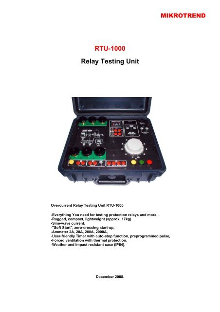
<strong>RTU</strong>-<strong>1000</strong><br />
<strong>Relay</strong> <strong>Testing</strong> <strong>Unit</strong><br />
Overcurrent <strong>Relay</strong> <strong>Testing</strong> <strong>Unit</strong> <strong>RTU</strong>-<strong>1000</strong><br />
-Everything You need for testing protection relays and more...<br />
-Rugged, compact, lightweight (approx. 17kg)<br />
-Sine-wave current,<br />
-"Soft Start", zero-crossing start-up,<br />
-Ammeter 2A, 20A, 200A, 2000A,<br />
-User-friendly Timer with auto-stop function, preprogrammed pulse,<br />
-Forced ventilation with thermal protection,<br />
-Weather and impact resistant case (IP64).<br />
December 2008.<br />
MIKROTREND
CONTENTS<br />
1. General terms............................................................................................................................... 3<br />
2. Function discription....................................................................................................................... 4<br />
3. Block schematic............................................................................................................................ 5<br />
4. Wiring diagram ............................................................................................................................. 6<br />
5. Technical specification .............................................................................................................. 7-8<br />
6. Load curve.................................................................................................................................... 9<br />
7. Timer...................................................................................................................................... 10-14<br />
8. Current clamp ........................................................................................................................ 15-28<br />
9. Accessories ................................................................................................................................ 29
1. GENERAL TERMS<br />
MIKROTREND<br />
Important User Information<br />
This guide has been developed as a quick reference tool to <strong>Mikrotrend</strong> d.o.o. industrial automation controls and<br />
factory assemblies. It is not intended to replace factory user manuals or technical documentation supplied with<br />
<strong>Mikrotrend</strong> d.o.o. equipment. Because of the variety of uses for the products described in this publication, those<br />
responsible for the application and use of these products must satisfy themselves that all necessary steps have been<br />
taken to assure that each application and use meets all performance and safety requirements, including any<br />
applicable laws, regulations, codes, and standards. Factory provided user manuals and technical documentation<br />
should not be solely relied on for those purposes. <strong>Mikrotrend</strong> d.o.o. reserves the right to change the features or<br />
characteristics of its products at any time. Therefore, the information contained in this publication is subject to change<br />
at any time without notice.<br />
The illustrations, charts, diagrams, and layout examples shown in technical documentation are intended solely as<br />
examples. Since there are many variables and requirements associated with any particular installation, <strong>Mikrotrend</strong><br />
d.o.o. can not assume responsibility or liability (including intellectual property infringement liability) for actual use<br />
based upon the examples shown in this publication.<br />
Service and Installation Conditions<br />
Unless otherwise noted, the products described in this publication are designed to meet usual "service and installation<br />
conditions”. Open-style devices must be provided with environmental and safety protection by proper mounting in<br />
enclosures designed for specific application conditions. See explanations of the degrees of protection provided by<br />
different types of enclosures.<br />
Performance Data<br />
Performance data given in technical documentation is provided only as a guide for the user in determining suitability<br />
and do not constitute a performance warranty of any kind. Such data may represent the results of accelerated testing<br />
at elevated stress levels, and the user is responsible for correlating the data to actual application requirements.<br />
ALL WARRANTIES AS TO ACTUAL PERFORMANCE, WHETHER EXPRESS OR IMPLIED, ARE EXPRESSLY<br />
DISCLAIMED.<br />
Safety Recommendations for Maintenance Personnal<br />
All maintenance work should be done by qualified personnel familiar with the construction, operation, and hazards<br />
involved with the equipment.<br />
<strong>RTU</strong> 100 - User manual 3/10
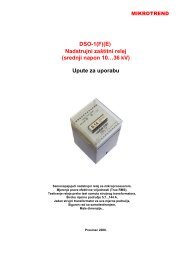
1.<br />
2.<br />
3.<br />
4.<br />
5.<br />
6.<br />
7.<br />
8.<br />
9.<br />
10.<br />
11.<br />
12.<br />
13.<br />
14.<br />
15.<br />
16.<br />
17.<br />
18.<br />
19.<br />
24<br />
1 2 3<br />
23<br />
22<br />
Output A1<br />
Output A2 (Built-in Ammeter)<br />
Output A3<br />
Timer reset<br />
Set time<br />
Timer display<br />
(sec.)<br />
Ammeter<br />
21<br />
Output ( C or A)<br />
and range selector<br />
Mains power plug, 230Vac, 50Hz<br />
Mains power switch<br />
Mains power fuse (6A), automatic<br />
High temperature, output A,<br />
T>110°C<br />
Regulation transformer<br />
“ Stop ” , manual stop<br />
“ Start”, manual start<br />
“ Reset”,<br />
timer reset<br />
Output D - output 110Vdc<br />
Output D - output 48Vdc<br />
Output D - output 24Vdc<br />
25<br />
26<br />
27<br />
28<br />
29<br />
4 5 6 7 8<br />
20<br />
19<br />
20.<br />
21.<br />
22.<br />
23.<br />
24.<br />
25.<br />
26.<br />
27.<br />
28.<br />
29.<br />
18<br />
30.<br />
31.<br />
32.<br />
33.<br />
34.<br />
30 31 32 33 34<br />
17<br />
16<br />
15<br />
14<br />
Output D - output 0V<br />
Regulation transformer fuse ( 6A), automatic<br />
Output C - output 0...230Vac<br />
Output B - output 230Vac, timer activated<br />
“ Trip”, activates output B<br />
Auto-Start signal, input<br />
Selector Normally O pen/Normally Closed contact of Auto-Start signal<br />
Selector INTern/ EXTern<br />
power for<br />
Auto-Start signal<br />
Selector Normally O pen/Normally Closed contact of Auto-Stop signal<br />
Selector INTern/ EXTern<br />
power for<br />
Auto-Stop signal<br />
Auto-Stop signal, input<br />
Indicator: Auto-Stop signal, circuit closed<br />
Indicator: Auto-Stop signal, circuit open<br />
Indicator: Auto-Start signal, circuit closed<br />
Indicator: Auto-Start signal, circuit open<br />
MIKROTREND<br />
<strong>RTU</strong> 100 - User manual 4/10<br />
9<br />
10<br />
11<br />
12<br />
13
MIKROTREND<br />
<strong>RTU</strong> 100 - User manual 5/10
MIKROTREND<br />
<strong>RTU</strong> 100 - User manual 6/10
5. TECHNICAL SPECIFICATION<br />
Specification:<br />
Measured at 230Vac, 50Hz, 25°C ambient, duty cycle = 1/10<br />
Output A: For testing Overcurrent Protective <strong>Relay</strong>s, etc. Consists of 3 independent output windings<br />
which can be connected in parallel or in series:<br />
Parallel connection:<br />
0...3Vac max, 0...<strong>1000</strong>Aac max,<br />
Serial connection:<br />
0...9Vac max, 0...350Aac max,<br />
Output B: For testing Actuators etc.<br />
230Vac, 6A max., continuous,<br />
Output C: For testing Voltmeters, Overcurrent Protective <strong>Relay</strong>s (via current transformer test input)<br />
etc.<br />
0...230Vac, 6A max.,<br />
Output D: Auxillary power supply for devices under test (DUT)<br />
24Vdc, 1,2A max., stabilised, continuous,<br />
48Vdc, 0,6A max., stabilised, continuous,<br />
110Vdc, 0,3A max., stabilised, continuous,<br />
TIMER:<br />
Time: 999,99sec.<br />
Functions: AutoStart, AutoStop, Manual Start, Manual Stop, Reset, Preprogrammed pulse,<br />
AutoStart signal: 24...240Vdc, 10mA max, Normally Open or Normally Closed, Internal or External<br />
powered,<br />
AutoStop signal: 24...240Vdc, 10mA max, Normally Open or Normally Closed, Internal or External<br />
powered,<br />
Resolution: 10msec,<br />
Display: LED, 8mm,<br />
AMMETER:<br />
Range: 2A, 20A, 200A, 2000A,<br />
Accuracy : +/3% (23°C
DIGITAL MULTIMETER WITH CURRENT CLAMP AND IR THERMOMETER<br />
EX810 with IR Thermometer<br />
Range, accuracy:<br />
0,1...<strong>1000</strong>Aac, 2,0%,<br />
0,1mV...600Vac, +/1,8%,<br />
0,1mV...600Vdc, +/2,8%,<br />
0,1...40MOhm, +/1,5%,<br />
0,001nF...40000uF, +/3%,<br />
0,001kHz...4kHz, +/1,5%,<br />
50...270°C, +/2°C,<br />
Working temperature: +5...+40°C,<br />
Storage temperature: 20...+60°C,<br />
Battery: 9V,<br />
GENERAL:<br />
Power supply: 230Vac, 50Hz, 8A max.,<br />
Fuse: T6A,<br />
Protection: Thermal cutout and miniature circuit breakers,<br />
Working temperature: +5...+45°C,<br />
Storage temperature: 40...+60°C,<br />
Dimensions: 380×430×160mm, portable case,<br />
Weight: approx. 17kg<br />
ACCESSORIES:<br />
1 x Current clamp<br />
Connection cables:<br />
3 x 16mm2 × 2,5m, silicone insulation<br />
2 x 16mm2 × 2,5m with alligator clips, silicone insulation<br />
2 x 2,5mm2 × 3m with 4mm plug+alligator clip, silicone insulation<br />
4 x 1,5mm2 × 3m with 4mm plug+alligator clip, silicone insulation<br />
Specifications are subject to change without notice.<br />
MIKROTREND<br />
<strong>RTU</strong> 100 - User manual 8/10
MIKROTREND<br />
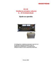
6. <strong>RTU</strong> - <strong>1000</strong>, Output A, load curve, max. allowed values<br />
I(A)<br />
I(A)<br />
I(A)<br />
I(A)<br />
500<br />
400<br />
300<br />
200<br />
100<br />
Measured at 230Vac, 50Hz, 25°C ambient<br />
Two output windings in serial connection<br />
0<br />
1 10 100 <strong>1000</strong><br />
<strong>1000</strong><br />
800<br />
600<br />
400<br />
200<br />
Three output windings in serial connection<br />
400<br />
350<br />
300<br />
250<br />
200<br />
150<br />
100<br />
50<br />
0<br />
1 10 100 <strong>1000</strong><br />
1200<br />
<strong>1000</strong><br />
800<br />
600<br />
400<br />
200<br />
t(s)<br />
t(s)<br />
Three output windings in parallel connection<br />
0<br />
1 10 100 <strong>1000</strong><br />
t(s)<br />
Two output windings in parallel connection<br />
0<br />
1 10 100 <strong>1000</strong><br />
t(s)<br />
www.mikrotrend.com<br />
<strong>RTU</strong> 100 - User manual 9/10
Zeitvorwahlzähler elektronisch<br />
Multifunktionaler Vorwahlzähler Typ 715<br />
Technische Daten<br />
Spannungs- 11 ... 30 V DC, mit Verpolungsschutz<br />
versorgung: 115 V AC, 230 V AC<br />
Stromaufnahme: max. 100 mA, 4 VA<br />
Anzeige: 5-stellige rote 7-Segment LED-Anzeige;<br />
7,5 mm hoch<br />
Polarität der Eingangs- programmierbar für alle Eingänge gemeinsam<br />
Signale:<br />
Eingangswiderstand: ca. 10 kΩ<br />
Zählfrequenz: über DIL-Schalter für INP A und INP B<br />
separat einstellbar, 30 Hz, 10 kHz (7,5 kHz bei<br />
Eingangsart E4) bei automatischer Wiederholung<br />
1 kHz ohne Zählverluste (600 Hz bei<br />
Eingangsart E4)<br />
Mindestimpulsdauer der 5 ms<br />
Steuereingänge:<br />
Schaltpegel der DC-Versorgungsspannung:<br />
Eingänge bei: Low: 0 ... 0,2 x UB [V DC]<br />
High: 0,6 x UB ... 30 V DC<br />
AC-Versorgungsspannung:<br />
Low 0 ... 4 V DC<br />
High 12 ... 30 V DC<br />
Impulsform: beliebig, da Schmitt-Trigger<br />
1/2006<br />
Ihr Nutzen<br />
gut ablesbare helle LED-Anzeige<br />
programmierbar als Impuls-, Frequenzoder<br />
Betriebsstundenvorwahlzähler<br />
Spannungsversorgung 230 V AC, 115 V AC<br />
oder 11 ... 30 V DC<br />
Approbation<br />
Anwendungsbeispiele Betriebsarten Impulszähler<br />
Weitere Vorzüge<br />
Anzeigebereich –19999 ... 99 999<br />
mit Vornullenunterdrückung<br />
einfache Vorwahleinstellung; jeder Dekade<br />
ist eine Vorwahltaste zugeordnet<br />
Relais oder Optokoppler-Ausgang<br />
Faktoreinstellung von 0,001 ... 9,999<br />
Ausgang Relais: mit potentialfreiem Wechselkontakt<br />
max. 250 V AC/300 V DC<br />
Schaltstrom max. 3 A,<br />
Schaltstrom bei DC min. 30 mA<br />
Schaltleistung: max. 50 W bei DC<br />
max. 2000 VA bei AC<br />
Optokoppler: mit offenem Kollektor<br />
max. 30 V DC, 15 mA<br />
Ansprechzeit der Relais: ca. 6 ms<br />
Ausgänge: Optokoppler: ca. 1 ms<br />
Datensicherung: min. 10 Jahre oder 10 6 Speicherzyklen<br />
Geberspannung: 24 V DC –40 %/+15 %, 80 mA unstabilisiert<br />
bei AC-Ausführung<br />
Umgebungstemperatur: 0 ... +50 °C, nicht betauend<br />
Lagertemperatur: –25 ... +70 °C<br />
EMV: CE-konform zur EG-Richtlinie 89/36/EWG<br />
Normen : EN 6<strong>1000</strong>-6-4/EN 55011 Klasse B<br />
EN 6<strong>1000</strong>-6-2<br />
UL: File-Nr.: E128604<br />
Schutzart: IP65 (frontseitig)<br />
Gewicht: ca. 240 g, (AC-Ausführung mir Relais)<br />
Betriebs- Zählbeginn Aussgangssignal Ausgangsart<br />
art bei Zählerstand<br />
1 0 > Vorwahl Dauer oder<br />
Wischsignal<br />
2 Vorwahl < 0 Dauer oder<br />
Wischsignal<br />
3 0 = Vorwahl Wischsignal und<br />
automatische<br />
Wiederholung<br />
4 Vorwahl = 0 Wischsignal und<br />
automatische<br />
Wiederholung<br />
www.kuebler.com 201<br />
Zeitzähler<br />
elektromechanisch
Zeitvorwahlzähler elektronisch<br />
Betriebsart-Einstellungen<br />
1. Impulszähler<br />
Betriebsarten siehe Tabelle<br />
Dezimalpunkt: 0 ... 3 Dezimalstellen<br />
Polarität: npn oder pnp<br />
Eingangsarten:<br />
E1: Impuls bzw. Zähleingang und ein Eingang für Vor- oder<br />
Rückwärtsumschaltung. Wird dieser Eingang nicht<br />
beschaltet, addiert der Zähler; beschaltet subtrahiert er.<br />
E2: Differenzeingang mit einem Vorwärts- und einem Rückwärtseingang<br />
E3: Phasendiskriminatoreingang für Drehgeber mit zwei um 90°<br />
phasenverschobenen Impulsen zur automatischen Zählrichtungserkennung<br />
E4: Phasendiskriminatoreingang mit Impulsdoppelauswertung.<br />
Jede Impulsflanke des Zähleingangs “A” erzeugt einen<br />
Zählimpuls<br />
Faktor: 0,001 ... 9,999<br />
Ausgangssignale: Dauer- oder Wischsignal<br />
einstellbar (0,01 ... 99,98 s)<br />
Anschlussbelegung:<br />
X2<br />
X1<br />
Steckerbelegung X1:<br />
Pin 115/230 V AC-Version 11 ... 30 V DC Version<br />
1 +24 V DC Geber- –<br />
versorgungsspannung<br />
2 0 V DC (GND) –<br />
3 Relaisausgang, gemeinsamer Kontakt (C)<br />
Optokopplerausgang Emitter<br />
4 Relaisausgang Schließer (NO)<br />
5 Relaisausgang Öffner (NC)<br />
Optokopplerausgang Kollektor<br />
6 115 V AC/230 V AC 11 ... 30 V DC<br />
7 115 V AC/230 V AC 0 V DC (GND)<br />
Steckerbelegung X2:<br />
Pin Benennung Funktion<br />
1 INP A Zähleingang A<br />
2 INP B Zähleingang B<br />
3 Gate Toreingang<br />
4 Reset Rücksetzeingang<br />
5 Latch Anzeigestop-Eingang<br />
6 Key Tastaturverriegelungs-Eingang<br />
2. Frequenzzähler<br />
Gate: Torzeit, einstellbar von 0,001 ... 99,99 s<br />
Dezimalpunkt: 0 ... 3 Dezimalstellen<br />
Polarität: npn oder pnp<br />
Eingangsarten: siehe Impulszähler E1 ... E4<br />
Faktor: 0,001 ... 9,999<br />
Ausgangssignale: Dauer- oder Wischsignal<br />
einstellbar (0,01 ... 99,98 s)<br />
3. Zeitzähler<br />
Betriebsarten: siehe Impulszähler<br />
Zählung: s, min oder h;<br />
Auflösung: 0,001; 0,01; 0,1 oder 1,0<br />
Polarität: npn oder pnp<br />
Ausgangssignale: Dauer- oder Wischsignal<br />
einstellbar (0,01 ... 99,98 s)<br />
202 www.kuebler.com 1/2006
Zeitvorwahlzähler elektronisch<br />
Maßbilder:<br />
715: Einbauquerschnitt 45 x 45 mm<br />
715: mit Frontrahmen 2<br />
Einbauquerschnitt 50 x 50 mm<br />
715: mit Frontrahmen 3<br />
Einbauquerschnitt 50 x 50 mm<br />
Lieferumfang:<br />
Zähler 715<br />
1 Schraubklemme 7polig<br />
1 Schraubklemme 6polig<br />
1 Frontrahmen für Schraubbefestigung<br />
Einbauquerschnitt 50 x 50 mm<br />
1 Frontrahmen für Spannbügelbefestigung<br />
Einbauquerschnitt 50 x 50 mm<br />
1 Spannbügel<br />
1 Schablone für Schalttafelausschnitt<br />
1 Bedienungsanleitung<br />
1/2006<br />
Bestellschlüssel:<br />
6.715.01X.X00<br />
Versorgungsspannung<br />
0 = 230 V AC<br />
1 = 115 V AC<br />
3 = 11 ... 30 V DC<br />
Ausgang<br />
0 = Relais<br />
1 = Optokoppler<br />
www.kuebler.com 203<br />
Zeitzähler<br />
elektromechanisch
– Änderungen vorbehalten –<br />
Bedienungsanleitung 5.94.1 (Ausg. 3.97)<br />
Elektronischer Vorwahlzähler<br />
Type 715<br />
1. Beschreibung<br />
– 5stelliger add./subtr. Vorwahlzähler mit einer Vorwahl<br />
– gut ablesbare 7,5 mm hohe LED-Anzeige<br />
– Zähl- und Vorwahlbereich –19999 bis 99999<br />
Über- oder Unterlauf ohne Zählverluste bis jeweils 1 Dekade,<br />
hierbei blinkt die Anzeige im s-Takt<br />
– programmierbar als Impuls-, Frequenz- oder Zeit- bzw. Betriebsstundenzähler<br />
– Relais- oder Optokopplerausgang (siehe Bestellschlüssel)<br />
– Die Programmierung der Zählfunktionen bzw. Betriebsparameter<br />
erfolgt über die Vorwahltasten. Bedienerführung<br />
auf dem Display während der Programmierroutine.<br />
– programmierbar sind:<br />
Betriebsart (Ausgangssignal bei Null oder Vorwahl, mit<br />
oder ohne automat. Wiederholung)<br />
Dezimalpunkt<br />
Polarität der Eingänge (NPN oder PNP)<br />
Eingangsart und Faktor<br />
Ausgangssignal als Dauer- oder Wischsignal<br />
Torzeit bei Programmierung als Frequenzzähler,<br />
Auflösung in s, min oder h als Zeitzähler<br />
– Spannungsversorgung 230 VAC, 115 VAC oder 11…30<br />
VDC<br />
2. Eingänge<br />
2.1 INP A, INP B<br />
Zähleingänge. Die max. Zählfrequenz dieser beiden Eingänge<br />
ist über die Programmierschalter C und D (an der<br />
rechten Seite des Zählergehäuses) auf 30 Hz oder 10 kHz<br />
einstellbar.<br />
INP A INP B<br />
Mikroschalter 30 Hz 10 kHz 30 Hz 10 kHz<br />
D ON OFF<br />
C ON OFF<br />
2.2 Gate<br />
Statischer Toreingang; keine Zählung solange dieser Eingang<br />
aktiviert ist.<br />
In der Betriebsart Zeitzähler blinkt bei nichtaktiviertem Toreingang<br />
der Dezimalpunkt zwischen der 4. und 5. Dekade<br />
(Laufanzeige bei Zeiteinheiten h, min oder 0,1 min).<br />
2.3 Reset<br />
Dynamischer Rücksetzeingang; er ist mit der roten SetTaste<br />
parallel geschaltet und setzt den Zähler bei add. Zählweise<br />
auf Null, bei subtr. Zählweise auf den Vorwahlwert.<br />
2.4 Latch<br />
Statischer Speichereingang für Anzeigestop. Mit der Aktivierung<br />
dieses Einganges wird der momentane Zählerstand in<br />
der Anzeige solange festgehalten, bis der Speichereingang<br />
wieder frei ist. Der Zähler zählt im Hintergrund weiter.<br />
2.5 Key<br />
Statischer Tastaturverriegelungseingang.<br />
Solange dieser Eingang aktiviert ist, sind alle Fronttasten<br />
gesperrt.<br />
3. Ausgang<br />
Relaisausgang mit potentialfreiem Wechselkontakt oder Optokoppler<br />
mit offenem Emitter und Kollektor.<br />
Bei aktivem Ausgang erscheint rechts von der 1. Dekade der<br />
Dezimalpunkt.<br />
Für Sicherheitsschaltungen kann in den Betriebsarten 1 und<br />
2 (nur bei Dauersignal) die Relais- bzw. Optokoppleransteuerung<br />
invertiert werden, d.h. die Relaisspule wird bei<br />
Erreichen der Vorwahl spannungslos bzw. der Optokoppier<br />
gesperrt. Hierzu muß in den Programmierroutinen die Dauer<br />
des Ausgangssignals auf 99,99 s eingestellt werden.<br />
4. Einstellung der Betriebsparameter<br />
a. Spannungsversorgung einschalten<br />
b. Programmierschalter „A“ (an<br />
der rechten Seite des Zählergehäuses)<br />
kurzzeitig auf „0N“ stellen.<br />
Auf dem Display wird der 1.<br />
Menüpunkt angezeigt.<br />
c. Mit der Taste 1 die gewünschte Funktion auswählen.<br />
d. Mit der Taste 5 wird der eingestellte Wert übernommen<br />
und auf den jeweiligen nächsten Menüpunkt weitergeschaltet.<br />
e. Erneut mit der Taste 1 die gewünschte Funktion bzw.<br />
Zählerwerte (Faktor, Wisch- oder Torzeit) direkt über die Tasten<br />
1 bis 4 eingeben.<br />
f. Nach dem letzten Menüpunkt (Dauersignal oder Wischsignal)<br />
wird mit der Taste 5 die Programmierroutine verlassen<br />
(Programmierschalter „A“ auf „OFF“). Falls Schalter „A“<br />
noch auf „ON“ geschaltet ist, wird die Programmierroutine<br />
nochmals durchlaufen.<br />
5. Einstellung der Betriebsart<br />
5.1 Einstellung der Grundbetriebsart<br />
Nach kurzzeitigem Umschalten des Programmierschalters<br />
„A“ auf „ON“ erscheint eines der folgenden Bilder auf dem<br />
Display.<br />
Programmier- Programmier- Programmierroutine<br />
routine routine<br />
Impulszähler Zeitzähler Frequenzzähler<br />
5.2.1 Programmierroutine Impulszähler<br />
Betriebsart 1:<br />
Ausgang bei Zählerstand � Vorwahl<br />
Reset auf Null<br />
Betriebsart 2:<br />
Ausgang bei Zählerstand � Null<br />
Reset auf Vorwahl<br />
Betriebsart 3:<br />
Wischsignal bei Zählerstand = Vorwahl<br />
und automat. Nullsetzen<br />
Reset auf Null<br />
Betriebsart 4:<br />
Wischsignal bei Zählerstand = Null<br />
und autom. Setzen auf Vorwahl<br />
Reset auf Vorwahl<br />
Dezimalpunkt:<br />
nur anzeigende Funktion!<br />
dP0 = kein Dezimalpunkt<br />
dP1 = 0000.0<br />
dP2 = 000.00<br />
dP3 = 00.000<br />
Polarität der Eingänge:<br />
negative Polarität (NPN),<br />
nach 0 V schaltend<br />
positive Polarität (PNP),<br />
nach + 24 V schaltend<br />
Eingangsart:<br />
E 1: INP A = Zähleingang<br />
INP B = Zählrichtungseingang<br />
E 2:INP A = Zähleingang add.<br />
INP B = Zähleingang subtr.<br />
E 3:Phasendiskriminator<br />
INP A = Zähleingang 0°<br />
INP B = Zähleingang 90°<br />
E 4:wie E 3, jedoch mit Impulsverdoppelung.<br />
Jede Flanke von INP A wird gezählt<br />
Faktor:<br />
0,001...9,999<br />
Einstellung über Tasten 1 bis 4<br />
Faktor 0,000 wird nicht akzeptiert<br />
Achtung! In den Betriebsarten 2 und<br />
4 (Ausgangssignal bei Zählerstand<br />
= Null) muß der Vorwahlwert ganzzahlig<br />
durch den Faktor teilbar sein,<br />
andernfalls wird der Zähler bei<br />
einem Reset auf das nächstgrößere<br />
ganzzahlige Vielfache des Faktors<br />
gesetzt.<br />
Dauer des Ausgangssignals:<br />
00,00 = Dauersignal bei Betriebsarten<br />
1 und 2<br />
0,01...99,98 s = Wischsignal bei Betriebsarten<br />
1 bis 4<br />
Einstellung 99,99 s = Dauersignal<br />
bei Betriebsarten 1 und 2, jedoch mit<br />
invertierter Relais- oder Optokoppleransteuerung<br />
(Relaisspule wird bei<br />
Erreichen der Vorwahl spannungslos<br />
bzw. Optokoppler gesperrt).<br />
Wenn Programmierschalter „A“ auf „0FF“ ist, wird jetzt die<br />
Programmierroutine verlassen und der Zähler ist funktionsbereit.<br />
Falls Programmierschalter „A“ noch auf „0N“ steht, muß die<br />
Programmierroutine nochmals durchlaufen werden.<br />
5.2.2 Programmierroutine Zeitzähler<br />
Betriebsart 1: Dauersignal bei Zählerstand<br />
� Vorwahl oder Wischsignal<br />
bei Zählerstand = Vorwahl<br />
Reset auf Null<br />
Betriebsart 2: Dauersignal bei Zählerstand<br />
� Null oder Wischsignal bei<br />
Zählerstand = Null<br />
Reset auf Vorwahl<br />
Betriebsart 3: Wischsignal bei Zählerstand<br />
= Vorwahl und automat.<br />
Nullsetzen<br />
Reset auf Null<br />
Betriebsart 4: Wischsignal bei Zählerstand<br />
= Null und autom. Setzen<br />
auf Vorwahl<br />
Reset auf Vorwahl<br />
Zeiteinheit:<br />
Zählung in s; 0,1 s; 0,01 s oder 0,001<br />
s*<br />
Zählung in min; 0,1 min; 0,01 min<br />
oder 0,001 min*<br />
Zählung in h; 0,1 h; 0,01 h oder<br />
0,001 h*<br />
*je nach Stellung des Dezimalpunktes<br />
Dezimalpunkt (Auflösung)<br />
dP0 = keine Dezimalstelle<br />
dP1 = 0000.0<br />
dP2 = 000.00<br />
dP3 = 00.000<br />
Polarität der Eingänge<br />
negative Polarität (NPN), nach 0 V<br />
schaltend<br />
positive Polarität (PNP), nach<br />
+ 24 V schaltend<br />
Dauer des Ausgangssignals:<br />
00,00 = Dauersignal bei Betriebsarten<br />
1 und 2<br />
0,01...99,98 s = Wischsignal bei Betriebsarten<br />
1 bis 4<br />
Fritz Kübler GmbH · Zähl- und Sensortechnik · Postfach 3440 · D-78023 VS-Schwenningen · Germany<br />
Telefon 07720/39 03-0 · Telefax 07720/215 64 · E-Mail: sales@kuebler-gmbh.de · www.kuebler-gmbh.de
Einstellung 99,99 s = Dauersignal bei Betriebsarten 1 und 2,<br />
jedoch mit invertierter Relais- oder 0ptokoppleransteuerung<br />
(Relaisspule wird bei Erreichen der Vorwahl spannungslos<br />
bzw. Optokoppler gesperrt).<br />
Wenn Programmierschalter „A“ auf „OFF“ ist, wird jetzt die<br />
Programmierroutine verlassen und der Zähler ist funktionsbereit.<br />
Falls Programmierschalter „A“ noch auf „ON“ steht, muß die<br />
Programmierroutine nochmals durchlaufen werden.<br />
5.2.3 Programmierroutine Frequenzzähler<br />
Torzeit = Zeit innerhalb der eingehende<br />
Impulse gezählt und zur Anzeige<br />
gebracht werden.<br />
Einstellbereich 0,01s...99,99 s<br />
Einstellung über die Tasten 1 bis 4<br />
00,00 wird als Einstellung nicht akzeptiert<br />
Dezimalpunkt:<br />
nur anzeigende Funktion.<br />
dP0 = kein Dezimalpunkt<br />
dP1 = 0000.0<br />
dP2 = 000.00<br />
dP3 = 00.000<br />
Polarität der Eingänge<br />
negative Polarität (NPN),nach 0 V<br />
schaltend<br />
positive Polarität (PNP),<br />
nach + 24 V schaltend<br />
Eingangsart:<br />
E1:<br />
INP A = Zähleingang<br />
INP B = Zählrichtungseingang<br />
E2:<br />
INP A = Zähleingang add.<br />
INP B = Zähleingang subtr.<br />
E3:<br />
Phasendiskriminator<br />
INP A = Zähleingang 0°<br />
INP B = Zähleingang 90°<br />
E4:<br />
wie E3, jedoch mit Impulsverdoppelung.<br />
Jede Flanke von INP A wird gezählt<br />
Faktor:<br />
0,001…9,999<br />
Einstellung über Tasten 1 bis 4<br />
Faktor 0,000 wird nicht akzeptiert<br />
Dauer des Ausgangssignals:<br />
00,00 = Dauersignal bei Betriebsarten<br />
1 und 2<br />
0,01…99,98 s = Wischsignal bei Betriebsarten<br />
1 bis 4.<br />
Einstellung 99,99 s = Dauersignal<br />
bei Betriebsarten 1 u. 2, jedoch mit<br />
invertierter Relais- oder Optokoppleransteuerung<br />
(Relaisspule wird bei<br />
Erreichen der Vorwahl spannungslos<br />
bzw. Optokoppler gesperrt).<br />
Wenn Programmierschalter „A“ auf „0FF“ ist, wird jetzt die<br />
Programmierroutine verlassen und der Zähler ist funktionsbereit.<br />
Falls Programmierschalter „A“ noch auf „0N“ steht, muß die<br />
Programmierroutine nochmals durchlaufen werden.<br />
6. Vorwahleinstellung:<br />
Jeder Dekade ist eine Vorwahltaste zugeordnet.<br />
Nach Betätigen einer der 5 Vorwahltasten<br />
wird die Vorwahl angezeigt. Danach kann<br />
die Vorwahl eingegeben bzw. verändert<br />
werden. 4 Sekunden nach der letzten Vorwahltastenbetätigung<br />
wird wieder der Zählerstand<br />
angezeigt.<br />
6.1 Vorwahleingabe in der 5. Dekade<br />
Vorwahl +9XXXX<br />
Vorwahl –XXXX<br />
Vorwahl –1XXXX<br />
Vorwahl +0XXXX<br />
7. Anschlußbeispiele:<br />
Ansteuerung über Kontakt<br />
programmierte Polarität PNP<br />
Ansteuerung über Lichtschranke<br />
Ansteuerung über Drehgeber<br />
8. Anschlußbelegung<br />
Steckerbelegung X1<br />
�entfällt<br />
in der<br />
Betriebsart<br />
Zeitzähler<br />
Klemme<br />
Nr. 115/230-VAC-Version 11…30 VDC-Version<br />
1 + 24 VDC Geberversorgungsspannung<br />
—<br />
2 0 VDC (GND) —<br />
3 Relaisausgang gemeinsamer Kontakt (C)<br />
Optokopplerausgang Emitter<br />
4 Relaisausgang Schließer (NO)<br />
5 Relaisausgang Öffner (NC)<br />
Optokopplerausgang Kollektor<br />
6 115 VAC / 230 VAC 11…30 VDC<br />
Betriebsspannung<br />
7 115 VAC / 230 VAC 0 VDC (GND)<br />
Achtung! Bei Einstellung Dauersignal = 99,99 s (invertierte<br />
Relais- oder Optokoppleransteuerung) ändern sich die Anschlüsse<br />
der Klemmen 4 und 5.<br />
Klemme<br />
Nr. AC- und DC-Version<br />
4 Relaisausgang Öffner (NC)<br />
5 Relaisausgang Schließer (NO)<br />
Steckerbelegung X2<br />
Klemme Nr. Benennung Funktion<br />
1 INP A Zähleingang A<br />
2 INP B Zähleingang B<br />
3 GATE Toreingang<br />
4 RESET Rücksetzeingang<br />
5 LATCH Anzeigestop-Eingang<br />
6 KEY Tastaturverriegelungs-Eingang<br />
9. Technische Daten<br />
Spannungsversorgung:<br />
230 VAC, 115 VAC, max. 4 VA<br />
oder 11…30 VDC, max. 0,1 A<br />
Anzeige: 5stellige 7-Segment-LED-Anzeige<br />
7,5 mm hoch, rot<br />
Polarität der Eingangssignale:<br />
programmierbar, für alle Eingänge gemeinsam<br />
Eingangswiderstand:<br />
ca. 10 kOhm<br />
Zählfrequenz: über DIL-Schalter für INP A und INP B<br />
separat einstellbar<br />
30 Hz<br />
10 kHz (7,5 kHz bei Eingangsart E4)<br />
bei automatischer Wiederholung 1 kHz ohne<br />
Zählverluste (600 Hz bei Eingangsart E4)<br />
Mindestimpulszeit der Steuereingänge:<br />
5 ms<br />
Schaltpegel der Eingänge:<br />
Bei AC-Spannungsversorgung<br />
Log „0“: 0… 4 VDC<br />
Log „1“: 12…30 VDC<br />
Bei DC-Spannungsversorgung Ub<br />
Log „0“: 0…0,2 x Ub<br />
Log „1“: 0,6 x Ub…30 VDC<br />
Impulsform: beliebig, da Schmitt-Trigger-Eingänge<br />
Ausgang: Relais mit potentialfreiem Wechselkontakt<br />
Schaltspannung max. 250 VAC / 300 VDC<br />
Schaltstrom max. 3 A<br />
Schaltstrom bei DC min. 30 mA<br />
Schaltleistung max. 50 W bei DC<br />
max. 2000 VA bei AC<br />
oder<br />
Optokoppler mit offenem Kollektor und Emitter<br />
Schaltleistung: 30 VDC / 15 mA<br />
Ucesat bei Ic = 15 mA: max. 2,0 V<br />
Ucesat bei Ic = 5 mA: max. 0,4 V<br />
Ansprechzeit des Ausganges:<br />
Relais: ca. 6 ms<br />
Optokoppler: ca. 1 ms<br />
Datensicherung:<br />
min. 10 Jahre oder 10 6 Speicherzyklen<br />
Geberspannung:<br />
24 VDC –40%/+15%, 80 mA unstabilisiert<br />
bei AC-Ausführung<br />
Störfestigkeit: EN 55011 Klasse B und prEN 50082-2<br />
mit geschirmten Dateneingängen<br />
Umgebungstemperatur:<br />
0…50°C<br />
Lagertemperatur:<br />
–25°C…+70°C<br />
Gewicht: ca. 240 g (AC-Ausführung mit Relais)<br />
Schutzart: IP 54 von vorne<br />
Gehäusefarbe: schwarz<br />
10. Bestellschlüssel<br />
6.715.01X.X00<br />
Spannungsversorgung<br />
0 = 230 VAC<br />
1 = 115 VAC<br />
3 = 11…30 VDC<br />
Ausgang<br />
0 = Relais<br />
1 = Optokoppler<br />
Fritz Kübler GmbH · Zähl- und Sensortechnik · Postfach 3440 · D-78023 VS-Schwenningen · Germany<br />
Telefon 07720/39 03-0 · Telefax 07720/215 64 · E-Mail: sales@kuebler-gmbh.de · www.kuebler-gmbh.de<br />
– Änderungen vorbehalten –
Features:<br />
• Non-contact InfraRed Temperature<br />
measurements with laser pointer<br />
• Models with True RMS Current and<br />
Voltage measurements<br />
• Peak hold captures inrush currents<br />
and Transients<br />
• MultiMeter functions include<br />
AC/DC Voltage, Resistance, Capacitance,<br />
Frequency, Diode, and Continuity<br />
• 1.7" (43mm) jaw opening for conductors<br />
up to 750MCM or two 500MCM<br />
• 4000 count backlit dual display<br />
• Features include Data Hold and Min/Max<br />
• Autoranging with manual range button<br />
• Auto Power off<br />
• Complete with test leads, 9V battery, Type K<br />
probe (-4 to 482°F/-20 to 250°C) for<br />
EX820/EX830, and belt holster<br />
CAT III - 600V<br />
Specifications EX810 EX820 EX830 Basic Accuracy<br />
IR Temperature -58 to 518ºF -58 to 518ºF -58 to 518ºF ±2.0% rdg or<br />
-50 to 270ºC -50 to 270ºC -50 to 270ºC ±4ºF/±2ºC<br />
AC Current 0.1 to <strong>1000</strong>A 0.1 to <strong>1000</strong>A 0.1 to <strong>1000</strong>A 2.0% (EX810)<br />
2.5% (EX820)<br />
2.8% (EX830)<br />
DC Current — — 0.1 to <strong>1000</strong>A ±2.8%<br />
AC Voltage 0.1mV to 600V 0.1mV to 600V 0.1mV to 600V ±1.8% (EX810)<br />
±1.5% (EX820, EX830)<br />
DC Voltage 0.1mV to 600V 0.1mV to 600V 0.1mV to 600V ±2.8% (EX830)<br />
Resistance 0.1 to 40MΩ 0.1 to 40MΩ 0.1 to 40MΩ ±1.5%<br />
Capacitance 0.001nF to 40,000µF 0.001nF to 40,000µF 0.001nF to 40,000µF ±3.0%<br />
Frequency 0.001kHz to 4kHz 0.001kHz to 4kHz 0.001kHz to 4kHz ±1.5%<br />
Type K Temperature — -4 to 1400ºF -4 to 1400ºF ±(3%rdg+9°F/5ºC)<br />
-20 to 760ºC -20 to 760ºC<br />
Continuity Yes Yes Yes<br />
Inrush Yes Yes Yes<br />
Diode Yes Yes Yes<br />
Dimensions 10.6x4.3x2" (270x110x50mm)<br />
Weight: 13.6oz (386g)<br />
Ordering Information:<br />
EX810 ..............<strong>1000</strong>A AC Clamp/DMM+IR Thermometer<br />
EX810-NISTL* <strong>1000</strong>A AC Clamp/DMM+IR Thermometer w/NIST Cert.<br />
EX820 ..............<strong>1000</strong>A AC True RMS Clamp/DMM+IR Thermometer<br />
EX820-NISTL* <strong>1000</strong>A AC True RMS Clamp/DMM+IR Thermometer w/NIST Cert.<br />
EX830 ..............<strong>1000</strong>A AC/DC True RMS Clamp/DMM+IR Thermometer<br />
EX830-NISTL* <strong>1000</strong>A AC/DC True RMS Clamp/DMM+IR Thermometer w/NIST Cert.<br />
*NISTL is a Limited NIST: Product is certified to all functions except IR Thermometer<br />
EXTECH INSTRUMENTS CORPORATION<br />
285 Bear Hill Road, Waltham, MA 02451-1064, U.S.A.<br />
Phone: 781-890-7440 • Fax: 781-890-7864<br />
ISO 9001:2000 CERTIFIED<br />
Product DATASHEET<br />
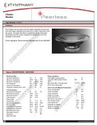
<strong>1000</strong>A Clamp Meters with IR Thermometers<br />
Clamp-on multimeter with built-in non-contact InfraRed Thermometer<br />
Built-in<br />
IR Thermometer<br />
Patent Pending<br />
Built-in IR Thermometer with<br />
laser pointer is an excellent<br />
troubleshooter for locating hot<br />
spots and overheating motors.<br />
Model EX810<br />
• AC Current<br />
• Average<br />
responding<br />
“Make mine an Extech! ”<br />
www.extech.com<br />
Model EX820<br />
• AC Current<br />
• True RMS<br />
• Type K<br />
thermometer<br />
Model EX830<br />
• AC/DC Current<br />
• True RMS<br />
• Type K<br />
thermometer<br />
• DC Zero<br />
05/10/05 - R1<br />
Copyright © 2005 Extech Instruments Corporation. All rights reserved including the right of reproduction in whole or in part in any form.
User's Guide<br />
Extech 800 Series<br />
<strong>1000</strong> Amp Clamp Meters<br />
with IR Thermometer<br />
EX810 AC Clamp meter<br />
EX820 True RMS AC Clamp meter<br />
EX830 AC/DC True RMS Clamp meter
Introduction<br />
Congratulations on your purchase of the EX800 Series Clamp device. The series consists<br />
of the following models:<br />
EX810 <strong>1000</strong>A AC Current Clamp meter<br />
EX820 <strong>1000</strong>A True RMS AC Current Clamp<br />
EX830 <strong>1000</strong>A True RMS AC/DC Current Clamp<br />
All models measure:<br />
� Infrared Temperature<br />
� AC/DC Voltage<br />
� Resistance<br />
� Capacitance<br />
� Frequency<br />
� Continuity<br />
� Diode<br />
Model specific functions:<br />
� EX830: DC Current, True RMS, Type K thermometer, DC Zero<br />
� EX820: True RMS, Type K thermometer<br />
� EX810: Average responding<br />
The EX800 Series features:<br />
� Auto Power OFF<br />
� Max/Min recording<br />
� Data Hold<br />
� Peak Hold<br />
� Backlit LCD display<br />
Careful use of this meter will provide many years of reliable service.<br />
2<br />
EX800 Series Version 3.1 6/05
Safety<br />
International Safety Symbols<br />
This symbol, adjacent to another symbol or terminal, indicates the user must refer<br />
to the manual for further information.<br />
This symbol, adjacent to a terminal, indicates that, under normal use, hazardous<br />
voltages may be present<br />
Double insulation<br />
SAFETY NOTES<br />
• Do not exceed the maximum allowable input range of any function.<br />
• Do not apply voltage to meter when resistance function is selected.<br />
• Set the function switch OFF when the meter is not in use.<br />
• Remove the battery if meter is to be stored for longer than 60 days.<br />
WARNINGS<br />
• Set function switch to the appropriate position before measuring.<br />
• When measuring volts do not switch to current/resistance modes.<br />
• Do not measure current on a circuit whose voltage exceeds 600V.<br />
• When changing ranges always disconnect the test leads from the circuit under test.<br />
UL Note<br />
A UL mark does not indicate that this product has been evaluated for accuracy.<br />
CAUTIONS<br />
• Improper use of this meter can cause damage, shock, injury or death. Read and<br />
understand this user manual before operating the meter.<br />
• Always remove the test leads before replacing the battery or fuses.<br />
• Inspect the condition of the test leads and the meter itself for any damage before<br />
operating the meter. Repair or replace any damage before use.<br />
• Use great care when making measurements if the voltages are greater than 25VAC<br />
rms or 35VDC. These voltages are considered a shock hazard.<br />
• Always discharge capacitors and remove power from the device under test before<br />
performing Diode, Resistance or Continuity tests.<br />
• Voltage checks on electrical outlets can be difficult and misleading because of the<br />
uncertainty of connection to the recessed electrical contacts. Other means should be<br />
used to ensure that the terminals are not "live".<br />
• If the equipment is used in a manner not specified by the manufacturer, the protection<br />
provided by the equipment may be impaired.<br />
Function Maximum Input<br />
A AC, A DC (A DC on Model EX830 only) <strong>1000</strong>A DC/AC<br />
V DC, V AC 600V DC/AC<br />
Resistance, Capacitance, Frequency, Diode Test 250V DC/AC<br />
Type K Temperature (EX820 & EX830 only) 60V DC, 24V AC<br />
3<br />
EX800 Series Version 3.1 6/05
Description<br />
Meter Description (EX830 pictured)<br />
1. Current clamp<br />
2. Clamp opening trigger<br />
3. Data Hold Button<br />
4. Mode<br />
5. Peak<br />
6. Range<br />
7. DCA Zero (EX830 only)<br />
8. MIN/MAX<br />
9. Backlit LCD Display<br />
10. Test lead input jacks<br />
11. IR thermometer and laser pointer (rear)<br />
12. Backlight Button<br />
13. Laser pointer button<br />
14. Function switch<br />
Display icons Description<br />
HOLD Data Hold<br />
Minus sign Negative reading display<br />
0 to 3999 Measurement display digits<br />
ZERO DCA Zero (Model EX830 only)<br />
P Peak value<br />
AUTO Auto Range mode<br />
DC/AC Direct Current / Alternating<br />
Current<br />
MAX Max reading<br />
MIN Min reading<br />
Low battery<br />
mV or V Milli-volts or Volts (Voltage)<br />
Ω Ohms (Resistance)<br />
A Amperes (Current)<br />
F Farad (Capacitance)<br />
Hz Hertz (Frequency)<br />
o o<br />
F and C Fahrenheit and Celsius units (Temperature)<br />
n, m, µ, M, k <strong>Unit</strong> of measure prefixes: nano, milli, micro, mega, and kilo<br />
• ))) Continuity test<br />
Diode test<br />
Laser pointer<br />
4<br />
EX800 Series Version 3.1 6/05
Specifications<br />
Function<br />
Range &<br />
Resolution<br />
EX810<br />
Accuracy<br />
(% of reading + digits)<br />
EX820 EX830<br />
AC Current<br />
50/60 Hz<br />
400.0 AAC ± (2.8% + 8d) ± (2.5% + 8d) ± (2.5% + 8d)<br />
True RMS on<br />
EX820 & EX830<br />
<strong>1000</strong> AAC ± (3.0% + 8d) ± (2.8% + 5d) ± (2.8% + 5d)<br />
DC Current 400.0 ADC ----- ----- ± (2.5% + 5d)<br />
EX830 only <strong>1000</strong> ADC ----- ----- ± (2.8% + 5d)<br />
400.0 mVAC ± (1.5% + 10d) ± (1.0% + 10d) ± (1.0% + 10d)<br />
AC Voltage 4.000 VAC<br />
50/60Hz<br />
40.00 VAC ± (1.8% + 8d) ± (1.5% + 5d) ± (1.5% + 5d)<br />
True RMS on<br />
EX820 & EX830 400.0 VAC<br />
600 VAC ± (2.5% + 8d) ± (2.0% + 5d) ± (2.0% + 5d)<br />
400.0 mVDC<br />
4.000 VDC<br />
± (0.8% + 2d) ± (0.8% + 2d) ± (0.8% + 2d)<br />
DC Voltage 40.00 VDC<br />
400.0 VDC<br />
± (1.5% + 2d) ± (1.5% + 2d) ± (1.5% + 2d)<br />
600 VDC ± (2.0% + 2d) ± (2.0% + 2d) ± (2.0% + 2d)<br />
400.0Ω ± (1.0% + 4d) ± (1.0% + 4d) ± (1.0% + 4d)<br />
Resistance<br />
4.000kΩ<br />
40.000kΩ<br />
400.0kΩ<br />
± (1.5% + 2d) ± (1.5% + 2d) ± (1.5% + 2d)<br />
4.000MΩ ± (2.5% + 3d) ± (2.5% + 3d) ± (2.5% + 3d)<br />
40.00MΩ ± (3.5% + 5d) ± (3.5% + 5d) ± (3.5% + 5d)<br />
4.000nF ± (5.0% + 30d) ± (5.0% + 30d) ± (5.0% + 30d)<br />
40.00nF<br />
400.0nF<br />
± (5.0% + 20d) ± (5.0% + 20d) ± (5.0% + 20d)<br />
Capacitance 4.000µF<br />
40.00µF<br />
± (3.0% + 5d) ± (3.0% + 5d) ± (3.0% + 5d)<br />
400.0µF ± (4.0% + 10d) ± (4.0% + 10d) ± (4.0% + 10d)<br />
4.000mF ± (10% + 10d) ± (10% + 10d) ± (10% + 10d)<br />
40.00mF unspecified unspecified unspecified<br />
Frequency<br />
4.000kHz ± (1.5% + 2d) ± (1.5% + 2d) ± (1.5% + 2d)<br />
Sensitivity: 100V (
Range and<br />
Accuracy<br />
(% of reading + digits)<br />
Function Resolution EX810 EX820 EX830<br />
-4 to 1400 o F NA ± (3%rdg + 9 o F) ± (3%rdg + 9 o Temperature<br />
F)<br />
(type-K) -20 to 760 o C NA ± (3%rdg + 5 o C) ± (3%rdg + 5 o C)<br />
Temp<br />
(IR)<br />
-58 to -4°F ± 9 °F ± 9 °F ± 9 °F<br />
-4 to 518°F<br />
±2.0% reading or<br />
± 4°F<br />
whichever is ><br />
6<br />
±2.0% reading or<br />
± 4°F<br />
whichever is ><br />
±2.0% reading or<br />
± 4°F<br />
whichever is ><br />
-50 to -20°C ±5°C ±5°C ±5°C<br />
-20 to 270°C<br />
±2.0% reading or<br />
±2°C<br />
whichever is ><br />
±2.0% reading or<br />
±2°C<br />
whichever is ><br />
±2.0% reading or<br />
±2°C<br />
whichever is ><br />
General Specifications<br />
Clamp jaw opening 1.7" (43mm) approx.<br />
Display 3-3/4 digits (4000 counts) backlit LCD<br />
Continuity check Threshold 40Ω; Test current < 0.5mA<br />
Diode test Test current of 0.3mA typical;<br />
Open circuit voltage < 3VDC typical<br />
Low Battery indication Battery symbol is displayed<br />
Over-range indication ‘OL’ display<br />
Measurement rate 2 readings per second, nominal<br />
PEAK Captures peaks >1ms<br />
Thermocouple sensor Type K thermocouple required<br />
IR Spectral response 6 to 16µm<br />
IR Emissivity 0.95 fixed<br />
IR distance ratio 8:1<br />
Input Impedance 10MΩ (VDC and VAC)<br />
AC bandwidth 50 to 400Hz (AAC and VAC)<br />
AC response True rms (AAC and VAC) on EX820 & EX830<br />
Crest Factor 3.0 in 40A and 400A ranges, 1.4 in <strong>1000</strong>A range (50/60Hz<br />
and 5% to 100% of range)<br />
Operating Temperature 41°F to 104°F (5°C to 40°C)<br />
Storage Temperature -4°F to 140°F (-20°C to 60°C)<br />
Operating Humidity Max 80% up to 87°F (31°C) decreasing linearly to 50% at<br />
104°F(40°C)<br />
Storage Humidity
Operation<br />
NOTES: Read and understand all Warning and Caution statements in this operation<br />
manual prior to using this meter. Set the function select switch to the OFF position when<br />
the meter is not in use.<br />
AC/DC Current Measurements (DC Current on Model EX830 only)<br />
WARNING: Ensure that the test leads are disconnected from the meter before making<br />
current clamp measurements.<br />
1. Set the Function switch to the AAC<br />
or ADC range<br />
2. Press the trigger to open jaw.<br />
Fully enclose only one conductor.<br />
For optimum results, center the<br />
conductor in the jaw.<br />
3. The clamp meter LCD will display<br />
the reading.<br />
DCA ZERO (EX830 only)<br />
The DC Zero feature removes offset<br />
values and improves accuracy for DC<br />
current measurements. To perform a<br />
zero, select ADC and with no<br />
conductor in the jaw:<br />
1. Press the DC ZERO button to<br />
zero the display. “ZERO” will appear in the display. The offset value is now stored and<br />
removed from all measurements.<br />
2. To view the stored value, press the DC ZERO button. “ZERO” will flash and the<br />
stored value will be displayed.<br />
3. To exit this mode, press and Hold the ZERO button until “ZERO” is no longer in the<br />
display.<br />
AC/DC Voltage Measurements<br />
1. Insert the black test lead into the negative COM terminal and the<br />
red test lead into the positive V terminal.<br />
2. Set the function switch to the VAC or VDC position.<br />
3. Use the MODE button to select AC or DC Voltage (EX830 only).<br />
4. Connect the test leads in parallel to the circuit under test.<br />
5. Read the voltage measurement on the LCD display.<br />
7<br />
Correct<br />
Incorrect<br />
EX800 Series Version 3.1 6/05
Resistance Measurements<br />
Note: Remove power before making resistance measurements<br />
1. Insert the black test lead into the negative COM terminal and the<br />
red test lead into the Ω positive terminal.<br />
2. Set the function switch to the Ω position.<br />
3. Touch the test probe tips across the circuit or component under<br />
test.<br />
4. Read the resistance on the LCD display.<br />
Capacitance Measurements<br />
WARNING: To avoid electric shock, discharge the capacitor under test<br />
before measuring. If “dISC” appears in the display, remove<br />
and discharge the capacitor.<br />
1. Set the function switch to the capacitance position.<br />
2. Insert the black test lead banana plug into the negative COM jack<br />
and the red test lead banana plug into the CAP positive jack.<br />
3. Press MODE to zero any stray capacitance.<br />
4. Touch the test probe tips across the part under test.<br />
5. Read the capacitance value in the display.<br />
6. The display will indicate the proper decimal point and value.<br />
Note: For very large values of capacitance measurement time can be<br />
several minutes before the final reading stabilizes.<br />
Frequency Measurements<br />
1. Set the function switch to the V Hz Position.<br />
2. Press and hold the MODE button to select the Frequency (Hz)<br />
function. “k Hz” will appear in the display.<br />
3. Insert the black test lead banana plug into the negative COM jack<br />
and the red test lead banana plug into the Hz positive jack.<br />
4. Touch the test probe tips across the part under test.<br />
5. Read the Frequency value on the display.<br />
6. The display will indicate the proper decimal point and value.<br />
7. Press and hold the MODE button again to return to the voltage mode<br />
8<br />
Ù<br />
CAP<br />
Hz<br />
EX800 Series Version 3.1 6/05
Type K Temperature Measurements<br />
(Models EX820 and EX830 only)<br />
1. Set the function switch to the K Temp position.<br />
2. Insert the Temperature Probe into the negative COM and the<br />
positive TEMP jacks, observing polarity.<br />
3. Touch the Temperature Probe tip to the device under test.<br />
Continue to touch the part under test with the probe until the<br />
reading stabilizes.<br />
4. Read the temperature on the display. The digital reading will<br />
indicate the proper decimal point and value.<br />
WARNING: To avoid electric shock, be sure the thermocouple probe<br />
has been removed before changing to another measurement function.<br />
Note: An open input or a temperature overrange the meter will display<br />
“OL” and beep.<br />
Note: See the “Temperature <strong>Unit</strong>s” paragraph to select °F or °C<br />
Continuity Measurements<br />
1. Insert the black test lead into the negative COM terminal and the red test lead into the<br />
Ω positive terminal.<br />
2. Set the function switch to the •))) position.<br />
3. Use the MODE button to select continuity •))). The display icons will change when the<br />
MODE button is pressed.<br />
4. Touch the test probe tips across the circuit or component under test.<br />
5. If the resistance is < 40Ω, a tone will sound.<br />
Diode Test<br />
1. Insert the black test lead banana plug into the negative COM jack and the red test<br />
lead banana plug into the positive jack<br />
2. Turn the function switch to position. Use the MODE button to select the diode<br />
function if necessary (diode symbol will appear on the LCD when in Diode test mode)<br />
3. Touch the test probe tips to the diode or semiconductor junction under test. Note the<br />
meter reading<br />
4. Reverse the test lead polarity by reversing the red and black leads. Note this reading<br />
5. The diode or junction can be evaluated as follows:<br />
� If one reading displays a value (typically 0.400V to 0.900V) and the other<br />
reading displays OL, the diode is good.<br />
� If both readings display OL the device is open.<br />
� If both readings are very small or ‘0’, the device is shorted.<br />
9<br />
EX800 Series Version 3.1 6/05
Non-Contact InfraRed Temperature Measurements<br />
1. Set the function switch to the IR Temp<br />
position.<br />
2. Aim the infrared sensor (rear of the meter) at<br />
the surface to be measured.<br />
3. Press the button in the center of the rotary<br />
function switch to turn on the laser pointer and<br />
identify the surface spot to be measured.<br />
4. The area of the surface to be measured must<br />
be larger than the spot size as determined by<br />
the distance to spot size specification.<br />
5. Read the temperature in the display.<br />
Note: See the “Temperature <strong>Unit</strong>s” paragraph to select o F or o C<br />
WARNING: Do not directly view or direct the laser pointer at<br />
an eye. Low power visible lasers do not normally present a<br />
hazard, but may present some potential for hazard if viewed<br />
directly for extended periods of time.<br />
IR Spot to Distance Diagram<br />
The 8:1 spot to distance ratio determines the size of the measured surface area with<br />
respect to the distance the meter is held away from the surface.<br />
Diameter of spot<br />
(7.5cm)<br />
(2.5cm)<br />
(1.25cm)<br />
3”<br />
1”<br />
0.5”<br />
4”<br />
(10cm)<br />
8”<br />
(20cm)<br />
24”<br />
(60cm)<br />
Distance to object<br />
IR Measurement Notes<br />
1. The object under test should be larger than the spot (target) size calculated by the<br />
field of view diagram.<br />
2. If the surface of the object under test is covered with frost, oil, grime, etc., clean<br />
before taking measurements.<br />
3. If an object's surface is highly reflective, apply masking tape or flat black paint to the<br />
surface before measuring.<br />
4. The meter may not make accurate measurements through transparent surfaces such<br />
as glass.<br />
5. Steam, dust, smoke, etc. can obscure measurements.<br />
6. To find a hot spot, aim the meter outside the area of interest then scan across (in an<br />
up and down motion) until the hot spot is located.<br />
10<br />
EX800 Series Version 3.1 6/05
Data Hold<br />
To freeze the LCD reading, press the HOLD button. While data hold is active, the HOLD<br />
icon appears on the LCD. Press the HOLD button again to return to normal operation.<br />
Peak Hold<br />
The Peak Hold function captures the peak AC or DC voltage or current. The meter can<br />
capture negative or positive peaks as fast as 1 millisecond in duration.<br />
1. Turn the function switch to the A or V position.<br />
2. Use the MODE button to select AC or DC (ADC EX830 only).<br />
3. Allow time for the display to stabilize.<br />
4. Press and Hold the PEAK button until “CAL” appears in the display. This procedure<br />
will zero the range selected.<br />
5. Press the PEAK button, Pmax will display.<br />
6. The display will update each time a higher positive peak occurs.<br />
7. Press the PEAK button again, Pmin will display. The display will now update and<br />
indicate the lowest negative peak.<br />
8. To return to normal operation, press and hold the PEAK button until the Pmin or<br />
Pmax indicator switches off.<br />
Note: If the Function switch position is changed after a calibration the Peak Hold<br />
calibration must be repeated for the new function selected.<br />
MAX/MIN<br />
1. Press the MAX/MIN key to activate the MAX/MIN recording mode. The display icon<br />
"MAX" will appear. The meter will display and hold the maximum reading and will<br />
update only when a new “max” occurs.<br />
2. Press the MAX/MIN key and “MIN” will appear The display icon "MIN" will appear.<br />
The meter will display and hold the minimum reading and will update only when a<br />
new “min” occurs<br />
3. Press the MAX/MIN key and a blinking “MAX MIN” will appear. The meter will display<br />
the present reading, but will continue to update and store the max and min readings.<br />
4. To exit MAX/MIN mode press and hold the MAX/MIN key for 2 seconds.<br />
Temperature <strong>Unit</strong>s ( F / C)<br />
The temperature units selection switch is located in the battery<br />
compartment. To change the units, remove the battery door, lift<br />
out the battery and set the switch for the desired units.<br />
LCD Backlight Button<br />
The LCD is equipped with backlighting for easier viewing,<br />
especially in dimly lit areas. Press the backlight button to turn the<br />
backlight on. Press again to turn the backlight off.<br />
Automatic Power OFF<br />
In order to conserve battery life, the meter will automatically turn off after approximately 25<br />
minutes. To turn the meter on again, turn the function switch to the OFF position and then<br />
to the desired function position.<br />
11<br />
<strong>Unit</strong>s Switch<br />
F C<br />
EX800 Series Version 3.1 6/05
Maintenance<br />
WARNING: To avoid electrical shock, disconnect the meter from any circuit, remove the<br />
test leads from the input terminals, and turn OFF the meter before opening the case. Do<br />
not operate the meter with an open case.<br />
Cleaning and Storage<br />
Periodically wipe the case with a damp cloth and mild detergent; do not use abrasives or<br />
solvents. If the meter is not to be used for 60 days or more, remove the battery and store it<br />
separately.<br />
Battery Replacement<br />
1. Remove the Phillips head screw that secures the rear battery door<br />
2. Open the battery compartment<br />
3. Replace the 9V battery<br />
4. Secure the battery compartment<br />
Temperature Probe Replacement<br />
The replacement bead wire probe (with banana plug connectors) is Part Number TP873.<br />
Note: To use a Type K thermocouple probe that is terminated by a subminiature (flat<br />
blade) connector, a subminiature-to-banana plug adaptor (Part Number TP879) is<br />
required.<br />
12<br />
EX800 Series Version 3.1 6/05
Warranty<br />
EXTECH INSTRUMENTS CORPORATION warrants this instrument to be free of defects in parts<br />
and workmanship for one year from date of shipment (a six month limited warranty applies to<br />
sensors and cables). If it should become necessary to return the instrument for service during or<br />
beyond the warranty period, contact the Customer Service Department at (781) 890-7440 ext. 210<br />
for authorization or visit our website www.extech.com for contact information. A Return<br />
Authorization (RA) number must be issued before any product is returned to Extech. The sender is<br />
responsible for shipping charges, freight, insurance and proper packaging to prevent damage in<br />
transit. This warranty does not apply to defects resulting from action of the user such as misuse,<br />
improper wiring, operation outside of specification, improper maintenance or repair, or<br />
unauthorized modification. Extech specifically disclaims any implied warranties or merchantability<br />
or fitness for a specific purpose and will not be liable for any direct, indirect, incidental or<br />
consequential damages. Extech's total liability is limited to repair or replacement of the product.<br />
The warranty set forth above is inclusive and no other warranty, whether written or oral, is<br />
expressed or implied.<br />
Calibration and Repair Services<br />
Extech offers repair and calibration services for the products we sell. Extech also<br />
provides NIST certification for most products. Call the Customer Service Department for<br />
information on calibration services available for this product. Extech recommends that<br />
annual calibrations be performed to verify meter performance and accuracy.<br />
�<br />
Support line (781) 890-7440<br />
Technical support: Extension 200; E-mail: support@extech.com<br />
Repair & Returns: Extension 210; E-mail: repair@extech.com<br />
Product specifications subject to change without notice<br />
For the latest version of this User’s Guide, Software updates, and other<br />
up-to-the-minute product information, visit our website: www.extech.com<br />
Copyright © 2004 Extech Instruments Corporation<br />
All rights reserved including the right of reproduction in whole or in part in any form.<br />
13<br />
EX800 Series Version 3.1 6/05
MIKROTREND<br />
0,.5275(1' G R R<br />
Tehnološki park Zagreb<br />
'UYLQMH<br />
=$*5(%<br />
7HO<br />
)D[<br />
*60<br />
H PDLO PLNURWUHQG #\DKRR FRP<br />
ZZZ PLNURWUHQG FRP<br />
<strong>RTU</strong> 100 - User manual 10/10