SOBTRADE Sp. z o. o. 01-934 Warszawa, ul. Jowisza 18
SOBTRADE Sp. z o. o. 01-934 Warszawa, ul. Jowisza 18
SOBTRADE Sp. z o. o. 01-934 Warszawa, ul. Jowisza 18

You also want an ePaper? Increase the reach of your titles
YUMPU automatically turns print PDFs into web optimized ePapers that Google loves.
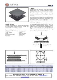
Novibra ® type RAEM<br />
For effective isolation of vibration and noise on machines<br />
with rotating movements, e.g.<br />
• Compressors • Large milling<br />
• AC units machinery<br />
• Industrial fans • Industrial and<br />
• Generators marine gen sets<br />
• Combustion engines • Refiners<br />
• Emergency power sets • Defibrators<br />
M<br />
� �<br />
�<br />
�<br />
Features<br />
RAEM is a universal mounting for applications demanding<br />
maximum isolation. It is a further development of RA,<br />
where EM stands for “extra soft”. Suitable for both light<br />
and heavy machines.<br />
For normal speeds of approx. 1500 rpm the RAEM type<br />
provides a degree of isolation of 85-95%, and gives good<br />
isolation with low frequency machines.<br />
Its unique construction and the latest production methods<br />
make Novibra type RAEM a high performance mounting<br />
having a number of advantages:<br />
• Rubber features are utilised effectively combining<br />
compression and shear.<br />
• Wide load rating options, 10-3400 kg.<br />
• Corrosion protected to cope with arduous environments<br />
on land or marine applications (Fe/Zn8C as per ISO<br />
2081).<br />
• Fitted as standard with an integral fail-safe design with<br />
resilient stop, making RAEM ideal for use on mobile<br />
applications. The RAEM mounts can accomodate<br />
occasional shock loads to 5 g reference to the weight<br />
in hardness 60° IRH. The mount will withstand shock<br />
loads up to 2 g without plastic deformation.<br />
• Clear and durable product marking so that mountings<br />
can be identified even after several years in operation.<br />
• Domed shape cover to protect against oil contamination.<br />
�����������������<br />
��������<br />
�<br />
�<br />
�<br />
��������<br />
�<br />
�<br />
�<br />
�<br />
�<br />
�������<br />
�<br />
�<br />
�<br />
��������������������<br />
Part no. Part no. Dimensions in mm Weight M-Max(kg)<br />
Type 40° IRH 60° IRH D A W H K d L G (kg) 40° IRH 60° IRH<br />
RAEM 40 10-0<strong>01</strong>22-<strong>01</strong> 10-0<strong>01</strong>23-<strong>01</strong> 64 88 35.5 110 9 12 M10 0.26 30 60<br />
RAEM 60 10-0<strong>01</strong>83-<strong>01</strong> 10-0<strong>01</strong>84-<strong>01</strong> 63 100 61 35.5 120 11 15 M12 0.30 60 120<br />
RAEM 125 M10 10-0<strong>01</strong>08-<strong>01</strong> 10-0<strong>01</strong>09-<strong>01</strong> 84 110 35.5 135 11 15 M10 0.37 80 <strong>18</strong>0<br />
RAEM 125 M12 10-0<strong>01</strong>68-<strong>01</strong> 10-0<strong>01</strong>69-<strong>01</strong> 84 110 35.5 135 11 15 M12 0.37 80 <strong>18</strong>0<br />
RAEM 350 M12 10-0<strong>01</strong>74-<strong>01</strong> 10-0<strong>01</strong>75-<strong>01</strong> 110 140-148 42 175 14 <strong>18</strong> M12 0.80 200 400<br />
RAEM 350 M16 10-0<strong>01</strong>14-<strong>01</strong> 10-0<strong>01</strong>15-<strong>01</strong> 110 140-148 42 175 14 <strong>18</strong> M16 0.80 200 400<br />
RAEM 800 10-0<strong>01</strong>20-<strong>01</strong> 10-0<strong>01</strong>21-<strong>01</strong> 155 <strong>18</strong>2 54 216 14 <strong>18</strong> M16 1.8 450 800<br />
RAEM 1500 10-0<strong>01</strong>58-<strong>01</strong> 10-0<strong>01</strong>59-<strong>01</strong> <strong>18</strong>2 146 85 <strong>18</strong>0 14 M20 3.0 900 1700<br />
RAEM 2500 10-0<strong>01</strong>60-<strong>01</strong> 10-0<strong>01</strong>61-<strong>01</strong> 224 <strong>18</strong>0 105.5 220 17.5 M24 4.6 1700 3400<br />
20<br />
RAEM<br />
Trelleborg Industrial AVS operates a policy of continuous improvement and development. We reserve the right to change design and specification of our products without prior notification or alteration of literature<br />
�<br />
�<br />
�<br />
�<br />
�
3500<br />
3000<br />
2500<br />
2000<br />
1500<br />
1000<br />
800<br />
700<br />
600<br />
500<br />
400<br />
300<br />
250<br />
200<br />
150<br />
100<br />
80<br />
70<br />
60<br />
50<br />
40<br />
30<br />
25<br />
20<br />
15<br />
RAEM 2500-60<br />
RAEM 2500-40<br />
RAEM 1500-40<br />
RAEM 1500-60<br />
RAEM 800-40<br />
RAEM 800-60<br />
RAEM 350-60<br />
RAEM 125-60<br />
RAEM 350-40<br />
RAEM 60-60<br />
RAEM 40-40<br />
RAEM 125-40<br />
RAEM 40-60<br />
RAEM 60-40<br />
RAEM 350-60<br />
RAEM 125-60<br />
RAEM 60-60<br />
RAEM 125-40<br />
RAEM 40-60<br />
RAEM 60-40<br />
RAEM 40-40<br />
Trelleborg Industrial AVS operates a policy of continuous improvement and development. We reserve the right to change design and specification of our products without prior notification or alteration of literature<br />
0<br />
50<br />
70<br />
80<br />
85<br />
90<br />
L<br />
I<br />
RAEM<br />
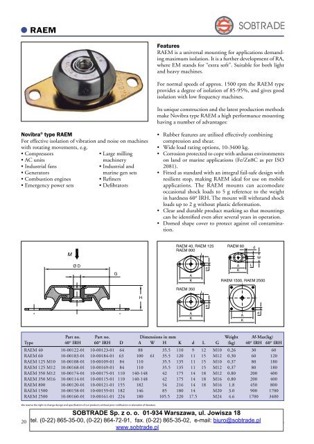
Note: The natural frequencies and degrees of isolation are based on dynamic characteristics of the mountings.<br />
Load<br />
per mounting (kg)<br />
25<br />
30<br />
40<br />
50<br />
60<br />
70<br />
80<br />
90<br />
100<br />
Resonance Avoid this region<br />
Diagram 1<br />
RAEM 2500-60<br />
RAEM 1500-60<br />
RAEM 2500-40<br />
RAEM 800-60<br />
RAEM 1500-40<br />
RAEM 800-40<br />
RAEM 350-40<br />
Diagram 2<br />
10<br />
5<br />
6 7 8 9 10 11 12 13 14 16 <strong>18</strong> 20 1 2 3 4 5 6 8 10 12 15 20<br />
Interfering frequency (Hz)<br />
Natural frequency (Hz) Static deflection (mm)<br />
5<br />
Diagram 3<br />
6<br />
To select correct mounting, following<br />
7<br />
data are needed:<br />
1) Load per mounting (kg)<br />
8<br />
9<br />
10<br />
2) Interfering frequency (Hz)<br />
(Hz = rpm / 60 )<br />
Select correct load line in diagram 1 and<br />
correct interference line in diagram 3.<br />
The load line intersects with required type<br />
of mounting.<br />
Connect this intersection point vertically<br />
15<br />
down to the interference line in diagram 3.<br />
Here, on the sloping curve, the isolation<br />
degree is indicated.<br />
20<br />
For static deflection, see diagram 2.<br />
Degree of isolation (%)<br />
1<br />
3<br />
2<br />
21