Specifying Crystal Oscillators - isotemp
Specifying Crystal Oscillators - isotemp
Specifying Crystal Oscillators - isotemp

Create successful ePaper yourself
Turn your PDF publications into a flip-book with our unique Google optimized e-Paper software.
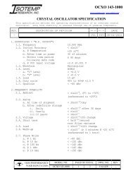
<strong>Specifying</strong> <strong>Crystal</strong> <strong>Oscillators</strong><br />
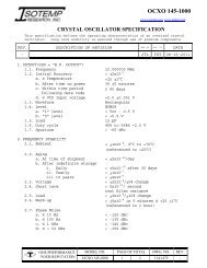
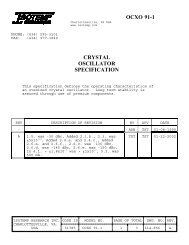
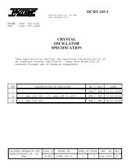
INTRODUCTION<br />
ISOTEMP RESEARCH specializes in providing custom and semi-custom oscillators. We have focused our<br />
efforts on OCXO’s and high performance NCXO’s, VCXO’s, and TCXO’s. This application note is designed to help<br />
our customers understand the parameters used in specifying a crystal oscillator.<br />
GENERAL<br />
When specifying a crystal oscillator, it is important for the supplier to understand the requirements. The<br />
underlying requirement is usually some stability of frequency or time. This stability information needs to be<br />
conveyed to the supplier along with the maximum changes that will be seen by the oscillator in its environment.<br />
Some of these changes are: operating temperature, voltage, load, altitude, shock, vibration, number of times turned<br />
on and off, humidity, and storage temperature. In addition, there will be other stability requirements such as phase<br />
noise and short term stability. Other parameters of specifying an oscillator are: r.f. output type and level, amount<br />
of time allowed after power on for the oscillator to meet the stability requirements, type of frequency adjustment and<br />
range, power availability, and noise emitted by the oscillator. Some other functions available are: oven monitor and<br />
reference voltage.<br />
These requirements should have an order of importance during the initial quotation process. The order of<br />
importance will allow the supplier and the customer to make trade offs if necessary and to come up with the most<br />
cost effective solution. The overall goal is to get the total of the stabilities to be less than the requirements.<br />
Obviously an oscillator with no deviations in temperature, time, voltage, etc. would be the ideal solution. However,<br />
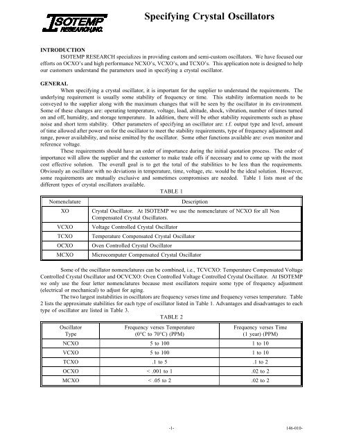
some requirements are mutually exclusive and sometimes compromises are needed. Table 1 lists most of the<br />
different types of crystal oscillators available.<br />
TABLE 1<br />
Nomenclature Description<br />
XO <strong>Crystal</strong> Oscillator. At ISOTEMP we use the nomenclature of NCXO for all Non<br />
Compensated <strong>Crystal</strong> <strong>Oscillators</strong>.<br />
VCXO Voltage Controlled <strong>Crystal</strong> Oscillator<br />
TCXO Temperature Compensated <strong>Crystal</strong> Oscillator<br />
OCXO Oven Controlled <strong>Crystal</strong> Oscillator<br />
MCXO Microcomputer Compensated <strong>Crystal</strong> Oscillator<br />
Some of the oscillator nomenclatures can be combined, i.e., TCVCXO: Temperature Compensated Voltage<br />
Controlled <strong>Crystal</strong> Oscillator and OCVCXO: Oven Controlled Voltage Controlled <strong>Crystal</strong> Oscillator. At ISOTEMP<br />
we only use the four letter nomenclatures because most oscillators require some type of frequency adjustment<br />
(electrical or mechanical) to adjust for aging.<br />
The two largest instabilities in oscillators are frequency verses time and frequency verses temperature. Table<br />
2 lists the approximate stabilities for each type of oscillator listed in Table 1. Advantages and disadvantages to each<br />
type of oscillator are listed in Table 3.<br />
TABLE 2<br />
Oscillator<br />
Type<br />
Frequency verses Temperature<br />
(0°C to 70°C) (PPM)<br />
Frequency verses Time<br />
(1 year) (PPM)<br />
NCXO 5to100 1to10<br />
VCXO 5to100 1to10<br />
TCXO .1 to 5 .1 to 2<br />
OCXO < .001 to 1 .02 to 2<br />
MCXO < .05 to 2 .02 to 2<br />
-1- 146-010-
<strong>Specifying</strong> <strong>Crystal</strong> <strong>Oscillators</strong><br />
TABLE 3<br />
TYPE ADVANTAGES DISADVANTAGES<br />
NCXO Low power. Minimal warm up time. Least<br />
expensive crystal oscillator. Much higher<br />
frequency stability than a LC or ceramic<br />
oscillator.<br />
VCXO Low power. Minimal warm up time. Can be<br />
locked to an external source. Provides good<br />
local short term stability.<br />
TCXO Low power. Short warm up time as<br />
compared to an OCXO. Good temperature<br />
performance.<br />
OCXO Best stability available for a crystal oscillator.<br />
Superior: Phase noise, temperature<br />
performance, aging, etc.<br />
MCXO Low power as compared to an OCXO. Short<br />
warm up time as compared to an OCXO.<br />
Good temperature performance.<br />
More PCB space than a LC oscillator. Poor<br />
temperature performance as compared to<br />
TCXO’s and OCXO’s<br />
High frequency adjustment range could degrade<br />
temperature performance to less than an<br />
NCXO. Poor temperature performance as<br />
compared to TCXO’s and OCXO’s<br />
More expensive than NCXO’s and VCXO’s.<br />
Requires more PCB space than most NCXO’s<br />
and VCXO’s.<br />
Largest package size of any oscillator. Has the<br />
longest warm up time. More expensive than<br />
TCXO’s.<br />
Higher cost with today's technology as<br />
compared to an OCXO. Increased noise due to<br />
digital switching.<br />
The cost order does overlap in certain areas where the technology of that type of oscillator is pushed to its<br />
limits. Some examples are:<br />
A ± 0.1 PPM temperature requirement is usually less expensive as an OCXO than a TCXO.<br />
A wide pull range VCXO (i.e., ± >100 PPM) will usually cost more than a standard TCXO.<br />
PARAMETERS<br />
The following sections are general guidelines to help specify a crystal oscillator. A section may be omitted<br />
from the specification if that parameter is not critical to the application. <strong>Specifying</strong> less will help keep cost under<br />
control. However, there should be minimum requirements on some specifications and some specifications will come<br />
naturally because of other parameters. Let us know if you have statistical information requirements on certain<br />
specifications.<br />
Parameter Name Description<br />
OUTPUT<br />
FREQUENCY<br />
Obviously a frequency needs to be specified. However, sometimes it is more cost effective to get<br />
an oscillator at a multiple of the desired frequency.<br />
FREQUENCY AT TIME OF SHIPMENT<br />
To reduce production test and calibration, many customers request that the oscillators are<br />
received within a specified frequency window or tolerance. This frequency tolerance is specified<br />
after some period of warm up. Knowing this tolerance, ISOTEMP can set the oscillator within the<br />
specified after warm up tolerance. However, when the oscillator is received, the frequency will<br />
not be the same as when the oscillator left ISOTEMP. This frequency difference can be attributed<br />
to: 1) the overall oscillator stability, 2) time off power, 3) shipping, 4) test conditions at the<br />
customer, and 5) retrace. The frequency tolerance can range from 0.02 PPM to 0.3 PPM. Contact<br />
ISOTEMP Engineering for further application-specific information.<br />
-2- 146-010-
<strong>Specifying</strong> <strong>Crystal</strong> <strong>Oscillators</strong><br />
WAVE FORM<br />
The types of wave forms available are: Sine wave, Rectangular, Clipped Sine wave, and ECL. The<br />
two most popular outputs are sine wave and rectangular. For sine wave output a higher load impedance<br />
and lower level will require fewer buffering stages, reduce the internal parts count, and consume less<br />
current. Additionally, TCXO’s with a higher load and a lower output level will have a reduced warm up<br />
time. Units with a rectangular wave form usually use a buffering device from the HCMOS family.<br />
(ACMOS, HCMOS, CMOS, etc.) With a rectangular output, internal division is easily done and gives<br />
ISOTEMP design flexibility.<br />
LEVEL<br />
For sine wave units output levels are available up to +20 dBm. For units with loads other than<br />
50 ohms there is a lot of flexibility in the output level. The maximum level is determined by the input<br />
voltage, package size, and input power. The most cost effective way to specify an output level is to specify<br />
a minimum. However, depending upon the level required and the internal oscillator design, the level can<br />
be specified with a tolerance of ±0.5 dBm or ±5%.<br />
For rectangular wave form units, the levels are those specified by the chip manufacturers. Refer<br />
to the data books for the family type and output level for the requirement.<br />
LOAD<br />
For sine wave units almost any load is possible. If the load is non-resistive, the actual load should<br />
be specified. (E.g., 510 ohms in parallel with 15 pF)<br />
For rectangular wave form units the load should be specified for the family type and fan out that<br />
will be connected to the oscillator. To reduce the size of our oscillators, we use IC’s that are not capable<br />
of driving the full fan out that many families specify. A fan out of one or two loads is desired and will<br />
give more design flexibility. If the oscillator is not driving the load for any particular IC family, the actual<br />
load should be specified.<br />
HARMONICS<br />
For sine wave units a specified harmonic content of
<strong>Specifying</strong> <strong>Crystal</strong> <strong>Oscillators</strong><br />
FREQUENCY STABILITY<br />
TOTAL<br />
A total frequency stability verses the particular requirements may be specified. This parameter is<br />
a good way to convey the requirements needed in the end application. (E.g., < ±0.1 PPM/ day for<br />
temperature, voltage, and load.) Sometimes the end application will not experience the total changes as<br />
called out in other areas of the specification. (E.g., The input voltage tolerance is ±5% as dictated by the<br />
tolerance of the voltage supply to the oscillator. However in system, the supply voltage may only change<br />
±1% due to effects of the load, temperature, etc.) Therefore, this requirement may be specified over<br />
particular changes of other parameters.<br />
AMBIENT (TEMPERATURE)<br />
This parameter has a considerable effect on the overall stability of the oscillator and should always<br />
be specified. It can be specified as a peak to peak window over the operating temperature range, or as a<br />
zero to peak movement referenced to a particular temperature, or a frequency change per degree of<br />
temperature. For NCXO’s and VCXO’s the characteristic of this parameter follows the curve of the crystal,<br />
a third order polynomial. For TCXO’s the characteristics usually follow a third or higher order polynomial.<br />
For OCXO’s the characteristics usually follow a first or second order polynomial. At ISOTEMP we usually<br />
specify a zero to peak movement with a reference temperature. Usually this requirement is specified under<br />
static conditions. If the requirements are under dynamic conditions such as rapid temperature changes, these<br />
changes should be specified.<br />
AGING (TIME)<br />
In addition to the ambient performance aging also has a considerable effect on the overall stability<br />
and it should always be specified. The aging rate should be specified after a specific period. For most<br />
oscillators the aging more closely resembles a straight line on a semi-log plot with time being on the log<br />
scale. Because of this logarithmic characteristic, the aging rate is specified over one or more periods of<br />
time (Day, month, year, and XX years.) For ovenized oscillators an aging rate at time of shipment is also<br />
specified. <strong>Oscillators</strong> will age when left un-powered but not as much as when energized. The off power<br />
aging sometimes dictates specifying aging after storage. For more information on aging see ISOTEMP<br />
application note CRYSTAL OSCILLATOR AGING (146-000).<br />
VOLTAGE<br />
The voltage stability of an oscillator is also an important parameter. If this parameter is too loose,<br />
it will show up as changes in other parameters such as ambient and initial frequency tolerance. If multiple<br />
input voltages are used, this parameter should be specified for each voltage. If the input voltages change<br />
together, this information should also be conveyed on the specification.<br />
SHORT TERM<br />
The short term stability is the change in the oscillator’s frequency when measured with a counter.<br />
Short term is usually specified by calculation method and time interval. ISOTEMP usually specifies the<br />
short term by the calculation method of the Allan variance, but RMS, peak to peak, and others can also be<br />
specified.<br />
LOAD<br />
The frequency change verses the change in load for an oscillator is usually not a large<br />
consideration, except on sine wave units where minimal buffering is available. A reactive load change will<br />
affect the frequency more than a resistive change. For most sine wave units the load stability is specified<br />
for a ±5% change in a resistive load. If the load will be reactive, the possible impedance change should<br />
also be specified. For rectangular output units the load is usually specified for a one gate change.<br />
-4- 146-010-
<strong>Specifying</strong> <strong>Crystal</strong> <strong>Oscillators</strong><br />
WARM UP<br />
All oscillators experience some frequency change during initial power on. For TCXO’s the change<br />
is minimal and is usually masked by the temperature performance. For VCXO’s and NCXO’s the warm<br />
up characteristic is seen as the internal components warm up and cause the frequency to follow the crystal<br />
curve. Warm up is usually not specified for non-ovenized types. OCXO’s have the largest frequency<br />
movement during initial power on (typically 40 PPM at 25°C.) For all oscillators except OCXO’s the<br />
frequency will usually stabilize in less than 15 minutes and the warm up period will not change much with<br />
temperature. However, for OCXO’s the time can vary a great deal depending upon the temperature and<br />
the type of design. For more information on OCXO warm up see ISOTEMP application note<br />
UNDERSTANDING OVENIZED OSCILLATORS (146-003). Warm up is specified as a frequency at some<br />
point in time referenced to the frequency at a later point in time measured at the same outside temperature.<br />
PHASE NOISE<br />
Single side band phase noise is the signal to noise ratio measured in a1Hzbandwidth at a<br />
frequency offset from the carrier. The phase noise of an oscillator is tightly coupled with other parameters.<br />
The short term stability of the oscillator is a function of the phase noise. When a low phase noise unit is<br />
specified, the unit will also exhibit good aging and temperature performance. Phase noise is usually<br />
specified in dBc at certain frequency offsets from the carrier. When more than one frequency offset is<br />
specified, the noise of the oscillator must be below the line connecting these points when plotted on a<br />
semi-log plot with frequency offset being on the log axis.<br />
RETRACE<br />
Retrace is the degree to which an oscillator will repeat its frequency after being turned off for a<br />
specified amount of time. Retrace is in the 1x10 -8 range and is usually not specified except for very high<br />
stability OCXO’s. In order for other parameters not to mask this characteristic, a sufficient pre and post<br />
power off period should be specified and other influences such as voltage and temperature should be held<br />
constant.<br />
HUMIDITY<br />
Open frame and non-sealed units will change frequency with humidity. If the oscillator will<br />
experience high humidity levels, a sealed unit should be considered.<br />
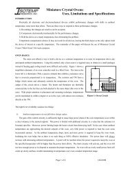
MECHANICAL STRESSES<br />
One of the most fragile parts in an oscillator is the crystal. Think of the crystal as an electro-mechanical<br />
part. Unlike other electrical components that manipulate electrons without any physical movement, the crystal is<br />
physically moving at the oscillating frequency. Therefore, any physical movements to the crystal will cause a change<br />
in frequency. This frequency shift may be temporary or permanent depending upon the level of the movements the<br />
crystal experiences. The frequency change will be different for each axis. The most sensitive axis is in the plane<br />
of the crystal blank in the oscillator. Temporary frequency shifts are associated with crystal blank mounting stresses<br />
and the flexing of the crystal blank. Permanent frequency shifts are associated with the crystal blank mounting<br />
structure permanently changing the mounting stresses on the crystal blank. Catastrophic failures occur when some<br />
part in the crystal unit breaks (Mounting structure, epoxy, or the crystal blank.) Therefore, all oscillators will have<br />
associated frequency instability due to shock and vibration. These instabilities are specified in the following ways:<br />
SHOCK, ASSOCIATED FREQUENCY SHIFT<br />
The before to after frequency change due to a shock or series of shocks in one or more planes<br />
either on power or off power.<br />
-5- 146-010-
<strong>Specifying</strong> <strong>Crystal</strong> <strong>Oscillators</strong><br />
SHOCK SENSITIVITY<br />
The frequency short term stability caused by a shock in one or more planes.<br />
VIBRATION, ASSOCIATED FREQUENCY SHIFT<br />
The before to after frequency change due to vibration in one or more planes occurring on power<br />
or off power.<br />
VIBRATION SENSITIVITY<br />
The frequency short term stability or phase noise caused by vibration in one or more planes.<br />
ACCELERATION SENSITIVITY (2-g TIP OVER)<br />
The frequency change with the oscillator’s relative position to the pull of gravity. Frequency<br />
change caused by turning the oscillator upside down. This is the zero frequency VIBRATION<br />
SENSITIVITY.<br />
MICROPHONICS<br />
A way of specifying SHOCK SENSITIVITY and/or VIBRATION SENSITIVITY without elaborate<br />
shock and vibration equipment.<br />
FREQUENCY ADJUSTMENT<br />
RANGE<br />
The range of the frequency adjustment should be specified to cover all the oscillator’s instabilities<br />
for the life of the oscillator, the largest is usually aging. Since aging is not a linear function, the range<br />
should not be the yearly aging rate times the life. The XX year aging plus the other stabilities will be<br />
sufficient for this specification. If the system requirements or design require a wider range, this wider range<br />
should then be added to the total above.<br />
MECHANICAL<br />
RANGE<br />
Only a minimum range should be specified. The resolution will dictate the maximum<br />
range. Also see FREQUENCY ADJUSTMENT, RANGE.<br />
COARSE RANGE<br />
If the requirements demand that the unit be set to a frequency tighter than what is capable<br />
from a unit with a single adjustment, a course and fine mechanical frequency adjustment will be<br />
required. The coarse adjustment should follow the rules in FREQUENCY ADJUSTMENT,<br />
RANGE.<br />
FINE RANGE<br />
The fine range should be sufficient to cover the resolution of the coarse adjustment.<br />
RESOLUTION<br />
The resolution is dictated by the maximum design range and the number of turns of the<br />
trimmer. Any technician can set the trimmer to within 10 degrees without a problem. If the<br />
requirement necessitates tighter than 10 degrees of rotation, excessive time will be spent setting<br />
the oscillator to frequency.<br />
CONTROL<br />
At ISOTEMP we use many different trimmers with the number of turns varying from ½<br />
turn to 25 turns. Using a multi-turn trimmer makes the oscillator much easier to set to frequency.<br />
-6- 146-010-
<strong>Specifying</strong> <strong>Crystal</strong> <strong>Oscillators</strong><br />
ELECTRICAL<br />
NOTE: Caution must be taken on PCB design when ELECTRICAL frequency adjustment is used.<br />
Besides the VCO port picking up noise, special attention needs to be given to the ground paths. Ground<br />
voltage build ups are of particular importance when the power fluctuates in the system. For a system with<br />
an OCXO the power will change with temperature. A few milli-ohms resistance difference between the<br />
oscillator ground and the electrical frequency controlling device may cause the oscillator to fail ambient.<br />
If the oscillator is socketed, the contact resistance should also be considered.<br />
RANGE<br />
The electrical frequency adjustment range is usually specified over a particular control<br />
voltage range. A minimum and maximum range should be specified. The maximum range will<br />
keep the frequency verses voltage sensitivity in check. If the oscillator does not have<br />
MECHANICAL FREQUENCY ADJUSTMENT, the range should be specified referenced to<br />
nominal frequency when the oscillator is new. If the oscillator does not have MECHANICAL<br />
FREQUENCY ADJUSTMENT or the system design requires no calibration of the MECHANICAL<br />
FREQUENCY ADJUSTMENT, the range should be wide enough to cover aging plus any<br />
modulation and/or the stability of any external reference source. If the oscillator does have<br />
MECHANICAL FREQUENCY ADJUSTMENT, this range should be referenced to the CENTER<br />
VOLTAGE. Also see FREQUENCY ADJUSTMENT, RANGE.<br />
CONTROL<br />
Control specifies how the ELECTRICAL FREQUENCY ADJUSTMENT will be<br />
controlled. This control specifies the voltage range and/or pin connections for an external trimmer<br />
for the electrical frequency adjustment.<br />
SLOPE<br />
Slope specifies positive or negative frequency verses voltage for the electrical frequency<br />
adjustment.<br />
CENTER<br />
Center specifies the voltage and tolerance at which nominal frequency will occur. On<br />
units with mechanical frequency adjustment a tolerance on the center does not need to be specified.<br />
For 99% of the oscillators at ISOTEMP the center voltage is held internally by an high impedance<br />
resistor network; therefore, the oscillator frequency is stable even if no voltage is applied.<br />
LINEARITY<br />
Linearity specifies how much the frequency verses voltage function varies from a straight<br />
line. This function is usually a second order polynomial. Most oscillators will have a linearity of<br />
< ±20%.<br />
INPUT IMPEDANCE<br />
The input impedance of the electrical trim input is usually resistive and for most<br />
oscillators is > 50 k ohms. <strong>Specifying</strong> excessively high input impedances (> 200 k ohms) will<br />
limit design flexibility and affect production yields and phase noise.<br />
FREQUENCY RESPONSE<br />
The frequency response of the electrical adjustment is dictated by the Input impedance,<br />
the controlling varactor, and any capacitance designed into the electrical frequency adjustment<br />
biasing network.<br />
-7- 146-010-
<strong>Specifying</strong> <strong>Crystal</strong> <strong>Oscillators</strong><br />
INPUT POWER<br />
The voltage and current requirements for oscillators vary greatly depending upon the oscillator type and<br />
frequency. OCXO’s have the largest power variations. Therefore, they will be discussed separately.<br />
NCXO’s, VCXO’s and TCXO’s for the most part are constant current designs. These oscillators require<br />
a certain amount of current for operation independent of the input voltage. Many designs also have internal voltage<br />
regulators. Because most designs are optimized for operation at a particular voltage, a ±5% voltage tolerance is<br />
preferred. Additionally, a larger than ±5% tolerance at +5 VDC operation makes the design even more difficult.<br />
In an OCXO, the oscillator section of the design has the same characteristics outlined above. However, the<br />
heater section of the design has two operating modes. At turn on, while the oven is warming up, the heater is in<br />
a constant current mode. After the oven reaches temperature, the input is in a constant power mode. This power<br />
varies with temperature. Since the heater control circuitry consumes little power compared with the heater and the<br />
heater consumes most of the power, many OCXO’s have two voltage inputs: one for the oscillator section and one<br />
for the heater. Dual inputs offer the advantage of having a large voltage tolerance on heater input allowing the heater<br />
to run directly off an unregulated voltage. The dual inputs are advantageous for systems where overall power is a<br />
concern. Additionally, a separate oven input will put less requirements on the voltage regulator supplying the<br />
oscillator, saving system space and costs. For more information on OCXO power consumption see ISOTEMP<br />
application note UNDERSTANDING OVENIZED OSCILLATORS (146-003).<br />
OTHER OUTPUTS<br />
OVEN MONITOR<br />
An oven monitor is an output that indicates that the heater in an OCXO has reached temperature<br />
(for most designs, the oven monitor toggles when the heater switches from the constant current mode to the<br />
constant power mode.) The point in time where the oven monitor toggles corresponds to a somewhat stable<br />
frequency. However, since there is a time lag between the heater temperature and the crystal temperature<br />
and the heater temperature is still approaching its final value, the frequency will not be its final value.<br />
There are two types of oven monitors: 1) A signal indicating the oven is below the operating temperature,<br />
2) A signal indicating the oven is not at operating temperature (above or below.)<br />
REFERENCE VOLTAGE<br />
On some OCXO’s and TCXO’s with electrical frequency adjustment a reference voltage is<br />
available. Since on these types of oscillators a stable voltage is required in the design, a reference voltage<br />
comes at little cost. For OCXO’s the internal voltage regulator is usually heated and offers temperature<br />
performance superior to external voltage regulators. The voltage verses temperature will be in the range<br />
of a few PPM per °C. Since this voltage is manipulated and fed back into the VCO port of the oscillator,<br />
the following parameters need to be considered when determining the ambient performance of the oscillator:<br />
VOLTAGE, LOAD, AMBIENT, REGULATION, temperature coefficient of VCO port controlling device.<br />
EMITTED NOISE<br />
All oscillators will inject some noise back onto the supply line. This noise will be a current surge at the<br />
output frequency and the internal frequencies of the oscillator. In some cases this noise may cause problems in the<br />
system and may need to be specified. If the emitted noise will be a concern in the system, contact ISOTEMP<br />
Engineering for more information.<br />
-8- 146-010-
<strong>Specifying</strong> <strong>Crystal</strong> <strong>Oscillators</strong><br />
ENVIRONMENTAL and PRODUCTION PROCESSES<br />
STORAGE TEMPERATURE<br />
<strong>Crystal</strong> oscillators are assembled using commercially available components and epoxies. The<br />
limiting factor in the maximum storage temperature is the epoxies and should be limited to +105°C. The<br />
limiting factor in the minimum storage temperature is the electronic components and should be limited to<br />
-50°C.<br />
SEAL AND CLEANING<br />
If the oscillator is going to be cleaned by an automatic cleaner or immersion, a seal should be<br />
specified. Solder sealed units will meet MIL-STD-202, Method 112C, Test condition D. This test is a<br />
bubble leak test and is sufficient for most cleaning methods. If an open frame unit is being considered,<br />
contact ISOTEMP sales for recommended cleaning methods.<br />
OPERATING TEMPERATURE<br />
If the oscillator is required to operate outside the specified Frequency verses temperature range,<br />
an operating temperature range should be specified. The oscillator will continue to operate, but it will not<br />
hold any stability specifications.<br />
TEST DATA<br />
A prerequisite to supplying quality products is having checks during the production process. ISOTEMP uses<br />
these tests to find and resolve process variations before they become a problem. While performing test steps, data<br />
is recorded and used for process centering. On many units there is also out-going verification of some specified<br />
parameters. The parameters critical to function, the statistical soundness, and product quantity dictate what type of<br />
data is taken. Contact ISOTEMP sales for the data and data type available. If the data is part of our regular<br />
processes, ISOTEMP will provide it at no charge.<br />
DATA STORAGE<br />
Most data is stored on computer and all data obtained during production processes is stored for a minimum<br />
of two years.<br />
MARKING<br />
Most of ISOTEMP’s product is marked with a Label. Many products have a label overlay to protect the<br />
marking during cleaning.<br />
MECHANICAL<br />
See an ISOTEMP catalog for available packages. We offer many different sizes of NCXO’s, VCXO’s,<br />
TCXO,s and OCXO’s. If a package is not listed that meets the requirement, contact ISOTEMP SALES. We are<br />
continually developing new packages.<br />
CONCLUSION<br />
This application note does not list all of the possible parameters used to specify a crystal oscillator; however,<br />
it provides a good starting point for customers new to crystal oscillators. <strong>Specifying</strong> an oscillator can be very<br />
involved, but one must remember that all of these parameters may not be needed. Over or under specifying a unit<br />
can end up being very costly. Through awareness and communication, we can work together to fulfill your<br />
requirements. At ISOTEMP we pride ourselves on supplying quality service and products. We will give you the<br />
best value obtainable anywhere. By working with you and understanding your requirements, we will meet or exceed<br />
your expectations.<br />
-9- 146-010-
<strong>Specifying</strong> <strong>Crystal</strong> <strong>Oscillators</strong><br />
This page left intentionally blank.<br />
-10- 146-010-
<strong>Specifying</strong> <strong>Crystal</strong> <strong>Oscillators</strong><br />
This page left intentionally blank.<br />
-11- 146-010-
REFERENCES<br />
MIL-O-55310B Military specification for crystal oscillators.<br />
U.S. government<br />
<strong>Specifying</strong> <strong>Crystal</strong> <strong>Oscillators</strong><br />
For further information on the specification and application of Ovenized <strong>Crystal</strong> <strong>Oscillators</strong>, please contact the sales<br />
or engineering staff at Isotemp Research, Inc. For reprints of this article, ask for document number 146-010.<br />
P.O. Box 3389<br />
Charlottesville, VA 22903 USA<br />
Voice: (804) 295-3101<br />
FAX: (804) 977-1849<br />
Internet: http://www.<strong>isotemp</strong>.com<br />
Written by Todd S. Tignor, BSEE, V.P. of Engineering ISOTEMP RESEARCH INC.<br />
Isotemp Research Inc. is an American company building performance ovens and oscillators since 1968<br />
-12- 146-010-