

industry current voltage transducers

You also want an ePaper? Increase the reach of your titles
YUMPU automatically turns print PDFs into web optimized ePapers that Google loves.
Technologies<br />
Transducer Technologies<br />
DV & DVL Type Voltage <strong>transducers</strong><br />
Features<br />
• Insulating digital technology<br />
• Measurement of all<br />
types of signals: DC, AC,<br />
pulsed and complex<br />
• Compact size,<br />
reduced volume<br />
Operation principle<br />
• High galvanic isolation<br />
• Low consumption and losses<br />
• Very high accuracy, Class<br />
0.5R according to EN<br />
50463 (DV Models)<br />
• Low temperature drift<br />
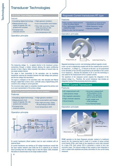
Rogowski Current <strong>transducers</strong> RT type<br />
Features<br />
• Non-contact measurement<br />
of AC & pulsed signal<br />
• Thin, lightweight & flexible<br />
measuring head<br />
• Easy to use: Can be opened<br />
Operation principle<br />
• Sensitivity to external field<br />
disturbances minimized<br />
• Wide frequency range<br />
• Galvanic isolation<br />
Transducer Technologies<br />
Split Core Current transformers AT & TT type<br />
Features<br />
• Non-contact measurement • Easy to use: Can be opened<br />
• AC & pulsed signal<br />
• Good overall accuracy<br />
• No power supply<br />
• Galvanic isolation<br />
Operation principle<br />
Technologies<br />
+HT<br />
Primary<br />
Voltage<br />
VP -HT<br />
-Up<br />
Rectifier Filter<br />
+Up -Up 0V +5V<br />
Modulator<br />
Supply<br />
Bitstream<br />
• Insulating digital technology<br />
• Measurement of all<br />
types of signals: DC, AC,<br />
pulsed and complex<br />
• Compact size,<br />
reduced volume<br />
Primary<br />
Current<br />
Shunt<br />
Rectifier<br />
Filter<br />
Power Supply<br />
Digital<br />
Filter<br />
I P<br />
+Up -Up 0V +5V<br />
+In<br />
Bitstream<br />
Digital<br />
Modulator<br />
Filter<br />
-In<br />
-Up<br />
Supply<br />
Micro controller<br />
D/A Converter<br />
U / I<br />
Generator<br />
+V C<br />
-V C<br />
Output<br />
The measuring <strong>voltage</strong>, V P<br />
, is applied directly to the transducer primary<br />
connections through a resistor network allowing the signal conditioning<br />
circuitry to feed a Sigma-Delta modulator that allows to transmit data via<br />
one single isolated channel.<br />
The signal is then transmitted to the secondary over an insulating<br />
transformer ensuring the insulation between the high <strong>voltage</strong> side (primary)<br />
and the low <strong>voltage</strong> side (secondary).<br />
The signal is reshaped on the secondary side, then decoded and filtered<br />
through a digital filter to feed a micro-controller using a Digital/Analog (D/A)<br />
converter and a <strong>voltage</strong> to <strong>current</strong> generator.<br />
The recovered output signal is completely insulated against the primary and<br />
is an exact representation of the primary <strong>voltage</strong>.<br />
DI Type Current <strong>transducers</strong> (Shunt isolator)<br />
Features<br />
Operation principle<br />
• High galvanic isolation<br />
• Low consumption and losses<br />
• Very high accuracy, Class<br />
1R according to EN 50463<br />
• Low temperature drift<br />
Power<br />
Supply<br />
Micro controller<br />
D/A Converter<br />
U / I<br />
Generator<br />
+V C<br />
-V C<br />
Output<br />
R M<br />
I P<br />
V ind<br />
I S<br />
C<br />
S<br />
W P<br />
N S<br />
N P =1<br />
R M<br />
Primary Current I P<br />
AC<br />
Isolated Output Current I S<br />
Primary Current I P<br />
AC<br />
V out Isolated Output Voltage V out<br />
A transformer is a static electrical device transferring energy by inductive<br />
Rogowski technology is an Air-core technology (without magnetic circuit).<br />
coupling between the windings making part of it. It is made with a primary<br />
A pick-up coil is magnetically coupled with the flux created by the <strong>current</strong> to<br />
coil (W P<br />
) with N P<br />
turns and a secondary coil (W S<br />
) with N S<br />
turns, wound<br />
be measured I P<br />
. A <strong>voltage</strong> V OUT<br />
is induced on the pick-up coil proportional<br />
around the same magnetic core (C).<br />
to the derivative of flux and thus proportional to the derivative of the <strong>current</strong><br />
A varying <strong>current</strong> I P<br />
in the primary winding (assimilated here to the primary<br />
to be measured I P<br />
. Because the derivative of DC is zero this technology is<br />
conductor crossing the aperture: N P<br />
= 1) creates a varying magnetic flux<br />
only useful for the measurement of AC or pulsed <strong>current</strong>s.<br />
in the transformer’s core crossing the secondary winding. This varying<br />
The waveform of the measured <strong>current</strong> requires the integration of the<br />
magnetic flux induces a varying electromotive force or <strong>voltage</strong> V ind<br />
in the<br />
induced <strong>voltage</strong> V OUT<br />
. Therefore, the <strong>current</strong> transducer may includes an<br />
secondary winding. Connecting a load to the secondary winding causes a<br />
integration function in the processing electronics (option).<br />
<strong>current</strong> I S<br />
to flow. This compensating secondary <strong>current</strong> I S<br />
is substantially<br />
proportional to the primary <strong>current</strong> I P<br />
to be measured so that N P<br />
.I P<br />
= N S<br />
.I S<br />
PRiME Current Transducers<br />
Features<br />
DC <strong>current</strong>s are not measured and not suitable because they<br />
represent a risk of magnetic saturation. The relationship here above<br />
• AC measurement with • Accuracy independent<br />
is respected only within the bandwidth of the <strong>current</strong> transformer.<br />
wide dynamic range<br />
of the position of the<br />
Warning!: Never let the output unloaded because there is a risk of safety<br />
cable in the aperture<br />
for users.<br />
• No magnetic saturation<br />
and of external fields<br />
• High overload capacity<br />
• Light weight and<br />
• Good linearity<br />
small package<br />
• Low thermal losses<br />
Operation principle<br />
V out<br />
Integrator<br />
0V<br />
Isolated Output Voltage V out<br />
DI <strong>current</strong> <strong>transducers</strong> (Shunt isolator) must be used combined with an<br />
external Shunt.<br />
DI <strong>current</strong> <strong>transducers</strong> are working as DV <strong>voltage</strong> <strong>transducers</strong> except that<br />
the input resistor network used inside the DV is replaced by an external<br />
Shunt providing then the <strong>voltage</strong> input to feed the Sigma-Delta modulator<br />
that allows to transmit data via one single isolated channel.<br />
PRiME operates on the basic Rogowski principle. Instead of a traditional<br />
wound coil, the measuring head is made of a number of sensor printed<br />
circuit boards (PCBs, each made of two separate air cored coils) mounted<br />
on a base-PCB. Each sensor PCB is connected in series to form two<br />
concentric loops. The induced <strong>voltage</strong> at their outputs is then integrated in<br />
order to obtain both amplitude and phase information for the <strong>current</strong> being<br />
measured.<br />
* For further information, refer to the brochure “Characteristics - Applications -Calculations” or www.lem.com<br />
10 11


