

industry current voltage transducers

You also want an ePaper? Increase the reach of your titles
YUMPU automatically turns print PDFs into web optimized ePapers that Google loves.
Technologies<br />
Transducer Technologies<br />
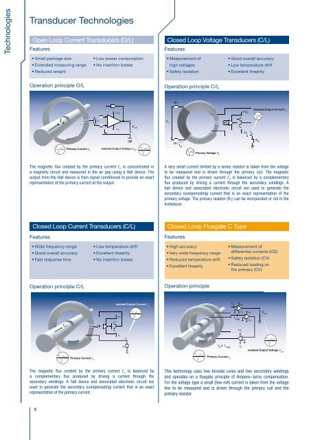
Open Loop Current Transducers (O/L)<br />
Features<br />
Closed Loop Voltage Transducers (C/L)<br />
Features<br />
Closed Loop Fluxgate CAS-CASR-CKSR type<br />
Features<br />
Features<br />
Transducer Technologies<br />
Closed loop Fluxgate ITC type<br />
Technologies<br />
• Small package size<br />
• Extended measuring range<br />
• Reduced weight<br />
Operation principle O/L<br />
• Low power consumption<br />
• No insertion losses<br />
• Measurement of<br />
high <strong>voltage</strong>s<br />
• Safety isolation<br />
Operation principle C/L<br />
• Good overall accuracy<br />
• Low temperature drift<br />
• Excellent linearity<br />
• Any kind of AC, DC, pulsed<br />
and complex signal<br />
• High accuracy<br />
• High accuracy in<br />
temperature<br />
Operation principle<br />
• Very low drift in temperature<br />
(gain and offset)<br />
• Galvanic isolation<br />
• Fast response time<br />
• Excellent linearity<br />
• Better than Class 0.5R<br />
according to EN 50463<br />
• Outstanding longterm<br />
stability<br />
Operation principle<br />
• Low residual noise<br />
• Very low sensitivity to high<br />
external DC and AC fields<br />
• High temperature stability<br />
R1<br />
I Compensation<br />
Isolated Output Voltage V out<br />
+ U C<br />
+U C<br />
Isolated Output Current I S<br />
R<br />
kR<br />
Test winding<br />
I P<br />
VHV<br />
V<br />
P<br />
V H<br />
R SHUNT<br />
_<br />
Diff Amp<br />
+<br />
V OUT<br />
Compensation<br />
winding<br />
Fluxgate D<br />
Supplies<br />
Isolated Output<br />
Current I S<br />
V OUT<br />
- U C<br />
0V<br />
Isolated Output Voltage V OUT<br />
R1<br />
I P<br />
-U C<br />
I S<br />
R M<br />
0V<br />
Compensation<br />
Windingng<br />
Primary Conductor<br />
I P<br />
Fluxgate<br />
Interface<br />
Filter<br />
Fluxgate<br />
Magnetic Core<br />
H-Bridge<br />
Driver<br />
R<br />
kR kR SHUNT V ref IN<br />
Internal<br />
V<br />
Ref<br />
ref out<br />
I P<br />
Supplies Monitoring<br />
Over Voltage<br />
Protection<br />
OV Protection<br />
Micro-Controller<br />
Offset Correction<br />
Bridge<br />
_<br />
Resistor<br />
+<br />
Fluxgate D’<br />
Fluxgate<br />
Oscillator<br />
Synchronous<br />
Rectifier<br />
LP Filter<br />
Fault_PS<br />
Fluxgate<br />
Current<br />
PI Regulator<br />
DAC 0<br />
Power Stage<br />
Primary Current I P<br />
V H<br />
R M<br />
Primary Voltage V P<br />
Primary Current I P<br />
The magnetic flux created by the primary <strong>current</strong> I P<br />
is concentrated in<br />
a magnetic circuit and measured in the air gap using a Hall device. The<br />
output from the Hall device is then signal conditioned to provide an exact<br />
representation of the primary <strong>current</strong> at the output.<br />
A very small <strong>current</strong> limited by a series resistor is taken from the <strong>voltage</strong><br />
to be measured and is driven through the primary coil. The magnetic<br />
flux created by the primary <strong>current</strong> I P<br />
is balanced by a complementary<br />
flux produced by driving a <strong>current</strong> through the secondary windings. A<br />
hall device and associated electronic circuit are used to generate the<br />
secondary (compensating) <strong>current</strong> that is an exact representation of the<br />
primary <strong>voltage</strong>. The primary resistor (R1) can be incorporated or not in the<br />
transducer.<br />
The operating principle is that of a <strong>current</strong> transformer, equipped with a<br />
magnetic sensing element, which senses the flux density in the core. The<br />
output of the field sensing element is used as the error signal in a control<br />
loop driving a compensating <strong>current</strong> through the secondary winding of the<br />
transformer. At low frequencies, the control loop maintains the flux through<br />
the core near zero. As the frequency rises, an increasingly large fraction of<br />
the compensating <strong>current</strong> is due to the operation in transformer mode. The<br />
secondary <strong>current</strong> is therefore the image of the primary <strong>current</strong>. In a <strong>voltage</strong><br />
output transducer, the compensating <strong>current</strong> is converted to a <strong>voltage</strong><br />
through a precision resistor, and made available at the output of a buffer<br />
amplifier.<br />
I COMPENSATION<br />
Primary Current I P<br />
ITC <strong>current</strong> <strong>transducers</strong> are high accuracy <strong>transducers</strong> using fluxgate<br />
technology. This high sensitivity zero-flux detector uses a second wound<br />
core (D’) for noise reduction. A difference between primary and secondary<br />
ampere turns creates an asymmetry in the fluxgate <strong>current</strong>.<br />
This difference is detected by a microcontroller that controls the secondary<br />
<strong>current</strong> that compensates the primary ampere turns (I P<br />
x N P<br />
).<br />
This results in a very good accuracy and a very low temperature drift.<br />
The secondary compensating <strong>current</strong> is an exact representation of the<br />
primary <strong>current</strong>.<br />
I S<br />
R M<br />
Closed Loop Current Transducers (C/L)<br />
Closed Loop Fluxgate C Type<br />
Closed Loop Fluxgate CTSR type<br />
Closed Loop Fluxgate IT type<br />
Features<br />
• Wide frequency range<br />
• Good overall accuracy<br />
• Fast response time<br />
• Low temperature drift<br />
• Excellent linearity<br />
• No insertion losses<br />
Features<br />
• High accuracy<br />
• Very wide frequency range<br />
• Reduced temperature drift<br />
• Excellent linearity<br />
• Measurement of<br />
differential <strong>current</strong>s (CD)<br />
• Safety isolation (CV)<br />
• Reduced loading on<br />
the primary (CV)<br />
Features<br />
• Any kind of AC, DC, pulsed<br />
and complex signal<br />
• Non-contact measurement<br />
of differential <strong>current</strong>s<br />
• High accuracy for small<br />
residual <strong>current</strong>s<br />
• Very low drift in temperature<br />
(gain and offset)<br />
• Protection against<br />
parasitic magnetic field<br />
• Galvanic isolation<br />
Features<br />
• Very high global accuracy<br />
• Low residual noise<br />
• Excellent linearity < 1 ppm<br />
• Low cross-over distortion<br />
• High temperature stability<br />
• Wide frequency range<br />
Operation principle C/L<br />
Operation principle<br />
Operation principle<br />
Operation principle<br />
I P<br />
V H<br />
Isolated Output Current I S<br />
+U C<br />
-U C<br />
I S<br />
0V<br />
Isolated Output Voltage V out<br />
Magnetic Shells<br />
I S +U C<br />
Diff Amp<br />
-U C +U C<br />
V out<br />
I mag<br />
-U C<br />
V OUT<br />
0V<br />
Fluxgate<br />
Filter Driver<br />
Interface<br />
V ref IN<br />
I P +U I<br />
C<br />
COMP2<br />
I S<br />
+ I mag -U C<br />
Isolated Output Voltage V out<br />
L<br />
R S<br />
I COMP1<br />
I L IN<br />
N<br />
Primary conductors<br />
Primary Residual Current I PR (I L +I N )<br />
Int. ref<br />
V ref out<br />
Compensation<br />
Winding<br />
S<br />
I P<br />
D<br />
D’<br />
W<br />
AC Pickup<br />
Winding<br />
Fluxgate Saturation<br />
Detection<br />
oscillator<br />
Sweep<br />
amplifier<br />
2nd Harmonic<br />
Detector<br />
+<br />
Integrator<br />
Power<br />
+<br />
+ corrector<br />
Amplifier<br />
I S<br />
Isolated Output Current I S<br />
Compensation<br />
Current<br />
R M<br />
Primary Current I P<br />
Primary Current I P<br />
No use of Hall generators. The magnetic flux created by the primary residual IT <strong>current</strong> <strong>transducers</strong> are high accuracy, large bandwidth <strong>transducers</strong><br />
<strong>current</strong> I PR<br />
(sum between I L<br />
and I N<br />
) is compensated by a secondary<br />
using fluxgate technology with no Hall generators. The magnetic flux<br />
The magnetic flux created by the primary <strong>current</strong> I P<br />
is balanced by This technology uses two toroidal cores and two secondary windings<br />
<strong>current</strong>. The zero-flux detector is a symmetry detector using a wound<br />
core connected to a square-wave generator. The secondary compensating<br />
created by the primary <strong>current</strong> I P<br />
is compensated by a secondary <strong>current</strong>.<br />
a complementary flux produced by driving a <strong>current</strong> through the and operates on a fluxgate principle of Ampere-turns compensation.<br />
<strong>current</strong> is an exact representation of the primary <strong>current</strong>.<br />
The zero-flux detector is a symmetry detector using two wound cores<br />
secondary windings. A hall device and associated electronic circuit are For the <strong>voltage</strong> type a small (few mA) <strong>current</strong> is taken from the <strong>voltage</strong><br />
In a <strong>voltage</strong> output transducer, the compensating <strong>current</strong> is converted to a connected to a square-wave generator. The secondary compensating<br />
used to generate the secondary (compensating) <strong>current</strong> that is an exact line to be measured and is driven through the primary coil and the<br />
<strong>voltage</strong> through a precision resistor, and made available at the output of a <strong>current</strong> is an exact representation of the primary <strong>current</strong>.<br />
representation of the primary <strong>current</strong>.<br />
primary resistor.<br />
buffer amplifier.<br />
The magnetic core is actually made up of a pair of 2 magnetic shells inside<br />
which the detector is located.<br />
8 * For further information, refer to the brochure “Characteristics- Applications -Calculations” or www.lem.com<br />
9<br />
Primary Current I P


