obd2cartool.com Tech-2-User-Guide

You also want an ePaper? Increase the reach of your titles
YUMPU automatically turns print PDFs into web optimized ePapers that Google loves.
<strong>Tech</strong> 2 <strong>User</strong>’s <strong>Guide</strong><br />
CONTENTS<br />
I. Introduction<br />
II. Care & Cleaning<br />
III. Getting Started<br />
IV. Power Supply<br />
V. Adapters<br />
VI. Troubleshooting<br />
VII. Software<br />
©2005 GM Service and Parts Operations
<strong>Tech</strong> 2 <strong>User</strong>’s <strong>Guide</strong><br />
The <strong>Tech</strong> 2 <strong>User</strong>’s <strong>Guide</strong> provides a <strong>com</strong>prehensive overview of the <strong>Tech</strong> 2 scan tool.<br />
Everything contained in this manual is based on the latest product information available at the time of<br />
publication. The right is reserved to make changes at any time without notice.<br />
No part of this publication may be reproduced, stored in any retrieval system, or transmitted in any form<br />
by any means, including but not limited to electronic, mechanical, photocopying, recording, or otherwise,<br />
without the prior written permission of GM Service and Parts Operations. This includes all text, tables,<br />
illustrations, and charts.<br />
Requests for permission should be sent to:<br />
General Motors Corporation<br />
Service and Parts Operations<br />
Product Engineering<br />
37350 Ecorse Road<br />
Romulus, MI 48174-1376<br />
U.S.A.<br />
© 2005 GM Service and Parts Operations. Made in the U.S.A. All rights reserved.<br />
® <strong>Tech</strong> 2 is a registered trademark of General Motors Corporation.<br />
GM<br />
Ser vice and Par ts Operations<br />
2005 <strong>Tech</strong> 2 <strong>User</strong>’s <strong>Guide</strong> i
Customer Support Overview<br />
To obtain assistance with a question or problem concerning the operation of your <strong>Tech</strong>line product and its<br />
attached products, or to arrange for warranty and non-warranty repairs, telephone the GM-<strong>Tech</strong>line<br />
Customer Support Center. To order replacement parts, contact GM Dealer Equipment or your customer<br />
support representative for GM-<strong>Tech</strong>line.<br />
Before Calling<br />
Before making a call to the Customer Support Center or GM Dealer Equipment, be sure to have the<br />
following information ready:<br />
• Dealership name, address and dealer code number<br />
• Serial number of equipment or tool<br />
• Name, part number, and quantity of the item to be requested<br />
• Telephone number where the technician may be reached<br />
Prepare a brief description of the problem:<br />
• Tell when the problem occurred<br />
• List any error codes displayed<br />
• Tell what accessories were being used when the problem occurred, and vehicle information<br />
Please see next page...<br />
2005 <strong>Tech</strong> 2 <strong>User</strong>’s <strong>Guide</strong> ii
Making the Call<br />
The GM Service and Parts Operations <strong>Tech</strong>line Customer Support Center telephone lines operate from<br />
8:00 a.m. to 8:00 p.m. (Eastern Standard Time) Monday to Friday.<br />
In the United States and Canada to contact Customer Support, dial:<br />
• English: 1-800-828-6860 (option 1) or 1-888-337-1010 (option 3)<br />
• French: 1-800-503-3222<br />
• Spanish: 1-248-265-0840 (option 2)<br />
• Fax line: 1-248-265-9327*<br />
To call GM Dealer Equipment, dial 1-800-GM-TOOLS (1-800-468-6657).<br />
International customers can send questions or <strong>com</strong>ments by fax, (U.S. country code) 248-265-9327, or<br />
use the following telephone numbers:<br />
Latin America 1-248-265-0840 Asia Pacific 045-562-4483<br />
Europe 41-41-766-2940 Australia 613-9544-6222<br />
A GM-<strong>Tech</strong>line Customer Support representative will <strong>com</strong>e on the line or respond by fax to answer<br />
questions, make suggestions, and take repair and parts orders. To make sure every problem is resolved to<br />
the satisfaction of the caller, the GM-<strong>Tech</strong>line Customer Support representative will record each problem,<br />
question, or suggestion into a special problem tracking system. Any problems that cannot be resolved over<br />
the phone will be directed to the appropriate group for resolution.<br />
* You may also send a GM-<strong>Tech</strong>line Product Assistance fax form to the Customer Support Center.<br />
2005 <strong>Tech</strong> 2 <strong>User</strong>’s <strong>Guide</strong> iii
Declaration of Conformity<br />
According to ISO/IEC <strong>Guide</strong> and EN 45014,<br />
Manufacturer’s Name: Vetronix Corp.<br />
Manufacturer’s Address: 2030 Alameda Padre Serra<br />
Santa Barbara, CA 93103<br />
declares that the product,<br />
Product Name: <strong>Tech</strong> 2<br />
Model Number(s): Z1090A<br />
Product Options: ALL<br />
conforms to the following product specifications:<br />
Safety: IEC 1010-1: 1990 + A1 / EN 61010-1: 1993<br />
EMC:<br />
CISPR 11: 1990 / EN 55011 1991 - Class A<br />
EN 50082-1: 1992<br />
IEC 801-2: 1991 / prEN 55024-2 1992 - 3kV CD, 8kV AD<br />
IEC 801-3: 1984 / prEN 55024-3 1991 - 3V/m<br />
IEC 801-4: 1988 / prEN 55024-4 1992 - 0.5kV<br />
Signal Lines. 1kV Power Lines<br />
Supplementary Information<br />
This is a Class A product. In a domestic environment this product may cause radio interference in which<br />
case the user may be required to take adequate measures.<br />
The product herewith <strong>com</strong>plies with the requirements of the Low Voltage Directive 73/23/EEC and the<br />
EMC Directive 89/336/EEC.<br />
Location:<br />
Santa Barbara, California<br />
Date: 3 / 19 / 01<br />
QA Manager:<br />
David Parker, Product Regulations<br />
2005 <strong>Tech</strong> 2 <strong>User</strong>’s <strong>Guide</strong> iv
Software License Agreement<br />
Please read this license agreement carefully before proceeding to operate the equipment. Rights to the<br />
software are offered only on the condition that the customer agrees to all terms and conditions of the<br />
license agreement. Proceeding to operate the equipment indicates your acceptance of these terms and<br />
conditions:<br />
1. USE: Customer may use the software only on the <strong>com</strong>puter system on which it was originally installed. Customer may not reverse<br />
assemble or de<strong>com</strong>pile software unless authorized by law.<br />
2. OWNERSHIP: Customer agrees that it does not have any title or ownership of the software, other than ownership of the physical<br />
media. Customer acknowledges and agrees that the software is copyrighted and protected under the copyright laws. Customer<br />
acknowledges and agrees that the software may have been developed by a third party software supplier named in the copyright<br />
notices included with the software, who shall be authorized to hold the Customer responsible for any copyright infringement or<br />
violation of this agreement.<br />
3. TERMINATION: General Motors may terminate this software license for failure to <strong>com</strong>ply with any of these terms provided GM has<br />
requested Customer to cure the failure and Customer has failed to do so within thirty (30) days of such notice.<br />
Limited Warranty<br />
SOFTWARE: Vetronix warrants for a period of ninety (90) days from the date of purchase that the Vetronix software product<br />
will execute its programming instructions when properly installed. Vetronix does not warrant that the operations of the<br />
Vetronix software will be uninterrupted or error free. In the event that this Vetronix software product fails to execute its<br />
programming instructions during the warranty period, the remedy shall be a replacement of such software product.<br />
LIMITATION OF WARRANTY: Vetronix makes no other express warranty, whether written or oral with respect to this product.<br />
Any implied warranty of merchantability or fitness for or a particular purpose is limited to the 90-day duration of this written<br />
warranty. Some states or provinces do not allow limitations on how long an implied warranty lasts, so the above limitations or<br />
exclusion may not apply to you.<br />
EXCLUSIVE REMEDIES: The remedies provided above are Customer’s sole and exclusive remedies. In no event shall<br />
Vetronix be liable for any direct, indirect, special, incidental or consequential damages (including lost profit) whether based<br />
on warranty, contract, tort or any other legal theory.<br />
2005 <strong>Tech</strong> 2 <strong>User</strong>’s <strong>Guide</strong> v
SECTION I<br />
INTRODUCTION<br />
Using This Manual<br />
To increase their effectiveness with the <strong>Tech</strong> 2, users should familiarize themselves with the format and<br />
information contained in this guide.<br />
IMPORTANT<br />
<strong>Tech</strong> 2 figures and illustrations are hyperlinked to the text of this manual. To view a figure, simply click<br />
on its description, which is shown in blue text. After viewing the figure, click on the rainbow-colored<br />
arrow at the lower left-hand corner of the screen to return to your place in the manual.<br />
Vehicle System Familiarity<br />
While the <strong>Tech</strong> 2 is a powerful tool, it cannot replace knowledge and skill. To obtain maximum benefit from<br />
the <strong>Tech</strong> 2, service technicians must have a <strong>com</strong>plete understanding of vehicle systems.<br />
When using the <strong>Tech</strong> 2 to diagnose a vehicle, it is re<strong>com</strong>mended that service technicians also refer to the<br />
service manual and the latest service bulletins.<br />
Disclaimer<br />
The <strong>Tech</strong> 2 is designed for use by trained service personnel only. It has been developed for the sole<br />
purpose of diagnosing and repairing automotive systems with electronic controls and interfaces.<br />
Every attempt has been made to provide <strong>com</strong>plete and accurate technical information based on factory<br />
service information available at the time of publication. However, the right is reserved to make changes at<br />
any time without notice.<br />
2005 <strong>Tech</strong> 2 <strong>User</strong>’s <strong>Guide</strong> I - 1
SECTION I<br />
INTRODUCTION<br />
Things You Should Know<br />
CAUTION: EXHAUST GAS<br />
When performing any checks with the engine running in an enclosed space such as a garage, ensure proper<br />
ventilation. Never inhale exhaust gases; they contain carbon monoxide—a colorless, odorless, extremely dangerous<br />
gas that can cause unconsciousness or death.<br />
CAUTION: PARKING BRAKE<br />
To help avoid personal injury, always set the parking brake securely and block the drive wheels before performing<br />
any checks or repairs on the vehicle.<br />
CAUTION: SPARKS<br />
The <strong>Tech</strong> 2 uses parts that can produce arcs or sparks. When used in a garage environment, the <strong>Tech</strong> 2 must be<br />
located not less than 18 inches (460 mm) above the floor.<br />
Please see next page...<br />
2005 <strong>Tech</strong> 2 <strong>User</strong>’s <strong>Guide</strong> I - 2
SECTION I<br />
INTRODUCTION<br />
NOTICE<br />
• DO NOT clasp battery clamps together when connected simultaneously to the vehicle’s 12 volt<br />
cigarette lighter or power supply. Reverse polarity in the vehicle’s cigarette lighter may be present.<br />
Damage could occur to the <strong>Tech</strong> 2 or to the vehicle.<br />
• If power is applied to the <strong>Tech</strong> 2 and the display remains blank, reverse polarity in the cigarette<br />
lighter may be present. Damage to the <strong>Tech</strong> 2 could occur. DO NOT connect the DLC cable to the<br />
vehicle. Verify that the center contact of the vehicle’s cigarette lighter has +12 volts and that the outer<br />
contact is grounded.<br />
• Turn off the power before inserting or removing the PCMCIA card. Continual removal and reinsertion<br />
of this card is not re<strong>com</strong>mended.<br />
• Align all cards and <strong>com</strong>ponents carefully before inserting them into the <strong>Tech</strong> 2.<br />
• Make sure all cables and adapters are firmly connected before starting to use the <strong>Tech</strong> 2.<br />
• Always read the instructions <strong>com</strong>pletely before attempting a new procedure.<br />
• The RS-232 and RS-485 ports must not be connected to a direct phone line as the <strong>Tech</strong> 2 was not<br />
designed for this method of <strong>com</strong>munication.<br />
• Do not place the <strong>Tech</strong> 2 so that the tilt stand can make contact with the vehicle battery terminal as<br />
this could short out the battery.<br />
2005 <strong>Tech</strong> 2 <strong>User</strong>’s <strong>Guide</strong> I - 3
SECTION I<br />
INTRODUCTION<br />
FCC Compliance<br />
This equipment has been tested and found to <strong>com</strong>ply with the limits for a Class A digital device, pursuant<br />
to Part 15 of the FCC rules. These limits are designed to provide reasonable protection against harmful<br />
interference when the equipment is operated in a <strong>com</strong>mercial environment.<br />
This equipment generates, uses, and can radiate radio frequency energy. If not installed and used in<br />
accordance with the instruction manual, it may cause harmful interference to radio <strong>com</strong>munications.<br />
Operation of this equipment in a residential area is likely to cause harmful interference’s in which case the<br />
user will be required to correct the interference at his or her own expense.<br />
VDE Certification (for European Use)<br />
This equipment <strong>com</strong>plies with the requirements of VDE 0871/6.78. Improper use or maintenance neglect<br />
may cause unacceptable radio or TV interference.<br />
2005 <strong>Tech</strong> 2 <strong>User</strong>’s <strong>Guide</strong> I - 4
SECTION I<br />
INTRODUCTION<br />
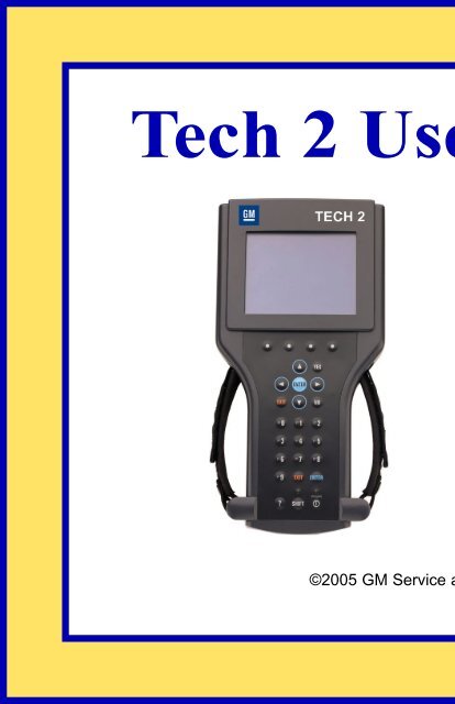
<strong>Tech</strong> 2 Overview<br />
The <strong>Tech</strong> 2 is a hand-held <strong>com</strong>puter designed to aid in diagnosis and repair of automotive systems with<br />
electronic controls and interfaces.<br />
Figure I-1<br />
External features of the <strong>Tech</strong> 2 (front view)<br />
Hardware<br />
The <strong>Tech</strong> 2 has been designed as a rugged, shop-ready tool by having:<br />
• A sturdy case<br />
• A sealed keypad<br />
• Heavy-duty cables and connectors<br />
You can expect years of trouble-free service if you take reasonable care of the <strong>Tech</strong> 2 and follow the<br />
maintenance procedures outlined in Section II.<br />
Figure I-2<br />
Table listing <strong>Tech</strong> 2 base kit part numbers and descriptions (see Section III for illustrations)<br />
Figure I-3<br />
Table listing part numbers for <strong>Tech</strong> 2 adapters and accessories (see Sections V and Section VII)<br />
Video clip 1 (38 seconds)<br />
90-degree adapter (J42598-20) installation demo*<br />
*After viewing, click the X in the upper right-hand corner of the video window to close.<br />
2005 <strong>Tech</strong> 2 <strong>User</strong>’s <strong>Guide</strong> I - 5
SECTION I<br />
INTRODUCTION<br />
Power Supply (see Section IV)<br />
The <strong>Tech</strong> 2 can be powered from:<br />
• The automobile battery power cable<br />
• The cigarette lighter power cable<br />
• The <strong>Tech</strong> 2 power supply<br />
• The DLC (Data Link Connector) connection in most vehicles<br />
Figure I-4<br />
Table listing part numbers for <strong>Tech</strong> 2 power supplies and cables (see Section IV)<br />
Commands<br />
The <strong>Tech</strong> 2 prompts you to enter <strong>com</strong>mands via the membrane keypad for:<br />
• Retrieving and viewing diagnostic information<br />
• Selecting self tests<br />
• Performing vehicle diagnostics<br />
Data Storage<br />
The <strong>Tech</strong> 2 contains electronic <strong>com</strong>ponents called PCMCIA (Personal Computer Memory Card Industry<br />
Association) cards, which store diagnostic programs. The <strong>Tech</strong> 2 can be updated as vehicle models<br />
change by reprogramming the PCMCIA card via the RS-232 connector.<br />
Figure I-5<br />
Table showing the PCMCIA kit part number and description<br />
2005 <strong>Tech</strong> 2 <strong>User</strong>’s <strong>Guide</strong> I - 6
SECTION I<br />
INTRODUCTION<br />
Mechanical Dimensions<br />
The dimensions of the <strong>Tech</strong> 2 are as follows:<br />
• Width – 6.1 inches (155 mm)<br />
• Height – 11.8 inches (300 mm)<br />
• Depth – 2.0 inches (55 mm)<br />
• Weight – 2.2 pounds (1.0 kg)<br />
Environmental Specifications<br />
CONDITIONS<br />
SPECIFICATIONS<br />
Temperature Operating: 0 to 40°C (32 to 104°F)<br />
Non-operating:<br />
-40 to 70°C (-40 to 158°F)<br />
Relative Humidity Operating: 15% to 95% at 40°C (non-condensing)<br />
Non-operating:<br />
90% at 65°C (non-condensing)<br />
2005 <strong>Tech</strong> 2 <strong>User</strong>’s <strong>Guide</strong> I - 7
SECTION I<br />
INTRODUCTION<br />
Warranty<br />
The <strong>Tech</strong> 2 is warranted against defects in materials and workmanship by the manufacturer for 24 months<br />
beginning five days after the date of shipment to your service center.<br />
If your <strong>Tech</strong> 2 must be sent in for repair, a replacement will be sent to your dealership prior to the return of<br />
the failed <strong>Tech</strong> 2. Use the package that the replacement arrives in to return the defective unit. You can<br />
contact Customer Support at 1-800-828-6860 for the exact exchange procedure. If notification of defect is<br />
received during the warranty period, the part listed in figures I-2, I-3, I-4, or I-5 that is defective will be<br />
replaced. You must return the defective unit as directed, or you will be charged for the replacement.<br />
Important: This warranty does not cover any part that has been abused, altered, used for purpose other<br />
than which it was intended, or used in a manner inconsistent with instructions regarding use. This<br />
includes, but is not limited to, removal of any <strong>Tech</strong> 2 screws.<br />
2005 <strong>Tech</strong> 2 <strong>User</strong>’s <strong>Guide</strong> I - 8
SECTION II<br />
CARE & CLEANING<br />
Care and Cleaning<br />
After using the <strong>Tech</strong> 2, a few simple steps will insure that you get the most life out of this diagnostic tool.<br />
NOTICE<br />
Do not spray or pour cleaner anywhere on the <strong>Tech</strong> 2. If the <strong>Tech</strong> 2 should be<strong>com</strong>e dirty, clean it with a<br />
mild detergent or hand soap. Avoid using harsh solvents such as petroleum-based cleaning agents:<br />
acetone, benzene, trichlorethylene, etc. Harsh solvents can etch <strong>Tech</strong> 2 plastic surfaces.<br />
Although the <strong>Tech</strong> 2 is water resistant it is not waterproof, so be sure to thoroughly dry off the <strong>Tech</strong> 2<br />
prior to usage and/or storage.<br />
Maintenance of the <strong>Tech</strong> 2 requires periodic inspection and cleaning of:<br />
• The display window<br />
• The keypad<br />
• The cable assemblies and connectors<br />
Make sure the <strong>Tech</strong> 2 is not connected to a vehicle or other power source and follow the cleaning<br />
procedures detailed below.<br />
Please see next page...<br />
2005 <strong>Tech</strong> 2 <strong>User</strong>’s <strong>Guide</strong> II - 1
SECTION II<br />
CARE & CLEANING<br />
Cleaning the Display<br />
The display collects dust and grime during normal use. Occasionally wipe the screen with a clean, soft,<br />
static-free cloth. Remove stubborn stains by applying a non-abrasive glass cleaner to a soft cloth and wipe<br />
cloth across display area.<br />
Cleaning the Keypad<br />
Clean the keypad with a non-abrasive cleaner. Apply a small amount of cleaner on a soft cloth and wipe<br />
cloth across keypad area.<br />
Maintaining the Cable Assemblies and Connectors<br />
Inspect cable assemblies during connection and disconnection to <strong>com</strong>ponents. Watch for any cuts or<br />
abrasions along the cables. Check the connectors and connector pins for grease, dirt and corrosion. If<br />
contaminants are present, remove them with a mild soap solution.<br />
Storing the <strong>Tech</strong> 2<br />
• Store the <strong>Tech</strong> 2 away from solvents and other liquids. It is NOT moisture proof.<br />
• Store the <strong>Tech</strong> 2 away from direct sunlight. Ultraviolet and infrared light will darken the display.<br />
• Store the <strong>Tech</strong> 2 in its plastic case. Otherwise, the high-impact plastic cover could be<strong>com</strong>e scratched.<br />
2005 <strong>Tech</strong> 2 <strong>User</strong>’s <strong>Guide</strong> II - 2
SECTION III<br />
GETTING STARTED<br />
Getting Started<br />
This section covers all <strong>Tech</strong> 2 vehicle applications. Therefore, some of the information provided may not<br />
be required for individual applications.<br />
The <strong>Tech</strong> 2 contains two serial <strong>com</strong>munication ports: the RS-232 and the RS-485. Use the RS-232 port for<br />
downloading data from another <strong>com</strong>puter to the <strong>Tech</strong> 2. The RS-485 port is currently not used.<br />
The <strong>Tech</strong> 2 also contains two PCMCIA ports, a power jack connector, and a Vehicle Communications<br />
Interface (VCI) connector. One of the PCMCIA slots contains a memory card with diagnostic information.<br />
The power jack accepts power from the AC/DC power supply, battery, or cigarette lighter power cable. The<br />
VCI connector accepts the DLC cable or DLC loopback adapter.<br />
Figure III-1<br />
Identification of the <strong>Tech</strong> 2’s external ports<br />
NOTICE<br />
When using the <strong>Tech</strong> 2 for vehicle <strong>com</strong>munications, the power jack must be connected to the <strong>Tech</strong> 2<br />
DLC cable for proper grounding.<br />
2005 <strong>Tech</strong> 2 <strong>User</strong>’s <strong>Guide</strong> III - 1
SECTION III<br />
GETTING STARTED<br />
Initial Hardware Installation<br />
The <strong>Tech</strong> 2 hardware initial installation requires the following seven tasks:<br />
1. Remove the RS-232 loopback adapter (P/N 3000112) from the storage case (P/N 3000116). Plug it into<br />
the RS-232 port (Figure III-2).<br />
2. Attach the <strong>Tech</strong> 2 DLC cable (P/N 3000095) to the VCI connector (Figure III-3).<br />
3. Locate the DLC loopback adapter (P/N 3000109) in the storage case. Attach it to the DLC cable<br />
(Figure III-4).<br />
4. Locate the NAO (P/N 3000113) or Universal (P/N 3000115) power supply and appropriate power cord in<br />
the storage case. Insert the power jack into the <strong>Tech</strong> 2 DLC cable (Figure III-5) or into the bottom of the<br />
<strong>Tech</strong> 2 next to DLC cable connector (Figure III-6).<br />
5. Turn on power by pressing the PWR button located on the <strong>Tech</strong> 2 keypad.<br />
6. <strong>Tech</strong> 2 hardware will be verified automatically by the POST test. (For information on this program, refer<br />
to Section VI - Troubleshooting.)<br />
7. Disconnect the RS-232 loopback adapter, the power supply, and the DLC loopback adapter and return<br />
to the <strong>Tech</strong> 2 storage case (Figure III-7).<br />
Figure III-2 – Connection of the RS-232<br />
loopback adapter to the RS-232 port<br />
Figure III-5 – Connection of the power jack<br />
to the DLC cable<br />
Figure III-3 – Connection of the DLC cable<br />
to the VCI connector<br />
Figure III-6 – Connection of the power jack<br />
to the bottom of the <strong>Tech</strong> 2<br />
Figure III-4 – Connection of the DLC<br />
loopback adapter to the DLC cable<br />
Figure III-7 – Disconnection of the RS-232<br />
loopback adapter, DLC loopback adapter,<br />
and the power supply<br />
2005 <strong>Tech</strong> 2 <strong>User</strong>’s <strong>Guide</strong> III - 2
SECTION III<br />
GETTING STARTED<br />
PCMCIA Card Removal<br />
The PCMCIA Card is accessed by opening the hinged door located at the top of the <strong>Tech</strong> 2. The card is<br />
found in the upper slot. The lower slot will be used for future enhancements. Press the arrow button<br />
(located beside the slot) to eject the card (Figure III-8).<br />
Figure III-8<br />
Ejection of PCMCIA card<br />
PCMCIA Card Insertion<br />
The PCMCIA Card is keyed with two notches on one side and one notch on the other side (Figure III-9).<br />
Make sure that the notches are in the correct position before inserting the card. Slowly insert the card<br />
(Figure III-10) until it clicks into place.<br />
Figure III-9<br />
PCMCIA card keying<br />
Figure III-10<br />
PCMCIA card insertion<br />
NOTICE<br />
Use only GM Service and Parts Operations supplied PCMCIA cards. The PCMCIA slots are designed<br />
to interface with 5-volt cards. Permanent damage to <strong>Tech</strong> 2 could occur if a 3.3-volt card is inserted into<br />
the <strong>Tech</strong> 2 PCMCIA connector.<br />
2005 <strong>Tech</strong> 2 <strong>User</strong>’s <strong>Guide</strong> III - 3
SECTION III<br />
GETTING STARTED<br />
Vehicle Communications Interface Module Removal<br />
The Vehicle Communications Interface (VCI) module is located at the lower end of the <strong>Tech</strong> 2. Removal of<br />
this module is required only if the VCI needs to be updated or replaced.<br />
To remove the module disconnect <strong>Tech</strong> 2 DLC cable if attached, move the lever (Figure III-11) all the way<br />
toward the right side of the <strong>Tech</strong> 2 (Figure III-12). The VCI module can now be removed.<br />
Figure III-11<br />
VCI module removal<br />
Figure III-12<br />
VCI module removed<br />
Hand Strap Adjustment<br />
The <strong>Tech</strong> 2 velcro hand straps may be adjusted for individual needs as shown in the illustration below<br />
(Figure III-13).<br />
Figure III-13<br />
<strong>Tech</strong> 2 hand strap adjustment<br />
2005 <strong>Tech</strong> 2 <strong>User</strong>’s <strong>Guide</strong> III - 4
SECTION III<br />
GETTING STARTED<br />
<strong>Tech</strong> 2 Keypad<br />
The <strong>Tech</strong> 2 keypad consists of six major keypad operation areas (Figure III-14):<br />
1. Control keys (SHIFT, PWR)<br />
2. Soft keys<br />
3. Selection (arrow) keys<br />
4. Action keys (YES, NO, ENTER, EXIT)<br />
5. Function keys (F0 to F9)<br />
6. Help (?) key<br />
Control Keys<br />
The [PWR] key is used to turn the <strong>Tech</strong> 2 on or off (Figure III-15). The status indicator light above this key<br />
will be illuminated green when the <strong>Tech</strong> 2 is operational.<br />
The [SHIFT] key is used with the up and down arrow keys to change screen brightness and contrast<br />
(Figure III-15). To adjust screen brightness and contrast, perform the following:<br />
• Press the [SHIFT] key once (amber status indicator light above [SHIFT] should light up).<br />
• Use up and down arrows to adjust screen brightness and contrast:<br />
Press up arrow key to increase screen brightness and contrast.<br />
Press down arrow key to decrease screen brightness and contrast.<br />
• Press [SHIFT] key again when desired brightness is reached (status indicator light above [SHIFT]<br />
should now be off).<br />
The <strong>Tech</strong> 2 should return to normal operation after following the above steps.<br />
Figure III-14<br />
<strong>Tech</strong> 2 keypad<br />
Figure III-15<br />
Location of control keys<br />
2005 <strong>Tech</strong> 2 <strong>User</strong>’s <strong>Guide</strong> III - 5
SECTION III<br />
GETTING STARTED<br />
Soft Keys<br />
Four soft keys are located directly below the <strong>Tech</strong> 2 screen (Figure III-16). The soft keys correspond<br />
directly to the four possible selection boxes found at the bottom region of the <strong>Tech</strong> 2 screen. These<br />
selections may change from screen to screen and are under the control of the application software. To<br />
make a screen selection, press the corresponding soft key. In the example shown in Figure III-17, the first<br />
soft key was pressed to select [Display Time].<br />
Figure III-16<br />
Location of soft keys<br />
Figure III-17<br />
Soft key selection for display time<br />
Selection Keys<br />
The <strong>Tech</strong> 2 selection keys are four directional arrow keys (Figure III-18). Press the arrow keys to move the<br />
highlighted area to a selection on the screen (Figure III-19) or to scroll the screens if more than one. Once<br />
the desired selection is highlighted, press [ENTER] to activate the selection.<br />
Figure III-18<br />
Location of selection keys<br />
Figure III-19<br />
Positioning the highlighted area to make a selection<br />
2005 <strong>Tech</strong> 2 <strong>User</strong>’s <strong>Guide</strong> III - 6
SECTION III<br />
GETTING STARTED<br />
Action Keys<br />
Action keys are used to respond to a specific question, initiate an action, or to exit from the <strong>Tech</strong> 2<br />
program (Figure III-20). Specific “yes or no” questions will often appear on the <strong>Tech</strong> 2 screen. The [YES]<br />
and [NO] keys are used to respond to these questions. Either of the two [ENTER] keys may be pressed to<br />
activate a menu selection. Either of the two [EXIT] keys may be pressed to leave the current <strong>Tech</strong> 2<br />
screen and return to a previous screen.<br />
Figure III-20<br />
Location of action keys<br />
Function Keys<br />
Ten function keys (F0 to F9) are located on the <strong>Tech</strong> 2 keypad (Figure III-21). A function key may be<br />
pressed to initiate a specific <strong>Tech</strong> 2 function. In some cases the function keys are used for numeric data<br />
entry. The arrow keys and [ENTER] may also be used to initiate a function selection, but this will require<br />
multiple keystrokes as opposed to only one.<br />
Figure III-21<br />
Location of function keys<br />
Help Key<br />
The help key [?] may be pressed at any time to obtain a help screen (Figure III-22). The help screen will<br />
provide specific information relating to the operation of the <strong>Tech</strong> 2.<br />
Figure III-22<br />
Location of help key<br />
2005 <strong>Tech</strong> 2 <strong>User</strong>’s <strong>Guide</strong> III - 7
SECTION III<br />
GETTING STARTED<br />
<strong>Tech</strong> 2 Connection to Vehicle<br />
The <strong>Tech</strong> 2 receives power through the DLC cable connection to vehicles equipped with On-Board<br />
Diagnostics (OBD II) (Figure III-23). In the case of vehicles not equipped with OBD II, an external power<br />
source such as a vehicle cigarette lighter must be used (Figure III-24).<br />
Figure III-23<br />
Attaching the <strong>Tech</strong> 2 to OBD II equipped vehicles<br />
Figure III-24<br />
Attaching the <strong>Tech</strong> 2 to non-OBD II equipped vehicles<br />
2005 <strong>Tech</strong> 2 <strong>User</strong>’s <strong>Guide</strong> III - 8
SECTION III<br />
GETTING STARTED<br />
<strong>Tech</strong> 2 Connection to <strong>Tech</strong>line Terminal<br />
At times the <strong>Tech</strong> 2 will need to be connected to a terminal. Reasons for connection to a terminal include<br />
the following:<br />
• Transfer of vehicle data (calibration information, “snapshot,” etc.) from the <strong>Tech</strong> 2 to the terminal<br />
• Transfer of vehicle calibration data from the terminal to the <strong>Tech</strong> 2<br />
• Transfer of data (software update, etc.) from the terminal to the <strong>Tech</strong> 2<br />
Before connecting <strong>Tech</strong> 2 to the terminal, the following steps should be taken:<br />
• Make sure the RS-232 cable (P/N 3000110) is attached to the <strong>Tech</strong> 2 RS-232 port located on the left<br />
side of the <strong>Tech</strong> 2 (Figure III-1 and Figure V-3).<br />
• Make sure the appropriate power supply is connected to the DLC cable power jack connector, or to the<br />
power jack connector at the bottom of the <strong>Tech</strong> 2 (Figure III-25).<br />
• Make sure the PCMCIA card is fully inserted into the upper slot at the top of the <strong>Tech</strong> 2 (Figure III-8,<br />
Figure III-9 and Figure III-10).<br />
• Make sure the CANdi module is not connected to the <strong>Tech</strong> 2.<br />
Figure III-25<br />
Power supply connections for <strong>com</strong>munication with <strong>com</strong>puter terminals<br />
NOTICE<br />
Always use the <strong>Tech</strong> 2 NAO power supply (P/N 3000113) when connecting the <strong>Tech</strong> 2 to a terminal. It is<br />
also acceptable to connect the power cable to the vehicle cigarette lighter receptacle.<br />
2005 <strong>Tech</strong> 2 <strong>User</strong>’s <strong>Guide</strong> III - 9
SECTION III<br />
GETTING STARTED<br />
How to Connect the <strong>Tech</strong> 2 to a Computer Terminal<br />
Follow the steps below and refer to Figure III-26, which illustrates the typical <strong>Tech</strong> 2 connection to a<br />
<strong>com</strong>puter terminal.<br />
1. Plug the serial port adapter (P/N TA00040) into the serial port marked “A” or “1” on the back of the<br />
<strong>com</strong>puter terminal or to the USB port using the USB serial adapter.<br />
2. Plug the <strong>Tech</strong> 2’s RS-232 cable into the serial port / USB port adapter and connect the appropriate<br />
power supply.<br />
3. After power is supplied to the <strong>Tech</strong> 2 and the [PWR] button is pressed, the <strong>Tech</strong> 2 start-up display<br />
should appear on the <strong>Tech</strong> 2 screen (Figure III-27).<br />
Figure III-26<br />
Typical <strong>Tech</strong> 2 connection to a <strong>com</strong>puter terminal (rear view)<br />
Figure III-27<br />
<strong>Tech</strong> 2 displaying the <strong>Tech</strong> 2 start-up screen<br />
2005 <strong>Tech</strong> 2 <strong>User</strong>’s <strong>Guide</strong> III - 10
SECTION IV<br />
POWER SUPPLIES<br />
Power Supplies<br />
Power up the <strong>Tech</strong> 2 using either:<br />
• The power jack connector at the bottom of the <strong>Tech</strong> 2 unit (Figure IV-1), or<br />
• The DLC cable power jack connector behind the area where various DLC adapters are connected<br />
(Figure IV-1).<br />
For non-vehicle <strong>com</strong>munications, connect power source to either location.<br />
For vehicle <strong>com</strong>munications, connect the power source to the DLC cable power jack connector only.<br />
Proper grounding may not be present if power source is connected directly to <strong>Tech</strong> 2.<br />
When the <strong>Tech</strong> 2 is connected to the DLC of an appropriate vehicle, the vehicle battery supplies power.<br />
When the <strong>Tech</strong> 2 is not connected to the vehicle’s DLC, the DLC cable power jack connector accepts<br />
power from the following:<br />
• Cigarette lighter power cable (Figure IV-1, see text on page IV-2)<br />
• Battery power cable (Figure IV-1, see text on page IV-2)<br />
• NAO or Universal power supply (Figure IV-1 and Figure IV-2, see text on page IV-3)<br />
If the DLC and external power source are both connected, the power jack connection supplies current to<br />
the <strong>Tech</strong> 2. In this instance, power from the vehicle’s DLC connector is automatically disconnected from<br />
the <strong>Tech</strong> 2 internal power supply.<br />
Figure IV-1<br />
<strong>Tech</strong> 2 power connections (without direct power connection from the DLC)<br />
2005 <strong>Tech</strong> 2 <strong>User</strong>’s <strong>Guide</strong> IV - 1
SECTION IV<br />
POWER SUPPLIES<br />
Cigarette Lighter Power Cable<br />
This cable contains one fuse and two connectors. It has a cigarette lighter plug at one end and a power<br />
jack at the other (Figure IV-1). The power jack connects to the <strong>Tech</strong> 2 DLC cable and carries power to the<br />
<strong>Tech</strong> 2 when the selected vehicle adapter does not provide power.<br />
Battery Power Cable<br />
This cable has red and black battery clamps attached to one end and a power jack attached to the other<br />
(Figure IV-1). The power jack connects to the <strong>Tech</strong> 2 DLC cable and carries current to the <strong>Tech</strong> 2 when the<br />
selected vehicle adapter does not provide power and there is no cigarette lighter adapter available.<br />
Important: This cable contains two 3-amp fuses. If you need to replace them, use identical 3-amp fuses.<br />
For information on fuse replacement, see Section VI - Troubleshooting.<br />
2005 <strong>Tech</strong> 2 <strong>User</strong>’s <strong>Guide</strong> IV - 2
SECTION IV<br />
POWER SUPPLIES<br />
NAO Power Supply<br />
North American electrical supply is normally 110 volts. The <strong>Tech</strong> 2 base kit includes an external AC to DC<br />
power supply with 110 V AC/60 Hz input (Figure IV-2). Output is 12 volts at 1.5 amps.<br />
Universal Power Supply<br />
Wherever 220 current is required, use the 110/220 V AC/50 Hz external AC to DC power supply<br />
(Figure IV-2). A specific power cord is provided to permit connection to your area’s power cord receptacle.<br />
Figure IV-2<br />
<strong>Tech</strong> 2 power supplies (NAO and Universal)<br />
CAUTION<br />
To avoid personal injury due to electric shock, use grounded outlet only. The NAO power supply<br />
is for North American use only. The Universal power supply is for use outside North America.<br />
These devices are intended for indoor use only.<br />
Power Cord Plugs<br />
Various types of power cord plugs are available for the <strong>Tech</strong> 2, depending your geographic location<br />
(Figure IV-3).<br />
Figure IV-3<br />
Table showing various types of power cord plugs for the <strong>Tech</strong> 2<br />
2005 <strong>Tech</strong> 2 <strong>User</strong>’s <strong>Guide</strong> IV - 3
SECTION V<br />
ADAPTERS<br />
Adapters<br />
A number of adapters are available for the <strong>Tech</strong> 2 which allow connection to many different vehicles<br />
(Figure V-1 and Figure V-2). Specific adapters are included in the <strong>Tech</strong> 2 base kit depending upon <strong>Tech</strong> 2<br />
configuration—NAO, International, Saab, Opel, Vauxhall, etc. Adapters not included in the base kit may be<br />
purchased separately from your tool distributor.<br />
DLC Cable<br />
The DLC cable (P/N 3000095) has a 26-pin connector with thumb screws at one end that connects to the<br />
<strong>Tech</strong> 2’s VCI cable connector. At the other end is a 19-pin connector that connects to a variety of adapters<br />
(Figure V-1 and Figure V-2).<br />
Figure V-1<br />
DLC cable adapter connections<br />
Figure V-2<br />
Table showing various adapters and their part numbers<br />
RS-232 Cable<br />
The RS-232 cable (P/N 3000110) has an 8-pin RJ45 plug connector at each end (Figure V-3). This cable<br />
attaches to the <strong>Tech</strong> 2 RS-232 port and is used to <strong>com</strong>municate with the <strong>Tech</strong>line terminal.<br />
Figure V-3<br />
RS-232 cable connections<br />
2005 <strong>Tech</strong> 2 <strong>User</strong>’s <strong>Guide</strong> V - 1
SECTION V<br />
ADAPTERS<br />
RS-232 DB9 Adapter<br />
The RS-232 DB9 adapter (P/N 3000111) has an RJ45 connector at one end and a DB9 connector at the<br />
other (Figure V-4). This adapter allows the connection of the <strong>Tech</strong> 2 to some terminals.<br />
Figure V-4<br />
RS-232 DB9 adapter connections<br />
RS-232 Loopback Adapter<br />
The loopback adapter (P/N 3000112) has an 8-pin RJ45 connector that attaches to the <strong>Tech</strong> 2 RS-232<br />
port (Figure III-2). It is used to perform the <strong>Tech</strong> 2 self test.<br />
DLC Loopback Adapter<br />
Various <strong>Tech</strong> 2 applications require the DLC loopback adapter (P/N 3000109), which has a Burndy cable<br />
connection end and a VCI DB-26 connection end (Figure V-5). Refer to pages III-1, III-2, VI-18, VII-69, and<br />
figures I-2, III-4, III-7, and VI-4 for more information about this adapter.<br />
Figure V-5<br />
End views of the DLC loopback adapter<br />
2005 <strong>Tech</strong> 2 <strong>User</strong>’s <strong>Guide</strong> V - 2
SECTION VI<br />
TROUBLESHOOTING<br />
Troubleshooting<br />
Section VI is a general troubleshooting guide for all vehicle applications of the <strong>Tech</strong> 2 scan tool. Some of<br />
the information may differ for your particular vehicle application.<br />
If the <strong>Tech</strong> 2 appears to be operating abnormally, refer to this section—particularly the diagnostic charts<br />
and troubleshooting tables beginning on page VI-6—for probable causes and solutions.<br />
The following two types of self tests are available on the <strong>Tech</strong> 2:<br />
• Power On Self Test (POST) checks the major functions of the <strong>Tech</strong> 2 at power-up.<br />
• Self Tests check the major and minor functions of the <strong>Tech</strong> 2.<br />
If errors are detected, a <strong>Tech</strong> 2 malfunction is present which may result in vehicle misdiagnosis.<br />
For customer support, refer to the Customer Support Overview on pages ii and iii of this user’s guide.<br />
NOTICE<br />
The CANdi module should not be connected while running <strong>Tech</strong> 2 and VCI self tests.<br />
2005 <strong>Tech</strong> 2 <strong>User</strong>’s <strong>Guide</strong> VI - 1
SECTION VI<br />
TROUBLESHOOTING<br />
Power On Self Test (POST)<br />
Power On Self Tests run automatically each time the power [PWR] button on the <strong>Tech</strong> 2 keypad is pressed<br />
on. The screen displays pass or fail results for each area tested. POST automatically checks the following:<br />
• MC68332 processor<br />
• External RAM (Random Access Memory)<br />
• Flash memory<br />
• Display controller and display<br />
• Sound transducer<br />
• MC68332 RAM<br />
• Real-time clock<br />
• Keypad controller and keypad<br />
• Main UART (Universal Asynchronous Receiver/Transmitter)<br />
Results of POST may include fatal errors that do not allow you to continue, or non-fatal errors that allow<br />
you to continue without full <strong>Tech</strong> 2 operation. If normal <strong>Tech</strong> 2 functions are stopped or limited, contact<br />
Customer Support to determine if service is required.<br />
At <strong>com</strong>pletion of POST, the following audible signals indicate a pass or fail condition:<br />
• One beep - No problem. Your <strong>Tech</strong> 2 is operating normally.<br />
• No beep - Sound transducer has failed. Contact Customer Support.<br />
• Three short beeps - <strong>Tech</strong> 2 has failed POST. Contact Customer Support.<br />
In the United States and Canada to contact Customer Support, dial:<br />
• English: 1-800-828-6860 (option 1)<br />
• French: 1-800-503-3222<br />
• Spanish: 1-248-265-0840 (option 2)<br />
• Fax line: 1-248-265-9327<br />
Refer to page iii for international customer support.<br />
2005 <strong>Tech</strong> 2 <strong>User</strong>’s <strong>Guide</strong> VI - 2
SECTION VI<br />
TROUBLESHOOTING<br />
<strong>Tech</strong> 2 Self Tests<br />
<strong>Tech</strong> 2 self tests verify that the <strong>Tech</strong> 2 is functioning normally. The self tests evaluate all critical areas of<br />
the <strong>Tech</strong> 2 and display pass or fail messages for each subsystem tested. Self tests isolate user error from<br />
system hardware failures. The self tests should be performed periodically to insure that the <strong>Tech</strong> 2 is<br />
operating properly.<br />
The <strong>Tech</strong> 2 must meet the following requirements in order to do a self test:<br />
• Screen display must be fully readable<br />
• Keypad must be operational<br />
Begin the <strong>Tech</strong> 2 self-testing program by following these steps:<br />
1. Press [ENTER] while viewing the <strong>Tech</strong> 2 start-up screen (Figure VI-1).<br />
2. Select F3: Tool Options from the <strong>Tech</strong> 2 Main Menu (Figure VI-2).<br />
3. Select F3: Self Test from the Tool Options menu (Figure VI-3).<br />
Figure VI-1<br />
<strong>Tech</strong> 2 startup screen<br />
Figure VI-2<br />
Tools Options selected on Main Menu<br />
Figure VI-3<br />
Self Test selected on Tool Options menu<br />
2005 <strong>Tech</strong> 2 <strong>User</strong>’s <strong>Guide</strong> VI - 3
SECTION VI<br />
TROUBLESHOOTING<br />
<strong>Tech</strong> 2 Self Test Main Menu<br />
Each <strong>Tech</strong> 2 Self Test main menu selection is explained in detail on the following pages. All users have<br />
access to all the options listed, which are shown in Figure VI-5.<br />
Read all screen instructions and connect or disconnect the appropriate cables and loopback adapters.<br />
Screen messages will be displayed when external loopback connectors are connected. For specific<br />
loopback connection information, refer to Figure III-2, Figure III-4, and Figure VI-4.<br />
F0: Automated Main PCB and VCI Test<br />
Selecting Automated Main PCB and VCI (Figure VI-5) is a quick way to test the performance of the main<br />
Printed Circuit Board (main PCB—the <strong>Tech</strong> 2 main circuit board) and the Vehicle Communications<br />
Interface (VCI). The <strong>Tech</strong> 2 displays a test-in-progress screen (Figure VI-6) while performing all the PCB<br />
and VCI tests in sequential order.<br />
Figure VI-4<br />
Connection of DLC loopback adapter to the <strong>Tech</strong> 2 VCI connector<br />
Figure VI-5<br />
Automated Main PCB and VCI test selected on <strong>Tech</strong> 2 Self Test main menu<br />
Figure VI-6<br />
Automated Main PCB and VCI test results screen<br />
Continued on next page...<br />
2005 <strong>Tech</strong> 2 <strong>User</strong>’s <strong>Guide</strong> VI - 4
SECTION VI<br />
TROUBLESHOOTING<br />
The Automated Main PCB portion tests the following <strong>com</strong>ponents:<br />
• RAM / ROM<br />
• RS-485 loopback (This test requires the connection of a loopback adapter to the <strong>Tech</strong> 2.)<br />
• RS-232 loopback (This test requires the connection of a loopback adapter to the <strong>Tech</strong> 2.)<br />
• Keypad<br />
• PCMCIA slot 1<br />
• PCMCIA slot 2<br />
• Display controller<br />
• Sound transducer<br />
• Real-time clock<br />
Refer to figures VI-9 and VI-10 (next page) for help in diagnosing problems that involve the PCB and VCI.<br />
If the <strong>Tech</strong> 2 passes all Automated Main PCB and VCI tests, you will not need to run any more tests to<br />
verify that the <strong>Tech</strong> 2 is working properly.<br />
The following test results will be displayed:<br />
Total Pass ................................ 1 - indicates that <strong>Tech</strong> 2 passed test<br />
0 - indicates a test failure<br />
Total Failures ........................... 0 - indicates that <strong>Tech</strong> 2 passed test<br />
1 - indicates a test failure<br />
PCMCIA Cards Present ........... 1 or 2 indicates how many cards present in <strong>Tech</strong> 2<br />
Once tests are <strong>com</strong>plete, select the soft keys Main Details or VCI Details (Figure VI-6) to review the<br />
results of the main PCB or VCI tests (Figure VI-7 and Figure VI-8).<br />
If any failures occur, select F3: Selectable Main PCB (Figure VI-13) or F4: Selectable VCI (Figure VI-15)<br />
from the Self Test main menu to further isolate the failure. Report failure information to Customer Support.<br />
2005 <strong>Tech</strong> 2 <strong>User</strong>’s <strong>Guide</strong> VI - 5
SECTION VI<br />
TROUBLESHOOTING<br />
F1: Automated Main PCB Test<br />
This test works the same as the Automated Main PCB and VCI test, except the VCI portion of the test is<br />
not included (Figure VI-11).<br />
F2: Automated VCI Test<br />
This test works the same as the Automated Main PCB and VCI test, except the PCB portion of the test is<br />
not included (Figure VI-12).<br />
Figure VI-7<br />
Main Details selection<br />
Figure VI-8<br />
VCI Details selection<br />
Figure VI-9<br />
Diagnostic chart for <strong>Tech</strong> 2 Main Printed Circuit Board (PCB)<br />
Figure VI-10<br />
Diagnostic chart for <strong>Tech</strong> 2 Vehicle Communications Interface (VCI) module<br />
Figure VI-11<br />
Automated Main PCB test selected on <strong>Tech</strong> 2 Self Test main menu<br />
Figure VI-12<br />
Automated VCI test selected on <strong>Tech</strong> 2 Self Test main menu<br />
2005 <strong>Tech</strong> 2 <strong>User</strong>’s <strong>Guide</strong> VI - 6
SECTION VI<br />
TROUBLESHOOTING<br />
F3: Selectable Main PCB Test<br />
Choose F3: Selectable Main PCB (Figure VI-13) after a fail message has been displayed during the<br />
Automated Main PCB and VCI or Automated Main PCB tests. When you choose F3: Selectable Main<br />
PCB, a screen like the one shown in Figure VI-14 is displayed. You may then select individual tests for<br />
failed <strong>com</strong>ponents. For specific information on failed <strong>com</strong>ponents, refer to the Main Printed Circuit Board<br />
(PCB) Diagnostic Chart (Figure VI-9).<br />
Figure VI-13<br />
Selectable Main PCB test selected on <strong>Tech</strong> 2 Self Test main menu<br />
Figure VI-14<br />
Selectable Main PCB Self Test screen<br />
2005 <strong>Tech</strong> 2 <strong>User</strong>’s <strong>Guide</strong> VI - 7
SECTION VI<br />
TROUBLESHOOTING<br />
F4: Selectable VCI Test<br />
Choose F4: Selectable VCI (Figure VI-15) after a fail message has been displayed during the Automated<br />
Main PCB and VCI or Automated VCI tests. When you choose F4: Selectable VCI, a screen like the one<br />
shown in Figure VI-16 is displayed. You may select individual tests for failed <strong>com</strong>ponents from this screen.<br />
If you select More Tests, a screen like the one shown in Figure VI-17 is displayed. If you then select<br />
Previous Menu, the screen shown in Figure VI-16 returns. For specific information on failed <strong>com</strong>ponents,<br />
refer to the Vehicle Communications Interface (VCI) Module Diagnostic Chart (Figure VI-10).<br />
F5: Power On Self Test Results<br />
Choose F5: Power On Self Test Results (Figure VI-18) after a fail message has been displayed during the<br />
Power On Self Test (POST). Specific information on the failure will be displayed on the screen. Select F0,<br />
F1, F2, F3, or F4 to further isolate the specific fault.<br />
Figure VI-15<br />
Selectable VCI test selected on <strong>Tech</strong> 2 Self Test main menu<br />
Figure VI-16<br />
First selectable VCI Self Test screen<br />
Figure VI-17<br />
Second selectable VCI Self Test screen<br />
Figure VI-18<br />
Power On Self Test Results selected on <strong>Tech</strong> 2 Self Test main menu<br />
2005 <strong>Tech</strong> 2 <strong>User</strong>’s <strong>Guide</strong> VI - 8
SECTION VI<br />
TROUBLESHOOTING<br />
No Power to <strong>Tech</strong> 2 Troubleshooting Tables<br />
Use the following four tables—Figure VI-19, Figure VI-20, Figure VI-21, and Figure VI-22—to diagnose,<br />
isolate, and correct power source problems that may cause a No Power condition to your <strong>Tech</strong> 2 scan tool.<br />
To help determine power supply source, see Section IV - Power Supplies.<br />
Figure VI-19<br />
Troubleshooting table for DLC cable “No Power”<br />
Figure VI-20<br />
Troubleshooting table for cigarette lighter power cable “No Power”<br />
Figure VI-21<br />
Troubleshooting table for battery power cable “No Power”<br />
Figure VI-22<br />
Troubleshooting table for NAO or universal power supply “No Power”<br />
2005 <strong>Tech</strong> 2 <strong>User</strong>’s <strong>Guide</strong> VI - 9
SECTION VI<br />
TROUBLESHOOTING<br />
Cigarette Lighter Power Cable 3-Amp Fuse Replacement<br />
A three-amp removable fuse is located in the cigarette lighter power cable (P/N 3000096) connector<br />
(Figure VI-23). When required, check or replace the fuse by performing the following steps:<br />
1. Ensure cigarette lighter power cable is not connected to vehicle or <strong>Tech</strong> 2.<br />
2. Unscrew fuse retainer cap and remove three-amp fuse.<br />
3. Inspect fuse for damage and replace with identical three-amp fuse if required.<br />
4. Verify by connecting cigarette lighter power cable to <strong>Tech</strong> 2 and vehicle.<br />
Figure VI-23<br />
Cigarette lighter power cable three-amp fuse replacement<br />
2005 <strong>Tech</strong> 2 <strong>User</strong>’s <strong>Guide</strong> VI - 10
SECTION VI<br />
TROUBLESHOOTING<br />
Battery Power Cable 3-Amp Fuse Replacement<br />
Two three-amp fuses are located in the battery power cable (P/N 3000097) three-amp fuse box<br />
(Figure VI-24). When required, check or replace the fuse(s) by performing the following steps:<br />
1. Ensure battery power cable is not connected to vehicle battery or <strong>Tech</strong> 2.<br />
2. Use a standard fuse puller to remove the fuse(s) from the fuse box.<br />
3. Inspect fuse(s) for damage and replace with identical 3-amp fuse(s) if required.<br />
4. Verify by connecting battery power cable to <strong>Tech</strong> 2 and vehicle battery.<br />
Figure VI-24<br />
Battery power cable three-amp fuse replacement<br />
CAUTION:<br />
To help avoid personal injury by electric shock, make sure the battery power cable is not<br />
connected to the vehicle’s battery before removing the fuse(s).<br />
2005 <strong>Tech</strong> 2 <strong>User</strong>’s <strong>Guide</strong> VI - 11
SECTION VI<br />
TROUBLESHOOTING<br />
CANdi Module Troubleshooting<br />
The following troubleshooting information applies only to the CANdi module. This application is<br />
unavailable for most vehicles at the time of writing.<br />
Figure VI-25 shows the screen that the <strong>Tech</strong> 2 displays during programming of the CANdi module.<br />
If the <strong>Tech</strong> 2 loses power during programming, the CANdi module will not be properly programmed. The<br />
CANdi module will be automatically reprogrammed when power is available.<br />
Figure VI-25<br />
CANdi module programming screen<br />
If a fault occurs during reprogramming, a screen like the one shown in Figure VI-26 may appear. If this<br />
occurs, power off the <strong>Tech</strong> 2 and attempt to reprogram the CANdi module again. If the problem persists,<br />
incorrect CANdi software may be present on the <strong>Tech</strong> 2 PCMCIA card. Connect the <strong>Tech</strong> 2 to the TIS<br />
terminal and download a new version of the software.<br />
Figure VI-26<br />
CANdi fault screen<br />
NOTE: Do not perform a VCI self-test while the CANdi module is connected. If the CANdi module is<br />
connected and an error screen occurs, disconnect the CANdi module from the <strong>Tech</strong> 2 and<br />
perform the test again.<br />
Continued on next page...<br />
2005 <strong>Tech</strong> 2 <strong>User</strong>’s <strong>Guide</strong> VI - 12
SECTION VI<br />
TROUBLESHOOTING<br />
The screen shown in Figure VI-27 is displayed when the <strong>Tech</strong> 2 does not detect the CANdi module. This<br />
can occur under the following conditions:<br />
• The CANdi module is not connected to the <strong>Tech</strong> 2, or<br />
• A problem occurred during start-up that prevented the <strong>Tech</strong> 2 from configuring the CANdi module.<br />
If this occurs, power the <strong>Tech</strong> 2 off and start again. If the problem persists, follow the troubleshooting tests<br />
on page VI-15.<br />
It is also possible to connect a CANdi module after the <strong>Tech</strong> 2 has been powered up via the VCI. If this<br />
occurs, the <strong>Tech</strong> 2 will not detect CANdi module and will not properly <strong>com</strong>municate, even if the LED is<br />
flashing on the CANdi module. Power off the <strong>Tech</strong> 2 and start again.<br />
Figure VI-27<br />
CANdi module not detected screen<br />
The screen displayed in Figure VI-28 occurs when the <strong>Tech</strong> 2 loses <strong>com</strong>munication with the CANdi<br />
module. This could be a result of the following:<br />
• VCI not properly seated in the <strong>Tech</strong> 2 slot<br />
• DLC cable not properly connected<br />
• Poor Burndy cable connection to the CANdi module<br />
• Worn or damaged cable that results in a poor connection between the CANdi module and the VCI<br />
If this occurs, check all <strong>Tech</strong> 2 and CANdi module connections, power off the <strong>Tech</strong> 2 and start again.<br />
If problem persists perform the troubleshooting tests on page VI-15.<br />
Figure VI-28<br />
<strong>Tech</strong> 2 lost <strong>com</strong>munication with the CANdi module screen<br />
2005 <strong>Tech</strong> 2 <strong>User</strong>’s <strong>Guide</strong> VI - 13
SECTION VI<br />
TROUBLESHOOTING<br />
CANdi Module Diagnostics<br />
Select “CANdi Diagnostics” from the <strong>Tech</strong> 2’s Tools Options menu (Figure VI-29), and the screen shown in<br />
Figure VI-30 appears. If the CANdi module is not connected, the screen shown in Figure VI-27 appears.<br />
Figure VI-29<br />
CANdi Diagnostics selected on Tool Options menu<br />
Figure VI-30<br />
CANdi Diagnostics menu: “POST Results” or “Self Test”<br />
When you select “POST Results” from the CANdi Diagnostics menu (Figure VI-30), the screen shown in<br />
Figure VI-31 appears. You can use the information to determine if the CANdi module had any problems<br />
during its start-up sequence. Software and hardware revision numbers are identified and displayed.<br />
Figure VI-31<br />
CANdi POST Results screen<br />
Selecting “Self Test” from the CANdi Diagnostics menu (Figure VI-30) initiates a <strong>com</strong>plete test of the<br />
CANdi module. When testing is <strong>com</strong>plete, all results are displayed on the screen shown in Figure VI-32.<br />
Figure VI-32<br />
CANdi Self Test Results screen<br />
2005 <strong>Tech</strong> 2 <strong>User</strong>’s <strong>Guide</strong> VI - 14
SECTION VI<br />
TROUBLESHOOTING<br />
CANdi Module Troubleshooting <strong>Guide</strong><br />
If a CANdi module is not functioning properly, please perform the following tests:<br />
1. Make sure the CANdi module is properly grounded by connecting to a vehicle or by using the 12-pin<br />
ALDL connector, which has the signal and chassis ground shorted.<br />
IMPORTANT<br />
If not properly grounded, the CANdi module will appear to be defective when it is not. The CANdi<br />
module will fail due to improper grounding if you use the 16-pin DLC (J-1962) connector and power the<br />
<strong>Tech</strong> 2 from an AC/DC power supply. The adapter you use must have a GM part number. Although PVI<br />
adapters are similar to GM adapters, they will not work with the CANdi module.<br />
2. Verify that the <strong>Tech</strong> 2 passes all stand-alone self-tests. Replace the <strong>Tech</strong> 2 if it fails. If the <strong>Tech</strong> 2<br />
passes, proceed to step three. The CANdi module must be disconnected to run self-tests. If the<br />
CANdi module is connected, a message will appear instructing you to disconnect the module.<br />
3. Verify that the VCI passes self-tests. Replace the VCI if it fails. If the VCI passes, proceed to step four.<br />
The CANdi module must be disconnected to run self-tests. If the CANdi module is connected, a<br />
message will appear instructing you to disconnect the module.<br />
When performing this test, you must also perform the Selectable VCI test (option F4 on the self-test<br />
menu—see Figure VI-15). First install the Burndy loopback adapter into the VCI 26-pin connector,<br />
which does not require the cable. Once you select “Selectable VCI,” select the “More Tests” soft key<br />
(Figure VI-16). In the new submenu, select “F6: VCI TPU” (Figure VI-17). If the VCI passes the test, all<br />
the TPU channels will display a Pass indicator as shown in the example at the top of the next page.<br />
Continued on next page...<br />
2005 <strong>Tech</strong> 2 <strong>User</strong>’s <strong>Guide</strong> VI - 15
SECTION VI<br />
TROUBLESHOOTING<br />
Testing<br />
TPU0<br />
TPU1<br />
TPU5<br />
TPU12 and 15<br />
TPU13 and 14<br />
Status<br />
Pass<br />
Pass<br />
Pass<br />
Pass<br />
Pass<br />
The two TPU inputs that the CANdi module requires are TPU12 and TPU15, which enable the module<br />
and detect its presence. If TPU12 and 15 do not appear on the screen, then they are defective in the<br />
VCI module and the VCI is failing to properly enable the CANdi module. If the above test passes, you<br />
must repeat the same test with the Burndy loopback adapter at the end of the cable. The setup is the<br />
same as if you were plugging into a vehicle without the CANdi module connected and with the loopback<br />
adapter at the end of the cable. Then you must run the VCI TPU test. If the example above appears<br />
(TPU13 and 14 are missing in this test because these I/Os don’t go through the cable), then the cable<br />
is also fine. However, if TPU12 and 15 are missing, then the cable is defective.<br />
4. Verify that the DLC cable (also known as the ALDL, J-1962, or OBDII interface cable) is functioning<br />
properly and then proceed to step five. Replace the DLC cable if it does not function properly. Call the<br />
<strong>Tech</strong>line Customer Support Center (TCSC) at 1-800-828-6860 for more information if you have trouble<br />
with this test.<br />
Continued on next page...<br />
2005 <strong>Tech</strong> 2 <strong>User</strong>’s <strong>Guide</strong> VI - 16
SECTION VI<br />
TROUBLESHOOTING<br />
5. Connect the CANdi module to the <strong>Tech</strong> 2. Connect the system (<strong>Tech</strong> 2 and CANdi module) to a vehicle<br />
and power on the <strong>Tech</strong> 2. Verify that the LED on the CANdi module is flashing.<br />
If the LED does not flash or light up at all, it may be defective and you should proceed to step six.<br />
If the LED is not flashing but illuminated, a bad ground may exist somewhere. The grounding problem<br />
could be due to a defective ALDL (J-1962) female interface on the vehicle. Power the <strong>Tech</strong> 2 through an<br />
AC/DC power supply and connect the 12-pin ALDL connector. If this fixes the problem with the CANdi<br />
(the LED is flashing), then the vehicle has a grounding problem and the CANdi module is OK.<br />
If the LED is flashing while connected to the vehicle, but the CANdi module still has a problem, proceed<br />
to step six.<br />
6. If problems persist with the CANdi module, and the <strong>Tech</strong> 2 recognizes the interface, perform self-test<br />
diagnostics on the CANdi module. Select CANdi Diagnostics from the Tool Options menu (Figure VI-29)<br />
to see the CANdi Diagnostics menu (Figure VI-30). This menu allows you to display POST results, or<br />
request the CANdi module to perform a self-test. Refer to page VI-14 for more information.<br />
If a diagnostic test fails, return the CANdi module to the repair center (see page VI-18).<br />
Contact the Customer Support Center at 1-800-828-6860 before returning the CANdi module.<br />
If a known problem with a software version is identified, Customer Support will inform you to update<br />
<strong>Tech</strong> 2 software with the correct software version number.<br />
2005 <strong>Tech</strong> 2 <strong>User</strong>’s <strong>Guide</strong> VI - 17
SECTION VI<br />
TROUBLESHOOTING<br />
Replacing the CANdi Module<br />
If CANdi fails and Customer Support (800-828-6860) has verified that it needs to be replaced, package the<br />
CANdi module and send it freight prepaid to the nearest Vetronix Warranty Repair Center, as listed below.<br />
Vetronix Warranty Repair Centers:<br />
United States and Latin America<br />
Vetronix Corporation<br />
2030 Alameda Padre Serra<br />
Santa Barbara, CA 93103<br />
U.S.A. - (805) 966-2000, Fax (805) 966-3845<br />
Canada<br />
Custone Electromotive Inc.<br />
1150 Champlain Court<br />
Whitby, ON L2N 6A8<br />
Canada<br />
Europe<br />
Getronics Service GmbH/Frankfort<br />
Philipp-Reis Strasse 15<br />
D-63128 Dietzenback<br />
Germany<br />
Please enclose your telephone number, return address, and an explanation of the problem. If the product<br />
is determined to be in warranty, it will be repaired or replaced at no charge and returned freight prepaid.<br />
If determined to be non-warranty, the product will be repaired for a nominal service fee, plus freight costs.<br />
Part numbers - CANdi module: J-45289 (SPX), 3000164 (GM), 02003039 (Vetronix)<br />
Connectors: 12-pin #3000099 and loop back #3000109<br />
2005 <strong>Tech</strong> 2 <strong>User</strong>’s <strong>Guide</strong> VI - 18
SECTION VI<br />
TROUBLESHOOTING<br />
Additional CANdi Troubleshooting Tips<br />
Transformer voltage output test using DVOM:<br />
• Set DVOM to Volt setting.<br />
• Probe cable end inside and outside the terminal.<br />
• Twelve volts is the minimum.<br />
Updating the CANdi module:<br />
IMPORTANT<br />
You must use a 32-megabyte (32-MB) PCMCIA card in the <strong>Tech</strong> 2, not a 10-megabyte (10-MB) card.<br />
You must update the 32-MB PCMCIA card before connecting the CANdi module to the <strong>Tech</strong> 2.<br />
Always disconnect the CANdi module from the <strong>Tech</strong> 2 before downloading software updates to<br />
the PCMCIA card.<br />
The CANdi module is capable of storing up to three different software versions.<br />
• Will the CANdi module require updates?<br />
Possibly. The CANdi module ships <strong>com</strong>plete with software, but possibly not the most current version.<br />
• Be sure to update the <strong>Tech</strong> 2 with the latest software before using the CANdi module.<br />
The CANdi module will <strong>com</strong>pare software and look for a possible update from the <strong>Tech</strong> 2. When you<br />
update the <strong>Tech</strong> 2, any software updates for the CANdi module will download to the PCMCIA card.<br />
The CANdi module will automatically receive updates each time it is connected to the DLC and <strong>Tech</strong> 2 at<br />
power-up. Therefore, it is very important that you always run the latest available software version when<br />
using the CANdi module.<br />
2005 <strong>Tech</strong> 2 <strong>User</strong>’s <strong>Guide</strong> VI - 19
SECTION VII<br />
SOFTWARE<br />
Software<br />
Section VII contains a description of software related to the <strong>Tech</strong> 2 in four subsections:<br />
A) <strong>Tech</strong> 2 Main Menu and Live Plot, beginning on page VII-2<br />
B) <strong>Tech</strong>line Information System (TIS), beginning on page VII-14<br />
C) Service Programming System (SPS), beginning on page VII-36<br />
D) Controller Area Network Diagnostic Interface (CANdi), beginning on page VII-67<br />
IMPORTANT<br />
Proper PCMCIA updates are required and are essential for successful vehicle diagnoses. Refer to the<br />
Programming <strong>Tech</strong> 2 function under Tool Options, and the <strong>Tech</strong> 2 PCMCIA Card in the <strong>Tech</strong>line<br />
Information System (TIS) subsection.<br />
2005 <strong>Tech</strong> 2 <strong>User</strong>’s <strong>Guide</strong> VII - 1
SECTION VIIA<br />
TECH 2 MAIN MENU & LIVE PLOT<br />
<strong>Tech</strong> 2 Main Menu<br />
Five primary functions or “paths” are available on the <strong>Tech</strong> 2’s Main Menu:<br />
Diagnostics, Service Programming System, View Captured Data, Tool Options, and Getting Started are all<br />
described in more detail on the following pages.<br />
Figure VIIA-1<br />
<strong>Tech</strong> 2 Main Menu<br />
2005 <strong>Tech</strong> 2 <strong>User</strong>’s <strong>Guide</strong> VII - 2
SECTION VIIA<br />
TECH 2 MAIN MENU & LIVE PLOT<br />
Diagnostics<br />
Selecting Diagnostics from the <strong>Tech</strong> 2 Main Menu and identifying the vehicle as shown below gives you<br />
access to four major systems: Powertrain, Body, Chassis, and Diagnostic Circuit Check (Figure VIIA-2).<br />
F0: DIAGNOSTICS<br />
<br />
Vehicle Identification:<br />
Select Model Year<br />
1991-2003<br />
<br />
Select Vehicle Type<br />
Passenger Car<br />
LD Trk, MPV, In<strong>com</strong>plete<br />
Medium Duty Truck, Saturn<br />
<br />
Select System<br />
<br />
F0: F1: F2: F3:<br />
Powertrain Body Chassis Diagnostic Circuit Check<br />
Figure VIIA-2<br />
System Selection Menu<br />
2005 <strong>Tech</strong> 2 <strong>User</strong>’s <strong>Guide</strong> VII - 3
SECTION VIIA<br />
TECH 2 MAIN MENU & LIVE PLOT<br />
Service Programming System<br />
Selecting Service Programming System from the <strong>Tech</strong> 2 Main Menu leads to selections shown below.<br />
Refer also to Section VIIC.<br />
F1: SERVICE PROGRAMMING<br />
(for remote programming only)<br />
<br />
Request Info.<br />
<br />
Continue (soft key) with Instructions<br />
<br />
Vehicle Identification:<br />
Salesmake(s)<br />
<br />
Model Year(s)<br />
<br />
Vehicle Type(s)<br />
<br />
Model (body, style)<br />
<br />
Continue (soft key) with Instructions<br />
<br />
VIN Verification (Y/N)<br />
<br />
Procedural Instructions Screen<br />
View Captured Data<br />
Selecting View Captured Data from the <strong>Tech</strong> 2 Main Menu results in the selections shown below.<br />
F2: VIEW CAPTURED DATA<br />
<br />
<br />
Capture Info<br />
Snapshot<br />
<br />
Select Items, Plot, Select Frame, Auto Reverse, Stop, Auto Forward<br />
F0: DTC Information First Frame, Trigger Frame, Last Frame, Units, Previous Frame,<br />
F1: Freeze Frame / Failure Records Next Frame DTC, Previous DTC-Chg, Next DTC-Chg<br />
Live Plot - Change Min/Max, Zoom In-Out<br />
2005 <strong>Tech</strong> 2 <strong>User</strong>’s <strong>Guide</strong> VII - 4
SECTION VIIA<br />
TECH 2 MAIN MENU & LIVE PLOT<br />
Tool Options<br />
Selecting Tool Options from the <strong>Tech</strong> 2 Main Menu (see Figure VI-2) gives you the Tool Options menu<br />
(Figure VIIA-3), leading to 10 major selections, as follows:<br />
F3: TOOL OPTIONS<br />
↓<br />
F0: Set Clock<br />
F1: Set Screen Contrast<br />
F2: Set Units<br />
(Metric or English)<br />
F3: Self Test<br />
F4: Set Training Center Mode<br />
(Instructor or Student)<br />
F5: Programming <strong>Tech</strong> 2<br />
F6: Set Communication By-Pass Mode<br />
F7: Make Duplicate PCMCIA Card<br />
F8: Set Language<br />
F9: CANdi Diagnostics<br />
These features—described in more detail on the following pages—are useful for controlling various <strong>Tech</strong> 2<br />
settings including the self tests and CANdi diagnostics.<br />
Figure VIIA-3<br />
Tool Options menu<br />
Tool Options continued on next page...<br />
2005 <strong>Tech</strong> 2 <strong>User</strong>’s <strong>Guide</strong> VII - 5
SECTION VIIA<br />
TECH 2 MAIN MENU & LIVE PLOT<br />
F0: Set Clock<br />
After you select F0: Set Clock from the Tool Options menu (Figure VIIA-3) and the Set Real-Time Clock<br />
menu (Figure VIIA-4) appears, you can set the internal <strong>Tech</strong> 2 real-time clock in two ways:<br />
1. Use the up and down arrow keys to move the cursor to desired selection. Press [ENTER] to change the<br />
value. Each time [ENTER] is pressed the value will be increased by one unit until a preset maximum<br />
unit is reached. Once all correct values are entered, press the Set Clock soft key to save all changes.<br />
2. Use the function key of the desired selection to change an incorrect value. Each time the function key is<br />
pressed the value will be increased by one unit until a preset maximum is reached. Once all correct<br />
values are entered, press the Set Clock soft key to save all changes.<br />
Figure VIIA-4<br />
Set Real-Time Clock menu<br />
Tool Options continued on next page...<br />
2005 <strong>Tech</strong> 2 <strong>User</strong>’s <strong>Guide</strong> VII - 6
SECTION VIIA<br />
TECH 2 MAIN MENU & LIVE PLOT<br />
F1: Set Screen Contrast<br />
Selecting F1: Set Screen Contrast reveals a Set Contrast Control screen (Figure VIIA-5) that instructs<br />
you on how to set and save the screen contrast to optimize the tool’s visibility in your lighting conditions.<br />
IMPORTANT<br />
The Set Contrast Control tool option adjusts the permanent default contrast setting of <strong>Tech</strong> 2 display.<br />
Because of the nature of the LCD (Liquid Crystal Display), you will experience some contrast variance.<br />
When the temperature of the <strong>Tech</strong> 2 increases the display will brighten slightly. As the temperature of the<br />
<strong>Tech</strong> 2 decreases, the display will darken. This variance is a characteristic of an LCD screen and should<br />
be considered normal operation.<br />
The screen contrast control setting described above may not account for the entire variance of operating<br />
temperatures. Set a default setting which is mid-range between the operating temperatures. Screen<br />
contrast may be adjusted during any function by pressing the SHIFT key and using the up and down<br />
arrows for adjustment. Periodic adjustments may be necessary, but settings outside of this application are<br />
only retained during the current power-up session.<br />
Figure VIIA-5<br />
Set Contrast Control screen<br />
Tool Options continued on next page...<br />
2005 <strong>Tech</strong> 2 <strong>User</strong>’s <strong>Guide</strong> VII - 7
SECTION VIIA<br />
TECH 2 MAIN MENU & LIVE PLOT<br />
F2: Set Units<br />
When you select the F2: Set Units option, a Set Units screen will appear (Figure VIIA-6). Use the up and<br />
down arrow keys to change the Current Units Setting from English to Metric or vice versa, if desired. Press<br />
[ENTER] to save your setting as the default.<br />
Figure VIIA-6<br />
Set Units screen<br />
F3: Self Test<br />
Selecting F3: Self Test gives you access to the <strong>Tech</strong> 2 Self Test menu screen (Figure VI-5), which will help<br />
you to verify that the <strong>Tech</strong> 2 is functioning normally. Refer to Section VI - Troubleshooting for more<br />
information on this area.<br />
Power Down Screen. After <strong>com</strong>pletion of any Self Test, return to the <strong>Tech</strong> 2 Self Test menu screen. After<br />
pressing [EXIT], a screen will appear instructing you to turn the <strong>Tech</strong> 2 power off (Figure VIIA-7). Turn off<br />
the <strong>Tech</strong> 2 and turn back on to continue.<br />
Figure VIIA-7<br />
<strong>Tech</strong> 2 power down screen<br />
Tool Options continued on next page...<br />
2005 <strong>Tech</strong> 2 <strong>User</strong>’s <strong>Guide</strong> VII - 8
SECTION VIIA<br />
TECH 2 MAIN MENU & LIVE PLOT<br />
F4: Set Training Center Mode<br />
After you select F4: Set Training Center Mode—for GM Training Centers only—a Set Training Center<br />
Mode screen appears (Figure VIIA-8), giving you the ability to connect multiple <strong>Tech</strong> 2 scan tools for<br />
instructional purposes.<br />
Figure VIIA-8<br />
Set Training Center Mode screen<br />
F5: Programming <strong>Tech</strong> 2<br />
After you select F5: Programming <strong>Tech</strong> 2, you can follow the on-screen instructions (Figure VIIA-9) for<br />
downloading from a PC to the <strong>Tech</strong> 2 scan tool via the RS-232 cable. Refer also to Software Download,<br />
<strong>Tech</strong> 2 PCMCIA Card, and <strong>Tech</strong> 2 Update Procedure later in this section.<br />
Figure VIIA-9<br />
Programming <strong>Tech</strong> 2 screen<br />
F6: Set Communication By-Pass Mode<br />
When you select F6: Set Communication By-Pass Mode, the up<strong>com</strong>ing screen (Figure VIIA-10) offers<br />
Disable and Enable options. By enabling the by-pass mode, the <strong>Tech</strong> 2 bypasses error handling and<br />
allows the user to view data display information without being connected to a vehicle. Highlight the desired<br />
setting using the up or down arrow keys, then press [ENTER] to change the current mode. The <strong>Tech</strong> 2 will<br />
default to the Disable mode after it has been powered off.<br />
Figure VIIA-10<br />
Set Communication By-Pass Mode screen<br />
Tool Options continued on next page...<br />
2005 <strong>Tech</strong> 2 <strong>User</strong>’s <strong>Guide</strong> VII - 9
SECTION VIIA<br />
TECH 2 MAIN MENU & LIVE PLOT<br />
F7: Make Duplicate PCMCIA Card<br />
After you select the F7: Make Duplicate PCMCIA Card option, which enables you to duplicate current<br />
PCMCIA card data, the display will ask you to insert the destination card (the PCMCIA card that you want<br />
to update) into the open PCMCIA card slot, then press [ENTER] to continue. The PCMCIA Card Duplicator<br />
screen (Figure VIIA-11) will appear, showing the current version of both cards. The highlighted areas on<br />
the screen represent the locations of the source and destination PCMCIA cards, and the arrows indicate<br />
the direction of the data flow. Slot 1 is defined as the slot closest to the <strong>Tech</strong> 2 display. Use the Copy soft<br />
key to initiate the duplication process.<br />
If the card capacity is too small (less than 32 megabytes), a screen like the one shown in Figure VIIA-12<br />
will appear. Insert a 32-megabyte PCMCIA card to resolve the problem.<br />
Figure VIIA-11<br />
PCMCIA Card Duplicator screen displaying card data for both <strong>Tech</strong> 2 slots<br />
Figure VIIA-12<br />
PCMCIA Card Duplicator screen displaying “Card Too Small” message<br />
F8: Set Language<br />
The F8: Set Language option enables you to set your language preference.<br />
F9: CANdi Diagnostics<br />
When you select F9: CANdi Diagnostics (a function limited to certain vehicles), the CANdi Diagnostics<br />
screen (Figure VI-30) appears and you may perform a <strong>com</strong>plete diagnosis of the CANdi module.<br />
Refer to Section VI and Section VIID for more detail on CANdi diagnostics.<br />
2005 <strong>Tech</strong> 2 <strong>User</strong>’s <strong>Guide</strong> VII - 10
SECTION VIIA<br />
TECH 2 MAIN MENU & LIVE PLOT<br />
Getting Started<br />
Selecting Getting Started from the <strong>Tech</strong> 2 Main Menu (Figure VIIA-13) reveals the Getting Started Menu<br />
(Figure VIIA-14), which provides an on-line overview of the <strong>Tech</strong> 2 and useful operation information.<br />
The following options are available from the Getting Started Menu.<br />
F0: Tool Controls - Selecting an option from the Tool Controls Menu (Figure VIIA-15) will give you<br />
information on <strong>Tech</strong> 2 help functions, key pad layout, screen contrast control, and soft keys.<br />
F1: Hardware - The Hardware Menu (Figure VIIA-16) offers information on screen display, VCI module<br />
removal, PCMCIA card removal and installation, cables/adapters and power connections, prop rod and<br />
hand straps, and RS-232 and RS-485 ports.<br />
F2: <strong>Tech</strong> 2 Features - This selection displays a vehicle information entry sequence for a fictitious vehicle<br />
(Figure VIIA-17).<br />
F3: Programming <strong>Tech</strong> 2 - This option provides instructions for downloading from a PC to the <strong>Tech</strong> 2<br />
scan tool. Due to a specific sequence of events in the evolution of the <strong>Tech</strong> 2, this option duplicates the<br />
Programming <strong>Tech</strong> 2 function of the Tool Options Menu, as described on page VII-9.<br />
Figure VIIA-13<br />
Getting Started selected on Main Menu<br />
Figure VIIA-14<br />
Getting Started Menu<br />
Figure VIIA-16<br />
Hardware Menu<br />
Figure VIIA-17<br />
<strong>Tech</strong> 2 Features screen<br />
Figure VIIA-15<br />
Tool Controls Menu<br />
2005 <strong>Tech</strong> 2 <strong>User</strong>’s <strong>Guide</strong> VII - 11
SECTION VIIA<br />
TECH 2 MAIN MENU & LIVE PLOT<br />
Live Plot<br />
Live Plot is a <strong>Tech</strong> 2 feature that allows data display parameters to be graphed in real time as it happens.<br />
The Live Plot function will allow up to three parameters to be plotted on a graph at one time. The data of<br />
these parameters will be plotted as the information is received on the <strong>Tech</strong> 2 from the vehicle. This may<br />
aid in the diagnosis of an intermittent vehicle condition by enabling the user to view data from the vehicle<br />
graphically. Any spikes or drops on the graph can be analyzed immediately. Previously, data had to be<br />
captured before it could be plotted. The Live Plot application is available from the Data Display, Quick<br />
Snapshot, and Snapshot applications on the <strong>Tech</strong> 2.<br />
SCREEN DISPLAY SAMPLES:<br />
1. Select F0: Diagnostics from the <strong>Tech</strong> 2 Main Menu (Figure VIIA-1), “build” the vehicle, and select a<br />
system—powertrain, body, or chassis (refer to page VII-3).<br />
2. From Data Display, select the More soft key twice to bring<br />
up the Live Plot soft key.<br />
3. Once up to three parameters are selected, select Accept to<br />
see a graph of the data.<br />
4. All of the features on the resulting graph are available while<br />
Live Plot is functioning. Pressing the More soft key leads to<br />
options that allow the user to zoom in and out on the plotted<br />
graph 50 frames at a time and change the min/max values of<br />
a highlighted data parameter.<br />
Figure VIIA-18<br />
“Live Plot” soft key on data screen<br />
Figure VIIA-19<br />
“Accept” soft key on data screen<br />
Figure VIIA-20<br />
Live Plot screen soft key options<br />
Live Plot example continued on next page...<br />
2005 <strong>Tech</strong> 2 <strong>User</strong>’s <strong>Guide</strong> VII - 12
SECTION VIIA<br />
5. Using soft keys, the min/max values of a highlighted data<br />
parameter can be edited in several ways.<br />
a. Selecting Change Min/Max allows the minimum and<br />
maximum values of a data parameter to be changed.<br />
b. Edit Min and Edit Max enables the keypad to be used to<br />
set the minimum and maximum values respectively. The<br />
value also can be assigned a positive or negative value.<br />
c. Selecting Learn and Learn All allows the <strong>Tech</strong> 2 to learn<br />
the min/max values of a highlighted parameter or of all<br />
selected parameters.<br />
d. Selecting Restore Default restores the default min/max<br />
values of the highlighted parameter.<br />
6. To stop the plot function for analysis, select Pause. Resume<br />
will restart the Live Plot.<br />
7. To switch the display mode from Live Plot display back to a<br />
text display, select the More soft key twice from the Live Plot<br />
graph and then select Data List.<br />
8. From the Snapshot standby mode, the Live Plot function also<br />
is available by selecting the More soft key. While viewing<br />
Live Plot, a snapshot also can be triggered the same way it<br />
is in the Snapshot mode.<br />
TECH 2 MAIN MENU & LIVE PLOT<br />
Figure VIIA-21<br />
Live Plot screen soft key options<br />
Figure VIIA-22<br />
Min/Max Adjustment screen<br />
Figure VIIA-23<br />
“Learn” and “Learn All” soft keys<br />
on Min/Max Adjustment screen<br />
Figure VIIA-24<br />
Live Plot “Resume” soft key<br />
Figure VIIA-25<br />
Live Plot “Data List” soft key<br />
Figure VIIA-26<br />
Data Snapshot Record screen<br />
NOTE: Be sure to update your <strong>Tech</strong> 2 with the latest TIS software as soon as it is available.<br />
2005 <strong>Tech</strong> 2 <strong>User</strong>’s <strong>Guide</strong> VII - 13
SECTION VIIB<br />
TIS SOFTWARE<br />
<strong>Tech</strong>line Information System (TIS)<br />
<strong>Tech</strong>line Information System (TIS) is a <strong>com</strong>ponent-oriented service information delivery system that allows<br />
technicians to perform SPS, update the <strong>Tech</strong> 2, and view <strong>Tech</strong> 2 snapshot data in a Windows<br />
environment. Refer to the model of a <strong>Tech</strong>line information system in Figure VIIB-1.<br />
Figure VIIB-1<br />
<strong>Tech</strong>line information system overview<br />
TIS Application Selection and Toolbar Options<br />
Launch <strong>Tech</strong>line Information System (TIS) from your terminal by double clicking the TIS icon.<br />
This will open the TIS Application Selection screen (Figure VIIB-2). An indicator light in the lower<br />
right corner of the screen turns green when the PC is ready for input, and red when the PC is not.<br />
TIS has four major applications: <strong>Tech</strong> 2 View, Service Programming System (SPS), Software Download,<br />
and Snapshot Upload/Display. Subsection VIIB of this guide covers the <strong>Tech</strong> 2 View, Software Download<br />
and Snapshot applications. Subsection VIIC covers the SPS application.<br />
The following icons are located on the TIS toolbar (Figure VIIB-3):<br />
• Exit TIS. Quits TIS and returns to the Desktop screen.<br />
• Selection Page. Returns to TIS main screen, leaving current application open in background.<br />
• Vehicle Context. Opens the Display Vehicle Data screen.<br />
• Close Active Application. Quits the current application and returns to TIS main screen.<br />
• Print a Screendump. Produces a printout of whatever is on the screen.<br />
• TIS Newsletter. Provides overview of latest software changes.<br />
• Help. Launches TIS’s built-in Help program.<br />
Figure VIIB-2<br />
TIS Application Selection main screen<br />
Figure VIIB-3<br />
TIS toolbar icons<br />
2005 <strong>Tech</strong> 2 <strong>User</strong>’s <strong>Guide</strong> VII - 14
SECTION VIIB<br />
TIS SOFTWARE<br />
<strong>Tech</strong> 2 View<br />
<strong>Tech</strong> 2 View is an application that enables you to view <strong>Tech</strong> 2 screens on your PC. <strong>Tech</strong> 2 View can aid<br />
<strong>Tech</strong>nical Assistance when diagnosing tool problems and can also be useful in <strong>Tech</strong> 2 training classes.<br />
Double-click the <strong>Tech</strong> 2 View icon on the TIS main screen (Figure VIIB-2) and follow the on-screen<br />
directions.<br />
Software Download<br />
The Software Download function of TIS is used to update the <strong>Tech</strong> 2 scan tool software to the latest<br />
version. Like all <strong>com</strong>puters, the <strong>Tech</strong> 2 scan tool stores software that determines how it runs and what it<br />
can do. This software allows the scan tool to perform diagnostic routines on or for the following vehicle<br />
applications: Powertrain, Body, Chassis, and Service Programming.<br />
Scan tool software is regularly updated to reflect changes in vehicle engineering or diagnostics. As<br />
changes to the scan tool software are developed, they are released to the dealership through a satellite<br />
broadcast or a data CD in a stand-alone environment. Scan tool software updates can include new vehicle<br />
and system coverage, updates to original application releases, and fixes to known software concerns.<br />
2005 <strong>Tech</strong> 2 <strong>User</strong>’s <strong>Guide</strong> VII - 15
SECTION VIIB<br />
TIS SOFTWARE<br />
<strong>Tech</strong> 2 PCMCIA Card<br />
NOTICE<br />
The PCMCIA card is sensitive to magnetism and static electricity. Use care when handling.<br />
IMPORTANT<br />
The PCMCIA card is accessed through a door on top of the <strong>Tech</strong> 2, and should only be removed if<br />
instructed by the <strong>Tech</strong>line Customer Support Center. The card is ejected by pushing the arrow button<br />
pointing to card to be removed. Cards are notched to allow insertion only one way. When reinserting<br />
the card make sure that it fully seats into the <strong>Tech</strong> 2. The PCMCIA card fits into Slot 1, which is closest<br />
to the screen. The second slot is identified as Slot 2.<br />
The <strong>Tech</strong> 2 software is stored on a Personal Computer Memory Card Industry Association (PCMCIA) card.<br />
All of the applications share a single database on the PCMCIA card. Refer to Figure III-8 (ejection of<br />
PCMCIA card), Figure III-9 (PCMCIA card keying), and Figure III-10 (PCMCIA card insertion).<br />
The card can store at least two snapshots and one Capture Info data file. This allows analysis of<br />
intermittent conditions on a vehicle being serviced.<br />
A write-protect slide mechanism is on the top edge of the card—usually under a white plastic CPA-type<br />
device on new cards. If the write-protect slide mechanism is in the locked position, you will not be able to<br />
store snapshots or captured information, and service programming will not work. The correct position is at<br />
the middle of the card (unlocked).<br />
PCMCIA Card continued on next page...<br />
2005 <strong>Tech</strong> 2 <strong>User</strong>’s <strong>Guide</strong> VII - 16
SECTION VIIB<br />
TIS SOFTWARE<br />
J-45080 32-MB PCMCIA Card<br />
Background:<br />
When the <strong>Tech</strong> 2 was introduced in 1996, it was equipped with a 10-MB (10-megabyte) PCMCIA card,<br />
which had 10 times the capacity of the original mass storage cartridge of the <strong>Tech</strong> 1. The 10-MB card was<br />
installed in Slot 1, closest to the screen, with Slot 2 reserved for future use.<br />
Vehicle on-board <strong>com</strong>puter capabilities multiply with each new model year, and the <strong>Tech</strong> 2 has had to keep<br />
pace. The capacity of the 10-MB card reached its limits, and it was time to expand again.<br />
Why a larger memory card was needed:<br />
The memory card contains diagnostic and reprogramming applications, and space for vehicle calibrations.<br />
As the functions of the <strong>Tech</strong> 2 expand, more space is needed for new diagnostic applications.<br />
For convenience, coverage of the 1991 to 2003 vehicles is being retained, and capacity is being added to<br />
ac<strong>com</strong>modate up<strong>com</strong>ing model years.<br />
Acquiring additional memory cards:<br />
Call Kent-Moore Tools at 1-800-345-2233 to order replacement cards for additional units, or to obtain<br />
further information about this product.<br />
IMPORTANT<br />
The <strong>Tech</strong> 2 requires a 32-MB card called a linear flash card. The low-priced 32-MB cards called “strata<br />
flash cards”—available on Internet sites—will not work in the <strong>Tech</strong> 2.<br />
2005 <strong>Tech</strong> 2 <strong>User</strong>’s <strong>Guide</strong> VII - 17
SECTION VIIB<br />
TIS SOFTWARE<br />
<strong>Tech</strong> 2 Standard Update Procedure<br />
To perform a standard <strong>Tech</strong> 2 update:<br />
1. Connect the scan tool to the PC using the RS-232 cable (refer to the illustration in Figure VIIB-4).<br />
2. Power up the scan tool using the AC power supply that came with the tool (refer to Figure VIIB-4).<br />
3. At the PC, launch TIS.<br />
4. From the TIS main screen (Figure VIIB-2), select Software Download.<br />
5. At the “Select Diagnostic Tool for Download” screen, select <strong>Tech</strong> 2 and “Standard” (Figure VIIB-5) to<br />
install the newest software on the scan tool. After confirming the selection, select Next. A message will<br />
appear indicating the PC is reading the contents of the diagnostic tool.<br />
6. The PC will display a “Confirm Software Change” screen (Figure VIIB-6) showing what the <strong>Tech</strong> 2<br />
currently contains and what it will contain after the download. Click Next to continue.<br />
IMPORTANT<br />
Clicking Next at the “Confirm Software Change” screen will initiate the download. Be sure the correct<br />
file has been selected before clicking Next.<br />
Figure VIIB-4<br />
<strong>Tech</strong> 2 to <strong>com</strong>puter connection<br />
Figure VIIB-6<br />
“Confirm Software Change” screen<br />
Figure VIIB-5<br />
Standard update selected on the “Select<br />
Diagnostic Tool for Download” screen<br />
Standard <strong>Tech</strong> 2 Update continued on next page...<br />
2005 <strong>Tech</strong> 2 <strong>User</strong>’s <strong>Guide</strong> VII - 18
SECTION VIIB<br />
TIS SOFTWARE<br />
7. A “Performing the Software Download” screen appears (Figure VIIB-7) to display the progress of the<br />
download.<br />
8. When the download is <strong>com</strong>plete, a “Download Finished” screen appears (Figure VIIB-8). Select Close<br />
to close the application. The scan tool now contains the latest software.<br />
Figure VIIB-7<br />
“Performing the Software Download” screen<br />
Figure VIIB-8<br />
“Download Finished” screen<br />
2005 <strong>Tech</strong> 2 <strong>User</strong>’s <strong>Guide</strong> VII - 19
SECTION VIIB<br />
TIS SOFTWARE<br />
<strong>Tech</strong> 2 Custom Update Procedure<br />
To perform a custom <strong>Tech</strong> 2 update to backdate the scan tool or install different language software:<br />
1. Connect the scan tool to the PC using the RS-232 cable (refer to the illustration in Figure VIIB-4).<br />
2. Power up the scan tool using the AC power supply that came with the tool (refer to Figure VIIB-4).<br />
3. At the PC, launch TIS.<br />
4. From the TIS main screen, select Software Download.<br />
5. At the “Select Diagnostic Tool for Download” screen, select <strong>Tech</strong> 2 and “Custom” (Figure VIIB-9) to<br />
allow backdating or installing of non-NAO software on the scan tool. After confirming the selection,<br />
select Next. A message will appear indicating the PC is reading the contents of the diagnostic tool.<br />
6. A “Select the Applications” screen (Figure VIIB-10) appears. The left side of the screen lists software<br />
release numbers. Select the “+” sign to see the list of languages for each release (Figure VIIB-11).<br />
7. Select the desired software version and language either by double-clicking on it or by highlighting the<br />
desired language file; then click Select in the middle of the screen. The selected software will appear in<br />
the right side of the screen (Figure VIIB-12). Click on the tabs to <strong>com</strong>pare the current and selected<br />
scan tool software. Click Download to proceed.<br />
8. A “Performing the Software Download” screen appears (Figure VIIB-7) to track the download status.<br />
9. When the download is <strong>com</strong>plete, a “Download Finished” screen appears (Figure VIIB-8). Click Close to<br />
close the application.<br />
Figure VIIB-9<br />
Custom update mode selected for download<br />
Figure VIIB-10<br />
Applications available for custom download<br />
Figure VIIB-11<br />
Language files available for download<br />
Figure VIIB-12<br />
Software selected for download<br />
2005 <strong>Tech</strong> 2 <strong>User</strong>’s <strong>Guide</strong> VII - 20
SECTION VIIB<br />
TIS SOFTWARE<br />
Snapshot Upload / Display<br />
The Snapshot Upload/Display function of TIS provides a means for viewing scan tool snapshot data, as<br />
well as freeze frame and capture info data on the PC. This data can be analyzed in a variety of ways to<br />
determine when and where a fault may have occurred.<br />
Using the Snapshot display feature involves three steps:<br />
1. Capture snapshot(s) with the scan tool.<br />
2. Upload the snapshot(s) to the terminal.<br />
3. View the snapshot(s) using the TIS Snapshot Upload/Display function.<br />
The following procedures describe how to capture, upload and view a snapshot.<br />
Capturing a Snapshot of the Vehicle Data Stream<br />
1. Connect the <strong>Tech</strong> 2 to the vehicle Data Link Connector (DLC) as shown in Figure III-23.<br />
2. Power up the <strong>Tech</strong> 2 and press the ENTER key at the title screen (Figure VI-1).<br />
3. From the Main Menu select F0: Diagnostics (Figure VIIA-1).<br />
4. Enter all vehicle information as requested on the scan tool's display (powertrain, body, chassis).<br />
5. From the application menu, select F3: Snapshot.<br />
• At the next screen, select the desired system to snapshot (e.g. Engine, Transmission, ATC).<br />
• At the next screen, select the desired data list (e.g. Engine Data 1, Engine Data 2, EGR Data).<br />
• At the next screen, select trigger type and trigger point, as described on the next page. Note that<br />
your choices may be limited depending on the application.<br />
Capturing a Snapshot steps continued on next page...<br />
2005 <strong>Tech</strong> 2 <strong>User</strong>’s <strong>Guide</strong> VII - 21
SECTION VIIB<br />
TIS SOFTWARE<br />
Trigger Type (F0 - F3 function keys) determines how the snapshot is triggered:<br />
F0: Manual Trigger triggers a snapshot when you press the Trigger soft key.<br />
F1: Any Code triggers a snapshot whenever any current trouble code is stored. This event occurs<br />
when the first code is stored in the vehicle controller memory.<br />
F2: Single Code triggers a snapshot when a user specified trouble code is stored.<br />
F3: Automatic Trigger (chassis applications only) automatically triggers a snapshot.<br />
Trigger Point (F4 - F6 function keys) is the exact point at which the trouble code (fault) or manual<br />
trigger occurs within the snapshot period. It helps to know the trigger point when you are looking for<br />
changes in data parameters. Trigger point may be set for:<br />
F4: Beginning causes the <strong>Tech</strong> 2 to start recording information from the trigger point until<br />
snapshot storage is full. This choice is useful if the fault is predictable.<br />
F5: Center is the most <strong>com</strong>monly used trigger point because it stores information leading up to<br />
and following the trigger point. This function allows <strong>com</strong>parison of events before, during, and<br />
after a fault.<br />
F6: End sets the trigger point at the end of the snapshot recording and therefore shows only<br />
information leading up to and including the fault.<br />
6. Press the Record Snapshot soft key. The <strong>Tech</strong> 2 screen will display the flashing message “standby.”<br />
• When the fault occurs, press the Trigger soft key.<br />
• The <strong>Tech</strong> 2 will display the message “triggered.”<br />
• Allow the scan tool to record a sufficient amount of data, then press [EXIT] to store the snapshot data.<br />
• Press the Continue soft key when the snapshot trigger type screen is displayed.<br />
7. Exit to the Main Menu, then power down and disconnect the <strong>Tech</strong> 2 from the vehicle.<br />
2005 <strong>Tech</strong> 2 <strong>User</strong>’s <strong>Guide</strong> VII - 22
SECTION VIIB<br />
TIS SOFTWARE<br />
Uploading the Snapshot to the PC<br />
After a snapshot has been successfully captured, perform the following steps to upload it from the scan<br />
tool to the <strong>com</strong>puter.<br />
1. Launch TIS.<br />
2. Select Snapshot Upload/Display from the TIS main screen (Figure VIIB-2).<br />
3. Select the “Upload from Handheld” box in the center of the screen (Figure VIIB-13), or select the<br />
Upload from Handheld icon on the Snapshot toolbar (refer to Figure VIIB-15).<br />
4. Select <strong>Tech</strong> 2 on the “Upload from a Handheld Device” window, verify that the <strong>Tech</strong> 2 is connected to<br />
the terminal, and then select OK (Figure VIIB-14).<br />
5. Select the snapshot to be uploaded, then select OK.<br />
6. After the snapshot uploads, a list of data parameters will display on the monitor (Figure VIIB-15).<br />
For instructions on viewing a snapshot after it has been uploaded, refer to the next page.<br />
Figure VIIB-13<br />
“Upload from Handheld” option shown on Snapshot Upload/Display screen<br />
Figure VIIB-14<br />
On-screen instructions for uploading from a handheld device<br />
Figure VIIB-15<br />
Snapshot Upload/Display screen (two-column mode) with toolbar and playback details defined<br />
2005 <strong>Tech</strong> 2 <strong>User</strong>’s <strong>Guide</strong> VII - 23
SECTION VIIB<br />
TIS SOFTWARE<br />
Viewing the Snapshot<br />
After a snapshot has been uploaded (either from disk or the scan tool), it can be viewed and analyzed in a<br />
variety of ways. Figure VIIB-15 identifies the different display icons and replay selections.<br />
Replaying the Snapshot<br />
To replay a snapshot, use the row of icons in the lower left-hand corner of the screen (see Figure VIIB-15).<br />
The selections and their functions are as follows:<br />
• First Frame. Displays the first frame of the snapshot, regardless of which frame was displayed prior to<br />
selection.<br />
• Reverse One Frame. Displays the frame immediately preceding the one currently displayed.<br />
• Play in Reverse. Causes the snapshot to continuously play in reverse until the first frame is displayed.<br />
• Trigger Frame. Causes the display to move to the exact frame when the snapshot was triggered,<br />
regardless of which frame was displayed before the item was selected.<br />
• Play Forward. Causes the snapshot to continuously play forward until the last frame is reached.<br />
• Forward One Frame. Moves the snapshot forward to the next frame.<br />
• Last Frame. Displays the last frame in the snapshot.<br />
• Stop Play. Stops a continuous play snapshot at the frame displayed at the time of selection.<br />
2005 <strong>Tech</strong> 2 <strong>User</strong>’s <strong>Guide</strong> VII - 24
SECTION VIIB<br />
TIS SOFTWARE<br />
Single-Column vs. Two-Column Display<br />
The two-column and single-column icons in the toolbar change the appearance of data parameters.<br />
• Two-Column Mode (refer to Figure VIIB-15) displays a double list. When using the two-column mode,<br />
the maximum number of characters of any one line is 80.<br />
• Single-Column Mode (refer to Figure VIIB-16) lists data parameters in a single column using larger<br />
type, which makes the data easier to read at a distance.<br />
A default (single- or two-column mode) can be set by selecting Options from the menu bar.<br />
Figure VIIB-16<br />
Snapshot single-column display mode<br />
2005 <strong>Tech</strong> 2 <strong>User</strong>’s <strong>Guide</strong> VII - 25
SECTION VIIB<br />
TIS SOFTWARE<br />
Displaying Diagnostic Trouble Codes<br />
The View Diagnostic Trouble Code Information mode displays all relevant trouble code information for<br />
each individual frame. Note that when replaying a snapshot, every frame of the snapshot may not have a<br />
stored DTC.<br />
To use the DTC display feature:<br />
1. Select the View DTC Information icon on the Snapshot toolbar. A box will appear near the top of the<br />
screen listing DTC information (see Figure VIIB-17). The following information is provided:<br />
• The first line indicates how many codes are in the frame—e.g. “1 of 2,” “2 of 2,” etc. This is not the<br />
total number of DTCs stored in the entire snapshot, just in the individual frame being displayed.<br />
• Below the first line is the number and name of the DTC.<br />
• Diagnostic test status tells whether the test ran and whether it passed or failed.<br />
• DTC status lists the DTC information. This is the status of the tests that were run and the related DTC<br />
messages that can be viewed by the technician. This information is based only on the DTC<br />
information listed, since some DTC information will not be available on all applications.<br />
2. If more than one DTC is set for a frame, scroll bars will appear at the right side of the DTC window. To<br />
view other DTCs (Figure VIIB-18), click-and-drag the scroll box or use the scroll arrows.<br />
Figure VIIB-17<br />
“View DTC Information” icon selected on the Snapshot toolbar<br />
Figure VIIB-18<br />
DTC display mode (“2 of 4”)<br />
Displaying DTCs continued on next page...<br />
2005 <strong>Tech</strong> 2 <strong>User</strong>’s <strong>Guide</strong> VII - 26
SECTION VIIB<br />
TIS SOFTWARE<br />
3. To determine exactly when a DTC set during a snapshot, use the “Play Forward” and “Play in Reverse”<br />
selections to play the snapshot with the DTC window still in view. DTC information will continue to<br />
display for all the frames during which the DTC was set.<br />
• This information can be useful for diagnosing DTCs by displaying related data parameters at the point<br />
in time when the code was set.<br />
T I P <br />
The View DTC Information icon will be highlighted if a code was set during a snapshot.<br />
Select the View DTC Information icon. This will show any and all DTCs set during the<br />
snapshot, since DTCs are stored for the duration of the snapshot.<br />
4. When a frame is reached for which a diagnostic trouble code does not exist, the DTC window will<br />
display a blank.<br />
T I P <br />
In most snapshots, DTCs set near the trigger frame. To quickly locate the frame where<br />
a DTC occurred, click on the “Trigger Frame” selection. Then use the “Forward One<br />
Frame” or “Reverse One Frame” selections to view the frames just before and after the<br />
trigger frame. Chances are the DTC will appear within these frames. If not, continue<br />
viewing the snapshot using the “Play Forward” or “Play in Reverse” selections.<br />
2005 <strong>Tech</strong> 2 <strong>User</strong>’s <strong>Guide</strong> VII - 27
SECTION VIIB<br />
TIS SOFTWARE<br />
Diagnostic Trouble Code Change Mode<br />
This feature allows the user to move from trouble code to trouble code within the snapshot. If you select<br />
the View DTC Information icon, when in a snapshot the Snapshot application will display a split screen.<br />
This screen will consist of the DTC information on the upper half of the screen and the parameter data<br />
display on the lower half of the screen (Figure VIIB-18).<br />
If the DTC was not set in the selected frame of the snapshot, the DTC information will not display until the<br />
snapshot is advanced to the first frame in which the DTC was set. Select the Diagnostic Trouble Code<br />
Change icon (Figure VIIB-19) to advance to the first frame of the DTC. In DTC change mode, selecting the<br />
forward or reverse arrows will move the application to only the frames in which a DTC was set.<br />
Figure VIIB-19<br />
“DTC Change” icon selected while in DTC display mode<br />
2005 <strong>Tech</strong> 2 <strong>User</strong>’s <strong>Guide</strong> VII - 28
SECTION VIIB<br />
TIS SOFTWARE<br />
Displaying Graphs<br />
Graph display modes give you the ability to view snapshot parameters in graph form. This allows you to<br />
see how a parameter functions over time. It also allows easy visual <strong>com</strong>parison of up to six parameters at<br />
a single time. The two graph display modes are three-graph and six-graph (Figure VIIB-15).<br />
Three-Graph Display<br />
To access the three-graph display mode:<br />
1. Click the Display Graph (three) icon (Figure VIIB-20).<br />
2. Click on the first graph icon at the top of the Graph Parameters window (Figure VIIB-21), then select a<br />
parameter from the list in the lower portion of the box. The parameter name will appear next to the first<br />
graph icon.<br />
3. Repeat this procedure for the second and third graphs.<br />
IMPORTANT<br />
When selecting parameters to be graphed, it is important to consider the values used to measure the<br />
parameter, and to correctly plot these on the graphs. This is done in the “Min Y Axis Value” and “Max Y<br />
Axis Value” fields. These may need to be adjusted to reflect the normal range of values for the<br />
parameter — for example, 0 to 5 volts for MAP sensor.<br />
Figure VIIB-20<br />
“Display Graph” (three) icon selected<br />
Figure VIIB-21<br />
Graph Parameters window<br />
Displaying Graphs continued on next page...<br />
2005 <strong>Tech</strong> 2 <strong>User</strong>’s <strong>Guide</strong> VII - 29
SECTION VIIB<br />
TIS SOFTWARE<br />
4. When one to three desired parameters have been selected, click OK.<br />
5. The screen changes to display the chosen parameters in graph form (Figure VIIB-22).<br />
• Using the navigation icons, move through the parameters.<br />
• Click and drag on the arrow along the bottom of each graph (Figure VIIB-22) to move through the<br />
graph. This arrow represents the current frame being viewed. It is useful for pinpointing precisely<br />
when a parameter change indicates a fault.<br />
• A data value corresponding to the frame the arrow is pointing to will be displayed in the upper left<br />
corner of each graph.<br />
6. To select a different parameter to be graphed, simply click and hold on the parameter name in the data<br />
list, then drag the cursor over one of the existing graphs and release the mouse button. The new<br />
parameter will be graphed in place of the old one.<br />
7. To view a graph at full-screen size, move the cursor over the graph. When the cursor changes to a<br />
magnifying glass, click on the graph. The graph will appear at full-screen size (Figure VIIB-23). Click on<br />
the full-size graph to return to the three-graph display.<br />
Figure VIIB-22<br />
Three-graph display screen<br />
Figure VIIB-23<br />
One graph at full-screen size<br />
Six-Graph Display<br />
Up to six parameters can be displayed on a single graph. Parameters are selected in the same manner as<br />
described for three-graph display. Each parameter is color-coded (Figure VIIB-24), and you can change<br />
the background color to improve visibility (<strong>com</strong>pare Figure VIIB-23 with Figure VIIB-24).<br />
Figure VIIB-24<br />
Six-graph display screen showing “Display Graph” (six) icon selected<br />
2005 <strong>Tech</strong> 2 <strong>User</strong>’s <strong>Guide</strong> VII - 30
SECTION VIIB<br />
TIS SOFTWARE<br />
Lock / Unlock Parameters<br />
The Lock/Unlock Parameters function is used to isolate specific parameters so they can be viewed and<br />
<strong>com</strong>pared more easily than if they were part of the larger parameters list. To use this function:<br />
1. Select (highlight) the desired parameter, then click the Lock/Unlock Parameters icon (Figure VIIB-25).<br />
The selected parameter will appear at the top of the data list, above a “lock line” (Figure VIIB-26).<br />
2. To add other parameters, follow the same procedure. The “locked” parameters can then be viewed<br />
together to <strong>com</strong>pare their data values. Parameters can also be locked by double-clicking on them in the<br />
data list.<br />
3. To remove an item from the locked list, select it, then click the Lock/Unlock Parameters icon. The item<br />
will be removed from the list.<br />
T I P <br />
Display modes can be used in various <strong>com</strong>binations to provide the most useful<br />
diagnostic capability. It is even possible to view DTC information, locked parameters,<br />
and graphed parameters simultaneously (Figure VIIB-27). In multi-display mode,<br />
replay selections can be used, as previously described, to move through the snapshot.<br />
Figure VIIB-25<br />
“Lock/Unlock Parameters” icon selected<br />
Figure VIIB-27<br />
Multiple display modes<br />
Figure VIIB-26<br />
Selected parameter shown above “lock line”<br />
2005 <strong>Tech</strong> 2 <strong>User</strong>’s <strong>Guide</strong> VII - 31
SECTION VIIB<br />
TIS SOFTWARE<br />
Viewing Capture Info Data<br />
Capture Info is a feature that allows the <strong>Tech</strong> 2 to retrieve DTCs, Freeze Frame and Failure Records from<br />
the vehicle’s control module. This is a different function than snapshot display. Capture Info files consist of<br />
only one frame of data, whereas snapshots typically contain multiple frames of data.<br />
When Capture Info is selected (refer to p. VII-4), the scan tool displays a menu selection that allows data<br />
from the control module to be stored to the <strong>Tech</strong> 2 PCMCIA card, or to refresh the PCMCIA card with new<br />
data from a control module.<br />
IMPORTANT<br />
A single code may be counted as two different codes in a Capture Info file if it exists both in freeze<br />
frame and failure records (Figure VIIB-28).<br />
To view DTCs, freeze frame or failure record data through TIS software:<br />
1. Use the <strong>Tech</strong> 2 Capture Info function to retrieve data from a vehicle’s control module.<br />
2. Connect the <strong>Tech</strong> 2 to the <strong>com</strong>puter (Figure VIIB-4) and go to the <strong>Tech</strong> 2 start-up screen (Figure VI-1).<br />
3. Launch TIS.<br />
4. Select the Snapshot Upload/Display application.<br />
Figure VIIB-28<br />
Viewing Capture Info data on the Snapshot Upload/Display screen<br />
Viewing Capture Info Data continued on next page...<br />
2005 <strong>Tech</strong> 2 <strong>User</strong>’s <strong>Guide</strong> VII - 32
SECTION VIIB<br />
TIS SOFTWARE<br />
5. Click the “Upload from Handheld” icon on the toolbar (Figure VIIB-15).<br />
• Select <strong>Tech</strong> 2, then click OK.<br />
• Select Capture Data from upload selection menu, then click OK.<br />
6. The data will display on screen. The top of the screen lists DTCs that were stored in the control module.<br />
The lower portion of the screen lists captured freeze frame or failure record data for the selected DTC.<br />
• Notice that the navigation selections at the bottom of the screen are gray (cannot be selected)<br />
because the data record consists of only one frame.<br />
7. If more than one DTC is present, selecting a DTC in the list changes the data list to match that DTC.<br />
8. Capture Info can be stored and printed by the PC.<br />
9. The user may toggle on/off the DTC(s) at the top of the screen in order to view only the freeze frame or<br />
fail record data by selecting the Show/Hide Failure Record Information icon (Figure VIIB-29) on the<br />
toolbar. This icon is only active for the Capture Info Data function.<br />
Figure VIIB-29<br />
“Show/Hide Failure Record Information” icon selected<br />
2005 <strong>Tech</strong> 2 <strong>User</strong>’s <strong>Guide</strong> VII - 33
SECTION VIIB<br />
TIS SOFTWARE<br />
Saving a Snapshot to Disk<br />
If you wish to save a file that you’ve opened, click the Save Snapshot icon on the toolbar (Figure VIIB-30).<br />
You then have the option of saving the file to the terminal’s hard drive, to a floppy disk, or to the server.<br />
NOTICE<br />
When inserting a floppy disk into the PC, it is re<strong>com</strong>mended to run a virus check on the disk. This will<br />
prevent <strong>com</strong>puter viruses from getting onto the PC and possibly corrupting data. Windows software<br />
includes a virus-checking utility located in the StartProgramsAccessoriesSystem Tools folder.<br />
When saving a snapshot, the program automatically identifies the file by vehicle description.<br />
This information is not always enough to describe the snapshot. To help identify the snapshot, type in<br />
descriptive information about the snapshot when saving it (Figure VIIB-31). This can include vehicle<br />
conditions, DTCs, symptoms, repair order, etc. The next time a file is opened, this information will aid<br />
in locating the correct file.<br />
Figure VIIB-30<br />
“Save Snapshot” icon selected<br />
Figure VIIB-31<br />
Save a Snapshot to Disk window<br />
2005 <strong>Tech</strong> 2 <strong>User</strong>’s <strong>Guide</strong> VII - 34
SECTION VIIB<br />
TIS SOFTWARE<br />
Printing a Snapshot<br />
Printing can be ac<strong>com</strong>plished in three ways:<br />
1. Using the “Print” <strong>com</strong>mand in the File menu (Figure VIIB-32),<br />
2. Using the “Print screendump” icon on the TIS toolbar (Figure VIIB-33),<br />
3. Using the “Print” icon on the snapshot toolbar (Figure VIIB-34).<br />
The “Print” <strong>com</strong>mands produce a text listing of data parameters. The “Print screendump” icon produces a<br />
full-page representation of what’s displayed on the monitor.<br />
Figure VIIB-32<br />
“Print” <strong>com</strong>mand selected from the File menu<br />
Figure VIIB-33<br />
“Prints a screendump” icon selected on TIS toolbar<br />
Figure VIIB-34<br />
“Print” icon selected on Snapshot toolbar<br />
2005 <strong>Tech</strong> 2 <strong>User</strong>’s <strong>Guide</strong> VII - 35
SECTION VIIC<br />
SERVICE PROGRAMMING SYSTEM<br />
The Service Programming System (SPS)<br />
The Service Programming System (SPS) updates the flash calibration files that are stored in a vehicle<br />
onboard controller (e.g. PCM, ABS, VTD). The calibration file custom-tailors a module to a certain vehicle.<br />
The calibration file contains data for things such as spark curves and fuel control. When troubleshooting a<br />
driveability condition, diagnosis may call for reprogramming the controller with newer calibration<br />
information to correct a customer concern.<br />
The ECM/PCM controller can generally use four types of serial <strong>com</strong>munications:<br />
• UART (Universal Asynchronous Receive and Transmit)<br />
• Class 2<br />
• Keyword<br />
• CAN – GM LAN (recent <strong>com</strong>munications application currently available only on a few limited applications)<br />
2005 <strong>Tech</strong> 2 <strong>User</strong>’s <strong>Guide</strong> VII - 36
SECTION VIIC<br />
SERVICE PROGRAMMING SYSTEM<br />
VCI Number<br />
A Vehicle Configuration Index (VCI) is a number representing a valid <strong>com</strong>bination of parts and systems<br />
built in a vehicle, including optional equipment. GM Service and Parts Operations uses VCI numbers to<br />
identify a unique calibration or group of calibrations.<br />
You will need a VCI number to access vehicle calibrations when reprogramming if the VIN of the vehicle is<br />
not part of the TIS data, depending on the vehicle, if it has been reconfigured from its original build<br />
specifications. Keep in mind that many calibrations for reconfiguring vehicles (adding/changing options,<br />
such as fog lamps) are selectable in TIS and a VCI number is not necessary.<br />
If the VIN is not part of the TIS data that is currently loaded, a TIS error message will state that the VIN is<br />
incorrect or a VCI number is needed. If this is the case, make sure that the appropriate software version is<br />
loaded to your terminal.<br />
To check which TIS version you are using, select the Help menu, then select TIS Main Help and click<br />
About TIS. The current data version will be listed along with the blockpoint version for North American<br />
Operations (Figure VIIC-1).<br />
A VCI number also allows you to program a vehicle that has been reconfigured from its original<br />
configuration. This includes changes in tire sizes and axle ratios. When selecting Reconfigure from the<br />
“Supported Controllers” screen in TIS, the calibrations that support various configurations are presented<br />
as information only. To access those calibrations, you’ll need a VCI number.<br />
The VCI number provides access to all of the latest calibrations available for the vehicle based on its VIN.<br />
A VCI number does not allow you to access calibrations that are designated “Not Selectable.” It is<br />
important to ensure you have the correct VCI number to access the calibrations before reprogramming.<br />
Figure VIIC-1<br />
About TIS window shown in foreground of TIS Application Selection screen<br />
2005 <strong>Tech</strong> 2 <strong>User</strong>’s <strong>Guide</strong> VII - 37
SECTION VIIC<br />
SERVICE PROGRAMMING SYSTEM<br />
Selecting the Right Calibration<br />
When reprogramming a vehicle, selecting the right calibration is critical. You will only see calibrations that<br />
are valid for the VIN entered. Be sure to check the history of each calibration. The history lists an<br />
explanation of the calibration file, telling what the calibration is for and whether it supersedes any other<br />
calibrations. It is helpful to read the latest bulletins to stay up to date on why certain calibrations have been<br />
released. Related bulletin numbers are sometimes listed along with the calibration files.<br />
Based on the calibration history and bulletins, select the appropriate calibration file. For many vehicles<br />
equipped with VCMs, you’ll also need to <strong>com</strong>plete the multiple tab selections. Each tab is for a distinct<br />
calibration file contained in the VCM. An unchecked box on a system tab indicates that a necessary<br />
selection has not been made.<br />
If you need a VCI number, contact the <strong>Tech</strong>line Customer Support Center (TCSC). Once you have the VCI<br />
number, it must be entered in the entry screen when requested by the SPS.<br />
The four main SPS methods are:<br />
• Remote Programming<br />
• Pass-Thru Programming<br />
• Off-Board Remote Programming<br />
• Off-Board Pass-Thru Programming<br />
For a <strong>com</strong>plete representation of the <strong>Tech</strong> 2 interface screens while performing remote SPS, see <strong>Tech</strong> 2<br />
SPS <strong>User</strong> Interface Screens and Functionality on pages VII-47 to VII-49.<br />
Regardless of the vehicle involved, the general three-part process for SPS programming is as follows:<br />
1. Check the vehicle’s control module to determine which, if any, calibration file is currently stored.<br />
2. Determine if an update is required.<br />
3. Transfer the selected data to the vehicle’s control module.<br />
2005 <strong>Tech</strong> 2 <strong>User</strong>’s <strong>Guide</strong> VII - 38
SECTION VIIC<br />
SERVICE PROGRAMMING SYSTEM<br />
NOTICE<br />
Prior to performing SPS, it is important to heed the following precautions:<br />
• Using an outdated version could damage vehicle modules. The <strong>Tech</strong> 2 and the terminal must have the latest software.<br />
• Make sure the vehicle battery is fully charged. Battery voltage for SPS should be between 12 and 14 volts. However, a<br />
battery charger must not be connected to the vehicle when using the <strong>Tech</strong> 2.<br />
• Make sure the cable connections are secure. A disconnected cable could cause controller failure.<br />
• If you use a laptop <strong>com</strong>puter for pass-thru programming, ensure that the power supply is properly connected.<br />
If powered by AC and the power cord be<strong>com</strong>es disconnected, it could interrupt programming and cause damage to<br />
the control module. If the laptop is operating from its internal power source (batteries), then make sure it is adequately<br />
charged to <strong>com</strong>plete the SPS process.<br />
Remote SPS Programming<br />
The Remote SPS method is a three-step process that involves:<br />
1. Connecting the scan tool to the vehicle and obtaining information from the module.<br />
2. Connecting the scan tool to the PC and downloading a new calibration file from the PC to the scan<br />
tool’s memory.<br />
3. Reconnecting the scan tool to the vehicle and uploading the new calibration file to the module.<br />
IMPORTANT: TIS supports Service Programming with the <strong>Tech</strong> 2 scan tool only.<br />
Off-Board Programming<br />
Off-Board Programming is used when a reprogrammable control module must be programmed away from<br />
the vehicle. This method requires the use of an Off-Board Programming Adapter (OBPA), J-41207-C.<br />
2005 <strong>Tech</strong> 2 <strong>User</strong>’s <strong>Guide</strong> VII - 39
SECTION VIIC<br />
SERVICE PROGRAMMING SYSTEM<br />
Performing Remote SPS<br />
NOTICE<br />
ECU to be programmed must be installed in the vehicle before beginning this process. Make sure the<br />
battery is fully charged.<br />
Perform remote SPS using TIS as follows:<br />
STEP 1: Obtain Vehicle Information (Request Info) from new ECU or an ECU to be programmed.<br />
1.1 With the <strong>Tech</strong> 2 and vehicle both off, connect the <strong>Tech</strong> 2 to the vehicle DLC (Figure III-23).<br />
1.2 Power on the <strong>Tech</strong> 2. At the <strong>Tech</strong> 2 title screen, press [ENTER].<br />
1.3 Turn the vehicle ignition to the on position (engine off).<br />
1.4 At the <strong>Tech</strong> 2 Main Menu, select Service Programming System (Figure VIIC-13).<br />
1.5 Select “Request Info” on the <strong>Tech</strong> 2 (Figure VIIC-14).<br />
IMPORTANT<br />
If a VIN was previously stored in the <strong>Tech</strong> 2, press Request New Info (soft key), and follow the onscreen<br />
directions.<br />
1.6 Follow the on-screen instructions. After the vehicle description is entered, turn off all power<br />
consuming devices, then press Continue (soft key).<br />
1.7 The <strong>Tech</strong> 2 reads the VIN, then displays the VIN and calibrations. The <strong>Tech</strong> 2 will ask “Is this VIN<br />
correct?” Select Yes. (If the answer is No, write down the VIN number.)<br />
1.8 When finished, press [EXIT], power down, and disconnect the <strong>Tech</strong> 2 from the vehicle. Turn the<br />
vehicle ignition off.<br />
2005 <strong>Tech</strong> 2 <strong>User</strong>’s <strong>Guide</strong> VII - 40
SECTION VIIC<br />
SERVICE PROGRAMMING SYSTEM<br />
STEP 2: Transfer Data from the PC to the <strong>Tech</strong> 2<br />
2.1 Connect the <strong>Tech</strong> 2 to the terminal, as shown in Figure VIIB-4.<br />
2.2 At the terminal, launch TIS.<br />
2.3 From the TIS main screen (Figure VIIB-2), select the Service Programming System icon.<br />
2.4 At the Select Diagnostic Tool and Programming Process screen (Figure VIIC-2), make the<br />
appropriate selection for your procedure:<br />
• Under “Select Diagnostic Tool,” select <strong>Tech</strong> 2.<br />
(You would select Information Only/PROM data to get calibrations for a particular vehicle without<br />
using the <strong>Tech</strong> 2, or to get PROM data for vehicles that cannot be programmed. You would select<br />
Pass-Thru to perform SPS without disconnection from the vehicle or the terminal.)<br />
• Under “Select Programming Process,” select Reprogram ECU or Replace and Program ECU,<br />
depending on whether you are reprogramming an existing module or replacing a module.<br />
• Under “Select ECU Location,” select Vehicle or Off Board Programming Adapter (OBPA),<br />
depending on whether you are performing on-vehicle or off-board programming.<br />
2.5 After making selections, select Next.<br />
2.6 Confirm connections and select Next on the Preparing for Communication screen (Figure VIIC-3).<br />
Figure VIIC-2<br />
Select Diagnostic Tool and Programming<br />
Figure VIIC-3<br />
Preparing for Communication screen<br />
IMPORTANT<br />
If you answered NO to the VIN in step 1.7, a box may appear stating “The ECU could be a service<br />
ECU.” Click OK.<br />
Performing Remote SPS, Step 2, continued on next page...<br />
2005 <strong>Tech</strong> 2 <strong>User</strong>’s <strong>Guide</strong> VII - 41
SECTION VIIC<br />
SERVICE PROGRAMMING SYSTEM<br />
2.7 A Validate VIN screen (Figure VIIC-4) will appear. After confirming and/or entering the correct VIN,<br />
select Next.<br />
2.8 A Supported Controllers screen (Figure VIIC-5) will appear asking you to identify the type of<br />
controller being programmed. Some vehicles may have more than one programmable controller —<br />
examples include PCM, BCM, IPC. Select the appropriate controller for the vehicle being serviced.<br />
After selecting the controller to be programmed, identify the type of programming to be performed:<br />
• Normal is used for updating an existing calibration or programming a new controller.<br />
• For newer vehicles that do not have VINs in the database, VCI (Vehicle Configuration Index) is<br />
used for updating an existing controller or programming a new controller. For these vehicles, you<br />
will need to contact <strong>Tech</strong>line Customer Support at 1-800-828-6860 for assistance.<br />
• Reconfigure is used to reconfigure a vehicle, such as a truck, for changes in tire size & axle ratios.<br />
2.9 After making selections, select Next.<br />
Figure VIIC-4<br />
Validate Vehicle Identification Number screen<br />
Figure VIIC-5<br />
Supported Controllers screen<br />
IMPORTANT<br />
If bulletins are listed together with the calibration files, refer to these service bulletins before performing<br />
service programming.<br />
IMPORTANT<br />
Select Cancel if you receive a message stating that the calibration selected is already the current<br />
calibration in the control module, and reprogramming with the same software calibrations is not allowed.<br />
Performing Remote SPS, Step 2, continued on next page...<br />
2005 <strong>Tech</strong> 2 <strong>User</strong>’s <strong>Guide</strong> VII - 42
SECTION VIIC<br />
SERVICE PROGRAMMING SYSTEM<br />
2.10 A Calibration Selection screen will appear showing the calibration file history for the vehicle or<br />
controller being serviced. The screen displays a description for each calibration file. Select the<br />
appropriate file based on these descriptions.<br />
• Vehicles with PCMs will display a screen similar to the one shown in Figure VIIC-6. It contains a<br />
single “tab” that summarizes all calibration files for the vehicle.<br />
• Vehicles with VCMs will display a screen similar to the one shown in Figure VIIC-7. It contains<br />
multiple “tabs” — one for each distinct calibration file contained in the VCM. For these vehicles,<br />
you must make a selection within each tab. Otherwise, the system will display the message like<br />
the one shown in Figure VIIC-8 indicating that not all selections have been made. (Notice the<br />
unchecked box on the “System” tab.)<br />
The following icons appear on the calibration selection screen:<br />
• A circle with a slash (̸) indicates a file that is not selectable.<br />
• An open box () indicates a file that is selectable.<br />
• A box with a check mark () indicates a valid file/option that has been selected.<br />
• If service bulletins are listed along with the calibration files, the bulletins should be referred to<br />
before service programming is performed.<br />
Then select Next.<br />
Figure VIIC-6<br />
PCM calibration file selection<br />
Figure VIIC-7<br />
VCM calibration file selection<br />
Figure VIIC-8<br />
In<strong>com</strong>plete calibration selection message<br />
Performing Remote SPS, Step 2, continued on next page...<br />
2005 <strong>Tech</strong> 2 <strong>User</strong>’s <strong>Guide</strong> VII - 43
SECTION VIIC<br />
SERVICE PROGRAMMING SYSTEM<br />
2.11 After making the necessary selections, a Summary screen will appear (Figure VIIC-9) allowing you<br />
to confirm your selection. Select Next to continue.<br />
Note: If calibrations are the same, the NAODRUI Control box appears (Figure VIIC-10) stating that<br />
the calibrations selected are already the current calibrations in the control module. Click OK<br />
and Back out or click Cancel on the Summary screen.<br />
2.12 The application will automatically initiate the download of the new calibration file to the <strong>Tech</strong> 2, and a<br />
Transfer Data screen (Figure VIIC-11) will track the progress of the download.<br />
2.13 After the download is <strong>com</strong>plete, a Program Controller screen (Figure VIIC-12) will appear with<br />
instructions for connecting the <strong>Tech</strong> 2 to the vehicle to <strong>com</strong>plete the programming process.<br />
Close the application to return to the TIS Application Selection screen, then power down and<br />
disconnect the <strong>Tech</strong> 2 from the PC.<br />
Controller Specific Instructions.<br />
If “Crankshaft Position Variation Relearn Procedure” appears under “Controller Specific<br />
Instructions,” you must perform this procedure after reprogramming the PCM/VCM.<br />
Refer to Service Manual DTC P1336 or P315CKP (System Variation Not Learned) for this<br />
procedure.<br />
Figure VIIC-9<br />
SPS Summary screen to confirm calibration<br />
Figure VIIC-10<br />
NAODRUI Control box<br />
Figure VIIC-11<br />
SPS Transfer Data screen<br />
Figure VIIC-12<br />
SPS Program Controller screen<br />
2005 <strong>Tech</strong> 2 <strong>User</strong>’s <strong>Guide</strong> VII - 44
SECTION VIIC<br />
SERVICE PROGRAMMING SYSTEM<br />
STEP 3: Transfer Data from the <strong>Tech</strong> 2 to the Control Module<br />
3.1 With the <strong>Tech</strong> 2 and vehicle both off, connect the <strong>Tech</strong> 2 to the vehicle DLC (Figure III-23).<br />
3.2 Power on the <strong>Tech</strong> 2. At the <strong>Tech</strong> 2 title screen, press [ENTER].<br />
3.3 Turn the vehicle ignition to the “on” position (engine off).<br />
3.4 At the <strong>Tech</strong> 2 Main Menu, select Service Programming System (Figure VIIC-13).<br />
3.5 Select "F1: Program ECU" on the <strong>Tech</strong> 2 (Figure VIIC-22). The <strong>Tech</strong> 2 will display the new<br />
programming data — VIN and software numbers (Figure VIIC-23). Verify, then select the soft key<br />
Continue. The <strong>Tech</strong> 2 will display the "Programming in Progress - Downloading calibration file"<br />
screen (Figure VIIC-24).<br />
3.6 When the transfer is <strong>com</strong>plete, the <strong>Tech</strong> 2 will display the message “Programming Was Successful.”<br />
Press the Continue soft key to exit the program. Turn the vehicle ignition off first, then turn the <strong>Tech</strong><br />
2 off and disconnect it from the vehicle.<br />
Be sure to verify successful reprogramming. Refer to the re<strong>com</strong>mendations on the next page.<br />
2005 <strong>Tech</strong> 2 <strong>User</strong>’s <strong>Guide</strong> VII - 45
SECTION VIIC<br />
SERVICE PROGRAMMING SYSTEM<br />
Verifying Reprogramming<br />
After any kind of control module programming, verify that programming was successful:<br />
Turn the ignition off, wait at least 30 seconds, then start the vehicle to confirm that reprogramming was<br />
successful. If the vehicle does not start or starts but runs rough, repeat the SPS procedure.<br />
IMPORTANT<br />
Some vehicles will require that Idle Learn, TP Learn, Theft Deterrent Relearn, or Crankshaft Variation<br />
Learn procedures be performed after programming. Consult the appropriate service information for<br />
these procedures.<br />
2005 <strong>Tech</strong> 2 <strong>User</strong>’s <strong>Guide</strong> VII - 46
SECTION VIIC<br />
SERVICE PROGRAMMING SYSTEM<br />
<strong>Tech</strong> 2 SPS <strong>User</strong> Interface Screens and Functionality<br />
Overview<br />
This section is a representation of the <strong>Tech</strong> 2 Service Programming System (SPS) user interface screen<br />
application. <strong>User</strong> interface screens that could be encountered during the execution of <strong>Tech</strong> 2 remote SPS<br />
are shown. The <strong>Tech</strong> 2 screen information is organized into two sections: Requesting Information and<br />
Programming. Follow the steps to perform remote SPS using the <strong>Tech</strong> 2 scan tool and TIS software.<br />
Requesting Information<br />
1. At the <strong>Tech</strong> 2 title screen, select Enter. To execute the SPS application, press F1 on the <strong>Tech</strong> 2 keypad<br />
or highlight Service Programming System on the Main Menu screen (Figure VIIC-13), then press<br />
Enter.<br />
2. At the Request Information screen (Figure VIIC-14), press F0 or Enter.<br />
Note: ECU to be programmed must be installed before requesting information.<br />
3. At the Salesmake(s) screen (Figure VIIC-15), highlight one of the salesmakes, then select Enter.<br />
Note: Information entered incorrectly may result in programming errors.<br />
Figure VIIC-13<br />
<strong>Tech</strong> 2 Main Menu screen with SPS selected<br />
Figure VIIC-14<br />
Request Info screen<br />
Figure VIIC-15<br />
Salesmake(s) screen<br />
<strong>Tech</strong> 2 SPS Screens and Functionality continued on next page...<br />
2005 <strong>Tech</strong> 2 <strong>User</strong>’s <strong>Guide</strong> VII - 47
SECTION VIIC<br />
SERVICE PROGRAMMING SYSTEM<br />
4. At the Model Year(s) screen (Figure VIIC-16), highlight the appropriate year, then select Enter.<br />
5. At the Vehicle Type(s) screen (Figure VIIC-17), highlight the vehicle type, then select Enter.<br />
6. At the Vehicle Identification screen (Figure VIIC-18), highlight the vehicle type, then select Enter.<br />
Note: Some vehicle builds may have additional option screens.<br />
7. Figure VIIC-19 shows a <strong>Tech</strong> 2 procedure screen. Follow the on-screen instructions. Failure to do this<br />
may result in programming errors. After following on-screen instructions, press the Continue softkey.<br />
8. The Existing ECU Data screen (Figure VIIC-20) displays a VIN and software calibration number(s). It<br />
also asks if the VIN is correct. Select either Yes or No using the <strong>Tech</strong> 2 keys. In this example, Yes is<br />
selected.<br />
Note: If No is selected, follow all on-screen instructions. After going to the PC, continue with step 10.<br />
9. Figure VIIC-21 shows another <strong>Tech</strong> 2 Existing ECU Data information screen. Follow the on-screen<br />
instructions: Turn off the ignition. Disconnect the <strong>Tech</strong> 2 from the vehicle and connect it to the PC.<br />
Figure VIIC-16<br />
Model Year(s) screen<br />
Figure VIIC-17<br />
Vehicle Type(s) screen<br />
Figure VIIC-18<br />
Vehicle Identification option screen<br />
Figure VIIC-19<br />
<strong>Tech</strong> 2 SPS procedure screen<br />
Figure VIIC-20<br />
Existing ECU Data screen<br />
Figure VIIC-21<br />
Instructions on ECU Data screen<br />
<strong>Tech</strong> 2 SPS Screens and Functionality continued on next page...<br />
2005 <strong>Tech</strong> 2 <strong>User</strong>’s <strong>Guide</strong> VII - 48
SECTION VIIC<br />
SERVICE PROGRAMMING SYSTEM<br />
Programming<br />
10. After downloading information from the PC to the <strong>Tech</strong> 2, return to the vehicle. At the <strong>Tech</strong> 2 title<br />
screen, select Enter. To execute the SPS application, press F1 on the <strong>Tech</strong> 2 keypad or highlight<br />
Service Programming System on the Main Menu screen (Figure VIIC-13), then press Enter. Select F1<br />
or highlight Program ECU, then select Enter (Figure VIIC-22).<br />
11. The New Programming Data screen that appears next (Figure VIIC-23) contains VIN and software<br />
calibration numbers. Verify that the VIN is correct, then press the Continue softkey.<br />
12. At the next <strong>Tech</strong> 2 SPS screen (Figure VIIC-19), follow the on-screen instructions: Turn off all power<br />
consuming devices. Turn the ignition on with the engine off. Make sure the battery is fully charged.<br />
Then press the Continue softkey.<br />
13. “Please wait,” may briefly appear as programming begins. A percentage bar will track the progress of<br />
the download (Figure VIIC-24).<br />
14. When programming is <strong>com</strong>plete, the Programming Was Successful screen appears (Figure VIIC-25).<br />
Turn off the ignition and press the Continue softkey.<br />
NOTE: Error screens you may encounter are shown in figures VIIC-26 and VIIC-27.<br />
Figure VIIC-22<br />
Program ECU option selected<br />
Figure VIIC-23<br />
New Programming Data<br />
Figure VIIC-24<br />
Programming in Progress<br />
Figure VIIC-26<br />
Programming failed!<br />
Figure VIIC-27<br />
<strong>Tech</strong> 2 SPS Error - No Communications with<br />
Vehicle instructional screen<br />
Figure VIIC-25<br />
Programming Was Successful<br />
2005 <strong>Tech</strong> 2 <strong>User</strong>’s <strong>Guide</strong> VII - 49
SECTION VIIC<br />
SERVICE PROGRAMMING SYSTEM<br />
Performing Pass-Thru Programming<br />
Pass-thru programming allows the scan tool to remain connected to the terminal and to the vehicle<br />
throughout the programming process. The vehicle must be in close proximity to the terminal while using<br />
pass-thru programming (see Figure VIIC-28).<br />
Figure VIIC-28<br />
Vehicle to terminal pass-thru connection<br />
IMPORTANT: TIS supports Service Programming with the <strong>Tech</strong> 2 scan tool only.<br />
Pass-Thru Programming Procedure<br />
1. Launch TIS.<br />
2. From the TIS main screen (Figure VIIB-2), select the Service Programming System icon.<br />
3. At the Select Diagnostic Tool and Programming Process screen (Figure VIIC-29):<br />
• Select Pass-Thru under “Select Diagnostic Tool.”<br />
• Under “Select Programming Process,” select Reprogram ECU or Replace and Program ECU,<br />
depending on whether you are reprogramming an existing module or replacing a module.<br />
• Under “Select ECU Location,” select Vehicle or Off Board Programming Adapter (OBPA), depending<br />
on whether you are performing on-vehicle or off-board programming.<br />
• Select Next.<br />
Figure VIIC-29<br />
Select Diagnostic Tool and Programming Process screen showing selections appropriate for pass-thru<br />
Pass-Thru Programming continued on next page...<br />
2005 <strong>Tech</strong> 2 <strong>User</strong>’s <strong>Guide</strong> VII - 50
SECTION VIIC<br />
SERVICE PROGRAMMING SYSTEM<br />
4. At the Preparing for Communication “Determine Vehicle” screen (Figure VIIC-30), <strong>com</strong>plete all terminaldirected<br />
data until Next is highlighted (vehicle data will vary). Select Next.<br />
IMPORTANT<br />
In order to reduce the potential for signal loss, the RS-232 cable should not be more than 25 feet long.<br />
5. Follow the instructions on the Preparing for Communication screen (Figure VIIC-31), then select Next.<br />
6. Verify the VIN at the Validate Vehicle Identification Number (VIN) screen (Figure VIIC-4). Select Next.<br />
If the option screen appears: Enter all information, then select Next.<br />
IMPORTANT<br />
If the vehicle identification number (VIN) does not appear correctly, the correct VIN must be entered.<br />
Figure VIIC-30<br />
Preparing for Communication “Determine Vehicle” screen<br />
Figure VIIC-31<br />
Preparing for Communication instruction screen<br />
Pass-Thru Programming continued on next page...<br />
2005 <strong>Tech</strong> 2 <strong>User</strong>’s <strong>Guide</strong> VII - 51
SECTION VIIC<br />
SERVICE PROGRAMMING SYSTEM<br />
7. At the Supported Controllers screen (Figure VIIC-5):<br />
• Select the appropriate control module under “Select Controller,” e.g. PCM/VCM Powertrain/Vehicle<br />
Control Module. Options available in the Select Controller box will vary depending upon the VIN<br />
number entered at the previous screen.<br />
• Select the appropriate programming type (Normal, VCI, or Reconfigure).<br />
• Select Next.<br />
IMPORTANT<br />
When selecting the vehicle configuration index (VCI) programming type, a valid VCI number for the<br />
vehicle must be entered. This number may be obtained from the <strong>Tech</strong>line Customer Support Center.<br />
The correct tire size and axle ratio must be highlighted and a valid VCI number entered if you select<br />
Reconfigure for your programming type.<br />
Select Cancel if you receive a message stating that the calibration selected is already the current<br />
calibration in the control module and reprogramming with the same download is not allowed.<br />
• If you select VCI for your programming type, the VCI number entry box appears (Figure VIIC-32).<br />
Enter a valid VCI number for this vehicle (obtained from Customer Support) and select OK.<br />
• If you select Reconfigure for your programming type, the Reconfigure box appears (Figure VIIC-33).<br />
Select the correct tire size and axle ratio, then select OK. The VCI number entry box appears<br />
(Figure VIIC-32). Enter a valid VCI number for this vehicle and select OK.<br />
Figure VIIC-32<br />
VCI number entry box<br />
Figure VIIC-33<br />
Reconfigure box<br />
Pass-Thru Programming continued on next page...<br />
2005 <strong>Tech</strong> 2 <strong>User</strong>’s <strong>Guide</strong> VII - 52
SECTION VIIC<br />
SERVICE PROGRAMMING SYSTEM<br />
8. At the Calibration Selection screen (Figure VIIC-7):<br />
• Select the appropriate calibration(s).<br />
• Make sure all folder tabs have a green check mark.<br />
• Select Next.<br />
9. At the Summary screen (Figure VIIC-9):<br />
• Verify current calibration(s) with selected calibration(s).<br />
• Select Next.<br />
IMPORTANT<br />
Some vehicles will require that Idle Learn, TP Learn, Theft Deterrent Relearn, or Crankshaft Variation<br />
Learn procedures be performed after programming. Consult the appropriate service information for<br />
these procedures.<br />
• If calibrations are the same, the NAODRUI Control box will appear (Figure VIIC-10). Select OK.<br />
• On model year 1996 and newer controllers, a Crankshaft Position notice may appear under<br />
“Controller Specific Instructions” on the Program Controller screen. Select OK.<br />
• The Transfer Data screen appears (Figure VIIC-11) as reprogramming begins, finishing when the<br />
percentage bar reaches 100 per cent. This may take up to 30 minutes.<br />
Pass-Thru Programming continued on next page...<br />
2005 <strong>Tech</strong> 2 <strong>User</strong>’s <strong>Guide</strong> VII - 53
SECTION VIIC<br />
SERVICE PROGRAMMING SYSTEM<br />
10. The Program Controller “Programming Complete” screen appears (Figure VIIC-34). Select Close. The<br />
program will return to the TIS main screen. Be sure to verify successful reprogramming. Refer to<br />
Verifying Reprogramming on page VII-46.<br />
11. Turn off the <strong>Tech</strong> 2.<br />
12. Disconnect the <strong>Tech</strong> 2 from the vehicle.<br />
Figure VIIC-34<br />
Program Controller “Programming Complete” screen (pass-thru)<br />
2005 <strong>Tech</strong> 2 <strong>User</strong>’s <strong>Guide</strong> VII - 54
SECTION VIIC<br />
SERVICE PROGRAMMING SYSTEM<br />
Performing Off-Board Programming Adapter (OBPA) Remote SPS<br />
The OBPA is used in situations where a module must be programmed without having the vehicle present.<br />
This need may arise, for example, when a dealership parts department sells a control module to a retail or<br />
aftermarket customer. To perform SPS in this scenario requires an off-board programming adapter. The<br />
adapter allows the module to be powered up and <strong>com</strong>municate with the scan tool. The part number for the<br />
OBPA kit is J-41207-C. It is available for purchase by calling 1-800-GM-TOOLS (1-800-468-6657), or send<br />
your order by fax at 1-800-578-7375.<br />
NOTICE<br />
Prior to performing SPS, it is important to heed the following precaution. Ensure that the <strong>Tech</strong> 2 and<br />
the terminal are both equipped with the latest software.<br />
Off-Board Remote Programming Procedure<br />
1. Obtain VIN of the vehicle for which the module is being programmed.<br />
IMPORTANT: TIS supports Service Programming with the <strong>Tech</strong> 2 scan tool only.<br />
2. Launch TIS. Select the Service Programming System icon on the TIS main screen (Figure VIIB-2).<br />
3. At the Select Diagnostic Tool and Programming Process screen (Figure VIIC-2), make the appropriate<br />
selection for your procedure:<br />
• Under “Select Diagnostic Tool,” select <strong>Tech</strong> 2.<br />
• Under “Select Programming Process,” identify whether an existing module is being reprogrammed or<br />
a module is being replaced with a new one.<br />
OBPA Remote SPS Procedure continued on next page...<br />
2005 <strong>Tech</strong> 2 <strong>User</strong>’s <strong>Guide</strong> VII - 55
SECTION VIIC<br />
SERVICE PROGRAMMING SYSTEM<br />
• Under “Select ECU Location,” select Off-Board Programming Adapter.<br />
• Select Next.<br />
4. Follow the directions on the Preparing for Communication screen (Figure VIIC-35) for connecting the<br />
control module, OBPA, and <strong>Tech</strong> 2. Be sure to use the correct connector for the control module.<br />
5. With the connection screen still up on the PC, go to the <strong>Tech</strong> 2 and select the Service Programming<br />
“Request Information” function. Follow the <strong>Tech</strong> 2 instructions to obtain module data and security<br />
information.<br />
6. After the <strong>Tech</strong> 2 has received data from the module, exit the “Request Info” mode and disconnect the<br />
<strong>Tech</strong> 2 from the OBPA. Power down the <strong>Tech</strong> 2.<br />
7. Connect the <strong>Tech</strong> 2 to the PC (Figure VIIB-4). Power up the <strong>Tech</strong> 2.<br />
8. After the <strong>Tech</strong> 2 start-up screen appears, select Next at the PC.<br />
9. At the PC, enter the VIN of the vehicle that will be receiving the control module. Select Next.<br />
10. The PC will display the message “Please wait! Attaching to database.”<br />
Figure VIIC-35<br />
Preparing for Communication screen (OBPA)<br />
IMPORTANT<br />
When selecting the vehicle configuration index (VCI) programming type, a valid VCI number for the<br />
vehicle must be entered. This number may be obtained from the <strong>Tech</strong>line Customer Support Center.<br />
OBPA Remote SPS Procedure continued on next page...<br />
2005 <strong>Tech</strong> 2 <strong>User</strong>’s <strong>Guide</strong> VII - 56
SECTION VIIC<br />
SERVICE PROGRAMMING SYSTEM<br />
11. On the Supported Controllers screen (Figure VIIC-5), select the type of programming to be performed<br />
from the following categories:<br />
• Normal – Used for updating an existing calibration or programming a new controller<br />
• VCI (Vehicle configuration index) – Used for updating an existing controller or programming a new<br />
controller for newer vehicles whose VINs are not yet in the database<br />
• Reconfigure – Used to reconfigure a vehicle for changes in tire size and axle ratios<br />
• Select Next.<br />
12. A Calibration Selection screen will appear showing the calibration to be used (Figure VIIC-7). Make a<br />
calibration selection, if necessary. When all calibrations are selected, a green check mark will appear<br />
on each folder tab. Select Next.<br />
13. A Summary screen will appear that summarizes the current and selected calibrations of the control<br />
module (Figure VIIC-9). Confirm your choices, then select Next.<br />
Note: If calibrations are the same, the NAODRUI Control box appears (Figure VIIC-10) stating that<br />
the calibrations selected are already the current calibrations in the control module. Click OK.<br />
14. A Transfer Data screen will appear (Figure VIIC-11). The PC will automatically load the calibration into<br />
the <strong>Tech</strong> 2.<br />
15. After the download is <strong>com</strong>plete, a Program Controller screen appears (Figure VIIC-36). Follow the<br />
on-screen instructions (if any), then select Close, power down and disconnect the <strong>Tech</strong> 2 from the PC.<br />
Note: Most GM vehicles require you to perform the crankshaft position variation relearn procedure.<br />
Figure VIIC-36<br />
Program Controller screen (OBPA)<br />
OBPA Remote SPS Procedure continued on next page...<br />
2005 <strong>Tech</strong> 2 <strong>User</strong>’s <strong>Guide</strong> VII - 57
SECTION VIIC<br />
SERVICE PROGRAMMING SYSTEM<br />
NOTICE<br />
To help avoid possible controller failure, make sure all cable connections are secure.<br />
16. Reconnect the <strong>Tech</strong> 2 to the OBPA. Enter the <strong>Tech</strong> 2 “Service Programming” function and download<br />
the calibration to the module by selecting the Program ECU function (F1). At the New Programming<br />
Data screen (Figure VIIC-23), press the Continue soft key. Follow the <strong>Tech</strong> 2 on-screen instructions,<br />
then press the Continue soft key.<br />
17. When programming is <strong>com</strong>plete, press [EXIT] on the <strong>Tech</strong> 2, power off the OBPA, then power off the<br />
<strong>Tech</strong> 2.<br />
IMPORTANT<br />
Wait 30 seconds after OBPA is shut off before disconnecting the control module in order to allow the<br />
controller to reset.<br />
Figure VIIC-37<br />
OBPA connected to control module<br />
Figure VIIC-38<br />
Table showing OBPA adapter selection information<br />
2005 <strong>Tech</strong> 2 <strong>User</strong>’s <strong>Guide</strong> VII - 58
SECTION VIIC<br />
SERVICE PROGRAMMING SYSTEM<br />
Performing Off-Board Programming Adapter (OBPA) Pass-Thru SPS<br />
The OBPA is used in situations where a module must be programmed without having the vehicle present.<br />
This need may arise, for example, when a dealership parts department sells a control module to a retail or<br />
aftermarket customer. To perform SPS in this scenario requires an off-board programming adapter. The<br />
adapter allows the module to be powered up and <strong>com</strong>municate with the scan tool. The part number for the<br />
OBPA kit is J-41207-C. It is available for purchase by calling 1-800-GM-TOOLS (1-800-468-6657), or send<br />
your order by fax at 1-800-578-7375.<br />
NOTICE<br />
• Prior to performing SPS, make sure that the scan tool and the terminal are both equipped with the<br />
latest software.<br />
• To help avoid possible controller failure, make sure all cable connections are secure.<br />
Off-Board Pass-Thru Programming Procedure<br />
1. Connect the OBPA to the <strong>Tech</strong> 2 and the PC.<br />
2. Launch TIS. Click the Service Programming System icon on the TIS main screen (Figure VIIB-2).<br />
3. At the Select Diagnostic Tool and Programming Process screen (Figure VIIC-39), select Pass-Thru,<br />
Reprogram ECU, and Off-Board Programming Adapter as the ECU location. Select Next.<br />
Figure VIIC-39<br />
Select Diagnostic Tool and Programming Process screen with selections appropriate for OBPA pass-thru<br />
OBPA Pass-Thru SPS Procedure continued on next page...<br />
2005 <strong>Tech</strong> 2 <strong>User</strong>’s <strong>Guide</strong> VII - 59
SECTION VIIC<br />
SERVICE PROGRAMMING SYSTEM<br />
IMPORTANT<br />
In order to reduce the potential for signal loss, the RS-232 cable should not be more than 25 feet long.<br />
4. At the Preparing for Communication “Determine Vehicle” screen (Figure VIIC-30), <strong>com</strong>plete all terminaldirected<br />
data until Next is highlighted (vehicle data will vary), and then select Next.<br />
5. Follow all the on-screen directions for connecting the control module, OBPA, and scan tool (refer to<br />
Figure VIIC-35). Select Next.<br />
IMPORTANT<br />
Be sure that you use the correct connector for the control module.<br />
6. “Pass-Thru” will display the VIN (Figure VIIC-4) stored in the control module. If programming a new<br />
control module, enter the correct VIN of the vehicle to be programmed. Select Next.<br />
7. If the Options screen appears (Figure VIIC-40), select the appropriate options. Select Next, and select<br />
subsequent options that apply.<br />
Figure VIIC-40<br />
Options screen<br />
OBPA Pass-Thru SPS Procedure continued on next page...<br />
2005 <strong>Tech</strong> 2 <strong>User</strong>’s <strong>Guide</strong> VII - 60
SECTION VIIC<br />
SERVICE PROGRAMMING SYSTEM<br />
8. The PC will display a screen asking you to select the type of programming to be performed—Normal<br />
or VCI (Figure VIIC-5). Select Normal. If you select VCI, a series of screens will direct you through<br />
the process. Select Next.<br />
IMPORTANT<br />
When selecting the vehicle configuration index (VCI) programming type, a valid VCI number for the<br />
vehicle must be entered. This number may be obtained from the <strong>Tech</strong>line Customer Support Center.<br />
9. A Calibration Selection screen (Figure VIIC-7) will appear showing the calibration to be used. Make a<br />
calibration selection, if necessary. When all calibrations are selected, a green check mark will appear<br />
on each folder tab. Select Next.<br />
10. A Summary screen (Figure VIIC-9) will appear that summarizes the current and selected calibrations<br />
of the control module. Confirm your choices, then select Next.<br />
Note: If calibrations are the same, the NAODRUI Control box appears (Figure VIIC-10). Select OK.<br />
IMPORTANT<br />
Select Cancel if you receive a message stating that the calibration selected is already the current<br />
calibration in the control module, and reprogramming with the same download is not allowed.<br />
Note: On model year ‘96 and newer controllers, a crankshaft position variation relearn procedure box<br />
may appear on the Program Controller screen (Figure VIIC-36). Select Close.<br />
OBPA Pass-Thru SPS Procedure continued on next page...<br />
2005 <strong>Tech</strong> 2 <strong>User</strong>’s <strong>Guide</strong> VII - 61
SECTION VIIC<br />
SERVICE PROGRAMMING SYSTEM<br />
11. A Transfer Data screen will appear (Figure VIIC-11). The PC will automatically load the calibration into<br />
the control module.<br />
12. When programming is <strong>com</strong>plete, a Program Controller “Programming Complete” screen appears.<br />
Follow the on-screen instructions (if any), then select Close.<br />
13. Power off the OBPA, then power off the scan tool (wait 30 seconds after OBPA is shut off before<br />
disconnecting the control module in order to allow the controller to reset).<br />
14. Disconnect the OBPA from the <strong>Tech</strong> 2 and the control module. (Refer to figures VIIC-37 and VIIC-38.)<br />
2005 <strong>Tech</strong> 2 <strong>User</strong>’s <strong>Guide</strong> VII - 62
SECTION VIIC<br />
SERVICE PROGRAMMING SYSTEM<br />
Control Module Stand-Alone Programming Adapter (J-45211) for Cadillacs<br />
The J-45211 control module stand-alone programming adapter (Figure VIIC-41), also called the PCM<br />
programming adapter harness, is used to connect the <strong>Tech</strong> 2 to a vehicle’s PCM and perform SPS<br />
functions for the 2000 or later Cadillac models DeVille, Seville, and Eldorado. The J-45211 isolates the<br />
PCM from a vehicle’s electrical system so that the activity of other on-board <strong>com</strong>puters cannot interrupt<br />
the <strong>com</strong>munication between the <strong>Tech</strong> 2 and the PCM.<br />
NOTICE<br />
Failure to maintain unbroken J-45211 connections (PCM, <strong>Tech</strong> 2, power, and ground) throughout the<br />
entire programming procedure may cause an interruption, resulting in PERMANENT PCM DAMAGE.<br />
Procedure for Using the J-45211 Tool:<br />
1. Ensure that the <strong>Tech</strong>line terminal and the <strong>Tech</strong> 2 are updated with their latest respective software.<br />
2. Turn the vehicle ignition off and remove the key from the ignition lock cylinder. Turn off all electrical<br />
power consumers and accessories.<br />
3. Open the hood and measure the battery voltage directly at the battery positive and negative terminals<br />
using the J-39200 digital multimeter. If the negative battery terminal is inaccessible, or the battery is not<br />
located under the hood, check the voltage between engine block ground and the underhood “+” junction<br />
block.<br />
4. If the vehicle’s battery voltage is not 12.0 volts or higher, charge the battery before continuing. When<br />
finished charging the battery, disconnect the charger from the battery before programming the PCM.<br />
Figure VIIC-41<br />
Control module stand-alone programming adapter J-45211<br />
Procedure for the J-45211 continued on next page...<br />
2005 <strong>Tech</strong> 2 <strong>User</strong>’s <strong>Guide</strong> VII - 63
SECTION VIIC<br />
SERVICE PROGRAMMING SYSTEM<br />
5. Locate the PCM and disconnect the vehicle harness connectors from the PCM.<br />
6. Connect the J-45211 harness connectors to the PCM.<br />
7. Connect the J-45211 power clips directly to the vehicle battery terminals. If the battery terminals are<br />
inaccessible, or the battery is not located under the hood, then connect to the engine block (ground),<br />
and to the underhood source of vehicle battery’s positive 12-volt power.<br />
8. Observe the red battery LED on the J-45211. The red LED should remain lit whenever the J-45211 is<br />
connected to the battery voltage. If the red LED does not illuminate, check the tool’s five-amp fuse. If<br />
the fuse is good and yet the red LED will not illuminate, contact 1-800-GM-TOOLS (1-800-468-6657)<br />
for assistance.<br />
9. Toggle the power switch on J-45211 to apply ignition voltage to the PCM.<br />
10. The yellow and green LEDs should illuminate when the power switch is toggled on. The yellow LED<br />
monitors the ignition voltage being applied to the control module. The green LEDs are a feedback<br />
signal from the control module indicating that the modules’s internal circuits are operating.<br />
11. Connect the <strong>Tech</strong> 2 to the J-45211 and enter Service Programming System.<br />
12. Select and perform Request Information.<br />
13. After the <strong>Tech</strong> 2 has <strong>com</strong>pleted the information request, toggle the J-45211 switch off.<br />
14. Turn off the <strong>Tech</strong> 2 and disconnect it from the J-45211.<br />
15. Connect the <strong>Tech</strong> 2 to the <strong>Tech</strong>line terminal. Download the new PCM calibration into the <strong>Tech</strong> 2 using<br />
the <strong>Tech</strong>line terminal and TIS software. After the download into the <strong>Tech</strong> 2 is <strong>com</strong>plete, disconnect the<br />
<strong>Tech</strong> 2 from the <strong>Tech</strong>line terminal.<br />
16. Reconnect <strong>Tech</strong> 2 to J-45211 and toggle the tool’s power switch on.<br />
17. Enter Service Programming System, and select and perform Program.<br />
Procedure for the J-45211 continued on next page...<br />
2005 <strong>Tech</strong> 2 <strong>User</strong>’s <strong>Guide</strong> VII - 64
SECTION VIIC<br />
SERVICE PROGRAMMING SYSTEM<br />
18. After programming is <strong>com</strong>plete, toggle the J-45211 switch off, and wait until the green LEDs turn off<br />
before continuing or disconnecting any connectors.<br />
19. Turn off the <strong>Tech</strong> 2 and disconnect it from the J-45211.<br />
20. Disconnect the J-45211 from the PCM.<br />
21. Disconnect the power clips from the vehicle battery terminals.<br />
22. Reconnect the vehicle harness connectors to the PCM and reinstall PCM.<br />
23. Connect the <strong>Tech</strong> 2 to the DLC connector under the instrument panel, and start the engine.<br />
24. Turn the <strong>Tech</strong> 2 on, “build” the vehicle, and select Diagnostic Circuit Check, then Clear All DTCs.<br />
Note: This will clear all DTCs in all control modules simultaneously.<br />
25. If the Service Engine Soon light <strong>com</strong>es back on after clearing DTCs, another problem may be present<br />
or a CKP System Variation Learn Procedure may need to be performed. Follow existing service<br />
manual procedures.<br />
2005 <strong>Tech</strong> 2 <strong>User</strong>’s <strong>Guide</strong> VII - 65
SECTION VIIC<br />
SERVICE PROGRAMMING SYSTEM<br />
Serial Data Link Tester (J-42236-A) for Corvettes<br />
The J-42236-A serial data link tester (Figure VIIC-42) is used to perform SPS functions for the 1997 to<br />
present Chevrolet Corvette. Refer to the service manual for detailed instructions on how to use this device<br />
for programming.<br />
NOTICE<br />
Failure to follow proper programming procedures could result in PERMANENT DAMAGE to the PCM.<br />
Procedure for Connecting the J-42236-A to the Vehicle PCM:<br />
1. Ensure that the battery is fully charged, and that the scan tool cable connection at the data link<br />
connector (DLC) is secure.<br />
2. Turn off the ignition.<br />
3. Remove the passenger side floor access panel. (Refer to service manual for details.)<br />
4. Remove the shorting bars from both splice packs (star connectors). It may be necessary to remove<br />
splice packs from the mounting positions.<br />
5. Install the splice pack (star connector) cable #1 from the J-42236-A serial data link tester to the 12-pin<br />
splice pack. This is the connector with eight or 10 wires.<br />
6. Install the splice pack (star connector) cable #2 from the J-42236-A to the 12-pin splice pack. This is<br />
the connector with four wires.<br />
7. Select the splice pack (star connector) cable #1 on the J-42236-A toggle switch.<br />
8. Select position B on the J-42236-A. Proceed with normal programming procedures.<br />
Figure VIIC-42<br />
Serial data link tester J-42236-A<br />
2005 <strong>Tech</strong> 2 <strong>User</strong>’s <strong>Guide</strong> VII - 66
SECTION VIID<br />
CANDI MODULE<br />
CANdi Module<br />
This section applies only to GM vehicles equipped with the new GM LAN/CAN (General Motors<br />
Local Area Network/Controller Area Network). Please disregard this section if your dealership<br />
currently does not have any vehicles supported by this application.<br />
GM vehicles use class 2, low-speed (10.4 K baud rate) systems. A limited number of vehicle platforms<br />
(e.g. Saturn Ion, Cadillac XLR) are equipped with the new GM LAN/CAN system. This type of application<br />
has a single-wire CAN bus for body controls, a medium-speed CAN bus for information and entertainment,<br />
and a high-speed CAN bus for powertrain (OBD II <strong>com</strong>pliant modules). A new diagnostic interface—the<br />
Controller Area Network diagnostic interface (CANdi) has been developed to address these needs. The<br />
CANdi module (Figure VIID-1, Figure VIID-2) serves as an enhancement to the <strong>Tech</strong> 2 and <strong>com</strong>pletes the<br />
interface necessary to <strong>com</strong>municate with future on-board <strong>com</strong>puter systems.<br />
Figure VIID-1<br />
Controller Area Network diagnostic interface (CANdi) module<br />
Figure VIID-2<br />
Illustration of CANdi module showing wiring<br />
2005 <strong>Tech</strong> 2 <strong>User</strong>’s <strong>Guide</strong> VII - 67
SECTION VIID<br />
CANDI MODULE<br />
Basic Operation<br />
The CANdi is an in-line cable module that works with existing <strong>Tech</strong> 2 <strong>com</strong>ponents including the VCI,<br />
cables and adapters. Installed, the CANdi module is fully <strong>com</strong>patible with current and past <strong>Tech</strong> 2<br />
software. The module powers up in a way that makes it transparent to the user. This allows the existing<br />
<strong>Tech</strong> 2 software to be used with no changes when the CANdi module is installed. If a vehicle requires the<br />
use of a CANdi module, the <strong>Tech</strong> 2 will enable features specific to the module.<br />
The primary function of the CANdi module is to add CAN (controller area network) capability to the <strong>Tech</strong> 2.<br />
The following list summarizes the basic characteristics of the CANdi module:<br />
Supports simultaneous <strong>com</strong>munications on three CAN buses<br />
Provides high-speed UART <strong>com</strong>munications with the <strong>Tech</strong> 2<br />
The <strong>Tech</strong> 2 controls CANdi module operation. When installed, the CANdi module does not interfere with<br />
any diagnostic procedure currently performed by the <strong>Tech</strong> 2. Use of the module does not require any<br />
physical changes to the <strong>Tech</strong> 2, cables, or adapters. The module operates transparently until activated by<br />
the <strong>Tech</strong> 2. Upon activation, the CANdi module operates under control of the <strong>Tech</strong> 2. <strong>Tech</strong> 2 application<br />
software loaded on the <strong>Tech</strong> 2 PCMCIA card determines all functionality.<br />
IMPORTANT<br />
When functioning properly the CANdi’s LED will flash. If a problem occurs, the LED will be constantly<br />
illuminated. If the module’s light is constantly illuminated, refer to the troubleshooting section in this<br />
manual.<br />
2005 <strong>Tech</strong> 2 <strong>User</strong>’s <strong>Guide</strong> VII - 68
SECTION VIID<br />
CANDI MODULE<br />
Connection of CANdi Module to <strong>Tech</strong> 2<br />
The CANdi module connects to the <strong>Tech</strong> 2 by the existing Burndy data link connector (DLC). The vehicle<br />
side connection remains unchanged using the existing adapter to interface between the DLC cable and<br />
the SAE J-1962 adapter, as shown in Figure VIID-3.<br />
Figure VIID-3<br />
CANdi module connections<br />
<strong>Tech</strong> 2 - VCI - Cable Test<br />
Before using the CANdi module, perform the <strong>Tech</strong> 2 - VCI - cable test described in Appendix 1 to verify the<br />
integrity of the system. Refer to Figure V-5 to see the connector end views of the DLC loopback adapter.<br />
IMPORTANT<br />
To ensure accurate test results, you must install <strong>Tech</strong> 2 software version 23.005 (August 2003) or later.<br />
Necessary <strong>com</strong>ponents are:<br />
1. <strong>Tech</strong> 2 with VCI module installed<br />
2. DLC Burndy cable<br />
3. AC/DC power source<br />
4. DLC loopback adapter (P/N 3000109), connected directly to the VCI module as shown in Figure VI-4<br />
Appendix 1<br />
<strong>Tech</strong> 2 - VCI - cable system test<br />
2005 <strong>Tech</strong> 2 <strong>User</strong>’s <strong>Guide</strong> VII - 69
SECTION VIID<br />
CANDI MODULE<br />
CANdi Module Software Updates<br />
IMPORTANT<br />
You must update the PCMCIA (32-megabyte) card first before connecting the CANdi module to the<br />
<strong>Tech</strong> 2. Always disconnect the CANdi module from the <strong>Tech</strong> 2 before downloading any software<br />
updates to the PCMCIA card.<br />
The CANdi module has the capability to store three different software versions.<br />
Software updates for the CANdi module are stored on the 32-megabyte PCMCIA card. The CANdi module<br />
will be automatically updated when it is connected to the vehicle’s DLC and the <strong>Tech</strong> 2 is powered on.<br />
When a CANdi module is updated, the screen shown in Figure VI-25 will be displayed. Software update<br />
progress will be displayed on the <strong>Tech</strong> 2 screen. If any problems occur concerning the update, they will be<br />
displayed on the <strong>Tech</strong> 2. (Refer to Section VI - Troubleshooting.)<br />
After a successful update, the current CANdi software version can be obtained by selecting:<br />
F9: CANdi Diagnostics - from the Tool Options menu (Figure VI-29)<br />
F0: POST Results - from the CANdi Diagnostics menu (Figure VI-30)<br />
The CANdi POST Results screen (Figure VI-31) can also be used to determine if the module had any<br />
problems during the software update or start-up sequence. Customer Support may also use the<br />
information from the CANdi POST Results screen, if you encounter any problems during an update.<br />
The latest CANdi software version will be included in TIS software and will be automatically downloaded to<br />
the PCMCIA card during a software update. Make sure you have the latest version of TIS software on your<br />
terminal.<br />
2005 <strong>Tech</strong> 2 <strong>User</strong>’s <strong>Guide</strong> VII - 70
SECTION VIID<br />
CANDI MODULE<br />
CANdi Warranty and Repair<br />
Warranty period:<br />
Two years<br />
No extended warranty available at this time<br />
Warranty card:<br />
Send in registration card to Vetronix (or other supplier depending upon country location) as soon as you receive<br />
the CANdi connector.<br />
This card provides phone numbers to call.<br />
European dealers have the option to mail warranty registration cards to Getronics in Germany:<br />
Getronics Service GmbH/Frankfort<br />
Philipp-Reis Strasse 15<br />
D-63128 Dietzenbach<br />
Germany<br />
For technical assistance, contact GM <strong>Tech</strong>line Customer Centers for the following locations:<br />
North America 1-800-828-6860 Asia Pacific 045-562-4483<br />
Latin America 1-248-265-0840 Australia 613-9544-6222<br />
Europe 41-41-766-2940<br />
Send defective modules to the nearest repair facility (refer to page VI-18 for specific addresses):<br />
U.S.A. Repairs: Vetronix Corporation<br />
Canada Repairs: Custone Electromotive Inc.<br />
Europe Repairs: Getronics Service<br />
Warranty repair procedure:<br />
All Vetronix repair facilities offer the Express Exchange program for their CANdi modules.<br />
When instructed by Customer Support (after troubleshooting guide has been followed) to ship defective units to a<br />
Vetronix repair facility (e.g. Custone Electromotive or Getronics), the CANdi unit will be repaired or replaced with<br />
a new one within 48 hours and shipped back to the dealer.<br />
2005 <strong>Tech</strong> 2 <strong>User</strong>’s <strong>Guide</strong> VII - 71
1. Ensure the connection of the DLC (VCI) loopback adapter (Part Number 3000109) to the VCI module of the <strong>Tech</strong> 2.<br />
2. Navigate to the self test option: At the <strong>Tech</strong> 2 Main Menu, select F3: Tool Options, and then choose Self Test.<br />
3. Select the test F2: Automated VCI. Screen 1 (shown below) should appear if the test passes. (Note: If failures are noticed on the<br />
CCD test and the HBCC test, these will not affect diagnostics on GM vehicles.)<br />
4. Select F4: Selectable VCI and press the More Test soft key. Choose F1: VCI Dual Uart. Screen 2 appears if the test passes.<br />
5. Select F5: VCI J1708, and Screen 3 will display.<br />
6. Select F6: VCI TPU, and Screen 4 will display.<br />
NOTE:<br />
GM <strong>Tech</strong> 2 / VCI / Cable Test<br />
When performing the TPU test, it is critical that TPU12 and TPU15 indicate “Pass.” If these two TPU channels indicate “Fail,”<br />
or if they are not present in the above list, then the VCI module for the <strong>Tech</strong> 2 is possibly damaged.<br />
Screen 1 Screen 2 Screen 3 Screen 4<br />
7. Insert the DLC Burndy cable into the <strong>Tech</strong> 2/VCI and the DLC loopback adapter at the end of the cable and repeat the tests listed<br />
above. (Note: When running the VCI TPU test, TPU12 and TPU15 must show up as pass. If they indicate, “fail,” or if they are not<br />
present on the screen, then the cable might be damaged. This is assuming that TPU12 and TPU15 passed with the VCI loopback<br />
adapter connected directly into the VCI. Also, when performing the VCI TPU test, TPU13 and TPU14 will not appear on the screen<br />
when running this test with the DLC Burndy cable inserted into the <strong>Tech</strong> 2/VCI and the loopback adapter at the end of the cable.)
7<br />
1<br />
2<br />
3<br />
6<br />
5<br />
4<br />
1. Keypad<br />
2. Power on and off button<br />
3. DLC cable connection<br />
4. VCI (Vehicle Communications Interface) latching lever<br />
5. Adjustable strap<br />
6. Tilt stand<br />
7. Display
Your <strong>Tech</strong> 2 will be <strong>com</strong>posed of a base kit and a variety of the following<br />
sub<strong>com</strong>ponents:<br />
Product Number<br />
Product Name<br />
3000094 GM <strong>Tech</strong> 2 Unit<br />
Part Number<br />
Base Kit<br />
3000095 DLC cable<br />
3000096 Cigarette lighter power cable<br />
3000097 Battery power cable<br />
3000098 SAE 16/19 pin adapter<br />
3000109 DLC loopback adapter<br />
3000110 RS-232 cable<br />
3000111 RS-232 DB9 adapter<br />
3000112 RS-232 loopback adapter<br />
3000116 Storage case
Additional <strong>Tech</strong> 2 adapters and accessories are listed below:<br />
Part Number<br />
Adapter or Accessory<br />
3000099 NAO 12/19 adapter<br />
3000100 Opel 10/19 adapter<br />
3000101 SAAB 10/19 adapter<br />
3000102 Opel/Isuzu/Geo 3/19 adapter<br />
3000164 CANdi* module<br />
J-45211 Control module stand-alone<br />
programming adapter (Cadillac)<br />
J-42236-A<br />
Serial data link tester<br />
(Corvette Star Tool)<br />
J-42598-20<br />
90-degree adapter kit (includes<br />
connectors J-42598-21 and J-42598-22)<br />
NOTE: Every <strong>Tech</strong> 2 kit does not include every adapter listed.<br />
*Controller Area Network diagnostic interface
<strong>Tech</strong> 2 power supplies and cables are listed below:<br />
Part Number<br />
Power Accessory<br />
3000113 NAO power supply<br />
3000115 Universal power supply*<br />
3000141 NAO power cable UL 125-127 volts AC / 10 amps<br />
3000142 Universal power cable IEC 250 volts AC / 10 amps*<br />
3000143 Universal power cable BS 250 volts AC / 5 amps*<br />
3000144 Universal power cable AS 250 volts AC / 7.5 amps*<br />
3000145 Universal power cable SI 250 volts AC / 6 amps*<br />
3000146 Universal power cable SI 250 volts AC / 6 amps*<br />
3000147 Universal power cable JIS 125 volts AC / 12 amps*<br />
3000148 Universal power cable SI 250 volts AC / 6 amps*<br />
*European and international use
The part number for the PCMCIA kit is shown below:<br />
Part Number<br />
PCMCIA Kit<br />
3000118 32 MB PCMCIA card<br />
<strong>User</strong> documentation
5<br />
1<br />
4<br />
3<br />
2<br />
1. Power jack connector<br />
2. VCI connector<br />
3. RS-232 port<br />
4. RS-485 port<br />
5. PCMCIA port
2<br />
1<br />
1. RS-232 port<br />
2. RS-232 loopback adapter (P/N 3000112)
1<br />
2<br />
1. VCI connector<br />
2. <strong>Tech</strong> 2 DLC cable (P/N 3000095)
1<br />
2<br />
1. <strong>Tech</strong> 2 DLC cable (P/N 3000095)<br />
2. DLC loopback adapter (P/N 3000109)
1<br />
2<br />
1. <strong>Tech</strong> 2 DLC cable power jack connector<br />
2. Power jack (NAO or Universal power supply)
1<br />
2<br />
1. <strong>Tech</strong> 2 power jack connector<br />
2. Power jack (NAO or Universal power supply)
1<br />
2<br />
5<br />
4<br />
3<br />
1. Power jack<br />
2. NAO power supply (P/N 3000113)<br />
3. <strong>Tech</strong> 2 DLC cable (P/N 3000095)<br />
4. DLC loopback adapter (P/N 3000109)<br />
5. RS-232 loopback adapter (P/N 3000112)
1<br />
2<br />
1. Empty lower PCMCIA slot<br />
2. Up arrow eject button
1<br />
3<br />
2<br />
1. Bottom side of <strong>Tech</strong> 2<br />
2. <strong>Tech</strong> 2 PCMCIA card<br />
3. <strong>Tech</strong> 2 door
1. <strong>Tech</strong> 2 PCMCIA card<br />
1
1<br />
1. VCI module lever
1<br />
2<br />
1. VCI module lever (moved all the way to the right)<br />
2. VCI module
1<br />
1. Velcro strap
1<br />
6<br />
5<br />
2<br />
2<br />
4<br />
3<br />
1. Soft keys<br />
2. Action keys (YES, NO, ENTER, EXIT)<br />
3. Control keys (SHIFT, PWR)<br />
4. Help key<br />
5. Function keys (F0 - F9)<br />
6. Selection (arrow) keys
4<br />
1<br />
3<br />
2<br />
1. Power status indicator light<br />
2. Power key<br />
3. Shift key<br />
4. Shift status indicator light
1<br />
4<br />
3<br />
2<br />
1. Highlighted (selected) area<br />
2. Bottom [ENTER] key<br />
3. Down arrow (used to move highlighted<br />
area downward line by line)<br />
4. Top [ENTER] key
2<br />
1<br />
1. DLC cable connection<br />
2. SAE 16/19 pin adapter (P/N 3000098)
1<br />
2<br />
3<br />
1. Cigarette lighter power cable (P/N 3000096)<br />
2. Do not use power jack connector while DLC is connected<br />
to a vehicle.<br />
3. Pin adapter 3/19, 10/19, 12/19, or 16/19 (see Section V)
1<br />
2<br />
3<br />
4<br />
1. <strong>Tech</strong> 2 power jack connector<br />
2. Power jacks<br />
3. NAO power supply (P/N 3000113)<br />
4. Universal power supply (P/N 3000115)
1 2<br />
4<br />
3<br />
1. Serial port adapter (P/N TA00040)<br />
2. RS-232 <strong>com</strong>munications cable (P/N 3000110)<br />
3. Power jack (plugged into <strong>Tech</strong> 2 power jack connector)<br />
4. Appropriate power supply
1<br />
2<br />
9<br />
8<br />
7<br />
3<br />
4<br />
5<br />
6<br />
1. <strong>Tech</strong> 2 power jack connector<br />
(for non-vehicle <strong>com</strong>munications)<br />
2. <strong>Tech</strong> 2 DLC cable (P/N 3000095)<br />
3. NAO power supply (P/N 3000113)<br />
4. Universal power supply (P/N 3000115)<br />
5. Cigarette lighter power cable (P/N 3000096)<br />
6. Battery clamps<br />
7. Fuse box - 3 amps<br />
8. Battery power cable (P/N 3000097)<br />
9. DLC cable power jack connector<br />
(for vehicle <strong>com</strong>munications)
1<br />
2<br />
1. NAO power supply (110 volts) for North American use<br />
2. Universal power supply (220 volts) for use outside North America
A variety of power cord plugs are available for the <strong>Tech</strong> 2, as shown:<br />
AC Plug<br />
Type<br />
Voltage &<br />
Current<br />
GM Part<br />
Number<br />
AC Plug<br />
Type<br />
Voltage &<br />
Current<br />
GM Part<br />
Number<br />
NEMA 5-15P<br />
125-127 Volts AC<br />
10 Amps<br />
125 Volts AC<br />
12 Amps<br />
3000141<br />
3000147<br />
SEV 12<br />
250 Volts AC<br />
6 Amps<br />
3000145<br />
250 Volts AC<br />
10 Amps<br />
3000142<br />
250 Volts AC<br />
6 Amps<br />
3000146<br />
CEE 7-7<br />
ASFNIT 107<br />
250 Volts AC<br />
5 Amps<br />
3000143<br />
250 Volts AC<br />
10 Amps<br />
3000148<br />
BS 1363A<br />
IEL 83-B1<br />
250 Volts AC<br />
7.5 Amps<br />
3000144<br />
250 Volts AC<br />
6 Amps<br />
3000149<br />
AS 3112<br />
SI 32<br />
L = line or active conductor<br />
N = neutral or identified conductor<br />
E = earth or ground
1<br />
3<br />
2<br />
1. VCI cable connector (26-pin connector)<br />
2. Various vehicle adapters<br />
3. DLC cable (19-pin connector end)
A variety of adapters is available for the <strong>Tech</strong> 2, as shown:<br />
Description Function Part No. Description Function<br />
SAE 16/19<br />
Pin Adapter<br />
This adapter allows<br />
DLC connection to<br />
some 1994-1995<br />
NAO vehicles and<br />
all NAO vehicles<br />
from 1996 onward.<br />
3000098<br />
Saab 10/19<br />
Adapter<br />
Part No.<br />
This adapter allows<br />
connection for<br />
current Saab<br />
vehicles with a<br />
10-pin connector. 3000101<br />
NAO 12/19<br />
Pin Adapter<br />
This adapter allows<br />
ALDL connection to<br />
some 1994-1995<br />
NAO vehicles and<br />
all previous 1993<br />
and earlier vehicles<br />
equipped with<br />
12-pin ALDL<br />
connectors.<br />
3000099<br />
Opel / Isuzu / Geo<br />
3/19 Adapter<br />
This adapter allows<br />
connection for<br />
Opel, Isuzu, and<br />
Geo vehicles that<br />
have a 3-pin<br />
horizontal<br />
connector.<br />
3000102<br />
Opel 10/19<br />
Adapter<br />
This adapter allows<br />
connection for<br />
current Opel<br />
vehicles with a<br />
10-pin connector. 3000100<br />
Opel / Isuzu<br />
3/19 Adapter<br />
This adapter allows<br />
connection for Opel<br />
and Isuzu vehicles<br />
with a 3-pin “T”<br />
connector. 3000103
3<br />
1<br />
2<br />
1. Detail of 8-pin RJ45 connector<br />
2. <strong>Tech</strong> 2 RS-232 port<br />
3. RS-232 cable
1<br />
2<br />
3<br />
1. RS-232 cable connected to <strong>Tech</strong> 2<br />
2. 8-Pin RJ45 connector<br />
3. RS-232 DB9 adapter
1<br />
2<br />
1. Burndy cable connection end of the DLC loopback adapter<br />
2. VCI connection end of the DLC loopback adapter
1<br />
2<br />
1. <strong>Tech</strong> 2 VCI cable connector<br />
2. DLC loopback adapter (P/N 3000109)
DAY MONTH DATE YEAR TIME : :<br />
Test Complete<br />
Test Status<br />
Main PCB Self Test<br />
PASS<br />
VCI Self Test<br />
PASS<br />
Total Pass............................. 1<br />
Total Failures ...................... 0<br />
PCMCIA Cards Present .... 1<br />
Main<br />
Details<br />
VCI<br />
Details
DAY MONTH DATE YEAR TIME : :<br />
Test Complete<br />
Test Status<br />
RAM / ROM .......................... Pass<br />
RS-485 .................................... Missing LoopBack<br />
RS-232 .................................... Pass<br />
Keypad ................................... Pass<br />
PCMCIA Slot 1 ..................... Pass<br />
PCMCIA Slot 2 ..................... Card Not Present<br />
Display ................................... Pass<br />
Sound Transducer ................ Pass<br />
Real-Time Clock ................... Pass
DAY MONTH DATE YEAR TIME : :<br />
Test Complete<br />
MUX.......................Pass<br />
SIPO 8 ....................Pass<br />
DLC 1 .....................Pass<br />
TPU ........................Pass<br />
CCD........................Pass<br />
J1708 ......................Pass<br />
ADC........................Pass<br />
SIPO 20 ..................Pass<br />
DLC 2 .....................Pass<br />
HBCC.....................Pass<br />
Dual Uart ...............Pass<br />
Gnd FET ................Pass<br />
Level Shifters .....................Pass<br />
Cross Point .........................Pass<br />
Short L and M....................Pass<br />
Test I/01-I/016 ....................Pass<br />
LoopBack............................Pass
PCB DIAGNOSTIC CHART<br />
Test Results Solution<br />
RAM/ROM<br />
0 - Pass<br />
1 - ROM read fail<br />
2 - RAM read fail<br />
3 - RAM write and read do not <strong>com</strong>pare.<br />
Record type of failure.<br />
Cycle <strong>Tech</strong> 2 power (press [PWR]) and retest.<br />
If problem persists, contact Customer Support.<br />
RS-485 loopback<br />
Pass<br />
Fail -<br />
Loopback may not be connected.<br />
Check loopback connection.<br />
If problem persists, contact Customer Support.<br />
RS-232 loopback<br />
Pass<br />
Fail -<br />
Loopback may not be connected.<br />
Check loopback connection.<br />
If problem persists, contact Customer Support.<br />
Keypad<br />
PCMCIA<br />
(Tests both card slots)<br />
Display controller<br />
(Contrast and characters)<br />
Sound transducer<br />
Real-time clock<br />
Test successful<br />
Keypad failed<br />
Exiting the test before all keys are pressed<br />
results in a failed keypad test.<br />
Card detected<br />
Card not present<br />
Fail<br />
<strong>User</strong> determines if display is correct.<br />
<strong>User</strong> determines if sound transducer is<br />
working.<br />
Time is displayed correctly.<br />
Invalid values are displayed for date, year,<br />
hour, minute, or second.<br />
Cycle <strong>Tech</strong> 2 power and retest.<br />
If problem persists, contact Customer Support.<br />
Check that card is inserted properly.<br />
Cycle <strong>Tech</strong> 2 power and retest.<br />
If problem persists, contact Customer Support.<br />
If the display shows a noticeable failure during tests,<br />
contact Customer Support.<br />
If no sound is emitted by repeatedly selecting Automated<br />
Test or Sound On, contact Customer Support.<br />
Reset clock. Cycle <strong>Tech</strong> 2 power and retest. If time is<br />
not retained, contact Customer Support.
VCI MODULE DIAGNOSTIC CHART<br />
Test Results Solution<br />
MUX<br />
(Multiplexer)<br />
MUX A:<br />
MUX B:<br />
S5 & S14<br />
pass/fail<br />
S1 & S3<br />
pass/fail<br />
If MUX A or B fails, cycle <strong>Tech</strong> 2 power and retest.<br />
If problem persists, contact Customer Support.<br />
VCI adapter ID<br />
(performed only during<br />
selectable VCI test)<br />
VCI ADC<br />
(Analog to digital converter)<br />
Cross point<br />
SIPO<br />
(Serial In Parallel Out)<br />
DLC<br />
(Data Link Connector)<br />
CCD<br />
(Chrysler Collision Detection)<br />
Recognized adapter<br />
Cannot identify adapter<br />
Channel A - pass/fail<br />
Channel B - pass/fail<br />
Pull up - pass/fail<br />
TPU5, TPU1, and TPU0 - pass/fail (results<br />
from selectable VCI test)<br />
Pass/fail for each area tested<br />
DLC1 - DLC2<br />
pass/fail count<br />
DLC2 - DLC1<br />
pass/fail count<br />
CCD - pass/fail<br />
CCD - loopback not connected<br />
If adapter fails, use a different adapter to make sure<br />
that the VCI correctly identifies the adapters.<br />
Cycle <strong>Tech</strong> 2 power and retest failed adapter. If adapter<br />
fails second test, contact Customer Support.<br />
If channel A or channel B fail, cycle <strong>Tech</strong> 2 and retest.<br />
If problem persists, contact Customer Support.<br />
If a failure occurs, cycle <strong>Tech</strong> 2 and retest.<br />
If problem persists, contact Customer Support.<br />
If a failure occurs, cycle <strong>Tech</strong> 2 and retest.<br />
If problem persists, contact Customer Support.<br />
If a failure occurs, cycle <strong>Tech</strong> 2 and retest.<br />
If problem persists, contact Customer Support.<br />
Connect loopback and retest if loopback not connected.<br />
If test fails, disregard results. Test is not for GM vehicles<br />
(other than Saab) at this time.<br />
Continued on next page...
VCI MODULE DIAGNOSTIC CHART<br />
Test Results Solution<br />
GND FET<br />
(Ground Field Effect<br />
Transistor)<br />
VCI HBCC<br />
(Hosted Bus Control Chip)<br />
VCI DUART<br />
(Dual Universal Asynchronous<br />
Receiver Transmitter)<br />
VCI I/O 1 - I/O 16 Test<br />
VCI loopback<br />
VCI short L & M<br />
GND FET - pass/fail<br />
HBCC - pass/fail<br />
Channel A - pass/fail<br />
Channel B - pass/fail<br />
Pass/fail messages will be displayed for<br />
each of the I/O lines (results from selectable<br />
VCI test).<br />
If test fails, was loopback installed?<br />
Pass/fail message for each I/O loopback<br />
test.<br />
Open I/O 7 - pass/fail<br />
Open I/O 9 - pass/fail<br />
Hi I/O 7 - pass/fail<br />
Hi I/O 9 - pass/fail<br />
Lo I/O 7 - pass/fail<br />
Lo I/O 9 - pass/fail<br />
Check loopback adapter to make sure it is connected,<br />
cycle <strong>Tech</strong> 2 retest.<br />
If problem persists, contact Customer Support.<br />
If HBCC chip fails, cycle <strong>Tech</strong> 2 and retest.<br />
If problem persists, contact Customer Support.<br />
If channel A or channel B fail, cycle <strong>Tech</strong> 2 and retest.<br />
If problem persists, contact Customer Support.<br />
Once an error has been detected on one of the I/O<br />
lines, you can test the specific line by selecting F3 or F4<br />
tests. If the test fails continuously or intermittently,<br />
contact Customer Support.<br />
For any failure, make sure the loopback is connected.<br />
Use F1: Check ID to verify that the loopback is found.<br />
Cycle <strong>Tech</strong> 2 and retest. If problem persists, contact<br />
Customer Support.<br />
For any failure, cycle <strong>Tech</strong> 2 and retest.<br />
If problem persists, contact Customer Support.<br />
... Continued from previous page<br />
Continued on next page...<br />
Return to guide
VCI MODULE DIAGNOSTIC CHART<br />
Test Results Solution<br />
VCI J1708<br />
VCI TPU<br />
(Time Processor Unit)<br />
VCI level shifters<br />
Internal transceiver - pass/fail<br />
Differential - pass/fail<br />
Differential - pass/fail (results from<br />
selectable VCI test)<br />
TPU0 - pass/fail<br />
TPU1 - pass/fail<br />
TPU5 - pass/fail<br />
TPU12 & TPU15 - pass/fail (or not tested if<br />
no loopback)<br />
TPU13 & TPU14 - pass/fail (or not tested if<br />
no loopback)<br />
MUX A 2.5 V Hi - pass/fail<br />
MUX A 2.5 V Lo - pass/fail<br />
MUX A 5.0 V Hi - pass/fail<br />
MUX A 5.0 V Lo - pass/fail (results from<br />
selectable VCI test)<br />
For any failure, cycle <strong>Tech</strong> 2 and retest.<br />
If problem persists, contact Customer Support.<br />
For any failure, cycle <strong>Tech</strong> 2 and retest.<br />
If problem persists, contact Customer Support.<br />
For any failure, cycle <strong>Tech</strong> 2 and retest.<br />
If problem persists, contact Customer Support.<br />
... Continued from previous page<br />
Return to guide
POWER SOURCE: DLC CABLE<br />
Step Action Yes No<br />
1 Does vehicle support power through DLC cable connection<br />
exclusively? (If you are not sure, consult your service manual.)<br />
Go to Step 2.<br />
Use alternate power.<br />
2<br />
Using a digital multi-meter (DMM), verify vehicle battery voltage.<br />
Is battery fully charged?<br />
Go to Step 3.<br />
Charge battery.<br />
3<br />
Verify connection at vehicle DLC connector for loose or damaged<br />
pin(s).<br />
Did you find a problem?<br />
Repair connector.<br />
(Consult vehicle service<br />
manual.)<br />
Go to Step 4.<br />
4<br />
1. Disconnect DLC cable from vehicle.<br />
2. Power on <strong>Tech</strong> 2 using alternate power source at DLC cable<br />
power jack connection.<br />
Did your <strong>Tech</strong> 2 power on?<br />
Problem with vehicle.<br />
(Consult vehicle service<br />
manual.)<br />
Go to Step 5.<br />
5<br />
Remove DLC cable from <strong>Tech</strong> 2 and attach alternate power<br />
supply at VCI power jack connection located at bottom of <strong>Tech</strong> 2.<br />
Does <strong>Tech</strong> 2 power on?<br />
Replace DLC cable.<br />
Problem with <strong>Tech</strong> 2.<br />
Contact Customer<br />
Support.
POWER SOURCE: CIGARETTE LIGHTER POWER CABLE<br />
Step Action Yes No<br />
1<br />
2<br />
1. Unplug cigarette lighter power cable from DLC cable.<br />
2. Using a digital multi-meter (DMM), verify voltage output at<br />
cigarette lighter power cable power jack.<br />
Do you have battery voltage output?<br />
1. Remove DLC cable from <strong>Tech</strong> 2.<br />
2. Plug in cigarette lighter power jack to the VCI power jack<br />
connector located at bottom of <strong>Tech</strong> 2.<br />
Does the <strong>Tech</strong> 2 power on?<br />
Go to Step 2. Go to Step 3.<br />
Replace DLC cable. Problem with <strong>Tech</strong> 2.<br />
Contact Customer<br />
Support.<br />
3<br />
Using a DMM, verify voltage output at battery.<br />
Do you have battery voltage output?<br />
Go to Step 4.<br />
Charge battery.<br />
4<br />
Disconnect cigarette lighter power cable from vehicle and verify<br />
voltage output at vehicle cigarette lighter socket.<br />
Do you have battery voltage output?<br />
Go to Step 5.<br />
Problem with vehicle.<br />
Consult vehicle service<br />
manual.<br />
5<br />
Check fuse in cigarette lighter power cable (refer to Figure VI-23).<br />
Does fuse need replacing?<br />
Replace fuse.<br />
Replace cigarette lighter<br />
power cable.
POWER SOURCE: BATTERY POWER CABLE<br />
Step Action Yes No<br />
1<br />
2<br />
1. Unplug battery power cable power jack from DLC cable.<br />
2. Using a digital multi-meter (DMM), verify voltage output at<br />
battery power cable power jack.<br />
Do you have battery voltage output?<br />
1. Remove DLC cable from <strong>Tech</strong> 2.<br />
2. Plug in battery power cable power jack to the VCI power jack<br />
connector located at bottom of <strong>Tech</strong> 2.<br />
Does the <strong>Tech</strong> 2 power on?<br />
Go to Step 2. Go to Step 3.<br />
Replace DLC cable. Problem with <strong>Tech</strong> 2.<br />
Contact Customer<br />
Support.<br />
3<br />
Using a DMM, verify voltage output at battery.<br />
Do you have battery voltage output?<br />
Go to Step 4.<br />
Charge battery.<br />
4<br />
Check fuse(s) in battery power cable (refer to Figure VI-24).<br />
Does fuse(s) need replacing?<br />
Replace fuse(s).<br />
Replace battery power<br />
cable.
POWER SOURCE: NAO OR UNIVERSAL POWER SUPPLY<br />
Step Action Yes No<br />
1<br />
1. Unplug NAO (or Universal) power supply jack from DLC cable.<br />
2. Using a digital multi-meter (DMM), verify voltage output at<br />
power jack.<br />
Do you have battery voltage output?<br />
Go to Step 2.<br />
Replace NAO or<br />
Universal power supply.<br />
2<br />
1. Remove DLC cable from <strong>Tech</strong> 2.<br />
2. Plug in NAO (or Universal) power supply power jack to the VCI<br />
power jack connector located at bottom of <strong>Tech</strong> 2.<br />
Does the <strong>Tech</strong> 2 power on?<br />
Replace DLC cable. Problem with <strong>Tech</strong> 2.<br />
Contact Customer<br />
Support.
1<br />
2<br />
3<br />
1. Cigarette lighter power cable<br />
2. Three-amp fuse<br />
3. Fuse retainer cap
1<br />
3<br />
2<br />
1. Battery power cable 3-amp fuse box<br />
2. Battery clamps<br />
3. 3-amp fuse
Satellite Dish<br />
Server<br />
The satellite receives data<br />
and automatically supplies<br />
the server with GM service<br />
software.<br />
The hub allows multiple<br />
clients to access the server.<br />
Hub<br />
The hub also feeds other <strong>com</strong>puters,<br />
which are in the office area and do<br />
not require <strong>Tech</strong>line software.<br />
<strong>Tech</strong>line<br />
Client PC<br />
<strong>Tech</strong>line<br />
Client PC<br />
<strong>Tech</strong>line<br />
Client PC<br />
<strong>Tech</strong> 2<br />
Scan Tool<br />
Dealers must update software from the server for each individual <strong>Tech</strong>line client PC.<br />
NOTE: Hold your cursor arrow over the blue text to see definitions (above and below):<br />
Icon, LAN, Loading Procedure, Login / Logon, Logoff, Password, <strong>User</strong> Name
1 2 3 4 5 6 7<br />
1. Exit TIS<br />
2. Selection Page<br />
3. Vehicle Context<br />
4. Close Active Application<br />
5. Print a Screendump<br />
6. TIS Newsletter<br />
7. Help
RS-232 PORT<br />
POWER SUPPLY CONNECTED<br />
TO TECH 2 DLC ADAPTER
1 2 3 4 5 6 7 8 9 10 11 12 13<br />
KEY<br />
1. Upload from Handheld<br />
2. Open an Existing File<br />
3. Save Snapshot<br />
4. Single-Column Mode<br />
5. Two-Column Mode<br />
6. Toggle Units<br />
7. View DTC Information<br />
8. Display Graph (three)<br />
9. Lock/Unlock Parameters<br />
10. Display Graph (six)<br />
11. DTC Change Mode<br />
12. Print<br />
13. Show / Hide Failure<br />
Record Information<br />
14. First Frame<br />
15. Reverse One Frame<br />
16. Play in Reverse<br />
17. Trigger Frame<br />
18. Play Forward<br />
19. Forward One Frame<br />
20. Last Frame<br />
21. Stop Play<br />
14 15 16 17 18 19 20 21
RS-232 port<br />
DLC connector
2<br />
1<br />
1. SPS Off-Board Programming Adapter J 41207-C<br />
2. Reprogrammable Control Module (Flash EEPROM)
OBPA SELECTION<br />
OBPA Cable Adapter Color Years Body Engine<br />
Cable #1 Black 1990–94 R 1.6L LO1 VIN 6<br />
1991–94 R 1.8L LV6 VIN 8<br />
Clear 1996 A, J, L, S/T Truck 2.2L LN2 VIN 4<br />
1995 J 2.3L LD2 VIN D<br />
1996 J, N 2.4L LD9 VIN T<br />
1994–95 S/T Pickup 4.3L LB4 VIN Z<br />
Blue 1993 S/T Pickup 4.3L LB4 VIN Z<br />
Cable #2 Blue & Smoke 1993 W 3.1L LH0 VIN T<br />
1994–95 L, N, W 3.1L L82 VIN M<br />
1993–95 F 3.4L L32 VIN S<br />
1994–96 B 4.3L L99 VIN W<br />
1994–96 B, D, Y 5.7L LT1 VIN P<br />
1996 Y 5.7L LT4 VIN 5<br />
1994–97 F 5.7L LT1 VIN P<br />
Pink 1992–93 A, J 2.2L LN2 VIN 4<br />
1993 L 2.2L LN2 VIN 4<br />
Cable #3 Smoke 1995–97 S/T Truck 4.3L L35 VIN W<br />
1996–97 S/T Truck 4.3L LF6 VIN X<br />
1996–97 C/K, G, L/M, P Truck 4.3L L35 VIN W<br />
1996–97 C/K, G Truck 5.0L L30 VIN M<br />
1996–97 C/K, G, P Truck 5.7L L31 VIN R<br />
1996–97 C/K, G, P Truck 7.4L L29 VIN J<br />
1997 W4 5.7L L31 VIN R<br />
Cable #4 Blue 1996 A, L, N, W 3.1L L82 VIN M<br />
1996–97 W 3.4L LQ1 VIN X<br />
1997 W 3.8L L67 VIN 1<br />
1997 N, W 3.1L L82 VIN M<br />
1997 J, S/T Truck 2.2L LN2 VIN 4<br />
1997 J, N 2.4L LD9 VIN T<br />
1996–97 U Van 3.4L LA1 VIN E<br />
1995–97 F 3.8L L36 VIN K<br />
1997 Y 5.7L LS1 VIN G<br />
1996–97 C, G, H, W 3.8L L36 VIN K<br />
1996–97 C, G, H 3.8L L67 VIN 1<br />
1996–97 G 4.0L L47 VIN C<br />
1996–97 E, K 4.6L LD8 VIN Y<br />
1996–97 E, K 4.6L L37 VIN 9<br />
Light Blue 1996–97 C/K, G, P Truck 6.5L L65 VIN F<br />
1996–97 C/K Truck 6.5L L56 VIN S<br />
1997 C6/C7, PG/B7 6.5L L65 VIN F<br />
1997 Z 1.9L LLO VIN 7<br />
1997 Z 1.9L L24 VIN 8<br />
NOTE: For years 1998 through 2000:<br />
All truck VCM applications use Cable #3.<br />
All other applications use Cable #4.<br />
Beginning year 2001 and beyond, ALL applications use Cable #4.
<strong>Tech</strong> 2<br />
existing<br />
VCI<br />
existing<br />
DLC cable<br />
CANdi<br />
module<br />
existing<br />
J-1962<br />
adapter