Installation Manual of Troffer LED By Forest Lighting USA
In this PDF You will find the installation manual of LED Troffer. Which is originally published by Forest Lighting USA. To view the original PDF Please visit :- http://forestlighting.com/wp-content/uploads/2015/05/Troffer-Installation-Manual-V1.2.pdf
In this PDF You will find the installation manual of LED Troffer. Which is originally published by Forest Lighting USA. To view the original PDF Please visit :- http://forestlighting.com/wp-content/uploads/2015/05/Troffer-Installation-Manual-V1.2.pdf

Create successful ePaper yourself
Turn your PDF publications into a flip-book with our unique Google optimized e-Paper software.
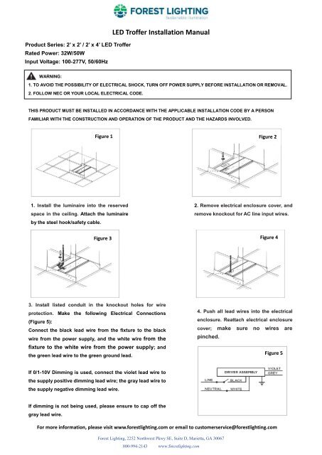
Product Series: 2’ x 2’ / 2’ x 4’ <strong>LED</strong> Tr<strong>of</strong>fer<br />
Rated Power: 32W/50W<br />
Input Voltage: 100‐277V, 50/60Hz<br />
<strong>LED</strong> Tr<strong>of</strong>fer <strong>Installation</strong> <strong>Manual</strong><br />
WARNING:<br />
1. TO AVOID THE POSSIBILITY OF ELECTRICAL SHOCK, TURN OFF POWER SUPPLY BEFORE INSTALLATION OR REMOVAL.<br />
2. FOLLOW NEC OR YOUR LOCAL ELECTRICAL CODE.<br />
3.<br />
THIS PRODUCT MUST BE INSTAL<strong>LED</strong> IN ACCORDANCE WITH THE APPLICABLE INSTALLATION CODE BY A PERSON<br />
FAMILIAR WITH THE CONSTRUCTION AND OPERATION OF THE PRODUCT AND THE HAZARDS INVOLVED.<br />
Figure 1 Figure 2<br />
1. Install the luminaire into the reserved<br />
space in the ceiling. Attach the luminaire<br />
by the steel hook/safety cable.<br />
Figure 3<br />
2. Remove electrical enclosure cover, and<br />
remove knockout for AC line input wires.<br />
Figure 4<br />
3. Install listed conduit in the knockout holes for wire<br />
protection. Make the following Electrical Connections<br />
(Figure 5):<br />
Connect the black lead wire from the fixture to the black<br />
wire from the power supply, and the white wire from the<br />
fixture to the white wire from the power supply; and<br />
the green lead wire to the green ground lead.<br />
4. Push all lead wires into the electrical<br />
enclosure. Reattach electrical enclosure<br />
cover; make sure no wires are<br />
pinched.<br />
Figure 5<br />
If 0/1-10V Dimming is used, connect the violet lead wire to<br />
the supply positive dimming lead wire; the gray lead wire to<br />
the supply negative dimming lead wire.<br />
If dimming is not being used, please ensure to cap <strong>of</strong>f the<br />
gray lead wire.<br />
For more information, please visit www.forestlighting.com or email to customerservice@forestlighting.com<br />
<strong>Forest</strong> <strong>Lighting</strong>, 2252 Northwest Pkwy SE, Suite D, Marietta, GA 30067<br />
800-994-2143 www.forestlighting.com