ESB3503-3SCD20
The SFP-BIDI transceivers are high performance, cost effective modules supporting data-rate of 155Mbps and 20KM transmission distance with SMF. The transceiver consists of three sections: a FP laser transmitter, a PIN photodiode integrated with a trans-impedance preamplifier (TIA) and MCU control unit. All modules satisfy class I laser safety requirements. The transceivers are compatible with SFP Multi-Source Agreement (MSA) and SFF-8472. For further information, please refer to SFP MSA.
The SFP-BIDI transceivers are high performance, cost effective modules supporting data-rate of
155Mbps and 20KM transmission distance with SMF.
The transceiver consists of three sections: a FP laser transmitter, a PIN photodiode integrated with a
trans-impedance preamplifier (TIA) and MCU control unit. All modules satisfy class I laser safety
requirements.
The transceivers are compatible with SFP Multi-Source Agreement (MSA) and SFF-8472. For further
information, please refer to SFP MSA.

Create successful ePaper yourself
Turn your PDF publications into a flip-book with our unique Google optimized e-Paper software.
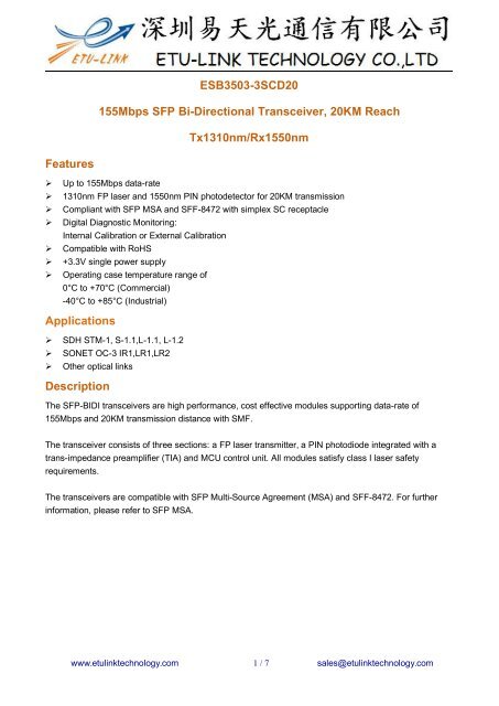
<strong>ESB3503</strong>-<strong>3SCD20</strong><br />
155Mbps SFP Bi-Directional Transceiver, 20KM Reach<br />
Tx1310nm/Rx1550nm<br />
Features<br />
‣ Up to 155Mbps data-rate<br />
‣ 1310nm FP laser and 1550nm PIN photodetector for 20KM transmission<br />
‣ Compliant with SFP MSA and SFF-8472 with simplex SC receptacle<br />
‣ Digital Diagnostic Monitoring:<br />
Internal Calibration or External Calibration<br />
‣ Compatible with RoHS<br />
‣ +3.3V single power supply<br />
‣ Operating case temperature range of<br />
0°C to +70°C (Commercial)<br />
-40°C to +85°C (Industrial)<br />
Applications<br />
‣ SDH STM-1, S-1.1,L-1.1, L-1.2<br />
‣ SONET OC-3 IR1,LR1,LR2<br />
‣ Other optical links<br />
Description<br />
The SFP-BIDI transceivers are high performance, cost effective modules supporting data-rate of<br />
155Mbps and 20KM transmission distance with SMF.<br />
The transceiver consists of three sections: a FP laser transmitter, a PIN photodiode integrated with a<br />
trans-impedance preamplifier (TIA) and MCU control unit. All modules satisfy class I laser safety<br />
requirements.<br />
The transceivers are compatible with SFP Multi-Source Agreement (MSA) and SFF-8472. For further<br />
information, please refer to SFP MSA.<br />
www.etulinktechnology.com 1 / 7 sales@etulinktechnology.com
Module Block Diagram<br />
Absolute Maximum Ratings<br />
Parameter Symbol Min Typ Max Unit Ref.<br />
Maximum Supply Voltage Vcc -0.5 4.7 V<br />
Storage Temperature TS -40 85 °C<br />
Case Operating Temperature TOP 0 70 °C<br />
Electrical Characteristics (TOP = 0 to 70℃, VCC = 3.15 to 3.60Volts)<br />
Parameter Symbol Min Typ Max Unit Ref.<br />
Supply Voltage Vcc 3.15 3.3 3.6 V<br />
Supply Current Icc 185 280 mA<br />
Transmitter<br />
Input differential impedance Rin 100 Ω 1<br />
Single ended data input swing Vin,pp 250 1200 mV<br />
Transmit Disable Voltage VD Vcc–1.3 Vcc V<br />
Transmit Enable Voltage VEN Vee Vee+ 0.8 V 2<br />
Transmit Disable Assert Time 10 us<br />
Receiver<br />
Single ended data output swing Vout,pp 250 800 mV 3<br />
Data output rise time tr 100 175 ps 4<br />
Data output fall time tf 100 175 ps 4<br />
LOS Fault VLOS fault Vcc–0.5 VccHOST V 5<br />
LOS Normal VLOS norm Vee Vee+0.5 V 5<br />
Power Supply Rejection PSR 100 mVpp 6<br />
www.etulinktechnology.com 2 / 7 sales@etulinktechnology.com
Notes:<br />
1. Connected directly to TX data input pins. AC coupled thereafter.<br />
2. Or open circuit.<br />
3. Into 100 ohms differential termination.<br />
4. 20 – 80 %<br />
5. Loss Of Signal is LVTTL. Logic 0 indicates normal operation; logic 1 indicates no signal detected.<br />
6. Receiver sensitivity is compliant with power supply sinusoidal modulation of 20 Hz to 1.5 MHz up to specified value<br />
applied through the recommended power supply filtering network.<br />
Electrical Input / Output Characteristics<br />
Transmitter<br />
Parameter Symbol Min. Typ Max. Unit Note<br />
Diff. input voltage swing 120 820 mVpp 1<br />
Tx Disable input H VIH 2.0 Vcc+0.3 V<br />
L VIL 0 0.8<br />
Tx Fault output H VOH 2.0 Vcc+0.3 V 2<br />
L VOL 0 0.8<br />
Input Diff. Impedance Zin 100 Ω<br />
Receiver<br />
Parameter Symbol Min. Typ Max. Unit Note<br />
Diff. output voltage swing 340 650 800 mVpp 3<br />
Rx LOS Output H VOH 2.0 Vcc+0.3 V 2<br />
L VOL 0 0.8<br />
Notes:<br />
1) TD+/- are internally AC coupled with 100Ω differential termination inside the module.<br />
2) Tx Fault and Rx LOS are open collector outputs, which should be pulled up with 4.7k to 10kΩ resistors on the<br />
host board. Pull up voltage between 2.0V and Vcc+0.3V.<br />
3) RD+/- outputs are internally AC coupled, and should be terminated with 100Ω (differential) at the user SERDES<br />
www.etulinktechnology.com 3 / 7 sales@etulinktechnology.com
Optical Characteristics<br />
Transmitter<br />
Parameter Symbol Min. Typ Max. Unit Note<br />
Operating Wavelength λC 1270 1310 1360 nm<br />
Ave. output power (Enabled) Po -14 -8 dBm 1<br />
Extinction Ratio ER 10 dB 1<br />
RMS spectral width Δλ 4 nm<br />
Rise/Fall time (20%~80%) Tr/Tf 0.26 ps 2<br />
Output Eye Mask<br />
Telcordia GR-253-CORE and ITU-T G.957 compatible<br />
Notes:<br />
4) Measure at 2^23-1 NRZ PRBS pattern<br />
5) Transmitter eye mask definition<br />
Receiver<br />
Parameter Symbol Min. Typ Max. Unit Note<br />
Operating Wavelength 1480 1580 nm<br />
Sensitivity Psen -32 dBm 1<br />
Min. overload Pimax -3 dBm<br />
LOS Assert Pa -45 dBm<br />
LOS De-assert Pd -34 dBm 2<br />
LOS Hysteresis Pd-Pa 0.5 6 dB<br />
Notes:<br />
6) Measured with Light source 1550nm(1310nm), ER=10dB; BER =
PIN Name Function Notes<br />
1 VeeT Tx ground<br />
2 Tx Fault Tx fault indication, Open Collector Output, active “H” 1<br />
3 Tx Disable LVTTL Input, internal pull-up, Tx disabled on “H” 2<br />
4 MOD-DEF2 2 wire serial interface data input/output (SDA) 3<br />
5 MOD-DEF1 2 wire serial interface clock input (SCL) 3<br />
6 MOD-DEF0 Model present indication 3<br />
7 Rate select No connection<br />
8 LOS Rx loss of signal, Open Collector Output, active “H” 4<br />
9 VeeR Rx ground<br />
10 VeeR Rx ground<br />
11 VeeR Rx ground<br />
12 RD- Inverse received data out 5<br />
13 RD+ Received data out 5<br />
14 VeeR Rx ground<br />
15 VccR Rx power supply<br />
16 VccT Tx power supply<br />
17 VeeT Tx ground<br />
18 TD+ Transmit data in 6<br />
19 TD- Inverse transmit data in 6<br />
20 VeeT Tx ground<br />
Notes:<br />
8) When high, this output indicates a laser fault of some kind. Low indicates normal operation. And should be pulled up<br />
with a 4.7 – 10KΩ resistor on the host board.<br />
9) TX disable is an input that is used to shut down the transmitter optical output. It is pulled up within the module with a<br />
4.7 – 10KΩ resistor. Its states are:<br />
10) Low (0 – 0.8V): Transmitter on (>0.8, < 2.0V): Undefined<br />
11) High (2.0V~Vcc+0.3V): Transmitter Disabled Open: Transmitter Disabled<br />
12) Mod-Def 0,1,2. These are the module definition pins. They should be pulled up with a 4.7K – 10KΩ resistor on the<br />
host board. The pull-up voltage shall be VccT or VccR.<br />
13) Mod-Def 0 has been grounded by the module to indicate that the module is present<br />
14) Mod-Def 1 is the clock line of two wire serial interface for serial ID<br />
15) Mod-Def 2 is the data line of two wire serial interface for serial ID<br />
16) When high, this output indicates loss of signal (LOS). Low indicates normal operation.<br />
17) RD+/-: These are the differential receiver outputs. They are AC coupled 100Ω differential lines which should be<br />
terminated with 100Ω (differential) at the user SERDES. The AC coupling is done inside the module and is thus not<br />
required on the host board.<br />
18) TD+/-: These are the differential transmitter inputs. They are AC-coupled, differential lines with 100Ω differential<br />
termination inside the module. The AC coupling is done inside the module and is thus not required on the host board.<br />
www.etulinktechnology.com 5 / 7 sales@etulinktechnology.com
Digital Diagnostic Functions<br />
ETU-LINK’S <strong>ESB3503</strong>-<strong>3SCD20</strong> transceivers support the 2-wire serial communication protocol as defined in the SFP MSA.<br />
It is very closely related to the E2PROM defined in the GBIC standard, with the same electrical specifications.<br />
The standard SFP serial ID provides access to identification information that describes the transceiver’s capabilities,<br />
standard interfaces, manufacturer, and other information.<br />
Additionally, ETU-LINK SFP transceivers provide a unique enhanced digital diagnostic monitoring interface, which allows<br />
real-time access to device operating parameters such as transceiver temperature, laser bias current, transmitted optical<br />
power, received optical power and transceiver supply voltage. It also defines a sophisticated system of alarm and warning<br />
flags, which alerts end-users when particular operating parameters are outside of a factory set normal range.<br />
The SFP MSA defines a 256-byte memory map in E2PROM that is accessible over a 2-wire serial interface at the 8bit<br />
address 1010000X (A0h). The digital diagnostic monitoring interface makes use of the 8 bit address 1010001X (A2h), so<br />
the originally defined serial ID memory map remains unchanged. The interface is identical to, and is thus fully backward<br />
compatible with both the GBIC Specification and the SFP Multi Source Agreement.<br />
The operating and diagnostics information is monitored and reported by a Digital Diagnostics Transceiver Controller<br />
(DDTC) inside the transceiver, which is accessed through a 2-wire serial interface. When the serial protocol is activated,<br />
the serial clock signal (SCL, Mod Def 1) is generated by the host. The positive edge clocks data into the SFP transceiver<br />
into those segments of the E2PROM that are not write-protected. The negative edge clocks data from the SFP transceiver.<br />
The serial data signal (SDA, Mod Def 2) is bi-directional for serial data transfer. The host uses SDA in conjunction with SCL<br />
to mark the start and end of serial protocol activation. The memories are organized as a series of 8-bit data words that can<br />
be addressed individually or sequentially.Digital diagnostics for the <strong>ESB3503</strong>-<strong>3SCD20</strong> are Internally calibrated by default.<br />
Typical Interface Circuit<br />
www.etulinktechnology.com 6 / 7 sales@etulinktechnology.com
Package Dimensions<br />
Regulatory Compliance<br />
Feature Reference Performance<br />
Electrostatic discharge(ESD) IEC/EN 61000-4-2 Compatible with standards<br />
Electromagnetic Interference (EMI)<br />
Laser Eye Safety<br />
FCC Part 15 Class B EN 55022 Class B<br />
(CISPR 22A)<br />
FDA 21CFR 1040.10, 1040.11 IEC/EN<br />
60825-1, 2<br />
Compatible with standards<br />
Class 1 laser product<br />
Component Recognition IEC/EN 60950, UL Compatible with standards<br />
ROHS 2002/95/EC Compatible with standards<br />
EMC EN61000-3 Compatible with standards<br />
www.etulinktechnology.com 7 / 7 sales@etulinktechnology.com