

First Breakthrough for Future Air-Breathing Magneto-Plasma Propulsion Systems
1609.04054
1609.04054

You also want an ePaper? Increase the reach of your titles
YUMPU automatically turns print PDFs into web optimized ePapers that Google loves.
<strong>First</strong> <strong>Breakthrough</strong> <strong>for</strong> <strong>Future</strong> <strong>Air</strong>-<strong>Breathing</strong><br />
<strong>Magneto</strong>-<strong>Plasma</strong> <strong>Propulsion</strong> <strong>Systems</strong><br />
B Göksel 1* , I Ch Mashek 2<br />
1<br />
Electrofluidsystems Ingenieurbüro Göksel, Berlin, Germany<br />
2<br />
St. Petersburg State University, St. Petersburg, Russia<br />
* Email: berkant.goeksel@electrofluidsystems.com<br />
Abstract. A new breakthrough in jet propulsion technology since the invention of the jet engine is<br />
achieved. The first critical tests <strong>for</strong> future air-breathing magneto-plasma propulsion systems have<br />
been successfully completed. In this regard, it is also the first time that a pinching dense plasma focus<br />
discharge could be ignited at one atmosphere and driven in pulse mode using very fast, nanosecond<br />
electrostatic excitations to induce self-organized plasma channels <strong>for</strong> ignition of the propulsive main<br />
discharge. Depending on the capacitor voltage (200-600 V) the energy input at one atmosphere varies<br />
from 52-320 J/pulse corresponding to impulse bits from 1.2-8.0 mNs. Such a new pulsed plasma<br />
propulsion system driven with one thousand pulses per second would already have thrust-to-area<br />
ratios (50-150 kN/m²) of modern jet engines. An array of thrusters could enable future aircrafts and<br />
airships to start from ground and reach altitudes up to 50km and beyond. The needed high power<br />
could be provided by future compact plasma fusion reactors already in development by aerospace<br />
companies. The magneto-plasma compressor itself was originally developed by Russian scientists as<br />
plasma fusion device and was later miniaturized <strong>for</strong> supersonic flow control applications. So the first<br />
breakthrough is based on a spin-off plasma fusion technology.<br />
Introduction<br />
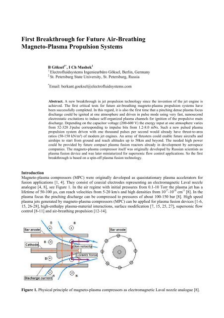
<strong>Magneto</strong>-plasma compressors (MPC) were originally developed as quasistationary plasma accelerators <strong>for</strong><br />
fusion applications [1, 4]. They consist of coaxial electrodes representing an electromagnetic Laval nozzle<br />
analogue [4, 8], see Figure 1. In the air regime with initial pressures from 0.1-10 Torr the plasma jet has a<br />
lifetime of 50-100 µs, can reach velocities from 5-20 km/s and high densities from 10 17 -10 18 cm -3 [8]. In the<br />
plasma focus the pinching discharge can be compressed to pressures of about 100-150 bar [8]. High speed<br />
plasma jets generated by magneto-plasma compressors (MPC) can be applied <strong>for</strong> plasma fusion devices [1-6,<br />
15, 26-28], high-enthalpy plasma-material interactions, surface modification [7, 15, 25, 27], supersonic flow<br />
control [8-11] and air-breathing propulsion [12-14].<br />
Figure 1. Physical principle of magneto-plasma compressors as electromagnetic Laval nozzle analogue [8].
Motivation<br />
Almost all known MPC types operate under high vacuum conditions (10 -5 -10 mbar) with very high discharge<br />
currents (10-200 kA) and low repetition frequencies (0,01-0,1 Hz). The overall system in all cases is based<br />
on bulky high-current switchers, heavy high voltage capacitor banks with tens of kV, complex control and<br />
diagnostics devices [1-7]. Nevertheless, all the previous work gave the main inspiration to develop new<br />
lightweight, highly miniaturized, lower voltage powered stable MPC-based plasma jet generator systems <strong>for</strong><br />
flow control and propulsion purposes. The main initiation was given in 2010 by an in<strong>for</strong>mal request from an<br />
European aerospace company <strong>for</strong> a stratospheric high-thrust plasma propulsion with tens to hundreds of<br />
Newton. At the time this technology was not available and the request could not be addressed but the idea<br />
was born to develop a new propulsion system which combines electrohydrodynamic barrier discharge and<br />
field electron emission effects with magnetohydrodynamic flux compression aspects. The first breakthrough<br />
milestone goal was to realize a MPC system with 5-10 Hz repetition frequency which is able to operate<br />
under atmospheric pressures from 0.1-1.0 bar [13]. So far there was no known work about MPC operating at<br />
high-pressure and high-frequency. This challenge and the industrial request <strong>for</strong> a high-altitude propulsion<br />
systems was the main motivation to start a R&D programme <strong>for</strong> pulsed plasma “detonation” thrusters.<br />
It is not widely known that a hydromagnetic Rankine-Hugeniot model <strong>for</strong> detonation and deflagration can be<br />
also used to describe gas-fed (air-breathing) coaxial plasma accelerators which are based on pinching dense<br />
plasma focus discharge devices like the magneto-plasma compressor. The gas is in this case is resistively<br />
heated by the pinching discharge instead of the burning in the combustor. The hydromagnetic shock caused<br />
by the high magnetic pressure ionizes and compresses the gas volume ahead of itself [19-22]. Nevertheless,<br />
all the known studies focus on high-vacuum conditions with plasma jet velocities exceeding 100-200 km/s.<br />
Recent studies about sub-millimeter dense plasma focus (DPF) devices also reveal attempts and proposals<br />
towards higher pressures of 10-1000 Torr in hydrogen though limitations in confinement due to increased<br />
collisions at high pressures are expected [23]. Nevertheless, the same authors could recently demonstrate a<br />
DPF operating in 50-190 Torr Helium [24]. This specific type of pinching plasma accelerator is producing<br />
short nanosecond discharge pulses which are also relevant <strong>for</strong> x-ray and short pulse neutron emissions. DPF<br />
devices and their applications are again reconsidered <strong>for</strong> investigation in large-scale plasma fusion and space<br />
propulsion programs [26-31]. This is a further motivation to study air-breathing magneto-plasma jet thrusters.<br />
In previous experiments the authors used microsecond discharges <strong>for</strong> internal initiation of the propulsive<br />
main discharge and could already increase the MPC operation pressure from 30 to 250 Torr (0.33 bar), see<br />
Figure 2a-2c [13]. The use of nanosecond discharge was the next logical step which was also motivated by<br />
the fact that in experiments to chemical pulse detonation engines distributed or transient nanosecond spark<br />
discharges are significantly more efficient <strong>for</strong> detonation initiation than localized microsecond spark<br />
discharges of comparable pulse energy [17]. So high repetition nanosecond pulsed discharge are already in<br />
the focus of groups working on efficient combustion processes <strong>for</strong> several years [18], though no working<br />
group has obviously ever combined the nanosecond know-how with pinching dense plasma focus discharges.<br />
5<br />
4<br />
Thrust (mN*s)<br />
Battery 2.0 kV<br />
3<br />
Thrust (mN*s)<br />
Battery 1.8 kV<br />
2<br />
1<br />
Energy input *100(J) /pulse<br />
Battery 2.0 kV<br />
Energy input *100 (J)<br />
Battery 1.8 kV<br />
/pulse<br />
0<br />
0 50 100 150 200 250<br />
Pressure (Torr)<br />
(a) (b) (c)<br />
Figure 2a-2c. Thrust and pulse energy deposition in dependence of the air pressure <strong>for</strong> different battery<br />
voltages with internal microsecond sliding discharge exitation [13].
General experimental setup<br />
The new MPC has an outlet diameter of 14 mm and contains six coaxial bar anodes (each from 3mm Copper<br />
rods) and one conical Copper cathode with a maximum diameter of 7 mm. The minimum distance between<br />
each anode and cathode is 2 mm. Following the electrode size and distances we can name this configuration<br />
(3-2-7) mm. The overall length of the new compressor is 80 mm, see Figure 3a. The MPC location inside an<br />
acrylic vacuum chamber is shown in Figure 3b and 3c.<br />
(a) (b) (c)<br />
Figure 3a-3c. Tested MPC and test vacuum chamber.<br />
The MPC is designed to work under pressures from 0.1-1.0 bar. The related self-breakdown threshold <strong>for</strong> the<br />
new (3-2-7) configuration is below 5kV. A nanosecond (ns) high voltage pulse generator (NPG-18/3500N,<br />
Megaimpulse Ltd, Russia) is used to induce a homogeneous, transient discharge <strong>for</strong> internal MPC excitation.<br />
High-frequency nanosecond pulse discharges have the unique property to induce transient self-organization<br />
of plasma channels between the electrodes [16, 17], see Figure 4a-4c. The transient ns-discharge is driven by<br />
-15 kV, 3.5 kHz pulses with 4 ns rise time and 10-20 ns pulse length <strong>for</strong> all test pressures. The full dynamic<br />
behavior of the ns-discharge will be addressed in a separate paper. The general scheme of experimental setup<br />
<strong>for</strong> the new MPC investigation is presented below in Figure 5.<br />
(a) (b) (c)<br />
Figure 4a-4c. Photos of transient atmospheric nanosecond pulse discharges <strong>for</strong> internal MPC excitation.<br />
Figure 5. General scheme of the setup.
The new MPC (7) is connected to a cable collector (4) through a short peace of coaxial cable (6) (0.1 m<br />
RG214U) and a discharge current/voltage measuring circuit (5) (current resistor 0.75 mOhm, voltage sensor<br />
PMK-14KVAC). The cable collector contains a high-frequency blocking filter (L b =150 nH, C b =1,1 nF), a<br />
separating capacitor C w (220 pF, 16 kV), a pull-down resistor R w (75 Ohm) and a low-inductance Copper<br />
plate which leads the current <strong>for</strong> the capacitor bank (battery) output cables. The cable collector (4) itself is<br />
connected with the main discharge battery by ten coaxial cables (3) having each 0.8 m length (RG214U).<br />
The main discharge capacitor bank consists of 10 impulse capacitors with 2700 µF and 1200V maximum<br />
voltage. This capacitor bank (2) is charged through the resistor R c and a voltage regulator with a maximum<br />
output voltage of 1100 V and 6 kW power.<br />
The nanosecond pulse generator (8) (NPG-18/3500N) operates in the boost regime (external trigger). The<br />
external synchronization input (28 ms) generates about 98 high voltage (HV) ns-pulses which again induce<br />
the homogeneous, transient plasma channels between the cathode and coaxial anodes. The blocking filter in<br />
the cable collector (4) saves the main battery from damage through each of the nanosecond HV pulses.<br />
The capacitor bank (2) has a total capacity of 2700 µF, an internal resistance of 0.3 mOhm and an internal<br />
inductance of 8.5 nH (10 capacitors in parallel connection). The cables connecting the battery with the cable<br />
collector have a self-inductance of 20 nH and a resistance of 0.6 mOhm (10 RG214U cable with each 0.8 m<br />
in parallel). The cable collector has the resistance of 0.02 mOhm and a self-inductance of 6.6 nH. The<br />
inductance of the blocking filter is 150 nH. The short connecting cable <strong>for</strong> the MPC (0.1 m RG212U) has 25<br />
nH and 0.7 mOhm.<br />
Visualization setup and results<br />
Visualization of MPC induced plasma jets was per<strong>for</strong>med with a Basler Ace100 camera (9 in Figure 5)<br />
having a frame exposition able to synchronize with the nanosecond HV pulse generator working in a boost<br />
regime with 28 ms. The camera itself was launched with a synchronizing circuit (10 in Figure 5) using short<br />
TTL pulses with a duration of 34.5 µs. The end of a pulse launches the boost regime of the ns pulse<br />
generator (8 in Figure 5). To minimize EM interferences from the nanosecond pulse discharges to the camera<br />
and computer electronics the synchronization pulse was transferred to the nanosecond HV pulse generator<br />
through an optical fiber coupling.<br />
In Figure 6a-6c, a general view of the high pressure plasma jet is presented. All pictures were taken with a<br />
dense red glass filter KS-15 and minimal camera lens diaphragm.<br />
(a) 400 V (front view) (b) 400 V (side view) (c) 500V, 25 kA<br />
Figure 6a-6c. View of MPC plasma jets <strong>for</strong> different battery voltages U b at an air pressure of 450 mbar.<br />
Usually, the main discharge is arising after 2-10 pulses of the internal ns-excitation. At one atmosphere the<br />
MPC plasma jets have a similar character but higher intensity than under a lower pressure of 450 mbar, see<br />
Figure 7a-7c. In Figure 7a, it can be clearly seen that a pinching plasma jet with a compression focus area<br />
already exists <strong>for</strong> a battery voltage as low as 300 V. The pinching plasma can be even more clearly seen<br />
through IR and UV filters, see Figure 8a-8b. Figure 9a-9b show a visualization of the nanosecond excitation<br />
(Figure 4a) and main discharge through a blue filter. In all previous studies the battery voltage was much<br />
higher in the range of at least 1.8 kV [13]. Nevertheless, the capacitor bank can provide voltages up to 1.2 kV.
(a) 300 V, 11.0 kA, (b) 400 V, 18.5 kA, (c) 500V, 25.0 kA.<br />
Figure 7a-7c. <strong>Plasma</strong> jets <strong>for</strong> different battery voltages U b at 1 bar atmospheric pressure through a red filter.<br />
(a) 500 V, IR filter 680 nm,<br />
(b) 500 V, UV filter 480 nm.<br />
Figure 8a-8b. <strong>Plasma</strong> jet <strong>for</strong> U b =500 V at 1 bar atmospheric pressure through IR and UV filters.<br />
(a) -15 kV, 3.5 kHz ns-excitation,<br />
(b) U b =300 V, main discharge with I d =11.0 kA peak current.<br />
Figure 9a-9b. Excitation and ignition of main discharge at 1 bar atmospheric pressure through a blue filter.<br />
Current and voltage measurements and simulations<br />
The discharge current <strong>for</strong> the MPC has a weak dependence from pressure, and mainly depends from the<br />
discharge voltage. A typical presentation of the discharge parameters are shown in Figure 10a.<br />
(a)<br />
Figure 10a and 10b. MPC discharge <strong>for</strong> U d =400 V (battery with 2700 µF) at 1 bar atmospheric pressure.<br />
(b)
In Figure 10b, the nonlinear resistance (red line) of the pinching high-current arc discharge is shown over<br />
time. The discharge resistance R d dramatically decreases when the discharge current reaches the higher peak<br />
levels of 15-18kA in this specific case, Figure 10b. This effect is related to the tangential component of the<br />
strong magnetic field arising between MPC electrodes. The intrinsic tangential component of the magnetic<br />
flux density is the most important factor in this type of pinching plasma accelerators.<br />
For a first estimation the value of the magnetic fields at different discharge currents were simulated in<br />
COMSOL, Figure 11a-11b. The experimentally obtained relationship between the nonlinear discharge<br />
resistance and the discharge current clearly shows that the generation of a flux compression plasma jet in the<br />
MPC is only possible at a certain level of the tangential magnetic flux density in the discharge gap.<br />
Minimum 0.7-1.2 T is necessary <strong>for</strong> the investigated plasma accelerator.<br />
The distribution of the tangential component of the magnetic flux density in the electrode gap <strong>for</strong> a discharge<br />
current of 30 kA is shown in Figure 11a. Figure 11b shows the radial distribution of the tangential<br />
component of the magnetic field <strong>for</strong> different discharge currents (direction cathode center to anode center).<br />
(a)<br />
(b)<br />
Figure 11a and 11b. The distribution of tangential magnetic fields between the MPC electrode gap.<br />
The results of simulations and experiments show that there are strict requirements on the geometry of the<br />
discharge electrode. A flux compression with a low energy loss can be reached <strong>for</strong> discharge currents higher<br />
than 15-18 kA. This level corresponds to a minimum tangential magnetic field of 0.7-0.9 T. Particularly, the<br />
discharge voltage in the working gap at the proper geometry becomes so small that it causes low energy<br />
losses. Thus, the energy efficiency (ratio between discharge energy and energy of the capacitor bank) <strong>for</strong> the<br />
(3-2-7) mm MPC version with six-anodes at low voltage is about 0.85-0.90 but is decreasing <strong>for</strong> higher<br />
voltages. The capacitor bank voltage U b here was varied from 200 to 600 V, though the maximum possible<br />
value is 1200 V. The overall energy efficiency <strong>for</strong> other voltages can be estimated or calculated using the<br />
<strong>for</strong>mula (1), the W d , U d values from Figure 14 and C b = 2700µF.<br />
η = W d / W b = I d (t) · U d (t) dt / [C b · U b · U b / 2] (1)
Impulse bit measurements<br />
The impulse bit of the new MPC was investigated using a free pendulum with 55 mm length and a mass of<br />
15 g (see Figure 12a-12b). The pendulum deflection angle varied from 5 o to 25 o . Such small angles allow the<br />
use of the simplest model <strong>for</strong> a mathematical pendulum. The estimated measurement accuracy is 10-15 %.<br />
An absolutely inelastic interaction of the plasma jet with the pendulum surface was assumed. Figure 12c<br />
shows a series of small motion pictures taken from a video <strong>for</strong> a variant with a more lightweight pendulum.<br />
Conductive and insulating pendula made the same impulse bit. Figure 13 shows the measured impulse bit <strong>for</strong><br />
different battery voltages and different atmospheric pressures. The first results show a comparatively weak<br />
dependence between impulse bit and atmospheric pressure in the measured range from 175-1000 mbar.<br />
(a) 0 V, 1000 mbar (b) 400 V, 1000 mbar (c) 400 V, 1000 mbar<br />
Figure 12a-12c. Measurement of impulse bit (Ibit) and thrust demonstration using a pendulum.<br />
5<br />
4<br />
200V<br />
400V<br />
300V<br />
3<br />
Ibit mNs<br />
2<br />
1<br />
0<br />
0 200 400 600 800 1000<br />
P mbar<br />
Figure 13. Measured impulse bit <strong>for</strong> different battery voltages and different atmospheric pressures.<br />
Summary and outlook<br />
Figure 14 gives a summary of the main results <strong>for</strong> the maximum discharge current I d,max , the impulse bit and<br />
the discharge energy W d . The input energy W b (proportional to the square of the battery voltage U b ) is<br />
dramatically increasing <strong>for</strong> higher input voltages, see also <strong>for</strong>mula (1). The measured discharge energy W d is<br />
also increasing in a similar way. But at higher voltages beyond 400 V the energy loss is rising too. So the<br />
effective energy available to initiate the discharge is not proportional to the input energy. The kink in the<br />
discharge energy slope at 400 V is caused by the higher energy losses at 500 and 600 V. In these cases, the<br />
energy efficiency is only 0.74 and 0.66 compared to the much higher efficiencies at voltages below 500 V.
40<br />
38<br />
36 I d,max<br />
kA<br />
34 Ibit mNs<br />
32<br />
W<br />
30<br />
d<br />
/10 J<br />
28<br />
26<br />
24<br />
22<br />
20<br />
18<br />
16<br />
14<br />
12<br />
10<br />
8<br />
6<br />
4<br />
2<br />
0<br />
0 50 100 150 200 250 300 350 400 450 500 550 600 650 700 750 800<br />
U b V<br />
Figure 14. Summary of results <strong>for</strong> I d,max , impulse bit and discharge energy W d <strong>for</strong> varying battery voltage U b .<br />
One of the most essential problems <strong>for</strong> future high-frequency MPC applications is the erosion of the<br />
electrode system. Figure 15 shows the results of the erosion process after approximately 10 3 main discharge<br />
ignitions with a maximum current no more than 30 kA. The observed level of erosion was unexpectedly low.<br />
But future air-breathing magneto-plasma propulsion systems will need up to 10 3 ignitions per second. So<br />
alternative materials from fusion reactors, amorphous metals and special alloys with different porosity and<br />
surface structuring could be also investigated in the future. In this regards, the MPC itself might be useful to<br />
manipulate the surface structure of future electrode materials [7].<br />
Figure 15. Results of erosion processes in MPC after 10 3 launches.<br />
In future experiments the plasma dynamics could be investigated using ultrafast cameras with up to 2 Mio<br />
frames per seconds which are available to the corresponding authors. In the present work the maximum<br />
voltage and power limits of the new MPC thruster were not tested. The main task was the first demonstration<br />
of a pulsed MPC-based plasma thruster with ns-internal excitation <strong>for</strong> a stabile operation at high atmospheric<br />
pressures up to 1 bar. In this regard, a first breakthrough and pulse operation with 4.7 Hz was demonstrated.<br />
In the next step, the pulse frequency of the main discharge will be increased up to 10 Hz. Furthermore, a new<br />
mobile power generator will be developed <strong>for</strong> the first flight demonstration onboard of the b-Ionic <strong>Air</strong>fish,<br />
which was the world’s first airship propelled by plasma engines in 2005, see Figure 16a-16b. Only 0.08 N or<br />
8 g would be sufficient to propel this 7.5 m airship at low speeds up to 1 m/s [32]. A 5 Hz thruster has<br />
already about 0.02 N. So an array of four plasma pulse “detonation” thrusters with the present power level<br />
would make it fly. The available maximum weight <strong>for</strong> the power generator is about 5.1 kg plus 1.2 kg <strong>for</strong><br />
LiPo batteries [32]. In any case, there are a large amount of other possible technological applications in the<br />
field of aerodynamics, material sciences and power engineering. But a real flight demonstration is the next<br />
milestone goal towards new magneto-plasma flux compression thrusters <strong>for</strong> stratospheric airships or high<br />
altitude plat<strong>for</strong>m stations (HAPS) which are currently all limited to about 25 km altitude by using propellers.
With future air-breathing magneto-plasma flux compression thrusters next generation solar, beamed or<br />
fusion energy powered airships could climb to altitudes up to 50 km and beyond.<br />
(a)<br />
(b)<br />
Figure 16a and 16b. The world’s first plasma propelled airship, the 7.5 m long b-Ionic <strong>Air</strong>fish (2005) [32].<br />
Acknowledgements<br />
The breakthrough experiments were funded by Electrofluidsystems and per<strong>for</strong>med by the authors in the<br />
company’s future workshop in Berlin. The numerical studies were per<strong>for</strong>med by Tatiana Banokina in St.<br />
Petersburg funded by a grant of the St. Petersburg State University with number 11.37.167.2014.<br />
References<br />
1. Morozov A 1975 Processes in a magnetoplasma compressor. Physics of <strong>Plasma</strong> 1 95-101 (in Russian).<br />
2. Astashinsky B, Bakanovich G, Minko L 1980 Investigations of dynamic of plasma arising and <strong>for</strong>ming<br />
processes of compression area in gas magneto-plasma compressor. Journal of Applied Spectroscopy 33<br />
629-633 (in Russian).<br />
3. Ananin S, Astashinsky B, Bakanovich G, Kostukevich E, Kusmitsky A, Manykovsky A, Minko L,<br />
Morozov A 1990 Investigations of processes of plasma jets rising in quasi stationary high-current plasma<br />
accelerator (QHPA). Physics of <strong>Plasma</strong> 16 186-196 (in Russian).<br />
4. Morozov A 1990 The principles of coaxial quasi stationary plasma accelerators. Physics of <strong>Plasma</strong> 16<br />
131-146 (in Russian).<br />
5. Astashinsky B, Bakanovich G, Kusmitsky A, Minko L 1992 Choosing of operation modes and plasma<br />
parameters of magneto plasma compressor. Engineering Physical Journal 62 (3) 386-390 (in Russian).<br />
6. Astashinsky B, Bakanovich G, Minko L 1980 Investigations of dynamic of plasma arising and <strong>for</strong>ming<br />
processes of compression area in gas magneto-plasma compressor. Journal of Applied Spectroscopy 33<br />
629-633 (in Russian).<br />
7. Kuraica M M, Astashynski V M, Dojcinovic I P, Puric J 2002 Modification of solid surface by a<br />
compression plasma flow. In Physics of Laser Crystals, edited by Krupa J-C, Kulagin N A, NATO<br />
Science Series II. Mathematics, Physics and Chemistry 126 245-254.<br />
8. Mashek I, Anisimov Yu I, Lashkov V A, Kolesnichenko Yu F 2006 Quasi-stationary magneto-plasma<br />
compressor <strong>for</strong> investigation of plasma jets in aerodynamics. 44 th Aerospace Science Meeting, Reno,<br />
AIAA-2006-1458.<br />
9. Mashek I Ch, Anisimov Yu I, Lashkov V A, Kolesnichenko Yu F 2007 Investigation of plasma jets<br />
generated by quasi-stationary magneto-plasma compressor under the high static pressure. 45 th AIAA<br />
Aerospace Sciences Meeting and Exhibit, Reno, AIAA 2007-0221.<br />
10. Mashek I Ch, Anisimov Yu I, Lashkov V A, Kolesnichenko Yu F 2008 <strong>Plasma</strong> actuator <strong>for</strong> supersonic<br />
flow based on miniature magneto-plasma compressor. 46 th AIAA Aerospace Sciences Meeting and<br />
Exhibit, Reno, AIAA 2008-1408.<br />
11. Mashek I Ch, Lashkov V A, Kolesnichenko Yu F, Brovkin V G 2011 Investigation of miniature<br />
magneto-plasma compressor as a basic part <strong>for</strong> perspective plasma actuators <strong>for</strong> supersonic flows. 49th
AIAA Aerospace Sciences Meeting Including the New Horizons Forum and Aerospace<br />
Exposition, AIAA-2011-1274.<br />
12. Mashek I, Lashkov V, Vinerov I, Mikhailov D 2012 Temperature dynamics of plasma focus in airbreathing<br />
magneto-plasma thruster. 11 th International Workshop on <strong>Magneto</strong>-<strong>Plasma</strong> Aerodynamics,<br />
JIHT RAS Moscow.<br />
13. Mashek I Ch, Lashkov V A, Göksel B, Paschereit O, Tajmar M 2012 Investigation of magneto-plasma<br />
compressors with internal initiation to develop high momentum pulsed plasma jet actuators <strong>for</strong> flow<br />
control. Conference Proceedings of the Joint ERCOFTAC/PLASMAERO Workshop, Paper 32, 108-109.<br />
14. Göksel B, Mashek I, Lashkov V et al 2013 Novel air-breathing plasma-jet propulsion <strong>for</strong> solar powered<br />
high altitude flight plat<strong>for</strong>ms. EUCASS, Munich, Paper a593.<br />
15. Trklja N 2015 Current status of the magnetoplasma compressor device in Belgrade – study of plasma<br />
facing materials important <strong>for</strong> fusion reactors. Interdisciplinary Description of Complex <strong>Systems</strong> 13 (1)<br />
173-181.<br />
16. Repin P B, Rep’ev A G 2001 Self-organization of the channel structure of a nanosecond diffuse<br />
discharge in a wire-plane electrode system. Technical Physics 46 (5) 632-634.<br />
17. Rakitin A E, Zhukov V P, Starikovskii A Yu 2009 Deflagration-to-detonation transition under initiation<br />
by high-voltage nanosecond discharges. Progress in <strong>Propulsion</strong> Physics 1 367-378.<br />
18. Bak M S, Kim W, Cappelli M A (2011) On the quenching of excited electronic states of molecular<br />
nitrogen in nanosecond pulsed discharges in atmospheric pressure air. Applied Physics Letters 98,<br />
011502-1 – 011502-3.<br />
19. Cheng D Y 1970 <strong>Plasma</strong> deflagration and the properties of a coaxial plasma deflagration gun. Nucl.<br />
Fusion 10 (3) 305.<br />
20. Poehlmann F, Gascon N, Cappelli M 2007 The deflagration-detonation transition in gas-fed pulsed<br />
plasma accelerators. 43 rd AIAA/ASME/SAE/ASEE Joint <strong>Propulsion</strong> Conference & Exhibit, Cincinnati,<br />
AIAA 2007-5263.<br />
21. Loebner K T K, Wang B C, Poehlmann F R, Watanabe Y, Cappelli M A 2014 High-Velocity Neutral<br />
<strong>Plasma</strong> Jet Formed by Dense <strong>Plasma</strong> Deflagration. IEEE Transactions on <strong>Plasma</strong> Science 42 (10) 2500-<br />
2501.<br />
22. Loebner K T K, Underwood T C, Cappelli M A 2015 Evidence of Branching Phenomena in Current-<br />
Driven Ionization Waves. Physics Review Letters 115 (17) 175001-175005.<br />
23. Pollard W, Carpenter B, Duggleby, A, Staack, D 2010 Design and preliminary characterization of a<br />
micro-scale dense plasma focus. 52 nd Annual Meeting of the APS Division of <strong>Plasma</strong> Physics, Abstract<br />
DPPXP9056P.<br />
24. Pollard W, Duggleby A, Staack A 2016 Dynamics of two microscale DPF devices. Journal of Physics D<br />
Applied Physics 49 (5) 055201.<br />
25. Wang Z P, Yousefi H R, Nishino Y, Ito H, Masugata K 2009 Fabrication of DLC films by pulsed ion<br />
beam ablation in a dense plasma focus device. Physics Letters A 373 4169-4173.<br />
26. Haruki T, Yousefi H R, Sakai J-I 2010 Simulation of plasma heating caused by the coalescence of<br />
multiple loops in a proton-boron fusion plasma. Physics of <strong>Plasma</strong>s 17 (3) 032504.<br />
27. Gribkov V A 2008 Current and perspective applications of dense plasma focus devices. AIP Conf. Proc.<br />
996 51.<br />
28. Schmidt A, Link A, Welch D, Meehan T, Tang V, Halvorson C, May M J, Hagen E C 2014 Fully kinetic<br />
simulations of megajoule-scale dense plasma focus. Physics of <strong>Plasma</strong>s 21 (10) 102703.<br />
29. Polsgrove T, Fincher S, Adams R B, Cassibry J, Cortez R, Turner M, Maples C D, Miernik J N, Statham<br />
G N, Fabisinski L, Santarius J, Percy T 2011 Design of z-pinch and dense plasma focus powered<br />
vehicles. AIAA Aerospace Sciences Meeting, Orlando, AIAA 2011-962.<br />
30. Thomas R, Yang Y, Miley G H, Mead F B 2005 Advancements in dense plasma focus (DPF) <strong>for</strong> Space<br />
<strong>Propulsion</strong>. AIP Conf. Proc. 746, 536.<br />
31. Knecht S D, Thomas R E, Mead F B, Miley G H, Froning D 2006 <strong>Propulsion</strong> and power generation<br />
capabilities of a dense plasma focus (DPF) fusion system <strong>for</strong> future military aerospace vehicles. AIP<br />
Conf. Proc. 813, 1232.<br />
32. Göksel B, Fischer M, Rechenberg I, Thallemer A 2005 Electrostatic plasma wave propulsion <strong>for</strong> bionic<br />
airships (Elektrostatischer <strong>Plasma</strong>-Wellantrieb für bionische Luftschiffe). Proceedings of the German<br />
Aerospace Congress 2005, 3 1853-1856 (Paper DGLR-2005-261 in German).