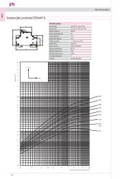
Technical data Rotary Cam Switches Technical data Type Rated insulation voltage Rated impulse withstand voltage Rated thermal current Main switch IEC 60947 (III/3) U i U imp I th Max. value of rated operational voltage Rated impulse withstand voltage Max. fuse size for short-circuit protection gL 10kA Rated short-time withstand current I cw Rated operational current I e AC1/AC21 Rated operational current I e AC15 Motor switch in utilisation category AC3/AC23 Motor switch in utilisation category AC4 Mechanical endurance Terminal screw Screw head Tightening torque Cable cross-section 3 phase 1 phase 2 poles 3 phase Protection degree of terminals Permissible ambient temperature Standards switching cycles 1 sec 3 sec 10 sec 30 sec 60 sec 110/120 V 220/230 V 380/400 V 660/690 V 220/230 V 380/400 V 500/690 V 110/120 V 220/230 V 380/400 V 220/230 V 380/400 V 500/690 V Rigid Flexible CS 10 CS 16 CS 25 CS 32 CS 40 CS 63 CS 80 CS 100 V 400 400 690 690 690 690 690 690 kV 4 4 6 6 6 6 6 6 A 16 20 25 32 50 70 85 100 V 400 400 480 480 480 480 480 480 kV 4 4 4 4 4 4 4 4 A 16 20 25 32 40 63 80 100 A 200 250 400 600 800 800 1000 1800 A 120 10 250 400 530 700 800 900 A 70 80 140 240 290 350 400 450 A 40 50 90 150 200 250 250 300 A 30 40 70 120 150 150 160 200 A 10 16 25 32 40 63 80 85 A 8 10 20 25 40 50 A 6 8 20 25 30 40 A 4 6 16 20 25 40 A 8 8,5 8,5 10 kW 2,5/3 3/5 5,6/6,5 7,6/8 9/9 11/15 12/18,5 19/22 kW 4/6 5/7,5 7,5/11 11/15 15/18,5 18,5/22 22/32 32/37 kW 11/11 15/18,5 19/22 22/30 28/45 42/55 kW 0,8/0,8 0,8/0,8 1,5/1,5 2,5/2,5 2,5/3 3/3,5 kW 1,5/1,7 2,2/2,5 3/3,7 4,8/5 5,5/6 6/9 kW 2,2/3 3/3,7 5,5/5,5 6,5/7,5 7,5/9 11/15 kW 1,2 1,5 2,5 3 5 6 7 9,5 kW 1,8 3 4 5,5 8 11 12 16 kW 4 7,5 8 11 12 16 10 6 3 3 3 3 3 2 2 2 M3,5 M3.5 M35 M4 M5 M5 2xM5 2xM5 (+,-) PZ2 (-) 0,8 0,8 0,8 1,2 1,8 2 2 2 mm 2 2x(1-2,5) 2x(1-2,5) 2x(1-4) 2x(2,5-6) 2x(2,5-10) 2x(4-16) 10-25 mm 2 2x(1-2,5) 2x(1-2,5) 2x(1-4) 2x(2,5-6) 2x(2,5-6) 2x(4-16) 6-25, 2x(6-10) IP20 0 C -25 ... +55 IEC 60947-3, VDE 0660, EN 60947 - 3 IP00 <strong>ETISWITCH</strong> Dimensions Type Marking Number of elements (L/mm) CS 10 CS 16 CS 25 CS 32 CS 40 CS 63 CS 80 CS 100 363
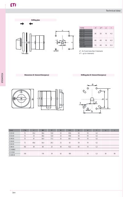
Technical data Drilling plan CS 10 CS 16 CS 25 CS 32 CS 40 CS 63 CS 80 CS 100 u <strong>ETISWITCH</strong> Dimensions LK (General Emergency) Drilling plan LK (General Emergency) /(mm) A C 0D P B L/2 b d f a c CS 25 LK 72 45,2 38,6 12,8 32 49,8 58 10 4,2 CS 32 LK 72 53 38,6 12,8 32 49,8 58 10 4,2 CS 40 LK 72 61 56,4 17,5 32 68,1 58 10 4,2 CS 50 LK CS 63 LK 72 68,6 56,4 20,5 32 63 58 10 4,2 CS 80 LK 105 84 80 25 44 92,5 85 14 5,3 CS 100KLK CS 125LK CS 200 LK 130 110 39 62 100 18 5,3 30 90 364