EQSP854A-3MCD01
ETU-LINK EQSP854A-3MCD01 are designed for use in 40 Gigabit per second links over multimode fiber. They are compliant with the QSFP+ MSAand IEEE 802.3ba 40GBASE-SR4. The optical transmitter portion of the transceiver incorporates a 4-channel VCSEL (Vertical Cavity Surface Emitting Laser) array, a 4-channel input buffer and laser driver, diagnostic monitors, control and bias blocks. For module control, the control interface incorporates a Two Wire Serial interface of clock and data signals. Diagnostic monitors for VCSEL bias, module temperature, transmitted optical power, received optical power and supply voltage are implemented and results are available through the TWS interface. Alarm and warning thresholds are established for the monitored attributes. Flags are set and interrupts generated when the attributes are outside the thresholds. Flags are also set and interrupts generated for loss of input signal (LOS) and transmitter fault conditions. All flags are latched and will remain set even if the condition initiating the latch clears and operation resumes. All interrupts can be masked and flags are reset by reading the appropriate flag register. The optical output will squelch for loss of input signal unless squelch is disabled. Fault detection or channel deactivation through the TWS interface will disable the channel. Status, alarm/warning and fault information are available via the TWS interface.
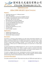
ETU-LINK EQSP854A-3MCD01 are designed for use in 40 Gigabit per second links over multimode fiber.
They are compliant with the QSFP+ MSAand IEEE 802.3ba 40GBASE-SR4.
The optical transmitter portion of the transceiver incorporates a 4-channel VCSEL (Vertical Cavity
Surface Emitting Laser) array, a 4-channel input buffer and laser driver, diagnostic monitors, control and
bias blocks. For module control, the control interface incorporates a Two Wire Serial interface of clock
and data signals. Diagnostic monitors for VCSEL bias, module temperature, transmitted optical power,
received optical power and supply voltage are implemented and results are available through the TWS
interface. Alarm and warning thresholds are established for the monitored attributes. Flags are set and
interrupts generated when the attributes are outside the thresholds. Flags are also set and interrupts
generated for loss of input signal (LOS) and transmitter fault conditions. All flags are latched and will
remain set even if the condition initiating the latch clears and operation resumes. All interrupts can be
masked and flags are reset by reading the appropriate flag register. The optical output will squelch for
loss of input signal unless squelch is disabled. Fault detection or channel deactivation through the TWS
interface will disable the channel. Status, alarm/warning and fault information are available via the TWS
interface.

Create successful ePaper yourself
Turn your PDF publications into a flip-book with our unique Google optimized e-Paper software.
15-16 All Reserved Reserved channel monitor flags, set 4<br />
17-18 All Reserved Reserved channel monitor flags, set 5<br />
19-20 All Reserved Reserved channel monitor flags, set 6<br />
21 All Reserved<br />
Module Monitors<br />
Real time monitoring for the QSFP+ module include transceiver temperature, transceiver supply voltage,<br />
and monitoring for each transmit and receive channel. Measured parameters are reported in 16-bit data<br />
fields, i.e., two concatenated bytes. These are shown in Table 6.<br />
Table 6 — Module Monitoring Values<br />
Byte Bit Name Description<br />
22 All Temperature MSB Internally measured module temperature<br />
23 All Temperature LSB<br />
24-25 All Reserved<br />
26 All Supply Voltage MSB Internally measured module supply voltage<br />
27 All Supply Voltage LSB<br />
28-33 All Reserved<br />
Channel Monitoring<br />
Real time channel monitoring is for each transmit and receive channel and includes optical input power ,<br />
Tx bias current and Tx output Power. Measurements are calibrated over vendor specified operating<br />
temperature and voltage and should be interpreted as defined below. Alarm and warning threshold<br />
values should be interpreted in the same manner as real time 16-bit data. Table 7 defines the Channel<br />
Monitoring.<br />
Table 7 — Channel Monitoring Values<br />
Byte Bit Name Description<br />
34 All Rx1 Power MSB Internally measured RX input power, channel 1<br />
35 All Rx1 Power LSB<br />
36 All Rx2 Power MSB Internally measured RX input power, channel 2<br />
37 All Rx2 Power LSB<br />
38 All Rx3 Power MSB Internally measured RX input power, channel 3<br />
39 All Rx3 Power LSB<br />
40 All Rx4 Power MSB Internally measured RX input power, channel 4<br />
41 All Rx4 Power LSB<br />
42 All Tx1 Bias MSB Internally measured TX bias, channel 1<br />
43 All Tx1 Bias LSB<br />
44 All Tx2 Bias MSB Internally measured TX bias, channel 2<br />
45 All Tx2 Bias LSB<br />
46 All Tx3 Bias MSB Internally measured TX bias, channel 3<br />
47 All Tx3 Bias LSB<br />
48 All Tx4 Bias MSB Internally measured TX bias, channel 4<br />
49 All Tx4 Bias LSB<br />
50 All Tx1 Power MSB Internally measured TX output power, channel 1<br />
51 All Tx1 Power LSB<br />
52 All Tx2 Power MSB Internally measured TX output power, channel 2<br />
53 All Tx2 Power LSB<br />
www.etulinktechnology.com 10 / 13 sales@etulinktechnology.com