FAN SPEED CONTROLER - STMicroelectronics
FAN SPEED CONTROLER - STMicroelectronics
FAN SPEED CONTROLER - STMicroelectronics

You also want an ePaper? Increase the reach of your titles
YUMPU automatically turns print PDFs into web optimized ePapers that Google loves.
FSCTxxA-UH5<br />
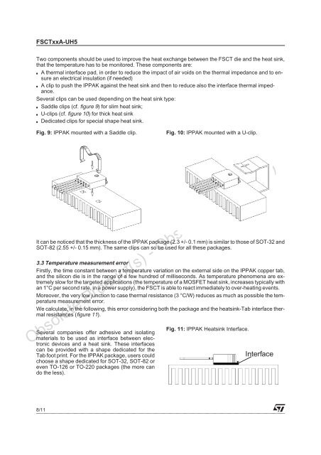
Two components should be used to improve the heat exchange between the FSCT die and the heat sink,<br />
that the temperature has to be monitored. These components are:<br />
■ A thermal interface pad, in order to reduce the impact of air voids on the thermal impedance and to ensure<br />
an electrical insulation (if needed)<br />
■ A clip to push the IPPAK against the heat sink and then to reduce also the interface thermal impedance.<br />
Several clips can be used depending on the heat sink type:<br />
■ Saddle clips (cf. figure 9) for slim heat sink;<br />
■ U-clips (cf. figure 10) for thick heat sink<br />
■ Dedicated clips for special shape heat sink.<br />
Fig. 9: IPPAK mounted with a Saddle clip. Fig. 10: IPPAK mounted with a U-clip.<br />
It can be noticed that the thickness of the IPPAK package (2.3 +/- 0.1 mm) is similar to those of SOT-32 and<br />
SOT-82 (2.55 +/- 0.15 mm). The same clips can so be used for all these packages.<br />
3.3 Temperature measurement error<br />
Firstly, the time constant between a temperature variation on the external side on the IPPAK copper tab,<br />
and the silicon die is in the range of a few hundred of milliseconds. As temperature phenomena are extremely<br />
slow for the targeted applications (the temperature of a MOSFET heat sink, increases typically with<br />
an 1°C per second rate, in a power supply), the FSCT is able to react immediately to over-heating events.<br />
Moreover, the very low junction to case thermal resistance (3 °C/W) reduces as much as possible the temperature<br />
measurement error.<br />
We calculate, in the following, this error considering both the package and the heatsink-Tab interface thermal<br />
resistances (figure 11).<br />
Several companies offer adhesive and isolating<br />
materials to be used as interface between electronic<br />
devices and a heat sink. These interfaces<br />
can be provided with a shape dedicated for the<br />
Tab foot print. For the IPPAK package, users could<br />
choose a shape dedicated for SOT-32, SOT-82 or<br />
even TO-126 or TO-220 packages (the more can<br />
do the less).<br />
Obsolete Product(s) - Obsolete Product(s)<br />
8/11<br />
Fig. 11: IPPAK Heatsink Interface.<br />
Interface