AM/FM, DAB/DAB+/DMB-A, DRM multi - STMicroelectronics
AM/FM, DAB/DAB+/DMB-A, DRM multi - STMicroelectronics
AM/FM, DAB/DAB+/DMB-A, DRM multi - STMicroelectronics

You also want an ePaper? Increase the reach of your titles
YUMPU automatically turns print PDFs into web optimized ePapers that Google loves.
Features<br />
■ General<br />
– Multi-standard digital radio channel decoding<br />
– Multi-standard digital radio source<br />
decoding (MPEG-1 AL II, AAC+, BSAC)<br />
– <strong>AM</strong>/<strong>FM</strong> phase diversity<br />
– Multiple streams parallel processing <strong>FM</strong><br />
phase diversity plus two <strong>DAB</strong> channels<br />
– Audio processing<br />
– Audio streaming from SD Card, CD ROM<br />
(optional)<br />
■ Supported radio systems<br />
– <strong>AM</strong>, <strong>FM</strong> including phase diversity<br />
– <strong>DAB</strong>, <strong>DAB</strong>+, <strong>DMB</strong>-Audio, <strong>DRM</strong><br />
– HD Radio (interface to co-processor<br />
STA680)<br />
■ Hardware<br />
– ARM946 core running at 131.328 MHz<br />
– STxP70 DSP core running at 262.256 or<br />
131.328 MHz<br />
– Emerald DSP core running at 131.328 MHz<br />
– Multilayer <strong>AM</strong>BA architecture (6 AHB + 3 APB)<br />
– DMA supporting 16 channels on 4<br />
dedicated AHB layers<br />
– VIC supporting vectored and standard<br />
interrupt requests<br />
– Hardware support for conditional access<br />
(one-time programmable 768-bit memory)<br />
– 2 internal PLLs:<br />
System PLL for cores and peripherals<br />
Fractional PLL for audio clocks input<br />
■ Memories<br />
– 64 KB Internal ROM<br />
– 740 KB of Internal R<strong>AM</strong> available for cores<br />
– 512 KB configurable <strong>DAB</strong> de-interleaving<br />
memory<br />
– SPI Flash interface for application code<br />
loading running up to 16 MHz (optional<br />
SD/MMC)<br />
July 2012 Doc ID 023407 Rev 1 1/24<br />
This is information on a product in full production. For further information contact your local <strong>STMicroelectronics</strong> sales<br />
office.<br />
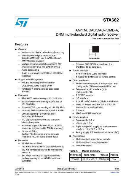
STA662<br />
<strong>AM</strong>/<strong>FM</strong>, <strong>DAB</strong>/<strong>DAB</strong>+/<strong>DMB</strong>-A,<br />
<strong>DRM</strong> <strong>multi</strong>-standard digital radio receiver<br />
Data brief − production data<br />
– External SDR-SDR<strong>AM</strong> interface: 2 x<br />
512 Mbit, 16-bit data bus<br />
■ Turner interface<br />
– 4 RF Front End LVDS interface<br />
– 4 master SPI interface for tuners control<br />
■ Other interfaces<br />
– Audio interfaces (up to 8 independent and<br />
configurable I 2 S based on 45.6 kHz rate)<br />
– Enhanced audio interface (fully<br />
configurable I2S) – 2 S/PDIF receiver<br />
– I 2 C interface<br />
– 3 UART - GPIO interface (24 dedicated lines)<br />
– Micro IF (based on 2 RX SPI + 2 TX SPI<br />
slave only + 4 audio clocks)<br />
– 5 timers<br />
– JTAG and ETM interfaces<br />
■ Power supplies<br />
– Core supply: 1.2 V<br />
– I/O supply: 3.3 V<br />
– Triple voltage I/O supply for host processor<br />
interface: 1.8 V / 2.5 V / 3.3 V<br />
– Analog supply: 2.5 V (external or internal LDO)<br />
■ Applications<br />
– Multi-standard smart tuner module<br />
– Multi-standard car-radio receiver<br />
– Home receivers<br />
Table 1. Device summary<br />
Order code Temp range Package Packing<br />
�����������<br />
TFBGA289<br />
STA662 -40 °C to +85 °C TFBGA289 Tray<br />
www.st.com<br />
24
Contents STA662<br />
Contents<br />
1 Description . . . . . . . . . . . . . . . . . . . . . . . . . . . . . . . . . . . . . . . . . . . . . . . . . 3<br />
1.1 <strong>DAB</strong> signal processing . . . . . . . . . . . . . . . . . . . . . . . . . . . . . . . . . . . . . . . . 4<br />
1.2 <strong>FM</strong> signal processing . . . . . . . . . . . . . . . . . . . . . . . . . . . . . . . . . . . . . . . . . 5<br />
1.3 <strong>AM</strong> signal processing . . . . . . . . . . . . . . . . . . . . . . . . . . . . . . . . . . . . . . . . . 6<br />
1.4 Multiple <strong>DAB</strong> radio stream parallel processing . . . . . . . . . . . . . . . . . . . . . . 6<br />
1.5 Overview of main functional blocks . . . . . . . . . . . . . . . . . . . . . . . . . . . . . . 7<br />
1.5.1 STA662 architecture . . . . . . . . . . . . . . . . . . . . . . . . . . . . . . . . . . . . . . . . 7<br />
1.5.2 ARM946 subsystem . . . . . . . . . . . . . . . . . . . . . . . . . . . . . . . . . . . . . . . . . 8<br />
1.5.3 DSP-STxP70 subsystem . . . . . . . . . . . . . . . . . . . . . . . . . . . . . . . . . . . . . 8<br />
1.5.4 DSP-Emerald subsystem . . . . . . . . . . . . . . . . . . . . . . . . . . . . . . . . . . . . . 8<br />
1.5.5 IPBUS subsytem . . . . . . . . . . . . . . . . . . . . . . . . . . . . . . . . . . . . . . . . . . . 9<br />
1.5.6 Embedded memories . . . . . . . . . . . . . . . . . . . . . . . . . . . . . . . . . . . . . . . . 9<br />
1.5.7 SDR-SDR<strong>AM</strong> controller . . . . . . . . . . . . . . . . . . . . . . . . . . . . . . . . . . . . . . 9<br />
1.5.8 Hardware accelerators . . . . . . . . . . . . . . . . . . . . . . . . . . . . . . . . . . . . . . 10<br />
1.5.9 Audio interface . . . . . . . . . . . . . . . . . . . . . . . . . . . . . . . . . . . . . . . . . . . . 10<br />
1.5.10 Enhanced serial audio interface . . . . . . . . . . . . . . . . . . . . . . . . . . . . . . 10<br />
1.5.11 Serial link and front end interface . . . . . . . . . . . . . . . . . . . . . . . . . . . . . 11<br />
1.5.12 APB peripherals . . . . . . . . . . . . . . . . . . . . . . . . . . . . . . . . . . . . . . . . . . . 11<br />
1.5.13 System management unit . . . . . . . . . . . . . . . . . . . . . . . . . . . . . . . . . . . 11<br />
1.5.14 Clock and reset distribution unit . . . . . . . . . . . . . . . . . . . . . . . . . . . . . . . 11<br />
2 Pin description . . . . . . . . . . . . . . . . . . . . . . . . . . . . . . . . . . . . . . . . . . . . 12<br />
2.1 Ball out . . . . . . . . . . . . . . . . . . . . . . . . . . . . . . . . . . . . . . . . . . . . . . . . . . . 12<br />
2.2 STA662 pin list . . . . . . . . . . . . . . . . . . . . . . . . . . . . . . . . . . . . . . . . . . . . . 13<br />
2.3 Pins termination . . . . . . . . . . . . . . . . . . . . . . . . . . . . . . . . . . . . . . . . . . . . 21<br />
3 Package information . . . . . . . . . . . . . . . . . . . . . . . . . . . . . . . . . . . . . . . . 22<br />
4 Revision history . . . . . . . . . . . . . . . . . . . . . . . . . . . . . . . . . . . . . . . . . . . 23<br />
2/24 Doc ID 023407 Rev 1
STA662 Description<br />
1 Description<br />
The STA662 from <strong>STMicroelectronics</strong> is a system-on-chip, based on <strong>multi</strong>ple microcontroller<br />
and DSP cores, designed for demodulating and decoding the most common digital radio<br />
standards and the legacy <strong>AM</strong>/<strong>FM</strong>. The digital radio standards supported by STA662 are:<br />
<strong>DAB</strong> (ETSI EN 300 401), <strong>DAB</strong>+ (ETSI TS 102 563), <strong>DMB</strong> (ETSI TS 102 428), <strong>DRM</strong> (ETSI<br />
ES 201 980).<br />
The STA662 implements the three main functions of a Eureka-147 <strong>DAB</strong> and <strong>DRM</strong> receiver<br />
specification.<br />
The synchronization: including sampling clock and carrier frequency synchronization;<br />
The channel demodulation and decoding: including OFDM demodulation and convolutional<br />
decoding;<br />
The source decoding: consisting of audio and data decoding. The source decoding can be<br />
moved on an external application processor (a.k.a. SDEC - Source DECoder) so that the<br />
additional resources available on the STA662 IC can be used to implement a second <strong>DAB</strong><br />
demodulation chain.<br />
STA662 can demodulate in parallel two <strong>DAB</strong> streams and legacy <strong>AM</strong> or <strong>FM</strong> phase diversity<br />
stream.<br />
<strong>AM</strong> and <strong>FM</strong> signal processing and audio functions are implemented on STA662 using<br />
dedicated resources, different from the resources used for the digital radio stream<br />
demodulation. <strong>FM</strong> phase diversity is implemented, as an alternative dual <strong>FM</strong> channels<br />
processing is possible, including the possibility to commute seamlessly from <strong>FM</strong> phase<br />
diversity to <strong>FM</strong> single tuner + <strong>FM</strong> background channels.<br />
To pursue the best combination in terms of current consumption, flexibility, system and<br />
device cost, these functions are implemented by a combination of hardware and software.<br />
Functional blocks which are standard and computationally intensive are implemented by<br />
custom logic. Functional blocks where flexibility is a key feature are implemented in<br />
software.<br />
The STA662 combines it all into a single IC consisting of several hardware blocks<br />
implementing custom logic, an ARM946 microcontroller one 24 bit DSP Emerald core and<br />
one 32 bit DSP xP70 core to guarantee the proper level of flexibility, low current<br />
consumption.<br />
Such flexibility enables the STA662 to be ready for future evolution, including the possibility<br />
to implement new radio standards (i.e. HD-Radio), and allows the implementation of<br />
specific and optional features.<br />
Multiple interfaces such as SPI, UART, I 2 C and I 2 S, allow a flexible utilization of the device<br />
and several applications can be addressed, including T-<strong>DMB</strong> (video), by connecting an<br />
additional application co-processor (i.e. STA2165).<br />
The STA662 implements a additional SDR-SDR<strong>AM</strong> interface thus allowing to implement<br />
memory-consuming firmware like <strong>DAB</strong> middleware and <strong>DAB</strong>/<strong>FM</strong> seamless switching.<br />
To build a complete <strong>DAB</strong>/<strong>FM</strong>/<strong>AM</strong> receiver, the STA662 needs to be fed by the STA610 RF<br />
Multistandard front-end or from the STA610A RF <strong>AM</strong>/<strong>FM</strong> front-end. STA662 supports up to<br />
four RF FE connected in parallel.<br />
The STA662 is assembled in TFBGA289 package.<br />
Doc ID 023407 Rev 1 3/24
Description STA662<br />
1.1 <strong>DAB</strong> signal processing<br />
The STA662 performs the processing of the <strong>DAB</strong> signal. It receives a complex digital signal<br />
from an <strong>DAB</strong> RF tuner either from a <strong>multi</strong>-standard RF tuner. The native sample rate is<br />
2048 kHz. Sample rate conversion hardware is provided on-chip. This feature allows the<br />
STA662 to operate with various <strong>DAB</strong> front-ends.<br />
The STA662 is then responsible for detection, acquisition, and demodulation of the <strong>DAB</strong><br />
signal. Such functions are primarily implemented by dedicated hardware accelerators. The<br />
demodulated signal is then passed to the ARM946 processor, for audio decoding and<br />
handling of data services. A digital decompressed audio at different audio rates is output via<br />
the Digital Audio Interface.<br />
As an alternative the compressed audio stream can be transferred to an application<br />
processor for the audio demodulation.<br />
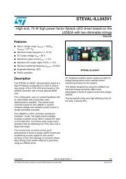
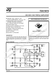
Figure 1 presents a functional diagram describing the data flow inside STA662 for <strong>DAB</strong><br />
demodulation and decoding. In some use cases source and service decoding can be<br />
performed on the external application processor.<br />
Figure 1. <strong>DAB</strong> demodulating and decoding functional data flow diagram<br />
������<br />
���� ��<br />
�������� ������<br />
����������<br />
���<br />
���������<br />
�������� ���<br />
�������� ���<br />
������ ��������<br />
����<br />
�������<br />
�� � ����������<br />
�����������<br />
����� ��������<br />
����� � ����� ��<br />
��� ��� ��<br />
����<br />
���� ��������<br />
��������<br />
�������<br />
�����������<br />
����<br />
���������<br />
���� ���<br />
���������<br />
��������������<br />
4/24 Doc ID 023407 Rev 1<br />
���<br />
������� ��������<br />
������� �������<br />
�������� �������<br />
����<br />
�����������<br />
���� ����<br />
�������<br />
�����<br />
����<br />
��������������<br />
�������<br />
�������<br />
���� � ���<br />
����� ���<br />
�������<br />
�����������
STA662 Description<br />
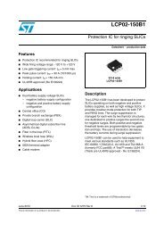
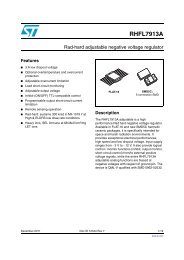
Figure 2 presents a functional diagram describing the data flow inside STA662 for <strong>DRM</strong><br />
demodulating and decoding.<br />
Figure 2. <strong>DRM</strong> demodulating and decoding functional data flow diagram<br />
���<br />
�������� ������<br />
����������<br />
���<br />
���������<br />
����<br />
�������<br />
1.2 <strong>FM</strong> signal processing<br />
����������<br />
�����������<br />
������ �������� ������� ��������<br />
�����������<br />
����� ��������<br />
������ ��<br />
����<br />
����<br />
���� ��������<br />
�� �<br />
�������<br />
���<br />
�������<br />
�������� �������<br />
���� ���<br />
���������<br />
��������������<br />
��� ��������������<br />
�<br />
������� �������<br />
STA662 features several strategies to improve the reception of <strong>FM</strong> signals. A DSP controlled<br />
variable bandwidth filtering of the complex base-band allows to greatly cope with adjacent<br />
channel interferences. Multipath fading distortion is mitigated by exploiting antenna<br />
switching (the antenna RF-switch is controlled through Digital pins).<br />
After dynamic filtering, the IFP block demodulates the complex base-band signal; the result<br />
of the detection is the composite MPX signal, which carries the stereo-encoded audio and<br />
the Radio Data System (RDS) information.<br />
The MPX signal is still affected by the instantaneous spike noise originated by the<br />
electromagnetic fields due to fast current variations, and to the high current discharges in<br />
the ignition phase of the car engine. Dedicated algorithms for spike detection and<br />
suppression have been developed; this processing is supported by a set of dedicated<br />
hardware accellerators under the control and supervision of the ARM946 microcontroller.<br />
Audio information is subsequently retrieved from the processed MPX by the mixed<br />
hardware/software stereo-decoder, which also performs typical weak-signal processing<br />
functions as stereo channel blending, audio soft-muting for low antenna signals, and deemphasis<br />
filtering. After further sample rate reduction, the audio is available for transmission<br />
to external devices.<br />
���<br />
������<br />
�������<br />
����������<br />
�����<br />
����<br />
��������������<br />
���<br />
�����������<br />
�������� ���<br />
�������� ���<br />
�����������<br />
Doc ID 023407 Rev 1 5/24
Description STA662<br />
1.3 <strong>AM</strong> signal processing<br />
<strong>AM</strong> bandwidth is about one-twentieth of the <strong>FM</strong>, thus additional filtering and decimation is<br />
required after the DDC. The hardware demodulator in the IFP block is used for evaluating<br />
the amplitude of the complex base-band. Similarly to <strong>FM</strong> signals, engine-injection-related<br />
spikes are a concern; spike detection and noise-blanking are performed on the audio signal,<br />
on the contrary since <strong>multi</strong>path distortion is not a major issue in <strong>AM</strong>, no antenna switching is<br />
necessary.<br />
1.4 Multiple <strong>DAB</strong> radio stream parallel processing<br />
STA662 is capable to simultaneously demodulate two different <strong>DAB</strong> Radio streams. This<br />
unique feature enables the device to decode a <strong>DAB</strong> Radio audio stream, in parallel with any<br />
data service broadcasted by a different radio channel. The implementation of the dual<br />
streams <strong>DAB</strong> Radio processing requires that two <strong>DAB</strong> or Multi-standard RF tuners are<br />
connected to the STA662.<br />
In a single channel implementation a single RF tuner is used. In such configuration STA662<br />
is able to demodulate at the same time both the audio and the data carried inside a single<br />
<strong>DAB</strong> ensemble. This means that the user can listen audio and receive traffic information or<br />
data broadcasted on that specific single ensemble.<br />
In a dual <strong>DAB</strong> channels implementation STA662 can simultaneously demodulate audio and<br />
data associated to different ensembles. This means that in the example above it would be<br />
still possible to receive traffic information broadcasted on ensemble A while listening audio<br />
program broadcasted on ensemble B.<br />
STA662 can always perform <strong>FM</strong> phase diversity reception in parallel with <strong>DAB</strong> channels<br />
decoding.<br />
The audio coming from any <strong>AM</strong>/<strong>FM</strong>/<strong>DAB</strong>/<strong>DRM</strong> channel is output in I 2 S digital format. The<br />
I 2 S configurable protocol is well-suited for sending data to external audio processors or<br />
digital-in power amplifier.<br />
6/24 Doc ID 023407 Rev 1
STA662 Description<br />
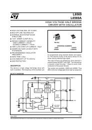
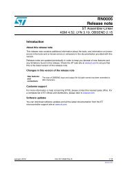
1.5 Overview of main functional blocks<br />
1.5.1 STA662 architecture<br />
Figure 3. STA662 architecture diagram<br />
��<br />
�� �<br />
��<br />
�� �<br />
���<br />
�� �<br />
���<br />
�� �<br />
��������<br />
����<br />
��� � ��<br />
�����<br />
����� ����� ����� �����<br />
���� ���<br />
���� ��<br />
����<br />
����<br />
����<br />
���<br />
������ ��<br />
������<br />
�� �����������<br />
��� ���<br />
���<br />
����� � ����� ���<br />
����� � ��<br />
������<br />
��<br />
���<br />
����� ���<br />
���� �������<br />
������<br />
���<br />
������<br />
�� ����������<br />
�����<br />
�������<br />
���<br />
���<br />
��� ����������<br />
�������<br />
������<br />
� ���<br />
���� ��<br />
������<br />
���<br />
���<br />
���<br />
� ���<br />
Doc ID 023407 Rev 1 7/24<br />
���<br />
������<br />
���<br />
�����<br />
���<br />
���<br />
���� ����<br />
������� �������<br />
������<br />
���<br />
����� ����� ����� �����<br />
����<br />
����<br />
��������� � � �<br />
��� ����<br />
� �������� ���<br />
�����������<br />
���������<br />
�����������
Description STA662<br />
1.5.2 ARM946 subsystem<br />
A 32-bit ARM946 microcontroller with ITCM and DTCM is embedded into STA662. It<br />
controls the I/O peripherals, the hardware accelerator modules, the DSP-Emerald<br />
subsystem and the DSP STxP70 subsystem.<br />
The ARM946 is used for:<br />
● System and data flow control<br />
● Peripherals initialisation<br />
● RDS alternate frequency switching strategy<br />
and in some application can be also used for:<br />
● <strong>DAB</strong>/<strong>DAB</strong>+ database management<br />
● Seamless linking<br />
The STA662 embeds into the ARM946 subsystem both program and data cache to improve<br />
performance during code execution. Also, the amount of Tightly Coupled Memory (TCM)<br />
assigned to the core can be defined by the user at start-up.<br />
The ARM946 uses a trace macro-cell (ETM9) with a trace debug port (JTAG) for in-system<br />
programming and debugging tools. JTAG is also shared with the DSP-Emerald subsystem<br />
and STxp70 subsystem.<br />
An AHB bus matrix is implemented for connecting the 6 AHB masters (ARM, xp70 and 4<br />
DMAs) with all the AHB slaves.<br />
Flexible DMA resources are available for data movement while VIC logic is implemented to<br />
managed interrupt requests.<br />
1.5.3 DSP-STxP70 subsystem<br />
STA662 includes a 32-bit STxP70- with DTCM and L2Pram. MPx and FPx extensions are<br />
connected to the core.<br />
The STxP70 is used for:<br />
● <strong>DRM</strong> channel decoding<br />
● <strong>DAB</strong> channel time and frequency synchronization<br />
● Audio decoding<br />
The STxP70 subsystem contains a program cache to improve performance during code<br />
execution. AHB master port is used by the DSP to access the STA662 architecture while an<br />
AHB slave port is used by DMA to access xp70 subsystem memories.<br />
Debugging of the software running on the DSP-STxp70 is possible through the JTAG<br />
interface.<br />
1.5.4 DSP-Emerald subsystem<br />
STA662 includes a 24-bit DSP-Emerald core connected to the hardware-accelerator (HAR)<br />
modules and to the microcontroller via the IPBUS.<br />
The Emerald core is used for:<br />
● <strong>FM</strong> processing<br />
● <strong>AM</strong> processing<br />
● Audio processing<br />
8/24 Doc ID 023407 Rev 1
STA662 Description<br />
The Emerald DSP is connected to the AHB bus matrix through an AHB slave port.<br />
Debugging of the software running on the DSP-Emerald is possible through the JTAG<br />
interface.<br />
1.5.5 IPBUS subsytem<br />
The IPBUS is a <strong>multi</strong>-master bus, connecting hardware accelerators for <strong>AM</strong>/<strong>FM</strong> and Audio<br />
processing, the DSP-Emerald subsystem and the <strong>AM</strong>BA subsystem. Access to the IPBUS<br />
is controlled by a dedicated arbiter module (ARB).<br />
Potential bus masters are:<br />
● The BCO (Bus COntrol) unit is used for managing the IPBUS transfers. This unit<br />
provides one set of programmable (synchronous or isochronous) transfers<br />
● The ARM946 which is intended as STA662 system controller<br />
● The DMA channels for data exchange<br />
● The STxp70 for specific data processing<br />
● The SPI debug interface for debugging and monitoring the subsystem<br />
The IPBUS subsystem is connected to the AHB bus matrix through the AHB2IPBUS Bridge.<br />
1.5.6 Embedded memories<br />
STA662 offers a flexible solution for allocating memories to the cores or IPs.<br />
Default configuration is:<br />
● 8KB+128KB of D and I TCMs and 8KB+16KB of D & P caches for the ARM core<br />
● 160KB of DTCM, 8KB Pcache and 64KB L2 program memory for the STxP70 DSP<br />
● 18 KB+18KB X & Y R<strong>AM</strong>, 24 KB PR<strong>AM</strong> and 64 KB PROM for the Emerald core<br />
● 64 KB of AHB ROM and 256 KB of AHB R<strong>AM</strong><br />
● 2 x 256KB of de-interleaving memory for the <strong>DAB</strong>-IP<br />
AHB memories are available for both the AHB mapped cores: ARM946 and STxP70.<br />
<strong>DAB</strong>-IP de-interleaving memory if not used for the <strong>DAB</strong> channel decoding can be remapped<br />
as ARM TCM or AHB memory.<br />
Part of the AHB memory can be remapped as ARM946 TCM.<br />
STxP70 L2 memory and D-TCM are mapped on the AHB and then available for the AHB<br />
masters.<br />
Emerald memories are mapped on the AHB and available for the AHB masters.<br />
1.5.7 SDR-SDR<strong>AM</strong> controller<br />
STA662 embeds an SDR-SDR<strong>AM</strong> controller. The controller is connected to the AHB <strong>multi</strong><br />
layer architecture so that it expands the memory available for both the AHB mapped cores:<br />
ARM946 and STxP70.<br />
SDR<strong>AM</strong> controller clock is selectable by a top level register between four different<br />
possibilities: full rate, which corresponds to the ARM9 core frequency (131.328 MHz), or this<br />
frequency divided by a factor 2, 4 or 8.<br />
Doc ID 023407 Rev 1 9/24
Description STA662<br />
1.5.8 Hardware accelerators<br />
STA662 uses an optimized partitioning of the processing functions among Emerald,<br />
ARM946, STxP70 and special-purpose hardware resources. Thanks to this strategy, high<br />
CPU-intensive routines take advantage of dedicated hardware processing blocks, though<br />
ensuring flexibility and customizability provided by the Emerald and STxP70 DSPs and the<br />
ARM946 embedded microcontroller; in fact, ARM946 is monitoring and controlling the<br />
processing running both on Emerald, STxP70 and on the dedicated peripherals.<br />
The list of hardware accelerators embedded into the STA662 comprises:<br />
● <strong>DAB</strong> demodulator compliant with the EUREKA 147 standard for Digital Audio<br />
Broadcasting<br />
● RS-DEC <strong>DMB</strong><br />
● RS-DEC <strong>DAB</strong>+<br />
● <strong>FM</strong>/<strong>AM</strong> Digital Intelligent Selectivity System (D-ISS)<br />
● <strong>FM</strong>/<strong>AM</strong> Stereo matrix separation<br />
● <strong>FM</strong>/<strong>AM</strong> Virtual Phase-array Antenna switching strategy<br />
● <strong>FM</strong>/<strong>AM</strong> Antenna Switching Diversity control (ASD)<br />
● <strong>FM</strong>/<strong>AM</strong> RDS demodulation and decoding (RDS)<br />
● Audio processing programmable filters<br />
1.5.9 Audio interface<br />
The Audio Interface (AIF) is used to exchange digital audio data with external devices using<br />
different Serial Audio Interface (SAI1-4) or S/PDIF protocols into the IPBUS subsystem.<br />
Two AIF modules have been integrated into STA662.<br />
The 6-channels Stereo Low Pass Filter (LPF6CH) can be used to apply programmable low<br />
pass filtering to the audio signal.<br />
The 6-channels Stereo Channel Sample Rate Converter (SRC6) introduces flexibility to the<br />
system, since it allows exchanging data with external units whose data rate is different from<br />
the STA662 one.<br />
Signal routing to and from the STA662 is ruled by the internal audio Input/Output <strong>multi</strong>plexer<br />
(AIMUX/AOMUX) configurable by software.<br />
1.5.10 Enhanced serial audio interface<br />
The Enhanced Serial Audio Interface (ESAI) is a serial synchronous interface intended to<br />
give transfer capability of digital audio samples or more generally digital data between the<br />
<strong>AM</strong>BA architecture and external devices.<br />
A clock divider logic gives the flexibility to the macro to generate all the needed audio clock<br />
rates. Master TX and slave RX are supported.TX and RX FIFO are available to reduce the<br />
load of the data channels inside the <strong>AM</strong>BA architecture.<br />
10/24 Doc ID 023407 Rev 1
STA662 Description<br />
1.5.11 Serial link and front end interface<br />
The Serial Link (SLINK) and the Front End interface (FEI) blocks have been designed to<br />
connect the STA662 with different kind of tuners such as STA606 or STA610. The SLINK<br />
block performs serial to parallel conversion of data coming from the tuners while the FEI<br />
block performs decimation, filtering and other digital signal processing such as gain control,<br />
DC offset cancellation, image rejection and so on.<br />
The Frontend interface is made up of four processing path: two dedicated to <strong>DAB</strong> and two to<br />
<strong>AM</strong>, <strong>FM</strong>, HD Radio or <strong>DRM</strong> baseband signal processing. If the system clock is provided by a<br />
frontend tuner then this FE must be connected to interface number 2 or 3.<br />
1.5.12 APB peripherals<br />
Three dedicated peripheral bus (APB0, APB1 and APBC) connect the <strong>AM</strong>BA architecture to<br />
several interfaces like 5 x SSP, EFT, MTU, I2C, GPIO, 3 x UART and Host interfaces.<br />
1.5.13 System management unit<br />
A system management unit (SMU) has been designed to control all the top level<br />
functionalities. These register are mapped on the APBC bus.<br />
1.5.14 Clock and reset distribution unit<br />
A clock and reset distribution unit (CRDU) is designed to generate and distribute all the<br />
needed clocks and resets. A System PLL and an Audio PLL are part of this logic.<br />
Doc ID 023407 Rev 1 11/24
Pin description STA662<br />
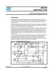
2 Pin description<br />
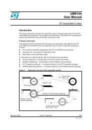
2.1 Ball out<br />
The STA662 is available in a 15x15x1.2 mm full matrix TFBGA package with 289 balls.<br />
Figure 4 indicates also basic pin functionality.<br />
Figure 4. Ball out diagram<br />
�<br />
�<br />
�<br />
�<br />
�<br />
�<br />
�<br />
�<br />
�<br />
�<br />
�<br />
�<br />
�<br />
�<br />
�<br />
�<br />
�<br />
� � � � �<br />
��� �������� �������� ��� �����<br />
������<br />
����� ����� �������� ��� �����<br />
������<br />
� � � � �<br />
� � � � ��<br />
����� �������<br />
��������<br />
������ ���������<br />
�������<br />
���������<br />
�����<br />
���������<br />
12/24 Doc ID 023407 Rev 1<br />
� � � � �� �� �� �� �� �� �� ��<br />
�����<br />
������<br />
�����<br />
������<br />
���� ���������<br />
���<br />
������ ������ ������ ��������� ��������� ��������� ������ ����� ����� ����� ���<br />
�����<br />
������<br />
����� ����� �������� �������� �������� ������ �����<br />
������<br />
��������� ��������� ���� �������� �������� �����<br />
������<br />
�����<br />
������<br />
�����<br />
����������<br />
������ ������ ����������� ��������� ��������� ����� ����� ����� ����� �����<br />
����<br />
������<br />
��������<br />
������<br />
����������� ����������� ��������� ��������� �������� ������ ����<br />
��������<br />
��������<br />
������<br />
�����<br />
���������<br />
��������<br />
������<br />
����� ����� ������� �������� �������� ������ ������ ��� ��� �����<br />
������<br />
����� ����� ���� �������� �������� ������ ������ ������ ���� �����<br />
������<br />
��������� ��������� ������� �������� ��� ���� ���<br />
���� ���� ����� ������<br />
�����<br />
���� ���<br />
��� ��� ����<br />
��� ��� ���<br />
������� ������� ������ ��� ��� ���� ��� ��� ��� ��� ����<br />
����� ����� ���� ������ �������� ��� ����<br />
��� ���<br />
����<br />
�����<br />
����<br />
������ �����<br />
�� �� �� �� ��<br />
������ �������<br />
���� � � �<br />
����������� ������<br />
�������� �������� �������� ������� ����������� �������<br />
�������� �������� ������� ������� ����<br />
�������<br />
��� ����<br />
�������<br />
����<br />
�������<br />
���� ��� �����<br />
��������<br />
����<br />
����<br />
��������<br />
����<br />
�������<br />
������� ������<br />
������ ������<br />
��������� ����� ����� ������<br />
������� ��������� ���������� ���������� �����<br />
�������<br />
������� �����<br />
�������<br />
������� ������� ��� ����� ������ ������ ��� ���� ����<br />
��� ���� ��� �����<br />
���������<br />
���� ���� ������ ������<br />
�����<br />
����������<br />
����<br />
������� ������� ������ ���� ����������<br />
���<br />
������� ������� �������� �������� ����������<br />
���<br />
����� ����� �������� �������� ����������<br />
����<br />
���� �������� �������� ��� ����������<br />
���<br />
��� �������� �������� ����������<br />
���<br />
�����<br />
������<br />
�����<br />
�������<br />
�����<br />
���������<br />
�����<br />
������<br />
�����<br />
������<br />
�����<br />
������<br />
�����<br />
�������<br />
�����<br />
��������<br />
�����<br />
��������<br />
�����<br />
������<br />
�����<br />
������<br />
�����<br />
������<br />
�����<br />
������<br />
�����<br />
���������<br />
�����<br />
��������<br />
�����<br />
������<br />
�����<br />
�������<br />
�����<br />
�������<br />
�����<br />
������<br />
�����<br />
���������<br />
�����<br />
��������<br />
�����<br />
�������<br />
��� ��� ���� ���� �����<br />
�������<br />
�����<br />
��������<br />
�����<br />
���������<br />
�����<br />
�������<br />
�����<br />
��������<br />
�����<br />
�������<br />
�����<br />
��������<br />
�������� �������� ���� �����<br />
������<br />
�����<br />
�������<br />
�����<br />
�����<br />
������<br />
�����<br />
�����<br />
�����<br />
�������<br />
�����<br />
�����<br />
������<br />
�����<br />
�����<br />
�����<br />
�����<br />
�����<br />
����<br />
�����<br />
�����<br />
�����<br />
�������<br />
�����<br />
������<br />
�����<br />
�������<br />
�����<br />
���������<br />
�����<br />
���������<br />
�����<br />
�������<br />
�����<br />
�������<br />
�����<br />
�������<br />
�����<br />
�������<br />
�����<br />
������<br />
�����<br />
��������<br />
�����<br />
��������<br />
�����<br />
������<br />
�����<br />
������<br />
�����<br />
������<br />
�����<br />
������<br />
�����<br />
��������<br />
�����<br />
�������<br />
�����<br />
���������<br />
�����<br />
��������<br />
�����<br />
��������<br />
�����<br />
������<br />
�����<br />
������<br />
�����<br />
������<br />
�����<br />
������<br />
�����<br />
��������<br />
�����<br />
���������<br />
�����<br />
��������<br />
�����<br />
���������<br />
�����<br />
��������<br />
�����<br />
�������<br />
�����<br />
��������<br />
�����<br />
��������<br />
�����<br />
��������<br />
�����<br />
��������<br />
�����<br />
�������<br />
�����<br />
�������<br />
�����<br />
���������<br />
�����<br />
�������<br />
�����<br />
��������<br />
�����<br />
��������<br />
�����<br />
���������<br />
�����<br />
�������<br />
���<br />
�� ��<br />
����<br />
�<br />
�<br />
�<br />
�<br />
�<br />
�<br />
�<br />
�<br />
�<br />
�<br />
�<br />
�<br />
�<br />
�<br />
�<br />
�<br />
�<br />
�����������
STA662 Pin description<br />
2.2 STA662 pin list<br />
Table 2. STA662 pin-out description<br />
Tuner interface<br />
Ball name Description Type Supply group<br />
Ball<br />
number<br />
RTC1P<br />
I LVDS B2<br />
Tuner IF RTC1 LVDS<br />
RTC1M I LVDS B1<br />
CLK1P<br />
I LVDS C2<br />
Tuner IF CLK1 LVDS<br />
CLK1M I LVDS C1<br />
CLK1 Reserved for future use I 3.3V D3<br />
IQ_DATA1P<br />
I LVDS D2<br />
Tuner IF IQ1 LVDS<br />
IQ_DATA1M I LVDS D1<br />
IQDATA1 Reserved for future use I 3.3V E3<br />
RTC2P<br />
I LVDS E2<br />
Tuner IF RTC2 LVDS<br />
RTC2M I LVDS E1<br />
CLK2P<br />
I LVDS F2<br />
Tuner IF CLK2 LVDS<br />
CLK2M I LVDS F1<br />
CLK2 Reserved for future use I 3.3V F3<br />
IQ_DATA2P<br />
I LVDS G2<br />
Tuner IF IQ2 LVDS<br />
IQ_DATA2M I LVDS G1<br />
IQDATA2 Reserved for future use I 3.3V G3<br />
WS2 Reserved for future use I 3.3V G5<br />
PWR_MNG3 Tuner IF PWR3 (CMOS) O 3.3V G4<br />
WAGC3 Tuner IF WAGC3 (CMOS) O 3.3V H3<br />
SNOOP_CTRL3 Tuner IF SNOOP CTRL3 (CMOS) I/O 3.3V H4<br />
WS3P<br />
I LVDS H2<br />
Tuner IF RTC3 LVDS<br />
WS3M I LVDS H1<br />
WS3 Reserved for future use I 3.3V J4<br />
IDATA3P<br />
I LVDS L2<br />
Tuner IF IQ3 LVDS<br />
IDATA3M I LVDS L1<br />
IDATA3 Reserved for future use I 3.3V K4<br />
QDATA3P<br />
I LVDS J2<br />
Reserved for future use<br />
QDATA3M I LVDS J1<br />
QDATA3 Reserved for future use I 3.3V J3<br />
CLK3P<br />
I LVDS K1<br />
Tuner IF CLK3 LVDS<br />
CLK3M I LVDS K2<br />
Doc ID 023407 Rev 1 13/24
Pin description STA662<br />
Table 2. STA662 pin-out description (continued)<br />
DBI Interface<br />
CLK3 Reserved for future use I 3.3V K3<br />
PWR_MNG4 Tuner IF PWR4 (CMOS) I/O 3.3V K5<br />
WAGC4 Tuner IF WAGC4 (CMOS) I/O 3.3V L4<br />
SNOOP_CTRL4 Tuner IF SNOOP CTRL4 (CMOS) I/O 3.3V M4<br />
WS4P<br />
I LVDS M1<br />
Tuner IF RTC4 LVDS<br />
WS4M I LVDS M2<br />
WS4 Reserved for future use I 3.3V L3<br />
IDATA4P<br />
I LVDS N1<br />
Tuner IF IQ4 LVDS<br />
IDATA4M I LVDS N2<br />
IDATA4 Reserved for future use I 3.3V M3<br />
QDATA4P<br />
I LVDS P1<br />
Reserved for future use<br />
QDATA4M I LVDS P2<br />
QDATA4 Reserved for future use I 3.3V N3<br />
CLK4P<br />
I LVDS R1<br />
Tuner IF CLK4 LVDS<br />
CLK4M I LVDS R2<br />
CLK4 Reserved for future use I 3.3V T1<br />
SAI_DBI_DI1 <strong>DRM</strong> i2s input (dato1) I/O 3.3V B10<br />
SAI_DBI_DI2 <strong>DRM</strong> i2s input (dato2) I/O 3.3V C9<br />
SAI_DBI_WS <strong>DRM</strong> i2s input (ws) I/O 3.3V C8<br />
SAI_DBI_SCK <strong>DRM</strong> i2s input (clock) I/O 3.3V C10<br />
IBOC/<strong>DRM</strong> output interface (IDO i/f)<br />
SSPs<br />
Ball name Description Type Supply group<br />
SAI_IDO1_D1 HD/<strong>DRM</strong> i2s output IF1 (dato1) O 3.3V F15<br />
SAI_IDO1_D2 HD/<strong>DRM</strong> i2s output IF1 (dato2) O 3.3V C16<br />
SAI_IDO1_WS HD/<strong>DRM</strong> i2s output IF1 (ws) O 3.3V D16<br />
SAI_IDO1_SCK HD/<strong>DRM</strong> i2s output IF1 (clock) O 3.3V C15<br />
SAI_IDO2_D1 HD/<strong>DRM</strong> i2s output IF2 (dato1) I/O 3.3V F13<br />
SAI_IDO2_D2 HD/<strong>DRM</strong> i2s output IF2 (dato2) I/O 3.3V E15<br />
SAI_IDO2_WS HD/<strong>DRM</strong> i2s output IF2 (ws) O 3.3V F12<br />
SAI_IDO2_SCK HD/<strong>DRM</strong> i2s output IF2 (clock) O 3.3V F14<br />
SSP0_FSS FSS for SSP0 I/O 3.3V C3<br />
SSP0_CLK Clock for SSP0 I/O 3.3V A3<br />
14/24 Doc ID 023407 Rev 1<br />
Ball<br />
number
STA662 Pin description<br />
Table 2. STA662 pin-out description (continued)<br />
SDR<strong>AM</strong> interface<br />
Ball name Description Type Supply group<br />
Ball<br />
number<br />
SSP0_RXD Rxd for SSP0 I 3.3V B3<br />
SSP0_TXD Txd for SSP0 O 3.3V A2<br />
SSP1_FSS FSS for SSP1 I/O 3.3V F4<br />
SSP1_CLK Clock for SSP1 I/O 3.3V F5<br />
SSP1_RXD Rxd for SSP1 I 3.3V E5<br />
SSP1_TXD Txd for SSP1 O 3.3V E4<br />
SSP2_FSS FSS for SSP2 I/O 3.3V T2<br />
SSP2_CLK Clock for SSP2 I/O 3.3V U2<br />
SSP2_RXD Rxd for SSP2 I/O 3.3V T3<br />
SSP2_TXD Txd for SSP2 I/O 3.3V U3<br />
SSP3_FSS FSS for SSP3 I/O 3.3V P3<br />
SSP3_CLK Clock for SSP3 I/O 3.3V P4<br />
SSP3_RXD Rxd for SSP3 I/O 3.3V R3<br />
SSP3_TXD Txd for SSP3 I/O 3.3V R4<br />
SSP4_FSS FSS for SSP4 I/O 3.3V D5<br />
SSP4_CLK Clock for SSP4 I/O 3.3V C4<br />
SSP4_RXD Rxd for SSP4 I/O 3.3V C5<br />
SSP4_TXD Txd for SSP4 I/O 3.3V D4<br />
DR<strong>AM</strong>_BANK_ADDR_1 DR<strong>AM</strong> bank addr bit 1 O 3.3V T9<br />
DR<strong>AM</strong>_BANK_ADDR_0 DR<strong>AM</strong> bank addr bit 0 O 3.3V T10<br />
DR<strong>AM</strong>_ADDR_12 DR<strong>AM</strong> address bit 12 O 3.3V R8<br />
DR<strong>AM</strong>_ADDR_11 DR<strong>AM</strong> address bit 11 O 3.3V T8<br />
DR<strong>AM</strong>_ADDR_10 DR<strong>AM</strong> address bit 10 O 3.3V U6<br />
DR<strong>AM</strong>_ADDR_9 DR<strong>AM</strong> address bit 9 O 3.3V U8<br />
DR<strong>AM</strong>_ADDR_8 DR<strong>AM</strong> address bit 8 O 3.3V P8<br />
DR<strong>AM</strong>_ADDR_7 DR<strong>AM</strong> address bit 7 O 3.3V P7<br />
DR<strong>AM</strong>_ADDR_6 DR<strong>AM</strong> address bit 6 O 3.3V R7<br />
DR<strong>AM</strong>_ADDR_5 DR<strong>AM</strong> address bit 5 O 3.3V T7<br />
DR<strong>AM</strong>_ADDR_4 DR<strong>AM</strong> address bit 4 O 3.3V U7<br />
DR<strong>AM</strong>_ADDR_3 DR<strong>AM</strong> address bit 3 O 3.3V P6<br />
DR<strong>AM</strong>_ADDR_2 DR<strong>AM</strong> address bit 2 O 3.3V U5<br />
DR<strong>AM</strong>_ADDR_1 DR<strong>AM</strong> address bit 1 O 3.3V T6<br />
DR<strong>AM</strong>_ADDR_0 DR<strong>AM</strong> address bit 0 O 3.3V R6<br />
Doc ID 023407 Rev 1 15/24
Pin description STA662<br />
Table 2. STA662 pin-out description (continued)<br />
Ball name Description Type Supply group<br />
DR<strong>AM</strong>_WE_N DR<strong>AM</strong> write enable O 3.3V T11<br />
DR<strong>AM</strong>_SEL_N_1 DR<strong>AM</strong> chip selector bit 0 I/O 3.3V R9<br />
DR<strong>AM</strong>_SEL_N_0 DR<strong>AM</strong> chip selector bit 1 O 3.3V R10<br />
DR<strong>AM</strong>_DQM_1 DR<strong>AM</strong> write mask bit 1 O 3.3V U9<br />
DR<strong>AM</strong>_DQM_0 DR<strong>AM</strong> write mask bit 0 O 3.3V U10<br />
DR<strong>AM</strong>_CKE DR<strong>AM</strong> clock enable O 3.3V P9<br />
DR<strong>AM</strong>_CAS_N DR<strong>AM</strong> column address selector O 3.3V R11<br />
DR<strong>AM</strong>_RAS_N DR<strong>AM</strong> row addr selector O 3.3V U11<br />
DR<strong>AM</strong>_DATA_15 DR<strong>AM</strong> data bit 15 IO 3.3V T13<br />
DR<strong>AM</strong>_DATA_14 DR<strong>AM</strong> data bit 14 IO 3.3V P13<br />
DR<strong>AM</strong>_DATA_13 DR<strong>AM</strong> data bit 13 IO 3.3V R13<br />
DR<strong>AM</strong>_DATA_12 DR<strong>AM</strong> data bit 12 IO 3.3V U13<br />
DR<strong>AM</strong>_DATA_11 DR<strong>AM</strong> data bit 11 IO 3.3V U12<br />
DR<strong>AM</strong>_DATA_10 DR<strong>AM</strong> data bit 10 IO 3.3V R12<br />
DR<strong>AM</strong>_DATA_9 DR<strong>AM</strong> data bit 9 IO 3.3V T12<br />
DR<strong>AM</strong>_DATA_8 DR<strong>AM</strong> data bit 8 IO 3.3V P12<br />
DR<strong>AM</strong>_DATA_7 DR<strong>AM</strong> data bit 7 I/O 3.3V U14<br />
DR<strong>AM</strong>_DATA_6 DR<strong>AM</strong> data bit 6 IO 3.3V R14<br />
DR<strong>AM</strong>_DATA_5 DR<strong>AM</strong> data bit 5 IO 3.3V T14<br />
DR<strong>AM</strong>_DATA_4 DR<strong>AM</strong> data bit 4 IO 3.3V P15<br />
DR<strong>AM</strong>_DATA_3 DR<strong>AM</strong> data bit 3 IO 3.3V P14<br />
DR<strong>AM</strong>_DATA_2 DR<strong>AM</strong> data bit 2 IO 3.3V T15<br />
DR<strong>AM</strong>_DATA_1 DR<strong>AM</strong> data bit 1 IO 3.3V U15<br />
DR<strong>AM</strong>_DATA_0 DR<strong>AM</strong> data bit 0 IO 3.3V R15<br />
DR<strong>AM</strong>_CLK DR<strong>AM</strong> clock O 3.3V P10<br />
Host Processor i/f (SDEC i/f)<br />
SDEC_SPI_CLKIN SSI interface I 1.8V/2.5V/3.3V L13<br />
SDEC_SPI_TX SSI interface O 1.8V/2.5V/3.3V L14<br />
SDEC_SPI_FSSIN SSI interface I 1.8V/2.5V/3.3V K16<br />
SDEC_SPI0_EN SSI interface I 1.8V/2.5V/3.3V K15<br />
SDEC_SPI1_RX SSI interface I 1.8V/2.5V/3.3V K14<br />
SDEC_SPI1_EN SSI interface I 1.8V/2.5V/3.3V K17<br />
SDEC_SPI2_EN SSI interface I 1.8V/2.5V/3.3V J13<br />
SDEC_SPI3_EN SSI interface I 1.8V/2.5V/3.3V J14<br />
16/24 Doc ID 023407 Rev 1<br />
Ball<br />
number
STA662 Pin description<br />
Table 2. STA662 pin-out description (continued)<br />
FIFOOUT_0E SSI 0 fifo empty signal I/O 1.8V/2.5V/3.3V H14<br />
FIFOIN_1F SSI 1 fifo full signal I/O 1.8V/2.5V/3.3V H13<br />
FIFOOUT_2E SSI 2 fifo empty signal I/O 1.8V/2.5V/3.3V H15<br />
FIFOIN_3F SSI 3 fifo full signal I/O 1.8V/2.5V/3.3V G14<br />
GPIO8 GPIO line I/O 1.8V/2.5V/3.3V G15<br />
GPIO9 GPIO line I/O 1.8V/2.5V/3.3V G16<br />
GPIO10 GPIO line I/O 1.8V/2.5V/3.3V F17<br />
GPIO11 GPIO line I/O 1.8V/2.5V/3.3V F16<br />
GPIO12 GPIO line I/O 1.8V/2.5V/3.3V G17<br />
Audio Clock Output Interface<br />
Audio interface<br />
Ball name Description Type Supply group<br />
Ball<br />
number<br />
PBCLK1 CLK GEN channel1 (bit clock) O 1.8V/2.5V/3.3V E17<br />
PWSCLK1 CLK GEN channel1 (ws clock) O 1.8V/2.5V/3.3V D17<br />
PBCLK2 CLK GEN channel2 (bit clock) O 1.8V/2.5V/3.3V C17<br />
PWSCLK2 CLK GEN channel2 (ws clock) O 1.8V/2.5V/3.3V E16<br />
AIF1_SAI1_CLK SAI1 CLK I/O 3.3V N12<br />
AIF1_SAI1_WS SAI1 WS I/O 3.3V T17<br />
AIF1_SAI1_DIN SAI1 DATA IN I/O 3.3V N14<br />
AIF1_SAI2_CLK SAI2 CLK I/O 1.8V/2.5V/3.3V H17<br />
AIF1_SAI2_WS SAI2 WS I/O 1.8V/2.5V/3.3V J17<br />
AIF1_SAI2_DIO SAI2 DATA IN-OUT I/O 1.8V/2.5V/3.3V J16<br />
AIF1_SAI3_CLK SAI3 CLK I/O 3.3V L16<br />
AIF1_SAI3_WS SAI3 WS I/O 3.3V M17<br />
AIF1_SAI3_DIN1 SAI3 DATA1 IN I/O 3.3V L15<br />
AIF1_SAI3_DIN2 SAI3 DATA2 IN I/O 3.3V M16<br />
AIF1_SAI3_DIN3 SAI3 DATA3 IN I/O 3.3V L17<br />
AIF1_SAI3_DO1 SAI3 DATA1 OUT I/O 3.3V N17<br />
AIF1_SAI3_DO2 SAI3 DATA2 OUT I/O 3.3V M14<br />
AIF1_SAI3_DO3 SAI3 DATA3 OUT I/O 3.3V P17<br />
AIF1_SAI4_CLK SAI4 CLK I/O 3.3V M10<br />
AIF1_SAI4_WS SAI4 WS I/O 3.3V M11<br />
AIF1_SAI4_DIN1 SAI4 DATA1 IN I/O 3.3V N10<br />
AIF1_SAI4_DIN2 SAI4 DATA2 IN I/O 3.3V M9<br />
AIF1_SAI4_DIN3 SAI4 DATA3 IN I/O 3.3V M8<br />
Doc ID 023407 Rev 1 17/24
Pin description STA662<br />
Table 2. STA662 pin-out description (continued)<br />
I 2 C<br />
GPIOs<br />
Ball name Description Type Supply group<br />
AIF1_SAI4_DO1 SAI4 DATA1 OUT I/O 3.3V N8<br />
AIF1_SAI4_DO2 SAI4 DATA2 OUT I/O 3.3V N11<br />
AIF1_SAI4_DO3 SAI4 DATA3 OUT I/O 3.3V N9<br />
AIF1_SPDIF_IN SPDIF in I/O 3.3V M7<br />
AIF2_SAI1_CLK SAI1 CLK I/O 3.3V U16<br />
AIF2_SAI1_WS SAI1 WS I/O 3.3V P16<br />
AIF2_SAI1_DIN SAI1 DATA IN I/O 3.3V T16<br />
AIF2_SAI2_CLK SAI2 CLK I/O 1.8V/2.5V/3.3V G13<br />
AIF2_SAI2_WS SAI2 WS I/O 1.8V/2.5V/3.3V H16<br />
AIF2_SAI2_DIO SAI2 DATA IN-OUT I/O 1.8V/2.5V/3.3V J15<br />
AIF2_SAI3_CLK SAI3 CLK I/O 3.3V R16<br />
AIF2_SAI3_WS SAI3 WS I/O 3.3V M12<br />
AIF2_SAI3_DIN1 SAI3 DATA1 IN I/O 3.3V R17<br />
AIF2_SAI3_DIN2 SAI3 DATA2 IN I/O 3.3V N13<br />
AIF2_SAI3_DIN3 SAI3 DATA3 IN I/O 3.3V M13<br />
AIF2_SAI3_DO1 SAI3 DATA1 OUT I/O 3.3V M15<br />
AIF2_SAI3_DO2 SAI3 DATA2 OUT I/O 3.3V N16<br />
AIF2_SAI3_DO3 SAI3 DATA3 OUT I/O 3.3V N15<br />
AIF2_SAI4_CLK SAI4 CLK I/O 3.3V N5<br />
AIF2_SAI4_WS SAI4 WS I/O 3.3V M6<br />
AIF2_SAI4_DIN1 SAI4 DATA1 IN I/O 3.3V M5<br />
AIF2_SAI4_DIN2 SAI4 DATA2 IN I/O 3.3V R5<br />
AIF2_SAI4_DIN3 SAI4 DATA3 IN I/O 3.3V N6<br />
AIF2_SAI4_DO1 SAI4 DATA1 OUT O 3.3V P5<br />
AIF2_SAI4_DO2 SAI4 DATA2 OUT O 3.3V U4<br />
AIF2_SAI4_DO3 SAI4 DATA3 OUT O 3.3V T5<br />
AIF2_SPDIF_IN SPDIF in I/O 3.3V N7<br />
SCLK I2C clock signal I/O 3.3V N4<br />
SDA I2C data signal I/O 3.3V T4<br />
GPIO14 GPIO line I/O 3.3V B9<br />
GPIO15 GPIO line I/O 3.3V A9<br />
GPIO16 GPIO line I/O 3.3V B8<br />
18/24 Doc ID 023407 Rev 1<br />
Ball<br />
number
STA662 Pin description<br />
Table 2. STA662 pin-out description (continued)<br />
UARTs<br />
Debug Interface<br />
JTAG<br />
Ball name Description Type Supply group<br />
GPIO17 GPIO line I/O 3.3V A8<br />
GPIO18 GPIO line I/O 3.3V A7<br />
GPIO19 GPIO line I/O 3.3V F8<br />
GPIO20 GPIO line I/O 3.3V F7<br />
GPIO21 GPIO line I/O 3.3V E7<br />
GPIO22 GPIO line I/O 3.3V F6<br />
GPIO23 GPIO line I/O 3.3V E6<br />
UART_RXD0 Rxd for UART0 I 3.3V B11<br />
UART_TXD0 Txd for UART0 O 3.3V A11<br />
UART_CTS0 Cts for UART0 I/O 3.3V D11<br />
UART_RTS0 Rts for UART0 I/O 3.3V A10<br />
UART_RXD1 Rxd for UART1 I/O 3.3V B12<br />
UART_TXD1 Txd for UART1 I/O 3.3V A12<br />
UART_RXD2 Rxd for UART2 I/O 3.3V C12<br />
UART_TXD2 Txd for UART2 I/O 3.3V C11<br />
GPIO0 GPIO line I/O 3.3V B17<br />
GPIO1 GPIO line I/O 3.3V A16<br />
GPIO2 GPIO line I/O 3.3V A15<br />
GPIO3 GPIO line I/O 3.3V B16<br />
GPIO4 GPIO line I/O 3.3V B15<br />
GPIO5 GPIO line I/O 3.3V A14<br />
GPIO6 GPIO line I/O 3.3V B13<br />
GPIO7 GPIO line I/O 3.3V B14<br />
GPIO13 GPIO line I/O 3.3V A13<br />
TCK (1)<br />
Ball<br />
number<br />
JTAG Test Clock I 3.3V H5<br />
TDI (1) JTAG Test Data In I 3.3V J5<br />
TDO JTAG Test Data Out O 3.3V H6<br />
TMS (1) JTAG Test Mode Select I 3.3V K6<br />
TRST (1) JTAG Test Circuit Reset I 3.3V J6<br />
Doc ID 023407 Rev 1 19/24
Pin description STA662<br />
Table 2. STA662 pin-out description (continued)<br />
Antenna switching<br />
System level signals<br />
XTAL<br />
AS0 Antenna switching selector bit 0 O 3.3V A4<br />
AS1 Antenna switching selector bit 1 O 3.3V B4<br />
CLKSEL0 Clock mode selector bit 0 I 3.3V E13<br />
CLKSEL1 Clock mode selector bit 1 I 3.3V E14<br />
MCLKOUT System clock out O 3.3V D15<br />
BOOTSEL0 Boot selector bit 0 I 3.3V D14<br />
BOOTSEL1 Boot selector bit 1 I 3.3V D13<br />
RESET_N (1) , (2)<br />
System reset input I 3.3 V C14<br />
IOPSW0 Pad ring power supply selector bit 0 I 3.3V L5<br />
IOPSW1 Pad ring power supply selector bit 1 I 3.3V L6<br />
TESTSEL0 Test mode selector bit 0 I 3.3V C13<br />
TESTSEL1 Test mode selector bit 1 I 3.3V E12<br />
TESTSEL2 Test mode selector bit 2 I 3.3V D12<br />
TESTSEL3 Test mode selector bit 3 I 3.3V E11<br />
DR<strong>AM</strong>_ENABLE (3)<br />
Dram interface enable I 3.3V F10<br />
XTI OSCI input Analog - E8<br />
XTO OSCI output Analog - E9<br />
AVDD2V5_OSCI30 OSCI analog power supply PWR 2.5V D9<br />
AGNDSUB_OSCI30 OSCI analog ground GND - D8<br />
2.5 Volt LDO<br />
Ball name Description Type Supply group<br />
AVDD1V2_OSCI30 OSCI digital power supply PWR 1.2V D10<br />
AGND_OSCI30 OSCI digital ground GND - E10<br />
LDO2V5<br />
PLLs Power supply and ground signal<br />
LDO regulator 2.5 V output power<br />
supply<br />
20/24 Doc ID 023407 Rev 1<br />
Ball<br />
number<br />
PWR - C6<br />
DVDD_SYSPLL PLLs Digital Power supply PWR 1.2V A6<br />
DGND_SYSPLL PLLs Digital Power ground GND - B6<br />
AVDD_SYSPLL PLLs Analog Power supply PWR 2.5V A5<br />
AGND_SYSPLL PLLs Analog Power ground GND - B5<br />
DVDD_AUDPLL PLLs Digital Power supply PWR 1.2V B7
STA662 Pin description<br />
Table 2. STA662 pin-out description (continued)<br />
Ball name Description Type Supply group<br />
DGND_AUDPLL PLLs Digital Power ground GND - D7<br />
AVDD_AUDPLL PLLs Analog Power supply PWR 2.5V C7<br />
AGND_AUDPLL PLLs Analog Power ground GND - D6<br />
Power Supply and Ground Signals (73 I/O)<br />
GNDE Pad ring ground GND -<br />
VDDE 3.3 V pad power supply PWR 3.3V<br />
VDDE_3P Triple voltage pad power supply PWR 1.8V/2.5V/3.3V<br />
GND / GNDS Digital ground GND -<br />
VDD / VDDS Digital power supply PWR 1.2V<br />
1. Smidth trigger input pad.<br />
2. Pull down pad.<br />
3. The DR<strong>AM</strong>_ENABLE pin must be set to logical one at PCB level.<br />
2.3 Pins termination<br />
Ball<br />
number<br />
G6, G8,<br />
G11,<br />
J11, L8,<br />
P11<br />
F9,<br />
G10,<br />
H7,<br />
H11,<br />
K7, L9,<br />
L11<br />
In order to guarantee the correct behavior of an STA662 based application it is mandatory to<br />
properly terminate unused input and inout pins.<br />
Since many of the STA662 pins have secondary/tertiary functions which depend on the<br />
specific firmware configuration, it is strongly suggested to review the final application's<br />
schematic with ST application engineer.<br />
H12,<br />
J12<br />
A1, A17,<br />
H8, H9,<br />
H10, J8,<br />
J9, J10,<br />
K8, K9,<br />
K10,<br />
K13<br />
F11,<br />
G7, G9,<br />
G12, J7,<br />
K11,<br />
K12, L7,<br />
L10,<br />
L12, U1,<br />
U17<br />
Doc ID 023407 Rev 1 21/24
Package information STA662<br />
3 Package information<br />
In order to meet environmental requirements, ST offers these devices in different grades of<br />
ECOPACK ® packages, depending on their level of environmental compliance. ECOPACK ®<br />
specifications, grade definitions and product status are available at: www.st.com.<br />
ECOPACK ® is an ST trademark.<br />
Figure 5. TFBGA289 mechanical data and package dimensions<br />
����<br />
�� ����<br />
���� ���� ���� ���� ���� ����<br />
� ����� ������<br />
�� ����� ������<br />
�� ����� ������<br />
�� ����� ������<br />
� ����� ����� ����� ������ ������ ������<br />
� ������ ������ ������ ������ ������ ������<br />
�� ������ ������<br />
� ������ ������ ������ ������ ������ ������<br />
�� ������ ������<br />
� ����� ������<br />
� ����� ������<br />
��� ����� ������<br />
��� ����� ������<br />
��� ����� ������<br />
22/24 Doc ID 023407 Rev 1<br />
������� ���<br />
���������� ����<br />
����� �� � �� � ������ ����� �����<br />
��������<br />
���� ������� ���� ����� ���� ���� �����<br />
������� �<br />
�����������
STA662 Revision history<br />
4 Revision history<br />
Table 3. Document revision history<br />
Date Revision Changes<br />
06-Jul-2012 1 Initial release.<br />
Doc ID 023407 Rev 1 23/24
Please Read Carefully:<br />
24/24 Doc ID 023407 Rev 1<br />
STA662<br />
Information in this document is provided solely in connection with ST products. <strong>STMicroelectronics</strong> NV and its subsidiaries (“ST”) reserve the<br />
right to make changes, corrections, modifications or improvements, to this document, and the products and services described herein at any<br />
time, without notice.<br />
All ST products are sold pursuant to ST’s terms and conditions of sale.<br />
Purchasers are solely responsible for the choice, selection and use of the ST products and services described herein, and ST assumes no<br />
liability whatsoever relating to the choice, selection or use of the ST products and services described herein.<br />
No license, express or implied, by estoppel or otherwise, to any intellectual property rights is granted under this document. If any part of this<br />
document refers to any third party products or services it shall not be deemed a license grant by ST for the use of such third party products<br />
or services, or any intellectual property contained therein or considered as a warranty covering the use in any manner whatsoever of such<br />
third party products or services or any intellectual property contained therein.<br />
UNLESS OTHERWISE SET FORTH IN ST’S TERMS AND CONDITIONS OF SALE ST DISCLAIMS ANY EXPRESS OR IMPLIED<br />
WARRANTY WITH RESPECT TO THE USE AND/OR SALE OF ST PRODUCTS INCLUDING WITHOUT LIMITATION IMPLIED<br />
WARRANTIES OF MERCHANTABILITY, FITNESS FOR A PARTICULAR PURPOSE (AND THEIR EQUIVALENTS UNDER THE LAWS<br />
OF ANY JURISDICTION), OR INFRINGEMENT OF ANY PATENT, COPYRIGHT OR OTHER INTELLECTUAL PROPERTY RIGHT.<br />
UNLESS EXPRESSLY APPROVED IN WRITING BY TWO AUTHORIZED ST REPRESENTATIVES, ST PRODUCTS ARE NOT<br />
RECOMMENDED, AUTHORIZED OR WARRANTED FOR USE IN MILITARY, AIR CRAFT, SPACE, LIFE SAVING, OR LIFE SUSTAINING<br />
APPLICATIONS, NOR IN PRODUCTS OR SYSTEMS WHERE FAILURE OR MALFUNCTION MAY RESULT IN PERSONAL INJURY,<br />
DEATH, OR SEVERE PROPERTY OR ENVIRONMENTAL D<strong>AM</strong>AGE. ST PRODUCTS WHICH ARE NOT SPECIFIED AS "AUTOMOTIVE<br />
GRADE" MAY ONLY BE USED IN AUTOMOTIVE APPLICATIONS AT USER’S OWN RISK.<br />
Resale of ST products with provisions different from the statements and/or technical features set forth in this document shall immediately void<br />
any warranty granted by ST for the ST product or service described herein and shall not create or extend in any manner whatsoever, any<br />
liability of ST.<br />
ST and the ST logo are trademarks or registered trademarks of ST in various countries.<br />
Information in this document supersedes and replaces all information previously supplied.<br />
The ST logo is a registered trademark of <strong>STMicroelectronics</strong>. All other names are the property of their respective owners.<br />
© 2012 <strong>STMicroelectronics</strong> - All rights reserved<br />
<strong>STMicroelectronics</strong> group of companies<br />
Australia - Belgium - Brazil - Canada - China - Czech Republic - Finland - France - Germany - Hong Kong - India - Israel - Italy - Japan -<br />
Malaysia - Malta - Morocco - Philippines - Singapore - Spain - Sweden - Switzerland - United Kingdom - United States of America<br />
www.st.com