VISAX MV Metal-clad Switchgear - Lindenberg-Anlagen GmbH
VISAX MV Metal-clad Switchgear - Lindenberg-Anlagen GmbH
VISAX MV Metal-clad Switchgear - Lindenberg-Anlagen GmbH

Create successful ePaper yourself
Turn your PDF publications into a flip-book with our unique Google optimized e-Paper software.
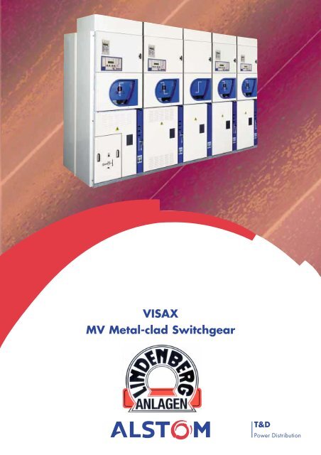
<strong>VISAX</strong><br />
<strong>MV</strong> <strong>Metal</strong>-<strong>clad</strong> <strong>Switchgear</strong><br />
T&D<br />
Power Distribution
<strong>VISAX</strong>: A New Generation of Medium Voltage <strong>Switchgear</strong><br />
Simple architecture<br />
The innovative design of <strong>VISAX</strong> is<br />
based on new metal-<strong>clad</strong><br />
switchgear architecture (fig.1)<br />
where all the functional elements<br />
are mounted in a direct line<br />
between the busbar and the cable<br />
terminals.<br />
Fig. 1 - Direct power line.<br />
<strong>VISAX</strong> combines the advantages of<br />
the most advanced withdrawable<br />
switchgear and the benefits<br />
associated with simplified<br />
architecture: reliability, functional<br />
safety, security.<br />
Fig. 2 - Lateral cross-section of<br />
conventional switchgear.<br />
2<br />
Original architecture<br />
The circuit breaker engages directly<br />
with the busbar, the number of<br />
connections and isolating elements<br />
is significantly reduced.<br />
Low voltage compartment<br />
Busbar compartment<br />
Circuit breaker compartment<br />
Cable compartment<br />
Compartment for the extraction of hot gases<br />
1<br />
2<br />
3 4<br />
Fig. 3 - Lateral cross-section<br />
of <strong>VISAX</strong> switchgear.<br />
1 - Busbar secured to the connection spouts<br />
2 - BLV self-isolating circuit breaker<br />
3 - Multipurpose bushing<br />
4 - Current transformers<br />
5 - Cable terminals<br />
6 - Earthing switch<br />
5<br />
6
The originality of <strong>VISAX</strong> :<br />
an isolating circuit breaker<br />
The circuit breaker is incorporated<br />
in a rotary isolator, thus forming a<br />
dual-purpose module : circuit<br />
breaker and isolator.<br />
This technical innovation has been<br />
made possible by the use of a<br />
vacuum circuit breaker, the poles of<br />
which are arranged longitudinally<br />
(the three poles of the operating<br />
mechanism are aligned along a<br />
single axis).<br />
<strong>VISAX</strong> switchgear concept<br />
Innovation through rotation<br />
The isolation function between the<br />
busbar and the cables is provided<br />
by 90° rotation of the<br />
isolator/circuit breaker (Fig. 5).<br />
Disconnection is thus performed by<br />
rotation of the circuit breaker.<br />
Fig. 5 - Disconnection by rotation.<br />
Description of the 3 positions<br />
• In the "service" position (Fig. 6a),<br />
the poles of the circuit breaker<br />
are in the vertical position. Once<br />
the circuit breaker has been<br />
opened, the poles can rotate to<br />
reach the "disconnected"<br />
position. They therefore withdraw<br />
from the connection spouts to<br />
adopt a horizontal position<br />
(isolated position).<br />
During this rotation, a metal<br />
shutter is automatically drawn<br />
across and obstructs access to the<br />
busbar.<br />
Fig. 6a - “Service” position: circuit breaker<br />
engaged (opening/closure).<br />
3<br />
Fig. 4 - Longitudinal circuit breaker.<br />
• In the "disconnected" position<br />
(Fig. 6b), the front face of the<br />
cubicle may be opened in<br />
complete safety. Tests and checks<br />
may then be carried out.<br />
Fig. 6b - “Disconnected” position or Test :<br />
circuit breaker disengaged through rotation<br />
(isolated position).<br />
• The withdrawal of the circuit<br />
breaker (Fig. 6c) is then possible<br />
after insertion of an isolating<br />
screen between the multipurpose<br />
bushing and the circuit breaker.<br />
Fig. 6c - “Removed” position (the handling<br />
trolley is not shown ) : testing and checking<br />
operations may be performed on the circuit<br />
breaker.
<strong>VISAX</strong>: user safety<br />
(1)<br />
(2)<br />
The circuit breaker compartment after<br />
withdrawal : no access to live sections.<br />
<strong>VISAX</strong> metal-<strong>clad</strong> switchgear<br />
In order to guarantee the safety of<br />
the operator during checking<br />
operations, the circuit breaker<br />
compartment on <strong>VISAX</strong> switchgear<br />
is fitted with an earthed metal<br />
shutter (1). When the circuit breaker<br />
rotates, this shutter is automatically<br />
drawn across to separate the<br />
busbar and circuit breaker<br />
compartments.<br />
When the circuit breaker is in the<br />
isolated position, access to the<br />
connection spouts and the cable<br />
terminals is therefore protected: the<br />
door may be opened in complete<br />
safety.<br />
Prior to withdrawal of the circuit<br />
breaker, an isolating screen (2)<br />
must be inserted so as to prohibit<br />
access to the multipurpose bushings<br />
and thus provide the user with full<br />
protection.<br />
Enhanced interlocks<br />
and safety devices<br />
Apart from the conventional<br />
interlocks, a particularly reliable<br />
chain of interlocks has been<br />
developed. These mechanical<br />
interlocks are simple, robust and<br />
are located, for the most part, on<br />
the front of the unit.<br />
For total reliability, the preassembled<br />
interlock plate has been<br />
designed as an independent subassembly,<br />
requiring no adjustment<br />
during integration into the unit. The<br />
reliability of the interlocks is thus<br />
enhanced for the greater safety of<br />
the personnel.<br />
The optional motorisation of<br />
isolation and earthing operations is<br />
fully integrated into the interlocking<br />
devices. Therefore, in the event of<br />
the loss of the auxiliary power<br />
supply, the manual operations can<br />
be performed without risk to the<br />
operator, as the mechanical<br />
interlocks then take priority.<br />
4<br />
Safety in use<br />
The original architecture of <strong>VISAX</strong>,<br />
combined with the presence of a<br />
gas extraction duct, make it<br />
possible to install the unit flush to<br />
the wall.<br />
In this way, all the steps involved in<br />
switchgear operation are performed<br />
from the front of the unit for<br />
complete user safety.<br />
A unit which allows true wall mounting.<br />
... and space saving<br />
The fact that the unit can be<br />
mounted against a wall allows<br />
space saving in substations,<br />
making it possible to overcome<br />
certain dimensional restrictions.
Internal arc withstand<br />
The rigid construction of the <strong>VISAX</strong><br />
unit, incorporating exhaust flaps on<br />
each compartment, ensures perfect<br />
internal arc withstand.<br />
Designed and tested according to<br />
the latest standard, CEI 298<br />
Appendix AA, each compartment<br />
has an internal arc withstand which<br />
conforms to criteria 1 to 6.<br />
Enhanced personnel safety is<br />
offered as manual operations are<br />
affected with the doors closed.<br />
The gases are channelled in<br />
a special compartment<br />
An advantage specific to <strong>VISAX</strong><br />
architecture is to allow, thanks to a<br />
single duct located at the rear of the<br />
unit, the collection and the<br />
evacuation of the hot gases in the<br />
event of internal arcing.<br />
This duct, a standard component in<br />
<strong>VISAX</strong> units, is designed to collect<br />
the gases from independent flaps,<br />
specific to each of the<br />
3 compartments: cables, circuit<br />
breaker and busbar.<br />
Should a problem arise in one of<br />
the compartments, it does not affect<br />
the others in any way.<br />
A single duct for the extraction of hot<br />
gases.<br />
Operator safety<br />
In this way, the hot gases are<br />
extracted at the back of the unit,<br />
towards the top, as far as possible<br />
from the operator, for improved<br />
safety.<br />
The safety conditions within<br />
substations are thus enhanced. The<br />
hot gases coming from these ducts<br />
can easily be collected from each<br />
unit by a conduit (optional) and<br />
expelled outside the substation.<br />
5
Reliability of information and ease of operation<br />
Operation from the front<br />
panel<br />
The original architecture of <strong>VISAX</strong><br />
provides the user with a new<br />
dimension in reliability and safety,<br />
both in terms of operation and<br />
readings.<br />
<strong>VISAX</strong> architecture allows all<br />
actions associated with the circuit<br />
breaker/isolator and the earthing<br />
switch to be carried out in complete<br />
Operation from the front panel.<br />
safety from the front face of the unit<br />
by direct action on the operating<br />
mechanism.<br />
Actions on the circuit breaker<br />
(opening/closing) while it is at the<br />
service position are performed<br />
directly via the push buttons located<br />
on the front door of the unit,<br />
whereas isolation of the circuit<br />
breaker is performed by inserting<br />
the isolating crank handle through<br />
the door.<br />
6<br />
Certainty of positional<br />
information<br />
The front-to-back layout of all the<br />
elements in the main circuit enables<br />
the operator to see directly the axes<br />
of both the circuit breaker and the<br />
earthing switch.<br />
Status and positions clearly visible, without<br />
intermediate or interface systems.<br />
The operator is left in no doubt, of<br />
the "service" or "disconnected"<br />
positions therefore benefiting from<br />
inherent reliability.<br />
The position of the earthing switch is clearly<br />
visible to the operator.
Self evident operation and<br />
indication<br />
The information essential to<br />
operation of the switchgear is laid<br />
out ergonomically and grouped on<br />
the front face, in areas clearly<br />
identified by specific blue<br />
colouring. The operator thus has<br />
access to the main information by<br />
simply reading:<br />
• from the legend plate located on<br />
the door of the circuit<br />
breaker compartment (fig. 1),<br />
• from the band located on the<br />
right hand side of the cable<br />
compartment (fig. 2).<br />
The circuit breaker mimic<br />
diagram<br />
The single line drawing of the unit<br />
and the positions of the circuit<br />
breaker are indicated by the mimic<br />
diagram. The mimic diagram<br />
allows the operator to view, without<br />
Fig. 3 - Circuit breaker status: clear, distinct information.<br />
“Service” position<br />
circuit breaker closed circuit breaker open<br />
the slightest ambiguity, the status of<br />
the circuit breaker: open, closed,<br />
isolated, in operation.<br />
Furthermore, the circuit breaker<br />
rating plate, the operation counter<br />
and the status of the spring of the<br />
operating mechanism are clearly<br />
visible from outside the unit, with<br />
the door closed.<br />
The earthing switch mimic<br />
diagram<br />
The information on its status<br />
correspond to reality without the<br />
slightest risk of error, as the<br />
position indicator forms an integral<br />
part of the axis of the earthing<br />
switch.<br />
Mimic diagrams reflecting<br />
reality in all circumstances<br />
The mimic diagram (fig. 3) of the<br />
single line drawing on the front<br />
face of the unit incorporates the<br />
position indicators directly. This<br />
7<br />
Fig. 1 - Status of the circuit breaker.<br />
Fig. 2 - Status of the earthing switch.<br />
mimic diagram is entirely made up<br />
of mechanical elements which<br />
remain operational even in the<br />
event of loss of power supply to the<br />
switchboard.<br />
The isolation distances and the<br />
position indicators are totally<br />
reliable and are clearly visible from<br />
the front face of the unit.<br />
“Disconnected” and Test position<br />
circuit breaker open circuit breaker closed
A solution suited to your applications<br />
<strong>VISAX</strong> : created for a modern<br />
world of communication<br />
The environment is changing and is<br />
leading to an evolution in needs,<br />
particularly in the fields of<br />
communication and remote control.<br />
The basic design of <strong>VISAX</strong> units<br />
incorporates the features of remote<br />
control and remote signalling.<br />
Motorisation : an easy<br />
solution<br />
The motorisation of the circuit<br />
breaker/isolator and earthing<br />
switch was taken into account from<br />
Rated voltage (kV)<br />
Rated withstand voltage<br />
7.2/12 17.5 24<br />
50/60 Hz - 1 min (kV rms) 28 38 50<br />
Lightning impulse (kVp)<br />
Rated current<br />
75 95 125<br />
Cubicle (A) ≤ 2500 ≤ 2500 ≤ 2500<br />
Busbar (A)<br />
Short time current<br />
≤ 2500 ≤ 2500 ≤ 2500<br />
Rms. value (kA 3s) 16/25/31.5/40* 16/25/31.5 16/25<br />
Peak value (kAp) 40/63/80/125* 40/63/80 40/63<br />
Breaking capacity (kA) 16/25/31,5/40 16/25/31,5 16/25<br />
Internal arc withstand (kA 1s) 25 25 25<br />
(kA 0.15s) 40<br />
Degree of protection of the enclosures IP 3X (1) IP 3X (1) IP 3X (1)<br />
Height with low voltage compartment (mm) 2150/2350 2150/2350 2450/2650<br />
Height of low voltage compartment (mm) 625/825 625/825 750/950<br />
Width (mm) ≤ 1250 A 650 (3) /800 (2) 650 (3) /800 (2) 800/1000 (2)<br />
1600 A 800 800 1000<br />
2000 A 900 900 1000<br />
2500 A (4) Main characteristics<br />
900 900 1100<br />
Depth (mm) 16-25 kA 1260 1420 1550<br />
31.5 kA 1460 1420<br />
40 kA 1460<br />
Approximate weight of a cubicle<br />
excluding voltage transformer (kg)<br />
500 550 600<br />
* Excepted earthing switch 1sec - 100 kAp - (1) for any other degree of protection, please contact us - (2) equipped with withdrawable voltage transformers<br />
(3) short time current ≤ 25 kA - (4) forced ventilation for 2500A - Please contact us.<br />
8<br />
the very start of the development<br />
process.<br />
On the motorised version,<br />
operations can be performed<br />
manually if required, and the<br />
mechanical interlocks take priority<br />
in all circumstances.
<strong>VISAX</strong> : a complete range<br />
Load break switch - fuse unit (ISR type load break switch).<br />
Coupling - bus riser unit with withdrawable VT.<br />
Incoming (or outgoing) unit fitted with withdrawable Voltage Transformers (VT) and surge arrester<br />
(fixed VT also available).<br />
Metering/measurement unit with fixed VT and busbar earthing.<br />
9
The essential components of the <strong>VISAX</strong> concept<br />
Multipurpose bushing. (1)<br />
Earthing switch. (2)<br />
Voltage transformer. (3)<br />
Compartment for inter-unit low voltage<br />
cableway, with customer terminal block<br />
accessible.<br />
Busbar compartment<br />
Optional: the compartment may be partitioned<br />
between units and the busbars isolated.<br />
Hot gases extraction duct (standard)<br />
A duct collecting the gases from the ducts of a<br />
series of units is proposed as an option.<br />
Cable compartment<br />
From 1 to 4 single core cable per phase<br />
(according to power handled) may be connected<br />
to the multipurpose bushings.Three-core cables<br />
may also be connected.<br />
The multipurpose bushing performs<br />
the following functions:<br />
• location of ring type current<br />
transformers,<br />
• power connection between circuit<br />
breaker and cable compartments,<br />
• section for the connection of<br />
medium voltage cables,<br />
• capacitor divider for signalling<br />
the presence of voltage on the<br />
cables.<br />
10<br />
(3)<br />
(1)<br />
(2)<br />
Incoming/outgoing and<br />
coupling/bus riser units may be<br />
fitted with voltage transformers, with<br />
or without fuses.<br />
They are available in two formats,<br />
fixed, easy to dismantle, or<br />
withdrawable, which can be<br />
extracted from the front face of the<br />
unit.<br />
<strong>VISAX</strong> is fitted with an earthing<br />
switch with making capacity on<br />
short circuit current.
The isolating circuit breaker<br />
The BLV circuit breaker constitutes<br />
the key element in <strong>VISAX</strong> units.<br />
During isolation, the assembly<br />
comprising the poles and the<br />
operating mechanism rotates. The<br />
circuit breaker is a self-supporting<br />
module which only exerts minimal<br />
forces on the mounting points.<br />
Consequently, the various<br />
operations only require low energy<br />
and the long-term reliability is<br />
further enhanced.<br />
BLV type self-isolating rotative vacuum<br />
circuit breaker<br />
Fig. 1 - Operating mechanism.<br />
Fig. 2 - Pole.<br />
(D)<br />
(C)<br />
Fig. 3 - Vacuum interrupter.<br />
11<br />
(A)<br />
(B)<br />
The elements making up the<br />
BLV circuit breaker<br />
The circuit breaker is fitted with a<br />
spring-loaded mechanical<br />
operating mechanism (fig. 1)<br />
specially developed and optimised<br />
for the specific characteristics of the<br />
vacuum interrupters. Its design<br />
based on a single shaft and spiral<br />
spring for both opening and<br />
closing operations guarantees<br />
exceptional reliability and safety.<br />
The vacuum interrupters are located<br />
in single-pole enclosures (fig. 2).<br />
These enclosures, made of synthetic<br />
resin, provide not only the required<br />
level of insulation, but also the<br />
complete protection of the<br />
interrupters from external damage.<br />
The vacuum interrupters (fig. 3) use<br />
the most advanced technology to<br />
control the arc: the axial magnetic<br />
field. They are essentially made up<br />
of a sealed ceramic enclosure<br />
containing the highly pure copper<br />
contacts. One of these contacts is<br />
fixed (A), the other moving (B) by<br />
means of a metal bellows (C). A<br />
screen (D), located around the<br />
contact zone, collects the metal<br />
vapours created by the arc.
ALSTOM Transmission & Distribution - Appareillage moyenne tension - Boulevard de la Résistance - B.P. 4019 - 71040 Mâcon Cédex 9<br />
Tel. : +33 (0)3 85 29 35 00 - Tlx : 800878 F - Fax : +33 (0)3 85 29 35 01 - www.alstom.com<br />
A067 - AMT - 12/2000 - © - ALSTOM - 2000. ALSTOM 2000 - The logo ALSTOM and their frameworks are trademarks and service trademark applications of ALSTOM. The other names mentioned, registered or not, are the property of their respective companies - COMIMPRESS - 03 85 32 25 40