In-Depth Understanding of Fiber Optic Splitter
It is used to enable a single optical fiber to serve multiple end-points, like customers, without having to provision individual fibers between the hub and customer, which greatly reduces time and capital cost. In this post, we will introduce fiber optic splitter from three aspect which can make you have a deep understanding of it.
It is used to enable a single optical fiber to serve multiple end-points, like customers, without having to provision individual fibers between the hub and customer, which greatly reduces time and capital cost. In this post, we will introduce fiber optic splitter from three aspect which can make you have a deep understanding of it.

You also want an ePaper? Increase the reach of your titles
YUMPU automatically turns print PDFs into web optimized ePapers that Google loves.
WHITE PAPER<br />
• PLC <strong>Splitter</strong><br />
PLC (planar lightwave circuit) splitter is the recent addition in fiber optic technology to exhibit<br />
uniform signal splitting among the most advanced optical networks. PLC splitter is a fully passive<br />
optical branching device that is based on planar light wave circuit technology and precision aligning<br />
process, which can evenly split or distribute a single optical signal/input into many outputs with<br />
high accuracy and minimal loss in an efficient manner. PLC splitter is a high-quality device, which<br />
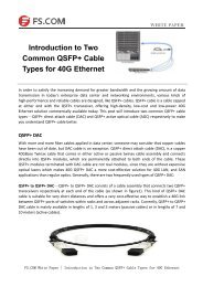
<strong>of</strong>fers a better solution for larger applications. Figure 2 is a picture <strong>of</strong> 1×64 PLC splitter.<br />
Figure2. 1×64 PLC <strong>Splitter</strong><br />
Splitting Ratios: 1×N VS. 2×N<br />
There are a number <strong>of</strong> splitting ratios available for splitter deployment, but the most common<br />
splitters deployed in a PON system is a uniform power splitter with a 1×N or 2×N splitting ratio,<br />
where the letter “N” means the number <strong>of</strong> output ports. The 1×N splitters are usually deployed in<br />
networks with a star configuration, while 2×N splitters are more suitable in networks with a ring<br />
configuration as shown in figure 3 to provide physical network redundancy. The optical input power<br />
is distributed uniformly across all output ports. Although non-uniform power distribution is also<br />
available for fiber optic splitters, such splitters are usually custom-made and command a premium.<br />
Besides, based on different data transmission distances, there are also some suggestions for<br />
splitting ratios selection. If your distance between OLT (optical line terminal) and ONU (optical<br />
network unit) is long, like 20 km, you can use splitting ratio 1:32 to receive qualified fiber optic<br />
signals, and when the distance between OLT and ONU is short, like 5 km, you can consider about<br />
1:64 splitting ratio.<br />
Figure 3. Star Configuration VS. Ring Configuration<br />
FS.COM White Paper | <strong>In</strong>-<strong>Depth</strong> <strong>Understanding</strong> <strong>of</strong> <strong>Fiber</strong> <strong>Optic</strong> <strong>Splitter</strong>