In-Depth Understanding of Fiber Optic Splitter
It is used to enable a single optical fiber to serve multiple end-points, like customers, without having to provision individual fibers between the hub and customer, which greatly reduces time and capital cost. In this post, we will introduce fiber optic splitter from three aspect which can make you have a deep understanding of it.
It is used to enable a single optical fiber to serve multiple end-points, like customers, without having to provision individual fibers between the hub and customer, which greatly reduces time and capital cost. In this post, we will introduce fiber optic splitter from three aspect which can make you have a deep understanding of it.

Create successful ePaper yourself
Turn your PDF publications into a flip-book with our unique Google optimized e-Paper software.
WHITE PAPER<br />
<strong>In</strong>-<strong>Depth</strong> <strong>Understanding</strong><br />
<strong>of</strong> <strong>Fiber</strong> <strong>Optic</strong> <strong>Splitter</strong><br />
<strong>Fiber</strong> optic splitter plays an important role in passive optical network (PON), where a<br />
point-to-multipoint architecture is implemented without any electrically power switching<br />
equipment involved. It is used to enable a single optical fiber to serve multiple end-points, like<br />
customers, without having to provision individual fibers between the hub and customer, which<br />
greatly reduces time and capital cost. <strong>In</strong> this post, we will introduce fiber optic splitter from three<br />
aspect which can make you have a deep understanding <strong>of</strong> it.<br />
<strong>Fiber</strong> <strong>Optic</strong> <strong>Splitter</strong> Types: PLC VS. FBT<br />
Generally, based on different working principles, fiber optic splitter can be divided into FBT splitter<br />
and PLC splitter.<br />
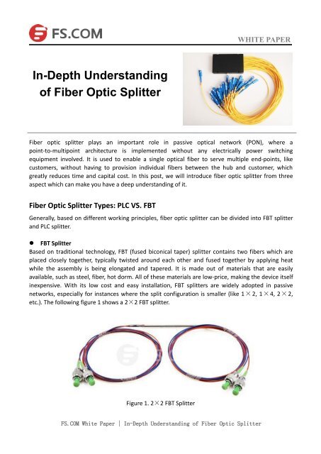
• FBT <strong>Splitter</strong><br />
Based on traditional technology, FBT (fused biconical taper) splitter contains two fibers which are<br />
placed closely together, typically twisted around each other and fused together by applying heat<br />
while the assembly is being elongated and tapered. It is made out <strong>of</strong> materials that are easily<br />
available, such as steel, fiber, hot dorm. All <strong>of</strong> these materials are low-price, making the device itself<br />
inexpensive. With its low cost and easy installation, FBT splitters are widely adopted in passive<br />
networks, especially for instances where the split configuration is smaller (like 1×2, 1×4, 2×2,<br />
etc.). The following figure 1 shows a 2×2 FBT splitter.<br />
Figure 1. 2×2 FBT <strong>Splitter</strong><br />
FS.COM White Paper | <strong>In</strong>-<strong>Depth</strong> <strong>Understanding</strong> <strong>of</strong> <strong>Fiber</strong> <strong>Optic</strong> <strong>Splitter</strong>
WHITE PAPER<br />
• PLC <strong>Splitter</strong><br />
PLC (planar lightwave circuit) splitter is the recent addition in fiber optic technology to exhibit<br />
uniform signal splitting among the most advanced optical networks. PLC splitter is a fully passive<br />
optical branching device that is based on planar light wave circuit technology and precision aligning<br />
process, which can evenly split or distribute a single optical signal/input into many outputs with<br />
high accuracy and minimal loss in an efficient manner. PLC splitter is a high-quality device, which<br />
<strong>of</strong>fers a better solution for larger applications. Figure 2 is a picture <strong>of</strong> 1×64 PLC splitter.<br />
Figure2. 1×64 PLC <strong>Splitter</strong><br />
Splitting Ratios: 1×N VS. 2×N<br />
There are a number <strong>of</strong> splitting ratios available for splitter deployment, but the most common<br />
splitters deployed in a PON system is a uniform power splitter with a 1×N or 2×N splitting ratio,<br />
where the letter “N” means the number <strong>of</strong> output ports. The 1×N splitters are usually deployed in<br />
networks with a star configuration, while 2×N splitters are more suitable in networks with a ring<br />
configuration as shown in figure 3 to provide physical network redundancy. The optical input power<br />
is distributed uniformly across all output ports. Although non-uniform power distribution is also<br />
available for fiber optic splitters, such splitters are usually custom-made and command a premium.<br />
Besides, based on different data transmission distances, there are also some suggestions for<br />
splitting ratios selection. If your distance between OLT (optical line terminal) and ONU (optical<br />
network unit) is long, like 20 km, you can use splitting ratio 1:32 to receive qualified fiber optic<br />
signals, and when the distance between OLT and ONU is short, like 5 km, you can consider about<br />
1:64 splitting ratio.<br />
Figure 3. Star Configuration VS. Ring Configuration<br />
FS.COM White Paper | <strong>In</strong>-<strong>Depth</strong> <strong>Understanding</strong> <strong>of</strong> <strong>Fiber</strong> <strong>Optic</strong> <strong>Splitter</strong>
Splitting Levels: Cascaded Splitting VS. Centralized Splitting<br />
WHITE PAPER<br />
Depending on the customer distribution, there are two common deployment strategies <strong>of</strong> <strong>Fiber</strong><br />
optic splitter—cascaded splitting and centralized splitting.<br />
• Cascaded Splitting<br />
<strong>In</strong> most cases, a cascaded splitter approach as shown in figure 4 has no splitters in the central <strong>of</strong>fice.<br />
The OLT port is connected/spliced directly to an outside plant fiber. A first level <strong>of</strong> splitting (1:4 or<br />
1:8) is installed in a closure, not far from the central <strong>of</strong>fice. A second level <strong>of</strong> splitters (1:16 or 1:8)<br />
resides in terminal boxes, very close to the customer premises (each splitter covering 8 to 16<br />
homes). The inputs <strong>of</strong> these splitters are the fibers coming from the outputs <strong>of</strong> the first level<br />
splitters described above.<br />
Figure 4. Cascaded <strong>Splitter</strong> Approach<br />
• Centralized Splitting<br />
A centralized splitter approach generally uses a combined splitting ratio <strong>of</strong> 1:64 (with a 1:2 splitter in<br />
the central <strong>of</strong>fice, and a 1:32 in an outside plant enclosure such as cabinet). These single-stage<br />
splitters can be placed at several locations in the network or housed at a central location. The 1:64<br />
splitter could even be placed within the central <strong>of</strong>fice to provide a point-to-multipoint (P2P) outside<br />
plant network that still shares bandwidth across multiple customers as shown in figure 5, for<br />
instance a group <strong>of</strong> subscribers a short distance from the central <strong>of</strong>fice. But most <strong>of</strong>ten, the splitters<br />
are placed in the outside plant to reduce the amount <strong>of</strong> overall fiber required.<br />
Figure 5. Centralized Splitting Approach<br />
FS.COM White Paper | <strong>In</strong>-<strong>Depth</strong> <strong>Understanding</strong> <strong>of</strong> <strong>Fiber</strong> <strong>Optic</strong> <strong>Splitter</strong>
Summary<br />
WHITE PAPER<br />
Most FTTH applications are favored PON network, which <strong>of</strong>fers many favorable advantages. <strong>Fiber</strong><br />
optic splitter, as an indispensable component in PON networks, are gained much attention. We have<br />
mentioned three aspects <strong>of</strong> fiber optic splitters, including common types, common splitting ratios,<br />
and common splitting levels, which can help you choose the suitable splitters for your project.<br />
FS.COM White Paper | <strong>In</strong>-<strong>Depth</strong> <strong>Understanding</strong> <strong>of</strong> <strong>Fiber</strong> <strong>Optic</strong> <strong>Splitter</strong>
WHITE PAPER<br />
Contact Us<br />
Manufacturing R & D (China)<br />
Eastern Side, Second Floor, Science &<br />
Technology Park, No.6, Keyuan Road,<br />
Nanshan District, Shenzhen 518057,<br />
China<br />
Tel: +86 (755) 8300 3611<br />
Fax: +86 (755) 8326 9395<br />
Email: sales@fs.com<br />
APAC Office (Hong Kong)<br />
1220 Tung Chun Commercial Centre,<br />
438-444 Shanghai Street, Kowloon,<br />
HongKong<br />
Tel: +(852) 817 636 06<br />
Fax: +(852) 817 636 06<br />
Email: sales@fs.com<br />
North America (United States)<br />
331 Andover Park East Ste330, Tukwila,<br />
WA 98188,United States<br />
Tel: +1 (253) 277 3058<br />
Fax: +1 (253) 246-7881<br />
Email: sales@fs.com<br />
London Office (United Kingdom)<br />
Third Floor 207 Regent Street, London,<br />
W1B 3HH, United Kingdom<br />
Tel: +44 (020) 3287 6810<br />
Follow us<br />
Linked<strong>In</strong><br />
Twitter<br />
Facebook<br />
G+<br />
Pinterest<br />
Youtube<br />
Blog<br />
Notice: This document is for informational purposes only and does not set forth any warranty, expressed or<br />
implied, concerning any equipment, equipment features, or service <strong>of</strong>fered or to be <strong>of</strong>fered by FS.COM.<br />
FS.COM reserves the right to make changes to this document at any time, without notice, and assumes no<br />
responsibility for its use. This information document describes features that may not be currently available.<br />
Contact a FS.COM sales team for information on feature and product availability.<br />
FS.COM White Paper | <strong>In</strong>-<strong>Depth</strong> <strong>Understanding</strong> <strong>of</strong> <strong>Fiber</strong> <strong>Optic</strong> <strong>Splitter</strong>