costshare
Virginia_Conservation_Assistance_Program_(VCAP)_Manual
Virginia_Conservation_Assistance_Program_(VCAP)_Manual

Create successful ePaper yourself
Turn your PDF publications into a flip-book with our unique Google optimized e-Paper software.
VIRGINIA CONSERVATION ASSISTANCE PROGRAM<br />
IMPLEMENTATION AND DESIGN MANUAL<br />
THIRD EDITION, July 2016<br />
[VCAP BMP MANUAL]<br />
July 2016<br />
The Virginia Conservation Assistance<br />
Program (VCAP) is an urban <strong>costshare</strong><br />
program that provides financial<br />
reimbursement to property owners<br />
installing eligible Best Management<br />
Practices (BMP’s) in Virginia’s<br />
Chesapeake Bay Watershed.
TABLE OF CONTENTS<br />
PART I – PROGRAM DEVELOPMENT AND IMPLEMENTATION .............................. 5<br />
Section 1.1 Background and Development of the Program ................................................... 5<br />
Section 1.2 Program Scope and Eligibility .............................................................................. 6<br />
Section 1.3 Goals and Objectives of the Program .................................................................. 7<br />
Section 1.4 District Responsibilities ......................................................................................... 7<br />
Section 1.5 Program Steering Committee Role....................................................................... 8<br />
Section 1.6 Program Technical Advisory Committee Role .................................................... 9<br />
Section 1.7 Funding Allocations, Payments, and Participant Responsibilities ................... 10<br />
Section 1.8 Compliance and Corrective Action .................................................................... 11<br />
PART II –STORMWATER OVERVIEW ........................................................................... 12<br />
Section 2.1 Introduction.......................................................................................................... 12<br />
Section 2.2 Stormwater Overview .......................................................................................... 12<br />
Section 2.3 Stormwater Best Management Practices (BMPs) ............................................. 14<br />
Section 2.4 General Stormwater BMP Design Considerations ............................................ 16<br />
PART III: New BMP Retrofit ................................................................................................ 21<br />
Section 3.0 General Practice Policies .................................................................................... 21<br />
Section 3.1 Pet Waste Stations (PWS) ................................................................................... 25<br />
Section 3.2 Urban Nutrient Management (UNMP).............................................................. 27<br />
Section 3.3 Impervious Surface Removal (ISR).................................................................... 30<br />
Section 3.4 Conservation Landscaping (CL)........................................................................ 32<br />
Section 3.5 Rain Garden (RG) ............................................................................................... 36<br />
Section 3.6 Dry Well (DW) ..................................................................................................... 39<br />
Section 3.7 Constructed Wetland (CW) ................................................................................ 42<br />
Section 3.8 Vegetated Stormwater Conveyance (VSC)........................................................ 45<br />
Section 3.9 Rainwater Harvesting (RH)................................................................................ 49<br />
Section 3.10 Bioretention (BR)............................................................................................... 52<br />
Section 3.11 Infiltration (IF)................................................................................................... 55<br />
Section 3.12 Permeable Pavement (PP)................................................................................. 58<br />
Section 3.13 Green Roof (GR)................................................................................................ 61<br />
General References ................................................................................................................. 65
Appendix A – Calculations<br />
APPENDICES<br />
Appendix B – Pretreatment Requirements for VCAP BMPs<br />
Appendix C – Reportable Measures for Crediting Urban BMPs for Chesapeake Bay<br />
Recovery Efforts<br />
Appendix D – VCAP Forms<br />
VCAP-1 Contract<br />
VCAP-2 Job Sheet<br />
VCAP-3 Landowner Agreement<br />
VCAP-4 Transfer of Responsibility<br />
VCAP-5 Release Agreement<br />
VCAP -6 Ranking Form
Introduction<br />
The VCAP Manual (“Manual”) is intended to assist Soil and Water Conservation District<br />
(SWCDs) personnel as they carry out the Virginia Conservation Assistance Program (VCAP or<br />
the “Program”). The Program was pioneered by the Grant Sub-committee of the Virginia<br />
Association of Soil and Water Conservation Districts’ Urban Committee and is based upon the<br />
North Carolina Community Conservation Assistance Program (NCCCAP), modified as<br />
appropriate to conform to best management practices accepted by the Virginia Department of<br />
Environmental Quality (DEQ).<br />
The purpose of this program is to provide cost-share and technical assistance to address natural<br />
resource concerns by assisting in the voluntary installation of certain stormwater best<br />
management practices on land where there is no other cost-share program assistance available.<br />
The program also aims to assist localities with the MS4 (Municipal Separate Storm Sewer<br />
System) Permit requirements and the challenges meeting the Chesapeake Bay Total Maximum<br />
Daily Load (TMDL) goals.<br />
This Manual is to be a resource for District staff as they provide technical assistance needed to<br />
guide the proper siting, selection, design, installation, and maintenance of stormwater best<br />
management practices, or BMPs, on eligible lands. These BMPs are intended to capture and/or<br />
infiltrate surface runoff produced immediately following a 1-inch rainfall event. These BMPs<br />
are designed to manage stormwater coming from a source on the property, such as roof,<br />
driveway or lawn. Sites with contributing offsite runoff can also be addressed with the<br />
practices in the Program, but may require more extensive planning and engineering.<br />
Where applicable, this document references the Non-Proprietary BMPs of the Stormwater<br />
Design Specifications contained in the Virginia Stormwater BMP Clearinghouse<br />
(http://vwrrc.vt.edu/swc/NonProprietaryBMPs.html). Users will also find the Virginia<br />
Agricultural Cost Share (VACS) BMP Manual and technical manuals of the Natural Resources<br />
Conservation Service (NRCS) helpful for fulfilling the intentions of the Program.<br />
The Manual is divided into three parts. Part I summarizes the background and history of the<br />
development of VCAP and its administrative framework. Part II contains background<br />
information on stormwater management and the Chesapeake Bay. Part III contains the design<br />
standards for all VCAP best management practice.<br />
4
PART I – PROGRAM DEVELOPMENT AND IMPLEMENTATION<br />
Section 1.1 Background and Development of the Program<br />
The Virginia Conservation Assistance Program (VCAP or the “Program”) is based upon the<br />
North Carolina Community Conservation Assistance Program (NCCCAP). The assistance and<br />
support of the staff of that program is gratefully acknowledged in the preparation of this<br />
Manual. Like VCAP, NCCCAP provides financial help to landowners in urban, suburban, and<br />
rural areas to control erosion and runoff on non-agricultural properties.<br />
NCCCAP is designed to retrofit water quality best management practices (BMPs) onto alreadydeveloped<br />
non- agricultural land. Several districts within the state, particularly Mecklenburg<br />
County, broadened their scope of resource protection and developed local community<br />
conservation assistance programs, and thus developed model programs potentially applicable<br />
across the entire state.<br />
Encouraged by these efforts, the North Carolina Association of Soil and Water Conservation<br />
Districts pursued the development of a statewide community conservation program. Through<br />
the strong support of district supervisors, the North Carolina Soil and Water Conservation<br />
Commission received authorizing legislation to establish the NCCCAP through Session Law<br />
2006-08. The North Carolina Division of Soil and Water Conservation began the program using<br />
grant funds to demonstrate recognizable results across the state. In July 2007, the program<br />
received its first state appropriation. Over the succeeding five years additional financial<br />
support was used to expand the program throughout the state.<br />
Desiring to replicate this successful program, in 2011 the Virginia Association of Soil and<br />
Water Conservation District’s Urban Committee sought a Chesapeake Bay Small Watershed<br />
Project Design Grant from the National Fish and Wildlife Foundation to support the<br />
establishment of design components for this Program, focused on filling “urban” gaps<br />
identified in Virginia’s Watershed Implementation Plan (WIP) for the Chesapeake Bay Total<br />
Maximum Daily Load (TMDL). The WIP noted that the “new stormwater regulations will not<br />
address sediment and nutrient loads associated with existing development, nor does the existing<br />
Chesapeake Bay Preservation Act . . . (To) fill this gap, new requirements, as well as financial<br />
incentives for stormwater BMPs are needed.”<br />
The Urban Committee’s Grant Sub-Committee was primarily comprised of representatives from<br />
four Soil and Water Conservation Districts (Districts) -- Culpeper, Hanover-Caroline, Piedmont,<br />
and Thomas Jefferson -- all of which played active roles with design of the Program.<br />
The remainder of this Manual is the result of this collaborative work, and is based on the North<br />
Carolina CCAP Program Manual, July 2007 (as partially updated through March 2012) and the<br />
North Carolina Division of Soil and Water Conservation Community Conservation Assistance<br />
Program Stormwater Management Practice Design Manual (no date), and conforms with the<br />
Non-Proprietary BMPs of the DCR Design Specifications contained in the Virginia Stormwater<br />
BMP Clearinghouse (http://vwrrc.vt.edu/swc/NonProprietaryBMPs.html) where necessary for<br />
Virginia programmatic purposes, as well as to the format and content of the Program Year 2012<br />
Virginia Agricultural Cost Share (VACS) BMP Manual.<br />
5
Section 1.2 Program Scope and Eligibility<br />
A. Program Scope<br />
Districts have a successful history of promoting the voluntary installation of water quality<br />
BMPs on agricultural lands through the Virginia Agricultural Cost-Share program. This<br />
Program expands this capacity by enabling Districts to promote efforts for corrective action<br />
on developed lands, often described as retrofitting. Installing stormwater BMPs on developed<br />
land reduces the amount of sediment, nutrients and other contaminants from reaching streams<br />
and rivers. Properly managed stormwater can help recharge groundwater and protect the land<br />
and streams from erosion. Financial incentives to help encourage the installation of<br />
stormwater BMPs will help Virginia meet its non-point source pollution reduction water<br />
quality objectives.<br />
While VCAP is designed to encourage the installation of stormwater BMPs on developed<br />
land, it is understood that resource-based problems affecting water quality occur on all land<br />
uses. For this reason VCAP, at this time, is not limited to strictly urban settings, but includes<br />
situations where there is no other cost-share program currently offered to implement a water<br />
quality improvement BMP. Broad eligibility criteria will allow VCAP to accomplish several<br />
priorities that are not limited to the treatment of stormwater in urban settings. A ranking<br />
system is used to help prioritize the recruitment of participants and the implementation of<br />
BMPs.<br />
B. Program Eligibility<br />
1. Development:<br />
The Program is not eligible to be used to assist new development sites to meet local, state<br />
and federal stormwater mandates.<br />
2. Flooding:<br />
The Program is not eligible to be used to deal with major flooding on existing<br />
development. Flooding, as defined by the Virginia Erosion and Stormwater Management<br />
Act (VESMA), is “a volume of water that is too great to be confined within the banks or<br />
walls of the stream, water body, or conveyance system and that overflows onto adjacent<br />
lands, thereby causing or threatening damage.” The Program may be used to address<br />
smaller scale localized flooding as long as there is no channelization of stormwater<br />
runoff and the drainage pattern remains unchanged. Localized flooding, as defined by<br />
the Virginia Stormwater Management Regulations, means “smaller scale flooding that<br />
may occur outside of a stormwater conveyance system. This may include high water,<br />
ponding, or standing water from stormwater runoff, which is likely to cause property<br />
damage or unsafe conditions.”<br />
3. Municipal Separate Stormwater Sewer Systems (MS4):<br />
Per subsection C (2b) (1) of Section 1 from 9VAC25-890-40, unregulated sites within<br />
designated MS4 localities are eligible for funding. Unregulated sites include any<br />
development not previously permitted through the Virginia Erosion and Stormwater<br />
Management Program (VESMP). Funded practices may be used as credit toward any<br />
local stormwater utility fees. These practices may not be used to trade credits to<br />
regulated activities. Funded practices must meet or exceed the baseline removal<br />
requirement for the site before the MS4 locality can report the BMP for load reduction<br />
credit. Funded practices that do not meet the baseline removal requirements for the site<br />
will be reported by this Program.<br />
6
Section 1.3 Goals and Objectives of the Program<br />
The overall Program goal is to encourage owners or managers of non-agricultural land in the<br />
Program District to install “urban” BMP retrofits that will provide nutrient and/or sediment<br />
reductions that can be credited toward accomplishing Virginia’s Chesapeake Bay TMDL goals<br />
by offering cost-sharing financial incentives. The Program will accomplish the following<br />
objectives to meet the Program goal.<br />
A. Maintain a suite of BMPs consistent with the Virginia Stormwater BMP Clearinghouse, as<br />
appropriate, and a subset of BMPs appropriate for the Program.<br />
B. Identify environmental benefits associated with BMPs including load reductions<br />
associated with Chesapeake Bay TMDL implementation efforts.<br />
C. Maintain BMP specifications that may be required beyond those provided by the Virginia<br />
Stormwater BMP Clearinghouse.<br />
D. Maintain partnerships between Districts and local government to ensure local support of<br />
the Program.<br />
E. Establish support for the Program through partnerships with community groups.<br />
F. Continue to develop and maintain Program information and outreach materials.<br />
G. Identify and establish contacts with other grant programs to maintain strategies to secure<br />
continued funding for the Program.<br />
H. Develop and maintain a training curriculum for staff and contractors.<br />
Section 1.4 District Responsibilities<br />
Local implementation of the Program is the responsibility of the participating Districts. The<br />
charge for the Districts is to execute the Program to satisfy a recognized nonpoint source<br />
pollution problem. Districts are to place the highest priority on water quality improvement and<br />
protection.<br />
A. All Program-related meetings will comply with the Open Meetings Law (Va. Code § 2.2-<br />
3707 et seq.). Districts will ensure that the District Board meets often enough to properly<br />
execute and oversee the Program in their Districts. The Program Steering Committee<br />
recommends that District Boards meet to review their Program activities at least six times<br />
per year.<br />
B. Each District that chooses to participate in the Program will give public notice of its<br />
planned activities preceding the start of each program year and/or when new sources of<br />
Program funds become available.<br />
C. Districts will research and develop strategy plans that:<br />
1. Determine what needs to be done to decrease residential, suburban, and urban nonpoint<br />
source pollution.<br />
2. Areas most critically needing attention will be prioritized.<br />
3. Assess outreach opportunities and determine marketing approaches.<br />
4. Prioritize applications based on numerical rankings, using primary and secondary<br />
considerations.<br />
5. Assess staff capability and determine technical and engineering assistance needs.<br />
6. Follow procedures for tracking and reporting BMP installation and nutrient reduction<br />
credits as appropriate.<br />
7
D. Districts will review and rank applications (Contract- VCAP form-1) for funding based on<br />
an established schedule.<br />
E. When an application for funding has been approved, the District will approve a design,<br />
installation and maintenance plan, which will become a part of the contract with the<br />
participant (Landowner Agreement- VCAP form-3).<br />
F. When BMPs are installed, District staff with appropriate technical authority, as applicable,<br />
will certify that the installation meets the requirements of Part III of this Manual. After<br />
certification, contingent on availability, Districts may disburse payment from the Program<br />
funds allocated to their project.<br />
G. Districts are responsible for conducting annual spot checks of 25 percent (25%) of all active<br />
contracts executed in their District to ensure on-going maintenance. Districts are to<br />
document the number and names of all persons participating in the spot check process. Spot<br />
checks will be performed by appropriate technical staff.<br />
H. Districts will ensure that participants adhere to the maintenance agreement. Participants<br />
found to be out of compliance are notified pursuant to the guidelines found in Part I,<br />
Section 1.8 (“Compliance & Corrective Actions”) of this Manual, and documentation of the<br />
noncompliance and resolution becomes a part of the District files. Districts will also ensure<br />
that the Program Steering Committee receives notification of noncompliance and the<br />
subsequent resolution of such noncompliance.<br />
I. Districts shall ensure that BMP maintenance is continued regardless of transfer of control<br />
of property (see Part 1, Section 1.7).<br />
J. Districts will exercise all jurisprudence to avoid any actual or perceived conflicts of interest<br />
in implementing the Program.<br />
Section 1.5 Program Steering Committee Role<br />
The role of the Program Steering Committee (“SC”) is to provide programmatic guidance to<br />
ensure the Program continues to accomplish the overall goal of enabling non-agricultural<br />
landowners to install BMPs that reduce the flow of nonpoint source pollution into local<br />
waterways and ultimately the Chesapeake Bay. The SC is also responsible for providing<br />
guidance on continued funding and legislative issues related to the Program that may arise.<br />
The Steering Committee will include the following members:<br />
<br />
<br />
<br />
A representative staff member of at least four, but not to exceed six, participating Districts;<br />
The Executive Director of the Virginia Association of Soil and Water Conservation<br />
Districts, or his or her representative; and<br />
The Chair of the VASWCD Urban Committee, or approved representative of the Urban<br />
Committee shall serve as an Ex-officio member. The Urban Committee member is<br />
responsible for keeping Urban Committee members informed of the progress of the Program,<br />
to encourage other Districts to adopt the Program and to determine collaborative opportunities<br />
with the larger Urban Committee based on its plan of work.<br />
As the Program evolves, the central focus of the SC should include long-range planning and<br />
goals, manual development, and critical technical feedback and expertise. Review and approval<br />
of practices, payments, and technical assistance will fall to the SC. Day-to-day operations;<br />
8
outreach; and branding of the program will fall primarily to the VCAP Coordinator. Any<br />
agreements made through an MOU with SC districts, such as technical training, funds<br />
management, and attending SC meetings will constitute the remainder of SC obligations.<br />
Primarily, the SC members provide critical feedback and assistance to the VCAP Coordinator<br />
through their years of experience in the field, technical knowledge, and past experience with the<br />
Program. This is an absolutely crucial role for the SC and will continue to be of great value to<br />
the VCAP Coordinator.<br />
Specifically, the Steering Committee will:<br />
<br />
<br />
<br />
<br />
<br />
<br />
<br />
<br />
Convene monthly SC meetings to discuss ongoing programmatic development, provide<br />
guidance to the VCAP Coordinator, and take part in long-range and strategic planning for<br />
the Program<br />
Review and approve cost-share applications, cost-share payments, and technical assistance<br />
payments<br />
Approve program level issues such as manual revisions, BMP criteria, and any changes to<br />
official Program policies<br />
Provide feedback on branded materials, outreach content, and other VCAP Coordinator<br />
roles in general<br />
Assist with District outreach and relationship building through promoting and discussing<br />
the Program<br />
Provide program feedback to the Virginia Association of Soil and Water Conservation<br />
Districts on program issues, challenges, or future plans based on experience and program<br />
feedback by participating Districts Bay wide<br />
Form and oversee a Technical Advisory Committee to continually develop and improve<br />
BMP specifications and Manual language<br />
Record and post minutes from monthly SC meetings and Technical Advisory Committee<br />
sessions<br />
Section 1.6 Program Technical Advisory Committee Role<br />
The Program Steering Committee is responsible for creating and maintaining a Technical<br />
Advisory Committee (“TAC”). The TAC is responsible for evaluating and providing technical<br />
advice to the Steering Committee regarding BMPs in the Program. Membership should consist<br />
of a proportional representation of participating Districts and other individuals by invitation<br />
from the Program Steering Committee. Ideally about three-fourths of the TAC is composed of<br />
licensed and certified professionals, and contractors or stormwater industry representatives that<br />
are involved in landscaping and stormwater management. The remaining members are agency<br />
personnel representing the agencies that are directly involved in the Virginia Conservation<br />
Assistance Program. The TAC should meet at least once per year, and may meet at any time<br />
appropriate to conduct business for the Program.<br />
The TAC is encouraged to solicit input by the Program Districts, other Non-Program Districts,<br />
or other specialty organizations or agencies on various issues including types of BMPs, BMP<br />
specifications, and average BMP costs. Directors, District staff, DCR personnel, and U.S.<br />
Department of Agriculture Natural Resources Conservation Service (NRCS) personnel have a<br />
standing invitation to attend TAC meetings and participate in the discussions. TAC members<br />
9
are not representatives of the Program and may not lobby on its behalf.<br />
Ad hoc technical review subcommittees will convene as needed to assist in development of new<br />
BMPs, program evaluation, and make recommendations to the full TAC. The subcommittees<br />
will assist in the evaluation of Innovative BMP Demonstration Project requests. The<br />
subcommittees will consist of appropriate DCR, DEQ, VCE, DOF, NRCS, SWCD, VASWCD,<br />
and other agency representatives and willing TAC members as needed.<br />
Section 1.7 Funding Allocations, Payments, and Participant Responsibilities<br />
A. Funding Allocations<br />
As of January 1, 2016 the Program is funded entirely through EPA’s Chesapeake Bay<br />
Implementation Grant (“CBIG”). With this grant, all districts falling within the Chesapeake<br />
Bay watershed in Virginia now qualify for the program, which is operated and managed by the<br />
Virginia Association of Soil and Water Conservation Districts (“VASWCD”). Cost-share<br />
funding is maintained at a bay-wide level on a first come, first serve basis. There are no perdistrict<br />
allocations and cost-share rates/caps are the same for all bay Districts.<br />
The allocation of funds will be administered by the Steering Committee with support from the<br />
VCAP Coordinator, an employee of the VASWCD. Any District that has the technical and<br />
administrative resources necessary to support the Program can accept applications from public,<br />
private, and business non-agricultural landowners and managers and submit them to the VCAP<br />
Coordinator for review. The funds will be reimbursed to the District upon project completion.<br />
B. Submission<br />
The process to apply for reimbursable cost-share funding begins by signing a VCAP form 1<br />
(Contract), which specifies the urban best management practice requesting to be installed and<br />
the total estimated cost, and by submitting a design plan and narrative.<br />
Districts are to review the Contract and design plan for compliance with the Program policies as<br />
described in the VCAP Manual. Districts are to rank each project using the VCAP Ranking<br />
Sheet (VCAP Form – 6) and provide this ranking sheet to the VCAP Coordinator.<br />
The District staff submits the application to the VCAP Coordinator. The VCAP Coordinator<br />
reviews the application for completeness. Each month, applications will be presented to the<br />
Steering Committee for consideration and approval. Final approval of practice funding is the<br />
responsibility of the local District Board of Directors. All actions taken must be voted upon<br />
and the outcome recorded in the minutes of the meeting where such action is taken. Districts<br />
should be prepared to verify and document that their cost-share payments are being spent in<br />
accordance with the administrative and technical guidance published in this manual.<br />
Once approved, the Program participant signs the Landowner Agreement (VCAP form-3)<br />
confirming the amount of cost-share approved, agreeing to allow district staff to access the<br />
property under specified terms, and specifying other terms of the agreement. As part of the<br />
Landowner Agreement, the participant works with the district technical staff to complete a Job<br />
Sheet (VCAP form-2) that describes any site-specific details, including an Operation and<br />
Maintenance Plan. The Operation and Maintenance Plan describes the participant’s obligations<br />
to maintain the practice. The participant is responsible for the maintenance of the practice for<br />
the entire lifespan of the practice. In cases where changes in the control of the land occur, such<br />
as the sale of the property, or any changes in lease agreements, the participant may complete an<br />
Agreement Transferring BMP Responsibility (VCAP form-4) to relieve them of the<br />
responsibility to maintain of the practice.<br />
10
C. Verification and Payments<br />
Once a practice has been installed, inspected, and approved by a district staff member, the<br />
district is expected to make the approved cost-share payment to the participant. An invoice is<br />
then submitted to the VCAP Coordinator for reimbursement.<br />
If it is not possible for the district to make cost-share payments on larger projects before being<br />
reimbursed, the district must submit a formal request to the VCAP Coordinator on district<br />
letterhead for an early reimbursement payment.<br />
Reimbursement will be made to the district for each completed contract and will include<br />
technical assistance funds at an established flat rate. Districts must submit a completed Job<br />
Sheet (VCAP Form-2), and a third-party as-built certification when necessary.<br />
D. Participant Responsibilities<br />
Maintenance agreements between the involved parties are acceptable but ultimate<br />
responsibilities still rest with the participant. Districts may choose to encourage landowner<br />
participation over tenant participation in their information and promotional campaigns.<br />
E. Reporting Completed Practices<br />
The VCAP Coordinator will report completed practices to the State tracking program at least<br />
annually. The reportable data will be collected on the Job Sheet (VCAP Form-2).<br />
Section 1.8 Compliance and Corrective Action<br />
Failure to maintain the practice for the specified lifespan will result in the participant being<br />
required to refund all or part of the cost-share amount. The required repayment amount is based<br />
on the amount of funding provided to the participant prorated to the lifespan remaining. In the<br />
case of the death of the participant this requirement may be waived. This determination<br />
requires an official action of the District Board that must be recorded in the minutes. A<br />
Transfer of Responsibility form (VCAP form-4) should be signed if the property changes<br />
ownership during the life of the BMP.<br />
Participants found to have practices not meeting specifications or practices destroyed during the<br />
designated life span will be contacted by the District and informed of the nature of the<br />
deficiency and repayment requirements if not corrected. This should initially be a verbal notice<br />
(with the date documented in a case file). Verbal notice should be followed with a written<br />
notice (by certified mail) within two weeks. This notice must indicate the observed nature of<br />
the problem and allow the individual the opportunity to respond within two weeks.<br />
Participants may be given a maximum grace period of six months from the date of the written<br />
notification for practice compliance. At the end of the grace period, the practice will be reinspected.<br />
The District will notify participants found with practices still not in compliance in<br />
writing that repayment of state or other cost-share funds is required.<br />
Participants will have 60 days from the date of the District’s notification of repayment to refund<br />
the cost-share funds. If restitution has not been made at the end of this 60-day period, the<br />
District will notify the Virginia Office of the Attorney General (OAG) for assistance to reclaim<br />
the funds. It is recommended that the OAG be apprised of the need for assistance as soon as the<br />
deadline for recovery has passed.<br />
11
Section 2.1 Introduction<br />
PART II –STORMWATER OVERVIEW<br />
The specifications and application of best management practices (or BMPs) are constantly<br />
evolving with new information and more experience. The specifications and standards found in<br />
this Manual will be updated as more research and information is gathered. This document<br />
focuses on retrofit BMPs that can be installed in small scale settings, such as existing individual<br />
residences and small businesses.<br />
Stormwater BMPs found in this Manual:<br />
Pet Waste Stations (PWS) 3.1<br />
Urban Nutrient Management (UNMP) 3.2<br />
Impervious Surface Removal (ISR) 3.3<br />
Conservation Landscaping (CL) 3.4<br />
Rain Gardens (RG) 3.5<br />
Dry Well (DW) 3.6<br />
Constructed Wetlands (CW) 3.7<br />
Vegetated Stormwater Conveyances (VSC) 3.8<br />
Rainwater Harvesting (RH) 3.9<br />
Bioretention (BR) 3.10<br />
Infiltration Basin (IB) 3.11<br />
Permeable Pavement (PP) 3.12<br />
Green Roofs (GR) 3.13<br />
Section 2.2 Stormwater Overview<br />
A. Definitions of Stormwater<br />
Stormwater describes surface runoff from disturbed and developed lands that is produced<br />
immediately following a rainfall event or as a result of snowmelt. Factors that affect stormwater<br />
include the quantity and intensity of a precipitation event, amount of impervious surfaces, the soil<br />
type and condition, vegetative cover, and slope length and steepness. The Virginia Stormwater<br />
Management Program Permit Regulations at 9VAC25-870-10 define the term as “precipitation<br />
that is discharged across the land surface or through conveyances to one or more waterways and<br />
that may include stormwater runoff, snow melt runoff, and surface runoff and drainage.”<br />
12
B. Effects of Urbanization<br />
Virginia is among the fastest growing states and the resulting urban influx affects many facets of<br />
the state’s infrastructure. More cars drive our roads, more people create higher wastewater<br />
discharges, and more development necessitates stormwater runoff controls.<br />
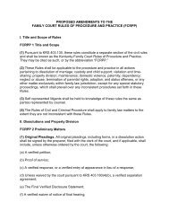
How does urbanization affect stormwater runoff? Roads, parking lots, sidewalks, homes, and<br />
offices replace the natural, permeable landscape. Rainfall that once soaked into vegetated ground<br />
is now available for stormwater runoff. Impermeable surfaces connect to form a “stormwater<br />
superhighway” that allows runoff to reach streams more quickly. The following diagram<br />
illustrates how stormwater runoff is a function of impervious cover.<br />
Stormwater Runoff as a Function of Impervious Cover (Potomac Conservancy 2008)<br />
There are many impacts from this increase in impermeable area: (1) more stormwater reaches<br />
streams because there is less opportunity for it to infiltrate into the ground; (2) peak flows increase<br />
because the “stormwater superhighway” transports runoff from large areas rapidly; (3) velocities<br />
in the stream increase, causing more erosion; and (4) base flow is lower during dry weather due<br />
to a lack of infiltration into the underlying groundwater (groundwater recharge).<br />
Although Virginia passed legislation to manage stormwater pollution in 2004, sediment remains a<br />
major pollutant of our waters. In addition, metals and chemicals from vehicles and industries<br />
pollute stormwater runoff in increasing amounts. Likewise, nutrients are found in the urban<br />
environment in a variety of forms, such as fertilizer used on lawns and deposition from the air.<br />
Fertilizer contains nutrients for plants to grow, but excess fertilizer, or fertilizer that is<br />
inadvertently applied to pavement, harms water quality. This manual will provide design guidance<br />
for several best management practices (BMPs) that can be installed to reduce the amount of<br />
pollution entering streams.<br />
13
Section 2.3 Stormwater Best Management Practices (BMPs)<br />
A. Overview of Stormwater BMPs<br />
Stormwater management is the attempt to reduce runoff volume, control peak flow rate, and<br />
improve water quality using best management practices (BMPs). Each BMP has certain<br />
conditions under which it will function properly. Site conditions such as amount of stormwater<br />
discharge, soil-type, slope, available land, impervious surface, and proximity to waterways all<br />
influence the selection of a BMP.<br />
The Environmental Protection Agency (EPA) has identified two distinct classifications of BMPs-<br />
“nonstructural” and “structural.”<br />
Nonstructural BMPs reduces stormwater quantity and improves water quality at the source. There<br />
are some simple non-structural practices that homeowners can implement themselves. Some<br />
examples include downspout disconnection, sheet flow to open space, grass channels, replacing<br />
managed turf with native plants, and amending soil.<br />
Structural BMPs are engineered systems that control the peak flow, reduce runoff volume, and<br />
improve stormwater quality. Some examples of these are bioretention areas, rain gardens, rain<br />
water harvesting, green roofs, and constructed wetlands.<br />
B. Practice Selection<br />
BMP selection will be based on site needs, conditions, or homeowner objectives, and can be very<br />
unique depending on the individual landowner’s desired outcome. Sites should have an<br />
identifiable water quality issue and BMP objectives should be limited to practices that capture and<br />
reuse or treat stormwater. Typically, measures to only reduce flooding will not be eligible for<br />
cost share.<br />
Some Examples:<br />
<br />
<br />
<br />
<br />
Sites with known erosion problems and poor drainage could consider improving the<br />
stormwater conveyance system.<br />
Sites with water volume issues and have an onsite need for water could consider rainwater<br />
harvesting to collect and reuse stormwater.<br />
Sites that produce high levels of pollutants could consider a conversion of land<br />
management practices that changes how the land is used to reduce pollutant generation.<br />
A combination of objectives can be satisfied with one or more practices, and practices can<br />
be combined to create “treatment trains” to accomplish all objectives.<br />
The following flow chart may be helpful to determine what practice is appropriate for a particular<br />
property.<br />
14
C. Accounting for Chesapeake Bay Model Credits<br />
Since the first Chesapeake Bay Agreement in 1983, Virginia along with the other states in the<br />
Chesapeake Bay watershed have been trying to reduce and reverse the adverse impacts of sediment<br />
and nutrient pollution to the Bay. As earlier efforts to reduce point source sediment and nutrient<br />
pollutants bore success, efforts have increasingly turned to the growing problem of nonpoint<br />
sources of sediment and nutrients. To reflect the growing concern of untreated runoff that results<br />
from agriculture and the proliferation of untreated runoff from urban and residential development,<br />
the Bay Agreement was updated in 1987, 2000 and 2014.<br />
The insufficient progress of cleanup and the continued impairment of the Chesapeake Bay led to<br />
the insistence that Chesapeake Bay Total Maximum Daily Load (TMDL) levels be determined for<br />
nitrogen, phosphorous, and sediment. Each state within the Chesapeake Bay watershed was<br />
required to develop Watershed Implementation Plans (WIPs). The WIPs detailed the strategies<br />
each state will implement to meet TMDL allocations (see Fact Sheet: Chesapeake Bay TMDL,<br />
12/29/10).<br />
The VCAP BMPs are intended to address Virginia’s Phase II WIP strategies and to be accountable<br />
for achieving a level of pollution reduction in accordance with the Urban BMPs of the Chesapeake<br />
Bay Model (see Sections 6.7 through 6.10). Pollution reduction under the Model is determined<br />
based on a BMP’s pollutant removal efficiency rate, a pollutant load reduction, or a land use<br />
change (see Table 6-4 in Section 6.10 of the Model). Since most of the VCAP BMPs are derived<br />
from the Virginia Stormwater BMP Clearinghouse, there is assurance of verification of those<br />
BMPs with the Chesapeake Bay Model and accountability towards meeting Virginia’s Phase II<br />
WIP strategy goals.<br />
Appendix C contains Sheet 2 of an NPS BMP DET V10 matrix used by the Chesapeake Bay<br />
Program to evaluate BMP data elements, and Sheet 3, an example VCAP project tacking<br />
spreadsheet.<br />
15
[Note: A separate VCAP guidance document entitled, “Comparison of VCAP BMPs and<br />
Chesapeake Bay Phase 5.3 Community Watershed Model Urban Practices BMPs, with additional<br />
input from the Commonwealth of Virginia Chesapeake Bay TMDL Phase II Watershed<br />
Implementation Plan (WIP)” compares the existing VCAP BMPs with the Chesapeake Bay<br />
Model’s discussions of Urban Practices, Shoreline Protection, Land Use Changes, and BMP<br />
Annual Time Series (see Model Sections 6.7 through 6.10).<br />
Section 2.4 General Stormwater BMP Design Considerations<br />
2.4.1 Water Quality Treatment<br />
A. The “First Flush” Concept and Treatment Volume Approach<br />
The term “first flush” has become common nomenclature in the stormwater management field.<br />
The concept behind this term is that pollutants that have collected on impervious surfaces will<br />
wash off during the first part of a storm event. The “first flush” contains more pollutants than<br />
stormwater runoff produced later in the storm. In theory, if the “first flush” could be captured and<br />
treated by a stormwater practice, 90% of the pollutants leaving the site could be treated by the<br />
stormwater practice (Schueler and Holland, 2000). However, it has been found that a Treatment<br />
Volume approach provides better pollutant removal performance by the BMPs than the “first<br />
flush” approach. The following is from Chapter 5 of the September 2012 Virginia Stormwater<br />
Management Handbook. Based on these findings, the Treatment Volume approach will be<br />
emphasized by future stormwater programs in Virginia:<br />
The Treatment Volume is a variation of the first flush concept that is based on a regional analysis<br />
of the mid-Atlantic rainfall frequency spectrum. Treatment volume (Tv) becomes the storage<br />
volume that stormwater BMPs provide water quality treatment. Treatment Volume is derived<br />
from the Simple Method for pollutant load using the 90th percentile rainfall event and the site<br />
cover coefficient. In Virginia, the 90th percentile rainfall event is defined as 1-inch of rainfall.<br />
The rationale for using the 90th percentile event is that it represents the majority of runoff volume<br />
on an annual basis.<br />
The proposed Treatment Volume (Tv) has several distinct advantages when it comes to sizing<br />
BMPs for water quality treatment:<br />
<br />
<br />
<br />
Storage is a direct function of impervious cover and disturbed soils, which provides<br />
designers incentives to minimize the area of both at a site.<br />
The Tv approach provides adequate storage to treat pollutants for a range of storm events.<br />
This is important since the first flush effect has been found to be modest for many<br />
pollutants (Pitt et al, 2005).<br />
The Tv provides effective stormwater treatment for approximately 90% of the annual<br />
runoff volume from the site, and larger storms will be partially treated.<br />
Tv provides an objective measure to gage the aggregate performance of environmental site design,<br />
Runoff Reduction, and Pollutant Removal BMPs together using a common currency (runoff volume).<br />
16
B. Disconnection<br />
Impervious areas that immediately drain to a stormwater conveyance system, such as inlets,<br />
culverts, and open channels, are considered to be “connected impervious” areas and produce<br />
stormwater that flows untreated to surface water bodies. For example, if a rooftop drains to a<br />
gutter, which then drains directly onto a nearby street and into the street storm drainage, this<br />
would be considered an example of “connected impervious.”<br />
Disconnection occurs when impervious surfaces are redirected and dispersed into sheet flow<br />
across an expanse of turf grass or natural vegetation. Runoff from disconnected impervious areas<br />
is routed to a pervious area where it has a chance to infiltrate. As a rule of thumb, impervious<br />
surfaces must sheet flow for at least 40 feet before it reaches some kind of conveyance system,<br />
before it may be considered a disconnected impervious surface for runoff calculation.<br />
C. Pollutant Load Treatment<br />
The “Simple Method” is a technique that can be used to calculate the anticipated pollutant load<br />
that will leave a given residence or small business (Schueler, 1987). The information required to<br />
employ the Simple Method is: (1)the area that will be draining to the proposed BMP location in<br />
acres, (2) the percentage of the drainage area that is impervious, (3) the annual regional rainfall,<br />
and (4) pollutant concentration. The Simple Method calculates storm intensity in a two-step<br />
process using a runoff coefficient to calculate runoff depth (inches), which is then used to<br />
determine the annual pollutant load (lbs./year). Instructions on using the Simple Method can be<br />
found in Appendix A (Calculations Specific to VCAP BMPs).<br />
2.4.2 Water Quantity Control<br />
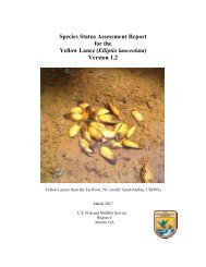
A. Peak Flow<br />
Determining the peak flow leaving a watershed during a storm is important when designing many<br />
stormwater BMPs. The peak flow is simply the period when the greatest volume of water leaves<br />
the watershed through the course of a storm event. The following graph shows a sample flow<br />
versus time relationship and its associated peak flow. The depth of rain that falls throughout the<br />
event can be observed on the right side of graph.<br />
Peak Flow Illustration (Figure 4-4 Virginia Stormwater Management Handbook, Volume 2, 1st edition 1999)<br />
17
The peak flow is used to determine the capacity of stormwater conveyance systems and size BMP<br />
outlet structures. See Appendix A.2 for detailed calculations.<br />
B. Dispersing Stormwater<br />
Stormwater collects and concentrates very easily in depressions, swales, natural runoff<br />
conveyances, rain gardens, and rain water cisterns. If possible, backyard stormwater BMPs should<br />
have an overflow connection to an existing stormwater drainage pathway. The current drainage<br />
path can be utilized as a way to convey water away from the BMP should a storm occur that is<br />
larger than what the BMP is designed to hold.<br />
2.4.3 BMP Components<br />
A. Pretreatment and Inlet Control<br />
Pretreatment is a necessary component of many stormwater BMPs. Pretreatment is a process to<br />
reduce pollution in stormwater before it is introduced into a stormwater BMP. Pretreatment is<br />
usually performed to reduce constituents, such as sediment, that may interfere or substantially<br />
reduce the effectiveness of a stormwater BMP. Pretreatment requirements for stormwater BMPs<br />
covered by the Program can be found in Appendix B.<br />
B. Outlet Structure<br />
Close attention should be paid to where the water from a stormwater BMP exits a given property.<br />
During small rain events, depending on soil conditions, all the stormwater produced in a small<br />
watershed may be retained in the BMP. However, during larger rainfall events the stormwater<br />
BMP will fill to capacity and spill over into the adjoining area.<br />
There are three types of outlets to consider: underdrains, orifices, and weirs. An underdrain is a<br />
perforated pipe that collects excess water from a filtering practice and is typically connected to a<br />
storm sewer system or ‘day lighted” into a conveyance system. An orifice is a part of a control<br />
structure that includes a riser and barrel through an earthen embankment. Orifice outlets typically<br />
connect to a storm sewer system or “daylights” into a conveyance system. A weir is a notch in the<br />
earthen embankment similar to an open channel. Weirs can be a vegetated, stone or concrete and<br />
they typically discharge runoff overland as sheet flow. Selection of an outlet is dependent on the<br />
stormwater BMP and location of an adequate conveyance system.<br />
Special care should be taken to ensure that the area into which the outlet discharges is able to<br />
convey the stormwater safely to a nearby conveyance system, such as an inlet, culvert or open<br />
channel. The procedure for determining the appropriate outlet size can be found in Appendix A.3<br />
2.4.4 Compliance with Local, State, and Federal Codes<br />
A. Permits<br />
The type, size and location of the BMP may require compliance with local zoning ordinances and<br />
local, state and federal permitting. A joint permit application (JPA) should be submitted when<br />
impacting wetlands and streams. If the size of the BMP disturbs enough land to qualify as a land<br />
disturbing activity, then a local land disturbing permit may be needed. These BMPs must comply<br />
with the local program ordinance and the Virginia Erosion and Sediment Control Regulations<br />
(9VAC25-840 et seq.).<br />
18
B. Riparian Buffers<br />
Riparian buffers help to absorb periodic flood surges; supply thermal protection, food, and cover<br />
to fish and other wildlife; stabilize stream-banks; filter runoff; and provide recreation and<br />
aesthetic values.<br />
Riparian buffer rules in certain localities can impact the function and siting of a backyard<br />
stormwater BMP. All participants should confer with their local governments, as well as their<br />
local Soil and Water Conservation District, to determine if proposed BMPs may be impacted by<br />
local riparian buffer requirements<br />
2.4.5 Considering Soil Conditions<br />
A. Soil Fertility<br />
Stormwater BMPs are impacted significantly by the soil in which they are constructed. Therefore,<br />
it is important to know which soil types are present at a given location before designing or<br />
constructing a stormwater BMP. The presence of restricted layers such as shallow bedrock, high<br />
water table, and compacted clay may affect construction and design of stormwater BMPs. Soil<br />
properties such as hydraulic conductivity, texture, and linear extensibility affect site infiltration<br />
rates. Soil nutrient levels (N-P-K), pH and cation-exchange-capacity (CEC) affect vegetation<br />
establishment. When a site is evaluated for a practice, determining the soil type at the site can be<br />
performed first by referring to soil surveys for general soil characteristics and then, more<br />
importantly, from field investigations.<br />
B. Soil Surveys<br />
Soil Surveys are comprehensive reports on soil resources of a given county. These publications<br />
include maps with soil boundaries, aerial photos, narrative descriptions of each soil map unit and<br />
tables explaining specific soil properties and features. District staff should become familiar with<br />
the soil survey of their particular counties. It is important to note that soil surveys may not be<br />
accurate to the site scale level.<br />
C. Site Investigations<br />
Soil information gathered solely from a soil survey should not be used exclusively to determine<br />
which type of soil is present at a given site. A site investigation is needed to verify that the soil on<br />
site is suitable for a given BMP, especially those intended to provide infiltration. Infiltration<br />
information can be gathered in two ways, first by testing for presence of wetland soils, and secondly<br />
by testing for permeability.<br />
To test for wetland soils dig a test hole in the location of the proposed BMP that is approximately<br />
2-foot deep, or to the depth of the bottom of the proposed BMP, whichever is deeper. As the hole<br />
is being dug, the soil should be observed for signs that it is a wetland soil. Wetland soils are<br />
commonly grey with ribbons of brown. If wetland soils are identified within 1 foot of the surface<br />
at a given site, the site is likely poorly drained. A detailed description of wetland soils is available<br />
in Vepraskas (1999).<br />
To test for permeability conduct a simplified soil infiltration test. This is a test to check the<br />
permeability of the soils being evaluated for BMP suitability. A hole should be dug using an<br />
auger or spade, approximately 1 foot below the expected bottom of BMP. The newly dug hole<br />
should be filled with a known amount of water. Monitor how quickly the hole drains and use this<br />
information to select the appropriate BMP. The drainage rate is particularly important for plant<br />
selection and bottom grading of the practice.<br />
19
2.4.6 Maintenance<br />
Once construction is completed, periodic inspections must be performed to ensure the BMP<br />
continues to function as designed. Maintenance is a necessary component of all BMPs. All<br />
participants must be aware of the operation and maintenance responsibilities for the proposed<br />
BMP. These responsibilities, as noted in the BMP-specific Operations and Maintenance Plan<br />
found in the Job Sheet (VCAP form-2) attached to the Landowner Agreement (VCAP form-3)<br />
(see Appendix D), may influence BMP selection. District Staff should discuss the following<br />
maintenance requirements with all participants:<br />
A. Routine Maintenance<br />
Routine maintenance may include landscaping and aesthetic maintenance such as grass, tree and<br />
shrub care, wetland plant care, re-seeding and mulching, slope stabilization, grass mowing,<br />
pruning, filling and repair of gully erosion, repair of shoreline, animal control caused by nuisance<br />
rodents, removal of invasive vegetation and minor sediment cleaning. It also may include removal<br />
of debris, trash, sediment, vegetation and other matter that impedes or threatens to impede<br />
stormwater functioning or structural integrity.<br />
B. Non-Routine Maintenance<br />
Non-routine maintenance may include the repair or replacement of structural components such as<br />
embankments, risers and outlet barrels, trash racks and anti-vortex devices, emergency spillways,<br />
pretreatment forebays, seepage controls, drains, water quality or quantity control devices, outlet<br />
protections or energy dissipaters, shoreline stabilization, and major sediment removal (excavation<br />
or dredging methods).<br />
2.4.7 Problems Regarding Multiple Property Owners<br />
Before a site is chosen for a backyard stormwater BMP, the property boundaries must be clearly<br />
defined by property owner and verified if possible by District staff. This is to ensure that no part<br />
of the stormwater BMP would be located on property belonging to an individual not participating<br />
in the Program. If a stormwater BMP is to be located in such a way that multiple property<br />
owners will be impacted, all property owners must be contacted and must agree upon the BMP<br />
measures in the project contract, and be noted in the Landowner Agreement VCAP form 3.<br />
Additionally, stormwater BMPs are designed to slow and capture stormwater before it leaves a<br />
given property, thus a pool of water may form as water slows and enters the BMP. This pool of<br />
water should not extend to a neighbor’s property without written consent in the project contract.<br />
It should also be noted that downstream property owners usually benefit from their upslope<br />
neighbor’s installation of backyard BMPs, which bring about a potential reduction in flooding and<br />
erosion on the downstream owner’s property. This benefit should be clearly communicated to the<br />
non- participating landowners as part of the development of the BMP project.<br />
20
Section 3.0 General Policies<br />
PART III: New BMP Retrofits<br />
A new “retrofit” occurs when installing a BMP that creates storage to reduce nutrients from<br />
existing developed land that is not currently receiving any stormwater treatment (CBPWQGIT,<br />
2012). These stormwater practices are built near stormwater outfalls or within existing<br />
stormwater conveyance system; adjacent to large parking lots or other impervious areas; within<br />
right-of-ways; and on individual residential properties.<br />
The practices in this section are organized by the level of engineering required for their design.<br />
When engineering is required, the practices are further divided by scale or scope of the project. As<br />
a guideline, the following is the assigned level of engineering for the BMPs in this section:<br />
Basic practices generally require no engineering in their installation and minimal planning. These<br />
can generally be planned and installed by a participant with minimal District assistance.<br />
3.1 Pet Waste Station (Not Currently Funded)<br />
3.2 Urban Nutrient Management Planning (Not Currently Funded)<br />
3.3 Impervious Surface Removal<br />
3.4 Conservation Landscaping<br />
Intermediate practices require more extensive planning and in some instances some engineering<br />
and thus may require the participant to hire a skilled contractor with some engineering expertise.<br />
3.5 Rain Garden<br />
3.6 Dry Well<br />
3.7 Constructed Wetland<br />
Advanced practices require extensive planning, the hiring of a skilled contractor and engineer,<br />
and District staff certification and training.<br />
3.8 Vegetated Stormwater Conveyance<br />
3.9 Rainwater Harvesting<br />
3.10 Bioretention<br />
3.11 Infiltration Basin<br />
3.12 Permeable Pavement<br />
3.13 Green Roof<br />
Release Agreement for Advanced BMPs:<br />
Depending on the scale of the practice, a Release Agreement (VCAP Form – 5) may be used to<br />
waive the requirement for the design plan to be certified with a stamp from a licensed<br />
professional. The Steering Committee must be notified when a participant requests waiving this<br />
requirement. The following will be used by Districts as a guide for that determination in<br />
accordance with the scale tables below.<br />
<br />
<br />
<br />
Local Districts may approve the waiver for Small Scale projects.<br />
The Steering Committee may approve the waiver for Medium Scale projects<br />
Large Scale projects cannot waive the requirement for a design plan to be stamped by a<br />
licensed professional. All Level 2 designs are considered Large Scale projects.<br />
21
Rainwater Harvesting (RH) Scales<br />
Scales Size (gallons) Allowable Configuration<br />
Small 6 feet and Height to<br />
Width > 2:1)<br />
Bioretention (BR), Infiltration (IF) and Vegetated Conveyance Systems (VCS) Scales<br />
Scales<br />
Small<br />
Medium<br />
Large<br />
Bioretention<br />
Size (square<br />
feet)<br />
< 300 sq. ft.<br />
< 1,500 sq. ft.<br />
>1,500 sq. ft.<br />
Permeable Pavement (PP) Scales<br />
Infiltration<br />
Size (square<br />
feet)<br />
< 300 sq. ft.<br />
and depth < 3<br />
feet<br />
< 1,500 sq. ft.<br />
and depth < 5<br />
feet<br />
>1,500 sq. ft.<br />
or depth > 5<br />
feet<br />
Vegetated Conveyance<br />
System<br />
Slope Gradient (%)<br />
Slope < 2%<br />
Slope 10%<br />
Drainage Area (acre)<br />
CDA < ½ acre at maximum<br />
25% IAT; or CDA < 10,000 sq.<br />
ft. and IAT is < 2,500 sq. ft.<br />
CDA < 1 acre and<br />
IAT < 20,000 sq. ft.<br />
CDA < 2 acre and<br />
IAT > 20,000 sq. ft.<br />
Scales Size (square feet) Drainage Area (acre) Allowable Configuration<br />
Small
Policies Regarding New BMP Retrofit Practices<br />
Detailed standards for each BMP are discussed in subsequent sections of this chapter. Where<br />
applicable, these BMP standards are based on the specifications of the Virginia Stormwater BMP<br />
Clearinghouse to be consistent with the Chesapeake Bay TMDL Watershed Implementation Plan<br />
(WIP). Below are the design standards that pertain to all practices within Section 3.<br />
A. Eligibility<br />
Practices are not intended to meet regulatory requirements.<br />
Practices funded through this program cannot be used for Nutrient Trading.<br />
B. Lifespan Requirements of VCAP Projects<br />
<br />
<br />
<br />
<br />
Urban Nutrient Management Plans expire after 3 years.<br />
Pet Waste Stations must be maintained for 3 years.<br />
All other practices must be maintained for 10 years.<br />
Once installed, projects should be considered permanent landscape features and an effort<br />
should be made to provide for continuation beyond the Program commitment.<br />
C. Ranking Criteria for VCAP Funding<br />
Each application will be numerically ranked based on Site, Practice and Application criteria.<br />
The site specific criteria include the presence of an existing BMP; ownership; proximity to<br />
waterway or storm drain; and existing problem. The practice specific criteria includes BMP<br />
type; mitigating a TMDL impairment; establishing or enhancing a riparian buffer or filter strip;<br />
critical slopes over 15 percent; impervious acres treated; contributing drainage area; and<br />
opportunities to disconnect and disperse impervious areas. The application specific criteria<br />
includes creating partnerships; signage; providing educational value; initiating practices in new<br />
Districts; and rewarding participants with final plans ready for implementation.<br />
See the VCAP Urban Practice Ranking Sheet (Form-6) in Appendix D.<br />
D. Plans and Specifications<br />
<br />
<br />
The participant is responsible for ensuring that the proposed project construction<br />
and subsequent maintenance meets all applicable local, state and federal permits,<br />
policies and ordinances.<br />
Design plan and Job Sheet (VCAP Form-2) shall include the following:<br />
- Sketch showing the location, specifications, contributing drainage area, impervious<br />
areas treated, and dimensions of the practice,<br />
- Cross section showing the depth, slope, and inlet, outlet and overflow structures<br />
where applicable,<br />
- Material Lists and Cost Estimate,<br />
- Site constraints for construction should be identified,<br />
- Installation requirements including construction sequence and site stabilization, and<br />
- Necessary computations per the practice standards.<br />
23
E. Operation and Maintenance<br />
<br />
<br />
All practices will be subject to spot checks by SWCD staff during the practice’s lifespan.<br />
Participant must accept maintenance responsibilities for the practice per an approved<br />
Operation and Maintenance Plan found in the Job Sheet (VCAP form 2), attached to the<br />
Landowner Agreement VCAP form 3(see Appendix D). This agreement will include<br />
specific maintenance objectives described for each BMP.<br />
F. Technical Responsibility<br />
<br />
<br />
<br />
<br />
The participant will be responsible for submitting all project plans. Technical guidance<br />
may be provided by local SWCDs. All projects must meet local codes, ordinances, and<br />
policies, and must address any permitting requirements.<br />
The local SWCD is responsible for reviewing all plans, providing any necessary technical<br />
guidance, and inspecting the completed practice to ensure that all standards have been<br />
met prior to issuance of payment.<br />
District staff that provides assistance and approval of projects must have a basic<br />
understanding of nonpoint source pollution and pollution reduction in Virginia.<br />
Stormwater and Erosion and Sediment Control certification is preferred.<br />
A licensed or certified professional is responsible for certifying design plans for advanced<br />
practices. Should a program participant choose to assume the responsibility and forgo a<br />
licensed, engineered design, a Release Agreement VCAP form-5 shall be signed.<br />
G. Cost-Share and Incentives<br />
<br />
<br />
<br />
Cost Estimates are needed to determine the Cost-Share amount.<br />
If a practice requires a pre-treatment then the pre-treatment costs are included in the<br />
primary practice costs.<br />
Incentives are flat payments that do not exceed the total cost of installation.<br />
H. Planning Considerations<br />
Miss Utility notification (Call 811).<br />
<br />
<br />
Infiltration test (USDA NRCS Soil Quality Test Kit Guide. Soil Quality Institute. July<br />
2001. Section I Part 3. Page 7-8. Or Appendix 8-A on the Virginia Stormwater BMP<br />
Clearinghouse)<br />
Soil Compaction Test (see Penn State Extension Agronomy Facts 63 or Bulk Density Test<br />
USDA NRCS. Soil Quality Test Kit Guide. Soil Quality Institute. July 2001. Section I<br />
Part 4. Page 9-13.)<br />
Soil Fertility Testing (see VCE PUB 425-125 and 425-129)<br />
<br />
Setbacks from dwellings, septic and wells shall follow guidelines per the practice standard.<br />
24
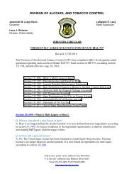
Section 3.1 Pet Waste Stations (PWS)<br />
Typical Pet Waste Station<br />
The Environmental Protection Agency estimates that the typical dog produces three-quarters of a<br />
pound of waste per day. Left alone, pet waste can pollute ground and surface water, attract flies<br />
and pests, and transmit parasites and infectious diseases. Pet waste stations are designed to<br />
encourage pet owners to pick up after their animals in parks and other public places to prevent<br />
waste from being transported off-site by stormwater runoff. As illustrated above, pet waste<br />
stations typically include a covered 10-gallon waste can and plastic or bio-degradable “pick-up”<br />
bags attached to a sign-post that identifies the station purpose, and are installed at convenient<br />
locations where pet-walking and pet exercise occurs. However, where trash receptacles are<br />
already deployed in a public area, the waste cans are not an essential component of this BMP.<br />
Policies Regarding PWS<br />
Pet Waste Stations have relatively few practice constraints other than ensuring that the receptacles<br />
are located at places where pet owners are likely to have need of their services, they can be<br />
serviced and maintained by available staff, and the ultimate disposal facility will not of itself cause<br />
a water quality problem by concentrating the pet waste in or near a watercourse or in groundwater.<br />
This practice is a nonstructural BMP and is simple to implement.<br />
A. Criteria<br />
<br />
<br />
<br />
<br />
This practice should only be installed in public areas such as parks, neighborhood<br />
common areas, apartment complexes, and similar public areas that are easily<br />
accessible and visible to pet walkers. .This practice is not designed for the individual<br />
homeowner.<br />
Receptacles should be safely located away from areas used for access by public<br />
utility service vehicles and must be at least 100 feet from water conveyance systems.<br />
Each station must have a professionally designed sign describing the use and purpose<br />
of the station. .Most commercial stations come with this type of sign.<br />
The waste disposal site will not of itself cause a water quality problem by its location<br />
to a watercourse or groundwater supply.<br />
25
B. Plans and Specifications<br />
<br />
A final design plan for the site must be submitted by the landowner and approved by the<br />
local Soil and Water Conservation District before construction is initiated. The installed<br />
practice must be in accordance with the approved design unless changes were preapproved<br />
by the local SWCD. .Information required in the plan includes:<br />
- Location within the property on a site map.<br />
- Site preparation details.<br />
- Provide Manufacturer specifications for installation, such as depth of posts and<br />
foundation materials.<br />
- Provide a waste disposal plan, if a trash can is included in the design.<br />
C. Operations and Maintenance<br />
<br />
<br />
At least weekly service and maintenance for all stations that include a waste receptacle.<br />
Refill waste bags as necessary.<br />
D. Cost-Share Rates<br />
<br />
<br />
After the initial purchase of the station, VCAP will not provide assistance for waste bags.<br />
The Program will reimburse up to 75 percent of costs up to a maximum payment of<br />
$400.00 per station.<br />
E. Helpful Technical Reference<br />
<br />
http://www.annapolisgreen.com/pdf/PetWasteStationCommProgHowToGuide.pdf<br />
26
Section 3.2 Urban Nutrient Management Planning (UNMP)<br />
Surveys 1 show that about 50 percent of homeowners fertilize their lawns, but fewer than 20<br />
percent of those who fertilize consult an expert lawn professional or take a soil test to determine<br />
the optimal fertilization strategy. Nutrient export associated with turf grass fertilizer use from<br />
home, commercial and industrial lawns depends on various landscape factors, fertilizer<br />
application rates and overall lawn care practices. Having an urban nutrient management plan<br />
developed ensures an optimal fertilization strategy will be implemented and helps to reduce<br />
nutrient export from fertilized lawns.<br />
1 Schueler, T., Lane, C. 2013. Recommendations of the Expert Panel to Define Removal Rates for<br />
Urban Nutrient Management: CBP Approved Final Report. p34-35.<br />
Policies Regarding UNMP<br />
Urban Nutrient Management plans (UNMP) have relatively few practice constraints other than:<br />
the area associated with the plan must currently be fertilized or have a critical need to be<br />
renovated because of poor or no vegetative cover, the property owner agrees to keep fertilization<br />
records regardless of who is making the applications, the property owner agrees to have a certified<br />
fertilizer applicator apply all fertilizer in accordance with the plan or the property owner<br />
demonstrates they have the necessary knowledge along with proper application and calibration<br />
equipment to apply the fertilizer themselves.<br />
Definitions:<br />
An amended Urban Nutrient Management Plan is a current UNMP that has been updated to<br />
accurately match current landscape management practices. Plans only need to be amended if<br />
changing of landscape plants or turf grass species drastically alters the optimal fertilization<br />
strategy outlined in the current plan.<br />
A revised Urban Nutrient Management Plan is an expired UNMP that has been rewritten to<br />
accurately match actual landscape plants and/or lawn management practices.<br />
A. Ranking and Priority (high and low)<br />
<br />
<br />
<br />
<br />
<br />
<br />
<br />
Proximity to stream, river, storm drain, or bay (within 300 feet = high priority).<br />
Very High (VH) Virginia Tech soil test phosphorus fertility rating or correlated to VH<br />
from another lab.<br />
Area was previously over fertilized compared to DCR guidelines.<br />
Newly established turf.<br />
Fertilized areas have slopes greater than 15% (and account for 33% or more of the<br />
landscape).<br />
High water table.<br />
Soil types: shallow soils, sandy soils or karst terrain.<br />
27
B. Criteria<br />
<br />
<br />
<br />
<br />
This BMP applies to fertilized turf grass landscapes and other ornamental plant landscape<br />
areas that receive nutrients at least once in a three year period.<br />
In order to be eligible for cost-share, urban nutrient management plans must be prepared<br />
by a private planner who holds a current Nutrient Management Planner Certificate in the<br />
Turf and Landscape Category issued by the Virginia Department of Conservation and<br />
Recreation. Urban Nutrient Management Plans must be written to comply with all<br />
requirements set forth in the Nutrient Management Training and Certification Regulations,<br />
(4 VAC 50-85-10 et seq.) and the criteria set forth in the Virginia Nutrient Management<br />
Standards and Criteria, revised July 2014.<br />
Plans must be developed based on soil analyses taken within a three year period prior to<br />
plan development and must be performed by soil testing laboratories approved by DCR.<br />
Before cost-share payment can be made the following items must be submitted:<br />
- A complete copy of the Urban Nutrient Management Plan, containing the planner’s<br />
Virginia Nutrient Management Certificate number.<br />
- An invoice for planning services from the private certified planner.<br />
- If the participant is seeking cost-share for a plan previously written under this<br />
specification, fertilizer application records and the previous plan must be presented<br />
to SWCD staff for review.<br />
C. Plans and Specifications<br />
<br />
Urban Nutrient Management Plans will be prepared to include all necessary information as<br />
outlined in the Nutrient Management Regulations 4 VAC 50-85-10 et seq. Outlined plan<br />
content can be found at: http://www.dcr.virginia.gov/soil_and_water/documents/nmtmsctl_plan_checklist.pdf<br />
D. Operations and Maintenance<br />
<br />
<br />
<br />
<br />
Participant is required to keep all fertilizer records regardless of who makes the<br />
applications.<br />
Participant is responsible for notifying the certified planner when landscape plants or lawn<br />
care practices have changed, warranting amendment of the plan.<br />
Participant is responsible for maintaining adequate vegetative cover.<br />
All plans are subject to spot check procedures and any other quality control measures.<br />
E. Cost-Share Rates<br />
<br />
<br />
The Program will reimburse up to $100 per parcel per year. If the plan is written through<br />
a Virginia Cooperative Extension Master Gardener program, the maximum allowable<br />
reimbursement is equal to the fee associated with the Master Gardener Program.<br />
Participants may redirect their cost-share payment to their private certified nutrient<br />
management planner by signing a written statement to that effect. A sample statement is<br />
attached to this specification<br />
28
F. Helpful Technical References<br />
Chapter 13 of the Urban Nutrient Management Handbook<br />
Nutrient Management Standards and Criteria Revised July 2014<br />
Fertilizer Applicator Certification Training (FACT)<br />
Fertilizer calculator (Derek)<br />
ASSIGNMENT OF URBAN NUTRIENT MANAGEMENT PLAN WRITING COST-SHARE<br />
PAYMENT AUTHORIZATION<br />
I<br />
, do hereby<br />
direct the<br />
Soil and Water<br />
Conservation District (SWCD) to pay any and all cost-share funds disbursed under the<br />
URBAN NUTRIENT MANAGEMENT PLAN WRITING to<br />
Name<br />
, of<br />
Business<br />
for services provided during development of my Nutrient Management Plan.<br />
Signature<br />
Date<br />
29
Section 3.3 Impervious Surface Removal (ISR)<br />
Surfaces covered by impenetrable materials such as asphalt, compacted gravel, concrete, brick,<br />
and stone are impermeable. These impermeable materials seal surfaces, repel water, and prevent<br />
precipitation from infiltrating into soils and groundwater. Removal of these impermeable<br />
materials, when combined with permeable pavement or vegetation establishment, is intended to<br />
reduce stormwater runoff rate and volume, as well as associated pollutants transported from the<br />
site by stormwater runoff.<br />
The process of urbanization, characterized by increases in impermeable or impervious areas,<br />
causes a substantial increase in stormwater runoff. One obviously beneficial stormwater<br />
management practice is to reduce the amount of impervious surface area in a given urbanized<br />
area. If an area has already been urbanized, this can be accomplished by removing impervious<br />
areas that can be replaced with pervious areas and still serve the intended purpose.<br />
Policies Regarding ISR<br />
Patios, walkways, parking areas, and driveways can all be converted to pervious areas that<br />
increase infiltration to groundwater. Gardens, lawns, and permeable pavers all can be used in<br />
place of the impervious area removed. In order for impervious surface removal costs to be offset<br />
by the Program, they must be accompanied by an approved stabilization plan. This practice is<br />
considered to be a nonstructural BMP.<br />
A. Criteria<br />
<br />
<br />
<br />
<br />
<br />
<br />
This BMP is not intended for impervious surface removal associated with roof removal<br />
(associated with structure removal)<br />
Removal must include the impervious surface and sub-grade aggregate. The materials<br />
removed must be properly disposed.<br />
The subsoil shall be scarified at least 2 inches below the compacted subgrade aggregate.<br />
The practice must include a plan for vegetation establishment or permeable pavement<br />
installation.<br />
When vegetation is to be established on site, the practice should be initiated as closely as<br />
possible to the optimum time for vegetation establishment. Temporary conservation cover<br />
must be established within 14 calendar days if permanent vegetation cannot be established.<br />
Vegetation establishment must include proper soil preparation, which may require a soil<br />
test. Deep tillage using a chisel plow, ripper or sub-soiler may be required to address soil<br />
compaction. Addition and incorporation of topsoil or organic matter may be necessary for<br />
proper seedbed establishment.<br />
Incorporate soil compost amendments if the intention is to have the newly previous act as<br />
a riparian buffer or filter strip.<br />
B. Plans and Specifications<br />
<br />
A design plan for the site must be submitted by the landowner and approved by the local<br />
Soil and Water Conservation District before construction is initiated. The installed<br />
practice must be in accordance with the approved design unless changes were preapproved<br />
by the local SWCD. Information required in the design plan includes:<br />
30
Total impervious surface area to be removed and detailed map of the site.<br />
A plan for fragmenting, removal and disposal of existing impervious cover.<br />
A plan for soil preparation, which must be supported by a soil-test.<br />
A plan for final site stabilization.<br />
Expected timeline for completion.<br />
Erosion and Sediment Control Plan, if applicable<br />
C. Operation and Maintenance<br />
<br />
<br />
<br />
<br />
Maintenance Inspection of the planted area shall be conducted annually by the landowner,<br />
or a designated sub-contracted agent of the landowner.<br />
Site specific maintenance items depending on final stabilization plan.<br />
Ensuring full vegetative cover remains intact and invasive species are controlled if<br />
vegetation is used.<br />
No impervious surface built over the treated area.<br />
D. Cost-Share Rates<br />
<br />
The Program will offer incentive payments based on a rate of up to $2.50 per square foot<br />
of treated area with a maximum payment of $10,000.00 per parcel per year.<br />
E. Helpful Technical References<br />
<br />
<br />
<br />
Conservation Landscaping BMP in this Manual (see Section 3.4 below).<br />
Permeable Pavement BMP in this Manual (see Section 3.11 below)<br />
Virginia Stormwater Clearinghouse Design Specification No. 4 Soil Amendments<br />
http://www.vwrrc.vt.edu/swc/NonProprietaryBMPs.html<br />
Virginia Erosion and Sediment Control Handbook Standard and Specification 3.30 –<br />
Topsoiling. http://www.dcr.virginia.gov/stormwater_management/e_and_s-ftp.shtml<br />
31
Section 3.4 Conservation Landscaping (CL)<br />
This practice encompasses the conversion of turf grass areas or bare soils to areas planted in native<br />
herbaceous and woody species. Converting landscape into highly functioning ecosystems<br />
collectively in a community can have significant beneficial impacts on local water quality and<br />
that of the Chesapeake Bay.<br />
Native plants are generally best adapted to local soil and climate conditions and therefore require<br />
the least amount of nutrient addition or cultivation in order to maintain the amount of ground<br />
cover best suited to minimize runoff. In contrast, turf grasses and non-native species generally<br />
require both continual maintenance and periodic fertilization in order to provide the same amount<br />
of stormwater runoff protection. Therefore, the conversion to of native plants will generally be<br />
beneficial from a nonpoint source runoff pollution prevention standpoint.<br />
The nutrient load of a residential lawn has been estimated at between 2 and 9.7 mg/L./year of<br />
nitrogen and between 0.3 and 1.9 mg/L/yr. of phosphorus (CSN TB 9, 2011).<br />
Policies Regarding CL<br />
Natural Meadow Turf to Native Plant Management<br />
There are three conservation landscaping practices covered under this standard; Meadow, Tree<br />
Planting, and Landscaped Mulched Bed. Meadow or Tree Planting may be used for establishing a<br />
Riparian Buffer along a waterway or pond. A Meadow may be used as a Filter Strip when<br />
receiving runoff from impervious surfaces. This practice is considered to be a nonstructural BMP,<br />
unless used as a Filter Strip.<br />
32
A. Criteria<br />
<br />
<br />
<br />
<br />
<br />
<br />
<br />
<br />
<br />
<br />
<br />
Perennial native species that are adapted to the site conditions must be used. Therefore,<br />
selected species must have the capacity to achieve adequate density and vigor within an<br />
appropriate time frame to stabilize the site sufficiently to permit suited uses with ordinary<br />
management activities. Invasive or noxious species are prohibited. Plant species must be<br />
considered native “Flora of Virginia”. See Helpful Technical References section for<br />
publications and websites related to native plants.<br />
Vegetation establishment must include proper soil preparation. Deep tillage using a chisel<br />
plow, ripper or sub-soiler may be required to address soil compaction. Addition and<br />
incorporation of topsoil or organic matter may be necessary for proper seedbed<br />
establishment.<br />
This practice should be initiated as closely as possible to the optimum time for vegetation<br />
establishment. Temporary conservation cover must be established within 14 calendar<br />
days if permanent vegetation cannot be established.<br />
Mowing of the planted area shall be limited according to the approved Operation and<br />
Maintenance Plan described in the Job Sheet VCAP form 2.<br />
A meadow should include a seed mix with at least two (2) native grass species and nine<br />
(9) forbs/wildflower species. Alternative Seed Mix ratio may be considered. Competition<br />
controls must be included with the final plans. Competition controls should be described<br />
in greater detail in the site specific plan submitted before installation. A temporary cover<br />
is necessary when there will be two (2) burn downs separated by a growing season.<br />
Tree plantings are intended to be native species. Diversity is encouraged for larger scale<br />
projects. Appropriate tree protection measures must be employed, such as tree shelters,<br />
weed barriers, tree wraps, or other methods approved by the local SWCD.<br />
Landscaped Mulch Beds must include suitable mulch at least 3 inches thick. Landscape<br />
edging is recommended when adjacent to invasive ground cover and impervious surfaces.<br />
Required density and minimum ground covers for all plantings will be based on approved<br />
site specific plans. See VDOF recommendations for tree plantings in the Helpful<br />
Technical References section.<br />
Fertilization, mulching, or other facilitating practices for plant growth must be timed and<br />
applied to accelerate establishment of selected species, and must not be a requirement for<br />
vegetation maintenance. Soil amendments will be added only as demonstrated necessary<br />
according to a soil test report.<br />
Measures to exclude pests that will interfere with the timely establishment of vegetation<br />
must be employed.<br />
If the planting area is to serve as a Filter Strip or Riparian Buffer, the following criteria<br />
should be followed:<br />
A robust stand of vegetation should be established.<br />
Slope gradient shall be less than 8% for Filter Strips.<br />
Minimum width of 35 feet for slope gradients less than 4%. Minimum width of 50<br />
feet for slope gradients 4 to 6 percent. Minimum width of 65 feet for slope<br />
gradients of 6 to 8 percent. Riparian Buffers with slope gradients over 8 percent<br />
shall have a minimum width of 100 feet.<br />
Runoff onto the Filter Strip should be evenly dispersed with an adequate<br />
pretreatment measure. See appendix B<br />
33
Impervious area to Filter Strip should be less than 5,000 square feet.<br />
B. Plans and Specifications<br />
<br />
A planting plan for the site must be submitted by the landowner and approved by the local<br />
Soil and Water Conservation District before construction is initiated. The installed<br />
practice must be in accordance with the approved design unless changes were preapproved<br />
by the local SWCD. Information required in the planting plan includes:<br />
Type of Conservation Landscaping.<br />
Square footage of the area being planted.<br />
Linear feet of stream being buffered (if applicable).<br />
Total drainage area of the site and the amount of impervious surface draining to the<br />
project. Only applicable for Filter Strip applications.<br />
Slope of the land.<br />
Plan to control and/or eliminate unwanted existing vegetation.<br />
Landscape planting and mulching plan including: species, rate of seeding or<br />
planting, minimum quality of planting stock and method of establishment. Only<br />
viable, high-quality seed or planting stock should be used. Soil types and any soil<br />
amendments required as a result of a soil test. Include the amounts, timing and<br />
method of application of each amendment.<br />
C. Operation and Maintenance<br />
<br />
<br />
Maintenance of the planted area will be conducted annually by the landowner, or a<br />
designated sub-contracted agent of the landowner.<br />
Maintenance will include:<br />
Annual survey of planted area to evaluate for invasive species and plant<br />
survival/success. For the first two years, trees must have a 75 %survival rate with<br />
an overall survival rate of 50 %. Meadows must maintain a cover of 75 % or more.<br />
If invasive species are present (according to:<br />
www.dcr.virginia.gov/natural_heritage/documents/invlist.pdf), remove to reduce<br />
invasive cover ground cover to less than 5%.<br />
Tree and shrub mortality will be addressed annually by replanting the species with<br />
adequate protection and support to ensure survival.<br />
Trash should be removed at least annually.<br />
Issues of trespass, leading to damaged vegetation, will be addressed as necessary.<br />
D. Cost Share Rates/Incentives<br />
<br />
<br />
Meadows and Landscaped Mulch Beds will offer incentive payments based on a rate of<br />
up to $250.00 per 1000 square feet of area planted.<br />
Tree-planting will offer incentive payments based on a rate of up to $9.00 per tree.<br />
Payments will not exceed total cost of the project with a maximum payment of $3,500.00<br />
per parcel per year.<br />
<br />
Only one cost-share rate can be applied per planting area.<br />
34
E. Helpful Technical References<br />
<br />
USDA NRCS Conservation Cover: Wildflower Meadow for Wildlife and Pollinators.<br />
Virginia Conservation Practice Job Sheet 327. 2011.<br />
USDA NRCS Riparian Forest Buffer. Conservation Practice Job Sheet 391. 1997.<br />
NRCS Virginia Plant Establishment Guide. 2011.<br />
http://www.dgif.virginia.gov/quail/nrcs-plant-establishment-guide-species-list-2011.xls<br />
<br />
<br />
<br />
<br />
<br />
Dorner, Jeanette. An Introduction to using native plants in restoration projects. National<br />
Park Service. 2000. www.nps.gov/plants/restore/pubs/intronatplant/index.htm<br />
Homeowner Guide to Make your Property Bay Friendly. Chesapeake Stormwater<br />
Network. June 19, 2013. http://chesapeakestormwater.net/be-bay-friendly/<br />
http://www.prairiemoon.com/growing-your-prairie/growing-your-prairie.pdf<br />
VDOF Tree planting recommendations: http://www.dof.virginia.gov/tree/care/index.htm<br />
Native Plant Resources:<br />
Native Plant Center (ACB): http://www.nativeplantcenter.net/<br />
Digital Atlas of the Flora of Virginia: http://vaplantatlas.org/<br />
Flora of Virginia Project: http://floraofvirginia.org/<br />
Native Plants for Conservation, Restoration & Landscaping<br />
http://www.dcr.virginia.gov/natural-heritage/nativeplants<br />
35
Section 3.5 Rain Garden (RG)<br />
A Rain Garden is a shallow landscaped depression that incorporates many pollutant removal<br />
mechanisms including temporarily ponding stormwater runoff 6 to 12 inches above a mulch layer<br />
that encourages the rain water to infiltrate into the underlying native soil within 48 hours.<br />
A Typical Rain Garden<br />
Policies Regarding RG<br />
Rain Gardens should be designed to treat runoff from small areas, such as individual rooftops,<br />
driveways and other on-lot features in single-family detached residential developments. Inflow<br />
is typically from a downspout with energy dissipaters or can be sheet flow from a<br />
driveway/patio or lawn. This practice is intended for disconnecting impervious surfaces.<br />
A. Criteria<br />
<br />
<br />
<br />
<br />
Practice should be located within 40 feet of downspout or contributing impervious<br />
surface.<br />
Project drainage area will not contain more than ½ acre at 25% impervious cover, unless<br />
the total project drainage area is less than 10,000 square feet in which case impervious<br />
area will not be greater than 2,500 square feet.<br />
Rain Gardens shall be sized with the following method (Fairfax County, 2009), Dp is<br />
the depth of ponding in feet:<br />
Impervious Surface (sq. ft.) x 0.072/ Dp = ___________ sq. ft.<br />
Pervious Surface (sq. ft.) x 0.028/ Dp =<br />
Total Surface Area Size Required =<br />
36<br />
___________ sq. ft.<br />
___________ sq. ft.<br />
Alternative sizing methods may be considered on a case-by-case basis. Multiple rain
gardens for a large drainage area are encouraged to keep the maximum size to no more<br />
than 300 sq. ft. per cell (excavated ponding area).<br />
The site must have soils capable of infiltrating stormwater runoff. If the need for soil<br />
replacement or underdrain is identified the participant should consider a bioretention<br />
practice.<br />
The subsoil of the ponding area will be amended with compost to achieve 5 percent<br />
organic matter content. Typically, compost is applied at a 4:1 ratio (soil to compost)<br />
usually 1 inch of compost incorporated 4 inches. A compost amendment rate calculator<br />
similar to the SoilsforSalmon.org may be used.<br />
Rain Gardens will not be placed in wetland soil or within the 100-year flood plain.<br />
Rain Gardens should retain water for less than 48 hours after a storm event.<br />
Depth to water table and bedrock shall be greater than 2 feet.<br />
Impact from location of proposed Rain Garden on septic drain fields and foundations<br />
should be evaluated prior to application approval.<br />
A stable stormwater overflow route must be available or provided.<br />
When concentrated stormwater is routed into a Rain Garden, an energy dissipater must<br />
be provided that will prevent scour of the Rain Garden. Alternative pretreatment may be<br />
considered. See Appendix B.<br />
All vegetated areas that drain to the Rain Garden must be maintained in full vegetative<br />
cover with no scour areas.<br />
Planting and mulching and all other site stabilization measures must occur immediately<br />
after constructing the Rain Garden. Seasonal exceptions can be made<br />
B. Plans and Specifications<br />
A design plan for the site must be submitted by the landowner and approved by the local<br />
Soil and Water Conservation District before construction is initiated. The installed<br />
practice must be in accordance with the approved design unless changes were preapproved<br />
by the local SWCD. Information required in the design plan includes:<br />
<br />
- Results of an infiltration test (see Section 3.0 for infiltration test details)<br />
- Landscape plan including: species, rate of seeding or planting, minimum quality<br />
of planting stock and method of establishment. Only viable, high-quality seed or<br />
planting stock should be used.<br />
- Soil types and any required soil amendments as a result of a soil fertility test or<br />
compaction test, such as compost to add organic matter and improve soil structure<br />
and water holding capacity, or application of lime to increase pH of acid soils with<br />
the amounts, timing and method of application of each amendment.<br />
- A statement regarding compliance with any permitting requirements.<br />
- Other information as requested by the local SWCD<br />
It is the program participant’s responsibility to ensure any contractors meet all local<br />
codes and requirements.<br />
37
C. Operation and Maintenance<br />
Maintenance inspection shall be conducted annually by the landowner, or a designated<br />
sub-contracted agent of the landowner.<br />
<br />
First year Maintenance will include:<br />
- Weekly watering during the growing season;<br />
- Repair of erosion, as necessary<br />
Maintenance will include:<br />
- Annual survey of planted area to evaluate for:<br />
• invasive species<br />
• plant survival/success<br />
• ensure all vegetation stabilization measures remain intact<br />
• runoff flow routes functioning<br />
- If invasive species are present (according to:<br />
www.dcr.virginia.gov/natural_heritage/documents/invlist.pdf), remove to reduce<br />
invasive cover ground cover to less than 5%.<br />
- Tree and shrub mortality will be addressed annually by replanting the species with<br />
adequate protection and support to ensure survival.<br />
- Reapply wood mulch as needed.<br />
- Trash should be removed at least annually.<br />
D. Cost-Share Rates/Incentives<br />
The Program will reimburse up to 75 percent of costs with a maximum payment of<br />
$2,000.00 per parcel per year.<br />
When pre-treatment is required, the pre-treatment costs are included in the cost of the<br />
practice.<br />
E. Helpful Technical References<br />
<br />
Rain Garden Design and Construction: A Northern Virginia Homeowner Guide. Fairfax<br />
County, Va. 4/2009. http://www.fairfaxcounty.gov/nvswcd/raingardenbk.pdf<br />
Virginia Stormwater BMP Clearinghouse Design Specification No. 1 and No. 9<br />
http://www.vwrrc.vt.edu/swc/NonProprietaryBMPs.html<br />
<br />
<br />
<br />
Rain Garden Landscape Templates for the Mid-Atlantic<br />
http://www.lowimpactdevelopment.org/raingarden_design/<br />
Virginia Cooperative Extension Urban Water Quality Management Rain Garden Plants.<br />
Pub 426-043 https://pubs.ext.vt.edu/426/426-043/426-043_pdf.pdf<br />
Cogger, Craig. Compost Amendment Rate Calculator. Washington State University.<br />
Accessed 2016 at: http://www.soilsforsalmon.org/resources.htm<br />
38
Section 3.6 Dry Well (DW)<br />
A Dry Well is a subsurface storage facility that receives and temporarily stores stormwater runoff<br />
from roofs of structures. Discharge of this stored runoff from a dry well occurs through<br />
infiltration into the surrounding soils. A Dry Well may be either a structural chamber and/or an<br />
excavated pit filled with gravel.<br />
A Typical Dry Well<br />
Policies Regarding DW<br />
This practice is designed to treat runoff from small areas, such as individual rooftops, driveways<br />
and other on-lot features in single-family detached residential developments. Inflow is typically<br />
from a downspout but could be sheet flow from a driveway/patio or lawn.<br />
A. Criteria<br />
<br />
<br />
Practice should be located within 40 feet of downspout or impervious surface.<br />
Project drainage area will not contain more than ½ acre at 25% impervious cover, unless<br />
the total project drainage area is less than 10,000 square feet in which case impervious area<br />
will not be greater than 2,500 square feet.<br />
Dry Well shall be sized according to the following, where D is the depth of the reservoir<br />
(ft.) and Vr is Void Ratio of reservoir (typical 0.4 to 1.0):<br />
Impervious Surface (sq. ft.) x 0.95/ (12*Vr*D) =<br />
39<br />
___________ sq. ft.<br />
Pervious Surface (sq. ft.) x 0.25/ (12*Vr*D) = ____________<br />
Total Surface Area Size Required =<br />
___________ sq. ft.<br />
sq. ft.<br />
The footprint of the Dry Well may be reduced based on soil attributes and other site<br />
conditions, as approved by the District or certified by a licensed professional.<br />
The site must have soils capable of infiltrating stormwater runoff. Should retain water for<br />
less than 48 hours after a storm event. If the need for an underdrain is identified the<br />
participant should consider a Bioretention practice (3.10).
Depth to Water Table and Bedrock shall be greater than 2 feet from bottom of excavation.<br />
Shall not be placed in wetland soil or within the 100-year flood plain.<br />
Shall not be appropriate where high pollutant or sediment loading is anticipated due to<br />
potential groundwater contamination and clogging.<br />
Shall not be appropriate where there is a significant risk for basement seepage or flooding,<br />
cause surficial flooding of groundwater, or interfere with the operation of drain fields or<br />
other subsurface structures.<br />
Dry Well depth is typically between 1 and 5 feet, with at least 12 inches of soil and sod<br />
cover.<br />
Gravel reservoir shall be wrapped in non-woven geotextile meeting NRCS specification<br />
Va-795.<br />
Where necessary, leaf screens or debris sump shall be used as pretreatment to prevent<br />
clogging.<br />
Not intended to provide storage for large storms; therefore, a stable stormwater overflow<br />
or bypass route must be provided when connected to a downspout or drain pipe.<br />
All vegetated areas that drain to the practice must be maintained in full vegetative cover.<br />
Sodding must occur immediately after construction. Seasonal exceptions can be made<br />
Dry Well shall include observation ports with maintenance access.<br />
B. Plans and Specifications<br />
<br />
A design plan for the site must be submitted by the landowner and approved by the local<br />
Soil and Water Conservation District before construction is initiated. The installed<br />
practice must be in accordance with the approved design unless changes were preapproved<br />
by the local SWCD. Information required in the planting/design plan includes:<br />
- Results of a infiltration test (see Section 3.0 for infiltration test details)<br />
- A statement regarding compliance with any permitting requirements or local codes.<br />
- Other information as requested by the local SWCD.<br />
C. Operation and Maintenance<br />
<br />
<br />
Maintenance inspections shall be conducted annually by the landowner, or a designated<br />
sub-contracted agent of the landowner.<br />
Maintenance will include:<br />
- Inspection of pretreatment devices.<br />
- Inspection of observation ports for signs of prolonged standing water.<br />
- Routine maintenance of sod to ensure vegetative cover survives.<br />
40
D. Cost-Share Rates/Incentives<br />
<br />
<br />
The Program will reimburse up to 75 percent of costs with a maximum payment of<br />
$2,000.00 per parcel per year.<br />
When pre-treatment is required, the pre-treatment costs are included in the cost of the<br />
practice.<br />
E. Helpful Technical References<br />
<br />
USDA NRCS Engineering Field Handbook Part 650 Chapter 14 Water Management<br />
(Drainage) subsection C Subsurface Drainage. 2001.<br />
Virginia Erosion and Sediment Control Handbook (VESCH) Specification 3.28<br />
Subsurface Drains.<br />
http://www.deq.virginia.gov/Programs/Water/StormwaterManagement/Publications/ESC<br />
Handbook.aspx<br />
<br />
Virginia Stormwater BMP Clearinghouse Design Specification No. 1 Disconnection and<br />
No. 8 Infiltration Practices http://www.vwrrc.vt.edu/swc/NonProprietaryBMPs.html<br />
41
Section 3.7 Constructed Wetlands (CW)<br />
Constructed Wetland Receiving a Roof Drain<br />
A constructed wetland can temporarily store, filter, and clean runoff from driveways, roofs and<br />
lawns and thereby improve water quality. To properly function in this regard, the wetland should<br />
be designed and constructed to retain water or remain saturated for two to three weeks.<br />
Constructed wetlands are typically less than 1 foot deep (although they have greater depths at the<br />
forebay and in micro pools) and possess variable micro topography to promote dense and diverse<br />
wetland cover. The wetland environment provides an ideal environment for gravitational<br />
settling, biological uptake, and microbial activity. Constructed wetlands are the final element in a<br />
roof-to- stream runoff reduction sequence. They should only be considered for use after all other<br />
upland runoff reduction opportunities have been exhausted and there is still a remaining water<br />
quality or channel protection volume to manage.<br />
Policies Regarding CW<br />
Constructed Wetlands are intended to meet the Level 1 baseline design criteria. Enhancements to<br />
a Level 2 design may be considered in accordance with the Clearinghouse guidelines. These are<br />
ideal for sites that cannot meet the Rain Garden or Dry Well practice standards. Consultation<br />
with the U.S. Army Corp of Engineers for the determination of jurisdictional wetlands is needed<br />
for poorly drained sites.<br />
A. Criteria<br />
<br />
<br />
Project drainage area will not contain more than ½ acre at 25% impervious cover, unless<br />
the total project drainage area is less than 10,000 sq. ft. in which case impervious area<br />
will not be greater than 2,500 sq. ft.<br />
Constructed wetlands must be excavated to the water table elevation to maintain a<br />
permanent base flow. Deep pools must be 24-48 inches deep. Micro-pools must be 12<br />
inches deep or less. High marsh areas must be 6 inches deep or less.<br />
Constructed wetlands must have at least three cells. Fifteen (15%) to Twenty-five (25%)<br />
percent of the surface area must be deep pools (DP); fifty (50%) to seventy (70%) percent<br />
of the surface area must be high marsh (HM); and the remaining area may be micro pools<br />
(MP). Surface area may be calculated as follows:<br />
42
Dmean = DDP x (% deep pool) + DMP x (% micro-pool) + DHM x (% high-marsh)<br />
Impervious Surface (sq. ft.) x 0.95/ (12Dmean) = ______ sq. ft.<br />
Pervious Surface (sq. ft.) x 0.25/ (12Dmean) = _______ sq. ft.<br />
Total Wetland Area Required = _______ sq. ft.<br />
<br />
<br />
<br />
<br />
<br />
Variable width aquatic bench should be provided around any deep pools for safety.<br />
Width should be between 2 and 6 feet at a depth of 12 inches.<br />
A sediment forebay must be located at every concentrated inlet that receives 10 %or more<br />
of the drainage area to provide energy dissipation and pretreatment. Forebays should be<br />
at least 15 %of the surface area. Forebays are considered deep pools.<br />
The designer should provide for overland relief from the storm event specified by local<br />
authority or for the 25-year storm event, whichever is the most stringent. However,<br />
the maximum depth shall not exceed a foot above the high marsh during this storm event.<br />
Refer to the BMP Clearinghouse, Appendix E Landscaping for planting zones. A short list<br />
of plants which thrive in wetland planting zones are shown in Tables 13.3 and 13.4 of<br />
Virginia Stormwater BMP Clearinghouse Design Specification No. 13. Consult a<br />
professional horticulture specialist for additional plant choices.<br />
All material specification and construction details shall be in accordance with the Virginia<br />
Stormwater BMP Clearinghouse Specification No. 13.<br />
B. Plans and Specifications<br />
<br />
A design plan for the site must be submitted by the landowner and approved by the local<br />
Soil and Water Conservation District before construction is initiated. The installed<br />
practice must be in accordance with the approved design unless changes were preapproved<br />
by the local SWCD. Information required in the plan includes:<br />
Soil types and any required soil amendments as a result of a soil test, such as<br />
compost to add organic matter and improve soil structure and water holding<br />
capacity, or application of lime to increase pH of acid soils with the amounts,<br />
timing and method of application of each amendment.<br />
An Erosion and Sediment Control Plan detailing full site stabilization.<br />
A statement regarding compliance with any permitting requirements or local<br />
codes.<br />
Other information as requested by the local SWCD.<br />
C. Operation and Maintenance<br />
<br />
<br />
<br />
<br />
Maintenance inspections shall be conducted annually by the participant, or a designated<br />
sub-contracted agent.<br />
Maintenance will follow guidelines on the Virginia Stormwater BMP Clearinghouse<br />
Design Specification No. 13.<br />
Sediment removal in the pools and forebays may be necessary every 3 to 5 years.<br />
Maintenance to include pretreatments, inlets/outlet, and vegetation.<br />
43
D. Cost-Share Rates/Incentives<br />
<br />
<br />
The Program will reimburse up to 75 percent of costs with a maximum payment of<br />
$5,000.00 per application per parcel per year.<br />
When pre-treatment is required, the pre-treatment costs are included in the cost of the<br />
practice.<br />
E. Helpful Technical Resources<br />
<br />
<br />
Virginia Stormwater BMP Clearinghouse, Design Specification No. 13 Constructed<br />
Wetlands, Design Specification Appendix D, Design Specification Appendix E<br />
http://www.vwrrc.vt.edu/swc/NonProprietaryBMPs.html<br />
Hunt, William F. and Bill Lord. 2006. Urban Waterways, Maintenance of Stormwater<br />
Wetlands and Wet Ponds. North Carolina Cooperative Extension Service. (Hunt and Lord,<br />
2006). Accessed 2016.<br />
http://www.bae.ncsu.edu/stormwater/PublicationFiles/WetlandMaintenance2006.pdf<br />
44
Section 3.8 Vegetated Stormwater Conveyances (VSC)<br />
Typical Channel<br />
Vegetated Stormwater Conveyances serve to prevent scour and erosion and provide water quality<br />
treatment while conveying stormwater. They are constructed trapezoidal channels lined with<br />
vegetation that inhibits erosion. From a water quality perspective, they are preferable to pipes<br />
because they allow more soil/water contact and more opportunity for infiltration. There are three<br />
types of vegetated conveyances: Dry Swales, Step Pool Conveyance, and Wet Swales.<br />
Dry swales (DS) are shallow channels with a series of check dams to provide temporary storage<br />
a n d to allow infiltration of the desired Treatment Volume (Tv). Dry Swales use an engineered<br />
soil media as the channel bed unless existing soils are permeable enough to infiltrate runoff into<br />
underlying soils. In most cases, however, the runoff treated by the soil media flows into an<br />
underdrain, which conveys treated runoff to a conveyance system downstream. The underdrain<br />
system consists of a perforated pipe within a gravel layer on the bottom of the swale, beneath the<br />
filter media. Dry swales can be planted with turf grass, tall meadow grasses, decorative<br />
herbaceous cover, or trees.<br />
Wet Swales (WS) are shallow channels with check dams that create permanent pools that intercept<br />
groundwater and provide enhanced pollutant removal within the conveyance. The saturated soil<br />
and wetland vegetation provide an ideal environment for gravitational settling, biological uptake,<br />
and microbial activity. On-line or off-line cells are formed within the channel to create saturated<br />
soil or shallow standing water conditions.<br />
Step Pool Conveyance Swales (SPCS) are defined channels that convert surface runoff to shallow<br />
groundwater through attenuation pools and sand seepage filters. These safely convey, attenuate,<br />
and treat stormwater with a series of constructed pools and riffles using engineered soil media.<br />
SPCS can be designed to provide energy dissipation and extreme flood control, best suited to<br />
natural ravines with slopes of 10 % or less.<br />
45
Policies Regarding VSC<br />
Vegetated Stormwater Conveyances shall not be used to modify or channelize existing drainage.<br />
All of these practices shall meet the Level 1 baseline design criteria. Dry and Wet Swales<br />
may be enhanced to a Level 2 design in accordance with the Clearinghouse guidelines.<br />
Step Pool Conveyance Swales shall only be considered after all other measures have been<br />
evaluated.<br />
A. Criteria<br />
<br />
<br />
<br />
<br />
<br />
Maximum contributing drainage area should be 5 acres or less.<br />
Riprap lining and concrete hardening are not eligible activities.<br />
The practice shall not convey flows from an intermittent or perennial stream.<br />
The practice shall not discharge directly into a natural stream channel, and must be<br />
dispersed into a stable riparian buffer or vegetated filter strip. Design must ensure a<br />
stable, adequate outfall condition will exist. See Appendix A3.<br />
Should be designed with enough capacity to convey runoff from the 10-year design storm<br />
event within the channel banks and be non-erosive during the 10-year design storm<br />
events. See Appendix A1 and A3 for calculation procedures.<br />
Design must include at least 3 inches of freeboard at the top of the channel during the 10-<br />
year storm for conveyance draining a single lot. Conveyances draining more than one<br />
(1) lot or more than 1 acre shall provide a minimum of 6 inches of freeboard above the<br />
10-year storm elevation to the foundation of adjacent structures.<br />
<br />
<br />
<br />
<br />
<br />
<br />
<br />
If turf reinforcement matting is used, it should be installed according to the manufacturer’s<br />
recommendations. Manufactured products should have maximum permissible velocity<br />
specifications available.<br />
It must be verified that temporary and permanent channel linings are adequate for<br />
design flows. It is good practice to design conservatively by multiplying the calculated<br />
velocity by a safety factor of 1.3.<br />
Channels should be designed with a trapezoidal or parabolic cross section. The bottom<br />
width of the channel shall be between 4-8 feet wide. A wider channel should incorporate<br />
benches, or a gravel diaphragm to prevent braiding and erosion.<br />
Each DS &WS must provide the required treatment volume within the temporary or<br />
permanent pool areas. See appendix A4 for calculation procedures.<br />
At least one Check Dam is required at the outfall of DS and WS and spaced according<br />
to the slope. Compacted earthen berm check dams are preferred. Pre-fabricated check<br />
dams, such as, timber, metal or concrete may be used where slope or length limitations<br />
exist.<br />
Adequate conveyance of stormwater into and out of the practice shall be in accordance<br />
with procedures outlined in Appendix A3 of this Manual.<br />
Dry Swale:<br />
Sites must have soils capable of infiltrating. Ponded water should be retained no<br />
longer than 48 hours. Ensure that there are appropriate numbers of underdrain pipes<br />
46
and that are adequately sized to meet this criterion.<br />
Depth to water table or bedrock shall be greater than 2 feet.<br />
The longitudinal slope of the channel should be less than 4%.<br />
Temporary pool depth for the Treatment Volume shall be no more than 9 inches<br />
The side slopes should be no steeper than 3H:1V, flatter slopes are encouraged where<br />
adequate space is available.<br />
All material specification and construction details shall be in accordance with the<br />
Virginia Stormwater BMP Clearinghouse Specification No. 10.<br />
Wet Swale:<br />
The longitudinal slope of the channel should be less than 2%.<br />
Permanent pool depth for the Treatment Volume shall be no more than 6 inches.<br />
Temporary ponding depth for the 10-year design storm shall not exceed 12 inches<br />
above the permanent pool elevation.<br />
Works best in impermeable Hydrologic Soil Group C or D.<br />
A landscaping plan is required for WS. See Constructed Wetland (CW) plant<br />
reference.<br />
The side slopes should be no steeper than 4H:1V to enable wetland plant growth.<br />
Flatter slopes are encouraged where adequate space is available, to enhance pretreatment<br />
of sheet flows entering the channel.<br />
All material specification and construction details shall be in accordance with the<br />
Virginia Stormwater BMP Clearinghouse Design Specification No. 11.<br />
Step-Pool Conveyance Swale:<br />
The longitudinal slope of the channel should be less than 10 %. Steeper slopes may<br />
be considered when a substantial benefit can be quantified.<br />
Riffles and pools shall not be more than 10 feet long.<br />
Riffles shall have a depth of less than 12 inches. Pools should have a depth of 18<br />
inches.<br />
Boulder cascade shall have an elevation drop of 5 feet or less.<br />
by cobble riffles shall be used below a boulder cascade.<br />
The width to depth ration (W/D) shall be greater than 2.<br />
47<br />
Three pools separated<br />
For other design specifications refer Anne Arundel County, Md. Step Pool Storm<br />
Conveyance Systems Design Guidelines and Calculator.<br />
B. Plans and Specifications<br />
<br />
A design plan for the site must be submitted by the landowner with a professional seal; or<br />
a waiver of liability may be accepted on a case-by-case basis (See Appendix D VCAP<br />
form-5). The installed practice must be in accordance with the approved design unless<br />
changes were pre-approved by the local SWCD. Information required in the design plan<br />
includes:<br />
Results of Soil Assessment including infiltration test as necessary.<br />
Adequate conveyance calculations<br />
Computations for Treatment Volume (Tv) in accordance with the applicable
standards from the BMP Clearinghouse.<br />
Landscape Plan including type of grasses, herbaceous plants or trees to be planted.<br />
A suitable Erosion and Sediment Control Plan to stabilize the flow area.<br />
A statement regarding compliance with any permitting requirements or local codes.<br />
Other information as requested by the local District.<br />
Certification by a Licensed Professional may be required by the District to verify practice<br />
installation.<br />
C. Operation and Maintenance<br />
<br />
<br />
<br />
Maintenance inspection shall be conducted annually by the landowner, or a designated<br />
sub-contracted agent of the landowner.<br />
Maintenance will follow guidelines on the Virginia Stormwater BMP Clearinghouse<br />
Design Specifications No. 10 and 11.<br />
Maintenance to include pretreatment, inlet/outlet, and check dams or grade control<br />
structures.<br />
D. Cost-Share Rates/Incentives<br />
Dry Swale and Step Pool Conveyance reimbursement payments will be made for up to 75<br />
p e r c e n t of costs with a maximum payment of $5,000.00 per parcel per year.<br />
<br />
<br />
Wet Swale reimbursement payments will be made for up to 75 percent of costs with a<br />
maximum payment of $3,000.00 per parcel per year.<br />
When pre-treatment is required, the pre-treatment costs are included in the cost of the<br />
practice.<br />
H. Helpful Technical References<br />
Virginia Stormwater BMP Clearinghouse Design Specification No. 10 and 11<br />
http://www.vwrrc.vt.edu/swc/NonProprietaryBMPs.html<br />
<br />
<br />
Virginia Erosion and Sediment Control Handbook, 3rd Edition<br />
http://www.deq.virginia.gov/Programs/Water/StormwaterManagement/Publications/ESCH<br />
andbook.aspx<br />
Regenerative Step Pool Storm Conveyance (SPSC) Design Guidelines. Anne Arundel<br />
County Maryland. December 2012. Accessed May 2016<br />
http://www.aacounty.org/departments/public-works/wprp/watershed-assessment-andplanning/step-pool-conveyance-systems/<br />
48
Section 3.9 Rainwater Harvesting (RWH)<br />
A Cistern Structure Employed in RWH<br />
Rainwater harvesting systems intercept, divert, store, and release rainfall for future use.<br />
Rainwater Harvesting includes the collection and conveyance into an above- or below-ground<br />
storage tank where it can later be used or directed to on-site stormwater practice for<br />
disposal/infiltration. Uses may include flushing of toilets and urinals inside buildings, landscape<br />
irrigation, exterior washing (e.g. car washes, building facades, sidewalks, street sweepers, fire<br />
trucks, etc.), fire suppression (sprinkler) systems, supply for chilled water cooling towers,<br />
replenishing and operation of water features and water fountains, and laundry, if approved by the<br />
local authority. Replenishing of pools may be acceptable if special measures are taken, as<br />
approved by the appropriate regulatory authority.<br />
Policies Regarding RWH<br />
In many instances, Rainwater Harvesting can be combined with a secondary (down-gradient)<br />
runoff reduction practice to enhance runoff volume reduction rates and/or provide treatment of<br />
overflow from the Rainwater Harvesting system. A water use plan that provides a year round<br />
demand will be given additional consideration.<br />
A. Criteria<br />
<br />
<br />
<br />
Cisterns must be at least250 gallons.<br />
The storage volume must at a minimum be sized to collect one inch of rainfall. Variances<br />
may be considered.<br />
Square footage of roof captured x 0.62 x 0.95 = _______ minimum gallons needed<br />
*0.62 is one inch of rainfall multiplied by a conversion factor.<br />
*0.95 is a runoff coefficient<br />
Water use plans shall outline the anticipated year-round water demand. Indoor usage<br />
shall include the flow rate of each fixtures and appliances connected to the system and its<br />
anticipated weekly use in gallons. Irrigation rates vary by crops, typically 0.67 gallons<br />
should be applied per square foot per week. See Virginia Cooperative Extension<br />
Publications or local VCE agent.<br />
49
Cisterns must be placed in accordance with manufacturing instructions. Below ground<br />
cisterns must be installed below the frost depth (typically 2 feet). Above ground cisterns<br />
must have a stable foundation. Unless otherwise noted in the manufacturer’s instructions,<br />
all cisterns shall be placed on a gravel bed or pad at least 6 inches thick. Concrete<br />
foundations may be necessary according to the Engineer.<br />
Above ground cisterns should have a height to width ratio of less than 2:1 whenever<br />
possible. An engineered design is required for cisterns over the 2:1 ratio.<br />
Local Building officials and Health Department officials should be consulted prior to<br />
installation of Rainwater Harvesting systems. All internal water uses and foundation<br />
designs must meet the applicable Health and Building Codes.<br />
Generally, winterization shall include disconnection of the downspout or following<br />
manufacturer guidelines for insulating spigots and pipes.<br />
Cistern overflow must be to a stable location. Adequate conveyance of stormwater<br />
overflow shall be in accordance with procedures outlined in Appendix A3 of this Manual.<br />
All material specification and construction details shall be in accordance with Virginia<br />
Stormwater BMP Clearinghouse Design Specification No. 6.<br />
B. Plans and Specifications<br />
<br />
<br />
A design plan for the site must be submitted by the landowner with a professional seal; or<br />
a waiver of liability may be accepted on a case-by-case basis (See Appendix D VCAP<br />
form-5). The installed practice must be in accordance with the approved design unless<br />
changes were pre-approved by the local SWCD. Information required in the plan<br />
includes:<br />
- Water use plan.<br />
- Foundation Design.<br />
- Winterization plan.<br />
- Cistern storage volume.<br />
- A statement regarding compliance with any permitting requirements or local<br />
codes.<br />
- Other information as requested by the local SWCD<br />
Certification by a Licensed Professional may be required by the District to verify practice<br />
installation.<br />
C. Operation and Maintenance<br />
<br />
<br />
<br />
Maintenance inspections shall be conducted annually by the landowner, or a designated<br />
sub-contracted agent of the landowner.<br />
Maintenance will follow guidelines of the Virginia Stormwater BMP Clearinghouse<br />
Design Specification No. 6<br />
Maintenance shall include gutters, downspouts, pretreatment, inlets and outlets.<br />
50
D. Cost-Share Rates/Incentives<br />
<br />
<br />
The Program will offer incentive payments based on a rate of up to $2.00 per gallon with<br />
a maximum payment of $10,000.00 per parcel per year.<br />
When pre-treatment is required, the pre-treatment costs are included in the cost of the<br />
practice.<br />
E. Helpful Technical References<br />
Virginia Rainwater Harvesting Manual. Cabell Brand Center. 2009.<br />
http://www.rainwatermanagement.com/News/RWH_Manual2009.pdf<br />
Virginia Stormwater Clearinghouse, Design Specification No. 6<br />
http://www.vwrrc.vt.edu/swc/NonProprietaryBMPs.html<br />
Virginia Stormwater BMP Clearinghouse, Cistern Design MS-Excel Spreadsheet, v. 1.6.<br />
March 1, 2011. http://www.vwrrc.vt.edu/swc/NonProprietaryBMPs.html (see Excel<br />
Spreadsheet; Note: Long download time, in excess of 10 minutes, is possible due to file<br />
size of 215MB.)<br />
Virginia Department of Health. Virginia Rainwater Harvesting & Use Guidelines. 2011.<br />
http://www.vdh.state.va.us/EnvironmentalHealth/ONSITE/gmp/documents/2011/pdf/GM<br />
P_154.pdf<br />
<br />
Virginia Cooperative Extension. Summer Lawn Management: Watering the Lawn. Pub<br />
430-010. http://pubs.ext.vt.edu/430/430-010/430-010.html<br />
Virginia Cooperative Extension. Irrigating the Home Garden. Pub 426-322<br />
http://pubs.ext.vt.edu/426/426-322/426-322.html<br />
51
Section 3.10 Bioretention (BR)<br />
A Typical Bioretention Practice Treating a Commercial Rooftop<br />
Bioretention as a practice is a shallow landscaped depression that temporarily ponds runoff 6 to 12<br />
inches above the mulch layer and then filters through an engineered soil media prior to<br />
discharging to an underdrain or infiltrating into the underlying native soils. Bioretention<br />
practices typically treat parking lots, multiple lots and/or commercial rooftops. Inflow can be<br />
either sheet flow or concentrated flow. Bioretention should be located in common areas or within<br />
drainage easements, to treat a combination of roadway and lot runoff. Bioretention used on<br />
individual residential lots is commonly referred to as a Rain Garden and is covered in Section 3.4<br />
above.<br />
The primary component of the bioretention practice is the engineered soil media, which has a<br />
mixture of sand, soil, and organic material as the filtering media and includes a surface layer of<br />
mulch. The underdrain consists of a perforated pipe in a gravel layer installed along the bottom<br />
of a filter bed.<br />
Policies Regarding BR<br />
Bioretention must have engineered soil media and an under drain. A Level 1 Bioretention is<br />
considered a baseline design. This practice may be enhanced to a Level 2 design in accordance<br />
with Clearinghouse guidelines.<br />
A. Criteria<br />
<br />
<br />
<br />
<br />
This BMP is intended to treat impervious surface areas greater than 2,500 square feet, and<br />
with a contributing drainage area of less than 2 acres.<br />
Shall not be placed on wetland soils or in the 100 year flood plain.<br />
Depth to Water Table and Bedrock shall be greater than 2 feet from bottom of excavation.<br />
Sites must have soils capable of infiltrating. Ponded water should be retained no longer<br />
than 48 hours. Ensure that there are appropriate numbers of underdrain pipes and that<br />
they are adequately sized to meet this criterion.<br />
Only when the soil infiltration rate has been confirmed to be adequate and the Level 2<br />
design criteria are met can underdrains be removed.<br />
52
Appropriate pretreatment practices for each inlet shall be provided. See appendix B.<br />
<br />
<br />
<br />
<br />
The designer should provide for relief from the storm event specified by local ordinance or<br />
for the 25-year storm event, whichever is the most stringent.<br />
Adequate conveyance of stormwater into and out of the practice shall be in accordance<br />
with procedures outlined in Appendix A3 of this Manual.<br />
All material specifications and construction details shall be in accordance with Virginia<br />
Stormwater BMP Clearinghouse Design Specification No. 9.<br />
Landscaping shall include one (1) tree per 250 square feet of ponding area with a shrub to<br />
tree ratio of 3 to 1. Appropriate density of perennials shall be planted as in-fill.<br />
B. Plans and Specifications<br />
<br />
<br />
<br />
A design plan for the site must be submitted by the landowner with a professional seal; or<br />
a waiver of liability may be accepted on a case-by-case basis (see Appendix D, VCAP<br />
form-5). The installed practice must be in accordance with the approved design unless<br />
changes were pre-approved by the local SWCD. Information required in the<br />
planting/design plan includes:<br />
- Results of Soil Assessment, including an infiltration test as necessary (see Section<br />
3.0 for infiltration test details).<br />
- Landscape planting and mulching plan including: species, rate of seeding or<br />
planting, minimum quality of planting stock and method of establishment. Only<br />
viable, high-quality seed or planting stock should be used.<br />
- An Erosion and Sediment Control Plan detailing full site stabilization.<br />
- A statement regarding compliance with any permitting requirements or local codes.<br />
- Other information as requested by the local SWCD.<br />
Certification by a Licensed Professional may be required by the District to verify practice<br />
installation.<br />
It is the program participant’s responsibility to ensure that any contractors meet all local<br />
codes and responsibilities.<br />
C. Operation and Maintenance<br />
<br />
<br />
<br />
Maintenance will follow guidelines on the Virginia BMP Stormwater Clearinghouse,<br />
Design Specification No. 9.<br />
Maintenance inspections shall be conducted annually by the landowner, or a designated<br />
sub-contracted agent of the landowner.<br />
First year Maintenance will include:<br />
- Weekly watering during the growing season;<br />
- Repair of erosion, as necessary<br />
Sediment removal in the ponding and pretreatment areas may be necessary every 3-5<br />
years.<br />
<br />
Maintenance shall include all components of the practice including inlets, pretreatments,<br />
outlets and vegetative cover.<br />
53
D. Cost-Share Rates/Incentives<br />
<br />
<br />
The Program will reimburse up to 75 percent of costs with a maximum payment of<br />
$10,000.00 per parcel per year.<br />
When pre-treatment is required, the pre-treatment costs are included in the cost of the<br />
practice.<br />
E. Helpful Technical References<br />
<br />
<br />
<br />
Virginia BMP Stormwater Clearinghouse, Design Specification No. 9 Bioretention &<br />
Appendix 9A Urban Bioretention http://www.vwrrc.vt.edu/swc/NonProprietaryBMPs.html<br />
Virginia Cooperative Extension. Urban Water-Quality Management: Rain Garden Plants.<br />
2015. 426-043. http://pubs.ext.vt.edu/426/426-043/426-043.html<br />
Rain Garden Landscape Templates for the Mid-Atlantic<br />
http://www.lowimpactdevelopment.org/raingarden_design/<br />
54
Section 3.11 Infiltration (IF)<br />
A Typical Infiltration Surface Practice<br />
Infiltration is a practice that provides temporary surface and/or subsurface storage of stormwater<br />
runoff. Examples include gravel trenches or sodded area over an underground gravel bed or<br />
storage chambers with or without an underdrain. Infiltration practices typically treat larger<br />
drainage areas such as parking lots, multiple lots and/or commercial rooftops. Inflow can be<br />
either sheet flow or concentrated flow. Infiltration should be located in common area or within<br />
drainage easements, to treat a combination of roadway and lot runoff. Infiltration used on<br />
individual residential lots is commonly referred to as a Dry Well and is covered in Section 3.6.<br />
The primary component of the Infiltration practice is a high void media with either a gravel or<br />
reinforced storage chamber. The underdrain consists of a perforated pipe in a gravel layer installed<br />
along the bottom.<br />
Policies Regarding IF<br />
An Infiltration must have an under drain and may have surface ponding. A Level 1 Infiltration is<br />
considered a baseline design. This practice may be enhanced to a Level 2 design in accordance<br />
with Clearinghouse guidelines.<br />
A. Criteria<br />
<br />
<br />
<br />
<br />
This BMP is intended to treat impervious surface areas greater than 2,500 square feet, and<br />
with a contributing drainage area of less than 2 acres.<br />
Shall not be placed on wetland soils or in the 100 year flood plain.<br />
Shall not be appropriate where high pollutant or sediment loading is anticipated due to<br />
potential groundwater contamination and clogging.<br />
Shall not be appropriate where there is a significant risk for basement seepage or flooding,<br />
cause surficial flooding of groundwater, or interfere with the operation of drain fields or<br />
other subsurface structures.<br />
55
Depth to Water Table and Bedrock shall be greater than 2 feet from bottom of excavation.<br />
Sites must have soils capable of infiltrating. Ponded water should be retained for 36 to 48<br />
hours.<br />
<br />
<br />
<br />
Observation wells are required for infiltration trenches and maintenance ports are required<br />
for underground chamber systems.<br />
Underground bottomless or perforated chamber systems shall be designed to support the<br />
appropriate structural loads.<br />
Underdrains should only be included when the infiltration rates are less than ½ inch per<br />
hour or the drawdown time is greater than 48 hours. Ensure that there are appropriate<br />
numbers of underdrain pipes and that are adequately sized to meet this criterion.<br />
Appropriate pretreatment practices for each inlet shall be provided. See appendix B.<br />
<br />
<br />
<br />
The designer should provide for relief from the storm event specified by local ordinance or<br />
for the 25-year storm event, whichever is the most stringent.<br />
Adequate conveyance of stormwater into and out of the practice shall be in accordance<br />
with procedures outlined in Appendix A3 of this Manual.<br />
All material specifications and construction details shall be in accordance with Virginia<br />
Stormwater BMP Clearinghouse Design Specification No. 8.<br />
B. Plans and Specifications<br />
<br />
<br />
<br />
A design plan for the site must be submitted by the landowner with a professional seal or a<br />
waiver of liability may be accepted on a case-by-case basis (see Appendix D, VCAP form-<br />
5). The installed practice must be in accordance with the approved design unless changes<br />
were pre-approved by the local SWCD. Information required in the design plan includes:<br />
- Results of Soils Assessment including an infiltration test (see Section 3.0 for<br />
infiltration test details).<br />
- An Erosion and Sediment Control Plan detailing full site stabilization, if necessary.<br />
- A statement regarding compliance with any permitting requirements or local codes.<br />
- Other information as requested by the local SWCD.<br />
Certification by a Licensed Professional may be required by the District to verify practice<br />
installation.<br />
It is the participant’s responsibility to ensure that any contractors meet all local codes and<br />
responsibilities.<br />
C. Operation and Maintenance<br />
<br />
<br />
<br />
Maintenance will follow guidelines on the Virginia BMP Stormwater Clearinghouse,<br />
Design Specification No. 8.<br />
Maintenance inspections shall be conducted annually by the landowner, or a designated<br />
sub-contracted agent of the landowner.<br />
Maintenance shall include all components of the practice including inlets, pretreatments,<br />
and outlets.<br />
56
D. Cost-Share Rates/Incentives<br />
<br />
<br />
The Program will reimburse up to 75 percent of costs with a maximum payment of<br />
$10,000.00 per parcel per year.<br />
When pre-treatment is required, the pre-treatment costs are included in the cost of the<br />
practice.<br />
E. Helpful Technical References<br />
<br />
Virginia BMP Stormwater Clearinghouse, Design Specification No. 8 Infiltration Practices<br />
http://www.vwrrc.vt.edu/swc/NonProprietaryBMPs.html<br />
Virginia Erosion and Sediment Control Handbook, Standard and Specification 3.28<br />
http://www.deq.virginia.gov/Programs/Water/StormwaterManagement/Publications/ESCH<br />
andbook.aspx<br />
57
Section 3.12 Permeable Pavement (PP)<br />
Typical Porous Concrete<br />
Typical Interlocking Concrete Pavers<br />
Typical Previous Pavers (Grassy Pavers TM )<br />
Permeable pavements are alternative paving surfaces that allow stormwater runoff to filter through<br />
voids in the pavement surface into an underlying stone reservoir, where it is temporarily stored<br />
and/or infiltrated. Traditionally paved surfaces are impermeable, converting rainfall to runoff.<br />
Permeable pavement slows and captures rainwater, allowing it to infiltrate, promoting a high<br />
degree of runoff volume reduction and nutrient removal, and reducing the amount of impervious<br />
cover of a developed site. A variety of permeable pavement surfaces are available, including<br />
pervious gird pavers, porous asphalt/concrete, and permeable interlocking pavers. While the<br />
specific design may vary, all permeable pavement systems have a similar structure, consisting of<br />
a surface permeable pavement layer, an underlying stone aggregate reservoir layer, and a filter<br />
58
layer or fabric installed underneath.<br />
Previous Grid Pavers typically consist of a plastic or wire mesh grid filled with amended soil or<br />
sandy gravel on top of a 4-12 inch clean stone aggregate. These are typically used for low traffic<br />
areas.<br />
Porous Asphalt and Concrete consist of a pavement mix with few fines that create pores in the<br />
surface. The Asphalt/Concrete is placed on top of a filter layer of clean pea gravel above a 12-24<br />
inch clean stone aggregate reservoir.<br />
Permeable Interlocking Pavers have previous seams around the paver filled with sandy gravel or<br />
pea gravel. The pavers are placed on top of a filter layer of clean pea gravel above a 12-24 inch<br />
clean stone aggregate reservoir.<br />
Policies Regarding PP<br />
Permeable pavement is typically designed with an underdrain and treats stormwater that falls on<br />
the actual pavement surface area, but it may also be used to accept run-off from small adjacent<br />
impervious areas, such as driving lanes or rooftops. This practice may be enhanced to a Level 2<br />
design in accordance with Clearinghouse guidelines.<br />
A. Criteria<br />
<br />
<br />
The Project area will not have a contributing drainage area greater than ½ acre. The<br />
contributing drainage area must be stabilized and ideally be as close to 100 percent<br />
impervious as possible.<br />
Depth to water table and bedrock shall be greater than 2 feet from bottom of excavation.<br />
Only when the soil infiltration rate has been confirmed to be adequate and the Level 2<br />
design criteria have been met can underdrains be removed.<br />
<br />
<br />
<br />
<br />
<br />
<br />
Shall not be appropriate where high pollutant or sediment loading is anticipated due to<br />
potential groundwater contamination and clogging.<br />
Shall not be appropriate where there is a significant risk for basement seepage or flooding,<br />
cause surficial flooding of groundwater, or interfere with the operation of drain fields or<br />
other subsurface structures.<br />
Shall not be installed on wetland soils or in the 100 year flood plain.<br />
The impact of freeze/thaw on the project must be evaluated. The reservoir layer and<br />
underdrain must be below the frost depth.<br />
The reservoir layer should not be hydraulically connected to the foundation of any<br />
structure.<br />
All material specification and construction details shall be in accordance with the<br />
manufacturers’ recommendations and Virginia Stormwater BMP Clearinghouse Design<br />
Specification No. 7.<br />
B. Plans and Specifications<br />
<br />
A design plan for the site must be submitted by the landowner with a professional seal; or<br />
a waiver of liability may be accepted on a case-by-case basis (see Appendix D, VCAP<br />
form-5). The installed practice must be in accordance with the approved design unless<br />
59
changes were pre-approved by the local SWCD. Information required in the plan<br />
includes:<br />
- Results of an infiltration test (see Section 3.0 for infiltration test details).<br />
- An Erosion and Sediment Control Plan detailing full site stabilization.<br />
- A statement regarding compliance with any permitting requirements or local codes.<br />
- Other information as requested by the local SWCD.<br />
Certification by a Licensed Professional may be required by the District to verify practice<br />
installation.<br />
C. Operation and Maintenance<br />
<br />
<br />
All operation and maintenance must follow manufacturers’ recommendations.<br />
Maintenance inspections shall be conducted annually by the landowner, or a designated<br />
sub-contracted agent of the landowner.<br />
Maintenance will follow guidelines per the Clearinghouse Design Specification No. 7.<br />
<br />
Some Permeable Pavement products require substantially more on-going maintenance,<br />
such as sweeping and vacuum cleaning.<br />
D. Cost-Share Rates/Incentives<br />
<br />
<br />
The Program will offer incentive payments based on a rate of up to $3.00 per square foot<br />
with a maximum payment of $10,000.00 per parcel per year.<br />
The incentive payment may be combined with Impervious Surface Removal (ISR), but<br />
may not be higher than the cost of installation.<br />
E. Helpful Technical References<br />
<br />
<br />
<br />
<br />
Virginia Stormwater BMP Clearinghouse, Design Specification No. 7 Permeable<br />
Pavement http://www.vwrrc.vt.edu/swc/NonProprietaryBMPs.html<br />
Ferguson, B.K., editor. 2005. Porous Pavements. Boca Raton, FL, CRC Press LLC.<br />
Smith, D.R. 2000. Permeable Interlocking Concrete Pavements: Selection, Construction,<br />
Maintenance, second edition. Washington, DC, Interlocking Concrete Pavement Institute<br />
(Smith, 2006) Smith, David R. 2006. Permeable Interlocking Concrete Pavement-<br />
Selection Design, Construction and Maintenance. Third Edition. Interlocking Concrete<br />
Pavement Institute. Herndon, VA.<br />
60
Section 3.13 Green Roofs (GR)<br />
Typical Green Roof Installation<br />
Green Roofs or vegetated roofs are alternative roof surfaces that typically consist of waterproofing<br />
and drainage materials and an engineered growth media that is designed to support plant growth.<br />
Vegetated roofs capture and temporarily store stormwater runoff in the growth media. A portion<br />
of the captured stormwater evaporates or is taken up by plants, which helps reduce runoff<br />
volumes, peak runoff rates, and pollutant loads on development sites.<br />
This standard is intended for situations where the primary design objective of the vegetated roof<br />
is stormwater management. Green roof installations provide many other environmental benefits<br />
such as energy efficiency, air quality improvements, and habitat. There are two different types of<br />
vegetated roof systems: intensive vegetated roofs and extensive vegetated roofs. Intensive<br />
systems have a deeper growth media layer that ranges from 6 inches to 4 feet thick, which is<br />
planted with a wider variety of plants, including trees. By contrast, extensive systems typically<br />
have much shallower growing media (2 to 6 inches), which is planted with carefully selected<br />
drought tolerant vegetation.<br />
Policies Regarding GR<br />
This standard was developed for the installation of extensive green roof systems. Intensive<br />
systems in accordance with the Clearinghouse guidelines are eligible to apply but the incentive<br />
payment rate remains the same.<br />
A. Criteria<br />
<br />
<br />
<br />
Roofs must be 200 square feet or larger.<br />
Plant establishment may be plugs/container; cuttings; seeding; vegetated mats; or<br />
modular/tray systems. Native species or mixes that are adapted to the site conditions and<br />
intended uses are encouraged. Selected species must have the capacity to achieve<br />
adequate density and vigor within an appropriate time frame. Establishment of vegetation<br />
generally takes 1-2 years. Invasive or noxious species, as identified by DCR invasive<br />
species list (http://www.dcr.virginia.gov/natural_heritage/invspinfo.shtml), are prohibited.<br />
Species, density/rate of seeding or planting, minimum quality of planting stock and<br />
61
method of establishment shall be specified as part of the application. Only viable, highquality<br />
seed or planting stock that is shallow-rooted, self-sustaining, and tolerant of direct<br />
sunlight, drought, wind, and frost should be used. Seeding or planting must be done at a<br />
time and in a manner that best ensures survival and growth of the selected species. The<br />
planting window extends from the spring to early fall, allowing plants to root thoroughly<br />
before the first killing frost. Green roofs should not be planted in the winter. Temporary<br />
irrigation is often necessary during dry months as the roof is established.<br />
<br />
<br />
North and east aspects are preferred for survivability of vegetation and reduction of<br />
irrigation.<br />
Green roof designs shall include the following components:<br />
deck layer with adequate structural support<br />
insulation layer<br />
waterproofing layer<br />
drainage layer and system<br />
root barrier (nonwoven geotextile fabric or similar)<br />
growth media<br />
plant cover<br />
Slope Stabilizer (if applicable)<br />
Roof pitch shall be a minimum of ¼”:12” (2%) and no more than 4”:12” (33%).<br />
<br />
<br />
<br />
<br />
<br />
<br />
<br />
Longest flow path from top of roof to gutter shall be less than 75 feet.<br />
Drainage layer shall be a minimum of 1 inches of pea gravel or a mat system.<br />
Growth media shall have less than 15% organic matter. Compost amendments must be<br />
free of detectable levels of pesticides and other hazardous chemicals.<br />
The participant is responsible for ensuring that the proposed installation and maintenance<br />
plan meets all applicable local policies and ordinances.<br />
Site constraints for construction and design should be identified (HVAC, Electrical,<br />
Roofing materials, Pitch/Slope, Access and Process for getting materials on the roof).<br />
Green Roof structural loads shall comply with Chapter 16 of the latest edition of the<br />
International Building Code.<br />
All material specification and construction details shall be in accordance with the<br />
manufacturers’ recommendations and Virginia Stormwater BMP Clearinghouse Design<br />
Specification No. 5.<br />
B. Plans and Specifications<br />
<br />
A design plan must be submitted by the property owner, with a professional seal; or a<br />
waiver of liability may be accepted on a case-by-case basis (see Appendix D, VCAP form-<br />
5), and approval by the local Building Office if applicable. The installed practice must be<br />
in accordance with the approved design unless changes were pre- approved by the local<br />
SWCD. Information required in the plan includes:<br />
waterproofing specifications<br />
structural design specifications<br />
62
nonwoven geotextile fabric specifications<br />
proposed growth medium depth and composition<br />
proposed vegetation and seeding/planting rate<br />
drainage system specifications<br />
drainage and overflow system details<br />
irrigation considerations (permanent or temporary watering systems, hose bib<br />
connections, etc.)<br />
a statement regarding compliance with any permitting requirements or local codes<br />
other information as requested by the local SWCD<br />
Certification by a Licensed Professional may be required by the District to verify practice<br />
installation.<br />
C. Operation and Maintenance<br />
<br />
<br />
<br />
Maintenance inspections shall be conducted a minimum of twice annually by the<br />
landowner, or a designated sub-contracted agent of the landowner.<br />
Maintenance will follow guidelines on the Virginia Stormwater BMP Clearinghouse<br />
Design Specification No. 5.<br />
Maintenance will include all components of the practice including vegetation, soil media,<br />
drainage system and structural integrity.<br />
I. Cost Share Rates/Incentives<br />
<br />
The Program will offer incentive payments based on a rate of up to $10 per square foot<br />
with a maximum payment of $10,000.00 per parcel per year.<br />
J. Helpful Technical References:<br />
<br />
<br />
<br />
<br />
<br />
<br />
<br />
Virginia Stormwater BMP Clearinghouse, Design Specification No. 5 Vegetated Roof<br />
http://www.vwrrc.vt.edu/swc/NonProprietaryBMPs.html<br />
Dunnett, N. and N. Kingsbury. 2004. Planting Green Roofs and Living Walls. Timber<br />
Press. Portland, Oregon.<br />
Weiler, S. and K. Scholz-Barth 2009. Green Roof Systems: A Guide to the Planning,<br />
Design, and Construction of Landscapes over Structure. Wiley Press. New York, NY.<br />
http://www.slideshare.net/Sotirakou964/pomegranate-center-green-roof-manual<br />
2015 International Building Code. July 2015. International Code Council, INC.<br />
http://www.greenroofs.com/Greenroofs101/index.html<br />
http://www.portlandoregon.gov/bes/article/331490<br />
http://www.portlandoregon.gov/bes/article/259381<br />
http://www.wbdg.org/resources/greenroofs.php<br />
Modular Roof: http://www.thisoldhouse.com/toh/how-to/step/0,,20473692,00.html<br />
The Green Roof Manual: A Professional Guide to Design, Installation, and Maintenance.<br />
By Edmund C. Snodgrass and Linda McIntyre. 2010.<br />
63
National Standards<br />
ASTM International. Standard Test Method for Maximum Media Density for Dead Load Analysis of Vegetative<br />
(Green) Roof Systems. Standard E2399-05www.astm.org/Standards/E2399.htm<br />
ASTM International. Standard Test Method for Saturated Water Permeability of Granular Drainage Media [Falling-<br />
Head Method] for Vegetative (Green) Roof Systems. Standard E2396-05www.astm.org/Standards/E2399.htm<br />
ASTM International. Standard Test Method for Water Capture and Media Retention of Geocomposite Drain Layers<br />
for Vegetative (Green) Roof Systems. Standard E2398-05www.astm.org/Standards/E2398.htm<br />
ASTM International. Standard Practice for Determination of Dead Loads and Live Loads Associated with Vegetative<br />
(Green) Roof Systems. Standard E2397-05www.astm.org/Standards/E2397.htm<br />
ASTM International. Standard Guide for Selection, Installation, and Maintenance of Plants for Green Roof Systems.<br />
Standard E2400-06www.astm.org/Standards/E2400.htm<br />
64
General References<br />
Alliance for the Chesapeake Bay. Chesapeake Riverwise Communities. Accessed 2016 at:<br />
http://www.stormwater.allianceforthebay.org/<br />
(Bedient and Huber, 1992) Bedient, P.B. and Huber, W.C. Hydrology and Floodplain Analysis. 2 nd<br />
edition. Addison-Wesley. 1992.<br />
(CBPWQGIT, 2010) Chesapeake Bay Program Water Quality Goal Implementation Team, 2010.<br />
Protocol for the Development, Review, and Approval of Loading and Effectiveness Estimates for<br />
Nutrient and Sediment Controls in the Chesapeake Bay Watershed Model. Accessed at:<br />
http://www.chesapeakebay.net/documents/merged_Nutrient-Sediment_Control_Review_Protocol.pdf<br />
(CBPWQGIT, 2012) Chesapeake Bay Program Water Quality Goal Implementation Team, 2012.<br />
Recommendations of the Expert Panel to Define Removal Rates for Urban Stormwater Retrofit<br />
Projects. Accessed 2016 at: http://chesapeakestormwater.net/bay-stormwater/urban-stormwaterworkgroup/retrofits/<br />
Chesapeake Stormwater Network. Homeowner Guide for a more Bay-Friendly Property. 2014.<br />
Accessed 2016 at: http://chesapeakestormwater.net/be-bay-friendly/<br />
(CSN TB 9, 2011). Chesapeake Stormwater Network. Technical Bulletin 9. Nutrient Accounting<br />
Methods to Document Local Stormwater Load Reductions in the Chesapeake Bay Watershed.<br />
August 15, 2011. http://chesapeakestormwater.net/2012/03/technical-bulletin-no-9-nutrientaccounting-methods-to-document-local-stormwater-load-reductions/<br />
Claytor, R.A., and T.R. Schueler. (1996) Design of Stormwater Filtering Systems. Prepared by the<br />
Center for Watershed Protection, Ellicott City, MD, for the Chesapeake Research Consortium,<br />
Solomons, MD, and USEPA, Region V, Chicago, IL.<br />
(DCR, 2006) Virginia Department of Conservation and Recreation. Riparian Buffers Modification<br />
& Mitigation Guidance Manual 2006. Accessed 2016 at:<br />
http://www.deq.virginia.gov/Portals/0/DEQ/Water/Publications/RiparianBufferManual.pdf.<br />
(DCR, 1999) Virginia Stormwater Management Handbook. First Edition. Commonwealth of<br />
Virginia Department of Conservation and Recreation. 1999.<br />
(DCR, 2012a) Commonwealth of Virginia Department of Conservation and Recreation.<br />
Commonwealth of Virginia Chesapeake Bay TMDL Phase II Watershed Implementation Plan,<br />
March 30, 2012. Accessed 2016 at:<br />
http://www.deq.virginia.gov/Portals/0/DEQ/Water/TMDL/Baywip/vatmdlwipphase2.pdf.<br />
(DCR, 2012b) Commonwealth of Virginia Department of Conservation and Recreation. 2012.<br />
DCR’s Data Exchange Template for the NEIEN Submission of NPS BMPs, February 15, 2012.<br />
(DCR, 1992) Virginia Erosion and Sediment Control Handbook. Third Edition. Commonwealth of<br />
Virginia Department of Conservation and Recreation. 1992.<br />
(Leopold, 1968) Leopold, L.B. 1968. Hydrology for Urban Land Planning. U.S. Geological Survey<br />
Circular 544.<br />
(MPCA, 2008) Minnesota Pollution Control Agency. Minnesota Stormwater Manual. Pretreatment.<br />
2008. Accessed 2015 at: http://stormwater.pca.state.mn.us/index.php/Pre-treatment<br />
(NRCS, 2001) Soil Quality Test Kit Guide. USDA. ARS. NRCS. Soil Quality Institute. 2001.<br />
Accessed 2016 at: http://www.nrcs.usda.gov/Internet/FSE_DOCUMENTS/nrcs142p2_050956.pdf<br />
65
(Potomac Conservancy, 2008) Potomac Conservancy. 2008. State of the Nation’s River, Potomac<br />
Stormwater Runoff. Accessed 2016 at:<br />
http://www.waterwebster.com/documents/PotomacRiver2008_000.pdf<br />
(Richardson and Vepraskas 2001) Richardson, J.L., and M.J. Vepraskas, eds. 2001. Wetland Soils:<br />
Genesis, Hydrology, Landscapes, and Classification. Boca Raton, FL: CRC Press LLC.<br />
(RRBC, 2012) Rappahannock River Basin Commission. 2012. Rappahannock River Friendly Yard<br />
Brochure, July 2012.<br />
(Schueler and Holland, 2000) Schueler, T.R., and H.K. Holland, eds. 2000. The Practice of<br />
Watershed Protection. Ellicott City, MD: Center for Watershed Protection.<br />
(Schueler, 1987) Schueler, T. 1987. Controlling Urban Runoff – A practical Manual for Planning<br />
and Designing Urban Best Management Practices. Metropolitan Washington Council of<br />
Governments. Washington, DC 240 pp.<br />
(UVA, 2012) UVA Today. 2012. U.Va. Researchers: Virginia’s Growth Outpaces Nation’s.<br />
Accessed at: http://www.virginia.edu/uvatoday/newsRelease.php?id=17201.<br />
(USEPA, 2010) United States Environmental Protection Agency Chesapeake Bay Program. 2010.<br />
Chesapeake Bay Phase 5 Community Watershed Model. Section 6. Best Management Practices for<br />
Nutrients and Sediments. Accessed at: ftp://ftp.chesapeakebay.net/modeling/<br />
P5Documentation/SECTION_6.pdf.<br />
(Vepraskas, 1999) Vepraskas, M.J. 1999. Redoximorphic Features for Identifying Aquic<br />
Conditions. Tech. Bull. 301. NC Agric. Exp. Stn., Raleigh, NC.<br />
Laws and Regulations Pertaining to Stormwater Management in the Commonwealth of Virginia:<br />
Commonwealth of Virginia Erosion and Sediment Control Act. Code of Virginia Title 62.1<br />
Chapter 3.1 Article 2.3 Section 44.15:51 seq.<br />
Virginia Erosion and Sediment Control Regulations. Virginia Administrative Code Title 9<br />
Agency 25 Chapter 840<br />
Commonwealth of Virginia Stormwater Management Act. Code of Virginia Title 62.1<br />
Chapter 3.1 Article 2.3 Section 44.15:24 seq.<br />
<br />
<br />
Virginia Stormwater Management Program Regulations. Virginia Administrative Code Title<br />
9 Agency 25 Chapter 870<br />
General VPDES Permit for Discharges of Stormwater from Small Municipal Separate Storm<br />
Sewer Systems (MS4s). Virginia Administrative Code Title 9 Agency 25 Chapter 890.<br />
66
Appendix A – Calculations<br />
A.1 Determining Peak Flow<br />
The peak flow is used to determine the proper size of stormwater conveyance systems such as<br />
inlets, culvert and open channels and is also used to determine the proper size of outlet devices.<br />
Peak flow can be calculated easily using the “Rational Method” (Bedient and Huber, 1992) for<br />
small impervious drainage areas. Larger drainage areas with a variety of vegetative cover and<br />
soil types should use the NRCS curve number method. For details on the Curve Number method<br />
see section 4 - 4.3 of the Virginia Stormwater Management Handbook Volume 2 first edition<br />
1999.<br />
Rational Method:<br />
The rational method is a simple model used to estimate the peak flow from a given watershed<br />
using a simple formula. For applications such as backyard stormwater BMPs, where small,<br />
highly impervious watersheds will be treated, the rational method offers a somewhat coarse, but<br />
adequate, estimate of peak flow. The rational formula estimates the peak rate of runoff at any<br />
location in a drainage area as a function of the runoff coefficient, rainfall intensity and drainage<br />
area. Runoff coefficient, C, represents the condition of the land within the drainage area and is<br />
based on land use, soil type and slope (See Table 4.5 of the 1999 VSWMH). Rainfall intensity, I,<br />
is the average rainfall rate (inches per hour) for a storm duration equal to the time of<br />
concentration (Tc) for a selected design storm event (2-year, 10-year, etc.). The drainage area,<br />
A, is the contributing area that is being treated by the BMP.<br />
The rational method formula is as follows:<br />
Where: Q = Rv I A<br />
Q = Peak flow (ft 3 /s)<br />
Rv = Runoff Coefficient (dimensionless), see table A4.2 of this manual<br />
A = Watershed area being treated (acres)<br />
I = Rainfall Intensity of Storm Event (inches/hour)<br />
I = B / (Tc + D) E<br />
Tc = Time of Concentration (minutes), see page V-5 of the 1992 VESCH (Typ. 5 minutes)<br />
B, D and E are constants; see App. 6C-2 of the VDOT Drainage Manual.<br />
(Note: There are 43,560 square feet in 1 acre)<br />
Limitations of Rational Method:<br />
The given watershed has a time of concentration, tc , less than 20 minutes;<br />
The drainage area is less than 20 acres.<br />
1
A.2 Outlet Sizing<br />
Sizing Underdrains:<br />
1. Determine drawdown rate<br />
Use Darcy’s Equation:<br />
Q = 2.3x10 -5 K (SA) (H/L)<br />
Where Q = drawdown rate (cubic feet per second)<br />
K = hydraulic conductivity of media (inches/hour) (typ. Loamy Sand = 2 iph)<br />
SA = surface area of media (square feet)<br />
H = height of water above the underdrain (feet) (typ. treatment volume elevation)<br />
L = thickness of media (feet)<br />
2. Size the underdrain pipe to carry 10 times drawdown rate<br />
Q’ = 10 (Q) Where Q’ is design flow rate and Q is drawdown rate.<br />
3. Calculate pipe capacity (N x D)<br />
N x D = 16 (Q’ n / S 0.5 ) 3/8<br />
Where N = number of pipes<br />
D = Diameter of pipe (inches) (Min. 3 inches)<br />
Q’ = design flow rate (cubic feet per second)<br />
n = Manning Roughness Coefficient (use 0.011 for smooth and 0.015 for corrugated)<br />
S = pipe slope (Typ. Assumed 0.5%)<br />
4. Find the number of underdrain pipes and diameter size combination (N x D) that<br />
will carry the flow rate.<br />
5. Space the underdrains according to the following equation from VESCH 3.28.<br />
S = √(4 K (M 2 + 2 A M)/Q’)<br />
M = Vertical distance after drawdown (typ. ½ pipe diameter)<br />
A = Vertical distance to bottom of excavation (typ. ½ pipe diameter plus bedding).<br />
This should be no more than 2 feet.<br />
Installation Note:<br />
<br />
<br />
<br />
Install underdrains in a gravel bed with at least 2 inches of cover over the top of the<br />
pipes. The minimum gravel thickness is determined by the diameter of the pipe.<br />
Install outlet protection where underdrain daylights.<br />
Discharge to adequate outfall<br />
2
Principal Outlet Orifice:<br />
Particular BMPs may have a hydraulic depth (i.e. head) of ponding sufficient to allow a pipe<br />
outlet. These BMPs will be designing a barrel outlet based on the orifice equation.<br />
Q = C a √(2gh)<br />
Where Q = design flow rate (cfs)<br />
C = orifice coefficient (typ. 0.6)<br />
a = area of orifice (sq. ft.)<br />
g = gravitational acceleration, 32.2 ft./ sec 2<br />
h = head or depth of dry storage (ft.)<br />
To size the barrel orifice, rearrange the equation and solve the area of orifice. Then use the<br />
following equation: d = √(4 a / ∏)<br />
Overflow Weirs:<br />
Weir outlets should be sized so that the berm is not overtopped during a 10-year storm event.<br />
This means that the weir notch must be long enough to allow the peak flow associated with the<br />
10-year storm to pass without the water rising high enough that the top of the berm is reached.<br />
To determine the appropriate length of weir notch to pass the 10-year storm, the weir equation<br />
can be applied.<br />
Q = Cw L H 1.5<br />
Where:<br />
Q = Flow (ft 3 /s)<br />
Cw = Weir Coefficient (dimensionless)<br />
L = Length of Weir (feet)<br />
H = Height of Water over Top of Weir (feet)<br />
The peak flow rate passed by the weir is the flow associated with the 10-year event (see<br />
appendix A2). The weir coefficient is set to 2.7 for a vegetated broad weir or 3.3 for a drop inlet.<br />
The 10-year depth, H should be no higher than 2 inches (0.17 feet) for a vegetated weir so the<br />
water will not flow over the containment berm. Thus, the only unknown in the equation is the<br />
length of the weir. This equation can be rearranged to solve for the weir length, as follows:<br />
L = Q ÷ (Cw H 1.5 )<br />
Weir Installation Note:<br />
All rigid weir structures should be tied into the underlying soils.<br />
<br />
<br />
Soils filled around structures should be compacted and protected.<br />
Vegetated weirs should have sod or stabilization matting installed immediately.<br />
3
A.3 Adequate Conveyance of Stormwater<br />
The Manning’s Equation and the Continuity equation below are used to calculate the velocity<br />
and flow rate capacity of downstream channel or pipe system. All structural practices are<br />
expected to discharge stormwater into an adequate stormwater conveyance system. After the<br />
peak flows are computed and the outlets sized, the designer should check that the practice<br />
discharges at an adequate velocity that is less than the permissible velocity of the channel<br />
materials and to verify that the conveyance has adequate capacity to handle the overflow.<br />
The receiving stormwater conveyance system shall have adequate capacity to handle the 10-year<br />
peak flow and resist erosion during the 10-year peak flow.<br />
Overland relief may be sheet flow, if the 10-year peak flow depth is less than half the height of<br />
the receiving vegetation and the 10-year flow velocity should be less than 1 foot per second.<br />
Manning’s Equation:<br />
V = 1.49 / n S 1/2 R 2/3<br />
Where: V = Velocity, ft./sec<br />
n = Mannings Roughness Coefficient<br />
S = Slope, ft./ft.<br />
R, Hydraulic Radius (ft.) = CSA / Pw<br />
CSA = Cross Section Area, sq. ft.<br />
Pw = wetted perimeter of channel, ft.<br />
Continuity Equation:<br />
Q = V (CSA)<br />
Where: Q = Flow Rate, cfs<br />
See Table 5-7 in the 1992 VESCH for roughness coefficients for sheet flow.<br />
Use the roughness coefficient modifying tables for Chanel roughness. See table 5-16 to 5-21 in<br />
the 1992 VESCH.<br />
Use Table 5-14 and 5-22 with Plate 5-39 in the 1992 VESCH for permissible velocities.<br />
4
A.4 Determining Pollutant Load<br />
The state of Virginia has accepted the Simple Method procedure for determining pollutant loads<br />
from developed sites. A more detailed discussion and derivation of the Simple Method (Schueler,<br />
1987). The Simple Method uses impervious cover as the key variable in calculating the levels of<br />
pollutant transported. The Simple Method is an easy technique that is used to calculate the<br />
Treatment Volume for a given stormwater treatment practice. The technique requires a modest<br />
amount of information including: (1) area that will be draining to the proposed BMP location in<br />
acres, (2) the percentage of the drainage area that is impervious, (3) annual regional rainfall, and<br />
(4) pollutant concentration.<br />
Simple Method General Pollutant Load Equation for chemical constituents:<br />
L = 0.226 x R x C x A<br />
L = relative total pollutant load (lbs/year) R = Annual Runoff (inches)<br />
C = Pollutant Concentration (see table A1)<br />
A = drainage area treated by stormwater treatment practice (acres) Note: 0.226 is a<br />
conversion factor<br />
Simple Method General Pollutant Load Equation for Bacteria:<br />
L = 103 x R x C x A<br />
L = relative annual load of bacteria (billions of colonies) R = Annual Runoff (inches)<br />
C = Pollutant Concentration (see table A1)<br />
A = drainage area treated by stormwater treatment practice (acres) Note: 103 is a conversion<br />
factor<br />
Calculate Annual Runoff<br />
R = P x Pj x Rv<br />
P = average annual rainfall (inches), usually 43 inches*<br />
Pj = unit less correction factor for storms with no runoff = 0.9 Rv = unit less Runoff<br />
coefficient<br />
Note: * indicates the annual rainfall may vary across the state of Virginia based on locally<br />
collected rainfall data.<br />
Calculate Runoff Coefficient<br />
Rv = 0.05 + (0.009 * I)<br />
Rv = Runoff Coefficient (fraction of rainfall that will produce runoff) I = Connected<br />
impervious percentage in watershed (%)<br />
5
Table A4.1: National Median Concentrations for Chemical Constituents in Stormwater<br />
Constituent Units Urban Runoff<br />
TSS mg / l 54.5 1<br />
TP mg / l 0.26 1<br />
TN mg / l 2.00 1<br />
Cu ug / l 11.1 1<br />
Pb ug / l 50.7 1<br />
Zn ug / l 129 1<br />
E. Coli 1,000 col / ml 1.5 2<br />
Source: 1 Pooled NURP/USGS (Smullen and Cave, 1998), 2 Schueler (1999)<br />
Pollutant Load Removed by Stormwater BMP<br />
Lremoved = L x EFF<br />
Lremoved = relative pollutant load removed from stormwater (lbs/year) L = pollutant load<br />
treated by stormwater BMP<br />
EFF = pollutant removal efficiency of stormwater BMP<br />
Treatment Volume is used to meet the performance criteria for selected types of stormwater<br />
BMPs such as runoff reduction and pollutant removal practices. These stormwater BMPs must<br />
have adequate treatment volume for the removal of pollutant loads as defined by the Virginia<br />
BMP clearinghouse.<br />
Calculate Treatment Volume<br />
Tv = Rv * A * (P/12)<br />
Tv = Volume of runoff (ft 3 )<br />
Rv = Runoff Coefficient (fraction of rainfall that will produce runoff)<br />
A = Area that drains to BMP (ft 2 )<br />
P = Depth of rainfall treated (inches) (determined by the BMP level of design)<br />
Table A4.2: Rv Coefficients (use this table as an alternative to percent impervious)<br />
Land Cover HSG A Soils HSG B Soils HSG C Soils HSG D Soils<br />
Forest/Unmanaged Lands 0.02 0.03 0.04 0.05<br />
Managed Turf 0.15 0.20 0.22 0.25<br />
Impervious Cover 0.95 0.95 0.95 0.95<br />
6
VCAP Manual<br />
Appendix B – Pretreatment Requirements for VCAP BMPs<br />
General Guidance:<br />
Pretreatment is a necessary component of many stormwater BMPs. Pretreatment techniques protect a<br />
BMP from the buildup of trash, sediments and particulate matter; and dissipate erosive velocities entering<br />
the practice (MPCA, 2008). If a particular stormwater BMP is sensitive to heavy loadings of fine<br />
sediments; or if there is a “hotspot” site which will produce high sediment and pollutant loads, then<br />
pretreatment is required.<br />
Table B.1: Acceptable Pretreatment Measures<br />
Sheet Flow Concentrated Flow Inlets<br />
Gravel Diaphragm Gravel Diaphragm Leaf Screens<br />
Grass Filter Strips Grass Channel Sump Basins<br />
Engineered Level Spreader<br />
Vortex Filters<br />
Other Proprietary Systems Sediment Forebay<br />
Street Sweeping<br />
Proprietary Systems<br />
Propriety Systems<br />
Specific Pretreatment Requirements:<br />
1. For stormwater BMPs requiring pretreatment, the selected pretreatment measures must be<br />
provided above and outside of the treatment area. Pretreatment may store up to 10 percent of the<br />
Treatment Volume per inlet.<br />
2. Pet Waste Stations (PWS), Conservation Landscaping (CL) and Impervious Surface Removal<br />
(ISR) require no pretreatment.<br />
3. Rain Gardens (RG), Dry Well (DW), Bioretention (BR), Infiltration (IF), Constructed Wetlands<br />
(CW), and Vegetated Stormwater Conveyances (VSC) require one or more pretreatment measures<br />
per the Virginia BMP Clearinghouse.<br />
4. Rainwater Harvesting (RH) and Permeable Pavement (PP) require unique pretreatment devices<br />
per the Virginia BMP Clearinghouse and Manufacturer’s specifications.<br />
a. Rainwater Harvesting (RH) is sensitive to roof debris and must have pretreatment of the<br />
gutter and downspout system that filters, captures or divert the “first flush” volume.<br />
b. Permeable Pavement (PP) is sensitive to debris from pervious surfaces and application of<br />
snow removal material; therefore, pretreatment must provide filtering layer or routine<br />
maintenance such as vacuuming.<br />
The following technical guidance for pretreatment measures can also be found in the Virginia Stormwater<br />
Management Handbook, first edition and Virginia Stormwater BMP Clearinghouse.<br />
7
VCAP Manual<br />
Grass Filter<br />
When runoff is sheet flow from such areas as parking lots, residential yards, etc., is involved, a grass<br />
filter strip, often enhanced with a gravel diaphragm, is usually employed. Table B.2 provides sizing<br />
guidelines as a function of inflow approach length, land use, and slope.<br />
<br />
<br />
<br />
<br />
The first 10 feet of the filter strip must be 2% or less.<br />
The minimum filter strip length should be 10 feet.<br />
The contributing drainage area should not have more than 5,000 square feet of impervious<br />
surface.<br />
Use a gravel diaphragm when impervious surface exceeds this limit or when the minimum filter<br />
length cannot be met.<br />
Table B.2: Pretreatment Filter Strip Sizing Guidance (Source: Claytor and Schueler, 1996)<br />
Parameter Impervious Parking Lot* Residential Lawns Notes<br />
Maximum Inflow<br />
Approach Length 35 75 75 150<br />
(Feet)<br />
Filter Strip Slope < 2 % >2% 2% 2% 2% Max = 6%<br />
Minimum Length<br />
*GD as<br />
10ft. 15ft. 20ft. 25ft. 10ft. 12ft. 15ft. 18ft.<br />
necessary<br />
Grass Filter for Sheet Flow Pretreatment<br />
(Va. Stormwater Clearinghouse Specification No. 9: Bioretention)<br />
8
VCAP Manual<br />
Gravel Diaphragm<br />
A gravel diaphragm at the top of the slope is created by excavating a 2-foot wide and 1-foot deep trench<br />
that runs on the same contour at the top of the filter strip or grass channel. The diaphragm serves two<br />
purposes. First, it acts as a pretreatment device, settling out sediment particles before they reach the<br />
practice. Second, it acts as a level spreader, maintaining sheet flow.<br />
<br />
<br />
<br />
<br />
<br />
<br />
Maximum flow length from previous surfaces shall be 150 feet.<br />
Maximum flow length from impervious surfaces shall be 75 feet.<br />
The flow should travel over the impervious area and to the practice as sheet flow and then drop at<br />
least 3 inches onto the gravel diaphragm. The drop helps to prevent runoff from running laterally<br />
along the pavement edge, where grit and debris tend to build up.<br />
A layer of nonwoven filter fabric should be placed between the gravel and the underlying soil<br />
trench.<br />
If the contributing drainage area is steep (4% slope or greater), then larger stone (clean gravel that<br />
meets VDOT #57 grade) should be used in the diaphragm.<br />
If the contributing drainage area is solely turf (e.g., lawn), then the gravel diaphragm may be<br />
eliminated.<br />
Gravel Diaphragm for Sheet flow Pretreatment<br />
(Va. Stormwater Clearinghouse Specification No. 2: Sheet flow to Filter<br />
or Open Space)<br />
9
VCAP Manual<br />
Grass Channel<br />
For applications where concentrated runoff enters the practice by surface flow, such as through a slotted<br />
curb opening, a grassed channel, often equipped with a gravel diaphragm to slow the velocity and spread<br />
out the flow entering the basin, is the usual pretreatment method. The length of the grassed channel<br />
depends on the drainage area, land use, and channel slope. Table B.3 provides recommendations on<br />
sizing for grass channels leading into a practice for a one acre drainage area.<br />
<br />
The minimum grassed channel length should be 20 feet.<br />
Dimensions of the grass channel shall ensure that the velocity during the 1 inch per hour storm is 1<br />
foot per second or less.<br />
<br />
<br />
Use a gravel diaphragm when the minimum length cannot be met or channel bottom width exceeds<br />
6 feet.<br />
Use Check Dams when channel slope exceed 2 percent or erosive flows occur for the 10-year<br />
storm.<br />
Table B.3: Pretreatment Grass Channel Sizing Guidance for a 1.0 Acre Drainage Area (Source:<br />
Claytor and Schueler, 1996)<br />
Parameter < 33 % Between 34 % and 66 >66 % Impervious Notes<br />
Impervious % Impervious<br />
Slope 2% 2% 2% Max. = 4%<br />
Minimum Length<br />
Multiple by<br />
25 40 30 45 35 50<br />
(feet)<br />
CDA acreage<br />
Grass Channel for Concentrated Flow Pretreatment<br />
(Va. Stormwater Clearinghouse Specification No. 3: Grass Channel).<br />
1<br />
0
Engineered Level Spreader with Forebay<br />
VCAP Manual<br />
An engineered level spreader is an energy dissipater device that is used to convert concentrated<br />
stormwater runoff to sheet flow. A forebay is constructed to allow sediment to settle from the<br />
incoming stormwater runoff before it is delivered to the treatment or control practice. The<br />
engineered level spreader should be located at each point of concentrated incoming flow of the<br />
stormwater BMP. Storm drain piping or other conveyances may be aligned to discharge into one<br />
forebay or several, as appropriate for the particular site. Engineered level spreaders should be<br />
installed in a location which is accessible by maintenance equipment.<br />
The following are design guidelines for using an engineered level spreader with forebay:<br />
The length of the level spreader lip shall be sized to disperse the 10- year peak flow as<br />
sheet flow with a flow depth less than ½ the height of the receiving vegetation, typically<br />
0.1 to 0.17 feet.<br />
The width of the level spreader channel on the up-stream side of the level lip should be<br />
three times the diameter of the inflow pipe, and the depth should be 9 inches or one-half<br />
the culvert diameter, whichever is greater.<br />
The level spreader lip may be set at the treatment volume elevation if no other<br />
pretreatment is provided and velocities are non-erosive.<br />
The forebay section of the level spreader shall be excavated as shown below.<br />
The forebay should be sized to hold 0.25 inches of runoff per impervious acre of<br />
contributing drainage area. Each individual forebay should hold a minimum of 0.1 inches<br />
per impervious acre.<br />
Level Spreader for Pipe or Channel Pretreatment<br />
(Va. Stormwater Clearinghouse Specification No. 2: Sheet Flow to Filter or Open Space).<br />
4
VCAP Manual<br />
Appendix C – Reportable Measures for Crediting Urban BMPs for Chesapeake Bay Recovery Efforts<br />
Overview:<br />
This appendix provides guidance on the necessary data collection for BMP reporting to the Chesapeake Bay Program.<br />
Sheets 1 provides more specific information on all of the urban BMPs approved for Chesapeake Bay recovery efforts, including practice name,<br />
practice codes, specific spatial and temporal requirements, BMP definitions/descriptions, and web sources of Virginia-specific specifications for<br />
these urban BMPs. Sheet 2 catalogues land use code information. Sheet 3 is the Project Tracking Document for the Program.<br />
Sheet 1 – Measures<br />
Type BMP Name Practice<br />
Code<br />
Practice<br />
Area<br />
Measure<br />
Urban Bioretention Filter 912 Drainage<br />
Area<br />
Urban Bioretention Filter ––<br />
Enhanced<br />
912E<br />
Drainage<br />
Area<br />
Practice<br />
Length<br />
Measure<br />
Practice<br />
Width<br />
Measure<br />
Count<br />
Measure<br />
Service<br />
Years<br />
BMP Definition<br />
10 An excavated pit backfilled with engineered media, topsoil,<br />
mulch, and vegetation. These are planting areas installed in<br />
shallow basins in which the storm water runoff is<br />
temporarily ponded and then treated by filtering through<br />
the bed components, and through biological and<br />
b iochemical reactions within the soil matrix and around the<br />
root zones of the plants.<br />
Underdrain existence and hydrologic soil group are<br />
unknown for this BMP, which reduces its pollution<br />
reduction credits. Some of the characteristics of this<br />
standard form include a required filter media depth of only<br />
24 inches and at least 75% planting coverage within 2<br />
years.<br />
10 An excavated pit backfilled with engineered media, topsoil,<br />
mulch, and vegetation. These are planting areas installed in<br />
shallow basins in which the storm water runoff is<br />
temporarily ponded and then treated by filtering through<br />
the bed components, and through biological and<br />
biochemical reactions within the soil matrix and around the<br />
root zones of the plants.<br />
Underdrain existence and hydrologic soil group are<br />
unknown in this BMP, which reduces its pollution<br />
reduction credits. Some of the characteristics of this<br />
enhanced form include a required filter media depth of at<br />
least 36 inches, sub-soil testing, and at least 90% planting<br />
coverage within 2 years.<br />
VA Specifications<br />
Virginia Stormwater BMP<br />
Clearinghouse Specification #9<br />
Bioretention (Level 1)<br />
VCAP Standard 3.10<br />
Bioretention (Level 1)<br />
Virginia Stormwater BMP<br />
Clearinghouse Specification #9<br />
Bioretention (Level 2)<br />
VCAP Standard 3.10<br />
Bioretention (Level 2)
VCAP Manual<br />
Type BMP Name Practice<br />
Code<br />
Practice<br />
Area<br />
Measure<br />
Urban Conserved Open Space UR-3 Drainage<br />
Area<br />
Practice<br />
Length<br />
Measure<br />
Length<br />
Treated<br />
Practice<br />
Width<br />
Measure<br />
Avg. Width<br />
Count<br />
Measure<br />
Service<br />
Years<br />
BMP Definition<br />
Maintaining natural vegetation areas to act as filter strips<br />
by accepting sheet flow from adjacent hardened surfaces.<br />
VA Specifications<br />
Virginia Stormwater BMP<br />
Clearinghouse Specification #2<br />
Conserved Open Space<br />
VCAP Standard 3.4<br />
Conservation Landscaping<br />
(Landscape beds used as Filter<br />
Strip)<br />
Urban Constructed Wetland 911 Drainage<br />
Area<br />
Urban Constructed Wetland ––<br />
Enhanced<br />
911E<br />
Drainage<br />
Area<br />
Urban Dry Swale 907 Drainage<br />
Area<br />
Urban Dry Swale - Enhanced 907E Drainage<br />
Area<br />
Length<br />
Treated<br />
Length<br />
Treated<br />
35 Creation of a wetland for intercepting stormwater runoff<br />
then releasing it to an open water system at a specified<br />
flow rate. These structures retain a permanent pool and<br />
usually have retention times sufficient to allow settlement<br />
of some portion of the intercepted sediments and attached<br />
nutrients/toxics. There is little or no vegetation living<br />
within the pooled area nor are outfalls directed through<br />
vegetated areas prior to open water release. Some<br />
characteristics that differ from the enhanced form include<br />
a single cell, possible extended detention, a mean wetland<br />
depth greater than 1 foot, comprises in area less than 3%<br />
of the contributing drainage area, and is an emergent<br />
wetland design.<br />
35 Creation of a wetland for intercepting stormwater runoff<br />
then releasing it to an open water system at a specified<br />
flow rate. These structures retain a permanent pool and<br />
usually have retention times sufficient to allow settlement<br />
of some portion of the intercepted sediments and attached<br />
nutrients/toxics. There is little or no vegetation living<br />
within the pooled area nor are outfalls directed through<br />
vegetated areas prior to open water release. This<br />
enhanced form is multi-cell and allows only limited water<br />
surface fluctuations, has a mean wetland depth less than 1<br />
foot, comprises in area greater than 3% of the contributing<br />
drainage area, and is a mixed wetland design.<br />
10 Dry swales are bioretention cells that are shallower,<br />
configured as linear channels, and covered with turf or<br />
other surface material (other than mulch and ornamental<br />
plants). They operate as a soil filter system that temporarily<br />
stores and then filters stormwater. Unlike the enhanced<br />
form, this BMP can have a swale slope of up to 2%, as<br />
little as 18 in. of media depth, and a turf cover. It must<br />
have an underdrain.<br />
10 Dry swales are bioretention cells that are shallower,<br />
configured as linear channels, and covered with turf or<br />
other surface material (other than mulch and ornamental<br />
plants). They operate as a soil filter system that temporarily<br />
stores and then filters stormwater. This enhanced form<br />
must have a swale slope of 1% or less, up to 24 in. of<br />
media depth, and trees and shrubs along with the turf<br />
cover. Options exist that do not require an underdrain.<br />
Virginia Stormwater BMP<br />
Clearinghouse Specification<br />
#13 Constructed Wetlands<br />
(Level 1)<br />
VCAP Standard 3.7<br />
Constructed Wetland (Level 1)<br />
Virginia Stormwater BMP<br />
Clearinghouse Specification<br />
#13 Constructed Wetlands<br />
(Level 2)<br />
VCAP Standard 3.7<br />
Constructed Wetland (Level 2)<br />
Virginia Stormwater BMP<br />
Clearinghouse Specification<br />
#10 Dry Swale (Level 1)<br />
VCAP Standard 3.8 Vegetated<br />
Conveyance System (Dry Swale<br />
Level 1)<br />
Virginia Stormwater BMP<br />
Clearinghouse Specification<br />
#10 Dry Swale (Level 2)<br />
VCAP Standard 3.8 Vegetated<br />
Conveyance System (Dry Swale<br />
Level 2)
VCAP Manual<br />
Type BMP Name Practice<br />
Code<br />
Practice<br />
Area<br />
Measure<br />
Urban Dry Well UR-9 Drainage<br />
Area<br />
Practice<br />
Length<br />
Measure<br />
Practice<br />
Width<br />
Measure<br />
Count<br />
Measure<br />
No.<br />
Installed<br />
Service<br />
Years<br />
BMP Definition<br />
15 On-lot infiltration systems for infiltration at the individual<br />
lot level, controlling runoff at its source. These systems<br />
generally receive sheet flow runoff.<br />
VA Specifications<br />
Virginia Stormwater BMP<br />
Clearinghouse Specification #1<br />
Disconnection and #8<br />
Infiltration<br />
VCAP Standard 3.6 Dry Well<br />
Urban Filter Strip 393 Drainage<br />
Area<br />
10 Practices that capture and temporarily store runoff and pass<br />
it through a filter bed of either sand or an organic media.<br />
This BMP is an above ground structure. An organic media<br />
filter uses another medium besides sand to enhance<br />
pollutant removal for many compounds due to the<br />
increased cation exchange capacity achieved by increasing<br />
the organic matter.<br />
These systems require yearly inspection and maintenance to<br />
receive pollutant reduction credit.<br />
Virginia Stormwater BMP<br />
Clearinghouse Specification #2<br />
Conserved Open Space<br />
VCAP Standard 3.4<br />
Conservation Landscaping<br />
(Meadow used as Filter Strip)<br />
Urban Green Roof System ––<br />
Extensive<br />
011EX<br />
Treated Roof<br />
Area<br />
- A vegetated roof surface that typically consist of<br />
waterproofing and drainage materials and an engineered<br />
growing media that is designed to support plant growth.<br />
Vegetated roofs capture and temporarily store stormwater<br />
runoff in the growing media before it is conveyed into the<br />
storm drain system. A portion of the captured stormwater<br />
evaporates or is taken up by plants, which helps reduce<br />
runoff volumes, peak runoff rates, and pollutant loads on<br />
development sites. An extensive vegetated roof typically<br />
has shallower growing media (2 to 6 inches thick), which is<br />
planted with carefully selected drought tolerant vegetation.<br />
Virginia Stormwater BMP<br />
Clearinghouse Specification #5<br />
Vegetated Roof (Level 1)<br />
VCAP Standard 3.13 Green<br />
Roof (Level 1)<br />
Urban Green Roof System ––<br />
Intensive<br />
011IN<br />
Treated Roof<br />
Area<br />
- A vegetated roof surface that typically consist of<br />
waterproofing and drainage materials and an engineered<br />
growing media that is designed to support plant growth.<br />
Vegetated roofs capture and temporarily store stormwater<br />
runoff in the growing media before it is conveyed into the<br />
storm drain system. A portion of the captured stormwater<br />
evaporates or is taken up by plants, which helps reduce<br />
runoff volumes, peak runoff rates, and pollutant loads on<br />
development sites. An intensive vegetated roof has a deep<br />
growing media layer (6 inches to 4 feet thick), which is<br />
planted with a wider variety of plants, including trees.<br />
Virginia Stormwater BMP<br />
Clearinghouse Specification #5<br />
Vegetated Roof (Level 2)<br />
VCAP Standard 3.13 Green<br />
Roof (Level 2)<br />
7
VCAP Manual<br />
Type BMP Name Practice<br />
Code<br />
Practice<br />
Area<br />
Measure<br />
Urban Infiltration Basin 908 Drainage<br />
Area<br />
Urban Infiltration Basin ––<br />
Enhanced<br />
908E<br />
Drainage<br />
Area<br />
Urban Infiltration Trench 909 Drainage<br />
Area<br />
Practice<br />
Length<br />
Measure<br />
Practice<br />
Width<br />
Measure<br />
Count<br />
Measure<br />
Service<br />
Years<br />
BMP Definition<br />
5 A depression to form an infiltration basin where sediment<br />
is trapped and water infiltrates the soil. No underdrains<br />
are associated with infiltration basins, because by<br />
definition they provide complete infiltration. Unlike the<br />
enhanced form, this BMP requires at least two forms of<br />
pre-treatment and a soil infiltration rate between 1/2 to 1<br />
in./hr.<br />
5 A depression to form an infiltration basin where sediment<br />
is trapped and water infiltrates the soil. No underdrains<br />
are associated with infiltration basins, because by<br />
definition they provide complete infiltration. This<br />
enhanced form requires at least three forms of pretreatment<br />
and a soil infiltration rate of 1.0 to 4.0 in/hr.<br />
10 A constructed trench where sediment is trapped and water<br />
infiltrates the soil. No underdrains are associated with<br />
infiltration trenches, because by definition they provide<br />
complete infiltration. Unlike the enhanced form, this BMP<br />
requires at least two forms of pre-treatment and a soil<br />
infiltration rate between 1/2 to 1 in./hr.<br />
VA Specifications<br />
Virginia Stormwater BMP<br />
Clearinghouse Specification #8<br />
Infiltration (Level 1)<br />
VCAP Standard 3.11<br />
Infiltration (Underground<br />
Chambers – Level 1)<br />
Virginia Stormwater BMP<br />
Clearinghouse Specification #8<br />
Infiltration (Level 2)<br />
VCAP Standard 3.11<br />
Infiltration (Underground<br />
Chambers – Level 2)<br />
Virginia Stormwater BMP<br />
Clearinghouse Specification #8<br />
Infiltration (Level 1)<br />
VCAP Standard 3.11<br />
Infiltration (Surface – Level 1)<br />
Urban Infiltration Trench ––<br />
Enhanced<br />
909E<br />
Drainage<br />
Area<br />
10 A constructed trench where sediment is trapped and water<br />
infiltrates the soil. No underdrains are associated with<br />
infiltration trenches, because by definition they provide<br />
complete infiltration. This enhanced form requires at<br />
least three forms of pre- treatment and a soil infiltration<br />
rate of 1.0 to 4.0 in/hr.<br />
Virginia Stormwater BMP<br />
Clearinghouse Specification #8<br />
Infiltration (Level 2)<br />
VCAP Standard 3.11<br />
Infiltration (Surface – Level 2)<br />
Urban<br />
Lined Waterway or<br />
Outlet<br />
468 Drainage Area Length<br />
Treated<br />
15 A waterway or outlet having an erosion-resistant lining of<br />
concrete, stone, synthetic turf reinforcement fabrics, or other<br />
permanent material<br />
Virginia Erosion and Sediment<br />
Control Handbook<br />
Specification 3.17 Stormwater<br />
Conveyance Channels<br />
VCAP Standard 3.8 Vegetated<br />
Conveyance System (Step Pool<br />
Conveyance system)<br />
8
VCAP Manual<br />
Type BMP Name Practice<br />
Code<br />
Urban<br />
Nutrient Management<br />
(Urban/Residential)<br />
UR-7<br />
Practice<br />
Area<br />
Measure<br />
Area<br />
Implemented<br />
Practice<br />
Length<br />
Measure<br />
Practice<br />
Width<br />
Measure<br />
Count<br />
Measure<br />
Service<br />
Years<br />
BMP Definition<br />
1 Urban nutrient management involves the reduction of<br />
fertilizer to grass lawns and other urban areas. The<br />
implementation of urban nutrient management is based on<br />
public education and awareness, targeting suburban<br />
residences and businesses, with emphasis on reducing<br />
excessive fertilizer use.<br />
VA Specifications<br />
VCAP Standard 3.2 Urban<br />
Nutrient Management Planning<br />
Urban Permeable Pavers ––<br />
Enhanced<br />
Urban Permeable Pavers - w/<br />
Sand, Veg, on A/B Soils<br />
Urban Permeable Pavers - w/<br />
Underdrain on A/B Soils<br />
Urban Permeable Pavers - w/<br />
Underdrain on C/D Soils<br />
910E Area Treated 25 Pavement or pavers that reduce runoff volume and treat<br />
water quality through both infiltration and filtration<br />
mechanisms. Water filters through open voids in the<br />
pavement surface to a washed gravel subsurface storage<br />
reservoir, where it is then slowly infiltrated into the<br />
underlying soils or exits via an underdrain.<br />
Underdrain, sand, and vegetation existence and hydrologic<br />
soil group are unknown for this BMP, which reduces its<br />
pollution reduction credits. The enhanced form of this<br />
BMP requires soil infiltration rates to exceed 0.5 in./hr.,<br />
has a contributing drainage area equal to the permeable<br />
pavement area, and has options to not require an<br />
underdrain.<br />
910A2 Area Treated 25 Pavement or pavers that reduce runoff volume and treat<br />
water quality through both infiltration and filtration<br />
mechanisms. Water filters through open voids in the<br />
pavement surface to a washed gravel subsurface storage<br />
reservoir, where it is then slowly infiltrated into the<br />
underlying soils or exits via an underdrain. This BMP has<br />
no underdrain, has sand and/or vegetation and is in A or B<br />
soil.<br />
910A1 Area Treated 25 Pavement or pavers that reduce runoff volume and treat<br />
water quality through both infiltration and filtration<br />
mechanisms. Water filters through open voids in the<br />
pavement surface to a washed gravel subsurface storage<br />
reservoir, where it is then slowly infiltrated into the<br />
underlying soils or exits via an underdrain. This BMP has<br />
an underdrain, no sand or vegetation and is in A or B soil.<br />
910C1 Area Treated 25 Pavement or pavers that reduce runoff volume and treat<br />
water quality through both infiltration and filtration<br />
mechanisms. Water filters through open voids in the<br />
pavement surface to a washed gravel subsurface storage<br />
reservoir, where it is then slowly infiltrated into the<br />
underlying soils or exits via an underdrain. This BMP has<br />
an underdrain, no sand or vegetation and is in C or D soil.<br />
Virginia Stormwater BMP<br />
Clearinghouse Specification #7<br />
Permeable Pavement (Level 2)<br />
VCAP Standard 3.12<br />
Permeable Pavement (Concrete<br />
Pavers –Level 2)<br />
Virginia Stormwater BMP<br />
Clearinghouse Specification #7<br />
Permeable Pavement (Level 1)<br />
VCAP Standard 3.12<br />
Permeable Pavement (Pervious<br />
Gird Pavers)<br />
Virginia Stormwater BMP<br />
Clearinghouse Specification #7<br />
Permeable Pavement (Level 1)<br />
VCAP Standard 3.12<br />
Permeable Pavement (Concrete<br />
Pavers on A/B Soils – Level 1)<br />
Virginia Stormwater BMP<br />
Clearinghouse Specification #7<br />
Permeable Pavement (Level 1)<br />
VCAP Standard 3.12<br />
Permeable Pavement (Concrete<br />
Pavers on C/D Soils – Level 1)<br />
9
VCAP Manual<br />
Type BMP Name Practice<br />
Code<br />
Practice<br />
Area<br />
Measure<br />
Practice<br />
Length<br />
Measure<br />
Practice<br />
Width<br />
Measure<br />
Count<br />
Measure<br />
Urban Pet Waste Management 1005 Lbs Waste<br />
Managed<br />
Service<br />
Years<br />
1<br />
BMP Definition<br />
VA Specifications<br />
VCAP Standard 3.1 Pet Waste<br />
Stations<br />
Urban Planter Boxes 071 Contributing<br />
Impervious<br />
Surface Area<br />
No.<br />
Structures<br />
10 Small landscaped stormwater treatment devices that can be<br />
placed above or below ground and can be designed as<br />
infiltration or filtering practices.<br />
Stormwater planters use soil infiltration and<br />
biogeochemical processes to decrease stormwater quantity<br />
and improve water quality, similar to rain gardens and<br />
green roofs but smaller in size.<br />
Virginia Stormwater BMP<br />
Clearinghouse Specification #9<br />
Bioretention (Level 1)<br />
VCAP Standard 3.5 Rain<br />
Gardens (Raised Planters)<br />
Urban Porous Pavement 910 Area Treated 30 A variety of permeable pavement surfaces including<br />
pervious concrete, porous asphalt and permeable<br />
interlocking concrete pavers. All permeable pavements<br />
have a similar structure, consisting of a surface pavement<br />
layer, an underlying stone aggregate reservoir layer and a<br />
filter layer or fabric installed on the bottom. Unlike the<br />
enhanced form, this BMP only requires soil infiltration<br />
rates less than 0.5 in./hr., an external contributing area to<br />
permeable pavement ratio not exceeding 2:1, and does not<br />
require an underdrain.<br />
Virginia Stormwater BMP<br />
Clearinghouse Specification #7<br />
Permeable Pavement (Level 1)<br />
VCAP Standard 3.12<br />
Permeable Pavement (Porous<br />
Asphalt or Concrete – Level 1)<br />
Urban Porous Pavement ––<br />
Enhanced<br />
910E Area Treated 30 A variety of permeable pavement surfaces including<br />
pervious concrete, porous asphalt and permeable<br />
interlocking concrete pavers. All permeable pavements<br />
have a similar structure, consisting of a surface pavement<br />
layer, an underlying stone aggregate reservoir layer and a<br />
filter layer or fabric installed on the bottom. The<br />
enhanced form of this BMP requires soil infiltration rates<br />
to exceed 0.5 in./hr., has a contributing drainage area<br />
equal to the permeable pavement area, and has options to<br />
not require an underdrain.<br />
Virginia Stormwater BMP<br />
Clearinghouse Specification #7<br />
Permeable Pavement (Level 2)<br />
VCAP Standard 3.12<br />
Permeable Pavement (Porous<br />
Asphalt or Concrete – Level 2)<br />
10
VCAP Manual<br />
Type BMP Name Practice<br />
Code<br />
Urban<br />
Rain garden/ Bioretention<br />
Basin<br />
Practice<br />
Area<br />
Measure<br />
0009 Drainage<br />
Area<br />
Practice<br />
Length<br />
Measure<br />
Practice<br />
Width<br />
Measure<br />
Count<br />
Measure<br />
No.<br />
Systems<br />
Service<br />
Years<br />
BMP Definition<br />
8 An excavated pit backfilled with engineered media, topsoil,<br />
mulch, and vegetation. These are planting areas installed in<br />
shallow basins in which the storm water runoff is<br />
temporarily ponded and then treated by filtering through<br />
the bed components, and through biological and<br />
biochemical reactions within the soil matrix and around the<br />
root zones of the plants.<br />
Underdrain existence and hydrologic soil group are<br />
unknown for this BMP, which reduces its pollution<br />
reduction credits.<br />
VA Specifications<br />
Virginia Stormwater BMP<br />
Clearinghouse Specification #1<br />
Disconnection<br />
Virginia Stormwater BMP<br />
Clearinghouse Specification #9<br />
Bioretention (Level 1)<br />
VCAP Standard 3.5 Rain<br />
Gardens<br />
Urban Rainwater Harvesting ––<br />
Cistern<br />
708 Contributing<br />
Impervious<br />
Surface Area<br />
No.<br />
Installed<br />
15 Cisterns harvest rainwater for reuse in significantly larger<br />
volumes than rain barrels. They use manufactured tanks or<br />
underground storage areas. Rainwater collected in cisterns<br />
may be used for lawn and garden watering and also in nonpotable<br />
water applications such as toilet flushing. Cisterns<br />
can be implemented without the use of pumping devices by<br />
relying on gravity flow instead.<br />
Virginia Stormwater BMP<br />
Clearinghouse Specification #6<br />
Rainwater Harvesting<br />
VCAP Standard 3.9 Rainwater<br />
Harvesting<br />
Urban Riparian Forest Buffer 391U Buffer Area Length<br />
Treated<br />
Avg.<br />
Buffer<br />
Width<br />
15 An area of trees at least 35 feet wide on one side of a<br />
stream, usually accompanied by trees, shrubs and other<br />
vegetation that is adjacent to a body of water. The riparian<br />
area is managed to maintain the integrity of stream<br />
channels and shorelines, to reduce the impacts of upland<br />
sources of pollution by trapping, filtering, and converting<br />
sediments, nutrients, and other chemicals.<br />
Virginia Stormwater BMP<br />
Clearinghouse Specification #2<br />
Conserved Open Space<br />
VCAP Standard 3.4<br />
Conservation Landscaping<br />
(Tree Planting as Riparian<br />
Buffer)<br />
Urban Seeding (Re-vegetation) 042 Area Treated<br />
or Planted<br />
Seeding of bare land and subsequent revegetation of that<br />
land to reduce erosion from it.<br />
Virginia Erosion and Sediment<br />
Control Handbook<br />
Specification 3.32 Permanent<br />
Seeding and 3.35 Mulching<br />
VCAP Standard 3.4<br />
Conservation Landscaping<br />
(Meadow and Landscape Beds)<br />
11
VCAP Manual<br />
Type BMP Name Practice<br />
Code<br />
Practice<br />
Area<br />
Measure<br />
Practice<br />
Length<br />
Measure<br />
Practice<br />
Width<br />
Measure<br />
Count<br />
Measure<br />
Service<br />
Years<br />
BMP Definition<br />
Urban Tree/Shrub Establishment 612 Area Planted 15 Urban tree planting is planting trees on urban pervious<br />
areas at a rate that would produce a forest-like condition<br />
over time. The intent of the planting is to eventually<br />
convert the urban area to forest. If the trees are planted as<br />
part of the urban landscape, with no intention to covert the<br />
area to forest, then this would not count as urban tree<br />
planting<br />
VA Specifications<br />
Virginia Erosion and Sediment<br />
Control Handbook<br />
Specification 3.37<br />
Trees/Shrubs<br />
Virginia Stormwater BMP<br />
Clearinghouse Specification #4<br />
Soil Amendments (Appendix<br />
4A)<br />
Urban Wet Swale 066 Drainage<br />
Area<br />
Urban Wet Swale - Enhanced 066E Drainage<br />
Area<br />
10 Vegetated open channels that convey stormwater runoff<br />
and provide treatment as the water is conveyed. Runoff<br />
passes through either vegetation in the channel, subsoil<br />
matrix, and/or is infiltrated into the underlying soils. This<br />
BMP has no underdrain and is in A or B soil. Unlike the<br />
enhanced form, this BMP slopes less than 2%, is an online<br />
design, and has only a turf cover.<br />
10 Vegetated open channels that convey stormwater runoff<br />
and provide treatment as the water is conveyed. Runoff<br />
passes through either vegetation in the channel, subsoil<br />
matrix, and/or is infiltrated into the underlying soils. This<br />
BMP has no underdrain and is in A or B soil. This<br />
enhanced form has swale slopes less than 1%, off-line<br />
swale cells, with wetland planting and trees within swale<br />
cells.<br />
VCAP Standard 3.4<br />
Conservation Landscaping<br />
(Tree Planting)<br />
Virginia Stormwater BMP<br />
Clearinghouse Specification<br />
#11 Wet Swales (Level 1)<br />
VCAP Standard 3.8 Vegetated<br />
Conveyance System (Wet<br />
Swales – Level 1)<br />
Virginia Stormwater BMP<br />
Clearinghouse Specification<br />
#11 Wet Swales (Level 2)<br />
VCAP Standard 3.8 Vegetated<br />
Conveyance System (Wet<br />
Swales – Level 2)<br />
12
VCAP Manual<br />
Sheet 2 – Land Use<br />
Existing Land Use Code Info<br />
Existing Land Use LU Code Definition<br />
Ag (unspecific) Agric Farmettes, mixed uses, indiscernible<br />
Urban (unspecific) Urban mixed uses, undiscernible<br />
Urban - Low Intensity Residential 21<br />
Urban - High Intensity Residential 22<br />
Urban -<br />
Commercial/Industrial/Transportation<br />
Urban/Recreational Grasses 85<br />
23<br />
Areas of mixed constructed materials (30-80% of cover) and vegetation (20-70% of cover). These areas<br />
commonly include single-family housing units in areas of lower population densities.<br />
Highly developed areas where people reside in high numbers. Examples include apartment complexes and row<br />
houses. Vegetation accounts for less than 20 percent of the cover. Constructed materials account for 80 to100<br />
percent of the cover.<br />
Includes infrastructure (e.g. roads, railroads, etc.) and all highly developed areas not classified as High<br />
Intensity Residential.<br />
Vegetation (primarily grasses) planted in developed settings for recreation, erosion control, or aesthetic<br />
purposes. Examples include parks, lawns, golf courses, airport grasses, and industrial site grasses.<br />
Forest - Deciduous 41<br />
Areas dominated by trees where 75 percent or more of the tree species shed foliage simultaneously in response to<br />
seasonal change.<br />
Forest - Evergreen 42<br />
Areas dominated by trees where more than 75% of the tree species maintain their leaves all year. Canopy is<br />
never without green foliage.<br />
Forest –– Mixed 43<br />
Areas dominated by trees where neither deciduous nor evergreen species are greater than 75% of total tree<br />
cover.<br />
Bare Rock/Sand/Clay 31<br />
Perennially barren areas of bedrock, desert pavement, scarps, talus, slides, volcanic material, glacial debris,<br />
beaches, and other accumulations of earthen material.<br />
Quarries/Strip Mines/Gravel Pits 32 Areas of extractive mining activities with significant surface expression.<br />
Transitional 33<br />
Areas of sparse vegetative cover (< 25 percent) that are dynamically changing from one land cover to another,<br />
often because of land use activities such as forest clear cuts, a forest-ag transition, the temporary clearing of<br />
vegetation, and changes due to natural causes (e.g. fire, flood, etc.).
VCAP Manual<br />
Sheet 3 – VCAP Project Tracking Document<br />
Data Reporting Fields<br />
Field<br />
Required?<br />
Description, purpose, and rules associated with the<br />
field<br />
Example 1 Example 2<br />
Date Installed Yes Report the year the practice was installed. 3/15/2015 5/30/2014<br />
BMP Name<br />
Yes<br />
Report the practice name either using Chesapeake Bay<br />
Program practice names, state practice names or<br />
facility-specific practice names. TCN – Tree planting RG<br />
Practice Description<br />
Yes<br />
Report a description of what the BMP does or a<br />
definition.<br />
An area of trees at least<br />
35 feet wide on one side<br />
of a stream, usually<br />
accompanied by trees,<br />
shrubs and other<br />
vegetation that is adjacent<br />
to a body of water…<br />
Small-Scale Bioretention<br />
implanted at the end of a<br />
downspout with no<br />
underdrain and using<br />
native soils.<br />
Landscaping is native<br />
plants…<br />
Contributing Drainage<br />
Area<br />
Impervious Acres Treated<br />
Yes, if 'Amount<br />
Applied' is not<br />
supplied<br />
Optional<br />
Report total site acres treated by the practice; includes<br />
the Impervious Acres. N/A 0.1<br />
Report the number of impervious acres treated by the<br />
practice. If unknown or left blank, DEQ will assume<br />
the Total Acres Treated are 100% pervious urban. N/A 0.057<br />
Runoff Captured<br />
Optional<br />
If the BMP meets Virginia's performance-based water<br />
quality criteria, calculate the runoff captured in acrefeet.<br />
0.0054<br />
Amount Applied<br />
Measurement Unit<br />
Yes, if<br />
'Contributing<br />
Drainage Area’<br />
is not supplied<br />
Yes, if 'Amount<br />
Applied' is<br />
supplied<br />
Report the number of units implemented for each<br />
practice at the location. 0.5 N/A<br />
Report the unit of measurement for the value entered<br />
under "Amount Applied." Most common measurement<br />
units will be acres, linear feet, or pounds. Acres N/A
VCAP Manual<br />
Data Reporting Fields<br />
Field<br />
County Name<br />
Required?<br />
Yes<br />
Description, purpose, and rules associated with the<br />
field<br />
Example 1 Example 2<br />
Report the name of the country in which the practice<br />
was implemented. Culpeper Farmville<br />
State FIPS Optional Report State FIPs code where the practice was<br />
installed.<br />
51047 51087<br />
HUC12 Yes Report HUC12 where the practice was installed, if<br />
available. 020802060105 020802070206<br />
Latitude<br />
Yes<br />
Report latitude of practice, if applicable or available. If<br />
latitude and longitude are provided HUC12 and State<br />
FIPs are unnecessary.<br />
DDD MM' SS.S''<br />
DDD MM' SS.S''<br />
Longitude<br />
Yes<br />
Report longitude of practice, if applicable or available.<br />
If latitude and longitude are provided HUC12 and State<br />
FIPs are unnecessary.<br />
DDD MM' SS.S''<br />
DDD MM' SS.S''<br />
Inspect Date<br />
Yes<br />
Report each inspection date (i.e. Spot Check date) for<br />
the practice. If more than 5 inspections have been<br />
performed for a given practice, insert additional<br />
columns to accommodate.<br />
None 7/1/2015<br />
District Approval Date Yes Report the date the allocation was approved by the<br />
District Boards.<br />
1/1/2015 5/15/2014<br />
Grant Source Yes Report the grant source providing funding. If multiple<br />
grants, insert additional columns to accommodate.<br />
NFWF<br />
WQIF<br />
Contract Number Yes Report the unique District identification number. VCAP 07-15-001 VCAP 05-14-005
VCAP Manual<br />
Appendix D – VCAP Forms<br />
VCAP Form-1: Contract<br />
VCAP Form-2: Job Sheet<br />
VCAP Form-3: Landowner Agreement<br />
VCAP Form-4: Transfer of Responsibility<br />
VCAP Form-5 Release Agreement<br />
VCAP Form-6 Ranking Sheet
Virginia Conservation Assistance Program (VCAP)<br />
Contract Number:<br />
Part A. Application<br />
CONTRACT<br />
VCAP Form – 1<br />
I, _ ___________________________________ (PRINT) hereby make application to _Soil &<br />
Water Conservation District for cost-share assistance to purchase and install a best management practice<br />
as described in part B below.<br />
I /We agree that all best management practice(s) approved will be installed, operated, and maintained in<br />
accordance with the practice(s) standard(s) and the Landowner Agreement (VCAP Form – 3). I/We agree not<br />
to use the BMP for purposes of Nutrient Trading or regulatory compliance. I/We shall indemnify and save<br />
the District harmless from any and all claims for damages to persons or property arising from the<br />
installation, maintenance, repair, operation or use of the BMP(s).<br />
I/We understand that it is my/our responsibility to pay in full all bills for work completed under this<br />
agreement prior to submission of eligible bills for reimbursement.<br />
Mailing Address:<br />
Phone:<br />
Email:<br />
Participant Signature:<br />
Circle one: Landowner or Manager<br />
SSN / Tax ID:<br />
Submit Design Plan:<br />
The local Soil and Water Conservation District (SWCD) is required to issue a 1099-form to the Internal Revenue Service (IRS) for any<br />
individual to whom it issues a check for over $600.00. Because the IRS uses the Social Security number or Federal Tax ID<br />
number as an unique identifier, the SWCD must collect that information from any individual to whom it issues a check. The SWCD<br />
does not use the Social Security number or Federal Tax ID number for any purpose other than that stated above.<br />
Part B. Technical Determination and District Approval (To be completed by District Staff)<br />
Practice Title<br />
Quantity<br />
Total Estimated<br />
Cost<br />
Approved Estimated<br />
Cost-Share<br />
Required<br />
Completion<br />
Date<br />
I have reviewed this application and all supporting documentation, and have indicated the quantity<br />
authorized based on technical need. This practice must be installed and certified by the completion date.<br />
X<br />
District Employee Signature<br />
Application Approval:<br />
Date<br />
X<br />
District Director Signature<br />
Date<br />
Carryover of this practice is granted to be completed by date: _______<br />
x____________________________<br />
District Director Signature Date<br />
Part C. Practice Verification and Payment (To be completed by District Staff)<br />
I verify that the above practice was installed according to the practice standards and specifications.<br />
X ______________________________________________<br />
District / Technical Representative Date<br />
Payment Amount ___________________ Date of Payment _____________Check Number _____________<br />
Funding Source ____________________<br />
District Soil and Water Conservation programs, activities and employment opportunities are available to all people regardless of race, color,<br />
religion, gender, age, national origin or political affiliation.
Virginia Conservation Assistance Program (VCAP)<br />
Contract Number:<br />
JOB SHEET<br />
VCAP Form – 2<br />
This Job sheet is to be filled out by district technical staff together with program participant. Please document any<br />
information that helps to describe any unique aspects of the project from design to completion. The Job Sheet will<br />
document the installed practice and must be submitted to the Program Coordinator at project completion.<br />
Tracking and Reporting:<br />
Property Owner: ________________________ Address: ___________________________<br />
Manager (if applicable):__________________ Contact: ____________________________<br />
Hydrologic Unit Code: __________________ GPS Coordinate: _____________________<br />
Grant Source: __________________________ Installation Date: ____________________<br />
Practice Description: ________________________________________________________<br />
Dominant Land Use Treated: _________________________________________________<br />
Contributing Drainage Area: ______________ Impervious Area Treated: ______________<br />
Acres Treated or Quantity, if applicable: ________________________________________<br />
Ranking: Circle or check all that apply.<br />
Existing BMP Treatment: YES NO<br />
Property Ownership: PUBLIC HOA or PRIVATE<br />
Proximity to Waterway: > 100 ft. < 100 ft.<br />
Type of Existing Problem: Erosion Impact Area Poor Vegetative Cover<br />
Site located in TMDL Watershed: YES NO<br />
BMP Type: Structural Nonstructural<br />
Practice Addresses TMDL Pollutant: YES NO<br />
Practice Create or Enhance a<br />
Riparian Area:<br />
Forest Buffer<br />
Meadow Buffer or Filter Strip<br />
Practice Treats Critical Slope (>15%): YES NO<br />
Practice Disperses Runoff on Slope: YES NO<br />
Practice Create Disconnection: YES NO<br />
Partnership Opportunity: YES NO<br />
Participant will Display a Sign YES NO<br />
Education Opportunity: Public Visibility Educational Program<br />
Sketch Layout: Attach an aerial of site and practice layout.
Virginia Conservation Assistance Program (VCAP)<br />
Contract Number:<br />
Site-Specific Details:<br />
Design Details: i.e. Dimensions, Sizing, Planting Plan (Describe or Attach)<br />
Construction and Installation Details: i.e. Materials and Specifications (Describe or Attach)<br />
Signage Requirement: i.e. NO MOW/WILDLIFE/EDUCATIONAL (Describe)<br />
Permits: Confirm local policies, such as Land Disturbance, grass heights, etc. (Describe)<br />
Operation and Maintenance Plan: (Describe)
Virginia Conservation Assistance Program (VCAP)<br />
Contract Number:<br />
LANDOWNER AGREEMENT<br />
VCAP Form – 3<br />
The<br />
Soil and Water Conservation District (District) has agreed to provide funding<br />
through a grant from the (Grant Agreement # ) to<br />
(Landowner) for the purpose of construction of a<br />
(BMP Description) located at<br />
(Landowner Address or BMP Location).<br />
A total amount of $ in cost share funding has been approved for this practice. The landowner agrees that access<br />
to the landowner’s property will be allowed for the District to:<br />
<br />
Evaluate site and design options, and to observe construction and operation of the BMP.<br />
Conduct Spot Checks during the year life span of the practice.<br />
Such access to the site shall be secured through consultation with the landowner to determine a mutually agreeable date<br />
and time for access.<br />
The landowner accepts responsibility for the maintenance of the BMP for the duration of its project lifespan. The<br />
landowner shall be responsible for maintaining the practice in accordance with the attached Job Sheet (VCAP Form-2).<br />
The Landowner may not use the approved BMP for purposes of Nutrient Trading or regulatory compliance.<br />
The Landowner shall indemnify and save the District harmless from any and all claims for damages to persons or<br />
property arising from the installation, maintenance, repair, operation or use of the BMP(s).<br />
Any breach of the above terms of this agreement shall lead to the immediate revocation of this agreement. All or part of<br />
funding assistance may be required to be refunded, on a straight line pro-rata basis based on the BMP lifespan, if the<br />
BMP is removed or not properly maintained during the life of the practice. Should the property change ownership<br />
during the life span of the practice, the landowner will work with the District to ensure that an Agreement Transferring<br />
BMP Responsibility (VCAP Form-4) form is completed. If the VCAP Form-4 is not completed, the participant remains<br />
responsible for the BMP during the project lifespan.<br />
Landowner<br />
Date<br />
District Representative<br />
Date
Virginia Conservation Assistance Program (VCAP)<br />
Contract Number:<br />
Agreement Transferring BMP Responsibility<br />
VCAP Form – 4<br />
Commonwealth of Virginia<br />
AGREEMENT TRANSFERRING RESPONSIBILITY FOR BEST MANAGEMENT<br />
PRACTICE<br />
This agreement is intended to designate the transfer of maintenance responsibility for a Best Management Practice that received <strong>costshare</strong>.<br />
The present participant of the property has received funding from the Commonwealth of Virginia to implement a Best<br />
Management Practice on the below-referenced land unit. In return he/she has agreed to maintain the practice until _______________.<br />
Completion of this agreement acknowledges assumption of responsibility by the new participant, including the requirement to repay<br />
cost-share funds received by the present participant if the BMP is not maintained according to state specifications or in accordance<br />
with the Operations and Maintenance Plan described in the Job Sheet (VCAP Form-2).<br />
Contract No.:<br />
Latitude:<br />
Name of Soil and Water Conservation District:<br />
Longitude:<br />
BMP description (if applicable):<br />
Extent Installed:<br />
PRESENT PARTICIPANT-NAME & ADDRESS<br />
________________________________________<br />
________________________________________<br />
________________________________________<br />
Phone No.: ______________________________<br />
NEW PARTICIPANT-NAME & ADDRESS<br />
_____________________________________<br />
_____________________________________<br />
_____________________________________<br />
Phone No.: ____________________________<br />
The undersigned hereby certifies that the present participant has transferred to the new participant his or her right and<br />
interest in the land unit described above. In consideration of this transfer of ownership or leasehold, it is hereby agreed:<br />
1. The new participant hereby assumes the duties and obligations of the present participant under Contract No.:<br />
______________ to maintain the above BMP for its lifespan in accordance with state specifications or the assigned<br />
Operation and Maintenance Plan described in the Job Sheet, and to refund all or part of the cost-share assistance or other<br />
provided funding if the practice is found not to meet state specifications, or if the practice is removed or not properly<br />
maintained during its lifespan. The new participant agrees to allow District personnel access to his/her property for the<br />
purpose of verifying maintenance of BMP.<br />
2. The District acknowledges the transfer of the maintenance responsibility. Any cost-sharing or assistance provided under this<br />
transfer agreement shall be in accordance with applicable program rules and regulations.<br />
(SIGNATURE OF PRESENT PARTICIPANT)<br />
(SIGNATURE OF NEW PARTICIPANT)<br />
DATE<br />
DATE<br />
SSN or Federal Tax ID#<br />
SSN or Federal Tax ID#<br />
District Board APPROVED BY:<br />
DATE:
Release Agreement for Eligible Practices<br />
VCAP Form -5<br />
PLE ASE RE AD C ARE FULLY BEFORE SIG NING<br />
I, (the Participant), wish to forgo a licensed engineered design as<br />
required by the Virginia Conservation Assistance Program Manual for the proposed<br />
____________________________________________________ (BMP Description), located at<br />
__________________________ (Address), funded by the<br />
____________________________ Soil and Water Conservation District (the District).<br />
I agree to the following:<br />
<br />
<br />
<br />
<br />
I verify that the design plan submitted is in accordance with the technical criteria in the applicable program<br />
standard and specifications.<br />
I will insure that the Practice will be built to the design plan which was submitted and in accordance with any<br />
manufacturing instructions.<br />
I hereby release from all liability and hold harmless the District, any of its employees representing or related to<br />
the District, any VCAP personnel, and any volunteers or other representatives, for any personal injuries, including<br />
death, property loss, or damage in connection with any activity related to the Engineered Practice located at the<br />
location stated above.<br />
I hereby acknowledge that it is my responsibility to abide by any and all local code requirements, state<br />
regulations, safety regulations, and manufacturer requirements.<br />
This contract shall be governed by the Commonwealth of Virginia in the County of<br />
Federal law.<br />
_______ and any applicable<br />
_<br />
Signature of Participant Date Signature of District Representative Date<br />
Print Name<br />
Print Name
Instructions<br />
VCAP Ranking Form-6<br />
The VCAP Ranking form is to be filled out by District staff for each application submitted for funding approval to the<br />
VCAP Steering Committee. The Contract Number, Practice Code, Estimated Cost and Cost Share Request shall be<br />
included in the Heading Section. Unless there are special instructions, input ONE for YES and ZERO for NO. Please<br />
note the Spreadsheet will compute the ranking score automatically.<br />
Site Specific Criteria are those elements found on the project site that may affect BMP performance.<br />
<br />
<br />
<br />
<br />
<br />
Existing BMPs include any stormwater management facilities installed to provide water quantity and/or water<br />
quality treatment in accordance with applicable stormwater management regulations at the time of<br />
construction. Ideally, the proposed BMP retrofit will occur on a site devoid of any water quality treatment.<br />
Sites without an existing facility or if the facility only provides detention receive 10 points. Treatment trains or<br />
a series of BMP treatments are allowed as long as type of treatment (Infiltration/Filtering/Biological<br />
Uptake/Sedimentation) is not duplicated (i.e. a Rain Garden draining to an existing Bioretention or Dry Swale<br />
practice should be discouraged). No additional points can be given for treatment trains.<br />
Ownership includes Public (lands or buildings owned by Governmental agency) for 10 points; HOA (lands or<br />
buildings owned by Homeowners Associations or nonprofit) for 7 points; or Private (Residential or Business)<br />
for 5 points. Apartment Complexes will be considered under a HOA. Areas on private property but within<br />
public right-of-ways require permission and are still considered Private.<br />
Proximity to Waterway or Storm Drain will be determined for the area needing treatment or the point of<br />
discharge for each downspout. A distance of less than 100 feet receives 10 points.<br />
Problem Area may include erosion and/or poor vegetative cover. Erosion impact occurs from an area of land<br />
not being disturbed but subject to persistent soil erosion resulting in the delivery of sediments onto<br />
neighboring areas or waterways; visible signs include rills, gullies and sediment deposition. Poor Vegetative<br />
Cover occurs when the vegetation is not able to maintain a uniform density to inhibit erosion or<br />
sedimentation; visible signs include bare spots, stressed, diseased and dead vegetation resulting in a<br />
vegetative density of less than 75 percent. For planning considerations a soil map with erodibility factors<br />
should be gathered for erosion impact areas and a soil nutrient test should be performed for poor vegetative<br />
cover. Each qualifying problem receives 10 points, both may occur on a site.<br />
TMDL Watershed includes any site located within a watershed with an approved TMDL implementation plan<br />
for a locally impaired waterway. The type of impairment does not matter, 5 points are given.<br />
BMP Specific Criteria are those elements affected by the BMP selected for implementation.<br />
<br />
BMP Type includes structural practices that have defined inlets and outlet and provides a quantifiable storage<br />
of stormwater runoff; Rain Gardens, Dry Wells, Constructed Wetlands, Vegetative Stormwater Conveyances,<br />
Rainwater Harvesting, Bioretention, Infiltration, Permeable Pavement and Green Roofs are examples of<br />
Structural BMPs. Nonstructural practices do not provide storage of stormwater runoff, these practices<br />
convert land cover and/or improves land management through changing behaviors; Pet Waste Stations, Urban<br />
Nutrient Management, Impervious Surface Removal, and Conservation Landscaping are examples of<br />
nonstructural BMPs. Structural BMPs are preferred and receive 10 points, nonstructural BMPs receive 0<br />
points.
TMDL Considerations include whether the selected BMP provides the necessary treatment mechanism for the<br />
pollutant of concern in the approved local implementation plan. See your local Implementation plan for<br />
approved practices to receive 5 points.<br />
Buffers refer to BMPs that create or enhance riparian areas where not required by regulation or law.<br />
Generally this is for Conservation Landscaping practices that are installed along a stream or waterway or<br />
configured to treat impervious runoff in a Filter Strip. Resource Protection Areas (RPAs), Resource<br />
Management Area (RMAs) and regulated buffer areas are not eligible for additional points. Practices that<br />
establish a Forested Riparian Buffer receive 10 points, Meadow Riparian Buffers and Filter Strips receive 5<br />
points.<br />
Slopes that are critical, greater than 15%, can be treated or protected by the proposed BMP. Practices that<br />
treat erosion impact areas or poor vegetative cover on critical slopes receive 10 points; includes Conservation<br />
Landscaping and Vegetative Stormwater Conveyances. Practices that protect critical slopes by dispersing flow<br />
non-erosively receive 5 points; includes Rain Garden, Bioretention, Infiltration, and may include Dry Well,<br />
Rainwater Harvesting, or Constructed Wetland on case by case.<br />
Impervious Area Treated (IAT) is intended for BMPs that treat hardscapes. Square Footage divided by 1,000 is<br />
used to compute a score not to exceed 10 points. Contributing Drainage Area (CDA) is used to determine<br />
percent Impervious Cover. The square footage of the CDA is divided by the IAT and multiplied by 10, with a<br />
score not to exceed 10 point, if CDA is less than IAT than an error will occur.<br />
Disconnection Created occurs when the proposed BMP disconnects impervious surface. Impervious surface is<br />
disconnected when the receiving area is well vegetated and the slope is less than 5% with a minimum flow<br />
path of 40 feet. When any of these conditions are not met, then a BMP can be used to create disconnection<br />
for 10 points; includes Conservation Landscaping – Filter Strips, Rain Gardens, Dry Wells, Rainwater<br />
Harvesting, Bioretention, Infiltration, and may include Constructed Wetlands or Impervious Surface Removal<br />
on case by case. Underground downspouts do not always mean impervious connection, verify outlet location.<br />
Application Specific Criteria are those elements based on the quality of the application packet and agreements<br />
made that promote the program.<br />
<br />
<br />
<br />
<br />
<br />
Partnership implies that the participant is a group or agency working on lands not within their ownership and<br />
there is a memorandum of agreement with the owner. This includes Master Gardner or Master Naturalists<br />
working on public lands or nonprofits working with a private residence for 5 points.<br />
Signage implies that the participant will place a permanent sign for the promotion of the program for 5 points.<br />
Signs must meet all local ordinances. The program will provide the sign.<br />
Educational Value is given when the practice is publicly visible and accessible for 10 points or the practice is<br />
part of an education program such as an outdoor classroom or demonstration site for 10 points. Only one<br />
category may be selected. Signage is preferred for educational sites.<br />
Initial Practice is given for District participation and for Districts that diversify the types of BMPs being<br />
implemented. First time Districts receive a one-time 10 point bonus. Each practice that is the first of its kind<br />
within the District receives an additional 10 point bonus. A maximum of 20 points may be given one-time.<br />
Design Plans that are complete and detailed will receive 10 points. Engineered Practices should always<br />
include a completed design plan with the Application.
VCAP Urban Practice Ranking Sheet (VCAP Form - 6)<br />
This form is to be filled out by District Staff for each application submitted for funding<br />
approval to the VCAP Steering Committee.<br />
Include the Contract Number (District#-FY-###), Practice Code (abreviation), Estimated<br />
Cost (If applicable) and Cost Share Requested<br />
Contract #<br />
Practice<br />
Estimated Cost<br />
Cost Share Requested<br />
Existing BMPs<br />
RANKING CRITERIA Input (1/0) POINT VALUE TOTAL POINTS EARNED NOTE<br />
Site Specific Criteria<br />
There are no existing BMPs to treat the contributing drainage area of the practice. 0 10 0<br />
Ownership<br />
Public (The practice is for a public owned space or building); or 0 10 0<br />
HOA (The practice is for private community owned or managed land); or 0 7 0<br />
Private (The practice is for an individual owner) 0 5 0<br />
Proximity to Waterway or Storm Drain<br />
Less than 100 feet 0 10 0<br />
Problem Area<br />
Erosion Impact Area (visible erosion and/or deposition); and/or 0 10 0<br />
Poor Vegetative Cover (Density =15%); and/or 0 10 0<br />
BMP disperses runoff nonerosively 0 5 0<br />
Impervious Area Treated (IAT)<br />
Impervious Area in square feet (point value = IAT Sq. Ft. / 1,000) 0 0 0<br />
Total Contributing Drainage Area in square feet (point value = IAT/CDA*10) 0 #DIV/0! #DIV/0!<br />
Disconnection Created<br />
BMP proposes to disconnect imperivous surfaces (see instructions) 0 10 0<br />
Partnership<br />
Application Specific Criteria<br />
Practice is in conjunction with partner agency project (VCE, Master Gardeners, etc.) 0 5 0<br />
Signage<br />
Applicant is willing to provide promotional signage 0 5 0<br />
Educational Value<br />
Practice is located in a public or highly visible area (school, shopping center, roadway, etc.); or 0 10 0<br />
Practice is a component of an education site (outdoor classroom, demonstration site, etc.) 0 10 0<br />
Initial Practice<br />
Application is the first for the Sponsoring District; and/or 0 10 0<br />
Practice is first of its kind for the Sponsoring District 0 10 0<br />
Design Plan<br />
The application includes a Final Design Plan 0 10 0<br />
TOTAL RANKING POINTS<br />
#DIV/0!