8- NFC 17102 Standard

You also want an ePaper? Increase the reach of your titles
YUMPU automatically turns print PDFs into web optimized ePapers that Google loves.
NF C 17-102<br />
September 2011<br />
Protection against lightning<br />
Classification index : C 17-102<br />
ICS : 91.120.40<br />
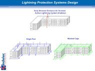
Early streamer emission lightning protection<br />
systems<br />
F : Protection contre la foudre - Systèmes de protection contre la foudre<br />
à dispositif d’amorçage<br />
D : Blitzschutz – Blitzableitersysteme mit Startvorrichtung<br />
Officially approved French standard<br />
On the decision of the Managing Director of AFNOR le 17th August 2011,<br />
with effect from 17th September 2011.<br />
Intended to replace officially approved standard NF C 17-102 of july 1995<br />
which remains in effect until September 2012.<br />
Correspondence<br />
Analysis<br />
There is no equivalent IEC or CENELEC document.<br />
This document describes the main dispositions in order to insure the<br />
protection of structures, buildings and open areas against direct lightning<br />
impact by early streamer emission protection system. Many tests on ESE<br />
are detailed and specific installation rules are introduced to ensure<br />
protection efficiency.<br />
Descriptors<br />
Modifications<br />
Structures, building, open areas, lightning protection, protection device,<br />
air terminal, installation, design, down conductor, earthing, equipotential<br />
bonding, verification, periodic inspection, maintenance.<br />
Previous edition of the standard has been upgraded to introduce more<br />
tests and also include new requirements both for product selection and<br />
installation rules.<br />
Corrections<br />
Published and distributed by Union Technique de l'Electricité (UTE) – Immeuble MB6 – 41, rue des Trois Fontanot – 92024 Nanterre<br />
Cedex - Tel. : + 33 (0) 1 49 07 62 00 – Télécopie : + 33 (0) 1 47 78 73 51 – email : ute@ute.asso.fr – Internet : http://www.ute-fr.com/<br />
Impr. UTE © 1 st printing 2012-08 – Reproduction prohibited
NF C 17-102 – 2 –<br />
UTE has taken all reasonable measures<br />
to ensure the accuracy of this translation<br />
but regrets that no responsibility can be accepted<br />
for any error, omission or inaccuracy.<br />
In cases of doubt or dispute,<br />
the original language text only is valid.
– 3 – NF C 17-102<br />
FOREWORD<br />
There is no international standard or specific European standard about early streamer emission<br />
lightning protection systems<br />
This document is intended to replace the 1995 edition of the NF C 17-102, with its second<br />
printing in 2009.<br />
This document specifies requirements for design, in the present state of knowledge and<br />
technology, protection against lightning of structures (buildings, fixtures, etc.) and open areas<br />
(storage areas, rest areas or sports, etc.) by early streamer emission lightning protection<br />
systems and provides guidance on how to achieve this protection.<br />
Installations for protection against lightning designed and made according to this document,<br />
may not, like everything about the natural elements, ensure the absolute protection of<br />
structures, people or objects; however, the application of this document must reduce<br />
significantly the risk of damage due to lightning on protected structures.<br />
The provisions stated in this document are minimum requirements to ensure statistically an<br />
effective protection.<br />
This new edition is a complete revision of the standard following the publication of the European<br />
standard series EN 62305 and more particularly to the EN 62305-3 giving the requirements for<br />
protection of structures against lightning<br />
However, the EN 62305 series is not dealing with early streamer emission technology, the<br />
revision of the NF C 17-102 appeared essential to provide the design requirements of an early<br />
streamer emission air terminal and those for implementing the ESE lightning protection system.<br />
In order to have no conflict with the European standard series, this document makes no<br />
reference to it, but repeats the necessary arrangements for the design and creation of the<br />
lightning protection system.<br />
The UTE has established the following dates:<br />
- Date on which the previous national standard will be canceled: September 2012;<br />
- Date of cessation of presumption of conformity of products manufactured under the<br />
superseded standard: September 2012.<br />
This document was approved June 28, 2011 by the Commission UF81, Protection against<br />
lightning.<br />
____________
NF C 17-102 – 4 –<br />
CONTENTS<br />
1 Scope .......................................................................................................................................... 9<br />
2 Normative and regulation references ............................................................................................ 9<br />
3 Definitions ................................................................................................................................. 11<br />
4 Lightning protection system with Early Streamer Emission Air Terminal ....................................... 16<br />
4.1 Need of protection ............................................................................................................ 16<br />
4.2 Components of the lightning protection system .................................................................. 16<br />
5 Early streamer emission lightning protection system ................................................................... 18<br />
5.1 Design .............................................................................................................................. 18<br />
5.2 Early Streamer Emission Terminal ..................................................................................... 18<br />
5.2.1 General principles ................................................................................................. 18<br />
5.2.2 ESEAT efficiency .................................................................................................. 18<br />
5.2.3 Positioning of the ESEAT ...................................................................................... 18<br />
5.2.4 Materials and dimensions. ..................................................................................... 21<br />
5.2.5 Installation ............................................................................................................ 21<br />
5.3 Down-conductors .............................................................................................................. 22<br />
5.3.1 General principles. ................................................................................................ 22<br />
5.3.2 Number of down-conductors. ................................................................................. 22<br />
5.3.3 Routing ................................................................................................................. 23<br />
5.3.4 Indoor routing ........................................................................................................ 24<br />
5.3.5 Outside cladding ................................................................................................... 24<br />
5.3.6 Materials and dimensions. ..................................................................................... 24<br />
5.3.7 Test joint. .............................................................................................................. 25<br />
5.3.8 Lightning event counter. ........................................................................................ 25<br />
5.3.9 Natural components. ............................................................................................. 25<br />
5.4 Equipotential bonding of metal parts .................................................................................. 26<br />
5.4.1 General ................................................................................................................. 26<br />
5.5 Lightning equipotential bonding ......................................................................................... 26<br />
5.5.1 General ................................................................................................................. 26<br />
5.5.2 Lightning equipotential bonding for metal installations ............................................ 26<br />
5.5.3 Lightning equipotential bonding for external conductive parts ................................. 27<br />
5.5.4 Lightning equipotential bonding for internal systems ............................................... 27<br />
5.5.5 Lightning equipotential bonding for lines connected to the structure to be<br />
protected .............................................................................................................. 28<br />
5.6 Electrical insulation of the external ESESystem ................................................................. 28<br />
6 Earth termination systems .......................................................................................................... 30<br />
6.1 General ............................................................................................................................ 30<br />
6.2 Earth termination system types ......................................................................................... 31<br />
6.3 Additional measures ......................................................................................................... 33<br />
6.4 Earthing equipotentiality .................................................................................................... 33<br />
6.5 Proximity requirements ..................................................................................................... 34<br />
6.6 Materials and dimensions .................................................................................................. 34<br />
7 Special measures ...................................................................................................................... 34<br />
7.1 Aerials .............................................................................................................................. 34<br />
7.2 Inflamable and explosive material storage areas ................................................................ 34<br />
7.3 Religious buildings ............................................................................................................ 34<br />
8 Execution file, vérification and maintenance ............................................................................... 35
– 5 – NF C 17-102<br />
8.1 Execution File ................................................................................................................... 35<br />
8.2 Orders of Verifications ...................................................................................................... 36<br />
8.3 Verification report ............................................................................................................. 36<br />
8.4 Initial verification ............................................................................................................... 36<br />
8.5 Visual verification ............................................................................................................. 37<br />
8.6 Complete verification ....................................................................................................... 37<br />
8.7 Maintenance ..................................................................................................................... 37<br />
ANNEXE A (normative) RISK ANALYSIS ................................................................................ 38<br />
A.1 Explanation of terms ......................................................................................................... 38<br />
A.1.1 Damage and loss .................................................................................................. 38<br />
A.1.2 Risk and risk components ...................................................................................... 39<br />
A.1.3 Composition of risk components related to a structure ............................................ 41<br />
A.2 Risk management ............................................................................................................. 42<br />
A.2.1 Basic procedure .................................................................................................... 42<br />
A.2.2 Structure to be considered for risk assessment ...................................................... 42<br />
A.2.3 Tolerable risk R T ................................................................................................... 42<br />
A.2.4 Specific procedure to evaluate the need of protection ............................................ 42<br />
A.2.5 Procedure to evaluate the cost effectiveness of protection ..................................... 43<br />
A.2.6 Selection of protection measures ........................................................................... 43<br />
A.3 Assessment of risk components for a structure .................................................................. 45<br />
A.3.1 Basic equation ...................................................................................................... 45<br />
A.3.2 Assessment of risk components due to flashes to the structure (S1) ....................... 45<br />
A.3.3 Assessment of the risk component due to flashes near the structure (S2) ............... 45<br />
A.3.4 Assessment of risk components due to flashes to a line connected to the structure<br />
(S3) ...................................................................................................................... 46<br />
A.3.5 Assessment of risk component due to flashes near a line connected to the<br />
structure (S4) ........................................................................................................ 46<br />
A.3.6 Summary of risk components in a structure ............................................................ 47<br />
A.3.7 Partitioning of a structure in zones Z S .................................................................... 47<br />
A.3.8 Assessment of risk components in a structure with zones Z S .................................. 48<br />
A.4 Assessment of annual number N of dangerous events ....................................................... 49<br />
A.4.1 General ................................................................................................................. 49<br />
A.4.2 Assessment of the average annual number of dangerous events due to flashes to<br />
a structure N D and to a structure connected at “a” end of a line N Da ........................ 50<br />
A.4.3 Assessment of the average annual number of dangerous events due to flashes<br />
near a structure N M ............................................................................................... 54<br />
A.4.4 Assessment of the average annual number of dangerous events due to flashes to<br />
a service N L .......................................................................................................... 54<br />
A.4.5 Assessment of average annual number of dangerous events due to flashes near a<br />
service N I .............................................................................................................. 55<br />
A.5 Assessment of probability P X of damage for a structure ..................................................... 56<br />
A.5.1 Probability P A that a flash to a structure will cause injury to living beings ................ 56<br />
A.5.2 Probability P B that a flash to a structure will cause physical damage ...................... 57<br />
A.5.3 Probability P C that a flash to a structure will cause failure of internal systems ......... 57<br />
A.5.4 Probability M P that a flash near a structure will cause failure of internal systems ..... 58<br />
A.5.5 Probability P U that a flash to a service will cause injury to living beings .................. 59<br />
A.5.6 Probability P V that a flash to a service will cause physical damage ......................... 60<br />
A.5.7 Probability P W that a flash to a service will cause failure of internal systems ........... 60<br />
A.5.8 Probability P Z that a lightning flash near an incoming service will cause failure of<br />
internal systems .................................................................................................... 60
NF C 17-102 – 6 –<br />
A.6 Assessment of amount of loss L X in a structure .................................................................. 61<br />
A.6.1 Average relative amount of loss per year ............................................................... 61<br />
A.6.2 Loss of human life ................................................................................................. 61<br />
A.6.3 Unacceptable loss of service to the public .............................................................. 64<br />
A.6.4 Loss of irreplaceable cultural heritage .................................................................... 64<br />
A.6.5 Economic loss ....................................................................................................... 65<br />
ANNEXE B (normative) N g maps ..................................................................................................... 66<br />
ANNEXE C(Normative) ESEAT testing procedures and requirements ............................................... 67<br />
C.1 Operation conditions ......................................................................................................... 67<br />
C.1.1 Normal conditions ................................................................................................. 67<br />
C.1.2 Abnormal conditions .............................................................................................. 67<br />
C.2 Requirements ................................................................................................................... 67<br />
C.2.1 General requirements ............................................................................................ 67<br />
C.2.2 Requirements for early streamer emission ............................................................. 67<br />
C.2.3 Electrical requirements .......................................................................................... 67<br />
C.2.4 Mechanical requirements ....................................................................................... 67<br />
C.2.5 Environmental requirements .................................................................................. 68<br />
C.2.6 Electromagnetic compatibility ................................................................................ 68<br />
C.3 Type test .......................................................................................................................... 69<br />
C.3.1 General tests ........................................................................................................ 70<br />
C.3.2 Mechanical tests ................................................................................................... 70<br />
C.3.3 Environmental conditioning .................................................................................... 70<br />
C.3.4 Current withstanding tests ..................................................................................... 70<br />
C.3.5 Early streamer emission tests ................................................................................ 71<br />
C.4 Structure and content of the test report ............................................................................. 77<br />
C.5 Care and maintenance of the ESEATs ............................................................................... 78<br />
Annexe D (Normative) Protection of people against electrical shocks caused by lightning ................ 79<br />
D.1 Protection measures against injury to living beings due to touch and step voltages ............ 79<br />
D.1.1 Protection measures against touch voltages .......................................................... 79<br />
D.1.2 Protection measures against step voltages ............................................................ 79<br />
Annexe E (Informative) Example of values of coefficient k c ............................................................... 80<br />
Bibliographie .................................................................................................................................... 82<br />
Figures :<br />
Figure 1 – Components of the lightning protection system ................................................................. 17<br />
Figure 2 – Protection Radii (with hypothesis h 1 = 5 m) ...................................................................... 19<br />
Figure 3 - Additional protection against direct lightning strike for the highest 20% of the structure<br />
height for buildings taller than 60 m ............................................................................................ 21<br />
Figure 4 – Down-conductor bend shapes .......................................................................................... 23<br />
Figure 5 – Illustrations of the separation distance according to the length in question and the<br />
increase in potential difference as a function of the distance at the nearest equipotential point<br />
(P) ............................................................................................................................................. 29<br />
Figure 6 – Scheme of earthing types A1 and A2 ................................................................................ 32<br />
Figure 7 - Religious buildings ........................................................................................................... 35<br />
Figure A.1 – Procedure for selecting protection measures in structures ............................................. 44<br />
Figure A.2 – Structures at line ends: at “b” end the structure to be protected (structure b) and at “a”<br />
end an adjacent structure(structure a) ........................................................................................ 47
– 7 – NF C 17-102<br />
Figure A.3 – Collection area Ad of an isolated structure .................................................................... 50<br />
Figure A.4 – Complex shape structure .............................................................................................. 51<br />
Figure A.5 – Different methods to determine the collection area for the structure of Figure A.4 .......... 52<br />
Figure A.6 – Structure to be considered for evaluation of collection area A d ....................................... 53<br />
Figure A7 – Collection areas (A d , A m , A i , A l ) ..................................................................................... 56<br />
Figure B.1 – Map of N k level, (N k =10xN g ) for France ......................................................................... 66<br />
Figure C.1: Sequence of testing ....................................................................................................... 69<br />
Figure C.2 - Reference single rod air terminal (SRAT) ....................................................................... 71<br />
Figure C.3 – Experimental set-up of the SRAT .................................................................................. 72<br />
Figure C.4 – Experimental set-up of the ESEAT ................................................................................ 72<br />
Figure C.5 – Reference wave ........................................................................................................... 75<br />
Figure C.6 - Graphic correction principle ........................................................................................... 76<br />
Figure E.1 – In the case of numerous ESE interconnected at roof level and type B earth-termination<br />
system....................................................................................................................................... 80<br />
Figure E.2 – Examples of calculation of the separation distance in the case of downconductors an<br />
interconnected by rings. ............................................................................................................. 81<br />
Tables :<br />
Table 1 – Minimum dimensions of conductors connecting different bonding bars or connecting<br />
bonding bars to the earth-termination system ............................................................................. 27<br />
Table 2 – Minimum dimensions of conductors connecting internal metal installations to the bonding<br />
bar ............................................................................................................................................ 27<br />
Table 3 – Isolation of external ESESystem – Values of coefficient k i ................................................. 29<br />
Table 4 – Isolation of External ESESystem – Values of coefficient k m ................................................ 29<br />
Table 5 – Isolation of external ESESystem – Values of coefficient k c ................................................. 30<br />
Table 6 – Typical resistivity soil ........................................................................................................ 32<br />
Table 7 – Periodicity of inspection regarding the protection level ....................................................... 36<br />
Table A.1 – Sources of damage, types of damage and types of loss according to the point of strike .. 39<br />
Table A.2 – Risk components to be considered for each type of loss in a structure ............................ 41<br />
Table A.3 – Typical values of tolerable risk R T .................................................................................. 42<br />
Table A.4 – Risk components for a structure for different types of damage caused by different<br />
sources ..................................................................................................................................... 47<br />
Table A.5 – Location factor C d .......................................................................................................... 53<br />
Table A.6 – Collection areas A l and A i depending on the service characteristics ................................ 55<br />
Table A.7 – Transformer factor C t ..................................................................................................... 55<br />
Table A.8 – Environmental factor C e ................................................................................................. 56<br />
Table A.9 – Values of probability P A that a flash to a structure will cause shock to living beings due<br />
to dangerous touch and step voltages ........................................................................................ 57<br />
Table A.10 – Values of P B depending on the protection measures to reduce physical damage ........... 57<br />
Table A.11 – Value of the probability P SPD as a function of LPL for which SPDs are designed ........... 57<br />
Table A.12 – Value of the probability P MS as a function of factor K MS ................................................. 58<br />
Table A.13 – Value of factor K S3 depending on internal wiring ........................................................... 59<br />
Table A.14 – Values of the probability P LD depending on the resistance R S of the cable screen and<br />
the impulse withstand voltage U w of the equipment ..................................................................... 60
NF C 17-102 – 8 –<br />
Table A.15 – Values of the probability P LI depending on the resistance R S of the cable screen and<br />
the impulse withstand voltage U w of the equipment ..................................................................... 61<br />
Table A.16 – Typical mean values of L t , L f and L o ............................................................................. 62<br />
Table A.17 – Values of reduction factors r a and r u as a function of the type of surface of soil or floor 62<br />
Table A.18 – Values of reduction factor r p as a function of provisions taken to reduce the<br />
consequences of fire .................................................................................................................. 63<br />
Table A.19 – Values of reduction factor r f as a function of risk of fire of structure ............................... 63<br />
Table A.20 – Values of factor h z increasing the relative amount of loss in presence of a special<br />
hazard ....................................................................................................................................... 63<br />
Table A.21 – Typical mean values of L f and L o .................................................................................. 64<br />
Table A.22 – Typical mean values of L t , L f and L o ............................................................................. 65<br />
Table C.1 – Material, setup and minimum area of the striking point part's body .................................. 68<br />
Table C.2 – Value of current I imp ....................................................................................................... 71<br />
Table C.3 – Variation of the climatic parameters during the tests....................................................... 73
– 9 – NF C 17-102<br />
Early streamer emission Lightning protection systems<br />
1 Scope<br />
This standard is applicable to early streamer emission lightning protection systems provided to protect<br />
facilities and open areas against direct lightning impact. This ESESystem shall be tested, selected and<br />
installed according to the present standard.<br />
2 Normative and regulation references<br />
The following standards include provisions which, through reference in this text, are necessary to<br />
implement this standard. For dated references, only the adverted version is applicable. For non-dated<br />
references, the last edition of the reference is applicable (comprinsing possible amendments).<br />
CLC/TS 61643-12<br />
EN 50164<br />
(Series)<br />
EN 50164-2<br />
(C 17-151-2)<br />
EN 50164-3<br />
(C 17-151-3)<br />
EN 50164-5<br />
(C 17-151-5)<br />
EN 50164-6<br />
(C 17-151-6)<br />
EN 50164-7<br />
(C 17-151-7)<br />
IEC 60060-1<br />
(C 41-100-1)<br />
EN 60068-2-52<br />
(C 20-752)<br />
EN 60079-10<br />
(C 23-579-10)<br />
(Série)<br />
EN 61000-6-2<br />
(C 91-006-2)<br />
EN 61000-6-3<br />
(C 91-006-3)<br />
EN 61180-1<br />
(C 41-106)<br />
EN 61241-10<br />
(C 23-241-10)<br />
Low-voltage surge protective devices -- Part 12: Surge protective devices<br />
connected to low-voltage power distribution systems - Selection and<br />
application principles<br />
Lightning protection system components -<br />
Lightning protection system components - Requirements for conductors and<br />
earth electrodes<br />
Lightning protection system components - Requirements for isolating spark<br />
gaps<br />
Lightning protection system components -<br />
Lightning protection system components - Requirements for lightning strike<br />
counters (LSC)<br />
Lightning protection system components - Requirements for earthing<br />
enhancing compounds<br />
High-voltage test techniques -- Part 1: General definitions and test<br />
requirements<br />
Environmental testing -- Part 2: Tests - Test Kb: Salt mist, cyclic (sodium<br />
chloride solution<br />
Electrical apparatus for explosive gas atmospheres<br />
Electromagnetic compatibility (EMC) -- Part 6-2: Generic standards - Immunity<br />
for industrial environments<br />
Electromagnetic compatibility (EMC) -- Part 6-3: Generic standards - Emission<br />
standard for residential, commercial and light-industrial environments<br />
High-voltage test techniques for low-voltage equipment -- Part 1: Definitions,<br />
test and procedure requirements<br />
Electrical apparatus for use in the presence of combustible dust -- Part 10:<br />
Classification of areas where combustible dust are or may be present
NF C 17-102 – 10 –<br />
EN 61643<br />
(Series)<br />
EN 61643-11<br />
(C 61-740)<br />
NF EN ISO 6988<br />
(A 05-106)<br />
Low-voltage surge protective devices -<br />
Low-voltage surge protective devices -- Part 11: Surge protective devices<br />
connected to low-voltage power systems - Requirements and tests<br />
Metallic and other non organic coatings -- Sulfur dioxide test with general<br />
condensation of (A 05-106) moisture<br />
UTE C 15-443<br />
UTE C 15-712-1<br />
Guide pratique – Protection des installations électriques basse tension contre<br />
les surtensions d’origine atmosphérique ou dues à des manœuvres. Choix et<br />
installation des parafoudres<br />
Guide Pratique – Installations photovoltaiques raccordées au réseau public de<br />
distribution – Installation électrique à basse tension
– 11 – NF C 17-102<br />
3 Definitions<br />
3.1<br />
coordinated SPD protection<br />
set of SPDs properly selected, coordinated and correctly installed to reduce failures of electrical and<br />
electronic systems<br />
3.2<br />
current impulse (I imp )<br />
peak value (I peak ) defined by charge Q and specific energy W/R<br />
3.3<br />
dangerous event<br />
lightning flash to the object to be protected or near the object to be protected<br />
3.4<br />
dangerous sparking<br />
electrical discharge due to lightning which causes physical damage inside the structure to be protected<br />
3.5<br />
down-conductor<br />
part of the Lightning Protection System intended to conduct the lightning current from ESEAT to the<br />
earth termination system<br />
3.6<br />
early streamer emission air terminal (ESEAT)<br />
air terminal generating a streamer earlier than a simple rod air terminal when compared in the same<br />
conditions<br />
NOTE – An early streamer emission air terminal is made up of a striking point, an emission device, a fixing element and a<br />
connection to the down conductors.<br />
3.7<br />
early streamer emission lightning protection system (ESESystem)<br />
complete system based on one or more ESEAT and all elements to safely conduct lightning to earth in<br />
order to protect a structure, facility or open area against direct lightning impact.<br />
NOTE – It comprises both internal and external lightning protection system.<br />
3.8<br />
earth termination system<br />
part of an external ESESystem which is intended to conduct and disperse lightning current into the<br />
earth.<br />
3.9<br />
electrical system<br />
system incorporating low voltage power supply components and ducts<br />
3.10<br />
electronic system<br />
system incorporating sensitive electronic components such as communication equipment, computers,<br />
control and instrumentation systems, radio systems, power electronic installations<br />
3.11<br />
equipotential bonding<br />
bonding to the ESESystem of separated conductive parts (see 5.5) of an installation, by direct<br />
connections or via surge protective devices, to reduce potential differences caused by lightning current.
NF C 17-102 – 12 –<br />
3.12<br />
equipotential bonding main bar<br />
a bar used to connect the natural components, ground conductors, earth conductors, screens, shields<br />
and conductors protecting telecommunication cables or other ones, to the lightning protection system.<br />
3.13<br />
equivalent collection area of a structure (A d )<br />
a flat ground surface subjected to the same number of lightning strikes as the structure under<br />
consideration.<br />
3.14<br />
ESEAT efficiency (ΔT)<br />
difference expressed in micro-seconds between the emission time of an ESEAT and an SRAT measured<br />
in a laboratory under the conditions defined in this standard.<br />
3.15<br />
external ESESystem isolated from the structure to be protected<br />
LPS with an air-termination system and down-conductor system positioned in such a way that the path of<br />
the lightning current has no contact with the structure to be protected<br />
NOTE: In an isolated LPS, dangerous sparks between the LPS and the structure are avoided.<br />
3.16<br />
external ESESystem not isolated from the structure to be protected<br />
LPS with an air-termination system and down-conductor system positioned in such a way that the path of<br />
the lightning current can be in contact with the structure to be protected<br />
3.17<br />
failure of electrical and electronic systems<br />
permanent damage of electrical and electronic systems due to LEMP<br />
3.18<br />
failure current (I a )<br />
minimum peak value of lightning current that will cause damages<br />
3.19<br />
injuries to living beings<br />
injuries, including loss of life, to people or to animals due to touch and step voltages caused by lightning<br />
3.20<br />
interconnected reinforcing steel<br />
Steelwork within a concrete structure which is considered to provide an electrically continuity.<br />
3.21<br />
internal systems<br />
electrical and electronic systems within a structure<br />
3.22<br />
isolating Spark Gap (ISG)<br />
component with discharge distance for isolating electrically conductive installation parts.<br />
NOTE In the event of a lightning strike, the installation parts are temporary connected conductively as the result of<br />
response of the discharge.<br />
3.23<br />
lightning electromagnetic impulse (LEMP)<br />
electromagnetic effects of lightning current<br />
NOTE It includes conducted surges as well as radiated impulse electromagnetic field effects.
– 13 – NF C 17-102<br />
3.24<br />
LEMP protection measures system (LPMS)<br />
complete system of protection measures for internal systems against LEMP<br />
3.25<br />
lightning ground flash density (N g )<br />
is the number of lightning flashes per km 2 per year. This value is available from ground flash location<br />
networks<br />
3.26<br />
lightning flash near an object<br />
lightning flash striking close enough to an object to be protected that it may cause dangerous<br />
overvoltages<br />
3.27<br />
lightning flash to an object<br />
lightning flash striking an object to be protected<br />
3.28<br />
lightning flash to earth<br />
atmospheric originated electrical discharge between cloud and earth consisting of one or more arcs<br />
3.29<br />
lightning protection level (LPL)<br />
number related to a set of lightning current parameter values relevant to the probability that the<br />
associated maximum and minimum design values will not be exceeded in naturally occurring lightning<br />
NOTE Lightning protection level is used to design protection measures according to the relevant appropriate set<br />
of lightning current parameters.<br />
3.30<br />
lightning protection zone (LPZ)<br />
zone where the lightning electromagnetic environment is defined<br />
NOTE The zone boundaries of an LPZ are not necessarily physical ones (e.g. walls, floor and ceiling).<br />
3.31<br />
loss (L X )<br />
mean amount of loss (humans and goods) consequent to a specified type of damage due to a dangerous<br />
event, relative to the value (humans and goods) of the object to be protected<br />
3.32<br />
natural component<br />
conductive element located outside the structure, sunk in the walls or located inside a structure and<br />
which may be used to supplement the ESESystem down conductors.<br />
NOTE – For the protection with ESEATs, natural components may complement but never be the only down<br />
conductor except in the case of complete metallic structures.<br />
3.33<br />
node<br />
point on a service line at a which surge propagation can be assumed to be neglected<br />
NOTE Examples of nodes are a connection of a HV/LV transformer, a multiplexer on a telecommunication line or<br />
SPD installed along a line.<br />
3.34<br />
Frequency of dangerous events due to flashes to a structure (N D )<br />
expected average annual number of dangerous events due to lightning flashes to a structure<br />
3.35<br />
Frequency of dangerous events due to flashes to a service (N L )<br />
expected average annual number of dangerous events due to lightning flashes to a service
NF C 17-102 – 14 –<br />
3.36<br />
Frequency of dangerous events due to flashes near a structure (N M )<br />
expected average annual number of dangerous events due to lightning flashes near a structure<br />
3.37<br />
Frequency of dangerous events due to flashes near a service (N I )<br />
expected average annual number of dangerous events due to lightning flashes near a service<br />
3.38<br />
object to be protected<br />
structure or service to be protected against the effects of lightning<br />
NOTE A structure to be protected may be a part of a larger structure<br />
3.39<br />
physical damage<br />
damage to a structure (or to its content) or to a service due to mechanical, thermal, chemical or<br />
explosive effects of lightning.<br />
3.40<br />
pipes<br />
piping intended to convey a fluid into or out of a structure, such as gas pipe, water pipe, oil pipe<br />
3.41<br />
probability of damage (P X )<br />
probability that a dangerous event will cause damage to or in an object to be protected<br />
3.42<br />
protected area<br />
zone protected by an early streamer emission lightning protection system.<br />
3.43<br />
protection measures<br />
measures to be adopted to the object to be protected, in order to reduce the risk<br />
3.44<br />
reference simple rod air terminal (SRAT)<br />
geometrical shape metal rod defined in this standard to be used as a reference.<br />
3.45<br />
rated impulse withstand voltage level (U W )<br />
impulse withstand voltage assigned by the manufacturer to the equipment or to a part of it,<br />
characterizing the specified withstand capability of its insulation against overvoltages<br />
NOTE For the purposes of this standard, only withstand voltage between live conductors and earth is considered.<br />
3.46<br />
risk (R)<br />
value of probable average annual loss (humans and goods) due to lightning, relative to the total value<br />
(humans and goods) of the object to be protected<br />
3.47<br />
risk component (R X )<br />
partial risk depending on the source and the type of damage<br />
3.48<br />
rural environment<br />
area showing a low density of buildings.<br />
NOTE ’Countryside’ is an example of a rural environment.
– 15 – NF C 17-102<br />
3.49<br />
separation distance<br />
distance between two conductive parts at which no dangerous sparking can occur.<br />
3.50<br />
specific downconductor<br />
downconductor complying with NF EN 50164-2 but being not a natural component of the structure<br />
3.51<br />
striking point<br />
point where a lightning stroke contacts the earth, a structure or a lightning protection system.<br />
3.52<br />
structures with risk of explosion<br />
structures containing solid explosive materials or hazardous zones as defined in accordance with<br />
IEC 60079-10 and IEC 61241-10<br />
NOTE For the purposes of the risk assessment of this standard, only structures with hazardous zones type 0 or<br />
containing solid explosive materials are considered.<br />
3.53<br />
structures dangerous for the environment<br />
structures which may cause biological, chemical and radioactive emission as a consequence of lightning<br />
(such as chemical, petrochemical, nuclear plants, etc).<br />
3.54<br />
suburban environment<br />
area showing a medium density of buildings<br />
NOTE ’Town outskirts’ is an example of a suburban environment.<br />
3.55<br />
surge<br />
transient wave appearing as overvoltage and/or overcurrents caused by LEMP<br />
NOTE Surges caused by LEMP can arise from (partial) lightning currents, from induction effects into installation<br />
loops and as remaining threats downstream from SPD.<br />
3.56<br />
surge protective device (SPD)<br />
device intended to limit transient overvoltages and drain away surge currents. It contains at least one<br />
non-linear component<br />
3.57<br />
telecommunication lines<br />
transmission medium intended for communication between equipment that may be located in separate<br />
structures, such as phone line and data line<br />
3.58<br />
test joint<br />
joint designed and placed to facilitate electrical testing and measurement of ESESystem components.<br />
3.59<br />
tolerable risk (R T )<br />
maximum value of the risk which can be tolerated for the object to be protected<br />
3.60<br />
atmospheric originated transient surge voltage<br />
short-time overvoltage – not longer than few milliseconds - oscillatory or not, usually strongly damped.
NF C 17-102 – 16 –<br />
3.61<br />
urban environment<br />
area showing a high density of populated buildings and tall buildings<br />
NOTE ’Town centre’ is an example of an urban environment.<br />
3.62<br />
zone of a structure (Z s )<br />
part of a structure showing homogeneous characteristics where only one set of parameters is involved in<br />
evaluating one risk component<br />
4 Lightning protection system with Early Streamer Emission Air Terminal<br />
4.1 Need of protection<br />
The need for protection is determined according to many parameters including the lightning flash density<br />
of the considered area. A risk analysis method is proposed in Annex A. The lightning flash density is<br />
given in annex B or by local data including for example detection network, maps and statistics.<br />
NOTE 1: Other considerations may lead to take the decision to adopt protection measures for reasons other than statistical<br />
ones. For example, compulsory regulations or personal considerations since some factors cannot be estimated: the wish to<br />
avoid risk to life or to provide safety to the occupants of a building may require the use of protection, even though the calculated<br />
risk is under the tolerable level.<br />
NOTE 2 Different normative documents give some risk analysis methods that can be used.<br />
4.2 Components of the lightning protection system<br />
The installation may be composed of the following elements:
– 17 – NF C 17-102<br />
3<br />
18<br />
1<br />
2<br />
14<br />
14<br />
14 16<br />
14<br />
8 9<br />
4<br />
11<br />
15<br />
14<br />
14 14<br />
14<br />
11<br />
7<br />
13<br />
12<br />
5<br />
17<br />
Key :<br />
1- One or more ESEAT<br />
2- Connection component<br />
3- One or more specific down-conductors<br />
4- A test joint for each down-conductor<br />
5- One earth termination for each specific down-conductor<br />
6- Foundation earth electrode (earthing of the structure)<br />
7- Electric power cable<br />
8- Main electric power distribution box with SPD<br />
9- Main telecom distribution box with SPD<br />
10- Telecom cable with SPD<br />
11- One or more equipotential bonding bars<br />
12- One or more equipotential bondings between earth terminations<br />
13- Disconnectable bonding device<br />
14- One or more equipotential bondings (direct or via an Isolating SparkGap).<br />
15- Main earthing bar<br />
16- Electric equipment<br />
17- Metallic pipe<br />
18- One or more equipotential bondings through a spark gap for aerial mast<br />
Figure 1 – Components of the lightning protection system<br />
6<br />
12<br />
10
NF C 17-102 – 18 –<br />
5 Early streamer emission lightning protection system<br />
5.1 Design<br />
Based on the necessary lightning protection level, a design should be made to determine the air terminal<br />
placement, the down-conductors paths and the location and type of the earth termination system.<br />
This design should be based on available data and including:<br />
- shape and slope of the roofs;<br />
- material of the roof, walls and internal structure;<br />
- metallic parts of the roof and important external metallic elements such as gas ducts, airconditioning<br />
equipment, ladders, aerials, water tanks,…<br />
- gutters and rainwater pipes;<br />
- prominent parts of the structure and the material they are made (conductive or not);<br />
- most vulnerable parts of the structure : the structural points considered as vulnerable are the<br />
prominent parts, particularly towers, weathervanes, sharp objects, chimneys, gutters, edges and<br />
ridges, metallic objects (air extractors, wall cleaning systems, rails,photovoltaic cells (UTE C 15-<br />
712-1), balustrades, …), staircases, equipment rooms on flat roofs, etc.;<br />
- positioning of the metallic ducts (water, power, gas…) of the structure;<br />
- nearby obstacles that may influence the trajectory of the lightning discharge, such as overhead<br />
power lines, metallic fences, trees, etc.;<br />
- the characteristics of the environment, that may be particularly corrosive (salty environment,<br />
petrochemical or cement factory, etc.;<br />
- presence of flammable material or sensitive equipment such as computers or electronic<br />
equipment, high value or irreplaceable goods, etc..<br />
5.2 Early Streamer Emission Terminal<br />
5.2.1 General principles<br />
An Early Streamer Emission Air Terminal (ESEAT) is composed of one striking point, emission device and a fixing<br />
element and a connection to the down-conductors.<br />
The area protected by an ESEAT is determined according to its efficiency as defined in Clause 5.2.2.<br />
The ESEAT should preferably be installed on the highest part of the structure. It shall be the highest point within<br />
the area to be protected.<br />
5.2.2 ESEAT efficiency<br />
An ESEAT is characterized by its efficiency ΔT which is proved in the evaluation test (see Annexe C).<br />
The maximum value for ΔT, whatever are the test results, is 60 µs.<br />
5.2.3 Positioning of the ESEAT<br />
5.2.3.1 Protected area.<br />
The protected area is delineated by a surface of revolution defined by the protection radii corresponding<br />
to the different considered heights h and which axis is the same as the one of the air terminal (see<br />
figure 2).
– 19 – NF C 17-102<br />
where:<br />
h n<br />
is the height of the ESEAT tip over the horizontal plane through the furthest<br />
point of the object to be protected<br />
R pn is the ESEAT protection radius to the considered height h n .<br />
Figure 2 – Protection Radii (with hypothesis h 1 = 5 m)
NF C 17-102 – 20 –<br />
5.2.3.2 Protection radius.<br />
The protection radius of an ESEAT is related to its height (h) relative to the surface to be protected, to<br />
its efficiency and to the selected protection level (see Annex A).<br />
and<br />
2<br />
R p<br />
( h)<br />
= 2rh<br />
− h + Δ(2r<br />
+ Δ)<br />
for h ≥ 5 m (1)<br />
R p = h x R p (5) / 5 for 2 m ≤ h ≤ 5 m (2)<br />
where<br />
R p (h) (m)<br />
h (m)<br />
is the protection radius at a given height h<br />
is the height of the ESEAT tip over the horizontal plane through the furthest<br />
point of the object to be protected<br />
r (m) 20 m for protection level I<br />
30m for protection level II<br />
45m for protection level III<br />
60m for protection level IV<br />
∆(m) ∆ = ∆T x 10 6<br />
Field experience has proved that ∆ is equal to the efficiency obtained during<br />
the ESEAT evaluation tests<br />
For buildings higher than 60m, the requirements in 5.2.3.4 should be applied.<br />
5.2.3.3 Selection and positioning of the ESEAT<br />
For the installation of each lightning protection system, a risk analysis must be made in order to<br />
determine the minimum required lightning protection level.<br />
The positioning of the ESEAT is chosen according to 5.2.1 and 5.2.5.<br />
The required protection radii to protect the structure are determined according to the features of the<br />
building.<br />
Both height of the ESEAT and its efficiency are determined using the points and formulas cited above<br />
based on the selected ESEAT.<br />
5.2.3.4 Protection of high rise buildings (height greather than 60 m)<br />
Additional protection against direct lightning strike for the highest 20% of the structure height for<br />
buildings greater than 60 m or any point above 120 m, using ESEAT or any other means must be<br />
implemented at each façade wall according to a valid standard. Furthermore a minimum of 4<br />
downconductors, interconnected by a ring conductor when applicable, shall be used, distributed along<br />
the perimeter and if possible at each angle of the building.<br />
NOTE : in general the risk due to the lateral flashes is low because only a few percent of all flashes to tall structures will be to<br />
the side and moreover their parameters are a lot lower than those of flashes to the top of structures.
– 21 – NF C 17-102<br />
Figure 3 - Additional protection against direct lightning strike for the highest 20% of the structure<br />
height for buildings taller than 60 m<br />
5.2.3.5 Protection of buildings for levels of protection I + and I ++<br />
Level of protection I + : the ESESystem at level of protection 1 is additionnaly connected to the metal<br />
structure or reinforced bars of the buildings used as natural downconductors in addition to the dedicated<br />
downconductors included in the ESESystem according to 5.3. Connection to the natural downconductors<br />
shall be made at roof level and ground level. When the dowconductors are not interconnected at roof<br />
level, a ring conductor located above the roof can be used to achieve these requirements. The<br />
downconductors shall be interconnected at ground level either by the earthing loop or by a dedicated<br />
conductor.<br />
If there is no natural downconductors or if one of the above requirements cannot be fulfilled, level I +<br />
cannot be achieved.<br />
Level of protection I ++ : the roof is protected at level I + with an ESEAT having a radius of protection<br />
reduced by 40% compared to values given in 5.2.3.2 to achieve a complete protection of equipments on<br />
the roof against direct lighning strikes.<br />
5.2.4 Materials and dimensions.<br />
All materials should comply with EN 50164-2<br />
5.2.5 Installation<br />
The top of the ESEAT shall be installed at least 2 m over the area that it protects, including aerials,<br />
refrigerating towers, roofs, tanks, etc.<br />
When designing the ESESystem, it is recommended to take into account the architectural spots that are<br />
adequate to place an ESEAT. These locations are high structural points like:<br />
- rooms on the terraces;<br />
- ridge;<br />
- masonry or metallic chimneys.
NF C 17-102 – 22 –<br />
Those ESEAT protecting open areas (sport fields, golf, swimming pools, campsites, etc.) will be installed<br />
over specific supports such as lighting masts, poles or any other nearby structure that allows the ESEAT<br />
to cover the whole area to be protected.<br />
ESEAT can occasionally be placed over free-standing masts. In case of using conductive guy wires, they<br />
will be bonded, at the anchoring point on the ground, to the down-conductors using conductors<br />
according to EN 50164-2.<br />
5.3 Down-conductors<br />
5.3.1 General principles.<br />
The function of the down-conductors is to conduct lightning current from the air terminal to the earth<br />
termination system. They will be placed preferrably at the external part of the structure.<br />
Each of the down-conductors will be fixed to the ESEAT by means of a connection system placed at the<br />
mast. The latter will comprise a mechanical adaptation element that will assure a permanent electrical<br />
contact.<br />
When the down-conductor is placed on a wall made of combustible material, and not being a copper<br />
one, then at least one of the following conditions should be satisfied in order to avoid any dangerous<br />
temperature rise:<br />
• the separation is at least 0,10 m;<br />
• the conductor section is at least 100mm².<br />
To be considered as 2 independent downconductors, they should not run in parallel (parallel means that<br />
there is a distance along a straight line higher than 2 m between downconductors). To take care of any<br />
practical problem that may be encountered, a tolerance of 5% of the total length of the shorter<br />
downconductor can run along the same path.<br />
5.3.2 Number of down-conductors.<br />
For non-isolated ESESystem, each ESEAT shall be connected to at least two downconductors. For a<br />
better current distribution, the two paths to ground should, be situated on two different facades unless in<br />
case of force majeure.<br />
At least one of them must be a specific downconductor complying with EN 50164-2 since natural<br />
components may be modified or removed without taking into account the fact that they belong to a<br />
lightning protection system. When many ESEAT are located on the same building, the downconductors<br />
may be mutualized possible if the calculated separation distance for the whole system is allowing that<br />
number. Therefore, if there are n ESEAT on the roof, it is not systematically necessary to have 2n<br />
downconductors installed but a minimum of n specific downconductors is mandatory.<br />
The number of specific downconductor according to EN 50164-2 should be at least equal to the number<br />
of ESEAT on the building. The distance of separation allows to determine the number of needed<br />
downconductors as well as possibility to mutualize the downconductors. Increasing the number of<br />
specific downconductors enables the decrease of the separation distance.<br />
See Annex E for some examples of calculation of separation distance depending on the number of down<br />
conductors.<br />
In case of an isolated ESESystem, at least one down-conductor is needed for each ESEAT.
– 23 – NF C 17-102<br />
In case of pylones, mast, chimneys and other metallic structures:<br />
• If the metallic structure fulfill the requirements for natural components, it may be used as a first<br />
downconductor;<br />
• If the structure is isolated, the structure may be used as the single needed downconductor. No<br />
other specific downconcutor is then needed additionnaly;<br />
• If the stucture is non isolated, the structure may be considered as the two needed<br />
downconductors if its section area is greather or equal to100 mm². If the section area is between<br />
50 mm² and 100 mm², a second specific downconductor according to EN 50164-2 is necessary. A<br />
structure that do not fulfill the requipement of natural components, cannot be used as a<br />
downconductor so one or two specific downconductor are needed.<br />
NOTE : the natural components shall have a low and permanent impedance value. It may be necessary to add a specific<br />
downconductor according to EN 50164-2 to obtain such low impedance.<br />
5.3.3 Routing<br />
The downconductor should be installed in such a way that its path is as direct as possible. The routing of<br />
the down-conductor should be as straight as possible, following the shortest path, avoiding sharp bends<br />
or upward sections. The bend radii should not be less than 20 cm (see figure 4). For down-conductors,<br />
bends formed edgewise should preferably be used.<br />
The down-conductors should not be routed along or across electrical conduits.<br />
Routing round parapet walls or cornices or more generally obstacles should be avoided. Provisions<br />
should be made to ensure that down-conductor paths are as direct as possible. However, maximum<br />
height of 40cm is permissible for passing over an obstacle with a slope of 45º or less (see figure 4<br />
case e).<br />
Alternatively, the calculation of the separation distance, according to 5.6 with l = l 1 + l 2 + l 3 depending on<br />
case f below-cited, allows to determine the minimal bend radius.<br />
In figure 4, case d, the condition d>l/20 is always fulfilled since d=l/√2 for any length l.<br />
l: length of the loop, in meters<br />
d: width of the loop, in meters<br />
The risk of any dielectric breakdown is avoided if the condition d>l/20 is fulfilled.<br />
Figure 4 – Down-conductor bend shapes
NF C 17-102 – 24 –<br />
The distance between downconductors and possible interconnecting ring conductors are correlated with<br />
the separation distance.<br />
The fixings of the down-conductors should be attached on the basis of three fixings per meter (every<br />
33 cm). These fixings should be suitable for the supports and their installation should not alter the roof<br />
water-tightness. The fixings should allow for possible thermal expansion of the conductors. Systematic<br />
drilling through the downconductor in order to attach it to the support is forbidden.<br />
All the conductors should be connected together with clamps of the same nature, using rivets, soldering<br />
or brazing.<br />
Down-conductors should be protected against the risk of mechanical impact with guard tubes up to a<br />
height of at least 2m above the ground level.<br />
NOTE: To avoid touch voltage, see Annex D.<br />
5.3.4 Indoor routing<br />
When a down conductor cannot be installed outside the structure, it can be fitted inside on a part or on<br />
the full height of the structure. In this case, the downconductor must be placed inside a dedicated nonflammable<br />
and insulating duct.<br />
The separation distance shall be calculated also for indoor downconductors in order to be able to<br />
determine the necessary insulation level of the dedicated duct.<br />
The building operator has to be aware of the resulting difficulties to check and maintain the down<br />
conductors, and of the resulting risks of over voltages inside the building.<br />
Access of people to the specific cable channel should be avoided in stormy periods or measures of<br />
protection as per outdoor downconductors should be fulfilled (see Annex D) including equipotential<br />
bondings of floors with the downconductor.<br />
5.3.5 Outside cladding<br />
When a building is fitted with a metallic external cladding or stone facing or in glass, or in the case of a<br />
fixed covering part of the facade, the down conductor can be installed on the concrete façade or on the<br />
main structure, under the cladding.<br />
In this case, the conductive parts of the cladding must be connected to the down conductor at the top<br />
and at the bottom.<br />
The downconductor, if not a copper one, shall be located at more than 10 cm behind inflammable<br />
material of the outside cladding if its cross section area if lower than 100 mm². For cross section area of<br />
100 mm² or greater, there is no need to keep a distance between the downconductor and the insulating<br />
material.<br />
NOTE 1: a specific calculation of the temperature increase may be performed to validate a different rule.<br />
NOTE 2: the same requirements apply also to all inflammable material even on the roof (e.g. thatched roof)<br />
5.3.6 Materials and dimensions.<br />
See EN 50164-2.
– 25 – NF C 17-102<br />
5.3.7 Test joint.<br />
Each down-conductor should be provided with a test joint in order to disconnect the earth termination<br />
system for enabling measurements.<br />
Test joints are usually installed at the bottom of the down-conductors. When downconductors are<br />
installed on metal walls or when ESESystems are not provided with specific downconductors, test joints<br />
will be inserted between each earthing system and the metallic item to which the earth termination<br />
system is connected. The test joints are then installed inside inspection pits (complying with<br />
EN-50164-5) showing the earth termination symbol.<br />
5.3.8 Lightning event counter.<br />
When the installation is provided with a lightning event counter, it should be placed at the most direct<br />
down-conductor above. It shall comply with EN 50164-6.<br />
5.3.9 Natural components.<br />
Some of the conductive structural components may replace all or part of a down-conductor or be a<br />
supplement for it.<br />
5.3.9.1 Natural components which may replace the entire down-conductor or part of it.<br />
Generally, external interconnected steel frames (metal structures) may be used as down-conductors if<br />
they are conductive and their resistance is 0.1 Ω or lower.<br />
In such case, the upper end of the ESEAT is connected directly to the metal frame whose lower end is to<br />
be connected to the earth termination system.<br />
The use of a natural down-conductor should meet the equipotential bonding requirements in chapter 3.<br />
5.3.9.2 Natural components that may be used to supplement down-conductor(s).<br />
The following items may be used to supplement the lightning protection and bonded to it:<br />
(a) interconnected steel frames providing electrical continuity:<br />
- internal metallic structures, concrete reinforcements and metal structures inside the walls,<br />
provided that specific connection terminals exist for this purpose at the upper and lower part;<br />
- External metallic structures which do not run over the entire structure height.<br />
NOTE 1: when pre-stressed concrete is used, special attention should be paid to the risk of mechanical effects due to<br />
the lightning current flowing through the lightning protection system.<br />
(b) metal sheets covering the area to be protected, provided that: :<br />
- the electrical continuity among the different parts is made durable<br />
- they are not coated with insulating material.<br />
NOTE 2: a thin protective paint coat, 1mm concrete or 0,5mm PVC are not considered as an insulation.<br />
(c) Metallic pipes if their thickness is at least 2mm
NF C 17-102 – 26 –<br />
5.4 Equipotential bonding of metal parts<br />
5.4.1 General<br />
The internal ESESystem shall prevent the occurrence of dangerous sparking within the structure to be<br />
protected due to lightning current flowing in the external ESESystem or in other conductive parts of the<br />
structure.<br />
Dangerous sparking may occur between the external ESESystem and the following components:<br />
- the metal installations;<br />
- the internal systems;<br />
- the external conductive parts and lines connected to the structure.<br />
Dangerous sparking between different parts can be avoided by means of<br />
- equipotential bonding in accordance with 5.5, or<br />
- electrical insulation between the parts in accordance with 5.6.<br />
5.5 Lightning equipotential bonding<br />
5.5.1 General<br />
Equipotentialization is achieved by interconnecting the ESESystem with<br />
- structural metal parts;<br />
- metal installations;<br />
- internal systems;<br />
- external conductive parts and lines connected to the structure.<br />
When lightning equipotential bonding is established to internal systems, part of the lightning current may<br />
flow into such systems and this effect shall be taken into account.<br />
Interconnecting means can be:<br />
- bonding conductors, where the electrical continuity is not provided by natural bonding;<br />
- surge protective devices (SPDs), where direct connections with bonding conductors is not<br />
feasible.<br />
The manner in which lightning equipotential bonding is achieved is important and shall be discussed with<br />
the operator of the telecommunication network, the electric power operator, and other operators or<br />
authorities concerned, as there may be conflicting requirements.<br />
SPDs shall be installed in such a way that they can be inspected.<br />
NOTE When an ESESystem is installed, metalwork external to the structure to be protected may be affected. This should be<br />
considered when designing such systems. Lightning equipotential bonding for external metalwork may also be necessary.<br />
5.5.2 Lightning equipotential bonding for metal installations<br />
In the case of an isolated external ESESystem, lightning equipotential bonding shall be established at<br />
ground level only.<br />
For an external ESESystem which is not isolated, lightning equipotential bonding shall be installed at the<br />
following locations:<br />
a) in the basement or approximately at ground level. Bonding conductors shall be connected to<br />
a bonding bar constructed and installed in such a way that it allows easy access for<br />
inspection. The bonding bar shall be connected to the earth-termination system. For large<br />
structures (typically more than 20 m in length), more than one bonding bar can be installed,<br />
provided that they are interconnected;
– 27 – NF C 17-102<br />
b) where insulation requirements are not fulfilled (see 5.6).<br />
Lightning equipotential bonding connections shall be made as direct and straight as possible.<br />
NOTE When lightning equipotential bonding is established to conducting parts of the structure, part of the lightning current<br />
may flow into the structure and this effect should be taken into account.<br />
The minimum values of the cross-section of the bonding conductors connecting different bonding bars<br />
and of the conductors connecting the bars to the earth-termination system are listed in Table 1.<br />
The minimum values of the cross-section of the bonding conductors connecting internal metal<br />
installations to the bonding bars are listed in Table 2.<br />
Table 1 – Minimum dimensions of conductors connecting different bonding bars<br />
or connecting bonding bars to the earth-termination system<br />
Protection Level<br />
I to IV<br />
Material<br />
Cross-section<br />
mm 2<br />
Copper 16<br />
Aluminum 22<br />
Steel 50<br />
Table 2 – Minimum dimensions of conductors connecting internal metal installations<br />
to the bonding bar<br />
Protection Level<br />
I to IV<br />
Material<br />
Cross-section<br />
mm 2<br />
Copper 6<br />
Aluminum 8<br />
Steel 16<br />
Bonding may be achieved by a ISGs according to NF EN50164-3.<br />
5.5.3 Lightning equipotential bonding for external conductive parts<br />
For external conductive parts, lightning equipotential bonding shall be established as near as possible to<br />
the point of entry into the structure to be protected.<br />
Bonding conductors shall be capable of withstanding part of the lightning current flowing through them.<br />
Bonding may be achieved by a ISGs according to NF EN50164-3.<br />
5.5.4 Lightning equipotential bonding for internal systems<br />
It is imperative that lightning equipotential bonding is installed in accordance with 5.5.2 a) and 5.5.2 b).<br />
If the internal systems conductors are screened or located in metal conduits, it may be sufficient to bond<br />
only these screens and conduits.<br />
If conductors of internal systems are neither screened nor located in metal conduits, they shall be<br />
bonded via SPDs. In TN systems, PE and PEN conductors shall be bonded to the ESESystem directly or<br />
with a SPD.<br />
Bonding conductors and SPDs shall have the same characteristics as indicated in 5.5.2.<br />
If protection of internal systems against surges is required, a “coordinated SPD system” conforming to<br />
the requirements of NF EN 61643-11, CLC/TS 61643-12 shall be used.
NF C 17-102 – 28 –<br />
5.5.5 Lightning equipotential bonding for lines connected to the structure to be protected<br />
Lightning equipotential bonding for electrical and telecommunication lines shall be installed in<br />
accordance with 5.5.3.<br />
All the conductors of each line should be bonded directly or with an SPD. Live conductors shall only be<br />
bonded to the bonding bar via an SPD. In TN systems, PE or PEN conductors shall be bonded directly or<br />
via SPD to the bonding bar.<br />
If lines are screened or routed into metal conduits, these screens and conduits shall be bonded;<br />
Lightning equipotential bonding of the cable screens or of the conduits shall be performed near the point<br />
where they enter the structure.<br />
Bonding conductors and SPDs shall have the same characteristics as indicated in 5.5.3.<br />
If protection against surges of internal systems connected to lines entering the structure is required, a<br />
“coordinated SPD system” conforming to the requirements of NF EN 61643-11and CLC/TS 61643-12 and<br />
UTE C 15-443 shall be used.<br />
5.6 Electrical insulation of the external ESESystem<br />
The electrical insulation between the air termination or the down-conductor and the structural metal<br />
parts, the metal installations and the internal systems can be achieved by providing a separation<br />
distance “s” between the parts. The general equation for the calculation of “s” is given by:<br />
k<br />
c<br />
s = k<br />
i<br />
I (m) (3)<br />
k<br />
m<br />
where:<br />
k i depends on the selected Protection Level (see Table 3);<br />
k m depends on the electrical insulation material (see Table 4);<br />
k c depends on the lightning current flowing on the air termination and the down-conductor;<br />
l is the length, in metres, along the air termination and the down-conductor from the point, where<br />
the separation distance is to be considered, to the nearest equipotential bonding point.<br />
NOTE The length l along the air-termination can be disregarded in structures with continuous metal roof acting as natural airtermination<br />
system.
– 29 – NF C 17-102<br />
s 2<br />
s 1<br />
s<br />
l 1<br />
Electrical<br />
installation<br />
Métal<br />
installation<br />
s 3<br />
s<br />
Approach limit of<br />
metal elements<br />
l 2<br />
l 3<br />
P P P<br />
Figure 5 – Illustrations of the separation distance according to the length in question and the<br />
increase in potential difference as a function of the distance<br />
at the nearest equipotential point (P)<br />
Table 3 – Isolation of external ESESystem – Values of coefficient k i<br />
Protection Level<br />
k i<br />
I 0,08<br />
II 0,06<br />
III and IV 0,04<br />
Table 4 – Isolation of External ESESystem – Values of coefficient k m<br />
Material<br />
k m<br />
Air 1<br />
Concrete, bricks 0,5<br />
NOTE 1 When there are several insulating materials in series, it is a good<br />
practice to use the lower value for k m .<br />
NOTE 2 In using other insulating materials construction guidance and the value of<br />
k m should provided by the manufacturer.<br />
In structures with metallic or electrically continuous connected reinforced concrete framework of the<br />
structures a separation distance is not required.
NF C 17-102 – 30 –<br />
Table 5 – Isolation of external ESESystem – Values of coefficient k c<br />
Number of downconductors<br />
n<br />
Earthing arrangement<br />
type A1 or A2<br />
1 1 1<br />
k c<br />
Earthing arrangement<br />
type B<br />
2 0,75 c) 1… 0,5 a)<br />
3 0,60 b,c) 1 ...1/n (see Figure E.1 and E.2) a,b)<br />
4 and more 0,41 b,c) 1 ...1/n (see Figure E.1 and E.2) a,b)<br />
a) See Annex E<br />
b) If the down-conductors are connected horizontally by ring conductors, the current distribution is<br />
more homogeneous in the lower parts of the down-conductor system and k c is further reduced.<br />
This is especially valid for tall structures.<br />
c) These values are valid for single earthing electrodes with comparable earthing resistances. If<br />
earthing resistances of single earthing electrodes are clearly different, k c = 1 is to be assumed<br />
NOTE Other values of k c may be used if detailed calculations are performed.<br />
6 Earth termination systems<br />
6.1 General<br />
All earthing system for a same structure should be interconnected<br />
One earth termination will be provided for each downcoductor based on at least on two electrodes per<br />
earth termination.<br />
Due to the impulsional nature of lightning current and in order to enhance the current draining to earth<br />
thus minimizing the risk of dangerous surges inside the protected volume, it is important to consider the<br />
shape and dimensions of the earth termination system as well as the value of its resistance.<br />
A certain contact surface with the soil shall be assured in order to facilitate the lightning current<br />
dispersion in a short time.<br />
Earth termination systems should meet the following requirements:<br />
- the resistance value measured using a conventional equipment should be the lowest possible<br />
(less than 10 Ω). This resistance should be measured on the earthing termination insulated from<br />
any other conductive component.<br />
- earth termination systems having a single excessively long horizontal or vertical component<br />
(> 20 m) should be avoided in order to minimise the inductive voltage drop.<br />
The use of a single vertical termination system deeply buried to reach a humid layer of soil is thus not<br />
advantageous unless the surface resistivity is particularly high and there a high conductivity layer far<br />
below.<br />
However it should be noted that such drilled earth termination systems have a high wave impedance<br />
when the depth exceeds 20 m. Then a greater number of horizontal conductors or vertical rods should<br />
be used, always perfectly electrically interconnected.<br />
Earth termination systems should be made and laid out as stated above.
– 31 – NF C 17-102<br />
Unless there is a real impossibility, earth termination systems should always be directed outward from<br />
the buildings<br />
NOTE : To avoid step voltages see Annex D.<br />
6.2 Earth termination system types<br />
The earth termination dimensions depend on the soil resistivity in which the earth termination systems<br />
are installed. The resistivity may vary, to a considerable extent depending on the soil material (clay,<br />
sand, rock…)<br />
The resistivity can be assessed from the table 6 or measured using a suitable method with an earth<br />
meter.<br />
For each down-conductor, the earth termination systems may consist of:<br />
Type A: divised in:<br />
• A1. conductors of the same nature and cross-sectional area as the down-conductors, except for<br />
aluminium, arranged in the shape of goose-foot of large dimensions and buried at a minimum<br />
depth of 50 cm.<br />
Example: three 7-8 meter long conductors, buried horizontally at a minimum depth of 50 cm.<br />
and:<br />
• A2. set of several vertical rods with a minimum length of 6 metres at a minimum depth of 50 cm.<br />
arranged linearly or as a triangle and separated from each other by a distance equal to at least<br />
the buried length;<br />
interconnected by a buried conductor which is identical to or has compatible characteristics<br />
compatible with the down-conductor.<br />
NOTE : the recommended arrangement is the triangle<br />
Type B: Ring earth electrode<br />
This type of arrangement comprises either a ring conductor external to the structure, in contact with the<br />
soil for at least 80% of its total length or a fundation earth electrode provided it is based on a 50 mm²<br />
conductor. The bottom of each downconductor should at least additionnaly be connected to either a 4 m<br />
minimum radial or a 2 m minimum rod.
NF C 17-102 – 32 –<br />
Table 6 – Typical resistivity soil<br />
Type of soil<br />
Swampy terrain<br />
Silt<br />
Humus<br />
Wet peat<br />
Soft clay<br />
Marl and compact clay<br />
Jurassic marl<br />
Clayey sand<br />
Siliceous sand<br />
Bare stony soil<br />
Stony soil covered with grass<br />
Soft limestone<br />
Compact limestone<br />
Fissured limestone<br />
Schist<br />
Mica Schist<br />
Weathered granite and sandstone<br />
Highly weathered granite and sandstone<br />
Resistivity (Ω·m)<br />
a few units up to 30<br />
20-100<br />
10-150<br />
5-100<br />
50<br />
100-200<br />
30-40<br />
50-500<br />
200-3000<br />
1500-3000<br />
300-500<br />
100-300<br />
1000-5000<br />
500-1000<br />
50-300<br />
800<br />
1500-10000<br />
100-600<br />
D<br />
Test joint<br />
D<br />
Test joint<br />
B<br />
Desconnectable<br />
bonding<br />
P<br />
P<br />
Desconnectable<br />
bonding<br />
B<br />
D: down-conductors<br />
B: ring at the foundations of the building<br />
P: ESESystem earthing<br />
Figure 6 – Scheme of earthing types A1 and A2
– 33 – NF C 17-102<br />
6.3 Additional measures<br />
When the high soil resistivity makes it impossible to achieve an earth termination system resistance<br />
lower than 10 Ω using the above standard protective measures, then the following additional measures<br />
may be used:<br />
- adding a non-corrosive soil-conductivity improver with a lower resistivity around the earth<br />
conductors;<br />
- add earth rods to the goose-foot arrangement or connect them to the already existing rods;<br />
- apply a ground improuvment in accordance with NF EN 50164-7.<br />
When all the above measures are adopted and a resistance value of less than 10 ohms cannot be<br />
obtained, it can be considered that the earth termination system Type A provides acceptable lightning<br />
current draining when it consists of a buried termination system at least:<br />
- 160m long in case of Protection Level I;<br />
- 100m long in case of Protection Level II, III, IV.<br />
In any case, each vertical or horizontal element should not be longer than 20 m.<br />
The need length may be a mix of radial (cumulated length L 1 ) and rods (cumulated length L 2 ) with the<br />
following requirement :<br />
160 m (respectively 100 m) ≤ L 1 + 2 x L 2<br />
For Type B earthing system, when value of 10 ohms cannot be achieved, the cumulated length of the<br />
additional electrodes should be:<br />
- 160 m for level of protection I (respectively 100 m for other levels of protection) for radial<br />
electrode;<br />
- 80 m for level of protection I (respectively 50 m for other levels of protection) for rods;<br />
- or a combination as explained above for Type A earthing system.<br />
6.4 Earthing equipotentiality<br />
When the building or the protected volume has a foundation earth termination system for the electrical<br />
system, the ESESystem earth termination systems should be connected to it with a standardised<br />
conductor (see NF EN 50164-2).<br />
For new installations, this measure should be taken into account since the initial design stage, and the<br />
interconnection to the foundation earth circuit should be made right in front of each down-conductor by a<br />
device which can be disconnected and located in front of an inspection pit with the symbol .<br />
For existing buildings and installations, the connections should be preferably made to the buried parts<br />
and it should be possible to disconnect them for inspection purposes.In case of interconnections inside a<br />
building, the routing of the bonding cable should avoid inductions on cables and objects in the<br />
surroundings.<br />
When several separate structures are included in the protected volume, the earth termination system of<br />
the ESEAT should be bonded to the buried equipotential earth network that interconnects all the<br />
structures.
NF C 17-102 – 34 –<br />
6.5 Proximity requirements<br />
The ESESystem earth termination components should be at least 2 m distant from any buried metal pipe<br />
or electrical conduit, in case these conduits are not electrical connected to the main equipotential<br />
bonding of the structure.<br />
For soils which resistivity is over 500 Ω·m, the minimum distance should be 5 m.<br />
6.6 Materials and dimensions<br />
See NF EN 50164-2.<br />
7 Special measures<br />
7.1 Aerials<br />
An aerial on the roof of a building increases the lightning stroke probability and is the first vulnerable<br />
element likely to receive the lightning discharge.<br />
The aerial support mast should be connected directly or through an SPD or an isolated spark gap to the<br />
lightning protection system with a suitable conductor, unless the antenna is outside the protected area or<br />
on another roof. The coaxial cable should be protected with a surge protective device.<br />
A common support mast may be used under the following conditions:<br />
- the ESEAT is fixed to the tip of the mast;<br />
- the ESEAT tip is at least 2 m above the nearest aerial;<br />
- the down-conductor is fixed directly onto the air terminal with a clamp;<br />
- the aerial coaxial cable is routed inside the antenna mast.<br />
In case of a trestle tower, it is preferable to route the coaxial cable inside a metal tube.<br />
7.2 Inflamable and explosive material storage areas<br />
Tanks containing flammable fluids should be earthed. But such an earth connection does not provide<br />
adequate protection against atmospheric discharges. A thorough additional survey is therefore<br />
necessary.<br />
ESEATs should be placed outside the safety area, higher than the installations to be protected. When it<br />
is possible down-conductors layout should be outside the safety area. When it is not feasible, special<br />
care shall be considered to avoid electrical arc.<br />
Earth termination systems should be oriented opposite to the storage areas.<br />
NOTE The installation of a lightning event counter is recommended.<br />
7.3 Religious buildings<br />
Steeples, towers, minarets and belfries are prone to being struck by lightning because of their<br />
prominence.<br />
The main prominence(s) should be protected with ESEATs connected to the ground by a direct downconductor<br />
routed along the main tower.
– 35 – NF C 17-102<br />
When the main prominence (s) is higher than 40 m, it is recommended that the second specific downconductor<br />
should follow the nave ridge.<br />
In case the end of the nave is fitted with a non-metallic cross or statue then such objects will be provided<br />
with an air terminal.<br />
Both ESESystem earth termination systems and the electric earthing should be interconnected by an<br />
earth conductor.<br />
Some religious buildings have electric bells. The electrical power supply must be protected against<br />
overvoltages using surge protective devices according to NF EN 61643-11 and CLC/TS 61643-12.<br />
Figure 7 - Religious buildings<br />
8 Execution file, vérification and maintenance<br />
ESESystem layout and litghning protection components installed shall be verified in relation to the<br />
present document and the execution file. The good condition of ESESystem should be maintained<br />
throughout the ESESystem life.<br />
8.1 Execution File<br />
An execution file shall be established by the contractor once the ESESystem installation is completed<br />
and shall include at least the following:<br />
- Required protection Level;<br />
- Justification of the protection;<br />
- Type and characteristics of ESEAT;<br />
- ESEAT Test procedure;<br />
- Nomber and localization of down-conductors;<br />
- Existence and localization of lightning event counter;<br />
- Justification of electrical insulation;<br />
- Justification of ligthning equipotential bonding including SPDs;<br />
- Type and value of earth terminaisons systems;<br />
- Justification of earth terminaisons systems dimensions if the value is higher than 10 Ω.
NF C 17-102 – 36 –<br />
8.2 Orders of Verifications<br />
Lightning protection systems should be subjected to verification:<br />
- Initially once the ESESystem installation is completed;<br />
- Periodically in accordance with following table 7;<br />
- Whenever the protected structure is modified, repaired or when the structure has been struck by<br />
lightning.<br />
NOTE 1: for levels of protection 1 and 2, a complete inspection is carried out when the structure has been struck by lightning.<br />
Table 7 – Periodicity of inspection regarding the protection level<br />
Protection level<br />
Visual inspection<br />
(year)<br />
Complete inspection<br />
(year)<br />
Critical systems<br />
complete inspection<br />
(year)<br />
I and II 1 2 1<br />
III and IV 2 4 1<br />
NOTE Lightning protection systems utilized in applications involving structures with a risk of explosion should be<br />
visually inspected every 6 months. Electrical testing of the installation should be performed once a year.<br />
An acceptable exception to the yearly test schedule would be perform the tests on a 14 to 15 month cycle where it<br />
is considered beneficial to conduct earth resistance testing over different times of the year to get an indication of<br />
seasonal variations.<br />
NOTE 2 Lightning flashes can be recorded by a lightning flash counter installed at one of the down-conductors.<br />
NOTE 3 If national authorities or institutions require regular tests of the electrical system of a structure, it is recommended to<br />
test the lightning protection system with regard to the functioning of the Internal lightning protection measures including the<br />
lightning protection equipotential bonding with electric systems at the same time.<br />
NOTE 4 Older installations should be related to a lightning protection level or the verifications intervals should be taken from the<br />
local or any other test specifications such as construction guide lines, technical regulations, instructions, industrial safety and<br />
protection of labour laws.<br />
NOTE 5 Critical systems shall be defined by laws or final users.<br />
8.3 Verification report<br />
Each periodic inspection should be registered with a detailed report containing all the findings of the<br />
inspection and the corrective measures to be taken.<br />
8.4 Initial verification<br />
Initial verification should be performed once the ESESystem installation is completed in order to make<br />
sure that it complies with the provisions of this standard and the execution file.<br />
This verification is based at least on the following points:<br />
- ESEAT is 2 meters or more above any object in the protected area;<br />
- ESEAT characteristics are conform to execution file;<br />
- number of down-conductors;<br />
- Compliance of ESESystem elements to this standard and to NF EN 50164 and NF EN 61643<br />
series by marking, by statement or by documentation;<br />
- routing, location and electrical continuity of the down-conductors;<br />
- fixing of the different components;
– 37 – NF C 17-102<br />
- separation distances and/or equipotential bondings;<br />
- earth termination system;<br />
- interconnection of the ESESystem earth termination systems to the main equipotential bonding of<br />
the structure.<br />
Anyway if a conductor is entirely or totally hidden, its electrical continuity should be checked<br />
8.5 Visual verification<br />
A visual inspection should be performed to make sure that:<br />
- no damage related to lightning has been noted;<br />
- Integrity of ESESystem has not been modified;<br />
- no extension or modification of the protected structure needs the installation of additional<br />
lightning protection measures;<br />
- the electrical continuity of visible conductors is correct;<br />
- all component fasteners and mechanical protectors are in good condition;<br />
- no parts have been weakened by corrosion;<br />
- the separation distance is respected and there are enough equipotential bondings and their<br />
condition is correct;<br />
- end of life indicator is correct;<br />
- maintenance operations results are checked and recorded (see article 8.7).<br />
8.6 Complete verification<br />
Complete verification includes visual verification and the following measurements to check:<br />
- the electrical continuity of hidden conductors;<br />
- the earth termination system resistance values (any variation with regards to initial values > 50 %<br />
should be analysed);<br />
- Properly working of ESEAT according to manufacturer procedure.<br />
NOTE High frequency earth system measurement is feasible during installation or in maintenance operation in order to check<br />
the coherence between the needs and the installed earth system.<br />
8.7 Maintenance<br />
Any faults found in the ESESystem during an inspection should be corrected as soon as possible in<br />
order to maintain its optimal effectiveness.<br />
Maintenance of components and protections system has to be conducted according to manufacturer<br />
documentations.
NF C 17-102 – 38 –<br />
ANNEXE A<br />
(normative)<br />
RISK ANALYSIS<br />
A.1 Explanation of terms<br />
A.1.1<br />
Damage and loss<br />
A.1.1.1 Source of damage<br />
The lightning current is the primary source of damage. The following sources are distinguished by the<br />
strike attachment point (see Table A.1):<br />
• S1: flashes to a structure;<br />
• S2: flashes near a structure;<br />
• S3: flashes to a service;<br />
• S4: flashes near a service.<br />
A.1.1.2 Types of damage<br />
A lightning flash may cause damage depending on the characteristics of the object to be protected.<br />
Some of the most important characteristics are: type of construction, contents and application, type of<br />
service and protection measures provided.<br />
For practical applications of this risk assessment, it is useful to distinguish between three basic types of<br />
damage which can appear as the consequence of lightning flashes. They are as follows (see Table A.1):<br />
• D1: injury to living beings;<br />
• D2: physical damage;<br />
• D3: failure of electrical and electronic systems.<br />
The damage to a structure due to lightning may be limited to a part of the structure or may extend to the<br />
entire structure. It may also involve surrounding structures or the environment (e.g. chemical or<br />
radioactive emissions).<br />
Lightning affecting a service can cause damage to the physical means itself – line or pipe – used to<br />
provide the service, as well as to related electrical and electronic systems. The damage may also extend<br />
to internal systems connected to the service.<br />
A.1.1.3 Types of loss<br />
Each type of damage, alone or in combination with others, may produce a different consequential loss in<br />
the object to be protected. The type of loss that may appear depends on the characteristics of the object<br />
itself and its content. The following types of loss shall be taken into account (see Table A.1):<br />
• L1: loss of human life;<br />
• L2: loss of service to the public;<br />
• L3: loss of cultural heritage;<br />
• L4: loss of economic value (structure and its content).
– 39 – NF C 17-102<br />
Table A.1 – Sources of damage, types of damage and types of loss<br />
according to the point of strike<br />
Point of strike<br />
Source of<br />
damage<br />
Structure<br />
Type of<br />
Type of loss<br />
damage<br />
S1<br />
D1<br />
D2<br />
D3<br />
L1, L42)<br />
L1, L2, L3,<br />
L4<br />
L11), L2, L4<br />
S2 D3 L11), L2, L4<br />
S3<br />
D1<br />
D2<br />
D3<br />
L1, L42)<br />
L1, L2, L3,<br />
L4<br />
L11), L2, L4<br />
S4 D3 L11), L2, L4<br />
1) Only for structures with risk of explosion, and for hospitals or other structures<br />
where failures of internal systems immediately endangers human life.<br />
2) Only for properties where animals may be lost.<br />
A.1.2<br />
Risk and risk components<br />
A.1.2.1<br />
Risk<br />
The risk R is the value of a probable average annual loss. For each type of loss which may appear in a<br />
structure or in a service, the relevant risk shall be evaluated.<br />
The risks to be evaluated in a structure may be as follows:<br />
• R 1 : risk of loss of human life;<br />
• R 2 : risk of loss of service to the public;<br />
• R 3 : risk of loss of cultural heritage;<br />
• R 4 : risk of loss of economic value.<br />
To evaluate risks, R, the relevant risk components (partial risks depending on the source and type of<br />
damage) shall be defined and calculated.<br />
Each risk, R, is the sum of its risk components. When calculating a risk, the risk components may be<br />
grouped according to the source of damage and the type of damage.
NF C 17-102 – 40 –<br />
A.1.2.2 Risk components for a structure due to flashes to the structure<br />
• R A : Component related to injury to living beings caused by touch and step voltages in the<br />
zones up to 3 m outside the structure. Loss of type L1 and, in the case of structures holding<br />
livestock.<br />
NOTE 1 The risk component caused by touch and step voltages inside the structure due to flashes to the structure is<br />
not considered in this standard.<br />
NOTE 2 In special structures, people may be endangered by direct strikes (e.g. top level of garage parking or<br />
stadiums). These cases may also be considered using the principles of this standard.<br />
• R B : Component related to physical damage caused by dangerous sparking inside the<br />
structure triggering fire or explosion, which may also endanger the environment. All types of loss<br />
(L1, L2, L3) may arise.<br />
• R C : Component related to failure of internal systems caused by LEMP. Loss of type L2 could<br />
occur in all cases along with type L1 in the case of structures with risk of explosion and hospitals<br />
or other structures where failure of internal systems immediately endangers human life.<br />
A.1.2.3<br />
Risk component for a structure due to flashes near the structure<br />
• R M : Component related to failure of internal systems caused by LEMP. Loss of type L2 could<br />
occur in all cases, along with type L1 in the case of structures with risk of explosion and hospitals<br />
or other structures where failure of internal systems immediately endangers human life.<br />
A.1.2.4<br />
Risk components for a structure due to flashes to a service connected to the<br />
structure<br />
• R U : Component related to injury to living beings caused by touch voltage inside the structure,<br />
due to lightning current injected in a line entering the structure. Loss of type L1 and, in the case<br />
of agricultural properties.<br />
• R V : Component related to physical damage (fire or explosion triggered by dangerous sparking<br />
between external installation and metallic parts generally at the entrance point of the line into the<br />
structure) due to lightning current transmitted through or along incoming services. All types of<br />
loss (L1, L2, L3) may occur.<br />
• R W : Component related to failure of internal systems caused by overvoltages induced on<br />
incoming lines and transmitted to the structure. Loss of type L2 could occur in all cases; along<br />
with type L1 in the case of structures with risk of explosion and hospitals or other structures<br />
where failure of internal systems immediately endangers human life.<br />
NOTE The services taken into account in this assessment are only the lines entering the structure. Lightning flashes<br />
to or near pipes are not considered as a source of damage based on the bonding of pipes to an equipotential bonding<br />
bar. If an equipotential bonding bar is not provided, such a threat must also be considered.<br />
A.1.2.5<br />
Risk component for a structure due to flashes near a service connected to the<br />
structure<br />
• R Z : Component related to failure of internal systems caused by overvoltages induced on<br />
incoming lines and transmitted to the structure. Loss of type L2 could occur in all cases; along<br />
with type L1 in the case of structures with risk of explosion and hospitals or other structures<br />
where failure of internal systems immediately endanger human life.<br />
NOTE The services taken into account in this assessment are only the lines entering the structure. Lightning flashes<br />
to or near pipes are not considered as a source of damage based on the bonding of pipes to an equipotential bonding<br />
bar. If an equipotential bonding bar is not provided, such a threat must also be considered.
– 41 – NF C 17-102<br />
A.1.3<br />
Composition of risk components related to a structure<br />
Risk components to be considered for each type of loss in a structure are listed below:<br />
• R 1 : Risk of loss of human life:<br />
R 1 = R A + R B + R C 1) + R M 1) + R U + R V + R W 1) + R Z<br />
1)<br />
(A.1)<br />
1)<br />
Only for structures with risk of explosion and for hospitals with life-saving electrical equipment or other structures when<br />
failure of internal systems immediately endangers human life.<br />
• R 2 : Risk of loss of service to the public:<br />
R 2 = R B + R C + R M + R V + R W + R Z<br />
(A.2)<br />
• R 3 : Risk of loss of cultural heritage:<br />
R 3 =R B + R V<br />
(A.3)<br />
• R 4 : Risk of loss of economic value:<br />
R 4 = R A 2) + R B + R C + R M + R U 2) + R V + R W + R Z<br />
(A.4)<br />
2) Only for properties where animals may be lost.<br />
The risk components corresponding to each type of loss are also combined in Table A.2.<br />
Table A.2 – Risk components to be considered for each type of loss in a structure<br />
Source of damage<br />
Flash to a structure<br />
S1<br />
Flash near a<br />
structure<br />
S2<br />
Flash to a line<br />
connected to<br />
the structure<br />
S3<br />
Flash near a line<br />
connected to the<br />
structure<br />
S4<br />
Risk component R A R B R C R M R U R V R W R Z<br />
Risk for each type of<br />
1)<br />
2)<br />
loss<br />
R 1<br />
R 2<br />
R 3<br />
R 4<br />
*<br />
* 2) *<br />
*<br />
*<br />
*<br />
* 1)<br />
*<br />
*<br />
* 1)<br />
*<br />
*<br />
*<br />
* 2) *<br />
*<br />
*<br />
*<br />
* 1)<br />
*<br />
*<br />
* 1)<br />
*<br />
*<br />
Only for structures with risk of explosion, and for hospitals or other structures where failure of internal systems<br />
immediately endangers human life.<br />
Only for properties where animals may be lost.
NF C 17-102 – 42 –<br />
A.2 Risk management<br />
A.2.1<br />
Basic procedure<br />
The following procedure shall be applied:<br />
- identification of the object to be protected and its characteristics;<br />
- identification of all the types of loss in the object and the relevant corresponding risk R (R 1 to R 4 );<br />
- evaluation of risk R for each type of loss (R 1 to R 4 );<br />
- evaluation of need of protection, by comparison of risk R 1 , R 2 and R 3 for a structure with the<br />
tolerable risk R T ;<br />
- evaluation of cost effectiveness of protection by comparison of the costs of total loss with and<br />
without protection measures. In this case, the assessment of components of risk R 4 for a<br />
structure shall be performed in order to evaluate such costs.<br />
A.2.2 Structure to be considered for risk assessment<br />
Structure to be considered includes:<br />
- the structure itself ;<br />
- installations in the structure ;<br />
- contents of the structure ;<br />
- persons in the structure or standing in the zones up to 3 m from the outside of the structure ;<br />
- environment affected by a damage to the structure.<br />
Protection does not include connected services outside of the structure.<br />
NOTE The structure to be considered may be subdivided into several zones (see A.3.7).<br />
A.2.3<br />
Tolerable risk R T<br />
It is the responsibility of the authority having jurisdiction to identify the value of tolerable risk.<br />
Representative values of tolerable risk R T , where lightning flashes involve loss of human life or loss of<br />
social or cultural values, are given in Table A.3.<br />
Table A.3 – Typical values of tolerable risk R T<br />
Types of loss R T (y –1 )<br />
Loss of human life or permanent 10 –5<br />
injuries<br />
Loss of service to the public 10 –3<br />
Loss of cultural heritage 10 –3<br />
A.2.4<br />
Specific procedure to evaluate the need of protection<br />
The following risks shall be considered in the evaluation of the need of protection against lightning for an<br />
object:<br />
• risks R 1 , R 2 and R 3 for a structure.
– 43 – NF C 17-102<br />
For each risk to be considered the following steps shall be taken:<br />
- identification of the components R X which make up the risk;<br />
- calculation of the identified risk components R X ;<br />
- calculation of the total risk R (see A.1.2);<br />
- identification of the tolerable risk R T ;<br />
- comparison of the risk R with the tolerable value R T .<br />
If R ≤ R T , lightning protection is not necessary.<br />
If R > R T protection measures shall be adopted in order to reduce R ≤ R T for all risks to which the object<br />
is subjected.<br />
A.2.5<br />
Procedure to evaluate the cost effectiveness of protection<br />
Besides the need of lightning protection for a structure or for a service, it may be useful to ascertain the<br />
economic benefits of installing protection measures in order to reduce the economic loss L4.<br />
The assessment of components of risk R 4 for a structure allows the user to evaluate the cost of the<br />
economic loss with and without the adopted protection measures.<br />
The procedure to ascertain the cost effectiveness of protection requires:<br />
- identification of the components R X which make up the risk R 4 for a structure ;<br />
- calculation of the identified risk components R X in absence of new/additional protection<br />
measures ;<br />
- calculation of the annual cost of loss due to each risk component R X ;<br />
- calculation of the annual cost C L of total loss in the absence of protection measures ;<br />
- adoption of selected protection measures ;<br />
- calculation of risk components R X with selected protection measures present ;<br />
- calculation of the annual cost of residual loss due to each risk component R X in the protected<br />
structure, or service;<br />
- calculation of the total annual cost C RL of residual loss with selected protection measures<br />
present;<br />
- calculation of the annual cost C PM of selected protection measures;<br />
- comparison of costs.<br />
If C L < C RL + C PM , lightning protection may not be deemed to be cost effective.<br />
If C L ≥ C RL + C PM , protection measures may prove to save money over the life of the structure or the<br />
service.<br />
A.2.6<br />
Selection of protection measures<br />
The selection of the most suitable protection measures shall be made by the designer according to the<br />
share of each risk component in the total risk R and according to the technical and economic aspects of<br />
the different protection measures.<br />
Critical parameters shall be identified to determine the more efficient measure to reduce the risk R.
NF C 17-102 – 44 –<br />
For each type of loss, there is a number of protection measures which, individually or in combination,<br />
make the condition R ≤ R T . The solution to be adopted shall be selected with allowance for technical and<br />
economic aspects. A simplified procedure for selection of protective measures is given in the flow<br />
diagrams of Figure A.1 for structures. In any case the installer or planner should identify the most critical<br />
risk components and reduce them, also taking into account economic aspects.<br />
Identify the structure to be<br />
protected<br />
Identify the types of loss relevant to the<br />
structure<br />
For each type of loss identify and calculate the risk<br />
components R A , R B , R C , R M , R U , R V , R W , R Z<br />
R > R T<br />
NO<br />
Structure<br />
protected<br />
YES<br />
Calculated new<br />
values of risk<br />
components<br />
Is LPS<br />
installed?<br />
NO<br />
YES<br />
Is LPMS<br />
installed?<br />
YES<br />
R B > R T<br />
NO<br />
NO<br />
YES<br />
Install an<br />
adequate type<br />
of LPS<br />
Install adequate<br />
LPMS<br />
Install other<br />
protection<br />
measures<br />
Figure A.1 – Procedure for selecting protection measures in structures
– 45 – NF C 17-102<br />
A.3 Assessment of risk components for a structure<br />
A.3.1<br />
Basic equation<br />
Each risk component R A , R B , R C , R M , R U , R V , R W and R Z , as described in A.1, may be expressed by the<br />
following general equation<br />
Where<br />
R x = N x × Px<br />
× Lx<br />
(A.5)<br />
• N X is the number of dangerous events per annum (see also A.4);<br />
• P X is the probability of damage to a structure (see also A.5);<br />
• L X is the consequent loss (see also A.6).<br />
NOTE 1 The number N X of dangerous events is affected by lightning ground flash density (N g ) and by the physical<br />
characteristics of the object to be protected, its surroundings and the soil.<br />
NOTE 2 The probability of damage P X is affected by characteristics of the object to be protected and the protection measures<br />
provided.<br />
NOTE 3 The consequent loss L X is affected by the use to which the object is assigned, the attendance of persons, the type of<br />
service provided to public, the value of goods affected by the damage and the measures provided to limit the amount of loss.<br />
A.3.2<br />
Assessment of risk components due to flashes to the structure (S1)<br />
For evaluation of risk components related to lightning flashes to the structure, the following relationship<br />
apply:<br />
- component related to injury to living beings (D1)<br />
R A = ND<br />
× PA<br />
× LA<br />
(A.6)<br />
- component related to physical damage (D2)<br />
R B = ND<br />
× PB<br />
× LB<br />
(A.7)<br />
- component related to failure of internal systems (D3)<br />
R C = ND<br />
× PC<br />
× LC<br />
(A.8)<br />
A.3.3<br />
Assessment of the risk component due to flashes near the structure (S2)<br />
For evaluation of the risk component related to lightning flashes near the structure, the following<br />
relationship applies:<br />
- component related to failure of internal systems (D3)<br />
R M = NM<br />
× PM<br />
× LM<br />
(A.9)
NF C 17-102 – 46 –<br />
A.3.4<br />
Assessment of risk components due to flashes to a line connected to the structure (S3)<br />
For evaluation of the risk components related to lightning flashes to an incoming line, the following<br />
relationships apply:<br />
- component related to injury to living beings (D1)<br />
R U = ( NL<br />
+ NDa<br />
) × PU<br />
× LU<br />
(A.10)<br />
- component related to physical damage (D2)<br />
R V = ( NL<br />
+ NDa<br />
) × Pv<br />
× Lv<br />
(A.11)<br />
- component related to failure of internal systems (D3)<br />
R w = ( NL<br />
+ NDa<br />
) × Pw<br />
× Lw<br />
(A.12)<br />
If the line has more than one section, the values of R U , R V and R W are the sum of the R U , R V and R W<br />
values relevant to each section of the line. The sections to be considered are those between the<br />
structure and the first distribution node.<br />
In the case of a structure with more than one connected line with different routing, the calculations shall<br />
be performed for each line.<br />
A.3.5<br />
Assessment of risk component due to flashes near a line connected to the structure (S4)<br />
For evaluation of the risk component related to lightning flashes near a line connected to the structure,<br />
the following relationship applies:<br />
- component related to failure of internal systems (D3)<br />
R ( × P × L<br />
z = N I − N L )<br />
z<br />
z<br />
(A.13)<br />
If the line has more than one section, the value of R Z is the sum of the R Z components relevant to each<br />
section of the line. The sections to be considered are those between the structure and the first<br />
distribution node.<br />
In the case of a structure with more than one connected line with different routing, the calculations shall<br />
be performed for each line.<br />
For the purpose of this assessment, if (N l -N L )< 0, then assume (N l -N L )= 0.
– 47 – NF C 17-102<br />
3H b<br />
3H a<br />
H<br />
b<br />
b<br />
a<br />
H a<br />
Section 1<br />
(buried)<br />
Section 2<br />
(overhead)<br />
Structure b<br />
(structure to be protected)<br />
Structure a<br />
(adjacent structure)<br />
IEC 2086/05<br />
Figure A.2 – Structures at line ends: at “b” end the structure to be protected<br />
(structure b) and at “a” end an adjacent structure (structure a)<br />
A.3.6<br />
Summary of risk components in a structure<br />
Risk components for structures are summarized in Table A.4, according to different types of damage and<br />
different sources of damage.<br />
Table A.4 – Risk components for a structure for different types of damage<br />
caused by different sources<br />
Source of<br />
damage<br />
S1<br />
Lightning<br />
flash to a<br />
structure<br />
Damage<br />
D1<br />
R<br />
Injury to living<br />
A = N D ×P A<br />
×r<br />
beings<br />
a ×L t<br />
D2<br />
Physical damage R B = N D ×P B × r p<br />
×h z ×r f ×L f<br />
D3<br />
Failure of<br />
electrical and<br />
electronic<br />
systems<br />
R C = N D ×P C ×L o<br />
S2<br />
Lightning<br />
flash near a<br />
structure<br />
R M =<br />
N M ×P M ×L o<br />
S3<br />
Lightning<br />
flash to an<br />
incoming<br />
service<br />
R U =<br />
(N L +N Da )<br />
×P U ×r u ×L t<br />
R V =<br />
(N L +N Da )<br />
×P V × r p<br />
×h z ×r f ×L f<br />
S4<br />
Lightning<br />
flash near a<br />
service<br />
R W = (N L +<br />
N Da ) ×P W ×L o<br />
R Z = (N I –N L )<br />
×P Z × L o<br />
If the structure is partitioned in zones Z S (see A.3.7), each risk component shall be evaluated for each<br />
zone Z S .<br />
The total risk R of the structure is the sum of risks components relevant to the zones Z S which constitute<br />
the structure.<br />
A.3.7<br />
Partitioning of a structure in zones Z S<br />
To assess each risk component, a structure could be divided into zones Z S each having homogeneous<br />
characteristics. However, a structure may be, or may be assumed to be, a single zone.
NF C 17-102 – 48 –<br />
Zones Z S are mainly defined by<br />
- type of soil or of floor (risk components R A and R U ),<br />
- fire proof compartments (risk components R B and R V ),<br />
- spatial shields (risk components R C and R M ).<br />
Further zones may be defined according to<br />
- layout of internal systems (risk components R C and R M ),<br />
- protection measures existing or to be provided (all risk components),<br />
- losses L X values (all risk components).<br />
Partitioning of the structure in zones Z S should take into account the feasibility of the implementation of<br />
the most suitable protection measures.<br />
A.3.8<br />
Assessment of risk components in a structure with zones Z S<br />
Rules to evaluate the risk components depends on the type of risk.<br />
A.3.8.1 Risks R 1 , R 2 , R 3 and R 4<br />
A.3.8.1.1<br />
Single zone structure<br />
In this case only one zone Z S made up of the entire structure is defined. According to A.3.7, the risk R is<br />
the sum of risk components R X in the structure. For the evaluation of risk components and the selection<br />
of the relevant parameters involved, the following rules apply:<br />
- parameters relevant to the number N of dangerous events shall be evaluated according to A.4 ;<br />
- parameters relevant to the probability P of damage shall be evaluated according to A.5.<br />
Moreover:<br />
- For components R A , R B , R U , R V , R W and R Z , only one value is to be fixed for each parameter<br />
involved. Where more than one value is applicable, the highest one shall be chosen ;<br />
- For components R C and R M , if more than one internal system is involved in the zone, values of P C<br />
and P M are given by:<br />
P C = 1 – (1 – P C1 ) × (1 – P C2 ) × (1 – P C3 )<br />
P M = 1 – (1 – P M1 ) × (1 – P M2 ) × (1 – P M3 )<br />
(A.14)<br />
(A.15)<br />
where P Ci , and P Mi are parameters relevant to internal system i.<br />
- Parameters relevant to the amount L of loss shall be evaluated according to A.6.<br />
The typical mean values derived from A.6 may be assumed for the zone, according to the use of<br />
the structure.<br />
With the exception made for P C and P M , if more than one value of any other parameter exists in a zone,<br />
the value of the parameter leading to the highest value of risk is to be assumed.<br />
Defining the structure with a single zone may lead to expensive protection measures because each<br />
measure must extend to the entire structure.
– 49 – NF C 17-102<br />
A.3.8.1.2<br />
Multi-zone structure<br />
In this case, the structure is divided into multiple zones Z S . The risk for the structure is the sum of the<br />
risks relevant to all zones of the structure; in each zone, the risk is the sum of all relevant risk<br />
components in the zone.<br />
For the evaluation of risk components and the selection of the relevant parameters involved, the rules of<br />
A.3.8.1.1 apply.<br />
Dividing a structure into zones allows the designer to take into account the peculiar characteristics of<br />
each part of the structure in the evaluation of risk components and to select the most suitable protection<br />
measures tailored zone by zone, reducing the overall cost of protection against lightning.<br />
A.4 Assessment of annual number N of dangerous events<br />
A.4.1 General<br />
The average annual number N of dangerous events due to lightning flashes influencing an object to be<br />
protected depends on the thunderstorm activity of the region where the object is located and on the<br />
objects physical characteristics. To calculate the number N, it is generally accepted to multiply the<br />
lightning ground flash density N g by an equivalent collection area of the object and by taking into<br />
account correction factors for objects physical characteristics.<br />
The lightning ground flash density N g is the number of lightning flashes per km 2 per year. This value is<br />
available from ground flash location networks in many areas of the world.<br />
NOTE If a map of Ng is not available, in temperate regions it may be estimated by:<br />
N g ≈ 0,1 T d<br />
(A.16)<br />
where T d is the thunderstorm days per year (which can be obtained from isokeraunic maps).<br />
Events that may be considered as dangerous for a structure to be protected are<br />
- flashes to the structure;<br />
- flashes near the structure;<br />
- flashes to a service entering the structure;<br />
- flashes near a service entering the structure;<br />
- flashes to a structure to which a service is connected.<br />
A simplified method could be apply only for the structure where :<br />
- fire risk is low or ordinary;<br />
- fire risk is high but with low level of panic;<br />
- there is no explosion risk;<br />
- there is no environnemental risk;<br />
- it’s not an hospital.
NF C 17-102 – 50 –<br />
A.4.2<br />
Assessment of the average annual number of dangerous events due to flashes to a<br />
structure N D and to a structure connected at “a” end of a line N Da<br />
A.4.2.1<br />
Determination of the collection area A d<br />
For isolated structures on flat ground, the collection area A d is the area defined by the intersection<br />
between the ground surface and a straight line with 1/3 slope which passes from the upper parts of the<br />
structure (touching it there) and rotating around it. Determination of the value of A d may be performed<br />
graphically or mathematically.<br />
A.4.2.1.1<br />
Rectangular structure<br />
For an isolated rectangular structure with length L, width W, and height H on a flat ground, the collection<br />
area is then equal to<br />
A d = L × W + 6 × H ×(L + W) + 9 × π × (H) 2<br />
(A.17)<br />
with L, W and H expressed in metres (see Figure A.3).<br />
NOTE A more precise evaluation could be obtained considering the relative height of the structure with respect to the<br />
surrounding objects or the soil within a distance of 3H from the structure.<br />
H<br />
1: 3<br />
3H<br />
W<br />
L<br />
IEC 2087/05<br />
Figure A.3 – Collection area A d of an isolated structure<br />
A.4.2.1.2<br />
Complex shaped structure<br />
If the structure has a complex shape such as elevated roof protrusions (see Figure A.5), a graphic<br />
method should be used to evaluate A d (see Figure A.6), because the differences may be too great if the<br />
maximum (A dmax ) or minimum (A dmin ) dimensions are used.
– 51 – NF C 17-102<br />
An acceptable approximate value of the collection area is the maximum between Admin and the<br />
collection area attributed to the elevated roof protrusion A d ’. A d ’ may be calculated by:<br />
A d ’ = 9π× (H p ) 2<br />
(A.18)<br />
where H p is the height of protrusion.<br />
L = 70<br />
W = 30<br />
8<br />
8<br />
H min = 25<br />
H p = H max =<br />
40<br />
Figure A.4 – Complex shape structure
NF C 17-102 – 52 –<br />
3H mi<br />
3H p = 3H max<br />
A dmin<br />
Rectangular structure with H = H min Formula (A.17)<br />
A′ d Protrusion with H = H p = H max Formula (A.18)<br />
A d<br />
Collection area determined using the graphic method.<br />
Figure A.5 – Different methods to determine the collection area for the structure of Figure A.4<br />
A.4.2.1.3 Structure as a part of a building<br />
Where the structure S to be considered consists of only a part of a building B, the dimensions of<br />
structure S may be used in evaluation of Ad provided that the following conditions are fulfilled (see<br />
Figure A.6):<br />
- the structure S is a separated vertical part of the building B;<br />
- the building B does not have a risk of explosion;<br />
- propagation of fire between the structure S and other parts of the building B is avoided by means<br />
of walls with resistance to fire of 120 min (REI 120) or by means of other equivalent protection<br />
measures;<br />
- propagation of overvoltages along common lines, if any, is avoided by means of SPD installed at<br />
the entrance point of such lines in the structure or by means of other equivalent protection<br />
measure.<br />
NOTE For definition and information on REI see Official Journal of European Union, 1994/28/02, n. C 62/63.<br />
Where these conditions are not fulfilled, the dimensions of the whole building B should be used.
– 53 – NF C 17-102<br />
B<br />
1 S<br />
1<br />
2<br />
1, 2, 3, 5, 6, 7<br />
B<br />
S<br />
3<br />
4<br />
B<br />
4, 8<br />
B<br />
legend:<br />
5<br />
B<br />
6<br />
B<br />
A<br />
c.c.<br />
B building or part of it for which<br />
protection is required (evaluation of<br />
A d is needed)<br />
Part of building for which protection is<br />
not required (evaluation of A d is not<br />
needed)<br />
S structure to be considered for risk<br />
assessment (dimensions of S are to<br />
be used for evaluation of A d )<br />
Partitioning REI ≥ 120<br />
Partitioning REI < 120<br />
7<br />
B<br />
A<br />
c.c.<br />
8<br />
B<br />
A<br />
c.c.<br />
A<br />
c.c.<br />
Apparatus<br />
Internal system<br />
SPD<br />
Figure A.6 – Structure to be considered for evaluation of collection area A d<br />
IEC 2090/05<br />
A.4.2.2<br />
Relative location of the structure<br />
The relative location of the structure, compensating for surrounding objects or an exposed location, will<br />
be taken into account by a location factor C d (see Table A.5).<br />
Table A.5 – Location factor C d<br />
Relative location<br />
C d<br />
Object surrounded by higher objects or trees 0,25<br />
Object surrounded by objects or trees of the same heights or smaller 0,5<br />
Isolated object: no other objects in the vicinity 1<br />
Isolated object on a hilltop or a knoll 2
NF C 17-102 – 54 –<br />
A.4.2.3<br />
Number of dangerous events N D for a structure (“b” end of a service)<br />
N D may be evaluated as the product:<br />
N D = N g ×A d/b ×C d/b ×10 –6<br />
(A.19)<br />
where<br />
N g<br />
A d/b<br />
C d/b<br />
is the lightning ground flash density (1/km 2 /year);<br />
is the collection area of the isolated structure (m 2 ) (see Figure A.3);<br />
is the location factor of the structure (see Table A.5).<br />
A.4.2.4<br />
Number of dangerous events N Da for an adjacent structure (“a” end of a service)<br />
The average annual number of dangerous events due to flashes to a structure at “a” end of a line N Da<br />
(see A.3.5 and Figure A.2) may be evaluated as the product:<br />
N Da = N g × A d/a × C d/a × C t × 10 –6<br />
(A.20)<br />
where<br />
N g<br />
A d/a<br />
C d/a<br />
C t<br />
A.4.3<br />
is the lightning ground flash density (1/km 2 /year);<br />
is the collection area of the isolated adjacent structure (m 2 ) (see Figure A.3);<br />
is the location factor of the adjacent structure (see Table A.2);<br />
is the correction factor for the presence of a H V /L V transformer on the service to which the<br />
structure is connected, located between the point of strike and the structure (see Table A.4). This<br />
factor applies to line sections upstream from the transformer with respect to the structure.<br />
Assessment of the average annual number of dangerous events due to flashes near a<br />
structure N M<br />
N M may be evaluated as the product:<br />
N M = N g ×(A m – A d/b C d/b ) ×10 –6<br />
(A.21)<br />
where<br />
N g is the lightning ground flash density (flash/km 2 /year);<br />
A m is the collection area of flashes striking near the structure (m 2 ).<br />
The collection area A m extends to a line located at a distance of 250 m from the perimeter of the<br />
structure (see Figure A.7).<br />
If N M < 0, N M = 0 shall be used in the assessment.<br />
A.4.4<br />
Assessment of the average annual number of dangerous events due to flashes to a<br />
service N L<br />
For a one-section service, N L may be evaluated by:<br />
N L = N g × A l × C d × C t × 10 –6<br />
(A.22)<br />
where<br />
N g<br />
A l<br />
C d<br />
C t<br />
is the lightning ground flash density (flash/km 2 /year);<br />
is the collection area of flashes striking the service (m 2 ) (see Table A.3 and Figure A.7);<br />
is the location factor of service (see Table A.2);<br />
is the correction factor for the presence of a HV/LV transformer located between the point of<br />
strike and the structure( see Table A.4). This factor applies to line sections upstream from the<br />
transformer with respect to the structure.
– 55 – NF C 17-102<br />
Table A.6 – Collection areas A l and A i depending on the service characteristics<br />
Aerial<br />
Buried<br />
A l (L c – 3(H a + H b )) 6 H c (L c – 3(H a + H b )) √ρ<br />
A i 1 000 L c 25 L c √ρ<br />
where<br />
A l is the collection area of flashes striking the service (m 2 );<br />
A i is the collection area of flashes to ground near the service(m 2 );<br />
H c is the height of the service conductors above ground (m);<br />
L c is the length of the service section from the structure to the first node (m). A maximum value<br />
L c = 1 000 m should be assumed;<br />
is the height of the structure connected at end “a” of service (m);<br />
H a<br />
H b<br />
ρ<br />
is the height of the structure connected at end “b” of service (m);<br />
is the resistivity of soil where the service is buried (Ωm). A maximum value ρ = 500 Ωm should be<br />
assumed.<br />
For the purposes of this calculation:<br />
- where the value of L c is unknown, L c = 1 000 m is to be assumed;<br />
- where the value of soil resistivity is unknown, ρ = 500 Ωm is to be assumed;<br />
- for underground cables running entirely within a highly meshed earth termination, A i = A l = 0 may<br />
be assumed for the equivalent collection area;<br />
- the structure to be protected shall be assumed to be the one connected at “b” end of service.<br />
NOTE More information on the collection areas A l and A i can be funded in ITU Recommendations K.46 and K.47.<br />
Table A.7 – Transformer factor C t<br />
Transformer<br />
C t<br />
Service with two winding transformer 0,2<br />
Service only 1<br />
A.4.5<br />
Assessment of average annual number of dangerous events due to flashes near a<br />
service N I<br />
For a one-section (overhead, underground, screened, unscreened, etc.) service, the value of N I may be<br />
evaluated by:<br />
N I = N g × A i × C e × C t × 10 –6<br />
(A.23)<br />
Where<br />
N g is the lightning ground flash density (flash/km 2 /year);<br />
A i is the collection area of flashes to ground near the service (m 2 ) (see Table A.3 and Figure A.7);<br />
C e is the environmental factor (see Table A.8);<br />
C t is the correction factor for the presence of a HV/LV transformer located between the point of<br />
strike and the structure (see Table A.4). This factor applies to line sections upstream from the<br />
transformer with respect to the structure.
NF C 17-102 – 56 –<br />
Table A.8 – Environmental factor C e<br />
Environment<br />
C e<br />
Urban with tall buildings 1) 0<br />
Urban 2) 0,1<br />
Suburban 3) 0,5<br />
Rural 1<br />
1) Height of buildings higher than 20 m.<br />
2) Height of buildings ranging between 10 m and 20 m.<br />
3) Height of buildings lower than 10 m.<br />
NOTE The collection area A i of the service is defined by its length L c and by the lateral distance D i (see Figure A.7) at which a<br />
flash near the service may cause induced overvoltages not lower than 1,5 kV.<br />
A m<br />
250 m<br />
A d<br />
3H<br />
2D i<br />
A i<br />
3H a<br />
A a<br />
L c<br />
H<br />
A l<br />
H a<br />
L a<br />
End<br />
“b”<br />
End<br />
“a”<br />
W a<br />
W<br />
L<br />
IEC 2091/05<br />
Figure A7 – Collection areas (A d , A m , A i , A l )<br />
A.5 Assessment of probability P X of damage for a structure<br />
The probabilities given in this annex are valid if protection measures conform to their standards.<br />
Values of probabilities P X less than 1 may only be selected if the measure or characteristic is valid for<br />
the entire structure or zone of structure (Z S ) to be protected and for all relevant equipment.<br />
A.5.1<br />
Probability P A that a flash to a structure will cause injury to living beings<br />
The values of probability P A of shock to living beings due to touch and step voltage by a lightning flash<br />
to the structure, as a function of typical protection measures, are given in Table A.9.
– 57 – NF C 17-102<br />
Table A.9 – Values of probability P A that a flash to a structure will cause shock<br />
to living beings due to dangerous touch and step voltages<br />
Protection measure<br />
P A<br />
No protection measures 1<br />
Electrical insulation of exposed down-conductor (e.g. at<br />
10 –2<br />
least 3 mm cross-linked polyethylene)<br />
Effective soil equipotentialization 10 –2<br />
Warning notices 10 –1<br />
If more than one provision has been taken, the value of P A is the product of the corresponding P A values.<br />
NOTE Where the structureis reinforcing members or framework is used as a down-conductor system, or where physical<br />
restrictions are provided, the value of probability P A is negligible.<br />
A.5.2<br />
Probability P B that a flash to a structure will cause physical damage<br />
The values of probability P B of physical damage by a flash to a structure, as a function of lightning<br />
protection level (LPL), is given in Table A.10.<br />
Table A.10 – Values of P B depending on the protection measures to reduce physical damage<br />
Characteristics of structure Class of ESESystem P B<br />
Structure not protected by ESESystem<br />
_<br />
1<br />
Structure protected by ESESystem IV 0,2<br />
III 0,1<br />
II 0,05<br />
I 0,02<br />
Level I + 0,01<br />
Level I ++ 0,001<br />
A.5.3<br />
Probability P C that a flash to a structure will cause failure of internal systems<br />
The probability P C that a flash to a structure will cause a failure of internal systems depends on the<br />
adopted coordinated SPD protection:<br />
P C = P SPD<br />
(A.24)<br />
Values of P SPD depend on lightning protection level (LPL) for which SPD are designed, as shown in<br />
Table A.11.<br />
Table A.11 – Value of the probability P SPD as a function of LPL<br />
for which SPDs are designed<br />
LPL<br />
P SPD<br />
No coordinated SPD protection 1<br />
III-IV 0,03<br />
II 0,02<br />
I 0,01<br />
NOTE 3 0,005 – 0,001<br />
NOTE 1 Only “coordinated SPD protection” is suitable as a protection measure to reduce P C . Coordinated SPD protection is<br />
effective to reduce P C only in structures protected by an ESESystem or structures with continuous metal or reinforced concrete<br />
framework acting as a natural ESESystem, where bonding and earthing requirements are satisfied.<br />
NOTE 2 Shielded internal systems connected to external lines consisting of lightning protective cable or systems with wiring in<br />
lightning protective cable ducts, metallic conduit, or metallic tubes; may not require the use of coordinated SPD protection.<br />
NOTE 3 Smaller values of P SPD are possible in the case of SPDs having better protection characteristics (higher current<br />
withstand capability, lower protective level, etc.) compared with the requirements defined for LPL I at the relevant installation<br />
locations.
NF C 17-102 – 58 –<br />
A.5.4<br />
Probability M P that a flash near a structure will cause failure of internal systems<br />
The probability P M that a lightning flash near a structure will cause failure of internal systems depends<br />
on the adopted lightning protection measures (LPM), according to a factor K MS .<br />
When coordinated SPD protection meeting the requirements of NFEN 61643-11 and CLC/TS 61643-12 is<br />
not provided, the value of P M is equal to the value of P MS .<br />
The values of P MS .as a function of K MS are given in Table A.12, where K MS is a factor related to the<br />
performances of the adopted protection measures.<br />
When coordinated SPD protection according to NF EN 61643-11 and CLC/TS 61643-12 is provided, the<br />
value of P M is the lower value between P SPD and P MS .<br />
Table A.12 – Value of the probability P MS as a function of factor K MS<br />
K MS<br />
P MS<br />
≥ 0,4 1<br />
0,15 0,9<br />
0,07 0,5<br />
0,035 0,1<br />
0,021 0,01<br />
0,016 0,005<br />
0,015 0,003<br />
0,014 0,001<br />
≤ 0,013 0,000 1<br />
For internal systems with equipment not conforming to the resistibility or withstand voltage level given in<br />
the relevant product standards P MS = 1 shall be assumed.<br />
The values of factor K MS are obtained from the product:<br />
K MS = K S1 × K S2 × K S3 × K S4<br />
(A.25)<br />
where<br />
K S1<br />
K S2<br />
K S3<br />
K S4<br />
takes into account the screening effectiveness of the structure, ESESystem or other shields at<br />
boundary L PZ 0/1;<br />
takes into account the screening effectiveness of shields internal to the structure at boundary L PZ<br />
X/Y (X>0, Y>1);<br />
takes into account the characteristics of internal wiring (see Table A.13);<br />
takes into account the impulse withstand voltage of the system to be protected.<br />
Inside an L PZ , at a safety distance from the boundary screen at least equal to the mesh width w, factors<br />
K S1 and K S2 for ESESystem or spatial grid-like shields may be evaluated as<br />
K S1 = K S2 = 0,12 × w<br />
(A.26)<br />
where w (m) is the mesh width of grid-like spatial shield, or of mesh type ESESystem down-conductors<br />
or the spacing between the structure metal columns, or the spacing between a reinforced concrete<br />
framework acting as a natural ESESystem.
– 59 – NF C 17-102<br />
For continuous metal shields with thickness of 0,1 mm to 0,5 mm, K S1 = K S2 = 10 –4 to 10 –5 .<br />
Where the induction loop is running close to the LPZ boundary screen conductors at a distance from the<br />
shield shorter than the safety distance, the values of K S1 and K S2 will be higher. For instance, the values<br />
of K S1 and K S2 should be doubled where the distance to the shield ranges from 0,1 w to 0,2 w.<br />
For a cascade of LPZ the resulting K S2 is the product of the relevant K S2 of each LPZ.<br />
NOTE 1 The maximum value of K S1 is limited to 1.<br />
Table A.13 – Value of factor K S3 depending on internal wiring<br />
Type of internal wiring<br />
K S3<br />
Unshielded cable – no routing precaution in order to avoid loops 1) 1<br />
Unshielded cable – routing precaution in order to avoid large loops 2) 0,2<br />
Unshielded cable – routing precaution in order to avoid loops 3) 0,02<br />
Shielded cable with shield resistance 4) 5
NF C 17-102 – 60 –<br />
Table A.14 – Values of the probability P LD depending on the resistance R S of the cable screen and<br />
the impulse withstand voltage U w of the equipment<br />
U w<br />
5 < R S ≤ 20<br />
kV<br />
Ω/km<br />
1,5<br />
1<br />
2,5<br />
0,95<br />
4<br />
0,9<br />
6<br />
0,8<br />
R S (Ω/km): resistance of the cable shield.<br />
1 < R S ≤ 5<br />
Ω/km<br />
0,8<br />
0,6<br />
0,3<br />
0,1<br />
R S ≤ 1<br />
Ω/km<br />
0,4<br />
0,2<br />
0,04<br />
0,02<br />
For unshielded service P LD = 1 shall be taken.<br />
When protection measures, such as physical restrictions, warning notices, etc. are provided, probability<br />
P U shall be further reduced by multiplying it by the values of probability P A given in Table A.9.<br />
A.5.6<br />
Probability P V that a flash to a service will cause physical damage<br />
The values of probability P V of physical damage by a flash to a service entering the structure depend on<br />
the characteristics of service shield, the impulse withstand voltage of internal systems connected to the<br />
service and the SPDs provided.<br />
When S PD (s) are not provided for equipotential bonding, the value of P V is equal to the value of P LD ,<br />
where P LD is the probability of failure of internal systems due to a flash to the connected service.<br />
Values of P LD are given in Table A.14.<br />
When SPD(s) are provided for equipotential bonding, the value of P V is the lower value between P SPD<br />
(see Table A.11) and P LD .<br />
NOTE Coordinated SPD protection according to NF EN 61643-11 and CLC/TS 61643-12 is not necessary to reduce P V in this<br />
case. SPD(s) are sufficient.<br />
A.5.7<br />
Probability P W that a flash to a service will cause failure of internal systems<br />
The values of probability P W that a flash to a service entering the structure will cause a failure of internal<br />
systems depend on the characteristics of service shielding, the impulse withstand voltage of internal<br />
systems connected to the service and the SPDs installed.<br />
When coordinated SPD protection conforming to NF EN 61643-11 and CLC/TS 61643-12 is not provided,<br />
the value of P W is equal to the value of P LD , where P LD is the probability of failure of internal systems due<br />
to a flash to the connected service.<br />
Values of P LD are given in Table A.14.<br />
When coordinated SPD protection conforming to NF EN 61643-11 and CLC/TS 61643-12 is provided, the<br />
value of P W is the lower value between P SPD (see Table A.11) and P LD .<br />
A.5.8<br />
Probability P Z that a lightning flash near an incoming service will cause failure of internal<br />
systems<br />
The values of probability P Z that a lightning flash near a service entering the structure will cause a failure<br />
of internal systems depend on the characteristics of the service shield, the impulse withstand voltage of<br />
the system connected to the service and protection measures provided.<br />
When coordinated SPD protection conforming to NF EN 61643-11 and CLC/TS 61643-12 is not provided,<br />
the value of P Z is equal to the value of P LI , where P LI is the probability of failure of internal systems due<br />
to flash to the connected service.<br />
Values of P LI are given in Table A.15.
– 61 – NF C 17-102<br />
When coordinated SPD protection conforming to NF EN 61643-11 and CLC/TS 61643-12 is provided, the<br />
value of P Z is the lower value between P SPD (see Table A.11) and P LI .<br />
Table A.15 – Values of the probability P LI depending on the resistance R S of the cable screen and<br />
the impulse withstand voltage U w of the equipment<br />
U w<br />
kV<br />
1,5<br />
2,5<br />
4<br />
6<br />
No shield<br />
1<br />
0,4<br />
0,2<br />
0,1<br />
R s : resistance of the cable shield (Ω/km).<br />
Shield not bonded to<br />
equipotential bonding<br />
bar to which equipment<br />
is connected<br />
0,5<br />
0,2<br />
0,1<br />
0,05<br />
Shield bonded to equipotential bonding bar and<br />
equipment connected to the same bonding bar<br />
5 < R S ≤ 20<br />
Ω/km<br />
1 < R S ≤ 5<br />
Ω/km<br />
R S ≤ 1<br />
Ω/km<br />
0,15<br />
0,04<br />
0,02<br />
0,06<br />
0,02<br />
0,008<br />
0,03<br />
0,008<br />
0,004<br />
0,02<br />
0,004<br />
0,002<br />
NOTE More precise evaluation of K s for shielded and unshielded sections can be found in ITU Recommendation K.46.<br />
A.6 Assessment of amount of loss L X in a structure<br />
A.6.1<br />
Average relative amount of loss per year<br />
The loss L X refers to the mean relative amount of a particular type of damage which may be caused by a<br />
lightning flash, considering both its extent and effects.<br />
Its value depends on:<br />
- the number of persons and the time for which they remain in the hazardous place;<br />
- the type and importance of the service provided to the public;<br />
- the value of the goods affected by the damage.<br />
The loss L X varies with the type of loss (L1, L2, L3, L4) considered and, for each type of loss, with the<br />
type of damage (D1, D2 and D3) causing the loss. The following symbols are used:<br />
• L t is the loss due to injury by touch and step voltages;<br />
• L f is the loss due to physical damage;<br />
• L o is the loss due to failure of internal systems.<br />
A.6.2<br />
Loss of human life<br />
The value of L t , L f and L o may be determined in terms of the relative number of victims from the following<br />
approximate relationship:<br />
L X = (n p / n t ) × (t p / 8 760)<br />
(A.28)<br />
where<br />
n p<br />
n t<br />
t p<br />
is the number of possible endangered persons (victims);<br />
is the expected total number of persons (in the structure);<br />
is the time in hours per year for which the persons are present in a dangerous place, outside of<br />
the structure (L t only) or inside the structure (L t , L f and L o ).<br />
Typical mean values of L t , L f and L o , for use when the determination of n p , n t and t p is uncertain or<br />
difficult, are given in Table A.16.
NF C 17-102 – 62 –<br />
Table A.16 – Typical mean values of L t , L f and L o<br />
Type of structure<br />
L t<br />
All types – (persons inside the building) 10 –4<br />
All types – (persons outside the building) 10 –2<br />
Type of structure<br />
L f<br />
Hospitals, hotels, civil buildings 10 –1<br />
Industrial, commercial, school 5 × 10 –2<br />
Public entertainment, churches, museum 2 × 10 –2<br />
Others 10 –2<br />
Type of structure<br />
L o<br />
Structure with risk of explosion 10 –1<br />
Hospitals 10 –3<br />
Loss of human life is affected by the characteristics of a structure. These are taken into account by<br />
increasing (h z ) and decreasing (r f , r p , r a , r u ) factors as follows:<br />
where<br />
r a<br />
r u<br />
r p<br />
r f<br />
h z<br />
L A = r a × L t<br />
L U = r u × L t<br />
L B = L V = r p × hz × r f × L f<br />
L C = L M = L W = L Z = L o<br />
(A.29)<br />
(A.30)<br />
(A.31)<br />
(A.32)<br />
is a factor reducing the loss of human life depending on the type of soil (see Table A.17);<br />
is a factor reducing the loss of human life depending on the type of floor (see Table A.17);<br />
is a factor reducing the loss due to physical damage depending on the provisions taken to reduce<br />
the consequences of fire (see Table A.18);<br />
is a factor reducing the loss due to physical damage depending on the risk of fire of the structure<br />
(see Table A.19);<br />
is a factor increasing the loss due to physical damage when a special hazard is present(see<br />
Table A.20).<br />
Table A.17 – Values of reduction factors r a and r u as a function<br />
of the type of surface of soil or floor<br />
Type of surface<br />
Contact resistance<br />
kΩ 1)<br />
r a and r u<br />
Agricultural, concrete ≤1 10 –2<br />
Marble, ceramic 1 – 10 10 –3<br />
Gravel, moquette, carpets 10 – 100 10 –4<br />
Asphalt, linoleum, wood ≥100 10 –5<br />
1)<br />
Values measured between a 400 cm 2 electrode compressed with force of 500 N at a point of infinity.
– 63 – NF C 17-102<br />
Table A.18 – Values of reduction factor r p as a function of provisions taken<br />
to reduce the consequences of fire<br />
Provisions<br />
r p<br />
No provisions 1<br />
One of the following provisions: extinguishers; fixed manually operated extinguishing<br />
installations; manual alarm installations; hydrants; fire proof compartments; protected<br />
escape routes<br />
One of the following provisions: fixed automatically operated extinguishing installations;<br />
automatic alarm installations 1) 0,2<br />
1)<br />
Only if protected against overvoltages and other damages and if firemen can arrive in less than 10 min.<br />
0,5<br />
If more than one provision has been taken, the value of r p shall be taken as the lowest of the relevant<br />
values.<br />
In structures with risk of explosion, r p = 1 for all cases.<br />
Table A.19 – Values of reduction factor rf as a function of risk of fire of structure<br />
Risk of fire<br />
r f<br />
Explosion 1<br />
High 10 –1<br />
Ordinary 10 –2<br />
Low 10 –3<br />
None 0<br />
NOTE 1 In the cases of a structure with risk of explosion and a structure containing explosive mixtures a more detailed<br />
evaluation of rf may be necessary.<br />
NOTE 2 Structures with a high risk of fire may be assumed to be structures made of combustible materials, structures with roof<br />
made of combustible materials or structures with a specific fire load larger than 800 MJ/m 2 .<br />
NOTE 3 Structures with an ordinary risk of fire may be assumed to be structures with a specific fire load between 800 MJ/m 2<br />
and 400 MJ/m 2 .<br />
NOTE 4 Structures with a low risk of fire may be assumed to be structures with a specific fire load less than 400 MJ/m 2 , or<br />
structures containing combustible materials only occasionally.<br />
NOTE 5 Specific fire load is the ratio of the energy of the total amount of the combustible material in a structure and the<br />
overall surface of the structure.<br />
Table A.20 – Values of factor h z increasing the relative amount of loss<br />
in presence of a special hazard<br />
Kind of special hazard<br />
h z<br />
No special hazard 1<br />
Low level of panic (e.g. a structure limited to two floors and the number of persons not 2<br />
greater than 100)<br />
Average level of panic (e.g. structures designed for cultural or sport events with a 5<br />
number of participants between 100 and 1 000 persons)<br />
Difficulty of evacuation (e.g. structures with immobilized persons, hospitals) 5<br />
High level of panic (e.g. structures designed for cultural or sport events with a number 10<br />
of participants greater than 1 000 persons)<br />
Hazard for surroundings or environment 20<br />
Contamination of surroundings or environment 50
NF C 17-102 – 64 –<br />
A.6.3<br />
Unacceptable loss of service to the public<br />
The values of L f and L o can be determined in term of the relative amount of possible loss from the<br />
following approximate relationship:<br />
L x = n p / n t × t / 8 760<br />
(A.33)<br />
where<br />
n p<br />
n t<br />
t<br />
is the mean number of possible endangered persons (users not served);<br />
is the total number of persons (users served);<br />
is the annual period of loss of service (in hours).<br />
Typical mean values of L f and L o , for use when the determination of n p , n t and t is uncertain or difficult,<br />
are given in Table 21.<br />
Table A.21 – Typical mean values of L f and L o<br />
Type of service L f L o<br />
Gas, water 10 –1 10 –2<br />
TV, TLC, power supply 10 –2 10 –3<br />
Loss of service to the public is affected by structure characteristics and by a reduction factor (r p ) as<br />
follows:<br />
L B = L V = r p × r f × L f<br />
L C = L M = L W = L Z = Lo<br />
(A.34)<br />
(A.35)<br />
Values for factors r p and r f are given in Tables A.18 and A.19 respectively.<br />
A.6.4<br />
Loss of irreplaceable cultural heritage<br />
The value of L f can be determined in terms of the relative amount of possible loss from the following<br />
approximate relationship:<br />
L x = c / c t<br />
(A.36)<br />
where<br />
c<br />
c t<br />
is the mean value of possible loss of the structure (i.e. the insurable value of possible loss of<br />
goods) in currency;<br />
is the total value of the structure (i.e. the total insured value of all goods present in the structure)<br />
in currency.<br />
A typical mean value of L f , when the determination of c and c t is uncertain or difficult, is:<br />
L f = 10 -1<br />
(A.37)<br />
Loss of irreplaceable cultural heritage is affected by the characteristics of the structure by reduction<br />
factor rp as follows:<br />
L B = L V = r p × r f × L f<br />
(A.38)<br />
Values for factors r p and r f are given in Tables A.18 and A.19, respectively.
– 65 – NF C 17-102<br />
A.6.5<br />
Economic loss<br />
The value of L t , L f and L o can be determined in terms of the relative amount of possible loss from the<br />
following approximate relationship:<br />
L x = c / c t<br />
(A.39)<br />
where<br />
c<br />
c t<br />
is the mean value of possible loss of the structure (including its content and relevant activities<br />
and its consequences) in currency;<br />
is the total value of the structure (including its content and relevant activities) in currency.<br />
Typical mean values of L t , L f and L o for all types of structures, for use when the determination of c and c t<br />
is uncertain or difficult, are given in Table A.22.<br />
Table A.22 – Typical mean values of L t , L f and L o<br />
Type of structure<br />
L t<br />
All types – Inside buildings 10 -4<br />
All types – Outside buildings 10 -2<br />
Type of structure<br />
L f<br />
Hospital, industrial, museum, agriculture 0,5<br />
Hotel, school, office, church, public entertainment, 0,2<br />
economic building<br />
Others 0,1<br />
Type of structure<br />
L o<br />
Risk of explosion 10 -1<br />
Hospital, industrial, office, hotel, economic building 10 -2<br />
Museum, agriculture, school, church, public entertainment 10 -3<br />
Others 10 -4<br />
Loss of economical value is affected by the characteristics of the structure. These are taken into account<br />
by increasing (h z ) and decreasing (r p , r a , r f , r u ) factors as follows:<br />
L A = r a × L t<br />
L U = r u × L t<br />
L B = L V = r p × r f × h z × L f<br />
L C = L M = L W = L Z = L O<br />
(A.40)<br />
(A.41)<br />
(A.42)<br />
(A.43)
NF C 17-102 – 66 –<br />
ANNEXE B<br />
(normative)<br />
N g maps<br />
Réunion : N k = 20<br />
Guyane/Martinique/Guadeloupe : N k = 40<br />
Saint-Pierre et Miquelon : N k = 1<br />
Figure B.1 – Map of N k level, (N k =10xN g ) for France
– 67 – NF C 17-102<br />
ANNEXE C(Normative)<br />
ESEAT testing procedures and requirementsC.1<br />
Operation conditions<br />
C.1.1 Normal conditions<br />
The normal operating conditions are as follows:<br />
- operating temperature -20°C to 60°C;<br />
- wind speed lower than 122 km/h.<br />
C.1.2 Abnormal conditions<br />
The abnormal operation conditions are as follows:<br />
- operating temperature lower than -20°C or higher than 60°C;<br />
- wind speed higher than 122 km/h;<br />
- snow and ice;<br />
- site with highly polluted atmosphere.<br />
C.2 Requirements<br />
C.2.1 General requirements<br />
C.2.1.1<br />
Identification and documentation<br />
The ESEAT is identified by the following information indicated on the product (marking):<br />
- name, logo or trade mark of the manufacturer;<br />
- product reference;<br />
- early streamer emission efficiency : ΔT (in µs);<br />
- serial number.<br />
C.2.1.2<br />
Marking<br />
The information shall me marked legibly and indelibly. It shall include at least the name, logo or trade<br />
mark of the manufacturer, the reference of the product and the serial number. Checked by the tests in<br />
§ C.2.6.2.<br />
C.2.2 Requirements for early streamer emission<br />
The early streamer emission of the ESEAT (ΔT) shall be determined according to the procedures of<br />
clause C.3.5.<br />
It shall range between 10 µs and 60 µs.<br />
If the result of ΔT is lower than 10 µs, then the air terminal will not be considered as an ESEAT.<br />
If the result of ΔT is higher than 60 µs, then all the calculations will be made considering ΔT = 60 µs.<br />
C.2.3 Electrical requirements<br />
The ESEAT shall be resistant to a lighting impulse of 100 kA (10/350 wave). This is verified by the tests<br />
defined in C.3.5.<br />
C.2.4 Mechanical requirements<br />
The parts of the ESEAT through which the lightning current transits shall have a section compliant<br />
NF EN 50164-2 (possible spark gaps used in the design of the ESEAT are tested during the current<br />
withstanding tests and do not require mechanical requirements).<br />
The parts of the ESEAT that shall capture the lightning shall have dimensional characteristics compliant<br />
with the table below.
NF C 17-102 – 68 –<br />
Table C.1 – Material, setup and minimum area of the striking point part's body<br />
Material Setup Minimum area Comments<br />
Copper,Aluminium,<br />
Aluminium alloy,<br />
hot dip galvanised steel (note 1),<br />
stainless steel (note 2),<br />
Full solid 200 mm 2 16 mm diameter<br />
NOTE 1: coating shall be smooth and continuous and shall not have any flux tarnishing. Minimum thickness shall be 50 µm.<br />
NOTE 2: Chromium 16 %, nickel 8 %, carbon 0.07 %.<br />
C.2.5 Environmental requirements<br />
C.2.5.1<br />
Climate conditions<br />
The ESEAT shall resist environmental constraints such as salt spray and sulphide atmospheres<br />
characteristic of seaside pollution and industrial pollution. This is checked by carrying out tests<br />
described in C.3.<br />
C.2.6 Electromagnetic compatibility<br />
C.2.6.1<br />
Electromagnetic immunity<br />
The ESEATs without an electronic system or for which all components are passive (e.g. diodes,<br />
resistors, capacitators, inductances, varistors and other protective components) are not sensitive to the<br />
electromagnetic waves of industrial environments. Thus, no immunity tests are required.<br />
The other ESEATs shall be subjected to testing. These ESEATs shall be compliant with the<br />
NF EN 61000-6-2 immunity for industrial environments standard for applicable tests. The operation of<br />
the early streamer emission device and of the testing device possibly integrated into the ESEAT shall<br />
not be disturbed during the test. This is verified by the absence of sparks detected visually.<br />
C.2.6.2<br />
Electromagnetic emission<br />
The ESEATs without an electronic system or for which all components are passive (e.g. diodes,<br />
resistors, capacitators, inductances, varistors and other protective components) do not generate any<br />
signals outside of stormy conditions. Thus, no emission tests are required.<br />
ESEATs with electronic circuits shall be compliant with the NF EN 61000-6-3 emission standard for<br />
residential environments.<br />
For ESEATs that meet these conditions but include radio modules, all requirements described in the<br />
RTTE 1999/5/CE directive shall be met.
– 69 – NF C 17-102<br />
C.3 Type test<br />
The tests shall be carried out on a sample according to the flowchart in figure C.1.<br />
General tests<br />
Documentary<br />
information &<br />
Identification<br />
Marking tests<br />
Mechanical tests<br />
Inspection of dimensional<br />
characteristics<br />
Environmental tests<br />
Salt Mist Treatment<br />
Humid Sulphurous<br />
atmosphere Treatment<br />
Electrical tests<br />
Voltage withstanding<br />
Early streamer<br />
emission tests<br />
Experimental assembly<br />
Recording of climatic<br />
parameters<br />
Measuring of early<br />
streamer emission<br />
Figure C.1: Sequence of testing
NF C 17-102 – 70 –<br />
C.3.1<br />
C.3.1.1<br />
General tests<br />
Documentary information and identification<br />
The checking via examination of the identification of markings shall be carried out according to the<br />
requirements of C.2.1.2 Compliance is checked by visual inspection.<br />
C.3.1.2<br />
Marking<br />
A test shall be carried out on all types of markings except those carried out via pressure casting or<br />
engraving.<br />
The test is carried out by rubbing the marking by hand for 15 s with a cotton rag dipped in water and for<br />
15 s more with a cotton rag dipped in hexane aliphatic.<br />
NOTE Hexane aliphatic is defined by a 0.1 % maximum content of aromatic carbide in volume, a kauributanol index of 29, an<br />
initial boiling temperature of approx. 65°C, a final boiling temperature of approx. 69°C and a specific mass of 0.68 g/cm3<br />
After this test, the marking shall be legible.<br />
C.3.2<br />
Mechanical tests<br />
The checking of the dimensional characteristics with their tolerances is carried out according to<br />
manufacturer drawings and data:<br />
- determination of the sensor part,<br />
- Calculation of the bore of the sensor part’s body,<br />
- Calculation of the bore of the parts through which the current shall transit.<br />
C.3.3<br />
C.3.3.1<br />
Environmental conditioning<br />
Salt mist treatment<br />
Salt spray test according to the NF EN 60068-2-52 standard, except articles 7, 10 and 11 that are not<br />
applicable.<br />
The test is carried out with level 2 severity.<br />
C.3.3.2<br />
Humid Sulphurous atmosphere Treatment<br />
Test in a humid sulphurous atmosphere according to the NF EN ISO 6988 standard with seven cycles<br />
and a sulphur dioxide concentration of 667 ppm (in volume).<br />
Each cycle lasts 24 hours and includes an 8-hour heating period at a temperature of 40°C ± 3 °C in a<br />
saturated humid environment followed by a 16-hour standing period. After this standing period, the<br />
humid sulphide atmosphere is restored.<br />
C.3.4 Current withstanding tests<br />
After environmental pre-conditioning and without the sample being cleaned, the ESEAT is subjected to<br />
the following tests.<br />
I imp Impulse current test<br />
The I imp test impulse is defined by I peak ,Q and W/R. A unipolar current impulse shall reach these<br />
parameters within 10 ms.<br />
A typical wave shape able to achieve these parameters is the 10/350 wave. The relationship between<br />
I peak , Q and W/R is given in the following formulas:<br />
Q (As) = 0.5 I peak (kA)<br />
W/R (kJ/Ω°= Q² (As)<br />
(C.1)<br />
(C.2)
– 71 – NF C 17-102<br />
The tolerances on the peak value of the I peak current, l oad Q and specific energy W/R are:<br />
- I peak ± 10 %<br />
- Q ± 20 %<br />
- W/R ± 35%<br />
The sample shall be subjected three times to a test current given in table C.2. The time-slot between<br />
each test shall enable the sample to cool down at room-temperature.<br />
Test endorsement<br />
I peak<br />
Table C.2 – Value of current I imp<br />
Q<br />
W/R<br />
(kA)<br />
(A.s)<br />
(kJ/Ω)<br />
100 50 2 500<br />
The sample passes the test if the voltage/current recordings and the visual inspection do not reveal any<br />
indications of deterioration or perforation of the sample, except the parts that drain off the lighting<br />
current where traces of emission and superficial fusion can appear.<br />
C.3.5<br />
Early streamer emission tests<br />
The reference standard for testing procedures is NF EN 61180-1. The ESEAT shall be installed and<br />
connected electrically according to manufacturer instructions.<br />
During the tests, no maintenance or disassembly of the ESEAT is authorised.<br />
It shall be seen that appropriate testing techniques are necessary for crash tests and measurements, in<br />
order to ensure that the correct test values are recorded. Experimental set-up.<br />
C.3.5.1.1<br />
Characterisation of the reference single rod air terminal<br />
The reference single rod air terminal (SRAT) shall respect the dimensions indicated in the drawing<br />
below.<br />
Cone ∅ 28 mm at base,<br />
1mm radius of curvature tip<br />
∅ 28 mm<br />
d<br />
d - 90 mm<br />
Metallic surface with a minimum<br />
contact surface = 400 cm 2<br />
d ≥ 1 m<br />
Figure C.2 - Reference single rod air terminal (SRAT)
NF C 17-102 – 72 –<br />
C.3.5.1.2<br />
Dimensions of the test assembly<br />
The dimensions of the test assembly are as follows:<br />
- the height of the air terminals (h) exceeds or equals 1 m . The difference of height between the<br />
two terminals shall be less than 1%;<br />
- the distance between the upper plate and the ground (H) shall exceed 2 m. The h/H ratio shall<br />
range between 0.25 and 0.5;<br />
- the smallest horizontal dimension of the upper plate is the distance between platen and ground<br />
(H);<br />
- the 28 mm diameter rod, the air terminal support, rests on a square support with a 0.2 m side.<br />
The following figures represent the two test configurations that correspond respectively with the testing<br />
of the reference SRAT (defined in Figure C.2) and the testing of the ESEAT.<br />
Figure C.3 – Experimental set-up of the SRAT<br />
Figure C.4 – Experimental set-up of the ESEAT
– 73 – NF C 17-102<br />
C.3.5.2<br />
Experiment conditions<br />
The effectiveness of the ESEAT is assessed by comparing, in a high voltage laboratory, the emission<br />
time of the ascending tracer which it emits with the one an SRAT emits.<br />
To achieve this, the SRAT and the ESEAT are assessed one after the other under the same electrical<br />
and geometrical conditions during laboratory tests that simulate natural discharge capturing start-up<br />
conditions (ascending positive tracer).<br />
C.3.5.2.1<br />
Wave simulation<br />
The natural wave that exists before a lightning strike has consequences on the forming conditions of the<br />
corona and the pre-existing space-charge. It is therefore necessary to simulate it by applying a direct<br />
current that creates an electric fields between the plate and the ground ranging between -20 kV/m and-<br />
25 kV/m.<br />
C.3.5.2.2<br />
Impulse field simulation<br />
The impulse field may be simulated by a switching impulse which rise time ranging between 100µs to<br />
1000µs. The waveform slope when the upward initiates should be between 2·108 and 2·109 V/m/s. A<br />
typical waveshape is 250/2500 as per NF EN 60060-1 (only the tolerance on the front is important).<br />
C.3.5.2.3<br />
C.3.5.2.3.1<br />
Quantities to be inspected – Measurement to be carried out<br />
Electrical parameters<br />
The electrical parameters to be inspected and recorded are the shape and the magnitude of the voltages<br />
applied (calibration of the ambient field, impulse voltage wave, associated current) for the SRAT and the<br />
ESEAT.<br />
To achieve this, the following shall be adjusted:<br />
• the continuous polarizing voltage;<br />
• the impulse wave that triggers the emission on the single rod air terminal: the voltage to be<br />
applied is determined using a simplified “up and down” procedure so as to obtain the value U100<br />
with a final precision of 1%.<br />
C.3.5.2.3.2 Geometrical conditions<br />
Distance d shall be strictly the same (+/- 1 mm) for each test configuration; it is inspected before each<br />
configuration (see figure C.3).<br />
C.3.5.2.3.3 Climatic parameters<br />
The climatic conditions (pressure, temperature, relative humidity) shall be recorded at the beginning and<br />
the middle of the tests of each series and at the end of the tests for the test configuration.<br />
In order for the test configurations of the SRAT and the ESEAT to be considered identical (same U100<br />
voltage), the variations of the climatic parameters shall comply with the values defined in the table<br />
below. Otherwise, it is necessary to re-measure the U100 voltage before the next configuration.<br />
Table C.3 – Variation of the climatic parameters during the tests<br />
Parameter<br />
Variation for both test configurations<br />
Pressure +/- 2%<br />
Temperature +/- 10°C<br />
Relative humidity +/- 20%<br />
The values are recorded in the test report but do not lead to corrections.
NF C 17-102 – 74 –<br />
C.3.5.2.3.4 Number of impacts per configuration<br />
For each configuration, the first 50 usable impacts will be recorded. (Example of a non-usable impact:<br />
pre-starting of the generator). The standing time between two impacts shall equal 2 minutes. This value<br />
should be maintained throughout the tests.<br />
C.3.5.2.3.5 Measuring the early streamer emission of the ESEAT<br />
The chosen criterion for assessing the effectiveness of an ESEAT is its ability to repeatedly emit an<br />
ascending tracer before an SRAT placed in the same conditions. For each usable impact on the SRAT<br />
and on the ESEAT, we measure the value T of the emission time of the ascending tracer. Time T is<br />
measured between the point of intersection of the time axis with the impulse voltage curve and the time<br />
corresponding to the sudden change of the impulse voltage slope corresponding to an emission.<br />
Based on the measurements of the ascending tracer’s emission times taken from an SRAT and an<br />
ESEAT, the average emission times T moy’SRAT and T moy’ESEAT are calculated based on the usable impacts,<br />
while respecting the parameters). The standard deviation of the two distributions are also calculated<br />
(σ SRAT et σE SEAT ).
– 75 – NF C 17-102<br />
C.3.5.2.4<br />
Determination of the early streamer emission of the ESEAT<br />
The early streamer emission is determined in relation to a reference wave defined by a build up time T m<br />
= 650µs and the shape defined by Figure C.5.<br />
Figure C.5 – Reference wave<br />
On top of the reference wave shape, for which the value of the field E M is set to the maximum<br />
experimental field value E Mexp the experimental curve is juxtaposed.<br />
T moy’ESEAT and T moy’SRAT are related to E fields by way of the experimental curve. From these E fields,<br />
using the reference wave shape, we deduce the emission times related to the reference curve T SRAT and<br />
T ESEAT used for calculating the early streamer emission ∆T(µs) = T SRAT – T ESEAT .
NF C 17-102 – 76 –<br />
Figure C.6 - Graphic correction principle<br />
Onde de référence<br />
Onde de mesure<br />
Reference wave<br />
Measuring wave
– 77 – NF C 17-102<br />
C.3.5.2.5 Validation of the ESEAT effect<br />
Average values T ESEAT and T SRAT and standard deviations σ ESEAT and σ SRAT are calculated.<br />
The tested lighting conductor is an ESEAT if both the following conditions are met:<br />
• T ESEAT < T SRAT<br />
• Σ ESEAT < 0,8 σ SRAT<br />
• T PTS - T PDA > 10 μs<br />
C.4 Structure and content of the test report<br />
The purpose of this instruction is to provide general requirements for laboratory test reports. This<br />
document is intended to promote clear, complete reporting procedures for laboratories submitting test<br />
reports.<br />
The results of each test carried out by the laboratory shall be reported accurately, clearly,<br />
unambiguously and objectively, in accordance with any instructions in the test methods. The results shall<br />
be reported in a test report and shall include all the information necessary for the interpretation of the<br />
test results and all information required by the method used.<br />
Particular care and attention shall be paid to the arrangement of the report, especially with regard to<br />
presentation of the test data and ease of assimilation by the reader. The format shall be carefully and<br />
specifically designed for each type of test carried out, but the headings shall be standardized as<br />
indicated herein.<br />
The structure of each report shall include at least the following:<br />
• Report Identification;<br />
• A title or subject of the report;<br />
• Name, address and telephone number of the test laboratory;<br />
• Name, address and telephone number of the sub test laboratory where the test was carried out if<br />
different from company which has been assigned to perform the test;<br />
• Unique identification number (or serial number) of the test report;<br />
• Name and address of the vendor/manufacturer;<br />
• Report shall be paginated and the total number of pages indicated;<br />
• Date of issue of report;<br />
• Date(s) of performance of test(s);<br />
• Signature and title, or an equivalent identification of the person(s) authorized to sign for the<br />
testing laboratory for the content of the report;<br />
• Signature and title of person(s) conducting the test;<br />
• Specimen description;<br />
• Sample Description;<br />
• Detailed description and unambiguous identification of the test sample and/or test assembly;<br />
• Characterization and condition of the test sample and/or test assembly;<br />
• Photographs, drawings or any other visual documentation, if available;<br />
• <strong>Standard</strong>s and References;<br />
• Identification of the test standard used and the date of issue of the standard;<br />
• Other relevant documentation with the documentation date;<br />
• Test Procedure;<br />
• Description of the test procedure;<br />
• Justification for any deviations from, additions to or exclusions from the referenced standard;<br />
• Any other information relevant to a specific test such as environmental conditions;<br />
• Configuration of testing assembly;<br />
• Location of the arrangement in the testing area and measuring techniques;<br />
• Testing Equipment, description;<br />
• Description of equipment used for every test conducted i.e. generator etc.;<br />
• Measuring Instruments description;
NF C 17-102 – 78 –<br />
• Characteristics and calibration date of all instruments used for measuring the values specified in<br />
the standard;<br />
• Results and parameters recorded;<br />
• The measured, observed or derived results shall be clearly identified;<br />
• The above shall be presented by tables, graphs, drawings, photographs or other documentation<br />
of visual observations as appropriate;<br />
• A statement of pass/fail identifying the part of the test for which the specimen has failed and also<br />
a description of the failure. This shall be illustrated by drawings, photographs or other<br />
documentation of visual observations as appropriate.<br />
C.5 Care and maintenance of the ESEATs<br />
In order to ensure the ESEATs are working correctly, the manufacturer shall describe, in an inspection<br />
and maintenance note, the measures to be taken in order ensure the upkeep and maintenance of its<br />
product.<br />
This note shall contain at least the following information:<br />
• The operation(s) to be carried out during the visual inspection of the lightning protection system;<br />
• The operation(s) to be carried out during the full inspection of the lightning protection system;<br />
• The testing equipment which may be necessary for carrying out product inspection;<br />
• Correct operating criteria for the product;<br />
• The approach in case of product malfunction.<br />
When the ESEAT requires specific periodic maintenance (for example the replacing of a battery), this<br />
shall be specified in the note provided with the product.
– 79 – NF C 17-102<br />
Annexe D<br />
(Normative)<br />
Protection of people against electrical shocks caused by lightning<br />
D.1 Protection measures against injury to living beings due to touch and step<br />
voltages<br />
D.1.1 Protection measures against touch voltages<br />
In certain conditions, the vicinity of the down-conductors of an ESESystem, outside the structure,<br />
may be hazardous to life even if the ESESystem has been designed and constructed according to<br />
the above-mentioned requirements.<br />
The hazard is reduced to a tolerable level if one of the following conditions is fulfilled:<br />
a) the probability of persons approaching, or the duration of their presence outside the<br />
structure and close to the down-conductors, is very low;<br />
b) the natural down-conductor system consists of typically more than ten columns of the<br />
extensive metal framework of the structure or of several pillars of interconnected steel of the<br />
structure, with the electrical continuity assured;<br />
c) the contact resistance of the surface layer of the soil, within 3 m of the down-conductor, is<br />
not less than 100 kΩ.<br />
NOTE A layer of insulating material, e.g. asphalt, of 5 cm thickness (or a layer of gravel 15 cm thick) generally<br />
reduces the hazard to a tolerable level.<br />
If none of these conditions is fulfilled, protection measures shall be adopted against injury to living<br />
beings due to touch voltages as follows:<br />
- insulation of the exposed down-conductor is provided giving a 100 kV, 1,2/50 µs impulse<br />
withstand voltage, e.g. at least 3 mm cross-linked polyethylene;<br />
- physical restrictions and/or warning notices to minimize the probability of down-conductors<br />
being touched.<br />
D.1.2 Protection measures against step voltages<br />
In certain conditions, the vicinity of the down-conductors outside the structure may be hazardous to<br />
life even if the ESESystem has been designed and constructed according to the above-mentioned<br />
rules.<br />
The hazard is reduced to a tolerable level if one of the following conditions is fulfilled:<br />
a) the probability of persons approaching, or the duration of their presence in the dangerous<br />
area within 3 m from the down-conductors, is very low;<br />
b) the natural down-conductor system consists of typically more than ten columns of the<br />
extensive metal framework of the structure or of several pillars of interconnected steel of the<br />
structure, with the electrical continuity assured;<br />
c) the contact resistance of the surface layer of the soil, within 3 m of the down-conductor, is<br />
not less than 100 kΩ.<br />
NOTE A layer of insulating material, e.g. asphalt, of 5 cm thickness (or a layer of gravel 15 cm thick) generally<br />
reduces the hazard to a tolerable level.<br />
If none of these conditions is fulfilled, protection measures shall be adopted against injury to living<br />
beings due to step voltages as follows:<br />
- equipotentialization by means of a meshed earth termination system;<br />
- physical restrictions and/or warning notices to minimize the probability of access to the<br />
dangerous area, within 3 m of the down-conductor.
NF C 17-102 – 80 –<br />
Annexe E<br />
(Informative)<br />
Example of values of coefficient k c<br />
1<br />
k c = + 0,1 + 0,2 ×<br />
2n<br />
3<br />
c<br />
h<br />
Key<br />
n<br />
c<br />
h<br />
total number of down-conductors<br />
distance of a down-conductor to the next down-conductor<br />
spacing (or height) between ring conductors<br />
Figure E.1 – In the case of numerous ESE interconnected at roof level<br />
and type B earth-termination system<br />
When intermediate additional rings are used to better balance the lightning current or as additional<br />
striking elements, the separation distance is improved (lowered, see Figure E.3). However, for very<br />
tall structures, to maintain the separation distance in a realistic is not really possibe.<br />
NOTE<br />
In that later case, it is then needed to interconnect at roof level the LPS to the metallic structure of the building.<br />
It is possible to calculate the current distribution at each level from 1 to m beginning by the roof,<br />
from k c1 to k cm . From this value of current distribution, we can determine the separation distance at<br />
each level, from s a to s f at the illustrated example of the Figure E.2.
– 81 – NF C 17-102<br />
Key<br />
n<br />
c<br />
h<br />
m<br />
d<br />
l<br />
total number of down-conductors<br />
distance of a down-conductor to the next down-conductor<br />
spacing (or height) between ring conductors<br />
total number of level<br />
distance to the nearest down-conductor<br />
height above the equipotential point<br />
Figure E.2 – Examples of calculation of the separation distance in the case of<br />
downconductors an interconnected by rings.
NF C 17-102 – 82 –<br />
Bibliographie<br />
[1] NF EN 61643-21, Low voltage surge protective devices - Part 21: Surge protective devices<br />
connected to telecommunications and signalling networks - Performance requirements and<br />
testing methods<br />
[2] IEC 61643-22, Low-voltage surge protective devices - Part 22: Surge protective devices<br />
connected to telecommunications and signalling networks - Selection and application<br />
principles<br />
[3] UTE C 17-108, Analyse simplifiée du risque foudre<br />
[4] Arrêté du 31 décembre 1999, fixant la réglementation technique générale destinée à prévenir et<br />
limiter les nuisances et les risques externes résultant de l’exploitation des installations nucléaires<br />
de base (version consolidée au 25 mars 2011).<br />
[5] Arrêté du 19 novembre 2001, portant approbation de dispositions complétant et modifiant le<br />
règlement de sécurité contre les risques d’incendie et de panique dans les établissements recevant<br />
du public.<br />
[6] Arrêté du 5 août 2002, relatif à la prévention des sinistres dans les entrepôts couverts soumis à<br />
autorisation sous la rubrique 1510.<br />
[7] Circulaire du 24 avril 2008, relative à l'arrêté du 15 janvier 2008 relatif à la protection contre la<br />
foudre de certaines installations classées.<br />
[8] ITU K.46, Protection of telecommunication lines using metallic symmetric conductors<br />
against Recommendationslightning-induced surges<br />
[9] ITU K.47, Protection of telecommunication lines using metallic conductors against direct<br />
lightning Recommendations discharges<br />
[10] Directive RTTE 1999/5/CE, concernant les équipements hertziens et les équipements<br />
terminaux de télécommunications et la reconnaissance mutuelle de leur conformité.
– 83 – NF C 17-102<br />
Protection against lightning UTE/UF 81<br />
List of organizations participating in the standardization committee<br />
Secretariat : UTE<br />
ADEME (AGENCE DE L'ENVIRONNEMENT & DE LA MAITRISE DE L'ENERGIE)<br />
COPREC<br />
EDF (ELECTRICITE DE FRANCE)<br />
FFIE (FEDERATION FRANCAISE DES ENTREPRISES DE GENIE ELECTRIQUE ET<br />
ENERGETIQUE)<br />
FRANCE TELECOM<br />
GIMELEC (GROUPEMENT DES INDUSTRIES DE L'EQUIPEMENT ELECTRIQUE, DU<br />
CONTRÔLE-COMMANDE ET DES SERVICES ASSOCIES)<br />
IGNES (Groupement des Industries du Génie Numérique Energétique et Sécuritaire)<br />
INERIS (INSTITUT NATIONAL DE L'ENVIRONNEMENT INDUSTRIEL ET DES RISQUES)<br />
LCPP (LABORATOIRE CENTRAL DE LA PREFECTURE DE POLICE)<br />
MINISTERE DU TRAVAIL, DES RELATIONS SOCIALES, DE LA FAMILLE, DE LA<br />
SOLIDARITE ET DE LA VILLE<br />
SUPELEC (ECOLE SUPERIEURE D'ELECTRICITE)<br />
SYCABEL (SYNDICAT PROFESSIONNEL DES FABRICANTS DE FILS ET CABLES<br />
ELECTRIQUES ET DE COMMUNICATION)<br />
TOTAL