- Page 2:
This page intentionally left blank
- Page 8:
Basic Electronics for Scientists an
- Page 12:
To my wife Lynne
- Page 18:
viii Contents 4.3 DC and switching
- Page 24:
Preface A professor of mine once op
- Page 28:
Preface xiii “Basic Electronics f
- Page 34:
2 Basic concepts and resistor circu
- Page 38:
4 Basic concepts and resistor circu
- Page 42:
6 Basic concepts and resistor circu
- Page 46:
8 Basic concepts and resistor circu
- Page 50:
10 Basic concepts and resistor circ
- Page 54:
12 Basic concepts and resistor circ
- Page 58:
14 Basic concepts and resistor circ
- Page 62:
16 Basic concepts and resistor circ
- Page 66:
18 Basic concepts and resistor circ
- Page 70:
20 Basic concepts and resistor circ
- Page 74:
22 Basic concepts and resistor circ
- Page 78:
24 Basic concepts and resistor circ
- Page 82:
26 Basic concepts and resistor circ
- Page 86:
28 AC circuits V C 1 C 2 C 3 V C eq
- Page 90:
30 AC circuits (Faraday’s Law). P
- Page 94:
32 AC circuits 2.4.1 Charging To fu
- Page 98:
34 AC circuits V c V 0 0.37V 0 RC t
- Page 102:
36 AC circuits V in C R V out Figur
- Page 106:
38 AC circuits the current has the
- Page 110:
40 AC circuits V in C R V out Figur
- Page 114:
42 AC circuits |V out | |V in| 1 1
- Page 118:
44 AC circuits 2.6.2 The basics of
- Page 122:
46 AC circuits V in I C R Figure 2.
- Page 126:
48 AC circuits ω →∞, Z inducto
- Page 130:
50 AC circuits where ( ) ωL θ = t
- Page 134:
52 AC circuits |V out | |V in| 1 1
- Page 138:
54 AC circuits |I| V p R V p √ 2R
- Page 142:
56 AC circuits To this we must add
- Page 146:
58 AC circuits V c V 0 0 t Figure 2
- Page 150:
60 AC circuits V p f (t) −T −V
- Page 154:
62 AC circuits I 2 V 1 I 1 n 2 V 2
- Page 158:
64 AC circuits I 1 Source V 1 I 2 V
- Page 162:
66 AC circuits 7. Suppose we change
- Page 166:
3 Band theory and diode circuits 3.
- Page 170:
70 Band theory and diode circuits E
- Page 174:
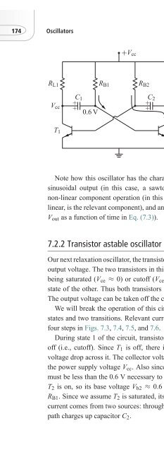
72 Band theory and diode circuits o
- Page 178:
74 Band theory and diode circuits -
- Page 182:
76 Band theory and diode circuits f
- Page 186:
78 Band theory and diode circuits I
- Page 190:
80 Band theory and diode circuits T
- Page 194:
82 Band theory and diode circuits I
- Page 198:
84 Band theory and diode circuits V
- Page 202:
86 Band theory and diode circuits Y
- Page 206:
88 Band theory and diode circuits V
- Page 210:
90 Band theory and diode circuits r
- Page 214:
92 Band theory and diode circuits T
- Page 218:
94 Band theory and diode circuits V
- Page 222:
96 Band theory and diode circuits T
- Page 226:
98 Band theory and diode circuits R
- Page 230:
100 Band theory and diode circuits
- Page 234:
102 Band theory and diode circuits
- Page 238:
4 Bipolar junction transistors 4.1
- Page 242:
106 Bipolar junction transistors 1.
- Page 246:
108 Bipolar junction transistors V
- Page 250:
110 Bipolar junction transistors In
- Page 254:
112 Bipolar junction transistors V
- Page 258:
114 Bipolar junction transistors I
- Page 262:
116 Bipolar junction transistors B
- Page 266:
118 Bipolar junction transistors Ta
- Page 270:
120 Bipolar junction transistors R
- Page 274:
122 Bipolar junction transistors V
- Page 278:
124 Bipolar junction transistors B
- Page 282:
126 Bipolar junction transistors mo
- Page 286:
128 Bipolar junction transistors v
- Page 290:
130 Bipolar junction transistors an
- Page 294:
132 Bipolar junction transistors 9.
- Page 298:
134 Field-effect transistors parame
- Page 302:
136 Field-effect transistors Drain
- Page 306:
138 Field-effect transistors In con
- Page 310:
140 Field-effect transistors of FET
- Page 314:
142 Field-effect transistors 5.4.1
- Page 318:
144 Field-effect transistors 5.4.2
- Page 322:
146 Field-effect transistors The ne
- Page 326: 148 Field-effect transistors V dd R
- Page 330: 150 Field-effect transistors EXERCI
- Page 334: 6 Operational amplifiers 6.1 Introd
- Page 338: 154 Operational amplifiers V in 1V
- Page 342: 156 Operational amplifiers V in +
- Page 346: 158 Operational amplifiers where th
- Page 350: 160 Operational amplifiers I + B B
- Page 354: 162 Operational amplifiers V in R +
- Page 358: 164 Operational amplifiers 6.4.4 Fr
- Page 362: 166 Operational amplifiers C A R f
- Page 366: 168 Operational amplifiers EXERCISE
- Page 370: 170 Operational amplifiers 6. Draw
- Page 374: 172 Oscillators V cc R b R 1 V g R
- Page 380: 7.2 Relaxation oscillators 175 +V c
- Page 384: 7.2 Relaxation oscillators 177 R L1
- Page 388: 7.2 Relaxation oscillators 179 +V c
- Page 392: 7.2 Relaxation oscillators 181 +V c
- Page 396: 7.2 Relaxation oscillators 183 V cc
- Page 400: 7.3 Sinusoidal oscillators 185 V A
- Page 404: 7.3 Sinusoidal oscillators 187 C 1
- Page 408: 7.3 Sinusoidal oscillators 189 Rela
- Page 412: 7.3 Sinusoidal oscillators 191 V cc
- Page 416: 7.4 Oscillator application: EM comm
- Page 420: 7.4 Oscillator application: EM comm
- Page 424: 7.4 Oscillator application: EM comm
- Page 428:
Further reading 199 circuit with th
- Page 432:
8.2 Binary numbers 201 Table 8.1 Th
- Page 436:
8.3 Representing binary numbers in
- Page 440:
8.4 Logic gates 205 A B Out ≡ A
- Page 444:
8.5 Implementing logical functions
- Page 448:
8.6 Boolean algebra 209 Table 8.3 T
- Page 452:
8.7 Making logic gates 211 A 0 Out
- Page 456:
8.8 Adders 213 Table 8.4 Characteri
- Page 460:
8.8 Adders 215 A B C HA C S HA C S
- Page 464:
8.9 Information registers 217 Table
- Page 468:
8.9 Information registers 219 Q S
- Page 472:
8.10 Counters 221 S Q C R MSFF Q Fi
- Page 476:
8.11 Displays and decoders 223 f e
- Page 480:
8.12 Shift registers 225 clock S 1
- Page 484:
8.13 Digital to analog converters 2
- Page 488:
8.15 Multiplexers and demultiplexer
- Page 492:
8.15 Multiplexers and demultiplexer
- Page 496:
8.16 Memory chips 233 A 7 A 6 D 3 A
- Page 500:
Further reading 235 FURTHER READING
- Page 504:
Appendix A: Selected answers to exe
- Page 508:
B.2 Cramer’s Method 239 determina
- Page 512:
Appendix C: Inductively coupled cir
- Page 516:
C.2 Transformers 243 V(t) = V p e j
- Page 520:
References Charles K. Alexander and
- Page 524:
Index A/D, see analog to digital co
- Page 528:
Index 249 frequency domain analysis
- Page 532:
Index 251 ripple factor, 91 roll of