STi5516 - Read
STi5516 - Read
STi5516 - Read

You also want an ePaper? Increase the reach of your titles
YUMPU automatically turns print PDFs into web optimized ePapers that Google loves.
®<br />
● 180 MHz, 8 Kbyte instruction cache, 8 Kbyte data cache<br />
and 8 Kbyte SRAM<br />
■ Shared memory interface<br />
● 135 MHz,16-bit wide SDRAM interface, 64 and 128 Mbit<br />
support<br />
■ Programmable external memory interface<br />
● 6 separately configurable banks, 8/16-bits wide<br />
● SRAM, SDRAM, SFlash support<br />
● PIO mode HDD or DVB-CI support<br />
■ Programmable transport interfaces (PTI)<br />
● 2 input static MUX<br />
● single transport stream deMUX: DVB and/or DIRECTV ®<br />
● integrated DES-ECB, DVB and ICAM descramblers<br />
● support for low cost DVB-CI interface<br />
■ Package 35 x 35 PBGA388<br />
■ MPEG2 MP@ML video decoder<br />
● greater than 2x decoding speed<br />
● trick modes including smooth fast-forward and rewind<br />
● fully programmable horizontal and vertical SRCs<br />
■ Graphics/display<br />
● 5 display planes<br />
● 2, 4 and 8 bpp CLUT graphics, 256 x 30 bits (AYCbCr)<br />
CLUT entries. Link list control<br />
● alpha blending, antialiasing, antiflutter, antiflicker filters<br />
Confidential ■ Enhanced ST20 32-bit VL-RISC CPU<br />
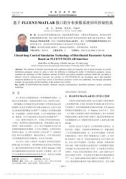
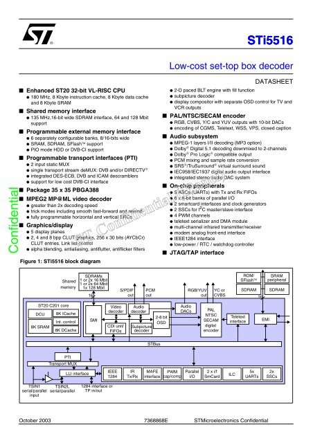
Figure 1: <strong>STi5516</strong> block diagram<br />
ST20 C201 core<br />
DCU<br />
8K SRAM<br />
Shared<br />
memory<br />
8K ICache<br />
Int. control<br />
8K DCache<br />
PTI<br />
Transport MUX<br />
LLI interface<br />
SDRAMs<br />
1 or 2x 16 Mbit<br />
1 or 2x 64 Mbit<br />
1x 128 Mbit<br />
16<br />
SMI<br />
TSIN1<br />
serial/parallel<br />
input<br />
TSIN2L<br />
serial/parallel<br />
1284 interface or<br />
TP in/out<br />
Video<br />
decoder<br />
CDI unit/<br />
FIFOs<br />
IEEE<br />
1284<br />
S/PDIF<br />
out<br />
Audio<br />
decoder<br />
Subpicture<br />
decoder<br />
IR<br />
Tx/Rx<br />
October 2003 7368868E STMicroelectronics Confidential<br />
PCM<br />
out<br />
STBus<br />
MAFE<br />
interface<br />
<strong>STi5516</strong><br />
DATASHEET<br />
● 2-D paced BLT engine with fill function<br />
● subpicture decoder<br />
● display compositor with separate OSD control for TV and<br />
VCR outputs<br />
■ PAL/NTSC/SECAM encoder<br />
● RGB, CVBS, Y/C and YUV outputs with 10-bit DACs<br />
● encoding of CGMS, Teletext, WSS, VPS, closed caption<br />
■ Audio subsystem<br />
● MPEG-1 layers I/II decoding (MP3 option)<br />
● Dolby ® Digital 5.1 decoding downmixed to 2-channels<br />
● Dolby ® Pro Logic ® compatible output<br />
● PCM mixing and sample rate conversion<br />
● SRS ® /TruSurround ® virtual surround sound<br />
● IEC958/IEC1937 digital audio output interface<br />
● integrated stereo audio DAC system<br />
■ On-chip peripherals<br />
● 5 ASCs (UARTs) with Tx and Rx FIFOs<br />
● 6 x 8-bit banks of parallel I/O<br />
● 2 smartcard interfaces and clock generators<br />
● 2 SSCs for I 2 C master/slave interface<br />
● 4 PWM channels<br />
● teletext serializer and DMA module<br />
● multi-channel infrared transmitter/receiver<br />
● modem analog front-end interface<br />
● IEEE1284 interface<br />
● low-power / RTC / watchdog controller<br />
2-8 bit<br />
OSD<br />
Low-cost set-top box decoder<br />
■ JTAG/TAP interface<br />
PWM<br />
cap/comp<br />
Audio<br />
DACs<br />
RGB/YUV<br />
out<br />
Parallel<br />
I/O<br />
YC or<br />
CVBS<br />
PAL<br />
NTSC<br />
SECAM<br />
digital<br />
encoder<br />
2 x i/f<br />
SmCard<br />
Teletext<br />
interface<br />
ILC<br />
ROM/<br />
SFlash<br />
SRAM<br />
peripheral<br />
SDRAM SDRAM<br />
5x<br />
UARTs<br />
16<br />
EMI<br />
2x<br />
SSCs
Confidential<br />
Table of contents<br />
2/709 STMicroelectronics Confidential 7368868E<br />
<strong>STi5516</strong><br />
Chapter 1 Introduction . . . . . . . . . . . . . . . . . . . . . . . . . . . . . . . . . . . . . . . . . . . . . . . . . . . . .14<br />
Chapter 2 Architecture . . . . . . . . . . . . . . . . . . . . . . . . . . . . . . . . . . . . . . . . . . . . . . . . . . . . .15<br />
2.1 Overview ............................................................................................................................15<br />
2.2 Omega2 (STBus) interconnect ...........................................................................................16<br />
2.3 Processor core ...................................................................................................................16<br />
2.4 Memory subsystem ............................................................................................................16<br />
2.5 Transport stream processing .............................................................................................17<br />
2.6 LLI interface .......................................................................................................................18<br />
2.7 MPEG graphics and display architecture ...........................................................................19<br />
2.8 Graphics and display ..........................................................................................................20<br />
2.9 Digital encoder ...................................................................................................................21<br />
2.10 Audio subsystem ................................................................................................................21<br />
2.11 Modem ...............................................................................................................................22<br />
2.12 Internal peripherals ............................................................................................................23<br />
2.13 EMI programmable output drive .........................................................................................23<br />
2.14 Clock generation ................................................................................................................23<br />
2.15 Smartcard interface ............................................................................................................23<br />
Chapter 3 Audio and video summary specification . . . . . . . . . . . . . . . . . . . . . . . . . . . . . .24<br />
3.1 Functional limitations ..........................................................................................................24<br />
3.2 Summary specification .......................................................................................................24<br />
Chapter 4 Pin list . . . . . . . . . . . . . . . . . . . . . . . . . . . . . . . . . . . . . . . . . . . . . . . . . . . . . . . . . .26<br />
4.1 Pin-out ................................................................................................................................26<br />
4.2 <strong>STi5516</strong> pin list ...................................................................................................................28<br />
4.3 PIO pins and alternative functions .....................................................................................36<br />
4.4 Reset states .......................................................................................................................40<br />
Chapter 5 Package specifications . . . . . . . . . . . . . . . . . . . . . . . . . . . . . . . . . . . . . . . . . . . .43<br />
Chapter 6 Register base addresses . . . . . . . . . . . . . . . . . . . . . . . . . . . . . . . . . . . . . . . . . . .46
<strong>STi5516</strong><br />
Chapter 8 Central processing unit (CPU) . . . . . . . . . . . . . . . . . . . . . . . . . . . . . . . . . . . . . .81<br />
8.1 Overview ............................................................................................................................81<br />
8.2 Registers used in sequential integer processes .................................................................81<br />
8.3 Processes and concurrency ...............................................................................................82<br />
8.4 Priority ................................................................................................................................83<br />
8.5 Process communications ...................................................................................................84<br />
8.6 Timers ................................................................................................................................84<br />
8.7 Traps and exceptions .........................................................................................................86<br />
Chapter 9 Central processing unit (CPU) registers . . . . . . . . . . . . . . . . . . . . . . . . . . . . . .91<br />
9.1 Machine registers ...............................................................................................................91<br />
9.2 Other machine registers .....................................................................................................91<br />
9.3 Register details ..................................................................................................................93<br />
Chapter 10 Instruction set . . . . . . . . . . . . . . . . . . . . . . . . . . . . . . . . . . . . . . . . . . . . . . . . . . . .97<br />
10.1 Overview ............................................................................................................................97<br />
10.2 Instruction cycles ................................................................................................................97<br />
10.3 Instruction characteristics ...................................................................................................98<br />
10.4 Instruction set tables ..........................................................................................................99<br />
Confidential Chapter 7 Register summary . . . . . . . . . . . . . . . . . . . . . . . . . . . . . . . . . . . . . . . . . . . . . . . .48<br />
Chapter 11 Interrupt system . . . . . . . . . . . . . . . . . . . . . . . . . . . . . . . . . . . . . . . . . . . . . . . . .110<br />
11.1 Overview ..........................................................................................................................110<br />
11.2 Interrupt controller ............................................................................................................111<br />
11.3 Interrupt level controller ....................................................................................................114<br />
11.4 Interrupt assignments .......................................................................................................115<br />
Chapter 12 Interrupt system registers . . . . . . . . . . . . . . . . . . . . . . . . . . . . . . . . . . . . . . . . .117<br />
12.1 Interrupt level controller registers .....................................................................................123<br />
Chapter 13 Memory map . . . . . . . . . . . . . . . . . . . . . . . . . . . . . . . . . . . . . . . . . . . . . . . . . . . .128<br />
7368868E STMicroelectronics Confidential 3/709
4/709 STMicroelectronics Confidential 7368868E<br />
<strong>STi5516</strong><br />
14.1 External memory ..............................................................................................................131<br />
14.2 On-chip SRAM memory ...................................................................................................131<br />
14.3 Cacheing ..........................................................................................................................132<br />
Chapter 15 Memory registers . . . . . . . . . . . . . . . . . . . . . . . . . . . . . . . . . . . . . . . . . . . . . . . .135<br />
Chapter 16 External memory interface (EMI) . . . . . . . . . . . . . . . . . . . . . . . . . . . . . . . . . . .141<br />
16.1 Overview ..........................................................................................................................141<br />
16.2 Operation .........................................................................................................................142<br />
16.3 Default/reset configuration ...............................................................................................144<br />
16.4 Peripheral interface with synchronous flash memory support ..........................................145<br />
16.5 SDRAM interface .............................................................................................................151<br />
Chapter 17 External memory interface (EMI) registers . . . . . . . . . . . . . . . . . . . . . . . . . . .168<br />
17.1 Configuration register format for peripherals ....................................................................173<br />
17.2 Configuration register format for SDRAM ........................................................................177<br />
Chapter 18 Padlogic . . . . . . . . . . . . . . . . . . . . . . . . . . . . . . . . . . . . . . . . . . . . . . . . . . . . . . .180<br />
18.1 Overview ..........................................................................................................................180<br />
18.2 EMI padlogic ....................................................................................................................180<br />
18.3 TRI_PTI MUXing ..............................................................................................................191<br />
Confidential Chapter 14 Memory . . . . . . . . . . . . . . . . . . . . . . . . . . . . . . . . . . . . . . . . . . . . . . . . . . . . . . . .131<br />
18.4 CDREQ MUXing ..............................................................................................................192<br />
Chapter 19 Padlogic registers . . . . . . . . . . . . . . . . . . . . . . . . . . . . . . . . . . . . . . . . . . . . . . .193<br />
19.1 EMI general purpose configuration outputs .....................................................................193<br />
19.2 Monitor registers ..............................................................................................................194<br />
19.3 Configuration registers .....................................................................................................194<br />
Chapter 20 EMI buffer . . . . . . . . . . . . . . . . . . . . . . . . . . . . . . . . . . . . . . . . . . . . . . . . . . . . . .199<br />
Chapter 21 EMI buffer registers . . . . . . . . . . . . . . . . . . . . . . . . . . . . . . . . . . . . . . . . . . . . . .200
<strong>STi5516</strong><br />
22.1 Overview ..........................................................................................................................204<br />
22.2 Power-on hard reset .........................................................................................................204<br />
22.3 Bootstrap ..........................................................................................................................204<br />
Chapter 23 Diagnostic controller (DCU) . . . . . . . . . . . . . . . . . . . . . . . . . . . . . . . . . . . . . . .205<br />
23.1 Overview ..........................................................................................................................205<br />
23.2 Diagnostic hardware ........................................................................................................205<br />
23.3 Access features ................................................................................................................206<br />
23.4 Software debugging features ...........................................................................................207<br />
23.5 Controlling the diagnostic controller .................................................................................208<br />
23.6 Peeking and poking the host from the target ...................................................................210<br />
Chapter 24 Diagnostic controller (DCU) registers . . . . . . . . . . . . . . . . . . . . . . . . . . . . . . .211<br />
24.1 General registers ..............................................................................................................211<br />
24.2 Jump trace registers .........................................................................................................218<br />
24.3 Compare registers ............................................................................................................221<br />
24.4 Capture registers ..............................................................................................................223<br />
24.5 Sequencing registers .......................................................................................................224<br />
24.6 Work space range enable registers .................................................................................225<br />
Chapter 25 Test access port . . . . . . . . . . . . . . . . . . . . . . . . . . . . . . . . . . . . . . . . . . . . . . . . .227<br />
Confidential Chapter 22 System services . . . . . . . . . . . . . . . . . . . . . . . . . . . . . . . . . . . . . . . . . . . . . . . . .204<br />
Chapter 26 Test access port registers . . . . . . . . . . . . . . . . . . . . . . . . . . . . . . . . . . . . . . . . .228<br />
Chapter 27 Data flow . . . . . . . . . . . . . . . . . . . . . . . . . . . . . . . . . . . . . . . . . . . . . . . . . . . . . . .229<br />
27.1 Overview ..........................................................................................................................229<br />
27.2 Audio: PCM mixing ...........................................................................................................229<br />
27.3 Video: standard decode ...................................................................................................230<br />
Chapter 28 Programmable transport interface (PTI) . . . . . . . . . . . . . . . . . . . . . . . . . . . . .232<br />
28.1 Overview ..........................................................................................................................232<br />
28.2 PTI functions ....................................................................................................................234<br />
28.3 PTI architecture ................................................................................................................235<br />
28.4 PTI operation ....................................................................................................................238<br />
28.5 Interrupt handling .............................................................................................................240<br />
7368868E STMicroelectronics Confidential 5/709
Confidential<br />
6/709 STMicroelectronics Confidential 7368868E<br />
<strong>STi5516</strong><br />
28.6 DMA operation .................................................................................................................242<br />
28.7 Section filter (SF) .............................................................................................................244<br />
28.8 Compatibility with PTI1 .....................................................................................................250<br />
Chapter 29 Programmable transport interface (PTI) registers . . . . . . . . . . . . . . . . . . . . .251<br />
29.1 DMA registers ..................................................................................................................251<br />
29.2 Input interface registers ....................................................................................................259<br />
29.3 PTI configuration registers ...............................................................................................261<br />
29.4 Section filter registers .......................................................................................................265<br />
29.5 Transport controller mode register ...................................................................................267<br />
Chapter 30 Transport stream multiplexor (TSMUX) . . . . . . . . . . . . . . . . . . . . . . . . . . . . . .269<br />
30.1 Overview ..........................................................................................................................269<br />
30.2 Architecture ......................................................................................................................269<br />
30.3 Transport stream routing ..................................................................................................270<br />
30.4 PTI MUXing ......................................................................................................................271<br />
30.5 Transport output ...............................................................................................................271<br />
30.6 Local byte clock ................................................................................................................272<br />
30.7 TS timing information .......................................................................................................272<br />
30.8 TSMUX_SWTS ................................................................................................................272<br />
Chapter 31 Transport stream multiplexor (TSMUX) registers . . . . . . . . . . . . . . . . . . . . . .274<br />
Chapter 32 IEEE1394 link layer interface (LLI) . . . . . . . . . . . . . . . . . . . . . . . . . . . . . . . . . .278<br />
32.1 Overview ..........................................................................................................................278<br />
32.2 Block diagram .................................................................................................................278<br />
32.3 Data streams ....................................................................................................................279<br />
32.4 Pin function ......................................................................................................................280<br />
Chapter 33 IEEE1394 link layer interface (LLI) registers . . . . . . . . . . . . . . . . . . . . . . . . . .281<br />
Chapter 34 MPEG video decoder . . . . . . . . . . . . . . . . . . . . . . . . . . . . . . . . . . . . . . . . . . . . .283<br />
34.1 Overview ..........................................................................................................................283<br />
34.2 Decoder operation ............................................................................................................283<br />
34.3 Configuration and control .................................................................................................284<br />
34.4 Reset ................................................................................................................................284
Confidential<br />
<strong>STi5516</strong><br />
34.5 Bit buffer and start code detection (video) .......................................................................285<br />
34.6 Video decoding pipeline control .......................................................................................287<br />
34.7 Quantization table loading ................................................................................................288<br />
34.8 Memory mapping of data .................................................................................................289<br />
34.9 Using picture pointers ......................................................................................................299<br />
34.10 Video pipeline ...................................................................................................................299<br />
34.11 PES parser .......................................................................................................................303<br />
34.12 Enhanced trick modes ......................................................................................................304<br />
Chapter 35 MPEG video decoder registers . . . . . . . . . . . . . . . . . . . . . . . . . . . . . . . . . . . . .306<br />
35.1 Configuration and control (CFG) register information ......................................................328<br />
35.2 PES parser (PES) register Information ............................................................................330<br />
Chapter 36 Subpicture decoder . . . . . . . . . . . . . . . . . . . . . . . . . . . . . . . . . . . . . . . . . . . . . .333<br />
36.1 Overview ..........................................................................................................................333<br />
36.2 Buffer management and pointers .....................................................................................334<br />
36.3 Subpicture decoder operation ..........................................................................................334<br />
36.4 Subpicture display ............................................................................................................336<br />
Chapter 37 Subpicture decoder registers . . . . . . . . . . . . . . . . . . . . . . . . . . . . . . . . . . . . . .338<br />
Chapter 38 Display planes . . . . . . . . . . . . . . . . . . . . . . . . . . . . . . . . . . . . . . . . . . . . . . . . . .344<br />
38.1 Overview ..........................................................................................................................344<br />
38.2 Background color .............................................................................................................345<br />
38.3 Still picture plane ..............................................................................................................346<br />
38.4 MPEG video plane ...........................................................................................................348<br />
38.5 On-screen display (OSD) .................................................................................................358<br />
38.6 Subpicture or cursor plane ...............................................................................................373<br />
38.7 Mixing display planes .......................................................................................................373<br />
Chapter 39 Display planes registers . . . . . . . . . . . . . . . . . . . . . . . . . . . . . . . . . . . . . . . . . .376<br />
39.1 Background color registers ..............................................................................................376<br />
39.2 Still picture plane registers ...............................................................................................377<br />
39.3 On-screen display registers .............................................................................................382<br />
7368868E STMicroelectronics Confidential 7/709
8/709 STMicroelectronics Confidential 7368868E<br />
<strong>STi5516</strong><br />
40.1 Overview ..........................................................................................................................397<br />
40.2 Copying blocks of data .....................................................................................................397<br />
Chapter 41 2-D block move registers . . . . . . . . . . . . . . . . . . . . . . . . . . . . . . . . . . . . . . . . . .399<br />
Chapter 42 Teletext DMA . . . . . . . . . . . . . . . . . . . . . . . . . . . . . . . . . . . . . . . . . . . . . . . . . . . .402<br />
42.1 Overview ..........................................................................................................................402<br />
42.2 Teletext packet format ......................................................................................................402<br />
42.3 Data transfer sequence ....................................................................................................403<br />
42.4 Interrupt control ................................................................................................................403<br />
Chapter 43 Teletext DMA registers . . . . . . . . . . . . . . . . . . . . . . . . . . . . . . . . . . . . . . . . . . .404<br />
Chapter 44 Digital encoder . . . . . . . . . . . . . . . . . . . . . . . . . . . . . . . . . . . . . . . . . . . . . . . . . .407<br />
44.1 Overview ..........................................................................................................................407<br />
44.2 Video timing .....................................................................................................................407<br />
44.3 Reset procedure ...............................................................................................................411<br />
44.4 Slave modes ....................................................................................................................411<br />
44.5 Input demultiplexor ...........................................................................................................416<br />
44.6 Subcarrier generation .......................................................................................................417<br />
44.7 Burst insertion (PAL and NTSC) ......................................................................................418<br />
Confidential Chapter 40 2-D block move . . . . . . . . . . . . . . . . . . . . . . . . . . . . . . . . . . . . . . . . . . . . . . . . . .397<br />
44.8 Subcarrier insertion (SECAM) ..........................................................................................419<br />
44.9 Luminance encoding ........................................................................................................420<br />
44.10 Chrominance encoding ....................................................................................................421<br />
44.11 Composite video signal generation ..................................................................................423<br />
44.12 RGB and UV encoding .....................................................................................................425<br />
44.13 Closed captioning .............................................................................................................425<br />
44.14 CGMS encoding ...............................................................................................................426<br />
44.15 WSS encoding .................................................................................................................427<br />
44.16 VPS encoding ..................................................................................................................427<br />
44.17 Teletext encoding .............................................................................................................428<br />
44.18 CVBS, S-VHS, RGB and UV outputs ...............................................................................430
<strong>STi5516</strong><br />
Chapter 46 Triple video DAC . . . . . . . . . . . . . . . . . . . . . . . . . . . . . . . . . . . . . . . . . . . . . . . .458<br />
46.1 Overview ..........................................................................................................................458<br />
46.2 Input codes for video application ......................................................................................459<br />
46.3 Video output voltage level ................................................................................................459<br />
46.4 Video specifications and DAC setup ................................................................................460<br />
46.5 Output stage adaptation and amplification .......................................................................460<br />
Chapter 47 Audio decoder . . . . . . . . . . . . . . . . . . . . . . . . . . . . . . . . . . . . . . . . . . . . . . . . . .461<br />
47.1 Overview ..........................................................................................................................461<br />
47.2 Decoding process ............................................................................................................465<br />
47.3 Operation .........................................................................................................................466<br />
47.4 Decoding states ...............................................................................................................467<br />
47.5 Stream parsers .................................................................................................................468<br />
47.6 Decoding modes ..............................................................................................................469<br />
47.7 PCM output ......................................................................................................................472<br />
47.8 S/PDIF output ...................................................................................................................477<br />
47.9 Interrupts ..........................................................................................................................478<br />
47.10 Audio/video synchronization ............................................................................................479<br />
47.11 PCM beep tone ................................................................................................................480<br />
Confidential Chapter 45 Digital encoder registers . . . . . . . . . . . . . . . . . . . . . . . . . . . . . . . . . . . . . . . . . .432<br />
47.12 PCM mixing ......................................................................................................................481<br />
47.13 VCR output .......................................................................................................................482<br />
Chapter 48 Audio decoder registers . . . . . . . . . . . . . . . . . . . . . . . . . . . . . . . . . . . . . . . . . .483<br />
48.1 Audio DSP start up registers ............................................................................................483<br />
48.2 Audio DSP version registers ............................................................................................484<br />
48.3 RS232 activation registers ...............................................................................................485<br />
48.4 Audio DSP setup and input registers ...............................................................................485<br />
48.5 PCM configuration registers .............................................................................................486<br />
48.6 ADC input/second input registers .....................................................................................488<br />
48.7 PCM mixing registers .......................................................................................................493<br />
48.8 VCR configuration registers .............................................................................................495<br />
48.9 S/PDIF output setup registers ..........................................................................................496<br />
48.10 Audio command registers ................................................................................................499<br />
7368868E STMicroelectronics Confidential 9/709
Confidential<br />
10/709 STMicroelectronics Confidential 7368868E<br />
<strong>STi5516</strong><br />
48.11 Audio interrupt registers ...................................................................................................502<br />
48.12 Audio DSP decoding algorithm registers .........................................................................509<br />
48.13 Audio DSP system synchronization registers ..................................................................510<br />
48.14 Postdecoding and Pro Logic® registers ...........................................................................512<br />
48.15 Bass redirection registers .................................................................................................514<br />
48.16 Dolby® Digital configuration registers ..............................................................................516<br />
48.17 MPEG configuration registers ..........................................................................................522<br />
48.18 LPCM registers ................................................................................................................527<br />
48.19 LPCM downmix coefficients .............................................................................................528<br />
48.20 PCM beep tone registers .................................................................................................532<br />
48.21 Pink noise register ............................................................................................................534<br />
48.22 General mode configuration registers ..............................................................................535<br />
Chapter 49 Audio decoder interface (AUDIF) . . . . . . . . . . . . . . . . . . . . . . . . . . . . . . . . . . .537<br />
49.1 Overview ..........................................................................................................................537<br />
49.2 PCM input module (PCMI) ...............................................................................................538<br />
49.3 PCM output module (PCMO) ...........................................................................................538<br />
Chapter 50 Audio decoder interface (AUDIF) registers . . . . . . . . . . . . . . . . . . . . . . . . . . .542<br />
Chapter 51 Audio DAC . . . . . . . . . . . . . . . . . . . . . . . . . . . . . . . . . . . . . . . . . . . . . . . . . . . . .547<br />
51.1 Description .......................................................................................................................547<br />
51.2 Input signals and output pins ...........................................................................................548<br />
51.3 Soft mute ..........................................................................................................................549<br />
51.4 Output stage filtering ........................................................................................................549<br />
Chapter 52 Clock generator . . . . . . . . . . . . . . . . . . . . . . . . . . . . . . . . . . . . . . . . . . . . . . . . .551<br />
52.1 Overview ..........................................................................................................................551<br />
52.2 Maximum clock frequencies and restrictions ...................................................................552<br />
52.3 Modes of operation ..........................................................................................................554<br />
52.4 System clocks ..................................................................................................................556<br />
52.5 Programmable dividers ....................................................................................................558<br />
52.6 PCM clock ........................................................................................................................560<br />
52.7 Smartcard clocks ..............................................................................................................561<br />
52.8 Auxiliary clock ..................................................................................................................561
<strong>STi5516</strong><br />
53.1 Programmable dividers registers .....................................................................................566<br />
53.2 Shift register for SDLL_CLOCK[2:0] ................................................................................568<br />
53.3 Audio DAC, DSS smartcard, auxiliary clock registers ......................................................569<br />
53.4 Low power mode registers ...............................................................................................570<br />
53.5 CPU tick timer register .....................................................................................................572<br />
Chapter 54 Low power module (LPM) and power-down mode . . . . . . . . . . . . . . . . . . . . .573<br />
54.1 Power-down mode ...........................................................................................................573<br />
54.2 Real-time counter .............................................................................................................573<br />
54.3 Watchdog counter ............................................................................................................574<br />
Chapter 55 Low power module (LPM) registers . . . . . . . . . . . . . . . . . . . . . . . . . . . . . . . . .575<br />
Chapter 56 PWM and counter module . . . . . . . . . . . . . . . . . . . . . . . . . . . . . . . . . . . . . . . . .577<br />
56.1 External interface .............................................................................................................577<br />
56.2 PWM outputs ....................................................................................................................577<br />
56.3 Capture inputs ..................................................................................................................578<br />
56.4 Compare (programmable timer) facilities .........................................................................578<br />
56.5 Capture/compare counter, prescaling and clocking .........................................................578<br />
Chapter 57 PWM and counter module registers . . . . . . . . . . . . . . . . . . . . . . . . . . . . . . . . .579<br />
Confidential Chapter 53 Clock generator registers . . . . . . . . . . . . . . . . . . . . . . . . . . . . . . . . . . . . . . . . .562<br />
Chapter 58 Modem analog front-end interface (MAFEIF) . . . . . . . . . . . . . . . . . . . . . . . . . .587<br />
58.1 Overview ..........................................................................................................................587<br />
58.2 Using the MAFEIF to connect to a modem ......................................................................587<br />
58.3 Software ...........................................................................................................................588<br />
Chapter 59 Modem analog front-end interface (MAFEIF) registers . . . . . . . . . . . . . . . . .589<br />
Chapter 60 Infrared transmitter/receiver . . . . . . . . . . . . . . . . . . . . . . . . . . . . . . . . . . . . . . .593<br />
60.1 Overview ..........................................................................................................................593<br />
60.2 Functional description ......................................................................................................593<br />
7368868E STMicroelectronics Confidential 11/709
12/709 STMicroelectronics Confidential 7368868E<br />
<strong>STi5516</strong><br />
61.1 RC transmitter registers ...................................................................................................596<br />
61.2 RC receiver registers .......................................................................................................599<br />
61.3 Noise suppression register ...............................................................................................602<br />
61.4 RC and UHF receiver control ...........................................................................................602<br />
61.5 Reverse polarity registers ................................................................................................603<br />
Chapter 62 Asynchronous serial controller (ASC) . . . . . . . . . . . . . . . . . . . . . . . . . . . . . . .604<br />
62.1 Overview ..........................................................................................................................604<br />
62.2 Control ..............................................................................................................................604<br />
62.3 Data frames ......................................................................................................................605<br />
62.4 Transmission ....................................................................................................................607<br />
62.5 Reception .........................................................................................................................608<br />
62.6 Baudrate generation .........................................................................................................610<br />
62.7 Interrupt control ...............................................................................................................612<br />
62.8 Smartcard operation .........................................................................................................615<br />
Chapter 63 Asynchronous serial controller (ASC) registers . . . . . . . . . . . . . . . . . . . . . . .617<br />
Chapter 64 Smartcard interface . . . . . . . . . . . . . . . . . . . . . . . . . . . . . . . . . . . . . . . . . . . . . .625<br />
64.1 Overview ..........................................................................................................................625<br />
64.2 External interface .............................................................................................................625<br />
64.3 Smartcard clock generator ...............................................................................................626<br />
Confidential Chapter 61 Infrared transmitter/receiver registers . . . . . . . . . . . . . . . . . . . . . . . . . . . . . . .596<br />
Chapter 65 Smartcard interface registers . . . . . . . . . . . . . . . . . . . . . . . . . . . . . . . . . . . . . .627<br />
Chapter 66 Synchronous serial controller (SSC) . . . . . . . . . . . . . . . . . . . . . . . . . . . . . . . .628<br />
66.1 Overview ..........................................................................................................................628<br />
66.2 Basic operation ................................................................................................................628<br />
66.3 I2C operation ....................................................................................................................636<br />
Chapter 67 Synchronous serial controller (SSC) registers . . . . . . . . . . . . . . . . . . . . . . . .644<br />
Chapter 68 Parallel I/O port . . . . . . . . . . . . . . . . . . . . . . . . . . . . . . . . . . . . . . . . . . . . . . . . . .651<br />
Chapter 69 Parallel I/O port registers . . . . . . . . . . . . . . . . . . . . . . . . . . . . . . . . . . . . . . . . . .652
<strong>STi5516</strong><br />
70.1 Overview ..........................................................................................................................658<br />
70.2 IEEE 1284 port pins .........................................................................................................659<br />
70.3 IEEE 1284 mode ..............................................................................................................660<br />
70.4 Transport stream mode ....................................................................................................662<br />
Chapter 71 IEEE 1284 port (PC parallel port) registers . . . . . . . . . . . . . . . . . . . . . . . . . . .666<br />
Chapter 72 Electrical specifications . . . . . . . . . . . . . . . . . . . . . . . . . . . . . . . . . . . . . . . . . .679<br />
72.1 Absolute maximum ratings ..............................................................................................679<br />
72.2 Operating conditions .......................................................................................................680<br />
72.3 DC specifications .............................................................................................................681<br />
72.4 Audio DAC specifications ..............................................................................................682<br />
72.5 Video DAC specifications ................................................................................................682<br />
Chapter 73 Timing specification . . . . . . . . . . . . . . . . . . . . . . . . . . . . . . . . . . . . . . . . . . . . . .683<br />
73.1 SMI SDRAM .....................................................................................................................683<br />
73.2 Audio PCM interface timings ............................................................................................688<br />
73.3 EMI timings ......................................................................................................................689<br />
73.4 PIO timings .......................................................................................................................693<br />
73.5 Reset timings ...................................................................................................................694<br />
73.6 Clock timings ....................................................................................................................695<br />
Confidential Chapter 70 IEEE 1284 port (PC parallel port) . . . . . . . . . . . . . . . . . . . . . . . . . . . . . . . . . . .658<br />
73.7 TAP timings ......................................................................................................................696<br />
73.8 Transport stream timings .................................................................................................697<br />
73.9 Teletext timings ................................................................................................................699<br />
73.10 IEEE 1284 timings ............................................................................................................700<br />
Chapter 74 Revision history . . . . . . . . . . . . . . . . . . . . . . . . . . . . . . . . . . . . . . . . . . . . . . . . .701<br />
Chapter 75 Index of registers . . . . . . . . . . . . . . . . . . . . . . . . . . . . . . . . . . . . . . . . . . . . . . . .704<br />
7368868E STMicroelectronics Confidential 13/709
Introduction <strong>STi5516</strong><br />
The <strong>STi5516</strong> is a single transport derivative of the STi5514 Omega set-top box decoder intended<br />
mainly for use in nonhard disk drive set-top boxes. However support for a simple PIO mode hard<br />
disk drive interface is included, mapped on to the external memory interface (EMI). Also included<br />
is support for a single DVB-CI port. The device is also intended as an upgrade path for<br />
customers using the STi5512. New features have been included to increase performance and<br />
reduce system cost, whilst they have been specified so that a single PCB can be designed to<br />
take either the <strong>STi5516</strong>A or <strong>STi5516</strong> device. (See <strong>STi5516</strong>A/<strong>STi5516</strong> Product Preview for<br />
differences between the STi5514, <strong>STi5516</strong>A and <strong>STi5516</strong> devices)<br />
Performance is enhanced with a 180 MHz, ST20 VL-RISC CPU and increased cache sizes. This<br />
increased performance allows system cost to be reduced by implementing low speed modem<br />
processing entirely in software. In applications requiring a high speed modem, the controller<br />
code can be run on the ST20 CPU, thus reducing the cost of the external data pump.<br />
The additional performance also allows memory usage to be optimized and unified in a single<br />
64-Mbit or 128-Mbit SDRAM for most pay TV applications.<br />
The <strong>STi5516</strong> contains all of the most commonly used descramblers, and thus allows a single<br />
platform to be developed to cover the entire mainstream set-top box market.<br />
The <strong>STi5516</strong> is suitable for use in satellite, terrestrial and cable applications. A typical application<br />
is shown in Figure 2.<br />
Figure 2: Basic pay TV<br />
Confidential 1 Introduction<br />
PTSN<br />
QPSK ZIF Rx<br />
STV0399<br />
MAFE<br />
Transport<br />
stream in<br />
64 Mbit<br />
SDRAM<br />
SMI<br />
14/709 STMicroelectronics Confidential 7368868E<br />
PTI<br />
Smart<br />
cards Cards<br />
<strong>STi5516</strong><br />
EMI4<br />
IR<br />
Tx/Rx<br />
Flash<br />
RGB<br />
CVBS/YC<br />
VCR
<strong>STi5516</strong> Architecture<br />
2.1 Overview<br />
The <strong>STi5516</strong> is derived from the STi5514 with the following functional blocks removed:<br />
● Two PTIs,<br />
● GPDMA,<br />
● HDDI (hard disk drive interface),<br />
● DES (for HDD encryption).<br />
The <strong>STi5516</strong> EMI only has a 16-bit wide data port and does not support MPX.<br />
The architecture of the <strong>STi5516</strong> is illustrated in Figure 3. This chapter briefly describes each of<br />
the major functional blocks.<br />
Figure 3: <strong>STi5516</strong> architecture<br />
FECs<br />
TSIN1<br />
TSIN2L<br />
TSOUT<br />
Confidential 2 Architecture<br />
TS sub<br />
Comms<br />
C201<br />
Clock<br />
generator<br />
PTIA<br />
IFetch<br />
DFetch<br />
SDRAM<br />
STBus interconnect<br />
MPEG INT<br />
MPB LMCB<br />
CD-FIFOs<br />
SUB<br />
TAP + TAPlink + RID<br />
EMI<br />
SMI<br />
Video<br />
Audio<br />
decoder<br />
OSD<br />
Digital encoder<br />
Padlogic<br />
Padlogic<br />
Audio<br />
DACs<br />
ROM/<br />
flash<br />
SRAM/<br />
peripheral<br />
SDRAM<br />
SDRAM<br />
7368868E STMicroelectronics Confidential 15/709
Architecture <strong>STi5516</strong><br />
The Omega2 multipath unified interconnect provides high on-chip bandwidth and low latency<br />
accesses between modules.<br />
The interconnect operates hierarchically, with latency-critical modules placed at the top level.<br />
The multipath router allows simultaneous access paths between modules, and simultaneous<br />
read and write phases from different transactions to and from the modules. Split transactions<br />
maximize the use of the available bandwidth.<br />
2.3 Processor core<br />
The ST20-C201 processor core is composed of the ST20C2+ CPU, a diagnostic controller unit<br />
(for low intrusion, real-time debugging), memory (8-Kbyte instruction cache, 8-Kbyte data cache<br />
and 8 Kbyte SRAM) and a 16 priority-level interrupt controller.<br />
2.4 Memory subsystem<br />
The <strong>STi5516</strong> has two memory interfaces.<br />
The SMI is the <strong>STi5516</strong>'s local memory interface and is used for all the <strong>STi5516</strong>’s data<br />
requirements in unified memory applications, including graphics, video and audio buffers.<br />
For high-performance, nonunified memory systems, additional data SDRAM can be placed on<br />
the EMI. Instructions can execute in place from flash/SFlash on the EMI or can be copied to<br />
SDRAM on the SMI for unified memory applications or to SDRAM on the EMI for the highest<br />
performance systems.<br />
The sections below overview the different memory interfaces.<br />
2.4.1 Shared memory interface (SMI)<br />
The SMI is a 16-bit wide data bus with a peak bandwidth of 270 Mbyte/s. It supports one or two<br />
banks of 16-Mbit SDRAMs, or one bank of 64-Mbit SDRAM, or one bank of 128-Mbit SDRAM.<br />
The SMI provides a fully cacheable address space for data and instructions, with data<br />
cacheability controlled in 512 Kbyte blocks for up to 8 Mbytes.<br />
Confidential 2.2 Omega2 (STBus) interconnect<br />
2.4.2 External memory interface (EMI)<br />
This fourth generation EMI provides a glueless interface to SDRAM, SRAM, flash, SFlash and<br />
peripherals, in up to six configurable banks over a 16-bit wide interface.<br />
Bus cycle strobe timings can be programmed from 0 to 15 phases for slower peripherals.<br />
16/709 STMicroelectronics Confidential 7368868E
<strong>STi5516</strong> Architecture<br />
2.5 Transport stream processing<br />
Confidential<br />
1284/LLI pins TSIN2L TSIN1<br />
The <strong>STi5516</strong> contains a programmable transport interface (PTI) block for concurrent<br />
demultiplexing and descrambling of transport streams (TS). Transport streams are input via the<br />
two parallel/serial TS inputs. A third parallel TS input interface is available via the link layer<br />
interface if neither IEEE1284 nor a transport stream output is required.<br />
2.5.1 Transport stream input/output<br />
A single transport stream is routed to the PTI by the TSMUX block. Any of the three externally<br />
supplied input streams can be routed to the PTI. This is illustrated in Figure 4.<br />
Figure 4: TSMUX inputs and outputs<br />
External TSIN1<br />
serial/parallel<br />
External TSIN2L<br />
serial/parallel in<br />
parallel out<br />
1284 interface<br />
or external<br />
TSIN3 or TSOUT<br />
AV in<br />
MUX<br />
AV out<br />
MUX<br />
The PTI has an output that allows the entire transport stream or selected packets to be output to<br />
an external device such as a DVCR or IEEE1394 link layer controller. The output pins can be tristated<br />
under software control to support low cost DVB-CI implementations and similar module<br />
interfaces. Also under software control, the transport stream input on TSIN1 can be output<br />
directly via TSIN2L. This is again to support low cost DVB-CI implementations. The returned<br />
stream from the CI module can be input on the 1284 LLI pins (TSIN3).<br />
Note: Only one transport stream can be routed to the single PTI at any one time. The TSMUX cannot<br />
dynamically multiplex two streams, so one TS input can be processed by the PTI.<br />
2.5.2 Programmable transport interface (PTI)<br />
LLI<br />
Software<br />
control<br />
TSMUX<br />
TSOUT<br />
The PTI (PTI3) performs transport-stream descrambling, demultiplexing and data filtering. PES<br />
data is transferred by DMA to audio and video decoders via circular buffers. Section data is<br />
transferred by DMA to separate buffers for further processing by the CPU.<br />
● DIRECTV ® and DVB transport streams can be handled by the PTI with data rates up to<br />
120 Mbit/s.<br />
● The PTI performs PID/SCID filtering to select audio, video and data packets to be<br />
processed. More than 48 PID/SCID slots are supported.<br />
● The PTI can descramble streams using DES-ECB or DVB ciphers. NDS specific streams<br />
are also supported by the integration of ICAM functionality.<br />
PTIA<br />
1284<br />
IEEE DMA<br />
1284<br />
controller<br />
7368868E STMicroelectronics Confidential 17/709
Confidential<br />
Architecture <strong>STi5516</strong><br />
● The PTI has a section filter core that filters DVB standard sections. Four filtering modes are<br />
available:<br />
- wide match mode: 32 x 16-byte filters,<br />
- long match mode: 64 x 8-byte filters,<br />
- MAC match mode: 32 x 8-byte filters plus 32 x 6-byte MAC address filter,<br />
- positive/negative mode: 32 x 8-byte filters with positive/negative filtering at the bit level.<br />
Matching sections are transferred to memory buffers for processing by software.<br />
Note: The section filter core can also be used to filter nonDVB section data, for DIRECTV ® format data<br />
streams.<br />
When the PTI is required to output a transport stream, it can output the entire transport stream or<br />
selected packets filtered by PID. A latency counter is provided to ensure packet timing is<br />
preserved. Packets can also be substituted.<br />
2.6 LLI interface<br />
The LLI interface has two functions.<br />
● It provides a dedicated serial/parallel TS input (TSIN2L) that is routed to the TSMUX.<br />
● It selects whether an IEEE1284 data or a parallel transport stream is available on the<br />
bidirectional 1284/LLI pins. In this case, the TS is either an output stream (TSOUT) from the<br />
PTI (arriving from the TSMUX) or an input stream (TSIN3).<br />
The LLI interface selects either TSIN3 or TSIN2L to route to the TSMUX.<br />
The 1284/LLI interface is used to interface with another IEEE1284 device (in 1284 mode) or to<br />
send/receive transport packets to/from an IEEE1394 link layer controller or DVCRs, for example.<br />
18/709 STMicroelectronics Confidential 7368868E
<strong>STi5516</strong> Architecture<br />
2.7 MPEG graphics and display architecture<br />
Confidential<br />
Audio<br />
Video<br />
Subpic<br />
The MPEG graphics and display architecture shown in the following diagram provides the<br />
graphics, video-stream processing and display capabilities of the <strong>STi5516</strong>.<br />
Figure 5: Graphics and display subsystem<br />
SDRAM<br />
SMI<br />
2.7.1 Compressed data unit<br />
16<br />
Video<br />
decoder<br />
2-D block<br />
move<br />
Compressed<br />
data unit<br />
The compressed data unit accepts three memory mapped stream inputs, for audio PES/ES,<br />
video PES/ES and subpicture units (SPUs). It can also directly accept MPEG-1 system streams<br />
or MPEG-2 program streams. It performs PTS/DTS extraction and association, and DSM trick<br />
mode bit extraction and association, before writing to the bit buffers via the audio, video,<br />
subpicture CD FIFOs.<br />
2.7.2 Video display<br />
A/V bus and arbiter<br />
Video<br />
pipeline<br />
Block<br />
to row<br />
Shared<br />
memory<br />
buffer<br />
Vertical<br />
processor<br />
Still picture<br />
processing<br />
Horizontal<br />
SRC<br />
Mixing<br />
unit 4:2:2<br />
Digital<br />
encoder<br />
YC/CVBS<br />
The video display pipeline includes highly programmable horizontal and vertical sample-rate<br />
converters (SRCs) for smooth video resizing with interpolated filtering. Horizontal and vertical<br />
resizing can both be programmed over a x0.25 to x4 range. The video display pipeline also<br />
provides chroma upsampling and subpixel and subline pan and scan as part of the filtering and<br />
display process.<br />
OSD<br />
Subpicture<br />
decoder<br />
Omega2 interconnect<br />
4:2:2<br />
4:2:2<br />
4:4:4<br />
4:4:4<br />
4:4:4<br />
4:4:4<br />
RGB/YUV<br />
4:2:2<br />
Digital YCbCr<br />
output<br />
7368868E STMicroelectronics Confidential 19/709
Architecture <strong>STi5516</strong><br />
2.8.1 Display planes<br />
The following display planes are available:<br />
● background color,<br />
● picture plane,<br />
● video plane,<br />
● on-screen display (OSD) plane,<br />
● subpicture/cursor plane.<br />
Figure 6: Display planes<br />
Confidential 2.8 Graphics and display<br />
2.8.2 Picture plane<br />
The picture plane can be used for still pictures and graphics display behind the video plane.<br />
Images are stored using YCbCr 4:2:2 format. The picture plane can perform zoom in (x2) and<br />
zoom out (x1/2) and hardware unroll or wipes. A 2-D paced BLT engine is also provided for<br />
manipulating images and tiling operations (wallpaper effect).<br />
2.8.3 OSD plane<br />
Background<br />
color<br />
08:23pm<br />
Replay Score Stats<br />
France<br />
On-screen display<br />
Still<br />
picture<br />
plane<br />
Decompressed<br />
video<br />
The OSD plane is managed as a set of regions with a specification comprising configuration, bit<br />
map and palette information for each region. Each region can be independently specified with a<br />
resolution of 2 bpp, 4 bpp or 8 bpp. Regions can be frame-based or field-based. Each region<br />
palette can support up to 256 colors with up to 24-bit resolution per color entry. A vertical<br />
interfield, antiflicker filter is provided to reduce flicker on interlace displays.<br />
20/709 STMicroelectronics Confidential 7368868E<br />
France<br />
08:23pm<br />
Replay Score Stats<br />
Cursor on subpicture plane<br />
Subpicture optional<br />
positions<br />
08:23pm<br />
Replay Score Stats<br />
France
<strong>STi5516</strong> Architecture<br />
Display planes are composited using alpha blending between planes. Mixing of the OSD plane<br />
with the lower layers is achieved using an alpha blending component per region or using an<br />
individual 6-bit alpha component per color to support antialiased fonts.<br />
Mixing of OSD regions and the subpicture/curser layer on the composite outputs (YC and<br />
CVBS), intended for a VCR, may be disabled at the same time as outputting all the layers to the<br />
component (RGB/YUV) and digital video outputs.<br />
2.9 Digital encoder<br />
The digital encoder converts a 4:2:2 digital video stream from the display mixer into a standard<br />
analog baseband PAL/SECAM/NTSC signal. It also converts a 4:4:4 digital video stream from<br />
the digital mixer into RGB and YUV components. The digital encoder can also input a 4:2:2<br />
digital video stream from the digital video output port, when the port is used in input mode.<br />
Note: These functions are mutlplexed on to parallel input/output (PIO) ports.<br />
The digital encoder can handle interlaced mode in all standards. Both square pixel and ITU-T<br />
601 aspect ratio displays can be supported in all standards. The digital encoder performs<br />
closed-caption, CGMS, WSS, teletext and VPS encoding and allows Macrovision 7.01/ 6.1<br />
copy protection.<br />
Two integrated tri-DACs provide six analog TV outputs on which it is possible to output either<br />
(S-VHS(Y/C) + CVBS + RGB) or (S-VHS(Y/C)+ CVBS + YUV) or (Y1 + C1 + CVBS1 + C2 + Y2<br />
+ CVBS2).<br />
The encoder can operate in master mode or in one of several slave modes, where it locks on to<br />
incoming sync signals.<br />
2.10 Audio subsystem<br />
The audio subsystem supports Dolby ® Digital 5.1 (Dolby ® AC3) audio decoding and mixing with<br />
internal PCM files. Decoding of MPEG-1 layers I and II are also supported. MP3 is supported as<br />
product variant option. Decoded multi-channel audio is downmixed before emerging as stereo or<br />
Dolby ® Pro Logic ® encoded audio.<br />
Confidential 2.8.4 Display mixing<br />
The integrated DACs provide analog stereo output directly from the device. Alternatively the<br />
output can be from an external stereo DAC.<br />
Multichannel streams are not decoded for full multichannel output, but can be passed through to<br />
the IEC958 output for external decoding. sound. Audio sample rates of 32 kHz, 44.1 kHz and<br />
48 kHz are supported. The audio subsystem is illustrated in Figure 7.<br />
7368868E STMicroelectronics Confidential 21/709
Confidential<br />
Architecture <strong>STi5516</strong><br />
Figure 7: Audio subsystem<br />
The audio subsystem consists of the units listed below.<br />
2.11 Modem<br />
SDRAM<br />
Shared memory interface<br />
PES<br />
CDin<br />
FIFO<br />
CD stream<br />
CD unit<br />
Internal stream<br />
STBus CPU<br />
MPEG A/V bus<br />
DMA<br />
PCM file<br />
interface/FIFO<br />
Player 1<br />
DMA and FIFO<br />
● Compressed data interface: inputs compressed data audio streams and buffers them in an<br />
audio bit buffer in local memory. The stream source is internal (from the PTI, for example).<br />
● CD player: manages the CD stream bit buffer; it reads the CD stream and sends it to the<br />
DSP for decoding, mixing and output at the same time as formatting the stream and sending<br />
it to the IEC958 output.<br />
● PCM file interface: receives a PCM file, from a PCM file buffer using the PTI channel 3 DMA<br />
as PCM file player and sends it to the DSP for sample rate conversion, mixing and output. It<br />
is also possible to write directly from the CPU to the PCM file interface.<br />
● Audio decoder 24-bit audio digital signal processor: processes audio streams sent to it by<br />
the CD player and PCM file player.<br />
● IEC958 output interface: outputs IEC958/IEC1937 formatted CD or PCM audio received<br />
from the audio DSP.<br />
● 1-channel PCM output interface: outputs PCM audio received from the audio DSP.<br />
● Integrated 24-bit stereo audio DAC system.<br />
● Audio PLL/ digital frequency synthesizer: generates the PCM and sample rate clocks.<br />
● Programmable tone generation for dish alignment.<br />
Standard drivers are available for V22bis software modem and V34/V90 controllerless modem<br />
ported to the <strong>STi5516</strong> architecture.<br />
22/709 STMicroelectronics Confidential 7368868E<br />
PCMI input pins<br />
Compressed<br />
audio MUX<br />
Sample rate<br />
conversion<br />
Decoding /<br />
PCM bypass<br />
IEC958/1937<br />
formatting<br />
Vol ctrl<br />
Vol ctrl<br />
Mixer<br />
Vol ctrl<br />
2 channels<br />
Audio decoder<br />
S/PDIF<br />
interface<br />
Main PCM<br />
interface<br />
Stereo audio<br />
DAC system<br />
Audio subsystem
<strong>STi5516</strong> Architecture<br />
The <strong>STi5516</strong> has many dedicated internal peripherals for digital TV receiver applications,<br />
including:<br />
● five ASCs (UARTs), two of which are generally used by the smartcard controllers,<br />
● teletext serializer and DMA,<br />
● two SSCs for I 2 C master/slave interfaces,<br />
● an IEEE1284 interface module with DMA (Note: 1284 electrical drivers are not present in<br />
the device),<br />
● six GPIO ports,<br />
● four PWM channels,<br />
● a multichannel, infrared blaster/decoder interface module,<br />
● a modem analog front-end interface (MAFE),<br />
● an interrupt level controller,<br />
● a low-power/RTC/watchdog controller,<br />
● DCU toolset support,<br />
● a JTAG/TAP interface.<br />
2.13 EMI programmable output drive<br />
The EMI output drive of the <strong>STi5516</strong> is programmable on a bus-by-bus basis.<br />
2.14 Clock generation<br />
All system clocks are generated using the clock generator block. This contains a high-frequency<br />
PLL (600 MHz) that is divided down to produce a series of phase-related programmable clock<br />
channels. The guaranteed phase relationship between these channels simplifies interconnect<br />
bridging between different subsystem modules and gives lower latency compared to a fully<br />
asynchronous clocking scheme.<br />
The <strong>STi5516</strong> has a clock master; the two channels driving the SDRAM/flash clock outputs are<br />
systematically phase aligned to optimize the external bus performance of the EMI.<br />
Confidential 2.12 Internal peripherals<br />
2.15 Smartcard interface<br />
The <strong>STi5516</strong> smartcard interface is ISO7816, EMV2000 and NDS compliant with the addition of<br />
an ST8004 smartcard interface. Note for some markets the ST8004 functions can be<br />
implemented using lower-cost discrete solutions.<br />
7368868E STMicroelectronics Confidential 23/709
Audio and video summary specification <strong>STi5516</strong><br />
3.1 Functional limitations<br />
Functional limitations of the <strong>STi5516</strong> different from this datasheet can be found in the <strong>STi5516</strong><br />
buglist, reference number ADCS 7428678. This datasheet must be used in conjunction with the<br />
bug list.<br />
3.2 Summary specification<br />
Table 1: Summary specification<br />
Video decoder<br />
Bit streams accepted MPEG-1 video (ISO/IEC 11172-2), MPEG-2 video (ISO/IEC 13818-2)<br />
MPEG-2 Packetized elementary stream (PES) format as defined by ISO/IEC 13818-1<br />
MPEG-1 ISO/IEC 11172-1 packets<br />
MPEG-2 profiles/levels<br />
supported<br />
Confidential 3 Audio and video summary specification<br />
24/709 STMicroelectronics Confidential 7368868E<br />
Main profile@main level (MP@ML), main profile @ low level (MP@LL)<br />
Simple profile@main level (SP@ML)<br />
Maximum picture size Width: 4080<br />
Number of macroblocks: 16383<br />
Motion vector range MPEG-1: -1024 to 1023 (full pel), -512 to 511.5 (half pel) horizontal and vertical<br />
MPEG-2: -1024 to 1023.5 horizontal and vertical<br />
PTI compressed data<br />
input<br />
(2 x parallel/serial)<br />
Parallel peak input rate: 160 Mbit/s<br />
Serial peak input rate: 100 Mbit/s<br />
Maximum sustained average input rate:120 Mbit/s<br />
SDRAM interface External SDRAM used for storage of picture buffers, bit buffer and on-screen display<br />
definitions.<br />
16-bit data bus, one or two banks, refresh handled by decoder<br />
Configurations supported for SDRAM:<br />
1 M x 16 (1 bank),<br />
2 M x 16 (2 banks),<br />
4 M x 16 (1 bank) for a single 64 Mbit SDRAM,<br />
8 M x 16 (1 bank), for 128 Mbit SDRAM.<br />
Start code detection Automatic detection of start codes (of picture layer and above) to enable the<br />
microcontroller to access header data.<br />
Counters provided for time-stamp tracking<br />
Decoding pipeline Instruction register sets up each picture and defines pipeline operation.<br />
Double-buffered quantization matrices enable loading of new tables concurrently with<br />
decoding<br />
Error concealment Automatic concealment of errors detected by VLD and decoding pipeline by<br />
macroblock copy
Confidential<br />
<strong>STi5516</strong> Audio and video summary specification<br />
Table 1: Summary specification<br />
Display<br />
Video clock 27 MHz nominal<br />
Video output External pel clock<br />
Horizontal/vertical synchronization provided by internal digital encoder or external<br />
source<br />
Interlaced output<br />
3:2 pull-down operation supported<br />
On-chip up-/down-sampling with antialiasing filter<br />
Vertical chroma reconstruction or luma filtering up to 4-tap filter<br />
Pan and scan vectors Horizontal: Maximum vector size: 2047 pels, resolution: 1/8 pel<br />
Vertical: Maximum vector size: 1022 lines, resolution: 1 line<br />
On-screen display<br />
(OSD)<br />
Audio decoder<br />
A bitmap that is separately definable for each field or frame which can be<br />
superimposed on the final picture output<br />
OSD defined as rectangular regions, each with unique palette defining 4, 16 or 256<br />
colors (including transparency)<br />
Each region has a blending factor, selectively applied to each color in the palette<br />
The number of regions limited by the memory space allocated to the OSD<br />
Region definitions can be organized as a linked list<br />
A block move facility is available for reduction of microcontroller loading<br />
Bit streams accepted Dolby ® Digital, MPEG-1 layers I and II and PCM<br />
MPEG2 PES streams for MPEG-1, Dolby ® Digital, MP3 (product option) and Linear<br />
PCM (LPCM)<br />
S/PDIF input data (IEC-60958 or IEC-61937 standards) is accepted if an external<br />
circuitry extracts the PCM clock from the stream<br />
Performance ISO/IEC 11172-3 Layers I and II<br />
All MPEG input bit rates supported with sampling rates of 32 kHz, 44.1 kHz and<br />
48 kHz, free format at 32 kHz and 48 kHz sampling rates<br />
Decodes in single channel, dual channel, stereo, or joint stereo modes<br />
Audio clock 27 MHz nominal<br />
Compressed data input Byte-mode input - burst rate up to 28.5 Mbyte/s<br />
PCM output 16-, 18-, 20- or 24-bit PCM output, I 2 S and other popular formats supported<br />
Error concealment Automatic error concealment on CRC or synchronization error detection<br />
General<br />
Support for A/V sync PTS/DTS extraction from MPEG packet layers with automatic association<br />
7368868E STMicroelectronics Confidential 25/709
Pin list <strong>STi5516</strong><br />
4.1 Pin-out<br />
The following pages give the allocation of pins to the package, shown from the top looking down.<br />
A<br />
Confidential 4 Pin list<br />
1 2 3 4 5 6 7 8 9 10 11 12 13<br />
EMI<br />
SDRAM<br />
CLK<br />
EMIFLASH<br />
CLK<br />
B VDD33 VDD33<br />
EMIDATA<br />
[14]<br />
EMIDATA<br />
[15]<br />
C VDD33 VDD33 VDD33<br />
EMIDATA<br />
[13]<br />
EMIDATA<br />
[12]<br />
EMIDATA<br />
[11]<br />
EMIDATA<br />
[10]<br />
EMIDATA<br />
[9]<br />
EMIDATA<br />
[8]<br />
D VDD33 VDD33 VDD33 VDD33 VDD33<br />
E GND GND GND VDD33<br />
F GND GND GND VDD33<br />
G VDD18 VDD18 VDD18 GND<br />
H<br />
J<br />
K<br />
L<br />
NOT_EMI<br />
ACKREQ<br />
NOT_EMI<br />
CAS<br />
NOT_EMI<br />
CSD<br />
NOT_EMIBE<br />
[1]<br />
NC<br />
NOT_EMI<br />
RAS<br />
NOT_EMI<br />
CSC<br />
NOT_EMIBE<br />
[0]<br />
EMIBOOT<br />
MODE[0]<br />
NOT_EMI<br />
REQGNT<br />
NOT_EMI<br />
CSB<br />
NOT_EMI<br />
CSF<br />
VDD18<br />
VDD33<br />
NOT_EMI<br />
CSA<br />
NOT_EMI<br />
CSE<br />
EMIDATA<br />
[7]<br />
EMIDATA<br />
[6]<br />
EMIDATA<br />
[5]<br />
EMIDATA<br />
[4]<br />
26/709 STMicroelectronics Confidential 7368868E<br />
EMIDATA<br />
[3]<br />
EMIDATA<br />
[2]<br />
EMIDATA<br />
[1]<br />
EMIDATA<br />
[0]<br />
EMIADDR<br />
[25]<br />
EMIADDR<br />
[24]<br />
GND VDD33<br />
EMIADDR<br />
[23]<br />
EMIADDR<br />
[22]<br />
EMIADDR<br />
[21]<br />
EMIADDR<br />
[20]<br />
EMIADDR<br />
[19]<br />
EMIADDR<br />
[18]<br />
EMIADDR<br />
[17]<br />
EMIADDR<br />
[16]<br />
EMIADDR<br />
[15]<br />
EMIADDR<br />
[14]<br />
VDD18 VDD33<br />
EMIADDR<br />
[13]<br />
EMIADDR<br />
[12]<br />
EMIADDR<br />
[11]<br />
EMIADDR<br />
[10]<br />
EMIADDR<br />
[9]<br />
EMIADDR<br />
[8]<br />
EMIADDR<br />
[7]<br />
EMIADDR<br />
[6]<br />
GND GND GND<br />
M NOT_EMIOE VDD33 VDD33 VDD33 GND GND GND<br />
N VDD33<br />
P<br />
DCU<br />
TRIGGER<br />
IN<br />
EMIRD<br />
NOTWR<br />
R VDD18 VDD18<br />
T<br />
INTER<br />
RUPT[3]<br />
NOT_EMI<br />
LBA<br />
EMIWAIT<br />
NOT<br />
TREADY<br />
GND GND GND<br />
VDD18 VDD18 VDD18 GND GND GND<br />
INTER<br />
RUPT[2]<br />
DCU<br />
TRIGGER<br />
OUT<br />
INTER<br />
RUPT[1]<br />
VDD18 GND GND GND<br />
INTER<br />
RUPT[0]<br />
U PIO0[1] PIO0[0] PIO0[2] VDD33<br />
V PIO0[6] PIO0[5] PIO0[4] PIO0[3]<br />
W PIO1[2] PIO1[1] PIO1[0] PIO0[7]<br />
Y PIO1[5] PIO1[4] PIO1[3] GND<br />
A<br />
A<br />
A<br />
B<br />
A<br />
C<br />
A<br />
D<br />
A E<br />
A F<br />
VSSAA<br />
DAC<br />
OUTM<br />
LEFT<br />
VCCASA<br />
DAC<br />
VDDAA<br />
DAC<br />
VCCAA<br />
DAC<br />
IREF<br />
VDDASA<br />
DAC<br />
GNDAA<br />
DAC<br />
OUTP<br />
LEFT<br />
PIO1[6]<br />
OUTM<br />
RIGHT<br />
OUTP<br />
RIGHT<br />
GND VDD33 TDI LPCLKIN<br />
VBGFIL PIO2[1] PIO2[5] PIO2[7] PIO3[6] PIO3[4] TMS<br />
LPCLK<br />
OSC<br />
PIO1[7] PIO2[2] PIO2[6] PIO3[1] PIO3[0] NOT_TRST NOT_RESET RTCVDD<br />
PIO2[0] PIO2[3] PIO2[4] PIO3[3] PIO3[2] TDO TCK<br />
NOT_WDOG<br />
RSTOUT<br />
SHIELDV<br />
DAC<br />
VREFDAC<br />
YCC<br />
IREFDAC<br />
YCC<br />
COUT<br />
GNDVDAC<br />
YCC<br />
CVOUT<br />
GND GND GND<br />
VREFDAC<br />
RGB<br />
IREFDAC<br />
RGB<br />
YOUT GOUT<br />
VDDVDAC<br />
YCC<br />
GNDVDAC<br />
RGB<br />
VDD18<br />
BOUT SCLK<br />
VDDVDAC<br />
RGB<br />
PCMCLK<br />
ROUT NC LRCLK
<strong>STi5516</strong> Pin list<br />
power or signals on the PCB.<br />
2 Do not connect: pin is reserved. It may have an electrical connection and must not be used.<br />
14 15 16 17 18 19 20 21 22 23 24 25 26<br />
EMIADDR<br />
[5]<br />
EMIADDR<br />
[4]<br />
EMIADDR<br />
[3]<br />
EMIADDR<br />
[2]<br />
GND<br />
GND<br />
VDDVPLL<br />
VDDGEN<br />
FSYN<br />
GNDGEN<br />
FSYN<br />
CLK<br />
SPEED<br />
SEL<br />
GND GND<br />
NC CLK27MA VDD18 VDD33 GND<br />
VDD<br />
AUDIO<br />
FSYN<br />
GND<br />
AUDIO<br />
FSYN<br />
AUXCLK<br />
OUT<br />
Confidential Note: 1 NC (not connected): indicates that the pin has no electrical connection, and may be used to route<br />
Do not<br />
connect<br />
GND GND GND GND A<br />
VDD18 VDD33 GND GND VDD18 GND GND GND<br />
VDD18 VDD33 GND GND GND GND GND<br />
VDD18 VDD33 GND GND GND GND<br />
VDD33<br />
P1284<br />
DATA[4]<br />
GND<br />
TSIN2L<br />
DATA[5]<br />
GND GND GND VDD18<br />
GND GND GND<br />
GND GND GND<br />
GND GND GND<br />
VDD33<br />
GND<br />
TSIN1<br />
DATA[4]<br />
TSIN1<br />
DATA[0]<br />
TSIN1<br />
BYTE<br />
CLK<br />
NOT_P1284<br />
AUTOFD<br />
NOT_P1284<br />
SELECTIN<br />
P1284<br />
DATA[5]<br />
P1284<br />
DATA[1]<br />
TSIN2L<br />
DATA[6]<br />
TSIN2L<br />
DATA[3]<br />
TSIN2L<br />
DATA[0]<br />
TSIN2L<br />
BYTE<br />
CLK<br />
TSIN1<br />
DATA[5]<br />
TSIN1<br />
DATA[1]<br />
TSIN1<br />
PACKET<br />
CLK<br />
P1284<br />
BUSY<br />
P1284<br />
SELECT<br />
NOT_P1284<br />
INIT<br />
P1284<br />
DATA[6]<br />
P1284<br />
DATA[2]<br />
TSIN2L<br />
DATA[7]<br />
TSIN2L<br />
PACKET<br />
CLK<br />
TSIN2L<br />
DATA[1]<br />
TSIN2L<br />
ERROR<br />
TSIN1<br />
DATA[6]<br />
TSIN1<br />
DATA[2]<br />
TSIN1<br />
ERROR<br />
NOT_P1284<br />
STROBE<br />
NOT_P1284<br />
ACK<br />
P1284<br />
PERROR<br />
NOT_P1284<br />
FAULT<br />
P1284<br />
DATA[7]<br />
P1284<br />
DATA[3]<br />
P1284<br />
DATA[0]<br />
TSIN2L<br />
DATA[4]<br />
TSIN2L<br />
DATA[2]<br />
TSIN2L<br />
BYTE<br />
CLKVALID<br />
TSIN1<br />
DATA[7]<br />
TSIN1<br />
DATA[3]<br />
TSIN1<br />
BYTE<br />
CLKVALID<br />
GND GND GND VDD18 VDD18 VDD18 VDD18 R<br />
GND GND GND<br />
GND SPDIF VDD18 PIO4[4] VDD33 PIO5[3] GND VDD18 VDD33<br />
DO NOT<br />
CONNECT<br />
PCM<br />
DATA[1]<br />
DO NOT<br />
CONNECT<br />
PIO3[5] PIO4[1] PIO4[5] PIO5[1] PIO5[4] PIO5[7] GND VDD33<br />
PIO3[7] PIO4[2] PIO4[7] PIO5[2] PIO5[5]<br />
PIO4[0] PIO4[3] PIO5[0] PIO4[6] PIO5[6]<br />
NOT_<br />
HSYNC<br />
EVENNOT<br />
ODD<br />
GND VDD33<br />
GND VDD33<br />
SMIMEM<br />
CLKIN<br />
NOT_SMI<br />
CAS<br />
VDD33<br />
SMIDATA<br />
[11]<br />
VDD33<br />
GND<br />
VDD33<br />
SMIADDR<br />
[12]<br />
SMIADDR<br />
[8]<br />
SMIADDR<br />
[4]<br />
SMIADDR<br />
[0]<br />
SMIDATA<br />
ML<br />
NOT_SMI<br />
RAS<br />
SMIDATA<br />
[15]<br />
SMIDATA<br />
[12]<br />
SMIDATA<br />
[8]<br />
SMIDATA<br />
[5]<br />
SMIDATA<br />
[2]<br />
SMIADDR<br />
[13]<br />
SMIADDR<br />
[9]<br />
SMIADDR<br />
[5]<br />
SMIADDR<br />
[1]<br />
SMIDATA<br />
MU<br />
NOT_SMIWE<br />
NOT_SMI<br />
CS0<br />
SMIDATA<br />
[13]<br />
SMIDATA<br />
[9]<br />
SMIDATA<br />
[6]<br />
SMIDATA<br />
[3]<br />
SMIDATA<br />
[0]<br />
SMIADDR<br />
[10]<br />
SMIADDR<br />
[6]<br />
SMIADDR<br />
[2]<br />
7368868E STMicroelectronics Confidential 27/709<br />
NC<br />
SMIMEM<br />
CLKOUT<br />
NOT_SMI<br />
CS1<br />
SMIDATA<br />
[14]<br />
SMIDATA<br />
[10]<br />
SMIDATA<br />
[7]<br />
SMIDATA<br />
[4]<br />
SMIDATA<br />
[1]<br />
SMIADDR<br />
[11]<br />
SMIADDR<br />
[7]<br />
SMIADDR<br />
[3]<br />
B<br />
C<br />
D<br />
E<br />
F<br />
G<br />
H<br />
J<br />
K<br />
L<br />
M<br />
N<br />
P<br />
T<br />
U<br />
V<br />
W<br />
Y<br />
A<br />
A<br />
A<br />
B<br />
A<br />
C<br />
A<br />
D<br />
A E<br />
A F
Pin list <strong>STi5516</strong><br />
Signal names are prefixed by NOT_ if they are active low; otherwise they are active high.<br />
All signals are only 3.3 V capable unless otherwise indicated as 1.8 V or 5 V tolerant.<br />
Table 2: I/O load capacitance and DC loading<br />
Pad type<br />
Confidential 4.2 <strong>STi5516</strong> pin list<br />
Functional pin<br />
group<br />
Maximum load<br />
capacitance (pF)<br />
C4 Others 75 4<br />
S8 SDRAM/EMI 75 8<br />
S8b SDRAM/EMI 75 8<br />
E8 EMI<br />
(programmable)<br />
a. Typical load, but the maximum is 75 pF<br />
28/709 STMicroelectronics Confidential 7368868E<br />
Drive (mA) Notes<br />
35 8 a<br />
P4 PIO 400 4<br />
Table 3: Analog power supply pins<br />
25 6 a<br />
15 4 a<br />
5 2 a<br />
Pin Location Number Function<br />
VDDVDACRGB AE12 1 3.3 V power supply for RGB video DAC<br />
VDDVDACYCC AF10 1 3.3 V power supply for YCC video DAC<br />
GNDVDACRGB AC12 1 Ground for RGB video DAC<br />
GNDVDACYCC AC10 1 Ground for YCC video DAC<br />
SHIELDVDAC AC9 1 Shield ground for 2 x video DACs<br />
IREFDACRGB AD11 1 RGB video DAC current reference<br />
IREFDACYCC AE9 1 YCC video DAC current reference<br />
VREFDACRGB AC11 1 RGB video DAC voltage reference<br />
VREFDACYCC AD9 1 YCC video DAC voltage reference<br />
VDDVPLL C15 1 3.3 V power for video PLL<br />
VDDAUDIOFSYN B17 1 1.8 V dedicated power for low jitter audio clock<br />
frequency synthesizer<br />
GNDAUDIOFSYN C17 1 Dedicated ground for low jitter audio clock frequency<br />
synthesizer<br />
VDDGENFSYN A16 1 1.8 V dedicated power for nonaudio clock frequency<br />
synthesizer<br />
GNDGENFSYN B16 1 Dedicated ground for nonaudio clock frequency<br />
synthesizer<br />
VDDAADAC AA2 1 3.3 V power for audio DAC<br />
VSSAADAC AA1 1 Ground for audio DAC command switches
Confidential<br />
<strong>STi5516</strong> Pin list<br />
Table 3: Analog power supply pins<br />
Pin Location Number Function<br />
VDDASADAC AA3 1 3.3 V power for audio DAC substrate<br />
VCCAADAC AB2 1 3.3 V power for audio DAC command switches<br />
GNDAADAC AB3 1 Ground for audio DAC<br />
VCCASADAC AC1 1 3.3 V power for audio DAC command switches<br />
substrate<br />
IREF AC2 1 Audio DAC output reference current<br />
VBGFIL AD1 1 Audio DAC filtered output reference voltage<br />
Table 4: Digital power supply pins<br />
Pin Location Number Function<br />
VDD18 a 24 1.8 V power supply<br />
VDD33 b 35 3.3 V power supply<br />
RTCVDD AE8 1 Low power controller 1.8 V power supply<br />
GND c 76 Ground for power supplies<br />
a. A19, B18, B22, C18, D10, D18, G1 to G3, H4, L23, P2 to P4, R1, R2, R4, R23 to R26, AC13,<br />
AC16 and AC21.<br />
b. A20, B1, B2, B19, C1 to C3, C19, D1 to D5, D8, D11, D19, E4, E23, F4, J4, J23, M2 to M4,<br />
N1, U4, V23, Y23, AB23, AC6, AC18, AC22, AD22, AE22 and AF22.<br />
c. A15, A21, A23 to A26, B15, B20, B21, B23 to B25, C20 to C24, D7, D15, D16, D20 to D23,<br />
E1 to E3, F1 to F3, G4, G23, K23, L11 to L16, M11 to M16, N11 to N16, P11 to P16, R11 to<br />
R16, T11 to T16, Y4, AA23, AC5, AC14, AC20, AD21, AE21 and AF21.<br />
Table 5: RTC pins<br />
Pin Location I/O Function<br />
LPCLKIN<br />
a AC8 I Low power clock input<br />
LPCLKOSC A AD8 I/O Low power clock oscillator<br />
a. 1.8 V tolerant<br />
7368868E STMicroelectronics Confidential 29/709
Confidential<br />
Pin list <strong>STi5516</strong><br />
Table 6: System pins<br />
Pin Location I/O Function<br />
CLK27MA A A18 I Selectable input clock to PLL or for x1 mode C4<br />
a<br />
CLKSPEEDSEL C16 I PLL speed select C4<br />
AUXCLKOUT<br />
a D17 O Auxiliary clock for general use C4<br />
NOT_RESET B AE7 I System reset -<br />
a<br />
NOT_WDOGRSTOUT AF8 O Internal watchdog timer reset. C4<br />
a. 5 V tolerant<br />
b. 1.8 V tolerant<br />
Table 7: JTAG pins<br />
Pin Location I/O Function<br />
TDI A AC7 I Boundary scan test data input C4<br />
a<br />
TMS AD7 I Boundary scan test mode select C4<br />
TCK<br />
a AF7 I Boundary scan test clock -<br />
NOT_TRST<br />
a AE6 I Boundary scan test logic reset C4<br />
TDO<br />
a AF6 O Boundary scan test data output C4<br />
a. 5 V tolerant<br />
Table 8: DCU pins<br />
Pin Location I/O Function<br />
DCUTRIGGERIN<br />
a P1 I External trigger input to DCU C4<br />
DCUTRIGGEROUT A R3 O Signal to trigger external debug circuitry C4<br />
a. 5 V tolerant<br />
30/709 STMicroelectronics Confidential 7368868E<br />
Pad<br />
type<br />
Pad<br />
type<br />
Pad<br />
type
Confidential<br />
<strong>STi5516</strong> Pin list<br />
Table 9: EMI pins<br />
Pin Location I/O Function<br />
NOT_EMIRAS or<br />
NOT_CI_IORD a<br />
NOT_EMICAS or<br />
NOT_CI_IOW a<br />
J2 O Row address strobe for SDRAM C4<br />
J1 O Column address strobe for SDRAM E8<br />
NOT_EMICSA K4 O Peripheral chip select A E8<br />
NOT_EMICSB K3 O Peripheral chip select B E8<br />
NOT_EMICSC K2 O Peripheral chip select C E8<br />
NOT_EMICSD K1 O Peripheral chip select D E8<br />
NOT_EMICSE L4 O Peripheral chip select E E8<br />
NOT_EMICSF L3 O Peripheral chip select F E8<br />
NOT_EMIBE[1:0] L1, L2 O External device data bus byte enable. 1 bit per<br />
byte of the data bus.<br />
NOT_EMIOE or<br />
NOT_CI_OE<br />
NOT_EMILBA or<br />
NOT_CI_WEA<br />
M1 O External device output enable. E8<br />
N3 O Flash device load burst address. E8<br />
EMIWAITNOTTREADYb N4 I External memory device target ready indicator C4<br />
EMIRDNOTWR N2 O External read/write access indicator. Common to<br />
all devices.<br />
EMIDATA[15:0] c I/O External common data bus. E8<br />
EMIADDR[25:2] d e O External common address bus E8<br />
NOT_EMIREQGNT J3 O Bus request/grant indicator E8<br />
b<br />
NOT_EMIACKREQ H1 I Bus grant/request indicator C4<br />
EMIBOOTMODE0<br />
b H3 I External power-up port size indicator C4<br />
EMISDRAMCLK A1 O SDRAM clock E8<br />
EMIFLASHCLK A2 O Peripheral clock E8<br />
a. Or equivalent ATA HDD interface signal.<br />
b. 5 V tolerant<br />
c. B3, A3, A4, B4, C4, A5, B5, C5, A6, B6, C6, D6, A7, B7, C7 and A8.<br />
d. EMIADDR[19:20] are used as ATA HDD interface function: ATA CS0 and CS1. There is no<br />
interconnect configuration control register bit to select this function. The addresses are just<br />
reused as chip selects.<br />
e. B8, C8, A9, B9, C9, D9, A10, B10, C10, A11, B11, C11, A12, B12, C12, D12, A13, B13, C13,<br />
D13, A14, B14, C14 and D14.<br />
Pad<br />
type<br />
7368868E STMicroelectronics Confidential 31/709<br />
E8<br />
E8
Confidential<br />
Pin list <strong>STi5516</strong><br />
Table 10: Transport stream 2 pins<br />
Pin Location I/O Function<br />
TSIN2LBYTECLKa L24 I/O Transport stream bit clock C4<br />
TSIN2LBYTECLKVALID<br />
a L26 I/O Transport stream bit clock valid edge C4<br />
TSIN2LERROR<br />
a L25 I/O Transport stream packet error C4<br />
TSIN2LPACKETCLK<br />
a J25 I/O Transport stream packet strobe C4<br />
TSIN2LDATA[7:0] a bc I/O Transport stream data C4<br />
a. 5 V tolerant<br />
b. H25, H24, H23, J26, J24, K26, K25 and K24<br />
c. TSIN2LDATA7 is used for data input in serial mode.<br />
Table 11: Transport stream 1 pins<br />
Pin Location I/O Function<br />
TSIN1BYTECLK<br />
a P23 I Transport stream bit/byte clock C4<br />
TSIN1BYTECLKVALID<br />
a P26 I Transport stream bit/byte clock valid edge C4<br />
TSIN1ERROR<br />
a P25 I Transport stream packet error C4<br />
TSIN1PACKETCLK<br />
a P24 I Transport stream packet strobe C4<br />
TSIN1DATA[7:0] a b, c I Transport stream data in C4<br />
a. 5 V tolerant<br />
b. M26, M25, M24, M23, N26, N25, N24 and N23.<br />
c. TSIN1DATA7 is used for data input in serial mode.<br />
32/709 STMicroelectronics Confidential 7368868E<br />
Pad<br />
type<br />
Pad<br />
type
Confidential<br />
<strong>STi5516</strong> Pin list<br />
Table 12: Programmable I/O pins<br />
Pin Location I/O Function<br />
PIO0[0:7] A b I/O Parallel input/output pin or alternative function P4<br />
PIO1[0:7] a c I/O P4<br />
PIO2[0:7] a d I/O P4<br />
PIO3[0:7] a e I/O P4<br />
PIO4[0:7] a f I/O P4<br />
PIO5[0:7] a g I/O P4<br />
a. 5 V tolerant<br />
b. U2, U1, U3, V4, V3, V2, V1 and W4<br />
c. W3, W2, W1, Y3, Y2, Y1, AA4 and AE1<br />
d. AF1, AD2, AE2, AF2, AF3, AD3, AE3 and AD4<br />
e. AE5, AE4, AF5, AF4, AD6, AD15, AD5 and AE15<br />
f. AF15, AD16, AE16, AF16, AC17, AD17, AF18 and AE17<br />
g. AF17, AD18, AE18, AC19, AD19, AE19, AF19 and AD20<br />
Table 13: Digital audio pins a<br />
Pin Location I/O Function<br />
SCLK B AD13 O Serial clock C4<br />
b<br />
PCMDATA[1] AE14 O PCM data out C4<br />
PCMCLK<br />
b AE13 I/O External PCM clock input or internal PCM clock<br />
output<br />
LRCLK<br />
b AF13 O Left/right clock C4<br />
SPDIF<br />
b AC15 O Digital audio output C4<br />
a. Note: Digital audio input pins PCMI_SCLK, PCMI_DATA and PCMI_LRCLK are alternate<br />
functions for NOT_CD_REQ[1], I1284HOSTLOGICHIGH, and NOT_CD_REQ[0], on PIO port<br />
3 bits [6:4]<br />
b. 5 V tolerant<br />
Pad<br />
type<br />
Pad<br />
type<br />
7368868E STMicroelectronics Confidential 33/709<br />
C4
Confidential<br />
Pin list <strong>STi5516</strong><br />
Table 14: AVSDRAM pins (SMI)<br />
Pin Location I/O Function<br />
SMIADDR[13:0] a O Audio/video core SDRAM address bus S8<br />
SMIDATA[15:0] b I/O Audio/video core SDRAM data bus S8<br />
NOT_SMICS0 V25 O Audio/video core SDRAM chip select for 1st<br />
SDRAM<br />
NOT_SMICS1 V26 O Audio/video core SDRAM chip select for 2nd<br />
16 Mbit SDRAM<br />
NOT_SMICAS U23 O Audio/video core SDRAM column address strobe S8<br />
NOT_SMIRAS U24 O Audio/video core SDRAM row address strobe S8<br />
NOT_SMIWE U25 O Audio/video core SDRAM write enable S8<br />
SMIMEMCLKIN T23 I Audio/video core SDRAM memory clock input S8b<br />
SMIMEMCLKOUT U26 O Audio/video core SDRAM memory clock output S8<br />
SMIDATAML T24 O Audio/video core SDRAM data bus lower byte<br />
enable<br />
SMIDATAMU T25 O Audio/video core SDRAM data bus upper byte<br />
enable<br />
a. AC24, AC23, AD26, AD25, AD24, AD23, AE26, AE25, AE24, AE23, AF26, AF25, AF24 and<br />
AF23.<br />
b. V24, W26, W25, W24, W23, Y26, Y25, Y24, AA26, AA25, AA24, AB26, AB25, AB24, AC26<br />
and AC25.<br />
Table 15: IEEE 1284/1394 pins<br />
Pin Location I/O Function<br />
P1284DATA[7:0] A b I/O 1284 data or 1394 AV data I14<br />
a<br />
NOT_P1284SELECTIN E24 I/O 1284 or 1394 AV control signals I14<br />
NOT_P1284INIT<br />
a E25 I/O I14<br />
NOT_P1284FAULT<br />
a E26 I/O I14<br />
NOT_P1284AUTOFD<br />
a D24 I/O I14<br />
P1284SELECT<br />
a D25 I/O I14<br />
P1284PERROR<br />
a D26 I/O I14<br />
P1284BUSY<br />
a C25 I/O I14<br />
NOT_P1284ACK<br />
a C26 I/O I14<br />
NOT_P1284STROBE<br />
a B26 I/O I14<br />
a. 5 V tolerant<br />
b. F26, F25, F24, F23, G26, G25, G24 and H26.<br />
34/709 STMicroelectronics Confidential 7368868E<br />
Pad<br />
type<br />
S8<br />
S8<br />
S8<br />
S8<br />
Pad<br />
type
Confidential<br />
<strong>STi5516</strong> Pin list<br />
Table 16: Interrupt pins<br />
Pin Location I/O Function<br />
INTERRUPT[3:0] A b I/O External interrupts C4<br />
a. 5 V tolerant<br />
b. T1, T2, T3 and T4.<br />
Table 17: Analog audio DAC (digital-to-analog converter) pins<br />
Pin Location I/O Function<br />
OUTPLEFT AC3 O Left channel, differential positive current output<br />
OUTMLEFT AB1 O Left channel, differential negative current output<br />
OUTPRIGHT AC4 O Right channel, differential positive current output<br />
OUTMRIGHT AB4 O Right channel, differential negative current output<br />
Table 18: Analog video DAC pins<br />
Pin Location I/O Function<br />
ROUT AF11 O Red output<br />
GOUT AE11 O Green output<br />
BOUT AD12 O Blue output<br />
COUT AF9 O Chroma output<br />
CVOUT AD10 O Composite video output<br />
YOUT AE10 O Luma output<br />
Table 19: Digital video pins<br />
Pin Location I/O Function<br />
NOT_HSYNC A AE20 I/O Horizontal sync C4<br />
a<br />
EVENNOTODD AF20 I/O Vertical sync C4<br />
a. 5 V tolerant<br />
Pad<br />
type<br />
Pad<br />
type<br />
7368868E STMicroelectronics Confidential 35/709
Pin list <strong>STi5516</strong><br />
To improve flexibility and to allow the <strong>STi5516</strong> to fit into different set-top box application<br />
architectures, the input and output signals from some of the peripherals are not directly<br />
connected to the pins of the device. Instead they are assigned to the alternative function inputs<br />
and outputs of a PIO port bit. This scheme allows these pins to be configured as general purpose<br />
PIO if the associated peripheral input or output is not required in that particular application.<br />
Peripheral inputs connected to the alternative function input of a PIO bit are permanently<br />
connected to the input pin. The output signal from a peripheral is only connected when the PIO<br />
bit is configured into either push-pull or open drain driver alternative function mode.<br />
Figure 8: I/O port pins<br />
Push-pull<br />
tri-state<br />
open drain<br />
weak pull-up<br />
Alternative function<br />
Alternative function output<br />
1 0<br />
Table 20 to Table 25 show the assignment of the alternative functions to the PIO bits. Brackets ( )<br />
in the table indicate suggested or possible pin usages as a PIO, not an alternative function<br />
connection.<br />
Confidential 4.3 PIO pins and alternative functions<br />
36/709 STMicroelectronics Confidential 7368868E<br />
I/O pin<br />
Output latch Input latch<br />
Alternative function input
Confidential<br />
<strong>STi5516</strong> Pin list<br />
Table 20: Port 0 PIO signal assignments<br />
Port 0 bit Input Output<br />
Bit 0 SC0_DATAOUT or ASC0_TXD a<br />
Bit 1 SC0_DATAIN or ASC0_RXD a<br />
Bit 2 SC0_CG_EXTCLK<br />
Bit 3 SC0CG_CLK or SMCDSS_CLK b<br />
Bit 4 (SCO_RESET)<br />
Bit 5 (SC0_NOT_SETVCC)<br />
Bit 6 SC0_DIR or ASC0_NOTOE c ,<br />
(SC0_NOT_SETVPP)<br />
Bit 7 (SC0_DETECT)<br />
a. ASC0 TX/RX data becomes smartcard TX/RX data when the ASC module is used in<br />
smartcard mode.<br />
b. Output function between PIO or smartcard module clock generator alternate function and<br />
clock generator module frequency synthesizer clock is selected by bit 28 in the interconnect<br />
register CONFIG_CONTROL_A (SMCARDA_DSSSMCLK_NOT_PIOBIT3). If the DSS<br />
smartcard mode is selected (bit 28 = 1), this overrides the normal PIO or PIO alternate<br />
function output.<br />
c. When ASC0 is used in nonsmartcard mode, the smartcard direction signal becomes an active<br />
low ASC TX output enable signal. The signals are in fact the same, that is, SC0_DIR = 0<br />
means smartcard TX is active.<br />
Table 21: Port 1 PIO signal assignments<br />
Port 1 bit Input Output<br />
Bit 0 SC1_DATAOUT or ASC1_TXD a<br />
Bit 1 SC1_DATAIN or ASC1_RXD a<br />
Bit 2 SC1_CG_EXTCLK<br />
Bit 3 SC1CG_CLK or SMCDSS_CLK b<br />
Bit 4 (SC1_RESET)<br />
Bit 5 YC[1] YC[1], (SC1_NOT_SETVCC)<br />
Bit 6 SC1_DIR or ASC1_NOTOE c ,<br />
(SC1_NOT_SETVPP)<br />
Bit 7 YC[0] (SC1_DETECT) YC[0]<br />
a. ASC1 TX/RX data becomes smartcard TX/RX data when the ASC module is used in<br />
smartcard mode.<br />
b. Output function between PIO or smartcard module clock generator alternate function and<br />
clock generator module frequency synthesizer clock is selected by bit 29 in the interconnect<br />
register CONFIG_CONTROL_A (SMCARDB_DSSSMCLK_NOT_PIOBIT3). If the DSS<br />
smartcard mode is selected (bit 29 = 1) this overrides the normal PIO or PIO alternate function<br />
output.<br />
c. When ASC1 is used in nonsmartcard mode the smartcard direction signal becomes an active<br />
low ASC TX output enable signal. The signals are in fact the same, that is, SC1_DIR = 0<br />
means smartcard TX is active.<br />
7368868E STMicroelectronics Confidential 37/709
Confidential<br />
Pin list <strong>STi5516</strong><br />
Table 22: Port 2 PIO signal assignments<br />
Port 2 bit Input Output<br />
Bit 0 MAFE_HC1 or NOT_ASC4_RTS a<br />
Bit 1 MAFE_DOUT or ASC4_TXD a<br />
Bit 2 MAFE_DIN or ASC4_RXD a<br />
Bit 3 MAFE_FS or NOT_ASC4_CTS a<br />
Bit 4 MAFE_SCLK<br />
Bit 5 PWM_CAPTURE0<br />
Bit 6 PWM_COMPARE0<br />
Bit 7 PWM_OUT0<br />
a. Controlled by bit MAFE_OR_UART4_SEL in interconnect register CONFIG_CONTROL_D<br />
(bit 20).<br />
Table 23: Port 3 PIO signal assignments<br />
Port 3 bit Input Output<br />
Bit 0 SSC0_MTSR_DIN or SSC0_MRST_DIN SSC0_MTSR_DOUT or SSC0_MRST_DOUT a<br />
Bit 1 SSC0_SCLKIN SSC0_SCLKOUT<br />
Bit 2 SSC1_MTSR_DIN or SSC1_MRST_DIN SSC1_MTSR_DOUT or SSC1_MRST_DOUT b<br />
Bit 3 SSC1_SCLK SSC1_SCLK<br />
Bit 4 NOT_CD_REQ[0] or PCMI_LRCLK I1284PERILOGICHIGH<br />
Bit 5 Slave mode I1284HOSTLOGICHIGH or<br />
PCMI_DATA<br />
Bit 6 NOT_CD_REQ[1] or PCMI_SCLK I1284INNOTOUT<br />
Bit 7 PWM_OUT1<br />
38/709 STMicroelectronics Confidential 7368868E<br />
Master mode I1284HOSTLOGICHIGH<br />
a. Output function selected by bit 24 in interconnect configuration register<br />
CONFIG_CONTROL_B (COMMS_SSC0_DOUT_MRST_NOTMTSR_MUXSEL)<br />
b. Output function selected by bit 25 in interconnect configuration register<br />
CONFIG_CONTROL_B (COMMS_SSC1_DOUT_MRST_NOTMTSR_MUXSEL)
Confidential<br />
<strong>STi5516</strong> Pin list<br />
Table 24: Port 4 PIO signal assignments<br />
Port 4 bit Input Output<br />
Bit 0 TTXTREQUEST or OSDENABLE OSDENABLE a<br />
Bit 1 CFC TXTDATAOUT b<br />
Bit 2 YC[7] YC[7]<br />
Bit 3 ASC2_RXD<br />
Bit 4 ASC2_TXD c<br />
Bit 5 PWM_CAPTURE2 or YC[6] YC[6]<br />
Bit 6 SCCG_EXTCLK PWM_COMPARE2<br />
Bit 7 PWM_OUT2<br />
a. OSDENABLE output function is selected rather than PIO by interconnect configuration<br />
register CONFIG_CONTROL_C, bit 2 (CONFIG_OTHER_ALT_PIOPORT4[0]). The output<br />
can then be turned off by the MPEG video decoder to use OSDENABLE as an input.<br />
b. TXTDATAOUT function selected by interconnect configuration register<br />
CONFIG_CONTROL_C, bit 3 (CONFIG_OTHER_ALT_PIOPORT4[1])<br />
c. After reset, register CONFIG_CONTROL_C bit 4 must be set to 1 to pass PIO data or to use<br />
ASC2_TXD in alternate output PIO mode.<br />
Table 25: Port 5 PIO signal assignments<br />
Port 5 bit Input Output<br />
Bit 0 IRB_IR_IN a<br />
Bit 1 IRB_UHF_IN b<br />
Bit 2 Infrared transmitter/receiver drive PPM<br />
Bit 3 Infrared transmitter/receiver drive jack (0 or z)<br />
c, d<br />
open drain jack output<br />
Bit 4 YC[5] ASC3_TXD or YC[5] e<br />
Bit 5 ASC3_RXD or YC[4] YC[4]<br />
Bit 6 NOT_ASC3_CTS or YC[3] YC[3]<br />
Bit 7 YC[2] NOT_ASC3RTS or YC[2] e<br />
a. The wake-up from low power mode function is enabled by interconnect configuration register<br />
CONFIG_CONTROL_D, bit 21 (RC_IRDA_DATA_IN_EN).<br />
b. The wake-up from low power mode function is enabled by interconnect configuration register<br />
CONFIG_CONTROL_D, bit 22 (UHF_IN_EN).<br />
c. PIO needs to be configured as open drain in alternate output mode to use infrared transmitter/<br />
receiver drive jack.<br />
d. After reset, bit 5 in CONFIG_CONTROL_C must be set to 1 to pass PIO data or use infrared<br />
transmitter/receiver drive jack in alternate function mode.<br />
e. Output function selected by bit 11 in CONFIG_CONTROL_E<br />
(CONFIG_OTHER_ALT_PIO_YC)<br />
7368868E STMicroelectronics Confidential 39/709
Pin list <strong>STi5516</strong><br />
Table 26: Pin reset states<br />
Pin name<br />
System<br />
Confidential 4.4 Reset states<br />
Normal pin<br />
direction<br />
40/709 STMicroelectronics Confidential 7368868E<br />
Reset pin<br />
direction<br />
Pin I/O<br />
value<br />
(Hex)<br />
CLK27MA In In Z -<br />
CLKSPEEDSEL In In Z -<br />
AUXCLKOUT Out Out b -<br />
NOT_RESET In In Z -<br />
NOT_WDOGRSTOUT Out Out 0 -<br />
JTAG<br />
TDI In In Z Up<br />
TMS In In Z Up<br />
TCK In In Z -<br />
NOT_TRST In In Z -<br />
TDO Out In Z -<br />
DCU<br />
DCUTRIGGERIN In In Z -<br />
DCUTRIGGEROUT Out Out 0 -<br />
Transport stream 1<br />
TSIN1BITCLK In In Z -<br />
TSIN1BITCLKVALID In In Z -<br />
TSIN1ERROR In In Z -<br />
TSIN1PACKETCLK In In Z -<br />
TSIN1DATA[7:0] In In ZZ -<br />
Transport stream 2L<br />
TSIN2LBYTECLK In/Out In Z -<br />
TSIN2LBYTECLKVALID In/Out In Z -<br />
TSIN2LERROR In/Out In Z -<br />
TSIN2LPACKETCLK In/Out In Z -<br />
TSIN2LDATA[7:0] In/Out In ZZ -<br />
Interrupts<br />
INTERRUPT[3:0] In/Out In Z -<br />
Pull up/<br />
pull down a
Confidential<br />
<strong>STi5516</strong> Pin list<br />
Table 26: Pin reset states<br />
Pin name<br />
System EMI<br />
NOT_EMIRAS Out In Z -<br />
NOT_EMICAS Out In Z -<br />
NOT_EMICS[A:F] Out In Z -<br />
NOT_EMIBE[1:0] Out In Z -<br />
NOT_EMIOE Out In Z -<br />
NOT_EMILBA Out In Z -<br />
EMIWAITNOTTREADY In In Z -<br />
EMIRDNOTWR Out In Z -<br />
EMIDATA[15:0] In/Out In ZZZZ -<br />
EMIADDR[25:2] Out In ZZZZZZ -<br />
NOT_EMIREQGNT Out Out 0 -<br />
NOT_EMIACKREQ In In Z -<br />
EMIBOOTMODE0 In In Z -<br />
EMISDRAMCLK Out Out c -<br />
EMIFLASHCLK Out Out -<br />
Programmable I/O<br />
PIO0[7:0] In/Out In ZZ Up<br />
PIO1[7:0] In/Out In ZZ Up<br />
PIO2[7:0] In/Out In ZZ Up<br />
PIO3[7:0] In/Out In ZZ Up<br />
PIO4[7:0] In/Out In ZZ Up<br />
PIO5[7:0] In/Out In ZZ Up<br />
Digital audio<br />
Normal pin<br />
direction<br />
SCLK Out Out 0 -<br />
PCMDATA1 Out Out 0 -<br />
PCMCLK In/Out In Z -<br />
LRCLK Out Out 0 -<br />
SPDIF Out Out 0 -<br />
IEEE 1284/1394 (all signals in this section refer to footnote c )<br />
Reset pin<br />
direction<br />
Pin I/O<br />
value<br />
(Hex)<br />
P1284DATA[7:0] In/Out In ZZ -<br />
NOT_P1284SELECTIN In/Out In Z -<br />
NOT_P1284INIT In/Out In Z -<br />
NOT_P1284FAULT In/Out Out 0 -<br />
Pull up/<br />
pull down a<br />
7368868E STMicroelectronics Confidential 41/709
Confidential<br />
Pin list <strong>STi5516</strong><br />
Table 26: Pin reset states<br />
Pin name<br />
NOT_P1284AUTOFD In/Out In Z -<br />
P1284SELECT In/Out Out 0 -<br />
P1284PERROR In/Out Out 0 -<br />
P1284BUSY In/Out Out 0 -<br />
NOT_P1284ACK In/Out Out 0 -<br />
NOT_P1284STROBE In/Out In Z -<br />
AV SDRAM<br />
Normal pin<br />
direction<br />
SMIADDR[13:0] Out In Z -<br />
SMIDATA[15:0] In/Out In Z -<br />
NOT_SMICS0 Out In Z -<br />
NOT_SMICS1/SMIADDR[14] Out In Z -<br />
NOT_SMICAS Out In Z -<br />
NOT_SMIRAS Out In Z -<br />
NOT_SMIWE Out In Z -<br />
SMIMEMCLKIN In In Z Up<br />
SMIMEMCLKOUT Out Out d -<br />
SMIDATAML Out In Z -<br />
SMIDATAMU Out In Z -<br />
a. All resistors are 50 kΩ..<br />
b. When in reset mode, the frequency synthesizer that drives AUX_CLK_OUT is set to bypass<br />
mode. Therefore the output follows the master clock and toggles.<br />
c. When in reset the I/O value for the EMI clocks is the same as the internal clock signals. In<br />
reset the internal clock does not stop running so the pad output transitions regularly from<br />
0 to 1.<br />
d. When in reset the SMIMEMCLKOUT outputs a regular 27 MHz waveform.<br />
42/709 STMicroelectronics Confidential 7368868E<br />
Reset pin<br />
direction<br />
Pin I/O<br />
value<br />
(Hex)<br />
Pull up/<br />
pull down a
<strong>STi5516</strong> Package specifications<br />
The <strong>STi5516</strong> is packaged in a 388-pin ball grid array (BGA).<br />
Figure 9: 388-pin BGA package<br />
J<br />
Confidential 5 Package specifications<br />
I<br />
26 24 22 20 18 16 14 12 10 8 6 4 2<br />
25 23 21 19 17 15 13 11 9 7 5 3 1<br />
e<br />
b Ø<br />
Bottom view<br />
e<br />
ø.30 S C A S B S<br />
A1 ball pad<br />
A<br />
corner<br />
B<br />
C<br />
D<br />
E<br />
F<br />
G<br />
H<br />
J<br />
K<br />
L<br />
M<br />
N<br />
P<br />
R<br />
T<br />
U<br />
V<br />
W<br />
Y<br />
AA<br />
AB<br />
AC<br />
AD<br />
AE<br />
AF<br />
7368868E STMicroelectronics Confidential 43/709
Confidential<br />
Package specifications <strong>STi5516</strong><br />
Table 27 gives the values of the dimensions marked in Figure 10.<br />
Figure 10: Package dimension<br />
A<br />
Pin #1<br />
corner<br />
Pin #1 ID<br />
A1 C<br />
44/709 STMicroelectronics Confidential 7368868E<br />
A2<br />
// .127 A<br />
D<br />
D1<br />
Rounded or chamfer<br />
(4 PLCS)<br />
Top view<br />
Side view<br />
Seating plane<br />
-A-<br />
E1<br />
E<br />
-B-<br />
^ .127 A<br />
// bbb C<br />
« bbb -C-
Confidential<br />
<strong>STi5516</strong> Package specifications<br />
Table 27: Package dimensions<br />
Dimension<br />
Millimeters Inches<br />
Minimum Typical Maximum Minimum Typical Maximum<br />
A 2.21 2.33 2.52 0.087 0.092 0.099<br />
A1 0.50 0.60 0.70 0.020 0.024 0.028<br />
A2 1.12 1.17 1.22 0.044 0.046 0.048<br />
b 0.60 0.76 0.90 0.024 0.030 0.036<br />
D 34.80 35.00 35.20 1.371 1.379 1.387<br />
D1 30.00 30.70 1.181 1.210<br />
D2 -<br />
e 1.27 BASIC 0.050 BASIC<br />
E 34.80 35.00 35.20 1.371 1.379 1.387<br />
E1 30.00 30.70 1.181 1.210<br />
E2 -<br />
Controlling dimensions: Millimeters<br />
Reference document: JEDEC M0151 Revision A<br />
7368868E STMicroelectronics Confidential 45/709
Register base addresses <strong>STi5516</strong><br />
Table 28: Register base addresses<br />
Module<br />
Base<br />
address<br />
Confidential 6 Register base addresses<br />
46/709 STMicroelectronics Confidential 7368868E<br />
Register summary<br />
2-D block move 0x0000 0000 Table 29: 2-D block move registers on page 48<br />
Asynchronous serial<br />
controller: UART0<br />
Asynchronous serial<br />
controller: UART1<br />
Asynchronous serial<br />
controller: UART2<br />
Asynchronous serial<br />
controller: UART3<br />
Asynchronous serial<br />
controller: UART4<br />
0x2010 3000<br />
0x2010 4000<br />
0x2010 5000<br />
0x2010 6000<br />
0x2011 4000<br />
Table 30: Asynchronous serial controller (ASC)<br />
registers on page 48<br />
Audio decoder 0x0000 0800 Table 31: Audio decoder registers on page 49<br />
Audio interface 0x2050 0000 Table 32: Audio interface registers on page 53<br />
Clock generator 0x2001 3000 Table 33: Clock generator registers on page 54<br />
Memory: DCache 0x3000 5000<br />
Memory: ICache 0x3000 4000<br />
Table 44: Memory registers on page 69<br />
Diagnostic controller 0x3000 3000 Table 34: Diagnostic controller (DCU) registers on<br />
page 56<br />
Digital encoder 0x0000 1800 Table 35: Digital encoder registers on page 59<br />
EMI 0x2020 0000<br />
EMI banks: Bank 5 0x7F80 0000<br />
EMI banks: Bank 4 0x7F00 0000<br />
EMI banks: Bank 3 0x7000 0000<br />
EMI banks: Bank 2 0x6000 0000<br />
EMI banks: Bank 1 0x5000 0000<br />
EMI banks: Bank 0 0x4000 0000<br />
Table 37: EMI registers on page 63<br />
EMI buffer 0x202F F800 Table 38: External memory interface (EMI) buffer<br />
registers on page 64<br />
IEEE1284 port 0x2012 5000 Table 39: IEEE 1284 port registers on page 65<br />
Infrared blaster 0x2011 5000 Table 41: Infrared transmitter/receiver registers on<br />
page 66<br />
Interconnect 0x2001 0000 Table 47: Padlogic registers on page 73
Confidential<br />
<strong>STi5516</strong> Register base addresses<br />
Table 28: Register base addresses<br />
Module<br />
Interrupt controller 0x3000 0000<br />
Interrupt level controller 0x2011 1000<br />
Table 42: Interrupt system registers on page 67<br />
Link layer interface 0x2030 0000 Table 40: IEEE1394 link layer interface (LLI)<br />
registers on page 65<br />
Low power module 0x2010 0000 Table 43: Low power module (LPM) registers on<br />
page 69<br />
MAFEI 0x2011 3000 Table 45: Modem analog front-end interface<br />
(MAFEIF) registers on page 70<br />
MPEG video decoder 0x0000 0000 Table 46: MPEG video decoder registers on page 70<br />
On-screen display 0x0000 0000 Table 36: Display planes registers on page 61<br />
PIO: PIO0 0x2010 C000<br />
PIO: PIO1 0x2010 D000<br />
PIO: PIO2 0x2010 E000<br />
PIO: PIO3 0x2010 F000<br />
PIO: PIO4 0x2011 0000<br />
PIO: PIO5 0x2011 2000<br />
Table 48: Parallel I/O port registers on page 73<br />
PTI 0x2002 0000 Table 49A: Programmable transport interface (PTI)<br />
registers: DMA on page 74<br />
Table 49B: Programmable transport interface (PTI)<br />
registers: others on page 76<br />
PWM 0x2010 B000 Table 50: PWM and counter module registers on<br />
page 77<br />
Smartcard interface: SCCG0 0x2010 7000<br />
Smartcard interface: SCCG1 0x2010 8000<br />
Still picture plane 0x0000 0000 Table 36: Display planes registers on page 61<br />
Subpicture decoder 0x0000 1000 Table 52: Subpicture decoder registers on page 78<br />
Synchronous serial controller:<br />
SSC0<br />
Synchronous serial controller:<br />
SSC1<br />
Base<br />
address<br />
0x2010 9000<br />
0x2010 A000<br />
Register summary<br />
Table 53: Synchronous serial controller (SSC)<br />
registers on page 79<br />
Teletext DMA 0x2012 4000 Table 54: Teletext DMA registers on page 79<br />
TSMUX 0x2040 0000 Table 55: Transport stream multiplexor (TSMUX)<br />
registers on page 80<br />
7368868E STMicroelectronics Confidential 47/709
Register summary <strong>STi5516</strong><br />
All areas not allocated are reserved. Reserved areas must never be accessed.<br />
Table 29: 2-D block move registers<br />
Register name Description<br />
Confidential 7 Register summary<br />
48/709 STMicroelectronics Confidential 7368868E<br />
Address<br />
offset<br />
USD_BMC Block move control, see page 399 0x009E and<br />
0x009F<br />
USD_BMH Block move height, see page 400 0x00A2 and<br />
0x00A3<br />
USD_BMW Block move width, see page 400 0x00A0 and<br />
0x00A1<br />
USD_BRP Memory read pointer, see page 400 0x0088 to<br />
0x008A<br />
USD_BSK Block skip, see page 401 0x00A4,<br />
0x00A5 and<br />
0x00A6<br />
USD_BWP Memory write pointer, see page 401 0x008C to<br />
0x008E<br />
USD_PAT Block move pattern, see page 401 0x00A7 to<br />
0x00AE<br />
Table 30: Asynchronous serial controller (ASC) registers<br />
Register name Description<br />
ASC_ENABLE Asynchronous I/O enable register, see<br />
page 617<br />
Address<br />
offset<br />
0x00D0 a<br />
ASC_n_BAUDRATE ASCn baudrate generator, see page 618 0x0000 R/W<br />
ASC_n_CONTROL ASCn control register, see page 620 0x000C R/W<br />
ASC_n_GUARDTIME ASCn guard time, see page 621 0x0018 R/W<br />
ASC_n_INTENABLE ASCn interrupt enable, see page 621 0x0010 R/W<br />
ASC_n_RETRIES ASCn number of retries on transmission, see<br />
page 622<br />
a. Uses IRBBaseAddress<br />
Type<br />
R/W<br />
R/W<br />
R/W<br />
R/W<br />
R/W<br />
R/W<br />
R/W<br />
Type<br />
R/W<br />
0x0028 R/W<br />
ASC_n_RXBUFFER ASCn receive buffer, see page 622 0x0008 RO<br />
ASC_n_RXRESET ASCn receive FIFO reset, see page 622 0x0024 WO<br />
ASC_n_STATUS ASCn interrupt status, see page 623 0x0014 RO<br />
ASC_n_TIMEOUT ASCn time out, see page 624 0x001C R/W<br />
ASC_n_TXBUFFER ASCn transmit buffer, see page 624 0x0004 WO<br />
ASC_n_TXRESET ASCn transmit FIFO reset, see page 624 0x0020 WO
Confidential<br />
<strong>STi5516</strong> Register summary<br />
Table 31: Audio decoder registers<br />
Register name Description<br />
Audio decoder start procedure<br />
Address<br />
offset<br />
AUD_BREAKPOINT Set breakpoints, see page 483 0x002B WO<br />
AUD_CLOCKCMD Start DSP clock, see page 483 0x003A WO<br />
AUD_INT_RAM Status of hardware registers, see page 484 0x00FF RO<br />
Version<br />
AUD_VERSION Version, see page 484 0x0000 RO<br />
AUD_IDENT Identify, see page 484 0x0001 RO<br />
AUD_SOFTVER Software version, see page 484 0x0071 R/W<br />
RS232 activation<br />
AUD_RS232_INTERF_ECHO Enable RS232 input, see page 485 0x00EF R/W<br />
First input configuration<br />
AUD_SIN_SETUP Input data setup, see page 485 0x000C R/W<br />
AUD_CAN_SETUP A/D converter setup, see page 486 0x000D R/W<br />
Output configuration<br />
AUD_PCMDIVIDER Input divider for PCM clock, see page 486 0x0054 R/W<br />
AUD_PCMCONF PCM configuration, see page 487 0x0055 R/W<br />
AUD_PCMCROSS Cross PCM channels, see page 487 0x0056 R/W<br />
AUD_SFREQ Sampling frequency, see page 488 0x0005 R/W<br />
ADC input configuration<br />
AUD_ADCIN_PLAY Switch second input processing, see<br />
page 488<br />
AUD_SFREQ2 PCM sampling frequency for the second input,<br />
see page 489<br />
AUD_ADCIN_MODE Configure the input mode of PCM data, see<br />
page 489<br />
AUD_ADCIN_CFG Configure the second input hardware<br />
processing, see page 490<br />
Type<br />
0x00AD R/W<br />
0x0094 R/W<br />
0x0095 R/W<br />
0x00B1 R/W<br />
AUD_ADCIN_USERSETUP Size of second input data, see page 490 0x00AB R/W<br />
AUD_ADCIN_USERSETUP2 Second input data position, see page 491 0x00AC R/W<br />
AUD_ADCIN_LEFT_VOL Second input left attenuation, see page 491 0x0088 R/W<br />
AUD_ADCIN_RIGHT_VOL Second input right attenuation, see page 491 0x0089 R/W<br />
AUD_ADCIN_SHIFT Second input level shift, see page 492 0x00FC R/W<br />
PCM-mixing<br />
AUD_PCMMIX_UPDATE PCM mixing configuration, see page 493 0x00B2 R/W<br />
AUD_PCMMIX_FIRSTINPUT_VOLUME Volume can be applied on main channels, see<br />
page 494<br />
0x00B3 R/W<br />
AUD_PCMMIX_MIX_COEFFICIENT Mixing level of second input, see page 494 0x00BA R/W<br />
7368868E STMicroelectronics Confidential 49/709
Confidential<br />
Register summary <strong>STi5516</strong><br />
Table 31: Audio decoder registers<br />
Register name Description<br />
AUD_PCMMIX_SRC_MSB Input of the MSB of a new SRC coefficient,<br />
see page 494<br />
AUD_PCMMIX_SRC_LSB Input LSB of a new SRC coefficient, see<br />
page 494<br />
AUD_PCMMIX_SRC_HANDSHAKE Allow input of a new SRC coefficient, see<br />
page 495<br />
AUD_PCMMIX_ACK Activate DSP acquisition of a new SRC<br />
coefficient, see page 495<br />
Auxiliary output (PCMOUT3)<br />
AUD_VCR_OUTPUT Possible configurations for the VCR output,<br />
see page 495<br />
S/PDIF output setup<br />
50/709 STMicroelectronics Confidential 7368868E<br />
0x00B8 R/W<br />
0x00B9 R/W<br />
0x00B7 R/W<br />
0x0016 R/W<br />
0x00AE R/W<br />
AUD_SPDIF_CMD S/PDIF control, see page 496 0x005E R/W<br />
AUD_SPDIF_CAT Category code, see page 496 0x005F R/W<br />
AUD_SPDIF_CONF S/PDIF PCMCLK register, see page 497 0x0060 R/W<br />
AUD_SPDIF_STATUS S/PDIF status bit, see page 498 0x0061 R/W<br />
AUD_SPDIF_REP_TIME S/PDIF repetition time of a pause frame, see<br />
page 498<br />
0x0075 R/W<br />
AUD_SPDIF_LATENCY Latency value, see page 498 0x007E R/W<br />
AUD_SPDIF_DTDI S/PDIF data type information, see page 499 0x007F R/W<br />
Command<br />
AUD_SOFTREST Soft reset, see page 499 0x0010 WO<br />
AUD_PLAY Play, see page 500 0x0013 R/W<br />
AUD_MUTE Mute, see page 500 0x0014 R/W<br />
AUD_RUN Run decoding, see page 500 0x0072 R/W<br />
AUD_SKIP_MUTE_CMD Skip or mute commands, see page 501 0x0073 R/W<br />
AUD_SKIP_MUTE_VALUE Skip frames or mute blocks of frame, see<br />
page 502<br />
Interrupt<br />
AUD_INTE Interrupt enable, see page 502 0x0007,<br />
0x0008<br />
AUD_INT |nterrupts (L and H), see page 503 0x0009,<br />
0x000A<br />
Interrupt status<br />
Address<br />
offset<br />
0x0074 R/W<br />
AUD_SYNC_STATUS Synchronization status, see page 504 0x0040 RO<br />
AUD_ANCCOUNT Ancillary data, see page 504 0x0041 RO<br />
AUD_HEAD4 Header 4, see page 505 0x0042 RO<br />
AUD_HEAD3 Header 3, see page 505 0x0043 RO<br />
Type<br />
R/W<br />
RO
Confidential<br />
<strong>STi5516</strong> Register summary<br />
Table 31: Audio decoder registers<br />
Register name Description<br />
AUD_HEADLEN Frame length, see page 506 0x0044,<br />
0x0045<br />
AUD_PTS PTS, see page 506 0x0046 to<br />
0x004A<br />
AUD_ERROR Error code, see page 506 0x000F RO<br />
Decoding algorithm<br />
AUD_DECODESEL Decoding algorithm, see page 509 0x004D R/W<br />
AUD_STREAMSEL Stream selection, see page 510 0x004C R/W<br />
System synchronization<br />
AUD_PACKET_LOCK Packet lock, see page 510 0x004F R/W<br />
AUD_ID_EN Enable audio ID, see page 510 0x0050 R/W<br />
AUD_ID Audio ID, see page 511 0x0051 R/W<br />
AUD_ID_EXT Audio extension, see page 511 0x0052 R/W<br />
AUD_SYNC_LOCK Sync lock, see page 511 0x0053 R/W<br />
Postdecoding and Pro Logic ®<br />
AUD_PDEC Postdecoder control, see page 512 0x0062 R/W<br />
AUD_PL_AB Pro Logic ® autobalance, see page 512 0x0064 R/W<br />
AUD_PL_DWNX Pro Logic ® decoder downmix, see page 513 0x0065 R/W<br />
AUD_DWSMODE Downsampling filter, see page 513 0x0070 R/W<br />
Bass redirection<br />
AUD_VOLUME0 Volume of first channel, see page 514 0x004E R/W<br />
AUD_VOLUME1 Volume of second channel, see page 514 0x0063 R/W<br />
AUD_OCFG Out put configuration, see page 515 0x0066 R/W<br />
AUD_CHAN_IDX Channel index, see page 515 0x0067 R/W<br />
Dolby ® Digital configuration<br />
Address<br />
offset<br />
AUD_AC3_DECODE_LFE Decode LFE, see page 516 0x0068 R/W<br />
AUD_AC3_COMP_MOD Compression mode, see page 516 0x0069 R/W<br />
AUD_AC3_HDR High dynamic range, see page 516 0x006A R/W<br />
AUD_AC3_LDR Low dynamic range, see page 517 0x006B R/W<br />
AUD_AC3_RPC Repeat count, see page 517 0x006C R/W<br />
AUD_AC3_KARAMODE Karaoke downmix, see page 518 0x006D R/W<br />
AUD_AC3_DUALMODE Dual downmix, see page 519 0x006E R/W<br />
AUD_AC3_DOWNMIX Downmix, see page 519 0x006F R/W<br />
AUD_AC3_STATUS0 Dolby ® Digital status 0, see page 519 0x0076 RO<br />
AUD_AC3_STATUS1 Dolby ® Digital status 1, see page 520 0x0077 RO<br />
Type<br />
7368868E STMicroelectronics Confidential 51/709<br />
RO<br />
R/W
Confidential<br />
Register summary <strong>STi5516</strong><br />
Table 31: Audio decoder registers<br />
Register name Description<br />
AUD_AC3_STATUS2 Dolby ® Digital status 2, see page 520 0x0078 RO<br />
AUD_AC3_STATUS3 Dolby ® Digital status 3, see page 520 0x0079 RO<br />
AUD_AC3_STATUS4 Dolby ® Digital status 4, see page 521 0x007A RO<br />
AUD_AC3_STATUS5 Dolby ® Digital status 5, see page 521 0x007B RO<br />
AUD_AC3_STATUS6 Dolby ® Digital status 6, see page 521 0x007C RO<br />
AUD_AC3_STATUS7 Dolby ® Digital status 7, see page 522 0x007D RO<br />
MPEG-1 and MPEG-2 configuration<br />
AUD_MP_SKIP_LFE Channel skip, see page 522 0x0068 R/W<br />
AUD_MP_PROG_NUMBER Program number, see page 522 0x0069 R/W<br />
AUD_MP_DUALMODE MPEG setup dual mode, see page 523 0x006E R/W<br />
AUD_MP_DRC Dynamic range control, see page 523 0x006A R/W<br />
AUD_MP_CRC_OFF CRC check off, see page 523 0x006C R/W<br />
AUD_MP_MC_OFF Multichannel, see page 523 0x006D R/W<br />
AUD_MP_DOWNMIX MPEG downmix, see page 524 0x006F R/W<br />
AUD_MP_STATUS0 MPEG status 0, see page 525 0x0076 RO<br />
AUD_MP_STATUS1 MPEG status 1, see page 525 0x0077 RO<br />
AUD_MP_STATUS2 MPEG status 2, see page 525 0x0078 RO<br />
AUD_MP_STATUS3 MPEG status 3, see page 526 0x0079 RO<br />
AUD_MP_STATUS4 MPEG status 4, see page 526 0x007A RO<br />
AUD_MP_STATUS5 MPEG status 5, see page 526 0x007B RO<br />
MP3 configuration<br />
AUD_CRC_OFF CRC checking, see page 527 0x006C RO<br />
LPCM configuration<br />
AUD_DOWNSAMPLING Audio downsampling, see page 527 0x0070 R/W<br />
AUD_CHANNEL_ASSIGNMENT Channel assignment, see page 527 0x00A8 R/W<br />
AUD_MULTI_CHANNEL Multichannel structure, see page 528 0x00A9 R/W<br />
AUD_LPCM_DOWNMIX LPCM downmix, see page 528 0x006F R/W<br />
AUD_DM_COEFT_0 to<br />
AUD_DM_COEFT_13<br />
PCM beep tone configuration<br />
52/709 STMicroelectronics Confidential 7368868E<br />
LPCM downmix coefficients, see page 528 to<br />
page 532<br />
0x0096 to<br />
0x00A3<br />
AUD_BEEP_FREQ PCM beep tone frequency, see page 532 0x0068 R/W<br />
AUD_BT_CHANNELCONF PCM beep tone channel configuration, see<br />
page 533<br />
Address<br />
offset<br />
Type<br />
R/W<br />
0x0069 R/W
Confidential<br />
<strong>STi5516</strong> Register summary<br />
Table 31: Audio decoder registers<br />
Register name Description<br />
Pink noise configuration<br />
AUD_PN_CHANNELCONF PCM pink noise channel configuration, see<br />
page 534<br />
De-emphasis<br />
0x0069 R/W<br />
AUD_DEEMPH De-emphasis, see page 535 0x00B5 R/W<br />
Downmix<br />
AUD_DOWNMIX Downmix values, see page 536 0x006F R/W<br />
Dual mode<br />
AUD_DUALMODE Dual mode, see page 536 0x006E R/W<br />
Table 32: Audio interface registers<br />
Register name Description<br />
Load/store4<br />
Address<br />
offset<br />
Address<br />
offset<br />
AUDIF_GCF General configuration, see page 542 0x0000 R/W<br />
AUDIF_MUX Audio MUX configuration, see page 543 0x0004 R/W<br />
AUDIF_PCMICFG PCMI configuration, see page 544 0x0008 R/W<br />
AUDIF_PCMOCFG PCMO configuration, see page 545 0x000C R/W<br />
Type<br />
Type<br />
7368868E STMicroelectronics Confidential 53/709
Confidential<br />
Register summary <strong>STi5516</strong><br />
Table 33: Clock generator registers<br />
Register name Description<br />
PLL_FS configuration<br />
PLLFSDIV0 PLL_FS predivider and feedback divider<br />
configuration, see page 564<br />
PLLFSDIV1 PLL_FS postdivider and electrical set up<br />
configuration, see page 564<br />
C201_CLK configuration<br />
CLKDIV0_CONFIG0 PLL_CLOCK[0] divider configuration register<br />
0, see page 567<br />
CLKDIV0_CONFIG1 PLL_CLOCK[0] divider configuration register<br />
1, see page 567<br />
CLKDIV0_CONFIG2 PLL_CLOCK[0] divider configuration register<br />
2, see page 567<br />
STBUS_CLK configuration<br />
CLKDIV1_CONFIG0 PLL_CLOCK[1] divider configuration register<br />
0, see page 567<br />
CLKDIV1_CONFIG1 PLL_CLOCK[1] divider configuration register<br />
1, see page 567<br />
CLKDIV1_CONFIG2 PLL_CLOCK[1] divider configuration register<br />
2, see page 567<br />
COMMS_CLK configuration<br />
CLKDIV2_CONFIG0 PLL_CLOCK[2] divider configuration register<br />
0, see page 567<br />
CLKDIV2_CONFIG1 PLL_CLOCK[2] divider configuration register<br />
1, see page 567<br />
CLKDIV2_CONFIG2 PLL_CLOCK[2] divider configuration register<br />
2, see page 567<br />
MEMCLK_CLK configuration<br />
CLKDIV4_CONFIG0 PLL_CLOCK[4] divider configuration register<br />
0, see page 567<br />
CLKDIV4_CONFIG1 PLL_CLOCK[4] divider configuration register<br />
1, see page 567<br />
CLKDIV4_CONFIG2 PLL_CLOCK[4] divider configuration register<br />
2, see page 567<br />
CLK2 configuration<br />
CLKDIV5_CONFIG0 PLL_CLOCK[5] divider configuration register<br />
0, see page 567<br />
CLKDIV5_CONFIG1 PLL_CLOCK[5] divider configuration register<br />
1, see page 567<br />
CLKDIV5_CONFIG2 PLL_CLOCK[5] divider configuration register<br />
2, see page 567<br />
54/709 STMicroelectronics Confidential 7368868E<br />
Address<br />
offset<br />
Type<br />
0x0000 R/W<br />
0x0004 R/W<br />
0x0010 R/W<br />
0x0014 R/W<br />
0x0018 R/W<br />
0x0020 R/W<br />
0x0024 R/W<br />
0x0028 R/W<br />
0x0030 R/W<br />
0x0034 R/W<br />
0x0038 R/W<br />
0x0050 R/W<br />
0x0054 R/W<br />
0x0058 R/W<br />
0x0060 R/W<br />
0x0064 R/W<br />
0x0068 R/W
Confidential<br />
<strong>STi5516</strong> Register summary<br />
Table 33: Clock generator registers<br />
Register name Description<br />
CLK3 configuration<br />
CLKDIV6_CONFIG0 PLL_CLOCK[6] divider configuration register<br />
0, see page 567<br />
CLKDIV6_CONFIG1 PLL_CLOCK[6] divider configuration register<br />
1, see page 567<br />
CLKDIV6_CONFIG2 PLL_CLOCK[6] divider configuration register<br />
2, see page 567<br />
DSP_CLK configuration<br />
CLKDIV7_CONFIG0 PLL_CLOCK[7] divider configuration register<br />
0, see page 567<br />
CLKDIV7_CONFIG1 PLL_CLOCK[7] divider configuration register<br />
1, see page 567<br />
CLKDIV7_CONFIG2 PLL_CLOCK[7] divider configuration register<br />
2, see page 567<br />
Flash clock configuration<br />
SDLLDIV1_CONFIG0 SDLL_CLOCK[1] configuration register 0,<br />
see page 567<br />
SDLLDIV1_CONFIG1 SDLL_CLOCK[1] configuration register 1,<br />
see page 567<br />
SDLLDIV1_CONFIG2 SDLL_CLOCK[1] configuration register 2,<br />
see page 567<br />
SDRAM clock configuration<br />
SDLLDIV2_CONFIG0 SDLL_CLOCK[2] configuration register 0,<br />
see page 567<br />
SDLLDIV2_CONFIG1 SDLL_CLOCK[2] configuration register 1,<br />
see page 567<br />
SDLLDIV2_CONFIG2 SDLL_CLOCK[2] configuration register 2,<br />
see page 567<br />
PCMCLKIN configuration<br />
SYNTH0_CONFIG0 SYNTH_CLOCK[0] digital frequency<br />
synthesizer configuration register 0, see<br />
page 569<br />
SYNTH0_CONFIG1 SYNTH_CLOCK[0] CLOCK[8] digital<br />
frequency synthesizer configuration register<br />
1, see page 570<br />
SMART_CARD_CLK configuration<br />
SYNTH1_CONFIG0 SYNTH_CLOCK[1] digital frequency<br />
synthesizer configuration register 0, see<br />
page 569<br />
SYNTH1_CONFIG1 SYNTH_CLOCK[1] digital frequency<br />
synthesizer configuration register 1, see<br />
page 570<br />
Address<br />
offset<br />
Type<br />
0x0070 R/W<br />
0x0074 R/W<br />
0x0078 R/W<br />
0x0080 R/W<br />
0x0084 R/W<br />
0x0088 R/W<br />
0x00D0 R/W<br />
0x00D4 R/W<br />
0x00D8 R/W<br />
0x00E0 R/W<br />
0x00E4 R/W<br />
0x00E8 R/W<br />
0x0120 R/W<br />
0x0124 R/W<br />
0x0130 R/W<br />
0x0134 R/W<br />
7368868E STMicroelectronics Confidential 55/709
Confidential<br />
Register summary <strong>STi5516</strong><br />
Table 33: Clock generator registers<br />
Register name Description<br />
AUX_CLK_OUT configuration<br />
SYNTH2_CONFIG0 SYNTH_CLOCK[2] digital frequency<br />
synthesizer configuration register 0, see<br />
page 569<br />
SYNTH2_CONFIG1 SYNTH_CLOCK[2] digital frequency<br />
synthesizer configuration register 1, see<br />
page 570<br />
LP_CLK configuration<br />
LPMODE0 LP_CLOCK configuration register 0, see<br />
page 570<br />
LPMODE1 LP_CLOCK configuration register 1, see<br />
page 571<br />
LPMODE2 LP_CLOCK configuration register 2, see<br />
page 572<br />
56/709 STMicroelectronics Confidential 7368868E<br />
0x0140 R/W<br />
0x0144 R/W<br />
0x020C R/W<br />
0x0210 R/W<br />
0x0214 R/W<br />
REGISTER_LOCK Lock configuration registers, see page 562 0x0300 R/W<br />
Other registers<br />
SHIFT_CONFIG Shift configuration for SDLL channels, see<br />
page 568<br />
0x00F0 R/W<br />
DIVIDER_MODE Mode transitions register, see page 562 0x00F8 R/W<br />
REDUCED_POWER Reduced power mode, see page 563 0x00FC R/W<br />
CLOCK_SEL1 PLL clock MUX selection register, see<br />
page 565<br />
TICKTIMER CPU_TICK configuration register, see<br />
page 572<br />
Table 34: Diagnostic controller (DCU) registers<br />
Register name Description<br />
DCU_CAPABILITY Indicates the capabilities of this version of the<br />
DCU, see page 211<br />
DCU_CONTROL Control CPU and DCU behavior, see<br />
page 212<br />
0x0200 R/W<br />
00208 R/W<br />
Address<br />
offset<br />
Type<br />
0x0000 RO<br />
0x0004 R/W<br />
DCU_SIGNALLING Communicate trigger events, see page 213 0x0008 R/W<br />
DCU_STATUS CPU and DCU status summary, see<br />
page 214<br />
0x000C RO<br />
DCU_TRIGGER_IN Trigger status, see page 215 0x0010 RO<br />
DCU_COMPARE_STATUS Matched status of compare blocks, see<br />
page 215<br />
DCU_SEQUENCING_<br />
CONFIGURATION<br />
Indicates the connectivity of the sequencing<br />
block, see page 216<br />
Address<br />
offset<br />
0x0014 RO<br />
0x0040 RO<br />
DCU_TRIGGER_IN_PROPERTIES Properties for TRIGGER_IN, see page 217 0x0080 R/W<br />
Type
Confidential<br />
<strong>STi5516</strong> Register summary<br />
Table 34: Diagnostic controller (DCU) registers<br />
Register name Description<br />
DCU_JUMPTRACE_PROPERTIES Properties for jump trace, see page 218 0x0100 R/W<br />
DCU_JUMPTRACE_FROM_LPTR IPTR prior to jump, see page 219 0x0104 RO<br />
DCU_JUMPTRACE_TO_LPTR Current (next) IPTR, see page 219 0x0108 RO<br />
DCU_JUMPTRACE_LAST_LPTR Previous IPTR stored to jump trace, see<br />
page 219<br />
DCU_JUMPTRACE_LAST_<br />
CAPTURE0<br />
Previous capture0 stored to jump trace, see<br />
page 220<br />
DCU_JUMPTRACE_BYTES Buffer for incomplete jump trace words, see<br />
page 220<br />
DCU_JUMPTRACE_START_<br />
ADDRESS<br />
Pointer to start of rolling jump trace buffer,<br />
see page 220<br />
DCU_JUMPTRACE_END_ADDRESS Pointer to end of rolling jump trace buffer, see<br />
page 220<br />
DCU_JUMPTRACE_ADDRESS Pointer to rolling jump trace buffer, see<br />
page 221<br />
DCU_COMPARE0_PROPERTIES Properties for general compare block 0, see<br />
page 221<br />
DCU_COMPARE0_VALUE1 General compare block 0, first comparison<br />
value, see page 222<br />
DCU_COMPARE0_VALUE2 General compare block 0, second<br />
comparison value, see page 222<br />
DCU_COMPARE1_PROPERTIES Properties for general compare block 1, see<br />
page 221<br />
DCU_COMPARE1_VALUE1 General compare block 1, first comparison<br />
value, see page 222<br />
DCU_COMPARE1_VALUE2 General compare block 1, second<br />
comparison value, see page 222<br />
DCU_COMPARE2_PROPERTIES Properties for general compare block 2, see<br />
page 221<br />
DCU_COMPARE2_VALUE1 General compare block 2, first comparison<br />
value, see page 222<br />
DCU_COMPARE2_VALUE2 General compare block 2, second<br />
comparison value, see page 222<br />
0x010C RO<br />
0x0110 RO<br />
0x0114 RO<br />
0x0118 R/W<br />
0x011C R/W<br />
0x0120 R/W<br />
0x0200 R/W<br />
0x0204 R/W<br />
0x0208 R/W<br />
0x0210 R/W<br />
0x0214 R/W<br />
0x0218 R/W<br />
0x0220 R/W<br />
0x0224 R/W<br />
0x0228 R/W<br />
DCU_CAPTURE0_PROPERTIES Properties for capture block 0, see page 223 0x0400 R/W<br />
DCU_CAPTURE0_VALUE Captured value of capture block 0, see<br />
page 223<br />
0x0404 R/W<br />
DCU_CAPTURE1_PROPERTIES Properties for capture block 1, see page 223 0x0408 R/W<br />
DCU_CAPTURE1_VALUE Captured value of capture block 1, see<br />
page 223<br />
DCU_SEQUENCING_ENABLE Enable mask register for hardware single<br />
step, see page 224<br />
Address<br />
offset<br />
Type<br />
0x040C R/W<br />
0x0500 R/W<br />
7368868E STMicroelectronics Confidential 57/709
Confidential<br />
Register summary <strong>STi5516</strong><br />
Table 34: Diagnostic controller (DCU) registers<br />
Register name Description<br />
DCU_SEQUENCING_DISABLE Disable mask register for hardware single<br />
step, see page 225<br />
DCU_SEQUENCING_TRIGGER_IN_<br />
ENABLE<br />
DCU_SEQUENCING_TRIGGER_IN_<br />
DISABLE<br />
DCU_SEQUENCING_JUMPTRACE_<br />
ENABLE<br />
DCU_SEQUENCING_JUMPTRACE_<br />
DISABLE<br />
DCU_SEQUENCING_COMPARE0_<br />
ENABLE<br />
DCU_SEQUENCING_COMPARE0_<br />
DISABLE<br />
DCU_SEQUENCING_COMPARE1_<br />
ENABLE<br />
DCU_SEQUENCING_COMPARE1_<br />
DISABLE<br />
DCU_SEQUENCING_COMPARE2_<br />
ENABLE<br />
DCU_SEQUENCING_COMPARE2_<br />
DISABLE<br />
DCU_SEQUENCING_CAPTURE0_<br />
ENABLE<br />
DCU_SEQUENCING_CAPTURE0_<br />
DISABLE<br />
DCU_SEQUENCING_CAPTURE1_<br />
ENABLE<br />
DCU_SEQUENCING_CAPTURE1_<br />
DISABLE<br />
DCU_WRANGE_ENABLE_ONLY_IN_<br />
RANGE<br />
DCU_WRANGE_ENABLE_ONLY_<br />
OUT_ OF_RANGE<br />
58/709 STMicroelectronics Confidential 7368868E<br />
Enable mask register for TRIGGER_IN, see<br />
page 224<br />
Disable mask register for TRIGGER_IN, see<br />
page 225<br />
Enable mask register for jump trace, see<br />
page 224<br />
Disable mask register for jump trace, see<br />
page 225<br />
Enable mask register for compare0, see<br />
page 224<br />
Disable mask register for compare0, see<br />
page 225<br />
Enable mask register for compare1, see<br />
page 224<br />
Disable mask register for compare1, see<br />
page 225<br />
Enable mask register for compare2, see<br />
page 224<br />
Disable mask register for compare2, see<br />
page 225<br />
Enable mask register for capture0, see<br />
page 224<br />
Disable mask register for capture0, see<br />
page 225<br />
Enable mask register for capture1, see<br />
page 224<br />
Disable mask register for capture1, see<br />
page 225<br />
Enable properties for WPTR range enable<br />
block, see page 225<br />
Enable properties for WPTR range enable<br />
block, see page 226<br />
DCU_WRANGE_LOWER Lower value for WPTR range enable block,<br />
see page 226<br />
DCU_WRANGE_UPPER Upper value for WPTR range enable block,<br />
see page 226<br />
Address<br />
offset<br />
DCU_HOSTED_MEMORY_VIA_TAP Target initiated PEEK/POKE to host, see 0x0800 to<br />
0x0FFC<br />
Type<br />
0x0504 R/W<br />
0x0508 R/W<br />
0x050C R/W<br />
0x0510 R/W<br />
0x0514 R/W<br />
0x0518 R/W<br />
0x051C R/W<br />
0x0520 R/W<br />
0x0524 R/W<br />
0x0528 R/W<br />
0x052C R/W<br />
0x0530 R/W<br />
0x0534 R/W<br />
0x0538 R/W<br />
0x053C R/W<br />
0x0600 R/W<br />
0x0604 R/W<br />
0x0608 R/W<br />
0x060C R/W<br />
R/W
Confidential<br />
<strong>STi5516</strong> Register summary<br />
Table 35: Digital encoder registers<br />
Register name Description<br />
Address<br />
offset<br />
DEN_CFG0 Configuration 0, see page 432 0x0000 R/W<br />
DEN_CFG1 Configuration 1, see page 433 0x0001 R/W<br />
DEN_CFG2 Configuration 2, see page 434 0x0002 R/W<br />
DEN_CFG3 Configuration 3, see page 435 0x0003 R/W<br />
DEN_CFG4 Configuration 4, see page 436 0x0004 R/W<br />
DEN_CFG5 Configuration 5, see page 437 0x0005 R/W<br />
DEN_CFG6 Configuration 6, see page 437 0x0006 R/W<br />
DEN_CFG7 Configuration 7, see page 438 0x0007 R/W<br />
DEN_CFG8 Configuration 8, see page 439 0x0008 R/W<br />
DEN_STA Status, see page 440 0x0009 RO<br />
DEN_IDFS[1:3] Increment for digital frequency synthesizer,<br />
see page 441<br />
DEN_PDFS[1:2] Static phase offset for digital frequency<br />
synthesizer(s), see page 442<br />
0x000A,<br />
0x000B,<br />
0x000C<br />
0x000D,<br />
0x000E<br />
DEN_WSS[1:2] WSS data registers, see page 444 0x000F,<br />
0x0010<br />
DEN_DAC13 DAC1 and DAC3 multiplying factors, see<br />
page 445<br />
DEN_DAC45 DAC4 and DAC5 multiplying factors, see<br />
page 445<br />
DEN_DAC6C DAC6 and DACC multiplying factors, see<br />
page 446<br />
DEN_CID Digital encoder version identification number,<br />
see page 446<br />
DEN_VPS1 VPS data registers, see page 447 0x0019,<br />
0x001A,<br />
0x001B,<br />
0x001C,<br />
0x001D,<br />
0x001E<br />
DEN_CGMS[1:3] CGMS data registers, see page 448 0x001F,<br />
0x0020,<br />
0x0021<br />
DEN_TTX[1:5] Teletext block, see page 448 0x0022,<br />
0x0023,<br />
0x0024,<br />
0x0025,<br />
0x0026<br />
DEN_CCF1 Closed caption characters and extended<br />
data for field 1, see page 450<br />
DEN_CCF2 Closed caption characters and extended<br />
data for field 2, see page 450<br />
Type<br />
R/W<br />
R/W<br />
R/W<br />
0x0011 R/W<br />
0x0012 R/W<br />
0x0013 R/W<br />
0x0018 RO<br />
0x0027,<br />
0x0028<br />
0x0029,<br />
0x002A<br />
R/W<br />
R/W<br />
R/W<br />
R/W<br />
R/W<br />
7368868E STMicroelectronics Confidential 59/709
Confidential<br />
Register summary <strong>STi5516</strong><br />
Table 35: Digital encoder registers<br />
Register name Description<br />
DEN_CLF1 Closed caption and extended data line<br />
insertion for field 1, see page 451<br />
DEN_CLF2 Closed caption and extended data line<br />
insertion for field 2, see page 452<br />
60/709 STMicroelectronics Confidential 7368868E<br />
0x002B R/W<br />
0x002C R/W<br />
DEN_REG_64 Teletext configuration, see page 453 0x0040 R/W<br />
DEN_REG_65 DAC2 multiplier and teletext, see page 453 0x0041 R/W<br />
DEN_REG_69 Brightness, see page 454 0x0045 R/W<br />
DEN_REG_70 Contrast, see page 454 0x0046 R/W<br />
DEN_REG_71 Saturation, see page 454 0x0047 R/W<br />
DEN_CFCOEF[0:8] Chroma coefficient 0 to 8, see page 455 0x0048,<br />
0x0049,<br />
0x004A,<br />
0x004B,<br />
0x004C,<br />
0x004D,<br />
0x004E,<br />
0x004F,<br />
0x0050<br />
DEN_CDEL_LFC Chroma delay and luma filter control, see<br />
page 456<br />
Address<br />
offset<br />
DEN_LFCOEF[0:9] Luma filter coefficient 0 to 9, see page 457 0x0052,<br />
0x0053,<br />
0x0054,<br />
0x0055,<br />
0x0056,<br />
0x0057,<br />
0x0058,<br />
0x0059,<br />
0x005A,<br />
0x005B<br />
Type<br />
R/W<br />
0x0051 R/W<br />
R/W
Confidential<br />
<strong>STi5516</strong> Register summary<br />
Table 36: Display planes registers<br />
Register name Description<br />
Background color registers (offset from video base address)<br />
Address<br />
offset<br />
BCK_Y Background color Y, see page 376 0x0098 R/W<br />
BCK_U Background color U, see page 376 0x0099 R/W<br />
BCK_V Background color V, see page 376 0x009A R/W<br />
Still picture plane registers<br />
TDL_CSO TDL chrominance offset, see page 377 0x00EC R/W<br />
TDL_DCF Still picture display configuration, see<br />
page 377<br />
Type<br />
0x00F4 R/W<br />
TDL_LSO TDL luminance offset, see page 378 0x00EA R/W<br />
TDL_LSR Still picture SRC luma/chroma resolution,<br />
see page 378<br />
0x00EB,<br />
0x00ED<br />
TDL_SCN Still picture scan vector, see page 379 0x00B0,<br />
0x00B1<br />
TDL_SWT Picture switch line number for unrolling, see<br />
page 380<br />
TDL_TDW Still picture width in macroblocks, see<br />
page 379<br />
TDL_TEP Buffer pointer for the displayed even still<br />
picture, see page 380<br />
TDL_TEP2 Buffer pointer for the displayed even still<br />
picture 2, see page 380<br />
TDL_TOP Buffer pointer for the displayed odd still<br />
picture, see page 380<br />
TDL_TOP2 Buffer pointer for the displayed odd still<br />
picture 2, see page 381<br />
TDL_YDO Still picture display start Y offset, see<br />
page 382<br />
0x00C8,<br />
0x00C9<br />
R/W<br />
R/W<br />
R/W<br />
0x0086 R/W<br />
0x00E6,<br />
0x00E7,<br />
0x00E8<br />
0x0093,<br />
0x0094,<br />
0x0095<br />
0x00E3,<br />
0x00E4,<br />
0x00E5<br />
0x00B2,<br />
0x00B3,<br />
0x00B4<br />
0x00EE,<br />
0x00EF<br />
TDL_YDS Still picture display Y end, see page 382 0x00C6,<br />
0x00C7<br />
TDL_XDO Still picture display start X offset, see<br />
page 381<br />
0x00F0,<br />
0x00F1<br />
TDL_XDS Still picture display X end, see page 381 0x00F2,<br />
0x00F3<br />
On screen display registers<br />
VID_DFP Displayed luma frame pointer, see page 387 0x000C,<br />
0x000D<br />
VID_XFW Displayed frame width, see page 395 0x0028 R/W<br />
R/W<br />
R/W<br />
R/W<br />
R/W<br />
R/W<br />
R/W<br />
R/W<br />
R/W<br />
R/W<br />
7368868E STMicroelectronics Confidential 61/709
Confidential<br />
Register summary <strong>STi5516</strong><br />
Table 36: Display planes registers<br />
Register name Description<br />
OSD_TOP OSD top field pointer, see page 384 0x002A Serial<br />
R/W<br />
OSD_BOT OSD bottom field pointer, see page 383 0x002B Serial<br />
R/W<br />
VID_PAN Pan/scan horizontal vector integer part, see<br />
page 391<br />
62/709 STMicroelectronics Confidential 7368868E<br />
0x002C,<br />
0x002D<br />
VID_656 Enable 656 mode, see page 385 0x0032 R/W<br />
OSD_ACT Active signal, see page 382 0x003E R/W<br />
VID_656B 656 status word set up, see page 385 0X0045 R/W<br />
VID_YDS Display Y end, see page 396 0x0046,<br />
0x0047<br />
VID_DFC Displayed chroma frame pointer, see<br />
page 387<br />
0x0058,<br />
0x0059<br />
VID_LSO SRC luminance offset, see page 389 0x006A R/W<br />
VID_LSR SRC luma/chroma resolution, see page 389 0x006B,<br />
0x006D<br />
VID_CSO SRC chrominance offset, see page 385 0x006C R/W<br />
VID_YDO Display Y offset, see page 395 0x006E,<br />
0x006F<br />
VID_XDO Display X offset, see page 394 0x0070,<br />
0x0071<br />
VID_XDS Display X end, see page 394 0x0072,<br />
0x0073<br />
VID_DCF Display configuration, see page 386 0x0074,<br />
0x0075<br />
VID_SCN Pan/scan vertical vector, see page 391 0x0087 R/W<br />
VID_OUT Output of 4:2:2 display, see page 391 0x0090 R/W<br />
OSD_CFG OSD configuration, see page 384 0x0091 R/W<br />
OSD_BDW OSD boundary weight, see page 383 0x0092 R/W<br />
VID_MWV Mix weight video, see page 390 0x009B R/W<br />
VID_MWS Mix weight still picture, see page 390 0x009C R/W<br />
VID_MWSV Mix weight still/video, see page 390 0x009D R/W<br />
VID_XDO_656 Display X offset (in 656 mode only), see<br />
page 394<br />
VID_YDO_656 Display Y offset (in 656 mode only), see<br />
page 396<br />
Address<br />
offset<br />
0x00B5,<br />
0x00B6<br />
0x00B8,<br />
0x00B9<br />
VID_DIS Video configuration, see page 388 0x00D6 R/W<br />
Type<br />
R/W<br />
R/W<br />
R/W<br />
R/W<br />
R/W<br />
R/W<br />
R/W<br />
R/W<br />
R/W<br />
R/W
Confidential<br />
<strong>STi5516</strong> Register summary<br />
Table 36: Display planes registers<br />
Register name Description<br />
VID_VFLMODE Configure luminance of block row, see<br />
page 393<br />
VID_XDS_656 Display X end (in 656 mode only), see<br />
page 395<br />
VID_YDS_656 Display Y end (in 656 mode only), see<br />
page 396<br />
VID_VFCMODE Configure chrominance of block row, see<br />
page 392<br />
Table 37: EMI registers<br />
0x00DA,<br />
0x00 DB,<br />
0x00DC,<br />
0x00DD,<br />
0x00DE<br />
0x00F5,<br />
0x00F6<br />
0x00F8 to<br />
0x00F9<br />
0x00FA,<br />
0x00FB,<br />
0x00FC,<br />
0x00FD,<br />
0x00FE<br />
Name Function Address offset Type<br />
EMI_STATUSCFG EMI status configuration register, see<br />
page 169<br />
EMI_STATUSLOCK EMI status configuration lock register,<br />
see page 169<br />
R/W<br />
R/W<br />
R/W<br />
R/W<br />
0x0010 RO<br />
0x0018 RO<br />
EMI_LOCK EMI lock register, see page 169 0x0020 R/W<br />
EMI_GENCFG EMI general purpose register, see<br />
page 170<br />
EMI_SDRAMNOPGEN EMI NOP generate register, see<br />
page 170<br />
EMI_SDRAMMODEREG EMI SDRAM mode register, see<br />
page 170<br />
EMI_SDRAMINIT EMI SDRAM initialize register, see<br />
page 171<br />
EMI_REFRESHINIT EMI refresh interval setting register, see<br />
page 171<br />
EMI_FLASHCLKSEL EMI flash burst clock select register, see<br />
page 171<br />
EMI_SDRAMCLKSEL EMI SDRAM clock select register, see<br />
page 172<br />
0x0028 R/W<br />
0x0030 WO<br />
0x0038 WO<br />
0x0040 WO<br />
0x0048 WO<br />
0x0050 WO<br />
0x0058 WO<br />
EMI_CLKENABLE EMI clock enable register, see page 172 0x0068 WO<br />
EMI_CONFIGDATA0 EMI configuration 0 data register for<br />
banks 0 to 5, see page 173 and<br />
page 177<br />
Address<br />
offset<br />
0x0100 (bank 0),<br />
0x0140 (bank 1),<br />
0x0180 (bank 2),<br />
0x01C0 (bank 3),<br />
0x0200 (bank 4),<br />
0x0240 (bank 5)<br />
Type<br />
R/W<br />
7368868E STMicroelectronics Confidential 63/709
Confidential<br />
Register summary <strong>STi5516</strong><br />
Table 37: EMI registers<br />
Name Function Address offset Type<br />
EMI_CONFIGDATA1 EMI configuration 1 data register for<br />
banks 0 to 5, see page 174 and<br />
page 178<br />
EMI_CONFIGDATA2 EMI configuration 2 data register for<br />
banks 0 to 5, see page 175 and<br />
page 178<br />
EMI_CONFIGDATA3 EMI configuration 3 data register for<br />
banks 0 to 5, see page 176 and<br />
page 179<br />
Table 38: External memory interface (EMI) buffer registers<br />
Name Function<br />
BANK_0_BASE_ADDRESS Bits 27 to 22 of base address of external<br />
memory bank 0, see page 200<br />
BANK_1_BASE_ADDRESS Bits 27 to 22 of base address of external<br />
memory bank 1, see page 200<br />
BANK_2_BASE_ADDRESS Bits 27 to 22 of base address of external<br />
memory bank 2, see page 201<br />
BANK_3_BASE_ADDRESS Bits 27 to 22 of base address of external<br />
memory bank 3, see page 201<br />
BANK_4_BASE_ADDRESS Bits 27 to 22 of base address of external<br />
memory bank 4, see page 202<br />
BANK_5_BASE_ADDRESS Bits 27 to 22 of base address of external<br />
memory bank 5, see page 202<br />
BANKS_ENABLED Value of the total number of enabled banks<br />
(not configured by the bank programming),<br />
see page 203<br />
64/709 STMicroelectronics Confidential 7368868E<br />
0x0108 (bank 0),<br />
0x0148 (bank 1),<br />
0x0188 (bank 2),<br />
0x01C8 (bank 3),<br />
0x0208 (bank 4),<br />
0x0248 (bank 5)<br />
0x0110 (bank 0),<br />
0x0150 (bank 1),<br />
0x0190 (bank 2),<br />
0x01D0 (bank 3),<br />
0x0210 (bank 4),<br />
0x0250 (bank 5)<br />
0x0118 (bank 0),<br />
0x0158 (bank 1),<br />
0x0198 (bank 2),<br />
0x01D8 (bank 3),<br />
0x0218 (bank 4),<br />
0x0258 (bank 5)<br />
Address<br />
offset<br />
R/W<br />
R/W<br />
R/W<br />
Type<br />
0x0000 R/W<br />
0x0010 R/W<br />
0x0020 R/W<br />
0x0030 R/W<br />
0x0040 R/W<br />
0x0050 R/W<br />
0x0060 R/W
Confidential<br />
<strong>STi5516</strong> Register summary<br />
Table 39: IEEE 1284 port registers<br />
Register name Description<br />
Address<br />
offset<br />
1284CHECKSUM 1284 check sum, see page 666 0x0028 RO<br />
1284CONTROL 1284 DMA control, see page 667 0x0008 WO<br />
1284DATAIN 1284 data input, see page 668 0x0020 RO<br />
1284DATAOUT 1284 data output, see page 669 0x0024 WO<br />
1284DMAADDRESS 1284 DMA address, see page 669 0x0040 WO<br />
1284DMACONTROL 1284 DMA control, see page 670 0x0048 R/W<br />
1284DMACOUNT 1284 DMA count, see page 670 0x0044 R/W<br />
1284DMATOKEN 1284 DMA token, see page 671 0x0030 R/W<br />
1284INTACK 1284 interrupt acknowledge, see page 672 0x0054 WO<br />
1284INTENABLE 1284 interrupt enable, see page 673 0x004C R/W<br />
1284INTSTATUS 1284 interrupt status, see page 674 0x0050 RO<br />
1284MODEENABLE 1284 mode enable, see page 675 0x0000 WO<br />
1284PACKETSIZE 1284 packet size, see page 675 0x002C WO<br />
1284PININ 1284 pin input, see page 676 0x0010 RO<br />
1284PININENABLE 1284 pin input enable, see page 676 0x0014 R/W<br />
1284PININVALUE 1284 pin output, see page 677 0x0018 R/W<br />
1284PINOUT 1284 pin out, see page 677 0x001C R/W<br />
1284PULSEWIDTH 1284 pulse width, see page 678 0x0004 WO<br />
1284STATUS 1284 status, see page 678 0x000C RO<br />
Table 40: IEEE1394 link layer interface (LLI) registers<br />
Register name Description<br />
LLI_CONTROL LLI control register<br />
Sets LLI mode of operation by selecting<br />
stream and clock sources, see page 281<br />
LLI_BYTECLOCK Sets the frequency of the locally generated<br />
BYTECLOCK as a ratio of the system clock,<br />
see page 282<br />
LLI_BYTECLOCKSELECT Bit used to select TSOSBYTECLK, see<br />
page 282<br />
Address<br />
offset<br />
Type<br />
Type<br />
0x0000 R/W<br />
0x0008 R/W<br />
0x0018 R/W<br />
7368868E STMicroelectronics Confidential 65/709
Confidential<br />
Register summary <strong>STi5516</strong><br />
Table 41: Infrared transmitter/receiver registers<br />
Register name Description<br />
RC transmit interface registers<br />
66/709 STMicroelectronics Confidential 7368868E<br />
Address<br />
offset<br />
IRB_TX_PRE_SCALER_IR Clock prescaler selection, see page 596 0x0000 R/W<br />
IRB_TX_SUB_CARRIER_IR Subcarrier frequency programming, see<br />
page 599<br />
Type<br />
0x0004 R/W<br />
IRB_TX_SYM_PERIOD_IR a Symbol period programming, see page 596 0x0008 WO<br />
a<br />
IRB_TX_ON_TIME_IR Symbol on time programming, see page 597 0x000C WO<br />
IRB_TX_INT_EN_IR Transmit Interrupt enable register, see<br />
page 597<br />
IRB_TX_INT_STATUS_IR Transmit Interrupt status register, see<br />
page 598<br />
0x0010 R/W<br />
0x0014 RO<br />
IRB_TX_EN_IR RC transmit enable register, see page 598 0x0018 R/W<br />
IRB_TX_CLR_UNDERRUN_IR Clears the underrun status, see page 599 0x001C WO<br />
IRB_TX_SUB_CARRIER_WIDTH_IR Subcarrier frequency programming, see<br />
page 599<br />
RC receive interface registers for infrared signals<br />
0x0020 R/W<br />
IRB_RX_ON_TIME_IR<br />
a Received pulse time capture, see page 599 0x0040 RO<br />
IRB_RX_SYM_PERIOD_IR<br />
a Received symbol period capture, see<br />
page 600<br />
IRB_RX_INT_EN_IR Receive interrupt enable register, see<br />
page 600<br />
IRB_RX_INT_STATUS_IR Receive interrupt status register, see<br />
page 601<br />
0x0044 RO<br />
0x0048 R/W<br />
0x004C RO<br />
IRB_RX_EN_IR RC receive enable register, see page 601 0x0050 R/W<br />
IRB_RX_MAX_SYM_PERIOD_IR Maximum RC symbol period register, see<br />
page 601<br />
0x0054 R/W<br />
IRB_RX_CLR_OVERRUN_IR Clears the overrun status, see page 602 0x0058 WO<br />
IRB_RX_NOISE_SUPPRESS_<br />
WIDTH_IR<br />
Common to RC and UHF receivers<br />
IRB_RX_SAMPLING_RATE_<br />
COMMON<br />
RC receive interface registers for UHF signals<br />
Noise suppression width, see page 602 0x005C R/W<br />
Sampling frequency division for UHF and IR<br />
frequencies, see page 602<br />
0x0064 R/W<br />
IRB_RX_ON_TIME_UHF<br />
a Received pulse time capture, see page 599 0x0080 RO<br />
IRB_RX_SYM_PERIOD_UHF<br />
a Received symbol period capture, see<br />
page 600<br />
IRB_RX_INT_EN_UHF Receive interrupt enable register, see<br />
page 600<br />
IRB_RX_INT_STATUS_UHF Receive interrupt status register, see<br />
page 601<br />
0x0084 RO<br />
0x0088 R/W<br />
0x008C RO
Confidential<br />
<strong>STi5516</strong> Register summary<br />
Table 41: Infrared transmitter/receiver registers<br />
Register name Description<br />
IRB_RX_EN_UHF RC receive enable register, see page 601 0x0090 R/W<br />
IRB_RX_MAX_SYM_PERIOD_<br />
UHF<br />
Maximum RC symbol period register, see<br />
page 601<br />
0x0094 R/W<br />
IRB_RX_CLR_OVERRUN_UHF Clears the overrun status, see page 602 0x0098 WO<br />
IRB_RX_NOISE_SUPPRESS_<br />
WIDTH_UHF<br />
Reverse polarity registers<br />
Noise suppression width, see page 602 0x009C R/W<br />
IRB_POLINV_REG_IR IR polarity, see page 603 0x0068 R/W<br />
IRB_POLINV_REG_UHF UHF polarity, see page 603 0x00A8 R/W<br />
a. These locations have a quadruple buffer, that is, a FIFO of length 4 words.<br />
Table 42: Interrupt system registers<br />
Register name Description<br />
INC_CLEAR_EXEC Clear a bit of the INC_EXEC register, see<br />
page 117<br />
INC_CLEAR_MASK Clear a bit of the interrupt enable mask, see<br />
page 117<br />
INC_CLEAR_PENDING Clear a bit of the pending register, see<br />
page 117<br />
Address<br />
offset<br />
Type<br />
0x0108 WO<br />
0x00C8 WO<br />
0x0088 WO<br />
INC_EXEC Interrupts executing, see page 118 0x0100 R/W<br />
INC_HANDLERWPTRn Interrupt handler work space pointer, see<br />
page 119<br />
0x0000,<br />
0x0004,<br />
0x0008,<br />
0x000C,<br />
0x0010,<br />
0x0014,<br />
0x0018,<br />
0x001C,<br />
0x0020,<br />
0x0024,<br />
0x0028,<br />
0x002C,<br />
0x0030,<br />
0x0034,<br />
0x0038,<br />
0x003C<br />
INC_MASK Interrupt enable mask, see page 120 0x00C0 R/W<br />
INC_PENDING Interrupt pending, see page 121 0x0080 R/W<br />
INC_SET_EXEC Set a bit of the INC_EXEC register, see<br />
page 121<br />
R/W<br />
0x0104 WO<br />
INC_SET_MASK Set an interrupt enable mask, see page 121 0x00C4 WO<br />
INC_SET_PENDING Set a bit of the pending register, see<br />
page 122<br />
Address<br />
offset<br />
Type<br />
0x0084 WO<br />
7368868E STMicroelectronics Confidential 67/709
Confidential<br />
Register summary <strong>STi5516</strong><br />
Table 42: Interrupt system registers<br />
Register name Description<br />
INC_TRIGGERMODEn Interrupt trigger mode, see page 122 0x0040,<br />
0x0044,<br />
0x0048,<br />
0x004C,<br />
0x0050,<br />
0x0054,<br />
0x0058,<br />
0x005C,<br />
0x0060,<br />
0x0064,<br />
0x0068,<br />
0x006C,<br />
0x0070,<br />
0x0074,<br />
0x0078,<br />
0x007C<br />
ILC_INPUT_INTERRUPT Input interrupt register, see page 123 0x0080 and<br />
0x0084<br />
ILC_STATUS Status registers, see page 123 0x0200 and<br />
0x0204<br />
68/709 STMicroelectronics Confidential 7368868E<br />
Address<br />
offset<br />
ILC_CLEAR_STATUS Clear status locations, see page 124 0x0280 and<br />
0x0284<br />
ILC_ENABLE Enable registers, see page 124 0x0400 and<br />
0x0404<br />
ILC_CLEAR_ENABLE Clear enable locations, see page 125 0x0480 and<br />
0x0484<br />
ILC_SET_ENABLE Set enable locations, see page 125 0x0500 and<br />
0x0504<br />
ILC_WAKEUP_ENABLE Wake up enable registers, see page 126 0x0604 R/W<br />
ILC_WAKEUP_ACTIVE_LEVEL Wake up level registers, see page 126 0x0684 R/W<br />
ILC_PRIORITYn Priority registers, see page 127 0x0800 +<br />
(n x 0x0800)<br />
ILC_MODEn Mode registers, see page 127 0x0800 +<br />
(n x 0x0008)<br />
+ 0x0004<br />
Type<br />
R/W<br />
RO<br />
RO<br />
WO<br />
R/W<br />
WO<br />
WO<br />
R/W<br />
R/W
Confidential<br />
<strong>STi5516</strong> Register summary<br />
Table 43: Low power module (LPM) registers<br />
Register name Description<br />
Address<br />
offset<br />
LPM_TIMER Low power timer, see page 575 0x0400 and<br />
0x0404<br />
LPM_TIMERSTART Low power timer start, see page 575 0x0408 WO<br />
LPM_ALARM Low power alarm, see page 575 0x0410 and<br />
0x0414<br />
LPM_ALARMSTART Low power alarm start, see page 576 0x0418 WO<br />
LPM_WDENABLE Watchdog enable, see page 576 0x0510 R/W<br />
LPM_WDFLAG Watchdog flag, see page 576 0x0514 RO<br />
Table 44: Memory registers<br />
Name Function<br />
Address<br />
offset<br />
CACHEING_ENABLE Global cacheing enable, see page 135 0x0000 R/W<br />
INVALIDATE Start invalidate, see page 135 0x0010 WO<br />
FLUSH Start flush (DCache only), see page 136 0x0014 WO<br />
STATUS Monitor status, see page 136 0x0018 RO<br />
REGION_0_ENABLE Configure region 0 cacheability, see<br />
page 136<br />
Type<br />
R/W<br />
R/W<br />
Type<br />
0x0020 R/W<br />
REGION_1_BLOCK_ENABLE Configure region 1 cacheability, see<br />
0x0028 R/W<br />
page 137<br />
REGION_1_TOP_ENABLE 0x002C R/W<br />
REGION_2_ENABLE Configure region 2 cacheability, see<br />
page 138<br />
0x0030 R/W<br />
REGION_3_BLOCK_ENABLE Configure region 3 cacheability, see<br />
0x0038 R/W<br />
page 139<br />
REGION_3_BANK_ENABLE 0x003C R/W<br />
7368868E STMicroelectronics Confidential 69/709
Confidential<br />
Register summary <strong>STi5516</strong><br />
Table 45: Modem analog front-end interface (MAFEIF) registers<br />
Register name Description<br />
70/709 STMicroelectronics Confidential 7368868E<br />
Address<br />
offset<br />
MOD_CONTROL MAFEIF control, see page 589 0x0000 R/W<br />
MOD_STATUS MAFEIF status, see page 589 0x0004 RO<br />
MOD_INT_ENABLE Interrupt enable, see page 590 0x0008 R/W<br />
MOD_ACK Acknowledge, see page 590 0x000C WO<br />
MOD_BUFFER_SIZE Buffer size, see page 590 0x0010 R?W<br />
MOD_MAFE_CTRL MAFEIF control, see page 590 0x0014 WO<br />
MOD_MAFE_STATUS MAFEIF status, see page 591 0x0018 RO<br />
MOD_RECEIVE0_POINTER Receive memory buffer 0 start address, see<br />
page 591<br />
MOD_RECEIVE1_POINTER Receive memory buffer 1 start address, see<br />
page 591<br />
MOD_TRANSMIT0_POINTER Transmit memory buffer 0 start address, see<br />
page 591<br />
MOD_TRANSMIT1_POINTER Transmit memory buffer 1 start address, see<br />
page 592<br />
Table 46: MPEG video decoder registers<br />
Register name Description<br />
Type<br />
0x0020 R?W<br />
0x0024 R/W<br />
0x0028 R?W<br />
0x002C R/W<br />
Address<br />
offset<br />
MPEGCONTROL MPEG control register, see page 306 0x5000 R/W<br />
VID_ABG Start of audio bit buffer, see page 307 0x001C and<br />
0x001D<br />
VID_ABL Audio bit buffer level, see page 307 0x001E and<br />
0x001F<br />
VID_ABS Audio bit buffer stop, see page 307 0x0020 and<br />
0x0021<br />
VID_ABT Audio bit buffer threshold, see page 308 0x0022 and<br />
0x0023<br />
VID_BFC Backward chroma pointer, see page 308 0x005E and<br />
0x005F<br />
VID_BFP Backward frame pointer, see page 308 0x0012 and<br />
0x0013<br />
VID_CDCOUNT Bit buffer input counter, see page 309 0x0067 RO<br />
VID_CTL Decoding control, see page 309 0x0002 R/W<br />
VID_CWL CD write launch, see page 309 0x0031 R/W<br />
VID_DFS Decoded frame size, see page 310 0x0024 R/W<br />
VID_DFW Decoded frame width, see page 310 0x0025 R/W<br />
VID_FFC Forward chroma frame pointer, see page 310 0x005C and<br />
0x005D<br />
Type<br />
R/W<br />
RO<br />
R/W<br />
R/W<br />
R/W<br />
R/W<br />
R/W
Confidential<br />
<strong>STi5516</strong> Register summary<br />
Table 46: MPEG video decoder registers<br />
Register name Description<br />
VID_FFP Forward luma frame pointer, see page 311 0x0010 and<br />
0x0011<br />
VID_HDF Header data FIFO, see page 311 0x0066 RO<br />
VID_HDS Header search, see page 312 0x0069 R/W<br />
VID_ITM Interrupt mask, see page 312 0x003C,<br />
0x0060 and<br />
0x0061<br />
VID_ITS Interrupt status, see page 313 0x003D,<br />
0x0062 and<br />
0x0063<br />
VID_LDP Load pointer, see page 313 0x003F R/W<br />
VID_PFH Picture f-parameters horizontal, see<br />
page 314<br />
R/W<br />
R/W<br />
7368868E STMicroelectronics Confidential 71/709<br />
RO<br />
0x0004 R/W<br />
VID_PFV Picture f-parameters vertical, see page 314 0x0005 R/W<br />
VID_PPR1 Picture parameters 1, see page 315 0x0006 R/W<br />
VID_PPR2 Picture parameters 2, see page 316 0x0007 R/W<br />
VID_PTH Panic threshold, see page 316 0x002E and<br />
0x002F<br />
VID_QMW Quantization matrix data, see page 317 0x0076 WO<br />
VID_LCK Memory configuration lock, see page 317 0x007B R/W<br />
VID_RFC Reconstructed chroma frame pointer, see<br />
page 317<br />
Address<br />
offset<br />
0x005A and<br />
0x005B<br />
VID_RFP Reconstructed frame pointer, see page 318 0x000E and<br />
0x000F<br />
VID_SCDCOUNT Bit buffer output controller, see page 318 0x0068 RO<br />
VID_SPB Subpicture buffer begin, see page 318 0x0050 and<br />
0x0051<br />
VID_SPE Subpicture buffer end, see page 319 0x0052 and<br />
0x0053<br />
VID_SPREAD Subpicture read pointer, see page 319 0x004E R/W<br />
VID_SPWRITE Subpicture write pointer, see page 320 0x004F R/W<br />
VID_SRA Audio soft reset, see page 320 0x0035 R/W<br />
VID_SRV Video soft reset, see page 320 0x0039 R/W<br />
VID_STA Status, see page 321 0x003B,<br />
0x0064 and<br />
0x0065<br />
VID_STL SCD trick mode launch, see page 322 0x0030 R/W<br />
VID_TIS Task instruction, see page 323 0x0003 WO<br />
VID_TP_CD CD pointer load address, see page 323 0x00CA,<br />
0x00CB and<br />
0x00CC<br />
Type<br />
R/W<br />
R/W<br />
R/W<br />
R/W<br />
R/W<br />
R/W<br />
R/W
Confidential<br />
Register summary <strong>STi5516</strong><br />
Table 46: MPEG video decoder registers<br />
Register name Description<br />
VID_TP_CDLIMIT CD write limit address, see page 324 0x00E2,<br />
0x00E1 and<br />
0x00E0<br />
VID_TP_CD_RD CD pointer address, see page 324 0x0085,<br />
0x0084 and<br />
0x0083<br />
VID_TP_SCD SCD pointer load address, see page 324 0x00C0,<br />
0x00C1 and<br />
0x00C2<br />
VID_TP_SCD_CURRENT SCD pointer current address, see page 325 0x00CD,<br />
0x00CE and<br />
0x00CF<br />
VID_TP_SCD_RD SCD pointer VLD load address, see<br />
page 325<br />
72/709 STMicroelectronics Confidential 7368868E<br />
Address<br />
offset<br />
0x0080,<br />
0x0081 and<br />
0x0082<br />
VID_TP_SCDLIMIT SCD read limit address, see page 318 0x00BA,<br />
0x00BB and<br />
0x00BC<br />
VID_TP_VLD VLD pointer load address, see page 325 0x00D4 and<br />
0x00D5<br />
VID_TP_VLD_RD VLD pointer current address, see page 325 0x00C3,<br />
0x00C4 and<br />
0x00C5<br />
VID_TRF Temporal reference, see page 326 0x0056 and<br />
0x0057<br />
VID_VBG Start of video bit buffer, see page 326 0x0014 and<br />
0x0015<br />
VID_VBL Video bit buffer level, see page 327 0x0016 and<br />
0x0017<br />
VID_VBS Video bit buffer stop, see page 327 0x0010 and<br />
0x0019<br />
VID_VBT Video bit buffer threshold, see page 327 0x001A and<br />
0x001B<br />
CFG_CCF Chip configuration, see page 328 0x0001 R/W<br />
CFG_CDR Compressed data input, see page 328 0x0044 WO<br />
CFG_DRC DRAM configuration, see page 329 0x0038 R/W<br />
CFG_GCF General configuration, see page 329 0x003A R/W<br />
CFG_MCF Memory refresh interval, see page 330 0x0000 R/W<br />
Type<br />
R/W<br />
RO<br />
R/W<br />
RO<br />
RO<br />
R/W<br />
R/W<br />
RO<br />
R/W<br />
R/W<br />
RO<br />
R/W<br />
R/W
Confidential<br />
<strong>STi5516</strong> Register summary<br />
Table 46: MPEG video decoder registers<br />
Register name Description<br />
PES_CF1 PES audio decoding control, see page 330 0x0040 R/W<br />
PES_CF2 PES video parser control, see page 331 0x0041 R/W<br />
PES_TM1 DSM trick mode, see page 331 0x0042 RO<br />
PES_TM2 PES parser status, see page 331 0x0043 RO<br />
PES_TS PES time stamps, see page 332 0x0049 to<br />
0x004D<br />
Table 47: Padlogic registers<br />
Register name Description<br />
EMI_GENCFG General purpose configuration outputs, see<br />
page 193<br />
Address<br />
offset<br />
7368868E STMicroelectronics Confidential 73/709<br />
RO<br />
Type<br />
0x0028 a R/W<br />
CONFIG_DEVICEID_REG Device ID register, see page 194 0x0010 b RO<br />
CONFIG_CONTROL_A Interconnect configuration control register A,<br />
see page 194<br />
CONFIG_CONTROL_B Interconnect configuration control register B,<br />
see page 195<br />
CONFIG_CONTROL_C Interconnect configuration control register C,<br />
see page 196<br />
CONFIG_CONTROL_D Interconnect configuration control register D,<br />
see page 197<br />
CONFIG_CONTROL_E Interconnect configuration control register E,<br />
see page 198<br />
a. Uses EMIBaseAddress<br />
b. Uses InterconnectBaseAddress<br />
Table 48: Parallel I/O port registers<br />
Register name Description<br />
Address<br />
offset<br />
b<br />
0x0000 R/W<br />
0x0004<br />
b R/W<br />
0x0008<br />
b R/W<br />
0x000C<br />
b R/W<br />
0x0028<br />
b R/W<br />
Address<br />
offset<br />
PIO_CLEAR_PnC[2:0] Clear bits of PnC[2:0], see page 652 0x0028 to<br />
0x0048<br />
PIO_CLEAR_PnCOMP Clear bits of PnCOMP, see page 652 0x0058 WO<br />
PIO_CLEAR_PnMASK Clear bits of PnMASK, see page 653 0x0068 WO<br />
PIO_CLEAR_PnOUT Clear bits of PnOUT, see page 653 0x0008 WO<br />
PIO_PnC[2:0] PIO configuration, see page 654 0x0020 to<br />
0x0040<br />
PIO_PnCOMP PIO input comparison, see page 655 0x0050 R/W<br />
PIO_PnIN PIO input, see page 655 0x0010 RO<br />
PIO_PnMASK PIO input comparison mask, see page 655 0x0060 R/W<br />
Type<br />
Type<br />
WO<br />
R/W
Confidential<br />
Register summary <strong>STi5516</strong><br />
Table 48: Parallel I/O port registers<br />
Register name Description<br />
PIO_PnOUT PIO output, see page 656 0x0000 R/W<br />
PIO_SET_PnC[2:0] Set bits of PnC[2:0], see page 656 0x0024 to<br />
0x0044<br />
PIO_SET_PnCOMP Set bits of PnCOMP, see page 656 0x0054 WO<br />
PIO_SET_PnMASK Set bits of PnMASK, see page 656 0x0064 WO<br />
PIO_SET_PnOUT Set bits of PnOUT, see page 657 0x0004 WO<br />
Table 49A: Programmable transport interface (PTI) registers: DMA<br />
Register name Description<br />
74/709 STMicroelectronics Confidential 7368868E<br />
Address offset<br />
PTI3 PTI1<br />
PTI_DMA0BASE Base address for channel 0, see page 252 0x1000 0x1000 R/W<br />
PTI_DMA0TOP Top of the circular buffer for channel 0, see<br />
page 256<br />
PTI_DMA0WRITE Absolute write pointer for channel 0, see<br />
page 256<br />
PTI_DMA0READ Absolute read pointer for channel 0, see<br />
page 254<br />
PTI_DMA0SETUP Channel 0 holdoff enable, burst/word enable<br />
(PTI3 mode only), see page 255<br />
PTI_DMA0HOLDOFF Write size and holdoff limits for channel 0,<br />
(PTI3 mode only) see page 253<br />
WO<br />
Type<br />
0x1004 0x1010 R/W<br />
0x1008 0x1020 R/W<br />
0x100C 0x1030 R/W<br />
0x1010 Not<br />
used<br />
0x1014 Not<br />
used<br />
PTI_DMA0STATUS Reports the current status, see page 251 0x1018 0x1040 R/W<br />
PTI_DMAENABLE Global DMA channel enables, see page 258 0x101C 0x1050 R/W<br />
PTI_DMACDADDR CD FIFO page address (PTI1 mode only),<br />
see page 257<br />
Not<br />
used<br />
R/W<br />
R/W<br />
0x1060 WO<br />
PTI_DMA1BASE Base address for channel 1, see page 252 0x1020 0x1004 R/W<br />
PTI_DMA1TOP Top of the circular buffer for channel 1, see<br />
page 256<br />
PTI_DMA1WRITE Absolute write pointer for channel 1, see<br />
page 256<br />
PTI_DMA1READ Absolute read pointer for channel 1, see<br />
page 254<br />
PTI_DMA1BURST Byte or word transfers (PTI1 mode only), see<br />
page 252<br />
PTI_DMA1SETUP Byte not word mode and block move for<br />
channel 1 (PTI3 mode only), see page 255<br />
PTI_DMA1HOLDOFF Write size and holdoff limits for channel 1,<br />
see page 253<br />
PTI_DMA1CDADDR Configuration of CD FIFO address for<br />
channel 1, see page 257<br />
0x1024 0x1014 R/W<br />
0x1028 0x1024 R/W<br />
0x102C 0x1034 R/W<br />
Not<br />
used<br />
Address<br />
offset<br />
0x1030 Not<br />
used<br />
Type<br />
0x1044 R/W<br />
R/W<br />
0x1034 0x1054 R/W<br />
0x1038 0x1064 R/W
Confidential<br />
<strong>STi5516</strong> Register summary<br />
Table 49A: Programmable transport interface (PTI) registers: DMA<br />
Register name Description<br />
PTI_DMASECSTART Start address the of current section, see<br />
page 258<br />
0x103C 0x1074 R/W<br />
PTI_DMA2BASE Base address for channel 2, see page 252 0x1040 0x1008 R/W<br />
PTI_DMA2TOP Top of the circular buffer for channel 2, see<br />
page 256<br />
PTI_DMA2WRITE Absolute write pointer for channel 2, see<br />
page 256<br />
PTI_DMA2READ Absolute read pointer for channel 2, see<br />
page 254<br />
PTI_DMA2BURST Byte or word transfers (PTI1 mode only), see<br />
page 252<br />
PTI_DMA2SETUP Byte not word mode and block move for<br />
channel 2 (PTI3 mode only), see page 255<br />
PTI_DMA2HOLDOFF Write size and holdoff limits for channel 2,<br />
see page 253<br />
PTI_DMA2CDADDR Configuration of CD FIFO address for<br />
channel 2, see page 257<br />
PTI_DMAFLUSH Tell the DMA to flush ready for a soft reset,<br />
see page 258<br />
0x1044 0x1018 R/W<br />
0x1048 0x1028 R/W<br />
0x104C 0x1038 R/W<br />
Not<br />
used<br />
0x1050 Not<br />
used<br />
0x1048 R/W<br />
R/W<br />
0x1054 0x1058 R/W<br />
0x1058 0x1068 R/W<br />
0x105C 0x1078 R/W<br />
PTI_DMA3BASE Base address for channel 3, see page 252 0x1060 0x100C R/W<br />
PTI_DMA3TOP Top of the circular buffer for channel 3, see<br />
page 256<br />
PTI_DMA3WRITE Absolute write pointer for channel 3, see<br />
page 256<br />
PTI_DMA3READ Absolute read pointer for channel 3, see<br />
page 254<br />
PTI_DMA3BURST Byte or word transfers (PTI1 mode only), see<br />
page 252<br />
PTI_DMA3SETUP Byte not word mode and blockmove for<br />
channel 3 (PTI3 mode only), see page 255<br />
PTI_DMA3HOLDOFF Write size and holdoff limits for channel 3,<br />
see page 253<br />
PTI_DMA3CDADDR Configuration of CD FIFO address for<br />
channel 3, see page 257<br />
PTI_DMAPTI3PROG Switch between PTI1 and PTI3 memory<br />
maps for DMA, see page 259<br />
Address offset<br />
PTI3 PTI1<br />
0x1064 0x101C R/W<br />
0x1068 0x102C R/W<br />
0x106C 0x103C R/W<br />
Not<br />
used<br />
0x1070 Not<br />
used<br />
Type<br />
0x104C R/W<br />
R/W<br />
0x1074 0x105C R/W<br />
0x1078 0x106C R/W<br />
0x107C - R/W<br />
7368868E STMicroelectronics Confidential 75/709
Confidential<br />
Register summary <strong>STi5516</strong><br />
Table 49B: Programmable transport interface (PTI) registers: others<br />
Register name Description<br />
Input interface registers<br />
76/709 STMicroelectronics Confidential 7368868E<br />
Address<br />
offset<br />
PTI_IIFALTFIFOCOUNT IIF alternative FIFO count, see page 259 0x2004 RO<br />
PTI_IIFALTLATENCY IIF alternative output latency, see page 259 0x2010 WO<br />
PTI_IIFFIFOCOUNT IIF count, see page 260 0x2000 RO<br />
PTI_IIFFIFOENABLE IIF FIFO enable, see page 260 0x2008 R/W<br />
PTI_IIFSYNCDROP IIF sync drop, see page 260 0x2018 WO<br />
PTI_IIFSYNCLOCK IIF sync lock, see page 260 0x2014 WO<br />
PTI_IIFSYNCCONFIG IIF sync configuration, see page 261 0x201C WO<br />
PTI_IIFSYNCPERIOD IIF sync period, see page 261 0x2020 WO<br />
PTI configuration registers<br />
PTI_AUDPTS Audio presentation time stamp, see<br />
page 261<br />
0x0040 and<br />
0x0044<br />
PTI_INTACK PTI interrupt acknowledgment, see page 262 0x0020 to<br />
0x002C<br />
PTI_INTENABLE PTI interrupt enable, see page 262 0x0010 to<br />
0x001C<br />
PTI_INTSTATUSn PTI interrupt status, see page 263 0x0000 to<br />
0x000C<br />
PTI_VIDPTS Video presentation time stamp, see page 263 0x0048 to<br />
0x004C<br />
PTI_STCTIMER Set STC timer, see page 264 0x0050 to<br />
0x0054<br />
Section filter registers<br />
PTI_SFFILTERDATAn Section filter data, see page 265 0x4000 to<br />
0x41F8<br />
PTI_SFFILTERMASKn Section filter mask, see page 266 0x4004 to<br />
0x41FC<br />
PTI_SFNOTMATCHn Section filter not match mode for CAM A, see<br />
page 267<br />
Transport controller mode register<br />
0x4400 to<br />
0x447C<br />
PTI_TCMODE Transport controller mode, see page 267 0x0030 R/W<br />
Type<br />
RO<br />
WO<br />
R/W<br />
RO<br />
RO<br />
WO<br />
R/W<br />
R/W<br />
R/W
Confidential<br />
<strong>STi5516</strong> Register summary<br />
Table 50: PWM and counter module registers<br />
Register name Description<br />
PWM_nCAPTUREEDGE PWM n capture event definition, see<br />
page 579<br />
Address<br />
offset<br />
0x0030 to<br />
0x003C<br />
PWM_nCAPTUREVAL PWM n capture value, see page 580 0x0010 to<br />
0x001C<br />
PWM_nCOMPAREOUTVAL PWM n compare output value, see page 581 0x0040 to<br />
0x004C<br />
PWM_nCOMPAREVAL PWM n compare value, see page 581 0x0020 to<br />
0x002C<br />
PWM_nVAL PWM n pulse width, see page 582 0x0000 to<br />
0x000C<br />
PWM_CAPTURECOUNT PWM capture and compare counter, see<br />
page 582<br />
Type<br />
R/W<br />
7368868E STMicroelectronics Confidential 77/709<br />
RO<br />
R/W<br />
R/W<br />
R/W<br />
0x0064 R/W<br />
PWM_CONTROL PWM control register, see page 583 0x0050 R/W<br />
PWM_COUNT PWM output counter, see page 583 0x0060 R/W<br />
PWM_INTACK PWM interrupt acknowledge, see page 584 0x005C WO<br />
PWM_INTENABLE PWM interrupt enable, see page 585 0x0054 R/W<br />
PWM_INTSTATUS PWM interrupt status, see page 586 0x0058 RO<br />
Table 51: Smartcard interface registers<br />
Register name Description<br />
Address<br />
offset<br />
SCI_n_CLKCON Smartcard n clock control, see page 627 0x0004 WO<br />
SCI_n_CLKVAL Smartcard n clock, see page 627 0x0000 WO<br />
Type
Confidential<br />
Register summary <strong>STi5516</strong><br />
Table 52: Subpicture decoder registers<br />
Register name Description<br />
78/709 STMicroelectronics Confidential 7368868E<br />
Address<br />
offset<br />
SPD_CTL1 Control register 1, see page 338 0x0000 R/W<br />
SPD_CTL2 Control register 2, see page 339 0x0002 R/W<br />
SPD_HCN Highlight region contrast, see page 339 0x0016 and<br />
0x0017<br />
SPD_HCOL Highlight region color, see page 339 0x0014 and<br />
0x0015<br />
SPD_HLEX Highlight region end X, see page 340 0x0010 and<br />
0x0011<br />
SPD_HLEY Highlight region end Y, see page 340 0x0012 and<br />
0x0013<br />
SPD_HLSX Highlight region start X, see page 340 0x000C and<br />
0x000D<br />
SPD_HLSY Highlight region start Y, see page 340 0x000E and<br />
0x000F<br />
SPD_LUT Main look-up table, see page 341 0x0003 WO<br />
SPD_SPR Soft reset, see page 341 0x0001 R/W<br />
SPD_SXD0 Subpicture display area, see page 341 0x0024 and<br />
0x0025<br />
SPO_SXD1 Subpicture display area, see page 342 0x0028 and<br />
0x0029<br />
SPD_SYD0 Subpicture display area, see page 342 0x0026 and<br />
0x0027<br />
SPD_SYD1 Subpicture display area, see page 342 0x002A and<br />
0x002B<br />
SPD_XD0 Subpicture X offset, see page 343 0x0004 and<br />
0x0005<br />
SPD_YD0 Subpicture Y offset, see page 343 0x0006 and<br />
0x0007<br />
Type<br />
R/W<br />
R/W<br />
R/W<br />
R/W<br />
R/W<br />
R/W<br />
R/W<br />
R/W<br />
R/W<br />
R/W<br />
R/W<br />
R/W
Confidential<br />
<strong>STi5516</strong> Register summary<br />
Table 53: Synchronous serial controller (SSC) registers<br />
Register name Description<br />
Address<br />
offset<br />
SSCnBRG SSC n baudrate generation, see page 644 0x0000 R/W<br />
SSCnCON SSC n control, see page 645 0x000C R/W<br />
SSCnI2C SSC n I 2 C control, see page 646 0x0018 R/W<br />
SSCnIEN SSCn interrupt enable, see page 647 0x0010 R/W<br />
SSCnRBUF SSC n receive buffer, see page 647 0x0008 RO<br />
SSCnSLAD SSC n slave address, see page 648 0x001C WO<br />
SSCnSTAT SSC n status, see page 648 0x0014 RO<br />
SSCnTBUF SSC n transmit buffer, see page 649 0x0004 WO<br />
CLEAR_STATUS_SSC SSC clear bit operation, see page 649 0x0080 R/W<br />
NOISE_SUPPRESS_WIDTH_SSC Noise suppression width, see page 649 0x0100 R/W<br />
PRE_SCALER_SSC Clock prescaler, see page 650 0x0104 R/W<br />
Table 54: Teletext DMA registers<br />
Register name Description<br />
Address<br />
offset<br />
TTXT_ABORT Teletext abort, see page 404 0x0024 R/W<br />
TTXT_ACKODDEVEN Teletext acknowledge odd or even, see<br />
page 404<br />
Type<br />
Type<br />
0x0020 R/W<br />
TTXT_DMAADDRESS Teletext DMA address, see page 404 0x0000 R/W<br />
TTXT_DMACOUNT Teletext DMA count, see page 405 0x0004 R/W<br />
TTXT_INTENABLE Teletext interrupt enable, see page 405 0x001C R/W<br />
TTXT_INTSTATUS Teletext interrupt status, see page 406 0x0018 R/W<br />
TTXT_MODE Teletext mode, see page 406 0x0014 R/W<br />
TTXT_OUTDELAY Teletext output delay, see page 406 0x0008 R/W<br />
7368868E STMicroelectronics Confidential 79/709
Confidential<br />
Register summary <strong>STi5516</strong><br />
Table 55: Transport stream multiplexor (TSMUX) registers<br />
Register name Description<br />
TSMUX_TSISnMODE Input modes for transport streams 0 to 2, see<br />
page 274<br />
TSMUX_SWTS Software stream data register (SWTS), see<br />
page 275<br />
80/709 STMicroelectronics Confidential 7368868E<br />
Address<br />
offset<br />
0x0008 to<br />
0x0010<br />
Type<br />
R/W<br />
0x0028 R/W<br />
TSMUX_SWTSCONFIG SWTS configuration, see page 275 0x0030 R/W<br />
TSMUX_PTIASOURCE Transport stream input source for PTI A, see<br />
page 274<br />
TSMUX_TSOUTSOURCE PTI source for transport stream output<br />
(TSOUT), see page 276<br />
TSMUX_TSOUTCLKSOURCE Source for transport stream output clock, see<br />
page 276<br />
TSMUX_CLOCKGEN Speed select for locally generated byte clock,<br />
see page 277<br />
0x0040 R/W<br />
0x00A0 R/W<br />
0x00A8 R/W<br />
0x00B0 R/W
<strong>STi5516</strong> Central processing unit (CPU)<br />
8.1 Overview<br />
The central processing unit (CPU) is the ST20 32-bit processor core. It contains instruction<br />
processing logic, instruction and data pointers, and a three registers evaluation stack. It can<br />
directly access the high speed on-chip memory, which can store data or programs. Where larger<br />
amounts of memory are required, the processor can access memory via the external memory<br />
interface (EMI). The processor provides high performance features:<br />
● fast integer multiply: 4 cycle multiply,<br />
● fast bit shift: single cycle barrel shifter,<br />
● byte and part word handling,<br />
● scheduling and interrupt support,<br />
● 64-bit integer arithmetic support.<br />
The scheduler provides a single level of preemption. In addition, multilevel preemption is<br />
provided by the interrupt subsystem. Additionally, there is a per priority trap handler to improve<br />
the support for arithmetic errors and illegal instructions, refer to Section 8.7: Traps and<br />
exceptions on page 86.<br />
8.2 Registers used in sequential integer processes<br />
The CPU contains six registers which are used in the execution of a sequential integer process.<br />
The six registers are:<br />
● the work space pointer (WPTR) which points to an area of store where local data is kept,<br />
● the instruction pointer (IPTR) which points to the next instruction to be executed,<br />
● the status register (STATUS),<br />
● the AREG, BREG and CREG registers which form an evaluation stack.<br />
The AREG, BREG and CREG registers are the sources and destinations for most arithmetic and<br />
logical operations. Loading a value into the stack pushes BREG into CREG, and AREG into<br />
BREG, before loading AREG. Storing a value from AREG, pops BREG into AREG and CREG<br />
into BREG. CREG is left undefined.<br />
Confidential 8 Central processing unit (CPU)<br />
Figure 11: Registers used in sequential integer processes<br />
Registers<br />
AREG<br />
BREG<br />
CREG<br />
WPTR<br />
IPTR<br />
Local data Program<br />
Expressions are evaluated on the evaluation stack, and instructions refer to the stack implicitly.<br />
For example, the add instruction adds the top two values in the stack and places the result on<br />
the top of the stack. The use of a stack removes the need for instructions to explicitly specify the<br />
location of their operands. No hardware mechanism is provided to detect that more than three<br />
7368868E STMicroelectronics Confidential 81/709
Confidential<br />
Central processing unit (CPU) <strong>STi5516</strong><br />
values have been loaded on to the stack; it is easy for the compiler to ensure that this never<br />
happens.<br />
Note: A location in memory can be accessed relative to the work space pointer, enabling the work<br />
space to be of any size. The use of shadow registers provides fast, simple and clean context<br />
switching.<br />
8.3 Processes and concurrency<br />
This section describes the default behavior of the CPU.<br />
Note: This behavior can be altered, for example by disabling timeslicing or installing a user scheduler.<br />
A process starts, performs a number of actions, and then either stops without completing or<br />
terminates complete. Typically, a process is a sequence of instructions. The CPU can run<br />
several processes in parallel (concurrently). Processes may be assigned either high or low<br />
priority, and there may be any number of each.<br />
The processor has a microcoded scheduler which enables any number of concurrent processes<br />
to be executed together, sharing the processor time. This removes the need for a software<br />
kernel, although kernels can still be written if desired. At any time, a process may be:<br />
● active:<br />
- being executed,<br />
- interrupted by a higher priority process,<br />
- on a list waiting to be executed,<br />
● inactive:<br />
- waiting to input,<br />
- waiting to output,<br />
- waiting until a specified time.<br />
The scheduler operates so that inactive processes do not consume any processor time. Each<br />
active high priority process executes until it becomes inactive. The scheduler allocates a portion<br />
of the processor’s time to each active low priority process in turn (see Section 8.4: Priority on<br />
page 83). Active processes waiting to be executed are held in two linked lists of process work<br />
spaces, one of high priority processes and one of low priority processes. Each list is<br />
implemented using two registers, one of which points to the first process in the list, the other to<br />
the last. In the linked process list shown in Figure 12, process S is executing and P, Q and R are<br />
active, awaiting execution. Only the low priority process queue registers are shown; the high<br />
priority process ones behave in a similar manner.<br />
Figure 12: Linked process lists<br />
Registers Local data<br />
FPTRREG1<br />
BPTRREG1<br />
AREG<br />
BREG<br />
CREG<br />
WPTR<br />
IPTR<br />
82/709 STMicroelectronics Confidential 7368868E<br />
P<br />
Q<br />
R<br />
S<br />
IPTR.S<br />
LINK.S<br />
IPTR.S<br />
LINK.S<br />
IPTR.S<br />
Program
Confidential<br />
<strong>STi5516</strong> Central processing unit (CPU)<br />
Table 56: Priority queue control registers<br />
Each process runs until it has completed its action or is descheduled. In order for several<br />
processes to operate in parallel, a low priority process is only permitted to execute for a<br />
maximum of two timeslice periods. After this, the machine deschedules the current process at<br />
the next timeslicing point, adds it to the end of the low priority scheduling list and executes the<br />
next active process. The timeslice period is 1 ms.<br />
There are only certain instructions at which a process may be descheduled. These are known as<br />
descheduling points. A process may only be timesliced at certain descheduling points. These are<br />
known as timeslicing points and are defined in such a way that the operand stack is always<br />
empty. This removes the need for saving the operand stack when timeslicing. As a result, an<br />
expression evaluation can be guaranteed to execute without the process being timesliced part<br />
way through.<br />
Whenever a process is unable to proceed, its instruction pointer is saved in the process work<br />
space and the next process is taken from the list.<br />
The processor core provides a number of special instructions to support the process model,<br />
including startp (start process) and endp (end process). When a main process executes a<br />
parallel construct, startp is used to create the necessary additional concurrent processes. A<br />
startp instruction creates a new process by adding a new work space to the end of the<br />
scheduling list and enabling the new concurrent process to be executed together with the ones<br />
already being executed. When a process is made active it is always added to the end of the list,<br />
and thus cannot preempt processes already on the same list.<br />
The correct termination of a parallel construct is assured by use of the endp instruction. This<br />
uses a data structure that includes a counter of the parallel construct components which have<br />
still to terminate. The counter is initialized to the number of components before the processes<br />
are started. Each component ends with an endp instruction which decrements and tests the<br />
counter. For all but the last component, the counter is nonzero and the component is<br />
descheduled. For the last component, the counter is zero and the main process continues.<br />
8.4 Priority<br />
Function High priority Low priority<br />
Pointer to front of active process list FPTRREG0 FPTRREG1<br />
Pointer to back of active process list BPTRREG0 BPTRREG1<br />
This section describes default behavior of the CPU.<br />
Note: This behavior can be altered, for example, by disabling timeslicing and priority interrupts.<br />
The processor can execute processes at one of two priority levels, one level for urgent (high<br />
priority) processes, one for less urgent (low priority) processes. A high priority process always<br />
executes in preference to a low priority process if both are able to do so.<br />
High priority processes are expected to execute for a short time. If one or more high priority<br />
processes are active, then the first on the queue is selected and executes until it has to wait for<br />
a communication, a timer input, or it completes processing.<br />
If no process at high priority is active, but one or more processes at low priority are active, then<br />
one is selected. Low priority processes are periodically timesliced to provide an even distribution<br />
of processor time between tasks which use a lot of computation.<br />
If there are n low priority processes, then the maximum latency from the time at which a low<br />
priority process becomes active to the time when it starts processing is the order of 2n timeslice<br />
periods. It is then able to execute for between one and two timeslice periods, less any time taken<br />
7368868E STMicroelectronics Confidential 83/709
Confidential<br />
Central processing unit (CPU) <strong>STi5516</strong><br />
by high priority processes. This assumes that no process monopolizes the time of the CPU; that<br />
is, it has frequent timeslicing points.<br />
The specific condition for a high priority process to start execution is that the CPU is idle or<br />
running at low priority and the high priority queue is nonempty.<br />
If a high priority process becomes able to run while a low priority process is executing, the low<br />
priority process is temporarily stopped and the high priority process is executed. During<br />
execution of the high priority process, the state of low priority process is preserved in the shadow<br />
registers (see Shadow registers on page 92). When no further high priority processes are able to<br />
run, the state of the interrupted low priority process is reloaded from the shadow registers and<br />
the interrupted low priority process continues executing. Instructions are provided on the<br />
processor core to allow a high priority process to store the shadow registers to memory and to<br />
load them from memory. Instructions are also provided to allow a process to exchange an<br />
alternative process queue for either priority process queue. These instructions allow extensions<br />
to be made to the scheduler for custom run time kernels.<br />
A low priority process may be interrupted after it has completed execution of any instruction. In<br />
addition, to minimize the time taken for an interrupting high priority process to start executing, the<br />
potentially time consuming instructions are interruptible. Also some instructions may be aborted,<br />
and restarted when the process next becomes active (see Chapter 10: Instruction set<br />
on page 97).<br />
8.5 Process communications<br />
Communication between processes takes place over channels, and is implemented in hardware.<br />
Communication is point-to-point, synchronized and unbuffered. As a result, a channel needs no<br />
process queue, no message queue and no message buffer. A channel between two processes<br />
executing on the same CPU is implemented by a single word in memory; a channel between<br />
processes executing on different processors is implemented by point-to-point links. The<br />
processor provides a number of operations to support message passing, the most important<br />
being in (input message) and out (output message).<br />
The in and out instructions use the address of the channel to determine whether the channel is<br />
internal or external. This means that the same instruction sequence can be used for both hard<br />
and soft channels, allowing a process to be written and compiled without knowledge of where its<br />
channels are implemented.<br />
Communication takes place when both the input and output processes are ready. Consequently,<br />
the process which first becomes ready must wait until the second one is also ready. The input<br />
and output processes only become active when the communication has completed. A process<br />
performs an input or output by loading the evaluation stack with a pointer to a message, the<br />
address of a channel, and a count of the number of bytes to be transferred, and then executing<br />
an in or out instruction.<br />
Note: The <strong>STi5516</strong> does not have an OS Link for interprocessor point-to-point links, nor does it<br />
implement hard channels for any of its peripherals. The only use of channels is for soft channels<br />
between two processes executing on the CPU.<br />
8.6 Timers<br />
There are two 32-bit hardware timer clocks which tick periodically. These are independent of any<br />
on-chip peripheral real time clock. The timers provide accurate process timing, allowing<br />
processes to deschedule themselves until a specific time.<br />
One timer is accessible only to high priority processes and is incremented every microsecond,<br />
cycling completely in 4295 seconds. The other is accessible only to low priority processes and<br />
84/709 STMicroelectronics Confidential 7368868E
Confidential<br />
<strong>STi5516</strong> Central processing unit (CPU)<br />
runs 64 times slower, giving 15625 ticks per second. It has a full period of approximately<br />
76 hours.<br />
Actual timer speeds are derived from the external 27 MHz input. The periods may be calculated<br />
as follows:<br />
The high priority clock period is derived from the clock generator TICKTIMER register (see<br />
register TICKTIMER on page 572) the default is 27 MHz. This is divided by 27 to give a 1 µs high<br />
priority tick.<br />
The low priority clock period equals the high priority clock period x 64.<br />
Table 57: Timer registers<br />
Register Function<br />
CLOCKREG0 Current value of high priority (level 0) process clock.<br />
CLOCKREG1 Current value of low priority (level 1) process clock.<br />
TNEXTREG0 Indicates time of earliest event on high priority (level 0) timer queue.<br />
TNEXTREG1 Indicates time of earliest event on low priority (level 1) timer queue.<br />
TPTRREG0 High priority timer queue.<br />
TPTRREG1 Low priority timer queue.<br />
The current value of the processor clock can be read by executing an ldtimer (load timer)<br />
instruction. A process can arrange to perform a tin (timer input), in which case it is ready to<br />
execute after a specified time has been reached. The tin instruction requires a time to be<br />
specified. If this time is in the past then the instruction has no effect. If the time is in the future<br />
then the process is descheduled. When the specified time is reached the process becomes<br />
active. In addition, the ldclock (load clock) and stclock (store clock) instructions allow total<br />
control over the clock value. The clockenb (clock enable) and clockdis (clock disable)<br />
instructions allow each clock to be individually stopped and restarted.<br />
Figure 13 shows two processes waiting on the timer queue, one waiting for time 21, the other for<br />
time 31.<br />
Figure 13: Timer registers<br />
CLOCKREG0<br />
TNEXTREG0<br />
TPTRREG0<br />
5<br />
Comparator<br />
21<br />
Work spaces<br />
Alarm 21<br />
Empty<br />
31<br />
Program<br />
7368868E STMicroelectronics Confidential 85/709
Central processing unit (CPU) <strong>STi5516</strong><br />
A software error, such as arithmetic overflow or array bounds violation, can cause an error flag to<br />
be set in the CPU. The flag can be ignored or the CPU stopped. Stopping the CPU on an error<br />
means that the error cannot cause further corruption. As well as containing the error in this way<br />
it is possible to determine the state of the CPU and its memory at the time the error occurred.<br />
However, the error flag feature is not directly supported in the software toolset as it has been<br />
superseded by using the error trap handler. If a trap handler process is installed, a variety of<br />
traps or exceptions can be trapped and handled by software. A user supplied trap handler<br />
routine can be provided for each high and low process priority level. The handler is started when<br />
a trap occurs and is given the reason for the trap. The trap handler is not re-entrant and must not<br />
cause a trap itself within the same group. All traps can be individually masked.<br />
Note: The software toolset installs a null error trap handler by default. Therefore a breakpoint can be<br />
set to stop the CPU.<br />
8.7.1 Trap groups<br />
The trap mechanism is arranged on a per priority basis. For each priority there is a handler for<br />
each group of traps, as shown in Figure 14.<br />
Figure 14: Trap arrangement<br />
There are four groups of traps, as detailed below.<br />
● Breakpoint: This group consists of the BREAKPOINT trap. The breakpoint instruction (j0)<br />
calls the breakpoint routine via the trap mechanism.<br />
● Errors: The traps in this group are INTEGERERROR and OVERFLOW. OVERFLOW<br />
represents arithmetic overflow, such as arithmetic results which do not fit in the result word.<br />
INTEGERERROR represents errors caused when data is erroneous, for example when a<br />
range checking instruction finds that data is out of range.<br />
● System operations: This group consists of the LOADTRAP, STORETRAP and<br />
ILLEGALOPCODE traps. The ILLEGALOPCODE trap is signalled when an attempt is made<br />
to execute an illegal instruction. The LOADTRAP and STORETRAP traps allow a kernel to<br />
intercept attempts by a monitored process to change or examine trap handlers or trapped<br />
process information. It enables a program to signal to a kernel that it wishes to install a new<br />
trap handler.<br />
● Scheduler: The scheduler trap group consists of the EXTERNALCHANNEL,<br />
INTERNALCHANNEL, TIMER, TIMESLICE, RUN, SIGNAL, PROCESSINTERRUPT and<br />
QUEUEEMPTY traps. The PROCESSINTERRUPT trap signals that the machine has<br />
performed a priority interrupt from low to high. The QUEUEEMPTY trap indicates that there<br />
is no further executable work to perform. The other traps in this group indicate that the<br />
hardware scheduler wants to schedule a process on a process queue, with the different<br />
traps enabling the different sources of this to be monitored.<br />
The scheduler traps enable a software scheduler kernel to use the hardware scheduler to<br />
implement a multipriority software scheduler.<br />
Confidential 8.7 Traps and exceptions<br />
Low priority traps High priority traps<br />
CPU error<br />
Scheduler<br />
trap handler<br />
trap handler<br />
Breakpoint System operations<br />
trap handler<br />
trap handler<br />
86/709 STMicroelectronics Confidential 7368868E<br />
Breakpoint<br />
trap handler<br />
CPU error<br />
trap handler<br />
System operations<br />
trap handler<br />
Scheduler<br />
trap handler
<strong>STi5516</strong> Central processing unit (CPU)<br />
than by an executing process.<br />
Trap groups encoding is shown in Table 58. These codes are used to identify trap groups to<br />
various instructions.<br />
Table 58: Trap group codes<br />
Trap group Code<br />
Breakpoint 0<br />
CPU errors 1<br />
System operations 2<br />
Scheduler 3<br />
In addition to the trap groups mentioned above, the CAUSEERROR flag in the STATUS register<br />
is used to signal when a trap condition has been activated by the causeerror instruction. It can<br />
be used to indicate when trap conditions have occurred due to the user setting them, rather than<br />
by the system.<br />
8.7.2 Events that can cause traps<br />
Table 59 summarizes the events that can cause traps and gives the encoding of bits in the trap<br />
STATUS and ENABLE registers.<br />
Table 59: Trap causes and status/enable codes<br />
Trap cause<br />
Status/<br />
enable bit<br />
number<br />
Trap<br />
group<br />
Comments<br />
Breakpoint 0 0 When a process executes the breakpoint instruction (j0) then it<br />
traps to its trap handler.<br />
Integer error 1 1 Integer error other than integer overflow, for example, explicitly<br />
checked or explicitly set error.<br />
Confidential Note: Scheduler traps are different from other traps as they are caused by the microscheduler rather<br />
Overflow 2 1 Integer overflow or integer division by zero.<br />
Illegal opcode 3 2 Attempt to execute an illegal instruction. This is signalled when<br />
opr is executed with an invalid operand.<br />
Load trap 4 2 When the trap descriptor is read with the ldtraph instruction or<br />
when the trapped process status is read with the ldtrapped<br />
instruction.<br />
Store trap 5 2 When the trap descriptor is written with the sttraph instruction or<br />
when the trapped process status is written with the sttrapped<br />
instruction.<br />
Internal channel 6 3 Scheduler trap from internal channel.<br />
External channel 7 3 Scheduler trap from external channel.<br />
Timer 8 3 Scheduler trap from timer alarm.<br />
Timeslice 9 3 Scheduler trap from timeslice.<br />
Run 10 3 Scheduler trap from runp (run process) or startp (start process).<br />
7368868E STMicroelectronics Confidential 87/709
Central processing unit (CPU) <strong>STi5516</strong><br />
Table 59: Trap causes and status/enable codes<br />
Trap cause<br />
Signal 11 3 Scheduler trap from signal.<br />
Process interrupt 12 3 Start executing a process at a new priority level.<br />
Queue empty 13 3 Caused by no process active at a priority level.<br />
Cause error 15 (Status<br />
only)<br />
For each trap handler there is a trap handler structure and a trapped process structure. Both the<br />
trap handler structure and the trapped process structure are in memory and can be accessed via<br />
instructions.<br />
The trap handler structure specifies what should happen when a trap is taken, see Table 60.<br />
The trapped process structure saves some of the state of the process that was running when the<br />
trap was taken, see Table 61.<br />
In addition, for each priority there is an ENABLES register and a STATUS register. The<br />
ENABLES register contains flags to enable each cause of trap. The STATUS register contains<br />
flags to indicate which trap conditions have been detected. The ENABLES and STATUS register<br />
bit encoding is given in Table 59 on page 87.<br />
Confidential 8.7.3 Trap handlers<br />
Status/<br />
enable bit<br />
number<br />
Table 60: Trap handler structure<br />
Trap<br />
group<br />
Any,<br />
encoded<br />
0 to 3<br />
A trap is taken at an interruptible point if a trap is set and the corresponding trap enable bit is set<br />
in the ENABLES register. If the trap is not enabled then nothing is done with the trap condition. If<br />
the trap is enabled then the corresponding bit is set in the STATUS register to indicate the trap<br />
condition has occurred.<br />
88/709 STMicroelectronics Confidential 7368868E<br />
Signals that the causeerror instruction set the trap flag.<br />
Register Comments Location<br />
IPTR IPTR of trap handler process. Base + 3<br />
WPTR WPTR of trap handler process. A null WPTR indicates that a trap handler has not<br />
been installed.<br />
Base + 2<br />
STATUS Contains the STATUS register that the trap handler starts with. Base + 1<br />
ENABLES A word which encodes the trap enable and global interrupt masks, which is ANDed<br />
with the existing masks to allow the trap handler to disable various events while it<br />
runs.<br />
Table 61: Trapped process structure<br />
Comments<br />
Base + 0<br />
Register Comments Location<br />
IPTR Points to the instruction after the one that caused the trap condition. Base + 3<br />
WPTR WPTR of the process that was running when the trap was taken. Base + 2<br />
STATUS The relevant trap bit is set, see Table 58 on page 87 for trap codes. Base + 1<br />
ENABLES Interrupt enables. Base + 0
Confidential<br />
<strong>STi5516</strong> Central processing unit (CPU)<br />
When a process takes a trap the processor saves the existing IPTR, WPTR, STATUS and<br />
ENABLES in the trapped process structure. It then loads IPTR, WPTR and STATUS from the<br />
equivalent trap handler structure and ANDs the value in ENABLES with the value in the<br />
structure. This allows the user to disable various events while in the handler, in particular a trap<br />
handler must disable all the traps of its trap group to avoid the possibility of a handler trapping to<br />
itself.<br />
The trap handler then executes. The values in the trapped process structure can be examined<br />
using the ldtrapped instruction. When the trap handler has completed its operation it returns to<br />
the trapped process via the tret (trap return) instruction. This reloads the values saved in the<br />
trapped process structure and clears the trap flag in STATUS.<br />
Note: When a trap handler is started, AREG, BREG and CREG are not saved. The trap handler must<br />
save the AREG, BREG, CREG registers using stl (store local).<br />
8.7.4 Trap instructions<br />
Trap handlers and trapped processes can be set up and examined via the ldtraph, sttraph,<br />
ldtrapped and sttrapped instructions. Table 62 describes the instructions that may be used<br />
when dealing with traps.<br />
Table 62: Instructions which may be used when dealing with traps<br />
Instruction Meaning Use<br />
ldtraph Load trap handler Load the trap handler from memory to the trap handler descriptor.<br />
sttraph Store trap handler Store an existing trap handler descriptor to memory.<br />
ldtrapped Load trapped Load replacement trapped process status from memory.<br />
sttrapped Store trapped Store trapped process status to memory.<br />
trapenb Trap enable Enable traps.<br />
trapdis Trap disable Disable traps.<br />
tret Trap return Used to return from a trap handler.<br />
causeerror Cause error Program can simulate the occurrence of an error.<br />
The first four instructions transfer data to or from the trap handler structures or trapped process<br />
structures from or to an area in memory. In these instructions, AREG contains the trap group<br />
code (see Table 58 on page 87) and BREG points to the 4-word area of memory used as the<br />
source or destination of the transfer. In addition, CREG contains the priority of the handler to be<br />
installed or examined in the case of ldtraph or sttraph. ldtrapped and sttrapped apply only to<br />
the current priority.<br />
If the LOADTRAP trap is enabled then ldtraph and ldtrapped do not perform the transfer but set<br />
the LOADTRAP trap flag. If the STORETRAP trap is enabled then sttraph and sttrapped do not<br />
perform the transfer but set the STORETRAP trap flag.<br />
The trap enable masks are encoded by an array of bits (see Table 59 on page 87) which are set<br />
to indicate which traps are enabled. This array of bits is stored in the lower half word of the<br />
ENABLES register. The ENABLES register consists of the following subregisters:<br />
● TRAPENABLESREG[0] for high priority trap enables,<br />
● TRAPENABLESREG[1] for low priority trap enables,<br />
● GLOBALENABLESREG bits, used to control timeslicing and interruptability.<br />
7368868E STMicroelectronics Confidential 89/709
Confidential<br />
Central processing unit (CPU) <strong>STi5516</strong><br />
Traps are enabled or disabled by loading a mask into AREG with bits set to indicate which traps<br />
are to be affected and the priority to affect in BREG. Executing trapenb ORs the mask supplied<br />
in AREG with the trap enables mask in the ENABLES register for the priority in BREG. Executing<br />
trapdis negates the mask supplied in AREG and ANDs it with the trap enables mask in the<br />
ENABLES register for the priority in BREG. Both instructions return the previous value of the trap<br />
enables mask in AREG.<br />
8.7.5 Restrictions on trap handlers<br />
There are various restrictions that must be placed on trap handlers to ensure that they work<br />
correctly.<br />
● Trap handlers must not deschedule or timeslice. Trap handlers alter the ENABLES masks,<br />
therefore they must not allow other processes to execute until they have completed.<br />
● Trap handlers must have their ENABLE masks set to mask all traps in their trap group to<br />
avoid the possibility of a trap handler trapping to itself.<br />
● Trap handlers must terminate via the tret (trap return) instruction. The only exception to this<br />
is that a scheduler kernel may use RESTART to return to a previously shadowed process.<br />
90/709 STMicroelectronics Confidential 7368868E
<strong>STi5516</strong> Central processing unit (CPU) registers<br />
9.1 Machine registers<br />
Two sets of registers are explained here. The first set of registers are known as state registers.<br />
They fully define the state of the executing process. The second set of registers are used for<br />
multitasking, real-time clocks and trap and interrupt handling.<br />
9.1.1 Process state registers<br />
The state of an executing process at any instant is defined by the contents of the machine<br />
registers listed in Table 63.<br />
Table 63: Process state registers<br />
Register Full name or description process modes<br />
STATUS Status register<br />
WPTR Work space pointer, contains the address of the<br />
stack of the currently executing process<br />
IPTR Instruction pointer register, pointer to next instruction<br />
to be executed<br />
AREG Evaluation stack register A<br />
BREG Evaluation stack register B<br />
CREG Evaluation stack register C<br />
9.2 Other machine registers<br />
There are several other registers which are important, but which are not part of the process<br />
state. These are presented in Table 64.<br />
Confidential 9 Central processing unit (CPU) registers<br />
Table 64: Other machine registers<br />
Register Full name and description<br />
PROCQUEUEFPTR[0] High priority front pointer register<br />
Contains pointer to first process on the high priority scheduling list<br />
PROCQUEUEFPTR[1] Low priority front pointer register<br />
Contains pointer to first process on the low priority scheduling list<br />
PROCQUEUEBPTR[0] High priority back pointer register<br />
Contains pointer to last process on the high priority scheduling list<br />
PROCQUEUEBPTR[1] Low priority back pointer register<br />
Contains pointer to last process on the low priority scheduling list<br />
CLOCKREG[0] High priority clock register<br />
Contains current value of high priority clock<br />
CLOCKREG[1] Low priority clock register<br />
Contains current value of low priority clock<br />
TPTRREG[0] High priority timer list pointer register<br />
Contains pointer to the first process on the high priority timer list<br />
7368868E STMicroelectronics Confidential 91/709
Central processing unit (CPU) registers <strong>STi5516</strong><br />
Table 64: Other machine registers<br />
Register Full name and description<br />
TPTRREG[1] Low priority timer list pointer register<br />
Contains pointer to the first process on the low priority timer list<br />
TNEXTREG[0] High priority alarm register<br />
Contains the time of the first process on the high priority timer queue<br />
TNEXTREG[1] Low priority alarm register<br />
Contains the time of the first process on the low priority timer queue<br />
ENABLES Trap and global interrupt enables register<br />
CLOCKENABLES is a pair of flags which enable the timers CLOCKREG to tick. Bit zero of<br />
CLOCKENABLES controls CLOCKREG[0] and bit 1 controls CLOCKREG[1]. In each case, the<br />
timer ticks if the CLOCKENABLES bit is set to1. CLOCKENABLES can be set using the<br />
clockenb instruction and cleared using clockdis.<br />
9.2.2 Shadow registers<br />
When a high priority process interrupts a low priority process, the state of the currently executing<br />
process needs to be saved. For this purpose, two sets of process state registers are provided,<br />
one each for high and low priority. On interrupt, the processor switches to using the high priority<br />
registers, leaving the low priority registers to preserve the low priority state.<br />
A high priority process may manipulate the low priority shadow registers with the instructions<br />
ldshadow and stshadow. In the definitions of these instructions, the process state registers<br />
have a subscript (for example AREG[low priority]) indicating the priority. If the process state<br />
registers are referred to without subscripts then the current priority is implied.<br />
9.2.3 Error flags<br />
The other machine flags referred to in the instruction definitions are listed in Table 65.<br />
Confidential 9.2.1 CLOCKENABLES<br />
Table 65: Error flags<br />
Flag name Description<br />
ERRORFLAG Untrapped arithmetic error flags<br />
HALTONERRORFLAG Halt the processor if the ERRORFLAG is set<br />
ERRORFLAG is a pair of flags, one for each priority, set by the processor if an integer error or<br />
integer overflow error occurs and the corresponding trap is not enabled. The processor<br />
immediately halts if the HALTONERRORFLAG is also set, or continues otherwise. The<br />
ERRORFLAGS may also be set by the seterr instruction or tested and cleared by the testerr<br />
instruction. The stoperr instruction stops the current process if the ERRORFLAG is set. The low<br />
priority ERRORFLAG is copied to the high priority when the processor switches from low to high<br />
priority. The HALTONERRORFLAG may be set by the sethalterr instruction, cleared by<br />
clrhalterr and tested by testhalterr.<br />
92/709 STMicroelectronics Confidential 7368868E
<strong>STi5516</strong> Central processing unit (CPU) registers<br />
9.3 Register details<br />
Confidential<br />
STATUS_VALID<br />
INTERRUPTED_OPERATION_STATUS<br />
STATUS Status register<br />
31 30 29 28 27 26 25 24 23 22 21 20 19 18 17 16 15 14 13 12 11 10 9 8 7 6 5 4 3 2 1 0<br />
Reserved<br />
TIMESLICE_ENABLE<br />
TRAP_GROUP_STATUS<br />
SCHEDULER_TRAP_RETURN_PRIORITY_STATUS<br />
Type: <strong>Read</strong>/write<br />
Reset: Undefined<br />
Description: The STATUS register contains status bits which describe the current state of the<br />
process and any errors which may have been detected.<br />
[31] STATUS_VALID: Status valid bit<br />
[30:26] INTERRUPTED_OPERATION_STATUS: Interrupted operation status bits:<br />
00000: None 00001: move 00010: devmove 00011: move2dall<br />
00100: move2dzero 00101: move2dnonzero 00110: in 00111: out<br />
01000: tin 01001: tin restart 01010: taltwt 01011: taltwt restart<br />
01100: dist 01101: dist restart 01110: enbc 01111: disc<br />
10000: resetch<br />
[25:21] Reserved<br />
[20] TIMESLICE_ENABLE: TIMESLICE enable bit<br />
[19:18] TRAP_GROUP_STATUS: Trap group status bits<br />
00: Breakpoint 01: Error 10: System 11: Scheduler<br />
[17:16] SCHEDULER_TRAP_RETURN_PRIORITY_STATUS: Scheduler trap return priority status bits:<br />
00: High priority 01: Low priority<br />
[15] CAUSEERROR_STATUS: CAUSEERROR status bit<br />
[14] Reserved<br />
[13] QUEUE_EMPTY_TRAP_STATUS: QUEUEEMPTY trap status bit<br />
[12] PROCESS_INTERRUPT_TRAP_STATUS: PROCESSINTERRUPT trap status bit<br />
[11] SIGNAL_TRAP_STATUS: SIGNAL trap status bit<br />
[10] RUN_TRAP_STATUS: RUN trap status bit<br />
[9] TIMESLICE_TRAP_STATUS: TIMESLICE trap status bit<br />
[8] TIMER_TRAP_STATUS: TIMER trap status bit<br />
[7] EXTERNAL_CHANNEL_TRAP_STATUS: EXTERNALCHANNEL trap status bit<br />
[6] INTERNAL_CHANNEL_TRAP_STATUS: INTERNALCHANNEL trap status bit<br />
[5] STORETRAP_TRAP_STATUS: STORETRAP trap status bit<br />
[4] LOADTRAP_TRAP_STATUS: LOADTRAP trap status bit<br />
[3] ILLEGAL_OPCODE_TRAP_STATUS: ILLEGALOPCODE trap status bit<br />
[2] INTEGER_OVERFLOW_TRAP_STATUS: OVERFLOW trap status bit<br />
[1] INTEGER_ERROR_TRAP_STATUS: INTEGERERROR trap status bit<br />
[0] BREAKPOINT_TRAP_STATUS: BREAKPOINT trap status bit<br />
CAUSEERROR_STATUS<br />
Reserved<br />
QUEUE_EMPTY_TRAP_STATUS<br />
PROCESS_NTERRUPT_TRAP_STATUS<br />
SIGNAL_TRAP_STATUS<br />
RUN_TRAP_STATUS<br />
TIMESLICE_TRAP_STATUS<br />
TIMER_TRAP_STATUS<br />
7368868E STMicroelectronics Confidential 93/709<br />
EXTERNAL_CHANNEL_TRAP_STATUS<br />
INTERNAL_CHANNEL_TRAP_STATUS<br />
STORE_TRAP_TRAP_STATUS<br />
LOAD_TRAP_TRAP_STATUS<br />
ILLEGAL_OPCODE_TRAP_STATUS<br />
INTEGER_OVERFLOW_TRAP_STATUS<br />
INTEGER_ERROR_TRAP_STATUS<br />
BREAKPOINT_TRAP_STATUS
Confidential<br />
Central processing unit (CPU) registers <strong>STi5516</strong><br />
ENABLES Enables register<br />
31 30 29 28 27 26 25 24 23 22 21 20 19 18 17 16 15 14 13 12 11 10 9 8 7 6 5 4 3 2 1 0<br />
Reserved<br />
LOW_PRIORITY_TIMER_ALARM_ENABLE<br />
Type: <strong>Read</strong>/write<br />
Reset: Undefined<br />
Description: The ENABLES register consists of two subregisters:<br />
• TRAPENABLESREG[priority] (the TRAPENABLESREG for the current priority),<br />
bits (0 to 15), which is used to control the taking of traps. There are two<br />
TRAPENABLESREGs:<br />
- TRAPENABLESREG[0] for high priority trap enables,<br />
- TRAPENABLESREG[1] for low priority trap enables.<br />
• GLOBALENABLESREG, bits 16 to 31, which is used to control timeslicing and<br />
interruptability. These bits are normally set to 1.<br />
Note: While TRAPENABLESREG is dependent on the priority, GLOBALENABLESREG is a<br />
single register visible to both priorities.<br />
Bits of either priority TRAPENABLESREG may be set using the trapenb instruction and<br />
cleared using trapdis. Bits of GLOBALENABLESREG may be set using the instruction<br />
gintenb and cleared using gintdis.<br />
Note: While the bits of GLOBALENABLESREG appear in ENABLES as bits 16 to 31, when<br />
accessed directly using gintenb and gintdis then they appear as bits 0 to 15.<br />
Bit 15 of TRAPENABLESREG, the diagnostics enable bit, does not control any trap<br />
directly but is used to signal to a diagnostic control unit (DCU) whether breakpoints and<br />
watchpoints are enabled. This is designed to stop the DCU monitoring activity for<br />
breakpoints and watchpoints while the processor is executing a breakpoint trap handler.<br />
This bit should be set (that is diagnostics enabled) by the initialization code after booting<br />
and should only be cleared on entry to breakpoint trap handlers.<br />
94/709 STMicroelectronics Confidential 7368868E<br />
LOW_PRIORITY_EXTERNAL_EVENT_ENABLE<br />
LOW_PRIORITY_TIMESLICE_ENABLE<br />
LOW_PRIORITY_PROCESS_PREEMPTION_ENABLE<br />
HIGH_PRIORITY_TIMER_ALARM_ENABLE<br />
HIGH_PRIORITY_EXTERNAL_EVENT_ENABLE<br />
HIGH_PRIORITY_TIMESLICE_ENABLE<br />
HIGH_PRIORITY_PROCESS_PREEMPTION_ENABLE<br />
DIAGNOSTICS_ENABLE<br />
Reserved<br />
QUEUE_EMPTY_TRAP_ENABLE<br />
PROCESS_INTERRUPT_TRAP_ENABLE<br />
SIGNAL_TRAP_ENABLE<br />
RUN_TRAP_ENABLE<br />
TIMESLICE_TRAP_ENABLE<br />
TIMER_TRAP_ENABLE<br />
EXTERNAL_CHANNEL_TRAP_ENABLE<br />
INTERNAL_CHANNEL_TRAP_ENABLE<br />
STORE_TRAP_TRAP_ENABLE<br />
LOAD_TRAP_TRAP_ENABLE<br />
ILLEGAL_OPCODE_TRAP_ENABLE<br />
INTEGER_OVERFLOW_TRAP_ENABLE<br />
INTEGER_ERROR_TRAP_ENABLE<br />
BREAKPOINT_TRAP_ENABLE
<strong>STi5516</strong> Central processing unit (CPU) registers<br />
GLOBALENABLESREG is modified (as part of the ENABLES register) on entry to trap<br />
handlers. This means that by setting the ENABLES mask in the trap handler state to<br />
clear all these bits, a trap handler (and in particular a scheduler trap handler) can have<br />
full atomic access to the processor state.<br />
The GLOBALENABLESREG register allows various aspects of the built in scheduling<br />
system to be globally enabled or disabled. This register can be modified using the<br />
gintdis (global interrupt disable) and gintenb (global interrupt enable) instructions.<br />
GLOBALENABLESREG bits 4 and 1 (HIGH_PRIORITY_TIMESLICE_ENABLE and<br />
LOW_PRIORITY_PROCESS_PREEMPTION_ENABLE) are allocated meaning in the<br />
ENABLES register, although they have no actual effect and are treated as reserved.<br />
Each bit exists in a low and high priority version.<br />
• Process preemption enable<br />
This controls whether the built in microscheduler allows this priority to pre-empt a<br />
lower priority process. This only makes sense for the high priority process<br />
pre-emption enable bit and the low priority version has no meaning. If pre-emption<br />
is disabled and the machine is at low priority then any high priority processes that<br />
become ready are placed on the high priority queue and are only released for<br />
execution when this bit is enabled. This is unlike the behavior of INTDIS, INTENB<br />
which only allow pre-emption to be disabled locally until the next process<br />
deschedules.<br />
• Timeslice enable<br />
This controls whether timeslicing is enabled. Timeslicing is limited to low priority<br />
processes so the high priority version of this bit has no meaning. This enables<br />
timeslicing to be globally disabled for all low priority processes, unlike settimeslice<br />
which only affects behavior until the next process deschedules.<br />
• External event enable<br />
This controls whether the processor responds to external events (that is, the<br />
response from subsystems and external interrupts) at the appropriate priority. If<br />
disabled then any such events remain pending in the command bus interface or the<br />
subsystem until external events are re-enabled. External events which occur while<br />
this bit is disabled are not ignored but are deferred until the CPU is again prepared<br />
to accept them.<br />
• Timer alarm enable<br />
This controls whether the processor responds to processes on the appropriate<br />
timer queue becoming ready. If disabled then any process which becomes ready is<br />
left on the timer queue and is taken off when timer alarms are re-enabled.<br />
Note: Timer alarms should only be disabled for less than half a cycle of the clock register. If<br />
the alarms are disabled for more than half a clock cycle, processes may become ready<br />
during the disabled time but appear to be in the past when re-enabled. This causes the<br />
timer alarm to be missed and also may result in the violation of ordering rules in the<br />
timer queues. Since the timer alarm cannot be disabled more than 35 minutes at high<br />
priority and 38 hours at low priority, this should not be too severe a limitation.<br />
Both gintenb and gintdis take a mask value in AREG (only the bottom eight bits are<br />
significant). gintenb ORs this value into GLOBALENABLESREG to ensure that the<br />
actions specified by the bits set in AREG are enabled. gintdis performs a bitwise<br />
negation on the bottom eight bits of AREG and then ANDs this into<br />
Confidential 9.3.1 GLOBALENABLESREG<br />
7368868E STMicroelectronics Confidential 95/709
Confidential<br />
Central processing unit (CPU) registers <strong>STi5516</strong><br />
GLOBALENABLESREG to ensure that the actions specified by the bits set in AREG are<br />
disabled. Both instructions return the value of GLOBALENABLESREG prior to their<br />
execution in AREG.<br />
Thus timeslicing can be globally disabled by:<br />
ldc 2; gintdis<br />
and later re-enabled by:<br />
ldc 2; gintenb<br />
Also at any point the value of GLOBALENABLESREG can be examined by:<br />
ldc 0; gintenb<br />
If all the enables bits in GLOBALENABLESREG are cleared (that is all disabled) then<br />
the process executing can be guaranteed to have exclusive control over the processor<br />
as:<br />
• no process can preempt it,<br />
• it cannot be descheduled by timeslicing,<br />
• no actions are taken in response to external events,<br />
• no actions are taken for processes on the timer queue becoming ready.<br />
This means that with respect to the rest of the system any actions performed by the<br />
process on the processor state is atomic. In particular, the process can safely<br />
manipulate objects such as scheduling queues without the danger other parts of the<br />
system attempting to modify them (for example via a reschedule request from a<br />
subsystem) while the state may be inconsistent. While all global enables are disabled<br />
the process must not deschedule for any reason. Thus it must not execute instructions<br />
that could deschedule. Although the process may have exclusive access to the state of<br />
the processor it cannot claim exclusive access over the memory system (as<br />
subsystems may be performing DMAs). However in most circumstances through the<br />
use of semaphores, protocols can be established to ensure that such a process has<br />
exclusive access to the structures which it needs to access atomically.<br />
96/709 STMicroelectronics Confidential 7368868E
<strong>STi5516</strong> Instruction set<br />
10.1 Overview<br />
This chapter provides information on the ST20-C201 instruction set. It contains tables listing all<br />
the instructions and, where applicable, provides details of the number of processor cycles taken<br />
by an instruction.<br />
The instruction set has been designed for simple and efficient compilation of high level<br />
languages. All instructions have the same format, designed to give a compact representation of<br />
the operations occurring most frequently in programs.<br />
Each instruction consists of a single byte divided into two 4-bit parts. The four most significant<br />
bits (MSB) of the byte are a function code and the four least significant bits (LSB) are a data<br />
value, as shown in Figure 15.<br />
Figure 15: Instruction format<br />
Function Data<br />
7 4 3 0<br />
For further information on the instruction set refer to the ST20C2/C4 Core Instruction Set<br />
Reference Manual (document number 7301761).<br />
10.2 Instruction cycles<br />
Timing information is available for some instructions. However, it should be noted that many<br />
instructions have ranges of timings which are data dependent.<br />
Where included, timing information is based on the number of clock cycles assuming any<br />
memory accesses are to two cycle internal memory and no other subsystem is using memory.<br />
Actual time is dependent on the speed of external memory and memory bus availability.<br />
The actual time can be increased as in the conditions below.<br />
● The instruction requires a value on the register stack from the final memory read in the<br />
previous instruction. The current instruction stalls until the value becomes available.<br />
● The first memory operation in the current instruction can be delayed while a preceding<br />
memory operation completes. Any two memory operations can be in progress at any time.<br />
Any further operation stalls until the first completes.<br />
● Memory operations in current instructions can be delayed by access from either instruction<br />
fetches or subsystems to the memory interface.<br />
● There can be a delay between instructions while the instruction fetch unit fetches and<br />
partially decodes the next instruction. This is the case whenever an instruction causes the<br />
instruction flow to jump.<br />
Note: The instruction timings given refer to standard behavior and may be different if, for example,<br />
traps are set by the instruction.<br />
Confidential 10 Instruction set<br />
7368868E STMicroelectronics Confidential 97/709
Instruction set <strong>STi5516</strong><br />
Table 68 on page 99 gives the basic function code of each of the primary instructions. Where the<br />
operand is less than 16, a single byte encodes the complete instruction. If the operand is greater<br />
than 15, one prefix instruction (pfix) is required for each additional four bits of the operand. If the<br />
operand is negative the first prefix instruction is nfix. Examples of pfix and nfix coding are given<br />
in Table 66 below.<br />
Table 66: Prefix coding<br />
Mnemonic Function code Memory code<br />
ldc 0x3 0x4 0x43<br />
ldc 0x35<br />
is coded as<br />
pfix 0x3 0x2 0x23<br />
ldc 0x5 0x4 0x45<br />
ldc 0x987<br />
is coded as<br />
pfix 0x9 0x2 0x29<br />
pfix 0x8 0x2 0x28<br />
ldc 0x7 0x4 0x47<br />
ldc -31 (ldc 0xFFFF FFE1)<br />
is coded as<br />
nfix 0x1 0x6 0x61<br />
ldc 0x1 0x4 0x41<br />
Any instruction which is not in the instruction set tables is an invalid instruction and is flagged<br />
illegal, returning an error code to the trap handler if loaded and enabled.<br />
Confidential 10.3 Instruction characteristics<br />
98/709 STMicroelectronics Confidential 7368868E
<strong>STi5516</strong> Instruction set<br />
In the instruction set tables, Table 68: Primary functions on page 99 to Table 89: Clock<br />
instructions on page 109, the following conventions apply:<br />
m = memory speed,<br />
d = peripheral space access time.<br />
The Notes column indicates the features of an instruction as described in Table 67.<br />
Table 67: Instruction features<br />
Identifier Feature<br />
E Instruction can set an INTEGERERROR trap<br />
L Instruction can cause a LOADTRAP trap<br />
S Instruction can cause a STORETRAP trap<br />
O Instruction can cause an OVERFLOW trap<br />
I Interruptible instruction<br />
A Instruction can be aborted and later restarted<br />
D Instruction can deschedule<br />
T Instruction can timeslice<br />
Table 68: Primary functions<br />
Function<br />
code<br />
Memory<br />
code<br />
Confidential 10.4 Instruction set tables<br />
Mnemonic Processor cycle Name Notes<br />
0x000 0x0 j 4 if not breakpoint or timeslice<br />
5 if breakpoint<br />
5 + 2m if timeslice<br />
Jump D, T<br />
0x001 0x1 ldlp 1 Load local pointer<br />
0x002 0x2 pfix 0 to 1 Prefix<br />
0x003 0x3 ldnl 1 + m Load nonlocal<br />
0x004 0x4 ldc 0 or 1 (can be grouped) Load constant<br />
0x005 0x5 ldnlp m + 1 Load nonlocal<br />
pointer<br />
0x006 0x6 nfix 0 to 1 Negative prefix<br />
0x007 0x7 ldl 0: Grouped<br />
1: Register cache, not grouped<br />
m + 1: General case<br />
Load local<br />
0x008 0x8 adc 1 Add constant O<br />
0x009 0x9 call 4 + 4m Call<br />
7368868E STMicroelectronics Confidential 99/709
Confidential<br />
Instruction set <strong>STi5516</strong><br />
Table 68: Primary functions<br />
Function<br />
code<br />
0x00A 0xA cj 1 if jump not taken<br />
4 if jump is taken<br />
100/709 STMicroelectronics Confidential 7368868E<br />
Conditional jump<br />
0x00B 0xB ajw 2 Adjust work space<br />
0x00C 0xC eqc 1 Equals constant<br />
0x00D 0xD stl m Store local<br />
0x00E 0xE stnl 1 + m Store nonlocal<br />
0x00F 0xF opr 0 Operate<br />
Table 69: Processor initialization operation codes<br />
Memory<br />
code<br />
Mnemonic Processor cycle Name Notes<br />
0x22FA testpranal 2 Test processor analyzing<br />
0x23FE saveh 1 + 2m Save high priority queue registers<br />
0x23FD savel 1 + 2m Save low priority queue registers<br />
0x21F8 sthf 1 Store high priority front pointer<br />
0x25F0 sthb 1 Store high priority back pointer<br />
0x21FC stlf 1 Store low priority front pointer<br />
0x21F7 stlb 1 Store low priority back pointer<br />
0x25F4 sttimer 2 Store timer<br />
0x27FE ldmemstartval 1 Load value of mem start address<br />
Table 70: Arithmetic/logical operation codes<br />
Memory<br />
code<br />
Memory<br />
code<br />
Mnemonic Processor cycle Name Notes<br />
0x24F6 and 1 And<br />
0x24FB or 1 Or<br />
0x23F3 xor 1 Exclusive or<br />
0x23F2 not 1 Bitwise not<br />
0x24F1 shl 1 Shift left<br />
0x24F0 shr 1 Shift right<br />
0x00F5 add 1 Add O<br />
0x00FC sub 1 Subtract O<br />
0x25F3 mul 4 Multiply O<br />
0x27F2 fmul 6 no overflow<br />
7 overflow<br />
0x22FC div 5 if division by ±2n<br />
37 otherwise<br />
Mnemonic Processor cycle Name Notes<br />
Fractional multiply O<br />
Divide A, O
Confidential<br />
<strong>STi5516</strong> Instruction set<br />
Table 70: Arithmetic/logical operation codes<br />
Memory<br />
code<br />
0x21FF rem 5 if divisor is ±2n<br />
40 otherwise<br />
0x00F9 gt 1 Greater than<br />
Remainder A, O<br />
0x25FF gtu 1 Greater than unsigned<br />
0x00F4 diff 1 Difference<br />
0x25F2 sum 1 Sum<br />
0x00F8 prod 4 Product<br />
0x26F8 satadd 2 Saturating add<br />
0x26F9 satsub 2 Saturating subtract<br />
0x26FA satmul 5 Saturating multiply<br />
Table 71: Long arithmetic operation codes<br />
Memory<br />
code<br />
Mnemonic Processor cycle Name Notes<br />
Mnemonic Processor cycle Name Notes<br />
0x21F6 ladd 2 Long add O<br />
0x23F8 lsub 2 Long subtract O<br />
0x23F7 lsum 2 Long sum<br />
0x24FF ldiff 2 Long diff<br />
0x23F1 lmul 5 or 6 Long multiply<br />
0x21FA ldiv 3 overflow<br />
38 no overflow<br />
0x23F6 lshl 2 Long shift left<br />
0x23F5 lshr 2 Long shift right<br />
0x21F9 norm 2 if result 64<br />
4 if result 32 to 64<br />
5 if result 0 to 31<br />
Long divide A, O<br />
Normalize<br />
0x26F4 slmul 5 Signed long multiply<br />
0x26F5 sulmul 5 Signed times unsigned long<br />
multiply<br />
7368868E STMicroelectronics Confidential 101/709
Confidential<br />
Instruction set <strong>STi5516</strong><br />
Table 72: General operation codes<br />
Memory<br />
code<br />
Mnemonic Processor cycle Name Notes<br />
0x00F0 rev 1 Reverse<br />
0x23FA xword 4 Extend to word<br />
0x25F6 cword 2 if no error<br />
3 if error<br />
0x21FD xdble 2 Extend to double<br />
0x24FC csngl 2 if no error<br />
3 if error<br />
0x24F2 mint 1 Minimum integer<br />
102/709 STMicroelectronics Confidential 7368868E<br />
Check word E<br />
Check single E<br />
0x25FA dup 1 Duplicate top of stack<br />
0x27F9 pop 1 Pop processor stack<br />
0x68FD reboot Not applicable Reboot<br />
Table 73: Indexing/array operation codes<br />
Memory<br />
code<br />
Mnemonic Processor cycle Name Notes<br />
0x00F2 bsub 1 Byte subscript<br />
0x00FA wsub 1 Word subscript<br />
0x28F1 wsubdb 1 Form double word subscript<br />
0x23F4 bcnt 1 Byte count<br />
0x23FF wcnt 2 Word count<br />
0x00F1 lb m Load byte<br />
0x23FB sb 1 + m Store byte<br />
0x24FA move 2 + (r + w) m Move message I<br />
Table 74: Timer handling operation codes<br />
Memory<br />
code<br />
Mnemonic Processor cycle Name Notes<br />
0x22F2 Idtimer 1 Load timer<br />
0x22FB tin 3 if time is in past<br />
7 + N (2 + 2m) + 6m<br />
if time is in future<br />
Where N is depth in timer queue<br />
of process insertion<br />
0x24FE talt 1 + 2m Timer ALT start<br />
Timer input D, I
Confidential<br />
<strong>STi5516</strong> Instruction set<br />
Table 75: Input and output operation codes<br />
Memory<br />
code<br />
Mnemonic Processor cycle Name Notes<br />
0x00F7 in 6 + 3m internal channel not ready<br />
8 + (3 + r + w) m internal channel<br />
ready and scheduling queue<br />
empty<br />
7 + (4 + r + w) m internal channel<br />
ready and queue not empty<br />
8 + m external channel<br />
0x00FB out 6 + 3m internal channel not ready<br />
6 + 5m internal channel to<br />
process in enabling ALT state<br />
8 + 5m internal channel to waiting<br />
ALT sched queue empty<br />
7 + 6m internal channel to waiting<br />
ALT queue not empty<br />
6 + 5m internal channel to ready<br />
ALT<br />
9 + (3 + r + w) m internal channel<br />
ready and scheduling queue<br />
empty<br />
8 + (4 + r + w) m internal channel<br />
ready and queue not empty<br />
8 + m external channel<br />
0x00FF outword As for out but with additional 1 +<br />
m<br />
Input message D, I<br />
Output message D, I<br />
Output word D, I<br />
0x00FE outbyte As for outword Output byte D, I<br />
0x24F3 alt 1 + m ALT start<br />
0x24F4 altwt 2 + m if ready<br />
6 + 2m if not ready<br />
0x24F5 altend 5 + m ALT end<br />
0x24F9 enbs 1 if guard is false<br />
1 + m if guard is true<br />
0x23F0 diss 2 if guard is false<br />
2 + 2m if guard is true<br />
0x21F2 resetch 2 + 2m internal channel<br />
4 + maximum (c, 2 + m) + 2m<br />
external channel<br />
0x24F8 enbc 1 if guard is false<br />
2 + 2m if guard true, internal<br />
channel not ready<br />
3 + m if guard true, internal<br />
channel already enabled<br />
3 + 2m if guard true, internal<br />
channel ready for output<br />
3 + 2m + maximum (c, m) if guard<br />
true, external channel<br />
ALT wait D<br />
Enable skip<br />
Disable skip<br />
Reset channel A<br />
Enable channel I<br />
7368868E STMicroelectronics Confidential 103/709
Confidential<br />
Instruction set <strong>STi5516</strong><br />
Table 75: Input and output operation codes<br />
Memory<br />
code<br />
0x22FF disc 2 if guard is false<br />
4 + 2m if guard true and internal<br />
channel not ready<br />
6 + m if guard true and internal<br />
channel already disabled<br />
6 + 3m if guard true and internal<br />
channel is first one ready<br />
7 + 2m if guard true and internal<br />
channel ready but not first<br />
10 + c + m if guard true and<br />
external channel not ready<br />
10 + c + 3m if guard true and<br />
external channel is first one ready<br />
11 + c + 2m if guard true and<br />
external channel ready but not<br />
first<br />
Table 76: Control operation codes<br />
Memory<br />
code<br />
104/709 STMicroelectronics Confidential 7368868E<br />
Disable channel I<br />
Mnemonic Processor cycle Name Notes<br />
0x22F0 ret 5 + m Return<br />
0x21FB ldpi 1 Load pointer to instruction<br />
0x23FC gajw 1 General adjust work space<br />
0x00F6 gcall 5 General call<br />
0x22F1 lend 3 + 3m if last iteration<br />
5 + 4m if not last iteration<br />
Table 77: Scheduling operation codes<br />
Memory<br />
code<br />
Mnemonic Processor cycle Name Notes<br />
Loop end D, T<br />
Mnemonic Processor cycle Name Notes<br />
0x00FD startp 4 + 3m if trapped<br />
4 + m not trapped, scheduling<br />
queue empty<br />
3 + 2m not trapped, scheduling<br />
queue not empty<br />
0x00F3 endp 4 + 2m not last process<br />
6 + 2m last process to end<br />
0x23F9 runp 5 + 2m if trapped<br />
4 if not trapped and queue empty<br />
3 + m if not trapped and queue<br />
not empty<br />
Start process<br />
End process D<br />
Run process<br />
0x21F5 stopp 3 + m Stop process D<br />
0x21FE ldpri 2 Load current priority
Confidential<br />
<strong>STi5516</strong> Instruction set<br />
Table 78: Error handling operation codes<br />
Memory<br />
code<br />
Mnemonic Processor cycle Name Notes<br />
0x21F3 csub0 1 if no error<br />
2 if error<br />
0x24FD ccnt1 2 if no error<br />
3 if error<br />
Check subscript from 0 E<br />
Check count from 1 E<br />
0x22F9 testerr 2 Test error false and clear<br />
0x21F0 seterr 2 Set error<br />
0x25F5 stoperr 4+m if error flag set<br />
2 if not<br />
0x25F7 clrhalterr 1 Clear halt on error<br />
0x25F8 sethalterr 1 Set halt on error<br />
0x25F9 testhalterr 2 Test halt on error<br />
Table 79: 2-D block move operation codes<br />
Memory<br />
code<br />
Stop on error (no error) D<br />
Mnemonic Processor cycle Name Notes<br />
0x25FB move2dinit 4 Initialize data for 2-D block move<br />
0x25FC move2dall 7 + 4 × rows + (r + w) m 2-D block copy I<br />
0x25FD move2dnonzero 7 + 4 × rows + (r + w) m 2-D block copy nonzero bytes I<br />
0x25FE move2dzero 7 + 4 × rows + (r + w) m 2-D block copy zero bytes I<br />
Table 80: CRC and bit operation codes<br />
Memory<br />
code<br />
Mnemonic Processor cycle Name Notes<br />
0x27F4 crcword 36 Calculate crc on word A<br />
0x27F5 crcbyte 12 Calculate crc on byte A<br />
0x27F6 bitcnt 3 Count bits set in word<br />
0x27F7 bitrevword 1 Reverse bits in word<br />
0x27F8 bitrevnbits 2 Reverse bottom n bits in word<br />
7368868E STMicroelectronics Confidential 105/709
Confidential<br />
Instruction set <strong>STi5516</strong><br />
Table 81: Floating point support operation codes<br />
Memory<br />
code<br />
Mnemonic Processor cycle Name Notes<br />
0x27F3 cflerr 2 if no error<br />
3 if error<br />
106/709 STMicroelectronics Confidential 7368868E<br />
Check floating point error E<br />
0x29FC fptesterr 1 Load value true (FPU not<br />
present)<br />
0x26F3 unpacksn 10 Unpack single length floating<br />
point number<br />
0x26FD roundsn 7 Round single length floating point<br />
number<br />
0x26FC postnormsn 9 Postnormalize correction of<br />
single length floating point<br />
number<br />
0x27F1 ldinf 1 Load single length infinity<br />
Table 82: Range checking and conversion instructions<br />
Memory<br />
code<br />
Mnemonic Processor cycle Name Notes<br />
0x2CF7 cir 2 if no error<br />
3 if error<br />
0x2CFC ciru 2 if no error<br />
3 if error<br />
0x2BFA cb 2 if no error<br />
3 if error<br />
0x2BFB cbu 2 if no error<br />
3 if error<br />
0x2FFA cs 2 if no error<br />
3 if error<br />
0x2FFB csu 2 if no error<br />
3 if error<br />
Check in range E<br />
Check in range unsigned E<br />
Check byte E<br />
Check byte unsigned E<br />
Check 16 E<br />
Check 16 unsigned E<br />
0x2FF8 xsword 3 Sign extend 16 to word<br />
0x2BF8 xbword 3 Sign extend byte to word<br />
Table 83: Indexing/array instructions<br />
Memory<br />
code<br />
Mnemonic Processor cycle Name Notes<br />
0x2CF1 ssub 1 16 subscript<br />
0x2CFA ls m Load 16<br />
0x2CF8 ss 1 + m Store 16<br />
0x2BF9 lbx m Load byte and sign extend<br />
0x2FF9 lsx m Load 16 and sign extend<br />
A<br />
A
Confidential<br />
<strong>STi5516</strong> Instruction set<br />
Table 84: Device access instructions<br />
Memory<br />
code<br />
Mnemonic Processor cycle Name Notes<br />
0x2FF0 devlb 2 + m if to memory space<br />
3 + d if to device space<br />
0x2FF2 devls 2 + m if to memory space<br />
3 + d if to device space<br />
0x2FF4 devlw 2 + m if to memory space<br />
3 + d if to device space<br />
0x62F4 devmove 2 + m if to memory space<br />
3 + d if to device space<br />
0x2FF1 devsb 2 + m if to memory space<br />
3 + d if to device space<br />
0x2FF3 devss 2 + m if to memory space<br />
3 + d if to device space<br />
0x2FF5 devsw 2 + m if to memory space<br />
3 + d if to device space<br />
Table 85: Semaphore instructions<br />
Memory<br />
code<br />
Device load byte A<br />
Device load 16 A<br />
Device load word A<br />
Device move I<br />
Device store byte A<br />
Device store 16 A<br />
Device store word A<br />
Mnemonic Processor cycle Name Notes<br />
0x60F5 wait 2 + 2m semaphore available<br />
6 + 5m semaphore not available<br />
but queue empty<br />
6 + 6m semaphore not available<br />
and queue not empty<br />
0x60F4 signal 3 + 3m count not 0<br />
5 + 3m count 0, size semaphore<br />
queue 1, empty sched queue<br />
4 + 4m count 0, size semaphore<br />
queue 1, queue not empty<br />
6 + 4m count 0, size semaphore<br />
queue > 1, empty sched queue<br />
5 + 5m count 0, size semaphore<br />
queue > 1, queue not empty<br />
Wait D<br />
Signal<br />
7368868E STMicroelectronics Confidential 107/709
Confidential<br />
Instruction set <strong>STi5516</strong><br />
Table 86: Scheduling support instructions<br />
Memory<br />
code<br />
Mnemonic Processor cycle Name Notes<br />
0x60F0 swapqueue 4 Swap scheduler queue<br />
0x60F1 swaptimer 3 if swapping in empty queue<br />
4 + m if swapping in nonempty<br />
queue<br />
0x60F2 insertqueue 3 queue was empty<br />
4 + m queue not empty<br />
0x60F3 timeslice 3 + 2m if trapped<br />
5 + m otherwise<br />
0x60FC ldshadow 7 + m = if enables load selected<br />
7 + 3 + 3m if status, WPTR, IPTR<br />
load selected<br />
7 + 1 + 3m if stack load selected<br />
7 + 5 + 4m if other registers load<br />
selected<br />
0x60FD stshadow 7 + m if enables store selected<br />
7 + 3m if status, WPTR, IPTR<br />
store selected<br />
7 + 3m if stack store selected<br />
7 + 4m if other register store<br />
selected<br />
0x62FE restart 11 + 10m Restart<br />
0x62FF causeerror 6 if scheduler trap not set<br />
7 + m if scheduler trap set<br />
0x61FF iret 4 >+ m if returning to idle<br />
machine priority<br />
7 + 6m if returning to nonidle<br />
machine priority<br />
108/709 STMicroelectronics Confidential 7368868E<br />
Swap timer queue<br />
Insert at front of scheduler queue<br />
Timeslice D<br />
Load shadow registers A<br />
Store shadow registers A<br />
Cause error<br />
Interrupt return<br />
0x2BF0 settimeslice 2 Set timeslicing status<br />
0x2CF4 intdis 2 Interrupt disable<br />
0x2CF5 intenb 2 Interrupt enable<br />
0x2CFD gintdis 5 Global interrupt disable<br />
0x2CFE gintenb 5 Global interrupt enable
Confidential<br />
<strong>STi5516</strong> Instruction set<br />
Table 87: Trap handler instructions<br />
Memory<br />
code<br />
Mnemonic Processor cycle Name Notes<br />
0x26FE ldtraph 3 + 8m if not trapped<br />
4 if trapped<br />
0x2CF6 ldtrapped 3 + 8m if not trapped<br />
4 if trapped<br />
0x2CFB sttrapped 3 + 8m if not trapped<br />
4 if trapped<br />
0x26FF sttraph 3 + 8m if not trapped<br />
4 if trapped<br />
0x60F7 trapenb 4 Trap enable<br />
0x60F6 trapdis 4 Trap disable<br />
0x60FB tret 4 + 5m return from program trap<br />
6 + 5m return from scheduler trap<br />
Table 88: Processor initialization and no operation instructions<br />
Memory<br />
code<br />
Load trap handler L<br />
Load trapped process status L<br />
Store trapped process status S<br />
Store trap handler S<br />
Trap return<br />
Mnemonic Processor cycle Name Notes<br />
0x68FC ldprodid 1 Load product identity<br />
0x63F0 nop 1 No operation<br />
Table 89: Clock instructions<br />
Memory<br />
code<br />
Mnemonic Processor cycle Name Notes<br />
0x64FF clockenb 2 Clock enable<br />
0x64FE clockdis 2 Clock disable<br />
0x64FD ldclock 2 Load clock<br />
0x64FC stclock 3 Store clock<br />
7368868E STMicroelectronics Confidential 109/709
Interrupt system <strong>STi5516</strong><br />
11.1 Overview<br />
The interrupt system allows an on-chip module or external interrupt pin to interrupt an active<br />
process so that an interrupt handling process can be run. Interrupts are signalled by one of the<br />
following:<br />
● a signal on an external interrupt pin,<br />
● a signal from an internal peripheral or subsystem,<br />
● software asserting an interrupt in the pending register.<br />
Interrupts are implemented by an on-chip interrupt controller (see Section 11.2: Interrupt<br />
controller on page 111) and an on-chip interrupt level controller (see Section 11.3: Interrupt level<br />
controller on page 114). The interrupt level controller multiplexes the 38 incoming interrupt<br />
sources on to the 16 programmable interrupt level inputs of the interrupt controller. Multiplexing<br />
is controlled by software. This is illustrated in Figure 16.<br />
Figure 16: Interrupt network<br />
Interrupt steering output<br />
pins (INTERRUPT[3:0])<br />
To low power module<br />
Data from pins<br />
IRB_ IR_ N<br />
IRB_UHF_IN<br />
Comms<br />
Confidential 11 Interrupt system<br />
Four external interrupts<br />
Wake up interrupt<br />
Comms<br />
module<br />
Comms irq<br />
Infrared<br />
transmitter<br />
/receiver<br />
wake up<br />
Four external<br />
interrupt pins (INTERRUPT[3:0])<br />
External<br />
Pins INTERRUPT[3:0] can be connected to both the interrupt steering outputs or the four<br />
external interrupt inputs. The direction is controlled by the interconnect configuration control<br />
register B [29:26] EXT_INTERRUPT_ENABLES [3:0]<br />
110/709 STMicroelectronics Confidential 7368868E<br />
ILC<br />
Internal<br />
PTI<br />
ST20-C201<br />
Interrupt<br />
controller<br />
Wake up Int Out 16 interrupt levels<br />
LPC<br />
Low power mode<br />
CA<br />
LPC<br />
wake up<br />
Audio<br />
video<br />
subsystems
<strong>STi5516</strong> Interrupt system<br />
The interrupt controller supports 16 prioritized interrupts as inputs, and manages the pending<br />
interrupts. This allows nested preemptive interrupts for real time system design. Interrupt level<br />
15 has the highest priority and interrupt level 0 has the lowest.<br />
All interrupts have a higher priority than the low priority process queue. Each interrupt can be<br />
programmed to be at a lower or higher priority than the high priority process queue by writing to<br />
the priority bit in the INC_HANDLERWPTR registers. Interrupts which are specified as higher<br />
priority must be contiguous from the highest numbered interrupt downwards. For example, if<br />
eight interrupts are programmed as high priority and eight as low, then the higher priority<br />
interrupts must be set to interrupt [15:8] and the lower priority interrupts to interrupt [7:0].<br />
Each of the 16 interrupt levels of the interrupt controller can be programmed with a interrupt<br />
trigger mode, using the INC_TRIGGERMODE register. The trigger mode can be set to be high or<br />
low level, rising edge, falling edge or any edge sensitive. All on-chip module interrupt sources<br />
produce active high level interrupt signals. Therefore the interrupt level that these interrupt<br />
sources are multiplexed on to (by the interrupt level controller) must be programmed with a high<br />
level trigger mode.<br />
Each of the 16 interrupt levels can be programmed to be enabled or disabled by the INC_MASK<br />
register. The default state of INC_MASK is that all interrupt levels are disabled. A corresponding<br />
level bit is set in the INC_PENDING register if the interrupt signal from the interrupt level<br />
controller matches the level trigger condition. If this is the highest priority bit set in the<br />
INC_PENDING register, the CPU then executes the interrupt handler associated with that level<br />
by the INC_HANDLERWPTR register and the INC_PENDING bit is then reset. If the level bit set<br />
in the INC_PENDING register is not the highest priority bit set, then the bit remains set until it is<br />
the highest priority level bit, then the CPU executes the associated interrupt handler for that<br />
level. The CPU only executes the interrupt handler and then clear the INC_PENDING register bit<br />
if it is enabled in the INC_MASK register. Software can write to the INC_PENDING register to<br />
generate a software interrupt on any of the 16 interrupt levels. Programming of the INC_MASK,<br />
INC_PENDING and INC_TRIGGERMODE registers is supported via the operating system run<br />
time library functions of STLite/OS20.<br />
The interrupt controller also contains an INC_EXEC register. This is used by the interrupt<br />
controller logic to keep a record of which interrupt level handler is currently executing on the CPU<br />
(or was previously executing before being preempted by a high priority process, for low priority<br />
interrupts) and which levels have been preempted by higher priority interrupt levels. This register<br />
can be read by user software, if required, but the register must never be written to as its behavior<br />
is undefined.<br />
Confidential 11.2 Interrupt controller<br />
Figure 17: Interrupt priority<br />
Interrupt 15<br />
when priority bit set to 0<br />
Interrupt 0<br />
when priority bit set to 0<br />
Increasing<br />
High priority<br />
preemption process<br />
Interrupt 15<br />
when priority bit set to 1<br />
Interrupt 0<br />
when priority bit set to 1<br />
Low priority<br />
process<br />
7368868E STMicroelectronics Confidential 111/709
Interrupt system <strong>STi5516</strong><br />
The interrupt controller contains a table of pointers to interrupt handlers. There are 16 interrupt<br />
handlers, each controlled by a work space register INC_HANDLERWPTR 0 to 15. The table of<br />
pointer values contains a work space pointer for each interrupt level.<br />
The INC_HANDLERWPTR registers access the code, data and interrupt save area of the<br />
interrupt handler. The position of the INC_HANDLERWPTR register in the interrupt table sets the<br />
priority of the interrupt.<br />
The operating system run time library (STLite/OS20) supports the setting and programming of<br />
the vector table.<br />
11.2.2 Interrupt handlers<br />
The CPU can receive an interrupt request from the interrupt controller at any interruptible point in<br />
its execution and immediately acknowledges the request.<br />
In response to receiving an interrupt, the CPU performs a procedure call to the process in the<br />
vector table. The state of the interrupted process is stored in the work space of the interrupt<br />
handler as shown in Figure 18. Each interrupt level has its own work space.<br />
Figure 18: State of interrupted process<br />
HANDLERWPTR<br />
Before interrupt<br />
Handler IPTR<br />
Handler STATUS<br />
Confidential 11.2.1 Interrupt vector table<br />
HANDLERWPTR<br />
The interrupt routine is initialized with space below HANDLERWPTR. The IPTR and STATUS<br />
word for the routine are stored there permanently. This should be programmed before the<br />
HANDLERWPTR is written into the vector table.<br />
The behavior of the interrupt differs depending on the priority of the CPU and the interrupt, when<br />
the interrupt occurs. If an interrupt occurs when the CPU is running at high priority, and the<br />
interrupt is set at a higher priority than the high priority process queue, the CPU saves the<br />
current process state (AREG, BREG, CREG, WPTR, IPTR and STATUS) into the work space of<br />
the interrupt handler. The value of HANDLERWPTR, which is stored in the interrupt controller,<br />
points to the top of this work space. The values of IPTR and STATUS to be used by the interrupt<br />
handler are loaded from this work space and starts executing the handler. The value of WPTR is<br />
then set to the bottom of this save area.<br />
If an interrupt occurs when the CPU is running at high priority, and the interrupt is set at a lower<br />
priority than the high priority process queue, no action is taken and the interrupt waits in a queue<br />
until the high priority process queue is empty (see Section 11.2.4: Preemption and interrupt<br />
priority on page 113).<br />
112/709 STMicroelectronics Confidential 7368868E<br />
Interrupting high priority<br />
process<br />
Handler IPTR<br />
Handler STATUS<br />
CREG<br />
BREG<br />
AREG<br />
IPTR<br />
WPTR<br />
STATUS<br />
HANDLERWPTR<br />
Interrupting low priority<br />
process or CPU idle<br />
Handler IPTR<br />
Handler STATUS<br />
Null status
Confidential<br />
<strong>STi5516</strong> Interrupt system<br />
Interrupts always take priority over low priority processes. If a high priority interrupt occurs when<br />
the CPU is idle or running at low priority, the STATUS is saved. This indicates that no valid<br />
process is running (null status). The state of the interrupted low priority processes is stored in<br />
shadow registers. This state can be accessed via the ldshadow (load shadow registers) and<br />
stshadow (store shadow registers) instructions. The interrupt handler is then run at high priority.<br />
When the CPU runs at low priority and the interrupt has lower priority than a high priority<br />
process, the CPU saves the current process state (AREG, BREG, CREG, WPTR, IPTR and<br />
STATUS) into the work space of the interrupt handler. The value HANDLERWPTR, which is<br />
stored in the interrupt controller, points to the top of this work space. The values of IPTR and<br />
STATUS to be used by the interrupt handler are loaded from this work space and starts<br />
executing the handler. The value of WPTR is then set to the bottom of this save area.<br />
When the interrupt routine has completed it must adjust WPTR to the value at the start of the<br />
handler code and then execute the iret (interrupt return) instruction. This restores the interrupted<br />
state from the interrupt handler structure and signals to the interrupt controller that the interrupt<br />
has completed. The processor then continues from where it was before being interrupted.<br />
11.2.3 Interrupt latency<br />
The interrupt latency depends on the type of data being accessed, and the position in memory of<br />
the interrupt handler and the interrupted process. This allows a trade off between fast internal<br />
SRAM memory and interrupt latency.<br />
11.2.4 Preemption and interrupt priority<br />
Each interrupt channel has an implied priority fixed by its place in the interrupt vector table. All<br />
interrupts cause scheduled processes of any priority to be suspended and the interrupt handler<br />
started. Once an interrupt has been sent from the controller to the CPU the controller keeps a<br />
record of the current executing interrupt priority in the INC_EXEC register. This is only cleared<br />
when the interrupt handler executes a return from interrupt (iret) instruction. Interrupts of a lower<br />
priority arriving are blocked by the interrupt controller until the interrupt priority is low enough for<br />
the routine to execute. An interrupt of a higher priority than the currently executing handler is<br />
passed to the CPU and causes the current handler to be suspended until the higher priority<br />
interrupt is serviced. In this way, interrupts can be nested and a higher priority interrupt always<br />
preempts a lower priority one.<br />
Note: Deep nesting and the placing of frequent interrupts at high priority can result in systems where<br />
low priority interrupts are never serviced or CPU time is consumed in nesting interrupt priorities<br />
instead of executing the interrupt handlers.<br />
11.2.5 Restrictions on interrupt handlers<br />
For optimum interrupt handling, the following restrictions are placed on interrupt handlers:<br />
● Interrupt handlers must not deschedule.<br />
● Interrupt handlers must not execute communication instructions.<br />
(However, they may communicate with other processes through shared variables using the<br />
semaphore signal to synchronize.)<br />
● Interrupt handlers must not perform CPU 2-D block move instructions.<br />
A workaround is to store the state of the shadow registers used by the 2-D block move<br />
instruction into memory, with the stshadow instruction. The state must be restored after the<br />
2-D block move instruction by using the ldshadow instruction.<br />
● Interrupt handlers must not cause program traps.<br />
(However, they may be trapped by a scheduler trap)<br />
7368868E STMicroelectronics Confidential 113/709
Interrupt system <strong>STi5516</strong><br />
The interrupt level controller multiplexes 34 internal and 5 external interrupt source signals on to<br />
the 16 interrupt level inputs of the interrupt controller. In this way, it gives programmable control<br />
of the priority of the interrupt sources and extends the number of possible interrupts. In addition,<br />
interrupt steering is provided to allow routing of a further four interrupts off chip, any interrupt<br />
source may be mapped on to any of the four outputs.<br />
The incoming interrupt signals can be generated by on-chip subsystems or received from<br />
external pins. Table 90 on page 115 assigns each of the interrupt sources to a number n from<br />
0 to 34. Software assigns a signal n to 1 of the 16 interrupt levels by writing the priority of the<br />
required input in the register ILC_PRIORITY. Each of the 35 interrupt sources in the interrupt<br />
level controller can be selectively enabled or disabled at source, by writing to the ILC_ENABLE<br />
register. This is in addition to the individual masking of the 16 levels in the interrupt controller.<br />
This disables the interrupt source from generating an interrupt, without disabling all other<br />
interrupt sources mapped on to that interrupt level. This would be the case if the INC_MASK<br />
register in the interrupt controller was used.<br />
All internal interrupts are assumed to be level sensitive and active high.<br />
Each external interrupt source can be used to trigger an interrupt and can be programmed to<br />
trigger on rising or falling (or either) edges, or on the high or low logic level of the incoming<br />
interrupt source signal. This is controlled by writing to the ILC_MODE registers.<br />
The default state of the interrupt level controller trigger mode registers is no trigger, therefore,<br />
these registers need to be programmed if external interrupts are to be enabled. The default state<br />
of the enable registers is low, therefore these registers need to be programmed before internal<br />
interrupts can be serviced.<br />
When setting trigger modes in the interrupt level controller, the corresponding trigger mode for<br />
the interrupt level in the interrupt controller that the source(s) are mapped to, must be<br />
programmed to high level. Otherwise, the trigger mode in the interrupt controller and the interrupt<br />
level controller may conflict. The ILC_INPUT_INTERRUPT register has the same function as in<br />
the STi5500, STi5505, STi5508, STi5518 and can be used to indicate the current logic state of all<br />
the interrupt sources. This register is just a buffered version of the interrupt source signals before<br />
the trigger mode detection stage. ILC_INPUT_INTERRUPT does not latch the signal, as the<br />
ILC_STATUS register does, for interrupt sources defined with an edge sensitive trigger mode.<br />
The ILC_STATUS register is more useful because of this feature, as it can be read by the<br />
interrupt handler software routine to determine which interrupt sources have triggered.<br />
For example, if the interrupt source is external and provides a pulse, the interrupt level controller<br />
would have the interrupt source trigger mode set to be rising edge. On a rising edge the<br />
corresponding bit in the ILC_STATUS register would be set high and would remain set until<br />
explicitly cleared by the interrupt handler routine writing to the corresponding bit in the<br />
ILC_CLEAR_STATUS register. However if the pulse was short, by the time the interrupt handler<br />
was executed and had read the ILC_INPUT_INTERRUPT register, the pulse may have returned<br />
to a logic low and the bit would be read as zero. Thus the cause of interrupt could not be<br />
determined if more than one interrupt source had been multiplexed on to the interrupt level.<br />
So now, using the ILC_STATUS register, it is possible to multiplex interrupt sources of different<br />
types, including edge sensitive, on to the same interrupt level in the interrupt controller.<br />
The <strong>STi5516</strong> interrupt level controller also has two registers mapped into its register address<br />
space, that have no connection with normal interrupt operation. These registers control the wake<br />
up of the CPU by an external interrupt pin, when it has been put into low power mode, by the low<br />
power controller module. The register ILC_WAKEUP_ACTIVE_LEVEL controls whether the four<br />
external interrupt pins are active high or low, to wake up the CPU from low power mode. The<br />
setting of this register has no effect on the triggering of the external interrupt pins in the interrupt<br />
level controller. The register ILC_WAKEUP_ENABLE is a mask register to enable or disable the<br />
external interrupt pins from waking up the CPU from low power mode. Again, this has no effect<br />
on the masking of these interrupts in the interrupt level controller.<br />
Confidential 11.3 Interrupt level controller<br />
114/709 STMicroelectronics Confidential 7368868E
<strong>STi5516</strong> Interrupt system<br />
All interrupts are active high. Interrupts from the internal peripherals and external pins are<br />
assigned as in Table 90.<br />
Table 90: <strong>STi5516</strong> interrupt assignments<br />
INT n Peripheral Description of the function<br />
0 PIO0 Compare function<br />
1 PIO1 Compare function<br />
2 PIO2 Compare function<br />
3 PIO3 Compare function<br />
4 PIO4 Compare function<br />
5 SSC0 SSC0TIR, SSC0RIR, SSC0EIR I 2 C MASTER<br />
6 SSC1 SSC1TIR, SSC1RIR, SSC1EIR I 2 C MASTER<br />
7 ASC3 ASC3TIR, ASC3TBIR, ASC3RIR, ASC3EIR<br />
8 ASC2 ASC2TIR, ASC2TBIR, ASC2RIR, ASC2EIR<br />
9 ASC1 ASC1TIR, ASC1TBIR, ASC1RIR, ASC1EIR<br />
10 ASC0 ASC0TIR, ASC0TBIR, ASC0RIR, ASC0EIR<br />
11 PWM and capture PWM_OUT[3:0], PWM_CAPTURE0, PWM_CAPTURE2,<br />
PWM_COMPARE0 and PWM_COMPARE2<br />
12 P1284<br />
13 TTXT Teletext DMA interrupt<br />
14 PTI<br />
15 Reserved<br />
Confidential 11.4 Interrupt assignments<br />
16 Modem DMA MAFE interface interrupt<br />
17 PIO5 Compare function<br />
18 IR blaster Tx, Rx interrupts<br />
19 Reserved<br />
20 Reserved<br />
21 Video Decoder<br />
22 Audio Decoder<br />
23 to 34 Reserved<br />
35 ASC4 ASC4TIR, ASC4TBIR, ASC4RIR, ASC4EIR<br />
36 to 47 Reserved<br />
7368868E STMicroelectronics Confidential 115/709
Confidential<br />
Interrupt system <strong>STi5516</strong><br />
Table 90: <strong>STi5516</strong> interrupt assignments<br />
INT n Peripheral Description of the function<br />
48 (EXT0) EXTINTIN0 From external device(s)<br />
49 (EXT1) EXTINTIN1<br />
50 (EXT2) EXTINTIN2<br />
51 (EXT3) EXTINTIN3<br />
52 (EXT4) IR wake up From pins via pulse stretcher<br />
Interrupt outputs below this line (inputs above)<br />
48 (EXT0) EXTINTOUT0 To external device(s)<br />
49 (EXT1) EXTINTOUT1<br />
50 (EXT2) EXTINTOUT2<br />
51 (EXT3) EXTINTOUT3<br />
116/709 STMicroelectronics Confidential 7368868E
<strong>STi5516</strong> Interrupt system registers<br />
12 Interrupt system registers<br />
Confidential<br />
Reserved<br />
Reserved<br />
CLR<br />
CLR<br />
Addresses are provided as the BaseAddress + offset.<br />
The BaseAddresses are:<br />
IntControllerBaseAddress: 0x3000 0000,<br />
ILCBaseAddress: 0x2011 1000.<br />
A register summary is given in Table 42: Interrupt system registers on page 67.<br />
INC_CLEAR_EXEC Clear a bit of the exec register<br />
31 30 29 28 28 26 25 24 23 22 21 20 19 18 17 16 15 14 13 12 11 10 9 8 7 6 5 4 3 2 1 0<br />
Address: IntControllerBaseAddress + 0x108<br />
Type: Write only<br />
Description: When set, bits 0 to15 of this register clear the corresponding interrupt exec bit (INTEX)<br />
in register INC_EXEC. There is one bit for each of the 16 interrupt levels, where bit 0<br />
corresponds to bit INTEX0. Bit 16 of this register clears all of the bits of the INC_EXEC<br />
register.<br />
Note: This register must not be used as its operation is undefined.<br />
INC_CLEAR_MASK Clear a bit of the interrupt enable mask<br />
31 30 29 28 28 26 25 24 23 22 21 20 19 18 17 16 15 14 13 12 11 10 9 8 7 6 5 4 3 2 1 0<br />
Address: IntControllerBaseAddress + 0x0C8<br />
Type: Write only<br />
Description: When set, bits 0 to 15 of this register clear the corresponding interrupt enable bit<br />
(INTEN) in register INC_MASK. There is one bit for each of the 16 interrupt levels,<br />
where bit 0 corresponds to bit INTEN0. Bit 16 of this register clears all of the bits of the<br />
INC_MASK register.<br />
INC_CLEAR_PENDING Clear a bit of the pending register<br />
31 30 29 28 28 26 25 24 23 22 21 20 19 18 17 16 15 14 13 12 11 10 9 8 7 6 5 4 3 2 1 0<br />
Reserved<br />
CLR<br />
Address: IntControllerBaseAddress + 0x088<br />
Type: Write only<br />
Description: When set, bits 0 to15 of this register clear the corresponding interrupt pending bit<br />
(PENDINT) in register INC_PENDING. There is one bit for each of the 16 interrupt<br />
levels, where bit 0 corresponds to bit PENDINT0. Bit 16 of this register clears all of the<br />
bits of the INC_PENDING register.<br />
CLR<br />
CLR<br />
CLR<br />
CLR<br />
CLR<br />
CLR<br />
CLR<br />
CLR<br />
CLR<br />
CLR<br />
CLR<br />
CLR<br />
CLR<br />
CLR<br />
CLR<br />
CLR<br />
CLR<br />
CLR<br />
CLR<br />
CLR<br />
CLR<br />
CLR<br />
CLR<br />
CLR<br />
7368868E STMicroelectronics Confidential 117/709<br />
CLR<br />
CLR<br />
CLR<br />
CLR<br />
CLR<br />
CLR<br />
CLR<br />
CLR<br />
CLR<br />
CLR<br />
CLR<br />
CLR<br />
CLR<br />
CLR<br />
CLR<br />
CLR<br />
CLR<br />
CLR<br />
CLR<br />
CLR<br />
CLR<br />
CLR<br />
CLR<br />
CLR
Confidential<br />
Interrupt system registers <strong>STi5516</strong><br />
INC_EXEC Interrupts executing<br />
15 14 13 12 11 10 9 8 7 6 5 4 3 2 1 0<br />
INTEX15<br />
INTEX14<br />
INTEX13<br />
INTEX12<br />
Address: IntControllerBaseAddress + 0x100<br />
Type: <strong>Read</strong>/write<br />
Reset: 0<br />
Description: This register records whether interrupt levels 0 to15 are currently executing and<br />
preempting interrupts. The bit is set when the CPU starts running code for that interrupt,<br />
where INTEX0 corresponds to interrupt level 0. The highest priority interrupt bit is reset<br />
once the interrupt handler executes a return from interrupt instruction (iret).<br />
This register is specified as being read/write, but users should not attempt to write to<br />
this register, as the device operation is undefined.<br />
118/709 STMicroelectronics Confidential 7368868E<br />
INTEX11<br />
INTEX10<br />
INTEX9<br />
INTEX8<br />
INTEX7<br />
INTEX6<br />
INTEX5<br />
INTEX4<br />
INTEX3<br />
INTEX2<br />
INTEX1<br />
INTEX0
Confidential<br />
<strong>STi5516</strong> Interrupt system registers<br />
INC_HANDLERWPTRn Interrupt handler work space pointer<br />
31 30 29 28 27 26 25 24 23 22 21 20 19 18 17 16 15 14 13 12 11 10 9 8 7 6 5 4 3 2 1 0<br />
HANDLERWPTR0[31:2] Res P<br />
HANDLERWPTR1[31:2] Res P<br />
HANDLERWPTR2[31:2] Res P<br />
HANDLERWPTR3[31:2] Res P<br />
HANDLERWPTR4[31:2] Res P<br />
HANDLERWPTR5[31:2] Res P<br />
HANDLERWPTR6[31:2] Res P<br />
HANDLERWPTR7[31:2] Res P<br />
HANDLERWPTR8[31:2] Res P<br />
HANDLERWPTR9[31:2] Res P<br />
HANDLERWPTR10[31:2] Res P<br />
HANDLERWPTR11[31:2] Res P<br />
HANDLERWPTR12[31:2] Res P<br />
HANDLERWPTR13[31:2] Res P<br />
HANDLERWPTR14[31:2] Res P<br />
HANDLERWPTR15[31:2] Res P<br />
Address: IntControllerBaseAddress + 0x000 (INC_HANDLERWPTR0) to 0x03C<br />
(INC_HANDLERWPTR15)<br />
Type: <strong>Read</strong>/write<br />
Reset: Undefined<br />
Description: This register points to the work space of the corresponding interrupt handler<br />
(HANDLERWPTR0 corresponds to interrupt level 0). The base of the work space is 32bit<br />
word aligned, so the two least significant bits of the 32-bit address are always zero,<br />
and are not held. Each register contains a priority bit P which determines whether the<br />
interrupt is at a higher or lower priority than the high priority process queue.<br />
Before the interrupt is enabled by writing 1 in the INC_MASK register, the software must<br />
ensure that there is a valid HANDLERWPTRn in the register.<br />
[31:2] HANDLERWPTRn[31:2]<br />
The 30 most significant bits of the address of the work space of the interrupt handler.<br />
[1] Reserved<br />
[0] P<br />
Sets the priority of the interrupt. If this bit is set to 0, the interrupt is a higher priority than the high priority<br />
process queue; if this bit is 1, the interrupt is a lower priority than the high priority process queue.<br />
0: High priority 1: Low priority<br />
7368868E STMicroelectronics Confidential 119/709
Confidential<br />
Interrupt system registers <strong>STi5516</strong><br />
INC_MASK Interrupt enable mask<br />
31 30 29 28 28 26 25 24 23 22 21 20 19 18 17 16 15 14 13 12 11 10 9 8 7 6 5 4 3 2 1 0<br />
Reserved<br />
Address: IntControllerBaseAddress + 0x0C0<br />
Type: <strong>Read</strong>/write<br />
Reset: 0<br />
Description: This register selectively enables or disables interrupts from the interrupt level controller,<br />
connected to each of the 16 interrupt levels. The global interrupt disable bit, disables all<br />
interrupt levels, whatever the state of the individual interrupt mask bits.<br />
The INC_PENDING register contains a pending flag for each interrupt level. The<br />
INC_MASK register masks the INC_PENDING register to control what interrupts the<br />
CPU, while continually monitoring interrupts.<br />
On start up, INC_MASK is initialized to zeros so all interrupts are disabled both globally<br />
and individually. When 1 is written to the GLOEN bit, the individual interrupt channels<br />
are still disabled. To enable an interrupt channel, 1 must also be written to the<br />
corresponding INTEN bit.<br />
[31:17] Reserved<br />
[16] GLOEN<br />
1: Interrupt setting determined by the corresponding INTEN bit<br />
0: All interrupts disabled<br />
[15:0] INTEN[15:0]<br />
1: Interrupt enabled<br />
0: Interrupt disabled.<br />
INC_MASK is mapped on to registers INC_SET_MASK and INC_CLEAR_MASK so<br />
that bits can be set or cleared individually.<br />
120/709 STMicroelectronics Confidential 7368868E<br />
GLOEN<br />
INTEN15<br />
INTEN14<br />
INTEN13<br />
INTEN12<br />
INTEN11<br />
INTEN10<br />
INTEN9<br />
INTEN8<br />
INTEN7<br />
INTEN6<br />
INTEN5<br />
INTEN4<br />
INTEN3<br />
INTEN2<br />
INTEN1<br />
INTEN0
Confidential<br />
<strong>STi5516</strong> Interrupt system registers<br />
INC_PENDING Interrupt pending<br />
15 14 13 12 11 10 9 8 7 6 5 4 3 2 1 0<br />
PENDINT15<br />
PENDINT14<br />
PENDINT13<br />
PENDINT12<br />
Address: IntControllerBaseAddress + 0x080<br />
PENDINT11<br />
Type: <strong>Read</strong>/write<br />
Reset: 0<br />
Description: This register contains one bit per interrupt level. A read of this register examines the<br />
state of the interrupt controller; a write can explicitly trigger an interrupt.<br />
A bit is set when the triggering condition for an interrupt level is met. All bits are<br />
independent so that several bits can be set in the same cycle. Once a bit is set, a further<br />
triggering condition has no effect. The triggering condition is independent of<br />
INC_MASK.<br />
The highest priority interrupt bit is reset, once the interrupt controller has made an<br />
interrupt request to the CPU.<br />
The interrupt controller receives interrupt requests and makes an interrupt request to<br />
the CPU when it has a pending interrupt request of higher priority than the currently<br />
executing interrupt handler.<br />
If the software needs to write or clear some bits of the INC_PENDING register, the<br />
interrupts should be masked (by writing or clearing the INC_MASK register) before<br />
writing or clearing the INC_PENDING register. The interrupts can then be unmasked.<br />
The INC_PENDING register is mapped on to registers INC_SET_PENDING and<br />
INC_CLEAR_PENDING so that bits can be set or cleared individually.<br />
INC_SET_EXEC Set a bit of the exec register<br />
Address: IntControllerBaseAddress + 0x104<br />
Type: Write only<br />
Description: This register sets bits of the INC_EXEC register individually. Writing 1 in this register<br />
sets the corresponding bit in the INC_EXEC register, 0 leaves the bit unchanged.<br />
Note: Do not write to this register as device operation is undefined.<br />
INC_SET_MASK Set an interrupt enable mask<br />
PENDINT10<br />
PENDINT9<br />
PENDINT8<br />
31 30 29 28 28 26 25 24 23 22 21 20 19 18 17 16 15 14 13 12 11 10 9 8 7 6 5 4 3 2 1 0<br />
Reserved<br />
SET<br />
31 30 29 28 28 26 25 24 23 22 21 20 19 18 17 16 15 14 13 12 11 10 9 8 7 6 5 4 3 2 1 0<br />
Reserved<br />
SET<br />
Address: IntControllerBaseAddress + 0x0C4<br />
Type: Write only<br />
Description: This register sets bits of the INC_MASK register individually. Writing 1 in this register<br />
sets the corresponding bit in the INC_MASK register, 0 leaves the bit unchanged.<br />
SET<br />
SET<br />
PENDINT7<br />
SET<br />
SET<br />
SET<br />
SET<br />
PENDINT6<br />
SET<br />
SET<br />
SET<br />
SET<br />
PENDINT5<br />
SET<br />
SET<br />
SET<br />
SET<br />
PENDINT4<br />
SET<br />
SET<br />
7368868E STMicroelectronics Confidential 121/709<br />
SET<br />
SET<br />
PENDINT3<br />
SET<br />
SET<br />
SET<br />
SET<br />
PENDINT2<br />
SET<br />
SET<br />
SET<br />
SET<br />
PENDINT1<br />
SET<br />
SET<br />
SET<br />
SET<br />
PENDINT0<br />
SET<br />
SET
Confidential<br />
Interrupt system registers <strong>STi5516</strong><br />
INC_SET_PENDING Set a bit of the pending register<br />
31 30 29 28 28 26 25 24 23 22 21 20 19 18 17 16 15 14 13 12 11 10 9 8 7 6 5 4 3 2 1 0<br />
Reserved<br />
Address: IntControllerBaseAddress + 0x084<br />
Type: Write only<br />
Description: This register sets bits of the INC_PENDING register individually. Writing 1 in this<br />
register sets the corresponding bit in the INC_PENDING register, 0 leaves the bit<br />
unchanged.<br />
INC_TRIGGERMODEn Interrupt trigger mode<br />
Address: IntControllerBaseAddress + 0x040 (INC_TRIGGERMODE0) to 0x07C<br />
(INC_TRIGGERMODE15)<br />
Type: <strong>Read</strong>/write<br />
Reset: Undefined<br />
Description: These registers control the triggering conditions of the interrupts. Each interrupt channel<br />
can be programmed to trigger on rising or falling edges or high or low levels on the<br />
incoming interrupt signal.<br />
Level triggering is different from edge triggering in that if the input is held at the<br />
triggering level, a continuous stream of interrupts is generated.<br />
122/709 STMicroelectronics Confidential 7368868E<br />
SET<br />
31 30 29 28 27 26 25 24 23 22 21 20 19 18 17 16 15 14 13 12 11 10 9 8 7 6 5 4 3 2 1 0<br />
SET<br />
SET<br />
SET<br />
SET<br />
SET<br />
SET<br />
SET<br />
Reserved TRIGGER0<br />
Reserved TRIGGER1<br />
Reserved TRIGGER2<br />
Reserved TRIGGER3<br />
Reserved TRIGGER4<br />
Reserved TRIGGER5<br />
Reserved TRIGGER6<br />
Reserved TRIGGER7<br />
Reserved TRIGGER8<br />
Reserved TRIGGER9<br />
Reserved TRIGGER10<br />
Reserved TRIGGER11<br />
Reserved TRIGGER12<br />
Reserved TRIGGER13<br />
Reserved TRIGGER14<br />
Reserved TRIGGER15<br />
SET<br />
SET<br />
SET<br />
SET<br />
SET<br />
SET<br />
SET<br />
SET<br />
SET
<strong>STi5516</strong> Interrupt system registers<br />
12.1 Interrupt level controller registers<br />
Confidential<br />
INT31<br />
INT31<br />
INT30<br />
INT30<br />
INT29<br />
INT29<br />
INT28<br />
INT28<br />
INT27<br />
INT27<br />
INT26Reserved<br />
INT26Reserved<br />
INT25<br />
INT25<br />
INT24<br />
INT24<br />
INT23<br />
INT23<br />
INT22<br />
INT22<br />
INT21<br />
INT21<br />
INT20 EXT4<br />
INT20 EXT4<br />
INT19 EXT3<br />
INT19 EXT3<br />
INT18 EXT2<br />
INT18 EXT2<br />
INT17 EXT1<br />
INT17 EXT1<br />
INT16 EXT0<br />
INT16 EXT0<br />
ILC_INPUT_INTERRUPT Input interrupt register<br />
31 30 29 28 27 26 25 24 23 22 21 20 19 18 17 16 15 14 13 12 11 10 9 8 7 6 5 4 3 2 1 0<br />
Address: ILCBaseAddress + 0x080 and 0x084<br />
Type: <strong>Read</strong><br />
Reset: 0<br />
Description: The synchronized version of all the interrupt numbers can be read from this register.<br />
There are two input interrupt registers from 0x080 to 0x084. The contents of this register<br />
are set to logic 0 on reset.<br />
Note: Interrupt EXT4 is not a valid output, see Section 11.4: Interrupt assignments on<br />
page 115 for a list of interrupt numbers.<br />
ILC_STATUS Status registers<br />
INT10<br />
Reserved<br />
INT9<br />
31 30 29 28 27 26 25 24 23 22 21 20 19 18 17 16 15 14 13 12 11 10 9 8 7 6 5 4 3 2 1 0<br />
Address: ILCBaseAddress + 0x200 and 0x204<br />
Type: <strong>Read</strong><br />
Reset: 0<br />
Description: The status of the interrupt numbers is inferred by reading this register. The bit in the<br />
status register is at logic 1 on the following conditions.<br />
• If the corresponding interrupt number is internal (synchronous), then the interrupt<br />
number should be at logic 1.<br />
• If the corresponding interrupt number is external (asynchronous), then the interrupt<br />
number should match the programmed trigger condition.<br />
There are two input interrupt registers from 0x200 to 0x204. The contents of this register<br />
are set to logic 0 on reset.<br />
Note: Interrupt EXT4 is not a valid output, see Section 11.4: Interrupt assignments on<br />
page 115 for a list of interrupt numbers.<br />
INT15<br />
INT15<br />
INT14<br />
INT14<br />
INT13<br />
INT13<br />
INT12<br />
INT12<br />
INT11<br />
INT11<br />
INT10<br />
Reserved<br />
INT9<br />
INT8<br />
INT8<br />
7368868E STMicroelectronics Confidential 123/709<br />
INT7<br />
INT7<br />
INT6<br />
INT6<br />
INT5<br />
INT5<br />
INT4<br />
INT4<br />
INT35<br />
INT3<br />
INT35<br />
INT3<br />
INT34<br />
INT2<br />
INT34<br />
INT2<br />
INT33<br />
INT1<br />
INT33<br />
INT1<br />
INT32<br />
INT0<br />
INT32<br />
INT0
Confidential<br />
Interrupt system registers <strong>STi5516</strong><br />
ILC_CLEAR_STATUS Clear status locations<br />
31 30 29 28 27 26 25 24 23 22 21 20 19 18 17 16 15 14 13 12 11 10 9 8 7 6 5 4 3 2 1 0<br />
INT31<br />
INT30<br />
INT29<br />
INT28<br />
INT27<br />
INT26Reserved<br />
INT25<br />
INT24<br />
INT23<br />
Address: ILCBaseAddress + 0x280 and 0x284<br />
Type: Write only<br />
Reset: Undefined<br />
Description: This location is used to clear bits in the status register. The locations that correspond to<br />
external interrupts are valid. The status is cleared only if the interrupt trigger mode is<br />
edge sensitive that is the rising edge, falling edge or any edge. To clear the status bit, a<br />
clear bit operation is to be performed on this location. Clear bit operation is performing a<br />
write operation with logic 1 on data bus corresponding to the locations which have to be<br />
cleared.<br />
There are two clear status locations at 0x280 and 0x284.<br />
Note: Interrupt EXT4 is not a valid output, see Section 11.4: Interrupt assignments on<br />
page 115 for a list of interrupt numbers.<br />
ILC_ENABLE Enable registers<br />
Address: ILCBaseAddress + 0x400 and 0x404<br />
Type: <strong>Read</strong>/write<br />
Reset: 0<br />
Description: Interrupt generation from an interrupt number is enabled only if the corresponding bit in<br />
the enable register is set to logic 1. The contents of this register are at logic 0 on reset.<br />
There are two enable registers at 0x400 and 0x404.<br />
Note: Interrupt EXT4 is not a valid output, see Section 11.4: Interrupt assignments on<br />
page 115 for a list of interrupt numbers.<br />
124/709 STMicroelectronics Confidential 7368868E<br />
INT22<br />
INT21<br />
EXT4<br />
INT20<br />
EXT3<br />
INT19<br />
EXT2<br />
INT18<br />
EXT1<br />
INT17<br />
EXT0<br />
INT16<br />
INT15<br />
INT14<br />
INT13<br />
INT12<br />
INT11<br />
INT10<br />
Reserved<br />
INT9<br />
31 30 29 28 27 26 25 24 23 22 21 20 19 18 17 16 15 14 13 12 11 10 9 8 7 6 5 4 3 2 1 0<br />
INT31<br />
INT30<br />
INT29<br />
INT28<br />
INT27<br />
INT26Reserved<br />
INT25<br />
INT24<br />
INT23<br />
INT22<br />
INT21<br />
EXT4<br />
INT20<br />
EXT3<br />
INT19<br />
EXT2<br />
INT18<br />
EXT1<br />
INT17<br />
EXT0<br />
INT16<br />
INT15<br />
INT14<br />
INT13<br />
INT12<br />
INT11<br />
INT10<br />
Reserved<br />
INT9<br />
INT8<br />
INT8<br />
INT7<br />
INT7<br />
INT6<br />
INT6<br />
INT5<br />
INT5<br />
INT4<br />
INT4<br />
INT35<br />
INT3<br />
INT35<br />
INT3<br />
INT34<br />
INT2<br />
INT34<br />
INT2<br />
INT33<br />
INT1<br />
INT33<br />
INT1<br />
INT32<br />
INT0<br />
INT32<br />
INT0
Confidential<br />
<strong>STi5516</strong> Interrupt system registers<br />
ILC_CLEAR_ENABLE Clear enable locations<br />
31 30 29 28 27 26 25 24 23 22 21 20 19 18 17 16 15 14 13 12 11 10 9 8 7 6 5 4 3 2 1 0<br />
INT31<br />
INT30<br />
INT29<br />
INT28<br />
INT27<br />
INT26Reserved<br />
INT25<br />
INT24<br />
INT23<br />
Address: ILCBaseAddress + 0x480 and 0x484<br />
Type: Write only<br />
Reset: Undefined<br />
Description: Any bit in the enable register can be cleared by performing a clear bit operation on the<br />
appropriate location.<br />
There are two locations at 0x480 and 0x484 corresponding to respective enable<br />
registers.<br />
Note: Interrupt EXT4 is not a valid output, see Section 11.4: Interrupt assignments on<br />
page 115 for a list of interrupt numbers.<br />
ILC_SET_ENABLE Set enable locations<br />
INT22<br />
INT21<br />
EXT4<br />
INT20<br />
EXT3<br />
INT19<br />
EXT2<br />
INT18<br />
EXT1<br />
INT17<br />
EXT0<br />
INT16<br />
INT10<br />
Reserved<br />
INT9<br />
31 30 29 28 27 26 25 24 23 22 21 20 19 18 17 16 15 14 13 12 11 10 9 8 7 6 5 4 3 2 1 0<br />
INT31<br />
INT30<br />
INT29<br />
INT28<br />
INT27<br />
INT26Reserved<br />
INT25<br />
INT24<br />
INT23<br />
INT22<br />
INT21<br />
EXT4<br />
INT20<br />
EXT3<br />
INT19<br />
EXT2<br />
INT18<br />
EXT1<br />
INT17<br />
EXT0<br />
INT16<br />
Address: ILCBaseAddress + 0x500 and 0x504<br />
Type: Write only<br />
Reset: Undefined<br />
Description: Any bit in the enable register can be set by performing a set bit operation on the<br />
appropriate location (set bit operation is performing a write operation with logic 1 on the<br />
data bus corresponding to the location which has to be set).<br />
There are two locations at 0x500 and 0x504 corresponding to respective enable<br />
registers.<br />
Note: Interrupt EXT4 is not a valid output, see Section 11.4: Interrupt assignments on<br />
page 115 for a list of interrupt numbers.<br />
INT15<br />
INT15<br />
INT14<br />
INT14<br />
INT13<br />
INT13<br />
INT12<br />
INT12<br />
INT11<br />
INT11<br />
INT10<br />
Reserved<br />
INT9<br />
INT8<br />
INT8<br />
7368868E STMicroelectronics Confidential 125/709<br />
INT7<br />
INT7<br />
INT6<br />
INT6<br />
INT5<br />
INT5<br />
INT4<br />
INT4<br />
INT35<br />
INT3<br />
INT35<br />
INT3<br />
INT34<br />
INT2<br />
INT34<br />
INT2<br />
INT33<br />
INT1<br />
INT33<br />
INT1<br />
INT32<br />
INT0<br />
INT32<br />
INT0
Confidential<br />
Interrupt system registers <strong>STi5516</strong><br />
ILC_WAKEUP_ENABLE Wake up enable registers<br />
31 30 29 28 27 26 25 24 23 22 21 20 19 18 17 16 15 14 13 12 11 10 9 8 7 6 5 4 3 2 1 0<br />
Reserved<br />
Address: ILCBaseAddress + 0x604<br />
Type: <strong>Read</strong>/write<br />
Reset: 0<br />
Description: This register is used to enable the external interrupt (asynchronous) for wake up by<br />
interrupt generation. Only the locations corresponding to external interrupts are valid.<br />
The external interrupt enables the wake up by interrupt generation only if the<br />
corresponding bit in this register is set to logic 1. The contents of this register are set to<br />
logic 0 on reset.<br />
The location at 0x604 corresponds to respective interrupt numbers.<br />
Note: Interrupt EXT4 is not a valid output, see Section 11.4: Interrupt assignments on<br />
page 115 for a list of interrupt numbers.<br />
To wake up a device from low-power mode each source can be woken up<br />
independently, see register CONFIG_CONTROL_D, bits 21 and 22 in Section 19.3:<br />
Configuration registers.<br />
ILC_WAKEUP_ACTIVE_LEVEL Wake up level registers<br />
Address: ILCBaseAddress + 0x684<br />
Type: <strong>Read</strong>/write<br />
Reset: 1<br />
Description: This register is used to program the polarity of the external interrupt line on which a<br />
wake up by interrupt is to be generated. If a bit in this register is set to 1 then a wake up<br />
by interrupt is generated, only if the corresponding external interrupt is at logic 1. Writing<br />
logic 0 generates the wake up by interrupt when corresponding external interrupt pin is<br />
at logic 0. The contents of this register are set to logic 1 on reset.<br />
The location at 0x684 corresponds to respective interrupt numbers.<br />
Note: Interrupt EXT4 is not a valid output, see Section 11.4: Interrupt assignments on<br />
page 115 for a list of interrupt numbers.<br />
126/709 STMicroelectronics Confidential 7368868E<br />
EXT4<br />
EXT3<br />
EXT2<br />
EXT1<br />
EXT0<br />
31 30 29 28 27 26 25 24 23 22 21 20 19 18 17 16 15 14 13 12 11 10 9 8 7 6 5 4 3 2 1 0<br />
Reserved<br />
EXT4<br />
EXT3<br />
EXT2<br />
EXT 1<br />
EXT 0<br />
Reserved<br />
Reserved
Confidential<br />
<strong>STi5516</strong> Interrupt system registers<br />
ILC_PRIORITYn Priority registers<br />
31 30 29 28 27 26 25 24 23 22 21 20 19 18 17 16 15 14 13 12 11 10 9 8 7 6 5 4 3 2 1 0<br />
Reserved<br />
Address: ILCBaseAddress + 0x800+(n x 0x008)<br />
Type: <strong>Read</strong>/write<br />
Reset: 0<br />
Description: The priority register assigns the interrupt number to one of the available interrupt levels.<br />
The assignment is done by writing appropriate word into the priority register.<br />
To map an interrupt number on the interrupt level of a local processor (ST20 core), a<br />
value between 0x0000 to 0x7FFF needs to be written. For example, the ST20 core has<br />
16 interrupt levels, values between 0x0000 to 0x000F are valid. Other values from<br />
0x0010 to 0x7FFF are invalid.<br />
To map an interrupt number on the interrupt level of an external processor, a value<br />
between 0x8000 to 0xFFFF has to be written. ILC can only map on to four interrupt<br />
levels of an external processor, therefore the values between 0x8000 to 0x8003 are<br />
valid. Other values from 0x8004 to 0xFFFF are invalid.<br />
For example:<br />
If bit 15 is set to 1, bits 0 and 1 are used to determine which of the four external<br />
interrupts is to be set.<br />
If bit 15 is set to 0, bits 0 to 3 are used to determine which of the 16 interrupt levels is to<br />
be set.<br />
The register is set to 0x0000 on reset. The address of the priority register corresponding<br />
to interrupt number n is at 0x800 + (n x 0x008).<br />
ILC_MODEn Mode registers<br />
Priority levels 0 to 15<br />
Bits 14:4 must be set to 0 at all times<br />
31 30 29 28 27 26 25 24 23 22 21 20 19 18 17 16 15 14 13 12 11 10 9 8 7 6 5 4 3 2 1 0<br />
Reserved<br />
Address: ILCBaseAddress + 0x800+(n x 0x008) + 0x004<br />
Type: <strong>Read</strong>/write<br />
Reset: 0<br />
Description: The mode register is used to program the trigger mode for a given interrupt number.<br />
This is a 3-bit register. The mode register is present only for external interrupts. No<br />
mode register is present for internal interrupts. All the internal interrupt numbers are<br />
assumed active high.<br />
• Program the trigger modes to appropriate trigger levels by writing the values as<br />
shown below. Use the syntax 0xnnnn nnnn for the address.<br />
• Include the values outside the address range (and say what happens when they<br />
are accessed).<br />
[31:3] Reserved<br />
[2:0] MODE[2:0]<br />
0x00: No trigger mode 0x01: High level trigger mode<br />
0x02: Low level trigger mode 0x03: Rising edge trigger mode<br />
0x04: Falling edge trigger mode 0x05: Any edge trigger mode<br />
0x06: No trigger mode 0x07: No trigger mode<br />
The mode register is set to 0x00 on reset. The address of mode register corresponding<br />
to interrupt number n is at 0x800 + (n x 0x008) + 0x004.<br />
7368868E STMicroelectronics Confidential 127/709<br />
MODE2<br />
MODE1<br />
MODE0
Memory map <strong>STi5516</strong><br />
The <strong>STi5516</strong> memory space is divided into four main regions:<br />
● region 0: addresses which map on to the on-chip SRAM,<br />
● region 1: addresses which map on to the off-chip SDRAM connected to the local SMI,<br />
● region 2: addresses which map on to the on-chip peripheral configuration registers,<br />
● region 3: addresses which map on to the external memory interface (EMI).<br />
Region 3 is decoded via the EMI buffer into six banks, the boundaries between these banks can<br />
be programmed using six configuration registers. Address bits 29 down to 22 are compared with<br />
the programmed values to determine the bank of the current access.<br />
The largest programmable size of a bank is 256 Mbytes. The minimum is 4 Mbytes.<br />
Figure 19 illustrates the top level address map breakdown.<br />
Figure 19: Memory map<br />
0x7FFF FFFF<br />
0x4000 0000<br />
Confidential 13 Memory map<br />
0x0000 0000<br />
0xC000 0000<br />
0x8000 0000<br />
Region 3<br />
Region 2<br />
Region 1<br />
Region 0<br />
System EMI<br />
128/709 STMicroelectronics Confidential 7368868E<br />
Peripherals/Comms<br />
SMI space (16 Mbytes)<br />
Bank 5<br />
Bank 4<br />
Bank 3<br />
Bank 2<br />
Bank 1<br />
Bank 0<br />
Internal SRAM (Lower 8 Kbytes)<br />
0x7FFF FFFF<br />
DVB-CI/HDD<br />
0x4000 0000
Confidential<br />
<strong>STi5516</strong> Memory map<br />
Table 91: Typical EMI configuration<br />
Bank From To Size (Mbytes) Type<br />
5 0x7F80 0000 0x7FFF FFFF 8 ROM<br />
4 0x7F00 0000 0x7F7F FFFF 8 SRAM<br />
3 0x7000 0000 0x7EFF FFFF 240 Peripheral<br />
2 0x6000 0000 0x6FFF FFFF 256 Peripheral<br />
1 0x5000 0000 0x5FFF FFFF 256 SDRAM<br />
0 0x4000 0000 0x4FFF FFFF 256 SDRAM<br />
Table 92: Region 2 (comms/peripherals) breakdown<br />
Address range<br />
From To<br />
Size<br />
0x3000 6000 0x3FFF FFFF 256 Mbytes<br />
Region<br />
type<br />
Subregion type a<br />
Reserved core expansion<br />
0x3000 5000 0x3000 5FFF 4 Kbytes DCache configuration<br />
0x3000 4000 0x3000 4FFF 4 Kbytes ICache configuration<br />
0x3000 3000 0x3000 3FFF 4 Kbytes DCU<br />
0x3000 0000 0x3000 2FFF 12 Kbytes Interrupt controller (INTC) includes future<br />
Peripherals<br />
expansion<br />
0x2060 0000 0x206F FFFF 250 Mbytes Reserved<br />
0x2050 0000 0x205F FFFF 1 Mbyte Audio interface<br />
0x2040 0000 0x204F FFFF 1 Mbyte TSMUX<br />
0x2030 0000 0x203F FFFF 1 Mbyte Link layer interface<br />
0x2020 0000 0x202F FFFF 1 Mbyte System EMI configuration<br />
0x2010 0000 0x201F FFFF 1 Mbyte<br />
0x2010 B000 0x2010 BFFF 4 Kbytes Comms PWM<br />
Comms base address and range<br />
0x2010 0000 0x2010 0FFF 4 Kbytes Low power module (LPM)<br />
0x2010 3000 0x2010 6FFF 16 Kbytes Asynchronous serial controller (0 to 3)<br />
0x2010 7000 0x2010 8FFF 8 Kbytes Smartcard clock generator (0 to 1)<br />
0x2010 9000 0x2010 AFFF 8 Kbytes Synchronous serial controller (0 to 1)<br />
0x2010 C000 0x2011 0FFF 20 Kbytes PIO (0 to 4)<br />
0x2011 1000 0x2011 1FFF 4 Kbytes Interrupt level controller (ILC)<br />
0x2011 2000 0x2011 2FFF 4 Kbytes PIO5<br />
0x2011 3000 0x2011 3FFF 4 Kbytes MAFE<br />
0x2011 4000 0x2011 4FFF 4 Kbytes Asynchronous serial controller 4<br />
7368868E STMicroelectronics Confidential 129/709
Confidential<br />
Memory map <strong>STi5516</strong><br />
Table 92: Region 2 (comms/peripherals) breakdown<br />
Address range<br />
From To<br />
Size<br />
0x2011 5000 0x2011 5FFF 4 Kbytes<br />
0x2011 6000 0x2011 6FFF 4 Kbytes Reserved<br />
Comms<br />
0x2012 4000 0x2012 4FFF 4 Kbytes Teletext<br />
130/709 STMicroelectronics Confidential 7368868E<br />
Infrared blaster<br />
0x2012 5000 0x2012 5FFF 4 Kbytes 1284 interface<br />
0x2006 0000 0x200F FFFF 64 Kbytes<br />
0x2005 0000 0x2005 FFFF 64 Kbytes<br />
0x2004 0000 0x2004 FFFF 64 Kbytes<br />
0x2003 0000 0x2003 FFFF 64 Kbytes<br />
Peripherals<br />
Reserved<br />
0x2002 0000 0x2002 FFFF 64 Kbytes PTI A<br />
0x2001 C000 0x2001 FFFF 16 Kbytes<br />
0x2001 B000 0x2001 BFFF 4 Kbytes<br />
0x2001 A000 0x2001 AFFF 4 Kbytes<br />
0x2001 9000 0x2001 9FFF 4 Kbytes<br />
0x2001 8000 0x2001 8FFF 4 Kbytes<br />
0x2001 7000 0x2001 7FFF 4 Kbytes<br />
0x2001 6000 0x2001 6FFF 4 Kbytes<br />
0x2001 5000 0x2001 5FFF 4 Kbytes<br />
0x2001 4000 0x2001 4FFF 4 Kbytes<br />
Reserved<br />
0x2001 3000 0x2001 3FFF 4 Kbytes Clock generator configuration<br />
0x2001 2000 0x2001 2FFF 4 Kbytes<br />
0x2001 1000 0x2001 1FFF 4 Kbyte<br />
0x2001 0C00 0x2001 0FFF 1 Kbyte<br />
0x2001 0800 0x2001 0BFF 1 Kbyte<br />
0x2001 0400 0x2001 07FF 1 Kbyte<br />
Region<br />
type<br />
Peripherals<br />
Reserved<br />
0x2001 0000 0x2001 03FF 1 Kbyte Interconnect configuration<br />
0x2000 0400 0x2000 FFFF 63 Kbytes Reserved<br />
0x2000 0000 0x2000 03FF 1 Kbyte INTC<br />
Subregion type a<br />
a. Spaces which are reserved or not used allow accesses but return unknown data.<br />
Reserved spaces must not be programmed as this causes unpredictable behavior.
<strong>STi5516</strong> Memory<br />
14.1 External memory<br />
14.1.1 Programmable CPU memory interface<br />
The programmable CPU memory interface (commonly referred to as the EMI) decodes region 3<br />
of the address space into six banks, into which different external memories and peripherals can<br />
be mapped. Two of the banks support SDRAM and one bank is normally used for boot ROM.<br />
● Default locations 0x4000 0000 to 0x5FFF FFFF (banks 0 and 1) are generally used for<br />
SDRAM, but may be used for any external memory or peripherals.<br />
● The default locations 0x6000 0000 to 0x6FFF FFFF (bank 2) may be used for any external<br />
memory or peripherals except SDRAM.<br />
● Default locations 0x7000 0000 to 0x7FFF FFFF (banks 3, 4 and 5) may be used for any<br />
external memory or peripherals except SDRAM, but are generally used for boot ROM.<br />
When booting from ROM, the system boots from the predefined location BOOTENTRY<br />
(0x7FFF FFFE) at the top of memory space.<br />
Depending on the way the EMI is programmed, the accessing some areas of memory causes<br />
special access characteristics (strobes for example) to be generated.<br />
The EMI provides address decoding, address and data buses, timing strobes, enabling signals<br />
and refresh where appropriate.<br />
14.1.2 Shared SDRAM memory<br />
The shared SDRAM memory occupies a maximum of 128 Mbits of region 1, and is shared with<br />
the MPEG decoders. OSD bitmaps, for example, are stored in this memory. Depending on the<br />
configuration, the shared SDRAM memory may only use 64 Mbits, backwardly compatible<br />
systems use 32 or 16 Mbits of space.<br />
For details of the shared SDRAM memory interface configuration and set-up, refer to<br />
Chapter 16: External memory interface (EMI) and Chapter 17: External memory interface (EMI)<br />
registers on page 168.<br />
Confidential 14 Memory<br />
14.2 On-chip SRAM memory<br />
This internal memory module, known as on-chip memory, contains 8 Kbytes of SRAM, which is<br />
mapped into the lowest 8 Kbytes of memory space from MININT (0x8000 0000) extending<br />
upwards, as shown in Chapter 13: Memory map , Figure 19: Memory map on page 128.<br />
Part of the lowest 4 Kbytes of memory is committed to system use; see Chapter 13: Memory<br />
map on page 128 for details. The remainder of the lowest 4 Kbytes of memory is uncommitted<br />
and can be used to store on-chip data, stack or code for time-critical routines.<br />
The upper 4 Kbytes of the on-chip memory is also uncommitted SRAM, and is contiguous with<br />
the lower 4 Kbytes.<br />
Locations between 0x8000 2000 and 0xBFFF FFFF should not be addressed.<br />
7368868E STMicroelectronics Confidential 131/709
Memory <strong>STi5516</strong><br />
Cache can be used to reduce the average access delay imposed on the CPU when it accesses<br />
a memory location to read or write. Some locations should not be cached, for example those to<br />
which other modules have direct memory access.<br />
The <strong>STi5516</strong> cache subsystem provides:<br />
● 8 Kbytes of direct-mapped write-back data cache,<br />
● 8 Kbytes of direct-mapped read-only instruction cache.<br />
The cache configuration is held in memory-mapped registers. The registers must be accessed<br />
using the device access instructions.<br />
Device access instructions can also be used to force access to external memory without going<br />
through the cache. These instructions can be used to resolve any cache coherency issues.<br />
Device writes do not change the value in the cache.<br />
Registers are provided to configure areas of memory that are cacheable or noncacheable for<br />
data access, as described in Cacheable and noncacheable memory locations on page 134.<br />
Note: The correct cache initialization sequences, described in Cache initialization on page 133, must<br />
be used before the caches are enabled.<br />
14.3.1 Outline of operation<br />
The cache is four 32-bit words (16 bytes) wide and 512 lines (8 Kbytes, 1024 words) high. It is<br />
direct-mapped (sometimes called ‘one way set associative’). This is shown in Figure 20.<br />
Figure 20: 8 Kbyte data or instruction cache<br />
512 lines<br />
Confidential 14.3 Cacheing<br />
Address tag<br />
bits 31 to 13<br />
Each line of the cache can only store data from specific four-word sections of memory at 8 Kbyte<br />
intervals, with the bottom line of the cache coinciding with the four words just above each 8 Kbyte<br />
boundary. Thus the line number of the cache pinpoints the four-word section of memory within a<br />
8 Kbyte block, that is, bits 4 to 12 of the address.<br />
The 19 most significant bits of the address selects the 8 Kbyte block. These 19 bits are stored in<br />
512 tag registers, with one tag register corresponding to each cache line. The significant parts of<br />
the address, when using the cache, are shown in Figure 21.<br />
Figure 21: Address fields when using cache<br />
31<br />
19-bit address tag<br />
132/709 STMicroelectronics Confidential 7368868E<br />
16 bytes per line<br />
13 12<br />
9-bit selector of line in<br />
8 Kbyte memory block<br />
or cache<br />
4<br />
3<br />
0<br />
4-bit selector of<br />
byte within cache line
Confidential<br />
<strong>STi5516</strong> Memory<br />
If a request is made to access a cacheable memory location, and a copy of that location is held<br />
in cache, then the access is said to have made a cache hit. A hit is identified by comparing the<br />
address bits 13 to 31 with the address tag for the cache line given by the address bits 4 to 12. If<br />
the cache is hit, then the access is completed by the cache subsystem. If the cache is missed,<br />
the appropriate cache line is written back to memory, and if necessary, the new location in<br />
memory is read into that cache line. All cache reads and writes to memory are complete lines<br />
due to the efficiency of accessing the memory in burst mode.<br />
14.3.2 Cache initialization<br />
Before the caches are enabled, they must be correctly initialized. To do this the cache must first<br />
be invalidated before it is accessed. To ensure this occurs, the invalidate bit of each cache must<br />
be set with the cache disabled and then the enable bit set to enable the cache.<br />
This sequence has the effect of forcing a cache to be invalid, which initializes the cache state<br />
before any other accesses are considered by it.<br />
14.3.3 Cache subsystem control<br />
The cache subsystem registers control cache functions such as flushing and invalidation, and<br />
are used to mark sections of memory space as cacheable or not cacheable. Registers should be<br />
accessed using the device access instructions.<br />
14.3.4 Data cache<br />
Flushing the cache means forcing a write back to memory of every dirty line in the cache. A dirty<br />
line is a line of cache that has been written to since it was loaded or last written back. Only the<br />
data cache can be flushed; the instruction cache never needs flushing since it is read-only.<br />
To flush the data cache, set the FLUSH register to 1. It is automatically reset to 0 on completion<br />
of the task. Any memory accesses that are cacheable, which were started before the flush of the<br />
data cache is complete, is blocked until it is completed.<br />
14.3.5 Instruction cache<br />
The instruction cache can be selected by writing 1 to the CACHEING_ENABLE register; the<br />
default condition is no instruction cache.<br />
The instruction cache must be enabled before it is used therefore, by default, it is disabled.<br />
Invalidating a cache marks every line as not containing valid data. This is done by setting the<br />
INVALIDATE register to 1. This register is automatically reset to 0 on completion of the task.<br />
Any instruction fetches that are cacheable, and were started before completion of the<br />
invalidation of the instruction cache, is blocked until it is completed.<br />
If the instruction cache is enabled, the cache contents is random and must be invalidated by<br />
setting the invalidate bit first before being enabling.<br />
The STATUS register is read-only, and shows the current state of the caches.<br />
7368868E STMicroelectronics Confidential 133/709
Memory <strong>STi5516</strong><br />
It may be desirable for some locations in memory to not be cached. For example, where other<br />
units have direct memory access, the cache could get out of step with the memory, that is, the<br />
cache could become incoherent.<br />
Figure 22: Cacheability memory map<br />
0x7FFF FFFF<br />
0x7000 0000<br />
0x6FFF FFFF<br />
0x6000 0000<br />
0x5FFF FFFF<br />
0x5000 0000<br />
0x4FFF FFFF<br />
0x407F FFFF<br />
0x4000 0000<br />
0x3FFF FFFF<br />
0x0000 0000<br />
0xFFFF FFFF<br />
0xC07F FFFF<br />
0xC000 0000<br />
0xBFFF FFFF<br />
0x8000 0000<br />
Cache block 3<br />
Cache block 2<br />
Cache block 1<br />
Cache block 0<br />
Block 15<br />
Block 1<br />
Block 0<br />
Block 15<br />
Block 1<br />
Block 0<br />
Confidential 14.3.6 Cacheable and noncacheable memory locations<br />
The six EMI banks do not directly map to the cacheable blocks shown in Figure 22. However it is<br />
possible to program them to correspond by specifying the top address for each bank and the<br />
number of banks enabled (see Chapter 20: EMI buffer on page 199 for further details). The<br />
cacheable regions are fixed by the cacheability control registers, REGION_1_BANK_ENABLE<br />
and REGION1_TOP_ENABLE for SMI and REGION_3_BLOCK_ENABLE and<br />
REGION_3_BANK_ENABLE for EMI.<br />
The registers may be either programmed at start up or configured dynamically. If they are to be<br />
set up once and for all then it is recommended that they are locked afterwards, using the lock<br />
register, to ensure that they cannot be accidentally overwritten. If, however, they are to be<br />
changed dynamically during operation then the following procedure should be used:<br />
1. Wait until all outstanding read and write requests to the cache are complete; it is not<br />
necessary to wait for its output to be free, or invalidate or flush operations to complete,<br />
unless these are holding up an outstanding request on its input.<br />
2. Ensure that no more requests are made on the memory port input of the cache while:<br />
2.1 making the changes required, using peripheral port requests,<br />
2.2 waiting for 1 clock cycle before resuming requests to the cache input memory port.<br />
134/709 STMicroelectronics Confidential 7368868E<br />
Region 3<br />
Region 2<br />
Region 1<br />
Region 0
<strong>STi5516</strong> Memory registers<br />
Addresses are provided as the BaseAddress + offset.<br />
The BaseAddress are:<br />
DCacheBaseAddress: 0x3000 5000,<br />
ICacheBaseAddress: 0x3000 4000.<br />
A register summary is given in Table 44: Memory registers on page 69.<br />
CACHEING_ENABLE Cacheing enable register<br />
31 30 29 28 27 26 25 24 23 22 21 20 19 18 17 16 15 14 13 12 11 10 9 8 7 6 5 4 3 2 1 0<br />
Address: ICache or DCache BaseAddress + 0x00<br />
Type: <strong>Read</strong>/write<br />
Reset: 0<br />
Description:<br />
[31:1] Reserved<br />
[0] CACHE_ENABLE<br />
1: Enabled regions are cacheable according to the other configuration registers<br />
0: No access is cacheable<br />
INVALIDATE Invalidate register<br />
Confidential 15 Memory registers<br />
Address: ICache or DCache BaseAddress + 0x10<br />
Type: Write only<br />
Reset: 0<br />
Description:<br />
[31:1] Reserved<br />
[0] INVALIDATE: When accessed, begins the invalidate process (internal invalidate signal goes high)<br />
Reserved<br />
31 30 29 28 27 26 25 24 23 22 21 20 19 18 17 16 15 14 13 12 11 10 9 8 7 6 5 4 3 2 1 0<br />
Reserved<br />
7368868E STMicroelectronics Confidential 135/709<br />
CACHE_ENABLE<br />
INVALIDATE
Confidential<br />
Memory registers <strong>STi5516</strong><br />
FLUSH Flush register<br />
31 30 29 28 27 26 25 24 23 22 21 20 19 18 17 16 15 14 13 12 11 10 9 8 7 6 5 4 3 2 1 0<br />
Address: DCache BaseAddress + 0x14<br />
Type: Write only<br />
Reset: 0<br />
Description:<br />
[31:1] Reserved<br />
[0] FLUSH: When accessed, begins the flush process (internal flush signal goes high)<br />
STATUS Status register<br />
Address: ICache or DCache BaseAddress + 0x18<br />
Type: <strong>Read</strong> only<br />
Reset: 0<br />
Description:<br />
[31:3] Reserved<br />
[2] READY: Status of cache<br />
1 means ready and that any flush or invalidate process has finished<br />
[1] FLUSH_START: Status of flush process<br />
0: Reset when ready, flush is complete when ready returns to 1. This is not applicable to ICACHE.<br />
[0] INVALIDATE_START: Status of invalidate process<br />
0: Reset when ready, flush is complete when ready returns to 1. An invalidate is also performed on reset.<br />
REGION_0_ENABLE Region 0 enable register<br />
Address: ICache or DCache BaseAddress + 0x20<br />
Type: <strong>Read</strong>/write<br />
Reset: 0<br />
Description:<br />
[31:1] Reserved<br />
[0] REGION_ENABLE<br />
1: Reserved 0: Region 0 (0x8000 0000 to 0xBFFF FFFF) is not cached<br />
136/709 STMicroelectronics Confidential 7368868E<br />
Reserved<br />
31 30 29 28 27 26 25 24 23 22 21 20 19 18 17 16 15 14 13 12 11 10 9 8 7 6 5 4 3 2 1 0<br />
Reserved<br />
31 30 29 28 27 26 25 24 23 22 21 20 19 18 17 16 15 14 13 12 11 10 9 8 7 6 5 4 3 2 1 0<br />
Reserved<br />
READY<br />
FLUSH_START<br />
FLUSH<br />
INV_START<br />
REGION_ENABLE
Confidential<br />
<strong>STi5516</strong> Memory registers<br />
REGION_1_BLOCK_ENABLERegion 1 enable register<br />
31 30 29 28 27 26 25 24 23 22 21 20 19 18 17 16 15 14 13 12 11 10 9 8 7 6 5 4 3 2 1 0<br />
Reserved<br />
Address: ICache or DCache BaseAddress + 0x28<br />
Type: <strong>Read</strong>/write<br />
Reset: 0<br />
Description:<br />
[31:16] Reserved<br />
[15] BLOCK_15<br />
1: Block 15 (0xC078 0000 to 0xC07F FFFF) uses the cache 0: It is not cacheable<br />
[14] BLOCK_14<br />
1: Block 14 (0xC070 0000 to 0xC077 FFFF) uses the cache 0: It is not cacheable<br />
[13] BLOCK_13<br />
1: Block 13 (0xC068 0000 to 0xC06F FFFF) uses the cache 0: It is not cacheable<br />
[12] BLOCK_12<br />
1: Block 12 (0xC060 0000 to 0xC067 FFFF) uses the cache 0: It is not cacheable<br />
[11] BLOCK_11<br />
1: Block 11 (0xC058 0000 to 0xC05F FFFF) uses the cache 0: It is not cacheable<br />
[10] BLOCK_10<br />
1: Block 10 (0xC050 0000 to 0xC057 FFFF) uses the cache 0: It is not cacheable<br />
[9] BLOCK_9<br />
1: Block 9 (0xC048 0000 to 0xC04F FFFF) uses the cache 0: It is not cacheable<br />
[8] BLOCK_8<br />
1: Block 8 (0xC040 0000 to 0xC047 FFFF) uses the cache 0: It is not cacheable<br />
[7] BLOCK_7<br />
1: Block 7 (0xC038 0000 to 0xC03F FFFF) uses the cache 0: It is not cacheable<br />
[6] BLOCK_6<br />
1: Block 6 (0xC030 0000 to 0xC037 FFFF) uses the cache 0: It is not cacheable<br />
[5] BLOCK_5<br />
1: Block 5 (0xC028 0000 to 0xC02F FFFF) uses the cache 0: It is not cacheable<br />
[4] BLOCK_4<br />
1: Block 4 (0xC020 0000 to 0xC027 FFFF) uses the cache 0: It is not cacheable<br />
[3] BLOCK_3<br />
1: Block 3 (0xC018 0000 to 0xC01F FFFF) uses the cache 0: It is not cacheable<br />
[2] BLOCK_2<br />
1: Block 2 (0xC010 0000 to 0xC017 FFFF) uses the cache 0: It is not cacheable<br />
[1] BLOCK_1<br />
1: Block 1 (0xC008 0000 to 0xC00F FFFF) uses the cache 0: It is not cacheable<br />
[0] BLOCK_0<br />
1: Block 0 (0xC000 0000 to 0xC007 FFFF) uses the cache 0: It is not cacheable<br />
BLOCK_15<br />
BLOCK_14<br />
BLOCK_13<br />
BLOCK_12<br />
BLOCK_11<br />
BLOCK_10<br />
BLOCK_9<br />
BLOCK_8<br />
7368868E STMicroelectronics Confidential 137/709<br />
BLOCK_7<br />
BLOCK_6<br />
BLOCK_5<br />
BLOCK_4<br />
BLOCK_3<br />
BLOCK_2<br />
BLOCK_1<br />
BLOCK_0
Confidential<br />
Memory registers <strong>STi5516</strong><br />
REGION_1_TOP_ENABLE Region 1 top enable register<br />
31 30 29 28 27 26 25 24 23 22 21 20 19 18 17 16 15 14 13 12 11 10 9 8 7 6 5 4 3 2 1 0<br />
Address: ICache or DCache BaseAddress + 0x2C<br />
Type: <strong>Read</strong>/write<br />
Reset: 0<br />
Description:<br />
[31:1] Reserved<br />
[0] TOP_REGION_ENABLE<br />
1: All of top region 1(0xC080 0000 to 0xFFFF FFFF) is cacheable. Writing 1 to this register causes all<br />
memory above 0xC080 0000 to be cached.<br />
0: This area is not cached<br />
REGION_2_ENABLE Region 2 enable register<br />
Address: ICache or DCache BaseAddress + 0x30<br />
Type: <strong>Read</strong>/write<br />
Reset: 0<br />
Description:<br />
[31:1] Reserved<br />
[0] REGION_ENABLE<br />
1: All of Region 2 (0x0000 0000 to 0x3FFF FFFF) is cacheable. Do not write 1 to this register as it causes<br />
the device to malfunction.<br />
0: This area is not cached<br />
138/709 STMicroelectronics Confidential 7368868E<br />
Reserved<br />
31 30 29 28 27 26 25 24 23 22 21 20 19 18 17 16 15 14 13 12 11 10 9 8 7 6 5 4 3 2 1 0<br />
Reserved<br />
TOP_REGION_ENABLE<br />
REGION_ENABLE
Confidential<br />
<strong>STi5516</strong> Memory registers<br />
REGION_3_BLOCK_ENABLERegion 3 enable register<br />
31 30 29 28 27 26 25 24 23 22 21 20 19 18 17 16 15 14 13 12 11 10 9 8 7 6 5 4 3 2 1 0<br />
Reserved<br />
Address: ICache or DCache BaseAddress + 0x38<br />
Type: <strong>Read</strong>/write<br />
Reset: 0<br />
Description:<br />
[31:16] Reserved<br />
[15] BLOCK_15<br />
1: Block 15 (0x4078 0000 to 0x407F FFFF) uses the cache 0: It is not cacheable<br />
[14] BLOCK_14<br />
1: Block 14 (0x4070 0000 to 0x4077 FFFF) uses the cache 0: It is not cacheable<br />
[13] BLOCK_13<br />
1: Block 13 (0x4068 0000 to 0x406F FFFF) uses the cache 0: It is not cacheable<br />
[12] BLOCK_12<br />
1: Block 12 (0x4060 0000 to 0x4067 FFFF) uses the cache 0: It is not cacheable<br />
[11] BLOCK_11<br />
1: Block 11 (0x4058 0000 to 0x405F FFFF) uses the cache 0: It is not cacheable<br />
[10] BLOCK_10<br />
1: Block 10 (0x4050 0000 to 0x4057 FFFF) uses the cache 0: It is not cacheable<br />
[9] BLOCK_9<br />
1: Block 9 (0x4048 0000 to 0x404F FFFF) uses the cache 0: It is not cacheable<br />
[8] BLOCK_8<br />
1: Block 8 (0x4040 0000 to 0x4047 FFFF) uses the cache 0: It is not cacheable<br />
[7] BLOCK_7<br />
1: Block 7 (0x4038 0000 to 0x403F FFFF) uses the cache 0: It is not cacheable<br />
[6] BLOCK_6<br />
1: Block 6 (0x4030 0000 to 0x4037 FFFF) uses the cache 0: It is not cacheable<br />
[5] BLOCK_5<br />
1: Block 5 (0x4028 0000 to 0x402F FFFF) uses the cache 0: It is not cacheable<br />
[4] BLOCK_4<br />
1: Block 4 (0x4020 0000 to 0x4027 FFFF) uses the cache 0: It is not cacheable<br />
[3] BLOCK_3<br />
1: Block 3 (0x4018 0000 to 0x401F FFFF) uses the cache 0: It is not cacheable<br />
[2] BLOCK_2<br />
1: Block 2 (0x4010 0000 to 0x4017 FFFF) uses the cache 0: It is not cacheable<br />
[1] BLOCK_1<br />
1: Block 1 (0x4008 0000 to 0x400F FFFF) uses the cache 0: It is not cacheable<br />
[0] BLOCK_0<br />
1: Block 0 (0x4000 0000 to 0x4007 FFFF) uses the cache 0: It is not cacheable<br />
BLOCK_15<br />
BLOCK_14<br />
BLOCK_13<br />
BLOCK_12<br />
BLOCK_11<br />
BLOCK_10<br />
BLOCK_9<br />
BLOCK_8<br />
7368868E STMicroelectronics Confidential 139/709<br />
BLOCK_7<br />
BLOCK_6<br />
BLOCK_5<br />
BLOCK_4<br />
BLOCK_3<br />
BLOCK_2<br />
BLOCK_1<br />
BLOCK_0
Confidential<br />
Memory registers <strong>STi5516</strong><br />
REGION_3_BANK_ENABLERegion 3 block enable register<br />
31 30 29 28 27 26 25 24 23 22 21 20 19 18 17 16 15 14 13 12 11 10 9 8 7 6 5 4 3 2 1 0<br />
Address: ICache or DCache BaseAddress + 0x3C<br />
Type: <strong>Read</strong>/write<br />
Reset: 0<br />
Description:<br />
[31:4] Reserved<br />
[3] BLOCK 3_ENABLE<br />
1: All of cache block 3 (0x7000 0000 to 0x7FFF FFFF) is cacheable<br />
0: This area is not cached<br />
[2] BLOCK 2_ENABLE<br />
1: All of cache block 2 (0x6000 0000 to 0x6FFF FFFF) is cacheable<br />
0: This area is not cached<br />
[1] BLOCK 1_ENABLE<br />
1: All of cache block 1 (0x5000 0000 to 0x5FFF FFFF) is cacheable<br />
0: This area is not cached<br />
[0] BLOCK0_TOP_ENABLE<br />
1: Top of cache block 0 (0x4080 0000 to 0x4FFF FFFF) is cacheable<br />
0: This area is not cached<br />
140/709 STMicroelectronics Confidential 7368868E<br />
Reserved<br />
BLOCK 3_ENABLE<br />
BLOCK 2_ENABLE<br />
BLOCK 1_ENABLE<br />
BLOCK0_TOP_ENABLE
<strong>STi5516</strong> External memory interface (EMI)<br />
16.1 Overview<br />
The EMI is a general purpose external memory interface which allows the system to support a<br />
number of memory types, external process interfaces and devices. This includes glueless<br />
support for up to six independent memories or devices. The EMI allows external devices to<br />
become master of the memory bus to support features such as external DMAs and bus<br />
mastering.<br />
The main features include:<br />
● up to 100 MHz operating frequency,<br />
● support for up to six external memory banks,<br />
● SDRAM support with possible subdecoding (connectable banks 0 to 5),<br />
● burst flash support (AMD AM29BL162C, STMicroelectronics M58LW064, Intel 28F160F3<br />
compatible) (connectable banks 0 to 5),<br />
● peripheral support (SRAM and ROM) (connectable banks 0 to 5),<br />
● external bus multimaster (DMA and other) support.<br />
Note: Refer to Section 18.2.15: Bank configurations on page 191 for specific <strong>STi5516</strong> settings.<br />
The EMI memory map is divided into six regions (EMI banks) which may be independently<br />
configured to accommodate one of SRAM, ROM, burst flash, or SDRAM.<br />
Each bank can only accommodate one type of device, but different device types can be placed in<br />
different banks to provide glueless support for mixed memory systems.<br />
EMI endianness is fixed at system reset to little endian and cannot be changed dynamically. Bit<br />
positions are numbered left to right from the most significant to the least significant. Thus in a 32bit<br />
word, the left most bit, bit 31, is the most significant bit and the right most bit, bit 0, is the least<br />
significant.<br />
A maximum of two banks may be configured as SDRAM at the same time, though these banks<br />
may be address subdecoded to provide glueless connection to several devices. If only one bank<br />
is dedicated to SDRAM, then subdecoding two subbanks is possible. If two SDRAM banks are<br />
used, both banks allow subdecoding for up to four subbanks, two for each bank.<br />
An additional EMI bank (bank 5) may also be address subdecoded for other peripheral devices,<br />
for example flash.<br />
The external data bus can be configured to be either 16 or 8 bits wide on a per bank basis.<br />
Confidential 16 External memory interface (EMI)<br />
Table 93: Possible configurations for each EMI bank<br />
EMI bank SDRAM Other peripheral EMI bank subdecoding<br />
0 ✓ ✓ ✓ (SDRAM only) -<br />
1 ✓ ✓ ✓ (SDRAM only) -<br />
2 - ✓ - -<br />
3 - ✓ - ✓<br />
4 - ✓ - -<br />
5 - ✓ ✓ -<br />
a. Simple PIO mode hard disk drive support, memory-mapped on the EMI<br />
DVB-CI, hard disk<br />
drive a<br />
7368868E STMicroelectronics Confidential 141/709
External memory interface (EMI) <strong>STi5516</strong><br />
configuration properties of the bank that is subdecoded.<br />
Another bank’s chip select strobe is used as the subbank chip select, so that there may be two<br />
chip selects per bank, one for each subbank. This allows up to four SDRAM devices to be<br />
address-mapped into the address spaces of two EMI banks and two other peripherals to be<br />
mapped into the address space of another bank.<br />
16.2 Operation<br />
The EMI is a highly flexible memory device which is able to support a large range of memory<br />
components gluelessly. It accepts memory operations from the system and, depending on the<br />
address of the operation, either accesses its internal configuration space or one of the possible<br />
six external memory banks.<br />
The position, size, clock frequency and memory type supported is dependent on how the<br />
associated control registers, EMI_BANKS[0:5], are programmed.<br />
Following reset, all banks start with the same configuration which allows the system to boot from<br />
a large range of nonvolatile memory devices.<br />
As part of the boot process, the user should program the EMI configuration registers to match<br />
the memory supported in that system, defining the memory size, the location in the address and<br />
the device type connected.<br />
16.2.1 Bank programming<br />
Please refer to Section 18.2.15: Bank configurations on page 191 for full bank programming<br />
details.<br />
16.2.2 Clock reconfiguration for synchronous interfaces<br />
Following reset, the clocks for synchronous interfaces are disabled. This is due to the default<br />
reset assuming a memory which may be accessed asynchronously.<br />
To access the synchronous memory, the user sets up the configuration state associated with that<br />
bank. The user then programs the required clock ratio in the register EMI_xxxCLKSEL<br />
associated with that memory type.<br />
The external clocks, and associated clock dividers, are then enabled by a write of 1 to the<br />
register EMI_CLOCKENABLE. Once enabled, any attempt to reprogram the clock ratios may<br />
have undefined effects.<br />
Confidential Note: An EMI bank can be address subdecoded into two subbanks. Each subbank has the<br />
16.2.3 Operating in master mode<br />
On the <strong>STi5516</strong> device the EMI is always the bus master. The internal bus arbitration signals<br />
HOLD_REQ and HOLD_ACK are not active, HOLD_ACK is held low and HOLD_REQ is held<br />
low by the EMI block.<br />
Note: To enable the EMI to work in master mode for synchronous devices, the SHIFT_CONFIG<br />
register must be set. See Chapter 52: Clock generator and the register SHIFT_CONFIG on<br />
page 568 for programming details.<br />
In this mode, the EMI is the bus master. A bus request from an external device (DMA or any<br />
device which is nonMPX) can occur asserting the signal BUS_REQ. The purpose of this is to<br />
allow the <strong>STi5516</strong> to boot without interruption before another agent can access the bus.<br />
Once the EMI_BUS_REQ has been enabled, and before an external bus request is granted, the<br />
generic EMI block ensures that the current precharge time for the previous SDRAM bank (if<br />
present) access is satisfied. The EMI block then checks if the bus release time is satisfied for the<br />
previous access. The bus release time is the time required for an external device to tri-state the<br />
142/709 STMicroelectronics Confidential 7368868E
Confidential<br />
<strong>STi5516</strong> External memory interface (EMI)<br />
data bus. During this period the EMI_DRV_ADDR and EMI_DRV_STROBE signals are set to<br />
low. If the bus release time has been satisfied, then the request is granted by taking<br />
EMI_BUS_GRANT high.<br />
Figure 23: Signal timings<br />
CLOCK<br />
EMI_BUS_REQ<br />
EMI_BUS_GRANT<br />
EMIADDRESS<br />
EMIDATA<br />
EMI_DRV_ADDR<br />
EMI_DRV_STROBE<br />
Precharge<br />
SDRAM<br />
bank<br />
Bus<br />
release<br />
Ext. bus master<br />
activity<br />
Bus<br />
release Precharge<br />
SDRAM<br />
bank<br />
External memory access is terminated by taking EMI_BUS_REQ low. The external agent uses<br />
the bus release time (which is fixed) to tri-state the address and data bus before the EMI drives<br />
it again. Since the EMI has no idea of the external activity, the slowest memory device is applied<br />
before allowing further external accesses. If the bus release time is satisfied the EMI starts to<br />
drive the bus again taking the EMI_DRV_ADDR and EMI_DRV_STROBE signals high. If there is<br />
a SDRAM bank, it is then assumed that precharging is required before being accessed (in the<br />
case of two SDRAM banks the EMI chooses the highest precharge time to satisfy).<br />
Whilst in the release bus state, the EMI may signal its intent to use the external buses by taking<br />
the EMI_RFSHPEND signal high. The external bus is then relinquished by the external agent<br />
taking EMI_BUS_REQ low. The external agent must ensure that EMI_BUS_REQ is not taken<br />
high again before either the precharge time or largest bus release time has elapsed. If<br />
EMI_BUS_REQ is raised too early, pending EMI accesses are not given the chance to execute.<br />
This is because external device requests are treated with the higher priority.<br />
7368868E STMicroelectronics Confidential 143/709
External memory interface (EMI) <strong>STi5516</strong><br />
Following reset, a default configuration setting is loaded into all six banks. This allows the EMI to<br />
access data from a slow ROM memory. The default settings are detailed in the following<br />
sections.<br />
16.3.1 Default configuration for asynchronous boot<br />
The default configuration setting is loaded into all six banks on reset.<br />
Table 94: Default configuration<br />
Parameter Default value<br />
DATADRIVEDELAY 10 phases<br />
BUSRELEASETIME 4 cycles<br />
CSACTIVE Active during read-only<br />
OEACTIVE Active during read-only<br />
BEACTIVE Inactive<br />
PORTSIZE Value of the signal EMI4_PRTSZ_INIT<br />
DEVICETYPE Peripheral<br />
ACCESSTIMEREAD (18 + 2 = 20 cycles)<br />
CSE1TIMEREAD 0 phases<br />
CSE2TIMEREAD 0 phases<br />
OEE1TIMEREAD 0 phases<br />
OEE2TIMEREAD 0 phases<br />
LATCHPOINT End of access cycle<br />
WAITPOLARITY Active high<br />
Confidential 16.3 Default/reset configuration<br />
CYCLENOTPHASE Phase<br />
BE1TIMEREAD 3 phases<br />
BE2TIMEREAD 3 phases<br />
The remaining configuration parameters are not relevant for an asynchronous boot, that is the<br />
aim of the default configuration.<br />
144/709 STMicroelectronics Confidential 7368868E
<strong>STi5516</strong> External memory interface (EMI)<br />
Figure 24: Default asynchronous configuration<br />
MEMADDR<br />
NOT_MEMCS<br />
NOT_EMIOE<br />
16.4.1 Overview<br />
EMIDATA<br />
(<strong>Read</strong>)<br />
EMIDATA<br />
(Write)<br />
10 phases<br />
A generic peripheral (for example SRAM, EPROM, SFlash) access is provided which is<br />
suitable for direct interfacing to a wide variety of SRAM, ROM, flash, SFlash and other<br />
peripheral devices. No subdecoding is possible with banks configured to hold a peripheral<br />
configuration.<br />
Note: Please refer to Section 18.2.15: Bank configurations on page 191 for specific <strong>STi5516</strong> settings.<br />
Figure 25 shows a generic access cycle and the allowable values for each timing field are<br />
shown.<br />
Figure 25: Generic access cycle<br />
Confidential 16.4 Peripheral interface with synchronous flash memory support<br />
EMIADDRESS<br />
NOT_CS<br />
NOT_OE<br />
NOT_BE<br />
EMIDATA<br />
(Write)<br />
EMIDATA<br />
(<strong>Read</strong>)<br />
READNOTWRITE<br />
CSE1 time CSE2 time<br />
OEE1 time<br />
BEE1 time BE E2 time<br />
Constant high for reads<br />
Data drive delay<br />
ACCESSCYCLETIME<br />
Constant high for reads<br />
Write<br />
OEE2Time<br />
<strong>Read</strong> data<br />
latch point<br />
4 cycles<br />
<strong>Read</strong> data<br />
latch point<br />
BUSRELEASETIME<br />
7368868E STMicroelectronics Confidential 145/709
Confidential<br />
External memory interface (EMI) <strong>STi5516</strong><br />
Table 95: Strobe timing parameters for peripheral<br />
Name Programmable value<br />
ACCESSTIME 2 cycles + 0 to 125 cycles<br />
BUSRELEASETIME 0 to 15 cycles<br />
DATADRIVEDELAY 0 to 31 phases after start of access cycle<br />
CSE1TIME Falling edge of CS. 0 to 15 phases or cycles after start of access cycle<br />
CSE2TIME Rising edge of CS. 0 to 15 phases or cycles before end of access cycle<br />
OEE1TIME Falling edge of OE. 0 to 15 phases or cycles after start of access cycle<br />
OEE2TIME Rising edge of OE. 0 to 15 phases or cycles before end of access cycle.<br />
BEE1TIME Falling edge of BE. 0 to 15 phases or cycles after start of access cycle<br />
BEE2TIME Rising edge of BE. 0 to 15 phases or cycles before end of access cycle<br />
LATCHPOINT 0: End of access cycle.<br />
1 to 16: 1 to 16 cycles before end of access cycle.<br />
Separate configuration parameters are available for reads and writes. In addition, each strobe<br />
can be configured to be active on read, write, neither or both.<br />
Table 96: Active code settings<br />
CS/OE/BE active code Strobe activity<br />
00 Inactive<br />
01 Active during read-only<br />
10 Active during write-only<br />
11 Active during read and write<br />
16.4.2 Synchronous burst flash support<br />
Burst mode flash accesses consist of multiple read accesses which must be made in a<br />
sequential order. The EMI maps system memory operations on to one or more burst flash<br />
accesses depending on the burst size configuration, operation size and the starting address of<br />
the memory access.<br />
The EMI supports the following memory devices:<br />
● AMD AM29BL162C,<br />
● STMicroelectronics M58LW064A/B,<br />
● Intel 28F800F3/ 28F160F3.<br />
In Table 97 there is a brief description and comparison of main the features of the flash<br />
memories that the EMI can interface with.<br />
Note: Not all memory features are supported. When a feature is not supported, this is highlighted.<br />
146/709 STMicroelectronics Confidential 7368868E
Confidential<br />
<strong>STi5516</strong> External memory interface (EMI)<br />
Table 97: STMicroelectronics, AMD, Intel flash supported features comparison<br />
AM29BL162C<br />
STMicroelectronics<br />
M58LW064A/B<br />
Intel 28F800F3/<br />
28F160F3<br />
Size 16 Mbits 64 Mbits 8/16 Mbits<br />
Maximuma operating<br />
frequency<br />
40 MHz 60 MHz 60 MHz<br />
Data bus 16 bits fixed 16/32 bits 16 bits fixed<br />
Main<br />
operations<br />
Asynch single access<br />
write<br />
Synch burst read<br />
Asynch single access<br />
read<br />
Asynch single access<br />
write<br />
Synch burst read<br />
Asynch single access<br />
read<br />
Asynch page read<br />
Not supported by EMI<br />
Burst size 32 word 1-2-4-8 wordsb or<br />
continuous<br />
Set by burst config<br />
register<br />
Burst stylec Linear burst -32 words Sequential burst Linear burst<br />
Asynch single access<br />
write<br />
Synch burst read<br />
Asynch single access<br />
read<br />
Asynch page read<br />
Not supported by EMI<br />
Synch single access read<br />
Not supported by EMI<br />
4 to 8 words or continuous<br />
Set by read config register<br />
X-latency d 70-90-120 ns 7-8-9-10-12 e cycles 2-3-4-5-6 cycles<br />
Y-latency f 1 cycle 1-2 cycles 1 cycle<br />
Burst suspend/<br />
resume g<br />
Yes via burst address<br />
advance (BAA) input<br />
Yes via burst address<br />
advance (B) input<br />
<strong>Read</strong>y/busy pin h Yes (RD/BY) Yes (RD/BY) No<br />
<strong>Read</strong>y for burst i No Yes (R) Yes (W)<br />
No automatic advance<br />
a. The flash operating frequency, clock divide ratios and system frequency should be consistent<br />
with the maximum operating frequency.<br />
b. A burst length of eight words is not available in the x32 data bus configuration.<br />
c. Modulo burst is equivalent to linear burst and sequential burst. Interleaved burst is equivalent<br />
to Intel burst. On AMD the burst is enabled by four asynch write operations. On<br />
STMicroelectronics and Intel devices the burst is enabled synchronously via the burst<br />
configuration register.<br />
d. X latency is the time elapsed from the beginning of the accesses (address put on the bus) to<br />
the first valid data that is output during a burst. For STMicroelectronics, it is the time elapsed<br />
from the sample valid of starting address to the data being output from memory for Intel and<br />
AMD<br />
e. 10 to 12 only for F = 50 MHz<br />
f. Y-latency is the time elapsed from the current valid data that is output to the next data valid in<br />
output during a burst<br />
g. In AMD and STMicroelectronics devices, BAA (or B) can be tied active. This means that the<br />
address advance during a burst is noninterruptable (Intel likewise). EMI assumes these pins<br />
are tied active and does not generate a BAA signal.<br />
h. When the pin is low, the device is busy with a program/erase operation. When high, the device<br />
is ready for any read, write operation<br />
i. These signals are used to introduce wait states. For example, in the continuous burst mode<br />
the memory may incur an output delay when the starting address is not aligned to a four word<br />
boundary. In this case a wait is asserted to cope with the delay.<br />
7368868E STMicroelectronics Confidential 147/709
Confidential<br />
External memory interface (EMI) <strong>STi5516</strong><br />
EMI implements a superset of operational modes so that it is compatible with most of the main<br />
functions listed for the three flash families. The following sections contain a brief description of<br />
the EMI flash interface functionality.<br />
16.4.3 Operating mode<br />
Two different programmable read modes are supported:<br />
● asynchronous single read,<br />
● synchronous burst mode (default four words length: configurable to 1, 2, 4 and 8 words)<br />
using a specific lower frequency clock selected using the EMI_FLASHCLKSEL register.<br />
Note: 1 Continuous burst is not supported by the EMI.<br />
2 32 words burst size is partially supported by the EMI; the burst is interrupted when the required<br />
data has been read.<br />
3 Asynchronous page mode read is not supported by the EMI.<br />
4 Interleaved burst mode is not supported by EMI because of the implementation of multiple reads<br />
only using synchronous burst mode (feature provided by all the three families of flash chips<br />
adopted).<br />
EMI supports a asynchronous single write.<br />
The asynchronous single read/write uses the same protocol as that of the normal peripheral<br />
interface.<br />
In Figure 26 a typical burst access with burst length of four words is shown.<br />
Figure 26: Synchronous burst mode flash read (burst length = 4)<br />
FLASHCLOCK<br />
EMIADDRESS<br />
NOT_ADDRVALID<br />
NOT_CS<br />
NOT_OE<br />
EMIDATA<br />
The ACCESSTIMEREAD parameter is used to specify the time taken by the device to process<br />
the burst request. The rate at which subsequent accesses can be made is then specified by the<br />
DATAHOLDDELAY parameter, e1 and e2 delays can also be specified.<br />
16.4.4 Burst interrupt and burst reiteration<br />
A A<br />
ACCESSTIMEREAD DATAHOLDDELAY<br />
The EMI interrupts the burst after the required amount of data has been read; thus making the<br />
chip select of the burst device inactive. This operation is allowed by all the three families of flash<br />
devices (burst read interrupt for an STMicroelectronics device, standby for Intel, terminate<br />
current burst read for AMD). Due to this operation, the flash device puts its outputs in tri-state. If<br />
a new burst operation is then required, a new chip select and load burst address is provided<br />
(EMI_LBA) to the memory chip.<br />
148/709 STMicroelectronics Confidential 7368868E<br />
D D + 1 D + 2 D + 3<br />
D
Confidential<br />
<strong>STi5516</strong> External memory interface (EMI)<br />
If the flash interface is configured to a burst sequence of n bytes, and a burst read request of m<br />
bytes is presented to the EMI on the STBus interface, there are three possible outcomes.<br />
● n = m<br />
The EMI performs one burst access during which it gets the exact number of words as<br />
requested (see example A on Figure 27 with n = m = 8). Depending on the starting address,<br />
there is possibly a wrap that is automatically completed by the flash device. The wrap<br />
occurs when the starting address is not aligned on an n-byte word boundary.<br />
Figure 27: Burst on a flash with a single access<br />
● n > m<br />
If the starting address is aligned on an m-byte word boundary, the EMI gets m bytes from a<br />
single burst sequence as explained in the previous paragraph. Then the transfer on flash is<br />
interrupted making the chip select inactive. This terminates the burst transfer and puts the<br />
memory device in standby mode, waiting for a new request and starting address for a new<br />
burst.<br />
If the starting address is not aligned on an m-byte word boundary, a first burst on the flash<br />
executes until the m-byte word boundary is crossed. The burst on the flash is interrupted<br />
and there follows another burst with a starting address that wraps to an m-byte boundary<br />
(directly given by STBus interface) to read the remaining data. After all the required bytes<br />
have been read, the burst access on flash can be interrupted.<br />
● n < m<br />
The EMI needs to perform more burst accesses until it gets the required m words.<br />
If the starting address is aligned on an n-byte word boundary, there are a series of flash<br />
burst accesses until the exact number of bytes is met.<br />
If the starting address is not aligned on an n-byte word boundary, there is a first access on<br />
flash to read data until the n-byte word boundary is met. This access is then interrupted and<br />
new series of accesses are started on a new address provided by STBus (that eventually<br />
wraps at the m-bytes boundary). This is repeated until the exact number of bytes is<br />
reached. This happens in the middle of the last flash burst that is interrupted in the usual<br />
manner.<br />
16.4.5 Synchronous burst enable<br />
B)<br />
A)<br />
0 1 2 3 4 5 6 7<br />
Single burst<br />
Start address = 0x0 000B<br />
0 1 2 3 4 5 6 7<br />
First burst<br />
Start address = 0x0 010B<br />
n = m = 8 words<br />
Wrap to read last two bytes is automatically done by flash device<br />
This operation is controlled by software and must only be performed when all other configuration<br />
registers in the EMI have been programmed.<br />
Table 97: STMicroelectronics, AMD, Intel flash supported features comparison on page 147,<br />
shows that for STMicroelectronics and Intel devices to operate in synchronous burst mode, the<br />
configuration parameters must be set in a special configuration register inside the memory<br />
7368868E STMicroelectronics Confidential 149/709
Confidential<br />
External memory interface (EMI) <strong>STi5516</strong><br />
device. The configuration software routine starts two asynchronous write operations for each<br />
bank of burst memory, where address and data, respect precise configuration rules. However,<br />
for AMD the burst enable is performed by a sequence of four normal asynchronous writes.<br />
16.4.6 Support for lower clock rates<br />
Many SFlash devices operate in the 30 to 50 MHz clock range (Table 97: STMicroelectronics,<br />
AMD, Intel flash supported features comparison on page 147) whereas the EMI operates up to a<br />
clock frequency of 100 MHz. To deal with this difference, the EMI runs in a lower speed mode.<br />
The hardware in the EMI needed for this mode forces accesses to always start on the rising edge<br />
of the slower clock. It is up to the user to configure the other EMI timings, to set up and latch, on<br />
the appropriate edge of this slower clock.<br />
Figure 28: Half speed EMI SFlash clock<br />
STBUSCLOCK<br />
FLASHCLOCK<br />
EMIADDRESS<br />
NOT_ADDRVALID<br />
NOT_CS<br />
NOT_OE<br />
EMIDATA<br />
16.4.7 Initialization sequence<br />
Peripheral interfaces are used immediately after reset to boot the device. Therefore, the default<br />
state must be correct for either synchronous or normal ROM. An SFlash device can be<br />
interfaced to normal ROM strobes with the addition of only the address valid signal and the clock.<br />
When the CPU has run the initial bootstrap, it can configure both the SFlash device and the<br />
EMI to make use of the burst features.<br />
Note: The flash devices are in asynchronous read mode after reset.<br />
Caution:<br />
The process of changing from default configuration to synchronous mode is not<br />
interruptible. Therefore the CPU must not be reading from the device at the same time as<br />
changing the configuration as there is a small window where the EMI’s configuration is<br />
inconsistent with the memory device’s.<br />
16.4.8 Flash subbank decoding<br />
As shown in Table 97: STMicroelectronics, AMD, Intel flash supported features comparison on<br />
page 147, the maximum size of memory chip for SFlash is 64 Mbits. This may not be enough<br />
for some of the variants that use the EMI. Hence subdecoding of the address space for the boot<br />
bank flash address (bank 5) may be needed. As for the normal peripherals, the chip select is the<br />
signal that starts a transaction. Therefore, the best choice in term of flexibility, is to leave the<br />
address/chip select subdecoding task to the padlogic (product dependent) as usual.<br />
150/709 STMicroelectronics Confidential 7368868E<br />
A<br />
ACCESSTIMEREAD<br />
DATAHOLDDELAY<br />
D D + 1 D + 2 D + 3
<strong>STi5516</strong> External memory interface (EMI)<br />
All signals on this interface are synchronous to the SDRAM clock, which can be set to the full<br />
STBus clock, 1/2 or 1/3 of this clock. The set up of the EMI_SDRAMCLKSEL sets the SDRAM<br />
clock.<br />
16.5.1 Typical access<br />
The following diagram describes a typical write access to an SDRAM. The waveforms show what<br />
should appear on the pads of a device containing the generic EMI. This example shows a bank<br />
activation, due to a page miss, then two write accesses in the same bank which are performed in<br />
page mode.<br />
Figure 29: Generic SDRAM write access<br />
EMISDRAMCLOCK<br />
EMIADDRESS<br />
NOT_EMICS<br />
(NOT_CS)<br />
NOT_EMIRAS<br />
(NOT_RAS)<br />
NOT_EMICAS<br />
(NOT_CAS)<br />
READNOTWRITE<br />
(NOT_WE)<br />
NOT_EMIBE<br />
(DQM)<br />
EMIDATA<br />
(WRITE)<br />
Confidential 16.5 SDRAM interface<br />
Activate to write<br />
ROW<br />
Bank<br />
activate<br />
COL<br />
N<br />
Data drive delay<br />
Write<br />
Precharge time<br />
A precharge is then completed in anticipation of another bank activation command. If, as in this<br />
example, only one SDRAM word is to be written, then the NOT_EMIBE signal is used as a data<br />
mask so that only the correct word is updated.<br />
The following figure shows a bank activation, due to a page miss, then two read accesses in the<br />
same bank are performed in page mode.<br />
COL<br />
M<br />
Write recovery time<br />
nop nop nop<br />
AP = 1<br />
Precharge<br />
all<br />
7368868E STMicroelectronics Confidential 151/709
Confidential<br />
External memory interface (EMI) <strong>STi5516</strong><br />
Figure 30: SDRAM read accesses with CASLATENCY = 2 cycles<br />
EMISDRAMCLOCK<br />
EMIADDRESS<br />
NOT_EMICS<br />
(NOT_CS)<br />
NOT_EMIRAS<br />
(NOT_RAS)<br />
NOT_EMICAS<br />
(NOT_CAS)<br />
READNOTWRITE<br />
(NOT_WE)<br />
NOT_EMIBE<br />
(DQM)<br />
EMIDATA<br />
(Write)<br />
ACTIVATETOREAD<br />
ROW<br />
COL<br />
N<br />
Bank <strong>Read</strong><br />
activate<br />
A precharge is then completed in anticipation of another bank activation command. If, as in this<br />
example, only one SDRAM word is to be read, then the NOT_EMIBE signal is used as a data<br />
output enable.<br />
Figure 31: SDRAM read accesses with CASLATENCY = 3 cycles<br />
EMISDRAMCLOCK<br />
EMIADDRESS<br />
NOT_EMICS<br />
(NOT_CS)<br />
NOT_EMIRAS<br />
(NOT_RAS)<br />
NOT_EMICAS<br />
(NOT_CAS)<br />
READNOTWRITE<br />
(NOT_WE)<br />
NOT_EMIBE<br />
(DQM)<br />
EMIDATA<br />
(Write)<br />
ACTIVATETOREAD<br />
ROW<br />
152/709 STMicroelectronics Confidential 7368868E<br />
CASLATENCY = 2<br />
COL<br />
M<br />
AP = 1<br />
Precharge<br />
all<br />
nop nop<br />
COL<br />
N<br />
Bank <strong>Read</strong><br />
activate<br />
CASLATENCY = 3<br />
COL<br />
M<br />
nop nop<br />
AP = 1<br />
Precharge<br />
all<br />
PRECHARGETIME<br />
DQM high to data out<br />
forced to High-Z equals to<br />
2 clock cycles (fixed DQM<br />
latency for reads)<br />
BUSRELEASETIME<br />
PRECHARGETIME<br />
nop<br />
DQM high to data out<br />
forced to High-Z equals to<br />
2 clock cycles (fixed DQM<br />
latency for reads)<br />
BUSRELEASETIME
<strong>STi5516</strong> External memory interface (EMI)<br />
EMIADDRESS<br />
This is driven with the ROW address during an activate command, and the COLUMN address<br />
(the full address bus without being shifted) during a read or write operation.<br />
The address lines used for the mode selection are controlled using the PORTSIZE configuration<br />
register settings, because the address lines effectively shift as the bus width alters.<br />
EMIDATA<br />
For writes, data is driven for each cycle of the burst access, either immediately after start of<br />
access cycle, or one phase later (DATADRIVEDELAY configuration parameter). For reads, the<br />
data is latched for each cycle of the read, this occurs a number of cycles after the command is<br />
sent to the SDRAM (CASLATENCY parameter).<br />
NOT_EMIRAS: NOT_RAS strobe<br />
Normally this is high, however it is low for a bank activate, precharge, refresh cycle. Additionally<br />
it is low for the SDRAM mode register initialization cycle. NOT_EMIRAS is shared by all the<br />
SDRAM present in the system.<br />
NOT_EMICAS: NOT_CAS strobe<br />
Normally this is high, however it is low in a read, write or refresh cycle. Additionally it is low for<br />
the SDRAM mode register initialization cycle. NOT_EMICAS is shared by all the SDRAM<br />
present in the system.<br />
NOT_EMICS[A:F]: NOT_CS strobes<br />
These signals select which device an access is destined for. They are normally high and one is<br />
asserted low in the cycle when an access is to be made.<br />
NOT_EMIBE[3:0]: DQM strobes<br />
Normally this is high. NOT_EMIBE is asserted low during read and write accesses to enable<br />
which bytes/words are accessed.<br />
DQM is a multiple function signal defined as data mask for both reads and writes. During reads,<br />
DQM performs synchronous output enable. During writes, DQM performs write data masking.<br />
The DQM latency is different for reads and writes. For reads, DQM latency is defined as the<br />
difference between the clock when DQM is asserted and the clock when the output bus has been<br />
forced to High-Z; its value is always two clock cycles. For writes, DQM latency is defined as the<br />
difference between the clock when DQM is asserted and the clock when the write input data is<br />
inhibited; its value is always 0.<br />
NOT_EMIBE[n] is only active if the corresponding byte is to be accessed. For single byte<br />
accesses only one is active. The behavior of these signals is dependent on the PORTSIZE<br />
configuration bits.<br />
Confidential 16.5.2 Description of signals<br />
READNOTWRITE: NOT_WE strobe<br />
This signal indicates that the current cycle is a read cycle and is normally high. It is asserted low<br />
for the prechargeall and write commands. Additionally it is low for the SDRAM mode register<br />
initialization cycle.<br />
7368868E STMicroelectronics Confidential 153/709
External memory interface (EMI) <strong>STi5516</strong><br />
The following diagram shows how the generic EMI controls an SDRAM. These states are a<br />
subset of the commands implemented by an SDRAM. The diagram describes the functionality<br />
though does not explain the actual implementation, that is these states may not all be<br />
implemented by one block within the EMI. For instance the refresh controller takes over from the<br />
SDRAM controller when it decides it is time for a refresh operation.<br />
Figure 32: SDRAM controller states in the current EMI implementation<br />
SDRAM<br />
initialize Prech/<br />
refresh<br />
If active go to precharge<br />
when the next access is<br />
not a page hit or no<br />
pending access and not in<br />
a burst or a refresh is<br />
needed.<br />
Confidential 16.5.3 SDRAM controller states<br />
Mode Idle<br />
set<br />
Row<br />
active<br />
Write <strong>Read</strong><br />
Precharge<br />
154/709 STMicroelectronics Confidential 7368868E<br />
Request for<br />
access<br />
Refresh<br />
counter<br />
for example<br />
zero<br />
Refresh<br />
The arcs and states in the state table are a subset of the<br />
possible ones in the SDRAM devices
<strong>STi5516</strong> External memory interface (EMI)<br />
The generic EMI supports the following SDRAM commands. The relevant NOT_EMICS signal is<br />
active for all these operations.<br />
Table 98: SDRAM commands with NOT_EMICS active<br />
Command Strobes state Mode bits Address Notes<br />
Confidential 16.5.4 Supported SDRAM commands<br />
NOT_RAS NOT_CAS NOT_WE BS A10<br />
AP<br />
prechargeall 0 1 0 X 1 X Used to close pages after<br />
a burst in simple page<br />
mode<br />
activate 0 1 1 1/0 1/0 Row addr Opens a page (row active)<br />
write 1 0 0 1/0 0 Col. addr Write words<br />
Uses byte enables to<br />
mask bytes<br />
read 1 0 1 1/0 0 Col. addr <strong>Read</strong> words<br />
modeset 0 0 0 1/0 1/0 Mode<br />
data<br />
Done once only at start up<br />
refresh 0 0 1 X X X CBR style refresh<br />
(autorefresh)<br />
or self-refresh a<br />
nooperation 1 1 1 X X X Does nothing<br />
Same as having CS<br />
inactive<br />
a. If clock enable is high, this is autorefresh, else this is self-refresh<br />
7368868E STMicroelectronics Confidential 155/709
External memory interface (EMI) <strong>STi5516</strong><br />
Using the above set of commands, the current implementation of the EMI supports the<br />
operations listed in Table 99.<br />
Table 99: Supported commands for a single SDRAM access<br />
SDRAM<br />
current state<br />
Command Notes<br />
Idle desl desl means that NOT_EMICS is inactive.<br />
activate The bank specified by the address pins and row address are activated.<br />
refresh SDRAM enters in refresh mode.<br />
self_refresh The self_refresh command is issued and EMI goes into power down<br />
mode.<br />
mode set SDRAM enters in mode register set cycle.<br />
Row active nop When the number of cycles between the activate of the page and the<br />
read/write command is > 1 cycle.<br />
read A read operation starts.<br />
write A write operation starts.<br />
<strong>Read</strong> read This command is issued for each read access in the same row (page<br />
mode).<br />
nop This command is performed when a write access follows the current<br />
read access and is in the same row (page mode) or before a<br />
prechargeall command when CASLATENCY is > 2 clock cycles. If<br />
during the cycle in which the nop is issued, a new request comes and it<br />
is in the same row, a read or a write command is generated.<br />
prechargeall This command occurs each time there is either a new access (read or<br />
write) but to a different row address (page miss), an EMI bank switch,<br />
no new pending requests from the EMI buffer, a pending refresh or a<br />
DMA access. The command is issued in the cycle after the current<br />
read, only if CASLATENCY is < 3 clock cycles.<br />
Confidential 16.5.5 Supported operations applicable to a single bank of SDRAM<br />
Write write This command is issued for each write access in the same row (page<br />
mode).<br />
read This command occurs when a read access is followed by a write<br />
access and within the same row (page mode).<br />
nop This command occurs each time there is either a new access (read or<br />
write) but to a different row address (page miss), an EMI bank switch,<br />
no new pending requests from the EMI buffer, a pending refresh or a<br />
DMA access. The command is followed by a prechargeall after the<br />
write recovery time is expired. If, in the cycle in which the nop is issued.<br />
a new request comes and it is in the same row, a read or a write<br />
command is generated.<br />
Precharge all desl desl means NOT_EMICS is inactive.<br />
nop This command is performed until desl command.<br />
Refresh desl desl means NOT_EMICS is inactive.<br />
156/709 STMicroelectronics Confidential 7368868E
<strong>STi5516</strong> External memory interface (EMI)<br />
If subbank decoding is used, the whole EMI block can support up to four arrays of SDRAM, two<br />
in each of EMI banks 0 and 1. An array for an EMI bank with a 16-bit wide data port is equivalent<br />
to a 16-bit wide data bus for a physical SDRAM device. The NOT_EMIRAS and NOT_EMICAS<br />
strobes are shared by all the devices. EMI subbank selection is made with the EMI_GENCFG<br />
bits, EMI_GENCFG[2] for bank 0 and EMI_GENCFG[3] for bank 1. To subdecode either of these<br />
banks set the corresponding EMI_GENCFG bit to 1.<br />
One SDRAM bank<br />
In this case only one bank is connected to an SDRAM.<br />
Table 100: Chip selects for bank 0<br />
Number of EMI subbanks Pin I/O<br />
1 a<br />
a. The EMI bank is not subdecoded<br />
Two SDRAM banks.<br />
Confidential 16.5.6 Multiple banks<br />
NOT_EMICSA<br />
2 NOT_EMICSA<br />
NOT_EMICSC<br />
Table 101: Chip selects for bank 1<br />
Number of EMI subbanks Pin I/O<br />
1 a<br />
a. The EMI bank is not subdecoded<br />
NOT_EMICSB<br />
2 NOT_EMICSB<br />
NOT_EMICSD<br />
Table 102: Chip selects for two SDRAM banks<br />
(lower address)<br />
(upper address)<br />
(lower address)<br />
(upper address)<br />
EMI bank Number of EMI subbanks Pin I/O name<br />
0 1 a<br />
a. The EMI bank is not address subdecoded<br />
NOT_EMICSA<br />
1 a<br />
1 NOT_EMICSB<br />
0 2<br />
NOT_EMICSA<br />
NOT_EMICSC<br />
1 1<br />
a NOT_EMICSB<br />
0 a<br />
1 NOT_EMICSA<br />
1 2<br />
0 2<br />
1 2<br />
NOT_EMICSB<br />
NOT_EMICSD<br />
NOT_EMICSA<br />
NOT_EMICSC<br />
NOT_EMICSB<br />
NOT_EMICSD<br />
(lower address)<br />
(upper address)<br />
(lower address<br />
(upper address)<br />
(lower address<br />
(upper address)<br />
(lower address<br />
(upper address)<br />
7368868E STMicroelectronics Confidential 157/709
Confidential<br />
External memory interface (EMI) <strong>STi5516</strong><br />
One peripheral bank<br />
Bank 5 can be subdecoded using GENCFG[11]. Set to 1 to enable subdecoding.<br />
Number of EMI subbanks GENCFG[11] Pin I/O<br />
1 a<br />
a. The EMI bank is not subdecoded<br />
16.5.7 Burst access behavior<br />
0 NOT_EMICSF<br />
2 1 NOT_EMICSE<br />
NOT_EMICSF<br />
A page hit occurs when a new memory access is in the range of an address in a page already<br />
activated. The EMI always accesses the SDRAM device in page mode, if enabled (RASBITS not<br />
all to zero) independently by the value of the burst length specified in the mode register.<br />
The EMI does not implement the JEDEC standard for SDRAM devices about random column<br />
accesses (also called 2n rule).<br />
Figure 33: Case of burst write accesses (BL = 2, port size = 16 bits)<br />
EMISDRAMCLOCK<br />
NOT_EMICSA<br />
(NOT_CS)<br />
NOT_EMIRAS<br />
(NOT_RAS)<br />
NOT_EMICAS<br />
(NOT_CAS)<br />
READNOTWRITE<br />
(NOT_WE)<br />
NOT_EMIBE<br />
(DQM)<br />
EMIDATA<br />
(Write)<br />
The activate command is used to open a page and allow read and write operations to be<br />
completed.<br />
The EMI analyzes the access for a page hit, and if no following access is available, the SDRAMs<br />
are precharged. This incurs a precharge and activate delay before making the next access.<br />
158/709 STMicroelectronics Confidential 7368868E<br />
(lower address)<br />
(upper address)<br />
COL COL COL COL A10<br />
EMIADDRESS ROW COL COL COL COL<br />
M N O P = 1<br />
A B C D<br />
Write burst<br />
PRECHARGE Bank<br />
ALL activate<br />
Write burst
<strong>STi5516</strong> External memory interface (EMI)<br />
Figure 34: Single WRITE<br />
EMISDRAMCLOCK<br />
Command<br />
NOT_EMICS<br />
NOT_EMIRAS<br />
NOT_EMICAS<br />
READNOTWRITE<br />
NOT_EMIBE<br />
EMIDATA<br />
Figure 35: Single READ and CASLATENCY = 1 cycle<br />
EMISDRAMCLOCK<br />
Confidential 16.5.8 SDRAM accesses example<br />
act write nop pre<br />
DATA<br />
PRECHARGETIME<br />
Note: ACTIVETOWRITE = 1 clock cycle; WRITERECOVERYTIME = 1 clock cycle<br />
Command<br />
NOT_EMICS<br />
NOT_EMIRAS<br />
NOT_EMICAS<br />
READNOTWRITE<br />
NOT_EMIBE<br />
EMIDATA<br />
act nop read pre nop<br />
Don’t<br />
DATA care<br />
Note: ACTIVETOREAD = 2 clock cycles<br />
PRECHARGETIME<br />
BUSRELEASETIME<br />
7368868E STMicroelectronics Confidential 159/709
Confidential<br />
External memory interface (EMI) <strong>STi5516</strong><br />
Figure 36: Pagemode READs and CASLATENCY = 1 cycle<br />
EMISDRAMCLOCK<br />
Command<br />
NOT_EMICS<br />
NOT_EMIRAS<br />
NOT_EMICAS<br />
READNOTWRITE<br />
NOT_EMIBE<br />
EMIDATA<br />
Figure 37: Pagemode READ after WRITE and CASLATENCY = 1 cycle<br />
EMISDRAMCLOCK<br />
Command<br />
NOT_EMICS<br />
NOT_EMIRAS<br />
NOT_EMICAS<br />
READNOTWRITE<br />
NOT_EMIBE<br />
EMIDATA<br />
act nop read 1 read 2 pre nop<br />
160/709 STMicroelectronics Confidential 7368868E<br />
DATA 1 DATA 2<br />
Note: ACTIVETOREAD = 2 clock cycles<br />
act nop write read pre nop<br />
DATA 1 DATA 2<br />
Note: ACTIVETOWRITE = 2 clock cycles<br />
PRECHARGETIME<br />
BUSRELEASETIME<br />
PRECHARGETIME<br />
BUSRELEASETIME
Confidential<br />
<strong>STi5516</strong> External memory interface (EMI)<br />
Figure 38: Pagemode WRITE after READ and CASLATENCY = 1 cycle<br />
EMISDRAMCLOCK<br />
Command<br />
NOT_EMICS<br />
NOT_EMIRAS<br />
NOT_EMICAS<br />
READNOTWRITE<br />
NOT_EMIBE<br />
EMIDATA<br />
Figure 39: Single READ and CASLATENCY = 2 cycles<br />
EMISDRAMCLOCK<br />
Command<br />
NOT_EMICS<br />
NOT_EMIRAS<br />
NOT_EMICAS<br />
READNOTWRITE<br />
NOT_EMIBE<br />
EMIDATA<br />
act nop nop read nop nop nop nop write pre<br />
DATAR Don’t<br />
care<br />
Note: ACTIVETOREAD = 3 clock cycles<br />
act nop read pre nop<br />
DATA<br />
Note: ACTIVETOREAD = 2 clock cycles<br />
DATAW<br />
BUSRELEASETIME = 2 cycles<br />
PRECHARGETIME<br />
BUSRELEASETIME<br />
PRECHARGETIM<br />
7368868E STMicroelectronics Confidential 161/709
Confidential<br />
External memory interface (EMI) <strong>STi5516</strong><br />
Figure 40: Pagemode READ and CASLATENCY = 2 cycles<br />
EMISDRAMCLOCK<br />
Command<br />
NOT_EMICS<br />
NOT_EMIRAS<br />
NOT_EMICAS<br />
READNOTWRITE<br />
NOT_EMIBE<br />
EMIDATA<br />
act nop nop read 1 read 2 pre nop<br />
Figure 41: Pagemode WRITE after READ and CASLATENCY = 2 cycles<br />
EMISDRAMCLOCK<br />
Command<br />
NOT_EMICS<br />
NOT_EMIRAS<br />
NOT_EMICAS<br />
READNOTWRITE<br />
NOT_EMIBE<br />
EMIDATA<br />
162/709 STMicroelectronics Confidential 7368868E<br />
DATA 1 DATA 2<br />
PRECHARGETIME<br />
BUSRELEASETIME<br />
act nop read nop nop nop write pre<br />
PRECHARGETIME<br />
DATA R DATA W<br />
Note: BUSRELEASETIME = 1 cycle
Confidential<br />
<strong>STi5516</strong> External memory interface (EMI)<br />
Figure 42: Single READ and CASLATENCY = 3 cycles<br />
EMISDRAMCLOCK<br />
Command<br />
NOT_EMICS<br />
NOT_EMIRAS<br />
NOT_EMICAS<br />
READNOTWRITE<br />
NOT_EMIBE<br />
EMIDATA<br />
act nop read nop pre nop<br />
PRECHARGETIME<br />
Note: ACTIVETOREAD = 2 clock cycles<br />
BUSRELEASETIME<br />
Figure 43: Pagemode READ and CASLATENCY = 3 cycles (pagehit during the nop)<br />
EMISDRAMCLOCK<br />
Command<br />
NOT_EMICS<br />
NOT_EMIRAS<br />
NOT_EMICAS<br />
READNOTWRITE<br />
NOT_EMIBE<br />
EMIDATA<br />
DATA<br />
act nop read 1 nop read 2 nop pre nop<br />
Note: ACTIVETOREAD = 2 clock cycles<br />
Don’t<br />
DATA 1 care<br />
DATA 2<br />
Page hit happened in this cycle<br />
PRECHARGETIME<br />
BUSRELEASETIME<br />
7368868E STMicroelectronics Confidential 163/709
Confidential<br />
External memory interface (EMI) <strong>STi5516</strong><br />
Figure 44: Single READ and CASLATENCY = 4 cycles<br />
EMISDRAMCLOCK<br />
16.5.9 SDRAM EMI bank subdecoding and address selection<br />
Each SDRAM bank may be subdecoded into two EMI subbanks using the SUBBANKS<br />
configuration parameter. The size and timing of each EMI subbank is identical. The size of each<br />
subbank is specified using the SUBBANKSIZE configuration parameter in EMI_CONFIGDATA0.<br />
The address bits used to select a NOT_EMICS[A:D] strobe depend on the number and size of<br />
the subbanks.<br />
The SUBBANKSIZE is the total amount of memory cells contained in one physical SDRAM<br />
memory device, for example 64 Mbits or 128 Mbits. In Table 103 the address A means<br />
EMIADDRESS.<br />
Table 103: EMI subbank decoding<br />
Number of<br />
EMI subbanks<br />
Command<br />
NOT_EMICS<br />
NOT_EMIRAS<br />
NOT_EMICAS<br />
READNOTWRITE<br />
NOT_EMIBE<br />
EMIDATA<br />
act nop read nop nop<br />
pre nop<br />
Note: ACTIVETOREAD = 2 clock cycles<br />
EMI subbank size<br />
CS[0:3] are internal EMI signals. These are mapped to the external signals CSA, CSB, CSC and<br />
CSD in the padlogic. See Section 18.2.10: Chip select output strobe generation on page 186.<br />
164/709 STMicroelectronics Confidential 7368868E<br />
EMI subbank selection<br />
address<br />
Strobe selection<br />
2 16 Mbits A 21 0: NOT_EMICSA<br />
1: NOT_EMICSB<br />
32 Mbits A 22<br />
64 Mbits A 23<br />
128 Mbits A 24<br />
256 Mbits A 25<br />
DATA<br />
PRECHARGETIME<br />
BUSRELEASETIME
Confidential<br />
<strong>STi5516</strong> External memory interface (EMI)<br />
An address line, connected to the SDRAM, is used as a precharge mode signal. It is always<br />
address pin 10 on the physical SDRAM and the address line from the EMI (the AP bit) is set to<br />
EMIADDRESS[12].<br />
Table 104: Internal SDRAM bank selection address and BS mapping to EMIADDRESS pins<br />
Number<br />
of DRAM<br />
banks a<br />
SDRAM<br />
memory<br />
size<br />
a. Physical SDRAM devices, number of internal DRAM banks<br />
b. Internal EMI address<br />
16.5.10 SDRAM refresh cycle<br />
DRAM<br />
bank<br />
selection<br />
address b<br />
BS<br />
SDRAM port size<br />
16-bit 8-bit<br />
2 16 Mbit A 20 BS0 EMI_MEM_ADDR[17] EMI_MEM_ADDR[18]<br />
32 Mbit A 21<br />
64 Mbit A 22<br />
128 Mbit A 23<br />
256 Mbit A 24<br />
4 16 Mbit A 20 to A 19 BS[1:0] EMI_MEM_ADDR[18:17] EMI_MEM_ADDR[19:18]<br />
32 Mbit A 21 to A 20<br />
64 Mbit A 22 to A 21<br />
128 Mbit A 23 to A 22<br />
256 Mbit A 24 to A 23<br />
The SDRAM bank is periodically refreshed at intervals specified by the REFRESHINTERVAL<br />
configuration parameter. All subbanks are refreshed in the same access. After the last refresh<br />
command is issued, the EMI waits for REFRESHTIME + PRECHARGETIME cycles before<br />
starting a new access with an activate command.<br />
Figure 45: Generic refresh access for SDRAM bank (case one SDRAM bank)<br />
EMISDRAMCLOCK<br />
NOT_EMICAS<br />
(NOT_CAS)<br />
NOT_EMIRAS<br />
(NOT_RAS)<br />
NOT_EMICSA<br />
(NOT_CS)<br />
NOT_EMICSC<br />
(NOT_CS)<br />
READNOTWRITE<br />
(NOT_WE) = 1<br />
1 cycle<br />
2 subbanks only<br />
REFRESHTIME<br />
PRECHARGETIME<br />
7368868E STMicroelectronics Confidential 165/709
Confidential<br />
External memory interface (EMI) <strong>STi5516</strong><br />
Figure 46: Generic refresh access for SDRAM bank (case two SDRAM banks)<br />
EMISDRAMCLOCK<br />
NOT_EMICAS<br />
(NOT_CAS)<br />
NOT_EMIRAS<br />
(NOT_RAS)<br />
NOT_EMICSA<br />
(NOT_CS)<br />
NOT_EMICSB<br />
(NOT_CS)<br />
NOT_EMICSC<br />
(NOT_CS)<br />
NOT_EMICSD<br />
(NOT_CS)<br />
READNOTWRITE<br />
(NOT_WE) = 1<br />
The precharge time commences after the end of the refresh access. The SDRAM bank is<br />
precharged before the refresh access starts.<br />
Table 105: Precharge and refresh times<br />
1 cycle<br />
Name Programmable value 50 MHz 100 MHz<br />
PRECHARGETIME 1 to 16 cycles 20 to 320 ns 10 to160 ns<br />
REFRESHINTERVAL 8 to 4096 cycles 160 ns to 82 µs 80 ns to 41µs<br />
REFRESHTIME 1 to 32cycles 20 to 640 ns 10 to 320 ns<br />
When two EMI banks are configured as SDRAM, the two devices could have different<br />
configuration values for REFRESHTIME. The EMI adopts the greatest configured refresh time<br />
from the two banks. A similar approach is adopted for precharge time.<br />
166/709 STMicroelectronics Confidential 7368868E<br />
2 subbanks only<br />
2 subbanks only<br />
REFRESHTIME<br />
PRECHARGETIME
<strong>STi5516</strong> External memory interface (EMI)<br />
This must only be done after all other configuration registers have been programmed.<br />
1. The JEDEC and PC100 standards recommends the application of nop input conditions for<br />
a minimum of 100 to 200 µs after stable power and stable clock. The EMI deals with this<br />
recommendation and provides a new register called SDRAMNOPGEN. Once it is written, it<br />
generates nop commands to all the SDRAM devices until the EMI_SDRAMINIT register is<br />
written. The system guarantees the maintenance of this condition for 100 to 200 µsec. To<br />
write to this register is optional. If it is written after EMI_SDRAMINIT, the write has no effect.<br />
Note: Most SDRAMs have a power up to first precharge which is a minimum delay of 100 to 200 µs.<br />
This is a system requirement and the EMI_SDRAMINIT should not be written to until this time<br />
has elapsed.<br />
2. The EMI_SDRAMINIT register is written to and an SDRAM bank is configured.<br />
3. All SDRAM EMI banks are precharged using the prechargeall command. Eight refresh<br />
cycles are completed. Any SDRAM in the system is refreshed at the same time, as shown in<br />
Figure 47.<br />
4. After the eight refresh cycles, the data written to the SDRAM mode registers is copied on to<br />
the bottom 16 address lines and a mode register set operation is executed (one or two<br />
depending upon the number of the EMI banks configured as SDRAM).<br />
5. After the MODESETDELAY cycle (interval between setting the mode register and executing<br />
a activate command), the SDRAM is ready to accept an activate command. In case of two<br />
SDRAM banks, the MODESETDELAY used comes from BANK0.<br />
Figure 47: EMI SDRAM initialization<br />
Confidential 16.5.11 Initialization<br />
nop nop pre ref ref mst mst act<br />
1 or more cycles of nops if<br />
SDRAMNOPGEN register<br />
is written. The number of nop<br />
commands depend when<br />
the SDRAMINITIALIZE register<br />
is written. The nop commands<br />
are issued to all the SDRAM<br />
devices in the system at the same<br />
time.<br />
8 cycles of<br />
refresh for all<br />
PRECHARGE SDRAM. Each<br />
TIME refresh<br />
command is<br />
separated by a<br />
PRECHARGETIME<br />
interval<br />
PRECHARGE<br />
TIME<br />
SDRAMNOPGEN register<br />
written. 1 precharge all<br />
command issued to all<br />
SDRAM devices in the<br />
system in the same cycle.<br />
MODESETDELAY<br />
1 or 2 modeset commands<br />
depending on the number of<br />
EMI banks programmed to be<br />
SDRAM. The first command<br />
writes the content of SDRAMMODEREG0<br />
register and the second the content<br />
of SDRAMMODEREG1 one. The command<br />
is issued to all the devices present in<br />
the EMI bank (depending on the EMI_SUBBANKS<br />
value) in the same cycle.<br />
7368868E STMicroelectronics Confidential 167/709
External memory interface (EMI) registers <strong>STi5516</strong><br />
The EMI is allocated a 256 Mbyte region of the available memory map which is separated into<br />
two spaces. One being configuration space used to control the behavior of the EMI, the other a<br />
memory region which is mapped on to six user configurable EMI banks.<br />
Each EMI_BANK[n] (n = [0:5]) contains a set of four 32-bit registers that are used to configure<br />
each bank depending on the type of device that is connected.<br />
Table 106 describes how the configuration region of each bank is divided. The address is offset<br />
from the EMI bank base address.<br />
Table 106: EMI bank[n] bank configuration register formats<br />
Register name Description<br />
The type and organization of each set of bank registers is dependent on the value in the<br />
DEVICETYPE bit (EMI_CONFIGDATA0) which defines the type of memory or device attached to<br />
that bank.<br />
The EMI has two memory type configurations:<br />
● peripheral interface,<br />
● SDRAM interface.<br />
The peripheral interface can be configured either for an asynchronous nonmultiplexed address<br />
and data bus (SRAM/peripheral/flash interface) or for SFlash. To configure an asynchronous<br />
nonmultiplexed device use EMI_CONFIGDATA0, EMI_CONFIGDATA1 and<br />
EMI_CONFIGDATA2. To configure for SFlash, set bit 26 (WE_USE_OE_CONFIG) in<br />
EMI_CONFIGDATA0 to and set EMI_CONFIGDATA3.<br />
Both memory types and their associated control registers are described in Chapter 16: External<br />
memory interface (EMI) on page 141.<br />
Addresses are provided as the EMIBaseAddress + offset.<br />
The EMIBaseAddress is:<br />
0x2020 0000.<br />
A register summary is given in Table 37: EMI registers on page 63.<br />
Confidential 17 External memory interface (EMI) registers<br />
168/709 STMicroelectronics Confidential 7368868E<br />
Address<br />
offset<br />
EMI_CONFIGDATA0 Configuration data 0 register, see page 173 0x0000 RW<br />
EMI_CONFIGDATA1 Configuration data 1 register, see page 174 0x0008 RW<br />
EMI_CONFIGDATA2 Configuration data 2 register, see page 175 0x0010 RW<br />
EMI_CONFIGDATA3 Configuration data 3 register, see page 176 0x0018 RW<br />
Reserved 0x0020 to 0x0038<br />
Type
Confidential<br />
<strong>STi5516</strong> External memory interface (EMI) registers<br />
EMI_STATUSCFG EMI status configuration register<br />
31 30 29 28 27 26 25 24 23 22 21 20 19 18 17 16 15 14 13 12 11 10 9 8 7 6 5 4 3 2 1 0<br />
Address: EMIBaseAddress + 0x0010<br />
Type: <strong>Read</strong> only<br />
Reset: Undefined<br />
Description: If bit [n] is set, then all configuration registers associated with bank [n] have been written<br />
to at least once.<br />
EMI_STATUSLOCK EMI status configuration lock register<br />
Address: EMIBaseAddress + 0x0018<br />
Type: <strong>Read</strong> only<br />
Reset: Undefined<br />
Description: If bit [n] is set, then all configuration registers associated with bank [n] are locked and<br />
further write accesses is ignored.<br />
EMI_LOCK EMI lock register<br />
Reserved<br />
31 30 29 28 27 26 25 24 23 22 21 20 19 18 17 16 15 14 13 12 11 10 9 8 7 6 5 4 3 2 1 0<br />
Reserved<br />
31 30 29 28 27 26 25 24 23 22 21 20 19 18 17 16 15 14 13 12 11 10 9 8 7 6 5 4 3 2 1 0<br />
Reserved PROTECT<br />
Address: EMIBaseAddress + 0x0020<br />
Type: <strong>Read</strong>/write<br />
Reset: Undefined<br />
Description: If bit [n] is set, then the registers EMI_CONFIGDATA[0:3] for EMI_BANK[n] may only be<br />
read. Subsequent writes to these registers are ignored.<br />
7368868E STMicroelectronics Confidential 169/709<br />
CONFIGURATION_UPDATED<br />
CONFIGURATION_LOCKED
Confidential<br />
External memory interface (EMI) registers <strong>STi5516</strong><br />
EMI_GENCFG EMI general purpose register<br />
31 30 29 28 27 26 25 24 23 22 21 20 19 18 17 16 15 14 13 12 11 10 9 8 7 6 5 4 3 2 1 0<br />
Address: EMIBaseAddress + 0x0028<br />
Type: <strong>Read</strong>/write<br />
Reset: Undefined<br />
Description: Used to propagate general purpose outputs. If bit [n] is set, then the general purpose<br />
output GENCFG[n] is set. See EMI_GENCFG in Chapter 19: Padlogic registers for<br />
more details about this register.<br />
The EWAIT_RETIME bits set the number of retime stages (from 0 to 2) for the<br />
EMIWAITNOTTREADY signal. The signal can be dynamically changed between a<br />
single retime input stage or a double retime input stage. Both retime stages on the<br />
retimed input are synchronized to the current clock.<br />
If EMIWAITNOTTREADY is set at the beginning of the access, ACCESSTIMEREAD ><br />
LATCHPOINT + (2 + EWAIT_RETIME).<br />
EMI_SDRAMNOPGEN EMI nop generate register<br />
Address: EMIBaseAddress + 0x0030<br />
Type: Write only<br />
Reset: Undefined<br />
Description: When an SDRAM is in the system it generates nop commands during the initialization<br />
phase until a SDRAM initialize is issued.<br />
EMI_SDRAMMODEREG EMI SDRAM mode register<br />
Address: EMIBaseAddress + 0x0038<br />
Type: Write only<br />
Reset: Undefined<br />
Description:<br />
[31:16] REG1: SDRAM mode register for the SDRAM EMI bank 1<br />
If only one SDRAM bank is defined, this register is reserved.<br />
[15:0] REG0: SDRAM mode register for the SDRAM EMI bank 0<br />
If only one SDRAM bank is defined, it is assumed to be EMI bank 0.<br />
170/709 STMicroelectronics Confidential 7368868E<br />
GENCFG[6:31]<br />
31 30 29 28 27 26 25 24 23 22 21 20 19 18 17 16 15 14 13 12 11 10 9 8 7 6 5 4 3 2 1 0<br />
Reserved<br />
31 30 29 28 27 26 25 24 23 22 21 20 19 18 17 16 15 14 13 12 11 10 9 8 7 6 5 4 3 2 1 0<br />
REG1 REG0<br />
EWAIT_RETIME<br />
GENCFG[0:3]<br />
NOPGEN
Confidential<br />
<strong>STi5516</strong> External memory interface (EMI) registers<br />
EMI_SDRAMINIT EMI SDRAM initialize register<br />
31 30 29 28 27 26 25 24 23 22 21 20 19 18 17 16 15 14 13 12 11 10 9 8 7 6 5 4 3 2 1 0<br />
Address: EMIBaseAddress + 0x0040<br />
Type: Write only<br />
Reset: Undefined<br />
Description: Initialize any SDRAM in the system. This bit to be set after the setting of<br />
SDRAMMODEREG.<br />
EMI_REFRESHINIT EMI refresh interval setting register<br />
Address: EMIBaseAddress + 0x0048<br />
Type: Write only<br />
Reset: Undefined<br />
Description: This register defines the interval between successive refreshes in clock cycles.<br />
Valid values are in the range 0x007 to 0xFFF corresponding to an interval of between<br />
8 and 4096 cycles. Values outside this range may lead to undefined behavior.<br />
EMI_FLASHCLKSEL EMI flash burst clock select register<br />
Address: EMIBaseAddress + 0x0050<br />
Type: Write only<br />
Reset:<br />
Description:<br />
Undefined<br />
[31:2] Reserved<br />
[1:0] FLASH_CLOCK_SELECT: Set clock ratio for burst flash clock<br />
00: 1:1 flash operates at STBus clock 01: 1:2 flash operates at 1/2 of STBus clock<br />
10: 1:3 flash operates at 1/3 of STBus clock 11: Reserved<br />
Reserved<br />
31 30 29 28 27 26 25 24 23 22 21 20 19 18 17 16 15 14 13 12 11 10 9 8 7 6 5 4 3 2 1 0<br />
Reserved REFRESH_INTERVAL<br />
31 30 29 28 27 26 25 24 23 22 21 20 19 18 17 16 15 14 13 12 11 10 9 8 7 6 5 4 3 2 1 0<br />
Reserved<br />
7368868E STMicroelectronics Confidential 171/709<br />
FLASH_CLOCK_SELECT<br />
SDRAMINIT
Confidential<br />
External memory interface (EMI) registers <strong>STi5516</strong><br />
EMI_SDRAMCLKSEL EMI SDRAM clock select register<br />
31 30 29 28 27 26 25 24 23 22 21 20 19 18 17 16 15 14 13 12 11 10 9 8 7 6 5 4 3 2 1 0<br />
Address: EMIBaseAddress + 0x0058<br />
Type: Write only<br />
Reset: 10<br />
Description:<br />
[31:2] Reserved<br />
[1:0] SDRAM_CLOCK_SELECT: Set clock ratio for SDRAM clock<br />
00: 1:1 SDRAM operates at STBus clock 01: 1:2 SDRAM operates at 1/2 of STBus clock<br />
10: 1:3 SDRAM operates at 1/3 of STBus clock 11: Reserved<br />
EMI_CLKENABLE EMI clock enable register<br />
Address: EMIBaseAddress + 0x0068<br />
Type: Write only<br />
Reset: 00<br />
Description:<br />
[31:1] Reserved<br />
[0] CLOCK_ENABLE: Update flash and SDRAM clocks<br />
1: Flash and SDRAM clocks are updated<br />
This operation should only occur once. Further writes to this register lead to undefined behavior.<br />
172/709 STMicroelectronics Confidential 7368868E<br />
Reserved<br />
31 30 29 28 27 26 25 24 23 22 21 20 19 18 17 16 15 14 13 12 11 10 9 8 7 6 5 4 3 2 1 0<br />
Reserved<br />
SDRAM_CLOCK_SELECT<br />
CLOCK ENABLE
<strong>STi5516</strong> External memory interface (EMI) registers<br />
17.1 Configuration register format for peripherals<br />
Confidential<br />
Reserved<br />
WE_USE_OE_CONFIG<br />
WAITPOLARITY<br />
LATCHPOINT<br />
DATADRIVEDELAY<br />
BUSRELEASETIME<br />
The following are the configuration registers formats for peripherals. Any bit in the configuration<br />
registers which is defined as reserved should be set to 0.<br />
EMI_CONFIGDATA0 EMI configuration data 0 register (peripheral format)<br />
31 30 29 28 27 26 25 24 23 22 21 20 19 18 17 16 15 14 13 12 11 10 9 8 7 6 5 4 3 2 1 0<br />
Address: EMIBaseAddress + 0x100 (Bank 0), 0x140 (Bank 1), 0x180 (Bank 2), 0x1C0 (Bank 3),<br />
0x200 (Bank 4), 0x240 (Bank 5)<br />
Type: <strong>Read</strong>/write<br />
Reset: 0<br />
Description:<br />
[31:27] Reserved<br />
[26] WE_USE_OE_CONFIG<br />
This bit must be set to 1 for the SFlash bank (like STMicroelectronics M58LW064A/B). It requires a<br />
configurable READNOTWRITE signal for asynch write operation<br />
When this bit is set to one the WE becomes low following the same timing defined for OEE1TIMEWRITE<br />
and OEE2TIMEWRITE<br />
Otherwise (bit set to 0) the READNOTWRITE becomes low at the start of the access and is deactivated<br />
at the end of the access<br />
[25] WAITPOLARITY: Set the wait signal polarity<br />
0: Wait active high 1: Wait active low<br />
[24:20] LATCHPOINT<br />
00000: End of access cycle 00001: 1 STBus clock cycle before end of access<br />
00010: 2 clock cycles before end of access cycle 00011: 3 cycles before end of access cycle<br />
00100: 4 cycles before end of access cycle 00101: 5 cycles before end of access cycle<br />
00110: 6 cycles before end of access cycle 00111: 7 cycles before end of access cycle<br />
01000: 8 cycles before end of access cycle 01001: 9 cycles before end of access cycle<br />
01010: 10 cycles before end of access cycle 01011: 11 cycles before end of access cycle<br />
01100: 12 cycles before end of access cycle 01101: 13 cycles before end of access cycle<br />
01110: 14 cycles before end of access cycle 01111: 15 cycles before end of access cycle<br />
10000: 16 cycles before end of access cycle Other: Reserved<br />
[19:15] DATADRIVEDELAY: 0 to 31 phases<br />
[14:11] BUSRELEASETIME: 0 to15 cycles<br />
[10:5] CSACTIVE, OEACTIVE, BEACTIVE: See in Chapter 16: External memory interface (EMI)<br />
Table 96: Active code settings<br />
[4:3] PORTSIZE<br />
00: Reserved 01: Reserved<br />
10: 16-bit 11: 8-bit<br />
[2:0] DEVICETYPE<br />
001: Normal peripheral 100: Burst flash<br />
Other: Reserved<br />
CSACTIVE<br />
OEACTIVE<br />
7368868E STMicroelectronics Confidential 173/709<br />
BEACTIVE<br />
PORTSIZE<br />
DEVICETYPE
Confidential<br />
External memory interface (EMI) registers <strong>STi5516</strong><br />
EMI_CONFIGDATA1 EMI configuration data 1 register (peripheral format)<br />
31 30 29 28 27 26 25 24 23 22 21 20 19 18 17 16 15 14 13 12 11 10 9 8 7 6 5 4 3 2 1 0<br />
CYCLENOTPHASEREAD<br />
ACCESSTIMEREAD<br />
Address: EMIBaseAddress + 0x108 (Bank 0), 0x148 (Bank 1), 0x188 (Bank 2), 0x1C8 (Bank 3),<br />
0x208 (Bank 4), 0x248 (Bank 5)<br />
Type: <strong>Read</strong>/write<br />
Reset:<br />
Description:<br />
0<br />
174/709 STMicroelectronics Confidential 7368868E<br />
CSE1TIMEREAD<br />
CSE2TIMEREAD<br />
[31] CYCLENOTPHASEREAD<br />
Change measure unit for e1/e2 time accesses from phases to cycles<br />
0: The e1(e2) timewrite for CS, BE, OE are expressed in STBus clock phases<br />
1: They are expressed in cycles<br />
[30:24] ACCESSTIMEREAD<br />
2 to 127 STBus clock cycles: Value 0 and 1 are reserved<br />
[23:20] CSE1TIMEREAD<br />
Falling edge of CS: 0 to 15 phases/cycles after start of access cycle<br />
[19:16] CSE2TIMEREAD<br />
Rising edge of CS: 0 to 15 phases/cycles before end of access cycle<br />
[15:12] OEE1TIMEREAD<br />
Falling edge of OE: 0 to 15 phases/cycles after start of access cycle<br />
[11:8] OEE2TIMEREAD<br />
Rising edge of OE: 0 to 15 phases/cycles before end of access cycle<br />
[7:4] BEE1TIMEREAD<br />
Falling edge of BE: 0 to 15 phases/cycles after start of access cycle<br />
[3:0] BEE2TIMEREAD<br />
Rising edge of BE: 0 to 15 phases/cycles before end of access cycle<br />
OEE1TIMEREAD<br />
OEE2TIMEREAD<br />
BEE1TIMEREAD<br />
BEE2TIMEREAD
Confidential<br />
<strong>STi5516</strong> External memory interface (EMI) registers<br />
EMI_CONFIGDATA2 EMI configuration data 2 register (peripheral format)<br />
31 30 29 28 27 26 25 24 23 22 21 20 19 18 17 16 15 14 13 12 11 10 9 8 7 6 5 4 3 2 1 0<br />
CYCLENOTPHASEWRITE<br />
ACCESSTIMEWRITE<br />
Address: EMIBaseAddress + 0x110 (Bank 0), 0x150 (Bank 1), 0x190 (Bank 2), 0x1D0 (Bank 3),<br />
0x210 (Bank 4), 0x250 (Bank 5)<br />
Type: <strong>Read</strong>/write<br />
Reset:<br />
Description:<br />
0<br />
CSE1TIMEWRITE<br />
CSE2TIMEWRITE<br />
[31] CYCLENOTPHASEWRITE<br />
Change measure unit for e1/e2 time accesses from phases to cycles:<br />
0: The e1(e2) timewrite for CS, BE, OE are expressed in STBus clock phases<br />
1: They are expressed in cycles.<br />
[30:24] ACCESSTIMEWRITE<br />
2 to 127 cycles: Value 0 and 1 are reserved<br />
[23:20] CSE1TIMEWRITE<br />
Falling edge of CS. 0 to 15 phases/cycles after start of access cycle<br />
[19:16] CSE2TIMEWRITE<br />
Rising edge of CS. 0 to 15 phases/cycles before end of access cycle<br />
[15:12] OEE1TIMEWRITE<br />
(WEE1TIMEWRITE)<br />
Falling edge of OE. 0 to 15 phases/cycles after start of access cycle<br />
The value is used for falling edge of WE as well if the bit WE_USE_OE_CONFIG (EMI_CONFIGDATA0,<br />
bit 26) is set to one.<br />
[11:8] OEE2TIMEWRITE<br />
(WEE2TIMEWRITE)<br />
Rising edge of OE. 0 to 15 phases/cycles before end of access cycle<br />
The value is used for rising edge of OE as well if the bit WE_USE_OE_CONFIG (EMI_CONFIGDATA0,<br />
bit 26) is set to one.<br />
[7:4] BEE1TIMEWRITE<br />
Falling edge of BE. 0 to 15 phases/cycles after start of access cycle<br />
[3:0] BEE2TIMEWRITE<br />
Rising edge of BE. 0 to 15 phases/cycles before end of access cycle<br />
OEE1TIMEWRITE<br />
OEE2TIMEWRITE<br />
7368868E STMicroelectronics Confidential 175/709<br />
BEE1TIMEWRITE<br />
BEE2TIMEWRITE
Confidential<br />
External memory interface (EMI) registers <strong>STi5516</strong><br />
EMI_CONFIGDATA3 EMI configuration data 3 register (peripheral format)<br />
31 30 29 28 27 26 25 24 23 22 21 20 19 18 17 16 15 14 13 12 11 10 9 8 7 6 5 4 3 2 1 0<br />
Reserved<br />
STROBEONFALLING<br />
Address: EMIBaseAddress + 0x118 (Bank 0), 0x158 (Bank 1), 0x198 (Bank 2), 0x1D8 (Bank 3),<br />
0x218 (Bank 4), 0x258 (Bank 5)<br />
Type: <strong>Read</strong>/write<br />
Reset: 0<br />
Description:<br />
[31:27] Reserved<br />
[26] a<br />
STROBEONFALLING<br />
0: Strobes for burst generated on rising edge of the flash clock<br />
1: Strobes for burst generated on falling edge of the flash clock<br />
[25:10] Reserved<br />
[9:7] BURST_SIZE<br />
The number of bytes which map on to the device’s burst mode.<br />
000: 2 001: 4<br />
010: 8 011: 16<br />
100: 32 101: 64b 110: 128 111: Reserved<br />
Only valid in burst mode<br />
[6:2] DATALATENCY<br />
The number of SFlash clock cycles between the address valid and the first data valid<br />
00010: 2 cycles 00011: 3 cycles<br />
00100: 4 cycles ...<br />
01001: 17 cycles Others: Reserved<br />
[1] DATAHOLDDELAY<br />
Extra delay when accessing same bank consecutively when in cycles between words in burst mode:<br />
0: One flash clock cycle 1: Two flash clock cycles<br />
[0] BURSTMODE<br />
Select synchronous flash burst mode:<br />
If this bit is set only ACCESSTIMEREAD and DATAHOLDDELAY are relevant for strobe generation<br />
timing during read operations<br />
Note: Any bit in the configuration register, which is defined as reserved, should be set to 0.<br />
EMI_CONFIGDATA3 does not need to be configured for a normal asynchronous peripheral.<br />
The strobe on falling feature of EMI means only that strobes, data and address are generated on<br />
the falling edge of the SFlash clock. This does not imply that the same signals are sampled on<br />
the falling edge by the memories. The EMI assumes memory always samples on the rising edge<br />
anyway. The strobes on falling feature has been implemented only to possibly extend the hold<br />
time of half a cycle to help padlogic implementation.<br />
176/709 STMicroelectronics Confidential 7368868E<br />
Reserved<br />
a. Configuration of EMI_CONFIGDATA0, EMI_CONFIGDATA1, EMI_CONFIGDATA2 relates only to the<br />
asynchronous behavior (normal peripheral and normal asynchronous behavior of flash). These<br />
registers must be programmed in terms of STBus clock cycle. EMI_CONFIGDATA3 must be configured<br />
only if there is burst flash and refers to the synchronous behavior of flash. The parameters in this<br />
register must be programmed in terms of flash clock cycles.<br />
b. The 64/128 byte burst mode is due to the possible usage of the AMD device that has a fixed 32-word<br />
burst length. STBus interface maximum transfer is 32 bytes on EMI, so in these cases the burst on flash<br />
is always interrupted.<br />
BURST_SIZE<br />
DATALATENCY<br />
DATAHOLDDELAY<br />
BURSTMODE
<strong>STi5516</strong> External memory interface (EMI) registers<br />
17.2 Configuration register format for SDRAM<br />
Confidential<br />
Reserved<br />
STROBEONFALLING<br />
Reserved<br />
BUSRELEASETIME<br />
The following are the configuration registers formats for SDRAM. Any bit in the configuration<br />
registers which is defined as reserved should be set to 0.<br />
EMI_CONFIGDATA0 EMI configuration data 0 register (SDRAM format)<br />
31 30 29 28 27 26 25 24 23 22 21 20 19 18 17 16 15 14 13 12 11 10 9 8 7 6 5 4 3 2 1 0<br />
Address: EMIBaseAddress + 0x100 (Bank 0), 0x140 (Bank 1), 0x180 (Bank 2), 0x1C0 (Bank 3),<br />
0x200 (Bank 4), 0x240 (Bank 5)<br />
Type: <strong>Read</strong>/write<br />
Reset: 0<br />
Description:<br />
[31:27] Reserved<br />
[26] STROBEONFALLING<br />
0: Strobes/Data/Address for SDRAM generated on rising edge of the clock (recommended mode)<br />
1: Strobes/Data/Address for SDRAM generated on falling edge of the clock<br />
[25:15] Reserved<br />
[14:13] BUSRELEASETIME<br />
1 to 4 SDRAM clock cycles<br />
[12:11] EMI_SUBBANKS<br />
00: 1, that is, bank is not subdecoded 01: 2<br />
10, 11: Reserved<br />
[10:8] SUBBANKSIZE<br />
The physical size of the SDRAM device used in each EMI bank or subbank<br />
Even if the subbank is selected in EMI_SUBBANKS (bits 12:11), the subbank size must be set to match<br />
the physical size of the SDRAM device used on this bank.<br />
000: 16 Mbit 001: 32 Mbit<br />
010: 64 Mbit 011: 128 Mbit<br />
100: 256 Mbit 101, 110, 111: Reserved<br />
[7:5] SHIFTAMOUNT<br />
Column address width<br />
0: 7 1: 8<br />
...<br />
[4:3] PORTSIZE<br />
00: Reserved 01: Reserved<br />
10: 16-bit 11: 8-bit<br />
[2:0] DEVICETYPE<br />
Sets the format of the configuration register 010: SDRAM<br />
EMI_SUBBANKS<br />
SUBBANKSIZE<br />
7368868E STMicroelectronics Confidential 177/709<br />
SHIFTAMOUNT<br />
PORTSIZE<br />
DEVICETYPE
Confidential<br />
External memory interface (EMI) registers <strong>STi5516</strong><br />
EMI_CONFIGDATA1 EMI configuration data 1 register (SDRAM format)<br />
31 30 29 28 27 26 25 24 23 22 21 20 19 18 17 16 15 14 13 12 11 10 9 8 7 6 5 4 3 2 1 0<br />
Reserved RASBITS<br />
Address: EMIBaseAddress + 0x108 (Bank 0), 0x148 (Bank 1), 0x188 (Bank 2), 0x1C8 (Bank 3),<br />
0x208 (Bank 4), 0x248 (Bank 5)<br />
Type: <strong>Read</strong>/write<br />
Reset: 0<br />
Description:<br />
[31:23] Reserved<br />
[22:0] RASBITS: Page address mask for address bits [29:7]<br />
For a 16-bit data bus port width, memory address bits [6:1] of the internal memory address are assumed<br />
to be 0 by default. For example for a 16-bit data bus (8-bit SDRAM column size) set RASBITS[1:0] to 0<br />
and RASBITS[22:2] to 1.<br />
EMI_CONFIGDATA2 EMI configuration data 2 register (SDRAM format)<br />
31 30 29 28 27 26 25 24 23 22 21 20 19 18 17 16 15 14 13 12 11 10 9 8 7 6 5 4 3 2 1 0<br />
Address: EMIBaseAddress + 0x110 (Bank 0), 0x150 (Bank 1), 0x190 (Bank 2), 0x1D0 (Bank 3),<br />
0x210 (Bank 4), 0x250 (Bank 5)<br />
Type: <strong>Read</strong>/write<br />
Reset: 0<br />
Description:<br />
[31:8] Reserved<br />
[7:4] PRECHARGETIME<br />
1 to 16 SDRAM clock cycles<br />
[3:0] Reserved<br />
178/709 STMicroelectronics Confidential 7368868E<br />
Reserved<br />
PRECHARGETIME<br />
Reserved
Confidential<br />
<strong>STi5516</strong> External memory interface (EMI) registers<br />
EMI_CONFIGDATA3 EMI configuration data 3 register (SDRAM format)<br />
31 30 29 28 27 26 25 24 23 22 21 20 19 18 17 16 15 14 13 12 11 10 9 8 7 6 5 4 3 2 1 0<br />
Reserved<br />
MODESETDELAY<br />
Address: EMIBaseAddress + 0x118 (Bank 0), 0x158 (Bank 1), 0x198 (Bank 2), 0x1D8 (Bank 3),<br />
0x218 (Bank 4), 0x258 (Bank 5)<br />
Type: <strong>Read</strong>/write<br />
Reset: 0<br />
Description:<br />
[31:20] Reserved<br />
[19:18] MODESETDELAY<br />
3 to 6 SDRAM clock cycles<br />
[17:13] REFRESHTIME<br />
1 to 32 SDRAM clock cycles<br />
[12:10] ACTIVATETOREAD<br />
1 to 8 SDRAM clock cycles<br />
[9:7] ACTIVATETOWRITE<br />
1 or 8 SDRAM clock cycles<br />
[6:4] CASLATENCY<br />
1 to 8 SDRAM clock cycles<br />
[3] DRAM_BANKS<br />
Internal DRAM arrays for a physical SDRAM device<br />
0: 2 DRAM banks, 1: 4 DRAM banks<br />
Set to 0 for a16-Mbit SDRAM device with two internal arrays and set to 1 for a 64-Mbit or 128-Mbit<br />
SDRAM device with four internal arrays.<br />
[2:0] WRITERECOVERYTIME<br />
000: Reserved 001: 1 SDRAM clock cycle<br />
.... 111: 7 cycles<br />
REFRESHTIME<br />
ACTIVATETOREAD<br />
ACTIVATETOWRITE<br />
7368868E STMicroelectronics Confidential 179/709<br />
CASLATENCY<br />
DRAM_BANKS<br />
WRITERECOVERYTIME
Padlogic <strong>STi5516</strong><br />
18.1 Overview<br />
This chapter describes:<br />
● the <strong>STi5516</strong> specific EMI padlogic that lies between the generic EMI and the device pins,<br />
● general nonEMI padlogic including system configuration registers.<br />
18.2 EMI padlogic<br />
Figure 48: Generic EMI and EMI padlogic architecture<br />
External<br />
memory<br />
interface<br />
(EMI)<br />
Confidential 18 Padlogic<br />
EMISS EMI subsystem<br />
Generic design<br />
See Chapter 11:<br />
External memory<br />
interface (EMI)<br />
Address/<br />
data<br />
Control<br />
The EMI padlogic is detailed in Figure 49.<br />
Figure 49: EMI padlogic architecture<br />
Pad enable<br />
generation<br />
Padlogic<br />
EMI<br />
padlogic<br />
Product specific<br />
design<br />
Internal interface<br />
Address bus<br />
control<br />
External interface<br />
180/709 STMicroelectronics Confidential 7368868E<br />
Silicon<br />
die<br />
pads<br />
Bond<br />
wires<br />
Pins<br />
Internal External<br />
Data bus<br />
control<br />
Memory<br />
bank 0<br />
Memory<br />
bank 5<br />
<strong>STi5516</strong> internal/<br />
external boundary<br />
(for example device pins)
<strong>STi5516</strong> Padlogic<br />
● Pad enable generation<br />
Generates the necessary internal pad driver signals for the address and data buses. Where<br />
necessary, it combines the two phases of output signals, generated internally by the generic<br />
EMI, into a single output signal for each of the general memory interface control signals. It<br />
also provides tri-state capability for bi-directional signals.<br />
● Address bus control<br />
Combines the two phases of address bus, generated internally by the generic EMI, into a<br />
single address bus output.<br />
● Data bus control<br />
Combines the two phases of the generic EMI write data bus into a single data bus, before<br />
combining the separate internal read/write data buses into a single output bus.<br />
● Programmable drive strength pads<br />
It is possible to select the drive strength of the EMI pins to match board loading<br />
characteristics.<br />
Note: The generic EMI chapter does not explicitly show the two phase EMI signals. These can be seen<br />
in Figure 50: EMI and EMI padlogic interfaces on page 182. The generic EMI generates two<br />
phase signals so that address, data and control strobes can be made to change state on the<br />
rising or falling edges of the STBus clock, thus achieving better resolution with slow clock<br />
frequencies.<br />
For each strobe, the EMI outputs two signals to the pad, one for each phase. At the pad, these<br />
two signals are latched and multiplexed with the current clock (for example, clock ruling current<br />
access) by the EMI padlogic, to provide signals which can change on both edges of the clock.<br />
The PHI1/PHI2 strobe pair is only useful for peripheral type accesses when the EMI is running at<br />
a low speed (50 MHz for example). In this case there is a gain of half a cycle (10 ns) due to<br />
strobe generation on falling edge of the clock. If the EMI runs at 100 MHz, a 10 ns time window<br />
is equal to a clock cycle, so strobe generation on rising edges would guarantee the same timing<br />
resolution due to the improved clock speed.<br />
For synchronous modes, the signals are synchronous to the rising edge of the current memory<br />
clock being used.<br />
Confidential 18.2.1 Features<br />
EMI padlogic interfaces<br />
In Figure 50, all internal interfaces to the EMI are shown on the left and interfaces to the external<br />
pins on the right.<br />
7368868E STMicroelectronics Confidential 181/709
Confidential<br />
Padlogic <strong>STi5516</strong><br />
Figure 50: EMI and EMI padlogic interfaces<br />
EMI_GENCFG register<br />
The EMI_GENCFG register is part of the generic EMI register set. It is a general purpose<br />
configuration register which provides 32 signals out of the EMI. These signals are then input to<br />
the EMI padlogic as EMI_GENCFG[31:0]. The outputs are used by the EMI padlogic to control<br />
such features as chip select type, address bus shifting for different bank data port widths, input<br />
signal retiming and tri-state control of control signals. The use of this register is summarized in<br />
Chapter 19: Padlogic registers on page 193.<br />
18.2.2 Strobe generation<br />
4<br />
4<br />
6<br />
32<br />
32<br />
4<br />
3<br />
32<br />
32<br />
3<br />
3<br />
2<br />
2<br />
2<br />
EMI_RAS<br />
EMI_CAS<br />
EMI_SDRAM_CS[3:0]<br />
EMI_BE[3:0]<br />
EMI_OE<br />
EMI_CS[5:0]<br />
EMI_LBA<br />
EMI_FRAME<br />
EMI_BS<br />
EMI_RDNOTWR<br />
EMI_MEM_DATA[31:0]<br />
EMI_MEM_ADDR[31:0]<br />
EMI_LATCHRDDATA[3:0]<br />
EMI_MEM_WAIT<br />
EMI_DRV_DATA[2:0]<br />
EMI_DRV_ADDR<br />
EMI_DRV_STROBE<br />
EMI_MEM_READDATA[31:0]<br />
EMI_HLDREQ<br />
EMI_HLDACK<br />
EMI_BUS_REQ<br />
EMI_BUS_GNT<br />
EMI_GENCFG[31:0]<br />
EMI_CURR_DEVTYPE[2:0]<br />
EMI_CURR_BANK[2:0]<br />
EMI_CURR_PRTSZ[1:0]<br />
EMI_INIT_RDY<br />
EMI_PRTSZ_INIT[1:0]<br />
SDRAM_PRTSZ[1:0]<br />
External<br />
padlogic I/O<br />
Internal EMI<br />
padlogic I/O<br />
External<br />
clocks<br />
Internal<br />
system<br />
EMI padlogic and pads<br />
The strobe generator retimes the selected signal with the current clock, and so generates an<br />
output that can change state on a rising or falling edge of the current clock. The relationship of<br />
the strobes is programmed inside the EMI (described in Chapter 16: External memory interface<br />
(EMI) ), to allow strobe edges to be controlled with a resolution of half a clock cycle. This is most<br />
used for improving timing resolution (for example, extending hold time) for slow asynchronous<br />
peripherals (1/2 or 1/3 of the EMI 100 MHz subsystem clock).<br />
At 100 MHz the extra resolution is not generally needed, and for synchronous interfaces, such as<br />
SDRAM, the EMI does not support negative edge transition.<br />
182/709 STMicroelectronics Confidential 7368868E<br />
NOT_EMIRAS<br />
NOT_EMICAS<br />
NOT_EMIOE<br />
NOT_EMICSA<br />
NOT_EMICSB<br />
NOT_EMICSC<br />
NOT_EMICSD<br />
NOT_EMICSE<br />
NOT_EMICSF<br />
NOT_EMILBA<br />
EMIWAITNOTTREADY<br />
EMIRDNOTWR<br />
NOT_EMIREQGNT<br />
NOT_EMIACKREQ<br />
SYSTEMNOTSTANDALONE<br />
EMIBOOTMODE0<br />
NOT_EMIBE[1:0]<br />
EMIDATA[15:0]<br />
EMIADDR[25:2]<br />
EMISDRAMCLK<br />
EMIFLASHCLK<br />
CURRENT_CLOCK<br />
EMI_FCLK_TO_PAD<br />
EMI_FCLK_FROM_PAD<br />
EMI_ECLK_TO_PAD<br />
EMI_ECLK_FROM_PAD<br />
2<br />
16<br />
24
<strong>STi5516</strong> Padlogic<br />
EMIWAITNOTTREADY may be passed to the generic EMI as a retimed input. The retimed input<br />
can be dynamically changed between a single retime input stage or a double retime input stage,<br />
selectable by the retime stage control input. Both retime stages are synchronized to the current<br />
clock. EMIWAITNOTTREADY uses the internal EMI control signal EMI_MEM_WAIT.<br />
Figure 51: Synchronous input strobe padlogic connections<br />
EMI_MEM_WAIT<br />
Retime stage control<br />
Current clock<br />
EMI<br />
When accessing a device, the number of retime stages is programmable through<br />
EMI_GENCFG[5:4] as shown in Table 107.<br />
Table 107: EMIWAITNOTTREADY retime stage control mapping<br />
Number of retime stages Retime stage control[1:0]<br />
0 (signal passed directly to the EMI) 1X<br />
1 (single retime stage) 01<br />
2 (double retime stage) 00 (default)<br />
Confidential 18.2.3 EMIWAITNOTTREADY input strobe<br />
The boot indicator (EMI_GENCFG[20]), an EMI register bit, is set by the software to logic 1 when<br />
the boot sequence is complete. Any subsequent reboot (hard or soft) forces this bit to be reset to<br />
logic 0.<br />
18.2.4 EMIBOOTMODE0 input strobe<br />
EMIBOOTMODE0 is passed directly to the EMI, without going through a retime element.<br />
18.2.5 Output strobe generation<br />
Pass/retime data in<br />
Retime control<br />
Clock<br />
Data from pad<br />
No/single/double<br />
retime input stage<br />
Padlogic<br />
Tie low<br />
Tie high<br />
External peripherals, such as memory devices and microprocessors, require control signals for<br />
their correct operation. These signals are generated internally by the EMI and are then passed to<br />
the padlogic. If necessary they are also inverted.<br />
Pad<br />
EMIWAITNOTTREADY<br />
7368868E STMicroelectronics Confidential 183/709
Confidential<br />
Padlogic <strong>STi5516</strong><br />
Figure 52: Output strobe padlogic connections<br />
Output A<br />
Current clock<br />
EMI<br />
Table 108 details the signal connection for the internal EMI control signals to the external device<br />
pins.<br />
Table 108: Output signal to pin connections<br />
Generic EMI output signal name Pin I/O name<br />
EMI_RAS NOT_EMIRAS<br />
EMI_CAS NOT_EMICAS<br />
EMI_BE[0] NOT_EMIBE[0]<br />
EMI_BE[1] NOT_EMIBE[1]<br />
EMI_OE NOT_EMIOE<br />
EMI_LBA NOT_EMILBA<br />
EMI_RDNOTWR EMIRDNOTWR<br />
18.2.6 Bus control input strobe<br />
The bus acknowledge/request input pad drives the EMI bus request input (thereby indicating that<br />
a slave device has requested access to the bus).<br />
18.2.7 DVB-CI support on EMI bank 3<br />
When bit CONFIG_EMISS_DVB_ENABLE of register CONFIG_CONTROL_E = 1, DVB-CI<br />
support is enabled for bank 3. When DVB-CI is enabled the following mapping is applied to the<br />
strobes:<br />
● NOT_EMIRAS: NOT_CI_IORD,<br />
● NOT_EMICAS: NOT_CI_IOWR,<br />
● NOT_EMILBA: NOT_CI_OE,<br />
● EMIRDNOTWR: NOT_CI_WE.<br />
Note: Bit CONFIG_EMISS_PORTSIZEBANK3BIT of register CONFIG_CONTROL_E must be set to<br />
match the port size of the peripheral connected.<br />
184/709 STMicroelectronics Confidential 7368868E<br />
D<br />
Clock<br />
Output<br />
Data register<br />
An inverter is used for each signal if required<br />
NOT_DRV_STROBE<br />
Padlogic Pad<br />
Pin I/O<br />
name
Confidential<br />
<strong>STi5516</strong> Padlogic<br />
Also the four read/write signals: DVB_OE[n], DVB_WE[n], DVB_IORD[n], DVB_IOWR[n] are<br />
generated using the following Boolean equations:<br />
● DVB_IORD[n] = NOT(SEMI_CS_D_N and SEMI_RDNOTWR and SEMI_NOT_OE and<br />
NOT(SEMI_MEM_ADDR[15])),<br />
● DVB_IOWR[n] = NOT(SEMI_CS_D_N and NOT(SEMI_RDNOTWR) and SEMI_NOT_OE<br />
and NOT(SEMI_MEM_ADDR[15])),<br />
● DVB_OE[n] = NOT(SEMI_CS_D_N and SEMI_RDNOTWR and SEMI_NOT_OE and<br />
SEMI_MEM_ADDR[15]),<br />
● DVB_WE[n] = NOT(SEMI_CS_D_N and NOT(SEMI_RDNOTWR) and SEMI_NOT_OE and<br />
SEMI_MEM_ADDR[15])<br />
See Section 18.2.5: Output strobe generation on page 183 for details about the EMI control<br />
signal connections.<br />
Figure 53: DVB-CI connections<br />
EMISS<br />
SEMI_CS_D_N<br />
SEMI_RDNOTWR<br />
SEMI_NOT_OE<br />
SEMI_MEM_ADDR[15]<br />
SEMI_MEM_ADDR[16]<br />
SEMI_MEM_ADDR[17]<br />
Padlogic shifted address<br />
CONFIG_EMISS_DVB_ENABLE<br />
CONFIG_EMISS_PORTSIZEBANK3BIT<br />
SEMI_CS_D<br />
RDNOTWR<br />
SEMI_OE<br />
GENCFG[9](EMISS)<br />
RAW_ADD[15]<br />
SEMI_CS_D<br />
DVBCI_MUX<br />
SEMI_CS_D<br />
RDNOTWr<br />
SEMI_OE<br />
RAW_ADD[15]<br />
SEMI_CS_D<br />
RDNOTWR<br />
SEMI_OE<br />
RAW_ADD[15]<br />
SEMI_CS_D<br />
RDNOTWR<br />
SEMI_OE<br />
RAW_ADD[15]<br />
SEMI_CS_D<br />
RDNOTWR<br />
SEMI_OE<br />
RAW_ADD[15]<br />
SEMI_NOT_OE<br />
(from EMISS)<br />
DVB_OE<br />
SEMI_NOT_LBA<br />
(from EMISS)<br />
DVB_WE<br />
SEMI_NOT_RAS<br />
(from EMISS)<br />
DVB_IORD<br />
SEMI_NOT_CAS<br />
(from EMISS)<br />
DVB_IOWR<br />
NOT_EMIOE<br />
NOT_EMILBA<br />
NOT_EMIRAS<br />
NOT_EMICAS<br />
To<br />
padlogic<br />
7368868E STMicroelectronics Confidential 185/709
Padlogic <strong>STi5516</strong><br />
Confidential 18.2.8 HDDI<br />
HDDI ATA mode uses NOT_CI_IORD and NOT_CI_IOWR as the ATA IORD and IOWR signals.<br />
EMI_MEMADDR[19:20] are used as ATA CS0 and CS1 respectively. To use HDDI interface<br />
mode put the device into DVD-CI mode (set CONFIG_CONTROL_E, bit 17 to 1).<br />
18.2.9 Bus control output strobe generation<br />
The bus grant output pad is driven by the EMI bus grant output (thereby indicating to a slave<br />
device that its data bus request has been accepted).<br />
18.2.10 Chip select output strobe generation<br />
The EMI provides the padlogic with ten chip selects for external devices (six dedicated banks 0<br />
to 5; two dedicated to SDRAM in bank 0; two dedicated to SDRAM in bank 1). The padlogic<br />
controls which of the peripheral/SDRAM chip selects are passed though to the external chip<br />
selects. Table 109: CSA to CSD control logic parameters and Table 111: CSE and CSF control<br />
logic parameters show the control parameters of the CS control logic that perform the function of<br />
chip select switching.<br />
SDRAM subdecoding<br />
The use of external SDRAM devices only affects the chip selects A, B, C and D (normally<br />
assigned to banks 0 to 3).<br />
Figure 54: SDRAM chip select connections<br />
EMI_GENCFG[n]<br />
EMI_CS[n]<br />
EMI_SDRAM_CS[n]<br />
Current clock<br />
EMI<br />
Padlogic<br />
186/709 STMicroelectronics Confidential 7368868E<br />
CS control logic<br />
CS<br />
Data in<br />
Clock<br />
Data register<br />
Output<br />
Note: A pull-up resistor must be<br />
connected on all chip select strobes<br />
NOT_DRV_STROBE<br />
Pad<br />
Pin I/O<br />
name<br />
3.3 V<br />
Pin<br />
10 k
Confidential<br />
<strong>STi5516</strong> Padlogic<br />
Table 109: CSA to CSD control logic parameters<br />
CS control logic setup<br />
CS control logic<br />
output<br />
Chip select function<br />
Inverter<br />
needed<br />
Pin I/O name<br />
EMI_GENCFG[0]: 0 EMI_CS[0] Bank 0 peripheral chip select Yes NOT_EMICSA<br />
EMI_GENCFG[0]: 1 EMI_SDRAM_CS[0] Bank 0 SDRAM chip select a<br />
EMI_GENCFG[1]: 0 EMI_CS[1] Bank 1 peripheral chip select Yes NOT_EMICSB<br />
EMI_GENCFG[1]: 1 EMI_SDRAM_CS[2] Bank 1 SDRAM chip select a<br />
EMI_GENCFG[2]: 0 EMI_CS[2] Bank 2 peripheral chip select Yes NOT_EMICSC<br />
EMI_GENCFG[2]: 1 EMI_SDRAM_CS[1] Bank 0 subdecoded upper<br />
address SDRAM chip select<br />
EMI_GENCFG[3]: 0 EMI_CS[3] Bank 3 peripheral chip select Yes NOT_EMICSD<br />
EMI_GENCFG[3]: 1 EMI_SDRAM_CS[3] Bank 1 subdecoded upper<br />
address SDRAM chip select<br />
a. If there is no subdecoding, the normal chip select applies. However, if subdecoding is used it<br />
becomes the lower address subbank chip select.<br />
Bank 5 subdecoding<br />
To support contiguous memory address space in the boot bank, bank 5 supports subdecoding<br />
when a peripheral device (for example, flash) is in bank 5. The bank 5 subdecoding is controlled<br />
by the logic block referred to as the CS control logic in Figure 55.<br />
Figure 55: Bank 5 subdecoding chip select connections<br />
EMI_ADDR[27:19]<br />
EMI_GENCFG[14:12]<br />
EMI_CS[4]<br />
EMI_CS[5]<br />
Current clock<br />
CS control logic<br />
Data in<br />
Clock<br />
Data register<br />
Output<br />
Note: A pull-up resistor must be<br />
connected on all chip select strobes<br />
NOT_DRV_STROBE<br />
Pin I/O<br />
name<br />
EMI Padlogic<br />
Pad<br />
Pin<br />
3.3 V<br />
7368868E STMicroelectronics Confidential 187/709<br />
10 k
Confidential<br />
Padlogic <strong>STi5516</strong><br />
Table 110: Bank 5 subbank size control logic<br />
Subbank size control<br />
(EMI_GENCFG[14:12])<br />
18.2.11 Address bus shifting<br />
Subbank size<br />
000 4 Mbit<br />
(512 Kbyte)<br />
001 8 Mbit<br />
(1 Mbyte)<br />
010 16 Mbit<br />
(2 Mbyte)<br />
011 32 Mbit<br />
(4 Mbyte)<br />
100 64 Mbit<br />
(8 Mbyte)<br />
101 1 Gbit<br />
(128 Mbyte)<br />
Others 1 Gbit<br />
(128 Mbyte)<br />
Table 111: CSE and CSF control logic parameters<br />
Bank 5<br />
subdecoding<br />
control<br />
(EMI_GENCFG[11])<br />
Subbank<br />
selection<br />
control<br />
The least significant address bus bit (bit 0) of any external device is connected to the <strong>STi5516</strong><br />
least significant address bus bit (bit 2). The port size for the EMI in the <strong>STi5516</strong> may be either 16or<br />
8-bit, and address bus shifting must always be enabled. Bits 1 and 0 of the internal address<br />
bus are not connected externally.<br />
Address bus shifting for banks 0 to 4 is enabled through the register EMI_GENCFG (bits 6 to 10).<br />
These bits should always be set to 1. For bank 5 the EMIBOOTMODE0 pin sets the port size and<br />
cannot be disabled. Bank 5 shifts the address bus according to the boot bank size values set, so<br />
the <strong>STi5516</strong> device can successfully access the boot memory with the correct address and data<br />
bus size. The AP bit is always set to MEM_ADDRESS[12].<br />
Address shifting also occurs during an SDRAM modeset instruction. To ensure the correct<br />
address shifting function is implemented, configuration bit 8 in register CONFIG_CONTROL_E<br />
must be set before the modeset instruction is issued (0 for a 16-bit port size and 1 for an 8-bit<br />
port size). CONFIG_CONTROL_E specifies the port size for all SDRAMs connected.<br />
188/709 STMicroelectronics Confidential 7368868E<br />
Subbank selection<br />
control<br />
Unshifted address[19]<br />
Unshifted address[20]<br />
Unshifted address[21]<br />
Unshifted address[22]<br />
Unshifted address[23]<br />
Unshifted address[27]<br />
Unshifted address[27]<br />
Outputs Function<br />
0: Disabled - EMI_CS[4] Bank 4 chip<br />
select<br />
1: Enabled 0: Lower bank EMI_CS[5] Bank 5 lower<br />
subdecoded chip<br />
1: Upper bank Inactive select<br />
0: Disabled - EMI_CS[5] Bank 5 chip<br />
select<br />
1: Enabled 0: Lower bank Inactive Bank 5 upper<br />
subdecoded chip<br />
1: Upper bank EMI_CS[5]<br />
select<br />
Inverter<br />
needed<br />
Pin I/O<br />
name<br />
Yes NOT_EMICSE<br />
Yes NOT_EMICSF
Confidential<br />
<strong>STi5516</strong> Padlogic<br />
Table 112: Address shift mapping to internal address lines for banks 0 and 1<br />
Device type Port size<br />
Name<br />
CONFIGDATA0<br />
setting<br />
Size CONFIGDATA0 setting<br />
SDRAM a 010 16-bit 10 [24:1]<br />
Note: EMI banks 2, 3, 4 and 5 do not support SDRAM devices.<br />
8-bit 11 [23:0]<br />
Peripheral 001 16-bit 10 [24:1]<br />
8-bit 11 [23:0]<br />
SFlash 100 16-bit 10 [24:1]<br />
8-bit 11 [23:0]<br />
a. If banks 0 and 1 are configured as SDRAM the BA select signals are shifted to the<br />
EMIADDR[18:17] pins.<br />
Table 113: Address shift mapping of internal address lines for banks 2, 3, and 4<br />
Device type Port size<br />
Name<br />
CONFIGDATA0<br />
setting<br />
Size CONFIGDATA0 setting<br />
EMIADDR[25:2]<br />
mapping<br />
EMIADDR[25:2]<br />
mapping<br />
SDRAM 010 16-bit 10 Not available<br />
8-bit 11<br />
Peripheral 001 16-bit 10 [24:1]<br />
8-bit 11 [23:0]<br />
SFlash 100 16-bit 10 [24:1]<br />
8-bit 11 [23:0]<br />
Table 114: Address shift mapping of internal address lines for bank 5<br />
Device type Port size<br />
Name<br />
CONFIGDATA0<br />
setting<br />
Size EMIBOOTMODE0<br />
EMIADDR[25:2]<br />
mapping<br />
SDRAM 010 16-bit 0 Not available<br />
8-bit 1<br />
Peripheral 001 16-bit 0 [24:1]<br />
8-bit 1 [23:0]<br />
SFlash 100 16-bit 0 [24:1]<br />
8-bit 1 [23:0]<br />
7368868E STMicroelectronics Confidential 189/709
Padlogic <strong>STi5516</strong><br />
Figure 56: Data bus two phase combination with output control<br />
EMI_MEM_DATA<br />
Current clock<br />
LATCHREADDATA<br />
EMI_MEM_READDATA<br />
Current clock<br />
18.2.13 External clocks<br />
The EMI padlogic is used to pass the necessary EMI clocks to the external devices. The SDRAM<br />
and peripheral (SFlash) clocks operate as outputs only.<br />
Figure 57: External clocks<br />
Confidential 18.2.12 Data bus control<br />
EMI Padlogic<br />
Pads<br />
NOT_PAD_ENABLE<br />
Clock output<br />
Clock input<br />
EMI<br />
Table 115: External clock control<br />
Data in<br />
Clock<br />
Clock output Clock input Pad enable Pad direction Clock pin name<br />
EMI_ECLK_TO_PAD EMI_ECLK_FROM_PAD Tie low Output EMISDRAMCLK<br />
EMI_FCLK_TO_PAD EMI_FCLK_FROM_PAD Tie low Output EMIFLASHCLK<br />
Within the EMI padlogic there are two digital phase comparators, one for each of the device<br />
clocks (EMISDRAMCLK and EMIFLASHCLK). Each digital phase comparator samples the<br />
output clock relative to the internal version and provides feedback to the clock generator module,<br />
to ensure clock edge alignment.<br />
190/709 STMicroelectronics Confidential 7368868E<br />
Output<br />
Data register<br />
0<br />
1<br />
Digital<br />
phase<br />
comparator<br />
Padlogic Pads<br />
NOT_DRV_DATA<br />
EMIDATA[15:0]<br />
pins<br />
Clock pin name
<strong>STi5516</strong> Padlogic<br />
During boot sequence, the EMI padlogic samples the boot mode input pin. This static input<br />
determines the boot bank (bank 5) port size. The <strong>STi5516</strong> only supports a port size of 16 bits<br />
(EMIBOOTMODE0 = 0) or 8 bits (EMIBOOTMODE0 = 1).<br />
18.2.15 Bank configurations<br />
Each of the EMI banks can be configured separately to support different types of devices. There<br />
are restrictions on certain banks as can be seen in Table 116.<br />
Only banks 0 and 1 can be programmed to be of SDRAM type. Banks 0 and 1 can be<br />
subdecoded only when they have been configured as SDRAM. Subdecoding in banks 2, 3 and 4<br />
is not supported.<br />
Table 116: Bank configuration and subdecoding options<br />
<strong>STi5516</strong> allowable bank configurations<br />
Note: A maximum of two SDRAM devices only can be subdecoded into a single bank, although the<br />
generic EMI can support a maximum of four SDRAM devices. Subdecoding of four SDRAM<br />
devices is not supported in <strong>STi5516</strong>.<br />
18.3 TRI_PTI MUXing<br />
Confidential 18.2.14 EMI booting<br />
Bank0 Bank1 Bank2 Bank3 Bank4 Bank5<br />
SDRAM device allowed Y Y N N N N<br />
SDRAM subbank Y Y - - - -<br />
Peripheral device allowed Y Y Y Y Y Y<br />
Peripheral subbank N N N N N Y<br />
DVB-CI/HDD N N N Y N N<br />
There are two sources for the PTI’s A_PTS_LATCH and V_PTS_LATCH. These are:<br />
● one internal set of A_PTS_LATCH and V_PTS_LATCH.<br />
● one external set of A_PTS_LATCH and V_PTS_LATCH (on the PIO alternate function).<br />
Therefore MUXing is required to select the possible sources for the PTI.<br />
Table 117: PTI MUX selects<br />
Bit[2:1] A_PTS_LATCH Bit[4:3] V_PTS_LATCH<br />
0x A_PTS_LATCH_INT 0x V_PTS_LATCH_INT<br />
10 A_PTS_LATCH_EXT 10 V_PTS_LATCH_EXT<br />
11 Not applicable 11 Not applicable<br />
7368868E STMicroelectronics Confidential 191/709
Padlogic <strong>STi5516</strong><br />
Figure 58: MUXing for each PTI<br />
There are several sources of CDREQ and DMAREQ available, these are:<br />
● three internal CD request signal which are routed to the PTI (from the AV decoder),<br />
● two external CD request signals that can be routed to the PTI (alternate pin functions),<br />
● the audio interface generates DMAREQ signals that can be routed to the PTI,<br />
● the SW transport input of the TSMUX generates a DMAREQ signal that can be routed to the<br />
PTI.<br />
The targets for these CDREQs are:<br />
● three NOT_CDREQs for the PTI.<br />
Note: NOT_CDREQ is an active low signal indicating that the target is ready to accept new data.<br />
The MUX control for each target is given in Table 118.<br />
Table 118: CDREQ_SRC_MUXSEL source select for each target<br />
Source Virt CDREQ Control[3:0] a<br />
Confidential 18.4 CDREQ MUXing<br />
NOT_CDREQ_UNUSED_INP b<br />
A_PTS_LATCH_INT<br />
A_PTS_LATCH_EXT<br />
PTIX_MUXSEL[2:1]<br />
V_PTS_LATCH_INT<br />
V_PTS_LATCH_EXT<br />
PTIX_MUXSEL[4:3]<br />
a. From general purpose configuration bit<br />
b. Inverted from general purpose configuration bit<br />
192/709 STMicroelectronics Confidential 7368868E<br />
A_PTS_LATCH<br />
V_PTS_LATCH<br />
- 0x00<br />
NOT_VIDEO_CDREQ_INT - 0x01<br />
NOT_AUDIO_CDREQ_INT - 0x10<br />
NOT_SP_CDREQ_INT - 0x11<br />
NOT_CDREQ_EXT[0] 0 1000<br />
NOT_CDREQ_EXT[1] 1 1001<br />
NOT_AIF_PCMO_REQ 2 1010<br />
NOT_AIF_PCMI_REQ 3 1011<br />
TSSUB_SWTS_REQ 4 1100<br />
Unused - 1101<br />
Unused - 1110<br />
Unused - 1111
<strong>STi5516</strong> Padlogic registers<br />
Addresses are provided as the BaseAddress + offset.<br />
The BaseAddresses are:<br />
EMIBaseAddress: 0x2020 0000,<br />
InterconnectBaseAddress: 0x2001 0000.<br />
A register summary is given in Table 47: Padlogic registers on page 73.<br />
19.1 EMI general purpose configuration outputs<br />
EMI_GENCFG General purpose configuration outputs<br />
31 30 29 28 27 26 25 24 23 22 21 20 19 18 17 16 15 14 13 12 11 10 9 8 7 6 5 4 3 2 1 0<br />
Address: EMIBaseAddress + 0x028<br />
Type: <strong>Read</strong>/write<br />
Reset: 0<br />
Description: These control outputs are padlogic internal signals and are not passed to output pins.<br />
[31:21]Reserved<br />
[20]EMI_GENCFG[20]: Boot indicator<br />
0: System in boot mode (default) 1: System in normal operation<br />
[19:15]Reserved<br />
[14:12]EMI_GENCFG[14:12]: Bank 5 subbank size<br />
Refer to Chapter 16: External memory interface (EMI) Bank 5 subdecoding on page 187<br />
[11]EMI_GENCFG[11]: Bank 5 subdecoding<br />
0: Subdecoding disabled (default) 1: Subdecoding enabled<br />
[10]EMI_GENCFG[10]: Bank 4 address shift<br />
0: Default, always reset to 1(address shift enabled)<br />
[9]EMI_GENCFG[9]: Bank 3 address shift<br />
0: Default, always reset to 1(address shift enabled)<br />
[8]EMI_GENCFG[8]: Bank 2 address shift<br />
0: Default, always reset to 1(address shift enabled)<br />
[7]EMI_GENCFG[7]: Bank 1 address shift<br />
0: Default, always reset to 1(address shift enabled)<br />
[6]EMI_GENCFG[6]: Bank 0 address shift<br />
0: Default, always reset to 1(address shift enabled)<br />
[5:4]EMI_GENCFG[5:4]: EMIWAITNOTTREADY retime control<br />
See Table 107: EMIWAITNOTTREADY retime stage control mapping on page 183<br />
[3]EMI_GENCFG[3]: CSD type<br />
0: Other (default) 1: Bank 1 subdecoded SDRAM<br />
[2]EMI_GENCFG[2]: CSC type<br />
0: Other (default) 1: Bank 0 subdecoded SDRAM<br />
[1]EMI_GENCFG[1]: CSB type<br />
0: Other (default) 1: Bank 1 SDRAM<br />
[0]EMI_GENCFG[0]: CSA type<br />
0: Other (default) 1: Bank 0 SDRAM<br />
Confidential 19 Padlogic registers<br />
EMI_GENCFG[31:0]<br />
7368868E STMicroelectronics Confidential 193/709
Padlogic registers <strong>STi5516</strong><br />
19.2 Monitor registers<br />
Confidential<br />
Reserved<br />
CDREQ_UNUSED_INP<br />
PTIA_CDREQ3_MUXSEL[3:0]<br />
CONFIG_DEVICEID_REG Device ID register<br />
31 30 29 28 27 26 25 24 23 22 21 20 19 18 17 16 15 14 13 12 11 10 9 8 7 6 5 4 3 2 1 0<br />
Address: InterconnectBaseAddress + 0x010<br />
Type: <strong>Read</strong> only<br />
Reset: Undefined<br />
Description: This register returns the device ID.<br />
19.3 Configuration registers<br />
Note: Reserved configuration register bits must not be changed from the default as this causes the<br />
device to malfunction.<br />
CONFIG_CONTROL_A Interconnect configuration control register A<br />
Address: InterconnectBaseAddress + 0x00<br />
Type: <strong>Read</strong>/write<br />
Reset: 0<br />
Description: .<br />
CONFIG_DEVICEID_REG<br />
31 30 29 28 27 26 25 24 23 22 21 20 19 18 17 16 15 14 13 12 11 10 9 8 7 6 5 4 3 2 1 0<br />
SMCARDB_DSSSMCLK_NOT_PIOBIT3<br />
SMCARDA_DSSSMCLK_NOT_PIOBIT3<br />
[31:30]Reserved<br />
194/709 STMicroelectronics Confidential 7368868E<br />
PTIA_CDREQ2_MUXSEL[3:0]<br />
PTIA_CDREQ1_MUXSEL[3:0]<br />
[29]SMCARDB_DSSSMCLK_NOT_PIOBIT3: Override of PIO1bit3 to DSS smartcard clock<br />
[28]SMCARDA_DSSSMCLK_NOT_PIOBIT3: Override of PIO0 bit3 to DSS smartcard clock<br />
[27:15]CDREQ_UNUSED_INP, PTIA_CDREQ3_MUXSEL, PTIA_CDREQ2_MUXSEL, PTIA_CDREQ1_MUXSEL<br />
See Section 18.4: CDREQ MUXing on page 192 for CDREQ and DMAREQ sources.<br />
[14:5]Reserved<br />
[4:1]PTIA_AVC_MUXSEL<br />
See Section 18.3: TRI_PTI MUXing on page 191 for A_PTS_LATCH and V_PTS_LATCH sources.<br />
[0]Reserved<br />
Reserved<br />
PTIA_AVC_MUXSEL[4:1]<br />
Reserved
Confidential<br />
<strong>STi5516</strong> Padlogic registers<br />
CONFIG_CONTROL_B Interconnect configuration control register B<br />
31 30 29 28 27 26 25 24 23 22 21 20 19 18 17 16 15 14 13 12 11 10 9 8 7 6 5 4 3 2 1 0<br />
TTXTOUTREQSEL_ALTNOTDENC<br />
I1284_MASTER_MODE<br />
EXT_INTERRUPT_ENABLE[3:0]<br />
COMMS_SSC1_DOUT_MRST_NOTMTSR_MUXSEL<br />
COMMS_SSC0_DOUT_MRST_NOTMTSR_MUXSEL<br />
Address: InterconnectBaseAddress + 0x04<br />
Type: <strong>Read</strong>/write<br />
Reset: 0<br />
Description:<br />
[31] TTXTOUTREQSEL_ALTNOTDENC<br />
Selects between digital encoder and alternate function pad control of TTXT out request<br />
1: PIO alternate 0: Digital encoder<br />
To block: TTXT<br />
[30] I1284_MASTER_MODE<br />
This is additional logic to the LLI1/1284 to allow for 1284 master mode. In this mode, pairs of the 1284<br />
interface swap functionality and direction<br />
The five pairs of signals are:<br />
1284NOTSELECTIN 1284NOTFAULT<br />
1284NOTINIT 1284SELECT<br />
1284NOTAUTOFD 1284PERROR<br />
1284HOSTLOGICH 1284BUSY<br />
1284NOTSTROBE 1284NOTACK<br />
1: Enable master mode 0: Disable master mode<br />
[29:26] EXT_INTERRUPT_ENABLE[3:0]: Control of external interrupt direction<br />
0: Input<br />
[25] COMMS_SSC1_DOUT_MRST_NOTMTSR_MUXSEL<br />
Selects between SSC1 MRST and MTSR serial data out<br />
1: SSC1 MRST 0: SSC1 MTSR<br />
To block: PIO alternate<br />
[24] COMMS_SSC0_DOUT_MRST_NOTMTSR_MUXSEL<br />
Selects between SSC0 MRST and MTSR serial data out<br />
1: SSC1 MRST 0: SSC1 MTSR<br />
To block: PIO alternate<br />
[23:0] Reserved<br />
Reserved<br />
7368868E STMicroelectronics Confidential 195/709
Confidential<br />
Padlogic registers <strong>STi5516</strong><br />
CONFIG_CONTROL_C Interconnect configuration control register C<br />
31 30 29 28 27 26 25 24 23 22 21 20 19 18 17 16 15 14 13 12 11 10 9 8 7 6 5 4 3 2 1 0<br />
Address: InterconnectBaseAddress + 0x08<br />
Reserved<br />
Type: <strong>Read</strong>/write<br />
Reset:<br />
Description:<br />
0<br />
[31:15] Reserved<br />
[14] VIDEODAC_ENABLE: Video DAC enable<br />
1: Enabled<br />
[13] AUDIODAC_MUTE: Audio DAC mute<br />
0: Disabled<br />
1: Mute<br />
[12:6] Reserved<br />
0: Not muted<br />
[5] CONFIG_OTHER_ALT_IRB_DRIVE_NOTIRCNTRL_RX_RST<br />
Always set this bit to 1<br />
[4] CONFIG_OTHER_ALT_IRD_NOTIRC_DOUT<br />
Always set this bit to 1<br />
[3] CONFIG_OTHER_ALT_PIOPORT4[1]<br />
1: CFC as input 0: PIO<br />
See Table 25: Port 5 PIO signal assignments on page 39<br />
(bit 1)<br />
[2] CONFIG_OTHER_ALT_PIOPORT4[0]<br />
1: OSDEN as bidirectional, video output enable controls direction.<br />
See Table 25: Port 5 PIO signal assignments on page 39<br />
(bit 0)<br />
0: PIO<br />
[1] AUDIOPCMDATA_1SEL_3_NOT0<br />
Bits 1 and 0 allow main and VCR PCM data combinations to be output on PCM output and audio DAC.<br />
1: Audio PCMD[3]<br />
[0] AUDIOPCMDATA_ADACSEL_3_NOT0<br />
0: Audio PCMD[0] Output: PCMDATA1 pin<br />
1: Audio PCMD[3] 0: Audio PCMD[0] Output: internal audio DAC input<br />
196/709 STMicroelectronics Confidential 7368868E<br />
VIDEODAC_ENABLE<br />
AUDIODAC_MUTE<br />
Reserved<br />
CONFIG_OTHER_ALT_IRB_DRIVE_NOTIRCNTRL_RX_RST<br />
CONFIG_OTHER_ALT_IRD_NOTIRC_DOUT<br />
CONFIG_OTHER_ALT_PIOPORT4[1]<br />
CONFIG_OTHER_ALT_PIOPORT4[0]<br />
AUDIOPCMDATA_1SEL_3_NOT0<br />
AUDIOPCMDATA_ADACSEL_3_NOT0
Confidential<br />
<strong>STi5516</strong> Padlogic registers<br />
CONFIG_CONTROL_D Interconnect configuration control register D<br />
31 30 29 28 27 26 25 24 23 22 21 20 19 18 17 16 15 14 13 12 11 10 9 8 7 6 5 4 3 2 1 0<br />
Reserved<br />
Address: InterconnectBaseAddress + 0x0C<br />
IRDA_ASC_RX_DATA_IN_EN<br />
UHF_IN_EN<br />
RC_IRDA_DATA_IN_EN<br />
MAFE_OR_UART4_SEL<br />
PCMCLK_FROM_PAD<br />
Reserved<br />
SMI_DATAIN_DEL_CTRL<br />
Type: <strong>Read</strong>/write<br />
Reset: 0<br />
Description:<br />
[31:24] Reserved<br />
[23:21] IRDA_ASC_RX_DATA_IN_EN, UHF_IN_EN, RC_IRDA_DATA_IN_EN<br />
Comms infrared transmitter/receiver input enables (for wake up masking)<br />
1: Input enabled<br />
[20] MAFE_OR_UART4_SEL<br />
1: Select ASC4 instead of MAFE on PIO2<br />
[19] PCMCLK_FROM_PAD<br />
Selects PCMCLK to clock generator to come from external pad<br />
[18] Reserved<br />
[17:16] SMI_DATAIN_DEL_CTRL<br />
Controls delay insertion on SMI data in path<br />
11: Maximum delay 00: Minimum delay<br />
[15] Reserved<br />
[14] AUDIODAC_DIGITAL_STANDBY<br />
[13] Reserved<br />
[12] AUDIODAC_ANALOG_PWRDN<br />
1: Power down analog DACs<br />
0 must be written to this bit to be forward compatible with the STi5517, where the bit is 1 by default.<br />
[11:0] Reserved<br />
Reserved<br />
AUDIODAC_DIGITAL_STANDBY<br />
Reserved<br />
AUDIODAC_ANALOG_PWRDN<br />
7368868E STMicroelectronics Confidential 197/709<br />
Reserved
Confidential<br />
Padlogic registers <strong>STi5516</strong><br />
CONFIG_CONTROL_E Interconnect configuration control register E<br />
31 30 29 28 27 26 25 24 23 22 21 20 19 18 17 16 15 14 13 12 11 10 9 8 7 6 5 4 3 2 1 0<br />
Reserved<br />
Address: InterconnectBaseAddress + 0x28<br />
Type: <strong>Read</strong>/write<br />
Reset: 0<br />
Description:<br />
[31:17] Reserved<br />
[18] CONFIG_EMISS_PORTSIZEBANK3BIT<br />
0: 16-bit 1: 8-bit<br />
The value of this bit must match the port size of the peripheral connected.<br />
[17] CONFIG_EMISS_DVB_ENABLE<br />
0: Disabled 1: DVB-CI or HDD mode enabled<br />
See Section 18.2.7: DVB-CI support on EMI bank 3 on page 184<br />
[16] CONFIG_IRB_UART2RXD_BYPASS<br />
0: Infrared transmitter/receiver to UART2RXD 1: PIO4[3] to UART2 directly<br />
[15] CONFIG_IRDACTRL_DIN_DISABLE<br />
Always set to 1<br />
[14] CONFIG_AUDIFREMAP_OVERRIDE<br />
0: Remapping 1: No remapping<br />
[13] Reserved<br />
[12] CONFIG_PCMDIVCLK_OVERRIDE<br />
198/709 STMicroelectronics Confidential 7368868E<br />
CONFIG_EMISS_PORTSIZEBANK3BIT<br />
CONFIG_EMISS_DVBCI_ENABLE<br />
CONFIG_IRB_UART2RXD_BYPASS<br />
CONFIG_IRDACTRL_DIN_DISABLE<br />
0: Functional mode (divider on the clock) 1: Dolby ® certification (no divider on the clock)<br />
[11] CONFIG_OTHER_ALT_PIO_YC<br />
0: Normal (after PIO) 1: YC<br />
[10] TO_PAD_TS2L_OE: Routing out TSIN1<br />
0: TSIN2L pins are inputs 1: TSIN1 signals routed out on TSIN2L pins<br />
[9] Reserved<br />
[8] EMI_SDRAM_PRTSZ: Set size of SDRAM connected to EMI<br />
0: 16-bit (default after reset) 1: 8-bit<br />
This value must be written before performing an SDRAM modeset command on the EMI.<br />
[7:6] Reserved<br />
[5:4] EMI_CTRL_DS_PROG[1:0]: Set drive strength on EMI control (all other) pads<br />
11: 15 pF 10: 35 pF<br />
01: 5 pF 00: 25 pF (default after hard reset)<br />
[3:2] EMI_DATA_DS_PROG[1:0]: Set drive strength on EMI data pads<br />
11: 15 pF 10: 35 pF<br />
01: 5 pF 00: 25 pF (default after hard reset)<br />
[1:0] EMI_ADDR_DS_PROG[1:0]: Set drive strength on EMI address pads<br />
11: 15 pF 10: 35 pF<br />
01: 5 pF 00: 25 pF (default after hard reset)<br />
CONFIG_AUDIFREMAP_OVERRIDE<br />
Reserved<br />
CONFIG_PCMDIVCLK_OVERRIDE<br />
CONFIG_OTHER_ALT_PIO_YC<br />
TO_PAD_TS2L_OE<br />
Reserved<br />
EMI_SDRAM_PRTSZ<br />
Reserved<br />
EMI_CTRL_DS_PROG[1:0]<br />
EMI_DATA_DS_PROG[1:0]<br />
EMI_ADDR_DS_PROG[1:0]
<strong>STi5516</strong> EMI buffer<br />
The EMI buffer is located between the STBus and the EMI. It handles the regular exchange of<br />
information between these two blocks, buffering all data from the STBus interconnect before<br />
passing it on to the EMI block. In particular the block performs the functions listed below.<br />
● Guarantees a continuous data flow to the EMI block. This means that the block must be<br />
able to transmit a packet from the STBus interconnect block towards the EMI block without<br />
a gap between two consecutive cells in the packet.<br />
● Support for EMI bank size programmability as well as the generation of the right external<br />
bank to access.<br />
Figure 59: EMI buffer<br />
The TX_BUFFER_SIDE handles the request packet from the STBus block to the EMI block. The<br />
EMI buffer deals with the timing constraints and continuous data flow in a burst transaction.<br />
The RX_BUFFER_SIDE completes the same operation as the TX_BUFFER_SIDE for the<br />
response packet request from the EMI block to the STBus block.<br />
The BANK_PROGR_CTRL_LOGIC controls the internal registers of the EMI buffer block<br />
containing the top address of the external memory banks. This block also provides the total<br />
number of external memory banks enabled at the same time (after setting an internal register).<br />
The EMI buffer block is characterized by the following seven internal registers:<br />
● six related to the accessible external memory banks (each composed of 8 bits),<br />
● one related to the value of the total number of banks registers enabled at the same time<br />
(composed of 3 bits).<br />
Confidential 20 EMI buffer<br />
Figure 60: EMI memory map<br />
TX_BUFFER_SIDE<br />
BANK_PROGR_CTRL_LOGIC<br />
RX_BUFFER_SIDE<br />
STBus to EMI buffer interface EMI buffer to EMI interface<br />
0x202F FFFF<br />
0x202F F870<br />
0x202F F860<br />
0x202F F800<br />
0x202F F7F8<br />
0x2020 0000<br />
EMI buffer<br />
Reserved<br />
EMI buffer register memory map<br />
EMI configuration registers<br />
7368868E STMicroelectronics Confidential 199/709
EMI buffer registers <strong>STi5516</strong><br />
Addresses are provided as the EMIBufferBaseAddress + offset.<br />
The EMIBufferBaseAddress is:<br />
0x202F F800.<br />
A register summary is given in Table 38: External memory interface (EMI) buffer registers on<br />
page 64.<br />
All EMI buffer registers are nonvolatile.<br />
BANK_0_BASE_ADDRESS External memory bank 0 base address<br />
31 30 29 28 27 26 25 24 23 22 21 20 19 18 17 16 15 14 13 12 11 10 9 8 7 6 5 4 3 2 1 0<br />
Address: EMIBufferBaseAddress + 0x000<br />
Type: <strong>Read</strong>/write<br />
Reset: 0x00<br />
Description: Contains bits 27 to 22 of the base address of external memory bank 0.<br />
Accesses to this address space cause transfer on EMI bank0 (0x4000 0000 to<br />
0x4FFF FFFF).<br />
Note: Do not change from the reset state when booting from ROM.<br />
BANK_1_BASE_ADDRESS External memory bank 1 base address<br />
Confidential 21 EMI buffer registers<br />
Address: EMIBufferBaseAddress + 0x010<br />
Type: <strong>Read</strong>/write<br />
Reset: 0x04<br />
Description: Contains bits 27 to 22 of the base address of external memory bank 1.<br />
Accesses to this address space cause transfer on EMI bank1 (0x5000 0000 to<br />
0x5FFF FFFF).<br />
200/709 STMicroelectronics Confidential 7368868E<br />
Reserved<br />
31 30 29 28 27 26 25 24 23 22 21 20 19 18 17 16 15 14 13 12 11 10 9 8 7 6 5 4 3 2 1 0<br />
Reserved<br />
BANK_0_BASE_ADDRESS<br />
BANK_1_BASE_ADDRESS
Confidential<br />
<strong>STi5516</strong> EMI buffer registers<br />
BANK_2_BASE_ADDRESS External memory bank 2 base address<br />
31 30 29 28 27 26 25 24 23 22 21 20 19 18 17 16 15 14 13 12 11 10 9 8 7 6 5 4 3 2 1 0<br />
Address: EMIBufferBaseAddress + 0x020<br />
Type: <strong>Read</strong>/write<br />
Reset: 0x08<br />
Description: Contains bits 27 to 22 of the base address of external memory bank 2.<br />
Accesses to this address space cause transfer on EMI bank2 (0x6000 0000 to<br />
0x6FFF FFFF).<br />
BANK_3_BASE_ADDRESS External memory bank 3 base address<br />
Reserved<br />
31 30 29 28 27 26 25 24 23 22 21 20 19 18 17 16 15 14 13 12 11 10 9 8 7 6 5 4 3 2 1 0<br />
Reserved<br />
Address: EMIBufferBaseAddress + 0x030<br />
Type: <strong>Read</strong>/write<br />
Reset: 0x0C<br />
Description: Contains bits 27 to 22 of the base address of external memory bank 3.<br />
Accesses to this address space cause transfer on EMI bank 3 (0x7000 0000 to<br />
0x7FFF FFFF).<br />
7368868E STMicroelectronics Confidential 201/709<br />
BANK_2_BASE_ADDRESS<br />
BANK_3_BASE_ADDRESS
Confidential<br />
EMI buffer registers <strong>STi5516</strong><br />
BANK_4_BASE_ADDRESS External memory bank 4 base address<br />
31 30 29 28 27 26 25 24 23 22 21 20 19 18 17 16 15 14 13 12 11 10 9 8 7 6 5 4 3 2 1 0<br />
Address: EMIBufferBaseAddress + 0x040<br />
Type: <strong>Read</strong>/write<br />
Reset: 0x10<br />
Description: Contains bits 27 to 22 of the base address of external memory bank 4.<br />
Accesses to this address space cause transfer on EMI bank 4 (0x7F00 0000 to<br />
0x7F7F FFFF).<br />
BANK_5_BASE_ADDRESS External memory bank 5 base address<br />
Address: EMIBufferBaseAddress + 0x050<br />
Type: <strong>Read</strong>/write<br />
Reset: 0x14<br />
Description: Contains bits 27 to 22 of the base address of external memory bank 5.<br />
Accesses to this address space cause transfer on EMI bank 5 (0x7F80 0000 to<br />
0x7FFF FFFF).<br />
202/709 STMicroelectronics Confidential 7368868E<br />
Reserved<br />
31 30 29 28 27 26 25 24 23 22 21 20 19 18 17 16 15 14 13 12 11 10 9 8 7 6 5 4 3 2 1 0<br />
Reserved<br />
BANK_4_BASE_ADDRESS<br />
BANK_5_BASE_ADDRESS
Confidential<br />
<strong>STi5516</strong> EMI buffer registers<br />
BANKS_ENABLED Enabled bank register<br />
31 30 29 28 27 26 25 24 23 22 21 20 19 18 17 16 15 14 13 12 11 10 9 8 7 6 5 4 3 2 1 0<br />
Address: EMIBufferBaseAddress + 0x060<br />
Reserved<br />
Type: <strong>Read</strong>/write<br />
Reset: 0x06<br />
Description: Contains the total number of bank registers enabled.<br />
At reset all the banks are enabled.<br />
6 (110) = All banks enabled<br />
5 (101) = Banks 5 down to 1 enabled<br />
4 (100) = Banks 5 down to 2 enabled<br />
3 (011) = Banks 5 down to 3 enabled<br />
2 (010) = Banks 5 down to 4 enabled<br />
1 (001) = Bank 5 only enabled<br />
When the number of banks is reduced by the BANKS_ENABLED register, the last bank<br />
(that is the bottom bank) takes its own area plus the remaining area of the banks<br />
disabled. For example if only five banks are enabled, BANK0 is disabled, then BANK1<br />
region contains its own area plus the BANK0 area.<br />
7368868E STMicroelectronics Confidential 203/709<br />
BANKS_ENABLED
System services <strong>STi5516</strong><br />
22.1 Overview<br />
The system services module includes all of the necessary logic to initialize the device. Device<br />
initialization and debugging can also be done with the diagnostic controller unit (DCU); see<br />
Section 23: Diagnostic controller (DCU) on page 205.<br />
22.2 Power-on hard reset<br />
The NOT_RESET pin provides a power-on or hard reset function. It must be asserted (low)<br />
before the clocks and power supply are stable. When the NOT_RESET pin is asserted<br />
(regardless of any other inputs), all modules are asynchronously forced into their power on reset<br />
state.<br />
The NOT_RESET pin should only be de-asserted (high) after both of the following events have<br />
taken place:<br />
● the clocks and power are stable, to guarantee well defined behavior,<br />
● the NOT_TRST TAP reset pin has been asserted.<br />
When the NOT_RESET pin is de-asserted, the CPU enters its boot sequence. The sequence<br />
starts only after the rising edge of the NOT_RESET pin is internally synchronized and the clocks<br />
are stable.<br />
Bootstrap code can either be in off-chip ROM or can be received through the DCU.<br />
22.3 Bootstrap<br />
The <strong>STi5516</strong> can be bootstrapped from the diagnostic controller (DCU) or ROM.<br />
22.3.1 Booting from the DCU<br />
Confidential 22 System services<br />
The <strong>STi5516</strong> can be booted from the DCU at any time by setting up the test access port (TAP) to<br />
do so. The procedure is explained in Section 23: Diagnostic controller (DCU) on page 205.<br />
If the device is not set up to boot from DCU, the <strong>STi5516</strong> boots from ROM as soon as it leaves<br />
the reset state.<br />
22.3.2 Booting from ROM<br />
Any value other than 0 on the EMIBOOTMODE0 pin causes the <strong>STi5516</strong> to boot from ROM as it<br />
comes out of reset.<br />
Boot code is run from a slow external ROM placed in bank 3 at the top of memory. The ROM<br />
width is 16 bits wide. When booting from ROM, the value in the configuration registers for the<br />
PORTSIZE for bank 3 is disregarded.<br />
When booting from ROM, the <strong>STi5516</strong> starts to execute code from the top two bytes in external<br />
memory, at address 0x7FFF FFFE, which should contain a backward jump to a bootstrap<br />
program in ROM.<br />
204/709 STMicroelectronics Confidential 7368868E
<strong>STi5516</strong> Diagnostic controller (DCU)<br />
23.1 Overview<br />
The <strong>STi5516</strong> diagnostic controller unit (DCU) is used to boot the CPU and to control and monitor<br />
all of the systems on the chip, via the standard IEEE 1194.1 test access port. The DCU includes<br />
on-chip hardware with ICE (in-circuit emulation) and LSA (logic state analyzer) features to<br />
facilitate verification and debugging of software running on the on-chip CPU in real time. It is an<br />
independent hardware module with a private link from the host to support real-time diagnostics.<br />
The DCU has the following features.<br />
● Unified compare blocks, each of which is capable of breakpoint, breakcount, breakrange,<br />
inverse breakrange, watchrange, inverse watchrange, datawatch or watchcount operations.<br />
The DCU on <strong>STi5516</strong> contains four compare blocks.<br />
● Four capture blocks. Each capture block can store the value of the instruction pointer,<br />
workspace pointer, data address or write data value when a particular event occurs (for<br />
example, match from a compare block).<br />
● A jump trace which can store:<br />
- instruction pointer to the source of the code jump,<br />
- instruction pointer to the destination of the code jump,<br />
- value in a capture block,<br />
- cycle count.<br />
The events which cause these to be stored are selected from: code jump, context change<br />
(change between threads), event from a compare block and store of a capture block. The<br />
DCU jump trace stores the information in a compressed format.<br />
23.2 Diagnostic hardware<br />
The on-chip diagnostic controller assists in debugging, while either reducing or eliminating the<br />
intrusion into the target code space, the CPU utilization and impact on the application. As shown<br />
in Figure 61, the DCU and TAP provide a means of connecting a diagnostic host to a target<br />
board with a suitable JTAG port connector and interface.<br />
Confidential 23 Diagnostic controller (DCU)<br />
Figure 61: Debugging hardware<br />
Logic<br />
state<br />
analyzer<br />
Host<br />
Host<br />
interface<br />
Test<br />
access<br />
port<br />
ST20<br />
Diagnostic<br />
controller<br />
7368868E STMicroelectronics Confidential 205/709
Confidential<br />
Diagnostic controller (DCU) <strong>STi5516</strong><br />
The diagnostic controller provides the following facilities for debugging from a host:<br />
● control of target CPU and subsystems including CPU boot,<br />
● hardware breakpoint, watchpoint, datawatch and single instruction step,<br />
● complex trigger sequencing and choice of subsequent actions,<br />
● nonintrusive jump trace and instruction pointer profiling,<br />
● access to the memory of the target while the device is powered up, regardless of the state<br />
of the CPU,<br />
● full debugging of ROM code.<br />
When running multitasking code on the target, one or more processes can be single stepped or<br />
stopped while others continue running in real time. In this case, the running threads can be<br />
interrupted by incoming hardware interrupts, with a low latency.<br />
The host can communicate with the DCU via a private link, using the five standard test pins.<br />
Target software allows access to the diagnostic facilities and access through the DCU to the host<br />
memory.<br />
A logic state analyzer can be connected to the DCUTRIGGERIN and DCUTRIGGEROUT pins.<br />
The response to DCUTRIGGERIN and the events that cause a TRIGGEROUT signal can be<br />
controlled by the host or by target software.<br />
The diagnostic controller provides debugging facilities with much less impact on the software<br />
and target performance. In particular:<br />
● nonintrusive attachment to the host system,<br />
● no intrusion into the performance of the CPU or any subsystems,<br />
● no intrusion into the code space, so the application builder does not need to add a<br />
debugging kernel,<br />
● no intrusion into any on-chip functional modules, including any communications facilities,<br />
● no functional external connection pins are used.<br />
The connections between the diagnostic controller and other on-chip modules and external<br />
hardware may vary between ST20 variants.<br />
23.3 Access features<br />
23.3.1 Access to target memory and peripheral registers from the host<br />
Full read and write access to the entire on-chip and external memory space, and the register<br />
space, is available via the TAP. This is independent of the state of the CPU.<br />
23.3.2 Access from the target CPU process<br />
The CPU itself can program its own diagnostic controller. Further access may be explicitly<br />
prevented by the lock mechanism so that the application being debugged cannot interfere with<br />
the breakpoint and watchpoint settings. When the breakpoint or watchpoint match occurs, then<br />
the diagnostic controller may release the lock according to settings in the DCU_CONTROL<br />
register.<br />
23.3.3 Access to host memory from target<br />
If the target CPU accesses any address in the top half of the DCU memory space, these<br />
accesses are mapped on to host memory via the TAP as target initiated PEEK and POKE<br />
messages. Peek and poke accesses are specifically enabled by separate property bits.<br />
206/709 STMicroelectronics Confidential 7368868E
<strong>STi5516</strong> Diagnostic controller (DCU)<br />
23.4.1 Control of the target CPU including boot<br />
Various state information about the target CPU may be monitored, and the CPU may be<br />
controlled from the diagnostic controller via the TAP. The control of the CPU extends to stalling,<br />
forcing a trap and booting.<br />
23.4.2 Nonintrusive IPTR profiling<br />
A copy of the IPTR is visible as a read-only register in the diagnostic controller. This register may<br />
be read at any time. <strong>Read</strong>ing this register is not intrusive on the CPU or its memory space.<br />
23.4.3 Events<br />
Support is provided by the diagnostic controller to trigger actions when certain predefined events<br />
occur.<br />
Table 119: Software debugging events<br />
Event Action<br />
Breakpoint The function of the breakpoint is to break before the instruction is executed, but only if it really<br />
was going to be executed. A 32-bit comparator is used to compare the breakpoint register against<br />
the instruction pointer of the next instruction to be executed. The matched instruction is not<br />
executed and the CPU state, including all CPU registers, is defined as at the start of the<br />
instruction. The previous instruction is run to completion.<br />
Breakpoint<br />
range<br />
The function of a breakpoint range is equivalent to any single breakpoint but where the breakpoint<br />
address can be anywhere within a range of addresses bound by lower and upper register values.<br />
Watchpoint The function of a watchpoint is to trigger after a memory access is made to an address within the<br />
range specified by a pair of 32-bit registers. The CPU pipeline architecture allows for the CPU to<br />
continue execution of instructions without necessarily waiting for a write access to complete. So,<br />
by the time a watchpoint violation has been detected, the CPU may have executed a number of<br />
instructions after the instruction which caused the violation. If the subsequent action is to stall the<br />
CPU or to take a hardware trap, then the last instruction executed before the stall or trap may not<br />
be the instruction which caused the violation.<br />
Confidential 23.4 Software debugging features<br />
Datawatch The function of a datawatch is to trigger after a data value specified in one 32-bit register is<br />
written to a memory word address specified in another 32-bit register. The subsequent action is<br />
equivalent to a watchpoint.<br />
Following a watchpoint match, or any other condition detectable by the diagnostic controller, the<br />
subsequent action may be programmed to do one of the following:<br />
● stall the CPU, that is, inhibit further instructions from being executed by the CPU,<br />
● wait until the end of the current instruction, then signal a hardware trap,<br />
● signal an immediate hardware trap,<br />
● continue without intrusion.<br />
In addition, the diagnostic controller may take any combination of the following actions:<br />
● signal on TRIGGEROUT to a logic state analyzer,<br />
● send a triggered message via the TAP to the host,<br />
● unlock access by the target CPU.<br />
7368868E STMicroelectronics Confidential 207/709
Diagnostic controller (DCU) <strong>STi5516</strong><br />
The function of single stepping one CPU instruction is performed by using a breakpoint range<br />
over the code to be single stepped. The DCU includes a mechanism to prevent the breakpoint<br />
trap handler single stepping itself. By selecting an inverse range, the effect of single stepping<br />
one high level instruction can be achieved.<br />
23.4.5 Jump trace<br />
Jump tracing monitors code jumps, where a jump is any change in execution flow from the<br />
stream of consecutive instructions stored in memory. A jump may be caused by a program<br />
instruction, an interrupt or a trap.<br />
When the jump occurs, a 32-bit DCU register is loaded with the origin of the jump. This value<br />
points to the instruction which would have been executed next if the jump had not occurred. The<br />
CPU may not have completed the instruction prior to the change in flow. The diagnostic<br />
controller can be set to trace the origin of each jump, the destination, or both.<br />
The DCU copies the details of each jump to a rolling trace buffer in memory. The trace buffer may<br />
be located in host memory, but using target memory has less impact on performance. The<br />
tracing facility has two modes.<br />
● Low intrusion: in this mode, the DCU uses dead memory cycles to write the trace into the<br />
buffer. This means that the CPU is not delayed, but some trace information may be lost.<br />
● Complete trace: in this mode, the CPU is stalled on every jump to ensure the data can be<br />
written to the buffer. This means that no trace information is lost, but the CPU performance<br />
is affected.<br />
23.4.6 Logic state analyzer (LSA) support<br />
Two signals, TRIGGERIN and TRIGGEROUT, are provided to support diagnostics with an<br />
external LSA. The action by the DCU on receiving a TRIGGERIN signal is programmable. The<br />
selection of internal events which trigger a TRIGGEROUT signal is also programmable.<br />
23.4.7 Trigger combinations and sequences<br />
Complex trigger conditions can be programmed. For example, the fifth time that breakpoint 3 is<br />
encountered or to enable a watchpoint when a breakpoint occurs.<br />
There is no software intrusion imposed by this mechanism.<br />
Confidential 23.4.4 Hardware single instruction step<br />
23.5 Controlling the diagnostic controller<br />
This section gives a summary of host communications with the diagnostic controller.<br />
The diagnostic controller has direct access to:<br />
● the instruction pointer,<br />
● a selection of CPU state control signals,<br />
● the memory bus,<br />
● memory-mapped peripheral configuration registers.<br />
This access does not depend on the state of the CPU. Access to nonmemory-mapped peripheral<br />
configuration registers is via the CPU, and for this the CPU must be active and running the<br />
appropriate handler.<br />
The host can give two commands to the diagnostic controller: peek and poke. peek reads<br />
memory locations or configuration registers, and poke writes to memory locations or<br />
configuration registers. The diagnostic controller responds to a peek command with a PEEKED<br />
message, giving the contents of the peeked addresses.<br />
208/709 STMicroelectronics Confidential 7368868E
Confidential<br />
<strong>STi5516</strong> Diagnostic controller (DCU)<br />
The diagnostic controller has registers, which are accessed from the host using peek and poke<br />
commands. The registers are used to control breakpoints, watchpoints, datawatch, tracing and<br />
other facilities.<br />
The target CPU can also access these registers using the normal load and store instructions, so<br />
the target software running on the CPU can program its own diagnostic controller. A lock is<br />
provided to prevent CPU access, which can be released by the diagnostic controller when a<br />
breakpoint or watchpoint match occurs.<br />
In addition, the target CPU can peek and poke the host via the diagnostic controller by reading or<br />
writing addresses in the top half of the memory space of the diagnostic controller. This facility<br />
can be disabled.<br />
Various different types of CPU events can be selected as trigger events. When a trigger event<br />
occurs, the diagnostic controller can send a triggered message.<br />
The four types of message are summarized in Table 120 below. The messages are distinguished<br />
by the two least significant bits of the message header byte.<br />
Table 120: Diagnostic controller message types<br />
Message type Direction Bit 1 Bit 0 Meaning<br />
POKE Command 0 0 Write to one or more addresses<br />
PEEK Command 0 1 <strong>Read</strong> from one or more addresses<br />
PEEKED Opposite of peek<br />
command<br />
1 0 The result of a peek command<br />
TRIGGERED DCU to host 1 1 A trigger event has occurred<br />
Messages may be initiated from either the host or the target. Target initiated messages, which<br />
constitute asynchronous or unsolicited messages, can be enabled by a property bit.<br />
Messages are composed of a header byte followed by zero or more data bytes, depending on<br />
the type of message. The formats for the four message types are shown in Figure 62.<br />
Figure 62: Message formats<br />
Command messages<br />
POKE<br />
PEEK<br />
Response messages<br />
PEEKED<br />
TRIGGERED<br />
Header<br />
Address First data word Second data word<br />
Header Address<br />
Header First data word Second data word Third data word<br />
Header<br />
7368868E STMicroelectronics Confidential 209/709
Diagnostic controller (DCU) <strong>STi5516</strong><br />
The target CPU can peek and poke the host via the diagnostic controller. This is done by reading<br />
or writing a single word to a block of addresses within the DCU register block. The DCU then<br />
sends a PEEK or POKE message to the host. After a host PEEK, the target CPU waits until the<br />
host responds with a peeked message, which the DCU returns to the CPU as memory read data.<br />
Peeking and poking the host from the target can be enabled or disabled. After reset, these bits<br />
are cleared, so peek and poke from the target are disabled.<br />
Confidential 23.6 Peeking and poking the host from the target<br />
210/709 STMicroelectronics Confidential 7368868E
<strong>STi5516</strong> Diagnostic controller (DCU) registers<br />
24 Diagnostic controller (DCU) registers<br />
Confidential<br />
MAJOR_VERSION<br />
MINOR_VERSION<br />
Reserved<br />
NUM_W_RANGE<br />
NUM_CAPTURE<br />
All the functions of the DCU are controlled by values in its registers. The base address of the<br />
DCU is programmable depending on the value of the DCUBaseAddress input.<br />
The addresses given in the following tables are offsets from this DCU base address. The register<br />
allocation allows for up to 32 blocks (any except jump trace). For any particular implementation,<br />
the value in the capability register and sequence configuration register can be used to calculate<br />
the address of all registers. Table 34: Diagnostic controller (DCU) registers shows addresses<br />
assuming three compare blocks, two capture blocks, one TRIGGER_IN block, one jump trace,<br />
one work space range compare block, with full connectivity of sequencing.<br />
Addresses are provided as the DCUBaseAddress + offset.<br />
The DCUBaseAddress is:<br />
0x3000 3000.<br />
A register summary is given in Table 34: Diagnostic controller (DCU) registers on page 56.<br />
24.1 General registers<br />
Note: All unused register bits have value zero when read and should be written with zero.<br />
DCU_CAPABILITY Capability register<br />
31 30 29 28 27 26 25 24 23 22 21 20 19 18 17 16 15 14 13 12 11 10 9 8 7 6 5 4 3 2 1 0<br />
Address: DCUBaseAddress + 0x000<br />
Type: <strong>Read</strong> only<br />
Reset: See table<br />
Description: The capability register provides information about the hardware configuration of a<br />
particular implementation of the DCU to allow software to see what hardware is<br />
available.<br />
[31:29] MAJOR_VERSION<br />
DCU major version number Reset (depends on implementation): 1<br />
[28:26] MINOR_VERSION<br />
DCU minor version number Reset (depends on implementation): 0<br />
[25:21] Reserved<br />
[20:16] NUM_W_RANGE<br />
The number of work space range detect blocks Reset (depends on implementation): 1<br />
[15:11] NUM_CAPTURE<br />
Number of capture blocks Reset (depends on implementation): 2<br />
[10:6] NUM_COMPARE<br />
Number of compare blocks Reset (depends on implementation): 3<br />
[5] JTR_SUPPORT<br />
1 if jump trace supported, 0 if not. Reset (depends on implementation): 1<br />
[4:0] NUM_TRIG_IN<br />
The number of TRIGGER_IN blocks Reset (depends on implementation): 1<br />
NUM_COMPARE<br />
7368868E STMicroelectronics Confidential 211/709<br />
JTR_SUPPORT<br />
NUM_TRIG_IN
Confidential<br />
Diagnostic controller (DCU) registers <strong>STi5516</strong><br />
DCU_CONTROL Control register<br />
31 30 29 28 27 26 25 24 23 22 21 20 19 18 17 16 15 14 13 12 11 10 9 8 7 6 5 4 3 2 1 0<br />
DCU_CONTROL_OUT<br />
Address: DCUBaseAddress + 0x004<br />
Type: <strong>Read</strong>/write<br />
Reset: 0 (BYTE_ENABLES = 1111, CPU_STALL depends on HOST_CONNECTED signal)<br />
Description:<br />
[31:16] DCU_CONTROL_OUT: General purpose outputs for functions like CPU reset, subsystem reset and stall.<br />
Output pins from the DCU reflect whatever value is written to DCU control out. The connection of these<br />
pins are product specific and include controls required to reset or stall the product during debugging.<br />
[15] IN_TRAP_LOCK: Disables IN_TRAP from being cleared automatically on an IPTR jump.<br />
This bit is set automatically on entering the diagnostics trap handler. It is cleared by the user at the end of<br />
the trap handler to re-enable the DCU functions on exiting the trap handler. Interrupts need to be turned<br />
off before clearing this bit to ensure that the first jump with this bit clear is the trap return.<br />
[14] IN_TRAP: Disables the DCU functions.<br />
This is automatically set when the CPU invokes the diagnostics trap handler and is automatically cleared<br />
on the next NEW_IPTR_LOADED that IN_TRAP_LOCK is not set. The return from the trap handler.<br />
[13:10] BYTE_ENABLES: Selects which bytes of host memory access are to be written/read.<br />
Host accesses are only to the bytes of the word which are specified in this field. To do a part word access,<br />
this field must have only the required bits set. To do a full word host access, all bits must be set.<br />
[9] DEVICE_ACCESS: Causes DCU memory accesses to be device accesses (to bypass the cache).<br />
[8] DISABLE_GROUPING: Disables the instruction fetch in the CPU from grouping instructions.<br />
[7] TARGET_PEEK_ENABLE<br />
Enables reads to the hosted memory area to be translated to peeks to the host when not executing the<br />
diagnostics trap handler (always enabled while IN_TRAP is high). While not enabled, reads from hosted<br />
addresses return undefined data.<br />
[6] TARGET_POKE_ENABLE<br />
Enables writes to the hosted memory area to be translated to pokes to the host when not executing the<br />
diagnostics trap handler (always enabled while IN_TRAP is high). While not enabled, writes to hosted<br />
addresses are ignored.<br />
[5] WRITE_LOCK<br />
When set, CPU write accesses to the DCU register space have no effect except when the CPU is<br />
executing the diagnostics trap handler (while IN_TRAP is high).<br />
[4] HOSTED_BUSY: High if the host interface is in use or when the host is not connected<br />
Indicates that an access to hosted memory would cause the CPU to hang and wait for the hosted<br />
memory interface to become available. No behavior on write to this bit.<br />
[3] TRIGGER: software input to the signalling scheme (see DCU_SIGNALLING on page 213)<br />
This can be used for sending trigger messages to the host or via TRIGGER_OUT.<br />
[2] SINGLE_STEP<br />
While high, the DCU requests a TRAP_AT_NEXT_INSTRUCTION for every INSTRUCTION_STARTED<br />
or NEW_IPTR_LOADED seen (unless IN_TRAP is set), causing a hardware single instruction step. Can<br />
be disabled by WRANGE enable.<br />
[1] CPU_TRAP<br />
A write of 1 to this bit causes the CPU to take a diagnostics trap at the next interrupt point. This bit<br />
automatically clears itself immediately.<br />
[0] CPU_STALL: Stalls CPU at the next interrupt point and remain stalled until this bit is cleared.<br />
The reset value depends on the signal HOST_CONNECTED, so if a host is connected at the end of<br />
reset, this is high and stalls the CPU for a boot from DCU otherwise it resets low and so does not stall the<br />
CPU as it comes out of reset.<br />
212/709 STMicroelectronics Confidential 7368868E<br />
IN_TRAP_LOCK<br />
IN_TRAP<br />
BYTE_ENABLES[3:0]<br />
DEVICE_ACCESS<br />
DISABLE<br />
TARGET_PEEK_ENABLE<br />
TARGET_POKE_ENABLE<br />
WRITE_LOCK<br />
HOSTED_BUSY<br />
TRIGGER<br />
SINGLE_STEP<br />
CPU_TRAP<br />
CPU_STALL
Confidential<br />
<strong>STi5516</strong> Diagnostic controller (DCU) registers<br />
DCU_SIGNALLING Signalling register<br />
31 30 29 28 27 26 25 24 23 22 21 20 19 18 17 16 15 14 13 12 11 10 9 8 7 6 5 4 3 2 1 0<br />
Reserved<br />
WIDTH<br />
POLARITY<br />
SIGNAL_VIA_TRIGGER_OUT<br />
SIGNAL_VIA_TAP<br />
Address: DCUBaseAddress + 0x008<br />
REPEATABLE<br />
TRIGGERED<br />
TRIGGER_ON_ILLEGAL_ACCESS<br />
Type: <strong>Read</strong>/write<br />
Reset: 0<br />
Description: The trigger on inputs of the signalling register consist of the monitor inputs which are<br />
enabled, trigger from TRIGGER_IN block, jump trace full, compare matched or software<br />
trigger from the control register.<br />
[31] Reserved<br />
[30:23] WIDTH<br />
This field specifies the number of extra clock cycles to hold TRIGGEROUT high when it is being used to<br />
generate pulses (0: Single cycle pulse).<br />
[22] POLARITY<br />
If this bit is high, TRIGGEROUT is inverted (active low).<br />
[21:20] SIGNAL_VIA_TRIGGER_OUT<br />
00: Don’t signal via TRIGGEROUT.<br />
01: TRIGGEROUT pulses high for one cycle on any new TRIGGER_ON condition.<br />
10: TRIGGEROUT is a level, the OR of any enabled conditions.<br />
11: TRIGGEROUT is the same value as TRIGGERED.<br />
[19] SIGNAL_VIA_TAP<br />
If set, then rising edge of the triggered bit causes a triggered message to be sent to the host.<br />
[18] REPEATABLE<br />
If this is set then triggered is automatically cleared the cycle after it is set, otherwise it remains set (that is,<br />
for multiple triggers rather than one shot).<br />
[17] TRIGGERED<br />
Reflects that one of the TRIGGER_ON events that signalling is sensitive to has occurred.<br />
This gets set when any of the TRIGGER_ON inputs goes high. If repeatable is set then it is cleared<br />
automatically the next cycle, otherwise it remains set until it is cleared by a write of 0 to this register bit (a<br />
write of 1 is ignored).<br />
[16] TRIGGER_ON_ILLEGAL_ACCESS<br />
If set, detects an access to registers or hosted memory when not enabled via the control register.<br />
[15:0] TRIGGER_ON_MONITOR<br />
This mask selects the monitor bits to which signalling is sensitive. Triggered becomes set following the<br />
rising of any monitor for which the mask value is set.<br />
TRIGGER_ON_MONITOR<br />
7368868E STMicroelectronics Confidential 213/709
Confidential<br />
Diagnostic controller (DCU) registers <strong>STi5516</strong><br />
DCU_STATUS Status register<br />
31 30 29 28 27 26 25 24 23 22 21 20 19 18 17 16 15 14 13 12 11 10 9 8 7 6 5 4 3 2 1 0<br />
COMPARE_MATCHED<br />
Address: DCUBaseAddress + 0x00C<br />
Type: <strong>Read</strong> only<br />
Reset: 0<br />
Description: The TRIGGER_IN, JUMPTRACE_FULL and COMPARE_MATCHED bits of the status<br />
register are identical to the corresponding TRIGGERED, FULL and MATCHED bits in<br />
the TRIGGER_IN, jump trace and compare properties registers. They are included in<br />
this status register to simplify polling the DCU to find the cause of a trap or stall. For<br />
typical implementations of the DCU this provides enough information. For<br />
implementations where there are more than one TRIGGER_IN block or more than 14<br />
compare blocks, TRIGGER_IN status and compare status are provided as all of these<br />
bits don’t fit in the status register.<br />
[31:18] COMPARE_MATCHED [n]<br />
Reflects the value of each of the match bits in the compare blocks. The number of bits depends on how<br />
many compare blocks there are.<br />
[17] JUMPTRACE_FULL<br />
High if JUMPTRACE_FULL bit is set.<br />
[16] TRIGGER_IN<br />
Value of TRIGGERIN[0] input.<br />
[15:0] MONITOR<br />
Value of bits on monitor input.<br />
Bits 3:0 contain a decoded CPU run state, which is<br />
different between the ST20-C1 and ST20-C2. The idle encoding is the same<br />
MONITOR[0]: C1 = user C2 = booting<br />
MONITOR[1]: C1 = trap C2 = halted<br />
MONITOR[2]: C1 = idle C2 = idle<br />
MONITOR[3]: C1 = interrupt C2 = running<br />
Bits 15:4 are general purpose and product specific.<br />
214/709 STMicroelectronics Confidential 7368868E<br />
JUMPTRACE_FULL<br />
TRIGGER_IN<br />
MONITOR
Confidential<br />
<strong>STi5516</strong> Diagnostic controller (DCU) registers<br />
DCU_TRIGGER_IN Trigger in status register<br />
31 30 29 28 27 26 25 24 23 22 21 20 19 18 17 16 15 14 13 12 11 10 9 8 7 6 5 4 3 2 1 0<br />
Address: DCUBaseAddress + 0x010<br />
Type: <strong>Read</strong> only<br />
Reset: 0<br />
Description:<br />
[31:1] Reserved<br />
[0] TRIGGER_IN[n]_TRIGGERED_STATUS<br />
Reflects the value of the triggered bits of all the TRIGGER_IN blocks.<br />
DCU_COMPARE_STATUS Compare status register<br />
Address: DCUBaseAddress + 0x014<br />
Type: <strong>Read</strong> only<br />
Reset: 0<br />
Description:<br />
[31:1] Reserved<br />
[0] COMPARE[n]_MATCHED_STATUS<br />
Reflects the value of the matched bits of all the compare blocks.<br />
Reserved<br />
31 30 29 28 27 26 25 24 23 22 21 20 19 18 17 16 15 14 13 12 11 10 9 8 7 6 5 4 3 2 1 0<br />
Reserved<br />
7368868E STMicroelectronics Confidential 215/709<br />
TRIGGER_IN[N]_TRIGGERED_STATUS<br />
COMPARE[n]_MATCHED_STATUS
Confidential<br />
Diagnostic controller (DCU) registers <strong>STi5516</strong><br />
DCU_SEQUENCING_CONFIGURATION Sequencing configuration register<br />
31 30 29 28 27 26 25 24 23 22 21 20 19 18 17 16 15 14 13 12 11 10 9 8 7 6 5 4 3 2 1 0<br />
Reserved<br />
COMPARE_EVENTS<br />
Address: DCUBaseAddress + 0x040<br />
Type: <strong>Read</strong> only<br />
Reset: 0<br />
Description: The sequencing configuration register provides information about the hardware<br />
configuration of a particular implementation of the DCU to allow software to find the<br />
register and bit allocations for the sequencing and wrange blocks.<br />
[31:27] Reserved<br />
[26:22] COMPARE_EVENTS<br />
Number of compare blocks that contribute to events detected by the sequencing blocks.<br />
Reset (depends on implementation): 3<br />
[21] JUMPTRACE_EVENTS<br />
Number of jump trace blocks that contribute to events detected by the sequencing blocks.<br />
Reset (depends on implementation): 1<br />
[20:16] TRIGGER_IN_EVENTS<br />
Number of TRIGGER_IN blocks that contribute to events detected by the sequencing blocks.<br />
Reset (depends on implementation): 1<br />
[15:11] CAPTURE<br />
Number of capture blocks that can be controlled by sequencing and work space range compare.<br />
Reset (depends on implementation): 2<br />
[10:6] COMPARE<br />
Number of compare blocks that can be controlled by sequencing and work space range compare.<br />
Reset (depends on implementation): 3<br />
[5] JUMPTRACE<br />
Number of jump trace blocks that can be controlled by sequencing and work space range compare.<br />
Reset (depends on implementation): 1<br />
[4:0] TRIGGER_IN<br />
Number of TRIGGER_IN blocks that can be controlled by sequencing and work space range compare.<br />
Reset (depends on implementation): 1<br />
216/709 STMicroelectronics Confidential 7368868E<br />
JUMPTRACE_EVENTS<br />
TRIGGER_IN_EVENTS<br />
CAPTURE<br />
COMPARE<br />
JUMPTRACE<br />
TRIGGER_IN
Confidential<br />
<strong>STi5516</strong> Diagnostic controller (DCU) registers<br />
DCU_TRIGGER_IN_PROPERTIES Trigger in properties register<br />
31 30 29 28 27 26 25 24 23 22 21 20 19 18 17 16 15 14 13 12 11 10 9 8 7 6 5 4 3 2 1 0<br />
Address: DCUBaseAddress + (0x080 + 4 x n)<br />
Reserved<br />
Type: <strong>Read</strong>/write<br />
Reset: 0<br />
Description:<br />
[31:7] Reserved<br />
[6:5] TRIGGER_TYPE<br />
00: Trigger on high level<br />
01: Trigger on low level<br />
10: Trigger on rising edge<br />
11: Trigger on falling edge<br />
[4] TRIGGER_ON<br />
If set, causes a trigger out when TRIGGER_IN is seen. Depends on setting of signalling register.<br />
[3] TRAP_ON<br />
If set, causes the CPU to take a diagnostics trap when TRIGGER_IN is seen.<br />
[2] STALL_ON<br />
If set, causes the CPU to stall when TRIGGER_IN is seen.<br />
[1] CAPTURED<br />
Gets set when TRIGGER_IN is seen. If STALL_ON or TRAP_ON are set then it stays set until cleared by<br />
the host or the CPU, otherwise it clears at the next cycle (a write of 1 is ignored).<br />
[0] ENABLE<br />
Enables this block<br />
7368868E STMicroelectronics Confidential 217/709<br />
TRIGGER_TYPE<br />
TRIGGER_ON<br />
TRAP_ON<br />
STALL_ON<br />
CAPTURED<br />
ENABLE
Diagnostic controller (DCU) registers <strong>STi5516</strong><br />
24.2 Jump trace registers<br />
Confidential<br />
Reserved<br />
MISSED_COUNT<br />
VALID_BYTES<br />
DCU_JUMPTRACE_PROPERTIES Jump trace properties register<br />
31 30 29 28 27 26 25 24 23 22 21 20 19 18 17 16 15 14 13 12 11 10 9 8 7 6 5 4 3 2 1 0<br />
Address: DCUBaseAddress + 0x100<br />
Type: <strong>Read</strong>/write<br />
Reset: See table for details<br />
Description:<br />
[31:25] Reserved<br />
[24:22] MISSED_COUNT (<strong>Read</strong> only)<br />
Contains the missed count field (used as bit 34:32 of the count when storing cycle counts).<br />
Not hard reset, 000: Soft reset<br />
[21] VALID_BYTES (<strong>Read</strong> only)<br />
Indicates which bytes in the jump trace bytes register are valid. (11: 3 left, 10: 2 left, 01: 1 left, 00: None or<br />
4 waiting to be written to memory.) Not hard reset, 00: Soft reset<br />
[20] Reserved<br />
[19] DATA_TO_WRITE (<strong>Read</strong> only)<br />
Indicates that the jump trace has more complete words to write to memory. Not hard reset, 0: Soft reset<br />
[18] WRAPPED<br />
Gets set when the jump trace buffer becomes full. Remains set until cleared by a write to this register (a<br />
write of 1 is ignored). Not hard reset, 0: Soft reset<br />
[17] RESET_JUMPTRACE<br />
Generates a soft reset for the jump trace block:. Causes the cycle and missed count to reset to zero.<br />
Resets the last values to zero and clears all buffering in the jump trace block. This bit must be written to<br />
prior to using jump trace. 0: Hard reset, 0: Soft reset<br />
[16] FLUSH<br />
Forces the jump trace to write any remaining complete words to the jump trace buffer, regardless of the<br />
state of the full bit. This is required to force a write out of data which is contained in internal buffering in<br />
the jump trace block when the trace buffer is full. 0: Hard reset, 0: Soft reset<br />
[15] WRITE_ENABLE<br />
Allows the jump trace block to do memory accesses. This is low following hard reset to prevent any data<br />
in the jump trace’s internal buffering being written to memory. 0: Hard reset, 1: Soft reset<br />
[14] INC_WHEN_STALLED<br />
If high, the cycle count used by jump trace increments regardless of the state of the CPU, if low it only<br />
increments when the CPU is not stalled. 0: Hard reset, 0: Soft reset<br />
[13] NONINTRUSIVE<br />
If set, the DCU does not stall the CPU if there is no available memory bandwidth to store the jump trace<br />
information and so is nonintrusive but loses trace data. It records the fact that data has been lost in the<br />
jump trace buffer. 0: Hard reset, 0: Soft reset<br />
[12] STORE_ON_CAPTURE: Trace on update of capture0 event. 0: Hard reset, 0: Soft reset<br />
[11] STORE_ON_COMPARE: Trace on match of compare block 0 (used for general trace). 0: Hard reset, 0:<br />
Soft reset<br />
[10] STORE_ON_CONTEXT: Trace on context change events (used for call profiling)<br />
0: Hard reset, 0: Soft reset<br />
[9] STORE_ON_IPTR: Trace on IPTR jump events (used for instruction jump trace)<br />
0: Hard reset, 0: Soft reset<br />
218/709 STMicroelectronics Confidential 7368868E<br />
Reserved<br />
DATA_TO_WRITE<br />
WRAPPED<br />
RESET_JUMPTRACE<br />
FLUSH<br />
WRITE_ENABLE<br />
INC_WHENSTALLED<br />
NONINTRUSIVE<br />
STORE_ON_CAPTURE<br />
STORE_ON_COMPARE<br />
STORE_ON_CONTEXT<br />
STORE_ON_IPTR<br />
STORE_COUNT<br />
STORE_CAPTURE<br />
STORE_TO_IPTR<br />
STORE_FROM_IPTR<br />
TRIGGER_ON_FULL<br />
TRAP_ON_FULL<br />
STALL_ON_FULL<br />
JUMPTRACE_FULL<br />
ENABLE
Confidential<br />
<strong>STi5516</strong> Diagnostic controller (DCU) registers<br />
[8] STORE_COUNT: If set, causes a cycle count (and missed field count) to be stored in the jump trace.<br />
Not hard reset, 0: Soft reset<br />
[7] STORE_CAPTURE: If set, causes the value in capture block 0 to be stored to the jump trace buffer<br />
Not hard reset, 0: Soft reset<br />
[6] STORE_TO_IPTR: If set, causes the IPTR_IN jump trace IPTR register to be stored in the jump trace<br />
Not hard reset, 0: Soft reset<br />
[5] STORE_FROM_IPTR: If set, causes the IPTR_IN jump trace from IPTR register to be stored in the jump<br />
trace. Not hard reset, 0: Soft reset<br />
[4] TRIGGER_ON_FULL: Depends on setting of signalling register. 0: Hard reset, 0: Soft reset<br />
[3] TRAP_ON_FULL<br />
If set, causes the CPU to take a diagnostics trap when the jump trace buffer becomes full.<br />
0: Hard reset, 0: Soft reset<br />
[2] STALL_ON_FULL: If set, stalls the CPU while jump trace full is set. 0: Hard reset, 0: Soft reset<br />
[1] JUMPTRACE_FULL<br />
Goes high to indicate that the jump trace buffer is full. If TRAP_ON_FULL or STALL_ON_FULL are set<br />
then it remains high until a write to this register, otherwise it automatically goes low in the next clock cycle<br />
(a write of 1 is ignored). Not hard reset, 0: Soft reset<br />
[0] ENABLE: Enables this block. 0: Hard reset, 0: Soft reset<br />
DCU_JUMPTRACE_FROM_LPTR Jump trace from LPTR register<br />
31 30 29 28 27 26 25 24 23 22 21 20 19 18 17 16 15 14 13 12 11 10 9 8 7 6 5 4 3 2 1 0<br />
Address: DCUBaseAddress + 0x104<br />
Type: <strong>Read</strong> only<br />
Reset: Not reset<br />
Description: IPTR before jump.<br />
DCU_JUMPTRACE_TO_LPTR Jump trace to LPTR register<br />
Address: DCUBaseAddress + 0x108<br />
Type: <strong>Read</strong> only<br />
Reset: Not reset<br />
Description: Contains the current value of IPTR.<br />
JUMPTRACE_FROM<br />
31 30 29 28 27 26 25 24 23 22 21 20 19 18 17 16 15 14 13 12 11 10 9 8 7 6 5 4 3 2 1 0<br />
JUMPTRACE_LPTR<br />
DCU_JUMPTRACE_LAST_LPTR Jump trace last LPTR register<br />
31 30 29 28 27 26 25 24 23 22 21 20 19 18 17 16 15 14 13 12 11 10 9 8 7 6 5 4 3 2 1 0<br />
JUMPTRACE_LAST_IPTR<br />
Address: DCUBaseAddress + 0x10C<br />
Type: <strong>Read</strong> only<br />
Reset: No hard reset, 1 for soft reset<br />
Description: Contains the value of the last IPTR written to the jump trace.<br />
7368868E STMicroelectronics Confidential 219/709
Confidential<br />
Diagnostic controller (DCU) registers <strong>STi5516</strong><br />
DCU_JUMPTRACE_LAST_CAPTURE0 Jump trace last capture0 register<br />
31 30 29 28 27 26 25 24 23 22 21 20 19 18 17 16 15 14 13 12 11 10 9 8 7 6 5 4 3 2 1 0<br />
Address: DCUBaseAddress + 0x110<br />
JUMPTRACE_LAST_CAPTURE0<br />
Type: <strong>Read</strong> only<br />
Reset: No hard reset, 1 for soft reset<br />
Description: Contains the value of the last capture0 written to the jump trace.<br />
DCU_JUMPTRACE_BYTES Jump trace bytes register<br />
31 30 29 28 27 26 25 24 23 22 21 20 19 18 17 16 15 14 13 12 11 10 9 8 7 6 5 4 3 2 1 0<br />
BYTE3 BYTE2 BYTE1 BYTE0<br />
Address: DCUBaseAddress + 0x114<br />
Type: <strong>Read</strong> only<br />
Reset: No hard reset, 0 for soft reset<br />
Description: Contains the value of the last IPTR written to the jump trace.<br />
[31:24] BYTE3<br />
[23:16] BYTE2 This is the byte buffer which contains incomplete words to write to the jump trace. The validity of<br />
[15:8] BYTE1<br />
[7:0] BYTE0<br />
these bytes is indicated by the state of the valid bytes field in the jump trace properties register.<br />
DCU_JUMPTRACE_START_ADDRESS Jump trace start address register<br />
31 30 29 28 27 26 25 24 23 22 21 20 19 18 17 16 15 14 13 12 11 10 9 8 7 6 5 4 3 2 1 0<br />
Address: DCUBaseAddress + 0x118<br />
Type: <strong>Read</strong>/write<br />
Reset: No hard reset, 0 for soft reset<br />
Description: Start of rolling jump trace buffer address.<br />
DCU_JUMPTRACE_END_ADDRESS Jump trace end address register<br />
Address: DCUBaseAddress + 0x11C<br />
Type: <strong>Read</strong>/write<br />
Reset: No hard reset, 0 for soft reset<br />
Description: End of rolling jump trace buffer address, (jump trace buffer includes this address).<br />
220/709 STMicroelectronics Confidential 7368868E<br />
JUMPTRACE_START_ADDRESS Res<br />
31 30 29 28 27 26 25 24 23 22 21 20 19 18 17 16 15 14 13 12 11 10 9 8 7 6 5 4 3 2 1 0<br />
JUMPTRACE_END_ADDRESS Res
Confidential<br />
<strong>STi5516</strong> Diagnostic controller (DCU) registers<br />
DCU_JUMPTRACE_ADDRESS Jump trace address register<br />
31 30 29 28 27 26 25 24 23 22 21 20 19 18 17 16 15 14 13 12 11 10 9 8 7 6 5 4 3 2 1 0<br />
Address: DCUBaseAddress + 0x120<br />
Type: <strong>Read</strong>/write<br />
Reset: No hard reset, 0 for soft reset<br />
Description: Current rolling jump trace buffer address.<br />
24.3 Compare registers<br />
JUMPTRACE_ADDRESS Res<br />
DCU_COMPAREn_PROPERTIES Compare properties register<br />
31 30 29 28 27 26 25 24 23 22 21 20 19 18 17 16 15 14 13 12 11 10 9 8 7 6 5 4 3 2 1 0<br />
Reserved<br />
Address: DCUBaseAddress + (0x200 + 0x10 x n)<br />
Type: <strong>Read</strong>/write<br />
Reset: See table<br />
Description:<br />
[31:15] Reserved<br />
[14] READ_NOT_WRITE<br />
While doing watchpoint compares, reflects whether the last access was a read (high) or write (low). Low<br />
for breakpoint compares. Reset: 0<br />
[13] WATCH_READS: Set to enable detection of read accesses for watchpoints. Reset: 0<br />
[12] WATCH_WRITES: Set to enable detection of write accesses for watchpoints. Reset: 0<br />
[11:8] BYTE_ENABLES<br />
Used during datawatch and counted watchpoint to select which bytes to compare. Reset: 1111<br />
[7:5] FUNCTION<br />
Selects which type of comparison function is to be performed.<br />
000: Breakpoint 001: Counted breakpoint<br />
010: Breakrange 011: Inverse breakrange<br />
100: Datawatch 101: Counted watchpoint<br />
110: Watchrange 111: Inverse watchrange<br />
Reset: 000<br />
[4] TRIGGER_ON_MATCH<br />
Send a trigger message to host or via TRIGGEROUT when the compare matches. Depends on setting of<br />
signalling register. Reset: 0<br />
[3] TRAP_ON_MATCH<br />
Causes the CPU to take a diagnostics trap when a match occurs. Reset: 0<br />
[2] STALL_ON_MATCH<br />
Causes the CPU to stall when matched is set. Reset: 0<br />
[1] MATCHED<br />
Set when the comparison function matches. Remains set if TRAP or STALL are set, otherwise is<br />
automatically cleared on the next comparison (a write of 1 is ignored). Reset: 0<br />
[0] ENABLE: Enables the compare block. Reset: 0<br />
READ_NOT_WRITE<br />
WATCH_READS<br />
WATCH_WRITES<br />
BYTE_ENABLES<br />
7368868E STMicroelectronics Confidential 221/709<br />
FUNCTION<br />
TRIGGER_ON_MATCH<br />
TRAP_ON_MATCH<br />
STALL_ON_MATCH<br />
MATCHED<br />
ENABLE
Confidential<br />
Diagnostic controller (DCU) registers <strong>STi5516</strong><br />
DCU_COMPAREn_VALUE1 Compare value1 register<br />
31 30 29 28 27 26 25 24 23 22 21 20 19 18 17 16 15 14 13 12 11 10 9 8 7 6 5 4 3 2 1 0<br />
VALUE1<br />
Address: DCUBaseAddress + (0x204 + 0x10 x n)<br />
Type: <strong>Read</strong>/write<br />
Reset: 0<br />
Description: This register holds the first value which is used in the comparison operations.<br />
DCU_COMPAREn_VALUE2 Compare value2 register<br />
31 30 29 28 27 26 25 24 23 22 21 20 19 18 17 16 15 14 13 12 11 10 9 8 7 6 5 4 3 2 1 0<br />
VALUE2<br />
Reserved COUNT<br />
Address: DCUBaseAddress + (0x208 + 0x10 x n)<br />
Type: <strong>Read</strong>/write<br />
Reset: 0<br />
Description: This register holds the first value which is used in the comparison operations.<br />
[31:0] VALUE2<br />
This register holds the second value which is used in the comparison operations.<br />
[31:16] Reserved<br />
[15:0] COUNT<br />
Used as a count value for the counted comparison operations.<br />
222/709 STMicroelectronics Confidential 7368868E
<strong>STi5516</strong> Diagnostic controller (DCU) registers<br />
DCU_CAPTUREn_PROPERTIES Capture properties register<br />
31 30 29 28 27 26 25 24 23 22 21 20 19 18 17 16 15 14 13 12 11 10 9 8 7 6 5 4 3 2 1 0<br />
Address: DCUBaseAddress + (0x400 + 0x08 x n)<br />
Type: <strong>Read</strong>/write<br />
Reset: 0<br />
Description:<br />
[31:5] Reserved<br />
[4] REASON (<strong>Read</strong> only): If storing address or data, is high if the last access was a read, otherwise low.<br />
Reset: 0<br />
[3:2] SELECT: Selects which input bus value to capture.<br />
00: IPTR 01: WPTR<br />
10: Address 11: Data<br />
[1] CAPTURED<br />
Goes high to indicate that a value has been captured. Stays set until cleared by a write to this register (a<br />
write of 1 is ignored).<br />
[0] ENABLE: Enables this block.<br />
While enabled, the value on the selected bus is captured on every change. When enable is low the value<br />
remains constant. This can be used to capture a value on an event by using the sequencing block to<br />
disable this function on the event.<br />
DCU_CAPTUREn_VALUE Capture register<br />
Confidential 24.4 Capture registers<br />
Address: DCUBaseAddress + (0x404 + 0x08 x n)<br />
Type: <strong>Read</strong> only<br />
Reset: Not reset<br />
Description: Contains the value which has been captured.<br />
Reserved<br />
31 30 29 28 27 26 25 24 23 22 21 20 19 18 17 16 15 14 13 12 11 10 9 8 7 6 5 4 3 2 1 0<br />
VALUE<br />
7368868E STMicroelectronics Confidential 223/709<br />
REASON<br />
SELECT<br />
CAPTURED<br />
ENABLE
Diagnostic controller (DCU) registers <strong>STi5516</strong><br />
DCU_SEQUENCING_ENABLE Sequencing enable register<br />
31 30 29 28 27 26 25 24 23 22 21 20 19 18 17 16 15 14 13 12 11 10 9 8 7 6 5 4 3 2 1 0<br />
Address: DCUBaseAddress + (0x500 + 0x08 x n)<br />
Type: <strong>Read</strong>/write<br />
Reset: 0<br />
Description:<br />
[31:6] Reserved<br />
[5] ON_COMPARE2MATCHED: When set, enables the feature when the matched bit of compare2 is set.<br />
[4] ON_COMPARE1MATCHED: When set, enables the feature when the matched bit of compare1 is set.<br />
[3] ON_COMPARE0MATCHED: When set, enables the feature when the matched bit of compare0 is set.<br />
[2] ON_SIGNALLINGTRIGGERED: When set, enables the feature when the triggered bit in the signalling<br />
register is set.<br />
[1] ON_JUMPTRACE FULL: When set, enables the feature when jump trace full is set.<br />
[0] ON_TRIGGER_IN: When set, enables the feature on TRIGGER_IN.<br />
Confidential 24.5 Sequencing registers<br />
224/709 STMicroelectronics Confidential 7368868E<br />
Reserved<br />
ON_COMPARE2MATCHED<br />
ON_COMPARE2MATCHED<br />
ON_COMPARE2MATCHED<br />
ON_SIGNALLINGTRIGGERED<br />
ON_JUMPTRACE_FULL<br />
ON_TRIGGER_IN
Confidential<br />
<strong>STi5516</strong> Diagnostic controller (DCU) registers<br />
DCU_SEQUENCING_DISABLE Disable register<br />
31 30 29 28 27 26 25 24 23 22 21 20 19 18 17 16 15 14 13 12 11 10 9 8 7 6 5 4 3 2 1 0<br />
Address: DCUBaseAddress + (0x504 + 8 x n)<br />
Type: <strong>Read</strong>/write<br />
Reset: 0<br />
Description: The positioning of the bits in these registers is implementation dependant, for any<br />
implementation, the positioning can be found by examining the sequencing<br />
configuration register, see DCU_SEQUENCING_CONFIGURATION on page 216.<br />
[31:6] Reserved<br />
[5] ON_COMPARE2MATCHED: When set, disables the feature when the matched bit of compare 2 is set.<br />
[4] ON_COMPARE1MATCHED: When set, disables the feature when the matched bit of compare 1 is set.<br />
[3] ON_COMPARE0MATCHED: When set, disables the feature when the matched bit of compare 0 is set.<br />
[2] ON_SIGNALLINGTRIGGERED: When set, disables the feature when the triggered bit in the signalling<br />
register is set.<br />
[1] ON_JUMPTRACE FULL: When set, disables the feature when jump trace full is set.<br />
[0] ON_TRIGGER_IN: When set, disables the feature on TRIGGER_IN.<br />
24.6 Work space range enable registers<br />
Reserved<br />
DCU_WRANGE_ENABLE_ONLY_IN_RANGE Wrange enable only in-range register<br />
31 30 29 28 27 26 25 24 23 22 21 20 19 18 17 16 15 14 13 12 11 10 9 8 7 6 5 4 3 2 1 0<br />
Reserved<br />
Address: DCUBaseAddress + (0x600 + 0x10 x n)<br />
Type: <strong>Read</strong>/write<br />
Reset: 0<br />
Description:<br />
[31:8] Reserved<br />
[7] CAPTURE1: Only enable capture1 block if in range.<br />
[6] CAPTURE0: Only enable capture0 block if in range.<br />
[5] COMPARE2: Only enable compare2 block if in range.<br />
[4] COMPARE1: Only enable compare1 block if in range.<br />
[3] COMPARE0: Only enable compare0 block if in range.<br />
[2] JUMPTRACE: Only enable jump trace block if in range.<br />
[1] TRIGGER_IN: Only enable trigger in block if in range.<br />
[0] SINGLE_STEP: Only enable single step if work space pointer is in range lower reg
Confidential<br />
Diagnostic controller (DCU) registers <strong>STi5516</strong><br />
DCU_WRANGE_ENABLE_ONLY_OUT_OF_RANGE<br />
Wrange enable only out of range register<br />
31 30 29 28 27 26 25 24 23 22 21 20 19 18 17 16 15 14 13 12 11 10 9 8 7 6 5 4 3 2 1 0<br />
Address: DCUBaseAddress + (0x604 + 0x10 x n)<br />
Type: <strong>Read</strong>/write<br />
Reset: 0<br />
Description: The positioning of the bits in these registers is implementation dependant. For any<br />
implementation, the positioning can be found by examining the sequencing<br />
configuration register. See DCU_SEQUENCING_CONFIGURATION on page 216.<br />
[31:8] Reserved<br />
[7] CAPTURE1: Only enable capture1 block if not in range.<br />
[6] CAPTURE0: Only enable capture0 block if not in range.<br />
[5] COMPARE2: Only enable compare2 block if not in range.<br />
[4] COMPARE1: Only enable compare1 block if not in range.<br />
[3] COMPARE0: Only enable compare0 block if not in range.<br />
[2] JUMPTRACE: Only enable jump trace block if not in range.<br />
[1] TRIGGER_IN: Only enable trigger in block if not in range.<br />
[0] SINGLE_STEP: Only enable single step if work space pointer is not in range (that is, WPTR < lower reg<br />
or WPTR ≥ upper reg).<br />
DCU_WRANGE_LOWER Wrange lower register<br />
Address: DCUBaseAddress + (0x608 + 0x10 x n)<br />
Type: <strong>Read</strong>/write<br />
Reset: 0<br />
Description: Contains the lower work space pointer value for the range comparison.<br />
DCU_WRANGE_UPPER Wrange upper register<br />
Address: DCUBaseAddress + (0x60C + 0x10 x n)<br />
Type: <strong>Read</strong>/write<br />
Reset: 0<br />
Description: Contains the upper work space pointer value for the range comparison.<br />
226/709 STMicroelectronics Confidential 7368868E<br />
Reserved<br />
31 30 29 28 27 26 25 24 23 22 21 20 19 18 17 16 15 14 13 12 11 10 9 8 7 6 5 4 3 2 1 0<br />
LOWER Res<br />
31 30 29 28 27 26 25 24 23 22 21 20 19 18 17 16 15 14 13 12 11 10 9 8 7 6 5 4 3 2 1 0<br />
UPPER Res<br />
CAPTURE1<br />
CAPTURE0<br />
COMPARE2<br />
COMPARE1<br />
COMPARE0<br />
JUMPTRACE<br />
TRIGGER_IN<br />
SINGLE_STEP
<strong>STi5516</strong> Test access port<br />
The <strong>STi5516</strong> test access port (TAP) conforms to IEEE standard 1149.1.<br />
The TAP has pins as listed in Table 121. TDO can be overdriven to the power rails, and TCK can<br />
be stopped in either logic state.<br />
Table 121: <strong>STi5516</strong> TAP pins<br />
Pin In/out Pull up/down Description<br />
TDI In Up Test data input<br />
TDO Out Test data output<br />
TMS In Up Test mode select<br />
TCK In Test clock<br />
NOT_TRST In Down Test logic reset<br />
The instruction register is 5 bits long with no parity. The pattern 00001 is loaded into the register<br />
during the Capture-IR state.<br />
There are four defined public instructions, see Table 122. All other instruction codes are<br />
reserved.<br />
Table 122: Instruction codes<br />
Instruction code a<br />
Confidential 25 Test access port<br />
a. MSB... LSB; LSB closest to TDO.<br />
Instruction Selected register<br />
0 0 0 0 0 extest BOUNDARY_SCAN<br />
0 0 0 1 0 idcode IDENTIFICATION<br />
0 0 0 1 1 sample/preload BOUNDARY_SCAN<br />
1 1 1 1 1 bypass BYPASS<br />
7368868E STMicroelectronics Confidential 227/709
Test access port registers <strong>STi5516</strong><br />
There are three test data registers; BYPASS, BOUNDARY_SCAN and IDENTIFICATION.<br />
These registers operate according to 1149.1. The operation of the BOUNDARY_SCAN register<br />
is defined in the BSDL description.<br />
The identification code is 0xnD41 D041 where n is the 4-bit silicon revision number.<br />
Table 123: Identification code<br />
Bit 31 Bit 0 a<br />
Mask rev ST20 family Variant<br />
a. Closest to TDO<br />
b. Defined as 1 in IEEE 1149.1 standard<br />
Confidential 26 Test access port registers<br />
228/709 STMicroelectronics Confidential 7368868E<br />
STMicroelectronics<br />
manufacturers id<br />
n D 4 1 D 0 4 1<br />
b
<strong>STi5516</strong> Data flow<br />
27.1 Overview<br />
This chapter describes the normal data flow through the <strong>STi5516</strong> from the incoming transport<br />
stream to the outgoing analog video and PCM audio. It details how the picture and sound<br />
modules are used together. The individual modules are described in the appropriate chapters.<br />
27.2 Audio: PCM mixing<br />
The audio core maintains two types of buffer in external memory, containing either compressed<br />
or PCM file data.<br />
Figure 63: CD and PCM data flow<br />
CPU<br />
CD FIFO<br />
Confidential 27 Data flow<br />
PTI<br />
CPU<br />
The audio subsystem supports multichannel audio decode and mixing with PCM files. This is<br />
completed in software, inside the audio decoder core.<br />
27.2.1 Compressed data<br />
EMI or local<br />
SDRAM<br />
PCM file<br />
buffer<br />
Local SDRAM<br />
CD stream<br />
buffer<br />
Player 1 DMA<br />
via LMC<br />
Compressed data normally arrives at the CD FIFOs having been extracted from a transport<br />
stream by a PTI, the data may have been back buffered in external memory before being written<br />
by the PTI DMA engine (channels 1 to 3). This data is extracted from the FIFO by the player 1<br />
DMA engine which sets up a CD stream buffer in the local SDRAM. A second player 1 DMA<br />
channel can play this buffer back to the audio decoder core.<br />
In addition it is possible for the CPU to transfer data directly into the CD stream buffer.<br />
PTI<br />
Audio IF<br />
FIFO<br />
I 2 S<br />
I 2 S<br />
Audio IF<br />
FIFO<br />
Audio<br />
decoder<br />
IEC958<br />
PCMOUT<br />
SPDIF_OUT<br />
Formatted CD<br />
core PCM audio<br />
7368868E STMicroelectronics Confidential 229/709
Data flow <strong>STi5516</strong><br />
A PCM file buffer may be located in external memory, either local SDRAM or EMI mapped<br />
SDRAM. The buffer is written from CPU initiators and played back by a PTI DMA channel which<br />
targets the audio decoder core via the audio interface.<br />
27.3 Video: standard decode<br />
Figure 64: Standard decode data flow<br />
Transport<br />
stream In<br />
Confidential 27.2.2 PCM files<br />
Back buffering<br />
is optional<br />
STBus<br />
interconnect<br />
PTI<br />
DMA<br />
ch 0<br />
ch 1<br />
ch 2<br />
ch 3<br />
PTI back buffers<br />
data with channel 0<br />
in local SDRAM.<br />
lmc buffer<br />
Local SDRAM<br />
Aud<br />
Transport stream packets are parsed by one of the PTI blocks, the transport stream is routed<br />
from the pins of the chip via the TSSUB/TSMUX block. The PTI channel 0 DMA engine is<br />
capable of performing four word burst (16 byte) accesses to the local SDRAM and can be used<br />
to back buffer the transport stream data into a circular buffer although this is optional.<br />
PTI channels 1 to 3 can perform single word read and write accesses (no burst support) and<br />
read the channel 0 buffer and write to the CD FIFO channels of the AV core that buffer audio,<br />
video and subpicture information.<br />
The CD FIFO function is implemented by the local memory controller (LMC) of the AV core which<br />
sets up circular buffers; again these are held in the local SDRAM.<br />
When paired with a STi7020 high definition decoder the <strong>STi5516</strong> embedded (SD) core is<br />
bypassed and the buffered PTI data is DMAed to the target device via the EMI.<br />
230/709 STMicroelectronics Confidential 7368868E<br />
Vid<br />
Sub<br />
MPEG buffer<br />
CD FIFO<br />
AV memory bus<br />
Flow control<br />
by LMC<br />
Audio decoder<br />
Video pipe<br />
Display<br />
AV core
Confidential<br />
<strong>STi5516</strong> Data flow<br />
Figure 65: Two chip HD application data flow<br />
Transport<br />
stream in<br />
SDRAM SDRAM<br />
PTI<br />
<strong>STi5516</strong><br />
EMI<br />
System bus<br />
CDREQ[1:0]<br />
A_PTS_LATCH<br />
V_PTS_LATCH<br />
EMPI<br />
STi7020<br />
Decoder<br />
Audio/video<br />
out<br />
7368868E STMicroelectronics Confidential 231/709
Programmable transport interface (PTI) <strong>STi5516</strong><br />
28.1 Overview<br />
The PTI is a dedicated transport engine. It contains its own CPU and handles the transport<br />
deMUX functionality of the set-top box.<br />
The PTI maintains an internal system time clock timer (STC) which keeps track of the encoder<br />
clock. The STC is clocked off the external 27 MHz clock which comes out of the set-top box<br />
VCXO (internal or external). The set-top box clock recovery software drives the VCXO in such a<br />
way that its output clock is locked on to the encoder’s clock.<br />
The ST20 sets up the PTI and loads its program through the type 1 interface. On reception of a<br />
new transport packet the PTI writes its content to the ST20 memory space through the type 2<br />
interface.<br />
The signals A_PTS_LATCH and V_PTS_LATCH come from the internal or external video<br />
decoder (depending on mode, standalone SD or companion STi7020 HD decoder) and are<br />
routed to the PTI in the <strong>STi5516</strong>. These two strobes are synchronous to the external 27 MHz<br />
clock. When the internal or external AV decoder starts displaying an audio or video frame it<br />
asserts A_PTS_LATCH or V_PTS_LATCH high for one cycle of the external 27 MHz clock. The<br />
PTI uses this signal to latch its local system clock into the AVPTS registers.<br />
The three CDREQ signals are used as pacing signals for the PTI DMAs.<br />
Figure 66: PTI inputs and outputs<br />
27 MHz<br />
(from VCXO)<br />
PTI CDREQ[3:1]<br />
Type 2 (to STBus)<br />
Confidential 28 Programmable transport interface (PTI)<br />
PTI<br />
IRQ<br />
to ILC<br />
CA<br />
IRQ<br />
Type 1<br />
(from STBus)<br />
A_PTS_LATCH<br />
V_PTS_LATCH<br />
232/709 STMicroelectronics Confidential 7368868E<br />
CDREQ[3:1]<br />
(from AV decoder)<br />
AIFCDREQ[1:0] PCMO and PCMI)<br />
SWTS request
Confidential<br />
<strong>STi5516</strong> Programmable transport interface (PTI)<br />
Table 124: PTI services<br />
Service Provider Comment<br />
Clock Clock generator<br />
(PLL channel 1)<br />
Clock_27 External VCXO Nominally 27 MHz<br />
Operates from STBUS_CLK (100 MHz)<br />
Interrupts x 2 Comms/ILC PTI and associated CA device.<br />
Pacing CD FIFOs CDREQ signals from CD FIFOs to PTI/DMA, CDREQ[3:1]<br />
External and internal CDREQs are MUXed together with audio<br />
interface requests and the SWTS request to allow the PTI DMA<br />
to be used as a more general purpose DMA engine.<br />
T1 target STBus Register configuration<br />
T2 initiator STBus PTI/DMA target<br />
Reset C201 Global system asynchronous reset<br />
Test TAP Standard scan, BIST for embedded FIFO and SRAM structures.<br />
The PTI module parses, descrambles and demultiplexes the transport stream, using a mixture of<br />
hardware and software running on an application specific processor called the transport<br />
controller (TC). The TC gives the PTI the level of flexibility normally associated with software<br />
based demultiplexing of transport streams without the overhead of this processing being placed<br />
on the ST20 CPU.<br />
The PTI is configured by registers and programmed by two blocks of static shared memory<br />
contained within the PTI, one block containing instructions and the other data. The data block<br />
contains structures shared with the ST20 CPU plus structures private to the TC. Code for the TC<br />
is downloaded into the PTI instruction memory by a PTI software driver running on the ST20.<br />
The functionality of the PTI is therefore defined by a combination of the PTI hardware, the<br />
software running on the TC, and the software driver running on the ST20. This arrangement<br />
allows great flexibility by changing the code to be run. Many parameters of the code are modified<br />
to change the behavior and features of the PTI. The TC code and PTI driver software are<br />
provided by STMicroelectronics. Different versions of these software components are available,<br />
with support for generic MPEG-2/DVB transport stream parsing, descrambling and<br />
demultiplexing.<br />
Specific details of the data structures and mechanisms used to communicate between the TC<br />
and the PTI driver running on the ST20 are contained in the documentation for these software<br />
components.<br />
PTI operation is controlled by software supplied by STMicroelectronics. An API is available for<br />
those who wish to modify the software or create new applications.<br />
The remainder of this chapter is a description of the hardware components of the PTI and the<br />
features and operation implemented by STMicroelectronics software.<br />
7368868E STMicroelectronics Confidential 233/709
Programmable transport interface (PTI) <strong>STi5516</strong><br />
The PTI provides great flexibility, since many features are implemented in either hardware,<br />
software or a combination of the two. What follows is a description of the features of the PTI<br />
when running the first version of the generic DVB code.<br />
The PTI hardware performs the following functions:<br />
● serial and parallel interface for transport stream input,<br />
● support for incoming MPEG2 transport streams with a data rate of 120 Mbit/s or greater,<br />
● framing of transport packets (sync byte detection),<br />
● descrambling to DVB standard - transport or PES level,<br />
● section filtering up to 64x8 bytes or 32x16 bytes using four programmable filtering modes,<br />
● CRC checking of sections (CRC32) and PES data (CRC16),<br />
● DMA and buffering of streams in circular buffers in memory.<br />
This behavior is changed with TC software:<br />
● DMA of three data streams to audio and video MPEG decoders via buffers in memory,<br />
● DMA of one data stream directly to decoders,<br />
● DMA support for block moves,<br />
● fast search for packet ID (PID) using dedicated hardware engine,<br />
● time stamp checking in two formats.<br />
Software extends the hardware’s capability:<br />
● PID filtering of more than 48 PIDs,<br />
● eight descrambling key pairs per PTI,<br />
● adaptation field parsing - PCR detection and time stamping,<br />
● special purpose section filters allowing total flexibility in processing transport streams,<br />
● demultiplexing of transport stream by PID, supported by hardware,<br />
● communication to ST20 CPU of buffer state.<br />
In addition to these transport device functions, the interface copies the entire transport stream or<br />
transport packets with selected PIDs from the transport stream through to the PTI output stream<br />
interface. Different PID groups or packet elements are tagged using packet tag signals which are<br />
output with the transport stream. This allows the input or output of transport streams using other<br />
interface standards, for example to provide a bidirectional transport stream interface to an<br />
external IEEE 1394 AV link layer device connected to the shared IEEE 1284/1394 and transport<br />
stream I/O pins.<br />
Details of how to control these features are contained in the PTI application programming<br />
interface (API) and the PTI software documentation for the particular version of the PTI code.<br />
Confidential 28.2 PTI functions<br />
234/709 STMicroelectronics Confidential 7368868E
<strong>STi5516</strong> Programmable transport interface (PTI)<br />
The PTI consists of the TC containing the TC core, input interface (IIF), DMA, and peripheral<br />
interface blocks. This is illustrated in Figure 67.<br />
Figure 67: PTI architecture<br />
Transport stream output,<br />
for example, to 1394<br />
Instruction<br />
SRAM<br />
28.3.1 Transport controller (TC)<br />
Confidential 28.3 PTI architecture<br />
Transport stream input<br />
Peripheral<br />
interface<br />
Timer<br />
STBus<br />
Input<br />
interface<br />
(IIF)<br />
Descrambler<br />
Transport controller (TC)<br />
TC<br />
core<br />
Conditional access<br />
Section filter<br />
(SF)<br />
Search<br />
engine (SE)<br />
DMA<br />
3 + 1 channels<br />
System memory interface<br />
Data<br />
SRAM<br />
The TC incorporates the TC core which implements the transport deMUX software. The TC core<br />
is a simple 16-bit RISC CPU which uses hardware accelerators to implement PID searching (SE)<br />
and section filtering (SF). There is also hardware support for CRC checking.<br />
The TC is responsible for parsing transport packets delivered via the IIF, and controls the entire<br />
PTI operation via memory mapped registers. Processed transport data is passed out from the<br />
TC to the dedicated DMAs where it is written to ST20 memory via the STBus.<br />
Search engine (SE)<br />
The SE performs a table look-up on the PID to determine whether the current packet is required.<br />
It supports searching on up to 48 PIDs and also implements range-checking.<br />
Section filter (SF)<br />
The SF is a hardware accelerator block dedicated to the section filtering task. It supports a<br />
number of standard section filtering schemes (short matching mode, long matching mode, MAC<br />
mode, positive negative mode) and any software based filtering scheme programmed using the<br />
PTI_SFFILTERMASK, PTI_SFFILTERDATA and PTI_SFNOTMATCH registers. Standard<br />
filtering is implemented using a pair of CAMs.<br />
7368868E STMicroelectronics Confidential 235/709
Confidential<br />
Programmable transport interface (PTI) <strong>STi5516</strong><br />
The SF operates in two modes: automatic or manual.<br />
● Automatic mode<br />
The SF takes over the entire filtering process, reading data directly from the TC core input<br />
register and writing directly to the output register. The TC merely reads the packet header,<br />
sets up the SF with the appropriate configuration, and sets it going. Breakpoints are allowed<br />
in the process to allow the TC to intervene and customize the filtering algorithm at specific<br />
points, allowing maximum flexibility at top performance (sometimes called semiautomatic<br />
mode).<br />
● Manual mode<br />
The TC core is in overall control of the process but uses the dedicated SF to perform<br />
specific filtering tasks.<br />
28.3.2 Shared memory<br />
The PTI contains 4 Kbytes of data memory which is accessed as 32-bit words by the ST20 CPU<br />
and as 16-bit words by the TC. This memory is used to hold the private data structures of the TC<br />
and data shared between the two processors.<br />
The 6-Kbyte instruction memory holds the instructions that the TC executes. It is accessed as<br />
32-bits wide by both the TC and the ST20 CPU, and is loaded with code by the ST20 before<br />
enabling the TC. The ST20 cannot access the instruction memory while the TC is executing.<br />
28.3.3 Input interface (IIF)<br />
The IIF provides the TC with a stream of descrambled transport packets for parsing. It also<br />
allows data to be copied directly to an output port, for example, one supporting the IEEE 1394<br />
protocol.<br />
The IIF is responsible for inputting the synchronous data stream to the PTI and passing data to<br />
the TC for processing. The start of a packet is detected either from the incoming packet clock or<br />
by sync byte detection. Under the control of TC software, the IIF routes data via the descrambler<br />
and conditional access modules to the TC input register via a special FIFO called the H- or<br />
Header FIFO. The H-FIFO, which sits between the IIF and the TC, helps to decouple<br />
descrambling from section filtering and prevents the descrambler from stalling if section filtering<br />
is late. This improves the overall performance of the system.<br />
In order to allow time for transport data to be processed within the TC, the IIF sets a fixed time<br />
period between packet input and data output on the alternate output port. This is known as<br />
latency and is programmable in a register.<br />
Descrambling is performed by the descrambler and conditional access modules, under the<br />
control of the TC. For each packet to be descrambled the TC loads a key into the descrambler<br />
and then requests a number of bytes. Descrambling schemes supported are:<br />
● DVB,<br />
● DES (DSS),<br />
● NDS proprietary.<br />
The IIF, like other DMA modules, is controlled by registers. Parameters programmed in these<br />
registers include:<br />
● latency period,<br />
● operating conditions for sync byte detection,<br />
● packet length up to 256 bytes long (default 188),<br />
● data transfer parameters, for example, number of bytes to be passed to the TC or whether<br />
descrambling is required,<br />
● alternate output parameters.<br />
236/709 STMicroelectronics Confidential 7368868E
<strong>STi5516</strong> Programmable transport interface (PTI)<br />
Confidential 28.3.4 DMA<br />
The DMA block is responsible for writing processed transport data to ST20 memory.<br />
There are four DMA channels. One channel (channel 0) is used for writing data to ST20 memory<br />
under the control of the TC, so that data is sorted into a number of circular buffers. Channels 1 to<br />
3 are dedicated to managing these buffers; data is written directly from these buffers to the video<br />
and audio decoders under the control of signals generated by the decoder FIFOs. These three<br />
channels are generic DMA engines controlled by the ST20 or TC. A programmable delay (the<br />
holdoff time) is built into the data transfer to ensure all data has reached the decoder before the<br />
FIFO signal is read for the next transfer. Also, a programmable write length ensures that all data<br />
has storage room in the target upon arrival.<br />
Channel 0 inputs single words or 4-word bursts. It may also be configured to output data directly<br />
to the decoders.<br />
Channels 1 to 3 are normally set to write whole words but are configured to write to byte-wide<br />
devices.<br />
The DMA block is controlled by a number of registers which are programmed by the TC<br />
software. Functions controlled by these registers include:<br />
● setting up and manipulating the circular data buffers,<br />
● configuring write channel (channel 0) operation,<br />
● configuring channels 1 to 3 to write to the decoders (or memory),<br />
● channel 0 status,<br />
● memory map selection (programming mode).<br />
28.3.5 Peripheral interface<br />
The peripheral interface allows the PTI to interact with the ST20 and communicate data between<br />
them. It handles all address decoding (for example, DMA writes and interrupts) and allows joint<br />
access to the instruction and data SRAMs and configuration registers. It also implements the<br />
timer and time stamp functions and soft reset (see Section 28.4.2: Soft reset on page 238).<br />
28.3.6 Timer module<br />
The timer module in the PER contains the system time clock (STC) and three time stamp<br />
registers:<br />
● packet start time register,<br />
● audio PTS (presentation time stamp) latch register,<br />
● video PTS latch register.<br />
These registers are loaded with the STC value according to the events shown in Table 125.<br />
Table 125: Timer module register update events<br />
Event Action<br />
Rising edge of packet clock (packet start) STC is loaded into the packet start time register<br />
Beginning of audio frame output STC is loaded into the audio PTS register<br />
VSYNC STC is loaded into the video PTS register<br />
The packet start time register is read by the TC and used to determine the arrival time of a<br />
program clock reference (PCR). The CPU cannot directly access this register. TC software<br />
stores this arrival time together with the PCR in shared data SRAM so it can be read by the CPU.<br />
7368868E STMicroelectronics Confidential 237/709
Confidential<br />
Programmable transport interface (PTI) <strong>STi5516</strong><br />
The audio and video PTS registers are read directly by the CPU and used by driver software to<br />
synchronize the audio and video. Each register consists of two words to accommodate 33-bit<br />
time stamp values, one word holds the lower 32 bits and the other holds the most significant bit.<br />
28.4 PTI operation<br />
The programmable transport interface (PTI) performs the transport parsing and processing<br />
functions without intervention of the ST20 CPU. The block is controlled by the ST20 and<br />
communicates with it via a shared data SRAM block local to the PTI, registers in the PTI, data<br />
structures in the ST20 memory written by the PTI and an interrupt from the PTI.<br />
The shared data SRAM is used to hold the main data structures for the PTI including:<br />
● PID values,<br />
● descrambler keys for each PID,<br />
● control bits for each PID to set up DMA parameters, to mark the PCR PID, to control section<br />
CRC checking, and to mark PIDs which need copying to the selective transport output<br />
interface,<br />
● PID state information, such as a transport or PES level descrambling flag, partial sections<br />
for filtering, partial section CRC values, and current continuity count values,<br />
● descriptors and pointers to the circular buffers where the streams from each PID are sent,<br />
● the last adaptation field and its time stamp from the local system clock.<br />
Registers are provided to allow the ST20 CPU to initialize and control the block and to provide<br />
interrupt status and control.<br />
28.4.1 Initialization<br />
After device reset, the TC in the PTI is halted and the PTI block remains idle. It stays in this state<br />
until:<br />
● the TC code is loaded into the instruction SRAM by the ST20,<br />
● initialization is performed as described below,<br />
● the TC is enabled by setting the TCENABLE bit of the TCMODE register high.<br />
There are a number of initialization steps that must be performed before the TC is enabled.<br />
1. The data SRAM must be initialized with any data structures required by the TC software.<br />
2. The interrupt status registers must be cleared.<br />
3. The IIFFIFOENABLE register bit must be set high to enable the input FIFO.<br />
28.4.2 Soft reset<br />
A soft reset feature is available on the PTI by setting a bit in the TC configuration register. The<br />
DMA should be flushed using register PTI_DMAFLUSH before the reset is initiated to ensure all<br />
outstanding signals on the bus are cleared.<br />
238/709 STMicroelectronics Confidential 7368868E
<strong>STi5516</strong> Programmable transport interface (PTI)<br />
When the TC is running, the software waits for a transport packet to arrive. Having detected the<br />
start of a packet, the TC code then sets up the PTI hardware search engine to perform PID<br />
filtering. The search engine searches a contiguous block of PID values within data SRAM for a<br />
match with the PID in the incoming transport packet header. If the packet is to be rejected, the<br />
software discards the packet and waits for the next packet to arrive. If the packet is one to be<br />
processed, the TC examines the data structure for the PID in the data SRAM to determine what<br />
other processing is required. The type of transport packet is recorded in this data structure by the<br />
ST20. The PTI driver sets variables in this data structure to configure the TC software to perform<br />
various tasks.<br />
Typical tasks might be:<br />
● descrambling at the transport or the PES level with a key pair,<br />
● section filtering, with a set of filters and section CRC checking for streams containing<br />
sections,<br />
● directing the output stream either to a circular buffer in memory or to a compressed data<br />
FIFO of an audio or video decoder,<br />
● enabling or disabling a stream,<br />
● appending or indexing extra information for further data processing by the ST20.<br />
Having examined the PID data structures, the TC sets up the rest of the hardware in the PTI to<br />
perform the required descrambling and DMA operations before starting to parse the rest of the<br />
packet. Processing varies depending on the contents of the transport packet, which includes:<br />
● PES data,<br />
● section data,<br />
● adaptation fields,<br />
● continuity count fields,<br />
● time stamp.<br />
Typical processing for different packet types and fields is described in the rest of this section.<br />
PES data<br />
Transport packets which contain PES data and are not rejected by PID filtering, are CRC<br />
checked and descrambled if required. The PES data is DMA transferred either into a circular<br />
buffer or to a decoder compressed data FIFO. The DMA features of the PTI buffer a PES stream<br />
in memory and then transfer the data to a decoder without the CPU being involved. Optionally an<br />
interrupt is generated to the ST20 when the buffer for a PES stream has data added to it and the<br />
state of the buffer changes from empty to nonempty. An interrupt is raised and an error flag set in<br />
the data SRAM if the buffer overflows. In such cases, the most recent data is lost.<br />
Confidential 28.4.3 Typical operation<br />
Section data<br />
Transport packets which contain section data and are not rejected by PID filtering, are<br />
descrambled if required and subjected to section filtering on each section or partial section in the<br />
packet.<br />
The PTI contains a hardware section filter which implements two standard filter modes:<br />
● short match mode (SMM): 64 filters of 8 bytes each,<br />
● long match mode (LMM): 32 filters of 16 bytes each.<br />
MAC match mode (MMM) and positive/negative matching mode are also supported.<br />
Section filtering is highly flexible. Any subset of the filters, including all or none, are applied to<br />
any PID, and filtering modes are mixed within an application.<br />
When a section passes the filtering, the complete section is written to the ST20 memory space,<br />
either to a circular buffer or to defined locations for a set of sections.<br />
7368868E STMicroelectronics Confidential 239/709
Confidential<br />
Programmable transport interface (PTI) <strong>STi5516</strong><br />
The PTI hardware also automatically detects (using the section syntax indicator bit) if CRC has<br />
been applied to the section, and performs CRC checking if required. If the CRC check fails, the<br />
TC software removes the incorrect section from the section buffer, discards the current PID, and<br />
waits until a new packet arrives (detected by the unit start indicator). CRC checking is enabled or<br />
disabled, and the TC is also programmed to keep a corrupt section.<br />
The TC software uses a bit in the interrupt status registers to raise an interrupt for the ST20<br />
signalling a buffer having a section placed in it.<br />
There are no restrictions on any of:<br />
● the alignment of the sections in transport packets,<br />
● the lengths of sections other than those in the MPEG-2 standard,<br />
● the numbers of sections in a packet when filtering standard sections.<br />
Section filtering is implemented by a mixture of TC code with the hardware section filter.<br />
Alternatively, it may be performed purely in TC code to implement a small number of longer or<br />
special purpose filters. In this case there may be some restrictions on the minimum length of a<br />
section or the number per transport packet, to ensure that the processing is performed within the<br />
period of one transport packet interval.<br />
Adaptation fields<br />
Typically only the program counter reference (PCR) would be extracted from this field although<br />
the TC software could extract other data.<br />
If a PID is flagged as the source for PCR values then any adaptation field in a transport packet<br />
with this PID containing a PCR has the PCR value extracted and stored in the data SRAM. The<br />
value is stored with a time stamp, which is the time when the transport packet arrived, as given<br />
by the system time clock (STC) counter value. An interrupt is raised to the ST20 and the interrupt<br />
bit itself is used as a handshake for the processing of the PCR by the ST20. Until the bit is<br />
cleared, no more PCRs are captured.<br />
The STC counter is clocked by the 27 MHz input clock to the device and is initialized by the ST20<br />
CPU.<br />
Continuity count field<br />
The TC software uses this field to check for missing transport packets. If a continuity count error<br />
is detected, the software discards any partial units of data, such as a partially complete section,<br />
and search for a new data unit starting point.<br />
28.4.4 Direct output of transport data<br />
Concurrently with the parsing, processing, and DMA transfer of the transport packets, some or<br />
all of the transport stream can be copied to an external interface, for example, an external IEEE<br />
1394 controller. The ST20 software directs specific packets to be output, with or without<br />
descrambling. Modifications of the transport stream, including modification of tables and<br />
substitution of packets, are possible by suitable programming of the TC.<br />
Groups of PIDs, or parts of transport packets, are flagged using packet tag signals which are<br />
output by the PTI along with the transport stream. These signals are controlled by the TC<br />
software and are updated for each byte output.<br />
28.5 Interrupt handling<br />
The PTI may interrupt the ST20 under a number of conditions, for example when a DMA<br />
operation changes a buffer from being empty to nonempty, or in the case of an error condition.<br />
The interrupt is generated by the TC writing into one of the 64 interrupt status register bits. These<br />
bits are ORed together to produce one interrupt and fed to the interrupt controller via the interrupt<br />
240/709 STMicroelectronics Confidential 7368868E
Confidential<br />
<strong>STi5516</strong> Programmable transport interface (PTI)<br />
level controller. The ST20 CPU then uses this interrupt to schedule a process to deal with this<br />
condition.<br />
The TC sets a given interrupt by writing to the appropriate bit position in the interrupt status<br />
register and the ST20 resets interrupts by writing to the appropriate bit position in the appropriate<br />
interrupt acknowledge register. The ST20 determines which interrupts are currently set by<br />
reading the appropriate interrupt status register.<br />
The ST20 enables or disables interrupts by writing 1 or 0 into the appropriate bit position in the<br />
appropriate interrupt enable register. Using this mechanism, the ST20 processes a buffer until a<br />
read to the write pointer (held in the data SRAM) shows the buffer to be empty. The process then<br />
clears the status bit which corresponds to that buffer by writing 1 to the corresponding interrupt<br />
acknowledge register bit.<br />
The detection of the empty condition on a buffer and the acknowledgement of an interrupt does<br />
not lock out the TC from writing the write pointer after the ST20 has checked, and setting the<br />
interrupt status bit before the ST20 has acknowledged. The buffer state must be reconfirmed<br />
before waiting on a semaphore for that buffer. Rechecking the write pointer avoids data being left<br />
in the buffer until the next data arrives and the TC sets the interrupt again. If the buffer is still<br />
empty then the ST20 process enables the interrupt by setting the correct interrupt enable bit<br />
before making the process wait on a semaphore.<br />
Figure 68 shows the TC and the ST20 processes and mechanism described above.<br />
Note: At any given time each process is at any point during the critical regions of code. There is no<br />
implied timing for each step of a process only an ordering of steps.<br />
After the buffer has been refilled the TC sets the interrupt status bit causing the PTI interrupt<br />
handler to be run. When the interrupt handler finds the buffer process semaphore status bit is set<br />
then the interrupt handler signals to the semaphore to restart the process and disable that<br />
interrupt bit. Therefore, the process itself disables the interrupt at the PTI level, and only enables<br />
it when it is about to sleep.<br />
An error condition would be handled in a similar manner.<br />
The association of interrupt bits with particular conditions and events is determined by the TC<br />
code and the corresponding PTI driver running on the ST20 CPU.<br />
Figure 68: PTI buffer interrupt handling<br />
Disable interrupt<br />
Finish processing <strong>Read</strong> write pointer Nonempty?<br />
Enter interrupt handler<br />
<strong>Read</strong> write pointer<br />
INTACK<br />
<strong>Read</strong> WritePtr<br />
<strong>Read</strong> interrupt status<br />
Write read pointer Nonempty?<br />
Wake-up process<br />
Enable Interrupt<br />
ST20 Interrupt handler<br />
ST20 process<br />
Sleep process<br />
Transport controller<br />
Finish packet IntSet<br />
<strong>Read</strong> read pointer Write WritePtr<br />
7368868E STMicroelectronics Confidential 241/709
Programmable transport interface (PTI) <strong>STi5516</strong><br />
The PTI contains a four channel DMA controller which is programmed by the TC and the ST20<br />
CPU. The channels are used to write or read data to or from circular buffers defined by a base<br />
and a top pointer. For each channel there is also a read and a write byte pointer.<br />
The TC uses DMA channel 0, a write-only DMA, to send the data from a transport packet to a<br />
circular buffer in the ST20 memory space, or when required, directly to a decoder mapped on to<br />
a fixed memory location. Since the TC reloads the registers of channel 0 at the start of<br />
processing each transport packet, this allows payloads from transport packets with different<br />
PIDs to be output to different buffers. It also enables the TC code to support output buffers with<br />
data structures other than circular buffers.<br />
Channel 0 is configured to write data directly to the decoders by specifying the address to be<br />
written to in the appropriate buffer registers. When using this feature channel 0 should be set to<br />
holdoff mode.<br />
It is also possible to configure channel 0 to ignore the decoder ready signal. This feature should<br />
be used with caution as it allows data to be written without flow control.<br />
Channels 1 to 3 are used to read from circular buffers and write the data to a device such as an<br />
audio or video decoder mapped to a fixed address in ST20 memory, in response to a request<br />
signal. Each time the request signal is active (low) and there is data to be read from the buffer<br />
(that is, the read pointer is not equal to the write pointer), a programmable number of bytes is<br />
transferred. This is followed by a hold-off time during which the request is not sampled, allowing<br />
the request signal time to become valid again.<br />
Block moves are supported on channels 1 to 3 using a special DMA mechanism which<br />
increments the input address after each write.<br />
During operation the read and write pointers are examined by the hardware to determine if there<br />
is data in the buffers to be transferred. If there is data in the buffer and the request line for that<br />
channel is active then the data is transferred and the read pointer updated. If channel 0 DMA is<br />
writing into the buffer then the write pointer is updated by the TC; otherwise the ST20 CPU<br />
updates the write pointer after adding data to a buffer.<br />
At the end of inputting each transport packet via channel 0, the DMA write pointer of the<br />
corresponding buffer data structure in the PTI data SRAM is updated. If the transport packet did<br />
not contain the end of a complete data unit such as a section, a temporary write pointer variable<br />
is used. This is done so that the ST20 process only sees a complete unit of data to be<br />
processed. The temporary write pointer is available for reading by the TC software in a special<br />
register. When the data unit is complete, the write pointer used by the ST20 process is updated<br />
and an interrupt is set to signal to the ST20 process that data is in that buffer. This mechanism of<br />
updating the write pointers and interrupting, is not used in the special case that the buffers are<br />
being transferred by DMA to an audio, video or other decoder.<br />
Channels 1 to 3 have the write pointers updated either by the TC software after data has been<br />
placed in the corresponding buffer by DMA channel 0, or, by the ST20 CPU if this is writing data<br />
into the buffer that DMA channels 1 to 3 are reading from.<br />
Confidential 28.6 DMA operation<br />
242/709 STMicroelectronics Confidential 7368868E
<strong>STi5516</strong> Programmable transport interface (PTI)<br />
Figure 69: DMA channels<br />
The inset in Figure 69 shows how the buffer pointer registers are used to implement circular<br />
buffers for the four DMA channels. The base register points to the base word of the buffer, and<br />
must be 16-byte aligned, so bits 0 to 3 must be zero. The top register points to the top byte of the<br />
buffer. If a circular buffer is being used then this address must be one byte below a 16-byte<br />
aligned address, so bits 0 to 3 must be 1. The buffer for channel 0 only is reduced to a single<br />
address by setting the top register equal to the base register. In this case, the data is written to a<br />
fixed address defined by the write pointer and the write pointer is not updated.<br />
The read and write buffers point to the next word to be read or written respectively.<br />
At initialization the read and write pointers are set to the same value, so that the buffers are<br />
empty. The base and top pointers are initialized to point to the beginning and end of the buffers.<br />
Confidential 28.6.1 Circular buffers<br />
Channel 0 Channel 1 Channel 2<br />
28.6.2 Channel arbitration<br />
Only one of the four DMA channels may have access to the memory bus at any time. To ensure<br />
smooth flow of data and to avoid mutual lockout, there is a fair and efficient arbitration scheme<br />
between the four DMA channels.<br />
The scheme used is the least recently used (LRU) method, that is, the channel that has not<br />
requested an access for the longest time is guaranteed the next access. This ensures that none<br />
of the channels locks out the others, and has the advantage that the LRU arbiter does not waste<br />
any clock cycles on an inactive channel.<br />
Although channel 0 appears to have no priority over channels 1 to 3 to write incoming transport<br />
data, in fact the performance of channel 0 is enhanced because:<br />
● it transfers data four times faster than channels 1 to 3 using 4-word bursts,<br />
● it never performs read accesses, which are inherently slower because they cannot be<br />
posted ahead.<br />
28.6.3 Flushing the DMA<br />
Channel 3<br />
MPEG decoders<br />
PTI_DMAnTOP<br />
PTI_DMAnWRITE<br />
PTI_DMAnREAD<br />
PTI_DMAnBASE<br />
Before doing a PTI soft reset (see Section 28.4.2: Soft reset on page 238), the DMA must be<br />
flushed to ensure it restarts cleanly without any outstanding request, grants or valid signals. This<br />
is performed using register PTI_DMAFLUSH.<br />
7368868E STMicroelectronics Confidential 243/709
Programmable transport interface (PTI) <strong>STi5516</strong><br />
Each DMA channel performs one read, write or burst access when it has been granted by the<br />
memory arbiter. When more than one channel is active, one performs an access while another is<br />
waiting for valid pulses to come back from the interconnect. So the accesses are interleaved,<br />
guaranteeing a high performance.<br />
Performance is enhanced by being able to post writes to the STBus that is, a read or write is<br />
initiated without waiting for a valid signal on the previous access. <strong>Read</strong>s cannot be posted since<br />
the next operation may be a write that depends on the result of the previous read.<br />
28.6.5 Block move<br />
In normal operation DMA channels 1 to 3 read from a circular buffer and write to a fixed address<br />
(the memory-mapped address of the decoder). Channels 1 to 3 are also configured to perform a<br />
block move by setting a bit in the channels status register. This causes the decoder address to<br />
be incremented after each write and effectively performs a circular- to- linear blockmove<br />
function. This is illustrated in Figure 70.<br />
Figure 70: DMA blockmove<br />
Confidential 28.6.4 Performance<br />
28.7 Section filter (SF)<br />
Address<br />
when<br />
finished<br />
Address<br />
when<br />
programmed<br />
Example A Example B<br />
Area to move (appropriate write and read pointer should be programmed)<br />
The section filter in the PTI hardware and TC software parses the section information in an<br />
MPEG-2 transport stream packet. Sections that pass the filter are transferred via the channel 0<br />
DMA to ST20 memory. These sections have a fixed format and are defined by the MPEG-2<br />
systems specification1 .<br />
The data sections arrive at a faster rate than the system processes them, so a filter selects only<br />
those sections that are required and thus reduces the required processing rate. In addition, the<br />
sections that are used to construct tables are repeated regularly, so it is possible to build up an<br />
information table by capturing a proportion of them using one set of values in the filters, and then<br />
capturing the remainder of the table by setting the filters up to select the missing sections.<br />
The hardware filter system looks for a match to the programmed filters, for example, using short<br />
match mode the match would be to a total of 64 filters of 8 bytes each. Each bit of each of the<br />
filters may be individually masked, so that no comparison is performed on that bit of the filter. In<br />
1. Generic Coding Of Moving Pictures And Associated Audio: Systems, Recommendation<br />
H.222.0, ISO/IEC 13818-1<br />
244/709 STMicroelectronics Confidential 7368868E<br />
Address<br />
when<br />
finished<br />
Address<br />
when<br />
programmed
Confidential<br />
<strong>STi5516</strong> Programmable transport interface (PTI)<br />
addition to the filtering operation the PTI performs CRC checking on the sections which match a<br />
filter. The CRC result is programmed to be acted upon for:<br />
● all sections,<br />
● no sections,<br />
● only those sections that have the section syntax indicator bit set via bits in the PID data<br />
structure read by the TC code.<br />
A 1-byte result report is output when sections are accepted.<br />
A filter mask word in each PID data structure specifies which set of filters is applied to sections in<br />
a transport packet with that PID.<br />
The filter matching is programmable by means of a set of registers. Each 8-byte section filter<br />
entry is composed of four 32-bit words in memory, with each group of four words aligned on a<br />
4-word boundary. Within the 4-word group, the section filter is composed of two 32-bit words<br />
dedicated to the storage of filter data, plus two 32-bit words dedicated to the storage of masking<br />
information. An overall view of the section filter data is shown in Figure 71, as it appears in the<br />
memory map. This memory map is for a single CAM. The second CAM is extended from 0x4200<br />
to 0x43FC. If 8-byte schemes (SMM) are used the filters are independent. In 16-byte schemes<br />
the filters are an extension of those shown in Figure 71.<br />
Figure 71: Section filter memory map<br />
Address<br />
0x41FC<br />
0x41F8<br />
0x41F4<br />
0x41F0<br />
0x400C<br />
0x4008<br />
0x4004<br />
32-bit register<br />
SFFILTERMASK31[63:32]<br />
SFFILTERDATA31[63:32]<br />
SFFILTERMASK31[31:0]<br />
SFFILTERDATA31[31:0]<br />
SFFILTERMASK0[63:32]<br />
SFFILTERDATA0[63:32]<br />
SFFILTERMASK0[31:0]<br />
0x4000 SFFILTERDATA0[31:0]<br />
Section filter 31<br />
Section filter 0<br />
Only one word of a filter is updated at a time, so updates of the section filters should be carried<br />
out when one of the following is true:<br />
● a false match does not matter,<br />
● the filter is not in use for any PIDs,<br />
● the PIDs that use the filter have been disabled.<br />
The section filter registers are in a block in the peripheral space in the ST20 memory map. The<br />
address of the base of the block is called SFBaseAddress, which has the value given by:<br />
SFBaseAddress = PTIBaseAddress + 0x4000<br />
Filtering is performed by testing whether:<br />
packet bit AND FilterMask = FilterData bit AND FilterMask<br />
If this is true then the packet passes through the filter.<br />
7368868E STMicroelectronics Confidential 245/709
Programmable transport interface (PTI) <strong>STi5516</strong><br />
The SF operates in automatic or manual mode.<br />
Automatic mode<br />
In automatic mode the entire filtering process is performed in the SF with no intervention by the<br />
ST20. The ST20 processes the packet header, sets up the SF with the required configuration,<br />
and starts the SF engine. The SF then reads data directly from the TC input register and parses<br />
the entire payload, outputting section data to the TC output register.<br />
To allow the TC to intervene and customize automatic filtering, breakpoints are set at the<br />
following events:<br />
● after filtering any section (wanted or unwanted),<br />
● after a wanted section has been output.<br />
This enables the TC to add extra filtering, recover unwanted sections, or intervene between<br />
sections.<br />
Breakpoints are enabled by setting the appropriate bits in the SF configuration register.<br />
Manual mode<br />
In manual mode the TC core controls the filtering process, writing section data to the SF header<br />
registers and reading the results from the SF, effectively using the section filtering and CRC<br />
modules as special purpose hardware engines.<br />
28.7.2 Filtering modes<br />
Standard filtering modes supported are:<br />
● short match mode (SMM): matches on CAM A or CAM B,<br />
● long match mode (LMM): matches on CAM A line n and CAM B line n,<br />
● positive/negative matching mode: matches on CAM A line n and not CAM B line n,<br />
● MAC match mode (MMM): matches on CAM A and CAM B.<br />
Standard filtering is performed by means of two 64-bit wide CAMs (A and B), the outputs of<br />
which are ANDed to give the final result. CAM A has an additional register (PTI_SFNOTMATCH)<br />
containing five bits of data and one bit to enable not matching. CAM lines are enabled or<br />
disabled using mask registers. Almost any CAM-based filtering match over 18 bytes can be<br />
programmed. The mapping of data to CAM A and CAM B for each of these modes is shown in<br />
Table 126 to Table 129.<br />
Confidential 28.7.1 Automatic and manual modes<br />
Table 126: SMM mapping<br />
Section bytes CAM A CAM B<br />
5[5:1] a PTI_SFNOTMATCHn[4:0] Not used<br />
0 PTI_SFDATAn[63:56] PTI_SFDATAn[63:56]<br />
1<br />
2<br />
Not used<br />
3 PTI_SFDATAn[55:48] PTI_SFDATAn[55:48]<br />
4 PTI_SFDATAn[47:40] PTI_SFDATAn[47:40]<br />
5 PTI_SFDATAn[39:32] PTI_SFDATAn[39:32]<br />
6 PTI_SFDATAn[31:24] PTI_SFDATAn[31:24]<br />
7 PTI_SFDATAn[23:16] PTI_SFDATAn[23:16]<br />
246/709 STMicroelectronics Confidential 7368868E
Confidential<br />
<strong>STi5516</strong> Programmable transport interface (PTI)<br />
Table 126: SMM mapping<br />
Section bytes CAM A CAM B<br />
8 PTI_SFDATAn[15:8] PTI_SFDATAn[15:8]<br />
9 PTI_SFDATAn[7:0] PTI_SFDATAn[7:0]<br />
10<br />
11<br />
12<br />
13<br />
14<br />
15<br />
16<br />
17<br />
Not used<br />
a. Used when bit ENn of register PTI_SFNOTMATCHn = 1<br />
Table 127: LMM mapping<br />
Section bytes CAM A CAM B<br />
5[5:1] a PTI_SFNOTMATCHn[4:0] Not used<br />
0 PTI_SFDATAn[63:56] Not used<br />
1<br />
2<br />
3 PTI_SFDATAn[55:48]<br />
4 PTI_SFDATAn[47:40]<br />
5 PTI_SFDATAn[39:32]<br />
6 PTI_SFDATAn[31:24]<br />
7 PTI_SFDATAn[23:16]<br />
8 PTI_SFDATAn[15:8]<br />
9 PTI_SFDATAn[7:0]<br />
10<br />
Not used<br />
Not used<br />
PTI_SFDATAn[63:56]<br />
11 PTI_SFDATAn[55:48]<br />
12 PTI_SFDATAn[47:40]<br />
13 PTI_SFDATAn[39:32]<br />
Not used<br />
14 PTI_SFDATAn[31:24]<br />
15 PTI_SFDATAn[23:16]<br />
16 PTI_SFDATAn[15:8]<br />
17 PTI_SFDATAn[7:0]<br />
a. Used when bit ENn of register PTI_SFNOTMATCHn = 1<br />
7368868E STMicroelectronics Confidential 247/709
Confidential<br />
Programmable transport interface (PTI) <strong>STi5516</strong><br />
Table 128: Positive/negative matching mode mapping<br />
Section bytes CAM A CAM B<br />
5[5:1] a PTI_SFNOTMATCHn[4:0] Not used<br />
0 PTI_SFDATAn[63:56] PTI_SFDATAn[63:56]<br />
1<br />
2<br />
Not used<br />
3 PTI_SFDATAn[55:48] PTI_SFDATAn[55:48]<br />
4 PTI_SFDATAn[47:40] PTI_SFDATAn[47:40]<br />
5 PTI_SFDATAn[39:32] PTI_SFDATAn[39:32]<br />
6 PTI_SFDATAn[31:24] PTI_SFDATAn[31:24]<br />
7 PTI_SFDATAn[23:16] PTI_SFDATAn[23:16]<br />
8 PTI_SFDATAn[15:8] PTI_SFDATAn[15:8]<br />
9 PTI_SFDATAn[7:0] PTI_SFDATAn[7:0]<br />
10<br />
11<br />
12<br />
13<br />
14<br />
15<br />
16<br />
17<br />
Not used<br />
a. Used when bit ENn of register PTI_SFNOTMATCHn = 1<br />
248/709 STMicroelectronics Confidential 7368868E
Confidential<br />
<strong>STi5516</strong> Programmable transport interface (PTI)<br />
Table 129: MAC match mode mapping<br />
Section bytes CAM A CAM B<br />
5[5:1] a PTI_SFNOTMATCHn[4:0] Not used<br />
0 PTI_SFDATAn[63:56]<br />
1<br />
28.7.3 CRC checking<br />
Not used<br />
2<br />
Not used<br />
3 PTI_SFDATAn[63:56]<br />
4 PTI_SFDATAn[55:48]<br />
5 PTI_SFDATAn[55:48]<br />
6 PTI_SFDATAn[47:40]<br />
7 PTI_SFDATAn[39:32]<br />
8<br />
Not used<br />
PTI_SFDATAn[47:40]<br />
9 PTI_SFDATAn[39:32]<br />
Not used<br />
10 PTI_SFDATAn[31:24]<br />
11 PTI_SFDATAn[23:16]<br />
12 PTI_SFDATAn[31:24]<br />
13 PTI_SFDATAn[23:16]<br />
14 PTI_SFDATAn[15:8]<br />
15 PTI_SFDATAn[7:0]<br />
Not used<br />
16<br />
PTI_SFDATAn[15:8]<br />
Not used<br />
17 PTI_SFDATAn[7:0]<br />
a. Used when bit ENn of register PTI_SFNOTMATCHn = 1<br />
A CRC check is performed after the section has been processed by the section filter. If the check<br />
fails the software ignores the corrupt section in the circular buffer and waits for it to be<br />
transmitted again. The address of the start of the section is stored in a temporary register, and<br />
when the packet is encountered again in the data stream this address is loaded and the section<br />
data is directed to the correct circular buffer, where it overwrites the corrupted data.<br />
7368868E STMicroelectronics Confidential 249/709
Programmable transport interface (PTI) <strong>STi5516</strong><br />
The section filter is configured and controlled by the TC software via a set of registers. These<br />
perform the following functions:<br />
● section filter set up and configuration: automatic/manual mode; filter mode; CRC type; mask<br />
enable; breakpoint enable,<br />
● section filter run,<br />
● section filter header data,<br />
● section filter process data: section filter state, CRC state, DMA write address,<br />
● CAM matching results,<br />
● CAM mask data,<br />
● CAM not matching results,<br />
● selection of memory map (programming mode).<br />
28.8 Compatibility with PTI1<br />
Address mappings for the DMA have changed from the PTI1. To allow software compatibility two<br />
programming modes have been defined.<br />
PTI1 mode<br />
PTI1 mode allows PTI1 code to run on the PTI3 without modification. PTI1 mode is the default on<br />
start up.<br />
PTI3 mode<br />
PTI3 mode uses the new memory map without transformation and allows access to the new<br />
features.<br />
Compatibility is achieved by the following methods.<br />
● Using a register format which is a superset of the previous format<br />
PTI3 registers retain the same bit positions as in the PTI1, and any new bits are disabled on<br />
reset. Default values, where set, are also the same.<br />
● Defining an alternative memory map<br />
In PTI1 mode PTI1 addresses and many of the new PTI3 registers are remapped in a way<br />
which is transparent to the programmer.<br />
Some of the new DMA registers can be accessed from PTI1 mode. CAM configuration does not<br />
need any change to make it compatible as the PTI1 had a single CAM memory and no version<br />
match registers. The first CAM holds the same address in PTI3.<br />
Programming modes are selected for the DMA by setting register PTI_DMAPTI3PROG to 1 for<br />
PTI3 mode and 0 for PTI1 mode (the default on reset). See Table 49A: Programmable transport<br />
interface (PTI) registers: DMA on page 74 for the differences in the register maps between PTI1<br />
and PTI3 modes.<br />
Confidential 28.7.4 Section filter registers<br />
250/709 STMicroelectronics Confidential 7368868E
<strong>STi5516</strong> Programmable transport interface (PTI) registers<br />
29 Programmable transport interface (PTI) registers<br />
Confidential<br />
Reserved<br />
DMA0OVERFLOW<br />
For compatibility between PTI1 and PTI3, two address maps are provided for the DMA registers.<br />
Input interface, PTI configuration and section filter registers remain the same for both PTI1 and<br />
PTI3.<br />
Addresses are provided as the PTIBaseAddress + offset.<br />
The PTIBaseAddress is:<br />
0x2002 0000.<br />
A register summary is given in Table 49A: Programmable transport interface (PTI) registers:<br />
DMA on page 74 and Table 49B: Programmable transport interface (PTI) registers: others on<br />
page 76.<br />
29.1 DMA registers<br />
PTI_DMA0STATUS DMA channel 0 status<br />
7 6 5 4 3 2 1 0<br />
Address: PTIBaseAddress + 0x1040 (PTI1)<br />
Address: PTIBaseAddress + 0x1018 (PTI3)<br />
Type: <strong>Read</strong>/write<br />
Reset: 0<br />
Description: The PTI_DMA0STATUS register shows whether DMA channel 0 overflowed. This is<br />
only used when debugging TC code. The TC code is normally designed to read the<br />
DMA0OVERFLOW bit and signal this condition to the ST20 software via one of the<br />
interrupt status bits. The interrupt bit is also used as a handshake that the ST20<br />
software has acknowledged the condition. Data is discarded by DMA channel 0 if the<br />
buffer it is writing overflows.<br />
[7:2] Reserved<br />
[1] DMA0OVERFLOW<br />
If 1, the channel 0 circular buffer overflowed. Reset by writing 1 to this bit.<br />
[0] Reserved<br />
Write 0. <strong>Read</strong> data undefined.<br />
7368868E STMicroelectronics Confidential 251/709<br />
Reserved
Confidential<br />
Programmable transport interface (PTI) registers <strong>STi5516</strong><br />
PTI_DMAnBASE DMA buffer base address<br />
0x1000/<br />
0x1000<br />
0x1004/<br />
0x1020<br />
0x1008/<br />
0x1040<br />
0x100C/<br />
0x1060<br />
31 30 29 28 27 26 25 24 23 22 21 20 19 18 17 16 15 14 13 12 11 10 9 8 7 6 5 4 3 2 1 0<br />
DMA0BASE<br />
DMA1BASE<br />
DMA2BASE<br />
DMA3BASE<br />
Address: PTIBaseAddress + 0x1000, 0x1004, 0x1008 and 0x100C (PTI1)<br />
Address: PTIBaseAddress + 0x1000, 0x1020, 0x1040 and 0x1060 (PTI3)<br />
Type: Write only<br />
Description: Each of these registers holds the base address of the DMA buffer for the corresponding<br />
DMA channel. This address must be aligned to a 16-byte boundary, so bits 3 to 0 must<br />
be written as 0. Bits 31 to 30 of this address must be the same as bits 31 to 30 of the<br />
corresponding PTI_DMAnTOP address register. The DMA channel 0 register would be<br />
set up for each PID in the PID data structure in the PTI data memory.<br />
PTI_DMAnBURST DMA byte or word transfers<br />
0x1044<br />
0x1048<br />
0x104C<br />
31 30 29 28 27 26 25 24 23 22 21 20 19 18 17 16 15 14 13 12 11 10 9 8 7 6 5 4 3 2 1 0<br />
Address: PTIBaseAddress + 0x1044 to 0x104C (PTI1 only)<br />
Type: Write only<br />
Description: The PTI_DMA[1:3]BURST registers determine the size of the DMA transfer that occurs<br />
each time the corresponding NOT_CDREQ[1:3] signal is low.<br />
0 means write one word at a time. 1 means write one byte at a time.<br />
252/709 STMicroelectronics Confidential 7368868E<br />
Reserved<br />
Reserved<br />
Reserved<br />
DMA3BURSTDMA2BURSTDMA1BURST
Confidential<br />
<strong>STi5516</strong> Programmable transport interface (PTI) registers<br />
PTI_DMAnHOLDOFF DMA hold off time<br />
0x1014<br />
0x1054<br />
0x1034<br />
0x1058<br />
0x1054<br />
0x105C<br />
0x1074<br />
31 30 29 28 27 26 25 24 23 22 21 20 19 18 17 16 15 14 13 12 11 10 9 8 7 6 5 4 3 2 1 0<br />
Reserved DMA0WRITESIZE Reserved DMA0HOLDOFF<br />
Reserved DMA1WRITESIZE Reserved DMA1HOLDOFF<br />
Reserved DMA2WRITESIZE Reserved DMA2HOLDOFF<br />
Reserved DMA3WRITESIZE Reserved DMA3HOLDOFF<br />
Address: PTIBaseAddress + 0x1054, 0x1058 and 0x105C (PTI1)<br />
Address: PTIBaseAddress + 0x1014, 0x1034, 0x1054 and 0x1074 (PTI3)<br />
Type: <strong>Read</strong>/write<br />
Reset: 0 (DMAnHOLDOFF)<br />
4 (DMAnWRITESIZE)<br />
Description: The PTI_DMA[1:3]HOLDOFF registers are used to specify the delay time between the<br />
end of a burst of data being transferred and resampling the NOT_CDREQ[1:3] signals<br />
before another transfer is started on a DMA channel. The time is in units of byte clock<br />
cycles in the range 0 to 31 cycles.<br />
[31:24] Reserved<br />
[23:16] DMAnWRITESIZE<br />
Number of bytes that can be written by the channel before having to wait for all valid pulses to be<br />
returned.<br />
[15:8] Reserved<br />
[7:0] DMAnHOLDOFF<br />
Number of clock cycles to count between receiving a valid pulse after writing to the CD FIFO, and<br />
assuming CD_REQ[n] is valid.<br />
7368868E STMicroelectronics Confidential 253/709
Confidential<br />
Programmable transport interface (PTI) registers <strong>STi5516</strong><br />
PTI_DMAnREAD DMA buffer read address<br />
0x1030<br />
0x100C<br />
0x1034<br />
0x102C<br />
0x1038<br />
0x104C<br />
0x103C<br />
0x106C<br />
31 30 29 28 27 26 25 24 23 22 21 20 19 18 17 16 15 14 13 12 11 10 9 8 7 6 5 4 3 2 1 0<br />
DMA0READ<br />
DMA1READ<br />
DMA2READ<br />
DMA3READ<br />
Address: PTIBaseAddress + 0x1030 to 0x103C (PTI1)<br />
Address: PTIBaseAddress + 0x100C to 0x106C (PTI3)<br />
Type: <strong>Read</strong>/write except DMA0READ which is write-only<br />
Reset: Undefined<br />
Description: Each of these registers holds the read address within the DMA buffer for the<br />
corresponding DMA channel. The address in the register is always a pointer to the next<br />
byte to be read except when the buffer is empty. The pointer must remain between the<br />
addresses defined by the base and top register. The channel 0 register would be<br />
initialized for each PID in the PID data structure in the PTI data shared memory, and an<br />
updated read pointer would be written into the same data structure.<br />
The read pointer is initialized to be equal to the write pointer. As data is read from the<br />
buffer, the hardware updates the read pointer.<br />
For channels 1 to 3, the read pointer is automatically wrapped round, and cannot<br />
overtake the write pointer. On reaching the top pointer address the read pointer wraps<br />
around to continue reading from the base address. If the read pointer is equal to the<br />
write pointer then no data is read.<br />
For channel 0, if the buffer is not being read by any of the DMA channels 1 to 3, then the<br />
ST20 software must perform the checks below.<br />
• If the read address is not less than the top address, then the read address must be<br />
wrapped round to the base address.<br />
• If the read address is equal to the write address then the buffer is empty and data<br />
should not be read.<br />
254/709 STMicroelectronics Confidential 7368868E
Confidential<br />
<strong>STi5516</strong> Programmable transport interface (PTI) registers<br />
PTI_DMA0SETUP DMA channel 0 byte not word mode and block move<br />
31 30 29 28 27 26 25 24 23 22 21 20 19 18 17 16 15 14 13 12 11 10 9 8 7 6 5 4 3 2 1 0<br />
Address: PTIBaseAddress + 0x1010 (PTI3 only)<br />
Type: <strong>Read</strong>/write<br />
Reset:<br />
Description:<br />
0<br />
[31:3] Reserved<br />
PTI_DMAnSETUP DMA channels 1 to 3 byte not word mode and block move<br />
Address: PTIBaseAddress + 0x1030, + 0x1050 and + 0x1070 (PTI3 only)<br />
Type: <strong>Read</strong>/write<br />
Reset:<br />
Description:<br />
0<br />
Reserved<br />
[2:1] DMA0CDSELECT<br />
Selects which NOT_CDREQ is checked when working in CD FIFO mode.<br />
00: NOT_CDREQ is not checked 01: NOT_CDREQ[1] signal is checked<br />
10: NOT_CDREQ[2] signal is checked 11: NOT_CDREQ[3] signal is checked<br />
When 00 is selected channel 0 works under CD_REQ and holdoff mode, but it is assumed that the<br />
CDREQ signal is always high when holdoff time is reached.<br />
[0] DMA0WORDNOTBURSTMODE<br />
0: Enable 4-word-bursts 1: Write word-at-a-time<br />
31 30 29 28 27 26 25 24 23 22 21 20 19 18 17 16 15 14 13 12 11 10 9 8 7 6 5 4 3 2 1 0<br />
[31:2] Reserved<br />
Reserved<br />
[1] DMAnBLOCKMOVE<br />
0: CDADDR remains fixed.<br />
1: CDADDR is incremented after each write. In this mode the CD FIFO mode is off, and so NOT_CDREQ<br />
is ignored and Holdoff and Writelength are not considered.<br />
[0] DMAnBYTENOTWORDMODE<br />
0: Write word-at-a-time 1: Write byte-at-a-time<br />
7368868E STMicroelectronics Confidential 255/709<br />
DMA0CDSELECT<br />
DMAnBLOCKMOVE<br />
DMA0WORDNOTBURSTMODE<br />
DMAnBYTENOTWORDMODE
Confidential<br />
Programmable transport interface (PTI) registers <strong>STi5516</strong><br />
PTI_DMAnTOP DMA buffer top address<br />
0x1010<br />
0x1004<br />
0x1014<br />
0x1024<br />
0x1018<br />
0x1044<br />
0x101C<br />
0x1064<br />
31 30 29 28 27 26 25 24 23 22 21 20 19 18 17 16 15 14 13 12 11 10 9 8 7 6 5 4 3 2 1 0<br />
DMA0TOP<br />
DMA1TOP<br />
DMA2TOP<br />
DMA3TOP<br />
Address: PTIBaseAddress + 0x1010 to 0x101C (PTI1)<br />
Address: PTIBaseAddress + 0x1004 to 0x1064 (PTI3)<br />
Type: Write only<br />
Description: Each of these registers holds the top address of the DMA buffer for the corresponding<br />
DMA channel. If the buffer size is not zero then this address must be one less than a<br />
16-byte boundary, so bits 3 to 0 must be written as 1. Bits 31 to 30 of this address must<br />
be the same as bits 31 to 30 of the corresponding DMAnBASE address register.<br />
For channel 0 only, if the buffer size is zero then this address must be equal to the<br />
corresponding DMAnBASE address. The DMA channel 0 register would be set up for<br />
each PID in the PID data structure in the PTI data SRAM.<br />
PTI_DMAnWRITE DMA buffer write address<br />
0x1020<br />
0x1008<br />
0x1024<br />
0x1028<br />
0x1028<br />
0x1048<br />
0x102C<br />
0x1068<br />
31 30 29 28 27 26 25 24 23 22 21 20 19 18 17 16 15 14 13 12 11 10 9 8 7 6 5 4 3 2 1 0<br />
DMA0WRITE<br />
DMA1WRITE<br />
DMA2WRITE<br />
DMA3WRITE<br />
Address: PTIBaseAddress + 0x1020, + 0x1024, + 0x1028, + 0x102C (PTI1)<br />
Address: PTIBaseAddress + 0x1008, + 0x1028, + 0x1048, + 0x1068 (PTI3)<br />
Type: Write only except DMA0WRITE which is read/write<br />
Reset: Undefined<br />
Description: Each of these registers holds the write address within the DMA buffer for the<br />
corresponding DMA channel. The address in the register is always a pointer to the next<br />
location for a byte to be written. The pointer must remain between the addresses<br />
defined by the base and top registers. The DMA channel 0 register would be set for<br />
each PID in the PID data structure in the PTI data SRAM and an updated write pointer<br />
would be read from the same data structure.<br />
The write pointer is initialized to be equal to the same address as the read pointer. As<br />
data is written into the buffer, the write pointer is updated, and, after reaching the top<br />
pointer address, wraps around to write the next byte at the base pointer address. In the<br />
case of channel 0 the DMA hardware updates the write pointer, the TC copies this back<br />
to the data SRAM at the end of a packet, and the CPU should read the pointer from the<br />
SRAM. In the case of channels 1 to 3, the write pointer is updated by the TC if channel<br />
0 is writing to the buffer for that channel or by the CPU in the case that the CPU is<br />
writing the data into the buffer.<br />
256/709 STMicroelectronics Confidential 7368868E
Confidential<br />
<strong>STi5516</strong> Programmable transport interface (PTI) registers<br />
PTI_DMACDADDR DMA CD FIFO page address<br />
31 30 29 28 27 26 25 24 23 22 21 20 19 18 17 16 15 14 13 12 11 10 9 8 7 6 5 4 3 2 1 0<br />
DMACDADDR Reserved<br />
Address: PTIBaseAddress + 0x1060 (PTI1 only)<br />
Type: Write only<br />
Reset: Undefined<br />
Description: DMA channels 1 to 3 must all write to the same 16-Kbyte page in memory. The<br />
PTI_DMACDADDR register holds the address of the base of the 16-Kbyte page. The<br />
page must be 16-Kbyte aligned, so the least significant 14 bits of PTI_DMACDADDR<br />
must be 0.<br />
For DMA channels 1 to 3, certain aspects of the output are fixed in the DMA channels.<br />
The destination addresses for the written data are at fixed offsets from the output base<br />
address given by DMACDADDR. The offsets are shown in Table 130. This table also<br />
shows which decoder is connected to each DMA channel.<br />
Table 130: DMA CD FIFO page address<br />
DMA channel<br />
Write address offset<br />
from DMACDAddr<br />
Target decoder<br />
DMA request<br />
signal<br />
1 0x2000 Video decoder NOT_CDREQ1<br />
2 0x3000 Audio decoder NOT_CDREQ2<br />
3 0x0000 Subpicture decoder NOT_CDREQ3<br />
PTI_DMAnCDADDR Configuration of CD FIFO address for channels 1 to 3<br />
0x1064<br />
0x1038<br />
0x1068<br />
0x1058<br />
0x106C<br />
0x1078<br />
31 30 29 28 27 26 25 24 23 22 21 20 19 18 17 16 15 14 13 12 11 10 9 8 7 6 5 4 3 2 1 0<br />
DMA1CDADDR Res<br />
DMA2CDADDR Res<br />
DMA3CDADDR Res<br />
Address: PTIBaseAddress + 0x1064, + 0x1068, + 0x106C (PTI1)<br />
Address: PTIBaseAddress + 0x1038, + 0x1058, + 0x1078 (PTI3)<br />
Type: Write only<br />
Reset: Undefined<br />
Description: PTI_DMAnCDADDR gives the address of the corresponding CD FIFO for channels 1 to<br />
3. The addresses must be aligned to a word boundary: The two LS bits are assumed to<br />
be 0. DMAnCDADDR is only defined for MPEG channels (MDC channels).<br />
7368868E STMicroelectronics Confidential 257/709
Confidential<br />
Programmable transport interface (PTI) registers <strong>STi5516</strong><br />
PTI_DMAENABLE DMA enable<br />
31 30 29 28 27 26 25 24 23 22 21 20 19 18 17 16 15 14 13 12 11 10 9 8 7 6 5 4 3 2 1 0<br />
Address: PTIBaseAddress + 0x1050 (PTI1)<br />
Address: PTIBaseAddress + 0x101C (PTI3)<br />
Type: Write only<br />
Reset: Undefined<br />
Description: This register controls the enabling of the four DMA channels. Disabling channels 1 to 3<br />
does not result in any data being lost inside the DMA controller but data may be lost by<br />
buffer overflow. Disabling channel 0 may result in lost data depending on the input data<br />
rate to the PTI and the length of time that the channel is disabled.<br />
[31:4] Reserved<br />
[3] DMA3_ENABLE<br />
Enable (1) or disable(0) channel 3.<br />
[2] DMA2_ENABLE<br />
Enable (1) or disable(0) channel 2.<br />
[1] DMA1_ENABLE<br />
Enable (1) or disable(0) channel 1.<br />
[0] DMA0_ENABLE<br />
Enable (1) or disable(0) channel 0.<br />
PTI_DMASECSTART Address of start of section<br />
Address: PTIBaseAddress + 0x1074 (PTI1)<br />
Address: PTIBaseAddress + 0x103C (PTI3)<br />
Type: <strong>Read</strong>/write<br />
Reset: 0<br />
Description: PTI_DMASECSTART gives the address of the start of the section currently being read<br />
by channel 0.<br />
PTI_DMAFLUSH Flush ready for a soft reset<br />
Address: PTIBaseAddress + 0x1078 (PTI1)<br />
Type: PTIBaseAddress + 0x105C (PTI3)<br />
Type: <strong>Read</strong>/write<br />
Reset: 0<br />
Description: 1 is written to PTI_DMAFLUSH when a flush is required. It is reset by writing 0 to the bit.<br />
258/709 STMicroelectronics Confidential 7368868E<br />
Reserved<br />
31 30 29 28 27 26 25 24 23 22 21 20 19 18 17 16 15 14 13 12 11 10 9 8 7 6 5 4 3 2 1 0<br />
DMASECSTART<br />
31 30 29 28 27 26 25 24 23 22 21 20 19 18 17 16 15 14 13 12 11 10 9 8 7 6 5 4 3 2 1 0<br />
Reserved<br />
DMA3_ENABLE<br />
DMA2_ENABLE<br />
DMA1_ENABLE<br />
DMA0_ENABLE<br />
DMAFLUSH
Confidential<br />
<strong>STi5516</strong> Programmable transport interface (PTI) registers<br />
PTI_DMAPTI3PROG Memory map for PTI<br />
31 30 29 28 27 26 25 24 23 22 21 20 19 18 17 16 15 14 13 12 11 10 9 8 7 6 5 4 3 2 1 0<br />
Address: PTIBaseAddress + 0x107C<br />
Type: <strong>Read</strong>/write<br />
Reset: 0<br />
Description: Select either PTI1 or PTI3 memory map.<br />
0: Use PTI1 memory map (default)<br />
1: Use PTI3 memory map<br />
29.2 Input interface registers<br />
Reserved<br />
PTI_IIFALTFIFOCOUNT IIF alternative FIFO count<br />
31 30 29 28 27 26 25 24 23 22 21 20 19 18 17 16 15 14 13 12 11 10 9 8 7 6 5 4 3 2 1 0<br />
Reserved COUNT<br />
Address: PTIBaseAddress + 0x2004<br />
Type: <strong>Read</strong> only<br />
Reset: Undefined<br />
Description: The number of bytes in the alternative FIFO. This FIFO does not overflow since there is<br />
flow control on its input.<br />
PTI_IIFALTLATENCY IIF alternative output latency<br />
31 30 29 28 27 26 25 24 23 22 21 20 19 18 17 16 15 14 13 12 11 10 9 8 7 6 5 4 3 2 1 0<br />
Reserved LATENCY<br />
Address: PTIBaseAddress + 0x2010<br />
Type: Write only<br />
Reset: Undefined<br />
Description: The number of byte clock cycles from a transport packet header being latched at input<br />
to data being available at the alternative output.<br />
7368868E STMicroelectronics Confidential 259/709<br />
DMAPTI3PROG
Confidential<br />
Programmable transport interface (PTI) registers <strong>STi5516</strong><br />
PTI_IIFFIFOCOUNT IIF count<br />
31 30 29 28 27 26 25 24 23 22 21 20 19 18 17 16 15 14 13 12 11 10 9 8 7 6 5 4 3 2 1 0<br />
Address: PTIBaseAddress + 0x2000<br />
Type: <strong>Read</strong> only<br />
Reset: Undefined<br />
Description:<br />
[31:8] Reserved<br />
[7] FULL<br />
A full flag which is set when the FIFO becomes full. It is reset when the ST20 reads this register.<br />
[6:0] COUNT<br />
The number of bytes in the input FIFO.<br />
PTI_IIFFIFOENABLE IIF FIFO enable<br />
Address: PTIBaseAddress + 0x2008<br />
Type: <strong>Read</strong>/write<br />
Reset: Undefined<br />
Description: Allows data into the input FIFO. When this field is zero, the input FIFO is reset. After the<br />
ST20 completes the initialization sequence, it should set this field to 1.<br />
PTI_IIFSYNCDROP IIF sync drop<br />
Address: PTIBaseAddress + 0x2018<br />
Type: Write only<br />
Reset: Undefined<br />
Description: The number of successive erroneous sync bytes found before the lock is treated as lost.<br />
PTI_IIFSYNCLOCK IIF sync lock<br />
Address: PTIBaseAddress + 0x2014<br />
Type: Write only<br />
Reset: Undefined<br />
Description: The number of successive correct sync bytes found before the sync detection is locked.<br />
260/709 STMicroelectronics Confidential 7368868E<br />
Reserved<br />
31 30 29 28 27 26 25 24 23 22 21 20 19 18 17 16 15 14 13 12 11 10 9 8 7 6 5 4 3 2 1 0<br />
Reserved COUNT<br />
31 30 29 28 27 26 25 24 23 22 21 20 19 18 17 16 15 14 13 12 11 10 9 8 7 6 5 4 3 2 1 0<br />
Reserved DROPPACKETS<br />
31 30 29 28 27 26 25 24 23 22 21 20 19 18 17 16 15 14 13 12 11 10 9 8 7 6 5 4 3 2 1 0<br />
Reserved LOCKPACKETS<br />
FULL<br />
COUNT
Confidential<br />
<strong>STi5516</strong> Programmable transport interface (PTI) registers<br />
PTI_IIFSYNCCONFIG IIF sync configuration<br />
31 30 29 28 27 26 25 24 23 22 21 20 19 18 17 16 15 14 13 12 11 10 9 8 7 6 5 4 3 2 1 0<br />
Address: PTIBaseAddress + 0x201C<br />
Type: Write only<br />
Reset: Undefined<br />
Description:<br />
[31:2] Reserved<br />
[1:0] SYNC<br />
00: Default, if SYNC is activated use the internal clock<br />
01: Use SOP<br />
10: Use incoming TS_PACKETCLK<br />
PTI_IIFSYNCPERIOD IIF sync period<br />
Address: PTIBaseAddress + 0x2020<br />
Type: Write only<br />
Reset: Undefined<br />
Description:<br />
[31:8] Reserved<br />
[7:0] SYNCPERIOD<br />
Specifies the expected number of TS_IN_BYTECLK_PULSE cycles between SYNC bytes<br />
On reset set to 188.<br />
29.3 PTI configuration registers<br />
PTI_AUDPTS Audio presentation time stamp<br />
Reserved SYNC<br />
31 30 29 28 27 26 25 24 23 22 21 20 19 18 17 16 15 14 13 12 11 10 9 8 7 6 5 4 3 2 1 0<br />
0x0040<br />
0x0044<br />
Reserved SYNCPERIOD<br />
31 30 29 28 27 26 25 24 23 22 21 20 19 18 17 16 15 14 13 12 11 10 9 8 7 6 5 4 3 2 1 0<br />
Address: PTIBaseAddress + 0x0040 and 0x0044<br />
Type: <strong>Read</strong> only<br />
Reset: Undefined<br />
Description: The system time clock (STC) value is latched into this register at the beginning of audio<br />
frame output.<br />
The audio and video PTS registers are used by driver software to synchronize the audio<br />
and video. The time stamps are 33-bit values, so the most significant bit is held at a<br />
separate address<br />
Reserved<br />
AUDPTS[31:0]<br />
7368868E STMicroelectronics Confidential 261/709<br />
AUDPTS[32]
Confidential<br />
Programmable transport interface (PTI) registers <strong>STi5516</strong><br />
Note: Because the PTI divides the 27 MHz clock by 300, the PTI_AUDPTS register timebase<br />
is 90 kHz.<br />
PTI_INTACK PTI interrupt acknowledgment<br />
31 30 29 28 27 26 25 24 23 22 21 20 19 18 17 16 15 14 13 12 11 10 9 8 7 6 5 4 3 2 1 0<br />
0x0020 Reserved INTACK0<br />
0x0024 Reserved INTACK1<br />
0x0028 Reserved INTACK2<br />
0x002C Reserved INTACK3<br />
Address: PTIBaseAddress + 0x0020 to 0x002C<br />
Type: Write only<br />
Reset: Undefined<br />
Description: Acknowledge the corresponding interrupt bit when a bit is written as 1.<br />
PTI_INTENABLE PTI interrupt enable<br />
31 30 29 28 27 26 25 24 23 22 21 20 19 18 17 16 15 14 13 12 11 10 9 8 7 6 5 4 3 2 1 0<br />
0x0010 Reserved INTENABLE0<br />
0x0014 Reserved INTENABLE1<br />
0x0018 Reserved INTENABLE2<br />
0x001C Reserved INTENABLE3<br />
Address: PTIBaseAddress + 0x0010 to 0x001C<br />
Type: <strong>Read</strong>/write<br />
Reset: Undefined<br />
Description: The corresponding interrupt is enabled when a bit is 1.<br />
262/709 STMicroelectronics Confidential 7368868E
Confidential<br />
<strong>STi5516</strong> Programmable transport interface (PTI) registers<br />
PTI_INTSTATUSn PTI interrupt status<br />
31 30 29 28 27 26 25 24 23 22 21 20 19 18 17 16 15 14 13 12 11 10 9 8 7 6 5 4 3 2 1 0<br />
0x0000 Reserved INTSTATUS0<br />
0x0004 Reserved INTSTATUS1<br />
0x0008 Reserved INTSTATUS2<br />
0x000C Reserved INTSTATUS3<br />
Address: PTIBaseAddress + 0x0000 to 0x000C<br />
Type: <strong>Read</strong> only<br />
Reset: Undefined<br />
Description: An interrupt is set when any bit of one of these registers is 1. The PTIINTSTATUS[3:0]<br />
registers are used by the TC to raise an interrupt to the ST20 by writing 1 to a bit in one<br />
of the registers. Each of the four registers has 16 bits. All 64 bits are ORed together to<br />
produce a single interrupt for the PTI.<br />
Once the TC has set the INTSTATUS bits to 1, each bit stays set until the interrupt is<br />
acknowledged by the ST20 software by writing 1 to the corresponding bit of the<br />
corresponding PTIINTACK register. An interrupt is masked by writing 0 to the<br />
corresponding enable bit of the corresponding PTIINTENABLE register.<br />
PTI_VIDPTS Video presentation time stamp<br />
0x0048<br />
0x004C<br />
31 30 29 28 28 26 25 24 23 22 21 20 19 18 17 16 15 14 13 12 11 10 9 8 7 6 5 4 3 2 1 0<br />
Address: PTIBaseAddress + 0x0048 and 0x004C<br />
Type: <strong>Read</strong> only<br />
Reset: Undefined<br />
Description: The STC value is latched into this register at VSYNC.<br />
The audio and video PTS registers are used by driver software to synchronize the audio<br />
and video. The time stamps are 33-bit values, so the most significant bit is held at a<br />
separate address.<br />
Note: Because the PTI divides the 27 MHz clock by 300, the PTI_VIDPTS register timebase is<br />
90 kHz.<br />
Reserved<br />
VIDPTS[31:0]<br />
7368868E STMicroelectronics Confidential 263/709<br />
VIDPTS[32]
Confidential<br />
Programmable transport interface (PTI) registers <strong>STi5516</strong><br />
PTI_STCTIMER Set STC timer<br />
0x0050<br />
0x0054<br />
31 30 29 28 28 26 25 24 23 22 21 20 19 18 17 16 15 14 13 12 11 10 9 8 7 6 5 4 3 2 1 0<br />
Address: PTIBaseAddress + 0x0050 to 0x0054<br />
Type: Write only<br />
Description: These registers, when written, load a new value into the STC timer counter. The load is<br />
performed on the next clock edge of the 27 MHz clock after the write.<br />
The most significant bit of the value to be loaded must be written to the register<br />
containing STCTIMER[32] before writing to the STCTIMER[31:0] register, as the write<br />
to the STCTIMER[31:0] causes the update of the 33-bit counter value.<br />
264/709 STMicroelectronics Confidential 7368868E<br />
Reserved<br />
STCTIMER[31:0]<br />
STCTIMER[32]
<strong>STi5516</strong> Programmable transport interface (PTI) registers<br />
PTI_SFFILTERDATAn Section filter data<br />
0x4000<br />
0x4200<br />
0x4008<br />
0x4208<br />
0x4010<br />
0x4210<br />
0x4018<br />
0x4218<br />
31 30 29 28 27 26 25 24 23 22 21 20 19 18 17 16 15 14 13 12 11 10 9 8 7 6 5 4 3 2 1 0<br />
Address: PTIBaseAddress + 0x4000, 0x4008, 0x4010, up to 0x41F8 (CAM A)<br />
PTIBaseAddress + 0x4200, 0x4208, 0x4210, up to 0x43F8 (CAM B)<br />
Type: <strong>Read</strong>/write<br />
Reset: Undefined<br />
Description: The PTI_SFFILTERDATAn registers are composed of four 32-bit words. Within the four<br />
word group the section filter has two 32-bit words dedicated to the storage of data, and<br />
two 32-bit words dedicated to the storage of masking information.<br />
There is one SFFILTERDATA register for each of the 32 section filters. Each register is<br />
split into two 32-bit registers; SFFILTERDATA[31:0] holds the least significant word,<br />
and SFFILTERDATA[63:32] holds the most significant word. This enables the least<br />
significant or most significant word to be written independently without affecting the<br />
other word.<br />
Only one word of a filter is updated at a time, so updates of the section filters should be<br />
carried out when one of the following is true:<br />
• a false match does not matter,<br />
• the filter is not in use for any PIDs,<br />
• the PIDs that use the filter have been disabled.<br />
Filtering is performed by testing whether packet bit AND FilterMask = FilterData bit AND<br />
FilterMask. If this is true then the packet passes through the filter.<br />
Confidential 29.4 Section filter registers<br />
SFFILTERDATA0[31:0]<br />
SFFILTERDATA0[63:32]<br />
SFFILTERDATA1[31:0]<br />
SFFILTERDATA1[63:32]<br />
... ...<br />
0x41F0<br />
0x43F0<br />
0x41F8<br />
0x43F8<br />
SFFILTERDATA31[31:0]<br />
SFFILTERDATA31[63:32]<br />
7368868E STMicroelectronics Confidential 265/709
Confidential<br />
Programmable transport interface (PTI) registers <strong>STi5516</strong><br />
PTI_SFFILTERMASKn Section filter mask<br />
0x4004<br />
0x4204<br />
0x400C<br />
0x420C<br />
0x4014<br />
0x4214<br />
0x401C<br />
0x421C<br />
31 30 29 28 27 26 25 24 23 22 21 20 19 18 17 16 15 14 13 12 11 10 9 8 7 6 5 4 3 2 1 0<br />
SFFILTERMASK0[31:0]<br />
SFFILTERMASK0[63:32]<br />
SFFILTERMASK1[31:0]<br />
SFFILTERMASK1[63:32]<br />
... ...<br />
0x41F4<br />
0x43F4<br />
0x41FC<br />
0x43FC<br />
SFFILTERMASK31[31:0]<br />
SFFILTERMASK31[63:32]<br />
Address: PTIBaseAddress + 0x4004, 0x400C, 0x4014 up to 0x41FC (CAM A)<br />
PTIBaseAddress + 0x4204, 0x420C, 0x4214 up to 0x43FC (CAM B)<br />
Type: <strong>Read</strong>/write<br />
Reset: Undefined<br />
Description: The PTI_SFFILTERMASK registers are 64-bit registers holding the filter masks. There<br />
is one PTI_SFFILTERMASK register for each of the 32 section filters. Each register is<br />
split into two 32-bit registers; PTI_SFFILTERMASK[31:0] holds the least significant<br />
word, and PTI_SFFILTERMASK[63:32] holds the most significant word. This enables<br />
the least significant or most significant word to be written independently without<br />
affecting the other word.<br />
Bits set to 1 in the PTI_SFFILTERMASK registers enable the corresponding bits in the<br />
PTI_SFFILTERMASK registers to be compared with the packet. Bits set to 0 in the<br />
mask disable comparison between the corresponding bits, and may be regarded as<br />
don’t care bits.<br />
Only one word of a filter is updated at a time, so updates of the section filters should be<br />
carried out when one of the following is true:<br />
• a false match does not matter,<br />
• the filter is not in use for any PIDs,<br />
• the PIDs that use the filter have been disabled.<br />
Filtering is performed by testing whether:<br />
packet bit AND FilterMask = FilterData bit AND FilterMask<br />
If this is true then the packet passes through the filter.<br />
266/709 STMicroelectronics Confidential 7368868E
Confidential<br />
<strong>STi5516</strong> Programmable transport interface (PTI) registers<br />
PTI_SFNOTMATCHn Not match mode for CAM A<br />
31 30 29 28 27 26 25 24 23 22 21 20 19 18 17 16 15 14 13 12 11 10 9 8 7 6 5 4 3 2 1 0<br />
0x4400 Reserved EN0 DATA0<br />
0x4404 Reserved EN1 DATA1<br />
... ...<br />
0x4478 Reserved EN30 DATA30<br />
0x447C Reserved EN31 DATA31<br />
Address: PTIBaseAddress + 0x4400, 0x4404, 0x4408 up to 0x447C (CAM A only)<br />
Type: <strong>Read</strong>/write (only readable when ENn set to 1)<br />
Reset: Undefined<br />
Description: For each line of CAM A there is a not match option. This consists of a 5-bit DATA field<br />
which is checked against the version number in a section and must not match for the<br />
CAM A line to record a hit. There is an enable bit (ENn) for each not match element.<br />
29.5 Transport controller mode register<br />
PTI_TCMODE Transport controller mode<br />
31 30 29 28 27 26 25 24 23 22 21 20 19 18 17 16 15 14 13 12 11 10 9 8 7 6 5 4 3 2 1 0<br />
Reserved<br />
Address: PTIBaseAddress + 0x0030<br />
Type: <strong>Read</strong>/write<br />
Reset: Undefined<br />
Description: The PTI_TCMODE register allows the ST20 software to control the transport controller.<br />
Under normal operation the software should only set the TCENABLE bit to start the TC<br />
executing code.<br />
[31:3] Reserved<br />
[2] TCSINGLESTEP: Reset TCENABLE after each instruction.<br />
[1] TCRESETIPTR: Reset the instruction pointer of the TC (level sensitive).<br />
[0] TCENABLE<br />
1 enables the TC<br />
0 disables the TC disabling instruction fetch. <strong>Read</strong>ing a zero after a single step means the TC has<br />
finished executing the previous instruction.<br />
7368868E STMicroelectronics Confidential 267/709<br />
TCSINGLESTEP<br />
TCRESETIPTR<br />
TCENABLE
Confidential<br />
Programmable transport interface (PTI) registers <strong>STi5516</strong><br />
Resetting the TC instruction pointer<br />
1 Clear the TCENABLE bit.<br />
2 Set the TCRESET bit.<br />
3 Clear the TCRESET bit.<br />
4 Set the TCENABLE bit.<br />
Single stepping the TC through its instructions<br />
1 Set the TCENABLE and TCSINGLESTEP bits.<br />
2 Wait for the TCENABLE bit to be cleared.<br />
Repeat this procedure for further single steps.<br />
268/709 STMicroelectronics Confidential 7368868E
<strong>STi5516</strong> Transport stream multiplexor (TSMUX)<br />
30.1 Overview<br />
Digital set-top boxes and digital TVs may require multiple program stream inputs, for example<br />
cable/terrestrial/satellite TV. The transport stream multiplexor (TSMUX) is designed to route two<br />
input transport streams independently to the on-chip PTI.<br />
The TSMUX also supports input from an internal transport stream (software writable transport<br />
stream, SWTS) and allows the PTI output to be multiplexed to an output stream.<br />
The operation of the TSMUX in terms of the main inputs and outputs is shown in Figure 72.<br />
Figure 72: TSMUX inputs and outputs<br />
30.2 Architecture<br />
TSIN1<br />
LLI<br />
TSIN2L<br />
TSOUT<br />
The architecture of the TSMUX is shown in Figure 73, which also shows how transport streams<br />
are routed.<br />
The design is organized as a number of independent blocks which are notionally linked together<br />
to form the TSMUX, all controlled by the CPU using the STBus interface.<br />
Figure 73: TSMUX architecture<br />
TSMUX<br />
Confidential 30 Transport stream multiplexor (TSMUX)<br />
STBus<br />
Register block<br />
Address<br />
decode<br />
TSIN1<br />
TSIN2L<br />
SWTS<br />
register<br />
LLI<br />
Configuration<br />
registers<br />
Serial/parallel<br />
Serial/parallel<br />
TSOUT<br />
Byte clock generator<br />
7368868E STMicroelectronics Confidential 269/709<br />
PTI<br />
to PTI
Transport stream multiplexor (TSMUX) <strong>STi5516</strong><br />
Transport streams from any of the input stages, or from the TSMUX_SWTS register are routed to<br />
multiplexors that are connected to the PTI.<br />
TSIN2L is routed via the LLI which multiplexes signals between a 1394 AV link layer interface<br />
and a 1284 controller interface.<br />
TSIN1 and TSIN2L support serial or parallel transport streams, selectable via the<br />
TSMUX_TSIS[1:2]MODE registers.<br />
The TSIN1 input can be routed directly to TSIN2L pins as an output for DVBCI integration. This<br />
is controlled by bit TO_PAD_TS2L_OE in register CONFIG_CONTROL_E.<br />
30.2.2 Transport stream output (TSOUT)<br />
30.2.3 SWTS<br />
The transport stream output from the PTI may be routed to the TSMUX transport output, for<br />
example, to write a stream to a device on a 1394 bus. The outgoing stream is multiplexed via the<br />
LLI on to a 1394 AV link layer interface.<br />
In HDD applications a transport stream ‘software input’ is retrieved from a disk and injected into<br />
the PTI via a special register. Transport stream bytes are written sequentially to the register by<br />
the CPU as words or bytes, buffered in FIFOs, and then converted to a standard byte-wide<br />
transport stream. The TSMUX then routes the reconstructed transport stream the PTI.<br />
30.2.4 Packet synchronization<br />
The PTI interface carries timing information that allows the PTI to set a fixed latency period<br />
between TSIN and TSOUT, this ensures that there is sufficient time to process the data. The<br />
latency value is programmable in the PTI_IIFALTLATENCY register.<br />
30.3 Transport stream routing<br />
The TSMUX routes transport streams from the two input streams, and the TSMUX_SWTS<br />
register, to the PTI input interface. It also controls the routing of transport outputs from the PTI<br />
back to the main TSMUX transport output (TSOUT).<br />
Confidential 30.2.1 Transport stream inputs<br />
30.3.1 Incoming stream protocol<br />
The channel decoder IC must contain the following signals:<br />
● TSBYTECLK<br />
This is used to clock in all the other signals. When TS input data is parallel (the<br />
TSIS[1:2]MODE bit in the TSMUX_TSIS[1:2]MODE register = 0) the TS byte clock should<br />
be set in relation to the STBus clock:<br />
STBus clock ≥ 3 x TS byte clock.<br />
When TSINPUT data is serial (the TSIS[1:2]MODE bit in the TSMUX_TSIS[1:2]MODE<br />
register = 1) the TSBYTECLK should be set to a maximum of 100 MHz only if using a DVB<br />
stream. In other circumstances the same relation between the STBus clock and TS byte<br />
clock remains:<br />
STBus clock ≥ 3 x TS byte clock.<br />
● TSDATA[7:0] or TSDATA[7]<br />
The data byte or bit to be input. Data is valid when TSVALID is high.<br />
● TSVALID<br />
When TSVALID is high TSDATA contains a valid byte.<br />
270/709 STMicroelectronics Confidential 7368868E
Confidential<br />
<strong>STi5516</strong> Transport stream multiplexor (TSMUX)<br />
● TSPACKETCLK<br />
Indicates the first byte of a packet. TSMUX interprets it differently in synchronous and<br />
asynchronous mode.<br />
● TSPACKETERROR<br />
Error flag for the transport packet. Sampled on the TSBYTECLK rising edge that samples<br />
the first byte of the transport packet.<br />
30.3.2 Asynchronous vs. synchronous packet detection<br />
Packet detection is set to asynchronous or synchronous operation. For DSS protocols (using<br />
FEC STV0299 only) use asynchronous operations and for DVB and DSS (without FEC<br />
STV0299) use synchronous.<br />
A rising edge on TSPACKETCLK indicates the first byte in a packet (start-of-packet).<br />
In asynchronous mode the start-of-packet is detected by the next TSBYTECLK which finds<br />
TSVALID high after TSPACKETCLK goes high. In synchronous mode the start-of-packet is<br />
detected when both TSPACKETCLK and TSVALID are high on a TSBYTECLK tick after the<br />
previous tick found TSPACKETCLK low. This is illustrated in Figure 74.<br />
Figure 74: Asynchronous packet detection<br />
30.4 PTI MUXing<br />
TSVALID<br />
TSPACKETCLK<br />
TSBYTECLK<br />
The MUXing stage routes the input transport streams to the PTI. Transport streams from either<br />
of the two inputs, or TSMUX_SWTS, are routed to the PTI. The MUX is controlled by a<br />
configuration register which can be programmed from software.<br />
30.5 Transport output<br />
Start of<br />
packet<br />
TSPACKETCLK<br />
high<br />
TSPACKETCLK<br />
low<br />
Valid<br />
Data Byte 1<br />
The output stage synchronizes a PTI output transport stream to a selected TSBYTECLK,<br />
allowing it to be sent to an off-chip target. The choice of the source for the transport output<br />
stream (TSOUT) is controlled by the TSOUT_SRC register.<br />
The source for the output clock is selected from any of the incoming TSIS input clocks, or the<br />
internally generated byte clock (local byte clock). The choice of output clock is controlled by the<br />
TSMUX_TSOUTCLKSOURCE register.<br />
7368868E STMicroelectronics Confidential 271/709
Transport stream multiplexor (TSMUX) <strong>STi5516</strong><br />
The TSMUX supports an internally generated byte clock (LOCALCLK) which can be used<br />
instead of the input byte clocks to clock out the transport streams from the PTI.<br />
The period of this clock is programmable in the TSMUX_CLOCKGEN register. This register<br />
specifies the period of the locally generated byte clock expressed in SYSCLK cycles. If the<br />
defined period is even then the locally generated clock goes high for n / 2 cycles and low for n /<br />
2 cycles. If the defined period is odd then the locally generated clock goes high for n / 2 cycles<br />
and low for n / 2 + 1 cycles.<br />
The maximum frequency of the local clock is STBus clock ≥ 4 x LOCALCLK.<br />
30.7 TS timing information<br />
Input byte rate and start-of-packet signals are passed directly to the PTI. Using this information a<br />
PTI defines a fixed latency between TSIN and TSOUT to allow the PTI sufficient time to process<br />
the data. This is programmable in the PTI_IIFALTLATENCY register in terms of clock cycles, to<br />
support the varying processing times required by different applications (depending on the type<br />
and extent of processing required and the use of hardware vs. software).<br />
The latency counter is reset at the start of each incoming packet. The start of an incoming packet<br />
is defined in the IIFSYNCCONFIG register.<br />
30.8 TSMUX_SWTS<br />
SWTS is the software writable transport stream register. The SWTS system can be used to copy<br />
a transport stream from memory to the PTI.<br />
Figure 75: SWTS architecture<br />
Confidential 30.6 Local byte clock<br />
Transport stream<br />
data<br />
TSMUX_SWTS register (32 bits) SWTS_REQ<br />
272/709 STMicroelectronics Confidential 7368868E<br />
SWTS 32-byte FIFO<br />
to PTI
<strong>STi5516</strong> Transport stream multiplexor (TSMUX)<br />
Bytes or words are written to the TSMUX_SWTS register using the CPU. The data is transferred<br />
to a 32-byte FIFO before being converted to a byte-wide transport stream for input to the PTI<br />
MUXes.<br />
Transfer of data from the SWTS register to the FIFO is paced using the SWTS_REQ signal that<br />
is routed through the PTI DMA channel. This is asserted when the FIFO has room for at least 16<br />
bytes.<br />
SWTS_REQ is made available to software in bit 10 of the SWTSCONFIG register.<br />
As soon as there is information available in the FIFO it is streamed out to the PTI MUX. The<br />
speed of byte transfer from the FIFO can be controlled using the SWTS_PACE field in the<br />
SWTSCONFIG register.<br />
30.8.2 Data format<br />
Data is assumed to be little endian that is, the LS byte contains the byte which is sent out first to<br />
the PTI. Either words or bytes can be written to the register. The SWTS only sends valid bytes to<br />
the PTI. The value returned on reading the register is either the current stored value or, if empty,<br />
the latest stored value.<br />
Confidential 30.8.1 Communication model<br />
7368868E STMicroelectronics Confidential 273/709
Transport stream multiplexor (TSMUX) registers <strong>STi5516</strong><br />
31 Transport stream multiplexor (TSMUX) registers<br />
Confidential<br />
Reserved Reserved<br />
All TSMUX registers are 32-bit read/write registers, aligned on 8-byte boundaries for future<br />
compliance with 64-bit architectures.<br />
Addresses are provided as the TSMUXBaseAddress + offset.<br />
The TSMUXBaseAddress is:<br />
0x2040 0000.<br />
A register summary is given in Table 55: Transport stream multiplexor (TSMUX) registers on<br />
page 80.<br />
TSMUX_TSISnMODE Set TSIS[1:2] stream input mode<br />
0x08<br />
0x10<br />
31 30 29 28 28 26 25 24 23 22 21 20 19 18 17 16 15 14 13 12 11 10 9 8 7 6 5 4 3 2 1 0<br />
Address: TSMUXBaseAddress + 0x08 to 0x10<br />
Type: <strong>Read</strong>/write<br />
Reset: 0<br />
Description: The TSMUX_TSISnMODE registers set the modes of operation of TSIS1 and TSIS2:<br />
• parallel or serial mode,<br />
• synchronous or asynchronous packet detection.<br />
[31:2] Reserved<br />
[1] TSISn_SYNC<br />
0: Packet detector in asynchronous mode 1: Packet detector in synchronous mode<br />
[0] TSISn_MODE<br />
0: Parallel mode 1: Serial mode<br />
TSMUX_PTIASOURCE Input source for the PTI<br />
31 30 29 28 27 26 25 24 23 22 21 20 19 18 17 16 15 14 13 12 11 10 9 8 7 6 5 4 3 2 1 0<br />
Address: TSMUXBaseAddress + 0x40<br />
Type: <strong>Read</strong>/write<br />
Reset: 0<br />
Description: The TSMUX_PTIASOURCE register defines the transport stream input source (TSIS)<br />
for the PTI.<br />
[31:3] Reserved<br />
[2:0] TSINPUTA<br />
000: Reserved 001: TSIS1<br />
010: TSIS2 011: Reserved<br />
100: Reserved 101: SWTS<br />
274/709 STMicroelectronics Confidential 7368868E<br />
Reserved TSINPUTA<br />
TSIS2_SYNC TSIS1_SYNC<br />
TSIS2_MODETSIS1_MODE
Confidential<br />
<strong>STi5516</strong> Transport stream multiplexor (TSMUX) registers<br />
TSMUX_SWTS SWTS data register<br />
31 30 29 28 27 26 25 24 23 22 21 20 19 18 17 16 15 14 13 12 11 10 9 8 7 6 5 4 3 2 1 0<br />
Address: TSMUXBaseAddress + 0x28<br />
SWTS_DATA<br />
Type: <strong>Read</strong>/write<br />
Description: The TSMUX_SWTS register is the data register for writing transport streams from<br />
memory to the PTI.<br />
Data may be written as words or bytes. On reading the register it contains either the<br />
current stored value or, if empty, the latest stored value.<br />
Byte transfer from TSMUX_SWTS is little endian, that is the LS byte is sent out first to<br />
the PTI. Bits within bytes are arranged in a big endian fashion, that is, earliest bit is bit 7.<br />
TSMUX_SWTSCONFIG Configure SWTS<br />
31 30 29 28 27 26 25 24 23 22 21 20 19 18 17 16 15 14 13 12 11 10 9 8 7 6 5 4 3 2 1 0<br />
Reserved<br />
Address: TSMUXBaseAddress + 0x30<br />
Type: <strong>Read</strong>/write<br />
Reset: 0<br />
Description: Transport data from SWTS enters a 32-byte FIFO. The FIFO is popped byte-by-byte<br />
and converted to a valid transport stream before being transferred to a PTI. The speed<br />
of byte transfer can be defined using SWTS_PACE (bits [9:0]) which sets the wait time<br />
between two valid bytes coming out of the FIFO.<br />
The FIFO is kept supplied with bytes from SWTS. SWTS_REQ is asserted when at<br />
least half the FIFO is empty and stays asserted until the FIFO is over half full. In<br />
software-controlled data transfer SWTS_REQ can be read by the program to determine<br />
if the FIFO is ready to receive the next block of data. In DMA-controlled transfers the<br />
DMA controller receives the SWTS_REQ signal directly.<br />
[31:11] Reserved<br />
[10] SWTS_REQ<br />
Request for data from the FIFO. Asserted when at least half the SWTS FIFO is empty, stays asserted<br />
until the FIFO is over half full.<br />
[9:0] SWTS_PACE<br />
Paces the transfer of bytes from SWTS to the PTI. SWTS_PACE sets the minimum number of wait states<br />
in numbers of clock cycles, between consecutive byte transfers from the SWTS FIFO to the PTI.<br />
SWTS_REQ<br />
7368868E STMicroelectronics Confidential 275/709<br />
SWTS_PACE
Confidential<br />
Transport stream multiplexor (TSMUX) registers <strong>STi5516</strong><br />
TSMUX_TSOUTSOURCE PTI source for TSOUT<br />
31 30 29 28 27 26 25 24 23 22 21 20 19 18 17 16 15 14 13 12 11 10 9 8 7 6 5 4 3 2 1 0<br />
Address: TSMUXBaseAddress + 0xA0<br />
Type: <strong>Read</strong>/write<br />
Reset: 0<br />
Description: The TSMUX_TSOUTSOURCE register defines the PTI source for TSOUT. Bits 0 to 1<br />
are used to define the PTI.<br />
[31:2] Reserved<br />
[1:0] TSOUT_SOURCE<br />
Source for TSOUT. Always set to 0.<br />
00: PTI 01: Reserved<br />
10: Reserved<br />
TSMUX_TSOUTCLKSOURCE TSOUT byte clock source<br />
Address: TSMUXBaseAddress + 0xA8<br />
Type: <strong>Read</strong>/write<br />
Reset: 0<br />
Description: The TSMUX_TSOUTCLKSOURCE register defines the source for the TSOUT byte<br />
clock. Either of the two incoming TSIS input clocks can be selected, or the internally<br />
generated clock can be used.<br />
[31:3] Reserved<br />
[2:0] TSOUTCLKSRC<br />
Source for TSOUT byte clock:<br />
000: Reserved 001: TSBYTECLK1<br />
010: TSBYTECLK2 011: Reserved<br />
100: Reserved 101: Locally generated clock<br />
276/709 STMicroelectronics Confidential 7368868E<br />
Reserved<br />
31 30 29 28 27 26 25 24 23 22 21 20 19 18 17 16 15 14 13 12 11 10 9 8 7 6 5 4 3 2 1 0<br />
Reserved<br />
TSOUT_ SOURCE<br />
TSOUTCLKSRC
Confidential<br />
<strong>STi5516</strong> Transport stream multiplexor (TSMUX) registers<br />
TSMUX_CLOCKGEN Local clock speed select<br />
31 30 29 28 27 26 25 24 23 22 21 20 19 18 17 16 15 14 13 12 11 10 9 8 7 6 5 4 3 2 1 0<br />
Address: TSMUXBaseAddress + 0xB0<br />
Reserved CLOCKGEN_DIVIDE<br />
Type: <strong>Read</strong>/write<br />
Reset: 0<br />
Description: The TSMUX_CLOCKGEN register sets the period of the locally generated byte clock.<br />
[31:10] Reserved<br />
[9:0] CLOCKGEN_DIVIDE<br />
Sets the period of the locally generated byte clock (LOCALCLK) in SYSCLK cycles. The minimum value<br />
for CLOCKGEN_DIVIDE is 4.<br />
If the period is even the clock goes high for n / 2 cycle and low for n / 2 cycles. If the period is odd the<br />
clock goes high for n / 2 cycle and low for (n / 2) + 1 cycles.<br />
7368868E STMicroelectronics Confidential 277/709
IEEE1394 link layer interface (LLI) <strong>STi5516</strong><br />
32 IEEE1394 link layer interface (LLI)<br />
Confidential<br />
1284/LLI pins<br />
32.1 Overview<br />
The LLI block operates as a multiplexor, selecting data streams from a number of sources and<br />
routing them to the correct subsystem and pins. It has an input port for transport streams, called<br />
the TSIN, and a bidirectional high speed data port, called the LLI port.<br />
The LLI port can be configured as an IEEE1284 interface or an interface to an external<br />
IEEE1394 link layer controller. The LLI pins are shared between these functions. In this chapter,<br />
the port may be referred to as the IEEE1394 port or the IEEE port depending on the context.<br />
The LLI also supplies a locally generated byte clock based on the STBus clock, with a frequency<br />
down to 10 MHz.<br />
32.2 Block diagram<br />
Figure 76: LLI block diagram<br />
1284 interface or<br />
external TSIN3 or<br />
TSOUT<br />
TSIN2 pin<br />
AV stream<br />
Audio/video<br />
output stream<br />
multiplexing<br />
I1284stream<br />
TSIN stream<br />
Byte clock generation<br />
Audio/video<br />
input stream<br />
multiplexing<br />
278/709 STMicroelectronics Confidential 7368868E<br />
Control registers<br />
TSOUT<br />
PTI input<br />
Link layer interface<br />
CPU<br />
IEEE1284<br />
TSMUX<br />
PTI A
<strong>STi5516</strong> IEEE1394 link layer interface (LLI)<br />
32.3.1 AV stream<br />
The AV stream is defined as any data passing between the I1284 pins and the AV input and<br />
output multiplexors. It may be an input or output stream, and may be clocked by either the<br />
external TSIN stream clock or by a locally generated byte clock.<br />
Depending on the settings of the LLI_CONTROL register bits, the AV stream may be:<br />
● an outgoing stream from the PTI output port, via the TSMUX, to the I1284 pins,<br />
● a set of IEEE1284 signals or a transport stream from the I1284 peripheral.<br />
The AV stream can be:<br />
● an incoming transport stream on the I1284 pins going to the PTI input,<br />
● a set of IEEE1284 signals to the I1284 peripheral.<br />
Note: The input and output AV stream multiplexors are independent and the AV stream input is taken<br />
directly from the I1284 pins, so that some loopback modes are possible.<br />
For example, a transport stream output from the I1284 peripheral can be input to the PTI.<br />
32.3.2 PTI input stream<br />
The PTI input stream is the stream from the LLI to the PTI.<br />
32.3.3 PTI output stream<br />
This is defined as the transport stream from the PTI block to the AV output multiplexor. It consists<br />
of the same signal group as the input stream, with the addition of PACKETTAG[3:0] signals but<br />
without the PACKETERROR signal.<br />
32.3.4 I1284 stream<br />
This is as defined as the transport or I1284 format information stream from the I1284 micro.<br />
32.3.5 TSIN stream<br />
Confidential 32.3 Data streams<br />
This is defined as the stream from the TSIN pins to the AV input multiplexor.<br />
7368868E STMicroelectronics Confidential 279/709
IEEE1394 link layer interface (LLI) <strong>STi5516</strong><br />
The function and direction of dataflow through the I1284 pins depends on the setting of the bits<br />
in the LLI_CONTROL register.<br />
Table 131 details the functions of each of the I1284 pins with different settings of the<br />
LLI_CONTROL register bits. Figure 77 shows the selection of the byte clock according to the<br />
settings of bit 2 (LOCALNOTTSCLOCK) in register LLI_CONTROL and bit 0<br />
(BYTECLKSELECT) in register LLI_BYTECLOCKSELECT.<br />
Table 131: Pin functions<br />
External pin name<br />
Confidential 32.4 Pin function<br />
Function and pin direction<br />
AVNOT1284 = 0<br />
280/709 STMicroelectronics Confidential 7368868E<br />
AVNOT1284 = 1<br />
P1284DATA[7:0] 1284DATA[7:0] I/O AVINPUTDATA[7:0] I a<br />
AVOUTNOTIN = 0 AVOUTNOTIN = 1<br />
AVOUTPUTDATA[7:0] O<br />
NOT_P1284SELECTIN 1284NOTSELECTIN I No function I GND O<br />
NOT_P1284INIT 1284NOTINIT I No function I AVPACKETTAG3<br />
NOT_P1284FAULT 1284NOTFAULT O No function I AVPACKETTAG2<br />
NOT_P1284AUTOFD 1284NOTAUTOFD I No function I AVPACKETTAG1<br />
P1284SELECT 1284SELECT O No function I AVPACKETTAG0<br />
P1284PERROR 1284PERROR O AVINPUTBYTE<br />
CLKVALID<br />
P1284BUSY 1284BUSY O AVINPUT<br />
PACKETCLK<br />
NOT_P1284ACK 1284NOTACK O AVBYTECLK O b<br />
NOT_P1284STROBE 1284NOTSTROBE I AVINPUT<br />
PACKETERROR<br />
I a AVOUTPUTBYTE<br />
CLKVALID<br />
I a AVOUTPUTPACKET<br />
CLK<br />
a. These signals are only fed into the PTI inputs when the LLI_CONTROL register bit AVNOTTS<br />
is set to 1.<br />
b. The BYTECLK output on this pin is selected by the LLI_CONTROL register bit<br />
LOCALNOTTSCLOCK. Setting this register bit to 0 selects the clock input on the<br />
TSIN2BYTECLOCK pin to be output on this pin. Setting the register bit to 1 selects the local<br />
byte clock generator signal to be output on this pin. This is overridden if the TSOS BYTECLK<br />
is set.<br />
Figure 77: Byte clock selection<br />
I1284<br />
pins<br />
0<br />
1<br />
Register<br />
LLI_BYTECLOCKSELECT[0]<br />
Register<br />
LLI_CONTROL[2]<br />
0<br />
1<br />
O<br />
O<br />
AVBYTECLK O b<br />
I a GND O<br />
TSIN2BYTECLOCK<br />
Internal byte clock<br />
TSMUX TSOS byte clock
<strong>STi5516</strong> IEEE1394 link layer interface (LLI) registers<br />
33 IEEE1394 link layer interface (LLI) registers<br />
Confidential<br />
Reserved<br />
AVOUTNOTIN<br />
LOCALNOTTSCLOCK<br />
Addresses are provided as the LLIBaseAddress + offset.<br />
The LLIBaseAddress is:<br />
0x2030 0000.<br />
A register summary is given in Table 40: IEEE1394 link layer interface (LLI) registers on<br />
page 65.<br />
LLI_CONTROL LLI control register<br />
7 6 5 4 3 2 1 0<br />
Address: LLIBaseAddress + 0x00<br />
Type: <strong>Read</strong>/write<br />
Reset: 0<br />
Description:<br />
[7:4] Reserved<br />
[3] AVOUTNOTIN<br />
Selects the direction of the AV stream when operating in transport mode:<br />
0: AV stream pins are inputs 1: AV stream pins are outputs<br />
[2] LOCALNOTTSCLOCK<br />
Selects the clock source to be output:<br />
0: Select TSINBYTECLK 1: Select locally generated BYTECLK<br />
[1] AVNOT1284<br />
Selects the AV output stream source:<br />
0: Select I1284 signals (bypass mode) 1: Select AV stream to/from I1284 pins<br />
[0] AVNOTTS<br />
Selects the PTI input stream:<br />
0: Select TSIN stream 1: Select AV input stream<br />
7368868E STMicroelectronics Confidential 281/709<br />
AVNOT1284<br />
AVNOTTS
Confidential<br />
IEEE1394 link layer interface (LLI) registers <strong>STi5516</strong><br />
LLI_BYTECLOCK LLI byte clock register<br />
7 6 5 4 3 2 1 0<br />
Address: LLIBaseAddress + 0x08<br />
Type: <strong>Read</strong>/write<br />
Reset: 00<br />
Description:<br />
[7:2] Reserved<br />
[1:0] DIVISION_RATIO<br />
Value by which to divide the system clock when producing the byte clock:<br />
00: Divide by 4 01: Divide by 6<br />
10: Divide by 8 11: Divide by 10<br />
The internal BYTE CLOCK is free running and is programmed to have a period which is a fixed<br />
multiple of the system clock period, as defined by the byte clock ratio register.<br />
Changing the clock source during operation may lead to glitches occurring on the clock and<br />
should therefore only be performed before initialization of any external IEEE1394 LLI devices<br />
which use the clock.<br />
LLI_BYTECLOCKSELECT LLI byte clock select register<br />
Address: LLIBaseAddress + 0x18<br />
Type: <strong>Read</strong>/write<br />
Reset: 00<br />
Description: When the BYTECLKSELECT bit is set, the BYTECLK from the TSOS within the<br />
TSMUX is selected as the BYTECLK going off-chip through the IEEE1394 port.<br />
This bit when set overrides the selection of LOCALNOTTSCLOCK in register<br />
LLI_CONTROL.<br />
282/709 STMicroelectronics Confidential 7368868E<br />
Reserved DIVISION_RATIO<br />
7 6 5 4 3 2 1 0<br />
Reserved<br />
BYTECLKSELECT
<strong>STi5516</strong> MPEG video decoder<br />
34.1 Overview<br />
The MPEG video decoder decompresses an MPEG 2-bit stream and constructs a picture<br />
stream. The display functions are described in Chapter 36: Subpicture decoder on page 333 and<br />
Chapter 38: Display planes on page 344. The MPEG video decoder registers are described in<br />
Chapter 35: MPEG video decoder registers on page 306.<br />
34.2 Decoder operation<br />
The video decoder is a picture decoder; it decodes one picture and then stops until instructed to<br />
decode the next picture in the video bit stream.<br />
Normally, the decoding of a new picture starts in response to the start of display of a new picture.<br />
The registers whose contents can change from picture to picture are double banked and are<br />
updated automatically when decoding starts. The bit stream is read from the bit buffer into the<br />
variable length decoder (VLD), from where a picture can be built. Any required predictors are<br />
fetched from the appropriate area of the external memory, and the reconstructed picture is<br />
written back into the area of memory assigned to the decoded picture.<br />
While a picture is being decoded, the start code detector locates the start of the next picture<br />
header. The CPU then uses this to set up the double banked registers to decode the next picture.<br />
All of these tasks can be synchronized using interrupts generated on start code hits and vertical<br />
sync signals.<br />
34.2.1 Start code search<br />
The video decoder is able to decode in its entirety a video bit stream from the slice layer<br />
downwards. The higher layers (that is, picture and upwards) are decoded by the driver in order to<br />
extract the information needed for decoding and set up the appropriate video decoder registers<br />
and quantization tables. Since the header information is byte aligned and requires minimal<br />
interpretation, this task represents only a small load on the CPU.<br />
The start code detector parses the bit stream stored in the bit buffer and locates start codes<br />
corresponding to picture layer and above. When one of these start codes has been found, the<br />
start code detector stops and raises an interrupt.<br />
The CPU is then able to read the header data following the start code. The start code detector<br />
starts automatically whenever the decoding of a new picture starts and on user command. In<br />
normal operation, start code parsing is performed one picture in advance of decoding.<br />
Confidential 34 MPEG video decoder<br />
34.2.2 Bandwidth reduction mode<br />
Bandwidth reduction mode is the only decoding mode that is supported by the device. In this<br />
mode, where I, P and B frames are decoded into and displayed from frame buffers in external<br />
memory, the decoder uses three frame buffers in external memory. This mode optimizes memory<br />
bandwidth use.<br />
Note: B frame on the fly decoding mode is not supported in the <strong>STi5516</strong>.<br />
7368868E STMicroelectronics Confidential 283/709
MPEG video decoder <strong>STi5516</strong><br />
The MPEG control register MPEGCONTROL controls the speed of CPU accesses to the audio,<br />
video, subpicture and digital encoder registers. It also controls the nature and speed of accesses<br />
to the CD FIFOs. For normal applications, this register should be left in its default state.<br />
Bits [14:12] (CSHOLDLSB and CSSETUPLSB) are used to slow down register accesses by<br />
adding extra cycles on the internal register select signals. Bits [10:8] (CDHOLDLSB and<br />
CDSETUPLSB) are used to slow down CD FIFO accesses by adding extra cycles on the internal<br />
FIFO strobe signals.<br />
There are two mechanisms to aid in the control of traffic to CD FIFOs:<br />
● a 5-bit interaccess delay between access groups,<br />
● ability to stall data transfers (not recommended).<br />
The interaccess value delays the return of the signal IC_R_REQ to the memory controller when<br />
accessing the MPEGAV FIFOs. This signal indicates to the requesting system that an access<br />
has completed, and if it is delayed stops the requester generating new requests to transfer data.<br />
This effectively regulates the maximum data throughput to the MPEGAV FIFOs.<br />
If the NOTxxEN bit is set, then the MPEG buffer samples the NOT_xxREQ signal on each byte<br />
transfer. If the NOT_xxREQ signal is inactive (high) and enabled, then the MPEG buffer stalls the<br />
transfer until the signal becomes active. If the enable is not set, then data is transferred<br />
regardless of the status of the request signal. Data transferred when NOT_xxREQ is inactive is<br />
lost. Since the MPEG registers and MPEG FIFOs share a single data port there is a danger of<br />
deadlock occurring if clearing the FIFO is dependent on accessing the MPEG registers and<br />
NOT_xxREQ is enabled. It is therefore not recommended to use the stall feature.<br />
The MPEGCONTROL register is shared between all three registers, and controls the maximum<br />
throughput to all MPEG FIFOs rather than each FIFO.<br />
A write to this register must be done as a 32-bit word. The read for this register is completed<br />
using three byte reads, (LD1). The active byte enable determines the byte lane used during the<br />
access. The strobe cycle timings default to one cycle. The base address is 0x0000 5000.<br />
34.4 Reset<br />
Confidential 34.3 Configuration and control<br />
Hard reset is a global signal and is described in Chapter 22: System services on page 204. The<br />
following types of soft reset can be used for the video decoder.<br />
● Total soft reset is generated by setting and resetting bit SRS (VID_CTL) and register<br />
AUD_RES.<br />
They must be set for a duration of at least 1 µs.<br />
● Audio, video and subpicture subsystems may be individually soft reset by setting and<br />
resetting VID_SRA and AUD_RES, VID_SRV and SPD_SPR respectively.<br />
● Pipeline reset is generated by setting and resetting bit PRS (VID_CTL).<br />
It must be set for a duration of at least 40 ns.<br />
After a soft reset, all processes concerning decoding and bit buffer control are reset. Any data<br />
remaining in the bit buffer, the compressed data FIFO and the start code detector FIFO are lost.<br />
The interrupt unit is reset. All registers maintain their contents and the display process is not<br />
disturbed. A soft reset would normally be used when the decoding of the current bit stream must<br />
be terminated and it is required to restart on a new sequence.<br />
After a hard, soft or a video soft reset, the first task performed by the pipeline when it has been<br />
enabled is always a search for the beginning of a new sequence. The bit buffer data is flushed<br />
until the first picture start code following a sequence start code is detected by the pipeline, at<br />
which time it stops. At this point normal picture decoding behavior is resumed. After a hard or a<br />
soft reset, the first search performed by the start code detector in response to the first DSYNC is<br />
284/709 STMicroelectronics Confidential 7368868E
Confidential<br />
<strong>STi5516</strong> MPEG video decoder<br />
always a search for a sequence start code, after which it stops. After this, the start code detector<br />
operates normally.<br />
A pipeline reset terminates the decoding of the current picture. The remaining bits of the picture<br />
are flushed from the bit buffer until the next picture start code is detected by the pipeline. At this<br />
point normal behavior is resumed, that is, the pipeline waits for the next picture decoding<br />
instruction. No other part of the circuit is affected by a pipeline reset. A pipeline reset would<br />
normally be used as part of a manual error recovery procedure. A pipeline reset has no effect if<br />
the decoding pipeline is in its idle state.<br />
34.5 Bit buffer and start code detection (video)<br />
34.5.1 Bit buffer<br />
The transfer of compressed data is carried out using the link DMA engines. Compressed data<br />
can be taken from any memory space visible to the CPU and transferred to the relevant<br />
elementary stream decoder.<br />
34.5.2 Start code detection<br />
The start code detector operates in parallel with the decoding pipeline. The purpose of this unit is<br />
to allow external access to the header data which follows start codes in the input bit stream.<br />
Compressed data is read twice from the bit buffer; once into the pipeline, and once into the start<br />
code detector through the 128-byte header FIFO. The transfer of data into the header FIFO does<br />
not affect the bit buffer level; only the data transfer into the pipeline can reduce the bit buffer<br />
level.<br />
Start code detection is initiated in two ways.<br />
● Automatically whenever the internal event DSYNC occurs. DSYNC is derived from VSYNC<br />
as described in Section 34.10.1: Decoding task on page 299.<br />
A DSYNC is generated every time the pipeline starts a new picture decoding task.<br />
● By software writing to the VID_HDS register with bit HDS set (VID_HDS).<br />
When start code detection has been started, data is read continuously from the bit buffer into the<br />
header FIFO and parsed by the start code detector, which receives the FIFO output data. When<br />
a start code is detected, the data scanning stops and the status bit SCH (VID_STA) becomes 1.<br />
When a start code has been detected, it can be identified by reading the VID_HDF register. The<br />
start code detector detects all start codes other than the codes from 0x0000 0102 through to<br />
0x0000 01AF. The first slice start code 0x0000 0101 can be optionally detected to help driver<br />
development.<br />
The register VID_HDF should always be read twice to return a 16-bit value. The most significant<br />
byte is read first. After detection of a start code, VID_HDF returns one of the 16-bit values shown<br />
in Figure 78.<br />
Figure 78: States of VID_HDF after detection of a start code<br />
First read Second read<br />
VID_HDF Last byte of start code First header byte<br />
VID_HDF 01 Last byte of start code<br />
Third read<br />
Header data First header<br />
First header byte<br />
7368868E STMicroelectronics Confidential 285/709
Confidential<br />
MPEG video decoder <strong>STi5516</strong><br />
The first step is to examine the first byte read from VID_HDF. If this contains 0x01, then the start<br />
code can be identified by a second read at the same address. If the first byte is not 0x01 then it<br />
must be the last byte of the start code and the second byte is the first byte of the header data. In<br />
both cases, subsequent reads from VID_HDF give access to the header data which follows the<br />
start code.<br />
Scanning for start codes recommences on either the next DSYNC or a write to HDS (VID_HDS).<br />
Whenever a start code has been detected, the VID_HDF register must be read in order for the<br />
start code detector to restart correctly. The number of reads before a manual or automatic<br />
(DSYNC) restart must always be even.<br />
The first start code search after a hard or soft reset is a search for a sequence header start code;<br />
all other start codes are ignored. When this start code has been read, all subsequent searches<br />
look for any start codes other than slice start codes.<br />
The two status bits HFE (header FIFO empty) and HFF (header FIFO full) in VID_STA indicate<br />
the state of the header FIFO. <strong>Read</strong>ing from HDF must never be performed if HFE is 1. HFF is set<br />
whenever the header FIFO contains at least 66 bytes.<br />
The start code detector can also be programmed to stop on the first slice of the picture. This<br />
allows the use of the start code search even after reception of the picture start code. All header<br />
data that is not used by the application can then be skipped without risk, in order to jump to the<br />
next picture start code.<br />
This mode is enabled by setting bit SOS (VID_HDS). To differentiate between first slice start<br />
code (00 00 01 01) and other start codes, it is possible to detect at which position (MSB or LSB)<br />
the last byte of start code is positioned in the VID_HDF register. When set, register bit SCM<br />
(VID_HDS) indicates that the last byte of start code is held by the MSB of VID_HDF. It is zero<br />
otherwise.<br />
34.5.3 Handling time stamps<br />
The video decoder accepts MPEG-1 system streams and MPEG-2 packet streams.<br />
For video/audio elementary streams, time stamps contained in the video packet headers are<br />
associated with the picture decode time. This is important because the number of pictures which<br />
may be stored in the bit buffer at any instant is unknown. Therefore there is a variable delay<br />
between the input of a picture into the bit buffer and its entry into the decoding pipeline.<br />
There is a 24-bit counter at the input and the output of the CD FIFO (bit buffer) header FIFO<br />
chain, as shown in Figure 79. Each time a byte is written into the CD FIFO the counter<br />
CDCOUNT is incremented. Each time a 16-bit word is read from the header FIFO, the counter<br />
SCDCOUNT is incremented. Both of the counters are reset by a hard or soft reset. Both are<br />
modulo 224 , that is, the state following 0xFF FFFF is 0x00 0000.<br />
286/709 STMicroelectronics Confidential 7368868E
Confidential<br />
<strong>STi5516</strong> MPEG video decoder<br />
Figure 79: Handling time stamps with VID_CDCOUNT and VID_SCDCOUNT<br />
ST20 arbiter<br />
and bus<br />
VID_CDCOUNT[23:0]<br />
PES<br />
parser<br />
Audio<br />
CD FIFO<br />
Subpicture<br />
CD FIFO<br />
When the first byte of video data from a new packet containing a time stamp is written into the<br />
CD FIFO, VID_CDCOUNT[23:0] is read.<br />
This value and the time stamp is recorded in a FIFO. When a picture start code is detected by<br />
the start code detector, VID_SCDCOUNT is read. If this value multiplied by two, is greater<br />
(modulo 224 ) than the last CDCOUNT in the FIFO, then the next picture to be decoded is<br />
associated with the time stamp stored at this position of the FIFO.<br />
The time stamp association information is available in the PES_TS register. The same<br />
mechanism is implemented for the DSM trick mode association (register PES_TMn).<br />
34.6 Video decoding pipeline control<br />
Video CD FIFO<br />
(128 bytes)<br />
SDRAM<br />
... Video<br />
bit-buffer<br />
Note: The video decoder only operates in bandwidth reduction mode.<br />
The pipeline is the core of the decoder. It is that part of the circuit which converts the compressed<br />
bit stream data for each picture into a decoded (or reconstructed) picture. These pictures can be<br />
frame or field pictures. The operation of the pipeline is controlled picture by picture. The<br />
decoding of a new picture can potentially start on every VSYNC, but usually the rate of decoding<br />
is faster than the VSYNC rate.<br />
The pipeline is controlled by the pipeline controller. When the pipeline controller starts the<br />
decoding pipeline, a DSYNC signal is issued and PSD (VID_STA) is set.<br />
This signal is also sent to the start code detector. When the pipeline has completed its decoding<br />
operation, a completion signal is sent to the pipeline controller, which is then able to launch<br />
another decoding operation, either immediately or when the next VSYNC occurs.<br />
The pipeline controller interprets certain bits of the decoding instruction, which must be set up<br />
before the start of each new task. The remaining bits of the instruction define the decoding task<br />
itself.<br />
The pipeline receives its compressed data from the bit buffer. This data is first processed by the<br />
variable length decoder (VLD) which regenerates the run/level coded DCT coefficients and the<br />
motion vectors (if present) for each macroblock. The picture data is reconstructed by passing the<br />
run/level data through the inverse quantizer and inverse DCT blocks.<br />
This is then added to the predictors which have been fetched from the memory taking into<br />
account the macroblock prediction modes and motion vectors.<br />
Finally, the decoded picture is written back into the memory, from where it can be accessed by<br />
the display unit for output.<br />
SDRAM arbiter (LMC)<br />
V<br />
L<br />
D<br />
S<br />
C<br />
D<br />
Video<br />
decoder<br />
VID_SCDCOUNT[23:0]<br />
7368868E STMicroelectronics Confidential 287/709
Confidential<br />
MPEG video decoder <strong>STi5516</strong><br />
The pipeline is also able to skip through picture data for various reasons. The different<br />
possibilities are:<br />
● Skip to next sequence<br />
This occurs unconditionally on the first instruction execution after a hard or soft reset (see<br />
Section 34.4: Reset on page 284). Compressed data is skipped until the first picture start<br />
code following a sequence start code is found. The pipeline then indicates task completion<br />
and waits for a new instruction.<br />
● Skip to next picture<br />
This occurs either after a pipeline reset (see Section 34.4: Reset on page 284) or when the<br />
decoding instruction specifies that one or two pictures should be skipped (see Section<br />
34.10.1: Decoding task on page 299). In the first case, compressed data is skipped until the<br />
next picture start code is found, after which the pipeline indicates task completion and waits<br />
for a new instruction. In the second case, after the skipping operation the decoding of the<br />
following picture is started immediately.<br />
● Skip to next slice<br />
This occurs after automatic error concealment (see Section 34.10.2: Error recovery and<br />
missing macroblock concealment on page 301). Compressed data is skipped until the next<br />
slice start code in the picture is found, after which normal decoding resumes.<br />
Before starting to decode a sequence, certain static parameters must be set up.<br />
These are:<br />
● MPEG-1 or MPEG-2 mode selection,<br />
● bit MP2 (VID_PPR2) must be set for an MPEG-2 sequence, reset for an MPEG-1<br />
sequence,<br />
● decoded picture size.<br />
Register VID_DFW must be set up with the picture width in macroblocks, and register<br />
VID_DFS must be set up with the number of macroblocks in the picture.<br />
Decoding is enabled by setting bit EDC (VID_CTL).<br />
34.7 Quantization table loading<br />
The two quantization matrices (intra and nonintra) used by the inverse quantizer must be<br />
initialized by the user. There are no built in quantization matrices. Therefore, they must be<br />
loaded either with default matrices or with those extracted from the bit stream by the ST20.<br />
The quantization tables are double buffered. This enables one or both tables to be updated<br />
without disturbing the decoding task in progress.<br />
The video decoder maintains two bits which record whether one or both of the tables have been<br />
modified. A modified table is automatically brought into operation at the start of the next<br />
decoding operation, that is, when the next DSYNC occurs.<br />
After a hard reset, the same pair of tables is always selected. The data previously loaded into the<br />
tables is not affected. Other types of reset have no effect on the quantization tables.<br />
The quantization tables are written at the address held in the register VID_QMW. Bit QMI<br />
(VID_HDS) is used to select the intra or nonintra quantization table; when it is set, the intra table<br />
is selected; when clear, the nonintra table is selected.<br />
288/709 STMicroelectronics Confidential 7368868E
<strong>STi5516</strong> MPEG video decoder<br />
Three types of external SDRAM can be mapped from the <strong>STi5516</strong>:<br />
● 1 or 2 x 16-Mbit SDRAM,<br />
● 1 x 64-Mbit SDRAM,<br />
● 1 x 128-Mbit SDRAM.<br />
This section discusses video decoder memory (SDRAM) addressing, 32-bit word addressing for<br />
the CPU and 64-bit word addressing for FIFO for both of these types of external SDRAM.<br />
34.8.1 Mapping 1 or 2 x 16-Mbit SDRAM<br />
Video decoder memory SDRAM addressing (for 1 or 2 x 16-Mbit SDRAM)<br />
The locations in an SDRAM are addressed row by row, bank A then bank B, as shown Figure 80.<br />
Figure 80: Standard addressing in a SDRAM (16-bit words) for 1 or 2 x 16-Mbit SDRAM<br />
Bank B<br />
Row<br />
32-bit word addressing for the CPU (for 1 or 2 x 16-Mbit SDRAM)<br />
The CPU accesses the SDRAM by using a 19-bit address for each 32-bit word. It is the task of<br />
the SDRAM memory controller to remap the logical address space of the CPU on to the SDRAM<br />
address space.<br />
The logical address map seen by the CPU is different from the one described above. For each<br />
row, both banks are used. The addresses seen by the CPU through the SDRAM interface are<br />
counted in the following order:<br />
Bank A row0 → Bank B row0 → Bank A row1 → Bank B row1 →... and so on, as illustrated in<br />
Figure 81.<br />
When using a second SDRAM chip, addresses continue in a similar way, starting from the next<br />
address above the first SDRAM, as illustrated in Figure 81. A maximum of two SDRAM chips are<br />
supported.<br />
Confidential 34.8 Memory mapping of data<br />
0x000F FFFF<br />
0x0008 0000<br />
0x0007 FFFF<br />
Bank A<br />
Row<br />
0x0000 00FF<br />
7368868E STMicroelectronics Confidential 289/709<br />
0
Confidential<br />
MPEG video decoder <strong>STi5516</strong><br />
Figure 81: 32-bit word addressing, as seen by the CPU for 1 or 2 x 16-Mbit SDRAM<br />
0x000F FFFF<br />
0x0008 00FF<br />
0x0007 FFFF<br />
0x0000 02FF<br />
0x0000 01FF<br />
0x0000 00FF<br />
Row n<br />
64-bit word addressing for FIFO processes (for 1 or 2 x 16-Mbit SDRAM)<br />
The video decoder uses circular buffers mapped into external SDRAM which act as software<br />
FIFOs. The processes pertaining to these circular buffers are managed with a 64-bit granularity.<br />
The memory mapping for these buffers is similar to that of the CPU and is shown in Figure 82.<br />
When using a second SDRAM chip, addresses continue in a similar way, starting from the next<br />
address above the first SDRAM. A maximum of two SDRAM chips is supported.<br />
Figure 82: 64-bit word addressing for FIFO processes for 1 or 2 x 16-Mbit SDRAM<br />
0x0007 FFFF<br />
0x0004 007F<br />
0x0003 FFFF<br />
0x0000 00FF<br />
0x0000 007F<br />
Bank B<br />
Row n<br />
0x0000 0080<br />
290/709 STMicroelectronics Confidential 7368868E<br />
Bank A<br />
Row n<br />
Bank B Bank A<br />
Row n<br />
0x0000 007F 0<br />
The system supports up to two SDRAM chips<br />
Bank B<br />
Row n<br />
Bank B<br />
Row n<br />
0x0000 0040<br />
Bank A<br />
Row n<br />
Bank A<br />
Row n<br />
0x0000 003F 0<br />
SDRAM 1<br />
0x0008 0000<br />
SDRAM 0<br />
SDRAM 1<br />
0x0004 0000<br />
SDRAM 0<br />
0x0000 0080
<strong>STi5516</strong> MPEG video decoder<br />
Video decoder memory SDRAM addressing (for 1 x 64-Mbit SDRAM)<br />
The locations in an SDRAM are addressed row by row, bank A, B, C and then bank D, as shown<br />
in Figure 83.<br />
Figure 83: Standard addressing in a SDRAM (16-bit words) for 1 x 64-Mbit SDRAM<br />
32-bit word addressing for the CPU (for 1 x 64-Mbit SDRAM)<br />
The CPU accesses the SDRAM by using a 21-bit address for each 32-bit word. It is the task of<br />
the SDRAM memory controller to remap the logical address space of the CPU on to the SDRAM<br />
address space.<br />
The logical address map seen by the CPU is different from the one described above. For each<br />
row, both banks are used. The addresses seen by the CPU through the SDRAM interface are<br />
counted in the following order:<br />
Bank A row0 → Bank B row0 → Bank A row1 → Bank B row1 →... → Bank A row 4005 →<br />
Bank B row 4005, → Bank C row 0 → Bank D row 0... and so on, as illustrated in Figure 84.<br />
Confidential 34.8.2 Mapping 1 x 64-Mbit SDRAM<br />
0x003F FFFF<br />
Bank D<br />
0x001F FFFF<br />
Bank B<br />
0x0030 0000<br />
0x0010 0000<br />
0x002F FFFF<br />
Bank C<br />
Row<br />
0x000F FFFF<br />
Bank A<br />
0x0020 0000<br />
Row<br />
0x0000 0000<br />
7368868E STMicroelectronics Confidential 291/709
Confidential<br />
MPEG video decoder <strong>STi5516</strong><br />
Figure 84: 32-bit word addressing, as seen by the CPU for 1 x 64-Mbit<br />
0x001F FFFF<br />
0x0010 00FF<br />
0x000F FFFF<br />
0x0000 02FF<br />
0x0000 01FF<br />
0x0000 00FF<br />
Row n<br />
64-bit word addressing for FIFO processes (for 1 x 64-Mbit SDRAM)<br />
The video decoder uses circular buffers mapped into external SDRAM which act as software<br />
FIFOs. The processes pertaining to these circular buffers are managed with a 64-bit granularity.<br />
The memory mapping for these buffers is similar to that of the CPU and is shown in Figure 85.<br />
Figure 85: 64-bit word addressing for FIFO processes for 1 x 64-Mbit SDRAM<br />
0x000F FFFF<br />
0x0008 007F<br />
0x0007 FFFF<br />
0x0000 00FF<br />
0x0000 007F<br />
Bank D<br />
Bank B<br />
Row n<br />
0x0000 0080<br />
Bank D<br />
Row n<br />
Bank B<br />
Row n<br />
0x0000 0040<br />
292/709 STMicroelectronics Confidential 7368868E<br />
Bank C<br />
Row n<br />
Bank A<br />
Row n<br />
0x0010 0000<br />
0x0000 007F 0<br />
Bank C<br />
Row n<br />
0x0008 0000<br />
Bank A<br />
Row n<br />
0x0000 003F 0<br />
0x0000 0080
<strong>STi5516</strong> MPEG video decoder<br />
Video decoder memory SDRAM addressing (for 1 x 128-Mbit SDRAM)<br />
The locations in an SDRAM are addressed row-by-row, bank A, B, C then bank D, as shown in<br />
Figure 86.<br />
Figure 86: Standard addressing in a SDRAM (16-bit words) for 1 x 128-Mbit SDRAM<br />
0x007F FFFF<br />
Bank D<br />
0x003F FFFF<br />
Bank B<br />
32-bit word addressing for the CPU (for 1 x 128-Mbit SDRAM)<br />
The CPU accesses the SDRAM by using a 22-bit address for each 32-bit word. It is the task of<br />
the SDRAM memory controller to remap the logical address space of the CPU onto the SDRAM<br />
address space.<br />
The logical address map seen by the CPU is different from the one described above. For each<br />
row, both banks are used. The addresses seen by the CPU through the SDRAM interface are<br />
counted in the following order:<br />
Bank A row0 → Bank B row0 → Bank A row1 → Bank B row1 → ... → Bank A row 4096 → Bank<br />
B row 4096 → Bank C row 0 → Bank D row 0... and so on, as illustrated in Figure 87.<br />
Confidential 34.8.3 Mapping 1 x 128-Mbit SDRAM<br />
0x0060 0000<br />
0x0020 0000<br />
0x005F FFFF<br />
Bank C<br />
Row<br />
0x001F FFFF<br />
Bank A<br />
0x0040 0000<br />
Row<br />
0x0000 0000<br />
7368868E STMicroelectronics Confidential 293/709
Confidential<br />
MPEG video decoder <strong>STi5516</strong><br />
Figure 87: 32-bit word addressing for FIFO processes for 1 x 128-Mbit SDRAM<br />
0x003F FFFF<br />
0x0010 01FF<br />
0x0001 FFFF<br />
0x0000 05FF<br />
0x0000 03FF<br />
0x0000 01FF<br />
Bank DD<br />
Row n<br />
Bank B<br />
Row n<br />
64-bit word addressing for FIFO processes (for 1 x 128-Mbit SDRAM)<br />
The video decoder uses circular buffers mapped into external SDRAM which act as software<br />
FIFOs. The processes pertaining to these circular buffers are managed with a 64-bit granularity.<br />
The memory mapping for these buffers is similar to that of the CPU and is shown in Figure 88.<br />
Figure 88: 64-bit word addressing for FIFO processes for 1 x 128-Mbit SDRAM<br />
0x001F FFFF<br />
0x0010 00FF<br />
0x000F FFFF<br />
0x0000 01FF<br />
0x0000 00FF<br />
Bank D<br />
Row n<br />
Bank B<br />
Row n<br />
0x0000 0100<br />
0x0000 0080<br />
294/709 STMicroelectronics Confidential 7368868E<br />
Bank C<br />
Row n<br />
Bank A<br />
Row n<br />
0x0020 0000<br />
0x0000 00FF 0<br />
Bank C<br />
Row n<br />
0x0010 0000<br />
Bank A<br />
Row n<br />
0x0000 007F 0<br />
0x0000 0100
<strong>STi5516</strong> MPEG video decoder<br />
The circular buffer start and end pointers are programmed by the user, in segments, where each<br />
segment is 256 bytes. The values in the configuration registers are numbers of segments. For<br />
example, a value of 4 means 4 x 256 bytes = 1 Kbyte or 128 x 64-bit words. This would result in<br />
a pointer pointing to a 64-bit word address of 128 (0x0080). This address would be physically<br />
mapped to the first word in the second row of bank A of SDRAM 0, as shown in Figure 89.<br />
Figure 89: SDRAM segments as seen by the user<br />
Arrangement of pixel pairs inside a luma SDRAM row<br />
Every SDRAM row in a luma frame contains 256 16-bit words and can store up to two luma<br />
macroblocks. Every 16-bit word contains a pair of horizontally adjacent luma pixels. The row<br />
itself stores a pair of horizontally adjacent luma macroblocks. The pixel pairs are arranged in line<br />
order; the first 16 words store the first line of pixels for the two macroblocks, the next 16 words<br />
store the second line and so on. This is shown in Table 132.<br />
Table 132: Arrangement of pixel pairs in a luma SDRAM row<br />
16-bit word addresses in<br />
SDRAM row<br />
Arrangement of luma pixel<br />
pairs<br />
Confidential 34.8.4 Memory segments for 16- or 64-Mbit SDRAM<br />
16-bit word addresses in<br />
SDRAM row<br />
Arrangement of luma pixel<br />
pairs<br />
0x00 0x01 0x02 0x03 0x04 0x05 0x06 0x07 0x08 0x09 0x0A 0x0B 0x0C 0x0D 0x0E 0x0F<br />
Y =<br />
2 pixels<br />
7 6<br />
3 2<br />
8<br />
5 4<br />
1 0<br />
Bank B Bank A<br />
Address = 0x0080<br />
Y Y Y Y Y Y Y Y Y Y Y Y Y Y Y<br />
Macroblock 0 Macroblock 1<br />
0xF0 0xF1 0xF2 0xF3 0xF4 0xF5 0xF6 0xF7 0xF8 0xF9 0xFA 0xFB 0xFC 0xFD 0xFE 0xFF<br />
Y Y Y Y Y Y Y Y Y Y Y Y Y Y Y Y<br />
Arrangement of pixel pairs inside a chroma SDRAM row<br />
Every SDRAM row in a chroma frame contains 256 16-bit words and can store up to four chroma<br />
macroblocks. Every 16-bit word contains a pair of horizontally adjacent 8-bit chroma pixels.<br />
The row stores pixel pairs in line order for macroblocks 0 and 1 and then macroblocks 2 and 3.<br />
The Cb and Cr words are interleaved two by two in the linear addressing order, as shown in<br />
Table 133.<br />
7368868E STMicroelectronics Confidential 295/709
Confidential<br />
MPEG video decoder <strong>STi5516</strong><br />
Table 133: Arrangement of pixel pairs in a chroma SDRAM row<br />
16-bit word addresses in<br />
SDRAM row<br />
Arrangement of luma pixel<br />
pairs<br />
16-bit word addresses in<br />
SDRAM row<br />
Arrangement of luma pixel<br />
pairs<br />
16-bit word addresses in<br />
SDRAM row<br />
Arrangement of luma pixel<br />
pairs<br />
16-bit word addresses in<br />
SDRAM row<br />
Arrangement of luma pixel<br />
pairs<br />
34.8.5 Memory segments for 128-Mbit SDRAM<br />
The circular-buffer start and end pointers are programmed by the user, in segments, where each<br />
segment is 256 bytes. The values in the configuration registers are numbers of segments. These<br />
values must be a multiple of 8 for 128-Mbit SDRAM. For example, a value of 8 means<br />
8 x 256 bytes = 2 Kbytes or 256 x 64-bit words. This would result in a pointer pointing to a 64-bit<br />
word address of 256 (0x0100). This address would be physically mapped to the first word in the<br />
second row of bank A of SDRAM 0, as shown in Figure 90.<br />
296/709 STMicroelectronics Confidential 7368868E<br />
0x00 0x01 0x02 0x03 0x04 0x05 0x06 0x07 0x08 0x09 0x0A 0x0B 0x0C 0x0D 0x0E 0x0F<br />
Cb =<br />
2 pixels<br />
Cb Cr Cr Cb Cb Cr Cr Cb Cb Cr Cr Cb Cb Cr Cr<br />
Macroblock 0 Macroblock 1<br />
0x70 0x71 0x72 0x73 0x74 0x75 0x76 0x77 0x78 0x79 0x7A 0x7B 0x7C 0x7D 0x7E 0x7F<br />
Cb Cb Cr Cr Cb Cb Cr Cr Cb Cb Cr Cr Cb Cb Cr Cr<br />
0x80 0x81 0x82 0x83 0x84 0x85 0x86 0x87 0x88 0x89 0x8A 0x8B 0x8C 0x8D 0x8E 0x8F<br />
Cb Cb Cr Cr Cb Cb Cr Cr Cb Cb Cr Cr Cb Cb Cr Cr<br />
Macroblock 0 Macroblock 1<br />
0xF0 0xF1 0xF2 0xF3 0xF4 0xF5 0xF6 0xF7 0xF8 0xF9 0xFA 0xFB 0xFC 0xFD 0xFE 0xFF<br />
Cb Cb Cr Cr Cb Cb Cr Cr Cb Cb Cr Cr Cb Cb Cr Cr<br />
Figure 90: SDRAM segments (128-Mbit SDRAM) as seen by the user<br />
7<br />
6<br />
Bank B<br />
5<br />
4<br />
3<br />
2<br />
Bank A<br />
9<br />
1<br />
8<br />
0<br />
Address = 0x0100
Confidential<br />
<strong>STi5516</strong> MPEG video decoder<br />
Arrangement of pixel pairs inside a luma SDRAM row<br />
Every SDRAM row of one bank in a luma frame contains 512 16-bit words and can store up to<br />
four luma macroblocks. Every 16-bit word contains a pair of horizontally adjacent luma pixels.<br />
The row itself stores 2 pairs of horizontally adjacent luma macroblocks. The pixel pairs are<br />
arranged in line order; the first 16 words store the first line of pixels for the two macroblocks, the<br />
next 16 words the second line and so on, as shown in Table 134.<br />
Table 134: Arrangement of pixel pairs in a chroma SDRAM row<br />
16-bit word addresses in<br />
SDRAM row<br />
Arrangement of luma pixel<br />
pairs<br />
16-bit word addresses in<br />
SDRAM row<br />
Arrangement of luma pixel<br />
pairs<br />
16-bit word addresses in<br />
SDRAM row<br />
Arrangement of luma pixel<br />
pairs<br />
16-bit word addresses in<br />
SDRAM row<br />
Arrangement of luma pixel<br />
pairs<br />
0x000 0x001 0x002 0x003 0x004 0x005 0x006 0x007 0x008 0x009 0x00A 0x00B 0x00C 0x00D 0x00E 0x00F<br />
Y =<br />
2 pixels<br />
Y Y Y Y Y Y Y Y Y Y Y Y Y Y Y<br />
Macroblock 0 Macroblock 1<br />
0x0F0 0x0F1 0x0F2 0x0F3 0x0F4 0x0F5 0x0F6 0x0F7 0x0F8 0x0F9 0x0FA 0x0FB 0x0FC 0x0FD 0x0FE 0x0FF<br />
Y Y Y Y Y Y Y Y Y Y Y Y Y Y Y Y<br />
0x100 0x101 0x102 0x103 0x104 0x105 0x106 0x107 0x108 0x109 0x10A 0x10B 0x10C 0x10D 0x10E 0x10F<br />
Y =<br />
2 pixels<br />
Y Y Y Y Y Y Y Y Y Y Y Y Y Y Y<br />
Macroblock 0 Macroblock 1<br />
0x1F0 0x1F1 0x1F2 0x1F3 0x1F4 0x1F5 0x1F6 0x1F7 0x1F8 0x1F9 0x1FA 0x1FB 0x1FC 0x1FD 0x1FE 0x1FF<br />
Y Y Y Y Y Y Y Y Y Y Y Y Y Y Y Y<br />
7368868E STMicroelectronics Confidential 297/709
Confidential<br />
MPEG video decoder <strong>STi5516</strong><br />
Arrangement of pixel pairs inside a chroma SDRAM row<br />
Every SDRAM row of one bank in a chroma frame contains 512 16-bit words and can store up to<br />
8 chroma macroblocks. Every 16-bit word contains a pair of horizontally adjacent 8-bit chroma<br />
pixels.<br />
The row stores pixel pairs in line order for macroblocks 0 and 1 and then macroblocks 2 and 3.<br />
The Cb and Cr words are interleaved two by two in linear addressing order, as in Table 135.<br />
Table 135: Arrangement of pixel pairs in a chroma SDRAM row<br />
16-bit word addresses in<br />
SDRAM row<br />
Arrangement of luma pixel<br />
pairs<br />
16-bit word addresses in<br />
SDRAM row<br />
Arrangement of luma pixel<br />
pairs<br />
16-bit word addresses in<br />
SDRAM row<br />
Arrangement of luma pixel<br />
pairs<br />
16-bit word addresses in<br />
SDRAM row<br />
Arrangement of luma pixel<br />
pairs<br />
16-bit word addresses in<br />
SDRAM row<br />
Arrangement of luma pixel<br />
pairs<br />
16-bit word addresses in<br />
SDRAM row<br />
Arrangement of luma pixel<br />
pairs<br />
16-bit word addresses in<br />
SDRAM row<br />
Arrangement of luma pixel<br />
pairs<br />
16-bit word addresses in<br />
SDRAM row<br />
Arrangement of luma pixel<br />
pairs<br />
298/709 STMicroelectronics Confidential 7368868E<br />
0x000 0x001 0x002 0x003 0x004 0x005 0x006 0x007 0x008 0x009 0x00A 0x00B 0x00C 0x00D 0x00E 0x00F<br />
Cb =<br />
2 pixels<br />
Cb Cr Cr Cb Cb Cr Cr Cb Cb Cr Cr Cb Cb Cr Cr<br />
Macroblock 0 Macroblock 1<br />
0x070 0x071 0x072 0x073 0x074 0x075 0x076 0x077 0x078 0x079 0x07A 0x07B 0x07C 0x07D 0x07E 0x07F<br />
Cb Cb Cr Cr Cb Cb Cr Cr Cb Cb Cr Cr Cb Cb Cr Cr<br />
0x080 0x081 0x082 0x083 0x084 0x085 0x086 0x087 0x088 0x089 0x08A 0x08B 0x08C 0x08D 0x08E 0x08F<br />
Cb Cb Cr Cr Cb Cb Cr Cr Cb Cb Cr Cr Cb Cb Cr Cr<br />
Macroblock 2 Macroblock 3<br />
0x0F0 0x0F1 0x0F2 0x0F3 0x0F4 0x0F5 0x0F6 0x0F7 0x0F8 0x0F9 0x0FA 0x0FB 0x0FC 0x0FD 0x0FE 0x0FF<br />
Cb Cb Cr Cr Cb Cb Cr Cr Cb Cb Cr Cr Cb Cb Cr Cr<br />
0x100 0x101 0x102 0x103 0x104 0x105 0x106 0x107 0x108 0x109 0x10A 0x10B 0x10C 0x10D 0x10E 0x10F<br />
Cb =<br />
2 pixels<br />
Cb Cr Cr Cb Cb Cr Cr Cb Cb Cr Cr Cb Cb Cr Cr<br />
Macroblock 4 Macroblock 5<br />
0x170 0x171 0x172 0x173 0x174 0x175 0x176 0x177 0x178 0x179 0x17A 0x17B 0x17C 0x17D 0x17E 0x17F<br />
Cb Cb Cr Cr Cb Cb Cr Cr Cb Cb Cr Cr Cb Cb Cr Cr<br />
0x180 0x181 0x182 0x183 0x184 0x185 0x186 0x187 0x188 0x189 0x18A 0x18B 0x18C 0x18D 0x18E 0x18F<br />
Cb Cb Cr Cr Cb Cb Cr Cr Cb Cb Cr Cr Cb Cb Cr Cr<br />
Macroblock 6 Macroblock 7<br />
0x1F0 0x1F1 0x1F2 0x1F3 0x1F4 0x1F5 0x1F6 0x1F7 0x1F8 0x1F9 0x1FA 0x1FB 0x1FC 0x1FD 0x1FE 0x1FF<br />
Cb Cb Cr Cr Cb Cb Cr Cr Cb Cb Cr Cr Cb Cb Cr Cr
<strong>STi5516</strong> MPEG video decoder<br />
Before decoding a picture, the following frame buffer pointers must be set up.<br />
● VID_RFC, VID_RFP for reconstructed frame pointers for chroma and luma.<br />
These pointers define the memory buffer to which the decoded picture is written.<br />
● VID_FFC, VID_FFP for forward prediction frame pointers for chroma and luma.<br />
These pointers define the areas in memory from which the predictors are fetched.<br />
● VID_BFC, VID_BFP for backward prediction frame pointers for chroma and luma.<br />
These pointers define the areas in memory from which the predictors are fetched.<br />
The displayed frame pointers, VID_DFC, VID_DFP, are described in Section 36.4: Subpicture<br />
display on page 336.<br />
The following rules must be followed when using prediction frame pointers.<br />
● Pictures are always stored as frames of interleaved lines. Therefore, to access a field (top<br />
or bottom), the starting address of the frame must be defined.<br />
● Pframe picture (frame, field or dual-prime prediction): VID_FFP and VID_FFC are set to the<br />
address of the predictor frame (in which the two predictor fields lie). VID_BFP and VID_BFC<br />
are not used.<br />
● Bframe picture (frame or field prediction): VID_FFP and VID_FFC are set to the address of<br />
the forward predictor frame (in which the two predictor fields lie). VID_BFP and VID_BFC<br />
are set to the address of the backward predictor frame (in which the two predictor fields lie).<br />
● Pfield picture (field, 16 x 8 or dual-prime prediction): When decoding either field, VID_FFP<br />
and VID_FFC are set to the address of the previous decoded I or P frame. VID_BFP and<br />
VID_BFC are not used.<br />
● Bfield picture (field or 16 x 8 prediction): VID_FFP and VID_FFC are set to the address of<br />
the frame in which the two forward predictor fields lie. VID_BFP and VID_BFC are set to the<br />
address of the frame in which the two backward predictor fields lie.<br />
● Ipictures: For Ipicture decoding, no predictors are necessary, but VID_FFP and VID_FFC<br />
must be set to the address of the last decoded Ipicture or Ppicture for use by the automatic<br />
error concealment function.<br />
Confidential 34.9 Using picture pointers<br />
34.10 Video pipeline<br />
34.10.1 Decoding task<br />
A task is a single picture decoding operation. A task is specified by the task description or<br />
instruction, which is set up before the decoding of each picture. A task starts when the internal<br />
signal DSYNC is generated. A task completes (the decoder becomes idle) when the picture is<br />
entirely reconstructed in the memory and the picture header of the following picture is detected<br />
by the pipeline. The instruction is double buffered, so that during execution of a decoding task,<br />
the instruction for the next task can be set up by the CPU. When the next instruction is activated,<br />
a DSYNC can be generated and the next decoding task started. The buffering mechanism is<br />
illustrated in Figure 91. Some instruction bits are latched by VSYNC, others by a signal from the<br />
pipeline controller new instruction.<br />
7368868E STMicroelectronics Confidential 299/709
Confidential<br />
MPEG video decoder <strong>STi5516</strong><br />
The instruction is written into registers VID_PPR1 and VID_PPR2. If a new instruction is not<br />
written, the task descriptor is the same as the previous one.<br />
Figure 91: Instruction buffering<br />
From<br />
CPU<br />
Instruction<br />
register<br />
Normally, it is VSYNC starts the execution of a new instruction and, thus, the generation of<br />
DSYNC. If however, a VSYNC occurs before task completion (that is, before the pipeline<br />
becomes idle), the start of the next task is delayed until the present one is completed. In this way,<br />
the picture decoding can extend beyond the nominal period by one or two VSYNC periods.<br />
Three status bits in VID_STA (and thus interrupts) are associated with pipeline control:<br />
● PSD indicates the occurrence of a DSYNC,<br />
● PII indicates that the pipeline is idle,<br />
● DEI indicates that the decoder is idle, that is, the pipeline is idle and the next picture start<br />
code has been found.<br />
The operation of the pipeline controller is shown in Figure 92. The abbreviations used in the<br />
diagram are explained in Table 136: State transition abbreviations on page 301.<br />
300/709 STMicroelectronics Confidential 7368868E<br />
New instruction or VSYNC<br />
Slave<br />
register<br />
Task<br />
description<br />
Registers VID_PPR1, VID_PPR2, VID_TIS(SKP[1:0])
Confidential<br />
<strong>STi5516</strong> MPEG video decoder<br />
Figure 92: Task control state diagram<br />
Reset<br />
Waiting for data<br />
Reset state<br />
PSD<br />
DEI<br />
Bit buffer empty<br />
New data input<br />
EXE.VSYNC<br />
OR EXE.FIS<br />
Table 136: State transition abbreviations<br />
Found first PSC<br />
after SEQ<br />
EXE.FIS<br />
or EXE.VSYNC<br />
PSD<br />
Syntax error<br />
Seeking SEQ<br />
IDLE<br />
Decoding picture<br />
Error<br />
concealment<br />
End of ERC<br />
Abbreviation Meaning<br />
ERC Automatic error concealment<br />
EXE.FIS Both EXE and FIS are set in VID_TIS<br />
EXE.VSYNC Bit EXE set when external VSYNC occurs<br />
PII Pipeline idle<br />
Skip and stop<br />
Skip twice and decode<br />
DEI<br />
Skip once and decode<br />
End of decode<br />
and PSC found<br />
PSD<br />
Found next PSC<br />
DEI Decoder idle interrupt generated<br />
PSC Picture start code<br />
PSD Pipeline start decode interrupt generated<br />
SEQ Sequence start code<br />
Skip and decode VID_TIS = EXE | SKP[01] and VSYNC occurred<br />
Skip and stop VID_TIS = EXE | SKP[11] and VSYNC occurred<br />
Skip twice and decode VID_TIS = EXE | SKP[10] and VSYNC occurred<br />
The instruction bits which affect state transitions are EXE and FIS in VID_TIS. The events to<br />
which the controller responds are:<br />
● VSYNC, either a VSYNC top or a VSYNC bottom,<br />
● IDLE representing the idle state of the pipeline.<br />
34.10.2 Error recovery and missing macroblock concealment<br />
Skipping once<br />
Skipping<br />
(then stop)<br />
Skipping twice<br />
For the video decoder, there are four levels of error detection and recovery:<br />
● bit stream syntax error detection with the option of automatic missing macroblock<br />
concealment,<br />
● bit stream semantic error detection with the option of automatic concealment or skip to the<br />
next picture,<br />
● pipeline overflow or underflow error detection,<br />
● user initiated skip to next sequence using soft reset.<br />
PII<br />
Found next PSC<br />
PSD<br />
Found next PSC<br />
7368868E STMicroelectronics Confidential 301/709
Confidential<br />
MPEG video decoder <strong>STi5516</strong><br />
Syntax error detection and concealment<br />
In normal operation of the <strong>STi5516</strong>, error concealment must always be enabled, that is, EDC<br />
(VID_CTL) should be reset.<br />
If the VLD detects a syntax error in the bit stream, the pipeline copies macroblocks from the<br />
previous picture using the motion vectors reconstructed for the previous row of macroblocks in<br />
the current picture, while scanning the bit stream until a slice start code is detected. At this point<br />
normal decoding resumes. If the slice in which the error occurred was the last one in the picture,<br />
concealment continues until the end of the picture, at which time the pipeline stops normally<br />
(assuming that the following picture start code is intact).<br />
The concealment macroblocks are accessed using the pointers VID_FFP and VID_BFP. Lost<br />
macroblocks in the first row are copied directly from the previous pictures (that is, as<br />
Pmacroblocks with zero motion vectors). If an intrapicture is coded with concealment motion<br />
vectors, these are used. If not, then the concealment is a simple copy from the previous picture<br />
using zero vectors. Even in intrapictures, the pointer VID_FFP must be set up.<br />
Table 137 gives the rules that are used for fetching concealment macroblocks.<br />
Table 137: Rules for fetching concealment macroblocks<br />
Picture type Macroblock type Fetch rule<br />
Ipicture Imacroblock without vectors Copy with zero motion.<br />
Imacroblock with vectors Copy as forward predicted macroblock.<br />
Ppicture Imacroblock without vectors Copy with zero motion.<br />
Imacroblock with vectors Copy as forward predicted macroblock.<br />
Pmacroblock Copy using stored vector.<br />
Pfield macroblock Copy in field mode using both vectors.<br />
Skipped macroblock Copy with zero vector.<br />
Dual-prime macroblock Copy using stored vector.<br />
Bpicture Imacroblock without vectors Copy with zero motion.<br />
Imacroblock with vectors Copy as forward predicted macroblock.<br />
Forward macroblock Copy using stored vector.<br />
Backward macroblock Copy using stored backward vector.<br />
Bidirectional macroblock Only the forward vectors are stored, concealed as<br />
forward macroblock.<br />
Skipped macroblock Copy in frame mode using the same mode and vectors<br />
as the previous macroblock.<br />
Overflow or underflow error<br />
An overflow error occurs whenever the pipeline reconstructs more macroblocks than are defined<br />
by the decoded picture size, VID_DFS. This can occur when the input data to the decoder<br />
contains undetected errors. This condition is signalled by bit SER (VID_STA). Decoding is<br />
automatically halted when this error is detected. In order to restart decoding, a pipeline reset<br />
must be performed.<br />
An underflow error occurs whenever the pipeline reconstructs less macroblocks than are defined<br />
by the decoded picture size, VID_DFS. This condition is signalled by bit PDE (VID_STA).<br />
Decoding is automatically halted when this error occurs. In order to restart decoding, a pipeline<br />
reset must be performed.<br />
302/709 STMicroelectronics Confidential 7368868E
<strong>STi5516</strong> MPEG video decoder<br />
34.11.1 Description<br />
The PES parser is situated between the ST20 arbiter/bus and the compressed data FIFOs of the<br />
video/audio core. It has a 100 Mbit/s (maximum burst) bit rate, and allows the following input<br />
streams:<br />
● MPEG-2 PES (Packetized PES), ISO 13818-1,<br />
● MPEG-1 system layer (ISO 11172-1).<br />
The MPEG-2 PES and MPEG-1 system parser accepts PES streams in the same way that pure<br />
audio or video streams are accepted.<br />
For packetized elementary stream data which is demultiplexed from a transport stream (MPEG-<br />
2), the data stream consists of concatenated, incomplete packets of audio, and video PES. To<br />
handle this configuration, the <strong>STi5516</strong> contains two separate parsers: one for the audio (audio<br />
PES parser in audio decoder) and one for the video (MPEG-2 PES and MPEG-1 system parser).<br />
As the audio or video data is input, it is demultiplexed by each parser and the audio/video<br />
streams are placed in their respective buffers. For program stream data or MPEG-1 systems<br />
stream data, the audio and video packets are complete so that a single parser (MPEG-2 PES<br />
and MPEG-1 system parser) can be used. The packets are internally separated into video and<br />
audio streams. If required, the two parsers can still be used but the packets must be separated<br />
by the ST20 (recommended mode). See Figure 93.<br />
Figure 93: System parser internal architecture<br />
Confidential 34.11 PES parser<br />
Video<br />
elementary<br />
stream<br />
ST20 arbiter and bus<br />
MPEG-2 PES parser<br />
and MPEG-1 system<br />
parser<br />
Video CD FIFO<br />
(128 bytes)<br />
Video bit buffer<br />
(SDRAM)<br />
Video decoder<br />
*1<br />
Audio PES packet or<br />
audio elementary<br />
stream<br />
PTS/DTS<br />
FIFO<br />
Audio CD FIFO<br />
(128 bytes)<br />
Audio bit buffer<br />
(SDRAM)<br />
*2<br />
Audio PES parser<br />
Audio decoder<br />
Subpicture<br />
elementary<br />
stream<br />
Subpicture CD<br />
FIFO (128 bytes)<br />
Subpicture bit<br />
buffer (SDRAM)<br />
Subpicture<br />
decoder<br />
*1 This path can be used for<br />
audio MPEG1 system stream<br />
decode or audio MPEG2<br />
program stream decode.<br />
However, this path is more<br />
sensitive to errors retrievals.<br />
The MPEG-2 PES and MPEG-1<br />
system parser can not output<br />
elementary stream on this path.<br />
*2 The audio PES parser is<br />
handled by the audio decoder<br />
(software parser).<br />
When the MPEG-2 PES and MPEG-1 system parser is configured to accept MPEG-2 PES<br />
audio/video packets (mode 3), the parser extracts audio and video bit streams in accordance<br />
with the programmed stream ID. For the audio stream this is contained in PES_CF1; for the<br />
video stream in PES_CF2. Any audio or video packets which are not selected for decode<br />
(because their stream IDs do not match the programmed values) are discarded. The audio PES<br />
are output on path 1 (see Figure 93).<br />
7368868E STMicroelectronics Confidential 303/709
Confidential<br />
MPEG video decoder <strong>STi5516</strong><br />
When used for decoding program streams or MPEG-1 system streams, the audio, video and<br />
system level data is automatically separated internally to the MPEG-2 PES and MPEG-1 system<br />
parser. Time stamp association is supported by the decoder.<br />
During parsing, decode or display time stamps (DTSs or PTSs, selected by SDT (PES_CF1))<br />
are stored in an internal FIFO. When the image corresponding to these time stamps is decoded<br />
(or, in the case of video, about to be decoded) the corresponding time stamp is made available<br />
and a flag or interrupt is given.<br />
34.11.2 Functional modes<br />
The parsers are enabled by setting bit SS (PES_CF2) for the video parser, and registers<br />
AUD_STREAMSEL/AUD_DECODESEL for the audio parser. Depending on the required mode,<br />
one or both of the parsers are required.<br />
Four different modes can be configured with the two mode bits of register PES_CF2[7:6].<br />
● Mode 0<br />
Automatic configuration. The parser examines the incoming stream and self-configures for<br />
decode. The mode selected can be read back from PES_TM2[1].<br />
● Mode 1<br />
MPEG-1 system stream decode. Single data strobe input format. The audio elementary<br />
stream is extracted by the MPEG-2 PES parser and MPEG-1 system parser block and sent<br />
to the CD audio FIFO.<br />
● Mode 2<br />
MPEG-2 PES decode. Twin data strobe input format. The video PES stream and the audio<br />
PES stream are sent separately and respectively to MPEG-2 PES parser and MPEG-1<br />
system parser block and audio CD FIFO. This is the most common way to enter data into<br />
the circuit.<br />
● Mode 3<br />
MPEG-2 whole PES audio/video packets. Single data strobe input format. This is used to<br />
decode MPEG-2 program streams. The audio PES are output on path 1 (see Figure 93)<br />
extracted by the MPEG-2 PES parser and MPEG-1 system parser block and send to the CD<br />
audio FIFO.<br />
The video parser is reset by setting SS (PES_CF2) to 0.<br />
34.12 Enhanced trick modes<br />
DVD trick modes, especially backward mode, require more video decoding flexibility than<br />
standard MPEG applications. The <strong>STi5516</strong> supports the following trick mode features:<br />
● programmable video CD (compressed data) FIFO pointer,<br />
● programmable SCD (start code detector) pointer,<br />
● programmable VLD (variable length decoder) pointer.<br />
Figure 94 illustrates the video decoder features which enhance DVD trick modes.<br />
304/709 STMicroelectronics Confidential 7368868E
<strong>STi5516</strong> MPEG video decoder<br />
Figure 94: Enhanced trick mode support<br />
ST20 arbiter<br />
and bus<br />
PES<br />
parser<br />
Audio<br />
CD FIFO<br />
Subpicture<br />
CD FIFO<br />
The video CD FIFO destination is programmed inside the SDRAM shared memory (up to<br />
128 Mbits).<br />
1. Set register bit TM (VID_LDP) to 1.<br />
2. Flush the FIFO by writing 64 bytes (0xFF) to the CD FIFO.<br />
3. Write a new 20-bit CD pointer value to the VID_TP_CD register (this is a three x 8-bit<br />
register).<br />
4. Set bit CWL of register VID_CWL to 1. This starts the FIFO reset mechanism.<br />
Status bit CWR of the VID_ITS register indicates that the CD FIFO is ready for transfer into<br />
SDRAM.<br />
Register VID_TP_CALINIT can be used for overwrite protection.<br />
34.12.2 Programming an SCD pointer<br />
Confidential 34.12.1 Programming a video CD FIFO pointer<br />
1. Set register bit TM (VID_LDP) to 1.<br />
2. Write a new 20-bit SCD pointer value to the VID_TP_SCD register (this is a three x 8-bit<br />
register).<br />
3. Set bit STL of register VID_STL to 1. This starts the FIFO reset mechanism.<br />
Status bit SWR of the VID_ITS register indicates that the SCD FIFO is ready for transfer<br />
into SDRAM.<br />
34.12.3 Programming a VLD pointer<br />
Video CD FIFO<br />
(128 bytes)<br />
SDRAM<br />
... Video<br />
bit buffer<br />
1. Set register bit TM (VID_LDP) to 1.<br />
2. Set register VID_TRF with the temporal reference, and set register VID_TP_VLD with a new<br />
read pointer.<br />
3. Set bit TR_TML of register VID_TRF to 1.<br />
Status bit TR_OK of register VID_ITS indicates that the VLR read pointer has been loaded<br />
into the memory controller, and that the VLD is ready to decode the selected picture.<br />
SDRAM arbiter (LMC)<br />
V<br />
L<br />
D<br />
S<br />
C<br />
D<br />
These three pointers are programmable<br />
Video<br />
decoder<br />
7368868E STMicroelectronics Confidential 305/709
MPEG video decoder registers <strong>STi5516</strong><br />
35 MPEG video decoder registers<br />
Confidential<br />
Reserved<br />
CSHOLDMSB<br />
CSSETUPMSB<br />
CDHOLDMSB<br />
CDSETUPMSB<br />
CSHOLDLSB<br />
Addresses are provided as the VideoBaseAddress + offset.<br />
TheVideoBaseAddress is:<br />
0x0000 0000.<br />
A register summary is given in Table 46: MPEG video decoder registers on page 70.<br />
MPEGCONTROL MPEG control register<br />
31 30 29 28 27 26 25 24 23 22 21 20 19 18 17 16 15 14 13 12 11 10 9 8 7 6 5 4 3 2 1 0<br />
Address: VideoBaseAddress + 0x5000<br />
Type: <strong>Read</strong>/write<br />
Reset: 0<br />
Description: The recommended value for this register is 0x007 7100. This means compressed data<br />
(CD) transfers are one STBus clock cycle longer. If this is unacceptable then CD hold<br />
could be reduced by 1 cycle. In this case the register should be set to 0x007 3500.<br />
The third option is the maximum setting of 0x007 F700.<br />
[31:19] Reserved<br />
[18] CSHOLDMSB: Chip select hold time (MSB)<br />
Extra cycle with chip select high (recommended value: 1)<br />
[17] CSSETUPMSB: Chip select setup time (MSB)<br />
Number of extra cycles with chip select low (recommended value: 1)<br />
[16] CDHOLDMSB: CD strobes hold time (MSB)<br />
Extra cycle with FIFO strobe high (recommended value: 1)<br />
[15] CDSETUPMSB: CD strobes setup time (MSB)<br />
Number of extra cycles with FIFO strobe low (recommended value: 0)<br />
[14] CSHOLDLSB: Chip select hold time (LSB)<br />
Extra cycle with chip select high (recommended value: 1)<br />
[13:12] CSSETUPLSB: Chip select setup time (LSB)<br />
Number of extra cycles with chips select low (recommended value: 11)<br />
[11] Reserved<br />
[10] CDHOLDLSB: CD strobes hold time (LSB)<br />
Extra cycle with FIFO strobe high (recommended value: 0)<br />
[9:8] CDSETUPLSB: CD strobes setup time (LSB)<br />
Number of extra cycles with FIFO strobe low (recommended value: 01)<br />
[7:3] DELAY<br />
Interaccess delay: Delays the IC_R_REQ signal<br />
[2] NOTSPCEN<br />
Enable NOT_SPC_REQ signal (use not recommended)<br />
[1] NOTAUDEN<br />
Enable NOT_AUD_REQ signal (use not recommended)<br />
[0] NOTVIDCSEN<br />
Enable NOT_VIDCS_REQ signal (use not recommended)<br />
306/709 STMicroelectronics Confidential 7368868E<br />
CSSETUPLSB<br />
Reserved<br />
CDHOLDLSB<br />
CDSETUPLSB<br />
DELAY<br />
NOTSPCEN<br />
NOTAUDEN<br />
NOTVIDCSEN
Confidential<br />
<strong>STi5516</strong> MPEG video decoder registers<br />
VID_ABG Start of audio bit buffer<br />
7 6 5 4 3 2 1 0<br />
0x1C ABG[15:8]<br />
0x1D ABG[7:0]<br />
Address: VideoBaseAddress + 0x001C and 0x001D<br />
Type: <strong>Read</strong>/write<br />
Reset: 0<br />
Description: The register holds the starting address of the audio bit stream buffer, defined in units of<br />
2 Kbits. If the audio bit buffer starts at address 0, then this register does not need to be<br />
set up, since its reset state is 0. When all the registers corresponding to the settings of<br />
the bit buffer are done (VID_ABG, VID_ABS), an audio soft reset must be done for<br />
values to be taken in account. In other words, it must only be changed before the first<br />
compressed data of a new sequence is input, and never during the decoding of a<br />
sequence.<br />
VID_ABL Audio bit buffer level<br />
7 6 5 4 3 2 1 0<br />
0x1E ABL[15:8]<br />
0x1F ABL[7:0]<br />
Address: VideoBaseAddress + 0x001E and 0x001F<br />
Type: <strong>Read</strong> only<br />
Reset: 0<br />
Description: This register holds the current level of occupation of the audio bit buffer, defined in units<br />
of 2 Kbits. It can be read at any time for the monitoring of the audio bit buffer level.<br />
When VID_ABL is greater than or equal to the value held in the VID_ABT register, the<br />
status bit ABF (audio bit buffer full) in VID_STA becomes set. When VID_ABL is zero,<br />
the status bit ABE (audio bit buffer empty) in VID_STA becomes set.<br />
VID_ABS Audio bit buffer stop<br />
7 6 5 4 3 2 1 0<br />
0x20 ABS[15:8]<br />
0x21 ABS[7:0]<br />
Address: VideoBaseAddress + 0x0020 and 0x0021<br />
Type: <strong>Read</strong>/write<br />
Reset: 0<br />
Description: This register holds the address of the top of the audio bit buffer, defined in units of<br />
2 Kbits. The space allocated to the audio bit buffer starts at the address defined by the<br />
VID_ABG register, or by default 0. The end address of the audio bit buffer is:<br />
(128 x ABS) + 127.<br />
VID_ABS must only be changed before the first compressed data of a new sequence is<br />
input, and never during the decoding of a sequence.<br />
7368868E STMicroelectronics Confidential 307/709
Confidential<br />
MPEG video decoder registers <strong>STi5516</strong><br />
VID_ABT Audio bit buffer threshold<br />
7 6 5 4 3 2 1 0<br />
0x22 ABT [15:8]<br />
0x23 ABT [7:0]<br />
Address: VideoBaseAddress + 0x0022 and 0x0023<br />
Type: <strong>Read</strong>/write<br />
Reset: 0<br />
Description: Edge triggered synchronization<br />
This register holds the level of occupancy of the audio bit buffer, in units of 2 Kbits.<br />
When reached it causes the status bit ABF (VID_STA) to become set.<br />
If the bit PBO (CFG_CCF) is set, then transfer of data to the audio bit buffer is<br />
prevented if the bit buffer level is at or above the level defined in the VID_ABT register.<br />
If VID_ABT is set to a value equal to the top of the bit buffer, then this automatic<br />
mechanism ensures that overflow never occurs.<br />
VID_BFC Backward chroma pointer<br />
7 6 5 4 3 2 1 0<br />
0x5E BFC [15:8]<br />
0x5F BFC [7:0]<br />
Address: VideoBaseAddress + 0x005E and 0x005F<br />
Type: <strong>Read</strong>/write<br />
Reset: 0<br />
Description: DSYNC synchronization<br />
This register holds the start address of the chrominance buffer of the backward<br />
prediction frame picture, defined in units of 256 bytes.<br />
Note: If using 128-Mbit of SDRAM the value must be a multiple of 8, see Section<br />
34.8.5: Memory segments for 128-Mbit SDRAM on page 296.<br />
VID_BFP Backward frame pointer<br />
7 6 5 4 3 2 1 0<br />
0x12 BFP [15:8]<br />
0x13 BFP [7:0]<br />
Address: VideoBaseAddress + 0x0012 and 0x0013<br />
Type: <strong>Read</strong>/write<br />
Reset: 0<br />
Description: DSYNC synchronization<br />
This register holds the start address of the luminance buffer of the backward prediction<br />
frame picture, defined in units of 256 bytes.<br />
Note: If using 128-Mbit of SDRAM the value must be a multiple of 8, see Section<br />
34.8.5: Memory segments for 128-Mbit SDRAM on page 296.<br />
308/709 STMicroelectronics Confidential 7368868E
Confidential<br />
<strong>STi5516</strong> MPEG video decoder registers<br />
VID_CDCOUNT Bit buffer input counter<br />
7 6 5 4 3 2 1 0<br />
1st cycle CDCOUNT [23:16]<br />
2nd cycle CDCOUNT [15:8]<br />
3rd cycle CDCOUNT [7:0]<br />
Address: VideoBaseAddress + 0x0067<br />
Type: Serial read-only<br />
Reset: 0<br />
Description: These three registers are accessed serially. They hold the number of bytes input to the<br />
bit buffer.<br />
The byte pointer is reset by a hardware reset, a global soft reset or a video soft reset.<br />
VID_CTL Decoding control<br />
7 6 5 4 3 2 1 0<br />
ERU ERS Reserved PRS SRS EDC<br />
Address: VideoBaseAddress + 0x0002<br />
Type: <strong>Read</strong>/write<br />
Description: Edge triggered synchronization<br />
[7] ERU<br />
Enable pipeline reset on picture decode error. When this bit is set, a pipeline reset is automatically<br />
generated in case of Picture Decode Error (less than DFS macroblocks decoded).<br />
[6] ERS<br />
Enable pipeline reset on severe error. When this bit is set, a pipeline reset is automatically generated in<br />
case of Severe Error (more than DFS macroblocks decoded).<br />
[5:3] Reserved<br />
[2] PRS<br />
Pipeline reset. In order to generate a pipeline reset, this bit must be kept set for a duration of at least four<br />
SDRAM clock cycles (40 ns for a 100 MHz SDRAM clock).<br />
[1] SRS<br />
Soft reset. In order to generate a soft reset, this bit must be kept set for a duration of at least 54 SDRAM<br />
clock cycles (540 ns for a 100 MHz primary clock).<br />
[0] EDC<br />
Enable decoding. This bit must be set to allow decoding.<br />
VID_CWL CD write launch<br />
7 6 5 4 3 2 1 0<br />
Reserved CWL<br />
Address: VideoBaseAddress + 0x0031<br />
Type: <strong>Read</strong>/write<br />
Reset: 0<br />
Description: Edge triggered synchronization<br />
[7:1] Reserved<br />
[0] CWL<br />
Launch compress data write FIFO reset procedure for trick modes<br />
Automatically set to zero once reset procedure is completed<br />
7368868E STMicroelectronics Confidential 309/709
Confidential<br />
MPEG video decoder registers <strong>STi5516</strong><br />
VID_DFS Decoded frame size<br />
7 6 5 4 3 2 1 0<br />
1st cycle Reserved DFS[13:8]<br />
2nd cycle DFS[7:0]<br />
Address: VideoBaseAddress + 0x0024<br />
Type: Serial read/write<br />
Reset: 0<br />
Description: DSYNC synchronization<br />
The circularity is reset by a software reset.<br />
1st cycle [7:6] Reserved<br />
1st cycle [5:0] DFS<br />
and 2nd cycle [7:0] This register field is set up with a value equal to the number of macroblocks in the decoded picture. This<br />
is derived from the HORIZONTAL_SIZE and VERTICAL_SIZE values transmitted in the sequence<br />
header.<br />
VID_DFW Decoded frame width<br />
7 6 5 4 3 2 1 0<br />
DFW[7:0]<br />
Address: VideoBaseAddress + 0x0025<br />
Type: <strong>Read</strong>/write<br />
Reset: 0<br />
Description: DSYNC synchronization<br />
This register is set up with the width in macroblocks of the decoded picture. This is<br />
derived from the HORIZONTAL_SIZE value transmitted in the sequence header.<br />
VID_FFC Forward chroma frame pointer<br />
7 6 5 4 3 2 1 0<br />
0x5C FFC[15:8]<br />
0x5D FFC[7:0]<br />
Address: VideoBaseAddress + 0x005C and 0x005D<br />
Type: <strong>Read</strong>/write<br />
Reset: 0<br />
Description: DSYNC synchronization<br />
This register holds the start address of the forward prediction chroma frame picture<br />
buffer, defined in units of 256 bytes.<br />
Note: If using 128-Mbit of SDRAM the value must be a multiple of 8, see Section<br />
34.8.5: Memory segments for 128-Mbit SDRAM on page 296.<br />
310/709 STMicroelectronics Confidential 7368868E
Confidential<br />
<strong>STi5516</strong> MPEG video decoder registers<br />
VID_FFP Forward luma frame pointer<br />
7 6 5 4 3 2 1 0<br />
0x10 FFP[15:8]<br />
0x11 FFP[7:0]<br />
Address: VideoBaseAddress + 0x0010 and 0x0011<br />
Type: <strong>Read</strong>/write<br />
Reset: 0<br />
Description: DSYNC synchronization<br />
This register holds the start address of the forward prediction luma frame picture buffer,<br />
defined in units of 256 bytes.<br />
Note: If using 128-Mbit of SDRAM the value must be a multiple of 8, see Section<br />
34.8.5: Memory segments for 128-Mbit SDRAM on page 296.<br />
VID_HDF Header data FIFO<br />
7 6 5 4 3 2 1 0<br />
1st cycle HDF[15:8]<br />
2nd cycle HDF[7:0]<br />
Address: VideoBaseAddress + 0x0066<br />
Type: Serial read-only<br />
Reset: Undefined<br />
Description: When the start code detector has found a start code, the header data FIFO must be<br />
read in order to identify the start code and if required to obtain the header data. The<br />
start code identification procedure is described in Section 34.5.2: Start code detection<br />
on page 285.<br />
Before reading the header FIFO, status bit HFE (VID_STA) should be checked to<br />
ensure that it is not empty. If bit HFF (VID_STA) is set then the header FIFO contains at<br />
least 66 bytes of data.<br />
As the start code detection is managed with 16-bit words, two successive reads are<br />
needed to access the whole 16-bit word; you must always perform an even number of<br />
reads before start code search restart (by software or with DSYNC signal).<br />
The byte pointer is reset by a hardware reset, a global soft reset or a video reset.<br />
7368868E STMicroelectronics Confidential 311/709
Confidential<br />
MPEG video decoder registers <strong>STi5516</strong><br />
VID_HDS Header search<br />
<strong>Read</strong><br />
cycle<br />
Write<br />
cycle<br />
7 6 5 4 3 2 1 0<br />
Address: VideoBaseAddress + 0x0069<br />
Type: <strong>Read</strong> only bit SCM, write-only HDS, QMI and SOS.<br />
Reset: 0<br />
Description: No synchronization<br />
This register controls the header search when it is written to, and returns the location of<br />
the start code when read.<br />
<strong>Read</strong> cycle: [7:4] Reserved<br />
<strong>Read</strong> cycle: [3] SCM<br />
Start code on MSB. This bit indicates in which byte the start code is located. If this bit is set then<br />
VID_HDF[15:8] contains the start code; otherwise VID_HDF[7:0] contains the start code.<br />
<strong>Read</strong> cycle: [2:0] Reserved<br />
Write cycle: [7:3] Reserved<br />
Write cycle: [2] SOS<br />
Stop on first slice. This bit when set allows the start code detector to stop on the first slice start code of a<br />
picture (0x0000 0101). To allow mismatches, this bit must be used in conjunction with SCM (VID_HDS).<br />
Write cycle: [1] QMI<br />
This bit is used to control access to the inverse quantizer tables.<br />
1: Select the intra table<br />
0: Select the nonintra table.<br />
For example, to write a new intra table, write QMI (VID_HDS) = 1 then write 64 weights to VID_QMW.<br />
Write cycle: [0] HDS<br />
Writing 1 to this bit starts a header search. Completion of the header search is indicated by the setting of<br />
bit SCH (VID_STA).<br />
VID_ITM Interrupt mask<br />
Address: VideoBaseAddress + 0x003C, 0x0060 and 0x0061<br />
Type: <strong>Read</strong>/write<br />
Reset: 0 (all interrupts disabled)<br />
Description: No synchronization<br />
Any bit set in this register enables the corresponding interrupt. An interrupt is generated<br />
whenever a bit in the VID_STA register changes from 0 to 1 and the corresponding<br />
mask bit is set.<br />
312/709 STMicroelectronics Confidential 7368868E<br />
Reserved SCM Reserved<br />
Reserved SOS QMI HDS<br />
7 6 5 4 3 2 1 0<br />
0x3C CWR ERR SWR TR_OK ABF SFF AFF ABE<br />
0x60 PDE SER BMI HFF PNC ERC DEI PII<br />
0x61 PSD VST VSB BBE BBF HFE CFF SCH
Confidential<br />
<strong>STi5516</strong> MPEG video decoder registers<br />
VID_ITS Interrupt status<br />
7 6 5 4 3 2 1 0<br />
0x3D CWR ERR SWR TR_OK ABF SFF AFF ABE<br />
0x62 PDE SER BMI HFF PNC ERC DEI PII<br />
0x63 PSD VST VSB BBE BBF HFE CFF SCH<br />
Address: VideoBaseAddress + 0x003D, 0x0062 and 0x0063<br />
Type: <strong>Read</strong> only<br />
Reset: 0<br />
Description: After the clocks have been enabled, the state changes to be the same as that of<br />
VID_STA.<br />
When a bit in the VID_STA register changes from 0 to 1, the corresponding bit in the<br />
VID_ITS register is set, irrespective of the state of VID_ITM. If the corresponding bit of<br />
VID_ITM is set, the interrupt is asserted. <strong>Read</strong>ing the most significant byte of VID_ITS<br />
clears it, leaving IRQ in its de-asserted (high) state.<br />
See Chapter 11: Interrupt system for more information on interrupt handling.<br />
VID_LDP Load pointer<br />
7 6 5 4 3 2 1 0<br />
Reserved SBS VSB TM LDP<br />
Address: VideoBaseAddress + 0x003F<br />
Type: <strong>Read</strong>/write<br />
Reset: 0<br />
Description: No synchronization.<br />
[7:3] Reserved<br />
[3] SBS<br />
This bit stops an SCD read<br />
1: SCD pointer address = SCD read limit pointer address<br />
0: SCD pointer address = CD write limit pointer address<br />
[2] VSB<br />
This bit stops a VLD read<br />
1: VLD pointer address = CD pointer address<br />
0: VLD pointer address = CD write limit address<br />
[1] TM<br />
0: Trick modes are not selected<br />
1: Trick modes are selected<br />
[0] LDP<br />
When this bit is set, the current start code detector pointer is stored in an internal register. When a PSC<br />
hit occurs, the current start code detector pointer has to be stored for further use by the VLD (if a B frame<br />
is to be processed on the fly). This bit has to be set then reset, before the PSD interrupt corresponding to<br />
the picture which has to be decoded on the fly (that is, during the SCH interrupt).<br />
B frame on the fly decoding is not supported in the <strong>STi5516</strong>.<br />
7368868E STMicroelectronics Confidential 313/709
Confidential<br />
MPEG video decoder registers <strong>STi5516</strong><br />
VID_PFH Picture f-parameters horizontal<br />
7 6 5 4 3 2 1 0<br />
Address: VideoBaseAddress + 0x0004<br />
BFH[3:0] FFH[3:0]<br />
Type: <strong>Read</strong>/write<br />
Reset: 0<br />
Description: DSYNC synchronization<br />
This register contains parameters of the picture to be decoded. These parameters are<br />
extracted from the bit stream.<br />
[7:4] BFH<br />
MPEG-1<br />
Set to BACKWARD_F_CODE of the picture header.<br />
Set to FULL_PEL_BACKWARD_VECTOR of the picture header.<br />
MPEG-2<br />
Set to BACKWARD_HORIZONTAL_F_CODE of the picture coding extension.<br />
[3:0] FFH<br />
MPEG-1<br />
Set to FORWARD_F_CODE of the picture header.<br />
Set to FULL_PEL_FORWARD_VECTOR of the picture header.<br />
MPEG-2<br />
Set to FORWARD_HORIZONTAL_F_CODE of the picture coding extension.<br />
VID_PFV Picture F-parameters vertical<br />
7 6 5 4 3 2 1 0<br />
BFV[3:0] FFV[3:0]<br />
Address: VideoBaseAddress + 0x0005<br />
Type: <strong>Read</strong>/write<br />
Reset: 0<br />
Description: DSYNC synchronization<br />
This register contains parameters of the picture to be decoded. These parameters are<br />
extracted from the bit stream.<br />
In MPEG-1 mode (that is, when MP2 (VID_PPR2) is reset), VID_PFV is not used.<br />
[7:4] BFV<br />
The BACKWARD_VERTICAL_F_CODE of the picture coding extension.<br />
[3:0] FFV<br />
The FORWARD_VERTICAL_F_CODE of the picture coding extension.<br />
314/709 STMicroelectronics Confidential 7368868E
Confidential<br />
<strong>STi5516</strong> MPEG video decoder registers<br />
VID_PPR1 Picture parameters 1<br />
7 6 5 4 3 2 1 0<br />
Reserved OTF PCT[1:0] DCP[1:0] PST[1:0]<br />
Address: VideoBaseAddress + 0x0006<br />
Type: <strong>Read</strong>/write<br />
Reset: 0<br />
Description: DSYNC synchronization<br />
This register contains parameters of the picture to be decoded. These parameters are<br />
extracted from the bit stream.<br />
In MPEG-1 mode (that is, when MP2 (VID_PPR2) is reset), only PCT has to be set; the<br />
other bits must be reset.<br />
[7] Reserved<br />
[6] OTF<br />
When set, this bit directs the decoded data in the block-to-row memory to be displayed directly. The<br />
picture data is not reconstructed in memory.<br />
[5:4] PCT<br />
Set to the two least significant bits of PICTURE_CODING_TYPE in the picture header.<br />
[3:2] DCP<br />
Set equal to INTRA_DC_PRECISION of the picture coding extension. The value 11, defining a precision<br />
of 3 bits, is not allowed.<br />
[1:0] PST<br />
Set to the PICTURE_STRUCTURE bits of the MPEG-2 picture coding extension.<br />
00: Frame picture. This value is illegal in the MPEG-2 variable.<br />
01: Top field.<br />
10: Bottom field.<br />
11: Frame picture.<br />
7368868E STMicroelectronics Confidential 315/709
Confidential<br />
MPEG video decoder registers <strong>STi5516</strong><br />
VID_PPR2 Picture parameters 2<br />
7 6 5 4 3 2 1 0<br />
Reserved MP2 TFF FRM CMV QST IVF AZZ<br />
Address: VideoBaseAddress + 0x0007<br />
Type: <strong>Read</strong>/write<br />
Reset: 0<br />
Description: DSYNC synchronization<br />
This register contains parameters of the picture to be decoded. These parameters are<br />
extracted from the bit stream.<br />
In MPEG-1 mode, all bits must be reset to 0.<br />
[7] Reserved<br />
[6] MP2: MPEG-2 mode<br />
When this bit is set, the <strong>STi5516</strong> expects an MPEG-2 video bit stream. If it is reset, then an MPEG-1 bit<br />
stream is expected.<br />
[5] TFF: Set equal to the TOP_FIELD_FIRST bit of the MPEG-2 picture coding extension<br />
[4] FRM: Set equal to the FRAME_PRED_FRAME_DCT bit of the picture coding extension<br />
[3] CMV: Set equal to the CONCEALMENT_MOTION_VECTORS bit of the MPEG-2 picture coding<br />
extension<br />
It indicates that motion vectors are coded for intra macroblocks<br />
[2] QST: Set equal to the Q_SCALE_TYPE bit of the picture coding extension<br />
[1] IVF: Set equal to the INTRA_VLC_FORMAT bit of the picture coding extension<br />
[0] AZZ: Set equal to the ALTERNATE_SCAN bit of the picture coding extension<br />
VID_PTH Panic threshold<br />
7 6 5 4 3 2 1 0<br />
0x2E Reserved FPAN PEN NFW PTH[10:8]<br />
0x2F PTH[7:0]<br />
Address: VideoBaseAddress + 0x002E and 0x002F<br />
Type: <strong>Read</strong>/write<br />
Reset: 0<br />
Description: VSYNC synchronization<br />
The panic threshold defines a block-to-row DRAM fullness level. In the block-to-row<br />
converter, there are two counters indicating the number of luma and chroma words<br />
stored. If the luma counter pointer is less than PTH or the chroma counter pointer is less<br />
than PTH divided by 2, a PANIC flag is set.<br />
The panic threshold is programmed in units of DRAM cells.<br />
0x2E: [7:6] Reserved<br />
0x2E: [5] FPAN: Force panic mode<br />
When set, this bit forces panic mode while decoding. For test purposes only.<br />
0x2E: [4] PEN: Panic mode enable<br />
When set, this bit allows the decoding to set the panic flag and enter the panic mode.<br />
0x2E: [3] NFW: Near forward<br />
This bit allows the user to select which prediction direction is retained for bidirectional macroblocks in<br />
panic mode. Forward if set, backward otherwise.<br />
0x2E: [2:0] PTH: Panic mode threshold.<br />
and 0x2F [7:0]<br />
316/709 STMicroelectronics Confidential 7368868E
Confidential<br />
<strong>STi5516</strong> MPEG video decoder registers<br />
VID_QMW Quantization matrix data<br />
7 6 5 4 3 2 1 0<br />
Address: VideoBaseAddress + 0x0076<br />
QMW[7:0]<br />
Type: Write only<br />
Reset: Undefined<br />
Description: No synchronization<br />
This address is used to load the quantization coefficients in the order in which they<br />
appear in the bit stream, that is, zigzag order. The bit QMI (VID_HDS) defines which<br />
matrix (intra or inter) is written.<br />
For example, to write a new intra table, write QMI = 1, and then write 64 waits to<br />
VID_QMW.<br />
VID_LCK Memory configuration register lock<br />
7 6 5 4 3 2 1 0<br />
Reserved LCK<br />
Address: VideoBaseAddress + 0x007B<br />
Type: <strong>Read</strong>/write<br />
Reset: 0<br />
Description:<br />
[7:1] Reserved<br />
[0] LCK<br />
When set, this bit locks the current values of registers CFG_DRC, CFG_MCF and CFG_CCF.<br />
VID_RFC Reconstructed chroma frame pointer<br />
7 6 5 4 3 2 1 0<br />
0x5A RFC[15:8]<br />
0x5B RFC[7:0]<br />
Address: VideoBaseAddress + 0x005A and 0x005B<br />
Type: <strong>Read</strong>/write<br />
Reset: 0<br />
Description: DSYNC synchronization<br />
This register holds the start address of the reconstructed (decoded) chroma frame<br />
picture buffer, defined in units of 256 bytes.<br />
Note: If using 128-Mbit of SDRAM the value must be a multiple of 8, see Section<br />
34.8.5: Memory segments for 128-Mbit SDRAM on page 296.<br />
7368868E STMicroelectronics Confidential 317/709
Confidential<br />
MPEG video decoder registers <strong>STi5516</strong><br />
VID_RFP Reconstructed frame pointer<br />
7 6 5 4 3 2 1 0<br />
0x0E RFP[15:8]<br />
0x0F RFP[7:0]<br />
Address: VideoBaseAddress + 0x000E and 0x000F<br />
Type: <strong>Read</strong>/write<br />
Reset: 0<br />
Description: DSYNC synchronization<br />
This register holds the start address of the reconstructed (decoded) luma frame picture<br />
buffer, defined in units of 256 bytes.<br />
Note: If using 128-Mbit of SDRAM the value must be a multiple of 8, see Section<br />
34.8.5: Memory segments for 128-Mbit SDRAM on page 296.<br />
VID_SCDCOUNT Bit buffer output counter<br />
7 6 5 4 3 2 1 0<br />
1st cycle SCDCOUNT [23:16]<br />
2nd cycle SCDCOUNT [15:8]<br />
3rd cycle SCDCOUNT [7:0]<br />
Address: VideoBaseAddress + 0x0068<br />
Type: Serial read-only<br />
Reset: 0<br />
Description: These three registers are accessed serially. This register holds the number of 16-bit<br />
words output from the bit buffer into the start code detector.<br />
The byte pointer is reset by a hardware reset, a global soft reset or a video reset.<br />
VID_TP_SCDLIMIT SCD read limit address<br />
7 6 5 4 3 2 1 0<br />
0xBA Reserved SRL_ADDRESS[17:16]<br />
0xBB SRL_ADDRESS[15:8]<br />
0xBC SRL_ADDRESS[7:0]<br />
Address: VideoBaseAddress + 0x00BA, 0x00BB, 0x00BC<br />
Type: <strong>Read</strong>/write<br />
Reset: 0<br />
Description: This register holds the SCD read limit pointer, only used in trick mode if VID_LDP[3] is<br />
set, to stop SCD read access when the SCD pointer reaches it.<br />
318/709 STMicroelectronics Confidential 7368868E
Confidential<br />
<strong>STi5516</strong> MPEG video decoder registers<br />
VID_SPB Subpicture buffer begin<br />
7 6 5 4 3 2 1 0<br />
0x50 Reserved SPB[12:8]<br />
0x51 SPB[7:0]<br />
Address: VideoBaseAddress + 0x0050 and 0x0051<br />
Type: <strong>Read</strong>/write<br />
Reset: 0<br />
Description: No synchronization<br />
This register holds the start address of the subpicture circular buffer and is programmed<br />
in units of 2 Kbytes.<br />
VID_SPE Subpicture buffer end<br />
7 6 5 4 3 2 1 0<br />
0x52 Reserved SPE[12:8]<br />
0x53 SPE[7:0]<br />
Address: VideoBaseAddress + 0x0052 and 0x0053<br />
Type: <strong>Read</strong>/write<br />
Reset: 0<br />
Description: No synchronization<br />
This register holds the stop address of the subpicture circular buffer and is programmed<br />
in units of 2 Kbytes.<br />
VID_SPREAD Subpicture read pointer<br />
7 6 5 4 3 2 1 0<br />
1st cycle Reserved SPR[20:16]<br />
2nd cycle SPR[15:8]<br />
3rd cycle SPR[7:0]<br />
Address: VideoBaseAddress + 0x004E<br />
Type: Serial read/write<br />
Reset: 0<br />
Description: VSYNC synchronization<br />
These three registers are accessed serially. The byte pointer is reset by a hardware<br />
reset. This is the absolute address in the memory. This register is used when the<br />
software needs to set the read address of the subpicture decoder and is programmed in<br />
units of 64-bit words. This value is taken into account after a VSYNC.<br />
7368868E STMicroelectronics Confidential 319/709
Confidential<br />
MPEG video decoder registers <strong>STi5516</strong><br />
VID_SPWRITE Subpicture write pointer<br />
7 6 5 4 3 2 1 0<br />
1st cycle Reserved SPW[20:16]<br />
2nd cycle SPW[15:8]<br />
3rd cycle SPW[7:0]<br />
Address: VideoBaseAddress + 0x004F<br />
Type: Serial read/write<br />
Reset: 0<br />
Description: No synchronization<br />
These three registers are accessed serially. The byte pointer is reset by a hardware<br />
reset. This is the absolute address in the memory. This register is used when the<br />
software needs to set the write address of the subpicture decoder and is programmed in<br />
units of 64-bit words.<br />
It is recommended to stop loading subpicture data to the subpicture decoder FIFO<br />
before changing the value of this register.<br />
VID_SRA Audio soft reset<br />
7 6 5 4 3 2 1 0<br />
Address: VideoBaseAddress + 0x0035<br />
Type: <strong>Read</strong>/write<br />
Reset: 0<br />
Description: No synchronization<br />
In order to generate an audio soft reset (bit buffer), this bit must be kept set for a<br />
duration of at least 54 SDRAM clock cycles (540 ns for a 100 MHz primary clock).<br />
VID_SRV Video soft reset<br />
Address: VideoBaseAddress + 0x0039<br />
Type: <strong>Read</strong>/write<br />
Reset: 0<br />
Description: No synchronization<br />
In order to generate a video soft reset, this bit must be kept set for a duration of at least<br />
54 SDRAM clock cycles (540 ns for a 100 MHz primary clock).<br />
320/709 STMicroelectronics Confidential 7368868E<br />
Reserved SRA<br />
7 6 5 4 3 2 1 0<br />
Reserved SRV
Confidential<br />
<strong>STi5516</strong> MPEG video decoder registers<br />
VID_STA Status<br />
7 6 5 4 3 2 1 0<br />
0x3B CWR ERR SWR TR_OK ABF SFF AFF ABE<br />
0x64 PDE SER BMI HFF PNC ERC DEI PII<br />
0x65 PSD VST VSB BBE BBF HFE BFF SCH<br />
Address: VideoBaseAddress + 0x003B, 0x0064 and 0x0065<br />
Type: <strong>Read</strong> only<br />
Reset: See table.<br />
Description: This register contains a set of bits which represent the status of the decoder at any<br />
instant. Any change from 0 to 1 of any of these bits sets the corresponding bit of the<br />
VID_ITS register, and can thus potentially cause an interrupt.<br />
The status vector is sampled internally at the start of the read cycle accessing the most<br />
significant byte of VID_STA (address 0x3B). VST, VSB and PSD are pulses and are<br />
unlikely ever to be read as 1.<br />
The status bits are described in the table below. Reset shows the state after clocks<br />
have been enabled.<br />
0x65: [7]PSD: Pipeline starting to decode<br />
This bit is set for a short period at the instant the pipeline starts decoding a picture. Reset: 0<br />
0x65: [6]VST: VSYNC top<br />
This bit is set for a short time at the beginning of the top field, corresponding to the falling edge of the B/T<br />
signal. Reset: 0<br />
0x65: [5]VSB: VSYNC bottom<br />
This bit is set for a short time at the beginning of the bottom field, corresponding to the rising edge of the B/<br />
T signal. Reset: 0<br />
0x65: [4]BBE: Video bit buffer empty<br />
This bit is set when the bit buffer contains no data. Reset: 1<br />
0x65: [3]BBF: Video bit buffer full<br />
This bit is set when the bit buffer level (= VID_VBL) is greater than or equal to the value loaded into the<br />
VID_VBT register. Reset: 1<br />
0x65: [2]HFE: Header FIFO empty<br />
This bit is set when the header FIFO is empty. Reset: 1<br />
0x65: [1]BFF: Video compressed data (bit stream) FIFO full<br />
This bit is set when the video CD FIFO is full. This bit is equivalent to the signal NOT_CDREQ. Reset: 0<br />
0x65: [0]SCH: Start code hit<br />
This bit is set whenever the first 16-bit word available in the header FIFO contains one of the start codes<br />
recognized. While data is being read from the header FIFO, this bit can be tested to determine whether the<br />
next word contains a start code. Reset: 0<br />
0x64: [7]PDE: Picture decoding error or underflow error<br />
This bit is set when less than the programmed number of macroblocks (defined by DFS) have been<br />
decoded, either due to a data or a programming error. Decoding is halted automatically when this error<br />
condition is detected. This bit is reset by all three types of reset. Reset: 0<br />
0x64: [6]SER: Severe error or overflow error<br />
This bit is set when more than the programmed number of macroblocks (defined by DFS) have been<br />
decoded, either due to a data or a programming error. Decoding is halted automatically when this error<br />
condition is detected. This bit is reset by all three types of reset. Reset: 0<br />
0x64: [5]BMI: Block move idle<br />
This bit is set when a block move operation has terminated. It is automatically reset at the start of a block<br />
move. Reset: 1<br />
0x64: [4]HFF: Header FIFO full<br />
This bit is set when the header FIFO contains at least 66 bytes. Reset: 0<br />
0x64: [3]PNC: Panic<br />
This bit is set when decoding is in late compare to display. Reset: 0<br />
7368868E STMicroelectronics Confidential 321/709
Confidential<br />
MPEG video decoder registers <strong>STi5516</strong><br />
0x64: [2]ERC: Error concealment<br />
This bit is set when an error is detected in the bit stream and the mechanism of error concealment is active.<br />
Reset: 0<br />
0x64: [1]DEI: Decoder idle<br />
This bit is set when the <strong>STi5516</strong> is not in the course of decoding a picture, that is, when the pipeline is<br />
inactive. It becomes low when the decoding of a picture starts and high when picture decoding is complete.<br />
Reset: 1<br />
0x64: [0]PII: Pipeline idle<br />
This bit is set when the <strong>STi5516</strong> is ready to decode a picture, that is, when the pipeline is inactive and it has<br />
found the next picture start code. It becomes low when the decoding of a picture starts and high when<br />
picture decoding is complete and the next picture start code has been found by the pipeline. Reset: 1<br />
0x3B: [7]CWR: Start code detector write ready<br />
Reset: 0<br />
0x3B: [6]ERR: Inconsistency error in PES parser<br />
Reset: 0<br />
0x3B: [5]SWR: CD write ready<br />
0x3B: [4]TR_OK: VLD pointer loaded and VLD ready to decode picture<br />
0x3B: [3]ABF: Audio bit buffer full. Reset: 0<br />
0x3B: [2]SFF: Subpicture compressed data (bit stream) FIFO full<br />
This bit is set when the subpicture CD FIFO is full. Reset: 0<br />
0x3B: [1]AFF: Audio compressed data (bit stream) FIFO full<br />
This bit is set when the audio CD FIFO is full. Reset: 0<br />
0x3B: [0]ABE: Audio bit buffer empty<br />
This bit is set when the audio bit buffer contains no data. Reset: 0<br />
VID_STL SCD trick mode launch<br />
7 6 5 4 3 2 1 0<br />
Address: VideoBaseAddress + 0x0030<br />
Type: <strong>Read</strong>/write<br />
Reset: 0<br />
Description: Edge triggered synchronization<br />
[7:3] Reserved<br />
[2] DSS<br />
Disable search of sequence start code after soft reset<br />
[1] INR<br />
Inhibit redecode mode.<br />
1: Start code search is never launched automatically (neither by the block itself nor by the standard<br />
process)<br />
0: Automatically starts header search after DSYNC<br />
[0] STL<br />
Launch start code detector FIFO reset procedure for trick modes<br />
Automatically set to zero once reset procedure is completed<br />
322/709 STMicroelectronics Confidential 7368868E<br />
Reserved DSS INR STL
Confidential<br />
<strong>STi5516</strong> MPEG video decoder registers<br />
VID_TIS Task instruction<br />
7 6 5 4 3 2 1 0<br />
Reserved SKP[1:0] OVW FIS RPT EXE<br />
Address: VideoBaseAddress + 0x0003<br />
Type: Write only<br />
Reset: 0<br />
Description: VSYNC synchronization<br />
This register contains six bits of the decoding task instruction.<br />
[7:6] Reserved<br />
[5:4] SKP<br />
These bits are part of the instruction register, and are thus synchronized with VSYNC. They define the<br />
skipping of one or two pictures. If skipping is required, then these bits must be set up as part of the<br />
instruction for the picture which is decoded immediately after the skipped pictures.<br />
00: No skip (default)<br />
01: Skip one picture, decode next<br />
10: Skip two pictures, decode next<br />
11: Skip one picture then stop<br />
[3] OVW<br />
This bit must be set when the displayed picture and the reconstructed picture share the same buffer (that<br />
is, VID_DFP = VID_RFP). It enables the overwrite mode which ensures that the reconstructed picture<br />
does not overwrite data which has not yet been displayed.<br />
[2] FIS<br />
Force instruction. If this bit is set, the task described by this register is launched immediately. This bit is<br />
reset after its action. Its effect is the same as the effect of a VSYNC.<br />
[1] RPT<br />
When this bit is set, the task duration is two VSYNC periods. When the frame display rate is equal to the<br />
picture decoding rate, RPT is generally always high. In the case of a task launched by FIS, RPT is not<br />
taken in account.<br />
[0] EXE<br />
When this bit is not set, no decoding or skipping task is executed for one or two VSYNC periods,<br />
depending on the state of RPT. If set, the next task (decoding or skipping) is executed. EXE is internally<br />
cleared when the task starts its execution, that is, setting this bit activates only one execution.<br />
VID_TP_CD CD pointer load address<br />
7 6 5 4 3 2 1 0<br />
0xCA Reserved CD_POINTER_ADDRESS[17:16]<br />
0xCB CD_POINTER_ADDRESS[15:8]<br />
0xCC CD_POINTER_ADDRESS[7:0]<br />
Address: VideoBaseAddress + 0x00CA, 0x00CB, 0x00CC<br />
Type: <strong>Read</strong>/write<br />
Description: This register holds the CD pointer address during trick modes, defined in units of<br />
512 bits.<br />
7368868E STMicroelectronics Confidential 323/709
Confidential<br />
MPEG video decoder registers <strong>STi5516</strong><br />
VID_TP_CDLIMIT CD write limit address<br />
7 6 5 4 3 2 1 0<br />
0xE0 Reserved CD_WRITE_LIMIT_ADDRESS[17:16]<br />
0xE1 CD_WRITE_LIMIT_ADDRESS[15:8]<br />
0xE2 CD_WRITE_LIMIT_ADDRESS[7:0]<br />
Address: VideoBaseAddress + 0x00E2, 0x00E1, 0x00E0<br />
Type: <strong>Read</strong>/write<br />
Description: Contains the CD write limit value; the CD cannot write beyond this limit. The address is<br />
not latched and is a multiple of the CAS cycle length. In trick modes, a special bit buffer<br />
management system is applied where the CD write flow is as follows:<br />
• CD pointer address = CD write limit = request CD disable.<br />
For VLD read flow:<br />
• VLD pointer address = CD write limit => VLD request disable if FMUFLAGS/VSB is<br />
reset<br />
• VLD pointer address = CD pointer address => VLD request disable if FMUFLAGS/<br />
VSB is set<br />
For SCD read flow:<br />
• VSCD pointer address = CD write limit => SD request disable<br />
Note: CD write limit must be in the same format as the address used during comparisons.<br />
VID_TP_CD_RD CD pointer address<br />
7 6 5 4 3 2 1 0<br />
0x83 Reserved CD_POINTER_ADDRESS[20:16]<br />
0x84 CD_POINTER_ADDRESS[15:8]<br />
0x85 CD_POINTER_ADDRESS[7:0]<br />
Address: VideoBaseAddress + 0x0085, 0x0084, 0x0083<br />
Type: <strong>Read</strong> only<br />
Description: Holds the current CD pointer address, defined in units of 64 bits.<br />
VID_TP_SCD SCD pointer load address<br />
7 6 5 4 3 2 1 0<br />
0xC0 Reserved SCD_POINTER_ADDRESS[17:16]<br />
0xC1 SCD_POINTER_ADDRESS[15:8]<br />
0xC2 SCD_POINTER_ADDRESS[7:0]<br />
Address: VideoBaseAddress + 0x00C0, 0x00C1, 0x00C2<br />
Type: <strong>Read</strong>/write<br />
Description: Holds the address to load into the SCD pointer during trick modes. The address is<br />
defined in units of 512 bits.<br />
324/709 STMicroelectronics Confidential 7368868E
Confidential<br />
<strong>STi5516</strong> MPEG video decoder registers<br />
VID_TP_SCD_CURRENT SCD pointer current address<br />
7 6 5 4 3 2 1 0<br />
0xCD Reserved SCD_POINTER_ADDRESS[20:16]<br />
0xCE SCD_POINTER_ADDRESS[15:8]<br />
0xCF SCD_POINTER_ADDRESS[7:0]<br />
Address: VideoBaseAddress + 0x00CD, 0x00CE, 0x00CF<br />
Type: <strong>Read</strong> only<br />
Description: Holds the current SCD address, defined in units of 64 bits.<br />
VID_TP_SCD_RD SCD pointer VLD load address<br />
7 6 5 4 3 2 1 0<br />
0x80 Reserved SCD_POINTER_ADDRESS_FOR_VLD[16]<br />
0x81 SCD_POINTER_ADDRESS_FOR_VLD[15:8]<br />
0x82 SCD_POINTER_ADDRESS_FOR_VLD[7:0]<br />
Address: VideoBaseAddress + 0x0080, 0x0081, 0x0082<br />
Type: <strong>Read</strong> only<br />
Description: Holds the address to be loaded into the VLD pointer during trick modes. When the start<br />
code detector finds a start code, this register holds the bit buffer address, defined in<br />
units of 1 Kbit.<br />
VID_TP_VLD VLD pointer load address<br />
7 6 5 4 3 2 1 0<br />
0xD3 Reserved VLD_POINTER_ADDRESS[16]<br />
0xD4 VLD_POINTER_ADDRESS[15:8]<br />
0xD5 VLD_POINTER_ADDRESS[7:0]<br />
Address: VideoBaseAddress + 0x00D4, 0x00D5<br />
Type: <strong>Read</strong>/write<br />
Reset: 0<br />
Description: This register holds the address to load to the VLD address pointer address during trick<br />
modes. It is defined in units of 1 Kbit.<br />
VID_TP_VLD_RD VLD pointer current address<br />
7 6 5 4 3 2 1 0<br />
0xC3 Reserved VLD_POINTER_ADDRESS[20:16]<br />
0xC4 VLD_POINTER_ADDRESS[15:8]<br />
0xC5 VLD_POINTER_ADDRESS[7:0]<br />
Address: VideoBaseAddress + 0x00C3, 0x00C4, 0x00C5<br />
Type: <strong>Read</strong> only<br />
Description: Holds the current VLD pointer address, defined in units of 64 bits.<br />
7368868E STMicroelectronics Confidential 325/709
Confidential<br />
MPEG video decoder registers <strong>STi5516</strong><br />
VID_TRF Temporal reference<br />
7 6 5 4 3 2 1 0<br />
0x56 Reserved TML DC2 DTR TRF[9:8]<br />
0x57 TRF[7:0]<br />
Address: VideoBaseAddress + 0x0056 and 0x0057<br />
Type: <strong>Read</strong>/write<br />
Reset: 0<br />
Description: DSYNC synchronization<br />
Description: This register contains extensions of the decoding task instruction. It is used only when<br />
decoding a B frame on the fly.<br />
0x56: [7:5] Reserved<br />
0x56: [4] TML: TRICK_MODE_LAUNCH<br />
This signal is autoreinitialized, that is it returns automatically to zero (it generates only a pulse).<br />
0x56: [3] DC2: Redecode same B frame twice<br />
When this bit is set it signals the VLD that the next picture has to be decoded twice. This bit is used when<br />
decoding a B frame on the fly. It has to be set by the user before the first PSD interrupt corresponding to<br />
a B frame and reset on the according PSD interrupt.<br />
0x56: [2] DTR: Disable temporal reference comparison<br />
This bit is used only when decoding a B frame on the fly. On every B frame redecode the VLD uses the<br />
temporal reference field TRF[9:0] to resynchronize on the previously decoded picture. When this bit is set<br />
this comparison mechanism is disabled.<br />
0x56: [1:0] TRF: Temporal reference<br />
0x57: [7:0] This field holds the temporal reference of the current decoded B frame. On every B frame redecode the<br />
VLD uses the temporal reference field TRF to resynchronize on the previously decoded picture. TRF is<br />
used only when bit DTR is reset. B frame on the fly decoding is not supported in the <strong>STi5516</strong>.<br />
VID_VBG Start of video bit buffer<br />
7 6 5 4 3 2 1 0<br />
0x14 VBG[15:8]<br />
0x15 VBG[7:0]<br />
Address: VideoBaseAddress + 0x0014 and 0x0015<br />
Type: <strong>Read</strong>/write<br />
Reset: 0<br />
Description: No synchronization<br />
The register holds the starting address of the video bit buffer, defined in units of 2 Kbits.<br />
If the video bit buffer starts at address 0, then this register does not need to be set up,<br />
since its reset state is 0. When all the registers corresponding to the settings of the bit<br />
buffer are done (VID_VBG, VID_VBS), a video soft reset must be done for values to be<br />
taken in account. In other words it must only be changed before the first compressed<br />
data of a new sequence is input, and never during the decoding of a sequence.<br />
326/709 STMicroelectronics Confidential 7368868E
Confidential<br />
<strong>STi5516</strong> MPEG video decoder registers<br />
VID_VBL Video bit buffer level<br />
7 6 5 4 3 2 1 0<br />
0x16 VBL[15:8]<br />
0x17 VBL[7:0]<br />
Address: VideoBaseAddress + 0x0016 and 0x0017<br />
Type: <strong>Read</strong> only<br />
Reset: 0<br />
Description: This register holds the current level of occupation of the video bit buffer, defined in units<br />
of 2 Kbits. It can be read at any time for the monitoring of the video bit buffer level.<br />
When VID_VBL is greater than or equal to the value held in the VID_VBT register, the<br />
status bit BBF (video bit buffer full) in VID_STA becomes set. When VID_VBL is zero,<br />
the status bit BBE (video bit buffer empty) in VID_STA becomes set.<br />
VID_VBS Video bit buffer stop<br />
7 6 5 4 3 2 1 0<br />
0x18 VBS[15:8]<br />
0x19 VBS[7:0]<br />
Address: VideoBaseAddress + 0x0018 and 0x0019<br />
Type: <strong>Read</strong>/write<br />
Reset: 0<br />
Description: No synchronization<br />
This register holds the address of the top of the video bit buffer, defined in units of<br />
2 Kbits. The space allocated to the video bit buffer starts at the address defined by the<br />
VID_VBG register, or, by default, 0. The end address of the video bit buffer is (in units of<br />
64 bits words):<br />
(32 x VID_VBS) + 31<br />
VID_VBS must only be changed before the first compressed data of a new sequence is<br />
input, and never during the decoding of a sequence.<br />
VID_VBT Video bit buffer threshold<br />
7 6 5 4 3 2 1 0<br />
0x1A VBT[15:8]<br />
0x1B VBT[7:0]<br />
Address: VideoBaseAddress + 0x001A and 0x001B<br />
Type: <strong>Read</strong>/write<br />
Reset: 0<br />
Description: Edge triggered synchronization<br />
This register holds the level of occupancy of the video bit buffer, in units of 2 Kbits,<br />
which when reached causes the status bit BBF (VID_STA) to become set, that is, if<br />
VID_VBL > VID_VBT, then BBF is set.<br />
If the bit PBO (CFG_CCF) is set, then transfer of data from the video CD FIFO to the bit<br />
buffer is prevented if the bit buffer level is at or above the level defined in the VID_VBT<br />
register. If VID_VBT is set to a value equal to the top of the bit buffer, then this<br />
automatic mechanism ensures that overflow never occurs.<br />
7368868E STMicroelectronics Confidential 327/709
MPEG video decoder registers <strong>STi5516</strong><br />
CFG_CCF Chip configuration<br />
7 6 5 4 3 2 1 0<br />
Reserved EOU PBO Reserved EDI EVI<br />
Address: VideoBaseAddress + 0x0001<br />
Type: <strong>Read</strong>/write<br />
Reset: 0<br />
Description: Edge triggered synchronization<br />
[7] Reserved<br />
[6] EOU<br />
Enable overflow/underflow errors.<br />
When this bit is reset overflow and underflow errors are not treated internally. This bit must be set for<br />
normal operation.<br />
[5] PBO<br />
Prevent bit buffer overflow.<br />
When this bit is set, bit buffer overflow (and thus the loss of data) is prevented by disabling the transfer of<br />
data from the compressed data FIFO to the bit buffer whenever the bit buffer level reaches the threshold<br />
defined in the VID_VBT or VID_ABT register.<br />
[4:2] Reserved<br />
[1] EDI<br />
Enable SDRAM interface.<br />
When this bit is reset the SDRAM interface is put into its high impedance state. This bit must be set for<br />
normal operation and for reduced power mode. It is reset in low power mode.<br />
[0] EVI<br />
Enable video interface.<br />
When this bit is reset the video interface is put into its high impedance state and the internal PIXCLK<br />
disabled. This bit must be set for normal operation and for reduced power mode (if the display interface is<br />
used). It is reset in low power mode.<br />
Confidential 35.1 Configuration and control (CFG) register information<br />
CFG_CDR Compressed data input<br />
7 6 5 4 3 2 1 0<br />
CFG_CDR[7:0]<br />
Address: VideoBaseAddress + 0x0044<br />
Type: Write only<br />
Reset: Undefined<br />
Description: No synchronization<br />
This register is a compressed data input register. It is used to input compressed data<br />
using a different path from the usual DMA path. Depending on the value of CDR[1:0]<br />
(CFG_GCF) the data stored in this register enters either the audio, video or subpicture<br />
compressed data FIFO.<br />
328/709 STMicroelectronics Confidential 7368868E
Confidential<br />
<strong>STi5516</strong> MPEG video decoder registers<br />
CFG_DRC DRAM configuration<br />
7 6 5 4 3 2 1 0<br />
MY_DEVICE MRS Reserved P[1:0] ERQ SDR<br />
Address: VideoBaseAddress + 0x0038<br />
Type: <strong>Read</strong>/write<br />
Reset: 0<br />
Description: No synchronization<br />
[7:6] MY_DEVICE<br />
Memory device<br />
00: 16 Mbits SDRAM (one or two units) 01: 128 Mbits SDRAM<br />
10: 64 Mbits SDRAM 11: Reserved<br />
[5] MRS<br />
Mode register set<br />
When this bit is set the special power-on reset sequence and mode register programming is carried out.<br />
When this bit is reset the procedure is inhibited. Mode used is: burst length = 4 and CAS latency = 3.<br />
[4] Reserved<br />
[3:2] P[1:0]<br />
CLK3 phase to MEMCLK<br />
The following procedure has to be executed to make sure the SDRAM interface is properly initialized:<br />
P[1:0] = 0, write four 32-bit words to SDRAM, read back the four words from SDRAM, if they do not read<br />
back correctly, increment the value of P[1:0] until the read is correct.<br />
[1] ERQ<br />
Enable processes requests<br />
This bit when reset disables all processes requests to the local memory controller. This bit must be set for<br />
normal operation.<br />
[0] SDR<br />
Synchronous DRAM mode<br />
This bit must always be written as 1.<br />
CFG_GCF General configuration<br />
7 6 5 4 3 2 1 0<br />
PXD Reserved CDR[1:0] Reserved<br />
Address: VideoBaseAddress + 0x003A<br />
Type: <strong>Read</strong>/write<br />
Reset: 0<br />
Description: No synchronization<br />
[7] PXD<br />
Add one PIXCLK delay<br />
When this bit is set the active video is delayed by one PIXCLK cycle with respect to NOT_HSYNC. This is<br />
to allow its horizontal position to be defined more precisely than is possible with VID_XDO and VID_XDS,<br />
which have a resolution of two PIXCLK cycles. Changing the value of PXD also has the effect of inverting<br />
the phasing of the Y/C output samples with respect to NOT_HSYNC.<br />
[6:5] Reserved<br />
[4:3] CDR<br />
Compressed data register<br />
00: Automatic strobe generation when writing to CD FIFOs10: Subpicture<br />
01: Audio 11: Video<br />
When one internal strobe is chosen, it has to be driven by writing to register CFG_CDR.<br />
[2:0] Reserved<br />
7368868E STMicroelectronics Confidential 329/709
Confidential<br />
MPEG video decoder registers <strong>STi5516</strong><br />
CFG_MCF Memory refresh interval<br />
7 6 5 4 3 2 1 0<br />
Reserved RFI[6:0]<br />
Address: VideoBaseAddress + 0x0000<br />
Type: <strong>Read</strong>/write<br />
Reset: 0<br />
Description: No synchronization<br />
This register defines the SDRAM refresh interval in units of 32 SDRAM clock periods.<br />
For example if 2048 rows must be refreshed every 32 ms, with an SDRAM clock of<br />
108 MHz, the following value must be stored in RFI[6:0]:<br />
(32 x 10 -3 / 2048) x (108 x 10 6 / 32) = 52<br />
If the register is set to 0 then refresh is disabled.<br />
35.2 PES parser (PES) register Information<br />
PES_CF1 PES audio decoding control<br />
7 6 5 4 3 2 1 0<br />
SDT FAD IAI AUD_ID[4:0]<br />
Address: VideoBaseAddress + 0x0040<br />
Type: <strong>Read</strong>/write<br />
Reset: 0<br />
Description: No synchronization<br />
This register controls the audio stream decoding and some miscellaneous parser<br />
functions.<br />
[7] SDT<br />
Store DTS not PTS<br />
[6] FAD<br />
1: Audio compressed data taken directly from audio DMA and not from MPEG2 PES parser/MPEG1<br />
system parser<br />
[5] IAI<br />
Ignore audio stream id<br />
[4:0] AUD_ID[4:0]<br />
Audio stream id<br />
330/709 STMicroelectronics Confidential 7368868E
Confidential<br />
<strong>STi5516</strong> MPEG video decoder registers<br />
PES_CF2 PES video parser control<br />
7 6 5 4 3 2 1 0<br />
MOD[1:0] SS IVI VID_ID[3:0]<br />
Address: VideoBaseAddress + 0x0041<br />
Type: <strong>Read</strong>/write<br />
Reset: 0<br />
Description: No synchronization<br />
This register controls the video stream parser.<br />
[7:6] MOD[1:0]<br />
00: Automatic configuration. The parser configures itself to decode the incoming stream.<br />
01: MPEG-1 system stream with one data strobe input format<br />
10: MPEG-2 PES separate data strobes input format (standard mode).<br />
11: MPEG-2 whole PES video and whole PES audio one after the other with single data strobe input<br />
format.<br />
[5] SS<br />
This bit, when set, indicates that the stream sent to the parser is a system stream. To decode a pure<br />
video or audio stream this bit should be set to zero.<br />
[4] IVI<br />
Ignore video stream identifier.<br />
[3:0] VID_ID[3:0]<br />
Video stream identifier.<br />
PES_TM1 DSM trick mode<br />
7 6 5 4 3 2 1 0<br />
PES_TM1[7:0]<br />
Address: VideoBaseAddress + 0x0042<br />
Type: <strong>Read</strong> only<br />
Reset: 0<br />
Description: No synchronization<br />
This register stores the DSM trick mode bits. This register may be used only if the ES<br />
rate flag of the bit stream is set to zero.<br />
PES_TM2 PES parser status<br />
7 6 5 4 3 2 1 0<br />
Reserved M2 DSA<br />
Address: VideoBaseAddress + 0x0043<br />
Type: <strong>Read</strong> only<br />
Reset: 2<br />
Description: No synchronization<br />
[7:2] Reserved<br />
[1] M2<br />
MPEG-2 not MPEG-1. This bit indicates, in automatic mode, if the current stream being decoded is an<br />
MPEG-2 or an MPEG-1 stream.<br />
[0] DSA<br />
DSM association flag. This bit, when set indicates that the picture header present in the start code<br />
detector is associated to DSM values present in the PES_TM1 register.<br />
7368868E STMicroelectronics Confidential 331/709
Confidential<br />
MPEG video decoder registers <strong>STi5516</strong><br />
PES_TS PES time stamps<br />
7 6 5 4 3 2 1 0<br />
0x49 PES_TS [7:0]<br />
0x4A PES_TS [15:8]<br />
0x4B PES_TS [23:16]<br />
0x4C PES_TS [31:24]<br />
0x4D Reserved TSA PES_TS [32]<br />
Address: VideoBaseAddress + 0x0049 to 0x004D<br />
Type: <strong>Read</strong> only<br />
Reset: 0<br />
Description: No synchronization<br />
0x4D: [7:2] Reserved<br />
0x4D: [1] TSA<br />
Time stamp association. When this bit is set it indicates that the picture to be decoded next<br />
(from which the header is available in the start code detector) has an associated time stamp<br />
available in PES_TS.<br />
0x4D: [0] PES_TS[32:0]<br />
0x49 to 0x4C: [7:0] Time stamps<br />
332/709 STMicroelectronics Confidential 7368868E
<strong>STi5516</strong> Subpicture decoder<br />
36.1 Overview<br />
A hardware subpicture decoder is integrated in the <strong>STi5516</strong>. The subpicture bit buffer that<br />
contains subpicture units (SPU) is integrated in SDRAM external memory and has a<br />
programmable size. Its position and size can be randomly chosen in multiples of 2 Kbytes. The<br />
subpicture bit buffer is set up at power on reset. During player operation, its size and location are<br />
constant. Compressed data is input into the bit buffer using a DMA or by a CPU write. Once<br />
control is given to the subpicture decoder, it is autonomous until stopped by software control.<br />
The subpicture decoder can decode complete subpicture units consisting of a subpicture unit<br />
header, compressed pixel data and the display control sequence table without any interaction<br />
from the CPU.<br />
Figure 95: Display planes<br />
Background<br />
color<br />
The subpicture decoder can also be used as a hardware cursor unit. The priority of the<br />
subpicture is first raised by programming a register so it is in front of all the other display planes.<br />
A cursor can be defined using an optionally compressed (run length encoded) bit map stored in<br />
external SDRAM. The bit map can be any size up to a full screen. Per-pixel alpha blending<br />
factors can be defined for each cursor to provide anti-aliasing with the background. The cursor is<br />
then moved around using register writes into X and Y coordinate registers. Figure 96 shows the<br />
architecture of the subpicture decoder.<br />
Confidential 36 Subpicture decoder<br />
Figure 96: Subpicture decoder architecture<br />
DCSQ parser<br />
Subpicture bit<br />
buffer<br />
Still<br />
picture<br />
plane Decompressed<br />
video<br />
Highlight<br />
area detect<br />
Subpicture<br />
area detect<br />
8 x PCI<br />
area detect<br />
Run length<br />
decoder<br />
Area<br />
prioritization<br />
logic<br />
Highlight<br />
LUT<br />
Subpicture<br />
LUT<br />
8 x line control<br />
LUTs<br />
Subpicture<br />
plane<br />
On screen<br />
display<br />
Color<br />
and<br />
contrast<br />
MUX<br />
Subpicture optional<br />
positions<br />
Main<br />
LUT<br />
Subpicture<br />
plane<br />
Mixing<br />
unit<br />
7368868E STMicroelectronics Confidential 333/709
Subpicture decoder <strong>STi5516</strong><br />
There are four programmable registers to control the subpicture bit buffer read and write<br />
processes, as shown in Figure 97.<br />
● Bit buffer base address (VID_SPB)<br />
This is an offset relative to the ST20 SDRAM base address. It is programmed in units of<br />
2 Kbytes.<br />
● Bit buffer end address (VID_SPE)<br />
This address is an offset relative to the ST20 SDRAM base address. It is programmed in<br />
units of 2 Kbytes.<br />
● Bit buffer read pointer (VID_SPREAD)<br />
It is set by software for each subpicture unit. This is done before control is given to the<br />
subpicture hardware decoder. This register is double buffered. The shadow register is<br />
updated with each field VSYNC event. This pointer is an offset relative to the ST20 SDRAM<br />
base address. It is programmed in units of 64-bit words.<br />
● Bit buffer write pointer (VID_SPWRITE)<br />
It is set by the ST20 before transferring each subpicture unit into the bit buffer. This pointer<br />
is an offset relative to the ST20 SDRAM base address. It is programmed in units of 64-bit<br />
words.<br />
Figure 97: Buffer management<br />
Bit buffer<br />
base address<br />
(VID_SPB)<br />
SPUn (cont.)<br />
Confidential 36.2 Buffer management and pointers<br />
SPUH (header)<br />
DCSQ position<br />
<strong>Read</strong> pointer<br />
(VID_SPREAD)<br />
36.3 Subpicture decoder operation<br />
Each subpicture unit data buffer start position is programmed using the register VID_SPWRITE.<br />
Subsequently the subpicture header, pixel data and display control sequences are sent via<br />
FIFOs to the subpicture decoder. The write into FIFOs is done by DMA or by CPU write. Only<br />
data belonging to the subpicture unit (SPUH, PXD, DCSQT) is transferred into the subpicture bit<br />
buffer. Subpicture pack headers are removed by the software demultiplexor. The decoder reads<br />
the header of the first packet (see Figure 98) and jumps to the first display control sequence<br />
using the command pointer.<br />
334/709 STMicroelectronics Confidential 7368868E<br />
Write pointer<br />
(VID_SPWRITE)<br />
Unused SPU1 SPU2 SPU3 SPUn<br />
64-bit boundary<br />
Bit buffer<br />
end address<br />
(VID_SPE)<br />
PXD (pixel data) DCSQT (display control sequence table)<br />
PXD position<br />
Wrap around
Confidential<br />
<strong>STi5516</strong> Subpicture decoder<br />
Figure 98: Subpicture unit structure<br />
H Subpicture bit map DCSQ DCSQ<br />
Subpicture<br />
data start position<br />
The instructions found in the DCSQ packets enable the subpicture unit to program the palettes<br />
and set mixing factors for each region. The DCSQ packets also contain a time stamp, which<br />
indicates which image the subpicture information refers to. This information is related to a local<br />
time for this subpicture unit. The micro should enable a given subpicture unit at the right global<br />
time via registers.<br />
Register bits BOT_TOP(SPD_CTL1) can be used to set which field the subpicture commands<br />
are executed on: any field, top field or bottom field. The default is any field.<br />
The overall control of the subpicture decoder is performed by software.<br />
The final information in the DCSQ packet is the region size (rectangle) and the relative position,<br />
in bytes, of the bit map start.<br />
A key point here is that the subpicture decoder must read beyond the end of the DCSQ packet in<br />
order to verify the next PTS. With this information held in a register, the subpicture decoder<br />
knows, in advance, when to change the DCSQ or bit map information. The subpicture unit simply<br />
executes the same DCSQ until the image corresponding to the next time stamp is reached.<br />
This is done at the beginning of every field so that the subpicture decoder can load all the<br />
relevant information from DCSQ before the first subpicture pixel is required.<br />
The subpicture region declaration is held in registers in the decoder so that the subpicture<br />
decoder is turned on and off at the correct position on the screen (see Figure 99). The bit map<br />
start pointer indicates where, in the bit map data, to start decoding. When the correct image,<br />
corresponding to the local time stamp contained in the DCSQ, should be displayed the<br />
subpicture controller enables the subpicture decode for that image.<br />
Figure 99: Subpicture region declaration<br />
SPD_SXD0<br />
Bit map start Next PTS held in a register<br />
SPD_SYD0<br />
Maximum 8 regions per line<br />
SPD_SXD1<br />
Minimum<br />
8 pixels<br />
SPD_SYD1<br />
A pause mode is defined in the subpicture decoder. As explained previously, the subpicture<br />
decoder is autonomous within a subpicture unit.<br />
This means that the DCSQ switching is timed automatically using an internal 90 kHz clock.<br />
During video trick modes, where the video stream may be frozen or slowed down the same thing<br />
should be possible with the subpicture decoder in order to maintain the synchronization between<br />
the two streams.<br />
A pause mode is implemented for the subpicture decoder which stops the 90 kHz counter and<br />
therefore pauses the subpicture decoder. This is controlled using the P field in the SPD_CTL1<br />
7368868E STMicroelectronics Confidential 335/709
Confidential<br />
Subpicture decoder <strong>STi5516</strong><br />
register and is synchronized to the VSYNC signal. This control bit can therefore be used as a<br />
pause and a single step control bit.<br />
The subpicture decoder registers are put together in the subpicture memory map except:<br />
● subpicture software reset (register SPD_SPR),<br />
● subpicture pause mode (P bit of SPD_CTL1),<br />
● subpicture FIFO full (bit 18 of VID_ITS and VID_STA register).<br />
36.4 Subpicture display<br />
36.4.1 Look up tables<br />
There are eleven look up tables inside the subpicture decoder:<br />
● one highlight LUT (2 to 4 bits mapping),<br />
● one subpicture LUT (2 to 4 bits mapping),<br />
● eight PCI LUTs (2 to 4 bits mapping),<br />
● one main LUT (4 to 24 bits mapping).<br />
The subpicture and PCI LUTs are automatically supplied by the decoder itself (subpicture<br />
commands contained in the SPU). The highlight and main LUTs need to be loaded by the ST20<br />
(SPD_HCN, SPD_HCOL, SPD_LUT registers).<br />
The output of the subpicture main LUT is mixed with the other planes. The contrast value<br />
between these two sources is set by the set_contr_dcsq command, by the PCINFs of a<br />
chg_colcon command or by highlight color information (the highlight LUT has the highest<br />
priority, followed by the PCI LUTs. The subpicture LUT has the lowest priority). The mixed video<br />
is a 24-bit Y, Cr, Cb video signal where:<br />
● YMIXED = [YPLANES x (16 - k) + YSUBP x k] / 16,<br />
● CrMIXED = [CrPLANES x (16 - k) + CrSUBP x k] / 16,<br />
● CbMIXED = [CbPLANES x (16 - k) + CbSUBP x k] / 16,<br />
● k = 0 if contrast value from high light, subpicture, PCI LUTs = 0,<br />
● k = contrast value + 1 if contrast value > 0.<br />
36.4.2 Subpicture areas<br />
The active subpicture decoding area can be 720 x 576 or 720 x 480 pixels. In order to align the<br />
subpicture decoding area with the video decoding area, the upper left corner of the active<br />
subpicture decoding area has to be set by software, using the SPD_XD0 and SPD_YD0<br />
registers.<br />
Note: The minimum values for SPD_XD0 and SPD_YD0 are 3 and 2 respectively. If the programmed<br />
values are less than this, no subpicture is displayed.<br />
The same semantics have been defined as for the video decoder, as shown in Figure 100 below.<br />
The active subpicture display area is defined in a similar manner, using the SPD_SXD0,<br />
SPD_SYD0, SPD_SXD1 and SPD_SYD1 registers. The highlighted area is defined by the<br />
SPD_HLSX, SPD_HLSY, SPD_HLEX and SPD_HLEY registers and is set by software.<br />
336/709 STMicroelectronics Confidential 7368868E
Confidential<br />
<strong>STi5516</strong> Subpicture decoder<br />
Figure 100: Subpicture areas<br />
(0,624 or 524)<br />
(0,0)<br />
SPD_XD0<br />
Horizontal blanking interval<br />
SPD_YD0<br />
(0,0)<br />
SPD_SXD0<br />
(0,575 or 479)<br />
Vertical blanking interval<br />
SPD_SYD0<br />
Subpicture<br />
display area<br />
SPD_SXD1<br />
SPD_SYD1<br />
Subpicture<br />
decoding area<br />
(0,863 or 857)<br />
7368868E STMicroelectronics Confidential 337/709
Subpicture decoder registers <strong>STi5516</strong><br />
Addresses are provided as the SubPictureBaseAddress + offset.<br />
The SubPictureBaseAddress is:<br />
0x0000 1000.<br />
A register summary is given in Table 52: Subpicture decoder registers on page 78.<br />
SPD_CTL1 Control register 1<br />
7 6 5 4 3 2 1 0<br />
BOT_TOP P B H V D S<br />
Address: SubPictureBaseAddress + 0x00<br />
Type: <strong>Read</strong>/write<br />
Reset: 0<br />
Description: VSYNC (field) synchronization<br />
This register contains control bits for the subpicture decoder.<br />
[7:6] BOT_TOP<br />
00: Subpicture commands execute on any field<br />
01: New subpicture command execute on top field<br />
10: New subpicture command execute on bottom field<br />
11: Reserved<br />
[5] P: Subpicture pause<br />
When set, the 90 kHz clock in subpicture is paused.<br />
[4] B: Bypass<br />
When set, the run length decoder is put into transparent mode. This allows standard 2-bit per pixel bit<br />
maps to be fed into the subpicture decoder.<br />
[3] H: Highlight enable<br />
When set, highlighting is turned on inside the subpicture display area.<br />
[2] V: Display active<br />
When reset, the subpicture display is turned off. However, decoding continues even when the display is<br />
disabled. When decoding is disabled using the decoder active bit then the display is automatically<br />
disabled.<br />
[1] D: Decoder active<br />
This bit is set by the decoder when, at shadow register update, the subpicture start bit is sampled high.<br />
When the decoder active bit is reset decoding is disabled and can only be re-enabled by the decoder start<br />
bit.<br />
[0] S: Subpicture decoder start command<br />
When this bit is set it indicates the start of a new subpicture unit. The subpicture decoder then resets the<br />
local time reference counter. The state is sampled on each VSYNC.<br />
Confidential 37 Subpicture decoder registers<br />
338/709 STMicroelectronics Confidential 7368868E
Confidential<br />
<strong>STi5516</strong> Subpicture decoder registers<br />
SPD_CTL2 Control register 2<br />
7 6 5 4 3 2 1 0<br />
Address: SubPictureBaseAddress + 0x02<br />
Type: <strong>Read</strong>/write<br />
Reset: 0<br />
Description: No synchronization<br />
This register contains control bits for the subpicture decoder.<br />
[7:1] Reserved<br />
[0] RC: Reset LUT #2<br />
This bit, when set, resets the autoincrement address counter.<br />
SPD_HCN Highlight region contrast<br />
Address: SubPictureBaseAddress + 0x16 and 0x17<br />
Type: <strong>Read</strong>/write<br />
Reset: 0<br />
Description: VSYNC synchronization<br />
These registers contain the highlight contrast map values.<br />
SPD_HCOL Highlight region color<br />
Reserved RC<br />
7 6 5 4 3 2 1 0<br />
0x16 E2[3:0] E1[3:0]<br />
0x17 P[3:0] B[3:0]<br />
7 6 5 4 3 2 1 0<br />
0x14 E2[3:0] E1[3:0]<br />
0x15 P[3:0] B[3:0]<br />
Address: SubPictureBaseAddress + 0x14 and 0x15<br />
Type: <strong>Read</strong>/write<br />
Reset: 0<br />
Description: VSYNC synchronization<br />
These registers contain the highlight color map values.<br />
7368868E STMicroelectronics Confidential 339/709
Confidential<br />
Subpicture decoder registers <strong>STi5516</strong><br />
SPD_HLEX Highlight region end X<br />
7 6 5 4 3 2 1 0<br />
0x10 Reserved SPD_HLEX[9:8]<br />
0x11 SPD_HLEX[7:0]<br />
Address: SubPictureBaseAddress + 0x10 and 0x11<br />
Type: <strong>Read</strong>/write<br />
Reset: 0<br />
Description: VSYNC synchronization<br />
Highlight region end position X coordinate.<br />
SPD_HLEY Highlight region end Y<br />
7 2 1 0<br />
0x12 Reserved SPD_HLEY[9:8]<br />
0x13 SPD_HLEY[7:0]<br />
Address: SubPictureBaseAddress + 0x12 and 0x13<br />
Type: <strong>Read</strong>/write<br />
Reset: 0<br />
Description: VSYNC synchronization<br />
Highlight region end position Y coordinate.<br />
SPD_HLSX Highlight region start X<br />
7 6 5 4 3 2 1 0<br />
0x0C Reserved SPD_HLSX[9:8]<br />
0x0D SPD_HLSX[7:0]<br />
Address: SubPictureBaseAddress + 0x0C and 0x0D<br />
Type: <strong>Read</strong>/write<br />
Reset: 0<br />
Description: VSYNC synchronization<br />
Highlight region start position X coordinate.<br />
SPD_HLSY Highlight region start Y<br />
7 6 5 4 3 2 1 0<br />
0x0E Reserved SPD_HLSY[9:8]<br />
0x0F SPD_HLSY[7:0]<br />
Address: SubPictureBaseAddress + 0x0E and 0x0F<br />
Type: <strong>Read</strong>/write<br />
Reset: 0<br />
Description: VSYNC synchronization<br />
Highlight region start position Y coordinate.<br />
340/709 STMicroelectronics Confidential 7368868E
Confidential<br />
<strong>STi5516</strong> Subpicture decoder registers<br />
SPD_LUT Main lookup table<br />
7 6 5 4 3 2 1 0<br />
Address: SubPictureBaseAddress + 0x03<br />
Type: Write only<br />
Reset: 0<br />
Description: No synchronization<br />
This register allows input of the main lookup table. Writing to this register<br />
autoincrements the address in the lookup table. For each color, starting with color 0, the<br />
Y component (8-bit) is written first followed by U and V. The process continues for each<br />
color up to 16 colors.<br />
SPD_SPR Soft reset<br />
SPD_LUT[7:0]<br />
7 6 5 4 3 2 1 0<br />
Address: SubPictureBaseAddress + 0x01<br />
Type: <strong>Read</strong>/write<br />
Reset: 0<br />
Description: No synchronization<br />
This register resets the subpicture decoder.<br />
[7:1] Reserved<br />
[0] SPR: Subpicture reset<br />
When this bit is set the subpicture decoder and its FIFOs are reset. Note that the subpicture decoder is<br />
also reset by a hard reset or a global soft reset.<br />
SPD_SXD0 Subpicture display area<br />
Reserved SPR<br />
7 6 5 4 3 2 1 0<br />
0x24 Reserved SPD_SXD0[9:8]<br />
0x25 SPD_SXD0[7:0]<br />
Address: SubPictureBaseAddress + 0x24 and 0x25<br />
Type: <strong>Read</strong>/write<br />
Reset: 0<br />
Description: VSYNC synchronization<br />
These registers contain the parameters which define the subpicture display area within<br />
the subpicture decode area. The value represents an offset from the corresponding<br />
parameter used to define the subpicture decode area.<br />
For example: The true horizontal start position of the subpicture display is equal to<br />
XDO + SXDO.<br />
7368868E STMicroelectronics Confidential 341/709
Confidential<br />
Subpicture decoder registers <strong>STi5516</strong><br />
SPD_SXD1 Subpicture display area<br />
7 6 5 4 3 2 1 0<br />
0x28 Reserved SPD_SXD1[9:8]<br />
0x29 SPD_SXD1[7:0]<br />
Address: SubPictureBaseAddress + 0x28 and 0x29<br />
Type: <strong>Read</strong>/write<br />
Reset: 0<br />
Description: VSYNC synchronization<br />
These registers contain the parameters which define the subpicture display area within<br />
the subpicture decode area. The value represents an offset from the corresponding<br />
parameter used to define the subpicture decode area.<br />
SPD_SYD0 Subpicture display area<br />
7 6 5 4 3 2 1 0<br />
0x26 Reserved SPD_SYD0[9:8]<br />
0x27 SPD_SYD0[7:0]<br />
Address: SubPictureBaseAddress + 0x26 and 0x27<br />
Type: <strong>Read</strong>/write<br />
Reset: 0<br />
Description: VSYNC synchronization<br />
These registers contain the parameters which define the subpicture display area within<br />
the subpicture decode area. The value represents an offset from the corresponding<br />
parameter used to define the subpicture decode area.<br />
SPD_SYD1 Subpicture display area<br />
7 6 5 4 3 2 1 0<br />
0x2A Reserved SPD_SYD1[9:8]<br />
0x2B SPD_SYD1[7:0]<br />
Address: SubPictureBaseAddress + 0x2A and 0x2B<br />
Type: <strong>Read</strong>/write<br />
Reset: 0<br />
Description: VSYNC synchronization<br />
These registers contain the parameters which define the subpicture display area within<br />
the subpicture decode area. The value represents an offset from the corresponding<br />
parameter used to define the subpicture decode area.<br />
342/709 STMicroelectronics Confidential 7368868E
Confidential<br />
<strong>STi5516</strong> Subpicture decoder registers<br />
SPD_XD0 Subpicture X offset<br />
7 6 5 4 3 2 1 0<br />
0x04 Reserved SPD_XD0[9:8]<br />
0x05 SPD_XD0[7:0]<br />
Address: SubPictureBaseAddress + 0x04 and 0x05<br />
Type: <strong>Read</strong>/write<br />
Reset: 0<br />
Description: VSYNC synchronization<br />
This register value sets the horizontal position of the left hand side of the active<br />
subpicture decode region. The position is measured in number of pixels from the left<br />
hand edge of the screen.<br />
The minimum values for SPD_XD0 and SPD_YD0 are 3 and 2 respectively. If the<br />
programmed values are less than this, no subpicture is displayed.<br />
SPD_YD0 Subpicture Y offset<br />
7 6 5 4 3 2 1 0<br />
0x06 Reserved SPD_YD0[9:8]<br />
0x07 SPD_YD0[7:0]<br />
Address: SubPictureBaseAddress + 0x06 and 0x07<br />
Type: <strong>Read</strong>/write<br />
Reset: 0<br />
Description: VSYNC synchronization<br />
This register value sets the vertical position of the top of the active subpicture decode<br />
region. The position is measured in number of pixels from the top edge of the screen.<br />
The minimum values for SPD_XD0 and SPD_YD0 are 3 and 2 respectively. If the<br />
programmed values are less than this, no subpicture is displayed.<br />
7368868E STMicroelectronics Confidential 343/709
Display planes <strong>STi5516</strong><br />
38.1 Overview<br />
The graphics and display subsystem reads, processes, overlays and mixes pixel data stored in<br />
various buffers in SDRAM, and produces a combined image for display on a TV. The buffers are<br />
called the display planes.<br />
The subsystem assumes five display planes as follows:<br />
● background color (see Section 38.2: Background color on page 345),<br />
● still picture and graphics plane, 4:2:2 YCbCr (see Section 38.3: Still picture plane on<br />
page 346),<br />
● MPEG video plane (see Section 38.4: MPEG video plane on page 348),<br />
● on screen display plane (OSD) (see Section 38.5: On-screen display (OSD) on page 358),<br />
● subpicture or cursor plane (see Section 38.6: Subpicture or cursor plane on page 373).<br />
The display planes are shown in Figure 101.<br />
Figure 101: Display planes<br />
Background<br />
color<br />
France<br />
Confidential 38 Display planes<br />
08:23pm<br />
Replay Score Stats<br />
On-screen display<br />
Still<br />
picture<br />
plane<br />
Decompressed<br />
video<br />
The display planes are normally overlaid in the order shown above, with the background color at<br />
the back and the subpicture used as a cursor plane at the front. The position of the subpicture<br />
plane can be programmed by register bit SPO in register VID_OUT as:<br />
● the most forward layer to be a cursor plane or a second on screen display plane (see<br />
Figure 101),<br />
● behind the OSD plane, in front of the MPEG video as a second on screen display plane.<br />
Figure 102 is a simplified block diagram of the graphics and display subsystem.<br />
344/709 STMicroelectronics Confidential 7368868E<br />
France<br />
08:23pm<br />
Replay Score Stats<br />
Cursor on subpicture plane<br />
Subpicture optional<br />
positions<br />
08:23pm<br />
Replay Score Stats<br />
France
Confidential<br />
<strong>STi5516</strong> Display planes<br />
Figure 102: Graphics and display subsystem<br />
Video<br />
decoder<br />
2-D block<br />
move<br />
engine with<br />
fill/shading<br />
SDRAM<br />
16<br />
SDRAM EMI<br />
4:2:0<br />
SDRAM bus<br />
and arbiter<br />
The planes can be blended together using the mixing unit, as described in Section 38.7: Mixing<br />
display planes on page 373.<br />
The mixing unit has two outputs as illustrated in Figure 102.<br />
● A 4:2:2 output that is input to the digital encoder to generate CVBS and YC output. This<br />
format is generally used for VCR recording. The OSD and subpicture display planes can be<br />
disabled from this output as described in 4:2:2 output control on page 375.<br />
● A 4:4:4 output, used in either of the following ways.<br />
- As an input to the digital encoder to generate the YUV and RGB signals. This is generally<br />
used for TV display, and includes all of the available display planes.<br />
- As a digital signal that bypasses the digital encoder and is output to the YUV pins<br />
YC[0:7]. This signal is downsampled to 4:2:2 format by removing the chroma. It is used,<br />
for example, for connection to an external graphics device.<br />
The routing of the 4:2:2 and 4:4:4 signals from the mixing unit, through the digital encoder to the<br />
DACs, is controlled by the DEN_CFG2 and DEN_CFG8 registers. When the YCrCb 4:2:2 signal<br />
is used, the presence of OSD in the digital encoder output is selected or deselected by the OSD<br />
block header format field S (see Table 148: OSD block header format on page 368). When the<br />
YCrCb 4:4:4 signal is used, OSD is always present in the digital encoder output.<br />
38.2 Background color<br />
MUX<br />
4:2:2<br />
Block<br />
to row<br />
Still picture<br />
processing<br />
Horizontal<br />
SRC<br />
Vertical<br />
processor<br />
Horizontal<br />
SRC<br />
OSD<br />
Subpicture<br />
decoder<br />
Mixing<br />
4:4:4<br />
unit<br />
4:2:2<br />
Digital encoder<br />
The background color is always the back plane of the video plus the still picture, with all the other<br />
display planes on top. The color of the background is defined using the three registers BCK_Y,<br />
BCK_U and BCK_V.<br />
4:2:2<br />
4:2:2<br />
4:4:4<br />
4:4:4<br />
4:4:4<br />
Downsampled<br />
to 4:2:2<br />
CCIR601 to<br />
656 converter<br />
DEN_CFG8<br />
DEN_CFG2<br />
Presence of OSD in<br />
the digital encoder<br />
output is set here by<br />
the OSD block header<br />
format field<br />
YCrCb 4:2:2<br />
digital output<br />
YUV and RGB<br />
CVBS and YC<br />
7368868E STMicroelectronics Confidential 345/709
Display planes <strong>STi5516</strong><br />
The still picture plane is sometimes referred to as the third display layer (TDL).<br />
The still picture plane can hold a picture stored in memory as a video backdrop. The picture can<br />
be, for example, a JPEG or MPEG still image. The display priority has the still picture backdrop<br />
as the second layer from the bottom, above the background color. The MPEG video, the<br />
subpicture and then the OSD are above the still picture plane. A typical example using three of<br />
the layers is shown in Figure 103.<br />
The still picture plane can be faded in and out of the background color and then mixed with the<br />
video plane.<br />
Figure 103: Use of the still picture plane<br />
OSD text and graphics<br />
38.3.1 Still pictures<br />
The still picture is stored in 4:2:2 raster scan format, ordered either as format A or format B in the<br />
figure below. The format is selected by register bit TDL_DCF[4].<br />
Format A has alternating luma and chroma data types; format B has grouped luma and chroma<br />
data types like the video format. Using format B speeds up the software conversion of the video<br />
format to the still picture 4:2:2 raster format, as the data can be copied in blocks of 32 bits.<br />
Confidential 38.3 Still picture plane<br />
Figure 104: Formats of the still picture plane in memory<br />
Format A<br />
Format B<br />
Still picture plane<br />
abc<br />
346/709 STMicroelectronics Confidential 7368868E<br />
abc<br />
abc<br />
MPEG video<br />
abc<br />
Cb Y Cr Y Cb Y Cr Y<br />
4 pixels = 64 bits<br />
Y Y Y Y Cb Cb Cr Cr<br />
4 pixels = 64 bits
Confidential<br />
<strong>STi5516</strong> Display planes<br />
The still picture plane pipeline is a duplicate of the video plane pipeline, without the block-to-row<br />
converter or the vertical filter. The following features operate in the same way as the video plane:<br />
● horizontal sample rate conversion,<br />
● picture start X/Y coordinates,<br />
● programmable size.<br />
The start point of the displayed picture with respect to the decoded picture (the picture start X/Y<br />
co-ordinate or pan/scan vector) is programmed by the register TDL_SCN. The vertical resolution<br />
is by line, and the horizontal resolution is by 1/8 pixel. Any part of the decoded picture that falls<br />
above or to the left of these coordinates is cut off.<br />
The displayed still picture location and size is defined by registers TDL_XDO, TDL_XDS,<br />
TDL_YDO and TDL_YDS. Register TDL_TDW gives the number of macroblocks displayed in<br />
one row. The picture width must be stored as a multiple of 64 pixels.<br />
38.3.2 Upscaling and downscaling the picture<br />
Although there is no vertical filter, any part of the decoded still picture can be displayed with<br />
scaling, by a factor of 2 or 0.5 in the vertical and horizontal directions. The vertical scaling is<br />
enabled by setting bit UDS in register TDL_DCF. The field line repeat mode for upsampling is<br />
selected by setting bit UND and line dropping mode for downsampling is selected by clearing<br />
UND. Horizontal scaling is performed by the sample rate converter using TDL_LSR. The starting<br />
point, location and size of the display are programmed as for unscaled pictures.<br />
38.3.3 Picture unrolling<br />
When a new still picture is needed, it may be progressively unrolled on to the screen to replace<br />
an existing displayed still picture. This effect is shown in Figure 105.<br />
Figure 105: Still picture unrolling<br />
New picture<br />
Picture being displayed<br />
Picture being displayed New picture Unrolling<br />
n<br />
field<br />
lines<br />
The two still pictures to be displayed must be stored in memory and must have the same size<br />
and the same resolution. The displayed still picture is addressed by TDL_TOP and TDL_TEP,<br />
and the new one by TDL_TOP2 and TDL_TEP2. When the unrolling is enabled, the still picture<br />
display controller switches automatically from the new picture to the old picture when the<br />
programmed number of lines have been displayed. The number of lines before the switch (n in<br />
Figure 105) is set by software, so the software can control the speed of the unrolling. The<br />
number of lines is held in TDL_SWT, and when this value is greater than zero the unrolling starts.<br />
7368868E STMicroelectronics Confidential 347/709
Display planes <strong>STi5516</strong><br />
38.4.1 Introduction<br />
The MPEG video plane displays a moving image decoded from an MPEG video stream by the<br />
MPEG video decoder. The MPEG video is displayed as the third layer, below subpicture and<br />
OSD, and above background color and still picture plane. The picture data is received either<br />
from the display frame buffer area of the external memory.<br />
The data is passed as an MPEG macroblock into the block-to-row converter, which generates a<br />
line based raster from the frame store. It also performs pan/scan operation and vertical<br />
postprocessing of the decoded video. The block-to-row converter is described in Section<br />
38.4.3: Block-to-row converter on page 353.<br />
The output of the block-to-row converter is fed to the horizontal sample rate converter (SRC),<br />
which is an 8-tap filter with two functions:<br />
● upscaling and downscaling of pixel data when the displayed line length is greater or smaller<br />
than the decoded picture width,<br />
● implementation of the fractional part of the pan scan horizontal offset.<br />
The SRC outputs are upsampled lines each having equal numbers of luminance and<br />
chrominance samples. The SRC can be bypassed if necessary. The sample rate converter is<br />
described in Section 38.4.2: MPEG video sample rate converter (horizontal filtering) on<br />
page 349.<br />
Figure 106 illustrates the MPEG video plane pipeline.<br />
Figure 106: MPEG video plane pipeline<br />
From SDRAM<br />
Setting up an MPEG video display<br />
The VID_DFP and VID_DFC registers must be set up with the base address of the buffer<br />
containing the picture to be displayed. This register is double buffered; when a new value is<br />
written it is taken into account on the occurrence of a VSYNC. Therefore, it is possible to write a<br />
new value for this pointer every field, although it would normally be updated only once per frame.<br />
The picture stored in the buffer is always treated as a frame. If ever no display is required, bit<br />
EVD in register VID_DCF may be reset and a constant black value is output. The size and<br />
location of the display window is defined by registers VID_XDO, VID_XDS, VID_YDO and<br />
VID_YDS. The register values define the horizontal and vertical boundaries of the displayed<br />
picture, as shown in Figure 107.<br />
Confidential 38.4 MPEG video plane<br />
Figure 107: Display window positioning<br />
VID_XDO<br />
VID_XDS<br />
Block<br />
to row<br />
VID_YDO<br />
348/709 STMicroelectronics Confidential 7368868E<br />
Vertical<br />
processor<br />
Decoded<br />
picture<br />
display<br />
VID_YDS<br />
Background color border<br />
Horizontal<br />
SRC processor<br />
To digital encoder,<br />
4:2:2
<strong>STi5516</strong> Display planes<br />
The sample rate converter upsamples or downsamples picture data to increase or decrease the<br />
number of horizontal samples in a line.<br />
● Upsampling is required if the horizontal size of the display is greater than the decoded<br />
picture width. For example, to display a 720 pixel width 16:9 source image on a 720 pixel<br />
width 4:3 display, then 540 pixels selected from each source line must be upsampled to<br />
720.<br />
● Downsampling is required when the resolution of the display is less than that of the decoded<br />
image. For example when square pixels are required for an NTSC image the 720 pixel wide<br />
image decoded must be downsampled to 640 pixels.<br />
To enable the SRC, register bit DSR in register VID_DCF must be reset to zero; if this bit is set to<br />
1, the SRC is bypassed and the horizontal resolution of the decoded picture is not changed. The<br />
sample rate converter can change the sampling rate by a programmable factor. The upsampling<br />
ratio is limited to 8 and the downsampling to less than or equal to a factor of 2. The same filter is<br />
used both for upsampling and downsampling. If either extreme limits is approached, artifacts<br />
may appear in the displayed image. The SRC operates by directly interpolating samples required<br />
for the new sampling rate by using those of the decoded picture data read from the display<br />
buffer. This is performed by an 8-tap interpolation filter with the structure shown in Figure 108.<br />
Figure 108: 8-tap interpolation filter<br />
Confidential 38.4.2 MPEG video sample rate converter (horizontal filtering)<br />
New input<br />
Input from display buffer (0, 1 or 2 samples)<br />
X(n)<br />
c0<br />
Delay registers<br />
R8<br />
R7<br />
R6<br />
R5<br />
R4<br />
R3<br />
R2<br />
R1<br />
C1<br />
C2<br />
C3<br />
C4<br />
C5<br />
C6<br />
C7<br />
The filter has three sets of delay registers multiplexed between the Y, C B and C R samples. It has<br />
eight sets of coefficients, each set defining one of eight subpixel interpolation positions. Consider<br />
an upsampling example, for subpixel position 0, the output is aligned with stored sample R4, for<br />
subpixel position 1, the output corresponds to an interpolated pixel position one eighth of the<br />
distance from sample R4 to sample R5, and so on. The number of inputs clocked into the SRC is<br />
equal to the number of samples used in each line of the source image, and the number of<br />
outputs generated is equal to the number of samples displayed. Thus the rate of generation of<br />
outputs are greater than the input data rate in the case of upsampling and less in the case of<br />
downsampling.<br />
S<br />
Output to<br />
vertical filter<br />
Y(m)<br />
7368868E STMicroelectronics Confidential 349/709
Confidential<br />
Display planes <strong>STi5516</strong><br />
MPEG video SRC operation<br />
The sample rate converter works in the following manner: The SRC takes a block of M samples<br />
of the input signal denoted as x(n’), n’ = 0, 1, 2, 3, . . . . M - 1 and computes a block of L output<br />
samples y(m’), m’ = 0, 1, 2, .. L - 1.<br />
For each output sample time m', m' = 0, 1, 2 . ., L - 1 the eight samples in the filter are multiplied<br />
with one of the eight sets of filter coefficients the products are accumulated to give the output<br />
y(m'). Each time the quantity m'M / L increases by one, one sample from the input buffer is<br />
shifted into the filter.<br />
The coefficient set used depends on the position of the sample being generated relative to the<br />
original samples of the source image. Thus after L output values are computed M input samples<br />
have been shifted into the filter delay registers.<br />
The SRC upsampling and downsampling factor is set up in the VID_LSR register. The<br />
resampling factors for the luminance and chrominance components are exactly the same. The<br />
resampling factor is equal to L / M. The value programmed into VID_LSR is 256 × M / L. This<br />
value is used to determine both the rate of input of data into the filters and the sequence of<br />
subpixel interpolation positions. The mechanism by which this is achieved is shown in<br />
Figure 109.<br />
Figure 109: Up/down sampling filter control<br />
Initialize<br />
Start<br />
LSR<br />
New input Subpixel<br />
position<br />
MPEG video upsampling example<br />
The example in Figure 110, illustrates the operation of the sample rate converter when the<br />
upsampling ratio is 8:7. For every eight samples clocked out of the filters, seven samples are<br />
clocked in.<br />
To illustrate the interpolation positions, at the right of Figure 110 are shown the outputs which<br />
would occur with a simple linear interpolation (that is, a 2-tap filter). The actual SRC output<br />
values are the 8-tap filter outputs with coefficients appropriate to subpixel positions 0, 7, 6, 5, 4,<br />
3, 2, 1, 0.<br />
The SRC output is limited to lie within the range [1:254], so the codes 0x00 and 0xFF are never<br />
output, giving compatibility with ITU-R 656.<br />
350/709 STMicroelectronics Confidential 7368868E<br />
10-bit adder
Confidential<br />
<strong>STi5516</strong> Display planes<br />
Figure 110: SRC example for 8:7 upsampling<br />
A Relation of input and output samples<br />
Input<br />
Output<br />
0 7 6 5 4 3 2 1 0<br />
B Filter operation<br />
Subpixel position<br />
R8 R7 R6 R5 R4 R3 R2 R1<br />
n + 7 n + 6 n + 5 n + 4 n + 3 n + 2 n + 1 n n + 3<br />
No input<br />
sample read n + 7 n + 6 n + 5 n + 4 n + 3 n + 2 n + 1 n 7 / 8 (n + 4) + 1 / 8 (n + 3)<br />
n + 8 n + 7 n + 6 n + 5 n + 4 n + 3 n + 2 n + 1 3 / 4 (n + 5) +1 / 4 (n + 4)<br />
n + 9<br />
n + 10<br />
n + 11<br />
n + 12<br />
n + 13<br />
n + 14<br />
n + 8<br />
The VID_LSR value is added into an accumulator register at a rate equal to the filter output rate.<br />
The top two bits indicate how many new inputs are to be loaded into the filter (0, 1 or 2). The next<br />
three bits of the accumulator register are used to select the subpixel position. For example, with<br />
an upsampling factor of 8:7, the VID_LSR value is (256 / 8) × 7 = 224. The sequence of values in<br />
the accumulator register are as shown in Table 138, assuming that it is initialized to zero.<br />
Table 138: Accumulator register sequence for upsampling example<br />
Accumulator register New input Subpixel position<br />
0 Yes 0<br />
224 No 7<br />
192 Yes 6<br />
160 Yes 5<br />
128 Yes 4<br />
96 Yes 3<br />
64 Yes 2<br />
32 Yes 1<br />
0 Yes 0<br />
n + 7 n + 6 n + 5 n + 4 n + 3 n + 2<br />
n + 9 n + 8 n + 7 n + 6 n + 5 n + 4 n + 3<br />
n + 10 n + 9 n + 8 n + 7 n + 6 n + 5 n + 4<br />
n + 11 n + 10 n + 9 n + 8 n + 7 n + 6 n + 5<br />
n + 12 n + 11 n + 10 n + 9 n + 8 n + 7 n + 6<br />
n + 13 n + 12 n + 11 n + 10 n + 9 n + 8 n + 7<br />
5 / 8 (n + 6) +3 / 8 (n + 5)<br />
1 / 2 (n + 7) +1 / 2 (n + 6)<br />
3 / 8 (n + 8) +5 / 8 (n + 7)<br />
1 / 4 (n + 9) +3 / 4 (n + 8)<br />
1 / 8 (n + 10) + 7 / 8 (n + 9)<br />
n + 10<br />
The VID_LSR value thus defines a cycle of subpixel positions as well as the rate of data input. If<br />
a value of less than 32 is loaded into VID_LSR, that is, an upsampling ratio of greater than 8 is<br />
defined, there could be repeated values in the filter output. This may cause unacceptable display<br />
artifacts.<br />
7368868E STMicroelectronics Confidential 351/709
Confidential<br />
Display planes <strong>STi5516</strong><br />
MPEG video downsampling example<br />
The example shown in Figure 111, illustrates the operation of the sample rate converter when<br />
the downsampling ratio is 9:8 (720:640).<br />
Figure 111: SRC example for 9:8 downsampling<br />
A Relation of input and output samples<br />
Input<br />
Output<br />
0 1 2 3 4 5 6 7 0<br />
B Filter operation<br />
Subpixel position<br />
R8 R7 R6 R5 R4 R3 R2 R1<br />
n + 7 n + 6 n + 5 n + 4 n + 3 n + 2 n + 1 n n + 3<br />
The VID_LSR value required for a downsampling ratio of 9:8 is 256 x 9 / 8 = 288.<br />
Table 139: Accumulator register sequence for downsampling example<br />
Accumulator register<br />
n + 8<br />
n + 9<br />
n + 10<br />
n + 11<br />
n + 12<br />
n + 13<br />
n + 14<br />
Subpixel<br />
position<br />
0 0 1<br />
288 1<br />
576 2<br />
864 3<br />
128 4<br />
416 5<br />
704 6<br />
992 7<br />
0 0 2<br />
n + 7 n + 6 n + 5 n + 4 n + 3 n + 2 n + 1<br />
n + 8<br />
n + 7 n + 6 n + 5 n + 4 n + 3 n + 2<br />
n + 9 n + 8 n + 7 n + 6 n + 5 n + 4 n + 3<br />
n + 10 n + 9 n + 8 n + 7 n + 6 n + 5 n + 4<br />
n + 11 n + 10 n + 9 n + 8 n + 7 n + 6 n + 5<br />
n+12 n + 11 n + 10 n + 9 n + 8 n + 7 n + 6<br />
n + 13 n + 12 n + 11 n + 10 n + 9 n + 8 n + 7<br />
n + 15<br />
n + 14 n + 13 n + 12 n +11 n + 10 n + 9 n + 8<br />
Delay register contents<br />
(One cycle per output clock cycle)<br />
Number of inputs<br />
At the start of a line, the three sets of delay registers R1, R2 and R3 are loaded with the black<br />
value (Y = 16, CB =CR = 128).<br />
The first output is thus derived from the inputs stored in registers R4 to R8. At the end of a line,<br />
the last eight input samples are stored in registers R1 to R8.<br />
352/709 STMicroelectronics Confidential 7368868E<br />
1 / 8 (n + 5) + 7 / 8 (n + 4)<br />
1 / 4 (n + 6) + 3 / 4 (n + 5)<br />
3 / 8 (n + 7) + 5 / 8 (n + 6)<br />
1 / 2 (n + 8) + 1 / 2 (n + 7)<br />
5 / 8 (n + 9) +3 / 8 (n + 8)<br />
3 / 4 (n + 10) + 1 / 4 (n + 9)<br />
7 / 8 (n + 11) + 1 / 8 (n + 10)<br />
n + 11<br />
Output<br />
(shown interpolated linearly)
Confidential<br />
<strong>STi5516</strong> Display planes<br />
The last valid interpolation is between the samples stored in R4 and R5. Correct interpolation is<br />
not possible beyond this except in the case where the next output is in subpixel position 0. This<br />
output is valid since coefficient C0 is zero for this position and the invalid sample beyond the end<br />
of the line is ignored.<br />
There is thus no valid interpolation possible between the last four input samples. This is<br />
illustrated in Figure 112 below, in which 544 pixels are upsampled to 721, in which the<br />
upsampling ratio is 4:3. The VID_LSR register would be loaded with the value 192.<br />
The number of valid outputs generated can be calculated as follows:<br />
The ratio between the number of input and output samples is 256:VID_LSR. Given that the last<br />
output sample cannot occupy a position beyond the fourth last input sample, the following<br />
inequality is always true:<br />
VID_LSR (n - 1) ≤ 256 (m - 4)<br />
where n is the number of output samples and m is the number of input samples. The value of n<br />
is thus given by:<br />
n = [256 (m - 4) / VID_LSR + 1]<br />
where [x] indicates the integer part of x.<br />
The value programmed into the VID_XDS register must be such that all samples beyond the last<br />
valid one are masked.<br />
Figure 112: Upsampling from 544 to 720<br />
Input<br />
Output<br />
1 2 3 4 5<br />
1 2 3 4 5 6<br />
Start of line<br />
38.4.3 Block-to-row converter<br />
538 539 540 541 542 543 544<br />
717 718 719 720 721<br />
End of line<br />
Last valid output<br />
(subpixel position 0)<br />
The block-to-row converter generates a line based raster scan of individual video components<br />
(YCbCr) from an MPEG macroblock organized frame store in 4:2:0 or 4:2:2 format.<br />
The block-to-row converter also performs:<br />
● the horizontal/vertical pan/scan operation;<br />
● vertical postprocessing of decoded video such as:<br />
- vertical zoom out x2, x3 (x8 / 3), and x4,<br />
- vertical programmable filtering with any zoom in, and zoom out up to x2,<br />
● horizontal zoom out x2 (for zoom out by more than x2).<br />
7368868E STMicroelectronics Confidential 353/709
Confidential<br />
Display planes <strong>STi5516</strong><br />
Pan/scan vectors<br />
When the display window has a smaller horizontal dimension than the decoded picture, a vector<br />
can be programmed to define the starting point of the displayed picture, as shown in Figure 113.<br />
Figure 113: Pan/scan vector<br />
This vector defines the point in the decoded picture which corresponds to the top left corner of<br />
the displayed picture. The displayed picture size and location is defined by the numbers<br />
programmed in registers VID_XDO, VID_XDS, VID_YDO and VID_YDS.<br />
The pan/scan vector components are programmed into the registers VID_PAN, VID_LSO,<br />
VID_CSO, VID_SCN, VID_VFLMODE and VID_VFCMODE. These registers are double<br />
buffered; when a new value is written it is taken into account on the occurrence of a VSYNC.<br />
Thus it is possible to write a new value of the pan/scan vector for every field.<br />
The integer part of the horizontal component of the pan/scan vector is loaded into the VID_PAN<br />
register, and the fractional part defines the contents of the VID_LSO and VID_CSO registers.<br />
The relationship between these quantities is illustrated in Figure 114.<br />
Figure 114: Components of the pan/scan vector<br />
VID_PAN<br />
Pan vector<br />
VID_CSO<br />
Vector<br />
VID_LSO<br />
Displayed<br />
picture<br />
Decoded picture<br />
The numbers loaded into the VID_LSO and VID_CSO registers are used to initialize the<br />
luminance and chrominance upsampling control registers at the start of every line. VID_LSO is<br />
set up directly with the value of the fractional part of the pan/scan vector horizontal component.<br />
VID_CSO is set up with half of this number, plus 128 if the integer part is an odd number. The<br />
resolution to which the horizontal component can be defined is 1/8 pel.<br />
The vertical component of the pan/scan vector is programmed into VID_SCN in units of<br />
framestore macroblock rows (that is, units of 16 lines). A vertical scan, with a resolution of 1/8<br />
line, can then be performed by programming the OFFEVEN and OFFODD bits of the<br />
VID_VFLMODE and VID_VFCMODE registers.<br />
354/709 STMicroelectronics Confidential 7368868E<br />
Luma<br />
Decoded<br />
Chroma<br />
Luma<br />
Displayed<br />
Chroma
Confidential<br />
<strong>STi5516</strong> Display planes<br />
Vertical filter<br />
The block-to-row converter has an output filter for vertical postprocessing of the video. This<br />
vertical filter performs the chroma reconstruction from 4:2:0 to 4:2:2 format, and upsamples and<br />
downsamples the luma and chroma components. Any zoom, from any zoom in to zoom out by 4,<br />
can be performed in addition to the following basic modes:<br />
● zoom in by 2,<br />
● zoom out by 2, 3 or 4, 1<br />
● zoom out by n (where n lines are produced for each line stored, 1/16 ≤ n ≤ 2),<br />
● 16:9 and 14:9 letter box filtering.<br />
The programmable PAL/NTSC vertical filter optimizes video quality according to the type of<br />
source, full or half resolution, interlaced or progressive. One luma filter operation and one<br />
chroma filter operation can run at the same time. The chroma filter mode is programmed in the<br />
register VID_VFCMODE on page 392 register, and the luma filter mode is programmed in<br />
register VID_VFLMODE on page 393. Table 140: Vertical filter modes on page 357 lists the<br />
recommended configurations.<br />
The interface between the block-to-row converter and the next block (horizontal sample rate<br />
converter (SRC)), has three video components. The video data output is in 4:2:2 format.<br />
Successive samples are presented at the relevant video component port (Y, Cr or Cb )<br />
synchronously with the relevant output sample clocking signal.<br />
Horizontal compression<br />
For zoom out by three or four, a frame store must not only be compressed vertically by three or<br />
four, but also horizontally by three or four. The SRC is able to downsample up to a factor of two.<br />
For zoom out by three or four horizontally, the block-to-row converter must preprocess its output<br />
data for the SRC. This is set by the HORIZDN bit (bit 39) of the VID_VFCMODE and<br />
VID_VFLMODE registers.<br />
Filter modes<br />
The vertical filter supports an unlimited number of configurations, however, recommended<br />
configurations are listed in Table 140 .<br />
1. STMicroelectronics recommends that the register bit ZOOMOUTX2 (in VID_DIS) is set to save<br />
bandwidth while performing a zoom out, as a zoom out by 2 in the block-to-row is only then<br />
necessary.<br />
7368868E STMicroelectronics Confidential 355/709
Confidential<br />
Display planes <strong>STi5516</strong><br />
Figure 115: Filter mode examples<br />
A<br />
B<br />
C<br />
D<br />
E<br />
F<br />
G<br />
H<br />
A<br />
B<br />
C<br />
D<br />
E<br />
F<br />
G<br />
H<br />
A<br />
B<br />
C<br />
D<br />
E<br />
F<br />
G<br />
H<br />
A<br />
B<br />
C<br />
D<br />
E<br />
F<br />
G<br />
H<br />
A<br />
A<br />
B<br />
B<br />
C<br />
C<br />
D<br />
D<br />
E<br />
E<br />
F<br />
F<br />
G<br />
G<br />
H<br />
H<br />
A<br />
(4A + 4B) / 8<br />
B<br />
(4B + 4C) / 8<br />
C<br />
(4C + 4D) / 8<br />
D<br />
(4D + 4E) / 8<br />
E<br />
(4E + 4F) / 8<br />
F<br />
(4F + 4G) / 8<br />
G<br />
(4G + 4H) / 8<br />
H<br />
(4H + 4I) / 8<br />
No zoom out<br />
356/709 STMicroelectronics Confidential 7368868E<br />
Parameter Value<br />
START_OFFSET_ODD 0 0000 0000<br />
START_OFFSET_EVEN 0 0000 0000<br />
INCREMENT 01 1111 1111<br />
INTERPOLATE Don’t care1<br />
ZOOM_OUT_MODE 00<br />
HORIZONTAL_DOWNSAMPLE 0<br />
Increment 255 offset 0 no interpolation<br />
Parameter Value<br />
START_OFFSET_ODD 0 0000 0000<br />
START_OFFSET_EVEN 0 0000 0000<br />
INCREMENT 00 1111 1111<br />
INTERPOLATE 0<br />
ZOOM_OUT_MODE 00<br />
HORIZONTAL_DOWNSAMPLE 0<br />
Increment 255 offset 0<br />
Parameter Value<br />
START_OFFSET_ODD 0 0000 0000<br />
START_OFFSET_EVEN 0 0000 0000<br />
INCREMENT 00 1111 1111<br />
INTERPOLATE 1<br />
ZOOM_OUT_MODE 00<br />
HORIZONTAL_DOWNSAMPLE 0
Confidential<br />
<strong>STi5516</strong> Display planes<br />
Table 140: Vertical filter modes<br />
Display<br />
Source<br />
resolution<br />
Spacial<br />
Temporal a<br />
Luminance register<br />
(VID_VFLMODE)<br />
[39]<br />
HORIZDN<br />
[38]<br />
INTP<br />
[37:36]<br />
ZOOMOUT<br />
[35:23]<br />
OFFODD<br />
[22:10]<br />
OFFEVEN<br />
[9:0]<br />
Chrominance register<br />
(VID_VFCMODE)<br />
[39]<br />
[38]<br />
[37:36]<br />
[35:23]<br />
VID_DIS<br />
Full screen Full I or P 0 0 0 512 512 511 0 1 0 64 192 255 0 0<br />
16:9 letter<br />
box<br />
14:9 letter<br />
box<br />
INCREMENT<br />
I or P 0 0 0 512 512 511 0 1 0 640 384 511 0 0<br />
P 0 1 0 1536 1024 1023 0 1 0 640 384 511 1 1<br />
Half I or P 0 1 0 255 127 253 0 1 0 0 0 126 0 0<br />
P 0 0 0 127 0 511 0 0 0 0 0 255 1 1<br />
Full I or P 0 1 0 597 512 681 0 1 0 106 192 340 0 0<br />
P 0 1 1 853 512 681 0 1 0 725 384 681 1 1<br />
Half I 0 1 0 255 127 339 0 1 0 0 0 169 0 0<br />
Full I<br />
fieldbased<br />
P 0 1 0 127 0 679 0 1 0 0 0 339 1 1<br />
HORIZDN<br />
0 1 0 0 36 583 0 1 0 0 0 291 0 0<br />
480 to 576 Full I or P 0 1 0 512 469 425 0 1 0 192 42 212 0 0<br />
576 to 480 Full I or P 0 1 0 512 563 611 0 1 0 192 90 305 0 0<br />
zoom in x2 Full I or P 0 1 0 384 512 255 0 1 0 0 192 127 0 0<br />
Full P 0 1 0 256 191 511 0 1 0 0 0 255 1 1<br />
zoom in x4 Full I 0 1 0 255 511 127 0 1 0 0 0 63 0 0<br />
zoom in x4 Half I 0 1 0 255 288 63 0 1 0 0 0 31 0 0<br />
zoom in x2 Half P 0 1 0 128 0 255 0 1 0 0 0 127 1 1<br />
zoom out<br />
x2<br />
zoom out<br />
x3<br />
zoom out<br />
x4<br />
Full I or P 0 1 0 0 0 1019 0 1 0 0 0 509 0 0<br />
Half I 0 1 0 255 255 509 0 1 0 0 0 253 0 0<br />
Half P 0 1 1 127 0 509 0 1 0 0 0 509 1 1<br />
Full I or P 1 0 2 0 0 573 1 0 1 0 0 382 0 0<br />
Half I 0 1 1 0 0 380 0 1 0 0 0 380 0 0<br />
Half P 0 0 2 0 0 573 0 0 1 0 0 382 1 1<br />
Full I or P 1 0 3 0 0 509 1 0 3 0 0 254 0 0<br />
Half I 0 1 0 0 0 1019 0 1 0 0 0 509 0 0<br />
Half P 0 0 3 255 64 507 0 0 3 0 0 253 1 1<br />
a. I = Interfaced, P = Progressive<br />
INTP<br />
ZOOMOUT<br />
OFFODD<br />
7368868E STMicroelectronics Confidential 357/709<br />
[22:10]<br />
OFFEVEN<br />
[9:0]<br />
INCREMENT<br />
[1]<br />
FBS<br />
[0]<br />
FBS
Display planes <strong>STi5516</strong><br />
Sometimes the device is used in a configuration where the available bandwidth on the SDRAM<br />
interface is limited. The possible reasons for this include a low clock frequency to use cheaper<br />
SDRAMs, or the processor making heavy use of the SDRAM. MPEG decode and display, being<br />
a real time process and also a heavy user of SDRAM memory bandwidth then requires a<br />
graceful degradation mode.<br />
A small piece of hardware is implemented in the decoder to measure the effective distance (in<br />
pixels) between the display process and the decode process. Under conditions of limited<br />
bandwidth the decoder becomes late and therefore may get caught by the real time limited<br />
display process.<br />
Degradation mode can be enabled and disabled using the register VID_PTH. A threshold or<br />
minimum allowable distance between the decode and display processes can also be set. If this<br />
threshold is crossed the decoder automatically insures that any bi-directionally predicted<br />
macroblock access results in only a single prediction access to external memory thus reducing<br />
the bandwidth required by the decoder and allowing recovery.<br />
38.5 On-screen display (OSD)<br />
38.5.1 Introduction<br />
The integrated on screen display (OSD) unit overlays the video picture with software generated<br />
graphics. The display priority puts the OSD in front of the MPEG video. It can be configured to be<br />
either in front of or behind the subpicture plane by clearing or setting bit SPO in register<br />
VID_OUT respectively. The OSD can be enabled by setting bit ENA in register OSD_CFG. The<br />
OSD bit map is defined with respect to the display area and is independent of the decoded<br />
picture size and any pan/scan offset.<br />
Note: The OSD region cannot be defined with an odd number of pixels. It must be defined with an even<br />
number of pixels. The output from the OSD is in 4:4:4 format.<br />
Register bit OSD_CFG[5] controls the polarity of the ENOT0 signal going to the OSD block.<br />
The OSD bit map is field-based and has the following features:<br />
● linked list memory management mode or STi3500A compatibility mode,<br />
● selectable 2, 4 or 8 bits per pixel palette modes giving 4, 16 or 256 palette colors,<br />
● either 6-bit luma resolution and 4-bit chroma resolution per component or 8-bit luma<br />
resolution and 8-bit chroma resolution,<br />
● programmable 4-bit mixing factor for each OSD region to blend the video plane and OSD<br />
data,<br />
● when anti-aliasing is enabled, each color in an OSD region can be assigned a separate 6-bit<br />
mixing factor for mixing with video,<br />
● optional antiflicker and antiflutter filters,<br />
● half resolution mode.<br />
The OSD unit uses color look up tables (LUTs), also called palettes, with 2-bit, 4-bit or 8-bit input.<br />
A 2-bit LUT means that four colors can be used at once, and each pixel of the bit map occupies<br />
only 2 bits of memory. A 4-bit LUT gives 16 colors and an 8-bit LUT gives 256 colors. The palette<br />
of 4, 16 or 256 predefined colors is loaded into the SDRAM by software using the shared<br />
memory interface. The palette modes are described in Section 38.5.6: Color palette on<br />
page 364.<br />
The output from the LUT can be 14-bit pixels (6-bit Y, 4-bit CB, 4-bit CR) or 24-bit pixels (8-bit Y,<br />
8-bit CB, 8-bit CR) plus 1 bit or 6 bits for transparency control. The color modes are described in<br />
Section 38.5.6: Color palette on page 364.<br />
Confidential 38.4.4 Degradation mode<br />
358/709 STMicroelectronics Confidential 7368868E
Confidential<br />
<strong>STi5516</strong> Display planes<br />
The OSD can consist of a number of display regions, each with its own palette and<br />
characteristics. The number of OSD regions resident in memory at any time is limited only by the<br />
amount of memory available. Each region has a specification, stored in memory, which contains<br />
a header, possibly including a palette, and a bit map. The specifications for the regions can be<br />
contiguous or linked in a list structure.<br />
OSD data is stored as one 64-bit SDRAM word and the bit map data in each specification is<br />
contiguous with the palette information, as shown in Figure 121: OSD specification on page 363.<br />
The bit map refers to the 2-, 4- or 8-bit color definitions in the palette to create the required<br />
picture.<br />
During the display of an image a small state machine first reads the OSD region start and stop<br />
addresses then it picks up the palette from SDRAM and loads it into the LUT. When the display<br />
reaches the OSD start position (defined in the header) the bit map is sent pixel by pixel to the<br />
LUT and the display switches from video to the output of the LUT or a mixture of both.<br />
This process continues until the defined OSD stop position. Thus, for the defined OSD region,<br />
the video display is overlaid by the colors which are defined by a combination of the LUT and the<br />
bit map.<br />
38.5.2 Using the OSD<br />
The OSD is enabled if register bit ENA in register OSD_CFG is set.<br />
The OSD top field start address is defined by register OSD_TOP, and the bottom field by register<br />
OSD_BOT.<br />
The line numbers, used to define the top and bottom of an OSD region, are the internal (field) line<br />
numbers illustrated in Figure 116.<br />
OSD specifications can be written into the SDRAM using the ST20 or the block move DMA. They<br />
can be rapidly moved within SDRAM using the SDRAM block move function.<br />
Figure 116: Internal line numbering<br />
B/T<br />
HSYNC<br />
B/T<br />
HSYNC<br />
1 2 3 4 5 6 7 8 9<br />
1 2 3 4 5 6 7 8 9<br />
It is therefore possible to share the same OSD specification for both fields of a frame. In this<br />
case, OSD_TOP and OSD_BOT are loaded with the same address.<br />
0<br />
Top field<br />
Bottom field<br />
7368868E STMicroelectronics Confidential 359/709
Display planes <strong>STi5516</strong><br />
The OSD function can be used to display a user defined bit map over any part of the displayable<br />
(that is, nonblanked) screen, independent of the size and location of the active video area<br />
(defined by VID_XDO, VID_XDS, VID_YDO, VID_YDS). This bit map can be defined<br />
independently for each field.<br />
The OSD consists of one or more regions in the display. Each region is a rectangle, and can<br />
have its own palette and other properties. Figure 117 shows examples of OSD regions. Region 3<br />
shows that the OSD can be outside the active video area.<br />
Figure 117: OSD regions<br />
No display line can be included in more than one active OSD region, so only one OSD region can<br />
be active on a line. If two areas of OSD are required which include the same display line then<br />
one region must be defined which includes both areas. For example, Figure 118 shows two<br />
areas, marked A and B, with some display lines used in both areas. If these areas are to be<br />
active at the same time then one region, marked C, must be defined, which includes both areas.<br />
The area of C outside A and B can be defined as transparent.<br />
Confidential 38.5.3 OSD regions<br />
38.5.4 OSD specification<br />
Boundary of displayable area<br />
(X0, Y0)<br />
Region 1<br />
Region 2 Transparent<br />
Figure 118: Two display areas using the same display lines<br />
In normal mode, an OSD specification is two lists of blocks of 64-bit words, stored in SDRAM.<br />
One list is for the top field and one for the bottom. Generally the lists are linked lists, as shown in<br />
Figure 119. The order of the blocks in the list is the order of the regions from top to bottom of the<br />
360/709 STMicroelectronics Confidential 7368868E<br />
A<br />
Areas of OSD<br />
Region 3<br />
C<br />
B<br />
(X 1 , Y 1 )<br />
Active video area<br />
OSD region<br />
Display lines<br />
in both areas
Confidential<br />
<strong>STi5516</strong> Display planes<br />
display. The last block in an OSD specification must point to an invalid header, which gives a<br />
starting line beyond the displayable area (for example 0xFFFF FFFF FFFF FFFF). This invalid<br />
header ends the OSD.<br />
Figure 119: Linked list structure for OSD data<br />
Linked list of<br />
top field blocks<br />
OSD_TOP<br />
OSD1 top field block<br />
OSD2 top field block<br />
OSD3 top field block<br />
Invalid header<br />
OSD1<br />
Decoded image<br />
OSD3<br />
OSD2<br />
Linked list of<br />
bottom field blocks<br />
OSD_BOT<br />
OSD1 bottom field block<br />
OSD2 bottom field block<br />
OSD3 bottom field block<br />
Invalid header<br />
The only case in which linked lists are not used is when the palette mode is two bits for two<br />
pixels, that is, the palette mode flags are set to M = 1, Q = 1, E = 0, as described in Section<br />
38.5.6: Color palette on page 364. In this case the blocks must be contiguous in memory, so the<br />
start of each block must immediately follow in memory the end of the previous block, as shown in<br />
Figure 120. No linked list is allowed after a two bits for two pixels zone.<br />
7368868E STMicroelectronics Confidential 361/709
Confidential<br />
Display planes <strong>STi5516</strong><br />
Figure 120: Block structure for OSD data in two bits per two pixels mode<br />
Linked list of<br />
top field blocks<br />
OSD_TOP<br />
OSD1 top field block<br />
OSD2 top field block<br />
OSD3 top field block<br />
Invalid header<br />
OSD1<br />
Decoded image<br />
Each block defines one field of one region and includes a header, an optional palette and a bit<br />
map. Each block must be aligned on a 64-bit (one memory word) boundary and the first block of<br />
each field must be aligned on a 16-word boundary.<br />
The bit map is stored such a way that we can access the OSD lines independently from each<br />
other: each OSD line starts at the beginning of a SDRAM 64-bits word and has a given length<br />
defined in the OSD header. This is obtained by stuffing the end of the line if required. In any<br />
cases only part of the last SDRAM word is stuffed, that is less than 64 bits.<br />
To have each OSD line starting with the first pixel of a SDRAM word allows to point to all the lines<br />
or only on one in two or one in three and so on until one in seven.<br />
Figure 121 shows a linked list of two OSD blocks in both modes.<br />
362/709 STMicroelectronics Confidential 7368868E<br />
OSD3<br />
OSD2<br />
Linked list of<br />
bottom field blocks<br />
OSD_BOT<br />
OSD1 bottom field block<br />
OSD2 bottom field block<br />
OSD3 bottom field block<br />
Invalid header
Confidential<br />
<strong>STi5516</strong> Display planes<br />
Figure 121: OSD specification<br />
Each region has associated with it a palette defining 4, 16 or 256 colors, used by the bit map. If<br />
required, one of these colors can be transparent, allowing the background to show through. Each<br />
region may have its own palette, or if a sequence of regions uses the same palette then the<br />
palette need only be defined in the first region of the sequence.<br />
The header of each block contains a definition of the boundaries of the region, a pointer to the<br />
next region and other control information. The format of the palette depends on the palette<br />
mode, as described in Section 38.5.6: Color palette on page 364. The formats are given in<br />
Section 38.5.8: OSD block header format on page 368.<br />
38.5.5 OSD region position<br />
Null header line<br />
Bit map data<br />
Palette<br />
Header<br />
Bit map map data<br />
Palette<br />
Header<br />
Region 2<br />
Region 1<br />
The position of each region of the OSD is defined in the header of the specification block. The<br />
positions of the left and right edge samples of an OSD region are defined as follows, in units of<br />
PIXCLK cycles from the falling edge of HSYNC:<br />
● left edge position = (2 × X_LEFT) + 8,<br />
● right edge position = (2 × X_RIGHT) + 9.<br />
where X_LEFT and X_RIGHT are the values defined in the header of the OSD region<br />
specification. This is illustrated in Figure 122 and Figure 123. The first sample output in an OSD<br />
region is always a CB value.<br />
7368868E STMicroelectronics Confidential 363/709
Confidential<br />
Display planes <strong>STi5516</strong><br />
Figure 122: OSD region horizontal positioning in 4:4:4 output<br />
HSYNC<br />
2X_LEFT + 7<br />
chroma samples<br />
Figure 123: OSD region horizontal positioning in 4:2:2 output<br />
HSYNC<br />
The top and bottom of the regions are defined by the values Y_TOP and Y_BOTTOM, which are<br />
also in the block header. These values are specified in units of display lines. The top line<br />
specified in the first word of an OSD region specification must be greater than or equal to 3.<br />
38.5.6 Color palette<br />
Y Y Y Y Y Y<br />
Each specification block after the first can either define a new palette or use the same palette as<br />
the preceding region. If a new palette is defined then it is held in SDRAM immediately after the<br />
header and before the bit map. The P flag in the header defines whether the palette follows the<br />
header; when P = 0 the palette for the region is immediately after header, when P = 1 the palette<br />
is the same as for the preceding region.<br />
Palette modes<br />
The palette mode defines the bits per pixel in the bit map and the pixel resolution. The palette<br />
mode can be different for each OSD region, and is defined by the E, M, and Q flags in the OSD<br />
region specification header. Q defines the pixel resolution, allowing half resolution modes to save<br />
memory while retaining the color resolution. The meaning of each combination of these flags is<br />
given in Table 141.<br />
364/709 STMicroelectronics Confidential 7368868E<br />
2 (X_RIGHT - X_LEFT) + 2 chroma samples<br />
or (X_RIGHT - X_LEFT) + 1 pixels<br />
Cb Cr Cb Cr Cb Cr Cb Cr Cb Cr Cb Cr<br />
Chroma sample number 2X_LEFT + 8 Chroma sample number 2X_RIGHT + 10<br />
2X_LEFT + 7<br />
samples<br />
2 (X_RIGHT - X_LEFT) + 2 samples<br />
or (X_RIGHT - X_LEFT) + 1 pixels<br />
Cb Y Cr Y Cb Y Cr Y Cb Y Cr Y<br />
Sample number 2X_LEFT + 8 Sample number 2X_RIGHT + 9
Confidential<br />
<strong>STi5516</strong> Display planes<br />
Table 141: M, Q and E palette mode header flags<br />
E M Q<br />
Resolution<br />
(pixels)<br />
Bits per pixel Number of colors<br />
0 0 0 1 2 4<br />
0 1 1 2<br />
0 1 0 1 4 16<br />
0 0 1 2<br />
1 0 0 1 8 256<br />
1 1 1 2<br />
1 1 0 Reserved<br />
1 0 1 Reserved<br />
To reduce the size of the bit maps while retaining the color resolution, a half-resolution mode is<br />
provided, as shown in Table 141. In half resolution, each pixel in the bit map defines the color of<br />
two adjacent pixels in the same line in the display.<br />
Color modes<br />
The pixel color mode defines the format of the output from the palette. Three pixel color modes<br />
are supported as listed in Table 142. This table shows how many bits are used for each color<br />
element and how many bits for the mixing factor MIXWEIGHT, which determines the effect of<br />
overlaying the picture. Anti-aliasing is supported only with 24-bit color.<br />
24-bit or 14-bit color for the region field is selected by the bit TC in the header of the specification<br />
block. Anti-aliasing is selected by the bit AA in the header.<br />
Table 142: OSD color modes<br />
Mode Color resolution Mixing Reference<br />
24-bit color with antialiasing<br />
Y[7:0], CB[7:0], CR[7:0] MIXWEIGHT[5:0] defined<br />
for each color.<br />
24-bit color Y[7:0], CB[7:0], CR[7:0] MIXWEIGHT[3:0] defined<br />
for the region.<br />
14-bit color Y[5:0], CB[3:0], CR[3:0] MIXWEIGHT[3:0] defined<br />
for the region.<br />
Table 143<br />
Table 144<br />
Table 145<br />
The format of each line of the palette depends on the color mode. Table 143 to Table 145 show<br />
the format of the palette lines for each color mode.<br />
7368868E STMicroelectronics Confidential 365/709
Confidential<br />
Display planes <strong>STi5516</strong><br />
Table 143: Palette line format in 24-bit color with anti-aliasing<br />
Bit field Bits Description<br />
CR[7:0] [7:0] Cr chroma value<br />
CB[7:0] [15:8] Cb chroma value<br />
Y[7:0] [23:16] Y luma value<br />
W[5:0] [29:24] Mix weight. See Section 38.7: Mixing display planes on page 373.<br />
Reserved [31:30] Reserved. Write 0.<br />
Table 144: Palette line format in 24-bit color without anti-aliasing<br />
Bit field Bits Description<br />
CR[7:0] [7:0] Cr chroma value<br />
CB[7:0] [15:8] Cb chroma value<br />
Y[7:0] [23:16] Y luma value<br />
T [24] Transparency:<br />
0: Do not blend video with OSD for this color.<br />
1: Blend video with OSD for this color using the mix weight.<br />
Reserved [31:25] Reserved. Write 0<br />
Table 145: Palette line format in 14-bit color mode<br />
Bit field Bits Description<br />
CR[3:0] [3:0] Cr chroma value<br />
CB[3:0] [7:4] Cb chroma value<br />
T [8] Transparency:<br />
0: Do not blend video with OSD for this color.<br />
1: Blend video with OSD for this color using the mix weight.<br />
Reserved [9] Reserved. Write 0.<br />
Y[5:0] [15:10] Y luma value<br />
366/709 STMicroelectronics Confidential 7368868E
Confidential<br />
<strong>STi5516</strong> Display planes<br />
Standard colors<br />
Table 146 shows the 14-bit Y, CR and CB values nearest to the standard color bar colors.<br />
Table 146: Standard colors in 14-bit color<br />
Standard color Y CR CB<br />
White 0x3B 0x08 0x08<br />
Black 0x04 0x08 0x08<br />
Red 0x10 0x0D 0x06<br />
Green 0x1C 0x04 0x04<br />
Blue 0x09 0x07 0x0D<br />
Yellow 0x28 0x09 0x03<br />
Cyan 0x22 0x03 0x0A<br />
Magenta 0x15 0x0C 0x0D<br />
Table 147 shows the 24-bit Y, CR and CB values nearest to the standard color bar colors.<br />
Table 147: Standard colors in 24-bit color<br />
Standard color Y CR CB<br />
White 0xEC 0x80 0x80<br />
Black 0x10 0x80 0x80<br />
Red 0x40 0xD4 0x64<br />
Green 0x70 0x40 0x48<br />
Blue 0x24 0x74 0xD4<br />
Yellow 0xA0 0x8C 0x2C<br />
Cyan 0x88 0x2C 0x9C<br />
Magenta 0x54 0xC8 0xB8<br />
38.5.7 OSD bit map<br />
The bit map for an OSD region follows the palette if defined, or the header if no palette is defined.<br />
The bit map defines the OSD pixels, in left to right order within lines, and follows the lines in top<br />
to bottom order. The number of bits per pixel is 2, 4 or 8 depending on the palette mode. The<br />
value for each pixel gives the line of the palette, which defines the color for the pixel. As all the<br />
different sources are mixed in 4:4:4 format, there is no risk of a miscolored boundary between<br />
OSD, video, still picture and subpicture. A homogeneous decimation is applied to avoid the<br />
problem on the 4:2:2 format.<br />
7368868E STMicroelectronics Confidential 367/709
Display planes <strong>STi5516</strong><br />
The OSD specification block location is defined by the OSD_BOT or OSD_TOP registers, in<br />
units of 256 bytes. This means that the full address of the first block must be a multiple of 64.<br />
Bit S in Table 148 controls the presence of the OSD on a region basis for the 4:2:2 path to the<br />
digital encoder, from which YC and CVBS signals are generated. If this bit is 1, the OSD region<br />
is not present; if it is set to 0, the OSD region is present provided the OSD is included in the 4:2:2<br />
output, as defined by OSD_CFG. This is to allow selective recording of OSD regions. This bit<br />
does not affect the 4:4:4 path to the digital encoder from which the RGB and YCbCr signals are<br />
generated.<br />
Table 148 shows the layout of the header, which occupies one 64-bit word. It shows the layout in<br />
graphical form, with each line representing a quarter of a 64-bit word. The header contains the<br />
OSDP[18:0] pointer. This pointer defines the address of the next block in the linked list to load<br />
from memory, as described in Section 38.5.4: OSD specification on page 360. If OSDP[18:0] = 0,<br />
then the next OSD block is read contiguously from memory, after the current OSD block. This is<br />
STi3500 compatibility mode.<br />
Table 148: OSD block header format<br />
Field Size Bits Description Reference<br />
M 1 [63] Palette mode. Table 141.<br />
Q 1 [62]<br />
E 1 [61]<br />
TC 1 [60] 1: Select 24-bit color mode.<br />
0: Select 14-bit color mode.<br />
P 1 [59] 0: A new palette follows the header.<br />
1: The palette is the same as the previous region.<br />
AA 1 [58] Select anti-aliasing. Anti-aliasing can only be used with 24-bit<br />
color.<br />
Confidential 38.5.8 OSD block header format<br />
368/709 STMicroelectronics Confidential 7368868E<br />
Table 142<br />
S 1 [57] OSD region not included in CVBS output in dual output mode. Below<br />
Section 38.5.6<br />
Y_TOP 9 [56:48] Position of the top of the OSD region. Section 38.5.5<br />
MIXWEIGHT 4 [47:44] Mixing weight a4 with planes behind when anti-aliasing is<br />
disabled. When anti-aliasing is enabled, write 0.<br />
Chapter 39<br />
OSDP[6:4] 3 [43:41] Pointer to the next region specification. Below<br />
Y_BOTTOM 9 [40:32] Position of the bottom of the OSD region. Section 38.5.5<br />
OSDP[12:7] 6 [31:26] Pointer to the next region specification. Below<br />
X_LEFT 10 [25:16] Position of the left of the OSD region. Section 38.5.5<br />
OSDP[18:13] 6 [15:10] Pointer to the next region specification. Below<br />
X_RIGHT 10 [9:0] Position of the right of the OSD region. Section 38.5.5<br />
M Q E TC P AA S Y_TOP<br />
MIXWEIGHT OSDP[6:4] Y_BOTTOM<br />
OSDP[12:7] X_LEFT<br />
OSDP[18:13] X_RIGHT
Confidential<br />
<strong>STi5516</strong> Display planes<br />
An OSD region can be placed anywhere in the whole 64-Mbit SDRAM area by setting register bit<br />
LLG in OSD_CFG.<br />
● When LLG = 0, the OSD linked-list pointer can point to any word in the lower 32 Mbits of the<br />
64 Mbit SDRAM area.<br />
● When LLG = 1, the OSD linked-list pointer can point to any alternate word in all of the 64<br />
Mbit SDRAM area. This effectively doubles the available area by halving the placement<br />
precision.<br />
The block must be 16-word aligned, so the OSDP[18:0] pointer must be a multiple of 16.<br />
Therefore, the least significant 4 bits of OSDP are always zero, and are not included in the<br />
header<br />
38.5.9 OSD specification block examples<br />
This section shows the format for some complete specification blocks.<br />
Normal mode<br />
Table 149 shows a specification using 2 bits per pixel in the bit map with 1 pixel resolution and<br />
14-bit color. Only the first 8 pixels of the bit map are shown. The palette occupies one 64-bit<br />
word, and the bit map occupies one 64-bit word for every 32 pixels.<br />
Table 149: 2 bits per pixel, 14-bit color OSD region specification<br />
Bits within a 16-bit quarter word<br />
15 14 13 12 11 10 9 8 7 6 5 4 3 2 1 0<br />
M =<br />
0<br />
Q = 0 E =<br />
0<br />
Tc =<br />
0<br />
P =<br />
0<br />
A =<br />
0<br />
MIXWEIGHT OSDP[6:4] Y_BOTTOM<br />
OSDP[12:7] X_LEFT<br />
OSDP[18:13] X_RIGHT<br />
Description<br />
S Y_TOP Word 0<br />
PALETTE0 Y 0 T0 PALETTE0 CB PALETTE0 CR Word 1<br />
PALETTE1 Y 0 T1 PALETTE1 CB PALETTE1 CR<br />
PALETTE2 Y 0 T2 PALETTE2 CB PALETTE2 CR<br />
PALETTE3 Y 0 T3 PALETTE3 CB PALETTE3 CR<br />
Bit map for 8 OSD pixels Bit map word<br />
7368868E STMicroelectronics Confidential 369/709
Confidential<br />
Display planes <strong>STi5516</strong><br />
Table 150 shows a specification using 4 bits per pixel in the bit map with 2 pixel resolution and<br />
14-bit color. Only the first 4 pixels of the bit map are shown. Each entry in the bit map uses 4 bits,<br />
but defines two display pixels of the same color.<br />
The palette occupies four 64-bit words, and the bit map occupies one 64-bit word for every 16 bit<br />
map pixels.<br />
Table 150: 4 bits per pixel, 2 pixel resolution 14-bit color OSD region specification<br />
Bits within a 16-bit quarter word<br />
15 14 13 12 11 10 9 8 7 6 5 4 3 2 1 0<br />
M=<br />
0<br />
Q = 1 E =<br />
0<br />
Tc =<br />
0<br />
P =<br />
0<br />
AA =<br />
0<br />
MIXWEIGHT OSDP[6:4] Y_BOTTOM<br />
OSDP[12:7] X_LEFT<br />
OSDP[18:13] X_RIGHT<br />
370/709 STMicroelectronics Confidential 7368868E<br />
Description<br />
S Y_TOP Word 0<br />
PALETTE0 Y 0 T0 PALETTE0 CB PALETTE0 CR Word 1<br />
PALETTE1 Y 0 T1 PALETTE1 CB PALETTE1 CR<br />
PALETTE2 Y 0 T2 PALETTE2 CB PALETTE2 CR<br />
PALETTE3 Y 0 T3 PALETTE3 CB PALETTE3 CR<br />
PALETTE4 Y 0 T4 PALETTE4 CB PALETTE4 CR Word 3<br />
PALETTE5 Y 0 T5 PALETTE5 CB PALETTE5 CR<br />
PALETTE6 Y 0 T6 PALETTE6 CB PALETTE6 CR<br />
PALETTE7 Y 0 T7 PALETTE7 CB PALETTE7 CR<br />
PALETTE8 Y 0 T8 PALETTE8 CB PALETTE8 CR Word 4<br />
PALETTE9 Y 0 T9 PALETTE9 CB PALETTE9 CR<br />
PALETTE10 Y 0 T10 PALETTE10<br />
CB<br />
PALETTE11 Y 0 T11 PALETTE11<br />
CB<br />
PALETTE12 Y 0 T12 PALETTE12<br />
CB<br />
PALETTE13 Y 0 T13 PALETTE13<br />
CB<br />
PALETTE14 Y 0 T14 PALETTE14<br />
CB<br />
PALETTE15 Y 0 T15 PALETTE15<br />
CB<br />
PALETTE10<br />
CR<br />
PALETTE11<br />
CR<br />
PALETTE12<br />
CR<br />
PALETTE13<br />
CR<br />
PALETTE14<br />
CR<br />
PALETTE15<br />
CR<br />
Word 5<br />
Bit map for 4 OSD pixels Bit map word
Confidential<br />
<strong>STi5516</strong> Display planes<br />
Table 151 shows a specification using 8 bits per pixel in the bit map with full resolution and 14-bit<br />
color. Only the first two pixels of the bit map are shown. Each pixel in the bit map uses 8 bits.<br />
The palette occupies 64 x 64-bit words (that is, 512 bytes), and the bit map occupies one 64-bit<br />
word for every eight bit map pixels.<br />
Table 151: 8 bits per pixel, 14-bit color OSD region specification<br />
Bits within a 16-bit quarter word<br />
15 14 13 12 11 10 9 8 7 6 5 4 3 2 1 0<br />
Description<br />
M = 0 Q = 0 E = 1 Tc = 0 P = 0 AA = 0 S Y_TOP Word 0<br />
MIXWEIGHT OSDP[6:4] Y_BOTTOM<br />
OSDP[12:7] X_LEFT<br />
OSDP[18:13] X_RIGHT<br />
PALETTE0 Y 0 T0 PALETTE0 CB PALETTE0 CR Word 1<br />
PALETTE1 Y 0 T1 PALETTE1 CB PALETTE1 CR<br />
PALETTE2 Y 0 T2 PALETTE2 CB PALETTE2 CR<br />
PALETTE3 Y 0 T3 PALETTE3 CB PALETTE3 CR<br />
PALETTE4 Y 0 T4 PALETTE4 CB PALETTE4 CR Word 2<br />
... ... ... ...<br />
PALETTE252 Y 0 T12 PALETTE252 CB PALETTE252 CR Word 64<br />
PALETTE253 Y 0 T13 PALETTE253 CB PALETTE253 CR<br />
PALETTE254 Y 0 T14 PALETTE254 CB PALETTE254 CR<br />
PALETTE255 Y 0 T15 PALETTE255 CB PALETTE255 CR<br />
Bit map for 2 OSD pixels with 8 bits per pixel or 8 bits per 2 pixel Bit map word<br />
7368868E STMicroelectronics Confidential 371/709
Confidential<br />
Display planes <strong>STi5516</strong><br />
Table 152 shows a specification using 2 bits per pixel in the bit map with full resolution and 24-bit<br />
color, without anti-aliasing. Only the first 8 pixels of the bit map are shown. Each entry in the bit<br />
map uses 2 bits. The palette occupies two 64-bit words, and the bit map occupies one 64-bit<br />
word for every 32 bit map pixels.<br />
The palette for 4-bit and 8-bit colors would be similar, but with 16 or 256 color lines in the palette<br />
instead of four.<br />
Table 152: 2 bits per pixel 24-bit color without anti-aliasing OSD region specification<br />
Bits within a 16-bit quarter word<br />
15 14 13 12 11 10 9 8 7 6 5 4 3 2 1 0<br />
M =<br />
0<br />
Q = 0 E =<br />
0<br />
Tc =<br />
1<br />
P =<br />
0<br />
AA =<br />
0<br />
MIXWEIGHT OSDP[6:4] Y_BOTTOM<br />
OSDP[12:7] X_LEFT<br />
OSDP[18:13] X_RIGHT<br />
372/709 STMicroelectronics Confidential 7368868E<br />
Description<br />
S Y_TOP Word 0<br />
0 (Reserved) T0 PALETTE0 Y Word 1<br />
PALETTE0 CB PALETTE0 CR<br />
0 (Reserved) T1 PALETTE1 Y<br />
PALETTE1 CB PALETTE1 CR<br />
0 (Reserved) T2 PALETTE2 Y Word 2<br />
PALETTE2 CB PALETTE2 CR<br />
0 (Reserved) T3 PALETTE3 Y<br />
PALETTE3 CB PALETTE3 CR<br />
Bit map for 8 OSD pixels Bit map word
Confidential<br />
<strong>STi5516</strong> Display planes<br />
Table 153 shows a specification using two bits per pixel in the bit map with full resolution and 24bit<br />
color with anti-aliasing. Only the first eight pixels of the bit map are shown. Each entry in the<br />
bit map uses two bits. The palette and bit map occupy the same memory as without anti-aliasing.<br />
The palette for 4-bit and 8-bit colors would be similar, but with 16 or 256 color lines in the palette<br />
instead of four.<br />
Table 153: 2 bits per pixel 24-bit color with anti-aliasing OSD region specification<br />
Bits within a 16-bit quarter word<br />
15 14 13 12 11 10 9 8 7 6 5 4 3 2 1 0<br />
M =<br />
0<br />
Q = 0 E =<br />
0<br />
Tc =<br />
1<br />
38.6 Subpicture or cursor plane<br />
The subpicture or cursor plane displays the output from the subpicture decoder, described in<br />
Chapter 36: Subpicture decoder on page 333. The subpicture can be either in front of or behind<br />
the OSD, depending on whether the bit SPO in register VID_OUT is 1 or 0 respectively.<br />
The subpicture decoder can also be used as a hardware cursor unit. The subpicture should be<br />
configured to be in front of the OSD. A cursor can be defined using an optionally compressed<br />
(run length encoded) bit map stored in external SDRAM. The bit map can be any size up to a full<br />
screen. Per pixel alpha blending factors can be defined for each cursor to provide anti-aliasing<br />
with the background. The cursor is then moved around using register writes into X and Y<br />
coordinate registers.<br />
38.7 Mixing display planes<br />
P =<br />
0<br />
AA =<br />
1<br />
0 (Reserved) OSDP[6:4] Y_BOTTOM<br />
OSDP[12:7] X_LEFT<br />
OSDP[18:13] X_RIGHT<br />
Description<br />
S Y_TOP Word 0<br />
0 MIXWEIGHT0 PALETTE0 Y Word 1<br />
PALETTE0 CB PALETTE0 CR<br />
0 MIXWEIGHT1 PALETTE1 Y<br />
PALETTE1 CB PALETTE1 CR<br />
0 MIXWEIGHT2 PALETTE2 Y Word 2<br />
PALETTE2 CB PALETTE2 CR<br />
0 MIXWEIGHT3 PALETTE3 Y<br />
PALETTE3 CB PALETTE3 CR<br />
Bit map for 8 OSD pixels Bit map word<br />
The blending of the elements of the final picture is performed by a mixing unit, which is shown in<br />
Figure 124 and Figure 125 on page 375. The mixing of the display planes is controlled by five<br />
mix weights, α1 to α5. The mix weights α1 to α3 values control the mixing of the back three<br />
planes, the background color, the still picture plane and the video plane. These are 8-bit values<br />
7368868E STMicroelectronics Confidential 373/709
Confidential<br />
Display planes <strong>STi5516</strong><br />
held in registers, as shown in Table 154. The three back planes are generated in 4:2:2 format<br />
and are mixed in that format and then converted to 4:4:4 for mixing with the subpicture and OSD.<br />
Table 154: Control of mixing factors α1 to α3<br />
Factor Register Mixed planes<br />
α1 VID_MWS The background color and<br />
the still picture plane.<br />
α2 VID_MWV The background color and<br />
MPEG video.<br />
α3 VID_MWSV The video and the still<br />
picture plane.<br />
The result of mixing the back three planes can be blended in turn with the subpicture and OSD.<br />
The mixing formula is: display = (1 - a) x source1 + a x source2.<br />
The order of this mixing depends on whether the subpicture is in front of or behind the OSD. The<br />
OSD mix weight is α4 and is defined in the OSD palette. If anti-aliasing is disabled, then the mix<br />
weight is a 4-bit value, defined for each OSD region, and mixing can be enabled or disabled for<br />
each color. If anti-aliasing is enabled, then the mix weight is a 6-bit value defined for each color.<br />
The subpicture mix weight is α5, which is a 4-bit value defined per pixel type. These values can<br />
be controlled by the subpicture bit stream except in the highlight area which is controlled by<br />
SPD_HCN.<br />
Figure 124: Mixing with the subpicture in front<br />
Color<br />
palette<br />
(LUT)<br />
Background<br />
color<br />
Still picture<br />
plane<br />
Video<br />
plane<br />
OSD<br />
Sub<br />
picture<br />
a4 value for whole region (16 levels)<br />
or blend per LUT entry (64 levels)<br />
4:2:2<br />
4:2:2<br />
a1 a2 a3 values<br />
256 levels<br />
374/709 STMicroelectronics Confidential 7368868E<br />
a1<br />
a2<br />
a3 Chroma<br />
filter<br />
4:4:4<br />
4:4:4<br />
4:4:4<br />
Plane displayed when<br />
mix weight is 0x00<br />
a4<br />
Plane displayed when<br />
mix weight is 0xFF<br />
Still picture plane Background color<br />
MPEG video Background color<br />
MPEG video Still picture plane<br />
Selection of video overlays<br />
for 4:2:2 output<br />
a5<br />
4:4:4<br />
SP mix (16 levels)<br />
User selectable<br />
AND by region<br />
OSD bit<br />
4:4:4<br />
Chroma<br />
decimate<br />
4:2:2<br />
Full 4:4:4 graphics<br />
format supported for<br />
RGB/YUV outputs<br />
CVBS<br />
PAL/<br />
NTSC/ YC<br />
SECAM<br />
encoder<br />
YUV<br />
YUV<br />
to<br />
RGB<br />
RGB
Confidential<br />
<strong>STi5516</strong> Display planes<br />
Figure 125: Mixing with the OSD in front<br />
Color<br />
palette<br />
(LUT)<br />
Background<br />
color<br />
Still picture<br />
plane<br />
Video<br />
plane<br />
Sub<br />
picture<br />
OSD<br />
4:2:2<br />
4:2:2<br />
38.7.1 4:2:2 output control<br />
a1<br />
a2<br />
a4 value for whole region (16 levels)<br />
or blend per LUT entry (64 levels)<br />
a1 a2 a3 values<br />
256 levels<br />
a3 Chroma<br />
filter<br />
4:4:4<br />
4:4:4<br />
The 4:2:2 output is used by the digital encoder to generate CVBS and YC output, and is<br />
generally used for recording by VCR. The OSD and subpicture can be omitted from this output,<br />
as controlled by the registers VID_OUT and OSD_CFG and by the S bits in the OSD region<br />
headers. The combined actions of these fields depend on whether the OSD is behind or in front<br />
of the subpicture. The 4:4:4 output is unaffected.<br />
Bit LAY in register VID_OUT defines the number of planes in front of the video which are initially<br />
included. Bit REC_OSD in register OSD_CFG turns on or off the OSD, as shown in Table 155. If<br />
bit REC_OSD of register OSD_CFG = 1 (OSD present) then the S bit in an OSD region header<br />
can alternatively be used to turn off that OSD region. When the OSD and subpicture planes are<br />
present, bit SPO of register VID_OUT defines which plane is in front. The combination of bit<br />
functions is given in Table 155.<br />
Table 155: Encoding of LAY, SPO (VID_OUT) and REC_OSD (OSD_CFG)<br />
LAY bit REC_OSD bit Subpicture in front (SP0 = 1) OSD in front (SP0 = 0)<br />
00 to 01 Any Video only Video only<br />
4:4:4<br />
10 1 Video + OSD Video + subpicture<br />
4:4:4<br />
a5<br />
SP mix<br />
(16 levels)<br />
0 Video only Video + subpicture<br />
11 1 Video + OSD + subpicture Video + subpicture + OSD<br />
0 Video + subpicture Video + subpicture<br />
a4<br />
Selection of video overlays<br />
for 4:2:2 output<br />
User selectable<br />
AND by region<br />
OSD bit<br />
4:4:4<br />
4:2:2<br />
Chroma<br />
decimate<br />
Full 4:4:4 graphics<br />
format supported for<br />
RGB/YUV outputs<br />
CVBS<br />
PAL/<br />
NTSC/ YC<br />
SECAM<br />
encoder<br />
YUV<br />
YUV<br />
to<br />
RGB<br />
RGB<br />
7368868E STMicroelectronics Confidential 375/709
Display planes registers <strong>STi5516</strong><br />
Addresses are provided as the VideoBaseAddress + offset.<br />
The VideoBaseAddress is:<br />
0x0000 0000.<br />
A register summary is given in Table 36: Display planes registers on page 61.<br />
39.1 Background color registers<br />
BCK_Y Background color Y<br />
7 6 5 4 3 2 1 0<br />
Address: VideoBaseAddress + 0x98<br />
Type: <strong>Read</strong>/write<br />
Reset: 0<br />
Description: VSYNC synchronization<br />
This register stores the value of the Y component of the background color mixable with<br />
the video or the still picture plane.<br />
BCK_U Background color U<br />
Address: VideoBaseAddress + 0x99<br />
Type: <strong>Read</strong>/write<br />
Reset: 0<br />
Description: VSYNC synchronization<br />
This register stores the value of the U component of the background color mixable with<br />
the video or the still picture plane.<br />
Confidential 39 Display planes registers<br />
BCK_Y[7:0]<br />
7 6 5 4 3 2 1 0<br />
BCK_U[7:0]<br />
BCK_V Background color V<br />
7 6 5 4 3 2 1 0<br />
BCK_V[7:0]<br />
Address: VideoBaseAddress + 0x9A<br />
Type: <strong>Read</strong>/write<br />
Reset: FF<br />
Description: VSYNC synchronization<br />
This register stores the value of the V component of the background color mixable with<br />
the video or the still picture plane.<br />
376/709 STMicroelectronics Confidential 7368868E
<strong>STi5516</strong> Display planes registers<br />
TDL_CSO TDL chrominance offset<br />
7 6 5 4 3 2 1 0<br />
Address: VideoBaseAddress + 0xEC<br />
Type: <strong>Read</strong>/write<br />
Reset: 0<br />
Description: VSYNC synchronization<br />
This register is set up with a value calculated from the fractional part of the TDL<br />
horizontal pan vector, integer part being in TDL_SCN HSCN vector. If no pan vector is<br />
defined, this register can be left in its reset (default) state.<br />
TDL_DCF TDL configuration<br />
Address: VideoBaseAddress + 0xF4<br />
Type: <strong>Read</strong>/write<br />
Reset: 0<br />
Description: VSYNC synchronization<br />
[7:4] Reserved<br />
[5] TRANSP<br />
This bit sets the TDL transparency mode. It can be set only if TDL_DCF[1] is also set.<br />
0: Basic TDL<br />
1: TDL transparent mode. TDL pixels with luma and chroma set to 0x00 are considered transparent.<br />
[4] FORMAT<br />
The still picture is stored in 4:2:2 raster scan format, the format order is set by this bit:<br />
0: Format order is: Cb Y Cr Y Cb Y Cr Y<br />
1: Format order is: Y Y Y Y Cb Cb Cr Cr<br />
[3] UND: Up not down<br />
This bit is valid only if UDS is set. When UND = 1 then a vertical size of the still picture plane is multiply by<br />
2 by repeating each line. When UND is reset then the vertical size of the still picture plane is divide by 2<br />
by line dropping.<br />
[2] UDS: Up/down scaling<br />
When this bit is set, enable the vertical resizing of the still picture plane.<br />
[1] DSR: Disable SRC<br />
When this bit is set, both luminance and chrominance SRCs (sample rate converters) are disabled.<br />
[0] ETDL: TDL enable video display<br />
When this bit is reset, the still picture plane has a constant value of Y = 16, CB = CR = 128. In this case<br />
no fading is possible between still picture plane and video picture.<br />
Confidential 39.2 Still picture plane registers<br />
CSO[7:0]<br />
7 6 5 4 3 2 1 0<br />
Reserved TRANSP FORMAT UND UDS DSR ETDL<br />
7368868E STMicroelectronics Confidential 377/709
Confidential<br />
Display planes registers <strong>STi5516</strong><br />
TDL_LSO TDL luminance offset<br />
7 6 5 4 3 2 1 0<br />
Address: VideoBaseAddress + 0xEA<br />
Type: <strong>Read</strong>/write<br />
Reset: 0<br />
Description: VSYNC synchronization<br />
This register is set up with a value calculated from the fractional part of the TDL<br />
horizontal pan vector, the integer part being in TDL_SCN HSCN vector. If no pan vector<br />
is defined, this register can be left in its reset (default) state.<br />
TDL_LSR SRC luma/chroma resolution<br />
Address: VideoBaseAddress + 0xEB, 0xED<br />
Type: <strong>Read</strong>/write<br />
Reset: 0<br />
Description: VSYNC synchronization<br />
This register holds the upsampling factor of the luminance SRC (sample rate converter).<br />
It applies on chroma also. The upsampling factor is equal to 256/LSR. Below are given<br />
some examples of upsampling factors, where in each case the displayed picture has a<br />
nominal width of 720 pels1 . Also shown are the numbers of valid pels generated, n.<br />
Note: Downsampling is not supported<br />
LSO[7:0]<br />
7 6 5 4 3 2 1 0<br />
0xEB TDL_LSR[7:0]<br />
0xED Reserved TDL_LSR[8]<br />
Table 156: Upsampling factors<br />
Decoded picture width LSR n<br />
640 228 715<br />
640 227 718<br />
544 193 717<br />
544 192 721<br />
480 170 717<br />
480 169 722<br />
352 125 713<br />
352 124 719<br />
704 250 717<br />
704 249 720<br />
1. Displayed picture widths other than 720 can of course be supported.<br />
378/709 STMicroelectronics Confidential 7368868E
Confidential<br />
<strong>STi5516</strong> Display planes registers<br />
TDL_SCN Still picture plane scan vector<br />
0xB0 Reserved<br />
7 6 5 4 3 2 1 0<br />
Address: VideoBaseAddress + 0xB0 to 0xB1<br />
TDL_HSCN[5:0]<br />
0xB1 TDL_SCN[7:0]<br />
Type: <strong>Read</strong>/write<br />
Reset: 0<br />
Description: VSYNC synchronization<br />
0xB0: [7] Reserved<br />
0xB0: [6:1] TDL_HSCN: Location of the first displayed pixel of the still picture plane in the decoded picture.<br />
If TDL_HSCN = 11, then the 11 left pixels of each field of the still picture plane are not displayed.<br />
0xB0: [0] TDL_SCN: Location of the first displayed line of the still picture plane in the decoded picture.<br />
0xB1: [7:0] If TDL_SCN = 11, then the 11 top lines of each field of the still picture plane are not displayed.<br />
TDL_SWT Switch line number<br />
Address: VideoBaseAddress + 0xC8 to 0xC9<br />
Type: <strong>Read</strong>/write<br />
Reset: 0<br />
Description: VSYNC synchronization<br />
This register holds the value of the line on which we switch from TDL_TEP to<br />
TDL_TEP2 or TDL_TOP to TDL_TOP2. This is the unrolling function.<br />
TDL_TDW Third display width<br />
Address: VideoBaseAddress + 0x86<br />
Type: <strong>Read</strong>/write<br />
Reset: 0<br />
Description: VSYNC synchronization<br />
This register is set up with a value defined in units of 16 pixels.<br />
TDL_SCN[8]<br />
7 6 5 4 3 2 1 0<br />
0xC8 Reserved TDL_SWT[9:8]<br />
0xC9 TDL_SWT[7:0]<br />
7 6 5 4 3 2 1 0<br />
Reserved TDL_TDW[6:0]<br />
7368868E STMicroelectronics Confidential 379/709
Confidential<br />
Display planes registers <strong>STi5516</strong><br />
TDL_TEP TDL even pointer<br />
7 6 5 4 3 2 1 0<br />
0xE6 Reserved TDL_TEP[18:16]<br />
0xE7 TDL_TEP[15:8]<br />
0xE8 TDL_TEP[7:0]<br />
Address: VideoBaseAddress + 0xE6 to 0xE8<br />
Type: <strong>Read</strong>/write<br />
Reset: Undefined<br />
This register holds the source address of the even field of the third display layer.<br />
TDL_TEP[18:0] is defined in units of 128 bytes (64 pixels). Therefore, the two LSBs<br />
must be programmed to zero.<br />
TDL_TEP2 TDL even pointer 2<br />
7 6 5 4 3 2 1 0<br />
0x93 Reserved TEP2[18:16]<br />
0x94 TDL_TEP2[15:8]<br />
0x95 TDL_TEP2[7:0]<br />
Address: VideoBaseAddress + 0x93 to 0x95<br />
Type: <strong>Read</strong>/write<br />
Reset: Undefined<br />
This register holds the second source address of the even field of the picture plane. See<br />
unrolling feature for the right usage of TDL_TEP and TDL_TEP2. TDL_TEP2[18:0] is<br />
defined in units of 128 bytes (64 pixels). Therefore, the two LSBs must be programmed<br />
to zero.<br />
TDL_TOP TDL odd pointer<br />
7 6 5 4 3 2 1 0<br />
0xE3 Reserved TDL_TOP[18:16]<br />
0xE4 TDL_TOP[15:8]<br />
0xE5 TDL_TOP[7:0]<br />
Address: VideoBaseAddress + 0xE3 to 0xE5<br />
Type: <strong>Read</strong>/write<br />
Reset: Undefined<br />
This register holds the source address of the odd field of the third display layer.<br />
TDL_TOP[18:0] is defined in units of 128 bytes (64 pixels). Therefore, the two LSBs<br />
must be programmed to zero.<br />
380/709 STMicroelectronics Confidential 7368868E
Confidential<br />
<strong>STi5516</strong> Display planes registers<br />
TDL_TOP2 TDL odd pointer<br />
7 6 5 4 3 2 1 0<br />
0xB2 Reserved TOP2[18:16]<br />
0xB3 TDL_TOP2[15:8]<br />
0xB4 TDL_TOP2[7:0]<br />
Address: VideoBaseAddress + 0xB2 to 0xB4<br />
Type: <strong>Read</strong>/write<br />
Reset: Undefined<br />
This register holds the second source address of the odd field of the picture plane. See<br />
unrolling feature for the right usage of TDL_TOP and TDL_TOP2. TDL_TOP2[18:0] is<br />
defined in units of 128 bytes (64 pixels). Therefore, the two LSBs must be programmed<br />
to zero.<br />
TDL_XDO TDL X offset<br />
7 6 5 4 3 2 1 0<br />
0xF0 Reserved TDL_XDO[9:8]<br />
0xF1 TDL_XDO[7:0]<br />
Address: VideoBaseAddress + 0xF0 to 0xF1<br />
Type: <strong>Read</strong>/write<br />
Reset: 0<br />
Description: VSYNC synchronization<br />
TDL_XDO[9:0] is set up with a number defining the beginning of the left border of the<br />
display. This offset is measured from the active (first) edge of HSYNC and is specified in<br />
units of PIXCLK cycles. The horizontal offset, XDO', is given by: XDO' = TDL_XDO + 11<br />
TDL_XDS TDL X end<br />
7 6 5 4 3 2 1 0<br />
0xF2 Reserved TDL_XDS[9:8]<br />
0xF3 TDL_XDS[7:0]<br />
Address: VideoBaseAddress + 0xF2 to 0xF3<br />
Type: <strong>Read</strong>/write<br />
Reset: 0<br />
Description: VSYNC synchronization<br />
This register is set up with a number defining the right boundary of the picture display<br />
window, expressed in units of PIXCLK cycles. The value of XDS[9:0] must be equal to<br />
TDL_XDO[9:0] plus the width of the display window. The actual offset, XDS', is given<br />
by: XDS' = TDL_XDS + 11.<br />
7368868E STMicroelectronics Confidential 381/709
Confidential<br />
Display planes registers <strong>STi5516</strong><br />
TDL_YDO TDL Y offset<br />
7 6 5 4 3 2 1 0<br />
0xEE Reserved TDL_YDO[9:8]<br />
0xEF TDL_YDO[7:0]<br />
Address: VideoBaseAddress + 0xEE to 0xEF<br />
Type: <strong>Read</strong>/write<br />
Reset: 0<br />
Description: VSYNC synchronization<br />
This register is set up with a number defining the first line of the picture display, that is,<br />
the top edge of the display window. Lines are counted from the active (first) edge of<br />
VSYNC. In an interlaced display, the same value of TDL_YDO would be used for both<br />
fields.<br />
TDL_YDS TDL Y end<br />
7 6 5 4 3 2 1 0<br />
0xC6 Reserved TDL_YDS[9:8]<br />
0xC7 TDL_YDS[7:0]<br />
Address: VideoBaseAddress + 0xC6 to 0xC7<br />
Type: <strong>Read</strong>/write<br />
Reset: 0<br />
Description: VSYNC synchronization<br />
This register is set up with a number defining the bottom line of the display window<br />
counted in one field. In an interlaced display, the same value of TDL_YDS would be<br />
used for both fields.<br />
39.3 On-screen display registers<br />
OSD_ACT Active signal<br />
7 6 5 4 3 2 1 0<br />
Reserved OAM OAD[5:0]<br />
Address: VideoBaseAddress + 0x3E<br />
Type: <strong>Read</strong>/write<br />
Reset: 0<br />
Description:<br />
[7] Reserved<br />
[6] OAM<br />
OSD active signal mode<br />
When this bit is set, OSD active signal is an input. When it is reset, OSD active signal is an output. Note<br />
that OSD active signal must never be driven when bit EVI of register VID_CTL = 1 and bit OAM of<br />
register VID_OSD = 0.<br />
[5:0] OAD<br />
OSD active signal delay<br />
These bits are used to define the delay of the OSD active signal corresponding to output OSD pixels.<br />
382/709 STMicroelectronics Confidential 7368868E
Confidential<br />
<strong>STi5516</strong> Display planes registers<br />
OSD_BDW OSD boundary weight<br />
7 6 5 4 3 2 1 0<br />
Reserved OSD_BDW[5:0]<br />
Address: VideoBaseAddress + 0x92<br />
Type: <strong>Read</strong>/write<br />
Reset: 0<br />
These bits represent the value of MIX_WEIGHT at the horizontal border of an OSD<br />
region or at a horizontal border of a transparent region within an OSD region. The<br />
OSD_BDW value is used in OSD filter formulae and has therefore no meaning when the<br />
OSD is in normal mode.<br />
OSD_BOT OSD bottom field pointer<br />
7 6 5 4 3 2 1 0<br />
1st cycle OBP[15:8]<br />
2nd cycle OBP[7:0]<br />
Address: VideoBaseAddress + 0x2B<br />
Type: Serial read/write<br />
Reset: 0<br />
Description: VSYNC bottom synchronization<br />
This register is written or read in two cycles:<br />
• first cycle: OBP[15:8],<br />
• second cycle: OBP[7:0].<br />
The circularity is reset by a hardware reset or a bottom field VSYNC. The register holds<br />
the start address, in units of 256 bytes of the current OSD specification buffer for the<br />
bottom field. This specification is decoded during bottom fields when OSD is enabled.<br />
7368868E STMicroelectronics Confidential 383/709
Confidential<br />
Display planes registers <strong>STi5516</strong><br />
OSD_CFG OSD configuration<br />
7 6 5 4 3 2 1 0<br />
Reserved REC_OSD OSD_POL LLG Reserved ENA NOR FIL<br />
Address: VideoBaseAddress + 0x91<br />
Type: RW<br />
Reset: 0<br />
Description:<br />
[7] Reserved<br />
[6] REC_OSD<br />
When set, include the OSD in the 4:2:2 output.<br />
[5] OSD_POL<br />
When set, this bit inverts the internal ENOT0 signal used by the OSD.<br />
[4] LLG<br />
Linked list granularity:<br />
0: OSD linked-list pointer can point to any word in the lower 32 Mbits of the 64-Mbit SDRAM area,<br />
1: OSD linked-list pointer can point to any alternate word in all of the 64-Mbit SDRAM area.<br />
This effectively doubles the available area by halving the placement precision.<br />
[3] Reserved<br />
[2] ENA<br />
OSD enable. 0: OSD disabled, 1: OSD enabled<br />
[1] NOR<br />
OSD normal mode:<br />
0: OSD normal mode active, filter modes specified in bit FIL of register OSD_CFG are not active<br />
1: Filter mode specified in bit FIL of register FIL (OSD_CFG.) is active<br />
[0] FIL<br />
OSD filter mode: to activate one of the two filter modes bit NOR must be set.<br />
0: Antiflicker mode active, 1: Antiflutter mode active<br />
OSD_TOP OSD top field pointer<br />
7 6 5 4 3 2 1 0<br />
1st cycle OTP[15:8]<br />
2nd cycle OTP[7:0]<br />
Address: VideoBaseAddress + 0x2A<br />
Type: Serial read/write<br />
Reset: 0<br />
Description: VSYNC top synchronization<br />
This register is written or read in two cycles:<br />
• first cycle: OTP[15:8],<br />
• second cycle: OTP[7:0].<br />
The circularity is reset by a hardware reset or a top VSYNC. The register holds the start<br />
address, in units of 256 bytes, of the current OSD specification buffer for the top field.<br />
This specification is decoded during top fields when OSD is enabled.<br />
384/709 STMicroelectronics Confidential 7368868E
Confidential<br />
<strong>STi5516</strong> Display planes registers<br />
VID_656 Enable 656 mode<br />
7 6 5 4 3 2 1 0<br />
Reserved POU POY ADDYDS ADDYDO POE E6M<br />
Address: VideoBaseAddress + 0x32<br />
Type: <strong>Read</strong>/write<br />
Reset: 0<br />
Description: Edge triggered synchronization<br />
[7:6] Reserved<br />
[5] POU<br />
If set to 1 changes the polarity of UNOTV<br />
[4] POY<br />
If set to 1 changes the polarity of YNOTC<br />
[3] ADDYDS<br />
If set to 1 add 1 to YDS_656 value (YDS_656 + 1)<br />
[2] ADDYDO<br />
If set to 1 add 1 to YDO_656 value (YDO_656 + 1)<br />
[1] POE<br />
If set to 1 changes the polarity of ENOTO to generate synchro pattern F<br />
[0] E6M<br />
Enable CCIR 656 mode<br />
0: Basic digital video output is sent to port YC[7:0] (CCIR601)<br />
1: Synchronous patterns are inserted in video stream according to CCIR 656 recommendations<br />
VID_656B Control synchronization patterns<br />
7 6 5 4 3 2 1 0<br />
Reserved FFZ SF[2:0]<br />
Address: VideoBaseAddress + 0x45<br />
Type: <strong>Read</strong>/write<br />
Reset: 0<br />
Description: Edge triggered synchronization<br />
[7:4] Reserved<br />
[3] FFZ<br />
1: Force synchro pattern F to zero (used for progressive mode)<br />
[2:0] SF[2:0]<br />
These three register bits allow the F synchro pattern to be generated 0 to 7 lines after the field active area<br />
000: 0 lines after the field active area... up to 111: 7 lines after the field active area<br />
7368868E STMicroelectronics Confidential 385/709
Confidential<br />
Display planes registers <strong>STi5516</strong><br />
VID_CSO SRC chrominance offset<br />
7 6 5 4 3 2 1 0<br />
Address: VideoBaseAddress + 0x6C<br />
CSO[7:0]<br />
Type: <strong>Read</strong>/write<br />
Reset: 0<br />
Description: VSYNC synchronization<br />
This register is set up with a value calculated from the fractional part of the pan vector.<br />
If no pan vector is defined, this register can be left in its reset (default) state. The<br />
method of calculation of the CSO value is given in the VID_PAN register description.<br />
VID_DCF Display configuration<br />
7 6 5 4 3 2 1 0<br />
0x74 Reserved BLL BFL FNF Reserved FRZ<br />
0x75 FPO BCK_ACT EVD Reserved DSR B2R_POL Reserved<br />
Address: VideoBaseAddress + 0x74 and 0x75<br />
Type: <strong>Read</strong>/write<br />
Reset: 0<br />
Description: VSYNC synchronization<br />
0x74: [7:6] Reserved<br />
0x74: [5] BLL: Blank last line<br />
If this bit is set, the last active line of a picture is blanked. (Used in letter box format display).<br />
0x74: [4] BFL: Blank first line.<br />
If this bit is set the first active line of a picture is blanked. (Used in letter box format display).<br />
0x74: [3] FNF: Frame not field<br />
Always set to 1.<br />
0x74: [2:1] Reserved<br />
0x74: [0] FRZ: Freeze the display<br />
When bit 0 is set, the current decoded field is displayed continuously on both fields until this bit is reset by<br />
the user. This bit is also used to control three-to-two pull-down operation. Note that the actual effect of<br />
this bit is to simply freeze the current polarity of the internal B/NOTT signal.<br />
0x75: [7] FPO: Field polarity<br />
When the display is frozen (FRZ = 1), this bit chooses whether to display the top or bottom field.<br />
0x75: [6] BCK_ACT<br />
1: The background color fills the screen outside the video and TDL active area.<br />
0: Blanking outside the video and TDL active area<br />
0x75: [5] EVD: Enable video display<br />
When this bit is reset, the video output has a constant value of Y = 16, CB = CR = 128. OSD is still<br />
displayed.<br />
0x75: [4] Reserved<br />
0x75: [3] DSR: Disable SRC<br />
When this bit is set, both luminance and chrominance SRCs (sample rate converters) are disabled. In this<br />
case no horizontal filtering can occur, as would be required when the horizontal resolution of the decoded<br />
picture is equal to the horizontal resolution of the display.<br />
0x75: [2] B2R_POL: Active video polarity (field parity).<br />
0x75: [1:0] Reserved<br />
386/709 STMicroelectronics Confidential 7368868E
Confidential<br />
<strong>STi5516</strong> Display planes registers<br />
VID_DFC Displayed chroma frame pointer<br />
7 6 5 4 3 2 1 0<br />
0x58 VID_DFC[15:8]<br />
0x59 VID_DFC[7:0]<br />
Address: VideoBaseAddress + 0x58 and 0x59<br />
Type: <strong>Read</strong>/write<br />
Reset: 0<br />
Description: VSYNC synchronization<br />
This register holds the start address, defined in units of 256 bytes, of the chroma frame<br />
which is currently being displayed. When a new value is written this is used at the start<br />
of the next field. When VID_DFC is set to same value as VID_RFC (that is, the decoder<br />
is writing the reconstructed picture into the buffer which is being displayed), bit OVW of<br />
register VID_TIS must be set.<br />
VID_DFP Displayed luma frame pointer<br />
7 6 5 4 3 2 1 0<br />
0x0C VID_DFP[15:8]<br />
0x0D VID_DFP[7:0]<br />
Address: VideoBaseAddress + 0x0C and 0x0D<br />
Type: <strong>Read</strong>/write<br />
Reset: 0<br />
Description: VSYNC synchronization<br />
This register holds the start address, defined in units of 256 bytes, of the luma frame<br />
which is currently being displayed. When a new value is written this is used at the start<br />
of the next field.<br />
When VID_DFP is set to the same value as VID_RFP (that is, the decoder is writing the<br />
reconstructed picture into the buffer which is being displayed), bit OVW of register<br />
VID_TIS must be set.<br />
7368868E STMicroelectronics Confidential 387/709
Confidential<br />
Display planes registers <strong>STi5516</strong><br />
VID_DIS Video configuration<br />
7 6 5 4 3 2 1 0<br />
Reserved<br />
CPU_PRIORITY<br />
Address: VideoBaseAddress + 0xD6<br />
Type: <strong>Read</strong>/write<br />
Reset: 0<br />
Description:<br />
[7] Reserved<br />
[6:3] CPU_PRIORITY and DISPLAY_PRIORITY<br />
These bits set the priority for the memory accesses of the CPU, still picture plane and MPEG video<br />
planes. The register can be set according to the application.<br />
In the default (5510 compatible) configuration, the CPU takes high priority and the still picture and video<br />
take lower priority. In all other configurations, still picture-plane memory accesses take high priority.<br />
‘x’ indicates that the bit value is not important.<br />
388/709 STMicroelectronics Confidential 7368868E<br />
DISPLAY_PRIORITY<br />
CPU_PRIORITY DISPLAY_PRIORITY<br />
Still picture<br />
plane<br />
priority<br />
[2] ZOOMOUTX2<br />
When set, this bit can be used with a block-to-row filter (set by registers VID_VFLMODE and<br />
VID_VFCMODE) to increase the zoom-out by X2, without increasing the bandwidth. This bit sets-up a<br />
line drop, where alternate lines are read into the memory.<br />
[1:0] FBS<br />
Selects frame-based or field-based vertical filtering. These bits are used in conjunction with registers<br />
VID_VFCMODE and VID_VFLMODE to set the vertical filter mode.<br />
ZOOMOUTX2<br />
MPEG<br />
video plane<br />
priority<br />
FBS<br />
CPU<br />
priority<br />
xx 00 (default) Medium Medium High<br />
1x 01 High Low High<br />
01 01 High Low Medium<br />
00 01 High Low Low<br />
1x 10 High Medium High<br />
01 10 High Medium Medium<br />
00 10 High Medium Low<br />
1x 11 High High High<br />
01 11 High High Medium<br />
Bit field Luma Chroma Type<br />
00: Field Field Field-based filtering<br />
01: Field Frame Luma field-based, chroma frame-based filtering<br />
10: Frame Field Luma frame-based, chroma field-based filtering<br />
11: Frame Frame Frame-based filtering
Confidential<br />
<strong>STi5516</strong> Display planes registers<br />
VID_LSO SRC luminance offset<br />
7 6 5 4 3 2 1 0<br />
Address: VideoBaseAddress + 0x6A<br />
LSO[7:0]<br />
Type: <strong>Read</strong>/write<br />
Reset: 0<br />
Description: VSYNC synchronization<br />
This register is set up with a value calculated from the fractional part of the pan vector.<br />
If no pan vector is defined, this register can be left in its reset (default) state.<br />
The method of calculation of the LSO value is given in the VID_PAN register<br />
description.<br />
VID_LSR SRC luma/chroma resolution<br />
7 6 5 4 3 2 1 0<br />
0x6B LSR[7:0]<br />
0x6D Reserved LSR[8]<br />
Address: VideoBaseAddress + 0x6B and 0x6D<br />
Type: <strong>Read</strong>/write<br />
Reset: 0<br />
Description: VSYNC synchronization<br />
This register holds the upsampling factor of the luminance SRC (sample rate converter).<br />
It applies on chroma also.<br />
The upsampling factor is equal to 256/LSR. Table 157 gives some examples of<br />
upsampling factors, where in each case the displayed picture has a nominal width of<br />
720 pels. Also shown are the numbers of valid pels generated, n, calculated as shown<br />
in Section 38.4.2: MPEG video sample rate converter (horizontal filtering) on page 349.<br />
Displayed picture widths other than 720 are supported.<br />
Table 157: Example upsampling factors<br />
Decoded picture width LSR n<br />
640 228 715<br />
640 227 718<br />
544 193 717<br />
544 192 721<br />
480 170 717<br />
480 169 722<br />
352 125 713<br />
352 124 719<br />
704 250 717<br />
704 249 720<br />
7368868E STMicroelectronics Confidential 389/709
Confidential<br />
Display planes registers <strong>STi5516</strong><br />
VID_MWS Mix weight still picture<br />
7 6 5 4 3 2 1 0<br />
Address: VideoBaseAddress + 0x9C<br />
MWS[7:0]<br />
Type: <strong>Read</strong>/write<br />
Reset: 0<br />
Description: VSYNC synchronization<br />
This register holds the value of the mix between the background color and the still<br />
picture plane. When VID_MWS = 0xFF then the background color is being displayed<br />
and at 0 the still picture plane is being displayed.<br />
VID_MWSV Mix weight still/video<br />
7 6 5 4 3 2 1 0<br />
MWSV[7:0]<br />
Address: VideoBaseAddress + 0x9D<br />
Type: <strong>Read</strong>/write<br />
Reset: 0<br />
Description: VSYNC synchronization<br />
This register holds the value of the mix between the video and the still picture plane.<br />
When VID_MWSV = 0xFF then the still picture plane is being displayed and at 0 the<br />
video is being displayed.<br />
VID_MWV Mix weight video<br />
7 6 5 4 3 2 1 0<br />
MWV[7:0]<br />
Address: VideoBaseAddress + 0x9B<br />
Type: <strong>Read</strong>/write<br />
Reset: 0<br />
Description: VSYNC<br />
This register holds the value of the mix between the background color and the video.<br />
When VID_MWV = 0xFF then the background color is being displayed and at 0 the<br />
video is being displayed.<br />
390/709 STMicroelectronics Confidential 7368868E
Confidential<br />
<strong>STi5516</strong> Display planes registers<br />
VID_OUT Output of 4:2:2 display<br />
7 6 5 4 3 2 1 0<br />
Address: VideoBaseAddress + 0x90<br />
Reserved SPO LAY<br />
Type: <strong>Read</strong>/write<br />
Reset: 11002 Description: VSYNC synchronization<br />
This register controls the content of the 4:2:2 output from the display mixing unit and the<br />
order of the OSD and subpicture planes.<br />
[7:3] Reserved<br />
[2] SPO: Place the subpicture plane in front of the OSD plane.<br />
[1:0] LAY: The number of layers to be displayed in front of the video in the 4:2:2 output.<br />
VID_PAN Pan/scan horizontal vector integer part<br />
7 6 5 4 3 2 1 0<br />
0x2C Reserved PAN[10:8]<br />
0x2D PAN[7:0]<br />
Address: VideoBaseAddress + 0x2C and 0x2D<br />
Type: <strong>Read</strong>/write<br />
Reset: 0<br />
Description: VSYNC synchronization<br />
This register is set up with the integer part of the horizontal pan/scan vector. The<br />
horizontal pan/scan vector defines, in the decoded picture, the location of the first<br />
displayed luminance sample relative to the first luminance sample in the line.<br />
The VID_LSO and VID_CSO registers are set up with the fractional part of the<br />
horizontal pan/scan vector, as follows:<br />
• PSV:⎣horizontal pan / scan vector⎦, where ⎣x⎦ indicates the integer part of x.<br />
• VID_LSO: 256 x (horizontal pan / scan vector - PSV)<br />
• VID_CSO: VID_LSO / 2 (+ 1 if PSV is odd)<br />
VID_SCN Pan/scan vertical vector<br />
7 6 5 4 3 2 1 0<br />
Reserved SCN[8:3]<br />
Address: VideoBaseAddress + 0x87<br />
Type: <strong>Read</strong>/write<br />
Reset: 0<br />
Description: VSYNC synchronization<br />
This register defines the position of the top left corner of the displayed picture with<br />
respect to the decoded picture. The position is defined by this register in macroblocks,<br />
that is two fields of eight lines.<br />
7368868E STMicroelectronics Confidential 391/709
Confidential<br />
Display planes registers <strong>STi5516</strong><br />
VID_VFCMODE Configure chrominance of block row<br />
7 6 5 4 3 2 1 0<br />
0xFA HORIZDN INTP ZOOMOUT[37:36] OFFODD[35:32]<br />
0xFB OFFODD[31:24]<br />
0xFC OFFODD[23] OFFEVEN[22:16]<br />
0xFD OFFEVEN[15:10] INCREMENT[9:8]<br />
0xFE INCREMENT[7:0]<br />
Address: VideoBaseAddress + 0xFA, 0xFB, 0xFC, 0xFD, 0xFE<br />
Type: <strong>Read</strong>/write<br />
Reset: 0<br />
Description: VSYNC synchronization.<br />
0xFA: [7] HORIZDN<br />
Horizontal downsample by 2 (neighboring samples are averaged)<br />
Interpolation is disabled by setting the HORIZDN bit.<br />
0xFA: [6] INTP<br />
When set, the interpolation field forces a line repeat (or line drop) instead of 2-bit interpolation.<br />
0xFA: [5:4] ZOOMOUT<br />
The INCREMENT bit is used for downsampling up to zoom out x2, for zoom out x3 and x4, ZOOMOUT<br />
must be used in as below. For zoom out between x2 and x3, or x3 and x4, for example x2.1 and x2.2.<br />
ZOOMOUT must be used in conjunction with INCREMENT.<br />
00: No zoom out<br />
01: Zoom out by 2<br />
10: Zoom out by 3 ( 8 / 3 )<br />
11: Zoom out by 4<br />
0xFA: [3:0] OFFODD<br />
0xFB: [7:0] Vertical scans for odd fields. Adjusts and superposes the luma and chroma filtering. The offset is a<br />
0xFC: [7] variable distance from the first line.<br />
0xFC: [6:0] OFFEVEN<br />
0xFD: [7:2] Vertical scans for even fields. Adjusts and superposes the luma and chroma filtering. The offset is a<br />
variable distance from the first line.<br />
0xFD: [1:0] INCREMENT<br />
0xFE: [7:0] The INCREMENT bit is used for downsampling up to zoom out x2, and in conjunction with ZOOMOUT for<br />
fractional zoom out between x2 and x3, or x3 and x4, for example x2.1 and x2.2.<br />
Define the vertical ratio of the zoom, and given by the formula:<br />
framestoresize<br />
increment = ⎛------------------------------------------- × 512⎞<br />
– 1<br />
⎝ desiredsize ⎠<br />
Where framestoresize is the number of lines in the framestore, and desiredsize is the number of lines in<br />
the display region.<br />
For example, to display a 525 line framestore on to a 625 display<br />
525<br />
region: increment = ⎛--------- × 512⎞<br />
– 1 =<br />
429<br />
⎝625 ⎠<br />
The formula is only true in case no offset is performed due to OFFEVEN and OFFODD bits of the<br />
VID_VLFMODE and VID_VFCMODE registers<br />
392/709 STMicroelectronics Confidential 7368868E
Confidential<br />
<strong>STi5516</strong> Display planes registers<br />
VID_VFLMODE Configure luminance of block row<br />
7 6 5 4 3 2 1 0<br />
0xDA HORIZDN INTP ZOOMOUT[37:36] OFFODD[35:32]<br />
0xDB OFFODD[31:24]<br />
0xDC OFFODD[23] OFFEVEN[22:16]<br />
0xDD OFFEVEN[15:10] INCREMENT[9:8]<br />
0xDE INCREMENT[7:0]<br />
Address: VideoBaseAddress + 0xDA, 0xDB, 0xDC, 0xDD, 0xDE<br />
Type: <strong>Read</strong>/write<br />
Reset: 0<br />
Description: VSYNC synchronization<br />
0xDA: [7] HORIZDN<br />
Horizontal downsample by 2 (neighboring samples are averaged)<br />
Interpolation is disabled by setting the HORIZDN bit.<br />
0xDA: [6] INTP<br />
When set, the interpolation field forces a line repeat (or line drop) instead of 2-bit interpolation.<br />
0xDA: [5:4] ZOOMOUT<br />
The INCREMENT bit is used for downsampling up to zoom out x2, for zoom out x3 and x4,<br />
ZOOMOUT must be used in as below. For zoom out between x2 and x3, or x3 and x4, for example<br />
x2.1 and x2.2. ZOOMOUT must be used in conjunction with INCREMENT.<br />
00: No zoom out<br />
01: Zoom out by 2<br />
10: Zoom out by 3 ( 8 / 3 )<br />
11: Zoom out by 4<br />
0xDA: [3:0] OFFODD<br />
0xDB: [7:0] Vertical scans for odd fields. Adjusts and superposes the luma and chroma filtering. The offset is a<br />
0xDC: [7] variable distance from the first line.<br />
0xDC: [6:0] OFFEVEN<br />
0xDD: [7:2] Vertical scans for even fields. Adjusts and superposes the luma and chroma filtering. The offset is a<br />
variable distance from the first line.<br />
0xDD: [1:0] INCREMENT<br />
0xDE: [7:0] The INCREMENT bit is used for downsampling up to zoom out x2, and in conjunction with ZOOMOUT for<br />
fractional zoom out between x2 and x3, or x3 and x4, for example x2.1 and x2.2.<br />
Define the vertical ratio of the zoom, and given by the formula:<br />
framestoresize<br />
Increment = ⎛------------------------------------------- × 512⎞<br />
– 1<br />
⎝ desiredsize ⎠<br />
Where framestoresize is the number of lines in the framestore, and desiredsize is the number of lines in<br />
the display region.<br />
For example, to display a 525 line framestore on to a 625 display region:<br />
525<br />
Increment = ⎛--------- × 512⎞<br />
– 1 =<br />
429<br />
⎝625 ⎠<br />
This formula is only true in case no offset is performed due to OFFEVEN and OFFODD bits of the<br />
VID_VLFMODE and VID_VFCMODE registers<br />
7368868E STMicroelectronics Confidential 393/709
Confidential<br />
Display planes registers <strong>STi5516</strong><br />
VID_XDO Display X offset<br />
7 6 5 4 3 2 1 0<br />
0x70 Reserved XDO[9:8]<br />
0x71 XDO[7:0]<br />
Address: VideoBaseAddress + 0x70 to 0x71<br />
Type: <strong>Read</strong>/write<br />
Reset: 0<br />
Description: VSYNC synchronization<br />
VID_XDO is set up with a number defining the beginning of the left border of the display.<br />
This offset is measured from the active (first) edge of HSYNC and is specified in units of<br />
PIXCLK cycles.<br />
The horizontal offset, XDO', is given by: XDO' = VID_XDO + 4.<br />
The offset, XDO cannot be less than 153 video decoder clock cycles.<br />
VID_XDO_656 Display X offset (in 656 mode only)<br />
7 6 5 4 3 2 1 0<br />
0xB5 Reserved XDO_656[9:8]<br />
0xB6 XDO_656[7:0]<br />
Address: VideoBaseAddress + 0xB5 to 0xB6<br />
Type: <strong>Read</strong>/write<br />
Reset: 0<br />
Description: VSYNC synchronization<br />
VID_XDO_656 is set up with a number defining the beginning of the left border of the<br />
display. This offset is measured from the active (first) edge of HSYNC and is specified in<br />
units of PIXCLK cycles.<br />
The horizontal offset, XDO_656, is given by: XDO_656' = VID_XDO_656 + 4.<br />
The offset, XDO_656 cannot be less than 153 video decoder clock cycles.<br />
VID_XDS Display X end<br />
7 6 5 4 3 2 1 0<br />
0x72 Reserved XDS[9:8]<br />
0x73 XDS[7:0]<br />
Address: VideoBaseAddress + 0x72 to 0x73<br />
Type: <strong>Read</strong>/write<br />
Reset: 0<br />
Description: VSYNC synchronization<br />
This register is set up with a number defining the right boundary of the picture display<br />
window, expressed in units of PIXCLK cycles. The value of VID_XDS must be equal to<br />
VID_XDO plus the width of the display window.<br />
The actual offset, XDS', is given by:<br />
XDS' = VID_XDS + 4.<br />
394/709 STMicroelectronics Confidential 7368868E
Confidential<br />
<strong>STi5516</strong> Display planes registers<br />
VID_XDS_656 Display X end (in 656 mode only)<br />
7 6 5 4 3 2 1 0<br />
0xF5 Reserved XDS_656[9:8]<br />
0xF6 XDS_656[7:0]<br />
Address: VideoBaseAddress + 0xF5 to 0xF6<br />
Type: <strong>Read</strong>/write<br />
Reset: 0<br />
Description: VSYNC synchronization<br />
This register is set up with a number defining the right boundary of the picture display<br />
window, expressed in units of PIXCLK cycles. The value of VID_XDS_656 must be<br />
equal to VID_XDO_656 plus the width of the display window.<br />
The actual offset, XDS_656', is given by:<br />
XDS_656' = VID_XDS_656 + 4.<br />
VID_XFW Displayed frame width<br />
7 6 5 4 3 2 1 0<br />
0x28 XFW[7:0]<br />
Address: VideoBaseAddress + 0x28<br />
Type: <strong>Read</strong>/write<br />
Reset: 0<br />
Description: VSYNC synchronization<br />
This register is set up with a value equal to the width in macroblocks of the displayed<br />
picture. This is derived from the horizontal size value transmitted in the sequence<br />
header.<br />
VID_YDO Display Y offset<br />
7 6 5 4 3 2 1 0<br />
0x6E Reserved YDO[9:8]<br />
0x6F YDO[7:0]<br />
Address: VideoBaseAddress + 0x6E to 0x6F<br />
Type: <strong>Read</strong>/write<br />
Reset: 0<br />
Description: VSYNC synchronization<br />
0x6E: [7:2] Reserved<br />
0x6E: [1:0] YDO<br />
0x6F: [7:0] This value defines the first line of the picture display, that is, the top edge of the display window. Lines are<br />
counted from the active (first) edge of VSYNC.<br />
In an interlaced display, the same value of VID_YDO must be used for both fields.<br />
7368868E STMicroelectronics Confidential 395/709
Confidential<br />
Display planes registers <strong>STi5516</strong><br />
VID_YDO_656 Display Y offset (in 656 mode only)<br />
7 6 5 4 3 2 1 0<br />
0xB8 Reserved YDO_656[9:8]<br />
0xB9 YDO_656[7:0]<br />
Address: VideoBaseAddress + 0xB8 to 0xB9<br />
Type: <strong>Read</strong>/write<br />
Reset: 0<br />
Description: VSYNC synchronization<br />
0xB8: [7:2] Reserved<br />
0xB8: [1:0] YDO_656<br />
0xB9: [7:0] This value defines the first line of the picture display, that is, the top edge of the display window. Lines are<br />
counted from the active (first) edge of VSYNC.<br />
In an interlaced display, the same value of VID_YDO_656 must be used for both fields.<br />
VID_YDS Display Y end<br />
7 6 5 4 3 2 1 0<br />
0x46 Reserved YDS[9:8]<br />
0x47 YDS[7:0]<br />
Address: VideoBaseAddress + 0x46 to 0x47<br />
Type: <strong>Read</strong>/write<br />
Reset: 0<br />
Description: VSYNC synchronization<br />
This register is set up with a number defining the bottom line of the display window. The<br />
value of YDS must be equal to:<br />
VID_YDO + (display size / 2) -1<br />
In an interlaced display, the same value of VID_YDS must be used for both fields.<br />
VID_YDS_656 Display Y end (in 656 mode only)<br />
7 6 5 4 3 2 1 0<br />
0xF8 Reserved YDS_656[9:8]<br />
0xF9 YDS_656[7:0]<br />
Address: VideoBaseAddress + 0xF8 to 0xF9<br />
Type: <strong>Read</strong>/write<br />
Reset: 0<br />
Description: VSYNC synchronization<br />
This register is set up with a number defining the bottom line of the display window. The<br />
value of YDS_656 must be equal to:<br />
VID_YDO_656 + (display size / 2) -1.<br />
In an interlaced display, the same value of VID_YDS_656 must be used for both fields.<br />
396/709 STMicroelectronics Confidential 7368868E
<strong>STi5516</strong> 2-D block move<br />
40.1 Overview<br />
This module copies rectangular blocks of data from one area in display memory to another. The<br />
width and height of the destination block must be the same as the width and height of the source<br />
block. If the source area overlaps the destination area, then the result depends on the copy<br />
direction. To copy correctly, the copy direction must first be setup by the user (see<br />
Figure 127: How to handle overlaps on page 398). The module cannot access devices other<br />
than the MPEG/Graphics SDRAM.<br />
The copying is done by DMA engines, so the CPU can perform other tasks during the copying.<br />
The interface between the CPU and the 2-D block move module is provided using a set of<br />
registers and an interrupt to signal when a copy has completed.<br />
40.2 Copying blocks of data<br />
To perform a 2-D block move, the module must first be initialized with the source and destination<br />
addresses and the dimensions of the block to be copied. The terminology used for 2-D block<br />
moves is shown below.<br />
Figure 126: 2-D block move<br />
Increasing address and line number<br />
Increasing address<br />
Confidential 40 2-D block move<br />
Source when incrementing addresses<br />
+1<br />
+Block skip<br />
Block width<br />
The source and destination addresses are the start of the source and destination areas and must<br />
be 64-bit aligned. Normally the addresses are incremented at each step, so the top left corner of<br />
the source and destination blocks should be given. If the addresses are set to decrement by<br />
writing 1 to D_A (USD_BMC) then the bottom right hand corners must be given.<br />
The source and destination addresses are indicated by the initial value of the registers<br />
USD_BRP and USD_BWP. These registers give the offsets in 64-bit words from the base of the<br />
SDRAM, SDRAM_base. Thus if the full source and destination addresses are source_address<br />
and dest_address then the following values should be written in the following registers:<br />
● USD_BRP = (source_address - SDRAM_base) / 8,<br />
● USD_BWP = (dest_address - SDRAM_base) / 8.<br />
Block height<br />
Block skip<br />
Source when decrementing addresses<br />
Destination when incrementing addresses<br />
Destination when decrementing addresses<br />
7368868E STMicroelectronics Confidential 397/709
Confidential<br />
2-D block move <strong>STi5516</strong><br />
The block width is held in USD_BMW. It is given in 64-bit words, and can be any value in the<br />
range of 1 to 65535. The block height is held in USD_BMH and is given in lines. It can be any<br />
value in the range of 1 to 1023 lines.<br />
The block skip is defined as the number of 64-bit words from the end of one line of the block to<br />
the beginning of the next. That is, the width of the displayed picture on the screen, less than the<br />
width of the block to be copied, plus or minus one pixel, depending on bit D_A as shown in<br />
Figure 127. The block skip is held in register USD_BSK.<br />
To start the block move, 1 is written to EXE (USD_BMC). Depending on the value of fields in the<br />
control register USD_BMC, the 2-D block move engine can be set up to start on various types of<br />
events:<br />
● the start of display of the odd field,<br />
● the start of display of the even field,<br />
● after the display of a given line number.<br />
Setting CPAT (USD_BMC) causes the pattern in register USD_PAT to be copied to the whole of<br />
the destination rectangular block as a fill function.<br />
At the end of the block move operation an interrupt is generated.<br />
Figure 127: How to handle overlaps<br />
Block skip > 0<br />
Block skip < 0<br />
Decrement address (D_A = 1) Increment address (D_A = 0)<br />
Y<br />
Block skip = pitch - width + 1<br />
Destination<br />
Source<br />
Width<br />
Pitch<br />
Height<br />
398/709 STMicroelectronics Confidential 7368868E<br />
X<br />
<strong>Read</strong> left to right and top to bottom from<br />
point X, line by line. Copy to the destination<br />
in the same way, starting at point Y.<br />
Block skip = - pitch - width + 1<br />
Width<br />
X<br />
Destination<br />
Y<br />
Source<br />
Pitch<br />
Height<br />
<strong>Read</strong> left to right and bottom to top from<br />
point X, line by line. Copy to the destination<br />
in the same way, starting at point Y.<br />
Block skip = pitch + width - 1<br />
Y<br />
Destination<br />
Height Source<br />
Width<br />
Pitch<br />
<strong>Read</strong> right to left and top to bottom from poin<br />
X, line by line. Copy to the destination in the<br />
same way, starting at point Y.<br />
Block skip = - pitch + width - 1<br />
Width<br />
Height<br />
Pitch<br />
Source<br />
X<br />
X<br />
Destination<br />
Y<br />
<strong>Read</strong> from right to left and bottom to top,<br />
from point X, line by line. Copy to the<br />
destination in the same way, starting at
<strong>STi5516</strong> 2-D block move registers<br />
Addresses are provided as the VideoBaseAddress + offset.<br />
The VideoBaseAddress is:<br />
0x0000 0000.<br />
A register summary is given in Table 29: 2-D block move registers on page 48.<br />
USD_BMC Block move control<br />
7 6 5 4 3 2 1 0<br />
0x9E NUM_LINE[7:0]<br />
0x9F Reserved D_A NIR CPAT RST VSE VSO EXE<br />
Address: VideoBaseAddress + 0x9E and 0x9F<br />
Type: <strong>Read</strong>/write<br />
Reset: 0x00<br />
Description: This register controls the 2-D block move engine.<br />
0x9E: [7:0] NUM_LINE<br />
When NUM_LINE is reached, the block move starts.<br />
0x9F: [7] Reserved<br />
0x9F: [6] D_A<br />
Decrement address.<br />
0: Increment the address by one after each read or write<br />
1: Decrement the address by one after each read or write<br />
This has to be combined with the right skip value to generate a block move from right bottom to left top.<br />
0x9F: [5] NIR<br />
No increment read.<br />
When this bit is set, the read address never changes. This feature can be used to fill the memory with a<br />
pattern stored in memory.<br />
0x9F: [4] CPAT<br />
Copy pattern.<br />
When this bit is set the data written is specified by register. See USD_PAT on page 401.<br />
0x9F: [3] RST<br />
Reset block move.<br />
When this bit is set the block move is reset. This bit must be reset before continuing (after a minimum of<br />
200 ns).<br />
0x9F: [2] VSE<br />
Vertical synchronization even.<br />
When this bit is set the block move waits for the even VSYNC to begin. This can be combined with line<br />
number.<br />
0x9F: [1] VSO<br />
Vertical synchronization odd.<br />
When this bit is set the block move waits for the odd VSYNC to begin. This can be combined with line<br />
number. If you set VSE and VSO, the block move begins at next VSYNC.<br />
0x9F: [0] EXE<br />
Execute.<br />
This bit has to be set to launch the block move. This bit is internally cleared when the block move begins.<br />
Confidential 41 2-D block move registers<br />
7368868E STMicroelectronics Confidential 399/709
Confidential<br />
2-D block move registers <strong>STi5516</strong><br />
USD_BMH Block move height<br />
7 6 5 4 3 2 1 0<br />
0xA2 Reserved USD_BMH[9:8]<br />
0xA3 USD_BMH[7:0]<br />
Address: VideoBaseAddress + 0xA2 and 0xA3<br />
Type: <strong>Read</strong>/write<br />
Reset: Undefined<br />
Description: When a 2-D block move is to be executed, this register holds the number of lines of the<br />
block to be moved.<br />
USD_BMW Block move width<br />
7 6 5 4 3 2 1 0<br />
0xA0 USD_BMW[15:8]<br />
0xA1 USD_BMW[7:0]<br />
Address: VideoBaseAddress + 0xA0 to 0xA1<br />
Type: <strong>Read</strong>/write<br />
Reset: 0<br />
Description: This register holds the number of 64-bit words to be moved in a block move operation.<br />
The write to the higher address A1 (the least significant byte) with USD_BMW nonzero<br />
enables (but does not launch) the 2-D block move mode. This register must be written<br />
before the associated USD_BRP.<br />
The byte pointer is reset by a hardware reset.<br />
USD_BRP Memory read pointer<br />
7 6 5 4 3 2 1 0<br />
0x88 Reserved USD_BRP[20:16]<br />
0x89 USD_BRP[15:8]<br />
0x8A USD_BRP[7:0]<br />
Address: VideoBaseAddress + 0x88 to 0x8A<br />
Type: <strong>Read</strong>/write<br />
Reset: Undefined<br />
Description: This register holds the source address of the block to be moved. USD_BRP defines a<br />
21-bit memory word address (a memory word is 64 bits). The pointer is read<br />
sequentially from 0x88 to 0x8A<br />
400/709 STMicroelectronics Confidential 7368868E
Confidential<br />
<strong>STi5516</strong> 2-D block move registers<br />
USD_BSK Block skip<br />
7 6 5 4 3 2 1 0<br />
0xA4 Reserved USD_BSK[20:16]<br />
0xA5 USD_BSK[15:8]<br />
0xA6 USD_BSK[7:0]<br />
Address: VideoBaseAddress + 0xA4, 0xA5, 0xA6<br />
Type: <strong>Read</strong>/write<br />
Reset: Undefined<br />
Description: When a 2-D block move is to be executed, this register holds the number of 64-bit words<br />
to skip before finding the beginning of the next line to move. As this register has 21 bits, it<br />
is able to contain negative values in two’s complement in order to read the source from bottom<br />
to top. This is useful to handle source/destination overlap in memory.<br />
USD_BWP Memory write pointer<br />
7 6 5 4 3 2 1 0<br />
0x8C Reserved USD_BWP[20:16]<br />
0x8D USD_BWP[15:8]<br />
0x8E USD_BWP[7:0]<br />
Address: VideoBaseAddress + 0x8C to 0x8E<br />
Type: <strong>Read</strong>/write<br />
Reset: Undefined<br />
Description: When a block move is to be executed, this register holds the destination address where<br />
the block is to be moved. USD_BWP defines a 21-bit memory word address, where a<br />
memory word is 64 bits. The pointer is written sequentially from 0x8C to 0x8E.<br />
USD_PAT Block move pattern<br />
7 6 5 4 3 2 1 0<br />
0xA7 PATTERN[63:56]<br />
0xA8 PATTERN[55:48]<br />
0xA9 PATTERN[47:40]<br />
0xAA PATTERN[39:32]<br />
0xAB PATTERN[31:24]<br />
0xAC PATTERN[23:16]<br />
0xAD PATTERN[15:8]<br />
0xAE PATTERN[7:0]<br />
Address: VideoBaseAddress + 0xA7 to 0xAE<br />
Type: <strong>Read</strong>/write<br />
Reset: Undefined<br />
Description: This register is to be used to fill a part of memory with a pattern. It is a 64-bit pattern.<br />
7368868E STMicroelectronics Confidential 401/709
Teletext DMA <strong>STi5516</strong><br />
42.1 Overview<br />
Teletext data is retrieved from memory, serialized and transferred to the digital encoder by a<br />
dedicated teletext DMA. The digital encoder encodes teletext data according to the CCIR/ITU-R<br />
Broadcast Teletext System B specification (also known as World System Teletext).<br />
Five dedicated digital encoder registers, DEN_TTX1 to DEN_TTX4, and DEN_TTXM, program<br />
the teletext encoding in various areas of the vertical blanking interval (VBI) of each field. Four of<br />
these areas (that is, blocks of contiguous teletext lines) can independently be defined within the<br />
two VBIs of one frame (for example, two blocks in each VBI, or three blocks in field1 VBI and one<br />
in field2 VBI). In certain circumstances it is possible to define up to four areas in each VBI.<br />
42.2 Teletext packet format<br />
One teletext packet (otherwise called a teletext line) is a stream of 360 bits, transferred at an<br />
average frequency of 6.9375 MHz. The data format is the same as the contents of the PES data<br />
packet as defined in the ETSI specification. The DMA reads in multiples of 46 bytes and<br />
transfers lines of 45 bytes to the digital encoder.<br />
Each teletext packet is composed of the clock run in and the data field, as illustrated in<br />
Figure 128.<br />
● The clock run in is composed of two bytes, each with the hexadecimal value 0xAA (binary<br />
value 1010 1010).<br />
● The data field consists of three fields: framing code, magazine and packet address, and<br />
data block fields.<br />
These three fields provide the block of teletext data.<br />
The framing code is a single byte of hexadecimal value 0xE41 . The data is transmitted in order,<br />
from the LSB to the MSB of each byte in memory.<br />
Figure 128: Teletext packet format<br />
Confidential 42 Teletext DMA<br />
10101010<br />
Clock run in<br />
10101010<br />
Teletext line<br />
(45 bytes, 360 bits)<br />
1. Specification for conveying ITU-R Systems B Teletext in Digital Video Broadcasting (DVB) bit<br />
streams.<br />
402/709 STMicroelectronics Confidential 7368868E<br />
Data field<br />
(43 bytes, 344 bits)<br />
8 bits 16 bits 320 bits<br />
Framing code Magazine and packet address Data block
<strong>STi5516</strong> Teletext DMA<br />
The digital encoder issues a teletext request signal to the teletext DMA, this is shown by the<br />
rising edge of signal TTXT_REQUEST in Figure 129. After a delay, programmable from two to<br />
nine master clock periods, the teletext DMA transmits the first valid teletext data bit of the teletext<br />
packet.<br />
The 360 bits of output data are defined as nine 37-bit sequences, ending with one 27-bit<br />
sequence. Within each sequence, each bit is transmitted in four 27 MHz cycles, except bits 10,<br />
19, 28 and 37, which are transmitted in three 27 MHz cycles. This is illustrated in the figure below<br />
for bits 0 to 10.<br />
Figure 129: Teletext data transfer sequence<br />
CLOCKIN 27MHz<br />
TTXT_REQUEST<br />
Teletext data Invalid Bit 1 Bit 2 Bit 10<br />
The duration of the TTXS window is 1402 reference clock periods (51.926 µs), which<br />
corresponds to the duration of 360 teletext bits.<br />
The delay between signal TTXT_REQUEST becoming high and the transfer of the first bit of the<br />
teletext packet is between two and nine, 27 MHz clock cycles. This delay is programmed by<br />
register bits TTXDEL[2:0] (DEN_TTX1.) The value written to this register is increased by two<br />
27 MHz clock cycles, so the value 0 corresponds to an overall delay of two x 27 MHz clock<br />
cycles, and the value seven corresponds to a delay of nine x 27 MHz clock cycles.<br />
Confidential 42.3 Data transfer sequence<br />
42.4 Interrupt control<br />
Teletext interrupts can be programmed by the TTXT_INTENABLE register to interrupt the CPU<br />
whenever one of the following occurs:<br />
● a teletext data transfer is complete,<br />
● the current video frame toggles odd to even or even to odd.<br />
The interrupt status is given by the TTXT_INTSTATUS register and masked by the<br />
TTXT_INTENABLE register. The interrupt bits are reset when the CPU writes to the<br />
acknowledge register, or when a DMA operation is completed.<br />
7368868E STMicroelectronics Confidential 403/709
Teletext DMA registers <strong>STi5516</strong><br />
Addresses are provided as the TtxtBaseAddress + offset.<br />
The TtxtBaseAddress is:<br />
0x2012 4000.<br />
A register summary is given in Table 54: Teletext DMA registers on page 79.<br />
TTXT_ABORT Teletext abort<br />
31 30 29 28 27 26 25 24 23 22 21 20 19 18 17 16 15 14 13 12 11 10 9 8 7 6 5 4 3 2 1 0<br />
Address: TtxtBaseAddress + 0x24<br />
Type: Write only<br />
Description: A write of any value to this address causes the teletext interface to abort the current<br />
operation. The state of the teletext operation is reset, and the teletext data transfer is<br />
interrupted. The DMA engine is reset only after the current word read or write is<br />
complete.<br />
TTXT_ACKODDEVEN Teletext acknowledge odd or even<br />
Address: TtxtBaseAddress + 0x20<br />
Type: Write only<br />
Description: This register acknowledges the odd/even toggle interrupt. Any write to the<br />
TTXT_ACKODDEVEN register clears the ODD and EVEN bits of the<br />
TTXT_INTSTATUS register.<br />
Confidential 43 Teletext DMA registers<br />
ABORT<br />
31 30 29 28 27 26 25 24 23 22 21 20 19 18 17 16 15 14 13 12 11 10 9 8 7 6 5 4 3 2 1 0<br />
ACKODDEVEN<br />
TTXT_DMAADDRESS Teletext DMA address<br />
31 30 29 28 27 26 25 24 23 22 21 20 19 18 17 16 15 14 13 12 11 10 9 8 7 6 5 4 3 2 1 0<br />
DMAADDRESS<br />
Address: TtxtBaseAddress + 0x00<br />
Type: <strong>Read</strong>/write<br />
Reset: Undefined<br />
Description: The TTXT_DMAADDRESS register is a 32-bit register, which specifies the base<br />
address in memory for the DMA transfer from memory.<br />
[31:0] DMAADDRESS<br />
The base address for DMA transfer of data to or from memory.<br />
404/709 STMicroelectronics Confidential 7368868E
Confidential<br />
<strong>STi5516</strong> Teletext DMA registers<br />
TTXT_DMACOUNT Teletext DMA count<br />
31 30 29 28 27 26 25 24 23 22 21 20 19 18 17 16 15 14 13 12 11 10 9 8 7 6 5 4 3 2 1 0<br />
Address: TtxtBaseAddress + 0x04<br />
Reserved DMACOUNT<br />
Type: <strong>Read</strong>/write<br />
Reset: Undefined<br />
Description: The TTXT_DMACOUNT register specifies the number of bytes to be transferred from<br />
memory during the DMA operation. A write to this register also starts the teletext output<br />
operation.<br />
• For teletext output operation, this value must be:<br />
46 bytes x number_of_teletext_lines_to_send.<br />
• For teletext input operation, the value must be:<br />
42 bytes x number_of_teletext_lines_to_receive.<br />
TTXT_INTENABLE Teletext interrupt enable<br />
7 6 5 4 3 2 1 0<br />
Reserved<br />
Address: TtxtBaseAddress + 0x1C<br />
Type: <strong>Read</strong>/write<br />
Reset: Undefined<br />
Description: The TTXT_INTENABLE register allows masking of the TTXT_INTSTATUS register.<br />
[7:3] Reserved<br />
[2] EVENENABLE<br />
Enable even field interrupt.<br />
[1] ODDENABLE<br />
Enable odd field interrupt.<br />
[0] INOUTCOMPLETEEN<br />
Enable teletext input or output operation completed interrupt.<br />
EVENENABLE<br />
7368868E STMicroelectronics Confidential 405/709<br />
ODDENABLE<br />
INOUTCOMPLETEEN
Confidential<br />
Teletext DMA registers <strong>STi5516</strong><br />
TTXT_INTSTATUS Teletext interrupt status<br />
31 30 29 28 27 26 25 24 23 22 21 20 19 18 17 16 15 14 13 12 11 10 9 8 7 6 5 4 3 2 1 0<br />
Address: TtxtBaseAddress + 0x18<br />
Type: <strong>Read</strong> only<br />
Reset: Undefined<br />
Description: The TTXT_INTSTATUS register gives the current state of the teletext operations. If the<br />
appropriate bits in the interrupt enable register are set then interrupts can be driven by<br />
the state of this register.<br />
[31:3] Reserved<br />
[2] EVEN: Current (video encoder) field is EVEN<br />
[1] ODD: Current (video encoder) field is ODD<br />
[0] INOUTCOMPLETE: Teletext input or output operation completed<br />
TTXT_MODE Teletext mode<br />
Address: TtxtBaseAddress + 0x14<br />
Type: <strong>Read</strong>/write<br />
Reset: Undefined<br />
Description: The TTXT_MODE register sets the mode of the teletext interface to teletext data output.<br />
It also specifies whether teletext data from memory is for odd or even fields.<br />
[31:2] Reserved<br />
[1] ODDEVEN: Specify odd or even fields of teletext data<br />
0: Teletext data from memory is for even fields<br />
1: Teletext data from memory is for odd fields.<br />
[0] MODE: Teletext interface mode<br />
0: Teletext output enabled (this bit must be programmed to 0)<br />
TTXT_OUTDELAY Teletext output delay<br />
Address: TtxtBaseAddress + 0x08<br />
Type: <strong>Read</strong>/write<br />
Reset: Undefined<br />
Description: This register programs the delay, in 27 MHz clock periods, from the rising edge of<br />
TTXT_REQUEST to the first valid teletext data bit, that is TTXT_DATA starting to<br />
transmit.<br />
406/709 STMicroelectronics Confidential 7368868E<br />
Reserved<br />
31 30 29 28 27 26 25 24 23 22 21 20 19 18 17 16 15 14 13 12 11 10 9 8 7 6 5 4 3 2 1 0<br />
Reserved<br />
31 30 29 28 27 26 25 24 23 22 21 20 19 18 17 16 15 14 13 12 11 10 9 8 7 6 5 4 3 2 1 0<br />
Reserved DELAY<br />
EVEN<br />
ODD<br />
ODDEVEN<br />
INOUTCOMPLETE<br />
MODE
<strong>STi5516</strong> Digital encoder<br />
44.1 Overview<br />
This the final stage of the video pipeline of the device is a high performance PAL/SECAM/NTSC<br />
digital encoder referred to as the digital encoder. The digital encoder converts a 4:2:2 digital<br />
video stream into a standard analog baseband PAL/SECAM/NTSC signal and into RGB and<br />
YUV analog components.<br />
The digital encoder can perform closed captions, CGMS, WSS, teletext and VPS encoding and<br />
allows Macrovision 7.01/ 6.1 copy protection. Six analog output pins are available, on which it<br />
is possible to output one of the following:<br />
● (S-VHS[Y/C]+ CVBS + RGB),<br />
● (S-VHS[Y/C]+ CVBS + V + Y + U),<br />
● (Y1 + C1 + CVBS1 + C2 + Y2 + CVBS2).<br />
The encoder can operate in master mode or in one of several slave modes, where it locks on to<br />
incoming synchronous signals. An autotest mode is also provided.<br />
Note: The digital encoder handles interlaced mode only.<br />
44.2 Video timing<br />
The burst sequences are internally generated, subcarrier generation being performed<br />
numerically with CKREF as reference. 4-frame bursts are generated for PAL or 2-frame bursts<br />
for NTSC. Rise and fall times of synchronization tips and burst envelope are internally controlled<br />
according to the relevant ITU-R and SMPTE recommendations. The 6-frame subcarrier phase<br />
sequence is generated in SECAM (see Section 44.8: Subcarrier insertion (SECAM) on<br />
page 419).<br />
Figure 131 to Figure 134 depict typical vertical blanking interval (VBI) waveforms.<br />
It is possible to encode incoming YCrCb data on those lines of the VBI that do not bear line sync<br />
pulses or pre-equalization and postequalization pulses (see Figure 131 to Figure 134). This<br />
mode of operation is referred to as partial blanking and is the default set up. It allows the<br />
encoded waveform to keep any VBI data present in digitized form in the incoming YCrCb stream<br />
(for example, supplementary closed caption lines or StarSight ® data). In SECAM mode, only Y<br />
data are encoded, Cr and Cb are ignored. Alternatively, the complete VBI may be fully blanked,<br />
so no incoming YCrCb data is encoded on these lines. Full or partial blanking is set by register bit<br />
BLKLI (DEN_CFG1).<br />
For 525/60 systems, with the SMPTE line numbering convention:<br />
● complete VBI consists of lines 1 to 19 and the second half of lines 263 to 282,<br />
● partial VBI consists of lines 1 to 9 and the second half of lines 263 to 272,<br />
● line 282 is either fully blanked or fully active.<br />
For 625/50 systems, with the CCIR line numbering convention:<br />
● complete VBI consists of the second half of lines 623 to 22 and lines 311 to 335,<br />
● partial VBI consists of the second half of lines 623 to 5 and lines 311 to 318,<br />
● line 23 is always fully active.<br />
In an ITU-R656 compliant digital TV line, the active portion of the digital line is the portion<br />
included between the start of active video (SAV) and end of active video (EAV) words. However,<br />
this digital active line starts somewhat earlier and may end slightly later than the active line<br />
usually defined by analog standards.<br />
Confidential 44 Digital encoder<br />
7368868E STMicroelectronics Confidential 407/709
Confidential<br />
Digital encoder <strong>STi5516</strong><br />
The digital encoder allows two approaches.<br />
● Encoding the full digital line (720 pixels / 1440 clock cycles)<br />
In this case, the output waveform reflects the full YCrCb stream included between SAV and<br />
EAV.<br />
● Dropping some YCrCb samples at the extremities of the digital line so that the encoded<br />
analog line fits within the analog ITU-R/SMPTE specifications.<br />
In all cases, the transitions between horizontal blanking and active video are shaped to avoid too<br />
steep edges within the active video. Figure 134 gives typical timings concerning the horizontal<br />
blanking interval and the active video interval.<br />
Figure 130: Input data format (ITU-R656 /D1 4:2:2)<br />
NTSC, PAL M<br />
PAL B, G, H, I, N<br />
SECAM<br />
Square pixel<br />
525 / 60 system<br />
Square pixel<br />
625 / 50 system<br />
Note: The burst envelope shown here indicates the location from which the first subcarrier positive<br />
zero crossing is sought (with respect to the 0 H reference). The normal burst always starts with<br />
such a positive zero crossing.<br />
408/709 STMicroelectronics Confidential 7368868E<br />
4T<br />
4T<br />
E S E<br />
A<br />
V<br />
0H<br />
128T<br />
137T<br />
146T (PAL M)<br />
128T<br />
151T (145T in SECAM)<br />
115T<br />
139T<br />
131T<br />
169T<br />
A<br />
V<br />
1716T<br />
1728T<br />
1560T<br />
1888T<br />
1440T<br />
Digital active line<br />
1440T<br />
Digital active line<br />
1280T<br />
Digital active line<br />
1536T<br />
Digital active line<br />
A<br />
V<br />
T = clock period<br />
PAL, NTSC and SECAM: 37.037 ns<br />
Square pixel PAL: 33.898 ns<br />
Square pixel NTSC: 40.75 ns
Confidential<br />
<strong>STi5516</strong> Digital encoder<br />
Figure 131: PAL-BDGHI, PAL-N typical VBI waveform, interlaced mode (ITU-R625 line numbering)<br />
C<br />
0 V :<br />
308 309 310 311 312 313 314 315<br />
Full VBI1<br />
316 317 318 319 320<br />
Partial VBI1<br />
I<br />
A<br />
I, II, III, IV :<br />
A :<br />
B :<br />
C :<br />
621 622 623<br />
308 309 310<br />
621 622 623<br />
Frame synchronization reference<br />
1st and 5th , 2nd and 6th , 3rd and 7th , 4th and 8th fields<br />
Burst phase : nominal value +135°<br />
Burst phase : nominal value -135°<br />
Burst suppression internal<br />
0 V<br />
311 312 313 314 315 316 317 318 317 335 336<br />
A B<br />
624 625 1 2 3 4 5 6 7 8<br />
Figure 132: NTSC-M typical VBI waveforms, interlaced mode (SMPTE-525 line numbering)<br />
262<br />
525<br />
0.5H<br />
263<br />
263<br />
1<br />
264<br />
IV<br />
III<br />
I<br />
II<br />
III<br />
IV<br />
A B<br />
624 625 1 2 3<br />
Full VBI2<br />
4 5 6 7 22 23<br />
Partial VBI2<br />
II<br />
A<br />
2 3<br />
265<br />
H<br />
266<br />
Full VBI1<br />
4<br />
Partial VBI1<br />
5 6 7 8 9 10 18 19<br />
H<br />
Partial VBI2<br />
267 268<br />
269<br />
Full VBI2<br />
VBI3<br />
1 2 3 4 5 6 7 8 9 10 18 19<br />
264<br />
265<br />
266<br />
267<br />
268<br />
269<br />
270<br />
VBI4<br />
270<br />
271<br />
H<br />
271<br />
0.5H<br />
272<br />
H<br />
272<br />
273<br />
273<br />
7368868E STMicroelectronics Confidential 409/709<br />
H<br />
282<br />
282
Confidential<br />
Digital encoder <strong>STi5516</strong><br />
Figure 133: PAL-M typical VBI waveforms, interlaced mode (ITU-R/CCIR-525 line numbering)<br />
C<br />
Figure 134: Horizontal blanking interval and active video timings<br />
Table 158: Horizontal blanking interval and active video typical timings<br />
NTSC-M PAL-BDGHI PAL-N PAL-M SECAM<br />
a a 5.38 µs (even lines)<br />
5.52 µs (odd lines)<br />
F'<br />
519<br />
F<br />
519<br />
F<br />
257<br />
F'<br />
257<br />
F<br />
520<br />
F'<br />
520<br />
F'<br />
258<br />
F<br />
5.54 µs (A-type)<br />
5.66 µs (B-type)<br />
410/709 STMicroelectronics Confidential 7368868E<br />
F'<br />
521<br />
F<br />
F<br />
521 522<br />
5.54 µs (A-type)<br />
5.66 µs (B-type)<br />
5.73 µs (A-type)<br />
5.87 µs (B-type)<br />
5.60 µs<br />
b1 1.56 µs 1.3 µs 1.3 µs 1.56 µs 1.0 µs<br />
b2 1.56 µs 1.52 µs 1.52 µs 1.56 µs 1.52 µs<br />
c1 8.8 µs 9.6 µs 9.6 µs 8.8 µs 9.9 µs<br />
c2 9.41 µs 10.48 µs 10.48 µs 9.41 µs 10.48 µs<br />
d 9 cycles of 3.58 MHz 10 cycles of 4.43 MHz 9 cycles of<br />
3.58 MHz<br />
A B<br />
9 cycles of<br />
3.58 MHz<br />
A B<br />
522 523 524 525 1 2 3 4 5 6 7 8 9 16 17<br />
F<br />
Partial VBI2<br />
II<br />
Full VBI2<br />
A B<br />
259 260<br />
258 259 260<br />
0V : Frame synchronization reference<br />
I, II, III, IV : 1<br />
A :<br />
B :<br />
C :<br />
st and 5th , 2nd and 6th , 3rd and 7th , 4th and 8th fields<br />
Burst phase : nominal value +135°<br />
Burst phase : nominal value -135°<br />
Burst suppression internal<br />
0H<br />
b1 (bit aline = 0)<br />
b2 (bit aline = 1)<br />
0 V<br />
Partial VBI1<br />
I<br />
261 262 263 264 265 266 267 268 269 270 271 279 280<br />
523 524 525 1 2 3 4 5 6 7 8 9<br />
A B<br />
261 262 263 264 265 266 267 268 269 270 271 272<br />
I<br />
Horizontal blanking interval<br />
a<br />
d<br />
c1 (bit aline = 0)<br />
a. These are typical values, actual values depend on the static offset programmed for subcarrier<br />
generation.<br />
III<br />
IV<br />
II<br />
III<br />
IV<br />
c2 (bit aline = 1)<br />
Full VBI1<br />
Active video<br />
Full digital line encoding<br />
(720 pixels - 1440 T)<br />
Analog line encoding<br />
-
<strong>STi5516</strong> Digital encoder<br />
A hardware reset sets the digital encoder in HSYNC + ODDEVEN (line locked) slave mode, for<br />
NTSC-M, interlaced ITU-R601 encoding closed captioning, WSS, VPS and CGMS encoding are<br />
all disabled.<br />
The configuration can then be customized by writing into the appropriate registers. A few<br />
registers are never reset, their contents are unknown until the first loading. See the register<br />
information in Chapter 45: Digital encoder registers on page 432.<br />
It is also possible to perform a software reset by setting the seventh bit in the DEN_CFG6<br />
register. The device responds in a similar way as after a hardware reset except that the<br />
configuration registers and a few other registers are not altered.<br />
44.4 Slave modes<br />
44.4.1 Introduction<br />
The following slave modes are available:<br />
● ODDEVEN(VSYNC) + HSYNC based (line based sync),<br />
● ODDEVEN(VSYNC)-only based (frame based sync),<br />
● sync in data based (line locked or frame locked).<br />
ODDEVEN refers to an odd/even field flag, also known as BottomTop. HSYNC is a line sync<br />
signal and VSYNC is a vertical sync signal. Their waveforms are depicted in Figure 135. The<br />
polarities of HSYNC and ODDEVEN(VSYNC) are independently programmable in all slave<br />
modes. In all slave modes, ODDEVEN(VSYNC) or HSYNC signals, must be related to CKREF,<br />
the principal digital encoder clock. In other words, there is no genlocking performed by the digital<br />
encoder.<br />
44.4.2 Line based synchronization<br />
ODDEVEN + HSYNC based synchronization<br />
Synchronization is performed on a line by line basis by locking on to incoming ODDEVEN and<br />
HSYNC signals. Refer to Figure 135 for waveforms and timings. The polarities of the active<br />
edges of HSYNC and ODDEVEN are programmable and independent. The first active edge of<br />
ODDEVEN initializes the internal line counter but encoding of the first line does not start until an<br />
HSYNC active edge is detected (at the earliest, an HSYNC transition may be at the same time as<br />
ODDEVEN). At that point, the internal sample counter is initialized and encoding of the first line<br />
starts. Then, encoding of each subsequent line is individually triggered by HSYNC active edges.<br />
The phase relationship between HSYNC and the incoming YCrCb data is normally such that the<br />
first clock rising edge following the HSYNC active edge samples Cb (that is, a blue chroma<br />
sample within the YCrCb stream). It is however possible to internally delay the incoming sync<br />
signals (HSYNC + ODDEVEN) by up to three clock cycles to cope with different data/sync<br />
phases, using configuration bits SYNCIN_AD in DEN_CFG4. The digital encoder is thus fully<br />
slaved to the HSYNC signal, which means that lines may contain more or less samples than<br />
usual.<br />
● If the digital line is shorter than its nominal value, the sample counter is reinitialized when<br />
the early HSYNC arrives and all internal synchronization signals are reinitialized.<br />
● If the digital line is longer than its nominal value, the sample counter is stopped when it<br />
reaches its nominal end of line value and waits for the late HSYNC before reinitializing.<br />
Confidential 44.3 Reset procedure<br />
7368868E STMicroelectronics Confidential 411/709
Digital encoder <strong>STi5516</strong><br />
Figure 135: HSYNC + ODDEVEN based slave mode sync signals<br />
CKREF<br />
ODDEVEN (in)<br />
HSYNC (in)<br />
HSYNC + VSYNC based synchronization<br />
Synchronization is performed on a line by line basis by locking on to incoming VSYNC and<br />
HSYNC signals. Refer to Figure 136 for waveforms and timings. The polarities of HSYNC and<br />
VSYNC are programmable and independent.<br />
The incoming VSYNC signal is immediately transformed into a waveform identical to the odd/<br />
even waveform of an ODDEVEN signal, therefore, the behavior with this synchronization is<br />
identical to that described above for ODDEVEN + HSYNC based synchronization. Again, the<br />
phase relationship between HSYNC and the incoming YCrCb data is normally such that the first<br />
clock rising edge following the HSYNC active edge samples Cb (that is, a blue chroma sample<br />
within the YCrCb stream). It is however possible to internally delay the incoming sync signals<br />
(HSYNC + VSYNC) by up to three clock cycles to cope with different data/sync phasing, using<br />
configuration bits SYNCIN_AD (DEN_CFG4).<br />
44.4.3 Frame based synchronization<br />
ODDEVEN-only based synchronization<br />
Synchronization is performed on a frame by frame basis by locking on to an incoming<br />
ODDEVEN signal. A line sync signal is derived internally and is also issued to the outside as<br />
HSYNC. Refer to Figure 137 for waveforms and timings. The phase relationship between<br />
ODDEVEN and the incoming YCrCb data is normally such that the first clock rising edge<br />
following the ODDEVEN active edge samples Cb (that is, a blue chroma sample within the<br />
YCrCb stream). It is however possible to internally delay the incoming ODDEVEN signal by up to<br />
three clock cycles to cope with different data/sync phasing, using configuration bits SYNCIN_AD<br />
in DEN_CFG4.<br />
Confidential Note: This figure is valid for bits SYNCIN_AD[1:0] = default<br />
Figure 136: HSYNC + VSYNC based slave mode sync signals<br />
CKREF<br />
VSYNC (in)<br />
HSYNC (in)<br />
YCrCb<br />
YCrCb<br />
Active edge (programmable polarity)<br />
412/709 STMicroelectronics Confidential 7368868E<br />
Active edge (programmable polarity)<br />
Cb Y Cr Y¢ Cb<br />
Active edge (programmable polarity)<br />
Active edge (programmable polarity)<br />
Cb Y Cr Y¢ Cb
<strong>STi5516</strong> Digital encoder<br />
The active edges of HSYNC and VSYNC should normally be simultaneous. It is permissible that<br />
HSYNC transitions before VSYNC, but VSYNC must not transition before HSYNC.<br />
Figure 137: ODDEVEN based slave mode sync signals<br />
CKREF<br />
ODDEVEN (in)<br />
YCrCb<br />
Note: This figure is valid for bits SYNCIN_AD[1:0] = default<br />
The first active edge of ODDEVEN triggers generation of the analog sync signals and encoding<br />
of the incoming video data. Frames being supposed to be of constant duration, the next<br />
ODDEVEN active transition is expected at a precise time after the last ODDEVEN detected.<br />
So, once an active ODDEVEN edge has been detected, checks that the following ODDEVEN are<br />
present at the expected instants are performed.<br />
Encoding and analog sync generation carry on unless three successive fails of these checks<br />
occur.<br />
In that case, three behaviors are possible, according to the configuration programmed in<br />
registers DEN_CFG[1:2].<br />
● If FREERUN is enabled:<br />
The digital encoder carries on outputting the digital line sync HSYNC and generating analog<br />
video just as though the expected ODDEVEN edge had been present. However, it<br />
resynchronizes on to the next ODDEVEN active edge detected, whatever its location.<br />
● If FREERUN is disabled but bit SYNCOK is set in the configuration registers:<br />
The digital encoder sets the active portion of the TV line to black level but carries on<br />
outputting the analog sync tips (on Ys and CVBS) and the digital line sync signal HSYNC.<br />
When programmed, Macrovision pseudosync pulses and AGC pulses are also present in<br />
the analog sync waveform.<br />
● If FREERUN is disabled and bit SYNCOK is not set:<br />
All analog video is at black level and neither analog sync tips nor digital line sync are output.<br />
This mode is a frame based sync mode, as opposed to a field based sync mode. This means that<br />
only one type of edge (rising or falling, according to programming) is of interest to the digital<br />
encoder; the other one is ignored.<br />
Confidential Note: This figure is valid for bits SYNCIN_AD[1:0] = default.<br />
Cb Y Cr Y¢ Cb<br />
VSYNC-only based synchronization<br />
Synchronization is performed on a frame by frame basis by locking on to an incoming VSYNC<br />
signal.<br />
An auxiliary line sync signal HSYNC must also be fed to the digital encoder, which uses it to<br />
reconstruct from VSYNC and HSYNC information an internal odd/even waveform identical to<br />
that of an ODDEVEN signal. Therefore, the behavior with this synchronization is identical to that<br />
described above for ODDEVEN-only based synchronization (except that nothing is output on<br />
HSYNC pin since it is an input port in this mode).<br />
7368868E STMicroelectronics Confidential 413/709
Digital encoder <strong>STi5516</strong><br />
incoming VSYNC pulse flags an odd or an even field. In other words, the digital encoder does not<br />
lock on to HSYNC in this mode since this is NOT a line locked mode.<br />
The phase relationship between VSYNC and the incoming YCrCb data is normally such that the<br />
first clock rising edge following the VSYNC active edge samples Cb (that is, a blue chroma<br />
sample within the YCrCb stream). It is however possible to internally delay the incoming sync<br />
signals (VSYNC + HSYNC) by up to three clock cycles to cope with different data/sync phasing,<br />
using configuration bits SYNCIN_AD (DEN_CFG4).<br />
Figure 138: Data (EAV) based slave mode sync signals<br />
CKREF<br />
YCrCb<br />
ODDEVEN<br />
(out)<br />
HSYNC<br />
(out)<br />
EAV<br />
44.4.4 Sync in data based synchronization<br />
00 B6 Cb Y<br />
End of frame word-based synchronization<br />
Synchronization is performed by extracting the 1 to 0 transitions of the F flag (end of frame) from<br />
the EAV (end of active video) sequence embedded within ITU-R656 / D1 compliant digital video<br />
streams. Both a frame sync signal and a line sync signal are derived and are made available<br />
externally as ODDEVEN and HSYNC. Refer to Figure 138 for waveforms and timings.<br />
The first successful detection of the F flag triggers generation of the analog sync signals and<br />
encoding of the incoming video data. Frames being supposed to be of constant duration, the<br />
next EAV word containing the F flag is expected at a precise time after the latest detection.<br />
So, once an active F flag has been detected, checks that the following flags are present within<br />
the incoming video stream at the expected times are performed.<br />
Encoding and analog sync generation carry on unless there are three successive fails of these<br />
checks. Then, depending on the programmed configuration, one of the following three events<br />
occurs.<br />
● If FREERUN is enabled<br />
The digital encoder carries on generating the digital frame and line syncs (ODDEVEN and<br />
HSYNC) and generating analog video just as though the expected F flag had been present.<br />
However, it resynchronizes on to the next 'F' flag detected within the incoming ITU-R656/<br />
D1 video stream.<br />
● If FREERUN is disabled but the bit SYNCOK is set in the configuration registers<br />
The digital encoder sets the active portion of the TV line to black level but carries on<br />
outputting the analog sync tips (on Ys and CVBS) and the digital frame and line sync<br />
signals ODDEVEN and HSYNC. (When programmed, Macrovision pseudosync pulses<br />
and AGC pulses are also present in the analog sync waveform).<br />
● If FREERUN is disabled and the bit SYNCOK is not set<br />
All analog video is at black level and neither analog sync tips nor digital frame/line sync are<br />
output.<br />
The SAV and EAV words are Hamming decoded.<br />
Confidential Note: HSYNC is an input but has no other use than allowing the digital encoder to decide whether an<br />
414/709 STMicroelectronics Confidential 7368868E<br />
FF<br />
00<br />
46TCLKREF<br />
1TCLKREF<br />
HSYNC duration = 128 TCLKREF
Confidential<br />
<strong>STi5516</strong> Digital encoder<br />
After detection of two successive errors, a bit is set in the status register to inform the<br />
microcontroller of the poor transmission quality.<br />
End of line word-based synchronization<br />
Synchronization is performed by extracting the F and H flags from the SAV (start of active video)<br />
and EAV (end of active video) words embedded within ITU-R656/D1 compliant digital video<br />
streams. A line sync signal and a frame sync signal are derived from these flags and are issued<br />
to the outside on the HSYNC and ODDEVEN/VSYNC pins in output mode. These signals are<br />
also used by the digital encoder, which treats them as incoming ODDEVEN and HSYNC signals<br />
in HSYNC + ODDEVEN based synchronization.<br />
Autotest mode<br />
An autotest mode is available, which causes the digital encoder to produce a color bar pattern, in<br />
the appropriate standard, independently from the video input.<br />
The autotest mode is started by setting to 7 the 3-bit field SYNC in the register DEN_CFG0. As<br />
this mode sets the digital encoder in master mode, VSYNC/ODDEVEN and HSYNC signals are<br />
in output mode. In Table 159, the decimal values of Y, Cr and Cb are shown corresponding to the<br />
autotest color bar.<br />
Note: The digital encoder autotest mode is used only to have a picture on the screen, even when the<br />
block(s) before the digital encoder are not working correctly. It generates the color bar pattern<br />
internally. This color bar pattern is not the standard one because only 6 bits and not 8 for each<br />
color level have been used and the transitions between the colors do not respect the video<br />
standards. For this reason the autotest color bar pattern should not be used for validation (video<br />
quality measurements).<br />
Table 159: Autotest colors<br />
Color Y Cr Cb<br />
Black 16 128 128<br />
Blue 36 116 212<br />
Red 64 212 100<br />
Magenta 84 200 184<br />
Green 112 56 72<br />
Cyan 136 44 156<br />
Yellow 160 140 44<br />
White 236 128 128<br />
The corresponding decimal output values just before the DACs are shown graphically in<br />
Figure 140 and Figure 142. Both figures show the static values corresponding to the input values<br />
in Table 159.<br />
7368868E STMicroelectronics Confidential 415/709
Confidential<br />
Digital encoder <strong>STi5516</strong><br />
Figure 139: Luminance output levels in autotest for NTSC without set up<br />
Blank level<br />
Figure 140: Luminance output levels in autotest for PAL (BGHI) and SECAM<br />
Blank level<br />
44.5 Input demultiplexor<br />
Sync level<br />
The incoming YCrCb data, as well as Y4 and CrCb in 4:4:4 mode, is demultiplexed into a blue<br />
difference chroma information stream, a red difference chroma information stream and a luma<br />
information stream. Incoming data bits are treated as blue, red or luma samples according to<br />
their relative position with respect to the sync signals in use and the contents of configuration bits<br />
SYNCIN_AD (slave modes) or SYNCOUT_AD (master mode). Brightness, saturation and<br />
contrast are then performed on demultiplexed data, refer to registers DEN_REG_69,<br />
DEN_REG_70 and DEN_REG_71.<br />
416/709 STMicroelectronics Confidential 7368868E<br />
16<br />
16<br />
240<br />
Black<br />
256<br />
Black<br />
800<br />
White<br />
816<br />
White<br />
608<br />
Yellow<br />
624<br />
Yellow<br />
Sync level<br />
546<br />
Cyan<br />
562<br />
Cyan<br />
486<br />
Green<br />
502<br />
Green<br />
414<br />
Magenta<br />
430<br />
Magenta<br />
362<br />
Red<br />
378<br />
Red<br />
290<br />
Blue<br />
306<br />
Blue<br />
240<br />
Black<br />
256<br />
Black
Confidential<br />
<strong>STi5516</strong> Digital encoder<br />
The ITU-R601 recommendation defines the black luma level as Y = 16 and the maximum white<br />
luma level as Y = 235. Similarly, it defines 225 quantification levels for the color difference<br />
components (Cr, Cb), centered around 128. After the saturation, brightness and contrast stage,<br />
the incoming YCrCb samples can be saturated in the input multiplexor with the following rules:<br />
For Cr or Cb samples: Cr,Cb > 240 => Cr,Cb saturated at 240<br />
This avoids having to heavily saturate the composite video codes before digital to analog<br />
conversion in case erroneous or unrealistic YCrCb samples are input to the encoder (there may<br />
otherwise be overflow errors in the codes driving the DACs), and therefore avoids generating a<br />
distorted output waveform.<br />
However, in some applications, it may be desirable to let extreme YCrCb codes pass through the<br />
demultiplexor. This is controlled using bit MAXDYN in register DEN_CFG6. In this case, only<br />
codes 0x00 and 0xFF are overridden; if such codes are found in the active video samples, they<br />
are forced to 0x01 and 0xFE.<br />
In any case, the YCrCb codes are not overridden for the EAV/SAV decoder.<br />
44.6 Subcarrier generation<br />
Cr,Cb < 16 => Cr,Cb saturated at 16<br />
For Y samples: Y > 235 => Y saturated at 235<br />
Y < 16 => Y saturated at 16<br />
A direct digital frequency synthesizer (DDFS) generates the required color subcarrier frequency<br />
using a 24-bit phase accumulator. This oscillator feeds a quadrature modulator which modulates<br />
the base band chrominance components.<br />
The subcarrier frequency is obtained from the following equation:<br />
Fsc = (Increment_Word / 224 ) x CKREF<br />
where Increment _Word is a 24-bit value.<br />
Hard wired Increment_Word values are available for each standard and can be automatically<br />
selected. Alternatively (according to bit SELRST_INC in DEN_CFG5), the frequency can be fully<br />
customized by programming other values into a dedicated Increment_Word register, DEN_IDFS.<br />
This allows, for instance, the encoding of NTSC-4.43 or PAL-M-4.43.<br />
This is done with the following procedure.<br />
1. Program the required increment in DEN_IDFS.<br />
2. Set bit SELRST_INC to 1 in register DEN_CFG5.<br />
3. Perform a software reset using register DEN_CFG6. This sets all bits in all digital encoder<br />
registers except DEN_CFGn to their default value.<br />
Alternatively, set DEN_CFG8 bits PH_RST_MODE[1:0] to 01. Then the frequency (and<br />
phase) update is done on the beginning of the next video line.<br />
Note: If a standard change occurs after the software reset, the increment value is automatically<br />
reinitialized with the hard wired or loaded value according to bit SELRST<br />
The reset phase of the color subcarrier can also be software controlled by register DEN_PDFS.<br />
The subcarrier phase can be periodically reset to its nominal value to compensate for any drift<br />
introduced by the finite accuracy of the calculations. In the PAL and NTSC subcarrier phase<br />
adjustment can be performed every line, every eight fields, every four fields, or every two fields<br />
(DEN_CFG2 bits VALRST[1:0]). If SECAM is performed, the subcarrier phase is reset every line.<br />
When performing external genlocking, the reference frequency of the regenerated clock may<br />
slightly deviate depending on the line length measurement. To prevent this drift from corrupting<br />
7368868E STMicroelectronics Confidential 417/709
Confidential<br />
Digital encoder <strong>STi5516</strong><br />
the colors, the color frequency control line (CFC pin) can be used to update the 24-bit increment<br />
of the DDFS and keep the color subcarrier stable (see Figure 141).<br />
Note: If this feature is not used, the CFC pin must be grounded. The digital encoder can also detect<br />
phase reset information coming up to 10 clock cycles after transmission of the CFC’s LSB. (see<br />
DEN_CFG8 bits PH_RST_MODE[1:0]). It can also automatically reset the phase after CFC<br />
loading (see DEN_CFG8 description).<br />
Figure 141: Color subcarrier frequency control (CFC) transmission format<br />
CKREF<br />
CFC<br />
Stand-by<br />
level<br />
24<br />
Oscillator 24-bit<br />
increment update<br />
44.7 Burst insertion (PAL and NTSC)<br />
MSB LSB<br />
Start bit 24-bit increment (absolute value)<br />
Active edge for CKREF is rising edge.<br />
Color subcarrier frequency control word update<br />
Burst location<br />
HSYNC input<br />
HSYNC output<br />
CFC loading<br />
(1): Immediate update after serial loading (+1 CKREF period)<br />
(2): Update on the next line start (HSYNC active edge)<br />
(3): Update on the next burst start<br />
(4): CFC word ignored<br />
The color reference burst is inserted so as to always start with a positive zero crossing of the<br />
subcarrier sine wave. The first and last half cycles have a reduced amplitude so that the burst<br />
envelope starts and ends smoothly.<br />
The burst contains 9 or 10 sine cycles of 4.43361875 MHZ or 3.579545 MHz (depending on the<br />
standard programmed in the register DEN_CFG0) as follows:<br />
● NTSC-M 9 cycles of 3.579545 MHz,<br />
● PAL-BDGHI 10 cycles of 4.43361875 MHz,<br />
● PAL-M 9 cycles of 3.579545 MHz,<br />
● PAL-N 9 cycles of 3.579545 MHz.<br />
418/709 STMicroelectronics Confidential 7368868E<br />
Stand-by<br />
level<br />
Possible parallel load<br />
for 24-bit increment<br />
24<br />
update<br />
(1) (2) (3)<br />
53 x T CKREF
Confidential<br />
<strong>STi5516</strong> Digital encoder<br />
The burst can be turned off (no burst insertion) by setting DEN_CFG2 configuration bit<br />
BURSTEN to 0.<br />
Burst insertion is performed by always starting the burst with a positive-going zero crossing. This<br />
guarantees a smooth start and end of burst with a maximum of undistorted burst cycles and can<br />
only be beneficial to chroma decoders.<br />
This avoids an uncontrolled initial burst phase, and guarantees a start on a positive-going zero<br />
crossing with the consequence that two burst start locations are visible over successive lines,<br />
according to the line parity. This is normal and explained below.<br />
In NTSC, the relation between subcarrier frequency and line length creates a 180o subcarrier<br />
phase difference (with respect to the horizontal sync) from one line to the next according to the<br />
line parity. So if the burst always starts with the same phase (positive-going zero crossing), this<br />
means the burst is inserted at:<br />
time X,<br />
or<br />
at time X + TNTSC / 2,<br />
where TNTSC is the duration of one cycle of the NTSC burst<br />
after the horizontal sync tip according to the line parity.<br />
With PAL, a similar rationale holds, and again there are two possible burst start locations. The<br />
subcarrier phase difference (with respect to the horizontal sync) from one line to the next in that<br />
case is either 0 o or 180 o with the series: A-A-B-B-A-A-, where A denotes A type bursts and B<br />
denotes B type bursts, A type and B type being 180o out of phase with respect to the horizontal<br />
sync. So two locations are possible, one for A type, the other for B type.<br />
This assumes a periodic reset of the subcarrier is automatically performed (see bits<br />
VALRST[1:0] in DEN_CFG2). Otherwise, over several frames, the start of burst drifts within an<br />
interval of half a subcarrier’s cycle. This is normal and means the burst is correctly locked to the<br />
colors encoded. The equivalent effect with a gated burst approach is that the start location is<br />
fixed but the burst start phase (with respect to the horizontal sync) is drifting.<br />
44.8 Subcarrier insertion (SECAM)<br />
Subcarrier frequency in SECAM mode depends on Cr and Cb values (frequency modulation).<br />
The color subcarrier frequency is 4 250 000 Hz for Cb = 128 (on blue lines) and 4 406 249 Hz for<br />
Cr = 128 (on red lines). Frequency clipping values are 3 900 000 Hz and 4 756 250 Hz.<br />
The insertion point of the nonmodulated subcarrier is shown in the Figure 142.<br />
Figure 142: SECAM color bar pattern (blue line)<br />
400<br />
350<br />
300<br />
250<br />
200<br />
150<br />
100<br />
50<br />
5.6 µs<br />
cvbs<br />
2.1 2.11 2.12 2.13 2.14 2.15<br />
x 10 6<br />
7368868E STMicroelectronics Confidential 419/709
Confidential<br />
Digital encoder <strong>STi5516</strong><br />
In odd fields the phase of subcarrier follows the sequence: 0, 0, π, 0, 0, π, 0, 0, π, ... comparing to<br />
a sine wave starting at the same point - 5.6 µs after a horizontal synch pulse (inverted on one line<br />
out of every three and also at each frame). This sequence begins from line 1 or line 23 of the first<br />
field (see GEN_SECAM bit of register DEN_CFG7). DEN_CFG7 bit INV_PHI_SECAM allows<br />
the inversion of this sequence (π, π,0,π, π, 0,... instead of 0, 0, π,0,0,π,...), in odd fields. In even<br />
fields the sequence of subcarrier is always inverted with respect to the odd field one.<br />
To enable SECAM mode, program 1 in DEN_CFG7.7 (MSB) and then perform a soft reset or<br />
loading of DEN_CFG0.<br />
44.9 Luminance encoding<br />
The demultiplexed Y samples are band limited and interpolated at CKREF clock rate. The<br />
resulting luminance signal is properly scaled before insertion of any closed captions, CGMS,<br />
VPS, teletext or WSS data and synchronization pulses.<br />
The interpolation filter compensates for the sin(x)/ x attenuation inherent in digital to analog<br />
conversion and greatly simplifies the output stage filter. See Figure 143, 144 and 145 for<br />
characteristic curves.<br />
In addition, the luminance that is added to the chrominance to create the composite CVBS signal<br />
can be trap filtered at 3.58 MHz (NTSC) or 4.43 MHz (PAL). This supports applications oriented<br />
towards low end TV sets which are subject to cross color if the digital source has a wide<br />
luminance bandwidth (for example, some DVD sources). Note that the trap filter does not affect<br />
the S-VHS luminance output nor the RGB outputs. If SECAM is performed, enable the trap filter<br />
with 4.43 MHz cut off frequency on the luma part of the CVBS signal (see DEN_CFG3 bits<br />
ENTRAP and TRAP_4.43).<br />
A 7.5 IRE pedestal can be programmed if needed with all standards (see registers DEN_CFG1<br />
and DEN_CFG7). This allows in particular to encode Argentinian and non-Argentinian PAL-N, or<br />
Japanese NTSC (NTSC with no set up).<br />
Figure 143: Luma filtering including DAC attenuation<br />
420/709 STMicroelectronics Confidential 7368868E<br />
Amplitude (dB)<br />
0<br />
-5<br />
-10<br />
-15<br />
-20<br />
-25<br />
-30<br />
-35<br />
-40<br />
1 2 3 4 5 6 7 8 9 10 11 12 13<br />
Frequency (MHz)
Confidential<br />
<strong>STi5516</strong> Digital encoder<br />
Figure 144: Luma filtering with 3.58 MHz trap, including DAC attenuation<br />
Amplitude (dB)<br />
0<br />
-5<br />
-10<br />
-15<br />
-20<br />
-25<br />
-30<br />
-35<br />
-40<br />
Figure 145: Luma filtering with 4.43 MHz trap, including DAC attenuation<br />
Amplitude (dB)<br />
The luma channel has a 19th order filter with coefficients programmable by registers<br />
DEN_LFCOEF[0:9]. This filter is described in Section 44.10: Chrominance encoding on<br />
page 421.<br />
Register bit FLT_YS (DEN_CDEL_LFC) selects either the register or the hard wired values for<br />
the filter coefficients.<br />
The luma processing as well as line and field timings in SECAM mode are identical to PAL<br />
BDGHI ones.<br />
44.10 Chrominance encoding<br />
0<br />
-5<br />
-10<br />
-15<br />
-20<br />
-25<br />
-30<br />
-35<br />
-40<br />
1 2 3 4 5 6 7 8 9 10 11 12 13<br />
Frequency (MHz)<br />
1 2 3 4 5 6 7 8 9 10 11 12 13<br />
Frequency (MHz)<br />
U, V (PAL and NTSC) and Dr, Db (SECAM) chroma components are computed from<br />
demultiplexed Cb, Cr samples. Before modulating the subcarrier, these are band limited and<br />
interpolated at CKREF clock rate. This processing eases the filtering following digital to analog<br />
conversion and allows more accurate encoding.<br />
A set of four different filters is available in PAL and NTSC for chroma filtering to fit a wide variety<br />
of applications in the different standards and include filters recommended by ITU-R 624-4 and<br />
SMPTE170-M.<br />
The available 3 dB bandwidths are 1.1, 1.3, 1.6 or 1.9 MHz. See Figure 148, 149, 150, 151 and<br />
152 for the various frequency responses and register DEN_CFG1 for programming. The<br />
narrower bandwidths are useful against cross luminance artifacts, the wider bandwidths allow<br />
higher chroma contents.<br />
7368868E STMicroelectronics Confidential 421/709
Confidential<br />
Digital encoder <strong>STi5516</strong><br />
Alternatively, a filter with programmable coefficients (see registers DEN_CFCOEF[0:8]) can be<br />
used. This is necessary when other clock frequencies are used (24.545454 and 29.5 MHz clocks<br />
in square pixel mode), or for specific applications where another frequency response is needed.<br />
The order of chroma filter is 17, with symmetric coefficients and works at frequency CKREF<br />
(default 27 MHz). If the 4:2:2 input format is used on CVBS and S-VHS outputs, then the first<br />
upsampling by 2 (6.75 to 13.5 MHz sampling frequency with 27 MHz CKREF) is done by<br />
repeating the samples (10 20 30... at 6.75 MHz gives 10 10 20 20 30 30... at 13.5 MHz clock<br />
frequency). This is equivalent to filtering by cos(π x f / (2 x fck)), where fck is the CKREF clock<br />
frequency. The second upsampling (13.5 to 27 MHz with 27 MHz CKREF) is done by padding<br />
with zeros.<br />
Register bit FLT_S (DEN_CFCOEF0) selects either the register or the hard wired values for the<br />
filter coefficients.<br />
In SECAM, 1.3 MHz low pass and pre-emphasis filtering are performed on Dr and Db chroma<br />
components, before the frequency modulation, according to ITU-R Rec624-4.<br />
Refer to Figure 146 for frequency response of these filters. Bell filtering is performed at the end<br />
of frequency modulation stage.<br />
Peak to peak amplitude of modulated chrominance signal at the central frequency (4 279.7 kHz)<br />
is 22,88% of the black/white interval (22.88 IRE).<br />
The chrominance path can be delayed, with respect to luma path, for S-VHS and CVBS outputs.<br />
Register bit DEL_EN (DEN_CFG3) selects either the default delays or the programmable delay.<br />
The default delays are preprogrammed for the PAL, SECAM and NTSC modes in 4:2:2 and 4:4:4<br />
format on CVBS.<br />
Refer to Figure 147 for frequency response of bell filter with subcarrier frequencies and clipping<br />
values.<br />
Figure 146: SECAM chroma filtering (pre-emphasis and 1.3 MHz low pass filtering)<br />
422/709 STMicroelectronics Confidential 7368868E<br />
Amplitude (dB)<br />
10<br />
5<br />
0<br />
-5<br />
-10<br />
-15<br />
10-1 100<br />
Frequency (MHz)
Confidential<br />
<strong>STi5516</strong> Digital encoder<br />
Figure 147: SECAM high frequency subcarrier pre-emphasis (Bell filtering), including DAC<br />
attenuation<br />
Figure 148: Various chroma filters available and RGB filter<br />
44.11 Composite video signal generation<br />
Amplitude (dB)<br />
Gain (dB)<br />
Gain en dB<br />
12<br />
10<br />
8<br />
6<br />
4<br />
2<br />
0<br />
Filtrage anti−cloche du SECAM (avec les DACs)<br />
3.8 3.9 4 4.1 4.2 4.3 4.4 4.5 4.6 4.7 4.8<br />
Frequence (MHz)<br />
Frequency (MHz)<br />
1<br />
0<br />
-1<br />
-2<br />
-3<br />
-4<br />
-5<br />
-6<br />
-7<br />
-8<br />
f-3=1.1<br />
f-3=1.6<br />
RGB<br />
f-3=1.9<br />
f-3=1.3<br />
-9<br />
0 0.5 1 1.5 2 2.5 3 3.5<br />
Frequency (MHz)<br />
The composite video signal is created by adding the luminance (after trap filtering, optional in<br />
PAL and NTSC, see register DEN_CFG3) and the chrominance components. A saturation<br />
function is included in the adder to avoid overflow errors should extreme luminance levels be<br />
modulated with highly saturated colors. This does not occur with natural colors but may be<br />
generated by computers or graphics engines.<br />
A color killing function is available, whereby the composite signal contains no chrominance, that<br />
is, it replicates the trap filtered luminance. This function does not suppress the chrominance on<br />
the S/VHS outputs, but suppressing the S-VHS chrominance is possible using bit BKDACn in<br />
DEN_CFG5, where the chrominance signal is outputted on DAC n.<br />
7368868E STMicroelectronics Confidential 423/709
Confidential<br />
Digital encoder <strong>STi5516</strong><br />
Figure 149: 1.1 MHz chroma filter<br />
Figure 150: 1.3 MHz chroma filter<br />
Figure 151: 1.6 MHz chroma filter<br />
424/709 STMicroelectronics Confidential 7368868E<br />
Amplitude (dB)<br />
Amplitude (dB)<br />
Amplitude (dB)<br />
0<br />
-5<br />
-10<br />
-15<br />
-20<br />
-25<br />
-30<br />
-35<br />
-40<br />
0 2 4 6 8 10 12 14<br />
Frequency (MHz)<br />
0<br />
-5<br />
-10<br />
-15<br />
-20<br />
-25<br />
-30<br />
-35<br />
-40<br />
0 2 4 6 8 10 12 14<br />
Frequency (MHz)<br />
0<br />
-5<br />
-10<br />
-15<br />
-20<br />
-25<br />
-30<br />
-35<br />
-40<br />
0 2 4 6 8 10 12 14<br />
Frequency (MHz)
<strong>STi5516</strong> Digital encoder<br />
Figure 152: 1.9 MHz chroma filter<br />
After demultiplexing, the Cr and Cb samples feed a 4 times interpolation filter. The resulting base<br />
band chroma signal has a 2.45 MHz bandwidth (Figure 153) and is combined with the filtered<br />
luma component to generate R, G, B or U, V samples at 27 MHz.<br />
If Y4 and CrCb inputs are used, the filtering identical to luma filtering (see Figure 143) is<br />
performed on all components (Y4, Cr and Cb). In this case DAC5 output data encoded from Y4<br />
input if YUV configuration is used (see DEN_CFG8 bits CONF_OUT1 and CONF_OUT0).<br />
Figure 153: RGB chroma filtering<br />
Confidential 44.12 RGB and UV encoding<br />
44.13 Closed captioning<br />
Amplitude (dB)<br />
Amplitude (dB)<br />
0<br />
-5<br />
-10<br />
-15<br />
-20<br />
-25<br />
-30<br />
-35<br />
-40<br />
0 2 4 6 8 10 12 14<br />
Frequency (MHz)<br />
0<br />
-5<br />
-10<br />
-15<br />
-20<br />
-25<br />
-30<br />
-35<br />
-40<br />
0 2 4 6 8 10 12 14<br />
Frequency (MHz)<br />
Closed captions (or data from an extended data service as defined by the closed captions<br />
specification) can be encoded by the circuit. The closed caption data is delivered to the circuit<br />
through the register interface. Two dedicated pairs of bytes (2 bytes per field), each pair<br />
preceded by a clock run in and a start bit can be encoded and inserted on the luminance path on<br />
a selected TV line. The clock run in and start code are generated by the digital encoder.<br />
Closed caption data registers are double buffered so that loading can be performed anytime,<br />
even during line 21/284 or any other selected line.<br />
User register DEN_CCF1 and DEN_CCF2 each contain the first and second byte to send (LSB<br />
first) after the start bit on the appropriate TV line, where DEN_CCF1 refers to field 1 and<br />
DEN_CCF2 to field 2. The TV line number where data is to be encoded is programmable using<br />
7368868E STMicroelectronics Confidential 425/709
Confidential<br />
Digital encoder <strong>STi5516</strong><br />
registers DEN_CLF1 and DEN_CLF2. Lines that may be selected include those used by the<br />
StarSight ® data broadcast system. Closed caption data has priority over any CGMS signals<br />
programmed for the same line.<br />
The internal clock run in generator is based on a direct digital frequency synthesizer. The<br />
nominal instantaneous data rate is 503.496 kHz (that is 32 times the NTSC line rate). Data low<br />
corresponds nominally to 0 IRE, data high corresponds to 50 IRE at the DAC outputs.<br />
When closed captioning is on (bits CC1 and CC2 in DEN_CFG1), the CPU should load the<br />
relevant registers (DEN_CCF1 or DEN_CCF2) once every frame at most (although there is in<br />
fact some margin due to the double buffering). Two bits are set in the DEN_STA register in case<br />
of attempts to load the closed caption data registers too frequently; these can be used to<br />
regulate the loading rate.<br />
Figure 154: Example of closed caption waveform<br />
The closed caption encoder considers that closed caption data has been loaded and is valid on<br />
completion of the write operation into DEN_CCF1 for field1, or DEN_CCF2 for field 2. If closed<br />
caption encoding has been enabled and no new data bytes have been written into the closed<br />
caption data registers when the closed caption window starts on the appropriate TV line, then the<br />
circuit outputs two US-ASCII NULL characters with odd parity after the start bit.<br />
44.14 CGMS encoding<br />
CGMS stands for copy generation management system, and is also known as VBID and<br />
described by standard CPX-1204 of EIAJ. CGMS data can be encoded by the digital encoder.<br />
Three bytes, containing twenty significant bits, are delivered to the chip via the register interface.<br />
Two reference bits (1 then 0) are encoded first, followed by 20 bits of CGMS data. This includes<br />
a cyclic redundancy check sequence, which is not computed by the device but is supplied to it as<br />
part of the 20 data bits. The reference bits are generated locally by the digital encoder.<br />
Figure 155 shows a typical CGMS waveform.<br />
Figure 155: Example of CGMS waveform<br />
426/709 STMicroelectronics Confidential 7368868E<br />
LSB<br />
LSB<br />
300<br />
250<br />
200<br />
150<br />
100<br />
50<br />
0<br />
300<br />
250<br />
200<br />
150<br />
100<br />
50<br />
0<br />
10µs<br />
27.35µs<br />
13.9µs<br />
7 cycles<br />
of 504kHz<br />
11µs<br />
61µs<br />
t<br />
Word 0<br />
6 bits<br />
Transition<br />
Time : 220ns<br />
t<br />
48.7µs<br />
Word 1Word<br />
2<br />
4 bits 4 bits<br />
CRCC<br />
6 bits<br />
Bit 1 Bit 20
Confidential<br />
<strong>STi5516</strong> Digital encoder<br />
CGMS encoding is enabled by setting bit ENCGMS in register DEN_CFG3. When enabled, the<br />
CGMS waveform is present once in each field, on lines 20 and 283 (SMPTE-525 line<br />
numbering).<br />
The CGMS data register is double buffered, which means that it can be loaded at any time (even<br />
during line 20/283) without any risk of corrupting CGMS data that could be in the process of<br />
being encoded. The CGMS encoder considers that new CGMS data has been loaded and is<br />
valid on completion of the write operation into register DEN_CGMS[1:3].<br />
44.15 WSS encoding<br />
The digital encoder allows WSS (wide screen signalling) in 625 line format, complying with the<br />
ETS 300 294 standard. Two bytes are delivered to the circuit through the register interface into<br />
two dedicated registers (see register DEN_WSS[1:2]).<br />
WSS encoding is enabled using bit ENWSS in register DEN_CFG3. When WSS encoding is<br />
enabled, a waveform is present on the first half of line 23 of each frame. Data is preceded by a<br />
run in sequence and a start code generated locally by the digital encoder.<br />
44.16 VPS encoding<br />
VPS data encoding is defined by ETS 300 231 communication, June 1993. VPS data can be<br />
encoded by the digital encoder on line 16 (CCIR) for 625 line PAL and SECAM television<br />
systems. The VPS data is delivered to the circuit using registers DEN_VPS1. The data<br />
transmission is preceded by a clock run in and a start code generated by the digital encoder. The<br />
clock frequency is 5 MHz. This feature is enabled by setting the ENVPS bit of register<br />
DEN_CFG7. Figure 156 shows an example of VPS waveform.<br />
Figure 156: Example of VPS waveform<br />
LSBs<br />
Run-In Start -Code<br />
Data<br />
7368868E STMicroelectronics Confidential 427/709
Digital encoder <strong>STi5516</strong><br />
The digital encoder can encode teletext according to the CCIR/ITU-R broadcast teletext system<br />
B specification (also known as world system teletext), and NABTS (North American basic<br />
teletext specification) EIA-516.<br />
In DVB applications, teletext data is embedded within DVB streams as MPEG data packets. The<br />
transport layer processing IC (ST20) sorts incoming data packets and stores teletext packets in<br />
a buffer. It then passes them to the digital encoder on request.<br />
44.17.1 Signal exchange<br />
The digital encoder and the teletext buffer exchange two signals, TTXS (teletext<br />
synchronization) going from the digital encoder to the teletext buffer and TTXD (teletext data)<br />
going from the teletext buffer to the digital encoder.<br />
The TTXS signal is a request signal generated on selected lines. In response to this signal, the<br />
teletext buffer is expected to send teletext bits to the digital encoder for insertion of a teletext line<br />
into the analog video signal. The number of teletext bits sent, depends on the teletext system<br />
being used (selected by register bit TTXT_ABCD (DEN_REG_64)) 360 bits are sent for teletext<br />
B, WST in PAL and SECAM, or 288 for Teletext C, NABTS in NTSC.<br />
The duration of the TTXS window corresponds to the number of bits being sent (see<br />
Transmission Protocol below).<br />
● For Teletext B and 625 line systems, the TTXS window duration is 1402 reference clock<br />
periods (corresponding to 360 bits).<br />
● For Teletext C and 525 line systems (NABTS), this duration is 1121 master clock periods.<br />
Following the TTXS rising edge, the encoder expects data from the teletext buffer after a<br />
programmable number (two to nine) of 27 MHz master clock periods. Data is transmitted<br />
synchronously with the master clock at an average rate of 6.9375 Mbit/s according to the<br />
protocol described below. In order of transmission, it consists of 16 clock run in bits, 8 framing<br />
code bits and one teletext packet of 336 or 228 bits (depending on the teletext system being<br />
used). If more than one packet of bits (336 or 228) are transmitted, they are ignored by the digital<br />
encoder. By default, register bit TTX_MASK_OFF (DEN_REG_65) masks the two bits of teletext<br />
framing code, allowing the code to be set by the digital encoder according to the selected teletext<br />
standard.<br />
Confidential 44.17 Teletext encoding<br />
44.17.2 Transmission protocol<br />
In order to transmit the teletext data bits at an average rate of 6.9375 Mbit/s, which is about<br />
1 / 3.89 times the master clock frequency, the following scheme is adopted.<br />
The 360-bit packet is regarded as nine 37-bit sequences plus one 27-bit sequence. In every<br />
sequence, each teletext data bit is transmitted as a succession of four identical samples at<br />
27 Msample/s, except for the 10th, 19th, 28th and 37th bits of the sequence which are<br />
transmitted as a succession of three identical samples.<br />
44.17.3 Programming TTXS rising to first valid sample<br />
The encoder expects the teletext buffer to clock out the first teletext data sample on the (2 + n) th<br />
rising edge of the master clock following the rising edge of TTXS. Figure 157 depicts this<br />
graphically for n = 0.<br />
428/709 STMicroelectronics Confidential 7368868E
Confidential<br />
<strong>STi5516</strong> Digital encoder<br />
Figure 157: TTXT rising to first valid sample delay for TXDL[2:0] = 0<br />
CKREF<br />
TTXS<br />
TTXD<br />
N is programmable from 0 to 7 by register bits TTXDEL[2:0] (DEN_TTX1). The value written in<br />
TXDL[2:0] is two less than the overall delay in CKREF cycles, so a value of 0 for TXDL[2:0]<br />
corresponds to an overall delay of two cycles, and a value of seven corresponds to a delay of<br />
nine cycles.<br />
44.17.4 Programming teletext line selection<br />
Five dedicated registers, DEN_TTX[1:5], program teletext encoding in various lines in the<br />
vertical blanking interval (VBI) of each field. In this way, each line in VBI can be selected<br />
independently.<br />
Full page teletext encoding is set by register bit FP_TTXT (DEN_TTX1). teletext is encoded on<br />
lines 24 to 311 and 336 to 623 (ITU-R line numbering). This is in addition to the lines already<br />
programmed in the VBI. When full page teletext is performed, no video data is encoded (YCrCb,<br />
Y4 and CrCb input streams are ignored).<br />
44.17.5 Teletext pulse shape<br />
(TXDL[2:0] + 2) TCKREF<br />
Not valid Bit 1 Bit 2<br />
The shape and amplitude of a single teletext pulse is shown in Figure 158. Its relative power<br />
spectral density is shown in Figure 159 and Figure 160. It is zero at frequencies above 5 MHz, as<br />
required by the world system teletext specification.<br />
Figure 158: Shape and amplitude of a single teletext symbol<br />
IRE<br />
70<br />
60<br />
50<br />
40<br />
30<br />
20<br />
10<br />
0<br />
-100 -50 0 50 100<br />
-144 ns<br />
+144 ns<br />
7368868E STMicroelectronics Confidential 429/709
Confidential<br />
Digital encoder <strong>STi5516</strong><br />
Figure 159: Linear PSD scale<br />
Figure 160: Logarithmic PSD scale<br />
44.18 CVBS, S-VHS, RGB and UV outputs<br />
Six out of eight video signals can be directed to six analog output pins through a 10-bit digital to<br />
analog converters operating at the reference clock frequency. The available combinations are:<br />
S-VHS (Y/C) + CVBS + RGB, or S-VHS (Y/C) + CVBS + U + Y2 + V, or Y1 + C1 + CVBS1 +<br />
C2 + Y2 + CVBS2.<br />
These combinations are controlled by bits CONF_OUT1 and CONF_OUT0 in register<br />
DEN_CFG8, as shown in Table 160.<br />
Table 160: Encoding of CONF_OUT<br />
CONF_<br />
OUT1<br />
CONF_<br />
OUT0<br />
1<br />
0.9<br />
0.8<br />
0.7<br />
0.6<br />
0.5<br />
0.4<br />
0.3<br />
0.2<br />
0.1<br />
0<br />
0 1 2 3 4 5 6 7 8<br />
Frequency (MHz)<br />
The register bits SET4:4:4 (DEN_CFG3) and SET444_CVBS (DEN_CDEL_LFC) select the<br />
outputs CVBS/S-VHS or RGB/YUV for each of the two encoded input formats.<br />
430/709 STMicroelectronics Confidential 7368868E<br />
PSD (dB)<br />
PSD (dB)<br />
0<br />
-10<br />
-20<br />
-30<br />
-40<br />
-50<br />
-60<br />
-70<br />
-80<br />
0 1 2 3 4 5 6 7 8<br />
Frequency (MHz)<br />
Normalized power spectral density (PSD)<br />
of a single teletext pulse<br />
DAC1 DAC2 DAC3 DAC4 DAC5 DAC6 Notes<br />
0 0 Y C CVBS C Y CVBS<br />
0 1 Y C CVBS V Y U<br />
1 x Y C CVBS R G B Default
Confidential<br />
<strong>STi5516</strong> Digital encoder<br />
The C to Y peak to peak amplitude ratio can be modified in both CVBS and VHS (Y/C) outputs<br />
(see MULT_RGB_C).<br />
Default peak to peak amplitude of UV and RGB outputs is set to 70% of Y or CVBS peak to peak<br />
amplitude, for 100/0/100/0 color bar pattern, and can be modified using the multiplying factors in<br />
registers DEN_DAC45 and DEN_DAC6C.<br />
If DEN_CFG7[2] bit UV_LEV is 0 (default value) U and V outputs have 0.7 V peak to peak<br />
amplitude if 100/0/100/0 color bar pattern is inputted. If this bit is 1 U and V outputs are those<br />
defined by ITU-R 624-4 for PAL and NTSC standards (Vpp/Upp = 1.4). In that case U peak to<br />
peak amplitude is 0.61 V (0.57 V if DEN_CFG7 bit SETUPYUV is set) and V peak to peak<br />
amplitude is 0.86 V (0.80 V if register DEN_CFG7 bit SETUPYUV is set). In all these cases UV<br />
outputs can be multiplied by 0.75 to 1.22 factor according to register bits DAC4_MULT<br />
(DEN_DAC45) and DAC6_MULT (DEN_DAC6C).<br />
A single external analog power supply pair is used for all DACs, but two independent pairs of<br />
current and voltage references are needed. A 10 Kbytes resistor must be connected between<br />
each IREF and VREF pin.<br />
The internal current sources are independent from the positive supply, and the consumption of<br />
the DACs is constant whatever the codes converted.<br />
Any unused DAC may be independently disabled by software, in which case its output is at<br />
neutral level (blanking for luma and composite outputs, no color for chroma output, black for<br />
RGB and UV outputs). For applications where a single CVBS output is required, the RGB/CVBS<br />
and S-VHS/UV triple DAC should be disabled, pin IREFDACRGB should be tied to analog<br />
ground and pin VREFDACRGB should be left unconnected.<br />
Due to the 3.3 V power supply used, the output swing of the DACs is about 1 Vp-p. Therefore<br />
some external gain may be required, which, combined with the recommended output filtering<br />
stage, means active filtering. For this active filtering stage to be very simple, it is possible to<br />
invert the DAC outputs by programming a bit of DEN_CFG5. Code N becomes code 1024-N,<br />
that is, the resulting waveform undergoes a symmetry around the midswing code.<br />
7368868E STMicroelectronics Confidential 431/709
Digital encoder registers <strong>STi5516</strong><br />
The main functions are controlled using a 32-bit register interface with the CPU. In all digital<br />
encoder registers bits 31 to 8 are reserved.<br />
Addresses are provided as the DENCBaseAddress + offset.<br />
The DENCBaseAddress is:<br />
0x0000 1800.<br />
A register summary is given in Table 35: Digital encoder registers on page 59.<br />
DEN_CFG0 Configuration0<br />
7 6 5 4 3 2 1 0<br />
STD1 STD0 SYNC2 SYNC1 SYNC0 POLH POLV FREERUN<br />
Address: DENCBaseAddress + 0x000<br />
Type: <strong>Read</strong>/write<br />
Reset: 1001 0010<br />
Description:<br />
[31:8] Reserved<br />
[7:6] STD[1:0]: Standard<br />
00: PAL BDGHI 01: PAL N (see bit setup)<br />
10: NTSC M ab 11: PAL M<br />
[5:3] SYNC[2:0]: Configuration<br />
000: ODDEVEN-only based slave mode (frame locked)<br />
001: F based slave mode (frame locked)<br />
010: ODDEVEN + HSYNC based slave mode (line locked)<br />
011: F+ H based slave mode (line locked)<br />
100: VSYNC-only based slave mode (frame locked)<br />
a. The standard on hardware reset is NTSC; any standard modification automatically selects the right<br />
parameters for correct subcarrier generation.<br />
b. If bit SECAM from register DEN_CFG7 is set, the STD1 and STD0 bits are not taken into account.<br />
c<br />
101: VSYNC + HSYNC based slave mode (line locked)<br />
110: Master mode<br />
111: Autotest mode (color bar pattern)<br />
[2] POLH: Synchro: Active edge of HSYNC selection (when input) or polarity of HSYNC (when output)<br />
0: HSYNC is a negative pulse (128 TCKREF wide) or falling edge is active<br />
1: HSYNC is a positive pulse (128 TCKREF wide) or rising edge is active<br />
[1] POLV: Synchro: Active edge of ODDEVEN/VSYNC selection (when input)<br />
0: Falling edge of ODDEVEN flags start of field1 (odd field) or VSYNC is active low<br />
1: Rising edge of ODDEVEN flags start of field1 (odd field) or VSYNC is active high<br />
[0] FREERUN<br />
Bit FREERUN is taken into account in ODDEVEN-only, VSYNC-only or F-based slave modes. It is<br />
irrelevant to other synchronization modes.<br />
Synchro: Active edge of ODDEVEN/VSYNC selection (when input)<br />
0: Disabled 1: Enabled<br />
c. In VSYNC-only based slave mode (SYNC[2:0]: 100), HSYNC is nevertheless needed as an input.<br />
Confidential 45 Digital encoder registers<br />
432/709 STMicroelectronics Confidential 7368868E
Confidential<br />
<strong>STi5516</strong> Digital encoder registers<br />
DEN_CFG1 Configuration1<br />
7 6 5 4 3 2 1 0<br />
BLKLI FLT1 FLT0 SYNCOK COKI SETUP CC2 CC1<br />
Address: DENCBaseAddress + 0x001<br />
Type: <strong>Read</strong>/write<br />
Reset: 0100 0100<br />
Description:<br />
[7] BLKLI a<br />
Vertical blanking interval selection for active video lines area.<br />
0: (Partial blanking) Only the following lines inside the vertical interval are blanked: b<br />
NTSC-M: lines [1.9], [263(half)..272] (525-SMPTE), PAL-M: lines [523..6], [260(half)..269] (525-CCIR)<br />
other PAL: lines [623(half)..5], [311..318] (625-CCIR)<br />
This mode preserves embedded VBI data within the incoming YCrCb, for example teletext (lines [7..22]<br />
and [320..335]), wide screen signalling (full line 23), video programing service (line16).<br />
1: (full blanking) All lines inside VBI are blanked<br />
NTSC-M: lines [1..19], [263(half)..282] (525-SMPTE), PAL-M: lines [523..16], [260(half)..279] (525-CCIR)<br />
other PAL: lines [623(half)..22], [311..335] (625-CCIR)<br />
[6:5] FLT[1:0]<br />
UV chroma filter bandwidth selection. Typical applications for 3 dB bandwidth are given for each FLT bit<br />
configuration.<br />
00: f-3dB = 1.1 MHz low definition NTSC filter<br />
01: f-3dB = 1.3 MHz low definition PAL filter<br />
10: f-3dB = 1.6 MHz high definition NTSC filter (ATSC compliant) and PAL M/N (ITU-R 624.4 compliant) b<br />
11: f-3dB = 1.9 MHz high definition PAL filter: Rec 624 - 4 for PAL BDG/I compliant<br />
[4] SYNCOK<br />
Sync signal availability (analog and digital) for input synchronization loss with FREERUN inactive<br />
(FREERUN = 0)<br />
0: b No synchro output signals<br />
1: Output synchro signals available on YS, CVBS and, when applicable, HSYNC (if output port),<br />
ODDEVEN (if output port),: that is the same behavior as FREERUN except that video outputs are<br />
blanked in the active portion of the line<br />
[3] COKI<br />
Color killer<br />
0: Color on b<br />
1: Color suppressed on CVBS output signal (CVBS = YS) but color still present on C output<br />
For color suppression on chroma DAC C, see register BKDAC2 (DEN_CFG5).<br />
[2] SETUP<br />
Pedestal enable<br />
0: Blanking level and black level are identical on all lines (for example, Arg. PAL-N, Japan NTSC-M, PAL-<br />
BDGHI) b<br />
1: Black level is 7.5 IRE above blanking level on all lines outside VBI (for example, Paraguayan and<br />
Uruguayan PAL-N). In all cases, gain factor is adjusted to obtain the required chrominance levels.<br />
[1:0] CC[2:1]<br />
00: No closed caption/extended data encoding b<br />
01: Closed caption/extended data encoding enabled in field 1 (odd)<br />
10: Closed caption/extended data encoding enabled in field 2 (even)<br />
11: Closed caption/extended data encoding enabled in both fields<br />
a. BLKLI must be set to 0 when closed captions are to be encoded on the following lines:<br />
in the 525/60 system: before line 20(SMPTE) or before line 283(SMPTE)<br />
in the 625/50 system: before line 23(CCIR) or before line 336(CCIR)<br />
b. Default mode when DENC_NRST pin is active (low level)<br />
7368868E STMicroelectronics Confidential 433/709
Confidential<br />
Digital encoder registers <strong>STi5516</strong><br />
DEN_CFG2 Configuration2<br />
7 6 5 4 3 2 1 0<br />
Reserved ENRST BURSTEN SET4:4:4 SELRST RSTOSC_BUF VALRST1 VALRST0<br />
Address: DENCBaseAddress + 0x002<br />
Type: <strong>Read</strong>/write<br />
Reset: 0010 0000<br />
Description:<br />
[7] Reserved<br />
[6] ENRST<br />
Cyclic update of DDFS phase<br />
0: No cyclic subcarrier phase reseta 1: Cyclic subcarrier phase reset depending on VALRST1 and VALRST0 (see above)<br />
[5] BURSTEN<br />
Chrominance burst control<br />
0: Burst is turned off on CVBS, chrominance output is not affected<br />
1: Burst is enabled<br />
a. Default mode when DENC_NRST pin is active (low level)<br />
a<br />
[4] SET4:4:4<br />
Selects the 4:2:2 or 4:4:4 video input from the mixing unit<br />
0: YCrCb (4:2:2) input: a<br />
The presence of OSD on the digital encoder output can be selected or deselected by OSD block header<br />
field S.<br />
1: YCrCb (4:4:4) input: In this mode OSD is always present on the digital encoder output.<br />
[3] SELRST<br />
Selects reset values for direct digital frequency synthesizer<br />
0: Hardware reset values for subcarrier oscillator phase (see DEN_PDFS[1:2] register descriptions for<br />
values) a<br />
1: Loaded reset values selected (see contents of the DEN_PDFS[1:2] registers)<br />
[2] b<br />
RSTOSC_BUF<br />
Software phase reset of DDFS (direct digital frequency synthesizer) buffer<br />
0: No reset a<br />
1: When a 0 to 1 transition occurs, either the hard wired default phase value, or the value loaded in the<br />
DEN_PDFS[1:2] register (according to bit SELRST), is put to phase buffer. This value is loaded into<br />
accumulator (phase of subcarrier) when bits PH_RST_OSC from DEN_CFG8 are programmed, or when<br />
the standard changes or soft reset occurs.<br />
[1:0] c<br />
VALRST[1:0]<br />
00: Automatic reset of the oscillator every line<br />
b. RSTOSC_BUF is automatically set back to 0 after the buffer is loaded<br />
a<br />
01: Automatic reset of the oscillator every 2nd field<br />
10: Automatic reset of the oscillator every 4 th field<br />
11: Automatic reset of the oscillator every 8 th field<br />
c. VALRST[1:0] is taken into account only if bit ENRST is set. Resetting the oscillator means here forcing<br />
the value of the phase accumulator to its nominal value to avoid accumulating errors due to the finite<br />
number of bits used internally. The value to which the accumulator is reset is either the hard wired<br />
default phase value or the value loaded in the DEN_PDFS[1:2] registers (according to bit SELRST), to<br />
which a 00, 900, 1800, or 2700 correction is applied according to the field and line on which the reset<br />
is performed. Note: If SECAM is performed the oscillator is reset every line.<br />
434/709 STMicroelectronics Confidential 7368868E
Confidential<br />
<strong>STi5516</strong> Digital encoder registers<br />
DEN_CFG3 Configuration3<br />
ENTRAP<br />
7 6 5 4 3 2 1 0<br />
TRAP_4.43<br />
ENCGMS<br />
Address: DENCBaseAddress + 0x003<br />
Type: <strong>Read</strong>/write<br />
Reset: 00000000<br />
Description:<br />
[7] a<br />
ENTRAP<br />
Enable trap filter<br />
0: Trap filter disabled a<br />
1: Trap filter enabled<br />
[6] TRAP_4.43<br />
Enable trap filter: TRAP_4.43 is taken into account only if bit ENTRAP is set<br />
0: Select the trap filter centered around 3.58 MHza 1: Select the trap filter centered around 4.43 MHz<br />
[5] b<br />
ENCGMS<br />
CGMS encoding enable<br />
0: Disabled a<br />
1: Enabled<br />
[4] c<br />
CK_IN_PHASE<br />
Choice of active edge of CKREF (master clock) that samples incoming YCrCb data.<br />
This bit can be used to analyze the cause of application synchronization problems.<br />
0: CKREF falling edgea 1: CKREF rising edge<br />
[3] DEL_EN<br />
Enable of chroma to luma delay programming:<br />
0: Disabled (default)<br />
1: Enabled (chroma to luma delay is programmed by DEL[3:0] bits from register 81.<br />
[2] YCRCB_REF_CLK_S<br />
Select whether the clock and data comes from the system or the pad.<br />
0: Internal clock and video data<br />
1: Clock from PIO1[2] and data from yc[0:7]<br />
[1] Reserved<br />
[0] ENWSS<br />
WSS encoding enable<br />
0: Disabledd 1: Enabled<br />
CK_IN_PHASE<br />
a. When SECAM is performed trap filter is always enabled (ENTRAP = 1).<br />
b. When ENCGMS is set to 1, closed captions and extended data services should not be programmed on<br />
lines 20 and 283 (525/60, SMPTE line number convention).<br />
c. This bit is typically used when synchronization problems appear in application.<br />
d. Default mode when DENC_NRST pin is active (low level)<br />
DEL_EN<br />
YCRCB_REF_CLK_S<br />
7368868E STMicroelectronics Confidential 435/709<br />
Reserved<br />
ENWSS
Confidential<br />
Digital encoder registers <strong>STi5516</strong><br />
DEN_CFG4 Configuration4<br />
SYNCIN_AD1<br />
7 6 5 4 3 2 1 0<br />
SYNCIN_AD0<br />
Address: DENCBaseAddress + 0x004<br />
Type: <strong>Read</strong>/write<br />
Reset:<br />
Description:<br />
0000 0000<br />
436/709 STMicroelectronics Confidential 7368868E<br />
SYNCOUT_AD1<br />
SYNCOUT_AD0<br />
[7:6] SYNCIN_AD[1:0]<br />
Adjustment of incoming sync signals. Used to ensure correct interpretation of incoming video samples as<br />
Y, Cr or Cb when the encoder is slaved to incoming sync signals (including F/H flags stripped off ITU-<br />
R656/D1 data)<br />
00: Nominala 01: +1 CKREF<br />
10: +2 CKREF<br />
11: +3 CKREF<br />
[5:4] SYNCOUT_AD[1:0]<br />
Adjustment of outgoing sync signals. Used to ensure correct interpretation of incoming video samples as<br />
Y, Cr or Cb when the encoder is master and supplies sync signals<br />
00: Nominal a<br />
01: +1 CKREF<br />
10: +2 CKREF<br />
11: +3 CKREF<br />
[3] ALINE<br />
Video active line duration control<br />
0: Full digital video line encoding (720 pixels - 1440 clock cycles) a<br />
1: Active line duration follows ITU-R/SMPTE analog standard requirements<br />
[2:0] DEL4[2:0]<br />
Delay on luma path w.r.t chroma path on YUV and RGB outputs when 4:4:4 input is used<br />
010: + 2 pixel delay on luma<br />
001: + 1 pixel delay on luma<br />
000: + 0 pixel delay on luma<br />
111: - 1 pixel delay on luma<br />
110: - 2 pixel delay on luma<br />
Other configurations: + 0 pixel delay on luma<br />
a. Default mode when DENC_NRST pin is active (low level)<br />
ALINE<br />
DEL4_[2:0]
Confidential<br />
<strong>STi5516</strong> Digital encoder registers<br />
DEN_CFG5 Configuration5<br />
SELRST_INC<br />
7 6 5 4 3 2 1 0<br />
BKDAC1<br />
Address: DENCBaseAddress + 0x005<br />
Type: <strong>Read</strong>/write<br />
Reset:<br />
Description:<br />
0000 0000<br />
DEN_CFG6 Configuration6<br />
BKDAC2<br />
BKDAC3<br />
[7] SELRST_INC<br />
Choice of digital frequency synthesizer increment after soft reset or when PH_RST_MODE = 01<br />
(see the DEN_CFG8 register)<br />
0: Hard wired value (depending on TV standard) a<br />
1: Soft (value from DEN_IDFS[1:3] registers)<br />
[6:1] BKDACn: Blanking of DACs (n = 1, 2, 3, 4, 5 or 6)<br />
0: DAC N in normal operation a<br />
1: DAC N input code forced to black level (if RGB, UV or C) or blanking level (if Y or CVBS) depending on<br />
CONF_OUT bits of the DEN_CFG8 register.<br />
[0] DACINV: Inverts DAC codes to compensate for an inverting output stage in the application<br />
0: Noninverted DAC inputs (outputs) a<br />
1: Inverted DAC inputs (outputs)<br />
a. Default mode when DENC_NRST pin is active (low level)<br />
7 6 5 4 3 2 1 0<br />
SOFTRESET Reserved CFC0 TTX_EN MAXDYN<br />
Address: DENCBaseAddress + 0x006<br />
Type: <strong>Read</strong>/write<br />
Reset: 0001 0000<br />
Description:<br />
[7] a<br />
SOFTRESET : Software reset<br />
0: No reset c<br />
1: Software reset<br />
[6:4] Reserved<br />
[3:2] CFC[1:0]: Color frequency control via CFC line<br />
00: Update mode disabled (update is carried out by loading DEN_IDFS[1:3] registers) c<br />
01: Update of increment for DDFS just after serial loading via CFC<br />
10: Update of increment for DDFS on next active edge of HSYNC<br />
11: Update of increment for DDFS just before next color burst<br />
[1] TTX_EN: Teletext enable bit<br />
0: Disabledc 1: Enabled<br />
[0] b<br />
MAXDYN : Maximum dynamic magnitude allowed on YCrCb inputs for encoding<br />
0: 0x10 to 0xEB for Y, 0x10 to 0xE0 for chrominance (Cr, Cb) c 1: 0x01 to 0xFE for Y, Cr and Cb<br />
a. Bit SOFTRESET is automatically reset after internal reset generation. Software reset is active for four<br />
CKREF periods. When soft reset is activated, all the device is reset as with hardware reset except for<br />
the first nine user registers (DEN_CFG0 to DEN_CFG8).<br />
b. EAV and SAV words are replaced by blanking values before being fed to the luminance and<br />
chrominance processing.<br />
c. Default mode when DENC_NRST pin is active (low level)<br />
BKDAC4<br />
BKDAC5<br />
7368868E STMicroelectronics Confidential 437/709<br />
BKDAC6<br />
DACINV
Confidential<br />
Digital encoder registers <strong>STi5516</strong><br />
DEN_CFG7 Configuration7<br />
SECAM<br />
7 6 5 4 3 2 1 0<br />
GEN_SECAM<br />
Address: DENCBaseAddress + 0x007<br />
Type: <strong>Read</strong>/write<br />
Reset: 00000000<br />
Description:<br />
[7:6] SECAM and GEN_SECAM<br />
Where the bit order is SECAM, GEN_SECAM:<br />
00: Standard selected by STD1 and STD0 bits of DEN_CFG0 (PAL or NTSC) a<br />
01: Invalid on <strong>STi5516</strong><br />
10: SECAM standard, the subcarrier phase sequence start point is line1<br />
11: SECAM standard, the subcarrier phase sequence start point is line23<br />
If master mode is performed in the SECAM standard, bit SECAM must be set before SYNC2, SYNC1 and<br />
SYNC0 bits of DEN_CFG0. If DEN_CFG0 is not programmed, then a soft reset must be performed after<br />
programming SECAM. In SECAM, the trap filter should always be enabled (see DEN_CFG3 register).<br />
[5] INV_PHI_SECAM<br />
Inversion of subcarrier phase<br />
0: 0, 0, π,... in odd fields and π, π, 0 in even fields a<br />
1: π, π, 0 in odd fields and 0, 0, π,... in even fields<br />
[4] Reserved<br />
[3] SETUPYUV<br />
Pedestal enable on YUV outputs:<br />
This bit is significant only if register DEN_CFG8 bit CONF_OUT[1:0] = 01 (YUV outputs). If this is the<br />
case, the Y output on DAC5_G_Y has a 7.5 IRE pedestal. Furthermore, if UV_LEV = 1 then the U and V<br />
levels also depend on the value of SETUPYUV.<br />
0: Disable a<br />
1: Enable<br />
[2] UV_LEV<br />
UV output level<br />
0: Same peak to peak amplitude for both U and V (default value is 0.7 Vpp for 100/0/100/0 color bar<br />
pattern) a<br />
1: U and V outputs as defined by ITU-R624-4<br />
[1] ENVPS<br />
VPS encoding enable<br />
0: Disable a<br />
1: Enable<br />
[0] SQPIX<br />
Square pixel mode enable<br />
0: Disable a<br />
1: Enable<br />
a. Default value<br />
438/709 STMicroelectronics Confidential 7368868E<br />
INV_PHI_SECAM<br />
Reserved<br />
SETUPYUV<br />
UV_LEV<br />
ENVPS<br />
SQPIX
Confidential<br />
<strong>STi5516</strong> Digital encoder registers<br />
DEN_CFG8 Configuration8<br />
PH_RST_MODE1<br />
7 6 5 4 3 2 1 0<br />
PH_RST_MODE0<br />
CONF_OUT1<br />
CONF_OUT0<br />
Address: DENCBaseAddress + 0x008<br />
Type: <strong>Read</strong>/write<br />
Reset: 0010 0000<br />
Description:<br />
[7:6] PH_RST_MODE[1:0]<br />
Subcarrier phase reset mode.<br />
In modes 01 and 10, this bit is automatically reset to 00 after oscillator reset.<br />
00: Disabledb 01: Enabled: phase is updated with value from phase buffer register (see DEN_CFG2 bit RSTOSC_BUF)<br />
on the beginning of the next video line. Increment is updated with hard or soft value depending on<br />
SELRST_INC value (see DEN_CFG5)<br />
10: Enabled: phase is updated with value from the DEN_IDFS[1:3] registers on the next increment<br />
updating by CFC (depending on CFC loading moment and DEN_CFG6 CFC[1:0] bits.<br />
11: Enabled: phase is reset after detecting of RST bit on CFC line, up to nine CKREF after loading of CFC<br />
s LSB.<br />
[5:4] CONF_OUT[1:0]<br />
Digital encoder output configuration<br />
DAC1 DAC2 DAC3 DAC4 DAC5 DAC6<br />
0 0 Y C CVBS C Y CVBS<br />
0 1 Y C CVBS V Y U<br />
1 x b<br />
Y C CVBS R G B<br />
If CONF_OUT[1:0] = 01 and register DEN_CFG2 bit SET_4:4:4 = 1, then the DAC5 output Y comes from<br />
the Y4 input.<br />
[3] BLK_ALL<br />
Blanking of all video lines<br />
0: Disabledb 1: Enabled (all inputs ignored - 0x80 instead of Cr and Cb and 0x10 instead of Y and Y4)<br />
[2] TTX_NOTMV<br />
After reset, the default value of this bit is zero, however, for devices using teletext, this bit must then be<br />
reprogrammed to 1. This is to avoid the occurrence of teletext glitches in SECAM mode and loss of<br />
teletext data in all modes.<br />
Priority of ancillary data on a VBI line. Note, higher priority data overwrites lower priority data.<br />
0: Priority is: CGMS > closed caption > Macrovisiona > WSS > VPS > teletext b<br />
1: Priority is: teletext > CGMS > closed caption > WSS > VPS > Macrovision<br />
[1:0] Reserved<br />
a. If there is no Macrovision programmed on the line, then VBI line blanking (when register DEN_CFG1<br />
bit BLKI = 1) overwrites VPS or teletext, and no VPS or teletext data is encoded.<br />
b. Default value<br />
BLK_ALL<br />
TTX_NOTMV<br />
7368868E STMicroelectronics Confidential 439/709<br />
Reserved
Confidential<br />
Digital encoder registers <strong>STi5516</strong><br />
DEN_STA Status (read-only)<br />
7 6 5 4 3 2 1 0<br />
HOK ATFR BUF2_FREE BUF1_FREE FIELDCT2 FIELDCT1 FIELDCT0 JUMP<br />
Address: DENCBaseAddress + 0x009<br />
Type: R0<br />
Reset: Undefined<br />
Description:<br />
[7] HOKa Hamming decoding of frame sync flag embedded within ITU-R656 / D1 compliant YCrCb streams<br />
0: Consecutive errors<br />
1: A single or no error b<br />
[6] ATFR<br />
Frame synchronization flag<br />
0: Encoder not synchronized<br />
a. Signal quality detector is issued from Hamming decoding of EAV,SAV from YCrCb<br />
b<br />
1: In slave mode: encoder synchronized<br />
[5] BUF2_FREE<br />
Closed caption registers access condition for field 2<br />
Closed caption data for field 2 is buffered before being output on the relevant TV line; BUF2_FREE is<br />
reset if the buffer is temporarily unavailable. If the microcontroller can guarantee that the DEN_CCF2<br />
registers are never written more than once between two frame reference signals, then bit BUF2_FREE is<br />
always true (set). Otherwise, closed caption field2 registers (DEN_CCF2) access might be temporarily<br />
forbidden by resetting bit BUF2_FREE until the next field2 closed caption line occurs.<br />
Note that this bit is false (reset) when two pairs of data bytes are awaiting to be encoded, and is set back<br />
immediately after one of these pairs has been encoded (so at that time, encoding of the last pair of bytes<br />
is still pending)<br />
Reset value = 1 (access authorized) b<br />
[4] BUF1_FREE<br />
Closed caption registers access condition for field 1<br />
Same as BUF2_FREE but concerns field 1.<br />
Reset value: 1 (access authorized) b<br />
[3:1] FIELDCT[2:0]<br />
Digital field identification number<br />
000: Indicates field 1<br />
...<br />
111: Indicates field 8<br />
Note: FIELDCT[0] also represents the odd/even information (odd = 0, even = 1)<br />
[0] JUMP<br />
Indicates whether a frame length modification has been programmed at 1 from programming of bit JUMP<br />
to end of frame(s) concerned<br />
default = 0 Refer to DEN_CFG6 register<br />
b. Default mode when DENC_NRST pin is active (low level)<br />
440/709 STMicroelectronics Confidential 7368868E
Confidential<br />
<strong>STi5516</strong> Digital encoder registers<br />
DEN_IDFS[1:3] Increment for digital frequency synthesizer<br />
7 6 5 4 3 2 1 0<br />
0x00A D23 D22 D21 D20 D19 D18 D17 D16<br />
0x00B D15 D14 D13 D12 D11 D10 D9 D8<br />
0x00C D7 D6 D5 D4 D3 D2 D1 D0<br />
Address: DENCBaseAddress+ 0x00A (DEN_IDFS1), 0x00B (DEN_IDFS2), 0x00C (DEN_IDFS3)<br />
Type: <strong>Read</strong>/write<br />
Reset: Undefined<br />
Description: These three registers contain the 24-bit increment used by the DDFS, only if bit<br />
SELRST_INC (register DEN_CFG5) equals 1. They generate the phase of the<br />
subcarrier, that is, the address that is supplied to the sine ROM. It therefore customizes<br />
the synthesized subcarrier frequency:<br />
1 LSB ~ 1.6 Hz.<br />
To use these registers instead of the hard wired values follow the procedure below.<br />
Load the registers with the required value.<br />
Set bit SELRST_INC to 1 (register DEN_CFG5).<br />
Perform a software reset (register DEN_CFG6).<br />
Note: The values loaded in DEN_IDFS[1:3] are taken into account after a software reset, and<br />
only if bit SELRST_INC = 1 (register DEN_CFG5)<br />
These registers are never reset and must be explicitly written, to ensure that they<br />
contain sensible information.<br />
On hardware or software reset the DDFS is initialized with a hardwired increment,<br />
independent of DEN_IDFS[1:3]. These hardwired values cannot be read out of the<br />
digital encoder.<br />
Bit field Description<br />
Frequency<br />
synthesized (MHz)<br />
DEN_IDFS[1:3] D[23:0]: 0x21 F07C for NTSC M f = 3.5795452 27<br />
D[23:0]: 0x2A 098B for PAL BGHIN f = 4.43361875 27<br />
D[23:0]: 0x21 F694 for PAL N f = 3.5820558 27<br />
D[23:0]: 0x21 E6F0 for PAL M f = 3.57561149 27<br />
Ref. clock<br />
(MHz)<br />
D[23:0]: 0x25 5554 for NTSC M square pixel f = 3.5795434 24.545454<br />
D[23:0]: 0x26 798C for PAL BGHIN square pixel f = 4.43361867 29.5<br />
D[23:0]: 0x1F 15C0 for PAL N square pixel f = 3.58205605 29.5<br />
D[23:0]: 0x25 4AD4 for PAL M square pixel f = 3.57561082 24.545454<br />
7368868E STMicroelectronics Confidential 441/709
Confidential<br />
Digital encoder registers <strong>STi5516</strong><br />
DEN_PDFS[1:2] Static phase offset for digital frequency synthesizer<br />
SECAM mode<br />
7 6 5 4 3 2 1 0<br />
0x00D B21 B20 B19 B18 B17 B16 B15 B14<br />
0x00E R21 R20 R19 R18 R17 R16 R15 R14<br />
Address: DENCBaseAddress + 0x00D (DEN_PDFS1), 0x00E (DEN_PDFS2),<br />
Type: <strong>Read</strong>/write<br />
Reset: Undefined<br />
Description: When bit SECAM in register DEN_CFG7 = 1 and bit SELRST in register<br />
DEN_CFG2 = 1, this register configures the static phase offset for digital frequency<br />
synthesizer for two SECAM subcarriers (8 MSB only) (blue lines - DEN_PDFS1 and red<br />
lines - DEN_PDFS2).<br />
These registers contain the 8 bits (21 to 14) of the value with which the phase<br />
accumulator of the DDFS is initialized on every line in SECAM mode. The phase is<br />
calculated with 1.4o accuracy as:<br />
blue lines: DEN_PDFS1 x 16384 (decimal), or DEN_PDFS1 x 0x4000,<br />
red lines: (256 + DEN_PDFS1 + DEN_PDFS2) x 16384 (decimal), or<br />
(100 + DEN_PDFS1 + DEN_PDFS2) x 0x4000.<br />
If bit SELRST = 0 (for example after a hardware reset) the phase offset used every time<br />
the DDFS is reinitialized is a hard wired value. The hard wired values cannot be read<br />
out of the digital encoder. These are:<br />
0xD9 C000 for PAL BDGHI, N, M,<br />
0x1F C000 for NTSC-M,<br />
0x00 0000 (blue lines),<br />
0x43 C000 (red lines) for SECAM.<br />
To validate use of these registers instead of the hard wired values, follow the PAL and<br />
NTSC mode.<br />
The registers are never reset and must be explicitly written to.<br />
442/709 STMicroelectronics Confidential 7368868E
Confidential<br />
<strong>STi5516</strong> Digital encoder registers<br />
NonSECAM mode<br />
7 6 5 4 3 2 1 0<br />
0x00D Reserved O23 O22<br />
0x00E O21 O20 O19 O18 O17 O16 O15 O14<br />
In the following conditions, when bit SECAM in register DEN_CFG7 = 0 and bit SELRST<br />
in register DEN_CFG2 = 0, the phase accumulator can be initialized with the ten MSBs<br />
of this register:<br />
after a 0 to 1 transition of bit RSTOSC (DEN_CFG2),<br />
after a standard change,<br />
when cyclic phase readjustment has been programmed (see bits VALRST[1:0] of<br />
DEN_CFG2).<br />
The fourteen remaining LSBs loaded into the accumulator in these cases are all zeroes<br />
(defining the phase reset value with a 0.35o accuracy).<br />
If bit SELRST = 0 (for example after a hardware reset) the phase offset used every time<br />
the DDFS is reinitialized is a hard wired value. The hard wired values cannot be read<br />
out of the digital encoder. These are:<br />
0xD9 C000 for PAL BDGHI, N, M,<br />
0x1F C000 for NTSC-M,<br />
0x00 0000 (blue lines),<br />
0x43 C000 (red lines) for SECAM.<br />
To use these registers instead of the hard wired values follow the procedure below.<br />
1 Load the registers with the required value.<br />
2 Set bit SELRST to 1 (DEN_CFG2).<br />
3 Perform a software reset (DEN_CFG6), or set DEN_CFG6 bit RSTOSC_BUF to 1.<br />
This puts the soft phase value into a tampon register and sets register DEN_CFG8<br />
bit PH_RST_MODE[1:0] to put this value into an accumulator at the beginning of<br />
the next line.<br />
These registers are never reset and must be explicitly written to.<br />
7368868E STMicroelectronics Confidential 443/709
Confidential<br />
Digital encoder registers <strong>STi5516</strong><br />
DEN_WSS[1:2] WSS_BIT[15:0]: WSS data registers<br />
7 6 5 4 3 2 1 0<br />
0x00F WSS15 WSS14 WSS13 WSS12 WSS11 WSS10 WSS9 WSS8<br />
0x010 WSS7 WSS6 WSS5 WSS4 WSS3 WSS2 WSS1 WSS0<br />
Address: DENCBaseAddress + 0x00F (DEN_WSS1), 0x010 (DEN_WSS2)<br />
Type: <strong>Read</strong>/write<br />
Reset: Undefined<br />
Description:<br />
[15:13] WSS[15:13]<br />
0: Reserved<br />
[12] WSS[12]<br />
0: Camera mode<br />
1: Film mode<br />
[11:8] a<br />
WSS[11:8]<br />
1000: Full format 4:3 0001: Box 14:9 center<br />
0010: Box 14:9 top 1011: Box 16:9 center<br />
0100: Box 16:9 top 1101: > box 16:9 center<br />
1110: Full format 4:3 (shoot and protect 14:9 center) 0111: Full format 16:9 (anamorphic)<br />
[7:5] WSS[7:5]<br />
0: Reserved<br />
[4:3] WSS[4:3]<br />
00: No open subtitles 01: Subtitles in active image area<br />
10: Subtitles out of image area 11: Reserved<br />
[2] WSS[2]<br />
0: No subtitles within teletext 1: Subtitles within teletext<br />
[1:0] WSS[1:0]<br />
0: Reserved<br />
a. WSS11 is an odd parity bit<br />
444/709 STMicroelectronics Confidential 7368868E
Confidential<br />
<strong>STi5516</strong> Digital encoder registers<br />
DEN_DAC13 DAC1 and DAC3 multiplying factors<br />
7 6 5 4 3 2 1 0<br />
DAC1_MULT[3:0] DAC3_MULT[3:0]<br />
Address: DENCBaseAddress + 0x011<br />
Type: <strong>Read</strong>/write<br />
Reset: 1000 1000<br />
Description:<br />
[7:4] DAC1_MULT[3:0]: Multiplying factor on DAC1_Y digital signal before the DACs with 3.125% step<br />
0000: 75.000% DAC1_Y value compared to default 0001: 78.125% DAC1_Y value compared to default<br />
0010: 81.250% DAC1_Y value compared to default 0011: 84.375% DAC1_Y value compared to default<br />
.. .. .. .. 1000a : 100% DAC1_Y value compared to default<br />
.. .. .. .. 1111: 121.875% DAC1_Y value compared to default<br />
[3:0] DAC3_MULT[3:0]: Multiplying factor on DAC3_CVBS digital signal before the DACs with 3.125% step<br />
0000: 75.00% DAC3_CVBS compared to default 0001: 78.125% DAC3_CVBS compared to default<br />
0010: 81.25% DAC3_CVBS compared to default 0011: 84.375% DAC3_CVBS compared to default<br />
.. .. .. .. 1000<br />
a. Default value<br />
a : 100% DAC3_CVBS compared to default<br />
.. .. .. .. 1111: 121.875% DAC3_CVBS compared to default<br />
DEN_DAC45 DAC4 and DAC5 multiplying factors<br />
7 6 5 4 3 2 1 0<br />
DAC4_MULT[3:0] DAC5_MULT[3:0]<br />
Address: DENCBaseAddress + 0x012<br />
Type: <strong>Read</strong>/write<br />
Reset: 1000 1000<br />
Description:<br />
[7:4] DAC4_MULT[3:0]<br />
Multiplying factor on DAC4_R_V_C digital signal before the DACs: DAC4_R_V_C value (in% of<br />
default value)<br />
0000: if R (CONF_OUT = 1x) = 80.49%, if V or C (CONF_OUT = 0) = 75.000%<br />
0001: if R (CONF_OUT = 1x) = 82.93% if V or C (CONF_OUT = 0) = 78.125%<br />
0010: if R (CONF_OUT = 1x) = 85.37% if V or C (CONF_OUT = 0) = 81.250%<br />
0011: if R (CONF_OUT = 1x) = 87.81% if V or C (CONF_OUT = 0) = 84.375%<br />
...<br />
1000: if R (CONF_OUT = 1x) = 100% a If V or C (CONF_OUT = 0) = 100% a<br />
...<br />
1111: if R (CONF_OUT = 1x) = 117.07% if V or C (CONF_OUT = 0) = 121.875%<br />
[3:0] DAC5_MULT[3:0]<br />
Multiplying factor on DAC5_G_Y digital signal before the DACs: DAC5_G_Y value (in% of<br />
default value)<br />
0000: if G(CONF_OUT = 1x) = 80.49% if Y(CONF_OUT = 0x) = 75.000%<br />
0001: if G(CONF_OUT = 1x) = 82.93% if Y(CONF_OUT = 0x) = 78.125%<br />
0010: if G(CONF_OUT = 1x) = 85.37% if Y(CONF_OUT = 0x) = 81.250%<br />
0011: if G(CONF_OUT = 1x) = 87.81% if Y(CONF_OUT = 0x) = 84.375%<br />
...<br />
1000: if G(CONF_OUT = 1x) = 100% a<br />
if Y(CONF_OUT = 0x) = 100% a<br />
1111: if G(CONF_OUT = 1x) = 117.07% if Y(CONF_OUT = 0x) = 121.875%<br />
a. Default mode when DENC_NRST pin is active (low level)<br />
7368868E STMicroelectronics Confidential 445/709
Confidential<br />
Digital encoder registers <strong>STi5516</strong><br />
DEN_DAC6C DAC6 and C multiplying factors<br />
7 6 5 4 3 2 1 0<br />
DAC6_MULT[3:0] C_MULT[3:0]<br />
Address: DENCBaseAddress + 0x013<br />
Type: <strong>Read</strong>/write<br />
Reset: 1000 0000<br />
Description:<br />
[7:4] DAC6_MULT[3:0]<br />
Multiplying factor on DAC6_B_CVBS digital signal before the DACs:<br />
DAC6_B_CVBS value (in% of default value)<br />
0000: If B(CONF_OUT = 1x) = 80.49% If CVBS (CONF_OUT =01) = 75.000%<br />
i0001: F B(CONF_OUT = 1x) = 82.93% If CVBS (CONF_OUT = 01) 78.125%<br />
0010: If B(CONF_OUT = 1x) = 85.37% If CVBS (CONF_OUT = 01)81.250%<br />
0011: If B(CONF_OUT = 1x) = 87.81% If CVBS (CONF_OUT = 01)84.375%<br />
...<br />
1000: If B(CONF_OUT = 1x) = 100% If CVBS (CONF_OUT = 01)100%<br />
...<br />
1111: If B(CONF_OUT = 1x) = 117.07% If CVBS (CONF_OUT = 01)121.875%<br />
[3:0] C_MULT[3:0]<br />
Multiplying factor on C digital output (before DACs) and on color part of CVBS signal:<br />
0000: 1.000000 (1.000000 dec) (factor value (C_MULT))<br />
0001: 1.000001 (1.015625 dec) (factor value (C_MULT))<br />
0010: 1.000010 (1.031250 dec) (factor value (C_MULT))<br />
0011: 1.000011 (1.046875 dec) (factor value (C_MULT))<br />
...<br />
1111: 1.001111 (1.234375 dec) (factor value (C_MULT))<br />
Default peak to peak amplitude of U and V outputs corresponds to 70% of default Y or CVBS<br />
peak to peak amplitude if 100/0/100/0 color bar pattern is inputted. In other words, when IREF is<br />
set to deliver 1 Vpp for CVBS on DAC3 for example (and DAC3_MULT = 1000), when switched<br />
to U, DAC6 delivers 0.7 Vpp. If bit UV_LEV from register DEN_CFG7 is set, default peak to peak<br />
amplitude is 86% (80% if SETUPYUV = 1) for V output and 67% (57% if SETUPYUV = 1) for U<br />
output, of default Y or CVBS peak to peak amplitude if 100/0/100/0 color bar pattern is inputted,<br />
according to ITU-R 624-4 definition of UV signals.<br />
Default peak to peak amplitude of RGB outputs corresponds to 70% of default Y or CVBS peak<br />
to peak amplitude if 100/0/75/0 color bar pattern is inputted. In other words, when IREF is set to<br />
deliver 1Vpp for CVBS on DAC3 for example (and DAC3_MULT = 1000), when switched to B,<br />
DAC6 delivers 0.7 Vpp.<br />
DEN_CID CHIPID: digital encoder version identification number<br />
7 6 5 4 3 2 1 0<br />
Address: DENCBaseAddress + 0x018<br />
Type: RO<br />
Reset: Undefined<br />
Description:<br />
[7:0] CHIPID: 1010 0000<br />
CHIPID<br />
446/709 STMicroelectronics Confidential 7368868E
Confidential<br />
<strong>STi5516</strong> Digital encoder registers<br />
DEN_VPS1 VPS: VPS data registers<br />
7 6 5 4 3 2 1 0<br />
0x019 S1 S0 Reserved Reserved CNI3 CNI2 CNI1 CNI0<br />
0x01A NP7 NP6 D4 D3 D2 D1 D0 M3<br />
0x01B M2 M1 M0 H4 H3 H2 H1 H0<br />
0x01C MIN4 MIN3 MIN3 MIN2 MIN1 MIN0 C3 C2<br />
0x01D C1 C0 NP5 NP4 NP3 NP2 NP1 NP0<br />
0x01E PT7 PT6 PT5 PT4 PT3 PT2 PT1 PT0<br />
Address: DENCBaseAddress + 0x019 (DEN_VPS1), 0x01A (DEN_VPS2), 0x01B (DEN_VPS3),<br />
0x01C (DEN_VPS4), 0x01D (DEN_VPS5), 0x01E (DEN_VPS6)<br />
Type: <strong>Read</strong>/write<br />
Reset: Undefined<br />
Description:<br />
0x19: [7:0] S[1:0]<br />
Sounds<br />
00: Don’t know 01: Mono<br />
10: Stereo 11: Dual sound<br />
0x19: [5:4] Reserved<br />
0x19: [3:0] CNI[3:0]<br />
4 bits of CNI reserved for enhancement of VPS<br />
0x1A: [7:6] NP[7:6]<br />
Network or program CNI<br />
0x1A: [5:1] D[4:0]<br />
Day, binary<br />
0x1A: [0] M[3:0]<br />
0x1B: [7:5] Month, binary<br />
0x1B: [4:0] H [4:0]<br />
Hour, binary<br />
0x1C: [7:2] MIN[5:0]<br />
Minute, binary<br />
0x1C: [1:0] C[3:0]<br />
0x1D: [7:6] Country, binary<br />
0x1D: [5:0] NP[5:0]<br />
Network or program CNI (country and network identification)<br />
0x1E: [7:0] PT[7:0]<br />
Program type, binary<br />
7368868E STMicroelectronics Confidential 447/709
Confidential<br />
Digital encoder registers <strong>STi5516</strong><br />
DEN_CGMS[1:3] CGMS_BIT[1:20]: CGMS data registers (20 bits only)<br />
7 6 5 4 3 2 1 0<br />
0x01F Reserved B1 B2 B3 B4<br />
0x020 B5 B6 B7 B8 B9 B10 B11 B12<br />
0x021 B13 B14 B15 B16 B17 B18 B19 B20<br />
Address: DENCBaseAddress + 0x01F (DEN_CGMS1), 0x020 (DEN_CGMS2),<br />
0x021 (DEN_CGMS3)<br />
Type: <strong>Read</strong>/write<br />
Reset: Undefined<br />
Description:<br />
0x1F: [7:4] Reserved<br />
0x0F8: [3:1] B1 - B3: Word0A<br />
0x0F8: [0] B4 - B6: Word0B<br />
0x100: [7:6]<br />
0x100: [5:2] B7 - B10: Word1<br />
0x100: [1:0] B11 - B14: Word2<br />
0x108: [7:6]<br />
0x108: [5:0] B15 - B20: CRC (not internally computed)<br />
DEN_TTX[1:5] TTX__[1:5]_DEF teletext block definition<br />
7 6 5 4 3 2 1 0<br />
0x022 FP_TTXT TTXDEL2 TTXDEL1 TTXDEL0 TTX_L6 TTX_L7 TTX_L8 TTX_L9<br />
0x023 TTX_L10 TTX_L11 TTX_L12 TTX_L13 TTX_L14 TTX_L15 TTX_L16 TTX_L17<br />
0x024 TTX_L18 TTX_L19 TTX_L20 TTX_L21 TTX_L22 TTX_L23 TTX_L318 TTX_L319<br />
0x025 TTX_L320 TTX_L321 TTX_L322 TTX_L323 TTX_L324 TTX_L325 TTX_L326 TTX_L327<br />
0x026 TTX_L328 TTX_L329 TTX_L330 TTX_L331 TTX_L332 TTX_L333 TTX_L334 TTX_L335<br />
Address: DENCBaseAddress + 0x022 (DEN_TTX1), 0x023 (DEN_TTX2), 0x024 (DEN_TTX3),<br />
0x025 (DEN_TTX4), 0x026 (DEN_TTX5)<br />
Type: <strong>Read</strong>/write<br />
Reset: Undefined<br />
Description:<br />
0x22: [7] FP_TTXT: Full page teletext mode enable<br />
0: Disabled a 1: Enabled<br />
0x22: [6:4] TTXDEL[2:0]: Teletext data latency<br />
The encoder clocks the first teletext data sample on the (2 + TXDL[2:0]) th rising edge of the master clock,<br />
following the rising edge of TTXS (teletext synchronization signal, supplied by the encoder).<br />
100: Default value<br />
0x22: [3:0]<br />
0x23 to 0x26: [7:0]<br />
TTX_Ln<br />
Each of these bits enables teletext on line X (ITU-R line numbering and 625 line systems).<br />
teletext line selections for other standards refer to the table below.<br />
a. Default mode when DENC_NRST pin is active (low level).<br />
448/709 STMicroelectronics Confidential 7368868E
Confidential<br />
<strong>STi5516</strong> Digital encoder registers<br />
Table 161: Teletext block definition for PAL and NTSC standards<br />
TTX_[1:4]_DEF bit<br />
field<br />
PAL BDGHIN line<br />
(CCIR 625 line<br />
numbering)<br />
PAL M line<br />
(CCIR 525 line<br />
numbering)<br />
TTX_L6 6 6 9<br />
TTX_L7 7 7 10<br />
TTX_L8 8 8 11<br />
TTX_L9 9 9 12<br />
TTX_L10 10 10 13<br />
TTX_L11 11 11 14<br />
TTX_L12 12 12 15<br />
TTX_L13 13 13 16<br />
TTX_L14 14 14 17<br />
TTX_L15 15 15 18<br />
TTX_L16 16 16 19<br />
TTX_L17 17 17 20<br />
TTX_L18 18 18 21<br />
TTX_L19 19 19 22<br />
TTX_L20 20 20 23<br />
TTX_L21 21 21 24<br />
TTX_L22 22 22 25<br />
TTX_L23 23 23 26<br />
TTX_L318 318 268 271<br />
TTX_L319 319 269 272<br />
TTX_L320 320 270 273<br />
TTX_L321 321 271 274<br />
TTX_L322 322 272 275<br />
TTX_L323 323 273 276<br />
TTX_L324 324 274 277<br />
TTX_L325 325 275 278<br />
TTX_L326 326 276 279<br />
TTX_L327 327 277 280<br />
TTX_L328 328 278 281<br />
TTX_L329 329 279 282<br />
TTX_L330 330 280 283<br />
TTX_L331 331 281 284<br />
NTSC M line<br />
(SMPTE 525 line<br />
numbering)<br />
7368868E STMicroelectronics Confidential 449/709
Confidential<br />
Digital encoder registers <strong>STi5516</strong><br />
Table 161: Teletext block definition for PAL and NTSC standards<br />
TTX_[1:4]_DEF bit<br />
field<br />
PAL BDGHIN line<br />
(CCIR 625 line<br />
numbering)<br />
TTX_L332 332 282 285<br />
TTX_L333 333 283 286<br />
TTX_L334 334 284 287<br />
TTX_L335 335 285 288<br />
DEN_CCF1 CCCF1: closed caption characters/extended data for field 1<br />
7 6 5 4 3 2 1 0<br />
0x027 OPC11 C117 C116 C115 C114 C113 C112 C111<br />
0x028 OPC12 C127 C126 C125 C124 C123 C122 C121<br />
Address: DENCBaseAddress + 0x027 (DEN_CCF11), 0x028 (DEN_CCF12)<br />
Type: <strong>Read</strong>/write<br />
Reset: Undefined<br />
Description:<br />
0x27: [7] OPC11: Odd parity bit of US-ASCII 7-bit character c11[7:1]<br />
0x27: [6:0] C11[7:1]: First byte to encode in field1<br />
0x28: [7] OPC12: Odd parity bit of US-ASCII 7-bit character c12[7:1]<br />
0x28: [6:0] C12[7:1]: Second byte to encode in field1<br />
● Default value: none, but closed captions enabling without loading these registers issue a<br />
null character.<br />
● DEN_CCF1 registers are never reset.<br />
DEN_CCF2 CCCF2: closed caption characters/extended data for field 2<br />
7 6 5 4 3 2 1 0<br />
0x029 OPC21 C217 C216 C215 C214 C213 C212 C211<br />
0x02A OPC22 C227 C226 C225 C224 C223 C222 C221<br />
Address: DENCBaseAddress + 0x029 (DEN_CCF21), 0x02A (DEN_CCF22)<br />
Type: <strong>Read</strong>/write<br />
Reset: Undefined<br />
Description:<br />
0x29: [7] OPC21: Odd parity bit of US-ASCII 7-bit character c21[7:1]<br />
0x29: [6:0] C21[7:1]: First byte to encode in field2<br />
0x2A: [7] OPC22: Odd parity bit of US-ASCII 7-bit character c22(7, 1)<br />
0x2A: [6:0] C22[7:1]: Second byte to encode in field2<br />
Default value: none, but closed captions enabling without loading these registers<br />
issue a null character.<br />
DEN_CCF2 registers are never reset.<br />
450/709 STMicroelectronics Confidential 7368868E<br />
PAL M line<br />
(CCIR 525 line<br />
numbering)<br />
NTSC M line<br />
(SMPTE 525 line<br />
numbering)
Confidential<br />
<strong>STi5516</strong> Digital encoder registers<br />
DEN_CLF1 CCLIF1: closed caption/extended data line insertion for field 1<br />
7 6 5 4 3 2 1 0<br />
Reserved L14 L13 L12 L11 L10<br />
This register programs the TV line number of the closed caption/extended data encoded in field1<br />
Address: DENCBaseAddress + 0x02B<br />
Type: <strong>Read</strong>/write<br />
Reset: 0000 1111<br />
Description: 525/60 system: (525-SMPTE line number convention)<br />
Only lines 10 to 22 should be used for closed caption or extended data services (lines 1<br />
to 9 contain the vertical sync pulses with equalizing pulses).<br />
[7:5] Reserved<br />
[4:0] L1[4:0]<br />
00000: No line selected for closed caption encoding 000xx: Do not use these codes<br />
... i code line (i + 6) (SMPTE) selected for encoding 11111: Line 37 (SMPTE) selected<br />
625/50 system: (625-CCIR/ITU-R line number convention)<br />
Only lines 7 to 23 should be used for closed caption or extended data services.<br />
[7:5] Reserved<br />
[4:0] L1[4:0]<br />
00000: No line selected for closed caption encoding<br />
... i code line (i + 6) (CCIR) selected for encoding (i>0)11111: Line 37 (CCIR) selected<br />
Default value = 0 1111 line 21 (525/60, 525-SMPTE line number convention), which<br />
corresponds to line 21 in l625/50 system,(625-CCIR line number convention)<br />
7368868E STMicroelectronics Confidential 451/709
Confidential<br />
Digital encoder registers <strong>STi5516</strong><br />
DEN_CLF2 CCLIF2: closed caption/extended data line insertion for<br />
field 2<br />
7 6 5 4 3 2 1 0<br />
Reserved L24 L23 L22 L21 L20<br />
This register programs the TV line number of the closed caption/extended data<br />
encoded in field 1<br />
Address: DENCBaseAddress + 0x02C<br />
Type: <strong>Read</strong>/write<br />
Reset: 0000 1111<br />
Description: 525/60 system: (525-SMPTE line number convention)<br />
Only lines 273 to 284 should be used for closed caption or extended data services<br />
(preceding lines contain the vertical sync pulses with equalizing pulses), although it is<br />
possible to program over a wider range.<br />
[7:5] Reserved<br />
[4:0] L2[4:0]<br />
00000: No line selected for closed caption encoding<br />
000xx: Do not use these codes<br />
i line (269 +i) (SMPTE) selected for encoding<br />
....<br />
01111: Line 284 (SMPTE) selected for encoding<br />
11111: Line 289 (SMPTE)<br />
Note: If CGMS is allowed on lines 20 and 283 (525/60, 525-SMPTE line number convention),<br />
closed captions should not be programmed on these lines.<br />
625/50 system: (625-CCIR line number convention)<br />
Only lines 319 to 336 should be used for closed caption or extended data services<br />
(preceding lines contain the vertical sync pulses with equalizing pulses), although it is<br />
possible to program over a wider range.<br />
[7:5] Reserved<br />
[4:0] L2[4:0]<br />
00000: No line selected for closed caption encoding<br />
i line (318 +i) (CCIR) selected for encoding<br />
....<br />
10010: Line 336 (CCIR) selected for encoding<br />
11111: Line 349 (CCIR)<br />
Default value= 01111 line 284 (525/60, 525-SMPTE line number convention) this<br />
value also corresponds to line 333 in 625/50 system, (625-CCIR line number<br />
convention)<br />
452/709 STMicroelectronics Confidential 7368868E
Confidential<br />
<strong>STi5516</strong> Digital encoder registers<br />
DEN_REG_64 TTX_CONF<br />
7 6 5 4 3 2 1 0<br />
TTXT100IRE TTXT_ABCD[1:0] Reserved<br />
Address: DENCBaseAddress + 0x040<br />
Type: <strong>Read</strong>/write<br />
Reset: 0101 0000<br />
Description:<br />
[7] TTXT100IRE: Teletext waveform amplitude<br />
0: 70 IRE a 1: 100 IRE<br />
[6:5] TTXT_ABCD[1:0]: Teletext standard selection<br />
00: Teletext A<br />
01: Teletext B. Teletext B in 625 line systems is known as world system teletext<br />
10: Teletext C. Teletext C in 525 line systems is known as NABTS a<br />
11: Teletext D<br />
[4:0] Reserved. Do not change these values.<br />
a. Default mode when DENC_NRST pin is active (low level)<br />
DEN_REG_65 DAC2MULT and TTXS<br />
7 6 5 4 3 2 1 0<br />
DAC2_MULT[3:0]<br />
Address: DENCBaseAddress + 0x041<br />
Type: <strong>Read</strong>/write<br />
Reset:<br />
Description:<br />
1000 0010<br />
[7:4] DAC2_MULT[3:0]: Multiplying factor on DAC2_C digital signal before the DACs with 3.125% step<br />
0000: 75.000% DAC2_C value compared to default 0001: 78.125% DAC2_C value compared to default<br />
0010: 81.250% DAC2_C value compared to default 0011: 84.375% DAC2_C value compared to default...<br />
1000: a 100% DAC2_C value compared to default....1111: 121.875% DAC2_C value compared to default<br />
[3] TTX_MASK_OFF: Masking of 2 bits in teletext framing code, depending on selected teletext standard<br />
0: Enable<br />
a. Default mode when DENC_NRST pin is active (low level)<br />
a<br />
1: Disable<br />
[2] Reserved<br />
[1] BCS_EN_4: Brightness, contrast and saturation control by DEN_REG_69 to DEN_REG_71 on 4:4:4<br />
input<br />
0: Disable 1: Enable a<br />
[0] BCS_EN_2: Brightness, contrast and saturation control by DEN_REG_69 to DEN_REG_71 on 4:2:2<br />
input<br />
0: Disable a<br />
1: Enable<br />
TTX_MASK_OFF<br />
Reserved<br />
7368868E STMicroelectronics Confidential 453/709<br />
BCS_EN_4<br />
BCS_EN_2
Confidential<br />
Digital encoder registers <strong>STi5516</strong><br />
DEN_REG_69 Brightness<br />
7 6 5 4 3 2 1 0<br />
Address: DENCBaseAddress + 0x045<br />
Type: <strong>Read</strong>/write<br />
Reset: 1000 0000<br />
Description: The register contents are used by the following formula to adjust the luminance intensity<br />
of the display video image:<br />
Y<br />
out<br />
= Y<br />
in<br />
+ B – 128<br />
Where Yin is 8-bit input luminance and Yout is the result of brightness operation (still on<br />
8 bits). This value is saturated at 235 (16) or 254 (1) according to DEN_CFG6 bit<br />
MAXDYN, B: Brightness (unsigned value with center at 128, default 128).<br />
DEN_REG_70 Contrast<br />
Address: DENCBaseAddress + 0x046<br />
Type: <strong>Read</strong>/write<br />
Reset: 0000 0000<br />
Description: The register contents are used by the following formula to adjust the relative difference<br />
between the display image higher and lower intensity luminance values:<br />
( Y<br />
in<br />
– 128)<br />
( C + 128)<br />
Y<br />
out<br />
= ---------------------------------------------------- + 128<br />
128<br />
Where, Yin is 8-bit input luminance, Yout is the result of Contrast operation (still on<br />
8 bits). This value is saturated at 235 (16) or 254 (1) according to DEN_CFG6 bit<br />
MAXDYN, C: Contrast (two’s complement value from -128 to 127, default 0).<br />
DEN_REG_71 Saturation<br />
Address: DENCBaseAddress + 0x047<br />
B[7:0]<br />
7 6 5 4 3 2 1 0<br />
C[7:0]<br />
7 6 5 4 3 2 1 0<br />
S[7:0]<br />
Type: <strong>Read</strong>/write<br />
Reset: 1000 0000<br />
Description: The register contents are used by the following formula to adjust the color intensity of<br />
the displayed video image:<br />
Crout =<br />
S( Crin – 128)<br />
------------------------------------ + 128<br />
128<br />
Cbout<br />
S( Cbin – 128)<br />
= ------------------------------------- + 128<br />
128<br />
Where Crin and Cbin are the 8-bit input chroma, Crout and Cbout are the result of<br />
Saturation operation (still on 8 bits). This value is saturated at 240 (16) or 254 (1)<br />
according to DEN_CFG6 bit MAXDYN, S: Saturation value (unsigned value with centre<br />
at 128, default 128).<br />
454/709 STMicroelectronics Confidential 7368868E
Confidential<br />
<strong>STi5516</strong> Digital encoder registers<br />
DEN_CFCOEF[0:8] Chroma filter coefficient 0 to 8<br />
7 6 5 4 3 2 1 0<br />
0x048 FLT_S PLG_DIV1 PLG_DIV0 CH_COEF0[4:0]<br />
0x049 Reserved CH_COEF8[8] CH_COEF1[5:0]<br />
0x04A Reserved CH_COEF2[6:0]<br />
0x04B Reserved CH_COEF3[6:0]<br />
0x04C CH_COEF4[7:0]<br />
0x04D CH_COEF5[7:0]<br />
0x04E CH_COEF6[7:0]<br />
0x04F CH_COEF7[7:0]<br />
0x050 CH_COEF8[7:0]<br />
Address: DENCBaseAddress + 0x048 (DEN_CFCOEF0), 0x049, 0x04A, up to 0x050<br />
(DEN_CFCOEF8)<br />
Type: <strong>Read</strong>/write<br />
Reset: See table below<br />
Description: These registers contain the nine coefficients and three control bits for the chroma filter,<br />
which are described in the table below. The coefficients are chosen to give the required<br />
filter response for a specific application according to the symmetrical RIF filter equation:<br />
Hz ( ) c<br />
0<br />
c<br />
1<br />
z 1 –<br />
c<br />
2<br />
z 2 –<br />
c<br />
7<br />
z 7 –<br />
c<br />
8<br />
z 8 –<br />
c<br />
7<br />
z 9 –<br />
c<br />
2<br />
z 14 –<br />
c<br />
1<br />
z 15 –<br />
c<br />
0<br />
z 16 –<br />
=<br />
+ + + + + + + +<br />
The register reset (or default) values give the coefficients for the SECAM square pixel<br />
mode. Each register value is calculated by adding an offset value to the desired<br />
coefficient value, according to the relationship:<br />
register value = offset + actual coefficient value.<br />
For instance, to obtain a coefficient value of 5 for c4, which has an offset of 32, the<br />
register DEN_CFCOEF4 must contain the value 100101, which is the binary equivalent<br />
of 32 + 5. The offset values for each coefficient are listed in the table below.<br />
The sampling frequency of the filter is CKREF (27 MHz., 24.5454 MHz. or 29.5 MHz.).<br />
0x48: [7]FLT_S<br />
0: Use hard wired coefficients for the chroma filter 1: Use register DEN_CFCOEF0..8 values, default<br />
(reset) or programmed, to determine coefficients<br />
0x48: [6:5]PLG_DIV[1:0]<br />
00: When sum of coefficients = 512 (dec.) 01: When sum of coefficients = 1024 (dec. reset val)<br />
10: When sum of coefficients = 2048 (dec.) 11: When sum of coefficients = 4096 (dec.)<br />
0x48: [4:0]CH_COEF0[4:0]: Coefficient number 0; offset value = 16, reset value = 10001, corresponding to c0 = 1<br />
0x49: [7]Reserved: Reset value = 0<br />
0x49: [6]CH_COEF8[8]: Coefficient number 8 bit 8; reset value = 0, see CH_COEF8[7:0]<br />
0x49: [5:0]CH_COEF1[5:0]: Coefficient number 1; offset value = 32, reset value = 100111, corresponding to c1 = 7<br />
0x4A: [7]Reserved: Reset value = 0<br />
0x4A: [6:0]CH_COEF2[6:0]: Coefficient number 2; offset value = 64, reset value = 1010100, corresponding to c2 = 20<br />
0x4B: [7]Reserved: Reset value = 0<br />
0x4B: [6:0]CH_COEF3[6:0]: Coefficient number 3: Offset value = 32, reset value = 1000111, corresponding to c3 = 39<br />
0x4C: [7:0]CH_COEF4[7:0]: Coefficient number 4: Offset value = 32, reset value = 01011111, corresponding to c4 = 63<br />
0x4D: [7:0]CH_COEF5[7:0]: Coefficient number 5: Offset value = 32, reset value = 01110111, corresponding to c5 = 87<br />
0x4E: [7:0]CH_COEF6[7:0]: Coefficient number 6: Offset value = 0, reset value = 01101100, corresponding to c6 = 108<br />
0x4F: [7:0]CH_COEF7[7:0]: Coefficient number 7: Offset value = 0, reset value = 01111011, corresponding to c7 = 123<br />
0x50: [7:0] CH_COEF8[7:0] a : Coefficient number 8: Offset value = 0, reset value = 10000000, corresponding to c8 = 128<br />
a. The MSB of this coefficient value can be found in the DEN_CFCOEF1 register.<br />
7368868E STMicroelectronics Confidential 455/709
Confidential<br />
Digital encoder registers <strong>STi5516</strong><br />
DEN_CDEL_LFC Chroma delay and luma filter control<br />
7 6 5 4 3 2 1 0<br />
Address: DENCBaseAddress + 0x051<br />
DEL[3:0] SET444_CVBS PLG_DIV_Y[1:0] FLT_YS<br />
Type: <strong>Read</strong>/write<br />
Reset: 0010 0010<br />
Description: This register contains the chroma path delay (referenced to luma one on S-VHS and<br />
CVBS outputs), selection of input format mode, and three bits to control the luma filter.<br />
The following table describes the register’s functions.<br />
[7:4] DEL[3:0] a<br />
Delay on chroma path with reference to luma path encoding (1 pixel = 2 periods of frequency fCKREF): 0010: -0.5 pixel delay (default for PAL/NTSC in 4:2:2 format on CVBS)<br />
0011: -1.0 pixel delay<br />
0100: -1.5 pixel delay<br />
0101: -2.0 pixel delay<br />
1100: +2.5 pixel delay<br />
1101: +2.0 pixel delay<br />
1110: +1.5 pixel delay<br />
1111: +1.0 pixel delay<br />
0000: +0.5 pixel delay (default for SECAM in 4:4:4 format on CVBS)<br />
0110, 1000, 1010: +0.5 pixel delay<br />
0001: 0.0 pixel delay (default for PAL/NTSC in 4:4:4 format or SECAM in 4:2:2 format on CVBS)<br />
0111, 1001, 1011: 0.0 pixel delay<br />
[3] SET444_CVBS<br />
Select input format to digital encoder for S-VHS and CVBS outputs:<br />
0: 4:2:2 input format (default) 1: 4:4:4 input format<br />
[2:1] PLG_DIV_Y[1:0]<br />
00: When sum of coefficients = 256 (dec.) 01: When sum of coefficients = 512 (dec. reset val)<br />
10: When sum of coefficients = 1024 (dec.) 11: When sum of coefficients = 2048 (dec.)<br />
[0] FLT_YS<br />
0: Use hard wired coefficients for the luma filter<br />
1: Use register DEN_LFCOEF[0:9] values, default (reset) or programmed, to determine coefficients<br />
a. Bit DEL_EN in register DEN_CFG3 selects either default or programmed delays.<br />
456/709 STMicroelectronics Confidential 7368868E
Confidential<br />
<strong>STi5516</strong> Digital encoder registers<br />
DEN_LFCOEF[0:9] Luma filter coefficient[0:9]<br />
7 6 5 4 3 2 1 0<br />
0x052 Reserved LU_COEF8[8] LU_COEF0[4:0]<br />
0x053 LU_COEF9[9:8] LU_COEF1[5:0]<br />
0x054 LU_COEF6[8] LU_COEF2[6:0]<br />
0x055 LU_COEF7[8] LU_COEF3[6:0]<br />
0x056 LU_COEF4[7:0]<br />
0x057 LU_COEF5[7:0]<br />
0x058 LU_COEF6[7:0]<br />
0x059 LU_COEF7[7:0]<br />
0x05A LU_COEF8[7:0]<br />
0x05B LU_COEF9[7:0]<br />
Address: DENCBaseAddress + 0x052 (DEN_LFCOEF0), 0x053, 0x054, up to 0x05B<br />
(DEN_LFCOEF9)<br />
Type: <strong>Read</strong>/write<br />
Reset: See table below<br />
Description: These registers contain the ten coefficients for the luma filter, which are described in the<br />
table below. The coefficients give the required filter response for a specific application<br />
according to the symmetrical RIF filter equation:<br />
Hz ( ) l<br />
0<br />
l<br />
1<br />
z 1 –<br />
l<br />
2<br />
z 2 –<br />
l z<br />
8 8 –<br />
l<br />
9<br />
z 9 –<br />
l<br />
8<br />
z 10 –<br />
l z<br />
2 16 –<br />
l<br />
1<br />
z 17 –<br />
l<br />
0<br />
z 18 –<br />
=<br />
+ + + + + + + +<br />
The values of the coefficients LU_COEF0 through to LU_COEF7 must be entered in<br />
two’s complement form and the remainder as normal positive values.<br />
The sampling frequency of the filter is CKREF (27 MHz, 24.5454 MHz or 29.5 MHz).<br />
The control bits for this filter are in register DEN_CDEL_LFC.<br />
0x5B: [7:0] a<br />
LU_COEF9[7:0] : Coefficient number 9; reset value = 1111 1000, corresponding to l9 = +504<br />
0x5A: [7:0] a<br />
LU_COEF8[7:0] : Coefficient number 8; reset value = 0011 1101, corresponding to l8 = +317<br />
0x59: [7:0] a<br />
LU_COEF7[7:0]] : Coefficient number 7; reset value = 0000 0111, corresponding to l7 = +7<br />
0x58: [7:0] a<br />
LU_COEF6[7:0] : Coefficient number 6; reset value = 1010 1100, corresponding to l6 = -84<br />
0x57: [7:0] LU_COEF5[7:0]: Coefficient number 5; reset value = 1111 1011, corresponding to l5 = -5<br />
0x56: [7:0] LU_COEF4[7:0]: Coefficient number 4; reset value = 0001 1111, corresponding to l4 = +31<br />
0x55: [7] LU_COEF7[8]: Coefficient number 7 bit 8; reset value = 0, see LU_COEF7[7:0]<br />
0x55: [6:0] LU_COEF3[6:0]: Coefficient number 3; reset value = 000 0011, corresponding to l3 = +3<br />
0x54: [7] LU_COEF6[8]: Coefficient number 6 bit 8; reset value = 1, see LU_COEF6[7:0]<br />
0x54: [6:0] LU_COEF2[6:0]: Coefficient number 2; reset value = 111 0111, corresponding to l2 = -9<br />
0x53: [7:6] LU_COEF9[9:8]: Coefficient number 9 bits 8 and 9; reset value = 01, see LU_COEF9[7:0]<br />
0x53: [5:0] LU_COEF1[5:0]: Coefficient number 1; reset value = 11 1111, corresponding to l1 = -1<br />
0x52: [7:6] Reserved<br />
Reset: 0<br />
0x52: [5] LU_COEF8[8]: Coefficient number 8 bit 8; reset value = 1, see LU_COEF8[7:0]<br />
0x52: [4:0] LU_COEF0[4:0]: Coefficient number 0; reset value = 0 0001, corresponding to l0 = +1<br />
a. The MSB(s) of these coefficient values can be found in one of the above DEN_LFCOEF registers.<br />
7368868E STMicroelectronics Confidential 457/709
Triple video DAC <strong>STi5516</strong><br />
46.1 Overview<br />
There are two on-chip 3 x 10-bit digital to analog converters (triple DACs) used for video output.<br />
One provides output signals in CVBS, Y, C, and the other in RGB. Figure 161 shows the DAC<br />
arrangement.<br />
An external reference resistor is associated with the bandgap voltage to generate a reference<br />
current. This resistor is connected between the VREF pin of the bandgap and a dedicated IREF<br />
pin to achieve high noise immunity.<br />
The global segmented architecture is presented in Figure 161. Current sources provide an<br />
output range of 1.4 V with good linearity due to a 3.3 V power supply. Sampled data is available<br />
on video outputs after one clock period (on the next rising clock edge).<br />
Figure 161: Triple video DAC schematic<br />
From<br />
digital encoder<br />
Confidential 46 Triple video DAC<br />
D1[9:0]<br />
D2[9:0]<br />
D3[9:0]<br />
D4[9:0]<br />
D5[9:0]<br />
D6[9:0]<br />
Clock<br />
The triple video DAC has its own analog ground supplies for noise reduction. The analog section<br />
is supplied by a 3.3 V supply distinct from the 3.3 V of the rest of the chip. The digital section is<br />
common to the digital 1.8 V core supply of the chip.<br />
458/709 STMicroelectronics Confidential 7368868E<br />
1st triple DAC<br />
Bandgap<br />
DAC1<br />
DAC2<br />
DAC3<br />
2nd triple DAC<br />
Bandgap<br />
DAC4<br />
DAC5<br />
DAC6<br />
RREF<br />
COUT<br />
CVOUT<br />
YOUT<br />
RREF<br />
GOUT<br />
ROUT<br />
BOUT
<strong>STi5516</strong> Triple video DAC<br />
The table below lists the reference input codes generated by the digital encoder depending on<br />
the configuration for the DACs and the standard.<br />
Table 162: Reference input codes<br />
Y-PAL/SECAM Y-NTSC RGB<br />
WHITE(235) 816.00 802.00 602.00<br />
BLACK(16) 256.00 240.00 41.00<br />
SYNC TIP 16.00 16.00 -<br />
Note: CVBS = Y + C, therefore chrominance component has no effect on the CVBS signal (C is null).<br />
46.3 Video output voltage level<br />
The resistor Rref connected to the bandgap controls the DAC output current. For the maximum<br />
code (1023 in decimal):<br />
Iout (max) = 80.539 / Rref For example, with a typical value of Rref = 10 kΩ, Iout (max) = 8 mA for each DAC.<br />
The value of Rref must be greater or equal to 10 kΩ so as not to exceed the maximum output<br />
current. Due to the sensitive relationship between the DAC and Rref, the tolerance of Rref value<br />
must be small, typically 1%.<br />
The output voltage on the RGB output pins depends on the external load resistor Rload (connected between the DAC output and ground):<br />
Vout (max) = Rload x Iout (max)<br />
For example, with a typical load value<br />
Rload = 165 Ω,<br />
Iout (max) = 8 mA,<br />
Vout (max) = 1.32 V.<br />
Confidential 46.2 Input codes for video application<br />
Vout should always be lower than 1.4 V to guarantee linearity.<br />
For any given digital input code, the output voltage of the DAC is given by the following formula:<br />
Vout = Din / 1023 x Vout (max) = (Din x Rload x 80.539) / (Rref x 1023)<br />
Vout = Din x Rload x 0.0787 / Rref For example, with Rload = 165 Ω, Rref = 10 kΩ and Din = 802, Vout = 1.04 V.<br />
7368868E STMicroelectronics Confidential 459/709
Triple video DAC <strong>STi5516</strong><br />
In Y-PAL/SECAM, the output video range between code 16 (synchronization level) and code 816<br />
(white level) should be: Vout (816) - Vout (16) = 1 V. The output video range between code 256<br />
(black level) and code 816 (white level) should be 700 mV. This must be respected for all<br />
applications.<br />
The value of the Rref resistor must be chosen according to the value of Rload and the previous<br />
formula, to achieve the standard output video range. The minimum value for Rref is 10 kΩ.<br />
According to video specifications ITU-R BT 601, the nominal sampling frequency is 27 MHz. The<br />
DACs clock is buffered from the digital encoder clock, which is usually generated externally by a<br />
VCXO. It must be as clean as possible to achieve a good signal to noise ratio.<br />
To enable the video DAC, bit 14 (VIDEODAC_ENABLE) of interconnect configuration control<br />
register C must be set to 1. See CONFIG_CONTROL_C on page 196.<br />
46.5 Output stage adaptation and amplification<br />
A block diagram of the output stage is shown below. The purpose of the output stage depends on<br />
the application and the required price to performance ratio. The output stage is connected<br />
directly to a SCART connector or to other components (in which case the output signal level and<br />
impedance may be different).<br />
Figure 162: Output stage block diagram<br />
R ref<br />
R ref<br />
<strong>STi5516</strong><br />
T<br />
Tri-DAC<br />
Tri-DAC<br />
Confidential 46.4 Video specifications and DAC setup<br />
The amplifier gain must be in accordance with the one of the tri-DACs (defined by Rload and<br />
Rref ). If the amplifier gain cannot be set to the standard output video range by Rref and Rload , it<br />
can be tuned. In common applications (with Rref = 10 kΩ and Rload = 165 Ω), a video amplifier<br />
with a +6 dB gain should be adequate. The ideal input impedance of the output stage should be<br />
greater than Rload .<br />
The tri-DACs have no cut off frequency, therefore, a low pass filter (around 10 MHz) must be<br />
applied to remove harmonics (of mainly 27 MHz). If additional attenuation is applied by the filter<br />
due to imperfection of the amplifier (generally degrading the C/L ratio), correction must be<br />
applied to preserve a good performance. Also, to guarantee a good frequency behavior at high<br />
frequency, the analog power supply must be separate from the digital power supply. If this is not<br />
the case, additional correction may be required.<br />
460/709 STMicroelectronics Confidential 7368868E<br />
R<br />
G<br />
B<br />
CVBS<br />
Y<br />
C<br />
The output stage can be<br />
applied to any of the 6<br />
tri-DAC outputs<br />
R load<br />
Amplifier<br />
G = X<br />
Output stage<br />
Low pass filter<br />
SCART
<strong>STi5516</strong> Audio decoder<br />
47.1 Overview<br />
47.1.1 Input formats<br />
The audio decoder accepts:<br />
● Dolby ® Digital,<br />
● MPEG-1 layers I and II,<br />
● MP3 (a product variant option),<br />
● PCM formats,<br />
● PES streams for MPEG-1 and Dolby ® Digital.<br />
S/PDIF input data (IEC-60958 or IEC-61937 standards) is accepted if external circuitry extracts<br />
the PCM clock from the stream and decodes the biphase mark of S/PDIF.<br />
Note: MPEG2 audio format is not supported in <strong>STi5516</strong>. It may be referenced in the audio decoder<br />
register set, but MPEG2 decoding modes should not be used.<br />
47.1.2 Audio video synchronization<br />
Skip frame, pause blocks and soft mute frame features can be used to synchronize audio and<br />
video data. PTS audio extraction is also supported.<br />
47.1.3 Output formats<br />
The device outputs up to four channels of PCM data and appropriate clocks for external digitalto-analog<br />
converters:<br />
● two PCM data channels on a PCM output (PCMOUT3) for VCR,<br />
● two PCM data channels on a PCM output (PCMOUT0) for single stereo,<br />
● three clocks for the external DACs:<br />
- PCMCLK,<br />
- SCLK,<br />
- LRCLK.<br />
Postprocessing options on the VCR and single stereo channels are:<br />
● Pro Logic ® compatible downmix,<br />
● 2 front/0 rear downmix,<br />
● L/R hardware copy,<br />
● mixing between the first and second input,<br />
● a copy of the second input.<br />
Note: The top level configuration bits 1 and 0 in register CONFIG_CONTROL_C<br />
(AUDIOPCMOUT1_SEL_VCR_CANDSUB and AUDIODAC_SEL_VCR_NOT_MAINLR) allow<br />
MUXing of these internal signals to the PCMOUT1 pin.<br />
Programmable downmix enables 1, 2, 3, 4 or 5 channel outputs. Data can be output in either I2S or Sony formats. The decoder can format output data according to the IEC-60958 standard (for<br />
L/R channels or LVCR/RVCR PCM outputs, 16 or 24 bits) or the IEC-61937 standard (for<br />
compressed data), with a sampling frequency, Fs = 96, 48, 44.1 or 32 kHz.<br />
The VCR output is not available with MP3.<br />
Confidential 47 Audio decoder<br />
7368868E STMicroelectronics Confidential 461/709
Audio decoder <strong>STi5516</strong><br />
Sampling frequencies of F s = 96, 48, 44.1, 32 kHz and half sampling frequencies are supported.<br />
A downsampling filter (96/48 kHz) for PCM data is available. MP3 also supports sampling<br />
frequencies of 24, 22.05, 16, 11.025 and 8 kHz.<br />
47.1.5 Special modes<br />
The decoder supports dual mode for MPEG and Dolby ® Digital. It is karaoke aware and capable<br />
in Dolby ® Digital and MPEG formats, according to DVD specifications. It includes a Dolby ®<br />
surround compatible downmix and a Pro Logic ® decoder.<br />
A pink noise generator is also available to help position speakers accurately for optimal surround<br />
sound setup.<br />
PCM beep tone is a special mode used for set-top boxes. It generates a triangular wave signal of<br />
variable frequency and amplitude on the left and right channels. The intended use is for satellite<br />
dish alignment (22 kHz) and not for generating a beep tone through the television speaker. This<br />
is activated by using PCM mixing to play any type of sound effects mixed simultaneously with<br />
MPEG stream decoded audio.<br />
In global mute mode, the decoder decodes the incoming bit stream normally, but the PCM and<br />
S/PDIF outputs are softmuted. This mode is used to prepare a period of decoding mode that<br />
synchronizes audio and video data without sounding the audio.<br />
47.1.6 PCM mixing<br />
The device has PCM mixing capability with associated sample rate conversion. It includes a<br />
second PCM input for the reception of PCM data.<br />
Note: It is not possible to mix a second PCM input when the main input is stopped.<br />
47.1.7 Start procedure<br />
1. Set register AUD_BREAKPOINT (address 0x2B) to 8.<br />
2. Set register AUD_CLOCKCMD (0x3A) to 0 to start the DSP clock.<br />
3. Wait until register AUD_INT_RAM (0xFF) indicates the hard registers are initialized<br />
(AUD_INT_RAM = 1).<br />
4. Load the host register’s configuration, including the LPCM downmix coefficients.<br />
5. Set register AUD_RUN to 1 to start the request for data and the decoding.<br />
6. Set AUD_PLAY to 1 and AUD_MUTE to 0. The clocks are started as soon as the first data is<br />
ready to be output, that is after one block decoding.<br />
Confidential 47.1.4 Sampling frequencies<br />
462/709 STMicroelectronics Confidential 7368868E
<strong>STi5516</strong> Audio decoder<br />
The audio decoder has a programmable core, optimized for audio decoding algorithms.<br />
Dedicated hardware performs bit stream depacking and IEC data formatting.<br />
Figure 163: Architecture and data flow<br />
DATA_IN<br />
DATA_IN2<br />
Figure 163 illustrates the audio decoder data flow. The compressed bit stream is transferred<br />
from the audio bit buffer (which is mapped into external SDRAM memory) to the audio decoder,<br />
via the MPEG DMA, which filters a 64-byte FIFO. When the FIFO is filled, data is transmitted<br />
from the FIFO to the audio decoder.<br />
1. The input processor (composed of a packet parser and an audio parser) unpacks the bit<br />
stream (packet parser) and verifies its syntax (audio parser).<br />
2. The compressed audio frames with their associated information (PTS) are stored in the<br />
circular frame buffer.<br />
3. While a second frame is stored in the circular frame buffer, the audio core decoder extracts<br />
and decodes the first frame into audio samples.<br />
4. A PCM input captures incoming PCM samples and copies them to the main memory.<br />
A sample rate converter processes and mixes them to the left/right PCM output.<br />
5. The PCM unit converts the samples to PCM format.<br />
6. Simultaneously, the IEC unit transmits compressed or noncompressed data.<br />
- In compressed mode, data is extracted directly from the circular buffer and formatted<br />
according to the IEC-61937 standard.<br />
- In noncompressed mode, the IEC unit outputs either the left and right, or the LVCR and<br />
RVCR, PCM channels formatted by the PCM unit according to the IEC-60958 standard.<br />
Confidential 47.1.8 Architecture<br />
Input data<br />
interface<br />
Host<br />
interface<br />
control,<br />
status<br />
clocks<br />
PCM input<br />
interface<br />
FIFO<br />
256 x 8<br />
Input<br />
processor<br />
Circular frame buffer<br />
Core audio<br />
decoder<br />
IEC60958<br />
formatter<br />
PCM unit<br />
IEC-60958<br />
(61937)<br />
OUT<br />
PCMOUT<br />
7368868E STMicroelectronics Confidential 463/709
Confidential<br />
Audio decoder <strong>STi5516</strong><br />
Figure 164: Audio decoder block diagram<br />
AUDIO_REQ_1<br />
AUDIO_SCLKIN<br />
AUDIO_LRCLKIN_1<br />
AUDIO_DATA_1<br />
I2S_IN1<br />
PES packet<br />
parser<br />
ES audio<br />
parser<br />
Frame<br />
buffer<br />
Packet<br />
formatter PTS<br />
Host<br />
control<br />
REG_DATA[7:0]<br />
REG_ADDRESS[7:0]<br />
REG_NOT_AUDIO_CS<br />
REG_R_NOT_W<br />
Switch<br />
Pink noise generator<br />
Beep tone generator<br />
MP 3<br />
Down<br />
sampling<br />
96/48 kHz<br />
2<br />
PCM<br />
LPCM<br />
video<br />
MPEG-1<br />
layer I-II<br />
AC-3<br />
MPEG-2<br />
I2S_IN2<br />
AUDIO_REQ_2<br />
AUDIO_SCKLIN_2<br />
AUDIO_LRCLKIN_2<br />
AUDIO_DATA_2<br />
6 channels<br />
2 channels<br />
1 to 6<br />
Downmix<br />
2 to 6 ch<br />
Sample<br />
rate<br />
converter<br />
2 channels<br />
464/709 STMicroelectronics Confidential 7368868E<br />
6<br />
L/Lt<br />
R/Rt<br />
C<br />
LFE<br />
IEC 1937 (AC-3/MPEG-2)<br />
Ls<br />
Rs<br />
2 ch<br />
1 to 4<br />
Null data<br />
Pro Logic ®<br />
decoder<br />
(channels)<br />
L<br />
R<br />
C<br />
LFE<br />
6 ch<br />
Ls<br />
Rs<br />
Downmix Lt/Rt<br />
2 PCM<br />
mixing<br />
S/PDIF<br />
mode<br />
switch<br />
L<br />
R<br />
C<br />
LFE<br />
Ls<br />
Rs<br />
LVCR<br />
RVCR<br />
Audio decoder<br />
IEC958<br />
formatter<br />
PCM<br />
switch<br />
PLL<br />
and<br />
clocks<br />
SPDIF_OUT<br />
PCM_OUT0<br />
PCM_OUT3<br />
SCLK<br />
LRCLK<br />
PCMCLK<br />
PCMCLK<br />
PCMCLK<br />
Note: The top level configuration bits 1 and 0 in<br />
register CONFIG_CONTROL_C<br />
(AUDIOPCMOUT1_SEL_VCR_CANDSUB<br />
and AUDIODAC_SEL_VCR_NOT_MAINLR)<br />
allow MUXing of these internal signals to the<br />
PCMOUT1 pin name.
<strong>STi5516</strong> Audio decoder<br />
Decoding is performed in the following stages. The configuration registers can activate or bypass<br />
each stage:<br />
Table 163: Audio decoding stages<br />
Parsing The input processor parses the bit stream. Parsing discards all of the nonaudio information so that<br />
only the elementary audio stream (Dolby ® Digital, MPEG-1, LPCM, PCM, MP3) is transmitted to the<br />
next stage (the circular frame buffer). The parsing stage operates in two phases: the packet parser<br />
unpacks the stream, the audio parser checks the syntax of the bit stream.<br />
Main<br />
decoding<br />
Post<br />
decoding<br />
Volume<br />
control<br />
Confidential 47.2 Decoding process<br />
An elementary stream is input and decoded samples are output from this stage. Registers<br />
AUD_AC3_DOWNMIX, AUD_MP_DOWNMIX (one to six channels) define the number of output<br />
channels.<br />
Dolby ® Digital, MPEG-1 layers I and II, MPEG-2 layer II, LPCM and MP3 decoding formats are<br />
supported. The appropriate stream format must be set by registers AUD_STREAMSEL and<br />
AUD_DECODESEL before running the decoder.<br />
Postdecoding includes specific PCM processing: DC filter, de-emphasis filter and downsampling<br />
filter. The DC and de-emphasis filters can be independently enabled or disabled by register<br />
AUD_PDEC, the downsampling filter by register AUD_DWSMODE.<br />
Postdecoding also provides a Pro Logic ® decoder, described in Section 47.6.5: Pro Logic®<br />
decoding modes on page 470.<br />
A specific Pro Logic ® compatible downmix of the main six channels can be applied to VCR outputs<br />
and data from second input can be mixed to main left/right output.<br />
The volume is controlled independently for each channel in steps of 1 dB, by registers<br />
AUD_CHAN_IDX, AUD_VOLUME0 and AUD_VOLUME1.<br />
7368868E STMicroelectronics Confidential 465/709
Audio decoder <strong>STi5516</strong><br />
47.3.1 Reset<br />
47.3.2 Clocks<br />
Software resets the audio decoder using the following procedure.<br />
1. Soft reset: 1 is written to register AUD_SOFTRESET to reset the audio decoder.<br />
2. The interrupt related registers (AUD_INTE, AUD_INT, AUD_ERROR) and command<br />
registers (AUD_SOFTRESET, AUD_RUN, AUD_PLAY, AUD_MUTE,<br />
AUD_SKIP_MUTE_CMD, AUD_SKIP_MUTE_VALUE) are reset to zero.<br />
3. The volume registers are reset to 0, no other decoding configurations are changed. The<br />
DSP returns to idle mode.<br />
The following clocks are used by the audio decoder:<br />
Table 164: Audio decoder clocks<br />
The PCM clock (PCMCLK signal) used by the external DACs to convert PCMOUT1. An embedded PLL<br />
from the 27 MHz clock input usually generates the signal. If necessary an external PLL can<br />
also generated it. The internal frequency synthesizer can generate 256 x F s<br />
or 384 x F s , where F s = 12 (MP3 only), 32, 44.1, 48, 96, 16, 22.05 or 24 kHz.<br />
Audio system PLL The system PLL creates the audio system clock from the 27 MHz input clock.<br />
Bit clock SCLK The PCM serial clock is the bit clock. It provides clocks for each time slot (16 cycles for<br />
each channel in 16-bit mode, 32 cycles for each channel in 18-, 20-, 24-bit modes). The<br />
frequency of SCLK is, therefore, fixed to 2 x Nb time slots x Fs , where Fs is the sample<br />
frequency.<br />
The clock is derived from PCMCLK. Register AUD_PCMDIVIDER must be configured<br />
according to the selected output precision and the frequency of PCMCLK, so that the<br />
device can construct SCLK:<br />
FSCLK = FPCMCLK/{2 x (AUD_PCMDIVIDER + 1)}<br />
giving:<br />
AUD_PCMDIVIDER = FPCMCLK/(2 x FSCLK) - 1<br />
Confidential 47.3 Operation<br />
Word clock LRCLK The frequency of LRCLK is given by:<br />
FLRCLK = FSCLK/32; for 16-bit PCM output,<br />
FLRCLK = FSCLK/64; for 18-, 20- or 24-bit PCM output.<br />
No special configuration is required. Bit INV in register AUD_PCMCONF changes the<br />
polarity (see Section 47.7: PCM output on page 472).<br />
466/709 STMicroelectronics Confidential 7368868E
<strong>STi5516</strong> Audio decoder<br />
There are two decoding modes: idle and decode (see Figure 165). Register AUD_RUN changes<br />
the mode.<br />
Figure 165: Decoding states<br />
47.4.1 Reset mode<br />
After a hardware or software reset, the DSP software resets itself then enters the idle mode.<br />
47.4.2 Idle mode<br />
In this mode, the embedded DSP does not decode, that is, no data is processed; the chip is<br />
waiting for the run command. All configuration registers must be initialized during this mode. In<br />
idle mode, even if the chip is not processing data, the DAC clocks can be output, enabling the<br />
setup of the external DACs. Once the PCMCLK, SCLK and LRCLK clocks are configured, they<br />
can be output by setting register AUD_MUTE.<br />
Table 165: Idle mode, play and mute command effects<br />
PLAY MUTE Clock (SCLK, LRCLK) state PCM output<br />
X 0 Not running if PLAY is set to 0 after reset. a<br />
X 1 Running 0<br />
Confidential 47.4 Decoding states<br />
a. The play command has no effect in this state, as the decoder is not running. It can, however,<br />
be issued and may be executed as soon as the decoder enters the decode mode.<br />
47.4.3 Decode mode<br />
DSP reset<br />
mode<br />
Soft reset,<br />
reboot or hard reset<br />
Idle mode Init mode Decode mode<br />
RUN Decoder ready<br />
command<br />
to play sample<br />
This state is entered after the run command has been sent, that is, when register<br />
AUD_RUN = 1. In this mode, data is processed; the decoder can play sound, or mute the<br />
outputs by using registers AUD_PLAY and AUD_MUTE.<br />
To decode and output streams, register AUD_PLAY must be set. If register AUD_MUTE is reset,<br />
sound is sent to outputs; if register AUD_MUTE is set, outputs are muted.<br />
0<br />
Time<br />
7368868E STMicroelectronics Confidential 467/709
Audio decoder <strong>STi5516</strong><br />
Table 166: Decode mode, play and mute command effects a<br />
AUD_PLAY AUD_MUTE Clock state PCM output Decoding<br />
0 0 Not running 0 No<br />
0 1 Running 0 No<br />
1 0 Running Decoded samples Yes<br />
1 1 Running 0 Yes<br />
a. Configuration registers cannot be changed in this state, the chip must be soft reset<br />
beforehand. Only the following registers can be changed on the fly:AUD_CHAN_IDX,<br />
AUD_VOLUME0, AUD_VOLUME1, AUD_OCFG, AUD_AC3_DOWNMIX,<br />
AUD_MP_DOWNMIX.<br />
The synchronization status of both parsers is provided in register AUD_SYNC_STATUS. Each<br />
time the synchronization status of one of the two parsers changes, the interrupt SYN is<br />
generated (if enabled) and the status can be read in AUD_SYNC_STATUS.<br />
47.5.1 Packet parser<br />
The packet parser unpacks the stream, sorts packets and transmits data to the audio parser.<br />
Before unpacking packets and transmitting data, the packet parser must detect the packet start<br />
by recognizing the packet synchronization word.<br />
The parser can be set to search for two packet synchronization words before starting to unpack<br />
and transmit, by setting register AUD_PACKET_LOCK to 1. Otherwise, the packet parser starts<br />
handling the stream once it has detected information matching the packet synchronization word.<br />
The packet parser is also able to perform selective decoding. It can decode audio packets that<br />
match a specified ID. This ID is specified in registers AUD_ID and AUD_ID_EXT; the function is<br />
enabled by setting register AUD_ID_EN.<br />
Confidential 47.5 Stream parsers<br />
47.5.2 Audio parser<br />
The audio parser verifies the stream syntax, and separates audio from nonaudio data, sending<br />
audio data to the frame buffer. The parser must detect the audio synchronization word<br />
corresponding to the type of stream to be decoded.<br />
The parser can be set to detect more than one synchronization word before parsing, by setting<br />
register AUD_SYNC_LOCK to a value between 1 and 3. This number represents the number of<br />
supplementary sync words to detect before being synchronized.<br />
468/709 STMicroelectronics Confidential 7368868E
<strong>STi5516</strong> Audio decoder<br />
47.6.1 Dolby ® Digital decoding modes<br />
The decoder must be programmed to decode a Dolby ® Digital encoded audio bit stream by<br />
setting register AUD_DECODESEL to 0.<br />
The following modes refer to different implementations of the dialog normalization and dynamic<br />
range control features. The mode is selected by programming register AUD_AC3_COMP_MOD.<br />
Table 167: Decoding modes<br />
Line In line mode (AUD_AC3_COMP_MOD = 2), dialog normalization is always enabled. This is done by<br />
the decoder itself and dialog is reproduced at a constant level.<br />
The two scaling registers AUD_AC3_HDR (for high level cut compression) and AUD_AC3_LDR (for<br />
low level boost compression) use and scale the dynamic range control variable encoded in the bit<br />
stream. For 2 front/0 rear downmix, the high level cut compression is not scalable.<br />
RF In RF mode (AUD_AC3_COMP_MOD = 3), the decoder performs dialog normalization. Dialog is<br />
reproduced at a constant level.<br />
The dynamic range control and heavy compression variables encoded in the bit stream are used, but<br />
compression scaling is not allowed. This means that registers AUD_AC3_HDR and AUD_AC3_LDR<br />
cannot be used in this mode. An 11 dB gain shift is applied on the output channels.<br />
Custom 0 In custom 0 mode (AUD_AC3_COMP_MOD = 0), the decoder does not perform dialog normalization;<br />
this must be done by external circuitry.<br />
The two scaling registers AUD_AC3_HDR (for high level cut compression) and AUD_AC3_LDR (for<br />
low level boost compression) use and scale the dynamic range control variable encoded in the bit<br />
stream.<br />
Custom 1 In custom 1 mode (AUD_AC3_COMP_MOD = 1), the decoder performs dialog normalization. The<br />
two scaling registers AUD_AC3_HDR (for high level cut compression) and AUD_AC3_LDR (for low<br />
level boost compression) use and scale the dynamic range control variable encoded in the bit stream.<br />
47.6.2 MPEG decoding modes<br />
MPEG-1 layer I and layer II encoded data are decoded, as well as MPEG-2 layer II data with or<br />
without extension (that is, 6-channel streams). The MPEG input format must be specified in<br />
register AUD_DECODESEL, where AUD_DECODESEL equals 1 for MPEG-1 and equals 2 for<br />
MPEG-2. The dataflow is show in Figure 166.<br />
Confidential 47.6 Decoding modes<br />
Figure 166: 6-channel compressed data decoding flow<br />
6-channel compressed data<br />
Data input interface<br />
FIFO 256 bytes<br />
Packet parser<br />
Frame parser<br />
Frame buffer<br />
Dolby ® Digital or MPEG decoder<br />
L<br />
R<br />
C<br />
LFE<br />
Ls<br />
Rs<br />
Downmix<br />
L<br />
R<br />
C<br />
LFE<br />
Ls<br />
Rs<br />
Virtualizer<br />
7368868E STMicroelectronics Confidential 469/709<br />
L<br />
R<br />
Volume<br />
PCM_OUT0
Audio decoder <strong>STi5516</strong><br />
47.6.3 Dual mode decoding modes<br />
Confidential<br />
2-channel PCM/LPCM data<br />
Data input interface<br />
FIFO 256 bytes<br />
In dual mode, two completely independent mono program channels (for example, bilingual) are<br />
encoded in the bit stream, referred to as channel 1 and channel 2. Register<br />
AUD_MP_DUALMODE in MPEG format, and register AUD_AC3_DUALMODE in Dolby ® Digital<br />
format set the left/right output to the following options:<br />
● output channel 1 on both L/R outputs,<br />
● output channel 2 on both L/R outputs,<br />
● mix channels 1 and 2 to monophonic and output on both L/R,<br />
● output channel 1 on left output, and channel 2 on right output.<br />
47.6.4 PCM decoding modes<br />
The decoder supports PCM when register AUD_DECODESEL equals 3.<br />
When decoding PCM streams encoded at 96 kHz, register AUD_DWSMODE configures the<br />
filter that downsamples the stream from 96 to 48 kHz.<br />
Figure 167: PCM decoding flow<br />
47.6.5 Pro Logic ® decoding modes<br />
Pro Logic ® compatible downmix: a multichannel bit stream can be decoded and downmixed to<br />
provide a 2-channel output compatible with Pro Logic ® (Lt, Rt). Registers AUD_AC3_DOWNMIX<br />
and AUD_MP_DOWNMIX select this downmix. The two channels can be used as the input of a<br />
Pro Logic decoder and player (for example, home theatre).<br />
Pro Logic ® decoding: a 2-channel Pro Logic ® bit stream can be decoded. The two channels<br />
could come from a Dolby ® Digital 2-channel bit stream, a LPCM or an MPEG-1 bit stream. The 2channel<br />
bit stream can be converted into a 4-channel output (L, R, C, S). The surround (S) is<br />
simultaneously sent on Ls and Rs channels. A Pro Logic ® downmix enables the channels to<br />
output on PCM data to be configured. This is done through register AUD_PL_DWNX.<br />
470/709 STMicroelectronics Confidential 7368868E<br />
Packet parser<br />
Frame parser<br />
Frame buffer<br />
Downsampling filter<br />
96 kHz to 48 kHz<br />
L<br />
R<br />
Volume, balance<br />
PCM_OUT0
Confidential<br />
<strong>STi5516</strong> Audio decoder<br />
Figure 168: Dolby ® Digital and Pro Logic ® decoding flow<br />
2-Ch Dolby ® Digital data,<br />
Pro Logic ® encoded<br />
Data input interface<br />
FIFO 256 bytes<br />
Packet parser<br />
Frame parser<br />
Figure 169: MPEG and Pro Logic ® decoding flow<br />
2-Ch MPEG-1/2 data,<br />
Pro Logic ® encoded<br />
Figure 170: PCM and Pro Logic ® decoding flow<br />
2-Ch PCM/LPCM data,<br />
Pro Logic ® encoded<br />
Data input interface<br />
Data input interface<br />
FIFO 256 bytes<br />
FIFO 256 bytes<br />
Packet parser<br />
Packet parser<br />
Frame parser<br />
Frame parser<br />
47.6.6 Pink noise decoding modes<br />
Frame buffer<br />
Frame buffer<br />
Frame buffer<br />
Dolby ® Digital decoder<br />
MPEG-1/2 decoder<br />
Lt<br />
Rt Downmix<br />
Lt<br />
Downsampling filter<br />
96 kHz to 48 kHz<br />
Rt Downmix<br />
The pink noise generator is used to position the speakers in the listening room for optimum<br />
sound quality.<br />
The decoder is programmed to generate pink noise by writing the value 4 in register<br />
AUD_DECODESEL and 3 in register AUD_STREAMSEL. Register AUD_PN_CHANNELCONF<br />
selects the pink noise output channels.<br />
For pink noise generation, the register configuration should be: AUD_OCFG = 0 and volume<br />
control set to 0 dB.<br />
Lt<br />
Rt<br />
Lt<br />
Rt<br />
Lt<br />
Rt<br />
Pro Logic ® decoder<br />
Pro Logic ® decoder<br />
Pro Logic ® decoder<br />
L<br />
R<br />
C<br />
S<br />
L<br />
R<br />
C<br />
S<br />
Pro Logic ® downmix<br />
Pro Logic ® downmix<br />
L<br />
R<br />
C<br />
S<br />
7368868E STMicroelectronics Confidential 471/709<br />
Vitualizer<br />
L<br />
L<br />
R<br />
R<br />
C<br />
C<br />
S<br />
S Virtualizer<br />
Pro Logic ® downmix<br />
L<br />
R<br />
C<br />
S<br />
Virtualizer<br />
L<br />
R<br />
L<br />
R<br />
L<br />
R<br />
Volume, balance<br />
Volume, balance<br />
Volume, balance<br />
PCM_OUT0<br />
PCM_OUT0<br />
PCM_OUT0
Audio decoder <strong>STi5516</strong><br />
Figure 171: Pink noise decoding flow<br />
registers.<br />
47.6.7 MP3 decoding mode<br />
MP3 supports the following frequencies: 8, 11.025, 12, 16, 22.05, 24, 32, 44.1, and 48 kHz.<br />
Downmix, postprocessing and PCM delay are not supported in MP3 mode, also fast forward and<br />
automatic upsampling are not available. When in MP3 mode, the VCR output cannot be used.<br />
Volume control is possible in this mode if register AUD_OCFG is set to zero.<br />
47.7 PCM output<br />
47.7.1 Output configuration<br />
Figure 172 shows the configuration at the PCM output stage. Outputs are scaled and rounded<br />
(see Section 47.7.2).<br />
Note: Register AUD_OCFG must always be set to 0.<br />
Confidential Note: The appropriate pink noise level is obtained by attenuating all outputs by 10 dB through volume<br />
47.7.2 PCM scaling<br />
Pink<br />
Figure 172: PCM output configurations<br />
PCM scaling is required for each decoding mode. It is applied at the end of the filtering steps,<br />
before PCM output, allowing maximum effective word width for most of the prior signal<br />
processing.<br />
Each channel has independent volume control for PCM scaling (registers AUD_CHAN_IDX,<br />
AUD_VOLUME0, AUD_VOLUME1).<br />
472/709 STMicroelectronics Confidential 7368868E<br />
Pink noise generator<br />
noise<br />
Downmix<br />
L<br />
R<br />
PCM_OUT0<br />
L L<br />
C C<br />
R R<br />
LS LS<br />
RS RS<br />
LFE SUB
<strong>STi5516</strong> Audio decoder<br />
For 16-, 18- and 20-bit DACs, quantization with rounding is applied together with the PCM<br />
scaling. The sample value is multiplied by a rounding factor and rounded to 24 bits. The result is<br />
then left shifted (4/6/8) for PCM output. The output precision is selectable from 16 to 24 bits/word<br />
by configuring PREC (register AUD_PCMCONF).<br />
47.7.4 Interface and output formats<br />
The decoded audio data is output in serial PCM format. The interface signals are detailed in<br />
Table 168.<br />
Table 168: Interface formats<br />
PCMOUT[0:3] PCM data output<br />
SCLK Bit clock (or serial clock) output<br />
LRCLK Word clock (or left/right channel select clock) output<br />
PCMCLK PCM clock input or output<br />
47.7.5 Output precision and format selection<br />
The PCM output is set in register AUD_PCMCONF, bit fields ORD, DIF, FOR and PREC.<br />
● PREC sets the output precision from 16 to 24 bits/word.<br />
● In 16-bit mode, data can be output either with the MSB or LSB first, by setting ORD.<br />
● When PREC is set for more than 16 bits, 32 bits are output for each channel.<br />
● In this configuration, bit FOR selects either I2S or Sony formats; DIF positions the 18, 20 or<br />
24 bits either at the beginning or the end of each 32-bit frame.<br />
Figure 173 and Table 169 describe the different output formats, followed by two configuration<br />
examples<br />
Confidential 47.7.3 Output quantization<br />
7368868E STMicroelectronics Confidential 473/709
Confidential<br />
Audio decoder <strong>STi5516</strong><br />
Figure 173: Output formats<br />
LRCLK<br />
PCMOUT[2:0]<br />
PCMOUT[2:0]<br />
LRCLK<br />
PCMOUT[2:0]<br />
PCMOUT[2:0]<br />
PCMOUT[2:0]<br />
PCMOUT[2:0]<br />
16 SCLK cycles<br />
M<br />
S<br />
L<br />
S<br />
M<br />
S<br />
L M<br />
S S<br />
Note: Only PCMOUT0 or PCMOUT3 can be output on the <strong>STi5516</strong>. The top level configuration bits 1<br />
and 0 in register CONFIG_CONTROL_C (AUDIOPCMOUT1_SEL_VCR_CANDSUB and<br />
AUDIODAC_SEL_VCR_NOT_MAINLR) allow MUXing of these internal signals to the<br />
PCMOUT1 pin.<br />
474/709 STMicroelectronics Confidential 7368868E<br />
M<br />
S<br />
16 SCLK cycles<br />
L<br />
S<br />
32 SCLK cycles<br />
L<br />
S<br />
M<br />
S<br />
ORD = 0, PREC is 16 bits mode<br />
ORD = 1, PREC is 16 bits mode<br />
32 SCLK cycles<br />
L<br />
M<br />
L<br />
18, 20 or 24 bits 0 18, 20 or 24 bits 0<br />
S<br />
S<br />
S<br />
M<br />
L<br />
M<br />
0 18, 20 or 24 bits 0<br />
S<br />
S<br />
S<br />
18, 20 or 24 bits<br />
M<br />
L<br />
0 0<br />
M<br />
L<br />
18, 20 or 24 bits 0 18, 20 or 24 bits 0<br />
S<br />
S<br />
S<br />
S<br />
MSB<br />
M<br />
S<br />
L<br />
M<br />
18, 20 or 24 bits MSB 18, 20 or 24 bits<br />
S<br />
S<br />
L<br />
S<br />
L<br />
S<br />
FOR = 1<br />
DIF = 1<br />
FOR = 0<br />
DIF = 0<br />
FOR = 0<br />
DIF = 1<br />
FOR = 1<br />
DIF = 0
Confidential<br />
<strong>STi5516</strong> Audio decoder<br />
Table 169: PCM output formats<br />
AUD_PCMCONF register settings Data in sample<br />
Memory data<br />
[23:0] a<br />
PREC ORD FOR DIF<br />
Configuration example 1<br />
Data sent on the PCM serial<br />
output<br />
(left bit first)<br />
0:16-bit mode 1 - - {d23 - d8} - {8 x 0} {d8 - d23} 16 bits<br />
0 - - {d23 - d8}<br />
1:18-bit mode - 0 0 {d23 - d6} - {6 x 0} {13 x 0} {0} {d23 - d6} 32 bits<br />
1 {0} {d23 - d6} {13 x 0}<br />
1 0 {14 x d23} {d26 - d6}<br />
1 {d23 - d6} {14 x 0}<br />
2:20-bit mode - 0 0 {d23 - d4} - {4 x 0} {11 x 0} {0} {d23 - d4}<br />
1 {0} {d23 - d4} {11 x 0}<br />
1 0 {12 x d23} {d23 - d4}<br />
1 {d23 - d4} {12 x 0}<br />
3:24-bit mode - 0 0 {d23 - d0} {7 x 0} {0} {d23 - d0}<br />
1 {0} {d23 - d0}{7 x 0}<br />
1 0 {8 x d23} {d23 - d0}<br />
1 {d23 - d0} {8 x 0}<br />
a. The internal 24-bit decoded, scaled and rounded audio samples are listed as they are stored<br />
in memory. These 24 bits are referred to as d23, d22,..., d0, where MSB = d23, LSB = d0.<br />
In 16-bit mode, with ORD = 1: in memory, 24 bits are stored, where only the 16 MSB (d23 to d8)<br />
are significant and the eight remaining bits are 0. This is noted: {d23 - d8} {8 x 0}. The data is<br />
sent LSB first, that is, d8 is sent first and d23 is sent last. This is noted {d8 - d23}. 16 bits only are<br />
transmitted per channel.<br />
Configuration example 2<br />
In 20-bit mode (ORD is meaningless in this mode), with FOR = 1 and DIF = 0: in memory, 24 bits<br />
are stored, where only the 20 MSB (d23 to d4) are significant and the remaining four LSB are 0.<br />
This is noted: {d23 - d4} {4 x 0}. 32 bits are transmitted per channel on the PCM outputs: the first<br />
12 transmitted bits are d23, the last bits are d23 to d4, where d23 is transmitted first. This is<br />
noted: {12 x d23} {d23 - d4}.<br />
Only one PCM configuration can be supported at a time. If the internal audio DAC and external<br />
audio DACs are to be used simultaneously, the external DAC must support the internal format,<br />
based on the I2S standard. This is shown in Figure 174, Figure 175 and Table 170. In this format,<br />
the left and right data channels are time-multiplexed. The serial data is sampled in the DAC at<br />
the rising edge of SCLK. 7368868E STMicroelectronics Confidential 475/709
Confidential<br />
Audio decoder <strong>STi5516</strong><br />
Figure 174: Reset timing<br />
Figure 175: Serial input timing<br />
LR<br />
LR<br />
SCLK<br />
SDIN<br />
SCLK<br />
SDIN<br />
1 bit<br />
Table 170: Serial input timings<br />
MSB 20-bit word LSB 11 bits<br />
MSB 20-bit word LSB<br />
1 bit<br />
T SCLK<br />
T DS<br />
Left<br />
T DH<br />
Symbol Parameter Min Typ Max Units<br />
T SCLK Bit clock pulse cycle time Normal 320 ns<br />
Double mode is selected by setting a high level on X2.<br />
476/709 STMicroelectronics Confidential 7368868E<br />
X2 mode 160<br />
T LS LR edge to SCLK falling edge -25 25 ns<br />
T DS SDIN set up time 50 ns<br />
T DH SDIN hold time 50 ns<br />
T SETUP PDIN set up time 0.25 T LR<br />
T LS<br />
Right
<strong>STi5516</strong> Audio decoder<br />
The fields SCL and INV of register AUD_PCMCONF select the polarity of the PCM serial output<br />
clock (SCLK) and the PCM word clock (LRCLK) respectively.<br />
Figure 176 shows the polarities of SCLK and LRCLK.<br />
When SCL is set to 0, the DAC samples LRCLK and PCMOUT on the rising edge of SCLK, and<br />
when SCL is set to 1, on the falling edge.<br />
Figure 176: SCLK and LRCLK polarity selection<br />
SCLK<br />
LRCLK<br />
PCMOUT[2:0]<br />
LRCLK<br />
Table 171: PCM configuration for I 2 S and Sony compatible outputs<br />
Register configuration<br />
Confidential 47.7.6 Clock polarity<br />
47.8 S/PDIF output<br />
Left<br />
SCL = 0<br />
47.8.1 Overview of the S/PDIF output<br />
Output format compatibility<br />
I 2 S<br />
AUD_PCMCONF DIF 1: Not right padded<br />
Sony<br />
SCLK<br />
LRCLK<br />
PCMOUT[2:0]<br />
Right Left<br />
FOR 0: I 2 S 1: Sony<br />
INV 0: Do not invert LRCLK 1: Invert LRCLK<br />
SCL 0: Do not invert SCLK 0: Do not invert SCLK<br />
SCL = 1<br />
The S/PDIF output pad is a TTL output pad with slew rate control. The DC output capability is<br />
4 mA and the voltage drop is 3 V. This output must be connected to a TTL driver before being<br />
connected to a transformer.<br />
The S/PDIF output supports IEC-60958 and IEC-61937 standards. The following registers must<br />
be initialized to configure the S/PDIF output.<br />
● The category code must be entered in register AUD_SPDIF_CAT. This code is related to<br />
the type of application, and is specified in the digital output interface standard.<br />
● The status bits to be transmitted on the S/PDIF output must be programmed in register<br />
AUD_SPDIF_STATUS.<br />
● IEC clock setting must be specified in register AUD_SPDIF_CONF.<br />
● Data type dependent information can be specified in register AUD_SPDIF_DTDI.<br />
● The S/PDIF type is selected through register AUD_SPDIF_CMD. The IEC unit can output<br />
decoded data (PCM mode), encoded data, null data or pause bursts.<br />
Right<br />
INV = 1 INV = 0<br />
7368868E STMicroelectronics Confidential 477/709
Confidential<br />
Audio decoder <strong>STi5516</strong><br />
When configured in IEC-60958 mode, the S/PDIF output is used to transmit the decoded left and<br />
right channels. This is selected by choosing the PCM mode in register AUD_SPDIF_CMD and<br />
resetting the COM status bit in register AUD_SPDIF_STATUS.<br />
When configured in IEC-61937 mode, the S/PDIF output is used to transmit encoded data taken<br />
directly from the frame buffer. This is selected by choosing the encoded mode (bit CMD) in<br />
register AUD_SPDIF_CMD and setting the bit COM in register AUD_SPDIF_STATUS. The<br />
decompressed data is output simultaneously on the PCM outputs.<br />
When encoded S/PDIF data is output, a latency is inserted between the S/PDIF and PCM<br />
outputs. The PCM outputs are delayed with regard to the S/PDIF output. The latency is<br />
automatically set when bit LAT is 0 (register AUD_SPDIF_CONF). Standards define the value in<br />
autolatency mode. To control the latency manually, set LAT to 1 and define the latency in<br />
seconds by use of the register AUD_SPDIF_LATENCY.<br />
When configured in muted mode (register AUD_SPDIF_CMD), the outputs are PCM null data.<br />
This can be used to synchronize the external IEC receiver. Register AUD_SKIP_MUTE_CMD bit<br />
MUTE is used to transmit bursts of pause frames in IEC-61937 format.<br />
47.9 Interrupts<br />
47.9.1 Interrupt register<br />
The audio decoder contains a 16-bit interrupt register AUD_INT associated with a 16-bit enable<br />
register AUD_INTE. A bit set in AUD_INTE enables the corresponding interrupt. The interrupt<br />
associated with each bit is given in the AUD_INT description.<br />
According to the type of interrupt, other information such as stream header, type of error<br />
detected or PTS value can be obtained by reading associated registers.<br />
47.9.2 Error concealment<br />
The audio core signals errors as interrupts. The core automatically handles most errors, but<br />
some require software action. Error categories are defined in register AUD_ERROR.<br />
Dolby ® Digital decoding errors are signaled in AUD_ERROR but handled directly by the core.<br />
Software cannot change these errors. Dolby ® Digital decoding errors signal that something went<br />
wrong during decoding. The core soft mutes the frame and continues to decode.<br />
MPEG decoding errors are signaled in AUD_ERROR but are handled directly by the core.<br />
Nothing can be done by the software. They signal that something went wrong during the<br />
decoding. The core soft mutes the frame and continues decoding. Only one error in this category<br />
indicates a programing error. If triggering MPEG_EXT_CRC_ERROR, bit MC (register<br />
AUD_MP_MC_OFF) must be set. This indicates that the decoder tried to decode more than two<br />
channels whereas the incoming stream contains only two channels.<br />
Packet and audio synchronization errors are handled internally, and usually indicate that the<br />
incoming bit stream is incorrect or that it has been incorrectly input to the chip. In these cases,<br />
the decoder resets the corresponding parsing stage (packet or audio parser), then searches for<br />
the next correct frame.<br />
The miscellaneous error LATENCY_TOO_BIG indicates that the latency has been programmed<br />
greater than the maximum authorized value. The latency value should be changed or a switch<br />
made to autolatency mode. Other miscellaneous errors are handled internally.<br />
478/709 STMicroelectronics Confidential 7368868E
<strong>STi5516</strong> Audio decoder<br />
47.10.1 Presentation time stamp detection<br />
When enabled through register AUD_INTE, the interrupt PTS is generated when a PTS is<br />
present in the frame that is being output on PCMOUT (the interrupt is fired when the first<br />
decoded samples of the first block of the frame are output).<br />
47.10.2 Pause frames capability<br />
The number of audio blocks for the audio decoder to pause must be programmed in register<br />
AUD_SKIP_MUTE_VALUE. Then bit BLK of AUD_SKIP_MUTE_CMD must be set. The audio<br />
decoder finishes decoding the current frame, soft mutes the next frame, and pauses for the<br />
number of blocks specified in AUD_SKIP_MUTE_VALUE. When the pause is finished, decoding<br />
continues.<br />
47.10.3 Skip frames capability<br />
The number of frames to skip must be programmed in register AUD_SKIP_MUTE_VALUE. Then<br />
bit SKP of AUD_SKIP_MUTE_CMD must be set. The audio decoder finishes decoding the<br />
current frame, soft mutes the next frame, and skips the number of frames specified in<br />
AUD_SKIP_MUTE_VALUE. After skipping, it resumes decoding from the next incoming frame.<br />
47.10.4 Pause burst capability<br />
To synchronize video and audio outputs, the audio cell must be able to insert a pause on the<br />
output when required. This means that the audio decoder has to stop before decoding a new<br />
frame and the output of the audio has to be muted for a period of time as illustrated below.<br />
Figure 177: Pause burst capability example illustration<br />
Video angle 1<br />
Confidential 47.10 Audio/video synchronization<br />
Video frame v11 v12 v13 v14 v15<br />
Audio<br />
Frame a1 a2 a3 a4 a5 a6 a7<br />
Video angle 2<br />
Video frame v21 v22 v23 v24 v25<br />
Video input with change of angle<br />
Video frame v11 v12 v13 v24 v25<br />
Audio<br />
Frame a1 a2 a3 a4 a5 a6 a7<br />
Register AUD_SKIP_MUTE_CMD initiates a pause.<br />
● If bit PAU is set, a pause is inserted until bit PAU is reset.<br />
● If bit BLK is set, a pause burst is inserted for a duration set by AUD_SKIP_MUTE_VALUE.<br />
The granularity of the gap defined by this mechanism is:<br />
● 256 sampling periods for AC-3 (5.3 ms at 48 kHz, 5.8 ms at 44.1 kHz),<br />
● 96 sampling periods for MPEG (2 ms at 48 kHz).<br />
Gap of n ms<br />
Change of angle<br />
7368868E STMicroelectronics Confidential 479/709
Audio decoder <strong>STi5516</strong><br />
The soft mute is effective from the next block boundary from the time when the application sets<br />
the MU bit of AUD_SKIP_MUTE_CMD. It is complete in less than 20 ms.<br />
The time it takes to complete the soft mute is related to the decoder.<br />
● In AC-3 the overlap and add technology ensures a 50% overlap between the previous block<br />
and the first muted block. This means that the muting is complete after one block, that is<br />
256 samples.<br />
● In MPEG the muting takes longer because the filter bank operates on a delay line of<br />
512 samples. The muting is completed after 512 samples + 1 block (96 samples). This<br />
represents around two frames in MPEG-1 layer I (384 samples per frame) and only one<br />
frame for MPEG-1 layer II or MPEG-2 (1152 samples).<br />
● For PCM, the signal mutes after 1 block (80 samples).<br />
47.11 PCM beep tone<br />
The PCM beep tone is a special mode used for set-top boxes. It generates a triangular signal of<br />
variable frequency and amplitude on the left and right channels. The intended use is for satellite<br />
dish alignment (22 kHz) and not for generating a beep tone through the television speaker. This<br />
is activated by using PCM mixing to play any type of sound effects mixed simultaneously with<br />
MPEG stream decoded audio. The amplitude of the PCM beep tone is 0 dB. The PCM beep tone<br />
can be sent to the S/PDIF output when the S/PDIF output is configured in PCM mode.<br />
47.11.1 Activating PCM beep tone mode<br />
1. Reset the DSP.<br />
2. Set up the registers AUD_DECODESEL (0x4D) = 7 and AUD_STREAMSEL (0x4C) = 3.<br />
3. Restart the DSP by asserting registers AUD_RUN and AUD_PLAY.<br />
47.11.2 Changing the frequency<br />
Set register AUD_BEEP_FREQ (0x68) according to the equation below:<br />
Beep_tone frequency = (Fs/2)/(register_value + 1)<br />
Confidential 47.10.5 Soft mute capability<br />
47.11.3 Changing the amplitude<br />
The amplitude of the PCM beep tone is 0 dB by default; to change the amplitude, set the<br />
registers below:<br />
● AUD_OCFG (0x66) = 0,<br />
● AUD_CHAN_IDX (0x67) = 0 (to select the channel pair [left and right]),<br />
● AUD_VOLUME0 (0x4E) = attenuation value (step of -1 dB) on left channel,<br />
● AUD_VOLUME1 (0x63) = attenuation value (step of -1 dB) on right channel.<br />
The PCM beep tone can be sent to the S/PDIF output when the S/PDIF output is configured in<br />
PCM mode.<br />
480/709 STMicroelectronics Confidential 7368868E
<strong>STi5516</strong> Audio decoder<br />
A second serial input (I2S_IN2), which inputs PCM data can be used for PCM mixing with<br />
PCMOUT0.<br />
Note: It is not possible to mix a second PCM input when the main input is stopped.<br />
I2S_IN2 accepts the same formats as the main I2S input I2S_IN1 (left/right aligned, 16-, 18-, 20or<br />
24-bit data word length). Two channel data (synchronized with LRCLK according to the<br />
specified format) is stored in a bank of four 16-bit registers. An interrupt is generated each time<br />
a stereo sample is received. The DSP moves the received data into a double buffer structure<br />
located in the 24-bit RAM. When the buffer is full, the DSP stops requesting new data.<br />
AUDIO_REQ_2 is reset when the block sends an interrupt to the core. The software asserts<br />
AUDIO_REQ_2 at the end of the interrupt if the frame has not been fully received. When the<br />
DSP toggles the buffer, it sets AUDIO_REQ_2 to the next frame to be loaded.<br />
The frame storage buffer is 1536 words wide. Size is defined from the largest frame size used in<br />
the decoder (256 for AC-3, 96 for MPEG, 80 or 160 for LPCM) taking into account the possible<br />
oversampling of the second input with respect to the main stream and the delta corresponds to a<br />
reservation in case of jitter or shift in sampling frequency between the two inputs.<br />
To validate the PCM mixing configuration and play and stop commands, bit 0 of register<br />
AUD_PCMMIX_UPDATE must be set and the host must access (read or write) the generic<br />
AUD_PLAY register. This last action triggers an interrupt to the DSP core which then takes into<br />
account the new configuration and commands requested for the PCM mixing.<br />
The polarity of AUDIO_REQ_2 is controlled through bit POL_2 of AUD_SIN_SETUP (when it is<br />
high, data must be input when AUDIO_REQ_2 = 0).<br />
Double DMA injection<br />
When mixing a second PCM audio stream from memory with an MPEG decoded stream from<br />
the PTI, use two PTI DMAs instead of one. The first one always writes the data at the real<br />
address (the useful DMA) and the second one always writes at the second address (the stuffing<br />
DMA).The stuffing DMA must always write at least one word between each write of the useful<br />
DMA.<br />
Note: To simplify the implementation, put the stuffing DMA loop indefinitely in the same pattern, so that,<br />
once launched, additional CPU control is not required.<br />
The procedure for implementing double DMA injection is listed below.<br />
1. Set the PCMO request and attach it to PTI DMA1 and DMA3 (DMA2 has been used for<br />
legacy audio injection) by configuring CONFIG_CONTROL_A.<br />
*(int *)0x20010000=0x05150000;<br />
2. Disable the op code converter to allow configuration of the PCM interface registers by<br />
setting bit 14 of CONFIG_CONTROL_E.<br />
*(int*) 0x20010028=0x4000;<br />
3. Program the PCM configuration registers. For instance a 16 +16 bits unsigned.<br />
*(int*)0x20500000=0x13;<br />
*(int*)0x20500004=0x201;<br />
*(int*)0x20500008=0xC01;<br />
*(int*)0x2050000C=0xC01;<br />
4. Switch back on the op code converter, so the stream can start to be injected.<br />
*(int*) 0x20010028=0x4000;<br />
5. Inject an audio stream on compressed data input 1. This can be a live stream or a playback<br />
from a file, like in the standard case.<br />
Confidential 47.12 PCM mixing<br />
7368868E STMicroelectronics Confidential 481/709
Confidential<br />
Audio decoder <strong>STi5516</strong><br />
6. Prepare the mixing on the audio decoder.<br />
For example a standard configuration for 16 +16 bits stereo.<br />
*(char *)0x8ad=0;<br />
*(char *)0x8ba=0x7f;<br />
*(char *)0x8b2=0x58;<br />
*(char *)0x8b1=0x16;<br />
*(char *)0x895=0;<br />
*(char *)0x8ab=0xf2;<br />
*(char *)0x8ac=0x4;<br />
*(char *)0x888=0x20;<br />
*(char *)0x889=0x20;<br />
*(char *)0x8fc=0x0;<br />
*(char *)0x8ad=0x40; / start mixing */<br />
7. Prepare the PTI DMAs. PTI DMA1 (the stuffing DMA) sends a constant pattern from the<br />
internal SRAM for instance, whereas PTI DMA3 (the useful DMA) sends the PCM stream.<br />
The mapping for the DMA is the TC3/PTI3 mode map.<br />
*(int*)0x20021020=0x80000300; /* DMA1BASE */<br />
*(int*)0x20021024=0x80000310; /* DMA1TOP */<br />
*(int*)0x2002102c=0x80000300; /* DMA1READ */<br />
*(int*)0x20021028=0x80000320; /* DMA1WRITE */<br />
*(int*)0x20021030=0x00000000; /* DMA1SETUP */<br />
*(int*)0x20021034=0x00040000; /* DMA1HOLDOFF */<br />
*(int*)0x20021038=0x205000c4; /* DMA1CDADDR */<br />
*(int*)0x20021060=PCMBase; /* DMA3BASE */<br />
*(int*)0x20021064=PCMBase+PCMSize; /* DMA3TOP */<br />
*(int*)0x2002106c=PCMBase; /* DMA3READ */<br />
*(int*)0x20021068=PCMBase+PCMSize+16; /* DMA3WRITE */<br />
*(int*)0x20021070=0x00000000; /* DMA3SETUP */<br />
*(int*)0x20021074=0x00040001; /* DMA3HOLDOFF */<br />
*(int*)0x20021078=0x205000c0; /* DMA3CDADDR */<br />
8. Now launch the PTI DMA1 and DMA3 together.<br />
Audio mixing should process correctly. In the example, the programming is done in order<br />
that both DMA's are looping back, so there is no task to setup and PCM should play<br />
indefinitely.<br />
*(int*) 0x2002101C |= 0xA;<br />
47.13 VCR output<br />
PCMOUT3 outputs a Pro Logic ® compatible downmix of the six channels of PCMOUT0 to<br />
PCMOUT2 allowing the recording of the multichannel audio with a stereo VCR.<br />
In PCM mode, PCMOUT3 can be output through the S/PDIF by setting bit IECSELECT of<br />
AUD_PCMCONF.<br />
482/709 STMicroelectronics Confidential 7368868E
<strong>STi5516</strong> Audio decoder registers<br />
The audio DSP device contains 256 8-bit registers. There are two register types:<br />
● From address 0x00 to 0x3F, real registers that can be initialized after reset.<br />
● From address 0x40 to 0xFF, memory locations. These can have different meanings and<br />
usage according to the mode in which the device operates, and cannot be hardware reset.<br />
At reset, they contain undefined values and must be re-initialized.<br />
For example, if operating in AC-3 format, the register located at address 0x69 is<br />
AUD_AC3_COMP_MOD. However, this address corresponds to register<br />
AUD_MP_PROG_NUMBER when decoding MPEG streams.<br />
<strong>Read</strong>-only registers must never be written.<br />
Table 31: Audio decoder registers on page 49 lists the register map by address and function;<br />
each audio decoder register is then described individually.<br />
Addresses are provided as the AudioBaseAddress + offset.<br />
The AudioBaseAddress is:<br />
0x0000 0800.<br />
A register summary is given in Table 31: Audio decoder registers on page 49.<br />
48.1 Audio DSP start up registers<br />
AUD_BREAKPOINT Set breakpoints<br />
7 6 5 4 3 2 1 0<br />
Address: AudioBaseAddress: + 0x2B<br />
Type: Write only<br />
Description: Set to 0x08 on start up.<br />
Confidential 48 Audio decoder registers<br />
AUD_CLOCKCMD Start DSP clock<br />
AUD_BREAKPOINT<br />
7 6 5 4 3 2 1 0<br />
AUD_CLOCKCMD<br />
Address: AudioBaseAddress: + 0x3A<br />
Type: Write only<br />
Description: Set to 0x00 to start the DSP clock. This allows the CPU clocks to be used by the audio<br />
cell.<br />
7368868E STMicroelectronics Confidential 483/709
Confidential<br />
Audio decoder registers <strong>STi5516</strong><br />
AUD_INT_RAM Status of hardware registers<br />
7 6 5 4 3 2 1 0<br />
Address: AudioBaseAddress: + 0xFF<br />
Type: <strong>Read</strong> only<br />
Description: When set to 1, indicates the hardware registers are initialized and the audio DSP is<br />
ready.<br />
48.2 Audio DSP version registers<br />
AUD_VERSION Version<br />
Address: AudioBaseAddress + 0x0000<br />
Type: <strong>Read</strong> only<br />
Reset: 0x20 (soft)<br />
0x20 (hard)<br />
Description: This register gives the audio hardware version (binary decimal encoded).<br />
AUD_IDENT Identify<br />
AUD_INT_RAM<br />
7 6 5 4 3 2 1 0<br />
AUD_VERSION<br />
7 6 5 4 3 2 1 0<br />
AUD_IDENT<br />
Address: AudioBaseAddress + 0x0001<br />
Type: <strong>Read</strong> only<br />
Reset: Not applicable<br />
Description: This is a read-only register and is used to identify the IC on an application board.<br />
AUD_IDENT always has the value 0x5A.<br />
AUD_SOFTVER Software version<br />
7 6 5 4 3 2 1 0<br />
AUD_SOFTVER<br />
Address: AudioBaseAddress + 0x0071<br />
Type: <strong>Read</strong>/write<br />
Reset: 0x0B (soft)<br />
0x0B (hard)<br />
Description: This register gives the version of the microcode running on the device. The register is<br />
updated after a soft reset of the device.<br />
484/709 STMicroelectronics Confidential 7368868E
<strong>STi5516</strong> Audio decoder registers<br />
AUD_RS232_INTERF_ECHO Enable RS232 input<br />
7 6 5 4 3 2 1 0<br />
Address: AudioBaseAddress + 0x00EF<br />
Type: <strong>Read</strong>/write<br />
Reset: No change (soft)<br />
0 (hard)<br />
Description: The bit RS232_ON must be set to 1 to enable RS232 input.<br />
48.4 Audio DSP setup and input registers<br />
AUD_SIN_SETUP Input data setup<br />
Address: AudioBaseAddress + 0x000C<br />
Type: <strong>Read</strong>/write<br />
Reset: No change (soft)<br />
0 (hard)<br />
Description:<br />
Confidential 48.3 RS232 activation registers<br />
Reserved RS232_ON Reserved<br />
7 6 5 4 3 2 1 0<br />
[7:4] Reserved<br />
Reserved POL_2 POL_1 I_MODE<br />
[3] POL_2: Polarity of AUDIO_REQ_2.<br />
0: Signal AUDIO_REQ_2 is active high. Data must be input when AUDIO_REQ_2 is high.<br />
1: Signal AUDIO_REQ_2 is active low. Data must be input when AUDIO_REQ_2 is low.<br />
[2] POL_1: Polarity of AUDIO_REQ_1.<br />
0: Signal AUDIO_REQ_1 is active high. Data must be input when AUDIO_REQ_1 is high.<br />
1: Signal AUDIO_REQ_1 is active low. Data must be input when AUDIO_REQ_1 is low.<br />
[1:0] I_MODE<br />
00: Parallel input<br />
01: Serial input (AUDIO_SCLK_1 + AUDIO_DATA_1 + AUDIO_REQ_1)<br />
10: Reserved<br />
11: A/D input (AUDIO_SCLK_1 + AUDIO_DATA_1 + AUDIO_REQ_1); S/PDIF input or PCM input.<br />
7368868E STMicroelectronics Confidential 485/709
Confidential<br />
Audio decoder registers <strong>STi5516</strong><br />
AUD_CAN_SETUP A/D converter setup<br />
7 6 5 4 3 2 1 0<br />
Address: AudioBaseAddress + 0x000D<br />
Type: <strong>Read</strong>/write<br />
Reset: No change (soft)<br />
0 (hard)<br />
Description:<br />
[7:4] Reserved<br />
48.5 PCM configuration registers<br />
Reserved S16 SAM FIR PAD<br />
[3] S16<br />
0: The slot count is 32 but only the first 16 bits are extracted.<br />
1: The slot count is 16.<br />
[2] SAM<br />
0: The data is sampled on the rising edge of AUDIO_SCLK_1<br />
1: Data is sampled on the falling edge of the AUDIO_SCLK_1<br />
[1] FIR<br />
0: The first channel is input when AUDIO_LRCLK_1 = 0<br />
1: The first channel (left) is input when AUDIO_LRCLK_1 = 1<br />
[0] PAD: When 1, AUDIO_LRCLK_1 is delayed by one cycle (padding mode).<br />
AUD_PCMDIVIDER Divider for PCM clock<br />
7 6 5 4 3 2 1 0<br />
AUD_PCMDIVIDER<br />
Address: AudioBaseAddress + 0x0054<br />
Type: <strong>Read</strong>/write<br />
Reset: Undefined<br />
Description: The PCM divider must be set according to the formula below, where SCLK is the bit<br />
clock for the DAC. When Div is set to 0, SCLK is equal to PCMCLK:<br />
Div = PCMCLK / (2 x SCLK) - 1<br />
When the internal PLL is used, PCMCLK = 384 x Fs or 256 x Fs. If PCMCLK = 384 x Fs, the formula becomes:<br />
Div = (192 x Fs / SCLK) - 1<br />
If SCLK is 32 x Fs (common case with the 16-bit DAC), Div must be set to 5.<br />
[7:0] AUD_PCMDIVIDER<br />
0000 0001: PCMCLK = 256 F s , DAC is 32-bit mode<br />
0000 0010: PCMCLK = 384 F s , DAC is 32-bit mode<br />
0000 0011: PCMCLK = 256 F s , DAC is 16-bit mode<br />
0000 0101: PCMCLK = 384 F s, DAC is 16-bit mode<br />
486/709 STMicroelectronics Confidential 7368868E
Confidential<br />
<strong>STi5516</strong> Audio decoder registers<br />
AUD_PCMCONF PCM configuration<br />
7 6 5 4 3 2 1 0<br />
IECSELECT ORD DIF INV FOR SCL PREC<br />
Address: AudioBaseAddress + 0x0055<br />
Type: <strong>Read</strong>/write<br />
Reset: No change (soft)<br />
Undefined (hard)<br />
Description:<br />
[7] IECSELECT: 0: PCMOUT0 is output through S/PDIF.<br />
1: In PCM mode, PCMOUT3 is output through S/PDIF.<br />
[6] ORD: PCM order, only significant in 16-bit mode.<br />
0: MSB sent first. 1: LSB sent first.<br />
[5] DIF: When 0, left padded.<br />
[4] INV<br />
0: Left channel is output when LRCLK is low (I 2 S format).<br />
1: Left channel is output when LRCLK is high (Sony format).<br />
[3] FOR: 0: I 2 S format. 1: Sony format.<br />
[2] SCL: 0: PCM outputs and LRCLK are stable on the rising edge of SCLK.<br />
1: Polarity of SCLK is inverted, the PCM outputs and LRCLK are stable for the DACs on the falling edge<br />
of SCLK.<br />
[1:0] PREC: PCM precision.<br />
00: 16-bit mode (16 slots) 01: 18-bit mode (32 slots)<br />
10: 20-bit mode (32 slots) 11: 24-bit mode (32 slots)<br />
AUD_PCMCROSS Cross PCM channels<br />
7 6 5 4 3 2 1 0<br />
VCR CLR Reserved<br />
Address: AudioBaseAddress + 0x0056<br />
Type: <strong>Read</strong>/write<br />
Reset: No change (soft)<br />
Undefined (hard)<br />
Description: This register only acts if bit PFC of register AUD_SPDIF_DTDI is set.<br />
[7:6] VCR: Cross left and right VCR channels.<br />
00: Left channel is mapped on the left output, right channel is mapped on the right output.<br />
01: Left channel is duplicated on both outputs.<br />
10: Right channel is duplicated on both outputs.<br />
11: Right and left channels are toggled.<br />
[5:4] CLR: Cross left and right channels.<br />
[3:0] Reserved<br />
7368868E STMicroelectronics Confidential 487/709
Confidential<br />
Audio decoder registers <strong>STi5516</strong><br />
AUD_SFREQ Sampling frequency<br />
7 6 5 4 3 2 1 0<br />
Address: AudioBaseAddress + 0x0005<br />
AUD_SFREQ<br />
Type: <strong>Read</strong>/write (Specific mode)<br />
Reset: No change (soft)<br />
0 (hard)<br />
Description: This status register holds the code of the current output sampling frequency. If the audio<br />
stream is encoded (Dolby ® Digital, MPEG), or packetized (DVD LPCM), the sampling<br />
frequency is automatically read in the audio stream and written to this register by the<br />
audio DSP.<br />
For a PCM stream, the application writes to this register. The value in AUD_SFREQ<br />
corresponds to the following frequencies:<br />
Table 172: AUD_SFREQ register values and sampling frequencies<br />
Value Frequency (kHz) Value Frequency (kHz)<br />
0x0 48 0x8 24<br />
0x1 44.1 0x9 22.05<br />
0x2 32 0xA 16<br />
0x3 - 0xB -<br />
0x4 96 0xC 12<br />
0x5 88.2 0xD 11.025<br />
0x6 64 0xE 8<br />
0x7 - 0xF -<br />
48.6 ADC input/second input registers<br />
AUD_ADCIN_PLAY Switch second input processing<br />
7 6 5 4 3 2 1 0<br />
Reserved PLAY Reserved<br />
Address: AudioBaseAddress + 0x00AD<br />
Type: <strong>Read</strong>/write<br />
Reset: No change (soft)<br />
Undefined (hard)<br />
Description:<br />
[7] Reserved<br />
[6] PLAY<br />
0: Switch off can input two processing, even if data is coming in.<br />
1: Switch on can input two processing.<br />
[5:0] Reserved<br />
488/709 STMicroelectronics Confidential 7368868E
Confidential<br />
<strong>STi5516</strong> Audio decoder registers<br />
AUD_SFREQ2 PCM sampling frequency for the second input<br />
7 6 5 4 3 2 1 0<br />
Address: AudioBaseAddress + 0x0094<br />
AUD_SFREQ2<br />
Type: <strong>Read</strong>/write<br />
Reset: No change (soft)<br />
Undefined (hard)<br />
Description: The value in this register gives the sampling frequency of the incoming PCM stream,<br />
according to the table below. AUD_SFREQ2 is supported from 8 kHz to 48 kHz.<br />
Table 173: AUD_SFREQ2 register values and sampling frequencies<br />
Value Frequency (kHz) Value Frequency (kHz)<br />
0x0 48 0x8 24<br />
0x1 44.1 0x9 22.05<br />
0x2 32 0xA 16<br />
0x3 - 0xB -<br />
0x4 96 0xC 12<br />
0x5 88.2 0xD 11.025<br />
0x6 64 0xE 8<br />
0x7 - 0xF -<br />
AUD_ADCIN_MODE Configure the input mode of PCM data<br />
7 6 5 4 3 2 1 0<br />
CHAN_SWAP PCM_INPUT_MODE<br />
Address: AudioBaseAddress + 0x0095<br />
Type: <strong>Read</strong>/write<br />
Reset: No change (soft)<br />
Undefined (hard)<br />
Description: PCM_INPUT_MODE in decimal.<br />
[7] CHAN_SWAP<br />
0: Do not swap channels 1: Swap left/right channels<br />
[6:0] PCM_INPUT_MODE<br />
0000: 16 slots 0001: 16 slots, LSB first<br />
0010: 32 slots, left aligned 0011: 32 slots, right aligned<br />
0100: 32 slots I 2 S mode 0101: 32 slots, sign extended<br />
0110: 32 slots, 8 bits of data 0111: 32 slots, 16 bits of data<br />
1000: 32 slots, 8 bits of data, mono 1001: User setup mode. a<br />
a. See registers AUD_ADCIN_USERSETUP and AUD_ADCIN_USERSETUP2.<br />
7368868E STMicroelectronics Confidential 489/709
Confidential<br />
Audio decoder registers <strong>STi5516</strong><br />
AUD_ADCIN_CFG Configure the second input hardware processing<br />
7 6 5 4 3 2 1 0<br />
PREC2 CHK_SYNC2 LRCLK2_VAL INV_LRCLK2 INV_SCLK2 MSBFIRST I2SNOTSONY<br />
Address: AudioBaseAddress + 0x00B1<br />
Type: <strong>Read</strong>/write<br />
Reset: No change (soft)<br />
Undefined (hard)<br />
Description:<br />
[7:6] PREC2<br />
00: 16 bits 01: 18 bits<br />
10: 20 bits 11: 24 bits<br />
[5] CHK_SYNC2<br />
0: Begin capture on first LRCLK2 cycle<br />
1: Capture of incoming data begins on second LRCLK2 cycle. This ensures good synchronization.<br />
[4] LRCLK2_VAL: LRCLK2 start value<br />
0: First sample input is taken during LRCLKIN2 = 0 1: First sample input is taken during LRCLKIN2 = 1<br />
[3] INV_LRCLK2<br />
0: DATA2 is a right sample when LRCLKIN2 = 1 1: DATA2 is a left sample when LRCLKIN2 = 1<br />
[2] INV_SCLK2<br />
0: SCLKIN2 strobes DATA2 on falling edge 1: SCLKIN2 strobes DATA2 on rising edge<br />
[1] MSBFIRST<br />
0: LSB arrives first 1: MSB arrives first<br />
[0] I2SNOTSONY: Input standard<br />
0: Sony 1: I 2 S<br />
AUD_ADCIN_USERSETUP Size of second input data<br />
7 6 5 4 3 2 1 0<br />
Reserved DATA_SIZE<br />
Address: AudioBaseAddress + 0x00AB<br />
Type: <strong>Read</strong>/write<br />
Reset: No change (soft)<br />
Undefined (hard)<br />
Description: This register contains the size of the second input data minus one. For example, writing<br />
0x17 in this register means that one LRCLK input edge contains 24 bits of data.<br />
This register is enabled by writing 0x9 to PCM_INPUT_MODE (AUD_ADCIN_MODE).<br />
490/709 STMicroelectronics Confidential 7368868E
Confidential<br />
<strong>STi5516</strong> Audio decoder registers<br />
AUD_ADCIN_USERSETUP2 Second input data position<br />
7 6 5 4 3 2 1 0<br />
Reserved DATA_POSITION<br />
Address: AudioBaseAddress + 0x00AC<br />
Type: <strong>Read</strong>/write<br />
Reset: No change (soft)<br />
Undefined (hard)<br />
Description: This register contains the position of the second input data, that is the number of bits to<br />
shift to find the LSB of each data.<br />
This register is enabled by writing 0x9 to PCM_INPUT_MODE (AUD_ADCIN_MODE).<br />
AUD_ADCIN_LEFT_VOL Second input left attenuation<br />
7 6 5 4 3 2 1 0<br />
AUD_ADCIN_LEFT_VOL<br />
Address: AudioBaseAddress + 0x0088<br />
Type: <strong>Read</strong>/write<br />
Reset: No change (soft)<br />
Undefined (hard)<br />
Description: This register contains the scaling factor applied to the left channel of the second input.<br />
Its value varies from 0 to 1.0. See also AUD_ADCIN_SHIFT and bit<br />
ADCIN_PRE_VOLUME (AUD_PCMMIX_UPDATE).<br />
AUD_ADCIN_RIGHT_VOL Second input right attenuation<br />
7 6 5 4 3 2 1 0<br />
AUD_ADCIN_RIGHT_VOL<br />
Address: AudioBaseAddress + 0x0089<br />
Type: <strong>Read</strong>/write<br />
Reset: No change (soft)<br />
Undefined (hard)<br />
Description: This register contains the scaling factor applied to the right channel of the second input.<br />
Its value varies from 0 to 1.0. See also AUD_ADCIN_SHIFT and bit<br />
ADCIN_PRE_VOLUME (AUD_PCMMIX_UPDATE).<br />
7368868E STMicroelectronics Confidential 491/709
Confidential<br />
Audio decoder registers <strong>STi5516</strong><br />
AUD_ADCIN_SHIFT Second input level shift<br />
7 6 5 4 3 2 1 0<br />
Address: AudioBaseAddress + 0x00FC<br />
AUD_ADCIN_SHIFT<br />
Type: <strong>Read</strong>/write<br />
Reset: No change (soft)<br />
Undefined (hard)<br />
Description: This register contains the shift value applied on the two channels of the second input.<br />
The final attenuation on the second input is:<br />
if AUD_ADCIN_SHIFT > 0,<br />
Left level = (original left level * AUD_ADCIN_LEFT_VOL/256) <br />
abs(AUD_ADCIN_SHIFT)<br />
Right level = (original right level * AUD_ADCIN_RIGHT_VOL/256)<br />
>> abs(AUD_ADCIN_SHIFT)<br />
See also AUD_ADCIN_LEFT_VOL, AUD_ADCIN_RIGHT_VOL, and bit 6 of<br />
AUD_PCMMIX_UPDATE.<br />
492/709 STMicroelectronics Confidential 7368868E
<strong>STi5516</strong> Audio decoder registers<br />
48.7 PCM mixing registers<br />
Confidential<br />
MAIN_PRE_VOLUME<br />
ADCIN_PRE_VOLUME<br />
LR_COPY_ON_VCR<br />
AUD_PCMMIX_UPDATE PCM mixing configuration<br />
7 6 5 4 3 2 1 0<br />
Address: AudioBaseAddress + 0x00B2<br />
Type: <strong>Read</strong>/write<br />
Reset: No change (soft)<br />
Undefined (hard)<br />
MIX<br />
[7] MAIN_PRE_VOLUME<br />
0: No pre-volume on first input.<br />
1: Pre-volume applied on first input with the coefficient set in AUD_PCMMIX_FIRSTINPUT_VOLUME.<br />
[6] ADCIN_PRE_VOLUME<br />
0: No pre-volume on second input.<br />
1: Pre-volume applied on second input with the coefficients set in AUD_ADCIN_LEFT_VOL,<br />
AUD_ADCIN_RIGHT_VOL, and AUD_ADCIN_SHIFT.<br />
[5] LR_COPY_ON_VCR<br />
0: No copy on VCR<br />
1: Copy L/R channels (PCMOUT0) on VCR channels (PCMOUT3). This may be performed after mixing<br />
between second input and PCMOUT0 (see MIX bit).<br />
[4] MIX: When 1, mix second input with L/R (PCMOUT0) using AUD_PCMMIX_MIX_COEFFICIENT and<br />
output on PCMOUT0.<br />
[3] 2ND_INPUT_ON_VCR: When 1, copy of second input on VCR channels (PCMOUT3) after SRC<br />
[2] USE_SRCT: When 1, force DSP to use downloaded table for SRC instead of ROMed table<br />
[1] LOAD_SRCT: When 1, initiate the download of a new user coefficient table for SRC<br />
[0] Reserved<br />
If bits 5 and 3 are simultaneously set, LR_COPY_ON_VCR has priority over<br />
2ND_INPUT_ON_VCR.<br />
2ND_INPUT_ON_VCR<br />
USE_SRCT<br />
7368868E STMicroelectronics Confidential 493/709<br />
LOAD_SRCT<br />
Reserved
Confidential<br />
Audio decoder registers <strong>STi5516</strong><br />
AUD_PCMMIX_FIRSTINPUT_VOLUME Volume can be applied on main channels<br />
7 6 5 4 3 2 1 0<br />
NB_CHANS VOLUME<br />
Address: AudioBaseAddress + 0x00B3<br />
Type: <strong>Read</strong>/write<br />
Reset: No change (soft)<br />
Undefined (hard)<br />
[7] NB_CHANS<br />
0: Volume is applied on L/R only 1: Volume is applied on the six main channels<br />
[6:0] VOLUME: Volume attenuation by 1 dB steps from +12 to -64 dB.<br />
0x00: +12 dB 0x0C: 0 dB<br />
0x4C: -64 dB<br />
AUD_PCMMIX_MIX_COEFFICIENT Mixing level of second input<br />
7 6 5 4 3 2 1 0<br />
MIV_LEV<br />
Address: AudioBaseAddress + 0x00BA<br />
Type: <strong>Read</strong>/write<br />
Reset: No change (soft)<br />
Undefined (hard)<br />
Description: This register stores the level of second input relative to L/R outputs (PCMOUT0) when<br />
activating bit MIX of AUD_PCMMIX_UPDATE.<br />
The mixer outputs:<br />
PCMOUT0 = (1 - mix_level) x PCMOUT1 + mix_level x second input<br />
where mix_level = MIX_LEV/255.<br />
AUD_PCMMIX_SRC_MSB Input of the MSB of a new SRC coefficient<br />
7 6 5 4 3 2 1 0<br />
SRC_COEFF_MSB<br />
Address: AudioBaseAddress + 0x00B8<br />
Type: <strong>Read</strong>/write<br />
Reset: No change (soft)<br />
Undefined (hard)<br />
Description: See AUD_PCMMIX_ACK and AUD_PCMMIX_SRC_HANDSHAKE.<br />
AUD_PCMMIX_SRC_LSB Input LSB of a new SRC coefficient<br />
7 6 5 4 3 2 1 0<br />
SRC_COEFF_LSB<br />
Address: AudioBaseAddress + 0x00B9<br />
Type: <strong>Read</strong>/write<br />
Reset: No change (soft)<br />
Undefined (hard)<br />
Description: See AUD_PCMMIX_ACK and AUD_PCMMIX_SRC_HANDSHAKE.<br />
494/709 STMicroelectronics Confidential 7368868E
Confidential<br />
<strong>STi5516</strong> Audio decoder registers<br />
AUD_PCMMIX_SRC_HANDSHAKE Allow input of a new SRC coefficient<br />
7 6 5 4 3 2 1 0<br />
Address: AudioBaseAddress + 0x00B7<br />
Type: <strong>Read</strong>/write<br />
Reset: No change (soft)<br />
Undefined (hard)<br />
Description: See also AUD_PCMMIX_ACK, AUD_PCMMIX_SRC_MSB,<br />
AUD_PCMMIX_SRC_LSB.<br />
AUD_PCMMIX_ACK Activate DSP acquisition of a new SRC coefficient<br />
Address: AudioBaseAddress + 0x0016<br />
Type: <strong>Read</strong>/write<br />
Reset: 0 (soft)<br />
0 (hard)<br />
Description: When AUD_PCMMIX_SRC_MSB and AUD_PCMMIX_SRC_LSB are loaded with a<br />
new SRC coefficient and AUD_PCMMIX_SRC_HANDSHAKE is set to 1, write 1 to<br />
initiate the capture of this coefficient by the DSP. This bit generates an interrupt to the<br />
DSP core. The DSP then resets AUD_PCMMIX_ACK and<br />
AUD_PCMMIX_SRC_HANDSHAKE.<br />
48.8 VCR configuration registers<br />
AUD_VCR_OUTPUT Possible configurations for the VCR output<br />
Address: AudioBaseAddress + 0x00AE<br />
Type: <strong>Read</strong>/write<br />
Reset: No change (soft)<br />
Undefined (hard)<br />
Description:<br />
HSHAKE<br />
[7:0] HSHAKE: Write 0x01 when coefficients in AUD_PCMMIX_SRC_MSB and AUD_PCMMIX_SRC_LSB<br />
are ready for DSP. The DSP writes 0x00 when these coefficients have been read.<br />
7 6 5 4 3 2 1 0<br />
Reserved AUD_ACK<br />
7 6 5 4 3 2 1 0<br />
Reserved STEREO PRL Reserved COPY Reserved<br />
[7:5] Reserved<br />
[4] STEREO: When 1, stereo 2 front/0 rear downmix output on the VCR.<br />
[3] PRL: When 1, Pro Logic ® downmix output on the VCR.<br />
[2] Reserved<br />
[1] COPY: When 1, enables a hardware copy of left/right channels to the VCR channels.<br />
[0] Reserved<br />
7368868E STMicroelectronics Confidential 495/709
Audio decoder registers <strong>STi5516</strong><br />
AUD_SPDIF_CMD S/PDIF control<br />
7 6 5 4 3 2 1 0<br />
AUX Reserved CMD<br />
Address: AudioBaseAddress + 0x005E<br />
Type: <strong>Read</strong>/write<br />
Reset: No change (soft)<br />
Undefined (hard)<br />
Description: This register is the S/PDIF control register. Several modes are available, the mode is<br />
selected by value.<br />
[7] AUX<br />
0: PCMOUT0 (L/R) is transmitted to the S/PDIF out when S/PDIF is in PCM mode (see CMD bit).<br />
1: PCMOUT3 (VCR) is transmitted to the S/PDIF out when S/PDIF is in PCM mode (see CMD bit).<br />
[6:2] Reserved<br />
[1:0] CMD<br />
00: Off mode. The S/PDIF is not working; the output line is idle.<br />
01: Muted mode. The outputs are PCM null data.<br />
10: PCM mode (outputs are PCM data). Only the first two decoded channels (left and right) are<br />
transmitted.<br />
11: Encoded. The compressed bit stream is transmitted (see IEC61937 standard).<br />
AUD_SPDIF_CAT Category code<br />
7 6 5 4 3 2 1 0<br />
Address: AudioBaseAddress + 0x005F<br />
Type: <strong>Read</strong>/write<br />
Reset: No change (soft)<br />
Undefined (hard)<br />
Description: Refer to IEC60958 and its latest amendments for Category code programming.<br />
IEC60958 bits 15 to 8 correspond to AUD_SPDIF_CAT[7:0]. In particular,<br />
AUD_SPDIF_CAT[7] is the L-bit.<br />
IEC60958 bit 2 (Cp-bit or copyright) is AUD_SPDIF_STATUS bit 1 (COP).<br />
Confidential 48.9 S/PDIF output setup registers<br />
CAT_CODE<br />
496/709 STMicroelectronics Confidential 7368868E
Confidential<br />
<strong>STi5516</strong> Audio decoder registers<br />
AUD_SPDIF_CONF S/PDIF PCMCLK divider<br />
7 6 5 4 3 2 1 0<br />
LAT SM RND DIV<br />
Address: AudioBaseAddress + 0x0060<br />
Type: <strong>Read</strong>/write<br />
Reset: No change (soft)<br />
Undefined (hard)<br />
[7] LAT: Configures the latency mode between the S/PDIF output (in mode compressed) and audio output.<br />
0: Autolatency (latency is the transmission time for 2/3 of the payload, plus the time to decode an audio<br />
block). For MPEG autolatency, the latency is given here depending on the sampling frequency in the<br />
incoming bit stream: MPEG 48 kHz: 20.90 ms, MPEG 44.1 kHz: 22.95 ms, MPEG 32 kHz: 32.53ms.<br />
1: User programmable latency register AUD_SPDIF_LATENCY is used.<br />
[6] SM: Sync mute mode, must be set to zero.<br />
[5] RND: Used to obtain a 16-bit rounding on the S/PDIF (when in PCM mode).<br />
0: No rounding 1: Rounding<br />
This bit has no effect on the precision of PCMOUT[0:3] data.<br />
[4:0] DIV: This field is the PCMCLK divider. It must be set according to the formulae:<br />
16-bit mode: IECDIV = (1 + PCMDIV)/2 - 1<br />
32-bit mode: IECDIV = PCMDIV<br />
The table below shows the relationship between the value of the IEC divider and the<br />
value of the PCM divider.<br />
PCM divider value Mode description IEC divider value<br />
5 PCMCLK = 384 F s, DAC is 16-bit mode 2<br />
3 PCMCLK = 256 F s , DAC is 16-bit mode 1<br />
2 PCMCLK = 384 F s, DAC is 32-bit mode 2<br />
1 PCMCLK = 256 F s , DAC is 32-bit mode 1<br />
7368868E STMicroelectronics Confidential 497/709
Confidential<br />
Audio decoder registers <strong>STi5516</strong><br />
AUD_SPDIF_STATUS S/PDIF status bit<br />
7 6 5 4 3 2 1 0<br />
Reserved SFR PRE COP COM<br />
Address: AudioBaseAddress + 0x0061<br />
Type: <strong>Read</strong>/write<br />
Reset: No change (soft)<br />
Undefined (hard)<br />
Description: This register is used to set the value of the status bit in the IEC958 data stream.<br />
[7] Reserved<br />
[6:3] SFR: Sampling frequency:<br />
0000: 44.1 kHz 0010: 48 kHz<br />
0011: 32 kHz 1010: 96 kHz<br />
[2] PRE<br />
0: Output does not have pre-emphasis. 1: Output has pre-emphasis.<br />
[1] COP<br />
0: Copy not allowed. 1: Copy allowed.<br />
[0] COM: Compress data bit.<br />
0: Noncompressed mode. 1: Compressed mode.<br />
AUD_SPDIF_REP_TIME S/PDIF repetition time of a pause frame<br />
7 6 5 4 3 2 1 0<br />
Address: AudioBaseAddress + 0x0075<br />
Type: <strong>Read</strong>/write<br />
Reset: No change (soft)<br />
Undefined (hard)<br />
Description: In compressed mode, a burst of pause frames is sent when there is no more data to<br />
transmit, due to an error or a gap in the incoming bit stream, for example. This register<br />
sets the size of a pause frame in IEC frames: Dolby ® Digital = 4, MPEG = 32.<br />
AUD_SPDIF_LATENCY Latency value<br />
AUD_SPDIF_REF_TIME<br />
7 6 5 4 3 2 1 0<br />
VALUE<br />
Address: AudioBaseAddress + 0x007E<br />
Type: <strong>Read</strong>/write<br />
Reset: No change (soft)<br />
Undefined (hard)<br />
Description: If bit LAT of register AUD_SPDIF_CONF is set, a delay can be configured between the<br />
output of IEC61937 in compressed mode and the audio decoder output. To configure a<br />
latency period, set the register according the following formula:<br />
VALUE = L x FS/8, where L = latency (seconds) and Fs = sampling frequency (Hz).<br />
The minimum latency delay is 0; the maximum is the time taken to decode a frame.<br />
[7:0] VALUE: For Dolby ® Digital, L = 1536 samples/sampling frequency.<br />
For MPEG, L = 1152 samples/sampling frequency<br />
498/709 STMicroelectronics Confidential 7368868E
Confidential<br />
<strong>STi5516</strong> Audio decoder registers<br />
AUD_SPDIF_DTDI S/PDIF data type information<br />
7 6 5 4 3 2 1 0<br />
PFC DTD Reserved DTDI<br />
Address: AudioBaseAddress + 0x007F<br />
Type: <strong>Read</strong>/write<br />
Reset: No change (soft)<br />
Undefined (hard)<br />
Description:<br />
[7] PFC: When 1, PCMCROSS function enabled<br />
[6] DTD<br />
0: Transmitted DTDI are extracted from the stream.<br />
1: Data type dependent information used for the S/PDIF in compressed mode, can be set.<br />
Refer to IEC958 standard for more information.<br />
[5] Reserved<br />
[4:0] DTDI: In Dolby ® Digital mode: DTDI[4:3] = {0,0}; DTDI[2:0] = BSMOD[2:0]<br />
In MPEG mode: DTDI[4:2] = {0,0,0}; DTDI[1] = DR; DTDI[0] = K<br />
48.10 Audio command registers<br />
AUD_SOFTRESET Soft reset<br />
7 6 5 4 3 2 1 0<br />
AUD_SOFTRESET<br />
Address: AudioBaseAddress + 0x0010<br />
Type: Write only<br />
Reset: Not applicable<br />
Description: When bit 0 of this register is set, a soft reset occurs. The command registers and the<br />
interrupt registers listed below are cleared. The decoder goes into idle mode and the<br />
volumes are cleared.<br />
Command registers: AUD_MUTE, AUD_RUN, AUD_ADCIN_PLAY,<br />
AUD_SKIP_MUTE_CMD, AUD_SKIP_MUTE_VALUE.<br />
Interrupt registers: AUD_INTE, AUD_INT, AUD_ERROR.<br />
7368868E STMicroelectronics Confidential 499/709
Confidential<br />
Audio decoder registers <strong>STi5516</strong><br />
AUD_PLAY Play<br />
7 6 5 4 3 2 1 0<br />
Address: AudioBaseAddress + 0x0013<br />
Type: <strong>Read</strong>/write<br />
Reset: 0<br />
Description: The play command is treated according to the state of the decoder.<br />
When in idle or initialize mode, the decoder ignores the play command.<br />
When in decode mode, play enables the decoding, see the table below:<br />
AUD_MUTE Mute<br />
Address: AudioBaseAddress + 0x0014<br />
Type: <strong>Read</strong>/write<br />
Reset: 0<br />
Description: The mute command is handled differently according to the state of the decoder.<br />
When in idle mode after hardware reset, setting MUTE to 1 automatically runs the<br />
SCLK and LRCLK clocks and outputs them to the DACs.<br />
When playing, setting MUTE to 1 mutes the PCM outputs.<br />
Register AUD_MUTE has no effect on the S/PDIF output.<br />
AUD_RUN Run decoding<br />
Address: AudioBaseAddress + 0x0072<br />
Type: <strong>Read</strong>/write<br />
Reset: 0<br />
Description: This register enables the decoder to exit from idle mode. After a soft or hard reset, the<br />
decoder is in idle mode. It stays in this mode until run is set.<br />
In run mode, the decoder takes into account the state of all the configuration registers<br />
and begins to decode.<br />
Only the soft reset or reboot commands can reset register AUD_RUN<br />
500/709 STMicroelectronics Confidential 7368868E<br />
Reserved PLAY<br />
PLAY MUTE SCLK, LRCLK state PCMOUT Decoding<br />
0 0 Not running 0 No<br />
0 1 Running 0 No<br />
1 0 Running Decoded samples Yes<br />
1 1 Running 0 Yes<br />
7 6 5 4 3 2 1 0<br />
Reserved MUTE<br />
7 6 5 4 3 2 1 0<br />
Reserved RUN
Confidential<br />
<strong>STi5516</strong> Audio decoder registers<br />
AUD_SKIP_MUTE_CMD Skip or mute commands<br />
7 6 5 4 3 2 1 0<br />
Reserved PAU BLK SKP MU<br />
Address: AudioBaseAddress + 0x0073<br />
Type: <strong>Read</strong>/write<br />
Reset: 0<br />
Description: This register cannot be used in MP3 decoding mode. It is taken in to account at the<br />
beginning of decoding a frame.<br />
[7:4] Reserved<br />
[3] PAU: Pause command<br />
1: Decoder pauses while decoding one block, then tests if the host has reset the bit. If the bit is still set, it<br />
pauses during decoding a block again and so on. If reset, it plays the incoming stream.<br />
In compressed mode, the IEC61937 transmits a pause burst for the duration of the time taken to decode<br />
a frame with GAP_LENGTH_PARAMETER_1. If the bit is still set, it transmits a pause frame for the<br />
duration of the time taken to decode a block frame with GAP_LENGTH_PARAMETER_2 and so on. If<br />
reset, it transmits the next frame.<br />
In noncompressed mode, the IEC60958 transmits the same data as the decoder.<br />
[2] BLK: Pause blocks of frames<br />
1: Decoder pauses at the number of blocks set in the AUD_SKIP_MUTE_VALUE register. This command<br />
is useful for audio video synchronization when the video decoder is in late. Once the pause of blocks is<br />
finished, the decoder clears this bit.<br />
In compressed mode, the IEC61937 transmits pause bursts. Repetition times and the gap length<br />
parameter are given is the following table.<br />
In noncompressed mode, the IEC60958 is paused as the decoder (zeroes are transmitted)<br />
[1] SKP: Skip frame<br />
1: Decoder skips the number of frames set in the AUD_SKIP_MUTE_VALUE register. This command is<br />
useful for audio video synchronization when the audio decoder is in late. Once the frame skipped, the<br />
decoder clears this bit. This command is available for all decoders.<br />
In compressed mode, the IEC61937 does not transmit the skipped frames.<br />
In noncompressed mode, the IEC60958 does not transmit the skipped frame as the decoder.<br />
[0] MU: Global mute command<br />
1: PCM and S/PDIF outputs are muted.<br />
In compressed mode, the S/PDIF transmits bursts of pause frames<br />
In noncompressed mode, the IEC60958 transmits the same data as the decoder.<br />
0: Normal operation.<br />
7368868E STMicroelectronics Confidential 501/709
Confidential<br />
Audio decoder registers <strong>STi5516</strong><br />
AUD_SKIP_MUTE_VALUE Skip frames or mutes blocks of frame<br />
7 6 5 4 3 2 1 0<br />
Address: AudioBaseAddress + 0x0074<br />
Type: <strong>Read</strong>/write<br />
Reset: 0 (soft)<br />
0 (hard)<br />
Description: This register works according to soft mute block of frames (bit BLK) or skip frame (bit<br />
SKP) in register AUD_SKIP_MUTE_CMD.<br />
If the command skip is selected, the decoder skips n frames, and then clears the<br />
register.<br />
If the command aud_soft_mute_block is selected, the decoder mutes n blocks, and<br />
then clears the register, where n is the value in this register. The following table gives<br />
the number of samples in a block or a frame.<br />
48.11 Audio interrupt registers<br />
AUD_SKIP_MUTE_VALUE<br />
AUD_INTE Interrupt enable<br />
Address: AudioBaseAddress + 0x0007 (INTEL)/0x0008(INTEH)<br />
Type: <strong>Read</strong>/write<br />
Reset: 0<br />
Description: The audio decoder contains a 16-bit interrupt register (AUD_INT) associated with this<br />
16-bit enable register. A bit set in AUD_INTE enables the corresponding interrupt. The<br />
interrupt associated with each bit is given in the AUD_INT description.<br />
502/709 STMicroelectronics Confidential 7368868E<br />
Samples per frames Samples per block<br />
Dolby ® Digital 1536 256<br />
MPEG layer II 1152 96<br />
MPEG layer I 384 96<br />
MP3 1152 288<br />
7 6 5 4 3 2 1 0<br />
INTEH<br />
INTEL
Confidential<br />
<strong>STi5516</strong> Audio decoder registers<br />
AUD_INT Interrupts (L and H)<br />
7 6 5 4 3 2 1 0<br />
0x000A Reserved FBE FBF PCM<br />
0x0009 ANC PTS BOF DEM SFR ERR HDR SYN<br />
Address: AudioBaseAddress + 0x0009 (INTL)/0x000A (INTH)<br />
Type: <strong>Read</strong> only<br />
Reset: 0<br />
Description: Each interrupt can only occur if the corresponding bit is set in AUD_INTE. The table<br />
below shows the condition indicated by each bit.<br />
INTH<br />
0x000A: [7:3] Reserved<br />
0x000A: [2] FBE: The frame buffer memory contains one frame which is beginning to be decoded. The next frame<br />
begins to be parsed.<br />
0x000A: [1] FBF: Frame buffer full. The frame buffer memory contains two frames: one decoded, and one parsed for<br />
next decoding.<br />
0x000A: [0] PCM: PCM output underflow. Cleared after reset or when the MSB of the interrupt register is read.<br />
INTL<br />
0x0009: [7] ANC: Ancillary data registered. Cleared after reset or when the MSB of AUD_ANCCOUNT is read.<br />
0x0009: [6] PTS: First bit of new frame with PTS at output stage. Cleared after reset or when the MSB of AUD_PTS is<br />
read.<br />
0x0009: [5] BOF: First bit of new frame at output stage. Cleared after rest or when the MSB of the interrupt register is<br />
read.<br />
0x0009: [4] DEM: De-emphasis changed. Cleared after reset or when the MSB of the interrupt register is read.<br />
0x0009: [3] SFR: Sampling frequency changed. Cleared after reset or when the MSB of the interrupt register is read.<br />
0x0009: [2] ERR: Error detected. Cleared after reset or when the MSB of AUD_ERROR is read.<br />
0x0009: [1] HDR: Valid header registered. Cleared after reset or when the MSB of AUD_HEAD4 is read.<br />
0x0009: [0] SYN: Change in synchronization status. Cleared at reset or when the MSB of AUD_SYNC_STATUS is<br />
read.<br />
7368868E STMicroelectronics Confidential 503/709
Confidential<br />
Audio decoder registers <strong>STi5516</strong><br />
AUD_SYNC_STATUS Synchronization status<br />
7 6 5 4 3 2 1 0<br />
Address: AudioBaseAddress + 0x0040<br />
Type: <strong>Read</strong> only<br />
Reset: 0<br />
Description: This register indicates the status of the audio parser for synchronization. It is used in<br />
conjunction with registers AUD_PACKET_LOCK and AUD_SYNC_LOCK. On read, the<br />
synchronization status interrupts.<br />
[7:4] Reserved<br />
Reserved PAC FRA<br />
[3:2] PAC: Packet status<br />
00: Search packet synchronization word<br />
01: Wait for confirmation. Sync word detected but parser not yet detected PACKET_LOCK + 1 sync<br />
words<br />
10: Synchronized. PACKET_LOCK + 1 sync words detected<br />
11: Reserved<br />
[1:0] FRA: Frame status<br />
00: Search audio synchronization<br />
01: Wait for confirmation. Sync word detected but parser not yet detected SYNC_LOCK + 1 sync words<br />
10: Synchronized. SYNC_LOCK + 1 sync words detected<br />
11: Reserved<br />
AUD_ANCCOUNT Ancillary data<br />
7 6 5 4 3 2 1 0<br />
AUD_ANCCOUNT<br />
Address: AudioBaseAddress + 0x0041<br />
Type: <strong>Read</strong> only<br />
Reset: 0<br />
Description: This value gives the number of ancillary data in the stream. The ancillary data interrupt<br />
bit ANC of the AUD_INT register is cleared by a read.<br />
504/709 STMicroelectronics Confidential 7368868E
Confidential<br />
<strong>STi5516</strong> Audio decoder registers<br />
AUD_HEAD4 Header 4<br />
7 6 5 4 3 2 1 0<br />
AC_3 Reserved BSMOD<br />
MPEG-2 Reserved 0 DR K<br />
Other Reserved 0 0 0<br />
Address: AudioBaseAddress + 0x0042<br />
Type: <strong>Read</strong> only<br />
Reset: Undefined (soft)<br />
Undefined (hard)<br />
Description: This register contains header data HEAD[31:24]. The contents depend on the type of<br />
the frame.<br />
When the host reads this register, the corresponding interrupt bit (HDR) is cleared.<br />
[7:3] Reserved, must be set to 0.<br />
[2:0] Dolby ® Digital: BSMOD if a Dolby ® Digital frame<br />
MPEG-2:<br />
[2]: Must be set to 0<br />
[1]: DR: When set to 1, dynamic range exists<br />
[0]: K: 0: Normal mode 1: Karaoke mode.<br />
Other:<br />
In all other types of frame HEAD4[2:0] = 000.<br />
AUD_HEAD3 Header 3<br />
7 6 5 4 3 2 1 0<br />
Reserved DTYPE<br />
Address: AudioBaseAddress + 0x0043<br />
Type: <strong>Read</strong> only<br />
Reset: Undefined (soft)<br />
Undefined (hard)<br />
Description: This register contains header data HEAD[23:16]. HEAD3[7:5] = 000, in all cases<br />
HEAD3[4:0] = DTYPE<br />
DTYPE is the data type and is defined as follows:<br />
[7:5] Reserved, must be set to 0.<br />
[4:0] DTYPE<br />
0000: Null data or linear PCM 0001: Dolby ® Digital<br />
0100: MPEG-1 Layer I 0101: MPEG-1 Layer II or MPEG-2 word extension<br />
0110: MPEG-2 Layer II with extension 1001: MPEG-2 Layer II low sample rate<br />
This register cannot detect the data type of data in a stream.<br />
7368868E STMicroelectronics Confidential 505/709
Confidential<br />
Audio decoder registers <strong>STi5516</strong><br />
AUD_HEADLEN Frame length<br />
7 6 5 4 3 2 1 0<br />
Address: AudioBaseAddress + 0x0044 (AUD_HEADLEN[15:8])/0x0045 (AUD_HEADLEN[7:0])<br />
Type: <strong>Read</strong> only<br />
Reset: 0<br />
Description: This register contains the bit length of the compressed data frame HEADLEN[15:0].<br />
Header registers are all updated as soon as the decoder begins to decode a frame.<br />
AUD_PTS PTS<br />
Address: AudioBaseAddress + register offset<br />
Type: <strong>Read</strong>/write<br />
Reset: 0<br />
Description: When the PTS interrupt is activated, a new PTS value is stored in this register. Once the<br />
PTS[32] value is read bit PTS of register AUD_INT is cleared.<br />
AUD_ERROR Error code<br />
HEADLEN[15:8]<br />
HEADLEN[7:0]<br />
7 6 5 4 3 2 1 0<br />
0x0046 Reserved PTS[32]<br />
0x0047 PTS[31:24]<br />
0x0048 PTS[23:16]<br />
0x0049 PTS[15:8]<br />
0x004A PTS[7:0]<br />
7 6 5 4 3 2 1 0<br />
AUD_ERROR<br />
Address: AudioBaseAddress + 0x000F<br />
Type: <strong>Read</strong> only<br />
Reset: 0<br />
Description: This is a status register; when the ST20 reads this register, it is cleared along with the<br />
corresponding interrupt register. This 7-bit register is ANDed with 0x7F to get the<br />
correct value. The value in this register indicates the type of error that has occurred.<br />
These errors are defined in the table below.<br />
The warnings and errors for the AC-3 and MPEG-1, -2, -3 decoder are overlapped from<br />
value 1 to value 21. There are no warnings in AC-3 mode, only critical errors.<br />
An error interrupt occurs only for a critical error and not for a warning. If an error<br />
interrupt occurs, the error returned by register AUD_ERROR is the first invoked whilst<br />
frame decoding. Further errors or warnings may result from the first.<br />
506/709 STMicroelectronics Confidential 7368868E
Confidential<br />
<strong>STi5516</strong> Audio decoder registers<br />
Value MPEG-1, 2 MP3 AC-3<br />
- Warnings Errors<br />
1 MPEG2_MC_CRC_ERROR MP3_CRC_ERROR EXPAND_DELTA_PAST_<br />
END_ARRAY<br />
2 MPEG2_EXT_CRC_ERROR MP3_CUTOFF_ERROR XDCALL_TRY_TO_REUSE_<br />
REMAT_FLG<br />
3 MPEG1_CRC_ERROR MP3_BIG_VALUE_ERROR XDCALL_TRY_TO_REUSE_<br />
COUPLING_STRA<br />
4 MPEG_MC_LAYER1_NOT_<br />
SUPPORTED<br />
5 MPEG_MC_EXT_BAD_<br />
SYNCWORD_ERROR<br />
MP3_HUFFTABLE_ERROR XDCALL_CANT_COUPLE_<br />
IN_DUAL_MODE<br />
- XDCALL_TRY_TO_REUSE_<br />
CPL_LEAK<br />
6 - - XDCALL_TRY_TO_REUSE_SNR<br />
7 - - XDCALL_TRY_TO_REUSE_<br />
BIT_ALLOC<br />
8 - - XDCALL_TRY_TO_REUSE_<br />
COUPLING_EXPONENT_STRA<br />
9 MPEG2_ILLEGAL_HEADER MP3_MOD_BUF_SIZE_ERROR XDCALL_TRY_TO_REUSE_<br />
EXPONENT_STRA<br />
- Errors -<br />
10 MPEG_BITRATE_ERROR MP3_HUFFMAN_DECODE_ XDCALL_TRY_TO_REUSE_<br />
ERROR<br />
LFE_EXPONENT_STRA<br />
11 MPEG_LAYER1_NOT_<br />
SUPPORTED<br />
12 MPEG_LAYER2_NOT_<br />
SUPPORTED<br />
MP3_DYNPART_EXCHANGE_<br />
ERROR<br />
XDCALL_CHBWCOD_IS_<br />
TOO_HIGH<br />
MP3_GR_LENGTH_ERROR BSI_ERR_REV<br />
13 MPEG_ILLEGAL_LAYER MP3_CH_LENGTH_ERROR BSI_ERR_CHANS<br />
14 MPEG2_ILLEGAL_CHN_<br />
CONFIG<br />
15 MPEG_MC_NOT_<br />
SUPPORTED<br />
MP3_INPUT_BIT_AVAILABLE_<br />
ERROR<br />
MP3_HEAD_FRAMELENGTH_<br />
ERROR<br />
16 - MP3_DYNPART_LENGTH_ERROR -<br />
17 - MP3_BLOCK_TYPE_ERROR -<br />
18 - MP3_HEAD_EMPHASIS_ERROR -<br />
19 - MP3_HEAD_SAMP_FREQ_ERROR -<br />
20 - MP3_HEAD_LAYER_ERROR -<br />
21 - MP3_ILLEGAL_MODE -<br />
CRC_NOT_VALID<br />
-<br />
7368868E STMicroelectronics Confidential 507/709
Confidential<br />
Audio decoder registers <strong>STi5516</strong><br />
Table 174: Audio errors<br />
Number Name<br />
0 NO-ERROR<br />
Dolby ® Digital decoding<br />
Packet synchronization<br />
22 BAD_SUB_STREAM_ID<br />
23 PACK_HEADER_FIELD_PRESENCE_NOT_SUPPORTED<br />
24 BAD_INFO_IN_DVD_PACKET_HEADER<br />
25 BAD_INFO_IN_PES_PACKET_HEADER<br />
26 BAD_INFO_IN_DVDA_PACKET_HEADER<br />
27 BAD_INFO_IN_PACKMP1_PACKET_HEADER<br />
28 BAD_INFO_IN_SPDIF_PC<br />
29 BIT_ERROR_IN_BURST_PAYLOAD<br />
30 BAD_NULL_DATA_BURST<br />
31 BAD_STREAM_ID<br />
32 SYNCHRO_PACKET_NOT_FOUND<br />
Audio synchronization<br />
33 BAD_CRC_AC3<br />
34 BAD_LPCM_QUANTIZATION_WORDLENGTH<br />
35 BAD_AUDIO_SAMPLING_FREQUENCY<br />
36 BAD_MPEG_LAYER<br />
37 MPEG_BITRATE_FREE_FORMAT<br />
38 NOT_SUPPORTED_AC-3_FRMSIZECOD<br />
39 BAD_CRC_MPEG_FRONT_END<br />
40 BAD_MPEG_EXTENDED_RESERVED_BIT<br />
41 MPEG_EXTENDED_SYNC_NOT_FOUND<br />
42 MPEG_EXTENDED_LENGTH_TOO_SMALL<br />
64 SYNCHRO_AUDIO_NOT_FOUND<br />
Other errors<br />
67 LATENCY_TOO_BIG<br />
68 REPEAT_BLOCK_ERROR<br />
69 UNKNOW_SFREQ_FOR_LATENCY<br />
70 LATENCY_TOO_SMALL<br />
75 BAD_SFREQ<br />
86 SRC_ERROR<br />
87 ADCIN_MODE_INCORRECT<br />
88 ADCIN_OVERFLOW_ERROR<br />
128 BAD_HOST_CONFIG<br />
508/709 STMicroelectronics Confidential 7368868E
<strong>STi5516</strong> Audio decoder registers<br />
The table below shows how registers AUD_STREAMSEL and AUD_DECODESEL should be<br />
programmed for different types of bit stream.<br />
Table 175: AUD_STREAMSEL and AUD_DECODESEL programming definitions<br />
AUD_STREAMSEL AUD_DECODESEL Mode<br />
0 0 MPEG-2 PES carrying Dolby ® Digital (ATSC)<br />
0 1 MPEG-2 PES carrying MPEG-1 frames<br />
0 2 MPEG-2 PES carrying MPEG-2 frames<br />
2 1 MPEG-1 packet carrying MPEG-1 audio<br />
3 0 Dolby ® Digital frames elementary streams<br />
3 1 MPEG-1 frame elementary streams<br />
3 2 MPEG-2 frame elementary stream<br />
3 3 Stereo PCM (16-bit samples)<br />
3 4 Pink noise generator<br />
3 7 Activate PCM beep tone<br />
3 9 MP3 elementary streams<br />
5 0 IEC61937 input with Dolby ® Digital frames<br />
5 1 IEC61937 input with MPEG-1 frames<br />
5 2 IEC61937 input with MPEG-2 frames<br />
AUD_DECODESEL Decoding algorithm<br />
7 6 5 4 3 2 1 0<br />
Confidential 48.12 Audio DSP decoding algorithm registers<br />
Reserved DEC<br />
Address: AudioBaseAddress + 0x004D<br />
Type: <strong>Read</strong>/write<br />
Reset: No change (soft)<br />
Undefined (hard)<br />
Description: This register identifies the audio data type.<br />
[7:4] Reserved<br />
[3:0] DEC<br />
0000: Dolby ® Digital decoding 0001: MPEG-1<br />
0010: MPEG-2 0011: PCM<br />
0100: Pink noise generator 0110: Reserved<br />
0111: PCM beep tone generator 1001: MP3 (product variant option)<br />
7368868E STMicroelectronics Confidential 509/709
Confidential<br />
Audio decoder registers <strong>STi5516</strong><br />
AUD_STREAMSEL Stream selection<br />
7 6 5 4 3 2 1 0<br />
Address: AudioBaseAddress + 0x004C<br />
Type: <strong>Read</strong>/write<br />
Reset: No change (soft)<br />
Undefined (hard)<br />
Description:<br />
[7:3] Reserved<br />
48.13 Audio DSP system synchronization registers<br />
AUD_PACKET_LOCK Packet lock<br />
Address: AudioBaseAddress + 0x004F<br />
Type: <strong>Read</strong>/write<br />
Reset: No change (soft)<br />
Undefined (hard)<br />
Description: This register specifies the number of supplementary packet sync words that the packet<br />
parser must detect before it is considered as synchronized, and can send data to the<br />
audio parser (maximum = 1, minimum = 0). In this way, stream data cannot be sent to<br />
the audio parser instead of packet sync words.<br />
AUD_ID_EN Enable audio ID<br />
Address: AudioBaseAddress + 0x0050<br />
Type: <strong>Read</strong>/write<br />
Reset: No change (soft)<br />
Undefined (hard)<br />
Description: If set to 1, the audio decoder decodes only the stream corresponding to the stream ID or<br />
substream ID of the packet layer. This is selected through registers AUD_ID or<br />
AUD_ID_EXT. If set to 0, the decoder decodes all audio packets.<br />
510/709 STMicroelectronics Confidential 7368868E<br />
Reserved STRSEL<br />
[2:0] STRSEL<br />
000: PES 001: Reserved<br />
010: Packet MPEG-1 011: Elementary stream/IEC60958<br />
100: Reserved 101: S/PDIF IEC61937<br />
7 6 5 4 3 2 1 0<br />
[7:1] Reserved<br />
Reserved PACKET_LOCK<br />
[0] PACKET_LOCK<br />
0: Packet parser is synchronized when it has detected one packet sync word<br />
1: Packet parser is synchronized when it has detected two packet sync words<br />
7 6 5 4 3 2 1 0<br />
Reserved AUD_ID_EN
Confidential<br />
<strong>STi5516</strong> Audio decoder registers<br />
AUD_ID Audio ID<br />
7 6 5 4 3 2 1 0<br />
Reserved AUD_ID<br />
Address: AudioBaseAddress + 0x0051<br />
Type: <strong>Read</strong>/write<br />
Reset: No change (soft)<br />
Undefined (hard)<br />
Description: When decoding packets, an identifier may be specified for a selected program. This<br />
register must be written with the packet ID. This feature is enabled when the register<br />
AUD_ID_EN is set, and only packets with matching ID are decoded.<br />
For MPEG-1 packets or PES MPEG-2 packets carrying MPEG streams, the five LSB<br />
are significant. For PES MPEG-2 packets carrying AC-3 streams, the audio ID choice is<br />
not available in the standard. For DVD packets, the three LSB of this register are<br />
significant.<br />
These bits correspond to the stream number defined in the STREAM_ID field of the<br />
audio packet header.<br />
AUD_ID_EXT Audio extension<br />
7 6 5 4 3 2 1 0<br />
Address: AudioBaseAddress + 0x0052<br />
Type: <strong>Read</strong>/write<br />
Reset: No change (soft)<br />
Undefined (hard)<br />
Description: The three LSB of this register are significant. In the case of DVD MPEG-2 audio with<br />
extension bit stream, this register is used to select the stream defined in the<br />
STREAM_ID of the packets containing MPEG-2 extension bit stream data.<br />
AUD_SYNC_LOCK Sync lock<br />
Reserved AUD_ID_EXT<br />
7 6 5 4 3 2 1 0<br />
Address: AudioBaseAddress + 0x0053<br />
Type: <strong>Read</strong>/write<br />
Reset: No change (soft)<br />
Undefined (hard)<br />
Description: This register specifies the number of supplementary audio sync words that the audio<br />
parser must detect before it is considered as synchronized, and can send data to the<br />
decoder. In this way, stream data cannot be sent to the decoder instead of audio sync<br />
words. Maximum value = 3; minimum value = 0.<br />
[7:2] Reserved<br />
Reserved SYNC_LOCK<br />
[1:0] SYNC_LOCK<br />
00: Audio parser synchronized when one audio sync word detected<br />
01, 10, 11: When the audio parser has detected SYNC_LOCK + 1 audio sync words, it sends the data to<br />
the decoder<br />
7368868E STMicroelectronics Confidential 511/709
Audio decoder registers <strong>STi5516</strong><br />
AUD_PDEC Postdecoder control<br />
7 6 5 4 3 2 1 0<br />
Reserved DEM DCF DB Reserved PL<br />
Address: AudioBaseAddress + 0x0062<br />
Type: <strong>Read</strong>/write<br />
Reset: No change (soft)<br />
Undefined (hard)<br />
Description: This register controls the postdecoder operations.<br />
[7:6] Reserved<br />
[5] DEM: When 1, the de-emphasis filter is activated.<br />
[4] DCF: When 1, the DC filter is activated.<br />
[3] DB: When 1, the double stereo procedure is called. It consists in a copy of PCMOUT1 on to PCMOUT3<br />
channels in order to have a pseudo 5-channels decoder effect.<br />
[2:1] Reserved<br />
[0] PL<br />
0: The PL decoder is activated only if the output of the previous decoding stage is Pro Logic ® encoded.<br />
1: Pro Logic ® decoding is activated.<br />
AUD_PL_AB Pro Logic ® autobalance<br />
7 6 5 4 3 2 1 0<br />
Address: AudioBaseAddress + 0x0064<br />
Type: <strong>Read</strong>/write<br />
Reset: No change (soft)<br />
Undefined (hard)<br />
Description: This register enables the auto balance function of the Pro Logic ® decoder. The default<br />
value is zero (auto balance off).<br />
Confidential 48.14 Postdecoding and Pro Logic® registers<br />
[7:2] Reserved<br />
512/709 STMicroelectronics Confidential 7368868E<br />
Reserved PL_WS PL_AB<br />
[1] PL_WS: Select wide surround mode.<br />
0: Disabled 1: Enabled<br />
[0] PL_AB: Select the autobalance function (used to track out gain between Lt and Rt).<br />
0: Disabled 1: Enabled
Confidential<br />
<strong>STi5516</strong> Audio decoder registers<br />
AUD_PL_DWNX Pro Logic ® decoder downmix<br />
7 6 5 4 3 2 1 0<br />
Address: AudioBaseAddress + 0x0065<br />
Type: <strong>Read</strong>/write<br />
Reset: No change (soft)<br />
Undefined (hard)<br />
Description: The value in this register controls the function of the Pro Logic ® downmix.<br />
[7:3] Reserved<br />
AUD_DWSMODE Downsampling filter<br />
Reserved AUD_PL_DWNX<br />
[2:0] AUD_PL_DWNX<br />
000, 001, 010: Pro Logic ® is disabled. 011: 3 front/0 rear (L, C, R) three stereo.<br />
100: 2 front/1 rear (L, R, S) phantom a . 101: 3 front/1 rear (L, C, R, S).<br />
110: 2 front/2 rear (L, R, S, S) phantom. 111: 3 front/2 rear (L, C, R, S, S).<br />
a. Phantom mode means that the center is not used.<br />
7 6 5 4 3 2 1 0<br />
Reserved AUD_DWSMODE<br />
Address: AudioBaseAddress + 0x0070<br />
Type: <strong>Read</strong>/write<br />
Reset: No change (soft)<br />
Undefined (hard)<br />
Description: This register controls the downsampling filter. When decoding a 96 kHz PCM stream, it<br />
might be necessary to downsample the stream to 48 kHz.<br />
[7:2] Reserved<br />
[1:0] AUD_DWSMODE:<br />
00, 01: Automatic (according to input bit stream frequency).<br />
10: Suppress downsampling.<br />
7368868E STMicroelectronics Confidential 513/709
Audio decoder registers <strong>STi5516</strong><br />
AUD_VOLUME0 Volume of first channel<br />
7 6 5 4 3 2 1 0<br />
Address: AudioBaseAddress + 0x004E<br />
Type: <strong>Read</strong>/write (Specific mode)<br />
Reset: 0 (soft)<br />
Undefined (hard)<br />
Description: Attenuation applied to the channel selected by CHAN_IDX (register AUD_CHAN_IDX).<br />
The attenuation is -n dB where n is the contents of the register.<br />
AUD_VOLUME1 Volume of second channel<br />
Address: AudioBaseAddress + 0x0063<br />
Type: <strong>Read</strong>/write (Specific mode)<br />
Reset: 0 (soft)<br />
Undefined (hard)<br />
Description: Attenuation applied to the channel selected by CHAN_IDX (register AUD_CHAN_IDX).<br />
The attenuation is -n dB where n is the contents of the register<br />
[7:0] AUD_VOLUME1 is written with the attenuation applied to channel selected with the CHAN_IDX value<br />
000: Right<br />
Confidential 48.15 Bass redirection registers<br />
AUD_VOLUME0<br />
[7:0] AUD_VOLUME0 is written with the attenuation applied to channel selected with the CHAN_IDX value<br />
000: Left<br />
<strong>Read</strong>ing AUD_VOLUME0 provides the attenuation applied to channel selected with the CHAN_IDX value<br />
101: Left<br />
Other values of CHAN_IDX are meaningless.<br />
7 6 5 4 3 2 1 0<br />
AUD_VOLUME1<br />
<strong>Read</strong>ing AUD_VOLUME1 provides the attenuation applied to channel selected with the CHAN_IDX value<br />
101: Right<br />
Other values of CHAN_IDX are meaningless.<br />
514/709 STMicroelectronics Confidential 7368868E
Confidential<br />
<strong>STi5516</strong> Audio decoder registers<br />
AUD_OCFG Output configuration<br />
7 6 5 4 3 2 1 0<br />
Address: AudioBaseAddress + 0x0066<br />
Type: <strong>Read</strong>/write<br />
Reset: No change (soft)<br />
Undefined (hard)<br />
Description:<br />
[7:3] Reserved<br />
[2:0] OCFG_NUM<br />
Always set to 000<br />
AUD_CHAN_IDX Channel Index<br />
Reserved OCFG_NUM<br />
7 6 5 4 3 2 1 0<br />
Address: AudioBaseAddress + 0x0067<br />
Type: <strong>Read</strong>/write<br />
Reset: 4 (soft)<br />
Undefined (hard)<br />
Description: This register identifies the pair of channels and the type of access.<br />
Once read/write volume is finished, this register takes the value 4 again (waiting for<br />
read/write access). The volume is automatically updated at each block during decoding.<br />
[7:3] Reserved<br />
Reserved CHAN_IDX<br />
[2:0] CHAN_IDX<br />
000: Left and right write access 001, 010, 011: Reserved<br />
100: No pair selected. Indicates that volume can be read or written.<br />
101: Left and right read access 110, 111: Reserved<br />
To read a volume, AUD_CHAN_IDX must be set to the appropriate value. The DSP<br />
indicates that the attenuation is readable through registers AUD_VOLUME0 and<br />
AUD_VOLUME1 by automatically changing AUD_CHAN_IDX to value 4.<br />
To write a volume, the attenuation of the pair of channels should be written in<br />
AUD_VOLUME0 and AUD_VOLUME1. Then AUD_CHAN_IDX is written to the<br />
appropriate value. The attenuation is updated on the next audio block and<br />
AUD_CHAN_IDX is automatically changed to 4.<br />
7368868E STMicroelectronics Confidential 515/709
Audio decoder registers <strong>STi5516</strong><br />
AUD_AC3_DECODE_LFE Decode LFE<br />
7 6 5 4 3 2 1 0<br />
Address: AudioBaseAddress + 0x0068<br />
Type: <strong>Read</strong>/write<br />
Reset: No change (soft)<br />
Undefined (hard)<br />
Description: If DEC bit is set to 1, the device decodes LFE channel (if present).<br />
AUD_AC3_COMP_MOD Compression mode<br />
Address: AudioBaseAddress + 0x0069<br />
Type: <strong>Read</strong>/write<br />
Reset: No change (soft)<br />
Undefined (hard)<br />
Description: The value of this register defines the compression mode. In custom A mode, an external<br />
analog part performs the dialog normalization function, not the audio decoder. In all<br />
other modes, the audio decoder performs normalization.<br />
AUD_AC3_HDR High dynamic range<br />
Confidential 48.16 Dolby® Digital configuration registers<br />
Address: AudioBaseAddress + 0x006A<br />
Type: <strong>Read</strong>/write<br />
Reset: No change (soft)<br />
Undefined (hard)<br />
Description: This register corresponds to the dynamic range scale factor for high level signals, also<br />
called cut factor in the Dolby ® specifications.<br />
HDR = 255 x cut factor (in decimal), where the cut factor is a fractional number between<br />
0 and 1. It is used to scale the dynamic range control word for high level signals that<br />
would otherwise tend to be reduced.<br />
When HDR = 0xFF (cut factor = 1.0), high level signal reduction is the one given in the<br />
stream. A value of zero disables the high level compression. This word is ignored if the<br />
compression mode is set to RF mode.<br />
516/709 STMicroelectronics Confidential 7368868E<br />
Reserved DEC<br />
7 6 5 4 3 2 1 0<br />
AUD_AC3_COMP_MOD<br />
[7:0] AUD_AC3_COMP_MOD<br />
00: Custom A (analog) 01: Custom D (digital)<br />
10: Line out 11: RF mode<br />
7 6 5 4 3 2 1 0<br />
AUD_AC3_HDR
Confidential<br />
<strong>STi5516</strong> Audio decoder registers<br />
AUD_AC3_LDR Low dynamic range<br />
7 6 5 4 3 2 1 0<br />
Address: AudioBaseAddress + 0x006B<br />
Type: <strong>Read</strong>/write<br />
Reset: No change (soft)<br />
Undefined (hard)<br />
Description: This register corresponds to the dynamic range scale factor for low level signals, also<br />
called boost factor in the Dolby ® specifications.<br />
LDR = 255 x boost factor (in decimals), where the boost factor is a fractional number<br />
between 0 and 1.0.<br />
The boost factor scales the dynamic range control word for low level signals that would<br />
otherwise tend to be amplified. When LDR = 0xFF (boost factor = 1.0), and the low level<br />
signals amplification is maximum. A value of zero disables the low level amplification.<br />
This word is ignored if compression is set to RF mode.<br />
AUD_AC3_RPC Repeat count<br />
AUD_AC3_LDR<br />
7 6 5 4 3 2 1 0<br />
AUD_AC3_RPC<br />
Address: AudioBaseAddress + 0x006C<br />
Type: <strong>Read</strong>/write<br />
Reset: No change (soft)<br />
Undefined (hard)<br />
Description: When a CRC error is detected, previous blocks can be repeated or muted. This register<br />
specifies the number of audio blocks to repeat before muting. If this is zero, then blocks<br />
are muted until the next frame is decoded.<br />
7368868E STMicroelectronics Confidential 517/709
Confidential<br />
Audio decoder registers <strong>STi5516</strong><br />
AUD_AC3_KARAMODE Karaoke downmix<br />
7 6 5 4 3 2 1 0<br />
Address: AudioBaseAddress + 0x006D<br />
AUD_AC3_KARAMODE<br />
Type: <strong>Read</strong>/write<br />
Reset: No change (soft)<br />
Undefined (hard)<br />
Description: Downmix mode when a karaoke bit stream is received. A karaoke bit stream can be<br />
composed of five channels: L (left), R (right), M (music), V1 (vocal 1), V2 (vocal 2).<br />
There are two major modes when receiving a karaoke bit stream: aware and capable.<br />
When in aware mode (AUD_AC3_KARAMODE = 0), a predefined downmix is<br />
applied on all incoming channels.<br />
When in capable mode (AUD_AC3_KARAMODE = 4, 5, 6, 7), select different<br />
combinations of the two incoming vocal channels, V1 and V2.<br />
An additional mode is added (AUD_AC3_KARAMODE = 3) to allow multichannel<br />
reproduction. In this case, the downmix specified by registers AUD_AC3_DOWNMIX<br />
and AUD_AC3_DUALMODE is applied.<br />
[7:0] AUD_AC3_KARAMODE<br />
0x00: Karaoke aware mode<br />
Left = L + CLEV x M + SLEV x V1 Right = R + CLEV x M + SLEV x V2<br />
0x01, 0x02: Reserved<br />
0x03: Multichannel mode. Consider bit stream as multichannel. Perform downmix according to registers<br />
AUD_AC3_DOWNMIX and AUD_AC3_DUALMODE<br />
0x04: Karaoke capable mode. Do not reproduce V1, V2.<br />
Left = L + CLEV x M Right = R + CLEV x M<br />
0x05: Karaoke capable mode. Reproduction V1 only.<br />
Left = L + CLEV x M + 0.707 x V1 Right = R + CLEV x M + 0.707 x V1<br />
0x06: Karaoke capable mode. Reproduction V2 only.<br />
Left = L + CLEV x M + 0.707 x V2 Right = R + CLEV x M + 0.707 x V2<br />
0x07: Karaoke capable mode. Reproduction V1, V2.<br />
Left = L + CLEV x M + V1 Right = R + CLEV x M + V2<br />
Left: output channel. Right: output channel.<br />
L, R, M, V1, V2: input channels (coded in Dolby ® Digital karaoke bit stream).<br />
CLEV: center mix level (value provided in the bit stream).<br />
SLEV: surround mix level (value provided in the bit stream).<br />
For further information, refer to annex C of ATSC standard: Digital Audio Compression<br />
(AC-3).<br />
518/709 STMicroelectronics Confidential 7368868E
Confidential<br />
<strong>STi5516</strong> Audio decoder registers<br />
AUD_AC3_DUALMODE Dual downmix<br />
7 6 5 4 3 2 1 0<br />
Address: AudioBaseAddress + 0x006E<br />
Type: <strong>Read</strong>/write<br />
Reset: No change (soft)<br />
Undefined (hard)<br />
Description: This register allows additional downmix to be set when in 2 front/0 rear output mode or<br />
when receiving a dual mode incoming bit stream, for example, a disk with two different<br />
languages on channel 1 and channel 2. In the following table, channel 1 and 2 represent<br />
the output channels after downmix performed with AUD_AC3_DOWNMIX.<br />
This register enables mono downmix when AUD_AC3_DOWNMIX = 010 and<br />
AUD_AC3_DUALMODE = 11.<br />
AUD_AC3_DOWNMIX Downmix<br />
Address: AudioBaseAddress + 0x006F<br />
Type: <strong>Read</strong>/write<br />
Reset: No change (soft)<br />
Undefined (hard)<br />
Description:<br />
AUD_AC3_DUALMODE<br />
[7:0] AUD_AC3_DUALMODE<br />
00: Output as stereo<br />
01: Output channel 1 on both output L/R<br />
10: Output channel 2 on both output L/R<br />
11: Mix channel 1 and 2 to monophonic and output on both L/R<br />
7 6 5 4 3 2 1 0<br />
AUD_AC3_DOWNMIX<br />
[7:0] AUD_AC3_DOWNMIX<br />
000: 2 front/0 rear Dolby ® Surround (LT, RT) 001: 1 front/0 rear (C)<br />
010: 2 front/0 rear (L, R) 011: 3 front/0 rear (L, C, R)<br />
100: 2 front/1 rear (L, R, S) 101: 3 front/1 rear (L, C, R, S)<br />
110: 2 front/2 rear (L, R, L S , R S Dolby ® Phantom) 111: 3 front/2 rear (L, C, R, L S , R S )<br />
AUD_AC3_STATUS0 Dolby ® Digital status 0<br />
7 6 5 4 3 2 1 0<br />
Reserved FS_CODE BITRATE_CODE<br />
Address: AudioBaseAddress + 0x0076<br />
Type: <strong>Read</strong> only<br />
Reset: No change (soft)<br />
Undefined (hard)<br />
Description: This register contains bit stream information extracted from the stream.<br />
[7] Reserved<br />
[6:5] FS_CODE: Code identifying the sampling frequency.<br />
[4:0] BITRATE_CODE: Code identifying the bit rate. BITRATE_CODE = FRMSIZECOD[5:1].<br />
7368868E STMicroelectronics Confidential 519/709
Confidential<br />
Audio decoder registers <strong>STi5516</strong><br />
AUD_AC3_STATUS1 Dolby ® Digital status 1<br />
7 6 5 4 3 2 1 0<br />
Address: AudioBaseAddress + 0x0077<br />
Type: <strong>Read</strong> only<br />
Reset: No change (soft)<br />
Undefined (hard)<br />
Description: This register contains bit stream information extracted from the stream.<br />
[7:4] Reserved<br />
Reserved LFE ACMOD<br />
[3] LFE: Indicates if LFE channel is present in the stream.<br />
[2:0] ACMOD: Audio coding mode. Indicates which channels are in use.<br />
AUD_AC3_STATUS2 Dolby ® Digital status 2<br />
7 6 5 4 3 2 1 0<br />
BSMOD BSID<br />
Address: AudioBaseAddress + 0x0078<br />
Type: <strong>Read</strong> only<br />
Reset: No change (soft)<br />
Undefined (hard)<br />
Description: This register contains bit stream information extracted from the stream.<br />
[7:5] BSMOD: Bit stream mode, indicates the type of service.<br />
[4:0] BSID: Bit stream identification, indicates the version of the standard.<br />
AUD_AC3_STATUS3 Dolby ® Digital status 3<br />
7 6 5 4 3 2 1 0<br />
Address: AudioBaseAddress + 0x0079<br />
Type: <strong>Read</strong> only<br />
Reset: No change (soft)<br />
Undefined (hard)<br />
Description: This register contains bit stream information extracted from the stream.<br />
[7:4] Reserved<br />
Reserved CMIXLEVEL SURMIXLEVEL<br />
[3:2] CMIXLEVEL: Downmix level of center channel.<br />
[1:0] SURMIXLEVEL: Downmix level of surround channel.<br />
520/709 STMicroelectronics Confidential 7368868E
Confidential<br />
<strong>STi5516</strong> Audio decoder registers<br />
AUD_AC3_STATUS4 Dolby ® Digital status 4<br />
7 6 5 4 3 2 1 0<br />
Reserved DSURMOD COPYRIGHT ORIGBS LANCODE<br />
Address: AudioBaseAddress + 0x007A<br />
Type: <strong>Read</strong> only<br />
Reset: No change (soft)<br />
Undefined (hard)<br />
Description: This register contains bit stream information extracted from the stream.<br />
[7:5] Reserved<br />
[4:3] DSURMOD: In 2 front/0 rear mode, indicates if the stream is Dolby ® Surround encoded.<br />
[2] COPYRIGHT: When set to 1, the stream is protected by copyright.<br />
[1] ORIGBS: When set to 1, the stream is an original.<br />
[0] LANCODE: When set to 1, a language code is provided in the stream.<br />
AUD_AC3_STATUS5 Dolby ® Digital status 5<br />
7 6 5 4 3 2 1 0<br />
LANCODE<br />
Address: AudioBaseAddress + 0x007B<br />
Type: <strong>Read</strong> only<br />
Reset: No change (soft)<br />
Undefined (hard)<br />
Description: This register contains the code of the language of the audio service extracted from the<br />
stream.<br />
AUD_AC3_STATUS6 Dolby ® Digital status 6<br />
7 6 5 4 3 2 1 0<br />
Reserved DIALOG_NORMALIZATION<br />
Address: AudioBaseAddress + 0x007C<br />
Type: <strong>Read</strong> only<br />
Reset: No change (soft)<br />
Undefined (hard)<br />
Description: This register contains the code indicating the dialog normalization level extracted from<br />
the stream (see Dolby ® specifications).<br />
7368868E STMicroelectronics Confidential 521/709
Confidential<br />
Audio decoder registers <strong>STi5516</strong><br />
AUD_AC3_STATUS7 Dolby ® Digital status 7<br />
7 6 5 4 3 2 1 0<br />
ROOM_TYPE MIX_LEVEL AUDPRODIE<br />
Address: AudioBaseAddress + 0x007D<br />
Type: <strong>Read</strong> only<br />
Reset: No change (soft)<br />
Undefined (hard)<br />
Description: This register contains bit stream information extracted from the stream.<br />
[7:6] ROOM_TYPE: If AUDPRODIE is set, indicates room type.<br />
[5:1] MIX_LEVEL: If AUDPRODIE is set, indicates the sound level.<br />
[0] AUDPRODIE: When set to 1, room type and mix level are provided.<br />
48.17 MPEG configuration registers<br />
AUD_MP_SKIP_LFE Channel skip<br />
7 6 5 4 3 2 1 0<br />
Address: AudioBaseAddress + 0x0068<br />
Type: <strong>Read</strong>/write<br />
Reset: 0x00 (soft)<br />
Undefined (hard)<br />
Description: If SKP is set to 1, the LFE channel is skipped. If SKP is set to 0, the LFE channel is<br />
decoded if present.<br />
AUD_MP_PROG_NUMBER Program number<br />
Address: AudioBaseAddress + 0x0069<br />
Type: <strong>Read</strong>/write<br />
Reset: 0x00 (soft)<br />
Undefined (hard)<br />
Description: When the stream is in second stereo mode, this register specifies which program is<br />
played.<br />
522/709 STMicroelectronics Confidential 7368868E<br />
Reserved SKP<br />
7 6 5 4 3 2 1 0<br />
[7:1] Reserved<br />
Reserved PROG<br />
[0] PROG: Select program #0 or #1<br />
0: L0, R0 in front channels 1: L2, R2 in front channels
Confidential<br />
<strong>STi5516</strong> Audio decoder registers<br />
AUD_MP_DUALMODE MPEG setup dual mode<br />
7 6 5 4 3 2 1 0<br />
Address: AudioBaseAddress + 0x006E<br />
Type: <strong>Read</strong>/write<br />
Reset: 0x00 (soft)<br />
Undefined (hard)<br />
Description:<br />
AUD_MP_DRC Dynamic range control<br />
Address: AudioBaseAddress + 0x006A<br />
Type: <strong>Read</strong>/write<br />
Reset: 0x00 (soft)<br />
Undefined (hard)<br />
Description: When DRC is set to 1, dynamic range control is enabled. The dynamic range is set<br />
according to the data transmitted in the DVD MPEG stream.<br />
AUD_MP_CRC_OFF CRC check off<br />
Address: AudioBaseAddress + 0x006C<br />
Type: <strong>Read</strong>/write<br />
Reset: No change (soft)<br />
Undefined (hard)<br />
Description: When OFF is set to 1, the CRC in MPEG frame is not checked. When OFF is set to 0,<br />
the CRC in MPEG frame is checked if it exists. If a CRC error occurs, the decoder<br />
software mutes the frame (but does not stop).<br />
AUD_MP_MC_OFF Multichannel<br />
AUD_MP_DUALMODE<br />
[7:0] AUD_MP_DUALMODE<br />
00: Output as stereo 01: Output channel 1 on both outputs L/R<br />
10: Output channel 2 on both outputs L/R 11: Mix channel 1 and 2 to monophonic, and output<br />
on both L/R<br />
7 6 5 4 3 2 1 0<br />
Reserved DRC<br />
7 6 5 4 3 2 1 0<br />
Reserved OFF<br />
7 6 5 4 3 2 1 0<br />
Reserved MC<br />
Address: AudioBaseAddress + 0x006D<br />
Type: <strong>Read</strong>/write<br />
Reset: No change (soft)<br />
Undefined (hard)<br />
Description: When MC is set to 1, the multichannel part of the bit stream is not decoded, only the<br />
MPEG-1 compatible bit stream is decoded. Must be set to 1 for an MPEG-1 bit stream.<br />
7368868E STMicroelectronics Confidential 523/709
Confidential<br />
Audio decoder registers <strong>STi5516</strong><br />
AUD_MP_DOWNMIX MPEG downmix<br />
7 6 5 4 3 2 1 0<br />
Address: AudioBaseAddress + 0x006F<br />
AUD_MP_DOWNMIX<br />
Type: <strong>Read</strong>/write<br />
Reset: 0x08 (soft)<br />
Undefined (hard)<br />
Description: In the table below, LO, RO, CO, LsO, RsO represent the output channels after<br />
downmix, and L, R, C, LS, RS are the audio channels. The coefficients Kj, KC, Kr, KS,<br />
depend on the number of input channels. In the table, the equations are given for a 5channel<br />
input bit stream. If the input bit stream does not contain five channels (L, C, R,<br />
LS and RS), the coefficient Kj, corresponding to the channel not present, is equal to 0. If<br />
the MPEG bit stream contains only one surround channel (S), replace (KS x (LS + RS)),<br />
(KS x LS) and (KS x RS) by (KS x S) in the equations.<br />
Value Output mode Comment<br />
0x00 2 front/0 rear (Dolby ® surround LT, RT )<br />
524/709 STMicroelectronics Confidential 7368868E<br />
LT = (L + 0.707C - 0.707 x 0.5 (LS + RS)) /2.414,<br />
RT = (R + 0.707C + 0.707 x 0.5 (LS + RS)) /2.414<br />
0x01 1 front/0 rear (C) = mono CO = Kj x L + C + Kr x R + KS (LS + RS)<br />
0x02 2 front/0 rear (L, R) = stereo LO = (L + KC x C + KS x LS)/(1 + KC + KS),<br />
RO = (R + KC x C + KS x RS)/(1 + KC + KS)<br />
0x03 3 front/0 rear (L, C, R) LO = L + KS x LS, RO = R + KS x RS, CO = C<br />
0x04 2 front/1 rear (L, R, S) LO = L + KC x C, RO = R + KC x C, LsO = RsO = KS x (LS + RS)<br />
0x05 3 front/1 rear (L, C, R, S) LO = L, RO = R, CO = C, LsO = RsO = KS x (LS + RS)<br />
0x06 2 front/2 rear (L, R, LS , RS ) LO = L + KC x C, RO = R + KC x C, LsO = LS, RsO = RS<br />
0x07 3 front/2 rear (L, C, R, L S , R S ) LO = L, RO = R, CO = C, LsO = LS, RsO = RS<br />
0x10 2 front/0 rear karaoke capable:<br />
V1 OFF, V2 OFF<br />
0x11 2 front/0 rear karaoke capable:<br />
V1 ON, V2 OFF (Dolby ® Digital like)<br />
0x12 2 front/0 rear karaoke capable:<br />
V1 OFF, V2 ON (Dolby ® Digital like)<br />
0x13 2 front/0 rear karaoke capable:<br />
V1 ON, V2 ON<br />
0x14 2 front/0 rear karaoke capable:<br />
V1 ON, V2 OFF<br />
0x15 2 front/0 rear karaoke capable:<br />
V1 OFF, V2 ON<br />
0x20 3 front/0 rear karaoke capable:<br />
V1 OFF, V2 OFF<br />
0x21 3 front/0 rear karaoke capable:<br />
V1 ON, V2 OFF (Dolby ® Digital like)<br />
0x22 3 front/0 rear karaoke capable:<br />
V1 OFF, V2 ON (Dolby ® Digital like)<br />
0x23 3 front/0 rear karaoke capable:<br />
V1 ON, V2 ON<br />
0x24 3 front/0 rear karaoke capable:<br />
V1 ON, V2 OFF<br />
0x25 3 front/0 rear karaoke capable:<br />
V1 OFF, V2 ON<br />
Lk = L + 0.707 G, Rk = R + 0.707 G<br />
Lk = L + 0.707 A1 + 0.707 G, Rk = R + 0.707 A1 + 0.707 G<br />
Lk = L + 0.707 A2 + 0.707 G, Rk = R + 0.707 A2 + 0.707 G<br />
Lk = L + 0.707 A1 + 0.707 G, Rk = R + 0.707 A2 + 0.707 G<br />
Lk = L + 0.707 A1 + 0.707 G, Rk = R + 0.707 G<br />
Lk = L + 0.707 G, Rk = R + 0.707 A2 + 0.707 G<br />
Lk = L, Ck = G, Rk = R<br />
Lk = L, Ck = G + A1, Rk = R<br />
Lk = L, Ck = G + A2, Rk = R<br />
Lk = L + 0.707 A1, Ck = G, Rk = R + 0.707 A2<br />
Lk = L + 0.707 A1, Ck = G, Rk = R<br />
Lk = L, Ck = G, Rk = R + 0.707 A2
Confidential<br />
<strong>STi5516</strong> Audio decoder registers<br />
AUD_MP_STATUS0 MPEG status 0<br />
7 6 5 4 3 2 1 0<br />
ID LAY P BRI<br />
Address: AudioBaseAddress + 0x0076<br />
Type: <strong>Read</strong> only<br />
Reset:<br />
Description:<br />
Undefined<br />
[7] ID: Identifier<br />
[6:5] LAY: Layer<br />
[4] P: Protection bit<br />
[3:0] BRI: Bit rate index<br />
AUD_MP_STATUS1 MPEG status 1<br />
7 6 5 4 3 2 1 0<br />
SFR PAD PRI MOD MEX<br />
Address: AudioBaseAddress + 0x0077<br />
Type: <strong>Read</strong> only<br />
Reset:<br />
Description:<br />
Undefined<br />
[7:6] SFR: Sampling frequency<br />
[5] PAD: Padding bit<br />
[4] PRI: Private bit<br />
[3:2] MOD: Mode<br />
[1:0] MEX: Mode extension<br />
AUD_MP_STATUS2 MPEG status 2<br />
7 6 5 4 3 2 1 0<br />
Address: AudioBaseAddress + 0x0078<br />
Type: <strong>Read</strong> only<br />
Reset:<br />
Description:<br />
Undefined<br />
[7:4] Reserved<br />
[3] C: Copyright<br />
Reserved C OCB EMP<br />
[2] OCB: Original or copy bit<br />
[1:0] EMP: Emphasis rate index<br />
7368868E STMicroelectronics Confidential 525/709
Confidential<br />
Audio decoder registers <strong>STi5516</strong><br />
AUD_MP_STATUS3 MPEG status 3<br />
7 6 5 4 3 2 1 0<br />
CEN SUR LFE AMX DEM<br />
Address: AudioBaseAddress + 0x0079<br />
Type: <strong>Read</strong> only<br />
Reset:<br />
Description:<br />
Undefined<br />
[7:6] CEN: Center<br />
[5:4] SUR: Surround<br />
[3] LFE: Low-frequency effect<br />
[2] AMX: Audio mix<br />
[1:0] DEM: Dematrix procedure<br />
AUD_MP_STATUS4 MPEG status 4<br />
7 6 5 4 3 2 1 0<br />
EXT NML MFS MLY CIB CIS<br />
Address: AudioBaseAddress + 0x007A<br />
Type: <strong>Read</strong> only<br />
Reset:<br />
Description:<br />
Undefined<br />
[7] EXT: Extension bit stream present<br />
[6:4] NML: Number of multilingual channels<br />
[3] MFS: Multilingual F S<br />
[2] MLY: Multilingual layer<br />
[1] CIB: Copyright ID bit<br />
[0] CIS: Copyright ID start<br />
AUD_MP_STATUS5 MPEG status 5<br />
7 6 5 4 3 2 1 0<br />
AUD_MP_STATUS5<br />
Address: AudioBaseAddress + 0x007B<br />
Type: <strong>Read</strong> only<br />
Reset: Undefined<br />
Description: The number of extended ancillary data bytes is contained in this register.<br />
Note: VCR processing is not allowed while decoding MP3 streams. The only way to have an<br />
output on the VCR is to set bit 1 of AUD_VCR_OUTPUT (hardware copy).<br />
In MP3 mode, only the downmix value 1 (mono) is available. The other values have no<br />
effect because the decoder output can only be 1 or 2 channels.<br />
If the MP3 bit stream is mono encoded, the mono output is automatically copied on L<br />
and R channels.<br />
526/709 STMicroelectronics Confidential 7368868E
Confidential<br />
<strong>STi5516</strong> Audio decoder registers<br />
AUD_CRC_OFF CRC checking<br />
7 6 5 4 3 2 1 0<br />
Address: AudioBaseAddress + 0x006C<br />
Type: <strong>Read</strong> only<br />
Reset: No change (soft)<br />
Undefined (hard)<br />
Description:<br />
[7:1] Reserved<br />
48.18 LPCM registers<br />
AUD_DOWNSAMPLING Audio downsampling<br />
Address: AudioBaseAddress + 0x0070<br />
Type: <strong>Read</strong>/write<br />
Reset: No change (soft)<br />
Undefined (hard)<br />
Description:<br />
AUD_CHANNEL_ASSIGNMENT Channel assignment<br />
Reserved CRC_OFF<br />
[0] CRC_OFF:<br />
0: The CRC is checked and if a CRC error occurs, the corresponding frame is muted.<br />
1: The CRC in MP3 frame is not checked.<br />
7 6 5 4 3 2 1 0<br />
[7:3] Reserved<br />
[2] DISABLE<br />
Reserved DISABLE AUTO<br />
[1:0] AUTO: If 00 or 01, downsampling is automatically applied if F s = 96 kHz.<br />
If 10, no downsampling. The AUD_SFREQ register is automatically set to the output frequency value and<br />
not to the original input frequency value.<br />
7 6 5 4 3 2 1 0<br />
Address: AudioBaseAddress + 0x00A8<br />
Type: <strong>Read</strong>/write<br />
Reset: No change (soft)<br />
Undefined (hard)<br />
Description: This register describes the output configuration of the audio channels. The value must<br />
be comprised between 0 (mono) and 23 (8 channels). See the specification for readonly<br />
Disc/Part4. Version 1.0 table C1.2.<br />
7368868E STMicroelectronics Confidential 527/709
Confidential<br />
Audio decoder registers <strong>STi5516</strong><br />
AUD_MULTI_CHANNEL Multichannel structure<br />
7 6 5 4 3 2 1 0<br />
Address: AudioBaseAddress + 0x00A9<br />
Type: <strong>Read</strong>/write<br />
Reset: No change (soft)<br />
Undefined (hard)<br />
Description: This register describes the multichannel structure for output channels (1 for<br />
multichannels and 0 for stereo).<br />
AUD_LPCM_DOWNMIX LPCM downmix<br />
Address: AudioBaseAddress + 0x006F<br />
Type: <strong>Read</strong>/write<br />
Reset: No change (soft)<br />
Undefined (hard)<br />
Description: 0x8: Downmix not applied<br />
0x2: Stereo downmix (using coefficients from host 0x96 to 0xA7)<br />
48.19 LPCM downmix coefficients<br />
LPCM downmix coefficients are set by fourteen registers.<br />
HOST_DM_COEFT_0 LPCM downmix coefficient 0<br />
Address: AudioBaseAddress + 0x0096<br />
Type: <strong>Read</strong>/write<br />
Reset: No change (soft)<br />
Undefined (hard)<br />
Description: Phase coefficients for channels mixing to Lmix<br />
PHxL: 1 (invert input signal)<br />
PHxL: 0 (input signal is not inverted)<br />
528/709 STMicroelectronics Confidential 7368868E<br />
Reserved MC<br />
7 6 5 4 3 2 1 0<br />
7 6 5 4 3 2 1 0<br />
0 PH1L PH2L PH3L PH4L PH5L Reserved
Confidential<br />
<strong>STi5516</strong> Audio decoder registers<br />
HOST_DM_COEFT_1 LPCM downmix coefficient 1<br />
7 6 5 4 3 2 1 0<br />
PH1R 0 PH2R PH3R PH4R PH5R Reserved<br />
Address: AudioBaseAddress + 0x0097<br />
Type: <strong>Read</strong>/write<br />
Reset: No change (soft)<br />
Undefined (hard)<br />
Description: Phase coefficients for channels mixing to Rmix.<br />
HOST_DM_COEFT_2 LPCM downmix coefficient 2<br />
Address: AudioBaseAddress + 0x0098<br />
Type: <strong>Read</strong>/write<br />
Reset: No change (soft)<br />
Undefined (hard)<br />
Description: Gain mixing for Lf to Lmix.<br />
HOST_DM_COEFT_3 LPCM downmix coefficient 3<br />
7 6 5 4 3 2 1 0<br />
Address: AudioBaseAddress + 0x0099<br />
Type: <strong>Read</strong>/write<br />
Reset: No change (soft)<br />
Undefined (hard)<br />
Description: Gain mixing for Lf to Rmix.<br />
HOST_DM_COEFT_4 LPCM downmix coefficient 4<br />
Address: AudioBaseAddress + 0x009A<br />
Type: <strong>Read</strong>/write<br />
Reset: No change (soft)<br />
Undefined (hard)<br />
Description: Gain mixing for Rf to Lmix.<br />
COEF0R<br />
7 6 5 4 3 2 1 0<br />
COEF1L<br />
7368868E STMicroelectronics Confidential 529/709
Confidential<br />
Audio decoder registers <strong>STi5516</strong><br />
HOST_DM_COEFT_5 LPCM downmix coefficient 5<br />
7 6 5 4 3 2 1 0<br />
Address: AudioBaseAddress + 0x009B<br />
Type: <strong>Read</strong>/write<br />
Reset: No change (soft)<br />
Undefined (hard)<br />
Description: Gain mixing for Rf to Rmix.<br />
HOST_DM_COEFT_6 LPCM downmix coefficient 6<br />
Address: AudioBaseAddress + 0x009C<br />
Type: <strong>Read</strong>/write<br />
Reset: No change (soft)<br />
Undefined (hard)<br />
Description: Gain mixing for C to Lmix.<br />
HOST_DM_COEFT_7 LPCM downmix coefficient 7<br />
Address: AudioBaseAddress + 0x009D<br />
Type: <strong>Read</strong>/write<br />
Reset: No change (soft)<br />
Undefined (hard)<br />
Description: Gain mixing for C to Rmix.<br />
HOST_DM_COEFT_8 LPCM downmix coefficient 8<br />
Address: AudioBaseAddress + 0x009E<br />
Type: <strong>Read</strong>/write<br />
Reset: No change (soft)<br />
Undefined (hard)<br />
Description: Gain mixing for Ls/S to Lmix.<br />
COEF1R<br />
7 6 5 4 3 2 1 0<br />
COEF2L<br />
7 6 5 4 3 2 1 0<br />
COEF2R<br />
7 6 5 4 3 2 1 0<br />
COEF3L<br />
530/709 STMicroelectronics Confidential 7368868E
Confidential<br />
<strong>STi5516</strong> Audio decoder registers<br />
HOST_DM_COEFT_9 LPCM downmix coefficient 9<br />
7 6 5 4 3 2 1 0<br />
Address: AudioBaseAddress + 0x009F<br />
Type: <strong>Read</strong>/write<br />
Reset: No change (soft)<br />
Undefined (hard)<br />
Description: Gain mixing for Ls/S to Rmix.<br />
HOST_DM_COEFT_10 LPCM downmix coefficient 10<br />
Address: AudioBaseAddress + 0x00A0<br />
Type: <strong>Read</strong>/write<br />
Reset: No change (soft)<br />
Undefined (hard)<br />
Description: Gain mixing for Rs to Lmix.<br />
HOST_DM_COEFT_11 LPCM downmix coefficient 11<br />
Address: AudioBaseAddress + 0x00A1<br />
Type: <strong>Read</strong>/write<br />
Reset: No change (soft)<br />
Undefined (hard)<br />
Description: Gain mixing for Rs to Rmix.<br />
HOST_DM_COEFT_12 LPCM downmix coefficient 12<br />
Address: AudioBaseAddress + 0x00A2<br />
Type: <strong>Read</strong>/write<br />
Reset: No change (soft)<br />
Undefined (hard)<br />
Description: Gain mixing for LFE to Lmix.<br />
COEF3R<br />
7 6 5 4 3 2 1 0<br />
COEF4L<br />
7 6 5 4 3 2 1 0<br />
COEF4R<br />
7 6 5 4 3 2 1 0<br />
COEF5L<br />
7368868E STMicroelectronics Confidential 531/709
Confidential<br />
Audio decoder registers <strong>STi5516</strong><br />
HOST_DM_COEFT_13 LPCM downmix coefficient 13<br />
7 6 5 4 3 2 1 0<br />
Address: AudioBaseAddress + 0x00A3<br />
Type: <strong>Read</strong>/write<br />
Reset: No change (soft)<br />
Undefined (hard)<br />
Description: Gain mixing for LFE to Rmix. The coefficient value alpha[x], applied for channel x, is<br />
calculated with the following formula:<br />
- [x + (y/30)]<br />
alpha[x] = 2<br />
where y = [0..29], x = [0..7]<br />
COEF = [b7, b6, b5, b4, b3, b2, 1, b0]<br />
x = [b7, b6, b5] y = [b4, b3, b2, b1, b0].<br />
48.20 PCM beep tone registers<br />
COEF5R<br />
PCM beep-tone mode is programmed in registers AUD_DECODESEL (set to 0x7) and<br />
AUD_STREAMSEL (set to 0x3). In PCM beep tone mode, register AUD_DOWNMIX must be set<br />
to 0x8.<br />
AUD_BEEP_FREQ PCM beep tone frequency<br />
7 6 5 4 3 2 1 0<br />
AUD_BEEP_FREQ<br />
Address: AudioBaseAddress + 0x0068<br />
Type: <strong>Read</strong>/write<br />
Reset: 0 (soft)<br />
Undefined (hard)<br />
Description: The value in this register sets the PCM beep tone frequency according to the formula:<br />
Beep tone frequency = (Fs/2)/(Register_value) with Register_value in the range 8 to 254.<br />
532/709 STMicroelectronics Confidential 7368868E
Confidential<br />
<strong>STi5516</strong> Audio decoder registers<br />
AUD_BT_CHANNELCONF PCM beep tone channel configuration<br />
7 6 5 4 3 2 1 0<br />
Reserved RS LS LFE C R L<br />
Address: AudioBaseAddress + 0x0069<br />
Type: <strong>Read</strong>/write<br />
Reset: 0 (soft)<br />
Undefined (hard)<br />
Description: Register AUD_DOWNMIX must be set to 8.<br />
[7:6] Reserved<br />
[5] RS<br />
0: Right surround channel is forced to 0 1: Right surround channel contains beep tone<br />
[4] LS<br />
0: Left surround channel is forced to 0 1: Left surround channel contains beep tone<br />
[3] LFE<br />
0: LFE channel is forced to 0 1: LFE channel contains beep tone<br />
[2] C<br />
0: Center channel is forced to 0 1: Center channel contains beep tone<br />
[1] R<br />
0: Right channel is forced to 0 1: Right channel contains beep tone<br />
[0] L<br />
0: Left channel is forced to 0 1: Left channel contains beep tone<br />
7368868E STMicroelectronics Confidential 533/709
Audio decoder registers <strong>STi5516</strong><br />
Pink-noise mode is programmed in registers AUD_DECODESEL (set to 0x4) and<br />
AUD_STREAMSEL (set to 0x3). In pink noise mode, the AUD_DOWNMIX register must be set<br />
to 8, AUD_OCFG register must be set to 0x00, and attenuation on all channels must be set to<br />
-10 dB (registers AUD_VOLUME0 and AUD_VOLUME1).<br />
AUD_PN_CHANNELCONF PCM pink noise channel configuration<br />
7 6 5 4 3 2 1 0<br />
Reserved RS LS LFE C R L<br />
Address: AudioBaseAddress + 0x0069<br />
Type: <strong>Read</strong>/write<br />
Reset: 0 (soft)<br />
Undefined (hard)<br />
Description:<br />
[7:6] Reserved<br />
[5] RS<br />
0: Right surround channel is forced to 0 1: Right surround channel contains pink noise<br />
[4] LS<br />
0: Left surround channel is forced to 0 1: Left surround channel contains pink noise<br />
[3] LFE<br />
0: LFE channel is forced to 0 1: LFE channel contains pink noise<br />
[2] C<br />
0: Center channel is forced to 0 1: Center channel contains pink noise<br />
[1] R<br />
0: Right channel is forced to 0 1: Right channel contains pink noise<br />
[0] L<br />
0: Left channel is forced to 0 1: Left channel contains pink noise<br />
Confidential 48.21 Pink noise register<br />
534/709 STMicroelectronics Confidential 7368868E
<strong>STi5516</strong> Audio decoder registers<br />
AUD_DEEMPH De-emphasis<br />
7 6 5 4 3 2 1 0<br />
FORCE Reserved E<br />
Address: AudioBaseAddress + 0x00B5<br />
Type: <strong>Read</strong>/write (Specific mode)<br />
Reset: No change (soft)<br />
Undefined (hard)<br />
Description: The de-emphasis filter specified here is applied only if bit DEM of register AUD_PDEC<br />
is set. Whenever the de-emphasis status changes on the low pass filter, an interrupt is<br />
generated.<br />
This register can be used in each decoder, but only MPEG and DVD_LPCM standards<br />
have an emphasis information in the bit stream header.<br />
[7] FORCE: In MPEG and DVD_LPCM modes:<br />
0: The emphasis information is extracted from the bit stream and register AUD_DEEMPH is written with<br />
the right corresponding value.<br />
1: The value extracted from the bit stream is ignored. However if this value is different from the one of<br />
AUD_DEEMPH register an interrupt is generated at each frame.<br />
In all other modes the bit FORCE must be set to 1 to force the de-emphasis.<br />
[6:2] Reserved<br />
[1:0] E<br />
00: None 01: 50/15s<br />
10: Reserved 11: CCITT J.17<br />
Confidential 48.22 General mode configuration registers<br />
7368868E STMicroelectronics Confidential 535/709
Confidential<br />
Audio decoder registers <strong>STi5516</strong><br />
AUD_DOWNMIX Downmix values<br />
7 6 5 4 3 2 1 0<br />
Address: AudioBaseAddress + 0x006F<br />
Type: <strong>Read</strong>/write<br />
Reset: No change (soft)<br />
Undefined (hard)<br />
Description: The downmix table is identical for all decoders but the downmix coefficients may differ<br />
(mix coefficients different between AC-3 and MPEG).<br />
AUD_DUALMODE Dual mode<br />
DOWNMIX_VALUE<br />
DOWNMIX_VALUE Output mode<br />
0x00 2 front/0 rear (Dolby ® Surround LT, RT)<br />
0x01 1 front/0 rear (C) = mono<br />
0x02 2 front/0 rear (L, R) = stereo<br />
0x03 3 front/0 rear (L, C, R)<br />
0x04 2 front/1 rear (L, R, S)<br />
0x05 3 front/1 rear (L, C, R, S)<br />
0x06 2 front/2 rear (L, R, LS, RS)<br />
0x07 3 front/2 rear (L, C, R, LS, RS)<br />
0x08 No downmix<br />
7 6 5 4 3 2 1 0<br />
Address: AudioBaseAddress + 0x006E<br />
Type: <strong>Read</strong>/write<br />
Reset: No change (soft)<br />
Undefined (hard)<br />
Description: This register allows additional downmix to be set when in 2 front/0 rear output mode or<br />
when receiving a dual mode incoming bit stream (for example, a disk with two different<br />
languages on channel 1 and channel 2). In the following table, channel 1 and 2<br />
represent the output channels after downmix performed with AUD_DOWNMIX.<br />
This register enables mono downmix when AUD_DOWNMIX = 2 and<br />
AUD_DUALMODE = 3.<br />
[7:2] Reserved<br />
536/709 STMicroelectronics Confidential 7368868E<br />
Reserved DUAL_VALUE<br />
[1:0] DUAL_VALUE<br />
00: Output as stereo.<br />
01: Output channel 1 on both output L/R.<br />
10: Output channel 2 on both output L/R.<br />
11: Mix channel 1 and 2 to monophonic and output on both L/R.
<strong>STi5516</strong> Audio decoder interface (AUDIF)<br />
49.1 Overview<br />
This module provides an interface to the audio DSP core, which is designed to accept two serial<br />
PCM input streams. A full crossbar multiplexor arrangement allows each DSP input channel to<br />
be selected from one of two sources.<br />
The PCM output block (PCMO) acts as an STBus (SuperHyway) target/buffer and is capable of<br />
constructing a serialized data stream in a number of standard audio formats. It is intended to<br />
facilitate the playback of PCM file data. Output buffer management (circular, linear, one-shot) is<br />
established using the PTI DMAs and is controlled by the CPU, a PCM buffer may be placed<br />
anywhere in external memory.<br />
The PCM input block (PCMI) accepts a standard 3-wire serial audio input comprising LRCLOCK,<br />
BIT_CLOCK and serial data. This data is buffered, parallelized and formatted for the STBus<br />
interface. The DMA manages the transfer of data to and from the local memory using request<br />
lines. See Figure 180: PCM formats on page 540.<br />
The CD unit serializer provides a route for compressed audio data arriving from a PTI.<br />
Note: Audio sampling frequencies are supported up to 48 kHz.<br />
Figure 178: Audio interface block diagram<br />
CKGEN<br />
Compressed data<br />
Confidential 49 Audio decoder interface (AUDIF)<br />
STBus<br />
CD unit serializer<br />
32<br />
3<br />
3<br />
PCM output module<br />
32<br />
3<br />
32<br />
PCM input module<br />
Configuration<br />
registers<br />
Audio MUX<br />
AUDIO_DATA_1<br />
AUDIO_DATA_2<br />
PCMI_DATA_1<br />
7368868E STMicroelectronics Confidential 537/709
Audio decoder interface (AUDIF) <strong>STi5516</strong><br />
The PCMI module gets audio data from either PCM (from ADC in formats 1 to 7) or compressed<br />
data. It then parallelizes and stores the data in external memory in formats A to D (see<br />
Table 176).<br />
49.2.1 LRCLK<br />
The first sample captured after reset is captured on either LRCLK high or low (configurable).<br />
49.2.2 PCMI formatter<br />
PCMI gets data from memory in formats 1, 2, 3, 4, 6 and 7 and outputs them in formats A, B, or<br />
C (see Table 176 for format definitions).<br />
Confidential 49.2 PCM input module (PCMI)<br />
49.3 PCM output module (PCMO)<br />
Audio data may be sampled on 32-, 16- or 8-bit long in the external memory buffer. However,<br />
audio data may also be continuous (compressed data). PCMO can also directly serialize the 32bit<br />
words when they are compressed.<br />
The scanning order for a 32-bit word is MSB first that is, bit[31], bit[30], bit[29], ... , bit[0].<br />
Note: The default position when the FIFO is empty is that the serializer must send out zeros.<br />
The input FIFO is an STBus target and is capable of storing two LR samples. It generates a<br />
pacing request to the DMA when it is half full.<br />
49.3.1 LRCLK<br />
Table 176: Possible formats associations<br />
Function<br />
description<br />
16, 18, 20, 24<br />
bit PCM on 32<br />
slots LRCLK<br />
16 bits PCM<br />
on 16 LRCLK<br />
Input<br />
format<br />
AUDIF_<br />
PCMIF<br />
2, 3, 4, 5,<br />
7<br />
Output<br />
format (to<br />
mem)<br />
AUDIF_IMF<br />
PCMI_LRCLK<br />
hardware<br />
input pin<br />
The LRCLK is used to associate the outgoing serial data with the left or right stereo channel. By<br />
convention, the first sample sent after reset is set LRCLK high, thereafter the controls within the<br />
audio DSP are setup to correctly process the data.<br />
538/709 STMicroelectronics Confidential 7368868E<br />
First sample<br />
capture<br />
AUDIF_ILR<br />
Byte swap<br />
AUDIF_ISW<br />
A 32-bit High or low Not used Used<br />
0, 1 B 16-bit<br />
Byte file 6 C a<br />
Compressed<br />
data<br />
PCMO as<br />
PCMI b<br />
Not<br />
checked<br />
Not<br />
checked<br />
Sample<br />
precision<br />
AUDIF_<br />
IPREC<br />
High or low Used Not used<br />
D a High or low Not used<br />
D a High<br />
a. The PCMI_LRCLK input pin must be either 32-bit slots or hardwired stuck at the AUDIF_ILR<br />
value.<br />
b. In PCMO as PCMI mode, capture must begin on a high LRCLK sample as PCMO outputs the<br />
first sample on high LRCLK.
<strong>STi5516</strong> Audio decoder interface (AUDIF)<br />
The byte swapping function shown in Figure 179 is implemented before serialization. The main<br />
application of this optional mode arises from WinCE. The swap between the two 16-bit words is<br />
less costly and can be done by the audio DSP.<br />
Figure 179: Byte swapping<br />
49.3.3 Formatter<br />
The PCMO gets data from the memory in formats A, B, C or D (Table 176) and outputs them in<br />
modes 1, 2, 3, 4, 6 or 7 (see Section 49.3.4 on page 540 for format definitions).<br />
Table 177: Possible formats associations<br />
Function<br />
description<br />
16,18,20,24<br />
PCM on 32<br />
slots<br />
Confidential 49.3.2 Byte swap<br />
Serialization<br />
31<br />
31<br />
Input<br />
format<br />
(from mem)<br />
AUDIF_<br />
OMF<br />
A 2,<br />
3,<br />
4,<br />
5,<br />
7<br />
16 bit PCM B 0,<br />
1<br />
24<br />
24<br />
Output<br />
format<br />
AUDIF_<br />
PCMOF<br />
Sample<br />
precision<br />
AUDIF_<br />
OPREC<br />
Not used<br />
Used<br />
Not used<br />
Used<br />
Must be 16<br />
bit<br />
LRCLK<br />
hardware<br />
output pin<br />
Not used 16 slots<br />
Byte swap<br />
AUDIF_<br />
OSW<br />
First<br />
sample<br />
polarity:<br />
AUDIF_<br />
OLR<br />
32 slots 0 Usable<br />
Byte file C 6 Not used 32 slots Usable<br />
Compressed D As it is<br />
MSB first<br />
23<br />
23<br />
16<br />
16<br />
15<br />
15<br />
8<br />
8<br />
7<br />
7<br />
0<br />
Optional byte swap<br />
0<br />
7368868E STMicroelectronics Confidential 539/709
Audio decoder interface (AUDIF) <strong>STi5516</strong><br />
Figure 180: PCM formats<br />
LRCLK<br />
Mode 0<br />
Mode 1<br />
LRCLK<br />
Mode 2<br />
Mode 3<br />
Mode 4<br />
Mode 5<br />
Confidential 49.3.4 Example formats<br />
Mode 7<br />
LS<br />
16 cycles<br />
32 cycles<br />
16 cycles<br />
540/709 STMicroelectronics Confidential 7368868E<br />
32 cycles<br />
MS<br />
18, 20, 24 bits<br />
LS 0 MS<br />
18, 20, 24 bits<br />
LS 0<br />
0 MS<br />
0<br />
1-bit<br />
Mode 6 Bytes<br />
MS LS MS<br />
LS<br />
MS<br />
18, 20, 24 bits<br />
LS<br />
0 MS<br />
18, 20, 24 bits<br />
LS 0 MS<br />
18, 20, 24 bits<br />
MSB<br />
MS<br />
MS<br />
LS<br />
18, 20, 24 bits<br />
MS<br />
18, 20, 24 bits<br />
LS MSB MS<br />
18, 20, 24 bits<br />
LS<br />
0 MS<br />
16 bits<br />
LS 0<br />
MS<br />
16 bits<br />
LS<br />
LS<br />
0<br />
LS
Confidential<br />
<strong>STi5516</strong> Audio decoder interface (AUDIF)<br />
Figure 181: Memory storage formats<br />
16,18, 20, 24 bits<br />
32-bit word<br />
16 16<br />
8 8 8<br />
8<br />
32<br />
0<br />
PCM or file A<br />
PCM or file B<br />
File only C<br />
Compressed data D<br />
7368868E STMicroelectronics Confidential 541/709
Audio decoder interface (AUDIF) registers <strong>STi5516</strong><br />
50 Audio decoder interface (AUDIF) registers<br />
Confidential<br />
AUDIF_PLAYER<br />
Reserved<br />
Reserved Reserved Reserved<br />
Registers are accessed through the STBus interface and are aligned on 32 bits.<br />
Configuration registers (LOAD4 and STORE4) support also load8 and store8 operations.<br />
AUDIF_CFG_MUX at address 0x00<br />
AUDIF_PCMICFG_PCMOCFG at address 0x08<br />
All unused bits must be set to 0 when a register is written so that no single byte access is allowed<br />
(AUDIO_BE[1:0] must always be set to 11).<br />
Addresses are provided as the AudioIFBaseAddress + offset.<br />
The AudioIFBaseAddress is:<br />
0x2050 0000.<br />
A register summary is given in Table 31: Audio decoder registers on page 49.<br />
AUDIF_GCF AUDIOIF general configuration<br />
0x00<br />
0x01<br />
0x02<br />
0x03<br />
7 6 5 4 3 2 1 0<br />
Address: AudioIFBaseAddress + 0x00<br />
Type: <strong>Read</strong>/write<br />
Reset: 0x00 (Hard)<br />
No effects (nIrst and nOrst)<br />
Description:<br />
[7] AUDIF_PLAYER<br />
Must be set to 0 to enable AUDIO_IF_CLK to act as the PCM0 source clock. This is the default after reset<br />
and should therefore not be changed.<br />
[6:2] Reserved<br />
[1] AUDIF_NORST<br />
0: Resets the PCMO formatter and the AUDIF_PCMO register and sets the PCMO FIFO to all 0.<br />
1: Enables the PCMO process (PCMO_DMA_REQ may then be active).<br />
[0] AUDIF_256<br />
Allows use of the good divider for PCMO_CLK generation.<br />
0: PCMCLK = 384 fs 1: PCMCLK = 256 fs<br />
0x01: [7:0] Reserved<br />
0x02: [7:0]<br />
0x03: [7:0]<br />
542/709 STMicroelectronics Confidential 7368868E<br />
AUDIF_NORST<br />
AUDIF_256
Confidential<br />
<strong>STi5516</strong> Audio decoder interface (AUDIF) registers<br />
AUDIF_MUX Audio interface MUX configuration<br />
7 6 5 4 3 2 1 0<br />
0x04 Reserved AUDIF_R1P AUDIF_OUT1[2:0]<br />
0x05 Reserved AUDIF_R2P AUDIF_OUT2[2:0]<br />
0x06 Reserved AUDIF_R3P AUDIF_OUT3[2:0]<br />
0x07 Reserved<br />
Address: AudioIFBaseAddress + 0x04<br />
Type: <strong>Read</strong>/write<br />
Reset: 0x00000000 (Hard)<br />
No effect (nOrst)<br />
Description:<br />
[7:4] Reserved<br />
[3] a<br />
AUDIF_RnP : Polarity bit<br />
The null input selection deactivates the output (asserts DMA_REQUEST at 0 in case of PCMO module,<br />
and asserts AUDIO_DATA, AUDIO_SCLK and AUDIO_LRCLK at 0 in case of PCM output.<br />
For each input of AUDIOIF MUX, one bit codes the active polarity of the corresponding request<br />
0: If input n is not used, then corresponding request is high (not requesting data)<br />
1: If input n is not used, then corresponding request is low (not requesting data)<br />
[2:0] AUDIF_OUTn<br />
AUDIF_OUT1 configures output 1 of AUDIOIF, AUDIF_OUT2 configures output 2, AUDIF_OUT3<br />
configures input 1 and should be set to 101.<br />
For each output of the AUDIOIF MUX the 3 bit code selects the input associated.<br />
000: Null input 001: CDUNIT_SERIALIZER<br />
010: PCMO 011: PCMI formatter<br />
100 to 111: Reserved<br />
a. The polarity bit is only used when the input is left unconnected.<br />
7368868E STMicroelectronics Confidential 543/709
Confidential<br />
Audio decoder interface (AUDIF) registers <strong>STi5516</strong><br />
AUDIF_PCMICFG PCMI formatter<br />
7 6 5 4 3 2 1 0<br />
0x08 Reserved AUDIF_PCMIF[2:0] AUDIF_IMF[2:0]<br />
0x09 Reserved AUDIF_ISP AUDIF_IRP AUDIF_ILR AUDIF_ISWP AUDIF_IPREC[1:0]<br />
0x0A Reserved<br />
0x0B Reserved<br />
Address: AudioIFBaseAddress + 0x08<br />
Type: <strong>Read</strong>/write<br />
Reset: 0x0000 (Hard)<br />
No effect (nOrst)<br />
No effect (nIrst)<br />
Description:<br />
0x08: [7:6] Reserved<br />
0x08: [5:3] AUDIF_PCMIF: Input format<br />
000: Mode 0 001: Mode 1<br />
010: Mode 2 011: Mode 3<br />
100: Mode 4 101: Mode 5<br />
110: Mode 6 111: Mode 7<br />
0x08: [2:0] AUDIF_IMF: PCM memory storage format<br />
000: A 001: B<br />
010: C 011: D<br />
111: Unused<br />
0x09: [7:6] Reserved<br />
0x09: [5] AUDIF_ISP<br />
0: Input SDATA is valid on SCLK rising edge (generated on falling edge)<br />
1: Input SDATA is valid on SCLK on falling edge<br />
0x09: [4] AUDIF_IRP<br />
0: Request is active low 1: Request is active high<br />
0x09: [3] AUDIF_ILR<br />
0: First sample output on LRCLK low 1: First sample output on LRCLK high<br />
0x09: [2] AUDIF_ISWP<br />
0: No byte swap 1: Byte swap<br />
0x09: [1:0] AUDIF_IPREC: Sample precision<br />
00: 16 bits 01: 18 bits<br />
10: 20 bits 11: 24 bits<br />
0x0A: [7:0] Reserved<br />
0x0B: [7:0]<br />
544/709 STMicroelectronics Confidential 7368868E
Confidential<br />
<strong>STi5516</strong> Audio decoder interface (AUDIF) registers<br />
AUDIF_PCMOCFG PCMO formatter<br />
7 6 5 4 3 2 1 0<br />
0x0C Reserved AUDIF_PCMOF[2:0] AUDIF_OMF[2:0]<br />
0x0D Reserved AUDIF_OSP AUDIF_ORP AUDIF_OLR AUDIF_OSWP AUDIF_OPREC[1:0]<br />
0x0E Reserved<br />
0x0F Reserved<br />
Address: AudioIFBaseAddress + 0x0C<br />
Type: <strong>Read</strong>/write<br />
Reset: 0x0000 (Hard)<br />
No effect (nOrst)<br />
Description:<br />
0x0C: [7:6] Reserved<br />
0x0C: [5:3] AUDIF_PCMOF[2:0]: Output format<br />
000: Mode 0 001: Mode 1<br />
010: Mode 2 011: Mode 3<br />
100: Mode 4 101: Mode 5<br />
110: Mode 6 111: Mode 7<br />
0x0C: [2:0] AUDIF_OMF[2:0]: PCM memory storage format<br />
000: A 001: B<br />
010: C 011: D<br />
111: Unused<br />
0x0D: [7] Reserved<br />
0x0D: [5] AUDIF_OSP<br />
When 0 output SDATA is valid on SCLK rising edge (generated on falling edge), when 1 on falling<br />
0x0D: [4] AUDIF_ORP<br />
When 0, request is active low, when 1, high<br />
0x0D: [3] AUDIF_OLR<br />
When 0, first sample output on LRCLK low, when 1, high<br />
0x0D: [2] AUDIF_OSWP<br />
When 0, no byte swap, when 1 byte swap<br />
0x0D: [1:0] AUDIF_OPREC[1:0]: Sample precision<br />
00: 16 bits 01: 18 bits<br />
10: 20 bits 11: 24 bits<br />
0x0E: [7:0] Reserved<br />
0x0F: [7:0]<br />
7368868E STMicroelectronics Confidential 545/709
Confidential<br />
Audio decoder interface (AUDIF) registers <strong>STi5516</strong><br />
AUDIF_PCMO PCMO data from STBus<br />
7 6 5 4 3 2 1 0<br />
0x30 Reserved<br />
0x31 Reserved<br />
0x32 Reserved<br />
0x33 Reserved<br />
0x34 Reserved<br />
0x35 Reserved<br />
0x36 Reserved<br />
0x37 Reserved<br />
Address: AudioIFBaseAddress + 0x30<br />
Type: Write only<br />
Reset: 0x0000 0000 0000 0000 (Hard)<br />
0x0000 0000 0000 0000 (nOrst)<br />
Description: This register is not used. See Double DMA injection on page 481.<br />
546/709 STMicroelectronics Confidential 7368868E
<strong>STi5516</strong> Audio DAC<br />
51.1 Description<br />
The audio digital to analog converter is a high performance stereo audio converter which accepts<br />
a 24-bit serial data stream from the audio decoder macro block and converts it into a current<br />
source analog output signal. This signal is then filtered and transformed into a 1.1 VRMS output<br />
signal by an external analog filter.<br />
The data converter uses a sigma-delta architecture which includes a second order noise shaper.<br />
The sigma delta modulator is followed by a 5-bit DAC to achieve at least 18-bit resolution.<br />
This DAC can operate at sampling frequencies of 32, 44.1 and 48 kHz as well as any other audio<br />
frequencies below 48 kHz.<br />
Figure 182: Digital flow<br />
SDIN<br />
F S<br />
The input stream SDIN derived from the audio decoder macro cell, sampled at FS , is first<br />
interpolated by two and then filtered by a 75th order FIR filter, FIR3. This signal, at 2FS , is<br />
interpolated by two and filtered by a 20th order FIR filter FIR2 and followed by a 6th order FIR1<br />
to compensate the attenuation near fc. The signal, at 4 FS , enters the SINC filter which<br />
interpolates by 32. The noise shaper then transforms this 23-bit signal to 5 bits. A randomizer<br />
then expands the data to a thermometer code and permutes the sources to avoid mismatch<br />
between the 32 current sources.<br />
The audio frequency synthesizer, within the clock generator, provides a system clock at 512FS which is divided down internally to produce all other clocks.<br />
Confidential 51 Audio DAC<br />
Inter-<br />
FIR3<br />
Interpolation<br />
polation<br />
2 F S<br />
4 F S<br />
FIR2<br />
4 F S<br />
FIR1<br />
4 F S<br />
MUTE<br />
4 F S<br />
SINC<br />
128 F S<br />
NSH2<br />
128 F S<br />
RND<br />
CMxx<br />
128 F S<br />
7368868E STMicroelectronics Confidential 547/709
Audio DAC <strong>STi5516</strong><br />
51.2.1 Supplies<br />
For better noise immunity, and to fulfill the specifications in terms of output range, the audio DAC<br />
has several different supply pairs.<br />
● GNDD/VDDD: internal ground and 1.8 V digital power supply for the control logic, the digital<br />
filters and the digital outputs. They are routed inside the chip to the 1.8 V core supply.<br />
● VSSAADAC, VDDAADAC, VDDASADAC: ground and 3.3 V analog supplies for the<br />
switches (control of the current sources) are supplied to the chip externally.<br />
● GNDAADAC, VCCAADAC, VCCASADAC: grounds and 3.3 V analog supplies for the<br />
polarisation block and the current sources are supplied to the chip externally.<br />
51.2.2 Input/output signals<br />
51.2.3 Reset<br />
Table 178: Audio DAC output signals<br />
Input/output Pin name Description<br />
O OUTPRIGHT Right channel, differential positive analog output. The signal is then filtered.<br />
A low level on NOT_RESET input puts the system in reset mode by initializing internal counters<br />
and controls registers. Figure 183 shows the timing description of this mode.<br />
Confidential 51.2 Input signals and output pins<br />
OUTMRIGHT Right channel, differential negative analog output. The signal is then filtered.<br />
OUTPLEFT Left channel, differential positive analog output. The signal is then filtered.<br />
OUTMRIGHT Left channel, differential negative analog output. The signal is then filtered.<br />
I/O IREF DAC reference current. This pin should be connected to an external resistor.<br />
Figure 183: Reset timing<br />
VDD<br />
PCMCLK<br />
NOT_RESET<br />
VBGFIL DAC filtered reference voltage This pin should be connected to an external<br />
capacitor.<br />
After the NOT_RESET signal and the delay T REC the data at output is valid (usually 43 samples<br />
of data).<br />
548/709 STMicroelectronics Confidential 7368868E<br />
T REC
<strong>STi5516</strong> Audio DAC<br />
The mute function is controlled by the soft mute input. The current output signal (OUTPRIGHT,<br />
OUTPLEFT, OUTMRIGHT, OUTMLEFT) is first attenuated to 96 dB. When the output current<br />
reaches the common mode current LCOM, the current sources are switched off one after the<br />
other in order to decrease the output current on OUTPRIGHT or OUTPLEFT. Once this<br />
sequence is complete, the analog part can be powered down.<br />
Figure 184: Soft mute and digital power down<br />
SOFTMUTE<br />
LMAX<br />
LCOM<br />
LMIN<br />
Table 179: Soft mute and digital power down timings<br />
Symbol Parameter Min Typ Max Unit<br />
T MUTE Total time for mute/unmute sequence T φ1 +<br />
T φ1 Time for decrease/decrease the gain 1024 T LR a<br />
T φ2 Time for switch on/off all of the current sources 512 1024 T LR a<br />
Confidential 51.3 Soft mute<br />
a. T LR = 1/F S (Period of F S )<br />
51.4 Output stage filtering<br />
T MUTE<br />
Soft mute Power down<br />
OUTM<br />
OUTP<br />
The audio DAC provides differential current source outputs for each channel. The use of a<br />
differential mode interface circuit is recommended to achieve the best signal to noise ratio<br />
performance. A single-ended mode interface circuit can be used, by grounding the OUTMRIGHT<br />
and OUTMLEFT pins, but this is not recommended as the resulting signal to noise ratio is less<br />
than 90 dB.<br />
An external 1% resistor RREF should be connected to the IREF pin of the DAC. A typical value for<br />
RREF is 200 Ω. RREF should always be higher than 175 Ω to get proper band gap functionality.<br />
In Figure 185 the circuit using the transistor BC337 is part of the pop noise suppressing strategy.<br />
It is not needed if using a SWITCH matrix. For more details, see the <strong>STi5516</strong> bug list (reference<br />
ADCS 7428678) and the STBN pop noise suppressing strategy application note (reference<br />
ADCS 7462125).<br />
7368868E STMicroelectronics Confidential 549/709<br />
T φ2<br />
T LR a
Confidential<br />
Audio DAC <strong>STi5516</strong><br />
Figure 185: High end application (±9 V symmetrical op-amp power supply)<br />
Analog<br />
GND<br />
Star point<br />
AGND 4.7 κΩ<br />
R2PL<br />
24 Ω<br />
AGND<br />
VSSAADAC<br />
GNDAADAC<br />
GNDD<br />
VSS33<br />
VSSA<br />
VSSAS<br />
GNDAS<br />
GNDA<br />
1%<br />
200 Ω<br />
Rref<br />
OUTPLEFT<br />
2 Vrms<br />
Audio left<br />
DACL<br />
DACR<br />
550/709 STMicroelectronics Confidential 7368868E<br />
OUTPLEFT<br />
OUTMLEFT<br />
OUTPRIGHT<br />
OUTMRIGHT<br />
Buffer<br />
AGND<br />
IREF<br />
IREF<br />
AGND<br />
1 uF<br />
VBGFIL<br />
R1PL<br />
C1ML<br />
3.3 nF<br />
490 Ω<br />
C1PL<br />
3.3 nF<br />
R1ML<br />
490 Ω<br />
R1PR<br />
AGND<br />
PIO<br />
200 Ω<br />
BC337<br />
4.7 κΩ<br />
R2ML<br />
24 Ω<br />
SNR: 98 dB<br />
THD: -71 dB<br />
R2PR<br />
24 Ω<br />
VBGFIL<br />
490 Ω<br />
AGND<br />
VDDD<br />
VDD33<br />
VDDA<br />
VDDAS<br />
VCCAS<br />
VCCA<br />
C1PR<br />
3.3 nF<br />
VCCAADAC<br />
<strong>STi5516</strong><br />
VCCASADAC<br />
VDDASADAC<br />
Board<br />
200 Ω<br />
OUTPRIGHT<br />
2 Vrms<br />
Audio right<br />
VDDAADAC<br />
C1MR<br />
3.3 nF<br />
Analog<br />
3.3 V<br />
Star<br />
connection<br />
to analog<br />
power<br />
supply<br />
AGND<br />
R2MR<br />
24 Ω<br />
R1MR<br />
490 Ω
<strong>STi5516</strong> Clock generator<br />
52.1 Overview<br />
All of the <strong>STi5516</strong> clocks are generated from a clock generator block, and can be defined in the<br />
following groups:<br />
1. The system clocks are based on frequency synthesis PLL_FS. The system PLL multiplies<br />
the 27 MHz input clock to generate a common frequency which is divided by programmable<br />
dividers to provide various subsystem clocks, as shown in Figure 186.<br />
2. The <strong>STi5516</strong> is configured as clock master and the padlogic and external clocks (SDRAM/<br />
flash) are phase aligned to the EMI padlogic clock using synchronous delay locked loop<br />
technology (SDLL) to ensure maximum performance on the EMI external bus<br />
3. The PCM clock is based on a digital frequency synthesizer included in the clock generator.<br />
4. The smartcard clock is based on a digital frequency synthesizer included in the clock<br />
generator.<br />
5. The auxiliary clock is provided by a digital frequency synthesizer included in the clock<br />
generator.<br />
Figure 186 illustrates the device clock distribution.<br />
Figure 186: Clocks generation<br />
CLOCKIN<br />
27 MHz<br />
PLL_FS<br />
Confidential 52 Clock generator<br />
EXT_PCMCLKIN<br />
FS_216<br />
FS_216<br />
FS_216<br />
CLOCK_FS<br />
Programmable<br />
dividers x 7<br />
Programmable<br />
dividers x 2<br />
SYNTH_CLOCK[0]<br />
SYNTH_CLOCK[1]<br />
SYNTH_CLOCK[2]<br />
PLL_CLOCK[0]<br />
PLL_CLOCK[1]<br />
PLL_CLOCK[2]<br />
PLL_CLOCK[4]<br />
PLL_CLOCK[5]<br />
PLL_CLOCK[6]<br />
PLL_CLOCK[7]<br />
SDLL_CLOCK[1]<br />
SDLL_CLOCK[2]<br />
CPU C201_CLK<br />
STBUS_CLK<br />
COMMS_CLK<br />
Video MEMCLK (SMI)<br />
Video CLK2<br />
Video CLK3<br />
Audio DSP_CLK<br />
Flash clock<br />
SDRAM clock<br />
Audio DAC<br />
PCMCLKIN<br />
DSS smartcard<br />
SMART_CARD_CLK<br />
Auxiliary clock<br />
AUX_CLK_OUT<br />
7368868E STMicroelectronics Confidential 551/709
Confidential<br />
Clock generator <strong>STi5516</strong><br />
The clocking module utilizes an analogue PLL block, optimized for stable frequency synthesis<br />
(PLL_FS). In addition the three highly stable digital frequency synthesizer blocks provide low<br />
jitter clocks for audio DACs, smartcard and auxiliary clocks.<br />
Most clocks are derived from the PLL_FS block which operates at a nominal frequency of up to<br />
600 MHz. This is divided down to produce a series of phase-related clock channels. Each clock<br />
channel is created using shift registers to drive a clocked multiplexor. This is fully programmable<br />
through software so any waveform can be reproduced to a resolution of half a 600 MHz cycle<br />
(0.8 ns). This makes it possible to move clock edges.<br />
Two channels are devoted to the EMI/padlogic external clocks (SDRAM/flash) but have added<br />
steering logic. This allows the generated waveforms to be shifted up or down by half a 600 MHz<br />
cycle relative to the EMI clock. Phase comparison logic in the padlogic generates these steering<br />
signals and allows the two external clocks to be aligned with the internal EMI clock. This<br />
functionality is identical to that of a synchronous delay locked loop (SDLL). The net effect gives<br />
the appearance of zero delay clock output pads (+/- 0.8 ns).<br />
The guaranteed phase relationship between these channels simplifies interconnect bridging<br />
between different subsystem modules and gives lower latency compared to a fully asynchronous<br />
clocking scheme.<br />
52.2 Maximum clock frequencies and restrictions<br />
There are three main types of clock channels available at the clock generator output, these are<br />
labelled:<br />
● PLL_CLOCK[8:0]:derived from high speed PLL (channels 3 and 8 are not connected or<br />
used),<br />
● SDLL_CLOCK[2:0]: derived from high speed PLL with added (SDLL) phase steering.<br />
Channel 0 is not connected or used,<br />
● SYNTH_CLOCK[2:0]: derived from low jitter digital frequency synthesiser blocks.<br />
These are mapped to the internal subsystem modules as described in Table 180. The table lists<br />
the clock domain settings for the CPU and subsystems with a recommended optimal<br />
configuration and maximum frequencies for each clock.<br />
Note: The recommended optimum configuration column represents the best overall configuration for<br />
maximum system performance, given the maximum limits for clock domains and other system<br />
constraints.<br />
552/709 STMicroelectronics Confidential 7368868E
Confidential<br />
<strong>STi5516</strong> Clock generator<br />
Table 180: Recommended configuration and maximum clock frequencies<br />
Subsystem Clock name Clock<br />
CPU C201_CLK PLL_CLOCK[0] 162 b<br />
PTI STBUS_CLK PLL_CLOCK[1] 81 b<br />
STBus STBUS_CLK PLL_CLOCK[1] 81 b<br />
TSSUB STBUS_CLK PLL_CLOCK[1] 81 b<br />
Recommended<br />
optimum (MHz) a<br />
Maximum<br />
frequency<br />
(MHz)<br />
MS<br />
ratio<br />
Jitter<br />
b<br />
180 50:50 < 1 ns<br />
90<br />
b 50:50 < 1 ns<br />
90<br />
b 50:50 < 1 ns<br />
90<br />
b 50:50 < 1 ns<br />
Comms COMMS_CLK PLL_CLOCK[2] 60.75 60.75 c 50:50 < 1 ns<br />
SMI MEMCLK PLL_CLOCK[4] 121.5 b , d 135<br />
b,d 50:50 < 1 ns<br />
Audio<br />
decoder<br />
CLK2 PLL_CLOCK[5] 60.75 b,e 67.5<br />
b,e 50:50 < 1 ns<br />
CLK3 PLL_CLOCK[6] 30.375 b,f<br />
DSP_CLK PLL_CLOCK[7] 60.75 b<br />
EMI STBUS_CLK PLL_CLOCK[1] 81 b<br />
33.75<br />
b,f 50:50 < 1 ns<br />
b<br />
60.8 50:50 < 1 ns<br />
90<br />
b 50:50 < 1 ns<br />
Flash FLASHCLOCK SDLL_CLOCK[1] 81 90 - < 1ns<br />
SDRAM SDRAMCLOCK SDLL_CLOCK[2] 81 90 - < 1 ns<br />
PCM PCMCLK SYNTH_CLOCK[0] Variable 20 g 50:50 < 1.3 ns<br />
Smartcard SMART_CARD<br />
_CLK<br />
SYNTH_CLOCK[1] Variable g<br />
20 50:50 < 1.3 ns<br />
External AUX_CLK_OUT SYNTH_CLOCK[2] Variable 20 50:50 < 1.3 ns<br />
a. The asynchronous bridges must also be programmed for optimal performance. See the<br />
Programming asynchronous bridges application note (ADCS 7464707).<br />
b. Must have an integer divider value (no half values)<br />
c. Ideally the clock should be a multiple of 10 MHz, deviations from this will cause an error to the<br />
nominal 1 µs IR blaster timer register units so the clock should be as close as possible to this.<br />
At 60.75 MHz this gives a timer frequency of 1.0125 MHz (the period is 0.9877 µs and the<br />
deviation is 1.23%).<br />
d. Must be 180o out of phase with video CLK3<br />
e. Must be half the speed of MEMCLK<br />
f. Must be a quarter of the speed of MEMCLK, less than the STBus frequency when multiplied<br />
by 1.5 and 180 o out of phase with video MEMCLK<br />
g. Frequency external to the device. The internal frequency can be higher<br />
7368868E STMicroelectronics Confidential 553/709
Clock generator <strong>STi5516</strong><br />
The <strong>STi5516</strong> has on-chip phase lock loops to provide the following high frequency subsystem<br />
and external clocks:<br />
● processor clock,<br />
● interconnect clock,<br />
● video clocks,<br />
● audio clock,<br />
● flash and SDRAM clocks (external clocks).<br />
The clock generation architecture is arranged in several layers of increasing complexity allowing<br />
the system to be booted easily at low speed and then reconfigured later through software as<br />
necessary. A static pin (CLKSPEEDSEL) selects one of two start up modes and software is later<br />
able to program individual system clocks.<br />
These clocks are derived from CLOCKIN (27 MHz). <strong>STi5516</strong> operates in master configuration<br />
only. Within this configuration the clock generator operates in one of three states.<br />
● X1 mode, where the subsystem and external clocks are directly clocked by the input clock.<br />
● default mode, where the subsystem and external clock rates are selected from a table of<br />
defaults, see Table 182 on page 557.<br />
● programmable mode, where the subsystem and external clocks rates may be programmed<br />
by the user. These values must be programmed in X1 mode. A software induced transition<br />
to the programmable state then causes the clocks to be updated.<br />
This is illustrated in Figure 187.<br />
Figure 187: Clock generator operating states<br />
CLKSPEEDSEL = 1<br />
Confidential 52.3 Modes of operation<br />
Default<br />
SW<br />
SW<br />
Sleep<br />
The transition between states is determined by the CLKSPEEDSEL pin or a processor<br />
WRITE_REQUEST. The label SW in the above diagram (Figure 187) indicates a software<br />
induced transition, in other words the CPU writes to the clock generator state register.<br />
The clock generator has a reduced power mode which is accessed in programmable mode. This<br />
sources the programmable dividers with the 27 MHz clock and not the PLL clocks. The dividers<br />
are configured with divide ratios and the subsystem and external clocks are sourced with divided<br />
27 MHz clocks.<br />
554/709 STMicroelectronics Confidential 7368868E<br />
x1<br />
CLKSPEEDSEL = 0<br />
SW<br />
Programmable<br />
Rp
<strong>STi5516</strong> Clock generator<br />
The low power clock is derived from an external 32 kHz low power clock.<br />
The clock generator enters low power mode when the LP_MODE input from the low power<br />
controller is asserted.<br />
In low power mode all other clocks are set to zero and only the low power controller is clocked.<br />
An internal timer or external interrupt can cause LP_MODE to be deasserted, the clock<br />
generator then restarts all subsystem clocks.<br />
52.3.2 Start up configurations<br />
Table 181: Default subsystem clock rates<br />
Subsystem X1 mode<br />
52.3.3 Clock master default mode<br />
Confidential 52.3.1 Low power mode<br />
Default mode<br />
PLL freq = 450 MHz<br />
Subsystem Frequency Source Frequency Source<br />
C201 27 MHz Direct 90 MHz PLL_FS<br />
STBus, EMI 27 MHz Direct 90 MHz PLL_FS<br />
TSsub 27 MHz Direct 90 MHz PLL_FS<br />
PTI 27 MHz Direct 90 MHz PLL_FS<br />
Comms 27 MHz Direct 60 MHz PLL_FS<br />
AV/MEMCLK 27 MHz Direct 112.5 MHz PLL_FS<br />
AV/CLK2 27 MHz Direct 56.25 MHz PLL_FS<br />
AV/CLK3 27 MHz Direct 28.125 MHz PLL_FS<br />
Audio 27 MHz Direct 56.25 MHz PLL_FS<br />
Figure 188 shows the clock generator set up for master default mode. In this mode all major<br />
subsystem clocks are derived from the PLL_FS. The phase difference between subsystem and<br />
padlogic clocks is measured in the EMI padlogic and passed to the clock generator (SHIFT_UP<br />
and SHIFT_DOWN signals). Alignment is achieved though an SDLL circuit on each of the three<br />
clock outputs. Figure 188 only shows the PLL circuit. Outside this block is a phase comparator<br />
which, when using the hardware method (SHIFT_EN of the SHIFT_CONFIG register = 1),<br />
compares the SDLL_CLOCK at the pad with the EMI clock. The difference between the two<br />
clocks is reflected by the value on the SHIFT_UP and SHIFT_DOWN signals, which in turn<br />
changes the SDLL_CLOCK phase with respect to the EMI clock. This is repeated until the<br />
phases are aligned + / - 1/2 PLL clock cycle.<br />
In software mode (SHIFT_EN = 0), the shift is visible to software through the SHIFT_UP and<br />
SHIFT_DN bits in the SHIFT_CONFIG register, otherwise shifting is fully automated. When using<br />
the hardware method the register can still be read by software so that a decision can be made to<br />
stop shifting or set SHIFT_EN to 0.<br />
Note: 1 Only the EMI clock is required when no external synchronous devices such as flash or SDRAM<br />
are used<br />
2 The use of hardware shift enable mode is recommended when in default or programmable<br />
mode. This must be enabled by writing to the SHIFT_CONFIG[2:0] register before using the EMI.<br />
7368868E STMicroelectronics Confidential 555/709
Confidential<br />
Clock generator <strong>STi5516</strong><br />
Figure 188: Clock master default mode<br />
The up/down steering signals to the SDLL may be masked using a software register and the<br />
output of the phase comparators accessed directly by software from the padlogic. This enables<br />
software to break the loop and perform the edge adjustment by reprogramming the channels,<br />
testing and reprogramming until a static operating point is found.<br />
As all PLL derived output channels are generated in the same way, there is very little skew<br />
between channel outputs. Very low skew must be maintained between leaf nodes of all clock<br />
trees originating from these channels by using careful clock balancing. CTGEN performs clock<br />
balancing between all PLL derived clock trees by describing them as the same source.<br />
52.4 System clocks<br />
All of the system clocks are generated from the system PLLs and programmable dividers. The<br />
reference input frequency is the 27 MHz clock. This reference is multiplied by programmable<br />
integrated PLLs, of which the outputs are steered to a bank of 12 dividers. Table 182<br />
summarizes the system clocks for X1 and default mode.<br />
Each system clock can be bypassed with CLOCKIN and enabled (the output clock is turned off).<br />
The system clocks can be enabled independently but, during programmable mode, all system<br />
clocks are bypassed with the designated clock.<br />
Two clocks are required at the device pins in order to support SDRAM and synchronous flash:<br />
● SDRAMCLOCK,<br />
● FLASHCLOCK.<br />
PLL_FS<br />
CLOCKIN27 27 MHz 450 MHz<br />
PLL<br />
These clocks are produced in the padlogic using a macro that mirrors the configuration of the<br />
EMI, in addition the EMI is able to switch clock speeds dynamically between accesses. The<br />
source and sampling clock in the padlogic tracks this change using the same macro. Each clock<br />
may be set to an integer division N of the EMI clock frequency where N = 1, 2 or 3.<br />
Clock deskewing and alignment in the system is accomplished using two SDLL channels within<br />
the clock generator block. Phase detectors in the padlogic steer the SDLL channels to align the<br />
two external device clocks with the internal clock when in master mode. This creates a single<br />
virtual bus clock that is aligned through a multichip system to within 0.8 ns.<br />
The PLL lock state is readable, and the PLL reset is programmable. The processor makes a<br />
decision to switch to the PLL frequency based on the lock state of PLL_FS. The lock sensitivity<br />
of the PLL is software programmable, but under some circumstances the lock signal never goes<br />
high, for example with a jittery reference. To circumvent this, software can interpret the lock<br />
signal. The clock generator must first start in bypass mode for the CPU to boot and run software.<br />
556/709 STMicroelectronics Confidential 7368868E<br />
/n<br />
x8<br />
/n<br />
SDLL_CLOCK[2] (SDRAMCLOCk)<br />
SDLL_CLOCK[1] (FLASHCLOCK)<br />
PLL_CLOCK[2:0] and PLL_CLOCK[7:4]<br />
Padlogic<br />
SHIFT_UP[2:0]<br />
SHIFT_DOWN[2:0]
Confidential<br />
<strong>STi5516</strong> Clock generator<br />
Table 182: PLL_FS output frequency according to CLKSPEEDSEL<br />
Subsystem Channel<br />
X1 mode<br />
CLKSPEEDSEL = 0<br />
The system PLL_FS multiplies the 27 MHz input clock, the output frequency is calculated as<br />
below, where N = 150, M = 18, P = 0 for clock_fs = 450 MHz for default states. For optimum<br />
operating frequency, clock_fs = 600 MHz with setting of N = 200, M = 18, P = 0.<br />
Where the values of M, N and P must satisfy the following constraints:<br />
1 ≤M≤255, 1 ≤N≤255, 0 ≤P≤5 F<br />
( clockin)<br />
1MHz ≤ ---------------------------- ≤ 2MHz<br />
M<br />
Default mode<br />
CLKSPEEDSEL = 1<br />
PLL freq = 450 MHz<br />
Frequency Source Frequency Source<br />
C201 PLL_CLOCK[0] 27 MHz Direct 90 MHz PLL_FS<br />
Interconnect PLL_CLOCK[1] 27 MHz Direct 90 MHz PLL_FS<br />
TSsub PLL_CLOCK[1] 27 MHz Direct 90 MHz PLL_FS<br />
PTIs PLL_CLOCK[1] 27 MHz Direct 90 MHz PLL_FS<br />
Comms PLL_CLOCK[2] 27 MHz Direct 90 MHz PLL_FS<br />
Video MEMCLKIN PLL_CLOCK[4] 27 MHz Direct 112.5 MHz PLL_FS<br />
Video CLK2 PLL_CLOCK[5] 27 MHz Direct 56.25 MHz PLL_FS<br />
Video CLK3 PLL_CLOCK[6] 27 MHz Direct 28.125 MHz PLL_FS<br />
DSP PLL_CLOCK[7] 27 MHz Direct 56.25 MHz PLL_FS<br />
EMI PLL_CLOCK[1] 27 MHz Direct 90 MHz PLL_FS<br />
Flash<br />
SDRAM<br />
SDLL_CLOCK[1]<br />
SDLL_CLOCK[2]<br />
27 MHz Direct 90 MHz PLL_FS<br />
PCMCLKIN SYNTH_CLOCK[0] 27 MHz Direct Configurable Subsystem clock<br />
SMART_CARD_CLK SYNTH_CLOCK[1] 27 MHz Direct Configurable Subsystem clock<br />
AUX_CLK_OUT SYNTH_CLOCK[2] 27 MHz Direct Configurable Subsystem clock<br />
F<br />
( clockout)<br />
2× N<br />
M 2 P<br />
= ------------------ × F<br />
( clockin)<br />
×<br />
2 × N<br />
200MHz ≤ ⎛<br />
⎝<br />
-------------⎞<br />
× F<br />
M ⎠ ( clockin)<br />
≤622MHz<br />
F<br />
( clockin)<br />
≤<br />
200MHz<br />
7368868E STMicroelectronics Confidential 557/709
Clock generator <strong>STi5516</strong><br />
The programmable dividers are sourced by the PLL output clocks during normal operation and<br />
by the 27 MHz clock when in reduced power mode. The lowest programmable frequency for<br />
each clock domain in this mode is 1.35 MHz<br />
The dividers are programmable with a maximum divide ratio of 4:20, with half divide ratios up to<br />
a maximum of 9.5. This provides all the subsystem and padlogic clock requirements.<br />
The divider outputs are disabled for low power mode. In reduced power mode the dividers may<br />
be configured to clock the subsystems at frequency divisions of 27 MHz, 10.8 MHz down to a<br />
minimum of 1.35 MHz.<br />
The dividers can switch between X1 and programmable modes without adding glitches to the<br />
subsystem and padlogic clocks.<br />
Example frequencies are shown in Table 183 and Table 184.<br />
Table 183: Example output frequencies in MHz<br />
Divide<br />
ratio<br />
Output frequency (MHz)<br />
N = 148, M = 24, P = 0,<br />
CLOCKIN = 27 MHz,<br />
PLL = 333 MHz<br />
Confidential 52.5 Programmable dividers<br />
558/709 STMicroelectronics Confidential 7368868E<br />
N = 150, M = 18, P = 0,<br />
CLOCKIN = 27 MHz,<br />
PLL = 450 MHz<br />
4 83.25 112.5 124.88<br />
4.5 74 100 111<br />
5 66.6 90 99.9<br />
5.5 60.55 81.81 90.82<br />
6 55.5 75 83.25<br />
6.5 51.23 69.23 76.85<br />
7 47.57 64.28 71.36<br />
7.5 44.4 60 66.6<br />
8 41.63 56.25 62.44<br />
8.5 39.18 52.94 58.76<br />
9 37 50 55.5<br />
9.5 35.05 47.36 52.58<br />
10 33.3 45 49.95<br />
10.5 31.71 42.86 47.57<br />
11 30.27 40.9 45.41<br />
12 27.75 37.5 41.63<br />
13 25.62 34.62 38.42<br />
14 23.79 32.14 35.68<br />
15 22.2 30 33.3<br />
N = 222, M = 24, P = 0,<br />
CLOCKIN = 27 MHz,<br />
PLL = 499.5 MHz
Confidential<br />
<strong>STi5516</strong> Clock generator<br />
Table 184: Example output frequencies in MHz<br />
Divide<br />
ratio<br />
Output frequency (MHz)<br />
N = 200, M = 18, P = 0,<br />
CLOCKIN = 27 MHz,<br />
PLL = 600 MHz<br />
N = 207, M = 18, P = 0,<br />
CLOCKIN = 27 MHz,<br />
PLL = 612 MHz<br />
4 150 155.25 174.75<br />
4.5 133.33 138 155.33<br />
5 120 124.2 139.8<br />
5.5 109.09 112.91 127.09<br />
6 100 103.5 116.5<br />
6.5 92.31 95.54 107.54<br />
7 85.71 88.7 99.86<br />
7.5 80 82.8 93.2<br />
8 75 77.63 87.38<br />
8.5 70.59 73.06 82.24<br />
9 66.67 69 77.67<br />
9.5 63.16 65.37 73.58<br />
10 60 62.1 69.9<br />
10.5 57.14 59.14 66.57<br />
11 54.55 56.46 63.55<br />
12 50 51.75 58.25<br />
13 46.15 47.77 53.77<br />
14 42.86 44.36 49.93<br />
15 40 41.4 46.6<br />
N = 233, M = 18, P = 0,<br />
CLOCKIN = 27 MHz,<br />
PLL = 629 MHz<br />
7368868E STMicroelectronics Confidential 559/709
Clock generator <strong>STi5516</strong><br />
A frequency synthesizer generates the DAC clocks for the audio decoder. After hard reset, the<br />
PCM clock pins are input to the device. When the SYNTH0_CONFIG0 and SYNTH0_CONFIG1<br />
registers are set and the clock generator transitioned into programmable mode, the PCMCLK<br />
clock becomes an output.<br />
Table 185: Audio frequency values<br />
Audio<br />
frequency<br />
Confidential 52.6 PCM clock<br />
PLL_DIV a<br />
Table 186 shows the combinations which are used for audio PCM clock frequencies with the<br />
audio decoder, the internal audio DAC and the PCMCLK output.<br />
The SYNTH0_CONFIGn registers select the PCMCLK output frequency from one of the above<br />
values.<br />
560/709 STMicroelectronics Confidential 7368868E<br />
SYNTH0_CONFIG0 SYNTH0_CONFIG1<br />
NDIV SDIV MD PE<br />
384 x 32 kHz 0x0001 0x0001 0x0004 0x0011 0x3600<br />
384 x 44.1 kHz 0x0001 0x0001 0x0003 0x0019 0x3EB2<br />
384 x 48 kHz 0x0001 0x0001 0x0003 0x0017 0x4800<br />
256 x 32 kHz 0x0001 0x0001 0x0004 0x001A 0x5100<br />
256 x 44.1 kHz 0x0001 0x0001 0x0004 0x0013 0x6F05<br />
256 x 48 kHz =<br />
384 x 32 kHz<br />
0x0001 0x0001 0x0004 0x0011 0x3600<br />
256 x 96 kHz 0x0001 0x0001 0x0003 0x0011 0x3600<br />
384 x 96 kHz 0x0001 0x0001 0x0002 0x0017 0x4800<br />
256 x 192 kHz 0x0001 0x0001 0x0002 0x0011 0x3600<br />
192 x 192 kHz =<br />
384 x 96 kHz<br />
512 x 32 kHz b<br />
0x0001 0x0001 0x0002 0x0017 0x4800<br />
0x0001 0x0001 0x0003 0x001A 0x50FF<br />
a<br />
512 x 44.1 kHz 0x0001 0x0001 0x0003 0x0013 0x6F05<br />
512 x 48 kHz<br />
a 0x0001 0x0001 0x0003 0x0011 0x3600<br />
768 x 32 kHz 0x0001 0x0001 0x0003 0x0011 0x3600<br />
768 x 44.1 kHz 0x0001 0x0001 0x0002 0x0019 0x3EB1<br />
768 x 48 kHz 0x0001 0x0001 0x0002 0x0017 0x47FF<br />
a. Normal operating mode<br />
b. If the frequency synthesizer generates the PCMCLK at 512 x Fs, a divide by 2 in the audio<br />
decoder produces 256 x Fs. This allows the internal DAC and an external DAC working with<br />
a PCMCLK of 256 x Fs to be used.<br />
Table 186: PCM clock frequencies for the audio decoder and internal audio DAC<br />
SYNTH_CLOCK[0] Audio DSP Internal DAC PCMCLK output<br />
512 x Fs 256 x Fs 512 x Fs 256 x Fs<br />
768 x Fs 384 x Fs Not available 384 x Fs
<strong>STi5516</strong> Clock generator<br />
The smartcard clock operates from 843 kHz to 20 MHz. The common smartcard frequencies are<br />
detailed in Table 187. These register values must be used to achieve this frequency.<br />
Table 187: Smartcard frequencies<br />
Frequency<br />
PLL_DIV a<br />
a. Normal operating mode<br />
52.8 Auxiliary clock<br />
The auxiliary clock operates from 843 kHz to 20 MHz. Table 188 gives example values for<br />
programing the auxiliary clock.<br />
Confidential 52.7 Smartcard clocks<br />
SYNTH1_CONFIG0 SYNTH1_CONFIG1<br />
NDIV SDIV MD PE<br />
1 MHz 0x0001 0x0001 0x0007 0x001A 0x0000<br />
2 MHz 0x0001 0x0001 0x0006 0x001A 0x0000<br />
3 MHz 0x0001 0x0001 0x0006 0x0012 0x8000<br />
4 MHz 0x0001 0x0001 0x0005 0x001A 0x0000<br />
4.5 MHz 0x0001 0x0001 0x0005 0x0017 0x0000<br />
18.436 MHz 0x0001 0x0001 0x0003 0x0017 0x48A7<br />
27 MHz 0x0001 0x0001 0x0003 0x000F 0x0000<br />
Table 188: Auxiliary clock programming values<br />
Frequency<br />
PLL_DIV a<br />
SYNTH2_CONFIG0 SYNTH2_CONFIG1<br />
NDIV SDIV MD PE<br />
1 MHz 0x0001 0x0001 0x0007 0x001A 0x0000<br />
2 MHz 0x0001 0x0001 0x0006 0x001A 0x0000<br />
3 MHz 0x0001 0x0001 0x0006 0x0012 0x7FFF<br />
4 MHz 0x0001 0x0001 0x0005 0x001A 0x0000<br />
5 MHz 0x0001 0x0001 0x0005 0x0015 0x3333<br />
10 MHz 0x0001 0x0001 0x0004 0x0015 0x3333<br />
15 MHz 0x0001 0x0001 0x0003 0x001C 0x1999<br />
20 MHz 0x0001 0x0001 0x0003 0x0015 0x3333<br />
a. Normal operating mode<br />
7368868E STMicroelectronics Confidential 561/709
Clock generator registers <strong>STi5516</strong><br />
Addresses are provided as the ClockgenBaseAddress + offset.<br />
The ClockgenBaseAddress is:<br />
0x2001 3000.<br />
A register summary is given in Table 33: Clock generator registers on page 54.<br />
REGISTER_LOCK Lock register<br />
15 14 13 12 11 10 9 8 7 6 5 4 3 2 1 0<br />
Reserved LOCK KEY<br />
Address: ClockgenBaseAddress + 0x300<br />
Type: <strong>Read</strong>/write<br />
Reset: 0<br />
Description: After reset, all configuration registers are locked. Configuration registers can only be<br />
updated when the lock bit is 0.<br />
[15:9] Reserved<br />
[8] LOCK: LOCK bit, default configuration = 0x1<br />
0: Configuration registers unlocked for write access. 1: Configuration registers locked (read access only)<br />
[7:0] KEY[7:0]<br />
Unlocking keyword, write keyword followed by bit wise inverse to unlock. The keyword can be anything<br />
Programming involves the following sequence.<br />
Unlock the registers by writing the keyword followed by the bit wise inverse.<br />
Configure the registers as required.<br />
Lock the registers by writing 1 to the LOCK bit (bit 8 of REGISTER_LOCK).<br />
DIVIDER_MODE Mode transitions register<br />
Confidential 53 Clock generator registers<br />
15 14 13 12 11 10 9 8 7 6 5 4 3 2 1 0<br />
Address: ClockgenBaseAddress + 0x0F8<br />
Type: <strong>Read</strong>/write<br />
Reset: 0<br />
Description: The DIVIDER_MODE register controls the state transitions of the clock generator.<br />
To program configuration registers PLLFSDIVn, CLKDIVn_CONFIGn and<br />
SDLLDIVn_CONFIGn, the clock generator must transition into the programmable state<br />
(DIVIDER_MODE, 0x02) after the new values have been written in x1 mode<br />
(DIVIDER_MODE, 0x00). The other configuration register can be written to after the<br />
register are unlocked but it is recommended to transition into x1 mode before initiating<br />
any writes and then transition into programmable mode upon completion.<br />
[15:2] Reserved<br />
[1:0] MODE1, MODE0<br />
Used to transition between x1, default and programmable modes.<br />
MODE1 = 0, MODE0 = 0: Transition into x1 mode<br />
MODE1 = 0, MODE0 = 1: Transition into default mode<br />
MODE1 = 1, MODE0 = 0: Transition into programmable mode<br />
MODE1 = 1, MODE0 = 1: Transition into x1<br />
562/709 STMicroelectronics Confidential 7368868E<br />
Reserved MODE1 MODE0
Confidential<br />
<strong>STi5516</strong> Clock generator registers<br />
REDUCED_POWER Reduced power mode<br />
15 14 13 12 11 10 9 8 7 6 5 4 3 2 1 0<br />
Reserved<br />
REDUCED_DIVIDER_SDLL2<br />
Address: ClockgenBaseAddress + 0x0FC<br />
Type: <strong>Read</strong>/write<br />
Reset:<br />
Description:<br />
0<br />
[15:13] Reserved<br />
REDUCED_DIVIDER_SDLL1<br />
Reserved<br />
REDUCED_DIVIDER_PLL7<br />
[12] REDUCED_DIVIDER_SDLL2<br />
!: Selects reduced power mode for SDLL_CLOCK[2] divider, default configuration 0x00<br />
[11] REDUCED_DIVIDER_SDLL1<br />
!: Selects reduced power mode for SDLL_CLOCK[1] divider, default configuration 0x00<br />
[10:9] Reserved<br />
[8] REDUCED_DIVIDER_PLL7<br />
!: Selects reduced power mode for PLL_CLOCK[7] divider, default configuration 0x00<br />
[7] REDUCED_DIVIDER_PLL6<br />
!: Selects reduced power mode for PLL_CLOCK[6] divider, default configuration 0x00<br />
[6] REDUCED_DIVIDER_PLL5<br />
!: Selects reduced power mode for PLL_CLOCK[5] divider, default configuration 0x00<br />
[5] REDUCED_DIVIDER_PLL4<br />
!: Selects reduced power mode for PLL_CLOCK[4] divider, default configuration 0x00<br />
[4] Reserved<br />
[3] REDUCED_DIVIDER_PLL2<br />
!: Selects reduced power mode for PLL_CLOCK[2] divider, default configuration 0x00<br />
[2] REDUCED_DIVIDER_PLL1<br />
!: Selects reduced power mode for PLL_CLOCK[1] divider, default configuration 0x00<br />
[1] REDUCED_DIVIDER_PLL0<br />
!: Selects reduced power mode for PLL_CLOCK[0] divider, default configuration 0x00<br />
[0] PLL_BYPASS<br />
!: Selects reduced power mode for all dividers, default configuration 0x0<br />
REDUCED_DIVIDER_PLL6<br />
REDUCED_DIVIDER_PLL5<br />
REDUCED_DIVIDER_PLL4<br />
Reserved<br />
7368868E STMicroelectronics Confidential 563/709<br />
REDUCED_DIVIDER_PLL2<br />
REDUCED_DIVIDER_PLL1<br />
REDUCED_DIVIDER_PLL0<br />
PLL_BYPASS
Confidential<br />
Clock generator registers <strong>STi5516</strong><br />
PLLFSDIV0 FS_PLLDIV0 register<br />
15 14 13 12 11 10 9 8 7 6 5 4 3 2 1 0<br />
Address: ClockgenBaseAddress + 0x000<br />
N M<br />
Type: <strong>Read</strong>/write<br />
Reset: 0<br />
Description: The values needed for N and M can be obtained using the formulae in Section<br />
52.4: System clocks. Section 52.5: Programmable dividers shows some typical values<br />
for M and N, and the clock frequencies that are obtained for the divide ratios available.<br />
[15:8] N[7:0]<br />
Predivider value, default configuration = 0x96<br />
[7:0] M<br />
Feedback divider, default configuration = 0x12<br />
PLLFSDIV1 FS_PLLDIV1 register<br />
15 14 13 12 11 10 9 8 7 6 5 4 3 2 1 0<br />
Res LOK EN SETUP P<br />
Address: ClockgenBaseAddress + 0x004<br />
Type: <strong>Read</strong>/write<br />
Reset: 0<br />
Description: PLL_FS postdivider and electrical setup configuration<br />
[15] Reserved<br />
[14] LOK<br />
Lock signal indicates state of PLL_FS phase alignment, LOK is high when PLL_FS is locked<br />
0: PLL_FS unlocked<br />
1: PLL_FS locked<br />
[13] EN<br />
Global enable, when low PLL_FS is in IDDQ mode for test, default configuration = 0x01<br />
0: PLL disabled<br />
1: PLL enabled<br />
[12] SETUP[9]<br />
PLL_BYPASS, default configuration = 0x0<br />
[11:9] SETUP[8:6]<br />
Lock detector threshold, default configuration = 0x4<br />
[8:7] SETUP[5:4]<br />
Start up control, default configuration = 0x2<br />
[6:3] SETUP[3:0]<br />
Charge pump control, default configuration = 0x07<br />
[2:0] P[2:0]<br />
Postdivider value, default configuration = 0x00<br />
564/709 STMicroelectronics Confidential 7368868E
Confidential<br />
<strong>STi5516</strong> Clock generator registers<br />
CLOCK_SEL1 PLL clock MUX selection register<br />
15 14 13 12 11 10 9 8 7 6 5 4 3 2 1 0<br />
PCMCLKIN_SEL<br />
Address: ClockgenBaseAddress + 0x200<br />
Type: <strong>Read</strong>/write<br />
Reset:<br />
Description:<br />
0<br />
SOFT_BYPASS_27<br />
[15] PCMCLKIN_SEL<br />
Select SYNTH[0] output or external clock, default configuration = 0<br />
0: SYNTH_CLOCK[0] derived from frequency synthesizer SYNTH[0]<br />
1: SYNTH_CLOCK[0] derived from external input EXT_PCMCLKIN.<br />
[14:3] SOFT_BYPASS_27<br />
Controls PLL_FS bypass switching frequency. Always set to 0.<br />
0: Bypass mode, divider outputs are sourced from CLOCKIN27<br />
1: Reserved<br />
Each bit of SOFT_BYPASS_27 represents a divider<br />
SOFT_BYPASS_27[0] = Bypass switch for PLL_CLOCK[0]<br />
SOFT_BYPASS_27[8] = Bypass switch for PLL_CLOCK[8]<br />
SOFT_BYPASS_27[9] = Bypass switch for SDLL_CLOCK[0]<br />
SOFT_BYPASS_27[11] = Bypass switch for SDLL_CLOCK[2]<br />
[2] PLL_SEL2<br />
Selects PLLFS_CLOCK as divider input clock to SDLL_CLOCK[2:0]. Always set to 0.<br />
0: PLLFS_CLOCK input to divider<br />
1: Reserved<br />
[1] PLL_SEL1<br />
Selects PLLFS_CLOCK as divider input clock to PLL_CLOCK[8]. Always set to 0.<br />
0: PLLFS_CLOCK input to divider<br />
1: Reserved<br />
[0] PLL_SEL0<br />
Selects PLLFS_CLOCK as divider input clock to PLL_CLPCK[7:0]. Always set to 0.<br />
0: PLLFS_CLOCK input to divider.<br />
1: Reserved<br />
7368868E STMicroelectronics Confidential 565/709<br />
PLL_SEL2<br />
PLL_SEL1<br />
PLL_SEL0
Clock generator registers <strong>STi5516</strong><br />
The programmable dividers registers are identical for each of the PLL and SDLL clocks. The<br />
address base and clocks for the registers are shown in Table 33: Clock generator registers on<br />
page 54. To program the divider to particular divide ratios use Table 189. The SDLL_CLOCK<br />
channels are the only programmable dividers with phase shifting capabilities.<br />
Table 189: Programmable divider register values<br />
Divide<br />
ratio<br />
(Dec)<br />
SDLL/<br />
CLKDIVn_<br />
CONFIG1<br />
X[3:0]<br />
(Hex)<br />
SDLL/<br />
CLKDIVn_<br />
CONFIG0<br />
X[15:0]<br />
(Hex)<br />
Confidential 53.1 Programmable dividers registers<br />
566/709 STMicroelectronics Confidential 7368868E<br />
SDLL/<br />
CLKDIVn_<br />
DEPTH<br />
(Hex)<br />
CLKDIVn_<br />
SEQUENCE<br />
X[19:0]<br />
(Hex)<br />
Even<br />
(BIN)<br />
4 0x0 0xCCCC 0x05 0x0 CCCC 1 1<br />
4.5 0x3 0x399C 0x07 0X3 399C 0 1<br />
5 0x0 0x739C 0x04 0X0 739C 0 0<br />
5.5 0x0 0x071C 0x00 0X0 071C 0 1<br />
6 0x0 0x0E38 0x01 0X0 0E38 1 1<br />
6.5 0x0 0x1C78 0x02 0X0 1C78 0 1<br />
7 0x0 0x3C78 0x03 0X0 3C78 0 0<br />
7.5 0x0 0x7878 0x04 0X0 7878 0 1<br />
8 0x0 0xF0F0 0x05 0X0 F0F0 1 1<br />
8.5 0x1 0xE1F0 0x06 0X1 E1F0 0 1<br />
9 0x3 0xE1F0 0x07 0X3 E1F0 0 0<br />
9.5 0x7 0xC1F0 0x08 0X7 C1F0 0 1<br />
10 0xF 0x83E0 0x09 0XF 83E0 1 1<br />
11 0x0 0x07E0 0x00 0X0 07E0 0 0<br />
12 0x0 0x0FC0 0x01 0X0 0FC0 1 1<br />
13 0x0 0x1FC0 0x02 0X0 1FC0 0 0<br />
14 0x0 0x3F80 0x03 0X0 3F80 1 1<br />
15 0x0 0x7F80 0x04 0X0 7F80 0 0<br />
16 0x0 0xFF00 0x05 0X0 FF00 1 1<br />
17 0x1 0xFF00 0x06 0X1 FF00 0 0<br />
18 0x3 0xFE00 0x07 0X3 FE00 1 1<br />
19 0x7 0xFE00 0x08 0X7 FE00 0 0<br />
20 0xF 0xFC00 0x09 0XF FC00 1 1<br />
HALF_NO<br />
T_<br />
ODD<br />
(BIN)
Confidential<br />
<strong>STi5516</strong> Clock generator registers<br />
SDLL/CLKDIVn_CONFIG0 CLOCK[n]/SDLL_CLOCK[n] configuration register 0<br />
15 14 13 12 11 10 9 8 7 6 5 4 3 2 1 0<br />
X15 X14 X13 X12 X11 X10 X9 X8 X7 X6 X5 X4 X3 X2 X1 X0<br />
Address: ClockgenBaseAddress + 0x010, 0x020, 0x030, 0x040, 0x050, 0x060, 0x070, 0x080,<br />
0x090, 0x0C0, 0x0D0, 0x0E0<br />
Type: <strong>Read</strong>/write<br />
Description: See Chapter 52: Clock generator, Table 189: Programmable divider register values.<br />
SDLL/CLKDIVn_CONFIG1 CLOCK[n]/SDLL_CLOCK[n] configuration register 1<br />
15 14 13 12 11 10 9 8 7 6 5 4 3 2 1 0<br />
Reserved X19 X18 X17 X16<br />
Address: ClockgenBaseAddress + 0x014, 0x024, 0x034, 0x044, 0x054, 0x064, 0x074, 0x084,<br />
0x094, 0x0C4, 0x0D4, 0x0E4<br />
Description: See Chapter 52: Clock generator, Table 189: Programmable divider register values.<br />
SDLL/CLKDIVn_CONFIG2 CLOCK[n]/SDLL_CLOCK[n] configuration register 2<br />
15 14 13 12 11 10 9 8 7 6 5 4 3 2 1 0<br />
Reserved<br />
Address: ClockgenBaseAddress + 0x018, 0x028, 0x038, 0x048, 0x058, 0x068, 0x078, 0x088,<br />
0x098, 0x0C8, 0x0D8, 0x0E8<br />
Description:<br />
[15:7] Reserved<br />
[6:5] HALF_NOT_ODD, EVEN<br />
Used to set required divide ratio<br />
0 EVEN 0 HALF_NOT_ODD: Divide by odd whole number, for example, 5<br />
1 EVEN 1 HALF_NOT_ODD: Divide by even whole number, for example, 6<br />
0 EVEN 1 HALF_NOT_ODD: Divide by half ratio, for example, 4.5<br />
[4] SDLL/CLKDIVn_EN<br />
Clock output enable, default = 0x01<br />
0: Clock output disabled, at logic 0<br />
1: Clock output enabled<br />
[3:0] SDLL/CLKDIVn_DEPTH<br />
The clock depth starts at 10 (depth bit pattern of 0000 = 10), so divider ratios below 10 have to be<br />
multiplied by 2, 3, 4 or 5 to get the depth >= 10<br />
SDLL/CLKDIVn_SEQUENCE Sequence data<br />
Sequence data, binary coded = SDLL/CLKDIVn_CONFIG1[3:0] + CLKDIVn_CONFIG0.<br />
See Table 189: Programmable divider register values on page 566.<br />
HALF_NOT_ODD<br />
EVEN<br />
SDLL/CLKDIVn_EN<br />
7368868E STMicroelectronics Confidential 567/709<br />
SDLL/CLKDIVn_DEPTH
Clock generator registers <strong>STi5516</strong><br />
53.2 Shift register for SDLL_CLOCK[2:0]<br />
Confidential<br />
Reserved<br />
SHIFT_DN2<br />
SHIFT_DN1<br />
The SDLL_CLOCK channels are the only programmable dividers with phase shifting<br />
capabilities. The following register bits SHIFT_ENn, SHIFT_UPn, SHIFT_DNn relate to the<br />
SDLL_CLOCK where n is the channel number.<br />
SHIFT_CONFIG Shift configuration register<br />
15 14 13 12 11 10 9 8 7 6 5 4 3 2 1 0<br />
Address: ClockgenBaseAddress + 0x0F0<br />
Type: <strong>Read</strong>/write<br />
Reset: 0<br />
Description: Shifting of the SDLL_CLOCK channels are controlled through software. The<br />
SDLL_CLOCK channels are as follows:<br />
0: Not used,<br />
1: Flash,<br />
2: SDRAM<br />
[15:9] Reserved<br />
[8:6] SHIFT_DN<br />
<strong>Read</strong>-only bit for software phase alignment of programmable divider<br />
0: No shift right required<br />
1: Shift right required<br />
[5:3] SHIFT_UP<br />
<strong>Read</strong>-only bit for software phase alignment of programmable divider<br />
0: No shift left required<br />
1: Shift left required<br />
[2:0] SHIFT_EN<br />
Software configurable bit to enable shifting of programmable divider<br />
0: Software shifting enabled<br />
1: Reserved. (Note: Hardware shifting is not longer supported)<br />
568/709 STMicroelectronics Confidential 7368868E<br />
SHIFT_DN0<br />
SHIFT_UP2<br />
SHIFT_UP1<br />
SHIFT_UP0<br />
SHIFT_EN2<br />
SHIFT_EN1<br />
SHIFT_EN0
<strong>STi5516</strong> Clock generator registers<br />
53.3 Audio DAC, DSS smartcard, auxiliary clock registers<br />
Confidential<br />
Reserved<br />
PLL_DIV<br />
PLL_SEL<br />
OP_EN0<br />
DISABLE0<br />
MD0<br />
The registers are identical for PCMCLKIN, SMART_CARD_CLK and AUX_CLK_OUT. The<br />
address base for the registers are given at the beginning of this chapter.<br />
SYNTHn_CONFIG0 Digital frequency synthesizer configuration register 0<br />
15 14 13 12 11 10 9 8 7 6 5 4 3 2 1 0<br />
Address: ClockgenBaseAddress + 0x120, 0x130, 0x140<br />
Type: <strong>Read</strong>/write<br />
Reset: 0<br />
Description: In register SYNTHnCONFIG0 the clock channels are as follows:<br />
0: PCMCLKIN,<br />
1: SMART_CARD_CLK,<br />
2: AUX_CLK_OUT.<br />
[15:14] Reserved<br />
[13] PLL_DIV<br />
Loop divider for internal PLL, default configuration = 1<br />
0: Multiply by 8<br />
1: Multiply by 16 (normal operating mode)<br />
SYNTH disable at logic 1 in test mode (assertion of TST_MODE pin)<br />
[12] PLL_SEL<br />
Set to 1 if no external PLL is used, default configuration = 1<br />
[11] OP_EN0<br />
Setting to 1 enables the output, otherwise output at logic 0<br />
0: Output at logic 0<br />
1: Out enabled<br />
[10] DISABLE0<br />
Setting the DISABLE to logic 1 shuts down the PLL<br />
0: Normal mode<br />
1: PLL shutdown<br />
[9:5] MD0[4:0]<br />
Coarse selector bus for phase taps selection<br />
[4:2] SDIV0[2:0]<br />
Output divider<br />
[1:0] NDIV0[1:0]<br />
Input divider<br />
7368868E STMicroelectronics Confidential 569/709<br />
SDIV0<br />
NDIV0
Confidential<br />
Clock generator registers <strong>STi5516</strong><br />
SYNTHn_CONFIG1 Digital frequency synthesizer configuration register 1<br />
15 14 13 12 11 10 9 8 7 6 5 4 3 2 1 0<br />
Address: ClockgenBaseAddress + 0x124, 0x134, 0x144<br />
Type: <strong>Read</strong>/write<br />
Reset: 0<br />
Description: In register SYNTHnCONFIG1 the clock channels are as follows:<br />
0: PCMCLKIN,<br />
1: SMART_CARD_CLK,<br />
2: AUX_CLK_OUT.<br />
[15:0] PE[15:0]<br />
Fine selector bus for phase taps selection<br />
53.4 Low power mode registers<br />
PE[15:0]<br />
LPMODE0 LP_CLK configuration register 0<br />
15 14 13 12 11 10 9 8 7 6 5 4 3 2 1 0<br />
LPMARKCOUNT[7:0] LPSPACECOUNT[7:0]<br />
Address: ClockgenBaseAddress + 0x20C<br />
Type: <strong>Read</strong>/write<br />
Reset: 0<br />
Description:<br />
[15:8] LPMARKCOUNT[7:0]<br />
Count of clock periods during mark phase of LP_CLK<br />
Default configuration = 0x3F (63 dec)<br />
[7:0] LPSPACECOUNT[7:0]<br />
Count of clock periods during space phase of LP_CLK<br />
Default configuration = 0x3F (63 dec)<br />
570/709 STMicroelectronics Confidential 7368868E
Confidential<br />
<strong>STi5516</strong> Clock generator registers<br />
LPMODE1 LP_CLK configuration register 1<br />
15 14 13 12 11 10 9 8 7 6 5 4 3 2 1 0<br />
Reserved<br />
PLLFS_DIS<br />
CLKOUT27_OP_DIS<br />
Address: ClockgenBaseAddress + 0x210<br />
SYNTH_CLOCK_OP_DIS<br />
Type: <strong>Read</strong>/write<br />
Reset: 0<br />
Description:<br />
[15] Reserved<br />
[14] PLLFS_DIS<br />
To disable the PLL_FS when low power mode is active, default value 1<br />
0: PLL_FS is enabled during low power mode<br />
1: PLL_FS is disabled during low power mode<br />
[13] CLKOUT27_OP_DIS<br />
Set to disable CLKOUT27 when low power mode is active, default value 1<br />
0: CLKOUT27 is enabled during low power mode<br />
1: CLKOUT27 is disabled during low power mode<br />
[12:10] SYNTH_CLOCK_OP_DIS[2:0]<br />
Set to disable an output clock when low power mode is active, default configuration = 0x7, that is, all<br />
clock outputs disabled when low power mode is active<br />
[9:1] PLL_CLOCK_OP_DIS[8:0]<br />
Set to disable an output clock when low power mode is active.<br />
Default configuration = 0xFFF, (all clock outputs disabled when low power mode is active)<br />
For example, PLL_CLOCK_OP_DIS[0] = 1, then PLL_CLOCK[0] output is disabled (at logic 0) when low<br />
power mode is active<br />
PLL_CLOCK_OP_DIS[8] = 0, then PLL_CLOCK[8] output is enabled (at programmed frequency) when<br />
low power mode is active<br />
[0] INT_SEL<br />
Select internally generated low power clock (divide down of 27 MHz).<br />
Default value = 0<br />
0: EXT_LP_CLK used to source LP_CLK<br />
1: Internally derived clock used to source LP_CLK<br />
PLL_CLOCK_OP_DIS<br />
7368868E STMicroelectronics Confidential 571/709<br />
INT_SEL
Confidential<br />
Clock generator registers <strong>STi5516</strong><br />
LPMODE2 LP_CLK configuration register 2<br />
15 14 13 12 11 10 9 8 7 6 5 4 3 2 1 0<br />
Address: ClockgenBaseAddress + 0x214<br />
Type: <strong>Read</strong>/write<br />
Reset: 0<br />
Description:<br />
[15:4] Reserved<br />
[3:1] SDLL_CLOCK_OP_DIS[2:0]<br />
Set to disable an output clock when low power mode is active, default configuration = 0x7, that is, all<br />
clock outputs disabled when low power mode is active<br />
[0] PLLCS_DIS<br />
Always set to 1. Default value 1<br />
0: Reserved<br />
1: Always set to 1<br />
53.5 CPU tick timer register<br />
The cpu_tick function is generated using two timers which count the number of clock cycles for<br />
the mark and space phase of the cpu_tick period. The timers are programmable.<br />
TICKTIMER cpu_tick configuration register<br />
Address: ClockgenBaseAddress + 0x208<br />
Type: <strong>Read</strong>/write<br />
Reset: 0<br />
Description:<br />
[15] Reserved<br />
[14] TICK_EN<br />
cpu_tick output enable:<br />
0: cpu_tick output disabled, at logic 0<br />
1: cpu_tick enable<br />
[13:7] TICKMARKCOUNT[6:0]<br />
Count of clock periods during mark phase of cpu_tick<br />
Default configuration = 0x0C (12 dec)<br />
[6:0] TICKSPACECOUNT[6:0]<br />
Count of clock periods during space phase of cpu_tick<br />
Default configuration = 0x0D (13 dec)<br />
572/709 STMicroelectronics Confidential 7368868E<br />
Reserved<br />
15 14 13 12 11 10 9 8 7 6 5 4 3 2 1 0<br />
Reserved<br />
TICK_EN<br />
TICKMARKCOUNT<br />
TICKSPACECOUNT<br />
SDLL_CLOCK_OP_DIS<br />
PLLCS_DIS
<strong>STi5516</strong> Low power module (LPM) and power-down mode<br />
54.1 Power-down mode<br />
In power-down mode the internal clocks are turned off, the processor and all of the peripherals<br />
including the external memory controller are stopped. Effectively, the internal clock is stopped<br />
and functional operation is stalled.<br />
On restart, the clock is restarted and the chip resumes normal operation. The PLL_FS is turned<br />
on and off using the LPMODE1 register and the PLLCS is turned on and off using the LPMODE2<br />
register.<br />
Provided that there are no active external interrupts, power-down is entered when low power<br />
LP_MODE signal is asserted.<br />
Power-down is exited when an enabled external interrupt becomes active, when the LP_MODE<br />
signal is zero or when a wake up interrupt is triggered by the IR blaster.<br />
Note: Please see Chapter 53: Clock generator registers on page 562 for all LPM_MODE register<br />
details.<br />
54.1.1 Entering and leaving power-down mode<br />
The <strong>STi5516</strong> enters power-down when the low power alarm counter is programmed and started,<br />
providing there are no external interrupts active.<br />
The <strong>STi5516</strong> exits power-down when:<br />
● an enabled external interrupt becomes active,<br />
● the low power alarm counter reaches zero.<br />
Low power alarm<br />
The low power alarm counter is a 40-bit counter which, when started, triggers off power-down<br />
mode. A write to the LPM_ALARMSTART register starts the low power alarm counter and the<br />
<strong>STi5516</strong> enters low power mode. When the counter has counted down to zero and assuming no<br />
other valid wake up sources occur first, the <strong>STi5516</strong> exits low power mode and the global clocks<br />
are turned back on.<br />
Confidential 54 Low power module (LPM) and power-down mode<br />
54.2 Real-time counter<br />
This timer keeps track of real time, even when the internal clocks are stopped. The timer is a<br />
64-bit counter, powered from a separate VDD (RTCVDD) allowing it to operate even when the<br />
rest of the chip is not powered.<br />
The timer must be clocked at all times by one of the following clocking sources even if the<br />
real-time counter or other low power features are not being used, otherwise the CPU might fail to<br />
boot.<br />
● An external clock input (LPCLKIN): the specification for this clock should be as follows:<br />
- minimum frequency of 200 Hz<br />
- maximum frequency of 50 kHz,<br />
- maximum rise and fall times of 100 ns,<br />
- minimum mark/space of 40/60,<br />
- maximum mark/space of 60/40.<br />
In this case the LPCLKOSC pin should not be connected on the board.<br />
● A watch crystal, in the circuit shown in Figure 189.<br />
7368868E STMicroelectronics Confidential 573/709
Low power module (LPM) and power-down mode <strong>STi5516</strong><br />
Figure 189: Watch crystal clocking source<br />
LPCLKIN<br />
10 pF<br />
GND<br />
The low power alarm counter can be used as a watchdog timer if bit 0 of the register<br />
LPM_WDENABLE is set. Setting bit 0 of LPM_WDENABLE disables the entering of low power<br />
mode when starting the low power alarm counter.<br />
To trigger off watchdog functionality, the low power alarm is programmed and started as normal.<br />
When the low power alarm counts down to 1, the circuit resets. The LPM_WDFLAG register is<br />
set when a watchdog reset occurs.<br />
Confidential 54.3 Watchdog counter<br />
Watch crystal<br />
(32768 Hz)<br />
574/709 STMicroelectronics Confidential 7368868E<br />
B<br />
A Node should have very low capacitance < 10 pF.<br />
B Node must have zero dc load.<br />
LPCLKOSC<br />
A<br />
330 kΩ<br />
22 pF<br />
GND<br />
Internal low power clock
<strong>STi5516</strong> Low power module (LPM) registers<br />
Addresses are provided as the LPCBaseAddress + offset.<br />
The LPCBaseAddress is:<br />
0x2010 0000.<br />
A register summary is given in Table 43: Low power module (LPM) registers on page 69.<br />
LPM_TIMER Low power timer<br />
31 30 29 28 27 26 25 24 23 22 21 20 19 18 17 16 15 14 13 12 11 10 9 8 7 6 5 4 3 2 1 0<br />
0x400 LPTIMER[31:0]<br />
0x404 LPTIMER[63:32]<br />
Address: LPCBaseAddress + 0x400 and 0x404<br />
Type: <strong>Read</strong>/write<br />
Reset: Undefined<br />
Description: The LPM_TIMER registers are the least significant and most significant words of the low<br />
power timer register. These enable the least significant or most significant word to be<br />
written independently without affecting other words.<br />
When either word of the register is written, the low power timer is stopped and the new<br />
value in LPM_TIMER is available to be written to the low power timer.<br />
LPM_TIMERSTART Low power timer start<br />
31 30 29 28 27 26 25 24 23 22 21 20 19 18 17 16 15 14 13 12 11 10 9 8 7 6 5 4 3 2 1 0<br />
Confidential 55 Low power module (LPM) registers<br />
Address: LPCBaseAddress + 0x408<br />
Type: Write only<br />
Description: A write of any value to the LPM_TIMERSTART register starts the low power timer<br />
counter. The counter is stopped and the LPM_TIMERSTART register reset if either<br />
word of LPM_TIMER is written.<br />
Setting the LPM_TIMERSTART register to zero does not stop the timer.<br />
LPM_ALARM Low power alarm<br />
Reserved<br />
31 30 29 28 27 26 25 24 23 22 21 20 19 18 17 16 15 14 13 12 11 10 9 8 7 6 5 4 3 2 1 0<br />
0x410 LPALARM[31:0]<br />
0x414 Reserved LPALARM[39:32]<br />
Address: LPCBaseAddress + 0x410 and 0x414<br />
Type: <strong>Read</strong>/write<br />
Reset: Undefined<br />
Description: The LPM_ALARM registers are the least significant and most significant words of the<br />
low power alarm. They are used to program the alarm register.<br />
7368868E STMicroelectronics Confidential 575/709<br />
TIMERSTART
Confidential<br />
Low power module (LPM) registers <strong>STi5516</strong><br />
LPM_ALARMSTART Low power alarm start<br />
31 30 29 28 27 26 25 24 23 22 21 20 19 18 17 16 15 14 13 12 11 10 9 8 7 6 5 4 3 2 1 0<br />
Address: LPCBaseAddress + 0x418<br />
Type: Write only<br />
Description: Any write to the LPM_ALARMSTART register starts the low power alarm counter. The<br />
counter is stopped and the LPM_ALARMSTART register is reset if either word of the<br />
LPM_ALARM register is written.<br />
LPM_WDENABLE Watchdog enable<br />
Address: LPCBaseAddress + 0x510<br />
Type: <strong>Read</strong>/write<br />
Reset: Undefined<br />
Description: Setting the LPM_ WDENABLE register enables the low power alarm counter to be used<br />
as a watchdog timer.<br />
[31:1] Reserved<br />
[0] ENABLE<br />
0: Alarm<br />
1: Watchdog<br />
LPM_WDFLAG Watchdog flag<br />
Address: LPCBaseAddress + 0x514<br />
Type: <strong>Read</strong> only<br />
Reset: Undefined<br />
Description: The LPM_WDFLAG register is set when a watchdog reset occurs.<br />
[31:1] Reserved<br />
[0] WDFLAG<br />
0: No watchdog reset has occurred.<br />
1: A watchdog reset has occurred.<br />
576/709 STMicroelectronics Confidential 7368868E<br />
Reserved<br />
31 30 29 28 27 26 25 24 23 22 21 20 19 18 17 16 15 14 13 12 11 10 9 8 7 6 5 4 3 2 1 0<br />
Reserved<br />
31 30 29 28 27 26 25 24 23 22 21 20 19 18 17 16 15 14 13 12 11 10 9 8 7 6 5 4 3 2 1 0<br />
Reserved<br />
ALARMSTART<br />
ENABLE<br />
WDFLAG
<strong>STi5516</strong> PWM and counter module<br />
This module provides four PWM decoder (capture) inputs and four programmable timers. Each<br />
capture input can be programmed to detect rising edge, falling edge, both edges or neither edge<br />
(disabled). These facilities are clocked by two independent clocks, one for PWM outputs and one<br />
for capture inputs or timers.<br />
In the <strong>STi5516</strong>, not all the facilities in the module can be used, since some of the interface pins<br />
of the module are not available as external pins of this device. In particular, the following<br />
interface pins are not available:<br />
● PWM_OUT3<br />
● PWM_CAPTURE1 and PWM_CAPTURE3<br />
● PWM_COMPARE1 and PWM_COMPARE3<br />
However the corresponding COMPAREOUT facilities can be used to generate interrupts at<br />
programmable time intervals. Otherwise the corresponding registers should not be used.<br />
The module is programmed by means of registers described in the individual sections.<br />
The module generates a single interrupt signal. The exact event which caused an interrupt can<br />
be determined by reading the status bits in a register, which can then be cleared.<br />
56.1 External interface<br />
Table 190: PWM and counter pins<br />
Name Function name In/out Function<br />
PIO2[7] PWM_OUT0 Out PWM outputs<br />
PIO3[7] PWM_OUT1<br />
PIO4[7] PWM_OUT2<br />
PIO2[5] PWM_CAPTURE0 In Capture trigger inputs<br />
Confidential 56 PWM and counter module<br />
PIO4[5] PWM_CAPTURE2<br />
PIO2[6] PWM_COMPARE0 Out Compare output<br />
PIO4[6] PWM_COMPARE2<br />
56.2 PWM outputs<br />
There are four PWM outputs which share a common counter. The relative width (in counts) of the<br />
output pulse on pin PWM_OUTn is set between 1 and 256 by loading a value from 0 to 255 into<br />
the register PWM_nVAL. The width cannot be less than 1, and if it is 256 the pin is continuously<br />
high. Pulses occur every 256 counts.<br />
The counter is clocked by the 27 MHz clock CLOCKIN divided by a prescaler. The prescaling<br />
factor, and therefore the period represented by one count, is determined by the value of field<br />
PWMCLKVALUE in register PWM_CONTROL. The factor can be from 1 to 16.<br />
The counter (in register PWM_COUNT) is enabled by setting bit PWMENABLE of register<br />
PWM_CONTROL to 1. When it is disabled (PWMENABLE is 0), PWMOUTn is forced low.<br />
PWM_COUNT is writable at any time but can have a synchronization latency.<br />
7368868E STMicroelectronics Confidential 577/709
Confidential<br />
PWM and counter module <strong>STi5516</strong><br />
When the PWM counter overflows, an interrupt is generated if bit INTEN of register<br />
PWM_INTENABLE is set to 1. Bit INT of register PWM_INTSTATUS becomes 1, and can be<br />
reset by writing 1 to bit INTACK of register PWM_INTACK.<br />
56.3 Capture inputs<br />
There are four capture inputs which share a common counter with four compare facilities.<br />
What constitutes an event on input PWM_CAPTUREn is defined by the code in register<br />
PWM_nCAPTUREEDGE. Possible events are rising edge, falling edge, both or neither (in other<br />
words, disabled).<br />
When an input event occurs on input PWM_CAPTUREn, the value of the counter (in register<br />
PWM_CAPTURECOUNT) at that time is captured in register PWM_nCAPTUREVAL. The value<br />
can be 0x0000 0000 to 0xFFFF FFFF.<br />
When an input event occurs, an interrupt is generated provided the CPTIEn bit of the<br />
PWM_INTENABLE register is set to 1. Bit CPTn of register PWM_INTSTATUS becomes 1, and<br />
can be reset by writing 1 to bit CPTIAn of register PWM_INTACK.<br />
The counter is not stopped nor reset by any of these events. See Section 56.5 for details.<br />
56.4 Compare (programmable timer) facilities<br />
There are four programmable timer facilities which share a common counter with four capture<br />
inputs. Each of the four compare registers PWM_nCOMPAREVAL in the module can be set to a<br />
value 0x0000 0000 to 0xFFFF FFFF.<br />
When the counter in register PWM_CAPTURECOUNT reaches the value of register<br />
PWM_nCOMPAREVAL, two things happen:<br />
● An interrupt is generated provided the CMPIEn bit of the PWM_INTENABLE register is set<br />
to 1. Bit CMPn of register PWM_INTSTATUS becomes 1, and can be reset by writing 1 to bit<br />
CMPIAn of register PWM_INTACK.<br />
● Pin PWM_COMPAREn takes on the value set in register PWM_nCOMPAREOUTVAL.<br />
The counter is not stopped nor reset by any of these events. See Section 56.5 for details of the<br />
counter.<br />
56.5 Capture/compare counter, prescaling and clocking<br />
The capture/compare counter is clocked from the prescaled comms clock, and is common to all<br />
capture and compare functions. The prescaling factor, and therefore the period represented by<br />
one count, is determined by the value of field CAPTURECLKVALUE in register<br />
PWM_CONTROL. The factor can be from 1 to 32.<br />
The counter (in register PWM_CAPTURECOUNT) is enabled by setting the CAPTUREENABLE<br />
bit of the PWM_CONTROL register to 1. When it is disabled (CAPTUREENABLE is 0), none of<br />
the capture or compare functions work. PWM_CAPTURECOUNT, like PWM_COUNT, can be<br />
read or written at any time.<br />
When the capture/compare counter reaches its maximum count of 0xFFFF FFFF, it wraps round<br />
to count up from zero again.<br />
578/709 STMicroelectronics Confidential 7368868E
<strong>STi5516</strong> PWM and counter module registers<br />
57 PWM and counter module registers<br />
Confidential<br />
Reserved<br />
Reserved<br />
Reserved<br />
Addresses are provided as the PWMBaseAddress + offset.<br />
The PWMBaseAddress is:<br />
0x2010 B000.<br />
A register summary is given in Table 50: PWM and counter module registers on page 77.<br />
PWM_nCAPTUREEDGE PWM n Capture event definition<br />
0x30<br />
0x34<br />
0x38<br />
0x3C<br />
31 30 29 28 27 26 25 24 23 22 21 20 19 18 17 16 15 14 13 12 11 10 9 8 7 6 5 4 3 2 1 0<br />
Address: PWMBaseAddress + 0x30 (PWM_0CAPTUREEDGE) to 0x3C (PWM_3CAPTUREEDGE)<br />
Type: <strong>Read</strong>/write<br />
Reset: Undefined<br />
Description: The code in register PWM_nCAPTUREEDGE defines what constitutes an event on<br />
input pin PWM_CAPTUREn. Possible events are rising edge, falling edge, both or<br />
neither (in other words, disabled). Pin PWM_CAPTURE3 does not exist.<br />
[31:2] Reserved<br />
[1:0] PWM_nCAPTUREEDGE<br />
01: Capture on rising edge 10: Capture on falling edge<br />
11: Capture on rising or falling edge 00: Capture disabled<br />
Reserved<br />
7368868E STMicroelectronics Confidential 579/709<br />
PWM_3CAPTUREEDGEPWM_2CAPTUREEDGEPWM_1CAPTUREEDGEPWM_0CAPTUREEDGE
Confidential<br />
PWM and counter module registers <strong>STi5516</strong><br />
PWM_nCAPTUREVAL PWM n capture value<br />
31 30 29 28 27 26 25 24 23 22 21 20 19 18 17 16 15 14 13 12 11 10 9 8 7 6 5 4 3 2 1 0<br />
0x10 PWM0CAPTUREVAL<br />
0x14 PWM1CAPTUREVAL<br />
0x18 PWM2CAPTUREVAL<br />
0x1C PWM3CAPTUREVAL<br />
Address: PWMBaseAddress + 0x10 (PWM_0CAPTUREVAL) to 0x1C (PWM_3CAPTUREVAL)<br />
Type: <strong>Read</strong> only<br />
Reset: Undefined<br />
Description: Each of the four capture value registers holds the 32-bit counter value at the time of the<br />
last event occurring at the corresponding PWM_CAPTUREn pin. When an input event<br />
occurs on one of the input pins PWM_CAPTUREn, the value of the counter in register<br />
PWM_CAPTURECOUNT at that time is captured in register PWM_nCAPTUREVAL.<br />
The value can be any 32-bit value.<br />
The pin PWM_CAPTURE3, corresponding to register PWM_3CAPTUREVAL, does not<br />
exist.<br />
When an input event occurs, an interrupt is generated if the register bit CPTIEn<br />
(PWM_INTENABLE) is set to 1. Register bit CPTn (PWM_INTSTATUS) becomes 1,<br />
and can be reset by writing 1 to register CPTIAn (PWM_INTACK).<br />
The counter is not stopped or reset by any of these events.<br />
580/709 STMicroelectronics Confidential 7368868E
Confidential<br />
<strong>STi5516</strong> PWM and counter module registers<br />
PWM_nCOMPAREOUTVAL PWM n compare output value<br />
0x40<br />
0x44<br />
0x48<br />
0x4C<br />
31 30 29 28 27 26 25 24 23 22 21 20 19 18 17 16 15 14 13 12 11 10 9 8 7 6 5 4 3 2 1 0<br />
Address: PWMBaseAddress + 0x40 to 0x4C<br />
Type: <strong>Read</strong>/write<br />
Reset: Undefined<br />
Description: This register holds the value which is written to the PWM_COMPAREn pin when the<br />
compare value in register PWM_nCOMPAREVAL matches the counter value<br />
PWM_CAPTURECOUNT. Since there are only two PWM_COMPAREn pins (0 and 2),<br />
they are reserved for the bit 0 of the registers 0 and 1 (COMPAREOUTVAL0 and<br />
COMPAREOUTVAL1) only.<br />
PWM_nCOMPAREVAL PWM n compare value<br />
Address: PWMBaseAddress + 0x20 (PWM0COMPAREVAL) to 0x2C (PWM3COMPAREVAL)<br />
Type: <strong>Read</strong>/write<br />
Reset: Undefined<br />
Description: Each of the four compare registers PWM_nCOMPAREVAL in the module can be set to<br />
any 32-bit value. When the counter in register PWM_CAPTURECOUNT reaches the<br />
value of register PWM_nCOMPAREVAL, two things happen.<br />
An interrupt is generated if the register bit CMPIEn (PWM_INTENABLE) is set to 1.<br />
Register bit CMPn (PWM_INTSTATUS) becomes 1, and can be reset by writing 1<br />
to register bit CMPIAn (PWM_INTACK).<br />
Pin PWM_COMPAREn takes on the value set in register<br />
PWM_nCOMPAREOUTVAL.<br />
The counter is not stopped or reset by any of these events.<br />
Reserved<br />
Reserved<br />
Reserved Reserved<br />
31 30 29 28 27 26 25 24 23 22 21 20 19 18 17 16 15 14 13 12 11 10 9 8 7 6 5 4 3 2 1 0<br />
0x20 PWM0COMPAREVAL<br />
0x24 PWM1COMPAREVAL<br />
0x28 PWM2COMPAREVAL<br />
0x2C PWM3COMPAREVAL<br />
7368868E STMicroelectronics Confidential 581/709<br />
COMPAREOUTVAL1COMPAREOUTVAL0
Confidential<br />
PWM and counter module registers <strong>STi5516</strong><br />
PWM_nVAL PWM n pulse width<br />
31 30 29 28 27 26 25 24 23 22 21 20 19 18 17 16 15 14 13 12 11 10 9 8 7 6 5 4 3 2 1 0<br />
0x00 Reserved PWM0VAL<br />
0x04 Reserved PWM1VAL<br />
0x08 Reserved PWM2VAL<br />
0x0C Reserved PWM3VAL<br />
Address: PWMBaseAddress + 0x00 (PWM_0VAL) to 0x0C (PWM_3VAL)<br />
Type: <strong>Read</strong>/write<br />
Reset: Undefined<br />
Description: These registers hold the counter values, which are used to determine the width of the<br />
pulse generated on the output pins PWM_OUTn. PWMn pulse width = (PWMnVAL + 1)<br />
x prescaled clock period.<br />
If PWMnVAL is 255 then PWMn is always 1 (that is, it does not go low). PWM_3VAL has<br />
no associated output pin.<br />
PWM_CAPTURECOUNT PWM capture/compare counter<br />
31 30 29 28 28 26 25 24 23 22 21 20 19 18 17 16 15 14 13 12 11 10 9 8 7 6 5 4 3 2 1 0<br />
CAPTURECOUNT<br />
Address: PWMBaseAddress + 0x64<br />
Type: <strong>Read</strong>/write<br />
Reset: Undefined<br />
Description: This register holds the shared capture/compare counter used by all the capture and<br />
compare functions.<br />
The capture/compare counter is clocked from the prescaled comms clock. The<br />
prescaling factor, and therefore the period represented by one count, is determined by<br />
the value of field CAPTURECLKVALUE in register PWM_CONTROL. The factor can be<br />
from 1 to 32.<br />
The counter is enabled by setting register bit CAPTUREENABLE (PWM_CONTROL)<br />
to 1. When it is disabled (CAPTUREENABLE = 0), none of the capture or compare<br />
functions work. PWM_CAPTURECOUNT can be read or written at any time.<br />
When the capture/compare counter reaches its maximum count of 0xFFFF FFFF, it<br />
wraps round to count up from zero again.<br />
582/709 STMicroelectronics Confidential 7368868E
Confidential<br />
<strong>STi5516</strong> PWM and counter module registers<br />
PWM_CONTROL PWM control register<br />
31 30 29 28 27 26 25 24 23 22 21 20 19 18 17 16 15 14 13 12 11 10 9 8 7 6 5 4 3 2 1 0<br />
Address: PWMBaseAddress + 0x50<br />
Type: <strong>Read</strong>/write<br />
Reset: Undefined<br />
Description:<br />
[31:11] Reserved<br />
[10] CAPTUREENABLE<br />
Enables capture/compare counter when 1<br />
[9] PWMENABLE<br />
Enables PWM counter when 1<br />
[8:4] CAPTURECLKVALUE<br />
Capture/compare clock prescale factor 0 to 31 (divide clock by value + 1)<br />
[3:0] PWMCLKVALUE<br />
PWM clock prescale factor 0 to 15 (divide clock by value + 1)<br />
PWM_COUNT PWM output counter<br />
Reserved<br />
31 30 29 28 27 26 25 24 23 22 21 20 19 18 17 16 15 14 13 12 11 10 9 8 7 6 5 4 3 2 1 0<br />
Reserved COUNT<br />
Address: PWMBaseAddress + 0x60<br />
Type: <strong>Read</strong>/write (but see text)<br />
Reset: Undefined<br />
Description: PWM output counter. The counter (in register PWM_COUNT) is enabled by setting<br />
register bit PWMENABLE (PWM_CONTROL) to 1. When it is disabled<br />
(PWMENABLE = 0), pins PWM_OUT[2:0] are forced low. PWM_COUNT is writable at<br />
any time but can have a synchronization latency.<br />
CAPTUREENABLE<br />
PWMENABLE<br />
7368868E STMicroelectronics Confidential 583/709<br />
CAPTURECLKVALUE<br />
PWMCLKVALUE
Confidential<br />
PWM and counter module registers <strong>STi5516</strong><br />
PWM_INTACK PWM interrupt acknowledge<br />
31 30 29 28 27 26 25 24 23 22 21 20 19 18 17 16 15 14 13 12 11 10 9 8 7 6 5 4 3 2 1 0<br />
Address: PWMBaseAddress + 0x5C<br />
Type: Write only<br />
Description:<br />
[31:9] Reserved<br />
[8] CMPIA3<br />
Compare 3 interrupt acknowledge: Write 1 to reset status bit<br />
[7] CMPIA2<br />
Compare 2 interrupt acknowledge: Write 1 to reset status bit<br />
[6] CMPIA1<br />
Compare 1 interrupt acknowledge: Write 1 to reset status bit<br />
[5] CMPIA0<br />
Compare 0 interrupt acknowledge: Write 1 to reset status bit<br />
[4] CPTIA3<br />
Capture 3 interrupt acknowledge: Write 1 to reset status bit<br />
[3] CPTIA2<br />
Capture 2 interrupt acknowledge: Write 1 to reset status bit<br />
[2] CPTIA1<br />
Capture 1 interrupt acknowledge: Write 1 to reset status bit<br />
[1] CPTIA0<br />
Capture 0 interrupt acknowledge: Write 1 to reset status bit.<br />
[0] INTACK<br />
Interrupt acknowledge: Write 1 to reset PWMINT to 0<br />
584/709 STMicroelectronics Confidential 7368868E<br />
Reserved<br />
CMPIA3<br />
CMPIA2<br />
CMPIA1<br />
CMPIA0<br />
CPTIA3<br />
CPTIA2<br />
CPTIA1<br />
CPTIA0<br />
INTACK
Confidential<br />
<strong>STi5516</strong> PWM and counter module registers<br />
PWM_INTENABLE PWM interrupt enable<br />
31 30 29 28 27 26 25 24 23 22 21 20 19 18 17 16 15 14 13 12 11 10 9 8 7 6 5 4 3 2 1 0<br />
Address: PWMBaseAddress + 0x54<br />
Type: <strong>Read</strong>/write<br />
Reset: Undefined<br />
Description:<br />
[31:9] Reserved<br />
[8] CMPIE3<br />
Compare 3 interrupt enable<br />
1: Enabled<br />
[7] CMPIE2<br />
Compare 2 interrupt enable<br />
1: Enabled<br />
[6] CMPIE1<br />
Compare 1 interrupt enable<br />
1: Enabled<br />
[5] CMPIE0<br />
Compare 0 interrupt enable<br />
1: Enabled<br />
[4] CPTIE3<br />
Capture 3 interrupt enable<br />
1: Enabled<br />
[3] CPTIE2<br />
Capture 2 interrupt enable<br />
1: Enabled<br />
[2] CPTIE1<br />
Capture 1 interrupt enable<br />
1: Enabled<br />
[1] CPTIE0<br />
Capture 0 interrupt enable<br />
1: Enabled<br />
[0] INTEN<br />
PWM counter overflow interrupt enable<br />
Reserved<br />
CMPIE3<br />
7368868E STMicroelectronics Confidential 585/709<br />
CMPIE2<br />
CMPIE1<br />
CMPIE0<br />
CPTIE3<br />
CPTIE2<br />
CPTIE1<br />
CPTIE0<br />
INTEN
Confidential<br />
PWM and counter module registers <strong>STi5516</strong><br />
PWM_INTSTATUS PWM interrupt status<br />
31 30 29 28 27 26 25 24 23 22 21 20 19 18 17 16 15 14 13 12 11 10 9 8 7 6 5 4 3 2 1 0<br />
Address: PWMBaseAddress + 0x58<br />
Type: <strong>Read</strong> only<br />
Reset: Undefined<br />
Description:<br />
[31:9] Reserved<br />
[8] CMP3<br />
Compare 3 interrupt<br />
1: Interrupt<br />
[7] CMP2<br />
Compare 2 interrupt<br />
1: Interrupt<br />
[6] CMP1<br />
Compare 1 interrupt<br />
1: Interrupt<br />
[5] CMP0<br />
Compare 0 interrupt<br />
1: Interrupt<br />
[4] CPT3<br />
Capture 3 interrupt<br />
1: Interrupt<br />
[3] CPT2<br />
Capture 2 interrupt<br />
1: Interrupt<br />
[2] CPT1<br />
Capture 1 interrupt<br />
1: Interrupt<br />
[1] CPT0<br />
Capture 0 interrupt<br />
1: Interrupt<br />
[0] INT<br />
1: PWM counter overflow<br />
586/709 STMicroelectronics Confidential 7368868E<br />
Reserved<br />
CMP3<br />
CMP2<br />
CMP1<br />
CMP0<br />
CPT3<br />
CPT2<br />
CPT1<br />
CPT0<br />
INT
<strong>STi5516</strong> Modem analog front-end interface (MAFEIF)<br />
58.1 Overview<br />
The modem analog front end interface (MAFEIF) is an integrated interface to an analog front end<br />
(AFE) for a modem such as the STLC7550.<br />
In this chapter, the term sample is a 16-bit data object that is transferred to or from the modem<br />
through the MAFEIF, and the term sample period is the time from the start of one sample to the<br />
start of the next.<br />
The MAFEIF simultaneously transmits samples into and out of the AFE. It typically operates at a<br />
rate of 9600 samples/second, giving a typical sample period of 100 µs. That is, every 100 µs,<br />
one sample is transmitted and another received through the MAFEIF.<br />
The MAFEIF receives its system clock signal (SCLK) from the AFE. The SCLK frequency is<br />
typically 256 ticks/sample period, or 2.56 MHz. The first 16 ticks of the 256 tick sample period<br />
are used to exchange a 16-bit sample pair (1 bit per tick).<br />
The MAFEIF uses one DMA to transfer samples from a transmit memory buffer to the AFE, and<br />
simultaneously uses a second DMA to receive samples from the AFE and write them into the<br />
receive memory buffer. The software driver is woken up every time a simultaneous transfer is<br />
completed, that is, every time a transmit memory buffer has been emptied and a receive memory<br />
buffer has been filled. For example, if each memory buffer contains 100 samples, the software is<br />
woken up every 10 ms (100 x 100 µs). This is more stringent for handshake signals, where the<br />
buffer size could be as low as a few samples, for example, 4.<br />
The software modem has two pairs of pointers (that is, four pointers) that point to two pairs of<br />
transmit/receive buffers. The modem and the MAFEIF alternately switch between the two pairs<br />
of pointers. While the MAFEIF transmits and receives using one pair of buffers, the software<br />
modem processes the information in the other pair. Using the above example for a buffer<br />
containing 100 samples, the software has 10 ms to wake up and then process one pair of<br />
transmit/receive buffers before they are required again by the MAFEIF.<br />
58.2 Using the MAFEIF to connect to a modem<br />
Confidential 58 Modem analog front-end interface (MAFEIF)<br />
The following table lists the pins that are used by the MAFEIF to connect a modem:<br />
Table 191: MAFEIF pins<br />
Name Type<br />
MAFEIF function name<br />
(alternate)<br />
MAFEIF function description<br />
PIO2[0] O MAFE_HC1 Indicates to the AFE that a control/status exchange is to take<br />
place.<br />
PIO2[1] O MAFE_DOUT Line for serially transmitting samples to the AFE.<br />
PIO2[2] I MAFE_DIN Line for serially receiving samples from the AFE.<br />
PIO2[3] I MAFE_FS Signal from the AFE indicating the start of a sampling period.<br />
This is latched on falling edges of SCLK. For normal operation<br />
it should not remain high for more than 16 SCLK cycles, and<br />
there should be at least 20 SCLK ticks between consecutive<br />
rising edges of Fs.<br />
PIO2[4] I MAFE_SCLK Modem system clock. The frequency should be less than half<br />
of the device system clock.<br />
7368868E STMicroelectronics Confidential 587/709
Modem analog front-end interface (MAFEIF) <strong>STi5516</strong><br />
The MAFEIF software manages the data exchange between the software modem and MAFEIF,<br />
and handles the control/status exchange.<br />
58.3.1 Data exchange<br />
When the MAFEIF exchanges data, the software:<br />
1. disables all interrupts,<br />
2. sets the buffer size, for example, 100 samples (for handshake response times, the buffer<br />
size could be as low as a few samples, for example 4),<br />
3. sets up both pairs of memory pointers in the MAFEIF (this is probably not changed again),<br />
4. enables status (complete) interrupt,<br />
5. sets the control (run) bit,<br />
6. deschedules.<br />
The MAFEIF then processes a buffer load of samples (that is, it transmits 100 samples and<br />
receives 100 samples). When this is complete, the MAFEIF sets the status (complete) bit,<br />
causing the software to be woken up. The software then:<br />
7. processes the receive memory buffer and fills the next transmit memory,<br />
8. confirms that there has been no overflow (that is, failure to finish the software processing of<br />
a buffer before that buffer has started to be overwritten again),<br />
9. confirms that there have been no memory latency problems during the exchange of the<br />
previous buffer, by reading the status (missed) bit,<br />
10. if there are no problems, the software writes to the MOD_ACK register and deschedules.<br />
58.3.2 Control/status exchange<br />
For a control/status exchange, the software writes to the MOD_CONTROL register to enable the<br />
status interrupt (CTRL_EMPTY), and then deschedules.<br />
When the software wakes up, it reads the modem status and disables the status interrupt<br />
(CTRL_EMPTY) again.<br />
Confidential 58.3 Software<br />
588/709 STMicroelectronics Confidential 7368868E
<strong>STi5516</strong> Modem analog front-end interface (MAFEIF) registers<br />
Addresses are provided as the ModemBaseAddress + offset.<br />
The ModemBaseAddress is:<br />
0x2011 3000.<br />
A register summary is given in Table 45: Modem analog front-end interface (MAFEIF) registers<br />
on page 70.<br />
MOD_CONTROL MAFEIF control<br />
7 6 5 4 3 2 1 0<br />
Address: ModemBaseAddress + 0x00<br />
Type: <strong>Read</strong>/write<br />
Reset: Undefined<br />
Description:<br />
[7:2] Reserved<br />
[1] START<br />
Indicates which of the two pairs of memory buffer pointers it should start off using:<br />
0: Indicates RECEIVE0_POINTER and TRANSMIT0_POINTER<br />
1: Indicates RECEIVE1_POINTER and TRANSMIT1_POINTER<br />
[0] RUN<br />
1: The MAFEIF is to start exchanging data with the AFE.<br />
0: The MAFEIF stops after completing the exchange of the current buffer load of samples.<br />
MOD_STATUS MAFEIF status<br />
Reserved START RUN<br />
7 6 5 4 3 2 1 0<br />
Confidential 59 Modem analog front-end interface (MAFEIF) registers<br />
Reserved MISSED OVERFLOW LAST CTRL_EMPTY COMPLETE IDLE<br />
Address: ModemBaseAddress + 0x04<br />
Type: <strong>Read</strong> only<br />
Reset: Undefined<br />
Description:<br />
[7:6] Reserved<br />
[5] MISSED: 1: Memory latency is too high, causing a sample to be missed. The MAFEIF is exchanging<br />
samples faster than being read from/written to the memory buffers. Cleared by writing to MOD_ACK.<br />
[4] OVERFLOW: 1: Overflow has occurred. The MAFEIF has completed the exchange of a buffer load of<br />
samples before software has acknowledged the previous buffer load. Cleared by writing to MOD_ACK.<br />
[3] LAST: Indicates the last pair of buffer pointers used by the DMA<br />
[2] CTRL_EMPTY<br />
Set to 0 by writing to MOD_MAFE_CTRL. Set to 1 when the MAFEIF completes control/status exchange.<br />
[1] COMPLETE<br />
Set to 1 when a buffer load of samples has been exchanged. Cleared by writing to MOD_ACK.<br />
[0] IDLE<br />
0: MAFEIF is exchanging data with the AFE. 1: RUN bit low. MAFEIF is not exchanging data.<br />
After software clears RUN, MAFEIF goes idle after exchanging the current buffer load of samples.<br />
7368868E STMicroelectronics Confidential 589/709
Confidential<br />
Modem analog front-end interface (MAFEIF) registers <strong>STi5516</strong><br />
MOD_INT_ENABLE Interrupt enable<br />
7 6 5 4 3 2 1 0<br />
Address: ModemBaseAddress + 0x08<br />
Type: <strong>Read</strong>/write<br />
Reset: Undefined<br />
Description:<br />
[7:3] Reserved<br />
[2:0] INTENABLE[2:0]<br />
Enables interrupts connected to MOD_MAFE_STATUS[2:0].<br />
1: Indicates that the corresponding interrupt is enabled.<br />
MOD_ACK Acknowledge<br />
Address: ModemBaseAddress + 0x0C<br />
Type: Write only<br />
Reset: Undefined<br />
Description:<br />
[7:0] ACK<br />
Clears the overflow, missed and complete flags in the MOD_MAFE_STATUS register.<br />
MOD_BUFFER_SIZE Buffer size<br />
Address: ModemBaseAddress + 0x10<br />
Type: <strong>Read</strong>/write<br />
Reset: Undefined<br />
Description:<br />
[7:1] SIZE<br />
This value must be a multiple of two, it sets the buffer size (the number of 16-bit samples in a buffer).<br />
[0] Reserved<br />
MOD_MAFE_CTRL MAFEIF control<br />
Address: ModemBaseAddress + 0x14<br />
Type: Write only<br />
Reset: Undefined<br />
Description:<br />
[15:0] CNTVAL<br />
This number is the control value to send out to the MAFEIF.<br />
590/709 STMicroelectronics Confidential 7368868E<br />
Reserved INTENABLE2 INTENABLE1 INTENABLE0<br />
7 6 5 4 3 2 1 0<br />
ACK<br />
7 6 5 4 3 2 1 0<br />
SIZE Reserved<br />
15 14 13 12 11 10 9 8 7 6 5 4 3 2 1 0<br />
CNTVAL
Confidential<br />
<strong>STi5516</strong> Modem analog front-end interface (MAFEIF) registers<br />
MOD_MAFE_STATUS MAFEIF status<br />
15 14 13 12 11 10 9 8 7 6 5 4 3 2 1 0<br />
Address: ModemBaseAddress + 0x18<br />
STATUS<br />
Type: <strong>Read</strong> only<br />
Reset: Undefined<br />
Description:<br />
[15:0] STATUS<br />
This number is the status value received from the MAFEIF.<br />
MOD_RECEIVE0_POINTER receive_memory_buffer_0 start address<br />
31 30 29 28 27 26 25 24 23 22 21 20 19 18 17 16 15 14 13 12 11 10 9 8 7 6 5 4 3 2 1 0<br />
Address: ModemBaseAddress + 0x20<br />
Type: <strong>Read</strong>/write<br />
Reset: Undefined<br />
Description:<br />
[31:2] ADDR<br />
This number is the start address of the receive_memory_buffer_0.<br />
[1:0] Reserved<br />
MOD_RECEIVE1_POINTER receive_memory_buffer_1 start address<br />
Address: ModemBaseAddress + 0x24<br />
Type: <strong>Read</strong>/write<br />
Reset: Undefined<br />
Description:<br />
[31:2] ADDR<br />
This number is the start address of the receive_memory_buffer_1.<br />
[1:0] Reserved<br />
MOD_TRANSMIT0_POINTER transmit_memory_buffer_0 start address<br />
Address: ModemBaseAddress + 0x28<br />
Type: <strong>Read</strong>/write<br />
Reset: Undefined<br />
Description:<br />
[31:2] ADDR<br />
This number is the start address of the transmit_memory_buffer_0.<br />
[1:0] Reserved<br />
ADDR Res<br />
31 30 29 28 27 26 25 24 23 22 21 20 19 18 17 16 15 14 13 12 11 10 9 8 7 6 5 4 3 2 1 0<br />
ADDR Res<br />
31 30 29 28 27 26 25 24 23 22 21 20 19 18 17 16 15 14 13 12 11 10 9 8 7 6 5 4 3 2 1 0<br />
ADDR Res<br />
7368868E STMicroelectronics Confidential 591/709
Confidential<br />
Modem analog front-end interface (MAFEIF) registers <strong>STi5516</strong><br />
MOD_TRANSMIT1_POINTER transmit_memory_buffer_1 start address<br />
31 30 29 28 27 26 25 24 23 22 21 20 19 18 17 16 15 14 13 12 11 10 9 8 7 6 5 4 3 2 1 0<br />
Address: ModemBaseAddress + 0x2C<br />
Type: <strong>Read</strong>/write<br />
Reset: Undefined<br />
Description:<br />
[31:2] ADDR<br />
This number is the start address of the transmit_memory_buffer_1.<br />
[1:0] Reserved<br />
592/709 STMicroelectronics Confidential 7368868E<br />
ADDR Res
<strong>STi5516</strong> Infrared transmitter/receiver<br />
60.1 Overview<br />
The infrared (IR) transmitter/receiver is an ST20 peripheral. For each symbol transmitted, the<br />
software driver determines the symbol period and the symbol on time of the IR pulse, and<br />
transfers these parameters into a 4-word deep FIFO. The IR transmitter/receiver then generates<br />
coded symbols using an internally generated subcarrier clock.<br />
The parameters symbol period and symbol on time are illustrated in Figure 190.<br />
The incoming signal must be detected, and the subcarrier must be suppressed, externally. Only<br />
the symbol envelope can be used by the IR and UHF processors. It is sampled at 10 MHz and<br />
the sample values are transferred into the input buffer in microseconds.<br />
Figure 190: IR transmitter/receiver symbol<br />
Symbol on time<br />
60.2 Functional description<br />
Symbol period<br />
The IR transmitter/receiver transmits infrared data and receives both IR and UHF data. The IR<br />
and UHF receivers are independent and identical, except that the IR receiver does not use the<br />
noise filter. Both receivers are simultaneously active. The IR transmitter/receiver supports RC<br />
(remote control) codes only.<br />
Figure 191 shows the IR transmitter/receiver block diagram in a typical circuit configuration with<br />
input demodulating and output buffering (open drain).<br />
In the transmitter there are two programmable dividers to generate the prescaled clock and the<br />
subcarrier clock. The subcarrier clock sets the resolution for the transmitted data. Both receivers<br />
contain a sampling rate clock, which samples the incoming data, and is programmed to 10 MHz.<br />
FIFOs buffer both the transmitter output and the receivers’ inputs to avoid timing problems with<br />
the CPU. Interrupts can be set on the FIFOs’ levels to prevent input data overrun and output data<br />
underrun.<br />
The two receivers each have one input pin, and the transmitter has two output pins (one driven<br />
directly and the other inverted as open drain).<br />
There are two 4-word FIFOs in the RC transmitter and two in each RC receiver. The fourth<br />
element in each 4-word FIFO is used internally and is not accessible to the STBus. Therefore,<br />
the 4-word FIFO is empty when there are three empty words and full when it contains three<br />
words. At all times, the fullness level of the 4-word FIFO is given in the corresponding status<br />
register.<br />
The pair of FIFOs, for symbol period and symbol on time, in each submodule should be treated<br />
as a set and must be consecutively accessed for read or for write. They share a common pointer<br />
which is incremented only when they have been accessed correctly. Repeated reads on one<br />
FIFO always give the same data, and repeated writes always overwrite the previous data.<br />
Confidential 60 Infrared transmitter/receiver<br />
7368868E STMicroelectronics Confidential 593/709
Infrared transmitter/receiver <strong>STi5516</strong><br />
Figure 191: IR transmitter/receiver block diagram and implementation<br />
STBus<br />
IR module<br />
RC receive<br />
code processor<br />
UHF processor<br />
RC transmit<br />
code processor<br />
RC receive<br />
code processor<br />
IR processor<br />
RC transmit code processor<br />
RC codes are generated by programming the transmit frequency and writing the symbol<br />
information into a FIFO which is then read internally and the data processed to provide a serial<br />
PWM data stream. The transmit interrupt is set on a preselected FIFO level. An interrupt and a<br />
flag in the status register indicates an underrun condition (that is, an empty FIFO). RC data<br />
transmission is disabled by setting bit 0 of register IRB_TX_EN_IR to 0.<br />
The transmit interrupt is set by register IRB_TX_INT_EN_IR, on one of three FIFO levels:<br />
● when three words are empty (buffer is empty),<br />
● Confidential60.2.1<br />
when two words are empty (buffer is half full),<br />
● when at least one word is empty.<br />
The transmit interrupt is cleared automatically when new data is written to the registers<br />
IRB_TX_SYM_PERIOD_IR and IRB_TX_ON_TIME_IR. Register bits<br />
IRB_TX_INT_STATUS_IR[5:4] give the FIFO’s fullness status.<br />
The frequency of the subcarrier is set by programming the registers IRB_TX_PRE_SCALER_IR<br />
and IRB_TX_SUB_CARRIER_IR.<br />
The symbol period, in subcarrier cycles, is programmed in the register<br />
IRB_TX_SYM_PERIOD_IR and the on time of the IR pulse is written to the register<br />
IRB_TX_ON_TIME_IR. These two registers are four-word FIFOs. They must be programmed<br />
sequentially as a pair to increment the write pointer and be ready for the next data. Transmission<br />
is enabled by setting register IRB_TX_EN_IR bit 0 to 1. If new data is not written before the last<br />
symbol in the buffer is transmitted, no RC codes are generated. The output is driven to logic 0<br />
and the register IRB_TX_INT_STATUS_IR bit 1 is set.<br />
Before data can be transmitted, the underrun condition must be cleared as in the procedure<br />
below.<br />
1. Disable the transmission by writing 0 to register IRB_TX_EN_IR.<br />
2. Load at least one block of data into IRB_TX_SYM_PERIOD_IR and IRB_TX_ON_TIME_IR.<br />
3. Clear the TX_UNDERRUN status bit by writing 1 to register<br />
IRB_TX_CLR_UNDERRUN_IR.<br />
Transmission is resumed by writing 1 to register IRB_TX_EN_IR.<br />
594/709 STMicroelectronics Confidential 7368868E<br />
UHF data in Demod and<br />
PIO5[1]<br />
carrier suppress Input<br />
signal<br />
IR data out<br />
IR data in<br />
PIO5[2]<br />
PIO5[3]<br />
PIO5[0]<br />
Demod and<br />
carrier suppress<br />
Input<br />
signal<br />
Note: PIO5[5] must be programmed in open drain mode
<strong>STi5516</strong> Infrared transmitter/receiver<br />
This section describes the UHF data and the IR data receivers. They are independent and<br />
identical except that the noise suppression filter is programmable in the UHF receiver, and is not<br />
used in the IR receiver. The 10 MHz sampling clock is common to both receivers and is set by<br />
register IRB_RX_SAMPLING_RATE_COMMON. This register is programmed with the value 5<br />
for a 50 MHz infrared transmitter/receiver system clock, or with the value 6 for a 60 MHz clock.<br />
Each receiver processes the incoming RC code symbol envelope and stores the values symbol<br />
period and symbol on time (in microseconds) in a four-word FIFO buffer, until the data can be<br />
read by the microcontroller.<br />
The receive interrupt is set by register IRB_RX_INT_EN to one of the following three FIFO<br />
levels:<br />
● at least one word is available to be read,<br />
● two or more words are available to be read (FIFO half full),<br />
● three words are available to be read (FIFO full).<br />
The interrupt is cleared when the registers IRB_RX_SYM_PERIOD and IRB_RX_ON_TIME<br />
have been read. They must be read consecutively, as a pair, to increment the FIFO read pointer.<br />
Bits 4 and 5 of the register IRB_RX_INT_STATUS give the fullness level of the FIFO.<br />
If the FIFO is full and has not been read before the arrival of new data, then this data is lost and<br />
a receive overrun flag is set in the status register IRB_RX_INT_STATUS. No new data is written<br />
to the FIFO while this condition exists. To reset the overrun flag the operations below must be<br />
performed.<br />
1. <strong>Read</strong> at least one word from each of the receive FIFO registers, IRB_RX_SYM_PERIOD<br />
and IRB_RX_ON_TIME.<br />
2. Clear the RXOVERRUNSTATUS bit by writing 0x01 to register IRB_RX_CLR_OVERRUN.<br />
The last symbol is detected using a time out condition whose value is stored in microseconds in<br />
register IRB_RX_MAX_SYM_PERIOD. If no pulse has been received during this time then the<br />
last word in the FIFO IRB_RX_SYM_PERIOD has a value 0xFFFF. If the value of register<br />
IRB_RX_INT_EN bit 1 (LASTSYMBOLIRQENABLE bit) is 1, then an interrupt is triggered and<br />
the status register IRB_RX_INT_STATUS bit 1 is set. The interrupt and its status bit are cleared<br />
automatically when the last value in the FIFO has been read.<br />
When register IRB_RX_INT_EN bit 0 is set to 0 then both the FIFO level interrupt and the last<br />
symbol interrupt are inhibited.<br />
RC data reception can be disabled by setting register IRB_RX_EN bit 0 to 0. However, both<br />
receivers are normally always enabled.<br />
Confidential 60.2.2 RC receive code processor<br />
60.2.3 Noise suppression filter<br />
This filter is turned off in the IR receiver and is programmable in the UHF receiver using register<br />
IRB_RX_NOISE_SUPPRESS_WIDTH_UHF. Any pulses, either high or low, having a value in<br />
microseconds of less than the programmed width, are assumed to be noise and, therefore,<br />
suppressed.<br />
The noise suppression filter can be disabled by writing 0x00 to register<br />
IRB_RX_NOISE_SUPPRESS_WIDTH_UHF.<br />
7368868E STMicroelectronics Confidential 595/709
Infrared transmitter/receiver registers <strong>STi5516</strong><br />
This section describes the RC transmitter and receiver registers, the RC and UHF receiver and<br />
control registers and the noise suppression registers of the IR transmitter/receiver. Although the<br />
IR RC receiver and UHF RC receiver registers are held at different addresses, their register<br />
descriptions are identical and are only given once for each pair of registers.<br />
Addresses are provided as the IRBBaseAddress + offset.<br />
The IRBBaseAddress is:<br />
0x2011 5000.<br />
A register summary is given in Table 41: Infrared transmitter/receiver registers on page 66.<br />
61.1 RC transmitter registers<br />
IRB_TX_PRE_SCALER_IR Clock prescaler<br />
7 6 5 4 3 2 1 0<br />
PRESCALEVAL<br />
Address: IRBBaseAddress + 0x00<br />
Type: <strong>Read</strong>/write<br />
Reset: 0x00<br />
Description: This register selects the value of the prescaler for clock division. The prescaled clock<br />
frequency is obtained by dividing the system clock frequency by PRESCALEVAL. It<br />
determines the transmit subcarrier resolution, see IRB_TX_SUB_CARRIER_IR.<br />
IRB_TX_SUB_CARRIER_IR Subcarrier frequency programming<br />
15 14 13 12 11 10 9 8 7 6 5 4 3 2 1 0<br />
Confidential 61 Infrared transmitter/receiver registers<br />
SUBCARRIERVAL<br />
Address: IRBBaseAddress + 0x04<br />
Type: <strong>Read</strong>/write<br />
Reset: 0x00<br />
Description: This register determines the RC transmit subcarrier frequency. The prescaled clock<br />
frequency divided by (SUBCARRIERVAL x 2) gives the subcarrier frequency, which has<br />
a 50% duty cycle.<br />
IRB_TX_SYM_PERIOD_IR Symbol time programming<br />
15 14 13 12 11 10 9 8 7 6 5 4 3 2 1 0<br />
TXSYMBOLTIMEVAL<br />
Address: IRBBaseAddress + 0x08<br />
Type: Write only<br />
Reset: 0x0000<br />
Description: The value in this register gives the symbol time (symbol period) in periods of the<br />
subcarrier clock. It must be programmed sequentially with the register<br />
IRB_TX_ON_TIME_IR. This register is quadruple buffered.<br />
596/709 STMicroelectronics Confidential 7368868E
Confidential<br />
<strong>STi5516</strong> Infrared transmitter/receiver registers<br />
IRB_TX_ON_TIME_IR Symbol ON time programming<br />
15 14 13 12 11 10 9 8 7 6 5 4 3 2 1 0<br />
Address: IRBBaseAddress + 0x0C<br />
TXONTIMEVAL<br />
Type: Write only<br />
Reset: 0x0000<br />
Description: The value in this register gives the symbol ON time (pulse duration) in periods of the<br />
subcarrier clock. This register is quadruple buffered.<br />
Note: The registers IRB_TX_SYM_PERIOD_IR and IRB_TX_ON_TIME_IR act as a single<br />
register set. They must be programmed sequentially as a pair to latch in the data.<br />
IRB_TX_INT_EN_IR Transmit interrupt enable register<br />
7 6 5 4 3 2 1 0<br />
Reserved TXFIFOIRQ Reserved TXIRQENABLE<br />
Address: IRBBaseAddress + 0x10<br />
Type: <strong>Read</strong>/write<br />
Reset: 0x00<br />
Description:<br />
[7:6] Reserved<br />
Set to logic 0<br />
[5:4] TXFIFOIRQ[1:0]<br />
Select the transmit FIFO fullness interrupt:<br />
00: Invalid<br />
01: One word available for read<br />
10: Two words available for read (half full)<br />
11: Three words available for read (FIFO full)<br />
[3:1] Reserved<br />
Set to logic 0<br />
[0] TXIRQENABLE<br />
Select the transmit interrupt enable/ disable:<br />
0: Interrupt disable<br />
1: Interrupt enable<br />
7368868E STMicroelectronics Confidential 597/709
Confidential<br />
Infrared transmitter/receiver registers <strong>STi5516</strong><br />
IRB_TX_INT_STATUS_IR Transmit Interrupt status register<br />
7 6 5 4 3 2 1 0<br />
Reserved<br />
Address: IRBBaseAddress + 0x14<br />
Type: <strong>Read</strong> only<br />
Reset: 0x00<br />
Description: This register is also updated when data is written into the registers<br />
IRB_TX_SYM_PERIOD_IR and IRB_TX_IR_ON_TIME_IR.<br />
[7:6] Reserved<br />
Set to logic 0<br />
[5:4] TXFIFOSTATUS[1:0]<br />
Transmit FIFO fullness status:<br />
00: FIFO empty<br />
01: One block full<br />
10: Two blocks full<br />
11: FIFO full<br />
[3:2] Reserved<br />
Set to logic 0<br />
[1] TXUNDERRUN_STATUS<br />
Transmit underrun status:<br />
0: No under run<br />
1: Under run occurred<br />
[0] TXIRQSTATUS<br />
Transmit interrupt status:<br />
1: Interrupt enabled<br />
IRB_TX_EN_IR RC transmit enable register<br />
Address: IRBBaseAddress + 0x18<br />
Type: <strong>Read</strong>/write<br />
Reset: 0x00<br />
Description: This register enables the RC transmit processor. When it is set to 1 and there is data in<br />
the transmit FIFO, then the RC processor is transmitting.<br />
598/709 STMicroelectronics Confidential 7368868E<br />
TXFIFOSTATUS<br />
7 6 5 4 3 2 1 0<br />
Reserved<br />
Reserved TXENABLE<br />
TXUNDERRUN_STATUS<br />
TXIRQSTATUS
Confidential<br />
<strong>STi5516</strong> Infrared transmitter/receiver registers<br />
IRB_TX_CLR_UNDERRUN_IR Clears the underrun status<br />
7 6 5 4 3 2 1 0<br />
Address: IRBBaseAddress + 0x1C<br />
Type: Write only<br />
Reset: 0x00<br />
Description: This register must be set to 1 as part of the procedure for clearing the underrun flag in<br />
the register IRB_TX_INT_STATUS_IR. No data is transmitted until this flag has been<br />
cleared.<br />
IRB_TX_SUB_CARRIER_WIDTH_IR Subcarrier frequency programming<br />
Address: IRBBaseAddress + 0x20<br />
Type: <strong>Read</strong>/write<br />
Reset: 0x00<br />
Description: The pulse width of the subcarrier generated is programmed into this register. Loading a<br />
value k into this register keeps the subcarrier high for n x k comms clock cycles. Where<br />
n is the value loaded into the IRB_TX_PRE_SCALER_IR register. Software has to<br />
ensure that the value written into this register should be less than that written in the<br />
register IRB_TX_SUB_CARRIER_IR. If the condition is not met the subcarrier is not<br />
generated.<br />
61.2 RC receiver registers<br />
If not explicitly stated the following registers are common to both the RC IR receiver and the RC<br />
UHF receiver. The first address given is the RC IR receiver (IR). The registers are distinguished<br />
by the suffix _IR for the IR receiver and _UHF for the UHF receiver.<br />
IRB_RX_ON_TIME Received pulse time capture<br />
Reserved<br />
15 14 13 12 11 10 9 8 7 6 5 4 3 2 1 0<br />
SUBCARRIERWIDTHVAL<br />
15 14 13 12 11 10 9 8 7 6 5 4 3 2 1 0<br />
RXONTIMEVAL<br />
Address: IRBBaseAddress + 0x40 (IR) IRBBaseAddress + 0x80 (UHF)<br />
Type: <strong>Read</strong> only<br />
Reset: 0x0000<br />
Description: The value in this register is the detected duration (in microseconds) of the received RC<br />
pulse. It must be read sequentially with register IRB_RX_SYM_PERIOD. The register is<br />
quadruple buffered.<br />
7368868E STMicroelectronics Confidential 599/709<br />
CLRUNDERRUN
Confidential<br />
Infrared transmitter/receiver registers <strong>STi5516</strong><br />
IRB_RX_SYM_PERIOD Received symbol period capture<br />
15 14 13 12 11 10 9 8 7 6 5 4 3 2 1 0<br />
RXSYMBOLTIMEVAL<br />
Address: IRBBaseAddress + 0x44 (IR) IRBBaseAddress + 0x84 (UHF)<br />
Type: <strong>Read</strong> only<br />
Reset: 0x0000<br />
Description: This register holds the detected time (in micro seconds) between the start of two<br />
successive received RC pulses. It is quadruple buffered.<br />
Note: The registers IRB_RX_SYM_PERIOD and IRB_RX_IR_ON_TIME act as a register set.<br />
A new value can only be read after reading both registers sequentially.<br />
IRB_RX_INT_EN Receive interrupt enable register<br />
7 6 5 4 3 2 1 0<br />
Reserved<br />
Address: IRBBaseAddress + 0x48 (IR) IRBBaseAddress + 0x88 (UHF)<br />
Type: <strong>Read</strong>/write<br />
Reset: 0x00<br />
Description: To inhibit all these interrupts the RXIRQENABLE bit (register bit 0) must be set to 0.<br />
[7:6] Reserved: Set to logic 0<br />
[5:4] RXFIFOIRQ[1:0]: Select the receive FIFO fullness interrupt<br />
00: Invalid 01: One word available for read<br />
10: Two words available for read (half full)<br />
[3:2] Reserved: Set to logic 0<br />
11: Three words available for read (FIFO full)<br />
[1] LASTSYMBOLIRQENABLE: Select interrupt enable/disable on last symbol<br />
1: Generate interrupt on last symbol received<br />
[0] RXIRQENABLE: Select the receive interrupt enable/disable<br />
0: Interrupt disable 1: Interrupt enable<br />
600/709 STMicroelectronics Confidential 7368868E<br />
RXFIFOIRQ[1:0]<br />
Reserved<br />
LASTSYMBOLIRQENABLE<br />
RXIRQENABLE
Confidential<br />
<strong>STi5516</strong> Infrared transmitter/receiver registers<br />
IRB_RX_INT_STATUS Receive Interrupt status register<br />
7 6 5 4 3 2 1 0<br />
Reserved<br />
Address: IRBBaseAddress + 0x4C (IR) IRBBaseAddress + 0x8C (UHF)<br />
Type: <strong>Read</strong> only<br />
Reset: 0x00<br />
Description:<br />
[7:6] Reserved: Set to logic 0<br />
[5:4] RXFIFOSTATUS[1:0]: Receive FIFO fullness status<br />
00: FIFO empty 01: One word in FIFO<br />
10: Two words in FIFO 11: Three words in FIFO<br />
[3] Reserved: Set to logic 0<br />
[2] RXOVERRUNSTATUS: Receive overrun status<br />
0: No overrun 1: Overrun occurred<br />
[1] LASTSYMBOLIRQSTATUS: Last symbol interrupt status<br />
1: Interrupt active<br />
[0] RXIRQSTATUS: Receive interrupt status<br />
1: Interrupt active<br />
IRB_RX_EN RC receive enable register<br />
RXFIFOSTATUS<br />
7 6 5 4 3 2 1 0<br />
Address: IRBBaseAddress + 0x50 (IR) IRBBaseAddress + 0x90 (UHF)<br />
Type: <strong>Read</strong>/write<br />
Reset: 0x00<br />
Description: When this register is set to 1 the RC receive section is enabled to read incoming data.<br />
IRB_RX_MAX_SYM_PERIOD Maximum RC symbol period register<br />
Address: IRBBaseAddress + 0x54 (IR) IRBBaseAddress + 0x94 (UHF)<br />
Type: <strong>Read</strong>/write<br />
Reset: 0x0000<br />
Description: The value in this register sets the maximum symbol period (in microseconds) which is<br />
necessary to define the time out for recognizing the end of the symbol stream.<br />
Reserved<br />
RXOVERRUNSTATUS<br />
Reserved RXENABLE<br />
15 14 13 12 11 10 9 8 7 6 5 4 3 2 1 0<br />
RXMAXSYMBOLTIMEVAL<br />
7368868E STMicroelectronics Confidential 601/709<br />
LASTSYMBOLIRQSTATUS<br />
RXIRQSTATUS
Confidential<br />
Infrared transmitter/receiver registers <strong>STi5516</strong><br />
IRB_RX_CLR_OVERRUN Clears the overrun status<br />
7 6 5 4 3 2 1 0<br />
Address: IRBBaseAddress + 0x58 (IR) IRBBaseAddress + 0x98 (UHF)<br />
Type: Write only<br />
Reset: 0x00<br />
Description: This register must be set to 1 as part of the procedure for clearing the overrun flag in the<br />
register IRB_RX_INT_STATUS. No new data is written into the receive FIFO while this<br />
flag is set.<br />
61.3 Noise suppression register<br />
IRB_RX_NOISE_SUPPRESS_WIDTH Noise suppression width<br />
Address: IRBBaseAddress + 0x5C (IR) IRBBaseAddress + 0x9C (UHF)<br />
Type: <strong>Read</strong>/write<br />
Reset: 0x00<br />
Description: The value, in microseconds, in this register determines the maximum width of noise<br />
pulses which the filter suppresses.<br />
61.4 RC and UHF receiver control<br />
IRB_RX_SAMPLING_RATE_COMMON Sampling frequency division for UHF and IR<br />
Address: IRBBaseAddress + 0x64<br />
Type: <strong>Read</strong>/write<br />
Reset: 0x00<br />
Description: The value in this register is the divisor which sets the sampling rate for the RC receive<br />
sections to 10 MHz. It must be set to five with an IR transmitter/receiver system clock of<br />
50 MHz or to six with a clock of 60 MHz. The register is common to both the IR and the<br />
UHF receive processors.<br />
602/709 STMicroelectronics Confidential 7368868E<br />
Reserved CLROVERRUN<br />
7 6 5 4 3 2 1 0<br />
NOISESUPPRESSWIDTH<br />
7 6 5 4 3 2 1 0<br />
Reserved SETSAMPLERATE
<strong>STi5516</strong> Infrared transmitter/receiver registers<br />
The two infrared transmitter/receiver input pins (IRB_IR_IN (PIO5 bit 0) and IRB_UHF_IN (PIO5<br />
bit 1)) are inverted internally from high to low. To account for this IRB_IR_IN and IRB_UHF_IN<br />
should be configured as PIO inputs and the bits in the POLINV registers set to 1.<br />
IRB_POLINV_REG_IR Reverse polarity on infrared data<br />
7 6 5 4 3 2 1 0<br />
Address: IRBBaseAddress + 0x68<br />
Type: <strong>Read</strong>/write<br />
Reset: 0<br />
Description:<br />
[7:1] Reserved<br />
[0] POLARITY<br />
0: No polarity inversion<br />
1: Polarity of infrared data inverted<br />
This bit should always be set to 1<br />
IRB_POLINV_REG_UHF Reverse polarity on UHF data<br />
Address: IRBBaseAddress + 0xA8<br />
Type: <strong>Read</strong>/write<br />
Reset: 0<br />
Description:<br />
[7:1] Reserved<br />
[0] POLARITY<br />
0: No polarity inversion<br />
1: Polarity of UHF data inverted<br />
This bit should always be set to 1<br />
Confidential 61.5 Reverse polarity registers<br />
Reserved POLARITY<br />
7 6 5 4 3 2 1 0<br />
Reserved POLARITY<br />
7368868E STMicroelectronics Confidential 603/709
Asynchronous serial controller (ASC) <strong>STi5516</strong><br />
62.1 Overview<br />
The asynchronous serial controller, also referred to as the UART interface, provides serial<br />
communication between the <strong>STi5516</strong> and other microcontrollers, microprocessors or external<br />
peripherals. The <strong>STi5516</strong> provides four ASCs, two of which are generally used by the smartcard<br />
controllers.<br />
Parity generation, 8- or 9-bit data transfer and the number of stop bits is programmable. Parity,<br />
framing, and overrun error detection is provided to increase the reliability of data transfers. The<br />
transmission and reception of data can simply be double-buffered, or 16-deep FIFOs may be<br />
used. Handshaking is supported on both transmission and reception. For multiprocessor<br />
communication, a mechanism to distinguish the address from the data bytes is included. Testing<br />
is supported by a loop back option. A dual mode 16-bit baudrate generator provides the ASC<br />
with a separate serial clock signal.<br />
Each ASC supports full duplex, asynchronous communication, where both the transmitter and<br />
the receiver use the same data frame format and the same baudrate. Data is transmitted on the<br />
transmit data output pins ASCn_TXD and received on the receive data input pin ASCn_RXD.<br />
Each ASC can be set to operate in smartcard mode for use when interfacing to a smartcard.<br />
62.2 Control<br />
The ASC_n_CONTROL register controls the operating mode of the ASC. It contains control and<br />
enable bits, error check selection bits, and status flags for error identification.<br />
Serial data transmission or reception is only possible when the baudrate generator run bit (RUN)<br />
is set to 1. When the RUN bit is set to 0, ASCn_TXD is 1. Setting the RUN bit to 0 immediately<br />
freezes the state of the transmitter and receiver and should only be done when the ASC is idle.<br />
Note: Programming the mode control field (MODE) to one of the reserved combinations results in<br />
unpredictable behavior.<br />
The ASC can be set to use either double-buffering or a 16-deep FIFO on transmission and<br />
reception.<br />
Confidential 62 Asynchronous serial controller (ASC)<br />
62.2.1 Resetting the FIFOs<br />
The registers ASC_n_TXRESET and ASC_n_RXRESET have no actual storage associated with<br />
them. A write of any value to one of these registers resets the corresponding FIFO.<br />
62.2.2 Transmission and reception<br />
Serial data transmission or reception is only possible when the baudrate generator run bit (RUN)<br />
is set to 1. A handshaking protocol is supported on both transmission and reception, using CTS<br />
and RTS signals.<br />
A transmission is started by writing to the transmit buffer register ASC_n_TXBUFFER. Data<br />
transmission is either double buffered or uses a FIFO (selectable in the ASC_n_CONTROL<br />
register), therefore a new character may be written to the transmit buffer register before the<br />
transmission of the previous character is complete. This allows characters to be sent back to<br />
back without gaps.<br />
Data reception is enabled by the receiver enable bit (RXENABLE) in the ASC_n_CONTROL<br />
register. After reception of a character has been completed, the received data and, if provided by<br />
the selected operating mode, the parity error bit, can be read from the receive buffer register,<br />
ASC_n_RXBUFFER.<br />
604/709 STMicroelectronics Confidential 7368868E
Confidential<br />
<strong>STi5516</strong> Asynchronous serial controller (ASC)<br />
Reception of a second character may begin before the received character has been read out of<br />
the receive buffer register. The overrun error status flag (OVERRUNERROR) in the status<br />
register, ASC_n_STATUS, is set when the receive buffer register has not been read by the time<br />
the reception of a second character is completed. The previously received character in the<br />
receive buffer is overwritten, and the ASC_n_STATUS register is updated to reflect the reception<br />
of the new character.<br />
The loop back option (selected by the LOOPBACK bit in the ASC_n_CONTROL register)<br />
internally connects the output of the transmitter shift register to the input of the receiver shift<br />
register. This may be used to test serial communication routines at an early stage without having<br />
to provide an external network.<br />
62.3 Data frames<br />
Data frames may be 8-bit or 9-bit, with or without parity and with or without a wake up bit. The<br />
data frame type is selected by setting the MODE bit field in the control register.<br />
The transmitted data frame consists of three basic elements:<br />
● start bit,<br />
● data field (8 or 9 bits, least significant bit (LSB) first, including a parity bit or wake up bit, if<br />
selected),<br />
● stop bits (0.5, 1, 1.5 or 2 stop bits).<br />
62.3.1 8-bit data frames<br />
Figure 192 illustrates an 8-bit transmitted data frame. 8-bit frames may use one of the following<br />
formats:<br />
● eight data bits D[0:7] (MODE set to 001),<br />
● seven data bits D[0:6] plus an automatically generated parity bit (MODE set to 011).<br />
Parity may be odd or even, depending on the PARITYODD bit in the ASC_n_CONTROL register.<br />
If the modulo 2 sum of the seven data bits is 1, then the even parity bit is set and the odd parity<br />
bit is cleared.<br />
In receive mode the parity error flag (PARITYERROR) is set if a wrong parity bit is received. The<br />
parity error flag is stored in the 8th bit (D7) of the ASC_n_RXBUFFER register. The parity error<br />
bit is set high if there is a parity error.<br />
Figure 192: 8-bit Tx data frame format<br />
Start<br />
bit<br />
D0<br />
(LSB)<br />
D1 D2 D3 D4 D5 D6<br />
8th<br />
bit<br />
1st<br />
stop<br />
bit<br />
Data bit (D7)<br />
Parity bit<br />
2nd<br />
stop<br />
bit<br />
7368868E STMicroelectronics Confidential 605/709
Asynchronous serial controller (ASC) <strong>STi5516</strong><br />
Figure 193 illustrates a 9-bit transmitted data frame. 9-bit data frames use of one of the following<br />
formats:<br />
● nine data bits D[0:8] (MODE set to 100),<br />
● eight data bits D[0:7] plus an automatically generated parity bit (MODE set to 111),<br />
● eight data bits D[0:7] plus a wake up bit (MODE set to 101).<br />
Figure 193: 9-bit Tx data frame format<br />
start<br />
bit<br />
Parity may be odd or even, depending on the PARITYODD bit in the ASC_n_CONTROL register.<br />
If the modulo 2 sum of the eight data bits is 1, then the even parity bit is set and the odd parity bit<br />
is cleared. The parity error flag (PARITYERROR) is set if a wrong parity bit is received. The<br />
parity error flag is stored in the 9th bit (D8) of the ASC_n_RXBUFFER register. The parity error<br />
bit is set high if there is a parity error.<br />
In wake up mode, received frames are only transferred to the receive buffer register if the ninth<br />
bit (the wake up bit) is 1. If this bit is 0, no receive interrupt requests is activated and no data is<br />
transferred.<br />
This feature may be used to control communication in multiprocessor systems. When the master<br />
processor wants to transmit a block of data to one of several slaves, it first sends out an address<br />
byte which identifies the target slave. An address byte differs from a data byte in that the<br />
additional ninth bit is 1 for an address byte and 0 for a data byte, so no slave is interrupted by a<br />
data byte. An address byte interrupts all slaves (operating in 8-bit data plus wake up bit mode),<br />
so each slave can examine the eight least significant bits (LSBs) of the received character, which<br />
is the address. The addressed slave switches to 9-bit data mode, which enables it to receive the<br />
data bytes that are coming (with the wake up bit cleared). The slaves that are not being<br />
addressed remain in 8-bit data plus wake up bit mode, ignoring the data bytes which follow.<br />
Confidential 62.3.2 9-bit data frames<br />
D0<br />
(LSB)<br />
D1 D2 D3 D4 D5 D6<br />
606/709 STMicroelectronics Confidential 7368868E<br />
D7<br />
9th<br />
bit<br />
Data bit (D8)<br />
Parity bit<br />
Wake up bit<br />
1st<br />
stop<br />
bit<br />
2nd<br />
stop<br />
bit
<strong>STi5516</strong> Asynchronous serial controller (ASC)<br />
Transmission begins at the next baudrate clock tick, provided that the RUN bit is set and data<br />
has been loaded into the ASC_n_TXBUFFER. If the CTSENABLE bit is set in the<br />
ASC_n_CONTROL register then transmission only occurs when NOT_ASCn_CTS is low.<br />
The transmitter empty flag (TXEMPTY) indicates whether the output shift register is empty. It is<br />
set at the beginning of the last data frame bit that is transmitted, that is, during the first comms<br />
clock cycle of the first stop bit shifted out of the transmit shift register.<br />
The loop back option (selected by the LOOPBACK bit of the ASC_n_CONTROL register)<br />
internally connects the output of the transmitter shift register to the input of the receiver shift<br />
register. This may be used to test serial communication routines at an early stage without having<br />
to provide an external network.<br />
A transmission ends with stop bits (1 is output on ASCn_TXD). When the SCENABLE bit in the<br />
ASC_n_CONTROL register is 0, the length of these stop bits is determined by the setting of the<br />
STOPBITS field of the ASC_n_CONTROL register. This can either be for 0.5, 1, 1.5 or 2 baud<br />
clock periods. In smartcard mode, when the SCENABLE bit in the ASC_n_CONTROL register<br />
is 1, the number of stop bits is determined by the value in ASC_n_ GUARDTIME.<br />
62.4.1 Transmission with FIFOs enabled<br />
The FIFOs are enabled by setting the FIFOENABLE bit of the ASC_n_CONTROL register. The<br />
output FIFO is implemented as a 16-deep array of 9-bit vectors. Values to be transmitted are<br />
written to the output FIFO by writing to ASC_n_TXBUFFER.<br />
The TXFULL bit of the ASC_n_STATUS register is set when the transmit FIFO is considered full,<br />
that is, when it contains 16 characters. Further writes to ASC_n_TXBUFFER fail to overwrite the<br />
most recent entry in the output FIFO. The TXHALFEMPTY bit of the ASC_n_STATUS register is<br />
set when the output FIFO contains eight or fewer characters.<br />
Values are shifted out of the bottom of the output FIFO into a 9-bit output shift register in order to<br />
be transmitted. If the transmitter is idle (that is, the output shift register is empty) and something<br />
is written to the ASC_n_TXBUFFER so that the output FIFO becomes nonempty, the output shift<br />
register is immediately loaded from the output FIFO and transmission of the data in the output<br />
shift register begins at the next baudrate tick.<br />
When the transmitter is just about to transmit the stop bits, and if the output FIFO is nonempty,<br />
the output shift register is immediately loaded from the output FIFO, and the transmission of this<br />
new data begins as soon as the current stop bit period is over (that is, the next start bit is<br />
transmitted immediately following the current stop bit period). If the output FIFO is empty at this<br />
point, the output shift register becomes empty. Thus back to back transmission of data can take<br />
place. Writing anything to ASC_n_TXRESET empties the output FIFO.<br />
After changing the FIFOENABLE bit, it is important to reset the FIFO to empty (by writing to the<br />
ASC_n_TXRESET register), or garbage may be transmitted.<br />
Confidential 62.4 Transmission<br />
62.4.2 Double buffered transmission<br />
Double buffering is enabled and the FIFOs disabled by writing 0 to the FIFOENABLE bit of the<br />
ASC_n_CONTROL register. When the transmitter is idle, the transmit data written into the<br />
transmit buffer ASC_n_TXBUFFER is immediately moved to the transmit shift register, thus<br />
freeing the transmit buffer for the next data to be sent. This is indicated by the transmit buffer<br />
empty flag (TXHALFEMPTY) being set. The transmit buffer can be loaded with the next data<br />
while transmission of the previous data is still going on.<br />
When the FIFOs are disabled, the TXFULL bit is set when the buffer contains 1 character, and a<br />
write to ASC_n_TXBUFFER in this situation overwrites the contents. The TXHALFEMPTY bit of<br />
the ASC_n_STATUS register is set when the output buffer is empty.<br />
7368868E STMicroelectronics Confidential 607/709
Asynchronous serial controller (ASC) <strong>STi5516</strong><br />
Reception is initiated by a falling edge on the data input pin ASCn_RXD, provided that the RUN<br />
and RXENABLE bits of the ASC_n_CONTROL register are set.<br />
Controlled data transfer can be achieved using the RTS handshaking signal provided by the<br />
UART. The sender checks the RTS to ensure the UART is ready to receive data. In double<br />
buffered reception RTS goes high when ASC_n_RXBUFFER is empty, in FIFO controlled<br />
operation it goes high when RXHALFFULL is zero.<br />
The ASCn_RXD pin is sampled at 16 times the rate of the selected baudrate. A majority decision<br />
of the first, second and third samples of the start bit determines the effective bit value. This<br />
avoids erroneous results that may be caused by noise.<br />
If the detected value of the first bit of a frame is not 0, then the receive circuit is reset and waits<br />
for the next falling edge transition at the ASCn_RXD pin. If the start bit is valid, that is 0, the<br />
receive circuit continues sampling and shifts the incoming data frame into the receive shift<br />
register. For subsequent data and parity bits, the majority decision of the seventh, eighth and<br />
ninth samples in each bit time is used to determine the effective bit value. The effective values<br />
received on ASCn_RXD are shifted into a 10-bit input shift register.<br />
For 0.5 stop bits, the majority decision of the third, fourth, and fifth samples during the stop bit is<br />
used to determine the effective stop bit value. For 1 and 2 stop bits, the majority decision of the<br />
seventh, eighth, and ninth samples during the stop bits is used to determine the effective stop bit<br />
values. For 1.5 stop bits, the majority decision of the 15th, 16th, and 17th samples during the<br />
stop bits is used to determine the effective stop bit value.<br />
Reception is stopped by clearing the RXENABLE bit of ASC_n_CONTROL. Any currently<br />
received frame is completed including the generation of the receive status flags. Start bits that<br />
follow this frame are not recognized.<br />
62.5.1 Hardware error detection<br />
To improve the safety of serial data exchange, the ASC provides three error status flags in the<br />
ASC_n_STATUS register which indicate if an error has been detected during reception of the last<br />
data frame and associated stop bits.<br />
● The parity error bit (PARITYERROR) in the ASC_n_STATUS register is set when the parity<br />
check on the received data is incorrect.<br />
In FIFO operation parity errors on the buffers are ORed to yield a single parity error bit.<br />
● The framing error bit (FRAMEERROR) in the ASC_n_STATUS register is set when the<br />
ASCn_RXD pin is not 1 during the programmed number of stop bit times (see Section 62.5).<br />
In FIFO operation the bit remains set while at least one of the entries has a frame error.<br />
● The overrun error bit (OVERRUNERROR) in the ASC_n_STATUS register is set when the<br />
input buffer is full and a character has not been read out of the ASC_n_RXBUFFER register<br />
before reception of a new frame is complete.<br />
These flags are updated simultaneously with the transfer of data to the receive input buffer.<br />
Confidential 62.5 Reception<br />
Frame and parity errors<br />
The most significant bit (bit 9 of 0 to 9) of each input entry, records whether or not there was a<br />
frame error when that entry was received (that is, one of the effective stop bit values was 0). The<br />
FRAMEERROR bit of the ASC_n_STATUS register is set when the input buffer (double buffered<br />
operation), or at least one of the valid entries in the input buffering (FIFO controlled operation),<br />
has its most significant bit set.<br />
If the mode is one where a parity bit is expected, then the next bit (bit 8 of 0 to 9) records whether<br />
there was a parity error when that entry was received. It does not contain the parity bit that was<br />
received. For 7-bit + parity data frames the parity error bit is set in both the eighth (bit 7 of 0 to 9)<br />
and the ninth (bit 8 of 0 to 9) bits. The PARITYERROR bit of ASC_n_STATUS is set when the<br />
608/709 STMicroelectronics Confidential 7368868E
Confidential<br />
<strong>STi5516</strong> Asynchronous serial controller (ASC)<br />
input buffer (double buffered operation), or at least one of the valid entries in the input buffering<br />
(FIFO controlled operation), has bit 8 set.<br />
When receiving 8-bit data frames without parity (see Section 62.3.1 on page 605), the ninth bit of<br />
each input entry (bit 8 of 0 to 9) is undefined.<br />
62.5.2 Input buffering modes<br />
FIFO enabled reception<br />
The FIFOs are enabled by setting the FIFOENABLE bit of the ASC_n_CONTROL register. The<br />
input FIFO is implemented as a 16-deep array of 10-bit vectors (each 9 down to 0). If the input<br />
FIFO is empty, that is, no entries are present, the RXBUFFULL bit of the ASC_n_STATUS<br />
register is set to 0. If one or more FIFO entries are present, the RXBUFFULL bit of the<br />
ASC_n_STATUS register is set to 1. If the input FIFO is not empty, a read from<br />
ASC_n_RXBUFFER gets the oldest entry in the input FIFO.<br />
The RXHALFFULL bit of the ASC_n_STATUS register is set when the input FIFO contains more<br />
than eight characters. Writing anything to ASC_n_RXRESET empties the input FIFO. As soon<br />
as the effective value of the last stop bit has been determined, the content of the input shift<br />
register is transferred to the input FIFO (except during wake up mode, in which case this<br />
happens only if the wake up bit, bit 8, is 1). The receive circuit then waits for the next falling edge<br />
transition at the ASCn_RXD pin.<br />
The OVERRUNERROR bit of the ASC_n_STATUS register is set when the input FIFO is full and<br />
a character is loaded from the input shift register into the input FIFO. It is cleared when the<br />
ASC_n_RXBUFFER register is read.<br />
After changing the FIFOENABLE bit, it is important to reset the FIFO to empty by writing to the<br />
ASC_n_RXRESET register; otherwise the state of the FIFO pointers may be garbage.<br />
Double buffered reception<br />
Double buffered operation is enabled and the FIFOs disabled by writing 0 to the FIFOENABLE<br />
bit of the ASC_n_CONTROL register. This mode can be seen as equivalent to a FIFO controlled<br />
operation with a FIFO of length 1 (the first FIFO vector is in fact used as the buffer). When the<br />
last stop bit has been received (at the end of the last programmed stop bit period) the content of<br />
the receive shift register is transferred to the receive data buffer register (ASC_n_RXBUFFER).<br />
The receive buffer full flag (RXBUFFULL) is set, and the parity error (PARITYERROR) and<br />
framing error (FRAMEERROR) flags are updated at the same time, after the last stop bit has<br />
been received (that is, at the end of the last stop bit programmed period), the flags are updated<br />
even if no valid stop bits have been received. The receive circuit then waits for the next falling<br />
edge transition at the ASCn_RXD pin.<br />
62.5.3 Time out mechanism<br />
The ASC contains an 8-bit time out counter. This reloads from ASC_n_TIMEOUT whenever one<br />
or more of the following is true:<br />
● ASC_n_RXBUFFER is read,<br />
● the ASC is in the middle of receiving a character,<br />
● ASC_n_TIMEOUT is written to.<br />
If none of these conditions hold the counter decrements towards 0 at every baudrate tick.<br />
The TIMEOUTNOTEMPTY bit of the ASC_n_STATUS register is 1 when the input FIFO is not<br />
empty and the time out counter is zero.<br />
The TIMEOUTIDLE bit of the ASC_n_STATUS register is 1 when the input FIFO is empty and<br />
the time out counter is zero.<br />
7368868E STMicroelectronics Confidential 609/709
Confidential<br />
Asynchronous serial controller (ASC) <strong>STi5516</strong><br />
The effect of this is that whenever the input FIFO has got something in it, the time out counter<br />
decrements until something happens to the input FIFO. If nothing happens, and the time out<br />
counter reaches zero, the TIMEOUTNOTEMPTY bit of the ASC_n_STATUS register is set.<br />
When the software has emptied the input FIFO, the time out counter resets and starts<br />
decrementing. If no more characters arrive, when the counter reaches zero the TIMEOUTIDLE<br />
bit of the ASC_n_STATUS register is set.<br />
62.6 Baudrate generation<br />
Each ASC has its own dedicated 16-bit baudrate generator with 16-bit reload capability. The<br />
baudrate generator has two possible modes of operation.<br />
The ASC_n_BAUDRATE register is the dual function baudrate generator and reload value<br />
register. A read from this register returns the content of the counter or accumulator (depending<br />
on the mode of operation); writing to it updates the reload register.<br />
If the RUN bit of the ASC_n_CONTROL register is 1, then any value written in the<br />
ASC_n_BAUDRATE register is immediately copied to the counter/accumulator. However, if the<br />
RUN bit is 0 when the register is written, then the counter/accumulator is not reloaded until the<br />
first comms clock cycle after the RUN bit is 1.<br />
The baudrate generator supports two modes of operation, offering a wide range of possible<br />
values. The mode is set via the BAUDMODE bit in the ASC_n_CONTROL register. Mode 0 is a<br />
simple counter driven by the comms clock whereas Mode 1 uses a loop back accumulator. Mode<br />
0 is recommended for low baudrates (below 19.2 Kbaud), where its error deviation is low, and<br />
Mode 1 is recommended for baudrates above 19.2 Kbytes.<br />
62.6.1 Baudrates<br />
The baudrate generator provides an internal oversampling clock at 16 times the external<br />
baudrate. This clock only ticks if the RUN bit of the ASC_n_CONTROL register is set to 1.<br />
Setting this bit to 0 immediately freezes the state of the ASC’s transmitter and receiver.<br />
Mode 0<br />
When the BAUDMODE bit in the ASC_n_CONTROL register is set to 0, the baudrate and the<br />
required reload value for a given baudrate can be determined by the following formulae:<br />
where:<br />
BaudRate =<br />
ASCBaudRate =<br />
f comms<br />
16 x ASCBaudRate<br />
f comms<br />
16 x BaudRate<br />
● ASCBaudRate represents the content of the ASC_n_BAUDRATE reload value register,<br />
taken as an unsigned 16-bit integer,<br />
● f comms is the frequency of the comms clock (clock channel PLL_CLOCK[2], see<br />
Chapter 52: Clock generator on page 551).<br />
The baudrate counter is clocked by the comms clock. It counts downwards and can be started or<br />
stopped by the RUN bit in the ASC_n_CONTROL register. Each underflow of the timer provides<br />
one oversampling baudrate clock pulse. The counter is reloaded with the value stored in its 16bit<br />
reload register each time it underflows.<br />
Writes to the ASC_n_BAUDRATE register update the reload register value. <strong>Read</strong>s from the<br />
ASC_n_BAUDRATE register return the current value of the counter.<br />
610/709 STMicroelectronics Confidential 7368868E
Confidential<br />
<strong>STi5516</strong> Asynchronous serial controller (ASC)<br />
Mode 1<br />
When the BAUDMODE bit in the ASC_n_CONTROL register is set to 1, the baudrate is<br />
controlled by the circuit in Figure 194.<br />
Figure 194: Baudrate in mode 1<br />
ASCBaudRate<br />
(Reload)<br />
The CPU writes go to ASC_n_BAUDRATE to the reload register. The CPU then reads from<br />
ASC_n_BAUDRATE and returns the value in the accumulator register. Both registers are 16 bits<br />
wide and are clocked by the comms clock (PLL_CLOCK[2]).<br />
Writing a value of ASCBaudRate to the ASC_n_BAUDRATE register results in an average<br />
oversampling clock frequency of:<br />
So the baudrate is given by:<br />
BaudRate =<br />
ASCBaudRate<br />
(accumulator)<br />
Comms clock<br />
216 ASCBaudRate xfcomms 16 x 216 ASCBaudRate x fcomms Carry-out<br />
Oversampling clock<br />
This gives good granularity, and hence low baudrate deviation errors, at high baudrate<br />
frequencies.<br />
7368868E STMicroelectronics Confidential 611/709
Asynchronous serial controller (ASC) <strong>STi5516</strong><br />
Each ASC contains two registers that are used to control interrupts, the status register<br />
(ASC_n_STATUS) and the interrupt enable register (ASC_n_INTENABLE). The status bits in the<br />
ASC_n_STATUS register show the cause of any interrupt. The interrupt enable register allows<br />
certain interrupt causes to be masked. Interrupts occur when a status bit is 1 (high) and the<br />
corresponding bit in the ASC_n_INTENABLE register is 1.<br />
The ASC interrupt signal is generated from the OR of all interrupt status bits after they have been<br />
ANDed with the corresponding enable bits in the ASC_n_INTENABLE register, as shown in<br />
Figure 195.<br />
The status bits cannot be reset by software because the ASC_n_STATUS register cannot be<br />
written to directly. Status bits are reset by operations performed by the interrupt handler:<br />
● transmitter interrupt status bits (TXEMPTY and TXHALFEMPTY) are reset when a<br />
character is written to the transmitter buffer,<br />
● receiver interrupt status bit (RXBUFFULL) is reset when a character is read from the<br />
receive buffer,<br />
● PARITYERROR and FRAMEERROR status bits are reset when all characters containing<br />
errors have been read from the receive input buffer,<br />
● The OVERRUNERROR status bit is reset when a character is read from<br />
ASC_n_RXBUFFER.<br />
62.7.1 Using the ASC interrupts when FIFOs are disabled (double buffered operation)<br />
The transmitter generates two interrupts; this provides advantages for the servicing software.<br />
For normal operation (that is, other than the error interrupt) when FIFOs are disabled the ASC<br />
provides three interrupt requests to control data exchange via the serial channel:<br />
● TXHALFEMPTY is activated when data is moved from ASC_n_TXBUFFER to the transmit<br />
shift register,<br />
● TXEMPTY is activated before the last bit of a frame is transmitted,<br />
● RXBUFFULL is activated when the received frame is moved to ASC_n_RXBUFFER.<br />
Confidential 62.7 Interrupt control<br />
612/709 STMicroelectronics Confidential 7368868E
Confidential<br />
<strong>STi5516</strong> Asynchronous serial controller (ASC)<br />
Figure 195: ASC status and interrupt registers<br />
RXBUFFULL<br />
TXEMPTY<br />
RXBUFFULLIE<br />
TXEMPTYIE<br />
TXHALFEMPTY TXHALFEMPTYIE<br />
PARITYERROR<br />
FRAMEERROR<br />
OVERRUNERROR<br />
TIMEOUTNOTEMPTY<br />
TIMEOUTIDLE<br />
RXHALFFULL<br />
TXFULL<br />
NKD<br />
PARITYERRORIE<br />
FRAMEERRORIE<br />
OVERRUNERRORIE<br />
TIMEOUTNOTEMPTYIE<br />
TIMEOUTIDLEIE<br />
RXHALFFULLIE<br />
ASC_n_STATUS ASC_n_INTENABLE<br />
register register<br />
As shown in Figure 195, TXHALFEMPTY is an early trigger for the reload routine, while<br />
TXEMPTY indicates the completed transmission of the data field of the frame. Therefore,<br />
software using handshakes should rely on TXEMPTY at the end of a data block to make sure<br />
that all data has really been transmitted.<br />
For single transfers it is sufficient to use the transmitter interrupt (TXEMPTY), which indicates<br />
that the previously loaded data has been transmitted, except for the last bit of a frame.<br />
For multiple back to back transfers it is necessary to load the next data before the last bit of the<br />
previous frame has been transmitted. The use of TXEMPTY alone would leave just one stop bit<br />
time for the handler to respond to the interrupt and initiate another transmission. Using the output<br />
buffer interrupt (TXHALFEMPTY) to signal for more data allows the service routine to load a<br />
complete frame, as ASC_n_TXBUFFER may be reloaded while the previous data is still being<br />
transmitted.<br />
AND<br />
AND<br />
AND<br />
AND<br />
AND<br />
AND<br />
AND<br />
AND<br />
AND<br />
7368868E STMicroelectronics Confidential 613/709<br />
OR<br />
ASC<br />
interrupt
Asynchronous serial controller (ASC) <strong>STi5516</strong><br />
62.7.2 Using the ASC interrupts when FIFOs are enabled<br />
Confidential<br />
Start<br />
Stop<br />
Start<br />
To transmit a large number of characters back to back, the driver routine initially writes 16<br />
characters to ASC_n_TXBUFFER. Then every time a TXHALFEMPTY interrupt fires, it writes<br />
eight more. When there is nothing more to send, a TXEMPTY interrupt tells the driver that<br />
everything has been transmitted.<br />
Figure 196: ASC transmission<br />
ASC_n_TXBUFFER register<br />
Output shift register<br />
TXHALFEMPTY interrupt<br />
TXEMPTY interrupt<br />
Transmission<br />
When receiving, the driver can use RXBUFFULL to interrupt every time a character arrives.<br />
Alternatively, if data is coming in back to back, it can use RXHALFFULL to interrupt it when there<br />
are more than eight characters in the input FIFO to read. It has as long as it takes to receive eight<br />
characters to respond to this interrupt before data overruns. If less than eight characters stream<br />
in, and no more are received for at least a time out period, the driver can be woken up by one of<br />
the two time out interrupts, TIMEOUTNOTEMPTY or TIMEOUTIDLE.<br />
Figure 197: ASC reception<br />
Input shift register<br />
Write char1 Write char2 Write char3<br />
Idle<br />
Char 2<br />
Char 1 Char 2<br />
614/709 STMicroelectronics Confidential 7368868E<br />
Start<br />
Char 3<br />
Char 3<br />
Stop<br />
Start<br />
Char 1 Char 2 Char 3<br />
Stop<br />
Start<br />
Receive Idle Char 1 Char 2 Char 3 Idle<br />
RXBUFFULL<br />
Stop<br />
Char 1 Char 2<br />
ASC_n_RXBUFFER<br />
register<br />
Char 1 Char 2<br />
Start<br />
Stop<br />
Char 3<br />
Char 3<br />
Stop
<strong>STi5516</strong> Asynchronous serial controller (ASC)<br />
Smartcard mode is selected by setting the SCENABLE bit in the ASC_n_CONTROL register<br />
to 1. In smartcard mode the RXD and TXD ports of the UART are both connected externally via<br />
a single bidirectional line to a smartcard I/O port. Characters are transferred to and from the<br />
smart card as 8-bit data frames with parity (see Section 62.3 on page 605). Handshaking<br />
between the UART and the smartcard ensures secure data transfer.<br />
The UART supports both T=0 and T=1 protocol. In T=0 protocol, the reception of parity errors by<br />
either the UART or the smartcard is signalled by the automatic transmission of a NACK, where<br />
the receiver pulls the data line low, 0.5 baud clock periods after the end of the parity bit. The<br />
UART supports the reception and transmission of such NACKs. In T=1 protocol, this NACK<br />
behavior is not required, and any such behavior on the part of the UART can be disabled by<br />
setting the ASC_n_ CONTROL bit NACKDISABLE.<br />
When the SCENABLE bit in the ASC_n_CONTROL register is set to 0, normal UART operation<br />
occurs.<br />
Smartcard operation complies with the ISO smartcard specification except where noted (see<br />
Section 62.8.4).<br />
62.8.1 Control registers<br />
ASC_n_GUARDTIME<br />
A programmable 9-bit register ASC_n_GUARDTIME controls the time between transmitting the<br />
parity bit of a character and the start bit of any further bytes, or transmitting a NACK (no<br />
acknowledge signal, see Handshaking below). During the guardtime period the UART receiver is<br />
insensitive to possible start bits and the smartcard is free to send NACKs.<br />
The guardtime is effectively the number of stop bits to use when transmitting in smart card mode.<br />
Programming a value of 0 is undefined. Any positive value < 512 is possible.<br />
The guardtime mentioned here is different from the guardtime mentioned in ISO7816. In fact to<br />
achieve a particular guardtime value, the guardtime should be programmed with the following<br />
value:<br />
Guardtime = guardtime + 2 (mod 256)<br />
In particular, this applies to the special case of guardtime = 255, where effectively, the number of<br />
stop bits is 1.<br />
Note: If guardtime = 255 then any NACKs from the smart card might conflict with subsequent<br />
transmitted start bits, so it is assumed that the smart card is not sending NACKs in this case<br />
(T=1 protocol is being used for example). It is also important that the UART should be<br />
programmed in 0.5 stop bit mode, so that it does not see a subsequent start bit as a frame error<br />
(that is a NACK). So when guardtime = 255, the UART should be programmed in 0.5 stop bit<br />
mode.<br />
Guardtime should always be set to at least two.<br />
Confidential 62.8 Smartcard operation<br />
62.8.2 Transmission<br />
In smartcard mode FIFOs can be either enabled or disabled. If FIFOs are disabled, the UART<br />
transmission behaves according to NDC requirements.<br />
Handshaking<br />
When the UART is transmitting data to the smartcard, the smartcard can NACK (not<br />
acknowledge) the transmission by pulling the line low, 0.5 baud clock periods into the guardtime<br />
period and holding it low for at least 1 baud clock period. The UART should also be programmed<br />
in 1.5 stop bit mode, and since it receives what it transmits, NACKs is detected as receive<br />
framing errors.<br />
7368868E STMicroelectronics Confidential 615/709
Confidential<br />
Asynchronous serial controller (ASC) <strong>STi5516</strong><br />
Behavior with FIFOs enabled<br />
At about 1 baud clock period into the guardtime period, the UART knows whether or not the<br />
transmitted character has been NACKed. If no NACK has been received and the Tx FIFO is not<br />
empty, the next character is transmitted after the guardtime period.<br />
If a transmitted character is NACKed by the receiving UART, the character is retransmitted as<br />
soon as the guardtime period expires (or if guardtime is two, an extra baud clock period later),<br />
and retransmission is attempted up to the number of retries set in the ASC_n_RETRIES register.<br />
If the last retry is also NACKed the Tx FIFO is emptied, putting the transmitter into an idle state,<br />
and the NKD bit is set in the ASC_n_STATUS register.<br />
Emptying the FIFO causes an interrupt, which can be handled by software. The NKD bit in the<br />
ASC_n_STATUS register can be reset by writing to the ASC_n_TXRESET register.<br />
All unNACKed (successfully transmitted) data is looped back into the receive FIFO. This FIFO<br />
can be read by software to determine the status of the data transmission.<br />
Behavior with FIFOs disabled<br />
When the smartcard mode bit is set to 1, the following operation occurs.<br />
● Transmission of data from the transmit shift register is guaranteed to be delayed by a<br />
minimum of 1/2 baud clock. In normal operation a full transmit shift register starts shifting on<br />
the next baud clock edge. In smartcard mode this transmission is further delayed by a<br />
guaranteed 1/2 baud clock.<br />
● If a parity error is detected during reception of a frame programmed with a 1/2 stop bit<br />
period, the transmit line is pulled low for a baud clock period after the completion of the<br />
receive frame, that is, at the end of the 1/2 stop bit period. This is to indicate to the<br />
smartcard that the data transmitted to the UART has not been correctly received.<br />
● The assertion of the TXEMPTY interrupt can be delayed by programming the<br />
ASC_n_GUARDTIME register. In normal operation, TXEMPTY is asserted when the<br />
transmit shift register is empty and no further transmit requests are outstanding.<br />
● The receiver enable bit in the ASC_n_CONTROL register is automatically reset after a<br />
character has been transmitted. This avoids the receiver detecting a NACK from the<br />
smartcard as a start bit.<br />
In smartcard mode an empty transmit shift register triggers the guardtime counter to count up to<br />
the programmed value in the ASC_n_GUARDTIME register. TXEMPTY is forced low during this<br />
time. When the guardtime counter reaches the programmed value TXEMPTY is asserted high.<br />
The de-assertion of TXEMPTY is unaffected by smartcard mode.<br />
62.8.3 Reception<br />
Reception can be done with FIFOs either enabled or disabled. The behavior is the same as in<br />
normal (nonsmartcard) mode except that if a parity error occurs then, providing the transmitter is<br />
idle, and the NACKDISABLE bit in ASC_n_CONTROL IS 0, the UART transmits a NACK on the<br />
ASCn_TXD for one baud clock period from the end of the received stop bit. ASCn_RXD is<br />
masked when transmitting a NACK, since ASCn_TXD is tied to ASCn_RXD and a NACK must<br />
not be seen as a start bit.<br />
If the NACKDISABLE bit in ASC_n_CONTROL is 1 then no automatic NACK generation takes<br />
place.<br />
62.8.4 Divergence from ISO smartcard specification<br />
This UART does not support guardtimes of 0 or 1, and does not have any special behavior for a<br />
guardtime of 255.<br />
616/709 STMicroelectronics Confidential 7368868E
<strong>STi5516</strong> Asynchronous serial controller (ASC) registers<br />
63 Asynchronous serial controller (ASC) registers<br />
Confidential<br />
Reserved<br />
The registers for each ASC are grouped in a 4-Kbyte block, with the base of the block for ASC<br />
number n at the address ASCnBaseAddress.<br />
Register addresses are provided as the ASCnBaseAddress + offset.<br />
The ASCnBaseAddresses are:<br />
UART0: 0x2010 3000,<br />
UART1: 0x2010 4000,<br />
UART2: 0x2010 5000,<br />
UART3: 0x2010 6000,<br />
UART4: 0x2011 4000.<br />
There is also one enable register located in the infrared blaster block. This is provided as<br />
IRBBaseAddress + offset. The IRBBaseAddress is 0x2011 5000.<br />
A register summary is given in Table 30: Asynchronous serial controller (ASC) registers on<br />
page 48.<br />
ASC_ENABLE Asynchronous I/O enable register<br />
31 30 29 28 27 26 25 24 23 22 21 20 19 18 17 16 15 14 13 12 11 10 9 8 7 6 5 4 3 2 1 0<br />
Address: IRBBaseAddress + 0x0D0<br />
Type: <strong>Read</strong>/write<br />
Reset: 0<br />
Description: If bit 0 in this register is set to 1, asynchronous data is available on the ASC2_TXD and<br />
ASC2_RXD pins.<br />
Note: This register must be set to 1 to enable the ASC block.<br />
ASC_EN<br />
7368868E STMicroelectronics Confidential 617/709
Confidential<br />
Asynchronous serial controller (ASC) registers <strong>STi5516</strong><br />
ASC_n_BAUDRATE ASCn baudrate generator<br />
31 30 29 28 28 26 25 24 23 22 21 20 19 18 17 16 15 14 13 12 11 10 9 8 7 6 5 4 3 2 1 0<br />
Address: ASCnBaseAddress + 0x00<br />
Reserved RELOADVAL<br />
Type: <strong>Read</strong>/write<br />
Reset: 1<br />
Description: This register is the dual function baudrate generator and reload value register. A read<br />
from this register returns the content of the 16-bit counter/accumulator; writing to it<br />
updates the 16-bit reload register.<br />
If the RUN bit of the ASC_n_CONTROL register is 1, then any value written in the<br />
ASC_n_BAUDRATE register is immediately copied to the timer. However, if the RUN bit<br />
is 0 when the register is written, then the timer is not reloaded until the first comms clock<br />
cycle after the RUN bit is 1.<br />
The mode of operation of the baudrate generator depends on the setting of the<br />
BAUDMODE bit in the ASC_n_CONTROL register.<br />
Mode 0<br />
When the BAUDMODE bit in the ASC_n_CONTROL register is set to 0, the baudrate<br />
and the required reload value for a given baudrate can be determined by the following<br />
formulae:<br />
ASCBaudRate =<br />
16 x BaudRate<br />
where: ASCBaudRate represents the content of the ASC_n_BAUDRATE register,<br />
taken as an unsigned 16-bit integer,<br />
fcomms is the frequency of the comms clock (clock channel PLL_CLOCK[2]).<br />
Mode 0 should be used for all baudrates below 19.2 Kbaud.<br />
Table 192 lists commonly used baudrates with the required reload values and the<br />
approximate deviation errors for an example baudrate with a comms clock of 60 MHz.<br />
Table 192: Mode 0 baudrates<br />
Baudrate<br />
BaudRate =<br />
Reload value<br />
(exact)<br />
Reload<br />
value<br />
(integer)<br />
f comms<br />
16 x ASCBaudRate<br />
f comms<br />
618/709 STMicroelectronics Confidential 7368868E<br />
Reload value<br />
(hex)<br />
38.4 K 97.656 98 0x0062 0.35%<br />
19.2 K 195.313 195 0x00C3 0.16%<br />
9600 390.625 391 0x0091 0.1%<br />
4800 781.250 781 0x030D 0.03%<br />
2400 1562.500 1563 0x061B 0.03%<br />
1200 3125.000 3125 0x0C35 0.00%<br />
600 6250.000 6250 0x186A 0.00%<br />
300 12500.000 12500 0x30D4 0.00%<br />
75 50000.000 50000 0xC350 0.00%<br />
Approximate. deviation<br />
error
Confidential<br />
<strong>STi5516</strong> Asynchronous serial controller (ASC) registers<br />
Mode 1<br />
When the BAUDMODE bit in the ASC_n_CONTROL register is set to 1, the baudrate is<br />
given by:<br />
where: f comms is the comms clock frequency and ASCBaudRate is the value written to<br />
the ASC_n_BAUDRATE register. Mode 1 should be used for baudrates of 19.2 Kbytes<br />
and above as it has a lower deviation error than Mode 0 at higher frequencies.<br />
Table 193: Mode 1 baudrates<br />
Baudrate<br />
BaudRate =<br />
Reload value<br />
(exact)<br />
16 x 216 ASCBaudRate x fcomms Reload<br />
value<br />
(integer)<br />
Reload value<br />
(hex)<br />
115200 2013.266 2013 0x07DD 0.01%<br />
96000 1677.722 1678 0x068E 0.02%<br />
38.4 K 671.089 671 0x029F 0.02%<br />
19.2 K 335.544 336 0x0150 0.14%<br />
Approximate. deviation<br />
error<br />
7368868E STMicroelectronics Confidential 619/709
Confidential<br />
Asynchronous serial controller (ASC) registers <strong>STi5516</strong><br />
ASC_n_CONTROL ASCn control register<br />
31 30 29 28 28 26 25 24 23 22 21 20 19 18 17 16 15 14 13 12 11 10 9 8 7 6 5 4 3 2 1 0<br />
Address: ASCnBaseAddress + 0x0C<br />
Type: <strong>Read</strong>/write<br />
Reset: 0<br />
Description: This register controls the operating mode of the UART ASCn and contains control bits<br />
for mode and error check selection, and status flags for error identification.<br />
Programming the mode control field (MODE) to one of the reserved combinations may<br />
result in unpredictable behavior. Serial data transmission or reception is only possible<br />
when the baudrate generator run bit (RUN) is set to 1. When the RUN bit is set to 0,<br />
ASCn_TXD is 1. Setting the RUN bit to 0 immediately freezes the state of the<br />
transmitter and receiver. This should only be done when the ASC is idle.<br />
Serial data transmission or reception is only possible when the baudrate generator RUN<br />
bit is set to 1. A transmission is started by writing to the transmit buffer register<br />
ASC_n_TXBUFFER.<br />
620/709 STMicroelectronics Confidential 7368868E<br />
Reserved<br />
[31:14] Reserved<br />
[13] NACKDISABLE: NACKing behavior control<br />
0: NACKing behavior in smartcard mode<br />
1: No NACKing behavior in smartcard mode<br />
[12] BAUDMODE: Baudrate generation mode<br />
0: Baud counter decrements, ticks when it reaches 1 1: Baud counter added to itself, ticks when there is<br />
a carry<br />
[11] CTSENABLE: CTS enable bit<br />
0: CTS ignored 1: CTS enabled<br />
[10] FIFOENABLE: FIFO enable bit:<br />
0: FIFO disabled 1: FIFO enabled<br />
[9] SCENABLE: Smartcard enable bit<br />
0: Smartcard mode disabled 1: Smartcard mode enabled<br />
[8] RXENABLE: Receiver enable bit<br />
0: Receiver disabled 1: Receiver enabled<br />
[7] RUN: Baudrate generator run bit<br />
0: Baudrate generator disabled (ASC inactive) 1: Baudrate generator enabled<br />
[6] LOOPBACK: Loopback mode enable bit<br />
0: Standard transmit/receive mode 1: Loopback mode enabled<br />
[5] PARITYODD: Parity selection<br />
0: Even parity (parity bit set on odd number of 1’s in data)<br />
1: Odd parity (parity bit set on even number of 1’s in data)<br />
[4:3] STOPBITS: Number of stop bits selection<br />
00: 0.5 stop bits 01: 1 stop bits<br />
10: 1.5 stop bits 11: 2 stop bits<br />
[2:0} MODE: ASC mode control: Mode2<br />
000: Reserved 001: 8-bit data<br />
010: Reserved 011: 7-bit data + parity<br />
100: 9-bit data 101: 8-bit data + wake up bit<br />
110: Reserved 111: 8-bit data + parity<br />
NACKDISABLE<br />
BAUDMODE<br />
CTSENABLE<br />
FIFOENABLE<br />
SCENABLE<br />
RXENABLE<br />
RUN<br />
LOOPBACK<br />
PARITYODD<br />
STOPBITS<br />
MODE
Confidential<br />
<strong>STi5516</strong> Asynchronous serial controller (ASC) registers<br />
ASC_n_GUARDTIME ASCn guard time<br />
31 30 29 28 28 26 25 24 23 22 21 20 19 18 17 16 15 14 13 12 11 10 9 8 7 6 5 4 3 2 1 0<br />
Address: ASCnBaseAddress + 0x18<br />
Type: <strong>Read</strong>/write<br />
Reset: 0<br />
Description: This register enables the delay of the assertion of the interrupt TXEMPTY by a<br />
programmable number of baud clock ticks. The value in the register is the number of<br />
baud clock ticks to delay assertion of TXEMPTY. This value must be in the range<br />
0 to 511.<br />
ASC_n_INTENABLE ASCn interrupt enable<br />
Reserved GUARDTIME<br />
31 30 29 28 27 26 25 24 23 22 21 20 19 18 17 16 15 14 13 12 11 10 9 8 7 6 5 4 3 2 1 0<br />
Reserved<br />
Address: ASCnBaseAddress + 0x10<br />
Type: <strong>Read</strong>/write<br />
Reset: 0<br />
Description:<br />
[31:9] Reserved<br />
[8] RHF: Receiver FIFO is half full interrupt enable<br />
0: Receiver FIFO is half full interrupt disable 1: Receiver FIFO is half full interrupt enable<br />
[7] TOI: Time out when the receiver FIFO is empty interrupt enable<br />
0: Time out when the input FIFO or buffer is empty interrupt disable<br />
1: Time out when the input FIFO or buffer is empty interrupt enable<br />
[6] TNE: Time out when not empty interrupt enable<br />
0: Time out when input FIFO or buffer not empty interrupt disable<br />
1: Time out when input FIFO or buffer not empty interrupt enable<br />
[5] OE: Overrun error interrupt enable<br />
0: Overrun error interrupt disable 1: Overrun error interrupt enable<br />
[4] FE: Framing error interrupt enable<br />
0: Framing error interrupt disable 1: Framing error interrupt enable<br />
[3] PE: Parity error interrupt enable:<br />
0: Parity error interrupt disable 1: Parity error interrupt enable<br />
[2] THE: Transmitter buffer half empty interrupt enable<br />
0: Transmitter buffer half empty interrupt disable 1: Transmitter buffer half empty interrupt enable<br />
[1] TE: Transmitter empty interrupt enable<br />
0: Transmitter empty interrupt disable 1: Transmitter empty interrupt enable<br />
[0] RBE: Receiver buffer full interrupt enable<br />
0: Receiver buffer full interrupt disable 1: Receiver buffer full interrupt enable<br />
RHF<br />
7368868E STMicroelectronics Confidential 621/709<br />
TOI<br />
TNE<br />
OE<br />
FE<br />
PE<br />
THE<br />
TE<br />
RBE
Confidential<br />
Asynchronous serial controller (ASC) registers <strong>STi5516</strong><br />
ASC_n_RETRIES ASCn number of retries on transmission<br />
31 30 29 28 27 26 25 24 23 22 21 20 19 18 17 16 15 14 13 12 11 10 9 8 7 6 5 4 3 2 1 0<br />
Address: ASCnBaseAddress + 0x28<br />
Type: <strong>Read</strong>/write<br />
Reset: 1<br />
Description: This register defines the number of transmissions attempted on a piece of data before<br />
the UART discards the data. If a transmission still fails after NUMBER_OF_RETRIES<br />
the NKD bit is set in the ASC_n_STATUS register where it can be read and acted on by<br />
software. This register does not have to be reinitialized after a NACK error.<br />
ASC_n_RXBUFFER ASCn receive buffer<br />
Address: ASCnBaseAddress + 0x08<br />
Type: <strong>Read</strong> only<br />
Reset: 0<br />
Description: Serial data reception is only possible when the baudrate generator RUN bit in the<br />
ASC_n_CONTROL register is set to 1.<br />
ASC_n_RXRESET ASCn receive FIFO reset<br />
Address: ASCnBaseAddress + 0x24<br />
Type: Write only<br />
Description: Reset the receiver FIFO. The registers ASC_n_RXRESET have no actual storage<br />
associated with them. A write of any value to one of these registers resets the<br />
corresponding receiver FIFO.<br />
622/709 STMicroelectronics Confidential 7368868E<br />
Reserved NUMBER_OF_RETRIES<br />
31 30 29 28 27 26 25 24 23 22 21 20 19 18 17 16 15 14 13 12 11 10 9 8 7 6 5 4 3 2 1 0<br />
Reserved RD<br />
[31:9] Reserved<br />
[8] RD[8]<br />
Receive buffer data D8, or parity error bit, or wake up bit depending on the operating mode (the setting of<br />
the MODE field of the ASC_n_CONTROL register)<br />
If the MODE field selects an 8-bit frame then this bit is undefined. Software should ignore this bit when<br />
reading 8-bit frames<br />
[7] RD[7]<br />
Receive buffer data D7, or parity error bit depending on the operating mode (the setting of the MODE bit<br />
of the ASC_n_CONTROL register)<br />
[6:0] RD[6:0]<br />
Receive buffer data D6 to D0
Confidential<br />
<strong>STi5516</strong> Asynchronous serial controller (ASC) registers<br />
ASC_n_STATUS ASCn interrupt status<br />
31 30 29 28 27 26 25 24 23 22 21 20 19 18 17 16 15 14 13 12 11 10 9 8 7 6 5 4 3 2 1 0<br />
Reserved<br />
Address: ASCnBaseAddress + 0x14<br />
Type: <strong>Read</strong> only<br />
Reset: 3 (that is RX buffer full and TX buffer empty)<br />
Description:<br />
[31:11] Reserved<br />
[10] NKD: Transmission failure acknowledgement by receiver<br />
0: Data transmitted successfully<br />
1: Data transmission unsuccessful (data NACKed by smartcard)<br />
[9] TF: Transmitter FIFO or buffer is full<br />
0: The FIFOs are enabled and the transmitter FIFO is empty or contains less than 16 characters or the<br />
FIFOs are disabled and the transmit buffer is empty<br />
1: The FIFOs are enabled and the transmitter FIFO contains 16 characters or the FIFOs are disabled and<br />
the transmit buffer is full<br />
[8] RHF: Receiver FIFO is half full<br />
0: The receiver FIFO contains eight characters or less<br />
1: The receiver FIFO contains more than eight characters<br />
[7] TOI: Time out when the receiver FIFO or buffer is empty<br />
0: No time out or the receiver FIFO or buffer is not empty<br />
1: Time out when the receiver FIFO or buffer is empty<br />
[6] TNE: Time out when the receiver FIFO or buffer is not empty<br />
0: No time out or the receiver FIFO or buffer is empty<br />
1: Time out when the receiver FIFO or buffer is not empty<br />
[5] OE: Overrun error flag<br />
0: No overrun error<br />
1: Overrun error, that is, data received when the input buffer is full<br />
[4] FE: Input frame error flag<br />
0: No framing error 1: Framing error, that is, stop bits not found<br />
[3] PE: Input parity error flag:<br />
0: No parity error 1: Parity error<br />
[2] THE: Transmitter FIFO at least half empty flag or buffer empty<br />
0: The FIFOs are enabled and the transmitter FIFO is more than half full (more than eight characters) or<br />
the FIFOs are disabled and the transmit buffer is not empty.<br />
1: The FIFOs are enabled and the transmitter FIFO is at least half empty (eight or less characters) or the<br />
FIFOs are disabled and the transmit buffer is empty<br />
[1] TE: Transmitter empty flag<br />
0: Transmitter is not empty 1: Transmitter is empty<br />
[0] RBF: Receiver FIFO not empty (FIFO operation) or buffer full (double buffered operation)<br />
0: Receiver FIFO is empty or buffer is not full 1: Receiver FIFO is not empty or buffer is full<br />
NKD<br />
TF<br />
RHF<br />
7368868E STMicroelectronics Confidential 623/709<br />
TOI<br />
TNE<br />
OE<br />
FE<br />
PE<br />
THE<br />
TE<br />
RBF
Confidential<br />
Asynchronous serial controller (ASC) registers <strong>STi5516</strong><br />
ASC_n_TIMEOUT ASCn time out<br />
31 30 29 28 27 26 25 24 23 22 21 20 19 18 17 16 15 14 13 12 11 10 9 8 7 6 5 4 3 2 1 0<br />
Address: ASCnBaseAddress + 0x1C<br />
Type: <strong>Read</strong>/write<br />
Reset: 0<br />
Description: The time out period in baudrate ticks. The ASC contains an 8-bit time out counter, which<br />
reloads from ASC_n_TIMEOUT when one or more of the following is true:<br />
ASC_n_RXBUFFER is read,<br />
the ASC is in the middle of receiving a character,<br />
ASC_n_TIMEOUT is written to.<br />
If none of these conditions hold the counter decrements to 0 at every baudrate tick.<br />
The TIMEOUTNOTEMPTY bit of the ASC_n_STATUS register is 1 when the input FIFO<br />
is not empty and the time out counter is zero. The TIMEOUTIDLE bit of the<br />
ASC_n_STATUS register is 1 when the input FIFO is empty and the time out counter is<br />
zero.<br />
When the software has emptied the input FIFO, the time out counter resets and starts<br />
decrementing. If no more characters arrive, when the counter reaches zero the<br />
TIMEOUTIDLE bit of the ASC_n_STATUS register is set.<br />
ASC_n_TXBUFFER ASCn transmit buffer<br />
Address: ASCnBaseAddress + 0x04<br />
Type: Write only<br />
Reset: 0<br />
Description: A transmission is started by writing to the transmit buffer register ASC_n_TXBUFFER.<br />
Serial data transmission is only possible when the baudrate generator RUN bit in the<br />
ASC_n_CONTROL register is set to 1.<br />
Data transmission is double buffered or uses a FIFO, so a new character may be written<br />
to the transmit buffer register before the transmission of the previous character is<br />
complete. This allows characters to be sent back to back without gaps.<br />
[31:9] Reserved<br />
[8] TD[8]<br />
Transmit buffer data D8, or parity bit, or wake up bit or undefined depending on the operating mode (the<br />
setting of the MODE field of the ASC_n_CONTROL register).<br />
If the MODE field selects an 8-bit frame then this bit should be written as 0.<br />
[7] TD[7]<br />
Transmit buffer data D7, or parity bit depending on the operating mode (the setting of the MODE field of<br />
the ASC_n_CONTROL register).<br />
[6:0] TD[6:0]: Transmit buffer data D6 to D0<br />
ASC_n_TXRESET ASCn transmit FIFO reset<br />
Address: ASCnBaseAddress + 0x20<br />
Type: Write only<br />
Description: Reset the transmit FIFO. Registers ASC_n_TXRESET have no storage associated with<br />
them. A write of any value to these registers resets the corresponding transmitter FIFO.<br />
624/709 STMicroelectronics Confidential 7368868E<br />
Reserved TIMEOUT<br />
31 30 29 28 27 26 25 24 23 22 21 20 19 18 17 16 15 14 13 12 11 10 9 8 7 6 5 4 3 2 1 0<br />
Reserved TD
<strong>STi5516</strong> Smartcard interface<br />
64.1 Overview<br />
The smartcard interface supports asynchronous protocol smartcards as defined in the ISO7816-<br />
3 standard. Limited support for synchronous smartcards can be provided in software by using<br />
the PIO bits to provide the clock, reset, and I/O functions on the interface to the card. Two<br />
smartcard interfaces are supported on the <strong>STi5516</strong>.<br />
The UART function of the smartcard interface is provided by a UART (ASC). UART ASC0 can be<br />
used by smartcard0 and ASC1 can be used by smartcard1.<br />
Each ASC used by a smartcard interface must be configured as eight data bits plus parity, 0.5 or<br />
1.5 stop bits, with smartcard mode enabled. A 16-bit counter, the smartcard clock generator,<br />
divides down either the comms clock, or an external clock connected to a pin shared with a PIO<br />
bit, to provide the clock to the smartcard. PIO bits in conjunction with software are used to<br />
provide the rest of the functions required to interface to the smartcard. The inverse signalling<br />
convention, as defined in ISO7816-3, is handled in software, inverted data and most significant<br />
bit first. See Chapter 62: Asynchronous serial controller (ASC) on page 604 for details of the<br />
ASC and Chapter 68: Parallel I/O port on page 651 for details of the PIO ports.<br />
64.2 External interface<br />
The smartcard pin functions are described in the table below:<br />
Table 194: Smartcard interface pins<br />
Pin In/Out Function<br />
SCn_CLK Out, open drain for 5V<br />
cards<br />
Confidential 64 Smartcard interface<br />
Clock for smartcard<br />
SC_EXTERNAL_CLOCK In External clock input to smartcard clock divider<br />
SCn_DATA Out, open drain driver Serial data output. Open drain drive<br />
SCn_DATA In Serial data input<br />
SCn_RST Out, open drain Reset to card<br />
SCn_CMD_VCC Out Supply voltage enable/disable<br />
SCn_DETECT In Smartcard detection<br />
SCn_DATA_DIR Out Indicates if the smartcard is operating in serial data<br />
output (open drain drive) mode or serial data input<br />
mode.<br />
The SCn_RST, SCn_CMD_VCC, and SCn_DETECT signals are provided by alternate functions<br />
of the PIO pins. The UARTn_TXD data signal is connected to the SCn_DATA pin with the correct<br />
driver type and the clock generator is connected to the SCn_CLK pin.<br />
The ISO standard defines the bit times for the asynchronous protocol in ETUs, which are related<br />
to the clock frequency received by the card. One bit time = one ETU.<br />
The ASC transmitter output and receiver input must be connected together externally. For the<br />
transmission of data from the <strong>STi5516</strong> to the smartcard, the ASC must be set up in smartcard<br />
mode.<br />
7368868E STMicroelectronics Confidential 625/709
Smartcard interface <strong>STi5516</strong><br />
Figure 198: ISO 7816-3 asynchronous protocol<br />
S a b c d e f g h P<br />
Start<br />
bit<br />
8 data bits<br />
The smartcard clock generator provides a clock signal to the smartcard. The smartcard uses this<br />
clock to derive the baudrate clock for the serial I/O between the smartcard and another UART.<br />
The clock is also used for the CPU in the card, if there is one present.<br />
Operation of the smartcard interface requires that the clock rate to the card is adjusted while the<br />
CPU in the card is running code, so that the baudrate can be changed or the performance of the<br />
card can be increased. The protocols that govern the negotiation of these clock rates and the<br />
altering of the clock rate are detailed in the ISO7816-3 standard. The clock is used as the comms<br />
clock for the smartcard, so updates to the clock rate must be synchronized with the clock to the<br />
smartcard. This means the clock high or low pulse widths must not be shorter than either the old<br />
or new programmed value.<br />
The clock generator clock source can be set to the system clock or an external pin. Two registers<br />
control the period of the clock and the running of the clock.<br />
● The SCI_n_CLKVAL register determines the smartcard clock frequency. The value given in<br />
the register is multiplied by 2 to give the division factor of the input clock frequency. The<br />
divider is updated with the new value for the divider ratio on the next rising or falling edge of<br />
the output clock.<br />
● The SCI_n_CLKCON register controls the source of the clock and determines whether the<br />
smartcard clock output is enabled. The programmable divider and the output are reset when<br />
the ENABLE bit is set to 0.<br />
Confidential 64.3 Smartcard clock generator<br />
626/709 STMicroelectronics Confidential 7368868E<br />
Parity<br />
bit<br />
11 ETU<br />
Line is pulled low by the receiver<br />
during stop bits if there is a parity<br />
error
<strong>STi5516</strong> Smartcard interface registers<br />
65 Smartcard interface registers<br />
Confidential<br />
Reserved<br />
Addresses are provided as the SmartcardnBaseAddress + offset.<br />
The SmartcardnBaseAddresses are:<br />
SCG0: 0x2010 7000,<br />
SCG1: 0x2010 8000.<br />
A register summary is given in Table 51: Smartcard interface registers on page 77.<br />
SCI_n_CLKCON Smartcard n clock control<br />
31 30 29 28 27 26 25 24 23 22 21 20 19 18 17 16 15 14 13 12 11 10 9 8 7 6 5 4 3 2 1 0<br />
Address: SmartcardnBaseAddress + 0x04<br />
Type: Write only<br />
Reset: 0<br />
Description: This register controls the source of the clock and determines whether the smartcard<br />
clock output is enabled. The programmable divider and the output are reset when bit<br />
ENABLE is set to 0.<br />
[31:2] Reserved<br />
Write 0.<br />
[1] ENABLE: Smartcard clock generator enable bit<br />
0: Stop clock, set output low and reset divider 1: Enable clock generator<br />
[0] SOURCE: Selects source of smartcard clock<br />
0: Selects global clock 1: Selects external pin<br />
SCI_n_CLKVAL Smartcard n clock<br />
31 30 29 28 27 26 25 24 23 22 21 20 19 18 17 16 15 14 13 12 11 10 9 8 7 6 5 4 3 2 1 0<br />
Reserved SCnCLKVAL<br />
Address: SmartcardnBaseAddress + 0x00<br />
Type: Write only<br />
Reset: 0<br />
Description: This register determines the smartcard clock frequency. The 5-bit value given in the<br />
register is multiplied by 2 to give the division factor of the input clock frequency. For<br />
example, if SCnCLKVAL=8 then the input clock frequency is divided by 16. The value<br />
“zero” must not be written into this register.<br />
The divider is updated with the new value for the divider ratio on the next rising or falling<br />
edge of the output clock.<br />
7368868E STMicroelectronics Confidential 627/709<br />
ENABLE<br />
SOURCE
Synchronous serial controller (SSC) <strong>STi5516</strong><br />
66.1 Overview<br />
The synchronous serial controller (SSC) is a high-speed interface which can be used to<br />
communicate with a wide variety of serial memories, remote control receivers and other<br />
microcontrollers. There are a number of serial interface standards for these. Two SSCs are<br />
provided on the <strong>STi5516</strong>. The SSC gives full support for the I2C bus.<br />
The SSC shares pins with the parallel input/output (PIO) ports. It supports half-duplex<br />
synchronous communication when used in conjunction with the PIO configuration.<br />
The SSC uses three signals:<br />
● serial clock SCLK,<br />
● serial data in/out MRST,<br />
● serial data out/in MTSR.<br />
On the <strong>STi5516</strong>, the two serial data in/out signals are multiplexed onto a single pin (full-duplex<br />
mode is not supported).<br />
To set the SSC PIOs to their alternate functions, follow this sequence:<br />
1. Set SCL and MTSR as open drain bidirectional.<br />
2. Set MRST as input.<br />
3. Set SCL and MTSR to logic high.<br />
4. Set all SSC registers to slave mode.<br />
5. Only now, when the software is ready to accept data from the master, reprogram the PIO<br />
pins to their alternate output functions.<br />
MRST and MTSR are connected together internally. These signals are connected to the SSC<br />
clock and data interface pins in a configuration which allows their direction to be changed when<br />
in master or slave mode (see Section 66.2.1: Pin connection and control on page 630). The<br />
serial clock signal is either generated by the SSC (in master mode) or received from an external<br />
master (in slave mode). The input and output data are synchronized to the serial clock.<br />
The following features are programmable: baudrate, data width, shift direction, clock polarity,<br />
clock phase.<br />
The SSC fully supports the I2C bus standard. The extra I2C features include:<br />
● multimaster arbitration,<br />
● acknowledge generation,<br />
● start and stop condition generation and detection,<br />
● clock stretching.<br />
These allow software to fully implement all aspects of the standard, such as master and slave<br />
mode, multi-master mode, 10-bit addressing and fast mode.<br />
Confidential 66 Synchronous serial controller (SSC)<br />
66.2 Basic operation<br />
Control of the direction, either as input, output or bidirectional, of the SCLK, MTSR and MRST<br />
pins 1 is performed in software by configuring the PIO.<br />
The serial clock output signal is programmable in master mode for baudrate, polarity and phase.<br />
This is described in Section 66.2.2: Clock generation on page 630.<br />
1. On the <strong>STi5516</strong>, the two serial data in/out signals are multiplexed on to a single pin (full-duplex<br />
mode is not supported).<br />
628/709 STMicroelectronics Confidential 7368868E
Confidential<br />
<strong>STi5516</strong> Synchronous serial controller (SSC)<br />
The SSC works by taking the data frame (two to sixteen bits) from a transmission buffer and<br />
placing it into a shift register. It then shifts the data at the serial clock frequency out of the output<br />
pin and synchronously shifts in data coming from the input pin. The number of bits and the<br />
direction of shifting (MSB or LSB first) are programmable. This is described in Section<br />
66.2.4: Shift register on page 632.<br />
Figure 199: SSC architecture<br />
Serial clock in<br />
Master/slave<br />
select<br />
Serial data in<br />
Interrupt, error<br />
Clock edge<br />
detector<br />
Shift register<br />
and control<br />
Transmit Receive<br />
buffer buffer<br />
Clock<br />
generator<br />
Peripheral interface<br />
Loopback<br />
control<br />
Serial clock out<br />
Serial data out<br />
Enable<br />
control<br />
Pin<br />
control<br />
Serial data out<br />
After the data frame has been completely shifted out of the shift register, it transfers the received<br />
data frame into the receive buffer. The transmit and receive buffers are described in Section<br />
66.2.7: Transmit and receive buffers on page 634. The SSC is therefore double buffered. This<br />
allows back-to-back transmission and reception of data frames up to the speed that interrupts<br />
can be serviced.<br />
The SSC can also be configured to loop the serial data output back to serial data input in order<br />
to test the device without any external connections. This is described in Section<br />
66.2.8: Loopback mode on page 634.<br />
The SSC can be turned on and off by setting the enable control. This is described in Section<br />
66.2.9: Enabling operation on page 634. It can be also be set to operate as a bus master or as a<br />
bus slave device. This is described in Section 66.2.10: Master/slave operation on page 634.<br />
The SSC generates interrupts in a variety of situations:<br />
● when the transmission buffer is empty,<br />
● when the receive buffer is full and<br />
● when an error occurs. A number of error conditions are detected. These are described in<br />
Section 66.2.11: Error detection on page 635.<br />
7368868E STMicroelectronics Confidential 629/709
Confidential<br />
Synchronous serial controller (SSC) <strong>STi5516</strong><br />
There are additional hardware features which can be independently enabled in order to fully<br />
support the I 2 C bus standard when used in conjunction with a suitable software driver. The<br />
additional I 2 C hardware is described in Section 66.3: I 2 C operation on page 636.<br />
66.2.1 Pin connection and control<br />
The SCLK, MTSR and MRST signals are provided by four bits of a standard PIO block. Their<br />
directions (input, output or bidirectional) can therefore be configured in software using the<br />
appropriate PIO settings. Consequently the SSC does not need to provide automatic control of<br />
data pad directions and does not need to provide a bidirectional clock port.<br />
The connections between the SSC ports and the relevant PIO pins are illustrated in Figure 200.<br />
Pins are shared with PIO.<br />
Figure 200: SSC to PIO and EMPI connections<br />
SSC[n]_SCLKOUT<br />
SSC[n]_SCLKIN<br />
SSC[n]_MTSR_DOUT<br />
SSC[n]_MTSR_DIN<br />
SSC[n]_MRST_DOUT<br />
SSC[n]_MRST_DIN<br />
SSC<br />
The pad control block inside the SSC determines which of the serial data input ports is used to<br />
read data from (depending on the master or slave mode). It also determines which of the serial<br />
data output ports to write data to (depending on the master or slave mode).<br />
It is up to the user to ensure that the PIO pads are configured correctly for direction and output<br />
driver type (for example, push/pull or open drain).<br />
Throughout the rest of this document, the data in and out ports is referred to as<br />
SERIAL_DATA_OUT and SERIAL_DATA_IN, where this is assumed to be the correct pair of<br />
signals dependent on the master or slave mode of the SSC.<br />
66.2.2 Clock generation<br />
OUTPUT_ENABLE[n]<br />
ALT_DATA_OUT[n]<br />
DATA_FROM_PADS[n]<br />
OUTPUT_ENABLE[m]<br />
ALT_DATA_OUT[m]<br />
DATA_FROM_PADS[m]<br />
OUTPUT_ENABLE[p]<br />
ALT_DATA_OUT[p]<br />
DATA_FROM_PADS[p]<br />
PIO/EMPI<br />
If the SSC is configured to be the bus master, then it generates a serial clock signal on the serial<br />
clock output port.<br />
The clock signal can be controlled for polarity and phase and its period (baudrate) can be set to<br />
a variety of frequencies.<br />
For I2C operation there are a number of additional clocking features. These are described in<br />
Section 66.3: I2 C operation on page 636.<br />
630/709 STMicroelectronics Confidential 7368868E<br />
SCL<br />
0<br />
1<br />
MTSR / MRST<br />
SSC clock<br />
Config control reg B bit 24 or 25<br />
SSC data
Confidential<br />
<strong>STi5516</strong> Synchronous serial controller (SSC)<br />
Clock control<br />
In master mode, the serial clock SCLK, is generated by the SSC according to the setting of the<br />
phase bit PH and polarity bit PO in the control register SSCnCON.<br />
The polarity bit PO defines the logic level the clock idles at, that is, when the SSC is in master<br />
mode but is between transactions. A polarity bit of 1 indicates an idle level of logic 1, 0 indicates<br />
idle of logic 0.<br />
The phase bit PH indicates whether a pulse is generated in the first or second half of the cycle.<br />
This is a pulse relative to the idle state of the clock line; so if the polarity is 0 then the pulse is<br />
positive going; if the polarity is 1 then the pulse is negative going. A phase setting of 0 causes the<br />
pulse to be in the second half of the cycle while a setting of 1 causes the pulse to occur in the first<br />
half of the cycle.<br />
The different combinations of polarity and phase are shown in Figure 201.<br />
Figure 201: Polarity and phase combinations<br />
PO PH<br />
0 0<br />
0 1<br />
1 0<br />
1 1<br />
Pins<br />
MTSR and MRST<br />
Load Latch Shift Latch Shift Latch Unload Load<br />
Latch Shift Latch Shift Latch Unload<br />
The SSC always latches incoming data in the middle of the clock period at the point shown in the<br />
diagram. With the different combinations of polarity and phase it is possible to generate or not<br />
generate a clock pulse before the first data bit is latched.<br />
Shifting out of data occurs at the end of the clock period. At the start of the first clock period the<br />
shift register is loaded. At the end of the last clock period, the shift register is unloaded into the<br />
receive buffer.<br />
7368868E STMicroelectronics Confidential 631/709
Synchronous serial controller (SSC) <strong>STi5516</strong><br />
The SSC can generate a range of different baudrate clocks in master mode. These are set up by<br />
programming the baudrate generator register SSCnBRG.<br />
In write mode this register is set up to program the baudrate as defined by the following formulae:<br />
where SSCBRG represents the content of the baudrate generator register, as an unsigned 16-bit<br />
integer, and fcomms represents the comms clock frequency.<br />
At a comms clock frequency of 60 MHz the baudrates generated are shown in Table 195.<br />
Table 195: Baudrates and bit times for different SSCBRG reload values<br />
Baudrate Bit time Reload value<br />
Reserved. Use a reload value > 0 - 0x0000<br />
5 MBaud 200 ns 0x0006<br />
3.3 MBaud 300 ns 0x0009<br />
2.5 MBaud 400 ns 0x000C<br />
2.0 MBaud 500 ns 0x000F<br />
1.0 MBaud 1 µs 0x001E<br />
100 KBaud 10 µs 0x012C<br />
10 KBaud 100 µs 0x0BB8<br />
1.0 KBaud 1 ms 0x07D0<br />
The value in SSCnBRG is used to load a counter at the start of each clock cycle. The counter<br />
counts down until it reaches 1 and then flips the clock to the opposite logic value. Consequently,<br />
the clock produced is twice the SSCnBRG number of comms clock cycles.<br />
In read mode the SSCnBRG register returns the current count value. This can be used to<br />
determine how far into each half cycle the counter is.<br />
Confidential 66.2.3 Baudrate generation<br />
66.2.4 Shift register<br />
Baudrate<br />
The shift register is loaded with the data in the transmit buffer at the start of a data frame. It then<br />
shifts data out of the serial output port and data in from the serial input port.<br />
The shift register can shift out LSB first or MSB first. This is programmed by the heading control<br />
bit HB in the control register SSCnCON. A logic 1 indicates that the MSB is shifted out first and a<br />
logic 0 that the LSB shifts first.<br />
The width of a data frame is also programmable from 2 bits to 16 bits. This is set by the BM bit<br />
field of the control register SSCnCON. A value of 0000 is not allowed. Subsequent values set the<br />
bit width to the value plus one; for example 0001 sets the frame width to 2 bits and 1111 sets it to<br />
16 bits.<br />
Note: For I 2C the BM bit in SSCn_CON must be programmed for a 9-bit data width.<br />
When shifting LSB first, data comes into the shift register at the MSB of the programmed frame<br />
width and is taken out of the LSB of the register. When shifting in MSB first, data is placed into<br />
the LSB of the register and taken out of the MSB of the programmed data width. This is shown<br />
for a 9-bit data frame in Figure 202.<br />
632/709 STMicroelectronics Confidential 7368868E<br />
fcomms<br />
fcomms<br />
= ------------------------------------ SSCBRG =<br />
------------------------------------<br />
2 × SSCGBR<br />
2 × Baudrate
Confidential<br />
<strong>STi5516</strong> Synchronous serial controller (SSC)<br />
Figure 202: 9-bit data frame shifting<br />
Data in<br />
Data in<br />
MSB<br />
15<br />
MSB<br />
15<br />
14<br />
14<br />
The shift register shifts at the end of each clock cycle. The clock pulse for shifting is presented to<br />
it from the clock generator (see Section 66.2.2: Clock generation on page 630). This is<br />
regardless of the polarity or phase of the clock.<br />
When a complete data frame has been shifted, the contents of the shift register (that is, all bits<br />
shifted into the register) is loaded into the receive buffer.<br />
There are some additional controls required on the shifting operation to allow full support of the<br />
I2C bus standard. These are described in Section 66.3: I 2 C operation on page 636.<br />
66.2.5 Receive data sampling<br />
The data received by the SSC is sampled after the latching edge of the input clock, the latching<br />
edge being determined by the programming of the polarity and phase bits.<br />
The data value which is finally latched is determined by taking three data samples at the third,<br />
fourth and fifth comms clock periods after the latching data edge. The data value is determined<br />
from the predominant data value in the three samples. This gives an element of spike<br />
suppression.<br />
66.2.6 Antiglitch filter<br />
13<br />
13<br />
12<br />
12<br />
11<br />
11<br />
10<br />
9<br />
LSB first direction (HB = 0)<br />
10<br />
MSB first direction (HB = 1)<br />
9<br />
8<br />
8<br />
The antiglitch filter suppresses any pulses which have a value in microseconds of less than a<br />
programmed width. Such signals may be either high or low. The filter has two registers,<br />
NOISE_SUPPRESS_WIDTH_SSC and PRE_SCALER_SSC.<br />
NOISE_SUPPRESS_WIDTH_SSC holds the value of maximum glitch width. To suppress<br />
glitches of n microseconds and below, the value n + 1 is written into the register. Writing 0x00<br />
into this register bypasses the antiglitch filter.<br />
The comms clock is divided by a prescaler factor equivalent to 10 MHz, before being fed to the<br />
antiglitch filter. For example, if the comms clock is 50 MHz the prescaler division factor is 5.<br />
7<br />
7<br />
6<br />
6<br />
5<br />
5<br />
4<br />
Shift direction<br />
4<br />
Shift direction<br />
3<br />
3<br />
7368868E STMicroelectronics Confidential 633/709<br />
2<br />
2<br />
1<br />
1<br />
LSB<br />
0<br />
Data out<br />
LSB<br />
0<br />
Data out
Synchronous serial controller (SSC) <strong>STi5516</strong><br />
The transmit and receive buffers are used to allow the SSC to do back-to-back transfers; that is,<br />
continuous clock and data transmission.<br />
The transmit buffer SSCnTBUF is written with the data to be sent out of the SSC. This is loaded<br />
into the shift register for transmission. Once this has been performed, the SSCnTBUF is<br />
available to be loaded again with a new data frame. This is indicated by the assertion of the<br />
transmit interrupt request status bit SSCTIR, which indicates that the transmit buffer is empty.<br />
This causes an interrupt if the transmit buffer empty interrupt is enabled, by setting the TIEN bit<br />
in the interrupt enable register SSCnIEN.<br />
A transmission is started in master mode by a write to the transmit buffer. This starts the clock<br />
generation circuit and loads the shift register with the new data.<br />
Continuous transfers of data are therefore possible by reloading the transmit buffer whenever<br />
the interrupt is received. The software interrupt routine has the length of time for a complete data<br />
frame in order to refill the buffer before it is next emptied. If the transmit buffer is not reloaded in<br />
time when in slave mode, a transmit error condition TE (see Section 66.2.11: Error detection) is<br />
generated.<br />
The number of bits to be loaded into the transmit buffer is determined by the frame data width<br />
selected in the control register bit BM. The unused bits are ignored.<br />
The receive buffer SSCnRBUF is loaded from the shift register when a complete data frame has<br />
been shifted in. This is indicated by the assertion of the receive interrupt request status bit RIR,<br />
which indicates that the receive buffer is full. This causes an interrupt if the receive buffer full<br />
interrupt is enabled, by setting the RIEN in the interrupt enable register.<br />
The CPU should then read out the contents of this register before the next data frame has been<br />
received otherwise the buffer is reloaded from the shift register over the top of the previous data.<br />
This is indicated as a receive error condition RE. See Section 66.2.11: Error detection.<br />
The number of bits which is loaded into the receive buffer is determined by the frame data width<br />
selected in the control register BM. The unused bits are not valid and should be ignored.<br />
66.2.8 Loopback mode<br />
A loopback mode is provided which connects the SERIAL_DATA_OUT to SERIAL_DATA_IN.<br />
This allows software testing to be performed without the need for an external bus device. This<br />
mode is enabled by setting the LPB bit in the control register, SSCnCON. A setting of logic 1<br />
enables loopback, logic 0 puts the SSC into normal operation.<br />
Confidential 66.2.7 Transmit and receive buffers<br />
66.2.9 Enabling operation<br />
The transmission and reception of data by the SSC block can be enabled or disabled by setting<br />
the EN bit in the control register, SSCnCON. A setting of logic 1 turns on the SSC block for<br />
transmission and reception. Logic 0 prevents the block from reading or writing data to the serial<br />
data input and output ports.<br />
66.2.10 Master/slave operation<br />
The control of a number of the features of the SSC depends on whether the block is in master or<br />
slave mode. For example, in master mode the SSC generates the serial clock signal according<br />
to the setting of baudrate, polarity and phase. In slave mode, no clock is generated and instead<br />
the assumption is made that an external device is generating the serial clock.<br />
Master or slave mode is set by the MS bit in the control register, SSCnCON. A setting of logic 0<br />
means the SSC is in slave mode, a setting of logic 1 puts the device into master mode.<br />
634/709 STMicroelectronics Confidential 7368868E
<strong>STi5516</strong> Synchronous serial controller (SSC)<br />
A number of different error conditions can be detected by the SSC. These are related to the<br />
mode of operation (master or slave, or both).<br />
On detection of any of these error conditions a status flag is set in the status register, SSCnSTAT.<br />
Also, if the relevant enable bit is set in the interrupt enables register SSCnIEN, then an error<br />
interrupt is generated from the SSC.<br />
The different error conditions are described as follows.<br />
Transmit error<br />
A transmit error can be generated both in master and slave mode. It indicates that a transfer has<br />
been initiated by a remote master device before a new transmit data buffer value has been<br />
written in to the SSC.<br />
In other words, the error occurs when old transmit data is going to be transmitted. This could<br />
cause data corruption in the half-duplex open drain configuration.<br />
The error condition is indicated by the setting of the TE bit in the status register. An interrupt is<br />
generated if the TEEN bit is set in the interrupt enables register.<br />
The transmit error status bit (and the interrupt, if enabled) is cleared by the next write to the<br />
transmit buffer.<br />
Receive error<br />
A receive error can be generated in both master and slave modes. It indicates that a new data<br />
frame has been completely received into the shift register and has been loaded into the receive<br />
buffer before the existing receive buffer contents have been read out. Consequently, the receive<br />
buffer has been overwritten with new data and the old data is lost.<br />
The error condition is indicated by the setting of the RE bit in the status register SSCnSTAT. An<br />
interrupt is generated if the REEN bit is set in the interrupt enables register.<br />
The receive error status bit (and the interrupt, if enabled) is cleared by the next read from the<br />
receive buffer.<br />
Phase error<br />
A phase error can be generated in master and slave modes. This indicates that the data received<br />
at the incoming data pin (MRST in master mode or MTSR in slave mode) has changed during<br />
the time from one sample before the latching clock edge and two samples after the edge.<br />
The data at the incoming data pin is supposed to be stable around the time of the latching clock<br />
edge, hence the error condition. Each sample occurs at the comms clock frequency. The<br />
sampling scheme is shown in Figure 203.<br />
Confidential 66.2.11 Error detection<br />
7368868E STMicroelectronics Confidential 635/709
Confidential<br />
Synchronous serial controller (SSC) <strong>STi5516</strong><br />
Figure 203: Sampling scheme<br />
Comms clock<br />
Serial clock in<br />
SERIAL_DATA_IN<br />
Sampling points<br />
The error condition is indicated by the setting of the PE bit in the status register. An interrupt is<br />
generated if the PEEN bit is set in the interrupt enables register. The phase error status bit (and<br />
the interrupt, if enabled) is cleared by the next read from the receive buffer.<br />
66.2.12 Interrupt mechanism<br />
The SSC can generate a variety of different interrupts. They can all be enabled or disabled<br />
independently of each other. All the enabled interrupt conditions are ORed together to generate<br />
a global interrupt signal.<br />
To determine which interrupt condition has occurred, a status register SSCnSTAT is provided<br />
which includes a bit for each condition. This is independent of the interrupt enables register<br />
SSCnIEN, and determines whether the condition asserts one or more of the interrupt signals.<br />
66.3 I 2 C operation<br />
Phase error? No No Yes<br />
This section describes the additional hardware features which are implemented in order to allow<br />
full support for the I2C bus standard.<br />
The architecture of the I2C including all the I2C hardware additions is shown in Figure 204.<br />
636/709 STMicroelectronics Confidential 7368868E
Confidential<br />
<strong>STi5516</strong> Synchronous serial controller (SSC)<br />
Figure 204: I 2 C architecture<br />
Serial clock in<br />
66.3.1 I 2 C control<br />
START/STOP<br />
detect<br />
Serial data in<br />
Clock<br />
generator<br />
I 2 C control<br />
Slave address<br />
comparison<br />
Shift register<br />
Transmit buffer Receive buffer<br />
Clock stretcher<br />
START/STOP<br />
generator<br />
Acknowledge<br />
generator<br />
Arbitration<br />
checker<br />
Peripheral interface<br />
Serial clock out<br />
Serial data out<br />
There are a number of features of the I 2 C-bus protocol which require special control.<br />
● To allow slow slave devices to be accessed and to allow multiple master devices to<br />
generate a consistent clock signal, a clock synchronization mechanism is specified.<br />
● START and STOP conditions must be recognized when in slave mode or multi-master<br />
mode. A START condition initiates the address comparison phase. A STOP condition<br />
indicates that a master has completed transmission and that the bus is now free.<br />
● In slave mode (and in multi-master configurations), it is necessary to determine if the first<br />
byte received after a START condition is the address of the SSC. If it is, then an<br />
acknowledge must be generated in the ninth bit position.<br />
Subsequently, an interrupt must be generated to inform the software that the SSC has been<br />
addressed as a slave device and therefore that it needs to either send data to the addressing<br />
master or to receive data from it.<br />
In addition to normal 7-bit addressing, there is an extended 10-bit addressing mode where the<br />
address is spread over two bytes. In this mode, the SSC must compare two consecutive bytes<br />
with the incoming data after a START condition. It must also generate acknowledge bits for the<br />
first and second bytes automatically if the address matches.<br />
The 10-bit addressing mode is further complicated by the fact that if the slave has been<br />
previously addressed for writing with the full 2-byte address, the master can issue a repeated<br />
7368868E STMicroelectronics Confidential 637/709
Confidential<br />
Synchronous serial controller (SSC) <strong>STi5516</strong><br />
START condition and then transmit just the first address byte for a read. The slave therefore<br />
must remember that it has already been addressed and must respond.<br />
● For the software interrupt handler to have time to service interrupts, the SSC can hold the<br />
clock line low until the software releases it. This is called clock stretching.<br />
● In master mode the SSC must begin a transmission by generating a START condition and<br />
must end transmission by generating a STOP condition. In multi-master configurations a<br />
START condition should not be generated if the bus is already busy; that is, a START<br />
condition has already been received.<br />
● When the SSC is receiving data from another device, it must generate acknowledge bits in<br />
the ninth bit position. However, when receiving data as a master, the last byte received must<br />
not be acknowledged. This only applies to data bytes; when operating as a slave device the<br />
SSC should always acknowledge a matching address byte; that is, the first byte after a<br />
START condition.<br />
● In multi-master configurations, arbitration must take place because it is not possible to<br />
determine if another master is also trying to transmit to the bus; that is, the START<br />
conditions were generated within the allowed time frame.<br />
Arbitration involves checking that the data being transmitted is the same as the data received. If<br />
this is not the case, then we have lost arbitration. The SSC must then continue to transmit a high<br />
logic level for the rest of the byte to avoid corrupting the bus.<br />
It is also possible that, having lost arbitration, it is addressed as a slave device. So the SSC must<br />
then go into slave mode and compare the address in the normal fashion (and generate an<br />
acknowledge if it was addressed).<br />
After the byte plus acknowledge the SSC must indicate to the software that we have lost<br />
arbitration by setting a flag.<br />
All of these features are provided in the SSC design. They are controlled by the I2C control block<br />
which interacts with various other modules to perform the protocols.<br />
In order to program for I2C mode, a separate control register SSCnI2C is provided. To perform<br />
any of the I2C hardware features, the I2C control bit I2CM, must be set in this register. When the<br />
I2C control bit is set, the clock synchronization mechanism is always enabled (see Section<br />
66.3.2: Clock synchronization on page 639). When the I2C control bit is set, the START and<br />
STOP condition detection is performed. Fast mode is supported by bit 12 (I2CFSMODE) of the<br />
SSCnI2C register. In addition bits PH and PO of register SSC_nCON must be set to 1.<br />
To program the slave address of the SSC the slave address register, SSCnSLAD must be written<br />
to with the address value. In the case of 7-bit addresses, only 7 bits should be written. For 10-bit<br />
addressing, the full 10 bits are written. The SSC then uses this register to compare the slave<br />
address transmitted after a START condition (see Section 66.3.4: Slave address comparison on<br />
page 641). To perform 10-bit address comparison and address acknowledge generation, the 10bit<br />
addressing mode bit AD10 must be set in the SSCnI2C register (see Section 66.3.4: Slave<br />
address comparison).<br />
The clock stretching mechanism is enabled for various interrupt conditions when the I2C control<br />
enable bit I2CM in register SSCnI2C is set (see Section 66.3.5: Clock stretching on page 642).<br />
To generate a START condition, the I2C START condition generate bit STRTG in register<br />
SSCnI2C, must be set (see Section 66.3.6: START/STOP condition generation on page 642). To<br />
generate a STOP condition, the I2C STOP condition generate bit STOPG, must be set (see<br />
Section 66.3.6: START/STOP condition generation).<br />
To generate acknowledge bits (that is, a low data bit), after each 8 bit data byte when receiving<br />
data, the acknowledge generation bit ACKG in register SSCnI2C, must be set. When receiving<br />
data as a master, this bit must be reset to 0 before the final data byte is received, thereby<br />
signalling to the slave to stop transmitting (see Section 66.3.7: Acknowledge bit generation on<br />
page 643).<br />
638/709 STMicroelectronics Confidential 7368868E
Confidential<br />
<strong>STi5516</strong> Synchronous serial controller (SSC)<br />
To indicate to the software that various situations have arisen on the I2C bus, a number of status<br />
bits are provided in the status register SSCnSTAT. In addition, some of these bits can generate<br />
interrupts if corresponding bits are set in the interrupt enable register SSCnIEN.<br />
To indicate that the SSC has been accessed as a slave device, the addressed as slave bit AAS<br />
in register SSCnSTAT, is set. This also causes an interrupt if the AASEN bit is set in register<br />
SSCnIEN.<br />
The interrupt occurs after the SSC has generated the address acknowledge bit. In 10-bit<br />
addressing mode; the interrupt occurs after the second byte acknowledge bit, in the situations<br />
where 2 bytes of address are sent; or it occurs after the first byte acknowledge in the situation<br />
where only 1 byte is required.<br />
Until the status bit is reset, the SSC holds the clock line low (see Section 66.3.5: Clock stretching<br />
on page 642). This forces the master device to wait until the software has processed the<br />
interrupt.<br />
The status bit and the interrupt are reset by reading from the receive buffer SSCnRBUF, when<br />
the slave is being sent data, and by writing to the transmit buffer SSCnTBUF, when the SSC<br />
needs to send data.<br />
To indicate that a STOP condition has been received, when in slave mode, the STOP condition<br />
detected bit STOP is set. This also causes an interrupt if the STOPEN bit is set in the interrupt<br />
enable register. The STOP interrupt and status bit is reset by a read of the status register<br />
SSCnSTAT.<br />
To indicate that the SSC has lost the arbitration process, when in a multi-master configuration,<br />
the arbitration lost bit ARBL in register SSCnSTAT, is set. This also results in an interrupt if the<br />
ARBLEN bit is set in the interrupt enable register. The interrupt occurs immediately after the<br />
arbitration is lost.<br />
Until the status bit is reset, the SSC holds the clock line low at the end of the current data frame,<br />
(see Section 66.3.5: Clock stretching). This forces the winning master device to wait until the<br />
software has processed the interrupt.<br />
The interrupt and status bit is reset by a read of the status register SSCnSTAT.<br />
To indicate that the I2C-bus is busy (that is, between a START and a STOP condition), the I2C bus busy bit BUSY in register SSCnSTAT is set. This does not generate an interrupt.<br />
66.3.2 Clock synchronization<br />
The I2C standard defines how the serial clock signal can be stretched by slow slave devices and<br />
how a single synchronized clock is generated in a multi-master environment. The clock<br />
synchronization of all the devices is performed as follows.<br />
All master devices start generating their low clock pulse when the external clock line goes low<br />
(this may or may not correspond with their own generated high to low transition).<br />
The devices count out their low clock period and when finished attempt to pull the clock line high.<br />
However, if another master device is attempting to use a slower clock frequency, then it is<br />
holding the clock line low, or if a slave device wants to, it can extend the clock period by<br />
deliberately holding the clock low.<br />
As the output drive is open-drain, the slower clock wins and the external clock line remains low<br />
until this device has finished counting its slow clock pulse, or until the slave device is ready to<br />
proceed. In the mean time, the quicker master device has detected a contradiction and goes into<br />
a wait state until the clock signal goes high again.<br />
Once the external clock signal goes high, all the master devices begin counting off their high<br />
clock pulse. In this case the first master to finish counting attempts to pull the external clock line<br />
low and wins (because of the open drain line). The other master devices detect this and abort<br />
their high pulse count and switch to counting out their low clock pulse.<br />
7368868E STMicroelectronics Confidential 639/709
Confidential<br />
Synchronous serial controller (SSC) <strong>STi5516</strong><br />
Consequently, the quicker master device determines the length of the high clock pulse and the<br />
slowest master or slave device determines the length of the low clock pulse.<br />
This results in a single synchronized clock signal which all master and slave devices then use to<br />
clock their shift registers.<br />
The synchronization and stretching mechanism is shown in Figure 205.<br />
Figure 205: Synchronization and stretching<br />
Master 1<br />
Master 2<br />
Resultant<br />
clock<br />
Slave<br />
stretched<br />
Master 2<br />
high period<br />
The SSC implements this clock synchronization mechanism when the I 2 C control bit I2CM, is<br />
enabled.<br />
66.3.3 START/STOP condition detection<br />
Master 1<br />
low period<br />
START/STOP conditions are only generated by a master device. A slave device must detect the<br />
START condition and expect the next byte (or 2 bytes in 10-bit addressing) to be a slave<br />
address. A STOP condition is used to signal when the bus is free.<br />
A START condition occurs when the transmit/receive data line changes from high to low during<br />
the high period of the clock line. It indicates that a master device wants control of the bus. In a<br />
single master configuration, it automatically gets control. In a multi-master configuration, it<br />
begins to transmit as part of the arbitration procedure, and may or may not get control (see<br />
Section 66.3.8: Arbitration checking on page 643).<br />
A STOP condition occurs when the transmit/receive data line changes from low to high during<br />
the high period of the clock line. It indicates that a master device has relinquished control of the<br />
bus (the bus is made free a specified time after the stop condition).<br />
An additional piece of hardware is provided on the SSC to detect START and STOP conditions.<br />
This is necessary in slave mode as detection cannot be performed in time merely by<br />
programming the PIO pads. This is because there is not sufficient time for a software interrupt<br />
between the end of the START condition and the beginning of the data transmitted by a remote<br />
master.<br />
START and STOP conditions are detected by sampling the data line continuously when the clock<br />
line is high. Minimum set up and hold times are measured by the counters.<br />
The START condition is detected when data goes low (and the clock is high) and remains low for<br />
the minimum time specified by the I2C standard.<br />
640/709 STMicroelectronics Confidential 7368868E<br />
Slave<br />
stretch
Confidential<br />
<strong>STi5516</strong> Synchronous serial controller (SSC)<br />
The STOP condition is detected when data goes high (and the clock is high) and remains high<br />
for the minimum time specified by the I2C standard.<br />
START and STOP condition detection is enabled when the I2C control bit I2CM is set in the I2C control register.<br />
When a START condition is triggered, the SSC informs the I2C control block which then initiates<br />
the address comparison phase.<br />
When a STOP condition is triggered, the SSC sets the STOP bit in the status register. It also<br />
generates an interrupt if the STOPDEN bit is set in the interrupt enable register.<br />
The interrupt and the status bit are cleared when the status register is read.<br />
66.3.4 Slave address comparison<br />
After a START condition has been detected, the SSC goes into the address comparison phase.<br />
It receives the first eight bits of the next byte transmitted and compares the first seven bits<br />
against the address stored in the slave address register SSCnSLAD. If they match, the address<br />
comparison block indicates this to the I2C control block.<br />
This generates an acknowledge bit in the next bit position and set the addressed as slave bit<br />
AAS in the status register. An interrupt is then generated after the acknowledge bit if the<br />
addressed as slave enable bit AASEN is set in the interrupt enables register.<br />
The eighth bit of the first byte indicates whether the SSC is written to (low) or read from (high).<br />
This is used by the control block to determine if it needs to acknowledge the following data bytes<br />
(that is, when receiving data).<br />
When 10-bit addressing mode is selected by setting the 10-bit addressing bit AD10 in register<br />
SSCnI2C, the first seven bits of the first data byte is compared against 11110nn, where nn is the<br />
two most significant bits of the 10-bit address stored in the slave address register.<br />
The read/write bit then determines what to do next.<br />
If the read/write bit is low, indicating a write, an acknowledge must be generated for the byte. The<br />
addressed as slave status bit and interrupt however are not yet asserted so, instead, the address<br />
comparator waits for the next data byte and compares this against the eight least significant bits<br />
of the slave address register.<br />
If this matches, then the SSC is being addressed, so the second byte is acknowledged and the<br />
addressed as slave bit is set. An interrupt also occurs after the acknowledge bit if the addressed<br />
as slave interrupt enable is set.<br />
On the other hand if the first byte sent has the read/write bit high, then the SSC only<br />
acknowledges it if it has previously been addressed and a STOP condition has not yet occurred<br />
(that is, the master has generated a repeated START condition). In this case the addressed as<br />
slave bit is set after the first byte plus acknowledge and an interrupt is generated if the interrupt<br />
enable is set. The second byte in this case is sent by the SSC as this is a read operation.<br />
In all cases if the address does not match, then the SSC ignores further data until a STOP<br />
condition is detected.<br />
7368868E STMicroelectronics Confidential 641/709
Synchronous serial controller (SSC) <strong>STi5516</strong><br />
The I2C standard allows slave devices to hold the clock line low if they need more time to<br />
process the data being received (see Section 66.3.2: Clock synchronization on page 639). The<br />
SSC takes advantage of this by inserting extended clock low periods. This is done to allow a<br />
software device driver to process the interrupt conditions when in slave mode.<br />
The clock stretching mechanism is used in the situations listed below.<br />
● When the SSC has been addressed as a slave device and the interrupt has been enabled.<br />
The clock stretch occurs immediately after the first byte with acknowledge, after a START<br />
condition has occurred (or in the case of 1-bit addressing this might occur after the second<br />
byte plus acknowledge). This gives the software interrupt routine time to initialize for<br />
transmission or reception of data. The clock stretch is cleared by writing 0x1FF to the<br />
transmit buffer register.<br />
● When the SSC is in slave mode and is transmitting or receiving. The clock stretch occurs<br />
immediately after each data byte plus acknowledge. When transmitting, this allows the<br />
software interrupt routine to check that the master has acknowledged before writing the next<br />
data byte into the transmit buffer. If no acknowledge is received, then the software must<br />
stop transmitting bytes. When receiving, it allows the software to read the next data byte<br />
before the master starts to send the next one. The clock stretch is cleared by a write to the<br />
transmit buffer when transmitting and by a read from the receive buffer when receiving.<br />
● When the SSC loses arbitration. The clock stretch occurs immediately after the current data<br />
byte and acknowledge have been performed only if the master which has lost arbitration<br />
has been addressed. This gives the software time to abort its current transmission and<br />
prepare to retry after the next STOP condition. The clock stretch is not performed if the<br />
master which has lost arbitration has not been addressed.<br />
If a clock stretching event occurs but no relevant interrupt is enabled then the clock is stretched<br />
indefinitely. Hence it is important that the correct interrupts are always enabled.<br />
66.3.6 START/STOP condition generation<br />
As a master device the SSC must generate a START condition before transmission of the first<br />
byte can start. It may also generate repeated START conditions. It must complete its access to<br />
the bus with a STOP condition.<br />
Between STOP and START conditions, the bus is free and the clock and data lines must be held<br />
high. The I2C control block determines this and instructs the START/STOP generator to hold the<br />
lines high between transactions.<br />
The START/STOP generator is controlled by the START condition generate bit STRTG and the<br />
STOP condition generate bit STOPG in register SSCnI2C.<br />
The generator pulls the SERIAL_DATA_OUT line low during the high period of the clock to<br />
produce a START condition. In the case of a STOP condition it pulls the data line high.<br />
However, a START condition is only generated if the bus is currently free (that is, the BUSY bit in<br />
the status register is low). This is to prevent the SSC from generating a START condition when<br />
another master has just generated one.<br />
If a START condition cannot be generated because the bus is busy, then the generator forces the<br />
arbitration checker to generate an arbitration lost interrupt and prevent data from being<br />
transmitted for the next byte. The software interrupt handler is therefore informed of the aborted<br />
transmission when servicing the interrupt. Bit 11 (REPSTRT) of register SSCnSTAT shows that a<br />
repeated start condition has occurred.<br />
To properly generate the timing waveforms of the START and STOP conditions, the SSC<br />
contains a timing counter. This ensures the minimum setup and hold times are met with some<br />
additional margin.<br />
Confidential 66.3.5 Clock stretching<br />
642/709 STMicroelectronics Confidential 7368868E
<strong>STi5516</strong> Synchronous serial controller (SSC)<br />
For I2C operation, it is required to both detect acknowledge bits when transmitting data, and to<br />
generate them when receiving data.<br />
An acknowledge bit must be transmitted by the receiver at the end of every 8-bit data frame. The<br />
transmitter must verify that an acknowledge bit has been received before continuing.<br />
An acknowledge bit is not generated by a master receiver for the last byte it wishes to receive.<br />
This “not acknowledge” is used by the slave device to determine when to stop transmission.<br />
The acknowledge bit is generated by the receiver after the eight data bits have been transferred<br />
to it. In the ninth clock pulse, the transmitter holds the data line high and the receiver must pull<br />
the line low to acknowledge receipt. If the receiver is unable to acknowledge receipt, then the<br />
master generates a stop condition to abort the transfer.<br />
Acknowledge bits are generated by the SSC when the acknowledge generation bit, ACKG, is set<br />
in the I2C control register. They are only generated when receiving data.<br />
When in master mode and receiving data the ACKG bit should be set to 0 before the last byte to<br />
be received. The SSC automatically generates acknowledge bits when addressed as a slave<br />
device.<br />
Bit 10 of the SSCnIEN register (NACKEN) permits the setting of an interrupt on a NACK<br />
condition.<br />
66.3.8 Arbitration checking<br />
This situation only arises when two or more master devices generate a START condition within<br />
the minimum hold time of the bus standard. This generates a valid start condition on the bus with<br />
more than one master valid.<br />
However, a master device cannot determine if two or more masters have generated a START<br />
condition, so arbitration is always enabled. The arbitration for which device wins control of the<br />
bus is determined by which master is the first to transmit a low data bit on the data line when the<br />
other master wants to send a high bit. This master wins control of the bus. Therefore a master<br />
which detects a different data bit on its input to that which it transmitted must switch off its output<br />
stage for the rest of the eight bit data byte, as it has lost the arbitration.<br />
The arbitration scheme does not affect the data transmitted by the winning master.<br />
Consequently, arbitration proceeds concurrently with data transmission and the data received by<br />
the selected slave during the arbitration process. It is valid that the winning master is actually<br />
addressing the losing master and hence this device must respond as if it were a slave device.<br />
Arbitration is implemented in hardware by comparing the transmitted and received data bits<br />
every cycle. Loss of arbitration is indicated by the setting of the ARBL arbitration lost error flag in<br />
the status register. An interrupt also occurs if the ARBLEN bit is set in the interrupt enables<br />
register.<br />
Loss of arbitration also causes a clock stretch to be inserted if the master which has lost<br />
arbitration has been addressed. The interrupt and the clock stretch occurs immediately after the<br />
eight bits plus acknowledge. The clock stretch is cleared when the software reads the receive<br />
buffer.<br />
Confidential 66.3.7 Acknowledge bit generation<br />
7368868E STMicroelectronics Confidential 643/709
Synchronous serial controller (SSC) registers <strong>STi5516</strong><br />
Addresses are provided as the SSCnBaseAddress + offset.<br />
The SSCnBaseAddresses are:<br />
SSC0: 0x2010 9000,<br />
SSC1: 0x2010 A000.<br />
A register summary is given in Table 53: Synchronous serial controller (SSC) registers on<br />
page 79.<br />
SSCnBRG SSC n baudrate generation<br />
15 14 13 12 11 10 9 8 7 6 5 4 3 2 1 0<br />
Address: SSCnBaseAddress + 0x00<br />
Type: <strong>Read</strong>/write<br />
Reset: 1<br />
Description: This address is dual purpose. When reading, the current 16-bit counter value is<br />
returned. When a value is to this address, the 16-bit reload register is loaded with that<br />
value.<br />
When in slave mode BRG must be zero.<br />
BRG is only changed when initialization of the master is performed for a master<br />
transaction. When the SSC is master and either the addressed as slave or arbitration<br />
lost interrupts are fired then BRG must be reset to 0.<br />
Confidential 67 Synchronous serial controller (SSC) registers<br />
BRG<br />
644/709 STMicroelectronics Confidential 7368868E
Confidential<br />
<strong>STi5516</strong> Synchronous serial controller (SSC) registers<br />
SSCnCON SSC n control<br />
15 14 13 12 11 10 9 8 7 6 5 4 3 2 1 0<br />
Reserved LPB EN MS SR PO PH HB BM<br />
Address: SSCnBaseAddress + 0x0C<br />
Type: <strong>Read</strong>/write<br />
Reset:<br />
Description:<br />
0<br />
[15:11] Reserved<br />
[10] LPB: SSC loopback bit<br />
0: Disabled, 1: Shift register output is connected to shift register input<br />
[9] EN: SSC enable bit<br />
0: Transmission and reception disabled,<br />
[8] MS: SSC master select bit<br />
1: Transmission and reception enabled<br />
0: Slave mode,<br />
[7] SR: SSC software reset<br />
1: Master mode<br />
0: Device is not reset,<br />
[6] PO: SSC clock polarity control bit<br />
1: All functions are reset while this bit is set<br />
0: Clock idles at logic 0,<br />
Must be set in I<br />
1: Clock idles at logic 1<br />
2 C mode.<br />
[5] PH: SSC clock phase control bit<br />
0: Pulse in second half cycle,<br />
Must be set in I<br />
1: Pulse in first half cycle<br />
2 C mode.<br />
[4] HB: SSC heading control bit<br />
0: LSB first,<br />
[3:0] BM: SSC data width selection (reset value is illegal)<br />
1: MSB first<br />
0000: Reserved, do not use this combination 0001: 2 bits<br />
0010: 3 bits up to 1111: 16 bits<br />
7368868E STMicroelectronics Confidential 645/709
Confidential<br />
Synchronous serial controller (SSC) registers <strong>STi5516</strong><br />
SSCnI2C SSC n I 2 C control<br />
15 14 13 12 11 10 9 8 7 6 5 4 3 2 1 0<br />
Reserved<br />
I2CFSMODE<br />
Address: SSCnBaseAddress + 0x18<br />
Type: <strong>Read</strong>/write<br />
Reset: 0<br />
Description: To suit I2C specifications, bits PH and PO of register SSC_nCON must also be set to 1.<br />
[15:13] Reserved<br />
[12] I2CFSMODE: Configures standard or fast mode for I 2 C operation<br />
0: Standard mode 1: Fast mode<br />
[11] REPSTRTG: SSC I2 C generate repeated START condition<br />
0: Disabled 1: Enabled<br />
[10:6] Reserved<br />
[5] 2<br />
TXENB: SSC I C transaction enable control<br />
0: Disabled 1: Enabled<br />
[4] AD10: SSC I2C 10-bit addressing control<br />
0: Disabled 1: Use 10 bit addressing<br />
[3] 2<br />
ACKG: SSC I C generate acknowledge bits<br />
0: Disabled 1: Generate acknowledge bits when receiving<br />
[2] STOPG: SSC I2C generate STOP condition<br />
0: Disabled 1: Generate a STOP condition<br />
[1] 2<br />
STRTG: SSC I C generate START condition<br />
0: Disabled 1: Generate a START condition<br />
[0] I2CM: SSC I 2 C control bit<br />
0: Disabled 1: Enable I 2 C features<br />
646/709 STMicroelectronics Confidential 7368868E<br />
REPSTRTG<br />
Reserved<br />
TXENB<br />
AD10<br />
ACKG<br />
STOPG<br />
STRTG<br />
I2CM
Confidential<br />
<strong>STi5516</strong> Synchronous serial controller (SSC) registers<br />
SSCnIEN SSCn interrupt enable<br />
15 14 13 12 11 10 9 8 7 6 5 4 3 2 1 0<br />
Reserved<br />
REPSTRTEN<br />
Address: SSCnBaseAddress + 0x10<br />
Type: <strong>Read</strong>/write<br />
Reset: 0<br />
Description: This register holds the interrupt enable bits, which can be used to mask the interrupts.<br />
[15:12] Reserved<br />
[11] 2<br />
REPSTRTEN: I C repeated start condition interrupt enable<br />
1: Repeated condition interrupt enabled<br />
[10] 2<br />
NACKEN: I C NACK condition interrupt enable<br />
1: NACK condition interrupt enabled<br />
[9] Reserved<br />
[8] 2<br />
ARBLEN: I C arbitration lost interrupt enable<br />
1: Arbitration lost interrupt enabled<br />
[7] 2<br />
STOPEN: I C stop condition interrupt enable<br />
1: Stop condition interrupt enabled<br />
[6] 2<br />
AASEN: I C addressed as slave interrupt enable<br />
1: Addressed as slave interrupt enabled<br />
[5] Reserved<br />
[4] PEEN: Phase error interrupt enable<br />
1: Phase error interrupt enabled<br />
[3] REEN: Receive error interrupt enable<br />
1: Receive error interrupt enabled<br />
[2] TEEN: Transmit error interrupt enable<br />
1: Transmit error interrupt enabled<br />
[1] TIEN: Transmitter buffer empty interrupt enable<br />
1: Transmitter buffer empty interrupt enabled<br />
[0] RIEN: Receiver buffer full interrupt enable<br />
1: Receiver buffer interrupt enabled<br />
SSCnRBUF SSC n receive buffer<br />
NACKEN<br />
Reserved<br />
ARBLEN<br />
15 14 13 12 11 10 9 8 7 6 5 4 3 2 1 0<br />
Address: SSCnBaseAddress + 0x08<br />
Type: <strong>Read</strong> only<br />
Reset: 0<br />
Description: Receive buffer data RD15 to RD0.<br />
STOPEN<br />
RD[15:0]<br />
AASEN<br />
Reserved<br />
PEEN<br />
7368868E STMicroelectronics Confidential 647/709<br />
REEN<br />
TEEN<br />
TIEN<br />
RIEN
Confidential<br />
Synchronous serial controller (SSC) registers <strong>STi5516</strong><br />
SSCnSLAD SSC n slave address<br />
15 14 13 12 11 10 9 8 7 6 5 4 3 2 1 0<br />
Reserved SL[9:7] SL[6:0]<br />
Address: SSCnBaseAddress + 0x1C<br />
Type: Write only<br />
Reset: 0<br />
Description: The slave address is written into this register. If the address is a 10-bit address it is<br />
written into bits [9:0]. If the address is a 7-bit address then it is written into bits [6:0].<br />
SSCnSTAT SSC n status<br />
15 14 13 12 11 10 9 8 7 6 5 4 3 2 1 0<br />
Reserved<br />
Address: SSCnBaseAddress + 0x14<br />
Type: <strong>Read</strong> only<br />
Reset: 2, that is, all active bits clear except TIR.<br />
Description:<br />
[15:12] Reserved<br />
[11] REPSTRT: I2C repeated start flag<br />
1: I 2 C repeated start condition detected<br />
[10] 2<br />
NACK: I C NACK flag<br />
1: NACK received<br />
[9] 2<br />
BUSY: I C bus busy flag<br />
1: I 2 C bus busy<br />
[8] 2<br />
ARBL: I C arbitration lost flag<br />
1: Arbitration lost<br />
[7] 2<br />
STOP: I C stop condition flag<br />
1: Stop condition detected<br />
[6] 2<br />
AAS: I C addressed as slave flag<br />
1: Addressed as slave device<br />
[5] 2<br />
CLST: I C clock stretch flag<br />
1: Clock stretching in operation<br />
[4] PE: Phase error flag<br />
1: Phase error set<br />
[3] RE: Receive error flag<br />
1: Receive error set<br />
[2] TE: Transmit error flag<br />
1: Transmit error set<br />
[1] TIR: Transmitter buffer empty flag<br />
1: Transmitter buffer empty<br />
[0] RIR: Receiver buffer full flag<br />
1: Receiver buffer full<br />
648/709 STMicroelectronics Confidential 7368868E<br />
REPSTRT<br />
NACK<br />
BUSY<br />
ARBL<br />
STOP<br />
AAS<br />
CLST<br />
PE<br />
RE<br />
TE<br />
TIR<br />
RIR
Confidential<br />
<strong>STi5516</strong> Synchronous serial controller (SSC) registers<br />
SSCnTBUF SSC n transmit buffer<br />
15 14 13 12 11 10 9 8 7 6 5 4 3 2 1 0<br />
Address: SSCnBaseAddress + 0x04<br />
Type: Write only<br />
Reset: 0<br />
Description: Transmit buffer data TD15 to TD0.<br />
TD[15:0]<br />
CLEAR_STATUS_SSC SSC clear bit operation<br />
15 14 13 12 11 10 9 8 7 6 5 4 3 2 1 0<br />
Reserved<br />
Address: SSCnBaseAddress + 0x80<br />
Type: <strong>Read</strong>/write<br />
Reset: 0<br />
Description:<br />
[15:12] Reserved<br />
[11] CIR_REPSTRT<br />
1: To clear the SSCREPSTRT in SSCnSTAT<br />
[10] CIR_NACK<br />
1: To clear the SCCNACK in SSCnSTAT<br />
[9] Reserved<br />
[8] CIR_SSCARBL<br />
1: To clear SSCARBL<br />
[7] CIR_SSCSTOP<br />
1: To clear SSCSTOP<br />
[6] CIR_SSCAAS<br />
1: To clear SSCAAS<br />
[5:0] Reserved<br />
CIR_REPSTRT<br />
CIR_NACK<br />
NOISE_SUPPRESS_WIDTH_SSC Noise suppression width<br />
Reserved<br />
CIR_SSCARBL<br />
7 6 5 4 3 2 1 0<br />
Address: SSCnBaseAddress + 0x100<br />
Type: <strong>Read</strong>/write<br />
Reset: 0x00<br />
Description: The value, in microseconds, in this register determines the maximum width of noise<br />
pulses which the filter suppresses. To suppress glitches of n width, load n+1 in this<br />
register. All signal transitions whose width is less than the value in<br />
NOISE_SUPPRESS_WIDTH_SSC are suppressed. Writing 0x00 into this register<br />
bypasses the antiglitch filter.<br />
CIR_SSCSTOP<br />
CIR_SSCAAS<br />
NOISESUPPRESSWIDTH<br />
7368868E STMicroelectronics Confidential 649/709<br />
Reserved
Confidential<br />
Synchronous serial controller (SSC) registers <strong>STi5516</strong><br />
PRE_SCALER_SSC Clock prescaler<br />
7 6 5 4 3 2 1 0<br />
Address: SSCnBaseAddress + 0x104<br />
Reserved PRESCALEVAL<br />
Type: <strong>Read</strong>/write<br />
Reset: 0x00<br />
Description: This register holds the prescaler division factor for glitch suppression, equivalent to<br />
10 MHz. For example if the comms clock is 50 MHz the prescaler division factor should<br />
be 5.<br />
650/709 STMicroelectronics Confidential 7368868E
<strong>STi5516</strong> Parallel I/O port<br />
There are 48 bits of parallel I/O configured in six ports. Each bit is programmable as output or<br />
input. The output can be configured as a totem-pole or open-drain driver. The input compare<br />
logic can generate an interrupt on any change of any input bit. Many parallel I/O have alternate<br />
functions and can be connected to an internal peripheral signal such as a UART or SSC.<br />
The PIO ports can be controlled by registers, mapped into the device address space. The<br />
registers for each port are grouped in a 4 Kbyte block, with the base of the block for port n at the<br />
address PIOnBaseAddress. During reset all of the registers are reset to zero.<br />
Each 8-bit PIO port has a set of eight-bit registers. Each of the eight bits of each register refers<br />
to the corresponding pin in the corresponding port. These registers hold:<br />
● the output data for the port (PIO_PnOUT),<br />
● the input data read from the pin (PIO_PnIN),<br />
● PIO bit configuration registers (PIO_PnC[2:0]),<br />
● the two input compare function registers (PIO_PnCOMP and PIO_PnMASK).<br />
Each of the registers, except PIO_PnIN, is mapped on to two additional addresses so that bits<br />
can be set or cleared individually.<br />
● The PIO_SET_x registers set bits individually. Writing 1 in these registers sets a<br />
corresponding bit in the associated register x; 0 leaves the bit unchanged.<br />
● The PIO_CLEAR_x registers clear bits individually. Writing 1 in these registers resets a<br />
corresponding bit in the associated register x; 0 leaves the bit unchanged.<br />
By default PIO5[3] and PIO4[4] use their alternate functions, even when the PIO is not in<br />
alternate function mode. To pass PIO data instead of the alternate function data, bits 4 and 5 in<br />
register CONFIG_CONTROL_C must be set to 1 after reset.<br />
Confidential 68 Parallel I/O port<br />
7368868E STMicroelectronics Confidential 651/709
Parallel I/O port registers <strong>STi5516</strong><br />
Each 8-bit PIO port has a set of eight-bit registers. Each of the eight bits of each register refers<br />
to the corresponding pin in the corresponding port.<br />
Register addresses are provided as the PIOnBaseAddress + offset.<br />
The PIOnBaseAddress are:<br />
PIO0: 0x2010 C000,<br />
PIO1: 0x2010 D000,<br />
PIO2: 0x2010 E000,<br />
PIO3: 0x2010 F000,<br />
PIO4: 0x2011 0000,<br />
PIO5: 0x2011 2000.<br />
A register summary is given in Table 48: Parallel I/O port registers on page 73.<br />
PIO_CLEAR_PnC[2:0] Clear bits of PnC[2:0]<br />
7 6 5 4 3 2 1 0<br />
0x28 CLEAR_PC0[7:0]<br />
0x38 CLEAR_PC1[7:0]<br />
0x48 CLEAR_PC2[7:0]<br />
Address: PIOnBaseAddress + 0x28 (PIO_CLEAR_PnC0), 0x38 (PIO_CLEAR_PnC1),<br />
0x48 (PIO_CLEAR_PnC2)<br />
Type: Write only<br />
Description: PIO_CLEAR_PnC[2:0] allows the bits of registers PIO_PnC[2:0] to be cleared<br />
individually. Writing 1 in one of these register clears the corresponding bit in the<br />
corresponding PIO_PnC[2:0] register, while 0 leaves the bit unchanged.<br />
Confidential 69 Parallel I/O port registers<br />
PIO_CLEAR_PnCOMP Clear bits of PnCOMP<br />
7 6 5 4 3 2 1 0<br />
CLEAR_PCOMP[7:0]<br />
Address: PIOnBaseAddress + 0x58<br />
Type: Write only<br />
Description: PIO_CLEAR_PnCOMP allows bits of PIO_PnCOMP to be cleared individually. Writing 1<br />
in this register clears the corresponding bit in the PIO_PnCOMP register, while 0 leaves<br />
the bit unchanged.<br />
652/709 STMicroelectronics Confidential 7368868E
Confidential<br />
<strong>STi5516</strong> Parallel I/O port registers<br />
PIO_CLEAR_PnMASK Clear bits of PnMASK<br />
7 6 5 4 3 2 1 0<br />
Address: PIOnBaseAddress + 0x68<br />
CLEAR_PMASK[7:0]<br />
Type: Write only<br />
Description: PIO_CLEAR_PnMASK allows bits of PIO_PnMASK to be cleared individually. Writing 1<br />
in this register clears the corresponding bit in the PIO_PnMASK register, while 0 leaves<br />
the bit unchanged.<br />
PIO_CLEAR_PnOUT Clear bits of PnOUT<br />
7 6 5 4 3 2 1 0<br />
CLEAR_POUT[7:0]<br />
Address: PIOnBaseAddress + 0x08<br />
Type: Write only<br />
Description: PIO_CLEAR_PnOUT allows bits of PIO_PnOUT to be cleared individually. Writing 1 in<br />
this register clears the corresponding bit in the PIO_PnOUT register, while 0 leaves the<br />
bit unchanged.<br />
7368868E STMicroelectronics Confidential 653/709
Confidential<br />
Parallel I/O port registers <strong>STi5516</strong><br />
PIO_PnC[2:0] PIO configuration<br />
7 6 5 4 3 2 1 0<br />
0x20 CONFIGDATA0[7:0]<br />
0x30 CONFIGDATA1[7:0]<br />
0x40 CONFIGDATA2[7:0]<br />
Address: PIOnBaseAddress + 0x20 (PIO_PnC0), 0x30 (PIO_PnC1), 0x40 (PIO_PnC2)<br />
Type: <strong>Read</strong>/write<br />
Reset: 0<br />
Description: There are three configuration registers (PIO_PnC0, PIO_PnC1 and PIO_PnC2) for<br />
each port. These are used to configure the PIO port pins. Each pin can be configured as<br />
an input, output, bidirectional, or alternative function pin (if any), with options for the<br />
output driver configuration.<br />
Three bits, one bit from each of the three registers, configure the corresponding bit of<br />
the port. The configuration of the corresponding I/O pin for each valid bit setting is given<br />
in Table 196.<br />
Table 196: PIO bit configuration encoding<br />
PnC2[y] PnC1[y] PnC0[y] Bit y configuration Bit y output<br />
0 0 0 Input Weak pull up (default)<br />
0 0 or 1 1 Bidirectional Open drain<br />
0 1 0 Output Push-pull<br />
1 0 0 or 1 Input High impedance<br />
1 1 0 Alternative function output Push-pull<br />
1 1 1 Alternative function bidirectional Open drain<br />
The PIO_PnC[2:0] registers are each mapped on to two additional addresses,<br />
PIO_SET_PnC and PIO_CLEAR_PnC, so that bits can be set or cleared individually.<br />
654/709 STMicroelectronics Confidential 7368868E
Confidential<br />
<strong>STi5516</strong> Parallel I/O port registers<br />
PIO_PnCOMP PIO input comparison<br />
7 6 5 4 3 2 1 0<br />
Address: PIOnBaseAddress + 0x50<br />
Type: <strong>Read</strong>/write<br />
Reset: 0<br />
Description: The input compare register PIO_PnCOMP can be used to cause an interrupt if the input<br />
value differs from a fixed value.<br />
The input data from the PIO ports pins are compared with the value held in<br />
PIO_PnCOMP. If any of the input bits is different from the corresponding bit in the<br />
PIO_PnCOMP register and the corresponding bit position in PIO_PnMASK is set to 1,<br />
then the internal interrupt signal for the port is set to 1.<br />
The compare function is sensitive to changes in levels on the pins. For the comparison<br />
to be seen as a valid interrupt by an interrupt handler, the change in state on the input<br />
pin must be longer in duration than the interrupt response time.<br />
The compare function is operational in all configurations for each PIO bit, including the<br />
alternative function modes.<br />
The PIO_PnCOMP register is mapped on to two additional addresses,<br />
PIO_SET_PnCOMP and PIO_CLEAR_PnCOMP, so that bits can be set or cleared<br />
individually.<br />
PIO_PnIN PIO input<br />
PCOMP[7:0]<br />
7 6 5 4 3 2 1 0<br />
PIN[7:0]<br />
Address: PIOnBaseAddress + 0x10<br />
Type: <strong>Read</strong> only<br />
Reset: 0<br />
Description: The data read from this register gives the logic level present on the input pins of the port<br />
at the start of the read cycle to this register. Each bit reflects the input value of the<br />
corresponding bit of the port. The read data is the last value written to the register<br />
regardless of the pin configuration selected.<br />
PIO_PnMASK PIO input comparison mask<br />
7 6 5 4 3 2 1 0<br />
PMASK[7:0]<br />
Address: PIOnBaseAddress + 0x60<br />
Type: <strong>Read</strong>/write<br />
Reset: 0<br />
Description: When a bit is set to 1, the compare function for the internal interrupt for the port is<br />
enabled for that bit. If the respective bit ([7:0]) of the input is different from the<br />
corresponding bit in the PIO_PnCOMP register, then an interrupt is generated.<br />
The PIO_PnMASK register is mapped on to two additional addresses,<br />
PIO_SET_PnMASK and PIO_CLEAR_PnMASK, so that bits can be set or cleared<br />
individually.<br />
7368868E STMicroelectronics Confidential 655/709
Confidential<br />
Parallel I/O port registers <strong>STi5516</strong><br />
PIO_PnOUT PIO output<br />
7 6 5 4 3 2 1 0<br />
Address: PIOnBaseAddress + 0x00<br />
POUT[7:0]<br />
Type: <strong>Read</strong>/write<br />
Reset: 0<br />
Description: This register holds output data for the port. Each bit defines the output value of the<br />
corresponding bit of the port.<br />
The PIO_PnOUT register is mapped on to two additional addresses, PIO_SET_PnOUT<br />
and PIO_CLEAR_PnOUT, so that bits can be set or cleared individually.<br />
PIO_SET_PnC[2:0] Set bits of PnC[2:0]<br />
7 6 5 4 3 2 1 0<br />
0x24 SET_PC0[7:0]<br />
0x34 SET_PC1[7:0]<br />
0x44 SET_PC2[7:0]<br />
Address: PIOnBaseAddress + 0x24 (PIO_SET_PnC0), 0x34 (PIO_SET_PnC1),<br />
0x44 (PIO_SET_PnC2)<br />
Type: Write only<br />
Description: PIO_SET_PnC[2:0] allow the bits of registers PIO_PnC[2:0] to be set individually.<br />
Writing 1 in one of these registers sets the corresponding bit in the corresponding<br />
PIO_PnC[2:0] register, while 0 leaves the bit unchanged.<br />
PIO_SET_PnCOMP Set bits of PnCOMP<br />
7 6 5 4 3 2 1 0<br />
SET_PCOMP[7:0]<br />
Address: PIOnBaseAddress + 0x54<br />
Type: Write only<br />
Description: PIO_SET_PnCOMP allows bits of PIO_PnCOMP to be set individually. Writing 1 in this<br />
register sets the corresponding bit in the PIO_PnCOMP register, while 0 leaves the bit<br />
unchanged.<br />
PIO_SET_PnMASK Set bits of PnMASK<br />
7 6 5 4 3 2 1 0<br />
SET_PMASK[7:0]<br />
Address: PIOnBaseAddress + 0x64<br />
Type: Write only<br />
Description: PIO_SET_PnMASK allows bits of PIO_PnMASK to be set individually. Writing 1 in this<br />
register sets the corresponding bit in the PIO_PnMASK register, while 0 leaves the bit<br />
unchanged.<br />
656/709 STMicroelectronics Confidential 7368868E
Confidential<br />
<strong>STi5516</strong> Parallel I/O port registers<br />
PIO_SET_PnOUT Set bits of PnOUT<br />
7 6 5 4 3 2 1 0<br />
Address: PIOnBaseAddress + 0x04<br />
SET_POUT[7:0]<br />
Type: Write only<br />
Description: PIO_SET_PnOUT allows bits of PIO_PnOUT to be set individually. Writing 1 in this<br />
register sets the corresponding bit in the PIO_PnOUT register, while 0 leaves the bit<br />
unchanged.<br />
7368868E STMicroelectronics Confidential 657/709
IEEE 1284 port (PC parallel port) <strong>STi5516</strong><br />
70.1 Overview<br />
The IEEE 1284 port 8-bit wide parallel interface supports a high speed data input/output to and<br />
from the set top receiver. It is capable of interfacing to a PC using the IEEE 1284 standard. The<br />
interface has a dedicated DMA controller to transfer data between memory and the port with little<br />
CPU overhead.<br />
The IEEE 1284 specification1 defines a standard for asynchronous, interlocked, bidirectional<br />
parallel communications between a host and a peripheral. The IEEE 1284 port supports all IEEE<br />
1284 modes of communication (except EPP mode) with appropriate software control. The port<br />
has three additional nonIEEE 1284 compliant modes to support transport stream output modes<br />
and allows software control of the port.<br />
Data may be accessed and sourced either from internal registers or by a DMA transfer. DMA<br />
transfers are used where appropriate to increase throughput and decrease system load. DMA<br />
transfers are not word aligned and may transfer between 1 and 65535 bytes. The DMA may only<br />
operate in one direction at any one time.<br />
An interrupt mechanism is used to indicate that the port has completed a transfer or has an event<br />
which needs servicing.<br />
The IEEE 1284 port supports the following main modes of operation:<br />
● IEEE 1284 mode,<br />
● transport stream mode,<br />
● software control mode.<br />
Each of these modes has associated modes. The modes are described in later sections of this<br />
chapter.<br />
Note: The port only functions as a 1284 slave mode device in IEEE 1284 mode. The port then expects<br />
the other device to be a master mode device (that is, a PC host), rather than another slave mode<br />
device, such as a printer. It is possible, however to configure the port to be a master mode<br />
device, but this can only be used in software control mode (see Section 70.4.7: Software mode<br />
on page 664).<br />
Confidential 70 IEEE 1284 port (PC parallel port)<br />
70.1.1 Powering on, initialization and termination<br />
The interface may be re-initialized at any time by the host; this produces an interrupt for the<br />
peripheral to respond to. The slave may request to terminate a communication, or request to<br />
interrupt the master, but waits for acknowledgment when operating in IEEE 1284 mode.<br />
1. IEEE Standard 1284-1994: IEEE Standard Signalling method for a Bidirectional Parallel<br />
Peripheral Interface for Personal Computers.<br />
658/709 STMicroelectronics Confidential 7368868E
<strong>STi5516</strong> IEEE 1284 port (PC parallel port)<br />
The port pins meet IEEE 1284 level 2 device requirements and are designed to directly drive an<br />
IEEE 1284 compliant cable with external matching resistors. Figure 206 shows how to interface<br />
the module to the cable.<br />
Figure 206: Interface to a cable<br />
<strong>STi5516</strong><br />
1284 pin<br />
Table 197: IEEE 1284 port pins<br />
Pin In/Out Function<br />
1284DATA[7:0] In/out IEEE 1284 serial data.<br />
1284NOTSELECTIN In The function of these control pins is dependent on the mode of<br />
operation of the IEEE 1284 port, as shown in Table 198.<br />
1284NOTINIT In<br />
1284NOTFAULT Out<br />
1284NOTAUTOFD In<br />
1284SELECT Out<br />
Confidential 70.2 IEEE 1284 port pins<br />
Set-top box<br />
1284PERROR/TSBYTECLKVALID Out<br />
1284BUSY/TSPACKETCLK Out<br />
1284NOTACK/TSBYTECLK Out<br />
1284NOTSTROBE In<br />
33 Ω<br />
1284INNOTOUT (PIO3[7]) Out a<br />
I/O and<br />
input only<br />
4.7 kΩ<br />
1284PERIPHLOGICH (PIO4[3]) a<br />
Out Peripheral logic high.<br />
1284HOSTLOGICH (PIO4[4]) In<br />
a Host logic high.<br />
Cable<br />
IEEE 1284 data output enable for an external buffer.<br />
a. These pins have the PIO pin electrical characteristics and timings.<br />
1284 host port<br />
The nine control pins have different functions depending on the mode of operation of the port<br />
interface. The mapping of the IEEE 1284 port pins to the function of the pin in a specific mode is<br />
given in Table 198. For full details of the IEEE 1284 signal functions in each mode refer to the<br />
IEEE Standard 1284-1994.<br />
7368868E STMicroelectronics Confidential 659/709
Confidential<br />
IEEE 1284 port (PC parallel port) <strong>STi5516</strong><br />
Table 198: IEEE 1284 port control pin functions<br />
Pin<br />
70.3 IEEE 1284 mode<br />
IEEE 1284 modes<br />
Compatible<br />
mode<br />
The IEEE 1284 port supports IEEE 1284 modes of communication, as defined below, with<br />
appropriate software control and use of DMA transfers where appropriate to increase throughput<br />
and decrease system load. For full details of the IEEE 1284 protocols and signal functions in<br />
each mode refer to the IEEE Standard 1284-1994.<br />
Forward transfer means a transfer from the host to the peripheral; reverse transfer means a<br />
transfer from the peripheral to the host.<br />
70.3.1 IEEE 1284 mode initialization<br />
The 1284MODEENABLE, 1284PULSEWIDTH and 1284PINOUT registers must be set before<br />
entering any IEEE 1284 mode. The 1284PERIPHLOGICH pin is forced high in all IEEE 1284<br />
modes.<br />
On entering the IEEE 1284 modes, the peripheral always completes an initialization sequence<br />
before starting in compatibility mode. If the OVERRIDEHOSTLOGICH bit in the 1284CONTROL<br />
register is not set then the part remains in this mode until the 1284HOSTLOGICH pin goes high.<br />
It is the responsibility of the software driver to ensure that the 1284PERIPHLOGICH pin setting is<br />
correct before entering the IEEE 1284 modes.<br />
The status of the peripheral is indicated to the host using the values in the 1284PINOUT register.<br />
If the BUSY bit is high then the peripheral is busy on entering compatible mode and the values of<br />
the 1284PERROR, 1284SELECT and 1284NOTFAULT pins reflect the values in the<br />
1284PINOUT register. The value of the 1284BUSY and 1284NOTACK pins are not under user<br />
control.<br />
660/709 STMicroelectronics Confidential 7368868E<br />
Nibble mode Byte mode ECP mode<br />
1284NOTSTROBE NSTROBE HOSTCLK HOSTCLK HOSTCLK<br />
Transport<br />
stream<br />
mode<br />
1284NOTACK NACK PTRCLK PTRCLK PERIPHCLK TSBYTECLK<br />
1284BUSY BUSY PTRBUSY PTRBUSY PERIPHACK TSPACKET<br />
CLK<br />
1284PERROR PERROR ACKDATAREQ ACKDATAREQ NACKREVERSE TSBYTECLK<br />
VALID<br />
1284SELECT SELECT XFLAG XFLAG XFLAG<br />
1284NOTAUTOFD NAUTOFD HOSTBUSY HOSTBUSY HOSTACK<br />
1284NOTINIT NINIT HIGH HIGH NREVERSE<br />
REQUEST<br />
1284NOTFAULT NFAULT NDATAAVAIL NDATAAVAIL NPERIPH<br />
REQUEST<br />
1284NOTSELECTIN NSELECTIN ACTIVE ACTIVE ACTIVE
<strong>STi5516</strong> IEEE 1284 port (PC parallel port)<br />
Compatibility mode supports forward transfers only. This mode is comparable to the centronics<br />
parallel port (CPP).<br />
Compatibility mode is always enabled when IEEE 1284 mode is enabled. Following initialization,<br />
or reset by either the host or the peripheral, the port operates in this mode until the host<br />
negotiation allows the port to move to another mode. Following any protocol exceptions or<br />
termination requests the module returns to this mode.<br />
The busy status of the peripheral in this mode is controlled by the BUSY bit of the 1284PINOUT<br />
register. The peripheral becomes busy when a transfer occurs, or when the BUSY bit of the<br />
1284PINOUT register is set. If the BUSY bit is high, the 1284PERROR, 1284SELECT and<br />
1284NOTFAULT pins are driven to the value given in the 1284PINOUT register. The value of the<br />
1284NOTACK pin is not under user control.<br />
70.3.3 Negotiation<br />
The host may request that the IEEE 1284 compliant device change communication mode. This is<br />
done by placing an extensibility request on the data bus during negotiation mode. Negotiation<br />
may only be entered from compatibility mode. A negative response to a request stalls the port<br />
until the host terminates the transaction, and returns the port to compatibility mode.<br />
The modes to which the module responds positively depends on the specific implementation and<br />
the 1284MODEENABLE register.<br />
On entering this mode the 1284BUSY pin assumes the value in the 1284PINOUT register. The<br />
control of the other pins is dependent on the mode being entered, and whether data is available<br />
to be transferred.<br />
70.3.4 Nibble mode<br />
Nibble mode supports reverse transfers only. This is the most basic reverse transfer mode and is<br />
used as the reverse channel in conjunction with compatible mode. Nibble mode is always<br />
enabled if IEEE 1284 mode is enabled.<br />
The data is transferred as 4-bit values on four of the IEEE 1284 control pins: 1284PERROR,<br />
1284BUSY, 1284NOTFAULT, 1284SELECT. The 1284BUSY pin reflects the value in the<br />
1284PINOUT register or the data value depending on the point in the transfer. The other pins are<br />
not under user control.<br />
Confidential 70.3.2 Compatibility mode<br />
70.3.5 Byte mode<br />
Byte mode supports reverse transfers only. It uses a similar protocol to nibble mode, but<br />
transfers the data as 8-bit values on the data bus (1284DATA[7:0]).<br />
The 1284BUSY pin reflects the value in the 1284PINOUT register. The other pins are not under<br />
user control.<br />
70.3.6 ECP mode<br />
ECP mode supports both forward and reverse transfers. The port supports run length encoding<br />
(RLE). The hardware allows access to channel and RLE data, and software support is provided.<br />
Expansion of incoming data using RLE encoding is supported in hardware and enabled using the<br />
1284CONTROL register. All output RLE encoded data must be pre-encoded.<br />
If channel or RLE information is passed to the DMA engines, a DMA error occurs.<br />
The 1284NOTFAULT pin reflects the value in the 1284PINOUT register and is expected to be<br />
used to trigger a host interrupt.<br />
7368868E STMicroelectronics Confidential 661/709
Confidential<br />
IEEE 1284 port (PC parallel port) <strong>STi5516</strong><br />
For the case when the IEEE 1284 port is not busy and a forward transfer is occurring, then the<br />
peripheral should ensure that when a token becomes available it is accepted from the IEEE 1284<br />
port within 35 ms. Failure to do so may cause the host to signal a time-out error. If hardware RLE<br />
decode is enabled, the application should ensure that a complete decoded RLE sequence is<br />
accepted within 35 ms.<br />
The maximum RLE sequence length allowed by the IEEE 1284 standard is 128 bytes. The<br />
tokens may be accepted by either the DMA or register transfers.<br />
70.3.7 Device identification<br />
The peripheral asserts an interrupt to indicate a device identification request has occurred.<br />
Software handles this request and return the device identification data stream. The protocol used<br />
to return the identification stream depends on the 1284MODEENABLE register.<br />
70.3.8 Host reset<br />
The interface may be re-initialized at any time by the host. This produces an interrupt for the<br />
peripheral to respond to. The slave may request to terminate a communication, or request to<br />
interrupt the master, but waits for acknowledgment when operating in IEEE 1284 mode.<br />
70.3.9 Termination<br />
Following termination of a mode by the host, the peripheral always returns to compatible mode.<br />
The behavior of the 1284PERROR, 1284NOTFAULT and 1284SELECT pins is dependent on<br />
the value in the 1284PINOUT register, and reflects the value in this register if the BUSY bit is set.<br />
If the BUSY bit of the 1284PINOUT register is set, the peripheral is busy on entering compatible<br />
mode. The peripheral sets the value of the 1284BUSY pin.<br />
An IEEE termination device is required for boards that use the <strong>STi5516</strong>, so that correct<br />
termination is provided when the <strong>STi5516</strong> is configured as either a master or slave.<br />
70.3.10 Data transfer rates<br />
The data transfer rate in these modes is dependent on the host, operating mode and memory<br />
speed, and is expected to be limited by the host response time.<br />
The DMA engine implements eight bytes of buffering for outgoing data, and four for incoming<br />
data.<br />
70.4 Transport stream mode<br />
The transport stream interface produces a byte wide output data stream compatible with the<br />
Link-IC protocol. The two alternate implementations of this output stream are defined below. The<br />
number of null byte transfers must be controlled by the driver software.<br />
The following sections describe the pin and register functionality of the IEEE 1284 port in<br />
transport stream mode.<br />
The value of the 1284PULSEWIDTH, 1284PINOUT and 1284PACKETSIZE registers must be<br />
set before entering transport mode.<br />
70.4.1 TSBYTECLK<br />
The data (1284DATA[7:0]), TSPACKETCLK and TSBYTECLKVALID are valid on the rising edge<br />
of this signal. The data, TSPACKETCLK and TSBYTECLKVALID change on the falling edge of<br />
this clock. The clock is active when a valid data token is available on the data bus.<br />
662/709 STMicroelectronics Confidential 7368868E
Confidential<br />
<strong>STi5516</strong> IEEE 1284 port (PC parallel port)<br />
The minimum frequency of the byte clock depends on the value held in the 1284PULSEWIDTH<br />
register. This gives the delay in clock cycles between byte clock edge transitions. At 40 MHz, a<br />
value of 2 in this register produces a byte clock with a nominal 100 ns period.<br />
In transport stream mode A, the byte clock is free running and TSBYTECLKVALID going high<br />
indicates that the clock is active. The frequency of the clock is fixed, and in the case of memory<br />
stalls, TSBYTECLKVALID going low indicates there is no data packet to transmit.<br />
In transport stream mode B, a rising transition only occurs on this clock when valid information is<br />
available to transmit. The frequency of the clock may change in the event of a memory stall. At<br />
the end of a packet transfer the clock becomes free running until the next packet transfer is<br />
started.<br />
70.4.2 TSBYTECLKVALID<br />
This validates the byte clock and indicates that the TSBYTECLK transition is valid.<br />
70.4.3 TSPACKETCLK<br />
This is high during a packet transfer. The length of a packet is defined by the 1284PACKETSIZE<br />
register. A packet transfer commences when valid data has been read from memory and is<br />
available on the data bus. It completes when the number of bytes defined by the<br />
1284PACKETSIZE register have been transferred.<br />
70.4.4 Packet size register<br />
A write to the 1284PACKETSIZE register defines the number of bytes within a packet.<br />
The IEEE 1284 packet size count is restarted after the required number of bytes have been<br />
transferred, and if a DMA transfer of greater than one packet is started, the second packet is<br />
transferred with a single null byte between packets. If a DMA transfer transfers an incomplete<br />
packet, the module stalls until more bytes become available.<br />
The count may be restarted by writing to the RESET bit in the 1284CONTROL register or by<br />
writing to the 1284PACKETSIZE register.<br />
70.4.5 Transfer stream mode A and B examples<br />
Figure 207 and Figure 208 give examples of a single packet transfer in transport stream modes<br />
A and B respectively. The number of null bytes depends on the time taken to start a second DMA<br />
transfer.<br />
Figure 207: Packet transfer in transport stream mode A<br />
TSBYTECLK<br />
TSPACKETCLK<br />
TSBYTECLKVALID<br />
1284DATA[7:0]<br />
Data packet<br />
Null<br />
bytes<br />
Data<br />
packet<br />
Packet start Invalid bytes due to module<br />
Length defined by<br />
stall or DMA transfer end 1284PULSEWIDTH register<br />
7368868E STMicroelectronics Confidential 663/709
IEEE 1284 port (PC parallel port) <strong>STi5516</strong><br />
Figure 208: Packet transfer in transport stream mode B<br />
In transport mode the data throughput is a function of the memory speed, the byte clock rate and<br />
the packet size. Assuming an average memory speed of twelve cycles, a sustained data rate of<br />
8 Mbytes/s can be maintained for word-aligned accesses for large packets.<br />
70.4.7 Software mode<br />
Software mode supports direct software control of the IEEE 1284 port, via the relevant control<br />
registers.<br />
The peripheral may set the value of the output pins, control the value and direction of the data<br />
bus, and examine the input pins.<br />
Interrupts may be set to occur if the input pins fail to match a pattern.<br />
Data tokens may be transferred to and from the DMA engines.<br />
In software mode the IEEE 1284 port can be configured to be a 1284 master mode device.<br />
Confidential 70.4.6 Data rates<br />
TSBYTECLK<br />
TSPACKETCLK<br />
TSBYTECLKVALID<br />
1284DATA[7:0]<br />
70.4.8 1284 master mode<br />
Packet start<br />
Data packet<br />
This mode can only be used in software mode, as in Section 70.4.7. The port can be<br />
programmed to be in master mode by writing 1 to bit 15 of the EMI_CONFIGPADLOGIC register.<br />
In this mode the function and direction of the IEEE 1284 port control signals are changed to<br />
support master mode. This is shown in Table 199. The control signal pins must be directly<br />
controlled by software. The input control signals are input by reading the 1284PININ register and<br />
the output control signals are output by writing to the 1284PINOUT register.<br />
664/709 STMicroelectronics Confidential 7368868E<br />
Null<br />
bytes<br />
Data<br />
packet<br />
Invalid bytes due to memory<br />
Length defined by<br />
stall or DMA transfer end 1284PULSEWIDTH register
<strong>STi5516</strong> IEEE 1284 port (PC parallel port)<br />
Table 199: 1284 master mode control signals<br />
Slave mode (default)<br />
pin name and<br />
function<br />
All IEEE 1284 control inputs (that is, all inputs except the data bus) have a digital filter to remove<br />
signal glitches less than the comms clock period.<br />
Confidential 70.4.9 Signal filtering<br />
Pin direction<br />
Master mode<br />
pin name and<br />
function<br />
1284NOTSELECTIN I 1284NOTFAULT O<br />
1284NOTFAULT O 1284NOTSELECTIN I<br />
1284NOTINIT I 1284SELECT O<br />
1284SELECT O 1284NOTINIT I<br />
1284NOTAUTOFD I 1284PERROR O<br />
1284PERROR O 1284NOTAUTOFD I<br />
1284HOSTLOGICH I/O (PIO pin input) 1284BUSY O<br />
1284BUSY O 1284HOSTLOGICH I<br />
1284NOTSTROBE I 1284NOTACK O<br />
1284NOTACK O 1284NOTSTROBE I<br />
Pin direction<br />
7368868E STMicroelectronics Confidential 665/709
IEEE 1284 port (PC parallel port) registers <strong>STi5516</strong><br />
All enables are active high unless otherwise stated.<br />
Addresses are provided as the 1284BaseAddress + offset.<br />
The 1284BaseAddresses are:<br />
0x2012 5000.<br />
A register summary is given in Table 39: IEEE 1284 port registers on page 65.<br />
1284CHECKSUM 1284 check sum<br />
7 6 5 4 3 2 1 0<br />
CHECKSUM<br />
Address: 1284BaseAddress + 0x28<br />
Type: <strong>Read</strong> only<br />
Reset: 0<br />
Description: The 1284CHECKSUM register contains a checksum of all bytes transmitted or received<br />
by the IEEE 1284. A read from this register causes it to be reset. The checksum is<br />
calculated by the accumulative bitwise XOR of each bit in the byte passing through the<br />
IEEE 1284 with the previous checksum value.<br />
This register is not defined in transport modes for a single cycle pulse width.<br />
This function is not part of the IEEE 1284 Standard, and is an addition to allow rapid<br />
checksum calculation in a specific application.<br />
Confidential 71 IEEE 1284 port (PC parallel port) registers<br />
666/709 STMicroelectronics Confidential 7368868E
Confidential<br />
<strong>STi5516</strong> IEEE 1284 port (PC parallel port) registers<br />
1284CONTROL 1284 control<br />
15 14 13 12 11 10 9 8 7 6 5 4 3 2 1 0<br />
Reserved<br />
Address: 1284BaseAddress + 0x08<br />
OVERRIDEHOSTLOGICH<br />
Type: Write only<br />
Reset: 0<br />
Description: The 1284CONTROL register controls the operating mode of the IEEE 1284 port.<br />
Setting the RESET bit forces all machines back to the idle status, discarding any stored<br />
data. This may cause protocol errors and loss of data. This is a functional synchronous<br />
reset, and returns the module to the initialization state in the enabled mode. This only<br />
resets the IEEE 1284 module, and not the DMA engines.<br />
If any IEEE 1284 mode or the transport stream mode is disabled during a transaction,<br />
the mode is disabled next time the controlling state machine reaches idle, after<br />
completing any ongoing transactions. In transport stream modes, the current package is<br />
completed before returning to idle. In IEEE 1284 mode it waits until returning to<br />
compatible mode.<br />
If hardware enables RLE expansion mode during a transaction (bit 5), the change takes<br />
effect next time the action associated with that transaction occurs.<br />
Note: When operating in IEEE 1284 mode, the point at which the IEEE 1284 port returns to<br />
idle is controlled by the host and therefore may be an unbounded period of time.<br />
[15:9] Reserved<br />
[8] OVERRIDEHOSTLOGICH<br />
When set to 1, the 1284HOSTLOGICH input signal is forced high, so when operating in any IEEE 1284<br />
mode the IEEE 1284 module always assumes that the input signals from the host are valid.<br />
[7] RESET<br />
When set to 1, the IEEE 1284 port is reset, and any stored data is discarded.<br />
[6] EXTBUSDIRECTION<br />
Enable external bus direction control.<br />
[5] HWINPUTRLEEXPAN<br />
Enable hardware input RLE expansion.<br />
[4:3] Reserved<br />
Write 0.<br />
[2:0] MODE<br />
IEEE 1284 port operating mode:<br />
000: Software mode<br />
001: IEEE 1284 mode<br />
010: Transport stream mode A<br />
011: Transport stream mode B<br />
RESET<br />
EXTBUSDIRECTION<br />
HWINPUTRLEEXPAN<br />
Reserved<br />
7368868E STMicroelectronics Confidential 667/709<br />
MODE
Confidential<br />
IEEE 1284 port (PC parallel port) registers <strong>STi5516</strong><br />
1284DATAIN 1284 data input<br />
15 14 13 12 11 10 9 8 7 6 5 4 3 2 1 0<br />
Reserved<br />
Address: 1284BaseAddress + 0x20<br />
Type: <strong>Read</strong> only<br />
Reset: 0<br />
Description: When in any IEEE 1284 mode, a read from the 1284DATAIN register reads the input<br />
data token stored in the IEEE 1284 module. In other modes it reflects the data currently<br />
on the input data pins (1284DATA[7:0]).<br />
This data is valid and available only when the INPUTDATAREADY bit is set high in the<br />
1284STATUS register, see 1284STATUS on page 678. If data is available, then reading<br />
this register removes the data token from the IEEE 1284 port and allows the next<br />
access sequence to proceed.<br />
<strong>Read</strong>ing from the register during a DMA transfer interrupts that transfer sequence, and<br />
may invalidate the DMA transfer.<br />
Bit 8 is valid only in ECP mode and indicates byte packet type, in all other modes it is<br />
undefined. The type of an incoming data package is mode dependent.<br />
[15:9] Reserved<br />
[8] CONTROL/ADDRESS<br />
Byte packet type<br />
0: Data 1: Control packet in ECP mode<br />
[7] CONTROL/DATA[7]:<br />
ECP mode - Control packet type<br />
1: Channel number packet 0: RLE count packet<br />
Any other mode - Data currently on the data pin (1284DATA7)<br />
[6:0] DATA[6:0]:<br />
Any IEEE 1284 mode - Input data token stored in the IEEE 1284 module<br />
Any other mode - Data currently on the data pins (1284DATA[6:0])<br />
668/709 STMicroelectronics Confidential 7368868E<br />
CONTROL/ADDRESS<br />
CONTROL/DATA[7]<br />
DATA[6:0]
Confidential<br />
<strong>STi5516</strong> IEEE 1284 port (PC parallel port) registers<br />
1284DATAOUT 1284 data output<br />
15 14 13 12 11 10 9 8 7 6 5 4 3 2 1 0<br />
Reserved<br />
Address: 1284BaseAddress + 0x24<br />
Type: Write only<br />
Reset: 0<br />
Description: A write to the 1284DATAOUT register writes a data token to the IEEE 1284 module.<br />
If a write to this register occurs in IEEE 1284 mode or transport stream mode, and the<br />
OUTPUTDATAREADY bit of the 1284STATUS register is set high, then a data token is<br />
transferred to the IEEE 1284 port and the access sequence started. In other modes it<br />
reflects the value on the data pins if the data bus is being driven.<br />
Bit 8 is valid in ECP mode only and controls the type of access triggered.<br />
Writing to this register during a DMA access interrupts the access sequence and may<br />
invalidate the DMA transfer.<br />
[15:9] Reserved<br />
[8] CONTROL/ADDRESS<br />
Byte packet type<br />
0: Data 1: Control packet in ECP mode<br />
[7] CONTROL/DATA[7]<br />
ECP mode - Control packet type:<br />
1: Channel number packet 0: RLE count packet.<br />
Any other mode - Data currently on the data pin (1284DATA7)<br />
[6:0] DATA[6:0]<br />
Any IEEE 1284 mode or transport mode - Output data token stored in the IEEE 1284 module<br />
Any other mode - Data currently on the data pins (1284DATA[6:0])<br />
1284DMAADDRESS 1284 DMA address<br />
CONTROL/ADDRESS<br />
31 30 29 28 27 26 25 24 23 22 21 20 19 18 17 16 15 14 13 12 11 10 9 8 7 6 5 4 3 2 1 0<br />
Address: 1284BaseAddress + 0x40<br />
Type: Write only<br />
Reset: 0<br />
Description: This defines the byte address from which the DMA starts. Following the completion of a<br />
DMA access, this register points to the next location in memory.<br />
This register is undefined following system reset.<br />
CONTROL/DATA[7]<br />
DMAADDRESS<br />
7368868E STMicroelectronics Confidential 669/709<br />
DATA[6:0]
Confidential<br />
IEEE 1284 port (PC parallel port) registers <strong>STi5516</strong><br />
1284DMACONTROL 1284 DMA control<br />
7 6 5 4 3 2 1 0<br />
Address: 1284BaseAddress + 0x48<br />
Type: <strong>Read</strong>/write<br />
Reset: 0<br />
Description: The 1284DMACONTROL register controls the DMA transfer.<br />
The direction of the DMA access, either from memory to the IEEE 1284 port or vice<br />
versa is specified by the DMADIRECTION bit.<br />
Setting the DMARESET bit terminates the DMA transfer. Buffered incoming data is<br />
written to memory. Stored outgoing data is lost. The 1284DMACOUNT register shows<br />
the number of bytes successfully transferred before reset occurred. When reset is<br />
complete, the DMARESET bit is set to zero.<br />
If the DMA engine is reset while a DMA output is occurring and the byte transfer is in<br />
progress on the IEEE 1284 port, the byte transfer may be corrupted, or the host left in a<br />
position of expecting data to be transferred. This byte is not included in the DMA count.<br />
DMA reset is only expected to be used to clear the DMA engines in exceptional<br />
conditions (such as errors), at which point the interface is stalled, or by stalling the DMA<br />
engines for long enough for all buffered tokens to be removed.<br />
Setting the DMASTALL bit stops the DMA transfer. The 1284DMACOUNT register<br />
shows the total number of bytes remaining to be transferred. Resetting the DMASTALL<br />
bit allows the DMA transfer to continue.<br />
[7:3] Reserved<br />
[2] DMARESET: Terminates the DMA transfer<br />
[1] DMASTALL: Stalls the DMA transfer<br />
[0] DMADIRECTION: Direction of the DMA access:<br />
0: From IEEE 1284 port to memory 1: From memory to IEEE 1284 port<br />
1284DMACOUNT 1284 DMA count<br />
Address: 1284BaseAddress + 0x44<br />
Type: <strong>Read</strong>/write<br />
Reset: Undefined<br />
Description: In the event of a DMA error, or other exception, the 1284DMACOUNT register contains<br />
the number of bytes which remain to be transferred.<br />
Writing to this register starts a new DMA sequence, starting from the address given in<br />
the 1284DMAADDRESS register, for the number of bytes written to this location.<br />
<strong>Read</strong>ing from this register gives the number of bytes remaining to be transferred. This<br />
value is constant only when the DMA engine has been stalled or reset. A value of zero<br />
in this register indicates that the DMA transfer has completed transfers to or from<br />
memory. If a zero is written to this register, a memory access may occur, but no data is<br />
transferred.<br />
This register is undefined following system reset.<br />
670/709 STMicroelectronics Confidential 7368868E<br />
Reserved<br />
15 14 13 12 11 10 9 8 7 6 5 4 3 2 1 0<br />
DMACOUNT<br />
DMARESET<br />
DMASTALL<br />
DMADIRECTION
Confidential<br />
<strong>STi5516</strong> IEEE 1284 port (PC parallel port) registers<br />
1284DMATOKEN 1284 DMA token<br />
7 6 5 4 3 2 1 0<br />
Reserved<br />
Address: 1284BaseAddress + 0x30<br />
Type: <strong>Read</strong>/write<br />
Reset: 0<br />
Description: This register allows the DMA engines to be used when driving the IEEE 1284 port<br />
directly in software mode. The register is valid only when software mode is enabled,<br />
writes to this register in other modes are undefined.<br />
A read from this register indicates whether the token has been successfully transferred<br />
to the DMA engine. If the bit is high then the memory system has not yet accepted the<br />
token, if the bit is zero it indicates that it has accepted the token.<br />
The token transfer only occurs if the direction of the DMA engine corresponds to the<br />
token transfer direction.<br />
The DMA engine may assemble each byte token in word packets before writing the<br />
token to memory.<br />
Writing 1 to bit 0 transfers a data token to the DMA engine from the data pins. Writing 1<br />
to bit 1 transfers a data token to the data pins from the DMA engine.<br />
[7:2] Reserved<br />
[1] TOKENFROMDMA: Data token transfer from the DMA engine to the data pins<br />
[0] TOKENTODMA: Data token transfer from the data pins to the DMA engine<br />
7368868E STMicroelectronics Confidential 671/709<br />
TOKENFROMDMA<br />
TOKENTODMA
Confidential<br />
IEEE 1284 port (PC parallel port) registers <strong>STi5516</strong><br />
1284INTACK 1284 interrupt acknowledge<br />
15 14 13 12 11 10 9 8 7 6 5 4 3 2 1 0<br />
Reserved<br />
Address: 1284BaseAddress + 0x54<br />
Type: Write only<br />
Reset: 0<br />
Description: Writing 1 to a bit in this register explicitly clears the associated active interrupt.<br />
The bits with their functions marked as not applicable in the table below reference<br />
interrupts which are implicitly cleared by completing the action associated with the<br />
interrupt. An explicit reset clears these bits, but the interrupt is immediately re-asserted<br />
if the triggering condition is still true.<br />
The IEEE 1284 input and output interrupts are cleared when the associated data token<br />
is transferred. The DMA error and DMA complete interrupts can be cleared by resetting/<br />
restarting the DMA engine. A IEEE 1284 request is cleared by outputting a data token.<br />
[15:10] Reserved<br />
[9] RESETACK<br />
1: The associated interrupt is cleared.<br />
[8] ERRORACK<br />
1: The associated interrupt is cleared.<br />
[7] REQUESTACK<br />
Not applicable<br />
[6] DIRECCHANGEACK<br />
1: The associated interrupt is cleared.<br />
[5] MODECHANGEACK<br />
1: The associated interrupt is cleared.<br />
[4] PININTACK<br />
Not applicable<br />
[3] DMAERRORACK<br />
Not applicable<br />
[2] DMACOMPLETEACK<br />
Not applicable<br />
[1] INPUTAVAILACK<br />
Not applicable<br />
[0] OUTPUTAVAILACK<br />
Not applicable<br />
672/709 STMicroelectronics Confidential 7368868E<br />
RESETACK<br />
ERRORACK<br />
REQUESTACK<br />
DIRECCHANGEACK<br />
MODECHANGEACK<br />
PININTACK<br />
DMAERRORACK<br />
DMACOMPLETEACK<br />
INPUTAVAILACK<br />
OUTPUTAVAILACK
Confidential<br />
<strong>STi5516</strong> IEEE 1284 port (PC parallel port) registers<br />
1284INTENABLE 1284 interrupt enable<br />
15 14 13 12 11 10 9 8 7 6 5 4 3 2 1 0<br />
Reserved<br />
Address: 1284BaseAddress + 0x4C<br />
RESETEN<br />
ERROREN<br />
Type: <strong>Read</strong>/write<br />
Reset: 0<br />
Description: The 1284INTENABLE register determines whether an interrupt is enabled.<br />
If the bit relating to the interrupt is set, then if that event occurs, an interrupt is<br />
generated.<br />
A DMA error occurs if a nondata packet (an RLE count, channel number or an address<br />
value) is passed during a DMA transfer. The DMA sequence stalls at this point. The<br />
DMA engine must then be reset to flush valid buffered incoming bytes to memory. The<br />
erroneous data token can be accessed directly and removed from the IEEE 1284<br />
module by reading the 1284DATAIN register (see1284DATAIN on page 668). Outgoing<br />
data tokens are not checked. The DMA access can also be stalled by a number of<br />
events such as mode and direction changes, protocol errors and IEEE 1284 requests.<br />
These events can be monitored and treated as a DMA error if the events are seen, by<br />
explicitly resetting the DMA engines, which flushes buffered valid bytes to memory,<br />
leaving the engines in the same state as a DMA error following a reset.<br />
[15:10] Reserved<br />
[9] RESETEN<br />
1: An interrupt is generated if the host system resets the IEEE 1284 port.<br />
[8] ERROREN<br />
1: An interrupt is generated if a protocol error is detected by the IEEE 1284 port.<br />
[7] REQUESTEN<br />
1: An interrupt is generated if a device id request is made.<br />
[6] DIRECCHANGEEN<br />
1: An interrupt is generated if the transfer direction of the IEEE 1284 port changes. The current transfer<br />
direction can be read from the 1284STATUS register.<br />
[5] MODECHANGEEN<br />
1: An interrupt is generated if the IEEE 1284 port changes mode. The operational modes are specified in<br />
the 1284STATUS register. Additional information on the direction of the bidirectional modes is also<br />
available in the 1284STATUS register or can be interpreted from bits 1:0 of the 1284INTSTATUS register.<br />
[4] PININTEN<br />
1: An interrupt is generated when the enabled (1284PININENABLE register) IEEE 1284 input pins fail to<br />
match the pattern in the 1284PININVALUE register. The value of the input pins can be read from the<br />
1284PININ register, see 1284PININ on page 676.<br />
[3] DMAERROREN<br />
1: An interrupt is generated if a nondata packet (an RLE count, channel number or address value) is<br />
passed by the IEEE 1284 port during a DMA transfer.<br />
[2] DMACOMPLETEEN<br />
1: An interrupt is generated when a DMA transfer is completed and all tokens have been transferred to<br />
and from the IEEE 1284 port.<br />
[1] INPUTAVAILEN<br />
1: An interrupt is generated when a IEEE 1284 input byte is available.<br />
[0] OUTPUTAVAILEN<br />
1: An interrupt is generated when the IEEE 1284 output is clear and available.<br />
REQUESTEN<br />
DIRECCHANGEEN<br />
MODECHANGEEN<br />
PININTEN<br />
7368868E STMicroelectronics Confidential 673/709<br />
DMAERROREN<br />
DMACOMPLETEEN<br />
INPUTAVAILEN<br />
OUTPUTAVAILEN
Confidential<br />
IEEE 1284 port (PC parallel port) registers <strong>STi5516</strong><br />
1284INTSTATUS 1284 interrupt status<br />
15 14 13 12 11 10 9 8 7 6 5 4 3 2 1 0<br />
Reserved<br />
Address: 1284BaseAddress + 0x50<br />
Type: <strong>Read</strong> only<br />
Reset: 0<br />
Description: This register gives the identity of the event which caused the interrupt. It may also be<br />
read to monitor the status of masked interrupts.<br />
[15:10] Reserved<br />
[9] RESET<br />
1: Indicates reset interrupt was generated.<br />
[8] ERROR<br />
1: Indicates error interrupt was generated.<br />
[7] REQUEST<br />
1: Indicates request interrupt was generated.<br />
[6] DIRECCHANGE<br />
1: Indicates direction change interrupt was generated.<br />
[5] MODECHANGE<br />
1: Indicates mode change interrupt was generated.<br />
[4] PININT<br />
1: Indicates input pin interrupt was generated.<br />
[3] DMAERROR<br />
1: Indicates DMA error interrupt was generated.<br />
[2] DMACOMPLETE<br />
1: Indicates DMA complete interrupt was generated.<br />
[1] INPUTAVAIL<br />
1: Indicates IEEE 1284 input byte available interrupt was generated.<br />
[0] OUTPUTAVAIL<br />
1: Indicates IEEE 1284 output clear and available interrupt was generated.<br />
674/709 STMicroelectronics Confidential 7368868E<br />
RESET<br />
ERROR<br />
REQUEST<br />
DIRECCHANGE<br />
MODECHANGE<br />
PININT<br />
DMAERROR<br />
DMACOMPLETE<br />
INPUTAVAIL<br />
OUTPUTAVAIL
Confidential<br />
<strong>STi5516</strong> IEEE 1284 port (PC parallel port) registers<br />
1284MODEENABLE 1284 mode enable<br />
7 6 5 4 3 2 1 0<br />
Reserved ENRLE ENECP Reserved ENDEVID Reserved ENBYTE<br />
Address: 1284BaseAddress + 0x00<br />
Type: Write only<br />
Reset: 0<br />
Description: The 1284MODEENABLE register bits are a direct mask of the IEEE 1284 extensibility<br />
request values. If a bit corresponding to the mode is set low, the peripheral is refused<br />
access to enter the mode when operating in IEEE 1284 mode. If all the bits are disabled<br />
the device operates in the nibble and compatible modes.<br />
If the register is modified, the change takes effect at the next IEEE 1284 negotiation<br />
transaction.<br />
This register is only valid when IEEE 1284 mode is enabled.<br />
[7:6] Reserved<br />
Write 0<br />
[5] ENRLE: Enable RLE<br />
[4] ENECP: Enable ECP<br />
[3] Reserved<br />
Write 0<br />
[2] ENDEVID: Enable device identification<br />
[1] Reserved<br />
Write 0<br />
[0] ENBYTE: Enable byte<br />
1284PACKETSIZE 1284 packet size<br />
15 14 13 12 11 10 9 8 7 6 5 4 3 2 1 0<br />
Reserved PACKETSIZE<br />
Address: 1284BaseAddress + 0x2C<br />
Type: Write only<br />
Reset: 0<br />
Description: This register contains the packet size during a transport stream transfer. It is valid only<br />
when transport mode is enabled.<br />
7368868E STMicroelectronics Confidential 675/709
Confidential<br />
IEEE 1284 port (PC parallel port) registers <strong>STi5516</strong><br />
1284PININ 1284 pin input<br />
7 6 5 4 3 2 1 0<br />
Reserved<br />
Address: 1284BaseAddress + 0x10<br />
Type: <strong>Read</strong> only<br />
Reset: 0<br />
Description: This register reflects the current status of the input pins in all modes. The value read is<br />
the value on the pins when the request is granted.<br />
[7:5] Reserved<br />
[4] HOSTLOGICH: 1284HOSTLOGICH pin status<br />
[3] NOTSELECTIN: 1284NOTSELECTIN pin status<br />
[2] NOTINIT: 1284NOTINIT pin status<br />
[1] NOTAUTOFD: 1284NOTAUTOFD pin status<br />
[0] NOTSTROBE: 1284NOTSTROBE pin status<br />
1284PININENABLE 1284 pin input enable<br />
Address: 1284BaseAddress + 0x14<br />
Type: <strong>Read</strong>/write<br />
Reset: 0<br />
Description: This register enables generation of an interrupt based on the values contained in the<br />
1284PININVALUE register.<br />
[7:5] Reserved<br />
[4] HOSTLOGICHINTEN<br />
1: Enables generation of an interrupt if the associated value given in the 1284PININVALUE register does<br />
not match the 1284HOSTLOGICH input pin setting.<br />
[3] NOTSELECTININTEN<br />
1: Enables generation of an interrupt if the associated value given in the 1284PININVALUE register does<br />
not match the 1284NOTSELECT input pin setting.<br />
[2] NOTINITINTEN<br />
1: Enables generation of an interrupt if the associated value given in the 1284PININVALUE register does<br />
not match the 1284NOTINIT input pin setting.<br />
[1] NOTAUTOFDINTEN<br />
1: Enables generation of an interrupt if the associated value given in the 1284PININVALUE register does<br />
not match the 1284NOTAUTOFD input pin setting.<br />
[0] NOTSTROBEINTEN<br />
1: Enables generation of an interrupt if the associated value given in the 1284PININVALUE register does<br />
not match the 1284NOTSTROBE input pin setting.<br />
676/709 STMicroelectronics Confidential 7368868E<br />
HOSTLOGICH<br />
7 6 5 4 3 2 1 0<br />
Reserved<br />
HOSTLOGICHINTEN<br />
NOTSELECTIN<br />
NOTSELECTININTEN<br />
NOTINIT<br />
NOTINITINTEN<br />
NOTAUTOFD<br />
NOTAUTOFDINTEN<br />
NOTSTROBE<br />
NOTSTROBEINTEN
Confidential<br />
<strong>STi5516</strong> IEEE 1284 port (PC parallel port) registers<br />
1284PININVALUE 1284 pin input value<br />
7 6 5 4 3 2 1 0<br />
Reserved<br />
Address: 1284BaseAddress + 0x18<br />
Type: <strong>Read</strong>/write<br />
Reset: 0<br />
Description: This register holds the value against which the input pins are compared. An interrupt is<br />
generated for any differences found, if the corresponding bit in register<br />
1284PININENABLE is set. The compare function is level sensitive, and any change in<br />
input must be held for longer than the interrupt response time to be seen as a valid<br />
interrupt. Following system reset this register is undefined.<br />
[7:5] Reserved<br />
[4] HOSTLOGICHINTVAL: Value to which the 1284HOSTLOGICH input pin setting is compared.<br />
[3] NOTSELECTININTVAL: Value to which the 1284NOTSELECT input pin setting is compared.<br />
[2] NOTINITINTVAL: Value to which the 1284NOTINIT input pin setting is compared.<br />
[1] NOTAUTOFDINTVAL: Value to which the 1284NOTAUTOFD input pin setting is compared.<br />
[0] NOTSTROBEINTVAL: Value to which the 1284NOTSTROBE input pin setting is compared.<br />
1284PINOUT 1284 pin output<br />
HOSTLOGICHINTVAL<br />
7 6 5 4 3 2 1 0<br />
Reserved<br />
DATABUSENABLE<br />
PERIPHLOGICH<br />
BUSY<br />
Address: 1284BaseAddress + 0x1C<br />
Type: <strong>Read</strong>/write<br />
Reset: 0<br />
Description: The bus direction pin signals are only under the control of this register when not<br />
controlled by the IEEE 1284 or transport mode state machine.<br />
All pins are under user control when the device is operating in software mode.<br />
A read from this register gives the current value of the output pin/bus direction. If the pin<br />
is not under user control this may not be the value written to this register, but reflects the<br />
current value on the output pins. If DATABUSENABLE is set low, the data bus is high<br />
impedance and may be driven by the host.<br />
[7] Reserved<br />
[6] DATABUSENABLE: 1284OUT output pin setting.<br />
[5] PERIPHLOGICH: 1284PERIPHLOGICH output pin setting.<br />
[4] BUSY: 1284BUSY output pin setting.<br />
[3] NOTACK: 1284NOTACK output pin setting.<br />
[2] PERROR: 1284PERROR output pin setting.<br />
[1] SELECT: 1284SELECT output pin setting.<br />
[0] NOTFAULT: 1284NOTFAULT output pin setting.<br />
NOTSELECTININTVAL<br />
NOTACK<br />
NOTINITINTVAL<br />
PERROR<br />
7368868E STMicroelectronics Confidential 677/709<br />
NOTAUTOFDINTVAL<br />
SELECT<br />
NOTSTROBEINTVAL<br />
NOTFAULT
Confidential<br />
IEEE 1284 port (PC parallel port) registers <strong>STi5516</strong><br />
1284PULSEWIDTH 1284 pulse width<br />
7 6 5 4 3 2 1 0<br />
Address: 1284BaseAddress + 0x04<br />
Type: Write only<br />
Reset: Undefined<br />
Description: In IEEE 1284 mode, the 1284PULSEWIDTH register specifies the time period (Tp) in<br />
number of comms clock cycles. Tp is defined in the IEEE 1284 spec as the minimum<br />
setup or pulse width for IEEE 1284 handshake.s. For the <strong>STi5516</strong> comms clock running<br />
at 40 MHz this value must be 20 comms clock cycles minimum in order to comply with<br />
the IEEE 1284 minimum time period of 500 ns. This register must only be written when<br />
transport and IEEE 1284 modes are disabled.<br />
In transport stream mode, this register specifies the minimum period between byte clock<br />
(TSBYTECLK) edge transitions. For details see Section 70.4: Transport stream mode<br />
on page 662.<br />
A write to this register takes effect at the next byte transfer.<br />
1284STATUS 1284 status<br />
CLOCKCYCLES<br />
15 14 13 12 11 10 9 8 7 6 5 4 3 2 1 0<br />
Reserved<br />
Address: 1284BaseAddress + 0x0C<br />
Type: <strong>Read</strong> only<br />
Reset: 0<br />
Description: The 1284STATUS register gives the current status of the IEEE 1284 module.<br />
Bit 3 is valid in ECP mode. It indicates that RLE expansion has been enabled. If the<br />
hardware expansion is not enabled then software is required to expand the byte stream.<br />
Following system reset the IEEE 1284 module starts in software mode. A<br />
1284REQUEST is cleared when the next data token is transferred to the IEEE 1284<br />
module.<br />
[15:9] Reserved<br />
[8] DATATRANSFERDIR: Data transfer direction<br />
0: From host to IEEE 1284 module 1: From IEEE 1284 module to host<br />
[7:4] OPMODE: Operational mode. Valid values are as follows:<br />
0000: EEE 1284 mode: initialization 0001: IEEE 1284 mode: compatible<br />
0010: IEEE 1284 mode: negotiation 0011: IEEE 1284 mode: nibble<br />
0100: IEEE 1284 mode: byte 0101: IEEE 1284 mode: ECP<br />
0111: IEEE 1284 mode: terminate 1000: software mode (peripheral control of IEEE<br />
1284 port)<br />
1001: Transport stream mode A 1010: Transport stream mode B<br />
[3] ENABLERLEEXT: RLE extensions enabled - in ECP mode<br />
[2] 1284REQUEST: Device id request.<br />
[1] INPUTDATAREADY: Input byte available.<br />
Data from the host is available in the IEEE 1284 module input buffer.<br />
[0] OUTPUTDATAREADY: Output clear and available.<br />
The IEEE 1284 module is ready to output data to the host.<br />
678/709 STMicroelectronics Confidential 7368868E<br />
DATATRANSFERDIR<br />
OPMODE<br />
ENABLERLEEXT<br />
1284REQUEST<br />
INPUTDATAREADY<br />
OUTPUTDATAREADY
<strong>STi5516</strong> Electrical specifications<br />
72.1 Absolute maximum ratings<br />
Table 200: Absolute maximum ratings<br />
Symbol Parameter Min Max Units<br />
VDD3 MAX VDD33 3.3 V DC supply voltage 4.6 V<br />
VDD18 MAX VDD18 1.8 V DC supply voltage 2.5 V<br />
VI18 MAX<br />
VI5 MAX<br />
VO3 MAX<br />
DC Voltage on input and bi-directional 1.8V tolerant<br />
pins<br />
DC Voltage on input, output and bi-directional 5 V<br />
tolerant pins<br />
DC Voltage on input, output and bidirectional 3.3 V<br />
tolerant pins<br />
Note: Stresses greater than those listed in Table 200 may cause permanent damage to the device.<br />
This is a stress rating only and functional operation of the device at these or any other conditions<br />
above those indicated in the operating sections of this specification is not implied. Exposure to<br />
absolute maximum rating conditions for extended periods may affect reliability.<br />
Confidential 72 Electrical specifications<br />
GND - 0.5 VDD18 + 0.5 V<br />
GND - 0.5 a<br />
a. AC transient undershoot of 0.7 V below GND - 0.5 V (i.e. - 1.2 V) is allowed for a maximum period<br />
of 2 ns.<br />
b. AC transient overshoot of 0.7 V above 5.5 V is allowed for a a maximum period of 2ns<br />
c. AC transient overshoot of 0.7 V above VDD3 + 0.5 V is allowed for a maximum period of 2 ns.<br />
5.5 b<br />
GND - 0.5 a VDD3 + 0.5 c<br />
IO MAX DC output current 20 mA<br />
TS MAX Storage temperature (ambient) -55 125 °C<br />
TA MAX Temperature under bias (ambient) -55 125 °C<br />
7368868E STMicroelectronics Confidential 679/709<br />
V<br />
V
Electrical specifications <strong>STi5516</strong><br />
Table 201: Operating conditions<br />
Symbol Parameter Min Max Typical Units Notes<br />
VI Input voltage (3.3 V I/O only) 0 3.6 V a<br />
VI18 Input voltage (1.8 V I/O only) 0 1.95 V b<br />
VI35 Input voltage (3.3 V/5 V tolerant I/O) 0 5.5 V c<br />
C L Load capacitance per pin 75 pF<br />
C LD Load capacitance per data pin 75 pF<br />
C LA<br />
Load capacitance per address/strobe<br />
pin<br />
a. Excursions beyond the supplies are permitted but not recommended. AC transient overshoot and<br />
undershoot are permitted up to the limits in Table 200: Absolute maximum ratings on<br />
page 679.<br />
b. Excursions beyond the supplies are permitted but not recommended.<br />
c. AC transient overshoot and undershoot is permitted up to the limits in Table 200: Absolute<br />
maximum ratings on page 679.<br />
d. Maximum dissipation of 2 W is allowed for the package.<br />
e. Power supplied to both RTCVdd and Vdd supplies and PLL still running, but internal clocks<br />
stopped.<br />
f. Power removed from Vdd but power remaining on RTCVdd to allow the real time clock to continue<br />
operating. The expected typical value was 0.008 mW, but due to a bug (GNBvd14846) on<br />
<strong>STi5516</strong>, 30 mA is consumed from the RTCVdd supply.<br />
Confidential 72.2 Operating conditions<br />
680/709 STMicroelectronics Confidential 7368868E<br />
75 pF<br />
C LP Load capacitance per PIO pin 100 pF<br />
C LPI2C Load capacitance per I 2 C PIO pin 400 pF<br />
TA Operating temperature (ambient) 0 70 °C<br />
PD Typical power dissipation 1.5 W<br />
Maximum power dissipation at<br />
VDD3 = 3.6 V and VDD = 1.95 V<br />
2.0 1.8 W d<br />
PD LP Power dissipation (low power mode) 400 250 mW e<br />
PD PD Power dissipation (power down mode) 60 mW f
<strong>STi5516</strong> Electrical specifications<br />
Table 202: DC specifications<br />
Symbol Parameter Min Typical Max Units Notes<br />
VDD18 Positive core supply voltage 1.65 1.8 1.95 V<br />
VDD3 Positive I/O supply voltage 3.0 3.3 3.6 V<br />
V IH Input logic 1 voltage (3.3 V I/O only) 2.0 VDD3 + 0.3 V<br />
V IH18 Input logic 1 voltage (1.8 V input only) 1.3 RTC VDD + 0.2 V a<br />
V IH5 Input logic 1 voltage (5 V tolerant I/O only) 2.0 5.5 V<br />
V IHLP Input logic 1 voltage (LP clocks only) 90% of<br />
VDD18<br />
V IL Input logic 0 voltage 0.8 V<br />
V IL18 Input logic 0 voltage (1.8 V input only) 0.5 V a<br />
V ILLP Input logic 0 voltage (LP clocks only) 10% of VDD18 V b<br />
I IN Input current (input pin) ±5 µA c<br />
I OZ Off state digital output current ±50 µA<br />
IOZ PIO Peak off state PIO input/output current ±200 µA c<br />
IOZ EMI Peak off state EMI input/output current 1 mA c<br />
LWP U Input weak pull-up current 110 µA<br />
LWP D Input weak pull-down current 110 µA<br />
LWP PIO Input weak pull-up current on PIO pins 60 108 µA d<br />
V OH Output logic 1 voltage 2.4 V e<br />
Confidential 72.3 DC specifications<br />
V OL Output logic 0 voltage 0.4 V d<br />
C IN Input capacitance (input pins) 10 pF c<br />
C IO Input capacitance (bi-directional pins) 15 pF c<br />
C OUT Output capacitance 15 pF c<br />
V HYS Hysteresis voltage (3 V/5 V tolerant I/O) 0.4 V<br />
V HYS18 Hysteresis voltage (1.8 V tolerant inputs) 0.2 V a<br />
a. NOT_RESET pin only<br />
b. Low power clock must be monotonic<br />
c. 0 ≤ VI ≤ VDD3<br />
d. VI = VDD3<br />
e. Iload = 4 mA for IEEE1284, 8 mA for EMI/SMI, 4 mA for PIO, 4 mA for all other outputs<br />
Note: For VDDAUDIOFSYN and VDDGENFSYN the supply tolerance is +/- 0.15 at synthesizer input,<br />
that is 1.65 V minimum to 1.95 V maximum.<br />
7368868E STMicroelectronics Confidential 681/709<br />
V<br />
b
Electrical specifications <strong>STi5516</strong><br />
Table 203: Audio DAC specifications: high end (±9 V)<br />
Symbol Parameter Min Typ Max Units Notes<br />
VDDAADAC<br />
VDDASADAC<br />
VCCAADAC<br />
VCCASADAC<br />
72.5 Video DAC specifications<br />
Confidential 72.4 Audio DAC specifications<br />
DC analog supply voltage 3.0 3.3 3.6 V<br />
SNR Signal to noise ratio 98 - - dB a<br />
THD Total harmonic distortion - - -71 dB a<br />
R ref External reference resistor 175 200 - Ω<br />
IOUT Output current on OUTP - - 7.17 mA<br />
a. Measured using the ±9 V op-amp power supply as shown in Figure 185: High end<br />
application (±9 V symmetrical op-amp power supply) on page 550.<br />
Table 204: Video DAC test conditions<br />
Test Value<br />
Nominal voltage 3.3 V<br />
RL 162 Ω<br />
RI ref<br />
10 kΩ<br />
DLE/ILE tests 1 K point ramp (10 bits) is acquired. 10 points per step are captured.<br />
Table 205: Video DAC specifications<br />
Symbol Parameter Min Typ Max Units<br />
RI ref Reference current resistor 8 10 12 kΩ<br />
V out DAC output voltage from code 0 to code maximum 1.20 1.4 V<br />
DAC to DAC V out mismatch (per tri-DAC) -2 2 %<br />
ILE LF integral nonlinearity Peak to Peak 1.5 2.5 LSB<br />
DLE LF differential nonlinearity ±0.3 ±0.9 LSB<br />
682/709 STMicroelectronics Confidential 7368868E
<strong>STi5516</strong> Timing specification<br />
Timings are based on the following conditions unless otherwise stated:<br />
● input rise and fall times of 1 ns (10% to 90%),<br />
● output load = 75 pF,<br />
● output threshold = 1.5 V.<br />
73.1 SMI SDRAM<br />
Figure 209: Synchronous DRAM power-on sequence<br />
CLK<br />
CKE<br />
NOT_CS<br />
NOT_RAS<br />
NOT_CAS<br />
NOT_WE<br />
A11<br />
A10<br />
Confidential 73 Timing specification<br />
A<br />
DQM<br />
DQ<br />
HI - Z<br />
High level<br />
4 cycles min 4 cycles min<br />
All banks<br />
precharge<br />
command<br />
x32<br />
Mode<br />
register<br />
write<br />
command<br />
Mode register data<br />
t RP t RC t RC<br />
Note: The number of required refreshes varies for different suppliers<br />
CBR refresh CBR refresh activate<br />
command<br />
7368868E STMicroelectronics Confidential 683/709
Confidential<br />
Timing specification <strong>STi5516</strong><br />
Figure 210: AC parameters for read (synchronous DRAM)<br />
Figure 211: AC parameters for write (synchronous DRAM)<br />
SDRAMCLKOUT<br />
SDRAMCLKIN<br />
Output data<br />
Address<br />
Commands<br />
Input data<br />
684/709 STMicroelectronics Confidential 7368868E<br />
t OH<br />
t HA<br />
t CMH<br />
t S<br />
t AC<br />
t SA<br />
t CMS<br />
t H
Confidential<br />
<strong>STi5516</strong> Timing specification<br />
Figure 212: Synchronous DRAM write (burst length = 4, CAS latency = 3)<br />
CLK<br />
CKE<br />
NOT_CS<br />
NOT_RAS<br />
Active A<br />
NOT_CAS<br />
NOT_WE<br />
A11<br />
A10<br />
A<br />
DQM<br />
DQ<br />
t CMS<br />
t CMH<br />
Active B Write A Write B Precharge all Active B<br />
t RRD<br />
t RCD<br />
In Table 206, the unit T is the period of the memory subsystem clock (typically 8.23 ns /<br />
121.5 MHz).<br />
t RC<br />
t DPL<br />
t DAL<br />
7368868E STMicroelectronics Confidential 685/709<br />
t RP
Confidential<br />
Timing specification <strong>STi5516</strong><br />
Table 206: Synchronous DRAM read and write<br />
Symbol Parameter Min Max Units Notes<br />
t RP active to pre command period 3 T<br />
t RC ref to ref/active command period 12 T<br />
t CK Clock cycle time 7.4 ns a<br />
t CH Clock high level width ns b<br />
t CL Clock low level width ns b<br />
t S Data input setup time 1.9 ns<br />
t H Data input hold time 1 ns<br />
t AC Output data access time 2.0 ns<br />
t OH Output data hold time -2.0 ns c<br />
t SA Address access time 2.0 ns<br />
t HA Address hold time -2.0 ns c<br />
t CMS<br />
t CMH<br />
Command (NOT_CS, NOT_RAS, NOT_CAS, NOT_WE,<br />
NOT_DQM) access time<br />
Command (NOT_CS, NOT_RAS, NOT_CAS, NOT_WE,<br />
NOT_DQM) hold time<br />
686/709 STMicroelectronics Confidential 7368868E<br />
2.0 ns<br />
-2.0 ns c<br />
t RCD Delay time active to read/write command 4 T<br />
t RRD active(a) to active(b) command period 4 T<br />
t DAL data-out to active command period 5 T<br />
t DPL data-out to precharge command period 2 T<br />
t RAS active to precharge command period 9 T<br />
a. Maximum clock rate is 135 MHz.<br />
b. A 50% duty cycle is recommended.<br />
c. Negative values mean that the measured event is before the falling edge of MEMCLKOUT.
Confidential<br />
<strong>STi5516</strong> Timing specification<br />
Figure 213: Synchronous DRAM read (burst length = 4, CAS latency = 3)<br />
CLK<br />
CKE<br />
NOT_CS<br />
NOT_RAS<br />
NOT_CAS<br />
NOT_WE<br />
A11<br />
A10<br />
A<br />
DQM<br />
DQ<br />
t CMS<br />
t CMH<br />
Active A <strong>Read</strong> A <strong>Read</strong> B Precharge all Active A<br />
t RCD<br />
t RAS<br />
tRP t RC<br />
7368868E STMicroelectronics Confidential 687/709
Timing specification <strong>STi5516</strong><br />
Figure 214: PCM data output<br />
SCLK<br />
PCMDATA<br />
LRCLK<br />
SCLK<br />
PCMDATA<br />
LRCLK<br />
Table 207: PCM data output<br />
t SCLPD<br />
t SCHPD<br />
Symbol Parameter Min Max Units<br />
t SCLPD SCLK low to PCMDA valid 10 ns<br />
Confidential 73.2 Audio PCM interface timings<br />
t SCLLR SCLK low to LRCLK 10 ns<br />
t SCHPD SCLK high to PCMDA valid 50 ns<br />
t SCHLR SCLK high to LRCLK 50 ns<br />
688/709 STMicroelectronics Confidential 7368868E<br />
INV_SCLK = 0<br />
INV_SCLK = 1<br />
t SCLLR<br />
t SCHLR
<strong>STi5516</strong> Timing specification<br />
The EMI supports synchronous accesses to SDRAM and SFlash and also access to<br />
asynchronous peripherals.<br />
73.3.1 Synchronous devices<br />
All synchronous transactions originate and terminate at flip flops within the padlogic. Outputs are<br />
generated with respect to the rising edge of the bus clock, and inputs are sampled with respect<br />
to the same edge. The static timing characteristics for all EMI pins are shown in Figure 215 and<br />
Table 208.<br />
Note: All outputs have been measured using the 15 pF drive strength selection.<br />
Figure 215: EMI interface timings for synchronous transactions<br />
EMIXCLK<br />
EMIALLOUTPUTS<br />
EMIALLINPUTS<br />
Table 208: EMI synchronous interface parameters (uncompensated, unshifted timing)<br />
Output values assume a 75 pF external load<br />
Symbol Min (ns) Max (ns) Description<br />
t ECHEOV 1.0 3.0 Bus clock rising edge to valid output data<br />
t EIVECH 4.0 Input valid to rising clock edge (input setup time)<br />
Confidential 73.3 EMI timings<br />
x = Flash, SDRAM<br />
t ECHEOV<br />
t EIVECH<br />
t ECHEIX<br />
t ECHEIX -1.0 Rising clock edge to input invalid (input hold time)<br />
EMIALLOUTPUTS refers to all EMI address/data/strobe outputs, DMARAK/ACK outputs and<br />
NOT_EMIREQGNT output.<br />
EMIALLINPUTS refers to all EMI data inputs, NOT_EMIACKREQ input and<br />
EMIWAITNOTTREADY input.<br />
These values are static offsets within a bus clock cycle, they should be read in conjunction with<br />
the waveforms in Chapter 16: External memory interface (EMI) on page 141, which are cycle<br />
accurate only.<br />
7368868E STMicroelectronics Confidential 689/709
Confidential<br />
Timing specification <strong>STi5516</strong><br />
STMicroelectronics strongly recommends using the shift value of 1 for the clock because this<br />
value gives optimum set up for most memory devices. Hence the parametrics in Table 209 are<br />
the limits to use for synchronous memory devices. However a manual shift offset may be<br />
applied, for a different shift value, using the formula:<br />
shifting setup = t CHEOV + deskew_value x PLL_period<br />
where:<br />
● deskew_value is the number of bits that the value in CLKDIVn_SEQUENCE register is<br />
rotated to the left (see Table 189: Programmable divider register values on page 566),<br />
● PLL_period is 2.06 ns (486 MHz).<br />
Table 209: Recommended configuration<br />
PLL frequency 540 MHz, external load of 75 pF, shift value of 1<br />
Symbol Min (ns) Max (ns) Description<br />
t ECHEOV 3.0 5.1 Bus clock rising edge to valid output data<br />
t EIVECH 2.0 - Input valid to rising clock edge (input setup time)<br />
t ECHEIX 1.1 - Rising clock edge to input invalid (input hold time)<br />
Bus cycle time is programmed as a division (1, 2 or 3) of the EMI subsystem clock frequency on<br />
a device by device basis. When configured as a clock master, the <strong>STi5516</strong> EMI may be<br />
programmed over a range of frequencies up to 90 MHz. Refer to Chapter 52: Clock generator<br />
on page 551 for details of this. A typical configuration for master mode is shown in Table 210.<br />
Table 210: Typical configuration, STBus clock = 90 MHz<br />
Device type Divide ratio Clock name Speed (MHz)<br />
SDRAM 1 EMISDRAMCLK 90<br />
SFlash 2 EMIFLASHCLK 45<br />
73.3.2 Asynchronous memory/peripherals<br />
The EMI strobes are programmed in terms of internal clock phases, that is to say with half cycle<br />
resolution. This is illustrated in Chapter 16: External memory interface (EMI) on page 141. The<br />
clock to output delay for all outputs (address, data and strobes) are closely matched, with a skew<br />
tolerance of ±3 ns.<br />
The input latch point for a read access is determined by the number of programmed EMI<br />
subsystem clock cycles for the latch point. The correction in Figure 216 allows the latch point to<br />
be measured from the edge of an active strobe, that has been programmed to rise at the<br />
programmed read latch point.<br />
For example if all signals are equally loaded with 75 pF, and with the same drive strength<br />
selection, the time between the address bus switching and a strobe or data bus output switching<br />
is only n programmed phases ±3 ns. That is: worst case the strobe or data is a maximum of 3 ns<br />
after the address, or worst case the strobe or data is 3 ns before the address.<br />
For a read cycle the data is latched by the <strong>STi5516</strong> at the programmed number of EMI<br />
subsystem clock cycles from the end of the access plus a latch point correction time, which is<br />
effectively the read setup time. The latch point correction time (read setup time) is a minimum of<br />
5 ns + skew tolerance correction of the output signal used as a reference. This is 5 ± 3 ns, thus<br />
the minimum read setup time relative to a strobe is 8 ns. This ensures that the read hold time is<br />
always a minimum of 0 ns, guaranteed by design.<br />
690/709 STMicroelectronics Confidential 7368868E
Confidential<br />
<strong>STi5516</strong> Timing specification<br />
Figure 216: Asynchronous access: READ<br />
EMIADDRESS<br />
EMISTROBE<br />
EMIREADDATA<br />
EMIWAITNOTTREADY 1<br />
(75 pF)<br />
tAVSV (75 pF)<br />
Figure 217: Asynchronous access: WRITE<br />
Nominal access time (+ any wait states)<br />
Actual<br />
latch point<br />
t RDVSV<br />
Programmed<br />
latch point<br />
t AVSV<br />
<strong>Read</strong> latch point correction (read setup time) t RDSV = 5 ns + skew correction of output used as reference<br />
(+3 ns at 75 pF) (worst case conditions)<br />
EMIADDRESS<br />
EMISTROBE<br />
EMIWRITEDATA<br />
EMIWRITEDATA<br />
t WVSV<br />
t AVWDON<br />
t AVWDV<br />
(75 pF)<br />
tAVSV (75 pF)<br />
t WVWV<br />
Data drive delay<br />
t AVSV<br />
t SVRDX<br />
7368868E STMicroelectronics Confidential 691/709
Confidential<br />
Timing specification <strong>STi5516</strong><br />
Table 211: EMI asynchronous access mode timings<br />
Values assume a 75 pF external load<br />
Symbol Min (ns) Max (ns) Description Notes<br />
t AVSV<br />
t RDVSV<br />
t SVRDX<br />
t WVSV<br />
t WVWV<br />
t AVWDON<br />
t AVWDV<br />
692/709 STMicroelectronics Confidential 7368868E<br />
-3.0 3.0 Address valid to output strobe valid a<br />
8.0 <strong>Read</strong> data valid to strobe valid (read setup<br />
time)<br />
0 <strong>Read</strong> data hold after strobe valid (read hold<br />
time)<br />
8.0 Wait valid to strobe valid (wait setup time) d,e<br />
>1T Minimum wait valid time (before state change) e<br />
3.0 Address valid to write data valid from tri-state f<br />
-3.0 3.0 Address valid to write data valid from on state g<br />
a. Skew plus nominal N programmed EMI subsystem clock cycles of strobe delay.<br />
b. Skew from nominal programmed read latch point.<br />
c. Minimum values are guaranteed by design.<br />
d. Use an output strobe programmed to fall on the rising edge of the EMI subsystem clock, as a reference.<br />
EMIWAITNOTTREADY is sampled at the end of the first and subsequent clock cycles of the access, except<br />
for the penultimate cycle.<br />
e. EMIWAITNOTTREADY is synchronized by the EMI pad logic using the EMI subsystem rising clock edge,<br />
so violating setup time just means that if the signal was sampled low, no wait state is inserted. If sampled<br />
high a wait state is inserted. The signal is resampled on the next EMI subsystem clock cycle, where T is the<br />
EMI subsystem clock period.<br />
f. Skew from nominal programmed phases of data drive delay.<br />
g. No data drive delay.<br />
b<br />
c
<strong>STi5516</strong> Timing specification<br />
Reference clock in this case means the last transition of any PIO signal.<br />
Note: There are two different sets of PIO timing, one for the SSC (I2C bus) outputs and one for all other<br />
PIO outputs.<br />
Table 212: PIO timings: SSC (I 2 C bus)<br />
Symbol Parameter Min Max Units Note<br />
t PCHPOV PIO_REFCLOCK high to PIO output valid -20.0 0.0 ns a<br />
t PCHWDZ PIO tristate after PIO_REFCLOCK high -20.0 5.0 ns a<br />
t PIOr Output rise time 7.0 30.0 ns<br />
t PIOf Output fall time 7.0 30.0 ns<br />
a. These timings only apply when a PIO pin is an output for the two SSC ports(PIO3 bits 0 to 3),<br />
since these outputs use a slew rate limited driver, to reduce noise on an I2C bus.<br />
Table 213: PIO timings: general<br />
Symbol Parameter Min Max Units Note<br />
t PCHPOV PIO_REFCLOCK high to PIO output valid -6.0 0.0 ns a<br />
t PCHWDZ PIO tristate after PIO_REFCLOCK high -6.0 5.0 ns a<br />
t PIOr Output rise time 1.0 7.0 ns a<br />
t PIOf Output fall time 1.0 7.0 ns a<br />
a. These timings apply to all PIO outputs, other than the two SSC ports (PIO3 bits 0 to 3).<br />
Figure 218: PIO timings<br />
Confidential 73.4 PIO timings<br />
PIO reference clock<br />
PIOOUT<br />
PIOOUT<br />
t PCHPOV<br />
t PCHWDZ<br />
V<br />
7368868E STMicroelectronics Confidential 693/709
Timing specification <strong>STi5516</strong><br />
The t RSTHRSTL value in the following figure and table is for reset when the device is warm. A<br />
warm reset is defined as occurring when the clock and power supply are stable.<br />
Table 214: Reset and analyze timings<br />
Symbol Parameter Min Nom Max Units<br />
t RSTLRSTH NOT_RST pulse width low 5 CLK27MA<br />
Figure 219: Reset and analyze timings<br />
The t RSTHRSTL value specified in the following table and figure is for power-on reset when the<br />
device is cold. Warm reset parameters (when the clock and power supply are stable) fall within<br />
these limits; the t RSTHRSTL value should be used for both cases.<br />
Table 215: Power-on reset timings<br />
Symbol Parameter Min Nom Max Units Notes<br />
t RSTHRSTL<br />
Confidential 73.5 Reset timings<br />
NOT_RST pulse width low<br />
with a stable VDD<br />
Figure 220: Reset timings<br />
NOT_RST<br />
1.95<br />
VDD18 1.65<br />
0<br />
NOT_RST<br />
t RSTLRSTH<br />
694/709 STMicroelectronics Confidential 7368868E<br />
10 ms Takes temp, voltage and process<br />
variations into account, and<br />
provides guardband.<br />
Crystal oscillator start-up times can<br />
be long and may dominate the time<br />
from power-up to the end of reset.<br />
t RSTHRSTL >=10 ms
<strong>STi5516</strong> Timing specification<br />
73.6.1 CLOCKIN timings<br />
Table 216: CLOCKIN timings<br />
Symbol Parameter Min Nom Max Units Notes<br />
t DCLDCH CLOCKIN pulse width low 6 ns<br />
t DCHDCL CLOCKIN pulse width high 10 ns<br />
t DCLDCL CLOCKIN period 37 ns a, b<br />
t DCr CLOCKIN rise time 10 ns c<br />
t DCf CLOCKIN fall time 10 ns c<br />
a. Measured between corresponding points on consecutive falling edges.<br />
b. Variation of individual falling edges from their nominal times.<br />
c. Clock transitions must be monotonic within the range VIH to VIL.<br />
Figure 221: CLOCKIN timings<br />
Confidential 73.6 Clock timings<br />
73.6.2 LPCLKIN timings<br />
Table 217: LPCLKIN timings<br />
Symbol Parameter Min Nom Max Units Notes<br />
t DCrLP LPCLKIN rise time 100 ns<br />
t DCfLP LPCLKIN fall time 100 ns<br />
t FLP<br />
90%<br />
10%<br />
2.0 V<br />
1.5 V<br />
0.8 V<br />
t DCf<br />
LPCLKIN frequency<br />
t DCLDCH<br />
t DCLDCL<br />
t DCHDCL<br />
200 Hz<br />
t MSLP Mark/space 40/60 60/40<br />
90%<br />
10%<br />
t DCr<br />
50 kHz<br />
7368868E STMicroelectronics Confidential 695/709
Timing specification <strong>STi5516</strong><br />
Table 218: TAP timings<br />
Symbol Parameter Min Nom Max Units<br />
t TCHTCH TCK period 6.25 MHz<br />
t TIVTCH TAP inputs valid to TCK high 4 ns<br />
t TCHTIX TAP input hold after TCK high 4 ns<br />
t TCHTOV TCK low to TAP output valid 15 ns<br />
Figure 222: TAP timings<br />
TCK<br />
TDI<br />
TMS<br />
TDO<br />
Confidential 73.7 TAP timings<br />
t TIVTCH<br />
t TCHTIX<br />
696/709 STMicroelectronics Confidential 7368868E<br />
t TCHTCH<br />
t TCHTOV
<strong>STi5516</strong> Timing specification<br />
73.8.1 TSIN interface<br />
Table 219: TSIN timings: parallel input mode<br />
Symbol Parameter Min Nom Max Units<br />
t LCLLCL TSINBYTECLK period 66 ns<br />
t LCHLCL TSINBYTECLK pulse width high 10 ns<br />
t LCLLCH TSINBYTECLK pulse width low 10 ns<br />
t LDVLCH TSIN signals valid to TSINBYTECLK high 4 ns<br />
t LCHLDX TSIN signals hold after TSINBYTECLK high 2 ns<br />
Figure 223: Parallel transport stream input timings (equivalent to 120 Mbit/s input rate)<br />
TSINBYTECLK<br />
TSINBYTECLKVALID<br />
TSINDATA[7:0]<br />
TSINERROR<br />
TSINPACKETCLK<br />
Confidential 73.8 Transport stream timings<br />
Table 220: TSIN timings: serial input mode<br />
t LCLLCH<br />
t LCLLCL<br />
t LCHLCL<br />
t LDVLCH t LCHLDX<br />
Symbol Parameter Min Nom Max Units Notes<br />
t LCLLCL TSINBITCLK period 10 ns a , b , c<br />
t LCHLCL TSINBITCLK pulse width high 3 ns<br />
t LCLLCH TSINBITCLK pulse width low 3 ns<br />
t LDVLCH TSIN signals valid to TSINBITCLK high 3 ns c<br />
t LCHLDX TSIN signals hold after TSINBITCLK high 2 ns<br />
a. The maximum frequency of the bit clock is 1/3 of the programmed STBus clock frequency for<br />
DSS format streams. See the <strong>STi5516</strong> bug list, bug GNBvd09735, for further details.<br />
b. PTI hardware sync lock and drop method must be used for DVB format streams, otherwise<br />
the maximum bit clock frequency is limited to 1/3 of the STBus clock frequency.<br />
c. TSIN2L port is slower than TSIN1 in serial mode, with t LDVLCH minimum of 5.0 ns.<br />
7368868E STMicroelectronics Confidential 697/709
Confidential<br />
Timing specification <strong>STi5516</strong><br />
Figure 224: Serial transport stream input timings<br />
This applies to TSIN1 and TSIN2 ports in serial mode.<br />
Equates to 100 Mbit/s transport rate.<br />
For TSIN1 and TSIN2 in serial mode, data is bit 7 of TSINDATA.<br />
AVSTREAM interface on the LLI/1284 pins in AV mode<br />
Table 221: AV timings<br />
Symbol Parameter Min Nom Max Units Notes<br />
t ACLACL AVBYTECLK period 100 ns<br />
t ACHACL AVBYTECLK pulse width high 40 ns<br />
t ACLLAH AVBYTECLK pulse width low 40 ns<br />
t ADVACH<br />
TSINBITCLK<br />
TSINBITCLKVALID<br />
TSINDATA<br />
TSINERROR<br />
TSINPACKETCLK<br />
LINKIC inputs valid to AVBYTECLK or<br />
TSINBYTECLK high<br />
t LCLLCH<br />
698/709 STMicroelectronics Confidential 7368868E<br />
t LCLLCL<br />
t LCHLCL<br />
t LDVLCH t LCHLDX<br />
12 ns a<br />
t ACHADX LINKIC input signal hold after AVBYTECLK high 2 ns a<br />
t ACLADV AVBYTECLK low to output data valid 0 20 ns<br />
a. The inputs refer to the clock selected by the LLI_CONTROL and LLI_BYTECLOCKSELECT<br />
registers.
<strong>STi5516</strong> Timing specification<br />
Figure 225: AV stream I/O timings<br />
Inputs<br />
Outputs<br />
Teletext timings<br />
73.9.1 Teletext data out<br />
tTRVCIH Confidential73.9<br />
Table 222: Teletext out timings<br />
Symbol Parameter Min Nom Max Units<br />
t CIHTRX<br />
AVBYTECLK<br />
AVBYTECLKVALID<br />
AVDATA[7:0]<br />
AVERROR<br />
AVPACKETCLK<br />
AVBYTECLKVALID<br />
AVDATA[7:0]<br />
AVPACKETCLK<br />
TELETEXTREQUEST setup time to CLK27MA<br />
high<br />
TELETEXTREQUEST hold time from CLK27MA<br />
high<br />
10 ns<br />
5 ns<br />
t CIHTTOV CLOCKIN high to teletext data output valid 8 27 ns<br />
Figure 226: Teletext out<br />
CLK27MA<br />
TXTREQUEST<br />
TXTDATAOUT<br />
t TRVCH<br />
t CIHTRX<br />
t CIHTTOV<br />
t ACLACH<br />
t ADVACH<br />
t ACLACL<br />
t ACHACL<br />
t ACHADX<br />
t ACLAOV<br />
7368868E STMicroelectronics Confidential 699/709
Timing specification <strong>STi5516</strong><br />
The reference clock shown below is a virtual clock and is defined as the point at which all output<br />
strobes are valid.<br />
Table 223: IEEE 1284 timings<br />
Symbol Parameter Min Nom Max Units Notes<br />
t IRCHIOV I1284_REFCLOCK high to 1284 data outputs valid -6.0 0 ns a<br />
t IIVIIX I1284 inputs valid time 120 ns b, c<br />
t IOLIOV I1284INNOTOUT low to data enable 0 -4 ns<br />
t IIOLIOZ I1284INNOTOUT low to data tristate 15 ns c<br />
a. The IEEE 1284/1394 LLI pins do not use the 14mA drivers required by the IEEE 1284<br />
standard, therefore an external buffer device must be used to implement an IEEE 1284 port.<br />
b. Equivalent to 3 clock cycles (3 x 27 MHz = 111 ns) + guard band<br />
c. EXTBUSDIRECTION control bit set to 0<br />
Figure 227: I1284 output skews<br />
I1284_REFCLOCK<br />
I1284 outputs<br />
Confidential 73.10 IEEE 1284 timings<br />
Figure 228: I1284INNOTOUT to I1284 I/O enable and disable<br />
I1284INNOTOUT<br />
I1284 I/Os<br />
I1284 I/Os<br />
t IIOLIOV<br />
t IIOLIOZ<br />
700/709 STMicroelectronics Confidential 7368868E<br />
t IRCHIOV
<strong>STi5516</strong> Revision history<br />
Version E<br />
29 Programmable transport interface (PTI) registers<br />
Confidential 74 Revision history<br />
Device name changed to from <strong>STi5516</strong>B to <strong>STi5516</strong><br />
PTI3 register map updated<br />
PTI_DMAENABLE uses bits 0 to 3 rather than 5 to 8.<br />
38 Display planes Double header mode removed<br />
47 Audio decoder<br />
Section 47.2: Decoding process on page 465<br />
72 Electrical specifications<br />
Version D<br />
The volume is controlled independently for each<br />
channel in steps of 1 dB<br />
LWP PIO max is 108 µA, typical is 60 µA<br />
Cover CPU speed is 180 MHz<br />
Introduction CPU speed is 180 MHz<br />
4 Pin list<br />
Section 4.2: <strong>STi5516</strong> pin list on page 28<br />
Section 4.4: Reset states on page 40<br />
17 EMI registers<br />
18 EMI padlogic<br />
Section 18.2.6: Bus control input strobe on page 184<br />
Section 18.2.9: Bus control output strobe generation on<br />
page 186<br />
IEEE 1284/1394 pad types are C4<br />
Pull-down on NOT_RESET pin removed<br />
EMI_CLKENABLE address corrected to 0x68<br />
Removed retiming<br />
Removed retiming<br />
19 EMI padlogic registers<br />
Section 19.3: Configuration registers on page 194 CONFIG_CONTROL_E, bit 10 description updated<br />
CONFIG_CONTROL_E, programmable pad strength<br />
bits updated<br />
21 EMI buffer registers<br />
24 Diagnostic controller (DCU) registers<br />
26 Test access port registers<br />
Register descriptions have changed<br />
DCU_CAPTUREn_VALUE, address calculation<br />
corrected to DCUBaseAddress + (0x404 + 0x08 x n)<br />
JTAG identification code is 0xnD4 1D041<br />
32 IEEE1394 Link layer interface (LLI)<br />
Section 32.4: Pin function on page 280 Figure 77: Byte clock selection corrected<br />
34 MPEG video decoder<br />
Section 34.8.5: Memory segments for 128-Mbit<br />
SDRAM on page 296<br />
Frame buffer alignment must be on an even bank in the<br />
SDRAM<br />
35 MPEG video decoder registers Recommended values for the MPEGCONTROL<br />
register<br />
7368868E STMicroelectronics Confidential 701/709
Confidential<br />
Revision history <strong>STi5516</strong><br />
39 Display planes registers<br />
47 Audio decoder<br />
48 Audio decoder registers<br />
49 Audio interface (AUDIF)<br />
50 Audio interface (AUDIF) registers<br />
52 Clock generator<br />
Section 52.2: Maximum clock frequencies and<br />
restrictions on page 552<br />
62 Asynchronous serial controller (ASC)<br />
Section 62.4: Transmission on page 607<br />
702/709 STMicroelectronics Confidential 7368868E<br />
TDL_TDW is defined in units of 16 pixels.<br />
Additional explanation of PCM mixing in Double DMA<br />
injection on page 481<br />
AUD_ADCIN_CFG bit 2 = if 1, SCLKIN2 strobes DATA2<br />
on rising edge, if 0, on falling edge<br />
Removed references to GPDMA<br />
Removed AUDIF_PCMI<br />
AUDIF_PCMO no longer used<br />
AUDIF_MUX register bits 2:0, 011 sets the PCMI<br />
formatter (GNBvd19566)<br />
Maximum and recommended optimum clock<br />
frequencies revised<br />
Transmission only occurs when NOT_ASCnCTS is low<br />
63 Asynchronous serial controller (ASC) registers Base address for UART4 corrected to 0x2011 4000<br />
New register ASC_ENABLE<br />
73 Timing specification<br />
Version C<br />
4 Pin list<br />
Section 4.4: Reset states on page 40 New section<br />
12 Interrupt system registers<br />
17 External memory interface registers<br />
Section 17.1: Configuration register format for<br />
peripherals on page 173<br />
T RC changed from 8 to 12<br />
Register map changed<br />
In EMI_CONFIGDATA2 BEE1TIMEWRITE applies to<br />
falling edge of BE and BEE2TIMEWRITE to the rising<br />
edge<br />
38 Display planes<br />
Section 38.4.3: Block-to-row converter on page 353 Table 140: Vertical filter modes on page 357 modified<br />
44 Digital encoder registers<br />
66 Synchronous serial controller<br />
Section 66.1: Overview on page 628<br />
Section 66.2.1: Pin connection and control on<br />
page 630<br />
67 Synchronous serial controller registers<br />
Register map changed<br />
Description of SPI functionality removed<br />
Pin connection described more clearly<br />
Register SSCnBRG description changed for slave<br />
mode<br />
72 Electrical specifications Full characterization data<br />
73 Timing specifications Full characterization data
Confidential<br />
<strong>STi5516</strong> Revision history<br />
Version B<br />
General Fast-I and Irdeto no longer supported<br />
4 Pin list<br />
Section 4.3: PIO pins and alternative functions on<br />
page 36<br />
12 Interrupt system registers<br />
Section 12.1: Interrupt level controller registers on<br />
page 123<br />
17 External memory interface (EMI) registers<br />
29 Programmable transport interface (PTI) registers<br />
Section 29.3: PTI configuration registers on page 261<br />
35 MPEG video decoder registers<br />
Section 35.1: Configuration and control (CFG) register<br />
information on page 328<br />
Alternate signals ASC4_RTS, ASC4_CTS, ASC3CTS<br />
and ASC3RTS renamed to NOT_ASCxxxxx<br />
Register map changed<br />
Address offsets changed for configuration registers<br />
The timebase for the PTI is 90 kHz.<br />
Register map changed<br />
VID_RS_WRG, VID_RS_RMWG, VID_RS_RDG and<br />
VID_TP_SCDLIMIT added<br />
37 Subpicture decoder registers SPD_PR_CFG, SPD_LR_EVEN and SPD_LR_ODD<br />
added<br />
39 Display planes registers Register map changed<br />
Register VID_656B added<br />
41 2-D block move registers Register map changed<br />
44 Digital encoder registers<br />
Section 44.4.4: Sync in data based synchronization on<br />
page 414<br />
Note about use of autotest mode<br />
Register map changed<br />
48 Audio decoder registers<br />
Section 48.11: Audio interrupt registers on page 502 Updated description for AUD_INT register<br />
51 Audio DAC<br />
53 Clock generator registers<br />
56 PWM and counter module<br />
Section 56.4: Compare (programmable timer) facilities<br />
on page 578<br />
57 PWM and counter module registers<br />
High-end application schematic changed<br />
Automatic mode is no longer supported (see<br />
SHIFT_CONFIG)<br />
Pins PWM_COMPAREn referenced rather than<br />
PWM_COMPAREOUTn<br />
Register PWM_COMPAREOUTVAL2 now used rather<br />
than PWM_COMPAREOUTVAL1<br />
61 Infrared transmitter/receiver registers<br />
Section 61.2: RC receiver registers on page 599 Register IRB_TX_SUB_CARRIER_WIDTH_IR added<br />
73 Timing specification<br />
Added preliminary characterization data<br />
7368868E STMicroelectronics Confidential 703/709
Index of registers <strong>STi5516</strong><br />
1284CHECKSUM ....................................................... 666<br />
1284CONTROL .......................................................... 667<br />
1284DATAIN .............................................................. 668<br />
1284DATAOUT .......................................................... 669<br />
1284DMAADDRESS .................................................. 669<br />
1284DMACONTROL .................................................. 670<br />
1284DMACOUNT ...................................................... 670<br />
1284DMATOKEN ....................................................... 671<br />
1284INTACK .............................................................. 672<br />
1284INTENABLE ....................................................... 673<br />
1284INTSTATUS ....................................................... 674<br />
1284MODEENABLE .................................................. 675<br />
1284PACKETSIZE ..................................................... 675<br />
1284PININ .................................................................. 676<br />
1284PININENABLE ................................................... 676<br />
1284PININVALUE ...................................................... 677<br />
1284PINOUT .............................................................. 677<br />
1284PULSEWIDTH .................................................... 678<br />
1284STATUS ............................................................. 678<br />
ASC_ENABLE ............................................................ 617<br />
ASC_n_BAUDRATE .................................................. 618<br />
ASC_n_CONTROL .................................................... 620<br />
ASC_n_GUARDTIME ................................................ 621<br />
ASC_n_INTENABLE .................................................. 621<br />
ASC_n_RETRIES ...................................................... 622<br />
ASC_n_RXBUFFER .................................................. 622<br />
ASC_n_RXRESET ..................................................... 622<br />
ASC_n_STATUS ........................................................ 623<br />
ASC_n_TIMEOUT ...................................................... 624<br />
ASC_n_TXBUFFER ................................................... 624<br />
ASC_n_TXRESET ..................................................... 624<br />
AUD_AC3_COMP_MOD ........................................... 516<br />
AUD_AC3_DECODE_LFE ......................................... 516<br />
AUD_AC3_DOWNMIX ............................................... 519<br />
AUD_AC3_DUALMODE ............................................ 519<br />
AUD_AC3_HDR ......................................................... 516<br />
AUD_AC3_KARAMODE ............................................ 518<br />
AUD_AC3_LDR ......................................................... 517<br />
AUD_AC3_RPC ......................................................... 517<br />
AUD_AC3_STATUS0 ................................................ 519<br />
AUD_AC3_STATUS1 ................................................ 520<br />
AUD_AC3_STATUS2 ................................................ 520<br />
AUD_AC3_STATUS3 ................................................ 520<br />
AUD_AC3_STATUS4 ................................................ 521<br />
AUD_AC3_STATUS5 ................................................ 521<br />
AUD_AC3_STATUS6 ................................................ 521<br />
AUD_AC3_STATUS7 ................................................ 522<br />
AUD_ADCIN_CFG ..................................................... 490<br />
AUD_ADCIN_LEFT_VOL .......................................... 491<br />
AUD_ADCIN_MODE .................................................. 489<br />
AUD_ADCIN_PLAY ................................................... 488<br />
AUD_ADCIN_RIGHT_VOL ........................................ 491<br />
AUD_ADCIN_SHIFT .................................................. 492<br />
AUD_ADCIN_USERSETUP ...................................... 490<br />
AUD_ADCIN_USERSETUP2 .................................... 491<br />
AUD_ANCCOUNT ..................................................... 504<br />
AUD_BEEP_FREQ .................................................... 532<br />
AUD_BREAKPOINT .................................................. 483<br />
AUD_BT_CHANNELCONF ........................................ 533<br />
AUD_CAN_SETUP .................................................... 486<br />
AUD_CHAN_IDX ....................................................... 515<br />
AUD_CHANNEL_ASSIGNMENT ............................... 527<br />
AUD_CLOCKCMD ..................................................... 483<br />
Confidential 75 Index of registers<br />
704/709 STMicroelectronics Confidential 7368868E<br />
AUD_CRC_OFF ......................................................... 527<br />
AUD_DECODESEL .................................................... 509<br />
AUD_DEEMPH .......................................................... 535<br />
AUD_DOWNMIX ........................................................ 536<br />
AUD_DOWNSAMPLING ............................................ 527<br />
AUD_DUALMODE ..................................................... 536<br />
AUD_DWSMODE ....................................................... 513<br />
AUD_ERROR ............................................................. 506<br />
AUD_HEAD3 .............................................................. 505<br />
AUD_HEAD4 .............................................................. 505<br />
AUD_HEADLEN ......................................................... 506<br />
AUD_ID ...................................................................... 511<br />
AUD_ID_EN ............................................................... 510<br />
AUD_ID_EXT ............................................................. 511<br />
AUD_IDENT ............................................................... 484<br />
AUD_INT .................................................................... 503<br />
AUD_INT_RAM .......................................................... 484<br />
AUD_INTE .................................................................. 502<br />
AUD_LPCM_DOWNMIX ............................................ 528<br />
AUD_MP_CRC_OFF ................................................. 523<br />
AUD_MP_DOWNMIX ................................................. 524<br />
AUD_MP_DRC ........................................................... 523<br />
AUD_MP_DUALMODE .............................................. 523<br />
AUD_MP_MC_OFF .................................................... 523<br />
AUD_MP_PROG_NUMBER ...................................... 522<br />
AUD_MP_SKIP_LFE .................................................. 522<br />
AUD_MP_STATUS0 .................................................. 525<br />
AUD_MP_STATUS1 .................................................. 525<br />
AUD_MP_STATUS2 .................................................. 525<br />
AUD_MP_STATUS3 .................................................. 526<br />
AUD_MP_STATUS4 .................................................. 526<br />
AUD_MP_STATUS5 .................................................. 526<br />
AUD_MULTI_CHANNEL ............................................ 528<br />
AUD_MUTE ................................................................ 500<br />
AUD_OCFG ............................................................... 515<br />
AUD_PACKET_LOCK ................................................ 510<br />
AUD_PCMCONF ........................................................ 487<br />
AUD_PCMCROSS ..................................................... 487<br />
AUD_PCMDIVIDER ................................................... 486<br />
AUD_PCMMIX_ACK .................................................. 495<br />
AUD_PCMMIX_FIRSTINPUT_VOLUME ................... 494<br />
AUD_PCMMIX_MIX_COEFFICIENT ......................... 494<br />
AUD_PCMMIX_SRC_HANDSHAKE ......................... 495<br />
AUD_PCMMIX_SRC_LSB ......................................... 494<br />
AUD_PCMMIX_SRC_MSB ........................................ 494<br />
AUD_PCMMIX_UPDATE ........................................... 493<br />
AUD_PDEC ................................................................ 512<br />
AUD_PL_AB ............................................................... 512<br />
AUD_PL_DWNX ........................................................ 513<br />
AUD_PLAY ................................................................. 500<br />
AUD_PN_CHANNELCONF ....................................... 534<br />
AUD_PTS ................................................................... 506<br />
AUD_RS232_INTERF_ECHO ................................... 485<br />
AUD_RUN .................................................................. 500<br />
AUD_SFREQ ............................................................. 488<br />
AUD_SFREQ2 ........................................................... 489<br />
AUD_SIN_SETUP ...................................................... 485<br />
AUD_SKIP_MUTE_CMD ........................................... 501<br />
AUD_SKIP_MUTE_VALUE ........................................ 502<br />
AUD_SOFTRESET .................................................... 499<br />
AUD_SOFTVER ......................................................... 484<br />
AUD_SPDIF_CAT ...................................................... 496<br />
AUD_SPDIF_CMD ..................................................... 496<br />
AUD_SPDIF_CONF ................................................... 497<br />
AUD_SPDIF_DTDI ..................................................... 499<br />
AUD_SPDIF_LATENCY ............................................. 498<br />
AUD_SPDIF_REP_TIME ........................................... 498<br />
AUD_SPDIF_STATUS ............................................... 498
Confidential<br />
<strong>STi5516</strong> Index of registers<br />
AUD_STREAMSEL .................................................... 510<br />
AUD_SYNC_LOCK .................................................... 511<br />
AUD_SYNC_STATUS ............................................... 504<br />
AUD_VCR_OUTPUT ................................................. 495<br />
AUD_VERSION ......................................................... 484<br />
AUD_VOLUME0 ........................................................ 514<br />
AUD_VOLUME1 ........................................................ 514<br />
AUDIF_GCF ............................................................... 542<br />
AUDIF_MUX .............................................................. 543<br />
AUDIF_PCMICFG ...................................................... 544<br />
AUDIF_PCMO ............................................................ 546<br />
AUDIF_PCMOCFG .................................................... 545<br />
BANK_0_BASE_ADDRESS ...................................... 200<br />
BANK_1_BASE_ADDRESS ...................................... 200<br />
BANK_2_BASE_ADDRESS ...................................... 201<br />
BANK_3_BASE_ADDRESS ...................................... 201<br />
BANK_4_BASE_ADDRESS ...................................... 202<br />
BANK_5_BASE_ADDRESS ...................................... 202<br />
BANKS_ENABLED .................................................... 203<br />
BCK_U ....................................................................... 376<br />
BCK_V ....................................................................... 376<br />
BCK_Y ....................................................................... 376<br />
CACHEING_ENABLE ................................................ 135<br />
CFG_CCF .................................................................. 328<br />
CFG_CDR .................................................................. 328<br />
CFG_DRC .................................................................. 329<br />
CFG_GCF .................................................................. 329<br />
CFG_MCF .................................................................. 330<br />
CLEAR_STATUS_SSC .............................................. 649<br />
CLOCK_SEL1 ............................................................ 565<br />
CONFIG_CONTROL_A ............................................. 194<br />
CONFIG_CONTROL_B ............................................. 195<br />
CONFIG_CONTROL_C ............................................. 196<br />
CONFIG_CONTROL_D ............................................. 197<br />
CONFIG_CONTROL_E ............................................. 198<br />
CONFIG_DEVICEID_REG ........................................ 194<br />
DCU_CAPABILITY ..................................................... 211<br />
DCU_CAPTUREn_PROPERTIES ............................. 223<br />
DCU_CAPTUREn_VALUE ........................................ 223<br />
DCU_COMPARE_STATUS ....................................... 215<br />
DCU_COMPAREn_PROPERTIES ............................ 221<br />
DCU_COMPAREn_VALUE1 ..................................... 222<br />
DCU_COMPAREn_VALUE2 ..................................... 222<br />
DCU_CONTROL ........................................................ 212<br />
DCU_JUMPTRACE_ADDRESS ................................ 221<br />
DCU_JUMPTRACE_BYTES ...................................... 220<br />
DCU_JUMPTRACE_END_ADDRESS ...................... 220<br />
DCU_JUMPTRACE_FROM_LPTR ............................ 219<br />
DCU_JUMPTRACE_LAST_CAPTURE0 ................... 220<br />
DCU_JUMPTRACE_LAST_LPTR ............................. 219<br />
DCU_JUMPTRACE_PROPERTIES .......................... 218<br />
DCU_JUMPTRACE_START_ADDRESS .................. 220<br />
DCU_JUMPTRACE_TO_LPTR ................................. 219<br />
DCU_SEQUENCING_CONFIGURATION ................. 216<br />
DCU_SEQUENCING_DISABLE ................................ 225<br />
DCU_SEQUENCING_ENABLE ................................. 224<br />
DCU_SIGNALLING .................................................... 213<br />
DCU_STATUS ........................................................... 214<br />
DCU_TRIGGER_IN ................................................... 215<br />
DCU_TRIGGER_IN_PROPERTIES .......................... 217<br />
DCU_WRANGE_ENABLE_ONLY_IN_RANGE ......... 225<br />
DCU_WRANGE_ENABLE_ONLY_OUT_OF_RANGE ....<br />
226<br />
DCU_WRANGE_LOWER .......................................... 226<br />
DCU_WRANGE_UPPER ........................................... 226<br />
DEN_CCF1 ................................................................ 450<br />
DEN_CCF2 ................................................................ 450<br />
DEN_CDEL_LFC ....................................................... 456<br />
DEN_CFCOEF[0:8] .................................................... 455<br />
DEN_CFG0 ................................................................ 432<br />
DEN_CFG1 ................................................................ 433<br />
DEN_CFG2 ................................................................ 434<br />
DEN_CFG3 ................................................................ 435<br />
DEN_CFG4 ................................................................ 436<br />
DEN_CFG5 ................................................................ 437<br />
DEN_CFG6 ................................................................ 437<br />
DEN_CFG7 ................................................................ 438<br />
DEN_CFG8 ................................................................ 439<br />
DEN_CGMS[1:3] ........................................................ 448<br />
DEN_CID .................................................................... 446<br />
DEN_CLF1 ................................................................. 451<br />
DEN_CLF2 ................................................................. 452<br />
DEN_DAC13 .............................................................. 445<br />
DEN_DAC45 .............................................................. 445<br />
DEN_DAC6C .............................................................. 446<br />
DEN_IDFS[1:3] ........................................................... 441<br />
DEN_LFCOEF[0:9] ..................................................... 457<br />
DEN_PDFS[1:2] ......................................................... 442<br />
DEN_REG_64 ............................................................ 453<br />
DEN_REG_65 ............................................................ 453<br />
DEN_REG_69 ............................................................ 454<br />
DEN_REG_70 ............................................................ 454<br />
DEN_REG_71 ............................................................ 454<br />
DEN_STA ................................................................... 440<br />
DEN_TTX[1:5] ............................................................ 448<br />
DEN_VPS1 ................................................................. 447<br />
DEN_WSS[1:2] ........................................................... 444<br />
DIVIDER_MODE ........................................................ 562<br />
EMI_CLKENABLE ...................................................... 172<br />
EMI_CONFIGDATA0 ................................................. 173<br />
EMI_CONFIGDATA0 ................................................. 177<br />
EMI_CONFIGDATA1 ................................................. 174<br />
EMI_CONFIGDATA1 ................................................. 178<br />
EMI_CONFIGDATA2 ................................................. 175<br />
EMI_CONFIGDATA2 ................................................. 178<br />
EMI_CONFIGDATA3 ................................................. 176<br />
EMI_CONFIGDATA3 ................................................. 179<br />
EMI_FLASHCLKSEL .................................................. 171<br />
EMI_GENCFG ............................................................ 170<br />
EMI_GENCFG ............................................................ 193<br />
EMI_LOCK ................................................................. 169<br />
EMI_REFRESHINIT ................................................... 171<br />
EMI_SDRAMCLKSEL ................................................ 172<br />
EMI_SDRAMINIT ....................................................... 171<br />
EMI_SDRAMMODEREG ........................................... 170<br />
EMI_SDRAMNOPGEN .............................................. 170<br />
EMI_STATUSCFG ..................................................... 169<br />
EMI_STATUSLOCK ................................................... 169<br />
ENABLES ..................................................................... 94<br />
FLUSH ........................................................................ 136<br />
HOST_DM_COEFT_0 ................................................ 528<br />
HOST_DM_COEFT_1 ................................................ 529<br />
HOST_DM_COEFT_10 .............................................. 531<br />
HOST_DM_COEFT_11 .............................................. 531<br />
HOST_DM_COEFT_12 .............................................. 531<br />
HOST_DM_COEFT_13 .............................................. 532<br />
HOST_DM_COEFT_2 ................................................ 529<br />
HOST_DM_COEFT_3 ................................................ 529<br />
HOST_DM_COEFT_4 ................................................ 529<br />
HOST_DM_COEFT_5 ................................................ 530<br />
HOST_DM_COEFT_6 ................................................ 530<br />
HOST_DM_COEFT_7 ................................................ 530<br />
HOST_DM_COEFT_8 ................................................ 530<br />
HOST_DM_COEFT_9 ................................................ 531<br />
ILC_CLEAR_ENABLE ................................................ 125<br />
ILC_CLEAR_STATUS ................................................ 124<br />
7368868E STMicroelectronics Confidential 705/709
Confidential<br />
Index of registers <strong>STi5516</strong><br />
ILC_ENABLE ............................................................. 124<br />
ILC_INPUT_INTERRUPT .......................................... 123<br />
ILC_MODEn ............................................................... 127<br />
ILC_PRIORITYn ......................................................... 127<br />
ILC_SET_ENABLE .................................................... 125<br />
ILC_STATUS ............................................................. 123<br />
ILC_WAKEUP_ACTIVE_LEVEL ................................ 126<br />
ILC_WAKEUP_ENABLE ............................................ 126<br />
INC_CLEAR_EXEC ................................................... 117<br />
INC_CLEAR_MASK ................................................... 117<br />
INC_CLEAR_PENDING ............................................. 117<br />
INC_EXEC ................................................................. 118<br />
INC_HANDLERWPTRn ............................................. 119<br />
INC_MASK ................................................................. 120<br />
INC_PENDING ........................................................... 121<br />
INC_SET_EXEC ........................................................ 121<br />
INC_SET_MASK ........................................................ 121<br />
INC_SET_PENDING .................................................. 122<br />
INC_TRIGGERMODEn .............................................. 122<br />
INVALIDATE .............................................................. 135<br />
IRB_POLINV_REG_IR ............................................... 603<br />
IRB_POLINV_REG_UHF ........................................... 603<br />
IRB_RX_CLR_OVERRUN ......................................... 602<br />
IRB_RX_EN ............................................................... 601<br />
IRB_RX_INT_EN ....................................................... 600<br />
IRB_RX_INT_STATUS .............................................. 601<br />
IRB_RX_MAX_SYM_PERIOD ................................... 601<br />
IRB_RX_NOISE_SUPPRESS_WIDTH ...................... 602<br />
IRB_RX_ON_TIME .................................................... 599<br />
IRB_RX_SAMPLING_RATE_COMMON ................... 602<br />
IRB_RX_SYM_PERIOD ............................................. 600<br />
IRB_TX_CLR_UNDERRUN_IR ................................. 599<br />
IRB_TX_EN_IR .......................................................... 598<br />
IRB_TX_INT_EN_IR .................................................. 597<br />
IRB_TX_INT_STATUS_IR ......................................... 598<br />
IRB_TX_ON_TIME_IR ............................................... 597<br />
IRB_TX_PRE_SCALER_IR ....................................... 596<br />
IRB_TX_SUB_CARRIER_IR ..................................... 596<br />
IRB_TX_SUB_CARRIER_WIDTH_IR ........................ 599<br />
IRB_TX_SYM_PERIOD_IR ....................................... 596<br />
LLI_BYTECLOCK ...................................................... 282<br />
LLI_BYTECLOCKSELECT ........................................ 282<br />
LLI_CONTROL ........................................................... 281<br />
LPM_ALARM ............................................................. 575<br />
LPM_ALARMSTART .................................................. 576<br />
LPM_TIMER ............................................................... 575<br />
LPM_TIMERSTART ................................................... 575<br />
LPM_WDENABLE ...................................................... 576<br />
LPM_WDFLAG .......................................................... 576<br />
LPMODE0 .................................................................. 570<br />
LPMODE1 .................................................................. 571<br />
LPMODE2 .................................................................. 572<br />
MOD_ACK ................................................................. 590<br />
MOD_BUFFER_SIZE ................................................ 590<br />
MOD_CONTROL ....................................................... 589<br />
MOD_INT_ENABLE ................................................... 590<br />
MOD_MAFE_CTRL ................................................... 590<br />
MOD_MAFE_STATUS ............................................... 591<br />
MOD_RECEIVE0_POINTER ..................................... 591<br />
MOD_RECEIVE1_POINTER ..................................... 591<br />
MOD_STATUS ........................................................... 589<br />
MOD_TRANSMIT0_POINTER .................................. 591<br />
MOD_TRANSMIT1_POINTER .................................. 592<br />
MPEGCONTROL ....................................................... 306<br />
NOISE_SUPPRESS_WIDTH_SSC ........................... 649<br />
OSD_ACT .................................................................. 382<br />
OSD_BDW ................................................................. 383<br />
OSD_BOT .................................................................. 383<br />
706/709 STMicroelectronics Confidential 7368868E<br />
OSD_CFG .................................................................. 384<br />
OSD_TOP .................................................................. 384<br />
PES_CF1 ................................................................... 330<br />
PES_CF2 ................................................................... 331<br />
PES_TM1 ................................................................... 331<br />
PES_TM2 ................................................................... 331<br />
PES_TS ...................................................................... 332<br />
PIO_CLEAR_PnC[2:0] ............................................... 652<br />
PIO_CLEAR_PnCOMP .............................................. 652<br />
PIO_CLEAR_PnMASK ............................................... 653<br />
PIO_CLEAR_PnOUT ................................................. 653<br />
PIO_PnC[2:0] ............................................................. 654<br />
PIO_PnCOMP ............................................................ 655<br />
PIO_PnIN ................................................................... 655<br />
PIO_PnMASK ............................................................. 655<br />
PIO_PnOUT ............................................................... 656<br />
PIO_SET_PnC[2:0] .................................................... 656<br />
PIO_SET_PnCOMP ................................................... 656<br />
PIO_SET_PnMASK .................................................... 656<br />
PIO_SET_PnOUT ...................................................... 657<br />
PLLFSDIV0 ................................................................ 564<br />
PLLFSDIV1 ................................................................ 564<br />
PRE_SCALER_SSC .................................................. 650<br />
PTI_AUDPTS ............................................................. 261<br />
PTI_DMA0SETUP ...................................................... 255<br />
PTI_DMA0STATUS .................................................... 251<br />
PTI_DMACDADDR .................................................... 257<br />
PTI_DMAENABLE ...................................................... 258<br />
PTI_DMAFLUSH ........................................................ 258<br />
PTI_DMAnBASE ........................................................ 252<br />
PTI_DMAnBURST ...................................................... 252<br />
PTI_DMAnCDADDR .................................................. 257<br />
PTI_DMAnHOLDOFF ................................................. 253<br />
PTI_DMAnREAD ........................................................ 254<br />
PTI_DMAnSETUP ...................................................... 255<br />
PTI_DMAnTOP .......................................................... 256<br />
PTI_DMAnWRITE ...................................................... 256<br />
PTI_DMAPTI3PROG .................................................. 259<br />
PTI_DMASECSTART ................................................. 258<br />
PTI_IIFALTFIFOCOUNT ............................................ 259<br />
PTI_IIFALTLATENCY ................................................ 259<br />
PTI_IIFFIFOCOUNT ................................................... 260<br />
PTI_IIFFIFOENABLE ................................................. 260<br />
PTI_IIFSYNCCONFIG ................................................ 261<br />
PTI_IIFSYNCDROP ................................................... 260<br />
PTI_IIFSYNCLOCK .................................................... 260<br />
PTI_IIFSYNCPERIOD ................................................ 261<br />
PTI_INTACK ............................................................... 262<br />
PTI_INTENABLE ........................................................ 262<br />
PTI_INTSTATUSn ...................................................... 263<br />
PTI_SFFILTERDATAn ............................................... 265<br />
PTI_SFFILTERMASKn ............................................... 266<br />
PTI_SFNOTMATCHn ................................................. 267<br />
PTI_STCTIMER ......................................................... 264<br />
PTI_TCMODE ............................................................ 267<br />
PTI_VIDPTS ............................................................... 263<br />
PWM_CAPTURECOUNT ........................................... 582<br />
PWM_CONTROL ....................................................... 583<br />
PWM_COUNT ............................................................ 583<br />
PWM_INTACK ........................................................... 584<br />
PWM_INTENABLE ..................................................... 585<br />
PWM_INTSTATUS ..................................................... 586<br />
PWM_nCAPTUREEDGE ........................................... 579<br />
PWM_nCAPTUREVAL ............................................... 580<br />
PWM_nCOMPAREOUTVAL ...................................... 581<br />
PWM_nCOMPAREVAL .............................................. 581<br />
PWM_nVAL ................................................................ 582<br />
REDUCED_POWER .................................................. 563
Confidential<br />
<strong>STi5516</strong> Index of registers<br />
REGION_0_ENABLE ................................................. 136<br />
REGION_1_BLOCK_ENABLE ................................... 137<br />
REGION_1_TOP_ENABLE ....................................... 138<br />
REGION_2_ENABLE ................................................. 138<br />
REGION_3_BANK_ENABLE ..................................... 140<br />
REGION_3_BLOCK_ENABLE ................................... 139<br />
REGISTER_LOCK ..................................................... 562<br />
SCI_n_CLKCON ........................................................ 627<br />
SCI_n_CLKVAL ......................................................... 627<br />
SDLL/CLKDIVn_CONFIG0 ........................................ 567<br />
SDLL/CLKDIVn_CONFIG1 ........................................ 567<br />
SDLL/CLKDIVn_CONFIG2 ........................................ 567<br />
SDLL/CLKDIVn_SEQUENCE .................................... 567<br />
SHIFT_CONFIG ......................................................... 568<br />
SPD_CTL1 ................................................................. 338<br />
SPD_CTL2 ................................................................. 339<br />
SPD_HCN .................................................................. 339<br />
SPD_HCOL ................................................................ 339<br />
SPD_HLEX ................................................................ 340<br />
SPD_HLEY ................................................................ 340<br />
SPD_HLSX ................................................................ 340<br />
SPD_HLSY ................................................................ 340<br />
SPD_LUT ................................................................... 341<br />
SPD_SPR .................................................................. 341<br />
SPD_SXD0 ................................................................ 341<br />
SPD_SXD1 ................................................................ 342<br />
SPD_SYD0 ................................................................ 342<br />
SPD_SYD1 ................................................................ 342<br />
SPD_XD0 ................................................................... 343<br />
SPD_YD0 ................................................................... 343<br />
SSCnBRG .................................................................. 644<br />
SSCnCON .................................................................. 645<br />
SSCnI2C .................................................................... 646<br />
SSCnIEN .................................................................... 647<br />
SSCnRBUF ................................................................ 647<br />
SSCnSLAD ................................................................ 648<br />
SSCnSTAT ................................................................. 648<br />
SSCnTBUF ................................................................ 649<br />
STATUS ..................................................................... 136<br />
STATUS ....................................................................... 93<br />
SYNTHn_CONFIG0 ................................................... 569<br />
SYNTHn_CONFIG1 ................................................... 570<br />
TDL_CSO ................................................................... 377<br />
TDL_DCF ................................................................... 377<br />
TDL_LSO ................................................................... 378<br />
TDL_LSR ................................................................... 378<br />
TDL_SCN ................................................................... 379<br />
TDL_SWT .................................................................. 379<br />
TDL_TDW .................................................................. 379<br />
TDL_TEP ................................................................... 380<br />
TDL_TEP2 ................................................................. 380<br />
TDL_TOP ................................................................... 380<br />
TDL_TOP2 ................................................................. 381<br />
TDL_XDO ................................................................... 381<br />
TDL_XDS ................................................................... 381<br />
TDL_YDO ................................................................... 382<br />
TDL_YDS ................................................................... 382<br />
TICKTIMER ................................................................ 572<br />
TSMUX_CLOCKGEN ................................................ 277<br />
TSMUX_PTIASOURCE ............................................. 274<br />
TSMUX_SWTS .......................................................... 275<br />
TSMUX_SWTSCONFIG ............................................ 275<br />
TSMUX_TSISnMODE ................................................ 274<br />
TSMUX_TSOUTCLKSOURCE .................................. 276<br />
TSMUX_TSOUTSOURCE ......................................... 276<br />
TTXT_ABORT ............................................................ 404<br />
TTXT_ACKODDEVEN ............................................... 404<br />
TTXT_DMAADDRESS ............................................... 404<br />
TTXT_DMACOUNT .................................................... 405<br />
TTXT_INTENABLE .................................................... 405<br />
TTXT_INTSTATUS .................................................... 406<br />
TTXT_MODE .............................................................. 406<br />
TTXT_OUTDELAY ..................................................... 406<br />
USD_BMC .................................................................. 399<br />
USD_BMH .................................................................. 400<br />
USD_BMW ................................................................. 400<br />
USD_BRP .................................................................. 400<br />
USD_BSK ................................................................... 401<br />
USD_BWP .................................................................. 401<br />
USD_PAT ................................................................... 401<br />
VID_656 ..................................................................... 385<br />
VID_656B ................................................................... 385<br />
VID_ABG .................................................................... 307<br />
VID_ABL ..................................................................... 307<br />
VID_ABS .................................................................... 307<br />
VID_ABT .................................................................... 308<br />
VID_BFC .................................................................... 308<br />
VID_BFP .................................................................... 308<br />
VID_CDCOUNT ......................................................... 309<br />
VID_CSO .................................................................... 386<br />
VID_CTL ..................................................................... 309<br />
VID_CWL ................................................................... 309<br />
VID_DCF .................................................................... 386<br />
VID_DFC .................................................................... 387<br />
VID_DFP .................................................................... 387<br />
VID_DFS .................................................................... 310<br />
VID_DFW ................................................................... 310<br />
VID_DIS ..................................................................... 388<br />
VID_FFC .................................................................... 310<br />
VID_FFP ..................................................................... 311<br />
VID_HDF .................................................................... 311<br />
VID_HDS .................................................................... 312<br />
VID_ITM ..................................................................... 312<br />
VID_ITS ...................................................................... 313<br />
VID_LCK .................................................................... 317<br />
VID_LDP .................................................................... 313<br />
VID_LSO .................................................................... 389<br />
VID_LSR .................................................................... 389<br />
VID_MWS ................................................................... 390<br />
VID_MWSV ................................................................ 390<br />
VID_MWV ................................................................... 390<br />
VID_OUT .................................................................... 391<br />
VID_PAN .................................................................... 391<br />
VID_PFH .................................................................... 314<br />
VID_PFV .................................................................... 314<br />
VID_PPR1 .................................................................. 315<br />
VID_PPR2 .................................................................. 316<br />
VID_PTH .................................................................... 316<br />
VID_QMW .................................................................. 317<br />
VID_RFC .................................................................... 317<br />
VID_RFP .................................................................... 318<br />
VID_SCDCOUNT ....................................................... 318<br />
VID_SCN .................................................................... 391<br />
VID_SPB .................................................................... 319<br />
VID_SPE .................................................................... 319<br />
VID_SPREAD ............................................................. 319<br />
VID_SPWRITE ........................................................... 320<br />
VID_SRA .................................................................... 320<br />
VID_SRV .................................................................... 320<br />
VID_STA .................................................................... 321<br />
VID_STL ..................................................................... 322<br />
VID_TIS ...................................................................... 323<br />
VID_TP_CD ................................................................ 323<br />
VID_TP_CD_RD ........................................................ 324<br />
VID_TP_CDLIMIT ...................................................... 324<br />
VID_TP_SCD ............................................................. 324<br />
7368868E STMicroelectronics Confidential 707/709
Confidential<br />
Index of registers <strong>STi5516</strong><br />
VID_TP_SCD_CURRENT ......................................... 325<br />
VID_TP_SCD_RD ...................................................... 325<br />
VID_TP_SCDLIMIT .................................................... 318<br />
VID_TP_VLD .............................................................. 325<br />
VID_TP_VLD_RD ...................................................... 325<br />
VID_TRF .................................................................... 326<br />
VID_VBG .................................................................... 326<br />
VID_VBL .................................................................... 327<br />
VID_VBS .................................................................... 327<br />
VID_VBT .................................................................... 327<br />
VID_VFCMODE ......................................................... 392<br />
708/709 STMicroelectronics Confidential 7368868E<br />
VID_VFLMODE .......................................................... 393<br />
VID_XDO .................................................................... 394<br />
VID_XDO_656 ............................................................ 394<br />
VID_XDS .................................................................... 394<br />
VID_XDS_656 ............................................................ 395<br />
VID_XFW ................................................................... 395<br />
VID_YDO .................................................................... 395<br />
VID_YDO_656 ............................................................ 396<br />
VID_YDS .................................................................... 396<br />
VID_YDS_656 ............................................................ 396
Confidential<br />
<strong>STi5516</strong><br />
Information furnished is believed to be accurate and reliable. However, STMicroelectronics assumes no responsibility for the consequences<br />
of use of such information nor for any infringement of patents or other rights of third parties which may result from its use. No license is granted<br />
by implication or otherwise under any patent or patent rights of STMicroelectronics. Specifications mentioned in this publication are subject<br />
to change without notice. This publication supersedes and replaces all information previously supplied. STMicroelectronics products are not<br />
authorized for use as critical components in life support devices or systems without the express written approval of STMicroelectronics.<br />
The ST logo is a registered trademark of STMicroelectronics<br />
TruSurround, SRS, and the SRS symbol are registered trademarks of SRS Labs, Inc. in the United States and selected foreign<br />
countries. SRS and TruSurround are incorporated under license from SRS Labs, Inc. and are protected under U.S. Patent<br />
Nos. 4,748,669 and 4,841,572 and corresponding patents worldwide.<br />
Dolby is a registered trademark of Dolby Laboratories.<br />
Pro Logic is a registered trademark of Dolby Laboratories.<br />
DIRECTV and the Cyclone Design logo are registered trademarks of DIRECTV,Inc.,a unit of Hughes Electronics Corp.,and<br />
are used with permission.<br />
All other trademarks are the property of their respective companies.<br />
© 2003 STMicroelectronics - All Rights Reserved<br />
STMicroelectronics Group of Companies<br />
Australia - Brazil - Canada - China - Finland - France - Germany - Hong Kong - India - Israel - Italy - Japan<br />
Malaysia - Malta - Morocco - Singapore - Spain - Sweden - Switzerland - United Kingdom - U.S.A.<br />
www.st.com<br />
7368868E STMicroelectronics Confidential 709/709