

Pickering Electronics Catalog Jan17

Create successful ePaper yourself
Turn your PDF publications into a flip-book with our unique Google optimized e-Paper software.
High Voltage<br />
Series 119 switch ratings - The contact ratings for each switch type are shown below:<br />
Switch<br />
No<br />
Switch<br />
form<br />
Operating voltages<br />
Coil voltage - nominal Must operate voltage - maximum at 25°C Must release voltage - minimum at 25°C<br />
3 V 2.25 V 0.3 V<br />
5 V 3.75 V 0.5 V<br />
12 V 9 V 1.2 V<br />
Coil data and type numbers<br />
Device<br />
type<br />
Power<br />
rating<br />
1 Form A (energize to make)<br />
Switch No. 1 (1kV)<br />
1 Form A (energize to make)<br />
Switch No. 2 (2kV)<br />
1 Form A (energize to make)<br />
Switch No. 3 (3kV)<br />
2 Form A (energize to make)<br />
Switch No. 1 (1kV)<br />
1 Form B (energize to break)<br />
Switch No. 1 (1kV)<br />
1 Form B (energize to break)<br />
Switch No. 2 (2kV)<br />
Max.<br />
switch<br />
current<br />
Type Number<br />
Max.<br />
carry<br />
current<br />
119-1-A-3/1D<br />
119-1-A-5/1D<br />
119-1-A-12/1D<br />
119-1-A-3/2D<br />
119-1-A-5/2D<br />
119-1-A-12/2D<br />
119-1-A-3/3D<br />
119-1-A-5/3D<br />
119-1-A-12/3D<br />
119-2-A-3/1D<br />
119-2-A-5/1D<br />
119-2-A-12/1D<br />
119-1-B-3/1D<br />
119-1-B-5/1D<br />
119-1-B-12/1D<br />
119-1-B-3/2D<br />
119-1-B-5/2D<br />
119-1-B-12/2D<br />
When an internal diode is required, the suffix D is added to the part number as shown in the table.<br />
Environmental specification<br />
Coil<br />
(V)<br />
3<br />
5<br />
12<br />
3<br />
5<br />
12<br />
3<br />
5<br />
12<br />
3<br />
5<br />
12<br />
3<br />
5<br />
12<br />
3<br />
5<br />
12<br />
Max.<br />
switching<br />
volts<br />
(see Note 1 )<br />
Coil<br />
resistance<br />
100 Ω<br />
250 Ω<br />
750 Ω<br />
75 Ω<br />
200 Ω<br />
500 Ω<br />
50 Ω<br />
125 Ω<br />
400 Ω<br />
50 Ω<br />
100 Ω<br />
400 Ω<br />
50 Ω<br />
100 Ω<br />
400 Ω<br />
50 Ω<br />
100 Ω<br />
400 Ω<br />
Max.<br />
stand-off<br />
volts<br />
Max.<br />
contact<br />
resistance<br />
(initial)<br />
Life expectancy<br />
ops typical<br />
(see Note 2 below)<br />
Insulation resistance<br />
(minimum)<br />
Switch<br />
to coil<br />
Operate time<br />
inc bounce<br />
(max)<br />
Across<br />
switch<br />
Note 3 Capacitance across open switch<br />
This is measured with all other component leads connected to the guard terminal of the measuring bridge.<br />
Release<br />
time<br />
Capacitance (typical)<br />
(see Note 3 below)<br />
Closed switch<br />
to coil<br />
Special<br />
features<br />
1 A or B 10 W 0.7 A 1.25 A 1000 1000 10E8 0.5 ms 0.2 ms High voltage<br />
2 A or B 10 W 0.7 A 1.25 A 1000 2000 10E8 0.5 ms 0.2 ms High voltage<br />
3 A 10 W 0.7 A 1.25 A 1000 3000 10E8 0.5 ms 0.2 ms High voltage<br />
Across<br />
open switch<br />
0.17 Ω 10E12 Ω 10E12 Ω 2.5 pF 0.1 pF<br />
0.17 Ω 10E12 Ω 10E12 Ω 2.5 pF 0.1 pF<br />
0.17 Ω 10E12 Ω 10E12 Ω 2.0 pF 0.1 pF<br />
0.17 Ω 10E12 Ω 10E12 Ω 2.5 pF 0.1 pF<br />
0.17 Ω 10E12 Ω 10E12 Ω 2.5 pF 0.1 pF<br />
0.17 Ω 10E12 Ω 10E12 Ω 2.5 pF 0.1 pF<br />
Standard operating temperature range: -20 to +85 °C.<br />
Note: The upper temperature limit can be extended to +125 °C if the coil drive voltage is increased to accommodate the<br />
resistance/temperature coefficient of the copper coil winding. This is approximately 0.4% per °C. This means that at 125 °C the<br />
coil drive voltage will need to be increased by approximately 40 x 0.4 =16% to maintain the required magnetic drive level.<br />
Please contact sales@pickeringrelay.com for assistance if necessary.<br />
Vibration: Maximum 20 G<br />
Shock: Maximum 50 G<br />
Note 1 Switching Voltage<br />
This high voltage rating is for RESISTIVE loads only. At these high voltages, even stray capacitance can generate very high current<br />
pulses, which can damage the contact plating causing welding of the reed switch. If there is capacitance in circuit, provision should<br />
be made to limit the surge, to within the current and power ratings of the relay.<br />
Note 2 Life expectancy<br />
The life of a reed relay depends upon the switch load and end of life criteria. For example, for an ‘end of life’ contact resistance<br />
specification of 1 Ω, switching low loads (10 V at 10 mA resistive) or when ‘cold’ switching, typical life is approx 1 x 10 8 ops. At the<br />
maximum load (resistive), typical life is 1 x 10 7 ops. In the event of abusive conditions, e.g. high currents due to capacitive inrushes,<br />
this figure reduces considerably. <strong>Pickering</strong> will be pleased to perform life testing with any particular load condition.<br />
Help<br />
If you need any technical advice or other help, for example, any special tests that you would like carried out, please<br />
do not hesitate to contact our Technical Sales Department. We will always be pleased to discuss <strong>Pickering</strong> relays<br />
with you. email: techsales@pickeringrelay.com<br />
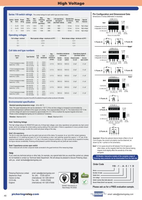
Pin Configuration and Dimensional Data<br />
Dimensions in Inches (Millimeters in brackets)<br />
Note 4 : A 1cm space should be left between Form B types and<br />
other relays, as the magnetic field from the internal biasing<br />
magnet could slightly affect the sensitivity of the relay<br />
alongside.<br />
Order Code<br />
1kV<br />
0.595 (15.1)<br />
P I C K E R I N G<br />
119P-1-A-5/1D<br />
1 Form A 0.26 (6.6)<br />
1 Form B 0.35 (8.9)<br />
0.125 (3.3)<br />
Pin 1<br />
0.02<br />
(0.5)<br />
Pins 0.15 (3.8) Pitch<br />
1 Form A<br />
1 2 3 4<br />
2kV<br />
0.595 (15.1)<br />
P I C K E R I N G<br />
119P-1-A-5/2D<br />
0.145<br />
(3.7)<br />
0.145<br />
(3.7)<br />
0.02<br />
(0.5)<br />
0.01<br />
(0.25)<br />
1 Form A 0.26 (6.6)<br />
1 Form B 0.35 (8.9)<br />
0.02<br />
(0.5)<br />
0.125 (3.3)<br />
Pin 1<br />
0.2 0.1 0.2<br />
0.02<br />
(0.5)<br />
(5.1)(2.54)(5.1)<br />
0.01<br />
(0.25)<br />
1 Form A<br />
3kV<br />
0.26 (6.6)<br />
0.79 (20.1)<br />
P I C K E R I N G<br />
119P-1-A-5/3D<br />
0.02<br />
(0.5)<br />
0.125 (3.3)<br />
Pin 1<br />
0.3 0.1 0.3<br />
0.02<br />
(0.5)<br />
0.01<br />
(0.25)<br />
(7.6) (2.54) (7.6)<br />
1 Form A<br />
1kV<br />
2 Form A<br />
0.35 (8.9)<br />
1 2 3 4<br />
0.79 (20.1)<br />
P I C K E R I N G<br />
119P-2-A-5/1D<br />
1 2 3 4<br />
0.145<br />
(3.7)<br />
1 Form B<br />
0.02<br />
(0.5)<br />
0.125 (3.3)<br />
Pin 1 0.02 0.01<br />
0.15 0.15 0.15 0.15(0.5)<br />
(0.25)<br />
(3.8) (3.8) (3.8) (3.8)<br />
0.1<br />
(2.54)<br />
2 Form A<br />
+ +<br />
+ +<br />
1 2 3 4<br />
+<br />
+<br />
1 2 3 4 5 6<br />
1 2 3 4<br />
0.145<br />
(3.7)<br />
Note 4<br />
1 Form B<br />
Note 4<br />
Important: Where the optional internal diode is fitted or for all<br />
Form B types, the correct coil polarity must be observed, as<br />
shown by the + symbol on the schematics.<br />
3D Models: Interactive models of the complete range of<br />
<strong>Pickering</strong> relay products can be downloaded from the web site.<br />
119 - 1 - A - 5 / 1 D<br />
<strong>Pickering</strong> <strong>Electronics</strong> Limited<br />
Stephenson Road<br />
Clacton-on-Sea<br />
CO15 4NL<br />
England<br />
email: sales@pickeringrelay.com<br />
Tel. (UK) 01255 428141<br />
(International) +44 1255 428141<br />
Fax. (UK) 01255 475058<br />
(International) +44 1255 475058<br />
Series<br />
Number of reeds<br />
Switch form<br />
Coil voltage<br />
Switch number (See table adjacent)<br />
Diode if fitted (Omit if not required)<br />
ISO9001 Manufacture of<br />
Reed Relays FM 29036<br />
Please ask us for a FREE evaluation sample.<br />
40<br />
pickeringrelay.com<br />
pickering<br />
email: sales@pickeringrelay.com