VMG-F_cat_en

You also want an ePaper? Increase the reach of your titles
YUMPU automatically turns print PDFs into web optimized ePapers that Google loves.
Blow Gun<br />
RoHS<br />
New<br />
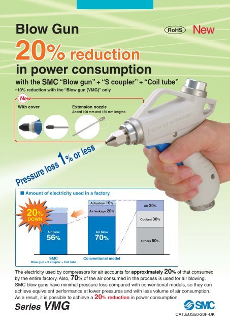
20% reduction<br />
in power consumption<br />
with the SMC “Blow gun” + “S coupler” + “Coil tube”<br />
∗10% reduction with the “Blow gun (<strong>VMG</strong>)” only<br />
New<br />
With cover<br />
Ext<strong>en</strong>sion nozzle<br />
Added 100 mm and 150 mm l<strong>en</strong>gths<br />
Pressure loss 1% or less<br />
Amount of electricity used in a factory<br />
20%<br />
DOWN<br />
Actuators 10%<br />
Air leakage 20%<br />
Air 20%<br />
Coolant 30%<br />
Air blow<br />
56%<br />
Air blow<br />
70%<br />
Others 50%<br />
SMC<br />
Blow gun + S coupler + Coil tube<br />
Conv<strong>en</strong>tional model<br />
The electricity used by compressors for air accounts for approximately 20% of that consumed<br />
by the <strong>en</strong>tire factory. Also, 70% of the air consumed in the process is used for air blowing.<br />
SMC blow guns have minimal pressure loss compared with conv<strong>en</strong>tional models, so they can<br />
achieve equival<strong>en</strong>t performance at lower pressures and with less volume of air consumption.<br />
As a result, it is possible to achieve a 20% reduction in power consumption.<br />
Series <strong>VMG</strong><br />
CAT.EUS50-20F-UK
Energy Saving Pneumatic System Proposal<br />
<br />
<br />
compare<br />
<br />
<br />
Wh<strong>en</strong> the yearly total working hours sp<strong>en</strong>t on air blowing amounts to 8,300 hours, the use of conv<strong>en</strong>tional<br />
models results in power consumption costs totaling 1540,95 €. Wh<strong>en</strong> using the SMC system (Blow gun + S<br />
coupler + Coil tube), however, the yearly cost is reduced to 1235 €, for € <br />
.<br />
+ S coupler + <br />
1<br />
Amount saved as a result<br />
1<br />
<br />
20% reduction<br />
306 €/year<br />
1600<br />
€<br />
1450<br />
1300<br />
Conv<strong>en</strong>tional<br />
1235 €<br />
model<br />
1150<br />
<br />
1000<br />
<br />
850<br />
<br />
<br />
only<br />
<br />
Calculation conditions<br />
Amount saved as a result<br />
<br />
10% reduction<br />
<br />
154 €/year<br />
€/kWh<br />
<br />
<br />
Work model<br />
€<br />
Conv<strong>en</strong>tional<br />
<br />
<br />
model<br />
1388 €<br />
<br />
<br />
<br />
<br />
<br />
<br />
<br />
<br />
850<br />
<br />
<br />
<br />
Straighter flowing fluid<br />
“improves pressure loss!”<br />
Series <strong>VMG</strong><br />
Conv<strong>en</strong>tional model<br />
Pressure loss ···<br />
<br />
<br />
area<br />
area<br />
0.3<br />
Energy saving valve construction<br />
Conv<strong>en</strong>tional<br />
30 mm 6 mm 0.25<br />
<br />
construction<br />
<br />
€)<br />
<br />
€)<br />
Features 1<br />
Valve Construction and Pressure Loss<br />
PAT.PEND<br />
<br />
This is<br />
the result<br />
Pressure loss [MPa]<br />
0.2<br />
0.15<br />
0.1<br />
0.05<br />
Conv<strong>en</strong>tional<br />
model<br />
0<br />
0 0.2 0.4 0.6 0.8 1<br />
Supply pressure [MPa]<br />
<strong>VMG</strong> (Nozzle size: ø2.5)<br />
<br />
0.005 MPa or less
SMC helps you work toward a revolutionized production system<br />
with a focus on saving-<strong>en</strong>ergy.<br />
Example of Improvem<strong>en</strong>t<br />
Review the air-blow job and change to the SMC blow gun, S coupler and coil tube to create a larger effective<br />
area.<br />
After improvem<strong>en</strong>t<br />
Before improvem<strong>en</strong>t<br />
Filter<br />
regulator<br />
S coupler<br />
1 2<br />
L<br />
Coil tube<br />
Conv<strong>en</strong>tional<br />
coupler model<br />
1 2<br />
L<br />
Conv<strong>en</strong>tional<br />
coil tube model<br />
<strong>VMG</strong><br />
Nozzle ø2.5<br />
Air gun<br />
Nozzle ø3<br />
S0 to S1<br />
S2<br />
S0 to S1<br />
S2<br />
Effective area<br />
ratio<br />
3.04 : 1<br />
Effective area<br />
ratio<br />
0.69 : 1<br />
Equipm<strong>en</strong>t<br />
Effective<br />
area<br />
Impact pressure<br />
Coupler<br />
Piping<br />
Air gun<br />
Coupler, Piping (S0)<br />
Air gun (S1)<br />
Nozzle (S2)<br />
Effective area ratio (S0 to S1: S2)<br />
Regulator pressure<br />
Pressure inside nozzle<br />
Compressor pressure<br />
Air consumption<br />
Power consumption by compressor<br />
After improvem<strong>en</strong>t<br />
Before improvem<strong>en</strong>t<br />
S coupler<br />
Conv<strong>en</strong>tional model<br />
TCU1065-1-20-X6<br />
Conv<strong>en</strong>tional coil tube model (I.D. ø5, equival<strong>en</strong>t l<strong>en</strong>gth 5 m)<br />
<strong>VMG</strong> (Nozzle size ø2.5)<br />
Conv<strong>en</strong>tional model (Nozzle size ø3)<br />
13.45 mm 2<br />
5.1 mm 2<br />
30 mm 2<br />
6 mm 2<br />
4.4 mm 2 6.3 mm 2<br />
3.04 : 1<br />
0.69 : 1<br />
0.011 MPa (at a distance of 100 mm)<br />
0.011 MPa (at a distance of 100 mm)<br />
0.4 MPa<br />
0.5 MPa<br />
0.385 MPa<br />
0.276 MPa<br />
0.5 MPa<br />
0.6 MPa<br />
257 dm 3 /min (ANR)<br />
287 dm 3 /min (ANR)<br />
1.25 kW<br />
1.56 kW<br />
20%<br />
reduction<br />
Effects of reduced<br />
power consumption<br />
16.7%<br />
reduction in<br />
pressure<br />
Effects of lowered<br />
pressure<br />
10.4%<br />
reduction in<br />
flow volume<br />
Effects of reduced<br />
flow volume<br />
After<br />
improvem<strong>en</strong>t<br />
Before<br />
improvem<strong>en</strong>t<br />
After<br />
improvem<strong>en</strong>t<br />
Before<br />
improvem<strong>en</strong>t<br />
After<br />
improvem<strong>en</strong>t<br />
Before<br />
improvem<strong>en</strong>t<br />
Features 2
Blow Gun, Coil Tube and S Coupler Selection<br />
Recomm<strong>en</strong>ded system in<br />
accordance with the distance<br />
Energy saving effects are <strong>en</strong>hanced through the appropriate<br />
blow gun model selection in accordance with the distance from<br />
the target object.<br />
Distance<br />
Blow gun<br />
Recomm<strong>en</strong>ded system<br />
Nozzle size Fitting<br />
Coil tube ∗<br />
S coupler<br />
Up to 20 mm <strong>VMG</strong>1-02-01 ø1<br />
KQ2H06-02S TCU0604-1-20-X6 KK4P-06H<br />
Up to 40 mm <strong>VMG</strong>1-02-02 ø1.5 KQ2H06-02S TCU0604-1-20-X6 KK4P-06H<br />
Up to 60 mm <strong>VMG</strong>1-02-03 ø2<br />
KQ2H08-02S TCU0805-1-20-X6 KK4P-08H<br />
Over 60 mm <strong>VMG</strong>1-02-04 ø2.5 KQ2H10-02S TCU1065-1-20-X6 KK4P-10H<br />
Energy Saving Flow<br />
Air guns with an effective area around 6 mm 2 are most commonly used.<br />
But the SMC blow gun achieves a 30 mm 2 effective area.<br />
Effective area: Large<br />
Features<br />
So<br />
Pressure drop: Small<br />
High pressure right before the nozzle<br />
As a result…<br />
Method<br />
Required less air consumption<br />
Effective discharge at low pressure<br />
Process<br />
Smaller nozzle diameter<br />
Thus…<br />
Lower discharge pressure<br />
from compressor<br />
Effects<br />
Reduction in the amount of electricity<br />
consumed by compressor<br />
Energy saving!<br />
Related Product<br />
For pressure loss improvem<strong>en</strong>t S coupler: Series KK<br />
Improved fitting’s restrictor and leakage<br />
Special method of<br />
connection and fixation<br />
With a structure that employs no steel<br />
balls, the coupler achieves a slim body<br />
without narrowing of the channel, allowing<br />
coverage of a wide effective area.<br />
Smooth channel with<br />
minimal unev<strong>en</strong>ness<br />
By not blocking the channel with the<br />
valve spring, the loss of effective area<br />
can be minimised.<br />
Seal structure with<br />
minimal leakage<br />
The surface-to-surface design allows<br />
super-tight sealing.<br />
Conical structure of<br />
check valve tip<br />
This structure achieves smooth flow<br />
through the channel.<br />
Features 3
Variations<br />
Nozzle type<br />
Low noise nozzle<br />
Mono-porous nozzle (ø2) 90 to 100 dB<br />
ø1 x 4 low noise nozzles 80 dB or less<br />
Note) Supply pressure: 0.5 MPa<br />
Measured at a 45 degree angle<br />
according to JIS B 8379<br />
One-touch fitting type<br />
∗ Achieving lower noise by dividing the air blow slit<br />
Male thread nozzle<br />
Nozzie size: ø1, ø1.5, ø2, ø2.5, ø3, ø3.5, ø4<br />
With cover<br />
Cover for male thread nozzle<br />
Bottom<br />
<br />
High effici<strong>en</strong>cy nozzle<br />
∗ Powerful and economical<br />
Cover for copper ext<strong>en</strong>sion nozzle<br />
(Outside diameter ø6 only)<br />
S coupler plug type<br />
Top<br />
<br />
Connection type<br />
∗ Making use of Bernoulli effect and<br />
achieving high effici<strong>en</strong>cy<br />
Copper ext<strong>en</strong>sion nozzle<br />
Nozzle l<strong>en</strong>gth: 100 mm, 150 mm,<br />
300 mm, 600 mm<br />
Screw-in type<br />
S coupler plug type<br />
Port size<br />
Plug part no.<br />
Rc, NPT, G 1/4<br />
Rc, NPT, G 3/8<br />
KK4P-02MS<br />
KK130P-02MS<br />
∗ Secures more power ev<strong>en</strong> at a greater<br />
distance from a workpiece.<br />
One-touch fitting type<br />
Applicable<br />
tube O.D.<br />
Metric size: ø6, ø8, ø10<br />
Inch size: ø1/4", ø5/16", ø3/8"<br />
Operability, Safety, Environm<strong>en</strong>t<br />
Not affected by supply pressure,<br />
assured operability<br />
Compon<strong>en</strong>ts are separable.<br />
Environm<strong>en</strong>tally fri<strong>en</strong>dly<br />
Resin parts are inscribed with the<br />
name of the material. Additionally, all<br />
parts can be separated by material.<br />
Wh<strong>en</strong> using this product ev<strong>en</strong> at a high<br />
pressure, the same gripping force is<br />
required as for a lower pressure due to<br />
the unique balance-poppet construction.<br />
Use of shockresistant<br />
resin<br />
Shock-resistant resin is used in<br />
the main body. No cracks, breaks<br />
or other damage occurred in a<br />
drop test from a 2-meter height or<br />
in a human stomp test.<br />
Resin:<br />
PBT<br />
Metal:<br />
Aluminum<br />
alloy<br />
Stainless<br />
steel<br />
Seals:<br />
NBR<br />
Nozzle:<br />
Brass<br />
Recyclable<br />
Features 4
Blow Gun<br />
Series <strong>VMG</strong><br />
RoHS<br />
How to Order<br />
<strong>VMG</strong> 1 1 W 02 32<br />
C<br />
1<br />
2<br />
W<br />
BU<br />
Symbol Piping connection method<br />
02<br />
03<br />
N02<br />
Threaded<br />
N03<br />
F02<br />
F03<br />
11 S coupler<br />
12 plug<br />
H06<br />
Metric size<br />
H08<br />
one-touch fitting<br />
H10<br />
H07<br />
Inch size<br />
H09<br />
one-touch fitting<br />
H11<br />
Piping <strong>en</strong>try<br />
Bottom<br />
Top<br />
Body color<br />
White<br />
Dark blue<br />
Note 1) S coupler and fitting are included in the same<br />
package.<br />
Note 2) Port size is Rc1/4 if using the S coupler plug.<br />
Note 3) The blow gun port size is Rc1/4 if using the<br />
metric size one-touch fitting.<br />
Note 4) The blow gun port size is NPT1/4 if using the<br />
inch size one-touch fitting.<br />
Specifi<strong>cat</strong>ions<br />
Fluid<br />
Operating pressure range<br />
Proof pressure<br />
Ambi<strong>en</strong>t and fluid<br />
temperature<br />
Flow-rate characteristics<br />
(With nozzle removed)<br />
Port size<br />
Piping <strong>en</strong>try<br />
Nozzle port size<br />
Weight (Main unit only)<br />
Operational force (wh<strong>en</strong><br />
the valve is fully op<strong>en</strong>)<br />
Connection size<br />
Size and model no.<br />
Rc1/4<br />
Rc3/8<br />
NPT1/4<br />
NPT3/8<br />
G1/4<br />
G3/8<br />
KK4P-02MS<br />
KK130P-02MS<br />
KQ2H06-02S<br />
KQ2H08-02S<br />
KQ2H10-02S<br />
KQ2H07-35S<br />
KQ2H09-35S<br />
KQ2H11-35S<br />
Thread size<br />
Model no. of<br />
coupler used<br />
Model no. of<br />
fitting used<br />
Model no. of<br />
fitting used<br />
Air<br />
0 to 1.0 MPa<br />
1.5 MPa<br />
–5 to 60°C (No freezing)<br />
C (dm 3 /s·bar): 6.0, b: 0.25<br />
(Effective area: 30 mm 2 )<br />
Rc, NPT, G 1/4, 3/8<br />
Bottom<br />
Top<br />
Rc1/4<br />
165 g<br />
7 N<br />
With nozzle cover (Only for male thread nozzle,<br />
ø6 ext<strong>en</strong>sion nozzle)<br />
—<br />
C<br />
CF<br />
Nozzle<br />
Symbol<br />
Type<br />
—<br />
01<br />
02<br />
03<br />
04 Male thread nozzle<br />
05<br />
06<br />
07<br />
11<br />
12 High effici<strong>en</strong>cy nozzle<br />
13<br />
21<br />
22 Low noise nozzle<br />
23 with male thread<br />
24<br />
Ext<strong>en</strong>sion nozzle<br />
Symbol<br />
31<br />
32<br />
33<br />
34<br />
35<br />
36<br />
37<br />
38<br />
41<br />
42<br />
43<br />
44<br />
45<br />
46<br />
47<br />
48<br />
49<br />
50<br />
51<br />
52<br />
Type<br />
ø6 copper<br />
ext<strong>en</strong>sion<br />
nozzle Note)<br />
ø8 copper<br />
ext<strong>en</strong>sion<br />
nozzle Note)<br />
None<br />
With nozzle cover/HNBR<br />
With nozzle cover/Fluororubber<br />
Nozzle l<strong>en</strong>gth<br />
300 mm<br />
600 mm<br />
100 mm<br />
150 mm<br />
100 mm<br />
150 mm<br />
300 mm<br />
600 mm<br />
Nozzle size<br />
Without nozzle<br />
ø1<br />
ø1.5<br />
ø2<br />
ø2.5<br />
ø3<br />
ø3.5<br />
ø4<br />
ø1<br />
ø1.5<br />
ø2<br />
ø0.75 x 4<br />
ø0.9 x 8<br />
ø1 x 4<br />
ø1.1 x 8<br />
Nozzle size<br />
ø1.5<br />
ø2<br />
ø1.5<br />
ø2<br />
ø1.5<br />
ø2<br />
ø1.5<br />
ø2<br />
ø2.5<br />
ø3<br />
ø3.5<br />
ø2.5<br />
ø3<br />
ø3.5<br />
ø2.5<br />
ø3<br />
ø3.5<br />
ø2.5<br />
ø3<br />
ø3.5<br />
Nozzle part no.<br />
KN-R02-100<br />
KN-R02-150<br />
KN-R02-200<br />
KN-R02-250<br />
<strong>VMG</strong>1-R02-300<br />
<strong>VMG</strong>1-R02-350<br />
<strong>VMG</strong>1-R02-400<br />
KNH-R02-100<br />
KNH-R02-150<br />
KNH-R02-200<br />
KNS-R02-075-4<br />
KNS-R02-090-8<br />
KNS-R02-100-4<br />
KNS-R02-110-8<br />
Nozzle part no.<br />
<strong>VMG</strong>1-06-150-300<br />
<strong>VMG</strong>1-06-200-300<br />
<strong>VMG</strong>1-06-150-600<br />
<strong>VMG</strong>1-06-200-600<br />
<strong>VMG</strong>1-06-150-100<br />
<strong>VMG</strong>1-06-200-100<br />
<strong>VMG</strong>1-06-150-150<br />
<strong>VMG</strong>1-06-200-150<br />
<strong>VMG</strong>1-08-250-100<br />
<strong>VMG</strong>1-08-300-100<br />
<strong>VMG</strong>1-08-350-100<br />
<strong>VMG</strong>1-08-250-150<br />
<strong>VMG</strong>1-08-300-150<br />
<strong>VMG</strong>1-08-350-150<br />
<strong>VMG</strong>1-08-250-300<br />
<strong>VMG</strong>1-08-300-300<br />
<strong>VMG</strong>1-08-350-300<br />
<strong>VMG</strong>1-08-250-600<br />
<strong>VMG</strong>1-08-300-600<br />
<strong>VMG</strong>1-08-350-600<br />
Note) Part number for set of ext<strong>en</strong>sion nozzle and fitting. Ext<strong>en</strong>sion nozzle and<br />
fitting are included in the same package.<br />
Refer to “How to attach ext<strong>en</strong>sion nozzle” in the operation manual for<br />
assembly procedures.<br />
1
Blow Gun Series <strong>VMG</strong><br />
Construction<br />
!1<br />
o<br />
t<br />
!0<br />
!7<br />
!9 !8<br />
!3<br />
qw<br />
!6<br />
e<br />
!2<br />
r<br />
u<br />
i<br />
!4<br />
!5<br />
y<br />
Compon<strong>en</strong>t Parts<br />
No.<br />
1<br />
2<br />
3<br />
4<br />
5<br />
6<br />
7<br />
8<br />
9<br />
10<br />
11<br />
12<br />
13<br />
14<br />
15<br />
16<br />
17<br />
18<br />
19<br />
Description<br />
Body L<br />
Body R<br />
Main valve<br />
Valve guide<br />
Nozzle holder<br />
Port<br />
Elbow<br />
Cover<br />
Ring<br />
Arm<br />
Spring<br />
Main valve seal<br />
Lever<br />
Piping (bottom)<br />
O-ring<br />
O-ring<br />
Parallel pin<br />
Cross recessed round head screw<br />
Hexagon nut<br />
Material<br />
PBT<br />
PBT<br />
PBT<br />
POM<br />
Aluminium alloy<br />
Aluminium alloy<br />
PBT<br />
Stainless steel<br />
Stainless steel<br />
PBT<br />
Stainless steel<br />
HNBR<br />
PBT<br />
POM<br />
NBR<br />
NBR<br />
Stainless steel<br />
Stainless steel<br />
Stainless steel<br />
Note) Grease is used on rubber and sliding sections.<br />
Note<br />
Anodized<br />
Anodized<br />
Only for the <strong>VMG</strong>12<br />
Only for the <strong>VMG</strong>11<br />
Combined with the<br />
elbow u.<br />
Flow-rate Characteristics<br />
Male thread nozzle<br />
High effici<strong>en</strong>cy nozzle<br />
Note) Values wh<strong>en</strong> the main valve is fully op<strong>en</strong><br />
Flow rate [L/min (ANR)]<br />
1500<br />
1400<br />
1300<br />
1200<br />
1100<br />
1000<br />
900<br />
800<br />
700<br />
600<br />
500<br />
400<br />
300<br />
200<br />
100<br />
0<br />
<strong>VMG</strong>1-R02-400:ø4<br />
<strong>VMG</strong>1-R02-350:ø3.5<br />
<strong>VMG</strong>1-R02-300:ø3<br />
KN-R02-250:ø2.5<br />
KN-R02-200:ø2<br />
KN-R02-150:ø1.5<br />
KN-R02-100:ø1<br />
0.1 0.2 0.3 0.4 0.5 0.6 0.7 0.8 0.9 1<br />
Flow rate [L/min (ANR)]<br />
400<br />
350<br />
300<br />
250<br />
200<br />
150<br />
100<br />
50<br />
0<br />
KNH-R02-200<br />
KNH-R02-150<br />
KNH-R02-100<br />
0.1 0.2 0.3 0.4 0.5 0.6 0.7 0.8 0.9 1<br />
Supply pressure [MPa]<br />
Supply pressure [MPa]<br />
Low noise nozzle with male thread<br />
Copper ext<strong>en</strong>sion nozzle<br />
Flow rate [L/min (ANR)]<br />
900<br />
800<br />
700<br />
600<br />
500<br />
400<br />
300<br />
200<br />
100<br />
0<br />
KNS-R02-110-8<br />
KNS-R02-090-8<br />
KNS-R02-100-4<br />
KNS-R02-075-4<br />
0.1 0.2 0.3 0.4 0.5 0.6 0.7 0.8 0.9 1<br />
Flow rate [L/min (ANR)]<br />
1200<br />
1100<br />
1000<br />
900<br />
800<br />
700<br />
600<br />
500<br />
400<br />
300<br />
200<br />
100<br />
0<br />
<strong>VMG</strong>1-08-350-:ø3.5<br />
<strong>VMG</strong>1-08-300-:ø3<br />
<strong>VMG</strong>1-08-250-:ø2.5<br />
<strong>VMG</strong>1-06-200-:ø2<br />
<strong>VMG</strong>1-06-150-:ø1.5<br />
0.1 0.2 0.3 0.4 0.5 0.6 0.7 0.8 0.9 1<br />
Supply pressure [MPa]<br />
Supply pressure [MPa]<br />
2
156<br />
172.5 Note) 34.2 Note)<br />
Series <strong>VMG</strong><br />
Dim<strong>en</strong>sions<br />
<strong>VMG</strong>11/Piping <strong>en</strong>try: Bottom<br />
Nozzle<br />
Rc1/4<br />
Note) Refer<strong>en</strong>ce dim<strong>en</strong>sions after installation<br />
23<br />
A<br />
Width across flats 22<br />
102<br />
117.5<br />
Rc, NPT, G 1/4, 3/8<br />
<strong>VMG</strong>12/Piping <strong>en</strong>try: Top<br />
Nozzle<br />
Rc, NPT, G 1/4, 3/8<br />
Width across flats 22<br />
Rc1/4<br />
30<br />
S coupler plug<br />
mounting<br />
(KK4P-02MS)<br />
34.2 Note)<br />
S coupler plug<br />
mounting<br />
(KK130P-02MS)<br />
32 Note)<br />
B Note)<br />
One-touch fitting<br />
mounting<br />
(Series KQ2H)<br />
32 Note) B Note)<br />
147<br />
S coupler plug<br />
mounting<br />
(KK4P-02MS)<br />
S coupler plug<br />
mounting<br />
(KK130P-02MS)<br />
170.8 Note)<br />
One-touch fitting<br />
mounting<br />
(Series KQ2H)<br />
C Note)<br />
Symbol<br />
01<br />
02<br />
03<br />
04<br />
05<br />
06<br />
07<br />
11<br />
12<br />
13<br />
21<br />
22<br />
23<br />
24<br />
31<br />
32<br />
33<br />
34<br />
35<br />
36<br />
37<br />
38<br />
3<br />
A<br />
Type<br />
Male thread<br />
nozzle<br />
High effici<strong>en</strong>cy<br />
nozzle<br />
23<br />
Low noise nozzle<br />
with male thread<br />
102<br />
117.5<br />
Nozzle l<strong>en</strong>gth:<br />
300 mm<br />
Nozzle l<strong>en</strong>gth:<br />
ø6 copper 600 mm<br />
ext<strong>en</strong>sion<br />
nozzle Note)<br />
Nozzle l<strong>en</strong>gth:<br />
100 mm<br />
Nozzle l<strong>en</strong>gth:<br />
150 mm<br />
Nozzle part no.<br />
KN-R02-100<br />
KN-R02-150<br />
KN-R02-200<br />
KN-R02-250<br />
<strong>VMG</strong>1-R02-300<br />
<strong>VMG</strong>1-R02-350<br />
<strong>VMG</strong>1-R02-400<br />
KNH-R02-100<br />
KNH-R02-150<br />
KNH-R02-200<br />
KNS-R02-075-4<br />
KNS-R02-090-8<br />
KNS-R02-100-4<br />
KNS-R02-110-8<br />
<strong>VMG</strong>1-06-150-300<br />
<strong>VMG</strong>1-06-200-300<br />
<strong>VMG</strong>1-06-150-600<br />
<strong>VMG</strong>1-06-200-600<br />
<strong>VMG</strong>1-06-150-100<br />
<strong>VMG</strong>1-06-200-100<br />
<strong>VMG</strong>1-06-150-150<br />
<strong>VMG</strong>1-06-200-150<br />
Note) Refer<strong>en</strong>ce dim<strong>en</strong>sions after installation<br />
Nozzle size<br />
ø1<br />
ø1.5<br />
ø2<br />
ø2.5<br />
ø3<br />
ø3.5<br />
ø4<br />
ø1<br />
ø1.5<br />
ø2<br />
ø0.75 x 4<br />
ø0.9 x 8<br />
ø1 x 4<br />
ø1.1 x 8<br />
ø1.5<br />
ø2<br />
ø1.5<br />
ø2<br />
ø1.5<br />
ø2<br />
ø1.5<br />
ø2<br />
30<br />
[mm]<br />
A Note)<br />
23.4<br />
23<br />
22.5<br />
22.1<br />
22<br />
21.5<br />
44<br />
12<br />
298<br />
598<br />
98<br />
148<br />
Symbol Type<br />
41<br />
Nozzle l<strong>en</strong>gth:<br />
42<br />
100 mm<br />
43<br />
44<br />
Nozzle l<strong>en</strong>gth:<br />
45<br />
46<br />
ø8 copper 150 mm<br />
ext<strong>en</strong>sion<br />
47 nozzle Note) Nozzle l<strong>en</strong>gth:<br />
48<br />
300 mm<br />
49<br />
50<br />
Nozzle l<strong>en</strong>gth:<br />
51<br />
600 mm<br />
52<br />
Type<br />
Metric size<br />
one-touch fitting<br />
Inch size<br />
one-touch fitting<br />
Nozzle part no.<br />
<strong>VMG</strong>1-08-250-100<br />
<strong>VMG</strong>1-08-300-100<br />
<strong>VMG</strong>1-08-350-100<br />
<strong>VMG</strong>1-08-250-150<br />
<strong>VMG</strong>1-08-300-150<br />
<strong>VMG</strong>1-08-350-150<br />
<strong>VMG</strong>1-08-250-300<br />
<strong>VMG</strong>1-08-300-300<br />
<strong>VMG</strong>1-08-350-300<br />
<strong>VMG</strong>1-08-250-600<br />
<strong>VMG</strong>1-08-300-600<br />
<strong>VMG</strong>1-08-350-600<br />
One-touch fitting model<br />
KQ2H06-02S<br />
KQ2H08-02S<br />
KQ2H10-02S<br />
KQ2H07-35S<br />
KQ2H09-35S<br />
KQ2H11-35S<br />
Note) Refer<strong>en</strong>ce dim<strong>en</strong>sions after installation<br />
Nozzle size<br />
ø2.5<br />
ø3<br />
ø3.5<br />
ø2.5<br />
ø3<br />
ø3.5<br />
ø2.5<br />
ø3<br />
ø3.5<br />
ø2.5<br />
ø3<br />
ø3.5<br />
B Note)<br />
17<br />
20.5<br />
27.5<br />
17<br />
20.5<br />
27.5<br />
C Note)<br />
158<br />
161.5<br />
168<br />
158<br />
161.5<br />
168<br />
[mm]<br />
A Note)<br />
98<br />
148<br />
298<br />
598<br />
[mm]
Blow Gun Series <strong>VMG</strong><br />
Dim<strong>en</strong>sions: Nozzles/Series KN<br />
Male thread nozzle: KN<br />
Part no.<br />
KN-R02-100<br />
KN-R02-150<br />
KN-R02-200<br />
KN-R02-250<br />
<strong>VMG</strong>1-R02-300<br />
<strong>VMG</strong>1-R02-350<br />
<strong>VMG</strong>1-R02-400<br />
Nozzle size<br />
D<br />
ø1<br />
ø1.5<br />
ø2<br />
ø2.5<br />
ø3<br />
ø3.5<br />
ø4<br />
Connection<br />
thread<br />
R1/4 14<br />
∗ Refer<strong>en</strong>ce dim<strong>en</strong>sions after R thread installation<br />
Width across flats<br />
H1<br />
L1<br />
31.4<br />
31<br />
30.5<br />
30.1<br />
30<br />
29.5<br />
29.5<br />
A ∗<br />
25.4<br />
25<br />
24.5<br />
24.1<br />
24<br />
23.5<br />
23.5<br />
[mm]<br />
Connection thread<br />
øD<br />
H1<br />
A<br />
L1<br />
High effici<strong>en</strong>cy nozzle: KNH<br />
Part no.<br />
KNH-R02-100<br />
KNH-R02-150<br />
KNH-R02-200<br />
Nozzle size<br />
D<br />
ø1<br />
ø1.5<br />
ø2<br />
Connection<br />
thread<br />
∗ Refer<strong>en</strong>ce dim<strong>en</strong>sions after R thread installation<br />
Width across flats<br />
H1<br />
L1<br />
A ∗<br />
R1/4 14 52 46<br />
Connection thread<br />
A<br />
L1<br />
H1<br />
[mm]<br />
øD<br />
Low noise nozzle with male thread: KNS<br />
Part no.<br />
KNS-R02-075-4<br />
KNS-R02-090-8<br />
KNS-R02-100-4<br />
KNS-R02-110-8<br />
Nozzle size<br />
D<br />
ø0.75 x 4<br />
ø0.9 x 8<br />
ø1 x 4<br />
ø1.1 x 8<br />
Connection<br />
thread<br />
∗ Refer<strong>en</strong>ce dim<strong>en</strong>sions after R thread installation<br />
Width across flats<br />
H1<br />
L1<br />
A ∗<br />
R1/4 14 20 14<br />
øD<br />
H1<br />
2<br />
A<br />
L1<br />
[mm]<br />
Connection<br />
thread<br />
Copper ext<strong>en</strong>sion nozzle set<br />
Part no.<br />
<strong>VMG</strong>1-06-150-100<br />
<strong>VMG</strong>1-06-200-100<br />
<strong>VMG</strong>1-06-150-150<br />
<strong>VMG</strong>1-06-200-150<br />
<strong>VMG</strong>1-06-150-300<br />
<strong>VMG</strong>1-06-200-300<br />
<strong>VMG</strong>1-06-150-600<br />
<strong>VMG</strong>1-06-200-600<br />
<strong>VMG</strong>1-08-250-100<br />
<strong>VMG</strong>1-08-300-100<br />
<strong>VMG</strong>1-08-350-100<br />
<strong>VMG</strong>1-08-250-150<br />
<strong>VMG</strong>1-08-300-150<br />
<strong>VMG</strong>1-08-350-150<br />
<strong>VMG</strong>1-08-250-300<br />
<strong>VMG</strong>1-08-300-300<br />
<strong>VMG</strong>1-08-350-300<br />
<strong>VMG</strong>1-08-250-600<br />
<strong>VMG</strong>1-08-300-600<br />
<strong>VMG</strong>1-08-350-600<br />
Nozzle size<br />
D<br />
ø1.5<br />
ø2<br />
ø1.5<br />
ø2<br />
ø1.5<br />
ø2<br />
ø1.5<br />
ø2<br />
ø2.5<br />
ø3<br />
ø3.5<br />
ø2.5<br />
ø3<br />
ø3.5<br />
ø2.5<br />
ø3<br />
ø3.5<br />
ø2.5<br />
ø3<br />
ø3.5<br />
Outside<br />
diameter<br />
ø6<br />
ø8<br />
L1<br />
100<br />
150<br />
300<br />
600<br />
100<br />
150<br />
300<br />
600<br />
L2 Note1) 100 106<br />
150<br />
300<br />
600<br />
100<br />
150<br />
300<br />
600<br />
L Note1)<br />
156<br />
306<br />
606<br />
106<br />
156<br />
306<br />
606<br />
Width across flats<br />
Note 1) Refer<strong>en</strong>ce dim<strong>en</strong>sions after installation<br />
Note 2) Copper ext<strong>en</strong>sion nozzle and self-align fitting are included in the same package, (but unassembled).<br />
Refer to “How to attach ext<strong>en</strong>sion nozzle” in the operation manual for assembly procedures.<br />
H1<br />
12<br />
14<br />
[mm]<br />
L1 (Ext<strong>en</strong>sion nozzle l<strong>en</strong>gth)<br />
Width across flats 14 R1/4<br />
Outside<br />
diameter<br />
øD<br />
L2<br />
L<br />
H1<br />
4
Series <strong>VMG</strong><br />
Dim<strong>en</strong>sios: Nozzle Cover<br />
Cover for male thread nozzle<br />
Nozzle cover part no.<br />
P5670129-01<br />
P5670129-01F<br />
P5670129-02<br />
P5670129-02F<br />
Material<br />
HNBR<br />
Fluororubber<br />
HNBR<br />
Fluororubber<br />
Applicable blow gun model<br />
Model<br />
Nozzle type<br />
Male thread nozzle<br />
<strong>VMG</strong>1--01 to 04<br />
ø1 to ø2.5<br />
Male thread nozzle<br />
<strong>VMG</strong>1--05 to 07<br />
ø3 to ø4<br />
Width across<br />
flats 17<br />
[mm]<br />
25<br />
<strong>VMG</strong>1--1 to 04<br />
Width across<br />
flats 17<br />
23.5<br />
<strong>VMG</strong>1--05 to 07<br />
Cover for copper ext<strong>en</strong>sion nozzle<br />
Nozzle cover part no.<br />
P5670129-11<br />
P5670129-11F<br />
Material<br />
HNBR<br />
Fluororubber<br />
Applicable blow gun model<br />
Model<br />
Nozzle type<br />
<strong>VMG</strong>1--31 to 38<br />
ø6 copper<br />
ext<strong>en</strong>sion nozzle<br />
ø10<br />
[mm]<br />
22<br />
<strong>VMG</strong>1--31 to 38<br />
5
Series <strong>VMG</strong><br />
Specific Product Precautions 1<br />
Be sure to read this before handling.<br />
Warning<br />
Wr<strong>en</strong>ch<br />
Nozzle tight<strong>en</strong>ing torque range<br />
Selection<br />
1. Check the specifi<strong>cat</strong>ions.<br />
The products in this <strong>cat</strong>alogue are designed to be used in<br />
compressed air systems only. If the products are used in an<br />
<strong>en</strong>vironm<strong>en</strong>t where pressure or temperature is out of the<br />
specified range, damage and/or malfunction may result. Do<br />
not use under such conditions.<br />
Caution<br />
1. Do not apply the blow gun to flammable, explosive<br />
or toxic substances such as gas, fuel gas or<br />
refrigerant. Such substances may exude from<br />
inside the blow gun.<br />
Warning<br />
Mounting<br />
1. Install a stop valve on the supply pressure side of the<br />
blow gun to <strong>en</strong>able emerg<strong>en</strong>cy shut off in case of<br />
unexpected leakage or damage.<br />
2. Wh<strong>en</strong> installing a nozzle on the blow gun, wrap pipe<br />
tape around the threads of the nozzle.<br />
3. Wh<strong>en</strong> installing the nozzle, secure the nozzle holder<br />
of the blow gun by applying a wr<strong>en</strong>ch of 22 mm<br />
width across flats to the two chamfered surfaces of<br />
the holder without applying force to the body. Th<strong>en</strong>,<br />
tight<strong>en</strong> the nozzle with force within the torque range<br />
below. As a guideline, it is equival<strong>en</strong>t to 2 to 3<br />
additional turns with a tool after manual tight<strong>en</strong>ing.<br />
Nozzle holder<br />
12 to 14 N⋅m<br />
Insuffici<strong>en</strong>t tight<strong>en</strong>ing may cause loos<strong>en</strong>ing of the nozzle.<br />
Caution<br />
Piping<br />
1. Check the model, type and size before installation.<br />
Also, confirm that there is no scratches, gouges or cracks on<br />
the product.<br />
2. Before piping<br />
Before piping, it should be thoroughly blown out with air<br />
(flushing) or washed to remove chips, cutting oil and other<br />
debris from inside the pipe.<br />
Caution<br />
Expose approx. 2 threads.<br />
Wr<strong>en</strong>ch<br />
Port<br />
Piping<br />
3. Wrapping of pipe tape<br />
Wh<strong>en</strong> screwing together pipes and fittings, etc., be certain that<br />
chips from the pipe threads and sealing material do not get<br />
inside the blow gun. Also, wh<strong>en</strong> the pipe tape is used, leave<br />
1.5 to 2 thread ridges exposed at the <strong>en</strong>d of the threads.<br />
Wrapping<br />
direction<br />
Pipe tape<br />
4. Wh<strong>en</strong> tight<strong>en</strong>ing the threads, secure the nozzle holder<br />
of the blow gun by applying a wr<strong>en</strong>ch of 22 mm width<br />
across flats to the two chamfered surfaces of the<br />
holder without applying force to the body. Th<strong>en</strong>,<br />
tight<strong>en</strong> the nozzle with torque specified in the table<br />
below. As a guideline, it is equival<strong>en</strong>t to 2 to 3<br />
additional turns with a tool after manual tight<strong>en</strong>ing.<br />
Be careful that tight<strong>en</strong>ing with torque beyond the ranges in the<br />
table below may cause damage to the body.<br />
Male thread<br />
R1/4<br />
R3/8<br />
Tight<strong>en</strong>ing torque N⋅m<br />
12 to 14<br />
22 to 24<br />
5. Allow extra l<strong>en</strong>gth wh<strong>en</strong> connecting a tube to<br />
accommodate changes in tube l<strong>en</strong>gth due to<br />
pressure.<br />
6. Confirm that no twisting, turning or t<strong>en</strong>sile force or<br />
mom<strong>en</strong>t load is applied to the port or tube. This<br />
may cause fittings to fracture or tubes to be<br />
crushed, burst or come loose.<br />
7. Do not abrade, <strong>en</strong>tangle or scratch the tube. This<br />
may cause the tube to be crushed, burst or come<br />
loose.<br />
Warning<br />
Lubri<strong>cat</strong>ion<br />
1. Do not lubri<strong>cat</strong>e the product.<br />
It may contaminate or damage the target object.<br />
Warning<br />
Air Supply<br />
1. Use clean air.<br />
Do not use compressed air which includes chemicals, synthetic<br />
oils containing organic solv<strong>en</strong>ts, salt or corrosive gases, etc.,<br />
as it can cause damage or malfunction.<br />
6
Series <strong>VMG</strong><br />
Specific Product Precautions 2<br />
Be sure to read this before handling.<br />
Caution<br />
Air Supply<br />
1. Install air filters.<br />
Install air filters at the upstream side of blow gun. Choose the<br />
filtration degree of 5 μm or finer.<br />
2. Install an after-cooler, air dryer or water droplet<br />
separator, etc.<br />
Air excessive drainage may cause a malfunction of blow gun<br />
and contaminate or damage the target object. To prev<strong>en</strong>t this,<br />
install an after-cooler, air dryer or water droplet separator, etc.<br />
Warning<br />
Operating Environm<strong>en</strong>t<br />
1. Do not use in an atmosphere of corrosive gases,<br />
chemicals, sea water, water or water vapor or in an<br />
<strong>en</strong>vironm<strong>en</strong>t where such substances may adhere.<br />
2. Provide shading in an <strong>en</strong>vironm<strong>en</strong>t where the<br />
product is exposed to the sunlight.<br />
3. Do not use in an <strong>en</strong>vironm<strong>en</strong>t where a heat source<br />
is at a close distance.<br />
4. Do not use in an <strong>en</strong>vironm<strong>en</strong>t where static electricity<br />
is a problem. It may cause malfunction or failure of the<br />
system. Please contact SMC for use in such an<br />
<strong>en</strong>vironm<strong>en</strong>t.<br />
5. Do not use in an <strong>en</strong>vironm<strong>en</strong>t where spatters are<br />
g<strong>en</strong>erated. There is danger of fires caused by<br />
spattering. Please contact SMC for use in such an<br />
<strong>en</strong>vironm<strong>en</strong>t.<br />
6. Do not use in an <strong>en</strong>vironm<strong>en</strong>t where the product is<br />
exposed to cutting oil, lubri<strong>cat</strong>ing oil or coolant oil.<br />
Please contact SMC for use in an <strong>en</strong>vironm<strong>en</strong>t<br />
where the product is exposed to such liquid as<br />
cutting oil, lubri<strong>cat</strong>ing oil or coolant oil.<br />
Warning<br />
Hook<br />
Handling<br />
1. To prev<strong>en</strong>t lurching of the nozzle due to air<br />
pressure, confirm that the nozzle is not loos<strong>en</strong>ed or<br />
rattling by pulling it by hand before operation.<br />
2. Make sure to wear safety goggles to protect<br />
yourself from splashed substances.<br />
3. Do not direct the tip of the nozzle at the face or<br />
other parts of a human body. It may cause danger<br />
to personnel.<br />
4. Do not use the product to clean or remove toxic<br />
substances or chemicals.<br />
5. Do not drop, step on or hit the product. It may cause<br />
damage to the product.<br />
6. Do not use the product to disturb public order or<br />
public hygi<strong>en</strong>e.<br />
7. This product is not a toy.<br />
8. After blowing, make sure to hang the product on a<br />
hook, etc.<br />
If leaving the product in a dusty place, particles will <strong>en</strong>ter the<br />
product and may result in a malfunction.<br />
Caution<br />
Maint<strong>en</strong>ance<br />
1. In periodical inspections, check the following items<br />
and replace the parts if necessary.<br />
a) Scratches, gouges, abrasion, corrosion<br />
b) Air leakage<br />
c) Twisting, crushing and turning of connected tubes<br />
d) Hard<strong>en</strong>ing, deterioration and soft<strong>en</strong>ing of connected tubes<br />
e) Loos<strong>en</strong>ing of nozzles<br />
2. Wh<strong>en</strong> removing the product, first stop the pressure<br />
supply, exhaust compressed air in the piping and<br />
check the condition of atmospheric release.<br />
3. Do not disassemble or remodel the body of the<br />
product.<br />
9. Wh<strong>en</strong> the blow gun is used or stored, confirm that<br />
no twisting, turning or t<strong>en</strong>sile force or mom<strong>en</strong>t load<br />
is applied to the port or tube. This may cause<br />
fittings to fracture or tubes to be crushed, burst or<br />
come loose.<br />
10. Wh<strong>en</strong> attaching a nozzle cover, align the hex parts<br />
of the nozzle and nozzle cover before covering.<br />
Wh<strong>en</strong> attaching an ext<strong>en</strong>sion nozzle cover, confirm<br />
that the nozzle tip is completely inserted into the<br />
ext<strong>en</strong>sion nozzle cover.<br />
11. Do not use a nozzle cover or ext<strong>en</strong>sion nozzle cover<br />
if it is cracked or does not fit securely, and replace<br />
with a new cover.<br />
7
8
9
10
Safety Instructions<br />
Caution:<br />
Warning:<br />
Danger :<br />
Caution indi<strong>cat</strong>es a hazard with a low level of risk<br />
which, if not avoided, could result in minor or<br />
moderate injury.<br />
Warning indi<strong>cat</strong>es a hazard with a medium level of<br />
risk which, if not avoided, could result in death or<br />
serious injury.<br />
Danger indi<strong>cat</strong>es a hazard with a high level of risk<br />
which, if not avoided, will result in death or serious<br />
injury.<br />
These safety instructions are int<strong>en</strong>ded to prev<strong>en</strong>t hazardous situations and/or<br />
equipm<strong>en</strong>t damage. These instructions indi<strong>cat</strong>e the level of pot<strong>en</strong>tial hazard with<br />
the labels of “Caution,” “Warning” or “Danger.” They are all important notes for<br />
safety and must be followed in addition to International Standards (ISO/IEC) ∗1) ,<br />
and other safety regulations.<br />
∗1) ISO 4414: Pneumatic fluid power – G<strong>en</strong>eral rules relating to systems.<br />
ISO 4413: Hydraulic fluid power – G<strong>en</strong>eral rules relating to systems.<br />
IEC 60204-1: Safety of machinery – Electrical equipm<strong>en</strong>t of machines.<br />
(Part 1: G<strong>en</strong>eral requirem<strong>en</strong>ts)<br />
ISO 10218-1: Manipulating industrial robots - Safety.<br />
etc.<br />
Warning<br />
1. The compatibility of the product is the responsibility of the<br />
person who designs the equipm<strong>en</strong>t or decides its specifi<strong>cat</strong>ions.<br />
Since the product specified here is used under various operating conditions, its<br />
compatibility with specific equipm<strong>en</strong>t must be decided by the person who designs<br />
the equipm<strong>en</strong>t or decides its specifi<strong>cat</strong>ions based on necessary analysis and test<br />
results. The expected performance and safety assurance of the equipm<strong>en</strong>t will be<br />
the responsibility of the person who has determined its compatibility with the<br />
product. This person should also continuously review all specifi<strong>cat</strong>ions of the<br />
product referring to its latest <strong>cat</strong>alogue information, with a view to giving due<br />
consideration to any possibility of equipm<strong>en</strong>t failure wh<strong>en</strong> configuring the<br />
equipm<strong>en</strong>t.<br />
2. Only personnel with appropriate training should operate<br />
machinery and equipm<strong>en</strong>t.<br />
The product specified here may become unsafe if handled incorrectly. The<br />
assembly, operation and maint<strong>en</strong>ance of machines or equipm<strong>en</strong>t including our<br />
products must be performed by an operator who is appropriately trained and<br />
experi<strong>en</strong>ced.<br />
3. Do . not service or attempt to remove product and<br />
machinery/equipm<strong>en</strong>t until safety is confirmed.<br />
1. The inspection and maint<strong>en</strong>ance of machinery/equipm<strong>en</strong>t should only be<br />
performed after measures to prev<strong>en</strong>t falling or runaway of the driv<strong>en</strong> objects<br />
have be<strong>en</strong> confirmed.<br />
2. Wh<strong>en</strong> the product is to be removed, confirm that the safety measures as<br />
m<strong>en</strong>tioned above are implem<strong>en</strong>ted and the power from any appropriate source<br />
is cut, and read and understand the specific product precautions of all relevant<br />
products carefully.<br />
3. Before machinery/equipm<strong>en</strong>t is restarted, take measures to prev<strong>en</strong>t<br />
unexpected operation and malfunction.<br />
4. Contact SMC beforehand and take special consideration of safety<br />
measures if the product is to be used in any of the following<br />
conditions.<br />
1. Conditions and <strong>en</strong>vironm<strong>en</strong>ts outside of the giv<strong>en</strong> specifi<strong>cat</strong>ions, or use<br />
outdoors or in a place exposed to direct sunlight.<br />
2. Installation on equipm<strong>en</strong>t in conjunction with atomic <strong>en</strong>ergy, railways, air<br />
navigation, space, shipping, vehicles, military, medical treatm<strong>en</strong>t, combustion<br />
and recreation, or equipm<strong>en</strong>t in contact with food and beverages, emerg<strong>en</strong>cy<br />
stop circuits, clutch and brake circuits in press appli<strong>cat</strong>ions, safety equipm<strong>en</strong>t<br />
or other appli<strong>cat</strong>ions unsuitable for the standard specifi<strong>cat</strong>ions described in the<br />
product <strong>cat</strong>alogue.<br />
3. An appli<strong>cat</strong>ion which could have negative effects on people, property, or<br />
animals requiring special safety analysis.<br />
4. Use in an interlock circuit, which requires the provision of double interlock for<br />
possible failure by using a mechanical protective function, and periodical<br />
checks to confirm proper operation.<br />
Caution<br />
1. The product is provided for use in manufacturing industries.<br />
The product herein described is basically provided for peaceful use in<br />
manufacturing industries.<br />
If considering using the product in other industries, consult SMC beforehand and<br />
exchange specifi<strong>cat</strong>ions or a contract if necessary.<br />
If anything is unclear, contact your nearest sales branch.<br />
Limited warranty and Disclaimer/<br />
Compliance Requirem<strong>en</strong>ts<br />
The product used is subject to the following “Limited warranty and Disclaimer”<br />
and “Compliance Requirem<strong>en</strong>ts”.<br />
Read and accept them before using the product.<br />
Limited warranty and Disclaimer<br />
1. The warranty period of the product is 1 year in service or 1.5 years after<br />
the product is delivered. ∗2)<br />
Also, the product may have specified durability, running distance or<br />
replacem<strong>en</strong>t parts. Please consult your nearest sales branch.<br />
2. For any failure or damage reported within the warranty period which is clearly our<br />
responsibility, a replacem<strong>en</strong>t product or necessary parts will be provided.<br />
This limited warranty applies only to our product indep<strong>en</strong>d<strong>en</strong>tly, and not to any<br />
other damage incurred due to the failure of the product.<br />
3. Prior to using SMC products, please read and understand the warranty terms<br />
and disclaimers noted in the specified <strong>cat</strong>alogue for the particular products.<br />
∗2) Vacuum pads are excluded from this 1 year warranty.<br />
A vacuum pad is a consumable part, so it is warranted for a year after it is delivered.<br />
Also, ev<strong>en</strong> within the warranty period, the wear of a product due to the use of the vacuum pad<br />
or failure due to the deterioration of rubber material are not covered by the limited warranty.<br />
Compliance Requirem<strong>en</strong>ts<br />
1. The use of SMC products with production equipm<strong>en</strong>t for the manufacture of<br />
weapons of mass destruction (WMD) or any other weapon is strictly prohibited.<br />
2. The exports of SMC products or technology from one country to another are<br />
governed by the relevant security laws and regulations of the countries involved<br />
in the transaction. Prior to the shipm<strong>en</strong>t of a SMC product to another country,<br />
assure that all local rules governing that export are known and followed.<br />
Safety Instructions<br />
Be sure to read “Handling Precautions for SMC Products” (M-E03-3) before using.<br />
SMC Corporation (Europe)<br />
Austria +43 (0)2262622800 www.smc.at office@smc.at<br />
Belgium +32 (0)33551464 www.smcpneumatics.be info@smcpneumatics.be<br />
Bulgaria +359 (0)2807670 www.smc.bg office@smc.bg<br />
Croatia +385 (0)13707288 www.smc.hr office@smc.hr<br />
Czech Republic +420 541424611 www.smc.cz office@smc.cz<br />
D<strong>en</strong>mark +45 70252900 www.smcdk.com smc@smcdk.com<br />
Estonia +372 6510370 www.smcpneumatics.ee smc@smcpneumatics.ee<br />
Finland +358 207513513 www.smc.fi smcfi@smc.fi<br />
France +33 (0)164761000 www.smc-france.fr promotion@smc-france.fr<br />
Germany +49 (0)61034020 www.smc.de info@smc.de<br />
Greece +30 210 2717265 www.smchellas.gr sales@smchellas.gr<br />
Hungary +36 23511390 www.smc.hu office@smc.hu<br />
Ireland +353 (0)14039000 www.smcpneumatics.ie sales@smcpneumatics.ie<br />
Italy +39 0292711 www.smcitalia.it mailbox@smcitalia.it<br />
Latvia +371 67817700 www.smclv.lv info@smclv.lv<br />
Lithuania +370 5 2308118 www.smclt.lt info@smclt.lt<br />
Netherlands +31 (0)205318888 www.smcpneumatics.nl info@smcpneumatics.nl<br />
Norway +47 67129020 www.smc-norge.no post@smc-norge.no<br />
Poland +48 (0)222119616 www.smc.pl office@smc.pl<br />
Portugal +351 226166570 www.smc.eu postpt@smc.smces.es<br />
Romania +40 213205111 www.smcromania.ro smcromania@smcromania.ro<br />
Russia +7 8127185445 www.smc-pneumatik.ru info@smc-pneumatik.ru<br />
Slovakia +421 (0)413213212 www.smc.sk office@smc.sk<br />
Slov<strong>en</strong>ia +386 (0)73885412 www.smc.si office@smc.si<br />
Spain +34 902184100 www.smc.eu post@smc.smces.es<br />
Swed<strong>en</strong> +46 (0)86031200 www.smc.nu post@smc.nu<br />
Switzerland +41 (0)523963131 www.smc.ch info@smc.ch<br />
Turkey +90 212 489 0 440 www.smcpnomatik.com.tr info@smcpnomatik.com.tr<br />
UK +44 (0)845 121 5122 www.smcpneumatics.co.uk sales@smcpneumatics.co.uk<br />
SMC CORPORATION Akihabara UDX 15F, 4-14-1, Sotokanda, Chiyoda-ku, Tokyo 101-0021, JAPAN Phone: 03-5207-8249 FAX: 03-5298-5362<br />
1st printing QU printing QU 00 Printed in Spain<br />
Specifi<strong>cat</strong>ions are subject to change without prior notice and any obligation on the part of the manufacturer.