Baldor Basics Motors
motor-frame-size
motor-frame-size

Create successful ePaper yourself
Turn your PDF publications into a flip-book with our unique Google optimized e-Paper software.
TECHNICAL<br />
<strong>Baldor</strong> <strong>Basics</strong>: <strong>Motors</strong><br />
Edward Cowern, P.E.<br />
A continuing series of articles, courtesy of the <strong>Baldor</strong> Electric Co., dedicated<br />
primarily to motor basics; e.g. — how to specify them; how to operate them;<br />
how — and when — to repair or replace them, and considerably more. Stay tuned!<br />
THIS ISSUE:<br />
The Mystery of Motor Frame Size<br />
Primer on Two-Speed <strong>Motors</strong><br />
Introduction<br />
Industrial electric motors have been available for nearly a<br />
century. In that time there have been a great many changes.<br />
One of the most obvious has been the ability to pack more<br />
horsepower in a smaller physical size. Another important<br />
achievement has been the standardization of motors by the<br />
National Electric Manufacturers Association (NEMA).<br />
A key part of motor interchangeability has been the standardization<br />
of frame sizes. This means that the same horsepower,<br />
speed, and enclosure will normally have the same<br />
frame size from different motor manufacturers. Thus, a motor<br />
from one manufacturer can be replaced with a similar motor<br />
from another company provided they are both in standard<br />
frame sizes.<br />
Three Generations<br />
The standardization effort over the last forty-plus years has<br />
resulted in one original grouping of frame sizes called “original.”<br />
In 1952, new frame assignments were made. These were<br />
called “U frames.” The current “T frames” were introduced in<br />
1964. “T” frames are the current standard and most likely will<br />
continue to be for some time in the future.<br />
Even though “T” frames were adopted in 1964, there are<br />
still a great many “U” frame motors in service that will have<br />
to be replaced in the future. Similarly there are also many of<br />
the original frame size motors (pre-1952) that will reach the<br />
end of their useful life and will have to be replaced. For this<br />
reason it is desirable to have reference material available on<br />
frame sizes and some knowledge of changes that took place<br />
as a part of the so-called re-rate programs.<br />
Rerating and Temperatures<br />
The ability to re-rate motor frames to get more horsepower<br />
in a frame has been brought about mainly by improvements<br />
made in insulating materials. As a result of this improved<br />
insulation, motors can now be run much hotter. This allows<br />
more horsepower in a compact frame. For example, the original<br />
NEMA frame sizes ran at very low temperatures. The “U”<br />
frame motors were designed for use with Class A insulation,<br />
which has a rating of 105° C. The motor designs were such<br />
that the capability would be used at the hottest spot within<br />
the motor. “T” frame motor designs are based on utilizing<br />
Class B insulation with a temperature rating of 130° C. This<br />
increase in temperature capability made it possible to pack<br />
more horsepower into the same size frame. To accommodate<br />
the larger mechanical horsepower capability, shaft and<br />
bearing sizes had to be increased. Thus, you will find that<br />
the original 254 frame (5 HP at 1,800 RPM) has a 1 1 ⁄8" shaft.<br />
The 254U frame (7½ HP at 1,800 RPM) has a 1 3 ⁄8" shaft, and<br />
the current 254T frame (15 HP at 1800 RPM) has a 1 5 ⁄8" shaft.<br />
Bearing diameters were also increased to accommodate the<br />
larger shaft sizes and heavier loads associated with the higher<br />
horsepower.<br />
Frame Size Basis<br />
On page 14 you will find a <strong>Baldor</strong> frame size chart that is a<br />
great reference on “T” frame, “U” frame and original frame<br />
motors. Most of the dimensions are standard dimensions<br />
that are common to all motor manufacturers. One exception<br />
to this is the “C” dimension (overall motor length) which will<br />
change from one manufacturer to another.<br />
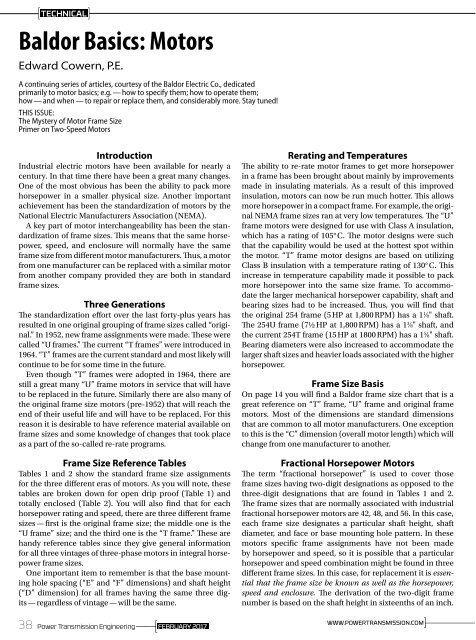
Frame Size Reference Tables<br />
Tables 1 and 2 show the standard frame size assignments<br />
for the three different eras of motors. As you will note, these<br />
tables are broken down for open drip proof (Table 1) and<br />
totally enclosed (Table 2). You will also find that for each<br />
horsepower rating and speed, there are three different frame<br />
sizes — first is the original frame size; the middle one is the<br />
“U frame” size; and the third one is the “T frame.” These are<br />
handy reference tables since they give general information<br />
for all three vintages of three-phase motors in integral horsepower<br />
frame sizes.<br />
One important item to remember is that the base mounting<br />
hole spacing (“E” and “F” dimensions) and shaft height<br />
(“D” dimension) for all frames having the same three digits<br />
— regardless of vintage — will be the same.<br />
Fractional Horsepower <strong>Motors</strong><br />
The term “fractional horsepower” is used to cover those<br />
frame sizes having two-digit designations as opposed to the<br />
three-digit designations that are found in Tables 1 and 2.<br />
The frame sizes that are normally associated with industrial<br />
fractional horsepower motors are 42, 48, and 56. In this case,<br />
each frame size designates a particular shaft height, shaft<br />
diameter, and face or base mounting hole pattern. In these<br />
motors specific frame assignments have not been made<br />
by horsepower and speed, so it is possible that a particular<br />
horsepower and speed combination might be found in three<br />
different frame sizes. In this case, for replacement it is essential<br />
that the frame size be known as well as the horsepower,<br />
speed and enclosure. The derivation of the two-digit frame<br />
number is based on the shaft height in sixteenths of an inch.<br />
WWW.POWERTRANSMISSION.COM<br />
38 Power Transmission Engineering FEBRUARY 2017<br />
]————
Table 1<br />
RPM<br />
NEMA<br />
Program<br />
HP<br />
Open Drip-Proof<br />
Orig.<br />
3600<br />
1952<br />
Rerate<br />
1964<br />
Rerate<br />
THREE PHASE FRAME SIZES - GENERAL PURPOSE<br />
Orig.<br />
1800<br />
1952<br />
Rerate<br />
1964<br />
Rerate<br />
Orig.<br />
1200<br />
1952<br />
Rerate<br />
1964<br />
Rerate<br />
Orig.<br />
900<br />
1952<br />
Rerate<br />
1964<br />
Rerate<br />
1 203 182 143T 204 184 145T 225 213 182T<br />
1.5 203 182 143T 204 184 145T 224 184 182T 254 213 184T<br />
2 204 184 145T 224 184 145T 225 213 184T 254 215 213T<br />
3 224 184 145T 225 213 182T 254 215 213T 284 254U 215T<br />
5 225 213 182T 254 215 184T 284 254U 215T 324 256U 254T<br />
7.5 254 215 184T 284 254U 213T 324 256U 254T 326 284U 256T<br />
10 284 254U 213T 324 256U 215T 326 284U 256T 364 286U 284T<br />
15 324 256U 215T 326 284U 254T 364 324U 284T 365 326U 286T<br />
20 326 284U 254T 364 286U 256T 365 326U 286T 404 364U 324T<br />
25 364S 286U 256T 364 324U 284T 404 364U 324T 405 365U 326T<br />
30 364S 324US 284TS 365 326U 286T 405 365U 326T 444 404U 364T<br />
40 365S 326US 286TS 404 364U 324T 444 404U 364T 445 405U 365T<br />
50 404S 364US 324TS 405S 365US 326T 445 405U 365T 504 444U 404T<br />
60 405S 365US 326TS 444S 404US 364T 504 444U 404T 505 445U 405T<br />
75 444S 404US 364TS 445S 405US 365T 505 445U 405T — — 444T<br />
100 445S 405US 365TS 504S 444US 404T — — 444T — — 445T<br />
125 504S 444US 404TS 505S 445US 405T — — 445T —<br />
150 505S 445US 405TS — 444T —<br />
200 444TS — 445T —<br />
250 445TS —<br />
Table 2<br />
RPM<br />
NEMA<br />
Program<br />
HP<br />
Totally Enclosed, Fan-Cooled<br />
Orig.<br />
3600<br />
1952<br />
Rerate<br />
1964<br />
Rerate<br />
THREE PHASE FRAME SIZES - GENERAL PURPOSE<br />
Orig.<br />
1800<br />
1952<br />
Rerate<br />
1964<br />
Rerate<br />
Orig.<br />
1200<br />
1952<br />
Rerate<br />
1964<br />
Rerate<br />
Orig.<br />
900<br />
1952<br />
Rerate<br />
1964<br />
Rerate<br />
1 203 182 143T 204 184 145T 225 213 182T<br />
1.5 203 182 143T 204 184 145T 224 184 182T 254 213 184T<br />
2 204 184 145T 224 184 145T 225 213 184T 254 215 213T<br />
3 224 184 182T 225 213 182T 254 215 213T 284 254U 215T<br />
5 225 213 184T 254 215 184T 284 254U 215T 324 256U 254T<br />
7.5 254 215 213T 284 254U 213T 324 256U 254T 326 284U 256T<br />
10 284 254U 215T 324 256U 215T 326 284U 256T 364 286U 284T<br />
15 324 256U 254T 326 284U 254T 364 324U 284T 365 326U 286T<br />
20 326 286U 256T 364 286U 256T 365 326U 286T 404 364U 324T<br />
25 365S 324U 284TS 365 324U 284T 404 364U 324T 405 365U 326T<br />
30 404S 326US 286TS 404 326U 286T 405 365U 326T 444 404U 364T<br />
40 405S 364US 324TS 405 364U 324T 444 404U 364T 445 405U 365T<br />
50 444S 365US 326TS 444S 365US 326T 445 405U 365T 504 444U 404T<br />
60 445S 405US 364TS 445S 405US 364T 504 444U 404T 505 445U 405T<br />
75 504S 444US 365TS 504S 444US 365T 505 445U 405T — — 444T<br />
100 505S 445US 405TS 505S 445US 405T — 444T — — 445T<br />
125 444TS — 444T — 445T —<br />
150 445TS — 445T<br />
FEBRUARY 2017<br />
Power Transmission Engineering<br />
39
TECHNICAL<br />
Leading Provider of Energy Efficient<br />
Industrial Electric <strong>Motors</strong> and Drives<br />
NEMA Keyseat NEMA Keyseat<br />
Shaft Dimensions Shaft Dimensions<br />
(U) (R) (S) (U) (R) (S)<br />
3/8 21/64 FLAT 1-7/8 1-19/32 1/2<br />
1/2 29/64 FLAT 2-1/8 1-27/32 1/2<br />
5/8 33/64 3/16 2-3/8 2-1/64 5/8<br />
7/8 49/64 3/16 2-1/2 2-3/16 5/8<br />
1-1/8 63/64 1/4 2-7/8 2-29/64 3/4<br />
1-3/8 1-13/64 5/16 3-3/8 2-7/8 7/8<br />
1-5/8 1-13/32 3/8 3-7/8 3-5/16 1<br />
Drawings represent standard TEFC general purpose motors.<br />
*Dimensions are for reference only.<br />
*Contact your local <strong>Baldor</strong> Sales Office for “C” Dimensions.<br />
The above chart provides typical <strong>Baldor</strong>•Reliance motor dimensions.<br />
For more exact dimensional data, please check the specifi c drawing<br />
for each catalog number. NEMA states only a minimum value for AA<br />
dimension. AA dimensions shown in chart are <strong>Baldor</strong> typical values<br />
meeting or exceeding NEMA. Please check motor drawing for actual<br />
dimensions.<br />
Frame L449T is not included in this chart. Please refer to the Large AC<br />
motor chart, or to the specifi c motor drawings for L449T dimensions.<br />
NEMA QUICK REFERENCE CHART<br />
NEMA C-Face<br />
BA<br />
Dimensions<br />
143-5TC 2-3/4<br />
182-4TC 3-1/2<br />
213-5TC 4-1/4<br />
254-6TC 4-3/4<br />
BALDOR ELECTRIC COMPANY<br />
P.O. BOX 2400<br />
FORT SMITH, ARKANSAS<br />
72902-2400 U.S.A.<br />
Dimensions - N, O, P, AB and XO are specific to <strong>Baldor</strong>.<br />
NEMA<br />
FRAME<br />
D E 2F H N O P U V AA AB AH AJ AK BA BB BD XO TAP<br />
42 2-5/8 1-3/4 1-11/16<br />
9/32<br />
SLOT<br />
1-1/2 5 4-11/16 3/8 1-1/8 3/8 4-1/32 1-5/16 3-3/4 3 2-1/16 1/8 4-5/8 1-9/16 1/4-20<br />
48 3 2-1/8 2-3/4<br />
11/32<br />
SLOT<br />
1-7/8 5-7/8 5-11/16 1/2 1-1/2 1/2 4-3/8 1-11/16 3-3/4 3 2-1/2 1/8 5-5/8 2-1/4 1/4-20<br />
56<br />
56H<br />
143T<br />
145T<br />
182<br />
184<br />
182T<br />
184T<br />
213<br />
215<br />
213T<br />
215T<br />
254U<br />
256U<br />
254T<br />
256T<br />
284U<br />
286U<br />
284T<br />
286T<br />
284TS<br />
286TS<br />
324U<br />
326U<br />
324T<br />
326T<br />
324TS<br />
326TS<br />
364U<br />
365U<br />
364T<br />
365T<br />
364TS<br />
365TS<br />
404U<br />
405U<br />
404T<br />
405T<br />
404TS<br />
405TS<br />
444U<br />
445U<br />
444T<br />
445T<br />
447T<br />
449T<br />
444TS<br />
445TS<br />
447TS<br />
449TS<br />
3-1/2 2-7/16<br />
3-1/2 2-3/4<br />
4-1/2 3-3/4<br />
5-1/4 4-1/4<br />
6-1/4 5<br />
7 5-1/2<br />
8 6-1/4<br />
9 7<br />
10 8<br />
11 9<br />
3<br />
5<br />
4<br />
5<br />
4-1/2<br />
5-1/2<br />
4-1/2<br />
5-1/2<br />
5-1/2<br />
7<br />
5-1/2<br />
7<br />
8-1/4<br />
10<br />
8-1/4<br />
10<br />
9-1/2<br />
11<br />
9-1/2<br />
11<br />
9-1/2<br />
11<br />
10-1/2<br />
12<br />
10-1/2<br />
12<br />
10-1/2<br />
12<br />
11-1/4<br />
12-1/4<br />
11-1/4<br />
12-1/4<br />
11-1/4<br />
12-1/4<br />
12-1/4<br />
13-3/4<br />
12-1/4<br />
13-3/4<br />
12-1/4<br />
13-3/4<br />
14-1/2<br />
16-1/2<br />
14-1/2<br />
16-1/2<br />
20<br />
25<br />
14-1/2<br />
16-1/2<br />
20<br />
25<br />
11/32<br />
SLOT<br />
2-7/16<br />
2-1/8<br />
6-7/8 6-5/8 5/8 1-7/8 1/2 5 2-1/16 5-7/8 4-1/2 2-3/4 1/8 6-1/2 2-1/4 3/8-16<br />
11/32 2-1/2 6-7/8 6-5/8 7/8 2-1/4 3/4 5-1/4 2-1/8 5-7/8 4-1/2 2-1/4 1/8 6-1/2 2-1/4 3/8-16<br />
13/32<br />
13/32<br />
17/32<br />
17/32<br />
21/32<br />
21/32<br />
13/16<br />
13/16<br />
2-11/16<br />
2-11/16<br />
3-9/16<br />
3-9/16<br />
3-1/2<br />
3-1/2<br />
3-7/8<br />
3-7/8<br />
4-1/16<br />
4-1/16<br />
4-5/16<br />
4-5/16<br />
5-1/8<br />
5-1/8<br />
4-7/8<br />
4-7/8<br />
3-3/8<br />
3-3/8<br />
5-7/8<br />
5-7/8<br />
5-1/2<br />
5-1/2<br />
3-15/16<br />
3-15/16<br />
6-3/4<br />
6-3/4<br />
6-1/4<br />
6-1/4<br />
4<br />
4<br />
7-3/16<br />
7-3/16<br />
7-5/16<br />
7-5/16<br />
4-1/2<br />
4-1/2<br />
8-5/8<br />
8-5/8<br />
8-9/16<br />
8-9/16<br />
8-9/16<br />
8-9/16<br />
4-13/16<br />
4-13/16<br />
4-13/16<br />
4-13/16<br />
8-11/16 7-7/8<br />
10-1/4 9-9/16<br />
12-7/8 12-15/16<br />
14-5/8 14-5/8<br />
16-1/2 16-1/2<br />
18-1/2 19-1/2<br />
21-5/16 22-1/2<br />
24.24<br />
24.24<br />
24.24<br />
24.24<br />
24.24<br />
24.24<br />
24.24<br />
24.24<br />
24.24<br />
24.24<br />
27.57<br />
27.57<br />
27.57<br />
27.57<br />
27.57<br />
27.57<br />
27.57<br />
27.57<br />
27.57<br />
27.57<br />
7/8<br />
7/8<br />
1-1/8<br />
1-1/8<br />
1-1/8<br />
1-1/8<br />
1-3/8<br />
1-3/8<br />
1-3/8<br />
1-3/8<br />
1-5/8<br />
1-5/8<br />
1-5/8<br />
1-5/8<br />
1-7/8<br />
1-7/8<br />
1-5/8<br />
1-5/8<br />
1-7/8<br />
1-7/8<br />
2-1/8<br />
2-1/8<br />
1-7/8<br />
1-7/8<br />
2-1/8<br />
2-1/8<br />
2-3/8<br />
2-3/8<br />
1-7/8<br />
1-7/8<br />
2-3/8<br />
2-3/8<br />
2-7/8<br />
2-7/8<br />
2-1/8<br />
2-1/8<br />
2-7/8<br />
2-7/8<br />
3-3/8<br />
3-3/8<br />
3-3/8<br />
3-3/8<br />
2-3/8<br />
2-3/8<br />
2-3/8<br />
2-3/8<br />
2-1/4<br />
2-1/4<br />
2-3/4<br />
2-3/4<br />
3<br />
3<br />
3-3/8<br />
3-3/8<br />
3-3/4<br />
3-3/4<br />
4<br />
4<br />
4-7/8<br />
4-7/8<br />
4-5/8<br />
4-5/8<br />
3-1/4<br />
3-1/4<br />
5-5/8<br />
5-5/8<br />
5-1/4<br />
5-1/4<br />
3-3/4<br />
3-3/4<br />
6-3/8<br />
6-3/8<br />
5-7/8<br />
5-7/8<br />
3-3/4<br />
3-3/4<br />
7-1/8<br />
7-1/8<br />
7-1/4<br />
7-1/4<br />
4-1/4<br />
4-1/4<br />
8-5/8<br />
8-5/8<br />
8-3/8<br />
8-3/8<br />
8-3/8<br />
8-1/2<br />
4-5/8<br />
4-5/8<br />
4-5/8<br />
4-3/4<br />
3/4 5-7/8<br />
1 7-3/8<br />
1 9-5/8<br />
1-1/2 13-1/8<br />
2 14-1/8<br />
3<br />
3<br />
3<br />
3<br />
4<br />
4<br />
4<br />
4<br />
4<br />
4<br />
4<br />
4<br />
18<br />
18<br />
18-1/16<br />
18-1/16<br />
18-1/16<br />
18-1/16<br />
19-1/4<br />
19-1/4<br />
19-5/16<br />
19-5/16<br />
19-5/16<br />
19-5/16<br />
22.68<br />
22.68<br />
22.68<br />
22.68<br />
23.86<br />
23.86<br />
22.68<br />
22.68<br />
23.86<br />
23.86<br />
2-1/8<br />
2-1/8<br />
2-5/8<br />
2-5/8<br />
2-3/4<br />
2-3/4<br />
3-1/8<br />
3-1/8<br />
3-1/2<br />
3-1/2<br />
3-3/4<br />
3-3/4<br />
4-5/8<br />
4-5/8<br />
4-3/8<br />
4-3/8<br />
3<br />
3<br />
5-3/8<br />
5-3/8<br />
5<br />
5<br />
3-1/2<br />
3-1/2<br />
6-1/8<br />
6-1/8<br />
5-5/8<br />
5-5/8<br />
3-1/2<br />
3-1/2<br />
6-7/8<br />
6-7/8<br />
7<br />
7<br />
4<br />
4<br />
8-3/8<br />
8-3/8<br />
8-1/4<br />
8-1/4<br />
8-1/4<br />
8-1/4<br />
4-1/2<br />
4-1/2<br />
4-1/2<br />
4-1/2<br />
5-7/8<br />
5-7/8<br />
7-1/4<br />
7-1/4<br />
4-1/2<br />
4-1/2<br />
8-1/2<br />
8-1/2<br />
2-3/4<br />
1/8<br />
1/8<br />
1/4<br />
1/4<br />
6-1/2<br />
6-1/2<br />
9<br />
9<br />
2-3/8<br />
3/8-16<br />
3/8-16<br />
1/2-13<br />
1/2-13<br />
7-1/4 8-1/2 3-1/2 1/4 9 2-3/4 1/2-13<br />
7-1/4 8-1/2 4-1/4 1/4 10 — 1/2-13<br />
9 10-1/2 4-3/4 1/4 11-1/4 — 1/2-13<br />
11 12-1/2 5-1/4 1/4 13-3/8 — 5/8-11<br />
11 12-1/2 5-7/8 1/4 13-3/8 — 5/8-11<br />
11 12-1/2 6-5/8 1/4 13-7/8 — 5/8-11<br />
14 16 7-1/2 1/4 16-3/4 — 5/8-11<br />
NEMA FRAMES PRIOR TO 1953<br />
Frame<br />
D E F N U V BA<br />
66 4-1/8 2-15/16 2-1/2 2-1/4 3/4 2-1/4 3-1/8<br />
203<br />
2-3/4<br />
5 4<br />
2-7/16 3/4 2 3-1/8<br />
204 3-1/4<br />
224<br />
3-3/8<br />
5-1/2 4-1/2<br />
3-1/4 1 3 3-1/2<br />
225 3-3/4<br />
254 6-1/4 5 4-1/8 3-7/16 1-1/8 3-3/8 4-1/4<br />
284 7 5-1/2 4-3/4 4-1/4 1-1/4 3-3/4 4-3/4<br />
324<br />
5-1/4<br />
8 6-1/4<br />
5-3/8 1-5/8 4-7/8 5-1/4<br />
326 6<br />
364<br />
5-5/8<br />
9 7<br />
5-5/8 1-7/8 5-3/8 5-7/8<br />
365 6-1/8<br />
404<br />
6-1/8<br />
10 8<br />
6-3/8 2-1/8 6-1/8 6-5/8<br />
405 6-7/8<br />
444<br />
7-1/4<br />
11 9<br />
7-1/8 2-3/8 6-7/8 7-1/2<br />
445 8-1/4<br />
504<br />
8<br />
12-1/2 10<br />
8-5/8 2-7/8 8-3/8 8-1/2<br />
505 9<br />
WWW.POWERTRANSMISSION.COM<br />
40 Power Transmission Engineering FEBRUARY 2017<br />
]————
You can figure that a 48-frame motor will have a shaft height<br />
of 48 divided by 16 or 3 inches. Similarly, a 56-frame motor<br />
would have a shaft height of 3½ inches. The largest of the current<br />
fractional horsepower frame sizes is a 56-frame that is<br />
available in horsepower greater than those normally associated<br />
with fractionals. For example, 56-frame motors are built<br />
in horsepower up to 3 HP and, in some cases, 5 HP. For this<br />
reason calling motors with 2-digit frame sizes “fractionals” is<br />
somewhat misleading.<br />
Integral Horsepower <strong>Motors</strong><br />
The term “integral-horsepower motor” generally refers to<br />
those motors having three-digit frame sizes such as 143T or<br />
larger. When dealing with these frame sizes one rule of thumb<br />
applies: the centerline shaft height (“D” dimension) above<br />
the bottom of the base is the first two digits of the frame size<br />
divided by four. For example, a 254T frame would have a shaft<br />
height of 25 ÷ 4 = 6.25 inches. Although the last digit does not<br />
directly relate to an “inch” dimension, larger numbers do indicate<br />
that the rear bolt holes are moved further away from<br />
the shaft end bolt holes (the “F” dimension becomes larger).<br />
Variations<br />
In addition to the standard numbering system for frames,<br />
there are some variations that will appear; these are itemized<br />
below along with an explanation of what the various letters<br />
represent.<br />
C Designates a “C” face (flange) mounted motor. This is the<br />
most popular type of face-mounted motor and has a specific<br />
bolt pattern on the shaft end to allow mounting. The<br />
critical items on “C” face motors are the “bolt circle” (AJ<br />
dimension), register (also called rabbet), diameter (AK dimension)<br />
and shaft size (U dimension). C flange motors<br />
always have threaded mounting holes in the face of the<br />
motor.<br />
D The “D” flange has a special type of mounting flange installed<br />
on the shaft end; i.e. — the flange diameter is larger<br />
than the body of the motor and it has clearance holes<br />
suitable for mounting bolts to pass through from the back<br />
of the motor into threaded holes in the mating part. “D”<br />
flange motors are not as popular as “C” flange motors.<br />
H Used on some 56-frame motors, “H” indicates that the<br />
base is suitable for mounting in either 56, 143T, or 145T<br />
mounting dimensions.<br />
J<br />
This designation is used with 56-frame motors and indicates<br />
that the motor is made for “jet pump” service with a<br />
threaded stainless steel shaft and standard 56C face.<br />
JM The letters “JM” designate a special pump shaft originally<br />
designed for a “mechanical seal;” this motor also has a C<br />
face.<br />
JP Similar to the JM style of motor having a special shaft, the<br />
JP motor was originally designed for a “packing” type of<br />
seal. The motor also has a C face.<br />
S<br />
The use of the letter “S” in a motor frame designates that<br />
the motor has a “short shaft.” Short shaft motors have<br />
shaft dimensions that are smaller than the shafts associated<br />
with the normal frame size. Short shaft motors are<br />
designed to be directly coupled to a load through a flexible<br />
coupling. They are not intended for applications where<br />
belts are used to drive the load.<br />
T “T” at the end of the frame size indicates that the motor is<br />
of the 1964 and later “T” frame vintage.<br />
U A “U” at the end of the frame size indicates that the motor<br />
falls into the “U” frame size assignment (1952 to 1964) era.<br />
Y When a “Y” appears as a part of the frame size it means<br />
that the motor has a special mounting configuration. It is<br />
impossible to tell exactly what the special configuration<br />
is, but it does denote that there is a special non-standard<br />
mounting.<br />
Z Indicates the existence of a special shaft that could be longer,<br />
larger, or have special features such as threads, holes,<br />
etc. “Z” indicates only that the shaft is special in some undefined<br />
way.<br />
(* The NEMA chart provides typical <strong>Baldor</strong>•Reliance motor<br />
dimensions. For more exact dimensional data, please check<br />
the specific drawing for each catalog number. NEMA states<br />
only a minimum value for AA dimension. AA dimensions<br />
shown in chart are <strong>Baldor</strong> typical values meeting or exceeding<br />
NEMA. Please check motor drawing for actual dimensions.)<br />
Frame L449T is not included in this chart. Please refer to<br />
the Large AC motor chart, or to the specific motor drawings<br />
for L449T dimensions.<br />
Primer On Two-Speed <strong>Motors</strong><br />
There seems to be a lot of mystery involved in two speed motors<br />
but they are really quite simple. They can first be divided<br />
into two different winding types:<br />
Two-speed, two-winding. The two winding motor is made<br />
in such a manner that it is really two motors wound into one<br />
stator. One winding, when energized, gives one of the speeds.<br />
When the second winding is energized, the motor takes on<br />
the speed that is determined by the second winding. The twospeed,<br />
two-winding motor can be used to get virtually any<br />
combination of normal motor speeds and the two different<br />
speeds need not be related to each other by a 2:1 speed factor.<br />
Thus, a two-speed motor requiring 1,750 RPM and 1,140 RPM<br />
would, of necessity, have to be a two-winding motor.<br />
Two-speed, one-winding. The second type of motor is<br />
the two-speed, single-winding motor. In this type of motor,<br />
a 2:1 relationship between the low and high speed must exist.<br />
Two-speed, single-winding motors are of the design that<br />
is called “consequent pole.” These motors are wound for one<br />
speed, but when the winding is reconnected the number of<br />
magnetic poles within the stator is doubled and the motor<br />
speed is reduced to one-half of the original speed. The twospeed,<br />
one-winding motor is, by nature, more economical to<br />
manufacture than the two-speed, two-winding motor. This is<br />
because the same winding is used for both speeds and the<br />
slots in which the conductors are placed within the motor do<br />
not have to be nearly as large as they would have to be to accommodate<br />
two separate windings that work independently.<br />
Thus, the frame size on the two-speed, single-winding motor<br />
can usually be smaller than on an equivalent two-winding<br />
motor.<br />
Load classification. A second item that generates a good<br />
deal of confusion in selecting two speed motors is the load<br />
FEBRUARY 2017<br />
Power Transmission Engineering<br />
41
TECHNICAL<br />
classification for which these motors are to be used. In this<br />
case, the type of load to be driven must be defined and the<br />
motor is selected to match the load requirement.<br />
The three types available are: constant torque, variable<br />
torque, and constant horsepower. For more details on load<br />
types please refer to “Understanding Torque” in this booklet.<br />
Constant torque. Constant torque loads are those types<br />
of loads where the torque requirement is independent of<br />
speed. This type of load is the normally occurring load on<br />
such things as conveyors, positive displacement pumps, extruders,<br />
hydraulic pumps, packaging machinery, and other<br />
similar types of loads.<br />
Variable torque. A second load type that is very different<br />
from constant torque is the kind of load presented to a motor<br />
by centrifugal pumps and blowers. In this case, the load<br />
torque requirement changes from a low value at low speed to<br />
a very high value at high speed. On a typical variable torque<br />
load, doubling the speed will increase the torque requirement<br />
by 4 times and the horsepower requirement by 8 times. Thus,<br />
on this type load, brute force must be supplied at the high<br />
speed and much reduced levels of horsepower and torque<br />
are required at the low speed. A typical two-speed, variable<br />
torque motor might have a rating of 1 HP at 1,725 and .25 HP<br />
at 850 RPM.<br />
The characteristics of many pumps, fans, and blowers are<br />
such that a speed reduction to one-half results in an output at<br />
the low speed which may be unacceptable. Thus, many twospeed,<br />
variable-torque motors are made with a speed combination<br />
of 1,725/1,140 RPM. This combination gives an output<br />
from the fan or pump of roughly one-half when the<br />
low speed is utilized.<br />
Constant horsepower. The final type of<br />
two-speed motor utilized is the two-speed,<br />
constant-horsepower motor. In this case<br />
the motor is designed so that the horsepower<br />
stays constant when the speed is<br />
reduced to the low value. In order to do<br />
this it is necessary for the motor’s torque<br />
to double when it is operating in lowspeed<br />
mode. The normal application<br />
for this type of motor is on metal working<br />
processes such as drill presses, lathes,<br />
milling machines, and other similar metal<br />
removing machines. The requirement for<br />
constant horsepower can perhaps be best visualized<br />
when you consider the requirements<br />
of a simple machine like a drill press. In this case,<br />
when drilling a large hole with a large drill, the speed is<br />
low but the torque requirement is very high. Compare<br />
that to the opposite extreme of drilling a small hole when<br />
the drill speed must be high but the torque requirement is<br />
low. Thus, there is a requirement for torque to be high when<br />
speed is low and torque to be low when speed is high. This is<br />
the “constant-horsepower” scenario.<br />
The constant-horsepower motor is the most expensive<br />
two-speed motor. Three-phase, two-speed motors are quite<br />
readily available in constant torque and variable torque.<br />
Two-speed, constant-horsepower motors are usually only<br />
available on a custom order basis.<br />
Two-speed, single-phase motors. Two-speed, singlephase<br />
motors for constant torque requirements are more difficult<br />
to supply since there is a problem in providing a starting<br />
switch that will operate at the proper time for both speeds.<br />
Thus the normal two-speed, single-phase motor is offered as<br />
a variable-torque motor in a permanent-split capacitor configuration.<br />
The permanent-split capacitor motor has very low<br />
starting torque but is suitable for use on small, centrifugal<br />
pumps and fans.<br />
Summary<br />
The use of two-speed motors in the future will grow quite rapidly<br />
as industrial motor users begin to realize the desirability<br />
of using this type of motor on exhaust fans and circulating<br />
pumps, so that air flow and water flow can be optimized to<br />
suit the conditions that exist in a plant or a process. Very dramatic<br />
savings in energy can be achieved by utilizing the twospeed<br />
approach.<br />
For more information:<br />
<strong>Baldor</strong> Electric Company/Member of the ABB Group<br />
5711 R. S. Boreham Jr. Street<br />
Fort Smith AR 72901<br />
Phone: (479) 648.5694<br />
www.baldor.com<br />
For Related Articles Search<br />
motor basics<br />
at www.powertransmission.com<br />
WWW.POWERTRANSMISSION.COM<br />
42 Power Transmission Engineering FEBRUARY 2017<br />
]————