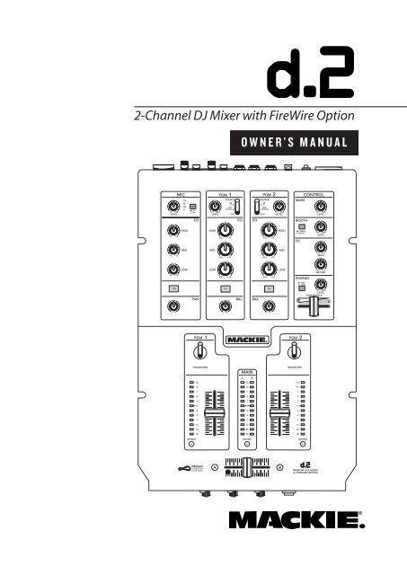
d.2 2-Channel DJ Mixer Owner's Manual - Mackie
d.2 2-Channel DJ Mixer Owner's Manual - Mackie
d.2 2-Channel DJ Mixer Owner's Manual - Mackie

You also want an ePaper? Increase the reach of your titles
YUMPU automatically turns print PDFs into web optimized ePapers that Google loves.
2-<strong>Channel</strong> <strong>DJ</strong> <strong>Mixer</strong> with FireWire Option<br />
+3 +50<br />
LEVEL<br />
U<br />
-15 +15<br />
U<br />
-15 +15<br />
U<br />
-15 +15<br />
L R<br />
HIGH<br />
MID<br />
LOW<br />
PGM 1<br />
TRANSFORM<br />
OL<br />
10<br />
7<br />
4<br />
2<br />
0<br />
2<br />
4<br />
7<br />
10<br />
20<br />
30<br />
infinium<br />
contact-free<br />
cross-fader<br />
A<br />
OWNER’S MANUAL<br />
MIC PGM<br />
PGM<br />
CONTROL<br />
OL<br />
U SOURCE<br />
SOURCE U MAIN<br />
SIG 48V<br />
OFF<br />
ON<br />
EQ<br />
MAX<br />
LEVEL<br />
HIGH<br />
MID<br />
LOW<br />
LINE/<br />
PHONO<br />
CD<br />
EQ<br />
MAIN<br />
L R<br />
OL<br />
10<br />
7<br />
4<br />
2<br />
0<br />
2<br />
4<br />
7<br />
10<br />
20<br />
30<br />
EQ<br />
PAN BAL BAL<br />
1<br />
KILL +10<br />
KILL +10<br />
KILL +10<br />
ON FX<br />
O<br />
LINE/<br />
PHONO<br />
CD<br />
L R<br />
L R<br />
REVERSE REVERSE<br />
2<br />
KILL +10<br />
KILL +10<br />
KILL +10<br />
FX<br />
MAX<br />
LEVEL<br />
O<br />
HIGH<br />
MID<br />
LOW<br />
B<br />
BOOTH<br />
FX<br />
PGM 2<br />
TRANSFORM<br />
STEREO<br />
MONO<br />
PHONES<br />
PGM<br />
MAIN<br />
OL<br />
10<br />
7<br />
4<br />
2<br />
0<br />
2<br />
4<br />
7<br />
10<br />
20<br />
30<br />
REVERSE<br />
MAX<br />
LEVEL<br />
O<br />
MAX<br />
LEVEL<br />
O<br />
+15<br />
SEND<br />
O<br />
+15<br />
RETURN<br />
O<br />
U<br />
U<br />
MAX<br />
LEVEL<br />
PGM SOURCE<br />
1 2<br />
O
<strong>d.2</strong> 2-channel <strong>DJ</strong> <strong>Mixer</strong><br />
Important Safety Instructions<br />
1. Read these instructions.<br />
2. Keep these instructions.<br />
3. Heed all warnings.<br />
4. Follow all instructions.<br />
5. Do not use this apparatus near water.<br />
6. Clean only with dry cloth.<br />
7. Do not block any ventilation openings. Install in accordance with the<br />
manufacturer’s instructions.<br />
8. Do not install near any heat sources such as radiators, heat registers,<br />
stoves, or other apparatus (including amplifi ers) that produce heat.<br />
9. Do not defeat the safety purpose of the polarized or grounding-type<br />
plug. A polarized plug has two blades with one wider than the other.<br />
A grounding-type plug has two blades and a third grounding prong.<br />
The wide blade or the third prong are provided for your safety. If the<br />
provided plug does not fi t into your outlet, consult an electrician for<br />
replacement of the obsolete outlet.<br />
10. Protect the power cord from being walked on or pinched particularly at<br />
plugs, convenience receptacles, and the point where they exit from the<br />
apparatus.<br />
11. Only use attachments/accessories specifi ed by the manufacturer.<br />
12. Use only with a cart, stand, tripod, bracket, or table specifi ed by the<br />
manufacturer, or sold with the apparatus. When a cart is used, use<br />
caution when moving the cart/apparatus combination to avoid injury<br />
from tip-over.<br />
PORTABLE CART WARNING<br />
2 <strong>d.2</strong> <strong>DJ</strong> <strong>Mixer</strong><br />
CAUTION AVIS<br />
RISK OF ELECTRIC SHOCK<br />
DO NOT OPEN<br />
RISQUE DE CHOC ELECTRIQUE<br />
NE PAS OUVRIR<br />
Carts and stands - The<br />
Component should be used<br />
only with a cart or stand<br />
that is recommended by<br />
the manufacturer.<br />
A Component and cart<br />
combination should be<br />
moved with care. Quick<br />
stops, excessive force, and<br />
uneven surfaces may cause<br />
the Component and cart<br />
combination to overturn.<br />
CAUTION: TO REDUCE THE RISK OF ELECTRIC SHOCK<br />
DO NOT REMOVE COVER (OR BACK)<br />
NO USER-SERVICEABLE PARTS INSIDE<br />
REFER SERVICING TO QUALIFIED PERSONNEL<br />
ATTENTION: POUR EVITER LES RISQUES DE CHOC<br />
ELECTRIQUE, NE PAS ENLEVER LE COUVERCLE. AUCUN<br />
ENTRETIEN DE PIECES INTERIEURES PAR L'USAGER. CONFIER<br />
L'ENTRETIEN AU PERSONNEL QUALIFIE.<br />
AVIS: POUR EVITER LES RISQUES D'INCENDIE OU<br />
D'ELECTROCUTION, N'EXPOSEZ PAS CET ARTICLE<br />
A LA PLUIE OU A L'HUMIDITE<br />
The lightning flash with arrowhead symbol within an equilateral<br />
triangle is intended to alert the user to the presence of uninsulated<br />
"dangerous voltage" within the product's enclosure, that may be<br />
of sufficient magnitude to constitute a risk of electric shock to persons.<br />
Le symbole éclair avec point de flèche à l'intérieur d'un triangle<br />
équilatéral est utilisé pour alerter l'utilisateur de la présence à<br />
l'intérieur du coffret de "voltage dangereux" non isolé d'ampleur<br />
suffisante pour constituer un risque d'éléctrocution.<br />
The exclamation point within an equilateral triangle is intended to<br />
alert the user of the presence of important operating and maintenance<br />
(servicing) instructions in the literature accompanying the appliance.<br />
Le point d'exclamation à l'intérieur d'un triangle équilatéral est<br />
employé pour alerter les utilisateurs de la présence d'instructions<br />
importantes pour le fonctionnement et l'entretien (service) dans le<br />
livret d'instruction accompagnant l'appareil.<br />
13. Unplug this apparatus during lightning storms or when unused for long<br />
periods of time.<br />
14. Refer all servicing to qualifi ed service personnel. Servicing is required<br />
when the apparatus has been damaged in any way, such as powersupply<br />
cord or plug is damaged, liquid has been spilled or objects have<br />
fallen into the apparatus, the apparatus has been exposed to rain or<br />
moisture, does not operate normally, or has been dropped.<br />
15. This apparatus shall not be exposed to dripping or splashing, and no<br />
object fi lled with liquids, such as vases or beer glasses, shall be placed<br />
on the apparatus.<br />
16. This apparatus has been designed with Class-I construction and must<br />
be connected to a mains socket outlet with a protective earthing connection<br />
(the third grounding prong).<br />
17. This apparatus has been equipped with an all-pole, rocker-style AC<br />
mains power switch. This switch is located on the rear panel and<br />
should remain readily accessible to the user.<br />
18. This apparatus does not exceed the Class A/Class B (whichever is<br />
applicable) limits for radio noise emissions from digital apparatus as<br />
set out in the radio interference regulations of the Canadian Department<br />
of Com mu ni ca tions.<br />
ATTENTION — Le présent appareil numérique n’émet pas de bruits<br />
radioélectriques dépassant las limites applicables aux appareils numériques de<br />
class A/de class B (selon le cas) prescrites dans le réglement sur le brouillage<br />
radioélectrique édicté par les ministere des com mu ni ca tions du Canada.<br />
19. Exposure to extremely high noise levels may cause permanent hearing<br />
loss. Individuals vary considerably in susceptibility to noise-induced<br />
hearing loss, but nearly everyone will lose some hearing if exposed to<br />
suffi ciently intense noise for a period of time. The U.S. Government’s<br />
Occupational Safety and Health Administration (OSHA) has specifi ed<br />
the permissible noise level exposures shown in the following chart.<br />
According to OSHA, any exposure in excess of these permissible limits<br />
could result in some hearing loss. To ensure against potentially dangerous<br />
exposure to high sound pressure levels, it is recommended that all<br />
persons exposed to equipment capable of producing high sound pressure<br />
levels use hearing protectors while the equipment is in operation.<br />
Ear plugs or protectors in the ear canals or over the ears must be worn<br />
when operating the equipment in order to prevent permanent hearing<br />
loss if exposure is in excess of the limits set forth here.<br />
Duration Per Day Sound Level dBA, Typical<br />
In Hours Slow Response Example<br />
8 90 Duo in small club<br />
6 92<br />
4 95 Subway Train<br />
3 97<br />
2 100 Very loud classical music<br />
1.5 102<br />
1 105 Dave screaming at Steve about deadlines<br />
0.5 110<br />
0.25 or less 115 Loudest parts at a rock concert<br />
WARNING — To reduce the risk of fi re or<br />
electric shock, do not expose this apparatus<br />
to rain or moisture.
Table of Contents<br />
Safety Instructions................................... 2<br />
Introduction...............................................4<br />
Getting Started ......................................... 5<br />
READ THIS PAGE!!....................................................5<br />
Hookup Diagrams.....................................6<br />
Rear Panel Features................................ 10<br />
Top Panel Features...................................12<br />
Microphone Input Section ................................. 12<br />
Program Input Section......................................... 13<br />
Control Section......................................................14<br />
Program Output Section..................................... 15<br />
Front Panel Features ...............................17<br />
Appendix A: Service Information....... 18<br />
Warranty Service...................................................18<br />
Troubleshooting ....................................................18<br />
Repair .......................................................................19<br />
Appendix B: Connections .....................20<br />
Appendix C: Technical Info ...................21<br />
Specifi cations ......................................................... 21<br />
Block Diagram........................................................23<br />
Gain Structure Diagram...................................... 24<br />
Appendix D: Transform Switch<br />
Rotation and Fader Replacement...... 25<br />
Limited Warranty ...................................27<br />
Don’t forget to visit our website at www.mackie.com for more<br />
information about this and other <strong>Mackie</strong> products.<br />
Part No. 0014096 Rev. A 7/05<br />
©2005 LOUD Technologies Inc. All Rights Reserved. Printed in China.<br />
Owner’s <strong>Manual</strong><br />
Owner’s <strong>Manual</strong><br />
3
<strong>d.2</strong> 2-channel <strong>DJ</strong> <strong>Mixer</strong><br />
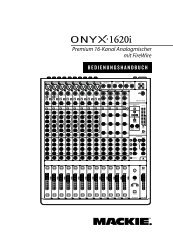
Introduction<br />
Thank you for choosing a <strong>Mackie</strong> <strong>d.2</strong> Premium VCA<br />
<strong>Mixer</strong> for scratch and club <strong>DJ</strong>s. It contains all your favorite<br />
features in a scratch mixer, along with signifi cant<br />
extras that you will come to appreciate.<br />
The <strong>d.2</strong> is the fi rst <strong>DJ</strong> mixer made by <strong>Mackie</strong>. We were<br />
able to apply our extensive knowledge of mixer design<br />
to the <strong>d.2</strong>, making it a truly professional product with<br />
the high-end performance you’ve come to expect from<br />
<strong>Mackie</strong>. Features like our “built like a tank” construction,<br />
premium analog circuitry, infi nium contact-free<br />
crossfader, optional FireWire connectivity, and “Planet<br />
Earth” power supply add value to the <strong>d.2</strong> not found in<br />
any other scratch mixer in its class.<br />
FEATURES<br />
4 <strong>d.2</strong> <strong>DJ</strong> <strong>Mixer</strong><br />
Mighty strong construction to withstand the<br />
rigors of <strong>DJ</strong> work.<br />
Integrated rack ears (Odyssey Battle Bridge compatible).<br />
Removable top panel provides access to the<br />
rotatable transform switches and to the<br />
user-replaceable faders.<br />
Premium VCA-based design offers extremely<br />
smooth fades and cross fades with very low<br />
distortion characteristics for warm, hearty<br />
sounding mixes.<br />
<strong>Mackie</strong> mic preamp with 3-band EQ for proquality<br />
vocals through the <strong>d.2</strong>.<br />
XLR main outputs with Mic/Line switch (mic<br />
position allows stage connections with no D.I.<br />
boxes required).<br />
RCA main outs with Live/Record switch<br />
(Record position delivers a pre-main out).<br />
Endless-life optical crossfader from the UKbased<br />
Infi nium, with adjustable mechanical<br />
tension accessible from the top panel.<br />
Please write your serial number here for future<br />
reference (i.e., insurance claims, tech support,<br />
return authorization, etc.)<br />
Purchased at:<br />
Date of purchase:<br />
Optional user-installable FireWire card receives<br />
four program channels from PC/Mac and sends<br />
a stereo L-R recording stream to PC/Mac.<br />
Program faders and Crossfader have variable<br />
contour curves and reverse switches.<br />
Ultra bright blue/white main meters plus<br />
individual program meters for cueing and beat<br />
matching.<br />
Separate mono/stereo switchable booth output<br />
on balanced TRS connectors.<br />
Stereo FX loop for outboard effects.<br />
“Planet Earth” power-supply operates on voltages<br />
between 100 and 240 VAC.<br />
Standard IEC power receptacle and power cord.<br />
HOW TO USE THIS MANUAL<br />
We know that many of you can’t wait to get your new<br />
mixer hooked up, and you’re probably not going to read<br />
the manual fi rst (sigh!). So the fi rst section after this<br />
Introduction is a Getting Started guide to help you get<br />
the mixer set up fast so you can start using it right away.<br />
Right after that are the ever popular hook-up diagrams<br />
that show you some typical setups.<br />
Then, when you have time, read the Features Description<br />
section. This describes every knob, button, and<br />
connection point on the <strong>d.2</strong>, roughly following the signal<br />
fl ow through the mixer from top to bottom.<br />
Throughout this section you’ll fi nd illustrations with<br />
each feature numbered. If you want to know more about<br />
a feature, simply locate it on the appropriate illustration,<br />
notice the number attached to it, and fi nd that<br />
number in the nearby paragraphs.<br />
This icon marks information that is critically<br />
important or unique to the <strong>d.2</strong>. For your own<br />
good, read them and remember them. They<br />
will be on the fi nal test.<br />
This icon leads you to in-depth explanations<br />
of features and practical tips. While not<br />
mandatory, they usually have some valuable<br />
nuggets of information.<br />
Appendix B is a section on connectors: XLR connectors,<br />
TRS balanced connectors, TS unbalanced connectors,<br />
and RCA unbalanced connectors.<br />
Appendix C shows the <strong>d.2</strong> specifi cations, a block diagram,<br />
and a gain structure diagram.<br />
Appendix D shows how to adjust the position of the<br />
transform switches, and how to replace the faders if you<br />
ever have to.
Getting Started<br />
READ THIS PAGE!!<br />
Zero the Controls<br />
Even if you never reads manuals, please<br />
read and digest the safety instructions<br />
on page 2, and this page before you<br />
begin using the <strong>d.2</strong> mixer.<br />
1. Turn the rear panel POWER switch off.<br />
2. Turn down the LEVEL controls for MIC, PGM 1 and<br />
PGM 2, and center all EQ, PAN, and BAL controls.<br />
3. Set all push button switches to their “out” positions.<br />
4. In the CONTROL section (right hand side), turn all<br />
the rotary knobs down, and the switches out.<br />
5. Set the PROGRAM Faders fully down.<br />
6. On the front panel, set the REVERSE switches out.<br />
7. Center the CROSSFADER.<br />
Connections<br />
If you already know how you want to connect the <strong>d.2</strong>,<br />
go ahead and connect the inputs and outputs the way<br />
you want them. If you just want to get sound through<br />
the <strong>d.2</strong> mixer, follow these steps:<br />
1. Plug a signal source to the <strong>d.2</strong>. This could be a:<br />
Microphone into the MIC input<br />
Turntable into a PHONO input (push in the<br />
rear panel LINE/PHONO switch)<br />
Line-level source such as a CD player into the<br />
PHONO input (push out the LINE/PHONO<br />
switch)<br />
Line-level source such as a CD player into a CD<br />
input.<br />
2. If you are using the PHONO input, make sure you<br />
set the LINE/PHONO switch correctly.<br />
3. Connect cords from the <strong>d.2</strong>’s MAIN OUTs (XLR or<br />
RCA connectors on the rear panel) to your powered<br />
speakers or amplifi er.<br />
4. Plug in the detachable linecord, connect it to a live<br />
AC outlet, and turn on the <strong>d.2</strong>’s POWER switch.<br />
5. If you have powered speakers, turn them on. Otherwise,<br />
hook up your speakers to the amp and turn it<br />
on. Adjust your powered speaker or amplifi er level<br />
controls to however the manufacturer recommends.<br />
(This is usually all the way up.)<br />
Set the Levels<br />
To set the LEVEL controls, it’s not even necessary<br />
to hear what you’re doing at the outputs of the mixer.<br />
If you want to listen while you work, plug headphones<br />
into the PHONES jack on the front panel, then set the<br />
PHONES knob up a little.<br />
1. Select the input using the SOURCE switch.<br />
2. Play something into the selected input. Be sure<br />
that the volume of the input source is the same as<br />
it would be during normal use. If it isn’t, you might<br />
have to readjust these levels during the middle of a<br />
set.<br />
3. Center the TRANSFORM switch. There will be no<br />
output, but the PROGRAM METER will still work.<br />
4. Adjust the channel’s rotary LEVEL control so that<br />
the LEDs on the PROGRAM meter stay around “0”<br />
and +4, and never go higher than “+7.”<br />
5. Apply some EQ if needed, (return to step 4 if you<br />
do, just to check the levels are still OK).<br />
6. Repeat for the other channel (if you want to).<br />
Set the MIC Levels<br />
1. To level the microphone input, keep the ON button<br />
off, and talk or sing at your highest expected level.<br />
2. Adjust the MIC LEVEL until the OL LED next to it<br />
only comes on occasionally.<br />
Instant Mixing<br />
1. To get sound out of the speakers, press the TRANS-<br />
FORM switch up (the latched position), turn up the<br />
PROGRAM fader, and slowly rotate the MAIN control<br />
to a comfortable listening level.<br />
2. Sing and play. You’re a star! Bring in the other<br />
channel, play with the CROSSFADER, and generally<br />
have fun.<br />
Other Nuggets of Wisdom<br />
Always turn down the MAIN, BOOTH, and PHONE<br />
knobs before making any connections.<br />
When you shut down your equipment, turn off the<br />
amplifi ers fi rst. When powering up, turn on the<br />
amplifi ers last.<br />
Never listen to loud music for prolonged periods.<br />
Please see the Safety Instructions on page 2 for<br />
information on hearing protection.<br />
Owner’s <strong>Manual</strong><br />
Owner’s <strong>Manual</strong><br />
5
<strong>d.2</strong> 2-channel <strong>DJ</strong> <strong>Mixer</strong><br />
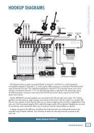
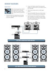
Hookup Diagrams<br />
(The following hookup diagrams show the <strong>d.2</strong> with the optional FireWire card installed.)<br />
6 <strong>d.2</strong> <strong>DJ</strong> <strong>Mixer</strong><br />
Plug into<br />
front panel<br />
headphone jack<br />
Headphones<br />
SRM450<br />
Powered Speaker<br />
Main Left<br />
SWA1501<br />
Powered Subwoofer<br />
Main Left<br />
Main Right<br />
~100-240 VAC 50-60Hz 20W<br />
DESIGNED BY MACKOIDS IN WOODINVILLE, WA, USA • MANUFACTURED IN CHINA<br />
FABRIQUE EN CHINE • COPYRIGHT ©2005 • "MACKIE", AND THE RUNNING MAN<br />
FIGURE ARE TRADEMARKS OF LOUD TECHNOLOGIES, INC. • PATENT PENDING.<br />
MAIN OUT BOOTH FX<br />
PGM 2<br />
PGM 1<br />
MIC<br />
L R<br />
LINE<br />
MIC<br />
L<br />
L SEND R<br />
PHONO<br />
L<br />
CD<br />
L<br />
PHONO<br />
L<br />
CD<br />
L<br />
ON<br />
L<br />
R<br />
LIVE<br />
RECORD<br />
Effects Processor<br />
R<br />
SERIAL / DATE CODE<br />
RETURN<br />
L R<br />
R R R R<br />
Mobile <strong>DJ</strong> System: Rental, Wedding, or Funeral<br />
LINE<br />
PHONO<br />
GND<br />
FIREWIRE<br />
SRM450<br />
Powered Speaker<br />
Main Right<br />
SWA1501<br />
Powered Subwoofer<br />
Pro CD Player<br />
LINE<br />
PHONO<br />
GND<br />
Laptop Computer<br />
Microphone
Plug into<br />
front panel<br />
headphone jack<br />
Headphones<br />
~100-240 VAC 50-60Hz 20W<br />
DESIGNED BY MACKOIDS IN WOODINVILLE, WA, USA • MANUFACTURED IN CHINA<br />
FABRIQUE EN CHINE • COPYRIGHT ©2005 • "MACKIE", AND THE RUNNING MAN<br />
FIGURE ARE TRADEMARKS OF LOUD TECHNOLOGIES, INC. • PATENT PENDING.<br />
MAIN OUT BOOTH FX<br />
PGM 2<br />
PGM 1<br />
MIC<br />
L R<br />
LINE<br />
MIC<br />
L<br />
L SEND R<br />
PHONO<br />
L<br />
CD<br />
L<br />
PHONO<br />
L<br />
CD<br />
L<br />
ON<br />
L<br />
R<br />
LIVE<br />
RECORD<br />
ground wire<br />
Turntable with phono-level output<br />
R<br />
SERIAL / DATE CODE<br />
RETURN<br />
L R<br />
R R R R<br />
Radio Show Recording/Podcasting/having a good old time<br />
LINE<br />
PHONO<br />
GND<br />
FIREWIRE<br />
Laptop Computer<br />
cup of tea<br />
(optional)<br />
LINE<br />
PHONO<br />
GND<br />
Microphone<br />
ground wire<br />
Turntable with phono-level output<br />
Owner’s <strong>Manual</strong><br />
Owner’s <strong>Manual</strong><br />
7
<strong>d.2</strong> 2-channel <strong>DJ</strong> <strong>Mixer</strong><br />
8 <strong>d.2</strong> <strong>DJ</strong> <strong>Mixer</strong><br />
Plug into<br />
front panel<br />
headphone jack<br />
Headphones<br />
SRM450<br />
Powered Speaker<br />
Main Left<br />
SWA1501<br />
Powered Subwoofer<br />
Main Left<br />
Main Right<br />
~100-240 VAC 50-60Hz 20W<br />
DESIGNED BY MACKOIDS IN WOODINVILLE, WA, USA • MANUFACTURED IN CHINA<br />
FABRIQUE EN CHINE • COPYRIGHT ©2005 • "MACKIE", AND THE RUNNING MAN<br />
FIGURE ARE TRADEMARKS OF LOUD TECHNOLOGIES, INC. • PATENT PENDING.<br />
MAIN OUT BOOTH FX<br />
PGM 2<br />
PGM 1<br />
MIC<br />
L R<br />
LINE<br />
MIC<br />
L<br />
L SEND R<br />
PHONO<br />
L<br />
CD<br />
L<br />
PHONO<br />
L<br />
CD<br />
L<br />
ON<br />
L<br />
R<br />
LIVE<br />
RECORD<br />
ground wire<br />
Turntable with phono-level output<br />
R<br />
SERIAL / DATE CODE<br />
RETURN<br />
L R<br />
R R R R<br />
LINE<br />
PHONO<br />
Two-Turntable Portable System<br />
GND<br />
FIREWIRE<br />
SRM450<br />
Powered Speaker<br />
Main Right<br />
SWA1501<br />
Powered Subwoofer<br />
LINE<br />
PHONO<br />
GND<br />
Microphone<br />
ground wire<br />
Turntable with phono-level output
Booth Left<br />
Plug into<br />
front panel<br />
headphone jack<br />
Booth Right<br />
SA1532z<br />
Powered Speaker<br />
Main Left<br />
Headphones<br />
Main Left<br />
~100-240 VAC 50-60Hz 20W<br />
DESIGNED BY MACKOIDS IN WOODINVILLE, WA, USA • MANUFACTURED IN CHINA<br />
FABRIQUE EN CHINE • COPYRIGHT ©2005 • "MACKIE", AND THE RUNNING MAN<br />
FIGURE ARE TRADEMARKS OF LOUD TECHNOLOGIES, INC. • PATENT PENDING.<br />
MAIN OUT BOOTH FX<br />
PGM 2<br />
PGM 1<br />
MIC<br />
L R<br />
LINE<br />
MIC<br />
L<br />
L SEND R<br />
PHONO<br />
L<br />
CD<br />
L<br />
PHONO<br />
L<br />
CD<br />
L<br />
ON<br />
L<br />
R<br />
LIVE<br />
RECORD<br />
Turntable (PGM 2)<br />
with phono-level output<br />
SRM450 Powered Speaker<br />
Booth Left<br />
SWA1801<br />
Powered<br />
Subwoofers<br />
Main Right<br />
ground wire<br />
R<br />
SERIAL / DATE CODE<br />
RETURN<br />
L R<br />
Club System<br />
R R R R<br />
LINE<br />
PHONO<br />
GND<br />
FIREWIRE<br />
Laptop Computer<br />
SWA1801<br />
Powered<br />
Subwoofers<br />
LINE<br />
PHONO<br />
SA1532z<br />
Powered Speaker<br />
Main Right<br />
CD Turntable (PGM 2) CD Turntable (PGM 1)<br />
GND<br />
Turntable (PGM 1)<br />
with phono-level output<br />
Microphone<br />
ground wire<br />
SRM450 Powered Speaker<br />
Booth Right<br />
Owner’s <strong>Manual</strong><br />
Owner’s <strong>Manual</strong><br />
9
<strong>d.2</strong> 2-channel <strong>DJ</strong> <strong>Mixer</strong><br />
Rear Panel Features<br />
1. MIC Input<br />
This is a Neutrik “combo” input connector that accepts<br />
either a balanced male XLR connector or a 1/4"<br />
balanced or unbalanced connector. Use an XLR connector<br />
for low-impedance microphones and a 1/4" connector<br />
for high-impedance microphones.<br />
The MIC Input signal is routed through the MIC Input<br />
Section, MIC EQ, and then to the Main Mix bus.<br />
2. CD Inputs<br />
These RCA jacks accept a stereo line-level signal from<br />
a CD player or other line-level playback device (such as<br />
an MP3 player or DVD audio).<br />
3. LINE/PHONO Inputs<br />
These RCA jacks accept a stereo phono-level signal<br />
from a turntable (when the LINE/PHONO [4] switch<br />
is pushed in), or from a line-level playback device such<br />
as a CD player or MP3 player (when the LINE/PHONO<br />
switch is out). Check that your turntable has a phonolevel<br />
output and a Moving Magnet cartridge.<br />
4. LINE/PHONO Switch<br />
If you connect a turntable with phono-level outputs<br />
to the LINE/PHONO inputs [3], push this switch in to<br />
select the phono-level input stage, which includes an<br />
RIAA preamp for proper re-equalization of the incoming<br />
phono signal.<br />
If you are connecting a line-level playback device like<br />
a CD or MP3 player, leave this switch out to select the<br />
line-level preamp.<br />
10 <strong>d.2</strong> <strong>DJ</strong> <strong>Mixer</strong><br />
~100-240 VAC 50-60Hz 20W<br />
MAIN OUT BOOTH FX<br />
PGM 2<br />
PGM 1<br />
MIC<br />
L R<br />
L<br />
L SEND R<br />
PHONO<br />
L<br />
CD<br />
L<br />
PHONO<br />
L<br />
CD<br />
L<br />
LINE<br />
MIC<br />
Do not press it in if you have a line-level<br />
signal connected.<br />
ON<br />
L<br />
R<br />
LIVE<br />
RECORD<br />
R<br />
SERIAL / DATE CODE<br />
RETURN<br />
L R<br />
DESIGNED BY MACKOIDS IN WOODINVILLE, WA, USA • MANUFACTURED IN CHINA<br />
FABRIQUE EN CHINE • COPYRIGHT ©2005 • "MACKIE", AND THE RUNNING MAN<br />
FIGURE ARE TRADEMARKS OF LOUD TECHNOLOGIES, INC. • PATENT PENDING.<br />
R R<br />
LINE<br />
PHONO<br />
GND<br />
FIREWIRE<br />
LINE<br />
PHONO<br />
(ACCESSORY CARD REQUIRED)<br />
R R<br />
5. GND Terminal<br />
GND<br />
These terminals are provided to connect a ground<br />
wire from your turntable(s) to the <strong>d.2</strong>. Most turntables<br />
provide a ground wire to connect to the preamp for the<br />
purpose of eliminating “hum” in the audio signal. Simply<br />
turn the ground terminal on the <strong>d.2</strong> counter-clockwise<br />
to loosen it, wrap the end of the ground wire clockwise<br />
around the terminal, and hand-tighten the ground terminal<br />
for a secure ground connection.<br />
6. Stereo FX SEND<br />
These 1/4" TRS jacks provide a balanced line-level<br />
output signal from the stereo FX Send bus. Use these to<br />
connect to the inputs of an external effects processor.<br />
You can also use an unbalanced 1/4" TS cable to make<br />
this connection.<br />
7. Stereo FX RETURN<br />
These 1/4" TRS jacks accept a balanced line-level<br />
signal from an external effects processor. They will also<br />
accept an unbalanced 1/4" TS connector.<br />
If you are using a stereo effects processor, connect its<br />
left and right outputs to the corresponding left and right<br />
FX RETURN jacks. If it is a mono effects processor, connect<br />
its output signal to the left FX RETURN jack, and it<br />
will appear on both the left and right Main Mix bus.<br />
8. BOOTH Outputs<br />
These 1/4" TRS jacks provide a balanced line-level<br />
signal from the Main Mix bus, prior to the rotary MAIN<br />
LEVEL control [32]. Use these to connect to a pair<br />
of powered monitor speakers (or to the inputs of an<br />
amplifi er powering the monitor speakers in the booth).
If you only have one monitor speaker, just use one of<br />
the BOOTH Outputs and push in the BOOTH STEREO/<br />
MONO switch [34] in the CONTROL section on the top<br />
panel.<br />
9. XLR MAIN OUTs<br />
These male XLR connectors provide a balanced mic-<br />
or line-level signal from the MAIN LEVEL control [32].<br />
The LINE/MIC Switch [10] determines if it is a miclevel<br />
or line-level output. Connect these to the balanced<br />
inputs of the active speakers, or power amplifi er(s)<br />
powering your main speakers.<br />
If you are connecting the MAIN OUT of the <strong>d.2</strong> to an<br />
unbalanced input, use the RCA Main Outs [11] instead.<br />
Note: Balanced connections offer better immunity to<br />
external noise (specifi cally, hum and buzz) than unbalanced<br />
connections. Because of this, it is the preferred<br />
interconnect method, especially in cases where very<br />
long lengths of cable are being used. A long unbalanced<br />
cable carries with it more opportunity for noise to get<br />
into the system — having balanced cables means very<br />
little noise will enter the system. If you must use an<br />
unbalanced connection, keep the cable length to 10 feet<br />
or less (3 meters).<br />
10. LINE/MIC Switch<br />
If you are connecting the XLR MAIN OUTs [9] to linelevel<br />
inputs like a power amplifi er’s inputs, leave this<br />
switch out, in the LINE position.<br />
If you are using the <strong>d.2</strong> as a submixer and connecting<br />
the XLR MAIN OUTS to the mic inputs of another mixer,<br />
push this switch in to the MIC position. This inserts a<br />
30 dB pad to reduce the output signal to a mic level.<br />
This great feature allows you to connect the <strong>d.2</strong> output<br />
directly to a snake without using direct boxes.<br />
11. RCA Main Outs<br />
These RCA connectors provide an unbalanced linelevel<br />
signal from the MAIN OUT, either pre- or post-<br />
MAIN LEVEL control [32], depending on the setting of<br />
the LIVE/RECORD switch [12].<br />
12. LIVE/RECORD Switch<br />
When this switch is out (LIVE position), the RCA<br />
Main Outs provide the signal just after the MAIN LEVEL<br />
control [32], so it essentially provides the same signal<br />
as the XLR MAIN OUTs [9], except it is an unbalanced<br />
signal rather than a balanced one.<br />
When this switch is pushed in (RECORD position),<br />
the RCA Main Outs provide the signal just prior to the<br />
MAIN LEVEL control. This allows you to make a stereo<br />
recording that is not affected by Main Out level changes<br />
during a performance.<br />
13. POWER Switch<br />
When the POWER switch is turned ON, power is supplied<br />
to the <strong>d.2</strong> and the cool blue EQ knobs light up.<br />
14. Power Receptacle<br />
This is a standard 3-prong IEC power connector. Connect<br />
the detachable linecord (included in the box with<br />
your <strong>d.2</strong>) to the power receptacle, and plug the other<br />
end of the linecord into an AC outlet.<br />
The <strong>d.2</strong> has a universal power supply that can accept<br />
any AC voltage from 100 VAC to 240 VAC. No need for<br />
voltage select switches. It will work virtually anywhere<br />
in the world. That’s why we call it a “Planet-Earth”<br />
power supply! This also means that it is less susceptible<br />
to voltage sags or spikes, providing greater electromagnetic<br />
isolation and better protection against AC line<br />
noise.<br />
15. FIREWIRE I/O Option<br />
FireWire (a.k.a. IEEE 1394) is a high-speed serial I/O<br />
interface for connecting digital devices, with more than<br />
30 times the bandwidth of USB 1.1. You can install the<br />
optional FireWire card here, to provide two FireWire<br />
connectors for transferring digital audio to and from<br />
your laptop computer or digital audio workstation<br />
(DAW) with absolute zero latency.<br />
FIREWIRE<br />
The FireWire interface provides a stereo main output<br />
to your computer. The signals are pre-MAIN LEVEL control<br />
[32], so they are independent of any adjustments<br />
made to the MAIN LEVEL control. This allows you to<br />
record your live performance directly to your laptop.<br />
The FireWire interface also lets you use your computer<br />
to playback music for mixing on the <strong>d.2</strong>. It provides<br />
a return for four signals, which can be selected as the<br />
program source for PGM 1 and PGM 2. Assign two channels<br />
(or a stereo pair) to ASIO or CoreAudio outputs 1<br />
and 2 for PGM 1, and two channels (or a stereo pair) to<br />
outputs 3 and 4 for PGM 2.<br />
The FireWire card can easily be installed with the<br />
help of a small screwdriver. Ask your <strong>Mackie</strong> dealer<br />
about it. (The FireWire card, not the screwdriver.) Each<br />
card comes with installation instructions that I have<br />
to write before the boss gets back from his vacation in<br />
Gary, Indiana.<br />
Owner’s <strong>Manual</strong><br />
Owner’s <strong>Manual</strong><br />
11
<strong>d.2</strong> 2-channel <strong>DJ</strong> <strong>Mixer</strong><br />
Top Panel Features<br />
MIC Input Section<br />
16. MIC LEVEL Control<br />
This knob adjusts the gain<br />
of the mic preamp for any<br />
microphone plugged into the<br />
MIC input jack [1]. It ranges<br />
from +13 dB to +63 dB of<br />
gain. Adjust this knob so<br />
that the loudest speaking or<br />
shouting that you do into the<br />
microphone just barely lights<br />
the OL LED [18]. This gives<br />
you the best signal-to-noise<br />
ratio for the mic preamp.<br />
17. MIC SIGNAL LED<br />
L R<br />
This green LED is a signal<br />
present indicator. It lights<br />
when the microphone signal<br />
reaches –20 dBu, to give you a clue that the microphone<br />
is working.<br />
18. MIC OL LED<br />
This red LED lights when the microphone signal<br />
reaches 6 dB below clipping. It’s okay if this LED blinks<br />
occasionally, but if it is blinking frequently or lit continuously,<br />
turn down the MIC LEVEL control [16] until<br />
it just blinks occasionally.<br />
19. 48V Phantom Power Switch<br />
If your microphone is a condenser design, it probably<br />
requires phantom power to operate. Push in this switch<br />
to supply 48 VDC to pins 2 and 3 of the XLR microphone<br />
connector.<br />
Dynamic microphones, like Shure’s SM57 and SM58,<br />
do not require phantom power. However, phantom<br />
power will not harm most dynamic microphones should<br />
you accidentally plug one in while the phantom power<br />
is turned on. Check your microphone’s user’s manual if<br />
you are not sure whether your microphone needs phantom<br />
power or not.<br />
20. HIGH EQ<br />
This knob gives your mic signal up to 15 dB of boost<br />
and cut at 12 kHz and above. At the center position the<br />
HIGH EQ has no effect on the signal.<br />
12 <strong>d.2</strong> <strong>DJ</strong> <strong>Mixer</strong><br />
+3 +50<br />
LEVEL<br />
-15<br />
-15<br />
-15<br />
U<br />
U<br />
U<br />
MIC PGM<br />
PGM<br />
CONTROL<br />
OL<br />
U SOURCE<br />
SOURCE U MAIN<br />
SIG 48V<br />
+15<br />
+15<br />
+15<br />
HIGH<br />
MID<br />
LOW<br />
OFF<br />
ON<br />
EQ<br />
MAX<br />
LEVEL<br />
HIGH<br />
MID<br />
LOW<br />
LINE/<br />
PHONO<br />
CD<br />
EQ<br />
EQ<br />
PAN BAL BAL<br />
1<br />
KILL +10<br />
KILL +10<br />
KILL +10<br />
ON FX<br />
O<br />
LINE/<br />
PHONO<br />
CD<br />
L R<br />
L R<br />
21. MID EQ<br />
2<br />
KILL +10<br />
KILL +10<br />
KILL +10<br />
FX<br />
MAX<br />
LEVEL<br />
O<br />
HIGH<br />
MID<br />
LOW<br />
BOOTH<br />
STEREO<br />
MONO<br />
FX<br />
PHONES<br />
PGM<br />
MAIN<br />
MAX<br />
LEVEL<br />
O<br />
MAX<br />
LEVEL<br />
O<br />
+15<br />
SEND<br />
O<br />
+15<br />
RETURN<br />
O<br />
U<br />
U<br />
MAX<br />
LEVEL<br />
PGM SOURCE<br />
1 2<br />
This knob gives you up to 15 dB of boost and cut at<br />
2.5 kHz. At the center position the MID EQ has no effect<br />
on the signal.<br />
22. LOW EQ<br />
This knob gives you up to 15 dB of boost and cut at<br />
80 Hz and below. At the center position the LOW EQ has<br />
no effect on the signal.<br />
23. ON Switch<br />
Press this switch in to send the microphone signal to<br />
the MAIN outputs, otherwise, your dulcet tones will not<br />
be heard, and people will say “huh?”<br />
24. PAN<br />
This knob adjusts the amount of microphone signal<br />
that is sent to the left versus the right main outputs.<br />
When the knob is turned hard left, the signal feeds only<br />
the left main out, and when the knob is turned hard<br />
right, it only feeds the right main out. When the knob is<br />
in the center, the microphone signal is sent equally to<br />
the left and right main mix. The fi endish design of the<br />
pan circuit allows “constant pan power,” where the average<br />
audio output level remains constant for all positions<br />
of the PAN control.<br />
O
Program Input Section<br />
25. LEVEL Control<br />
This knob adjusts the gain of the PGM input signals<br />
selected by the position of the SOURCE Select switch<br />
[26]. This knob ranges from off to +13 dB of gain at<br />
maximum. Adjust this with your good eye on the PRO-<br />
GRAM METERS [42], so the level is typically bouncing<br />
between the 0 and +4 LEDs.<br />
26. SOURCE Select Switch<br />
This switch selects one of three possible input sources<br />
for the PGM channel:<br />
FireWire: The signal coming in from the optional<br />
FireWire interface is selected as the source.<br />
LINE/PHONO: The signal connected to the PHONO<br />
connectors on the rear panel is selected. This<br />
could be from a turntable or from a line-level<br />
playback device, depending on the setting of<br />
the LINE/PHONO switch [4].<br />
CD: The signal connected to the CD connectors on<br />
the rear panel is selected.<br />
You could have a signal coming in on all three inputs,<br />
and quickly change from one input source to another<br />
using this heavy duty switch.<br />
27. HIGH EQ<br />
This knob gives you up to 10 dB of boost at 4 kHz and<br />
above, and turns off the signal at 4 kHz and above when<br />
the knob is turned to the KILL position. At the center<br />
position, the HIGH EQ has no effect on the signal.<br />
28. MID EQ<br />
This knob gives you up to 10 dB of boost at 1 kHz, and<br />
turns off the signal at 1 kHz when the knob is turned to<br />
the KILL position. At the center position, the MID EQ<br />
has no effect on the signal.<br />
29. LOW EQ<br />
This knob gives you up to 10 dB of boost at 300 Hz<br />
and below, and turns off the signal at 300 Hz and below<br />
when the knob is turned to the KILL position. At the<br />
center position, the LOW EQ has no effect on the signal.<br />
Note: When all three EQ knobs are turned to the KILL<br />
position, the signal is effectively muted and no signal<br />
passes through to the output.<br />
30. FX Switch<br />
Press this switch in to tap the PGM signal to the FX<br />
SEND outputs. This allows you to send the signal to an<br />
external effects processor, or even provide a direct feed<br />
for the PGM signal to another mixer. This switch will<br />
route the PGM signal to the FX send output connectors,<br />
interrupting the signal to the Main Outputs. If there<br />
is no effects processor connected to the FX send and<br />
returns, then the PGM signal is muted.<br />
31. BAL<br />
This knob works like the balance control on a home<br />
stereo. Turning the knob to the left turns down the right<br />
side, and turning the knob to the right turns down the<br />
left side. When the BAL control is in the center, the left<br />
and right sides are equally as loud (assuming the left<br />
and right inputs are equal loudness).<br />
Owner’s <strong>Manual</strong><br />
Owner’s <strong>Manual</strong><br />
13
<strong>d.2</strong> 2-channel <strong>DJ</strong> <strong>Mixer</strong><br />
Control Section<br />
32. MAIN LEVEL<br />
Control<br />
This knob adjusts the<br />
main output level at the<br />
MAIN OUT XLRs [9]<br />
(and to the RCA Main<br />
Outs [11] when the<br />
LIVE/RECORD switch<br />
[12] is out). (Remember,<br />
when the LIVE RE-<br />
CORD switch is pushed<br />
in, the RCA Main Outs<br />
are not affected by the<br />
MAIN LEVEL control.)<br />
33. BOOTH LEVEL<br />
Control<br />
This knob adjusts<br />
the output level at the<br />
BOOTH outputs [8].<br />
34. STEREO/MONO Switch<br />
With this switch up, the BOOTH outputs [8] provide<br />
a stereo left and right output of the main mix. Push the<br />
switch in to combine the left and right signals to mono if<br />
you only have one booth monitor speaker.<br />
35. FX SEND LEVEL Control<br />
This knob controls the amount of signal being sent to<br />
FX SEND outputs [6]. Adjust this knob to provide an<br />
appropriate input signal level to your external effects<br />
processor (or whatever you have connected to the FX<br />
SENDs). It ranges from off to +13 dB at maximum.<br />
Note: The FX SENDs are affected by the TRANSFORM<br />
switches [40], so if you mute a PGM channel with the<br />
TRANSFORM switch, the FX SEND for that PGM channel<br />
is muted as well.<br />
36. FX RETURN LEVEL Control<br />
This adjusts the signal level coming from your external<br />
effects processor via the FX RETURN jacks [7]. Use<br />
it to adjust the processed signal going to the main mix<br />
bus. It ranges from off to +13 dB at maximum.<br />
14 <strong>d.2</strong> <strong>DJ</strong> <strong>Mixer</strong><br />
+3 +50<br />
LEVEL<br />
-15<br />
-15<br />
-15<br />
U<br />
U<br />
U<br />
L R<br />
MIC PGM<br />
PGM<br />
CONTROL<br />
OL<br />
U SOURCE<br />
SOURCE U MAIN<br />
SIG 48V<br />
+15<br />
+15<br />
+15<br />
HIGH<br />
MID<br />
LOW<br />
OFF<br />
ON<br />
EQ<br />
MAX<br />
LEVEL<br />
HIGH<br />
MID<br />
LOW<br />
LINE/<br />
PHONO<br />
CD<br />
EQ<br />
EQ<br />
PAN BAL BAL<br />
1<br />
KILL +10<br />
KILL +10<br />
KILL +10<br />
ON FX<br />
O<br />
LINE/<br />
PHONO<br />
CD<br />
L R<br />
L R<br />
2<br />
KILL +10<br />
KILL +10<br />
KILL +10<br />
MAX<br />
LEVEL<br />
O<br />
HIGH<br />
MID<br />
LOW<br />
BOOTH<br />
STEREO<br />
MONO<br />
FX<br />
PHONES<br />
PGM<br />
MAIN<br />
37. PHONES LEVEL Control<br />
FX<br />
MAX<br />
LEVEL<br />
O<br />
MAX<br />
LEVEL<br />
O<br />
+15<br />
SEND<br />
O<br />
+15<br />
RETURN<br />
O<br />
U<br />
U<br />
MAX<br />
LEVEL<br />
PGM SOURCE<br />
1 2<br />
This controls the volume of the PHONES output from<br />
off to maximum gain.<br />
Turn it to minimum before connecting and<br />
putting on headphones. Increase it slowly to<br />
a safe listening level. See page 17.<br />
38. PGM/MAIN Switch<br />
Use this switch to select the source for the headphones<br />
signal. When the switch is up (PGM position),<br />
the signal is tapped just after the BAL control [30] on<br />
the PGM channels. You can use the PGM SOURCE crossfader<br />
[39] to fade between PGM 1 and PGM 2.<br />
When the switch is down (MAIN position), the signal<br />
is tapped from the Main Mix bus, just before the MAIN<br />
LEVEL control [32].<br />
39. PGM SOURCE Cue Crossfader<br />
When the PGM/MAIN switch [38] is up (in the PGM<br />
position), you can use this crossfader to listen to PGM<br />
1 and PGM 2 in the headphones. When the crossfader<br />
is all the way to the left, PGM 1 is heard in the headphones.<br />
When the crossfader is all the way to the right,<br />
PGM 2 is heard in the headphones. When the knob is in<br />
the center, the headphones get an even mix of PGM 1<br />
and 2.<br />
Note: When the PGM/MAIN switch is down (MAIN<br />
position), this control has no effect on the PHONES<br />
output.<br />
O
Program Output Section<br />
40. TRANSFORM<br />
Switch<br />
The transform switch<br />
has three positions: Latching,<br />
Center, and Momentary.<br />
When the switch is<br />
Latched, this program’s<br />
signal is on, and passes<br />
through to the outputs.<br />
When the switch is in<br />
the center position, this<br />
program’s signal is muted<br />
at the outputs and FX<br />
Sends.<br />
The other position is a<br />
momentary version of the<br />
Latched position (in other<br />
words, it won’t stay there<br />
when you let go of it), and allows the signal to pass as<br />
long as the switch is held down. Let go of the switch,<br />
and the signal is muted again. This lets you quickly use<br />
the transform switch for “stutter” effects.<br />
If you prefer, you can rotate the Transform switch 45º<br />
or 90º so the switch moves diagonally or horizontally instead<br />
of vertically. See Appendix D on page 25 for more<br />
information.<br />
Note: If this switch is in the center position, the<br />
program can still be heard and cued in the headphones<br />
if the PGM/MAIN switch [38] is up.<br />
41. PROGRAM FADER<br />
PGM 1<br />
TRANSFORM<br />
This controls the volume for the PGM signal being<br />
sent to the Main Mix bus. The characteristics of how the<br />
fader affects the audio signal are determined by the corresponding<br />
CONTOUR control [47] and the REVERSE<br />
switch [48].<br />
These faders have a very light touch<br />
and are designed to last the lifetime of the<br />
<strong>d.2</strong>. No audio passes through these faders.<br />
Rather, they send a control voltage to a pair of VCAs<br />
(Voltage-Controlled Amplifi ers) that determine the gain<br />
of the signal. This is a very good thing, by the way, as the<br />
audio will not be affected by any scratchy electrical contacts,<br />
and the design allows for customizing the fader<br />
action using the CONTOUR and REVERSE controls.<br />
OL<br />
10<br />
7<br />
4<br />
2<br />
0<br />
2<br />
4<br />
7<br />
10<br />
20<br />
30<br />
A<br />
MAIN<br />
L R<br />
OL<br />
10<br />
7<br />
4<br />
2<br />
0<br />
2<br />
4<br />
7<br />
10<br />
20<br />
30<br />
REVERSE REVERSE<br />
infinium<br />
contact-free<br />
cross-fader<br />
42. PGM LEVEL METERS<br />
These meters have 12 LEDs, ranging from –30 to +20<br />
(OL). They indicate the summed-mono signal strength<br />
of the PGM signals just before the BAL controls [31].<br />
The meters are not affected by the PROGRAM faders<br />
[41].<br />
Typically, you want to see these meters bouncing<br />
between the “0” and the “+4” LEDs. It is okay if the OL<br />
LED lights occasionally, but if it lights frequently or continuously,<br />
turn down the PGM LEVEL control [25] until<br />
the OL LED blinks occasionally or not at all.<br />
43. REVERSE LED<br />
These light when the front-panel REVERSE switches<br />
[48] have been activated for PGM 1 or PGM 2 faders.<br />
They show that the fader direction-of-action is reversed.<br />
(The meters are not reversed, just the faders.)<br />
44. MAIN LEVEL METERS<br />
B<br />
PGM 2<br />
TRANSFORM<br />
OL<br />
10<br />
7<br />
4<br />
2<br />
0<br />
2<br />
4<br />
7<br />
10<br />
20<br />
30<br />
REVERSE<br />
These meters are similar to the PGM LEVEL METERS<br />
[42], but indicate the signal strength of the Main outputs<br />
before the MAIN LEVEL control. As with the other<br />
meters, you want to see the signals bouncing between<br />
the “0” and the “+4” LEDs. It is okay if the OL LEDs light<br />
occasionally, but if they light frequently or continuously,<br />
turn down the PROGRAM FADERS [41] until the OL<br />
LEDs blink occasionally, or not at all.<br />
Owner’s <strong>Manual</strong><br />
Owner’s <strong>Manual</strong><br />
15
<strong>d.2</strong> 2-channel <strong>DJ</strong> <strong>Mixer</strong><br />
45. REVERSE LED<br />
This LED lights when<br />
the REVERSE switch<br />
[48] has been activated<br />
for the Crossfader. For<br />
more details, see the discussion<br />
of the REVERSE<br />
switches [48] on the<br />
next page.<br />
46. CROSSFADER<br />
The crossfader is used<br />
to fade between the<br />
two PGM signals in the<br />
MAIN outputs. When<br />
the crossfader is all the<br />
way to the left, PGM 1 is<br />
heard in the MAIN outs.<br />
When the crossfader is<br />
all the way to the right,<br />
PGM 2 is heard. When<br />
the crossfader knob is<br />
in the center, the MAIN outs get an even mix of PGM 1<br />
and 2.<br />
The characteristics of how the crossfader affects the<br />
audio signal are determined by its corresponding CON-<br />
TOUR control [47] and the REVERSE switch [48].<br />
16 <strong>d.2</strong> <strong>DJ</strong> <strong>Mixer</strong><br />
The crossfader is a high-quality<br />
infi nium contact-free optical digital fader,<br />
designed to last the lifetime of the <strong>d.2</strong> with<br />
no degradation in quality.<br />
You can adjust the tension of the fader movement to<br />
your specifi c taste.<br />
To adjust the crossfader tension:<br />
PGM 1<br />
TRANSFORM<br />
1. Move the crossfader all the way to the left.<br />
2. Remove the fader cap (knob) by grasping it<br />
fi rmly and pulling straight up.<br />
3. Use a small slot-head screwdriver to turn the<br />
screw located through the hole on the left side<br />
of the crossfader slot.<br />
Rotate the screw clockwise to tighten the tension,<br />
and rotate the screw counter-clockwise to<br />
loosen the tension. You might need a fl ashlight<br />
to make sure you are lined up on the screw.<br />
4. Replace the fader cap, and you’re all done.<br />
OL<br />
10<br />
7<br />
4<br />
2<br />
0<br />
2<br />
4<br />
7<br />
10<br />
20<br />
30<br />
A<br />
MAIN<br />
L R<br />
OL<br />
10<br />
7<br />
4<br />
2<br />
0<br />
2<br />
4<br />
7<br />
10<br />
20<br />
30<br />
REVERSE REVERSE<br />
infinium<br />
contact-free<br />
cross-fader<br />
B<br />
PGM 2<br />
TRANSFORM<br />
OL<br />
10<br />
7<br />
4<br />
2<br />
0<br />
2<br />
4<br />
7<br />
10<br />
20<br />
30<br />
REVERSE
Front Panel Features<br />
47. CONTOUR Controls<br />
Use the CONTOUR controls to adjust how fast or<br />
slow each fader responds to movement. In the SLOW<br />
position, the faders respond in a linear fashion, increasing<br />
from minimum to maximum at the same rate. In<br />
the FAST position, the faders respond logarithmically,<br />
increasing from minimum to maximum very quickly, and<br />
then changing very little for the remainder of the fader<br />
travel. Adjust the CONTOUR controls between the two<br />
extremes to get the fader response that works best for<br />
your application.<br />
The CONTOUR control for the crossfader works in<br />
a similar fashion, crossfading linearly with the CON-<br />
TOUR control in the SLOW position, and crossfading<br />
very quickly with the CONTOUR control in the FAST<br />
position. In fact, in the FAST position, the crossfading<br />
occurs within the fi rst 2 mm of fader travel. This is great<br />
for “crabbing” techniques.<br />
48. REVERSE Switches<br />
PGM 1 FADER<br />
REVERSE<br />
Normally (with these switches out) when you move<br />
the PGM 1 or PGM 2 faders up, the volume will increase.<br />
When you move the crossfader left to right, PGM 1 will<br />
fade into PGM 2.<br />
These switches let you reverse the direction of the<br />
action of the program faders and the crossfader:<br />
With the PGM 1 or PGM 2 REVERSE switches on,<br />
when you move the PGM 1 or PGM 2 faders up, the<br />
volume will now decrease.<br />
CROSS FADER<br />
REVERSE<br />
With the Crossfader REVERSE switch on, when you<br />
move the crossfader left to right, PGM 2 will fade into<br />
PGM 1. (This is sometimes called a hamster switch.)<br />
Note: These switches and the CONTOUR controls do<br />
not affect the meters, just the faders.<br />
PGM 2 FADER<br />
REVERSE<br />
SLOW FAST SLOW FAST<br />
SLOW FAST<br />
CONTOUR<br />
CONTOUR<br />
CONTOUR<br />
49. Headphones Jack<br />
This is where you plug in your stereo headphones. It is<br />
a 1/4" TRS stereo jack.<br />
If you have the PGM/MAIN switch [38] up, you can<br />
listen to the PGM 1 or PGM 2 signals, or a mix of both,<br />
determined by setting the PGM SOURCE Slider [39].<br />
The signals are taken just after the BAL controls [31],<br />
but before the PROGRAM Faders [41].<br />
If you have the PGM/MAIN switch [38] down, you can<br />
listen to the MAIN MIX signals, taken just before the<br />
MAIN LEVEL control [32].<br />
The headphone volume is controlled by the PHONES<br />
LEVEL control [37], and the position of the PGM<br />
SOURCE Crossfader [39] if you are listening to PGM 1<br />
or PGM 2.<br />
WARNING: The headphone amp is designed<br />
to drive any standard headphones to<br />
a very loud level. We’re not kidding! It can<br />
cause permanent hearing damage. Even intermediate<br />
levels may be painfully loud with some headphones. BE<br />
CAREFUL!<br />
Always start with the PHONES LEVEL<br />
control [37] turned all the way down before<br />
connecting headphones to the PHONES<br />
jack, or making any connections. Keep it down until<br />
you’ve put on the headphones. Set the PGM SOURCE<br />
Slider [39] if you are listening to PGM 1 or PGM 2, then<br />
turn up the PHONES LEVEL control [37] slowly. Why?<br />
Always remember: “Engineers who fry their ears, fi nd<br />
themselves with short careers.”<br />
Owner’s <strong>Manual</strong><br />
Owner’s <strong>Manual</strong><br />
17
<strong>d.2</strong> 2-channel <strong>DJ</strong> <strong>Mixer</strong><br />
Appendix A: Service Information<br />
Warranty Service<br />
Details concerning Warranty Service are spelled out in<br />
the Warranty section on page 27.<br />
If you think your <strong>d.2</strong> has a problem, please do everything<br />
you can to confi rm it before calling for service. Doing so<br />
might save you from the deprivation of your mixer and<br />
the associated suffering.<br />
These may sound obvious to you, but here are some<br />
things you can check. Read on:<br />
Troubleshooting<br />
No Power<br />
Our favorite question: Is it plugged in?<br />
Make sure the power cord is securely seated in the<br />
IEC socket [14] and plugged all the way into the<br />
AC outlet.<br />
Make sure the AC outlet is live (check with a tester<br />
or lamp).<br />
Make sure the rear panel POWER switch [13] is in<br />
the ON position (up).<br />
Are the EQ controls on the front panel illuminated?<br />
If not, make sure the AC outlet is live.<br />
Are all the lights out in your town? If so, contact<br />
your local power company to get power restored.<br />
If no LEDs are illuminated, and you are certain that<br />
the AC outlet is live, it will be necessary to have<br />
your <strong>d.2</strong> serviced. There are no user serviceable parts<br />
inside. Refer to “Repair” on the next page to fi nd out<br />
how to proceed.<br />
Bad <strong>Channel</strong><br />
Check the TRANSFORM switch [40] is not in the<br />
center position.<br />
Is a fader or crossfader REVERSE LED [48] on?<br />
Check the channel’s PROGRAM fader [41] is not<br />
fully down.<br />
Are that channel’s EQ controls all turned down?<br />
Is the signal source turned up? Make sure the<br />
signal level from the selected input source is high<br />
enough to light up some of the PROGRAM METER<br />
LEDs [42].<br />
Is the correct input chosen with the SOURCE SE-<br />
LECT switch [26], and its PGM LEVEL [25] turned<br />
up far enough?<br />
18 <strong>d.2</strong> <strong>DJ</strong> <strong>Mixer</strong><br />
If the FX button [30] is pressed on that channel,<br />
make sure your effects processor is connected correctly<br />
and is working.<br />
Try the same source signal in the other channel, set<br />
up exactly like the suspect channel.<br />
Bad Output<br />
Is the associated level control (if any) turned up?<br />
If it’s one of the MAIN OUTPUTS, try unplugging<br />
the others. For example, if it’s the XLR LEFT MAIN<br />
OUT, unplug the RCA LEFT OUT. If the problem<br />
goes away, it’s not the mixer.<br />
If a left output is presumed dead, switch the left<br />
and right cords at the mixer end. If the problem<br />
stays on the left side, it’s not the mixer.<br />
Bad Sound<br />
Is the input connector plugged completely into the<br />
jack?<br />
Is it loud and distorted? Make sure the input<br />
LEVEL control [25] is set correctly. Reduce the<br />
signal level on the input source if possible.<br />
If possible, listen to the signal with headphones<br />
plugged into the input source device. If it sounds<br />
bad there, it’s not the <strong>d.2</strong> causing the problem.<br />
If you are using a turntable with a phono-level output,<br />
and the sound is low and distorted, check that<br />
the LINE/PHONO switch [4] is set to PHONO. Note<br />
that the phono section requires your cartridge to be<br />
a Moving Magnet type. It may be too low to amplify<br />
the low levels of a Moving Coil type.<br />
Noise/Hum<br />
Turn down the FX RETURN knob [36]. If the noise<br />
disappears, it’s coming from whatever is plugged<br />
into the FX RETURNS [7].<br />
Check that your turntable’s audio ground wire is<br />
connected to the GND terminals [5].<br />
Turn down each channel, one by one. If the noise<br />
disappears, it’s coming from whatever is plugged<br />
into that channel. Check your whatever.<br />
Check the signal cables between the input sources<br />
and the <strong>d.2</strong>. Disconnect them one by one. When the<br />
noise goes away, you’ll know which input source is<br />
causing the problem.<br />
Sometimes it helps to plug all the audio equipment<br />
into the same AC circuit so they share a common<br />
ground.
Repair<br />
Service for <strong>Mackie</strong> products is available at a factoryauthorized<br />
service center. Service for <strong>Mackie</strong> products<br />
living outside the United States can be obtained through<br />
local dealers or distributors.<br />
If your <strong>d.2</strong> needs service, follow these instructions:<br />
1. Review the preceding troubleshooting suggestions.<br />
Please.<br />
2. Call Tech Support at 1-800-898-3211, 7 am to 5 pm<br />
PST, to explain the problem and request a Service<br />
Request Number. Have your <strong>d.2</strong>’s serial number<br />
ready. You must have an Service Request Number<br />
before you can obtain warranty service.<br />
3. Keep this owner’s manual and the detachable linecord.<br />
We don’t need them to repair the mixer.<br />
4. Pack the mixer in its original package, including<br />
endcaps and box. This is VERY IMPORTANT.<br />
<strong>Mackie</strong> is not responsible for any damage that<br />
occurs due to non-factory packaging.<br />
5. Include a legible note stating your name, shipping<br />
address (no P.O. boxes), daytime phone number,<br />
Service Request Number, and a detailed description<br />
of the problem, including how we can duplicate it.<br />
6. Write the Service Request Number in BIG PRINT on<br />
top of the box. Units sent without the SR number will<br />
be refused.<br />
7. Tech Support will tell you where to ship the <strong>d.2</strong> for<br />
repair. We suggest insurance for all forms of cartage.<br />
8. You will need to contact the authorized service center<br />
for their latest turn-around times. The <strong>d.2</strong> must<br />
be packaged in its original packing box, and must<br />
have the Service Request Number on the box. Once<br />
it’s repaired, the authorized service center will ship<br />
it back by ground shipping, pre-paid (if it was a warranty<br />
repair).<br />
Note: Under the terms of the warranty, you must ship<br />
or drop-off the unit to an authorized service center.<br />
The return ground shipment is covered for those<br />
units deemed by us to be under warranty.<br />
Note: You must have a sales receipt from<br />
an authorized <strong>Mackie</strong> dealer for your<br />
unit to be considered for warranty<br />
repair.<br />
Owner’s <strong>Manual</strong><br />
Owner’s <strong>Manual</strong><br />
19
<strong>d.2</strong> 2-channel <strong>DJ</strong> <strong>Mixer</strong><br />
Appendix B: Connections<br />
XLR Connectors<br />
The <strong>d.2</strong> MIC combo input accepts 3-pin male XLR<br />
connectors; the MAIN OUTs accept 3-pin female XLR<br />
connectors. These are wired as follows, according to<br />
standards specifi ed by the AES (Audio Engineering<br />
Society).<br />
XLR Balanced Wiring:<br />
Pin 1 = Shield<br />
Pin 2 = Hot (+)<br />
Pin 3 = Cold (–)<br />
20 <strong>d.2</strong> <strong>DJ</strong> <strong>Mixer</strong><br />
SHIELD<br />
COLD<br />
SHIELD<br />
HOT<br />
COLD 3<br />
HOT<br />
3<br />
1<br />
2<br />
2<br />
2<br />
3 1<br />
1<br />
SHIELD<br />
COLD<br />
1/4" TRS Phone Plugs and Jacks<br />
“TRS” stands for Tip-Ring-Sleeve, the three connection<br />
points available on a stereo 1/4" or balanced phone<br />
jack or plug. TRS jacks and plugs are used for balanced<br />
signals and stereo headphones:<br />
Balanced Mono<br />
RING SLEEVE<br />
TIP<br />
1/4" TRS Balanced Mono Wiring:<br />
Sleeve = Shield<br />
Tip = Hot (+)<br />
Ring = Cold (–)<br />
Stereo Headphones<br />
RING SLEEVE<br />
1/4" TRS Stereo Unbalanced Wiring:<br />
Sleeve = Shield<br />
Tip = Left<br />
Ring = Right<br />
TIP<br />
HOT<br />
SLEEVE RING TIP<br />
RING<br />
TIP<br />
SLEEVE<br />
SLEEVE RING TIP<br />
RING<br />
TIP<br />
SLEEVE<br />
1/4" TS Phone Plugs and Jacks<br />
“TS” stands for Tip-Sleeve, the two connection points<br />
available on a mono 1/4" phone jack or plug. They are<br />
used for unbalanced signals.<br />
1/4" TS Unbalanced Wiring:<br />
Sleeve = Shield<br />
Tip = Hot (+)<br />
SLEEVE<br />
RCA Plugs and Jacks<br />
TIP<br />
SLEEVE<br />
TIP<br />
TIP<br />
SLEEVE<br />
RCA-type plugs (also known as phono plugs) and jacks<br />
are often used in home stereo and video equipment and<br />
in many other applications. They are unbalanced and<br />
electrically equivalent to a 1/4" TS phone plug.<br />
RCA Unbalanced Wiring:<br />
Sleeve = Shield<br />
Tip = Hot (+)<br />
SLEEVE TIP SLEEVE TIP
Appendix C: Technical Info<br />
Specifi cations<br />
Frequency Response :<br />
Mic Input to any Output: (Trim at 0 dB):+0, –1 dB<br />
20 Hz to 20 kHz<br />
Line/CD Input to any Output: ±0.5 dB<br />
20 Hz to 20 kHz<br />
Phono input to any Output: ±1 dB of RIAA EQ curve<br />
Distortion (THD and IMD):<br />
THD @ Main Output, 20 Hz to 20 kHz<br />
Mic Input @ 30 dB Gain: Less than 0.0075%<br />
Line/CD Input @ 0 dB Gain: Less than 0.0075%<br />
Phono Input: Less than 0.01%<br />
THD @ Phones Output, 20 Hz to 20 kHz<br />
Line Input @ 0 dB Gain: Less than 0.03%<br />
SMPTE IMD @ +4 dBu Output:<br />
Mic Input @ 30 dB Gain: Less than 0.008%<br />
Line/CD Input @ 0 dB Gain: Less than 0.008%<br />
Common Mode Rejection Ratio (CMRR):<br />
Mic Input (Gain = maximum) Greater than 60 dB<br />
@ 1 kHz<br />
Crosstalk:<br />
Adjacent Inputs or Input to Main Output:<br />
Less than –85 dB<br />
@ 1 kHz<br />
Noise Characteristics:<br />
Equivalent Input Noise (E.I.N.) (20 Hz to 20 kHz):<br />
Mic Input (150 Ω source impedance): Less than –123 dBu<br />
Phono Input (500 Ω/500 mH source impedance):<br />
Less than 0.3 µV<br />
CD/Line Input (150 Ω source impedance):<br />
Less than –110 dBu<br />
Dynamic Range (Main Out): Greater than 100 dB<br />
Maximum Input Levels (rated at 1% THD):<br />
Mic Input (Gain @ minimum): +9 dBu<br />
CD and Line Inputs (PGM Gain = 0 dB):<br />
+22 dBu<br />
FX Input: +22 dBu<br />
Phono Input: 78 mV @ 1kHz<br />
Input/Output Characteristics:<br />
Input Gain Control Range:<br />
Mic Input: +13 dB to +63 dB<br />
PGM Input: OFF to +13 dB<br />
FX Return: OFF to +13 dB<br />
Input Impedance:<br />
Mic Input: 2.4 kΩ balanced<br />
CD/ Line Input: 20 kΩ balanced<br />
FX Return: 20 kΩ balanced<br />
Phono Input: 47.5 kΩ shunted with 200 pF<br />
Maximum Output Levels:<br />
XLR Main Output: +22 dBu<br />
RCA Main Output: +22 dBu<br />
Booth Output: +22 dBu<br />
FX Send: +22 dBu<br />
Phones: 15 volts rms into 8Ω (28 watts)<br />
Output Impedance:<br />
Main XLR/RCA Output: 150 Ω<br />
Booth Output: 150 Ω<br />
FX Send: 150 Ω<br />
Phones: 25 Ω<br />
Equalization<br />
Mic <strong>Channel</strong><br />
Low: ±15 dB @ 80 Hz<br />
Mid: ±15 dB @ 2.5 kHz<br />
High: ±15 dB @ 12 kHz<br />
PGM <strong>Channel</strong><br />
Low: +10/–inf dB @ 300 Hz<br />
Mid: +10/–inf dB @ 1 kHz<br />
High: +10/–inf dB @ 4 kHz<br />
VU Meters<br />
12-segment pre-fader PGM meters<br />
12-segment pre-fader Main Mix meters<br />
OL (+20), +10, +7, +4, +2, 0, –2, –4, –7, –10, –20, –30<br />
0 LED = +4 dBu<br />
Mic Input Signal Present LED (Sensitivity): –20 dBu<br />
continued<br />
Owner’s <strong>Manual</strong><br />
Owner’s <strong>Manual</strong><br />
21
<strong>d.2</strong> 2-channel <strong>DJ</strong> <strong>Mixer</strong><br />
AC Power Requirements:<br />
Power Consumption: 20 watts<br />
Universal AC Power Supply: 100 VAC – 240 VAC,<br />
50-60 Hz<br />
Physical Dimensions and Weight:<br />
Height: 15.49”/393.4 mm (including knobs and connectors)<br />
Width: 10"/254 mm<br />
Depth: 4.62”/ 117.3 mm (including knobs and connectors)<br />
Weight: 11 lb/5 kg (with FireWire card)<br />
The <strong>d.2</strong> mounting slots are compatible with the Odyssey Battle<br />
Bridge. This consists of two L brackets which bolt to the <strong>d.2</strong><br />
and allow you to fi t it securely between two turntable cases.<br />
See www.odysseygear.com for more details.<br />
Options<br />
<strong>d.2</strong> FireWire Interface Card<br />
22 <strong>d.2</strong> <strong>DJ</strong> <strong>Mixer</strong><br />
4.62"<br />
117.3 mm<br />
15.49"<br />
393.4 mm<br />
9.06"<br />
230.1 mm<br />
10.00"<br />
254 mm<br />
3.59"<br />
91.2 mm<br />
0.28"<br />
7.1 mm<br />
7.1"<br />
180.3 mm<br />
4.42"<br />
112.3 mm<br />
WEIGHT<br />
11 lb<br />
5 kg<br />
14.79"<br />
375.7 mm<br />
LOUD Technologies Inc. is always striving to improve our products<br />
by incorporating new and improved materials, components,<br />
and manufacturing methods. Therefore, we reserve the right to<br />
change these specifi cations at any time without notice.<br />
“<strong>Mackie</strong>,” and the “Running Man” are registered trademarks of<br />
LOUD Technologies Inc. All other brand names mentioned are<br />
trademarks or registered trademarks of their respective holders,<br />
and are hereby acknowledged.<br />
©2005 LOUD Technologies Inc. All Rights Reserved.
MAIN OUT<br />
RCA<br />
L<br />
LIVE<br />
REC<br />
Post-Fader<br />
FX<br />
L<br />
R MAIN<br />
Block Diagram<br />
R<br />
L<br />
20 dB Pad<br />
Pre-Fader<br />
R<br />
Post-Fader<br />
MAIN MIX<br />
METERS<br />
20 dB Pad<br />
Pre-Fader<br />
SIG CLIP<br />
MAIN OUT<br />
XLR 2<br />
1<br />
L<br />
3<br />
Bal<br />
2<br />
1<br />
R 3<br />
L Sum<br />
ON Assign<br />
LEVEL<br />
48V 48VDC<br />
LINE<br />
PAN<br />
MIC<br />
NO<br />
LO MID HI<br />
+<br />
–<br />
Mono<br />
Sum<br />
Mic<br />
30 dB Pad<br />
+<br />
–<br />
R Sum<br />
Line<br />
30 dB Pad<br />
TRANSFORM<br />
SWITCH<br />
Momentary<br />
3-BAND EQ<br />
MAIN<br />
LEVEL<br />
PGM1<br />
FADER<br />
Mute<br />
CD<br />
L<br />
BOOTH<br />
OUTPUT<br />
BOOTH<br />
LEVEL<br />
MONO<br />
L<br />
FX MIX RIGHT BUS<br />
PGM1 Fader<br />
Curve Logic<br />
FX MIX LEFT BUS<br />
MAIN MIX RIGHT BUS<br />
MAIN MIX LEFT BUS<br />
Latching<br />
REVERSE<br />
CONTOUR<br />
R<br />
FX Assign<br />
R<br />
VCA<br />
BAL<br />
PGM1<br />
LEVEL<br />
LINE<br />
PHONO<br />
NC<br />
Control Voltage<br />
PGM1<br />
LINE/PHONO<br />
L<br />
Phono<br />
Preamp<br />
LO MID HI<br />
NO<br />
R<br />
FireWire I/O<br />
FireWire<br />
Output<br />
(option)<br />
Phono<br />
Preamp<br />
3-BAND EQ<br />
Cue<br />
CROSS<br />
FADER<br />
Crossfader<br />
Curve Logic<br />
SOURCE<br />
SWITCH<br />
PGM1<br />
METER<br />
FireWire I/O<br />
FireWire 1<br />
Inputs<br />
(option) 2<br />
CROSSFADER<br />
HEADPHONES<br />
OUTPUT<br />
PHONES<br />
LEVEL<br />
PROGRAM/<br />
MAIN<br />
REVERSE<br />
CONTOUR<br />
CD INPUT<br />
L<br />
R<br />
FX Assign<br />
Control Voltage<br />
PGM2<br />
VCA<br />
PGM2<br />
LEVEL<br />
LINE<br />
PHONO<br />
NC<br />
BAL<br />
LINE/PHONO<br />
3<br />
Phono<br />
Preamp<br />
LO MID HI<br />
NO<br />
4<br />
Phono<br />
Preamp<br />
Momentary<br />
3-BAND EQ<br />
PGM2 Fader<br />
Curve Logic<br />
SOURCE<br />
SWITCH<br />
PGM2<br />
FADER<br />
Mute<br />
Latching<br />
PGM2<br />
METER<br />
FireWire I/O<br />
FireWire 3<br />
Inputs<br />
(option) 4<br />
TRANSFORM<br />
SWITCH<br />
FX SEND<br />
OUTPUT<br />
FX SEND<br />
LEVEL<br />
REVERSE<br />
CONTOUR<br />
FX RETURN<br />
LEVEL<br />
FX RETURN<br />
L<br />
L<br />
R<br />
R<br />
Owner’s <strong>Manual</strong><br />
R<br />
L<br />
L<br />
R<br />
FX<br />
MAIN<br />
MACKIE<br />
D2<br />
BLOCK DIAGRAM<br />
(#072305_SSE)<br />
NOTE: Switches are shown in the default (out) position.<br />
Owner’s <strong>Manual</strong><br />
23
<strong>d.2</strong> 2-channel <strong>DJ</strong> <strong>Mixer</strong><br />
Gain Structure Diagram<br />
HEADPHONES<br />
+13 dB<br />
MIC CHANNEL<br />
(+19 dBu max in)<br />
+15 dB<br />
+15 dB<br />
+15 dB<br />
(0 dB)<br />
(0 dB)<br />
F<br />
24 <strong>d.2</strong> <strong>DJ</strong> <strong>Mixer</strong><br />
Phones Output<br />
(+22 dBu max out)<br />
PHONES<br />
LEVEL<br />
PGM 1/2<br />
CUE FADER<br />
to C<br />
PAN<br />
(+13 dB) LOW MID HIGH<br />
-3 dB @<br />
center<br />
TRS 1<br />
+13 dB<br />
GAIN = CCW<br />
-15 dB<br />
-15 dB<br />
-15 dB<br />
XLR I<br />
-inf dB<br />
-inf dB<br />
EQ<br />
+63 dB<br />
GAIN = CW<br />
MAIN MIX<br />
PHONES CUE<br />
Tap<br />
PGM CHANNEL<br />
to B<br />
FX Assign<br />
(+22 dBu max out)<br />
to F<br />
to D, E and F<br />
+10 dB<br />
+10 dB<br />
+10 dB<br />
+13 dB<br />
(+6 dB)<br />
XLR Output<br />
MIC/LINE<br />
SWITCH<br />
(0 dB)<br />
(0 dB)<br />
BALANCE<br />
(+0 dB) LOW MID HIGH<br />
(0 dB)<br />
to C<br />
CD/Line In<br />
RCA Output<br />
C<br />
MAIN<br />
LEVEL<br />
GAIN<br />
(+22 dBu max in)<br />
PGM FADER<br />
CROSSFADER<br />
-3 dB @<br />
center<br />
XLR Out<br />
(-30 dB)<br />
switch IN<br />
-inf dB<br />
-inf dB<br />
-inf dB<br />
Phono In<br />
RIAA Gain = +33 dB @ 1 kHz<br />
(-11 dBu max in @ 1 kHz)<br />
-inf dB<br />
-inf dB<br />
EQ<br />
-inf dB<br />
MAIN RCA<br />
OUT<br />
+13 dB<br />
FX SEND<br />
FX RETURN<br />
LIVE/REC<br />
(0 dB) SWITCH (0 dB)<br />
E<br />
(0 dB) FX<br />
SELECT<br />
(+22 dBu max out)<br />
(0 dB)<br />
B<br />
+13 dB<br />
MAIN RCA OUT<br />
(+22 dBu max out)<br />
RCA Out (-20 dB)<br />
switch IN<br />
to C<br />
(0 dB)<br />
INPUT<br />
(+22 dBu max in)<br />
BOOTH<br />
OUT<br />
(0 dB) (0 dB) BOOTH<br />
OUT<br />
(+22 dBu max out)<br />
D<br />
-inf dB<br />
SEND LEVEL<br />
-inf dB<br />
LEVEL<br />
-inf dB<br />
BOOTH LEVEL
Appendix D: Transform Switch Rotation and<br />
Fader Replacement<br />
Transform Switch Rotation<br />
From the factory, the transform switches operate<br />
vertically, that is (to get all technical for a moment)<br />
fore and aft.<br />
You can perform a simple modifi cation to make these<br />
switches operate sideways, or even diagonally, to suit<br />
your carefully cultivated set of operational preferences.<br />
Tools<br />
To do this procedure, you will need a small phillips<br />
screwdriver, nerves of steel, grit, determination, and a<br />
steady hand. People should fi nd you ruggedly charming,<br />
yet approachable.<br />
Procedure<br />
1. Remove the power cord, and any other cords or<br />
cables connected to the <strong>d.2</strong>.<br />
2. Gently place the <strong>d.2</strong> face upwards on a fl at,<br />
clean and dry surface, such as the kitchen<br />
table.<br />
3. Remove the three slider knobs, by gently pulling<br />
them upwards. Keep them safe.<br />
4. Undo the fi ve screws from the top panel and<br />
two screws from the front, as shown. Keep the<br />
screws in a safe place, away from Llamas.<br />
PGM 1<br />
TRANSFORM<br />
OL<br />
10<br />
7<br />
4<br />
2<br />
0<br />
2<br />
4<br />
7<br />
10<br />
20<br />
30<br />
A<br />
MAIN<br />
L R<br />
OL<br />
10<br />
7<br />
4<br />
2<br />
0<br />
2<br />
4<br />
7<br />
10<br />
20<br />
30<br />
REVERSE REVERSE<br />
infinium<br />
contact-free<br />
cross-fader<br />
PGM 1 FADER<br />
REVERSE<br />
CROSS FADER<br />
REVERSE<br />
PGM 2 FADER<br />
REVERSE<br />
SLOW FAST SLOW FAST<br />
SLOW FAST<br />
CONTOUR<br />
CONTOUR<br />
CONTOUR<br />
B<br />
PGM 2<br />
TRANSFORM<br />
OL<br />
10<br />
7<br />
4<br />
2<br />
0<br />
2<br />
4<br />
7<br />
10<br />
20<br />
30<br />
REVERSE<br />
5. Gently lift off the panel, taking care not to damage<br />
the front panel contour knobs. Keep it in a<br />
safe place were it won’t get scratched, or fall off<br />
the table and hit the cat.<br />
6. Each transform switch has<br />
four screws, but remove only<br />
the outer two. These are<br />
black, whereas the inner<br />
screws are bright and shiny.<br />
7. Rotate the switch assembly<br />
to suit your preference, and replace the two<br />
screws.<br />
Diagonally<br />
Sideways<br />
8. If you need to replace a transform switch,<br />
gently pull it out just enough so you can reach<br />
and undo its connector. Connect the new switch<br />
securely, and screw it in the desired position.<br />
You might want to replace both switches, if they<br />
are both aged and/or had a rough life.<br />
9. Replace the top cover, and make sure that all<br />
the meter LEDs and the Reverse LEDs are poking<br />
through before you tighten down the screws<br />
securely.<br />
Owner’s <strong>Manual</strong><br />
Owner’s <strong>Manual</strong><br />
25
<strong>d.2</strong> 2-channel <strong>DJ</strong> <strong>Mixer</strong><br />
Replacing Faders<br />
If the faders ever need to be replaced, this can be<br />
done with the help of your trusty screwdriver.<br />
10. Follow steps 1 to 5 and remove the top panel.<br />
11. Take care to only remove the two outer screws<br />
of each fader you are replacing, as shown below.<br />
12. Gently lift up the fader assembly, just enough to<br />
be able to pull the connector out of the receptacle<br />
on the bottom of the fader assembly.<br />
Removing the Cross Fader Connector<br />
Removing a Program Fader Connector<br />
13. Insert the connector into the receptacle on the<br />
new fader assembly. (It will only fi t in one way.)<br />
26 <strong>d.2</strong> <strong>DJ</strong> <strong>Mixer</strong><br />
14. Secure the fader assembly to the chassis with<br />
the two screws you lost in step 11.<br />
15. Replace the top cover, and make sure that all<br />
the meter LEDs and the Reverse LEDs are poking<br />
through before you tighten down the screws<br />
securely.<br />
16. Check that all the faders and switches are<br />
working normally. (You might have to reset the<br />
tension if you changed the cross fader.)
Limited Warranty<br />
Please keep your sales receipt in a safe place.<br />
A. LOUD Technologies Inc. warrants all materials,<br />
workmanship and proper operation of this product for a<br />
period of three years from the original date of purchase. If<br />
any defects are found in the materials or workmanship or if<br />
the product fails to function properly during the applicable<br />
warranty period, LOUD Technologies, at its option, will repair<br />
or replace the product. This warranty applies only to<br />
equipment sold and delivered within the U.S. by<br />
LOUD Technologies Inc. or its authorized dealers.<br />
B. Failure to register online or return the product registration<br />
card will not void the three-year warranty.<br />
C. Service and repairs of <strong>Mackie</strong> products are to be<br />
performed only at a factory-authorized facility (see D below).<br />
Unauthorized service, repairs, or modifi cation will void this<br />
warranty. To obtain repairs under warranty, you must have a<br />
copy of your sales receipt from the authorized <strong>Mackie</strong> dealer<br />
where you purchased the product. It is necessary to establish<br />
the purchase date and determine whether your <strong>Mackie</strong><br />
product is within the warranty period.<br />
D. To obtain factory-authorized service:<br />
1. Call <strong>Mackie</strong> Technical Support at 800/898-3211, 7<br />
AM to 5 PM Monday through Friday (Pacifi c Time) to get<br />
a Service Request Number. Products returned without a<br />
Service Request Number will be refused.<br />
2. Pack the product in its original shipping carton. Also<br />
include a note explaining exactly how to duplicate the<br />
problem, a copy of the sales receipt with price and date<br />
showing, and your return street address (no P.O. boxes or<br />
route numbers, please!). If we cannot duplicate the problem<br />
or establish the starting date of your Limited Warranty, we<br />
may, at our option, charge for service time.<br />
4. Ship the product in its original shipping carton, freight<br />
prepaid to the authorized service center. The address of<br />
your closest authorized service center will be given to you<br />
by Technical Support.<br />
IMPORTANT: Make sure that the Service Request<br />
Number is plainly written on the shipping carton.<br />
E. LOUD Technologies reserves the right to inspect any<br />
products that may be the subject of any warranty claims before<br />
repair or replacement is carried out. LOUD Technologies may,<br />
at our option, require proof of the original date of purchase in<br />
the form of a dated copy of the original dealer’s invoice or sales<br />
receipt. Final determination of warranty coverage lies solely<br />
with LOUD Technologies.<br />
F. Any products returned to one of the LOUD Technologies<br />
factory-authorized service centers, and deemed eligible for<br />
repair or replacement under the terms of this warranty will<br />
be repaired or replaced within thirty days of receipt. LOUD<br />
Technologies and its authorized service centers may use<br />
refurbished parts for repair or replacement of any product.<br />
Products returned to LOUD Technologies that do not meet<br />
the terms of this Warranty will not be repaired unless<br />
payment is received for labor, materials, return freight,<br />
and insurance. Products repaired under warranty will be<br />
returned freight prepaid by LOUD Technologies to any<br />
location within the boundaries of the USA.<br />
G. LOUD Technologies warrants all repairs performed<br />
for 90 days or for the remainder of the warranty period.<br />
This warranty does not extend to damage resulting from<br />
improper installation, misuse, neglect or abuse, or to<br />
exterior appearance. This warranty is recognized only if<br />
the inspection seals and serial number on the unit have not<br />
been defaced or removed.<br />
H. LOUD Technologies assumes no responsibility for the<br />
quality or timeliness of repairs performed by an authorized<br />
service center.<br />
I. This warranty is extended to the original purchaser and to<br />
anyone who may subsequently purchase this product within<br />
the applicable warranty period. A copy of the original sales<br />
receipt is required to obtain warranty repairs.<br />
J. This is your sole warranty. LOUD Technologies does not<br />
authorize any third party, including any dealer or sales<br />
representative, to assume any liability on behalf of LOUD<br />
Technologies or to make any warranty for LOUD Technologies<br />
Inc.<br />
K. THE WARRANTY GIVEN ON THIS PAGE IS THE SOLE<br />
WARRANTY GIVEN BY LOUD TECHNOLOGIES INC.<br />
AND IS IN LIEU OF ALL OTHER WARRANTIES, EXPRESS<br />
AND IMPLIED, INCLUDING THE WARRANTIES OF<br />
MERCHANTABILITY AND FITNESS FOR A PARTICULAR<br />
PURPOSE. THE WARRANTY GIVEN ON THIS PAGE<br />
SHALL BE STRICTLY LIMITED IN DURATION TO THREE<br />
YEARS FROM THE DATE OF ORIGINAL PURCHASE<br />
FROM AN AUTHORIZED MACKIE DEALER. UPON<br />
EXPIRATION OF THE APPLICABLE WARRANTY PERIOD,<br />
LOUD TECHNOLOGIES INC. SHALL HAVE NO FURTHER<br />
WARRANTY OBLIGATION OF ANY KIND. LOUD<br />
TECHNOLOGIES INC. SHALL NOT BE LIABLE FOR ANY<br />
INCIDENTAL, SPECIAL, OR CONSEQUENTIAL DAMAGES<br />
THAT MAY RESULT FROM ANY DEFECT IN THE MACKIE<br />
PRODUCT OR ANY WARRANTY CLAIM. Some states do<br />
not allow exclusion or limitation of incidental, special,<br />
or consequential damages or a limitation on how long<br />
warranties last, so some of the above limitations and<br />
exclusions may not apply to you. This warranty provides<br />
specifi c legal rights and you may have other rights which<br />
vary from state to state.<br />
Owner’s <strong>Manual</strong><br />
Owner’s <strong>Manual</strong><br />
27
16220 Wood-Red Road NE • Woodinville, WA 98072 • USA<br />
United States and Canada: 800.898.3211<br />
Europe, Asia, Central and South America: 425.487.4333<br />
Middle East and Africa: 31.20.654.4000<br />
Fax: 425.487.4337 • www.mackie.com<br />
E-mail: sales@mackie.com