XRAY T1 EVO2.pdf - Minicars Hobby AB
XRAY T1 EVO2.pdf - Minicars Hobby AB
XRAY T1 EVO2.pdf - Minicars Hobby AB

Create successful ePaper yourself
Turn your PDF publications into a flip-book with our unique Google optimized e-Paper software.
309343<br />
SFH M3x6<br />
309335<br />
SH M3x10<br />
309343<br />
SFH M3x6<br />
309335<br />
SH M3x10<br />
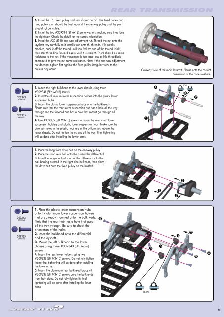
6. Install the 16T fixed pulley and seat if over the pin. The fixed pulley and<br />
fixed pulley shim should be flush against the one-way pulley and the pin<br />
should not be visible.<br />
7. Install the two #309314 (ST 6x12) cone washers, making sure they face<br />
the right way. Check the detail for the correct orientation.<br />
8. Install the #30 5540 one-way adjustment nut. Thread the nut onto the<br />
layshaft very carefully so it installs true onto the threads. If it installs<br />
crooked, back it off the thread until you feel the end of the thread "click",<br />
then start threading forward again until it is straight. There should be some<br />
resistance to the nut; if the movement is too loose, use a little threadlock<br />
compound to give the nut some resistance. Note: If the one-way adjustment<br />
nut does not tighten flat against the fixed pulley, irregular wear to the<br />
pulleys may occur.<br />
1. Mount the right bulkhead to the lower chassis using three<br />
#309343 (SFH M3x6) screws.<br />
2. Insert the aluminum lower suspension holders into the plastic lower<br />
suspension hubs.<br />
3. Mount the plastic lower suspension hubs onto the bulkheads.<br />
Please note that the rear lower suspension hub has a hole all the way<br />
through and the forward one has a hole that doesn't go through all<br />
the way.<br />
4. Use #309335 (SH M3x10) screws to mount the aluminum lower<br />
suspension holders and plastic lower suspension hubs. Make sure the<br />
pivot pin holes in the plastic hubs are at the bottom, just above the<br />
lower chassis. Do not tighten the screws all the way; final tightening<br />
will be done after installing the lower arms.<br />
1. Place the long front drive belt on the one-way pulley.<br />
2. Place the short rear belt onto the assembled differential.<br />
3. Insert the longer output shaft of the differential into the<br />
ball-bearing pressed in the right side bulkhead, then place<br />
the drive belt onto the fixed pulley on the layshaft.<br />
1. Place the plastic lower suspension hubs<br />
onto the aluminum lower suspension holders<br />
that are already mounted onto the bulkheads.<br />
Note that the rear hub has a hole that goes<br />
all the way through. Be sure to check the<br />
orientation of the holes.<br />
2. Insert the bulkhead onto the differential<br />
and the layshaft.<br />
3. Mount the left bulkhead to the lower<br />
chassis using three #309343 (SFH M3x6)<br />
screws.<br />
4. Mount the rear lower holders using two<br />
#309335 (SH M3x10) screws. Do not fully tighten<br />
them; final tightening will be done after installing<br />
the lower arms.<br />
5. Mount the aluminum rear bulkhead brace with<br />
#309335 (SH M3x10) screws onto the bulkheads<br />
from both sides. Do not fully tighten it; final<br />
tightening will be done after installing the lower<br />
arms.<br />
➎<br />
REAR TRANSMISSION<br />
Cutaway view of the main layshaft. Please note the correct<br />
orientation of the cone washers.<br />
➊<br />
DETAIL<br />
➌<br />
➍<br />
➊<br />
➎<br />
➋<br />
➊<br />
➌<br />
DETAIL<br />
➌<br />
➋<br />
➋<br />
➎<br />
➍<br />
6