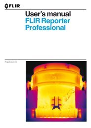
User's Guide Light Meter - Alpine Components
User's Guide Light Meter - Alpine Components
User's Guide Light Meter - Alpine Components

You also want an ePaper? Increase the reach of your titles
YUMPU automatically turns print PDFs into web optimized ePapers that Google loves.
<strong>User's</strong> <strong>Guide</strong><br />
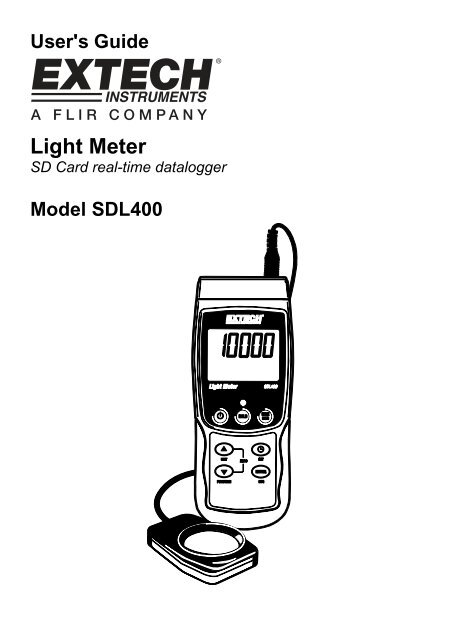
<strong>Light</strong> <strong>Meter</strong><br />
SD Card real-time datalogger<br />
Model SDL400
Introduction<br />
Congratulations on your purchase of the Extech SDL400 <strong>Light</strong> <strong>Meter</strong>. This meter displays and<br />
stores light meter readings in three ranges: 2,000 / 20,000 / 100,000 LUX or Foot candles from the<br />
supplied domed light sensor. The meter automatically ranges light meter measurements and the<br />
light sensor spectrum meets C.I.E.<br />
This meter also displays and logs temperature readings from a connected Type J or Type K<br />
thermocouple.<br />
Logged data readings are stored on an SD card for transfer to a PC. This meter is shipped fully<br />
tested and calibrated and, with proper use, will provide years of reliable service.<br />
Safety<br />
International Safety Symbols<br />
This symbol, adjacent to another symbol or terminal, indicates the user must refer to the<br />
manual for further information.<br />
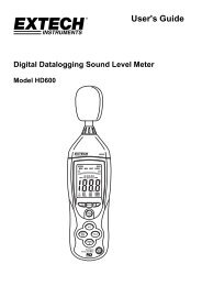
<strong>Meter</strong> Description<br />
1. Temperature (thermocouple) input jack<br />
2. <strong>Light</strong> <strong>Meter</strong> Sensor input plug<br />
3. Measurement reading<br />
4. Temperature units of measure<br />
5. HOLD and Backlight key<br />
6. MAX-MIN key<br />
7. SET and Clock key<br />
8. PC interface jack<br />
9. Reset button<br />
10. Power Adaptor jack<br />
11. SD card slot<br />
12. ENTER and LOG key<br />
13. Down arrow ▼ / FUNCTION / ZERO key<br />
14. Up arrow ▲ / UNIT / ZERO key<br />
15. Power ON-OFF key<br />
16. Thermocouple type or <strong>Light</strong> measurement unit of measure<br />
17. <strong>Light</strong> Sensor dome<br />
Notes:<br />
Items 8, 9, and 10 are located behind the snap-off compartment cover on meter’s right side.<br />
Battery compartment, tilt stand, and tripod mount are located on the rear of the instrument<br />
2 SDL400-EU-EN-V1.1-6/11
Getting Started<br />
Power ON-OFF<br />
• Power the meter by pressing and holding the power button for at least 1.5 seconds.<br />
• Press and hold the power button for at least 1.5 seconds to power OFF the meter.<br />
• This meter is powered by six (6) 1.5VDC ‘AA’ batteries or by optional AC adaptor. If the meter<br />
will not switch ON please check that fresh batteries are installed in the rear battery compartment<br />
or, in the case of the AC adaptor, check that the adaptor is connected correctly to the meter and<br />
to an AC source.<br />
Display Backlight<br />
To turn the display backlight ON or OFF, press and hold the backlight button for at least 1.5<br />
seconds. The meter will beep when switching the backlight ON or OFF unless the beeper is<br />
disabled as described in the Setup Mode section of this user guide.<br />
<strong>Light</strong> <strong>Meter</strong> Sensor Connection<br />
The supplied light sensor is connected to the meter via the DIN jack at the top right of the meter.<br />
When taking measurements snap off the light sensor’s protective cover and then replace the cover<br />
when finished.<br />
<strong>Light</strong> <strong>Meter</strong> Units of Measure<br />
The currently selected unit of measure is shown to the left of the light measurement reading on the<br />
meter’s LCD. To change the unit of measure, press and hold the UNIT button until the desired unit<br />
of measure appears and then release the UNIT button. The available light measurement units are<br />
LUX and FOOT CANDLE (ft-cd).<br />
Thermocouple Temperature Sensor Connection<br />
A type K or J thermocouple temperature sensor can be connected via the sub-miniature<br />
thermocouple jack at the top left of the meter. The display icon for the type of thermocouple<br />
selected (J or K) is shown on the meter’s LCD to the left of the temperature measurement. To<br />
change the type, use the Setup Mode.<br />
Temperature Measurement Units of Measure<br />
The currently selected unit of measure is shown below the temperature measurement reading on<br />
the meter’s LCD. To change the unit of measure, press and hold the UNIT button until the desired<br />
unit of measure appears and then release the UNIT button. The available temperature<br />
measurement units are °C and °F.<br />
3 SDL400-EU-EN-V1.1-6/11
Measurements<br />
<strong>Light</strong> <strong>Meter</strong> Measurements<br />
1. Connect the light sensor to the top of the meter as previously described<br />
2. Power the meter by holding the power button for at least 1.5 seconds<br />
3. Select the <strong>Light</strong> Measurement mode by pressing and holding the FUNCTION button for at least<br />
1.5 seconds (if necessary). The ‘LIgHt’ icon indicates the <strong>Light</strong> <strong>Meter</strong> mode<br />
4. Select the desired unit of measure LUX or Foot candles by pressing and holding the UNIT<br />
button for at least 1.5 seconds (if necessary)<br />
5. Place the sensor on a surface, or hold in hand, with the domed area facing the light source<br />
under test. The light sensor is dome shaped to accommodate light reaching it from various<br />
angles.<br />
6. Read the measurement on the meter’s LCD<br />
7. This instrument measures light intensity (illuminance) in LUX or Foot candle measurement units<br />
ZERO Adjustment (<strong>Light</strong> Measurement readings only)<br />
To zero the light meter display, simply press and hold both arrow keys (▼ ▲) for at least 1.5<br />
seconds. This is typically done with the protective sensor cover installed to ensure that a complete<br />
absence of light displays a zero reading. This zero function can also be used as a relative, or offset,<br />
function but remember to re-zero the meter with the protective cap on after such use.<br />
Temperature Measurements<br />
1. Connect the temperature sensor to the top of the meter as previously described<br />
2. Power the meter by holding the power button for at least 1.5 seconds<br />
3. Select the Temperature Measurement mode by pressing and holding the FUNCTION button for<br />
at least 1.5 seconds (if necessary). The ‘tP’ icon indicates the temperature mode of operation<br />
4. Select the desired Thermocouple Type (K or J) in the Setup Mode<br />
5. Select the desired unit of measure (C or F) in the Setup Mode<br />
6. Hold the thermocouple in the air in the area under test<br />
7. Read the temperature measurement on the meter’s LCD<br />
Important Safety Note on Thermocouple Ratings<br />
The temperature range of this meter extends up to 1300°C (2372°F); however the range of<br />
thermocouple probes vary greatly; be sure to select a probe rated for the expected temperature<br />
measurement ranges.<br />
Data Hold<br />
To freeze a displayed reading on the LCD, momentarily press the HOLD button (the HOLD display<br />
icon will appear above the held reading. To release the held reading press the HOLD button again.<br />
4 SDL400-EU-EN-V1.1-6/11
Setup Mode<br />
Basic settings at a glance<br />
To view the current configuration of the meter with regard to time, date, and datalogging sampling<br />
rate press the SET button momentarily. The meter will now display the configuration in quick<br />
succession. If the information is missed on the first try, simply press the SET button again until all of<br />
the information is noted.<br />
Accessing the Setup mode<br />
1. Press and hold the SET button for at least 1.5 seconds to access the Setup menu.<br />
2. Press the SET button momentarily to step through the available parameters. The parameter<br />
type is shown on the bottom of the LCD and the current selection for that type is shown above<br />
it.<br />
3. When a parameter is displayed that is to be changed, use the arrow keys to change the<br />
setting. Press the ENTER button to confirm a change.<br />
4. Press and hold the SET button for at least 1.5 seconds to exit the Setup mode. Note that the<br />
meter automatically switches out of the Setup mode if no key is pressed within 7 seconds.<br />
5. The available Setup parameters are listed below. Additional detailed information is provided<br />
below this list:<br />
dAtE Set the clock (Year/Month/Date; Hours/Minutes/Seconds)<br />
SP-t Set the datalogger sampling rate (Hours/Minutes/Seconds)<br />
PoFF Automatic power-off management (Enable or disable the auto-power off function)<br />
bEEP Set the beeper sound ON/OFF<br />
dEC Set the numerical format; USA (decimal: 20.00) or European (comma: 20,00)<br />
Sd F Format the SD memory card<br />
t-CF Units of measure selection for temperature readings (C or F)<br />
tYPE Select the Thermocouple type (K or J)<br />
Setting the Clock Time<br />
1. Access the dAtE parameter as described in the Accessing Setup Mode section above.<br />
2. Use the arrow keys to change a value<br />
3. Use the ENTER button to step through the selections<br />
4. Press and hold the SET button for at least 1.5 seconds to exit to the normal operation mode (or<br />
simply wait 7 seconds for the meter to automatically switch to the normal operating mode)<br />
5. The clock will keep accurate time even when the meter is switched off. However, if the battery<br />
expires the clock will have to be reset after fresh batteries are installed<br />
Setting the Datalogger Sampling Time (Rate)<br />
1. Access the SP-t parameter as described in the Accessing Setup Mode section above<br />
2. The sampling rate can be set to ‘0’ seconds (for manual logging) or 1, 2, 5, 10, 30, 60, 120,<br />
300, 600, 1800, 3600 seconds for auto logging. Use the arrow keys to select the sampling rate<br />
3. Press the ENTER button to confirm the entry<br />
4. Press and hold the SET button for at least 1.5 seconds to exit to the normal operation mode (or<br />
simply wait 7 seconds for the meter to automatically switch to the normal operating mode)<br />
5 SDL400-EU-EN-V1.1-6/11
Enabling/Disabling the Auto Power OFF Feature<br />
1. Access the PoFF parameter as described in the Accessing Setup Mode section above.<br />
2. Use the arrow buttons to select ON (enable) or OFF (disable). With the Auto Power OFF<br />
feature enabled, the meter will automatically switch OFF after 5 minutes of inactivity.<br />
3. Press ENTER to confirm setting.<br />
4. Press and hold the SET button for at least 1.5 seconds to exit to the normal operation mode (or<br />
simply wait 7 seconds for the meter to automatically switch to the normal operating mode).<br />
Set the Beeper Sound ON or OFF<br />
1. Access the bEEP parameter as described in the Accessing Setup Mode section above.<br />
2. Use the arrow buttons to select ON (enable) or OFF (disable).<br />
3. Press ENTER to confirm setting.<br />
4. Press and hold the SET button for at least 1.5 seconds to exit to the normal operation mode (or<br />
simply wait 7 seconds for the meter to automatically switch to the normal operating mode).<br />
Numerical Format (comma or decimal)<br />
European and USA numerical formats differ. The meter defaults to USA mode where a decimal<br />
point is used to separate units from tenths, i.e. 20.00; The European format uses a comma, i.e.<br />
20,00 to separate units from tenths. To change this setting:<br />
1. Access the dEC parameter as described in the Accessing Setup Mode section above.<br />
2. Use the arrow buttons to select USA or EUro.<br />
3. Press ENTER to confirm setting.<br />
4. Press and hold the SET button for at least 1.5 seconds to exit to the normal operation mode (or<br />
simply wait 7 seconds for the meter to automatically switch to the normal operating mode).<br />
SD Card FORMATTING<br />
1. Access the Sd-F parameter as described in the Accessing Setup Mode section above.<br />
2. Use the arrow buttons to select YES to format the card (select NO to abort). Note that all data<br />
on the card will be lost if formatting is attempted.<br />
3. Press ENTER to confirm selection.<br />
4. Press ENTER again to re-confirm.<br />
5. The meter will automatically return to the normal operating mode when formatting is complete.<br />
If not, press and hold the SET button for at least 1.5 seconds to exit to the normal operation<br />
mode.<br />
6 SDL400-EU-EN-V1.1-6/11
Set the Temperature Units of Measure (C or F)<br />
1. Access the t-CF parameter as described in the Accessing Setup Mode section above.<br />
2. Use the arrow buttons to select the desired unit of measure<br />
3. Press ENTER to confirm setting.<br />
4. Press and hold the SET button for at least 1.5 seconds to exit to the normal operation mode (or<br />
simply wait 7 seconds for the meter to automatically switch to the normal operating mode).<br />
Set the Thermocouple Type (K or J)<br />
1. Access the tYPE parameter as described in the Accessing Setup Mode section above.<br />
2. Use the arrow buttons to select the desired sensor type.<br />
3. Press ENTER to confirm setting.<br />
• Press and hold the SET button for at least 1.5 seconds to exit to the normal operation mode.<br />
System Reset<br />
If the meter’s keys become inoperable or if the display freezes the Reset button can be used to<br />
reset the instrument.<br />
• Use a paper clip or similar item to momentarily press the reset button located on the lower right<br />
side of the instrument under the snap-off compartment cover.<br />
• After pressing the Reset button, switch the instrument ON by pressing and holding the POWER<br />
key for at least 1.5 seconds. If using the power adaptor unplug the adaptor and then plug it back<br />
in again to power the meter.<br />
Max-Min Reading Record and Recall<br />
For a given measurement session, this meter can record the highest (MAX) and the lowest (MIN)<br />
readings for later recall.<br />
1. Press the MAX-MIN button momentarily to access this mode of operation (REC icon appears)<br />
2. The meter is now recording the MAX and MIN readings.<br />
3. Press the MAX-MIN button again to view the current MAX readings (MAX icon appears). The<br />
readings on the display are now the highest readings encountered since the REC icon was<br />
switched on (when the MAX-MIN button was first pressed).<br />
4. Press the MAX-MIN button again to view the current MIN readings (MIN icon appears). The<br />
readings on the display are now the lowest readings encountered since the REC icon was<br />
switched on (when the MAX-MIN button was first pressed).<br />
5. To exit the MAX-MIN mode, press and hold the MAX-MIN button for at least 1.5 seconds. The<br />
meter will beep, the REC-MAX-MIN icons will switch off, the MAX-MIN memory will clear, and<br />
the meter will return to the normal operating mode.<br />
7 SDL400-EU-EN-V1.1-6/11
Datalogging and PC Interface<br />
Types of Data Recording<br />
• Manual Datalogging: Manually log up to 99 readings onto an SD card via push-button press.<br />
• Automatic Datalogging: Automatically log data onto an SD memory card where the number of<br />
data points is virtually limited only by the card size. Readings are logged at a rate specified by<br />
the user.<br />
SD Card Information<br />
• Insert an SD card (from 1G size up to 16G) into the SD card slot at the bottom of the meter. The<br />
card must be inserted with the front of the card (label side) facing toward the rear of the meter.<br />
• If the SD card is being used for the first time it is recommended that the card be formatted and<br />
the logger’s clock set to allow for accurate date/time stamping during datalogging sessions.<br />
Refer to the Setup Mode section for SD card formatting and time/date setting instructions.<br />
• European and USA numerical formats differ. The data on the SD card can be formatted for<br />
either format. The meter defaults to USA mode where a decimal point is used to separate units<br />
from tenths, i.e. 20.00. The European format uses a comma, i.e. 20,00. To change this setting,<br />
refer to the Setup Mode section.<br />
Manual Datalogging<br />
In the manual mode the user presses the LOG button to manually log a reading onto the SD card.<br />
1. Set the sampling rate to ‘0’ seconds as described in the Setup Mode section.<br />
2. Press and hold the LOG button for at least 1.5 seconds and the lower portion of the display will<br />
show P-n (n = memory position number 1-99).<br />
3. Momentarily press the LOG button to store a reading. The REC icon will flash each time a data<br />
point is stored.<br />
4. Use the ▲ and ▼ buttons to select one of the 99 data memory positions in which to record.<br />
5. To exit the manual datalogging mode, press and hold the LOG button for at least 1.5 seconds.<br />
The Pn icon will switch off.<br />
8 SDL400-EU-EN-V1.1-6/11
Automatic Datalogging<br />
In automatic datalogging mode the meter takes and stores a reading at a user-specified sampling<br />
rate onto an SD memory card. The meter defaults to a sampling rate of one second. To change the<br />
sampling rate, refer to the Setup Mode section (the sampling rate cannot be ‘0’ for automatic<br />
datalogging):<br />
1. Select the sampling rate in the Setup Mode (refer to Setup Mode section) to a value other than<br />
zero.<br />
2. Press and hold the LOG button for at least 1.5 seconds. The meter will flash the REC icon at<br />
the selected sampling rate indicating that readings are now being automatically recorded to the<br />
SD card. Note that if the battery is low, the meter will flash the BAT icon and datalogging will<br />
not commence. Replace the batteries at this point (see Battery Replacement section of this<br />
guide)<br />
3. If a card is not inserted or if the card is defective, the meter will display SCAN SD indefinitely.<br />
In this case, switch the meter OFF and try again with a valid SD card.<br />
4. Pause the datalogger by pressing the LOG button momentarily. The REC icon will stop<br />
flashing and the sample rate will display for a short time. To resume logging simply press the<br />
LOG button again momentarily.<br />
5. To terminate the datalogging session press and hold the LOG button for at least 1.5 seconds.<br />
6. When an SD card is used for the first time a folder is created on the card and named LXB01.<br />
Up to 99 spreadsheet documents (each with 30,000 readings) can be stored in this folder.<br />
7. When datalogging begins a new spreadsheet document named LXB01001.xls is created on<br />
the SD card in the LXB01 folder. The data recorded will be placed in the LXB01001.xls<br />
document until 30,000 readings are reached.<br />
8. If the measurement session exceeds 30,000 readings, a new document will be created<br />
(LXB01002.xls) where another 30,000 readings can be stored. This method continues for up to<br />
99 documents, after which another folder is created (LXB02) where another 99 spreadsheet<br />
documents can be stored. This process continues in this same fashion with folders LXB03<br />
through LXB10 (last allowable folder).<br />
SD Data Card to PC Data Transfer<br />
1. Complete a datalogging session as detailed above in the previous sections. Hint: For the first<br />
few tests, simply record a small amount of test data. This is to ensure that the datalogging<br />
process is well understood before committing to critical, large scale datalogging.<br />
2. With the meter switched OFF, remove the SD Card.<br />
3. Plug the SD Card directly into a PC SD card reader. If the PC does not have an SD card slot,<br />
use an SD card adaptor (available at most outlets where computer accessories are sold).<br />
4. Power the PC and run a spreadsheet software program. Open the saved documents in the<br />
spreadsheet software program (see example spreadsheet data screen below).<br />
9 SDL400-EU-EN-V1.1-6/11
RS-232/USB PC Interface<br />
Spreadsheet data example<br />
The optional 407001A software kit (software and cable) allows streaming of data to a PC via<br />
the RS232 Output jack.<br />
AC Power Adaptor<br />
This meter is normally powered by six (6) 1.5V ‘AA’ batteries. An optional 9V power adaptor is<br />
available. When the adaptor is used, the meter is permanently powered and the power button will<br />
be disabled.<br />
Battery Replacement and Disposal<br />
When the low battery icon appears on the LCD, the batteries must be replaced. Several hours of<br />
accurate readings are still possible in this condition; however batteries should be replaced as soon<br />
as possible. Note that the Datalogger will not run with the low battery symbol showing.<br />
• Remove the two (2) Phillips screws from the rear of the meter (directly above the top of the tilt<br />
stand).<br />
• Remove and safely place the battery compartment and screws where they will not be damaged<br />
or lost.<br />
• Replace the six (6) 1.5V ‘AA’ batteries observing polarity.<br />
• Replace the battery compartment cover with the two (2) Phillips screws.<br />
All EU users are legally bound by the battery ordinance to return all used batteries to<br />
collection points in your community or wherever batteries / accumulators are sold!<br />
Disposal in the household garbage is prohibited!<br />
10 SDL400-EU-EN-V1.1-6/11
Specifications<br />
General Specifications<br />
Display Backlit LCD; LCD size: 52 x 38mm (2 x 1.5”)<br />
Status indicators Over-range (----) and low battery<br />
Sensor types <strong>Light</strong>: Supplied color corrected, domed light intensity sensor (meets<br />
C.I.E.); Temperature: Thermocouple (J or K) temperature probe<br />
Temperature compensation Automatic compensation for thermocouple temperature<br />
measurements<br />
Measurement Units Temperature: °C, °F; <strong>Light</strong>: LUX, Foot candles<br />
Zero Adjust <strong>Light</strong> function only. Front panel push-button.<br />
Datalogger Sampling Rate AUTO LOGGING: 1, 2, 5, 10, 30, 60, 120, 300, 600, 1800,<br />
3600 seconds. Note that a one (1) second sampling rate<br />
can cause some data loss on slower computers<br />
MANUAL LOGGING: Set the sampling rate to ‘0’<br />
Memory Card SD memory card: 1GB to 16GB size<br />
Data Hold Freeze the displayed reading<br />
Memory Recall Record and Recall the Maximum and Minimum readings<br />
Display update rate Approx. 1 second.<br />
Data Output RS-232 / USB PC computer interface; for use with optional<br />
software kit part number 407001A<br />
Operating Temperature 0 to 50°C (32 to 122°F)<br />
Operating Humidity 85% R.H. max.<br />
Auto Power OFF After 10 minutes of inactivity (can be disabled)<br />
Power Supply Six (6) 1.5 VDC batteries (optional 9V AC adaptor)<br />
Power Consumption Normal operation (backlight & datalogger OFF): approx. 6.5mAdc<br />
With backlight OFF and datalogging ON: approx. 30mAdc<br />
With backlight ON add approx. 16mAdc<br />
Weight 346g (0.76 lbs.) meter only<br />
Dimensions Main instrument: 182 x 73 x 47.5mm (7.1 x 2.9 x 1.9”)<br />
11 SDL400-EU-EN-V1.1-6/11
Electrical Specifications (ambient temperature 23°C ± 5°C)<br />
<strong>Light</strong> meter<br />
Measurement Range Actual Display for each range<br />
LUX<br />
(auto range)<br />
Foot-candles<br />
(auto range)<br />
2,000LUX 0 to 1,999 LUX<br />
20,000 LUX 1,800 to 19,990 LUX<br />
100,000 LUX 18,000 to 99,900 LUX<br />
200Ft-cd 0 to 186.0 Ft-cd<br />
2,000 Ft-cd 167.0 to 1,860.0 Ft-cd<br />
10,000 Ft-cd 1,670.0 to 9,290.7 Ft-cd<br />
Range Resolution Accuracy<br />
2,000 LUX 1 LUX<br />
20,000 LUX 10 LUX<br />
100,000 LUX 100 LUX<br />
200 Ft-cd 0.1 Ft-cd<br />
± (4% + 2 dgt)<br />
2,000 Ft-cd 1 Ft-cd ± (4% + 2 Ft-cd)<br />
10,000 Ft-cd 10 Ft-cd ± (4% + 20 Ft-cd)<br />
Note: Accuracy tested using a standard tungsten lamp (2856 K degree temperature)<br />
Temperature meter<br />
Sensor Type Resolution Range Accuracy<br />
Type K 0.1 °C -50.0 to 1300.0°C ± (0.4% + 0.5°C)<br />
-50.1 to -100.0°C ± (0.4% + 1.0°C)<br />
0.1 °F -58.0 to 2372.0°F ± (0.4% + 1.0°F)<br />
-58.1 to -148.0°F ± (0.4% + 1.8°F)<br />
Type J 0.1 °C -50.0 to 1200.0°C ± (0.4% + 0.5°C)<br />
-50.1 to -100.0°C ± (0.4% + 1.0°C)<br />
0.1 °F -58.0 to 2192.0°F ± (0.4% + 1.0°F)<br />
-58.1 to -148.0°F ± (0.4% + 1.8°F)<br />
Copyright © 2011 Extech Instruments Corporation (a FLIR company)<br />
All rights reserved including the right of reproduction in whole or in part in any form<br />
www.extech.com<br />
<strong>Alpine</strong> <strong>Components</strong><br />
Telephone: 01424 437000 E-mail: info@alpine-components.co.uk<br />
12 SDL400-EU-EN-V1.1-6/11<br />
Web: www.alpine-components.co.uk Fax: 01424 722502