PRODUCTION OF AMMONIA - OCI Nitrogen
PRODUCTION OF AMMONIA - OCI Nitrogen
PRODUCTION OF AMMONIA - OCI Nitrogen

Create successful ePaper yourself
Turn your PDF publications into a flip-book with our unique Google optimized e-Paper software.
Best Available Techniques<br />
for Pollution Prevention and Control<br />
in the European Fertilizer Industry<br />
Booklet No. 1 of 8:<br />
<strong>PRODUCTION</strong> <strong>OF</strong> <strong>AMMONIA</strong><br />
2000<br />
EFMA<br />
European Fertilizer Manufacturers’ Association<br />
Ave. E van Nieuwenhuyse 4<br />
B-1160 Brussels<br />
Belgium
Best Available Techniques<br />
for Pollution Prevention and Control<br />
in the European Fertilizer Industry<br />
Booklet No. 1 of 8:<br />
<strong>PRODUCTION</strong> <strong>OF</strong> <strong>AMMONIA</strong><br />
Copyright 2000 – EFMA<br />
This publication has been prepared by member companies of the<br />
European Fertilizer Manufacturers’ Association (EFMA). Neither the<br />
Association nor any individual member company can accept liability<br />
for accident or loss attributable to the use of the information given in<br />
this Booklet.
2<br />
Hydrocarbon feed<br />
Water<br />
Air<br />
Water<br />
Air<br />
Water<br />
Sulphur<br />
Water<br />
Phosphate<br />
rock<br />
Booklet No. 1<br />
No. 2<br />
No. 3<br />
Ammonia<br />
Nitric Acid<br />
Sulphuric Acid<br />
No. 4<br />
Phosphoric<br />
Acid<br />
Calcium<br />
carbonate<br />
Phosphate rock<br />
K, Mg, S,<br />
micronutrients<br />
K, Mg, S,<br />
micronutrients<br />
Phosphate rock<br />
No. 5<br />
No. 6<br />
No. 7<br />
Urea<br />
UAN<br />
AN<br />
CAN<br />
NPK<br />
(nitrophosphate<br />
route)<br />
No. 8<br />
NPK<br />
(mixed acid<br />
route)
CONTENTS<br />
PREFACE 4<br />
DEFINITIONS 6<br />
1. INTRODUCTION 7<br />
2. DESCRIPTION <strong>OF</strong> <strong>PRODUCTION</strong> PROCESSES 7<br />
2.1 Production Processes in Operation in Europe 7<br />
2.2 BAT Production Processes 10<br />
3. DESCRIPTION <strong>OF</strong> STORAGE AND TRANSFER EQUIPMENT 18<br />
3.1 Introduction 18<br />
3.2 Storage Tanks 18<br />
3.3 Transfer Equipment 19<br />
4. ENVIRONMENTAL DATA 21<br />
4.1 Production Input Requirements 21<br />
4.2 Production Output 22<br />
4.3 Production Emissions and Wastes 23<br />
4.4 Environmental Data for Ammonia Storage and Transfer 27<br />
4.5 Environmental Hazards Associated with Emissions and Wastes 27<br />
4.6 Emission Limits and Guideline Values for Ammonia Production in<br />
Some West-European Countries 27<br />
5. EMISSION MONITORING 28<br />
6. MAJOR HAZARDS 29<br />
7. OCCUPATIONAL HEALTH & SAFETY 29<br />
8. SUMMARY <strong>OF</strong> BAT EMISSION LEVELS 30<br />
8.1 Achievable Emission Levels for New Plants 30<br />
8.2 Achievable Emission Levels for Existing Plants 31<br />
8.3 Cost of Pollution Control Measures 31<br />
9. REFERENCES 31<br />
GLOSSARY <strong>OF</strong> TERMS 32<br />
APPENDIX 1 Emission Monitoring in Ammonia Plants 35<br />
APPENDIX 2 General Product Information on Ammonia 40<br />
3
PREFACE<br />
In 1995, the European Fertilizer Manufacturers Association (EFMA) prepared eight Booklets<br />
on Best Available Techniques (BAT) in response to the proposed EU Directive on integrated<br />
pollution prevention and control (IPPC Directive). These booklets were reviewed and<br />
updated in 1999 by EFMA experts drawn from member companies. They cover the production<br />
processes of the following products:-<br />
No. 1 Ammonia<br />
No. 2 Nitric Acid<br />
No. 3 Sulphuric Acid<br />
(updated in collaboration with ESA)<br />
No. 4 Phosphoric Acid<br />
No. 5 Urea and Urea Ammonium Nitrate (UAN)<br />
No. 6 Ammonium Nitrate (AN) and Calcium Ammonium Nitrate (CAN)<br />
No. 7 NPK Compound Fertilizers by the Nitrophosphate Route<br />
No. 8 NPK Compound Fertilizers by the Mixed Acid Route<br />
The Booklets reflect industry perceptions of what techniques are generally considered to be<br />
feasible and present achievable emission levels associated with the manufacturing of the products<br />
listed above. The Booklets do not aim to create an exhaustive list of BAT but they highlight<br />
those most widely used and accepted. They have been prepared in order to share knowledge<br />
about BAT between the fertilizer manufacturers, as well as with the regulatory authorities.<br />
The Booklets use the same definition of BAT as that given in the IPPC Directive 96/61 EC<br />
of 1996. BAT covers both the technology used and the management practices necessary to<br />
operate a plant efficiently and safely. The EFMA Booklets focus primarily on the technological<br />
processes, since good management is considered to be independent of the process route.<br />
The industry recognises, however, that good operational practices are vital for effective environmental<br />
management and that the principles of Responsible Care should be adhered to by<br />
all companies in the fertilizer business.<br />
The Booklets give two sets of BAT emission levels:-<br />
– For existing production units where pollution prevention is usually obtained by revamps<br />
or end-of-pipe solutions<br />
– For new plants where pollution prevention is integrated in the process design<br />
The emission levels refer to emissions during normal operations of typical sized plants.<br />
Other levels may be more appropriate for smaller or larger units and higher emissions may<br />
occur in start-up and shut-down operations and in emergencies.<br />
4
Only the more significant types of emissions are covered and the emission levels given in<br />
the Booklets do not include fugitive emissions and emissions due to rainwater. Furthermore,<br />
the Booklets do not cover noise, heat emissions and visual impacts.<br />
The emission levels are given both in concentration values (ppm, mg.m-3 or mg.l-1 ) and in<br />
load values (emission per tonne of product). It should be noted that there is not necessarily a<br />
direct link between the concentration values and the load values. EFMA recommends that the<br />
given emission levels should be used as reference levels for the establishment of regulatory<br />
authorisations. Deviations should be allowed as governed by:-<br />
– Local environmental requirements, given that the global and inter-regional environments<br />
are not adversely affected<br />
– Practicalities and costs of achieving BAT<br />
– Production constraints given by product range, energy source and availability of raw<br />
materials<br />
If authorisation is given to exceed these BAT emission levels, the reasons for the deviation<br />
should be documented locally.<br />
Existing plants should be given ample time to comply with BAT emission levels and care<br />
should be taken to reflect the technological differences between new and existing plants when<br />
issuing regulatory authorisations, as discussed in these BAT Booklets.<br />
A wide variety of methods exist for monitoring emissions. The Booklets provide examples<br />
of methods currently available. The emission levels given in the Booklets are subject to some<br />
variance, depending on the method chosen and the precision of the analysis. It is important<br />
when issuing regulatory authorisations, to identify the monitoring method(s) to be applied.<br />
Differences in national practices may give rise to differing results as the methods are not<br />
internationally standardised. The given emission levels should not, therefore, be considered as<br />
absolute but as references which are independent of the methods used.<br />
EFMA would also advocate a further development for the authorisation of fertilizer plants.<br />
The plants can be complex, with the integration of several production processes and they can<br />
be located close to other industries. Thus there should be a shift away from authorisation governed<br />
by concentration values of single point emission sources. It would be better to define<br />
maximum allowable load values from an entire operation, eg from a total site area. However,<br />
this implies that emissions from single units should be allowed to exceed the values in the<br />
BAT Booklets, provided that the total load from the whole complex is comparable with that<br />
which can be deduced from the BAT Booklets. This approach will enable plant management<br />
to find the most cost-effective environmental solutions and would be to the benefit of our<br />
common environment.<br />
Finally, it should be emphasised that each individual member company of EFMA is<br />
responsible for deciding how to apply the guiding principles of the Booklets.<br />
Brussels, April 2000<br />
5
DEFINITIONS<br />
The following definitions are taken from Council directive 96/61/EC of 1996 on Integrated<br />
Pollution Prevention and Control:-<br />
“Best Available Techniques” mean the most effective and advanced stage in the development<br />
of activities and their methods of operation which indicate the practical suitability of<br />
particular techniques for providing, in principle, the basis for emission limit values designed<br />
to prevent or, where that is not practicable, generally to reduce emissions and the impact on<br />
the environment as a whole:-<br />
“Techniques” include both the technology used and the way in which the installation is<br />
designed, built, maintained, operated and decommissioned.<br />
“Available” techniques mean those developed on a scale which allows implementation in<br />
the relevant industrial sector under economically viable conditions, taking into consideration<br />
the costs and advantages, whether or not the techniques are used or produced inside the<br />
Member State in question, as long as they are reasonably accessible to the operator.<br />
“Best” means most effective in achieving a high general level of protection for the environment<br />
as a whole.<br />
6
1. INTRODUCTION<br />
This Booklet covers Best Available Techniques (BAT) for ammonia production, storage, and<br />
transfer. The description is partly based on Reference [1].<br />
Ammonia is produced basically from water, air, and energy. The energy source is usually<br />
hydrocarbons, thus providing hydrogen as well, but may also be coal or electricity. Steam<br />
reforming of light hydrocarbons is the most efficient route, with about 77% of world ammonia<br />
capacity being based on natural gas [2].<br />
The total energy consumption for the production of ammonia in a modern steam reforming<br />
plant is 40-50% above the thermodynamic minimum. More than half of the excess consumption<br />
is due to compression losses. The practical minimum consumption is assumed to be<br />
about 130% of the theoretical minimum.<br />
The typical size of a large single-train ammonia plant is 1,000-1,500t.d -1 , although capacities<br />
of 1,800t.d -1 and above are not uncommon for new plants. In this Booklet 1,500t.d -1<br />
(500,000t.y -1 ) will be considered as a standard capacity. The process and energy systems<br />
are integrated to improve overall energy efficiency. Further, the ammonia plant may stand<br />
alone or be integrated with other plants on the site, eg. a urea plant, but such integration is not<br />
covered in this Booklet.<br />
Plant battery limits are generally feedstock and fuel supply by pipelines at sufficient pressure<br />
for reforming; untreated water and air; and ammonia product stored as liquid, either<br />
refrigerated at atmospheric pressure or non-refrigerated at ambient temperature. In the case of<br />
steam and/or carbon dioxide export those battery limit conditions will depend on the receiver’s<br />
requirements.<br />
The equipment and machinery used in today’s large ammonia plants have achieved high<br />
reliabilities and technical on-stream factors in excess of 90% are common.<br />
2. DESCRIPTION <strong>OF</strong> <strong>PRODUCTION</strong> PROCESSES<br />
2.1 Production Processes in Operation in Europe<br />
Two main types of production process for ammonia synthesis gas are currently in operation<br />
in Europe:-<br />
– Steam reforming of natural gas or other light hydrocarbons (Natural Gas Liquids,<br />
Liquefied Petroleum Gas, Naphtha)<br />
– Partial oxidation of heavy fuel oil or vacuum residue<br />
In at least one partial oxidation unit, natural gas is used as feedstock. Coal gasification and<br />
water electrolysis are no longer in use in the European ammonia industry.<br />
The ammonia synthesis process is principally independent of the type of synthesis gas production<br />
process, but synthesis gas quality influences the loop design and operating conditions.<br />
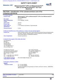
A block diagram of the conventional steam reforming process is shown in Figure 1. (In<br />
some cases, a separate auxiliary boiler is required). About 85% of world ammonia production<br />
is based on steam reforming concepts [3]. A process description is given in 2.2.1.<br />
7
8<br />
ZnO Desulphurisation<br />
ZnS<br />
H 2O,<br />
Fuel<br />
Air,<br />
Power<br />
Heat,<br />
Power<br />
Power<br />
Power<br />
Natural gas<br />
Primary reformer<br />
Secondary reformer<br />
Flue-gas<br />
Heat<br />
Shift conversion Heat<br />
CO2 removal<br />
Methanation<br />
Compression<br />
Ammonia synthesis<br />
NH3<br />
Figure 1 – Block diagram of the steam/air reforming process.<br />
Condensate<br />
CO 2<br />
Heat,<br />
Purge/flash gas
Power Air<br />
Air<br />
Separation<br />
Unit<br />
Power<br />
Power<br />
H 2O<br />
Heat,<br />
Power<br />
N2<br />
O2<br />
Heavy oil<br />
Gasification Heat<br />
Soot removal/recovery Slag<br />
Sulphur removal/recovery Sulphur<br />
Shift conversion<br />
CO 2 removal<br />
Liquid N2 wash<br />
Compression<br />
Ammonia synthesis<br />
NH 3<br />
Heat<br />
Condensate<br />
CO 2<br />
Heat,<br />
Flash gas<br />
Fuel Auxiliary boiler<br />
Flue-gas<br />
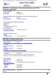
Figure 2 – Block diagram of the partial oxidation process.<br />
Fuel gas<br />
9
For heavier feedstocks than naphtha, partial oxidation with oxygen is used in the synthesis<br />
gas production. A block diagram of a typical partial oxidation process is shown in Figure 2,<br />
and a process description is given in 2.2.5.<br />
2.2 BAT Production Processes<br />
No single process can be identified as BAT for the production of ammonia. In this chapter the<br />
characteristics of BAT processes based on available feedstocks are described. Other BAT<br />
processes may also exist.<br />
Natural gas reforming with steam and air is the simplest and most efficient way of ammonia<br />
synthesis gas production. Comparing natural gas reforming, heavy oil and coal<br />
gasification gives the following approximate relative consumption figures, based on modern<br />
technological standards for each route, at European economic conditions:-<br />
Natural Heavy Coal<br />
gas oil<br />
Energy consumption 1.0 1.3 1.7<br />
Investment cost 1.0 1.4 2.4<br />
Production cost 1.0 1.2 1.7<br />
Based on the known resources of fossil raw materials, it is likely that natural gas will dominate<br />
as the feedstock for ammonia for the next 50 years at least. In the very long term, 50-200<br />
years, one might expect coal to take over, based on world reserves and consumption rate.<br />
Heavy oil may be attractive under special environmental concerns, when natural gas is not<br />
available and the partial oxidation process could solve a waste problem (heavy residues, plastics<br />
recycle).<br />
For the present time and the near future, the steam/air reforming concepts based on natural<br />
gas and other light hydrocarbons are considered to be the dominating group of BAT production<br />
processes. The BAT reforming processes can be divided into the following types:-<br />
– Conventional steam reforming with a fired primary reformer and stoichiometric air<br />
secondary reforming (stoichiometric H/N-ratio)<br />
– Steam reforming with mild conditions in a fired primary reformer and excess air secondary<br />
reforming (under-stoichiometric H/N-ratio)<br />
– Heat exchange autothermal reforming, with a process gas heated steam reformer<br />
(heat exchange reformer) and a separate secondary reformer, or in a combined<br />
autothermal reformer, using excess or enriched air (under-stoichiometric or stoichiometric<br />
H/N-ratio)<br />
For heavy feedstocks, partial oxidation is considered as the BAT production process.<br />
All three reforming versions, and partial oxidation of heavy residues, are operated in<br />
Europe today.<br />
The following description concentrates on presenting the conventional steam reforming<br />
process and only deviations and additions will be described for the other BAT processes.<br />
10
2.2.1 Conventional steam reforming<br />
2.2.1.1 Overall conversion<br />
The theoretical process conversions, based on methane feedstock, are given in the following<br />
approximate formulae:-<br />
0.88CH4 + 1.26Air + 1.24H2O 0.88CO2 + N2 + 3H2 N2 + 3H2 2NH3 The synthesis gas production and purification normally take place at 25-35bar pressure.<br />
The ammonia synthesis pressure is usually in the range 100-250bar. For more detailed<br />
process flow sheets refer to Ullmann [3].<br />
2.2.1.2 Feedstock desulphurisation<br />
Most of the catalysts used in the process are sensitive to sulphur and sulphur compounds. The<br />
feedstock normally contains up to 5mg S.Nm -3 as sulphur compounds. The feed-gas is preheated<br />
to 350-400°C, usually in the primary reformer convection section, and then treated in a<br />
desulphurisation vessel, where the sulphur compounds are hydrogenated to H 2 S, typically<br />
using a cobalt molybdenum catalyst, and then adsorbed on pelletised zinc oxide:-<br />
R-SH + H2 H2S + RH<br />
H2S + ZnO ZnS + H2O In this way, the sulphur is removed to less than 0.1ppm S in the gas feed. The zinc sulphide<br />
remains in the adsorption bed. The hydrogen for the reaction is usually recycled from the synthesis<br />
section.<br />
2.2.1.3 Primary reforming<br />
The gas from the desulphuriser is mixed with process steam, usually coming from an extraction<br />
turbine, and the steam/gas mixture is then heated further to 500-600°C in the convection<br />
section before entering the primary reformer. In some new or revamped plants the preheated<br />
steam/gas mixture is passed through an adiabatic pre-reformer and reheated in the convection<br />
section, before entering the primary reformer. (Special pre-reformer catalysts are offered by<br />
several suppliers). Also, in some plants, part of the process steam is supplied by feed-gas saturation.<br />
The amount of process steam is given by the process steam to carbon molar ratio (S/Cratio),<br />
which should be around 3.0 for the BAT reforming processes. The optimum ratio<br />
depends on several factors, such as feedstock quality, purge gas recovery, primary reformer<br />
capacity, shift operation, and the plant steam balance. In new plants the optimum S/C-ratio<br />
may be lower than 3.0.<br />
The primary reformer consists of a large number of high–nickel chromium alloy tubes<br />
filled with nickel-containing reforming catalyst. The overall reaction is highly endothermic<br />
and additional heat is required to raise the temperature to 780-830°C at the reformer outlet.<br />
11
The composition of the gas leaving the primary reformer is given by close approach to the<br />
following chemical equilibria:-<br />
12<br />
CH4 + H2O CO + 3H2 ΔH0 298 = 206 kJ.mol-1<br />
CO + H2O CO2 + H2 ΔH0 298 = –41 kJ.mol-1<br />
The heat for the primary reforming process is supplied by burning natural gas or other<br />
gaseous fuel, in the burners of a radiant box containing the tubes.<br />
The flue-gas leaving the radiant box has temperatures in excess of 900°C, after supplying<br />
the necessary high level heat to the reforming process. Thus only about 50-60% of the fuel’s<br />
heat value is directly used in the process itself. The heat content (waste heat) of the flue-gas is<br />
used in the reformer convection section, for various process and steam system duties. The<br />
fuel energy requirement in the conventional reforming process is 40-50% of the process feedgas<br />
energy.<br />
The flue-gas leaving the convection section at 100-200°C is one of the main sources of<br />
emissions from the plant. These emissions are mainly CO 2 , NO x , with small amounts of SO 2<br />
and CO.<br />
2.2.1.4 Secondary reforming<br />
Only 30-40% of the hydrocarbon feed is reformed in the primary reformer because of the<br />
chemical equilibria at the actual operating conditions. The temperature must be raised to<br />
increase the conversion. This is done in the secondary reformer by internal combustion of<br />
part of the gas with the process air, which also provides the nitrogen for the final synthesis<br />
gas. In the conventional reforming process the degree of primary reforming is adjusted so that<br />
the air supplied to the secondary reformer meets both the heat balance and the stoichiometric<br />
synthesis gas requirement.<br />
The process air is compressed to the reforming pressure and heated further in the primary<br />
reformer convection section to around 600°C. The process gas is mixed with the air in a burner<br />
and then passed over a nickel-containing secondary reformer catalyst. The reformer outlet<br />
temperature is around 1,000°C, and up to 99% of the hydrocarbon feed (to the primary<br />
reformer) is converted, giving a residual methane content of 0.2-0.3% (dry gas base) in the<br />
process gas leaving the secondary reformer.<br />
The process gas is cooled to 350-400°C in a waste heat steam boiler or boiler/superheater<br />
downstream from the secondary reformer.<br />
2.2.1.5 Shift conversion<br />
The process gas from the secondary reformer contains 12-15% CO (dry gas base) and most of<br />
the CO is converted in the shift section according to the reaction:-<br />
CO + H2O CO2 + H2 ΔH0 298 = –41 kJ.mol-1<br />
In the High Temperature Shift (HTS) conversion, the gas is passed through a bed of iron<br />
oxide/chromium oxide catalyst at around 400°C, where the CO content is reduced to about
3% (dry gas base), limited by the shift equilibrium at the actual operating temperature. There<br />
is a tendency to use copper containing catalyst for increased conversion. The gas from the<br />
HTS is cooled and passed through the Low Temperature Shift (LTS) converter.<br />
This LTS converter is filled with a copper oxide/zinc oxide-based catalyst and operates at<br />
about 200-220°C. The residual CO content in the converted gas is about 0.2-0.4% (dry gas<br />
base). A low residual CO content is important for the efficiency of the process.<br />
2.2.1.6 CO 2 removal<br />
The process gas from the low temperature shift converter contains mainly H 2 , N 2 , CO 2 and<br />
the excess process steam. The gas is cooled and most of the excess steam is condensed before<br />
it enters the CO 2 removal system. This condensate normally contains 1,500-2,000ppm of<br />
ammonia 800-1,200ppm of methanol. Minor amounts of amines, formic acid and acetic acid<br />
could be present in the condensate. All these components should be stripped from the condensate<br />
and/or recycled in BAT processes. The heat released during cooling/condensation is used<br />
for:-<br />
– The regeneration of the CO 2 scrubbing solution<br />
– Driving an absorption refrigeration unit<br />
– Boiler feedwater preheat<br />
The amount of heat released depends on the process steam to carbon ratio. If all this lowlevel<br />
heat is used for CO 2 removal or absorption refrigeration, high-level heat has to be used<br />
for the feedwater system. An energy-efficient process should therefore have a CO 2 removal<br />
system with a low heat demand.<br />
The CO 2 is removed in a chemical or a physical absorption process. The solvents used in<br />
chemical absorption processes are mainly aqueous amine solutions (Mono Ethanolamine<br />
(MEA), Activated Methyl DiEthanolamine (aMDEA) or hot potassium carbonate solutions.<br />
Physical solvents are glycol dimethylethers (Selexol), propylene carbonate and others. The<br />
MEA process has a high regeneration energy consumption and is not regarded as a BAT<br />
process.<br />
For new ammonia plants the following CO 2 removal processes are currently regarded as<br />
BAT:-<br />
– aMDEA standard 2-stage process, or similar<br />
– Benfield process (HiPure, LoHeat), or similar<br />
– Selexol or similar physical absorption processes<br />
Concepts such as Pressure Swing Adsorption (PSA) should also be regarded as BAT in<br />
some new plants but in such cases CO 2 removal is not the only function of the PSA unit.<br />
The typical range of heat consumption in the modern chemical absorption process is<br />
30-60MJ.kmol -1 CO 2 . The physical absorption processes may be designed for zero heat consumption,<br />
but for comparison with the chemical processes, the mechanical energy requirements<br />
have also to be considered.<br />
Residual CO 2 contents are usually in the range 100-1,000ppmv, dependent on the type and<br />
design of the removal unit. Contents down to about 50ppmv are achievable.<br />
13
2.2.1.7 Methanation<br />
The small amounts of CO and CO 2 , remaining in the synthesis gas, are poisonous for the<br />
ammonia synthesis catalyst and must be removed by conversion to CH 4 in the methanator:-<br />
CO + 3H2 CH4 + H2O CO2 + 4H2 CH4 + 2H2O The reactions take place at around 300°C in a reactor filled with a nickel containing catalyst.<br />
Methane is an inert gas in the synthesis reaction, but the water must be removed before<br />
entering the converter. This is done firstly by cooling and condensation downstream of the<br />
methanator and finally by condensation/absorption in the product ammonia in the loop or in a<br />
make-up gas drying unit.<br />
2.2.1.8 Synthesis gas compression and ammonia synthesis<br />
Modern ammonia plants use centrifugal compressors for synthesis gas compression, usually<br />
driven by steam turbines, with the steam being produced in the ammonia plant. The refrigeration<br />
compressor, needed for condensation of product ammonia, is also usually driven by a<br />
steam turbine.<br />
The synthesis of ammonia takes place on an iron catalyst at pressures usually in the range<br />
100-250bar and temperatures in the range 350-550°C:-<br />
14<br />
N 2 + 3H 2 2NH 3 ΔH 0 298 = –46 kJ.mol-1 NH 3<br />
Only 20-30% is reacted per pass in the converter due to the unfavourable equilibrium conditions.<br />
The ammonia that is formed is separated from the recycle gas by cooling/condensation,<br />
and the reacted gas is substituted by the fresh make-up synthesis gas, thus maintaining<br />
the loop pressure. In addition, extensive heat exchange is required due to the exothermic reaction<br />
and the large temperature range in the loop. A newly developed ammonia synthesis catalyst<br />
containing ruthenium on a graphite support has a much higher activity per unit of volume<br />
and has the potential to increase conversion and lower operating pressures.<br />
Synthesis loop arrangements differ with respect to the points in the loop at which the<br />
make-up gas is delivered and the ammonia and purge gas are taken out. The best arrangement<br />
is to add the make-up gas after ammonia condensation and ahead of the converter. The loop<br />
purge should be taken out after ammonia separation and before make-up gas addition. This<br />
configuration is dependent on the make-up gas being treated in a drying step before entering<br />
the loop. A make-up gas containing traces of water or carbon dioxide must be added before<br />
ammonia condensation, with negative effects both to ammonia condensation and energy.<br />
Conventional reforming with methanation as the final purification step, produces a synthesis<br />
gas containing inerts (methane and argon) in quantities that do not dissolve in the condensed<br />
ammonia. The major part of these inerts is removed by taking out a purge stream from<br />
the loop. The size of this purge stream controls the level of inerts in the loop to about 10-15%.<br />
The purge gas is scrubbed with water to remove ammonia before being used as fuel or before<br />
being sent for hydrogen recovery.
Ammonia condensation is far from complete if cooling is with water or air and is usually<br />
not satisfactory (dependent on loop pressure and cooling medium temperature). Vapourising<br />
ammonia is used as a refrigerant in most ammonia plants, to achieve sufficiently low ammonia<br />
concentrations in the gas recycled to the converter. The ammonia vapours are liquified<br />
after recompression in the refrigeration compressor.<br />
2.2.1.9 Steam and power system<br />
Steam reforming ammonia plants have high-level surplus heat available for steam production<br />
in the reforming, shift conversion, and synthesis sections, and in the convection section of the<br />
primary reformer. Most of this waste heat is used for high pressure steam production for use<br />
in turbines for driving the main compressors and pumps and as process steam extracted from<br />
the turbine system.<br />
A modern steam reforming ammonia plant can be made energetically self-sufficient if necessary,<br />
but usually a small steam export and electricity import are preferred.<br />
2.2.2 Steam reforming with excess air secondary reforming<br />
2.2.2.1 Process flowsheet<br />
Some processes are designed for reduced primary reforming by moving some of the duty to<br />
the secondary reformer because of the marginal low efficiency of the primary reformer.<br />
A brief description is given of features diverging from the conventional concept in the following<br />
paragraphs. These features are:-<br />
– Decreased firing in the primary reformer<br />
– Increased process air flow to the secondary reforming<br />
– Cryogenic final purification after methanation<br />
– Lower inert level of the make-up syngas<br />
2.2.2.2 Decreased firing in the primary reformer<br />
Decreased heat supply in the primary reformer means that the process outlet temperature is<br />
lowered (to about 700°C), the firing efficiency increases, and the size and cost of the primary<br />
reformer are reduced. The milder operating conditions prolong catalyst, catalyst tube and outlet<br />
header service lives. The extent of reforming is reduced according to the lower heat supply<br />
and lower temperature. Generally, a slight decrease in steam to carbon ratio is acceptable,<br />
compared to the conventional concept.<br />
2.2.2.3 Increased process air supply to the secondary reformer<br />
Decreased heat supply in the primary reformer means that increased internal firing is necessary<br />
to achieve approximately the same degree of total reforming. A somewhat higher<br />
methane slip, and thus a lower secondary reformer outlet temperature is acceptable and<br />
preferable in this type of process, as methane is removed in the final purification step.<br />
The process air requirement is about 50% higher than in the conventional process. This<br />
means increased compression capacity and energy. The process air compressor is usually driven<br />
by a gas turbine with the exhaust gas from the turbine being used as combustion air in the<br />
primary reformer. Some excess steam is available for export when using a gas turbine.<br />
15
2.2.2.4 Cryogenic final purification<br />
In the cryogenic purifier all the methane and the excess nitrogen are removed from the synthesis<br />
gas as well as a part of the argon. The cooling is produced by depressurisation and no<br />
external supply is needed. The purified syngas is then practically free of all impurities, except<br />
for a small amount of argon. The cryogenic unit also receives the purge from the synthesis<br />
section and delivers an off-gas for fuel.<br />
2.2.2.5 Lower syngas inert level<br />
The removal of essentially all impurities from the make-up synthesis gas is a significant<br />
improvement, compared to the conventional purification by methanation only. Higher conversion<br />
per pass and reduced purge flow, together result in a more efficient process.<br />
2.2.3 Heat exchange autothermal reforming<br />
From a thermodynamic point of view it is wasteful to use the high-level heat of the secondary<br />
reformer outlet gas and the primary reformer flue-gas, both at temperatures around 1,000°C,<br />
simply to raise steam. Recent developments are to recycle this heat to the process itself, by<br />
using the heat content of the secondary reformed gas in a newly-developed primary reformer<br />
(gas heated reformer, heat exchange reformer), thus eliminating the fired furnace. Surplus air<br />
or oxygen-enriched air is required in the secondary reformer to meet the heat balance in this<br />
autothermal concept.<br />
Emissions to the atmosphere are reduced significantly by eliminating the flue-gas from the<br />
primary reformer. NO x emissions may be reduced by 50% or more, depending on the extent<br />
of auxiliary combustion in the plant, compared to conventional steam reforming.<br />
Two processes of this kind are in operation, and some others are at the pilot stage. All these<br />
processes are considered as BAT production processes. Recently it has been reported that<br />
capacities in the range of 1,800t.d -1 can be built.<br />
2.2.4 BAT reforming processes for new plants<br />
The modern versions of the conventional steam reforming and excess air reforming processes<br />
will still be used for new plants for many years to come. Developments are expected to go in<br />
the following directions:-<br />
– Lowering the steam to carbon ratio<br />
– Shifting duty from primary to secondary reformer<br />
– Improved final purification<br />
– Improved synthesis loop efficiency<br />
– Improved power energy system<br />
– Low NO x burners<br />
– Non iron based ammonia synthesis catalyst<br />
The new autothermal concepts are expected to be developed further, and will continue the<br />
developments outlined above.<br />
16
2.2.5 Partial oxidation of heavy oils<br />
2.2.5.1 Process description<br />
The partial oxidation process is used for the gasification of heavy feedstocks such as residual<br />
oils and coal. Extremely viscous hydrocarbons and plastic wastes may also be used as fractions<br />
of the feed. The partial oxidation process offers an alternative for future utilisation of<br />
such wastes.<br />
An air separation unit is required for the production of oxygen for the partial oxidation<br />
step. The nitrogen is added in the liquid nitrogen wash to remove impurities from the synthesis<br />
gas and to get the required hydrogen/nitrogen ratio in the synthesis gas.<br />
The partial oxidation gasification is a non-catalytic process taking place at high pressure<br />
(>50bar) and temperatures around 1,400°C. Some steam is added for temperature moderation.<br />
The simplified reaction pattern is:-<br />
–CH n – + 0.5O 2<br />
CO + n/2H 2<br />
Carbon dioxide, methane and some soot are formed in addition. The sulphur compounds in<br />
the feed are converted to hydrogen sulphide. Mineral compounds in the feed are transformed<br />
into specific ashes. The process gas is freed from solids by water scrubbing after waste heat<br />
recovery and the soot is recycled to the feed. The ash compounds are drained with the process<br />
condensate and/or together with a part of the soot. In at least two units in Europe, the soot is<br />
separated from soot water in a mainstream filtration stage, to avoid ash build-up in the gasification<br />
cycle downstream units. The heavy metals, such as V, Ni and Fe are recovered. The<br />
hydrogen sulphide in the process gas is separated in a selective absorption step and<br />
reprocessed to elementary sulphur in a Claus unit.<br />
The shift conversion usually has two high temperature shift catalyst beds with intermediate<br />
cooling. Steam for the shift conversion is supplied partially by a cooler-saturator system and<br />
partially by steam injection.<br />
CO 2 is removed by using an absorption agent which might be the same as that in the sulphur<br />
removal step. Residual traces of absorption agent and CO 2 are then removed from the<br />
process gas, before final purification by a liquid nitrogen wash. In this unit practically all the<br />
impurities are removed and nitrogen is added to give the stoichiometric hydrogen to nitrogen<br />
ratio.<br />
The ammonia synthesis is quite similar to that used in steam reforming plants, but simpler<br />
and more efficient, due to the high purity of synthesis gas from liquid nitrogen wash units and<br />
the synthesis loop not requiring a purge.<br />
2.2.5.2 Steam and power system<br />
Auxiliary boilers are required if the compressors are steam-driven. The flue-gas from these<br />
power plants is the main source of emissions which are mainly SO 2 , NO x , and CO 2 . The site<br />
emissions are very low if the compressors are driven by imported electric power.<br />
17
2.2.5.3 Future improvements<br />
No major improvements are to be expected concerning process efficiency and plant investment<br />
costs. However, partial oxidation will continue to be interesting in the future, due to its<br />
feedstock flexibility. The separation and disposal of the soot and especially the ashes are necessary<br />
to adapt to deteriorating residue qualities or alternative raw material sources.<br />
3. DESCRIPTION <strong>OF</strong> STORAGE AND TRANSFER EQUIPMENT<br />
3.1 Introduction<br />
Liquefied ammonia from production plants is either used directly in downstream plants or<br />
transferred to storage tanks. From these the ammonia can be transferred to road tankers, rail<br />
tank cars or ships.<br />
Ammonia is usually stored by using one or other of three methods:-<br />
– Fully refrigerated storage in large tanks with a typical capacity of 10,000 to 30,000<br />
tonnes (up to 50,000)<br />
– Pressurised storage spheres or cylinders up to about 1,700 tonnes<br />
– Semi-refrigerated tanks<br />
Emissions during normal operation are negligible. Major leaks of ammonia from storage<br />
tanks are almost unknown with most of the leaks which do occur being during transport or<br />
transfer.<br />
A well designed, constructed, operated and maintained installation has a very low probability<br />
of an ammonia leak of hazardous proportions. However, even though the residual risk is<br />
small, the effects of a major leak on areas of high population density could be very serious. It<br />
is therefore good practice to build ammonia storage and handling installations at a sufficient<br />
distance from domestic housing, schools, hospitals or any area where substantial numbers of<br />
people may assemble. In some countries there are planning procedures or regulations which<br />
control the siting of ammonia storage installations and similar establishments.<br />
Where there are no formal controls, the siting of ammonia storage facilities should be<br />
given serious consideration at the design stage.<br />
It is undesirable for ammonia storage tanks to be sited close to installations where there is a<br />
risk of fire or explosion, since these could increase the possibility of a release of ammonia.<br />
3.2 Storage Tanks<br />
Anhydrous ammonia is stored in three types of tank as outlined above:-<br />
– Fully refrigerated at a temperature of about –33°C, these tanks are provided with refrigeration<br />
equipment<br />
– Non-refrigerated tanks in which the ammonia is stored at ambient temperature<br />
– Semi-refrigerated spheres<br />
18
Refrigerated storage is preferred for storage of large quantities of liquid ammonia. The initial<br />
release of ammonia in the case of a line or tank failure is much slower than with pressurised<br />
ammonia.<br />
There are several construction types for the storage of refrigerated liquid products. The<br />
most important types are:-<br />
– Single containment: a single-wall insulated tank, normally with a containment bund<br />
around it<br />
– Double containment: this type of storage tank has two vertical walls, both of which are<br />
designed to contain the stored amount of liquid and withstand the hydrostatic pressure of<br />
the liquid. The roof rests on the inner wall<br />
– Full containment: the two walls of this closed storage tank are also designed to contain<br />
the stored amount of liquid, but in this case the roof rests on the outer wall<br />
The tank must be constructed in conformity with an agreed code for the construction of<br />
pressure vessels or storage tanks and taking account of its pressure and operating temperature.<br />
The design and materials of construction of the tank should be checked by consulting an<br />
appropriate national, or recognised international, standard. These could make demands on the<br />
blast resistance of storage tanks in some cases.<br />
The storage tank must be safeguarded against high pressure and in the case of refrigerated<br />
liquid ammonia also against a pressure below the minimum design pressure. The ingress of<br />
warm ammonia into cold ammonia must be avoided to eliminate risk of excessive evaporation<br />
and the “roll-over” phenomenon. All storage tanks should be equipped with two independent<br />
level indicators, each having a high level alarm.<br />
An automatic cut-off valve, operated by a very high level alarm instrument, should be<br />
installed on the feeding line.<br />
In cases of refrigerated liquid ammonia, storage tanks must be equipped with a recompression<br />
installation to liquefy the boil-off. There should be at least two refrigeration units to<br />
allow proper maintenance and to prevent the emission of ammonia via the relief valves.<br />
Furthermore, an installed alternative power supply may be necessary. An automatic discharge<br />
system to a flare may be provided in case of failure of the refrigeration equipment. The flare<br />
must be located at a suitable distance from the tanks.<br />
Relief valves should be provided, appropriate for the duty using an adequate margin<br />
between operating and relief pressure.<br />
3.3 Transfer Equipment<br />
Liquid or gas pipelines should be fitted with isolation valves. The main isolation valves<br />
should be backed up by remotely operated valves. The remote systems should be of such a<br />
type that closure is automatic in case of a power failure. Liquid ammonia has a high thermal<br />
coefficient of expansion and, therefore, some means of safe venting should be provided on<br />
pipelines in which any significant quantity can be trapped between valves, etc.<br />
19
Liquid ammonia pipelines should be fitted with remotely operated valves at suitable intervals<br />
to minimise the loss in the event of a line failure.<br />
Ammonia is transported in road tankers, rail tank cars (both pressurised) and ships (pressurised<br />
or refrigerated).<br />
3.3.1 Railroad and road loading<br />
Loading and unloading of rail tank cars and road tankers is usually done by loading arms.<br />
During (un)loading both the liquid supply and vapour return lines must be connected to the<br />
transport medium. The ammonia vapours can be transferred during (un)loading to a storage<br />
tank, an ammonia vapour network of the site or to a scrubber/absorber, to prevent emissions<br />
to the atmosphere.<br />
Before disconnection of equipment after (un)loading the liquid ammonia in these parts<br />
must be removed to one of the reservoirs. Preferably, this should be done by using a pressurised<br />
inert gas such as nitrogen or ammonia vapour. If inert gas is used, attention should be<br />
paid to avoid getting inert gas into tankers and storage tanks. There should be a scrubbing<br />
system or a flare in the event of venting inert gas.<br />
A weigh check must be carried out after the loading, to ensure that the maximum allowable<br />
content has not been exceeded. Modern road and rail car loading stations are equipped with a<br />
safeguard against overfilling.<br />
3.3.2 Ships<br />
Loading and unloading of ships is only permitted at sites which are authorised for this purpose.<br />
During (un)loading a minimum safety distance to other ships must always be maintained<br />
around the ship (eg. 30m).<br />
Both liquid and vapour return lines should be present for import and export terminals. A<br />
vapour return line is not necessary when the ship has sufficient refrigeration capacity or for<br />
the import of ammonia only.<br />
Both liquid and vapour connections must be equipped with isolation valves as near to the<br />
ship as possible. It must be possible to close these valves quickly under all conditions and the<br />
connection between tank and liquid line must be equipped with an isolation valve.<br />
The ends of loading and unloading arms should be equipped with dry break couplings. The<br />
isolation valves must be closed automatically, when these couplings are disconnected or<br />
when the (un)loading arms are too far out of position.<br />
After each loading-unloading operation, liquid ammonia contained within loading arms<br />
must be collected in a suitable evaporation tank connected to the storage tank through the<br />
vapour line. Loading arms are then purged by inert gas or ammonia vapour. If inert gas is<br />
used, attention should be paid to avoid getting the inert gas into tankers and storage tanks.<br />
There should be a scrubbing system or flare in case the inert gas has to be vented.<br />
20
4. ENVIRONMENTAL DATA<br />
Environmental data for the BAT production processes are generally known with a high<br />
degree of reliability, while data for storage and transfer are more uncertain and of much less<br />
importance. Hence, data for production will be given the highest attention.<br />
4.1 Production Input Requirements<br />
4.1.1 Feedstock<br />
The typical feedstock requirements for modern plants are (approximately):-<br />
Conventional reforming: 22.1 GJ(LHV*).t -1 NH 3<br />
Excess air reforming : 23.4 GJ(LHV).t -1 NH 3<br />
Autothermal reforming : 24.8 GJ(LHV).t -1 NH 3<br />
Partial oxidation : 28.8 GJ(LHV).t -1 NH 3<br />
* Lower Heating Value<br />
4.1.2 Fuel<br />
Assuming an efficient stand-alone plant with no energy export and no other import than feedstock<br />
and fuel, the fuel requirements are (approximately):-<br />
Conventional reforming: 7.2-9.0 GJ(LHV).t -1 NH 3<br />
Excess air reforming : 5.4-7.2 GJ(LHV).t -1 NH 3<br />
Autothermal reforming : 3.6-7.2 GJ(LHV).t -1 NH 3<br />
Partial oxidation : 5.4-9.0 GJ(LHV).t -1 NH 3<br />
The uncertainty in autothermal reforming is mainly due to the type of compressor drives.<br />
4.1.3 Water and air<br />
In the steam reforming processes process steam is taken from the plant steam system, usually<br />
from an extraction turbine. The net consumption according to the stoichiometic conversion is<br />
0.6-0.7kg.kg -1 NH 3 , the total supply at a S/C ratio of 3.0 will be about 1.5kg.kg -1 NH 3 . In partial<br />
oxidation much less steam is fed to the gasification reactor, but additional steam is needed<br />
in shift conversion (1.2kg.kg -1 NH 3 in total).<br />
Process air supply: In conventional reforming the nitrogen supply equals the ammonia nitrogen<br />
content plus the purge losses, ie. about 0.85kg N 2 .kg -1 NH 3 or about 1.1kg air.kg -1 NH 3 . In<br />
the excess air reforming and gas heated reformer cases the process air requirements are about<br />
50% and 100% higher, respectively. In the partial oxidation process the amount of air fed to<br />
the air separation unit is approximately 4kg.kg -1 NH 3 , based on the oxygen requirement.<br />
Boiler feedwater: Assuming all steam condensates are recycled, only the process steam consumption<br />
has to be replaced by outside water. This will be 0.7-1.5kg.kg -1 NH 3 (see above),<br />
depending on process condensate recycle or not. Small additional losses and potential<br />
import/export have to be allowed for in practice.<br />
Air and/or water for cooling: Will differ from one site to another.<br />
21
4.1.4 Solvents and additives<br />
The consumption of solvent in the CO 2 removal unit should not normally exceed<br />
0.02-0.04kg.t -1 NH 3 , or about 2kg.h -1 for a BAT capacity plant. Solvent losses are mainly<br />
caused by leaks.<br />
The usual treatment additives and regeneration agents are used in the boiler feedwater<br />
preparation units. The consumption figures should not differ from those of a standard steam<br />
boiler plant at the same location.<br />
4.1.5 Catalysts<br />
Approximate consumption figures, based on average filling volumes and normally recommended<br />
operating periods, for a gas based conventional reforming plant, are given in the table<br />
below. The consumptions refer to a capacity of 1,500t.d -1 .<br />
Actual consumptions in existing plants may differ considerably from the guidance figures<br />
above.<br />
4.1.6 Energy requirements<br />
The total energy requirement in the reforming BAT processes is 28.8-31.5GJ (LHV).t -1 NH 3<br />
for a stand-alone plant with no energy export and no other import than feedstock and fuel.<br />
When using process waste heat in a gas heated reformer, the process itself will not produce<br />
enough steam to drive all the compressors. A part of the power needed may then be imported<br />
from a more efficient power plant outside the process plant. In such cases the total<br />
energy consumption may be lowered and approach the present practical minimum of<br />
27 GJ(LHV).t -1 NH 3 .<br />
In partial oxidation plants the total energy requirement is 36.9(35.1-37.8)GJ(LHV).t -1 NH 3 .<br />
This includes imported power and/or auxiliary steam for driving the machinery.<br />
4.2 Production Output<br />
4.2.1 Ammonia<br />
Ammonia production in the typical size BAT plant is 1,000-1,500t.d -1 (300,000-500,000t.y -1 ).<br />
The production not used in downstream plants on site is stored as described in Chapter 3.<br />
22<br />
Catalyst type Typical replacement,<br />
m 3 .y -1<br />
Hydrodesulphurisation 1<br />
Sulphur removal 5<br />
Primary 5<br />
Secondary reforming 4<br />
High temperature shift 10<br />
Low temperature shift 20<br />
Methanation 2<br />
Synthesis 10
Commercial anhydrous ammonia has two grades of purity:-<br />
– Anhydrous ammonia min. 99.7 wt %, water content (about 0.2% wt)<br />
– Anhydrous ammonia min. 99.9 wt %<br />
4.2.2 Carbon dioxide<br />
Carbon dioxide is produced according to the stoichiometric conversion and may be recovered<br />
for down-stream uses. The carbon dioxide production in steam/air reforming of natural gas is<br />
1.15-1.30kg.kg -1 NH 3 , dependent on the degree of air reforming. A CO 2 /NH 3 mole ratio of<br />
0.5 (weight ratio 1.29), the stoichiometric ratio for urea production, is obtainable in the heat<br />
exchange reformer concepts. In partial oxidation of residual oils the CO 2 production is<br />
2-2.6kg.kg -1 NH 3 , dependent on feedstock C/H ratio.<br />
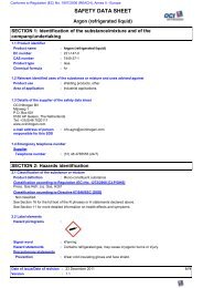
Carbon dioxide in the combustion gases is not included in the above figures, but is shown<br />
in Figure 3.<br />
4.2.3 Sulphur<br />
In BAT partial oxidation most (87-95%) of the sulphur content of the feed to the gasifier is<br />
recovered in the Claus unit.<br />
4.2.4 Steam export<br />
Modern steam reforming processes can be designed with no steam export or with some<br />
export of low/medium pressure steam if this can be favourably used on site. Steam export is<br />
usual in excess air reforming processes where the process air compressor is driven by a gas<br />
turbine, and in cases when electric power is used for driving one or more of the main compressors.<br />
Processes with gas heated primary reforming may be designed for zero steam export even<br />
with some power import or gas turbine drive.<br />
The partial oxidation process has a steam deficit if all compressors are steam driven.<br />
4.3 Production Emissions and Wastes<br />
4.3.1 Emissions into air from steam reforming plants<br />
From steam reforming plants with a fired primary reformer emissions into air come from the<br />
following sources:-<br />
– Flue-gas from the primary reformer<br />
– Vent gas from CO 2 removal<br />
– Breathing gas from oil buffers (seals/compressors)<br />
– Fugitive emissions (from flanges, stuffing boxes etc.)<br />
– Purge and flash gases from the synthesis section (usually added to the primary reformer<br />
fuel)<br />
– Non-continuous emissions (venting and flaring)<br />
23
24<br />
Fuel<br />
Air<br />
Natural gas<br />
Desulphurisation<br />
Primary reformer<br />
Secondary reformer<br />
Shift conversion<br />
CO 2 removal<br />
Methanation<br />
Compression<br />
Ammonia synthesis<br />
NH 3<br />
Flue-gas:<br />
CO 2: 500 kg.t -1<br />
NO2: 1 "<br />
SO 2:
4.3.1.1 Flue-gas from the primary reformer<br />
The flue-gas volume, at 3% (dry gas base) oxygen, for a gas-based conventional steam<br />
reforming plant producing 1,500t.d -1 , is approximately 200,000Nm 3 .h -1 , containing about 8%<br />
CO 2 (dry gas base), corresponding to 500kg CO 2 .t -1 NH 3 . The flue-gas volume from excess<br />
air reforming may be lower. The other pollutants in the flue-gas are:-<br />
NO x : 200-400mg.Nm -3 , (98-195ppmv), or 0.6-1.3kg.t -1 NH 3 expressed as NO 2<br />
SO 2 : 0.1-2mg.Nm -3 , (
4.3.2 Emissions into air from heat exchange reforming<br />
The flue-gas volume (from auxiliary fired equipment) and thus NO x and CO 2 emissions are<br />
considerably reduced, as these processes have much more internal combustion than the fired<br />
reformer processes because all the reforming process heat is generated by internal combustion.<br />
Total CO 2 emissions are fixed by the energy consumption. For self-sufficient plants the<br />
flue-gas volume in heat exchange reforming is about 50% of the figure for conventional<br />
steam reforming. In plants with power import the flue-gas volumes are lower. Reduction of<br />
NO x emissions by 80% has been claimed.<br />
4.3.3 Emissions into air from partial oxidation plants<br />
The partial oxidation process has the same emission sources as described for the reforming<br />
process except for the primary reformer flue-gas. A partial oxidation plant may also have auxiliary<br />
boiler(s) for power steam production, if more efficiently off-site produced power is not<br />
available. The fuel to the auxiliary boiler/superheater together with possible scrubbing equipment<br />
determines the amount of CO 2 in the flue-gas. Tail gas from sulphur recovery will also<br />
contain sulphur oxides. This means that the CO 2 emission from partial oxidation plants (max<br />
1,500mg.Nm -3 ) is higher than in the reformer flue-gas. Other additional emissions may<br />
be H 2 S (0.3ppmv), methanol (max. 100ppmv), CO (30ppmv), and dust (traces, max.<br />
50mg.Nm -3 ). NO x emission (max. 700mg.Nm -3 ) depends on the factors listed for the reformer<br />
flue-gas and the nitrogen content of the fuel.<br />
Excess nitrogen is usually vented.<br />
4.3.4 Emissions into water<br />
Pollution problems related to water, during normal operation, may occur due to process condensates<br />
or due to the scrubbing of waste gases containing ammonia. In partial oxidation, soot<br />
and ash removal may cause pollution problems, if not properly handled.<br />
Process condensate is found primarily in the condensation section prior to the CO 2<br />
removal, of the order of 1m 3 per ton NH 3 produced. Without treatment this condensate can<br />
contain up to 1kg of ammonia and 1kg methanol per m 3 . More than 95% of the dissolved<br />
gases can be recovered by stripping with process steam and are recycled to the process. The<br />
stripped condensate can be re-used as boiler feedwater make-up after treatment by ion<br />
exchange. Total recycle is obtained in this way. In some cases the process condensate is used<br />
for feed-gas saturation and thus recycled to the process.<br />
Usually the ammonia absorbed from purge and flash gases is recovered in a closed loop so<br />
that no aqueous ammonia emissions occur. Emissions into water from the production plant<br />
during normal operation can thus be fully avoided.<br />
Soot from gasification in partial oxidation processes is usually recovered and recycled to<br />
the process. Traces of soot and slag are emitted to water.<br />
4.3.5 Solid wastes<br />
The BAT ammonia processes do not normally produce solid wastes. Spent catalysts and<br />
mol.sieves have to be removed and valuable metals are recovered from them. In partial oxida-<br />
26
tion plants sulphur is recovered in the Claus plant and can be used as feedstock in sulphuric<br />
acid units. The ash can be upgraded and used as an ore substitute.<br />
4.4 Environmental Data for Ammonia Storage and Transfer<br />
In a refrigerated storage, the cold losses are balanced by recompressing and recondensing the<br />
evaporated ammonia. During recompression, some inerts containing also traces of ammonia<br />
cannot be condensed but must be flared or scrubbed with water. Small continuous emissions<br />
may thus occur, in addition to minor non-continuous emissions during loading operations.<br />
4.5 Environmental Hazards Associated with Emissions and Wastes<br />
The production of ammonia is relatively clean compared to many other chemical processes.<br />
During the normal operation of a reforming plant, only the NO x and CO 2 emissions have to<br />
be considered. In partial oxidation plants with oil-fired auxiliary boilers the reduction of SO 2<br />
emissions can be achieved by using low sulphur fuel oil. Generally the emissions from modern<br />
ammonia plants have little environmental impact.<br />
4.6 Emission Limits and Guideline Values for Ammonia Production in Some<br />
West-European Countries<br />
Two types of emission values are of importance:-<br />
– Legally binding emission limit values for specific pollutants which apply for ammonia<br />
production<br />
– Guideline values which are not legally binding but provide the background for requirements<br />
laid down in individual permits<br />
Specific legally binding emission limits for ammonia production are only laid down in<br />
Germany. In the Netherlands and in Germany limits for emissions from boilers have been laid<br />
down which include chemical reactors.<br />
Specific emission guideline values are laid down in the United Kingdom.<br />
With regard to the other countries, no national emission limits or guidelines are fixed for<br />
ammonia production plants. Very often the values are the subject of negotiations between the<br />
operator and the authority responsible for granting licences. In some countries, these authorities<br />
are of local character, so that even within one and the same country, different air pollution<br />
requirements may apply for comparable plants. At least in the Benelux countries and Ireland,<br />
the licensing authorities take into account emission limits applied in other countries, in particular<br />
those laid down in Dutch and German law, in their negotiations with operators. In practice,<br />
these values play the role of guideline values.<br />
Indirectly, the emission limits laid down for combustion installations play an important<br />
role because the energy consumption of an ammonia plant is relatively high. The emissions<br />
from a fired reformer or auxiliary boilers should conform with emission limits and guideline<br />
values adopted by the Council of EC in Directive 88/609/EEC or applied by the state.<br />
More detailed information is given in Reference [1].<br />
27
5. EMISSION MONITORING<br />
As outlined in Chapter 4, the emissions of pollutants to be expected from ammonia production<br />
are mainly:-<br />
–CO 2 , NO x , SO 2 , and CO in the flue-gas from steam reforming processes with a fired primary<br />
reformer and/or auxiliary boilers<br />
–SO 2 from the sulphur removal and recovery systems in partial oxidation processes<br />
–CO 2 and traces of removal solvents and synthesis gas in vent streams from the CO 2<br />
removal system<br />
– Small non-continuous and fugitive emissions<br />
–NH 3 and methanol in process condensates (if not recycled)<br />
The following emissions into air should be monitored as part of a proper supervision:-<br />
–NO x in flue-gases<br />
–SO 2 in flue-gases (may be calculated by mass balance instead of monitoring emission, if<br />
S input is known)<br />
–SO 2 and H 2 S from sulphur removal/recovery systems in partial oxidation processes<br />
The other emissions into air need not be monitored. CO 2 emission can be calculated from<br />
fuel specification and energy consumption, CO emission is fixed by the operating conditions<br />
and usually stable and low. Non-continuous and fugitive emissions are difficult to measure.<br />
The frequency of monitoring depends on local circumstances and the operating stability of<br />
the actual plant. Under normal operating conditions, measurements once a month are usually<br />
sufficient.<br />
Methods for discontinuous and continuous measurements of NO x , SO 2 and H 2 S are available<br />
and are to a large extent standardised at national level (Norme Belge/Belgische norm,<br />
British Standard, AFNOR, Verein Deutscher Ingenieure, Nederlands Normalisatie Instituut).<br />
Chemiluminescence or photometry are the most widely used methods for NO x . SO 2 is determined<br />
by Infra Red (IR) absorption techniques. Traces of H 2 S are measured by lead acetate.<br />
Emissions into water from new plants are virtually zero as process condensates are recycled<br />
and monitoring is not normally required. In existing plants without recycle of process<br />
condensate, the ammonia and methanol content should be monitored.<br />
A description of available methods for monitoring emissions is given in Appendix 1.<br />
28
6. MAJOR HAZARDS<br />
Historical data show that the major accidents in ammonia plants are explosions and fires. In<br />
addition there is also the potential for toxic hazard due to the handling and storage of liquid<br />
ammonia.<br />
The following credible major hazards events are identified in an ammonia production<br />
plant:-<br />
– Fire/explosion hazard due to leaks from the hydrocarbon feed system<br />
– Fire/explosion hazard due to leaks of synthesis gas in the CO removal/synthesis gas<br />
compression areas (75% hydrogen)<br />
– Toxic hazard from the release of liquid ammonia from the synthesis loop<br />
In ammonia storage the release of liquid ammonia (by sabotage) is a credible major hazard<br />
event.<br />
Confined explosions in ammonia plants appear to be limited to explosions equivalent to a<br />
few hundred kg TNT. Such explosions are normally not fatal for humans at 50-60m distance,<br />
and thus in most cases not severe for people outside the plant fence. The same is true for fire<br />
balls equivalent to 500kg hydrogen. Fires and explosions are usually not a hazard or only a<br />
minor hazard to the local population although potentially most severe for the plant operators.<br />
Appropriate precautions to protect both the operators and the local population are taken in the<br />
design and operation of the plants.<br />
The toxic hazard of a potential large release of liquid ammonia (ie. from a storage tank)<br />
may be much more serious for the local population. An emergency plan for this event, covering<br />
the operators and the local population must be maintained.<br />
7. OCCUPATIONAL HEALTH & SAFETY<br />
The occupational health and safety issues associated with ammonia production and storage<br />
are:-<br />
– Fire/explosion injuries<br />
– Poisoning<br />
– Suffocation<br />
Fires or explosions from the involuntary ignition of leaks are credible, especially when<br />
these occur in the feed-gas and synthesis gas systems (hydrocarbons, hydrogen).<br />
The most important toxic components are CO from potential leaks in the synthesis gas generation<br />
and shift areas and NH 3 from leaks in the ammonia synthesis and ammonia handling<br />
areas. In partial oxidation plants H 2 S and SO 2 are present in the sulphur removal/recovery<br />
sections. Traces of carbonyls (iron and nickel) may form during operation.<br />
Suffocation due to lack of oxygen may occur at points where the breathing air has been<br />
diluted with inert gases. In ammonia plants CO 2 and N 2 are potentially suffocating gases.<br />
29
ACGIH [4] occupational exposure limits for ammonia and other components associated<br />
with ammonia production are given in the table below. All the figures are ppmv:-<br />
Component TLV-TWA (8hr) TLV-STEL (15min)<br />
NH 3 25 35<br />
NO 2 3 5<br />
SO 2 2 5<br />
H 2 S 10 15<br />
CO 50 400<br />
CO 2 5,000 30,000<br />
The figures are subject to updating and may vary between European countries.<br />
Full health and safety information is given in Safety Data Sheets which must be available<br />
and updated. General product information on ammonia is given in Appendix 2.<br />
Ammonia plants have high technological standards and need professional management,<br />
operating and maintenance working routines and personnel. Precautions taken to prevent<br />
accidents and injuries during operation are incorporated in the operating and safety procedures<br />
for the plant.<br />
8. SUMMARY <strong>OF</strong> BAT EMISSION LEVELS<br />
8.1 Achievable Emission Levels for New Plants<br />
The following emission levels can be achieved for new ammonia plants. These levels relate to<br />
steady-state production, not accounting for peaks which can occur during the unsteady transient<br />
conditions of start-up and shut-down and during emergencies.<br />
8.1.1 Emissions into air<br />
ppmv mg.Nm-3 kg.t-1 of product<br />
NOx (as NO2 at 3% O2 ) 75 150 0.45<br />
SO2 (partial oxidation plants): as for combustion plants.<br />
8.1.2 Emissions into water<br />
NH 3 or NH 4 (as N) 0.1kg.t -1 of product<br />
8.1.3 Waste material<br />
Spent catalysts etc.
8.2 Achievable Emission Levels for Existing Plants<br />
The following emission levels can be achieved for existing ammonia plants. As for new<br />
plants, these levels do not account for peak values during unsteady or transient conditions.<br />
Contributions from ammonia-containing purge gases can be excluded from these figures in<br />
special cases, when authorised locally.<br />
8.2.1 Emissions into air<br />
ppmv mg.Nm-3 kg.t-1 of product<br />
NOx (as NO2 at 3% O2 ) 150 200-400 0.9<br />
SO2 (partial oxidation plants): as for combustion plants.<br />
8.2.2 Emissions into water<br />
NH 3 or NH 4 (as N) 0.1kg.t -1 of product<br />
8.2.3 Waste material<br />
Spent catalysts etc.
GLOSSARY<br />
The following abbreviations occur frequently throughout the series of Booklets but without<br />
necessarily appearing in each Booklet:-<br />
ACGIH American Conference of Governmental Industrial Hygienists<br />
AFNOR Association Française de Normalisation (France)<br />
AN Ammonium Nitrate<br />
AQS Air Quality Standard<br />
AS Ammonium Sulphate<br />
BAT Best Available Techniques<br />
BATNEEC Best Available Technology Not Entailing Excessive Cost<br />
BOD Biological Oxygen Demand<br />
BPL Basic Phosphate of Lime (Bone Phosphate of Lime)<br />
BS British Standard<br />
CAN Calcium Ammonium Nitrate<br />
CEFIC Conseil Europeen de l’Industrie Chimique (European Chemical<br />
Industry Council)<br />
COD Chemical Oxygen Demand<br />
DAP Di-Ammonium Phosphate<br />
DIN Deutsches Institut für Normung (Germany)<br />
EEC European Economic Community<br />
EFMA European Fertilizer Manufacturers Association<br />
ELV Emission Limit Value<br />
ESA European Sulphuric Acid Association<br />
EU European Union (Formerly, European Community, EC)<br />
IFA International Fertilizer Industry Association<br />
IMDG International Maritime Dangerous Goods (Code)<br />
IPC Integrated Pollution Control<br />
IPPC Integrated Pollution Prevention and Control<br />
ISO International Standards Organisation (International<br />
Organisation for Standardisation)<br />
MAP Mono-Ammonium Phosphate<br />
MOP Muriate of Potash (Potassium Chloride)<br />
NK Compound fertilizer containing <strong>Nitrogen</strong> and Potash<br />
NP Compound fertilizer containing <strong>Nitrogen</strong> and Phosphate<br />
NPK Compound fertilizer containing <strong>Nitrogen</strong>, Phosphate and Potash<br />
NS Fertilizer containing <strong>Nitrogen</strong> and Sulphur<br />
OEL Occupational Exposure Limit<br />
SSP Single Super-Phosphate<br />
STEL Short Term Exposure Limit<br />
TLV Threshold Limit Value<br />
TSP Triple Super-Phosphate<br />
TWA Time Weighted Average<br />
UAN Urea Ammonium Nitrate (Solution)<br />
32
CHEMICAL SYMBOLS<br />
The following chemical symbols may be used where appropriate in the text.<br />
C Carbon<br />
CaCO3 Cd<br />
Calcium Carbonate<br />
Cadmium<br />
CH3OH CH4 CO<br />
Methanol<br />
Methane<br />
Carbon Monoxide<br />
CO2 F<br />
Carbon Dioxide<br />
Fluorine<br />
F – Fluoride<br />
H (H2 )<br />
H2O H2S H2SiF6 H2SO4 H3PO4 HNO3 K<br />
Hydrogen<br />
Water<br />
Hydrogen Sulphide<br />
Hydrofluorosilicic Acid (Hexafluorosilicic Acid)<br />
Sulphuric Acid<br />
Phosphoric Acid<br />
Nitric Acid<br />
Potassium<br />
KCl Potassium Chloride (Muriate of Potash) (“Potash”)<br />
K2O N (N2 )<br />
N2O NH3 NH4-N NH4NO3 NO<br />
Potassium Oxide<br />
<strong>Nitrogen</strong><br />
Dinitrogen Monoxide (Nitrous Oxide)<br />
Ammonia<br />
Ammoniacal <strong>Nitrogen</strong><br />
Ammonium Nitrate<br />
<strong>Nitrogen</strong> Monoxide (Nitric Oxide or <strong>Nitrogen</strong> Oxide)<br />
NO2 NO3-N NOx O (O2 )<br />
P<br />
<strong>Nitrogen</strong> Dioxide<br />
Nitric <strong>Nitrogen</strong><br />
Oxides of <strong>Nitrogen</strong> (Excluding Nitrous Oxide)<br />
Oxygen<br />
Phosphorus<br />
P2O5 S<br />
Phosphorus Pentoxide<br />
Sulphur<br />
SO2 Sulphur Dioxide<br />
Sulphur Trioxide<br />
SO 3<br />
33
UNITS<br />
Units have been standardised as far as possible and these are abbreviated as follows:-<br />
bar Unit of pressure (equivalent to one atmosphere)<br />
GJ Giga Joule<br />
kg Kilogramme<br />
kg.h -1 Kilogrammes per hour<br />
kWh Kilowatt hour (1,000kWh = 3.6GJ)<br />
l Litre (liquid volume)<br />
m Metre<br />
LHV Lower Heating Value *<br />
m 3 Cubic Metre (liquid or solid volume)<br />
mg Milligramme<br />
mg.l -1 Milligrammes per litre<br />
MJ Mega Joule<br />
µm Micrometre<br />
Nm 3 Normal cubic metre (gas volume)<br />
ppb Parts per billion<br />
ppm Parts per million<br />
ppmv Parts per million by volume<br />
t Tonnes (Metric Tons)<br />
t.d -1 Tonnes per day<br />
t.y -1 Tonnes per year<br />
°C Degree Celsius<br />
K Degree Kelvin<br />
*Net caloric value or LHV H i : The amount of heat evolved by the complete combustion of a<br />
unit volume of gas V (T v : P v ) with air at a constant pressure of 101.325kPa and a constant<br />
temperature T H when the combustion products have once more cooled to the starting conditions<br />
and whereby the water produced by the combustion is assumed to remain as vapour.<br />
The internationally applicable starting conditions are:an<br />
absolute pressure of 101.325kPa<br />
a temperature T H of 298.15K (25°C)<br />
The definition of net calorific value is covered by an international standard,<br />
ISO 6976-1983 (E).<br />
34
APPENDIX 1 EMISSION MONITORING IN <strong>AMMONIA</strong> PLANTS<br />
1. Introduction<br />
Monitoring of emissions plays an important part in environmental management. It can be<br />
beneficial in some instances to perform continuous monitoring. This can lead to rapid detection<br />
and recognition of irregular conditions and can give the operating staff the possibility to<br />
correct and restore the optimum standard operating conditions as quickly as possible.<br />
Emission monitoring by regular spot checking in other cases will suffice to survey the status<br />
and performance of equipment and to record the emission level.<br />
In general, the frequency of monitoring depends on the type of process and the process<br />
equipment installed, the stability of the process and the reliability of the analytical method.<br />
The frequency will need to be balanced with a reasonable cost of monitoring.<br />
An extractive gas sampling system for continuous gas monitoring will typically comprise:-<br />
– A coarse filter (heated if necessary) which may be in the stack or duct or outside<br />
– A heated line to convey the sample gas from the stack but this may not be necessary if<br />
probe dilution is used<br />
– A cooler may be used to reduce moisture<br />
– A further drier installed before the analyser<br />
– A pump, situated before or after the analyser, as appropriate, to pull the gas from the<br />
stack or duct<br />
– A fine filter may be put immediately before the analyser<br />
National standards for gas sampling exist and the appropriate method should be adopted.<br />
Iso-Kinetic sampling will be necessary when particulates are present.<br />
Manual methods may be necessary or accepted by the authorities in certain cases and for<br />
situations where no continuous method is available.<br />
Vent streams are not normally measured by on-line methods and when measurements are<br />
required as base line checks, manual methods may be more appropriate.<br />
Typical methods for monitoring emissions into water rely on flow-proportioned sample<br />
collection or high frequency spot sampling together with analysis and continuous flow<br />
measurement.<br />
The use of trained staff is essential.<br />
Methods available for monitoring the emissions given in Chapter 8 of this Booklet are<br />
briefly described overleaf.<br />
35
2. Emissions into Air<br />
2.1. Flue-gas CO 2 , NO x , SO 2 , CO on-line analysis<br />
Commonly used methods:-<br />
CO 2 – Infra Red Spectrometry (Non-Dispersive Infra Red (NDIR))<br />
NO x – Chemiluminescence<br />
SO 2 – Infra Red Spectrometry (NDIR)<br />
CO – Infra Red Spectrometry (NDIR) or Electrochemical<br />
Extractive sampling with appropriate sample conditioning is used.<br />
NOTE: It may be possible to determine CO 2 by fuel specification and energy consumption<br />
figures and the CO may be sufficiently low and stable to avoid the need for continuous monitoring.<br />
The SO 2 may also be calculated on the basis of measuring the input of sulphur to the<br />
system. In such cases a monthly check may be acceptable – refer to the manual methods<br />
section.<br />
2.2 Sulphur Removal/Recovery SO 2 and H 2 S<br />
Commonly used methods:-<br />
SO 2 – Infra Red Spectrometry (NDIR)<br />
Extractive sampling with appropriate sample conditioning is required.<br />
H 2 S – Routine manual sampling and analysis using instrumental methods such as electrochemical<br />
cells or gas chromatography with flame photometric detection are<br />
required for accurate measurements<br />
2.3 On-Line Methods<br />
2.3.1 Infra red spectrometry<br />
In the simplest form of IR spectrometry, the equipment consists of an optical filter, the sample<br />
cell and a detector. When the wavelength of the radiation is not selected using a prism or diffraction<br />
grating, the instrument is known as a non-dispersive infra red gas analyser (NDIR).<br />
In a single-beam instrument a filter selects the part of the spectral range most characteristic of<br />
the substance. In a twin-beam instrument, (the most commonly used for on-line analysis) the<br />
radiation from the source is split and a comparison is made of the two beams after one has<br />
passed through a reference cell and the other through the sample gas.<br />
The two beams are brought together onto a half-silvered mirror or rotating chopper which<br />
alternately allows each beam to reach a detector cell which compares the heat received, by<br />
capacitance or resistance measurements. The twin-beam method is preferred in an on-line<br />
system as it overcomes some of the problems associated with drift due to small changes in<br />
detector sensitivity and in the optical and spectral properties of the optical filter. However,<br />
regular zeroing and calibration are needed to correct zero and range drift.<br />
36
2.3.2 Chemiluminescence<br />
These instruments use the property of fluorescence which can take place with some chemical<br />
reactions. By selecting two gases to react under carefully controlled conditions, the chemiluminescence<br />
can be measured to determine the concentration of reacting gases.<br />
NO x measurement makes use of the reaction:-<br />
NO + O 3<br />
NO 2 + O 2 + kv<br />
The sample gas is passed through a catalytic converter to change any nitrogen dioxide to<br />
nitric oxide and is then reduced in pressure and reacted with ozone. The chemiluminescence<br />
(kv) is measured by a photomultiplier tube after passing through an appropriate band pass<br />
filter.<br />
2.3.3 Range of methods available<br />
Method Potential Interferences Comments<br />
Sulphur Dioxide<br />
Extractive NDIR H 2 O, CO 2 , CO, NO, NO 2 The extraction system should<br />
SO 3 and particulates. be designed to allow the elimination<br />
of H 2 O, SO 3 and particulates.<br />
In-situ NDIR As for extractive NDIR High moisture, particulates and<br />
etching of the lens give problems.<br />
Calibration may be difficult.<br />
Extractive UV Eliminate the effects of other<br />
second derivative UV absorbing compounds.<br />
measurement<br />
Extractive NDUV CO 2 , CO, NO 2 , SO 3 , The extractive system should<br />
hydrocarbons and be designed to allow the<br />
particulates elimination of H 2 O, SO 3 and<br />
particulates.<br />
In-situ UV-visible H 2 O<br />
Extractive NO 2<br />
fluorescence<br />
Extractive flame H 2 O, SO 3<br />
photometry<br />
Extractive H 2 O, NH 3 , H 2 S Sample requires conditioning<br />
electrochemical to remove particulates and moisture<br />
to stop condensation and dissociation<br />
of salts.<br />
37
Method Potential Interferences Comments<br />
Oxides of <strong>Nitrogen</strong><br />
Chemiluminescence CO 2 , H 2 O and NH 3<br />
In-situ NDIR H 2 O and particulates Interferences can be reduced by<br />
precise selection of the wavelength.<br />
Carbon Monoxide/Carbon Dioxide<br />
Extractive NDIR H 2 O and particulates Straightforward conditioning<br />
In-situ IR (fibre Other IR absorbing Reduced accuracy due to<br />
optics) components, H 2 O, interferences.<br />
particulates, fibre<br />
optic losses<br />
2.4 Manual Methods<br />
2.4.1 Sulphur dioxide<br />
Standard methods rely on the solubility and acidic nature of the gas. An oxidising agent is<br />
generally used to convert the SO 2 to SO 3 . National standard methods include the use of<br />
hydrogen peroxide solution as the oxidising agent with titration against standard alkali or<br />
gravimetric analysis using barium chloride and hydrochloric acid to precipitate the sulphate.<br />
An alternative to this uses a sample collected in hydrogen peroxide solution and titration<br />
against barium perchlorate with thorin as indicator. A method which draws the filtered gas<br />
through a standard solution of iodine in potassium iodide is also used. The unreacted iodine is<br />
determined by titration with sodium thiosulphate and the SO 2 calculated from the amount of<br />
iodine used to oxidise the SO 2 .<br />
All the methods have errors associated with the interferences and the user should be<br />
knowledgeable about the method and its suitability.<br />
2.4.2 Oxides of nitrogen<br />
The instrumental methods given in 2.3 are preferred.<br />
2.4.3 Carbon monoxide/carbon dioxide<br />
These gases are generally measured by solution absorption into liquid reagents specific for<br />
each gas.<br />
38
3. Emissions into Water<br />
Whilst emissions into water are likely to be intermittent and of a low level, it is probable that<br />
any site operating an ammonia plant will have at least one overall consent for emissions into<br />
water and a requirement for plant monitoring. Typical monitoring methods may rely on flow<br />
proportioned sample collection or high frequency spot sampling and flow measurement. In<br />
either case the samples obtained may be analysed as follows:-<br />
3.1 Ammonia/Ammoniacal N<br />
The spectrophotometric method for ammonia relies on the reaction in which monochloramine<br />
is reacted with phenol to form an indophenol blue compound. This method is particularly<br />
suitable for the determination of ammonia in cooling waters derived from saline sources<br />
(dock, estuarine or sea water) and may be used in continuous flow colorimetry.<br />
Ion selective electrodes can also be used and are suitable for saline applications as well as<br />
pure water.<br />
Note that free ammonia exists in equilibrium with NH 4 + as follows:-<br />
NH 4 + + H2 O NH 3 + H 3 O +<br />
and that the equilibrium depends on pH. The above method determines the NH 4 + ammonia.<br />
Free ammonia is particularly toxic to fish and should an incident occur, it may be more<br />
important to relate the NH 4 + result to free ammonia. Any suitable pH determination may be<br />
used and the free ammonia estimated as given in “Hampson B L, J Cons Int Explor, Mer,<br />
1977,37. 11” and “Whitfield M, J Mar Biol. Ass UK, 1974,54, 562”.<br />
Manual laboratory based methods may be used for spot checks using Kjeldahl methods for<br />
the determination of organic and ammoniacal nitrogen in a mineralised sample.<br />
3.2 Methanol<br />
The spectrophotometric method for methanol relies on the oxidation reactions of potassium<br />
permanganate under acid conditions to give formaldehyde. The formaldehyde is reacted with<br />
acetylacetone in the presence of excess ammonium salt, to form diacetyldihydrotoluidine.<br />
The method may be used in continuous flow colorimetry or gas chromatography.<br />
39
APPENDIX 2 GENERAL PRODUCT INFORMATION ON <strong>AMMONIA</strong><br />
1. Identification<br />
Name : Ammonia<br />
Commonly used synonyms : Liquid Ammonia<br />
C.A.S. Registry number : 7664-41-7<br />
EINECS Number : 231-635-3<br />
EINECS Name : Anhydrous Ammonia<br />
Molecular formula : NH3 2. Hazards to Man and the Environment<br />
To man<br />
Ammonia is toxic by inhalation and pulmonary oedema may occur up to 48 hours after<br />
severe exposure and could be fatal.<br />
Vapours cause irritation and watering of eyes and in the presence of moisture, irritation of<br />
the skin.<br />
Liquid ammonia splashes may produce severe burns to the skin and permanent damage to<br />
the eyes.<br />
In enclosed spaces (eg vessels, closed workshops) ammonia vapour may be<br />
flammable/explosive.<br />
To the environment<br />
Ammonia is toxic to aquatic life.<br />
3. Physical and Chemical Properties<br />
Appearance : Colourless liquefied gas<br />
Odour : Pungent, suffocating<br />
pH water solution (1%) : 11.7<br />
Melting point (triple point) : –77.7°C<br />
Boiling point : –33.4°C at 101.3kPa<br />
Explosive limits : 16-27% NH 3 by vol. in air at 0°C<br />
Auto-ignition temperature : 651°C<br />
Vapour pressure : 1013kPa at 25°C<br />
Relative vapour density : 0.6 (air =1)<br />
Solubility in water : 529g.l -1 at 20°C<br />
Solubility in organic solvents : Soluble in alcohol, acetone, chloroform<br />
Liquid density : 0.6386g.cm -3 (at 0°C, 101.3kPa)<br />
Gas density : 0.7714g.l -1 (at 0°C, 101.3kPa)<br />
40
Best Available Techniques Booklets<br />
were first issued by EFMA in 1995<br />
Second revised edition 2000<br />
1. Production of Ammonia<br />
2. Production of Nitric Acid<br />
3. Production of Sulphuric Acid<br />
(in collaboration with ESA)<br />
4. Production of Phosphoric Acid<br />
5. Production of Urea and Urea-Ammonium Nitrate<br />
6. Production of Ammonium Nitrate and Calcium Ammonium Nitrate<br />
7. Production of NPK Compound Fertilizers by Nitrophosphate Route<br />
8. Production of NPK Compound Fertilizers by Mixed Acid Route<br />
Printed by Fisherprint Ltd, Peterborough, England