Milling machine S3-Master - Georg Schick Dental GmbH
Milling machine S3-Master - Georg Schick Dental GmbH
Milling machine S3-Master - Georg Schick Dental GmbH

Create successful ePaper yourself
Turn your PDF publications into a flip-book with our unique Google optimized e-Paper software.
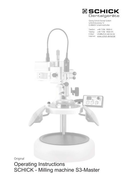
<strong>Georg</strong> <strong>Schick</strong> <strong>Dental</strong> <strong>GmbH</strong><br />
Lehenkreuzweg 12<br />
D-88433 Schemmerhofen<br />
Original<br />
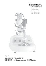
Operating Instructions<br />
SCHICK - <strong>Milling</strong> <strong>machine</strong> <strong>S3</strong>-<strong>Master</strong><br />
Telefon +49 7356 9500-0<br />
Telefax +49 7356 9500-95<br />
E-Mail info@schick-dental.de<br />
Internet www.schick-dental.de
Index<br />
!<br />
We are pleased that you decided to buy a highly<br />
developed piece of equipment from SCHICK and<br />
would like to wish you every success when working<br />
with your new milling <strong>machine</strong> <strong>S3</strong> <strong>Master</strong>.<br />
We wrote these operating instructions to enable<br />
you to get accustomed to your new piece of<br />
equipment and to provide you with the correct<br />
operating and maintenance instructions.<br />
1. List of contents ................................................................................................. 3<br />
2. Range of applications........................................................................................ 4<br />
3.<br />
Page<br />
General information / Safety information.................................................... 4-5<br />
4. Setting up ......................................................................................................... 6<br />
5. Short instruction into operation.........................................................................<br />
7<br />
.<br />
6. Picture milling <strong>machine</strong> <strong>S3</strong>-<strong>Master</strong> / operating elements.................................... 8<br />
7.<br />
8.<br />
Operation......................................................................................................... 9-12<br />
7.1 3D <strong>Milling</strong> arm<br />
7.2 Operating unit<br />
7.3 Integrated arm supports<br />
7.4 Height-adjustable milling table<br />
7.5 Motor technology<br />
Exchanging the rotary instruments.................................................................... 13<br />
9. Replacing the chuck.......................................................................................... 13<br />
10. Maintenance and care......................................................................................<br />
14<br />
11. Possible faults..................................................................................................<br />
14<br />
12.<br />
15<br />
Technical data / accessories..............................................................................<br />
13.<br />
16<br />
Declaration of conformity.................................................................................<br />
2<br />
Index
Serial parts<br />
<strong>Milling</strong> <strong>machine</strong> <strong>S3</strong> complete<br />
Foot-switch (Magnet-coupling)<br />
Foot-switch (Motor)<br />
C3-Motor incl. <strong>Milling</strong> spindle and cable<br />
Light equipment<br />
Mains cable<br />
Collet chuck Ø 2,35 mm<br />
stop for short tools<br />
Chuck key<br />
Counter stay wrench<br />
Hexagon socket wrench w.a.f. 2<br />
Hexagon socket wrench w.a.f. 4<br />
Dust protection cover<br />
optionally<br />
Collet chuck Ø 3 mm<br />
stop for short tools<br />
3<br />
Range of applications<br />
Art.-No.<br />
2500<br />
2110<br />
2560<br />
7000/05<br />
2510<br />
2160<br />
4114<br />
4918<br />
4115<br />
6223<br />
W602000200<br />
W602000400<br />
2502<br />
4117<br />
4925
2. Range of Applications<br />
3. General Information<br />
- Ascertain that your mains supply coincides with the data in the rating<br />
plate<br />
- The milling <strong>machine</strong>s <strong>S3</strong> <strong>Master</strong> are not suitable for the following applications:<br />
- in areas where there is a risk of explosion<br />
- for medical applications<br />
- Ensure that all regulatory requirements are observed during use (always waer<br />
protective glasses).<br />
- Under no circumstances should the milling <strong>machine</strong> be cleaned with<br />
compressed air<br />
- To keep the precision and the lifetime of the chuck always insert a rotary instrument<br />
or the pin, supplied with the unit, (37) - even if the motor stands still.<br />
- Recycling<br />
Range of Applications / General information<br />
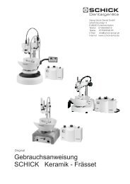
The <strong>S3</strong> <strong>Master</strong> milling <strong>machine</strong> is designed for use in dental laboratories<br />
when trimming crowns and bridges, respectively acrylic and chrome cobalt dentures.<br />
Highest precision, consistent quality control und minor maintenance are the merits<br />
of the <strong>S3</strong> <strong>Master</strong> which has been developed under assistance of recognized experts<br />
in milling technics.<br />
This novel construction - the model is moved up and down by means of the height<br />
adjustable milling table - is unique, and grants the technician ergonomic, relaxed sitting<br />
during work.<br />
The 3D integrated arm supports are also outstanding and support optimal the guidance<br />
of the milling hand. This ergonomic construction allows optimal results through relaxed<br />
working.<br />
Conditions of environment:<br />
- interior 5° - 40°<br />
- up to 2.000 meter over sea level<br />
Categorie of overvoltage: II<br />
Grade of pollution: 2<br />
WEEE-Reg.-Nr. DE 78620387<br />
4
3. Safety informations<br />
ATTENTION:<br />
!<br />
- Water-cooled turbines are only indicated to use in connection with a SCHICK<br />
suction tub to avoid defects at the elctrical equipment and corrosion.<br />
- When using rotary instruments, do not exceed the maximum speeds laid<br />
down by their manufacturer.<br />
- Repairs and other technical procedures must only be carried out by suitable<br />
qualified personnel, authorized by SCHICK.<br />
- SCHICK do not guarantee the <strong>S3</strong> <strong>Master</strong> milling unit should it not have<br />
been used in accordance with the operating instructions<br />
- For defects occured by using the <strong>S3</strong> <strong>Master</strong> milling <strong>machine</strong> in another way<br />
or by inappropriate handling the manufacturer rejects any liability.<br />
Safety informations<br />
These operating instructions should be readily accessible and are best kept<br />
close to the milling <strong>machine</strong> itself !<br />
5
4. Installation<br />
Setting up<br />
5<br />
1<br />
dimmer 6a<br />
6a<br />
Pict. 1<br />
pict. 2<br />
Pict. 3<br />
1<br />
2<br />
3<br />
4<br />
2<br />
7a<br />
7a<br />
Installation and setting up<br />
- Check the package for visible damages<br />
- When unpacking handle all parts of consignment with care.<br />
- Remove carefully the upper part of the inside package (withdraw<br />
slowly (pict.. 1)).<br />
Please look that parts of the milling <strong>machine</strong> do not become<br />
wedged with the package.<br />
- Remove cartons containing accessories (pict. 2)<br />
IMPORTANT: When unpacking the accessories please note<br />
the sign “OBEN” (pict. 3) !<br />
- Look for the space where to place the milling <strong>machine</strong><br />
- Using your left hand hold the milling <strong>machine</strong> at the column<br />
Do not hold at the milling arm !<br />
- Withdraw the <strong>machine</strong> a little bit and then hold it with your rigth<br />
hand at the basic plate to take the milling <strong>machine</strong> out.<br />
Please look for the milling arm being fixed.<br />
- Check all parts for visible damages. Place all parts of inner<br />
package back into the outer carton.<br />
Store the complete package for an eventual return to manufacturer.<br />
If you should intend to destruct the package, please be so kind<br />
to return the complete package to SCHICK.<br />
Foot-switch<br />
Put the connection plugs of foot-switch (magnet-coupling)<br />
(6a) and foot-switch (motor) (7a) on to the sockets situated on<br />
the right side of the milling <strong>machine</strong> (see picture). Press both plugs<br />
carefully into the sockets.<br />
Please note at both plugs the security against torsion !<br />
The foot-switch (magnet-coupling) is equipped with a thread<br />
connection, the foot-switch (motor) with a bayonet connection.<br />
So both plugs can be connected with the sockets tightly<br />
Dimmer is used for the stepless adjustement of light intensity.<br />
Mains cable<br />
Connect the milling <strong>machine</strong> with the mains supply by placing<br />
the mains cable at first into the socket (3) situated on the left<br />
side of the milling <strong>machine</strong> and then into a safe wall socket<br />
with earth connection.<br />
Please check that all plug connections are readily fixed !<br />
6
5. Operation<br />
3D-milling arm<br />
operating unit<br />
integrated<br />
arm supports<br />
heightadjustable.<br />
<strong>Milling</strong> table<br />
activate mains switch (4)<br />
Short instruction into operation<br />
jointed arm<br />
- Fastening and loosening is done with the foot switch (6)<br />
- adjust the additional, third joint with thumb drive (15)<br />
- When the milling <strong>machine</strong> is not in use please place the milling arm<br />
into ’parking postion’ (pict. 2; page 9)<br />
vertical saddle<br />
- adjust the vertical saddle at any position using knurled nut (8)<br />
- use lever (11) to draw spindle down<br />
fine adjustment through micrometer spindle (9)<br />
milling spindle<br />
- tension lever (31) showing to the left when chuck is closed<br />
- motor on/off with switch “Motor - EIN/AUS” (18) resp. foot switch (7)<br />
- speed adjustment variable with speed selector (19) - digital speed indicator (22)<br />
- magnet on / off use switch “Magnet - EIN/AUS” (20)<br />
- changing rotation of milling spindle by using switch “Motor - R/L” (21)<br />
- adjusment possible at any position through notches<br />
- height adjustment through thumb drive (23)<br />
- loosen clamping lever (26) ; for height adjustment use handwheel (25)<br />
- position of clamping lever can be adjusted at any position desired by<br />
pulling and turning.<br />
- Height stop (28) to mark and to find again the starting point of the<br />
milling table<br />
- gap (29) at magnet plate to remove easily cuttings etc.<br />
Important !<br />
Detailed description see point 7 “Operation”<br />
7
6. <strong>S3</strong>-<strong>Master</strong><br />
9<br />
10<br />
38<br />
8<br />
31<br />
13<br />
28<br />
27<br />
23<br />
29<br />
30<br />
6a<br />
6<br />
6a<br />
6<br />
12<br />
26<br />
22<br />
11<br />
15<br />
16<br />
19<br />
20 18 21<br />
8<br />
25<br />
14<br />
39<br />
24<br />
7a 7<br />
Picture <strong>Milling</strong> Machine<br />
1. Socket for foot-switch (magnet-coupl.)<br />
2. Socket for foot-switch (motor)<br />
3. Socket for mains cable<br />
4. Mains switch<br />
5. Fuses<br />
(point 1 - 5 see page 6)<br />
6. Foot-switch (magnet-coupl..)<br />
6.a Plug foot-switch (magnet-coupl.)<br />
7. Foot-switch (motor)<br />
7.a Plug foot-switch (motor)<br />
8. Knurled nut / vertical saddle<br />
9. Micrometer spindle / depth stop<br />
10. Spring tension<br />
11. Lever<br />
12. Holding hole<br />
13. Knurled nut / milling spindle<br />
14. Magnet<br />
15. Thumb screw / jointed arm<br />
16. Knurled screw / light attachment<br />
17. Measuring spindle (see page 10)<br />
18. switch “Motor-ON/OFF”<br />
19. Speed selection<br />
20. switch “Magnet-ON/OFF”<br />
21. Switch “Motor-right/left”<br />
22. Digital speed indicator<br />
23. Thumb drive / arm supports<br />
24. <strong>Milling</strong> table<br />
25. handwheel<br />
26. Lever / milling table<br />
27. Guidance for milling table<br />
28. Height stop ring<br />
29. Gap at magnet plate<br />
30. Plate<br />
31. Tension lever<br />
32. Chuck key<br />
33. Chuck<br />
34. Hold fast key<br />
35. Plug-in seal<br />
36. cap<br />
37. Pin<br />
(point 31 - 37 see page 13)<br />
38. Vertical saddle<br />
39. Arm supports<br />
24<br />
30
7. Operation<br />
Mains switch<br />
To activate the electric press mains switch (4) “ON”. The switch itself becomes<br />
shining. Now all electrical functions are controllable. To switch the unit off press<br />
mains switch (4) “OFF” again.<br />
Attention:: when the unit is switched off the magnetic couplings are no<br />
longer activated ! Put the milling arm into the resting position<br />
7.1 3D - <strong>Milling</strong> arm Jointed arm<br />
8<br />
31<br />
12<br />
16<br />
pict. 1<br />
pict. 2<br />
13<br />
pict. 3<br />
15<br />
9<br />
10<br />
38<br />
11<br />
Operation<br />
Fastening and loosening of the arm by the electro-magnetic<br />
couplings is done with the foot switch (6) . An additional, third<br />
articulation is loosened by turning the thumb screw (15) slightly<br />
to the left.<br />
Then the milling arm can be adjusted and locked again in any desired<br />
position. When work is finished the milling arm can be put into a<br />
“parking position” - also when the jointed arm is not in use for<br />
longer time ( pict. 2) . Before activating the mains switch put milling<br />
arm into this position (left side stop).<br />
A permanent magnet locks the arm. This is to avoid un unintended<br />
swing out of the milling arm when the unit is switched off.<br />
The magnetic couplings are inactive after the unit is switched off.<br />
Vertical saddle<br />
The vertical saddle (38) is to be fixed with a knurdel srew (8) in any<br />
position. On the top of this saddle there is the grip sleeve to adjust<br />
the depth stop (9).<br />
The tension of the spring (10) in the vertical saddle can individually<br />
be adjusted at the bottom of the milling arm (40) (see point 7.5;<br />
page 12) using the supplied hexagon head socket wrench w.a.f. 4.<br />
The spindle for depth stop (9) shows a radial graduation<br />
of 50 x 0,01 mm and an axial graduation of 0,5 mm.<br />
One complete rotation of this spindle is a travel of 0,5 mm.<br />
The vertical way of the saddle is 24 mm.<br />
The drill-lever (11) can be screwed out if required.<br />
<strong>Milling</strong> spindle<br />
To remove the milling spindle detach light equipment and loosen<br />
knurled nut (13) (pull spindle out upwards). To detach the light<br />
equipment loosen knurled screw (16) (pict.. 1) and pull light<br />
equipment carefully down.<br />
Put light equipment on again in reverse order.<br />
When<br />
putting on the light equipment please take care that the<br />
connections click into place !<br />
9
17<br />
7.2 Operating unit<br />
22<br />
12<br />
20 18<br />
When replacing the milling spindle pull down until stop.<br />
Operation<br />
Please pay attention that the thread pin placed in the spindle<br />
holder clicks into the notch at the milling spindle.<br />
The lever (31) (pict. 2) at the milling spindle has to show into left<br />
direction. Tighten knurled nut (13).<br />
Function of milling spindle see “ operating unit “ (point 7.2)<br />
Measuring spindle<br />
The measuring spindle (17) is supplied as accessory and can be<br />
placed into the spindle holder in the same way as the milling spindle.<br />
There is no stop position what allows to place the measuring spindle<br />
in each desired height position.<br />
If the measuring spindle is not in use it can be placed into the holding<br />
hole (12) in the back part of the milling arm.<br />
19<br />
21<br />
The operating unit is flexible connected to the milling <strong>machine</strong>.<br />
This flexible connection allows positioning to the optimum<br />
ergonimic, individual working position.<br />
<strong>Milling</strong> spindle ON / OFF<br />
The milling motor is switched on and off either by using the operating<br />
unit directly (switch “Motor - EIN/AUS” (18) ) or by using the supplied<br />
foot-switch (Motor) (7). If motor is switched on control light is shining.<br />
Speed of milling spindle<br />
The speed of the milling spindle is variable adjusted from 1.000 -<br />
50.000 min¯¹ by turning speed selector knob (19) .<br />
The choosen speed is clearly visible at the integrated digital<br />
display (22). If there is a point visible left from the shown speed the<br />
motor is not switched on (to select the speed). As soon as the spindle<br />
is rotating the point disappears.<br />
Magnet milling table<br />
To lock resp. to loosen of f.e. model table or coordiante table an<br />
electric magnet is used. Press the switch “Magnet -EIN/AUS” (20) ;<br />
the control light in the switch is shining.<br />
To inactivate the magnet press the switch again.<br />
10
7.3 Integrated arm supports<br />
23<br />
39<br />
7.4 Height adjustable milling table<br />
29<br />
30<br />
14<br />
Direction of rotation of milling spindle<br />
Operation<br />
To change direction of rotation of milling spindle use switch<br />
“Motor - R/L” (21) . If motor is running the direction right or left is<br />
shown through a green light in the switch. It is also possible to<br />
change the direction of rotation when motor is running.<br />
To allow relaxed working the flexible three dimensional arm supports<br />
are both individually adjustable.<br />
To adjust the height loosen thumb drive (23) . To fix the arms bring<br />
them into desired position and lock the thumb drive.<br />
In addition it’s possible to fix the arm supports on their inner<br />
side with the holding device by means of a hexagon socket<br />
wrench w.a.f. 2.<br />
In contrary of conventional milling <strong>machine</strong>s the height adjustment<br />
is not regulated through the milling arm but through the adjustable<br />
milling table (24) .<br />
This innovation allows working at constant eye level even with<br />
different heights of models.<br />
Magnetic platform<br />
To fix the model table or other accessories in the center of the<br />
24 magnetic platform an electro-magnet is placed (14) which is operated<br />
via the operating unit (see point 7.2; page 10). There is a gap at the<br />
magnetic platform (29) through which facings coming up when milling<br />
(precious metal), dust or liquids can be removed. To clear the platform<br />
you can easily take away the particles with a brush through the<br />
paralle grooves.<br />
The plate below (30) is destined to collect the particels and can<br />
easily be removed and cleaned.<br />
11<br />
.
28<br />
27<br />
26<br />
25<br />
24<br />
7.5 Motor technics<br />
40<br />
Height adjustment<br />
Operation<br />
To adjust the height of the milling table (24) turn handweel (25)<br />
which is placed on the right side of the column. But first loosen<br />
lever (26) working as additional clamp to fix the milling table.<br />
Put milling table up or down according to your needs using the<br />
handwheel and then clamp lever (26) to avoid unintended<br />
movement of the table.<br />
If needed you can put the lever (26) in different positions. Pull lever<br />
axial and turn to new position; when releasing the lever<br />
clicks into place<br />
Height stop ring<br />
Is the milling arm adjusted in a certain position (f.e. when milling),<br />
but the space between model and milling spindle is to narrow to<br />
change the tool you can mark the position of the milling table using<br />
the height stop ring (28).<br />
To find again the adjusted height loosen thumb screw at heigth stop<br />
ring (28) , put the heigth stop ring down till it stops at guidance (27)<br />
and fix it. Now the milling table can be put down and after the tool<br />
is changed it can be returned to the original height.<br />
The milling unit <strong>S3</strong> <strong>Master</strong> is equipped with the new C3 technology.<br />
This means extrem and stable torque in all speed ranges, silent and<br />
vibration free running and highest balance.<br />
With its 50.000 r.p.m. and 240 watt power the <strong>S3</strong> milling spindle<br />
masters even the hardest grinding and milling.<br />
Attention: Use only tools which are in accordance to the<br />
working speeds !<br />
Maintenance of motor and spindle see “ Maintenance and Care “<br />
(point 10; page 14)<br />
The integrated light equipment guaranties excellent illumination and<br />
visibility of the working area.<br />
Due to the direct connection with the milling spindle it’s not necessary<br />
to place the light always into the right position. Light exactly where<br />
it is needed. The light equipment is joined with a plug connection<br />
and can easily be removed and attached. The light intensity can be<br />
adjusted by the dimmer knob (see page 6)<br />
Removal of light equipment see “Operation - milling spindle“<br />
(point 7.1; page 9)<br />
12
8. Exchanging the rotary instruments<br />
!<br />
Exchanging the rotary instruments<br />
Replacing the chuck<br />
The chuck is opened by turning tension lever (31) to the right till it stops.<br />
When the shaft of the rotary instrument is placed into the chuck turn tension lever<br />
to the left till it stops.<br />
With regard to the precision and service-life of the chuck, an instrument must always<br />
be inserted into it - even when the spindle is not in use.<br />
CAUTION: Only ever exchange the rotary instrument with<br />
the motor switched off! Risk of damage !<br />
9. Replacing the chuck<br />
- Take milling spindle out of the spindle holder<br />
see “Operation - <strong>Milling</strong> Spindle” (point 7.1; page 9)<br />
- Open chuck and remove the rotary instrument.<br />
- Remove motorcable. Unscrew cap (36) from motor and loosen cable by pulling out the<br />
plug-in seal (35) . Please insure that the chuck is open.<br />
- Use a number 6223 wrench (34) to hold the motor end of the spindle.<br />
- Engage the triangular section of the chuck (33) with a number 4115 tool (32).<br />
Hold tight No. 6223 (34) wrench and screw out the chuck by turning the<br />
tool no. 4115 (32) anti-clockwise. The chuck has a right-handed thread!<br />
Please note: In the chuck is a stroke for short shafts, this could be removed<br />
or replaced as required.<br />
- Clean the chuck, grease its outside lightly and place it in the spindle.<br />
Use the tools as described to screw the chuck in - clockwise and as far as possible<br />
and tighten it slightly. Replace the plug-in seal (35) and screw the cap (36) back<br />
into place.<br />
- Replace milling spindle in spindle holder.<br />
32<br />
37<br />
33<br />
chuck 2,35/3,0 (art.-no. 4114/4117)<br />
stroke 2,35/3,0 (art.-no. 4918/4925)<br />
31<br />
34 35 36<br />
13
10. Maintenance and care<br />
!<br />
Maintenance and care<br />
Possible faults<br />
CAUTION!: Do not clean milling <strong>machine</strong> and milling spindle with<br />
compressed air !<br />
The chuck should be cleaned and re-greased once in a while, depending on how dirty it is<br />
see “Replacement of chuck” (point 9; page 13)<br />
- As the C3 milling spindle has no commutators, carbon brushes or ventilation parts,<br />
no further maintenance is required.<br />
- The wood of the arm supports is natural and superficially waxed.<br />
- All guideways are maintenance free.<br />
For cleaning please use only a brush !<br />
Before cleaning please switch the milling <strong>machine</strong> off and withdraw mains plug !<br />
11. Possible faults<br />
- Should the milling spindle be overloaded, respectively, jammed, for safety<br />
reasons the unit will switch off.<br />
- turn speed selection (19) back to “0-postion”; select the desired speed and the<br />
<strong>machine</strong> is ready for use again.<br />
- alternatively switch mains switch (4) off and on again.<br />
If after that the <strong>machine</strong> is not working please check the fuses and replace them if necessary.<br />
The fuses (5) (230V→ 2x T2AH250V art.no.:3106) (100-115V 2x T4AH art.no.: 7306) are to<br />
be found beside the socket for the mains cable (3) (see page 6).<br />
Should it not be possible to abolish the faults please contact SCHICK directly<br />
14
Technical Data <strong>S3</strong> <strong>Master</strong><br />
Rated voltage: 230V / 115V / 100V<br />
Rated frequenzy: 50/60 Hz<br />
Motor torque: 7,8 Ncm<br />
Speedrange: 1.000 - 50.000 min-1<br />
Concentricity: < 0,015 mm<br />
chuck: Ø 2,35 mm series<br />
Ø 3,00 mm on request<br />
Width: 300 mm<br />
Height: 500 mm<br />
Depth: 420 mm<br />
Weight: 23 kg<br />
Subject to technical modification without prior notice<br />
Accessory<br />
Model table Art.-Nr. 2407/9 Separator Art.-Nr. 2655 Suction tube Art.-Nr . 2470<br />
Coordinate table<br />
Art.-Nr. 2505<br />
<strong>Milling</strong> set 2,35 mm<br />
(7 pcs) Art.-Nr. 2530<br />
Light head for turbine<br />
Art.-Nr. 2510/1<br />
Adjustable Anglel<br />
Art.-Nr. 2506<br />
Polish set 2,35 mm<br />
(3 pcs) Art.-Nr. 2665 Diammond tool set<br />
Turbine 1,6 mm<br />
(8 pcs) Art.-Nr. 2660<br />
<strong>S3</strong> - Ceramic-set cpl. art.-no. 2650/01<br />
(without <strong>S3</strong> <strong>Master</strong>)<br />
turbine art.-no. 2640/1<br />
<strong>S3</strong> Adaptor for turbine art.-no. 2481<br />
holding clip art.-no. 2245<br />
light head for turbine art.-no. 2510/1<br />
Suction tube art.-no. 2470<br />
Separator art.-no. 2655<br />
Model table art.-no. 2407/9<br />
Diamond-tool-set for Turbine 1,6 mm (8 pcs.) art.-no. 2660<br />
Polish-set 2,35 mm (3 pcs.) art.-no. 2665<br />
15<br />
Technical Data / Accessory<br />
Adaptor ring Art.-Nr . 2508<br />
Measuring spindle Art.-Nr. 2250/1<br />
Holding tray Art.-Nr. 2509<br />
<strong>Milling</strong> tray Art.-Nr. 2507
04/12 bg<br />
We, GEORG SCHICK DENTAL <strong>GmbH</strong><br />
Lehenkreuzweg 12<br />
D-88433 Schemmerhofen<br />
declare herewith, that the product<br />
<strong>Milling</strong> <strong>machine</strong> <strong>S3</strong> <strong>Master</strong> Art.-Nr. 2500<br />
is in conformity with the following provisions of Directive:<br />
2001/95/EG (general product safety)<br />
2006/42/EG (<strong>machine</strong>ry directive)<br />
2006/95/EG (low voltage directive)<br />
2004/108/EG (EMV directive)<br />
Name and adress of<br />
person in charge:<br />
Schemmerhofen, April 2010<br />
W. <strong>Schick</strong><br />
Geschäftsführer<br />
Wolfgang <strong>Schick</strong><br />
Lehenkreuzweg 12<br />
88433 Schemmerhofen<br />
16<br />
Declaration of Conformity<br />
<strong>Georg</strong> <strong>Schick</strong> <strong>Dental</strong> <strong>GmbH</strong><br />
Lehenkreuzweg 12<br />
D-88433 Schemmerhofen<br />
Telefon +49 7356 9500-0<br />
Telefax +49 7356 9500-95<br />
E-Mail info@schick-dental.de<br />
Internet www.schick-dental.de<br />
D20110