iESP Master Control Unit - Ep-Solutions.com
iESP Master Control Unit - Ep-Solutions.com
iESP Master Control Unit - Ep-Solutions.com

You also want an ePaper? Increase the reach of your titles
YUMPU automatically turns print PDFs into web optimized ePapers that Google loves.
<strong>iESP</strong> <strong>Master</strong> <strong>Control</strong> <strong>Unit</strong><br />
Monitoring and control of operational electric submersible<br />
pump (ESP) installations is critical for several reasons. There<br />
are some instances where the well site visits of the pumper<br />
or operator are not frequent enough for the proper control<br />
on these installations. Some of the reasons for this are:<br />
Remote locations that are either difficult or dangerous to<br />
get to leading to a need to reduce the frequency of visits<br />
to the location.<br />
Prolific producers, of which any down time results in large<br />
losses of revenue, require immediate notification of a down<br />
system.<br />
Trouble wells due to dirty power, cyclic reservoirs, solids<br />
production, and scale formation require advanced control<br />
logic to optimize.<br />
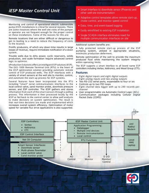
eProduction <strong>Solutions</strong> offers an intelligent ESP solution (<strong>iESP</strong>).<br />
The EXS-1000 Remote Terminal <strong>Unit</strong> (RTU) is the heart of<br />
the <strong>iESP</strong> optimization solution providing automatic remote<br />
control of ESP produced wells. The <strong>iESP</strong> interfaces with a<br />
variety of smart sensors at the well site to monitor, control,<br />
and automate the start-up process for ESP systems.<br />
Several features have been incorporated into the RTU<br />
including “smart” serial <strong>com</strong>munications interfaces to the<br />
local control valve, sand monitor probe, downhole pressure<br />
sensor, and ESP controller. The <strong>iESP</strong> gathers and stores<br />
information from each of the smart sensors through a polling<br />
process. This information is then processed locally by the<br />
<strong>iESP</strong> or fed back to the control center to allow well analysts<br />
to make decisions on system optimization. The result is<br />
that real-time decisions are made and implemented which<br />
increases overall system efficiency. Optimization of motor<br />
speed for variable flux drive applications is also supported.<br />
ESP <strong>Control</strong>lers:<br />
• Vortex<br />
• Keltronics<br />
• CTI<br />
ESP <strong>Control</strong> Interface<br />
Net Oil Computer<br />
Smart Sensor Interfaces:<br />
• Downhole sensor<br />
• Multi-phase flowmeter<br />
• Local control valve<br />
• Sand monitor probe<br />
AO<br />
<strong>Control</strong><br />
• Smart interface to downhole sensor (Phoenix) and<br />
other well site instrumentation<br />
• Adaptive control templates allow remote start-up,<br />
choke control, and monitor speed control<br />
• Data, time, and event-based logging<br />
• Easily retrofitted to existing ESP installation<br />
• Single SCADA interface eliminates need for<br />
multiple <strong>com</strong>munication interfaces on site<br />
Additional system benefits are:<br />
A fully protected remote start-up process of the ESP<br />
pumping system, utilized in appropriate situations,<br />
minimizes production deferment.<br />
Remote optimization of the well to provide the maximum<br />
produced fluid while maintaining the system integrity<br />
within operating limits.<br />
The <strong>iESP</strong> supports a smart interface to all brand name ESP<br />
controllers including Vortex, Keltronics, and Wood Group (CTI).<br />
Features<br />
• Eight digital inputs and eight digital outputs<br />
• Eight analog inputs and two analog outputs<br />
• Two RS-232 serial ports, expandable to four or six<br />
• <strong>Control</strong>s up to two PID loops<br />
• Eight channel data logger with up to 240 records-perchannel<br />
• User programmable via Automatic <strong>Control</strong> Logic (ACL)<br />
• Communication packages including Cellular Digital<br />
Packet Data (CDPD)<br />
<strong>iESP</strong> <strong>Master</strong> <strong>Control</strong> <strong>Unit</strong><br />
Application Programming:<br />
• Datalogger<br />
• Multiple end devices<br />
• Remote instrumentation<br />
• Local control<br />
RTU Functions<br />
AI<br />
Monitor<br />
D I/O<br />
Monitor/<br />
<strong>Control</strong><br />
UHF<br />
Radio/<br />
Modem<br />
Local<br />
MMI<br />
Laptop<br />
A Weatherford Company<br />
®
Applications<br />
The utilization of the <strong>iESP</strong> can range from simple to<br />
<strong>com</strong>plex. The use will depend on the end-devices available<br />
and actual application. Some of the uses are:<br />
• Data-logging<br />
• Interface to remote instrumentation<br />
• Implementation of custom well site logic<br />
Functions<br />
With the standard features of the EXS-1000 and the<br />
additional interfaces of the ESP firmware, the <strong>iESP</strong> can<br />
perform a multitude of functions. Some of these include:<br />
• Intelligence distributed at the well site<br />
• Access to continuous real-time data<br />
• Twenty-four hour local optimization<br />
• Single point interface to SCADA and MIS systems<br />
• Stand alone capability<br />
• Informed decisions<br />
• Multi-channel real-time data-logging<br />
• Interrogate and/or configure remote instruments<br />
Specifications<br />
Software Specifications<br />
<strong>Control</strong> Two PID control loops, output calculated every second<br />
Serial Communication<br />
Interface Two RS-232 asynchronous serial ports expandable<br />
up to four or six<br />
Communications Protocols Modbus ASCII, Modbus RTU or 8500<br />
Communications Options Bell Model 103, 202 or 212 modem. Digital radio<br />
with integral modem (450- or 900-Mhz)<br />
A Weatherford Company<br />
22001 North Park Dr.<br />
Kingwood, TX 77339<br />
Tel: 281-348-1000<br />
www.ep-solutions.<strong>com</strong><br />
info@ep-solutions.<strong>com</strong><br />
®<br />
Hardware Specifications<br />
Analog Inputs Eight (one analog input can be jumpered for direct<br />
100 Ohm platinum RTD input)<br />
Range Nominal 0 to 5 Vdc, 1 to 5 Vdc, 0 to 25 mA or 4 to<br />
20 mA (jumper selectable)<br />
Resolution 12-Bit, unipolar<br />
Accuracy Current inputs ±0.1% of full scale, voltage inputs<br />
±0.1% of full scale (including linearity, hysteresis,<br />
repeatability, and resolution)<br />
Temperature coefficient ±0.01% of full scale/degree F<br />
Analog Outputs Two<br />
Range 0- to 25-mA or 4- to 20-mA<br />
Resolution 12 Bit, unipolar<br />
Accuracy ±1.1%, firmware calibratable to ±0.1% (including<br />
linearity, hysteresis, repeatability, and resolution)<br />
Digital Inputs Eight inputs @ 4- to 32-Vdc, 2 Hz maximum, 2 mA<br />
current limited (firmware filtered)<br />
Optional Turbine meter prescaler accepts up to 5-Khz signals<br />
from turbine meter<br />
Digital Outputs Eight outputs @ 0.5-Amp continuous, 6 Amp<br />
pulsed, 32 Vdc maximum<br />
Real Time Clock Accurate to within ±1 minute/ month over operating<br />
temperature range<br />
Data Ports Two RS-232 asynchronous serial ports (1 for MMI,<br />
1 for 300 to 19.2 KBaud tele<strong>com</strong>munications)<br />
Expansion ports provide RS-232 or RS-485<br />
interface to external instruments and/or controllers<br />
Operating Range -40° to +85°C, 0-95% relative humidity (non-condensing)<br />
Overvoltage/Transient<br />
Protection All inputs/outputs and power supply devices<br />
provided with surge protection to ANSI/IEEE C37-<br />
90.1-1989 (IEEE Std. 472-1974)<br />
Local Display 2 x 24 LCD (-20°C to +70°C), optional with 20-key<br />
keypad<br />
Power Requirements 8- to 32-Vdc @ 2.5 Watts average<br />
Options 110 Vac, 50/60-Hz input with one day battery<br />
(12-Vdc) backup, 0° to 60°C operation (assumes<br />
1 Amp maximum load)<br />
24 Vdc battery charging and backup for AC or solar<br />
powered units<br />
12/24 Vdc DC to DC converter, used for 4 to 20 mA<br />
transmitters when battery backup is 12 Vdc<br />
220 Vac, 50/60-Hz operation for AC input units<br />
Visit www.ep-solutions.<strong>com</strong> for local sales,<br />
service, and support locations.<br />
eProduction <strong>Solutions</strong> products and services are subject to the Company’s standard<br />
terms and conditions, available on request. For more information contact an authorized<br />
eP representative. Unless noted otherwise, trademarks and service marks herein are the<br />
property of eP. Specifications are subject to change without notice.<br />
©2002-2006 eProduction <strong>Solutions</strong>. All rights reserved. Rev. 03, 08/06