C-Bus Scene Master Gives you Total Control - Clipsal
C-Bus Scene Master Gives you Total Control - Clipsal
C-Bus Scene Master Gives you Total Control - Clipsal

Create successful ePaper yourself
Turn your PDF publications into a flip-book with our unique Google optimized e-Paper software.
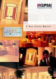
C-BUS SCENE MASTER<br />
SCENE MASTER GIVES YOU TOTAL CONTROL<br />
SCENE MASTER GIVES YOU 5 PRE-SET LIGHTING<br />
SCENES WITH FLEXIBLE CONTROL OF UP TO 33<br />
LIGHTING GROUPS IN COMMERCIAL OR DOMESTIC<br />
ENVIRONMENTS. NOW YOU’RE IN CONTROL.<br />
clipsal.com/cis
TOTAL LIGHTING CONVENIENCE FOR MEETINGS<br />
SWITCHING AND DIMMING PATTERNS ARE<br />
STORED FOR YOUR CONVENIENCE SO THAT A<br />
CONFERENCE ROOM, FOR EXAMPLE, COULD BE<br />
PROGRAMMED TO INSTANTLY CHANGE THE MOOD<br />
AND SUIT THE OCCASION.<br />
CONTENTS<br />
Now You’re in <strong>Control</strong> 1 - 2<br />
Setting Spectacular <strong>Scene</strong>s 1 - 2<br />
How <strong>Scene</strong> <strong>Master</strong> can work for <strong>you</strong> 3 - 4<br />
Using <strong>Scene</strong> <strong>Master</strong> - Commercial Application 5<br />
Using <strong>Scene</strong> <strong>Master</strong> - Residential Application 6<br />
Schematic Overview of connecting a C-<strong>Bus</strong> system 7 - 8<br />
How to Specify <strong>Scene</strong> <strong>Master</strong> 9 - 10<br />
<strong>Scene</strong> <strong>Master</strong> Technical Details 14 - 16<br />
<strong>Scene</strong> <strong>Master</strong> <strong>Control</strong>s La<strong>you</strong>t 15<br />
<strong>Scene</strong> <strong>Master</strong> Mechanical Details 16<br />
The Complete <strong>Clipsal</strong> C-<strong>Bus</strong> System 17 - 20<br />
Input Units<br />
Output Units<br />
System Support Units<br />
Software Tools
1<br />
NOW YOU’RE IN CONTROL<br />
WITH SCENE MASTER YOU HAVE CONTROL OF LIGHTING IN JUST ABOUT ANY KIND OF<br />
MULTI-PURPOSE AND OPEN PLAN AREA YOU CAN THINK OF. COMMERCIAL OR DOMESTIC,<br />
YOU CAN ILLUMINATE ANY AREA PRECISELY AS YOU WANT IT AT THE TOUCH OF A BUTTON.<br />
What’s more, <strong>Scene</strong> <strong>Master</strong> stores up to five lighting<br />
scenes that <strong>you</strong> can change whenever <strong>you</strong> want using<br />
the easy to understand display.<br />
It’s even easier with a hand held infra-red control. And<br />
<strong>Scene</strong> <strong>Master</strong> can control 33 groups of lighting.<br />
The push-button unit gives walls a touch of style. And<br />
because <strong>Scene</strong> <strong>Master</strong> uses sophisticated automation<br />
technology <strong>you</strong> can integrate it with other systems.<br />
It’s this kind of future-proof technology that is now being<br />
integrated within buildings all over the world.<br />
SETTING SPECTACULAR SCENES<br />
IMAGINE THE ROOM IS YOUR CANVAS, AND<br />
LIGHTING IS THE PAINT. WITH SCENE MASTER<br />
YOU HAVE THE BRUSH NEEDED TO DESIGN A<br />
ROOM’S LIGHTING AND CREATE THE PERFECT<br />
MOOD FOR ANY OCCASION.<br />
Plus, <strong>you</strong> can change it whenever <strong>you</strong> want. Up to five<br />
preset lighting scenes can be stored in the unit.<br />
Allowing a room’s lighting to be changed to suit<br />
frequently changing needs.<br />
For instance, in commercial applications, <strong>Scene</strong><br />
<strong>Master</strong> is perfect for conference rooms, executive offices, hotel lobbies, auditoriums, restaurants,<br />
museums, and galleries. It gives <strong>you</strong> the ability to create whatever moods <strong>you</strong> want in busy commercial<br />
areas at the press of a single button.<br />
In residential applications too, <strong>you</strong> can create spectacular effects in theatre rooms, lounge rooms,<br />
bedrooms, and outdoor entertaining areas. <strong>Scene</strong> <strong>Master</strong> means <strong>you</strong> can transform a home’s<br />
environment easily and with spectacular effects whenever <strong>you</strong> want.<br />
SCENE MASTER IS PERFECT<br />
FOR HOTEL LOBBIES<br />
ALL PURPOSE LIGHTING FOR THE FAMILY<br />
2
3<br />
Switching and dimming patterns are stored for <strong>you</strong>r convenience so that a<br />
conference room, for example, could be programmed to instantly change<br />
the mood and suit the occasion. At the office, typical scenes might include:<br />
1. a meeting scene 4. a luncheon scene<br />
2. a presentation scene 5. a formal evening function scene<br />
3. a video presentation scene 6. and the <strong>Master</strong> Off switch<br />
TOTAL LIGHTING CONVENIENCE FOR MEETINGS<br />
HOW SCENE MASTER CAN WORK FOR YOU<br />
PUT SIMPLY, SCENE MASTER MAKES IT EASIER TO CONTROL LIGHTING.<br />
THE EASY TO USE CONTROL PANEL AND INFRA-RED REMOTE CONTROL ALLOW YOU TO<br />
MAKE THE MOST OF ANY MULTI-PURPOSE AREA. AT THE PRESS OF A BUTTON YOU CAN<br />
ACCESS FIVE LIGHTING SCENES PLUS A MASTER OFF SWITCH.<br />
Easy to use<br />
Setting up <strong>you</strong>r preferred lighting scenarios is easy too.<br />
By pressing a few buttons <strong>you</strong> are taken through the<br />
simple step by step process. <strong>Scene</strong> <strong>Master</strong> can actually<br />
‘learn’ the scenes <strong>you</strong> want to use.<br />
You’ll find viewing and altering scenes is just as<br />
simple - so there is no waiting around for technicians<br />
to do it for <strong>you</strong>.<br />
Access from anywhere<br />
You don’t have to be near <strong>Scene</strong> <strong>Master</strong> to use it. For<br />
total convenience the lighting system can be set up<br />
so that a scene can be recalled from any other switch<br />
connected to <strong>Scene</strong> <strong>Master</strong>.<br />
It’s just another way to save <strong>you</strong> time and effort.<br />
Remote control convenience<br />
With a remote control <strong>you</strong> don’t need to leave <strong>you</strong>r<br />
chair. Let’s say <strong>you</strong> were holding a meeting at work and<br />
wanted to present a video during the discussions.<br />
<strong>Scene</strong> <strong>Master</strong>’s credit card size infra-red remote<br />
control lets <strong>you</strong> change the scene easily from<br />
anywhere in the room.<br />
Complete Systems Integration<br />
<strong>Scene</strong> <strong>Master</strong> can set a scene using signals from<br />
other systems as well. For example, <strong>Scene</strong> <strong>Master</strong><br />
can automatically set itself to a video watching scene<br />
whenever the audiovisual equipment is activated.<br />
Multi-purpose lighting<br />
for multi-purpose locations<br />
No matter what the location or kind of lighting, <strong>Scene</strong><br />
<strong>Master</strong> can cater for just about any combination of<br />
lighting, including:<br />
· Downlights<br />
· Wall mounted lights<br />
· Cove lights<br />
· Uplights<br />
· Perimeter lighting<br />
· Task lights<br />
· Wall washers<br />
· Fluorescent lighting<br />
Using any combination of these kinds of lights <strong>you</strong><br />
can program <strong>Scene</strong> <strong>Master</strong> to achieve some spectacular<br />
results. Remember, up to 33 groups of lighting<br />
can be controlled using a single <strong>Scene</strong> <strong>Master</strong> unit.<br />
An economical solution<br />
to yield better results<br />
Traditional electrical wiring systems are a cumbersome<br />
way of controlling multiple lighting systems. Using a<br />
network of wall switches and dimmers not only looks<br />
messy, it can be an expensive way to get the kind of<br />
flexibility <strong>you</strong> want.<br />
<strong>Scene</strong> <strong>Master</strong> not only gives walls a touch of style it<br />
also does the work of several traditional switches at once.<br />
4
USING SCENE MASTER - BOARDROOM APPLICATION USING SCENE MASTER - RESIDENTIAL APPLICATION<br />
5<br />
<strong>Scene</strong> <strong>Master</strong> is connected via C-<strong>Bus</strong> to two four<br />
channel relay units, one four channel 2 Amp dimmer,<br />
one four channel relay and one 0-10V analogue<br />
output unit. The lighting groups connected to C-<strong>Bus</strong><br />
outputs are assigned to the scene buttons and<br />
produce six different lighting patterns within the area.<br />
<strong>Scene</strong> #1 - Welcome Home<br />
Group Level<br />
Main Lounge Lights 90%<br />
Dining Room Lights 90%<br />
Lounge Wall Washer Lights 10%<br />
Dining Room Pendant 10%<br />
Entry Lights 100%<br />
Hallway Lights 90%<br />
Kitchen 90%<br />
<strong>Scene</strong> <strong>Master</strong> is connected via C-<strong>Bus</strong> to two four<br />
channel relay units, one four channel 2 Amp dimmer<br />
and one eight channel 1 Amp dimmer.<br />
<strong>Scene</strong> #2 - Party<br />
Group Level<br />
Main Lounge Lights 30%<br />
Dining Room Lights 30%<br />
Lounge Wall Washer Lights 20%<br />
Dining Room Pendant 30%<br />
Entry Lights 100%<br />
Hallway Lights 50%<br />
Kitchen 50%<br />
Pool Lights 100%<br />
Driveway Lights 100%<br />
<strong>Scene</strong> #3 - Watch a Movie<br />
Group Level<br />
Main Lounge Lights 10%<br />
Dining Room Lights 10%<br />
Lounge Wall Washer Lights 0%<br />
Hallway Lights 50%<br />
Kitchen 50%<br />
Bedroom 2 Lighting<br />
Bedroom 3 Lighting<br />
<strong>Scene</strong> #4 - Reading & Relaxing<br />
Group Level<br />
Main Lounge Lights 50%<br />
Dining Room Lights 0%<br />
Lounge Wall Washer Lights 25%<br />
The lighting groups connected to<br />
C-<strong>Bus</strong> outputs are assigned to the<br />
scene buttons and produce six<br />
different lighting patterns within<br />
the house.<br />
<strong>Scene</strong> #5 - Goodnight<br />
Group Level<br />
Main Lounge Lights 0%<br />
Dining Room Lights 0%<br />
Lounge Wall Washer Lights 0%<br />
Dining Room Pendant 0%<br />
Hallway Lights 10%<br />
Kitchen 0%<br />
Rumpus Room 0%<br />
6
SCHEMATIC OVERVIEW OF CONNECTING A C-BUS SYSTEM<br />
7<br />
THIS IS TO INDICATE THE PRINCIPLES OF C-BUS<br />
CONNECTIONS. PLEASE REFER TO INDIVIDUAL<br />
EQUIPMENT TECHNICAL DATA FOR FULL DETAILS<br />
OF INSTALLATION AND ELECTRICAL CONNECTIONS.<br />
-<br />
-<br />
-<br />
-<br />
-<br />
8
User Interface/<strong>Control</strong><br />
· The wall-mounted controller includes separate<br />
buttons to allow the user to individually dim three<br />
separate groups. The controlled output groups<br />
are programmable via a software assignable<br />
addressing system and are not limited to any<br />
hard wired groups of outputs.<br />
HOW TO SPECIFY SCENE MASTER<br />
TO OBTAIN A COPY OF THIS SPECIFICATION IN ELECTRONIC FORMAT (E.G., ASCII TXT FILE<br />
OR MICROSOFT WORD DOC FILE), PLEASE CONTACT YOU LOCAL CLIPSAL REPRESENTATIVE.<br />
General<br />
· A wall mounted Lighting <strong>Scene</strong> <strong>Control</strong>ler is<br />
provided to allow the user of the system to<br />
access lighting in the nominated areas.Switching,<br />
dimming and scene control are provided by the<br />
unit. The user accesses the controller via buttons<br />
located on the front panel or via a hand held<br />
remote Infra-red controller.<br />
Mechanical<br />
· The <strong>Scene</strong> <strong>Control</strong>ler is suitable for attachment<br />
to either an Australian, British or South African<br />
Standard Electrical Wall Box.<br />
· The unit can be mounted directly to a flat wall<br />
surface via supplied mounting brackets.<br />
· Cable termination is via a single Cat 5 data<br />
cable. No additional mains or low voltage cabling<br />
is required.<br />
· To facilitate daisy chaining of units and as an aid<br />
to maintenance, two loop-in/loop-out removable<br />
terminal blocks are<br />
accessible on the<br />
rear of the unit.<br />
· For ease of<br />
maintenance, the<br />
lighting output units<br />
(dimmers, relays, etc.)<br />
should be mounted<br />
remotely. Output devices<br />
mounted in the wall<br />
(either as an integral part<br />
of the Lighting <strong>Control</strong>ler<br />
or as a separate unit)<br />
will not be accepted.<br />
· The Lighting <strong>Control</strong>ler forms an integral part<br />
of the lighting system and has the capabilities to<br />
communicate with other input and output devices<br />
attached directly to the systems communication<br />
bus, including (but not limited to) Relay Units,<br />
Dimmer Units, Wall mounted Switches, Light Level<br />
Sensors and Passive Infra-red Movement Detectors.<br />
Output Load <strong>Control</strong><br />
· The <strong>Scene</strong> <strong>Control</strong>ler is load size and type<br />
independent and capable of regulating loads such<br />
as incandescent, ELV Tungsten Halogen and HF<br />
or Digital fluorescent ballasts through appropriate<br />
output devices.<br />
Preset <strong>Scene</strong>s<br />
· The Lighting <strong>Control</strong>ler incorporates a<br />
minimum of five programmable preset buttons<br />
associated LEDs. The LEDs indicate whether a<br />
lighting scene is active.<br />
· The user is able to assign and recall a<br />
preset lighting scene directly from the unit. Whilst<br />
acceptable for testing and commissioning<br />
purposes, <strong>Control</strong>lers that require the user to<br />
attach a separate device (e.g., a PC) to program<br />
and re-program scenes will not be accepted.<br />
· The unit has the facility to include a minimum<br />
of nine separate lighting groups as part of each<br />
preset scene. These nine groups are defined<br />
as follows:<br />
· Three of these nine groups (the ‘primary groups’)<br />
are available on all five presets.<br />
· The other six groups (the ‘secondary groups’)<br />
are defined individually on each preset.<br />
Thus, the Lighting <strong>Control</strong>ler has the facility to<br />
control a minimum of thirty-three programmable<br />
groups across the five presets. These thirty-three<br />
groups should have the ability to be associated<br />
with multiple outputs.<br />
9 10
Preset Learning<br />
· The unit has a ‘Setup Mode’ which allows<br />
the Lighting <strong>Control</strong>ler to ‘learn’ required lighting<br />
scenes without the use of a computer. A scene<br />
is learnt by initiating Setup Mode, manually<br />
setting a scene via the <strong>Scene</strong> <strong>Control</strong>ler and<br />
other system input devices (e.g. wall switches)<br />
and assigning a load to a preset button.<br />
Preset Triggering<br />
· It is possible to trigger a preset scene from<br />
an external input device which forms an integral<br />
part of the control system. The external devices<br />
capable of triggering scenes include a separate<br />
<strong>Scene</strong> <strong>Control</strong>ler, and wall mounted input<br />
switches connected directly to the bus system.<br />
Power-up<br />
· If power to the unit is lost, all preset levels are<br />
stored in non-volatile memory.<br />
<strong>Scene</strong> Fade Rate<br />
· When programming a Lighting <strong>Scene</strong>, the user<br />
also has a button available to manually select the<br />
fade (ramp) rate for that scene. As a minimum, the<br />
fade rate is selectable as 0 seconds, 4 seconds,<br />
12 seconds, 60 seconds and 10 minutes. Other<br />
fade rate times between 0 and a minimum of<br />
1020 seconds are assignable through the<br />
system’s software. The fade rate button has an<br />
associated series of LEDs to indicate the chosen<br />
fade rate.<br />
· A second press of each scene button causes the<br />
pre-programmed fade-in rates to be overridden<br />
and the target to be ‘instantly’ established.<br />
<strong>Master</strong> OFF<br />
· A ‘<strong>Master</strong> Off’ button is available on the<br />
Lighting <strong>Control</strong>ler. This <strong>Master</strong> Off button is<br />
programmable to allow the user to selectively<br />
turn off a variable number of controlled output<br />
groups. Pressing the <strong>Master</strong> Off button turns<br />
off all three of the primary groups.<br />
11<br />
· A special fade rate is associated with the <strong>Master</strong><br />
Off button and is indicated following a press of the<br />
<strong>Master</strong> Off button.<br />
Night Light function<br />
· There is provision for a “night light” function.<br />
This option can be enabled or disabled via the<br />
installation software. When enabled, it functions<br />
as follows: If no indicator other than the fade rate<br />
is active on the Lighting <strong>Control</strong>ler (all primary<br />
groups are off) then all five scene indicators will<br />
be dimly lit.<br />
Infra-red Interface<br />
· The hand held Remote control scene buttons<br />
(1 to 5) function as the scene buttons on the<br />
Lighting <strong>Control</strong>ler. The Infra-red <strong>Control</strong>ler effectively<br />
mimics the press scene buttons on the unit.<br />
· The Remote control ‘All Off’ button functions<br />
the same as the master off button on the<br />
Lighting <strong>Control</strong>ler.<br />
· The <strong>Master</strong> Up/Down buttons ramps the 3<br />
primary groups simultaneously. The <strong>Master</strong> Up/<br />
Down buttons on the Infra-red <strong>Control</strong>ler mimics<br />
the functions of the individual up/down buttons on<br />
the Lighting <strong>Control</strong>ler.<br />
· The level change performed by the <strong>Master</strong> Up/<br />
Down buttons on the Infra-red <strong>Control</strong>ler is only<br />
temporary and should not affect the preset levels.<br />
· All the scene button indicators flash when<br />
the scene controller is receiving valid data from<br />
the remote control Lighting <strong>Control</strong>ler.<br />
Self-Testing<br />
· The unit includes a self-test routine.<br />
<strong>Control</strong>ler Type<br />
· The Lighting <strong>Control</strong>ler shall be as a <strong>Clipsal</strong> C-<strong>Bus</strong><br />
<strong>Scene</strong> <strong>Master</strong>, part number 5035NIRS, scene<br />
controller with IR control (part number includes<br />
one 5035TX <strong>Scene</strong> <strong>Master</strong> handheld Infra-red<br />
Remote <strong>Control</strong> unit).<br />
SCENE MASTER TECHNICAL DETAILS<br />
SCENE MASTER CONTROLLER<br />
Catalogue Number 5035NIRS<br />
C-<strong>Bus</strong> Supply Voltage 15-36V DC @ 36mA required for normal operation.<br />
Does not source current to the C-<strong>Bus</strong> network.<br />
AC Input Impedance 50k @ 1kHz<br />
Electrical Isolation 3.75kV RMS. from C-<strong>Bus</strong> to mains<br />
(provided external to 5035NIRS)<br />
<strong>Control</strong> Functions 5 Preset <strong>Scene</strong>s<br />
<strong>Master</strong> Off Function<br />
Multi-Zone Up/Down Dim Functions<br />
Programmable Zone Fade Rates<br />
Maximum Number 33 <strong>Control</strong> Zones (Group Addresses)<br />
of <strong>Control</strong> Zones<br />
Status Indicators Primary 3 x 7 LED BAR GRAPH – Colour Orange<br />
Zone Level Indicators<br />
<strong>Scene</strong> Status x 5 – Colour Orange<br />
Fallback Mode Option Software Programmable low intensity LED illumination setting<br />
Night Light Option Allows permanent <strong>Scene</strong> Status LED illumination at low<br />
brightness level<br />
Maximum Number of Units 50<br />
on a single C-<strong>Bus</strong> Network<br />
Switch Operations >100K operations<br />
Warm Up Time 3 seconds<br />
Network Clock Software selectable<br />
C-<strong>Bus</strong> Connection 2 x Loop-in / Loop-out Removable Terminal Blocks provided<br />
0.2 – 1.5mm 2 (24-16AWG)<br />
Dimensions 175 x 88 x 23.3mm (LxWxD)<br />
Weight 220g<br />
Colour White<br />
Operating Temperature Range 0 – 45°C<br />
Operating Humidity Range 10 – 95% RH<br />
12
UP/DOWN<br />
<strong>Control</strong> for<br />
Primary Zone 1<br />
Brightness Level<br />
Indicator for<br />
Primary Zone 1<br />
<strong>Master</strong> OFF Button<br />
<strong>Scene</strong> 1<br />
Status Indicator<br />
<strong>Scene</strong> 1<br />
Selection Button<br />
<strong>Scene</strong> 2<br />
Selection Button<br />
SCENE MASTER INFRA-RED REMOTE CONTROL<br />
Catalogue Number 5035TX<br />
Supply Voltage 3V DC required for normal operation.<br />
Transmission range reduces with battery voltage.<br />
Battery Lithium Coin Battery CR2025 (or equivalent)<br />
Battery Shelf Life Approximately 1 Year<br />
Infra-red Transmission Range < 15m at 90° to <strong>Scene</strong> <strong>Master</strong> <strong>Control</strong> Unit<br />
Infra-red Transmission Protocol Standard NEC IR Code Compatible<br />
<strong>Control</strong> Functions 8 Membrane Buttons<br />
UNIT CONTROL CAPABILITIES<br />
<strong>Scene</strong> <strong>Control</strong>ler Capabilities<br />
5 Preset <strong>Scene</strong> Buttons<br />
<strong>Master</strong> Off Button<br />
Multi-Zone Up/Down Dim Buttons<br />
Dimensions 86 x 54 x 8mm (LxWxD)<br />
Weight 28g<br />
Colour Black<br />
Number of Zones per unit 33 Zones per unit<br />
Number of Zones per system 255 Zones (Groups) per network<br />
65,025 Zones (Groups) per system<br />
Number of <strong>Scene</strong>s 5 scenes per unit.<br />
250 scenes per network<br />
63,750 scenes per system<br />
Number of units 50 per network<br />
12,225 units per system<br />
SCENE MASTER CONTROLS LAYOUT<br />
13<br />
Protective<br />
Dust Cover<br />
Surround<br />
Fade Rate<br />
Selection Button<br />
<strong>Scene</strong> 5<br />
Status Indicator<br />
<strong>Scene</strong> 5<br />
Selection Button<br />
Infra-red Receiver<br />
Select <strong>Scene</strong> 1<br />
Select <strong>Scene</strong> 2<br />
Select <strong>Scene</strong> 3<br />
Select <strong>Scene</strong> 4<br />
Select <strong>Scene</strong> 5<br />
Infra-red Transmitter<br />
Ramp Down<br />
(Primary Zones)<br />
<strong>Master</strong><br />
OFF<br />
Ramp Up<br />
(Primary<br />
Zones)<br />
MECHANICAL DETAILS<br />
INFRA-RED REMOTE CONTROL<br />
STANDARDS COMPLIED<br />
Standard Title<br />
UNIVERSAL MOUNTING BRACKET<br />
SCENE MASTER CONTROL UNIT<br />
AS/NZS 3100:1997 General Requirements for Electrical Equipment<br />
AS/NZS 3260:1993 Approval and test specification – Safety of<br />
information technology and business equipment<br />
AS/NZS 1044:1995 RFI Emissions Standard<br />
IEC/CISPR 14:1993 RFI Emissions Standard<br />
BS/EN 55014: 1994 RFI Emissions Standard<br />
BS/EN 61000-4-2 Immunity to Electrostatic Discharge<br />
BS/EN 61000-4-3 Immunity to Radio Frequency Interference<br />
BS/EN 61000-4-4 Immunity to Electrical Fast Transients<br />
BS/EN 61000-4-5 Immunity to Surge Voltages<br />
89/336/EEC Electromagnetic Compatibility Directive<br />
14
15<br />
THE COMPLETE CLIPSAL C-BUS SYSTEM<br />
BECAUSE SCENE MASTER IS AN INTEGRAL PART OF THE CLIPSAL C-BUS SYSTEM, IT CAN<br />
BE USED IN CONJUNCTION WITH OTHER C-BUS PRODUCTS TO CREATE A COMPLETE BUILDING<br />
CONTROL SYSTEM. FOR MORE INFORMATION ABOUT OTHER C-BUS PRODUCTS REFER TO THEIR<br />
SEPARATE TECHNICAL DATA SHEETS OR CONTACT YOUR NEAREST CLIPSAL REPRESENTATIVE.<br />
Input Units<br />
Programmable Wall Mounted,<br />
Key Input Units<br />
· 1, 2 or 4 gang switches in standard sized wall plate<br />
· Can be software programmed as function as on /<br />
off switches, dimmers or timers<br />
· Programmable LED status indicators.<br />
· Wide range of styles and finishes including<br />
metallic, with plain or engraved face plates<br />
· Only requires the 2 conductor C-<strong>Bus</strong> cable -<br />
mains power is not required<br />
· 4 gang ‘<strong>Scene</strong> Setting’ version also available for<br />
multiple scene set-up<br />
· 4 gang switch built in with Infra-red receiver also available<br />
(for use with Hand Held Remote <strong>Control</strong>ler)<br />
Auxiliary Input Modules<br />
· Switch Input Modules allow conventional<br />
switches and push-buttons interface with C-<strong>Bus</strong><br />
· Can be software programmed as function as on /<br />
off switches, dimmers, timers or scene setting<br />
· Actions can also be programmed as a result of<br />
contact closures or openings in sensors, smoke<br />
detectors with isolation units, limit switches, level<br />
detectors, phase failure relays, etc.<br />
· The remote switches are electrically isolated from<br />
the C-<strong>Bus</strong> System by the use of transformers on<br />
each channel input<br />
Occupancy Sensors<br />
· Indoor and outdoor passive Infra-red (IP66) models<br />
· All functions separately adjustable and programmable<br />
· Programmable LED indicators<br />
· Walk test light indicator<br />
· Sensitivity & Light level adjustment<br />
· Integrated Light-level sensor, Sunset Switch and<br />
Security modes<br />
· Indoor ultrasonic version and combined<br />
ultrasonic and passive Infra-red indoor version<br />
OCCUPANCY SENSORS<br />
2000, C2000,<br />
B-STYLE AND<br />
SLIMLINE<br />
AUXILIARY<br />
INPUT MODULE<br />
LIGHT LEVEL SENSOR<br />
TEMPERATURE<br />
SENSOR<br />
TIME CLOCK MODULE<br />
REMOTE CONTROLLER<br />
Light Level Sensor<br />
· Measures from 20 to 3000 Lux<br />
· Programmable hysteresis values<br />
· Standard size mounting plate<br />
· Only requires the 2 conductor C-<strong>Bus</strong> cable -<br />
mains power is not required<br />
Temperature Sensor<br />
· Measures from 0° to 50°C, with adjustable<br />
hysteresis<br />
· Standard size mounting plate<br />
· Only requires the 2 conductor C-<strong>Bus</strong> cable -<br />
mains power is not required<br />
· Connects directly to C-<strong>Bus</strong> Network<br />
· Communicates directly with other C-<strong>Bus</strong> devices<br />
· Status light indicator<br />
Time Clock Module<br />
· Allows user override for special events and<br />
situations<br />
· <strong>Control</strong>s 2 separate C-<strong>Bus</strong> Channels and<br />
includes battery back-up<br />
· 7 day time control<br />
· 42 memory locations<br />
· 24 hour time backup<br />
· Vertical & horizontal mount<br />
· LCD clock display<br />
Remote <strong>Control</strong>ler (Infra-red)<br />
· Allows remote control of any standard C-<strong>Bus</strong><br />
function<br />
· Provides scene setting, timer, dimming and other<br />
overrides<br />
· A single remote control can be used to control<br />
a number of rooms without re-programming<br />
· 4 button or 12 button versions available<br />
16
17<br />
Output Units<br />
Professional Series Dimmers<br />
· <strong>Total</strong> unit capacity 20A<br />
· Available as 4 channels x 5A, 2 channels x 10A<br />
and 1 channel x 20A<br />
· Suitable for resistive loads (incandescent lamps)<br />
and inductive Low Voltage lighting transformers<br />
(e.g., 12V dichroic lamps). De-rating factor<br />
applicable for electronic transformers<br />
· Dimming setting for each channel is individually<br />
controllable<br />
· Dimming speeds (ramp-up times) are<br />
independently programmable<br />
· Frequency and amplitude output stability<br />
· Incorporates a C-<strong>Bus</strong> power supply unit (60mA)<br />
· Manual overrides to toggle the output state<br />
· LED output channel status indication<br />
· EMC compliant<br />
DIN Series Dimmers<br />
· <strong>Total</strong> unit capacity 8A<br />
· Available as 8 x 1A channels or 4 x 2A channels<br />
· Suitable for resistive loads (incandescent lamps)<br />
and inductive Low Voltage lighting transformers<br />
(e.g. 12V dichroic lamps). De-rating factor<br />
applicable for electronic transformers<br />
· Versions with and without C-<strong>Bus</strong> power supply units<br />
· Manual overrides to toggle the output state<br />
· LED output channel status indication<br />
· EMC compliant<br />
DIN Mounted Relay Units<br />
· Relay units with voltage free contacts<br />
· 12 Channels x 10A inductive<br />
· 12 Channels x 10A resistive, 1A inductive<br />
· 4 Channels x 10A inductive<br />
· Versions with and without C-<strong>Bus</strong> power supply<br />
units on-board<br />
· Manual overrides to toggle the output state<br />
· LED output channel status indication<br />
PROFESSIONAL SERIES DIMMER<br />
DIN SERIES DIMMER<br />
DIN MOUNTED<br />
RELAY UNITS<br />
FOUR CHANNEL<br />
ANALOGUE OUTPUT<br />
DEVICE<br />
SINGLE AND TWO CHANNEL<br />
RELAY DEVICES<br />
20A FOUR<br />
CHANNEL RELAY<br />
DSI Gateway<br />
· Provides C-<strong>Bus</strong> control of electronic DSI<br />
digital ballasts<br />
· <strong>Control</strong>s up to 100 DSI ballasts per channel<br />
· Channel status indicators<br />
· Faulty lamp/ballast detection and indication<br />
· DSI channel overload detection and indication<br />
· Local manual override buttons<br />
· Remote override facility<br />
Four Channel 0-10V Analogue Output Device<br />
· <strong>Control</strong>s third-party devices that use industry<br />
standard 0-10V or 1-10V dc control voltage<br />
(e.g. electronic controllable fluorescent ballasts)<br />
· Output voltage for each channel is individually<br />
controllable<br />
· Rate of change (ramp time) is independently<br />
programmable<br />
· Able to source or sink control current<br />
Single and Two Channel Relay Devices<br />
· 10A resistive and inductive switching plus 0-10V<br />
dc output<br />
· Compact modules for integration within other<br />
equipment<br />
· Integrated power supplies, override switches<br />
and LED status indicators<br />
20A Four Channel Relay Unit<br />
· Integrated or remote override switches and LED<br />
status indicators also available<br />
· Individual control of each output<br />
· Self-Powered (does not draw current from the<br />
C-<strong>Bus</strong> network)<br />
· Relay is mechanically latched for safety<br />
· Remote Manual Override ON/OFF of all four<br />
channels on a Module<br />
· Capability to switch 20A HID or fluorescent loads<br />
(2000A inrush and 1500A short circuit capabilities)<br />
· No de-rating required for inductive lighting loads<br />
· Manual operation lever built into relay with on/off<br />
indication<br />
18
19<br />
System Support Units<br />
Network Bridge<br />
· Data gateway between C-<strong>Bus</strong> networks.<br />
· Allow isolation of networks whilst maintaining all<br />
communications, and are also used to amplify the<br />
control signals in large installations.<br />
Power Supply Unit<br />
· Converts 240V a.c. input to C-<strong>Bus</strong> 36V d.c.,<br />
maximum C-<strong>Bus</strong> current of 350mA.<br />
· High ac impedance at C-<strong>Bus</strong> communications<br />
frequencies<br />
· Supports up to 18 C-<strong>Bus</strong> units.<br />
· LED Status indicators<br />
· Current overload / limiting protection circuitry<br />
PC Interface<br />
· Gateway between PC (RS232) and a C-<strong>Bus</strong><br />
network<br />
· Provides system clock for synchronised data<br />
communications<br />
· Provides Burden Network to C-<strong>Bus</strong><br />
· Uses a standard 9 pin RS232 serial port<br />
connection<br />
· Allows any external device with RS232 output to<br />
be interfaced to a C-<strong>Bus</strong> system<br />
C-<strong>Bus</strong> Software Tools<br />
C-<strong>Bus</strong> Installation software<br />
· Programming and Commissioning Software Tools<br />
· Ability to group loads in any required<br />
combination of switching combinations<br />
· Provides Manual and Automatic (time based)<br />
control for users who want control the system via<br />
a PC<br />
· Runs under Microsoft Windows 95/98 and NT<br />
NETWORK BRIDGE<br />
POWER SUPPLY UNIT<br />
PC INTERFACE<br />
C-BUS SOFTWARE TOOLS<br />
C-GATE SOFTWARE APPLICATION<br />
C-LUTION GRAPHICAL USER<br />
INTERFACE SOFTWARE APPLICATION<br />
C-Gate Software Application<br />
· C-Gate is the gateway software program which allows<br />
third parties to integrate with the C-<strong>Bus</strong> system<br />
· C-Gate server software can be embedded into<br />
third party software to automatically model the<br />
C-<strong>Bus</strong> network<br />
· C-Gate server is a software platform that monitors<br />
and controls the components of the <strong>Clipsal</strong> C-<strong>Bus</strong><br />
system<br />
· C-Gate uses the industry standard TCP/IP interface<br />
· C-Gate is written in JAVA and so can be ported to<br />
Windows, Linux, Mac OS, or Unix<br />
· C-Gate allows <strong>you</strong> to connect multiple C-<strong>Bus</strong><br />
networks across a TCP/IP backbone. TCP/IP is<br />
the Internet protocol<br />
C-Lution graphical user<br />
interface Software Application<br />
· graphical interface representing the C-<strong>Bus</strong><br />
network and building la<strong>you</strong>t<br />
· Provides Graphical C-<strong>Bus</strong> monitor and control<br />
functions<br />
· Provides C-<strong>Bus</strong> data logging<br />
· C-<strong>Bus</strong> users can monitor in real time if a load is<br />
On, Off or its dimmed level<br />
· C-<strong>Bus</strong> units can be modelled and displayed in<br />
any format<br />
20
A product of<br />
<strong>Clipsal</strong> Integrated Systems Pty Ltd<br />
ABN 15 089 444 931 ACN 089 444 931<br />
Head Office<br />
12 Park Terrace, Bowden<br />
South Australia 5007<br />
PO Box 103 Hindmarsh<br />
South Australia 5007<br />
Telephone (08) 8269 0560<br />
International +61 8 8269 0560<br />
Facsimile (08) 8346 0845<br />
International +61 8 8346 0845<br />
Internet clipsal.com/cis<br />
E-Mail cis@clipsal.com.au<br />
Offices in all States<br />
NSW Sydney (02) 9794 9200<br />
Albury (02) 6041 2377<br />
VIC Melbourne (03) 9207 3200<br />
Country areas 1800 653 893<br />
QLD Brisbane (07) 3244 7444<br />
Townsville (07) 4729 3333<br />
SA Adelaide (08) 8269 0555<br />
WA Perth (08) 9442 4444<br />
TAS Hobart (03) 6272 3177<br />
Launceston (03) 6343 5900<br />
NT Darwin (08) 8947 0278<br />
International Enquiries<br />
Head Office Export Department<br />
Telephone +61 8 8269 0587<br />
Facsimile +61 8 8340 7350<br />
E-Mail export@clipsal.com.au<br />
International Representatives<br />
New Zealand<br />
<strong>Clipsal</strong> Industries (NZ) Ltd (Auckland)<br />
Telephone (09) 576 3403<br />
Facsimile (09) 576 1015<br />
E-Mail headoffice@clipsal.co.nz<br />
Customer Service<br />
Free Fax (0508) 250 305<br />
Auckland/Mobile<br />
Phone (09) 572 0014<br />
Free Phone (0508) CLIPSAL<br />
2547725<br />
Malaysia<br />
<strong>Clipsal</strong> Integrated Systems Sdn Bhd<br />
Lot 26, Jalan Pengapit 15/19<br />
Shah Alam Industrial Estate<br />
40000 Shah Alam<br />
Selangor Darul Ehsan<br />
West Malaysia<br />
Telephone (3) 5519 1122<br />
Facsimile (3) 5512 3155<br />
E-Mail clipsal@clipsaltech.com.my<br />
Patented<br />
Singapore<br />
<strong>Clipsal</strong> Integrated Systems Pte Ltd<br />
No. 5 Fourth Chin Bee Road<br />
Singapore 619699<br />
Telephone (65) 266 1998<br />
Facsimile (65) 266 3922<br />
E-Mail clipsal@clipsaltech.com.sg<br />
Argentina <strong>Control</strong>es Tecnova S.A.<br />
Telephone (114) 207 9534<br />
China <strong>Clipsal</strong> (China) Ltd<br />
Telephone (755) 246 1122<br />
Greece <strong>Clipsal</strong> Hellas S.A.<br />
Telephone (1) 600 3718<br />
Middle East <strong>Clipsal</strong> Middle East<br />
Telephone (6) 557 0777<br />
South Africa <strong>Clipsal</strong> South Africa (Pty) Ltd<br />
Telephone (11) 314 5200<br />
Taiwan <strong>Clipsal</strong> (Taiwan) Co Ltd<br />
Telephone (2) 2558 3456<br />
Thailand <strong>Clipsal</strong> Thailand Ltd<br />
Telephone (2) 952 5338<br />
United Kingdom <strong>Clipsal</strong> Ltd (UK)<br />
Telephone (44) 1494 521111<br />
Vietnam <strong>Clipsal</strong> – VTEC<br />
Telephone (8) 856 3002<br />
© Copyright<br />
<strong>Clipsal</strong> Integrated Systems Pty Ltd 2000<br />
Printed by Custom Press Pty Ltd<br />
(08) 8346 7999<br />
Order No. 17652 00/1