
Create successful ePaper yourself
Turn your PDF publications into a flip-book with our unique Google optimized e-Paper software.
BALANCE<br />
-10 -9 -8 -7 -6 -5 -4 -3 -2 -1 0 1 2 3 4 5 6 7 8 9 10<br />
Mid Side<br />
LEVEL<br />
LOW FLOAT<br />
INSERT MUTE RANGE OFF INSERT<br />
PPM M/S -10dB ACTIVE<br />
FILTER<br />
OFF MUTE<br />
0 0.1 0.2 0.3 0.4 0.5 0.6 0.7 0.8 0.9 1<br />
–/+<br />
-10 -9 -8 -7 -6 -5 -4 -3 -2 -1 0 1 2 3 4 5 6 7 8 9 10<br />
FILTER<br />
STEREO WIDTH<br />
0 0.2 0.4 0.6 0.8 1 1.5 2<br />
OUTPUT LEFT<br />
-16 -15 -14 -13 -10 -8 -5 -2 0 2 3 4 dB<br />
MID<br />
RIGHT<br />
SIDE<br />
<strong>Manual</strong><br />
M/S <strong>Master</strong><br />
M/S <strong>Master</strong><br />
Model 1020<br />
Analog Processor for M/S <strong>Master</strong>ing<br />
VU<br />
Made in Germany<br />
Model<br />
1020
<strong>Manual</strong> M/S <strong>Master</strong>, Model 1020<br />
Version 1.2 – 1/2012<br />
Developer: Wolfgang Neumann<br />
This manual contains a description of the product. It in no way represents a guarantee of<br />
particular characteristics or results of use. The information in this document has been carefully<br />
compiled and verified and, unless otherwise stated or agreed upon, correctly describes<br />
the product at the time of packaging with this document.<br />
Sound Performance Lab (<strong>SPL</strong>) continuously strives to improve its products and reserves the<br />
right to modify the product described in this manual at any time without prior notice. This<br />
document is the property of <strong>SPL</strong> and may not be copied or reproduced in any manner, in part<br />
or fully, without prior authorization by <strong>SPL</strong>.<br />
<strong>SPL</strong> electronics GmbH<br />
Sohlweg 80, 41372 Niederkruechten, Germany<br />
Phone +49 (0)2163 983 40<br />
Fax +49 (0)2163 983 420<br />
E-Mail: info@spl.info<br />
Internet: spl.info<br />
The construction of the MS <strong>Master</strong>, Model 1020, is in compliance with the standards<br />
and regulations of the European Community.<br />
Notes on Environmental Protection<br />
At the end of its operating life, this product must not be disposed of with regular<br />
household waste but must be returned to a collection point for the recycling of<br />
electrical and electronic equipment. The wheelie bin symbol on the product,<br />
user‘s manual and packaging indicates that. The materials can be re-used in<br />
accordance with their markings. Through re-use, recycling of raw materials, or other forms<br />
of recycling of old products, you are making an important contribution to the protection of<br />
our environment. Your local administrative office can advise you of the responsible waste<br />
disposal point.<br />
WEEE Registration: 973 349 88<br />
© 2012 <strong>SPL</strong> electronics GmbH. All rights reserved. Names of other companies and their<br />
products are trademarks of their respective owners.<br />
2 M/S <strong>Master</strong>
Symbols and Notes 4<br />
Scope of Delivery 4<br />
Important Security Information 4<br />
Hook Up 5<br />
Introduction 6<br />
M/S Stereophony 6<br />
M/S <strong>Master</strong>ing, M/S <strong>Master</strong>, Application examples 7<br />
Rear Panel 8<br />
Signal Connections, Input and Output Electronics, MID INSERT, SIDE INSERT 9<br />
XLR sockets, Balanced connections, Unbalanced connections, Power connection and fuse 10<br />
Voltage Selector, Power switch, GND Lift 11<br />
Operation 11<br />
Overview, ACTIVE 11<br />
Control Elements 12<br />
Input settings, BALANCE 12<br />
MID: INSERT, MID: MUTE, LEVEL 13<br />
-/+ FILTER, LOW RANGE, FILTER OFF, FLOAT OFF 14<br />
SIDE: INSERT, SIDE: MUTE, STEREO WIDTH 15<br />
OUTPUT, VU meters, PPM, M/S 16<br />
-10 dB, ACTIVE 17<br />
Working with External Processors 18<br />
Compressor, Equalizer 19<br />
Specifications 20<br />
Copy <strong>Master</strong> Recall Settings 21<br />
M/S <strong>Master</strong><br />
3<br />
Content
Symbols and Notes<br />
Scope of Delivery<br />
Important Security Information<br />
N THIS MANUAL A LIGHTNING SYMBOL WITHIN A TRIANGLE WARNS YOU ABOUT THE<br />
POTENTIAL FOR DANGEROUS ELECTRICAL SHOCKS – WHICH CAN ALSO OCCUR EVEN AFTER<br />
THE MACHINE HAS BEEN DISCONNECTED FROM A POWER SOURCE.<br />
AN EXCLAMATION MARK (!) WITHIN A TRIANGLE IS INTENDED TO MAKE YOU AWARE OF<br />
IMPORTANT OPERATIONAL ADVICE AND/OR WARNINGS THAT MUST BE FOLLOWED. BE<br />
ESPECIALLY ATTENTIVE TO THESE AND ALWAYS FOLLOW THE ADVICE THEY GIVE.<br />
The symbol of a lamp directs your attention to explanations of important functions or applications.<br />
Attention: Do not attempt any alterations to this machine without the approval or supervision<br />
of <strong>SPL</strong> electronics GmbH. Doing so could nullify completely any and all of your warranty/<br />
guarantee rights and claims to user support.<br />
The scope of delivery comprises the Frontliner, the external power supply, the guarantee card<br />
and this manual.<br />
Please keep the original packaging. In case of a service procedure the original packaging<br />
ensures a safe transport. It also serves as a safe packaging for your own transports if you do<br />
not use special transportation cases.<br />
Please note and retain this manual. Carefully read and follow all of the safety and operating<br />
instructions before you use the machine. Be doubly careful to follow all warnings and special<br />
safety instructions noted in this manual and on the unit.<br />
Connections: Only use the connections as described. Other connections can lead to health<br />
risks and equipment damage.<br />
Water and humidity: Do not use this machine anywhere near water (for example near a wash<br />
basin or bath, in a damp cellar, near swimming pools, or the like). In such cases there is an<br />
extremely high risk of fatal electrical shocks!<br />
Insertion of foreign objects or fluids: Never allow a foreign object through any of the machine‘s<br />
chassis openings. You can easily come into contact with dangerous voltage or cause a damaging<br />
short circuit. Never allow any fluids to be spilled or sprayed on the machine. Such actions<br />
can lead to dangerous electrical shocks or fire!<br />
Opening the unit: Do not open the machine housing, as there is great risk you will damage the<br />
machine, or – even after being disconnected – you may receive a dangerous electrical shock!<br />
Electrical power: Run this machine only from power sources which can provide proper power<br />
in the range from 100 to 250 volts. When in doubt about a source, contact your dealer or a<br />
professional electrician. To be sure you have isolated the machine, do so by disconnecting all<br />
power and signal connections. Be sure that the power supply plug is always accessible. When<br />
not using the machine for a longer period, make sure to unplug it from your wall power socket<br />
and from the guitar amp.<br />
Cord protection: Make sure that your power and guitar amplifier signal cords are arranged<br />
to avoid being stepped on or any kind of crimping and damage related to such event. Do not<br />
allow any equipment or furniture to crimp the cords.<br />
Power connection overloads: Avoid any kind of overload in connections to wall sockets,<br />
extension or splitter power cords, or to signal inputs. Always keep manufacturer warnings<br />
and instructions in mind. Overloads create fire hazards and risk of dangerous shocks! ><br />
4 M/S <strong>Master</strong>
Lightning: Before thunderstorms or other severe weather, disconnect the machine from wall<br />
power (but to avoid life threatening lightning strikes, not during a storm). Similarly, before<br />
any severe weather, disconnect all the power connections of other machines and antenna and<br />
phone/network cables which may be interconnected so that no lightning damage or overload<br />
results from such secondary connections.<br />
Air circulation: Chassis openings offer ventilation and serve to protect the machine from overheating.<br />
Never cover or otherwise close off these openings. Never place the machine on a soft<br />
surface (carpet, sofa, etc.). Make sure to provide for a mounting space of 4-5 cm/2 inches to<br />
the sides and top of the unit when mounting the unit in racks or on cabinets.<br />
Controls and switches: Operate the controls and switches only as described in the manual.<br />
Incorrect adjustments outside safe parameters can lead to damage and unnecessary repair<br />
costs. Never use the switches or level controls to effect excessive or extreme changes.<br />
Repairs: Unplug the unit from all power and signal connections and immediately<br />
contact a qualified technician when you think repairs are needed – or when moisture<br />
or foreign objects may accidentally have gotten in to the housing, or in cases<br />
when the machine may have fallen and shows any sign of having been damaged.<br />
This also applies to any situation in which the unit has not been subjected to any<br />
of these unusual circumstances but still is not functioning normally or its performance<br />
is substantially altered.<br />
In cases of damage to the power supply and cord, first consider turning off the main circuit<br />
breaker before unplugging the power cord.<br />
Replacement/substitute parts: Be sure that any service technician uses original replacement<br />
parts or those with identical specifications as the originals. Incorrectly substituted parts can<br />
lead to fire, electrical shock, or other dangers, including further equipment damage.<br />
Safety inspection: Be sure always to ask a service technician to conduct a thorough safety<br />
check and ensure that the state of the repaired machine is in all respects up to factory standards.<br />
Cleaning: In cleaning, do not use any solvents, as these can damage the chassis finish. Use<br />
a clean, dry cloth (if necessary, with an acid-free cleaning oil). Disconnect the machine from<br />
your power source before cleaning.<br />
Be very careful to check that the rear chassis power selection switch is set to the correct<br />
local line voltage position before using the unit (230 V position: 220-240 V/50 Hz, 115 V position:<br />
110-120 V/60 Hz)! When in doubt about a source, contact your dealer or a professional<br />
electrician.<br />
Before connecting any equipment make sure that any machine to be connected is turned off.<br />
Follow all safety instructions on pages 4 and 5 and read further information on connections<br />
on pages 7-10.<br />
Place the unit on a level and stable surface. The unit’s enclosure is EMC-safe and effectively<br />
shielded against HF interference. Nonetheless, you should carefully consider where you place<br />
the unit to avoid electrical disturbances. It should be positioned so that you can easily reach<br />
it, but there are other considerations. Try not to place it near heat sources or in direct sunlight,<br />
and avoid exposure to vibrations, dust, heat, cold or moisture. It should also be kept away<br />
from transformers, motors, power amplifiers and digital processors. Always ensure sufficient<br />
air circulation by keeping a distance of 4-5 cm/2 inches to the sides and top of the unit.<br />
M/S <strong>Master</strong><br />
Important Security Information<br />
5<br />
Hook Up
Introduction<br />
M/S Stereophony<br />
Our ability to identify the direction and distance of a sound source is the essence of spatial<br />
hearing. The human ear can identify level and time differences from ear to ear very precisely<br />
and use that information to localize sound. At frequencies up to 1500 Hz the ear analyzes basically<br />
time differences to localize sound, while above this frequency it uses level differences.<br />
Our hearing provides excellent conditions to apply room information even to artificially generated<br />
sounds. Regardless of the deficiencies and differences that loudspeakers and headphones<br />
might present during playback, the human ear needs only the signals to be codified<br />
in, at least, two channels, in order to be able to identify time and level variations, which result<br />
in spatial hearing.<br />
This sort of recording and playback that includes spatial information is known as stereophony<br />
(from Greek stereos = solid or three-dimensional). The resulting stereo image is called panorama.<br />
Besides the two-channel stereophony there are several other formats of stereophony.<br />
The common conception of „stereo“ as a two-channel recording is thus incorrect.<br />
Equally incorrect is the concept that the encoding of a stereo signal is always done in a right<br />
and a left channel. This idea is based on the fact that we have a right and a left ear and that<br />
all two-channel recording and playback systems use the same right/left format. It is also not<br />
true that all recordings are made with a microphone for the left channel and a microphone for<br />
the right channel.<br />
The differences between the most important microphone techniques have much more to do<br />
with level and time differences. Due to the advantages and disadvantages that each technique<br />
provides, more often than not they are combined during production to achieve L/R playback.<br />
While there are several stereo techniques that can be applied during miking, for signal processing<br />
during production there is only one technique that is actually useful: M/S. „M“ stands for<br />
Middle (or Mid) and „S“ for Side, which means that signals are separated from the middle<br />
to the sides, instead of from left to right. M/S can be actually applied during recording: two<br />
microphones with different polar patterns record direct and spatial information.<br />
– Besides the microphone technique, M/S can also be used as an alternative stereo encoding<br />
for signal processing, which means that signals do not necessarily need to be recorded with<br />
the M/S microphone technique to be able to apply M/S encoding afterwards (at the mastering<br />
stage, for example).<br />
In fact, M/S encoding can be generated from L/R encoding by summing and subtracting<br />
signals:<br />
M = L + R, S = L – R<br />
The sum of the left and right signals in the Mid signal corresponds to the mono signal of the<br />
L/R encoding. The Side signal is also created from the L/R signal by inverting the polarity of<br />
the right channel. The sum of phase-inverted signals results in the cancellation of mono information<br />
in the signals summed; thus, the Side signal is made up of the differences between L<br />
and R. The detailed formula may be clearer: M = L + R, S = L + (-R). The minus sign stands for<br />
the phase inversion.<br />
It is also possible to create a L/R signal encoding from an M/S encoding by summing and<br />
subtracting the signals, what is usually called M/S decoding:<br />
L = M + S, R = M - S<br />
Mathematically, the sum and subtraction of signals guarantees a lossless conversion from<br />
L/R to M/S and back to L/R, which is a very important aspect for using M/S encoding for signal<br />
processing.<br />
6 M/S <strong>Master</strong>
M/S encoding is also used for VHF radio transmission. In this case, the Mid signal is sent with<br />
much higher energy. If the reception is not very good, a stereo receiver can switch to mono to<br />
retain the most important information. A mono receiver will always receive a mono compatible<br />
signal.<br />
Equally beneficial is M/S encoding when using „Joint Stereo“ compression with MP3. As long<br />
as there is almost no information in the side signal, the compression rate can be higher as<br />
with L/R encoding.<br />
Thus, in audio production M/S encoding is the best way to ensure full mono compatibility.<br />
M/S encoded signals provide an adequate way to control and ensure mono compatibility: the<br />
reduction of the Side signal results in the increase of the mono signal.<br />
M/S <strong>Master</strong>ing<br />
The use of a mid (M) and a side (S) signal instead of the usual L/R signal results in a much<br />
wiser musical processing.<br />
High-energy Mid signals (vocals, snare, bass guitars, etc.) can be easily separated from Side<br />
signals (guitars, keyboards, cymbals, etc.). When mastering sum signals, M/S encoding is<br />
often the best option to be able to target single elements within a mix.<br />
The M/S <strong>Master</strong> allows you to directly correct the balance in the mid frequency range and<br />
improve the depth and transparency of stringed instruments. Thanks to the inserts you can<br />
also use filters and effects (compressors, EQs, De-essers) more precisely. Thus, elements<br />
like vocals can be processed without affecting the overall ambience — removing vocal sibilance<br />
doesn‘t affect cymbals, for example. On the other hand, the stereo image can also be<br />
enlarged without affecting the mono information. Not to mention the fantastic possibilities to<br />
process ambience that M/S encoding provides.<br />
M/S <strong>Master</strong><br />
• Analog tool for M/S encoding<br />
• Active control of M/S mix ratio<br />
• Seamless integration of external processors<br />
• One-button insertion of outboard gear in the M/S or L/R path<br />
• Different VU-meter modes<br />
• Low cut filter for the Side signal<br />
• FLOAT function for better mono compatibility<br />
Application examples<br />
• Stereo image enhancement after mixdown or during mastering<br />
• Reverb and ambience reduction without losing brilliance<br />
• Independent processing of rhythmic elements, pads and other sounds placed off the<br />
center of the stereo image without affecting central elements, and viceversa.<br />
• Precise EQ processing of elements that sound too dull<br />
• Specific dynamic correction of lively parts<br />
• Dynamic reduction in Side elements without affecting drum transients<br />
M/S <strong>Master</strong><br />
7<br />
Introduction
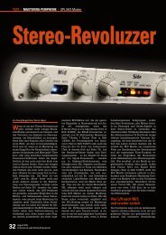
Rear Panel<br />
Console, Patchbay,<br />
DAW/Converter<br />
External Processors<br />
(Equalizer, Reverb ...)<br />
LEFT INPUT RIGHT<br />
RETURN MID INS. SEND<br />
For unbalanced<br />
operation connect<br />
Pin 3 to GND (Pin 1)<br />
RETURN SIDE INS. SEND<br />
LEFT OUTPUT RIGHT<br />
SERIAL No.<br />
CAUTION<br />
RISK OF ELECTRIC SHOCK<br />
DO NOT OPEN<br />
AVIS: RISQUE DE CHOC ÉLECTRIQUE – NE PAS OUVRIR<br />
VOLTAGE | FUSE<br />
230V ~50Hz<br />
315mA slow<br />
I<br />
GND LIFT<br />
0<br />
RIGHT INPUT LEFT<br />
SEND MID INS. RETURN<br />
Pin 2 = (+) hot<br />
Pin 3 = (–) cold<br />
www.spl.info<br />
MADE IN GERMANY RIGHT OUTPUT LEFT<br />
SEND SIDE INS. RETURNPin<br />
1 = GND<br />
GND LIFT<br />
GND<br />
115V ~60Hz<br />
630mA slow<br />
Make sure that<br />
the voltage switch setting<br />
reflects the correct<br />
local power line voltage.<br />
External Processors<br />
(Compressor, DeEsser ...)<br />
Console, Patchbay,<br />
DAW/Converter<br />
Wiring Diagram<br />
Pin wiring XLR output sockets:<br />
1=GND, 2=hot (+), 3=cold (-)<br />
Pin wiring XLR input sockets:<br />
1=GND, 2=hot (+), 3=cold (-)<br />
8 M/S <strong>Master</strong><br />
PUSH<br />
2<br />
1<br />
3<br />
2 1<br />
3
Connections<br />
Signal Connections<br />
Turn off the unit before connecting or disconnecting any cable or equipment to it. Otherwise<br />
you risk the possibility of damaging your ears or equipment.<br />
Input and Output Electronics<br />
The input and output electronics of the M/S <strong>Master</strong> possesses two very distinctive features:<br />
1. Bridge circuits that keep the signal flow constant, regardless of malfunctioning equipment<br />
and power outages (power fail safety by relay hard bypasses).<br />
2. External processors connected to the INSERTs can be used for A/B stereo processing<br />
without the need of any recabling.<br />
The bridge and insert circuits rely on high-quality relays. Contact surfaces are gold-plated to<br />
provide better conductivity and encapsulated to avoid external influences due to climate or<br />
atmospheric conditions.<br />
Power fail safety is only provided under two conditions:<br />
1. If the M/S <strong>Master</strong> is operated in single mode without processors at its inserts, the insert<br />
send/return sockets have to be bridged with XLR patch cables.<br />
2. If the M/S <strong>Master</strong> is operated together with inserted processors, the inserted processors<br />
must have relay hard bypasses, too. Otherwise these machines can break off the signal<br />
flow (also refer to the next chapter „MID INSERT, SIDE INSERT“).<br />
MID INSERT, SIDE INSERT<br />
Both MID and SIDE channels have insert points that enable you to integrate external processors<br />
in each channel‘s path. The INSERT SEND outputs the signal to the external processor;<br />
the processed signal is then input back through the INSERT RETURN.<br />
IMPORTANT: If there are no processors closing the loop, the inserts have to be bridged with<br />
XLR patch cables. Use the shortest cables possible.<br />
You can make a loop with one or more processors and you can even use a patchbay if needed.<br />
IMPORTANT: Cabling does not need to be changed in order to use processors connected to<br />
the M/S <strong>Master</strong> for L/R stereo processing.<br />
Simply disengage the ACTIVE push button on the front panel or turn off the M/S <strong>Master</strong> to<br />
use the processors as you usually would. Thus, the stereo signal is not M/S encoded but<br />
forwarded directly to the connected processors.<br />
NOTE: The VU-meters drop considerably when you disengage the ACTIVE push button while<br />
the MID INSERT and SIDE INSERT push buttons are engaged. If the INSERT push buttons are<br />
not engaged, the VU-meter remains active. This applies to all VU-meter modes and is based<br />
on the complex relay circuits of the inputs, outputs, insert points, and L/R and M/S encoding.<br />
Considering that the push button setting described does not correspond to an actual work<br />
function, it can be neglected.<br />
M/S <strong>Master</strong><br />
9<br />
Rear Panel
Rear Panel Connections<br />
I<br />
0<br />
I<br />
0<br />
XLR sockets<br />
All signal connections are made via balanced XLR connectors. Inputs are always female and<br />
accept male connectors; outputs are always male. All in all, a very comprehensible principle.<br />
Balanced connections<br />
It is impossible to exclude interferences when a single audio signal is transmitted. Shielding<br />
is effective against electric, but not against electromagnetic influences. Motors, transformers,<br />
and alternating current can always induce interferences. But even if the transmission<br />
would succeed, differences in ground potentials between driver and receiver would produce<br />
disturbances.<br />
In balanced connections a reference signal with reversed polarity is transmitted additionally<br />
to the audio signal through a second wire. The ground signal is routed separately through<br />
a third wire. Input and output stages are drivers and receivers, and the receiving stage can<br />
suppress interferences by subtracting the difference between audio and reference signal.<br />
Unbalanced connections<br />
Unbalanced connections from and to RCA or 1/4“ TS sockets can be made without adaptors to<br />
the balanced XLR sockets. The correct wiring is important. The diagram shows the pin configuration<br />
of the XLR sockets and how to correctly connect them for unbalanced connections:<br />
Input Output<br />
balanced unbalanced balanced unbalanced<br />
2<br />
3<br />
1<br />
Connections to RCA sockets are always unbalanced, a wiring to jack connectors can be both<br />
balanced (1/4“ TRS/stereo jack) or unbalanced (1/4“ TS/mono jack). We recommend to use<br />
individually configured cables from XLR to RCA or jack sockets instead of adaptors. You can<br />
get cables in any needed configuration from audio dealers. With the diagram above, the<br />
dealer can ensure to provide the appropriate cable for your application.<br />
Power connection and fuse<br />
2<br />
3<br />
1<br />
1=GND<br />
2=hot (+)<br />
3=cold (-)<br />
1 2<br />
3<br />
1 2<br />
3<br />
Connect the power cord to the rear MAINS INPUT socket. Transformer, power cord and case<br />
connection conform to VDE, UL and CSA requirements.<br />
The fuse is accessible from outside and placed right behind the flap right from the socket.<br />
Fuse ratings are 315 mA slow blow (230 volts) or 630 mA slow blow (115 volts).<br />
10 M/S <strong>Master</strong>
Switches<br />
Voltage Selector<br />
The rear panel VOLTAGE selector sets the local line voltage (115 V position: 110-120 volts/6o Hz,<br />
230 V position: 220-240 volts/50 Hz). The diagram shows the correct switch position for 230 V<br />
power supply.<br />
BEFORE you connect electrical power make sure that the VOLTAGE selector setting reflects<br />
the correct local power line voltage.<br />
Power switch<br />
Use the POWER switch on the rear panel to turn the unit on or off. The VU-meters on the front<br />
panel will light on as soon as you turn the unit on, regardless of the position of the ACTIVE<br />
push button. Thus, they fulfill a second function as power indicators.<br />
GND Lift<br />
The rear panel GND LIFT switch eliminates hum by separating the internal ground from the<br />
unit’s housing ground. Hum can, for example, result when this unit’s housing has a common<br />
ground connection with other devices that might have a different ground potential. The switch<br />
is usually deactivated to retain the shielding of the housing.<br />
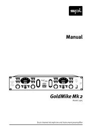
Overview<br />
Overview<br />
The control elements on the front panel of the M/S <strong>Master</strong> are divided into three sections:<br />
MID, SIDE and OUTPUT/VU-meters.<br />
1. In the MID section you adjust the balance of Mid signals in the stereo panorama and their<br />
level.<br />
2. In the SIDE section you define the stereo width and apply filters as well as other functions<br />
to the signal.<br />
3. In the OUTPUT/VU section you adjust the output level, monitor the VU-meters and switch<br />
on, with the ACTIVE push button, the M/S <strong>Master</strong>, as well as engage the insert paths<br />
ACTIVE<br />
BALANCE<br />
-10 -9 -8 -7 -6 -5 -4 -3 -2 -1 0 1 2 3 4 5 6 7 8 9 10<br />
Use the ACTIVE push button to switch on or off the totality of the electronic components of the<br />
M/S <strong>Master</strong>. When switched off, input signals are forwarded directly to the outputs.<br />
The ACTIVE push button accomplishes two very important tasks:<br />
1. A/B comparison between processed and unprocessed audio material.<br />
2. Switching between M/S and A/B stereo processing, including external processing<br />
without the need of any recabling.<br />
Refer to the information on „Input and Output Electronics“ and „MID INSERT, SIDE INSERT“<br />
on page 9.<br />
M/S <strong>Master</strong><br />
Mid Side<br />
LEVEL<br />
VOLTAGE | FUSE<br />
230V ~50Hz<br />
315mA slow<br />
115V ~60Hz<br />
630mA slow<br />
11<br />
GND LIFT<br />
GND LIFT<br />
GND<br />
LOW FLOAT<br />
INSERT MUTE RANGE OFF INSERT<br />
PPM M/S -10dB ACTIVE<br />
FILTER<br />
OFF MUTE<br />
0 0.1 0.2 0.3 0.4 0.5 0.6 0.7 0.8 0.9 1<br />
–/+<br />
-10 -9 -8 -7 -6 -5 -4 -3 -2 -1 0 1 2 3 4 5 6 7 8 9 10<br />
FILTER<br />
STEREO WIDTH<br />
0 0.2 0.4 0.6 0.8 1 1.5 2<br />
OUTPUT LEFT<br />
-16 -15 -14 -13 -10 -8 -5 -2 0 2 3 4 dB<br />
MID<br />
RIGHT<br />
SIDE<br />
ACTIVE<br />
VU<br />
Rear Panel<br />
M/S <strong>Master</strong><br />
I<br />
0<br />
Operation<br />
Made in Germany<br />
Model<br />
1020
Operation<br />
Control Elements<br />
BALANCE<br />
-10 -9 -8 -7 -6 -5 -4 -3 -2 -1 0 1 2 3 4 5 6 7 8 9 10<br />
Input settings<br />
Input settings<br />
Given that all productions are mixed differently, it is impossible to provide general recommendations<br />
regarding settings. By default, settings correspond to a passive M/S encoder without<br />
applying any processing, i.e. L/R stereo is encoded as M/S stereo and the rest of the M/S<br />
<strong>Master</strong> functions have no influence on the sound. This is the best starting point to get to know<br />
the functions and settings of the unit:<br />
MID/BALANCE: 0 (center position)<br />
MID/INSERT and MUTE: OFF<br />
SIDE/FILTER: 0 (center position)<br />
SIDE/all switches: OFF<br />
SIDE/STEREO WIDTH: 1 (around three o‘clock)<br />
OUTPUT: 0 (around three o‘clock)<br />
VU-switch: all OFF<br />
ACTIVE: ON<br />
At this point, when you switch on or off the M/S <strong>Master</strong> processing there is no real difference<br />
in the sound. And this is where the fun begins: the original L/R signal is now M/S encoded and<br />
can be processed with the integrated as well as with external processors.<br />
Do note that the M/S <strong>Master</strong> features exclusively high-quality potentiometers (ALPS RK 27 or<br />
„Big Blue“). But even these potentiometers can exhibit minor imprecisions. Therefore scale<br />
values can be subject to minor deviations. For a perfect 1:1 comparison with the aforementioned<br />
values you ought to consider minor tolerances and compensate if needed. The M/S<br />
<strong>Master</strong> was not conceived to provide a perfect comparison between L/R and M/S encoding.<br />
Its primary goal is individual processing of audio material, therefore, minor deviations in scale<br />
values do not have a considerable impact on the overall performance. If you wish to have<br />
a higher technical precision, you can always use specifically designed measurement equipment<br />
(phase correlation meters, etc.). We have taken these factors in consideration during<br />
development in order to keep a reasonable price/performance ratio.<br />
BALANCE<br />
MID section<br />
Use the BALANCE control to place the Mid signal in the stereo panorama. With this control,<br />
the Mid signal created from the sum of L and R can be placed anywhere along the stereo<br />
panorama. In practice, hard left and hard right are not commonly used: normal settings are<br />
somewhere around +/- 1, and up to 3 at the most. Maximal values are meant to serve as a reference<br />
for testing loudspeakers and acoustical conditions in order to hear if both sides sound<br />
uniformly.<br />
The M/S <strong>Master</strong> provides two measuring instruments to check Mid balance:<br />
1. The VU-meters. If one channel is continuously higher while in L/R display mode, some<br />
adjustment might be needed.<br />
2. A phase correlation meter (or omnimeter). Adjust the BALANCE control in order for the<br />
phase correlation meter to show a perfectly balanced central position..<br />
12 M/S <strong>Master</strong>
MID section<br />
MID: INSERT<br />
Use the INSERT switch to activate the insert point for the Mid channel. You can connect any<br />
mono processor, or a single channel of a stereo unit, to the insert jacks on the rear panel.<br />
As soon as you engage the INSERT switch, the connected units are integrated into the M/S<br />
<strong>Master</strong> processing path. To use the processors independently of the M/S <strong>Master</strong>, as well as<br />
for mono or L/R processing, disengage the ACTIVE switch of the M/S <strong>Master</strong>.<br />
Refer to the information on „Input and Output Electronics“ and „MID INSERT, SIDE INSERT“ on<br />
page 9 and „ACTIVE“ on page 11.<br />
For more information on how to use external processors go to „Working with External<br />
Processors“ on page 18.<br />
MID: MUTE<br />
The MUTE push button silences the Mid signal. There is another MUTE button for the SIDE<br />
section. When you isolate either channel from the other, you can actually concentrate better<br />
and gain a more focused perspective on the audio material of that particular channel. The<br />
relation between the mixed elements is easier to distinguish and, at the same time, overprocessing<br />
becomes much more evident. Focused processing is also made easier and the control<br />
over previous work becomes very revealing.<br />
LEVEL<br />
Use the LEVEL control to set the Mid signal volume in relation to the Side signal. The start<br />
position is set hard right. The more you turn the control to the left, the more the volume decreases.<br />
When turned fully left, the Mid signal disappears completely.<br />
Together with the STEREO WIDTH control in the SIDE section, the LEVEL control determines<br />
the ratio between both channels. Understanding the interdependence of these controls is<br />
essential when working with them. Thus, you should always ponder if it is more appropriate<br />
to decrease one or increase the other. For example: to expand the stereo image without losing<br />
mono compatibility, the most convenient would be to increase the STEREO WIDTH to positive<br />
values. On the contrary, if you were to decrease the LEVEL of the (Mono) Mid signal without<br />
changing the STEREO WIDTH value, mono compatibility would also be affected. Typical application<br />
examples include the need to emphasize or attenuate elements in the Mid signal, with<br />
the intention of modifying the depth of elements (like the vocals) placed at the front or back of<br />
a mix, or even to alter the relation between Mid and Side elements.<br />
In this last case, and as described above, the LEVEL and STEREO WIDTH controls provide optimal<br />
conditions to make delicate adjustments. When it comes to localization, as in the first case, it is<br />
interesting to know that the depth of a signal is strongly influenced by high-frequency, monophonic<br />
differences, which are then shaped by the ear. Sounds above 1.5 kHz coming from in front<br />
of the receiver are more intensely reflected by the ear and are responsible for a good directivity.<br />
Given this, processing the relevant frequency range in the Mid signal with an EQ connected to the<br />
MID INSERT can help modify positioning. Signal presence is intensified by emphasizing frequencies<br />
between 1.5 kHz and 2 kHz, which results in a small increase in the overall level.<br />
Dynamic differences throughout the audio material are one of the most common situations<br />
that require correcting. For example, the level of vocals usually changes when the song goes<br />
from the verse to a chorus, so it might be necessary to control the dynamics. The high quality<br />
of the potentiometers is evident on their perfectly adjusted torque – dynamic adjustments<br />
are thus much more carefully controlled.<br />
M/S <strong>Master</strong><br />
Control Elements<br />
INSERT MUTE<br />
13<br />
Mid<br />
Mid<br />
INSERT MUTE<br />
LEVEL<br />
0 0.1 0.2 0.3 0.4 0.5 0.6 0.7 0.8 0.9 1
Control Elements<br />
–/+<br />
-10 -9 -8 -7 -6 -5 -4 -3 -2 -1 0 1 2 3 4 5 6 7 8 9 10<br />
Side<br />
FILTER<br />
LOW FLOAT<br />
RANGE OFF INSERT<br />
FILTER<br />
OFF MUTE<br />
Side<br />
LOW FLOAT<br />
RANGE OFF INSERT<br />
FILTER<br />
OFF MUTE<br />
Side<br />
LOW FLOAT<br />
RANGE OFF INSERT<br />
FILTER<br />
OFF MUTE<br />
-/+ FILTER<br />
SIDE section<br />
The „-/+“ knob controls the only actual effect on the M/S <strong>Master</strong>: a shelving filter meant to<br />
boost or attenuate low and mid frequencies in the Side signal. The frequency range below<br />
the given cut-off frequency is equally boosted. Use the LOW RANGE push button next to it<br />
to set one of two possible cut-off frequencies, in order to define the frequency range to be<br />
processed (see the next section).<br />
Low and mid frequencies up to 2 kHz are very important when it comes to signal positioning,<br />
that is why the filter is set to affect this specific frequency range. As mentioned before, for<br />
frequencies up to 1.5 kHz it is time differences that define localization. Like any other filter,<br />
the „+/-“ filter affects signal phase, which results in time shifts. An increase in intensity<br />
results in an increase of the influence on the perception of the stereo image according to the<br />
scale (attenuation to the left, boosting to the right).<br />
Thus, filtering of low and mid frequencies increases the correction and shaping possibilities<br />
with the on-board elements of the M/S <strong>Master</strong>. At the same time, the integration of an EQ in<br />
the Side insert broadens even more the possibilities to make selective frequency processing.<br />
The „+/-“ control is therefore a good complement to the STEREO WIDTH setting; the combination<br />
of both provides a wide and effective variety of processing approaches.<br />
LOW RANGE<br />
Use the LOW RANGE push button to set the cut-off frequency of the „+/-“ filter. When<br />
engaged, the cut-off frequency is set to 800 Hz so you can process the low frequency range.<br />
When disengaged, the cut-off frequency is set to 2.2 kHz, which means that the „+/-“ filter<br />
processes all frequencies below 2.2 kHz.<br />
FILTER OFF<br />
Use this push button to disengage the „+/-“ filter. By disengaging the filter, the processing is<br />
done solely on the Side signal encoded directly from the original L/R signal. Thus, the actual<br />
L/R stereo image, ambience, etc. can be accurately appraised and processed if needed.<br />
FLOAT OFF<br />
FLOAT refers to a signal created from L/R that is mixed with the Side signal. Actually, in<br />
addition to the L/R signal, from where the M/S encoding is created, a part of the L/R signal<br />
(reduced in level) is attached to the Side signal. This is done as a parallel process, i.e. it is not<br />
added to the encoded signal. This portion accounts for 10% at the most.<br />
Mixing the FLOAT signal with the Side signal has two major advantages:<br />
1. It avoids the risk of having a negative phase correlation ratio.<br />
2. The less substance the Side signal has, the easier and safer the processing is with the<br />
FLOAT signal.<br />
In relation to 1: Even extremely wide stereo images remain mono compatible. In this case,<br />
FLOAT extends the bandwidth, so a compromise between mono compatibility and stereo<br />
image is easier to reach.<br />
In relation to 2: If the original Side signal is made up of ambience or pad sounds, processing<br />
can be very difficult. The risk of extreme settings is quite high because it is very hard to identify<br />
sonic differences clearly. Thus, the FLOAT signal provides a good sonic reference – even<br />
if only during processing. After all, the FLOAT signal can be turned off anytime (once you are<br />
done optimizing settings, for example).<br />
Engage the FLOAT OFF push button to listen only to the Side signal created from the M/S encoding.<br />
14 M/S <strong>Master</strong>
SIDE section Control Elements<br />
SIDE: INSERT<br />
Use the INSERT switch to activate the insert point for the Side channel. You can connect any<br />
mono processor, or a single channel of a stereo unit, to the insert jacks on the rear panel.<br />
As soon as you engage the INSERT switch, the connected units are integrated into the M/S<br />
<strong>Master</strong> processing path. To use the processors independently of the M/S <strong>Master</strong>, as well as<br />
for mono or L/R processing, disengage the ACTIVE switch of the M/S <strong>Master</strong>.<br />
Refer to the information on „Input and Output Electronics“ and „MID INSERT, SIDE INSERT“ on<br />
page 9 and „ACTIVE“ on page 11.<br />
For more information on how to use external processors go to „Working with External<br />
Processors“ on page 18.<br />
SIDE: MUTE<br />
The MUTE push button mutes the Side signal. There is another MUTE button for the MID<br />
section. When you isolate either channel from the other, you can actually concentrate better<br />
and gain a more focused perspective on the audio material of that particular channel. The<br />
relation between the mixed elements is easier to distinguish and, at the same time, overprocessing<br />
becomes much more evident. Focused processing is also made easier and the control<br />
over previous work becomes very revealing.<br />
STEREO WIDTH<br />
Use the STEREO WIDTH control to adjust the Side signal level in relation to the Mid signal.<br />
When set to 1 (around two o‘clock) there is no difference, i.e. the signal is played back 1:1.<br />
As you turn the control to the right, the Side signal is made bigger. When set hard right (2)<br />
the stereo image is 200% wider. As you turn the control to the left, the Side signal is made<br />
smaller. When set hard left, the Side signal is muted.<br />
Adjustment of the STEREO WIDTH should always be made taking into account the settings<br />
of the „+/-“ filter and the LEVEL control in the MID section. Understanding the interdependence<br />
of these controls is essential when working with them. Thus, you should always ponder<br />
if it is more appropriate to decrease one or increase the other. For example: to expand the<br />
stereo image without losing mono compatibility, the most convenient would be to increase<br />
the STEREO WIDTH to positive values. On the contrary, if you were to decrease the LEVEL of<br />
the (Mono) Mid signal without changing the STEREO WIDTH value, mono compatibility would<br />
also be affected.<br />
The interaction with the „+/-“ filter is quite simple and it could almost be described as a<br />
coarse/fine adjustment: if you have already set the stereo image, you can use the „+/-“ filter<br />
to focus on the details. Please refer to „+/- FILTER“ on page XXX for more important information.<br />
Typical applications where the use of STEREO WIDTH comes in handy are recordings with too<br />
little room ambience (in studios, for example) or too much room ambience (in places with a<br />
reverb time of more than five seconds, like churches). M/S encoding is rather useful to solve<br />
problems that are very difficult or even impossible to work through in L/R format: speech<br />
transmission during events can be easily isolated to improve intelligibility, regardless of the<br />
unfavorable acoustics of a room, hall or stadium.<br />
M/S <strong>Master</strong><br />
15<br />
Side<br />
LOW FLOAT<br />
RANGE OFF INSERT<br />
FILTER<br />
OFF MUTE<br />
Side<br />
LOW FLOAT<br />
RANGE OFF INSERT<br />
FILTER<br />
OFF MUTE<br />
STEREO WIDTH<br />
0 0.2 0.4 0.6 0.8 1 1.5 2
Control Elements<br />
LEFT<br />
MID<br />
OUTPUT<br />
RIGHT<br />
-16 -15 -14 -13 -10 -8 -5 -2 0 2 3 4 dB<br />
PPM M/S<br />
VU<br />
PPM M/S<br />
VU<br />
-10dB<br />
-10dB<br />
SIDE<br />
OUTPUT<br />
Output & VU section<br />
Use the OUTPUT control to attenuate the output signal up to -16 dB or boost it up to +4 dB,<br />
in order to match it to the following unit in the chain. The output level on the VU-meter is<br />
indicated in PPM mode. Before starting any processing, always set the OUTPUT control to 0<br />
(around three o‘clock). That way you can read the Mid and Side signal levels on the VU-meter<br />
without the output setting having any influence on them.<br />
VU meters<br />
The VU meters (VU = Volume Unit) measure the output level, which ranges from -20 dB to<br />
+5 dB. The meters show the changes in level caused by processing the signal with the M/S<br />
<strong>Master</strong>. The VU meters have two different operating modes: L/R or M/S. That way you can<br />
always have an accurate level reading while working with the M/S <strong>Master</strong> – including the<br />
changes in level that may be caused by external processors. You may find more detailed information<br />
under the descriptions of the „PPM“, „M/S“ and „-10 dB“ push buttons.<br />
PPM<br />
Use the VU/PPM push button to toggle between VU and PPM display mode. VU mode shows<br />
average level readings and therefore provides information on the overall loudness or energy<br />
of the signal.<br />
PPM mode (PPM = Peak Program Meter) indicates peak levels, similar to AD converter meters,<br />
where it is important to control peak levels in order to avoid the converter from saturating and<br />
distorting. Sometimes it can be useful to activate the -10 dB push button while in PPM mode<br />
to extend the display range.<br />
M/S<br />
Use the M/S push button to toggle between L/R output level display (M/S push button disengaged)<br />
and M/S level display (M/S push button engaged).<br />
The VU-meters are labeled „LEFT“ and „RIGHT“ respectively (left, above the meters). When in<br />
M/S mode, the labels that apply are „MID“ and „SIDE“ (right, below the meters).<br />
In L/R mode the level shown is post output control, which means that it takes into account all<br />
processing that you have made with the M/S <strong>Master</strong>, including the OUTPUT control.<br />
In M/S mode it shows the output signals of the Mid and Side channels respectively. That way<br />
you can see how processing, including external processors, affects level relations in M/S<br />
encoding. Level changes produced by the OUTPUT control are not shown in M/S mode. To<br />
keep track of the L/R output level switch to L/R mode (M/S push button disengaged).<br />
16 M/S <strong>Master</strong>
Output & VU section<br />
-10 dB<br />
Use this push button to reduce 10 dB the sensitivity of the VU-meters. When the VU-meters‘<br />
needle points at 0 db, it actually corresponds to -10 dBu and the maximum value is +15 dB.<br />
The sensitivity switch allows you to analyze very high level signals that would otherwise be<br />
beyond the range of a normal meter.<br />
ACTIVE<br />
Use the ACTIVE push button to switch on or off the processing electronics of the M/S <strong>Master</strong>.<br />
When switched off, input signals are forwarded directly to the outputs.<br />
The ACTIVE push button accomplishes two very important tasks:<br />
1. A/B comparison between processed and unprocessed audio material.<br />
2. Switching between M/S and A/B stereo processing, including external processing<br />
without the need of any recabling.<br />
Refer to the information on „Input and Output Electronics“ and „MID INSERT, SIDE INSERT“<br />
on page 9.<br />
M/S <strong>Master</strong><br />
Control Elements<br />
17<br />
PPM M/S<br />
ACTIVE<br />
VU<br />
-10dB
Working with External Processors<br />
We will describe in detail the two most common types of processing units used: compressors<br />
(to process dynamics) and equalizers (to correct or shape signals based on frequency).<br />
You can obviously connect all sorts of processors to the inserts of the M/S <strong>Master</strong>: reverb and<br />
delay effects, a De-esser in the MID INSERT to reduce vocal sibilance, tube processors to add<br />
character to the sound... Whatever suits your needs.<br />
Compressor<br />
Compressor<br />
Compressors are usually used at the mastering stage to increase level across the entire<br />
frequency spectrum. Loud level peaks are attenuated and the dynamic range of the mix as<br />
a whole is reduced. Afterwards, the signal‘s average level is increased to the original value.<br />
This conventional use of a compressor might or might not work, it depends. Over the last<br />
two decades, dynamic range reduction has steadily increased; almost at the same pace as<br />
sonic quality has decreased – insofar as musically oriented dynamic relationships are used<br />
as benchmark. When optimizing dynamic structures, M/S encoding offers significant advantages<br />
over the across-the-board approach of sum compression in L/R format. M/S encoding<br />
allows you to focus on single elements of finished mixes, making it easier to increase overall<br />
loudness while preserving the dynamic range.<br />
Let‘s take, for example, a pop song that sounds fairly balanced, even though the vocals are a<br />
bit too high within the mix. With a compressor in the MID INSERT, you can reduce the level of<br />
the vocals as one of the main elements in the Mid signal. Backing vocals and harmonic instruments,<br />
as well as all other elements of the Side signal, are left untouched.<br />
The compressor‘s „Auto Gain“ or similar functions should be avoided. Make-up gain shouldn‘t<br />
be necessary either. Otherwise, the (mono) Mid signal could become too loud and other<br />
central instruments like bass drum, snare, bass guitar, etc. could result too imposing. Unless,<br />
of course, the Mid signal needs a push to come through in the mix due to a very dominant Side<br />
signal. When it comes to depth (front/back positioning), there are some EQ techniques that<br />
are very useful and do not affect the overall level too much. Read the section „Equalizer“.<br />
You can always compress a loud Side signal if there are certain instruments that stand out too<br />
much in that channel. The mix will sound more balanced and compact without affecting the<br />
dynamic range and transient structure of the snare and bass drum.<br />
Heavy compression on the Side signal can be also useful to enhance the room ambience of a<br />
mix.<br />
18 M/S <strong>Master</strong>
Equalizer Working with External Processors<br />
Equalizer<br />
The possibilities that an equalizer provides when working with the Mid or Side signals correspond<br />
to the normal applications of an EQ, the full scope of which is beyond our purpose.<br />
Two of the most common functions of an EQ ought to be more than enough to illustrate<br />
the potential of using it as an INSERT: attenuation of low frequencies and boosting of high<br />
frequencies.<br />
Among the most common problems of a mix are booming synth pads and guitar walls with a<br />
very deep frequency response. They can make a Side signal too dense or clash with important<br />
low frequency signals – like bass guitar and bass drum – usually found in the Mid signal. With<br />
an EQ in the MID and/or SIDE INSERT you can focus on that specific frequency range in order<br />
to avoid conflicts. The Mid signal is thus cleansed and the primal elements become more<br />
precise and distinguishable. Selective EQ can give the Side signal more air, making cymbals<br />
and harmonic instruments sound more present without adding too much sharpness to vocals.<br />
Increasing high frequencies in the Side signal usually results in a wider stereo image with a<br />
solid center image.<br />
Another interesting possibility is the processing of individual elements of a mix to affect positioning.<br />
The depth of a signal is strongly influenced by high-frequency, monophonic differences,<br />
which are then shaped by the ear. Sounds above 1.5 kHz coming from in front of the<br />
receiver are more intensely reflected by the ear and are responsible for a good directivity. In<br />
this situation, an EQ can be used to process the frequency range in question (generally speaking,<br />
this will affect Mid signals so you will have to use the MID INSERT). Signal presence is<br />
intensified by emphasizing frequencies between 1.5 kHz and 2 kHz, which results in a small<br />
increase in the overall level.<br />
M/S <strong>Master</strong><br />
19
Specifications<br />
Inputs & Outputs<br />
Electronically balanced instrumentation amplifiers<br />
Sockets: XLR<br />
Input impedance: 20 kOhm balanced/10 kOhm unbalanced<br />
Output impedance: 150 Ohm balanced/75 Ohm unbalanced<br />
Max. input level: 20 dBu<br />
Max. output level: 20 dBu<br />
Measurements<br />
Frequency response (-3 dB): 10 Hz - 100 kHz<br />
Common mode rejection ratio: › 60 dB<br />
(@ 1 kHz, 0 dBu input level and unity gain)<br />
Total harmonic distortion & noise: 0,007 %<br />
(@ 1 kHz, 0 dBu input level and unity gain)<br />
Signal to noise ratio (A-weighted): -82 dB<br />
Dynamik range (unweighted): 102 dB<br />
Power supply<br />
Toroidal transformer<br />
Fuses: 230 V AC, 50 Hz: 315 mA; 120 V AC, 60 Hz: 630 mA<br />
Voltage selector: 115V/230V<br />
Power consumption: @ 230 V: 9,1 W/10,8 VA ; @ 115 V: 5,6 W/7,1 VA<br />
Dimensions and Weight<br />
Housing (W x H x D):<br />
(depth including controls and sockets)<br />
482 x 88 x 320 mm<br />
Weight: 3,6 kg/7,94 lbs<br />
Notes: 0 dBu = 0,775 V. Specifications subject to change without notice.<br />
20 M/S <strong>Master</strong>
SIDE<br />
VU<br />
Made in Germany<br />
-10 -9 -8 -7 -6 -5 -4 -3 -2 -1 0 1 2 3 4 5 6 7 8 9 10<br />
-10 -9 -8 -7 -6 -5 -4 -3 -2 -1 0 1 2 3 4 5 6 7 8 9 10<br />
FILTER<br />
MID<br />
Model<br />
1020<br />
0 0.1 0.2 0.3 0.4 0.5 0.6 0.7 0.8 0.9 1<br />
0 0.2 0.4 0.6 0.8 1 1.5 2<br />
-16 -15 -14 -13 -10 -8 -5 -2 0 2 3 4 dB<br />
LOW FLOAT<br />
INSERT MUTE RANGE OFF INSERT<br />
PPM M/S -10dB ACTIVE<br />
FILTER<br />
OFF MUTE<br />
BALANCE<br />
Mid Side<br />
STEREO WIDTH<br />
RIGHT<br />
LEVEL<br />
–/+<br />
OUTPUT LEFT<br />
M/S <strong>Master</strong><br />
Title:<br />
Date:<br />
Album/Gig:<br />
Track(s)/Groups:<br />
Artist:<br />
Engineer:<br />
Copy <strong>Master</strong> Recall Settings
<strong>Manual</strong> M/S <strong>Master</strong>, Model 1020