Chapter 2 Software Functions - DCA
Chapter 2 Software Functions - DCA
Chapter 2 Software Functions - DCA

Create successful ePaper yourself
Turn your PDF publications into a flip-book with our unique Google optimized e-Paper software.
ABB Safety Safeguard 400 Series<br />
Product Guide<br />
August, 2000
Use of�������,��������,��������, and�����<br />
This publication includes, ������, �������, �������, and ���� information where appropriate to point out safety<br />
related or other important information.<br />
������ Hazards which could result in severe personal injury or death<br />
������� Hazards which could result in personal injury<br />
������� Hazards which could result in equipment or property damage<br />
���� Alerts user to pertinent facts and conditions<br />
Although ������ and ������� hazards are related to personal injury, and ������� hazards are associated with<br />
equipment or property damage, it should be understood that operation of damaged equipment could, under certain operational<br />
conditions, result in degraded process performance leading to personal injury or death. Therefore, comply fully with all<br />
������, �������, and ������� notices.<br />
����������<br />
Advant, AdvaCommand, AdvaInform, and AdvaBuild are registered trademarks of ABB Asea Brown Boveri Ltd. Switzerland.<br />
Safeguard 400 Series is a trademark of ABB Industri AS, Norway.<br />
������<br />
The information in this document is subject to change without notice and should not be construed as a commitment by ABB<br />
Industri AS. ABB Industri AS assumes no responsibility for any errors that may appear in this document.<br />
In no event shall ABB Industri AS be liable for direct, indirect, special, incidental or consequential damages of any nature or<br />
kind arising from the use of this document, nor shall ABB Industri AS be liable for incidental or consequential damages arising<br />
from use of any software or hardware described in this document.<br />
This document and parts thereof must not be reproduced or copied without ABB Industri AS’s written permission, and the<br />
contents thereof must not be imparted to a third party nor be used for any unauthorized purpose.<br />
The software described in this document is furnished under a license and may be used, copied, or disclosed only in accordance<br />
with the terms of such license.<br />
����������<br />
This product meets the requirements specified in EMC Directive 89/336/EEC and in Low Voltage Directive 72/23/EEC.<br />
Copyright © ABB Industri AS 2000.<br />
Template: 3BSE001286/E<br />
3BNP000431R301<br />
3BSE001264/D
<strong>Chapter</strong> 1 - Introduction<br />
�����������������<br />
������������� TM ��������������������<br />
�����������������<br />
1.1 Overview.................................................................................................................. 1-1<br />
1.2 General information................................................................................................. 1-1<br />
1.3 Safeguard design concept ........................................................................................ 1-4<br />
1.4 Applications............................................................................................................. 1-6<br />
1.4.1 Process safeguarding............................................................................... 1-6<br />
1.4.2 Plant/Area safeguarding and personnel safety........................................ 1-8<br />
1.4.3 Application implementation ................................................................... 1-8<br />
1.4.3.1 AMPL............................................................................... 1-8<br />
1.4.3.2 Safety Builder .................................................................. 1-9<br />
1.5 Theory of operation ................................................................................................. 1-9<br />
1.5.1 Dual controller structure ......................................................................... 1-9<br />
1.5.2 Single controller structure..................................................................... 1-10<br />
1.6 Certification ............................................................................................................1-11<br />
<strong>Chapter</strong> 2 - <strong>Software</strong> <strong>Functions</strong><br />
2.1 Safeguard 400 Series <strong>Software</strong>................................................................................ 2-1<br />
2.1.1 General base system operation ............................................................... 2-1<br />
2.1.2 AMPL Safeguard features ...................................................................... 2-2<br />
2.1.3 Cause & Effect programming ................................................................. 2-3<br />
2.1.4 Safeguard 400 Series Central Processing Unit ....................................... 2-3<br />
2.1.5 Basic system testing................................................................................ 2-4<br />
2.1.6 Master Vote 3000 safety outputs............................................................. 2-5<br />
2.1.6.1 Signal processing ............................................................. 2-6<br />
2.1.6.2 Output testing................................................................... 2-7<br />
2.1.7 Bypass Management............................................................................... 2-7<br />
2.1.7.1 Operator station access control ........................................ 2-7<br />
2.1.7.2 On-Line Builder (engineering tool) access control.......... 2-8<br />
2.1.7.3 Override control and reset................................................ 2-8<br />
2.2 Operator Interface <strong>Software</strong>..................................................................................... 2-8<br />
2.2.1 General.................................................................................................... 2-8<br />
2.2.2 Safety functions ...................................................................................... 2-9<br />
2.2.3 System security......................................................................................2-11<br />
2.2.4 AdvaCommand user interface .............................................................. 2-12<br />
2.2.4.1 User defined displays ..................................................... 2-14<br />
2.2.5 Predefined reports (Status lists) ............................................................ 2-17<br />
2.2.6 Alarm management............................................................................... 2-19<br />
2.2.7 Safety management............................................................................... 2-20<br />
3BNP000431R301 i
������������� TM ����������������������<br />
�����������������<br />
2.2.8 Matrix and mimic panels....................................................................... 2-21<br />
2.3 Safeguard Handler for Advant Enterprise Historian.............................................. 2-21<br />
2.4 Engineering <strong>Software</strong> for AS 100 Series ES.......................................................... 2-21<br />
2.4.1 General .................................................................................................. 2-21<br />
2.4.2 Advant Engineering Workplace ............................................................ 2-22<br />
2.4.3 AMPL Control Configuration............................................................... 2-22<br />
2.4.3.1 Application Builder ........................................................ 2-23<br />
2.4.3.2 Function Chart Builder................................................... 2-24<br />
2.4.3.3 Bus Configuration Builder ............................................. 2-24<br />
2.4.3.4 On-line Builder............................................................... 2-24<br />
2.4.4 Computer Aided Electrical Engineering ............................................... 2-25<br />
2.4.4.1 Electrical Diagram Builder - Wiring Builder ................. 2-25<br />
2.4.5 AdvaBuild Safety Builder..................................................................... 2-26<br />
2.4.6 Safeguard Configuration Builder .......................................................... 2-27<br />
2.5 Communication software and functions................................................................. 2-27<br />
2.5.1 MasterBus 300 ...................................................................................... 2-27<br />
2.5.2 RCOM/RCOM+.................................................................................... 2-29<br />
2.5.3 MVI-MODBUS..................................................................................... 2-29<br />
2.5.4 AF 100................................................................................................... 2-30<br />
2.6 Application <strong>Software</strong> ............................................................................................. 2-32<br />
2.6.1 General .................................................................................................. 2-32<br />
2.6.2 Application unit..................................................................................... 2-32<br />
2.6.2.1 Fire & Gas ...................................................................... 2-32<br />
2.6.2.2 Shutdown........................................................................ 2-32<br />
2.6.2.3 High Integrity Dual Loop ............................................... 2-33<br />
<strong>Chapter</strong> 3 - Hardware <strong>Functions</strong><br />
3.1 General Information................................................................................................. 3-1<br />
3.1.1 Safeguard 410.......................................................................................... 3-1<br />
3.1.2 Safeguard 415.......................................................................................... 3-1<br />
3.1.3 Input/Output hardware ............................................................................ 3-2<br />
3.2 S100 I/O ................................................................................................................... 3-2<br />
3.2.1 Input subsystem....................................................................................... 3-3<br />
3.2.1.1 DSAI 160, loop monitored digital inputs ......................... 3-4<br />
3.2.1.2 DSAI 165, Gas Inputs, catalytic detectors........................ 3-6<br />
3.2.1.3 DSAI 130, Analog Inputs................................................. 3-6<br />
3.2.1.4 DSAI 133, Analog Inputs................................................. 3-7<br />
3.2.1.5 DSAI 133N, Safety Analog Inputs................................... 3-7<br />
3.2.1.6 DSAI 110, Analog Inputs ................................................. 3-7<br />
3.2.1.7 DSDI 110A, Digital Inputs............................................... 3-7<br />
ii 3BNP000431R301
������������� TM ��������������������<br />
�����������������<br />
3.2.1.8 DSDI 110N, Safety Digital Inputs ................................... 3-8<br />
3.2.2 Output Subsystem................................................................................... 3-8<br />
3.2.2.1 Master Vote 3000, safety digital outputs.......................... 3-8<br />
3.2.2.2 DSDO 110/115, Digital Outputs .................................... 3-13<br />
3.2.2.3 DSAX 110, Analog Outputs/Inputs ............................... 3-14<br />
3.2.2.4 DSAO 130, Analog Outputs .......................................... 3-14<br />
3.3 Addressable detector systems ................................................................................ 3-14<br />
3.3.1 Fire detection ........................................................................................ 3-15<br />
3.3.1.1 Fireguard ........................................................................ 3-15<br />
3.3.1.2 Autronica BS-100 .......................................................... 3-15<br />
3.4 External Watch Dog............................................................................................... 3-15<br />
3.5 Advant Engineering Workplace............................................................................. 3-15<br />
3.6 Advant Operator Workplace .................................................................................. 3-16<br />
3.7 Communication hardware...................................................................................... 3-16<br />
3.7.1 MasterBus 300 ...................................................................................... 3-16<br />
3.7.2 RCOM/RCOM+ ................................................................................... 3-18<br />
3.7.3 MVI-MODBUS .................................................................................... 3-18<br />
3.7.4 AF100 ................................................................................................... 3-19<br />
<strong>Chapter</strong> 4 - Product Configuration and Documentation<br />
4.1 Application Program Configuration ........................................................................ 4-1<br />
4.1.1 Tools and procedures .............................................................................. 4-1<br />
4.2 System configuration ............................................................................................... 4-2<br />
4.2.1 Safeguard 410/415 basic unit.................................................................. 4-4<br />
4.2.2 Safeguard 415 extension S100 I/O racks................................................ 4-5<br />
4.2.3 Available I/O unit positions .................................................................... 4-8<br />
4.2.4 Capacity and performance ...................................................................... 4-8<br />
4.2.5 Master Vote 3000 output system configuration ...................................... 4-9<br />
4.2.6 Addressable fire input configuration .................................................... 4-10<br />
4.2.7 MB 300 network configuration............................................................. 4-10<br />
4.3 System Power Supplies and Distribution................................................................4-11<br />
4.3.1 System power supply.............................................................................4-11<br />
4.3.2 Field power supply.................................................................................4-11<br />
4.3.3 Compact power supply ..........................................................................4-11<br />
4.4 Reference Guide .................................................................................................... 4-15<br />
4.5 Advant Operator Interface Products ...................................................................... 4-37<br />
4.5.1 Product Benefits.................................................................................... 4-37<br />
4.5.2 Features................................................................................................. 4-38<br />
4.6 Advant Engineering Products ................................................................................ 4-39<br />
4.6.1 Product Benefits.................................................................................... 4-39<br />
3BNP000431R301 iii
������������� TM ����������������������<br />
�����������������<br />
4.6.2 Advant Engineering Products ............................................................... 4-40<br />
4.7 Advant Engineering Workplace ............................................................................. 4-40<br />
4.7.0.1 Product Benefits and Features........................................ 4-41<br />
4.7.1 AMPL Control Configuration............................................................... 4-41<br />
4.7.1.1 Product Benefits and Features........................................ 4-41<br />
4.7.2 Computer Aided Electrical Engineering ............................................... 4-42<br />
4.7.2.1 Product Benefits and Features........................................ 4-42<br />
4.7.3 Advant Station 100 Series..................................................................... 4-42<br />
4.7.3.1 Product Benefits and Features........................................ 4-43<br />
iv 3BNP000431R301
ILLUSTRATIONS<br />
������������� TM ��������������������<br />
�����������������<br />
Figure 1-1. Structure and tasks of a safety system.......................................................... 1-2<br />
Figure 1-2. Integrated process control and safety system ............................................... 1-3<br />
Figure 1-3. Operator Station presentation of an ESD application................................... 1-7<br />
Figure 1-4. Dual controller principle............................................................................. 1-10<br />
Figure 1-5. Single controller principle ...........................................................................1-11<br />
Figure 2-1. Database entry for a Normally Closed loop monitored digital input ........... 2-1<br />
Figure 2-2. Isolate and shutdown/activate signal operation............................................ 2-6<br />
Figure 2-3. Safety system status object display .............................................................2-11<br />
Figure 2-4. Screen layout .............................................................................................. 2-12<br />
Figure 2-5. F&G overview display with gas alarm....................................................... 2-14<br />
Figure 2-6. F&G level 2 section floorplan display........................................................ 2-15<br />
Figure 2-7. F&G level 3 fire room/area detail display.................................................. 2-16<br />
Figure 2-8. Status list menu........................................................................................... 2-18<br />
Figure 2-9. Status list configuration.............................................................................. 2-19<br />
Figure 2-10. Safety Builder default display .................................................................... 2-26<br />
Figure 2-11. Cause definition dialog box........................................................................ 2-27<br />
Figure 2-12. Control and safety network with MasterBus 300....................................... 2-28<br />
Figure 2-13. Control and safety network with redundant MasterBus 300...................... 2-28<br />
Figure 2-14. Advant Fieldbus 100................................................................................... 2-31<br />
Figure 3-1. Sub-rack configuration ................................................................................. 3-2<br />
Figure 3-2. Loop monitored digital input with zener barrier........................................... 3-4<br />
Figure 3-3. Digital input with galvanic isolation barrier................................................. 3-4<br />
Figure 3-4. Principle diagram for DSAI 160 input set.................................................... 3-5<br />
Figure 3-5. Principle diagram for DSAI 165 input set.................................................... 3-6<br />
Figure 3-6. Master Vote 3000 Output Set for 1oo2D Systems...................................... 3-10<br />
Figure C-7. Master Vote 3000 Output Set for 1oo1D Systems.......................................3-11<br />
Figure 3-8. Master Vote 3000 Normally Energized principle ....................................... 3-12<br />
Figure 3-9. Master Vote 3000 Normally De-energized principle.................................. 3-13<br />
Figure 3-10. Using repeaters to extend the range of MasterBus 300.............................. 3-17<br />
Figure 3-11. MB 300/300E Hardware in a Safeguard 400 Series controller .................. 3-17<br />
Figure 3-12. Safeguard 400 Series communication on MODBUS ................................. 3-18<br />
Figure 4-1. Single cabinet configuration......................................................................... 4-2<br />
Figure 4-2. Double cabinet configuration ....................................................................... 4-3<br />
Figure 4-3. Advant Operator Workplace for UNIX, with two monitors....................... 4-37<br />
3BNP000431R301 v
������������� TM ����������������������<br />
�����������������<br />
TABLES<br />
Table 2-1. Safety PC elements. ...................................................................................... 2-2<br />
Table 2-2. Overview of functions and product series ................................................... 2-8<br />
Table 4-1. Basic unit Safeguard 400 Series ................................................................... 4-4<br />
Table 4-2. Available Sub-modules for PM150V08........................................................ 4-5<br />
Table 4-3. S100 I/O extension rack 1 for Safeguard 415............................................... 4-5<br />
Table 4-4. S100 I/O extension rack 2 for Safeguard 415............................................... 4-6<br />
Table 4-5. Bus supervision units.................................................................................... 4-6<br />
Table 4-6. Remote S100 I/O basic unit for Safeguard 415 w/ fiberoptic comm............ 4-6<br />
Table 4-7. Bus extension kit when using one I/O-rack.................................................. 4-7<br />
Table 4-8. Bus extension kit when using two I/O-racks ................................................ 4-7<br />
Table 4-9. I/O board capacity for Safeguard 410 and 415............................................. 4-8<br />
Table 4-10. S100 I/O and signal capacity in Safeguard 400 Series ................................. 4-8<br />
Table 4-11. Power configurations ................................................................................. 4-12<br />
Table 4-12. Power modules............................................................................................ 4-13<br />
Table 4-13. Field power distribution.............................................................................. 4-13<br />
Table 4-14. Basic unit Safeguard 410/415..................................................................... 4-15<br />
Table 4-15. <strong>Software</strong> options ......................................................................................... 4-16<br />
Table 4-16. Program Card.............................................................................................. 4-17<br />
Table 4-17. Communication ......................................................................................... 4-17<br />
Table 4-18. Power systems ........................................................................................... 4-20<br />
Table 4-19. S100 I/O rack extensions .......................................................................... 4-23<br />
Table 4-20. Input sets ................................................................................................... 4-24<br />
Table 4-21. Status outputs.............................................................................................. 4-26<br />
Table 4-22. Master Vote 3000........................................................................................ 4-26<br />
Table 4-23. Analog output ............................................................................................. 4-28<br />
Table 4-24. Mounting bars and dummy boards ............................................................. 4-28<br />
Table 4-25. Assembly .................................................................................................... 4-29<br />
Table 4-26. Local assembly license ............................................................................... 4-29<br />
Table 4-27. RM 500 cabinets ....................................................................................... 4-29<br />
Table 4-28. VSH 200 cabinets ..................................................................................... 4-30<br />
Table 4-29. Cooling Fan ............................................................................................... 4-31<br />
Table 4-30. Single System Items .................................................................................. 4-31<br />
Table 4-31. Single <strong>Software</strong> options.............................................................................. 4-31<br />
Table 4-32. MB300 Communications options for Single Safeguard............................. 4-32<br />
Table 4-33. Documentation .......................................................................................... 4-32<br />
Table 4-34. Documentation in Electronic Format.......................................................... 4-36<br />
vi 3BNP000431R301
<strong>Chapter</strong> 1 Introduction<br />
1.1 Overview<br />
1.2 General information<br />
������������� TM ��������������������<br />
����������� ��������<br />
This Product Guide describes Safeguard 400 Series, controllers designed to monitor and control<br />
safety aspects of an industrial plant. Safeguard 400 Series is derived from standard ABB control<br />
products, which have been expanded, enhanced and configured to offer the necessary safety<br />
functions. Hardware and software have been added, and configurations have been changed.<br />
This Product Guide describes the Safeguard system, what it consists of, how it works in general,<br />
and what software tools that are included in the portfolio.<br />
Many modern processing industries present hazards which pose major risks for workers,<br />
machinery and the environment. At the same time, ever increasing demands are being made on<br />
productivity and quality. These developments have led to more complex, more sophisticated<br />
production systems, which in turn generate more process-related critical situations than ever<br />
before.<br />
Although the automation system in itself represents a high level of security, there is still a need<br />
for superior safety systems exclusively dedicated to further reducing risks, and minimizing the<br />
effects if something should go wrong. These safety systems have two major tasks:<br />
• Preventing the process from entering an unsafe state<br />
• Re-establishing a safe state of the plant, or reduce the consequences and protect personnel,<br />
if the process for any reason has reached an unsafe state (e.g. gas leaks caused by pipe<br />
rupture).<br />
3BNP000431R301 1-1
������������� TM ����������������������<br />
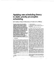
��������� ������������<br />
Safety Systems<br />
National and/or<br />
International<br />
Safety related<br />
standards.<br />
ESS<br />
PSD<br />
DCS<br />
An additional task is to protect vital and expensive process equipment<br />
Emergenc<br />
y Support<br />
Systems<br />
Process<br />
Shutdown<br />
Systems<br />
(Interlock)<br />
Distributed<br />
Control<br />
Systems<br />
Emergency Shutdown Systems<br />
Fire & gas protection systems<br />
Emergency shutdown systems<br />
Secondary safety protection<br />
2nd Barrier<br />
Primary safety protection<br />
1st Barrier<br />
Machinery and equipment protection<br />
Process control<br />
Covered by Advant OCS<br />
Normally diverse technique,<br />
or separate PES<br />
Figure 1-1. Structure and tasks of a safety system<br />
Re-establish a safe state<br />
of the plant or reduce the<br />
consequences.<br />
Prevent the plant from<br />
entering into an unsafe<br />
state<br />
Protect production<br />
equipment<br />
Achieve product quality<br />
Safeguard is a fault-tolerant safety system especially designed for the protection of industrial<br />
processes. Based on ABB’s family of micro-computer based controllers and networks, it offers<br />
high reliability control and supervision in process applications such as Emergency Shutdown<br />
(ESD), Process Shutdown (PSD), Equipment Protection, Critical Control and Fire & Gas<br />
Protection (F&G) systems.<br />
Important characteristics of this system are:<br />
Safety and reliability<br />
Safeguard 400 Series is based on Advant Controller 410 and is extended with software and<br />
hardware for handling safety signals, test, monitoring and advanced diagnostics. It adds an<br />
advanced output voting unit called Master Vote 3000. A single failure in the system will not<br />
prevent a pre-defined safety action from being executed.<br />
Availability and fault tolerance<br />
A combination of output voting, testing and monitoring detects and isolates faulty components<br />
in the system. Safeguard offers fault tolerance for critical single faults, and fail-to-safe action<br />
for multiple faults. This ensures high availability through error-free, uninterrupted process<br />
operation, while preserving a high reliability in safety operations.<br />
1-2 3BNP000431R301
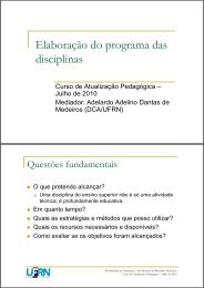
Plant Network<br />
������������� TM ��������������������<br />
����������� �������������������<br />
Connectivity<br />
The Safeguard system can be connected to virtually any control system on the market, and may<br />
use the same network to freely communicate with process, operator and engineering stations if<br />
so desired. This, in some cases, allows full integration of operator presentation, alarm handling,<br />
maintenance and information exchange between process control and safety applications.<br />
Safeguard can easily be connected to:<br />
• ABBs control systems w/ Master <strong>Software</strong><br />
• ABBs control systems w/ MOD <strong>Software</strong><br />
• ABB Bailey Products<br />
• Former Alfa-Laval Automation Products<br />
• Other DCS-vendors Products<br />
Safeguard supports restricted access functions, offering password protection for safety<br />
application programs, key-lock restrictions for user-specified operator functions, and restricted<br />
access to database information.<br />
Control Network<br />
ABB ABB ABB ABB<br />
ABB<br />
Figure 1-2. Integrated process control and safety system<br />
Local Network<br />
3BNP000431R301 1-3
������������� TM ����������������������<br />
��������� ������������<br />
1.3 Safeguard design concept<br />
Engineering efficiency<br />
Reduced engineering time, increased efficiency and enhanced integrity of safety application<br />
programming are just three of the advantages of AdvaBuild, a series of engineering tools<br />
especially developed by ABB.<br />
Safeguard 400 Series includes a highly versatile cause and effect schematic based configuration<br />
tool called Safety Builder. This configuration tool significantly reduces the time used and<br />
potential errors involved in converting the industry standard documentation to logic program<br />
representation and thereby increases the quality.<br />
Safeguard 400 Series design criteria<br />
Safeguard 400 Series is certified by TÜV Product Service (refer to Section 1.6, Certification)<br />
according to Requirement Class 1-6, and Safety Integrity Level (SIL) 1-3 as defined in DIN V<br />
VDE 0801, DIN V 19250 and IEC 61508. Safeguard 400 Series is also designed according to<br />
relevant chapters of DIN VDE 0116 and EN 298, which relates to burner management systems,<br />
and EN 54, which relates to Fire and Gas Protection.<br />
The Safeguard 400 Series is a system based on Refined Duplex Architecture (RDA). The<br />
architecture utilizes a refined version of the standard Advant Controller 410 from the Advant<br />
OCS product platform. The idea of offering a safety system with high safety integrity combined<br />
with a generic ability to be easily integrated into modern control systems, is a core strategy in<br />
ABB safety system product development.<br />
�����������������������<br />
The Safeguard 400 Series complies with the design standard 1oo2D (one out of two) and 1oo1D<br />
(one out of one), two of the designated architectures for safety systems defined by the IEC<br />
61508, the international standard for functional safety. One main property of this architecture is<br />
to detect and localize potential failures by means of active self-testing.<br />
For the 1oo2D it combines the safety factor of the 1oo2 architecture with the availability factor<br />
of the 2oo2 architecture. When comparing different generic control structures, the potential<br />
advantage of this architecture regarding safety/availability trade-off can be proved.<br />
For the 1oo1D it combines the safety factor of the 1oo2 architecture for the safety outputs with<br />
the availability factor of the 1oo1 architecture for the system. This gives a system with a<br />
comparable safety to the 1oo2D system.<br />
The main difference between a 1oo2D system and a 1oo1D system:<br />
• 1oo2D has two independent controller branches for processing and diagnostics of the<br />
signals.<br />
• 1oo1D has one controller branch for processing and diagnostics of the signals.<br />
1-4 3BNP000431R301
������������� TM ��������������������<br />
����������� ������������������������<br />
��������������������<br />
The Safeguard 400 Series consist of the two product variants; Safeguard 410 and Safeguard<br />
415. The difference between these two variants are described below. Description contained in<br />
all other parts of this manual are common for both variants unless otherwise specified.<br />
The hardware for Safeguard 400 Series consists of processor module, sub-modules, sub-racks,<br />
and power supplies.<br />
Common characteristics:<br />
The processor module used is PM150V08 and has the following characteristics:<br />
• The CPU board contains a Motorola MC68020 processor and dynamic read/write memory<br />
(RAM) with ECC (Error Correction Circuit). The memory houses the system software as<br />
well as the user application. The CPU board is delivered with PM150V08 which is a 8 MB<br />
dynamic read/write memory version.<br />
• One slot for flash memory Program Card holding the safety system software.<br />
• Two RS-232-C ports dedicated for printer and MasterView 320<br />
• One port dedicated for connection of Advant Station 100 Series Engineering Stations<br />
• Four slots for communication sub-modules, two slots are configured with MB300<br />
interface.<br />
• Direct access to Fireguard and Autronica addressable detector systems connected via the<br />
communication sub-module slots.<br />
�������������<br />
The safety system consists of one central S100 I/O rack where the CPU-module and the I/O<br />
boards are located.<br />
• Direct access to up to 15 S100 I/O boards.<br />
�������������<br />
The safety system consists of one central S100 I/O rack where the CPU-module and I/O boards<br />
are located plus up to two additional S100 I/O sub-racks where I/O boards are located<br />
• Direct access to up to 54 S100 boards.<br />
����������������<br />
This is the product variant with only one controller. These are called Safeguard 410 Single and<br />
Safeguard 415 Single. The hardware and functions described in this manual are valid for both<br />
variants with the exceptions described in Appendix A of the Safety Manual<br />
(3BNP000432R301).<br />
Isolation of failures<br />
If a critical failure is detected in one of the safety control branches, the process will continue,<br />
uninterrupted. The failure will be isolated upon detection, thus preventing spurious trips.<br />
3BNP000431R301 1-5
������������� TM ����������������������<br />
��������� ������������<br />
1.4 Applications<br />
1.4.1 Process safeguarding<br />
Safeguard 400 Series will then operate as a 1oo1D (single) system. Alarm messages and<br />
detailed diagnostic information will be presented to the operator so that the fault can be repaired<br />
quickly.<br />
Fail-safe action<br />
In the very rare case where critical failures are detected in both safety controller branches, a<br />
partial or complete fail-to-safe action is initiated. The fail-safe function in the RDA is to deenergize<br />
the field devices connected as critical outputs to the Master Vote 3000 termination<br />
units in the Safeguard 400 Series. In this way ABB Safety fully maintains the philosophy of<br />
fail-safe shut down control.<br />
As indicated in Figure 1-1, there is no exact border between safety systems and process control<br />
systems regarding safety application functions (e.i. equipment protection can be performed in<br />
both PSD and DCS). The safety system is normally considered to be a shutdown system taking<br />
action when the process goes outside the safe operating range. This may be due to an event in<br />
the process equipment itself, such as a pipe rupture, a stuck valve, or detection of fire or gas in<br />
the plant. Equally critical are abnormal process conditions arising from loss of control (for<br />
example reaction runaway) or failure in the process control system itself.<br />
Further, the safety and process control systems must interact during recovery from a trip (safety<br />
action) or at normal process start-up. As the process is outside the normal state for a long<br />
interval, the normal cause-effect actions should not be taken. However, to simply bypass these<br />
safety actions during start-up poses serious safety risks at a time when the process state is<br />
normally very unstable. Therefore, the process control and safety systems must communicate to<br />
ensure that safety mechanisms are being applied during the various phases of plant start-up.<br />
This is one main argument for an integrated system design.<br />
The safety systems can be divided into two main application areas:<br />
1. Process safeguarding:<br />
a. PSD (Process Shut Down) system<br />
b. Equipment Protection<br />
c. Critical Control.<br />
2. Plant/Area safeguarding and personnel safety:<br />
a. ESD (Emergency Shut Down) system<br />
b. F&G (Fire and Gas) Detection and Protection system.<br />
Safeguard 400 Series includes hardware and software constructed to assist in the design of<br />
safety system structures that meet industry regulations for such systems. A large number of predefined<br />
application solutions for commonly used process transmitters, detectors and actuators<br />
are defined as function block macros.<br />
1-6 3BNP000431R301
������������� TM ��������������������<br />
������������� ��������������������<br />
Process Shutdown<br />
The purpose of a PSD (Process Shutdown) system is to prevent the development of an abnormal<br />
process condition into an undesirable event (emergency). The PSD safety system goes into<br />
action when the process control system, DCS, is no longer able to control the process in a safe<br />
manner. This may be a result of faults in the process equipment, instrumentation or computer<br />
hardware, or caused by unwanted control program actions (for example from an erroneous setpoint)<br />
with process instability as a result. Generally the action is to section off the process, to<br />
prevent the situation from spreading, and for example cool/de-pressurize the process to achieve<br />
thermodynamic stability.<br />
Figure 1-3. Operator Station presentation of an ESD application<br />
Equipment Protection<br />
This is related to single equipment protection and will in many cases be part of the process<br />
control system but with its own outputs for shutdown purposes. This could be monitoring of<br />
control equipment, as well as vulnerable, investment-intensive production equipment. For<br />
example, all types of rotating machinery - turbines, generators and compressors<br />
3BNP000431R301 1-7
������������� TM ����������������������<br />
��������� ������������<br />
Critical Control<br />
Safeguard also supports safety applications with critical control functions, e.g.critical valve<br />
control on a pipe line. This enables application solution for implementing analog outputs and<br />
PIDCON (predefined function block for PID control in the ABB Masterpiece language, AMPL)<br />
in a dual system.<br />
1.4.2 Plant/Area safeguarding and personnel safety<br />
1.4.3 Application implementation<br />
1.4.3.1 AMPL<br />
Emergency Shutdown<br />
The ESD (Emergency Shutdown) system comes into action when the situation has developed<br />
into an emergency. The purpose of the system is to limit the consequences of the uncontrolled<br />
state, contribute to evacuation and emergency blow-down actions, and to re-establish safe<br />
operation.<br />
Fire and gas detection and protection<br />
The purpose of the F&G system is to detect a fire and/or gas situation at an early stage, fight the<br />
fire and limit the gas leakage by de-pressurization, process section shutdown and closing of<br />
ventilation (dampers). Personnel warnings such as beacons, horns and messages (PA system)<br />
may be activated to initiate evacuation of the area.<br />
In addition to flammable compounds, detection includes other gases and fluids, for example<br />
toxic and corrosive substances that may cause personnel or environmental hazard.<br />
Safeguard 400 Series include hardware and software solutions to support all commonly used<br />
detectors and fire fighting equipment. Some examples are heat, flame and smoke fire detectors,<br />
optical and electro-catalytic gas detection, and CO2, halon or water based extinguishing<br />
systems.<br />
Safeguard 400 Series can be configured with both conventional or/and addressable fire and gas<br />
detectors.<br />
There are two methods for realization of safety system logic within Safeguard.<br />
• AMPL (ABB Master Programming Language)<br />
• Safety Builder (Cause & Effect tool).<br />
The two methods can be combined in a system for optimal solutions.<br />
AMPL is the standard function-block/Process Control (PC)-elements language with graphic<br />
representation used for application programs in both Safeguard and ABB OCS. See also Section<br />
2.4, Engineering <strong>Software</strong> for AS 100 Series ES for enhanced use of AMPL as Type Circuits<br />
or/and Circuits in the Advant Station 100 Engineering Station.<br />
1-8 3BNP000431R301
1.4.3.2 Safety Builder<br />
1.5 Theory of operation<br />
1.5.1 Dual controller structure<br />
������������� TM ��������������������<br />
����������� �������������������<br />
User elements<br />
User Defined PC elements is an optional function which when installed enables the user to<br />
create typical application solutions (based upon the AMPL) as user defined function blocks.<br />
These function blocks will be handled like a standard AMPL function block element in the<br />
safety controller. The UDPC function is a software module which enables you to simplify<br />
implementation and documentation of frequently used safety and control solutions and adapt<br />
them to your own requirements. It is possible to design and combine a number of user elements<br />
into libraries which can be downloaded into the controller. These libraries can be modified by<br />
adding new elements to existing libraries, or by creating new libraries when required.<br />
Safety Builder is a software package used to configure, verify and document Cause and Effect<br />
(C&E) matrices and is especially suitable for safety shutdown and -protection related<br />
applications.<br />
The application interacts with the signal database where the inputs (causes) and outputs (effects)<br />
of the process in question are defined. The database includes signal specific information such as<br />
signal names and descriptions, input alarm levels, alarm delays etc. The inputs and outputs are<br />
entered into a C&E matrix. Corresponding interaction is plotted in relevant cells.<br />
Safety Builder supports shut-down level (ESD level) definition. An ESD level is a defined<br />
action on a fixed set of outputs. Associating an input with a defined ESD level, ensures a<br />
structured shutdown philosophy and the predetermined action for the cause in question is<br />
performed.<br />
Larger installations often integrate several safety systems along with other ABB controllers.<br />
Safety Builder supports routines enabling a subscription to inputs and ESD levels defined in<br />
integrated, remote systems. The remote inputs can be assigned action in the controller in<br />
question.<br />
The 1oo2D system has an architecture that consists of two parallel control branches that act<br />
independently and with equal priority on the control decision. The common mode of operation<br />
and any common source of failure is reduced.<br />
Active self-tests instead of voting mechanisms reduces the probability of accumulated hidden<br />
dangerous failures in the system.<br />
The two parallel control branches read the field signals, execute the safety control logic,<br />
calculate the control outputs and set the field output signals individually and independent of<br />
each other. However, each control branch is able to set the field output signals only when its<br />
diagnostics control gives an active permissive signal.<br />
3BNP000431R301 1-9
������������� TM ����������������������<br />
��������� ������������<br />
�����<br />
�������<br />
�����<br />
�����������<br />
�����<br />
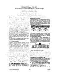
���������������� �������������� �����������������<br />
�����<br />
������<br />
�����<br />
������<br />
�����<br />
��������<br />
�����<br />
��������<br />
����� ���������������������������<br />
�������������������<br />
�����������<br />
����������������<br />
����������������<br />
�����������<br />
�������������������<br />
������<br />
��������<br />
������<br />
��������<br />
������ ���� �������������������������<br />
The combination of active self-testing with permissive control of any control action adds<br />
optimal failure tolerance capability to the superior attributes of the 1oo2 architecture regarding<br />
safety integrity.<br />
Extensive and active self-tests with replication are implemented individually in both control<br />
branches. Detected failures are generally isolated from causing any spurious interruption of the<br />
process. In the event of correlated failure in both branches a fail-to-safe action takes place.<br />
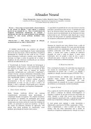
The 1oo1D system has an architecture that consists of one control branch that performs the<br />
control decision. The safety output handling is duplicated as in the dual controller structure to<br />
maintain the test and availability of the safety function.<br />
1-10 3BNP000431R301<br />
������<br />
�����<br />
������<br />
�����<br />
������������<br />
�����������<br />
����<br />
����<br />
����<br />
����<br />
�����<br />
�������
�����<br />
�������<br />
�����<br />
�����������<br />
�����<br />
1.6 Certification<br />
������������� TM ��������������������<br />
����������� �������������<br />
The controller reads the field signals, execute the safety control logic, calculate the control<br />
outputs and set the field output signals individually. However, each output branch is able to set<br />
the field output signals only when its diagnostics control gives an active permissive signal.<br />
���������������� �������������� �����������������<br />
�����<br />
������<br />
�������������������<br />
�����<br />
��������<br />
�����������<br />
����������������<br />
������<br />
��������<br />
������<br />
��������<br />
������ ���� ���������������������������<br />
ABB Safety has chosen TÜV Product Service GmbH as our external validation and certification<br />
partner. TÜV Product Service is a highly recognized certification authority.<br />
All development of the Safeguard 400 Series product is performed in a close relationship with<br />
TÜV. The following major milestones are part of a development project:<br />
• Concept approval<br />
• Design approval<br />
• Functional validation<br />
For details regarding certification, please refer to the Safeguard 400 Series Safety Manual,<br />
3BNP000432R301. The Safety Manual is a TÜV approved document and contains relevant<br />
information for implementation and maintenance of the safety system.<br />
Single Safeguard and dual Safeguard have different levels of certification. Safeguard 410 and<br />
Safeguard 415 are designed to comply with the requirements of AK 6/SIL 3. A Single<br />
Safeguard system may be configured to comply with the requirements of AK 4/SIL 2<br />
The different types of certification status for the various system components are defined as<br />
follows.<br />
3BNP000431R301 1-11<br />
������<br />
�����<br />
������<br />
�����<br />
������������<br />
�����������<br />
����<br />
����<br />
����<br />
����<br />
�����<br />
�������
������������� TM ����������������������<br />
��������� ������������<br />
Certified:<br />
Hardware and software functions certified for use in a safety system.<br />
Safety critical:<br />
Hardware and software functions certified to be used to control safety devices in a safety<br />
system.<br />
Non-interference:<br />
Hardware and software functions certified to be used in a safety system for non-safety related<br />
devices.<br />
Non-certified:<br />
Hardware and software functions not certified for use in a safety system.<br />
1-12 3BNP000431R301
<strong>Chapter</strong> 2 <strong>Software</strong> <strong>Functions</strong><br />
2.1 Safeguard 400 Series <strong>Software</strong><br />
2.1.1 General base system operation<br />
������������� TM ��������������������<br />
����������� �����������������������������<br />
Most of the operation of the Safeguard/AC410 base system is transparent to the end user, who<br />
only sees the system database and application program, unless explicitly accessing other<br />
functions by means of system commands.<br />
Database<br />
The database is distributed to each individual Safeguard 400 Series controller. Access is<br />
symbolic, which means that all information is available by specifying the signal name. All<br />
relevant information about an I/O point or a loop is available in one record, which is<br />
simultaneously updated to ensure that all data for a single point is consistent.<br />
FINC1<br />
1<br />
306.0<br />
1<br />
0<br />
0<br />
0<br />
1S<br />
0<br />
200<br />
Figure 2-1. Database entry for a Normally Closed loop monitored digital input<br />
The following data given in the database specifies how the underlying software will treat that<br />
point:<br />
• Name, description, service status etc. for all objects.<br />
• Range, hysteresis, scaling, filtering, addresses etc. provides data for the I/O handlers to<br />
access the hardware to obtain data, perform basic treatment and convert it to engineering<br />
units.<br />
3BNP000431R301 2-1<br />
1<br />
51<br />
52<br />
12<br />
15<br />
33<br />
64<br />
X1<br />
32<br />
53<br />
S2<br />
S3<br />
E4<br />
FINC1<br />
Normally Closed Det.<br />
(308.1)<br />
NAME ERR<br />
CHANNEL F_EARTHF<br />
FI_BOARD OP_CIRC<br />
ACT SH_CIRC<br />
BLOCKED EARTHF<br />
CALC_INH OUT_OF_R<br />
RS_INH_D POW_FAIL<br />
SCANT AL<br />
RS_LATCH AL_L<br />
AL_DELAY AL_NI<br />
AL_NIL<br />
INH<br />
AUTO_INH<br />
UPDATED<br />
STATUS<br />
Limit check<br />
Operator functions<br />
Group Alarm<br />
13<br />
38<br />
39<br />
40<br />
37<br />
41<br />
42<br />
20<br />
22<br />
21<br />
23<br />
43<br />
27<br />
14<br />
11
������������� TM ����������������������<br />
��������� ������������������<br />
2.1.2 AMPL Safeguard features<br />
• Alarm limits and alarm handling parameters specify how event and alarm handling is to be<br />
carried out.<br />
• Engineering unit, number of decimals, accessed, blocked, manual entry and others define<br />
basic parameters for the operator interface.<br />
Application program<br />
The application program works with the database to define additional treatment (for example<br />
input voting) and the cause & effect algorithm. This program can be designed in two formats:<br />
• As a function block program, using the functional element library of basic algorithms.<br />
• As a cause & effect chart, table files loaded in the system.<br />
AMPL is a function block language with graphical representation. The function blocks offer a<br />
high level of configuration from simple to complex. The language is common for all ABB<br />
controller products with Master software. However, as the products are optimized to different<br />
application areas the functional extent and the execution environments differ between the<br />
products. For the Safeguard 400 Series the following AMPL elements are supplied additionally,<br />
either as an option or as a part of the base product.<br />
NOTE<br />
For the range of standard elements also included (AC410) refer to PC Elements<br />
Advant Controller 400 Series Reference Manual.<br />
Table 2-1. Safety PC elements.<br />
Type Function PC Element<br />
Safety address Reads the node number. S-ADDR<br />
Fire and gas input<br />
voting<br />
Integer word<br />
handling<br />
Data base network<br />
transfer<br />
Combines inputs from loop<br />
monitored digital inputs or gas<br />
detector inputs for coincidence<br />
signals and for area<br />
presentations.<br />
Performs AND, OR, bit reversal<br />
and bit extractions on integer<br />
values.<br />
Copies values in the data base<br />
from one node on the network to<br />
another node.<br />
FI-VOTE, GI-VOTE<br />
IOR, IAND, I-NOT,<br />
BTST<br />
DB-COP<br />
2-2 3BNP000431R301
C&E matrix<br />
control<br />
(optional)<br />
C&E matrix output<br />
control<br />
(optional)<br />
2.1.3 Cause & Effect programming<br />
������������� TM ��������������������<br />
������������� ��������������������������<br />
Table 2-1. Safety PC elements.<br />
Type Function PC Element<br />
Controls the execution and<br />
supervises the C&E matrixes.<br />
Enables access to outputs in a<br />
C&E matrix from other AMPL<br />
logic.<br />
The AdvaBuild Safety Builder is an advanced Microsoft Windows based programming tool<br />
especially designed for safety engineering applications. The tool offers a straight forward<br />
WYSIWYG cause & effect application design. The application programming is simply<br />
performed by graphically creating shutdown levels, inserting inputs and outputs and plotting in<br />
the correlation between them, just as it appears in the cause & effect engineering<br />
documentation. The Safety Builder increases the efficiency and reduces the possibility of faults<br />
in the application programs caused by “translation” of C&E diagrams to AMPL function block<br />
logic. The AdvaBuild Safety Builder cause & effect tool can be ordered as an option.<br />
The Safety Builder supports a number of functions such as:<br />
• Hierarchical shutdown level definition.<br />
• Possibility of remote shutdown level interaction on installations with several safety<br />
systems.<br />
• Flexibility in changes of each individual C&E diagram and number of diagrams and<br />
shutdown levels.<br />
• Standard function for defining time delays.<br />
• Standard reset function.<br />
• Direct access to the I/O database.<br />
• Cause & effect diagram format documentation of the application.<br />
• Revision handling on the individual C&E documentation diagram.<br />
2.1.4 Safeguard 400 Series Central Processing Unit<br />
CE-MATR<br />
CE-OPC<br />
The Safeguard 400 Series controllers are configured with Advant Controller 410 central<br />
processing units. The main tasks handled by the central processor unit are:<br />
• Execute the operating system and communications system functions<br />
• Hardware and firmware basic fault detection<br />
• Field I/O handling and database updates<br />
3BNP000431R301 2-3
������������� TM ����������������������<br />
��������� ������������������<br />
2.1.5 Basic system testing<br />
• Application program execution<br />
• Application dependent test routines<br />
In addition to the standard AC410 basic system function (QC01-BAS11, QC01-OPF11 and<br />
QC01-LIB11), the following safety system software modules are provided as a part of the<br />
Safeguard 400 Series standard product:<br />
• QC05-BAS11 which includes:<br />
– Routines for safety input sets, including alarm treatment and input inhibit<br />
– Handling of Master Vote 3000 including application dependent test routines<br />
– Dual system start-up and maintenance functions, including status synchronization<br />
between branches at system restart (in 1oo2D dual system only)<br />
– Loop monitored digital inputs<br />
– Gas inputs<br />
– Improved system diagnostics<br />
– Bypass management<br />
Most of the functions included in the safety software are transparent to the user. Application<br />
programming, database fill-in and cause and effect logic are done as if working with a single<br />
system. In the 1oo2D Safeguard system, identical applications are loaded into the two system<br />
branches, and the only difference between the two branches is their data highway bus addresses<br />
(set in hardware).<br />
• As options the following system functions can be selected:<br />
• QC05-CEM11, Handling of the cause and effect files from the Safety Builder<br />
• QC05-FIE11, High functional level communication with Fireguard addressable fire<br />
detector system<br />
• QC05-FIA11, Communication with Autronica BS-100 addressable fire detector system<br />
• QC05-SIO11, Safety analog and digital inputs<br />
• QC01-UDP11, Program module for User Defined PC elements (UDPC)<br />
• QC01-LIB12, Element library for advanced process control<br />
• QC01-LOS11, Local operator station support, MasterView 300<br />
This section describes the basic system testing performed by the main CPU.<br />
Most test and diagnostics information is available as safety messages and in system status<br />
displays on the operator station. If a serious fault does occur, and the system is not considered<br />
reliable, the CPU will be halted, and diagnostic information is presented on the CPU board<br />
front.<br />
Indicators on the CPU board front include power status, halt (system stopped), stall (watchdog<br />
time-out), and a two-digit system status display. With these indicators, and indications on the<br />
2-4 3BNP000431R301
������������� TM ��������������������<br />
������������� �������������������������������<br />
I/O boards, most errors are diagnosed simply by locating the red error indicators. The same<br />
status, including more detailed diagnostic messages are also available on operator station<br />
displays.<br />
Further information in this state can be obtained with the Advant Station 100 or 500 Series<br />
Engineering Station.<br />
Basic system tests include:<br />
• CPU Instruction set test<br />
• CPU Illegal instruction trap<br />
• CPU watchdog, high and low level (Fail, Infinite loop, overload)<br />
• Bus backplane supervision, address error, bus time-out (no response)<br />
• Dynamic RWM error detection and correction<br />
• System clock supervision<br />
• CRC sign calculation on system software modules<br />
• CRC sign calculation on application database and AMPL program<br />
• Task execution supervision<br />
• Operating system call error detection<br />
• Communication handlers (ISO OSI 7-layer model)<br />
• Peripheral driver diagnostics.<br />
• Power supply fail<br />
• Cabinet fan fail, over-temperature.<br />
For dangerous errors, such as program system illegal execution, appropriate actions and<br />
reporting are taken directly by the operating system. In less serious situations, the status is also<br />
available to the application program, which can decide on the correct action to take. Some<br />
safety applications may for example allow execution to continue when communication to other<br />
systems is lost, while others would regard this as a shutdown condition.<br />
The result of a serious system fault is to shut down operation and halt the CPU. This action will<br />
cause the CPU Run status line to fall (i.e. go to zero) and de-energize all outputs.<br />
It is important to note that the main function of the basic tests is to ensure that all hardware<br />
components are operable, that the firmware and application software is executing and is not<br />
corrupted by spurious changes. It is therefore not necessary to design additional test programs,<br />
(for example pattern tests with output vector comparison of the logic) to ensure that the safety<br />
system has not changed.<br />
2.1.6 Master Vote 3000 safety outputs<br />
There are two types of Master Vote 3000 connection units. DSTD N020 is for normally<br />
energized outputs and DSTD N021 is for normally de-energized outputs. They have a fail-tosafe<br />
design and support a 1 out of 2 voting system. The functions on the units are continuously<br />
supervised and tested by the Safeguard 400 Series system software.<br />
3BNP000431R301 2-5
������������� TM ����������������������<br />
��������� ������������������<br />
2.1.6.1 Signal processing<br />
Application output<br />
Manual action<br />
Test pulse<br />
Test pulse<br />
Maintenance bypass<br />
Test fault diagnosis<br />
<strong>Software</strong> fatal error-Not<br />
Hardware stall / Halt-Not<br />
The control of the field outputs from Master Vote 3000 relies on the correct operation of the<br />
Isolate-Not and Shutdown/Activate signals.<br />
(-Not is logically negated signal):<br />
�������� ��������<br />
���<br />
���<br />
�<br />
Inverted only<br />
for NE<br />
Figure 2-2. Isolate and shutdown/activate signal operation<br />
Isolate-Not<br />
The Isolate-Not is a composite signal that represents a number of control unit states in the<br />
control unit that should result in branch isolation. Isolate is negated (goes low) as a result of<br />
system malfunction (see previous chapters on system diagnostics), a manual request for<br />
maintenance purpose, or when a test reveals a fault that must be handled by disabling the failing<br />
branch. This is particularly applicable to NE outputs.<br />
The Isolate signal is timed so the loss of a control unit or an output board will always cause a<br />
low Isolate signal to be recognized first. The shutdown output is timed to go low after isolate to<br />
prevent it from requesting a shutdown when the isolate is still high.<br />
In a similar fashion, the isolate is designed to return high after a valid signal is presented on the<br />
shutdown output to prevent spurious action on system restart or isolate removal. This function<br />
allows fault tolerant action to be taken on failure or during maintenance.<br />
Shutdown-Not or Activate<br />
The Shutdown-Not (Normally Energized) or Activate (Normally De-Energized) signal is a<br />
combination of an application generated action, manual action and signals from the test<br />
program. It is also affected by system errors, and is forced low (NE) or will stay low (ND) on a<br />
control unit malfunction.<br />
2-6 3BNP000431R301<br />
�<br />
�<br />
Shutdown-Not/Activate<br />
Isolate-Not<br />
System run bus signal
2.1.6.2 Output testing<br />
2.1.7 Bypass Management<br />
2.1.7.1 Operator station access control<br />
������������� TM ��������������������<br />
������������� �����������������<br />
Master Vote 3000 automatic output tests are performed as a part of the Safeguard 400 Series<br />
base software and consists of:<br />
The output tests consist of:<br />
• Channel test<br />
• Isolate test<br />
• Option for monitoring of read-back of the output status.<br />
• Option for feedback of the output loop supervision signal.<br />
The basic test uses the Isolate-Not and Shutdown-Not (NE) / Activate (ND) signals to control<br />
the test, and receives information back on two inputs (Isolate Status and Test Status). These are<br />
common to all seven outputs on one Master Vote 3000 unit. The standard tests cover all<br />
functions of the Master Vote 3000. The normal action for a NE output on detection of a fault is<br />
to isolate the branch by deactivating Isolate-Not, and report this as a safety message and on the<br />
diagnostics displays. ND stays low.<br />
The functions of Bypass management are:<br />
• Operator station access control<br />
• On-Line Builder (engineering tool) access control<br />
• Override control and reset<br />
Override is generally used as a collective term for inhibit, input block, output block and manual<br />
mode for the relevant signal types.<br />
The use of override functions in safety related equipment introduces a potential hazard to the<br />
installation and to the people it is designed to protect. Any inhibit of a safety critical input or<br />
override on a safety critical output represents a degradation of the safety level and a possibility<br />
for failure on demand.<br />
Nevertheless, such functions are necessary to achieve a reasonable availability of the process.<br />
All field equipment needs maintenance or replacement at regular intervals, and this is included<br />
in the design of the safety system regarding e.g. number/wiring and placement of instruments.<br />
In these cases the safety level may be maintained by other measures while necessary<br />
maintenance operations are carried out.<br />
There are also requirements for use of inhibits during start-up in certain applications.<br />
The Bypass management function enables project/application specific configuration of the<br />
appropriate level of restrictions regarding operation of the Safeguard 400 Series.<br />
Operator stations which shall be accepted for write access must be configured in the Safeguard<br />
400 Series and a key switch shall be hard wired to the Safeguard 400 Series for control of<br />
permission to operate the system.<br />
3BNP000431R301 2-7
������������� TM ����������������������<br />
��������� ������������������<br />
2.1.7.2 On-Line Builder (engineering tool) access control<br />
2.1.7.3 Override control and reset<br />
2.2 Operator Interface <strong>Software</strong><br />
2.2.1 General<br />
Communication with engineering tools can be controlled by the isolation key switch on the<br />
local panel and/or by a successful isolation of the safety controller.<br />
The number of simultaneously occurring overrides are controlled by a configuration parameter.<br />
The reset of the overridden signals can be done in several ways:<br />
• The primary reset of overrides is via normal communicated dialog operations (manual<br />
entry).<br />
• A hard wired input to the Safeguard 400 Series is the secondary possibility for reset of all<br />
overrides in the safety system, independent of communication with any operator stations.<br />
• Automatic reset of all overrides in case of loss of communication with all access granted<br />
operator stations.<br />
• Automatic reset of all overrides in case of maximum allowed time exceeded timed from<br />
the first occurring override.<br />
The number of configured and active overrides are presented on the operator station and it is<br />
also possible to configure any active override in the system as an activation of a dedicated<br />
digital output.<br />
All activation and de-activation of overrides is recorded on the operator station event list.<br />
The basic operator interface software, named AdvaCommand, is available for the HP-UX-based<br />
Advant Station 500 Operator Station and for a Windows NT-based PC. AdvaCommand is a<br />
family of operator control and interaction functions.<br />
It provides functions for presentation of safety and process information, command entry, event<br />
and alarm handling, system status, window handling, process sectioning and status lists.<br />
The AdvaCommand Safeguard Handler is an option which is required for handling of the<br />
Safeguard 400 Series products. All Advant Station 500 Operator Station series can also be<br />
delivered with the AdvaCommand Safeguard Handler option.<br />
Table 2-2. Overview of functions and product series<br />
Function<br />
Safeguard 400<br />
Series<br />
AdvaCommand User Interface and Manual Control - (1)<br />
AdvaCommand<br />
for Unix<br />
AdvaCommand<br />
for Windows NT<br />
yes yes<br />
AdvaCommand Event&Alarm yes yes yes<br />
AdvaCommand Group Alarm - yes yes<br />
2-8 3BNP000431R301
2.2.2 Safety functions<br />
Table 2-2. Overview of functions and product series (Continued)<br />
Function<br />
Safeguard 400<br />
Series<br />
������������� TM ��������������������<br />
������������� ����������������<br />
AdvaCommand<br />
for Unix<br />
AdvaCommand<br />
for Windows NT<br />
AdvaCommand Process Sectioning - option option<br />
AdvaCommand Status List - option option<br />
AdvaCommand System Status yes (2)<br />
yes yes<br />
AdvaCommand Safeguard Handler - option (3)<br />
option<br />
(1) Data to present in the displays are available in for example the Safeguard 400 Series, and subscribed to by the<br />
AdvaCommand User Interface at presentation.<br />
(2) The System status function has software running in Safeguard 400 Series. The distributed software reports<br />
current status on request from the AdvaCommand System Status function at presentation.<br />
(3) If the operator station is used in a plant network, the node number for the safety and process controllers must<br />
be unique for all nodes in all the connected control networks.<br />
All Advant Operator Workplace functions are retained when used with the Safeguard 400<br />
Series. This means that the product can be used as a common operator station for safety and<br />
process control.<br />
With AdvaCommand Safeguard Handler the following functions are added to the basic<br />
Operator station:<br />
• A dual system handler that allows both branches of the Safeguard 400 Series to appear as<br />
one object to the operator. This gives:<br />
– Single presentation of alarms in lists and on printer.<br />
– Single presentation of objects.<br />
– Dialogue handler with commands sent to both safety controllers.<br />
NOTE<br />
If the operator workplace is used in a plant network, the node number must be<br />
unique in all the connected control networks. This is due to limitations in the dual<br />
handling function in the operator station.<br />
• Presentation and interaction for safety object types, e.g. detection and protection systems,<br />
required by Safeguard 400 Series is added to the standard operator station functionality.<br />
This consists of Object (Faceplate) displays, group displays and display elements as well<br />
as dialogs. The following safety object types are available in the Safeguard Handler:<br />
– FI (Fire Input), Loop monitored digital inputs<br />
– FD, for addressable Fire Detector signals<br />
– GI, for Gas input signals<br />
– Safety System Status, diagnostic status display for Safeguard 400 Series<br />
– FG, diagnostic status display for Fireguard<br />
3BNP000431R301 2-9
������������� TM ����������������������<br />
��������� ������������������<br />
– C&E shutdown level group display.<br />
• Presentations and dialogs for these safety objects include:<br />
– Presentations:<br />
– Signal (On/Off or Value)<br />
– Alarm limits and alarms<br />
– Object status (inhibit, bypass, latched alarm, selected for operation etc.)<br />
– Loop and I/O diagnostics.<br />
– Maintenance.<br />
– Dialogs:<br />
– Activation and manual entry.<br />
– Control of status (for example inhibit, reset).<br />
• Diagnostic and status functions.<br />
– Alarm/Event list.<br />
– Group alarm (option).<br />
– Status list (report special status and conditions).<br />
– System fault list and diagnostic displays.<br />
• Process Parameter Backup, which includes functions for backup/restore of a process<br />
station’s process parameters to/from an operator station. The process parameters stored in<br />
the backup are available for restore at a later time. The process parameters involved are<br />
those that are changeable by dialog commands from the operator station(s) such as alarm<br />
limits, initial values etc. Process Parameter Backup is not included in AdvaCommand for<br />
Windows NT.<br />
• Signal Filtering function for filtering the events, alarms, system alarms and system status<br />
in the Operator Station to reduce system load in the controllers in the network.<br />
Object display<br />
The object display shows a message buffer where dedicated safety system messages are<br />
presented. The available dialogs enable a limited control of the safety system:<br />
• Presentation of messages from the safety message buffer with scrolling facilities.<br />
• Isolate control of the Master Vote 3000 outputs.<br />
• Alarm and print blocking.<br />
• C&E matrix communication blocking.<br />
Regarding Figure 2-3: in Single Safeguard systems, only SIDE A is presented.<br />
2-10 3BNP000431R301
2.2.3 System security<br />
Figure 2-3. Safety system status object display<br />
������������� TM ��������������������<br />
������������� ���������������<br />
For system security, access to objects and specific functions can be placed under key lock<br />
protection. Refer to Section 2.1.7, Bypass Management<br />
• Process Sectioning and authorization allows the safety systems to be placed in separate<br />
process sections. Individual objects (for example an input or output) are assigned a section<br />
number. Access to systems are defined on a workstation basis as None, Inspect or Control<br />
towards each section. The function is key lock or password protected. This function is<br />
included in the optional AdvaCommand Process Sectioning<br />
• When displays are designed each point is given a dialog. 'Dialogs are built in three forms.<br />
None, operator and maintenance. An operator dialog allows access for normal operation<br />
only, while a maintenance dialog allows full control. The maintenance dialog is key lock or<br />
password protected. A pre-defined set is included in the product, but as the dialog editor<br />
(option) allows design of custom dialogs, they can be adapted to individual requirements.<br />
The AdvaBuild Display Builder will present these functions along with the basic functions (that<br />
is in the presentation element list), the difference lies in which displays that are defined for a fire<br />
& gas or shutdown system, rather than how they are built and operated.<br />
3BNP000431R301 2-11
������������� TM ����������������������<br />
��������� ������������������<br />
2.2.4 AdvaCommand user interface<br />
The operator interacts with the automation system using either the mouse/track-ball, the operator<br />
keyboard or a combination of both. The moment a process object has been selected for control,<br />
exclusive access is guaranteed and no other operator can interact.<br />
The AdvaCommand User Interface supports different user categories by offering several dialog<br />
styles, which are adapted to the different users and their needs, for example menus for configuration<br />
and dynamic function keys for process control.<br />
The screen is divided into areas, each reserved for a specific purpose. The basic screen layout is<br />
shown below:<br />
Alarm line<br />
Display name<br />
and description<br />
Display area<br />
(1280 x 778<br />
for high<br />
resolution<br />
monitors)<br />
Dynamic<br />
function<br />
keys<br />
Dialog line<br />
Message line<br />
Icons (system alarm, etc.)<br />
Date and time<br />
Figure 2-4. Screen layout<br />
Fixed display area<br />
Object<br />
closeup<br />
area<br />
The different screen areas are as follows:<br />
• The icon area contains various icons for indication and selection. The icons include for<br />
example system alarm, maximum authority, as well as external alarm and dedicated screen<br />
buttons.<br />
• The date-and-time field shows the current date and time as measured by the internal system<br />
clock<br />
• The fixed display area is for continuous presentation of a user-created display, for example<br />
a process overview, a production summary, or an alarm summary<br />
• The alarm line shows the latest unacknowledged process alarm. There is also a list of current<br />
process alarms for trouble-shooting in the plant.<br />
• The display-name and description field contains the name and description of the current<br />
display. Displays are searched for and accessed by name and the descriptions make it easy<br />
to find the right display on menus etc. at all times.<br />
• The display area is where the displays called up appear.<br />
• The dynamic function key field is the main means for operator input of commands both to<br />
the system and to the process. Commands are issued by pointing at the desired key with<br />
2-12 3BNP000431R301
������������� TM ��������������������<br />
������������� ��������������������������<br />
the cursor and clicking a button or by pressing the desired function key on the keyboard.<br />
• The dialog line guides the operator through command sequences by displaying intelligent,<br />
situation-sensitive prompting messages.<br />
• The message line supplements the dialog line in guiding the operator by providing additional<br />
information, for example error messages.<br />
• The object close-up area presents detailed information on the process or system object<br />
selected for control, thus providing the information the operator needs for the actions<br />
ahead without having to call up other displays with more details.<br />
The status of the process is shown on different types of displays:<br />
• Process displays are application-specific displays entirely defined by the user. Values and<br />
states of objects, such as regulators, sequences, measurement points, motors, etc., are presented<br />
dynamically.<br />
• Overview and group displays offer a cursory view of the different parts of the process.<br />
Objects are arranged in groups, corresponding to process areas. The format of these displays<br />
is standardized; all that needs to be defined is which objects to show where.<br />
• Object displays present all the information available about single objects. These displays<br />
require no configuration but are automatically made available for all the objects in the control<br />
system.<br />
• Alarm and event lists providing records of the latest alarms and events in the process, in<br />
the system.<br />
• AdvaCommand User Interface allows access to a vast amount of historical data stored<br />
throughout the automation system. For presentation on curves, histograms, and tables.<br />
In separate curve displays, overlapping windows or as part of basic process displays.<br />
Data for curve displays can be obtained from any log or log group containing the variable<br />
of interest, regardless of time interval. This means that the same data logs and log groups<br />
can be used for both short-range/high-resolution and long-range/low-resolution diagrams.<br />
Process objects can be selected for control directly from curve displays.<br />
Historical data can be presented on predefined curve displays or as elements of normal<br />
user-defined process displays. A number of curve displays are available for the purpose of<br />
presenting historical data and process trends. Curves can be panned smoothly or in jumps,<br />
in the latter case by specifying the desired time period. Values can be fetched from any log<br />
containing the variable concerned, regardless of time interval. This amounts to seamless<br />
retrieval” and convenient panning far back in time if need be. The value scale can easily be<br />
adjusted by the user and the latest value is presented numerically for best possible reading<br />
accuracy. There is also a ruler which can be slid across the graph for accurate numeric<br />
reading at any point.<br />
• Status lists, extracting the process objects matching specified search keys.<br />
• Display printouts.<br />
3BNP000431R301 2-13
������������� TM ����������������������<br />
��������� ������������������<br />
2.2.4.1 User defined displays<br />
The layout oriented user defined displays for a safety system are normally organized in a<br />
hierarchy by the dynamic function keys and display select buttons built in the free graphic<br />
display. For fire & gas, the hierarchy could normally be organized as follows:<br />
1. Level 1: Plant overview<br />
2. Level 2: Section floorplan<br />
3. Level 3: Fire room/area detail.<br />
Examples of these displays for an offshore oil production platform are given in the following<br />
displays<br />
Plant overview<br />
Figure 2-5. F&G overview display with gas alarm<br />
The dynamic presentations are “hidden” when the Fire and Gas system are in a normal state (no<br />
alarms, inhibits, errors or releases anywhere on the platform) and visual when an abnormal<br />
situation, such as a detector alarm, occurs.<br />
All information in the overview display are collected from the various module displays.<br />
The status from each module is represented with dynamic group indication for gas detection,<br />
fire detection, protection systems and a common error for the detection/protection systems.<br />
The grouping is performed in application logic and can be defined by the user.<br />
2-14 3BNP000431R301
Section floorplan<br />
Figure 2-6. F&G level 2 section floorplan display<br />
������������� TM ��������������������<br />
������������� ��������������������������<br />
All information in the section displays are collected from the various fire area detail display<br />
(shown next). The status from each fire room/area is represented with dynamic group indication<br />
for gas detection, fire detection, protection systems. The grouping is performed in application<br />
logic and can be defined by the user.<br />
3BNP000431R301 2-15
������������� TM ����������������������<br />
��������� ������������������<br />
Fire room/area detail<br />
Figure 2-7. F&G level 3 fire room/area detail display<br />
The fire room/area detail display contains information on all detectors and protection systems<br />
present in the fire area. The displays are normally divided in two parts. One part is layout<br />
oriented and includes dynamic symbols for all fire and gas detectors. The other part contains a<br />
listing of the detectors together with the protection systems<br />
For shutdown systems, the displays are often a part of the process display hierarchy, with<br />
protection interlocks and shutdown actions indicated along with process equipment. Supporting<br />
displays (for example behind the help button) would detail the status of shutdown equipment<br />
and permit operator actions. Refer to Figure 1-3.<br />
2-16 3BNP000431R301
2.2.5 Predefined reports (Status lists)<br />
������������� TM ��������������������<br />
������������� ���������������������������������<br />
The predefined reports/status lists are created with the AdvaCommand status list function.<br />
An important aspect of system functionality is to avoid degradation of the system and protection<br />
mechanisms due to manual interactions.<br />
The status list function aids in this process, and is used to search the control system for specific<br />
conditions. Any value or status in the real time object database may be searched. Wild card<br />
names, process section, object class etc. are used to select a range of objects to search, such as a<br />
module, building or fire area. This function is used to produce a variety of predefined reports<br />
such as (but not limited to):<br />
• Input Override List: A list of all inputs that have the inhibited condition (override) set.<br />
• Output Override/Bypass List: For all outputs, list special status of this type<br />
• Fault list: A list of all detectors that have a fault condition detected<br />
• Special status: Lists all systems in manual or blocked mode<br />
• Blocked alarms<br />
• Gas detection LEL readings.<br />
The lists can be produced on demand, or are timed, e.g. per shift or per day. The output can be<br />
sent to a display or to a printer. For indication, the periodic timed lists can set or reset indication<br />
flags, that are used as alarms or for summary displays.<br />
3BNP000431R301 2-17
������������� TM ����������������������<br />
��������� ������������������<br />
Figure 2-8. Status list menu<br />
2-18 3BNP000431R301
2.2.6 Alarm management<br />
Figure 2-9. Status list configuration<br />
������������� TM ��������������������<br />
������������� ����������������<br />
Alarm management is a standard AdvaCommand Event & Alarm function<br />
Alarm and Event messages are stored and presented in chronological lists. The list of events is<br />
circular and when the list is full, the next event will overwrite the oldest. An alarm is a special<br />
type of event, requiring your attention and acknowledgment. While events are generated<br />
whenever predefined conditions are met, for example, binary variables change state or analog<br />
values exceed limits, alarms are generated when abnormal events occur. By default, an alarm is<br />
not removed from the list until you have acknowledged the alarm and the error has disappeared.<br />
However, it is possible to configure the function in such a way that the message disappears after<br />
acknowledgment, even if the alarm condition still exists.<br />
3BNP000431R301 2-19
������������� TM ����������������������<br />
��������� ������������������<br />
2.2.7 Safety management<br />
Alarms are also indicated on all displays as a latest unacknowledged alarm line, and as red<br />
status indications in displays with dynamic data from the objects concerned, flashing until the<br />
alarm is acknowledged, and then steady as long as the alarm condition persists.<br />
You can also configure objects for repetition control of alarms, which means that repetitive<br />
reporting of the same alarm is suppressed if the object toggles between the normal and faulty<br />
states. On your request, the alarm and event messages can be presented in different types of<br />
lists. The lists can be presented as base displays or as overlap displays. When presented as base<br />
displays the lists can be directed to another screen by using the dedicated screen function. The<br />
following types of lists are available:<br />
• Process event lists<br />
• Process alarm lists<br />
• System alarm lists<br />
The system alarm lists contains messages of control system errors, indicating faults or other<br />
changes of state in the control system. All three types of lists can be printed on request, when<br />
the events and alarms occur. The length of the lists, for example, the number of alarms in the<br />
process alarm list can be configured.<br />
NOTE<br />
All Advant Operator Workplaces within one control network should have the<br />
same length of the lists since the automatic acknowledge facility starts when the<br />
alarm list is full.<br />
The contents and the layout of the three types of lists and the alarm line showing the latest<br />
unacknowledged process alarm can all be configured from the System Configuration Dialog.<br />
Filter parameters can be set up in order to filter out not relevant alarms. Several alarm lists with<br />
different filter parameters can be specified.<br />
Dual handling<br />
Events and alarms are generated individually by each Safety controller, and sent onto the<br />
MasterBus 300 data highway. To avoid duplicate entries from the dual system in lists and on<br />
printers, the alarms are received in a temporary buffer in the Operator Station. The first alarm is<br />
immediately presented, but is also retained in the buffer. If a corresponding alarm is received<br />
from the other controller within 12 seconds, it is discarded.<br />
The alarms are passed on into the operator station alarm and event list and sorted according to<br />
their time stamp which is set by the safety controller. The system time in the two safety<br />
controllers will be synchronized within 10 milliseconds of each other.<br />
The focus on environmental issues and safety aspects is increasing in modern industrial plant<br />
operation. Lifecycle safety management is the scope of coming standards that will affect all<br />
parties involved in industrial activities.<br />
2-20 3BNP000431R301
2.2.8 Matrix and mimic panels<br />
������������� TM ��������������������<br />
������������� �����������������������<br />
In day-to-day operations, the safety level of a plant depends mainly on the quality of the<br />
equipment, the quality of the execution of the different activities and on the quality of work<br />
management.<br />
Analyses of major accidents and catastrophes generally document that a series of unfortunate<br />
coincidental events have taken place prior to such incidents, and also that adequate actions<br />
where not taken in the first critical phase of fighting them.<br />
Knowledge, information availability and awareness are key factors and important safety criteria<br />
in the daily achievement of plant safety.<br />
All indications and actions are accessible from the operator station. The operator station can be<br />
complemented with panels. A subset of actions and indications can be present on the matrix and<br />
mimic panels, ranging from simple group indications and actions to a full matrix with status<br />
indication, inhibit, bypass and manual action for each individual input and output. The matrices<br />
and mimics can be hardwired or driven by a serial bus for lower cost and reduced wiring, and<br />
essentially is normal status Input/Outputs defined in function block macros.<br />
2.3 Safeguard Handler for Advant Enterprise Historian<br />
Safeguard Handler for Advant Enterprise Historian is a software option to be installed in an<br />
AEH or in an Advant Station 500 IMS.<br />
Safeguard Handler software has been designed to present Safeguard 400 Series as a single<br />
controller in the AEH or in the IMS, even though every signal from the safety controller is<br />
duplicated.<br />
2.4 Engineering <strong>Software</strong> for AS 100 Series ES<br />
2.4.1 General<br />
AdvaBuild Engineering <strong>Software</strong> is designed for use under Windows NT and is structured into<br />
three major product groups:<br />
• Advant Engineering Workplace<br />
For establishing the engineering environment, navigation and administration<br />
functions.<br />
• AMPL Control Configuration<br />
For configuration and commissioning functions for Advant controllers.<br />
• Computer Aided Electrical Engineering<br />
For handling of electrical diagrams.<br />
Each product group consists of a basic unit and some options. Tools which perform a dedicated<br />
engineering task are called Builders. A product may contain several Builders like Application<br />
Builder and Function Chart Builder, as well as utilities like a text editor or an example project.<br />
3BNP000431R301 2-21
������������� TM ����������������������<br />
��������� ������������������<br />
2.4.2 Advant Engineering Workplace<br />
2.4.3 AMPL Control Configuration<br />
The Advant Engineering Workplace is necessary to work in the cooperating mode. The<br />
components included are described in the following sections.<br />
Structure Builder<br />
Structure Builder is the tool to handle the Advant Objects and to visualize the structure of a<br />
plant. The plant is represented as a set of structures, containing Advant Objects in hierachical<br />
relations. Structure Builder enables the user to navigate between Advant Objects in a convenient<br />
way and to perform activities on a selected Advant Object, such as opening certain views,<br />
copying or moving Advant Objects, structures or even a whole project.<br />
Advant Engineering Server<br />
The Advant Engineering Server prepares the environment for the engineering data storage.<br />
Parameter Builder<br />
Parameter Builder is the tool for efficient bulk data handling. It allows to enter and modify<br />
engineering data which are used as parameters for other aspects. For example, Type Circuit<br />
instances in a Circuit aspect can refer to parameter aspects and can be updated by the actual<br />
values of the parameter aspects at the users request. Parameter Builder is based on Microsoft<br />
Access.<br />
Document Builder<br />
Document Builder is the tool to efficiently create, administer and integrate documents like<br />
functional descriptions, specifications, and memos. Various editing tools like Microsoft Word<br />
or Microsoft Excel can be used, depending on the dedicated purpose or existing installation.<br />
These tools mentioned are not part of Document Builder, but are assumed to be installed, and<br />
are supported by Document Builder.<br />
AMPL Control Configuration is a suite of builders necessary to configure Safeguard 400 Series,<br />
as well as other ABB controllers. The products run on Windows NT.<br />
AMPL Control Configuration includes the following components:<br />
• Application Builder<br />
• Function Chart Builder<br />
• Bus Configuration Builder<br />
Two options which extend the functionality of AMPL Control Configuration are available,<br />
• On-line Builder for on-line configuration and download of the Safeguard 400 Series<br />
applications.<br />
• Optional AMPL PC (Process Control) and DB (Database) Element Libraries including the<br />
PC and DB element libraries and reference manuals for Advant Controller 400 Series<br />
2-22 3BNP000431R301
2.4.3.1 Application Builder<br />
������������� TM ��������������������<br />
������������� ��������������������������<br />
(Advant Controller 410 and Advant Controller 450) and Advant Controller 100 Series<br />
(Advant Controller 110, Advant Controller 70 and Advant Controller 55).<br />
Product Benefits and Features<br />
AMPL Control Configuration provides, together with the options, the following features:<br />
• Administration of nodes, Circuits and Type Circuits simplifying project start-up and reuse<br />
• Off-line editing with powerful cut/copy/paste<br />
• On-line editing for rapid program modifications<br />
• Target system control for easy testing of installed system<br />
• Module diagnosis<br />
In cooperating mode it supports much more features like:<br />
• Support for the Advant Object concept including parameterized data in Circuits and Type<br />
Circuits<br />
Type Circuits<br />
Recurring process control tasks can be solved once by using type circuits.Type circuits are userdefined,<br />
configurable process control solutions which are pretested and stored in libraries on<br />
different levels (e.g. project level, organization level etc.). They can be reused whenever a<br />
similar task occurs again. Using well-tested and standardized type circuits increases the quality<br />
and the project efficiency and reduces maintenance efforts. The main difference between the<br />
Type Circuit and the UDPC function block (described in Section 1.4.3, Application<br />
implementation) is that a UDPC function block resides as a function block when loaded in a<br />
Safeguard 400 Series controller while a Type Circuit is expanded when loaded in a Safeguard<br />
400 Series controller.<br />
Type circuits consist of standard PC and DB elements. Symbols and terminals are formal<br />
parameters of type circuits. They allow to adapt each instance of the type circuit to the specific<br />
function needed.<br />
Application Builder is the navigation tool for working in the independent mode. It handles the<br />
Safeguard configuration data. For detailed information about the independent mode,<br />
Creating Advant Objects is not possible in this mode. Nevertheless, aspect type data for<br />
configuration, such as projects, nodes, Circuits, and Type Circuits are handled by Application<br />
Builder.<br />
From within Application Builder the tools Function Chart Builder, On-line Builder, Bus<br />
Configuration Builder, and a text editor (for example AS100-EDIT) can be started. Application<br />
Builder can store default values to be used throughout a whole project. Application Builder<br />
assures that you always work on the application data with the correct Builder version. It<br />
supports exchange of configuration data between different nodes and across different projects.<br />
3BNP000431R301 2-23
������������� TM ����������������������<br />
��������� ������������������<br />
2.4.3.2 Function Chart Builder<br />
2.4.3.3 Bus Configuration Builder<br />
2.4.3.4 On-line Builder<br />
General<br />
Function Chart Builder provides an easy-to-use environment for application programming of<br />
ABB controllers. It supports Advant OCS controllers as well as Safeguard 400 Series. It offers<br />
efficient methods of object oriented project engineering by supporting Type Circuits and<br />
Circuits. In the cooperating mode these entities are mapped to control aspects of Advant<br />
Objects, for example, the Type Circuit and the Circuit aspect. This ensures a high software<br />
quality and low maintenance efforts. It can be used in both cooperating and independent mode.<br />
User Interface<br />
With Function Chart Builder it is possible to have several windows open at the same time. For<br />
example, the user can create a DB element while working in the function chart representation.<br />
In addition, the tree representation can be open to keep control over the whole control logic.<br />
Multiple PC section windows can be opened, which is especially useful when working with<br />
large AMPL programs. Scrolling within each section window to inspect and connect different<br />
parts of that AMPL program at the same time is possible. To adjust the view to the interesting<br />
part of the control logic, zooming is supported.<br />
Function Chart Builder supports the possibility to store bus configuration data of Advant<br />
Fieldbus 100 objects.<br />
On-line Builder is the tool for configurating, commissioning and testing applications for Advant<br />
Controller 400 Series, Safeguard 400 Series, MasterPiece 200/1, MasterPiece 51, MasterGate<br />
230/1 and Advant Operator Workplace.<br />
Basic <strong>Functions</strong><br />
• Selection of target system<br />
• Command file handling<br />
• Symbol handling<br />
• Performance analysis<br />
• Backup and restore of application data<br />
• Post-Mortem Analysis<br />
• AMPL source code editing and handling<br />
• Trend Recording<br />
• Direct connection to Advant Controller 400 Series and direct connection to Master Bus<br />
300 with possibilities of remote communication to other controllers is supported<br />
2-24 3BNP000431R301
������������� TM ��������������������<br />
������������� �������������������������������������<br />
• On-line Builder is split into a client and server part. Only the server part needs to be<br />
connected to an Advant Controller 400 via Advant Station 100 Series Engineering Board.<br />
Any On-line Builder - one at a time - running on a networked PC connected via TCP/IP<br />
with the On-line Builder server can use this server to access Advant Controller 400 Series.<br />
Configuration and Programming<br />
The following functions are included:<br />
• Dimensioning of database and AMPL program areas<br />
• Database population<br />
• Application program entry, editing, and on-line modification of AMPL programs during<br />
program execution<br />
• Application program and process database documentation, in graphic or list form<br />
• Source code loading and dumping of application programs and database contents<br />
• Testing and fault tracing<br />
• Dynamic display and trend recording of variables; display and modification of parameters<br />
• Forcing of inputs and outputs<br />
• Reading/setting of date and time.<br />
For information on Optional AMPL PC and DB Element Libraries and Computer Aided<br />
Electrical Engineering etc, refer to Advant Engineering Products Product Guide 3BSE 014<br />
966R601.<br />
2.4.4 Computer Aided Electrical Engineering<br />
The products of Computer Aided Electrical Engineering (CAEE) efficiently supports the tasks<br />
of electrical engineering.<br />
The user can decide on a project by project basis to work either in cooperating or independent<br />
mode. The project data of the independent mode can be reused in cooperating mode, if the<br />
Advant Objects with their Electrical Aspects are created later on.<br />
2.4.4.1 Electrical Diagram Builder - Wiring Builder<br />
Electrical Diagram Builder - Wiring Builder supports the electrical plant engineering process.<br />
The main functions of the Electrical Diagram Builder are:<br />
ï editing of different electrical diagrams with a bi-directional database connection, making the<br />
diagrams live engineering documents,<br />
• handling of documents such as electrical diagrams and reports,<br />
• handling of product data for electrical equipment.<br />
Diagram editing is supported using the power and performance of AutoCAD Release 14,<br />
enhanced by additional, comfortable drawing functions for electrical diagrams, such as circuit<br />
3BNP000431R301 2-25
������������� TM ����������������������<br />
��������� ������������������<br />
2.4.5 AdvaBuild Safety Builder<br />
Shutdown levels<br />
(ESD / PSD)<br />
Input causes<br />
diagrams, connection diagrams, layout diagrams, and overview diagrams. Different symbol<br />
libraries are available for different types of diagrams.<br />
The title block and symbols in a diagram can be updated from attribute values in the database<br />
and vice versa.<br />
The AdvaBuild Safety Builder is an engineering tool for designing and documenting<br />
Cause & Effect matrices. A Cause & Effect matrix is a presentation of the relation between<br />
a set of process inputs and the actions they trigger (outputs). The AdvaBuild Safety<br />
Builder is only available for Advant Station 100 series Engineering Station.<br />
Level relations. Relations between Relations between Relations between<br />
causes and levels inputs and outputs levels and effects<br />
Figure 2-10. Safety Builder default display<br />
Output Effects<br />
This configuration method saves manual work and reduces possible errors in translating<br />
the C&E chart to logic element representation, and provides additional functions such as<br />
automatic definition of shutdown levels and automatic transfer of remote shutdown level<br />
and input status between control units in a network.<br />
The Safety Builder allows database entry and configures connections between inputs,<br />
function blocks and causes as well as effects, function blocks and outputs. A function<br />
block is not needed between the C&E matrix and the input/output. The connection can be<br />
2-26 3BNP000431R301
2.4.6 Safeguard Configuration Builder<br />
������������� TM ��������������������<br />
������������� �������������������������������<br />
direct if additional processing above the basic mechanisms provided in the database is not<br />
needed.<br />
The following figure shows the definition dialogue for outputs to C&E effects:<br />
Safeguard Configuration Builder is a tool used to configure the parameters that control the startup<br />
and monitoring of safety functions as well as Cause & Effect communication. After the user<br />
selects various parameters from drop-down menus and lists, the tool will automatically generate<br />
the necessary configuration file.<br />
2.5 Communication software and functions<br />
2.5.1 MasterBus 300<br />
Figure 2-11. Cause definition dialog box.<br />
Outline description<br />
MasterBus 300 is used to interconnect Advant Station 500 Series and MasterGate 230/1 stations<br />
in a plant network. In a control network MasterBus 300 is used to interconnect Advant Station<br />
500 Series, MasterView 800/1 Series, Advant Controller -and Safeguard 400 Series,<br />
MasterPiece 200/1, and MasterBatch 200/1 stations. It provides high-speed, high-performance<br />
communication over medium distances.<br />
MasterBus 300 is based on the IEEE 802.2 class 1 connection-less unconfirmed data link service<br />
protocol, and IEEE 802.3 CSMA/CD (Carrier Sense Multiple Access/Collision Detection)<br />
medium access control. In short this means that there is no specific master station, but all stations<br />
have equal access to the bus. A connection-oriented transport protocol according to ISO<br />
class 4 ensures flow control and reliability.<br />
3BNP000431R301 2-27
������������� TM ����������������������<br />
��������� ������������������<br />
Network configurations<br />
Up to 45 stations can be connected to a MasterBus 300.<br />
The following figure shows an example of a control network configuration based on<br />
MasterBus 300.<br />
AC 410<br />
Process Control<br />
To ensure availability of data communication also when a cable or a communication unit fails,<br />
MasterBus 300 can be duplicated. This is illustrated in the figure below. Note that all stations<br />
are connected to both buses to achieve fully redundant communication links.<br />
AC 410<br />
MV 800/1 Series AS 500 Series<br />
AC 450<br />
Process Control<br />
MasterBus 300<br />
Figure 2-12. Control and safety network with MasterBus 300<br />
Safeguard<br />
410<br />
AS 500 Series<br />
Safeguard 410<br />
Safeguard<br />
415<br />
MasterBus 300<br />
Figure 2-13. Control and safety network with redundant MasterBus 300<br />
NOTE<br />
For proper safety system integrity, a redundant communication system is<br />
required.<br />
Performance<br />
The transmission rate is 10 Mbits/second. This gives an effective data transfer rate of approximately<br />
2000 packets/second, where the length of each packet is up to 300 bytes. This capacity is<br />
sufficient for all situations that can occur in an Advant OCS network with up to 45 stations.<br />
2-28 3BNP000431R301<br />
11<br />
11<br />
12<br />
13
2.5.2 RCOM/RCOM+<br />
2.5.3 MVI-MODBUS<br />
������������� TM ��������������������<br />
������������� ����������<br />
Outline description<br />
RCOM/RCOM+ (Remote COMmunication) provides multi-drop, point-to-point or telecommunication<br />
capabilities (dial-up connections, e.g. over public telephone networks).<br />
Traffic on an RCOM/RCOM+ link is controlled by a master station. Direct communication is<br />
possible only between the master and the slaves.<br />
Stations connected via RCOM/RCOM+ appear in the Advant OCS system as stations in a<br />
MasterNet local control network.<br />
The difference between RCOM and RCOM+ is that RCOM uses the Break character to alert a<br />
slave, while the RCOM+ uses a special character combination, up to 24 DAT’s and a safer<br />
check sum calculation (CRC 16).<br />
RCOM+ is used together with modems that do not reproduce the Break character. In communication<br />
with MasterPiece 40 and MasterPiece 200/1 RCOM shall be used.<br />
The following RCOM/RCOM+ functions are examples of functions performed in master mode:<br />
• Polling of event from the slaves<br />
• Read and Write command to the salves<br />
• Clearing of the event queues and Setting of the clocks in the slaves<br />
• Blocking and Deblocking of the slaves.<br />
The data transfer is performed using packets of data (Data Sets). Time stamped events can be<br />
transferred from slave to master.<br />
Up to 8 slave nodes can be connected in an RCOM/RCOM+ configuration for Safeguard 400<br />
Series.<br />
Performance<br />
RCOM/RCOM+ operates at a speed up to 19 200 bps. The communication speed and data<br />
throughput depends on the physical media for communication and the controller in which the<br />
module is mounted.<br />
Outline description<br />
The Gould Electronics MODBUS communication protocol can be used when the Safeguard or<br />
Advant OCS system communicates with other systems. The connection is of point-to-point or<br />
multi-drop type and the board can act as master or slave. Both RTU (that is binary) and ASCII<br />
modes are supported.<br />
Equipment requirements<br />
Safeguard 400 Series must be equipped with a communications submodule in order to use the<br />
MVI-MODBUS protocol. The submodule can be of the type CI534V02 or CI532V02.<br />
3BNP000431R301 2-29
������������� TM ����������������������<br />
��������� ������������������<br />
2.5.4 AF 100<br />
Network configuration<br />
The transmission speed is up to 19200 bits/s Traffic on the MVI-MODBUS link is controlled by<br />
the master station. Direct communication is only possible between the master and the slaves.<br />
Safeguard 400 Series can act as both a master or as a slave station.<br />
Outline description<br />
Advant Fieldbus 100 is a high speed communication link intended for communication between<br />
an Advant Controller - and Safeguard 400 Series, Advant Controller 110, Advant Controller 70,<br />
Advant Controller 31-S, S800 I/O Station, AdvaSoft for Windows and other equipment adapted<br />
for the bus. Besides the ABB control products, converters for motor drives can be connected to<br />
the bus. Units connected to the bus are denoted stations.<br />
Advant Fieldbus 100 is a high-performance bus specifically designed for real time applications.<br />
It features reliable, cyclic (deterministic) data transfer (using Data Set Peripherals), cyclic data<br />
transfer between S800 I/O station(s) to an Advant Controller -and Safeguard 400 Series as well<br />
as event-driven background transfer of service data.<br />
Cyclic data is deterministic in time and size.<br />
Advant Fieldbus 100 is mainly installed with electrical medium, coaxial or twisted pair.<br />
To allow distances longer than 700 meters (coax) respectively 750 meter (twisted pair), optical<br />
medium is used.<br />
Bus lines may be single or redundant, when redundant lines are used all parts of the bus must be<br />
redundant. When optical media is used redundant lines can not be used. If redundant lines are<br />
used, the communication interfaces monitor the two lines and automatically select the “working<br />
line” in case of a fault in the bus interface or a broken cable.<br />
Advant Fieldbus 100 features a master scheme, distributed to one or several communication<br />
interfaces on the bus, such interface is denoted Bus Administrator (BA). One of the Bus Administrators<br />
is master, while the others are back ups. The master Bus Administrator controls the<br />
traffic on the bus, concerning the master scheme, by polling data to be sent.<br />
The communication module in the controllers supports the exchange of data by cyclic data communication<br />
and the message transfer.<br />
2-30 3BNP000431R301
Network configurations<br />
Safeguard<br />
400<br />
Series<br />
AC 110<br />
Advant Fieldbus 100<br />
AC 70<br />
Figure 2-14. Advant Fieldbus 100<br />
������������� TM ��������������������<br />
������������� ������<br />
S800 I/O<br />
AdvaSoft for<br />
Windows<br />
AC 31-S<br />
On Advant Fieldbus 100, service data is transferred in background mode and is automatically<br />
initiated when required. It does not disrupt or delay cyclic data communication.<br />
Up to 80 stations can be connected to a bus.<br />
Performance<br />
The transmission rate is 1.5 Mbit/second. Cyclic communication is user configured by means of<br />
Cyclic Data Packets (CDPs), each corresponding to a Data Set Peripheral. Cyclic data packets<br />
are configured to be transferred on the bus with cycle times of 1, 2, 4, 8,...,4096 ms and with<br />
size of 2, 4, 8, 16, and 32 bytes. Cyclic Data Packets are broadcasted on the bus. Cyclic data<br />
transmission can use up to 75% of the total bus capacity. The remaining 25% is reserved for<br />
message transfer. If not used for cyclic data, up to 50% of the bus capacity can be used for message<br />
transfer. Message transfer is used for e.g. event handling or remote access.<br />
Any unit on the bus can be removed from the bus and be replaced without disturbing other stations<br />
on the bus or their communication with each other. Communication with a reconnected<br />
unit is resumed automatically.<br />
3BNP000431R301 2-31
������������� TM ����������������������<br />
��������� ������������������<br />
2.6 Application <strong>Software</strong><br />
2.6.1 General<br />
2.6.2 Application unit<br />
2.6.2.1 Fire & Gas<br />
2.6.2.2 Shutdown<br />
In order to make application engineering less complicated, ABB has assembled a series of<br />
application units, which enable the user to configure operator station displays and application<br />
logic through the use of display elements, dialogs and user elements (which are PC elements<br />
specific to the application in question). Application Units generally consist of:<br />
• Display Elements and Dialogs for applications specific to Safeguard for the Advant<br />
Operator Workplace. These display elements and dialogs are not included in the Safeguard<br />
option in the Operator Workplace.<br />
• User elements are the preferred library of elements for safety-specific application logic.<br />
The elements are predefined by means of the UDPC (User defined PC elements) utility.<br />
The term ‘User Elements’ (abbreviated UE) is used to distinguish these elements from<br />
standard PC elements.<br />
• User defined events are event texts.<br />
• A manual, which describes and lists all features and aspects of the application unit in<br />
detail, and instructs the user in how to configure it.<br />
A number of application solutions are available as re-usable application units that contains<br />
presentations, dialogs, user defined PC elements accompanied by a manual that describes the<br />
parameterization and use.<br />
• Fire & Gas<br />
• Shutdown<br />
• High integrity dual loop control (HIDL)<br />
Safeguard Fire & Gas protection technology, as a part of the ABB Safety concept, is an integral<br />
part of ABB’s open control systems. Fire and gas protection is implemented by integrating<br />
modern certified products for fire & gas detection, and using standardized, high performance<br />
plant network solutions in combination with Safeguard 400 Series controllers. The application<br />
unit for fire and gas protection contains elements and instructions designed to allow<br />
uncomplicated configuration of fire and gas protection systems.<br />
Shutdown, whether Emergency Shutdown or Process Shutdown, is a vital part of contemporary<br />
safety technology. The application unit Shutdown is designed to supply application-specific<br />
user elements, display elements, dialogs and instructions on how to structure the cause & effect<br />
logic.<br />
2-32 3BNP000431R301
2.6.2.3 High Integrity Dual Loop<br />
������������� TM ��������������������<br />
������������� ����������������<br />
The application unit High Integrity Dual Loop is an extension of the functional unit AO (Analog<br />
Output), making it possible to implement analog outputs in dual systems, with 0-20 mA<br />
electrical output interface. Also included is the possibility for implementing control loops with<br />
the functional unit PIDCON in dual systems. The application unit HIDL comprises necessary<br />
functions for presentation, operation and maintenance of a control loop.<br />
• Scanning of inputs from analog transmitters<br />
• Control loops including PIDCON<br />
• Analog outputs<br />
• Monitoring of output loop for loop faults<br />
• Internal board testing and fault detection<br />
• Single/dual switch over functions<br />
• Operator station functions.<br />
3BNP000431R301 2-33
������������� TM ����������������������<br />
��������� ������������������<br />
2-34 3BNP000431R301
<strong>Chapter</strong> 3 Hardware <strong>Functions</strong><br />
3.1 General Information<br />
3.1.1 Safeguard 410<br />
3.1.2 Safeguard 415<br />
������������� TM ��������������������<br />
����������� �������������������<br />
Safeguard 400 Series consists of Safeguard 410 and Safeguard 415. Safeguard 410 is a compact<br />
1 rack (per branch) version and Safeguard 415 can be configured with up to 3 racks (per<br />
branch). The controllers are based on Advant Controller 410.<br />
The hardware consists of processor modules, sub-modules, sub-racks, and power supplies. The<br />
central sub-rack differs slightly for Safeguard 410 and Safeguard 415 (bus expansion included<br />
for Safeguard 415), but the processor modules are identical.<br />
The Safeguard 400 Series complies with the design standard 1oo2D (one out of two) and 1oo1D<br />
(one out of one), two of the designated architectures for safety systems defined by the IEC<br />
61508, the international standard for functional safety.<br />
The main difference between 1oo1D (also known as Single Safeguard) and 1oo2D is:<br />
• 1oo2D has two independent controller branches for processing and diagnostics of the<br />
signals.<br />
• 1oo1D has one controller branch for the same purpose.<br />
The processor module and S100 I/O cards in Safeguard 410 are fitted into the same central S100<br />
I/O sub-rack. The processor module used is named PM150V08 and has the following<br />
characteristics:<br />
1. The CPU board contains a Motorola MC68020 processor and dynamic read/write memory<br />
(RAM) with ECC (Error Correction Circuit). The memory houses the system software as<br />
well as the user application. The CPU board is delivered with PM150V08 which is a 8 MB<br />
dynamic read/write memory version.<br />
2. One slot for flash memory Program Card holding the safety system software.<br />
3. Two RS-232-C ports dedicated for printer and MasterView 320<br />
4. One port dedicated for connection of Advant Station 100 Series Engineering Stations<br />
5. Four slots for communication sub-modules, two slots are configured with MB300<br />
interface.<br />
6. Direct access to Fireguard and Autronica addressable detector systems connected via the<br />
communication sub-module slots.<br />
The processor module and S100 I/O cards in Safeguard 415 are fitted into the same central S100<br />
I/O sub-rack. Safeguard 415 can be equipped with two additional S100 I/O sub-racks. The<br />
3BNP000431R301 3-1
������������� TM ����������������������<br />
��������� ������������������<br />
3.1.3 Input/Output hardware<br />
3.2 S100 I/O<br />
processor module used for Safeguard 410 /415 are identical and have the same characteristics<br />
except for point 6 which will be as follows:<br />
6. Direct access to up to 54 S100 I/O cards (or 52 I/O cards in a certified system) located in<br />
the central S100 I/O sub-rack and two S100 I/O sub-rack.<br />
In Safeguard 400 Series two different I/O systems are utilized, local and distributed. The local<br />
I/O system is named S100 I/O and distributed I/O system is named Addressable detector<br />
systems and have the following characteristics:<br />
• S100 I/O is a board based I/O system. The I/O boards are placed in I/O sub-racks.<br />
The process cables are connected to connection units which are connected via dual<br />
standard cables to the I/O boards in each branch of the Safeguard 400 Series.<br />
• Addressable detector systems is an addressable fieldbus based fire system for fire data<br />
acquisition. The fire detectors are connected on addressable loops which are terminated in<br />
Fire local panels. The fire units are connected via dual RS232 based protocol links to submodules<br />
in the CPU-unit in each branch of the safety system<br />
The S100 I/O system is used for Safeguard 400 Series<br />
Figure 3-1. Sub-rack configuration<br />
The S100 I/O system consists of I/O boards with 4 to 32 channels, depending on type.<br />
The boards are placed in I/O sub-racks with the following dimensions:<br />
Width: 482,6mm (19”)<br />
Height: 347mm (13.7”) (including cable duct)<br />
Depth: 335mm (13.2”)<br />
The sub-racks are mounted in cabinets and are fitted with guide bars for I/O boards and other<br />
plug-in units. Each board is connected to the back plane of the rack. One or several connection<br />
units with screw terminal blocks for connection of the process cables are provided for each I/O<br />
board. The connection units are connected with the I/O board via standard cables and are normally<br />
mounted in the rear part of the cabinet.<br />
3-2 3BNP000431R301
3.2.1 Input subsystem<br />
������������� TM ��������������������<br />
������������� ���������������<br />
The connection units have additional terminals for power distribution to sensors and actuators.<br />
For analog inputs the connection units also include current shunts. This feature makes it possible<br />
to exchange analog input boards without breaking any current loops.<br />
Digital I/O boards have LED indicators showing the status of each channel. Analog input units<br />
have a LED indicating completion of each A/D conversion.<br />
Diagnostic functions are executed for all I/O boards at system start-up and during normal operation.<br />
Any fault detected is indicated by a LED on the I/O boards face plate, and by a system<br />
error message reported to Advant Station 500 Series Operator Stations or to<br />
Advant Station 100 Series Engineering Stations connected to the controller concerned.<br />
The analog input signals are protected against over-voltage and hf-filtering by the connection<br />
unit. A low-pass filtering amplifier with programmable gain and A/D conversion is handled on<br />
the AI-board. The amplifier can be programmed to handle a wide range of voltage and current<br />
inputs, 4-20mA, 2-10mA, 0-±10mA, 0-10V, 0-±10V, 0-5V, 0-±5V and so on depending of type<br />
of I/O-board and connection unit.<br />
For some of the digital input boards local time tagging on the input board are available for process<br />
events, thus providing a very good time resolution.<br />
I/O boards can be exchanged while the system is running. New boards and functions can be<br />
added while the system is in operation.<br />
The total range of safety I/O sets in S100 I/O are presented in tables in Section 4.4, Reference<br />
Guide.<br />
The local input subsystem are S100 I/O input cards mounted in the S100 I/O sub-rack. Local<br />
inputs are available in the following types:<br />
1. DSAI 160 for the following type of signals:<br />
a. Normally-Open (NO) - loop monitored digital inputs (contacts)<br />
b. Normally-Closed (NC) - loop monitored digital inputs (contacts)<br />
c. Smoke/heat detectors with electrical reset pulse<br />
2. DSAI 165 for electro-catalytic gas detectors directly connected<br />
3. DSAI 130 (analog inputs, differential 12 bit), current or voltage loop<br />
4. DSAI 133 (analog inputs, single ended 12 bit), current or voltage loop<br />
5. DSAI 133N (safety analog inputs, single ended 12 bit), current or voltage loop<br />
6. DSAI 110 (analog inputs, single ended 8 bit), current or voltage loop<br />
7. DSDI 110A (digital input, scanning or interrupt controlled) 24 VDC<br />
8. DSDI 110N (safety digital input, scanning or interrupt controlled) 24 VDC<br />
All boards, except for points 7 and 8, are essentially analog in nature and use voltage level to<br />
detect the field signal status, such as Normal, Alarm and fault conditions, as well as value for<br />
the gas detectors and analog input sensors.<br />
3BNP000431R301 3-3
������������� TM ����������������������<br />
��������� ������������������<br />
A common termination unit distributes loop power and provides signal termination, signal<br />
conditioning (e.g. current shunt) and signal splitting.<br />
The signals are split to dual input boards, one in each safety controller, via separate cables. The<br />
input board uses high input resistance, typically more than 1 Mohm to prevent computer or<br />
board malfunctions from reaching the termination unit and hence affect the input signal or the<br />
other safety controller.<br />
In the case of Single Safeguard, there is only one cable, and one input board.<br />
Intrinsically safe field devices<br />
For connection of intrinsically safe field devices in explosive hazard area, safety barriers are<br />
used. The input stage must be used with zener type (passive) AC barriers to allow the loop<br />
monitoring current to flow from the termination unit through the field device.<br />
Zener (passive) barrier<br />
Figure 3-2. Loop monitored digital input with zener barrier.<br />
If galvanic isolation barriers are used, the signal path will only be monitored from the barrier to<br />
the input board. In such applications, a galvanic barrier with loop monitoring connected to two<br />
digital inputs may be used<br />
Figure 3-3. Digital input with galvanic isolation barrier<br />
3.2.1.1 DSAI 160, loop monitored digital inputs<br />
Loop monitored digital<br />
input signal (FI)<br />
Power<br />
Galvanic isolating (active) barrier,<br />
with field loop monitoring function<br />
Input signal (DI)<br />
Fault signal (DI)<br />
������������������������<br />
�����������������������<br />
�����������<br />
�����������������<br />
The loop monitored digital input set uses the 12 channel analog input board DSAI 160, and the<br />
termination board DSTD 170 with signal splitting. The signals are balanced differential ±<br />
12VDC used for detection of the various faults and alarm conditions. The field power are<br />
supplied through the termination board and can be single or redundant.<br />
The loop monitored digital input set is intended for<br />
• Safety critical voltage free field contacts such as level/pressure switches or push-button.<br />
3-4 3BNP000431R301
��<br />
��<br />
������������� TM ��������������������<br />
������������� ���������������<br />
NOTE<br />
For loop monitoring purposes an end of line resistor and a serial resistor must be<br />
mounted in the NO/NC field contact. See Table 4-20 for ordering details on<br />
standard end of line and serial resistors.<br />
• Conventional electronic heat, smoke and fire detectors.<br />
In those cases where the field device has additional status or test contacts, these could be wired<br />
to status digital inputs.<br />
The DSAI 160 has indicators on the front for common board fault and operation as well as<br />
indication of status, inhibit and loop fault individually for each channel.<br />
��<br />
Ux<br />
Uy<br />
�����<br />
�����<br />
��������<br />
Figure 3-4. Principle diagram for DSAI 160 input set<br />
�����������������<br />
�����������������<br />
The loop monitored digital inputs also allow several normally open contacts in parallel. This is<br />
primarily applicable for fire detection, where the input stage also provides reset for smoke<br />
detectors.<br />
End of line and intermediate resistors are used to provide defined voltage levels that are<br />
detected by the input boards to reflect switch status and loop failure mode (cable break or short<br />
circuit). The balanced ± 12 V loop power allows earth fault detection without loss of contact<br />
status.<br />
3BNP000431R301 3-5<br />
������<br />
������<br />
������<br />
������
������������� TM ����������������������<br />
��������� ������������������<br />
3.2.1.2 DSAI 165, Gas Inputs, catalytic detectors<br />
The DSAI 165 board set allows direct connection to 3 or 4 wire electro-catalytic gas detectors<br />
(pellistors.). The unit comes complete with current generators as well as software function for<br />
calibration of the detector, and thus needs no external circuitry except the pellistor itself.<br />
Pellistor<br />
Gas inlet<br />
3.2.1.3 DSAI 130, Analog Inputs<br />
Current<br />
generator<br />
�������<br />
�������<br />
������� (side A)<br />
������� (side B)<br />
Figure 3-5. Principle diagram for DSAI 165 input set<br />
LEL Amp<br />
FAULT Amp<br />
LEL Amp<br />
FAULT Amp<br />
The input stage accepts zero point and selectable test gas low explosive limit value during<br />
calibration and calculates the calibration correction values. Limit values can be set to prevent<br />
calibration when detector response is outside a given range, e.g. to prevent calibration of a<br />
contaminated pellistor. As an added feature, the firmware also calculates the normalized<br />
detector sensitivity to determine when the detector needs replacement. The interface can be<br />
programmed for different manufacturers’ detectors and allows setting of system parameters such<br />
as detector warm up time.<br />
The bridge voltage is converted to represent the gas concentration (% LEL) and checked against<br />
limits L and H. The input stage supports latched alarms and input inhibit functions.<br />
With the DSAI 165, loop fault types are not separated, but appear as a common loop fault status<br />
for each channel, covering cable break, short circuit and earth fault.<br />
The DSAI 165 has indicators on the board front for common board failure, operation and<br />
individual (per channel) indication of low limit alarm, high limit alarm, inhibit and loop fault.<br />
DSAI 130 is an analog input board, used with connection unit DSTA N001 or DSTA N002. The<br />
design of the two connection units are the same. The loop signals are connected to the<br />
connection unit. This unit contains terminals for connection of 16 differential 12-bit analog<br />
3-6 3BNP000431R301
3.2.1.4 DSAI 133, Analog Inputs<br />
3.2.1.5 DSAI 133N, Safety Analog Inputs<br />
3.2.1.6 DSAI 110, Analog Inputs<br />
3.2.1.7 DSDI 110A, Digital Inputs<br />
������������� TM ��������������������<br />
������������� ���������������<br />
input signals, as well as power distribution for field devices. Depending on which level of<br />
certification is required, the DSAI 130 input board can be configured in different ways.<br />
DSAI 133 is a 32 channel analog input board, which can also be used in pairs, for a redundant<br />
connection. It is used with DSTA 002A and DSTK 152.<br />
The Safety Analog Input (SAI) board used with Safeguard 400 Series is DSAI 133N.This is<br />
based on the DSAI 133 for the standard S100 I/O system. The connection units are made with<br />
dual connections. The DSAI 133N board is used with connection unit DSTA N040 (shunt<br />
resistor 2x125 ohm in series) which includes logic board DSTA N041.<br />
The AI-board database configuration is equal to DSAI 133. Channel 32 is used by the SAI<br />
software for test values to indicate if field values or test values are applied on the other 31<br />
channels.<br />
The loop signals are connected to the connection unit. This unit contains:<br />
• Terminals for connection of 31 single ended analog input signals. Power distribution for<br />
field devices.<br />
• The logic board is equipped with circuits for generation of test signals, as well as logic<br />
which controls the sequential alternation between field values and test values.<br />
The input board DSAI 133N contains:<br />
• The hardware used is based upon a standard DSAI 133 board, with 32 channels. The AIboard<br />
starts to synchronize with the input channel test sequence as soon as the start-up<br />
phase is finished. When it is synchronized with the connection unit, cyclic diagnostics will<br />
be executed.<br />
• <strong>Software</strong> to distinguish between test values and field values. The field values are updated<br />
every 248 ms.<br />
The operation of the analog input board is monitored. The monitoring task executes with a cycle<br />
of one second.<br />
DSAI 110 is an input board, used with connection unit DSTA N012 or DSTA N013. The loop<br />
signals are connected to the connection unit. This unit contains terminals for connection of 32<br />
single ended 8-bit analog input signals, as well as power distribution for field devices.<br />
The DSDI 110A digital input set uses the standard, 32 channels 24VDC, DSDI 110A digital<br />
input boards and a DSTD N007 termination board with signal splitting. The field power are<br />
supplied through the termination board and can be single or redundant.<br />
3BNP000431R301 3-7
������������� TM ����������������������<br />
��������� ������������������<br />
3.2.1.8 DSDI 110N, Safety Digital Inputs<br />
3.2.2 Output Subsystem<br />
The digital input sets are used for digital signals such as status signals and non-safety critical<br />
signals.<br />
The Safety Digital Input (SDI) board used with Safeguard 400 Series is DSDI 110N.This is<br />
based on the DSDI 110A for the normal S100 I/O system. The connection units are made with<br />
dual connections. The DSDI 110N board is used with connection unit DSTD N030 with one or<br />
two logic boards DSTD N031.<br />
The DI-board database configuration is equal to DSDI 110. Channel 32 is used as the test<br />
indication signal between the connection unit and the input board.<br />
The loop signals are connected to the connection unit. This unit contains:<br />
• Terminals for connection of 31 field input signals. Power distribution for the field<br />
devices.ï<br />
• The field termination unit is equipped with logic boards for generation of test patterns. It<br />
can be configured with one or two logic boards. One logic board is used in single<br />
controller systems. With two logic boards, each board is generating independent test<br />
signals for each controller in a dual system. A yellow LED indicates that the test is<br />
running.<br />
The input board DSDI 110N contains:<br />
In addition to the verification of the test patterns from the connection unit, the digital input<br />
board performs several internal diagnostics.<br />
The local output subsystem consists of S100 I/O output cards mounted in the S100 I/O sub-rack.<br />
Local outputs are available in the following types:<br />
1. Master Vote 3000 safety digital outputs (24 VDC)<br />
a. Normally Energized (NE) outputs for e.g. shutdown valves<br />
b. Normally De-energized (ND) outputs for e.g. fire protection devices<br />
2. DSDO 110 non fail-safe digital outputs, transistor type, for status outputs. (relay output)<br />
3. DSDO 115 non fail-safe digital outputs, relay type, for status outputs. (24 VDC)<br />
4. DSAX 110 analog I/O for PID control in high availability control systems<br />
5. DSAO 130 analog output signals.<br />
3.2.2.1 Master Vote 3000, safety digital outputs<br />
The Master Vote 3000 output stage is a safety output unit designed to reduce output spurious<br />
trips to a minimum, while at the same time guaranteeing executive action on demand. The<br />
Master Vote 3000 units are designed to support extended and independent self-testing and<br />
monitoring functions, including associated field devices such as cables and actuators. The<br />
3-8 3BNP000431R301
�����������������<br />
1 * DSDO 110<br />
1/4 * DSDI 110<br />
�����������������<br />
Content as for<br />
Safety Controller A<br />
������������� TM ��������������������<br />
������������� ����������������<br />
system incorporates a fail-to-safe isolate function, and offers true output state read-back and<br />
continuous loop fault monitoring.<br />
The Master Vote 3000 functions handle:<br />
• One out of two output voting (1oo2D) in normal operation for Normally Energized (NE)<br />
and Normally De-energized (ND) signals.<br />
• Performs active testing and diagnosis on itself and the processing units to control fault<br />
tolerant and fail-to-safe fall-back.<br />
• Permits isolation of one branch for maintenance operations.<br />
• Tests and/or read-back the field output loops to provide information on internal and<br />
external component malfunctions.<br />
Normally Energized (NE) outputs power the field device during normal operation. Power is<br />
interrupted to cause shutdown action. These outputs are used for shutdown valves, fire dampers<br />
and similar devices where fail-to-safe action is required. The fail-to-safe action is to deenergize.<br />
Normally De-energized (ND) outputs control field devices that are not powered during normal<br />
operation. Power is applied to cause action. These outputs are used for fire fighting, and<br />
alarming devices that do not require action on failure to take place. The fail-to-safe action is to<br />
remain de-energized.<br />
DSTD N007<br />
Figure 3-6. Master Vote 3000 Output Set for 1oo2D Systems<br />
�����������������<br />
3BNP000431R301 3-9<br />
24V<br />
24V<br />
24V<br />
24V<br />
�����������������<br />
�����������������<br />
�����������������
������������� TM ����������������������<br />
��������� ������������������<br />
�����������������<br />
DO1<br />
1 * DSDO 110<br />
(Side A)<br />
DI1<br />
1/4 * DSDI 110<br />
DO2<br />
1 * DSDO 110<br />
(Side B)<br />
DSTD N007<br />
�����������������<br />
������ ���� ���������������������������������������������<br />
The following hardware is required for a standard NE or ND Master Vote 3000 output set:<br />
1. Two DSDO 110 digital output card with 32 channels, one in each controller side, for<br />
controlling four output stage termination units.<br />
2. Four termination units, DSTD N020 for NE outputs or DSTD N021 for ND outputs.<br />
Each termination unit provides 7 field output channels. The termination units are<br />
connected to the digital output card with a 40-pole/split to 4x10-pole ribbon cable.<br />
3. Two DSDI 110 digital input card with 32 channels per 16 termination units (that is per<br />
4 Master Vote 3000 output sets) one in each controller side with one common termination<br />
unit DSTD N007, for the Master Vote 3000 output test program. Each termination unit<br />
gives 2 status feedback signals, one for channel test monitoring and one for isolate<br />
monitoring.<br />
3-10 3BNP000431R301<br />
24V<br />
24V<br />
24V<br />
24V<br />
�����������������<br />
�����������������<br />
�����������������
������������� TM ��������������������<br />
������������� ����������������<br />
Normally Energized Outputs<br />
The following figure gives an overview of the basic operation for a Normally Energized (NE)<br />
output.<br />
A Isolate-Not<br />
A Shutdown-Not<br />
B Shutdown-N ot<br />
B Isolate-Not<br />
Figure 3-8. Master Vote 3000 Normally Energized principle<br />
Actuator<br />
NOTE<br />
In Single Safeguard systems, Side A and B are controlled by consecutive bioards<br />
in the same controller.<br />
A logic state table for this circuit describes its operation. A/B Isolate-N (ISO-A, ISO-B) and<br />
A/B Shutdown-N (SD-A, SD-B) are the isolate and shutdown inputs from Safety Controller A<br />
(SCA) and Safety Controller B (SCB) respectively. The logic is negated, that is low (or zero)<br />
represents the activate signal state<br />
The Master Vote 3000 has two power interrupting relays in the output power supply, controlled<br />
directly from the A/B Isolate-N. This allows either computer to disable its power feed to the<br />
unit. The function is used de-energize the output in case of a driver short circuit, or to isolate<br />
one system side for maintenance (Maintenance Bypass).<br />
3BNP000431R301 3-11<br />
&<br />
&<br />
>=1<br />
>=1<br />
&<br />
Power A<br />
Power B
������������� TM ����������������������<br />
��������� ������������������<br />
Normally De-Energized Outputs<br />
The following figure gives an overview of the basic operation for a Normally De-energized<br />
(ND) Output.:<br />
A Isolate-Not<br />
A Activate<br />
B Activate<br />
B Isolate-Not<br />
3.2.2.2 DSDO 110/115, Digital Outputs<br />
Figure 3-9. Master Vote 3000 Normally De-energized principle<br />
NOTE<br />
In Single Safeguard systems, Side A and B are controlled by consecutive bioards<br />
in the same controller.<br />
A logic state table for this circuit describes its operation. A/B Isolate-N (ISO-A, ISO-B) and<br />
A/B Activate (ACT-A, ACT-B) are the inputs from Safety Controller A (SCA) and Safety<br />
Controller B (SCB) respectively. The isolate signal logic is negated (that is low is the active<br />
state).<br />
Master Vote 3000 Options<br />
For details see description in Section 2.1.6.2, Output testing.<br />
Manual release<br />
The Master Vote 3000 termination unit includes external output connections for hard-wired<br />
activation of the individual ND outputs. In this configuration, a hard-wired activation command<br />
will directly bypass the logic and cause a direct activation. Read-back and testing will detect the<br />
presence of a hard-wired command action.<br />
The DSDO 115 digital output set consist of standard, 32 channels, DSDO 115, digital output<br />
boards and a, DSTD N007, termination board with signal splitting. The 24 VDC transistor<br />
outputs are short circuit proof and can supply maximum 150 mA pr. channel.<br />
The field power are supplied through the termination board and can be single or redundant.<br />
3-12 3BNP000431R301<br />
&<br />
&<br />
>=1<br />
Power A<br />
Power B<br />
Actuator
3.2.2.3 DSAX 110, Analog Outputs/Inputs<br />
3.2.2.4 DSAO 130, Analog Outputs<br />
3.3 Addressable detector systems<br />
������������� TM ��������������������<br />
����������� ����������������������������<br />
The DSDO 110 digital output set consist of standard, 32 channels, DSDO 110, digital output<br />
boards and four, DSTD N010, termination boards with signal splitting.<br />
The potential free relay outputs can break loop voltage from 24 VDC to 250 VAC.<br />
The safety digital output sets are used for status indication and other non-safety critical signals.<br />
Analog outputs are normally a process control function.<br />
The Application Unit HIDL (High Integrity Dual Loop) is a method for implementing analog<br />
outputs and PIDCON (PID controller) in dual nodes when this is required for high availability<br />
control systems. The hardware needed to include this function is the DSAX 110 safety analog<br />
output and control set, which consist of the standard DSAX 110 analog input/output board with<br />
the connection unit DSTA 001A, and an additional control board AXTX N001.<br />
Analog outputs are normally a process control function.<br />
The DSAO 130 analog output set consist of standard, 16 channels DSAO 130, analog output<br />
boards and DSTA N180 termination boards without signal splitting. Additional master/slave<br />
switch-over relay for loop control is required. The 8 bit analog outputs can either be 0-10 VDC<br />
or 0-20 mA. The field power are supplied through the termination board and can be single or<br />
redundant for both termination boards.<br />
The analog output sets are used for status indication and other non-safety critical signals<br />
For ordering details on Fireguard and addressable fire detectors please contact ABB Industri<br />
AS, Norway.<br />
3BNP000431R301 3-13
������������� TM ����������������������<br />
��������� ������������������<br />
3.3.1 Fire detection<br />
3.3.1.1 Fireguard<br />
3.3.1.2 Autronica BS-100<br />
3.4 External Watch Dog<br />
3.5 Advant Engineering Workplace<br />
The addressable fire inputs are connected via a fire panel. The fire alarm panel communicates<br />
with the Safeguard 400 Series. It is fully integrated with high functionality as a part of ABB<br />
Safety, and is connected through a link to each safety controller in the Safeguard 400 Series.<br />
NOTE<br />
Optical isolators or modems must be installed on communication links between<br />
Safeguard 400 Series and the Fireguard (or Autronica).<br />
For ordering details of Fireguard and Autronica communication software please refer to<br />
Table 4-15, <strong>Software</strong> options.<br />
Analogue heat, smoke (ionization and optical), manual call points and flame are all fire<br />
detectors which can be connected to the Fireguard fire alarm panel manufactured by Eltek. Each<br />
Fireguard contains 2 or 4 addressable loops with a maximum of 99 detector addresses per loop.<br />
The Fireguard can handle detectors in both non-hazardous and hazardous areas.<br />
Addressable fire inputs can also be connected via an Autronica BS-100 addressable fire alarm<br />
panel which also is supported by an individual protocol.<br />
The function of the External Watch Dog is to interrupt the control power to the Master Vote<br />
3000 termination units. It is only required if the controller is located in an installation which is<br />
unmanned for periods longer than the degraded mode time. The safety outputs from Master<br />
Vote 3000 are switched off if the External Watchdog is not triggered by the application engine.<br />
Advant Engineering Workplace establishes the engineering environment for the AdvaBuild<br />
Engineering <strong>Software</strong> under Windows NT. Further engineering products can be added and<br />
extend the basic functions of the Advant Engineering Workplace by controller configuration<br />
functions and computer aided electrical engineering functions.<br />
• Advant Station 130 Engineering Station for Windows NT<br />
– a ruggedized PC (Personal Computer) with AMPL Control Configuration software<br />
including options On-line Builder and AMPL PC, and DB Element Libraries for offline<br />
engineering, on-line programming, maintenance and fault tracing of Advant<br />
OCS. Ideal for field work.<br />
• Advant Station 100 Series Engineering Board<br />
– an ISA board which allows use of an appropriate IBM compatible PC together with<br />
AMPL Control Configuration products similar to an Advant Station 100 Engineering<br />
3-14 3BNP000431R301
3.6 Advant Operator Workplace<br />
3.7 Communication hardware<br />
3.7.1 MasterBus 300<br />
������������� TM ��������������������<br />
����������� �������������������������<br />
station for off-line engineering, on-line programming, maintenance and fault tracing<br />
of Advant OCS.<br />
Advant Operator Workplace with AdvaCommand for UNIX and Windows NT represents a new<br />
approach to supervision and control of industrial processes. It does not only provide the<br />
capability to communicate with the process but also with other computers and systems outside<br />
the automation system. This information integration capability makes it possible to view both<br />
administrative data and process control data on the operator workplace.<br />
Unix Hardware<br />
Advant Operator Workplace for Unix is available as:<br />
• Advant Station 520, a desktop workstation<br />
It is based on the Hewlett-Packard 9000/700 series workstation with the HP-UX 10.20 operating<br />
system and it can have one or two monitors. It is equipped with a real-time accelerator board,<br />
including an optionally redundant interface to MasterBus 300/300E, ensuring real-time<br />
performance and response.<br />
Each station constitutes one workplace. A workplace is equipped with one or two monitors, a<br />
operator keyboard or/and a standard QWERTY keyboard, a track ball or/and a mouse. There are<br />
also two models of track balls<br />
• the standard unit with push-buttons for basic command entry - straight from the track ball<br />
• the enhanced unit for a wider range of operator interaction.<br />
Windows Hardware<br />
Advant Operator Workplace for Windows NT shall run on a powerful PC workstation for<br />
Windows NT that combines real-time performance with an open system technology. The PC<br />
workstation hardware forms a base for the operator workplace.<br />
The workstations used for Advant Operator Workplace for Windows NT should be equipped<br />
with a real-time accelerator board including an optional, redundant interface for connection to<br />
MasterBus 300/300E<br />
NOTE<br />
For continuously updated and more detailed information on which PC<br />
workstations ABB recommends for AdvaCommand for Windows NT, please<br />
contact your local ABB sales department.<br />
Physically MasterBus 300/300E is a multi-drop link built in segments with coaxial cable. The<br />
maximum length of one segment is 500 m (1640 ft.). A larger distance can be covered by connecting<br />
several coaxial segments with repeaters, if required with special point-to-point link seg-<br />
3BNP000431R301 3-15
������������� TM ����������������������<br />
��������� ������������������<br />
ments between two repeaters, as shown in Figure 3-10. The maximum resulting cable length<br />
between any two stations on the bus, including repeaters and possible link segments between<br />
repeaters, is then five segments or 2500 m (8200 ft.) when using coaxial cable. Of these five<br />
segments, a maximum of three may be coaxial segments, the rest of the segments are link segments.<br />
Transceiver<br />
Coaxial<br />
Segment<br />
Station<br />
Coaxial<br />
Segment<br />
Termination Local repeater<br />
Link<br />
Segment<br />
Coaxial<br />
Segment<br />
Link<br />
Segment<br />
Remote repeater<br />
Link<br />
Segment<br />
Figure 3-10. Using repeaters to extend the range of MasterBus 300<br />
By using fibre optic cable in the link segments the maximum distance between two stations can<br />
be extended to 3500 m (11480 ft.). A fibre optic link segment can be maximum 1km (3280 ft.).<br />
The distance between two stations can be increased even further by using an active star coupler.<br />
With active star couplers and fibre optic cables the maximum distance between two stations is<br />
4500 m (14760 ft.). Active star couplers are supplied by other vendors than ABB.<br />
Outdoor installation of bus cables requires special considerations. Please refer to the MasterNet<br />
User’s Guide.<br />
For ordering details of MasterBus 300/300E communication units, connection units, cables and<br />
transceivers, please refer to Table 4-17 in the Reference list section of this guide.<br />
CI547/<br />
CS513<br />
PM 150<br />
1<br />
234<br />
P<br />
1<br />
Figure 3-11. MB 300/300E Hardware in a Safeguard 400 Series controller<br />
Coaxial<br />
Segment<br />
Coaxial<br />
Segment<br />
3-16 3BNP000431R301<br />
T2<br />
TK576<br />
AUI cable<br />
Ground Transceiver<br />
IEEE 802.3 Trunk Cable or<br />
REPEATER Point-to-point Link<br />
T1<br />
Terminator for<br />
Trunk Cable
3.7.2 RCOM/RCOM+<br />
3.7.3 MVI-MODBUS<br />
������������� TM ��������������������<br />
������������� ����������<br />
CI547<br />
The CI547 communication interface is a replacement for CS513, the MasterBus 300<br />
communication interface for Advant Controllers. Unlike CS513, CI547 contains its own<br />
microprocessor (CPU). This will reduce the load of the main CPU, since the load is independent<br />
of the number of nodes in the network. All routing messages will now be handled by the<br />
communications board directly.<br />
RCOM/RCOM+ links are connected to the controller by means of the communication board<br />
CI532V01 for Advant Controller 400 Series and Advant Controller 110.<br />
Physical configuration<br />
Physically RCOM/RCOM+ conforms to the CCITT recommendation V.24. The maximum permissible<br />
distance between end nodes, and other configuration details such as multi-drop, pointto-point<br />
or dial-up connections, depend on the choice of modem and cabling. The transmission<br />
speed depends on chosen hardware. The maximum RCOM/RCOM+ transmission speed is<br />
19200 bits/s.<br />
The MultiVendor Interface for Safeguard 400 Series is designated CI532V0X or CI534V0X,<br />
where “X” is a character indicating the communication protocol.<br />
Physical configuration<br />
Physically the MVI links conform to the CCITT recommendation V.24. Each Multi Vendor<br />
Interface has two communication channels with full IBM-PC modem support. The connection is<br />
a DE9S connector with a DTE interface. The maximum permissible distance between end nodes<br />
and other configuration details depend on the choice of modems and cabling.<br />
CI532/CI534V0X<br />
Modem<br />
Modem<br />
Figure 3-12. Safeguard 400 Series communication on MODBUS<br />
3BNP000431R301 3-17<br />
PM150<br />
2 buses
������������� TM ����������������������<br />
��������� ������������������<br />
3.7.4 AF100<br />
The Advant Fieldbus 100 (AF 100) is a high performance fieldbus which is used for communication<br />
between Safeguard 400 Series and AdvaSoft for Windows and equipment developed and<br />
sold by other suppliers. Distributed S800 I/O stations can be connected via Advant Fieldbus<br />
100.<br />
Up to 80 nodes (79 AC 110, AC 70, AC 31-S, or S800 I/O Station) can theoretical be connected<br />
to one bus. For twisted pair cable theoretical 32 stations can be connected to each segment.<br />
The bus has a theoretical maximum bus length of 2000 m (6561 ft.) but the actual bus length is<br />
depending on which transmission media is used. Three types of transmission media, coaxial<br />
cable, twisted pair (twp) cable and optical fibre are supported. The bus can be build up by several<br />
segments. Different segments are interconnected with the modems TC513 respectively<br />
TC630.<br />
The cable types to use are:<br />
• Coaxial cable, up to 300 m (984 ft.) per segment - RG59 B/U, 75Ω, Connectors: BNC<br />
• Coaxial cable, up to 700 m (2296 ft.) per segment - RG11 A/U, 75Ω, Connectors: BNC<br />
• Twisted pair cable, up to 750 m (2460 ft.) per segment, Communication media according<br />
to IEC 1158-2 fieldbus standard.<br />
Twisted pair cable used:<br />
Trunk cable: Belden - 1634, IBM type 1, 2 pair.<br />
Drop cable: Belden - 1642A, IBM type 6, 2 pair<br />
Connectors: e.g. Phoenix Combicon MSTB 2.5/4-ST-5,08<br />
• Optical fibre allows the total bus length to be, up to 1700 m (5576 ft.).<br />
Dual 62.5/125μ or 100/140 Multimode graded index type,<br />
Connectors: Multimode ST Style.<br />
3-18 3BNP000431R301
��������� ���������������������������������������<br />
��� ���������������������������������<br />
����� ��������������������<br />
������������� ��à ��������������������<br />
����������� ���������������������������������<br />
The database contains a record (also called an object) for each of the many I/O points in the<br />
process. Configuration is done in the AdvaBuild Function Chart Builder.<br />
The function blocks are used to provide extended basic treatment, such as handling of<br />
coincidence conditions, and design of typical solutions for protection systems (halon, deluge,<br />
sprinkler, water spray and so on) and actuator devices (sectioning ESD valves, blowdown<br />
valves and so on).<br />
The cause and effect logic is designed with logic function elements (such as AND, OR) from the<br />
AdvaBuild Function Chart Builder or as a cause & effect logic matrix in the AdvaBuild Safety<br />
Builder.<br />
The AdvaBuild Function Chart Builder is available for the Advant Station 500 and 100 Series<br />
Engineering station.<br />
The AdvaBuild Safety Builder is available for the Advant Station 100 Engineering station.<br />
The configuration tools comprise:<br />
• AdvaBuild Function Chart Builder (FCB) that is used to<br />
– generate function block macros.<br />
– generate the application program and database<br />
– generate User Elements.<br />
• AdvaBuild Safety Builder, an optional cause and effect application editor, that produces<br />
the cause and effect table.<br />
• Target system functions in the AdvaBuild On-Line Builder, for up and downloading the<br />
application as well as measurement of system performance, fault tracing and so on<br />
• Utilities, such as standard or custom import/export filters.<br />
• The application source code files that are contained in a project library.<br />
When configuring the system, one can choose three different procedures:<br />
1. When design basis documentation is machine readable, it can be directly imported to<br />
source code format via import/export filters. Additional entry of function block macros is<br />
done in the Function Chart Builder (FCB). Set up of test programs, additional database<br />
data and verification of C&E data is performed with the Safety Builder<br />
2. When design documents are on paper format, the cause & effect chart and database<br />
contents is built in the Safety Builder.<br />
3BNP000431R301 4-1
������������� ��à ����������������������<br />
��������� ���������������������������������������<br />
��� ��������������������<br />
3. If the logic is not cause & effect oriented, import and configuration (application control<br />
program and database entry) is performed with the Function Chart Builder.<br />
Database and AMPL storage formats and down-loads are reversible, so resident data in the<br />
target system may be loaded back to the FCB and even exported to an external system.<br />
The operator station is configured with AdvaBuild on the operator station itself.<br />
The Safeguard 400 Series is delivered in standard 1 to 5 cabinet arrangements. The cabinet type<br />
is RM500 Series.<br />
��������������<br />
The single cabinet contains two central sub racks in the upper half of the hinged frame, each<br />
containing CPU, memory and communication as well as space for a limited number of I/O<br />
boards and is normally used for Safeguard 410. Both the system and the field power supply<br />
racks are located in the lower part of the frame. The connection units for field inputs as well as<br />
for field outputs are located in the rear mounting plane.<br />
������ ���� ���������������������������� ���<br />
(1) In certain cases (TÜV-certified systems), DSSXN404 can be replaced with SXN414<br />
����<br />
In Single Safeguard systems (1oo1D), the section marked SCB will not be<br />
present.<br />
4-2 3BNP000431R301<br />
���<br />
Local panel<br />
���<br />
DSSXN404<br />
Field power<br />
Power<br />
SCA<br />
Power<br />
SCB<br />
AI<br />
DI/FI<br />
Master Vote<br />
3000<br />
SX N711/N712<br />
DSSX N201A<br />
SX N75X<br />
����������� ����������
������������� ��à ��������������������<br />
����������� ��������������������<br />
��������������<br />
The double cabinet solution is used when the Safeguard 410 has a full I/O configuration, or<br />
when the Safeguard 415 is used.<br />
Cabinet No. 1 contains two central sub racks, each containing CPU memory and<br />
communications as well as room for input boards, systema dn field power supply racks, tha<br />
connection unit for main supply and the power distribution unit for input termination units. This<br />
cabinet is primarily intended for field input connection units.<br />
In Safeguard 415, Cabinet No. 2 contains the first I/O subracks, and in both the 410 and the 415<br />
it contains an optional field power supply rack and power distribution unit for outputs, as well<br />
as connection units for Master Vote 3000 output modules.<br />
���<br />
Local panel<br />
���<br />
DSSXN404<br />
Field power<br />
Power<br />
SCA<br />
Power<br />
SCB<br />
�����<br />
�����<br />
Current generators<br />
for gas detection<br />
Field power<br />
SX N71X<br />
DSSX N201A<br />
SX N75X<br />
������ ���� ���������������������������� ���<br />
(1) In certain cases (TÜV-certified systems), DSSXN404 can be replaced with SXN414<br />
����������������������<br />
An additional I/O cabinet would contain an I/O sub-rack with a set of field power distribution<br />
units. Extra cabinets can be added to accommodate the field termination units.<br />
����<br />
In Single Safeguard systems (1oo1D), the sections marked SCB and I/O B will<br />
not be present.<br />
3BNP000431R301 4-3<br />
AI<br />
DI/FI<br />
����������� ����������<br />
AI/GI<br />
Master Vote<br />
3000<br />
SX N71X
������������� ��à ����������������������<br />
��������� ���������������������������������������<br />
����� ����������������������������<br />
The basic unit for Safeguard 410/415 consists of units according to the table below:<br />
��������� ����� ���<br />
��������������������������������������������<br />
(1) Numbers in parentheses concern Single Safeguard only<br />
(2) Recommended standard installations.<br />
(3) For unmanned installations, refer to Section 3.4, External Watch Dog.<br />
�����������<br />
410/415 2 (1)* PM 150V08 Processor module with 8 Mbyte RAM<br />
410/415 4 (0)* CS 513 or<br />
4 (0)* CI 547<br />
Redundant MasterBus 300 sub-modules<br />
410/415 2 (1)* DSRF 185 I/O sub-rack for S100 I/O & process<br />
module<br />
410/415 2 (1)* DSSR 122 Voltage regulator, 24 V/5 V<br />
410/415 2 (1)* SB 171 Battery back-up charger unit<br />
410/415 2 (1)* SB 520 Battery unit<br />
410/415 1 (1)* DSHM 202 Local maintenance panel<br />
410/415 (2)<br />
410/415 (3)<br />
1 (0)* DSSX N404 Internal Supervision Distr.Unit<br />
1 (0)* SX N414 Internal Supervision Distr. Unit w/<br />
watchdog function<br />
415 2 (1)* DSTK 281 Bus extension cable for connection to<br />
DSTC 175 and to accommodate<br />
connection between extension rack 1<br />
and central S100 I/O rack.<br />
415 2 (1)* DSTC 175 Termination unit for supervisory signals.<br />
410/415 1 * Documentation 3BNP000432R301 Safety Manual<br />
410/415 Necessary parts Delivery binders, service shelf, socket<br />
outlet etc.<br />
The processor unit battery back-up are supplied by the SB 520 battery unit through the battery<br />
back up charger unit SB 171. The battery back-up time is minimum 4 hours.<br />
For longer application back-up time, refer to PCMCIA PROM cards listed in Table 4-17. The<br />
PROM cards can be used to store system software or application programs.<br />
The processor module PM150V08 have four slots for sub-modules built in. It can be equipped<br />
with sub-modules in accordance with the table below. The maximal number of sub-modules and<br />
sub-module buses allowed in processor module are also specified.<br />
4-4 3BNP000431R301
����� ��������������������������������������<br />
������������� ��à ��������������������<br />
������������� ��������������������������������������<br />
����<br />
The Safeguard 400 Series processor module is equipped with two MasterBus 300<br />
sub-modules (CI 547/CS 513) each, leaving two free sub-module slots for<br />
additional communication.<br />
�����������������������������������������������<br />
����������� ����������� ������������<br />
�������<br />
Serial communication CI 531 (1)<br />
������<br />
����<br />
������<br />
(1) This sub-module is used for RS232 communication to Fireguard and Autronica remote<br />
addressable systems<br />
������������<br />
�����<br />
2 2 4<br />
MasterBus 300 CS 513 2 1 Total 2<br />
MasterBus 300E CS 513 2 1<br />
MasterBus 300 CI547 2 1 Total 2<br />
MasterBus 300E CI547 2 1<br />
RCOM/RCOM + CI 532V01 2 2 Total 4<br />
MVI-MODBUS CI 532V02 2 2<br />
MVI-MODBUS CI 534V02 2 2<br />
Advant Fieldbus 100 CI 520 2 1 2<br />
The extension S100 I/O rack 1 and 2 for Safeguard 415 consists of units according to the tables<br />
below..<br />
��������������������������������������������������������<br />
����� �����������<br />
2 * DSRF 182 I/O sub-rack 1 for S100 I/O<br />
2 * DSSR 122 Voltage regulator, 24 V/5 V<br />
2 * DSBC 173N<br />
2 * DSBC 172N<br />
2 * DSTK 183<br />
2 * DSTK 281<br />
Bus extension board for I/O sub-rack.<br />
Bus extension board for CPU-rack<br />
Bus extension cable to accommodate<br />
connection between extension I/O rack 1 and<br />
central rack.<br />
3BNP000431R301 4-5
������������� ��à ����������������������<br />
��������� ���������������������������������������<br />
��������������������������������������������������������<br />
����� �����������<br />
2 * DSTK 185 Bus extension cable for connection between<br />
extension I/O rack 1 and central rack.<br />
2 * DSTC 176 Bus termination unit.<br />
��������������������������������������������������������<br />
����� �����������<br />
2 * DSRF 182 I/O sub-rack 2 for S100 I/O<br />
2 * DSSR 122 Voltage regulator, 24 V/5 V<br />
2 * DSBC 173N Bus extension card for I/O sub-rack<br />
2 * DSTK 183 Bus extension cable to accommodate<br />
connection between extension I/O rack 1 and<br />
2.<br />
2 * DSTK 185 Bus extension cable for connection between<br />
extension I/O rack 2 and 1<br />
����������������������������������<br />
����� �����������<br />
2 * DSBS 116N Bus supervision units<br />
�����������������������������������������������������������������������������<br />
����� �����������<br />
2 * DSRF 182 I/O sub-rack 2 for S100 I/O<br />
2 * DSSR 122 Voltage regulator, 24 V/5 V<br />
2 * DSBC 173N Bus extension card for I/O sub-rack<br />
1 * DSSXN404 Internal supervision distribution kit<br />
1 * DSSXN407 CPU/run distribution kit<br />
2 * DSTK 183 Bus extension cable to accommodate<br />
connection between extension I/O rack and<br />
modem.<br />
4-6 3BNP000431R301
������������� ��à ��������������������<br />
������������� ��������������������������������������<br />
�����������������������������������������������������������������������������<br />
����� �����������<br />
2 * TK 575 Bus extension cable for connection between<br />
extension I/O rack and modem.<br />
2 * TC 561 Fiberoptical modem<br />
������������������������������������������������������<br />
����� �����������<br />
2 * DSBC172N S 100 I/O Bus extender board<br />
2 * TC 560 Fiberoptical modem<br />
1 * DSSX N405 CPU/run-distribution<br />
1 * RA 543 Modem bracket<br />
2 * TK 580 Cables<br />
�������������������������������������������������������<br />
����� �����������<br />
2 * TC 560 Fiberoptical modem<br />
1 * TK 560 Interconnector<br />
1 * RA 543 Modem bracket<br />
2 * TK 580 Cables<br />
3BNP000431R301 4-7
������������� ��à ����������������������<br />
��������� ���������������������������������������<br />
����� ����������������������������<br />
����� ������������������������<br />
The following number of board positions are available: (Most article numbers take one slot in<br />
each redundant pair, thus the numbers can be added and compared with available slots below)<br />
���������������������������������������������������������<br />
���������<br />
����������<br />
����������� ����������������<br />
1 Central S100 I/O sub-rack for Safeguard 410<br />
15<br />
with CPU including memory and<br />
communication<br />
(Certified system: 14)<br />
1 Central S100 I/O sub-rack for Safeguard 415<br />
with CPU including memory, communication<br />
and bus extension card<br />
14<br />
2 S100 I/O sub-rack no. 1 for Safeguard 415 20<br />
(Certified system: 19)<br />
3 S100 I/O sub-rack no. 2 for Safeguard 415 20<br />
(Certified system: 19)<br />
This means that the maximum number of I/O cards for Safeguard 410 are 15, and 54 for<br />
Safeguard 415. For certified systems the numbers are 14 and 52, respectively.<br />
The following two tables define the maximum number of the various types of S100 I/O cards<br />
and the maximum number of the various signals allowed for a Safeguard 400 Series unit.<br />
������������������������������������������������������������������<br />
�����������<br />
�����������<br />
��������������<br />
������<br />
Gas inputs 32 (1)<br />
�����������<br />
������������<br />
Fire inputs 32 (2) 862<br />
Analog input 32 (2) 910<br />
Digital inputs inclusive status DI for Master<br />
Vote 3000 output set<br />
Digital output inclusive outputs for Master<br />
Vote 3000 output set<br />
(1) This total is a sum of gas input and analog output S100 I/O boards<br />
4-8 3BNP000431R301<br />
618<br />
48 2300<br />
48 1489<br />
Analog output 32 (1) 963
������������� ��à ��������������������<br />
������������� ��������������������������������������������<br />
(2) This total is a sum of fire input and analog input S100 I/O boards<br />
��������������������������������������������������<br />
�������������� �����������������<br />
For memory and load calculations, refer to the Safeguard 400 Series Safety Manual.<br />
����� ��������������������������������������������<br />
�����������<br />
������������<br />
����<br />
�����������<br />
������������<br />
Single Slow scan 10 280<br />
Fast scan 5 140<br />
Dual Slow scan 20 560<br />
Fast scan 10 280<br />
Normally Energized (NE) or Normally De-energized (ND) Master Vote 3000 is ordered in sets<br />
of 28 output channels. For Dual Safeguard, each set consists of one output board (1 board slot)<br />
for each of the two controllers and four Master Vote 3000 units. For Single Safeguard, each set<br />
consists of exactly the same components, except that the two output boards are mounted into the<br />
one controller. Each Master Vote 3000 unit requires physically one third DSRA 111 Mounting<br />
bar. One SXN71(x) field power distribution unit per 2 Master Vote output sets (if 1+1<br />
redundant) are also required. If N+1 redundant, one SXN71(x) is required per 4 Master Vote<br />
output sets.<br />
For each ���� board sets, (that is 112 channels) one digital input board for test signals is<br />
required. Each uses one half DSRA 110 Mounting Bar as for most other I/O board set<br />
termination units.<br />
If the ‘read-back’ option is required, one ‘loop status’ board is needed for each Master Vote<br />
3000 board set (of 28 channels).<br />
3BNP000431R301 4-9
������������� ��à ����������������������<br />
��������� ���������������������������������������<br />
����� ������������������������������������<br />
����� ����������������������������<br />
The Safeguard 400 Series remote inputs can be physically connected on addressable loops to<br />
Autronica BS-100 or Fireguard ANX95i fire alarm panels for fire detection. Each panel has a<br />
connection to each of the controllers in the Safeguard 400 Series on the CI 531 sub-module. A<br />
maximum combination of four fire alarm panels can be connected to one Safeguard 400 Series<br />
unit, meaning two CI 531 sub-modules per safety controller.<br />
The Safeguard 400 Series is used with Master Bus 300 and can be configured for single or<br />
redundant buses. To maintain the availability of the safety system it is strongly recommended<br />
that a redundant MasterBus 300 network and a redundant connection (one connection to each<br />
MB 300) for both safety controllers in the Safeguard 400 Series is implemented.<br />
����<br />
To support this recommendation, Safeguard 400 Series is configured with a<br />
redundant MasterBus 300 interface connection as a standard. See Basic unit<br />
Safeguard 400 Series Table 4-15 above.<br />
The network does not affect basic system operation and is not necessary for operation of a<br />
Safeguard 400 Series unit, however the network is used to update system status between<br />
branches after maintenance or other system restart actions. The network is used to exchange<br />
operator information with AS 500 series operator stations during normal operation.<br />
If the user application is made dependent upon MB 300 communication, e.g. through the Cause<br />
& Effect remote shutdown function between Safeguard 400 Series units, a redundant MB300<br />
network must be used to obtain a tolerance against single fault throughout the safety system.<br />
Thus network reliability and availability should be designed on requirements for operator<br />
information availability, not system reliability.<br />
The Safeguard 400 Series can share operator stations and networks in Advant OCS (Master). To<br />
take full advantage of the Integrated system design, such a connection is often recommended.<br />
Safeguard 400 Series avoids “contamination” (corruption) of the safety system with a number<br />
of control mechanisms built into the network. Since the ABB Master Net is a full ISO/OSI<br />
7-layer model implementation, these checks are layered so that even if erroneous information<br />
should enter the system on a lower level, it will be detected and discarded on some higher level.<br />
Some of these mechanisms are:<br />
• The Physical and Data link layers uses a CSMA/CD protocol with CRC check-sum<br />
according to IEEE 802.3 and 802.2<br />
• The transport layer is an ISO class 4 implementation with a calculated residual error rate of<br />
one message per 10 14 messages.<br />
• The application layer is protected by system authorization, as described under operator<br />
stations “System Security”.<br />
In addition, to cause contamination, the message must contain meaningful information to the<br />
configured application. It can therefore be concluded that safety integrity cannot be disturbed by<br />
4-10 3BNP000431R301
������������� ��à ��������������������<br />
����������� ��������������������������������������<br />
other computers on the data highway. The operator can be prevented from performing illegal<br />
actions by proper configuration of system access rights.<br />
Other forms of network contamination, such as computer virus cannot enter the control network<br />
or Safeguard 400 Series units due to the use of proprietary Network Protocols and Operating<br />
Systems on this level.<br />
��� ��������������������������������������<br />
����� �������������������<br />
����� ������������������<br />
����� ��������������������<br />
The standard power for Safeguard 400 Series is configured with two power systems; one for<br />
system power and one for field devices. The power system is modularized with input voltages<br />
18-72V DC, 110/230V AC or 110V DC and output voltages 24V DC 10A or ±12V DC 10A.<br />
The power system is prepared for redundant mains connections (Main I and Main II).<br />
Mains and field distribution units are installed.<br />
The mains distribution unit is designed for two incoming main supplies. The selection of the<br />
power rack type is dependent of the selected type of field power configuration.<br />
This provides power for the CPU and I/O racks as well as the internal control voltages for the<br />
Master Vote 3000 output units. Since the Safeguard 400 Series is a dual system, this in itself,<br />
gives redundancy in the power supply and each side is configured for the nominal current<br />
consumption, i.e. one module for the central rack only and two modules with up to two<br />
additional I/O racks.<br />
����<br />
Single Safeguard, which has only one controller ‘side’, is nonetheless also<br />
equipped with redundant system power supplies, for safety reasons.<br />
This must be configured in accordance with the project requirements and one or more racks can<br />
be used.<br />
If it is necessary to split inputs and outputs, this is easily changed on the rack. Then the intention<br />
is that module one and two, four and five supply output power and module three and six supply<br />
input power.<br />
Additional racks and modules can be added as needed.<br />
This one rack solution provides power for the central I/O racks as well as the internal control<br />
voltages for the Master Vote 3000 output units and field power.<br />
3BNP000431R301 4-11
������������� ��à ����������������������<br />
��������� ���������������������������������������<br />
�����������������������<br />
Main Power Distribution<br />
Basic mechanical details<br />
With space for:<br />
2 * SXN75(x) + SXN760 or<br />
1 * SXN711 + 1 * SXN712<br />
����������������������������������<br />
����������� �����������<br />
Main Supply Distribution 24VDC<br />
4 * C50A, 2 pole, MCB’s<br />
Main Supply Distribution 48VDC<br />
4 * C25A, 2 pole, MCB’s<br />
Main Supply Distribution 115VAC<br />
4 * C16A, 2 pole, MCB’s<br />
Main Supply Distribution 230VAC<br />
4 * C10A, 2 pole, MCB’s<br />
AC Utility Voltage Distr.<br />
1 * C6A, 2 pole, MCB and distribution<br />
connectors<br />
��������������������<br />
1 * SX N700<br />
1 * SX N751<br />
1 * SX N752<br />
1 * SX N753<br />
1 * SX N754<br />
1 * SX N760<br />
Filter 250V AC, 20 A 1 piece<br />
Filter 250V AC, 55 A 1 piece<br />
Filter 24/48/250V DC,<br />
80 A<br />
���������������<br />
6 slots for PMP3.00 power sub-rack for<br />
compact system 2*10A for CPU 2*10A<br />
(±12VDC) and 2*10A (24V DC) for field<br />
power<br />
6 slots for PMP3.00 power sub-rack for<br />
medium sized systems 2*2*10A for CPU<br />
2*10A (±12V DC)<br />
6 slots for PMP3.00 power sub-rack for<br />
large systems 2*3*10A for CPU<br />
1 piece<br />
1 * RF 194K01<br />
1 * RF 194K02<br />
1 * RF 194K03<br />
4-12 3BNP000431R301
����������������<br />
����������������������������������������������<br />
6 slots for PMP3.00 power sub-rack with<br />
1:1 redundancy for field power<br />
6 slots for PMP3.00 power sub-rack with<br />
N+1 redundancy for field power and dual<br />
mains with RF195 REL switchover unit<br />
���������������������������<br />
������������� ��à ��������������������<br />
������������� ��������������������<br />
����������� �����������<br />
1 * RF 194K04<br />
1 * RF 195K01<br />
����������� �����������<br />
Dummy module inclusive circuit and plug<br />
for serial alarm strapping<br />
Power module 230V AC/24V DC -10A, no<br />
power factor correction (1)<br />
Power module 230V AC/±12V DC or 24V<br />
DC -10A, with power factor correction<br />
Power module 110V AC or DC/±12V DC<br />
or 24V DC -10A, with power factor<br />
correction<br />
Power module 18-72V DC/±12V DC or<br />
24V DC - 10A<br />
1 * PMPDUMMY3.0<br />
1 * PMPE230K01<br />
1 * PMPSIC230K01<br />
1 * PMPSIC110K01<br />
1 * PMPDC24K01<br />
(1) This power module shall only be used for safety outputs (DSTD<br />
N020/N021).<br />
��������������������������������������<br />
����������� �����������<br />
Distribution unit for Field power, Field<br />
input voltage AI, FI, DI, GI and DO Intern.<br />
w/ 8 * K8A, 1 pole- MCB’s, 0V and<br />
Mastervote contr. volt, distribution<br />
Redundancy extension for Field power<br />
distr. unit SX N711<br />
w/ 8 * K8A, 1 pole- MCB’s<br />
1 * SX N711<br />
1 * SX N712<br />
3BNP000431R301 4-13
������������� ��à ����������������������<br />
��������� ���������������������������������������<br />
��������������������������������������<br />
����������� �����������<br />
Field power distr.unit for AI/DI/FI/GI/DO.<br />
1:1 red.: up to 20 AI/DI/GI/DO and 10 FI,<br />
total maximum 16 A<br />
N+1 red.: up to 30 AI/DI/GI/DO and 15 FI,<br />
total maximum 2*16 A<br />
Earth fault detection unit for balanced,<br />
floating 24V DC voltage<br />
1 * DSSX N201A<br />
1 * DSSS N001<br />
4-14 3BNP000431R301
��� ���������������<br />
������������� ��à ��������������������<br />
����������� ���������������<br />
This reference guide covers Safeguard 410 and 415 with S100 I/O. For ordering details refer to<br />
Price List 3BNP004143/A. Ordering details for fire & gas panels and field equipment are<br />
specified in Price List 3BNP000206 and 3BNP000207.<br />
Items without Classification information, are items that obviously do not affect TÜV<br />
certification.<br />
������������������������������������������<br />
����������� ����������� ����������� ��������������<br />
����������������������<br />
������������<br />
CE-Marking Safeguard 400<br />
Series 1.5 - Cabinet<br />
mounted delivery<br />
CE-Marking Safeguard 400<br />
Series 1.5 - Local<br />
assembly option<br />
������������������������<br />
�������������<br />
Safeguard 400 Series*1.5 -<br />
Basic unit with 1<br />
CS513/TÜV Certification<br />
�����������������������<br />
�������������<br />
TÜV Certification for<br />
Safeguard 400 Series *1.5<br />
numbers 3BNP004351R1<br />
and 3BNP004353R1<br />
Safeguard 400 Series*1.5<br />
Basic unit /standard with<br />
CI547<br />
2 * Standard<br />
AC410 Basic Units<br />
2 * DSBS116N<br />
4 * CS 513<br />
2 * DSBS116N<br />
Document license<br />
2 * Standard<br />
AC410 Basic Units<br />
4 * CI547<br />
3BNP004340R1 Certified<br />
3BNP004341R1 Contact product<br />
responsible<br />
3BNP004350R1 Certified<br />
3BNP004111R4 Certified<br />
3BNP004351R1 Certified<br />
3BNP000431R301 4-15
������������� ��à ����������������������<br />
��������� ���������������������������������������<br />
Safeguard 400 Series*1.5<br />
/standard with CS513<br />
Internal Supervision I/O kit,<br />
only required if External<br />
Watch Dog is used (1)<br />
2 * Standard<br />
AC410 Basic Units<br />
4 * CS513<br />
2 * DSDI 110A<br />
2 * DSDO 110<br />
1 * DSTD N007<br />
2 * TK 711<br />
������������������������������<br />
3BNP004353R1 Certified<br />
3BNP004163R1 Certified<br />
����������� ����������� ����������� ��������������<br />
Cause & Effect matrix<br />
programming option *4.0/0.<br />
Required when Safety<br />
Builder is used.<br />
PC element library *11.0/0<br />
for advanced process<br />
control<br />
Communication protocol<br />
*4.0/0 for Eltek ANX95E/i (1)<br />
Communication protocol<br />
*4.0/0 for Autronica BS-<br />
100/BS30 (1)<br />
Safety I/O software module<br />
*4.0/0 for DSAI 133N and<br />
DSDI 110N<br />
Program module *11.0/0<br />
for generation of User<br />
defined elements<br />
Local operator station<br />
interface *11.0/0<br />
System software backup<br />
card<br />
������������������������������������������<br />
����������� ����������� ����������� ��������������<br />
2 * QC05-CEM11 3BNP000413R4 Certified<br />
2 * QC01-LIB12 3BNP000455R4 Non-certified<br />
2 * QC05-FIE11 3BNP000427R4 Certified<br />
2 * QC05-FIA11 3BNP000425R4 Certified<br />
2 * QC05-SIO11 3BNP004152R4 Certified<br />
2 * QC01-UDP11 3BNP000439R4 Certified<br />
2 * QC01-LOS11 3BNP004129R4 Non-certified<br />
1 piece 3BSE009724R1<br />
(1) QC05-FIE11 cannot exist in same system as QC05-FIA11 (and vice versa)<br />
4-16 3BNP000431R301
��������������������������<br />
������������� ��à ��������������������<br />
����������� ���������������<br />
����������� ����������� ����������� ��������������<br />
MB510 Program Card<br />
Interface<br />
EQ_card: PCMCIA * 2MB<br />
Memory Card<br />
EQ_Card: PCMCIA * 4MB<br />
Memory Card<br />
EQ_Card: PCMCIA * 10MB<br />
Memory Card<br />
����������������������������<br />
3BSE002540R1 Certified<br />
3BSC630036R1<br />
3BSC630036R2<br />
3BSC630036R3<br />
����������� ����������� ����������� ��������������<br />
���������������<br />
Tranciever set for thick<br />
MB300 LAN or GCOM<br />
comm. set or TCP/IP<br />
5 m AUI cable assembly for<br />
transceivers<br />
15 m AUI cable assembly<br />
for transceivers<br />
Not certified for<br />
applications requiring<br />
EN54<br />
Tool Kit for tranciever<br />
installation<br />
����������������<br />
RS232 comm. interface<br />
Requires TC 710 and<br />
TK 710 or... (1)<br />
1 * MB300K01 5730030-VN Certified<br />
1 * TK 576V050 3BSC950055R1 Certified<br />
1 * TK 576V115 3BSC950056R1 Certified<br />
1 * MB300K02 5751029-2<br />
2 * CI 531 3BNP000408R1 Certified<br />
RS232 Fiber Op Modem 1 * TC 710 3BNP004154R1 Certified<br />
Modem Cable for TC 710 1 * TK 710 3BNP004153R1 Certified<br />
3BNP000431R301 4-17
������������� ��à ����������������������<br />
��������� ���������������������������������������<br />
Short distance modem for<br />
cable length < 10km<br />
24VDC. Point to point <<br />
1km 19200bps.<br />
Cable assemblies for<br />
CI 53x modem<br />
�����������<br />
���������<br />
1 * TC 562 3BSC630049R1 Non-certified<br />
1 * TK 595 3BSE006830R1<br />
RCOM+/RCOM Interface 2 * CI 532V07 3BNP000409R1 Non-certified<br />
Short distance modem for<br />
cable. Length < 10km<br />
24VDC. Point to point <<br />
1km 19200bps<br />
Cable assemblies for<br />
CI 53x modem<br />
����������������<br />
1 * TC 562 3BSC630049R1 Non-certified<br />
1 * TK 595 3BSE006830R1<br />
MODBUS comm interface 2 * CI 532V02 3BNP000410R1 Certified<br />
MODBUS comm interface<br />
Requires TC 710 and<br />
TK 710<br />
2 * CI 534V02 3BNP004024R1 Certified<br />
RS232 Fiber Op Modem 1 * TC 710 3BNP004154R1 Certified<br />
Short distance modem for<br />
cable length < 10km<br />
24VDC. Point to point <<br />
1km 19200bps<br />
Modem Cable for FO-<br />
RS232<br />
Cable assembly, DE9<br />
socket to DE9 pin, for<br />
CI 15x modems<br />
�����������������������<br />
���������������<br />
����������������������������������������<br />
����������� ����������� ����������� ��������������<br />
1 * TC 562 3BSC630049R1 Non-certified<br />
1 * TK 710 3BNP004153R1 Certified<br />
1 * TK 595 3BSE006830R1 Non-certified<br />
4-18 3BNP000431R301
Advant Fieldbus 100<br />
comm.interface incl. sub<br />
modules, coaxial modems<br />
and drop cables<br />
2 * CI 520<br />
2 * TC 512<br />
2 * TK 539<br />
������������� ��à ��������������������<br />
����������� ���������������<br />
3BNP000463R1 Certified<br />
AF100 Optical Modem 1 * TC 630 3BSE002253R1 Certified<br />
Connection Kit 1 * AF100K03 3BSE006251R1 Certified<br />
Terminator Kit 3BSE006244R1 Certified<br />
�������������������<br />
������������������<br />
Advant Fieldbus 100<br />
comm.interface incl. sub<br />
modules, coaxial modems<br />
and drop cables<br />
Connection kit 150 ohm<br />
incl.conn.unit terminator<br />
and drop cable<br />
�������������������<br />
���������<br />
Capacitive de-coupler<br />
device for 4 cables<br />
Capacitive de-coupler<br />
device for 8 cables<br />
Capacitive de-coupler<br />
device for 12 cables<br />
Capacitive de-coupler<br />
device for 16 cables<br />
Cable assembly DE9<br />
socket - DB25 pin conn. of<br />
CI 53X modem<br />
Short distance modem for<br />
cable length < 10km 24V<br />
DC. Point to point < 1km<br />
19200bps 110/230V AC<br />
Mounting plate for two<br />
modems/T-Boxes<br />
����������������������������������������<br />
����������� ����������� ����������� ��������������<br />
2 * CI 520<br />
2 * TC 512<br />
2 * TK 539<br />
1* TC 505<br />
1 * TC 501V150<br />
1 * Drop cable<br />
1 * TX 507 3BSE009892R1<br />
1* TX 507K01 3BSE009914R1<br />
3 * TX 507K02<br />
Assembly kit<br />
4 * TX 507K03<br />
Assembly kit<br />
3BNP000464R1 Non-certified<br />
3BSE009616R1 Non-certified<br />
3BSE009915R1<br />
3BSE009916R1<br />
1 * TK 577 3BSE004650R1<br />
1 * DSTC X008 5751030-1 Non-certified<br />
1 * RA 543 3BSE004691R1 Certified<br />
3BNP000431R301 4-19
������������� ��à ����������������������<br />
��������� ���������������������������������������<br />
Modem/T-Box sub-rack 1 * RF 541 3BSE003912R1 Certified<br />
Voting unit for dual to<br />
single DC power lines<br />
(1) See Safety Manual 3BNP000432R201, <strong>Chapter</strong> 2.2<br />
1 * SS 110 3BSE007698R1 Certified<br />
����������������������������<br />
����������� ����������� ����������� ��������������<br />
�����������������������<br />
Main Power Distribution<br />
Basic mechanical details<br />
With space for 2 * SX N75X<br />
+ 1 * SX N760<br />
Main Supply Distribution<br />
24VDC<br />
Includes 4 * 50A MCB’s<br />
Main Supply Distribution<br />
48VDC<br />
Includes 4 * 25A MCB’s<br />
Main Supply Distribution<br />
115VAC<br />
Includes 4 * 16A MCB’s<br />
Main Supply Distribution<br />
230VAC<br />
Includes 4 * 10A MCB’s<br />
AC Utility Voltage Distr.<br />
For Cubicle light and<br />
socket outlet<br />
���������������<br />
Power subrack w/ six slots<br />
for PMP3.00, 2x10A for<br />
CPU, 2x10A for +/-12VDC,<br />
2x10A for Field I/O (small<br />
systems)<br />
����������������������������������������<br />
����������� ����������� ����������� ��������������<br />
1 * SX N700 3BNP004192R1 Certified<br />
1 * SX N751 3BNP004196R1 Certified<br />
1 * SX N752 3BNP004197R1 Certified<br />
1 * SX N753 3BNP004198R1 Certified<br />
1 * SX N754 3BNP004199R1 Certified<br />
1 * SX N760 3BNP004195R1 Certified<br />
1 * RF 194K01 3BNP000440R2 Certified<br />
4-20 3BNP000431R301
Power subrack w/ six slots<br />
for PMP3.00, 2x2x10A for<br />
CPU and 2x10A for<br />
±12VDC (Medium systems)<br />
Power subrack w/ six slots<br />
for PMP3.00, 2x3x10A for<br />
CPU (Large systems)<br />
�����������������<br />
Dummy module incl. circuit<br />
and plug for serial alarm<br />
strapping<br />
Power module<br />
230VAC/24VDC -10A w/o<br />
power factor correction<br />
Power module<br />
230VAC/24VDC -10A with<br />
power factor correction<br />
Power module 110VAC or<br />
DC/24VDC -10A with<br />
power factor correction<br />
Power module 18-<br />
72VDC/24VDC - 10A<br />
����������������<br />
6 slots for PMP3.00 power<br />
sub-rack with 1:1<br />
redundancy for field power<br />
6 slots for PMP3.00 Main<br />
Power rack N+1 redundant<br />
switch-over unit.<br />
�������������������<br />
Dummy module incl. circuit<br />
and plug for serial alarm<br />
jumper function<br />
����������������������������������������<br />
������������� ��à ��������������������<br />
����������� ���������������<br />
����������� ����������� ����������� ��������������<br />
1 * RF 194K02 3BNP000440R3 Certified<br />
1 * RF 194K03 3BNP000440R4 Certified<br />
1 *<br />
PMPDUMMY3.0<br />
3BNP000456R1 Certified<br />
1 * PMPE230K01 3BNP000503R2 Non-certified<br />
1 *<br />
PMPSIC230K01<br />
1 *<br />
PMPSIC110K01<br />
3BNP000502R1 Certified<br />
3BNP000504R1 Certified<br />
1 * PMPDC24K01 3BNP000505R1 Certified<br />
1 * RF 194K04 3BNP000440R5 Certified<br />
1 * RF 195K01 3BNP000444R2 Certified<br />
1 *<br />
PMPDUMMY3.0<br />
3BNP000456R1 Certified<br />
3BNP000431R301 4-21
������������� ��à ����������������������<br />
��������� ���������������������������������������<br />
Power module<br />
230VAC/24VDC -10A no<br />
power factor correction<br />
TÜV-Certified for use with<br />
Master Vote outputs only<br />
Power module<br />
230VAC/24VDC -10A with<br />
power factor correction<br />
Power module 110VAC or<br />
DC/24VDC -10A with<br />
power factor correction<br />
Power module 18-<br />
72VDC/24VDC - 10A<br />
������������������������<br />
Field power distr.unit for<br />
AI/DI/FI/GI/DO.<br />
1:1 red.: up to 20<br />
AI/DI/GI/DO and 10 FI,<br />
total maximum 16 A<br />
N+1 red.: up to 30<br />
AI/DI/GI/DO and 15 FI,<br />
total maximum 2*16 A<br />
Distribution unit for Field<br />
power, Field input voltage<br />
AI, FI, DI, GI and DO<br />
Intern.<br />
Redundancy extension for<br />
Field power distr. unit<br />
SX N711<br />
Voting unit for dual to<br />
single DC power lines<br />
Earth fault det. unit for<br />
balanced floating 24V DC<br />
voltage<br />
Terminal Carrier for<br />
mechanical installation of 2<br />
x DSSSN001<br />
�������<br />
����������������������������������������<br />
����������� ����������� ����������� ��������������<br />
1 * PMPE230K01 3BNP000503R2 Certified<br />
1 *<br />
PMPSIC230K01<br />
1 *<br />
PMPSIC110K01<br />
3BNP000502R1 Certified<br />
3BNP000504R1 Certified<br />
1 * PMPDC24K01 3BNP000505R1 Certified<br />
1 * DSSX N201A 3BNP000091R1 Certified<br />
1 * SX N711 3BNP004193R1 Certified<br />
1 * SX N712 3BNP004194R1 Certified<br />
1 * SS 110 3BSE007698R1 Certified<br />
1 * DSSS N001 3BNP000183R1 Certified<br />
2664181-A<br />
4-22 3BNP000431R301
Main supply filter 250VAC,<br />
20 A<br />
Main supply filter 250VAC,<br />
55 A<br />
Main supply filter<br />
24/48/250VDC, 80 A<br />
������������� ��à ��������������������<br />
����������� ���������������<br />
1 piece 3BSC740007R1 Certified<br />
1 piece 3BSC740008R1 Certified<br />
1 piece 3BSC740009R1 Certified<br />
���������������������������������������<br />
����������� ����������� ����������� ��������������<br />
I/O Subrack 1 2 * DSRF 182/<br />
2 * DSSR 122<br />
2 * DSBC 172N/<br />
2 * DSBC 173N<br />
2 * DSTK 281<br />
2 * DSTK 183<br />
1 * DSTK 185<br />
2 * DSTC 176<br />
I/O Subrack 2 2 * DSRF 182/<br />
2 * DSSR 122<br />
2 * DSBC 173N<br />
2 * DSTK 185<br />
2 * DSTK 183<br />
Dual set of DSBS 116N for<br />
I/O rack 2. Required when<br />
TÜV certification specified.<br />
Install in leftmost card slot<br />
in I/O rack #2.<br />
�������������������������������<br />
����������������������������������������<br />
����������� ����������� ����������� ��������������<br />
3BNP00496R1 Certified<br />
3BNP000470R1 Certified<br />
2 * DSBS 116N 3BNP004128R1 Certified<br />
3BNP000431R301 4-23
������������� ��à ����������������������<br />
��������� ���������������������������������������<br />
Remote S100 I/O Basic<br />
unit for Safeguard 415 w/<br />
fiberoptic comm.<br />
Dual TC 560 set for<br />
installation in CPU cabinet<br />
when using one I/O-rack<br />
Dual TC 560 set for<br />
installation in CPU cabinet<br />
when using two I/O-racks<br />
:<br />
2 * DSRF 182<br />
2 * DSSR 122<br />
1 * DSSX N404<br />
1 * DSSX N407<br />
2 * DSBC 173N<br />
2 * DSTK 183<br />
2 * TK 575<br />
2 * TC 561<br />
2 * DSTC 176<br />
2 * TC 560V01<br />
1 * DSSX N405<br />
1 * DSBC172N<br />
1 * RA 543<br />
2 * TK 575<br />
2 * TX 560<br />
2 * TC 560V01<br />
1 * TK 560<br />
1 * RA 543<br />
2 * TK 580<br />
�������������������������<br />
3BNP004116R1 Certified<br />
3BNP004117R1 Certified<br />
3BNP004130R1 Certified<br />
����������� ����������� ����������� ��������������<br />
I/O input sets require DSSX N201A<br />
I/O output sets require SX N711 / SX N712<br />
Safety Digital Input<br />
31 channel, 24V DC<br />
Loop monitored digital<br />
input<br />
12 channel<br />
���������������������������������������������������<br />
����������� ����������� ����������� ��������������<br />
2 * DSDI 110N<br />
1 * DSTD N030<br />
2 * DSTD N031<br />
2 * DSTK 150<br />
2 * DSAI 160<br />
1 * DSTD 170<br />
2 * DSTK 150<br />
3BNP004156R1 Certified<br />
3BNP000024R1 Certified<br />
4-24 3BNP000431R301
End-of-line resistor unit<br />
6,8K ohm/0,5W<br />
25pcs.<br />
Intermediate resistor unit<br />
820 ohm/0,5W<br />
25 pcs.<br />
End-of-line/ intermediate<br />
resistor unit 6,8K ohm/820<br />
ohm/0,5W<br />
25pcs.<br />
Gas input<br />
12 ch. catalytic pellistor,<br />
combust. chamber type.<br />
Current Generator rack<br />
w/power distr. & 10 slots for<br />
DSST 111 constant current<br />
generators. One rack per 5<br />
* DSAI 165K01 input sets<br />
Safety Analog Input<br />
31 ch., 12 bit, single ended<br />
0-10V, 0-20mA<br />
Analog input<br />
16 ch. 12 bit, Diff.Input. 0 -<br />
+/- 10 V,<br />
0 - +/- 20 mA<br />
Analog input<br />
16 ch. 12 Bit, Diff. Input.0 -<br />
+/- 10 V, 0 - +/- 20 mA<br />
Analog input<br />
16 ch. 12 bit, diff. Input. 0 -<br />
+/- 10 V, 0 - +/- 20 mA<br />
�������������������������������������<br />
������������� ��à ��������������������<br />
����������� ���������������<br />
����������� ����������� ����������� ��������������<br />
RU1 3BNP000025R1<br />
RU2 3BNP000026R1<br />
RU3 3BNP000148R1<br />
2 * DSAI 165<br />
2 * DSST 111<br />
1 * DSTA 191<br />
2 * DSTK 150<br />
2 * DSTK 166<br />
2 * DSAI 133N<br />
1 * DSTA N040<br />
1 * DSTA N041<br />
2 * DSTK 152<br />
2 * DSAI 130<br />
1 * DSTA N001<br />
w/62.5 Ohm shunt<br />
2 * DSTK 150<br />
2 * DSAI 130<br />
1 * DSTA N002<br />
w/250 Ohm shunt<br />
2 * DSTK 150<br />
2 * DSAI 130<br />
2 * DSTA N001<br />
w/62,5 Ohm shunt<br />
2 * DSTK 150<br />
3BNP000027R1 Certified<br />
3BNP000298R1 Certified<br />
2BNP004157R1 Certified<br />
3BNP000028R1 Single loop:<br />
Noninterference<br />
Dual loop:<br />
Safety critical<br />
3BNP000281R1 Single loop:<br />
Noninterference<br />
Dual loop:<br />
Safety Critical<br />
3BNP004118R1 Certified/AK4-<br />
SIL2<br />
3BNP000431R301 4-25
������������� ��à ����������������������<br />
��������� ���������������������������������������<br />
Analog input<br />
32ch. 8 bit, single ended. 0<br />
- +/- 10 V, 0 - +/- 20 mA<br />
Analog input<br />
32ch. 8 bit, Single ended. 0<br />
- +/- 10 V, 0 - +/- 20 mA<br />
Digital input<br />
32 ch. 24V DC, scanning or<br />
interrupt.<br />
Analog input<br />
32 ch., 12 bit, single ended<br />
0-10V, 0-20mA<br />
2 * DSAI 110<br />
1 * DSTA N012<br />
w/62.5 Ohm shunt<br />
2 * DSTK 150<br />
2 * DSAI 110<br />
2 * DSTA N013<br />
w/250 Ohm shunt<br />
2 * DSTK 150<br />
2 * DSDI 10<br />
1 * DSTD N007<br />
2 * DSTK 150<br />
2 * DSAI 133<br />
2 * DSTA 002A<br />
2 * DSTK 152<br />
����������������������������<br />
3BNP000029R1 Certified<br />
3BNP000283R1 Certified<br />
3BNP000030R1 Certified<br />
3BSE008312R1 Certified<br />
����������� ����������� ����������� ��������������<br />
Digital output<br />
32 ch. 24V DC 150mA<br />
Short circuit proof.<br />
Digital output<br />
4x8 ch., 24-250V AC/DC<br />
3A, relay<br />
2 * DSDO 115<br />
1 * DSTD N007<br />
2 * DSTK 150<br />
2 * DSDO 110<br />
4 * DSTD N010<br />
2 * DSTK 165<br />
������������������������������<br />
3BNP000031R1 Certified<br />
3BNP000032R1 Certified<br />
����������� ����������� ����������� ��������������<br />
Max 4 Master Vote 3000 output sets pr. distribution unit (if 1:1 redundant).<br />
Max 6 Master Vote 3000 output sets pr. distribution unit (if N+1 redundant)<br />
Fail-safe NE output. 4x7<br />
ch. 18-36 VDC 2A<br />
�������������������������������������<br />
����������� ����������� ����������� ��������������<br />
2 * DSDO 110<br />
4 * DSTD N020<br />
2 * DSTK 165<br />
3BNP000009R1 Certified<br />
4-26 3BNP000431R301
Monitored ND output. 4x7<br />
ch. 18-36 VDC 2A<br />
DI for Test Signals. One<br />
set/112 outputs.<br />
2 * DSDO 110<br />
4 * DSTD N021<br />
2 * DSTK 165<br />
2 * DSDI 110A<br />
1 * DSTD N007<br />
2 * DSTK 150<br />
��������������������������������������<br />
������������� ��à ��������������������<br />
����������� ���������������<br />
3BNP000034R1 Certified<br />
3BNP000035R1 Certified<br />
DSTD N020, DSTD N021 and DSTD N010 are configurable in a free mix. Total max.<br />
quantity=4<br />
Master Vote auxiliary I/O<br />
boards.<br />
2 * DSDO 110<br />
2 * DSTK 165<br />
3BNP004119R1 Certified<br />
NE output unit. 24VDC/2A 1 * DSTD N020 3BSE003238R1 Certified<br />
ND output unit. 24VDC/2A 1 * DSTD N021 3BSE003239R1 Certified<br />
Relay output connection<br />
unit<br />
�����������������<br />
Loop status from DSTD<br />
N020/ DSTD N021,<br />
28 ch. 24V DC<br />
Unit error from DSTD<br />
N020/ DSTD N021,<br />
one set/224 outputs.<br />
������������������������������<br />
����������� ����������� ����������� ��������������<br />
1 * DSTD N010 3BNP000049R1 Certified<br />
2 * DSDI 110A<br />
2 * DSTK 165<br />
2 * DSDI 110A<br />
1 * DSTD N007<br />
2 * DSTK 150<br />
3BNP000051R1 Certified<br />
3BNP000053R1 Certified<br />
3BNP000431R301 4-27
������������� ��à ����������������������<br />
��������� ���������������������������������������<br />
���������������������������<br />
����������� ������������ ����������� ��������������<br />
Analog output<br />
16 ch. 8 Bit.0-10V/0-<br />
+20mA. Dual package w/ 2<br />
single sets, separate term.<br />
units for each safety<br />
controller.<br />
Analog input/output<br />
8 ch. in 8 ch. out. 0-10V<br />
0-+20mA.<br />
2 * DSAO 130<br />
2 * DSTA N180<br />
2 * DSTK 150<br />
2 * DSAX 110<br />
1 * DSTA 001A<br />
��������������������������������������������<br />
3BNP000466R1 Certified<br />
3BNP000465R1 Certified<br />
����������� ����������� ����������� ��������������<br />
�������������<br />
19” mounting bar for<br />
connection units, 3 module<br />
heights<br />
19” mounting bar for 3 *<br />
Master Vote 3000<br />
connection units, 4 module<br />
heights<br />
Handle for board<br />
exchange, to facilitate<br />
mounting/dismounting in<br />
sub-racks<br />
������������<br />
4TE-width dummy board<br />
for Local assembly option<br />
1 * RA 120 3BSE005464R1<br />
1 * RA 111 3BNP000457R1<br />
1 * DSRA 010 21880368-A<br />
1 piece 29401767-57<br />
4-28 3BNP000431R301
����������������������<br />
������������� ��à ��������������������<br />
����������� ���������������<br />
����������� ����������� ����������� ��������������<br />
Assembly and test of<br />
subrack by ABB.<br />
mech./cable/PCB/install.<br />
Inspection and testing.<br />
������������������������������������<br />
3BNP000405R1 Certified<br />
����������� ����������� ����������� ��������������<br />
Local assembly license. 1 * SG400LIC 3BNP000412R1 Non-certified<br />
������������������������������<br />
����������� ����������� ����������� ��������������<br />
Additional cabinet items, such as lights and other accessories, order from MSN Select<br />
catalogue from ABB LV Systems AB, Sweden.<br />
������������������<br />
Cabinet with hinged frame<br />
IP21 ventilated<br />
Max. installed Heat<br />
Dissipation at 40/55 Deg.<br />
C: 900/450 W<br />
Cabinet with hinged frame<br />
IP21 ventilated. (not<br />
verified for CE mark)<br />
��������������������<br />
Cabinet with hinged frame<br />
IP41 ventilated<br />
Max. installed Heat<br />
dissipation at 40/55 Deg.<br />
C: 550/350 W<br />
������������������<br />
1 * RM 517 3BSE16060R1 Certified<br />
1 * RM 547 3BSE016158R1 Non-certified<br />
1 * RM 518 3BSE016061R1 Certified<br />
3BNP000431R301 4-29
������������� ��à ����������������������<br />
��������� ���������������������������������������<br />
Cabinet with hinged frame,<br />
IP54 sealed<br />
Max. installed Heat<br />
dissipation at 40/55 Deg.<br />
C: 450/200 W<br />
�����������������<br />
Plate holder for front plate<br />
with customer designed<br />
text.<br />
End panel for RM 500V2<br />
cabinet.<br />
1 * RM 519 3BSE016062R1 Certified<br />
3BSE016259R1<br />
3BSE016254R1 Certified<br />
Shield plate 3BSE016257R1 Certified<br />
Locking device 3BSE016258R1<br />
Mounting Sheet Powerr<br />
Filter 20A<br />
Mounting Sheet Power<br />
Filter 55A<br />
Mounting Sheet Power<br />
Filter 80A<br />
3BSE016510R1<br />
3BSE016511R1<br />
3BSE016512R1<br />
�������������������������������<br />
����������� ����������� ����������� ��������������<br />
���������������������<br />
�����������<br />
VSH 200 Single cabinet<br />
Verified for CE Marking<br />
���������������<br />
������������������������������������������<br />
����������� ����������� ����������� ��������������<br />
1 * VSH 200 3BSE06070R1 Certified<br />
End plate 1 * VSH 200K30 3BSE006072R1 Certified<br />
Cubicle lighting SA362026-CM<br />
Galvanized isolation set 52820083-KX<br />
Bolt package 1 * RX 538 3BNP000484R1<br />
4-30 3BNP000431R301
Conductive gasket 1 * RX 539 3BNP000485R1<br />
Mechanical details 1 * RX 540 3BNP000486R1<br />
��������������������������<br />
������������� ��à ��������������������<br />
����������� ���������������<br />
����������� ����������� ����������� ��������������<br />
Cooling Fan Unit for<br />
cabinets, 24 VDC<br />
1 * DSRC113 52820083-LF Certified<br />
����������������������������������<br />
����������� ����������� ����������� ��������������<br />
�������������������������<br />
��������<br />
Single Safeguard 400<br />
Series*1.5 Basic Unit Items<br />
1 * Standard<br />
AC410 Basic Unit<br />
�������������������������������������<br />
3BNP004354R1 Certified<br />
����������� ����������� ����������� ��������������<br />
Cause & Effect matrix<br />
programming option *4.0/0.<br />
Required when Safety<br />
Builder is used.<br />
PC element library *11.0/0<br />
for advanced process<br />
control<br />
1 * QC05-CEM11 3BNP004356R4<br />
1 * QC01-LIB12 3BNP004360R4<br />
Communication protocol<br />
(1)<br />
*4.0/0 for Eltek ANX95E/i<br />
1 * QC05-FIE11 3BNP004357R4<br />
Communication protocol<br />
*4.0/0 for Autronica BS-<br />
100/BS30 (1)<br />
�������������������������������������������<br />
����������� ����������� ����������� ��������������<br />
1 * QC05-FIA11 3BNP004358R4<br />
3BNP000431R301 4-31
������������� ��à ����������������������<br />
��������� ���������������������������������������<br />
Safety I/O software module<br />
*4.0/0 for DSAI 133N and<br />
DSDI 110N<br />
Program module *11.0/0<br />
for generation of User<br />
defined elements<br />
Local operator station<br />
interface *11.0/0<br />
1 * QC05-SIO11 3BNP004359R4<br />
1 * QC01-UDP11 3BNP004361R4<br />
1 * QC01-LOS11 3BNP004362R4<br />
(1) QC05-FIE11 cannot exist in same system as QC05-FIA11 (and vice versa)<br />
���������������������������������������������������������������<br />
����������� ����������� ����������� ��������������<br />
CI547 Communication<br />
Board for AC410 and<br />
MB300<br />
CS513 MB300<br />
Communication Interface<br />
1 * CI547 3BNP004429R1<br />
1 * CS513K01 3BSE004772R1<br />
����������������������������<br />
����� ����������� ����������� ��������������<br />
��������������<br />
���������������<br />
�����<br />
��������������<br />
�����������<br />
This document containing a<br />
overview of the Safeguard<br />
400 Series product and<br />
additional descriptions of<br />
Advant OCS 500 Operator<br />
-and 100 Engineering<br />
stations.<br />
3BNP000431R301<br />
Safety Manual. 3BNP000432R301<br />
���������������� Reference Manual 3BNP004030R1<br />
��������������<br />
����������������<br />
�����<br />
�������������������������������������<br />
����������� ����������� ����������� ��������������<br />
Reference Manual for<br />
specific safety system<br />
hardware.<br />
3BNP000499R1<br />
4-32 3BNP000431R301
��������������<br />
������������������<br />
������������<br />
���������<br />
��������������<br />
������������������<br />
���������������<br />
���������������<br />
��������������<br />
������������������<br />
�������<br />
������������<br />
����������������<br />
��������������<br />
����������<br />
��������<br />
������������<br />
����������������<br />
����������<br />
�������<br />
��������������<br />
����������������<br />
�������������<br />
�������<br />
������������������<br />
���<br />
Describes the safety base<br />
functions included in the<br />
Safeguard 400 Series.<br />
Describes the Safety<br />
Builder tool and the Cause<br />
& Effect function.<br />
Describes the Fireguard<br />
and Autronica BS-100<br />
addressable detection<br />
units.<br />
Describes the safety PC<br />
elements.<br />
Including Terminal Diagram<br />
Forms on paper A4<br />
and in IGES format on 3.5”<br />
discetts.<br />
������������� ��à ��������������������<br />
����������� ���������������<br />
3BNP000433R301<br />
3BNP000434R0101<br />
3BNP000435R0101<br />
3BNP000436R0101<br />
3BNP000186R101<br />
3BNP000411R0001<br />
User’s Guide 3BSE002414R501<br />
������������������ User’s Guide<br />
Describes installation rules<br />
to ensure correct function<br />
in environments where<br />
disturbances are present.<br />
���������<br />
��������<br />
�����<br />
�������������<br />
����������������������������������������<br />
����� ����������� ����������� ��������������<br />
Reference manual.<br />
Contains data sheets and a<br />
description of the S100 I/O<br />
system.<br />
Advant Controller 400<br />
Series Reference Manual<br />
����������� Advant Controller 400<br />
Series Reference Manual<br />
3BSE009178R0001<br />
3BSE02413R0201<br />
3BSE002417R601<br />
3BSE002418R501<br />
3BNP000431R301 4-33
������������� ��à ����������������������<br />
��������� ���������������������������������������<br />
����������������<br />
��������<br />
���������<br />
��������<br />
�����<br />
������������<br />
��������<br />
User’s Guide 3BSE009739R0001<br />
Advant Controller 400<br />
Series Ref. Manual/Rev. A<br />
Reference Manual<br />
Describes in general terms<br />
how to create AMPL<br />
programs in the AC 400<br />
Series.<br />
3BSE0014819R201<br />
3BSE003841R0001<br />
�������������� User’s Guide 3BSE003836R0001<br />
���������� User’s Guide 3BSE003839R0201<br />
�������������� User’s Guide 3BSE000165R0001<br />
����������������<br />
���<br />
User’s Guide 3BSE000506R701<br />
���� Advant Controller 400<br />
Series User’s Guide /Rev:A<br />
Contains a technical<br />
description, instructions for<br />
installation, start-up, design<br />
and fault tracing of Remote<br />
COMmunication in<br />
AC410/450<br />
������������<br />
�����������<br />
�������������<br />
������������<br />
����������<br />
�����������<br />
��������<br />
��������<br />
����������������������������������������<br />
����� ����������� ����������� ��������������<br />
Advant Controller 400<br />
Series User’s Guide<br />
Contains a technical<br />
description, instructions for<br />
installation, start-up, design<br />
and fault tracing of<br />
MVI/MODBUS in<br />
AC410/450<br />
Advant Controller 400<br />
Series User’s Guide<br />
3BSE000532R0001<br />
3BSE000533R0001<br />
3BSE010719R0001<br />
4-34 3BNP000431R301
������������� ��à ��������������������<br />
����������� ���������������<br />
����� User’s Guide<br />
Contains a description of<br />
EXCOM, the necessary<br />
hardware and installation<br />
instructions. It describes all<br />
available services and their<br />
parameters. It also covers<br />
the subject of declaration of<br />
necessary variables, data<br />
types etc.<br />
3BSE003835R0001<br />
����� Application Notes 7650060-201<br />
�����������������<br />
������<br />
�����������������<br />
������<br />
�����������������<br />
������<br />
�����������������<br />
������<br />
�����������������<br />
������<br />
�����������������<br />
������<br />
������������������<br />
�����������<br />
����������������������������������������<br />
����� ����������� ����������� ��������������<br />
Common Properties User’s<br />
Guide /Rev.A<br />
AI, AO, DI, DO User’s<br />
Guide /Rev.A<br />
3BSE003849R1<br />
3BSE003850R0001<br />
User’s Guide /Rev.A 3BSE003851R0001<br />
PIDCON, RATIOSTN,<br />
MANSTN User’s Guide<br />
/Rev.A<br />
GENXXX, User’s Guide<br />
/Rev.A<br />
MOTCON, VALVECON,<br />
User’s Guide /Rev.A<br />
3BSE003852R0001<br />
3BSE003853R0001<br />
3BSE003854R0001<br />
Design and applications. 3BSE000877R0001<br />
Describes how to design<br />
circuit boards, electronics<br />
devices and systems with a<br />
high immunity to<br />
interference. It also deals<br />
with process adaption,<br />
communication and power<br />
supply with immunity to<br />
interference.<br />
3BNP000431R301 4-35
������������� ��à ����������������������<br />
��������� ���������������������������������������<br />
������������������������������������������������<br />
����������� ����������� ��������������<br />
������������������������� 3BSE018003R1<br />
�������������������� 3BSE018006R1<br />
��������������������������������� 3BSE018007R1<br />
4-36 3BNP000431R301
��� ����������������������������������<br />
����� ����������������<br />
������������� ��à ��������������������<br />
����������� ����������������������������������<br />
Advant Operator Workplace -with software AdvaCommand for Windows NT and<br />
AdvaCommand for UNIX- represents a new approach to supervision and control of industrial<br />
processes. It does not only provide the capability to communicate with the process but also with<br />
other computers and systems outside the automation system. This information integration<br />
capability makes it possible to view both administrative data and process control data on the<br />
operator workplace.<br />
������ ���� �����������������������������������������������������<br />
Advant Operator Workplace can be connected to MasterBus 300 control networks, and<br />
communicate with Advant Controller 400 Series as well as with Advant Information<br />
Management Workplaces.<br />
Advant Operator Workplace complies with the X Window System and the OSF/Motif Æ<br />
standards, making it possible to access and run applications in other stations throughout the<br />
network. For instance, to look up circuit drawings created and stored in an engineering station<br />
or view and edit data in product quality and business information systems.<br />
��������������������<br />
Operator interaction by means of Human Machine Interface (HMI) equipment, ranging from<br />
low-cost to advanced operator workplaces featuring the latest technology in user interfacing,<br />
that is, high-resolution color graphics and windowing based on industry standards, such as X<br />
Window System and OSF/Motif.<br />
3BNP000431R301 4-37
������������� ��à ����������������������<br />
��������� ���������������������������������������<br />
����� ��������<br />
Some features of the Advant Operator Interface Products are:<br />
• High resolution displays for presentation of process data.<br />
• Trend presentation of historical data.<br />
• Command entry to the process via mouse and keyboard -AdvaCommand for Windows NT<br />
• Command entry to the process via mouse/trackball, function keyboard or a combination of<br />
both -AdvaCommand for UNIX<br />
• Process alarms and events are time-tagged and presented for the operator in alarm and<br />
event lists and can also be announced audible to make the operator aware of it.<br />
• Event messages and alarms can be grouped and gated in multitude of ways, ensuring that<br />
only relevant and primary events are brought to the operatorís attention.<br />
• System status displays provides status information about the automation system with<br />
regards to all communication links, stations, peripheral equipment and process I/O boards.<br />
• Process sectioning provides functions for dividing the process into sections and linking<br />
each workplace to the desired mix of process sections for supervision and control.<br />
• Status lists is a list of process signals and objects matching search parameters supplied by<br />
the operator. Status lists are used to find process objects that are in a certain state or have<br />
something in common, for example, all blocked PID objects.<br />
• Display Builder supports the creation of free-image displays for interactive monitoring and<br />
control.<br />
• Station Backup function is used to backup applications in the own station.<br />
• On-line Builder. Process controllers can be configured, debugged and documented on line<br />
from a window in the operator workplace.<br />
• Trend presentation of historical data<br />
• Central Backup function is used to backup applications in other stations of the system such<br />
as process controllers -AdvaCommand for UNIX.<br />
• AdvaInform History. History is used for collection and long time storage of process data<br />
on the hard disk. These data can then be presented in Trend displays -AdvaCommand for<br />
UNIX.<br />
• Display Distribution Services is used to manage displays in large networks. With this tool<br />
it is possible to have the display source code on one operator station and allow distribution<br />
of different sets of displays to any other operator station within the network.<br />
4-38 3BNP000431R301
��� ���������������������������<br />
����� ����������������<br />
������������� ��à ��������������������<br />
����������� ���������������������������<br />
Advant Engineering Products implement ABBís approach to a scalable automation project<br />
engineering. From the independent products needed for quick and efficient controller<br />
configuration, for example AMPL Control Configuration, to Advant Engineering Workplace<br />
which serves as an integrated platform for all the tools needed to manage, design, engineer,<br />
install, commission and maintain industrial automation plants with Advant OCS with maximum<br />
productivity and quality. The smaller independent products easily integrate into the total<br />
concept which addresses the needs of both the engineering and maintenance phases, which<br />
means that it offers important benefits to both application development and plant maintenance<br />
engineers.<br />
Advant Engineering Products support the different tasks in the engineering process. They do so<br />
by letting individual products be combined to fit the team of persons working with the whole<br />
range of the engineering, from single controller configuration to projects handling for a<br />
complete plant.<br />
���������������������������<br />
The Advant Object concept is the common base for the set of tools providing efficient<br />
engineering methods to support process automation projects. Each project can be broken down<br />
into smaller and smaller components called Advant Objects. At the low level of the project<br />
structure these Advant Objects can be individual signals, connection terminals, motors, etc.<br />
Advant Objects are filled with information that describes different aspects of the corresponding<br />
real world object. These Aspects range from CAD drawings and functional descriptions to<br />
control programs. For easy access to the information there are different Views on the Aspects.<br />
The ability to include dynamic data in the Aspects gives the concept a very high flexibility.<br />
The fact that Advant Engineering Products and its components support this concept gives the<br />
engineer the means to handle projects of different size and scope in an efficient manner while<br />
maintaining high quality standards. Import of existing data into the engineering environment is<br />
well covered, allowing coexistence with existing tools and methods. To achieve a high<br />
engineering efficiency and quality one time data entry is supported.<br />
��������<br />
Advant Objects promote teamwork of qualified personnel from different areas. By supporting<br />
multiple access to Advant Objects it is possible for several engineers to work with the Aspect of<br />
their speciality on the same object at the same time. By using the licensing flexibility, the<br />
individual workplaces can be tailored according to the needs of each engineer in the team.<br />
�����<br />
Engineering becomes more efficient when using Advant Objects. This is mainly due to good<br />
reuse support and extensive import functionality. Dynamic solutions in libraries can be merged<br />
with new engineering data., thereby creating completely new applications for the current<br />
project.<br />
3BNP000431R301 4-39
������������� ��à ����������������������<br />
��������� ���������������������������������������<br />
����� ���������������������������<br />
��� ����������������������������<br />
����������������������������<br />
When the engineering is done and the plant is started, Advant Engineering Workplace acts as an<br />
excellent information data base. The possibility to add more Aspects to an Advant Object makes<br />
it is easy to keep the information updated and collect all the relevant information, about the<br />
object, in one place. This gives a certainty that, when needed, the information is accessible and<br />
complete.<br />
Advant Engineering Products are designed to help engineers build and maintain industrial<br />
automation plants more efficiently, at lower costs and with better engineering quality. It does so<br />
by providing an integrating platform for all the disciplines, tools and tasks involved, throughout<br />
the life cycles of these plants. In short, Advant Engineering Products helps industrial<br />
automation engineers do a better job faster.<br />
There are packages within Advant Engineering Products each built up by different tools. The<br />
tools, called Builders, are used for efficient entry of engineering data and graphical application<br />
programming of controllers. Since documentation is an important part in a project, functions for<br />
creation, managing, and printing of project documents are available. For electrical diagram<br />
handling there are products based on AutoCAD. There are also durable industrial PCs ideal for<br />
fieldwork.<br />
Products which support Advant Objects running on Windows NT<br />
• Advant Engineering Workplace, serves as a cooperation base for the engineering products<br />
• AMPL Control Configuration, for configuration of Advant Controller 100 and 400 Series<br />
• Computer Aided Electrical Engineering, for electrical CAD engineering<br />
• Advant Station 100 Series Engineering Station, a durable PC for field work<br />
����<br />
The minimum setup needed to configure an Advant Controller is AMPL Control<br />
Configuration.<br />
Advant Engineering Workplace establishes the engineering environment for the AdvaBuild<br />
Engineering <strong>Software</strong> under Windows NT.<br />
Further engineering products can be added and extend the basic functionality of the Advant<br />
Engineering Workplace. Together they can be run in a cooperating mode. These products are:<br />
• AMPL Control Configuration<br />
• Computer Aided Electrical Engineering (CAEE).<br />
����<br />
The two products above are stand-alone products as well. Advant Engineering<br />
Workplace is not needed to run either of them but in the cooperating mode there<br />
4-40 3BNP000431R301
������� �����������������������������<br />
������������� ��à ��������������������<br />
������������� ��������������������������<br />
is more functionality and advantages, Figure 2-1 and Figure 2-2.<br />
Two options which extend the functionality of Advant Engineering Workplace are available:<br />
• Option Parameter Builder which handles the import and editing of engineering data used<br />
as parameters by the other AdvaBuild Engineering <strong>Software</strong> products.<br />
• Option Document Builder which integrates office tools like Microsoft Word and Microsoft<br />
Excel with Advant Engineering Workplace. It also offers a document registry based on<br />
Microsoft Access. These features gives the user an excellent tool for the creation and<br />
administration of documents.<br />
Some features of Advant Engineering Workplace, in cooperating mode together with the<br />
options:<br />
• Multiple Structuring, that is, different views of the project<br />
• Filter functions for easy retrieval of data<br />
• Copy/Paste of Advant Objects including all its Aspects<br />
• Automatic creation of parameterized Advant Objects from libraries and spread sheets<br />
gives extensive reuse support<br />
• Dynamic documents, automatically updated when duplicated and given to another Advant<br />
Object<br />
• Flexible parameter handling, where parameters are available for other Aspects<br />
• Auto generated reports<br />
• I/O allocation<br />
• Printing<br />
����� ��������������������������<br />
������� �����������������������������<br />
AMPL Control Configuration is a suite of builders necessary to configure Advant Controller<br />
100 and 400 Series with Master software. The products are based on Windows NT.<br />
The option On-line Builder extends the functionality of AMPL Control Configuration by<br />
support of on-line configuration and download of Advant Controller 400 Series applications.<br />
The set of available elements for Function Chart Builder is determined by libraries. AMPL PC<br />
and DB Element Libraries include the PC and DB Element Libraries and reference manuals for<br />
Advant Controller 400 Series (Advant Controller 410 and Advant Controller 450) and Advant<br />
Controller 100 Series (Advant Controller 160, Advant Controller 110, Advant Controller 70 and<br />
Advant Controller 55).<br />
AMPL Control Configuration provides the following features:<br />
• Administration of nodes, Circuits and Type Circuits simplifying project start-up and reuse<br />
3BNP000431R301 4-41
������������� ��à ����������������������<br />
��������� ���������������������������������������<br />
• Off-line editing with powerful cut/copy/paste<br />
• On-line editing for rapid program modifications<br />
• Target system control for easy testing of installed system<br />
• Module diagnosis<br />
In cooperating mode it supports much more features like:<br />
• Support for the Advant Object concept including<br />
– parameterized data in Type Circuits used in Circuit aspects and DBElement aspects<br />
– efficient commands acting on sets of these aspects<br />
����� �������������������������������������<br />
������� �����������������������������<br />
����� �������������������������<br />
Electrical Diagram Builder - Wiring Builder is available for creation and administration of<br />
circuit diagrams, loop diagrams, connection diagrams, layout diagrams, I/O diagrams and<br />
overview diagrams and efficient handling and documentation of the plant wiring. As addition,<br />
CAEE Libraries contains symbol libraries and format libraries.<br />
Computer Electrical Engineering provides, in cooperating mode together with the options, the<br />
following features:<br />
• Support for the Advant Object concept including parameterized data<br />
• Effective symbol handling for better reuse<br />
• Extensive drawing help which shortens drawing time<br />
• Semi-automatic allocation of connections to cables reduces work and mistakes<br />
• Effective article import via standardized format to reduce work and mistakes<br />
• System neutral, standardized description of engineered data to be imported and used by the<br />
customerís maintenance system<br />
����������������������������������������������<br />
Advant Station 100 Series Engineering Stations are durable PCs which satisfy the Advant OCS<br />
environmental specifications. Advant Station 100 Series Engineering Stations are ideal for<br />
fieldwork, including off-line engineering, on-line programming, maintenance and fault tracing.<br />
The Advant Station 100 Series Engineering Stations are available in 2 different variants:<br />
• Advant Station 120 Engineering Station for Windows NT (PCI)<br />
• Advant Station 130 Engineering Station for Windows NT (ISA)<br />
4-42 3BNP000431R301
������� �����������������������������<br />
������������� ��à ��������������������<br />
������������� �������������������������<br />
��������������������������������������������<br />
Advant Station 100 Series Engineering Boards allows the use of an appropriate IBM compatible<br />
PC together with AMPL Control Configuration products for on-line configuration of Advant<br />
Controller 400 Series. This will give a similar functionality to an Advant Station 100 Series<br />
Engineering Station.<br />
The Advant Station 100 Series Engineering Boards are available in 2 different variants:<br />
• Advant Station 100 Series Engineering Board (ISA)<br />
• Advant Station 100 Series Engineering Board (PCI), which allows in addition direct<br />
connection to MasterBus 300.<br />
In addition to the benefits and features for AMPL Control Configuration, Advant Station 100<br />
Series Engineering Stations are very sturdy and can handle the rough treatment in the field. In a<br />
less hostile environment a PC together with any of the Advant Station 100 Series Engineering<br />
Boards can be used. If the Advant Station 100 Series Engineering Board (PCI) is used the<br />
configuration work can be made from the office via MasterBus 300.<br />
3BNP000431R301 4-43
������������� ��à ����������������������<br />
��������� ���������������������������������������<br />
4-44 3BNP000431R301
3BNP000431R301<br />
August 2000