User manual - SIKO GmbH
User manual - SIKO GmbH
User manual - SIKO GmbH

Create successful ePaper yourself
Turn your PDF publications into a flip-book with our unique Google optimized e-Paper software.
<strong>User</strong> <strong>manual</strong><br />
Absolute ROTARY ENCODER<br />
with interface<br />
WV36M/CAN
Table of Contents<br />
1. General Security Advise.......................................................................................... 5<br />
1.1 About this Manual...................................................................................................................5<br />
2. Introduction.............................................................................................................. 6<br />
2.1 General CANopen Information................................................................................................6<br />
3. Installation................................................................................................................ 7<br />
4. Configuration ........................................................................................................... 8<br />
4.1 Operating Modes....................................................................................................................8<br />
4.1.1 General ..................................................................................................................................8<br />
4.1.2 Mode: Preoperational .............................................................................................................8<br />
4.1.3 Mode: Start - Operational .......................................................................................................8<br />
4.1.4 Mode: Stopped.......................................................................................................................8<br />
4.1.5 Reinitialization of the Encoder.................................................................................................8<br />
4.2 Normal Operating...................................................................................................................9<br />
4.3 Storing Parameter ..................................................................................................................9<br />
4.3.1 List of storable Parameter.......................................................................................................9<br />
4.3.2 Storing Procedure ................................................................................................................10<br />
4.4 Restoring Parameters........................................................................................................... 10<br />
4.5 Usage of Layer Setting Services (LSS)................................................................................. 10<br />
5. Programmable Parameters ................................................................................... 10<br />
5.1 Programming example: Preset Value.................................................................................... 11<br />
5.1.1 Set Encoder Preset Value.....................................................................................................11<br />
5.2 Communication Profile DS301 specific objects from 1000h - 1FFFh...................................... 12<br />
5.3 Manufacturer specific objects 2000h – 5FFFh....................................................................... 13<br />
5.4 Application specific objects 6000h – 67FEh .......................................................................... 13<br />
5.5 Object Descriptions .............................................................................................................. 14<br />
5.5.1 Object 1000h: Device Type...................................................................................................14<br />
5.5.2 Object 1001h: Error Register ................................................................................................14<br />
5.5.3 Object 1003h: Pre-Defined Error Field ..................................................................................14<br />
5.5.4 Object 1005h: COB-ID Sync.................................................................................................15<br />
5.5.5 Object 1008h: Manufacturer Device Name............................................................................15<br />
5.5.6 Object 1009h: Manufacturer Hardware Version.....................................................................15<br />
5.5.7 Object 100Ah: Manufacturer Software Version......................................................................15<br />
5.5.8 Object 100Ch: Guard Time...................................................................................................15<br />
5.5.9 Object 100Dh: Life Time Factor ............................................................................................16<br />
5.5.10 Object 1010h: Store Parameters...........................................................................................16<br />
5.5.11 Object 1011h: Restore Parameters.......................................................................................16<br />
5.5.12 Object 1012h: COB-ID Time Stamp Object...........................................................................16<br />
5.5.13 Object 1013h: High Resolution Time Stamp..........................................................................17<br />
5.5.14 Object 1014h: COB-ID Emergency Object ............................................................................17<br />
5.5.15 Object 1016h: Consumer Heartbeat Time.............................................................................17<br />
5.5.16 Object 1017h: Producer Heartbeat Time...............................................................................17<br />
5.5.17 Object 1018h: Identity Object................................................................................................17<br />
5.5.18 Object 1020h: Verify configuration ........................................................................................18<br />
5.5.19 Object 1029h: Error behaviour..............................................................................................18<br />
5.5.20 Object 1800h: 1 st Transmit PDO Communication Parameter.................................................18<br />
5.5.21 Object 1801h: 2 nd Transmit PDO Communication Parameter ................................................18<br />
WV36M/CAN Date: 08.08.2011 Page 2 of 35 Art.No. 85655 Mod. status 282/11
5.5.22 Event Timer..........................................................................................................................19<br />
5.5.23 Object 1A00h: 1 st Transmit PDO Mapping Parameter ...........................................................19<br />
5.5.24 Object 1A01h: 2 nd Transmit PDO Mapping Parameter...........................................................19<br />
5.5.25 Object 1F50h: Download Program Area................................................................................20<br />
5.5.26 Object 1F51h: Program Control ............................................................................................20<br />
5.5.27 Object 2000h: Position Value................................................................................................20<br />
5.5.28 Object 2100h: Operating Parameters....................................................................................20<br />
5.5.29 Object 2101h: Resolution per Revolution..............................................................................21<br />
5.5.30 Object 2102h: Total Resolution.............................................................................................21<br />
5.5.31 Object 2103h: Preset Value..................................................................................................22<br />
5.5.32 Object 2104h: Limit Switch, min............................................................................................22<br />
5.5.33 Object 2105h: Limit Switch, max...........................................................................................22<br />
5.5.34 Object 2160h: Customer storage ..........................................................................................23<br />
5.5.35 Object 2200h: Cyclic Timer PDO ..........................................................................................23<br />
5.5.36 Object 2300h: Save Parameter with Reset............................................................................23<br />
5.5.37 Object 3000h: Node Number ................................................................................................23<br />
5.5.38 Object 3001h: Baudrate........................................................................................................23<br />
5.5.39 Object 3002h: Termination Resistor......................................................................................24<br />
5.5.40 Object 3010h: Speed Control................................................................................................24<br />
5.5.41 Object 3011h: Speed Value..................................................................................................24<br />
5.5.42 Object 3020h: Acceleration Control.......................................................................................24<br />
5.5.43 Object 3021h: Acceleration Value.........................................................................................25<br />
5.5.44 Object 4000h: Bootloader Control.........................................................................................25<br />
5.5.45 Object 6000h: Operating parameters....................................................................................25<br />
5.5.46 Object 6001h: Measuring units per revolution .......................................................................26<br />
5.5.47 Object 6002h: Total measuring range in measuring units......................................................26<br />
5.5.48 Object 6003h: Preset value...................................................................................................26<br />
5.5.49 Object 6004h: Position value ................................................................................................26<br />
5.5.50 Object 6030h: Speed Value..................................................................................................26<br />
5.5.51 Object 6040h: Acceleration Value.........................................................................................26<br />
5.5.52 Object 6200h: Cyclic timer....................................................................................................27<br />
5.5.53 Object 6300h: Cam state register..........................................................................................27<br />
5.5.54 Object 6301h: Cam enable register.......................................................................................27<br />
5.5.55 Object 6302h: Cam polarity register......................................................................................27<br />
5.5.56 Object 6400h: Area state register..........................................................................................29<br />
5.5.57 Object 6401h: Work area low limit.........................................................................................29<br />
5.5.58 Object 6402h: Work area high limit .......................................................................................30<br />
5.5.59 Object 6500h: Operating status ............................................................................................30<br />
5.5.60 Object 6501h: Single-turn resolution.....................................................................................30<br />
5.5.61 Object 6502h: Number of distinguishable revolutions............................................................30<br />
5.5.62 Object 6503h: Alarms...........................................................................................................30<br />
5.5.63 Object 6504h: Supported alarms ..........................................................................................31<br />
5.5.64 Object 6505h: Warnings .......................................................................................................31<br />
5.5.65 Object 6506h: Supported warnings.......................................................................................31<br />
5.5.66 Object 6507h: Profile and software version...........................................................................32<br />
5.5.67 Object 6508h: Operating time...............................................................................................32<br />
5.5.68 Object 6509h: Offset value ...................................................................................................32<br />
5.5.69 Object 650Ah: Module identification......................................................................................32<br />
5.5.70 Object 650Bh: Serial number................................................................................................33<br />
6. Diagnosis ............................................................................................................... 33<br />
6.1.1 Troubleshooting....................................................................................................................33<br />
WV36M/CAN Date: 08.08.2011 Page 3 of 35 Art.No. 85655 Mod. status 282/11
6.1.2 Power on – Encoder doesn’t respond ...................................................................................33<br />
6.1.3 Malfunction of the position value during transmission............................................................33<br />
6.1.4 Too much ERROR-Frames...................................................................................................33<br />
6.1.5 Limit switches without function..............................................................................................33<br />
6.1.6 Baudrate and Node Number changes...................................................................................33<br />
7. Appendix: Glossary............................................................................................... 34<br />
WV36M/CAN Date: 08.08.2011 Page 4 of 35 Art.No. 85655 Mod. status 282/11
1. General Security Advise<br />
Important Information<br />
Read these instructions carefully, and look at the equipment to become familiar with the device before<br />
trying to install, operate, or maintain it. The following special messages may appear throughout this<br />
documentation or on the equipment to warn of potential hazards or to call attention to information that<br />
clarifies or simplifies a procedure.<br />
Please Note<br />
The addition of this symbol to a Danger or Warning safety label indicates that an electrical<br />
hazard exists, which will result in personal injury if the instructions are not followed.<br />
This is the safety alert symbol. It is used to alert you to potential personal injury hazards.<br />
Obey all safety messages that follow this symbol to avoid possible injury or death.<br />
Electrical equipment should be serviced only by qualified personnel. No responsibility is assumed by<br />
<strong>SIKO</strong> for any consequences arising out of the use of this material. This document is not intended as<br />
an instruction <strong>manual</strong> for untrained people.<br />
1.1 About this Manual<br />
Background<br />
This user <strong>manual</strong> describes how to install and configure an WV36M/CAN absolute rotary encoder with<br />
CANopen interface.<br />
Imprint<br />
<strong>SIKO</strong> <strong>GmbH</strong><br />
Weihermattenweg 2<br />
D-79256 Buchenbach<br />
Telefon +49 (0) 7661 394-0<br />
Telefax +49 (0) 7661 394-388<br />
Internet http:// www.siko.de<br />
e-mail info@siko.de<br />
Copyright<br />
The company <strong>SIKO</strong> <strong>GmbH</strong> claims copyright on this documentation. It is not allowed to modify, to<br />
extend, to hand over to a third party and to copy this documentation without written approval by the<br />
company <strong>SIKO</strong> <strong>GmbH</strong>. Nor is any liability assumed for damages resulting from the use of the<br />
information contained herein. Further, this publication and features described herein are subject to<br />
change without notice.<br />
<strong>User</strong> Annotation<br />
The <strong>SIKO</strong> <strong>GmbH</strong> welcomes all readers to send us feedback and commands about this document. You<br />
can reach us by e-mail at info@siko.de<br />
WV36M/CAN Date: 08.08.2011 Page 5 of 35 Art.No. 85655 Mod. status 282/11
2. Introduction<br />
This <strong>manual</strong> explains how to install and configure WV36M/CAN absolute rotary encoder with<br />
CANopen interface applicable for both military and industrial applications with CANopen interface. The<br />
products are fully compliant with standard DS406.<br />
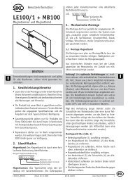
Measuring System<br />
Magnetic rotary encoder determine positions using the Hall effect sensor technology developed for the<br />
automotive mass market. A permanent magnet fixed to the shaft generates a magnetic field that is<br />
sampled by the Hall sensor, which translates the measured value into a unique absolute position<br />
value.<br />
To register revolutions even when no voltage is applied, energy from the turning of the shaft must<br />
suffice for proper operation. An innovative, patented technology makes this feasible even at low<br />
rotational speeds and through long standstill periods – a Wiegand wire ensures that the magnetic field<br />
can only follow the turning of the shaft in discrete steps. A coil wound on the Wiegand wire receives<br />
only brief, strong voltage spikes, which prompt the reliable recognition of each revolution.<br />
Typical Applications:<br />
� Packing Machines<br />
� Mobile Machines<br />
� Wind Mills<br />
� Medical Equipment<br />
2.1 General CANopen Information<br />
The CANopen system is used in industrial applications. It is a multiple access system (maximum: 127<br />
participants), which means that all devices can access the bus. In simple terms, each device checks<br />
whether the bus is free, and if it is the device is able to send messages. If two devices try to access<br />
the bus at the same time, the device with the higher priority level (lowest ID number) has permission to<br />
send its message.<br />
Devices with the lowest priority level must delay their data transfer and wait before retrying to send<br />
their message. Data communication is carried out via messages. These messages consist of 1 COB-<br />
ID followed by a maximum of 8 bytes of data. The COB-ID, which determines the priority of the<br />
message, consists of a function code and a node number. The node number corresponds to the<br />
network address of the device. It is unique on a bus. The function code varies according to the type of<br />
message being sent:<br />
� Management messages (LMT, NMT)<br />
� Messaging and service (SDOs)<br />
� Data exchange (PDOs)<br />
� Layer Setting Services (LSS)<br />
� Predefined messages (synchronization, emergency messages)<br />
The absolute rotary encoder supports the following operating modes:<br />
� Polled mode: The position value is only sent on request.<br />
� Cyclic mode: The position value is sent cyclically (regular, adjustable interval) on the bus.<br />
� SYNC mode: The position value is sent after a synchronization message (SYNC) is received.<br />
The position value is sent every n SYNCs (n � 1).<br />
Other functions (offset values, resolution, etc) can be configured. The absolute rotary encoder<br />
corresponds to the class 2 encoder profile (DS 406 in which the characteristics of encoder with<br />
CANopen interface are defined). The node number and speed in bauds are determined by their<br />
corresponding object dictionary entries.<br />
WV36M/CAN Date: 08.08.2011 Page 6 of 35 Art.No. 85655 Mod. status 282/11
The transmission speed can range from 20kBaud up to 1Mbaud (30m cable for a maximum speed of<br />
1Mbaud, 1000m cable for a maximum speed of 20 kbaud). Various software tools for configuration<br />
and parameter-setting are available from different suppliers. It is easy to align and program the rotary<br />
encoders using the EDS (electronic data sheet) configuration file provided.<br />
Further information is available at:<br />
CAN in Automation (CiA) International <strong>User</strong>s and Manufacturers Group e.V.<br />
Kontumazgarten 3<br />
DE-90429 Nurenberg<br />
(*) Reference: CAN Application Layer for Industrial Applications<br />
CiA Draft Standard 201 ... 207, Version 1.1<br />
CAL-based Communication Profile for Industrial Systems<br />
CiA Draft Standard 301<br />
CiA Draft Standard 305 Layer Setting Services<br />
CiA Draft Standard 406 Device Profile for Encoders<br />
Note: All datasheets and <strong>manual</strong>s can be downloaded for free from our website www.siko.de<br />
We do not assume responsibility for technical inaccuracies or omissions. Specifications are<br />
subject to change without notice.<br />
3. Installation<br />
Setting Node Number via SDO Objects<br />
The node number has to be adjusted via SDO objects. The default node-ID is 32 (20H). To set the<br />
node number, object 3000h has to be written. For further information regard chapter 5.5 Object<br />
Dictionary.<br />
Setting Baud Rate via SDO Objects<br />
The baudrate has to be adjusted via SDO objects. The default baudrate is 125 kBaud. To set baud<br />
rate object 3001h has to be written. For further information please regard chapter 5.5 Object<br />
Dictionary.<br />
Setting Node Number via LSS<br />
The node number can also be adjusted via Layer Setting Services (LSS). For further information<br />
regard chapter 4.5.<br />
Setting Baud Rate via LSS<br />
The baudrate can also be adjusted via Layer Setting Services (LSS). The default baudrate is 125<br />
kBaud. For further information regard chapter 4.5.<br />
Bus Termination<br />
If the encoder is the last device in the bus you can use the internal termination resistor which can be<br />
enabled with an SDO object.<br />
WV36M/CAN Date: 08.08.2011 Page 7 of 35 Art.No. 85655 Mod. status 282/11
4. Configuration<br />
The purpose of this chapter is to describe the configuration parameters of the absolute rotary encoder<br />
with CANopen interface.<br />
4.1 Operating Modes<br />
4.1.1 General<br />
The encoder accesses the CAN network after powerup in pre-operational mode:<br />
BootUp Message: 700 hex + Node Number<br />
It is recommended that the parameters can be changed by the user when the encoder is in<br />
preoperational mode. Pre-operational mode entails reduced activity on the network, which simplifies<br />
the checking of the accuracy of the sent/received SDOs. It is not possible to send or receive PDOs in<br />
pre-operational mode.<br />
4.1.2 Mode: Preoperational<br />
To set a node to pre-operational mode, the master must send the following message:<br />
Identifier Byte 0 Byte 1 Description<br />
0 h 80 h 00 NMT-PreOp, all nodes<br />
0 h 80 h NN NMT-PreOp, NN<br />
NN: node number<br />
It is possible to set all nodes (Index 0) or a single node (Index NN) to pre-operational mode.<br />
4.1.3 Mode: Start - Operational<br />
To put one or all nodes in the operational state, the master have to send the following message:<br />
Identifier Byte 0 Byte 1 Description<br />
0 h 01 h 00 NMT-Start, all nodes<br />
0 h 01 h NN NMT-Start, NN<br />
NN: node number<br />
It is possible to set all nodes (Index 0) or a single node (Index NN) to operational mode.<br />
4.1.4 Mode: Stopped<br />
To put one or all nodes in the stopped state, the master have to send the following message:<br />
Identifier Byte 0 Byte 1 Description<br />
0 h 02 h 00 NMT-Stop, all nodes<br />
0 h 02 h NN NMT-Stop, NN<br />
NN: node number<br />
It is possible to set all nodes (Index 0) or a single node (Index NN) to stop mode.<br />
4.1.5 Reinitialization of the Encoder<br />
If a node is not operating correctly, it is advisable to carry out a reinitialization:<br />
NN Command Index Description<br />
0 h 82 h 00 Reset Communication<br />
0 h 81 h NN Reset Node<br />
WV36M/CAN Date: 08.08.2011 Page 8 of 35 Art.No. 85655 Mod. status 282/11
NN: node number<br />
It is possible to set all nodes (Index 0) or a single node (Index NN) in reset mode.<br />
After reinitialization, the encoder accesses the bus in pre-operational mode.<br />
4.2 Normal Operating<br />
Polled Mode By a remote-transmission-request telegram the connected host calls for the<br />
current process value. The encoder reads the current position value,<br />
calculates eventually set-parameters and sends back the obtained process<br />
value by the same identifier.<br />
Cyclic Mode The encoder transmits cyclically - without being called by the host - the<br />
current process value. The cycle time can be programmed in milliseconds<br />
for values between 1 ms and 65536 ms.<br />
Sync Mode After receiving a sync telegram by the host, the encoder answers with the<br />
current process value. If more than one node number (encoder) shall<br />
answer after receiving a sync telegram, the answer telegrams of the nodes<br />
will be received by the host in order of their node numbers. The<br />
programming of an offset-time is not necessary. If a node should not<br />
answer after each sync telegram on the CAN network, the parameter sync<br />
counter can be programmed to skip a certain number of sync telegrams<br />
before answering again.<br />
Tab. 1: CAN Transmission Mode Description<br />
4.3 Storing Parameter<br />
4.3.1 List of storable Parameter<br />
Object Index Object Description<br />
1005h COB-ID Sync<br />
100Ch Guard Time<br />
100Dh Life Time Factor<br />
1016h Consumer Heartbeat Time<br />
1017h Producer Heartbeat Time<br />
1020h Verify configuration<br />
1800h Communication parameter PDO 1<br />
1801h Communication parameter PDO 2<br />
1A00h Transmit PDO1 Mapping Parameter<br />
1A01h Transmit PDO2 Mapping Parameter<br />
2100h Operating Parameters<br />
2101h Resolution per Revolution<br />
2102h Total Resolution<br />
2103h Preset Value<br />
2104h Limit Switch, min.<br />
2105h Limit Switch, max.<br />
2160h Customer Storage<br />
2200h Cyclic Timer<br />
3000h Node Number<br />
3001h Baudrate<br />
3002h Termination Resistor<br />
6000h Operating Parameter<br />
6001h Steps per Revolution<br />
6002h Total Resolution<br />
6003h Preset Value<br />
6200h Cyclic Timer<br />
Tab. 2: List of Storable Parameters<br />
WV36M/CAN Date: 08.08.2011 Page 9 of 35 Art.No. 85655 Mod. status 282/11
4.3.2 Storing Procedure<br />
The parameter settings can be stored in a non-volatile E 2 PROM. The parameter settings are<br />
stored in RAM when being programmed. When all the parameters are set and proved, they<br />
can be transferred in one burn cycle to the E 2 PROM by the parameter memory transfer. The<br />
stored parameters are copied after a RESET (Power on, NMT-Reset) from the E 2 PROM to<br />
the RAM (volatile memory).<br />
Storing without Reset<br />
By using the object 1010h from the communication profile related object dictionary you can store the<br />
parameters into the non-volatile memory without a reset.<br />
Storing with Reset<br />
By using the object 2300h from the manufacturer specific object dictionary you can store the<br />
parameters into the non-volatile memory. After storing the parameters a reset of the device is<br />
performed.<br />
4.4 Restoring Parameters<br />
The default parameters can be restored by using the object 1011h from communication profile related<br />
object dictionary. The already in the non-volatile memory programmed parameters are not overwritten.<br />
Only after a new store command the default parameters are stored in the non-volatile memory. To<br />
restore the default parameter the following telegram is used. The restored parameters are equal for<br />
every type of CANopen encoder and might not fit with the status after delivery. Please check the<br />
restored parameters before you store them to the non-volatile memory.<br />
4.5 Usage of Layer Setting Services (LSS)<br />
To configure the encoder via LSS the encoder will be the LSS slave device and the control has to<br />
support LSS master device functionality.<br />
The LSS master device requests services, that are performed by the LSS slave devices (encoder).<br />
The LSS master device requests the LSS address (vendor-id, product-code, revision-number, serialnumber)<br />
from the LSS slave device. After receiving this information the control can unequivocally<br />
identify the encoder and the node number and baudrate can be set.<br />
5. Programmable Parameters<br />
Objects are based on the CiA 406 DS V3.2: CANopen profile for encoders (www.can-cia.org).<br />
Command Function Telegram Description<br />
22h Domain Download Request Parameter to Encoderr<br />
23h, 27h, 2Bh, 2Fh (*) Domain Download Request Parameter to Encoder (Bytes<br />
indicated)<br />
60h Domain Download Confirmation Parameter received<br />
40h Domain Upload Request Parameter request<br />
43h, 47h, 4Bh, 4Fh (*) Domain Upload Reply Parameter to Master (Bytes<br />
indicated)<br />
80 h Warning Reply Transmission error<br />
Tab. 3: General Command Byte Description<br />
WV36M/CAN Date: 08.08.2011 Page 10 of 35 Art.No. 85655 Mod. status 282/11
(*)The value of the command byte depends on the data length of the called parameter:<br />
Command Data length Data type<br />
23h 4 Byte Unsigned 32<br />
27h 3 Byte Unsigned 24<br />
2Bh 2 Byte Unsigned 16<br />
2Fh 1 Byte Unsigned 8<br />
43h 4 Byte Unsigned 32<br />
47h 3 Byte Unsigned 24<br />
4Bh 2 Byte Unsigned 16<br />
4Fh 1 Byte Unsigned 8<br />
Tab. 4: Detailed Command Byte Description<br />
Object Dictionary<br />
The data transmission according to CAL is realized exclusively by object oriented data messages. The<br />
objects are classified in groups by an index record. Each index entry can be subdivided by subindices.<br />
The overall layout of the standard object dictionary is shown beside:<br />
Index (hex) Object<br />
0000 not used<br />
0001-001F Static Data Types<br />
0020-003F Complex Data Types<br />
0040-005F Manufacturer Specific Data Types<br />
0060-0FFF Reserved for further use<br />
1000-1FFF Communication Profile Area<br />
2000-5FFF Manufacturer Specific Profile Area<br />
6000-9FFF Standardized Device Profile Area<br />
A000-FFFF Reserved for further use<br />
Tab. 5: Overview Object Dictionary<br />
5.1 Programming example: Preset Value<br />
If a CANopen device is connected and configured with the right baudrate and also configured to a<br />
unused node number, it will start up into the pre-operational mode and send a bootup massage to the<br />
master.<br />
5.1.1 Set Encoder Preset Value<br />
Master to Encoder with Node Number 1.<br />
Setting Preset Value (Value 1000)<br />
Identifier DLC Command Index Subindex Service/Process data<br />
NN 1 Download 6003h Byte 4 Byte 5 Byte 6 Byte 7<br />
601 8 22 03 60 00 00 10 00 00<br />
Answer of the Encoder<br />
Identifier DLC Command Index Subindex Service/Process data<br />
NN 1 Download 6003h Byte 4 Byte 5 Byte 6 Byte 7<br />
581 8 43 03 60 00 00 00 00 00<br />
WV36M/CAN Date: 08.08.2011 Page 11 of 35 Art.No. 85655 Mod. status 282/11
Read Preset Value from the Encoder<br />
Identifier DLC Command Index Subindex Service/Process data<br />
NN 1 Download 6003h Byte 4 Byte 5 Byte 6 Byte 7<br />
601 8 40 03 60 00 00 00 00 00<br />
Answer of the Encoder<br />
Identifier DLC Command Index Subindex Service/Process data<br />
NN 1 Download 6003h Byte 4 Byte 5 Byte 6 Byte 7<br />
581 8 43 03 60 00 00 10 00 00<br />
Save Preset Values<br />
Identifier DLC Command Index Subindex Service/Process data<br />
NN 1 Download 1010h Byte 4 Byte 5 Byte 6 Byte 7<br />
601 8 22 10 10 01 73 61 76 65<br />
5.2 Communication Profile DS301 specific objects from 1000h - 1FFFh<br />
In this <strong>manual</strong> we refer to the communication profile DS301 V4.02.<br />
Object Description<br />
Page<br />
Hand-Book<br />
Page<br />
DS301<br />
Page<br />
DS406<br />
1000h Device type 22 86 8<br />
1001h Error register 22 87 8<br />
1003h Pre-defined error field 22 88<br />
1005h COB-ID SYNC-message 23 89<br />
1006h ComCyclePeriode 23 90<br />
1008h Device name 24 91<br />
1009h Hardware version 24 91<br />
100Ah Software version 24 91<br />
100Ch Guard Time 24 92<br />
100Dh Life Time Factor 24 92<br />
1010h Store parameters 25 92<br />
1011h Restore default parameters 25 94<br />
1012h COB-ID Time Stamp 26 97<br />
1013h High Resolution Time Stamp 26 98<br />
1014h COB-ID Emergency 26 98<br />
1016h Consumer Heartbeat Time 26 100<br />
1017h Producer Heartbeat Time 27 101<br />
1018h Identity Object 27 101<br />
1020h Verify Configuration 117<br />
1029h Error Behaviour 133 9<br />
1800h Communication parameter PDO 1 28 111 9<br />
1801h Communication parameter PDO 2 28 111 11<br />
1A00h Transmit PDO1 Mapping Parameter 30 112 11<br />
1A01h Transmit PDO2 Mapping Parameter 30 112 12<br />
1F50h Download Program Area<br />
1F51h Program Control<br />
Tab. 6: Object Dictionary 1000h-1FFFh<br />
WV36M/CAN Date: 08.08.2011 Page 12 of 35 Art.No. 85655 Mod. status 282/11
5.3 Manufacturer specific objects 2000h – 5FFFh<br />
Object Description<br />
Page<br />
Hand-Book<br />
2000h Position Value 31<br />
2100h Operating Parameters 31<br />
2101h Resolution per Revolution 31<br />
2102h Total Resolution 33<br />
2103h Preset Value 34<br />
2104h Limit Switch, min. 34<br />
2105h Limit Switch, max. 33<br />
2160h Customer Storage 35<br />
2200h Cyclic Timer 35<br />
2300h Save Parameter with reset 35<br />
3000h Node Number 36<br />
3001h Baudrate 36<br />
3002h Termination Resistor 36<br />
3010h Speed Control 37<br />
3011h Speed Value 37<br />
3020h Acceleration Control 37<br />
3021h Acceleration Value 37<br />
4000h Bootloader Control 38<br />
Tab. 7: Object Dictionary 2000-5FFF<br />
5.4 Application specific objects 6000h – 67FEh<br />
In this <strong>manual</strong> we refer to the communication profile DS406 V3.2.<br />
Object Description<br />
Page<br />
Hand-Book<br />
Page<br />
DS406<br />
6000h Operating Parameters 38 17<br />
6001h Measuring units per revolution 38 18<br />
6002h Total measuring range in measuring units 39 19<br />
6003h Preset value 39 19<br />
6004h Position Value 40 20<br />
6030h Speed Value 40 25<br />
6040h Acceleration Value 40 26<br />
6200h Cyclic Timer 40 28<br />
6300h Cam state register 40 30<br />
6301h Cam enable register 41 32<br />
6302h Cam polarity register 41 33<br />
6400h Area state register 44<br />
6401h Work area low limit 44<br />
6402h Work area high limit 44<br />
6500h Operating status 45 63<br />
6501h Single-turn resolution 45 64<br />
6502h Number of distinguishable revolutions 45 65<br />
6503h Alarms 46 65<br />
6504h Supported alarms 46 66<br />
WV36M/CAN Date: 08.08.2011 Page 13 of 35 Art.No. 85655 Mod. status 282/11
Object Description<br />
Page<br />
Hand-Book<br />
Page<br />
DS406<br />
6505h Warnings 47 67<br />
6506h Supported warnings 47 68<br />
6507h Profile and software version 48 69<br />
6508h Operating time 48 70<br />
6509h Offset value 49 70<br />
650Ah Module identification 49 71<br />
650Bh Serial number 49 72<br />
Tab. 8: Object Dictionary 6000h-6FFFh<br />
5.5 Object Descriptions<br />
In the following chapter you will find detailed information of the object dictionary related to the encoder<br />
device.<br />
5.5.1 Object 1000h: Device Type<br />
The object at index 1000h describes the type of device and its functionality. It is composed of a 16-bit<br />
field which describes the device profile that is used and a second 16-bit field which gives additional<br />
information about optional functionality of the device. The additional information parameter is device<br />
profile specific.<br />
Subindex Description Data Type Default Value Access Restore after<br />
BootUp<br />
0 - Unsigned 32 N/A ro no<br />
WV36M/CAN single turn: 10196h<br />
WV36M/CAN multi turn: 20196h<br />
5.5.2 Object 1001h: Error Register<br />
This object is used by the device to display internal faults. When a fault is detected, the corresponding<br />
bit is therefore activated.<br />
The following errors are supported:<br />
Bit Description Comments<br />
0 Generic Error The generic error is signaled at any error situation.<br />
Subindex Description Data Type Default Value Access Restore after<br />
BootUp<br />
0 - Unsigned 8 N/A ro no<br />
5.5.3 Object 1003h: Pre-Defined Error Field<br />
The object holds the errors that have occurred on the device and have been signaled via the<br />
Emergency Object.<br />
� The error code is located in the least significant word<br />
� Additional Information is located in the most significant word<br />
� Subindex 0 contains the number of recorded errors<br />
WV36M/CAN Date: 08.08.2011 Page 14 of 35 Art.No. 85655 Mod. status 282/11
Subindex Description Data Type Default Value Access Restore after<br />
BootUp<br />
0 Number of recorded<br />
errors<br />
Unsigned 8 0 rw no<br />
1 Most recent errors Unsigned 32 - ro no<br />
2<br />
…<br />
10<br />
Second to last error Unsigned 32 - ro no<br />
Clearing Error Log<br />
The error log can be cleared by writing 0 to subindex 0 of object 1003.<br />
5.5.4 Object 1005h: COB-ID Sync<br />
This object contains the synchronization message identifier.<br />
Subindex Description Data Type Default Value Access Restore after<br />
BootUp<br />
0 - Unsigned 32 80000080h rw no<br />
5.5.5 Object 1008h: Manufacturer Device Name<br />
This object contains the device name.<br />
Subindex Description Data Type Default Value Access Restore after<br />
BootUp<br />
0 - String - ro no<br />
5.5.6 Object 1009h: Manufacturer Hardware Version<br />
This object contains the article name of the circuit board.<br />
Subindex Description Data Type Default Value Access Restore after<br />
BootUp<br />
0 - String - ro no<br />
There is one actual version of circuit boards for WV36M/CAN.<br />
5.5.7 Object 100Ah: Manufacturer Software Version<br />
This object contains the manufacturer software version. The new encoder line 2008 starts with version<br />
4.00.<br />
Subindex Description Data Type Default Value Access Restore after<br />
BootUp<br />
0 - String 4.00 ro no<br />
5.5.8 Object 100Ch: Guard Time<br />
This object contains the guard time in milliseconds.<br />
Subindex Description Data Type Default Value Access Restore after<br />
BootUp<br />
0 - Unsigned 16 0 rw yes<br />
WV36M/CAN Date: 08.08.2011 Page 15 of 35 Art.No. 85655 Mod. status 282/11
5.5.9 Object 100Dh: Life Time Factor<br />
This object contains the life time factor parameters. The life time factor multiplied with the guard time<br />
gives the life time for the node guarding protocol.<br />
Subindex Description Data Type Default Value Access Restore after<br />
BootUp<br />
0 - Unsigned 8 0 rw yes<br />
5.5.10 Object 1010h: Store Parameters<br />
This object is used to store device and CANopen related parameters to non volatile memory.<br />
Subindex Description Data Type Default Value Access Restore after<br />
BootUp<br />
0 Number of sub indices Unsigned 8 2 ro no<br />
1 Store all parameters Unsigned 32 “save” rw no<br />
Storing procedure<br />
To save the parameters to non volatile memory the access signature “save” has to be sent to the<br />
corresponding subindex of the device.<br />
Most significant word Least significant word<br />
ASCII E v a s<br />
Hex value 65h 76h 61h 73h<br />
5.5.11 Object 1011h: Restore Parameters<br />
This object is used to restore device and CANopen related parameters to factory settings.<br />
Subindex Description Data Type Default Value Access Restore after<br />
BootUp<br />
0 Number of sub indices Unsigned 8 2 ro no<br />
1 Restore all parameters Unsigned 32 “load” rw no<br />
Storing procedure<br />
To save the parameters to non volatile memory the access signature “load” has to be sent to the<br />
corresponding subindex of the device.<br />
Most significant word Least significant word<br />
ASCII D a o l<br />
Hex value 64h 61h 6Fh 6Ch<br />
Note: The restoration of parameters will only be taken into account after a power up or reset<br />
command. Please check all parameters before you store them to the non volatile memory.<br />
5.5.12 Object 1012h: COB-ID Time Stamp Object<br />
This object contains the COB-ID of the Time Stamp object.<br />
Subindex Description Data Type Default Value Access Restore after<br />
BootUp<br />
0 - Unsigned 32 100h rw no<br />
WV36M/CAN Date: 08.08.2011 Page 16 of 35 Art.No. 85655 Mod. status 282/11
5.5.13 Object 1013h: High Resolution Time Stamp<br />
This object contains a time stamp with a resolution of 1µs.<br />
Subindex Description Data Type Default Value Access Restore after<br />
BootUp<br />
0 - Unsigned 32 0 rw no<br />
5.5.14 Object 1014h: COB-ID Emergency Object<br />
This object contains the EMCY emergency message identifier.<br />
Subindex Description Data Type Default Value Access Restore after<br />
BootUp<br />
0 - Unsigned 32 80h + Node ID rw no<br />
5.5.15 Object 1016h: Consumer Heartbeat Time<br />
The consumer heartbeat time defines the expected heartbeat cycle time in ms. The device can only<br />
monitor one corresponding device. If the time is set to 0 the monitoring is not active. The value of this<br />
object must be higher than the corresponding time (object 1017) of the monitored device.<br />
Subindex Description Data Type Default Value Access Restore after<br />
BootUp<br />
0 Number of indices Unsigned 8 1 ro no<br />
1 Consumer heartbeat<br />
time<br />
Unsigned 32<br />
0<br />
rw yes<br />
The context of subindex 1 is as follows:<br />
Bit 31 to 24 23 to 16 15 to 0<br />
Value 0h (reserved) Address of monitored device Monitoring time (ms)<br />
5.5.16 Object 1017h: Producer Heartbeat Time<br />
The object contains the time intervall in milliseconds in which the device has to produce the a<br />
heartbeat message.<br />
Subindex Description Data Type Default Value Access Restore after<br />
BootUp<br />
0 - Unsigned 16 0 rw yes<br />
5.5.17 Object 1018h: Identity Object<br />
This object contains the device information.<br />
Subindex Description Data Type Default Value Access Restore<br />
after BootUp<br />
0 Number of entries Unsigned 8 4 ro no<br />
1 Vendor ID Unsigned 32 195h ro no<br />
2 Product Code Unsigned 32 ro no<br />
3 Revision Number Unsigned 32 100h ro no<br />
4 Serial Number Unsigned 32 ro no<br />
WV36M/CAN Date: 08.08.2011 Page 17 of 35 Art.No. 85655 Mod. status 282/11
5.5.18 Object 1020h: Verify configuration<br />
This object indicates the downloaded configuration date and time.<br />
Subindex Description Data Type Default Value Access Restore<br />
after BootUp<br />
0h Number of entries Unsigned 8 2h ro no<br />
1h Configuration date Unsigned 32 rw no<br />
2h Configuration time Unsigned 32 rw no<br />
5.5.19 Object 1029h: Error behaviour<br />
This object indicates the error behavior.<br />
Subindex Description Data Type Default Value Access Restore after<br />
BootUp<br />
0h Number of entries Unsigned 8 1h ro no<br />
1h Communication error Unsigned 8 rw no<br />
5.5.20 Object 1800h: 1 st Transmit PDO Communication Parameter<br />
This object contains the communication parameter of the 1 st transmit PDO.<br />
Subindex Description Data Type Default Value Access Restore after<br />
BootUp<br />
0 Number of sub indices Unsigned 8 5 ro yes<br />
1 COB-ID Unsigned 32 180h + Node rw yes<br />
2 Transmission Mode Unsigned 8 FE rw yes<br />
3 Inhibit Time Unsigned 32 0 rw yes<br />
4 Not available<br />
5 Event Timer Unsigned 32 64h or 0 rw yes<br />
5.5.21 Object 1801h: 2 nd Transmit PDO Communication Parameter<br />
This object contains the communication parameter of the 2 nd transmit PDO.<br />
Note: In the OCD versions C2 and C5 the second PDO was configured via object 1802!<br />
Subindex Description Data Type Default Value Access Restore after<br />
BootUp<br />
0 Number of sub indices Unsigned 8 5 ro yes<br />
1 COB-ID Unsigned 32 280h + Node rw yes<br />
2 Transmission Mode Unsigned 8 1 rw yes<br />
3 Inhibit Time Unsigned 32 0 rw yes<br />
4 Not available<br />
5 Event Timer Unsigned 32 0 rw yes<br />
WV36M/CAN Date: 08.08.2011 Page 18 of 35 Art.No. 85655 Mod. status 282/11<br />
ID<br />
ID
Transmission Mode<br />
The transmission mode can be configured as described below:<br />
Transfer<br />
Transmission Mode<br />
Value Cyclic Acyclic Synchr Asynch RTR Notes<br />
(decimal)<br />
onous ronous only<br />
0 X X Send PDO on first Sync message<br />
following an event<br />
1-240 X X Send PDO every x Sync messages<br />
241-251 reserved<br />
252 X X Receive SYNC message and send<br />
PDO on Remote Request<br />
253 X Update data and send PDO on<br />
Remote Request<br />
254 X Send PDO on event<br />
255 X Send PDO on event<br />
Inhibit Time<br />
For "Transmit PDOs", the "inhibit time" for PDO transmissions can be entered in this 16 bit field. If data<br />
is changed, the PDO sender checks whether an "inhibit time" has expired since the last transmission.<br />
A new PDO transmission can only take place if the "inhibit time" has expired. The "inhibit time" is<br />
useful for asynchronous transmission (transmission mode 254 and 255), to avoid overloads on the<br />
CAN bus.<br />
5.5.22 Event Timer<br />
The "event timer" only works in asynchronous transmission mode (transmission mode 254 and 255). If<br />
the data changes before the "event timer" expires, a temporary telegram is sent. If a value > 0 is<br />
written in this 16-bit field, the transmit PDO is always sent after the "event timer" expires. The value is<br />
written in subindex 5 of a transmit PDO. The data transfer also takes place with no change to data.<br />
The range is between 1-65536 ms.<br />
5.5.23 Object 1A00h: 1 st Transmit PDO Mapping Parameter<br />
This object contains the mapping parameter of the 1 st transmit PDO.<br />
Subindex Description Data Type Default Value Access Restore after<br />
BootUp<br />
0 Number of sub indices Unsigned 8 2 ro yes<br />
1 1st mapped object Unsigned 32 60040020h rw yes<br />
5.5.24 Object 1A01h: 2 nd Transmit PDO Mapping Parameter<br />
This object contains the mapping parameter of the 2 nd transmit PDO.<br />
Subindex Description Data Type Default Value Access Restore after<br />
BootUp<br />
0 Number of sub indices Unsigned 8 2 ro yes<br />
1 2 nd mapped object Unsigned 32 60040020h rw yes<br />
WV36M/CAN Date: 08.08.2011 Page 19 of 35 Art.No. 85655 Mod. status 282/11
5.5.25 Object 1F50h: Download Program Area<br />
This is a special object that has functionality for the bootloader feature. (see Bootloader chapter)<br />
Use this entry to download your Intel hex file with the programming data. Detailed information about<br />
Domain download and Block transfer in CiA Draft Standard 301 Application Layer and communication<br />
Profile.<br />
Subindex Description Data Type Default Value Access Restore after<br />
BootUp<br />
0h Number of sub indices Unsigned 8 2h ro yes<br />
1h DOMAIN wo yes<br />
5.5.26 Object 1F51h: Program Control<br />
This is a special bootloader object, to update the firmware (see Bootloader chapter).<br />
This array controls the programs residing at index 0x1F50.<br />
Subindex Description Data Type Default Value Access Restore after<br />
BootUp<br />
0h Number of program<br />
control entries<br />
Unsigned 8 2h ro yes<br />
1h Unsigned 32 rw yes<br />
Sub-index 1h and higher control the memory block functionality. They can have the following values:<br />
for writing:<br />
1 - start downloaded program<br />
4 - erase flash<br />
5.5.27 Object 2000h: Position Value<br />
This object contains the position value.<br />
Subindex Description Data Type Default Value Access Restore after<br />
BootUp<br />
0 Position Value Unsigned 32 - ro n.a.<br />
5.5.28 Object 2100h: Operating Parameters<br />
As operating parameters the code sequence (Complement) can be selected and the limit switches can<br />
be turned on or off.<br />
Subindex Description Data Type Default Value Access Restore after<br />
BootUp<br />
0 Operating Parameters Unsigned 8 0h rw yes<br />
The parameter code sequence (Complement) determines the counting direction, in which the output<br />
process value increases or decreases (CW = Clockwise, CCW = Counterclockwise). The code<br />
sequence is determined by Bit 0 in Index 2100h. Additionally, the two limit switches, Min. and Max.<br />
can be turned on or off in Index 2100h.<br />
Bit 0 Code Code Bit 1 Limit Bit 2 Limit switch, Bit 3 Event triggered<br />
sequence<br />
switch, min.<br />
max.<br />
PDO<br />
0 CW increasing 0 off 0 off 0 off<br />
1 CCW increasing 1 on 1 on 1 on<br />
WV36M/CAN Date: 08.08.2011 Page 20 of 35 Art.No. 85655 Mod. status 282/11
Calculation Example: Target: Absolute rotary encoder with direction CCW increasing, limit switch min<br />
enabled and limit switch max disabled.<br />
Bitmatrix:<br />
Bit 0 = 1 Direction increasing CCW<br />
Bit 1 = 1 Limit switch min. enabled<br />
Bit 2 = 0 Limit switch max. disabled<br />
Result = 011b = 3h<br />
5.5.29 Object 2101h: Resolution per Revolution<br />
This object contains the desired steps per revolution of the encoder.<br />
Subindex Description Data Type Default Value Access Restore after<br />
BootUp<br />
0 Resolution per<br />
Revolution<br />
Unsigned 32 see type sign rw yes<br />
If the desired value exceeds the hardware resolution of the encoder or is not a value of 2 n , it will be<br />
out of range. Only values in the power of two are valid, otherwise the error code “06090030h: Value<br />
range of parameter exceeded” will appear.<br />
5.5.30 Object 2102h: Total Resolution<br />
This object contains the desired total resolution of the encoder.<br />
Subindex Description Data Type Default Value Access Restore after<br />
BootUp<br />
0 Total Resolution Unsigned 32 see type sign rw yes<br />
This parameter is used to program the desired number of measuring units over the total measuring<br />
range. This value must not exceed the total resolution of the absolute rotary encoder, which is printed<br />
on the type sign of the encoder.<br />
Attention:<br />
Following formula letter will be used:<br />
PGA Physical total resolution of the encoder (see type sign)<br />
PAU Physical resolution per revolution (see type sign)<br />
GA Total resolution (customer parameter)<br />
AU Resolution per revolution (customer parameter)<br />
Please use the following formula to calculate the total resolution of the encoder:<br />
�PGA � AU�<br />
GA � , AU �PAU<br />
PAU<br />
If the desired resolution per revolution is less than the really physical resolution per revolution of the<br />
encoder, then the total resolution must be entered as follows:<br />
Total resolution:<br />
Calculation example:<br />
Customer handicap: AU = 2048<br />
Encoder type sign:<br />
PGA=24 bit, PAU=12bit<br />
PGA<br />
k � , k �ganze<br />
Zahl<br />
GA<br />
�16777216 � 2048�<br />
GA �<br />
4096<br />
GA � 8388608<br />
WV36M/CAN Date: 08.08.2011 Page 21 of 35 Art.No. 85655 Mod. status 282/11
If the total resolution of the encoder is less than the physical total resolution, the parameter total<br />
resolution must be a multiple of the physical total resolution.<br />
5.5.31 Object 2103h: Preset Value<br />
The preset value is the desired position value, which should be reached at a certain physical position<br />
of the axis. The position value is set to the desired process value by the parameter preset. The preset<br />
value must not exceed the parameter total resolution to avoid run-time errors. If the parameter value<br />
exceeds the total resolution of the encoder a SDO “Out of range” message is generated.<br />
Subindex Description Data Type Default Value Access Restore after<br />
BootUp<br />
0 Preset Value Unsigned 32 0 rw yes<br />
5.5.32 Object 2104h: Limit Switch, min.<br />
Two position values can be programmed as limit switches. By reaching this value, one bit of the 32 bit<br />
process value is set to high. Both programmed values must not exceed the parameter total resolution<br />
to avoid run-time errors. If the parameter value exceeds the total resolution of the encoder a SDO “Out<br />
of range” message is generated.<br />
Bit 30 = 1: Limit Switch, Min. reached or passed under<br />
Subindex Description Data Type Default Value Access Restore after<br />
BootUp<br />
0 Limit Switch, min. Unsigned 32 0 rw yes<br />
The limit switch, Min sets Bit 30=1 with the next message telegram, if the process value reaches or<br />
passes under the value of the limit switch:<br />
Function Status Process value<br />
bits<br />
Bit 31 30 29 28 27 26 25 24 23 22 21 20 19 18 17 16 15 14 13 12 11 10 9 8 7 6 5 4 3 2 1 0<br />
0 1 X X X X X X X X X X X X X X X X X X X X X X X X X X X X X X<br />
5.5.33 Object 2105h: Limit Switch, max.<br />
Two position values can be programmed as limit switches. By reaching this value, one bit of the 32 bit<br />
process value is set to high. Both programmed values must not exceed the parameter total resolution<br />
to avoid run-time errors. If the parameter value exceeds the total resolution of the encoder a SDO “Out<br />
of range” message is generated.<br />
Bit 31 = 1: Limit Switch, Max. reached or passed beyond<br />
Subindex Description Data Type Default Value Access Restore<br />
after BootUp<br />
0 Limit Switch, max. Unsigned 32 0 rw yes<br />
The limit switch, max sets Bit 31=1 with the next message telegram, if the process value reaches or<br />
passes under the value of the limit switch:<br />
Function Status Process value<br />
bits<br />
Bit 31 30 29 28 27 26 25 24 23 22 21 20 19 18 17 16 15 14 13 12 11 10 9 8 7 6 5 4 3 2 1 0<br />
1 0 X X X X X X X X X X X X X X X X X X X X X X X X X X X X X X<br />
WV36M/CAN Date: 08.08.2011 Page 22 of 35 Art.No. 85655 Mod. status 282/11
5.5.34 Object 2160h: Customer storage<br />
This object provides for the customer the possibility to store any value.<br />
Subindex Description Data Type Default Value Access Restore<br />
after BootUp<br />
0h Number of sub indices Unsigned 8 4h ro<br />
1h Customer Storage1 Unsigned 32 rw<br />
2h Customer Storage2 Unsigned 32 rw<br />
3h Customer Storage3 Unsigned 32 rw<br />
4h Customer Storage4 Unsigned 32 rw<br />
5.5.35 Object 2200h: Cyclic Timer PDO<br />
This object contains cyclic time of the event timer in ms (of PDO 1).<br />
Subindex Description Data Type Default Value Access Restore after<br />
BootUp<br />
0h Event Time in ms Unsigned 16 0h ro yes<br />
The object 2200h is hard-wired to the objects 1800h subindex 5h and 6200h and provide the cycle<br />
time for the cyclic mode (see chapter Cycle Time and Event Timer).<br />
5.5.36 Object 2300h: Save Parameter with Reset<br />
With this object all parameters can be stored in the non volatile memory. After storing the parameters<br />
a reset is executed.<br />
Subindex Description Data Type Default Value Access Restore after<br />
BootUp<br />
0 Access code Unsigned 32 55AAAA55h wo no<br />
5.5.37 Object 3000h: Node Number<br />
This object contains the node number of the device. The standard node number is 32.<br />
Subindex Description Data Type Default Value Access Restore after<br />
BootUp<br />
0 Node Number Unsigned 8 1Fh rw yes<br />
Note: To avoid the node number 0, one will be added to the value of this object!<br />
E.g.: 1Fh+1h = 20h = 32 (dec)<br />
5.5.38 Object 3001h: Baudrate<br />
This object contains the baudrate of the device.<br />
Subindex Description Data Type Default Value Access Restore after<br />
BootUp<br />
0 Baudrate Unsigned 8 - rw yes<br />
Eight different baudrates are provided. To adjust the baudrate only one byte is used.<br />
WV36M/CAN Date: 08.08.2011 Page 23 of 35 Art.No. 85655 Mod. status 282/11
Baudrate in kBit/s Byte<br />
20 00h<br />
50 01h<br />
100 02h<br />
125 03h<br />
250 04h<br />
500 05h<br />
800 06h<br />
1000 07h<br />
5.5.39 Object 3002h: Termination Resistor<br />
Subindex Description Data Type Default Value Access Restore after<br />
BootUp<br />
0 Termination Resistor Unsigned 8 - rw yes<br />
By writing 01h to this object the internal galvanic isolated termination resistor is activated. Note that<br />
the resistor is only activated when the device is powered. If you have more CAN nodes on the Bus be<br />
sure to power them approx 700ms after the device with the programmed termination Resistor.<br />
5.5.40 Object 3010h: Speed Control<br />
This object contains the speed control. The speed measurement is disabled by default.<br />
Subindex Description Data Type Default Value Access Restore after<br />
BootUp<br />
0h Number of sub indices Unsigned 8 2h ro<br />
1h Enable Speed Unsigned 8 0h rw yes<br />
2h Speed modus Unsigned 8 0h rw yes<br />
5.5.41 Object 3011h: Speed Value<br />
This object contains speed value.<br />
Subindex Description Data Type Default Value Access Restore after<br />
BootUp<br />
0h Speed value Unsigned 8 romap no<br />
5.5.42 Object 3020h: Acceleration Control<br />
This object contains the acceleration control. Acceleration output is not supported by this device. This<br />
object is present only for compatibility reasons.<br />
Subindex Description Data Type Default Value Access Restore after<br />
BootUp<br />
0h Number of sub indices Unsigned 8 2h ro<br />
1h Enable Acceleration Unsigned 8 0h rw yes<br />
2h Acceleration modus Unsigned 8 0h rw yes<br />
WV36M/CAN Date: 08.08.2011 Page 24 of 35 Art.No. 85655 Mod. status 282/11
5.5.43 Object 3021h: Acceleration Value<br />
Acceleration output is not supported by this device. This object is present only for compatibility<br />
reasons.<br />
Subindex Description Data Type Default Value Access Restore after<br />
BootUp<br />
0h Acceleration Value Integer 32 romap<br />
5.5.44 Object 4000h: Bootloader Control<br />
This object controls the Bootloader functionality (see Bootloader chapter). Writing the security code to<br />
this object causes erasing the EEPROM and application information in the flash memory and resets<br />
the device. After a power-up, the Bootloader checks the user application and detects no more<br />
information. The Bootloader starts up with a pre-defined CANopen node ID of 1 (0x1) and a fixed CAN<br />
baudrate of 125 kbits.<br />
Subindex Description Data Type Default Value Access Restore after<br />
BootUp<br />
0h Bootloader Control Unsigned 32 wo<br />
Note: Activating the Bootloader courses a deep reset of the device. After this only a few<br />
objects are still available, the device does not behave like an encoder and waits for new<br />
programming. That is the reason why the security code is not published in this document.<br />
Please contact <strong>SIKO</strong> to obtain the code.<br />
5.5.45 Object 6000h: Operating parameters<br />
This object shall indicate the functions for code sequence, commissioning diagnostic control<br />
and scaling function control.<br />
Subindex Description Data Type Default Value Access Restore after<br />
BootUp<br />
0h Operating Parameter Unsigned 16 1h rw yes<br />
Code sequence: The code sequence defines, whether increasing or decreasing position values are<br />
output, in case the encoder shaft rotates clockwise or counter clockwise as seen from the point of view<br />
of the shaft.<br />
Scaling function control: With the scaling function the encoder numerical value is converted in<br />
software to change the physical resolution of the encoder. The measuring units per revolution (object<br />
6001h) and total measuring range in measuring units (object 6002h) are the scaling parameters. The<br />
scaling function bit is set in the operating parameters. If the scaling function bit is set to zero, the<br />
scaling function is disabled.<br />
Bit structure for the operating parameters<br />
Bit 15 14 13 12 11 10 9 8 7 6 5 4 3 2 1 0<br />
Use MS MS MS MS R R R R R R R R MD SFC CD CS<br />
Table Description:<br />
MS: Manufacturer Specific Function (not available)<br />
R: Reserved for future use<br />
MD: Measuring direction (not available)<br />
SFC: Scaling function (0 = disable, 1 = enable)<br />
CD: Commissioning diagnostic control (not availabe)<br />
CS: Code sequence (0 = CW Up, 1 = CCW Up)<br />
Code Sequence (CS Bit 0) is hardwired to Code Sequence (CS Bit 0) in object 2100h.<br />
WV36M/CAN Date: 08.08.2011 Page 25 of 35 Art.No. 85655 Mod. status 282/11
5.5.46 Object 6001h: Measuring units per revolution<br />
This object shall indicate the number of distinguishable steps per revolution.<br />
Subindex Description Data Type Default Value Access Restore after<br />
BootUp<br />
0h Measuring units per<br />
revolution<br />
Unsigned 32 see type sign rw yes<br />
Hardwired with 2101h.<br />
5.5.47 Object 6002h: Total measuring range in measuring units<br />
This object shall indicate the number of distinguishable steps over the total measuring range.<br />
Subindex Description Data Type Default Value Access Restore after<br />
BootUp<br />
0h Total measuring steps Unsigned 32 see type sign rw yes<br />
5.5.48 Object 6003h: Preset value<br />
This object indicates the preset value for the output position value.<br />
Subindex Description Data Type Default Value Access Restore after<br />
BootUp<br />
0h Preset Value Unsigned 32 0h rw yes<br />
5.5.49 Object 6004h: Position value<br />
This object contains the process value of the encoder.<br />
Subindex Description Data Type Default Value Access Restore after<br />
BootUp<br />
0h Process Value Unsigned 32 - romap yes<br />
Hardwired with Object 2000h.<br />
5.5.50 Object 6030h: Speed Value<br />
This object contains the speed value of the encoder.<br />
Subindex Description Data Type Default Value Access Restore after<br />
BootUp<br />
0h Number of sub indices Unsigned 8 1h ro<br />
1h Speed value channel1 Integer 16 - romap yes<br />
If the velocity exceeds the data type, the speed value is frozen to the maximal possible value.<br />
The customer can use the 3010h (32 bit) object.<br />
5.5.51 Object 6040h: Acceleration Value<br />
This object contains the acceleration value of the encoder.<br />
Subindex Description Data Type Default Value Access Restore after<br />
BootUp<br />
0h Number of sub indices Unsigned 8 1h ro<br />
1h Acceleration value<br />
channel1<br />
Integer 16 - romap yes<br />
WV36M/CAN Date: 08.08.2011 Page 26 of 35 Art.No. 85655 Mod. status 282/11
5.5.52 Object 6200h: Cyclic timer<br />
This object contains the value of the event timer of the corresponding TPDOs. The value can be<br />
changed between 1-65538 ms.<br />
Subindex Description Data Type Default Value Access Restore after<br />
BootUp<br />
0h Cyclic Time Unsigned 16 64h rw yes<br />
The object 6200h is hard-wired to the objects 1800h subindex 5h and 2200h and provide the cycle<br />
time for the cyclic mode (see chapter Cycle Time and Event Timer).<br />
5.5.53 Object 6300h: Cam state register<br />
This object contains the cam state register. The subindices 1h to FEh contain the cam state of channel<br />
1 to 254.<br />
Subindex Description Data Type Default Value Access Restore after<br />
BootUp<br />
0h Number of sub indices Unsigned 8 1h ro<br />
1h Cam state channel 1 Unsigned 8 4h romap yes<br />
5.5.54 Object 6301h: Cam enable register<br />
This object contains the cam enable register.<br />
Subindex Description Data Type Default Value Access Restore<br />
after BootUp<br />
0h Number of sub indices Unsigned 8 1h ro<br />
1h Cam enable channel 1 Unsigned 8 rw yes<br />
5.5.55 Object 6302h: Cam polarity register<br />
This object contains the cam enable register.<br />
Subindex Description Data Type Default Value Access Restore<br />
after BootUp<br />
0h Number of sub indices Unsigned 8 1h ro<br />
1h Cam polarity channel 1 Unsigned 8 0h rw yes<br />
List of Cam objects<br />
6310h Cam1 low limit rw<br />
0h VAR Highest sub-index supported U32 ro 0x1<br />
1h VAR Cam1 low limit channel1 rw<br />
6311h Cam2 low limit rw<br />
0h VAR Highest sub-index supported U32 ro 0x1<br />
1h VAR Cam2 low limit channel1 rw<br />
6312h Cam3 low limit rw<br />
0h VAR Highest sub-index supported U8 ro 0x1<br />
1h VAR Cam3 low limit channel1 rw<br />
6313h Cam4 low limit rw<br />
0h VAR Highest sub-index supported U8 ro 0x1<br />
1h VAR Cam4 low limit channel1 rw<br />
WV36M/CAN Date: 08.08.2011 Page 27 of 35 Art.No. 85655 Mod. status 282/11
List of Cam objects<br />
6314h Cam5 low limit rw<br />
0h VAR Highest sub-index supported U8 ro 0x1<br />
1h VAR Cam5 low limit channel1 rw<br />
6315h Cam6 low limit rw<br />
0h VAR Highest sub-index supported U8 ro 0x1<br />
1h VAR Cam6 low limit channel1 rw<br />
6316h Cam7 low limit rw<br />
0h VAR Highest sub-index supported U8 ro 0x1<br />
1h VAR Cam7 low limit channel1 rw<br />
6317h Cam8 low limit rw<br />
0h VAR Highest sub-index supported U8 ro 0x1<br />
1h VAR Cam8 low limit channel1 rw<br />
6320h Cam1 high limit rw<br />
0h VAR Highest sub-index supported U8 ro 0x1<br />
1h VAR Cam1 high limit channel1 rw<br />
6321h Cam2 high limit rw<br />
0h VAR Highest sub-index supported U8 ro 0x1<br />
1h VAR Cam2 high limit channel1 rw<br />
6322h Cam3 high limit rw<br />
0h VAR Highest sub-index supported U8 ro 0x1<br />
1h VAR Cam3 high limit channel1 rw<br />
6323h Cam4 high limit rw<br />
0h VAR Highest sub-index supported U8 ro 0x1<br />
1h VAR Cam4 high limit channel1 rw<br />
6324h Cam5 high limit rw<br />
0h VAR Highest sub-index supported U8 ro 0x1<br />
1h VAR Cam5 high limit channel1 rw<br />
6325h Cam6 high limit rw<br />
0h VAR Highest sub-index supported U8 ro 0x1<br />
1h VAR Cam6 high limit channel1 rw<br />
6326h Cam7 high limit rw<br />
0h VAR Highest sub-index supported U8 ro 0x1<br />
1h VAR Cam7 high limit channel1 rw<br />
6327h Cam8 high limit rw<br />
0h VAR Highest sub-index supported U8 ro 0x1<br />
1h VAR Cam8 high limit channel1 rw<br />
6330h Cam1 hyteresis rw<br />
0h VAR Highest sub-index supported U8 ro 0x1<br />
1h VAR Cam1 hyteresis channel1 rw<br />
6331h Cam2 hyteresis rw<br />
0h VAR Highest sub-index supported U8 ro 0x1<br />
1h VAR Cam2 hyteresis channel1 rw<br />
6332h Cam3 hyteresis rw<br />
0h VAR Highest sub-index supported U8 ro 0x1<br />
1h VAR Cam3 hyteresis channel1 rw<br />
6333h Cam4 hyteresis rw<br />
0h VAR Highest sub-index supported U8 ro 0x1<br />
1h VAR Cam4 hyteresis channel1 rw<br />
6334h Cam5 hyteresis rw<br />
0h VAR Highest sub-index supported U8 ro 0x1<br />
1h VAR Cam5 hyteresis channel1 rw<br />
6335h Cam6 hyteresis rw<br />
0h VAR Highest sub-index supported U8 ro 0x1<br />
WV36M/CAN Date: 08.08.2011 Page 28 of 35 Art.No. 85655 Mod. status 282/11
List of Cam objects<br />
1h VAR Cam6 hyteresis channel1 rw<br />
6336h Cam7 hyteresis rw<br />
0h VAR Highest sub-index supported U8 ro 0x1<br />
1h VAR Cam7 hyteresis channel1 rw<br />
6337h Cam8 hyteresis rw<br />
0h VAR Highest sub-index supported U8 ro 0x1<br />
1h VAR Cam8 hyteresis channel1 rw<br />
5.5.56 Object 6400h: Area state register<br />
This object contains the area state register.<br />
The object provides the actual area status of the encoder position. Figure 9 specifies the object<br />
structure and Table 106 specifies the value definition.<br />
Subindex Description Data Type Default Value Access Restore<br />
after BootUp<br />
0h Number of sub indices Unsigned 8 1h ro<br />
1h Work area state channel Unsigned 8 romap yes<br />
7 6 5 4 3 2 1 0<br />
R r r r r Range underflow Range overflow Out of range<br />
MSB LSB<br />
Signal Value Definition<br />
out of range 0<br />
1<br />
range overflow 0<br />
1<br />
range underflow 0<br />
1<br />
Position between low and high limit.<br />
Position out of range (refer to module identification object,<br />
650Ah) is reached<br />
r 0 Reserved<br />
No range overflow<br />
Position is lower than the position value set in object 6402h<br />
„work area low limit“<br />
5.5.57 Object 6401h: Work area low limit<br />
No range underflow<br />
Position is higher than the position value set in object 6401h<br />
„work area high limit“<br />
This object indicates the position value, at which bit 2 of the according work area state channel in<br />
object 6400h shall flag the underflow of the related work area.<br />
Subindex Description Data Type Default Value Access Restore<br />
after BootUp<br />
0h Number of sub indices Integer 32 1h ro<br />
1h Work area low limit<br />
channel 1<br />
Integer 32 0h rw yes<br />
This object is hardwired with 2104h (Limit Switch Min).<br />
WV36M/CAN Date: 08.08.2011 Page 29 of 35 Art.No. 85655 Mod. status 282/11
5.5.58 Object 6402h: Work area high limit<br />
This object indicates the position value, at which bit 1 of the according work area state channel in<br />
object 6400h shall flag the overflow of the related work area.<br />
Subindex Description Data Type Default Value Access Restore<br />
after BootUp<br />
0h Number of sub indices Integer 32 1h ro<br />
1h Work area high limit<br />
channel 1<br />
Integer 32 0h rw yes<br />
This object is hardwired with 2105h (Limit Switch Max).<br />
5.5.59 Object 6500h: Operating status<br />
This object shall provide the operating status of the encoder. It gives information on encoder internal<br />
programmed parameters.<br />
Subindex Description Data Type Default Value Access Restore after<br />
BootUp<br />
0h Operating status Unsigned 16 - ro no<br />
The operating status object corresponds to the value of the object 6000h and 2100h.<br />
5.5.60 Object 6501h: Single-turn resolution<br />
The object contains the physical measuring steps per revolution of the absolute rotary encoder.<br />
Subindex Description Data Type Default Value Access Restore after<br />
BootUp<br />
0h Single Turn Resolution Unsigned 32 see type sign ro no<br />
5.5.61 Object 6502h: Number of distinguishable revolutions<br />
This object contains number of revolutions of the absolute rotary encoder.<br />
Subindex Description Data Type Default Value Access Restore after<br />
BootUp<br />
0h Number of Revolutions Unsigned 16 see type sign ro no<br />
5.5.62 Object 6503h: Alarms<br />
Additionally to the emergency messages in DS301, this object shall provide further alarm messages.<br />
An alarm shall be set if a malfunction in the encoder could lead to incorrect position value. If an alarm<br />
occurs, the according bit shall indicate the alarm til the alarm is cleared and the encoder is able to<br />
provide an accurate position value.<br />
Subindex Description Data Type Default Value Access Restore after<br />
BootUp<br />
0h Alarms Unsigned 16 - romap no<br />
Bit structure of the alarms<br />
Bit 15 14 13 12 11 10 9 8 7 6 5 4 3 2 1 0<br />
Use MS MS MS MS R R R R R R R R R R CD PE<br />
WV36M/CAN Date: 08.08.2011 Page 30 of 35 Art.No. 85655 Mod. status 282/11
Table Description:<br />
MS: Manufacturer Specific Alarm (not supported)<br />
R: Reserved for future use<br />
CD: Commissioning diagnostic control (not supported)<br />
PE: Position Error (not supported)<br />
5.5.63 Object 6504h: Supported alarms<br />
The object shall provide the supported alarms of the device. Please refer to the bit structure table to<br />
find more details about the supported alarms.<br />
Subindex Description Data Type Default Value Access Restore after<br />
BootUp<br />
0h Supported Alarms Unsigned 16 1000h ro no<br />
The CA-encoder supports the position error alarm.<br />
5.5.64 Object 6505h: Warnings<br />
This object shall provide the warnings. Warnings indicate that tolerance for certain internal parameters<br />
of the encoder have been exceeded. In contrast to alarm and emergency messages warnings do not<br />
imply incorrect position values. All warnings shall be cleared if the tolerances are again within normal<br />
parameters.<br />
Subindex Description Data Type Default Value Access Restore after<br />
BootUp<br />
0h Warnings Unsigned 16 - romap no<br />
Bit structure of the warnings<br />
Bit 15 14 13 12 11 10 9 8 7 6 5 4 3 2 1 0<br />
Use MS MS MS MS R R R R R R RP BC OT CP LC FE<br />
Table Description:<br />
MS: Manufacturer Specific Warnings (not supported)<br />
R: Reserved for future use<br />
RP: Reference Point reached/not reached (not supported)<br />
BC: Battery charge (not supported)<br />
OT: Operating Time limit (not supported)<br />
CP: CPU watchdog status (not supported)<br />
LC: Light control reserve (not supported)<br />
FE: Frequency warning (not supported)<br />
5.5.65 Object 6506h: Supported warnings<br />
The object provides the supported warnings of the device. Please refer to the bit structure table to find<br />
more details about the supported warnings.<br />
Subindex Description Data Type Default Value Access Restore after<br />
BootUp<br />
0h Supported Warnings Unsigned 16 1000h ro no<br />
WV36M/CAN Date: 08.08.2011 Page 31 of 35 Art.No. 85655 Mod. status 282/11
5.5.66 Object 6507h: Profile and software version<br />
This object provides the implemented encoder device profile version and the manufacturer-specific<br />
software version.<br />
Subindex Description Data Type Default Value Access Restore after<br />
BootUp<br />
0h Profile and Software<br />
Version<br />
Unsigned 32 04040302h ro no<br />
The value is divided into the profile version part and the Software version part. Each part is divided in<br />
upper version and lower version.<br />
MSB LSB<br />
Software Version 4.4 Profile Version 3.2<br />
Upper Software Version Lower Software Version Upper Profile Version Lower Profile Version<br />
04 04 03 02<br />
5.5.67 Object 6508h: Operating time<br />
This object indicates the operating time of the device. Currently the operating time is not supported<br />
and the value of this object will always be FFFFFFFFh.<br />
Subindex Description Data Type Default Value Access Restore after<br />
BootUp<br />
0h Operatiung time Unsigned 32 FFFFFFFFh ro no<br />
5.5.68 Object 6509h: Offset value<br />
This object contains the offset value. It is been calculated by the preset function and shifts the physical<br />
position value with the desired value.<br />
Subindex Description Data Type Default Value Access Restore after<br />
BootUp<br />
0h Offset value Integer 32 - ro no<br />
5.5.69 Object 650Ah: Module identification<br />
This object shall provide the manufacturer-specific offset value, the manufacturer-specific minimum<br />
and maximum position value.<br />
Subindex Description Data Type Default Value Access Restore after<br />
BootUp<br />
0h Highest supported<br />
subindex<br />
Integer 32 3 ro no<br />
1h Manufacturer offset<br />
value<br />
Integer 32 - ro no<br />
2h Man. min. position value Integer 32 - ro no<br />
3h Man. max. position<br />
value<br />
Integer 32 - ro no<br />
WV36M/CAN Date: 08.08.2011 Page 32 of 35 Art.No. 85655 Mod. status 282/11
5.5.70 Object 650Bh: Serial number<br />
This object contains the serial number of the device. The serial number is also supported in object<br />
1018h subindex 4h.<br />
Subindex Description Data Type Default Value Access Restore after<br />
BootUp<br />
0h Serial Number Unsigned 32 See type sign ro no<br />
6. Diagnosis<br />
6.1.1 Troubleshooting<br />
6.1.2 Power on – Encoder doesn’t respond<br />
Problem:<br />
The bus is active but the installed encoder transmitted no boot up message.<br />
Possible solution:<br />
� The encoders have the default baudrate 125kbaud. Adapt your PLC setting accordingly.<br />
� Reprogram the encoders baudrate.<br />
� Restart encoder so the new baudrate setting will be valid.<br />
6.1.3 Malfunction of the position value during transmission<br />
Problem:<br />
During the transmission of the position value occasional malfunction occurs. The CAN bus can be<br />
temporary in the bus off state also.<br />
Possible solution:<br />
Check, if the last bus node has switched on the terminal resistor.<br />
6.1.4 Too much ERROR-Frames<br />
Problem:<br />
The bus load is too high in case of too much error frames.<br />
Possible solution:<br />
Check if all bus node has the same baudrate. If one node has another baudrate error frames are<br />
produced automatically.<br />
6.1.5 Limit switches without function<br />
Problem:<br />
The encoder didn’t transmit the bits for the limit switches.<br />
Possible solution:<br />
The limit switch functionality has to be activated once. Please follow the description you can find at<br />
4.5.<br />
6.1.6 Baudrate and Node Number changes<br />
Notice: The changing of baudrate and node number are only valid after a new power up, NMT Reset<br />
or the store parameters command.<br />
WV36M/CAN Date: 08.08.2011 Page 33 of 35 Art.No. 85655 Mod. status 282/11
7. Appendix: Glossary<br />
A<br />
Address Number, assigned to each node, irrespective of whether it is a master or slave.<br />
The encoder address (non-volatile) is configured in the base with rotary switches<br />
or SDO objects.<br />
APV Absolute Position Value.<br />
B<br />
Baudrate Transmission speed formulated in number of bits per second. Bus node Device<br />
that can send and/or receive or amplify data by means of the bus.<br />
Byte 8-bit unit of data = 1 byte.<br />
C<br />
CAL CAN application layer.<br />
CAN Controller Area Network or CAN multiplexing network.<br />
CANopen Application layer of an industrial network based on the CAN bus.<br />
CCW Counter-clockwise<br />
CiA CAN In Automation, organization of manufacturers and users of devices that<br />
operate on the CAN bus.<br />
COB Elementary communication object on the CAN network. All data is transferred<br />
using a COB.<br />
COB-ID COB-Identifier. Identifies an object in a network. The ID determines the<br />
transmission priority of this object. The COB-ID consists of a function code and a<br />
node number.<br />
CW Clockwise<br />
E<br />
EDS file Standardized file containing the description of the parameters and the<br />
communication methods of the associated device.<br />
F<br />
FAQ Frequently Asked Questions<br />
WV36M/CAN Date: 08.08.2011 Page 34 of 35 Art.No. 85655 Mod. status 282/11
FC Function code. Determines the type of message sent via the CAN network.<br />
L<br />
Line terminator Resistor terminating the main segments of the bus.<br />
LMT Network management object. This is used to configure the parameters of each<br />
layer in the CAN. Master "Active" device within the network, that can send data<br />
without having received a request. It controls data exchange and communication<br />
management.<br />
N<br />
NMT Network management object. This is responsible for managing the execution,<br />
NN Node number<br />
P<br />
PCV Process Value<br />
configuration and errors in a CAN network.<br />
PDO Communication object, with a high priority for sending process data.<br />
PV Preset Value: Configuration value<br />
R<br />
RO Read Only: Parameter that is only accessible in read mode.<br />
ROMAP Read Only MAPable: Parameter that can be polled by the PDO.<br />
RW Read/Write: Parameter that can be accessed in read or write mode.<br />
S<br />
SDO Communication object, with a low priority for messaging (configuration, error<br />
handling, diagnostics). Slave Bus node that sends data at the request of the<br />
master. The encoders are always slaves.<br />
W<br />
WO Write Only: Parameter that is only accessible in write mode.<br />
WV36M/CAN Date: 08.08.2011 Page 35 of 35 Art.No. 85655 Mod. status 282/11