Sensitivity Alignment - The R-390A Frequently Asked Questions Page
Sensitivity Alignment - The R-390A Frequently Asked Questions Page
Sensitivity Alignment - The R-390A Frequently Asked Questions Page

You also want an ePaper? Increase the reach of your titles
YUMPU automatically turns print PDFs into web optimized ePapers that Google loves.
sensitivity and alignment notes page 1<br />
R-<strong>390A</strong> notes on alignment and overall sensitivity<br />
---------------------------------------------------------------------------------------<br />
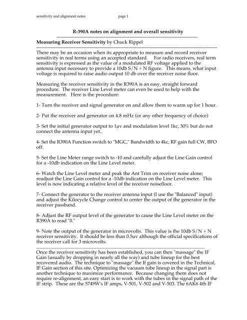
Measuring Receiver <strong>Sensitivity</strong> by Chuck Rippel<br />
----------------------------------------------------------------------------------------------------------------<br />
<strong>The</strong>re may be an occasion when its appropriate to measure and record receiver<br />
sensitivity in real terms using an accepted standard. For radio receivers, real term<br />
sensitivity is expressed as the value of a modulated RF voltage applied to the<br />
antenna input necessary to provide a 10db S/N + N figure. This means, what input<br />
voltage is required to raise audio output 10 db over the receiver noise floor.<br />
Measuring the receiver sensitivity in the R<strong>390A</strong> is an easy, straight forward<br />
procedure. <strong>The</strong> receiver Line Level meter can even be used to help with the<br />
measurement. Here is the procedure:<br />
1- Turn the receiver and signal generator on and allow them to warm up for 1 hour.<br />
2- Put the receiver and generator on 4.8 mHz (or any other frequency of choice)<br />
3- Set the initial generator output to 1µv and modulation level 1kc, 30% but do not<br />
connect the antenna input yet..<br />
4- Set the R<strong>390A</strong> Function switch to "MGC," Bandwidth to 4kc, RF gain full CW, BFO<br />
off.<br />
5- Set the Line Meter range switch to -10 and carefully adjust the Line Gain control<br />
for a -10db indication on the Line Level meter.<br />
6- Watch the Line Level meter and peak the Ant Trim on receiver noise alone;<br />
readjust the Line Gain control for a -10db indication on the Line Level meter. This<br />
level is now indicating a relative level of the receiver noisefloor.<br />
7- Connect the generator to the receiver antenna input (I use the "Balanced" input)<br />
and adjust the Kilocycle Change control to center the output of the generator in the<br />
receiver passband.<br />
8- Adjust the RF output level of the generator to cause the Line Level meter on the<br />
R<strong>390A</strong> to read "0."<br />
9- Note the output of the generator in microvolts. This value is the 10db S/N + N<br />
receiver sensitivity. It should be less than 0.5uv although the official specifications of<br />
the receiver call for 3 microvolts.<br />
...........................................................................................................................................<br />
Once the receiver sensitivity has been established, you can then "massage" the IF<br />
Gain (usually by dropping in nearly all the way) and tube lineup for the best<br />
recovered audio. <strong>The</strong> technique to "massage" the If gain is covered in the Technical,<br />
IF Gain section of this site. Optimizing the vacuum tube lineup in the signal part is<br />
another technique to maximize performance. Because changing them does not<br />
require re-alignment, an easy start is to work with the tubes in the signal path of the<br />
IF strip. <strong>The</strong>se are the 5749W's IF amps, V-501, V-502 and V-503. <strong>The</strong> 6AK6 4th IF
sensitivity and alignment notes page 2<br />
amp V-504 and the detector, V-506, a 5814A. With your generator set up and the<br />
receiver at step 8 above, install a replacement tube at V-501, allow it to warm up<br />
about 5 minutes and note the indication of the Line Level Meter. If it climbs above<br />
0db, the new tube has improved gain, if not, reinstall the old tube. Repeat the same<br />
steps for V502, V503, V-504 and V-506. You may "find" a few extra db in your spare<br />
tube stores.<br />
------------------------------------------------------------------------------------------------------------<br />
© 1996, 1997, 1998 Charles Rippel - All rights reserved.<br />
-------------------------------------------------------------------------------------------------------------<br />
R<strong>390A</strong> IF Deck <strong>Alignment</strong> (Chuck Rippel)<br />
R390's made after 1954 and those with mod 2 stamped on the IF chassis have a field<br />
change installed to the mechanical filters. Filter input and output trimmer capacitors<br />
have been added. <strong>The</strong> 4 input trimmer capacitors are found by removing the 2<br />
square can on top of the IF chassis using the single nut in the top. <strong>The</strong> 4 output<br />
trimmer capacitors are located behind 4 holes in the left hand side of the IF deck.<br />
<strong>The</strong> IF chassis will need to be loose but still electrically connected to complete these<br />
procedures.<br />
An accurate counter, analog VTVM and a signal generator capable of outputting<br />
455.00 KC, is required for these alignments.<br />
Connect the VTVM to the Diode Load bus on the rear and configure it to read a<br />
negative voltage of approximately -7vdc. Set the receiver FUNCTION control to<br />
MGC, BFO to OFF and the LOCAL GAIN control to a comfortable level. Lift and tilt<br />
the IF deck resting the front captive (green) screw over the front panel. You should<br />
be able to gain access to the mechanical filter trimmer capacitors through the large<br />
ventilation holes in the main chassis.<br />
Locate the cable running from the rear of the IF deck to the *IF OUT* BNC<br />
connector in the rear panel, upper left side. Unplug the cable from the IF deck only.<br />
Also unplug J-513 and the one next to it. Plug the cable running from the rear IF<br />
Out jack into J-513 on the IF deck. Connect the output of your 455.000 kc generator.<br />
----------------------------------------------------------------------------------------------------------------
sensitivity and alignment notes page 3<br />
Mechanical Filter <strong>Alignment</strong>-<br />
Set the 455kc generator output level to cause the VTVM to read about -2.5V.<br />
With the IF deck oriented so that the bandwidth control is towards you, set the<br />
bandwidth to 2Kc and align 1 of the four top trimmers.<br />
Adjust C-569 which is at 9 o'clock for a peak on the VTVM.<br />
Next, align the output trimmer in the left side of the IF deck, labeled C-567<br />
Set the BW to 4KC<br />
Align the top trimmer, C-568 located at 12 o'clock<br />
Align the side trimmer, C-566 located at rear, bottom.<br />
Set the BW to 8kc<br />
Align the top trimmer, C-570 located at 6 o'clock.<br />
Align the side trimmer, C-565 located at front, top.<br />
Set the BW to 16kc<br />
Align the top trimmer, C-571 located at 3 o'clock<br />
Align the side trimmer, C-564 located at front, bottom.<br />
-----------------------------------------------------------------------------------------------------------------<br />
Select the 16KC filter<br />
IF Transformer <strong>Alignment</strong>-<br />
Set the generator frequency to 467kc. Note: <strong>The</strong> generator output should be<br />
increased until the VTVM indicates approximately -2vdc. Do not be alarmed if<br />
that level is over 0.1 volts. Adjust the top slug (secondary) of T-501 for a peak<br />
reading on the VTVM, Adjust the bottom slug (primary) of T-502 for a peak<br />
reading on the VTVM<br />
Set the generator frequency to 443kc. Note: <strong>The</strong> generator output should be<br />
increased until the VTVM indicates approximately -2vdc. Again, do not be<br />
surprised if that level is over 0.1 volts. Adjust the bottom slug (primary) of T-501<br />
for a peak reading on the VTVM, Adjust the top slug (secondary) of T-502 for a<br />
peak reading on the VTVM. Decrease the generator output and adjust the<br />
frequency to 455kc Note: <strong>The</strong> generator output should be decreased until the<br />
VTVM indicates approximately -3vdc.Select the 4kc filter then peak top and bottom<br />
of T-503 only<br />
----------------------------------------------------------------------------------------------------------------
sensitivity and alignment notes page 4<br />
----------------------------------------------------------------------------------------------------------------<br />
AGC <strong>Alignment</strong>-<br />
Verify the generator is still outputting 455.00kc. Set the FUNCTION switch to AGC<br />
and connect the VTVM between the AGC bus on TB-102 3 & 4 located on the rear<br />
panel & ground.<br />
Adjust the generator output for a reading of approximately -5vdc on the VTVM.<br />
Peak Z-503.<br />
----------------------------------------------------------------------------------------------------------------<br />
----------------------------------------------------------------------------------------------------------------<br />
Verify that generator is still at 455.00kc<br />
BFO <strong>Alignment</strong>-<br />
Turn on the BFO and exactly zero beat it against the 455.00 generator frequency.<br />
Loosen the bristo spline socket on the BFO shaft coupler,<br />
Verify that you still have exact zero beat.<br />
Set the BFO Pitch control to indicate exactly 0.<br />
<strong>The</strong>n, tighten the bristol socket on the non-mar clamp on the BFO shaft coupler<br />
<strong>The</strong> filters have been aligned to 455 kc.<br />
(When a station broadcasting in AM is zero beat, the carrier will be in the center of<br />
the filter selected).<br />
Re-install the IF chassis in the receiver.<br />
---------------------------------------------------------------------------------------------------------<br />
-----------------------------------------------------------------------------------------------------------<br />
Setting the IF Gain Control for best performance<br />
<strong>The</strong> most common single item responsible for holding an R<strong>390A</strong> back is not lack of<br />
sensitivity. Rather it is internally generated IF deck noise. In an otherwise properly<br />
operating R<strong>390A</strong>, the cause of this excessive noise is IF gain control being set to<br />
high. Even the mfg spec of setting the IF deck gain such that -7vdc at the diode<br />
load when fed by 150uv @455kc into J-513 is far too hot.<br />
Here is a recently refined procedure to set the IF deck gain control. Anyone can<br />
perform the procedure whether they have access to a signal generator or not.
sensitivity and alignment notes page 5<br />
------------------------------------------------------------------------------------------------------------<br />
Procedure to set R<strong>390A</strong> IF Gain-<br />
Once the receiver has been fully mechanically and electrically aligned, the final<br />
procedure to perform before buttoning it up is to set the IF gain control. Many<br />
otherwise very sensitive R<strong>390A</strong>'s are thought not to be due to weak signals being<br />
covered by noise generated by excess IF deck gain.<br />
Allow the receiver to warm up for at least 1 hour then:<br />
Disconnect the antenna<br />
Set receiver for 15.2 mHz<br />
Set the FUNCTION control to MGC<br />
Select the 4kc filter with the BANDWIDTH<br />
Set RF GAIN control to 10 or maximum<br />
Peak the ANTENNA TRIM for maximum noise as indicated on the LINE LEVEL<br />
meter<br />
Set Line Meter switch to -10db scale<br />
Set Line Gain control to full CW or 10.<br />
Adjust IF gain control, R-519 to cause Line Level meter to indicate between -4 to -7<br />
db.<br />
Re-zero the carrier meter control, R-523<br />
Set controls above for normal operation and reconnect antenna<br />
Discussion:<br />
This will yield the best compromise on all bands. I usually poll those bands which I<br />
normally spec out. <strong>The</strong>n, using an HP signal generator set for internal modulation<br />
of 800 hz @ 30%, massage the gain setting and even specific signal path tube<br />
selections for the best overall performance.<br />
Contribution by Chuck Rippel, WA4HHG<br />
-------------------------------------------------------------------------------------------------------------
sensitivity and alignment notes page 6<br />
from EIB-836:<br />
-----------------------------------------------------------------------------------------------------------
sensitivity and alignment notes page 7<br />
----------------------------------------------------------------------------------------------------------------<br />
Variable IF Reference & Stage Gain<br />
by Chuck Rippel<br />
12/24/2001<br />
Part of the secret behind the R<strong>390A</strong>'s incredible selectivity and its immunity to near<br />
RF fields is found in the two tracking IF sections. <strong>The</strong> First Variable IF operates<br />
while receiving frequencies below 8 Mhz and is tuned to pass IF signals from 17 to<br />
25 mhz. This represents the sum of the actual received frequency that is amplified<br />
by V-201 and then applied to the grid of the First Mixer, V-202. <strong>The</strong> 17.0 Mhz<br />
output from the 1st Crystal Oscillator, V-207 is also applied to the cathode of the<br />
same tube. <strong>The</strong> signal represented by that sum is directed to the tracking coils Z-<br />
213-1, 213-2 and 213-3 which are kept tuned to the correct frequency within the 17 -<br />
25 mhz IF frequency range by the cam system. This signal is then known as the<br />
First Variable IF Frequency.<br />
During reception of frequencies 8 Mhz and below, the composite output of the First<br />
Variable IF is routed through S-208 (front), then C-286 and is applied to the grid of<br />
the 2nd Mixer, V-203. For reception of frequencies 8 Mhz and above, the amplified<br />
recived signal signal from V-201 is routed around the First Mixer by S-206 and<br />
applied to the grid of the 2nd Mixer through S-208 and C-286. <strong>The</strong> output of the 2nd<br />
Crystal Oscillator, V-401 is also applied to the cathode of V-203. <strong>The</strong> resultant<br />
output is the 2nd Variable IF Frequency which is always between 2 and 3 Mhz.<br />
That difference is applied to the tracking coils Z-216-1, 216-2 and 216-3 which are also<br />
kept tuned to the correct frequency within the 2-3 Mhz IF frequency range by the<br />
cam system.<br />
<strong>The</strong> 2nd Variable IF frequency is applied to the grid of the 3rd mixer, V-204 where it<br />
is mixed with the output of the PTO (V-701) applied to pin 7. <strong>The</strong> PTO tunes from<br />
3.455 to 2.455 Mhz . <strong>The</strong> difference frequency between the 2nd Variable IF<br />
Frequency and the output of the PTO is always 455kc. This difference frequency is<br />
applied to T-208 which is tuned to 455kc. <strong>The</strong> result is the 3rd IF Frequency which is<br />
then routed from the RF deck to the IF sub-chassis through P-213 and P-218.<br />
In analyzing a failure in the variable IF system, it can be seen that a signal related<br />
failure in the First Variable IF will result in low gain during reception of only the<br />
frequencies below 8 Mhz. A like failure in the 2nd Variable IF or 3rd IF would affect<br />
all frequencies.<br />
Here is a quick test to see if the Variable IF stages are generally working.
sensitivity and alignment notes page 8<br />
Initial checks:<br />
First Crystal Oscillator output as measured at pin 7 of V202:<br />
Normal is approx 4V P-P<br />
SecondCrystal Oscillator output as measured at pin 7 of V-203:<br />
Normal is approx 3.2V P-P<br />
PTO output measured at pin 7 of V-204:<br />
Normal is approx 6V p-p<br />
First Variable IF Gain Test:<br />
Tune the receiver to 00 500, AGC OFF, VTVM connected to read voltage at the rear<br />
Diode Load point.<br />
Inject a 17.5 Mhz signal at approximately 15uv through an RF coupled probe to E-<br />
210. This should result in a reading of approximately -5V at measured at the diode<br />
load point. This bypasses the coils Z-216-1, 216-2 & 216-3 and can be used as a<br />
reference.<br />
Inject a 17.5 Mhz signal at approximately 40uv through an RF coupled probe to pin 1<br />
of V 202. This should yield approx -3.5V at the diode load point.<br />
Discussion: An indication at the diode load point of approximately 1.5V of loss is<br />
nominal. If there is loss which cannot be corrected by proper alignment of coils Z-<br />
216-1, 216-2 and 216-3 or no signal at all, change the injection point coil to coil to<br />
moving "away" from the 2nd mixer to find the failure.<br />
Second Variable IF Gain Test<br />
Tune the receiver to 01 000+, AGC OFF, VTVM connected to read voltage at the rear<br />
Diode Load point.<br />
Inject a 2.0 Mhz signal at approximately 15uv through an RF coupled probe to pin 1<br />
of V203. This should result in a reading of approximately -2.2V at measured at the<br />
diode load point. Again, this bypasses the coils Z213-1, 213-2 & 213-3 and can be<br />
used as a reference. Inject the 2.0 Mhz signal at approximately 15uv through an RF<br />
coupled probe to pin 6 of V-204. This should yield approx -4.2V at the diode load<br />
point.<br />
Discussion: An indication at the diode load point of an increase of approximately 2V<br />
is nominal. Again, If there is loss which cannot be corrected by proper alignment of<br />
coils Z-213-1, 213-2 and 213-3 or no signal at all, change the injection point coil to coil<br />
to moving "away" from the 2nd mixer to find the failure. To align the variable IF<br />
stages, I use a different method from that found in the various military manuals.<br />
My technique yields better results by taking a systems approach and also not<br />
loading down the stage to be aligned. Its a bit lengthy to explain here but that<br />
procedure, along with many other techniques are demonstrated in the 7 hour long,<br />
R<strong>390A</strong> video tape series available from Hi-Res Communications. Don't forget to<br />
ask about the new 4 hour addendum to the 7 hour series.. R. Charles Rippel
sensitivity and alignment notes page 9<br />
--------------------------------------------------------------------------------------------------------<br />
Date: Sun, 12 Oct 1997 10:03:40 +0500<br />
From: "Chuck Rippel" <br />
Subject: [R-390] R<strong>390A</strong> alignment note<br />
<strong>The</strong> following is probably the single most important alignment component in the<br />
R<strong>390A</strong> receiver. It's relevence is not really spelled out in any of the techincal manuals<br />
I have seen but it is the real key to getting the receiver properly aligned.<br />
- - - -<br />
PTO tracking on the R<strong>390A</strong> is very important. Due to the tracking nature of the RF<br />
and IF circuitry, the PTO end points must be very carefully adjusted. If the PTO is<br />
"long" or "short," it will not tune in the designed 1 mHz segments that match the<br />
mechanical cam profiles which drive the slugs in the various coils. In as much as I<br />
restore R<strong>390A</strong>'s, I find that PTO mis-tracking by a little as 10 kHz can noticably<br />
degrade overall performance. Don't believe it? Losten the PTO coupler then tune<br />
the radio on simple band noise. At this point, changing frequency with the<br />
KILOCYCLE CHANGE knob will only tracking the cam stacks and not the PTO.<br />
Observe that the band noise drops away at about (+-) 7 kc or so from your original<br />
frequency. That's is how tight the mechnical tracking on the '<strong>390A</strong> is.<br />
Here is a quick check for proper PTO tracking: Let the radio warm up for about an<br />
hour.<br />
Tune the radio down to (-) 000 and zero beat the calibrator. Next, tune the radio up<br />
and note the frequency where it zero beats. <strong>The</strong> dial should read close, say to plus or<br />
minus 3 kc's of (+) 000. If that is not the result, both the PTO end points AND the dial<br />
over run need to be reset. This is followed by setting (timing, actually) the various<br />
cams which now need to be mechanically realigned. Follow this by an an electrical<br />
alignment as outlined on top of the "Utah shaped"<br />
plate on top of the RF deck.<br />
Successful completion will result in the mechanics of the receiver tracking with the<br />
electronics.<br />
-------------------------------------------------------------------------------------------<br />
Date: Sat, 1 Nov 1997 23:56:59 +0500<br />
From: "Chuck Rippel" <br />
Subject: [R-390] Filter and BFO alignment<br />
R<strong>390A</strong>'s made after 1954 and those with "mod 2" stamped on the IF chassis have a<br />
field change installed to the mechanical filters. Filter input and output trimmer<br />
capacitors have been added. <strong>The</strong> 4 input trimmer capacitors are found by removing<br />
the 2" square can on top of the IF chassis using the single nut in the top. <strong>The</strong> 4 output<br />
trimmer capacitors can be seen behind 4 holes in the left hand side of the IF deck.<br />
If you have a counter and a generator which can put out 455.00 KC, you can align<br />
filter network:
sensitivity and alignment notes page 10<br />
Connect a VTVM (NOT DVM) to the "Diode Load" bus on the rear and configure it<br />
to read negative voltage. (It'll be about -5 volts)<br />
Locate the cable running from the rear of the IF deck to the "IF OUT" BNC<br />
connector in the rear panel, upper left side. Unplug the cable from the IF deck only.<br />
Also unplug J-513 and the one next to it. Plug the cable running from the rear "IF<br />
Out" jack into J-513 on the IF deck. Connect the output of your 455.00kc generator.<br />
Set the .455kc from the generator to cause the VTVM to read about- - 2.5V<br />
With the If deck oriented so that the bandwidth control is towards you, set the<br />
bandwidth to 2Kc and align 1 of the 4 the top trimmers. Adjust the one which is at 9<br />
o'clock for a peak on the VTVM. Next, align the output trimmer in the left side of<br />
the IF deck, located at rear, top.<br />
Set the BW to 4KC<br />
Align the top trimmer located at 12 o'clock.<br />
Align the side trimmer located at rear, bottom.<br />
Set the BW to 8kc<br />
Align the top trimmer located at 6 o'clock.<br />
Align the side trimmer located at front, top.<br />
Set the BW to 16kc<br />
Align the top trimmer located at 3 o'clock<br />
Align the side trimmer located at front, bottom.<br />
Peak top and bottom of T-503 only!<br />
Verify that generator is still at 455.00kc<br />
Turn on the BFO and exactly zero beat it against the 455.00 generator frequency.<br />
Loosen the bristol spline socket on the BFO shaft coupler, verify that you still have<br />
exact zero beat. Set the "BFO Pitch" control to exactly "0" then tighten the bristol<br />
socket on the non-mar clamp on the BFO shaft coupler<br />
<strong>The</strong> filters have been aligned to 455 kc. When you zero beat a station broadcasting<br />
in AM, the carrier will be in the center of the filter selected.<br />
------------------------------------------------------------------------------------------------------------
sensitivity and alignment notes page 11<br />
------------------------------------------------------------------------------------------------------------<br />
Date: Wed, 5 Nov 1997 11:08:49 +0000<br />
From: crippel@...<br />
Subject: [R-390] Re: R<strong>390A</strong> question<br />
> Thank you Chuck for coming back to my call.... I have a 1st OSC problem<br />
> in the R<strong>390A</strong>. After it gets good and hot in the chassis the osc dies.<br />
> Sometime I can shock it back by unplugging the heated xtal assy. I<br />
> thought I fixed this about 4 yrs ago when I first got the rcvr. Any way<br />
> do you have any suggestions ? I am going to pull it out of the rack and<br />
> start snooping. I have a manual and the radio never saw military service<br />
> so the radio is really in very nice shape. TNX again FRED KC4MOP<br />
See that one all the time as it kills wht low bands when it fails.<br />
<strong>The</strong> fix is; its an easy. Remove the HR-202 xtal assy and:<br />
A: Replace it (Fair Radio has replacements)<br />
B: Take it a part and put a new 17mhz crystal in it. May as well replace the calibrator<br />
crystal while you're at it. It fails also. I favor "B" as the HR-202 assy's are getting hard<br />
to find. '<strong>390A</strong> xtals, 1st and 2nd oscillators) are dying right and left due to age.<br />
International crystal has the JAN cross reference. Take the number off the crystal<br />
case, (I know that the the R<strong>390A</strong> 2nd oscillator crystals are HC6/U) and give it to<br />
them.<br />
----------------------------------------------------------------------------------------------------------<br />
From: rerobins@... (Rick Robinson)<br />
Date: Tue Nov 18, 1997 1:18 pm<br />
Subject: [R-390] RF alignment<br />
My radio weekend was nearly ruined by sunny skies and temps in the high'50s.<br />
Fortunately the "honey do" list was very short so there was plenty of R-<strong>390A</strong> time.<br />
Now that the front panel is off, here is the next bear to cross. My RF cams do not<br />
align anywhere in the 7Mcs band. Part may be my fault in my previous tinkerings,<br />
part the previous owner. All the screw heads are buggered up, so someone has<br />
been visiting this problem before.<br />
I've been following along with Dallas Lankford's suggestions for RF alignment in<br />
some old Hollow State News issues to no avail. (I also have a 1980s printing of the<br />
Army Field Depot manual.) He suggests finding a freq where all 6 cams align and<br />
reset the Veeder-Root and assumes there will be such a spot. <strong>The</strong>re is no one freq<br />
where all 6 of my cams line up properly.<br />
What I've tried to do is find a freq where the 18-30 aligns itself and align the other 5<br />
there and set the Veeder Root to 7.000. When I turn back to the 10 turn stop point,<br />
I'm at -7.6XX. Hosed by the PTO.
sensitivity and alignment notes page 12<br />
To fix the 10 turn and RF cam problem, should I:<br />
1.set the dial/PTO to the 10 turn stop below 7Mcs<br />
2.disconnect the dial linkage to the PTO so it won't turn<br />
3.set the 6 cams to my 7.000Mcs spot and reset the Veeder-Root<br />
4.go back -6.965 or so for the 10 turn stop point, and recconect the PTO<br />
If I do need to disconnect the PTO linkage, what is the best way to do so?<br />
------------------------------------------------------------------------------------------------------------<br />
From: Tom Norris <br />
Date: Thu Nov 20, 1997 5:51 am<br />
Subject: [R-390] <strong>The</strong> "plus sign" cam alinement gotcha<br />
[ <strong>The</strong> plus sign gotcha, or "When 7 Mhz is REALLY 8" ] A reminder to those who<br />
may have had an alignment planned, or had done an aligment in the past that went<br />
awry--<br />
When the manual mentions the steps regarding the sync of the RF cams in the <strong>390A</strong><br />
the freq for this alignment is 7+000, rather that 7.000. That is, tune to 7.999, then go<br />
one more step till the red plus sign shows on the Veeder -Root counter. <strong>The</strong>n check<br />
to see if the lines marked on the chassis bisect the holes in the RF cams. Adjust as<br />
needed by loostening clamps.<br />
Very common mistake, according to those who did this for year in the military, and<br />
bit me a time or two when I first started on the things. ( though not in the military ).<br />
<strong>The</strong> 390 non-A has a similar cam aligment procedure, but it is done 2.000 Mhz. No<br />
pesky plus signs here. :-)<br />
-------------------------------------------------------------------------------------------------------<br />
From: "Chuck Rippel" <br />
Date: Sat Nov 22, 1997 8:06 pm<br />
Subject: [R-390] R<strong>390A</strong> "Mystery <strong>Alignment</strong>" found!<br />
Anyone who has ever tried to align an R<strong>390A</strong> has wondered about the purpose of<br />
the 2nd trimmer capacitors marked "BAL" in the antenna trim cans. As an F.Y.I.,<br />
these are the most forward cans in the tuneable slug racks. I found an old manual,<br />
TM-11-856A dated January 20, 1956 and on page 172, paragraph #164 which details<br />
their adjustment. I have not seen the procedure in any other version manual yet<br />
examined. <strong>The</strong>ir purpose is to balance the "Balanced" antenna input and set up the<br />
proper relationship between the 2 sides of that input depending on frequency. A<br />
friend told me that he feels that they would be used to properly set up a DF<br />
antenna. I have heard that DF'ing was one of the primary design considerations of<br />
the '<strong>390A</strong> and that the IF deck was specially gain engineered to allow for very<br />
accurate readings. While the results for our use seem dubious at best, I have never<br />
seen an explanation of the purpose and alignment of these trimmers. If anyone<br />
wants a copy, sent me a >business sized SASE< with one unit of postage and I will<br />
photo-copy the procedure and send it to them. <strong>The</strong> procedure is about 3/4 a page<br />
long and involves some high school level algebra to calculate.<br />
---------------------------------------------------------------------------------------------------------
sensitivity and alignment notes page 13<br />
------------------------------------------------------------------------------------------------------------<br />
From: "Chuck Rippel" <br />
Date: Tue Dec 2, 1997 4:03 am<br />
Subject: Re: [R-390] audio, nothing but hash from my A !<br />
> Hello, name here is Scott and I have a problem, hope a small one, with my<br />
Motorola mfg R-<strong>390A</strong>. It was working fine then without warning all I get from the<br />
speaker is white noise/hash. Meters seems to show a signal present on most any<br />
band but there is nothing there. Anyone run into this before ? Might I ask what the<br />
fix is? or rather what your fix was as I'm sure there are probably several ! Thanks<br />
for the help and happy listening. 73 Scott<br />
<strong>The</strong> RF deck is running away. You have a failed or loose in its socket C-227 located<br />
on the cathode of V-201. It screws into the chassis and can be seen from the top<br />
looking down between V-201 and<br />
V-202.<br />
-------------------------------------------------------------------------------------------------------<br />
From: dave metz <br />
Date: Thu Dec 25, 1997 10:24 am<br />
Subject: [R-390] R-<strong>390A</strong> XTAL Problem<br />
A recently post by our resident master Chuck Rippel, seemed to come back to haunt<br />
me last month. I have a great R<strong>390A</strong> that he worked over in the last year and has<br />
unbelievable sensitivity and looks after he got done with his renovation. . Anyway,<br />
this wonderful unit was stone cold on the lower bands when I turned it on after<br />
maybe being off for several months. Hmmmmm me says, I wonder if Chuck's<br />
comments about HR202 and the 17 Meg Xtal going bad would have anything to do<br />
with the problem as the tube check gave no indication of problems. . So I called JAN<br />
xtals and ordered a couple of these $20 xtals. <strong>The</strong>y came in yesterday and quickly<br />
one went into the assembly. Hot dog, its running like a champ today! I would<br />
caution anyone who does this surgery to take a spring hook to the center X of the<br />
holdown device to pull it out of the way and remove the plug in assembly with your<br />
other hand. <strong>The</strong>n put in a socket or something about the same height in its place to<br />
constantly keep tension on the springs while you are working on the assembly. To<br />
rehook those springs is a PAIN! If one slips and the spring goes down into the hole,<br />
you might be looking at removing the RF Deck to recover the spring. Such a deal!<br />
------------------------------------------------------------------------------------------------------------<br />
From: "Chuck Rippel" <br />
Date: Thu Dec 25, 1997 8:41 pm<br />
Subject: [R-390] HR-202 Mysteries & Details<br />
Dave Metz posted the failure conditions and cure for a very common R<strong>390A</strong><br />
problem, failure of HR-202. HR-202 is an approx 1-1/4" diameter, cylindrical oven<br />
containing crystals Y-203 and Y-202. It plugs in an octal socket located at the far right<br />
hand corner of the R<strong>390A</strong> RF deck. <strong>The</strong>re is a removeable spring clip affair across<br />
the top to assure that HR-202 stays in place. Having any of the two crystals within<br />
HR-202 fail can cause a lot of head scratching. Finding complete HR-202 assys<br />
becoming more difficult so rebuilding a defective one is the preferred option. <strong>The</strong><br />
first crystal within the HR-202 assy is Y-203, the 200KC crystal for the calibrator. This
sensitivity and alignment notes page 14<br />
crystal can fail completely causing the calibrator to not operate. More commonly, it<br />
will have drifted with age and be out of range of the calibrator adjustment, C-310.<br />
Zero beat will not be achieveable against<br />
the alignment standard being used. <strong>The</strong> calibrator zero adjustment, C-310 is<br />
acessable through the back panel.<br />
<strong>The</strong> cure is to replace Y-203, the 200KC crystal within HR-202.<br />
<strong>The</strong> second crystal in HR-202 is Y-201, the 17 mHz 1st xtal oscillator. It drives V-207<br />
whose plate is transformer coupled VIA T-207 to cathode of the first mixer, V-202.<br />
Part of the alignment procedure involves peaking T-207 during the IF<br />
alignment.<br />
A Y-201 or associated circuit failure will cause all bands below 8 mHz to be "dead." It<br />
is THE most common cause of that symptom. Signals from .5 to 7.999 mHz go<br />
through the first mixer, V-202 and its tracking IF network consisting of Z213-1<br />
through Z213-3. <strong>The</strong> oscillator, V-207 is turned on by the application of screen<br />
voltage, 150V B+ through S-208 (rear) which is sourced from V-605, the OA2 voltage<br />
regulator.<br />
<strong>The</strong> cure, as Dave correctly noted, is to replace Y-201, the 17mHz crystal.<br />
Note: <strong>The</strong> T-207 peak is very broad and its alignment will NOT cure a "dead"<br />
receiver.<br />
It has occured to me that part of a very complete R<strong>390A</strong> restoration might include<br />
replacement of ALL the crystals. This not only includes the calibrator and 1st crystal<br />
oscillator as above but also the dozen or so crystals in the 2nd crystal oscillator<br />
associated with V-401.<br />
In nearly every R<strong>390A</strong>, these xtals have drifted in frequency. A quick test is to<br />
simply zero beat the calibrator on one band then start changing bands and note the<br />
zero beat error from band to band.<br />
However, the cost of the crystals alone would be impressive to say the least.<br />
However, they are available as Dave pointed out.<br />
----------------------------------------------------------------------------------------------------------<br />
From: crippel@...<br />
Date: Mon Dec 29, 1997 9:12 am<br />
Subject: Re: [R-390] Posts<br />
Easy on the IF gain.<br />
Put the "LINE METER" control to -10<br />
Turn the "LINE GAIN" control full on, to "10"<br />
With NO antenna, peak the "ANT TRIM" on the internal noise generated by the RF<br />
deck and read the peak on the "LINE LEVEL" meter. (should peak up at about "0" if<br />
aligned properly)
sensitivity and alignment notes page 15<br />
Set the "IF Gain" pot to read about -7 db.<br />
That should get you very close to where I end up setting them with instruments.<br />
Note: If you cannot peak the ANT TRIM on internal noise, the radio has either a<br />
failure or out of electrical AND mechanical alignment.<br />
-----------------------------------------------------------------------------------------------------------<br />
From: Dan Martin <br />
Date: Mon Dec 29, 1997 5:30 pm<br />
Subject: Re: [R-390] Posts<br />
Like many others, I've followed Chuck's method for "field-setting" the IF. gain pot.<br />
This adjustment varies the cathode bias and therefore gain of the 3rd i.f. amplifier<br />
tube. It is kind of a semi-fixed "rf gain knob" for the 3rd i.f. tube, doing for that tube<br />
what the r.f. gain knob on the front panel does for the cathode bias of the r.f.<br />
amplifier tube and first and second i.f. amplifier tubes.<br />
It seems to function like a trim tab setting on a plane - it is used to compensate for<br />
aging tubes and varying amplification efficiencies of various tubes. Set your trim tab<br />
to fly straight and level, then use your r.f. gain knob to tactically vary your gain as<br />
you need. This adjustment is quick and easy to do and seems to work well. Chuck's<br />
method fixed a grossly too-strong setting on my <strong>390A</strong> (mine was almost wideopen!)and<br />
resulted in a much quieter receiver with fine sensitivity - approaching 0.15<br />
uv for 10 db sig-to-noise-plus-noise, as roughed out according to my trusty 606A.<br />
This method, or a similar version, is also described in HSN Issue 34 by another<br />
reader. It is interesting that Dallas Lankford in HSN Issue 29 advises the best way to<br />
adjust this rheostat is to simply crank it all the way down, or clockwise. (I *like*<br />
alignment procedures like that!) This should yield about 10 kohms at the pot, I<br />
believe Dallas says, and as long as your pot yields about that, just keep it all the way<br />
clockwise.<br />
What makes this interesting to me is that setting my i.f. gain, as suggested by<br />
Chuck, coincidentally also required my turning the pot all the way clock-wise!<br />
Chuck, we look forward to your posting on <strong>390A</strong> alignment!<br />
-------------------------------------------------------------------------------<br />
From: "Chuck Rippel" <br />
Date: Wed Jan 14, 1998 9:29 pm<br />
Subject: [R-390] Mechanical <strong>Alignment</strong> Check List<br />
This procedure is not at all for the meek and should only be attempted after a<br />
through review.<br />
----<br />
I am working on the electrical alignment document which I will post here. Before<br />
that can be attempted, the receiver must be in mechanical alignment. <strong>The</strong> reason for<br />
this is simple although often overlooked. When receiving and given frequency, the<br />
various slugs in the 2 tracking IF sections and RF section must be at a given height in<br />
their respective coils. This is determined by the profile of the cams driving the<br />
various slug racks. Also, the PTO must be outputting a specific frequency for those
sensitivity and alignment notes page 16<br />
slug heights. To have the receiver work properly, this whole assembly must be<br />
"timed."<br />
Here is how to check:<br />
First and formost, the PTO must be 1 mHz long. To check this, zero beat the<br />
calibrator and use the ZERO ADJ to set the odometer readout to the bottom of the<br />
PTO's range or, XX (-) 000. Run the KILOCYCLE CHANGE control to the top of the<br />
PTO's range or XX (+) 000 and note the frequency the odometer reads when zero<br />
beat. <strong>The</strong> difference between the indicated frequency and XX (+) 000 is the error. For<br />
the receiver to work properly, the error must be less than about 1KC.<br />
If the error is more than 1KC, you must perform the end point or "Variable-<br />
Frequency Oscillator End Point Adjustment." In the Army manual I have, it is<br />
outlined in paragraph 81 on page 119.<br />
<strong>The</strong>re are pictorials involved and I cannot post this procedure here. <strong>The</strong> Hollow<br />
State News may have some reprints available for those who do not have a manual<br />
but feel they can perform this procedure.<br />
Do not proceed further until the PTO end points are correct.<br />
Zero Beat the CALIBRATOR to WWV. This is easily done by first using the BFO to<br />
zero beat the receiver with WWV. <strong>The</strong>n, turn the FUNCTION control to CAL then<br />
adjust the calibrator capacitor through the rear panel and adjust for zero beat.<br />
Next, set the ZERO ADJ clutch to the center of its range. Disengage the clutch by<br />
turning the ZERO ADJ knob CW. Rotate the KILOCYCLE CHANGE control to the<br />
CW stop. Make a note of its position. <strong>The</strong>n, rotate it to the CCW stop and again,<br />
note its position. Finally, set the knob 1/2 way between these two points.<br />
Set the KILOCYCLE CHANGE and MEGACYCLE CHANGE controls so that the<br />
odometer readout indicates >exactly< 07 + 000. (<strong>The</strong> receiver would actually receive<br />
an 8 mHz signal at this point). Engage the DIAL LOCK.<br />
Turn the receiver upside down so that the PTO and oldham coupler can be accessed.<br />
Turn on the BFO and CALIBRATOR. Using the appropriate bristol spline wrench,<br />
loosen the >forward< clamp on the oldham coupler. Rotating the coupler will cause<br />
the PTO shaft to rotate and change frequency but the readout will stay the same.<br />
Zero beat the calibrator and retighten the screw. (NOTE: You should not have to<br />
move the oldham coupler more than 1/2 turn in either direction to achieve zero<br />
beat).<br />
Check the dial over run by turning the KILOCYCLE CHANGE control up in<br />
frequency past 000. It should stop at 035. DO NOT USE THE ZERO ADJUST KNOB<br />
TO ALTER THE READOUT. It it does not indicate 035, you will need to adjust it<br />
when once the front panel is down. This is a little complicated. First, breaking the<br />
bristol-spline cap screw loose on the gear clamp which drives the odometer readout.
sensitivity and alignment notes page 17<br />
It is directly to the right of the odometer drive. With clean hands, turn the last digit<br />
wheel so that the readout indicates 035. Re-tighten the clamp screw then rotate the<br />
KILOCYCLE CHANGE control to confirm that it stops on 035.<br />
Re-perform the PTO zero adjustment as above.<br />
Dropping the front panel:<br />
Turn off and >UNPLUG< the receiver!!<br />
Turn the receiver right side up and drop the front panel down by:<br />
1- Remove the BANDWIDTH, BFO CHANGE and ANT TRIM knobs.<br />
2- Removing the 8 phillips head screws on the sides of the panel and the 5 screws<br />
above and to the left of the BFO control.<br />
3- Remove the DIAL LOCK knob, loosen the nut and turn the lock mechanism so<br />
that it disengages the brake disk.<br />
4- Remove the phillips head screw directly to the left of the LOCAL GAIN control.<br />
This secures a wiring harness clamp to the front panel.<br />
GENTLY, work the front panel off using steady pressure and rocking back and forth<br />
until it clears the various control shafts. It will "hinge" down on the wiring harness<br />
and allow it to rest on your workspace on its handles. Reconfirm the odometer<br />
readout indicates 07 + 0000 exactly. If not, adjust the KILOCYCLE CHANGE control<br />
as necessary.<br />
<strong>The</strong>re are a total of 6 brass cams which can be found at the front of the RF chassis.<br />
<strong>The</strong> 4 which drive the RF coils are located towards the top of the RF chassis and the<br />
2 which drive the IF coils, toward the bottom. You must look through gaps in the<br />
gearing to see the 2 IF coils but they are easy to find. Each cam has a pointer which<br />
must line up with a mark on the RF chassis. From this point on, review this<br />
procedure before loosening ANY of the clamps. If you don't fully understand or are<br />
not comfortable the concepts, do not attempt to proceed. If the cams do not line up,<br />
there is a bristol spline cap screw on each that can be loosened so the cam can be<br />
positioned properly. <strong>The</strong> IF cam on the bottom left is the most difficult. It can be<br />
positioned by first loosening the bristol cap screw on the 3rd cam/gear assy from<br />
the right of the receiver. Poke a screw driver or pointed awl through the gears and<br />
postion it correctly.Once the cams are completely aligned with their panel marks, reinstall<br />
the front panel by reversing the procedure above. You can calibrate the BFO<br />
PITCH control by turning in the calibrator signal, setting the BANDWIDTH to .1 and<br />
tuning the KILOCYCLE CONTROL for a peak on the carrier meter. Turn the BFO<br />
on and rotate the shaft for perfect zero beat and install the knob with the indicator<br />
line at "0" <strong>The</strong> heart of getting an R<strong>390A</strong> to work properly is to have all 6 cams line<br />
up perfectly with their chassis marks when the receiver indicates 07 + 000 on the<br />
odometer, the PTO is zero beat at 07 + 000 and its end points within 1 kc and the dial<br />
over run set to 35 kc at each end. Do not proceed with the electrical alignment until<br />
these conditions have been met. Chuck Rippel, WA4HHG
sensitivity and alignment notes page 18<br />
-----------------------------------------------------------------------------------------------------------<br />
From: "Chuck Rippel" <br />
Date: Sat Jan 24, 1998 2:04 am<br />
Subject: Re: [R-390] No Cal. Signal on 16MC<br />
> I have a R-<strong>390A</strong> that doesn't have a calibration signal in the 16MC band position.<br />
All other bands have a signal, some stronger than others. Even after peaking the<br />
Ant. Trimmer. Also, the frequencies vary from band to band. Hopefully some of<br />
theses problems can be corrected through alignment.<br />
<strong>The</strong> band is dead because Y-413, the 9.5 mHz crystal is not oscillating. Put a scope on<br />
P-415 the output of the crystal deck and see. Should be about 2V p-p.<br />
------------------------------------------------------------------------------------------------------<br />
From: crippel@...<br />
Date: Mon Feb 2, 1998 5:35 am<br />
Subject: [R-390] R-<strong>390A</strong> IF gain Setting Technique<br />
> About a month ago Chuck Ripple had suggested an easy method for settting the<br />
>IF gain on the R-<strong>390A</strong>. I tried it.. Mine was set way too high.. NEW RADIO.. the<br />
>difference was dramatic!! Later cleaned up the IF deck. Tubes went back into<br />
>different sockets. <strong>The</strong> radio was 'mushy' again. Found the tube swaps had changed<br />
>the gain. Reset the gain and the radio came back to life.<br />
Glad it worked so well for you. I continue to be amazed by the performance of<br />
these receivers. This past Sunday, I was able to actually hear programming from the<br />
New Guinea regional SWBC outlet R. Enga transmitting on 2410. It is very rare for<br />
that station to be copyable on the East Coast. Moreover, the R<strong>390A</strong> pulled<br />
recordable audio off the signal at least 50% better than my state of the art, Watkins-<br />
Johnson HF-1000A. <strong>The</strong> most common single item responsible for holding an R<strong>390A</strong><br />
back is not lack of sensitivity. Rather it is internally generated IF deck noise. In an<br />
otherwise properly operating R<strong>390A</strong>, the cause of this excessive noise is IF gain<br />
control being set to high. Even the mfg spec of setting the IF deck gain such that -<br />
7vdc at the diode load when fed by 150uv @455kc into J-513 is far too hot. I see it<br />
time and time again. Because everyone is going to ask, here is a review of the<br />
recently refined procedure to set the IF deck gain control. Anyone can perform the<br />
procedure whether they have access to a signal generator or not. I have made one<br />
refinement since it was last posted:<br />
Procedure to set R<strong>390A</strong> IF Gain-<br />
Once the receiver has been fully mechanically and electrically aligned, the final<br />
procedure to perform before "buttoning it up" is to set the IF gain control. Many<br />
otherwise very sensitive R<strong>390A</strong>'s are thought not to be due to weak signals being<br />
covered by noise generated by excess IF deck gain.<br />
- Allow the receiver to warm up for at least 1 hour then:<br />
1- Disconnect antenna<br />
2- Set receiver for 15.2 mHz
sensitivity and alignment notes page 19<br />
3- Set "Line Meter" switch to -10db scale<br />
4- Set "Line Gain" control to full CW or "10."<br />
5- Adjust IF gain control, R-519 to cause "Line Level" meter to indicate between -4 to<br />
-7 db.<br />
6- Re-zero the carrier meter control, R-523<br />
7- Set controls above for normal operation and reconnect antenna<br />
Discussion:<br />
This will yield the best compromise on all bands. I usually "poll" those bands which I<br />
normally spec out. <strong>The</strong>n, using an HP signal generator set for internal modulation of<br />
800 hz @ 30%, "massage" the gain setting and even specific signal path tube<br />
selections for the best overall performance.<br />
--------<br />
RF Deck Test-<br />
I also encourage you to do a quick test that will verify the condition of your RF deck<br />
and state of alignment. <strong>The</strong> procedure is as follows:<br />
1- Disconnect the antenna<br />
2- Set the "Line Gain" and "Line Meter" controls for a relative -5 db indication on the<br />
"Line Level" meter.<br />
3- Adjust the antenna trimer for a relative peak on the "Line Level" meter and note<br />
the position of the control.<br />
Discussion:<br />
An R<strong>390A</strong> with a properly operating RF deck is capable of peaking on its own<br />
internal noise as indicated by the "Line Level" meter. Further, that peak with no<br />
antenna connected should be coincident with the "Ant Trim" control indicating "0."<br />
Having the peak not occur at all indicates an RF deck failure or poor/improper<br />
alignment. Additionally, improper alignment can also be the case when the noise<br />
peak as indicated by the "Line Level" meter not coincident with the "0" (+- .5)<br />
position on the "Antenna Trim" control.<br />
------------------------------------------------------------------------------------<br />
From: "Chuck Rippel" <br />
Date: Wed Feb 4, 1998 12:40 am<br />
Subject: Re: [R-390] R390 <strong>Alignment</strong><br />
> My question is even if I moved gears around if I set the read out to 7 +000 and line<br />
>all the cams up with their alignment marks is that correct, can it be that easy. I<br />
>removed the PTO and it was set at 00 -963 or kilocycles turned fully<br />
>counterclockwise. If my cam setup procedure was correct can I now just return the<br />
>readout to 00 -963 replace the PTO and start my electrical alignment. Any<br />
>comments will help Tnx Ben<br />
You are doing this a little backwards but no matter. It will only mean you have to<br />
perform a step twice. If you "loose" where the PTO is, you need a counter to set<br />
things up properly. Set everything up by aligning ALL of the cam gears at their
sensitivity and alignment notes page 20<br />
chassis marks at 07 + 000 and the output frequency of the PTO measured at the<br />
connector on the end of the PTO cable to be 2.455 mHz.<br />
After that, don't align ANYTHING until the PTO end points are set. When the<br />
endpoints are properly set, center the "Zero Adj" in the middle of its range and set<br />
the readout again to 07 + 000 and touch up the cam alignment. Lock the dial down,<br />
loosen the forward clamp on the Oldham coupler and set the PTO to output 2.455.<br />
Once that is done, then and only then can you do the electrical alignment properly.<br />
Failure to perform the above will result in less than acceptable performance.<br />
----------------------------------------------------------------------------------------------------------<br />
Date: Tue, 23 Feb 1999 16:02:18 -0800<br />
From: dma@islandnet.com<br />
Subject: Re: [R-390] [R390] <strong>Questions</strong> about IF and RF <strong>Alignment</strong><br />
>-I noted that the manual makes reference that some of the IF decks are<br />
>"stagger tuned", the implication being that some are not, is this true?<br />
Yes. An early Army manual I have makes no mention of this. Later manuals seem<br />
to recommend it. Stagger tuning gives a more symetrical bandpass, which results in<br />
better sound on AM signals. <strong>The</strong>re is no lack of gain in this amplifier and the<br />
mechanical filters should be allowed to set the bandpass shape - thus there is no<br />
advantage to peaking the i.f. at 455 kHz.<br />
>-Any tips or tricks in carrying out .....ARMY Manual......is a bit vague about this.<br />
It's very straightforward as long as you follow the instructions and have the right<br />
equipment. Also note that several manual versions have an error in the little table<br />
that gives you the tuning sequence for the I.F. coils. <strong>The</strong> T502 secondary (top slug) is<br />
missed out entirely in the right hand column, which if no one noticed might result in<br />
less than stellar performance. <strong>The</strong>re is a mistake in the instructions for aligning the<br />
first variable i.f. in some manuals. In b2) the frequency of the generator should be<br />
18.25 MHz,not 18.75 MHz as written.<br />
>RF Deck:<br />
>-Not sure if I can word this clearly, but here goes. When carrying out the<br />
alignment on the RF deck, the manual suggests the receiver be calibrated at the<br />
lower frequency (the one which the slugs are adjusted at), and then zero beat<br />
againist the signal generator. Why is this not carried out on both ends of the<br />
adjustment. For example should one use the internal calibrator at 550KC, then<br />
adjust the signal generator frequency for a zero beat, then do the same at 1100KC?<br />
Or is it bettter not to use the zero adjust function of the R<strong>390A</strong>, and just send the<br />
signal generator to the specified frequency, and adjust the <strong>390A</strong> frequency for a zero<br />
beat? I assume that the manual procedure was used due to the ambigious nauture<br />
of the analog signal generator. I use a HP 8640B and the digital readout leaves little<br />
room for error.
sensitivity and alignment notes page 21<br />
Others have done this many more times than I, so advice may vary! Assuming the<br />
PTO is correctly set (end-point, etc.) and the mechanical cams are set correctly, I<br />
follow the instructions in the manual fairly closely. However, I set the rcvr on the<br />
suggested alignment frequency, bring the signal generator to that frequency and<br />
zero beat it to the rcvrs BFO by adjusting the KHz knob. THIS ASSUMES THE BFO<br />
HAS BEEN SET RIGHT! My sig gen (an HP8601A) is harder to adjust than the rcvr is,<br />
thus this approach. Your sig gen is better than mine so you may be able to do it the<br />
other way round. What's critical, IMHO, is that the rcvr be close to the alignment<br />
frequency shown in the manual, but that the sig gen be right on the rcvr center<br />
frequency.<br />
I think your comment about why they do things the way they do (ever tried this<br />
with a URM-25D - I have!) is right on the mark.<br />
<strong>The</strong> RF alignment is tediously repetitive, but it's gotta be done carefully for max<br />
performance. Many coil problems can become evident when doing the alignment: if<br />
the slug ends up at the top or bottom of its range, and you're still not at optimum -<br />
you probably have a capacitor or other problem inside the can; if the trimmer won't<br />
peak, or seems to jump - you have a trimmer with the movable part stuck to the<br />
fixed part, and the whole thing is turning - or you have a cap where turning it<br />
results in the rotor actually popping away from the contact underneath the bakelite<br />
strip that holds it all together. And so on!<br />
--------------------------------------------------------------------------------------------------------<br />
Date: Tue, 23 Feb 1999 22:48:44 -0500 (EST)<br />
From: Norman Ryan <br />
Subject: Re: [R-390] [R390] <strong>Questions</strong> abt IF and RF <strong>Alignment</strong><br />
<strong>The</strong> posting from which the above was snipped is full of good advice on alignment<br />
procedures. Here is some detail on the errata:<br />
<strong>The</strong> NAVSHIPS 0967-063-2010 manual of 15 April 1970 reflects these corrections.<br />
<strong>The</strong> Army TM 11-5820-358-35 of 8 December 1961 does not.<br />
To amend the latter, go to page 113 and insert "T502 secondary (bottom slug)"<br />
under "T501 primary (bottom slug)" and bracket it to the 443 frequency.<br />
<strong>The</strong>n go to page 116 and change line b.(2) to read "18.25" instead of "18.75."<br />
Other editions may have the same errors. <strong>The</strong> above mentioned Army TM is<br />
probably the most widely distributed and in the hands of most of those who have a<br />
manual.<br />
An errata list would be a nice addition to the FAQ. :-)<br />
--------------------------------------------------------------------------------------------------------------
sensitivity and alignment notes page 22<br />
------------------------------------------------------------------------------------------------------------<br />
Date: Tue, 23 Feb 1999 21:55:12 -0600<br />
From: Dallas Lankford <br />
Subject: Re: [R-390] [R390] <strong>Questions</strong> abt IF and RF <strong>Alignment</strong><br />
I've never seen an R-<strong>390A</strong> with an IF which was not stagger tuned, including Collins<br />
R-<strong>390A</strong>'s from the first R-<strong>390A</strong> contract.<br />
---------------------------------------------------------------------------------------------------------------<br />
Date: Wed, 24 Feb 1999 11:14:42 -0500<br />
From: "Bruce J. Howes KG2IC" <br />
Subject: Re: [R-390] [R390] <strong>Questions</strong> abt IF and RF <strong>Alignment</strong><br />
With all due respect for your extensive background with the R<strong>390A</strong>, I have to differ<br />
with you.<br />
<strong>The</strong> '67 EAC that I aligned last night did not have the stagger tuned IF, I could only<br />
peak it at 455. I attempted to follow the procedure in the ARMY manual that<br />
outlines the stagger tuning at 467, etc but found I could only peak the IF<br />
transformers at 455.<br />
<strong>The</strong> Stewart Warner from the previous night did indeed have a stagger tuned IF.<br />
Not sure what the difference is, or how to tell them apart unless you actually<br />
attempt to peak the transformers, and find that they only peak at 455. I am going to<br />
do my Collins unit tonight, wonder what that one is?<br />
--------------------------------------------------------------------------------------------------------<br />
Date: Sat, 05 Jun 1999 12:32:51 -0500<br />
From: Nolan Lee <br />
Subject: [R-390] ceramic filters and stagger-tuned IF's<br />
Actually, there were only between 400 and 500 R-<strong>390A</strong> receivers that had their IF<br />
decks equipped with ceramic filters. <strong>The</strong>re were all part of the 1960 EAC contract. I<br />
have one of the IF decks, it's marked as follows:<br />
ELECTRONIC ASSISTANCE COPR.<br />
PART NO. 4-0039<br />
ORDER NO. 23137-PC-60<br />
SERIAL NO. 479 MFP<br />
<strong>The</strong> filters are all made by Clevite and are marked as follows:<br />
TL-2DS-2ATTL-4DBAT<br />
TL-8D16AT<br />
TL-16D25AT<br />
I know of only two other people that each have one of these decks. One still has all<br />
four of its ceramic filters and one has three ceramic and one mechnical filter. Most of<br />
these decks were "pulled" and either junked or refitted with mechnical filters after<br />
the Govt inspectors found out that EAC had deviated from the specifcations and<br />
used them. <strong>The</strong>y aren't very common. If you have one of these, or the specs on<br />
those particular model number Clevite filters, please drop me a note.
sensitivity and alignment notes page 23<br />
As far as the stagger-tuning, the contract number and serial number that this was<br />
was first implemented is mentioned in the December 8th 1961 edition of TM 11-<br />
5820-358-35 at the top of page 4. <strong>The</strong> earliest reference that I can find to it is the June<br />
7th 1957 Change 4 for the January 1956 TM 11-856A.<br />
Basically, the 363-P-54 1954 Collins contract receivers with Mod 1 on the IF deck<br />
were stagger-tuned and all receivers after serial number 599 of the 1955 Collins<br />
08719-P-55 contract had the T-502 through T-503 IF transformers stagger-tunned at<br />
the factory.<br />
---------------------------------------------------------------------------------------------------------<br />
Date: Sat, 05 Jun 1999 14:25:22 -0400<br />
From: antipode <br />
Subject: Re: [R-390] Dirty but not so quick total setup<br />
Maybe this has been addressed earlier, but what is the difference between staggertuned<br />
IF's and those that are not with the R-<strong>390A</strong>? Can a person be misled during<br />
an alignment process if it is not known which generation of radio is being aligned?<br />
If so, how does one differentiate these two schemes since there are many "Heinz 57"<br />
'<strong>390A</strong>'s out there?<br />
---------------------------------------------------------------------------------------------------------<br />
Date: Sat, 05 Jun 1999 18:50:14 -0500<br />
From: Nolan Lee <br />
Subject: Re: [R-390] Dirty but not so quick total setup<br />
>Maybe this has been addressed earlier, but what is the difference<br />
>between stagger-tuned IF's and those that are not with the R-<strong>390A</strong>?<br />
<strong>The</strong>re were a couple of different variations of transformers on the IF decks, but all<br />
can be stagger-tuned. I've got the original IF deck for my 1955 Collins that predates<br />
the SN range of the factory stagger-tuned ones by about 400 and it did just fine. I'd<br />
sone a couple of my spare Collins IF decks that are old enough to not have the<br />
trimmer caps for the mechnical filters and they did fine too.<br />
>Can a person be misled during an alignment process if it is not known which<br />
generation of radio is being aligned?<br />
No. <strong>The</strong> "generation" of the IF deck shouldn't affect it at all. Peaking the mechnical<br />
filters is a different story on the real old decks without the trimmers though.<br />
>If so, how does one differentiate these two schemes since there are many "Heinz<br />
57" '<strong>390A</strong>'s out there?<br />
Actually, the older decks will all be either Collins or the first (1954) Motorola<br />
contract. I've got a few of them, but as a rule, you don't see them that often<br />
anymore. I wouldn't worry about it, it's not an issue.<br />
----------------------------------------------------------------------------------------------------
sensitivity and alignment notes page 24<br />
R-<strong>390A</strong> IF Transformer <strong>Alignment</strong><br />
Dallas Lankford<br />
January 1988<br />
<strong>The</strong> R-<strong>390A</strong> IF transformers T501, T502, and T503 are stagger tuned in order to<br />
provide a flat IF passband for the wider mechanical filter bandwidths. <strong>The</strong> shields<br />
for T501 and T502 are usually marked with both T501 and T502. T501 is actually the<br />
first IF transformer to the front of the mechanical filters, and T502 is the second on<br />
the side in line with T501. T503 is the third IF transformer, on the front edge of the<br />
IF subchassis, offset from T501 and T502. <strong>The</strong> top and bottom cores of the IF<br />
transformers should be adjusted for maximum signal as described below. R-<strong>390A</strong><br />
manuals procedures for aligning the IF transformers are complex. My method<br />
below is easy.<br />
With the calibrator turned on, tune to a calibration frequency that is free of<br />
signals, say 2100 kHz. Set the selectivity switch to the 0.1 kHz position and tune for<br />
maximum signal level. Reset selectivity to 4 or 8 kHz, and turn on the BFO and set<br />
the BFO tone to a low frequency, say 50 ^÷ 100 kHz. Turn on the line meter and<br />
adjust the meter for mid scale by adjusting the line level control and meter control. I<br />
generally set the meter switch to the 0 position rather than the +10 or ^÷10 position.<br />
Next adjust both cores of T503 for maximum meter reading. If your IF<br />
transformer shield does not have a hole in the top of the shield, you will have to<br />
make a hole in its top, or better, use another IF transformer shield which already<br />
has a hole in it. A suitable alignment tool is the white tool in Radio Shack^“s TV<br />
<strong>Alignment</strong> Tool Kit, Cat. No. 64-2223B (or the older TV <strong>Alignment</strong> Tools, Cat. No.<br />
64-2223). This step aligns T503 at 455 kHz, assuming that the crystal filter is centered<br />
at 455 kHz. It is unlikely the 455 kHz crystal will be off more than a kHz or two,<br />
which is entirely acceptable for stagger tuning of this sort.<br />
After T503 is adjusted, set the line level control to 0 (minimum line level meter<br />
reading), and turn off the line meter. Reset the BFO to zero beat. Set the KCS<br />
frequency 12 kHz below the current frequency. Let^“s say your R-<strong>390A</strong> is currently<br />
tuned to 2102. <strong>The</strong>n you set the R-<strong>390A</strong> to 2102 ^÷ 12 = 2090. Turn on the line<br />
meter and adjust for about 1/3 scale reading. You probably will not hear the BFO<br />
pitch, and you will probably have to use the most sensitive meter setting, the ^÷10<br />
position. <strong>The</strong> meter reading will tend to be unstable, moving around.<br />
Adjust T501 top and T502 bottom for maximum meter reading. Because the<br />
meter needle is unstable and moving around, the maximum reading will not be<br />
precise, but because this is a stagger tuned IF alignment, you can get close enough<br />
even with the meter needle jumping around.<br />
After finishing the adjustment of T501 top and T502 bottom (in the paragraph<br />
above), reset the line level control to 0 and turn the liner meter off. Finally set the<br />
KCS frequency 12 kHz high (in this hypothetical case to 2114). Turn on the line<br />
meter and adjust for about 1/3 scale reading. <strong>The</strong> meter will jump around as<br />
before.<br />
Adjust T501 bottom and T502 top. When finished reset the line level meter to 0<br />
and turn the line level meter off.<br />
Your R-<strong>390A</strong> IF is now stagger tuned per the manual specs.
sensitivity and alignment notes page 25<br />
<strong>The</strong> theory behind my IF alignment is well-known: use the calibrator signal to<br />
align the IF. It assumes that the center frequency of the 455 kHz crystal filter is<br />
reasonably close to 455 kHz. You can check this by tuning for maximum signal in<br />
the 0.1 kHz bandwidth at a calibration point, and the switching to the 2 and 4 kHz<br />
bandwidths and observing the selectivity curves by watching the carrier meter as<br />
you turn the KCS knob. <strong>The</strong> 0.1 kHz bandwidth peak should be in about the center<br />
of the 2 kHz filter and 4 kHz filter passbands.<br />
My alignment procedure may not work at all if the previous owner has<br />
modified T501 and T502 and/or seriously misaligned them. You may at first suspect<br />
that I got the KCS settings wrong. But if you study an R-<strong>390A</strong> manual, and do a little<br />
arithmetic, you will find that setting the KCS frequency 12 kHz below a calibration<br />
point puts the calibration signal at 467 kHz in the IF strip, while setting the KCS<br />
frequency 12 kHz above a calibration point puts the calibration signal at 443 kHz in<br />
the IF strip. It is, of course, possible that T501 and T502 were replaced in your unit<br />
by a previous owner or by a military technician, and that the transformers were<br />
reversed. I have done the above alignment procedure on five different IF decks, and<br />
four aligned as I have described. In fact, none of the IF's really needed alignment;<br />
i.e., none of the cores required more than half a turn (except for one IF with cut Qspoiling<br />
resistors which was pealed at 455 kHz). To determine if your IF needs<br />
alignment, tune across a calibration point in the 8 and 16 selectivity positions. If the<br />
carrier level reading is reasonably constant from one end of the passband to the<br />
other end of the passband, your IF does not need alignment.<br />
-----------------------------------------------------------------------------------------------------------<br />
Date: Thu, 30 Sep 1999 13:32:02 -0400<br />
From: "Chuck Rippel" <br />
Subject: Re: [R-390] <strong>Alignment</strong>, etc.<br />
> Respected reflector-members,<br />
><br />
> A couple of questions that have arisen: When aligning, the manual points<br />
> one to J104, the balanced input. Does it matter which input is used for<br />
> the signal generator? I realize that there is about 10dB difference<br />
> between the two inputs.<br />
Yes, it asbolutely does. First, make the modification that the military did to that<br />
input. Its easy. If you go to the WWW site, there is a treatise and pictures of feeding<br />
the balanced input. Set that up, align the gear and front panel knob for the antenna<br />
trimmer per the book then and only then make the RF alignments.<br />
Gene and I have discussed the test equipment discussion. I will work on that.<br />
That subject was covered fairly extensively in the first R<strong>390A</strong> video but putting it up<br />
on the www site for wider distribution makes sense. However, a picture is equal to<br />
1000 words and anyone who is serious about using and keeping up their own<br />
R<strong>390A</strong> should have both the original videos and the update I did just last year about<br />
this time.<br />
--------------------------------------------------------------------------------------------------------
sensitivity and alignment notes page 26<br />
-----------------------------------------------------------------------------------------------------------<br />
Date: Thu, 30 Sep 1999 11:40 -0700 (PDT)<br />
From: rlruszkowski@west.raytheon.com<br />
Subject: Re:[R-390] <strong>Alignment</strong>, etc.<br />
I spent 8 years as a 33B20 33C20 33C40 33H40 doing R390/A maintenance. In all<br />
those years at several stations around the world and at the school house I never<br />
seen an extension cable for any of the R390 sub assemblies. By the 1960's it was<br />
discovered that putting a deck on an extended cable caused more problems than it<br />
was able to fix. For the IF we just undid the band width and BFO shafts. Tip the deck<br />
up on end in the chassis and plug it back in. <strong>The</strong> little BNC to Big BNC adapter on<br />
the rear panel that has the 455Khz output was recabeled to the IF 455KHz input. We<br />
had a couple of wood blocks that we had cut in the craft shop to set under the deck<br />
in the chassis to get a better fit. From time to time a real problem pops up. <strong>The</strong> best<br />
item is a 7 and 9 pin tube extender. these little gems put your tube up on a 2 inch<br />
extender and has a set of test points around it for the tube pins. Every one with fire<br />
bottles needs a 7 and 9 pin model. <strong>The</strong>se things really are what got used to trouble<br />
shoot receivers every day on the shop benches. You would also like a good pair of<br />
tube pullers. <strong>The</strong> tong type will get down to those Little BNC connectors on the<br />
decks. See pictures from Chucks pages for RF input. It shows the correct side to<br />
ground and the other side feed. If you have the Tri ax to D 90 degree connector it<br />
takes care of the issue for you. You can then put a D to BNC on that. I use a length<br />
of twin coax from the receiver into a balanced antenna tuner. That works great up<br />
front to reduce some of the out of band noise load that would other wise hit the<br />
front end of the receiver. And it lets me match a wire antenna to the receiver.<br />
What you really want is: Any good tube tester that will test the tubes in the R390.<br />
this just gets the crude shorts and out right dead ones out of the way. Next any<br />
good VOM hung across the audio terminal board will do. you also need a 600 Ohm<br />
resistor to do the load. Your VOM should have a DB scale on it. This works for the<br />
power level and signal to noise ratios. Any audio generator may be needed every<br />
now and then. Most audio problems can be resolved with crude measurements of<br />
every part on the chassis for shorts and low temperature burns. (Some bad tube<br />
pulled to much current through a resistor for some time. Not enough to smoke it or<br />
discolor it but enough to change its value a bunch. Next you want a RF GEN with a<br />
metered output. You want to get 150 Micro volts in to the IF deck, - 7 volts on the<br />
diode load, and more than 30 dB on the audio output across the 600 ohm load. Un<br />
plug the RF generator into the IF and get more than a 30 dB drop in noise. If you do<br />
not get past this test your R390 needs tubes. <strong>The</strong> tubes may pass tester but you are<br />
failing this noise. (Some other notes on the reflector here tell us a lot better sound is<br />
available if some value other than -7 volts is used on the diode load. Once you get<br />
past this noise test use those numbers in your final tweak.)<br />
Swap the 5749's around you will find the order changes your signal to noise.<br />
Acquire a few extra tubes over time. put the bad lot in the output end. Swap your<br />
stock into the first IF one at a time and find the noise performance of each tube. Put<br />
the best ones in the first IF and work to the audio. Test all the tubes you can get<br />
when ever you do a maintenance procedure and put the best ones in you can get. In<br />
the RF deck you will do the same things with the 6C4's. <strong>The</strong> BFO noise is a place for
sensitivity and alignment notes page 27<br />
the poor tube you need to use. Put a good (second best)one in the VFO (PTO). Do<br />
the same kind of noise test on the audio tubes. You looking at the noise (no<br />
generator attached) to signal plus noise (generator attached) You are doing a<br />
comparison test. From the tubes available here today which ones are less noisy.<br />
<strong>The</strong>n with a rank order for each type of tube plug them in to get the best overall<br />
receiver performance you can with what you have available. Operators would bitch<br />
about a bad receiver. We would take it to the shop. Watch it fail signal to noise. Do a<br />
noise test on the tubes. Re-arrange the tubes and it would pass in great shape. <strong>The</strong><br />
operators though we had done wonders. If you are on good main power you may<br />
work around the ballast tube. I wired 6.3 to unused pins on the ballast tube socket<br />
and put some jumper wires in the socket to run the PTO filaments at 6.3. Diodes<br />
across the 25Z6 is also a popular mod. Again I used diodes across un used pins on<br />
the 25Z6 sockets and jumpers in the socket. If I get my hands on the old tubes I can<br />
pull the jumpers out of the socket and just plug the tubes back in with no other<br />
changes. <strong>The</strong> wires and diodes are under the chassis out of sight.<br />
Once you get the IF, BFO and audio up to snuff you can move over to the RF deck.<br />
You can use the calibration tone and do signal to noise with that. It can also be used<br />
on the IF and audio tubes. All you need is a 600 ohm resistor and AC volt meter.<br />
Use calibration and standby for testing.<br />
For the RF deck a good spine tool is more important than the RF generator.<br />
Remember you are trying to get those slug racks to tune flat across their respective<br />
band. Use the cal tone to get the receiver close to the frequency you need for the<br />
alignment point you are on. Beat the generator against the BFO. Closer is do able<br />
with better and more gear. But you can get real good results with not much. Not<br />
only is the R390's and R<strong>390A</strong>'s great receivers but they are real easy to maintain.<br />
We would tweak the receiver and BFO to WWV. and then zero the calibration<br />
oscillator to that. I had a counter and liked to count the BFO to 455. Using a tube<br />
extender and probe on the end a coax test lead to the counter. Use the dB meter on<br />
the output. Go to the Crystal filter band switch setting. Peak the 455 through that<br />
filter and zero the BFO against that. It close.<br />
You can trim the PTO range against the calibration oscillator. However unless it is<br />
way off just leave it alone until you can get a counter and trim the band spread very<br />
close. Other than a counter to do the PTO and BFO the a RF generator<br />
(AN/URM25), a tube tester (TV7), and a volt meter (TS505) is all you need to keep<br />
these receivers going at full military specifications. I think the power meter we used<br />
was a TS382. It just has a set of resistors built in to act as different impedance loads<br />
and a meter scaled in Db.<br />
Jee, Clemens This got long winded. Roger KC6TRU San Diego<br />
-----------------------------------------------------------------------------------------------------------
sensitivity and alignment notes page 28<br />
------------------------------------------------------------------------------------------------------------<br />
Date: Wed, 20 Oct 1999 16:32:05 -0400 (EDT)<br />
From: JOHN_SEHRING.parti@ecunet.org (JOHN SEHRING)<br />
Subject: [R-390] RAMBLE ON RX SENSITIVITY<br />
I see some talk about achieving ultimate sensitivity with R-390/A.<br />
<strong>The</strong> MW & SW bands are a very noisy place from a variety of sources. Except when<br />
using a very short antenna, below about 21 MHz, you will be noise limited by<br />
external (coming from antenna) noise not receiver noise, *unless* your receiver is<br />
extremely insensitive. <strong>The</strong> latter would take a very weak RF amp tube and/or<br />
severe misalignment of front end. (<strong>The</strong> front end, the 1st stage, is where the<br />
ultimate sensitivity of a receiver is properly set.)<br />
In fact, even an rx with no RF stage, just a decent 1st mixer, does just fine in<br />
sensitivity below about 14 MHz because there's so much noise on the bands. <strong>The</strong><br />
real game is performance on MW & SW is strong-signal & strong-noise<br />
environments. That takes a different set of requirements. Extreme sensitivity is not<br />
one of them & in fact makes that worse!<br />
<strong>The</strong> 6DC6 used in R-<strong>390A</strong> (and Collins 75S-*, Halli SX-115, others?) as an RF amp<br />
was designed specifically to reduce cross- & inter-mod effects. Notice that only 1 RF<br />
amp is used in the rx's mentioned above. Multiple RF amps are more prone to offfreq,<br />
strong sig probs. <strong>The</strong> trend in rx design has clearly been away from multiple<br />
RF amps. In fact, the trend has extended to whole rx designs to use fewer rather<br />
than more RF & IF amps. I'm talking 1950 - 1965 time frame here. For example, the<br />
extraordinary lumped selectivity of mechancial filters (& relatively low loss) has<br />
given lots of selectivity with fewer stages. Each active stage gives yet another<br />
opportunity for non-linear effects that compromise strong signal handling<br />
capabilities.<br />
--------------------------------------------------------------------------------------------------------------<br />
Date: Wed, 20 Oct 1999 16:56:31 EDT<br />
From: Radiomatt@aol.com<br />
Subject: Re: [R-390] RAMBLE ON RX SENSITIVITY<br />
I disagree in part. I use my R-390 on MW DXiing (Euro split frequencies) in favor of<br />
my <strong>390A</strong> for several reasons:<br />
1) <strong>The</strong> mech filters "ping and ring" on splatter<br />
2) <strong>The</strong> extra RF stage allows for 3 tuned circuits in the front end, and the reduced<br />
gain of each stage keeps the tubes away from operating near the non-linear ends of<br />
the curves<br />
3) <strong>The</strong> six IF stages have a similar benefit, the gain is distributed more evenly. In<br />
fact, the cummulative selectivity is so high that "swamping" resistors are used inside<br />
the IF cans to broaden the passband a bit. <strong>The</strong> gradual implementation of increased<br />
selectivity as the signal goes from stage to stage keeps the audio from getting "hard"
sensitivity and alignment notes page 29<br />
(this is obviously a technical term, :-) ) compared to the <strong>390A</strong> where all the IF<br />
filtering is pushed into one filter.<br />
Call me old fashioned....but Anyway, until you compare side by side, you'll never<br />
know (I have 2 of each!!)<br />
-----------------------------------------------------------------------------------------------------------<br />
Date: Wed, 20 Oct 1999 22:19:45 -0500<br />
From: "Dr. Gerald N. Johnson, P.E." <br />
Subject: Re: [R-390] RAMBLE ON RX SENSITIVITY<br />
While the MW and SW bands ARE noisy on the average, its a shame to set the<br />
threshold by a receiver and thus fail to utilize those periods where the noise is<br />
lower. Remember noise is a time varying commodity. Both short term and long<br />
term there are great variations in noise. Its not a great idea (though the current crop<br />
of west Pacific rim receivers do just that with their own internal noise generators in<br />
the form of phase noise from synthesizers and computers) to set a receiver mds by<br />
the receiver noise that can occasionally be above the temporary antenna noise level<br />
unless you want to waste that period of low noise.<br />
Like others have mentioned, the Tchsbyshev response curve of the mechanical<br />
filters is prone to ringing. That's SOP for Tchebyshev filter curves. Always has,<br />
always will be. <strong>The</strong> skirts and corners of the IF response created by multiple IF<br />
transformers are not as extreme and so do not ring as much, and have more linear<br />
phase response near the corners. That's why the mechanical filter is NOT used in the<br />
DF versions of the <strong>390A</strong>.<br />
In my experience the 455 Khz 2.1 KHz bandwidth Collins filter will ring long<br />
enough on noise spikes from power line noise that the output of the filter will show<br />
NO damping between power line voltage peaks. And when hit by lightning static it<br />
turns what could be a click into a CRAAAAASH.<br />
My receiver for HF for stormy times is a crystal controlled converter and a BC-453<br />
that gets its selectivity from loosely coupled transformers at 85 Khz. With it I hear<br />
clicks for lightning static and can continue to copy. With a 75S3B on the same<br />
antenna at the same time I heard crashes and could not copy the signal I wished. It is<br />
all in the phase response of the filter. <strong>The</strong> mechanical filter is NOT better, nor are<br />
most of the crystal filters sold for consumer radio equipment. It is possible to create<br />
filters with adequate shape factors and improved time response. Listen to a Tentec<br />
(they all use the same filters). 75 meter static is heard as clicks, not crashes.<br />
Most of the problems of receiver non-linearity are in the mixer stages. Tentec's<br />
Corsair II which I'm using these days uses a diode ring mixer with lots of local<br />
oscillator drive and the RF and IF stage (before the filter to give the ring mixer the<br />
broad band termination it needs to have a great dynamic range) are Norton<br />
transformer feed back amplifiers. Those stages are probably linear to +10 dBm<br />
output. No receiving tube can do that. Third order intercept probably +25 dBm<br />
output. Ulrich Rohde's favorite circuits. <strong>The</strong>n the IF gets to the 9 MHz SSB filter that<br />
has a bit of slope on the sides and rounded corners and doesn't ring so much.
sensitivity and alignment notes page 30<br />
It can be done with sand state hardware, better than tubes because the diode ring<br />
mixers have better dynamic range than any old single ended tube mixer on both<br />
ends of the dynamics. A tube mixer might have a NF of 22 dB while the diode ring<br />
should only be 7 or 8 dB. And the diode ring might handle +5 dBm if ordinary, +10<br />
or 15 dBm input if built for really strong signals. <strong>The</strong> tube mixer won't handle better<br />
than probably -25 or - -30 dBm for the same amount of intermod. So its dynamic<br />
range is some 45 dB poorer.<br />
---------------------------------------------------------------------------------------------------------<br />
Date: Thu, 21 Oct 1999 12:30:11 -0500<br />
From: "Dr. Gerald N. Johnson, P.E." <br />
Subject: Re: [R-390] RAMBLE ON RX SENSITIVITY<br />
24 poles of crystal filtering need not be bad but generally is. It's easier to make a<br />
crystal lattice filter with a Tchebychev frequency and time response than a Gaussian<br />
frequency and time response. <strong>The</strong> pass band of the Gaussian filter is a lot like the<br />
bell curve, no sharp corners in the frequency response curve. But its the best for<br />
passing pulses.<br />
I believe its the Gaussian response that results from multiple under coupled IF<br />
transformers that makes the BC-453 handle noise well.<br />
Tentec uses ladder crystal filters and they are easier to make with rounded corners<br />
than lattice filters and I notice they ring less.<br />
As an experiment adding selectivity to an APA-10 I first made a 5 or 6 MHz ladder<br />
crystal filter using equal valued capacitors which is the typical design for squareness.<br />
It rang badly when swept (I think maybe at 20 Hz sweep rate) and in a panadapter<br />
that would not be useful. When I redesigned the ladder filter for a Gaussian<br />
frequency response I could sweep it many times faster (at least 60 Hz, maybe 120<br />
Hz) before it rings. <strong>The</strong> capacitor values have a wide range, but it works well. That's<br />
a project I should finish some decade, adding a second narrow IF for looking at VHF<br />
converter outputs in the 28 Mhz region.<br />
I've not had the chance to compare 390 to <strong>390A</strong>, but I'd suspect the 390 would beat<br />
the mechanical filters though it won't have the sharp corners on the pass bands. I<br />
don't recall the SX-96 that my dad and I bought as novices in 1956 or maybe 1955<br />
had much of a problem turning static into crashes, and it used multiple IFs to get<br />
relatively square cornered pass bands. Its trouble was that the case was made of<br />
slightly heavy tin cans and the local oscillator would jump more than the pass band<br />
width when we dropped a pencil on the table. Some bracing of the dial cutouts and<br />
stiffening of the cabinet bottom with a slab of 1/8" steel has helped considerably.<br />
And shortening that one coil mounting screw that pushed up against the middle<br />
shield of the tuning capacitor helped a lot too. Long about 1965, I mentioned my<br />
findings on mechanical filter ringing to the engineer in Cedar Rapids in charge of<br />
customer follow up for the S-line and he commented, "So that's why all those about<br />
me with Collins give it up, when there's static that I hardly notice on my HQ-129."<br />
-----------------------------------------------------------------------------------------------------------
sensitivity and alignment notes page 31<br />
-------------------------------------------------------------------------------------------------------------<br />
Date: Thu, 21 Oct 1999 17:12:57 -0400<br />
From: "Joe Schreiber" <br />
Subject: Re: [R-390] RAMBLE ON RX SENSITIVITY<br />
OK... I understand what you're saying about high rate CW ringing tight filters, but I<br />
was wondering more about whether a good DSP receiver, like the HF-1000, would<br />
handle static crashes noticeably better than one with conventional, especially<br />
mechanical filters. Most of my listening is on the tropical bands, and you're<br />
absolutely right about the annoying crashing static on my R-390. It's much worse<br />
than on the SP600. I never realized why this is so, but your ringing mechanical filter<br />
explanation makes sense. So I figure, a good DSP receiver with little filter ringing<br />
should really handle the static well. I wonder if anyone has made this observation.<br />
---------------------------------------------------------------------------------------------------------<br />
Date: Thu, 21 Oct 1999 15:44:27 -0500<br />
From: "Dr. Gerald N. Johnson, P.E." <br />
Subject: Re: [R-390] RAMBLE ON RX SENSITIVITY<br />
I only have the data from the filter ringing on CW presently available. I figure the<br />
relative bandwidths for the same ringing at the same CW speed is a good indicator<br />
of ringiness of the filters. <strong>The</strong> audio DSP receiver suffers from being after some sort<br />
of crystal or mechanical filter in most all uses and so has to contend with the crashes<br />
and can do little about them. I have the DSP-59+ on a Tentec Corsair II now and<br />
without it enabled the short clicks of static is noticeable. I've not tried the filter's<br />
noise reduction or filtering much yet with this receiver. Most of the time the DSP<br />
isn't as much help as it was on the TS-130. <strong>The</strong> bandpass tuning of the Corsair II and<br />
a 500 Hz CW filter take care of so much QRM that I've not reached for the DSP<br />
much.<br />
Whether a DSP receiver would handle static depends on the filter design in the DSP<br />
whether it emulates a crystal/mechanical filter or works to have much lower<br />
ringing. A DSP filter can be poorly designed using minimum poles to get the classic<br />
filter response curves that we've found poor but the receiver makers don't<br />
understand yet that are poor.<br />
I was about to build a receiver until I found the Corsair II had Ulrich Rohde's<br />
favorite circuits. Its much faster to buy one than to build from scratch!<br />
-----------------------------------------------------------------------------------------------------------<br />
Date: Thu, 21 Oct 1999 20:21:38 -0500<br />
From: "Dr. Gerald N. Johnson, P.E." <br />
Subject: Re: [R-390] RAMBLE ON RX SENSITIVITY<br />
> I have been using a Kachina 505 transceiver for listening for the last two<br />
> years. This is a double conversion receiver with a 15 KHz roofing filter at<br />
> 75 MHz and the dsp IF at 40 KHz. Static sounds like static in all of the<br />
> bandwidths. <strong>The</strong> filters are very sharp with shape factors very close to 1:1.<br />
> <strong>The</strong>y are a FIR type dsp filter. I do not here any ringing in the CW filter<br />
> bandwidths. I don't know what type of dsp filters are in the HF 1000/A. You<br />
> might ask Chuck Rippel, I know that he has an HF 1000A.
sensitivity and alignment notes page 32<br />
> Perhaps this just muddied the water.<br />
><br />
> Kurt Holbrook<br />
> ----- Original Message -----<br />
Kurt, do you hear clicks or prolonged crashes from lightning? Do you hear a buzz<br />
or continuous hash from line noise?<br />
--------------------------------------------------------------------------------------------------------------<br />
Date: Thu, 21 Oct 1999 19:41:19 -0700<br />
From: "Kurt Holbrook" <br />
Subject: Re: [R-390] RAMBLE ON RX SENSITIVITY<br />
Answers to your questions. Lightning crashes are sharp and distinct but more than a<br />
click. Line is more of a buzz. I do get some line noise that is hash, but that type of<br />
line noise wipes out all of my receivers.<br />
-----------------------------------------------------------------------------------------------------<br />
Date: Fri, 22 Oct 1999 11:52:43 -0400 (EDT)<br />
From: Norman Ryan <br />
Subject: Re: [R-390] 2nd IF frequency?<br />
First, we're talking about the Army manual TM 11-5820-358-35, right? On page 116,<br />
paragraph 76b, step (2), the signal generator setting should be 18.25 mc, not 18.75 as<br />
printed. Also, back on page 113, the chart is missing a line. Under "T501 primary<br />
(bottom slug)," add "T502 secondary (bottom slug)." This is for stagger tuning the<br />
IF's which will enable the wider bandwidth filters, 8 and 16 kc. Hope these and other<br />
amendments make it into the R-<strong>390A</strong>/2K edition.<br />
------------------------------------------------------------------------------------------------------------<br />
Date: Fri, 24 Dec 1999 15:31:21 -0500<br />
From: "Randall C. Stout" <br />
Subject: [R-390] Signal generator connection questions<br />
I would appreciate some info/advice on how to best couple my HP606A to the R-<br />
<strong>390A</strong>, both for RF and IF alignment.<br />
<strong>The</strong> HP is designed for termination into a 50 ohm load. Is the balanced antenna<br />
input too far off? <strong>The</strong> HP output will go up to 3V, so I would think it can overcome<br />
a modest mismatch. <strong>The</strong> HP uses BNC connections. I have a a BNC to C connector<br />
which would make the connection to the unbalanced input easy, but will have to rig<br />
up something for the balanced input. Chuck mentioned to just connect it the same<br />
way he shows the antenna feed connection on his web page. How careful do you<br />
need to be with the cable length and degree of shielding. Do you need a double<br />
shielded(braid) coax, or even a hardline cable? Fair sells some misc. hardline cables,<br />
and I thought of getting one of those.Thanks for the input. I hope to get the R-<strong>390A</strong><br />
aligned this weekend, but want to do it right! Randy Stout<br />
PS> Hey Nolan, don't tell me you use the left over cable that came with your<br />
telephone poles to connect your URM-25!!<br />
------------------------------------------------------------------------------------------------------
sensitivity and alignment notes page 33<br />
-------------------------------------------------------------------------------------------------------<br />
Date: Fri, 24 Dec 1999 15:00:54 -0600<br />
From: "Dr. Gerald N. Johnson, P.E." <br />
Subject: Re: [R-390] Signal generator connection questions<br />
Unless you find that turning down the signal generator doesn't reduce the signal<br />
detected by the receiver, single shielded coax will be adequate. I think probably the<br />
606 is fairly well shielded, but I've not tested them to really sensitive receivers.<br />
---------------------------------------------------------------------------------------------------------<br />
Date: Tue, 4 Jan 2000 18:09:04 -0500 (EST)<br />
From: JOHN_SEHRING.parti@ecunet.org (JOHN SEHRING)<br />
Subject: [R-390] R-<strong>390A</strong> SENSITIVITY MEASUREMENTS<br />
Am away from my tech refs at home... would someone please give me the self<br />
noise of a 50 ohm resitor at room temperature thru, say, a 3 kHz bandwidth?<br />
How does this compare with -141 dB (0.08 uV) noise floor reported for a <strong>390A</strong>? Just<br />
curious.<br />
Ultimate sensitivity is not the most important receiver spec except for permanent<br />
use with a very short antenna. Pursuit of it often compromises (much) more<br />
important specs such as performance in the presence of very strong adjacent (or<br />
further off-frequency) channel signals. <strong>The</strong> R-390 may<br />
be an exception but of course its design (& cost) are "extreme."<br />
-------------------------------------------------------------------------------------------------------<br />
Date: Tue, 4 Jan 2000 20:40:06 EST<br />
From: DJED1@aol.com<br />
Subject: Re: [R-390] R-<strong>390A</strong> SENSITIVITY MEASUREMENTS<br />
I calculate the resistor noise voltage as .05 microvolts RMS for a 50 ohm resistor and<br />
290 deg K. I have been getting sensitivity measurements in the 1/3 microvolt range<br />
on my R-<strong>390A</strong>, but I have to agree with you that less than 0.1 is pretty hard to<br />
believe. And, I always see about a 20 dB increase in noise when I connect my<br />
outdoor antenna.<br />
-------------------------------------------------------------------------------------------------------<br />
Date: Tue, 04 Jan 2000 22:11:18 -0600<br />
From: "Dr. Gerald N. Johnson, P.E." <br />
Subject: Re: [R-390] R-<strong>390A</strong> SENSITIVITY MEASUREMENTS<br />
Or used as an IF for VHF through microwave converters where maximum dynamic<br />
range needs to include minimum gain to the IF receiver. Having a noisy IF receiver<br />
makes the converter have excessive gain which simply raises the strong signals that<br />
much more to the detriment of system dynamic range.<br />
-----------------------------------------------------------------------------------------------------
sensitivity and alignment notes page 34<br />
Date: Wed, 5 Jan 2000 09:16:52 +0200<br />
From: <br />
Subject: RE: [R-390] R-<strong>390A</strong> SENSITIVITY MEASUREMENTS<br />
Matched terminal in front of a receiver in temperature T delivers power<br />
P = kTB, where<br />
k = Bolzmann's constant = 1,38*10E-23<br />
T = temperature in K<br />
B = bandwidth<br />
For a 3 kHz bandwidth in a room temperature 290 K we get power 1,2E-17 into<br />
the receiver, which is 0,025 uV into a 50 ohm input.<br />
--------------------------------------------------------------------------------------------------------<br />
Date: Wed, 16 Feb 2000 15:17 -0800 (PST)<br />
From: rlruszkowski@west.raytheon.com<br />
Subject: [R-390] semantic soliloquy<br />
You can do all the tube-subbing in advance. Here you are only testing tubes in the<br />
same common circuit to rank there performance against each other. You do not<br />
need much alignment after changing tubes. You are a boat anchor owner and this is<br />
your hobby. You should be able to tweak through your receiver in less than 3 hours<br />
back to front.<br />
Military standard was a receiver on forever. Never turn it off. Once a month do a<br />
spot check of signal to noise. At a field station we had a set of known stations. We<br />
walked around with a TS585 audio meter with a phone plug on it. You could plug it<br />
in to the front panel and roll through the frequency list. Some spots were on station<br />
some spots were off station. If the spots gave meter reading that we OK in range<br />
the receiver passed monthly. 10:1 signal + noise to noise. 24 x 30 = 720 operating<br />
hours.<br />
Every 720 operating hours check your receiver against your last alignment values.<br />
Every six months of operating hours. 720 x 6 = 4320 hours do a full tube check and<br />
realignment.<br />
Do the IF deck first. 150UV into it 100 Mili watts out on the back panel terminal strip.<br />
30 DB signal + noise (modulation on) to noise (CW signal). You need a good 30DB<br />
here. Crank the diode load voltage back from -7 volts for the 100 Mili watt (.1 Watt)<br />
output. You can get over a 1/2 watt out on the back panel. But that's noise and<br />
distortion. You will get less power out the front head phone jack because there is<br />
some circuits in the receiver. If you need the .1 watt to your phones, take it off the<br />
back panel terminal strip. Do not crank up the IF gain to get more at the phone jack.<br />
This add distortion and noise. <strong>The</strong>re be millions of Ditties who were able to use<br />
these receivers with these set ups just fine.<br />
After you get the IF tubes arranged for noise, do the IF filters. pull the can lid off<br />
and just do each on top. Lift the IF deck and do the side caps if your receiver has<br />
them. Maybe your receiver has holes in the chassis side wall for them. Put the lid
sensitivity and alignment notes page 35<br />
back over the filters. Go through the cans if your cans have holes on top. This is<br />
done infrequently. (Once in your life just to get an understanding) Spend some<br />
dollars on the CD and read the manual. Once every thing in the IF deck is aligned<br />
for peak output reset the If gain as above.<br />
Once you are putting RF into the antenna input you can align the 100 Hz and 1000<br />
Hz input can on the IF deck. Watch out for the AGC can alignment on the IF deck.<br />
You do some cans in manual gain and some in AGC.<br />
You can align the second and third IF by setting the receiver to the given frequency<br />
and putting the signal generator into the antenna input. Set the signal generator to<br />
the receiver frequency. Rock the generator to your best peak. <strong>The</strong>n rock the<br />
receiver to the max. peak. You will be close here. <strong>The</strong>n<br />
align the 3 slugs or caps at the frequency.<br />
Do the BFO, PTO and Calibration adjustments at this point. Check the mechanical<br />
alignment.<br />
You can do the crystal oscillator deck from the cal position of the front panel. I like<br />
to do a Signal generator on each mHz. At the end when I check signal to noise on<br />
each mHz I align the crystal cap once more.<br />
When you change the tube in the deck, Adjust the transformer first one frequency.<br />
This puts the whole collection back at peak. Some where one frequency will be<br />
weaker than the rest. Here adjust both the transformer and cap for the best you can<br />
get. Now leave the transformer alone. Go back and adjust all the caps again for the<br />
new transformer setting. Adjust the 17 Mega hertz transformer once. Adjust the 455<br />
RF deck output transformer once.<br />
Do the RF deck at this point.<br />
When you get done, go back and do all of this again. Once you get a receiver into<br />
peak adjustment it will stay there for a long time. More than one pass does help. So<br />
once a year you should spend a day doing your receiver.<br />
<strong>The</strong> R390/A manual does not cover adjusting the antenna trim cap on the very front<br />
of each RF band filter bank. <strong>The</strong>re are 2 caps on that front can and the book only<br />
deals with the back one. <strong>The</strong> R390 manual covers the topic.<br />
End point adjustment of the PTO is not covered in the R390/A manual and is<br />
covered in the R390 manual.<br />
Find a resistor pair 125 /2 = 62.5 Ohms. 47 to 75 ohms. plug one into each input of<br />
the balanced antenna input. feed the other end of both resistors at the same time<br />
from the signal generator. Use any point in the band. peak up the generator and<br />
receiver to the same frequency. Adjust the front antenna trim cap for max. output.<br />
<strong>The</strong> first time you do this right, the improvement in receiver performance may be<br />
shocking.<br />
---------------------------------------------------------------------------------------------------------
sensitivity and alignment notes page 36<br />
------------------------------------------------------------------------------------------------------------<br />
Date: Tue, 04 Apr 2000 21:14:23 -0700<br />
From: "William L. Turini" <br />
Subject: Re: [R-390] Calibration Problem?<br />
Took the can apart, there are two xtals there, both marked with the correct freq<br />
> Loose crystal in socket.......... reseated both xtals<br />
> Loose can in socket. took the can out and replaced it<br />
> Crud on contacts. cleaned them up<br />
> Bad crystal. looks like the only option. Which one? Is there a test point where I<br />
can measure the frequency? I believe there was an e-mail about the xtals failing and<br />
a suggestion that it might be a good idea to replace them.<br />
> Cold solder joints.possibly<br />
---------------------------------------------------------------------------------------------------------<br />
Date: Wed, 05 Apr 2000 09:01 -0700 (PDT)<br />
From: rlruszkowski@west.raytheon.com<br />
Subject: [R-390] Calibration Problem? More.<br />
<strong>The</strong> 17 Mhz crystal is for the third conversion of 0.5 to 8 up to 17 to 25. <strong>The</strong> other<br />
crystal is 200Khz (100Khz?) for the calibration oscillator. This would be the one to<br />
change. Do you have an Gen. that will tune to 200Khz and a scope or AC meter that<br />
will measure 200Khz? run a volt of 200Khz through the crystal and measure the<br />
output. As you tune the generator through the resonance of the crystal you will get<br />
a peaked output. <strong>The</strong> frequency will not be exact out of circuit on the bench. But it<br />
will test the Crystal for you. Next you can pull the can. Set the receiver over 8Mhz<br />
so the 17Mhz osc is not in use. Inject 100Khz into the correct pin of the octal socket<br />
and use this to pull the calibration oscillator onto frequency. If this test works, I<br />
would go for a new crystal. I have not been following this mail thread real close. Did<br />
you attempt to adjust the calibration frequency with the back panel adjustment?<br />
Tune WWV at 15 or 10Mhz. Peak it in the .1Khz band pass of the If deck.<br />
This get you to within a 100 Hertz. Turn the BFO on and zero it to WWV. Switch the<br />
receiver over to CAL. Stick you flat blade screw driver through the back panel and<br />
tweak the CAL Adjust (Its a small variable cap mounted in the back of the RF deck<br />
chassis) to zero the cal tone against the BFO. This should get you within a 100 Hertz<br />
of zero across the receivers range. You can radiate your signal Gen. against WWV at<br />
10 or 15Mhz and zero beat it. <strong>The</strong>n using the second or third harmonic on 30 Mhz.<br />
Use the PTO to max the signal in the .1 IF band pass. Beat the BFO against that<br />
signal. <strong>The</strong>n zero the cal oscillator against the BFO. This should get the calibration<br />
oscillator to within a few hertz all the way up to 30Mhz. You ask about test points.<br />
Locate a 7 pin and 9 pin tube extender. <strong>The</strong>se things have a set of contacts around<br />
them that let you measure the tube pin signals and voltages from the top of the<br />
deck. This was / is the standard method of test measurement for boat anchors in<br />
general. You can make them your self from a pair of tube sockets and some stiff<br />
copper wire. Roger KC6TRU<br />
San Diego<br />
------------------------------------------------------------------------------------------------------------
sensitivity and alignment notes page 37<br />
------------------------------------------------------------------------------------------------------------<br />
Date: Tue, 18 Apr 2000 07:55 -0700 (PDT)<br />
From: rlruszkowski@west.raytheon.com<br />
Subject: Re:[R-390] <strong>Questions</strong><br />
>But, how much test equipment am I going to need.......<br />
Of course more is better........................<br />
A signal generator 455Khz to 30Mhz.<br />
You would like it to modulate a 400 or 1000 tone.<br />
You would like it to have a metered output.<br />
Metered output lets you repeat tests.<br />
A voltmeter.<br />
You would like it to get down to 1 volt Ac<br />
You would like it to get up to 500 volts DC.<br />
An ohmmeter.<br />
This is likely part of the volt meter.<br />
A tube tester.<br />
You need not own one of these.<br />
You just need to know where one is still accessible at a parts store.<br />
Anything else you can build up.<br />
You can build meter scale expanders.<br />
You can build attenuators if necessary.<br />
<strong>The</strong> standard is a AN/URM25 Signal generator. $35.00 at Murphy's in San Diego. No<br />
cover. No adapters. It works. Shipping is extra.<br />
Analog meters are better than digital meters as you do alignments.<br />
30 volts AC and 10 volts DC are the ranges most used.<br />
<strong>The</strong> TM will talk about measuring the 455Khz output.. A load resistor, a diode, a<br />
small cap and a DC meter will do this for you. You are looking to adjust thing to a<br />
peak and absolute values are not required. Absolute frequency is not required. <strong>The</strong><br />
0.1 band width is 455Khz crystal. the narrow band filter is 800 Hertz. By putting 455<br />
Khz into the IF deck with the 400 Hertz modulation you can get 455 within a 100<br />
hertz. you can beat the BFO against that. You can align the PTO against WWV. You<br />
can adjust the PTO spread against WWV. You can adjust the calibration oscillator<br />
against WWV. You can get just as good an alignment this way as you can with a<br />
freq.. counter and generator.<br />
In the field, the ASA taught us to do it with an audio level meter (17 volts and a 600<br />
ohm resistor), a DC volt meter (-7 volts on the diode load) and a signal generator<br />
(read off the air signals and 455Khz into the IF deck). Thousands of folks did it this<br />
way for 40 years. And some of us are still doing it.<br />
------------------------------------------------------------------------------------------------------------
sensitivity and alignment notes page 38<br />
------------------------------------------------------------------------------------------------------------<br />
Date: Fri, 14 Apr 2000 08:10 -0700 (PDT)<br />
From: rlruszkowski@west.raytheon.com<br />
Subject: [R-390] Need TM and service tips.<br />
Inspect the cap that separates the B+ from the mechanical filters.<br />
Inspect the filter supply caps in the audio deck.<br />
Proper prior planing prevents poor performance.<br />
Changing these parts is the best cheapest insurance there is.<br />
You have an early R<strong>390A</strong>. So the IF deck is straight tuned. If this procedure drives<br />
your IF deck into oscillation, then the deck is not as old as we think and it is staggertuned.<br />
Tune T501 T502 and T503 top slug for max output.<br />
Stagger-tuned<br />
T501 Top T502 Bottom 442KC<br />
T502 Top T501 Bottom 467KC<br />
T503 Top T503 Bottom 455KC<br />
Listen to the audio output and adjust the side panel BFO trim for most gain just<br />
before it goes into oscillation.<br />
Lift the cover off the IF filters and see if you have trimmer caps. Pull the IF deck and<br />
see if you have trimmer caps on the side of the deck. If so you just trim these up for<br />
max through put. your model may have none, top only or both. One per filter.<br />
2,4,8,16<br />
At 0.1 band width you are going through a 455khz xtal in the can at the back left<br />
corner. You way lift the cover and check that the crystal is there. Using the 0.1 will<br />
get your signal generator with in a 100 Hertz to center it on 455Khz. trim the cap on<br />
top of the can. Once you get the Rf deck going you set the band width to 1 and trim<br />
the slug in this can for that band width.<br />
Doing Z501 for the AGC is coming later. Just let it set for now.<br />
Using the back panel BNC to mini-BNC adapter for the 455KC output. Disconnect<br />
P513 and P518. (RF to IF deck mini-BNC cables) from the IF deck. Move the IF<br />
output cable over to P513. You can now use the back panel BNC to inject 455KC into<br />
the IF deck.<br />
Use 150 microvolts. (0.000015 volts)455KHz. CW. You will need -7 volts on the diode<br />
load (Function switch set to MGC). This is about mid range on the IF deck<br />
Gain Adjust Resistor.<br />
On the rear panel locate pin 6 & 7 of the Local Audio Out. Hang a 600 Ohm load<br />
resistor across these two pins. Using a meter with a Power scale and dB scale (TS382)
sensitivity and alignment notes page 39<br />
you will need about 30 dB out and 500 milliwatts (0.5 watt) You can use any AC<br />
meter and do the math for power and dB conversion.<br />
For 150 microvolts 455Khz 30% modulation you must have.- -7 volt diode load. 0.5<br />
watt or more Local Audio power and the dB equivalent power. (17 volts 600 ohm)<br />
You need a 30dB difference in the signal plus noise to noise ratio. 150 microvolts<br />
modulated to 150 microvolts un-modulated (CW) for the IF and audio deck. MGC.<br />
BFO off. Audio Max RF gain max and 2Khz band width.<br />
Work on this until you get it. (tube noise is the problem, new tubes are the solution)<br />
Tube order will help. Put the lowest noise tubes to the early stages.<br />
Use the 7549 from the PTO and BFO to plug in the IF 502 and 503 sockets. <strong>The</strong>n you<br />
can try all you other tubes against these in the V501 socket. put your best tube in<br />
V501 second best in the PTO next best in V502. <strong>The</strong> 6AK6 's get the same treatment.<br />
Use the limiter to compare the 5814's turn the limiter on at 2 and compare all the<br />
5814's Put the best one in the diode. 2nd best in the limiter. put the poor ones in the<br />
AGC and IF output.<br />
When you get the IF up to par you can start on the RF deck. Poor signal sensitivity<br />
is antenna and alignment. Noise is tubes. 2 micovolts in the antenna should get you<br />
a 20dB signal to noise from 0.5 to 30Mhz. If your receiver is not putting out for you<br />
then you have some work to do. 10db at 4 microvolts passes military expectations<br />
and is considered operational.<br />
You get through the IF deck, write back. Let us know how you are doing. As you<br />
get specific questions we will get specific responses.<br />
------------------------------------------------------------------------------------------------------------<br />
Date: Fri, 14 Apr 2000 10:32:42 -0500<br />
From: "Dr. Gerald N. Johnson" <br />
Subject: Re: [R-390] Date: Mon, 14 Feb 2000 08:59:06 +0100<br />
If you haven't replaced the leaky paper capacitors they could easily account for poor<br />
sensitivity. Along with that you need to test the tubes for proper gain to be sure<br />
they aren't the limiting factor. Its common in these receivers for weak tubes and<br />
leaky capacitors (and resistors with values drifted way out of tolerance by age,<br />
environment, and heat) to cause poor performance. <strong>Alignment</strong> is only indicated<br />
when a tubes in aligned stages are changed or when fixing the other ills of poor<br />
capacitors, resistors, and tubes doesn't restore the performance or if its known that<br />
someone has twiddled alignment. To put it more succinctly, "<strong>Alignment</strong> has NEVER<br />
fixed a faulty radio." It just adds to the tasks.<br />
Check the archives of this mailing list for lots of discussions on capacitors, resistors,<br />
and tubes. <strong>The</strong> manuals are available from Jeff on CD-ROM for $10. <strong>The</strong>re's no<br />
excuse for not having them.<br />
73, Jerry, K0CQ<br />
---------------------------------------------------------------------------------------------------------
sensitivity and alignment notes page 40<br />
-----------------------------------------------------------------------------------------------------------<br />
Date: Sat, 29 Apr 2000 16:09:38 -0400 (EDT)<br />
From: "Paul H. Anderson" <br />
Subject: [R-390] <strong>390A</strong> sensitivity measurements with URM-25D and URM-25F<br />
When I follow procedure Q1 - Measure Receiver <strong>Sensitivity</strong> in my manual<br />
(navships 0967-063-2010) using my crappy URM-25D, I seem to get a reasonable<br />
sensitivity of 3uV @ 750KC on my blue stiper 390-A. Because my URM-25D is flaky,<br />
noisy, and stops working after it gets too warm, I prefer to use my URM-25F. When<br />
I do the same procedure, using what I think are the correct settings on the URM-25F<br />
(I have no manual on either), I am unable to get measurable sensitivity with manual<br />
gain control. If I flip to AGC, I hear the 400 or 1000 cycle tone no problem. If I use<br />
MGC and set the signal generator to what I think is 100uV, I cannot hear any audio,<br />
although I can flip the BFO on, and beat against that.<br />
Is this telling me something about my radio, or my ability to operate my URM-25F<br />
or both?<br />
<strong>The</strong> URM-25D, despite being in poor shape, makes sense with everything it does.<br />
<strong>The</strong> URM-25F doesn't seem to... Any advice would be welcome. Pointers to user<br />
manuals for either or both<br />
might be useful, too.<br />
-----------------------------------------------------------------------------------------------------<br />
Date: Mon, 4 Sep 2000 17:10:13 -0400<br />
From: "Walter Wilson" <br />
Subject: Re: [R-390] Low bands dead, but now resolved<br />
From the "Collins" listserver:<br />
> Be careful when hooking up your signal generator to your receiver. My<br />
> signal generators (HP-608, URM-25D) want a 50 ohm load for output meter<br />
> accuracy. <strong>The</strong> 50 ohm external resistor completes the voltage divider<br />
> that is in the generator. If the generator is not terminated into a 50<br />
> ohm resistor, you develop twice the voltage at the output. This makes<br />
> your receiver look twice as good as it actually is. Common terminations<br />
> are a male/female bnc combination with an internal 50 ohm resistor in between<br />
(to ground).<br />
I have found this to be the case, and I've constructed a little voltage divider so the<br />
URM-25 sees 50 ohms and the R-<strong>390A</strong> sees 120 ohm. <strong>The</strong>n you have to multiply by<br />
a factor to get the voltage delivered to your R-<strong>390A</strong>. I'll try to dig out some<br />
information if you have the URM-25x. BTW, all the sensivity measurements in the<br />
website were taken with this compensator in the circuit. <strong>The</strong>re was a standard<br />
military issue that did this in a small little enclosure, but mine is homemade.<br />
> Dumb question, but can you summarize how to check the sensitivity? I've<br />
> heard guys on the group talking about this measurement a lot, but I'm not<br />
> sure how to measure it. I realize it's a measure of the minimum amount of<br />
> signal that produces some change somewhere, but what is the change? Is it<br />
a > certain amount of voltage rise at some point (diode load?) in the receiver
sensitivity and alignment notes page 41<br />
> when a signal of a certain level (eg. 1uV) is applied to the input?<br />
><br />
> I'm pretty sure this is in the manual, but somehow the procedure doesn't<br />
> stick in my mind. Can you "nutshell" it for me?<br />
><br />
> Also, I notice by the chart on your website that the sensitivity tends to<br />
> get better as the signal rises. This seems backward to me, but it seems<br />
to be the same findings I'm seeing on my rig. I would think they would tend<br />
to perform better at the lower frequencies. Is this usually true in these radios?<br />
----------------------------------------------------------------------------------------------------------<br />
Date: Mon, 4 Sep 2000 16:59:07 -0400<br />
From: "Walter Wilson" <br />
Subject: Re: [R-390] Low bands dead, but now resolved<br />
You referred to the sensitivity charts on my website (R-<strong>390A</strong> page, bottom). I<br />
noticed too that the sensitivity seemed to improve at the higher frequencies. Also<br />
notice that the sensitivity is lower in the centers of the bands, and gets worse at the<br />
band edges. No real surprise there. I use a URM-25F signal generator, and I'm sure<br />
it needs a good calibration to give more accurate readings, but here's the general<br />
procedure that I use:<br />
1. Connect a good AC voltmeter (VTVM preferred) to the audio output jacks on the<br />
back of the radio. (We are going to measure signal to noise ratio through the whole<br />
receiver all the way to the audio output terminals)<br />
2. I go ahead and connect the signal generator and zero beat the frequency that I'm<br />
testing. <strong>The</strong>n I turn the signal generator output all the way down (off) at the lowest<br />
setting. Calibrate the signal generator output for the frequency range that is used (if<br />
you're using the URM-25 or similar sig gen)<br />
and set the audio at 400 Hz and 30% modulation.<br />
3. Put the R-<strong>390A</strong> in MGC mode with BFO off (we will measure AM sensitivity). Set<br />
the ANT TRIM at 0 and RF gain at maximum. I use the 4KC bandwidth for my<br />
measurements. Increase the Local Gain until the measured AC voltage output from<br />
the audio output is about 1 volt. This is your base level noise with no signal injected.<br />
[Note: In saying set the ANT TRIM at zero, I've made the assumption that you have<br />
aligned the radio (probably with the same signal generator) with<br />
the ANT TRIM control set at zero during alignment. If so, the signal should peak at<br />
the zero setting,]<br />
4. Now increase the output of the signal generator until the measured voltage<br />
increases by a factor of 3. If you chose 1 volt for base level noise, then increase the<br />
output until you get 3 volts AC. <strong>The</strong> output of the signal generator is the sensitivity<br />
reading for this frequency, expressed as 10 dB signal + noise / noise (S+N / N).<br />
This method is primarily taken from Chuck Rippel's 7-hour video series on the R-<br />
<strong>390A</strong>. I hope I've outlined it correctly enough for general purposes.<br />
---------------------------------------------------------------------------------------------------------
sensitivity and alignment notes page 42<br />
------------------------------------------------------------------------------------------------------------<br />
Date: Wed, 6 Sep 2000 08:35:13 -0500<br />
From: "Scott, Barry (Clyde B)" <br />
Subject: RE: [R-390] Low bands dead, but now resolved<br />
Okay, I understand. I figured my example was too simple! I'm copying the list as<br />
others may benefit. <strong>The</strong> URM-25 is seeing 66 ohms in parallel with 211 ohms which<br />
is almost exactly 50 ohms.<br />
o--------------o--------------o<br />
| | |<br />
| | |<br />
| | 91 ohms ------<br />
| | | \<br />
URM-25 66 ohms | 211 ohms<br />
| (50 ohms) | | /<br />
| | R<strong>390A</strong> (120 ohms) --<br />
| | |<br />
| | |<br />
o--------------o--------------o<br />
<strong>The</strong> R<strong>390A</strong> is seeing 91 ohms in series with approximately 28.45 ohms (the<br />
URM25 and 66 ohms in parallel) which is almost exactly 120 ohms.<br />
Pretty neat. I'll have to construct one of these. Thanks for straightening me out on<br />
this one!<br />
-----------------------------------------------------------------------------------------------------------<br />
Date: Wed, 06 Sep 2000 17:13:25 -0500<br />
From: Randy & Sherry Guttery <br />
Subject: Impedance matching [was [R-390] Low bands dead, but now resolved]<br />
On considering the above - a couple of thoughts occurred to me: 1) the fact of what<br />
the R-390 "sees" is irrelevant - it only matters what the generator "sees" - and<br />
consequently "delivers" to the R-390. If we were dealing with reactive components<br />
(in the generator, etc.) then a true impedance match would be required - but here -<br />
the only thing we're interested in is delivering a "known" signal to the receiver<br />
under test. Some givens - what we're working with here: In most constant<br />
impedance sources - the output is fed through a resistance of the desired impedance<br />
- and "expected" to be terminated by a like resistance - in this case the output of the<br />
generator is fed through a 50 ohm resistor -- so that half the output's stage is<br />
dropped across this resistor - and half appears across the "load". <strong>The</strong> "problem" with<br />
a R-390's higher input impedance is that it doesn't drop as much as a true 50 ohm<br />
load - so the input to the 390 is higher than designed. To examine what's going on -<br />
let's first talk about how generators "do their thing" (again in general; - while<br />
individual designs may vary a bit - the fact that they are designed for a 50 ohm load<br />
is a "given" that makes individual details of how they get there moot): Lets take a<br />
specified output voltage of 1VRMS. That means the generator is delivering 2VRMS<br />
to the output resistor - which is hooked through the output attenuator (which is in
sensitivity and alignment notes page 43<br />
feed-thru at this setting) directly to the output jack. (the 3VRMS output setting is<br />
usually a "boost" output that also by-passes the attenuator). Since both the output<br />
resistor and the load are 50 ohms - 1VRMS is developed across the load. So you can<br />
see that if 2V is applied to the output resistor and an R-390 for a load - you have: 2V<br />
/ (50 + 120) = 11.76470588 ma across the r-390's load - developing 1.41176VRMS vs.<br />
the intended (and indicated) 1.0VRMS. Any "sensitivity measurements" would<br />
make the R-390 look much better than it really is; while selectivity would suck.<br />
So... <strong>The</strong> above circuit (one quoted by Barry) with the original values does two<br />
things... it provides a (nearly) 50 ohm load presented to the generator - so that the<br />
voltage across the 91 ohm + 120 R-390 is 1 volt. However the second thing it does is<br />
create a drop across the 91 ohm that "eats" part of our 1V. As noted - this delivers<br />
approximately .57 volt to the R-390... a pain in the tail to calculate from the<br />
generator's settings. I posted a change in values that would deliver .5VRM - much<br />
easier to calculate - but still delivering much less voltage to the R-390 - and worse - in<br />
the real world - much more susceptible to variations in impedance within the R-390<br />
throwing our measurements off. So taking the "musings" a step further - why not<br />
just make sure that the "load" of the receiver and some parallel load - equal 50 Ohms<br />
- and therefore - deliver the Generator's full output to the receiver - Something<br />
like:<br />
o--------------o--------------o<br />
| | |<br />
| | |<br />
| | |<br />
| | |<br />
URM-25 85.71 ohms R<strong>390A</strong> (120 ohms)<br />
| (50 ohms) | |<br />
| | |<br />
| | |<br />
| | |<br />
o--------------o--------------o ( a 91 & 1500 in parallel comes close enough to 85.71<br />
Ohms).<br />
Here the generator still sees 50 ohms as a load - so delivers to the R-390 the desired<br />
(and indicated) voltage from the generator... Since we're dealing with pure<br />
resistance (in the generator and the "parallel load") - and since the receiver makes up<br />
less than half the "load" shifts in impedance, reflections, etc. have a very minimal<br />
effect.<br />
<strong>The</strong>n enters: REAL LIFE... the R-390's input impedance isn't that accurate - isn't that<br />
stable - and has some reactance to it. so----<br />
Remember - the above is from the view-point of the attenuator being out of the<br />
circuit - (1VRMS range on most generators). However - as the attenuators are<br />
designed to feed 50 Ohms - their dependence on a non varying load becomes more<br />
critical because they add series resistances to divide the voltage across between their<br />
scaling resistors - and the load. -<br />
So while the above circuit is good for that high range (with a total of 50 ohms<br />
"source") - the previous circuit - with it's lower "parallel load" resistance - and
sensitivity and alignment notes page 44<br />
isolation provided by that additional 120 Ohms in series with the receiver - make it a<br />
more desirable circuit over all. And since the delivered voltage is exactly 50% of the<br />
"indicated voltage" on the generator -- it doesn't wear you out figuring out what the<br />
actual levels are. So this then becomes the better circuit all around.<br />
o--------------o--------------o<br />
| | |<br />
| | |<br />
| | 120 ohms ------<br />
| | | \<br />
URM-25 63.25 ohms | 240 ohms<br />
| (50 ohms) | | /<br />
| | R<strong>390A</strong> (120 ohms) --<br />
| | |<br />
| | |<br />
o--------------o--------------o<br />
(a 68 Ohm and 910 Ohm in parallel comes close enough to 63.25 Ohms).<br />
For most of us - either the circuit above (we'll call it the 50% divider / matcher) or<br />
the slam dunk circuit before it (the cheapskates special with it's 100% signal delivery)<br />
will provide adequate accuracy -- usually as good as or better than the rest of our<br />
equipment is capable of. If I were to be interested in really "nailing down some<br />
numbers" on one of these sets - I'd get a custom transformer wound with a 1:2.4<br />
ratio -- But since nothing else I've got can claim that kind of accuracy - - what would<br />
be the point?<br />
<strong>The</strong> vast majority of R-390's I've aligned - I've run the generator straight into the<br />
390 - and just made a mental note that the readings were not to be taken literally -<br />
and tweaked them up just fine. This has been the case both with my HP606B --- and<br />
with the HP8640's I used while I was still in the Navy (one got them in mid '75 - and<br />
it didn't take long to spoil us!).<br />
-------------------------------------------------------------------------------------------------------<br />
Date: Mon, 11 Sep 2000 17:46:18 -0400<br />
From: Dennis McLaughlin <br />
Subject: RE: [R-390] URM pads<br />
I also build a matching unit. Used a 64.9ohm and 97.6ohm 1% 1/4 watt metal film<br />
resistors. If you do the math this works out to be a 50.25 ohm load on the generator<br />
and 125.8 ohm source impedance to the radio with a 5.01 dB loss (0.562 times).<br />
Note: When you use your generator to do the trouble isolation table 5-5 in the<br />
NAVSHIPS manual don't terminate the generator with 50 ohms. Leave is<br />
unterminated. You will actually be applying twice the voltage listed in the table. I<br />
found this out the hard way.<br />
-------------------------------------------------------------------------------------------------------
sensitivity and alignment notes page 45<br />
------------------------------------------------------------------------------------------------------------<br />
Date: Mon, 11 Sep 2000 18:44:56 -0400<br />
From: Dennis McLaughlin <br />
Subject: RE: Impedance matching<br />
Reading the Army and Navy manuals makes you wonder if the people that wrote<br />
the manual knew what they were doing or none of this makes any difference<br />
Example: Army manual TM 856A Paragraph 94 Over-all Receiver Gain Test step c.<br />
states "....connect generator through Electrical dummy load DA-121/U to the<br />
balanced antenna connector. ............etc.<br />
If a DA-121/U is a box with two resistors in it, a 68 ohm and a 100 ohm and it<br />
matches a 50 ohm generator to the 120 balanced antenna input. <strong>The</strong> input<br />
impedance of the radio from MIL Spec MIL-R-13947B is 125 Ohm BALANCED input.<br />
So how do you feed a balanced input with an unbalanced source without a balun?<br />
If you use the DA-121/U doesn't it ground one of the balanced input connector<br />
pins? <strong>The</strong>n isn't only half of the input transformer driven by the DA-121U and<br />
generator? <strong>The</strong>n wouldn't the impedance be 125/2 or 62.5 ohms.<br />
Other error I've noticed are the IF gain tests. Procedure 95 (TM 856A). Use a MX-<br />
1487. I think this is a 50 ohm feed through terminator. Sounds good. Connect your<br />
50 ohm generator to the 50 ohm feed through terminator then to J513. Set the<br />
generator to 150 uV. <strong>The</strong> input impedance to the IF chassis must be high. Navy<br />
NAVSHIPS the same (6.2.8). Both procedures adjust gain for -7 volts on the diode<br />
load terminal.<br />
Army procedure 105 Stage Gain Charts<br />
For -7 volts on the diode load terminal. 1st if ampl grid (V501) Signal generator<br />
output (microvolts) 100 to 200. <strong>The</strong> procedure tells you to inject the output of the<br />
generator through test lead CX-1363. Does the test lead load the generator at 50<br />
ohms and capacitively couple the signal to the grid? If it doesn't load the generator<br />
then the applied voltage will be 300 uV. I don't think C501 will drop the voltage in<br />
half. At 455kHz the reactance of C501 is about 70 ohm.<br />
On considering the above - a couple of thoughts occurred to me: 1) the fact of what<br />
the R-390 "sees" is irrelevant - it only matters what the generator "sees" - and<br />
consequently "delivers" to the R-390. If we were dealing with reactive components<br />
(in the generator, etc.) then a true impedance match would be required - but here -<br />
the only thing we're interested in is delivering a "known" signal to the receiver<br />
under test.<br />
Some givens - what we're working with here:<br />
In most constant impedance sources - the output is fed through a resistance of the<br />
desired impedance - and "expected" to be terminated by a like resistance - in this case<br />
the output of the generator is fed through a 50 ohm resistor -- so that half the<br />
output's stage is dropped across this resistor - and half appears across the "load".<br />
<strong>The</strong> "problem" with a R-390's higher input impedance is that it doesn't drop as much<br />
as a true 50 ohm load - so the input to the 390 is higher than designed.
sensitivity and alignment notes page 46<br />
To examine what's going on - let's first talk about how generators "do their thing"<br />
(again in general; - while individual designs may vary a bit - the fact that they are<br />
designed for a 50 ohm load is a "given" that makes individual details of how they get<br />
there moot):<br />
Lets take a specified output voltage of 1VRMS. That means the generator is<br />
delivering 2VRMS to the output resistor - which is hooked through the output<br />
attenuator (which is in feed-thru at this setting) directly to the output jack. (the<br />
3VRMS output setting is usually a "boost" output that also by-passes the attenuator).<br />
Since both the output resistor and the load are 50 ohms - 1VRMS is developed across<br />
the load.<br />
So you can see that if 2V is applied to the output resistor and an R-390 for a load -<br />
you have:<br />
2V / (50 + 120) = 11.76470588 ma across the r-390's load - developing 1.41176VRMS<br />
vs. the intended (and indicated) 1.0VRMS. Any "sensitivity measurements" would<br />
make the R-390 look much better than it really is; while selectivity would<br />
suck.<br />
-------------------------------------------------------------------------------------------------------------<br />
Date: Mon, 11 Sep 2000 21:30:49 -0500<br />
From: Randy & Sherry Guttery <br />
Subject: Re: Impedance matching [was [R-390] Low bands dead, but now resolved]<br />
> Reading the Army and Navy manuals makes you wonder if the people that wrote<br />
the manual knew what they were doing or none of this makes any difference.<br />
Example Army manual TM 856A<br />
I'll return to this question in a moment...<br />
> If a DA-121/U is a box with two resistors in it, a 68 ohm and a 100 ohm and<br />
> it matches a 50 ohm generator to the 120 balanced antenna input. <strong>The</strong> input<br />
> impedance of the radio from MIL Spec MIL-R-13947B is 125 Ohm BALANCED<br />
input. So how do you feed a balanced input with an unbalanced source without a<br />
balun? If you use the DA-121/U doesn't it ground one of the balanced input<br />
connector pins? <strong>The</strong>n isn't only half of the input<br />
> transformer driven by the DA-121U and generator? <strong>The</strong>n wouldn't the<br />
> impedance be 125/2 or 62.5 ohms.<br />
No... the result is something less than 125 ohms (since shorting one side of the<br />
transformer to ground effectively shorts out one of the input capacitors) - but not<br />
very much less than 125 ohm - and certainly much higher than 62.5. What you<br />
suggest would be (partially) true were the transformers input winding(s) center<br />
tapped - with such centertap grounded... but they are not - only the capacitors are<br />
affected. Neither the "loading effect" nor detuning are serious in this instance.<br />
> Other error I've noticed are the IF gain tests. Procedure 95 (TM 856A).<br />
> Use a MX-1487. I think this is a 50 ohm feed through terminator. Sounds<br />
> good. Connect your 50 ohm generator to the 50 ohm feed through terminator
sensitivity and alignment notes page 47<br />
> then to J513. Set the generator to 150 uV. <strong>The</strong> input impedance to the IF<br />
> chassis must be high. Navy NAVSHIPS the same (6.2.8). Both procedures<br />
> adjust gain for -7 volts on the diode load terminal.<br />
> Army procedure 105 Stage Gain Charts For -7 volts on the diode load terminal.<br />
> 1st if ampl grid (V501) Signal generator output (microvolts) 100 to 200.<br />
> <strong>The</strong> procedure tells you to inject the output of the generator through test<br />
> lead CX-1363. Does the test lead load the generator at 50 ohms and<br />
> capacitively couple the signal to the grid? If it doesn't load the<br />
> generator then the applied voltage will be 300 uV. I don't think C501 will<br />
> drop the voltage in half. At 455kHz the reactance of C501 is about 70 ohm.<br />
C501 certainly won't drop hardly any signal - as it's in series with some pretty high<br />
impedance stuff. While I'm not familiar with the MX1487 specifically - it likely is a<br />
simple resistor load that insures the proper signal size (in this case) 150UV.<br />
Back to your first question:<br />
> "if the people that wrote the manual knew what they were doing or<br />
> none of this makes any difference."<br />
<strong>The</strong>y knew what they were doing: 1) writing for a person that was trained in only<br />
the very basics. <strong>The</strong>y weren't dealing with engineers, etc. - just your average Joe<br />
just out of high school. 2) they weren't writing a procedure for calibrating these<br />
receivers - just insuring they were working pretty good - meeting some minimum<br />
level of performance. <strong>The</strong> generators in use were only moderately accurate (even<br />
when they WERE calibrated).<br />
As I noted in a previous post: For most of us (those who are interested in just<br />
insuring that our receivers are performing well -- i.e. not "spectacular!") making sure<br />
the signal applied to the receiver is just strong enough to allow tuning / tweaking -<br />
yet not so strong as to overload... gets us the performance we desire - while not<br />
"tweaked to perfection" our receivers still kick butt..<br />
While it's fine for those who wish to wring out every uv of sensitivity, etc. out of<br />
their sets to go to extraordinary extremes to do so... most of us just want a receiver<br />
that performs well --- which any 390/1/A tuned / tweaked to those procedures will<br />
do.<br />
-------------------------------------------------------------------------------------------------------
sensitivity and alignment notes page 48<br />
------------------------------------------------------------------------------------------------------------<br />
Date: Mon, 16 Oct 2000 16:51:47 -0700<br />
From: "Roger L Ruszkowski" <br />
Subject: Re: [R-390]
sensitivity and alignment notes page 49<br />
few tubes going in to the heat to fast. I like to do them in the near dark to watch the<br />
glass turn red. I hate hot glass I can not see.Cooking them in the tube tester with a<br />
higher filament voltage does not work!! And that's the truth. I hated to install a new<br />
6DC6 these new tubes would always be nosier than a 6 month (7x24) old tube.<br />
Jordan there is no know reason why your bottom 8 should not preform at least this<br />
good.<br />
Today their are lots of old caps and resistors to deal with. 25 Years ago it was tubes,<br />
tubes, tubes. Today my biggest pain is still getting good tubes, good tubes and a set<br />
of good tubes.<br />
I really wonder if the lack of gain below 1 mhz isn't built-in... perhaps to make up<br />
for the added QRN below 8 mhz, and due to the added mixer stage... I have tried<br />
massaging the tube line-up for all the mixers, which helped, but it is still less<br />
sensitive below 8Mhz...everything seems to check out OK as far as levels and values<br />
are concerned, so I really wonder...<br />
---------------------------------------------------------------------------------------------------------<br />
Date: Mon, 16 Oct 2000 18:38:33 -0600<br />
From: Jordan Arndt <br />
Subject: Re: [R-390]
sensitivity and alignment notes page 50<br />
-------------------------------------------------------------------------------------------------------------<br />
Date: Sun, 17 Dec 2000 15:53:45 -0500<br />
From: Al Solway <br />
Subject: [R-390] Low <strong>Sensitivity</strong> Need Help<br />
<strong>The</strong> first attempt at alignment of my R-<strong>390A</strong> blue stripper is complete. <strong>The</strong>re are a<br />
number of week tubes but this does not seem to be a problem. <strong>Sensitivity</strong> is about<br />
2uVs on all bands. On bands 01 through 07 the sensitivity drops to greater than<br />
30uV after 15 minutes to 1 hour of operation. This only happens when going from<br />
band 08 to 07. <strong>Sensitivity</strong> on band 00 is always very good as are the bands above 08.<br />
Going back to band 08 or above and then back to 07 restores sensitivity for 15<br />
minutes to 1 hour.<br />
<strong>The</strong> 17 Mhz from the 1st Crystal oscillator is always present. <strong>The</strong> sensitivity of the IF<br />
Amp is always good. I have removed the RF Deck and checked operation of S201<br />
through S208 and all appears normal to me. <strong>The</strong> mechanical/electrical<br />
synchronization is what the book says. One thing that to me could be a problem is<br />
that when changing the band switch above 08 there is an occasional popping sound<br />
as the indent mechanism goes through the indent. That's about all the details I have.<br />
Sure hope somebody can help. This radio performs so well on all the bands except<br />
those mentioned.<br />
This is my first attempt at restoration and the first R-<strong>390A</strong> worked on or used.<br />
-----------------------------------------------------------------------------------------------------------<br />
Date: Sun, 17 Dec 2000 17:52:02 -0600<br />
From: Dennis Clemenson <br />
Subject: RE: [R-390] Low <strong>Sensitivity</strong> Need Help<br />
I would be suspicious of the 17 MHz oscillator. I have my RF deck on the bench<br />
right now after I traced intermittent low sensitivity on the bands below 8MHz to<br />
that oscillator. You can put the rcvr in standby and measure the dc voltage on E209<br />
to check it.<br />
Mine shows -7.8 vdc when it is good and as low as -1.0 vdc or less when it is bad. I<br />
think I have mine traced to the 100pf capacitor, C327, across the T207 primary. I can<br />
make the problem go away with freeze spray on that capacitor and usually bring it<br />
back with a hair dryer.<br />
As long as I have the RF deck out of the radio, I am replacing the three brown<br />
beauty capacitors as well. And updating the value of R210 from 56K to 220K. My<br />
deck seems to have the other production changes already in place. I am checking<br />
the other resistors and cleaning up the bandswitch contacts with DeOxit while the<br />
deck is out.<br />
I'd rather not take it out again for a long while.<br />
-----------------------------------------------------------------------------------------------------------
sensitivity and alignment notes page 51<br />
-----------------------------------------------------------------------------------------------------------<br />
Date: Sun, 25 Oct 1998 20:07:36 -0800<br />
From: Philip Atchley <br />
Subject: Re: [R-390] RF sensitivity<br />
You may want to be carefull about increasing the sensitivity, RF front end design<br />
has many variables. ( Noise, IMD, etc) <strong>The</strong> r-390a already has an above average<br />
"quite" noise floor, better than many of your supersets. If you really want more "rf<br />
gain" you may be much better with an outboard "Amplified Preselector" such as a<br />
Lowe, Palomar, Ameco or even an MFJ unit.<br />
<strong>The</strong> Lowe is by far the best (and the costliest) . That way you can switch it out when<br />
not needed.<br />
-------------------------------------------------------------------------------------------------------<br />
Date: Tue, 27 Oct 1998 11:09:24 -0600<br />
From: "Dr. Gerald N. Johnson, P.E." <br />
Subject: Re: [R-390] Audio Chassis - Hi Fi<br />
When it's detected a preamp has no benefit, its time to forget the preamp. Because it<br />
that case it always has detriment causing the unwanted signals to be stronger<br />
making intermod and interference worse. <strong>The</strong> raw sensitivity figures for the 390 are<br />
generally very good (look at the sherwood engineering page for independent<br />
measurements). Most good receivers are hurt by preamps, not helped.<br />
--------------------------------------------------------------------------------------------------------ate:<br />
Tue, 27 Oct 1998 17:21:29 -0500<br />
From: "Steve Murphy" <br />
Subject: Re: [R-390] preselector/RF amplifier<br />
Years ago, I tried to improve the performance of my R-<strong>390A</strong> through the use of a<br />
preselector. <strong>The</strong> first unit I tried was the MFJ, I forget the model, but it's their superduper<br />
one that I think they still sell. Performance was, shall we say, less than<br />
acceptable. At the time I lived a few miles from some 5000 watt AM stations-not<br />
exactly powerhouses, and they swamped the thing something awful. Even after<br />
moving about 20 miles from these transmitters, I still was getting overload from<br />
AM stations. Basically, the thing was useless.<br />
<strong>The</strong> second one I tried was homebrew, my own design. It didn't suffer from the<br />
overload of the MFJ unit, and was somewhat useful on the higher frequencies, but<br />
really wasn't worth the time and the effort to build.<br />
At the time, I was actively DXing the tropical bands, particularly 60m. For this<br />
application, it doesn't really matter how sensitive the receiver is (after a certain<br />
point,) because you are fighting high levels of atmospheric and environmental<br />
noise. Using external amplification doesn't help the signal to noise ratio at all in<br />
these cases, it just increases everything equally.<br />
<strong>The</strong> best solution lies in improving the antenna system. <strong>The</strong>re are times when the<br />
usual longwires just won't cut it.<br />
-----------------------------------------------------------------------------------------------------------
sensitivity and alignment notes page 52<br />
-----------------------------------------------------------------------------------------------------------<br />
Date: Thu, 8 Feb 2001 22:33:27 -0800<br />
From: keith <br />
Subject: [R-390] R<strong>390A</strong> Cal level?<br />
When I go through the frequency calibration procedure, the CAL level on my<br />
carrier meter barely moves the meter. <strong>The</strong> meter seems fine, I can get large<br />
deflections on strong stations; its zero is set properly. BW control is set at 1, BFO at<br />
zero, Ant trim adjusted to peak what little deflection I get on the meter.<br />
Adjusting KC knob to find the peak. At maximum I seem to get less than 10 db on<br />
the meter. Is this a normal level? If not, what should I look at?<br />
----------------------------------------------------------------------------------------------------<br />
Date: Fri, 9 Feb 2001 12:08:31 -0500<br />
From: "Jim Miller" <br />
Subject: Re: [R-390] R<strong>390A</strong> Cal level?<br />
When I first got my <strong>390A</strong>, its cal level was low also, maybe 1-2 units on the carrier<br />
meter. And "strong" stations would read mid scale. After a lot of work, re-capping,<br />
alignment, and cleaning, mine now gives 50 dB, except on 7Mhz where its 40 dB (I'm<br />
still working on that band).<br />
And those "strong": stations now read 3/4 scale or more. I did also find about 5 bad<br />
resistors, including one in the calibrator circuit, replaced all the old black capacitors<br />
everywhere, etc..<br />
My Army manual says 40 dB is the typical minimum for the cal level. Some<br />
replacement meters tend to read low also, but not that low. Unless you have a<br />
calibrator problem, I would suspect yours needs some TLC. N4BE<br />
-----------------------------------------------------------------------------------------------------<br />
Date: Wed, 11 Apr 2001 08:21:03 -0700<br />
From: "Roger L Ruszkowski" <br />
Subject: [R-390] Working Blind<br />
A lot of the 05H CW operators worked blind. It was all touch and sound. <strong>The</strong> guys<br />
copied in near dark rooms. <strong>The</strong> lights were just more heat and power. <strong>The</strong> guys<br />
touch typed on the mills (upper case only manual typewriter) and never looked at<br />
the dial when they were tuning.<br />
<strong>The</strong> CAL will spot every 100Khz for you. As you really do want your receiver to be<br />
linear you may want to have the PTO aligned real good by one of the guys. As you<br />
go from Mhz to Mhz each crystal in the mixer will be a few cycles off. As you<br />
change bands, you will want to use the CAL and zero adjust to set the dial onto the<br />
frequency of the band. If some of the crystals for the bands you want to use are way<br />
off (more than 100 Hz.) you can swap crystals until you find one that is closer in<br />
frequency. Ask around here on the reflector for your specific needs. You never can<br />
tell how a specific crystal will work in a specific receiver. If its close in one receiver it<br />
will likely be good in any receiver. Ask for the ones you need. We can see if we can<br />
do a swap with you to get you a real close set so you do not need to CAL every
sensitivity and alignment notes page 53<br />
time you change the Mhz band. Peaking the crystal osc deck caps will not move the<br />
frequency. You will need to swap crystals to get better results. Have some one do<br />
the single side band mods, the solid state diodes in the power supply mods and the<br />
ballast tube mod for your receiver.<br />
Is it truly linear, i.e. a specific number of turns means a specific freq change?<br />
Some of the PTO's are straight to within 10 cycles at any point across the 1Mhz<br />
band. But like crystals it a mater of selecting the best of the available lot.<br />
PTO's can be adjusted. Most are very straight. You can do a CAL at 100Khz point<br />
and roll the Kc knob up or down a 100Khz by feel and "know" you are on the<br />
frequency.<br />
I have an idea to use the "cal" position of the function switch as a tuning aid. How<br />
does this work?<br />
Turn the BFO on. Set the BFO to zero. Roll the receiver to any 100Khz dial reading.<br />
Switch from AGC or MGC to CAL. you should get a near zero beat. Screw the zero<br />
adjust knob down to let the KC know move with out changing the dial count. Move<br />
the KC knob to zero beat. You are on frequency at that Mhz and Khz dial setting.<br />
Release the zero adjust knob. Set the function switch back to MGC or AGC. Set the<br />
BFO to off or the desired offset. When the CAL is on the antenna relay opens and<br />
drops the antenna input, so the CAL osc dose not radiate on the antenna. You can<br />
then roll the Khz up or down from the 100Khz cal point to your frequency. <strong>The</strong><br />
receivers work real good. You can count dial turns, detent stops (Mhz) or 100Khz cal<br />
tones and get to any 100Khz. <strong>The</strong>n you can get to a specific frequency by the feel of<br />
the Khz knob.<br />
<strong>The</strong>re is a micro dial for the BFO. It is round and has no feel for the zero point. You<br />
likely will want just the standard BFO knob. You can get a bump installed on you<br />
front panel to help you spot the BFO to zero. Straight up is close but you may want<br />
something with a more sure feel. <strong>The</strong> other knobs are OK as is and should not give<br />
you any trouble.<br />
I have a Kamtronix converter on my line audio into a computer. I use that to copy<br />
TTY and packet stuff. You are typing to us on the keyboard so you must have some<br />
form of text to you interface device. I do not know how you would tune the<br />
receiver blind to get good copy.<br />
<strong>The</strong>re is a lot of SSB and CW out there to work with.<br />
>My name is Gary Lee. I am currently studying for my tech license with<br />
>plans to pass the code test as well. I have been an swl for many years. I<br />
>developed a love of boat anchors when I had my novice ticket about 20 years<br />
>ago. One more bit of background, I am totally blind.<br />
I have a few questions for the list.
sensitivity and alignment notes page 54<br />
1. Last week I went to fair radio and looked at a 390a. I believe I can operate this<br />
receiver efficently. I like the idea of the stops, and tuning in 1mhz bands. Also the<br />
lenier feel of the kc change control. Is it truly leniar, i.e. a specific number of turns<br />
means a spicific freq change?<br />
2. If all is well, I plan to buy a 390a for my hf receiver. I would like some pointers<br />
for a good low to medium power hf transmitter to go with the 390a. Remember I<br />
am blind and therefore must have something I can tune reliably. Any ideas? I think<br />
I would prefer another boat anchor.<br />
3. I have an idea to use the "cal" position of the function switch as a tuning aid. How<br />
does this work?<br />
4. Any operating tips for using this receiver without sight? I don't mind if it is a<br />
little extra work.<br />
I will stop now. Thanks for any help.<br />
---------------------------------------------------------------------------------------------------<br />
Date: Thu, 12 Apr 2001 09:17:25 -0700<br />
From: "Roger L Ruszkowski" <br />
Subject: [R-390] Picking Crystals.<br />
>Tell me more about getting the crystals closer. I am way off on some bands<br />
>but thought it normal. I have a spare R-<strong>390A</strong> and a spare deck from ATC last<br />
>week for $27 to work with. <strong>The</strong> deal from ATC can't be beat. Prices dropped<br />
>a few bucks and free postage. Barry<br />
Barry, ask Barry, no not that Barry the other Barry.<br />
We know the resistance in a resistor can be within 20% of the value markedon the<br />
case. Pretty much the same with Crystals. However the tolerance is much better<br />
than 20%. We select resistor pairs or sets to get a balanced circuit. We select not for<br />
exact value but for equal value. <strong>The</strong> same with crystals. We are not selecting for<br />
exact frequency. We are selecting to get a set with about the same small error. <strong>The</strong>n<br />
as we change Megahertz bands and change the second converter crystal, each<br />
crystal has close to the same small error from the exact design value. Thus each<br />
Megahertz band "looks /sounds" to be very close in frequency and little if any zero<br />
adjustment is needed as we change bands. Of course we want to get the PTO aligned<br />
so we do not need to use the zero adjust as we tune from one end of a Megahertz<br />
band to the other end of the band.<br />
So as we switch from band to band and we find one band that is out cal by some<br />
kilohertz or so the crystal becomes a candidate for swapping. <strong>The</strong>re is nothing<br />
wrong with the receiver. <strong>The</strong>se things are normal. <strong>The</strong> receiver is up to Mil spec. By<br />
swapping crystals between the ones of the same value that you have, you are just<br />
looking for the one with the least difference from the other crystals.<br />
Get all you crystals to gather. Open every thing up and collect all the spares. Set one<br />
or your R-390's up in the Cal mode. Switch across a few band and find the best
sensitivity and alignment notes page 55<br />
group of bands that lay close on the same zero beat with out changing the PTO<br />
setting. Lock the dial.<br />
Now you want to get every band to zero beat. By swapping crystal in the 2nd<br />
converter. Remember the 17Mhz crystal for the bottom eight bands. You do want<br />
to get a close 17Mhz crystal so you get a minimum shift between the double and<br />
triple conversions. Starting at 8Mhz listen to the zero note you get. Swap all the<br />
crystals you have for that band. Select for the closest zero beat. Play with the<br />
trimmer cap. It will not change frequency. It will change output level. Now select<br />
between the crystal with best output level and best frequency. Make some hard<br />
choices. Repeat this process on each Mhz band.<br />
When you are done you should have two sets of crystals. <strong>The</strong> very best set is in<br />
your receiver. <strong>The</strong>se yield the least zero beat difference on each band in the Cal<br />
mode and provide a good output level. <strong>The</strong> second best set laid out on the bench<br />
ready to go back into your second receiver. <strong>The</strong>n you have a lot of spares.<br />
Do not lose those second and third choices. <strong>The</strong>se may be way off against your<br />
select set. However in the next receiver and in the next select set they may be dead<br />
on best choice. Remember we are not going for exact frequency here. We are going<br />
for a set that sounds all about the same. <strong>The</strong> PTO will offset the inexact value just<br />
like it has in every receiver since day 1.<br />
To tell you I have a crystal and its high or low against my set means nothing.<br />
Because we do not know where my set is centered. <strong>The</strong> nice thing about getting a<br />
whole deck is you may get a pretty good matched set. That set may or may not mix<br />
well with your current set. <strong>The</strong>y will work to well within Mil spec what every. Like<br />
you said. I though that variation was normal. Feel free to use what you have and<br />
pass them around as spare parts. Roger KC6TRU<br />
Barry, did this make sense?<br />
--------------------------------------------------------------------------------------------------------<br />
Date: Fri, 20 Apr 2001 10:22:30 -0500<br />
From: "Scott, Barry (Clyde B)" <br />
Subject: [R-390] Of Signal Generators and <strong>Sensitivity</strong> Tests<br />
I attempted Walter's test last night on my R90A. I have a problem, though, being<br />
able to perform the test correctly. My signal generator's lowest setting is 2.5uV. If I<br />
set the no-signal voltage to 1V, when I inject the signal, the voltage jumps way<br />
beyond 3V which, hopefully, it should do being as the 3V level should be<br />
somewhere around 1uV or less.<br />
Without a way to infinitely control the generator's output from 0uV up, is there a<br />
way to interpolate the reading I get to determine sensitivity?<br />
In other words, can I take the audio voltage I get at 2.5uV signal generator level and<br />
translate that back to the 3V level?
sensitivity and alignment notes page 56<br />
If there's not a way to interpolate the results (assuming it's probably not a linear<br />
calculation), then what about using a second attenuator?<br />
I'm using an AN/TRM-1 that has two generators in one (V/UHF and HF). Can I<br />
cascade the attenuator from the VHF to the attenuator in the HF to attempt to<br />
lower the output voltage? I'm not crazy about this method in that it still is a stepwise<br />
method instead of having an analog adjustment.<br />
Any suggestions? Thanks, Barry - N4BUQ<br />
----------------------------------------------------------------------------------------------------------<br />
Date: Fri, 20 Apr 2001 14:30:12 -0500<br />
From: "J. G. Kincade" <br />
Subject: Re: [R-390] Of Signal Generators and <strong>Sensitivity</strong> Tests<br />
Barry, I keep a couple or three sizes of 50 ohm attenuators handy on the bench for<br />
occasions such as this. A 10 db would be just dandy in your situation. Low power<br />
units for receiver work are not expensive if you scout around, I see them pretty<br />
frequently at hamfests. Just check them out if you can before buying to ensure some<br />
jerk hasn't keyed up 100W through one of them while it was connected to his<br />
transceiver. I happen to like to work with power levels/dbm's instead of microvolts<br />
for receiver measurements anyway, it always made more sense to me. A carryover<br />
from my ancient military electronics tech background, where we used mostly MDS<br />
(minimum discernable signal) for receiver sensitivity measurements, probably<br />
because the method was generally applicable across the board from comm gear to<br />
radar and IFF receivers, and the measurements are simple and fast to perform. Also,<br />
we were generally interested in the delta compared with the last time an MDS test<br />
was done, or with a set baseline value, instead of quantitative measurements. If we<br />
coundn't get at least a -130 dbm MDS out of a countermeasures receiver, for<br />
instance, it might fail to smell an incoming object in time to allow you do something<br />
about it, which could be really bad for you and your shipmate's health in the Taiwan<br />
Straits. :-)<br />
------------------------------------------------------------------------------------------------------------<br />
Date: Fri, 20 Apr 2001 21:44:12 -0700 (PDT)<br />
From: John Kolb <br />
Subject: Re: [R-390] Of Signal Generators and <strong>Sensitivity</strong> Tests<br />
>Actually it would be 1V to 3.16V for 10 db, instead of 3V, but 3V is close enough.<br />
If you place a 20 db attenuator in the line, you reduce the output voltage by a factor<br />
of 10, ie, 0.25 uV as the minimum output level. A 40 db attenuator, or a pair of 20's<br />
in series would give you a 100:1 attenuation, 0.025 uV output.<br />
My receivers used to measure infinite sensitivity - I put my Heathkit lab RF<br />
generator on the far side of the room, set the voltage level to minimum, tuned them<br />
to the receiver freq, and the audio increased about 30 db. This was without a coax<br />
cable between the generator and receiver. 30 db gain, with 0 uV input = infinite<br />
sensitivity, right?
sensitivity and alignment notes page 57<br />
<strong>The</strong> issue, of course, is leakage from the generator. To measure sensitivities down at<br />
1 uV and below requires extremely well shielded generators. Generally to be<br />
accurate, it also needs double shielded coax, particularly, if using additional<br />
attenuators in the line between the generator and receiver. If using leaky coax for<br />
the connection, RF can leak out through the shielded cable between the gen and the<br />
40 db attenuator, and back in through the shielded cable between the attenuator and<br />
and rx. In my case, the attenuator of my Logimetric sig gen is shot, so I have to run<br />
a 3V signal out of the generator into a external HP attenuator. It's easy for a 3V<br />
signal to leak a number of uV's out through the coax shield.<br />
Rather than unplugging the coax to get a 0V signal into the receiver to set the<br />
reference level, I generally tune the receiver slightly off freq to set the 1V output<br />
noise level, then back on freq for the 3V level. That way, I don't worry about<br />
leakage from the sig gen affecting the reference level setting. While 20 kHz or so off<br />
freq, now unplug the cable, and insure you do not have wideband noise out of the<br />
sig gen affecting the reference level.<br />
------------------------------------------------------------------------------------------------------------<br />
Date: Mon, 23 Apr 2001 09:02:25 -0500<br />
From: "Scott, Barry (Clyde B)" <br />
Subject: [R-390] More signal generator questions<br />
To maintain a correct output carrier level, my signal generator has a variable<br />
resistor that is used to vary the voltage to the oscillator's plate circuit. This<br />
adjustment is used to place a carrier level meter pointer at a reference mark. When<br />
this reference mark is set, the output from the attenuator should be at the correct<br />
uV level.<br />
I hooked the scope to the output of the attenuator (across a 49 ohm resistor<br />
- - the closest I had to 50 ohms) and set the level to the reference mark. At the 100K<br />
uV setting on the attenuator, I set the calibration pot to a 0.28Vp-p (assuming 100K<br />
uV is an RMS value).<br />
At that point, I switched to a different band and set the reference mark. Here, the<br />
scope showed a marked decrease in voltage level (about 1/3). Switching to higher<br />
bands showed further decreases in the output even though I am able to adjust the<br />
carrier level to the reference mark.<br />
A little circuit explanation might be in order. <strong>The</strong> plate of the amplifier runs through<br />
a series LC circuit to a branch point. One leg of the branch goes to a 535 ohm<br />
resistor to the attenuator. <strong>The</strong> other branch goes to a 1N34 diode through some<br />
resistors to a shunted meter (the carrier level control).<br />
Is this decrease in signal level at the higher frequencies normal? I wouldn't think so.<br />
Does this indicate the attenuator is defective?<br />
On another note, is it normal for 40-meter broadcast signals to make the sensitivity<br />
tests nearly impossible on that band? When I connect the R<strong>390A</strong> to the signal<br />
generator via a coaxial cable, I can't find a clear place to set the 1V no-signal level.<br />
It's like the coax or the signal generator are acting like an antenna. Is this abnormal?
sensitivity and alignment notes page 58<br />
--------------------------------------------------------------------------------------------------------<br />
Date: Mon, 23 Apr 2001 09:33:14 -0500<br />
From: "Scott, Barry (Clyde B)" <br />
Subject: RE: [R-390] Of Signal Generators and <strong>Sensitivity</strong> Tests<br />
Okay, just so I have it straight: the reason we are choosing a 1:3.16 voltage ratio is<br />
we are setting up a 10dB increase in the output level and whatever signal provides<br />
this 10dB increase is the definition of sensitivity. Is this correct?<br />
On a side note, when I tried the tests on the higher frequencies, I had a difficult time<br />
getting a 1V no-noise reading at the output terminals. It seems the noise decreases<br />
so much at the higher frequencies that getting one volt of hiss is pretty much full<br />
volume. Is this typical?<br />
----------------------------------------------------------------------------------------------------------<br />
Date: Mon, 23 Apr 2001 09:59:49 -0500<br />
From: "Scott, Barry (Clyde B)" <br />
Subject: [R-390] RE: More signal generator questions<br />
Perhaps to state it more succinctly: With the same input voltage, the<br />
output of the attenuator seems to decrease with an increase in frequency.<br />
Someone suggested it might be b/w of my scope. It's a TEK 561A. Shouldn't that<br />
get me to at least 10 Mc?<br />
----------------------------------------------------------------------------------------------------------<br />
Date: Mon, 23 Apr 2001 08:05:58 -0700<br />
From: "Bob Tetrault" <br />
Subject: Re: [R-390] More signal generator questions<br />
As long as you can set the ref level don't worry about the changes from band to<br />
band. And do try to use double-shielded coax as well as a good ground, especially<br />
between Rx and SigGen, as well as using the two units off one well-grounded power<br />
source. This will help with the 40M BC interference, though the big guys can have<br />
extraordinary sig strengths.<br />
------------------------------------------------------------------------------------------------------------<br />
Date: Mon, 23 Apr 2001 13:47:28 -0700<br />
From: "Bob Tetrault" <br />
Subject: Re: [R-390] RE: More signal generator questions<br />
I misread your earlier post. Absolutely, it is not normal that the output of the<br />
attenuator should decrease with increasing frequency, even though the reference<br />
level is met. Within the design bandwidth of the signal generator, such as a URM-25,<br />
the attenuator should be flat within 1dB or so. What the reason is is much harder to<br />
say. Possibly your scope is the culprit; calibration of the probe against the squarewave<br />
calibrator should be checked, it is easy to be off and have significant<br />
attenuation at high frequency. Especially, be careful to use a 10X probe with a BW<br />
much greater than the signal generator. 1X probes are typically down 3dB by<br />
15MHz at the most. Other than the scope, you've got some diggin to do. What kind<br />
of gen is it?<br />
------------------------------------------------------------------------------------------------------------
sensitivity and alignment notes page 59<br />
------------------------------------------------------------------------------------------------------------<br />
Date: Mon, 23 Apr 2001 18:37:34 -0700 (PDT)<br />
From: John Kolb <br />
Subject: Re: [R-390] RE: More signal generator questions<br />
<strong>The</strong> way scopes are specified, the published bandwidth is not the highest freq the<br />
scope is flat to, but the freq where the display is reduced 3 or 6 db. Thus the 561 will<br />
be quite a bit smaller at 10 MHz, even with a flat generator. Nice scope, by the way,<br />
as long as you don't need to look at much RF.<br />
-----------------------------------------------------------------------------------------------------------<br />
Date: Fri, 27 Apr 2001 12:03:43 -0400<br />
From: "Chuck Rippel" <br />
Subject: [R-390] Re: sensitivity<br />
What can I help you with on that process? <strong>The</strong> 10db S/N + N procedure and<br />
formula is fairly standard world wide bor both AM and SSB with the exception of<br />
the modulation percentage. F'instance, the JIS (Japan Industry Standard) consumer<br />
standard is 50% modulation and the R<strong>390A</strong> spec (Mil Spec at the time) is 30%<br />
modulation.<br />
<strong>The</strong> procedure requires that the receiver AGC re turned OFF and an audio meter<br />
connected to either the line or local output. I follow Dallas Lankfords suggestion<br />
and use the LINE output. <strong>The</strong> receiver is connected to the generator, the ANT<br />
trimmer peaked then the signal source turned off (my HP as a switch). <strong>The</strong>n, the<br />
VFO is moved about 50khz from the generator output and the audio meter set to a<br />
value -10db below 0.<br />
Set the receiver VFO to the generator frequency, enable the output, center the signal<br />
in the passband of the receiver and advance the signal output of the generator and<br />
advance the generator RF output until the audio meter increases 10db and reads 0.<br />
<strong>The</strong> number on the generator attenuator represents the level in microvolts for an<br />
AM signal to achieve the 10db S/N + N sensitivity figure when the audio meter<br />
reading is coincident 0.<br />
This is essentially the method published by Dallas Lankford some years ago and<br />
published in Hollow State News. However, I don't rely on the internal audio meter<br />
when I actually record the specs of a given receiver. Dallas, as I recall, from old HSN<br />
issues, used an external meter when he wanted to offer documented data.<br />
My meter of choice is an HP-400 audio meter. <strong>The</strong>re are several variants and I<br />
believe my specific model is an HP-400EL but don't hold me to that number. If<br />
anyone wants to know, drop me a note and I'll share the exact model.<br />
If you don't immediately hear from me this weekend, that is because my superdooper<br />
@home cable is still not working. <strong>The</strong> mail server was down last night and<br />
was still down this morning. Hope that helps.<br />
-------------------------------------------------------------------------------------------------------------
sensitivity and alignment notes page 60<br />
------------------------------------------------------------------------------------------------------------<br />
Date: Sat, 30 Jun 2001 01:57:52 -0500<br />
From: "Bill Hawkins" <br />
Subject: [R-390] alignment<br />
<strong>Alignment</strong> is the process of making all of the tuned circuits tune to the proper<br />
frequency for operation throughout the tuning range of the radio. Antenna and RF<br />
tuned circuits have to resonate at the frequency indicated on the dial, or the gain<br />
from tuning will be less than it could be. <strong>The</strong> oscillator tuned circuit has to resonate<br />
at exactly the dial frequency plus or minus the IF frequency, or the signal out of the<br />
mixer will be down on the skirts of the antenna and RF resonances. <strong>The</strong> IF<br />
amplifiers all have to be tuned to the IF frequency, or the overall gain will be<br />
reduced. And that's just for a tabletop superhet, with a single ganged variable<br />
capacitor. An R-390 class receiver is considerably more complicated, but the same<br />
principles apply. You have to worry about centering in a pass band instead of just<br />
peaking, especially in the IF, because the peak is broad. <strong>The</strong>n there is the oscillator,<br />
on a different shaft that is geared to the mechanical marvel that runs the slug racks.<br />
What I'm taking too much space to say is that if you're gonna align any radio,<br />
you've got to align all of it. Aligning the PTO so that a frequency counter would<br />
track the mechanical counter is a good thing to do. But if you don't align the slug<br />
racks, you won't get R-390 performance. <strong>The</strong> set didn't get its fine image rejection<br />
by having RF stages broad enough to tolerate misalignment between oscillator and<br />
RF frequencies. And then there's the variable IF ... Sure, things age, and not just the<br />
cores. That's why they put the alignment instructions in the manual.<br />
----------------------------------------------------------------------------------------------------------<br />
Date: Sat, 6 Oct 2001 20:15:52 -0700<br />
From: "dave faria" <br />
Subject: [R-390] <strong>Sensitivity</strong> Measurement<br />
GE list. I have just finished aligning a 390 non "a". I think there is a technique for<br />
measuring sensitivity in microvolts. <strong>The</strong> radio I just finished aligning required 1.5<br />
microvolts or less to get a peaking signal on my meter. I think its doing pretty good<br />
but, am just curious if it meets original specs. Some where I think I read use a 600<br />
ohm resistor across the audio out and input enough RF signal to get 10 volts peak to<br />
peak with the audio gain at full. <strong>The</strong>n cut back the RF gain to 1 volt peak to peak.<br />
<strong>The</strong> RF required to give 1 volt peak to peak was considered the sen. of the radio. Is<br />
this correct ???<br />
------------------------------------------------------------------------------------------------------------<br />
Date: Sat, 6 Oct 2001 23:22:04 -0700<br />
From: "Bob Tetrault" <br />
Subject: RE: [R-390] <strong>Sensitivity</strong> Measurement<br />
One Volt p-p across 600 Ohms is much stronger than the noise floor, which is what<br />
you or anyone else is trying to measure when chasing sensitivity. <strong>The</strong> idea is to find<br />
the signal level that just doubles the meter reading on the output, whether it is<br />
across 8 Ohms or 600 Ohms. That signal level is called the minimum discernible<br />
signal, or MDS. <strong>The</strong>n you can increase the signal level until you get 3.16X he meter<br />
reading. That signal level equals a signal that is 10dB above the noise.
sensitivity and alignment notes page 61<br />
<strong>The</strong> 3.16 multiple of the MDS works out to 10dB over the MDS after all the logs are<br />
calculated.<br />
<strong>The</strong> output impedance that the voltage meter is hooked up to is immaterial as long<br />
as you remember that you are after ratios: <strong>The</strong> ratio of minimum discernable signal<br />
to 10dB above. <strong>The</strong> microvolts corresponding to MDS is a valid number as well,<br />
since many operators are capable of CW copy at the MDS level.<br />
----------------------------------------------------------------------------------------------------------<br />
Date: Sun, 7 Oct 2001 10:04:50 EDT<br />
From: DJED1@aol.com<br />
Subject: Re: [R-390] <strong>Sensitivity</strong> Measurement<br />
I've used the audio meter to make the measurement- This procedure reflects the<br />
commonly used measure of sensitivity which is the microvolts required for a 10 dB<br />
signal plus noise to noise ratio with a 4 Kc bandwidth.<br />
Set the receiver to AM reception, manual gain control full up, and 4 Kc bandwidth.<br />
At the test frequency, set the signal generator up with AM modulation of 30%. <strong>The</strong>n<br />
turn the generator all the way down. <strong>The</strong>n set a reference using the noise only of -<br />
10 dB on tha audio meter. Increase the generator until the audio meter reads 0 dB,<br />
and the microvolts on the signal generator is the 10 dB sensitivity. <strong>The</strong> receiver is, if<br />
I recall, specified at 3 microvolts, but typical numbers for a well- adjusted radio are<br />
well under 1/2 microvolt.<br />
-----------------------------------------------------------------------------------------------------------<br />
Date: Mon, 08 Oct 2001 18:31:28 -0500<br />
From: Dallas Lankford <br />
Subject: [R-390] <strong>Sensitivity</strong> & MDS Measurements<br />
MDS is not the signal level that just doubles the meter reading. Rather, it is the signal<br />
level that increases the meter reading by 1.41. According to Rohde, et al.<br />
(Communications Receivers, 2nd Ed.), for SSB and CW, the sensitivity for a 10 dB<br />
S+N/N ratio is found by increasing the signal level from 0 to whatever signal level<br />
causes a meter increase of 3.16 (the increase is not from the MDS) where the receiver<br />
is tuned away from the signal so that a 1000 Hz tone is heard (measured by the<br />
meter). For AM (again, according to Rohde, et al.), a signal modulated 30% is<br />
increased until the difference between modulation on and modulation off (without<br />
changing the signal level) is 3.16.<br />
------------------------------------------------------------------------------------------------------------<br />
Date: Mon, 8 Oct 2001 17:41:59 -0700<br />
From: "Bob Tetrault" <br />
Subject: RE: [R-390] <strong>Sensitivity</strong> & MDS Measurements<br />
That was a mistake on my part, in the sense that a meter reading doubling was<br />
meant to imply a voltage change that would be equivalent to a 3dB change (a<br />
doubling), which would be the 1.41 multiple over zero input. It is interesting to note<br />
that the measurement error using my imprecise "meter doubling" language relative<br />
to what was originally posted would still be substantially reduced. In fact it would be<br />
reduced to a value only 3dB worse than the correction noted here, irrespective of<br />
equipment variations and calibration errors.
sensitivity and alignment notes page 62<br />
------------------------------------------------------------------------------------------------------------<br />
Date: Mon, 08 Oct 2001 20:48:07 -0400<br />
From: Bob Camp <br />
Subject: Re: [R-390] <strong>Sensitivity</strong> & MDS Measurements<br />
True if you are looking at the scale that is calibrated in volts rather than in db. I find<br />
it a lot easier to use the db scale for this kind of stuff. It makes the math a lot easier.<br />
------------------------------------------------------------------------------------------------------------<br />
Date: Mon, 08 Oct 2001 21:15:38 -0400<br />
From: Barry Hauser <br />
Subject: Re: [R-390] <strong>Sensitivity</strong> & MDS Measurements<br />
> MDS is not the signal level that just doubles the meter reading.<br />
> Rather, it is the signal level that increases the meter reading by 1.41.<br />
Is it more than a coincidence that 1.41 (or rather, 1.414) is double 0.707, the factor to<br />
convert from peak AC (sinewave) to RMS?<br />
According to Rohde, et al. (Communications Receivers, 2nd Ed.),<br />
> for SSB and CW, the sensitivity for a 10 dB S+N/N ratio is found by<br />
> increasing the signal level from 0 to whatever signal level causes a<br />
> meter increase of 3.16 (the increase is not from the MDS) where the<br />
> receiver is tuned away from the signal so that a 1000 Hz tone is heard<br />
> (measured by the meter).<br />
3.16(23) is the square root of 10 as in the 10 dB, right?<br />
For AM (again, according to Rohde, et al.), a signal modulated 30% is increased<br />
until the difference between modulation on and modulation off (without changing<br />
the signal level) is 3.16.<br />
Is that the same Rohde as in Rohde & Schwarz, the German electronics<br />
manufacturer? Just curious -- about that as well as the numbers..<br />
-------------------------------------------------------------------------------------------------------<br />
Date: Mon, 08 Oct 2001 20:35:09 -0500<br />
From: Dallas Lankford <br />
Subject: [R-390] AM <strong>Sensitivity</strong> Much Less Than 1/2 Microvolt<br />
I wish it were true, but it isn't. <strong>The</strong> R-<strong>390A</strong> AM sensitivity using a 4 kHz BW for a 10<br />
dB signal plus noise to noise ratio tends to be around 1/2 microvolt for an R-<strong>390A</strong><br />
that is within specifications (= performing correctly). This is what you will get if you<br />
have a "checked good" R-<strong>390A</strong> and follow the standard procedure for measuring<br />
sensitivity (the one I described earlier from the classic book, Communications<br />
Receivers, by Ulrich Rohde, et al.). If, on the other hand, you follow an incorrect<br />
procedure, such as increasing the signal level up by 10 dB from the noise floor, then<br />
you will get some outrageously "good" (but nevertheless wrong) sensitivity values,<br />
on the order of 0.13 microvolts. And there is even another even more outrageously<br />
"good" but also wrong) method, which gives even better values, on the order of
sensitivity and alignment notes page 63<br />
0.075 microvolts. None of this changes the fact that the correct AM sensitivity for an<br />
R-<strong>390A</strong> using a 4 kHz BW and 30% modulation is about 0.5 microvolts.<br />
----------------------------------------------------------------------------------------------------------<br />
Date: Mon, 08 Oct 2001 20:44:59 -0500<br />
From: Dallas Lankford <br />
Subject: Re: [R-390] <strong>Sensitivity</strong> & MDS Measurements<br />
> Is it more than a coincidence that 1.41 (or rather, 1.414)..............<br />
1.41 is 1.4125375, not 1.414. 1.41 is the inverse LOG of 3/20. It is the voltage form of<br />
saying that the power increased by 3 dB, or that the power doubled.<br />
> is double 0.707, the factor to convert from peak AC (sinewave) to RMS?<br />
> According to Rohde, et al. (Communications Receivers, 2nd Ed.),<br />
> > for SSB and CW, the sensitivity for a 10 dB S+N/N ratio is found by<br />
> > increasing the signal level from 0 to whatever signal level causes a<br />
> > meter increase of 3.16 (the increase is not from the MDS) where the<br />
> > receiver is tuned away from the signal so that a 1000 Hz tone is heard<br />
> > (measured by the meter).<br />
><br />
> 3.16(23) is the square root of 10 as in the 10 dB, right?<br />
3.16 is 3.1622777 = square root of 10. But that is not the right way to look at it.<br />
It is the inverse LOG of 10/20. <br />
----------------------------------------------------------------------------------------------------------<br />
Date: Tue, 9 Oct 2001 04:45:29 -0700 (PDT)<br />
From: "Tom M." <br />
Subject: Re: [R-390] AM <strong>Sensitivity</strong> Much Less Than 1/2 Microvolt<br />
All folks have to do is state the basis for their sensitivity measurements to clean the<br />
mess up. As you know it is meaningless to say that a rig has a 0.5 uV or a 0.12 uV<br />
sensitivity unless accompanied by the basis, such as MDS or 10 dB S+N/N, etc.<br />
Unless this is done, its like asking a runner, "how far can you run in an hour?" and<br />
getting an answer like "11.1". Well, 11.1 what? Furlongs? km? <strong>The</strong> 11.1 may be<br />
correct, but really meaningless without the basis.<br />
------------------------------------------------------------------------------------------------------------<br />
Date: Tue, 09 Oct 2001 08:27:37 -0400<br />
From: Bob Camp <br />
Subject: Re: [R-390] AM <strong>Sensitivity</strong> Much Less Than 1/2 Microvolt<br />
Nit picking time ..... I guess the only thing I would argue with is the use of "right"<br />
and "wrong" for the various measurements. I think that "standard" and "nonstandard"<br />
are a bit better terms as far as the measurement techniques. Any of these<br />
measurements are fine as long as you qualify them and only compare each to data
sensitivity and alignment notes page 64<br />
collected in a similar manner. <strong>The</strong> method of measure will *always* affect the<br />
outcome of the measurement.<br />
I do have a major problem with collecting the data by one method and then<br />
comparing it to data collected by another method. This is especially bad when you<br />
then come up with statements like "four times better than specification". That<br />
comparison is wrong and dead wrong, you can't compare data made by two<br />
different techniques that way. <strong>The</strong> measurements are fine, you just can't compare<br />
them to each other.<br />
<strong>The</strong>re was a great article in CQ back in the 1950's about this and I'll see if I can find a<br />
copy. Time to put the soap box away again ...<br />
-----------------------------------------------------------------------------------------------------------<br />
Date: Tue, 09 Oct 2001 08:31:32 -0500<br />
From: Dallas Lankford <br />
Subject: Re: [R-390] AM <strong>Sensitivity</strong> Much Less Than 1/2 Microvolt<br />
I have been nit picked. Can I still use "right" and "wrong?"<br />
------------------------------------------------------------------------------------------------------------<br />
Date: Tue, 09 Oct 2001 08:39:03 -0500<br />
From: Dallas Lankford <br />
Subject: Re: [R-390] AM <strong>Sensitivity</strong> Much Less Than 1/2 Microvolt<br />
<strong>The</strong>se different (wrong) bases for measuring AM sensitivity seem only to have<br />
appeared in this group. Elsewhere, the standard for measuring AM sensitivity has<br />
remained the same for perhaps 50 years, with the exception of modulation<br />
percentage, which was changed by AOR for the 7030 (to 70%) to make its AM<br />
sensitivity seem better than it really is. R. Netherlands said they defended the<br />
change of modulation depth because of audio compression techniques used by<br />
some (many?) MW and SW broadcasters which supposedly increase the effective<br />
sensitivity of received signals. However, I have not found that to be the case. <strong>The</strong><br />
7030 is insensitive.<br />
------------------------------------------------------------------------------------------------------------<br />
Date: Tue, 09 Oct 2001 10:43:22 -0400<br />
From: Barry Hauser <br />
Subject: Re: [R-390] AM <strong>Sensitivity</strong> Much Less Than 1/2 Microvolt<br />
> I have been nit picked. Can I still use "right" and "wrong?"<br />
By all means, just as long as you're not trying to be "politically correct" about it. ;-) I<br />
suspect the method that produced the reading that produced the original spec on a<br />
properly functioning receiver would be the right way -- as you explained. However,<br />
every now and then (every other day) in human history, some wrong way -- or<br />
maybe some other way (am I trying to be politically correct? I'll have to get that<br />
fixed.) -- anyway the wrong way becomes so popular it becomes another "standard"<br />
by virtue of the dynamics of democracy or maybe even "might makes right."<br />
Remember "music power" in the days of the escalating Hi-FI wattage wars? It was<br />
that vs. the more accurate RMS rating. Can't recall right now, but I think there was<br />
a third method that was in between. Anyone remember? Anyhow, on a completely
sensitivity and alignment notes page 65<br />
lower mental plane, the "best" number is determined by the Madison Avenue Rule.<br />
"<strong>The</strong> method which yields the highest or lowest number, depending on which sells<br />
more, is the best number, right or wrong." It's axiomatic, gentlemen. I do remember<br />
that at the height of the Wattage Wars, there were ads for stereo-hifi equipment that<br />
showed two or three wattage ratings to keep all the bases covered. Letsee now, if I<br />
remember my Music Power formula .... goes something like this -- If you can hear it<br />
in the same room, it's 100 watts, the next room -- 250 watts. If you can hear it<br />
outside -- megawatts. RMS might be 15 or 20 watts. <strong>The</strong> 20 watts RMS were perchannel<br />
-- the Music Power was caveat emptor. Y'know -- there was a time when<br />
nit-picking was a nice thing to do for somebody -- like a major favor. What ever<br />
happened to that? ;-) Going very retro, Barry<br />
------------------------------------------------------------------------------------------------------------<br />
Date: Tue, 9 Oct 2001 11:26:40 -0500<br />
From: "Scott, Barry (Clyde B)" <br />
Subject: RE: [R-390] AM <strong>Sensitivity</strong> Much Less Than 1/2 Microvolt<br />
So, perhaps there should be an R390 factor that, when multiplied by our "de-facto"<br />
standards, reveals the "real" sensitivity value?<br />
------------------------------------------------------------------------------------------------------------<br />
Date: Tue, 9 Oct 2001 12:35:00 -0400<br />
From: Tom Leiper <br />
Subject: [R-390] AM <strong>Sensitivity</strong> Much Less Than 1/2 Microvolt<br />
My system is quite simple. I have never been able to detect a signal on any receiver<br />
that I could not also detect with my R-390, although one expensive ricebox had a<br />
slight advantage in copying tough signals with fancy notch filters and tunable IF, etc.<br />
But as far as pure sensitivity, and especially sensitivity while maintaining extremely<br />
high selectivity, none has ever been better than the R-390 Non-A. So I will score this<br />
one at ".25 microvolt" simply because that's what the others claim and I can detect<br />
modulated CW signal well below that level as supplied from a URM-25. My SP-600s<br />
are almost as sensitive as the non-A, but nowhere near the selectivity. However,<br />
throw a CV-157 on it and you have the finest band cruising receiving system ever<br />
made. As to the R-<strong>390A</strong>s, they have not been able to match the sensitivity of the<br />
non-A in normal conditions, but in certain interference conditions they have had an<br />
advantage due to the sharp filter skirt.<br />
So I'll give the SP-600s and A's a half microvolt, and anything else isn't even worth<br />
scoring, especially if you fire up a T-368 somewhere in the neighborhood. Which<br />
leads to another aspect of sensitivity, namely which band you are talking about (and<br />
whether she prefers ribbed or nubby). Many receivers will reduce or bypass RF<br />
amp sections on the lower bands simply because the gain is not necessary, and<br />
mixers alone often are enough at VLF bands. So, what you really need to do is<br />
measure your R-<strong>390A</strong> at the middle and both ends of every band (to allow for osc<br />
injection variations) and plug all the data into your handy-dandy ACME R-<strong>390A</strong><br />
super-duper sensitivity plotting software and crank out a chart that shows that you<br />
really should have heard that signal, but you must not know how to operate the<br />
equipment. In other words, a failure of the "chair to control panel" interface unit.<br />
I like my system better.<br />
-----------------------------------------------------------------------------------------------------------
sensitivity and alignment notes page 66<br />
------------------------------------------------------------------------------------------------------------<br />
Date: Wed, 10 Oct 2001 14:06:14 -0700<br />
From: David Wise <br />
Subject: RE: [R-390] <strong>Sensitivity</strong> & MDS Measurements<br />
> According to Rohde, et al. (Communications Receivers, 2nd Ed.),<br />
> for SSB and CW, the sensitivity for a 10 dB S+N/N ratio is found by<br />
> increasing the signal level from 0 to whatever signal level causes a meter increase<br />
of 3.16<br />
I.e., 10dB. 10dB is a 10x rise in power. Since power is proportional to voltage<br />
squared, the corresponding voltage ratio is sqrt(10) or 3.16 .<br />
> ... where the receiver is tuned away from the signal so that a 1000 Hz tone is heard<br />
(measured by the meter).<br />
"Tuned away"? Wouldn't that cause inaccurate readings at narrow receiver<br />
bandwidths? Are you sure they didn't mean "where the receiver *BFO* is tuned<br />
away from the signal so that a 1000 Hz tone is heard"?<br />
> For AM (again, according to Rohde, et al.), a signal modulated 30% is increased<br />
until the difference between modulation on and modulation off (without changing<br />
the signal level) is 3.16.<br />
I have been suspicious of the manual's sensitivity procedure, because if you start at<br />
no signal and gradually add carrier (modulated or not), the noise increases a lot. (It<br />
increases rapidly at first, then tapers off above a few uV.) This gives IMHO an<br />
inflated figure, because at the 10dB point, what you've added is mostly noise. All it<br />
has going for it is simplicity. I inadvertently reinvented the Rohde AM procedure<br />
about a week ago. I increased carrier until switching the modulation on and off<br />
caused a 10dB change. This strikes me as a better figure of merit for voice recovery.<br />
A data point: My R-<strong>390A</strong> currently gives 0.5uV for the manual's procedure at 4kHz<br />
bandwidth, and 1.2uV for the Rohde AM procedure at 4kHz bandwidth.<br />
-----------------------------------------------------------------------------------------------------------<br />
Date: Wed, 10 Oct 2001 15:40:55 -0700<br />
From: David Wise <br />
Subject: RE: [R-390] <strong>Sensitivity</strong> Measurement<br />
Unless your attenuator is something special, this is probably not 0 signal, and your<br />
reading will look better than it really is. I'm using an HP 608D, which has a nicelooking<br />
coaxial probe attenuator calibrated in dBm down to about -130 and a Very<br />
Shielded oscillator module, and full CCW still puts out a detectable signal.<br />
Of course it does -- this kind of attenuator has a logarithmic response, and you'd<br />
have to crank it literally forever to get all the way to 0. I just switch bands instead. I<br />
wouldn't be surprised if the same attenuator is used in the 606B. About the URM-25<br />
I couldn't say. Just a data point.<br />
-----------------------------------------------------------------------------------------------------------
sensitivity and alignment notes page 67<br />
--------------------------------------------------------------------------------------------------------------<br />
Date: Wed, 10 Oct 2001 19:54:16 -0400<br />
From: Roy Morgan <br />
Subject: RE: [R-390] <strong>Sensitivity</strong> Measurement<br />
>.. I'm using an HP 608D, which has a <br />
<strong>The</strong> 608 attenuator is a "waveguide beyond cutoff" type. A pick up loop with 50-ohm<br />
source resistance slides in a waveguide which is very small compared to the<br />
wavelength of the signal. <strong>The</strong> result is an output level logarithmic with respect to<br />
the linear motion.<br />
>I wouldn't be surprised if the same attenuator is used in the 606B.<br />
<strong>The</strong> 606 attenuator is a ladder network of fixed resistors. <strong>The</strong> thing is built in a<br />
special casting that implements the ladder, houses the resistors, provides the needed<br />
isolation and constitutes the switching mechanism.<br />
>About the URM-25 I couldn't say.<br />
I think that the URM-25 attenuator is like the one in the HP 606 but I'm not sure.. for<br />
certain it is not a wave guide beyond cutoff type.<br />
--------------------------------------------------------------------------------------------------------<br />
Date: Wed, 10 Oct 2001 19:33:54 -0700<br />
From: "Bob Tetrault" <br />
Subject: RE: [R-390] Re: R-390/A FC-7 mod<br />
Just a clarification: I've been lucky enough to have a very sensitive R-<strong>390A</strong>, fully<br />
FC-7'd, and have never lugged the RF deck out more than once to clean it within an<br />
inch of its life. I have no idea what the sensitivity would be if I reverted to pre-FC-7.<br />
I can conjecture that, given that it was implemented to quell some spurious<br />
oscillations in the screen parasitics, that it is quite possible for such oscillations to<br />
degrade sensitivity.<br />
-----------------------------------------------------------------------------------------------------------<br />
Date: Thu, 11 Oct 2001 09:09:50 -0700<br />
From: David Wise <br />
Subject: RE: [R-390] <strong>Sensitivity</strong> Measurement<br />
> <strong>The</strong> 606 attenuator is a ladder network of fixed resistors. <br />
Ah-hah! If I had a 606 I'd have known this. I presume that there's also a pot to vary<br />
the output within each attenuator step. It had better be shielded like nobody's<br />
business. <strong>The</strong> slightest leak will inflate your sensitivity figure. I still recommend<br />
switching bands. Is the ladder network frequency-compensated?<br />
--------------------------------------------------------------------------------------------------------
sensitivity and alignment notes page 68<br />
------------------------------------------------------------------------------------------------------------<br />
Date: Thu, 11 Oct 2001 12:51:49 -0400<br />
From: Roy Morgan <br />
Subject: RE: [R-390] <strong>Sensitivity</strong> Measurement<br />
(this is all from memory, I may have some details wrong)<br />
<strong>The</strong>re is a level control on one stage of the RF amplifier chain. It lets you set the<br />
level of the main RF output at which point there is a high level detector. <strong>The</strong><br />
detector (a 6AL5, I think) feeds the "output level" meter. You set the output level to<br />
a calibrated mark and then can vary it downwards from there.<br />
>It had better be shielded like nobody's business.<br />
<strong>The</strong> control operates the screen voltage on an amplifier tube.. the HP generators are<br />
among the best examples of shielding and isolation in existence.<br />
><strong>The</strong> slightest leak will inflate your sensitivity figure.<br />
>I still recommend switching bands.<br />
I don't think you get zero output if you turn it all the way down.. yes switching<br />
bands, or tuning off frequency is a good thing when you are setting the reference<br />
level for sensitivity measurements.<br />
>Is the ladder network frequency-compensated?<br />
No. but it IS made with excruciating attention to detail. Here are some aspects I<br />
remember:<br />
- heavy cast aluminum housing machined to close tolerances<br />
- braided rf gasket employed in the cover<br />
- non-inductive resistors specially made for the application<br />
- type BNC or N connectors, with output cable mechanically joined to the<br />
housing to reduce leakage<br />
- double shielded coax or even hard line at the output.<br />
- proper attention to the switch elements and shafting<br />
- self shielding switch rotor that forms shielding for the un-used stages<br />
of the attenuator<br />
and on and on...<br />
-------------------------------------------------------------------------------------------------------
sensitivity and alignment notes page 69<br />
------------------------------------------------------------------------------------------------------------<br />
Date: Thu, 11 Oct 2001 20:40:17 -0400<br />
From: Bob Camp <br />
Subject: Re: [R-390] Several items<br />
Hi, Remember you asked .... :)<br />
<strong>Sensitivity</strong> is no different than a lot of things in electronics. <strong>The</strong>re have been<br />
numerous ways to measure it over the years and even different things that people<br />
think of as sensitivity. Also like a lot of things it gets *very* confusing when nonstandard<br />
measurements are used. <strong>The</strong> reason we try to standardize stuff is so that<br />
everybody will know what we are talking about without having to read long posts<br />
like this one.<br />
<strong>The</strong> original sensitivity measurements where what we would today call gain<br />
measurements. <strong>The</strong>y would crank the volume control up all the way and measure<br />
the audio output from the radio. As they cranked up the input signal the audio<br />
would go up to the point that they somehow defined as full output. This gave you<br />
an input number for full output from the speaker.<br />
After a while tubes got cheaper and their gain went up. You could actually afford to<br />
use several in a radio. Once you could do that the day arrived when a radio would<br />
produce a lot of noise out with no noise in. At that point the previous measurement<br />
of sensitivity stopped making much sense. It didn't stop it from being used, it just<br />
stopped it from being very useful.<br />
Even today many people will compare two radios and decide that one is better than<br />
the other because it is louder. Unless you have a major hearing problem that's<br />
probably not the best way to do it. You can always make a radio louder by hooking<br />
up an amplifier either on it's input or it's output. If you do have a hearing problem<br />
then there are better ways to address it than just simply turning everything up real<br />
loud.<br />
As WWII came along the electronics business grew up a lot. One thing that<br />
government contracts taught you was to read and meet specifications. You can see a<br />
major change in the way radio ads describe equipment if you grab a radio spec from<br />
1930 and compare it to 1950. Along with all of this came a tendency to specify things<br />
the same way the government did. This didn't make it right or wrong, just standard.<br />
Of course the government took a dim view of non-standard ..... What they decided<br />
they wanted to measure was the ability to copy a signal with the radio. <strong>The</strong>y fiddled<br />
around a bit and after some testing pretty much decided that if a cw signal was 10<br />
db above the noise (10:1 signal power to noise power ratio) that it was copyable. It<br />
also appeals to an engineer's sense of mathematical correctness to keep things at<br />
nice even ratios. After fiddling around a bit most designers found that the old<br />
designs with monstrous amounts of audio gain really didn't make much sense.<br />
What you wanted was a radio with reasonable gain and good noise figure. This is<br />
still pretty much the way we look at it today. <strong>The</strong> loudest radio isn't the one you<br />
want. <strong>The</strong> one you want is the one with less noise so you can hear the signal.
sensitivity and alignment notes page 70<br />
So far so good, but then they started to notice that radios have other things that go<br />
wrong other than just sensitivity. One major thing is overload. <strong>The</strong> way you reduce<br />
overload is to put filtering in front of your gain stages and mixers. That's the way<br />
both of the 390's do it. <strong>The</strong> problem with filtering is that it is lossy. You can not<br />
make a narrow filter without it being lossy. <strong>The</strong> loss in the filter directly takes away<br />
from the radio's noise figure. This is all physics and there isn't much of a way<br />
around it with normal materials.<br />
What this forces you to do is to trade off sensitivity for overload performance.<br />
That's what all the front end coils are doing in your rf deck. <strong>The</strong>y are not there to<br />
improve the sensitivity. <strong>The</strong>y are there to improve the overload performance. <strong>The</strong><br />
radio would be more sensitive if you put a very simple match network between the<br />
antenna and the grid of the rf amp. <strong>The</strong> problem is that the overload performance<br />
of the radio would get worse. <strong>The</strong> overload / sensitivity trade off stuff is why the<br />
military radios actually got less sensitive as time went on. <strong>The</strong>y chose to trade<br />
sensitivity for overload. In most applications they found that the thermal noise off<br />
of their antennas was high enough that sensitivity wasn't helping them much. <strong>The</strong>y<br />
did find that with all the RF flying around their sites that overload was (and still is)<br />
an major concern.<br />
You can fool yourself with almost any test, but here's one to run on your '390.<br />
Disconnect the antenna lead and peak up the antenna trimmer. Notice how high the<br />
audio level meter goes when you do this. Now hook a reasonable antenna back up<br />
and re-peak the trimmer. I'll bet that the audio level meter is more than a little bit<br />
higher than it was before. Generally around here I see at least a 10 db increase when<br />
the antenna is connected and the band is open. Often the antenna is > 20 db above<br />
the radio noise. What that more or less tells you is that the last 10 db of sensitivity in<br />
the radio isn't doing you much good.<br />
<strong>The</strong> next step is tough to do but can be very impressive if you have an attenuator<br />
handy. Wire in the attenuator and set it to 10 db. Next find a nice loud mashy<br />
sounding overload product. Once you hear one they are generally pretty easy to<br />
recognize. To make it easy you need one that is really getting the carrier meter<br />
going. I generally find them in the 5 to 7 MHz region at night. Now crank the<br />
attenuator up by another 10 db. If you have a third order overload product it will<br />
drop by 30 db. In other words you traded off 30 db of interference for 10 db of<br />
sensitivity. If the 10 db sensitivity wasn't helping any then it was hurting your ability<br />
to copy at that point by 30 db. That's a pretty big trade off.<br />
This whole overload / sensitivity thing also gets into how the AGC works on your<br />
radio. When they designed these radios they spent some time looking at how the<br />
overload performance and sensitivity related to each other as the AGC cut in. This is<br />
what makes it so tough to substitute tubes in one of these radios. It's awfully easy to<br />
mess up the AGC.<br />
Now aren't you glad you asked ..... :)<br />
------------------------------------------------------------------------------------------------------------
sensitivity and alignment notes page 71<br />
------------------------------------------------------------------------------------------------------------<br />
Date: Fri, 12 Oct 2001 21:37:57 EDT<br />
From: DJED1@aol.com<br />
Subject: Re: [R-390] <strong>Sensitivity</strong> Measurement<br />
<strong>The</strong> URM 25 attenuator is not a wavegide below cutoff- it's a resistive power<br />
divider. I know that the signal is not detectible on my R-<strong>390A</strong> when I crank the<br />
attenuator all the way down. An alternative is to shift the signal generator off<br />
frequency.<br />
------------------------------------------------------------------------------------------------------------<br />
Date: Thu, 6 Dec 2001 09:00:32 -0800<br />
From: David Wise <br />
Subject: Meter Cal (was RE: [R-390] Re: Baluns)<br />
(Note: I didn't hear you compare below-8 to above-8.)<br />
ISTR that the meter starts moving at around 1uV. If you take that to be 0dB, 100dB<br />
would be 1uV * 10**(100/20) or 100mV. You are reading higher than expected.<br />
Either the meter is off (and it's normal for it to be off by 5-10dB somewhere on the<br />
scale), or your generator is leaking. If it's not a lab-grade unit, it almost certainly is<br />
leaking and radiating all over the place. Some generators are also quite sensitive to<br />
termination impedance. My Triplett (no accuracy claimed!) expects 75 ohms; its<br />
output doubles if it's open-circuit. How are your determining the generator's<br />
output? Finally, if the generator output isn't shielded all the way to the antenna<br />
connector (balun included), there can be false pickup there too.<br />
------------------------------------------------------------------------------------------------------------<br />
Date: Thu, 6 Dec 2001 09:43:06 -0800<br />
From: "Bill Smith" <br />
Subject: [R-390] Re: Baluns<br />
>From: "Scott, Barry (Clyde B)" <br />
>1000uv = 0.001v, not 0.01v, right?<br />
Whoops, yes! Well, then the carrier meter reads 100 at 0.01v (10,000uv) We have<br />
more than a few very strong MW AM stations. A friend of mine has a crystal radio<br />
which drives an old speaker horn. One of the local stations can be heard anywhere<br />
in the room.<br />
-----------------------------------------------------------------------------------------------------------<br />
Date: Thu, 6 Dec 2001 10:26:37 -0800<br />
From: "Roger L Ruszkowski" <br />
Subject: [R-390] Intermod problems.<br />
Your are OK here. Now you should either crank the 100uv down to 4uv. With 30 %<br />
audio mod (400 Hz recommended 1000Hz ok) or use an attenuator between the<br />
gen. and the receiver it the gen output is not well incremented. set the IF gain to<br />
give you -7 volts on the diode load (BFO off). MGC, RF gain max, limiter off,<br />
bandwidth to 2Khz. You know like it says in the TM or the Y2K manual or on<br />
Chuck's or David's web pages. <strong>The</strong> audio output should be about 1/2 watt (likely<br />
more than 0.5 not less than 0.45) Now you can turn the audio mod on the gen. to
sensitivity and alignment notes page 72<br />
get a CW signal. you want a 20 db drop in output on the audio output. Do your own<br />
math it you are using an AC meter and 600 ohm resistor to find the change in<br />
voltage that should occur.<br />
20db was the shop standard min to push a receiver off the bench<br />
30db is very doable and a goal worth working for.<br />
40db has been done.<br />
I am not saying Dave and Chuck got that on every band on every receiver they<br />
ever worked over. But. Mine ain't there yet. I did see them in service. Not everyday.<br />
And the difference in signals heard on receivers that have been worked is readily<br />
hearable in side by side test between receivers that do 30db on the generator and<br />
receivers that do better than 30db on the generator. Read the Y2K and the wed<br />
pages. Chuck offers up some procedures to set the -7 volts to a better performance<br />
value for actual use.<br />
We just all use the TM procedure as documented and taught in school as the<br />
standard test for reference and comparison. If you tell us you set you receiver up for<br />
test IAW and found yada yada, then we can compare it to our life experience<br />
and offer up ideas.<br />
So now you want to get serious about your signal plus noise to noise ratio. This is<br />
where you start weeding your internal problems out of your external problems.<br />
Will your generator put out 455Khz for you? Do you have the adapters so you can<br />
easily put 150uv of 455Khz into the IF mini BNC jack (Where the RF is cabled to it)?<br />
Receivers had a short IF output cable and adapter to BNC on the back panel. Shop<br />
practice was to move the output cable to the input jack and feed the IF deck from<br />
the generator that way. If you do not have the parts on your receiver, Murphy has<br />
an alternate cable for a $1.00.<br />
You are looking to inject 150uv into the IF deck and get 30db signal to noise in that<br />
section of the receiver. If you can not get the IF and audio to make this test, you will<br />
never get 20db from the antenna to audio output.<br />
By adjusting the generator to pass the 455 through the .1Khz bandwidth 455Khz<br />
crystal in the IF deck you can get the generator close enough for government work.<br />
You can also zero the BFO against that generator setting and have a BFO close<br />
enough for government work.<br />
<strong>The</strong> extra conversion stage below 8Mhz is a common place to have problems. Either<br />
weak signals or extra noise.<br />
Your best 6C4 and 5749 for that stage is worth it if your interest is under 8Mhz.<br />
This is where you discover that there are things in tubes not checked by the tester<br />
and that are important.
sensitivity and alignment notes page 73<br />
Bill, Over time the R390 owner operators have recorded a lot of good knowledge<br />
that has come across this reflector. <strong>The</strong> Sysop has done an outstanding job of getting<br />
that knowledge into the archives where you can read it. A bunch more of the<br />
fellows put the Y2K manual together and share it with us all.<br />
Go get the archives and the Y2K manual and read them. paging through all the<br />
header stuff is boring, but the gems in there make it worth your time. On the back<br />
side of that life experience will be a fellow who knows a lot more about an R390<br />
receiver and is ready to get a lot more enjoyment from the awesome possession<br />
and R390 is.<br />
Ain't nothing I have had or seen that returns more to me day after day than my<br />
receiver. Best toy I have ever had.<br />
---------------------------------------------------------------------------------------------------------<br />
Date: Thu, 6 Dec 2001 15:15:59 -0800<br />
From: "Roger L Ruszkowski" <br />
Subject: [R-390] Warning Modern Math is use here. Not suitable for all viewers.<br />
>I'm not sure what you mean by a 20db drop by turning the audio mod on the<br />
>gen. to get a CW signal. Perhaps it is in the book."Bill Smith"<br />
<br />
...................................................<br />
Bill, if you had an AN/URM25 signal generator on your bench it would offer you<br />
CW, 400, 1000, and Ext modulation. as output options.<br />
<strong>The</strong> AN/URM25 has flavors from none to H. More than the R390 and R390/A pair.<br />
CW is flat no modulation RF<br />
400 is AM modulation with a 400Hz tone<br />
1000 is AM modulation with a 1000Hz tone<br />
Ext modulation lets you inject an audio generator and provide a AM modulation at<br />
any audio frequency you may want. You can vary the modulation level from 0 to<br />
100%. 30% is called out in the original TM's for the R390 & A. You can plug a<br />
microphone into a AN/URM25 and have a nice 0.2 watt AM transmitter anywhere<br />
between 300Khz and 50Mhz.<br />
With a CW (flat RF out of signal generator) signal into the receiver, the audio output<br />
should be a nice low level noise (20db in power below what ever a 1/2 watt of<br />
power is) <strong>The</strong> CW signal excites and converts all the stages between the antenna and<br />
the output. What ever this level is the noise level. Now turn the signal generator<br />
modulation on. <strong>The</strong> receiver output should be 1/2 watt. this is the signal output<br />
level or the receiver. Or signal plus noise level because the noise is still there.<br />
<strong>The</strong> two measurements give the noise to signal plus noise ratio. Or the signal to<br />
noise ratio. Its really the difference in power (db) between the two readings.<br />
Now this whole thing is dependent on what frequency you use.<br />
<strong>The</strong> IF bandwidth you use.<br />
<strong>The</strong> signal generator power setting used.<br />
<strong>The</strong> percentage of modulation used.
sensitivity and alignment notes page 74<br />
<strong>The</strong> modulation frequency used.<br />
So by convention there is the standard TM setup that nails all these variables down<br />
to what was a military go, no go test for the receivers. You did the test just like it<br />
said (not real clearly) in the TM. You looked at the output meter. you flipped the<br />
switch on the signal generator. <strong>The</strong> output meter reading dropped more than 20db<br />
and you were done. Or your receiver was still failing and you had work to do. <strong>The</strong><br />
test was conducted at 2 alignment points on each RF band. 0.5-1, 1-2, 3-4, 5-8, 9-16,<br />
17-32. It took us 4 (or more) hours to do this to a receiver. Every receiver go this<br />
twice a year. It was also allocated 1 hour per month for monthly.<br />
You worked 6 days on two days off (trick) 46.65 tricks a year 365 /8 you had 4 tricks<br />
day, swing, mid and off 273.75 days<br />
30 days of leave<br />
243 days to work 8 hour day<br />
1950 hours per year<br />
18 hours per receiver per year 10 months and 2 semi<br />
1 33B20 (Receiver Repairman) or 31E20 could service 108 receivers a year for a full<br />
time job. 1950 / 18 = 108<br />
If my trick at Torri Station Okinawa had 15 Receiver Repairmen and 14 Teletype<br />
Repairmen, how many R390/A could have been at Torii Station and receiving<br />
proper service? About every 4380 operating hours you need to put about 8 hours<br />
into your receiver for maintenance. It will not need tubes that often, but about<br />
every 4000 to 5000 hours of on time you need to check.<br />
Back to this signal-to-noise.<br />
You just can not get more than about 0.9 watt out of the audio. 0.5 is the expected<br />
value. So if your going to improve the signal to noise difference. You have to get<br />
less noise and better sensitivity. You get less noise by creatively selecting for quite<br />
tubes. So cap changing may get less noise (for your life time a one time gain) To get<br />
better sensitivity better alignment.<br />
This will get you up to military standard and better.<br />
4uv or less of RF with 30% modulation into the antenna should get you a 1/2 watt<br />
of audio out as signal plus noise.<br />
Turn the CW off and the output drops. Like the AM station goes to dead air (no<br />
modulation) as Opposed to the AM station falls off the air (lost carrier). This<br />
difference between a 1/2 watt of audio and no audio (noise) should be at least 20db<br />
of audio power.<br />
Minimum detectable signal. How low can you go. How far under 4uv can you go<br />
and still get 1/2 watt of audio power out? <strong>Sensitivity</strong> When you turn the modulation<br />
off at that signal level, how far down under the 1/2 watt level did the output of the<br />
receiver fall to? Signal plus noise to Noise Number.
sensitivity and alignment notes page 75<br />
When your receiver has a fair set of tubes and a good alignment you will expect 4<br />
uv sensitivity and 20db differnce between signal and signal plus noise.<br />
Now hook up your antenna. How much junk signal gets in the antenna, through<br />
the RF, through the IF and into the AGC detector and carrier level meter?<br />
How much good signal gets out of the audio into your ear?<br />
Antenna<br />
How do you best intercept the signal and get it transferred into the receiver while<br />
rejecting as much of the unwanted signals present that if not rejected, filtered off, or<br />
balanced out will become inter modulation products in your ear?<br />
-----------------------------------------------------------------------------------------------------------<br />
Subject: Re: [R-390] R<strong>390A</strong> / R390 help<br />
From: "Roger L Ruszkowski" <br />
Date: Thu, 24 Jan 2002 09:50:14 -0800<br />
>Hello Everyone, I have a question, how does the R390 and R<strong>390A</strong> compare as to<br />
>sensitivity? 73's<br />
........................................<br />
From 68 through 75 I took care of many thousands of R390/a and a few R390 all<br />
around the Pacific Rim. I have found either species of receiver to be about equally<br />
insensitive to GI's, Sailors, Marines and Airedales. When falling on fingers and feet I<br />
have never know a receiver to apologize for the clumsy act. <strong>The</strong> receivers are prone<br />
to popping a tube filament open at the most inopportune time without a care as to<br />
how it impacts our plans. <strong>The</strong> receivers will split a gear clamp or strip a spline screw<br />
at the thought of a maintenance procedure <strong>The</strong>se receivers can be as insensitive as<br />
any other living pet. I think the 47 Ohm resistors in the R390 power supply circuit<br />
can treat you with even more contempt than any cat I have known. Textbook-wise<br />
the receivers are equal in receiver sensitivity. Having cared for and watched op's use<br />
them for years of military service the two are so close you can not tell them apart.<br />
An R390 and an R390/A set up side by side in rack and coupled to some of the best<br />
antenna the military could build yields equal number of signals. One is not more<br />
hard or hearing than the other. <strong>The</strong> mechanical filters in the R390/A ring. <strong>The</strong> stock<br />
R390 sounds a little better on AM than the R390/A <strong>The</strong> two stage R390 RF does not<br />
produce any better response in the head phones than the single 6DC6 in the R390/A<br />
RF amp. Ethiopia, Turkey, Berlin got the first R390's. <strong>The</strong> R390/A went to Viet Nam,<br />
Okinawa, Japan, Korea. I had R390's in Korea with 28 Volt DC power supplies that<br />
were run off the 28 Volt truck generators. We had gas engines and heavy duty<br />
generators in the 2 1/2 ton trucks. <strong>The</strong> trucks had cargo boxes (vans) mounted on<br />
them and filled with radio's. You could run the radio's off the truck generators<br />
(batteries). We also had smaller engine generators that used a lot less gas and were<br />
much quieter than the truck engines. <strong>The</strong>se things were mostly in retirement by<br />
1971 in Korea. But hey there was a war on over there and had been since the early<br />
50's so we were ready to go to the field. Worry not if its a R390 or R390/A, you do<br />
not have enough of them either way. Keep what you can get.<br />
---------------------------------------------------------------------------------------------------------
sensitivity and alignment notes page 76<br />
------------------------------------------------------------------------------------------------------------<br />
Date: Sun, 03 Mar 2002 21:16:02 -0500<br />
From: Chris <br />
To: r-390@mailman.qth.net<br />
Subject: [R-390] R390 receive and frequency readout alignment question<br />
At the moment I have my radio tuned to 4965 khz here. It's actually reading 4967.<br />
What I want to know is exactly how I can readjust this reading to become accurate<br />
above each 500 khz part of the bands. It seems that after 500 khz (not just 500 khz<br />
on mw band ) and up is tuned it is off by almost 2 or 3 khz. I don't have a problem<br />
with recieving signals all that much as I was hearing Radio Angola on 4950 clear as<br />
a bell tonight.<br />
-----------------------------------------------------------------------------------------------------------<br />
Date: Sun, 3 Mar 2002 18:41:53 -0800 (PST)<br />
From: "Tom M." <br />
Subject: Re: R390 receive and frequency readout alignment question<br />
Chris, A couple of things. . . . Sounds like your PTO may have the classic long error,<br />
i.e. it may require more than 10 turns to put out its spec 1000 kcs. If this is the case<br />
your PTO needs this simple endpoint adjustment. Refer to an online manual (same<br />
for the <strong>390A</strong>). For any given calibration point, even with the error you described<br />
you can recalibrate at the nearest 100 kcs point by doing this.<br />
1) place the dial at an even 100 kcs calibration point (like 5000 in your case).<br />
2) turn BFO to ON<br />
3) crank your zero set knob all the way in<br />
4) turn calibrator to ON<br />
5) rotate the dial until you hear a zero beat.<br />
6) <strong>The</strong>n CAL OFF, BFO OFF, zero set cranked back out.<br />
Now you should be calibrated for 5000 and nearby freqs, even if your PTO is long<br />
on the endpoint adjustment. <strong>The</strong> error you described is very common with PTO<br />
aging. It is actually present at lower freqs, it just appears to be worse at higher freqs<br />
if you calibrate at a low freq. If you calibrate at 5000, it will be worse at a low freq. It<br />
can be corrected easily with the endpoint adjustment in the manual.<br />
------------------------------------------------------------------------------------------------------<br />
From: "Jim Temple" <br />
Date: Thu, 7 Mar 2002 15:09:07 -0500<br />
Subject: [R-390] <strong>Alignment</strong> help.<br />
I have owned a "massacre" R-<strong>390A</strong> since the end of Dec '01. Since that time I have<br />
spent many, many hours in cleaning, recapping, and generally solving one problem<br />
that reveals another problem. <strong>The</strong> solved problems generally relate to cleaning out<br />
the intrusive dirt and grime from the storage. Many problems have been solved by<br />
reworking grounds and intermittent contacts, as well as a few noisy caps and<br />
resistors. I am at the point where only the alignment remains, I think. What I am<br />
experiencing is this:
sensitivity and alignment notes page 77<br />
1. <strong>The</strong> equipment I have is a good freq counter, VTVM, and Heathkit signal<br />
generator. All work fine, except that as the alignment progresses, the radio<br />
becomes so sensitive at the higher bands, that the signal generator will not attenuate<br />
enough to keep the diode load at approx 7-8 volts. At this point I have been<br />
reducing the radio RF gain to reduce the voltage present at the diode load point.<br />
This works fine, except that the higher bands are ALIGNED WITH THE RADIO RF<br />
GAIN REDUCED to about 1:00 position. Now, after alignment, with the RF GAIN<br />
CONTROL UP FULL, the lower bands work fine and the antenna peak control is<br />
fine. However, the higher bands seem to overload and oscillate with a screeching or<br />
motorboat putting sound. When detuning the antenna peak control the overload<br />
seems to reduce somewhat, but with rotation of the antenna peak control, there is<br />
much popping and static.<br />
2. I am getting the impression that the alignment must be performed with the RF<br />
gain control up full, and the signal generator attenuated enough to present a diode<br />
load voltage of about 7 volts or so. If peaked with the radio RF gain reduced, my<br />
impression is that, after peaking, a normal RF gain position will introduce overload<br />
at the bands that were aligned with the RF gain reduced.<br />
SO NOW MY QUESTION.......... Does the overload, screeching, and motorboat putt<br />
sounds seem to be a true alignment problem (obtaining an attenuator), or is there a<br />
remaining component problem that is preventing a good alignment???<br />
Thanks for your past advice, and am looking forward to completing the restoration<br />
of this great radio.<br />
----------------------------------------------------------------------------------------------------<br />
From: "Scott, Barry (Clyde B)" <br />
Subject: RE: [R-390] <strong>Alignment</strong> help.<br />
Date: Thu, 7 Mar 2002 14:14:32 -0600<br />
Are you aligning the IF deck along with the RF deck?<br />
Sounds like the IF gain is too high.<br />
------------------------------------------------------------------------------------------------------<br />
From: "Jim Temple" <br />
To: <br />
Subject: Re: [R-390] <strong>Alignment</strong> help.<br />
Date: Thu, 7 Mar 2002 15:34:52 -0500<br />
Yes, the IF deck aligned like clockwork.......filters, agc, and stagger tuned. Very<br />
straight forward. Of course, the signal is injected directly into the IF deck. My<br />
confusion is whether or not the sensitivity will be affected. so radically, with the<br />
position of the RF gain control during RF alignment. After the IF deck alignment, I<br />
can only approximate the 150uF input to obtain the baseline 7volts diode load.<br />
Perhaps this is a critical baseline to set before the RF alignment? I have been setting<br />
the IF gain control about 1/8 to 1/4 turn clockwise from full. Would this affect the<br />
final sensitivity so radically?<br />
-----------------------------------------------------------------------------------------------------------
sensitivity and alignment notes page 78<br />
------------------------------------------------------------------------------------------------------------<br />
From: "Scott, Barry (Clyde B)" <br />
Subject: RE: [R-390] <strong>Alignment</strong> help.<br />
Date: Thu, 7 Mar 2002 14:39:55 -0600<br />
Not sure, but that setting sounds a bit high for the IF gain pot. You might want<br />
check Chuck Rippel's site for a procedure for setting the IF gain. I don't have as<br />
much experience with this as others on the list, but it does sound like an IF gain<br />
problem (which is what I was referring to when I said IF alignment -- I was<br />
including setting the gain as part of the procedure).<br />
---------------------------------------------------------------------------------------------------------<br />
Date: Thu, 07 Mar 2002 14:37:10 -0700<br />
From: Jordan Arndt <br />
Subject: Re: [R-390] <strong>Alignment</strong> help.<br />
<strong>The</strong> method I use to set the IF gain is by listening to white noise, and using the line<br />
level meter with the line terminated with a 610 ohm resistor... all I do is adjust the IF<br />
gain control to a point just before the carrier level meter 'takes off '...try it and you'll<br />
see what I mean... Motorboating sounds more like a capacitor problem than<br />
anything else, and it could perhaps be due to the failure or leakage of the 2uF cap on<br />
the IF deck.. does this occur on all settings of the AGC switch..?<br />
---------------------------------------------------------------------------------------------------------<br />
From: "Walter Wilson" <br />
Subject: Re: [R-390] <strong>Alignment</strong> help.<br />
Date: Thu, 7 Mar 2002 17:11:34 -0500<br />
An AGC problem was my first thought as well. With a strong signal output from<br />
your signal generator, how many volts do you get on the AGC terminal (back<br />
panel) to ground? I'd expect about 9 volts or more (voltage will be negative). An<br />
easy way to check the 2uF AGC capacitor is to first inject a constant signal with AGC<br />
on fast, and note the carrier level. Move the AGC switch to med and slow, and note<br />
any change in the carrier level. If the carrier level indication drops in the slow<br />
position, your 2uF cap is leaking a bit. You'd probably also notice this as a change in<br />
the AGC voltage as measured at the back panel.<br />
-----------------------------------------------------------------------------------------------------------<br />
From: "Ed Zeranski" <br />
Subject: Re: [R-390] <strong>Alignment</strong> help.<br />
Date: Thu, 7 Mar 2002 20:36:49 -0800<br />
>Does the overload, screeching, and motorboat putt sounds seem to be a true<br />
>alignment problem (obtaining an attenuator), or is there a remaining<br />
>component problem that is preventing a good alignment???<br />
I aligned MANY R390 and R<strong>390A</strong> radios at the Long Beach Naval Ship Yard, shop<br />
67, back in the late '60s and what you state was not normal.....nor has it been on any<br />
sets I've workrd as a hobby since. Sumtin' be busted!!<br />
--------------------------------------------------------------------------------------------------------
sensitivity and alignment notes page 79<br />
------------------------------------------------------------------------------------------------------------<br />
From: "Bill Smith" <br />
Date: Thu, 7 Mar 2002 22:47:58 -0800<br />
Subject: [R-390] Receiver Overload?<br />
I wonder what experts think... I experience RF overload on the BCST band. I think I<br />
mentioned same when I first obtained the receiver. After detecting leakage from<br />
E207 on several bands (measured high resistance to ground when it should have<br />
measured open), I replaced mica capacitors in Z202 and others and the problem<br />
seemed to go away. But now it is back. Symptoms are (1) intermod on BCST band.<br />
I wish to listen to a Los Angeles station from the SFO Bay Area, but with the<br />
antenna hooked directly through a small balun to the balanced input, the station is<br />
obliterated. If I feed the antenna through a lossy antenna tuner and balun, signal is<br />
heard fine.<br />
Local stations will pin the Carrier Level meter. Not hard, but meter will extend<br />
beyond 100. I have measured many resistors in the RF section by testing between<br />
the B+ and tube pins, all seem close to values listed in the schematic. Same with<br />
screen and cathode resistors. I get 9-10 volts from the agc terminals with strong<br />
signals, so there is apparently plenty of AGC voltage.<br />
I attached a RF choke to the tip of the VTVM DC probe and verified the same AGC<br />
voltage is present at E206 and E207. Does this sound normal, particularly the 100+<br />
reading from the Carrier Level meter? Otherwise, all seems normal (I have<br />
removed the IF module and verified all seems well in that section). Any suggestions<br />
are most welcome. I will next attach a strong signal generator to the unit and get<br />
better measurements.<br />
---------------------------------------------------------------------------------------------------------<br />
From: "AI2Q Alex" <br />
Subject: RE: [R-390] <strong>Alignment</strong> help.<br />
Date: Fri, 8 Mar 2002 10:26:42 -0500<br />
My thoughts as well. I've never seen an unstable R-<strong>390A</strong> due to misalignment. I<br />
worked on many of these sets when I was a 31E20 Spec.-5 Field Radio Repairman in<br />
Unc Sam's Signal Corps during the mid-1960s.<br />
----------------------------------------------------------------------------------------------------------<br />
Date: Fri, 08 Mar 2002 11:38:23 -0500<br />
From: James Miller <br />
Subject: Re: [R-390] Receiver Overload?<br />
This happened to mine once when I had inadvertently contaminated the insulated<br />
gear shaft on the antenna trimmer control. <strong>The</strong> antenna trim capacitor (inside the<br />
can) rides on the AGC line at the first RF amplifier. If the capacitor has contaminants<br />
on it (such as from the wrong kind of spray or moisture) or if oils or cleaner spray<br />
has gotten absorbed by the insulated gear shaft at the top of the radio, then it will<br />
drag the AGC down (at the RF amp).
sensitivity and alignment notes page 80<br />
This could be your problem. You should never lubricate the antenna trim geating or<br />
the insulated shaft. If it has gotten oil on it, a good non conductive oil/moisture<br />
displacement spray will be needed (Like "Big Bath"). Even using the wrong kind of<br />
contact cleaner spray or Deoxit to clean inside the trimmer can has caused weird<br />
things on mine (with th AGC). It is a very high impedance circuit so it doesnt take<br />
much.<br />
--------------------------------------------------------------------------------------------------------<br />
From: "Bill Smith" <br />
Subject: Re: [R-390] Receiver Overload?<br />
Date: Fri, 8 Mar 2002 13:06:57 -0800<br />
> Bill it still sounds like you are fighting a AGC problem.<br />
I wonder. I can turn the RF gain down, and recently adjusted the IF gain control.<br />
<strong>The</strong> intermod doesn't seem to be related strongly to either. In other words, the<br />
intermod is still there even if the RF gain is turned all the way down, and the IF gain<br />
didn't make all that much difference, though at higher levels the intermod<br />
worsened. I am listening around 1070 khz. I don't know yet if the problem is<br />
aggravated around that frequency, but I suspect it is. By the way, I tried tuning at<br />
1070 and also +0.070 (or close) and experience the same problem, so it doesn't seem<br />
to be a problem with the 1MHz RF position.<br />
> I would do 2 things first take a look at the 2 mf cap which is the big one on the IF<br />
>deck and then make sure there is nothing wrong with the antenna trim on the RF<br />
>deck that will cause havoc with the AGC .<br />
<strong>The</strong> 2 mf cap was replaced with a polyester mylar some time ago. <strong>The</strong> original caps<br />
were both leaky. I was able to open the case of one of the caps and fit the new 2mfd<br />
inside.<br />
> That antenna trim has a lot to do with the AGC circuit and that will cause your<br />
signals coming in to over load. I have serviced and refurbished many R 390a and I<br />
am currently working on 67 EAC unit as we speak. It would be nice if you had spare<br />
decks that way you could isolate the problem quickly .<br />
>Let me know and the group know if you find the problem.<br />
Not so far. I inspected the fibre shaft, but it didn't look contaminated, and the<br />
section where it fits through the chassis was clean. <strong>The</strong> insulating washer against the<br />
chassis looked ok also. I then used a VTVM to measure the resistance of the AVC<br />
circuit. Couldn't find any leakage whatsoever (tested using a 100MOhm indication).<br />
Also rechecked the IF module but found nothing wrong. Thanks for the<br />
suggestions!<br />
-------------------------------------------------------------------------------------------------------
sensitivity and alignment notes page 81<br />
------------------------------------------------------------------------------------------------------------<br />
From: "Bill Smith" <br />
Subject: Fw: [R-390] Receiver Overload?<br />
Date: Fri, 8 Mar 2002 13:48:03 -0800<br />
<strong>The</strong> AVC voltage at the RF trimmer cap shaft is exactly the same as pin 4 on the<br />
back panel. (Listening to a local AM station, AVC voltage was -7.5 volts in both<br />
cases.) Carrier meter reading is 90. By the way, I think a question arose regarding<br />
antenna connections.<br />
I am presently feeding the antenna into the balanced input through a small homemade<br />
torroid balun. I tried the unbalanced input, but aside from a slight signal loss,<br />
the signal (and noise) is the same. Intermod improves if I only hook up one of the<br />
two wires from the balun to the balanced input, but then that can be explained by<br />
the attenuation of the input.<br />
------------------------------------------------------------------------------------------------------------<br />
Date: Fri, 08 Mar 2002 18:03:49 -0700<br />
From: Jordan <br />
Subject: Re: [R-390] Receiver Overload?<br />
Me thinks you have a problem with the Balanced antenna input transformer...<br />
Grease, dirt, a cold solder joint... or something in the capacitor... I've had that<br />
happen before... try the "C" input and see if it is still present... the transformers are<br />
very easy to remove if you need to check the guts...<br />
--------------------------------------------------------------------------------------------------------<br />
From: "Bill Smith" <br />
Subject: Re: [R-390] Receiver Overload?<br />
Date: Fri, 8 Mar 2002 19:54:50 -0800<br />
Yes, AB6MT :-) I do have a 160 meter dipole antenna, and this has always been a<br />
good radio location. It might also be interesting to hook up the spectrum analyzer<br />
in Communications Monitor to the antenna and see if I can determine just how<br />
much energy is out there, and where. But that doesn't (yet) explain the receiver's<br />
operation. Think the next step is to hook up a 'scope and a signal generator and see<br />
what I can reproduce.<br />
-----------------------------------------------------------------------------------------------------<br />
From: "Bill Smith" <br />
Subject: Re: [R-390] Receiver Overload?<br />
Date: Fri, 8 Mar 2002 23:31:57 -0800<br />
Good question, James. I get about 30 on the Carrier Meter, but apparently lower on<br />
the lower bands. I will have to check the calibrator - it is underneath, so I haven't<br />
done much with it. I recall tweaking it, perhaps I had better look at it more<br />
carefully. I had dismissed it because it looks like it is coupled to the receiver with<br />
only a 2pf capacitor. But I suppose even a component of that sort can go bad.<br />
Possibly there is something strange going on with the multivibrator circuit too. At<br />
any rate, can't do it tonight, will have to tackle it in the future.
sensitivity and alignment notes page 82<br />
I agree the receiver is operating as if one tube is running wide open. But I have<br />
checked the tubes in the RF section - I used an RF choke in series with the VTVM DC<br />
probe to look at AGC voltages at the 1st and 2nd RF stages. All is well, and looked<br />
at the AVC voltage on the antenna trimmer; good there also. I have checked<br />
through the IF circuitry and can't find anything to complain about there, either.<br />
I would think, though, that if the problem was AVC, that backing down the RF<br />
control would improve the overload/intermod (don't know yet which it is). But<br />
backing down the RF control, while reducing the sensitivity of the receiver, does not<br />
affect the noise. Interesting, though, switching the Function switch to CAL does<br />
reduce the noise and allows the station to be heard. Of course that is likely because<br />
the input relay has disconnected the antenna when the Function switch is in the CAL<br />
position.<br />
By the way, there is still signal leakage through relay K101 when it is activated by<br />
switching the Function switch to CAL. Pulling the unbalanced input (although<br />
nothing is connected to it) reduces the signal as shown on the Carrier meter, but<br />
does not silence the receiver. Pulling either one of the balanced antenna BNC<br />
connectors (J110 or J111) does remove the signal. Will have to look into that also,<br />
although that could simply be a factor of a ground loop between the back panel and<br />
the balancing capacitors in T201, T202, ect. (Gads, those caps are a bad idea!)<br />
Anyway, thanks for the suggestion, and will keep looking. Might be interesting to<br />
pull the BNC out of the calibrator and see what happens.<br />
--------------------------------------------------------------------------------------------------------------<br />
<br />
As soon as reception reports started flowing into radio stations, some kind of<br />
internationally recognised codes were introduced. <strong>The</strong>se were needed not only<br />
to standardise report writing, but to be able to compare one report with<br />
another. <strong>The</strong> first, and most popular was the SINPO code, in which each letter<br />
stands for a specific item, and each is rated from 1 to 5. Full details are given<br />
below.<br />
S-Signal I-Interference N- Natural P-Propagation Overall<br />
Noise Conditions merit<br />
5-Excellent 5-None 5-None 5-Excellent 5-Excellent<br />
4-Good 4-Slight 4-Slight 4-Slight 4-Good<br />
disturbance<br />
3-Fair 3-Moderate 3-Moderate 3-Moderately 3-Fair<br />
disturbed<br />
2-Poor 2-Severe 2-Severe 2-Severe 2-Poor<br />
disturbance<br />
1-Barely 1-Extremely 1-Extremely 1-very poor 1-useless<br />
Audible strong strong<br />
Whilst the above may look impressive as well as concise, it will soon become<br />
evident that the SINPO code is very subjective. Somebody may rate a signal as
sensitivity and alignment notes page 83<br />
33232 whilst someone else might rate it as 44333. Likewise, although the original<br />
SINPO code did lay down technical specifications for each number (i.e. a number<br />
3 in the P column meant a fixed number of fades per minute) these are hardly<br />
ever adhered to by reporters. Nor is it advisable to use the so called 'Signal<br />
Strength' meter to judge signal strength. No 'S' meter on a communications<br />
receiver under US $600 in price is anything more than a tuning indicator. <strong>The</strong> 'S'<br />
meter reading is usually dependent on the setting of the RF gain control, so use<br />
your ears, not the needle, to judge signal strength. You may also find references<br />
to the "SINFO" code in some literature. In this case the 'F' stands for Fading,<br />
instead of 'P' for Propagation, but the two codes are essentially the same.<br />
It is also clear that many listeners cannot distinguish between the 'I' which stands<br />
for man-made interference, the 'N' which stands for natural atmospheric noise,<br />
sent to me that used SINPO rather than SIO. FAR more in fact than stations that<br />
used SIO. AND my very "professional" logging program (DXtreme Reception<br />
Log 2002) uses SINPO and it won't let you enter a logging without at least<br />
something in those 5 blocks (defaults to all 5's). <strong>The</strong>n, when you print a<br />
reception report in the appropriate language of the station it inserts that SINPO<br />
into the report along with an explanation. But of course for it to mean anything<br />
you have to carefully analyze it and say, "now was that interference actually<br />
QRM or QRN" etc and rate the respective blocks (I & N) appropriately. It<br />
actually gives MORE information than SIO, especially if you also include a<br />
written description of interference, fading etc. And the only block that I let the<br />
"S" meter (on an R-390 the carrier level meter) influence is the "S" (Signal) letter.<br />
and the rating for 'Propagation' is not often understood. <strong>The</strong>re are some books<br />
and periodicals that maintain the SINPO code as being the only one for DX<br />
reporters. However, from a station's point of view we suggest the following,<br />
simpler, code which is used by most professional monitoring stations around the<br />
world.<br />
<strong>The</strong> SIO Code<br />
S-Signal I- Interference O-Overall merit<br />
Strength (of any type)<br />
5-Excellent 5-No interference 5-Excellent<br />
4-Good 4-Nil or very slight 4-Good<br />
3-Fair 3-Moderate 3-Fair<br />
2-Poor 2-Heavy 2-Poor<br />
1-Useless 1-Extreme 1-Unusable!<br />
You can see that the SIO code is based on the SINPO code, but in a simpler form.<br />
<strong>The</strong> use of the SIO code, as opposed to the SINPO code, does not give the station<br />
the impression that you are an inferior reporter.<br />
<strong>The</strong> Backward Secret to the SIO code!<br />
Most books that cover the subject of reception report writing have a very simple<br />
method of evaluating a signal. First, they say, judge the signal strength, then<br />
look at the level of interference. Finally, fill in the 'O' column by taking the
sensitivity and alignment notes page 84<br />
average of the two numbers, and rounding down to the nearest whole number.<br />
So if the 'S' was 3, and the 'I' was 4, the 'O' rating would automatically be '3'. This<br />
is very misleading! Instead, you should work backwards. First evaluate the<br />
overall rating of the signal Is it 'listenable' or difficult to hear? Give it either 1, 2,<br />
3, 4 or 5. Now examine the reasons for your 'O' rating. <strong>The</strong> signal may be weak<br />
(i.e. a 2) but if there is no interference on the signal, you simply have to turn up<br />
the volume control to enjoy the programme. Thus an SIO rating of 244 is not<br />
impossible. Likewise a signal of 442 is possible. This might occur if the signal was<br />
strong, there was no interference, but the audio being broadcast was heavily<br />
distorted due to a fault in the transmitter. Listen around on the bands, and you<br />
will find a wide variation in the audio quality being broadcast. Being critical may<br />
alert a station to a problem. It is often very difficult to judge when<br />
measurements are made at the transmitter site.<br />
If you give an 'Interference' rating of either 1, 2 or 3 in your report, then you<br />
should explain why (as our example does in the 'Technical Remarks' column). If<br />
there is interference on the received signal, note the following details:<br />
a.Is the interference signal of the same frequency (so-called co-channel?). If it<br />
is, then as you move the tuning knob, the signal you want, and the interfering<br />
signal, will be tuned out together. If, however, the interference get stronger as<br />
you tune either up or down the band, the interference is probably coming<br />
from an adjacent frequency. It helps to indicate whether the interference is<br />
coming from a station on a higher or lower frequency than the one you are<br />
interested in. For example, if you are listening on 9895 kHz and a station on<br />
9890 kHz is causing interference, the interference is from a station which is<br />
lower in frequency. In the interference station is a jamming signal (a buzzing<br />
sound designed to deliberately interfere with an international broadcaster)<br />
when this should be noted too. Fortunately, jamming levels on shortwave<br />
have dropped considerably in the last few years, except in Asia and the Middle<br />
East.<br />
b.Local weather conditions do not generally affect shortwave broadcasts, with<br />
the exception of local thunder storms in your area. <strong>The</strong>se may cause loud<br />
'crashes' which spoil reception. If this affects your 'I' (Interference) rating, then<br />
note elsewhere that this was due to local thunderstorms.<br />
<br />
------------------------------------------------------------------------------------------------------------<br />
From: "Phil Atchley" <br />
Subject: Re: [R-390] S-Meter?<br />
Date: Tue, 29 Jul 2003 19:47:16 -0000<br />
Yes, I found that to be rather simplistic myself. I've actually had some relatively<br />
inexpensive receivers whose "S" meters were calibrated better than some of the<br />
more expensive ones. NOT all, but some such as some of the mid range<br />
Hammarlund sets etc. I guess that meters that "glow in the dark" don't count as<br />
"S" meters but are only good for tuning for maximum signal !) AND, not to<br />
beleaguer the point too much or venture too far OT (of R-390s), I found their
sensitivity and alignment notes page 85<br />
mention of using "SINPO" as indicating you're an "inferior reporter" rather<br />
obnoxious. I've been using it for nearly 50 years (over 45 anyway) AND I have<br />
had a lot of "blank report forms" that were printed by the stations themselves<br />
-------------------------------------------------------------------------------------------------------------<br />
Date: Sun, 10 Mar 2002 09:25:34 -0500<br />
From: Bill Cotter <br />
Subject: [R-390] LONG: <strong>Alignment</strong>, Overload and Distortion<br />
I read with interest the problems you have been dealing with, and they seem to be<br />
one of the tougher R-<strong>390A</strong> repair issues. I have been struggling with a very similar,<br />
and possibly related set of problems. I have an EAC that behaves in the most<br />
peculiar way and has given me fits in trying to correct the problem. This receiver is a<br />
'67 EAC sn#3669, and has been recapped, rebuilt and aligned.<br />
Here's what's going on:<br />
Pick a strong station on any band, say 17mHz (problem occurs on all bands). Tuning<br />
into the station and the carrier level is around 90-100dB. With the RF gain at 10 and<br />
the AVC on, filters in the 8kHz position the station sounds fine as long as there is no<br />
selective fading. When fading occurs and the signal dips down to say 70-80dB,<br />
distortion begins. When the level falls to 30-40dB, severe distortion appears until the<br />
signal rises above 70dB or more. Tune in a weak station around zero to 10dB and it<br />
is fine until it gets stronger, upwards of 30-40dB.<br />
Ok, figure it's the AVC, right?<br />
Go to MVC, and tune back in on the strong station. Now the signal jumps way up<br />
and I need to drop off the AF gain dramatically. With the RF gain full open, the<br />
signal is fine until fading occurs, signal level drops, and the distortion creeps in once<br />
more. While looking for that RF Gain sweet spot, I notice that as I advance the RFG<br />
from say 5 towards 10, an odd thing occurs. <strong>The</strong> volume through the speaker<br />
increases as I approach 10. Right around 8 the volume<br />
suddenly drops 20db or so (gain-compression??), and distortion begins. Increasing<br />
the control further the volume increases along with the distortion. <strong>The</strong> distortion is<br />
worse when the carrier meter is in the 10-30dB range.<br />
Now, I haul it up on the bench.<br />
-------
sensitivity and alignment notes page 86<br />
TEST 1 - IF Chain and AVC<br />
Connect the HP-8640B to the IF deck J-518, HP-427C HiZ VM to the AVC line, Fluke<br />
DMM to the RF gain line, and a HP-332A Distortion analyzer to the Diode Load line.<br />
Dial in 455kHz +/- to peak with the filter at 100Hz, return selectivity to 8kHz, and<br />
30% modulation at 1,000Hz. Controls AGC Fast, RFG wide open, and the following<br />
results (all AC Vrms):<br />
AVC ON<br />
Vinput Vdload Vavc Distortion<br />
---------------------------------------------------------------------------<br />
10uV 0.75v -0.6v 18.0%<br />
100uV 1.00v -3.5v 12.5%<br />
1mV 1.5v -8.4v 13.0%<br />
10mV 2.0v -14.9v 13.5%<br />
100mV 2.75v -20.6v 14%<br />
1V 3.5 -27.0 14%<br />
All looks fine from the AVC operational point of view.<br />
Now to test the influence of RF Bias on the IF-AVC system, in the MVC mode. <strong>The</strong><br />
RFG control is set at different positions and RF bias is measured at the RFG point on<br />
the rear panel. Two different input levels (100uV and 1000uV) are tested. <strong>The</strong> results:<br />
AVC OFF - MVC<br />
Vinput Vdload Vrfbias Distortion<br />
---------------------------------------------------------------------------<br />
100uV 10.0v 1.0v 14.0%<br />
100uV 6.0v 2.0v 14.5%<br />
100uV 3.8v 3.0v 14.0%<br />
100uV 2.5v 4.0v 15.0%<br />
100uV 1.9v 5.0v 14.0%<br />
100uV 1.5v 6.0v 14.0%<br />
100uV 1.1v 7.0v 14.5%<br />
AVC OFF - MVC<br />
Vinput Vdload Vrfbias Distortion<br />
-------------------------------------------------------------------<br />
1000uV 16.5v 4.0v 35.0%<br />
1000uV 17.0v 5.0v 22.0%<br />
1000uV 14.5v 6.0v 18.0%<br />
1000uV 12.0v 7.0v 16.0%<br />
1000uV 9.5v 8.0v 15.0%<br />
1000uV 6.0v 10.0v 14.5%<br />
Conclusion, the IF deck seems to be operating fine below 1000uV input at 6vdc and<br />
higher bias. However, as the bias decreases (RF gain control advanced towards 10)<br />
the distortion increases. Only if the input was held below 1000uV, will the IF deck<br />
function normally. This 'sweet spot' would be found by increasing the generator
sensitivity and alignment notes page 87<br />
level with the RFG wide open until the distortion sharply rises above the 14%<br />
average.<br />
Does anyone know offhand the signal level upper-limit entering the IF deck??<br />
------------------------------------------------<br />
TEST 2 - Overall receiver test<br />
Connect the HP-8640B to the antenna C-connector, HP-427C HiZ VM to the AVC<br />
line, Fluke DMM to the RF gain line, and a HP-332A Distortion analyzer to the Diode<br />
Load line. Dial in 17.5mHz, and 30% modulation at 1,000Hz. Controls AGC Fast,<br />
RFG wide open, and the following results (all AC Vrms):<br />
AVC ON<br />
Vinput Vavc Dist'n Meter<br />
--------------------------------------------------------------------<br />
1uV -2.2v 12.0% 15<br />
3uV -3.3v 5.5% 22<br />
10uV -4.5v 4.0% 35<br />
30uV -5.7v 3.5% 42<br />
100uV -6.8v 4.0% 52<br />
300uV -7.6v 4.0% 60<br />
1mV -8.4v 4.5% 70<br />
3mV -9.2v 4.5% 78<br />
10mV -9.8v 6.2% 80<br />
16mV -10.5v 25.0% 81<br />
30mV -10.6v 45.0% 82<br />
40mV -10.7v 35.0% 85<br />
50mV -10.8v 40.0% 89<br />
66mV -11.2v 22.0% 88<br />
100mV -11.6v 8.5% 90<br />
300mV -14.9v 14.0% 100+<br />
500mV -17.9v **% 100+<br />
800mV -21.3v 9.0% 100+<br />
1V -23.0v 10% 100+<br />
As you can immediately see from the results above there is a spot in the input-range<br />
where the distortion rises dramatically, then falls off. <strong>The</strong> AGC action and the carrier<br />
meter both follow the received signal flawlessly through out the range.<br />
.........................<br />
I have done all the usual first steps: tighten connectors, DeOxit sockets, swapped<br />
tubes with known good tubes, etc. I also swapped in a second identical EAC IF deck<br />
and had the same listening results. What I am wondering about now is the<br />
possibility of parasitics in the RF AMP, or a breakdown of a component (ie: mica<br />
cap, etc). Any suggestions would be appreciated. All results will be posted for the<br />
benefit of the group.<br />
-----------------------------------------------------------------------------------------------------------
sensitivity and alignment notes page 88<br />
------------------------------------------------------------------------------------------------------------<br />
From: "Peter Cade" <br />
Subject: Re: [R-390] Receiver Overload?<br />
Date: Sun, 10 Mar 2002 15:16:33 -0500<br />
I am ignorant of many of the differences between the 390 and the <strong>390A</strong>, so if this is a<br />
well known fact, duh..sorry to waste your time........... My <strong>390A</strong> measures about 1.5<br />
meg from the antenna trimmer shaft to ground, with the IF module unplugged<br />
(P112). A quick look at the schematic shows that there's a 1.5 meg resistor (R234)<br />
connected between the trimmer rotor and ground. <strong>The</strong> rotor also goes to the AGC<br />
line via a 270K resistor (R201). With P112 plugged in, the resistance at the rotor<br />
drops to about 470K. I have grease and stuff on the helical trimmer gears, and don't<br />
seem to have any problems with AGC weirdness.<br />
------------------------------------------------------------------------------------------------------------<br />
From: "Bill Hawkins" <br />
Subject: RE: [R-390] LONG: <strong>Alignment</strong>, Overload and Distortion<br />
Date: Sun, 10 Mar 2002 15:41:02 -0600<br />
Hope you are getting some good suggestions, but in case we're all waiting for<br />
someone else to step in, I'll make a basic suggestion:<br />
Have you set the IF Gain pot on the IF Amp Assy? <strong>The</strong> Navy manual says to change<br />
the RF cabling so that the IF Out jack is connected to IF In on the IF Amp. Supply<br />
150 microvolts at 455 KC, 30% mod to the external IF Out jack. Set Function to MGC<br />
and RF Gain to 10. Adjust IF Gain for -7 VDC at the Diode Load terminal, not the<br />
AGC voltage. See the Manual for further details.<br />
Since the RF Deck has only one stage of gain (the other tubes are oscillators and<br />
mixers) it seems unlikely that the IF Amp would see as much as 10 millivolts input,<br />
but I don't know the design input range. Perhaps the Technical Report has it.<br />
Usually, distortion comes from clipping, which can be from core saturation. In the<br />
<strong>390A</strong>, it can also come from overdriving the mechanical filters. Does anyone know<br />
the design input range for the IF Amp?<br />
------------------------------------------------------------------------------------------------------------<br />
From: "Bill Smith" <br />
Subject: Re: [R-390] LONG: <strong>Alignment</strong>, Overload and Distortion<br />
Date: Mon, 11 Mar 2002 09:40:31 -0800<br />
Now that sounds like a tough one! I'd look at the mixer stages, particularly<br />
oscillator injection voltage, but that is merely a guess. Ideas? You might have two<br />
problems, and see one, then the other with different signal levels. Also, check<br />
resistor values throughout the set, some resistor may have opened up somewhere<br />
(esp. B+ dropping or decoupling resistor) and stages are over-reacting somehow to<br />
make up the difference. From what you describe, it sounds like the set is operating<br />
normally when there is little or no AVC voltage, and it sounds like the set may not<br />
be operating normally with a strong signal, but the signal is getting through<br />
anyway. In between you hear distortion, where some stage is affected by AVC but<br />
can not operate normally. Sounds like a "fun" problem to troubleshoot. You'll feel<br />
great when you find it! :-)
sensitivity and alignment notes page 89<br />
--------------------------------------------------------------------------------------------------------<br />
Date: Mon, 11 Mar 2002 14:07:47 -0500<br />
From: Bill Cotter <br />
Subject: [R-390] Distortion troubleshooting<br />
Thanks for the suggestions, Bill. <strong>The</strong> idea of two problems has crossed my mind.<br />
Probability suggests that two un-related faults occurring at the same time would be<br />
significantly less likely than one problem causing two symptoms. All this is academic<br />
until the root cause is found. In the mean time, I'm trying to rule out what the<br />
problem is NOT. Of all the suggestions I've received, two suggestions dominate:<br />
1) Limiter misbehavior - Tonight I plan to settle the Limiter suggestions by breaking<br />
the coax connection in the IF deck and picking off the audio (diode load) before any<br />
coax cable breakdowns can occur. <strong>The</strong> distortion analyzer will provide the numbers<br />
for comparison, and a signal tracer will allow me to hear the results.<br />
2) AVC misbehavior - <strong>The</strong> distortion problem occurs with the AVC-OFF, zero volts<br />
on the AVC line. For the moment I feel confident ruling out any issues in the AVC<br />
amp, det, RC, etc department. I have also placed this IF deck in another receiver,<br />
and it worked well. Installing the second IF deck in the bad receiver made no<br />
difference in the problem.<br />
<strong>The</strong>re still exists a region in the RFG control range that produces severe distortion<br />
for a given signal. That range shifts downward with stronger signals and upward<br />
with weak signals. This tells me there is a signal level factor in the equation. <strong>The</strong> IF<br />
Gain has been set during alignment, but it can be retested for accuracy.<br />
One theory that sounds appealing to explore is the parasitics possibility, is sounds so<br />
mysterious and ghostly. <strong>The</strong> second is an internmod problem in the mixers. Chasing<br />
both of these may cost long hours of bench-instrument time, and since the RF deck<br />
would have to be removed, I think there is a better path to take first.<br />
That's the one you suggested of examining all the resistors and capacitors for out of<br />
spec condition. Along with examining all solder joints, connections and, the grounds<br />
of all shields, sockets and posts. To all that replied - Thanks,<br />
---------------------------------------------------------------------------------------------------------<br />
Date: Mon, 11 Mar 2002 14:08:01 -0500<br />
From: Bill Cotter <br />
Subject: [R-390] Distortion Troubleshooting<br />
Even though the IFG was set during final alignment, I will try to set it the 'Navy<br />
Way' with the sig gen input. I am pleased to learn 150uV is the setting range, that<br />
makes the operating range likely to be closely above and below this number.<br />
Your reasoning about the stage-gain in the RF section would substantiate this idea. I<br />
will go about setting the IFG in this manner, and testing afterwards should lead<br />
towards either the IF deck or RF deck as the source.<br />
--------------------------------------------------------------------------------------------------------
sensitivity and alignment notes page 90<br />
------------------------------------------------------------------------------------------------------------<br />
Date: Mon, 11 Mar 2002 21:38:59 -0500<br />
From: Barry Hauser <br />
Subject: Re: [R-390] Distortion troubleshooting<br />
This is a pretty dumb idea, but have you tried swapping tubes around -- not<br />
just subbing in new ones? <strong>The</strong>y say that too hot a tube is problematical for<br />
the PTO -- could that be the case elsewhere, as in the RF deck?<br />
May also be a tube or two with particularly non-linear gain, maybe somewhat<br />
microphonic - stuff that doesn't necessarily show up on the tube tester. If you're<br />
drawing new ones from the same batch, the problem may apply to all or most of<br />
the run, whereas you have a well behaved, broken in older tube in the working<br />
circuit. Another dumb question -- did you try tapping the tubes<br />
as you stepped through the signal level testing?<br />
Before you pull the RF deck, you might want to try some voltage measurements at<br />
the tube socket pins using a tube extender or two -- or use the wire-wrap technique.<br />
Don't rely on the voltages shown in the manual -- I would A-B them between the<br />
two RF and IF decks you have, looking for gross clues at the various signal levels.<br />
'Nother dumb one: Did you check to make sure the RF gain pot is the correct one -<br />
ohms/watts/taper? Might have been subbed out at some point.<br />
Also, as has often been suggested -- give the tube socket screws a twist to clear any<br />
bad ground tie points that may have some resistance, capacitance -- or maybe even,<br />
uh diode-ence?<br />
-----------------------------------------------------------------------------------------------------<br />
Date: Mon, 11 Mar 2002 21:48:38 -0500<br />
From: James Miller <br />
Subject: Re: [R-390] Distortion troubleshooting<br />
On the Collins list someone recently told the story of a 6U8 that tested very good on<br />
a tester, but was actually TOO sensitive. <strong>The</strong> elements had changed shape or<br />
spacing in some manner giving the tube excessive gain. Of course it tested real good<br />
on a tester, but behaved poorly in the circuit.<br />
Another thing to consider is bad plate, screen or cathode resistors in the tube<br />
circuits. In my case I had both an IF and RF deck where resistors that carried<br />
power/current (i.e. plate or cathode, sometimes screen) had aged due to over<br />
heating and drifted way out of tolerance. Could a bad cathode resistor cause a tube's<br />
grid AGC action to not perform properly?<br />
-------------------------------------------------------------------------------------------------------------
sensitivity and alignment notes page 91<br />
-----------------------------------------------------------------------------------------------------------<br />
Date: Tue, 12 Mar 2002 10:26:21 -0500<br />
From: Roy Morgan <br />
Subject: Re: [R-390] Distortion troubleshooting<br />
...................appealing to explore is the parasitics possibility,...........<br />
• Not necessarily. (removing the RF deck)<br />
• Get a scope onto the test points along the RF chain.<br />
• Listen to the signals inside the radio with another radio. (Put the antenna wire<br />
near or around the tube of the stage you want to listen to.)<br />
• Hook a little wire onto the grid pin of a tube and connect to that.<br />
• Feed modulated signals from your signal generator into the test points with<br />
• preceding tubes pulled out.<br />
• Watch the audio output on a scope.<br />
----------------------------------------------------------------------------------------------------------<br />
Subject: Re: [R-390] Receiver Overload?<br />
From: "Roger L Ruszkowski" <br />
Date: Fri, 8 Mar 2002 09:39:04 -0800<br />
>Does this IMD occur with both antenna inputs..? 73 de Jordan...<br />
Jordan, <strong>The</strong> difference in circuit and receiver performance between the two antenna<br />
inputs presents such a mix that using this criteria to judge a trouble shooting<br />
procedure on is not easy. When we do dial the antenna gain of peak, does the IMD<br />
decrees faster than the signal loss? This could then be excess RF hitting antenna.<br />
<strong>The</strong>n OK so how do you identify the over load signal frequency. It may or may not<br />
even be a broadcast signal doing the overloading. Just getting up the connectors to<br />
do antenna testing it is a problem. We need to think on this a bit. Even on a meter<br />
test for oiled antenna shaft isolators it is hard to get a reading that reflects what is<br />
happening at RF. You ask a real good question. I just do not think with every thing I<br />
have in my shack I can make a good assessment and report out an answer on my<br />
receiver. Please do not drop this subject. I suspect I have it in my receiver. I am<br />
afraid the solution will come from doing a by the step ABC process to inspect test<br />
and replace until problem is solved. I feel we are stuck with observing the problem<br />
and realizing it is between the antenna and the grid of the 6DC6. More observation<br />
and front panel testing is not going to further isolate the problem. I can be wrong<br />
on this. Now after we check the voltages at the test points, how do we use the<br />
deviation high or low to properly conclude what has changed in the circuit so we<br />
replace parts to bring the circuit back into design limits. Thus fixing the observed<br />
IMD problems. I think some of us have high AGC voltages and IMD and do not<br />
understand there is or were is the problem. As an aside, I now have an IF deck<br />
where the gain is just hot as hell. <strong>The</strong> signal to noise is good. From my days on the<br />
bench, I just know this deck has a problem. It is not normal. It is just two good.<br />
How do we check and decide if an IMD problem is internal or external?<br />
Roger KC6TRU<br />
----------------------------------------------------------------------------------------------------------
sensitivity and alignment notes page 92<br />
--------------------------------------------------------------------------------------------------------<br />
Subject: Re: [R-390] <strong>Alignment</strong> help.<br />
From: "Roger L Ruszkowski" <br />
Date: Fri, 8 Mar 2002 08:23:30 -0800<br />
>All works fine, except that as the alignment progresses, the radio becomes so<br />
>sensitive at the higher bands, that the signal generator will not attenuate >enough<br />
to keep the diode load at approx 7-8 volts. At this point I have been >reducing the<br />
radio RF gain to reduce the voltage present at the diode load >point. This works<br />
fine, except that the higher bands are aligned with the radio >RF gain reduced to<br />
about 1:00 position. Sincerely, Jim73, KF4ICZ<br />
Jim, <strong>The</strong>re is no reason the signal generator needs to be connected directly to the<br />
receiver. When we want to measure signal to noise and stuff, OK you need a setup<br />
where you know what is happening. But for the alignment, what ever, works OK. If<br />
your signal generator leaks to much to get you down to 1uv, you just are not going<br />
to do 1uv testing.<br />
Put your real antenna on the receiver, string some wire off the signalgenerator to<br />
get a signal coupled into the receiver antenna. Your not going to radiate more than<br />
1 watt from the signal generator, so do not worry about QRM. Vary the signal<br />
generator output and antenna to wire coupling to get the lowest usable signal level<br />
you can. Low level just lets you find a sharper point in the alignment of any slug or<br />
cap your adjusting.<br />
Jordan says,<br />
<strong>The</strong> method I use to set the IF gain is by listening to white noise, and using the line<br />
level meter with the line terminated with a 610 ohm resistor... all I do is adjust the IF<br />
gain control to a point just before the carrier level meter 'takes off '...try it and you'll<br />
see what I mean...This is a good way to finish up, or set the IF gain if you do not<br />
have a signal generator with known output level. What good does it do to tell you<br />
to put 150 uv at 455 into the IF and adjust for -7 volts if you can not establish what<br />
150 uv is on your bench. Jim, you have more than enough hardware and wetware<br />
in the shack to get your R390 up to snuff. Motorboating sounds more like a<br />
capacitor problem than anything else, and it could perhaps be due to the failure or<br />
leakage of the 2uF cap on the IF deck.. does this occur on all settings of the AGC<br />
switch..? 73 de Jordan...<br />
OK, so you have at least one more problem to find.<br />
Stay with it, once you get the problems out two things happen. You become a very<br />
happy radio owner / operator / listener. Future problems occur one at time and can<br />
be fixed one at a time. Roger.<br />
------------------------------------------------------------------------------------------------------------
sensitivity and alignment notes page 93<br />
------------------------------------------------------------------------------------------------------------<br />
Date: Tue, 12 Mar 2002 15:03:02 -0800 (PST)<br />
From: Joe Foley <br />
Subject: [R-390] RE: [Boatanchors] Peristent, annoying, intermittent,<br />
elusive QRN problem: help please!<br />
In a case like this it would be quick work to have a radio tuned to the "noise" while<br />
turning off breakers one at a time. Of course, that only works if you have some idea<br />
of where the circuit runs in the house. Don't forget the aquarium heater!<br />
---------------------------------------------------------------------------------------------------------<br />
Subject: Re: [R-390] Tube Info Needed..<br />
From: "Roger L Ruszkowski" <br />
Date: Mon, 25 Mar 2002 13:05:46 -0800<br />
>............where to put the best tube in the radio. Where you can put the weakest<br />
tube. Where to put the most stable tube. TKS Gary<br />
Gary, What is is the question here. after you have checked all your tubes in the 390<br />
What did you check? How did you check it. All the tubes? This is a 3 stage process.<br />
Stage 1 find all the tubes you can and check them on a tube tester. Throw the bad<br />
ones away. What is a bad tube? How will your tester know? How will you know?<br />
Stage 2 sub the tubes into the receiver to find the best low noise tubes.<br />
Start with the 5749 6AU6 IF Deck tubes.<br />
Use the very first If amp.<br />
Sub them all in to find some good ones.<br />
Put the good ones into the deck.<br />
Check all the tubes again to rank them.<br />
Put the very best most quiet one in the first IF<br />
Put the second in the PTO<br />
Put the 3rd in the BFO<br />
Put the next best ones in to IF strip down the IF chain.<br />
Do the 6AK6's next.<br />
Put the best one in the IF deck<br />
Put the 2nd best one in the audio chain you will<br />
Listen to (may or may not be the phone output)<br />
Put the 3rd best one over there on the other audio.<br />
Do all the 5814's into the audio link.<br />
Pick a socket where both sides of the of the tube is being used. Do not use the<br />
limiter. Do not use the diode detector.<br />
Put the best ones in the audio chain.<br />
Fill the AGC and limiter last.<br />
AGC is not listened to.<br />
Limiter is mostly off.
sensitivity and alignment notes page 94<br />
Do the 6C4,<br />
Do the 6AK5's<br />
Do the 6DC6.<br />
Turn the lights off and look for the pretty blue glow inside the bottle. <strong>The</strong>se will first<br />
become test spares until you acquire enough tubes with out blue glow to test your<br />
tube set. If you are desperate (who is not) there is a zippo process to conduct on the<br />
pretty blue glow ones to get the glow out of the bottle. <strong>The</strong>n these tubes become<br />
trash. If you are desperate (who is not) there is a zippo process to conduct on the<br />
pretty blue glow ones to get the glow out of the bottle.<br />
Stage 3 install the best of what you have.<br />
All ways put the best tube to the front end. Injecting a signal and metering signal<br />
plus noise to noise will provide a better test than the tube tester will. Start with 150<br />
UV (what ever [need not be calibrated]) into the IF deck and get a 30 db difference<br />
in signal plus noise to noise in the If audio deck. You can hang an AC volt meter and<br />
600 ohm resistor on the line out put. Do some math and determine what the voltage<br />
should be and difference is. signal plus noise is 455Khz with 30% mod at 400 - 1200<br />
hertz. noise is 455 Khz is CW on the signal gen. 455 Khz is peaked into the 100 Hz .1<br />
crystal filter of the IF deck.<br />
You need 0.5 watt into a 600 ohm line load.<br />
You need -7 volts on the diode load.<br />
If you can not set these 3 things up, the If deck and audio deck are below specs and<br />
nothing in the RF deck will overcome the problem.<br />
In the RF deck, just use the best tubes you can get. <strong>The</strong> first time you set the test up<br />
with 4 -5 UV into the antenna and measure the line out with the signal generator on<br />
and off to see the ratio, and then swap a tube, any tube, and see what the difference<br />
is, you become a believer for swapping tubes in socket for performance. You can<br />
use WWV and watch the meter bounce between carrier and tones if you do not<br />
have a signal generator.<br />
------------------------------------------------------------------------------------------------<br />
From: "Jim Temple" <br />
To: <br />
Date: Tue, 26 Mar 2002 19:12:09 -0500<br />
Subject: [R-390] Fw: <strong>Alignment</strong> help. (update).<br />
I have finally found some more time to work on my R-<strong>390A</strong>. I have received<br />
several good suggestions, but find that I am stalled because I have no tube socket<br />
test adapters (for testing voltages and resistances). I have discovered that testing<br />
most voltages is impossible without some of these adapters. Before I can proceed<br />
much farther, I need at least one of the 9pin and 7pin tube test adapters. Perhaps<br />
someone on the list will assist me in obtaining the adapters needed to proceed,<br />
efficiently, with test measurements. Someone must have a few spares that they will<br />
sell.<br />
-----------------------------------------------------------------------------------------------------------
sensitivity and alignment notes page 95<br />
------------------------------------------------------------------------------------------------------------<br />
Date: Tue, 26 Mar 2002 18:15:13 -0600<br />
From: mikea <br />
Subject: Re: [R-390] Fw: <strong>Alignment</strong> help. (update).<br />
You might give Fair Radio a call. If that fails, send me a note.<br />
------------------------------------------------------------------------------------------------------------<br />
From: "Jim Temple" <br />
To: <br />
Subject: Re: [R-390] Fw: <strong>Alignment</strong> help. (update).<br />
Date: Tue, 26 Mar 2002 21:04:13 -0500<br />
<strong>The</strong> tube test adapters have been found. Thanks for the suggestions and offer to get<br />
some to me. I will be back after getting some voltages. So long for now.<br />
---------------------------------------------------------------------------------------------------------<br />
Subject: Re: [R-390] Fw: <strong>Alignment</strong> help.more<br />
From: "Roger L Ruszkowski" <br />
Date: Wed, 27 Mar 2002 09:01:33 -0800<br />
Jim, What are you doing to an R-390/A? Since I was drafted and school trained as a<br />
repairman in '68 with 8 years in service doing it daily with a year as Instructor and<br />
now an owner, I have jus never needed tube extenders to fix an R390 or R390 /A.<br />
<strong>The</strong> voltage get measured with the tube out of the socket. If you need to do<br />
injection, pull the next tube up and with a cap to isolate B+ from your signal<br />
generator, inject into the plate pin of the tube socket.<br />
You can stand the receiver up on either end and lay any deck out on the bench and<br />
get under it to work on it live. You can drop the front panel and work it live. <strong>The</strong><br />
PTO comes out and can be worked held in hand.<br />
Pull the diode load jumper. Inject some audio into (60 cycle hum) into the audio deck<br />
and get both audio paths sounding the same. (power will not be equal because of<br />
the attenuator in the line side)<br />
Put 455 into the IF deck and get it all working.<br />
Do the RF deck mechanical alignment.<br />
Get the band switch sync correct.<br />
Get the crystal deck switch sync right.<br />
Find the bands that work,<br />
Work the bands that do not.<br />
If you do not have the parts to adapt the mini BNC to the signal Gen, put a cap on<br />
the wire lead and inject the signal Gen into the last test point of the RF deck. (use a<br />
whole lot less than 150 UV because it will get amplified in the last mixer) <strong>The</strong> last test<br />
point is a grid of the the last mixer (6C4).<br />
You will make more progress measuring resistors gone high in value. doing visual<br />
inspection for bad solder, and replacing suspect caps by the number.
sensitivity and alignment notes page 96<br />
Once you get to a tube stage, It works, It does not work. If your trying to decide if<br />
one tube stage is OK not OK by measuring signal level in and out. you are really<br />
going at it will out regard to what Elmer's have learned about these receiver<br />
working on them several a day years at a time for now nearly 50 years.<br />
In the mid 70's after 20 years of prime time big time use, I was still found that, there<br />
is no good table that says what the stage gain of any stage should be. It has big gain.<br />
If big gain is not found fix it.<br />
You can read all about calibrated AN/URM - 25 signal generators all week. That is<br />
no where near a standard. It just says a tube device is adjusted close. You can read<br />
all about calibrated volt meters. That is no where near a standard. It just says a tube<br />
device is adjusted close.<br />
We will talk about signal to noise like it was dead on, Its just whatever we got on the<br />
bench that day.<br />
Once you get to a bad stage. Working from the head phones to the antenna, you go<br />
in and do some voltage checks, this will find the smoked resistors. You then do a<br />
very good eyeball. You know where you are looking and why you are looking<br />
there. You have isolated the problem to a bad stage. It is bad because it does not<br />
have a big gain as expected.<br />
Get the ohm meter out and point to point verify every thing in the circuit.<br />
Crud in deck short.<br />
Cold solder joint.<br />
Broken wire.<br />
Over value resistor.<br />
<strong>The</strong> caps are killing us after 50 years.<br />
You can not measure then, most have a lower resistor parallel path.<br />
So by the number you just swap them all out.<br />
1 It is a 50 year old R390<br />
2 Experience has shown these item to be problems in these receivers<br />
3 A practical affordable test is not available to most owners.<br />
4 Testing exceeds return on investment.<br />
5 It is just been shown time and time again to do the replacement.<br />
I am not saying change every cap on the bench.<br />
You front paneled your receiver down to one two or three tubes. (Yes Alice, you<br />
can do that to an R390 or R390/A) You jammed a signal generator into a plate pin or<br />
two. You have decided a stage is suspect.<br />
So now your under the deck and hunting in a circuit between two plate pin. This one<br />
is good. This one is bad. That is a fixed number of parts in a fixed space.
sensitivity and alignment notes page 97<br />
List your problems here and get some specific help. Quit trying to solve and<br />
reinvent it all by your self. It is more fun that way. I do agree.<br />
What is your real objective?<br />
Do you want some tube extenders, or do you want to fix a receiver?<br />
Roger KC6TRU San Diego.<br />
------------------------------------------------------------------------------------------------------------<br />
From: "Scott, Barry (Clyde B)" <br />
To: r-390@mailman.qth.net<br />
Subject: RE: [R-390] Fw: <strong>Alignment</strong> help.more<br />
Date: Wed, 27 Mar 2002 13:31:18 -0600<br />
Perhaps tube extenders aren't a must-have, but I have used them in the R<strong>390A</strong>.<br />
When I set the bfo to 455kc (with the knob at 12-o'clock), I use the extender so I can<br />
tap off the circuit to a counter.<br />
Perhaps there are other ways to set the bfo, but I use this one. <strong>The</strong> counter isn't<br />
sensitive enough to pick up the signal without physically touching the pin.<br />
Yes, you could do this with the IF module outside the radio, but I just find this<br />
easier. I wouldn't discount the need/use of tube extenders entirely.<br />
--------------------------------------------------------------------------------------------------------<br />
From: "Claudio Spiritelli" <br />
Subject: RE: [R-390] Fw: <strong>Alignment</strong> help.more<br />
Date: Wed, 27 Mar 2002 21:01:38 +0100<br />
I think this is the most realistic way of fixing the receiver. Since this was always my<br />
way, I was afraid to say it loud and clear. Thanks Roger<br />
---------------------------------------------------------------------------------------------------------<br />
From: "Roger L Ruszkowski" <br />
Date: Wed, 27 Mar 2002 12:05:00 -0800<br />
Subject: [R-390] tube extenders<br />
>I wouldn't discount the need/use of tube extenders entirely..........<br />
Truth be known I do have a pair of each. I do use them. But I sure would not let the<br />
lack of them prevent me from continuing to work on a problem until I could have<br />
some in hand. I sure would never suggest some else can not work on an R390 with<br />
out them. I was taught and did work on and did teach and did supervise a lot of<br />
other repairmen, to day after day, problem after problem, get in, find it, and fix it<br />
without tube extenders. Now remember this was the Army, 200 Hundred years of<br />
tradition unhampered by progress. No doubt better ways. No doubt not the only<br />
way. I am in favor of getting on with what we got and not setting around waiting<br />
for more materiel to arrive.<br />
----------------------------------------------------------------------------------------------------------
sensitivity and alignment notes page 98<br />
------------------------------------------------------------------------------------------------------------<br />
From: "Scott, Barry (Clyde B)" <br />
Subject: RE: [R-390] tube extenders<br />
Date: Wed, 27 Mar 2002 14:23:14 -0600<br />
Agreed. More than one way to skin an R<strong>390A</strong>... By the way, you said the voltage<br />
levels can be checked with the tube out of the socket. How do you check grid or<br />
cathode voltages without the tube in place drawing grid current through its<br />
respective resistances? In some instances, isn't this impossible?<br />
-----------------------------------------------------------------------------------------------------------<br />
Subject: RE: [R-390] tube extenders<br />
From: "Roger L Ruszkowski" <br />
Date: Wed, 27 Mar 2002 13:01:35 -0800<br />
Snip.. ......... How do you check grid or cathode voltages ...................<br />
Now you want me to remember some thing.<br />
A. we did not advocate tube extenders.<br />
B. there were numbers in the TM.<br />
C. we had a TS505 meter.<br />
I think the meter was to measure the pins with no tube in the socket. Some one<br />
asked if tubes could be pulled with the power on. I think the numbers in the TM<br />
were for the expected voltage to be found on the pin when the tube was out. Thus<br />
no one reading the TM would have any clue what voltage was seen on the pins<br />
when the tube was in and operating. You have no clue from the TM what would be<br />
seen with a scope and you had not clue what you would find checking under the<br />
deck with a meter From the way the TM reads, you could pull a tube and read the<br />
voltage on the tube pins. So you can operate the receiver with tubes pulled out.<br />
Should you turn the receiver off before you pull the tube? Some one jump in here<br />
with the Y2K manual before Barry has to hurt me.<br />
What about operating with one 26Z5?<br />
What about the 6080's?<br />
What about the voltage regulator.<br />
What does the TM say to do for the OA2?<br />
Measure 150 on the test point.<br />
What is listed for the pin voltage in the TM?<br />
Is it 150 or the unregulated voltage?<br />
Or does the TM say do not do that?<br />
----------------------------------------------------------------------------------------------------------
sensitivity and alignment notes page 99<br />
----------------------------------------------------------------------------------------------------------------<br />
From: "fritsche" <br />
Subject: Re: [R-390] Fw: <strong>Alignment</strong> help.more<br />
Date: Wed, 27 Mar 2002 16:17:55 -0600<br />
Hi Roger, I tend to agree with you about the tube extenders. Not worth the effort to<br />
try and locate or roll your own. Never had to use one back in those late 1960 days.<br />
In fact I don't think we even had any that I remember at K-14. But, if a fellow has<br />
the rig and wants to do stage gain checks. What the hey, its his radio and time and<br />
money. Just another hobby like ham radio or anything else for that matter.<br />
----------------------------------------------------------------------------------------------------------<br />
From: G4GJL@aol.com<br />
Date: Thu, 28 Mar 2002 15:02:08 EST<br />
Subject: [R-390] R392 Tune up<br />
Does any one know of there is a guide to the realignment of the R392 PTO assembly<br />
online? <strong>The</strong> 390 resources are plentiful. Perhaps the 392 PTO is not too different?<br />
----------------------------------------------------------------------------------------------------------<br />
From: "Jim Temple" <br />
Date: Fri, 29 Mar 2002 18:38:41 -0500<br />
Subject: [R-390] <strong>Alignment</strong><br />
I did the alignment, before my latest excapade, and it went well. However, I<br />
estimated the 150uV needed to obtain the 7volts diode load. <strong>The</strong> signal generator is<br />
a Heathkit that has no meter, so the output is not calibrated. I measure the<br />
frequency with an HP freq counter, so I have accurate frequencies. I know that a<br />
calibrated output is not needed for any of the alignment, except to set the 7volts at<br />
150uV. Can the 150uV output be accurately measured with a VOM?? I think the<br />
output to be measured is RF voltage, so would a small RF detector, such as what is<br />
in the ARRL handbook be suitable and accurate enough for the purpose. Well, the<br />
receiver is still stable after 20min's burn in. He. He. Thanks for any input.<br />
----------------------------------------------------------------------------------------------------------<br />
Subject: Re: [R-390] <strong>Alignment</strong><br />
From: "Roger L Ruszkowski" <br />
Date: Mon, 1 Apr 2002 10:08:08 -0800<br />
>I did the alignment, before my latest escapade, and it went well. However, I<br />
estimated the 150uV needed to obtain the 7volts diode load. ............ <br />
Go read Chuck Rippel's page on how to set the IF gain. Chuck Rippel, WA4HHG A<br />
"must see" collection of R-<strong>390A</strong> information http://www.r390a.com/ A lot of<br />
owners do not have calibrated test equipment to set up the -7 volts. This procedure<br />
provides the best setting that really works in real life with your receiver at your Qth<br />
and your antenna. Roger.<br />
P.S. If you want to meter the Sig Gen. <strong>The</strong>n use a good tight metal box with high<br />
impedance detector (active amp) and meter. Put your own attenuator into the box.<br />
Measure the sig gen at full (near full) output in the meter box and then use your step<br />
attenuator to reduce the output to the level you need. Consider it easier to meter a
sensitivity and alignment notes page 100<br />
big voltage than a small voltage. <strong>The</strong>re is also the load impedance to consider in the<br />
metering. A scope that will get you down to mill volts (AN/URM 25 is only 0.2 volts<br />
max) and some math would let you measure the sig gen full voltage into a fixed<br />
load resistance. You may want to meter the signal gen one time at specific<br />
frequencies and then judge where to set the knob to get about what you need.<br />
-----------------------------------------------------------------------------------------------------------<br />
From: "Bill Smith" <br />
Subject: Re: [R-390] <strong>Alignment</strong><br />
Date: Mon, 1 Apr 2002 17:50:23 -0800<br />
Hi, Jim A couple of observations. 150uV is .000150 volts, which could be difficult to<br />
observe on a VOM, at least on an analog meter type. Typically a one volt signal is<br />
fed through a switched attenuator to obtain a calibrated signal.<br />
Regarding the Heathkit, is it a SG-8? I used one for years and used it to tune up all<br />
sorts of equipment, from AC-DC radios to 450MHz two-way radio. For a general<br />
purpose signal source, or a local AM transmitter (play music through your radio)<br />
they are great. However, they really aren't calibrated. Here are a couple of things<br />
to consider. First, the oscillator is a modified multivibrator, with a pulse-shaped<br />
output. Much of the output energy is at harmonics of the fundamental, so even if<br />
you were able to measure the voltage, the reading will probably be misleading<br />
because much of the energy is at frequencies other than the fundamental. To be<br />
meaningful, the generator should produce a low-distortion sine-wave. Remember<br />
that a diode detector is a peak reading device, that is the detector rectifies the<br />
waveshape, and a following capacitor stores the resultant voltage. With little or no<br />
load, the voltage will probably represent the peak voltage of the waveshape (less 0.7<br />
or 0.2 volts lost in the diode). Actually there are a number of variables in a RF diode<br />
detector, but that is another story.<br />
Another issue is shielding. Although you need a relatively strong signal (150uV),<br />
the SG-8 and similar generators leak signal through the cabinet, out through the line<br />
cord and through the mounting feet. :-) Just moving around can affect the signal<br />
pickup in the receiver.<br />
Also, although probably not an issue here, the output impedance of the SG-8 is a<br />
total unknown, which manifests itself in SWR (radiation) on the output cable as well<br />
as generating an unknown match to whatever you connect the cable to. <strong>The</strong><br />
attenuator (switch and pot) are for all purposes useless, as they are not shielded, and<br />
are not an effective design to attenuate RF signals.<br />
In short, the generator is fine for applications where you can place the unit next to<br />
the device you are working on, and tune with whatever signal the equipment picks<br />
up, but it is a difficult device with which to make any sort of measurements. Any<br />
attempt to modify it or overcome the SG-8's serious weaknesses make me reflect,<br />
today on April 1, of all the times I have embarked on a modification project to make<br />
a pearl out of a rock. I ended up with a broken, bruised rock every time. ;-)<br />
---------------------------------------------------------------------------------------------------------
sensitivity and alignment notes page 101<br />
------------------------------------------------------------------------------------------------------------<br />
From: "Jim Temple" <br />
Subject: Re: [R-390] <strong>Alignment</strong><br />
Date: Mon, 1 Apr 2002 21:37:12 -0500<br />
Hi Bill, <strong>The</strong> signal generator is a Heathkit IG-102, the next generation from the SG-8.<br />
My main concrern was how critical setting the -7 volts @150uV, IF Gain was in<br />
completing the alignment. It now occurs to me that I only have the test equipment<br />
that I have..... and I must estimate to the best of my ability with what I have. In the<br />
future, perhaps I can accumulate calibrated test equipment. I recently received a<br />
good suggestion, in response to an observation by me that my generator would not<br />
attenuate enough when directly attached, to not directly couple the generator to the<br />
antenna input, which would attenuate the signal through AIR SPACE. A good<br />
compromise for a calibrated, small signal generator. (My signal generator would<br />
not attenuate enough without reducing the RF GAIN control). So, the bottom line is<br />
to use what I have to the best of my ability and align with the best guesses I can,<br />
while reviewing some of the excellent web pages available. And this lists' opinions.<br />
Thanks for all the help. Jim<br />
-------------------------------------------------------------------------------------------------------------<br />
Date: Mon, 06 May 2002 23:43:26 -0400<br />
From: Gary Carter <br />
Subject: [R-390] <strong>Alignment</strong> Problem on R<strong>390A</strong>?<br />
I just recently acquired an R<strong>390A</strong> produced by Capehart. In trying out the receiver<br />
I've noticed that when I start tuning towards a strong AM signal I start detecting the<br />
station's audio anywhere from 8 to 16 kHz away from it's center frequency (using<br />
either the 4 or 8 kHz filters). When I'm almost at the center frequeny of the station<br />
the receiver sounds like it suddenly "captures" the signal to it's full strength, almost<br />
like tuning in an FM signal. Is this due to misalignment or errors in tracking?<br />
I'm new to this reflector, and although I've been in ham radio for twenty eight<br />
years, I've been one of those dreaded "appliance operators" that you've heard so<br />
much about. Even though I've been known to successfuly recap a radio by the "cap<br />
by numbers" method,<br />
I am trying to learn how to work on and understand the workings of this<br />
equipment correctly. Be patient with me. I am going to ask a lot of simple<br />
"electronics 101" questions from time to time, and I know how frustrating that can<br />
be for some engineering types out there.<br />
Just remember, we all have to start somewhere, and I'm willing to learn if you're<br />
willing to teach.<br />
-------------------------------------------------------------------------------------------------------
sensitivity and alignment notes page 102<br />
------------------------------------------------------------------------------------------------------------<br />
Date: Wed, 8 May 2002 04:56:57 -0700 (PDT)<br />
From: "Tom M." <br />
Subject: Re: [R-390] <strong>Alignment</strong> Problem on R<strong>390A</strong>?<br />
I'll take the coward's way out and recommend a complete alignment for your radio.<br />
I've never received one of these that did not need alignment. Make a by-the-book<br />
pass through it and I'd wager that your problem goes away.<br />
--------------------------------------------------------------------------------------------------------<br />
From: "AI2Q Alex" <br />
Subject: RE: [R-390] <strong>Alignment</strong> Problem on R<strong>390A</strong>?<br />
Date: Wed, 8 May 2002 09:19:51 -0400<br />
One more word: alignment is one of the best ways to evaluate and troubleshoot the<br />
set. It'll show you where any problems are in a methodical rear-to-front (audio to<br />
RF) manner.<br />
-----------------------------------------------------------------------------------------------------<br />
Date: Wed, 08 May 2002 20:21:40 -0400<br />
From: Gary Carter <br />
Subject: [R-390] R<strong>390A</strong> <strong>Alignment</strong> Problem<br />
Thanks to all who responded to my questions! <strong>The</strong> general consensus seems to be in<br />
favor of a thorough re-alignment. One respondant said he too had a Capehart<br />
R<strong>390A</strong> and his does the same thing. In looking closer at the carrier meter while<br />
tuning in a strong AM station using the 4 kHz filter I did not notice any dip in the<br />
signal level right before the signal is "captured".<br />
<strong>The</strong> audio can clearly be detected a good 8 to 16 kHz away from the center<br />
frequency. I downloaded the "Y2K" R<strong>390A</strong> manual last Sunday evening, with the<br />
intention to print it on the HP Laserjet 4Si at work. With my cable modem<br />
connection at home it took just 25 seconds to download the whole manual. Printing<br />
it duplex on the HP4Si took 1 hour 15 minutes! I'm glad I only have to do that once.<br />
------------------------------------------------------------------------------------------------------------<br />
From: DCrespy@aol.com<br />
Date: Wed, 12 Jun 2002 20:16:41 EDT<br />
Subject: Re: [R-390] Signal Generator wanted<br />
Hollow State News had an article (...Issue 34, article by Charles Taylor) about<br />
performing the alignment with the calibrator and "off the air" signals. <strong>The</strong> only<br />
tricky part was the variable IF. I have done it in a pinch and it works. His<br />
procedure does everything except the 455 kHz (excuse me.. "kc") IF. Reprints were<br />
(used to be, may still be) available from Ralph Sanserino at : sanser@GTE.net<br />
----------------------------------------------------------------------------------------------------
sensitivity and alignment notes page 103<br />
------------------------------------------------------------------------------------------------------------<br />
From: G4GJL@aol.com<br />
Date: Thu, 13 Jun 2002 04:46:09 EDT<br />
Subject: Re: [R-390] Signal Generator wanted<br />
I can verify that this technique works well in 2002 over here in England! I just went<br />
through all but the 455kc alignments on my Blue Streak III project without as much<br />
as a glimmer of power on the signal generator! In my case this was more out of<br />
laziness and inability to lift the sig gen onto the bench due to medical conditions, but<br />
I often use this method as a first pass at alignment of a rebuilt rig. In the specific case<br />
of my <strong>390A</strong>, I would find it hard to believe that audibly better performance could be<br />
achieved even with instruments. It sounds so great in its present state!. Unless there<br />
has been major surgery in the final IF, I would suggest there is no likely significant<br />
improvement in performance to be had by touching the final 455kc IF, with or<br />
without instruments. Those mechanical filters define the bandwidths and shape<br />
factors very convincingly any how.<br />
-------------------------------------------------------------------------------------------------------<br />
Date: Fri, 21 Jun 2002 11:41:51 -0400<br />
From: Roy Morgan <br />
Subject: Re: [R-390] DA-121/U Dummy Antenna<br />
>I would appreciate it if someone would tell me where there is a schematic<br />
>of the DA-121/U dummy antenna<br />
Dallas, HSN Issue 23 page 2 has an article on the DA-121/U. I do not know what<br />
that article says. Is that in the URM-25 manuals? <strong>The</strong> normal "dummy antenna" is<br />
specified in the RMA standard from the 1930's. You may find the details in a<br />
General Radio manual for the Model 1001A standard signal generator. On the other<br />
hand, you may be referring to the balanced dummy antenna - that I don't know<br />
much about.<br />
----------------------------------------------------------------------------------------------------<br />
Date: Fri, 21 Jun 2002 14:03:18 -0400<br />
From: Norman Ryan <br />
Subject: Re: [R-390] DA-121/U Dummy Antenna<br />
..........DA-121/U dummy antenna .......................... Hello, Dallas, I opened up my DA-<br />
121/U and found two 1/2 W 5% tolerance carbon composition resistors configured<br />
as shown:<br />
100<br />
>---|---\/\/\/---<<br />
GEN | REC<br />
><br />
< 68<br />
><br />
|<br />
ground Hope this helps.<br />
-----------------------------------------------------------------------------------------------------------
sensitivity and alignment notes page 104<br />
---------------------------------------------------------------------------------------------------------------<br />
Date: Fri, 21 Jun 2002 14:11:36 -0400<br />
From: Roy Morgan <br />
Subject: Re: [R-390] DA-121/U Dummy Antenna<br />
It looks to me (without doing any math) that the thing presents to the generator a<br />
50 ohm load and to the receiver a 125 ohm load. there will be some loss in this: that<br />
is the receiver will get less than the microvolts indicated on the generator.<br />
--------------------------------------------------------------------------------------------------------------<br />
From: "Dallas Lankford" <br />
Subject: Re: [R-390] DA-121/U Dummy Antenna<br />
Date: Fri, 21 Jun 2002 17:43:21 -0500<br />
Yes. And if one uses a 50 ohm signal generator, and measures the R-<strong>390A</strong><br />
sensitivity by reading the signal generator setting, the number one gets will be<br />
about 0.636 lower than the voltage across the antenna input. Here I am assuming<br />
that the signal generator is connected to the R-<strong>390A</strong> through a<br />
UG-971/U (with no impedance matching or adapter). So the method I have<br />
recommended previously is wrong too. That's really amusing. <strong>The</strong> numbers I have<br />
been getting should be multiplied by 1.57. And that does not necessarily give<br />
accurate values. What one really has to do is measure the antenna input resistance<br />
at the frequency where one measures sensitivity.<br />
----------------------------------------------------------------------------------------------------<br />
From: "Dallas Lankford" <br />
Date: Sun, 7 Jul 2002 14:28:48 -0500<br />
Subject: [R-390] R-<strong>390A</strong> 10 dB S+N/N AM <strong>Sensitivity</strong><br />
<strong>The</strong>re has been a lot of confusion about how to measure the AM sensitivity of an R-<br />
<strong>390A</strong>. Unfortunately the manuals have contributed to this confusion. <strong>The</strong> 1970<br />
Navships 0967-063-2010 manual has a sensitivity measuring procedure on pages 4-2<br />
and 4-3 which involves setting the signal generator (URM-25D) to minimum output.<br />
This is equivalent to the method of turning the signal generator on and off which is<br />
used at several web sites to find the 10 dB S+N/N ratio. However, the Navships<br />
manual does not mention a 10 dB S+N/N ratio, but rather a 10 dB rise, which it is.<br />
What the Navships and web sites measure is the 10 dB S+N1/N2 where N1 is the<br />
no-signal receiver noise, and N2 is the noise due to the signal and receiver. Also, the<br />
50 ohm impedance of the signal generator is not matched to the 125 ohm nominal<br />
(100 - 300 ohms) antenna input impedance (through a UG-636A/U and UG-971/U)<br />
of the R-<strong>390A</strong>. Consequently, the signal generator reading is not the number of<br />
microvolts that appears across the R-<strong>390A</strong> antenna input. <strong>The</strong> Army manual TM 11-<br />
5820-358-35 gives a <strong>Sensitivity</strong> Test, not a procedure for measuring the 10 dB S+N/N<br />
ratio. <strong>The</strong> earlier Army manual TM 11-856A in paragraph 166 has what it calls an<br />
AM <strong>Sensitivity</strong> measurement procedure. However, there are at least two things<br />
wrong with it: (1) a DA-121/U attenuator (8.9 dB) two way match (52.2 ohms to<br />
128.8 ohms) is used between the URM-25D and R-<strong>390A</strong>, and (2) the 0.8 volt noise<br />
indication in step (f.) is not maximized with the antenna trimmer, nor is its value<br />
checked after the signal generator is adjusted for 2.5 volts, as it must be.<br />
Here is a correct method for measuring the AM sensitivity of an R-<strong>390A</strong>.
sensitivity and alignment notes page 105<br />
I measured the real component of the R-<strong>390A</strong> antenna input impedance by<br />
connecting a 250 ohm 2 watt Clarostat composition pot in the signal path, and used<br />
a UG-971/U (twinax to C) and UG-636AU (C to BNC). <strong>The</strong> 10X scope probe was<br />
connected across the 636. <strong>The</strong> 25D was set to some convenient value that could bee<br />
seen on the scope. <strong>The</strong> signal was peaked (as seen on the scope) using the <strong>390A</strong><br />
antenna trimmer. <strong>The</strong> pot was adjusted so that the scope read half the open circuit<br />
voltage (the voltage from the antenna input side of the pot when disconnected from<br />
the antenna input). <strong>The</strong> value of the pot was read using an accurate voltmeter, call<br />
this value R1. <strong>The</strong> R-<strong>390A</strong> antenna input resistance is R = R1 + 50 at that frequency.<br />
I may have gotten the high end numbers a little too high previously. My scope<br />
method is probably not all that accurate because there is quite a bit of uncertainty as<br />
to the half the open circuit voltage. A true RMS voltmeter might be better. Now I<br />
am getting 180 - 220 ohms for the high values. Previously I got up to 300 ohms.<br />
<strong>The</strong> low values still come in around 90 - 100 ohms. Low values were found at 1.001,<br />
1.999, and 3.999 MHz. High values were found at 1.5, 4.5, and 5.5 MHz.<br />
I used a TEK 2465B (cal traceable to NIST), and a rebuilt (by me) URM-25D<br />
(calibrated by me using my 2465B and a precision 50 ohm terminator).<br />
I used 2 feet of RG-58A/U to connect the 25D to the <strong>390A</strong>, and a BNC-T connector<br />
adapter with a short stub coming out of one of the females of the BNC T for clipping<br />
the 10X probe to. I measured the voltage across the <strong>390A</strong> antenna input (UG-971/U<br />
and UG-636A/U) to get a correction factor to<br />
multiply the 25D reading by. <strong>The</strong>n I measured the S+N/N ratio as if the impedances<br />
were matched (which they weren't).<br />
My method for measuring sensitivity for a 10 dB S+N/N ratio involves turning the<br />
modulation ON and OFF (NOT turning the signal generator ON and OFF or tuning<br />
the R-<strong>390A</strong> away from and back to the signal generator). I could use a volt meter<br />
on the diode load, but it is more convenient and about as accurate to use the LINE<br />
LEVEL meter. I adjust the meter and signal generator repeatedly if necessary,<br />
peaking the ANT TRIM at each resetting of the signal generator output level, until<br />
the meter reads 0 VU with modulation on, and the meter reads -10 with modulation<br />
off.<br />
At 4.5 MHz, with the antenna input resistance measured as 187 ohms, using the 4<br />
kHz BW, and a correction factor of cf= 1.57 (cf = 2R/(R + 50), where R is the<br />
measured antenna input resistance of the R-<strong>390A</strong> at the frequency where the<br />
measurement is being taken), with AGC off, and 30% modulation, I got a reading of<br />
0.5 microvolts on the 25D for a 10 dB S+N/N ratio. Using the correction factor, the<br />
voltage across the UG-636A/U was deduced to be 0.785 microvolts. So the input<br />
power was P = (0.785)^2 x E-12/187 = 3.3 x E-15 watts, or -114.8 dBm. <strong>The</strong><br />
sensitivity looks a lot better when you convert it to dBm. If you had a 50 ohm<br />
receiver with a -114.8 dBm sensitivity for a 10 dB S+N/N ratio, that would be 0.41<br />
microvolts. Not shabby. Note that this is also quite close to the uncorrected 0.5<br />
microvolt measurement above
sensitivity and alignment notes page 106<br />
I also used a broadband matching transformer and got a slightly better sensitivity,<br />
namely -115.2 dBm. This suggests that matching with a broadband transformer<br />
does not change the results very much.<br />
My R-<strong>390A</strong> was a bit weak at the top end of the 4 MHz band, coming in at -109 dBm<br />
at 3.9 MHz. Maybe I need to go in there an up the 2 pF coupling capacitor in the<br />
double tuned circuit between the RF amp and MIXER? We'll see.<br />
------------------------------------------------------------------------------------------------------<br />
From: "Dallas Lankford" <br />
Date: Mon, 8 Jul 2002 06:35:46 -0500<br />
Subject: [R-390] AM <strong>Sensitivity</strong> Addenda<br />
<strong>The</strong>re is a typo in my previous posting. When referring to the signal generator<br />
(NOT modulation) OFF/ON I wrote S+N1/N2 but then identified N1 and N2<br />
reversed. N1 should have been receiver noise plus noise due to the signal, and N2<br />
should have been receiver noise alone.<br />
Coincidentally, late last night I received an e-mail copy of John Wilson's May 2002<br />
Short Wave Magazine article, "Simply <strong>The</strong> Best?" In the article John has a detailed<br />
discussion of why it is incorrect to turn the signal generator off and on, (or,<br />
equivalently, detune and retune the signal generator or receiver) when measuring<br />
the 10 dB S+N/N ratio. This would be a nice article to have on someone's web site if<br />
SWM would approve.<br />
------------------------------------------------------------------------------------------------------------<br />
Date: Wed, 14 Aug 2002 16:51:37 -0400<br />
Subject: Re: [R-390] Dynamic Range Measurements<br />
From: Thomas W Leiper <br />
><strong>The</strong> other problem is that having done the measurements you then have<br />
>to convince the world that you did them right.... <strong>The</strong> point is that in order to<br />
>be believed you need to do more than just one or two tests on one radio.<br />
I just throw all the test equipment out the window and see how the rigs compare<br />
when trying to copy crappy signals in a noisy world. Tops for CW has been, and<br />
always will be the 51J4 (or 75A4) with the deadly combination of both mechanical<br />
AND tunable crystal filters at your fingertips. Being able to notch out adjacent<br />
interfering signals is a big plus for CW. Yeah, the audio stinks, but you can get good<br />
AM audio AND selectivity in the rough stuff with an SP-600, which is easier by far<br />
than any of the others to cruise around and find those strange little signals in the<br />
first place. But, once you find that DOD channel or pirate station, there is none better<br />
than the R-390 to lock the channel in and leave it there for a few weeks or months...<br />
and if you hang a CV-591 on the ass end so much the better. So much for all the<br />
testing and theory, the bottom line is that different rigs serve different missions.<br />
Regardless, you will never copy any signal of any mode better than I can with my<br />
souped-up SP-600 and CV-157 motosyncrodetectoleviathon combo.<br />
-----------------------------------------------------------------------------------------------------------
sensitivity and alignment notes page 107<br />
------------------------------------------------------------------------------------------------------------<br />
From: "David Faria" <br />
Date: Tue, 10 Sep 2002 19:35:34 -0700<br />
Subject: [R-390] Sweep Generator <strong>Alignment</strong><br />
GE List. Would there be any benefit to aligning the IF of a 390a or non "a"<br />
using a sweep generator? If so how would one be connected? I have an<br />
opportunity to pick up a 4mhz sweep/function generator.<br />
-------------------------------------------------------------------------------------------------------<br />
Date: Wed, 11 Sep 2002 05:55:46 -0400<br />
From: Jim Brannigan <br />
Subject: Re: [R-390] Sweep Generator <strong>Alignment</strong><br />
A sweep generator is used in conjunction with an oscilloscope to display amplitude<br />
vs. frequency. It will present a "picture" of the shape of a tuned circuit. <strong>The</strong> sweep<br />
generator is connected to the input of the device under test and the O-scope to the<br />
output (through a demodulator). <strong>The</strong> sweep generator is also connected to the<br />
horizontal input of the scope. <strong>The</strong>y are commonly used to align fixed tuned circuits,<br />
like the 455kc. IF(or TV IF). I don't know how useful a 4Mhz. generator would be<br />
since the signal will have to pass through the entire receiver and this would not<br />
present a valid "picture" of the IF. If the price is right they are fun to play with.<br />
-----------------------------------------------------------------------------------------------------<br />
Date: Wed, 11 Sep 2002 12:32:42 +0200<br />
From: "Bryce Ringwood" <br />
Subject: Re: [R-390] Sweep Generator <strong>Alignment</strong><br />
I have a Philips sweep generator operating at 4 MHZ. You have to have a signal<br />
generator operating 455kHz above or below the 4Mz as input, as well as a 50 volt<br />
sawtooth from a scope timebase. You connect the Rx detector to the vertical input of<br />
the scope and the resulting swept output from the sweep generator to the IF stages<br />
you want to align. Other sweepers may have a different configuration. Remember<br />
that the selectivity curves presented are usually to a log scale, and your display will<br />
probably be linear. I used the setup with a Tek 549 storage 'scope on an AR88, which<br />
was rather upsetting, since all the different selectivity settings peaked at different<br />
centre frequencies when I displayed them on top of one another :( Maybe the<br />
other listers can give an opinion on whether it would be worthwhile repeating the<br />
experiment on the <strong>390A</strong> with its mechanical filters ?<br />
---------------------------------------------------------------------------------------------------------<br />
Date: Wed, 11 Sep 2002 07:37:47 -0400<br />
From: Bob Camp <br />
Subject: Re: [R-390] Sweep Generator <strong>Alignment</strong><br />
You inject the signal into the front end of the radio. Say you tune it to 600 KHz and<br />
also set the sweeper to 600 KHz. <strong>The</strong>n hook the sweeper to the antenna input of the<br />
radio. You hook a scope channel to the diode load output on the back of the<br />
radio.<strong>The</strong> sweep output of the sweeper goes to another scope channel or the trigger<br />
output of the sweeper goes to the trigger input of the sweeper. A storage scope is a<br />
good idea since you will be sweeping at a rate of 10 Hz or less. An alteranate<br />
hookup would be to unplug the IF input and inject the signal directly into the IF
sensitivity and alignment notes page 108<br />
deck. <strong>The</strong> disadvantage of that is you will not be able to properly set up the first coil<br />
on the deck and you need a cable with one of the weird little connectors. You can<br />
get around both problems, but why.....<br />
<strong>The</strong> Wavetek's are nice little sweepers. I have several various models of their stuff<br />
and use them from time to time. I generaly look at them as audio gear rather than<br />
RF. I don't know why I do, that's just me. <strong>The</strong> oscillators in them are R/C based<br />
rather than L/C or crystal based. That limits the stability of the output. I would not<br />
recomend trying to set up the CW crystal filter with one :)<br />
---------------------------------------------------------------------------------------------------------<br />
Subject: RE: [R-390] Sweep Generator <strong>Alignment</strong><br />
Date: Wed, 11 Sep 2002 08:01:11 -0400<br />
From: "Veenstra, Lester B." <br />
Yes if it can do a slow stable sweep and you have a useful way to see the result of<br />
that slow sweep. Inject via the grid test point of the mixer prior to the IF.<br />
------------------------------------------------------------------------------------------------------------<br />
Subject: RE: [R-390] Sweep Generator <strong>Alignment</strong><br />
Date: Wed, 11 Sep 2002 08:14:05 -0400<br />
From: "Veenstra, Lester B." <br />
To clarify, inject the nominal 455 kHz sweep via the grid test point of the mixer prior<br />
to the IF. Thiis allows the IF deck to see its correct impedance on the input for<br />
correct alignment of the mixer and the first IF stage. If you are lucky you can use a<br />
storage display specan on the IF output to see the result, or as previous posts have<br />
suggested, the diode load voltage to an o-scope is a more universally practical<br />
method. In a dim light you should be able to see the longer persistence trace on the<br />
scope.<br />
------------------------------------------------------------------------------------------------------------<br />
From: Helmut Usbeck <br />
Date: Mon, 4 Jan 1988 04:31:02 -0500<br />
Subject: [R-390] poor man's sweep generator<br />
I've been using a program called Spectrogram, www.vistualizationsoftware.com,<br />
for a while now. What I do is run the program, and take the output of the r-<strong>390A</strong> or<br />
any other receiver and input it to the soundcard of my computer. For a signal<br />
"injection" tune to a spot where there are no stations. Use the noise input from the<br />
ant. or a diode noise generator. One will see the bandpass of the filters displayed on<br />
your computer screen. I've used this with several receivers to compare bandpass of<br />
filters slopes of filters and also to adjust them. Yes, there is an improvement.<br />
--------------------------------------------------------------------------------------------------------<br />
Subject: RE: [R-390] poor man's sweep generator<br />
Date: Wed, 11 Sep 2002 09:57:23 -0400<br />
From: "Veenstra, Lester B." <br />
Agree, this works well, use a peak hold mode if available-<br />
-----------------------------------------------------------------------------------------------------------
sensitivity and alignment notes page 109<br />
----------------------------------------------------------------------------------------------------<br />
Subject: RE: [R-390] Sweep Generator <strong>Alignment</strong><br />
From: Richard.McClung@Dielectric.spx.com<br />
Date: Wed, 11 Sep 2002 13:18:13 -0700<br />
<strong>The</strong>re are two documents that describe the procedure for sweep aligning the IF strip<br />
of the R-390(*) receivers.<br />
-U. S. Army Security Agency Training Center Student Text, ST-32-151,<br />
Visual <strong>Alignment</strong> Procedures for the R-390 Receiver<br />
-U. S. Army Security Agency Training Center Student Text, ST-32-152,<br />
Visual <strong>Alignment</strong> Procedures for the R-390 and R-<strong>390A</strong> Receivers<br />
<strong>The</strong>re is a schematic for a test fixture to utilize in aligning the IF strip in the ST.<br />
-------------------------------------------------------------------------------------------------------<br />
Date: Wed, 11 Sep 2002 17:18:23 -0700 (PDT)<br />
From: Rodney Bunt <br />
Subject: [R-390] Sweep Generator <strong>Alignment</strong><br />
I have a HP-8601a sweep generator. It uses a voltage controlled oscillator and is<br />
quite stable. It has a "symmetric" sweep IE: it sweeps equally up and down from the<br />
center frequency. For Xtal Filters (or others) I find the center frequency of the<br />
crystal by putting the "peak" of the trace on the oscilloscope in the center of the<br />
sweep. <strong>The</strong>n I turn off "sweep" the resultant center frequency is the center of the<br />
Xtal bandpass, I use this frequency to tune the rest of the IF, I have found Xtals up to<br />
5Khz off frequency. So using this method you end up with the IF and the Xtal filter<br />
in alignment, and a very usefull Xtla filter/phasing combination. For "stagger tuned"<br />
IF's you use the xtal center frequency and sweep "symmetricaly" and obtain the<br />
correct bandpass shape on the scope.<br />
-------------------------------------------------------------------------------------------------------<br />
Subject: RE: [R-390] Sweep Generator <strong>Alignment</strong><br />
From: Richard.McClung@Dielectric.spx.com<br />
Date: Thu, 19 Sep 2002 14:38:49 -0700<br />
Since I have received numerous requests for the below information I am sending Al<br />
Tirevold a copy of:<br />
"U. S. Army Security Agency Training Center Student Text, ST-32-152, Visual<br />
<strong>Alignment</strong> Procedures for the R-390 and R-<strong>390A</strong> Receivers" for him to post to<br />
the R-390 FAQ URL.<br />
-------------------------------------------------------------------------------------------------------------<br />
From: Al Tirevold <br />
Date: Thu, 26 Sep 2002 20:41:00 -0400<br />
Subject: [R-390] ST 32-152<br />
Rich McClung's copies of ST 32-151 and ST32-152 arrived today. <strong>The</strong>y appear to be<br />
nearly identical. I scanned in the ST 32-152 "Visual <strong>Alignment</strong> of Radio Receivers "R-<br />
390/URR and R-<strong>390A</strong>/URR" and placed it on the FAQ site. <strong>The</strong> document is 9.1MB<br />
in size. <strong>The</strong> URL is: http://www.r-390a.net/ST-32-152.pdf Unless someone has an
sensitivity and alignment notes page 110<br />
urgent need to see the -151 document, which covers only the R-390 (Non-A), I will<br />
dispense with scanning it. Contact me directly if you would like to procure a<br />
scanned .pdf file. ALSO: If you sent me feedback from the Y2K-R2 manual or<br />
provided pictures, etc. for inclusion in the next version, please re-send them to me. I<br />
suffered a failure of both a hard drive AND the attending backup utility...(so much<br />
for store-bought code..I now have written my own).<br />
------------------------------------------------------------------------------------------------------<br />
From: "Tom Warren" <br />
Date: Sun, 29 Sep 2002 10:34:22 -0400<br />
Subject: [R-390] <strong>390A</strong> tuneup<br />
Roger, Latest numbers from my tuneup of a Motorola <strong>390A</strong> IF deck (tubes selected<br />
for best SNR at 150 microvolts input at 455kHz) and Collins <strong>390A</strong> RF deck (6DC6<br />
and 3 6C4 mixers chosen for best SNR):<br />
IF deck SNR at 150 microvolts, 455kHz, URM25 fed directly into IF deck per TM,<br />
400Hz modulation at 30%<br />
Bandwidth SNR<br />
16kHz 27.8 dB SNR per TM method, 0dBm<br />
with no modulation<br />
8kHz 27.7 dB SNR<br />
4kHz 30.5 dB SNR<br />
2kHz 30.2 dB SNR<br />
Hooking up the Collins RF deck to the above Motorola IF deck then yields:<br />
Test conditions - URM fed directly into RF deck (no 50-120 ohm matching<br />
attenuator),<br />
4 microvolts from the URM at 750 kHz, 400 Hz modulation at 30%<br />
Bandwidth SNR<br />
16kHz 23.7 dB SNR<br />
8kHz 25.4 dB SNR<br />
4kHz 27.4 dB SNR<br />
2kHz 28.6 dB SNR<br />
Also at 2kHz bandwidth and URM feeding the <strong>390A</strong> directly (no 50-120 matching<br />
attenuator), 400Hz modulation at 30%, I get about 0.35 microvolt for 10dB SNR<br />
Further, when I use the 50-120 ohm matching attenuator from the URM25 into the<br />
<strong>390A</strong> and 4 microvolt input, 750kHz carrier freq, 16kHz bandwidth,400 Hz<br />
modulation at 30%, all per the -35 TM method, I get 14.9dB SNR. I think I am about<br />
as "there" as I can get with my current set of tubes. I'm a little disappointed that I<br />
can't get more than just over 30 dB SNR from the IF deck. However, I am getting a<br />
reasonable amount over 20 dB SNR for the RF deck/IF deck combination at all IF<br />
bandwidths. Is this time to quit the fussing and start listening to the receiver for<br />
pleasure?<br />
---------------------------------------------------------------------------------------------------------
sensitivity and alignment notes page 111<br />
------------------------------------------------------------------------------------------------------------<br />
Date: Sat, 4 Jan 2003 18:54:19 -0800 (PST)<br />
From: John Kolb <br />
Subject: Re: [R-390] kilocycle/megacycle movement<br />
Not well shielded? Yes you might say that :) I used to measure a 0.1 uV S+N/N on<br />
one of my receivers, with the Heathkit on the other side of the room, and without a<br />
cable connecting the generator to the rx :) However for alignment where you are<br />
just adjusting things for peak reading, the absolute level doesn't matter, and most<br />
receivers can be aligned using their own xtal calibrator to provide signals to peak<br />
on. For medium output levels, using 50 or 100 uV to set an S-meter to exactly S9, for<br />
example, the leakage wouldn't be high enough to affect accuracy on a well<br />
constructed Heathkit - a poorly constructed lab generator could be horrible.<br />
--------------------------------------------------------------------------------------------------------------<br />
Subject: RE: [R-390] kilocycle/megacycle movement<br />
Date: Mon, 6 Jan 2003 10:22:09 -0800<br />
From: "David Wise" <br />
Agreed. If you have the radio's internal crystal calibrator tuned to WWV, you don't<br />
actually need a signal generator for alignment except to confirm you're in the right<br />
100kHz "bin".<br />
-----------------------------------------------------------------------------------------------------------<br />
Subject: RE: [R-390] 100Khz calibrator and alignment<br />
Date: Mon, 6 Jan 2003 12:14:02 -0800<br />
From: "David Wise" <br />
We're in "violent agreement". A good generator outdoes the calibrator. If you don't<br />
have a generator handy, or it's a really bad one, the calibrator is the better bet for all<br />
except the antenna coils.<br />
-----------------------------------------------------------------------------------------------------<br />
From: "Tom-WB3AKD" <br />
Date: Fri, 10 Jan 2003 09:07:15 -0500<br />
Subject: [R-390] 390 swept alignment:<br />
Probably no news for most of you here but having done the "manual" IF alignment<br />
some time ago and having the sweeper hooked up, I muscled the 390 over to the<br />
bench and swept it. I found the shapes to be unsatisfactory, so went through the<br />
procedure with the sweeper: Moved the LC pass bands over to where the crystal<br />
filter was centered then tweaked the shapes up a bit. Much nicer sound now. I am<br />
now fully sold on the sweep procedure.<br />
------------------------------------------------------------------------------------------------------<br />
From: "Tom-WB3AKD" <br />
Subject: Re: [R-390] R-390 Related Activities<br />
Date: Fri, 10 Jan 2003 11:04:09 -0500<br />
Well, I used the HP 3336B which was far better than I expected for this purpose. Its<br />
a sweeping synthesizer that goes up to 20.9 MHz or so. <strong>The</strong>re are 3 on the "E" for<br />
under 200. I have a couple of 8601A's but haven't tried them. I like being able to<br />
program the start and stop frequencies.Only problem with the 3336B is that the
sensitivity and alignment notes page 112<br />
output does not go below about -72 dBm which is too high if you're driving the font<br />
end of the receiver. Additional attenuation is required but that is not too big a deal.<br />
Procedure is here : http://www.r-390a.net/ST-32-152.pdf although I just winged it<br />
for now. I'll have to try this prcedure sometime as it was where I got the idea.<br />
-----------------------------------------------------------------------------------------------------<br />
Date: Sat, 11 Jan 2003 12:53:42 -0500<br />
From: Jim Brannigan <br />
Subject: [R-390] <strong>Alignment</strong> question<br />
I changed the 3rd mixer back to a 6C4, checked the mechanical alignment and am<br />
now warming up the URM-25 and R-<strong>390A</strong>. For the RF alignment the manual refers<br />
to using an electrical dummy load, a DA-121/U. This is not part of the URM-25<br />
pack. Is this necessary or should I just use a 50ohm load? If it is necessary, does<br />
anyone have the values used in the dummy load?<br />
----------------------------------------------------------------------------------------------------<br />
Date: Sat, 11 Jan 2003 17:09:50 -0500<br />
From: Glenn Little <br />
Subject: Re: [R-390] <strong>Alignment</strong> question<br />
A google search for DA-121/u produces only three hits. <strong>The</strong> last is a thread from<br />
this reflector that shows how to build one. It consists of a 68 and a 100 Ohm resistom<br />
and is used as an impedance transformer.<br />
------------------------------------------------------------------------------------------------------------<br />
Date: Sat, 11 Jan 2003 18:04:54 -0500<br />
From: Bob Camp <br />
Subject: Re: [R-390] <strong>Alignment</strong> question<br />
More or less the answer on the dummy load on the URM-25: Most signal generators<br />
are 50 ohm devices. That unfortunately can mean two different things. Either they<br />
are designed to run into a 50 ohm load -or- they are designed to run into a 50 ohm<br />
load AND they have a 50 ohm output impedance. A Measurements model 80 is a<br />
good example of a generator that is set up to drive 50 ohms but does not provide a<br />
50 ohm output impedance. You have to put a pad on the output to make it have a 50<br />
ohm output impedance. This turns out to be important for a rather odd reason.<br />
Changing a resistor in parallel with part of a tuned circuit probably will change the<br />
resonant frequency of that circuit. This was one of the things they used to teach<br />
everybody in school. <strong>The</strong>n along came Sputnik ..... In the case of the R-390 what the<br />
dummy load is doing is providing a match between the generator and the input of<br />
the radio. It's there to ensure that the radio is set up running out of the same<br />
impedance as the antenna distribution system it is connected to.<br />
<strong>The</strong> next question obviously is - are you running a 120 ohm balanced antenna<br />
distribution system ? If so - WOW! - you need the dummy load. If not - join the<br />
club - you need something different. Most of us these days seem to use 50 ohm<br />
single wire coax rather than 120 ohm balanced coax to hook things up. <strong>The</strong> 120 ohm<br />
balanced stuff is great and very useful; it's just not what we use anymore. In order<br />
to properly set up a R-390 for 50 ohm coax you need to strap the input of the radio<br />
or use a matching transformer. <strong>The</strong>re are threads on each back in the archives.
sensitivity and alignment notes page 113<br />
Once the radio is more or less set up to run 50 ohms you then use a 50 ohm output<br />
impedance generator to align the radio. If you decide to set up for 75 ohms and use<br />
cable TV stuff then you need a 50 ohm to 75 ohm pad between the generator and<br />
the radio. Chuck's good old R390 videos explain all this (except for Sputnik) a lot<br />
better than I can. Hope that makes at least some sense ...<br />
--------------------------------------------------------------------------------------------------<br />
From: "Tom Warren" <br />
Subject: Re: [R-390] R-390 Related Activities<br />
Date: Sun, 12 Jan 2003 08:52:02 -0500<br />
I'd sure like to hear more about your experience with aligning the <strong>390A</strong> with the<br />
sweep generator. Moving the LC passbands over to the the crystal filter center<br />
frequency will not make a difference as to sound quality since presumably you<br />
mean the sound quality when listening to an AM or SSB signal in the 2, 4, 8, or<br />
16kHz bandpass mode when the cryslal filter is not being used. HOWEVER,<br />
moving the LC passband to center on (say) the 8kHz filter and then fussing with the<br />
LC passband to get better passband symmetry throughout the whole IF strip<br />
indeed should make a good bit of difference. On one of Chuck's tapes (the ones I<br />
just sold), he talks about using an audio distortion analyzer on the output of the AF<br />
deck to then tune the IF-LC filters to then minimize the distortion. Presumably he is<br />
linearizing the phase response of the IF-LC-Mech Filter bandpass as best possible<br />
and thus reducing the distortion. My very limited experience is that there's lots of<br />
ripple (no pun intended with Chuck) (like 1.5-2.5dB) over the passband of the Mech<br />
Filters and I'm terrified to think what the phase response is through the IF strip.<br />
Not good is the first answer supported by the passband amplitude ripple. So bottom<br />
line is that I'm interested in your experience with the sweep generator method of<br />
alignment. I'm just now getting my two <strong>390A</strong>'s (my pristine EAC'67 and a depot<br />
dog, mostly Motorola) up to electrical specification (many, many capacitor, IF can,<br />
Mech Filter, and resistor replacements later) so that maybe I can take on some of the<br />
nuances of alignment. So far alignment has yielded over 23-25dB SNR (Roger<br />
Ruszkowski likes at least 20 dB) at 4 microvolts input over the entire 32mHz<br />
frequency range (oh well, the top two bands are a bit weaker, but who the heck<br />
listens to anything there anyhow?).<br />
------------------------------------------------------------------------------------------------------------<br />
From: "Tom-WB3AKD" <br />
Subject: Re: [R-390] R-390 Related Activities<br />
Date: Sun, 12 Jan 2003 09:56:35 -0500<br />
I have not swept my (A) yet, as the mechanical filters pretty much define the<br />
passband. I ressurrected an R-390 last fall and have been tinkering with it on and off<br />
over the past few months and that is the one I sweep aligned as the audio was not<br />
all that hot and I had used the CW alignement technique from the Tech Order.<br />
Once I set up the sweeper to check the bad 8KHz mech filter I had opened up and<br />
fixed, I just went ahead and checked the () while the sweeper was set up.<br />
I must have messed up the CW alignment or else the procedure is just inadequate<br />
because even the shap of the xtal filter was pretty bad. I went ahead and adjusted<br />
the 0.1 pass band so it was symetrical (the capacitor on the top of Z501. Now, mind<br />
you, I was monitoring the IF output jack with the scope and not the Det output tha
sensitivity and alignment notes page 114<br />
the ASA procedure calls for. That helps to get rid of the delay effects that cause<br />
multiple humps.<br />
Anyway, once the xtal filter looked good, I went to the 2KHz position and started<br />
squeaking the transformers over the the same center frequency as the<br />
xtal filter. This meanse that I won't have to retune the receiver too much as I<br />
decrease the BW on a weak signal during operation.<br />
After the 2 KHz was looking good, I widened the various BW and retweaked to<br />
keep the pass band centered and to keep the humps even. I basically just messed<br />
around 'til it looked good. Sounds much better now as there is less receiver<br />
induced distortion.<br />
As for the (A), the mech filter by itself, definitely has a bumpy passband and some<br />
experimentation yesterday suggests that the external capacitors largely just resonate<br />
the end transducer coils. Adding the capacitors increased the amplitude, but did not<br />
significantly change the passband. Bumps look to be 2 dB or so, as you said. I have<br />
not muscled the (A) over to the Lab bench for sweeping but will do that soon as I<br />
am curious how the NIB 8KHz filter I put in there looks in situ with (presumably) all<br />
the right parts. One thing I am trying to do is evaluate the quality of the repair on<br />
the old filter befor I bake it out and seal it up without actually putting it back in the<br />
receiver. My guess is that with all the high Q resonators in a mechanical filter would<br />
make the phase response squirrel-ly and that would be good for increased audio<br />
distortion, although from listening to it either it is not all that bad, or my ears are<br />
not all that good. Given that the DF system version of the R-390(A) (whatever the<br />
designation is) changed out the mechanical filter IF strip for an LC filter IF strip, my<br />
guess is that the phase distortion is certainly measureable, if you care that much.<br />
Since the HP 3336B generator is GPIB controlable, I'll probably make some serious<br />
attempt to make a bunch of automated measurements on the pass bands in a few<br />
months or so after I clear all the backlog of other things and have time to do the<br />
software and calibrate the setup. An interesting science project, if nothing else. I'll<br />
post the response curves or links thereto, when it happens.<br />
Probably more discussion than you were looking for.<br />
----------------------------------------------------------------------------------------------------------<br />
From: "Steve Hobensack" <br />
Date: Sun, 12 Jan 2003 10:22:14 -0500<br />
Subject: [R-390] sweep alignment<br />
What type/brand of sweep gen would be good? What is the hook-up? How would<br />
one install markers at 447 and 463kc? Thanks<br />
------------------------------------------------------------------------------------------------------------
sensitivity and alignment notes page 115<br />
----------------------------------------------------------------------------------------------------------<br />
Date: Sun, 12 Jan 2003 10:52:03 -0500<br />
From: Jim Brannigan <br />
Subject: Re: [R-390] <strong>Alignment</strong> question<br />
Glenn, I did find the schematic for the dummy load and Bob, the radio will be used<br />
with a 50 ohm system so I put the URM-25 50 ohm load in line, strapped the input<br />
connector and tuned it up.<br />
Overall impression: This R-<strong>390A</strong> was last aligned over 10 years ago. It sees fairly<br />
light use. Aligning the tuned circuits amounted to a "touch-up" as they were not far<br />
off. <strong>The</strong> biggest change was in the variable IF's and this was due to restoring the<br />
6C4 third mixer.<strong>The</strong> most noticeable difference came from changing the audio<br />
coupling caps to, 0.033's, the audio sounds much better.<br />
While it is on the bench I will run through the alignment again, then add the CV-591<br />
for a final test. I am going to compare the CV-591 vs. an Eldico SBA-1 and see which<br />
one goes back into the rack.<br />
---------------------------------------------------------------------------------------------------------<br />
From: "Tom-WB3AKD" <br />
Subject: Re: [R-390] sweep alignment<br />
Date: Sun, 12 Jan 2003 10:52:04 -0500<br />
I'm using an HP 3336B which is a synthesized level generator. This is a fairly smart<br />
box that allows you to set start and stop frequencies and its as dead on as you would<br />
ever need at 455. Also has a sawtooth output for driving the X-axis on the scope. I;s<br />
seen the for < 200 on the big "E". Paid $50 buck for mine at a hamfest, but if I keep<br />
the top cover on, it sometimes won;t boot. Havent figured out what that's about<br />
yet.<br />
Down sides: Weird output connector (WECO) adaptor about 15 bucks at<br />
Trompeter. Minimum output level -72 dBm which means you need<br />
additionalattenuators to get the level down to run the IF at max gain. Also has no<br />
internal mod source although will amplitude and phase modulate with external<br />
audio source.<br />
Up side: GPIB compatible (if you're into automation): coverage from audio tol 21<br />
MHz in teensy steps. Up to 60(?) MHz output on the back with no level control.<br />
Can specify sweep range very precisely which is a big plus for sweeping IF's and<br />
filters etc.<br />
A pretty $#/^-Hot tool from my point of view. I once used it to verify the sampling<br />
rate on an A/D converter. Took 256000 samples of 1KHz, did an FFT (that took a<br />
while) and then looked for which BIN the peak showed up in. Worked great and<br />
shut down the weenie that was trying blow up our test procedure.<br />
Setup:
sensitivity and alignment notes page 116<br />
3336B (via attenuator) drives IF input (Alternately the antenna input but better to<br />
use IF input) at low level (keep from saturation the IF when in MCG mode at Max<br />
RF gain). Sweep output from 3336B drives X-axis of Tek 475 scope. IF output from<br />
Rx drives the V-axis of the scope. Sweep<br />
time of 10 ms for wide BW but need to drop it down to .1 sec for xtal filters.<br />
My two pence. 73 Tom WB3AKD<br />
--------------------------------------------------------------------------------------------------------<br />
Date: Sun, 12 Jan 2003 11:14:38 -0500<br />
From: Bob Camp <br />
Subject: Re: [R-390] sweep alignment<br />
Here's the basic problem with sweep alignment on the R-390 - you have to go<br />
*slow*. A number of people have given this a try and most of us oddly enough have<br />
used the 3336 or one of it's cousins. In this case passband ripple = narrow peaks in<br />
the filter = narrow band stuff in the filter = long time delay in the filter.<br />
It's the same reason you don't normally see mechanical filters in the IF of a FM<br />
radio. <strong>The</strong> only way to be sure you are going slow enough is to keep slowing things<br />
down until the result doesn't change.<br />
Start with a sweep of just the passband. Don't worry about the entire filter response.<br />
Try something like 30 seconds for the 2 KHz filter and see what you get. Back it off<br />
to two minutes to be sure that the result is correct.<br />
From there you can speed it up to the point is begins to look weird. Since you can't<br />
do anything about the response of the mechanical filters some of this may not be<br />
needed. <strong>The</strong> only thing you can do anything about is the tuned coils in the IF strip.<br />
You may be able to set them adequately with a sweep speed that does not properly<br />
display the response of the IF. Take Care!<br />
-----------------------------------------------------------------------------------------------------<br />
From: "Tom-WB3AKD" <br />
Subject: Re: [R-390] sweep alignment<br />
Date: Sun, 12 Jan 2003 11:22:42 -0500<br />
Bob, What are you observing the output with?<br />
----------------------------------------------------------------------------------------------------------<br />
From: "Jerry Kincade" <br />
Subject: Re: [R-390] R-390 Related Activities<br />
Date: Sun, 12 Jan 2003 12:42:29 -0600<br />
Since the subject of sweeping receivers and filters has come up again, and at the risk<br />
of getting my typing hands severed at the wrist for mentioning this, I put my pet<br />
HP-3325A up for sale on that awful unmentionable place yesterday.<br />
Much like the 3336B, the 3325A is an outstanding sweeper up to 20 mHz if anyone<br />
wants to get into this test methodology.<br />
------------------------------------------------------------------------------------------------------
sensitivity and alignment notes page 117<br />
------------------------------------------------------------------------------------------------------------<br />
Date: Sun, 12 Jan 2003 15:40:14 -0500<br />
From: Bob Camp <br />
Subject: Re: [R-390] sweep alignment<br />
When I went through this I just did it the easy way and hit it with a network<br />
analyzer. I forget the model but it's the one that goes to 11 MHz and then you<br />
switch the cables to get it to go to 22 MHz. If<br />
I remember correctly Dave Medley did it the same way. Later on I tried it with a 200<br />
MHz network analyzer and ran into the same set of issues.<br />
--------------------------------------------------------------------------------------------------<br />
Date: Sun, 12 Jan 2003 16:58:06 -0800 (PST)<br />
From: Rodney Bunt <br />
Subject: Re: [R-390] <strong>Alignment</strong> question attenuator...<br />
I built a 10:1 attenuator with 50 Ohm in an 125 Ohm out. So for any measurements<br />
just add -10db for attenuation in the "matcher".<br />
Here is the circuit. 10 db Attenuator<br />
6 Ohm 97 Ohm<br />
50 Ohm in 0----\/\/\/\/------0------/\/\/\/\/----0 125 Ohm out<br />
|<br />
|<br />
\<br />
/<br />
\ 56 Ohm<br />
/<br />
|<br />
|<br />
0-----------------0------------------0<br />
------------------------------------------------------------------------------------------------<br />
From: "Kenneth G. Gordon" <br />
Date: Sun, 12 Jan 2003 17:29:17 -0800<br />
Subject: Re: [R-390] sweep alignment<br />
Rat own, as they say. I use a cheap B&K Sweep/Function generator and a Textronix<br />
7000 series scope. I've used the sweeper method with several receivers and it is my<br />
method of choice to align them. I have not yet tried this method on a TRF, but I<br />
don't see how it can not work with that either. It will be interesting to see what I get<br />
with the TRF. As Bob says, the secret is to sweep VERY slowly.<br />
If your scope doesn't have a long persistence phosphor, set the scope brightness to<br />
as bright as you can and still have it in focus, and turn out the room lights.<br />
Use a flashlight or similar to see the adjustments.<br />
----------------------------------------------------------------------------------------------------------
sensitivity and alignment notes page 118<br />
----------------------------------------------------------------------------------------------------------------<br />
From: "Kenneth G. Gordon" <br />
Date: Sun, 12 Jan 2003 17:45:23 -0800<br />
Subject: Re: [R-390] sweep alignment<br />
> What type/brand of sweep gen would be good? What is the hook-up? How<br />
> would one install markers at 447 and 463kc? Thanks ......Steve....KJ8L<br />
I suppose you have had answers to this question by now, but I thought I might add<br />
my experiences with this method and make a few suggestions: First of all, for 455<br />
KHz IFs, I use a cheap B&K Sweep/Function generator, and an old Tektronix 7000<br />
series scope. YMMV.<br />
1) I connect the output of the sweeper to the input of the 1st mixer in singleconversion<br />
sets. In the R-390, you should connect it to the input of the mixer stage<br />
which feeds the IF strip.<br />
2) Connect the sawtooth output of the sweep generator to the external horzontal<br />
input of the scope.<br />
3) Connect the receiver's output (usually either the detector output or the 1st audio<br />
output) to the vertical input of the scope.<br />
4) Set the SWEEP RATE of the sweep generator to as slowly as it will go.<br />
5) Adjust sweep generator output level, receiver output levels, and scope controls to<br />
get as clear a visual representation of the IF passband as possible.<br />
If the scope persistence is not very long, you will probably have to set the scope<br />
brightness to a fairly high level and turn out the room lights. You can use a small<br />
spot light or goose-neck desk lamp set to shine into the receiver so you can see what<br />
to adjust. If your sweep generator puts out a triangle wave instead of a sawtooth,<br />
you will get a double mirror image of the IF passband. MOST modern sweep<br />
generators do a pretty good sawtooth.<br />
Lastly, for markers, you will have to build or otherwise aquire either a crystal<br />
controlled oscillator with crystals for the two marker frequencies you want above,<br />
or an extremely accurate signal generator (HP-8640-B or similar) and connect it to<br />
the input of the first mixer stage simultaneously with the sweeper.<br />
However, since the actual IF frequency is a function of either the crystal filter crystal<br />
frequency, or the mechanical filter center frequencies, crystal markers are kinda<br />
moot.<br />
------------------------------------------------------------------------------------------------------
sensitivity and alignment notes page 119<br />
------------------------------------------------------------------------------------------------------------<br />
Date: Mon, 13 Jan 2003 08:04:52 -0500<br />
From: "Veenstra, Lester" <br />
Subject: RE: [R-390] sweep alignment<br />
Or use a Storage_Normalizer such as HP-8750 which digitizes a slow sweep XY<br />
signal and displays it as a fast sweep XY out to a scope.<br />
--------------------------------------------------------------------------------------------------------<br />
Date: Wed, 15 Jan 2003 19:06:27 -0500<br />
From: MURPH <br />
Subject: [R-390] T- 401<br />
What is the proper way to align T-401? I peaked mine at 22mc with a DVM between<br />
E210 and ground with the function switch in standby. <strong>The</strong>n peaked all trimmers on<br />
the module at their appropriate frequency.<br />
----------------------------------------------------------------------------------------------------------<br />
Date: Wed, 15 Jan 2003 21:45:06 -0500<br />
From: Bob Camp <br />
Subject: Re: [R-390] T- 401<br />
That's been a debate here for as long as there has been a list. A few things people<br />
agree on:<br />
1) Don't touch it after you have started peaking trimmers<br />
2) If you run out of range on the trimmers moving T401 may help<br />
3) If all the trimmers are in range (not at max or min) then there may be room to<br />
fiddle T401 At that point the best advice is to peak it for your least sensitive band<br />
*if* you can do that and still keep all the trimmers in range.<br />
------------------------------------------------------------------------------------------------------<br />
Date: Thu, 16 Jan 2003 18:13:18 -0500<br />
From: Jim Brannigan <br />
Subject: Re: [R-390] T- 401<br />
<strong>The</strong> Rippel site says to peak all crystal trimmers, then peak T-401 at 10Mc. (as a<br />
compromise)<br />
----------------------------------------------------------------------------------------------------------<br />
Date: Tue, 28 Jan 2003 09:23:24 -0800<br />
From: Dan Merz <br />
Subject: [R-390] 390/390a alignment<br />
Hi, I noticed the generator connection points for i.f. alignment of the 390a and 390<br />
non-a differ. <strong>The</strong> 390a puts the signal into the i.f. chassis input whereas the 390 puts<br />
the signal into the grid of the 3rd mixer. I can imagine this is because the 390a mech<br />
filters offer a degree of isolation not in the 390 but wonder if there is some other<br />
reason. Is the connector on a 390 non-a at the insertion point E210 (grid of 3rd<br />
mixer) the same type as E211 on the 390a, or is it a BNC connector? All this<br />
wondering came up as I started going thru the i.f. alignment descriptions for the
sensitivity and alignment notes page 120<br />
two radios, and that for the R-725, to align the 390 non-a chassis I put in the 390a<br />
radio. thanks, Dan.<br />
-----------------------------------------------------------------------------------------------------------<br />
Date: Fri, 31 Jan 2003 15:47:21 -0500<br />
From: "Veenstra, Lester" <br />
Subject: RE: [R-390] 390/390a alignment<br />
Injecting on the grid of the previous mixer isolated the signal generator's<br />
load impedance from the tuning of the 455 IF input stage. <strong>The</strong> result is a<br />
better alignment of the IF. Les K1YCM/3 (CTM1)<br />
-----------------------------------------------------------------------------------------------------<br />
From: "Barry Hauser" <br />
Subject: Re: [R-390] alignment assistance for an R-<strong>390A</strong> beginner<br />
Date: Tue, 4 Mar 2003 07:28:31 -0500<br />
Greetings Antero and Welcome Aboard! Also apologies to the List as I think I just<br />
hit the send button before typing anything, so there will be one of those reply posts<br />
with no reply in it.<br />
>this is the first, but probably not the last time I write to you.<br />
Well, I hope someone writes to the group -- it's been too quiet lately. ;-)<br />
>I have just recently acquired an R-<strong>390A</strong> receiver from Fair Radio. Having my<br />
background in >humanities (linguistics), I chose the "checked" option in<br />
hope of a working unit.<br />
That makes good sense. Something to keep in mind about Fair Radio. <strong>The</strong>y are<br />
true to their name. This is a good time to look over the receiver carefully for any<br />
missing or broken parts, just in case they missed anything. In particular, check for<br />
any broken shaft clamps, but also any missing hardware, etc. Make sure the<br />
receiver is truly working on all MC bands. If a few are not, it is probably a bad<br />
crystal. Fair is good about replacing any missing or defective parts and it is usually<br />
not necessary to return a bad part to get replacements..<br />
>After having paid almost another USD 550 for shipping, ........<br />
Wow! I suppose that was for air freight. At some point you might want to get a<br />
repro tag for the front panel depending on what the receiver mostly is. However, it<br />
seems it is the traditional "depot dog", so a generic tag might be most appropriate.<br />
<strong>The</strong>y can be mailed in an envelope for about 80 cents US postage.<br />
>I resisted the temptation to apply power to it before I had changed the critical<br />
capacitors in the >IF subchassis (C-531, 547, 549, 553).<br />
A good move.
sensitivity and alignment notes page 121<br />
>Obviously, I also had to make the necessary changes in the power supply for our<br />
230 VAC. >Further, I have now changed all the capacitors in the AF subchassis listed<br />
on KK4DF's >homepage.<br />
Also good.<br />
>At this point, the receiver is working surprisingly well, ....................<br />
A small digression: Now that you have an R-<strong>390A</strong>, with all its substantial knobs,<br />
etc., the Drake's tuning knob may feel particularly cheesy (cheap/light) by<br />
comparison, if you have not yet "upgraded" it. This is done by filling the hollows<br />
with something like steel balls and glue or by substituting the tuning knob from an<br />
Icom R-72, which is available from Icom as a replacement part.<br />
>Of course, my R-<strong>390A</strong> probably has who knows how old tubes and it probably<br />
is not perfectly >aligned, which brings me to, yes, alignment issues:<br />
It would be good if you could acquire or borrow a good tube tester. While you can<br />
simply substitute known good tubes, some replacements require an alignment. It is<br />
also important to check replacement tubes for shorts before using them. A short in<br />
a tube can cause other damage.<br />
>I can at the moment adjust the frequency display to indicate the correct frequency<br />
as described ..........specifically, I can't move the KC knob to the right (higher<br />
frequencies).<br />
It seems that -- provided all the cams are lined up at 07 990 -- you might simply<br />
adjust the reading of the counter with the gear on the counter shaft. However, the<br />
+/- 35 kHz will be off at the ends of the 10-turn stops of the KC shaft. It would<br />
seem that you should be able to adjust for that with the appropriate clamp on that<br />
shaft. But first .... Do you have the Bristol (spline) wrenches of the correct sizes?<br />
>So, as you notice, I'm a bit confused as to what setting affects what other<br />
settings and what the >correct order of doing things is. .................<br />
<strong>The</strong> alignment procedures are all in the manuals, however they presume going<br />
from start to finish, beginning with a full mechanical alignment. <strong>The</strong>re isn't much in<br />
the way of isolated, individual "tweaking" instructions, because the receiver is so<br />
complex mechanically, and so much is interdependent. <strong>The</strong> only way to assure that<br />
the receiver is running at peak performance is to go through all the steps. It seems<br />
as though you have been very thorough, however, it might be a good idea to do<br />
some more checking. For example, is the PTO fairly linear over its range? In other<br />
words, is the dial accuracy about the same at the low and high ends of the bands?<br />
Did you allow the receiver to warm up completely? Might take an hour or two for<br />
best results. If you have not already done so, "walk through" the full alignment as<br />
much as possible without changing anything. You can do some alignment just using<br />
the crystal calibrator, however, it would be better to have a signal generator<br />
available. A modest unit will be good enough, however, for accuracy, a frequency
sensitivity and alignment notes page 122<br />
counter should be used along with it. <strong>The</strong> small pocket-sized counters are sufficient.<br />
Hopefully, someone else on the list can suggest a simple adjustment -- perhaps just<br />
the coupling on the PTO.<br />
However, any quick fix may throw something else off, even slightly off peak and<br />
you will not be getting maximum performance. Considering the investment you<br />
already have made, the accuracy you seek and the fact that you are an R8B owner, I<br />
suspect you'll be shopping for some test equipment very soon ;-). I only spent one<br />
day in Helsinki a few years ago on a Scandinavian cruise, and I do not remember<br />
too much of what I saw through the tour bus window, so have no idea as to<br />
availablilty. Typically in the US, a suitable signal generator can be purchased for<br />
under $100. A new, small frequency counter typically sells for under $75.<br />
Radio Shack used to have one that went on sale for less than that. A signal<br />
generator with the built in accuracy required generally costs more that the sum of<br />
the two. You may be able to borrow these -- and possibly borrow the guy that<br />
owns them.<br />
I am sure there are sources in Europe where the base price might be higher, but<br />
shipping and customs would be less. You don't need an oscilloscope. Hope this<br />
helps. Barry<br />
----------------------------------------------------------------------------------------------------------<br />
Date: Tue, 04 Mar 2003 16:34:45 +0200<br />
From: "Bryce Ringwood" <br />
Subject: Re: [R-390] alignment assistance for an R-<strong>390A</strong> beginner<br />
Dear Antero, Welcome. <strong>The</strong> majority of the group are in a different time zone and<br />
will offer their wisdom when they awaken. I'm afraid my advice to you would<br />
probably cause a furore as there are others who know much more about the <strong>390A</strong><br />
than I do. <strong>The</strong>re is a wealth of information in the pearls of wisdom http://www.r-<br />
390a.net/Pearls/<br />
<strong>The</strong> R8B can be used to adjust the frequency and end-points of the PTO, and also to<br />
check the 1st Oscillator crystal frequencies are correct. <strong>The</strong> 455kHz IF strip must be<br />
in approximate alignment, so I would tackle the RF stage next. I'm not sure how<br />
you would proceed without some sort of signal generator. I just use an ancient<br />
signal generator (Clough-Brendell w/lethal PSU) and set its frequencies accurately<br />
with a digital Rx. Now there's one thing I'm not understanding - "Medium Wave<br />
<strong>Sensitivity</strong>". In the evenings here, stations can be heard from quite long distances on<br />
Medium Wave, but there's a huge level of background noise - much of man-made<br />
from TVs and goodness only knows what else, but the level of atmospheric noise is<br />
around S5 on all my Rxs. Most of the local stations pin the meter. (Again on all Rxs).<br />
<strong>The</strong> question then, is does sensitivity matter much above 10 MHz or so ? and should<br />
I buy a Drake R8B ?<br />
Best wishes - Bryce<br />
-----------------------------------------------------------------------------------------------------------
sensitivity and alignment notes page 123<br />
----------------------------------------------------------------------------------------------------------------<br />
From: "Drew Papanek" <br />
Date: Tue, 04 Mar 2003 15:50:16 -0500<br />
Subject: [R-390] <strong>Alignment</strong> Assistance<br />
I can't move the KC knob to the right (higher frequencies)...<br />
Cam setting seems to be about right (you mentioned alignment of timing marks at<br />
7990 KC). With zero adjust in the center of its range, can you get about 35 KC<br />
overtravel at both ends of range (7-965 to 7+035)? If so, then reset PTO shaft to<br />
receive indicated frequency with zero adjust in center of range. If you cannot get 35<br />
KC overtravel at both ends, reset position of large gear on KC knob shaft (with<br />
zero set in center). <strong>The</strong>n reset PTO shaft. Of course, it would be desireable to set PTO<br />
endpoint adjustment for 1 MHz in exactly 10 turns. <strong>The</strong> R-390 series tracking<br />
preselectors and tunable IF's are quite selective. If you carry the above process too<br />
far, sensitivity will suffer. It would be well to electrically align those sections. In the<br />
1-2 MHz band, for example, sensitivity is noticeably reduced when PTO mistracks<br />
by 10 KHz. Drew<br />
---------------------------------------------------------------------------------------------------------<br />
Date: Tue, 04 Mar 2003 22:29:11 -0500<br />
From: Bob Camp <br />
Subject: Re: [R-390] alignment assistance for an R-<strong>390A</strong> beginner<br />
Once you get it all tuned up and running right the R<strong>390A</strong> should do better than the<br />
R8B below about 10 or 12 MHz. From there up to roughly 22 MHz they should run<br />
equally well. <strong>The</strong> Drake *might* do a little better above 22 MHz. A lot depends on<br />
how well each radio is working.<br />
----------------------------------------------------------------------------------------------------------<br />
Date: Wed, 5 Mar 2003 08:06:27 -0600<br />
Subject: Fw: Re: [R-390] alignment assistance for an R-<strong>390A</strong> beginner<br />
From: windy10605@juno.com<br />
Also, be sure and use the twinax connector (fed by coax) for the antenna. Definite<br />
improvement in sensitivity.<br />
----------------------------------------------------------------------------------------------------------<br />
Date: Thu, 06 Mar 2003 10:19:07 -0500<br />
From: Gord Hayward <br />
Subject: [R-390] Algnment<br />
Hello all. I recently acquired an R-<strong>390A</strong>. I have replaced all the electrolytics and<br />
recapped the AGC and AF areas. Z503 was open so I replaced it (twice after learning<br />
a valuable lesson about Q) and I have gone once through the alignment. It sounds<br />
pretty good and the response seems to be at specification. Question: the manuals<br />
don't seem to say anything about setting the crystal oscillator plate coils T401 and<br />
T207 nor aboutsetting the RF amp input coils from the balanced input. Can anyone<br />
shed some light on this for me?<br />
---------------------------------------------------------------------------------------------------------
sensitivity and alignment notes page 124<br />
------------------------------------------------------------------------------------------------------------<br />
Date: Fri, 07 Mar 2003 14:04:53 -0500<br />
From: K2CBY@aol.com<br />
Subject: [R-390] <strong>Alignment</strong> - Gord Hayward Question<br />
Of the three questions, T207 is the simplest to align. Set the Megacycle control to any<br />
frequency below 8 MHz. Put an RF probe (or a scope probe) on the cathode of V202<br />
and peak L403 for maximum output at the 17.00 MHz crystal frequency.<br />
T401 is a different story because L234 has to resonate over the complete range of<br />
frequencies from 11.0 MHz to 34.0 MHz with only the values of the shunt capacitors<br />
switched from band to band. <strong>The</strong> simplest answer is if each of the trimmer<br />
capacitors peaks the output signal don't fool with it. <strong>The</strong> only time it has to be<br />
adjusted is if one or more of the trimmers has to be set to maximum or minimum<br />
capacitance to get a peak. (In other words, the screwdriver slot of the ceramic<br />
trimmers should NOT be perpendicular to the front panel.) Ideally, the slug of L234<br />
should be set so all the trimmers are somewhere around mid-range when adjusted<br />
for peak output. TH-5820-358-35 sort of buries the procedure for adjusting the<br />
antenna balance trimmers in paragraph 122 on page 164. I connect a 62 ohm carbon<br />
resistor from each side of the balanced antenna jack to the hot lead of a signal<br />
generator that has been terminated with a 125 ohm load. Follow the procedure in<br />
subparagraphs "a" thru "e" and "g" of paragraph 122. Adjust the "BAL" TRIMMERS<br />
C201A, C205A, C209A, C213A, C217A, and C221A for MINIMUM indication of the<br />
meter collected to the DIODE LOAD terminal with the front panel ANT TRIM knob<br />
peaked.<br />
---------------------------------------------------------------------------------------------------------<br />
From: "Steve Hobensack" <br />
Subject: Re: [R-390] <strong>Alignment</strong><br />
Date: Sun, 09 Mar 2003 17:05:13 -0500<br />
Gord, I feed my r-390a using the balanced input and tv ribbon. I adjusted the<br />
balancing trimmers this way: I put the main dial to the center frequency of the<br />
respective rf coil. I put two matched 150 ohm resistors in series across the balanced<br />
antenna input. I attached a signal generator to the center of the two resistors and<br />
ground. I injected a weak signal and adjusted the balance trimmer for a dip (null)on<br />
the carrier meter. It was quite sharp. Do this for every rf coil and also peak that coil<br />
(the other adjustment)by grounding one side of the balanced input and feeding a<br />
weak signal to the other side. Be sure the front panel antenna trim control is near<br />
zero and/or the two red dots on the gears are aligned. .....Steve...KJ8L<br />
-------------------------------------------------------------------------------------------------------
sensitivity and alignment notes page 125<br />
------------------------------------------------------------------------------------------------------------<br />
Date: Mon, 07 Apr 2003 16:10:21 -0400<br />
From: Roy Morgan <br />
Subject: Re: [R-390] Distortion<br />
>..probable cause for an R-<strong>390A</strong> going into distortion when the RF gain is turned up<br />
above 5?<br />
1) Remove all tubes substituted for the originally specified ones in attempt to make<br />
the receiver "hotter". Replace with the correct tube(s). Do not delude yourself in<br />
thinking that a higher gain tube is going to make the radio work better.<br />
2) Make sure your IF gain adjust pot is not set too high. See Chuck Rippel's site for<br />
the instructions on how to set it.<br />
specifically:<br />
<br />
Which I quote here to make it REALLY easy for any one wanting to do this<br />
(parentheses are mine):<br />
Procedure to set R<strong>390A</strong> IF Gain: (by Chuck Rippel)<br />
Once the receiver has been fully mechanically and electrically aligned, the final<br />
procedure to perform before "buttoning it up" is to set the IF gain control. Many<br />
otherwise very sensitive R<strong>390A</strong>'s are thought not to be due to weak signals being<br />
covered by noise generated by excess IF deck gain.<br />
Allow the receiver to warm up for at least 1 hour then:<br />
1- Terminate the antenna input (put 120 ohms across the balanced terminals, or<br />
ground one and put 50 ohms from the other to ground)<br />
2- Set receiver for 15.2 mHz<br />
3- Set the "FUNCTION" control to MGC<br />
4- Select the 4kc filter with the "BANDWIDTH"<br />
5- Set "RF GAIN" control to 10 or maximum<br />
6- Peak the "ANTENNA TRIM" for maximum noise as indicated on the "LINE<br />
LEVEL" meter (If you get no peak you have other problems, most likely alignment.)<br />
7- Set "Line Meter" switch to -10db scale<br />
8- Set "Line Gain" control to full CW or "10."
sensitivity and alignment notes page 126<br />
9- Adjust IF gain control, R-519 to cause "Line Level" meter to indicate between -4 to<br />
-7 VU.<br />
10- Re-zero the carrier meter control, R-523<br />
11- Set controls above for normal operation and reconnect antenna<br />
(12- Please report to the list what success you had with this.)<br />
(What this does is set the IF gain so that with the audio and RF gain full up, you get<br />
a modest but discernable noise from the front end, the first RF amplifier. <strong>The</strong><br />
overall gain of the radio is enough so you can hear any, repeat any signal that is just<br />
below, at or just above the noise of the radio itself. And, the IF and AVC system can<br />
manage the gain of the various stages of the radio to keep distortion to a minimum.<br />
Each stage of the radio is pulling its fair share without being run at too much gain.<br />
No stage overloads more than necessary or at a signal level lower than is optimum.)<br />
Roy<br />
-----------------------------------------------------------------------------------------------------------<br />
From: "Bill Smith" <br />
Subject: Re: [R-390] Distortion<br />
Date: Mon, 7 Apr 2003 14:12:41 -0700<br />
Is this also a good procedure for the R-390?<br />
------------------------------------------------------------------------------------------------------------<br />
Date: Mon, 07 Apr 2003 17:26:26 -0400<br />
From: Jim Brannigan <br />
Subject: Re: [R-390] Distortion<br />
Generally, it is a good procedure for all receivers. <strong>The</strong> first stage should set the noise<br />
level for the entire receiver. If a signal won't pass the threshold of first stage it<br />
won't be heard. from a snowy NY (in April, Grrrrr) Jim<br />
---------------------------------------------------------------------------------------------------------<br />
Subject: RE: [R-390] Distortion<br />
Date: Mon, 7 Apr 2003 14:28:33 -0700<br />
From: "David Wise" <br />
Roy mentioned tubes and IF gain. I'll add C551, the AGC filter cap. It's frequently<br />
leaky. If the problem clears up when you switch AGC to FAST, that's it for sure. If it<br />
gets better but doesn't go away, check C548 too.<br />
----------------------------------------------------------------------------------------------------------<br />
From: "Jim Miller" <br />
Subject: Re: [R-390] Distortion<br />
Date: Mon, 7 Apr 2003 17:56:17 -0400<br />
<strong>The</strong> geared shaft going into the Antenna Trim can is at a high impedance...it "sees"<br />
the front end AGC line. If you mistakenly lubricate the gearing and saturate the<br />
phenolic sleeve, it may begin to show enough conductance to drag down the AGC<br />
line. Some people mistakenly lubricate these gears and saturate the sleeve...not a
sensitivity and alignment notes page 127<br />
good idea. Get a trichlorethane or equivalent moisture displacement spray and<br />
clean off the shaft and gears, especially the phenolic sleeve under the gear.<br />
--------------------------------------------------------------------------------------------------------<br />
From: "AI2Q" <br />
Subject: RE: [R-390] Suggested Test Equipment for R-<strong>390A</strong> <strong>Alignment</strong> ??<br />
Date: Wed, 9 Apr 2003 10:16:27 -0400<br />
<strong>The</strong> URM-25 and other generators like it are really FB, and I have a URM-25 on my<br />
bench, but the fact is that you can align an R-390 or '<strong>390A</strong> very adequately with an<br />
old Eico or Heathkit signal generator too. Other companies made these low cost<br />
instruments too, and they're all adequate for an acceptable job on R-390 Series<br />
receivers.<br />
------------------------------------------------------------------------------------------------------<br />
Date: Wed, 09 Apr 2003 11:36:32 -0400<br />
From: Jim Brannigan <br />
Subject: Re: [R-390] Suggested Test Equipment for R-<strong>390A</strong> <strong>Alignment</strong> ??<br />
I also have a URM-25 and like it. However the older generators also did a good job.<br />
<strong>The</strong> calibrated output and attenuators are useful for trouble shooting.<br />
----------------------------------------------------------------------------------------------------<br />
Date: Thu, 10 Apr 2003 16:46:01 -0700 (PDT)<br />
From: Randy Zelick <br />
Subject: Re: [R-390] Suggested Test Equipment for R-<strong>390A</strong> <strong>Alignment</strong> ??<br />
Speaking of generators, I have a very nice HP 8640B, the source that several folks<br />
have been praising. Indeed, I like mine very much and would agree that it is<br />
probably the best generator I have owned. One advantage of this design (a cavity<br />
resonator) is the high spectralpurity. It can be a plus when tuning selective filters.<br />
You can get high output without a lot of spurs only 30 dB down that can lead to<br />
misalignment. But here is an issue with my unit: It leaks RF!!! Has anyone else had<br />
this experience with an 8640?? I can't believe it is supposed to do this, yet I can find<br />
no fault with my specimen. It is lot leaking out the attenuator, which is well<br />
calibrated down to 0.1 microvolt. Rather it seems to be leaking out the case.<br />
Switching off the RF using the little slide switch next to the output connector does<br />
not affect the leakage. Thanks for any suggestions.<br />
------------------------------------------------------------------------------------------------------<br />
From: "Glen Galati" <br />
Date: Thu, 10 Apr 2003 18:11:22 -0700<br />
Subject: [R-390] HP 8640B RF Sig Gen Leakage???<br />
What are you using to discern the RF leakage from the case of your 8640B?<br />
Is the leakage coming from a particular section or is is uniform over, across, around,<br />
etc. the generator? I'll present this to our resident 8640B expert and see what his<br />
experience, and thoughts are. In the interim, I will try to duplicate your case with<br />
my HP 8640B as soon as I hear from you, and what you are using to measure this<br />
leakage with.<br />
-------------------------------------------------------------------------------------------------------
sensitivity and alignment notes page 128<br />
-----------------------------------------------------------------------------------------------------------<br />
Date: Thu, 10 Apr 2003 18:19:08 -0700 (PDT)<br />
From: Randy Zelick <br />
Subject: Re: [R-390] HP 8640B RF Sig Gen Leakage???<br />
Here is the routine: I tune up a radio, say a VHF unit, and measure sensitivity. <strong>The</strong>n<br />
I disconnect the generator and hook the radio to a small shop antenna. Presto - an<br />
on-channel carrier. Run the 8640 attenuator to zero, or switch off the RF, carrier still<br />
there. Change frequency of the 8640, carrier gone... switch off the 8640, carrier gone.<br />
---------------------------------------------------------------------------------------------------------<br />
Date: Thu, 10 Apr 2003 21:51:36 -0400<br />
From: Kim Herron <br />
Subject: Re: [R-390] HP 8640B RF Sig Gen Leakage???<br />
I used to have the same problem with my HP-606B. On the higher freqs is where<br />
the problem showed up. Never did find the problem, though I suspected the line<br />
bypass caps and the grounding network in the shop. I haven't checked my<br />
HP8640B on VHF freqs (above 100 MHz) but I do know that it does not do that at<br />
30 MHz and down. Here's a thought, though. Are you using an external<br />
timebase that has a leaking cable connected to it?? I did discover some cables that<br />
decided that the shielding wasn't good in and I replaced them.<br />
------------------------------------------------------------------------------------------------------------<br />
From: "Jim Miller" <br />
Subject: Re: [R-390] HP 8640B RF Sig Gen Leakage???<br />
Date: Thu, 10 Apr 2003 21:35:38 -0400<br />
Actually I have noted that with mine using a 390a. <strong>The</strong> 390 is so sensitive that it<br />
picks up even low leakage.<br />
--------------------------------------------------------------------------------------------------------<br />
Date: Sat, 12 Apr 2003 16:07:31 -0400<br />
From: Bob Camp <br />
Subject: Re: [R-390] HP 8640B RF Sig Gen Leakage???<br />
Another way to do the same thing is to use a VHF or UHF pager. <strong>The</strong>y are<br />
amazingly sensitive. Back when I was with Motorola they would go over each new<br />
generator with a pager before they would trust it for leakage. <strong>The</strong>re are two basic<br />
ways to get a generator to radiate: One way is to feed signal back down the supply<br />
line. This is fairly rare in the case of stuff like the 8640. Most of what comes back out<br />
the line cord is fixed frequency stuff rather than the variable output frequency. It can<br />
be a problem in generators that are a bit simpler in design. <strong>The</strong> second way for the<br />
generator to radiate is a defective shield. It may be a piece of coax or a coax<br />
connector. It probably is a cover plate or push on cover. After years of maintenance<br />
things don't always get put back on quite right every time. Also things like emi<br />
gaskets get dirty or bent. Eventually the generator starts to leak. Here's another<br />
thought -<br />
Do you have a military version of the 8640? If so it's only rated for leakage if it's still<br />
in the big ugly yellow tub. I don't know why that's true, but I"m told it is.<br />
--------------------------------------------------------------------------------------------------------
sensitivity and alignment notes page 129<br />
-------------------------------------------------------------------------------------------------------<br />
Date: Sun, 13 Apr 2003 22:48:24 -0700 (PDT)<br />
From: Randy Zelick <br />
Subject: [R-390] update: HP8640B RF Sig Gen Leakage<br />
Thanks to all who made suggestions to remedy the generator leakage problem. It<br />
looks like the leak is plugged! Here is the tale....<br />
I made a sniffer out of some double-shielded coax and a miniature antenna at the<br />
end. <strong>The</strong>n I tested the generator at 440 MHz where the problem was the worst,<br />
using a very sensitive 2-way radio as the detector. <strong>The</strong>re was RF floating around the<br />
case at different points, but the worst leak by some margin was coming out along<br />
the shaft of the freq calibration knob. This is the tiny knob just to the right of the<br />
frequency display. If you turn it, the "uncal" light comes on. Next to that is a little<br />
hole for frequency calibration. So I popped the hood to look for problems. This 8640<br />
is quite a nice one, just a year out of cal with the stickers still over case screws. Clean<br />
as can be inside. So rough use and/or corrosion was not a likely issue. I took the<br />
cover off the frequency counter section which is also where the calibration control<br />
shaft enters. Inside there is a small spring leaf that grounds the shaft, which became<br />
immediately suspect. It was already clean, but I cleaned it more and added a little<br />
stabilant. Still RF leaking out. <strong>The</strong>n I re-surfaced the edges of the casting which<br />
forms the cover of the counter section and tightened all the screws down. Still<br />
leaking. Finally, I made my own shaft grouding gizmo from a piece of shim bronze.<br />
I captured it with the screw that faces front and holds the two halves of the counter<br />
case at their seam just right of the display. <strong>The</strong> other end I notched so it would rub<br />
against the shaft. Unlike the HP grounding shim, mine is mounted on the outside of<br />
the counter case. No leak!! I sniffed all around the 8640 and discovered that in<br />
addition the top cover must be very well secured, otherwise more minor RF leaks<br />
present in the interior get out. <strong>The</strong>se leaks seem to be coming from several sources,<br />
which I did not track down. But with the outer covers in place, I realized satisfactory<br />
behavior. <strong>The</strong> bottom line? I am a bit perplexed. Here is a generator of the highest<br />
quality and certainly appears as though attention was paid to every detail of<br />
construction. Solid castings held with many screws, gold plated circuit boards, best<br />
coaxial interconnects, and so forth. My specimen is extremely clean, unmodified,<br />
unabused and yet *barely* can keep RF from leaking out. Only with every little<br />
detail of grounding perfect does it not radiate. No overdesign there! I might<br />
speculate that the counter is the problem. <strong>The</strong> 8640 started life with a slide-rule<br />
frequency display (the A model) and likely was retrofitted with the digital counter to<br />
make the B model. Perhaps it was just too early in the days of RF counter design to<br />
seal all the RF leaks. Just for fun I ran the generator with the cast lid completely off<br />
the counter module. GOBS of RF pour out. C'mon HP! As I final note I want to plug<br />
the perverse obsession I have of saving little mechanical parts from cannibalized<br />
equipment. <strong>The</strong>re is an old military transit case in the corner of my shop where this<br />
variety of schmutz accumulates. I'm sure it will be the first thing my kids pitch in the<br />
dumpster when I go to the big test bench in the sky, but it took but a few minutes of<br />
rooting through the six inches of levers, pawls, shafts, couplings, washers and (very)<br />
etc to come up with the magic grounding shim. So there you have it. Cheers,<br />
=Randy=<br />
----------------------------------------------------------------------------------------------------------
sensitivity and alignment notes page 130<br />
------------------------------------------------------------------------------------------------------------<br />
Date: Wed, 16 Apr 2003 18:35:11 -0400<br />
From: Bob Camp <br />
Subject: Re: [R-390] update: HP8640B RF Sig Gen Leakage<br />
Hey, good job!!! This is the same sort of thing they used to have to do back at<br />
Motorola on the same gear fresh from HP. <strong>The</strong> bottom line seems to be that most<br />
people don't check really low levels with this kind of gear.<br />
------------------------------------------------------------------------------------------------------------<br />
Date: Wed, 16 Apr 2003 20:00:21 -0500<br />
From: mikea <br />
Subject: Re: [R-390] update: HP8640B RF Sig Gen Leakage<br />
Maybe this (leakage) is why I keep running out of attenuator when I try to do<br />
sensitivity measurements on my R-390.<br />
---------------------------------------------------------------------------------------------------------<br />
Date: Fri, 18 Apr 2003 15:28:40 -0400<br />
From: Bob Camp <br />
Subject: Re: [R-390] update: HP8640B RF Sig Gen Leakage<br />
Any time you are working on a sensitive radio it's a good idea to check for stray<br />
pickup. <strong>The</strong> R-390 isn't as well shielded as it might be and as this thread has<br />
demonstrated there are problems with signal generators as well. A simple quick<br />
check is to pop the coax off of the generator and then touch the shield of the cable to<br />
the chassis of the generator.<br />
That way you have the same ground loops set up when you do the check as when<br />
you do the test. If all is going well you should be able to crank the generator output<br />
up fairly high before you hear anything in the radio. You should not be able to hear<br />
a difference when you power cycle the generator. If you fail the test then a quick<br />
solution is often an attenuator at the input to the radio. This obviously will only<br />
work if the signal is getting in through the antenna and not if it's coming in through<br />
the power cord.<br />
If it's still a problem then simple separation of the generator and the radio often<br />
helps. Filtering type rfi/surge suppressors also can come in handy. None of this is<br />
specific to any one R-390 (A or not an A) or HP-8640. All are usually good pieces of<br />
gear. Any of them can have problems and it's a good thing to check when you are<br />
doing work. It can save a *lot* of time<br />
-----------------------------------------------------------------------------------------------------
sensitivity and alignment notes page 131<br />
Here is some related stuff from the Collins reflector that has some use for us.... remembering<br />
that 74A4's employ a simple 500kc Xtal filter unlike our<br />
R-<strong>390A</strong>'s setup... also nice advice from Dr. Jerry........ ed.<br />
Date: Mon, 07 Jul 2003 14:11:44 -0400<br />
From: Bill Russell <br />
Subject: [Collins] 75A4 sensitivity<br />
This might be a long question..... I have a 75A4 that exhibits a lot of background<br />
noise. I will try and explain. <strong>The</strong> 7 deadly caps have been replaced by the previous<br />
owner although the value is larger than the originals. When I got the radio, it would<br />
overload very easily. I found that the IF transformer for the AGC amplifier was<br />
way out of adjustment and I had very little AGC voltage. After alignment of this IF<br />
can, I now have plenty of AGC voltage and no more overload but the gain of the<br />
radio seems very high.<br />
With the IF gain control set at minimum and the s meter sensitivity also set at<br />
minimum, I always have a noise level of at least S9. When I remove the antenna, the<br />
S meter will fall to 0 but as soon as I connect the antenna its back up S9 or more.<br />
When I set the AF level for a comfortable listening level on a fairly strong station,<br />
the background hiss is very annoying. Its not noisy band conditions because when I<br />
switch to my SP600 or NC303, the band is quiet. As a matter of fact, my SP600 S<br />
meter will read about S1 but the A4 will read S9 to 10 over!!! Remove the antenna<br />
and back to 0 on the S meter and the background hiss will drop but I think its still<br />
noisy.Any ideas will be greatly appreciated. Thanks much, Bill Russell<br />
--------------------------------------------------------------------------------------------------------<br />
Date: Mon, 07 Jul 2003 17:54:01 -0400<br />
From: Ed Tanton <br />
Subject: Re: [Collins] 75A4 sensitivity<br />
One quick thing you could do that might isolate it to a stage: if you have a leveladjustable<br />
signal generator, you might set it to a microvolt or so, on a fequuency of<br />
your choice, and take a 'scope look at the individual stages as the signal comes in<br />
and goes out. If you can find a stage where it seems to suddenly show a lot of 'stuff'<br />
on top of the sine wave, or the gain just seems a whole lot more than the previous<br />
stage(s), then perhaps that'll narrow things down for you.<br />
-----------------------------------------------------------------------------------------------------------<br />
Date: Mon, 07 Jul 2003 17:14:22 -0500<br />
From: "Dr. Gerald N. Johnson, electrical engineer" <br />
Subject: Re: [Collins] 75A4 sensitivity<br />
What does the 75A4 have for RF stage? IF stages? Are they the original types? Is the<br />
screen bypass on the RF stage paper or disc ceramic and are its leads short? Also the<br />
plate feed bypass? Is there a 100 ohm resistor in series with the grid? If the screen<br />
bypass has short leads and is a disc ceramic, and the plate supply bypass is the same,<br />
and it has the right RF tube (no 6EJ7 or 6EH7), then I suspect a VHF parasitic<br />
oscillation. Adding a 100 ohm resistor in series with the control grid may help. It<br />
would help to be sure that the input tuning is actually to the signal frequency.<br />
--------------------------------------------------------------------------------------------------------
sensitivity and alignment notes page 132<br />
------------------------------------------------------------------------------------------------------------<br />
Date: Tue, 08 Jul 2003 09:11:23 -0500<br />
From: "Dr. Gerald N. Johnson, electrical engineer" <br />
Subject: Re: [Collins] 75A4 sensitivity<br />
I don't agree that alignment is a good diagnostic. <strong>The</strong> only radios that really need<br />
alignment are those that have been "aligned" by persons with a screwdriver and<br />
poor knowledge of alignment procedures. I believe that a radio should be made to<br />
work, find the bad capacitors, the fried resistors (and the old black beauties can<br />
often overheat screen dropping resistors) and the badly drifted resistors, and only<br />
then the alignment be tweaked if the performance is bad, as Bill found by poor AGC<br />
performance. When there is a circuit problem, such as a bad bypass capacitor,<br />
proper alignment may not be possible and may lead to misalignment, e.g.<br />
increasing signal at the detector by detuning the AGC IF stage. <strong>The</strong>re has been a<br />
myriad of mods for the A4 in the magazines. Occasionally one was good, many<br />
were bad. RF tube substitution with something having 5 times the gain would give<br />
the symptoms Bill experienced. Namely oscillation.<br />
----------------------------------------------------------------------------------------------------------<br />
Date: Tue, 08 Jul 2003 08:31:57 -0400<br />
From: Jim Brannigan <br />
Subject: Re: [Collins] 75A4 sensitivity<br />
To expand on Jerry's comments: Any boatanchor radio, Collins or not, is at least 30<br />
years old and may have seen hard service and have been subject to dubious<br />
modifications by several previous owners. It is worthwhile to carefully check the<br />
radio against the schematic and determine if the modifications add to the<br />
functionality of the radio (in my opinion, most do not) and if they were done to<br />
"good construction" standards. Does the work look like the factory wiring? If not,<br />
fix or remove it. Every time I service a radio, I check and record the tube socket<br />
voltages and resistance. On an unmodified radio they should be within 20% of the<br />
values in the manual. I use an Excel spreadsheet to record the values. <strong>The</strong> spread<br />
sheet is set up like the tables in the manual, with empty cells for the measured<br />
values. Some simple formulas compare the measured values with<br />
the factory (or last measured) values and let me know if I have a potential problem.<br />
A complete alignment is necessary and is also a good diagnostic tool.<br />
--------------------------------------------------------------------------------------------------------------<br />
Date: Fri, 11 Jul 2003 08:23:13 -0500<br />
From: "Dr. Gerald N. Johnson, electrical engineer" <br />
Subject: Re: [Collins] Need Advice - KWM 2A Transmitter Problems<br />
After cleaning all the bandswitch contacts with a quarter drop each of DeoxIT, you<br />
need to attack the Erie 8-50 trimmers for each band switch position. <strong>The</strong>y have a<br />
tendency for their internal connection from shaft to terminal (accessible on the<br />
bottom side) to go open. DeoxIT should work there too, but the necessary twisting<br />
to break down the oxide will destroy the alignment. It is also possible that the<br />
ceramic may be stuck making rotation difficult of impossible. <strong>The</strong>n replacement<br />
may be necessary.
sensitivity and alignment notes page 133<br />
I'm NOT a fan of test by alignment. Some of the slug tuned coils especially are<br />
fragile and the fiberglass has roughened the threads over the decades and one too<br />
many turns locks the slug and then breaks the coil form loose (if the epoxy hasn't<br />
already failed from old age) cause far more problems than if the coil was just a little<br />
off perfect alignment.<br />
--------------------------------------------------------------------------------------------------------<br />
Date: Fri, 11 Jul 2003 10:49:58 -0400<br />
From: Jim Brannigan <br />
Subject: Re: [Collins] Need Advice - KWM 2A Transmitter Problems<br />
If the trimmer won't tune the circuit or has a limited range (there should be two<br />
peaks 180 degrees apart) then they are a candidate for repair or replacement. I've<br />
had success repairing stuck trimmers. Remove the small retaining ring on the<br />
bottom of the trimmer. VERY carefully take it apart and clean. That will usually do<br />
it. On a few, I used a very small amount of rubber cement<br />
to hold the stator in place.<br />
-----------------------------------------------------------------------------------------------------------<br />
Date: Fri, 11 Jul 2003 08:43:09 -0700 (PDT)<br />
From: Glen Zook <br />
Subject: Re: [Collins] Need Advice - KWM 2A Transmitter Problems<br />
Actually, the small ceramic trimmers are very easy to clean. You remove the spring<br />
clip that holds the capacitor together. All you have to do is to use a small<br />
screwdriver or small needle-nosed pliers to compress the clip and slide it off of the<br />
post that comes from the top section of the trimmer. You do not have to unsolder<br />
the wiring which makes reassembly very easy.<br />
Remove the top and the rubber gasket. Usually the gasket is "stuck" to the top.<br />
Carefully peel the gasket from the top. Carefully remove the flat plate from the<br />
top. You will probably have to use an "X-acto" knife slipped between the top and<br />
the plate (or a single-edged razor blade works quite well). Normally just "touching"<br />
the seam between the plate and the top will cause the plate to be released. Do this<br />
very carefully so that you don't break the ceramic. "Freezing" of the plate to the top<br />
is the most common problem of these capacitors. What happens is that when the<br />
two parts are "frozen" together the plate turns as well as the top and you cannot<br />
ajust the trimmer. If the assembly turns very far in this "frozen" condition then you<br />
loose contact with the lower portion of the capacitor and no connection is made (the<br />
capacitor is effectively eliminated from the circuit). Use alcohol to clean the flat plate<br />
as well as cleaning the top and the gasket (you might also use one of the contact<br />
cleaners but make sure that no residue is left behind). Allow to dry completely<br />
(about a minute, or so, when using alcohol). Replace the gasket on the portion that<br />
is still attached to the unit making sure that the opening in the gasket allows the<br />
spring contacts to come through. Next put the flat plate on the top with the plating<br />
on the plate showing outwards. <strong>The</strong>n reinstall top making sure that the center of<br />
the plating on the plate makes contact with the spring contacts. Finally, hold the top<br />
of the capacitor in place and turn the unit on its side. Slide the spring clip back onto<br />
the stud from the top making sure that the little positioning "dimple" mates again to<br />
the phenolic base of the capacitor and that the clip "locks" into place.
sensitivity and alignment notes page 134<br />
Of course you will have to do a complete realignment of the unt, but 99.9% of the<br />
time you will have restored the capacitor and it will function completely normally.<br />
Clean all of the capacitors before turning the unit back on. What I do is to record<br />
the value of the capacitor at each position (there are 2 or 3 values of capacitors used,<br />
not just the 8-50) and take all of them apart to clean. <strong>The</strong>n reassemble putting the<br />
correct value capacitor in the proper position. You will have to segregate the plates<br />
in terms of values as well since they are different between the various absolute<br />
values before cleaning. It takes longer to read these instructions than it takes to<br />
disassemble, clean, and reassemble the capacitor. I have done this to many hundreds<br />
of these ceramic capacitors in all sorts of rigs including the S-Line, KWM-2 series, etc.<br />
So far, I have been "lucky" and haven't broken a single flat plate (but, my time is<br />
coming!).<br />
--- "Dr. Gerald N. Johnson, electrical engineer" wrote:<br />
You need to attack the Erie 8-50 trimmers for each band switch position. <strong>The</strong>y have<br />
a tendency for their internal connection from shaft to terminal (accessible on the<br />
bottom side) to go open. It is also possible that the ceramic may be stuck making<br />
rotation difficult of impossible. <strong>The</strong>n replacement may be necessary.<br />
---------------------------------------------------------------------------------------------------------<br />
Date: Sat, 12 Jul 2003 16:30:55 -0700<br />
From: Leslie Groberman <br />
Subject: R388 alignment<br />
More on good alignment of R388. <strong>The</strong> IF is 500kc, so the easiest way of getting good<br />
alignment is to put a counter on the IF out. <strong>The</strong>n tweak the IF adjustments with as<br />
low a signal as possible with an input that results in the IF signal being 500kc +/- 100<br />
hz. Use a scope as a signal strength meter. When you have gotten all you can out of<br />
the IF (you may have to go over the IF 3 or 4 times) then you can move onto the<br />
rest of the radio. <strong>The</strong> crystal filter should come in right on the button, and the BFO<br />
can easily be set for the middle of the range.(that is, the capacitor that tunes the BFO<br />
is pretty close to mid-range) <strong>The</strong> rest of the radio should go along without any<br />
surprises. Just peak the individual trimmers for the top end of the appropriate band.<br />
When all is said and done, it helps to plot amplitude versus frequency of the radio<br />
(this is easy with a counter on the IF out) and you can see the IF, what the crystal<br />
filter does and otherwise have some perverse fun with a 50 year old hulk that<br />
should come in at less than 1uv for 10db Sinad. It goes without saying that the<br />
ONLY problem with the radio is the alignment.<br />
------------------------------------------------------------------------------------------------------------<br />
Date: Fri, 11 Jul 2003 10:49:58 -0400<br />
From: Jim Brannigan <br />
Subject: Re: [Collins] Need Advice - KWM 2A Transmitter Problems<br />
If the trimmer won't tune the circuit or has a limited range (there should be two<br />
peaks 180 degrees apart) then they are a candidate for repair or replacement. I've<br />
had success repairing stuck trimmers. Remove the small retaining ring on the<br />
bottom of the trimmer. VERY carefully take it apart and clean. That will usually do<br />
it. On a few, I used a very small amount of rubber cement to hold the stator in<br />
place.
sensitivity and alignment notes page 135<br />
----------------------------------------------------------------------------------------------------------<br />
Date: Sun, 13 Jul 2003 10:25:09 -0500<br />
From: "Dr. Gerald N. Johnson, electrical engineer" <br />
Subject: Re: [Collins] RE: Collins digest, Vol 4 #184 - 5 msgs<br />
It's better to select the IF frequency by setting the crystal filter for its most narrow<br />
position using the switch and phasing control and set the signal generator to that<br />
very narrow crystal filter frequency. You can check it with a counter, but its<br />
probably not precisely 500 KHz because of crystal manufacturing tolerance and long<br />
term drift.<br />
----------------------------------------------------------------------------------------------------------<br />
Date: Sun, 13 Jul 2003 13:01:47 -0400<br />
From: "Joel R. Hallas" <br />
Subject: Re: [Collins] RE: Collins digest, Vol 4 #184 - 5 msgs<br />
<strong>The</strong> alignment you propose may give a good IF response for SSB and CW, but I<br />
think it may be too sharp for good AM reception. My 51J4 does not have the 6 KHz<br />
filter (anyone got one for cheap?), and in order to provide that kind of bandpass for<br />
the 6Kc position (jumpered across with a coupling capacitor and grid resistor, as I<br />
remember), I had to do a fair amount of stagger tuning. I would suggest use Les'<br />
proceedure as a starting point, then compare the bandpass with the crystal filter out<br />
with the curves in the manual and see what you get. If it's narrower or sharper than<br />
spec, stagger tune transformers a bit each side to try to match the desired passband.<br />
Note any change in sensitivity (I suspect not much) and decide what's more<br />
important, but I'm happy with what I got.<br />
----------------------end<br />
Collins stuff<br />
------------------------------------------------------------------------------------------------------<br />
Date: Mon, 18 Aug 2003 10:54:17 -0400<br />
From: Roy Morgan <br />
Subject: Re: [R-390] Initial progress and <strong>Questions</strong><br />
... I'd like to take some baseline >measurements of sensitivity ...<br />
Duplicate the setup called for in the R-<strong>390A</strong> manual if you want to be "authentic".<br />
Make believe your Model 80 is a URM-25. It has the same output requirements, I<br />
believe, but do check this.<br />
> ... I can build a pi network with a 50 ohm input and a 125 ohm output and a<br />
>balun to balance it to the radio, but it this necessary or overkill?........................<br />
It is overkill, unless you really want to know what's going on at the input terminals<br />
under balanced conditions. Likely a simple toroid with carefully counted windings<br />
would do the job... BUT: <strong>The</strong> actual input impedance of the radio varies with many<br />
factors: band, frequency within the band, adjustment of the input circuits, et. al. Soo,<br />
you'd need to arrange a swamped termination/input circuit combined with the<br />
balanced toroid to really know the input voltage with any certainty. Example: the<br />
output attenuator acccessory device supplied with the GR 1001A Standard Signal<br />
Generator had a division ratio of 100:1* and an output impedance of one half ohm*.
sensitivity and alignment notes page 136<br />
Readings indicated on the instrument were divided by 100 to get the actual voltage.<br />
<strong>The</strong> one-half ohm value made variations in receiver input impedance have no or<br />
little effect on the voltage developed. * I may remember these values incorrectly,<br />
but the basic idea is correct. <strong>The</strong>re can and has been much discussion on the actual<br />
voltage presented to the R-<strong>390A</strong> receiver input terminals by using the manual<br />
procedures and test equipment (URM-25). In my opinion, the methods specified<br />
give sensitivity numbers that are somewhat optimistic. But, the method did<br />
accomplish the goal of determining if a receiver was within "specifications" or if it<br />
needed work.<br />
> <strong>The</strong> generator is a Measurements Model 80 with calibrated attenuator and 50<br />
ohm output.<br />
If I remember correctly, the Model 80 needs a cable terminated in 50 ohms in order<br />
to create at the termination the voltage indicated by the panel controls. This is the<br />
case with the URM-25, HP 606 series, and many other lab grade signal generators.<br />
This is not necessarily the case with the GR 1001A.<br />
------------------------------------------------------------------------------------------------------------<br />
Date: Mon, 18 Aug 2003 20:33:47 -0700 (PDT)<br />
From: John Kolb <br />
Subject: Re: [R-390] Initial progress and <strong>Questions</strong><br />
Sounds like a 49.5 ohm resistor in series with a 0.5 ohm resistor.<br />
------------------------------------------------------------------------------------------------------------<br />
From: R390rcvr@aol.com<br />
Date: Thu, 4 Dec 2003 19:34:27 EST<br />
Subject: [R-390] Felton Electronic redesign of R-<strong>390A</strong><br />
Does anyone have experience with the above mentioned company. He makes some<br />
pretty impressive claims, but I haven't heard anyone ever mention him or his work.<br />
http://www.feltondesign.com/ Thanks for your input!<br />
------------------------------------------------------------------------------------------------------------<br />
From: "James A. (Andy) Moorer" <br />
Subject: Re: [R-390] Felton Electronic redesign of R-<strong>390A</strong><br />
Date: Thu, 4 Dec 2003 18:29:55 -0800<br />
I have no experience with his engineering work - I am sure the receivers are<br />
remarkable devices, and I am sure his work is top-notch. But his reported sensitivity<br />
figure of .012 microvolts across 50 ohms can't possibly be true. Please refer to my<br />
"noise and sensitivity" page at:<br />
www.jamminpower.com/main/noise.jsp<br />
<strong>The</strong> short version is that a 50 ohm resistor at room temperature will exhibit a .0266<br />
microvolt "thermal noise" voltage. This has been known for decades. A sensitivity<br />
measurement reports the voltage that is 10 dB above the base noise floor. <strong>The</strong><br />
absolute minimum sensitivity possible with a 50-ohm load would be 10 dB above<br />
.0266 microvolts, which is about .084 microvolts. That<br />
is the theoretical limit - the actual sensitivity is probably much higher than that.
sensitivity and alignment notes page 137<br />
James A. (Andy) Moorer<br />
www.jamminpower.com<br />
P.S. - even a receiver with a 100-200 microvolt input sensitivity is an incredible<br />
receiver! No reason to inflate (deflate?) the numbers beyond physical limits.<br />
------------------------------------------------------------------------------------------------------------<br />
Date: Thu, 04 Dec 2003 20:16:06 -0800<br />
From: Dan Arney <br />
Subject: Re: [R-390] Felton Electronic redesign of R-<strong>390A</strong><br />
Andy, You overlooked one thing Felton has the Almighty's power, just ask him. All<br />
of the rest of us know NADA. He defies all of of the rules.According to him none of<br />
us in the restoring business know anything about R-39XX or anything about quality<br />
of workmanship. He has all of the answers. Donde esta his track record???<br />
-----------------------------------------------------------------------------------------------------------<br />
From: "Bob Tetrault" <br />
Subject: RE: [R-390] Felton Electronic redesign of R-<strong>390A</strong><br />
Date: Thu, 4 Dec 2003 23:00:30 -0800<br />
Don't forget the 10db decrease in bandwidth (3500 to 350Hz) which goes directly to<br />
the bottom line. A zero noise figure receiver with a 1 Hertz bandwidth would have<br />
a sensitivity of -174dBm. Make that 500Hz BW and the sensitivity goes down by<br />
27db (10*log500) to -147dBm. Add in the typical and conservative noise figure of 5dB<br />
for a well adjusted 390 and you're at -142dBm. That's MDS, mind you. Figure on<br />
10db S/N and you have -132dBm. With a coherent (product detector) system, this is<br />
very typical performance figures for 390's but outstanding for modern<br />
communications receivers. Open up the BW and the sensitivity is reduced<br />
accordingly. When you realize a typical 20kHz two-tone IMD IP3 at 10dBm for the<br />
390's you have a truly remarkable rig. (easy there, Hank, we know, we know). <strong>The</strong><br />
dBm-BW approach is the method used by every coherent detection engineer in the<br />
world. When you convert from dBm to microvolts the numbers are startlingly<br />
small, yet nonetheless true. Mr. Johnson is still there, but his contribution has been<br />
reduced by the reduction in bandwidth. I remember working on the early Bell Labs<br />
specs for cell phones back in '82 and being unimpressed with a sensitivity spec of -<br />
112dBm until I found the references for required receiver BW to be many tens of<br />
kHz (inaudible control tones)... they all reduce to the -174dBm/Hz baseline. Every<br />
time.<br />
----------------------------------------------------------------------------------------------------------<br />
Date: Thu, 4 Dec 2003 21:15:59 -0800 (PST)<br />
From: John Kolb <br />
Subject: Re: [R-390] Felton Electronic redesign of R-<strong>390A</strong><br />
I'm not saying Mr Felton's figure is accurate - it doesn't take much signal generator<br />
leakage at all to cause inaccurate measurements, but his 0.012 µV figure was for<br />
minimum discernable signal with a 350 Hz IF bandwidth and 250 Hz audio filter.<br />
That should make the 50 ohm resistor noise a little less than 0.01 µV, dividing 0.266<br />
by the sq rt of 3500 hz/350 hz. My receivers routinely measured < 0.1 µV sensitivity<br />
with a Heathkit Lab Generator on the other side of the room, without a connection<br />
between the rx and the sig gen.
sensitivity and alignment notes page 138<br />
--------------------------------------------------------------------------------------------------------<br />
From: "DAN COTSIRILOS" <br />
Date: Wed, 31 Dec 2003 19:05:44 -0800<br />
Subject: [R-390] R-<strong>390A</strong> off tuning<br />
I have a EAC R-390 like brand new it was working perfect and I don't know what I<br />
did but now it tunes on all bands exactly 50 kc off! For example 10 mc www tunes in<br />
on 9950! All I did was take off the bottom cover remove some cobwebs and turn it<br />
back and this is what I found. Any ideas? can it be adjusted back somehow? Dan<br />
----------------------------------------------------------------------------------------------------------<br />
From: "Glen Galati" <br />
Subject: Re: [R-390] R-<strong>390A</strong> off tuning<br />
Date: Wed, 31 Dec 2003 17:52:08 -0800<br />
Just to be certain, Tune to your center calibration point and tighten 'ZERO ADJ'<br />
Knob, ZERO BEAT Receiver and 'unlock Zero Adj Knob'. Tune in WWV and check<br />
Zero Beat. Oh, by the way, make sure the BFO is set to ZERO. I'm doing this from<br />
memory as I haven't had my receivers on in ten years :~(, and I would surely follow<br />
the procedure outlined in the Operation Manual.<br />
------------------------------------------------------------------------------------------------------------<br />
Date: Wed, 28 Jan 2004 10:05:03 -0800<br />
From: Dan Merz <br />
Subject: Re: [R-390] HSR-2 vs 390a<br />
Hi again, thanks for all the attention to my question regarding this homebrew<br />
receiver vs the 390a. I have corresponded with the author a few times and see that<br />
his appreciation of the 390a is extensive and that he would never say his homebrew<br />
"runs circles" around the 390a. But on the other hand he has raised another<br />
question in my mind regarding the proper operation of a 390a. Keep in mind that I<br />
have a 390 i.f. chassis in my own set so my remarks concerning its operation are for<br />
that configuration at this point.<br />
Putting the original chassis back in may be relatively simple but it's not something I<br />
do casually or want to do very often, even for comparison purposes. But as I<br />
recall, the other i.f. chassis did not operate much differently with respect to what I<br />
discuss below.<br />
So... the matter of hiss , as we call it, came up. This is the noise that occurs when<br />
the r.f gain is turned up all the way with the antenna disconnected. On my receiver<br />
(and the author's 390a which he no longer owns), with the rf gain up all the way<br />
with the antenna disconnected, there is a noticeable hiss, or background noise. <strong>The</strong><br />
hiss is greater with the bfo on and increases in magnitude as the bandwith is<br />
switched to wider settings.<br />
<strong>The</strong> hiss doesn't move the S meter. I took this as normal and typical of most radios.<br />
It's not so loud that I considered it a problem but maybe it is. <strong>The</strong> author thought<br />
this was the thing about the 390a that interfered with reception of weak signals. My<br />
question this time: is this a normal adjustment of the 390a and does this exist in<br />
your well-adjusted receiver? I typically do not run the rf gain wide open because of
sensitivity and alignment notes page 139<br />
this and usually operate on ssb between 12 and 3 o'clock on the rf control. I think<br />
on strong AM stations, the set works well with the rf gain wide open and I never<br />
notice the hiss. I performed the standard alignment procedures on my set awhile<br />
back but if this hiss is unusual I may start looking for a fix.<br />
Dan.<br />
---------------------------------------------------------------------------------------------------------<br />
Subject: RE: [R-390] RE: HSR-2 vs 390a<br />
Date: Wed, 28 Jan 2004 11:34:29 -0800<br />
From: "David Wise" <br />
Today, rejection of interference is much more important than sensitivity. <strong>The</strong> latter<br />
is a lot easier to measure (that is, if you don't mind being wrong, see the old<br />
metrology threads), which is why you see it done so much.<br />
<strong>The</strong>re's no way a naked 6BE6 can compete with the R-<strong>390A</strong>'s image- and adjacentchannel<br />
rejection.<br />
------------------------------------------------------------------------------------------------------<br />
Date: Wed, 28 Jan 2004 16:25:51 -0500<br />
From: Jim Brannigan <br />
Subject: Re: [R-390] HSR-2 vs 390a<br />
Hiss or internal receiver noise is generated by the mixers and amplifiers in the<br />
receiver. This is quite normal. <strong>The</strong> first test of a receiver is to connect an antenna to<br />
the input terminal. <strong>The</strong> ambient noise level should be louder than the internal noise<br />
of the receiver. If it is not, than the first RF stage is not amplifying properly<br />
(usually).<br />
------------------------------------------------------------------------------------------------------------<br />
Date: Wed, 28 Jan 2004 16:35:02 -0500<br />
From: Roy Morgan <br />
Subject: [R-390] Receiver <strong>Sensitivity</strong> Measurements<br />
R-390 folks, <strong>The</strong> below rant was instigated by a question from Randy Stout I hope it<br />
is at least interesting to folks on the list:<br />
> Could you please give me a simple explanation of impedance matching for<br />
> connecting a 50 ohm signal generator (8640B) to the balanced connector on the R-<br />
<strong>390A</strong>.<br />
I can give you an outline of the factors involved. I've been wanting to write a rant<br />
on this topic for some time, so here goes:<br />
Signal Generator Termination:<br />
Most modern signal generators will deliver the indicated output voltage only if the<br />
output, including any connecting cable, is terminated with 50 ohms. At low<br />
frequencies, this can be done at the output connector but at higher frequencies it<br />
must be at the end of a 50 ohm cable. "Low frequencies" means where the cable is,<br />
say, less than 5 percent of a wavelength. At 30 mc, the effect of SWR on the cable
sensitivity and alignment notes page 140<br />
may change the voltage at the output end if the cable is of some length and is mismatched.<br />
Recommendations:<br />
1) Carefully read the manual for your generator to understand what conditions are<br />
needed for correct output voltage indications.<br />
2) Provide the proper cable (low leakage coax) of the correct impedance (50 ohms)<br />
with correct connectors.<br />
3) Use a flat load or attenuator of appropriate impedance at the termination end of<br />
the cable.<br />
Notes:<br />
1) <strong>The</strong> GR 1001A has fairly unique output termination requirements. <strong>The</strong> source<br />
impedance is not the same for all attenuator settings. Read the manual if you are<br />
using one. As far as I know, the HP 606 and later generators all require a 50 ohm<br />
termination to indicate output voltage correctly.<br />
2) <strong>The</strong> URM-25's all need 50 ohm terminations also.<br />
Signal Generator Leakage<br />
All signal generators leak to some degree. This means that when you set the<br />
output attenuator and level adjustments for very low output levels, say 10<br />
microvolts or less, signals that leak out of the generator by paths other than the<br />
output connector can be significant sources of error. One fellow reported that he<br />
measured his R-<strong>390A</strong> receiver sensitivity at about 5 microvolts. Trouble is that the<br />
Heath signal generator he was using was across the room and not connected to the<br />
receiver at all!<br />
Recommendations:<br />
1) Do not use Heath, Eico, or similar signal generators and expect to get meaningful<br />
results at very low signal levels under any circumstances.<br />
2) <strong>The</strong> GR signal generators and any by HP or other professional grade makers will<br />
likely do well if properly used.<br />
3) TEST for generator leakage. Put a modest antenna on the radio, a good load on<br />
the generator at the output connector, set the generator for one microvolt, and see<br />
what you can hear. A more severe test is to use a little loop or hank of wire at the<br />
end of a coax as a moveable antenna and "sniff'" around your signal generator with<br />
the receiver RF gain wide open. <strong>The</strong>n put the load at the end of the connecting cable<br />
you intend to use and sniff some more. Running a terminated cable at a generator<br />
output of a volt or so will let you estimate the shielding performance of the cable.<br />
You may need to clean and reseat grounding and shielding features of your<br />
generator to reduce any leakage you find.
sensitivity and alignment notes page 141<br />
4) Use a matched attenuator at the end of very good coax for testing. This<br />
minimizes the exposure to any existing leakage at the input to the receiver. One<br />
path for signal leakage is: radiated signal from the generator enters a poorly<br />
shielded connecting cable and adds to the signal from the attenuator in the<br />
generator. For the R-<strong>390A</strong>, this might mean building an attenuator in a metal box<br />
that has a twinax connector on it. Do not trust any coax supplied by a popular<br />
company that used to supply electronic parts and pretty much only sells tv's and cell<br />
phones now.<br />
Load Presented by the Device Under Test<br />
<strong>The</strong> load that the device under test (the rf input terminal of your R-<strong>390A</strong>) puts on<br />
the generator load or attenuator matters a lot if you want to know the actual input<br />
voltage. If the receiver is actually 50 ohms (very unlikely in the R-<strong>390A</strong>) then it can<br />
be the proper termination for the generator cable. Since it is both likely NOT 50<br />
ohms, and you are unlikely to know what it really is, other methods must be used if<br />
you want to be reasonably assured of the actual voltage at the input terminals.<br />
Recommendations:<br />
1) Understand the input impedance of the device under test, at least to the extent<br />
that you don't assume what it is.<br />
2) Use methods to reduce the effects of variable and unknown input impedance.<br />
Specifically, use a low output impedance voltage divider at the input to the receiver.<br />
A little shielded box, two resistors and two connectors will do the job nicely (at HF<br />
frequencies.)<br />
> I want to do reliable and comparable SN ratio measurements, so I can<br />
> track how my receiver behaves following alignment and other tweaks, such<br />
> as tube replacement, IF gain adjustment, etc.<br />
Reliable, can mean a couple of things:<br />
1) If reliable means that you can to be pretty sure of the actual receiver input<br />
voltage, you need to use a low output impedance voltage divider at the receiver<br />
input, and test for generator leakage.<br />
2) Reliable can mean repeatable. To get repeatability, use good equipment,<br />
careful methods, and keep good notes (and never transmit into the output of<br />
your signal generator with a transceiver!)<br />
Comparability can mean a couple of things also.<br />
1) It can mean consistent results from time to time. If you are careful in your setup<br />
and methods, you should be assured of consistency of results over time at your<br />
place.<br />
2) It can mean assurance that you can compare measurements made with your
sensitivity and alignment notes page 142<br />
set up with those made with someone else's. In order to compare your results with<br />
those of other people, you may want to use pretty much the same methods they<br />
use. In the case of the R-<strong>390A</strong>, using military manual procedures, this means<br />
grounding one side of the balanced input, using a 50-ohm load at the receiver end of<br />
the cable connecting the generator to the receiver, and accepting the errors that the<br />
variable input impedance and mismatch are introducing.<br />
Tracking changes in receiver performance due to alignment, tweaks and tube<br />
changes can be as simple as just using the same setup for RF signal input every time.<br />
This means carefully using the same equipment in the same way, based on notes<br />
and records. You may choose to use the manual procedure, or its equivalent with<br />
the gear you have, or you may choose to make a more careful setup to be more<br />
assured of the actual receiver input voltage.<br />
Recommendation: choose one of the below:<br />
1) Use the manual procedures. If you don't have a URM-25 in good shape, use any<br />
more modern signal generator with an understanding of its termination<br />
requirements.<br />
2) Use a reliable generator but use an attenuator with a low ouput impedance to<br />
establish a better-known receiver input voltage.<br />
3) Do both, and compare results.<br />
>I also would like to generate numbers that can be compared to other<br />
>peoples, using best principles of measurement.<br />
Unfortunately most folks who have R-<strong>390A</strong>'s don't use the best principles of<br />
measurement, depending on what we mean by "best". <strong>The</strong>y use the methods<br />
specified in the manual(s). Those methods are just fine for military situations with<br />
the goals of performance checking to determine suitability for service, and are very<br />
good if we want to compare numbers from two or more different people/places.<br />
<strong>The</strong>y leave something to be desired if what you want to do is accurately measure<br />
such things as receiver sensitivity.<br />
Recommendation:<br />
1) Carry out the methods in the military manuals as closely as you can. See if<br />
leakage is contributing to your sensitivity measurements.<br />
2) If you want to compare your measurements with those of other folks, find<br />
out as exactly as you can what setup they used. Duplicate their methods as<br />
closely as possible, including any sources of error.<br />
Miscellaneous observations:<br />
1) Measuring rf voltage accurately is far more difficult than most folks realize. An<br />
accuracy of 5 percent is achievable with good equipment and very careful
sensitivity and alignment notes page 143<br />
procedures. Accuracies of 3 percent or so are questionable under almost any<br />
circumstances. Accuracies of one percent are almost impossible anywhere. Careful<br />
reading of the specs of modern signal generators will give you an idea of the<br />
voltage accuracy they offer. Accuracy of rf voltage measurements is not normally<br />
an issue in receiver sensitivity. <strong>The</strong> difference between 1 microvolt sensitivity and<br />
1.02 microvolts is seldom important. Whether we have one micovolt at the antenna<br />
terminal or one tenth of a microvolt is much more important, and in my opinion<br />
deserves looking into. Most signal generators depend on the following three<br />
assumptions (at least) for proper indication of output voltage level: a) the rf voltage<br />
is reliably measured or set at some high level, such as 2 volts b) the attenuator is<br />
working as it is supposed to: c) the attenuator and connecting cable are properly<br />
terminated. And at low output levels, the assumption is that leakage is minimized.<br />
2) Measuring RF voltages directly at very low levels is nearly impossible. Calculating<br />
what we expect them to be is much easier, and is about all we can do.<br />
3) Noise and interference from the environment may affect sensitivity<br />
measurements. Almost none of us have access to an RF shielded room to make<br />
measurements in.<br />
4) <strong>The</strong>re have been reports that re-soldering the RF path connections in an R-<strong>390A</strong><br />
with silver bearing solder improved the sensitivity. I for one would like to hear of<br />
carefully documented experience with this.<br />
5) If I remember correctly the R-<strong>390A</strong> receiver sensitivity measurements are made<br />
with the RF gain at maximum (and AVC off.) Thus, the setting of the IF gain<br />
adjustment may make a difference. Presumably, receiver sensitivity measurements<br />
should be made after the IF gain is properly set. If the IF gain has been cranked up<br />
to the point where the IF sections are contributing significant noise, measurements<br />
of receiver sensitivity are questionable.<br />
6) In receivers such as the R-<strong>390A</strong>, it is the first, and possibly the second, RF<br />
amplifier that completely determines the sensitivity of a receiver if it is set up<br />
according to normal design intentions. That is, the IF section and mixers contribute<br />
very little to the noise against which the RF input is being compared.<br />
7) One way to detect leakage in a setup is to move your hand or a metal sheet,<br />
possibly grounded, around the generator and receiver. Also, move the connecting<br />
cable(s). Any variations in measured receiver output indicate that RF is getting into<br />
the receiver by some path other than through the path from generator attenuator<br />
output to receiver input. (This method is especially useful in UHF and microwave<br />
situations.)<br />
8) <strong>The</strong> input impedance of the R-<strong>390A</strong> is specified to fall within a range. Mil-R-<br />
13947B (which specifies the R-390 "non-A") states:<br />
"3.13.3 Antenna input impedance.- <strong>The</strong> rated input impedance for the balanced input<br />
circuit shall be 125 ohms. In the range from 500 kc to 16 mc, the measured input<br />
impedance shall not be less than 50 ohms nor greater than 375 ohms; for the range
sensitivity and alignment notes page 144<br />
from 16 mc to 32 mc the measured input impedance shall be not less than 100 ohms<br />
nor greater than 700 ohms."<br />
(I don't have corresponding specs for the R-<strong>390A</strong>/URR.)<br />
9) With the URM-25, it's very easy to get leakage. Simply connect your plastic cased<br />
counter to the "RF OUTPUT X200K" connector. With any generator made by Heath,<br />
Eico or of similar design, you get lots of leakage just the way the thing is.<br />
10) <strong>The</strong> use of a low-output-impedance voltage divider at the receiver reduces the<br />
impact of odd receiver input impedances. Even if the receiver input impedance<br />
varies from 50 ohms to 700 ohms, a 10:1 voltage divider with an output impedance<br />
of 5 ohms will deliver an output voltage very near one tenth of the input. <strong>The</strong> 100:1<br />
divider with an output impedance of 0.5 ohms will do even better.<br />
Possible conditions with the R-<strong>390A</strong>: Lets take a look at some possible scenarios<br />
when measuring the receiver sensitivity of an R-<strong>390A</strong>.<br />
A very bad case:<br />
- <strong>The</strong> signal generator in use has some leakage and the coax being used to connect<br />
the generator to the receiver is has poor shielding (or worse yet unshielded wires<br />
are used). <strong>The</strong> connectors in use are not all that good and allow for the leakage<br />
signal to enter the cable. This combination contributes a third of a microvolt of RF at<br />
the receiver end of the cable.<br />
- <strong>The</strong> cable is connected to the receiver with a UHF-to-twinax adapter, with<br />
no terminating load on the cable other than the input impedance of the radio.<br />
- <strong>The</strong> input impedance of the radio happens to be 200 ohms at the test<br />
frequency.<br />
- <strong>The</strong> receiver is in quite good alignment and actually has a sensitivity of about six<br />
tenths of a microvolt actual rf signal voltage at the antenna input.<br />
Here is what is going on in this situation. <strong>The</strong> signal generator's output impedance<br />
is 50 ohms. <strong>The</strong> generator is creating twice the indicated output voltage, with the<br />
assumption that the output is terminated in 50 ohms. <strong>The</strong> actual load of 200 ohms<br />
forms the expected voltage divider to deliver four fifths (0.8) of the voltage at the<br />
termination, not one half (0.5), thus an error of 30%. <strong>The</strong> actual voltage is 30<br />
percent higher than indicated. <strong>The</strong> operator makes the measurement and arrives at<br />
a signal generator setting that produces 10 db signal plus noise to noise ratio. What<br />
might the indication be? About point one nine microvolt. <strong>The</strong> leakage is<br />
contributing three tenths of a microvolt. <strong>The</strong> actual attenuator contribution to the<br />
signal is three tenths of a microvolt, but the generator indicates 0.19. So the proud<br />
owner reports 0.19 microvolt sensitivity when it is actually 0.6. If the actual<br />
sensitivity was a little better (say 0.4 microvolt), and the generator leakage a little<br />
higher, the proud owner might report sensitivity way below that. Another<br />
contribution to error (that may or may not have ever happened) is speaker<br />
impedance variation if the output voltage is measured across a speaker load. Many
sensitivity and alignment notes page 145<br />
speakers have a resonance somewhere in the low audio range, and it could be close<br />
enough to the 400 cycle or 1000 cycle modulation frequency to cause trouble. Even<br />
without pronounced resonances, actual speaker impedance can vary over a range<br />
from one third to four times the nominal impedance. Increased impedance at the<br />
test audio frequency, combined with the moderate output impedance of the receiver<br />
audio output would increase the measured audio voltage at that frequency. <strong>The</strong><br />
noise is broadband and spread over the audio spectrum and the test modulation<br />
frequency is enhanced by the resonance of the speaker load.<br />
A bad case in the other direction:<br />
- <strong>The</strong> signal generator has very low leakage and good coax and connectors are in<br />
use.<br />
- <strong>The</strong> actual receiver input impedance is 25 ohms at the test frequency<br />
- <strong>The</strong> coax in use is not terminated at the receiver and SWR on the coax is such that<br />
the voltage at the receiver is slightly less than would be expected.<br />
- <strong>The</strong> audio load is purely resistive with no resonance errors.<br />
- <strong>The</strong> signal generator actually modulates 25 percent not 30 percent as expected.<br />
In this case, the signal generator will indicate a voltage higher than the actual<br />
sensitivity of the receiver. <strong>The</strong> measurement might be about 0.9 microvolts or more<br />
for a receiver that actually has 0.6 microvolt sensitivity. <strong>The</strong> voltage divider formed<br />
by the load and the generator's attenuator output impedance will deliver two thirds<br />
of the indicated voltage. RF leakage and speaker resonance contribute little to the<br />
measurement. <strong>The</strong> weak modulation level makes a higher rf level necessary to<br />
generate the needed audio signal<br />
A case of good conditions:<br />
- <strong>The</strong> generator has very low leakage.<br />
- <strong>The</strong> coax in use is moderately short and has very good shielding. All<br />
connectors are good and a minimum of adapters is used.<br />
- A 10:1 or 100:1 voltage divider is in use at the receiver antenna jack and properly<br />
terminates the cable.<br />
- A resistive audio load is in use.<br />
- Indicated modulation level is accurate.<br />
In this situation, a number of good things are happening. <strong>The</strong> generator is properly<br />
terminated and well shielded coax is in use. <strong>The</strong> voltage divider at the receiver both<br />
reduces leakage into the receiver input terminals and divides any leakage into the<br />
cable by 10 or 100. We can have good confidence that the numbers arrived at are
sensitivity and alignment notes page 146<br />
pretty good. Here are my suggestions for things that others can carry out and<br />
report on:<br />
1) Build and use a termination/divider of 10:1 or 100:1 ratio, either inside a twinax<br />
connector or in a small metal box with a well-installed twinax connector. (A 50 ohm<br />
resistor and a 0.5 ohm resistor will get you very close to 100:1.) Use high quality<br />
coax either well fastened to the box or with very good connectors on ether end<br />
(Type N perhaps) and appropriate connector on the box.<br />
2) Build such a termination with a toroid to match the 50 ohm cable to the nominal<br />
125 ohm balanced input of the receiver.<br />
3) Assemble a setup with a leaky generator, unshielded connecting wires, or poor<br />
coax, and compare results with a well designed setup.<br />
4) Compare results at 30 mc with a long mis-matched cable and properly matched<br />
cable. Note that a quarter wavelength gives maximum impedance transformation<br />
and this length is about 8 or 9 feet at 28 mc. for foam coax.<br />
5) Find a speaker with pronounced resonance at 400 or 1000 cycles and see if it<br />
causes different results compared to a resistive load. Use of a 600 ohm to voice coil<br />
transformer tuned by a capacitor at it's input might simulate this situation with little<br />
trouble.<br />
6) Investigate the RF Input coil balance adjustment circuit. <strong>The</strong> input circuit of the R-<br />
<strong>390A</strong> has a fixed and a variable capacitor to establish the balance. Intentionally<br />
ground the fixed capacitor side and vary the capacitor adjustment to see if it affects<br />
the RF sensitivity measurement.<br />
7) Intentionally make a set up that includes:<br />
- Generator leakage in the range of the receiver actual sensitivity.<br />
- (Possibly with a URM-25 with a radiating wire attached to the high level rf<br />
output connector.)<br />
- A well aligned and sensitive receiver.<br />
- Unmatched generator load.<br />
- Leaky or unshielded connection from generator to receiver.<br />
- SWR effects in the generator to receiver coax or wire.<br />
- Somewhat high modulation level<br />
- Speaker load resonance.<br />
It might be possible to measure a receiver sensitivity below 0.01 microvolt!<br />
-----------------------------------------------------------------------------------------------------------
sensitivity and alignment notes page 147<br />
-----------------------------------------------------------------------------------------------------<br />
From: "Cecil Acuff" <br />
Subject: Re: [R-390] HSR-2 vs 390a<br />
Date: Wed, 28 Jan 2004 19:48:28 -0600<br />
Again I am a little late checking my mail today and this may have already been<br />
addressed....<br />
<strong>The</strong> issue in question here is the proper setting of the I.F. gain pot internal to the<br />
radio. Lots of folks believe that if there is a gain knob higher has got to be better.<br />
In actuality there is a setting for the I.F. gain that is lower than the manufacturer<br />
published setting that results in much improved overall sensitivity.<br />
I have found the same to be true of other radio's...such as the R-1051 series. I have<br />
found while experimenting with the alignment settings that a decrease in I.F. gain in<br />
that radio would make the difference between a 0.5uv 10db over noise sensitivity<br />
and a better than 1.0uv 10db over noise measurement. <strong>The</strong> problem with the R-<br />
1051 was it's lack of audio power...reducing the I.F. gain also reduced the resulting<br />
audio level but greatly perked up the radio's sensitivity. I have thought about<br />
finding out how low results in a point of diminishing gains and just using an external<br />
amp on the line out....I'll have to try that one day.<br />
Best I remember from the old days ( a year or so ago) many of the guys were<br />
running their R-<strong>390A</strong>'s through one channel of their stereos by interfacing to the<br />
diode load connections anyway....Sounds much much better...<br />
This IF gain decrease also resulted in a lower internal noise level with the RF gain<br />
full up.<br />
I don't know about most of you guys but I run my RF gain full up most all the<br />
time...of course with the AGC ON....<br />
Hope that helps a little.<br />
------------------------------------------------------------------------------------------------------<br />
Date: Wed, 28 Jan 2004 18:22:14 -0800<br />
From: Dan Merz <br />
Subject: Re: [R-390] HSR-2 vs 390a<br />
Hi Cecil, thanks for input, and I'm wondering when you run it at full gain, what is<br />
the sound like, do you hear some background "hiss" or noise, particularly with the<br />
antenna disconnected,<br />
thanks, Dan.<br />
--------------------------------------------------------------------------------------------------------
sensitivity and alignment notes page 148<br />
------------------------------------------------------------------------------------------------------------<br />
Date: Thu, 29 Jan 2004 08:36:58 +0200<br />
From: "Bryce Ringwood" <br />
Subject: Re: [R-390] HSR-2 vs 390a<br />
Also run with RF Gain full and AGC on. IF Gain set way way way lower than when<br />
I purchased the set. Noise I get is almost all aerial noise - a combination of power<br />
lines, electric fences ,TVs , hair dryers, ..... :(<br />
-----------------------------------------------------------------------------------------------------------<br />
Date: Thu, 29 Jan 2004 09:50:56 -0800<br />
From: Dan Merz <br />
Subject: Re: [R-390] HSR-2 vs 390a<br />
Bryce, if you use the Chuck Rippel check on i.f. gain what does your line meter<br />
read? For info, the check:<br />
disconnect antenna<br />
set recvr to 15.2 Mhz<br />
function switch to MGC<br />
4 kc bandwidth<br />
rf gain at maximum<br />
peak ant. trimmer for max on line level meter<br />
line meter switch to -10 db scale<br />
line gain control full clockwise<br />
What is the reading on the line level meter? Rippel recommends -4 to -7 db by<br />
adjusting the i.f. gain control, assuming the rest of the radio is operating right.<br />
I did this check on my receiver and it was reading lower than this so I'm guessing<br />
that my rf stage may need attention since if I adjust the i.f to bring it up to his<br />
recommended level, I think the noise is just going to get higher without really<br />
helping the radio receive better. As best I can recall, I used a 150 microvolt 455 khz<br />
signal to adjust the i.f. per the handbook, which according to Rippel is already too<br />
high. I also noticed that the antenna trim doesn't really peak the internal noise<br />
with the antenna disconnected so this would indicate that the rf section isn't doing its<br />
job (I think, according to Rippel). It does work in peaking a signal or band<br />
background noise.<br />
I think this excursion into the archives answered one question that I had regarding<br />
"hiss" or noise that is there when the rf gain is turned all the way up. I think the line<br />
level meter indication is a direct measure of this level, so the -4 to -7 db is at least an<br />
indicator of what that level would be in one guy's opinion of a well-adjusted set.<br />
-----------------------------------------------------------------------------------------------------------
sensitivity and alignment notes page 149<br />
------------------------------------------------------------------------------------------------------------<br />
Date: Fri, 4 Jun 2004 10:27:06 -0400<br />
From: "David C. Hallam" <br />
Subject: [R-390] R-390 Visual <strong>Alignment</strong><br />
Is the visual alignment procedure for the R-390 as described in US AS ATC&S ST 32-<br />
152 a worthwhile procedure to carry out?<br />
-------------------------------------------------------------------------------------------------------------<br />
Date: Fri, 04 Jun 2004 09:57:40 -0700<br />
From: "Kenneth G. Gordon" <br />
Subject: Re: [R-390] R-390 Visual <strong>Alignment</strong><br />
I don't know about using in with the R-390-A, but I know from experience, it is<br />
really the only way to ACCURATELY adjust the IF tuning in multi-transformer IF<br />
stages in most superhets. I have used it with a number of receivers and it always<br />
produces amazingly better results.<br />
------------------------------------------------------------------------------------------------------------<br />
Date: Fri, 04 Jun 2004 21:00:36 -0700<br />
From: "Kenneth G. Gordon" <br />
Subject: Re: [R-390] R-390 Visual <strong>Alignment</strong><br />
> Ken, I have never heard of a visual alignment .............<br />
For those who are not familiar with this method, it consists of using a sweep<br />
generator covering the IF frequency, and an oscilloscope, preferably with a<br />
triggered sweep and blanking on re-trace. It would also help if the o'scope had a<br />
long persistence phosphor on the screen. For a single-conversion receiver with a 455<br />
Khz IF, you connect the sweep generator through a DC blocking capacitor at the<br />
plate of the 1st mixer tube. Set the sweep genny frequency so that it sweeps from<br />
440 to 460 Khz, and set the sweep rate as slow as it will go. Connect the output of<br />
the sweep generator also to the scope so that it controls the horizontal sweep and in<br />
synchronized with it. Connect the vertical input of the scope to the plate of the<br />
detector tube. You may find that connection to the grid of the detector tube makes a<br />
slight difference so try it both ways. I prefer the plate. Again, I use a large value<br />
capacitor. With the lights dimmed so you can see the trace, start your sweep<br />
generator. When you have everything set right, you will see, on the scope screen, a<br />
visual representation of your receiver's IF passband. If your scope doesn't blank on<br />
re-trace, you will see two images. By proper manipulation of the controls, you can<br />
separate the two traces.Now, when you make any adjustment to any transformer in<br />
the IF strip, you will instantaneously see the effect. You may have to adjust the<br />
sweep generator amplitude until you get a large enough trace. Once you figure out<br />
how to use this method, it is REALLY NEAT and makes perfect adjustment of IF<br />
strips really easy.<br />
----------------------------------------------------------------------------------------------------
sensitivity and alignment notes page 150<br />
------------------------------------------------------------------------------------------------------------<br />
From: "David C. Hallam" <br />
Subject: RE: [R-390] R-390 Visual <strong>Alignment</strong><br />
<strong>The</strong> reference US AS ATC&S ST 32-152 in my note is the manual reference. I think it<br />
is commonly referred to as the Fort Devon or maybe Fort Monmouth procedure. I<br />
have a very old copy of this procedure. It was made on a hectograph and purple<br />
ink. I don't know if it would copy or scan.<br />
------------------------------------------------------------------------------------------------------<br />
Date: Sat, 5 Jun 2004 09:23:24 EDT<br />
From: Commtekman@aol.com<br />
Subject: [R-390] Visual <strong>Alignment</strong><br />
That is probably the procedure from the Army Security Agency in Fort<br />
Deven's Mass, of which I attended 44 years ago-<br />
--------------------------------------------------------------------------------------------------------<br />
Date: Sat, 05 Jun 2004 10:28:57 -0400<br />
From: Bob Camp <br />
Subject: Re: [R-390] Visual <strong>Alignment</strong><br />
You can also do this with a modern network analyzer. I suspect Dave Medley was<br />
the first to take a shot at it on a 390 and report the results here on the reflector.<br />
Several others here have tried it as well. <strong>The</strong> main problem is that the delay time /<br />
ringing through the mechanical filters is pretty long. If you think about it they are<br />
audio gizmos and you have to wait for the sound to go from one end of them to the<br />
other. That doesn't sound like much but it can easily get up to a fraction of a<br />
millisecond. In some filters it can run tens of milliseconds. What happens on your<br />
sweeper is that the display shifts so center frequency is no longer at center screen.<br />
<strong>The</strong>re is always a temptation to speed up the sweep so you can see what's going on<br />
faster. When you do so the results you see are not as accurate as they should be. An<br />
interesting replacement for the sweeper is a rig using a computer sound card in<br />
various configurations to generate and detect the signal. <strong>The</strong> main claimed<br />
advantage is that you can use the computer to store the results and don't have to try<br />
to figure out a couple of hertz rep rate on a P7 phosphor screen.<br />
------------------------------------------------------------------------------------------------------<br />
Date: Sat, 5 Jun 2004 12:40:27 -0500<br />
From: Tom Norris <br />
Subject: Re: [R-390] Visual <strong>Alignment</strong><br />
What is the best method of doing this? Any software packages out there for<br />
"software scopes" that aren't an arm and a leg?<br />
----------------------------------------------------------------------------------------------------<br />
Date: Sat, 05 Jun 2004 11:37:39 -0700<br />
From: "Kenneth G. Gordon" <br />
Subject: Re: [R-390] Visual <strong>Alignment</strong>..computer and sound card...<br />
Ah! Glad you reminded me...someone on the GB list mentioned this method a few<br />
months ago. I'll try to research the details and post them here. It makes the process<br />
MUCH easier and, as Bob mentioned, you can save the results. I'll look it up.<br />
-----------------------------------------------------------------------------------------------------------
sensitivity and alignment notes page 151<br />
------------------------------------------------------------------------------------------------------------<br />
Date: Sat, 05 Jun 2004 14:19:47 -0700<br />
From: "Kenneth G. Gordon" <br />
Subject:"Visual" alignment with a computer and a sound card...<br />
OK. I talked with one of our GB guys about this. What you need is a spectrum<br />
analyzer program like Spectogram, which is written by a ham, BTW, and a fairly<br />
decent computer with a sound card. You then connect the sound-card's mic or line<br />
input to the output of the receiver's detector. Using the proper settings in<br />
Spectogram, you will see a perfect representation of your receiver's passband when<br />
the receiver is hearing just band-noise. If it were me, I would use one of those<br />
simple noise-generators we used to use to align VHF pre-amps.I will forward on to<br />
this list the message I got from Ron D'Eau Claire which talks about this in greater<br />
detail. <strong>The</strong>re are other pieces of software available on the net which work almost as<br />
well.<br />
-------------------------------------------------------------------------------------------------------<br />
Date: Sat, 05 Jun 2004 14:20:23 -0700<br />
From: "Kenneth G. Gordon" <br />
Subject: [R-390] (Fwd) RE: GB> "Visual" alignment of receiver IFs...<br />
OK, gang, here is the message I got from the GB list. Ken W7EKB<br />
------- Forwarded message follows -------<br />
From: "Ron D'Eau Claire" <br />
Subject: RE: GB> "Visual" alignment of receiver IFs...<br />
Date sent: Sat, 5 Jun 2004 12:52:03 -0700<br />
Ken, there's an excellent program called "Spectrogram" available on the internet that<br />
runs on most Windows PC's. Basically what you need is an PC running windows (95<br />
or later), a sound card, and the ability to listen to "band noise" from your receiver<br />
I.F. strip that's been detected and presented as an audio signal to your computer<br />
sound card input. That's no problem, of course, if you are aligning a fully-functional<br />
receiver. It provides a great bandpass display showing frequency on the horizontal<br />
axis and amplitude on the vertical axis. You just align the filters for the desired<br />
bandpass characteristic you want, watching the display change in real-time. <strong>The</strong><br />
most recent version of spectrogram is available at: http://tinyurl.com/3922r It's<br />
shareware with a free downloadable trial version. <strong>The</strong> current version has a timer<br />
that limits your use to 10 minutes a session (I believe it is) before you must restart<br />
the program until/unless you register it. A version of the program that is still<br />
shareware (so you are encouraged to register it and keep the developer at his<br />
keyboard ) but which has no timer is available at Tom, N0SS, web site at:<br />
http://www.qsl.net/n0ss/<br />
Scroll down the page to locate "Download Spectrogram V5.17".<br />
Just below that link is another link: "Download Spectrogram v5.17-specific (K2)<br />
alignment docs"
sensitivity and alignment notes page 152<br />
That's a PDF file that was written for aligning the Elecraft K2 I.F. filters using<br />
Spectrogram. It's useful to you to see the menu setups in Spectrogram thatare<br />
recommended in this application, and it shows sample displays of what you'll see.<br />
Spectrogram is a really handy tool. I'm thoroughly spoiled after having used a<br />
signal generator and meter for so many years <br />
--------------------------------------------------------------------------------------------------------<br />
Date: Sun, 6 Jun 2004 14:03:08 -0400<br />
From: "John KA1XC" <br />
Subject: Re: [R-390] "Visual" alignment with a computer and a sound card...<br />
> Using the proper settings in Spectogram, you will see a perfect.......<br />
Perfect, well not quite. Not to quibble but the above statement would be true if you<br />
were using an RF spectrum analyzer and looking at the actual 455 KC IF; then the<br />
spectrum mask would be a representation of the IF passband. In the case of the<br />
audio soundcard analyzer you are looking at an audio spectrum which is the result<br />
of the detected IF signals, and this depends to some degree on the type of detector<br />
in use. To keep things simple what will be coming out of the sound card will be a<br />
composite of the LSB and USB power present in the IF response and there is no way<br />
to distinguish it at this point.<br />
What this means is that if you see an unwanted dip in the audio spectrum you really<br />
can't be sure which side of the IF passband is causing it, so it's actually possible to<br />
over-compensate the wrong side of the passband response in an effort to make the<br />
detected audio response look flat on the audio analyzer. Of course if you happen to<br />
adjust the correct side of the passband to begin with then things would work out<br />
better. Perhaps by manually tuning the receiver across the calibrator signal and<br />
watching the carrier meter you could get a better idea of which side of the passband<br />
might be causing trouble and then proceed from there.<br />
So the swept IF method of measurement is really the only accurate way to<br />
measure a passband response, as long as it is set up properly.----<br />
------------------------------------------------------------------------------------------------------------<br />
Date: Mon, 07 Jun 2004 12:38:39 -0400<br />
From: Roy Morgan <br />
Subject: RE: [R-390] R-390 Visual <strong>Alignment</strong><br />
><strong>The</strong> reference US AS ATC&S ST 32-152 in my note is the manual reference.<br />
I have a PDF version of the manual (file name ST-32-152.pdf), and it is available at:<br />
Also, I will mail it to anyone who asks for<br />
it. <strong>The</strong> title is: ST 32 - 152 VISUAL ALIGNMENT OF RADIO RECEIVERS R<br />
390/URR AND R-<strong>390A</strong>/URR<br />
USASATC&S 32-152 March 1959<br />
Notes:<br />
1) <strong>The</strong> title uses the word "alignment" but the word "alinement" is used in the text.
sensitivity and alignment notes page 153<br />
2) Figure 5-4 is supposed to be a sine wave but actually shows an S- hook shape<br />
that is not possible as a diagram of a voltage over time (But you can get the idea.)<br />
3) Some of the information relates to non-retrace-blanked situations where the RF<br />
sweep is derived from the line voltage and is a sine wave. More modern sweep<br />
generators will be more convenient to use.<br />
4) <strong>The</strong> majority of the procedure is for the R-390/URR (the "non-A") and a brief<br />
description of the procedure for the R-<strong>390A</strong>/URR is given, with many statements<br />
that it is the same as for the "non-A".<br />
------------------------------------------------------------------------------------------------------<br />
Date: Sun, 27 Jun 2004 10:50:09 -0400<br />
From: "Steve Hobensack" <br />
Subject: [R-390] aligning the balanced input<br />
I align the balanced input by selecting two matched 68 ohm resistors. I solder them<br />
in series and push the wild ends into the balanced input connector. I attach a signal<br />
generator to the center of the two resistors, and apply a signal. <strong>The</strong>re is a deep null<br />
at the balance point while adjusting the balancing trimmer. Inject only a small<br />
amount of signal.<br />
-----------------------------------------------------------------------------------------------------------<br />
Date: Sun, 27 Jun 2004 14:19:19 -0400<br />
From: Bob Camp <br />
Subject: Re: [R-390] aligning the balanced input<br />
<strong>The</strong>re is nothing wrong with the procedure you use. Provided you shield the setup<br />
and are careful about lead lengths and stray capacitance it will work and you are<br />
doing it correctly. If you want to go a little more nuts on the circuit then put a 50<br />
ohm resistor from the center tap of the two resistors to ground. That will give the<br />
signal generator something to run into. It won't have any effect on the outcome of<br />
the test but the signal generator police will not give you a ticket next time they cruse<br />
by.<br />
<strong>The</strong> only problems with the process are that it uses yet another custom test rig and<br />
it only makes sense on a 125 ohm balanced input radio. Since you need a 125 ohm to<br />
50 ohm adapter to set up the balanced radio in the first place that makes two odd<br />
setups to keep track of. I have enough trouble just finding my soldering iron from<br />
time to time .....<br />
On a 50 ohm unbalanced radio you are going to short out the balance adjustment<br />
cap as soon as you hook up the coax. Once you short out the balance cap the tuning<br />
of the first RF circuit changes. That pretty much eliminates any benefit from doing<br />
the balance adjustment.<br />
If you are running a true 125 ohm balanced setup then the balance cap adjustment is<br />
a very necessary part of the alignment. If you don't do it then the input simply isn't<br />
set up right.<br />
If you use it as a 50 ohm radio tune it up as a 50 ohm radio. If it's a 125 ohm radio<br />
tune it up as a 125 ohm radio. If you are running 300 ohm balanced line into the
sensitivity and alignment notes page 154<br />
radio then you should set it up for that. In each case the radio will run a whole lot<br />
better if you match things up.<br />
------------------------------------------------------------------------------------------------------------<br />
Date: Tue, 6 Jul 2004 11:13:12 -0400 (EDT)<br />
From: "Paul H. Anderson" <br />
Subject: [R-390] URM-25 RF output measurement<br />
I need to align a nice 67 EAC. To set the receiver gain pot, I have to set my URM-25<br />
to 150 microvolts output (then adjust the gain until the diode load voltage is -7<br />
volts).<br />
How can I tell if my URM-25 is actually putting out 150 microvolts?<br />
Do I need a calibrated RF meter with a known input impedance and make sure that<br />
is matched to the output of the URM-25? Thanks for any suggestions...<br />
---------------------------------------------------------------------------------------------------------<br />
Date: Tue, 06 Jul 2004 12:24:30 -0400<br />
From: Bob Camp <br />
Subject: Re: [R-390] URM-25 RF output measurement<br />
This is actually two questions in one.<br />
<strong>The</strong> first one deals with how to set up the IF gain adjustment. <strong>The</strong>re has been quite a<br />
bit of work done showing that the procedure in the manual does not result in the<br />
most sensitive radio. It does result in a radio that can be rigged up in a diversity<br />
system. Since most of us are not running diversity setups there are better ways to<br />
set the gain. Chuck Rippel certainly has made the most posts about this so I think<br />
you might want to check his web site for the details.<br />
<strong>The</strong> second question is how do I make sure I know what my URM-25 is actually<br />
doing? Needless to say this has been another of those things that long threads have<br />
gone on about. Here's one way to do it, there are *many* others some of which<br />
may be better:<br />
• 1) Always run the generator into an attenuator. This way you are always<br />
sure of what the output impedance of the generator is. Different people<br />
use anything from 6 db up to 20 db for the purpose.<br />
• 2) Take a radio you reasonably trust (an R-390 is always a good<br />
candidate here ...) and run the attenuator in the generator from one<br />
end of it's range to the other while watching the radio's AGC voltage.<br />
<strong>The</strong> if the AGC jumps abruptly you may have an attenuator with a<br />
problem. Often simple cleaning is all that's required to fix it.<br />
• 3) Grab a 20 db pad you trust and switch it in and out of the line from<br />
the generator to the radio. Since the external and internal attenuators<br />
add to each other a simple "get back to the same AGC voltage" approach<br />
will let you check the calibration on the generator's attenuator. Just<br />
like in the step above what you are really looking for are dead spots.
sensitivity and alignment notes page 155<br />
• 4) If you have a low level power meter you trust you may be able to get<br />
the URM-25 to drive it, if not then try step 5:<br />
• 5) <strong>The</strong> output of a CMOS gate running with a light load goes almost from<br />
ground to the supply voltage. Feed it with a simple crystal oscillator<br />
and that's close enough to make a pretty good RF voltage standard<br />
provided you keep the frequency down to a few MHz. A couple of one<br />
percent resistors from the junk box should let you go from a K ohm or<br />
so down to around 50 ohms. Just for fun let's say it's 1K down to 50<br />
and that gives you 250 mv peak to peak. Anything much less than this<br />
and the ground bounce on the CMOS gate may become a problem. 250 peak<br />
to peak has a 88 mv rms component in it at the fundamental frequency if<br />
I remember correctly. A pair of 20 db pads should get this down to the<br />
range that the radio and the URM-25 can reasonably deal with it.<br />
Once you have one frequency on one band checked out then you can be pretty sure<br />
the attenuator is running fine. All that remains is to be sure you have level on all the<br />
bands. I do not see any need to try to check the attenuators range at any more than<br />
one point. It takes almost as long to describe all that as it does to do the tests. Once<br />
you are done, except for leakage out of the generator<br />
cabinet and the accuracy of the attenuators you used your URM-25 pretty much<br />
right on for level calibration.<br />
You can get pretty exotic with the CMOS gate voltage standard.<br />
<strong>The</strong> Boonton calibrators have something like a 12th order low pass filter between<br />
the gate and the output. That's overkill for what you are doing with the standard<br />
and it adds the tolerance of all the filter parts into the mix.<br />
Padding the output part way, then putting it into a transformer to break up the<br />
grounds followed by another attenuator followed by another transformer also is<br />
said to help the ground bounce problems.<br />
Shielded box inside a shielded box construction probably is a good idea. That way<br />
you do not have a leakage path around everything that messes it all up. Copper foil<br />
flashing material from Home Depot cuts easily and can be quickly soldered into all<br />
kinds of cute little shield boxes. Some people like brass stock from the hobby store.<br />
If you have a good oscillator the output will be a 50/50 duty cycle square wave. <strong>The</strong><br />
odd harmonics will fall off in a predictable fashion up through at least the first few.<br />
Since the radio will tune the harmonic just as well as the fundamental this gives you<br />
a way to check the setup.<br />
----------------------------------------------------------------------------------------------------------
sensitivity and alignment notes page 156<br />
------------------------------------------------------------------------------------------------------------<br />
Date: Tue, 06 Jul 2004 16:10:26 -0400<br />
From: Roy Morgan <br />
Subject: Re: [R-390] URM-25 RF output measurement<br />
> ... How can I tell if my URM-25 is actually putting out 150 microvolts?<br />
Actually, you can't. You can be more or less confindent after some testing. Bob<br />
Camp's advice on building a new rf generator or level setting device sounds like a<br />
find but challenging project.<br />
> Do I need a calibrated RF meter with a known input impedance .......<br />
I see two ways to do this, both depending on the assumption that your URM-25<br />
attenuator is working as it should.<br />
1) Follow the calibration procedure in the URM-25 manual. Basically, you set the<br />
oscillator output to two volts and then depend on the attenuator to do the rest. the<br />
URM-25 front panel meter measures that two-volt level during normal operation.<br />
2) Get or borrow a millivoltmeter of some sort. A good oscilloscope may do in a<br />
pinch. Measure the URM-25 output level at some reasonable level like 100 millivolts<br />
(being sure to terminate the thing correctly) and then assume the attenuator is<br />
working on other (lower) settings. If you then think clearly about what the signal<br />
generator is doing, what the termination or external attenutaor "pad" is doing, and<br />
what the load of the receiver is on that setup, you will come to some conclusions<br />
about what the actual rf voltage is at the receiver terminals. (note that the input<br />
impedance of the balanced antenna input can vary from 50 to 700 ohms.)<br />
--------------------------------------------------------------------------------------------------------<br />
Date: Tue, 6 Jul 2004 13:46:17 -0700<br />
From: "Jack Antonio" <br />
Subject: Re: [R-390] URM-25 RF output measurement<br />
I'd like to add a couple of things to the URM-25 thread: I've used a scope to check<br />
output levels, but, remember the scope input is high impedance, so make sure the<br />
sig gen output sees a 50 ohm load, and also the scope reads peak to peak, not RMS. I<br />
wouldn't use this method for absolute accuracy, but at least it will let you know you<br />
are in the ballpark. I've also used the Tektronix 2710 spectrum analyzer at work to<br />
look at the sig gen output levels. Playing with looking at really weak signals with an<br />
analyzer is an education in itself. <br />
----------------------------------------------------------------------------------------------------------------<br />
Date: Tue, 06 Jul 2004 17:29:32 -0400<br />
From: Bob Camp <br />
Subject: Re: [R-390] URM-25 RF output measurement<br />
So now I'm both in hot water for Lutefisk threads and in trouble for being to<br />
technical. I just can't win this week .....Every time I have gotten the "can I trust my<br />
signal generator" bug the attenuator has been the part that I trusted the least.<br />
Admittedly the waveguide beyond cutoff style used in the URM-25 and it's cousins<br />
is less prone to trouble than the switch based gizmos used in more modern
sensitivity and alignment notes page 157<br />
equipment. <strong>The</strong> attenuator check is pretty simple and generally it gets me back to<br />
worrying about other things. <strong>The</strong> CMOS signal generator is fairly easy to build, but<br />
to your point if you don't get it quite right then it's more trouble than it's worth.<br />
<strong>The</strong>re is one other way to do the whole thing. It's nice because it takes out all the<br />
errors at the low signal end of things. That's normally where you really care about it<br />
being accurate anyway. <strong>The</strong> stuff I came up with last time was all aimed at the high<br />
level end of the range. <strong>The</strong>re are a number of ways to generate a fixed level of RF<br />
noise at R-390 type frequencies. One easy way is to pick up a used GR tube based<br />
noise source. You might also go looking for a tube for it as well. Since you have a<br />
R390 handy you have a radio with known IF bandwidths. Once you know the<br />
bandwidth *and* the noise level into the radio you can calibrate the radio in terms of<br />
micro volts. Poof! you have an accurate RF micro volt meter. Just the thing to check<br />
out your URM-25 with. Since you have the full attenuator in on the URM all the<br />
tolerance build up from the accuracy of your substitution attenuator in the other<br />
procedure goes away. Note that no animals were harmed in any of the above<br />
proceedings ....<br />
-------------------------------------------------------------------------------------------------------<br />
Date: Tue, 6 Jul 2004 19:40:18 -0400<br />
From: "Michael Murphy" <br />
Subject: Re: [R-390] URM-25 RF output measurement<br />
Bob and Roy, I agree, this is tough. Here are a few ideas. Calibrating the generator<br />
all the way down to the "knat level" that an R<strong>390A</strong> can handle may well be<br />
impossible in the shack. <strong>The</strong> leaking around problem (RF leaking around the<br />
attenuator) makes you think that the receiver is more sensitive than it actually is.<br />
(BELIEVING that the R<strong>390A</strong> really is that sensitive seems easier....) owever, finding,<br />
rolling and calibrating some decent attenuator pads may not be so difficult, at least<br />
at HF frequencies. If you can establish a reference that you can trust like 0 dBm or<br />
1mW RMS into 50 Ohms or 0.224V into 50 Ohms or God forbid 0.775 V into 600<br />
Ohms (something that you can easily measure with an AC meter), this makes a<br />
good starting point. You can also see how the generators attenuator works at a<br />
high level using the meter. This proves that the generators attenuator works fine<br />
and establishes that you can vary the generator by some trustworthy amount like<br />
20 dB. Sometimes you see a pile of attenuators at hamfests. Usually these are<br />
microwave grade and are well shielded - grab them! <strong>The</strong>y may be the best pieces of<br />
radio gear you will ever own. Measure (verify that they are not smoked) each<br />
attenuators loss with your generator and meter. Finally you put the attenuators in<br />
series until you get down to the signal level your need. If you can find a pair of<br />
those HP microwave attenuator banks, you havce hit gold! <strong>The</strong> attenuators will<br />
have to be a completely shielded type. Since the generator is always being used at<br />
high level, this will give you say 20 dB of range at the lower level set by the<br />
"calibrated" attenuators. If you put 100 dB of attenuators in line, you would end up<br />
with a range of -100 to -120 dBm, for example. Don't forget cable loss. This should<br />
be low at HF unless the cable or connectors are not correctly terminated. Double<br />
shielded cable like RG-223 is a must for accurate measurements. I have found that<br />
the problem (even with a lab calibrated generator) is that the signal easily sneaks<br />
around- over and through the generator chassis, cables, connector interfaces and<br />
thus around the attenuator or attenuators. I was having problems getting decent<br />
readings at work below -120 dBm at least at VHF. Having a 100 dB screen room at
sensitivity and alignment notes page 158<br />
work, I used a feedthru connector with 20 dB attenuators on each side of the wall<br />
and got the extra isolation I needed. Fortunately HF should be easier to deal with.<br />
-----------------------------------------------------------------------------------------------------------<br />
Date: Tue, 6 Jul 2004 19:47:47 -0400<br />
From: "Chuck Ochs" <br />
Subject: Re: [R-390] URM-25 RF output measurement<br />
> I need to align a nice 67 EAC. To set the receiver gain pot, I have to set my URM-<br />
25 to 150 microvolts output (then adjust the gain until the diode load voltage is -7<br />
volts). How can I tell if my URM-25 is actually putting out 150 microvolts? Do I<br />
need a calibrated RF meter with a known input impedance and make sure that is<br />
matched to the output of the URM-25?<br />
YES<br />
----------------------------------------------------------------------------------------------------------<br />
Date: Wed, 07 Jul 2004 20:10:30 -0400<br />
From: Bob Camp <br />
Subject: Re: [R-390] URM-25 RF output measurement<br />
Well if you wanted to set up specifically for R-390's there is a magic table in the<br />
manual that spells out the frequencies to use for alignment. Roughly it works out to<br />
three frequencies per octave. It's not quite every MHz but it's close to that on the<br />
low end. It's probably more reasonable to do the top bottom and middle of each<br />
range of the URM-25. Maybe use something like 10% in from the ends and the<br />
middle. <strong>The</strong> levels you care about are generally the ones down around a microvolt.<br />
If you know you are on say at 0.1, 1 , and 10 uv then you have a pretty good idea<br />
of what your generator is feeding the radio. If the generator has to crank more than<br />
10 uv in a sensitivity test then your R-390 is pretty sick ....If there's any interest I can<br />
probably make up some of the CMOS level standards. Somehow I seem to have<br />
most of the parts lying around here ..... they should be pretty cheap. Depends a lot<br />
on how nice a box we want to put them in.<br />
------------------------------------------------------------------------------------------------------------<br />
Date: Thu, 08 Jul 2004 04:22:35 +0000<br />
From: hdalexander@att.net<br />
Subject: [R-390] Calibrator tone every 90 Khz<br />
I have a Motorola R-390(non-A). <strong>The</strong> calibrator makes a tone approximately every<br />
90 Khz., not every 100 Khz.. For example: 14000, 14090, 14180,14270, 14360. Do any<br />
of you have any words of wisdom for me? Thank you in advance for any help.<br />
---------------------------------------------------------------------------------------------------------<br />
Date: Thu, 8 Jul 2004 00:50:14 -0500<br />
From: Tom Norris <br />
Subject: [R-390] How To Adjust the Calibrator on a non-A<br />
What is happening is that the crystal in your crystal calibrator is off freq. Find the<br />
calibrator chassis - It's on the bottom next to the PTO - it will have a crystal oven and<br />
2 12AU7's on it (V901 and V902). Between the crystal oven and V901 there is a<br />
trimmer cap with a metal shaft. This is trimmer C901 ( don't touch the small ceramic<br />
trimmer cap between the tubes.) With an antenna connected, tune to WWV and
sensitivity and alignment notes page 159<br />
adjust the BFO to zero with WWV. <strong>The</strong>n put receiver in CAL mode, (make sure you<br />
have not touched the BFO knob in the mean time) zero beat the cal signal by<br />
adjusting C-901. Double check afterwards by making sure the cal marker is now<br />
every 100 kc. If not, skip a paragraph and read what to do in the unlikely event that<br />
it's still screwy.<br />
Alternately can adjust the crystal for exactly 1.0000 MC using a frequency counter.<br />
Best way to couple your counter is to take the shield off V901 and wrap a few turns<br />
of wire around the tube for a pickoff. ( Usually works for me) With the second<br />
method it is easier to see if the other non-touchable cap needs adjusting. If don't<br />
have a counter, the WWV method is what is outlined<br />
in the manual, and should be considered good enough. If the crystal will zero beat<br />
with no problem, and the points are still off, you will need to go to the cap I said<br />
earlier not to touch. Best way is to use a freq counter then adjust the ceramic<br />
trimmer C912 for exactly 100 kHz out. (several turns of wire around V902 will<br />
maybe give you enough to see the signal. ) Most likely you won't need to adjust this<br />
trimmer if all else is normal. <strong>The</strong> 1 MC cal crystal does age over time and it is<br />
normal that it will need to be adjusted now and again as part of your regular PM.*<br />
It's really not as hard as it sounds, I just tend to ramble when I try to explain<br />
procedures.<br />
-------------------------------------------------------------------------------------------------------<br />
Date: Thu, 08 Jul 2004 13:29:08 -0400<br />
From: Roy Morgan <br />
Subject: Re: [R-390] Calibrator tone every 90 Khz<br />
<strong>The</strong> crystal can't be off enough to create this situation. <strong>The</strong> 1 mc crystal drives a 100<br />
kc multivibrator oscillator to synchronize it to the crystal. <strong>The</strong> multivibrator circit is<br />
not being synchronized and needs to be adjusted, or have some components<br />
replaced.<br />
------------------------------------------------------------------------------------------------------------<br />
Date: Thu, 08 Jul 2004 18:12:29 -0400<br />
From: Bob Camp <br />
Subject: Re: [R-390] VFO / BFO with no ballast.<br />
Actually if you want to check it out here's how to do it: Fire up your GPS and take<br />
it's 10 MHz output or what ever frequency it comes out with into the front end of<br />
the radio. Tune it in with the BFO on and then feed the audio output into your PC.<br />
Run a spectrum analysis program on the PC. <strong>The</strong>re are lots of free ones out there. If<br />
you get one with a waterfall display then you can watch it drift in real time.<br />
--------------------------------------------------------------------------------------------------------<br />
Date: Thu, 08 Jul 2004 18:36:41 -0400<br />
From: Bob Camp <br />
Subject: Re: [R-390] Calibrator tone every 90 Khz<br />
That's a little far for the crystal to have drifted. I suspect that the multi vibrator<br />
circuit has a carbon comp resistor in it that has shifted value.<br />
Here's how to figure out if it's the crystal: Crystals are pretty tough to tune very far<br />
at all. Fortunately they rarely drift further than you can tune them. A very wide
sensitivity and alignment notes page 160<br />
tune range circuit will pull a crystal 0.25 % of it's frequency. When you do this the<br />
stability of the oscillator is degraded quite a bit. For stable operation you rarely see<br />
them pulled more than about 0.0025%. Note that in your case the percentages refer<br />
to the 100 KHz frequency. A 10 KHz shift is 10%, way more than the crystal can<br />
move without being physically damaged. R-C circuits like the one in the<br />
mulitivibrator on the other hand can tune all over the place. That's why you see<br />
things like the HP 200 series audio oscillators using R-C circuits to set up their<br />
frequency. <strong>The</strong>y trade off stability for a wide tune range. At audio you never notice<br />
the stability, but at RF you would be bothered by it quite a bit.<br />
<strong>The</strong> manuals are generally pretty good at describing what is going on in the radio,<br />
but here's how the two gizmos work together:<br />
<strong>The</strong> multi vibrator runs as a frequency that is close to 100 KHz, but not quite on. <strong>The</strong><br />
crystal oscillator runs at a higher frequency. When a pulse comes along out of the<br />
crystal oscillator *and* the multivibrator is just about to go from one cycle to the<br />
next the crystal oscillator pulse makes the multivibrator cycle. <strong>The</strong> net result is that<br />
you can divide frequency this way. <strong>The</strong> technical term for all this is an injection<br />
locked divider. Back before digital IC's this was pretty common. I don't know if that<br />
helps or not but I have to post a certain number messages in threads that do not<br />
involve or mention certain words or I'm back in the penalty box .... hhmmm I<br />
wonder if penalty box is one of the words ....<br />
-----------------------------------------------------------------------------------------------------------<br />
Date: Thu, 8 Jul 2004 19:34:36 -0400<br />
From: "Michael Murphy" <br />
Subject: Re: [R-390] Calibrator tone every 90 Khz<br />
Perhaps a Motorola feature? Did you rock C310 the crystal frequency trimmer to<br />
try and zero her back in? Do you run out of adjustment? <strong>The</strong> crystal oven could<br />
have failed and cooked the crystal. Of course, it could just be a bad crystal.<br />
Most likely, the crystal has aged badly and drifted down in frequency. Do you have<br />
a counter with a 10X probe that you can put on the crystal pins (octal pins 2 or 8<br />
after removing the oven cover) to check for 100 kc? Do you have an old 100 kc<br />
crystal that you can plug in to the octal socket between pins 2 and 8? Next try<br />
swapping out the tubes in the calibrator.<br />
It also could be a cap or resistor failure in the circuit. This means pulling the RF Deck<br />
- much fun! My R<strong>390A</strong> calibrator had poor output - you could barely make it out on<br />
most cal points. I pulled my RF deck a couple of months ago when I was doing my<br />
general re-cap exercisce and replaced quite a few capacitors. I can report that several<br />
of the resistors in the calibrator, especially the plate resistors on the multivibrator<br />
were cooked and way off in value.<br />
I replaced R221, R224 and R226 with 1Watt flameproofs. Wishes for a much happier<br />
calibrator<br />
--------------------------------------------------------------------------------------------------------
sensitivity and alignment notes page 161<br />
-----------------------------------------------------------------------------------------------------------<br />
Date: Thu, 08 Jul 2004 17:40:15 -0600<br />
From: Jordan Arndt <br />
Subject: Re: [R-390] Calibrator tone every 90 Khz<br />
This is simply due to the calibrator being out of adjustment...setting it for zero beat<br />
with WWV will solve the problem... 73 de Jordan....<br />
---------------------------------------------------------------------------------------------------<br />
Date: Thu, 8 Jul 2004 19:44:56 -0400<br />
From: "Michael Murphy" <br />
Subject: Re: [R-390] Calibrator tone every 90 Khz<br />
I screwed up: the crystal is actually a 200 kc job, not 100 kc.<br />
<strong>The</strong> multivibrator is a divide by two afair much like a flip flop circuit, and thus it<br />
produces the square wave and dirty little 100 kc harmonics. If you stick a 100 kc<br />
crystal in you may get 50 kc markers!<br />
--------------------------------------------------------------------------------------------------<br />
Date: Thu, 08 Jul 2004 20:38:20 -0400<br />
From: Bob Camp <br />
Subject: Re: [R-390] Calibrator tone every 90 Khz<br />
Oddly enough since the divider is also an oscillator a 100 KHz crystal will give you<br />
100 KHz markers. <strong>The</strong> multivibrator is still timed by it's R-C circuit and it will lock<br />
lock directly to a 100 KHz input if that's what you give it. It will also probably do<br />
strange things like lock up at 100 KHz with a 333.3333 KHz input. Truly and almost<br />
unbelievable is the ability to be driven in KHz and put out in KC. It is also rumored<br />
that the circuit can be driven with KC and it will put out KHz ....<br />
---------------------------------------------------------------------------------------------------------<br />
Date: Thu, 8 Jul 2004 20:22:19 -0500<br />
From: Tom Norris <br />
Subject: [R-390] 390 non A calibrator is not 200 kc<br />
Far be it from me to start a fight or anything, but... In my previous post, I said the<br />
390 non A uses a 1 mc crystal I'm sitting here looking at the manual, and I quote -<br />
"Calibration oscillator V901A, a Pierce Crystal oscillator supplies a 1 mc signal for<br />
synchronizing multivibrator V902" Not 100 kc, not 200 kc, but 1 mc.<br />
I've got two versions of the manual here. Both say the same thing. Latest is TM 11-<br />
5820-357-35 dated 9 March 1962. <strong>The</strong> other is the "Air Force" printing which is the<br />
same manual same date. Also have the Navy Manual. Also says the Y2K CD.<br />
<strong>The</strong> <strong>390A</strong> does indeed have a 200 kc crystal oscillator in the cal circuit. So does the<br />
392. Got both those radios right in front of me. Only have the manual for the<br />
390NON A right now. Mind you the manual and schematics may be wrong....<br />
------------------------------------------------------------------------------------------------------------
sensitivity and alignment notes page 162<br />
------------------------------------------------------------------------------------------------------------<br />
Date: Thu, 08 Jul 2004 22:21:23 -0400<br />
From: Bob Camp <br />
Subject: Re: [R-390] 390 non A calibrator is not 200 kc<br />
Locking up a multi vibrator over a decade frequency ratio is quite a bit more tricky<br />
than over an octave. I suspect that's one of the reasons why they went to 200 KHz<br />
in the later radios.<br />
------------------------------------------------------------------------------------------------------------<br />
Date: Thu, 08 Jul 2004 22:35:51 -0400<br />
From: Bob Camp <br />
Subject: Re: [R-390] 390 non A calibrator is not 200 kc<br />
<strong>The</strong> problem I am having with this is that I had *exactly* this same thing happen on<br />
one of my radios. <strong>The</strong> answer was something simple and stupid, like a wrong tube<br />
or a mashed over part shorting out to the one under it.<br />
Wish I could remember what it was. Once I found it the fix was simple ...<br />
--------------------------------------------------------------------------------------------------------<br />
Date: Sun, 18 Jul 2004 12:39:27 +0200<br />
From: "Francesco Sartorello" <br />
Subject: [R-390] R<strong>390A</strong> GAIN ADJ and final testing<br />
In accordance with TM 11-856A, para 148 (adjustment of GAIN ADJ potentiometer<br />
R519) signal generator should be connected to J513 via an MX-1487 Impedance<br />
Adapter: is this a simple 50 ohm termination for the Signal Generator as the CU-<br />
406/URM-25F or else?<br />
About overall sensitivity, I have the impression that approximately the same results<br />
can be achieved with both antenna inputs (Balanced and Unbalanced), with proper<br />
setting of the Antenna Trimmer and alignment of the first set of RF coils is not so<br />
dependent from the antenna input used: will someone comment on this? What<br />
about Electrcal Dummy Load DA-121/U mentioned in Section 5- Final Testing? Is it,<br />
maybe, something like a DA-109/URM-25F with a resistive partitor to obtain<br />
balanced output?<br />
------------------------------------------------------------------------------------------------------<br />
Date: Sun, 18 Jul 2004 13:39:41 -0400<br />
From: Bob Camp <br />
Subject: Re: [R-390] R<strong>390A</strong> GAIN ADJ and final testing<br />
Since the manuals were written there have been some changes in how we do things<br />
in these areas. <strong>The</strong> input to the radio at the antenna jack should be the same<br />
impedance as the antenna you will use. If you use a 50 ohm antenna then use a 50<br />
ohm generator.<br />
<strong>The</strong> dummy load mentioned in the manual is only required to convert a 50 ohm<br />
generator into a 120 ohm generator. Since we do not have very many 120 ohm<br />
antennas we rarely use the dummy load. <strong>The</strong> IF gain setting in the manual was<br />
intended for running multiple radios in a diversity system. Some of these systems
sensitivity and alignment notes page 163<br />
used the AGC voltage as part of the "voting" between the receivers. Today thanks<br />
to members of this list we think that there is a better way to adjust the IF gain.<br />
We set it to optimize the sensitivity of the radio. This is a lower gain setting than the<br />
military recommended in the manual. Because it is a lower gain setting it also<br />
improves the overload performance of the radio. <strong>The</strong> web site www.r390a.com has<br />
some good information on both of these points if you are looking for more<br />
information.<br />
---------------------------------------------------------------------------------------------------------<br />
Date: Thu, 19 Aug 2004 10:04:37 +0100<br />
From: Charles B <br />
Subject: [R-390] Preselector<br />
What happens if you install a small preselector or preamplifier in front of an R-<br />
<strong>390A</strong>? Does it help or hinder?<br />
---------------------------------------------------------------------------------------------------------<br />
Date: Thu, 19 Aug 2004 09:25:58 -0400<br />
From: JMILLER1706@cfl.rr.com<br />
Subject: Re: [R-390] Preselector<br />
<strong>The</strong> entire front end of a 390 is in essence one very high performance tuned<br />
preselector, and probably does the preselection function very well by itself. So<br />
unless you have a particularly strong interfering signal in an adjacent band needing<br />
additional attenuation, I couldn't see another preselector as helping. If you have a<br />
less than optimum antenna, the preamplification (or maybe an active antenna) could<br />
help overcome antenna loss, but you also run the risk of overloading the 390 front<br />
end, although this is unlikely. <strong>Sensitivity</strong> at the high bands might be improved with<br />
a pre-amp. I have also heard that 390a's have a slight droop in sensitivity in the 7 Mc<br />
range, so there might be some improvement there. But in general I would think it<br />
would be like hitching a self-propelled mower in front of a Mac truck to improve its<br />
pulling torque.<br />
---------------------------------------------------------------------------------------------------------<br />
Date: Thu, 19 Aug 2004 12:20:57 -0400<br />
From: Roy Morgan <br />
Subject: Re: [R-390] Preselector<br />
To support J's message, it would be an unusual situation where an R-<strong>390A</strong> needed<br />
extra front end selectivity or RFI rejection. I can think of a few, however:<br />
1) As J mentions,<br />
> So unless you have a particularly strong interfering signal in an adjacent band<br />
needing additional attenuation, I couldn't see another preselector as helping.<br />
<strong>The</strong> R-390's were perhaps not meant primarily for broadcast band use, and some of<br />
us live near transmitters in that part of the frequency range. For example, here at<br />
my QTH, there is a moderate power AM transmitter less than 4 miles away, and a<br />
clear channel 50 kilowatter some 10 miles away. If this is your situation, a filter or<br />
preselector of the sort used by MWL folks or beacon hunters may be all you need. If<br />
there is just one station causing trouble, try a simple series tuned trap at the
sensitivity and alignment notes page 164<br />
frequency of the offending station from the antenna connector to ground. Here are<br />
some links to start a search for filters and the like:<br />
Long Wave Radio (UK)<br />
<br />
the Beaconworld Website (UK)<br />
<br />
the Longwave Club of America<br />
http://lwca.org/<br />
Altair's Lowfer <strong>Page</strong><br />
<br />
Kiwa Broadcast Band Rejection Filter ($60)<br />
http://www.kiwa.com/bcb.html<br />
Bandpass and I.F. Filter Information<br />
<br />
(not suggested for BCI problems from the high end of the band)<br />
2) If you are getting cross modulation of any sort:<br />
A) Check front end and mixer tubes for weakness or incorrect tube types. Many of<br />
our receivers suffered at the hands of folks who wanted to "make it a lot hotter" by<br />
putting in wrong tubes of higher gain, or cranking up the IF gain setting.<br />
B) Check the IF GAIN SETTING. Do the check from Chuck's website, and set the IF<br />
gain at a reasonable level. See: <br />
3) Preamplifiers and active antennas lead to trouble if not carefully selected and<br />
used. As J says:<br />
> If you have a less than optimum antenna, the preamplification (or maybe<br />
> an active antenna) could help overcome antenna loss, but you also run the<br />
> risk of overloading the 390 front end, although this is unlikely.<br />
It's easy for BCI or other interference to exceed the ability of an active antenna<br />
amplifier to stay linear. Even a properly working preamp can cause mixing of<br />
normal strength signals if it's not a really good one. Look for product reviews and<br />
performance reports from the SWL and ham literature before you buy any pre<br />
amplified device.<br />
<strong>The</strong> preamps built by Millen, RME and others, were intended to improve the<br />
performance of pre-war and budget receivers in use at the time. <strong>The</strong> SX-28, for<br />
instance, is terrible at higher frequencies when compared to the R-390 radios. Using<br />
one of those preamps with a well tuned-up R-390 would be quite instructive.
sensitivity and alignment notes page 165<br />
4) <strong>The</strong> LF "mod": One trick published some years ago to get the R-390 to operate<br />
below 500 kc<br />
is to feed the antenna to the set past the first RF stage. This opens up the receiver to<br />
all sorts of distortion and overload. At least one article mentions the use of a<br />
preselector if you are looking for signals below the BC band. <strong>The</strong> 55G-1 RF<br />
Preamplifier made by Colllins for use with the 51S-1<br />
receiver might be good for this, but unfortunately the only one I know of sold in<br />
quite some time apparently went for over $2,000. (On my to do list is a functional<br />
equivalent with a toobe instead of a FET.)<br />
5) Antenna thoughts: <strong>Sensitivity</strong> at the high bands might be improved with a preamp.<br />
I can't quote correctly, but the very first ARRL Antenna Book mentioned that the<br />
most and least costly improvement in any station can be made by improving the<br />
antenna. In most situations that advice still holds even though many decades have<br />
passed.<br />
-------------------------------------------------------------------------------------------------------<br />
Date: Thu, 19 Aug 2004 17:02:23 -0500<br />
From: "Cecil Acuff" <br />
Subject: Re: [R-390] Preselector<br />
Probably would just add weight....can't imagine improving the front end on a<br />
<strong>390A</strong>...kinda got one built in.<br />
---------------------------------------------------------------------------------------------------------<br />
Date: Thu, 19 Aug 2004 19:28:24 -0400<br />
From: Bob Camp <br />
Subject: Re: [R-390] Preselector<br />
One place that a pre-amp might help an R-390 is up on 10 meters. <strong>The</strong> radio is plenty<br />
sensitive enough on the lower bands but as frequency goes up the noise level off a<br />
typical antenna goes down. <strong>The</strong> antenna it's self gets smaller and both the man<br />
made and natural noise drop off some as frequency goes up. You can come up with<br />
a sub one db noise figure pre amp for just about any band from 1 GHz on down.<br />
That has to be significantly better than the front end of most HF radios.A simple<br />
way to check if it will help: Listen to the noise out of the radio as you attach the<br />
antenna. If it goes up you don't need a pre-amp. Since you have an antenna trimmer<br />
involved it's a little more complicated than with a rice box, but the net result is the<br />
same.<br />
--------------------------------------------------------------------------------------------------------
sensitivity and alignment notes page 166<br />
------------------------------------------------------------------------------------------------------------<br />
Date: Thu, 19 Aug 2004 20:03:20 -0700<br />
From: "Dan Merz" <br />
Subject: Re: [R-390] Preselector<br />
Bob, I've heard this said before - and I always delight when my receiver shows<br />
noise when the antenna is connected - a good sign. But what if the preselector that I<br />
add has narrower bandwidth than the front end of the receiver I'm using but is still<br />
wide enough for what I want to hear? Won't I see a benefit by adding this<br />
preselector? another misinformed listener ready to be informed,<br />
------------------------------------------------------------------------------------------------------------<br />
Date: Fri, 20 Aug 2004 10:35:04 -0400<br />
From: Bob Camp <br />
Subject: Re: [R-390] Preselector<br />
<strong>The</strong> balanced input to the R-390 has some fairly good filters on it already. In order to<br />
do better you would have to go to a fairly complex filter. <strong>The</strong> exception to this<br />
would be a notch filter for something like broadcast band overload. So far pretty<br />
straightforward ..... now off the deep end ..... Passive LC filters are not quite as<br />
simple as they look. As you add sections of a filter together they interact with each<br />
other. A simple example is to whip up two identical three element pi section 1 MHz<br />
low pass filters. Check them out to make sure they 3 db right at 1 MHz. Next put<br />
them in series and check out the result. For most filters you now have something<br />
that peaks significantly and may or may not cut of anywhere near 1 MHz. If you do<br />
the math for a proper five element filter you will find that the parts values are not<br />
the same as for the two three sections put together. <strong>The</strong> two filters interacted in a<br />
fashion that is predictable (the math works) but not intuitive (1 + 1 does not = 2).<br />
Filters can be cascaded but you can't design them to run into and out of a resistive<br />
load and then go and run them into something way different ....<br />
Now back to reality .... sorry for the drop off into theory land. If you have a passive<br />
filter on the front end of the R-390 *and* its narrower than the filter that's already in<br />
the R-390 front end then they probably are going to interact. <strong>The</strong> result may be a<br />
filter with more loss or a wider pass band than you expected. A solution to the<br />
problem is to isolate the two filters. That way they<br />
won't interact. <strong>The</strong> good old way to do this was to slap a tube in between the two<br />
filter sections. That keeps each filter so it runs like it should. Another equally good<br />
solution is to slap a 10 db attenuator in between the two filters. Either way the filters<br />
each see a proper resistive load and they work right.<br />
If you go with gain to isolate the two filters then you have a real possibility of<br />
overload and distortion. If you put in a pad then you have cut your sensitivity.<br />
Either way you are trading off one thing for another. I'm not suggesting that you<br />
can't do a better job than was done on the radio originally. All I'm saying is that it's<br />
a fairly complex thing to do.<br />
------------------------------------------------------------------------------------------------------------
sensitivity and alignment notes page 167<br />
------------------------------------------------------------------------------------------------------------<br />
Date: Fri, 20 Aug 2004 11:05:26 -0400<br />
From: Bob Camp <br />
Subject: [R-390] Antenna Noise<br />
We (I) keep talking about the noise of the radio going up as the antenna is attached.<br />
That's all well and good and it's an excellent way to check a receiving system. Like<br />
everything there are a few things you need to be careful of on any radio and a few<br />
things specific to the R-390's.<br />
<strong>The</strong> first thing to watch out for is a front end that is going in and out of oscillation.<br />
This is not a problem on a well designed radio, but not all radios are well designed.<br />
It can be an issue on a radio that's broken. Generally the effect is dramatic, the noise<br />
goes from "lots" to "none" when fairly small changes are made. <strong>The</strong> front end gain<br />
goes pretty much to zero db when it starts to oscillate....<br />
If you have a radio with a very hot front end then it may have a significantly<br />
different noise output with 25 ohms on the antenna terminals than with 100 ohms.<br />
To be absolutely accurate you should first measure the noise with the correct<br />
resistor on the antenna terminals and then check it with the antenna. If you are<br />
working on a moon bounce 0.4 db noise figure pre-amp for your R-390 then this is<br />
something to watch for.<br />
An R-390 and most of the radios of it's era have a tuning adjustment on the front<br />
end of the radio. Modern radios seem to have forgotten just how neat a thing this is.<br />
Unfortunately this makes the antenna test a little more difficult on the older radios.<br />
To be totally accurate you need to first peak up the radio with the resistor on the<br />
antenna input and then peak it up with the antenna. <strong>The</strong> proper comparison is<br />
between the two peaked conditions. On a radio with a good AGC you can have a<br />
case where the AGC comes in and makes this all a bit hard to check. Most noise<br />
measurements are made with the AGC turned off for this reason. As an alternative<br />
you can monitor the AGC voltage and see what's going on. Of course to do this you<br />
need a radio that was nicely designed to have the AGC voltage show up on a easy<br />
to get to terminal strip on the back, or better yet a nice Navy installed jack on the<br />
front panel. IF filters do not all have the same insertion loss. If you have a radio with<br />
significant differences between filters this can be an issue. One example would be a 4<br />
KHz filter that has the foam inside turning to sludge. In that case you need to check<br />
with the filter you will be using. On a normal radio with well matched filters the<br />
measurement will be lots easier with the widest bandwidth filter you can switch to.<br />
That way the noise through the filter will swamp any audio chain hum and noise as<br />
much as possible. So now we have a really complicated way to do something that<br />
was nice and simple. What you used to be able to do in about 10 seconds now takes<br />
the better part of an hour and requires a spread sheet to interpret the results. Well<br />
maybe not. <strong>The</strong> human ear is a marvelous thing. You can pretty quickly tell the<br />
difference between antenna noise (static pops and crashes) and thermal noise (no<br />
pops). Once you get used to the difference it's easy to spot a problem. So much for<br />
all the theory junk above and back to a quick and easy check.<br />
----------------------------------------------------------------------------------------------------------
sensitivity and alignment notes page 168<br />
------------------------------------------------------------------------------------------------------------<br />
Date: Fri, 20 Aug 2004 10:24:14 -0500<br />
From: "Cecil Acuff" <br />
Subject: Re: [R-390] Preselector<br />
I agree with Lester and others that have commented. I think the first question that<br />
needs to be asked is what problem are we trying to fix? Are we trying to increase<br />
sensitivity, reduce noise floor, eliminate adjacent channel interference..etc...??<br />
(probably others that could be added to this list) <strong>The</strong>n determine two things....is the<br />
radio fully up to specification and not the source of, or contributing to, the problem.<br />
(try other radio's on the same antenna system and determine if the problem still<br />
exists...even a high quality modern rig.) <strong>The</strong>n when all those questions are answered<br />
and the radio is eliminated as part of the problem...what would be the most<br />
appropriate fix for the problem. Could be as simple as some grounding<br />
improvements. Could be a local interference source that needs to be located...might<br />
be contributing to the creation of an intermod problem which can present itself as<br />
adjacent channel problems or overloading. (not a front end filter in the world going<br />
to fix an on frequency intermod problem)<br />
As you can see we are shooting in the dark here....<br />
I would say in general, the addition of a preselector to the front end of a properly<br />
working R-<strong>390A</strong> would probably not be an improvement....even with a preamp<br />
because unless the preamp is a late vintage, well designed preamp it would<br />
probably contribute more to the raising of the noise floor than to the improving of<br />
weak signal responsiveness of the radio. A well designed radio has the gain well<br />
distributed along the signal path to detection...adding significant additional gain to<br />
the front end brings along with it a truck load of new problems....even when<br />
combined with tunable selectivity.<br />
I've heard stories of guys bringing in an R-<strong>390A</strong> to replace any number of receivers<br />
used in amateur rigs of the last 20 years at annual Field Day events practiced by the<br />
Amateur Community because a complete operating position was rendered useless<br />
due to overloading from a co-located transmitter and antenna system but on<br />
another amateur band. <strong>The</strong> R-<strong>390A</strong> didn't even know the co-located radio systems<br />
were there. (as the story goes) Makes sense since the same type conditions existed<br />
many times in ship board installations.<br />
Hard to improve on that!<br />
-------------------------------------------------------------------------------------------------------------<br />
Date: Fri, 20 Aug 2004 11:29:13 -0400<br />
From: Roy Morgan <br />
Subject: Re: [R-390] Preselector<br />
>I see a benefit by adding this preselector?<br />
<strong>The</strong> preselector is operating at the received frequency, and will almost certainly<br />
have a bandwidth wider than the IF if the receiver. <strong>The</strong> IF bandwidth is set by the<br />
mechanical or crystal filters (and by the whole IF strip for those with "the MAN's R-
sensitivity and alignment notes page 169<br />
390".) <strong>The</strong> Preselector is a tuned circuit (or maybe two) at the normally much higher<br />
received frequency, and the Q needed for, say, 4 Kc bandwidth is not practical to<br />
build. <strong>The</strong> situation is different at LF and VLF, and in particular with TRF and<br />
regenerative detector receivers (such as the RAK/RAL at lower frequencies.)<br />
----------------------------------------------------------------------------------------------------------<br />
Date: Fri, 20 Aug 2004 11:32:34 -0400<br />
From: "WF2U" <br />
Subject: RE: [R-390] Antenna Noise<br />
Re.: low noise front ends - it is good to keep in mind, that the ambient atmospheric<br />
noise in the HF band (up to 30 MHz) averages 8 dB. Going out of the way on HF<br />
with attaching sub - dB noise figure preamps is a complete waste of effort, as it's not<br />
going to reduce the 8 dB noise you're going input to your receiver even under the<br />
most idealized conditions. Antenna mismatch from the lowest noise input complex<br />
impedance at a particular frequency and individual receiver is going to contribute<br />
additional noise. As we all know, the best noise figure is not at the best impedance<br />
match anyway... Fractional dB preamps are only valuable and necessary in the<br />
higher frequency bands - VHF, UHF and microwave - where the ambient noise is<br />
under a dB or less.<br />
----------------------------------------------------------------------------------------------------<br />
Date: Fri, 20 Aug 2004 11:54:14 -0400<br />
From: Bob Camp <br />
Subject: Re: [R-390] Preselector<br />
I agree that it's better to have a destination in mind before you pull out of the<br />
driveway ... One of the things that we all are putting up with a lot more of these<br />
days is man made crud. Seemingly simple stuff like toasters all of a sudden are full<br />
of strange RFI inducing gizmos. This not the world that the R-390 was designed for.<br />
<strong>The</strong>re are several paths that RF can take to get into an R-390. <strong>The</strong> antenna<br />
connectors are the obvious ones, but the power cord is an equally good path under<br />
some conditions. Almost any wire that attaches to the radio *can* act as an antenna.<br />
For those of us who live on multi hundred acre estates with several rhombics to<br />
choose between for any particular direction and band this is a particularly significant<br />
issue. It also impacts those of us who live in the real world. <strong>The</strong> line filter on the R-<br />
390 is there for a purpose. On a lot of radios this filter has not survived very well.<br />
Replacing it with an outboard filter is a reasonable solution to the problem. Isolation<br />
of any lines you have off of the radio may be as simple as a couple of resistors and<br />
maybe a coil or two. It may be a lot more complicated depending on how much<br />
crud you have in the same room as the radio. How does this all relate to<br />
preselectors? If the crud is coming from your VGA through the audio cable to the<br />
speaker no amount of preselection on the antenna lead is going to help you. You<br />
first need to be sure that the radio is quiet *without* the antenna. This is a bit easier<br />
on something like an R1051 with it's monster shield of a case than it is on a R-390.<br />
One nasty thing can be an RF loop that runs from a local crud source out to the<br />
antenna ground. <strong>The</strong> radio sounds fine with no antenna so the assumption is that<br />
the curd is not local in origin. A balanced antenna connection can help this out. Also<br />
an RF isolation transformer may be of help. Until you are sure that the problem is<br />
definitely coming from the antenna any work on preselection will be a very<br />
frustrating exercise.
sensitivity and alignment notes page 170<br />
------------------------------------------------------------------------------------------------------------<br />
Date: Fri, 20 Aug 2004 12:09:43 -0400<br />
From: Bob Camp <br />
Subject: Re: [R-390] Antenna Noise<br />
Absolutely true. <strong>The</strong> only case that can be made for a super pre amp on a good<br />
efficient antenna is up in the UHF / moon bounce area. Even a good antenna will<br />
have a significant amount of thermal noise if it's pointed at ground level targets. Not<br />
all antennas are good efficient antennas.<br />
Sixty feet of coax buried three feet down in the back yard terminated in 50 ohms will<br />
act as an antenna. It's not an efficient antenna, but it is an antenna. It will pick up<br />
signals and they can be heard on the receiver. Since the efficiency of this kind of<br />
antenna is quite low it will not have as much atmospheric noise out of it as a<br />
matched dipole. It's source impedance may be similar to the source impedance of<br />
the dipole, but it's noise will be lower. Of course the signal is also lower so who<br />
knows which antenna is better.<br />
<strong>The</strong>re are a number of these sorts of antennas out there. Most of them are quite<br />
small compared to a dipole and are resistively loaded in some way to improve<br />
directivity. <strong>The</strong> impedance match on these antennas does not imply that they have<br />
the same power capture as a properly matched short dipole.<br />
In the case of a low efficiency antenna like this you might need a lower noise front<br />
end even down at some fairly low frequencies. I'm not suggesting that we all go use<br />
our coax feed lines as antennas, only that it has been done. It is a special case but it<br />
does come up from time to time.<br />
----------------------------------------------------------------------------------------------------------<br />
Date: Fri, 20 Aug 2004 12:20:46 -0400<br />
From: Roy Morgan <br />
Subject: RE: [R-390] Antenna Noise<br />
>... the ambient atmospheric noise in the HF band (up to 30 MHz) averages 8 dB.<br />
Can someone give a relatively simple explanation of what this means? I seem to<br />
remember that the "8dB" indicates that a certain (standard?) antenna will deliver 8<br />
dB more noise to the receiver than a resistor (at room temperature?) equal to the<br />
antenna's impedance. Do I have that right? Maybe we could watch the RF Level<br />
meter and see such a change. Related musing: I wonder if anyone has measured the<br />
response of the RF Level meter and receiver system to see if the indications are<br />
anywhere near right.<br />
--------------------------------------------------------------------------------------------------------
sensitivity and alignment notes page 171<br />
------------------------------------------------------------------------------------------------------------<br />
Date: Fri, 20 Aug 2004 09:46:02 -0700<br />
From: "Kenneth G. Gordon" <br />
Subject: Re: [R-390] Antenna Noise<br />
Concerning noise levels below 30 Mhz: while I agree that noise in this range<br />
averages 8db, as implied by the word "average", there are times when it is both<br />
significantly lower, and significantly higher than 8db. Although, hanging a pre-amp<br />
on an R-390(A) is completely unnecessary, IMHO, there ARE times when, with<br />
OTHER receivers, a lower receiver noise level would be very useful. In my<br />
experience, some of these times were when I was doing 'phone patching into SEA<br />
during the Vietnam troubles. I was operating for AFMARS and working above the<br />
20 meter band. I purposely modified the driver I was using, an SB-101.5 (!), for<br />
lowest receiver noise possible, and could often run phone patches long after the SEA<br />
stations could not be heard at all on a KWM-2A sitting along side the SB-101.5,<br />
because of the higher noise level in the KWM-2A. Admittedly, this did not often<br />
occur, but it did often enough that I thought the effort well worth while. Hopefully,<br />
the guys in SEA thought so too.<br />
----------------------------------------------------------------------------------------------------------------<br />
Date: Fri, 20 Aug 2004 13:21:49 -0400<br />
From: Bob Camp <br />
Subject: Re: [R-390] Antenna Noise<br />
Simply put it's how much "extra" noise the antenna has. A resistor at room<br />
temperature generates a certain amount of noise all by it's self. In a 50 ohm system<br />
this is about -174 dbm in a 1 hertz bandwidth.Any antenna the size of a dipole or<br />
smaller *if* properly matched to it's load (and that's a big if in the case of antennas<br />
well below a 1/2 wavelength) will pull a certain amount of power out of the air.<br />
To keep things simple let's just say that we compare a normal 50 ohm resistor to a<br />
normal dipole and that the dipole is up high enough that it is working well. <strong>The</strong><br />
common way to look at it is "how much more noise did I get from the antenna than<br />
from a normal resistor?". It's a lot easier to understand 1.9 db that way than in terms<br />
something like -172.1 dbm in a 1 hertz bandwidth. <strong>The</strong> definition also fits into the<br />
noise figure concept fairly well. You can also look at it as the noise figure of your<br />
antenna. People sometimes carry it one step further and talk about the noise<br />
temperature of the antenna. People have spend a lot of time looking at how much<br />
background noise you get at various frequencies, times of year, angles of<br />
polarization, and for all I know as a function of the phase of the moon. You also see<br />
data up at radar type frequencies that is correlated to how far above the horizon the<br />
antenna is pointed. If anything there is more data on this stuff than you can keep up<br />
with. <strong>The</strong> measuring systems I am familiar with sit there on the antenna and<br />
average the output of a receiver over a period of several minutes and then record<br />
the result. When you do this there are a bunch of variables like antenna gain and the<br />
sensitivity of the radio. One of the most common ways to do this was with an R390<br />
hooked to a chart recorder. An awful lot of universities have an R-390 or ten sitting<br />
around from these 1950's and 1960's projects. I suspect that does not qualify for the<br />
winner in the "simple explanation" category .....<br />
----------------------------------------------------------------------------------------------------
sensitivity and alignment notes page 172<br />
------------------------------------------------------------------------------------------------------------<br />
Date: Fri, 20 Aug 2004 14:05:55 -0400<br />
From: Bob Camp <br />
Subject: Re: [R-390] Antenna Noise<br />
Here's a link<br />
www.ofcom.org.uk/static/archive/ra/topics/interference/documents/rsgb.pdf to<br />
a little four page thing on noise. One of the things it shows is that the picture<br />
changes fairly dramatically at about 15 MHz. Below 10 MHz the 8 db number is<br />
probably optimistic most all of the time. <strong>The</strong> chart they give shows numbers in the<br />
15 to 20 db range for most of the 500 KHz to 10 MHz region. <strong>The</strong> other thing they<br />
plot is man made noise. In that case you are talking about 50 db of noise by the time<br />
you get to 1 MHz. A lot is going to depend on how much noise you get from your<br />
neighbors.<br />
-----------------------------------------------------------------------------------------------------------<br />
Date: Sat, 21 Aug 2004 11:58:52 +1000<br />
From: "Bernie Nicholson" <br />
Subject: [R-390] preselectors<br />
<strong>The</strong> only case I could see for the use of a preselector with a <strong>390A</strong> RX is if you wanted<br />
to hear in duplex mode close to your transmit frequency . Both Racal and Collins<br />
have produced boxes for this purpose, I had a pair of URC32 trancievers from one<br />
of our Oberon class Submarines that were fitted with Tracking Preselectors and I<br />
was able to have Full Duplex QSO s with in the 80 meter band with with 200Khz<br />
separation and running 1Kw input .I have also seen similar boxes for the 618T<br />
system to permit full duplex telephone calls on 747 aeroplanes, I still own a Racal<br />
box called a preselector and protection unit that I use in conjunction with my Ra17L,<br />
it was designed so that you could opperate the receiver in a transmitter hall and not<br />
burn out the rf coils when you tuned across the transmit freq. and so you dont hear<br />
birdies associated with mixer overload<br />
This box also has the facility to instataniously switch it out of circuit so you can see<br />
what it is doing and I have never experienced a change in signal to noise ratio and all<br />
these boxes do is Increase the dynamic range of the system, further the dynamic<br />
range is increased much more on the lower frequencies than the higher frequencies<br />
due to the attainable Q of the tuned circuits dropping off as the frequency goes up<br />
there are diminishing returns.<br />
But in a contest on 80 or 40 meters and someone running a kilowatt just down the<br />
road one can operate with impunity , or if you lived next door to a 50 Kw broadcast<br />
station you would probablly gain from having one of these boxes, the dynamic<br />
Range of the <strong>390A</strong> is in the order of 80Db which is pretty amazing for a general<br />
coverage reciever of this age.<br />
HOW GOOD is it well looking on the TENTEC site the published figures on the<br />
Kenwood TF2000 is 69Db the FT1000Mp is 73Db and so on, so even after all this<br />
time the <strong>390A</strong> is still a FORCE to be reckoned with amongst recievers, I hope I have<br />
explained the use of PRESELECTORS , regards to<br />
----------------------------------------------------------------------------------------------------------
sensitivity and alignment notes page 173<br />
------------------------------------------------------------------------------------------------------------<br />
Date: Fri, 20 Aug 2004 22:17:52 -0400<br />
From: Bob Camp <br />
Subject: Re: [R-390] preselectors<br />
Sherwood Engineering has a pretty good page on comparing various radios<br />
http://www.sherweng.com/table.html . <strong>The</strong> amazing thing about the R-390 is that<br />
it combines good sensitivity with good overload performance. It is not tops in either<br />
category. It's the combination of the two that makes the R-390 one heck of a radio.<br />
----------------------------------------------------------------------------------------------------------<br />
Date: Fri, 20 Aug 2004 19:01:01 -0700<br />
From: "Dan Merz" <br />
Subject: Re: [R-390] Preselector<br />
Bob, ok, I am listening and becoming informed. My idea probably has no bearing<br />
on making a 390a work better. I do remember an article by D.Langford where he<br />
put a 6 khz filter in a 390a in front of all the other filters to improve the set, closer to<br />
the front end. My thinking started extending to the idea that if you didn't want to<br />
tune the radio and were happy with a fixed channel, how close to the antenna could<br />
you put a crystal or mechanical filter, and derive much improved performance.<br />
Have such receivers been built? It would seem that whispering is one of the earliest<br />
forms of hiding your conversation from another listener. Has this principle been<br />
extended to radio transmission by making the receiver capable of hearing such<br />
weak signals that no one else, except someone with the same type of receiver, can<br />
hear the deliberately weak signal.<br />
Or is this wishful thinking that such a concept would work? I suppose it's simpler to<br />
just encode the information by other means. Dan<br />
----------------------------------------------------------------------------------------------------------<br />
Date: Sat, 21 Aug 2004 17:26:33 -0400<br />
From: Bob Camp <br />
Subject: Re: [R-390] Preselector<br />
That's a couple of different questions on a couple of different topics. Yell if I miss one<br />
of them.<br />
Back when I worked for Motorola one of the standard products we made was a<br />
crystal filter that you stuck in the antenna line of your two way FM radio. Since the<br />
filter was in front of the entire receiver I suppose that's about as far forward in the<br />
process as you can possibly push the filter. I have seen the same thing done at HF<br />
both by Ham's and in military settings. NASA uses the same idea on their command<br />
destruct receivers. One problem with putting a poor little filter way up by the<br />
antenna is that filters have overload problems and produce intermodulation<br />
products. You can have a situation where the little narrow crystal filter actually<br />
produces a worse result than a big helical LC filter with a wider pass band. It all<br />
depends on how far away the overloading signals are from your channel.
sensitivity and alignment notes page 174<br />
Another problem with any kind of narrow front end filtering is that they generally<br />
have measurable insertion loss. If you have a 6 db loss in the front end filter you<br />
drop the noise figure of the radio by at least six db. If you are trying to pick a weak<br />
signal this is probably not a real good idea. To use your analogy of whispering, it<br />
only works in a quiet room. Making the room more noisy isn't going to help things<br />
much .... Cascading filters to get better selectivity is a workable idea. You have to be<br />
careful about pass band ripple. Depending on just where each filter peaks and dips<br />
you can wind up with some odd results. One solution is to use filters that have been<br />
designed from scratch to be cascaded. Another solution is to make one filter much<br />
wider than the other and pick a wide filter with very little ripple in the middle of it's<br />
pass band.<br />
Using the minimum amount of power to get a message through is one way to<br />
reduce the probability of intercept. One issue is the relative location of the intercept<br />
station If my R-390 has a better path to the transmitter than the intended receiver<br />
then my R-390 is going to get more power than the guy the message is intended for.<br />
Since propagation can be very strange stuff a better path may or may not be related<br />
to being closer to the transmitter. <strong>The</strong>re are a number of stories about HF and even<br />
VHF intercept taking place at significant distances from the transmitter. Of course<br />
they may just be stories .... Like it or not there is natural noise out there. It's a fact of<br />
life. As long as you are operating on a terrestrial path it's going to be a very<br />
significant limiting factor on what you can or can not do. Even with space<br />
communication they get to a noise limited situation, they just have to work harder<br />
to get there. Different modulation techniques result in different relationships<br />
between channel noise and noise after demodulation. <strong>The</strong>y all run out of steam at<br />
some point though.<br />
A guy named Shannon came up with a relationship about all this back in the 1940's.<br />
Still seems to hold true today ..... You can go real slow and real narrow and use low<br />
transmit power. You can go nice and fast and wide and use lots of transmit power.<br />
One interesting experiment with your R-390. Next time there's a lightning storm<br />
running a couple of towns over try to listen to a distant station through a narrow<br />
filter and through a wide one. Narrower is not *always* better .....<br />
You can design a system to perform optimally under a stated set of conditions. That<br />
often means it will be non-optimum under a much wider set of conditions. No free<br />
lunch .....<br />
<strong>The</strong> R-390 is an amazing compromise design that works awfully well under a wide<br />
range of conditions. It's a few db shy of being optimum on a number of measures. It<br />
is a good example of covering a lot of bases well rather then just one base and<br />
throwing the rest of it away. Even so it's only a few db away from perfect ....<br />
------------------------------------------------------------------------------------------------------------
sensitivity and alignment notes page 175<br />
----------------------------------------------------------------------------------------------------------<br />
Date: Sat, 21 Aug 2004 17:36:16 -0700<br />
From: "Dan Merz" <br />
Subject: Re: [R-390] Preselector<br />
Bob, thanks for the examples of real attempts at doing this sort of thing. I'll chew on<br />
it awhile. I've never read any of the initial defining theory for all this stuff - but the<br />
slow/narrow vs fast/wide makes sense and relates to what I've mostly heard and<br />
read about information theory. It may be analagous to picking any two of - price,<br />
schedule, quality- and I'll tell you what the third will be. Pick any two of<br />
bandwidth, speed (information rate), power and I'll tell you what the third has to<br />
be. Now this is getting far afield. thanks for relating your memories of some real<br />
gadgets - I'd love to know more about those filters at the front end - a crystal or<br />
mechanical filter only has so much off-frequency suppression which just isn't always<br />
good enough to keep out the strong signal relative to the one that we desire going<br />
down the pike unless we put it where the relative level of the two is more favorable,<br />
and you have to worry about noise figure degradation as well, best regards, Dan.<br />
--------------------------------------------------------------------------------------------------------<br />
Date: Sun, 10 Oct 2004 17:50:35 +0800<br />
From: face@netunltd.com.au<br />
Subject: [R-390] R390 Posts: Excess line input voltage Noise Figures<br />
I end with a question.<br />
Does any of you know if Collins specified a noise figure test on the R390 series ?<br />
Ie: a recommended test circuit.<br />
I was going to use a carbon resistor across the co ax input (known noise voltage). to<br />
determine overall receiver noise floor. (when I get my hands on a replacement set<br />
of good bottles). But I have seen 'dummy antenna' used to evaluate more realistic<br />
noise figures when connected to a 'real' antenna. Example: LCR network used to<br />
evelaute noise performance of LF receivers... such as seen in Termans and<br />
Langsfords Smiths books) We used such LCR networks across antenna terminals<br />
years ago for lw/shop evaluating probable S/N floor under actual operations in<br />
remote, desert areas when using a resonant long wire.(2 harmonically related 'ops'<br />
frequencies)<br />
I dont own an active, calibrated noise source and wondered whether the LCR<br />
dummy load would give a more realistic figure than just the resistor (<strong>The</strong> LCR<br />
circuit can be tuned to the resonace of the 'real' antenna, or to its receiver entry<br />
impedance at a working frequency and thus give a more realistic result than the<br />
broad banded carbon resistor approach.)<br />
----------------------------------------------------------------------------------------------------------
sensitivity and alignment notes page 176<br />
------------------------------------------------------------------------------------------------------------<br />
Date: Sun, 10 Oct 2004 11:44:03 -0400<br />
From: Bob Camp <br />
Subject: Re: [R-390] R390 Posts: Excess line input voltage Noise Figures<br />
Rather than specifying the noise figure of the radio Collins (or more correctly the<br />
military) specified the sensitivity of the radio with specific IF bandwidths. For what<br />
ever reason this was the more common approach in that era.<br />
<strong>The</strong> "correct" approach to making the measurement uses a resistive pad between the<br />
generator output and the radio input. You measure a signal to noise ratio on the<br />
output of the radio. <strong>The</strong> net result can be loosely translated into noise figure since<br />
you know the impedance of the pad and the bandwidth of the filter.<br />
<br />
-------------------------------------------------------------------------------------------------------<br />
Date: Tue, 12 Oct 2004 17:59:12 -0500<br />
From: "Cecil Acuff" <br />
Subject: [R-390] R-390 alignment questions<br />
I'm doing an alignment on an R-390\URR and I didn't follow the instructions in the<br />
manual as to inputting a signal for doing the RF alignment. <strong>The</strong> IF alignment went<br />
slick...no problems. (followed the book..HA!) For the RF alignment I put a signal<br />
into the unbalanced BNC cable that attaches to the antenna relay directly to my 50<br />
ohm input HP-8640B. Seemed the logical thing to do. <strong>The</strong> alignment went well and<br />
the radio turned out to be quite sensitive on all bands...around 0.2-0.3 uv for 10db<br />
over noise. Performs excellently on the air as well. I am aware of all the cable<br />
leakage problems and what not...but the final product turned out ok... I thought I<br />
would go back and input a signal on the balanced input through two 68 ohm<br />
resistors and set the balance trimmer for each band only to find the radio pretty<br />
much deaf. Thought maybe the antenna switch was bad....and I still have to check<br />
that tonight but I believe now that it's more the way I aligned the RF deck.<br />
My questions are this....what input do most of you use when operating the radio? I<br />
know that going into the unbalanced input bypasses part of the tracking<br />
preselector....but it sure is easier to get a signal into the unbalanced input...especially<br />
since most of our antennas are unbalanced.<br />
If I realign as per the manual am I going to be compromising performance on the<br />
unbalanced input to bring up the balanced input....or should I expect better<br />
performance by including the additional preselector stage.<br />
Or maybe I have stumbled upon something....the radio seems to work really good<br />
the way it was aligned? Just can't use the balanced input.(no loss here)<br />
I assume at this point the issues are the same...390/<strong>390A</strong>. This is the first time I have<br />
aligned the RF section of one of these radio's...(bet you couldn't guess) I plan to go<br />
back and realign one band tonight and see what difference it makes. I know using<br />
the 50 ohm generator is already a variance from the manual since it specifies using<br />
the URM/25 and it terminates differently. Any suggestions are appreciated....R-<br />
1051's don't give me these kinda problems....
sensitivity and alignment notes page 177<br />
--------------------------------------------------------------------------------------------------------<br />
Date: Wed, 13 Oct 2004 20:50:38 -0400<br />
From: Bob Camp <br />
Subject: Re: [R-390] R-390 alignment questions<br />
<strong>The</strong> unbalanced input bypasses part of the front end selectivity on the radio. <strong>The</strong><br />
balanced input is the preferred input. Some of the coils are not aligned when you<br />
only do an alignment with an unbalanced input. That's probably what happened<br />
with your radio.<br />
Most people run the radio with one side of the balanced input grounded. <strong>The</strong><br />
antenna hooks to the other side of the balanced input.<br />
No matter how you run the radio you need to align the radio the same way you use<br />
the radio. If you run a 50 ohm antenna then align the radio with a 50 ohm source. If<br />
you align with one impedance and then run with another the difference should not<br />
be dramatic, but it will be noticeable. Best guess is that you would see maybe a 30%<br />
change in sensitivity.<br />
-------------------------------------------------------------------------------------------------------------<br />
Date: Tue, 12 Oct 2004 22:40:42 -0400<br />
From: "John KA1XC" <br />
Subject: Re: [R-390] R-390 alignment questions<br />
Cecil, for doing the balance adjustment that's perfectly normal. I've found that to<br />
get a hearable signal for nulling I need to set the generator output several orders of<br />
magnitude greater. (Think about it, if the input balance was perfect you'd never<br />
hear ANY common mode signal).<br />
RF alignment is best done using the low-z balanced input with one side grounded<br />
(thus making it unbalanced) and connected directly to the signal generator output.<br />
Connecting a 50 ohm sig gen output to the hi-z unbalanced input will work of<br />
course but you're *really* loading down the front end tuned circuit and probably<br />
getting a much broader peak during its alignment.<br />
-----------------------------------------------------------------------------------------------------------<br />
Date: Tue, 12 Oct 2004 22:18:02 -0500<br />
From: "Cecil Acuff" <br />
Subject: Re: [R-390] R-390 alignment questions<br />
I feel kinda silly....after coming back in from the shop a few minutes ago and finding<br />
out exactly what John has described while out there. I didn't read the book close<br />
enough and use my brain. I knew I was doing a balance adjustment and by<br />
inputting an in phase signal on both inputs it's going to take a lot more signal....I<br />
also didn't notice I was tuning for a "NULL".... That's what happens when you stay<br />
in the shop till all hours of the night....hate to give it up knowing you have to go<br />
back to the real world in the morning... Anyway...after inputting a signal into the<br />
balanced input with one side referenced to ground only minor alignment to the first<br />
set of coils and caps was required then the balancing was performed... All is well<br />
now....sensitivity is still in the 0.3-0.4 uv range overall... slightly down from before<br />
but there is another set of coils in the signal path...so selectivity should be better.
sensitivity and alignment notes page 178<br />
I spot checked the other stages but found everything on peak...so I am calling it<br />
done. Antenna trimmer now peaks at the center for the input impedance being<br />
used so it looks like it's right... Thanks again for the help.... Gonna have to start<br />
giving it up a little earlier....<br />
-----------------------------------------------------------------------------------------------------------<br />
Date: Wed, 13 Oct 2004 08:50:28 EDT<br />
From: K2CBY@aol.com<br />
Subject: [R-390] R-390 alignment questions<br />
You may be deceiving yourself with respect to the sensitivity measurement. You<br />
make no mention of terminating the 8640B signal generator. To get an accurate<br />
reading, the output attenuator of the 8640B (and any other signal generator) has to<br />
be terminated with a specific load resistance -- in this case, 50 ohms. If it is<br />
terminated with a high impedance -- i.e., the unbalanced input of the R-<strong>390A</strong> -- less<br />
current is going to be pulled through the series element of the attenuator, and the<br />
"multiply by" marked on the skirt of the output attenuator dial isn't going to be<br />
correct. What appears to be 0.2 or 0.3 uV is actually going to be higher. <strong>The</strong><br />
BALANCED input is nominally rated at 125 ohms (though this is probably far from<br />
constant either from one band to another or across a signle band). A 50-ohm signal<br />
generator connected to the balanced input should therefore terminated by an 82<br />
ohm resistor (with short leads) connected across the antenna input terminals.<br />
<strong>The</strong> impedance of the UNBALANCED input is not indicated in any of the<br />
documentation I have, but it is supposed to be "high." I would therefore terminate<br />
the signal generator with a 51 ohm resistor so that it sees a proper load. Only when<br />
the signal generator is properly terminated do the output signal readings shown by<br />
the panel meter and the switch attenuator correspond with reality.<br />
------------------------------------------------------------------------------------------------------------<br />
Date: Wed, 13 Oct 2004 09:07:34 -0400<br />
From: "Veenstra, Lester" <br />
Subject: RE: [R-390] R-390 alignment questions<br />
Of course doing the balance nul adjustment assumes you are goung to feed your<br />
rhombics with long runns of latter line in a noisy environment,<br />
> I thought I would go back and input a signal on the balanced input<br />
> through two 68 ohm resistors and set the balance trimmer for each band<br />
> only to find the radio pretty much deaf.<br />
For doing the balance adjustment that's perfectly normal. I've found that to get a<br />
hearable signal for nulling I need to set the generator output several orders of<br />
magnitude greater. (Think about it, if the input balance was perfect you'd never<br />
hear ANY common mode signal). RF alignment is best done using the low-z<br />
balanced input with one side grounded (thus making it unbalanced) and connected<br />
directly to the signal generator output. Connecting a 50 ohm sig gen output to the<br />
hi-z unbalanced input will work of course but you're *really* loading down the front<br />
end tuned circuit and probably getting a much broader peak during its alignment.<br />
----------------------------------------------------------------------------------------------------------
sensitivity and alignment notes page 179<br />
------------------------------------------------------------------------------------------------------------<br />
Date: Wed, 13 Oct 2004 08:35:24 -0500<br />
From: "Cecil Acuff" <br />
Subject: Re: [R-390] R-390 alignment questions<br />
Rhombic I wish.....no ladder line either. Just a little Carolina Windom from Radio<br />
Works...fed unbalanced up about 50'.<br />
------------------------------------------------------------------------------------------------------------<br />
Date: Wed, 13 Oct 2004 11:48:25 -0400<br />
From: Gord Hayward <br />
Subject: [R-390] R-390 alignment<br />
One thing to note with the balanced input is that one side has a variable alignment<br />
cap to ground and the other a fixed cap. You need to make sure that if you ground<br />
one side and feed the other, you feed the side with the variable cap.<br />
<strong>The</strong> ground shorts the fixed cap. I did the balance adjustment to set these, but I<br />
wonder if running with an unbalanced input I should just peak the response with<br />
the variable cap to match the input better. What do you think?<br />
On a similar topic, I get some crackle when I adjust the antenna trim. I think the<br />
rotor contact is a bit dirty but getting into the box will be a major pain. I plan to try<br />
some deoxit on the shaft when I next open the case, but is there any other<br />
accumulated lore on this subject.<br />
--------------------------------------------------------------------------------------------------------<br />
Date: Wed, 13 Oct 2004 12:32:18 EDT<br />
From: K2CBY@aol.com<br />
Subject: [R-390] R-390 alignment<br />
Accumulated lore says to check the fibre insulated shaft of the antenna trim<br />
capacitor for oil-borne contamination.<br />
------------------------------------------------------------------------------------------------------------<br />
Date: Wed, 13 Oct 2004 14:28:27 -0400<br />
From: "John KA1XC" <br />
Subject: Re: [R-390] R-390 alignment questions<br />
Technically you are correct, and this is one of the several ways of measuring<br />
sensitivity that have been cussed and discussed here and on the different R<strong>390A</strong> web<br />
pages around.<br />
-Some folks want to terminate the sig gen for 50 ohms<br />
-others want to terminate the sig gen AND match the RX antenna input for 120<br />
ohms so they make a minimum loss matching pad, do the measurement, and then<br />
add in the loss factor for the pad.<br />
-others connect the 50 ohm sig gen directly to the RX.<br />
I used to worry a lot about what is the proper "correct" method, but in reality a 390x<br />
balanced input is anything but 120 ohms; I believe it actually rises to a few hundred<br />
ohms on some bands. So now I just use the simplest method with a direct
sensitivity and alignment notes page 180<br />
connection to the sig gen and be done with it, and BTW also use the sig gen<br />
Modulation on/off method when measuring the AM 10 db SN ratio. Both these are<br />
described in Para.166 of the TM-856A 1956 Army manual (my fave) and give me R-<br />
<strong>390A</strong> AM sensitivity values in the 0.4 to 0.5 uV range after a refurb and alignment.<br />
My feeling it this technique gives the most "honest" sensitivity measurement (or at<br />
least in the ballpark) and also aligns the receiver to a 50 ohm impedance which is a<br />
standard ham shack value. I suppose it would be cool if everybody could get on the<br />
same page with these sensitivity measurements but I doubt that'll ever happen :^)<br />
---------------------------------------------------------------------------------------------------------<br />
Date: Thu, 14 Oct 2004 18:16:05 -0400<br />
From: Bob Camp <br />
Subject: Re: [R-390] R-390 alignment questions<br />
In just about every other measurement I know of what you say is exactly true. For a<br />
variety of reasons receiver sensitivity is not measured that way. In the case of a<br />
receiver you do not know the impedance the receiver presents to the antenna. It<br />
may be high and it may be low, who knows. It is rarely 50 ohms. One solution<br />
would be to measure the actual impedance that the radio presents to the antenna.<br />
With a reasonable amount of gear you could do that. Once you know the radio's<br />
impedance you could come up with a combination of coils, capacitors, and resistors<br />
that converted that impedance to 50 ohms. In doing that you would have to make<br />
some decisions about the impedance transform you applied in the process. Different<br />
individuals could make different assumptions and their data would be significantly<br />
different as a result.<br />
Since that's more than anybody wants to go through they came up with a different<br />
approach to this particular measurement:<br />
1) Make sure the *source* impedance of the generator is correct. <strong>The</strong> old<br />
Measurements generators came with an attenuator to do this. Most modern<br />
generators have a number of fancy attenuators in them that do this quite nicely.<br />
2) Calibrate the generator into a 50 ohm load or into what ever impedance you are<br />
running.<br />
3) Hook the generator straight into the receiver. Use the "calibrated" numbers on<br />
the generator to report the data.<br />
Obviously this means that a radio *could* have twice the calibrated voltage at it's<br />
input. In fact this is exactly what most radios do. You could look at this as cheating<br />
but that's how it's done.<br />
---------------------------------------------------------------------------------------------------------------
sensitivity and alignment notes page 181<br />
---------------------------------------------------------------------------------------------------------------<br />
Date: Wed, 13 Oct 2004 18:39:54 -0700<br />
From: "Craig McCartney" <br />
Subject: RE: [R-390] R-390 alignment questions<br />
In some situations, like a large receive site, matching the impedance presented by<br />
the receiver to the antenna is not so important. <strong>The</strong> antennas all terminate in a set<br />
of distribution amplifiers. <strong>The</strong> output of these amps is what drives the receiver. <strong>The</strong><br />
amps are nominally rated at "50 ohms" which typically means a low impedance<br />
cathode follower (or emitter follower depending on vintage) output with several 50<br />
ohm resistors, one in series with each output connector. This is the setup at all the<br />
Globe Wireless and AIRINC HF sites (and also in my shack). In this case I think it is<br />
best to align (and measure) the receivers on the bench with the 50 ohm termination<br />
or matching pad. <strong>The</strong>n they will be optimized for a 50 ohm system. By the way,<br />
most antennas are not 50 ohms resistive over much of a frequency range (if any).<br />
Just some rambling thoughts.<br />
-------------------------------------------------------------------------------------------------------<br />
Date: Thu, 14 Oct 2004 13:41:54 +0800<br />
From: face@netunltd.com.au<br />
Subject: [R-390] r390 Alignement: Tuning r390 to the antenna via sig gen.<br />
Just a thought Try this systems aproach With all the unknown variables we seem to<br />
have, perhaps quickest way to actually tune (unknown) antenna to Rx (unknown)<br />
impedance without use of fancy Z bridges, etc:<br />
1. Make up a frame (lor simple loop aerial) to match your sig gen Zout n'<br />
frequencies of interest<br />
2. Stck sig gen and loop outside at fixed point as far back from antenna as you can<br />
3. Tune sig gen to centre of band of interest (or at where its quiet around there...<br />
like choose a daytime / nightime freq thats poor propagation wise)<br />
4. Tune in rx to gen sig, then adjust its front end bits for best signal strength.<br />
5. Check on band edges without touching anything for relative reading to band<br />
centre.<br />
Now your rx is best matched to the antennna charecteristics and the rx Zin, no<br />
matter what it might happen to be, for that frequency. Try out on differing<br />
frequencies, or the centres of the bands you want, to see how antenna characteristics<br />
and Rx Zin influence received signals. (<strong>The</strong> frame (loop) antenna output will change<br />
with frequency this way, as may the sig/gen, swr etc, but we are taking relative<br />
readings here for reference so doesnt matter so much.) Make the frame on a<br />
marked baseboard so you can repeat future tests at same angle to antenna (same<br />
location in backyard), of course)
sensitivity and alignment notes page 182<br />
Record all readings for future reference. It's cheap and dirty, and needs a sunny day<br />
/ dry night, but more certain this way as it considers most everything in the signal<br />
path without affecting results by tying stuff onto the front end.<br />
Notes:<br />
<strong>The</strong> magnetic field from the loop is more predictable and calculable than the electric<br />
field. (It is in fact, quite accurately calculable for emitted uV/m for a given,<br />
accurately made up loop) <strong>The</strong> antenna responds to both transmitted vectors<br />
anyhoo, so you are reading a fairly realistic result This signal is more predictable<br />
than using standard freq xmission and you have your choice of frrequencies, It gives<br />
you some exercise lugging sig gens around.(turns pears into mars bars)<br />
----------------------------------------------------------------------------------------------------------------<br />
Date: Fri, 15 Oct 2004 19:33:09 -0400<br />
From: Bob Camp <br />
Subject: Re: [R-390] R-390 alignment questions<br />
If you have a receiver with a 50 ohm input impedance *and* a generator with a 50<br />
ohm output impedance *and* a 50 ohm termination resistor then the impedance is<br />
equal to three 50 ohm resistors in parallel. That gives you about a 16 ohm<br />
impedance at the junction.<br />
I totally agree that the alignment needs to be done out of a well defined source<br />
impedance. If you don't do that then the resulting measurement has no meaning.<br />
Depending on the antenna and on the transmission line between the antenna and<br />
the receiver you can have just about anything as a source impedance in the real<br />
world.<br />
<strong>The</strong> more advanced radio designs have an antenna trim knob to help take care of<br />
this problem ....<br />
--------------------------------------------------------------------------------------------------------<br />
Date: Sun, 24 Oct 2004 18:48:23 -0400<br />
From: Bob Camp <br />
Subject: Re: [R-390] SP-600 - NRC Type 159 - Radio R-450/FRR-28<br />
I have no doubt that the radios were deliberately designed for 100 or 120 ohm feed.<br />
I also have ample evidence that they work perfectly well when re-aligned for 50<br />
ohm use. <strong>The</strong>re is a ton of gear out there that hooks to these radios when run with<br />
50 ohm feed. <strong>The</strong>re is also a lot of evidence of these radios being used in 50 ohm<br />
setups. Back to the original question - why go to all the trouble of designing them<br />
for 100 or 120 ohms and then use them at 50 ohms?<br />
Most of the theory work on coax cables was done in the 1930's. <strong>The</strong> relative merits<br />
of 50 and 75 ohm lines had been figured out before the start of WW 2. <strong>The</strong> 50 ohm<br />
coax thing was not an invention that came up some time in the mid 1950's after the<br />
radios were designed. <strong>The</strong> basic impedance data on antennas dates back at least into<br />
the 1920's and in some cases long before that. Again it's not something people<br />
discovered in the mid 1950's.
sensitivity and alignment notes page 183<br />
Obviously there are antennas like rhombics that you can match with a 4:1 balun to<br />
100 or 150 ohms and get a fairly good match. <strong>The</strong>re are also things like a full wave<br />
loop that are a better match to a 100 or 150 ohm line. Obviously a number of radios<br />
were used with rombics. I have not seen a lot of data on full wave loops.<br />
Was the whole balanced input, high impedance input driven by some kind of<br />
direction finding set? If so there must be data out there on them. Was there a<br />
standard wire antenna that worked into a 100 or 120 ohm impedance? Again there<br />
should be data on it.<br />
If 100 or 120 ohms was important enough to design all the radios for that impedance<br />
there *should* be data to support the decision ....<br />
----------------------------------------------------------------------------------------------------<br />
Date: Mon, 25 Oct 2004 10:32:58 -0400<br />
From: Rbethman <br />
Subject: Re: [R-390] SP-600 - NRC Type 159 - Radio R-450/FRR-28<br />
Perhaps the documentation makes more sense then. <strong>The</strong> diversity antenna system<br />
recommends the use of rhombics BEFORE talking about others. With what you've<br />
just written, that MAY be the reason.<br />
--------------------------------------------------------------------------------------------------------------<br />
Date: Mon, 3 Jan 2005 21:04:41 -0500<br />
From: <br />
Subject: [R-390] AGC/MGC<br />
Is this normal: RF gain at 10, AGC at FAST, on a local AM station, audio is absolutely<br />
excellent. I switch to MGC and audio becomes very badly distorted. If I back off RF<br />
gain to about 5 or 6, audio gets nice again. Normal?<br />
-----------------------------------------------------------------------------------------------------------<br />
Date: Mon, 3 Jan 2005 21:06:29 EST<br />
From: Llgpt@aol.com<br />
Subject: Re: [R-390] AGC/MGC<br />
Yes, the way it is supposed to work, however, you might want to use "slow" for<br />
listening. YMMV.<br />
------------------------------------------------------------------------------------------------------------<br />
Date: Tue, 4 Jan 2005 13:43:53 -0800<br />
From: "David Wise" <br />
Subject: RE: [R-390] AGC/MGC<br />
><br />
> RF gain at 10, AGC at FAST, on a local AM station, audio is absolutely excellent.<br />
> I switch to MGC and audio becomes very badly distorted. If I<br />
> back off RF gain to about 5 or 6, audio gets nice again. Normal?<br />
I should hope so! Note the reading on the Carrier meter when you're in<br />
AGC mode. It should be up the dial a ways, indicating that the Automatic Gain<br />
Control system is lowering the radio's gain. When you switch to Manual Gain<br />
Control, this is no longer done for you, and that strong local signal overloads the IF<br />
amplifier with attendant distortion, unless you back if off by hand. By the way, the
sensitivity and alignment notes page 184<br />
Carrier meter circuit is designed to go upscale on overload as well as on AGC action,<br />
so in your scenario it should be off 0 in both modes. Related topic: I'm an SWL and<br />
most of my radio time is spent listening to international broadcasts. I have found<br />
that the SLOW position gives the most uniform and listenable audio across fades,<br />
and I have gradually become convinced that the receiver's slow-attack AGC design<br />
contributes to this. This strikes me as counterintuitive, but I believe what I hear.<br />
Can anyone who's applied the Lankford or any other fast-attack AGC mod<br />
compare notes? Remember, I'm talking about AM voice/music, not SSB or CW.<br />
Does fast attack have a downside? Why? Discuss.<br />
On the other hand, FAST is better when I'm cruising looking for signals; then when I<br />
find a good one I go to SLOW. Because of this habit, I repeatedly experience the<br />
blast when entering SLOW and the Moment Of Silence when exiting. If you have<br />
replaced C551, it can be avoided to some extent by turning the knob as fast as<br />
possible, minimizing the time spent in MEDIUM, but this kind of clumsy<br />
workaround annoys me no end. Now and then I wonder if it would be possible to<br />
eliminate or reduce it without too much hacking. A quick glance at the Y2K suggests<br />
an interesting possibility, to wit: Disconnect S107 (AGC) pin 9 (MEDIUM) from<br />
ground, and instead connect a new capacitor between pin 9 and pin 8 (SLOW), sized<br />
to make a series combination with C551 that gives the same time constant operating<br />
in the V608A feedback loop, as was afforded with C551 in its original connection to<br />
ground and not using V608A. I haven't done the math, but it's probably between<br />
.1uF and .5uF . Also, connect a 22 meg resistor between pins 7 (rotor) and 8 (SLOW)<br />
to charge C551 to the average V608A plate voltage. <strong>The</strong> IF deck does not need to be<br />
modified, only the front panel. This would be very easy to test out with jumper<br />
leads clipped onto the switch (using the FAST position), no soldering or cutting.<br />
----------------------------------------------------------------------------------------------------------------<br />
Date: Sun, 16 Jan 2005 22:46:05 EST<br />
From: DJED1@aol.com<br />
Subject: [R-390] R-390 sensitivity measurements<br />
Here's another bit of trivia which I hope will entertain. In looking at Dallas' other<br />
postings, he discusses a method of measuring receiver sensitivity. From my view,<br />
I'm not sure there is an absolute correct way, but just for fun I looked up the MIL<br />
spec for the R-390 (MIL-R-13947B) to see what the test requirement was. It's pretty<br />
close, but not exactly what Dallas discussed. <strong>The</strong> spec has two tests: AM and CW.<br />
<strong>The</strong> AM is performed by turning the generator modulation on and off, with 30% at<br />
400 cycles modulation. <strong>The</strong> signal level is set for 10 mw audio out with modulation,<br />
and 1 mw with no modulation. <strong>The</strong> only difference from his test is that it is done at 8<br />
Kc bandwidth, and a 125 ohm matching resistor is in series between the generator<br />
and the receiver. You still need to do the correction for the generator reading to get<br />
the voltage at the receiver. For the CW case, the setup is the same, except the<br />
generator is unmodulated, where signal is carrier on and no signal is carrier off (still<br />
in the 8 Kc bandwidth). <strong>The</strong> AM spec is 3.3 uv except in the 16-32 bnd, where it is<br />
4.4 uv. <strong>The</strong> CW spec is 1 uv. This, I believe, was the final spec for the R-390 and was<br />
used for acceptance testing. I never did much like the concept of turning the<br />
modulation on and off, but this gives that approach significant legitimacy.<br />
----------------------------------------------------------------------------------------------------------
sensitivity and alignment notes page 185<br />
------------------------------------------------------------------------------------------------------------<br />
Date: Mon, 17 Jan 2005 10:37:05 -0500<br />
From: Bob Camp <br />
Subject: Re: [R-390] R-390 sensitivity measurements<br />
As with many things, what matters the most in sensitivity measurements is that you<br />
define how you got your numbers. <strong>The</strong>re are a number of ways to change the setup<br />
that will impact the result that you get. That's neither good or bad in it's self. What is<br />
a problem is a undefined method. If I use method A and you use method B we<br />
really can't be sure that the results are comparable to each other. If we each have<br />
fully characterized and defined (no small task) our methods then we may be able to<br />
guess at a comparison. A lot of restoring these radios comes down to "I got 0.001 uv<br />
on all bands, time to tell the world". I think that has lead to a number of<br />
conversations about measurement technique .... A far more interesting question -<br />
does *any* single sensitivity number actually tell what's going on in the real world?<br />
I would claim that the answer is no and that is the root of the problem. At that point<br />
(no one number) we more or less divide into those who give up on numbers and<br />
those who measure a whole bunch of numbers. That makes for interesting<br />
conversations.<br />
----------------------------------------------------------------------------------------------------------------<br />
Date: Mon, 17 Jan 2005 10:54:41 EST<br />
From: DJED1@aol.com<br />
Subject: Re: [R-390] R-390 sensitivity measurements<br />
I think the test serves two functions- first, you can tell if a particular repair to the<br />
radio has improved the performance in a relative sense, and you can compare two<br />
radios in a relative sense. <strong>The</strong> test is probably useful in an absolute sense only if<br />
you define all of the test conditions- then a knowledgable person can calculate the<br />
differences in measured performance based on the setup. For example, testing at 8<br />
Kc bandwidth versus 4 Kc gives a degradation in sensitivity of 3 dB. I think<br />
tweaking the radio for the best sensitivity has lead to its reputation as one of the<br />
best weak signal receivers ever made. I've found it to be as good as my R4C and<br />
distictly better than my SP-600. But I won't try and argue that its got 0.0XX<br />
microvolt sensitivity. Maybe the uncertainties in measurement is why the spec<br />
numbers are so loose.<br />
------------------------------------------------------------------------------------------------------<br />
Date: Mon, 17 Jan 2005 10:58:57 EST<br />
From: DJED1@aol.com<br />
Subject: Re: [R-390] R-390 sensitivity measurements<br />
Good point. Maybe the company QA people took advantage of that feature,<br />
although the spec was so loose that it should have been easy to get the radio<br />
through that test. I would expext the vibration test would have been tougher.<br />
Incidentally, the spec in on the R-390 FAQ web site if anyone is interested.<br />
----------------------------------------------------------------------------------------------------------
sensitivity and alignment notes page 186<br />
------------------------------------------------------------------------------------------------------------<br />
Date: Mon, 17 Jan 2005 11:46:38 -0500<br />
From: Bob Camp <br />
Subject: Re: [R-390] R-390 sensitivity measurements<br />
<strong>The</strong> nice thing about a relative measurement as you align the radio is that your<br />
setup stays more or less the same. For instance the output impedance of your<br />
generator doesn't change. <strong>The</strong> point of an absolute measurement is to know when<br />
to stop.<br />
<strong>The</strong>re's nothing wrong with working on radios but at some point you probably<br />
should haul it of the bench and *use* it. You can spend a couple of weeks going over<br />
all the possible variables in an absolute sensitivity test. At some point you either<br />
need a fairly fancy lab or you need to accept that the number may be off by 3 or<br />
even 6 db in either direction.<br />
Unfortunately 0.7 uV is a lot harder to brag about than 0.35 uV. <strong>The</strong>y both may be a<br />
reading on a radio that is really 0.5 uV ...... <strong>The</strong> real point is how does *your*<br />
antenna work into *your* radio. That's a tough one to characterize except by<br />
actually using the radio.<br />
-------------------------------------------------------------------------------------------------------<br />
Date: Mon, 17 Jan 2005 10:45:06 -0500<br />
From: "Lester.veenstra K1YCM" <br />
Subject: Re: [R-390] R-390 sensitivity measurements<br />
One unexplored problem with all the signal generator based sensitivity<br />
measurements is that they are dependent on a flat bandpass response for the results<br />
to be meaningful. For example. take a 4 kHz filter with 2 dB od pass band ripple. In<br />
terms of uV, a two dB difference in measured performance, what would appear to<br />
be a significant difference, as possible on the same receiver, as a function of where in<br />
the pass band the signal generator is placed. <strong>The</strong> solution, although not the most<br />
practical in most shops, is to go to a noise generator based system, which will be<br />
independent of both IF bandwidth in which the measurement is made and<br />
independent of any pass band ripple.<br />
--------------------------------------------------------------------------------------------------------<br />
Date: Wed, 19 Jan 2005 20:19:08 -0500<br />
From: Bob Camp <br />
Subject: Re: [R-390] R-390 sensitivity measurements<br />
I have run into this problem when measuring commercial gear. Some of the FM IF<br />
filters have a "dip" in the middle of their pass band. Since you measure with a carrier<br />
at channel center that's the *worst* sensitivity number you can get. <strong>The</strong> thing that<br />
always has bothered me is that the sensitivity measure assumes a 50 or 125 ohm<br />
system. In general both the receiver input and the antenna output will be<br />
significantly different than the assumed characteristic impedance.<br />
To many numbers .....<br />
----------------------------------------------------------------------------------------------------------
sensitivity and alignment notes page 187<br />
-----------------------------------------------------------------------------------------------------------<br />
Date: Wed, 19 Jan 2005 20:23:35 -0500<br />
From: "Dave Maples" <br />
Subject: RE: [R-390] R-390 sensitivity measurements<br />
All: While we are talking about sensitivity, I have wondered for a bit if doing a<br />
SINAD measurement on an R-<strong>390A</strong> in the 16 kHz or so setting would be of value in<br />
setting the sensitivity pot. <strong>The</strong> idea here is that we would be looking at a known<br />
modulation (1000 Hz) against composite noise. Any thoughts before I drag the<br />
service monitor home to take a look?<br />
-------------------------------------------------------------------------------------------------------<br />
Date: Thu, 20 Jan 2005 13:00:28 -0500 (EST)<br />
From: "William A Kulze" <br />
Subject: Re: [R-390] First they chased off Nolan...<br />
I knew I should have waited a bit longer before posting that one. I must be high...<br />
(Subtle binary humor purely intentional) I like to go through the postings and save<br />
the ones with good technical advice and info.<br />
Someday I'm probably gonna have to put it to use. I might even try to do the pto<br />
alignment. But for now, my old Motorola keeps chugging along, in spite of having<br />
solid state rectifiers, resistors instead of a ballast tube and some old meter that I cut<br />
the shunt resistor out of for carrier strength (I can hear the shrieks out there now).<br />
Not to mention a mixture of black and silver tube shields. For anyone new out there<br />
with one of these, in my humble opinion it does not take much more than a good<br />
alignment as long as everything else is in good working order. I used to fiddle with<br />
it every so often, but it seems to hold alignment for a VERY long time, so I haven't<br />
messed with it for a while.<br />
I've never had too much money to sink into this thing so I've always had to make<br />
do with what was handy. But I am in no means of a mind to hack it up with too<br />
many mods. I've just done what I needed to do to be able to keep enjoying this fine,<br />
fine radio. It seems to have very good sensitivity and stability. I most definitely<br />
respect all you guys out there, don't get me wrong. But this has been my experience<br />
with the receiver. Maybe my needs are not too demanding. I consider myself lucky<br />
to have one. It even has all Motorola sub assy's.<br />
---------------------------------------------------------------------------------------------------------<br />
Date: Thu, 20 Jan 2005 10:21:21 -0800<br />
From: "David Wise" <br />
Subject: RE: [R-390] R-390 sensitivity measurements<br />
It's well-known that the strong points of the manual's procedure for setting IF gain<br />
are ease and uniformity, not optimal S/N. <strong>The</strong> preferred gain is somewhat lower,<br />
and several people have discussed this. I think there's a technical report on Chuck<br />
Rippel's web page, for example, but there's no standard that I know of. <strong>The</strong> goal is<br />
weak-signal copy, but I don't know what kind of test signal serves that best.<br />
---------------------------------------------------------------------------------------------------------
sensitivity and alignment notes page 188<br />
------------------------------------------------------------------------------------------------------------<br />
From: MURPH <br />
Subject: [R-390] Red Dot - Second try a charm (Maybe)<br />
It's getting time to for cleaning, lube and alignment of my R390a. Need to know the<br />
physical position of the ant cap plates in relation to the red dot, i.e. open, closed, 90<br />
degrees etc., for mine is missing the dot and there is no punch mark or other marks<br />
to allude to its correct position.<br />
---------------------------------------------------------------------------------------------------------<br />
Date: Fri, 11 Feb 2005 15:42:51 -0800<br />
From: "David Wise" <br />
Subject: RE: [R-390] Red Dot - Second try a charm (Maybe)<br />
Find a band and antenna length where ANT TRIM peaks in two places. Set it<br />
midway between them, and reset the knob on the shaft to be horizontal.<br />
That's it. It's a plain old semicircular straight-line-capacitance unit. Doesn't matter<br />
whether +4 is closed or open, you'll get all possible capacitances either way.<br />
By the way, has anybody noticed that the Y2K front-page line drawing got it<br />
wrong? It says 0 to 8 instead of -4 to +4. Worse, it goes more than 180 degrees. I<br />
can't believe I didn't see this before.<br />
------------------------------------------------------------------------------------------------------------<br />
Date: Fri, 11 Feb 2005 18:51:50 -0500<br />
From: Bob Camp <br />
Subject: Re: [R-390] Red Dot - Second try a charm (Maybe)<br />
I have always looked at it this way, it may not be right but it seems to work. <strong>The</strong><br />
whole idea of the antenna trimmer is to compensate for an antenna that may be<br />
either capacitive or inductive. When you do an alignment the trimmer capacitor<br />
should be half way meshed. That corresponds to the knob being straight up. I<br />
generaly lift the lid to see what the state of the cap is ....<br />
-----------------------------------------------------------------------------------------------------------<br />
Date: Fri, 11 Feb 2005 20:16:13 -0600<br />
From: "Cecil Acuff" <br />
Subject: Re: [R-390] Red Dot - Second try a charm (Maybe)<br />
Best I remember the marking was to denote 90 degrees. Half meshed...<br />
------------------------------------------------------------------------------------------------------------<br />
Date: Sat, 12 Feb 2005 08:27:05 -0500<br />
From: "Steve Hobensack" <br />
Subject: Re: [R-390] Red Dot - Second try a charm (Maybe)<br />
This is the way I find half-mesh if the red dots are missing and the knob mounting is<br />
questionable. <strong>The</strong>re shoudl be two peaks in signal on the antenna trimmer. Find the<br />
mid position between the two peaks. This will be either full mesh or zero mesh.<br />
Move the knob 90 degrees from this position.<br />
---------------------------------------------------------------------------------------------------------
sensitivity and alignment notes page 189<br />
------------------------------------------------------------------------------------------------------------<br />
Date: Sat, 12 Feb 2005 10:12:47 -0500<br />
From: Bill Abate <br />
Subject: Re: [R-390] Red Dot - Second try a charm (Maybe)<br />
I was faced with the same problem on my <strong>390A</strong>. No marks. A friend told me that it<br />
is something that hardly anyone messes with. <strong>The</strong>re just is no reason to. So the<br />
knob set screw detent on the shaft is all I needed to align the knob.<br />
I felt I needed to check this so I used my capacitance meter to find the minimum. He<br />
was right. <strong>The</strong> detent indicated the correct alignment. I won't doubt him next time!<br />
--------------------------------------------------------------------------------------------------------------<br />
Date: Sun, 20 Feb 2005 13:14:20 -0500<br />
From: Bob Camp <br />
Subject: Re: [R-390] Source for URM-25 MX-1487/U impedance adaptors?<br />
<strong>The</strong>re are schematics out there for the adapter. Basically it is a 50 ohm to 125 ohm<br />
resistive matching pad if I remember correctly. I suspect that for an enormous sum<br />
of money they are available on the auction sites ...One question to ask before<br />
investing thousands of dollars in one of these - If you had one would you want to<br />
use it? <strong>The</strong> pad is useful for setting the radio up to run out of a 125 ohm source.<br />
Most of us seem to be running antennas that are anything but 125 ohm impedance<br />
devices. To be totally correct you would have to be running both a 125 ohm antenna<br />
*and* 125 ohm balanced coax into the radio. I suppose that if you have the antennas<br />
you probably are running the coax as well ....<br />
If you are running a 50 ohm (nominal) antenna and 50 ohm coax then you should<br />
align the radio from a 50 ohm source impedance. <strong>The</strong> same would be true of a 75<br />
ohm setup (75 ohm coax, 75 ohm antenna, 75 ohm generator). <strong>The</strong>re have been<br />
numerous posts on this list that verify the value of using the same source impedance<br />
for alignment as for operation.<br />
From personal experience the biggest benefit of using the correct impedance is that<br />
the antenna trimmer centers up better in actual operation. If you want the<br />
maximum correction range from the trimmer then using the correct impedance is a<br />
must. If you want to get hyper about all this then you can look at the input<br />
impedance of the radio. Unfortunately that only makes the problem more<br />
complicated since it's a complex impedance (versus pure resistive) even when<br />
correctly set up.<br />
<strong>The</strong>n you find that most antennas aren't 50 ohms over a very wide range. Ever<br />
*measure* the impedance of cheap coax (don't they won't take it back ...). Heck of a<br />
lot simpler to just look at the source impedance ....<br />
-----------------------------------------------------------------------------------------------------------
sensitivity and alignment notes page 190<br />
------------------------------------------------------------------------------------------------------------<br />
Date: Fri, 25 Feb 2005 23:04:12 -0500<br />
From: Bob Camp <br />
Subject: Re: [R-390] URM-25 replacement<br />
<strong>The</strong>re is one problem that you may run into and a fairly easy way to get around it.<br />
Almost any signal generator depends on the integrity of it's shielding to keep<br />
radiated RF from messing up the measurement you are doing. A URM-25 is a fairly<br />
simple beast in this respect. A 8660 is pretty darn complex by comparison. Our<br />
beloved R-390's are fine receivers, but they are not right at the top of the class when<br />
it comes to shielding. If you have enough RF running around the test bench it will<br />
get into the radio without going through the antenna connector. If you are going<br />
for that 0.03 uV alignment this may be an issue.... <strong>The</strong> easy way to check what's<br />
going on is to simply unplug the coax from the antenna connector on the radio and<br />
see if the signal goes away. To be complete you probably should ground the shield<br />
of the coax to the radio case just to be sure you don't have a ground loop. Of course<br />
if you fail the test then you have to do a little work. Often it's as simple as dressing<br />
the power cords on the bench with a little more care. Other times you need to clean<br />
the finger stock on the plug in compartment of the generator. Not a lot of rocket<br />
science, but there can be some work involved. If you want to go totally nuts then<br />
here's something else you can do. Make up a "sniffer coil" on the end of a scrap piece<br />
of coax. Four or five turns about 3/4 inch in diameter seem to work well. Crank up<br />
the generator into a shielded 50 ohm load. Hook the coil to a good radio (R390<br />
recommended ...). Tune the radio and generator to the same frequency. Run the coil<br />
all around the generator looking for a signal. Meter openings, attenuator knob's and<br />
power cords are all good things to check. If the generator passes this test at 30 MHz<br />
and at 500 KHz you should be fine.<br />
---------------------------------------------------------------------------------------------------------------<br />
Date: Sat, 26 Feb 2005 10:04:16 -0600<br />
From: "Cecil Acuff" <br />
Subject: Re: [R-390] URM-25 replacement<br />
Another suggestion someone mentioned at some time in the past to determine if<br />
your setup is causing you to THINK you have that ultimately sensitive receiver is to<br />
add 10 or 20db inline pad to the output of the generator at the front panel of the<br />
generator and see if your measurements move down the appropriate amount or<br />
stay the same. Could be a leakage problem. If there is little change it's probable that<br />
the generator is leaking more signal into the air than your attenuator setting<br />
indicates and the radio is detecting that instead. I guess it's the same principal as<br />
what Bob is describing it just keeps the generator and radio terminated into a<br />
controlled load.<br />
Part of the problem with getting a signal into the R-390 series is the darned balanced<br />
input and some of the silly things we may do to get a signal into the radio at that<br />
port. That is where it needs to be inputted but it should be shielded from connector<br />
to connector, radio to generator. That's not always easy to do.<br />
Just my 2 cents worth added on to the good info Bob has posted...<br />
----------------------------------------------------------------------------------------------------------
sensitivity and alignment notes page 191<br />
------------------------------------------------------------------------------------------------------------<br />
Date: Sat, 26 Feb 2005 11:28:40 -0500<br />
From: Bob Camp <br />
Subject: Re: [R-390] URM-25 replacement<br />
One other odd point. Back when I was at Motorola generator leakage was a big<br />
issue when testing pagers. A standard part of the acceptance procedure on *any*<br />
new generator was to run around the entire generator with a pager and see if you<br />
could "hear" anything. It was amazing just how many generators failed this test.<br />
If you are going the pad route I have always liked a 20 db pad. That way you just<br />
have to divide the generator output by 10. It's a lot less work for the poor tired old<br />
brain cells. Most pads I have seen work just fine at R-390 type frequencies. You don't<br />
have to be terribly careful about them they way you do at UHF or microwave<br />
frequencies. If you have a generator that uses a "stacked attenuator" rather than the<br />
old sliding coax attenuator it's a good idea to check the attenuator. <strong>The</strong>y switch in a<br />
variety of fixed attenuators to make up your final attenuation value. At any given<br />
setting you may have a fairly small number of pads in the circuit. With an external<br />
attenuator and a receiver (R390 recommended) you can step through the entire<br />
range of the generator. Since the attenuator is the part most likely to fail in a nonobvious<br />
way it's worth doing on a "new to you" generator. Checking the pads you<br />
use is probably a good idea. It turns out you can do a quick and dirty check on *any*<br />
pad with the same technique. Terminate one end of the pad with 50 ohms. Use your<br />
DVM to measure the resistance on the other end. It should be 50 ohms. Reverse the<br />
pad and repeat the procedure. Pads tend to die a lot more often from RF or DC<br />
overload. <strong>The</strong> thing that usually goes is the part would be a resistor to ground in a<br />
PI pad.<br />
If you want to go whole hog on your new pad you can put a *small* DC voltage on<br />
the input and check the DC on the output. <strong>The</strong> key issue here is keeping the DC low<br />
enough that you don't blow up the pad. Depending on your voltmeter you can<br />
check pads up into the 30 db range this way. Past that an AC signal and an AC<br />
voltmeter probably are a better idea.<br />
Both of these techniques depend on the fact that the DC and RF performance of the<br />
pads are nearly identical. This is normally a good bet at R390 frequencies. It may not<br />
be as good a bet at microwaves. I have certainly seen a number of dummy loads<br />
that are AC coupled. I have not seen any wide band attenuators that are AC blocked<br />
though.<br />
---------------------------------------------------------------------------------------------------------------
sensitivity and alignment notes page 192<br />
--------------------------------------------------------------------------------------------------------<br />
Date: Tue, 1 Mar 2005 21:31:00 EST<br />
From: DJED1@aol.com<br />
Subject: [R-390] R-<strong>390A</strong> sensitivity measurements<br />
I tried making some sensitivity measurements on my receiver, in which the IF gain<br />
was reduced per Chuck Rippel's suggestion. I tried several different scenarios:<br />
First, per the MIL spec, sensitivity is measured with an 8 Kc bandwidth and adjusted<br />
for a 10 dB change in output by switching the modulation on and off (30%, 400<br />
cycles). <strong>The</strong>y also call for a resistor in series with the radio input. I couldn't see<br />
how this made sense, so I followed the directions in the URM-25 manual. It calls for<br />
a series or parallel resistor such that the load the generator see is 50 ohms.<br />
I know both the URM-25 and the new HP need to be terminated in 50 ohms to<br />
provide the voltage indicated on their meter, so I put an 82 ohm resistor in parallel<br />
with the nominal 125 ohm receiver input, resulting in a 50-ohm load. <strong>The</strong> results<br />
were interesting:<br />
Using the method of modulation on and off gave a sensitivity of 1.9 microvolts.<br />
Not the result you often hear discussed with these radios, but credible for a radio<br />
where the specification is 3.3 yo 4.4 microvolts. I then tried the method I used in the<br />
past, of turning the modulated carrier on and off, and using a 4 Kc bandwidth. Big<br />
difference- 0.23 microvolts. I tend to like this method because it seems more<br />
representative of an actual signal. Finally, considering that we listen to CW and SSB<br />
as well as AM, I measured the sensitivity with the BFO on and a 2 Kc bandwidth.<br />
Got about the same result- 0.22 microvolts. I then reduced the signal level until the<br />
signal was just detectable in a 1 Kc bandwidth and got down around 0.01 microvolts.<br />
That's in the ballpark of the -143dBm noise floor that is quoted by some for the<br />
radio. All in all it was an interesting exercise. <strong>The</strong> measurements made with the<br />
specified method explain the specification of 3.3 microvolts, while I believe the<br />
method of switching the carrier on and off is more realistic.<br />
Definitely, the CW measurement is more representative of real world conditions.<br />
And I think 1/4 microvolt is adequate for almost all application in which I would use<br />
the receiver. I'd be interested in hearing from anyone who has duplicated the test<br />
setup and gotten results better than mine. (Incidentally, I did check the generator for<br />
leakage prior to making the measurements. Detected a very low level with the<br />
receiver connected to a wire near the generator, but nothing when connected to the<br />
generator by a shielded cable.) Ed<br />
---------------------------------------------------------------------------------------------------------
sensitivity and alignment notes page 193<br />
------------------------------------------------------------------------------------------------------------<br />
Date: Tue, 01 Mar 2005 21:53:22 -0500<br />
From: Bob Camp <br />
Subject: Re: [R-390] R-<strong>390A</strong> sensitivity measurements<br />
<strong>The</strong> only odd thing being done here is to terminate the generator with an external<br />
50 ohm load. Here's what's going on put in fairly simple terms to keep the math<br />
from overloading my brain ...<br />
1) <strong>The</strong> generator is set up to deliver 2 volts into an open circuit load<br />
2) You terminate the generator in 50 ohms.<br />
3) <strong>The</strong>re is 1 volt on the output of the generator (since it's a 50 ohm generator).<br />
4) <strong>The</strong> impedance at the output is now 25 ohms (50 in parallel with 50 = 25)<br />
Since the generator is calibrated in terms of a 50 ohm load the generator is "set to 1<br />
volt" in all the examples above. A lot of this does not make a lot of sense, but that's<br />
the way it's all defined. A normal sensitivity test is done with the generator only<br />
terminated by the impedance of the radio you are testing. If you have a radio that<br />
looks like an open circuit then it gets 2 volts. If the radio looks like 50 ohms it gets 1<br />
volt. This is also the way a 50 ohm antenna would drive the radio.<br />
If you want to have a 125 ohm generator then you need to put a 75 ohm resistor in<br />
series with a 50 ohm generator. Because of the way levels are defined you don't<br />
have to change the voltage level when you do this. If you first load the generator in<br />
50 ohms you cut the output voltage in half and must figure that into what you are<br />
doing. I know this all is a bit whacked, but that's the way RF is defined ....<br />
---------------------------------------------------------------------------------------------------------------<br />
Date: Tue, 1 Mar 2005 22:09:01 EST<br />
From: DJED1@aol.com<br />
Subject: Re: [R-390] R-<strong>390A</strong> sensitivity measurements<br />
Thanks for the note, Bob. I went with the instructions in the URM-25 manual,<br />
which clearly intend that there be a 50 ohm load on the generator for the output<br />
voltage to be equal to the meter reading. I was reminded of this when i put my<br />
scope on the HP generator to check the output- way off until I put a 50 ohm<br />
termination on the etup, then the generator output was right on.<br />
So I'm convinced that the generator needs to be terminated properly. Of course<br />
this is not a problem for 50 ohm receivers. For the R-390, it troubles me that we<br />
don't have an impedance match between the generator and the radio, but we do<br />
know, I submit, the voltage across the receiver terminals. If you wanted to<br />
determine the power going into the receiver, I would use the 125 ohm value and the<br />
measured voltage. Probably the best way is to devise a lossless transformer to go<br />
from 50 ohms to 125 ohms. I haven't tried to do that yet, but I'm working on it.<br />
Regards, Ed<br />
------------------------------------------------------------------------------------------------------------
sensitivity and alignment notes page 194<br />
------------------------------------------------------------------------------------------------------------<br />
Date: Tue, 01 Mar 2005 19:25:38 -0800<br />
From: "James A. (Andy) Moorer" <br />
Subject: Re: [R-390] R-<strong>390A</strong> sensitivity measurements<br />
Given that a 50 ohm resistor has a thermal noise of .0142 microvolts (at room temp,<br />
BW of 1 KHz), it is hard to see how adding .01 microvolts can cause a 10 dB change<br />
in the reading. Even if the input is 25 ohms, the thermal voltage will still be .010<br />
microvolts.<br />
See my "noise and sensitivity page" at<br />
http://www.jamminpower.com/main/noise.jsp<br />
I think we are doing this measurement wrong, but I haven't managed to figure out<br />
what the right way of doing it is. I did publish (with permission) an article by Dallas<br />
Lankford on the measurement process where he obtains numbers that are more<br />
believable. I understand that we do see the meter change by 10 dB, but I think there<br />
are other explanations for that.<br />
For instance, the R-<strong>390A</strong> is not very well shielded. Neither is the URM-25.<br />
Is it possible there is some leakage via a route that is external to the antenna input? I<br />
dunno, but I know we can't get more sensitive than the thermal noise. It doesn't<br />
take many electrons rolling through the ether to show up as a 10 picovolt input.<br />
-----------------------------------------------------------------------------------------------------------<br />
Date: Tue, 01 Mar 2005 23:26:16 -0500<br />
From: Gord Hayward <br />
Subject: Re: [R-390] R-<strong>390A</strong> sensitivity measurements<br />
I did the impedance match with one of National's really fast unity gain amplifiers,<br />
the LH0063. I run the sig gen into the high impedance fet input, with a 52 ohm<br />
terminator and drive the antenna input directly with the amp low impedance output<br />
with a 0.01 uF cap to kill any DC offset from the amp. <strong>The</strong> voltage at the amp input<br />
is the same as the voltage impressed on the radio antenna connector. I used 20 dB<br />
attenuators on the terminated amp input so I could check the actual sig gen output<br />
with a scope. <strong>The</strong> scope results look OK when I use a humongous signal and when I<br />
cut the gen output way back I get reasonable sensitivity values. Does this sound like<br />
a reasonable approach to the matching?<br />
----------------------------------------------------------------------------------------------------------------<br />
Date: Wed, 02 Mar 2005 07:16:21 -0500<br />
From: Bob Camp <br />
Subject: Re: [R-390] R-<strong>390A</strong> sensitivity measurements<br />
A lot of this is not a matter of what is right and wrong from theoretical standpoint.<br />
It's an issue of how things are defined. In the case of a receiver measurement you do<br />
not supply an external load, regardless of what the input impedance of the radio<br />
actually is. Fifty ohm radios rarely if ever present 50 ohms back to the generator.<br />
Since we don't know the impedance of the radio the decision was made long ago to<br />
define this measurement not in terms of the *actual* voltage at the input of the radio
sensitivity and alignment notes page 195<br />
but instead to define it in terms of what the voltage *would be* if the radio was<br />
presenting 50 ohms.<br />
One way of looking at this is to consider what we are trying to do. When we use the<br />
radio we hook it up to an antenna. Antennas are weird just like receivers, but let's<br />
ignore that for right now. With a bunch of power the antenna would put out 2 volts<br />
into an open circuit and 1 volt into a fifty ohm load. By the way we define things we<br />
would call this a 1 volt signal from the antenna. If the receiver presents an open<br />
circuit then it gets to use 2 volts. If it presents a 50 ohm load it gets to use 1 volt. We<br />
test the radio the same way we use the radio.<br />
If you are going to calibrate a scope then yes you need to remember to terminate<br />
the generator properly. Probably the biggest issue here is to check what the input<br />
capacitance of the scope looks like at the frequency you are using. A 15 pf scope<br />
capacitance can have a big effect at 400 MHz.<br />
If you are going to use a 125 ohm antenna then by all means use a 125 ohm<br />
generator. In fact if you use a balanced antenna then a balanced generator is a good<br />
idea. <strong>The</strong> radio should be aligned with the same source impedance as your best<br />
guess for the antenna. Again test the radio the way you are going to use the radio.<br />
Hard core electrical engineering for breakfast - gotta love it !!!<br />
----------------------------------------------------------------------------------------------------------<br />
Date: Wed, 02 Mar 2005 07:36:08 -0500<br />
From: "Mark Huss" <br />
Subject: RE: [R-390] R-<strong>390A</strong> sensitivity measurements<br />
First off, use the Balanced Adaptor that is normally used for the Balanced input. This<br />
shorts out one side of the input transformer, and presents the other pin with a '62<br />
ohm' input. Since this input changes with tuning, you will have error unless you<br />
correct impedance match at each frequency of<br />
measurement. According to Lankford, the input impedance of an R-<strong>390A</strong> varies<br />
from 90 to 250 ohms over frequency range. For measurement purposes, a reading<br />
of 0.3uV could actually be 0.2 to 0.4uV. Without a lot of work you are never going<br />
to get much better than that. If you are interested in doing better than that, build an<br />
attenuator with a 50 ohm input, and a variable impedance output. Connect the<br />
generator to the receiver at the frequency of interest. Tune radio to same<br />
frequency, increase generator output until you can measure amplitude on<br />
oscilloscope or AN/URM-26 VTVM across receiver input. (you have to use<br />
unbalanced feed for this to work). Adjust output impedance of attenuator to<br />
maximum. Measure voltage. Divide this by half, then adjust attenuator impedance<br />
until voltage reading is half. Measure components in attenuator and calculate input<br />
impedance, output impedance, and attenuation. Reinsert attenuator into circuit and<br />
do sensitivity test at that frequency. Adjust result using the calculated attenuation.<br />
Repeat the whole thing at the next frequency.<br />
Unless you want bragging rights, and can be sure they are doing it exactly the<br />
same, it doesn't seem to be worth the effort.<br />
---------------------------------------------------------------------------------------------------------------
sensitivity and alignment notes page 196<br />
---------------------------------------------------------------------------------------------------------<br />
Date: Wed, 2 Mar 2005 09:59:48 EST<br />
From: DJED1@aol.com<br />
Subject: Re: [R-390] R-<strong>390A</strong> sensitivity measurements<br />
What we old microwave guys are used to is having an impedance match between<br />
components, so maximum power is transferred. For newer equipment, we almost<br />
always work in a 50 ohm system, and measure in dBm.<br />
For older radios, where the impedance is not 50 ohms, measurments were not so<br />
clearly defined. This is true for the op-amp also, because its output impedance<br />
probably does not match that of the receiver.<br />
That's why I'm troubled by using resistors to fudge the sensitivity measurement-it<br />
terminates the generator properly, by part of the signal power is lost in the resistor.<br />
I think we need a good low-loss transformer to properly feed the R-390. Anyone<br />
have such a thing? Ed<br />
---------------------------------------------------------------------------------------------------------<br />
Date: Wed, 2 Mar 2005 09:51:25 EST<br />
From: DJED1@aol.com<br />
Subject: Re: [R-390] R-<strong>390A</strong> sensitivity measurements<br />
I didn't mean to imply that 0.01 microvolts gave a 10 dB S+N/N ratio- it was more<br />
like 1 dB- just detectable in the noise.<br />
--------------------------------------------------------------------------------------------------------<br />
Date: Wed, 2 Mar 2005 10:48:27 -0600<br />
From: "Cecil Acuff" <br />
Subject: Re: [R-390] R-<strong>390A</strong> sensitivity measurements<br />
I've been contemplating a balun to go from the balanced input to the<br />
antenna/generator anyway. Question is do I do a 2:1 or a 1:1. Keep the radio at it's<br />
native 125 ohm nominal impedance or take it to around 50 ohms nominal which is<br />
what we are doing using current wisdom on the twinax connector to coax<br />
fabrication.<br />
------------------------------------------------------------------------------------------------------------<br />
Date: Wed, 02 Mar 2005 13:30:35 -0500<br />
From: JMILLER1706@cfl.rr.com<br />
Subject: Re: [R-390] R-<strong>390A</strong> sensitivity measurements<br />
One thing I found with my HP8640B sig gen is that if you do not use the 50 ohm<br />
terminator, the output voltage meter would not measure correctly. If you depend<br />
on the output level meter as a reference point for sensitivity measurement, without<br />
the proper impedance match your calculaions could be off considerably due to<br />
meter inaccuracy.<br />
------------------------------------------------------------------------------------------------------------
sensitivity and alignment notes page 197<br />
------------------------------------------------------------------------------------------------------------<br />
Date: Wed, 02 Mar 2005 16:22:51 -0500<br />
From: Roy Morgan <br />
Subject: Re: [R-390] R-<strong>390A</strong> sensitivity measurements<br />
>I've been contemplating a balun to go from the balanced input to the<br />
>antenna/generator anyway. Question is do I do a 2:1 or a 1:1.<br />
Try both. And let us know what happens. I plan to install a little toroid core inside a<br />
twinax connector with a BNC female connector mounted in the rear of the twinax.<br />
there's plenty of room for a small toroid. I'll be glad to hear how you make out.<br />
<strong>The</strong> TMC company in their GPR-90 receivers used a toroid input transformer inside<br />
at the antenna connector. I don't know it's turns ratio. <strong>The</strong><br />
input RF amplifier tube is a 6AB4 triode in grounded grid configuration. <strong>The</strong><br />
transformer is tapped for both 300 and 75 ohms input, and the crystal calibrator<br />
signal is fed to the 300 ohm input point.<br />
------------------------------------------------------------------------------------------------------------<br />
Date: Wed, 02 Mar 2005 20:05:59 -0500<br />
From: Bob Camp <br />
Subject: Re: [R-390] R-<strong>390A</strong> sensitivity measurements<br />
Simply put you have two reasonable alternatives. A one to one turns ratio gives you<br />
50 ohms to 50 ohms. A two to one turns ratio gives you 50 ohms to 200 ohms.<br />
Either way it's a mismatch. In general (though not always) you will do better with<br />
an input impedance that is higher than the characteristic impedance rather than<br />
lower. <strong>The</strong> whole issue is made a bit more complex by having a piece of coax<br />
between the antenna and the radio.<br />
A high impedance at the radio may be transformed to a low impedance at the<br />
antenna. Each time this thread has come up before the net result of the tests run has<br />
been that the radio is slightly more sensitive when run from 50 ohms than it is when<br />
run from 125 ohms.<br />
------------------------------------------------------------------------------------------------------<br />
Date: Tue, 1 Mar 2005 20:16:15 -0500<br />
From: "Michael Murphy" <br />
Subject: Re: [R-390] R-<strong>390A</strong> sensitivity measurements<br />
A lot of these RF guys on the R390 net will attest that leakage can surely fool you.<br />
Some have probably solved the leakage isue by building something or using some<br />
clever technique. <strong>The</strong> basic symptom of RF leakage is that the receiver seems<br />
miraculously sensitive - "what a good tuneup job did I!" You keep reducing the RF<br />
input signal (throwing in more attenuation) and the<br />
receiver just keeps hanging in. Wow is this baby hot!<br />
I have been burned by measurements done much below half a microvolt on the<br />
bench. We have problems at work obtaining accurate measurements outside a<br />
screenroom or screenbox environment. One typical (difficult) test is to determine<br />
end to end system gain with a high power transmitter and a sensitive receiver. <strong>The</strong>
sensitivity and alignment notes page 198<br />
RF just seems to be able to go around to the back door! This is a bad example since<br />
our test generator is not a 2 Watt transmitter, but the ideas still apply.<br />
Let's look at an approach.. Good results are obtained by placing the RF generator on<br />
the outside of the screen room. This may not be ideal, but it keeps the receiver from<br />
picking up extraneous signals and keeps the higher level RF on the outside (the dirty<br />
side). Terminate the generator if that is<br />
required. Connect the generator to the screenroom bulkhead via double shielded<br />
coax like RG-223. Adding an inline pad of say 10 dB on EACH SIDE of the bulkhead<br />
is another good trick. Just inside is also a good spot to put a precision variable<br />
attenuator inline. Next connect to the receiver with more RG-223 using one of the<br />
matching networks described. Of course one will have to know the total loss of the<br />
cable attenuator system. Our three Screen Rooms at work are double shield Faraday<br />
types with a single point ground and they claim better than 100 dB of isolation. Solid<br />
construction screen rooms are actually far better than this.... but it gets so lonely.<br />
I would say that a more practical home version of this approach might be to make a<br />
simple screen box to house the generator side. This could be made of copper screen<br />
and wood. Making the inside and outside of the box insulated from one another<br />
using square dowel or lumber should enable you to build a tight little Faraday<br />
screenbox. <strong>The</strong> bulkhead can serve as the single point ground. Ground the box. A<br />
clever door with RF gasketing fingers would allow access to the generator for<br />
setting adjustment. Think about it - the door must also be two metal doors without<br />
inside touching outside to maintain the cage integrity. Again, double shielded cable<br />
is a must.<br />
------------------------------------------------------------------------------------------------------<br />
Date: Wed, 2 Mar 2005 23:02:35 EST<br />
From: DJED1@aol.com<br />
Subject: Re: [R-390] R-<strong>390A</strong> sensitivity measurements<br />
A shield room is not a bad idea, but it may be too expensive for most of us. I<br />
played around with a couple of items tonite, and the issue of shielding came to the<br />
fore. first, I made an autotransformer on a toroid which matched 125 ohms to 50<br />
ohms (both unbalanced). I soldered it to a piece of coax and a connector and put it<br />
on the back of the receiver... the external noise coming in on it was 10 dB higher<br />
than that of the receiver. Definitely not useful unless built in a well-shielded case.<br />
So I've put that on the back burner. I thought about the very good comments from<br />
you guys, and did a few calculations which turned up some interesting results. First,<br />
I concluded that adding an 82 ohm resistor in parallel with the receiver, to give the<br />
generator a 50 ohm load, and adding a 75 ohm resistor in series, to give the receiver<br />
a 125 ohm load, both form 2 to 1 voltage dividers between the generator open<br />
circuit voltage and the voltage across the receiver terminals. Thus either will allow<br />
us to use the generator meter to read the sensitivity. I haven't tried a pad which<br />
matches both, but requires a correction to the meter reading. That also awaits a<br />
shielded box. I also did some calculations on the noise floor assuming a 125 ohm<br />
resistor at room temperature, and the 9 dB noise figure I measured on my receiver.<br />
It comes out to a voltage of 0.4 microvolt for 10 dB S/N in a 4 Kc bandwidth. I then<br />
reran some of my measurements using both the URM-25 and the 8660.
sensitivity and alignment notes page 199<br />
For measurement with the carrier turned on or off, either with the BFO on or with<br />
30% modulation, I got measurements of 0.3 to 0.4 microvolt. So everything seems<br />
to hang together, including agreement between the URM-25 and the 8660. <strong>The</strong><br />
only difference is that below 0.5 microvolt on the URM-25 the readings don't drop<br />
down much as I turn the attenuator. <strong>The</strong> 8660, on the other<br />
hand, just keeps going down into the noise. So shielding is definitely an issue for<br />
the old generator. However, I think I'll keep her. I was pleasantly surprised at the<br />
accuracy- the two generators agreed within 1 dB at levels of 1 and 5 microvolts.I got<br />
sensitivity of 1 microvolt in 4 KC bandwidth when I measured with the modulation<br />
turned on and off. This is the specified procedure for AM.<br />
I'm now satisfied that I understand the methods and results. <strong>The</strong> only unexplored<br />
issue is whether a balun will make any significant difference.<br />
-------------------------------------------------------------------------------------------------------<br />
Date: Thu, 03 Mar 2005 18:21:54 -0500<br />
From: Bob Camp <br />
Subject: Re: [R-390] R-<strong>390A</strong> sensitivity measurements<br />
One or two minor items:<br />
When you put an 82 ohm shunt resistor on the generator that gives you a 31 ohm<br />
source impedance for the combination (50 ohms from the generator in parallel with<br />
the 82 ohms you just put in).<br />
When you sick a 75 ohm resistor in series with the receiver you get a 106 ohm<br />
source impedance.<br />
<strong>The</strong> 75 ohms is in series with the assumed 125 ohm input impedance of the receiver.<br />
That gives you 200 ohms.<br />
<strong>The</strong> 200 ohms in parallel with the 82 ohms gives you 58 ohms. That's pretty close to<br />
a 50 ohm match to the generator.<br />
<strong>The</strong> net result is that you are almost matched to the generator, and sort of matched<br />
to the radio.<br />
If you refigure the resistors you can hit both terminations at the same time. In this<br />
case you have put in a second termination on the generator. You need to subtract<br />
six db from the generator output to get the correct value for the driving voltage<br />
relative to the generator output.<br />
<strong>The</strong> real question is whether any of this will make the radio work better. Any time<br />
you put a resistor on the input of a radio you degrade its sensitivity. This is true<br />
whether the resistor is is in series or in parallel with the antenna input of the radio. If<br />
sensitivity is your goal stay away from resistors. <strong>The</strong>y can improve overload<br />
performance but you will always trade off sensitivity. When you use the radio you<br />
peak up the sensitivity with the antenna trimmer. As soon as you move it off of the<br />
"straight up" position you are changing the radio's input impedance to something<br />
other than the best setting for the impedance you aligned it with. Assuming the<br />
signal goes up when you do this then your antenna is not providing the same
sensitivity and alignment notes page 200<br />
source impedance as your generator. Most all of the time I seem to run with the<br />
antenna trimmer set to one side or the other of straight up. <strong>The</strong> antenna is what we<br />
care about. If you could set up the generator to duplicate the antenna then you<br />
might be able to directly measure what is really going on. If you run a vector<br />
network analyzer into the antenna you can get a pretty good idea of what it looks<br />
like. That sounds like a lot of work though .... <strong>The</strong> easy test is to hook the antenna to<br />
the radio. See if the noise out of the radio goes up. If it does then the whole front<br />
end match thing is not an issue. With a reasonable R390 and even a fairly short<br />
antenna I pretty much always seem to pass this test. <strong>The</strong> only time it can be a<br />
problem is above about 16 MHz after the band dies.<br />
---------------------------------------------------------------------------------------------------------<br />
Date: Thu, 3 Mar 2005 22:07:22 EST<br />
From: DJED1@aol.com<br />
Subject: Re: [R-390] R-<strong>390A</strong> sensitivity measurements<br />
Content-Type: text/plain; charset="US-ASCII"<br />
No, the 82 ohms goes in parallel with the nominal 125 ohms of the radio, resulting in<br />
50 ohms as seen by the generator (procedure from URM-25 manual) In this case, the<br />
generator is correctly terminated in 50 ohms, and connected directly to the receiver<br />
terminals.<strong>The</strong> 75 ohm resistor goes in series with the 50 ohms of the generator,<br />
giving a 125 ohm impedance for the radio (procedure from MIL-SPEC for R-390). In<br />
this case, the generator is not terminated in 50 ohms, but the voltage division<br />
between the 75 ohm resistor and the receiver impedance give the correct voltage at<br />
the receiver terminals. Either approach allows you to use the generator meter to<br />
correctly read the voltage across the receiver terminals. You can use both a series<br />
and shunt resistor to provide the correct impedance to both the generator and the<br />
radio, but then you have to correct the meter reading to get the voltage across the<br />
receiver terminals. I haven't tried this yet, but doubt that it will make much of a<br />
difference in the results.<br />
-------------------------------------------------------------------------------------------------------<br />
Date: Fri, 4 Mar 2005 07:50:29 -0500<br />
From: "Veenstra, Lester" <br />
Subject: RE: [R-390] R-<strong>390A</strong> sensitivity measurements<br />
"See if the noise out of the radio goes up. If it does then the whole front end match<br />
thing is not an issue"<br />
Again Bob has come back to the key point. If the interest is in coming up with<br />
numbers to make a radio look good, then there needs to be a commonly used<br />
"interface" pad (or no pad at all). However if the interest is in getting the most<br />
sensitive receiver operationally, than it should be connected to the antenna it will be<br />
operated on, and with signal injected via an independent antenna, the front end<br />
adjusted for optimum. In the absence of that, and in recognition of the fact that most<br />
of us use multiple antennas, an alignment with a 50 ohm source signal<br />
generator into the standard configuration of one side the standard balanced to<br />
external input and the other side of the balanced line to ground is most practical.<br />
<strong>The</strong>n, in the few cases where the ambient noise from external sources is not<br />
significantly in excess of the radio's internal (input terminated) noise, and when the
sensitivity and alignment notes page 201<br />
trimmer adjustment does not produce a peak within its range, you might want to<br />
consider an antenna specific front end only re-alignment.<br />
-------------------------------------------------------------------------------------------------------------<br />
Date: Fri, 4 Mar 2005 11:42:07 -0500<br />
From: "John KA1XC" <br />
Subject: Re: [R-390] R-<strong>390A</strong> sensitivity measurements<br />
I have to disagree here, I think aligning this receiver front end to a (freq dependent)<br />
antenna load is falling off the deep end of the RF sensibility curve; for one thing you<br />
can kiss your RF deck coil tracking goodbye. Is anyone actually doing this? (the<br />
aligning part, not the kissing part!). <strong>The</strong> 390x antenna trimmer circuit is designed to<br />
tune out only *small* amounts of XC or XL present at the antenna input, and it can<br />
do nothing to compensate for a mismatch in the R component because the turns<br />
ratio in the RF transformer Primary to Secondary windings is fixed and so is the<br />
degree of coupling between them. If you really have a bad antenna mismatch and<br />
you really really want<br />
that last dB of performance from your setup then put an antenna tuner/transmatch<br />
device inline and tune it up with a TX or MFJ-259B, they work as well in the receive<br />
direction as well as in the transmit direction ya know........<br />
----------------------------------------------------------------------------------------------------------<br />
Date: Fri, 4 Mar 2005 12:39:29 EST<br />
From: DJED1@aol.com<br />
Subject: Re: [R-390] R-<strong>390A</strong> sensitivity measurements<br />
I agree with John about not aligning the radio to the antenna- too much variation in<br />
impedance over the band. I use an antenna tuner on my wire antenna and logged<br />
the settings for each frequency of interest using an MFJ antenna analyzer. <strong>The</strong><br />
tuner settings show a LOT of antenna impedance<br />
variation, especially below 4 MHz. Of course, the radio is now looking into 50<br />
ohms, but it's close enough for Guvm't work. Certainly, for those of us in noisy<br />
suburban locations, a tuned antenna provides a high enough noise level that I don't<br />
worry about that last 0.5 dB of sensitivity. That's what I did today- put the signal<br />
generators away and tuned up the radio to some interesting SWBC. Ed<br />
--------------------------------------------------------------------------------------------------------<br />
Date: Fri, 4 Mar 2005 12:31:46 -0600<br />
From: "Cecil Acuff" <br />
Subject: Re: [R-390] R-<strong>390A</strong> sensitivity measurements<br />
I believe antenna tuners fool your radio by presenting a controlled impedance thus<br />
making solid state transmitters happy but they don't make your antenna system<br />
any more efficient. My guess is that received signal strengths with the antenna<br />
tuner in line and tuned are probably the same or maybe even lower as without the<br />
antenna tuner and antenna directly connected in an accepted manner and radio<br />
trimmer peaked. Just a guess....haven't tried it....yet!<br />
------------------------------------------------------------------------------------------------------
sensitivity and alignment notes page 202<br />
------------------------------------------------------------------------------------------------------------<br />
Date: Fri, 04 Mar 2005 18:26:04 -0500<br />
From: Bob Camp <br />
Subject: Re: [R-390] R-<strong>390A</strong> sensitivity measurements<br />
If when you *use* the radio the noise out goes up when the antenna is attached then<br />
you do not need to do anything at all. <strong>The</strong> front end of the radio is not limiting what<br />
is going on. If this is not the situation then the best thing to try is an antenna tuner.<br />
This will allow you to match things up better, add a little front end selectivity, and<br />
generally will not create distortion. <strong>The</strong>re are a variety of outboard tuners out there<br />
that allow you to do this. Since you really need this kind of thing at the higher end<br />
of the radio's range you can also build one fairly easily. To the extent that the<br />
antenna tuner is "tuning the radio" then it's a perfectly reasonable thing to do. If you<br />
have an idea that your antenna looks like 300 ohms broad band, then by all means<br />
align your radio out of 300 ohms. <strong>The</strong> main effect will be to better center up the<br />
antenna trimmer for use with a near 300 ohm antenna. Since the range of the<br />
trimmer is limited it makes sense to center it up as best you can. <strong>The</strong> radio will not<br />
provide a 300 ohm "match" but then it doesn't supply a 50 ohm or 125 ohm match<br />
either. If you want to go really nuts:<br />
1) Grab a "correct" coax connector for the balanced input and a chunk of "correct"<br />
coax.<br />
2) Run it over to a nice little box and mount a properly designed 1:1 balun to drive<br />
the coax.<br />
3) Put in a "bypass" switch and a simple T match tuner for 10 to 30 MHz<br />
On receive the tuner is not so much providing a proper load to the antenna as<br />
taking what you get from the antenna and doing the best job of shoving it into the<br />
radio. I would guess that if this won't peak up the antenna to override the front end<br />
noise then you have a really rotten antenna (or the band is *very* dead).<br />
--------------------------------------------------------------------------------------------------------<br />
Date: Sat, 05 Mar 2005 19:21:34 -0500<br />
From: Bob Camp <br />
Subject: Re: [R-390] Searching: R-<strong>390A</strong> & Signal Generator<br />
Depending on the local market and possibly the phase of the moon URM-25's and<br />
HP-606's move around relative to each other. Both are fine generators for setting up<br />
a R-390. About all you might need to go with them is a single pad in the 6 to 20 db<br />
range. A lot of people run them with no pad at all. A VTVM is about the only other<br />
"major" piece of test gear that you need for an R-390. Nothing fancy is required, the<br />
auction sites have a number of them pretty darn cheap these days.<br />
----------------------------------------------------------------------------------------------------------
sensitivity and alignment notes page 203<br />
------------------------------------------------------------------------------------------------------------<br />
Date: Thu, 7 Apr 2005 15:23:34 -0400<br />
From: "Veenstra, Lester" <br />
Subject: RE: [R-390] Ramblings on Calibration - was: HP 8640B<br />
By the way, there is another similar process, that can give significant accuracy, that I<br />
have used, particularly for setting internal ref of a synth receiver. On a good day, on<br />
a good freq, at the right time, set up the R-390 (of course) in AM detection mode, on<br />
WWV with audio to scope. Set up SSB receiver under test to same WWV carrier<br />
freq, with audio also to scope. (Dual trace sync to one trace, or XY, what ever you<br />
prefer) When the 600 Hz tone is broadcast, adjust frequency standard for no drift or<br />
1:1 ellipse.<br />
------------------------------------------------------------------------------------------------------------<br />
Date: Sat, 9 Apr 2005 09:19:53 -0700<br />
From: "Craig C. Heaton" <br />
Subject: [R-390] Help getting unstuck!<br />
Tried the usual fixes: Checked C327 & C286, they were both fine according to the<br />
TO-6A. Decided to read some of the older archives and found a post in April of 2000<br />
with a solution worth an attempt. Seems another Motorola owner had the same low<br />
sensitivity symptoms below 8MHz and noticed an open connection on pin 7 of<br />
V207. He installed a jumper between pins 2 & 7, to fix his dilemma. Looking at a pinout<br />
of that tube it has an internal connection between 2 and 7, I couldn't see where<br />
adding a jumper on the tube socket would make a difference. My Motorola was the<br />
same and had some flakey readings on pins 5 and 6 also. What the heck, it would<br />
only take a few minutes to try. Well it worked! Now have all bands working fine.<br />
Could of been a bad solder joint on pins 2 or 7??<br />
By the way, while going through the RF coil alignment per Y2K R1, I thought the<br />
sensitivity of the lower bands were still below those above 8MHz. So I went back to<br />
section 4 and ran the sensitivity test as per 4.3.1. 750kHz and 3.25MHz were lower<br />
than the rest. Peaking T207 on the RF deck brought those two up to spec. So now,<br />
with a URM-25D with no sticker traceable to NIST, the sensitivity is 3uV or just<br />
below. Next step is to put up an antenna better than a test lead. Tnx for all the help,<br />
those who wrote the Y2K manual and post information on this reflector are a great<br />
asset!<br />
---------------------------------------------------------------------------------------------------------<br />
From: Flowertime01@wmconnect.com<br />
Subject: Re: [R-390] What is the difference between 390 and <strong>390A</strong><br />
>I have heard of some WWII receivers that were specially built to minimize the osc<br />
leakage >through the antenna input for the reasons you mentioned, the National<br />
brand comes to mind but I >could be mistaken. John<br />
Folks, <strong>The</strong> Army Security Agency was happy to couple bunches of R390 and<br />
R390/A receivers to the same antenna. <strong>The</strong> favorite antenna was a rhombic. <strong>The</strong><br />
favorite antenna coupler to spread the signal around was a CU872.
sensitivity and alignment notes page 204<br />
Local oscillators radiating grief to other receivers was a real no-no. <strong>The</strong> R390 and<br />
R390/A will work and play well with any other thing that glows in the dark. Some<br />
solid stuff is a bit uppity but its the solid stuff not the warm and glowing items fault.<br />
<strong>The</strong> Ops ran rooms full of the receivers and you would never know there was<br />
another oscillator any where except that single signal you were working. R390 and<br />
R390/A just do not leak.<br />
---------------------------------------------------------------------------------------------------------<br />
Date: Mon, 11 Apr 2005 22:33:57 -0400<br />
From: Bob Camp <br />
Subject: Re: [R-390] What is the difference between 390 and <strong>390A</strong><br />
<strong>The</strong> mechanical filters in the R<strong>390A</strong> are not bad at all. <strong>The</strong> ringing is not a major<br />
issue. <strong>The</strong> main point is that if you have a good enough situation the R390 not an A<br />
will sound a little bit better. If you are fighting for the last couple of db with a strong<br />
signal just up band the 4 KC mechanical filter on the R<strong>390A</strong> will do a very nice job in<br />
AM mode. With an outboard gizmo like the Sherwood box you can do some odd<br />
stuff with the 2 KC filter as well.<br />
-----------------------------------------------------------------------------------------------------------<br />
Date: Mon, 11 Apr 2005 22:48:56 EDT<br />
From: Flowertime01@wmconnect.com<br />
Subject: Re: [R-390] What is the difference between 390 and <strong>390A</strong><br />
Most 05H guys liked the R390/A over the R390 when it was time to pick one out of<br />
the mud. <strong>The</strong> 2Hkz mechanical filter will let you get a bit more separation. On any<br />
day given any two adjacent signals one wanted one not, Its going to be a subjective<br />
opinion what one receiver works best. I watched 5 or 6 ops roll up on a ditty with<br />
two radios each and all the Opts said every R390/A of the 10 or 12 sounded<br />
different. <strong>The</strong>y would send the worst receiver to the shop for PM. But their choice<br />
was still the R39/A over the R390 to pick crude from mud.<br />
------------------------------------------------------------------------------------------------------------<br />
Date: Mon, 2 May 2005 21:35:35 EDT<br />
From: Flowertime01@wmconnect.com<br />
Subject: Re: [R-390] R390 progress 6AK5/6AJ5<br />
Sounds like you are making progress. Start hanging a DC volt meter on the diode<br />
load. You are looking for -7 volts. every place the procedure says tweak and<br />
measure some point, just tweak for maximum signal on the diode load.<br />
Put the scope away.<br />
Hang a DC meter on the diode load.<br />
Hang a 600 ohm 1 watt resistor on the audio output and an AC volt meter with<br />
a DB scale across the audio output and resistor.<br />
When the BFO is on read the AC volt meter for 1/2 watt of power. <strong>The</strong> DC volt<br />
meter will peg off the DC scale with over -30 volts.
sensitivity and alignment notes page 205<br />
When the BFO is off read around -7 volts on the DC load.<br />
If you have more than -7 volts (with the BFO off) back the signal drive down of<br />
reduce the DC gain in the IF deck.<br />
Just do all your adjustments for maximum signal on the DC load.<br />
<strong>The</strong> goal is signal you can hear.<br />
<strong>The</strong> DC load is where you can hear it.<br />
Set the receiver to CAL and the BFO off.<br />
Pick a 100 KC dial setting.<br />
Start at 31 so you can adjust the transformer and the cap for maximum signal and a<br />
single peak.<br />
On each band roll the KC knob around for a maximum cal signal and tweak the<br />
OCS trim cap for Max peak.<br />
Just monitor the DC load and peak them out.<br />
You need to get a signal generator on the antenna and start looking at your signal<br />
to noise.<br />
Until you see how close to the minimum 10:1 you are.<br />
How close you are to the 20:1 you should have.<br />
And how close to the 30:1 you can get, you just have no idea if the problem is a real<br />
problem or not.<br />
How old is the receiver?<br />
How exact is your line voltage?<br />
How exact was the TM reference?<br />
How exact is your meter?<br />
How does your meter load your circuit?<br />
How does your scope load your circuit?<br />
Just to many questions to mix in. Go to the bottom line. DC load voltage and Signal<br />
to noise ratio. <strong>The</strong>n any thing you try either makes an improvement, makes no<br />
difference, or makes the situation worse. Use the same test for every thing so you<br />
can at least compare the results. You will wonder for ever about voltages on grids<br />
and is the TM correct. At least your down to the 7Mhz band. And it sounds like your<br />
narrowing in the problem. Sounds as if their are some side benefits coming out of<br />
the effort as improved performance on other bands.<br />
Roger KC6TRU<br />
-------------------------------------------------------------------------------------------------------
sensitivity and alignment notes page 206<br />
------------------------------------------------------------------------------------------------------------<br />
Date: Tue, 03 May 2005 10:45:41 -0400<br />
From: Roy Morgan <br />
Subject: Re: [R-390] R390 progress 6AK5/6AJ5<br />
>Start hanging a DC volt meter on the diode load..................<br />
Above is a very succinct "how-to" for quick and useful results. You can't go far<br />
wrong with that, and this point may be very important:<br />
>or reduce the DC gain in the IF deck......................<br />
I suggest you set the IF gain with the procedure on Chuck's site, "Setting IF Gain for<br />
Optimum Performance"and specifically at: http://www.r390a.com/html/gain.html<br />
Two things may have been done to your radio by some dumbhead to "make it<br />
hotter":<br />
- crank up the IF gain<br />
- put high gain tubes in the thing instead of what should be there.<br />
Undo them both. Notice again Roger's suggestions on how to know what's going<br />
on in side your radio: <strong>The</strong>se two functions could be built into a small box: two panel<br />
meters, one for diode load voltage and one for audio output.<br />
In a well stocked junque boxe you can unearth a couple of meters of just the right<br />
scale markings and a nice slope-fronted box to mount them in. Label the thing "R-<br />
390 Series Receiver Test Boxe" Add a nice long shielded cable with spade tips on it<br />
and you can wrestle the radio around all over the bench and not knock over your<br />
meters.<br />
(Note to self: Follow own advice. Head for Junque Boxe asap.)<br />
-----------------------------------------------------------------------------------------------------------<br />
Date: Wed, 4 May 2005 12:31:16 -0400 (EDT)<br />
From: "William A Kulze" <br />
Subject: [R-390] R390a IF <strong>Alignment</strong><br />
What preference do some of you folks have on stagger-tuned IF vs all tuned for 455<br />
kc? I've done it both ways, and my latest run through the unit was 455kc all the<br />
way. Seems like I get more interference from strong adjacent stations when tuned<br />
this way. I can still go to 2kc filter and tune one side or the other for better audio,<br />
depending on which side the interfering station is. I'm just wondering what other<br />
folks have found from their experience.<br />
-------------------------------------------------------------------------------------------------------
sensitivity and alignment notes page 207<br />
------------------------------------------------------------------------------------------------------------<br />
Date: Sat, 7 May 2005 18:08:52 -0500<br />
From: "Barry" <br />
Subject: [R-390] <strong>Alignment</strong> questions<br />
I've started aligning my "new" R<strong>390A</strong>. When I got to the point of being able to hear<br />
AM broadcast stations, I used my frequency counter, tuned the PTO to the desired<br />
frequency (3.455 - 0.770) for a strong local station on 770kc and set the BFO to 455kc.<br />
At this point, the heterodyne theoretically should have been zero; however, I was<br />
hearing a very high-pitched heterodyne. Investigating this, I found the 17mc<br />
oscillator is 16.997mc. This (along with any inacurracy in the second crystal oscillator<br />
frequency) is the cause of the non-zero beat. When I originally set the PTO, I tuned it<br />
to 3.455 (by frequency counter), set the counter to x.000 and clamped it together. If<br />
the other oscillators are dead-on, this would be valid; however that's not the case.<br />
My first question is this: Using one of the crystal deck frequencies that is the closest,<br />
should the PTO be set to accomodate the off-frequency of the 17mc oscillator? In<br />
other words, it won't always track between 3.455 and 2.455 exactly. To do this, I can<br />
loosen the clamp from the Oldham coupler to the front-panel shaft, dial in a known<br />
frequency (say my 770kc station), set the BFO to 455kc, and while holding the dial at<br />
0.770kc, rotate the PTO shaft to zero-beat and retighten the clamp. Is this a good<br />
method?<br />
One more question: For aligning the second IF, the manual states to set the signal<br />
generator to 18.750mc and the R<strong>390A</strong> to 7.250mc. I think this should either be<br />
18.250 & 7.250 or 18.750 & 7.750. Is this a known issue with the documentation? If<br />
so, which frequency is correct?<br />
---------------------------------------------------------------------------------------------------------<br />
Date: Sat, 07 May 2005 20:01:12 -0400<br />
From: Bob Camp <br />
Subject: Re: [R-390] <strong>Alignment</strong> questions<br />
Since the crystals in the crystal deck can not be tuned you pretty much have to put<br />
up with what ever you have or swap them out. Back in the days when the radio was<br />
new getting crystals for them was fairly easy. Today it's not quite as simple. More or<br />
less:<br />
1) Run through the range of the radio and figure out the highest and lowest band in<br />
terms of frequency error. Hopefully this will be a few hundred cycles and not a few<br />
KHz.<br />
2) <strong>The</strong> PTO runs through a slip drive to correct for the error. <strong>The</strong> idea is to center up<br />
the PTO between the high and low band with extra room on each end.<br />
3) You slip the drive on the counter to get everything to center up once you have<br />
range for the high and low bands.<br />
<strong>The</strong> net result is that the PTO is running at who knows what frequency most of the<br />
time. It will be within a few hundred cycles most of the time. <strong>The</strong> Y2K manual is<br />
probably the best thing to refer to when the manual you have does not make sense.
sensitivity and alignment notes page 208<br />
On page 6-20 it talks about the alignment procedure for the first variable IF using<br />
the generator at 18.25 MHz and the radio at 7.200 and 7.250 MHz.<br />
-------------------------------------------------------------------------------------------------------------<br />
Date: Sat, 7 May 2005 21:46:10 EDT<br />
From: Flowertime01@wmconnect.com<br />
Subject: Re: [R-390] <strong>Alignment</strong> questions<br />
You are thinking to hard. I hope the following diatribe is helpful. If something just<br />
does not make sense, post some more questions. I retired because my senior<br />
moments were becoming problematic. Retirement did not cure the problem. I just<br />
am not making statements in retirement that impact people's lives. I may be<br />
screwing your hobby up, but you will have time to recover.<br />
>Should the PTO be set to accommodate the off-frequency of the 17mc oscillator?<br />
Answer NO.<br />
>PTO won't always track between 3.455 and 2.455 exactly, what do we do?<br />
Answer Set Zero adjust to center Set dial to 500, Set PTO to 2,955,000.<br />
Lock the clamps.<br />
>Is this a good method? To do this, I can loosen the clamp from the Oldham coupler<br />
>to the front-panel shaft, dial in a known frequency (say my 770kc station), set the<br />
>BFO to 455kc, and while holding the dial at 0.770kc, rotate the PTO shaft to zero-<br />
>beat and retighten the clamp.<br />
Answer NO. Set the PTO for 3.455 or 2.455 Smack in the middle of the zero adjust.<br />
Use the frequency counter. Remember you want it to work with some 20 crystals<br />
and their harmonics. You may never get the PTO to exactly 1 Mhz in ten turns. Just<br />
do the best you can. <strong>The</strong>n have it spread both ways from center by setting it up at<br />
500Khz rather than at either end point. When using a broadcast signal (good idea<br />
because we know what the frequency is), during alignment process. Set the zero<br />
adjust to calibrate on the nearest 100 KC.<br />
####<br />
This operation dials in the crystal offsets:<br />
Set the bandwidth to .1Khz (to get into the center of the filters)<br />
Set the BFO to zero (in the center of the IF deck filters)<br />
<strong>The</strong> 100Khz crystal has a 320 plus harmonic that is close at 31.000+<br />
<strong>The</strong> PTO is then beat with all the mixers to get into the middle of the band pass. <strong>The</strong><br />
act of doing a cal zero at the closest Khz marker dials all these offsets in for you.<br />
########################<br />
Roll the receiver counter to the same frequency as the signal is on.<br />
Now rock the Khz knob for the best peak output you can get.<br />
This will get you around the offset of the fixed crystals on any Mhz.
sensitivity and alignment notes page 209<br />
Believe this is close, remember it has worked for Army techs for the last 40 plus<br />
years. Now tweak the thing to be peaked at the frequency you are on.<br />
Skip trying to inject frequencies any where except the antenna input.<br />
If you are aligning the first and second mixers second IF's, use 10 µv or less of RF at<br />
the receiver dial reading into the antenna input.<br />
Use the frequency setting in the TM for the dial read outs.<br />
Adjust the item you need to adjust.<br />
For the Second variable IF Para 75 page 116. it says.<br />
Set the receiver to 1.900<br />
Set the signal gen to 2.1<br />
Inject the signal at E210.<br />
Adjust the 3 slugs in Z216 cans<br />
Really do the following:<br />
Set the receiver to 1.900<br />
Do the receiver Cal at 1.900 (a calibration point)<br />
Set the signal gen to 1.900<br />
Inject the signal into the antenna input.<br />
Rock the receiver to max signal or rock the signal generator.<br />
Adjust the 3 slugs in Z216 cans<br />
Remember symmetry. If you are doing an alignment 250 off one end, then you<br />
want to be 250 off the other end for the matching alignment. (off the other end is<br />
likely 750, because its below the end)<br />
<strong>The</strong> TM says find the nearest 100KHZ and zero adjust.<br />
<strong>The</strong>n it says rock the AN/URM25 to exact frequency.<br />
You are not going to rock the AM station, so you need to rock the receiver dial to<br />
peak.<br />
-------------------------<br />
>Investigating this, I found the 17mc oscillator is 16.997mc.<br />
Buy doing a calibration zero at 100Khz closest to the alignment frequency before<br />
injecting a signal and doing alignment, you factor this variation into the receiver's<br />
alignment.<br />
Trying to peak all the RF deck over a 3,000 cycle crystal shift is not going to make a<br />
performance difference in the receiver. We know these crystals are not super exact,<br />
which is why you want to inject everything at the antenna. Do the calibration zero<br />
beat against the BFO into the middle of the 0.1Khz 455 Khz IF before each tweak.<br />
<strong>The</strong>n set the dial where it belongs and then peak the<br />
innards to perform.<br />
<strong>The</strong>n when a signal comes in the antenna and we peak it max, the dial should read<br />
the exact frequency we expect it to see.
sensitivity and alignment notes page 210<br />
I watches a lot of guys try a lot of thing over several years. Tried a bunch myself.<br />
<strong>The</strong> approach above works the best. You can get some frequency to Max out buy<br />
playing around. But it will cost some where else. We had 4 or 5 guys working 2<br />
receivers per 8 hour shift. three shifts a day 365 days a year. We had time to try all<br />
kinds of stuff. Any and every variation was talked about. Some real tech wizards<br />
though about this stuff. I had techs with math degrees drafted to be receiver repair<br />
guys. We had some other guys who were detailed to clean dust out of fans, some<br />
more that were just allowed to push a pencil. Every one was not equal in creativity.<br />
But over the years some real sharp guys with lot of time on their hands considered<br />
what was going on. <strong>The</strong> TM procedure is pretty good. <strong>The</strong> mid point alignment<br />
procedures are really needed if you have a dead receiver or a marginal problem and<br />
you are trying to decide if you need to re replacing, cans, slugs, caps, or other nasty<br />
subtle problem. So the TM is the over-kill covers everything approach.<br />
For a good receiver just needing a good alignment, there are ways that get better<br />
results with less work. You try to do a real PM on your receiver in 4 hours. You are<br />
humping it. This is why we did them two at a time. Once you were dusting you<br />
dusted 4 or six, while your buddy shoved a bunch of tubes through the tester. You<br />
would be cleaning away and some guy would walk up and pop your 3 6C4's out<br />
and walk away. Soon he would bring you back 3 tubes plug them in and pop out<br />
some other tubes. If you were doing tubes you would grab all the 6C4 and test<br />
them all. <strong>The</strong> best would go back and you tried to put all the new tubes into one<br />
receiver. That receiver was noted on it PM record. In the next monthly you knew it<br />
would need alignment. <strong>The</strong> other 3 or 5 receivers would be OK in the monthly with<br />
well broke in tubes. Coming out of cleaning, someone would do the Calibration<br />
zero, BFO and PTO with the frequency counter. <strong>The</strong> rest of the alignment was done<br />
against the BFO, PTO and cal or the receiver. You could do 2 receiver by your self in<br />
8 hours, go to lunch and do a couple trouble calls.<br />
-------------------------<br />
>One more question: For aligning the second IF, the manual states to set the signal<br />
>generator to 18.750mc and the R<strong>390A</strong> to 7.250mc. I think this should be 18.250 &<br />
>7.250. Is this a known issue with the documentation?<br />
Answer: NO.<br />
Remember you are doing a difference in this mixer. you are 250 off the ends.<br />
One way is 250 the other way is -250 = 750.<br />
What you really want to do is:<br />
Do the calibration zero adjust at 7.200 or 7.300<br />
<strong>The</strong>n just insert 7.250 into the antenna input.<br />
Let the mixers mix it with all the small offsets.<br />
Tweak the proper item to get the best peak you can get.<br />
Trying to rezero, insert things in the middle, compensate for some item just drives<br />
you to distraction.
sensitivity and alignment notes page 211<br />
You want the receiver to perform the best it can on all frequencies.<br />
All frequencies may not perform equally well.<br />
But not because the receiver is not properly aligned.<br />
Get each setting as good as you can.<br />
Repeating the whole process 3 or more times will bring improvement on each pass.<br />
Realignment after changing a tube, may or may not bring an improvement. <strong>The</strong> old<br />
and replacement tube may be very equal in distributed capacitance and gain. <strong>The</strong><br />
first 100 tubes you try may all peak exactly the same. <strong>The</strong>n boom the next time you<br />
stuff a tube in, it will need a different alignment.<br />
Let the receiver run 24 x 7 and do a realignment of the RF deck. You likely will not<br />
need to do the BFO and PTO settings. Things seem to change with a little burn in<br />
time. We use to re align the receivers the first monthly TM after a semi annual PM<br />
and see some improvements. Enough to make it worth doing.<br />
--------------------------------<br />
>I used my frequency counter, tuned the PTO to the desired frequency (3.455 -<br />
>0.770) for a strong local station on 770kc and set the BFO to 455kc. At this point,<br />
>the heterodyne theoretically should have been zero; however, I was hearing a<br />
>very high-pitched heterodyne. Investigating this, I found the 17mc oscillator is<br />
>16.997mc. This (along with any inaccuracy in the second crystal oscillator<br />
>frequency) is the cause of the non-zero beat.<br />
Answer: This is why you do a calibration at the nearest 100Khz and move the zero<br />
adjust where ever it is needed to get a zero beat in the middle of the IF band pass.<br />
This is why you rock the AN/URM 25 to zero.<br />
<strong>The</strong> TM suggests the problem is the signal generator. You are not rocking an AM<br />
station to zero, so rock the receiver dial to zero. <strong>The</strong> alignment points in the TM are<br />
not set in stone. <strong>The</strong>y are some good points on the bandwidth slug rack position to<br />
give good performance.<br />
Just get close to the frequency and peak every thing up. <strong>The</strong> TM says rock the<br />
generator. You can rock the receiver much easier and get just as good an alignment.<br />
Good Luck with this Barry, Roger KC6TRU<br />
----------------------------------------------------------------------------------------------------------<br />
Date: Sat, 7 May 2005 21:51:32 EDT<br />
From: Flowertime01@wmconnect.com<br />
Subject: Re: [R-390] <strong>Alignment</strong> questions<br />
> <strong>The</strong> net result is that the PTO is running at who knows what frequency<br />
> most of the time. It will be within a few hundred cycles most of the time................<br />
Bob, nailed it pretty good.<br />
----------------------------------------------------------------------------------------------------------
sensitivity and alignment notes page 212<br />
------------------------------------------------------------------------------------------------------------<br />
Date: Mon, 9 May 2005 15:24:13 -0500<br />
From: "Barry" <br />
Subject: Re: [R-390] <strong>Alignment</strong> questions<br />
Thanks so much for the details. I'm still mulling over it, but I think I understand<br />
what you are saying. Since the 17mc oscillator is running 3kc below where it should<br />
be, then the clutch will be running at some point other than midrange to account for<br />
it. Granted there will still be +/- from that point for inaccuracies in the other<br />
oscillators, but basically, it will not be centered, right?<br />
This effect is most likely not noticeable since there is plenty of adjustment in the<br />
clutch, but theoretically, it isn't running "centered". <strong>The</strong> end effect, though, is that the<br />
PTO still won't be running from 3.455 to 2.455, but from 3.458 to 2.458 -- it's just the<br />
clutch is the mechanism that is letting me adjust it to accommodate the difference in<br />
the 17mc oscillator, right? Thanks again. I really love to hear from someone who<br />
has so much "been there, done that" experience!<br />
--------------------------------------------------------------------------------------------------------<br />
Date: Fri, 20 May 2005 18:21:59 -0500<br />
From: "Barry" <br />
Subject: [R-390] Stagger-tuned IF question<br />
In the alignment instructions in my R<strong>390A</strong> manual, it states that some IF's should be<br />
stagger-tuned while others should be straight through at 455kc, but it doesn't<br />
explain what determines this. Is there a component difference that makes this<br />
distinction or is it simply the application for which the receiver is to be used?<br />
I'm thinking a CW-only receiver might benefit from being tuned at 455kc while a<br />
receiver that was going to do a lot of voice work might sound better stagger-tuned.<br />
What's the skinny on this?<br />
---------------------------------------------------------------------------------------------------------<br />
Date: Sat, 21 May 2005 09:34:44 -0400<br />
From: Mark Huss <br />
Subject: Re: [R-390] Stagger-tuned IF question<br />
In the first run from Collins, all the I.F. cans were peaked at 455 kHz. Turned out,<br />
though, that the Q was a bit too sharp for the 16 kHz bandwidth, so all subsequent<br />
runs are stagger-tuned. This includes the first-run models as soon as they hit<br />
Maintenance.<br />
If you tune it straght, you will get higher gain and a bit less noise at the detector, but<br />
the 16 kHz position will roll off about 10-12 kHz. <strong>The</strong>n you will have to turn the<br />
GAIN pot on the I.F. deck down a bit, which will reduce noise a bit more. Don't<br />
know what you would gain by doing this, though, except a slightly lower noise<br />
floor.<br />
------------------------------------------------------------------------------------------------------------
sensitivity and alignment notes page 213<br />
---------------------------------------------------------------------------------------------------------------<br />
Date: Thu, 2 Jun 2005 11:18:01 -0500<br />
From: "Barry" <br />
Subject: [R-390] Signal Generator Impedance <strong>Questions</strong><br />
<strong>The</strong> IF alignment procedures for the R<strong>390A</strong> state to connect the URM-25* to the<br />
input connector using an impedance matching adapter (either Test MX-1487 /URM-<br />
25D or CU-206/URM-25F depending on which generator you have).<br />
Assuming the URM-25* is 50-ohm output, what does this converter do? I find it odd<br />
that the adapter is mentioned for the IF GAIN ADJUSTMENT procedure, but not for<br />
the IF alignment procedures even though the generator is connected to the IF<br />
module the same way for both procedures.<br />
I assume the input impedance of the IF module is something other than 50-ohms<br />
and the adapter is being used to match the two impedances, but I don't know what<br />
the input impedance of the IF module is.<br />
I have a GR1001A signal generator which, for most attenuation settings, has an<br />
output impedance of 10 ohms. <strong>The</strong> reason I'm asking about the above adapters is<br />
I'd like to construct a proper matching network for my 10-ohm generator to work<br />
the same way as the 50-ohm generators do for the IF alignment procedures.<br />
Another question: <strong>The</strong> instructions state to set the output at 150uV for the IF GAIN<br />
ADJUSTMENT procedure. If I'm using a different adapter for 10-ohms versus 50ohms,<br />
will I need to change the output setting to something other than 150uV to<br />
account for the different adapter impedances?<br />
-----------------------------------------------------------------------------------------------------------<br />
Date: Thu, 02 Jun 2005 16:44:04 +0000<br />
From: rbethman@comcast.net<br />
Subject: Re: [R-390] Signal Generator Impedance <strong>Questions</strong><br />
<strong>The</strong> GR-1001A originally came with a 50 ohm adapter. It, however, was limited to<br />
certain outputs to "maintain" its 50 ohm output. I'll take a GOOD look at mine and<br />
see if I can look inside and get a schematic drawn of its insides. May take a week!<br />
I'm just starting a string of 12 hour shifts.<br />
------------------------------------------------------------------------------------------------------------<br />
Date: Thu, 2 Jun 2005 11:48:14 -0500<br />
From: "Barry" <br />
Subject: Re: [R-390] Signal Generator Impedance <strong>Questions</strong><br />
That'd be great. I've not been too handicapped with the 10-ohm output for the<br />
most part, but I'd like to get 50-ohm output just so I can eliminate that from the<br />
overall equations.<br />
I'm guessing I'd still need details for the other test adapter as apparently it is<br />
matching the 50-ohm output from the URM-25 to whatever is the input impedance<br />
of the IF deck.<br />
----------------------------------------------------------------------------------------------------------
sensitivity and alignment notes page 214<br />
------------------------------------------------------------------------------------------------------------<br />
Date: Thu, 2 Jun 2005 13:33:23 EDT<br />
From: Flowertime01@wmconnect.com<br />
Subject: Re: [R-390] Signal Generator Impedance <strong>Questions</strong><br />
As it was done way back when (68-75) and taught at the ASA schoolhouse at Ft<br />
Devens Mass: skip all those adapters. None were actually used. We all read that<br />
same TM. Nice theory, good education, likely the real exact science way to do<br />
things. Just not what was practiced in the field world-wide for years.<br />
>I find it odd that the adapter.....for the IF GAIN ADJUSTMENT procedure, but not<br />
<br />
Just one of those errors in the TM. Do you know what it cost to get an errata page<br />
distributed for a TM? This was our excuse for never using any adapter. Just look at<br />
the preferred paragraph and get it done.<br />
>I assume the input impedance of the IF module is something other than 50-ohms..<br />
<br />
No one at the school house or student of the school house knows either.<br />
>I have a GR1001A signal generator which, for most attenuation settings, has an<br />
>output impedance of 10 ohms.... <br />
Old 33's knew the input of the IF deck was not 50 ohm's. Its likely not 10 ohms<br />
either. Field practice was to skip all the adapter stuff. Just cable it up. We did use<br />
150uv into the IF deck. BNC to adapter on the back panel and mini BNC jumper<br />
cable moved from the 50 ohm output to the IF deck input. Chuck Rippel had a good<br />
procedure to readjust the IF gain for over all receiver best signal to noise ratio. This<br />
procedure is not dependent on signal generator impedance matching and gives the<br />
real world best performance. Just cable up your generator for alignment and tube<br />
noise testing. Everything is relative. An adjustment either provides more output or<br />
less output. A tube change either provides a better signal to noise or a poorer signal<br />
to noise when the generator is adjust for the same signal plus noise level. This<br />
checks the noise of a tube compared to another tube in the same socket. Changing<br />
tubes into the same socket with the signal generator held constant, checks tube gain.<br />
More tube gain may or may not be more tube noise. This is a definite place where<br />
YMMV.<br />
will I need to change the output setting to something other than 150uV to<br />
>account for the different adapter impedances?<br />
For alignment and test, just cable it up and use 150uV. Run what you need to get a<br />
1/2 watt of audio out. You are running a 10 ohm source into a higher impedance.<br />
<strong>The</strong> higher impedance will not load the source. <strong>The</strong> receiver is essentially a voltage<br />
circuit as opposed to a current circuit. You hang a 1 watt 600 ohm resistor on the<br />
local audio output and start measuring the output while reading the DB scale of the
sensitivity and alignment notes page 215<br />
AC meter. You quickly find that when turning the audio modulation on and off, you<br />
either are getting a 30 DB change between modulated signal and un modulated<br />
signal. As you play with the IF gain to change the diode load DC voltage (-7 volts)<br />
and the signal generator output level to get the 1/2 watt output. you are either<br />
getting the 30 DB change. Changing the exact gain and drive will not change the<br />
signal to noise ratio. Making adjustments will make changes. Changing tubes will<br />
make changes. Work on it until you get the 30 DB change. <strong>The</strong>n just dial 150uV and<br />
set the IF gain for -7 volts. Go on to the RF deck alignment. When you get that done<br />
then set the IF deck gain as Chuck Rippel details it.<br />
Barry, If this is all not as clear as mud or darker, ask some more questions. Roger<br />
------------------------------------------------------------------------------------------------------------<br />
Date: Thu, 2 Jun 2005 13:06:57 -0500<br />
From: "Bill Hawkins" <br />
Subject: RE: [R-390] Signal Generator Impedance <strong>Questions</strong><br />
It's true that if you measure the input in microvolts then the impedance doesn't<br />
matter. But the low impedance puts a load across the antenna coil that isn't there if<br />
you use a long wire antenna.<br />
<strong>The</strong> purpose of the network was to simulate the antenna and not load down the<br />
antenna coil. As it is, most people aren't set up to do microvolt tests because their<br />
shielding isn't good enough.<br />
Might just as well connect the generator direct to the antenna and do the alignment<br />
without worrying about impedances. You'll use the antenna trimmer with a real<br />
antenna.<br />
You can't really test the receiver sensitivity that way, though. You can check your<br />
shielding by seeing if the jump in dB from 1 microvolt to 10 is the same as 10 to 100.<br />
If your generator has a microvoltmeter, it may be looking at the input to the<br />
attenuator, which has to be properly terminated to have the right voltage at the<br />
output.<br />
------------------------------------------------------------------------------------------------------------<br />
Date: Thu, 2 Jun 2005 13:18:11 -0500<br />
From: "Barry" <br />
Subject: Re: [R-390] Signal Generator Impedence <strong>Questions</strong><br />
It's pretty clear and makes sense. I have Chuck's method for setting the IF gain and<br />
will probably use it, but was wanting to try the method in the manual. One thing I<br />
did notice that was rather humorous. In the section for aligning Z503, the manual<br />
states that if Z503 is defective, replace it. I'm not sure why they felt the need to<br />
include that blurb. Kind of obvious, isn't it?<br />
------------------------------------------------------------------------------------------------------------
sensitivity and alignment notes page 216<br />
------------------------------------------------------------------------------------------------------------<br />
Date: Thu, 2 Jun 2005 13:23:05 -0500<br />
From: "Barry" <br />
Subject: Re: [R-390] Signal Generator Impedance <strong>Questions</strong><br />
<strong>The</strong> GR1001A doesn't have a microvolt meter. In reality, I was guessing at 150uV<br />
by setting the output level to 100uV and setting the adjustable attenuation control to<br />
150%. Kludgy, but probably not too far from accurate (if it is in calibration which<br />
I'm sure it isn't). I was just trying to get something close to the procedure that's in<br />
the manual. I was disappointed that with 150uV(?) at the input, I was not able to get<br />
-7V on the diode load. I'm guessing I have a gain problem (bad tube, drifted<br />
resistors, etc.) in the IF deck, but haven't checked all that yet (but plan to). I was<br />
thinking that the 10-ohm impedance mismatch might be affecting my ability to set<br />
the gain by the manual properly. Thanks for the input guys!<br />
-----------------------------------------------------------------------------------------------------------<br />
Date: Thu, 02 Jun 2005 14:59:51 -0400<br />
From: Roy Morgan <br />
Subject: Re: [R-390] Signal Generator Impedance <strong>Questions</strong><br />
I have both information and experience with the GR 1001A. (I thought I had a<br />
manual in digital form, but I find I do not.) I'll provide more details later, but in<br />
short:<br />
- <strong>The</strong> thing was meant to be operated with a 40 ohm series output resistor to create<br />
a generator of 50 ohms source resistance. For the RF Level Set meter, Output<br />
mulitplier, and Output Variable control to give you a correct indication, the end of<br />
any cable needs to be loaded with 50 ohms. With the end of the cable not<br />
terminated, you get twice the indicated output. - <strong>The</strong>y provided one 50 ohm load<br />
that was also a voltage divider (I think it was 10:1). Use of that thing let you be quite<br />
confident of the actual voltage at the input of the receiver (or whatever) with little<br />
effect from the actual receiver (or whatever) input impedance.<br />
> In reality, I was guessing at 150uV... .<br />
You did just the right thing *IF* you loaded the end of your cable with 50 ohms,<br />
*and* used a 40 ohm series resistor at the generator. (And avoided the one<br />
attenuator setting that is not 10 ohms source impedance.)<br />
> Kludgy, but probably not too far from accurate.. <br />
It may be closer than you think. More later. Roy<br />
-----------------------------------------------------------------------------------------------------------
sensitivity and alignment notes page 217<br />
------------------------------------------------------------------------------------------------------------<br />
Date: Thu, 2 Jun 2005 14:43:29 -0700<br />
From: "David Wise" <br />
Subject: RE: [R-390] Signal Generator Impedance <strong>Questions</strong><br />
Roy Morgan beat me to the punch in saying that the GR1001A "impedance matching<br />
adaptor" was nothing more than a 40 ohm resistor. <strong>The</strong> connector assembly it's<br />
embedded in costs about 100x what the resistor did.<br />
But I want to take issue with your statement that the 1001A does not have a<br />
calibrated attenuator.<br />
It most certainly does, unless early production omitted it.<br />
To get 150uV (assuming it's terminated right), using the CARRIER control you set<br />
the meter to the SET CARRIER line, then set the step attenuator (MULTIPLIER) to<br />
100uV, and set the vernier (OUTPUT) to 1.5 .<br />
Simple.<br />
-----------------------------------------------------------------------------------------------------------<br />
Date: Thu, 2 Jun 2005 17:17:50 -0500<br />
From: "Barry" <br />
Subject: Re: [R-390] Signal Generator Impedance <strong>Questions</strong><br />
Looks like I'll be finding a 40-ohm resistor post haste.<br />
I didn't say the 1001A does not have a calibrated attenuator; I said it doesn't have a<br />
microvolt meter. Your instructions to get 150uV are exactly what I did. I am<br />
confused on one issue, though. If a 40-ohm resistor is in series with the output and<br />
then a 50-ohm resistor is in parallel with the output, the 10-ohm output sees 90ohms,<br />
right? I don't quite understand this.<br />
---------------------------------------------------------------------------------------------------------<br />
Date: Thu, 2 Jun 2005 15:27:31 -0700<br />
From: "David Wise" <br />
Subject: RE: [R-390] Signal Generator Impedance <strong>Questions</strong><br />
Point well taken, Barry. I skipped past your words and went straight to the task.<br />
<strong>The</strong> 1001A meter is not calibrated in uV. For what it's worth, it does have a<br />
"relative" scale. <strong>The</strong> SET CARRIER line is 1.0, and there are marks for 1.2, 0.8, and so<br />
on. It doesn't matter what the 10 ohms sees; since it and the 40-ohm series resistor<br />
are not separated by any cable, there's no "termination issue" between them.<br />
<strong>The</strong> cable sees 50 ohms, and the generator+series R (which can be taken as one<br />
contiguous blob) sees 50 ohms, everybody happy. Note that you _will_ have to do<br />
some arithmetic to figure out what the output voltage is. This kind of "wart" was<br />
endemic to GR instruments. Good stuff, but quirky.<br />
------------------------------------------------------------------------------------------------------------
sensitivity and alignment notes page 218<br />
----------------------------------------------------------------------------------------------------------<br />
Date: Thu, 2 Jun 2005 18:51:48 EDT<br />
From: Flowertime01@wmconnect.com<br />
Subject: Re: [R-390] Signal Generator Impedance <strong>Questions</strong><br />
I have not used a GR1001A. Consider stepping the output up to the next output<br />
range and setting the adjustable attenuation control back under 100% to what would<br />
be 150uV. Just because the dial goes up to 150% the generator may not be able to<br />
put that out. Not that the generator will not do it, but the attenuation network and<br />
maybe current / voltage limiting of an output stage hits a ceiling before you 150%<br />
of output at the low ranges. Kludgy, !! Is there some other way?<br />
>I was disappointed that with 150uV(?) at the input, I was not able to get -7V on the<br />
diode load.<br />
Something is wrong, either low output or IF deck needs some work. <strong>The</strong> gain adjust<br />
should let you get about -15 volts with the pot cranked over full gain and 150 uV in.<br />
You are just not going to look at 150uv on a scope or measure it with a meter. How<br />
does the signal gen perform at 1 - 10 uv on another receiver? As the other mail<br />
pointed out, due to lack of shielding you cannot really run the 150uv output through<br />
an attenuator and see how it performs as a 1- 10uV drive for a receiver. You will<br />
know when you have it right, the R390 will definitely not be deaf.<br />
>I was thinking that the 10-ohm impedance mismatch might be affecting my<br />
>ability to set the gain by the manual properly.<br />
Not likely. Either the generator output is low, or you do have IF, Audio deck<br />
problems.<br />
Pop the VFO on and you should get about -30 volts on the diode load.<br />
>I was just trying to get something close to the procedure that's in the manual.<br />
Understandable Barry, when every thing is not going well, Try reading the manual.<br />
>....states that if Z503 is defective, replace it. <br />
Lots of little bits of humor in those TM's dry reading but some error included.<br />
---------------------------------------------------------------------------------------------------------<br />
Date: Thu, 2 Jun 2005 16:00:42 -0700<br />
From: "David Wise" <br />
Subject: RE: [R-390] Signal Generator Impedance <strong>Questions</strong><br />
It's not like that, Roger. <strong>The</strong> output from the oscillator goes to a meter. You goose<br />
the oscillator until it's on the SET mark, then you get a specific voltage by setting a<br />
downstream attenuator. It's a decade step atten plus a 0-to-2.0 vernier. So as I said<br />
to Barry, you'd set the step atten to 100uV and set the vernier to 1.5 . For the current<br />
task it's beside the point, as others have mentioned. Adjust for best S/N if you care;<br />
if you don't, well, you don't; set it midrange and forget it.<br />
------------------------------------------------------------------------------------------------------------
sensitivity and alignment notes page 219<br />
--------------------------------------------------------------------------------------------------------------<br />
Date: Thu, 2 Jun 2005 19:17:28 EDT<br />
From: Flowertime01@wmconnect.com<br />
Subject: Re: [R-390] Signal Generator Impedance <strong>Questions</strong><br />
OK, what you fellows say about the generator is good. Barry must have a poor IF /<br />
audio chain as he is not getting a good -7 volts and generator cable set up is OK.<br />
Once Barry does a once over on the front panel to make sure he has the knobs set<br />
right. MGC, BFO OFF, 2KC, Audio and RF gain to max and limiter really set off,<br />
then he has to look at the cable. I would hate for him to have a bum mini-BNC<br />
adapter cable giving him trouble. You and Barry feel the generator is OK. So it<br />
should drive the IF deck to get -7 Volts. Did Barry rock the generator to get it into<br />
the middle of the IF deck output? Or is he just reading the front panel dial? Another<br />
one of those silly little bit of real world that did not make the TM and bites everyone<br />
once in a while. I understand Barry's original view, before this turns into rocket<br />
science, what is wrong with the picture.<br />
-------------------------------------------------------------------------------------------------------<br />
Date: Fri, 3 Jun 2005 09:06:51 -0500<br />
From: "Barry" <br />
Subject: [R-390] GR Adapter and Signal Generator findings<br />
All this talk about the GR1001A reminds me that I need a GR 874 to BNC female<br />
adapter. Does anyone know where I can get one of these? Last night, I was playing<br />
around with the IF Gain control. I'm notconvinced I have it set right, but I think it's<br />
pretty close. It's about at 2/3 full CCW. After setting it and with the radio set to<br />
15.2mc, I connected the signal generator through my impedance matching network<br />
and started listening to the signal. With the output level set to 1uV, I could hear the<br />
modulated signal. I began decreasing the output and could still hear the signal as<br />
low as 0.2uV. I realize this isn't exactly scientific, but I was kind of surprised to hear<br />
the signal at that low level.<br />
Also, I didn't have the series 40-ohm or the parallel 50-ohm resistors in place yet so<br />
I'm not sure how this works into the overall equations, but I was pleased to be able<br />
to hear a signal that small. I also realize there is (can be) signal leakage from the<br />
generator, but if I turn the output down below 0.2uV, the signal is inaudible so I'm<br />
not sure I'm hearing leakage or not. I have the 2V output on the GR1001A plugged<br />
so I don't think there's much (if any) juice getting out from that point. What really<br />
surprised me was with the signal generator as my "antenna", signals on the 9mc<br />
band came blasting in.<br />
I've heard some signals with the generator connected before, but not that loud.<br />
Does this indicate the generator could be really leaking more than I suspect? It was<br />
pretty cool nonetheless. Thanks for listening to my longwinded post.<br />
--------------------------------------------------------------------------------------------------------
sensitivity and alignment notes page 220<br />
------------------------------------------------------------------------------------------------------------<br />
Date: Fri, 03 Jun 2005 11:18:22 -0400<br />
From: Roy Morgan <br />
Subject: Re: [R-390] GR Adapter and Signal Generator findings<br />
>I need a GR 874 to BNC female adapter.......<br />
Watch Ebay and go to Hamfests. (Sorry, none of mine are for sale.) Email the seller<br />
of item 7519425441 to ask if they have what you need. Several small lots of adapters<br />
have sold in the last couple of weeks. Item 7519914142 includes one 874 to BNC<br />
female adapter and three other items..<br />
>... With the output level set to 1uV.. <br />
Here is how it affects it: the "source impedance" of the GR 1001A generator is<br />
(engineered to be) 10 ohms. With no series output resistor, and no 50 ohm load, the<br />
open circuit output voltage will be about twice what the meter-attenuator-controls<br />
indicate. If you just hook the 1001A output to the receiver input, you have in effect a<br />
voltage divider of 10 ohms and whatever the input impedance of the receiver is.<br />
Let's assume it's 120 ohms (it varies with band and frequency). <strong>The</strong>n the actual<br />
voltage at the input terminal will be 120/130 of twice the indicated 0.2 uV, or<br />
roughly 0.4 uV. <strong>The</strong> accessory I mentioned earlier is the GR Type 1001-P3 Voltage<br />
Divider. I seem to remember that it is a 10:1 divider with an input impedance of 50<br />
ohms and an output impedance of 0.5 ohms. It this thing is used at the input to your<br />
receiver (along with the 40ohm series unit) you divide the indicated generator<br />
output by 10, and can rest assured that a receiver input impedance of 120 ohms or<br />
the like will not change that voltage value. Further, leakage is likely to cause less<br />
trouble. A further note on the 1001A: Another poster is right, the thing has a<br />
voltmeter (a "simple" diode peak rectifier) calibrated to indicate at the red line on the<br />
output meter when 2.0 volts RMS is present at the input to the attenuator. <strong>The</strong><br />
attenuator, multiplier, and output variable control are arranged to indicate the<br />
correct voltage at the cable termination if:<br />
- the 40 ohm series resistor is in place<br />
- the cable has a characteristic impedance of 50 ohms<br />
- the cable is terminated in 50 ohms.<br />
(<strong>The</strong>re are some circuit refinements that are switched in by the operator below 400<br />
kc or some such to retain accuracy of the system.) If I remember correctly, the "high<br />
level" output connector is at the point in the circuit where the 2.0 volts is measured.<br />
<strong>The</strong> manual does say to cover that connector when making low level<br />
measurements.<br />
>I also realize there is (can be) signal leakage... <br />
What *may* be going on is that the control you are moving is a dual wire wound<br />
potentiometer whose "bottom ene" is grounded. You may be simply getting to the<br />
ground point and cutting off the signal to the attenuator system. Leakage can exit<br />
the generator via many paths: bypass routes around the attenuator, power line,
sensitivity and alignment notes page 221<br />
meter holes, other connectors such as the high level output, shaft openings and so<br />
on. I would expect the 1001A to show moderately low leakage, but by no means<br />
superb by modern standards. I've never tested one. You can make a test though:<br />
terminate the cable with a good 50 ohm load (not a resistor twisted to the raw end<br />
of a coax cable). Set the generator output to some moderate or low level, and place<br />
the cable on the table near the receiver, and use a sniffer loop (a few turns of wire at<br />
the end of a coax cable) connected to the antenna input to see if you can find any<br />
signal at or around the generator or cable. Inversely, set the receiver up fed by the<br />
generator on some frequency, and use another generator with a sniffer loop on it's<br />
output to see if you can "inject" signals into the system from outside.<br />
> I have the 2V output on the GR1001A plugged... <br />
Those connectors were provided with a snap-on cap that simply covered the<br />
opening. Later GR 874 connectors were made in "locking" style that reduced<br />
leakage quite a bit.. if your generator does not have the locking style connector, and<br />
you are using the snap-over cap, you are likely getting some leakage from that<br />
place. Use of a GR-874 "open" termination with a locking connector would likely<br />
reduce leakage quite a bit.<br />
>.....generator as my "antenna", signals on the 9mc band came blasting in.<br />
This is the best indication that you may have been getting leakage. If radio signals<br />
can get INTO the generator, it's signals can get OUT.<br />
>Does this indicate the generator could be really leaking more than I suspect?<br />
It could be. You can experiment quite well with those signals coming in. Wiggle<br />
things and unhook and short circuit points in the system till you find where those<br />
signals are getting into the receiver. Of course, loose coax braids in your R-<strong>390A</strong> are<br />
a possibility. You have not told us whether or not you are using a proper GR 874<br />
connector at the output of the generator. If you are using banana plug-ended leads<br />
(as GR says you can) then that is a likely source of the signals.<br />
--------------------------------------------------------------------------------------------------------------<br />
Date: Fri, 3 Jun 2005 11:45:16 -0400<br />
From: "Bill Levy" <br />
Subject: Re: [R-390] GR Adapter and Signal Generator findings<br />
Besides Surplus Sales of N try emailing rfc@therfc.com<br />
http://users.erols.com/rfc/index1.htm<br />
He has lots and lots of connectors of all kinds and a few R390a's of his own.<br />
----------------------------------------------------------------------------------------------------------
sensitivity and alignment notes page 222<br />
------------------------------------------------------------------------------------------------------------<br />
Date: Fri, 3 Jun 2005 14:19:08 -0400<br />
From: "Joel Richey" <br />
Subject: Re: [R-390] GR Adapter and Signal Generator findings<br />
Hey there old buddy, sensitivity is all in the front end, IF gain is just that, if the front<br />
end isn't able to hear a 0.2uV signal they all the IF gain in the world won't have<br />
anything to amplify.<br />
<strong>The</strong> ability of a receiver to hear weak sigs is a function of the RF amp and the mixer<br />
stages, and the only reason there is an RF amp is to overcome the noise generated<br />
by the mixer, that's why alot of high end receivers made today don't have an RF<br />
amp, the mixer is so quiet that one isn't needed. I doubt if anyone on this list has the<br />
abality or the equipment or the shielding to come anywhere close to measuring<br />
levels as low as 0.2uV with any degree of accuracy and furthermore, unless you live<br />
on the moon that amount of sensitivity would be useless on the freq covered by the<br />
R390 series.<br />
---------------------------------------------------------------------------------------------------------<br />
Date: Fri, 3 Jun 2005 14:44:21 EDT<br />
From: Flowertime01@wmconnect.com<br />
Subject: Re: [R-390] GR Adapter and Signal Generator findings<br />
>I was pleased to be able to hear a signal that small. 0.2uV. What really surprised<br />
>me was with the signal generator as my "antenna", signals on the 9mc band<br />
>came blasting in.<br />
Two things: One is this idea of shielding.<br />
<strong>The</strong> other is I think you have your receiver working.<br />
Roger<br />
-----------------------------------------------------------------------------------------------------------<br />
Date: Fri, 3 Jun 2005 14:08:55 -0500<br />
From: "Barry" <br />
Subject: Re: [R-390] GR Adapter and Signal Generator findings<br />
Yeah, I'd guess the generator is leaking some, but it did seem odd that with the<br />
attenuator turned all the way down, I could not hear any signals from the<br />
generator. If it is leaking from somewhere besides through the cable going to the<br />
radio, it would seem that I would still hear the signal when the attenuator is fully<br />
"off". Don't know, though. I tend to agree. If it picks up that well with my cubical<br />
desktop"antenna", it seems the radio is working pretty well.<br />
------------------------------------------------------------------------------------------------------------<br />
Date: Fri, 03 Jun 2005 20:11:53 -0700<br />
From: "Kenneth G. Gordon" <br />
Subject: Re: [R-390] Signal Generator findings - .02 microvolt<br />
I disagree. Although IN GENERAL what you say is true, there are times when 0.02<br />
microvolt sensitivity comes in very handy.<br />
------------------------------------------------------------------------------------------------------------
sensitivity and alignment notes page 223<br />
------------------------------------------------------------------------------------------------------------<br />
Date: Sat, 04 Jun 2005 13:19:35 -0400<br />
From: "Drew Papanek" <br />
Subject: Re: [R-390] Signal Generator findings - .02 microvolt<br />
Atmospheric noise at HF almost always exceeds those fractional microvolt levels,<br />
particularly when the antenna resembles anything superior to an isotropic wet<br />
noodle. Where the sensitivity comes in handy, however, is for use with antennas<br />
having poor signal-gathering ability. Shielded loop antennas would fall into that<br />
category. <strong>The</strong> shielded loop can offer good interference-nulling capability and<br />
freedom from susceptibility to e-field hash and trash that is generated by<br />
computers, compact fluorescent lights, and virtually all other consumer electronics<br />
so prevalent and unavoidable in the vicinity of our listening environment.<br />
---------------------------------------------------------------------------------------------------------<br />
Date: Sun, 31 Jul 2005 11:44:39 -0700<br />
From: Dennis Wade <br />
Subject: [R-390] First <strong>390A</strong> <strong>Alignment</strong> prep and weak bands<br />
I've reassembled my Motorola '<strong>390A</strong> after recapping the last deck (AF). I've had<br />
this radio for over 13 years, but this will be the first alignment I've ever done on it.<br />
No major components were replaced as the IF deck is a very recent EAC unit.<br />
Equipment to be used is a Measurements Model 80 sig gen with assorted 50<br />
attenuators, an HP-410C VTVM and an Optoelectronics frequency counter. My<br />
intent is to align the radio to the conditions I expect to use it in, i.e. a nominal 50 ohm<br />
load fed through a balun into the balanced antenna terminals. I've elected to use<br />
Walter Wilson's alignment procedure<br />
(http://r-390a.us/R-<strong>390A</strong>%20<strong>Alignment</strong>%20v2.htm)<br />
because it avoids injecting (and loading) intermediate stages during alignment and<br />
I'm much more comfortable with a procedure that doesn't call for injecting signals<br />
into stages. <strong>The</strong> one exception maybe to use the calibrator to stagger tune the IF<br />
stages as Dallas Lankford described in the Pearls of Wisdom.<br />
When I put the last deck in I fired it up and did a quick check with the calibrator on<br />
all bands. <strong>The</strong> signal level was fairly consistent across all bands with the 2 and 3<br />
mc/s bands being the notable exceptions. On these bands, the calibrator was barely<br />
audible..no carrier level meter movement at all while other bands would be<br />
between 20 and 30 db. When I removed the RF deck for cleaning and recapping, I<br />
did remove the slug racks, but did not remove the slugs from the racks. I only<br />
replaced the brown beauties in the deck as I was not experiencing any sensitivity<br />
problems below 8 mc/s. Any comments, suggestions or wisdom are more than<br />
welcome.<br />
----------------------------------------------------------------------------------------------------------------
sensitivity and alignment notes page 224<br />
----------------------------------------------------------------------------------------------------------<br />
Date: Sun, 31 Jul 2005 17:00:14 -0400<br />
From: shoppa_r390a@trailing-edge.com (Tim Shoppa)<br />
Subject: Re: [R-390] First <strong>390A</strong> <strong>Alignment</strong> prep and weak bands<br />
> <strong>The</strong> signal level was fairly consistent across all bands with the<br />
> 2 and 3 mc/s bands being the notable exceptions.<br />
With regards to RF alignment, the bands are:<br />
0.5-1 MC 1-2 MC 2-4 MC 4-8 MC 8-16 MC 16-32 MC<br />
It looks like you need to check out the 2-4 MC RF section. Not just alignment but<br />
condition of the coils/caps, bandswitches, etc. Sometimes the variable caps go<br />
shorted, other times the inductors go open-circuit, etc. <strong>The</strong> latter especially when<br />
somebody pumps a few hundred watts of RF into the front end! Sounds like your<br />
variable IF sections are OK too. Not that they can't be topped off, but look where<br />
the problem is first.<br />
Tuning up your IF's won't make 2 and 3 MC come back. <strong>The</strong> right time to do the<br />
alignment is after you've gotten all the bands working - if you have to change out<br />
some parts then you may subtly affect the alignment of other bands. It's vaguely<br />
possible that the crystal oscillator section for 2 and 3 MC's are both out of kilter but<br />
it seems unlikely.<br />
And check mechanical cam alignment before suspecting any of the electronics I<br />
mention earlier! Sometimes it's as simple as the clamp for the cam in question being<br />
loose or the springs not working for that band.<br />
------------------------------------------------------------------------------------------------------<br />
Date: Sun, 31 Jul 2005 22:20:49 -0700<br />
From: Dennis Wade <br />
Subject: Re: [R-390] First <strong>390A</strong> <strong>Alignment</strong> prep and weak bands<br />
Thanks Tim for the reply. I completed the first pass on the alignment tonight with<br />
generally good results. A couple things of note for the list: Stagger tuned the fixed<br />
455 if, and to my surprise, both top and bottom cores of T-503 were fairly far off<br />
peak. Didn't expect to see such big gains from a stage I didn't go anything to.<br />
Seems to operate normally though.<br />
Crystal deck trimmers were generally right on peak, but couldn't hear the peaks on<br />
2-3 and 3-4. Used the upper bands for that adjustment. Both variable IFs peaked<br />
nicely with some increase in gain. 2-3 and 3-4 mc/s are deaf as stumps. In particular,<br />
the core for L-217 is all the way at the bottom of its travel with no real peak.<br />
Mechanical alignment is fine. Haven't set the IF gain pot yet, that will be the last<br />
thing I do. I want to find the trouble with the 2-4 mc/s section first. Looks like I<br />
need to pull T-203 again and have a look at the innards. Any idea what I should be<br />
looking for?<br />
-------------------------------------------------------------------------------------------------------
sensitivity and alignment notes page 225<br />
------------------------------------------------------------------------------------------------------------<br />
Date: Mon, 01 Aug 2005 09:15:43 -0400<br />
From: "Tim Shoppa" <br />
Subject: Re: [R-390] First <strong>390A</strong> <strong>Alignment</strong> prep and weak bands<br />
> .......... 2-3 and 3-4 mc/s are deaf as stumps..... <br />
If you've got a grid dip meter, you ought to see a peak at 4 or 5 MC with the core<br />
removed, and you ought to see it somewhere between 2 and 4 MC with the core<br />
halfway in. Take off the cover and look to see any physical evidence of burnt out<br />
inductors. If you don't have a grid dip meter, undo the minimum number of wires<br />
to separate the L's from the C's, and check for conductivity in the L's and lack of<br />
conductivity in the C's. If you've got some sort of capacitance meter, check the<br />
capacitors, including the variable ones under rotation. Those postage-stamp micas<br />
have been known to do some bizarre things, and I'm 99% sure there's two of them<br />
in the 2-4MC cans. IIRC there's also a small (
sensitivity and alignment notes page 226<br />
------------------------------------------------------------------------------------------------------------<br />
Date: Mon, 1 Aug 2005 10:16:19 -0600<br />
From: "Kenneth" <br />
Subject: [R-390] frequency counter<br />
I have one of the long discontinued RadioShack frequency counters. It works quite<br />
well except it's a battery hog. I want to use it to work on the IF/RF module.<br />
I need some information on building a test lead for this counter. It has a Hi-Z switch<br />
on it but the documentation for making up the cord is really lacking.<br />
-------------------------------------------------------------------------------------------------------<br />
Date: Mon, 1 Aug 2005 20:08:19 -0400<br />
From: "Michael Murphy" <br />
Subject: Re: [R-390] calibration osc<br />
I had the same experience with the way out of tolerance resistors in the calibration<br />
oscillator section of my Stewart Warner receiver and changed out quite a few with a<br />
power size larger. I suspect that this "digital" circuit stresses the resistors.<br />
This was also a common problem with early logic devices using vaccum tubes. <strong>The</strong>y<br />
actually had to design the tubes to be tougher too.<br />
--------------------------------------------------------------------------------------------------------------<br />
Date: Tue, 2 Aug 2005 12:53:39 -0700<br />
From: Dennis Wade <br />
Subject: [R-390] T203<br />
I got into the shop last night and pulled T203 to try and discover why my 2 and 3<br />
mc/s bands were deaf. In order to get it out, I had to pull the two in front just to be<br />
able to grip the thing. Once I had it out, I noticed that the slug was different in<br />
appearance than the other two. It has a glossy finish, almost like it was coated with<br />
a shellac, where the other two (and all the rest) have a very flat matte finish.<br />
Nothing was apparent on a visual inspection.<br />
No sign of burning or other evidence of too much power. Just in case, I swabbed<br />
the pins and sockets with DeOxit. Used a cotton swab on the pins and a very small<br />
brush in the sockets. Re-installed. Powered up and now I have an *almost* normal<br />
level of Cal signal.<br />
<strong>The</strong> T-203 core is now almost at the top of its range instead of almost at the bottom,<br />
but adjusting it shows no real definite peak..just a very broad increase. <strong>The</strong> caps all<br />
show a nice peak. I did notice that with an antenna connected, where the ANT<br />
TRIM control peaks varies alot from one end of the band to another...from the far<br />
right through zero to the far left. Next time I will go and swap cores and see if it acts<br />
differently. I'm still don't trust T203. Is that ANT TRIM behavior to be expected on<br />
the 2 and 3 mc/s bands?<br />
<strong>The</strong> antenna is a 120ft long dipole.<br />
-----------------------------------------------------------------------------------------------------------
sensitivity and alignment notes page 227<br />
------------------------------------------------------------------------------------------------------------<br />
Date: Sun, 7 Aug 2005 19:17:06 EDT<br />
From: Flowertime01@wmconnect.com<br />
Subject: Re: [R-390] T203<br />
Try to swap a core from the 4-8 rack into the 2-3 rack and see how that aligns. We<br />
know there are different cores of same size but different composite stuff. A lot of<br />
wrong cores have been dropped into receivers.<br />
If a core swap brings the 2-3 band up to par, you can go looking for a correct core.<br />
<strong>The</strong>y are available. Do not worry about the antenna trim. As you go from 2.000 to<br />
3.999 you run across whole fractions of wave lengths and impedance matches. Also,<br />
until you feed the antenna input with a balanced input and get the first trim cap in<br />
each band octave adjusted, the antenna trim can vary a lot.<br />
Feeding an adjusted receiver from a one sided input will still give you a lot of<br />
antenna trim adjustment. Roger KC6TRU<br />
-----------------------------------------------------------------------------------------------------------<br />
Date: Fri, 26 Aug 2005 12:15:29 -0400<br />
From: "Fraser Bonnett" <br />
Subject: Re: [R-390] Dead 6MHz and 10MHz<br />
Upon further investigation I have no Calibration signals on 6, 10, 23 and 28MHhz<br />
bands. (This is some sort of electrical retribution for not using the radio for 6<br />
months!)<br />
----------------------------------------------------------------------------------------------------------<br />
Date: Fri, 26 Aug 2005 11:56:51 -0500<br />
From: "Cecil Acuff" <br />
Subject: Re: [R-390] Dead 6MHz and 10MHz<br />
6, 10 and 23 mc all make sense....they share a common crystal in the crystal osc.<br />
Y407 13mc. 28 mc maybe needs to be confirmed. It uses a different crystal... Y415<br />
15.5 mc. Maybe a combination of things. Dirty contacts on the crystal osc. switch<br />
and dirty contacts on the Y407 crystal..... I would switch the bandswitch around<br />
quite a few times onto and off of 28 Mhz....and pull the cover on the crystal deck and<br />
clean the pins on Y403. Maybe do all of them while in there. DeOxit works<br />
wonders...<br />
Hope that helps...<br />
-----------------------------------------------------------------------------------------------------------<br />
Date: Sun, 28 Aug 2005 09:35:35 -0400<br />
From: "Fraser Bonnett" <br />
Subject: Re: [R-390] Dead 6MHz and 10MHz<br />
>..........I have no Calibration signals on 6, 10, 23MC.. OK, so these bands share the<br />
same crystal in the Crystal OSC module. Is it possible to get the cover off the crystal<br />
oven, without going through the steps outlined in the Tech manual involving<br />
removing the from panel, playing w/ the gears etc?<br />
------------------------------------------------------------------------------------------------------------
sensitivity and alignment notes page 228<br />
------------------------------------------------------------------------------------------------------------<br />
Date: Sun, 28 Aug 2005 11:45:42 -0400<br />
From: Roy Morgan <br />
Subject: Re: [R-390] Dead 6MHz and 10MHz<br />
Yes. <strong>The</strong> cover has three screws: one at the front visible from the top, and two at the<br />
rear, not so easy to see. <strong>The</strong>se two at the rear are accessible from the back of the<br />
radio if you have a LONG phillips screw driver. <strong>The</strong>y are able to fall down into the<br />
radio and be hard to retreive but with care you can capture them as they are<br />
loosened. Note: the cover of the crystal oven has a heater element in it (along with<br />
some fiberglass insulation). <strong>The</strong> heater is fed power by two pins that engage<br />
correstponding contacts in the base of the unit. SO...Pull straight up once the cover is<br />
loose. Get all three screws out before you remove the cover. All this is easy to see<br />
and manage once you've done it once. It's ok to run the radio with the crytal oven<br />
cover off. You MAY find that just removing and replacing the crystal will solve the<br />
problem. You should do this for all the crystals to make sure they all have nice<br />
connections. More likely, the crystal is bad, but let's hope it's just a bad connection.<br />
-----------------------------------------------------------------------------------------------------------<br />
Date: Sun, 28 Aug 2005 11:49:50 -0400<br />
From: Barry Hauser <br />
Subject: Re: [R-390] Dead 6MHz and 10MHz<br />
Your earlier post mentioned that this is an R-<strong>390A</strong>, right? <strong>The</strong>re's no need for major<br />
disassembly. <strong>The</strong> crystals are right on top of the crystal oscillator module under the<br />
cover. I think it's one screw to remove on top of the rectangular box - which is the<br />
oven, -- and there may be one along the side -- facing the rear panel. I forget if<br />
there's an access hole through the rear panel to get at that screw which may just be<br />
into an open slot whereby it just needs to be loosened so the thing lifts off. Be<br />
careful as there are the leads to supply current to the oven which is built into the top<br />
that you will be removing. Some versions may have a plug disconnect, but if not<br />
there's about enough slack to lay it to one side. If there is no access hole for the<br />
side/back screw, you can get at it with an offset screwdriver or possibly one of<br />
those mini-ratchet handles with a phillips bit in it. It might already be loose. I'm<br />
going from memory. It's been a while. Have no idea what you mean about<br />
removing the front panel, gears etc. You don't have to remove the crystal oscillator<br />
module to work on the crystals -- or the trimmers -- everything is right on<br />
top.Sometimes it's just a bit of oxidation on the crystal pins or socket terminals.<br />
Some contracts have a rather poor style of terminals made of dimpled stampings<br />
and may be loose. (found this with the '67 EAC's) Remove the xtal and stake the<br />
loose terminals with a sharp, small blade screwdriver lightly, so as to reduce the pin<br />
opening a bit. Use some DeOxit on the pins and sockets. Make sure the pins are<br />
clean and not hazed over with oxide. <strong>The</strong> problem might also be the trimmers on<br />
the top of the xtal deck -- in front of the oven (rectangular box). <strong>The</strong> one crystal<br />
that's not operative may have oxidation in/on the associated trimmer. Just turn a<br />
bit and turn back. If one is frozen, use some DeOxit and let it sit. You can either<br />
refer to the manual or the labeling of the trimmer caps to ID the correct trimmer<br />
and xtal. You should have the slotted switch on the rear panel labeled "ovens" set on<br />
off. You can operate the receiver with the cover off and tap lightly on the crystals to<br />
localize any intermittents. It's not a bad idea to remove, De-Oxit and re-insert all of
sensitivity and alignment notes page 229<br />
the crystals while you have it opened up. Actually, they're one of the easiest things<br />
to get at. Hope this helps<br />
-----------------------------------------------------------------------------------------------------------<br />
Date: Sun, 28 Aug 2005 13:03:54 -0400<br />
From: Barry Hauser <br />
Subject: Re: [R-390] Dead 6MHz and 10MHz<br />
> Yes. <strong>The</strong> cover has three screws:...<br />
In my description, I think I was confusing the oven/xtal cover with the cover for the<br />
mechanical filters. Yes, screws are on the side for the xtal cover only -- not the top .<br />
>...<strong>The</strong> heater is fed power by two pins that engage corresponding contacts in<br />
the base of the unit....<br />
Not all of them are "plug 'n play" design -- that much I remember. Many are as Roy<br />
describes -- integral contact pins. Others are hard-wired with a pair of leads. This<br />
may be a modification to ensure good connection to the heater element in the cover.<br />
Just watch for that as you lift the cover.<br />
>....but let's hope it's just a bad connection.......<br />
It's sometimes difficult to get a good connection if the sockets are of the "cost<br />
reduced" type I described. You might notice that the crystals are rather wobbly and<br />
there's hardly any tension on the pins when your remove or insert them.<br />
If so, then try staking them if they are of the type I described. <strong>The</strong>y look like<br />
dimpled plated stampings with pinholes and two or maybe 4 cuts in the metal<br />
radiating out from the holes for the pins. Staking them closes up the pin holes a bit -<br />
enough to dig into the pins and make a better connection. Don' t do it unless there's<br />
clearly a lot of slop.<br />
<strong>The</strong>y may be of a better design, more like a conventional crystal socket -- <strong>The</strong><br />
above does not apply to that type.<br />
--------------------------------------------------------------------------------------------------------------<br />
Date: Sun, 28 Aug 2005 18:59:29 -0400<br />
From: "Fraser Bonnett" <br />
Subject: Re: [R-390] Dead 6MHz and 10MHz<br />
Fortunately, some years ago, someone on this list sold a very long Philips<br />
screwdriver and a wrench that fits on the back panel.<br />
I was able to use the screwdriver through two access holes in the back panel, to<br />
remove the cover of the crystal oven. I removed each crystal, cleaned the pins, and<br />
put Deoxit on them.<br />
I inserted each one back into it's slot, fired her up, and those previously dead bands<br />
are working again. Phew! Thanks everyone for the pointers!<br />
----------------------------------------------------------------------------------------------------------------
sensitivity and alignment notes page 230<br />
------------------------------------------------------------------------------------------------------------<br />
Date: Thu, 1 Sep 2005 08:52:03 -0700 (GMT-07:00)<br />
From: Tony Angerame <br />
Subject: [R-390] R-390a Stability Specifications<br />
From a cold start how far should an R-390a drift? I have a cool basement shack (60F)<br />
so it takes a good houtr to warm up to operating temperature, maybe longer. In<br />
that time it drifts almost 1 kc. So that's a rise of about 60 degrees or more. After that<br />
well I can't notice much change. I seem to remember maintenance in USAF<br />
replacing a receiver but it took a while for it to stabilize. But that's becoming a fuzzy<br />
memory.<br />
----------------------------------------------------------------------------------------------------------------<br />
Date: Tue, 6 Sep 2005 21:30:46 +0100<br />
From: "charles bolland" <br />
Subject: [R-390] Little Fading<br />
Hi again, During the day when there's nothing to do, I like to listen to the BBC. If<br />
the BBC is fading badly, I end up watching Judge Judy - ugh! spit, spit. Anyway,<br />
sometimes I listen with my NRD545 and others with my R-<strong>390A</strong>.<br />
I've noticed that with the same antenna, the R-<strong>390A</strong> holds the signal better. Since the<br />
signal I am listening to is on 17 MHz, it has deep fades on the NRD545, but the R-<br />
<strong>390A</strong> holds the signal almost at a steady level.<br />
I guess it's the AGC, but you'd think the NRD545'S AGC would be just as good?<br />
Any comments why the difference would be appreciated. Both receivers seem to<br />
have equal sensitivity. I mean, I hear the weak ones on both equally.<br />
-------------------------------------------------------------------------------------------------------<br />
Date: Tue, 6 Sep 2005 17:34:19 -0400<br />
From: "Mark Richards" <br />
Subject: RE: [R-390] Little Fading<br />
Could also be simply bandwidth or a combination of this and AGC time constant,<br />
perhaps? However, being an R-390 enthusiast,<br />
I'd have to suggest that comparing it with anything else is unfair. <strong>The</strong> R-390 is, in<br />
Clint Eastwood speak, "the most powerful radio receiver in the world".<br />
------------------------------------------------------------------------------------------------------<br />
Date: Sun, 11 Sep 2005 15:07:08 -0700<br />
From: Dennis Wade <br />
Subject: [R-390] Noise when warm ('<strong>390A</strong>)<br />
I've noticed lately that after a few hours of operation, a "frying bacon" or "snapcrackle-pop"<br />
noise begins to occur, slowly increasing as time goes on. No real<br />
difference in band or mode. Any quick troubleshooting hints to isolate to a stage?<br />
What is the consensus...more likely a cap or a tube?<br />
------------------------------------------------------------------------------------------------------
sensitivity and alignment notes page 231<br />
------------------------------------------------------------------------------------------------------------<br />
Date: Sun, 11 Sep 2005 21:02:21 -0400<br />
From: shoppa_r390a@trailing-edge.com (Tim Shoppa)<br />
Subject: Re: [R-390] Noise when warm ('<strong>390A</strong>)<br />
<strong>The</strong> tubes get up to operating temperature within a few minutes of power-on. I<br />
would begin to suspect arcing over in the chokes or transformers. See if turning the<br />
rf gain all the way back to low gain makes the problem go away or if it stays there.<br />
If it stays there, it's probably something on the AF deck (which has plenty of<br />
transformers, chokes, capacitors, etc.) One of my two R-<strong>390A</strong>'s has this and I've<br />
traced it to the Limiter switch on the chassis. Snap-crackle-pop only when the<br />
limiter is off. I suppose it could be some part in the limiter stage though I suspect<br />
that stage is pretty much supposed to be bypassed when the limiter is off.<br />
Tim.<br />
--------------------------------------------------------------------------------------------------------<br />
Date: Sun, 11 Sep 2005 22:04:13 -0400<br />
From: llgpt@aol.com<br />
Subject: Re: [R-390] Noise when warm ('<strong>390A</strong>)<br />
<strong>The</strong> voltage regulator tube OA2 has been known to have those symptoms.<br />
--------------------------------------------------------------------------------------------------------<br />
Date: Sun, 11 Sep 2005 20:50:26 -0700<br />
From: Dennis Wade <br />
Subject: Re: [R-390] Noise when warm ('<strong>390A</strong>)<br />
Update. First thing I did was start unplugging modules to try and see when it went<br />
away. Guess what. It goes away when the antenna is unplugged (sigh). Sorry<br />
guys. Should have checked that first, although it still doesn't sound like it's from the<br />
antenna. Is there any failure mode anyone can think of that would only be apparent<br />
when the antenna is connected? Haven't changed the antenna<br />
configuration here by the way. Its a 120' dipole fed with open wire line to a balun.<br />
Coax to the balanced antenna jack fed according to Rippel's instructions. Thanks for<br />
all the suggestions from all.<br />
------------------------------------------------------------------------------------------------------<br />
Date: Mon, 12 Sep 2005 11:56:40 -0400<br />
From: "Jim Miller" <br />
Subject: Re: [R-390] Noise when warm ('<strong>390A</strong>)<br />
Here is what happened to my Stewart Warner 390a few years ago. I would get<br />
snap/crackle after warming up just like you said. And it tended to go away when<br />
no signals were present (such as antenna disconnected, hence no AGC). I discovered<br />
that as the AGC (NO, diode load) voltage increased when a signal was present, the<br />
noise would start up. No AGC voltage (no signals) and the noise went away. I tried<br />
everything, it drove me crazy. <strong>The</strong>n someone on the list (forgot who) said this<br />
could be caused by a breakdown of the center dielectric in the miniature coax cables<br />
that carry the diode load voltage from the IF strip to the AF deck and some of the<br />
front panel controls. Even with the low voltages there (7-10 volts) the little coax<br />
cables would start to break down causing the popping. Sure enough, I replaced the<br />
mini-ax cable from IF deck to the terminals on the back, to the front panel, etc. and
sensitivity and alignment notes page 232<br />
cured it. You can verify this by temporarily running a good cable from the IF deck<br />
to the AF deck or an external audio amp, isolating all other cable runs. Replacing<br />
the cables can be a pain if you are a purist and want to pull the old cable from the<br />
wiring harnesses, or you can just run the new cables along side the harness.<br />
--------------------------------------------------------------------------------------------------------<br />
Date: Mon, 12 Sep 2005 12:03:43 -0400<br />
From: Roy Morgan <br />
Subject: Re: [R-390] Noise when warm ('<strong>390A</strong>)<br />
YES. Static electricity building up on the antenna can make such noises. Put an RF<br />
choke or moderate value resistor (100 K or so) from the antenna to ground to see if<br />
it goes away. <strong>The</strong> R-390 antenna input transformer primary is isolated from ground<br />
for DC, so if you do not have one side grounded (which most of us do) then static<br />
electricity on the antenna can build up. (<strong>The</strong> neon lamp in the antenna relay is across<br />
the UNbalanced antenna input jack.)<br />
---------------------------------------------------------------------------------------------------------<br />
Date: Mon, 12 Sep 2005 12:15:36 -0400<br />
From: "Jim Miller" <br />
Subject: Re: [R-390] Noise when warm ('<strong>390A</strong>)<br />
Correction to previous post, I meant to say "Diode Load Voltage", not AGC. <strong>The</strong><br />
AGC is not carried on the mini-ax cable, but it is proportional to the diode load<br />
voltage on the mini-ax. As signal increases, so does diode load voltage up to the<br />
point of dielectric breakdown and the popping noise. It tended to go away on weak<br />
or no signals. You will have to open the large multi-pin connector on the IF deck to<br />
get to the end of the cable there. I forget the pin number, it's on the schematics. If<br />
you disconnect that end, and run a temporary cable from the connector to an AF<br />
amp, and if that cures it, then there you have it. Just one idea, however, that<br />
worked for me.<br />
------------------------------------------------------------------------------------------------------------<br />
Date: Mon, 12 Sep 2005 11:58:49 -0700<br />
From: Dennis Wade <br />
Subject: Re: [R-390] Noise when warm ('<strong>390A</strong>)<br />
Well they say great minds think alike.... I'm going down the same path. After<br />
my last post, I continued poking around looking at relevant voltages and resistances<br />
to ground. Remember that bad filter with a partial short to ground? Well, looks like<br />
something else is dragging the AGC line down again. I thought I heard the return of<br />
the strong signal distortion. I'm not looking forward to digging around in the IF<br />
deck again. Troubleshooting that thing requires some time and effort for me, and<br />
I'm not likely to get to it till the weekend unless I get really lucky. In the<br />
meantime...I have another "Poll" type question. How likely do you all think that one<br />
of my two remaining filters has developed a partial short to ground? How<br />
unexpected is that? I've already isolated the fault to the IF deck by the way. Would<br />
a leaky blocking cap contribute to a filter's slow demise, or would that take it out in<br />
milliseconds? Thanks to all... Dennis, who wishes he could just send his IF deck to a<br />
depot for overhaul...<br />
----------------------------------------------------------------------------------------------------------
sensitivity and alignment notes page 233<br />
------------------------------------------------------------------------------------------------------------<br />
Date: Mon, 12 Sep 2005 16:01:56 -0400<br />
From: "Jim Miller" <br />
Subject: Re: [R-390] Noise when warm ('<strong>390A</strong>)<br />
I assume you have already replaced the "kiler cap" C-553 in the IF deck. If it leaks<br />
and shorts it will kill your mechanical filters.<br />
http://www.r390a.com/html/C-553.htm<br />
I have also seen a lot of loose hardware in IF and RF deck. <strong>The</strong> screws holding<br />
sockets and terminal lugs to ground tend to loosen over time resulting in degraded<br />
performance and intermittants. Check the tightness of these. While that would<br />
probably not cause a partial short to ground in the IF filters, it's worth a look<br />
otherwise.<br />
-------------------------------------------------------------------------------------------------------<br />
Date: Mon, 12 Sep 2005 16:20:54 -0400<br />
From: "Jim Miller" <br />
Subject: Re: [R-390] Noise when warm ('<strong>390A</strong>)<br />
I read some of your past posts on your AGC problem,.. wow that's a good one.<br />
When I worked through my Stewart Warner I recall getting some questionable<br />
AGC behavior. <strong>The</strong> bypass caps on te AGC line would of course read fine with the<br />
VOM test. I finally just brute-force replaced ALL bypass caps in the darn thing. I<br />
suspect they could behave differently under power. Went through the whole radio,<br />
IF and RF decks, any bypass cap that touched the AGC line got replaced with a new<br />
one from Mouser. It wasn't elegant, but it cleared up a lot of problems. (I have<br />
used the brute force "replace 'em all, don't ask questions" approach on plate, screen<br />
and cathode resistors too.)<br />
------------------------------------------------------------------------------------------------------<br />
From: "Dennis Wade" <br />
Sent: Monday, September 12, 2005 4:58 PM<br />
Subject: Re: [R-390] Noise when warm ('<strong>390A</strong>)<br />
Thanks for the notes Jim. I may have said this in previous posts, but in case I<br />
didn't...the IF deck is a recent vintage EAC deck that was "factory" modded for SSB<br />
(Rippel on his site has a short description). It had no black/brown beauties, and all<br />
the "problem" caps were the West-something sealed variety. <strong>The</strong>refore I took the<br />
"only replace if needed" approach with the radio. My primary concern was physical<br />
access to the caps in the IF deck, especially the ones near V501 and V503. <strong>The</strong> bypass<br />
caps in there now look like disk ceramic (in shape). Are they really paper? And yes,<br />
of course they test good. Do you remember having to go through any disassembly<br />
to get to those caps to replace them? That is my major reluctance...incurring<br />
damage in getting to them. I am beginning to think wholesale replacement (at least<br />
in the IF deck) is indeed warranted even in a late EAC deck. Anyway, thanks for<br />
your input..I appreciate it.<br />
------------------------------------------------------------------------------------------------------------
sensitivity and alignment notes page 234<br />
---------------------------------------------------------------------------------------------------------<br />
Date: Mon, 12 Sep 2005 17:29:45 -0400<br />
From: "Jim Miller" <br />
Subject: Re: [R-390] Noise when warm ('<strong>390A</strong>)<br />
If I were you I would replace the problem caps, C553 especially, regardless of how<br />
new they look. It's still a 40+ year old deck and they can still start leaking with time.<br />
<strong>The</strong> AGC bypass caps in my radio were disc types also, but even they developed<br />
leakage apparently as I was able to remove some problem behavior by replacing<br />
them as well.<br />
I don't recall any disassembly required in the IF or RF deck to replace these, I used a<br />
small pencil type soldering iron with lots of solder wick to get the solder out first,<br />
then some dentist picks to loosen the wires and remove the capacitors.<br />
A magnifying lamp helps also. Your past posts seemed to indicate that the AGC to<br />
ground resistance dropped when you plugged in the IF deck, so these are<br />
suspects.Look also at caps C547, C548 (0.1) around the AGC time constant tube<br />
V506A.<br />
An earlier post mentined seeing 350-400K on the AGC line when the ID deck is<br />
plugged in. This is probably normal since R547 220K and R545 100K form a path to<br />
ground. And then there's also the story that the antenna trimmer shaft is actually at<br />
AGC potential in the RF deck. Too much oil and grease on it can create a path to<br />
ground there and mess up the AGC in the RF stage. A VOM/VTVM test will never<br />
detect that, only actual operation of the radio. Not sure I have helped,<br />
unfortunately I have found that part by part replacement may be the only way to<br />
finally isolate a problem, starting with the mosr likely culprits first. <strong>The</strong> best<br />
indicator of a bad part is how it misbehaves in the radio, not a VOM test.<br />
------------------------------------------------------------------------------------------------------------<br />
Date: Mon, 12 Sep 2005 17:37:21 -0400<br />
From: "Jim Miller" <br />
Subject: Re: [R-390] Noise when warm ('<strong>390A</strong>)<br />
My story about oil on the antenna trim shaft reminds me,... any oil anywhere on<br />
tube sockets or rotary switch materials can cause problems, even deoxit and contact<br />
cleaner. If the oil soaks into the tube socket or switch phenolic, you have a nice high<br />
impedance path formed, and it doesnt take much to disrupt a high impedance circuit<br />
like the AGC line. I fought with a Collins KWM2 radio once thinking I was doing<br />
good to clean the tube sockets with contact cleaner... NOT... messed up performance<br />
and AGC big time. Have to use deoxit very sparingly, q-tips or tooth picks just<br />
where you want it. If you suspect oil intrusion into any sockets or switches, use Big<br />
Bath (http://www.newark.com/product-details/text/catalog/59473.html)<br />
or similar to displace it. <strong>The</strong>se are high impedance circuits, everything you learned<br />
in solid-state books doesn't matter here. It just gets funner and funner doesnt it?<br />
-----------------------------------------------------------------------------------------------------
sensitivity and alignment notes page 235<br />
------------------------------------------------------------------------------------------------------------<br />
Date: Mon, 12 Sep 2005 17:44:59 -0400<br />
From: shoppa_r390a@trailing-edge.com (Tim Shoppa)<br />
Subject: Re: [R-390] Noise when warm ('<strong>390A</strong>)<br />
> And then there's also the story that the antenna trimmer shaft is<br />
> actually at AGC potential in the RF deck. Too much oil and grease on<br />
> it can create a path to ground there and mess up the AGC in the RF stage.<br />
On my blue striper, where the rubber spacer fell was decayed to such a point that it<br />
was a messy goo, I replaced it with some glass-epoxy washers. Worked like a<br />
charm, even if not quite original<br />
------------------------------------------------------------------------------------------------------<br />
Date: Thu, 22 Sep 2005 06:39:41 -0400<br />
From: "Thomas Guest" <br />
Subject: [R-390] Dead R<strong>390A</strong> Need HELP<br />
I am new to the R-<strong>390A</strong> but do antique radios. I may have bitten off more than I can<br />
chew at the moment but I hope that will change. I picked up this set from Fair Radio<br />
(used repairable) and powered it up and get almost nothing.<br />
I have replaced the killer cap in the IF, the 8 ufd audio section cap, and the<br />
electrolytic tests good at full rated voltages. Fuses are good. I have a short antenna<br />
20' hooked up to the balanced input with the other half of the connector grounded<br />
to the chassis.<br />
<strong>The</strong> ballast tube is good. <strong>The</strong> brown beauty caps in the set have NOT been replaced!<br />
I see B+ of 285Vdc at the back panel fuse.<br />
I have a Hallicrafters R-42 speaker (600 ohm input) tied to the set and get only a<br />
faint scratching noise from turning the volume control. No signals across the board<br />
on this set. <strong>The</strong> carrier meter deflects about 1⁄2 way (my meters are not the factory<br />
ones) and I get no deflection on the line meter.<br />
Problems that I did find was the VFO was not connected to the front panel knob, &<br />
the rear terminal strip was loose and could have been shorting the RF gain jumpers<br />
to the chassis. After fixing these issues still have the same results.<br />
Any ideas on where to look next? Or is there a way I could inject signals into the set<br />
to prove out a section at a time?<br />
------------------------------------------------------------------------------------------------------------
sensitivity and alignment notes page 236<br />
------------------------------------------------------------------------------------------------------------<br />
Date: Thu, 22 Sep 2005 07:10:20 -0400<br />
From: Walter Wilson <br />
Subject: Re: [R-390] Dead R<strong>390A</strong> Need HELP<br />
You can inject 455 KHz (modulated) into either one of the IF deck inputs and check<br />
the IF deck alone. After that checks out OK, you can start moving back through the<br />
RF deck one stage at a time, using the RF deck test points to inject signals into to<br />
grid circuit of each mixer.<br />
Details are in any of the R-<strong>390A</strong> field depot manuals, many available for free<br />
download. If the PTO was disconnected from the front panel, the first thing I would<br />
do is set it at 2455 KHz at 7+000 KC (that's 1 KC above 7 999 KC). While at this<br />
position, check that all the camshaft pointers line up with the black alignment marks<br />
on the front of the RF deck.<br />
<strong>The</strong> deck is so selective it won't receive any signals if the RF tuned circuits are a little<br />
off. Good luck.<br />
I have lots of alignment information on my website,<br />
www.r-390a.us<br />
--------------------------------------------------------------------------------------------------------<br />
Date: Thu, 22 Sep 2005 09:20:20 -0400<br />
From: "Miles B. Anderson" <br />
Subject: RE: [R-390] Dead R<strong>390A</strong> Need HELP<br />
<strong>The</strong> very first thing to do is to be certain that the jumpers (RF gain control to<br />
ground 1 to 2, AGC to normal 3 to 4, diode detector output to audio input 14 to 15)<br />
have been installed on the back panel terminal boards. Any one of these will kill the<br />
set dead.<br />
<strong>The</strong> very second thing is to make sure that all of the interconnect plugs (both the<br />
mini-BNC RF cables and the power plugs) between the modules are properly<br />
connected and fully seated. A loose or disconnected plug from the VFO to the RF<br />
deck will produce no signal. Don't forget to check the cabling to the antenna relay.<br />
One more quick fix -- be sure the Noise Limiter is set to OFF. When it works, the<br />
Noise Limiter pretty effective at killing the audio at anything above "2" or "3" on the<br />
dial. When the pot wears out it's even more effective. <strong>The</strong> OFF setting bypasses<br />
everything.<br />
If you don't have test equipment, there are a couple of quick checks you can<br />
perform:<br />
(1) Turn the radio on, let it warm up and leave it on for all of these tests.<br />
(2) Det the FUNCTION switch to MGC and both the RF and Audio gain controls<br />
wide open:
sensitivity and alignment notes page 237<br />
(2) Crank the IF gain pot on top of the IF subchassis wide open.<br />
(A) You can hear scratchiness when diddling the Audio Gain control.<br />
That's the first test, and the radio passes.<br />
(B) Pull V602 out of the socket on the IF chassis. You should hear a "pop" on audio. If<br />
not, the problem is somewhere between V602 and the Audio Gain control<br />
(2nd or 3rd IF amplifiers, detector or audio preamplifier). If OK, reinsert the tube.<br />
(C) Pull V601. You should hear the same thing, only louder. If not, the problem is<br />
the 1st IF stage, the BANDWIDTH switch, or the mechanical filter. If OK, the IF<br />
subchassis and audio subchassis are probably good enough to hear something.<br />
(D) Rotate the MEGACYCLE control to some setting above 7 MC -- say 8 MC. <strong>The</strong>n<br />
slowly rotate the control between any two adjacent stops (say 8 MC and 9 MC).<br />
You should hear a "pop" and a change in the noise level when the switch goes out<br />
of detent. If not, the problem is: the 1st or 2nd mixer or the crystal oscillator.<br />
Last: Remember the doctor's adage; "When you hear hoofbeats, think horses, not<br />
zebras." That is, look for the most common faults: (1) a bad tube or the wrong tube;<br />
(2) a disconnected plug -- before looking for something exotic.<br />
---------------------------------------------------------------------------------------------------------<br />
Date: Thu, 22 Sep 2005 10:01:13 -0400<br />
From: "Tim Shoppa" <br />
Subject: Re: [R-390] Dead R<strong>390A</strong> Need HELP<br />
As my yellow striper arrived from Fair Radio, there were a couple of broken tubes<br />
and a few connectors undone. Also missing the appropriate jumpers on the back.<br />
--------------------------------------------------------------------------------------------------------<br />
Date: Thu, 22 Sep 2005 07:43:57 -0700<br />
From: "Craig C. Heaton" <br />
Subject: RE: [R-390] Dead R<strong>390A</strong> Need HELP<br />
You have come to the right place. Just about everyone on the list has played with<br />
these beast for some time. Going back through the archives and reading earlier<br />
posts will help with issues. I don't think there is anything new under the sun with R-<br />
<strong>390A</strong>'s that hasn't been solved with this motley group. Do down-load (and print) the<br />
Y2K manual, it might be in a second revision and is 312 pages loooonnnng. It is a<br />
must read!! <strong>The</strong>re are several sites where it can be found, a search on google is a<br />
step in the right direction. Most of your future issues can be solved with a VOM of<br />
sorts,(DMM, VTVM, Dual FET-VOM,etc.) sig-gen(URM-25D is referred to in the Y2K<br />
manual), and a tube tester is sort of nice to have.<br />
<strong>The</strong> issue of capacitors will of course start quite a ruckus here, there are the replacers<br />
and keep everything original sides of the story. I let a Sprague TO-6A decide which<br />
caps get to stay and which have to go. All of the brown beauties in my R-<strong>390A</strong> were<br />
bad, poor, or no insulation resistance. Several of the electrolytic were shorted and or<br />
leaky.
sensitivity and alignment notes page 238<br />
You haven't bitten off more than you can chew. <strong>The</strong> R-<strong>390A</strong> was the first receiver<br />
I've ever worked on. <strong>The</strong> Y2K manual will take you through every step. I think the<br />
only thing missing in this document is a step by step (with pics) description<br />
assembly of the gears. It can be found elsewhere on the web, I can give a URL if<br />
needed. I'll take a guess the receiver from Fair might have been modules put<br />
together for a complete radio. It has to be in mechanical alignment before an<br />
electrical alignment will bring things together. Got mine running in less than two<br />
weeks.<br />
------------------------------------------------------------------------------------------------------------<br />
Date: Mon, 26 Sep 2005 21:34:31 EDT<br />
From: Flowertime01@wmconnect.com<br />
Subject: Re: [R-390] Dead R<strong>390A</strong> Need HELP<br />
Sorry to come in late on this one. I was up at Fair Radio in Lima getting myself<br />
another R<strong>390A</strong>. Spent $900.00 on travel to avoid $50.00 shipping charges. Its a Polish<br />
thing, don't ask. OK so I was going to visit Mom in Michigan and just stopped on<br />
the way up as on the way back was scheduled for a Saturday and Sunday.<br />
Once you get to the point where you have a calibration tone every 100 KC you have<br />
a working R390/A. Between a working R390/A and a wonderful receiving R390/A<br />
is a range of work. A working R390/A and a wonderful receiving R390/A should<br />
not be confused with a good looking R390/A. Each of these are different. Good<br />
looking R390/A are selling for over $1000.00 on Epay and may not work at all. A<br />
good working tube and a real good tube is a range that a tube tester will not<br />
evaluate for you. Old used tubes can work better than some new tubes. I do not<br />
want to send you out shopping for bunches of new tubes, because what you buy<br />
may not in fact be any really better than what you have. All tubes are not equal.<br />
Swapping the 5749s around will change your signal to noise. Changing the 6C4s will<br />
also make a difference. Finding a good 6DC6 can be a treasure hunt. Swapping the<br />
5814s around will make differences. <strong>The</strong> 6AK5s or 5654s also make differences. Start<br />
looking for tubes for your receiver. Accept what you can find when you find them.<br />
If you really need some tubes because some are just bad and you have nothing else<br />
to use, then buy some new ones. Hopefully not from Radio Shack. RCA and<br />
Sylvania are good. Other good brands are also around. Old JAN tubes are likely OK.<br />
<strong>The</strong>n comes alignment. Do the mechanical alignment of the dial over run and set the<br />
zero adjust to center before doing the RF cams.Once through the mechanical<br />
alignment of the RF cams will get you OK. Once the PTO is set you are OK. You can<br />
set the PTO against WWV and zero the cal osc to WWV. <strong>The</strong> mechanical coil<br />
alignment of the RF deck will improve with as many as 4 passes. If you change any<br />
RF tubes, 6C4, 6DC6, a realignment is in order. <strong>The</strong> Y2K manual will get you<br />
through that OK. A signal generator and a volt meter will get you through any<br />
alignment you need. Truth is that the cal tones and a volt meter will get you into<br />
good alignment. A good frequency counter that lets you set the PTO and BFO is a<br />
blessing. Not required, but use it if you have it.<br />
Real good reception comes from just swapping tubes into the same socket and<br />
evaluating the results. As my ear is not calibrated, I use a signal generator and a volt<br />
meter. I like my signal generator as I can turn the modulation on and off. This
sensitivity and alignment notes page 239<br />
compares CW to Modulated, AM. Some (Military) like to call this signal to signal<br />
plus noise test.<br />
I hang a 580 ohm (600 Ohm) 1 watt resistor across the local output on the terminal<br />
board with an AC volt meter. My AC voltmeter has a DB scale. A good receiver will<br />
put out 1/2 Watt so you need a 1 watt resistor or spares to burn.<br />
Using any signal frequency you can and start swapping tubes for comparison. Run<br />
all the tubes through a tube tester some where just to get the shorted ones<br />
discarded. Watch them all to get out the ones that glow blue. In the receiver circuit<br />
thump them all a time or two to get out the microphonic ones. Get all your 5749's or<br />
6BA6's and sub them one at a time into the first IF socket. Using the same level of<br />
signal generator input. inset a tube and compare the audio output level with the<br />
signal generator modulation turned on and turned off.<br />
A good (acceptable) receiver will have 10 DB difference. A nice (up to military spec)<br />
receiver will have 20 DB difference. 25 is very doable in today's R390/A even with<br />
their age. 30 has been seen on many receivers and can still be achieved today. (You<br />
may spend more on tubes and caps than you paid for the receiver to get there.) So<br />
sticking several tubes into a socket and comparing them to each other you can judge<br />
them for noise. Put the better performing ones into some of the other tube sockets.<br />
Set the test up again and compare the tubes you pulled. Find the best of what you<br />
have and use those tubes. Doing the 5814's needs two test to get each side of the<br />
dual triodes. Run the 6AK6's in the last IF not the audio deck. Swap the 6C4 into the<br />
second mixer above 8MHZ. If you are not blessed with tubes, Just buy your self a<br />
new 6DC6. Compare it to the one or ones you have and write that down some<br />
where (on the tube box side) so you can judge it again at some later date.<br />
<strong>The</strong> Army ran these receiver 24 x 7 for six months or 4380 hours. Tubes would go<br />
for a year or 8760 hours. We would check all the tubes every six months and swap<br />
out the poor ones to get the receiver back up to minimum of 20 DB signal to noise at<br />
1/2 watt output. Also need 4uv sensitive to get the 1/2 watt. If you do not have a<br />
calibrated signal generator this means nothing. It also has no impact on your ability<br />
to get your R390/A working very good. You can compare tubes using the Cal tone<br />
and BFO on and off. It will let you compare the same tube type in same socket and<br />
judge them from best to not best. You can them insert the best to the front end and<br />
work down the line from there with what you have.<br />
If you have a signal generator that puts out 150 uv at 455 you can get the IF deck<br />
into shape real fast. You need 150 uv in to the IF deck by moving the IF out jumper<br />
wire over to the IF input and feeding the BNC connector on the back panel. Set the<br />
RF gain adjust on the IF deck to -7 volts on the diode load. Set the RF gain to mid<br />
range and adjust the generator for -7 volts on the Diode load. Set the band switch to<br />
0.1 setting and rock the signal generator frequency for maximum signal level<br />
through the 455Khz crystal. You can zero the BFO against the signal generator. This<br />
will get you amazingly close. If you think you generator is close, set it to 150 uv and<br />
then set the RF gain to -7 volts. Set your generator modulation to 30%.
sensitivity and alignment notes page 240<br />
Open the IF bandwidth back up to 2KC. Turn the BFO off. Start swapping between<br />
modulation on and modulation off, you need a 30 DB difference. If you do not have<br />
this 30 DB difference in the IF deck and Audio deck string, you will never get a 20<br />
DB difference for the full receiver. You will get 30 DB in the IF deck and have the<br />
meter needle bumping around. This random noise will not get it. You may get 28<br />
and have a rock solid flat meter needle. This may be OK and things are just not all<br />
that exactly calibrated. So accept this and get on with life. Better tubes will come in<br />
the future. A bouncing needle may be a leaky cap. More likely its a noisy tube. Over<br />
time and repeating these test, you will get a feel for what is passable. Just get your<br />
receiver as good as you can with what you have today. Enjoy it.<br />
<strong>The</strong> IF front end 5749's will make the most difference. <strong>The</strong> 6AK6's are next in order.<br />
<strong>The</strong> 5814's will also make a difference. You can swap poor ones into the line audio<br />
path. Some 5814's are in the limiter, 455 cathode follower, and AGC circuit. You can<br />
get the better tubes into the critical path and put some of the others elsewhere until<br />
you can find some better tubes. Once you are getting 30 DB in the IF deck and audio<br />
string, you know that end of the receiver is good. You can move over to the RF<br />
deck. In the RF deck you run 4 uv into the antenna input and look for a 20 DB<br />
difference between modulated signal generator to unmodulated signal generator.<br />
You can set the IF band switch to the 0.1 position and rock the generator frequency<br />
into the band pass. Once you tweak over peak, you can roll the KC knob for<br />
maximum signal point. Doing the cap or core slug alignment in the RF deck within<br />
50KC of the specified number in the procedure will not cause you any grief in the<br />
final alignment and signal to noise ratio. Get the generator close and use the KC<br />
knob to get max signal. <strong>The</strong>n do adjustments.<br />
When you are done, go find the Chuck Ripple RF gain setting procedure and use<br />
that to get the best receiver sensitive setting. Swapping tubes in the RF deck will<br />
make improvements. When comparing tubes, do not try to align the RF deck for<br />
each tube. Just plug what you have of each tube type into the same socket for<br />
comparison. You will get real hot great gain tubes. Some will have lots of noise.<br />
Some lower gain tubes will give better noise ratios. Its just a plug and try process.<br />
Once you get the best of what you have sorted and the best moved to the front of<br />
the line the receiver will improve in sensitivity. Do the RF deck alignment more than<br />
once over with a set of tubes. It will make a difference.<br />
If the R390/URR receiver TM there is a procedure to feed both sides of the balanced<br />
antenna input from one signal generator wire through 2 each 68 ohm resistors, one<br />
to each side of the balanced antenna input. This set up lets you adjust the first<br />
antenna cap in the octaves of the RF deck. Any resistor pair between 50 and 120<br />
ohms has been shown to work for this test setup. Grab a pair of resistors and do this<br />
alignment on your receiver at least once. While any single ended input setup will<br />
show no difference in output or signal to noise having these caps balanced will<br />
improve the minimum signal you can hear. If you ever get to feed the receiver from<br />
a balanced antenna, you will want these caps adjusted. <strong>The</strong> R390/A URR manual has<br />
never covered this alignment procedure. I do use an antenna match box and band<br />
pass filter with my R390. It has a balanced output into the receiver. So I do this<br />
alignment.
sensitivity and alignment notes page 241<br />
Dave at Fair Radio provided you a working receiver. It works. What it needs now is<br />
within your ability to provide. <strong>The</strong> US Military taught thousands of guys and some<br />
gals to convert that receiver into an up to spec receiver with under 4 hours of hard<br />
work using only a screwdriver, spline wrench, volt meter, 600 ohm resistor, signal<br />
generator and one hand behind their back for safety. It took the instructors 50<br />
weeks to teach the required theory and mechanical skills to each student. It took 40<br />
hours to teach someone every thing the military mind knew about an R390/A and<br />
what was needed to service any problem that receiver may ever have. Two<br />
instructors taught me what I needed to know as part of a class of 10 guys. I used<br />
what I learned to fix receivers for 8 years back in 68 to 75. I have still not found a<br />
R390 problem I could not isolate and fix. <strong>The</strong> credit goes to the receivers. <strong>The</strong><br />
engineers at Collins did an awesome job. For as many parts as these receivers have<br />
they are still flat reliable and simple. Thomas, there is not any problem in that<br />
receiver you cannot fix. Ask hear on the R390 reflector and you will more help and<br />
humor than you will need to get er done. Roger KC6TRU<br />
----------------------------------------------------------------------------------------------------------------<br />
Date: Sat, 01 Oct 2005 18:47:58 -0700<br />
From: James Cottle <br />
Subject: [R-390] A little help on sensitivity - where to look<br />
I finally had the distinct pleasure of turning on my R-<strong>390A</strong> today after building a<br />
roll-around rack for it. I have the diode load output connected to an old Altec<br />
Lansing computer speaker system. Here is my problem: <strong>The</strong> AM broadcast band<br />
sounds simply fabulous. BFO works, both meters work, Veeder-Root is very<br />
accurate. I can get NOTHING ELSE! <strong>The</strong>re seems to be a distinct lack of sensitivity<br />
on most all other frequencies. On my ICOM 756 proII, I had WWVH coming in<br />
today at a solid S-9 with some fading. When I swapped the antenna over to the R-<br />
<strong>390A</strong>, I could hear nothing. On further digging, I could hear with the headphone<br />
output (through some Sony headphones), the WWV signal but barely discernible,<br />
way down in the mud of the noise and only with the AF gain turned all the way up.<br />
Obvious some work to do on the beast. Anyone have any ideas where to<br />
start? Thank you in advance for any advice.<br />
------------------------------------------------------------------------------------------------------------<br />
Date: Sun, 02 Oct 2005 08:47:01 -0400<br />
From: "Steve Hobensack" <br />
Subject: [R-390] RE: R-390 Digest, Vol 18, Issue 2<br />
<strong>The</strong> diode load is a very sensitive hi-z circuit. Computer audio systems are at linelevel<br />
impedance. Are you using a DC blocking capacitor and 10k to 250k ohm<br />
resistor in series between the diode load and audio input of the computer audio?<br />
How does the rig perform using the rcvr's own audio module? How does the rcvr<br />
hear its own 100 khz calibration signal? If the 756 Pro will hear 455 khz, put it on the<br />
rcvr's IF output and listen. You can use a ricebox receiver tuned to 455 khz, with a<br />
blocking cap on the ricebox coax, move the make-shift probe back through the if<br />
deck until you find the problem. Here is where it helps to have tube socket test<br />
adapters. Use the balanced line antenna input even if you are using a single line<br />
antenna. Just ground one side of the input. <strong>The</strong> single line coax input doesn't<br />
perform good with a long wire. It was made for a whip antenna fed by short coax.<br />
------------------------------------------------------------------------------------------------------
sensitivity and alignment notes page 242<br />
------------------------------------------------------------------------------------------------------------<br />
Date: Sun, 2 Oct 2005 14:05:35 EDT<br />
From: Flowertime01@wmconnect.com<br />
Subject: Re: [R-390] A little help on sensitivity - where to look<br />
I put this mail up last week to a similar question. Do you have a copy of the Y2K<br />
manual? It is on line and a must have read. Run the cal tones and tell us what bands<br />
have tones. You either have a tone some where in a 1MHz band or you do not. If<br />
tones are missing on one or more bands, then a band problem is to be resolved.<br />
If you are missing tones on whole octaves (.500 -.999 ) (1-1.999) (2-3.999)(4 - 7.999) (8<br />
-15.999) (16-31.999) <strong>The</strong>n you are looking at a set of octave transformers, slugs and<br />
caps. If you are missing two or more octaves, then you should look at the band<br />
switch. Likely you have enough AM stations to get through some weak tubes. <strong>The</strong><br />
rest of the receiver range just does not have enough antenna and signal to drive it to<br />
the output. From day one the most likely problem was just plain old tubes that have<br />
reached the end of their useful life. You may need to check your RF band switch if<br />
the receiver only works on the 0.5 - 1 and 1-2 octaves.<br />
Pull the RF deck and do the band switch by eye ball. All the switch sections are not<br />
exact and you want to get the best possible adjustment on all the octaves. <strong>The</strong> switch<br />
contacts carry current. If you get one section just barely making contact, over time<br />
the contact will burn. You want a good alignment when the octaves are changed<br />
going both up and down in range.<br />
Check your cam adjustments at 7 +000. <strong>The</strong> RF and IF slugs should all be about mid<br />
range. If any are at the upper or lower limits, some real good alignment is in order.<br />
You may need some tubes in the RF deck if the cam alignment is good and the slugs<br />
are at the ends or there range.Now you get to checking tubes and RF alignment.<br />
<br />
------------------------------------------------------------------------------------------------------------<br />
Date: Sun, 02 Oct 2005 16:06:39 -0700<br />
From: James Cottle <br />
Subject: [Fwd: Re: [R-390] A little help on sensitivity<br />
Roger, Thanks so much for your lengthy and helpful email. I did a little inspecting<br />
today and found two serious problems (one which is my original and probably one<br />
new one). <strong>The</strong> first was a single slug in one of the tuning racks that had broken free<br />
of its screw, meaning it was always stuck in the bottom of the coil form. <strong>The</strong> only<br />
place this was supposed to be the case was on the 1 MHz megacycle setting. I think<br />
this was my major problem, so a little glue got it back to where it will track with the<br />
other two. Secondly, today I could not get very much at all to work...then I noticed<br />
that the first 6BA6/5749 (V501) looked really cloudy. On pulling this tube, it had<br />
cracked diagonally across the base of the pins. I would bet that even before its<br />
catastrophic failure, it wasn't all that good. So NOW I am all set to proceed with a<br />
proper IF and RF alignment. I am sure that I will have a healthy beast when done.<br />
Your swapping tips are greatly appreciated, for these are not common knowledge,<br />
even in the technical manuals. Thank you for your tips. It is truly a wonderful beast<br />
to have in tip top shape.
sensitivity and alignment notes page 243<br />
-----------------------------------------------------------------------------------------------------------<br />
Date: Mon, 07 Nov 2005 17:03:38 -0500<br />
From: Roy Morgan <br />
Subject: Re: [R-390] Another <strong>390A</strong> Carrier meter question<br />
I did not get the impression that "the friend" claimed it was "Chuck's Method": here<br />
is what the friend apparently suggested: "Later a friend more familiar with R-390's<br />
told me the best method of setting the pot was using the line audio meter. First set<br />
the pot for full IF gain with no antenna input ..." Perhaps he really meant "set the RF<br />
GAIN full on with the antenna terminated by a resistor." Just for the record, here is<br />
the procedure from Chuck's site, with the comments in parentheses added by me..<br />
http://www.r390a.com/html/gain.html<br />
"Procedure to set R<strong>390A</strong> IF Gain:<br />
Once the receiver has been fully mechanically and electrically aligned, the final<br />
procedure to perform before "buttoning it up" is to set the IF gain control. Many<br />
otherwise very sensitive R<strong>390A</strong>'s are thought not to be due to weak signals being<br />
covered by noise generated by excess IF deck gain. Allow the receiver to warm up<br />
for at least 1 hour then:<br />
1- Terminate the antenna input (with 50 0hms to ground with one terminal of the<br />
balanced input grounded, or with 125 ohms across<br />
the balanced input.)<br />
2- Set receiver for 15.2 mHz<br />
3- Set the "FUNCTION" control to MGC<br />
4- Select the 4kc filter with the "BANDWIDTH"<br />
5- Set "RF GAIN" control to 10 or maximum<br />
6- Peak the "ANTENNA TRIM" for maximum noise as indicated on the "LINE<br />
LEVEL" meter (Adjust the LINE GAIN control upwards to get a reading.)<br />
7- Set "Line Meter" switch to -10db scale<br />
8- Set "Line Gain" control to full CW or "10."<br />
9- Adjust IF gain control, R-519 to cause "Line Level" meter to indicate between -4<br />
to -7 VU.<br />
10- Re-zero the carrier meter control, R-523<br />
11- Set controls above for normal operation and reconnect antenna.<br />
Discussion:<br />
This will yield the best compromise on all bands. I usually "poll" those bands which I<br />
normally spec out. <strong>The</strong>n, using an HP signal generator set for internal modulation of<br />
800 hz @ 30%, "massage" the gain setting and even specific signal path tube<br />
selections for the best overall performance." What this does is give you a modest<br />
amount of noise with the LINE GAIN and RF GAIN at full. Any signal at or above<br />
that level you probably will hear. But no stage in the radio is working harder than it<br />
needs to. <strong>The</strong> IF strip is contributing very little noise to the receiver output. <strong>The</strong><br />
majority of the noise you hear is from the first RF stage, where it should come from.<br />
Adjusting the ANT TRIM for the noise peak assures that this is true. If you get no<br />
peak with the ANT TRIM control, you have other things to fix first.
sensitivity and alignment notes page 244<br />
>I believe what it does is to set the gain lower in order to improve the<br />
>sensitivity by reducing the IF noise contribution.<br />
What it does is set the gain of the IF strip to be in balance with the gain of the other<br />
stages, and makes sure that the overall gain of the receiver, at full gain, is producing<br />
a modest amount of noise, mostly from the front end. Roy<br />
------------------------------------------------------------------------------------------------------------<br />
Date: Thu, 8 Dec 2005 01:34:13 EST<br />
From: Flowertime01@wmconnect.com<br />
Subject: Re: [R-390] Christmas Wish List (part 2)<br />
Part 2 and more to follow (tomorrow)<br />
This about the RF signal to noise test.<br />
Tomorrow will cover those tube swaps and IF deck test.<br />
Thank you Barry Al, and Pete for the Y2K manual. It is still the best book an R390<br />
owner or an A owner can have next to his receiver. Just my 2 cents. OK its<br />
Christmas. I owe Craig. Hopefully someone will put this in the frequent question<br />
file. You all copy this into you personal files. Healthy comment is welcome but<br />
when, Barry, Barry, Barry or Barry start to complain the horse is<br />
beginning to smell we drop this thread.<br />
A short dissertation of what happens when a sig-gen, such as an URM-25() is used<br />
without consideration of impedance matching, RF leakage, etc. Now this is a very<br />
dead horse in the archives. Mostly no one has an isolated shielded environment<br />
where impedance matching makes a "measurable difference". Les and other fellows<br />
provided some very real detail on this the last time we flogged this poor horse to<br />
death. Craig, from your point of view, do a Force mind trick here and just ignore it.<br />
Hey it worked for every one in service for years. It was just the way it was done.<br />
You start getting scientific here and the fun just falls right out of it. But you are right<br />
it is a relevant subject. Just saying ignore it is a flippant response. But the truth is not<br />
provided in the TM. Some Fellows have thought about it and there are real answers<br />
in the archives. From a practical point of view in any ham shack you just ignore it<br />
because the leakage exceeds any gain from cable matching and or impedance<br />
matching. At the real levels in use, the open bench work area, and the leakage, the<br />
effort to shield hings and do matching exceeds return on investment. Accept that<br />
thousands of technicians working on thousands of receivers for half a century did<br />
not even venture down this path and produced good results every day. <strong>The</strong>re is an<br />
explanation for why this has worked. It is scientific. It stands up to good logical<br />
investigation. I do not have the exact data here to pass on in this mail. Hopefully<br />
someone will dig it out of the past mail and post it again. Its Christmas and we can<br />
put it on the wish list.<br />
Addition three: Same thing in the above paragraph to the RF section all the while<br />
hoping for the 20dB difference between modulated signal to un-modulated signal.<br />
Of course ignoring impedance matching between the sig-gen/receiver, RF leakage,<br />
plus the antenna to be used with the receiver will vary your results in real life.
sensitivity and alignment notes page 245<br />
Exact calibration level and signal generator level is not required for this test. Exact<br />
output level is not required for this test. If you hang a 600 ohm 1⁄2 watt resistor (1<br />
watt preferred, 560 ohm is OK) on the line output of the receiver you can use the<br />
line level meter for your output measuring device. <strong>The</strong> meter of military choice was<br />
exactly a TS585 test set. This is a mW/dB meter with range switch and internal load<br />
resistors. One load resistor is 600 ohms and about 10-watt (de-rated because its in<br />
the case to 5 watts). Any AC voltmeter with a dB scale will work. Better meters and<br />
finer granularity of dB values just aid in getting the job done. Beyond the scope of<br />
this Christmas gift is the fact that with some math, just a plain AC volt meter can be<br />
used to meter the local or line output of the receiver for this test. So the signal<br />
generator does not matter, the output meter does not matter; the cabling does not<br />
mater. What counts is a relative difference in output meter reading when the signal<br />
generator modulation is switched on and off. All this gets you is a relative merit<br />
value of your receiver on any given day. It is not calibrated and it will not travel<br />
across the internet in mail as my receiver is better than your receiver because we<br />
have no clue as to the wholesomeness of any of the receivers, equipment or people<br />
involved in the comparison of the two events reported to have been conducted on<br />
planet earth in one or more of its current dimensions or incarnations. This silly little<br />
test does work to determine if the last, tweak, tube swap, change, adjustment,<br />
fiddle, nudge or whatever was an improvement.<br />
Why does this test need the un-modulated signal? Because with no input to the<br />
receiver, the front-end stages do not produce an output of the first stage's noise into<br />
the next stage and thus yield a noise level at the output. So one test-state is with a<br />
continuous signal activating all the stages and providing an output that reflects all of<br />
the receiver noise.<br />
Why does this test need the modulated signal? This provides the test with a second<br />
different state that can be compared to the first state. Someone please jump in here<br />
with some good real explanation of the signal to noise test. We were asked quite<br />
politely as a Christmas wish. I'm begging here not beginning here. (See past post).<br />
Actually the modulated signal is richer in content and more of the receiver noise<br />
mixes with the modulated signal to produce a greater output level. Greater output<br />
level is not by its self, good. Observe that as we make changes to the receiver and<br />
inject the same modulated and un-modulated signal the difference between the two<br />
test states increases (good) or decreases (bad) and the relative output power may go<br />
up or down (indifferent). You may change one tube then measure; less noise less<br />
power (OK), less noise, more power (good), more noise less power (very bad) or<br />
more noise more power (bad). More or less power is not the true grail. As long as<br />
there is the required half watt (OK 0.4-watt). <strong>The</strong> exact input level is not critical the<br />
exact output level is not critical. Notice that the absolute noise of the signal<br />
generator is not an aspect of this test. As long as the modulated signal from the<br />
generator is not so microphonic that every thump on the bench pegs the output<br />
meter. Some is OK as long as you let the setup rest while you are trying to evaluate<br />
the output meter reading. Again moving targets should be avoided.<br />
Accept that any change you make to the receiver that lets you reduce the signal<br />
generator output is good. Accept that any change you make to the receiver that<br />
produces a larger output meter reading between modulated and unmodulated
sensitivity and alignment notes page 246<br />
signal is good. <strong>The</strong> method of coupling the signal generator into the antenna input is<br />
not critical because the leakage of the equipment on the bench often exceeds<br />
shielding provided by the test setup. Here impedance match can be ignored for<br />
much the same reason. On the output you do want to provide a 600-ohm load. 600<br />
Is the "manufactures recommendation" 550 - 800 is likely OK. A wattage rating large<br />
enough to not smoke and change the resistance value during the conduct of the test<br />
is sort of nice. I hate working with moving<br />
targets. <strong>The</strong> output meter scale is not critical. It need not even be a dB scale. <strong>The</strong><br />
right scales and easy to read numbers just makes the project more fun. More<br />
difference in range between the two test states is good. Having the value in dB<br />
across a 600-ohm load just takes the math out of the problem. Hang a 600-ohm<br />
resistor across the line output and use the line meter to find the dB ranges on<br />
your AC voltmeter. <strong>The</strong> better resolution of the AC meter will help you judge if<br />
small differences are better or not.<br />
<strong>The</strong> military required 10:1 ratio in these two test states. <strong>The</strong> military required 0.4<br />
watt output for 4 microvolts of input. Collins engineers did a very good job on the<br />
design. We find that with good lab grade calibrated test equipment in very<br />
controlled test setups, the receivers will do 20:1 any day of the week even after half<br />
a century. Back when (68 -75) I saw receivers do 30:1. Using just military calibrated<br />
test equipment, miss matched cabling, no extra shielding, just setting on the bench,<br />
one side of the balanced antenna input grounded, long ground straps from receiver<br />
to a bench ground that when forever to the station ground, and a TS585 for a load<br />
resistor and output meter. That sorry test setup was used every day by every one in<br />
service. <strong>The</strong> test got good receivers up to the best we could get out of them. We<br />
shoot for a 20:1 ratio. If you were not getting it easy, you went looking for a few<br />
good tubes to install. Tweaking will bring the whole power level up and it will help<br />
the ratio. But you cannot tweak a receiver up to 20:1 if the tubes are not up to it.<br />
Tweak 20:1 on some poor tubes and you can have 25:1 just by swapping in some<br />
better tubes.<br />
Exactly what were we getting? Who knows. But it was every thing those receivers<br />
were capable of. We could determine if every change we did was making the<br />
receiver better or worse. You just had to know your limitations. How dead could<br />
you beat that receiver before the horse-meat began to smell so bad you got banded<br />
from the mess hall at mid meal time. <strong>The</strong>re is just no exact absolute benchmark in<br />
this test. But getting a 30:1 ratio was an all day job with a supply room that had all<br />
the tubes I wanted at no cost to me and no restocking charges. At what RPM does<br />
your Mustang idle? Who knows. But you know when you get it down low and<br />
smooth enough so it fells right and does not stall at the stoplight. Where does your<br />
Mustang red line? Who knows. At what ever you need to dust that thing in the<br />
other lane.<br />
So for the RF test, This is the full receiver from end to end.<br />
Specification is 10:1 signal to noise at 4 µV in and a 0.4-watt out across a 600-ohm<br />
load.
sensitivity and alignment notes page 247<br />
Wonderful life is a 20:1 ratio and about 4 µV in and 400-MW (0.4-watt) output.<br />
Never mind the impedance match or shielding. <strong>The</strong> exact audio modulation<br />
frequency is not critical. <strong>The</strong> URM-25 had 1000 and 400 Hz. We used 400 HZ just to<br />
save our ears.<br />
Run the signal generator into one side of the balanced antenna input.<br />
Ground the other side of the input<br />
IF bandwidth switch set to 2KC.<br />
Antenna trim to max.<br />
KC and MC to peak the signal pass.<br />
AF gain to Max<br />
RF gain to Max.<br />
Function to Manual<br />
AGC not being used.<br />
Limiter off.<br />
BFO off.<br />
What did I miss? Like it says in the TM. Someone quote the Y2K paragraph just to<br />
drag this horse a few more yards. Paragraph 93 Sensitive Test in the TM details this<br />
test. (Almost no one has a copy) <strong>The</strong> procedure calls for a ratio of 10:1 in mW on the<br />
TS585. We would get a 20:1 ratio with this test set up. You can fudge a 30:1 dB ratio if<br />
you work at it.<br />
To do a by the book at 10:1: we would set the AN/URM-25 for 4.0 microvolts. Set<br />
AF and RF gain to max. Adjust the IF gain for 0.4 watts with the 30 % 400 hertz<br />
signal. This is also 26dB on the TS585 meter (16+ 10). Back the local gain off some.<br />
Switch the meter down one step. Back the local gain off unit the TS585 reads 10 mW<br />
(10 dB). Turn the modulation off and switch the meter range down until you get a<br />
meter reading. To pass the test you needed to switch the meter down one step. This<br />
was down 10 dB and from the 10-mW range to the 1-mW range. <strong>The</strong> meter had to<br />
read less than 1-mW (1dB) to pass this test.<br />
For the 20:1 20 dB test we would set the AN/URM-25 for 4.0 microvolts. Set AF and<br />
RF gain to max. Adjust the IF gain for 0.4 watts with the 30 % 400 hertz signal. This<br />
is also 26DB on the TS585 meter (16+ 10). Back the local gain off some unit the TS585<br />
reads 100 mW (20DB). Turn the modulation off and switch the meter range down<br />
until you get a meter reading. To pass the test you needed to switch the meter<br />
down two steps. This was down 10 dB and from the 100-mW range to the 10-mW<br />
range. Plus down 10dB from the 10-mW range to the 1-mW range. <strong>The</strong> meter had to<br />
read less than<br />
1-mW 1(dB) to pass this test.<br />
For the 30 dB test we would set the AN/URM-25 for 4.0 microvolts. Set AF and RF<br />
gain to max. Adjust the IF gain for 0.5 watts with the 30 % 400 hertz signal. This is<br />
also 27DB on the TS585 meter (17+ 10). Turn the modulation off and switch the<br />
meter range down until you get a meter reading. To pass the test you needed to<br />
switch the meter down two steps and watch the meter very close.<br />
This was down 10 dB and from the 100-mW range to the 10-mW range. Plus down<br />
10dB from the 10-mW range to the 1-mW range. <strong>The</strong> meter had to read less than 1-
sensitivity and alignment notes page 248<br />
mW (1dB) to pass this test. If you had a good clean reading at 1-mW 1 dB you were<br />
at a 27:1 ratio. If the meter would peak on noise at less than the number 9 mark on<br />
the meter you were down 30:1. This was of course a judgment call and you had to<br />
work at getting a receiver to do it.<br />
I have read this a couple times and I think I have this all correct. We can rewrite it<br />
and re-post it until someone doth protest to much. Roger KC6TRU<br />
-------------------------------------------------------------------------------------------------------------<br />
Date: Thu, 8 Dec 2005 23:58:31 EST<br />
From: Flowertime01@wmconnect.com<br />
Subject: Re: [R-390] Christmas Wish List (part 3)<br />
------<br />
Warning this diatribe will induce drowsiness. Warning most satire was left out and<br />
this is no fun to read. But it was ask for and I offer it in the spirit of the Season. May<br />
you all enjoy. If any one wants any thing more, just ask. I'll give it another shot. I<br />
can fix them my self faster than I can write about it. Roger KC6TRU<br />
--------<br />
Ok so you have run all the subassemblies through the dishwasher. Pulled the RF<br />
deck, cleaned the gear train and lubed it with the magic synthetic Mobile oil.<br />
Everyone that went this far was sure to visually check the RF band switch<br />
alignment. Some have even taken the whole frame out in the summer sun light and<br />
given it a bath. A few more have removed the front panel, sanded it clean,<br />
scraped out the engravings an applied non military paint like things to the panel.<br />
<strong>The</strong>n all the parts were heaped back inside, the green screws (bolts) were snuggled<br />
up (yep snuggled), the connectors connected and the RF deck cover replaced, many<br />
more than the recommended tube shields inserted, all the knobs checked and<br />
twiddled, some (like me) mounted the micro dial on the BFO shaft, a few more<br />
installed the "@RARE@ dial bezel with @SPOOK@ cover to arrive at one specific<br />
incarnation of a good looking receiver. All this effort has been duly noted and good<br />
credit standing with Santa applied for.<br />
<strong>The</strong>n the shocking receiver was placed on the "bench" and properly grounded so<br />
that it could be checked to be a working receiver. After much tube testing, tweaking<br />
and other maintenance procedures as described in the manuals were completed the<br />
receiver was found to have a calibration tone on every 100 KC. <strong>The</strong> signal generator<br />
was attached to the antenna input, the voltmeter and<br />
load resistor attached to the output, the calculator dusted off and the End to End<br />
sensitive test was performed. After some button smashing on the calculator, review<br />
of math and magic thumping of test equipment, the receiver is found to clearly pass<br />
the military 10:1 signal to noise ratio any where on the dial. Some spots almost<br />
made 20:1 but the receiver clearly passes the 10:1 with less than 4 microvolts in and<br />
.4 watts out. All this effort has provided a working R390 receiver in much better<br />
condition than some things we have seen sell on E-bay. At least you know what<br />
state your state is in and that's a step ahead of some things we have seen sold.<br />
You have solid stated the rectifiers. Inspected the caps and replaced the brown and<br />
black critters. You have looked under all the subassembly decks and fixed any<br />
charred resistors, leaky caps and other real problems. You have the RF band switch<br />
properly adjusted by visual inspection. You have the crystal oscillator switch<br />
adjusted by visual inspection. You have the dial over run set. You have the Zero
sensitivity and alignment notes page 249<br />
adjust set. You have the detent load set. You have the mechanical alignment set. You<br />
checked the slug racks for nice operation. You have resolved your ballast tube<br />
problem to your satisfaction. You have the power supply caps on the Audio deck<br />
under control. You have the PTO end points set to your satisfaction. You have been<br />
through the RF alignment more than once. You have watched the receiver glow in<br />
the dark both the top side and the bottom side and none of the tubes have that that<br />
unhealthy blue glow in them. <strong>The</strong> 5654's tend to get it first. <strong>The</strong>n the 6C4's. Just<br />
using what you have you are doing the best you can. But maybe you can get a bit<br />
more with what you have if you just had some inspiration. You have a good<br />
working R390 and you have done the real right stuff to get it up to snuff. You have<br />
done all the right stuff, But you been watching Emeril Live and you want to kick it<br />
up a notch. Its Christmas and you deserve some additional sensitivity. Besides the<br />
sun-spots are not all that good this year and you need some additional sensitivity.<br />
You have been reading the E-bay pages and other things where you have seen<br />
allusions to receivers that do better than just pass requirements and work. You have<br />
explored this subject and understand that if you just replaced every tube in the<br />
receiver it could be better. A quick look at some tube prices and your pocket book<br />
tells you that that approach is not practical. Asking for a tube tester is not a solution<br />
to the problem. A more selective scientific selection of tubes to place on the<br />
Christmas Wish List is in order. You could get every tube you ask for no matter<br />
what the cost if you approach the request with rational. <strong>The</strong> I want it may fly with<br />
the children but these kinds of glow tube procurements need a bit more<br />
presentation to get through the procurement approval process.<br />
So you put out an E-mail request for some help to the R390 reflector Fellows and<br />
start asking for the inside real spook tips on how to get this done. All right enough<br />
ducking and dodging. Enough introduction. Enough procrastination. Its time to fish<br />
as I am not cutting no stinking bait. I did the RF end to end sensitivity test in DB<br />
milliwatt and too much detail. So I will do this tube time in AC volts across a 600ohm<br />
resistor. All in plain text as tables do not go through my mail tools. That's My<br />
choice and I'm sticking to it. Beat the 600-ohm problem with a pair of 1.2K 1⁄2 watt<br />
resistors. A pair of 1.2K 1⁄4 watt resistors will work. Pick you AC meter with the<br />
most readable scale. Go digital if you must. Warm up the signal generator.<br />
OK so you have this receiver on the bench. Its semi time. You did a good face wash,<br />
mechanical check and electrical alignment. You do the RF end to end sensitivity test<br />
described in part 2 of Christmas wish list and the receiver fails to get the 20:1 you<br />
need to have the trick chief hack off on the paper work so you get down the hall<br />
and on to important things. Where and how do you start trouble shooting this<br />
receiver problem. <strong>The</strong> receiver is aligned. Its OK. It works (sort of). It has no specific<br />
problem. It just does not pass the shops 20:1 signal to noise test setup. I seen this<br />
twice a day six days in a row took a trick shift (2 days more or less) off and did it<br />
again for years. You need to know how to deal with this problem. It is not in the<br />
manuals. It was taught in school.<br />
You need a minimum tube test set of each type tube in the receiver. (More is good<br />
but not required) For every tube type you need N-1 tubes. <strong>The</strong>re is one 6DC6. N-1<br />
is zero 6DC6 in the tube test set. <strong>The</strong>re are 3 6C4's one is in the first mixer. Above 8
sensitivity and alignment notes page 250<br />
MHz the receiver uses only two of the 6C4's So N-1 is 1 6C4 ,in the test set. <strong>The</strong> 26Z5<br />
are sand state and need zero. <strong>The</strong> 0A2 either lights or got replaced. N-1 is zero 0A2.<br />
<strong>The</strong> pair of 5654 AKA 6AK5 needs one. <strong>The</strong> three 6AK6's need 1 because the line<br />
and local are in parallel and you only meter one branch. You need 4 each 5749 AKA<br />
6BA6. You can grab the 5814's out of the calibration area and V509 for the theses<br />
test, but 3 each 5814's help.<br />
So you need<br />
1 signal generator (and wire to antenna input)<br />
1 AC volt meter (and test leads)<br />
1 600 ohm resistor<br />
1 6AK5<br />
1 6C4<br />
2 6AK6<br />
2 6BA6 /5749<br />
That's the ingredients..............A blow by blow account of what to connect, where to<br />
connect, the values are we looking for, and the correct order of tubes to swap while<br />
measuring for the 30db goal. Is that clear?? For the '60's Vets<br />
EXACT<br />
On the back of the receiver is J116. On the outside this is a BNC connector. On the<br />
inside this is a mini BNC connector. If your receiver is missing this item ask Santa for<br />
one this Christmas.<br />
On the inside of your receiver is a coax with two mini BNC numbered P116 and<br />
P114. <strong>The</strong> P114 connector should be attached to J514 on the IF subassembly. <strong>The</strong><br />
R390 did this sanely in BNC cable and all this mini stuff is avoided. If your receiver is<br />
missing this small assembly or it does not have continuity ask Santa for one this<br />
Christmas.<br />
Set the signal generator up for 455 kHz, 150 microvolts un-modulated. For those<br />
with a copy of the TM. this is paragraph 73 Adjustment of GAIN ADJ Potentiometer.<br />
Right out of the TM and to follow here in detail. But for reference and history just so<br />
every one knows where this stuff is being drug in from. So people with keyboard<br />
say I miss the truth some days. Its close to Christmas, My wish list is in and I'm not<br />
about to jinx my chances with any fibshere.Understand.<br />
If you were doing the electrical alignment of the receiver and got to paragraph 73 to<br />
set the IF gain R519, and knowing that proper prior planning prevents poor<br />
performance, you would make a could switch flips while in the conduct of this test<br />
and ensure the IF and audio deck was going to make the grade when you get to the<br />
end to end sensitivity test. Paragraph 73 has no clues on how to<br />
do a signal to noise test on the IF and Audio decks. This is where the inside<br />
information comes from. Believe you need a 30:1 ratio here. Exact reference to a<br />
voltage or power level is not needed. Exact calibration is not needed. <strong>The</strong> signal<br />
generator should be in the 2KC-band pass as best you can rock the generator into<br />
the band pass. <strong>The</strong> mechanical filter is not tunable, so you have to rock the
sensitivity and alignment notes page 251<br />
generator into the filter. <strong>The</strong> 150 microvolts is not exact. <strong>The</strong> 150 number is what got<br />
published in the book. Crank your generators output to 150-microvolts and accept<br />
it.<br />
If I have no frequency counter how do you get my signal generator set to exactly<br />
455? And the follow on question is how do I get the BFO set to exactly 455 and the<br />
knob pointing at zero? Glad you ask and it offers a nice transition into the next<br />
paragraph.<br />
Unhook P218 from J518 and P213 from J513. Tube pullers worked good for this.<br />
Unhook P114 from J514.<br />
Hang a 600-ohm resistor across terminals 6 and 7 of TB 102.<br />
Hang the AC voltmeter across this load resistor.<br />
Set the local gain to max<br />
Set the RF gain to max<br />
Set the BFO off<br />
Set the limiter OFF<br />
Set the function switch to MGC<br />
To set the signal generator on frequency do the following :<br />
Back the signal generator output down very low.<br />
Turn the BFO off.<br />
Set the band width switch to 1KC.<br />
Hook P114 to J513.<br />
Turn the signal generator modulation on.<br />
Set modulation to 30% and 400 Hertz as published in TM paragraph cited above.<br />
Hook the signal generator to J116 using a suitable length of coax and connectors as<br />
require too make the setup.<br />
Hook P114 to J513<br />
Rock the signal generator into the 1KC band pass while watching for a AC volt<br />
meter peak.<br />
Set the band width switch to 0.1KC.<br />
Rock the signal generator into the 0.1KC band pass while watching for a AC volt<br />
meter peak.<br />
This get the signal generator peaked into the 455 crystal filter of the 0.1KC band<br />
pass.<br />
To set the BFO to zero do the following;<br />
Turn the modulation off on the generator.<br />
Turn the BFO on.<br />
Tweak the BFO Pitch knob to zero beat with the signal generator, until AC<br />
voltmeter nulls
sensitivity and alignment notes page 252<br />
If null is not with the knob pointed to zero, perform a shaft clamp adjustment to null<br />
Do not adjust knob to shaft.<br />
Shaft at knob is burred and will not adjust easy.<br />
Spline bolt in knob is inaccessible at BFO zero.<br />
Set clamp inside front panel so spline bolt is easily accessible while making this<br />
adjustment.<br />
(Just some inside info not in the TM).<br />
Turn the BFO off.<br />
Set the generator output to 150 microvolts turn the modulation back on<br />
and peak it into the 455 crystal as best you can.<br />
Un hook P114 from J513<br />
Hook P114 to J518<br />
Set the band switch to 2KC<br />
You likely pop the top off the mechanical filters here and trim each cap up to the<br />
best you can.<br />
This is a subject for another mail.<br />
You may neutralize the BFO at this point<br />
This is a subject for another mail.<br />
Set the gain adjust as follows. (I can name five ways to do this "properly")<br />
For this test do the following and readjust later if necessary.<br />
Hang a DC voltmeter on the diode load to ground.<br />
Set the signal generator modulation off.<br />
Set the signal generator output to 150 microvolts.<br />
Set the BFO off<br />
Set the bandwidth to 2KC<br />
Set the function switch to MGC<br />
Adjust the IF gin R519 for -7 volts on the DC load.<br />
Remove the DC meter.<br />
As long as you are here, you may as well check to see if this receiver<br />
IF and audio decks are going to make the signal to noise test.<br />
You can do it now as part of the alignment of come back as part of your trouble<br />
shooting.<br />
As long as you are here. 400-mW across a 600-ohm load is Volts = square root ( P *<br />
R) = 15.4919 Volts = square root (0.4 * 600 )<br />
Verify the local gain as follows<br />
Set the signal generator modulation on.<br />
Set the signal generator output to 150 microvolts.<br />
Set the RF gain to max<br />
Set the local gain to max<br />
Set the BFO off
sensitivity and alignment notes page 253<br />
<strong>The</strong> AC volt meter on the local gain must exceed 15.50 volts. (It could even be twice<br />
this voltage)<br />
Verify the line gain as follows<br />
Set the signal generator modulation on.<br />
Set the signal generator output to 150 microvolts.<br />
Set the RF gain to max<br />
Set the line gain to max<br />
Set the BFO off<br />
Move the AC volt meter on the line gain with the load resistor<br />
Output must exceed 15.50 volts. (It could even be twice this voltage)<br />
<strong>The</strong> line level meter will flat peg out on the +10 meter setting.<br />
100-mW across a 600-ohm load is Volts = square root ( P * R)<br />
= 7.745 Volts = square root (0.1 * 600 )<br />
Reduce the line gain from max until the AC voltmeter reads 7.745 volts.<br />
<strong>The</strong> line meter should read 20 DB +10 on the switch and 10 on the meter scale.<br />
I know this is tricky math but follow along.<br />
OK, 150 µV modulated 30 % with 400-hertz tone should produce 0.4-watts of<br />
output into a 600-ohm load on both the local and line outputs. <strong>The</strong> power gain is<br />
there. Both channels work. <strong>The</strong> line meter works. <strong>The</strong> BFO is set. Run through all<br />
the 2, 4, 8, and 16 bandwidth switch settings and check that the power is up. All the<br />
mechanical filters are at least passing signal. You checked the 0.1 and 1 when you<br />
rocked the generator to 455. Depending on what modifications you have made to<br />
the caps in the audio section, the power output may be over 1 watt. At least a 1⁄2<br />
watt in a stock deck.<br />
If you have -7 volts on the diode load and less than 1⁄2 watt out of either audio<br />
channel you know you are looking for poor tubes between the diode load and the<br />
output. Grab your schematic and see which tubes are in the line.<br />
If you have trouble getting -7 volts on the diode load, look at the 5749's and 6AK6 in<br />
the IF deck. <strong>The</strong> diode load should crank to -10 or 15 on the end of the resistor<br />
range.<br />
OK, 150 µV modulated 30 % with 400-hertz tone should produce 0.4-watts of output<br />
into a 600-ohm load on both the local and line outputs. You can do the signal to<br />
noise test on either the line or local. You can do them both at the same time. If they<br />
are not equal you now the 5814 and 6AK6 in the audio deck is the difference<br />
between the two outputs. OK a 150 µV modulated 30 % with 400-hertz tone should<br />
produce .4-watts of output into a 600-ohm load on both the local and line outputs.<br />
To get the receiver to pass a 20:1 one signal to noise test this much of the receiver<br />
must be able to demonstrate a noise level that is 30 DB down from this output. 30<br />
DB in AC volts across a 600 ohm resistor is 16.67 volts.<br />
Verify the IF and audio noise range as follows.<br />
Set the signal generator modulation on.<br />
Set the signal generator output to 150 microvolts.
sensitivity and alignment notes page 254<br />
Set the RF gain to max<br />
Set the local gain to max<br />
Set the BFO off<br />
Set the band width to 2KC<br />
Set the limiter off<br />
Set the function switch to MGC.<br />
Set the audio gain for the channel under test so the AC voltmeter reads 17.32 V<br />
This is 0.5 watts into a 600 ohm load and equivalent to 27 DB.<br />
Set the signal generator modulation off.<br />
<strong>The</strong> AC voltmeter must read less than 0.65 volts.<br />
This test is not exact. Set the Audio as high as it will go.<br />
Turn the modulation on.<br />
Read the AC volts.<br />
Turn the modulation off<br />
Read the AC volts<br />
Is the difference more than 16.5 volts?<br />
Yes = you are OK<br />
No = you have work to do.<br />
Seeing all these silly AC voltages you understand why a nice analog AC voltmeter<br />
with a DB scale and range switch you understand how to use is nice here. With a DB<br />
scale on the meter you just read the max DB level with the modulation on. Switch<br />
the modulation off and read the meter in DB again if the difference is greater than 30<br />
you pass go and collect $200.00 if not you have work to do.<br />
What do you do when you do not have the 16-volt or 30DB difference?<br />
Round up those tubes. We know from life that front to back makes the most<br />
difference. In this test setup V501 is first and that 6AK6 in the audio channel is last.<br />
Some AGC tubes are out of the circuit. <strong>The</strong> exact order is as follows V501, V502,<br />
V503, V504, V506, V801, V602 and V603 or V604. That is all there is in the test string,<br />
eight tubes.<br />
Pull the BFO and PTO 5749's for test critters. Pull V508 for a test critter. V502 and<br />
V503 are under control for this test. V501 is the test socket. 5749/6BA6 is the test<br />
subject. If you have two extra 5759's install them into V502 and V503. If you have<br />
been here and done this before you have the two poorest 5749 you own marked<br />
and ready for this test.<br />
Run the test.<br />
Verify the IF and audio noise range as follows.<br />
Set the signal generator modulation on.<br />
Set the signal generator output to 150 microvolts.<br />
Set the RF gain to max<br />
Set the local gain to max<br />
Set the BFO off<br />
Set the band width to 2KC
sensitivity and alignment notes page 255<br />
Set the limiter off<br />
Set the function switch to MGC.<br />
Set the audio gain for the channel under test so the AC voltmeter reads. 17.32 v<br />
This is 0.5 watts into a 600 ohm load and equivalent to 27 DB.<br />
Set the signal generator modulation off.<br />
<strong>The</strong> AC voltmeter must read less than 0.65 volts.<br />
Swap the 5749 out of V501 and repeat the test.<br />
Did this tube provide a higher maximum voltage?<br />
Did this tube provide a wider range between modulation on and modulation off<br />
than the first tube?<br />
Check all the 5749 you can round up and rank them more range is best.<br />
If you do not have spares, swap the poor ones into V502 and V503 and run them all<br />
again.<br />
If you do not have spares put the poor one in the BFO<br />
Put the second poorest one in V508 AGC IF AMP.<br />
Run the receiver in MGC do not listen to SSB or CW and wish for 5749 for Xmas<br />
First put the very best 5749 into the PTO.<br />
Second put the next best one into V501.<br />
If this set up will not pass the 30:1 ratio test here, then put the best one in V501<br />
Third put the next best into V502,<br />
Fourth is V503.<br />
Fifth is V505 (BFO)<br />
Sixth is V508 AGC.<br />
Save at least two off the 5749's for test.<br />
Any tube that will not get you the 30 after 2 spares is a discard.<br />
Save the rest if you have them.<br />
<strong>The</strong> next time you run this test put your two weakest but (hopefully) passing<br />
5749's into V502 and V503 and grade all the other 5749 you can round up.<br />
Install the best of the 5749 and re grade all the spares so you know which will at<br />
least pass and which bottom end ones to save to start the test with the next time.<br />
You next test the 6AK6's in V504. You need to leave one in the audio channel you<br />
have the meter on. You can swap the other audio channel with V504 and pick the<br />
best one to go into the audio channel under test. <strong>The</strong>n check that one against the<br />
third one again for comparison. Put the best one in V504 and the second best in the<br />
local channel V603. If you have one spare 6AK6 to start with you can rank all three<br />
and place them in V504, V603 and V604.<br />
You next test the 5814's in V602 because this socket tests both side of the tube at<br />
once in series. You can pull almost all the 5814's in the receiver and rank them. You
sensitivity and alignment notes page 256<br />
need to have a tube in V506 the detector and V602. When you do this in the R390<br />
you have to watch the series filaments to keep the tubes you need lit up. Rank them<br />
all and put the best as follows.<br />
First one in V506 the detector<br />
Second one in V601 audio.<br />
Third one in V602 audio<br />
Fourth one in V507 limiter<br />
Fifth one in V509 AGC<br />
Sixth one in V205 Calibration<br />
Seventh one in V206 Cal buffer<br />
Save at least two for the next test event.<br />
Once you do this one time you start to see how tubes are making a difference. You<br />
swap the order of V501 and V502 a couple of your best 5749's and see a 6 or more<br />
DB change in the span of the modulated to un modulated signals and you become a<br />
believer. Once you get enough good tubes in the receiver to get the range in the IF<br />
and audio sections you can hear the difference in the receiver when you put it back<br />
on the antenna.<br />
V501, V502, V504 are the first three to receive new tubes if you can not get the 30:1<br />
range. This is 2 5749's and a 6AK6. Three 5749's and two 6AK6 will get you there as<br />
V501, V502, V503, V504 and V603 or V604. You almost can always find a few good<br />
5814's to fill the string. Trade a 6AK6 or 5759 for the 6DC6 on your Christmas list<br />
and have a 5 pack shipped in time for the Holidays.<br />
Once you get the IF and Audio deck aligned and tested you put the receiver back<br />
together and start on the end to end sensitive test as detailed in part 2. You go into<br />
the RF deck alignment knowing the IF and Audio are good those tubes are good<br />
and the signal to noise ratio is good. What ever you need to do to the receiver now<br />
is in the RF deck.<br />
If you went through this mess of testing for the um-tenth time it takes about a half<br />
an hour to just do it. First time can take a week of you hobby time. If you go<br />
through all of this and you have a meter needle that just wants to bounce big time,<br />
and none of the tube juggle seams to help, you may need to be rethinking caps. But<br />
you should still be able to rank your tubes and know the better from the poor. You<br />
can look into the IF deck and judge the cap problem. An assembly full of brown or<br />
black things is a cause to heat a solder iron. Been there done that is cause to consider<br />
some new tubes.<br />
Once upon a time a brought 5 new Raytheon 6BA6's. <strong>The</strong>y were the hottest tubes I<br />
have ever had. Power out over 1 watt. I can not get any of them to pass the noise<br />
test. I'm burning them in the BFO and AGC rectifier. I know its BFO noise but I can<br />
live with it. Moral new tubes may be worse than what you have. <strong>The</strong>re are lots of<br />
good brands.So all this work may not cure all ills. In service we just knew if you did<br />
not get past this test you were not going to make end to end test. It was a place we<br />
learned to divide and conquer. We had to set this test up and do the BFO and IF gain
sensitivity and alignment notes page 257<br />
here anyway. It was just a few switch steps to do the test. If you had to go for tube<br />
jockey status, this test at the half way point sorted the tube types. Only the 6C4,<br />
6AK5 and 6DC6 were left for the RF section.<br />
<strong>The</strong>se tubes were done the same way with the receiver set up for the end to end<br />
sensitivity test. You set up the RF alignment and could get the 20:1 ratio when you<br />
did an adjustment or you swapped some tubes. If the receiver was looking poor<br />
after getting the IF to pass, you just started with a new 6DC6. If it did not make a lot<br />
of difference you put the old one back in and went through the adjustments. You<br />
swap the 6AK5 into the crystal deck above 8 meg and rank the 6AK5's. You swap all<br />
the 6C4's you have into V603 and rank them. Put the best one forward. Do you put<br />
the best 6C4 into V202 or V203? Depends on what you are going to do under 8<br />
meg.<br />
You keep at this long enough, buying tubes and grading them you get over 20 end<br />
to end and have a wonderful receiver. You stay at it and you find you have 25 or<br />
more end to end. <strong>The</strong>n you find the meter is just not laying real still. So now you can<br />
go at it back to front one stage at a time with signal injection and see where that<br />
meter bounce is coming from. <strong>The</strong>n you can consider noisy caps. But until you get a<br />
real good set of tubes in the less noisy caps are not your major problem. I have<br />
found just getting good low noise tubes to be a problem or buy and try. This cap<br />
subject has driven most of us to just acquire a complement of good quality caps and<br />
re work the whole subassembly one-week<br />
end. Again the IF deck gets it first, then the Audio deck gets it, and last we do the RF<br />
deck.<br />
So I hope this covers the subject clearly and allows everyone to test their R390 so as<br />
to generate a concise wish list of parts that will make a difference in what they hear<br />
with out exceeding the allowance. Merry Christmas to All, Roger KC6TRU<br />
-----------------------------------------------------------------------------------------------------------<br />
(rest of this page left intentionally blank)
sensitivity and alignment notes page 258<br />
---------------------------------------------------------------------------------------------------------<br />
Date: Wed, 4 Jan 2006 18:09:29 +0100<br />
From: "paolo gramigna" <br />
Subject: [R-390] Tuning the IF question<br />
I'm trying to tune up my first R-<strong>390A</strong>. I have the manuals. When I came to the IF<br />
tuning, the manual says that each trsnsformer has two lugs; the primary in the<br />
bottom, the secondary in the top. <strong>The</strong> problem is, how can i reach the bottom one?<br />
<strong>The</strong>re is no hole in the IF module chassis; to reach the bottom lug, i have to remove<br />
the top one; and so the transformer goes so much out of tune that no reading is<br />
possible on the VTVM. Where am I wrong?<br />
---------------------------------------------------------------------------------------------------------<br />
Date: Wed, 4 Jan 2006 11:23:18 -0600<br />
From: mikea <br />
Subject: Re: [R-390] Tuning the IF question<br />
I think that the way to do this is to reach through the top slug to tune the bottom<br />
slug. This, of course, assumes that the slugs are hollow. I seem to remember that<br />
they are in fact hollow. Any other R-<strong>390A</strong> tweakers care to comment?<br />
------------------------------------------------------------------------------------------------------------<br />
Date: Wed, 04 Jan 2006 12:26:13 -0500<br />
From: Roy Morgan <br />
Subject: Re: [R-390] Tuning the IF question<br />
Use a tuning tool that is very thin in the middle and has a short hex section on the<br />
end. General Cement makes them. You put the tool down through the top slug to<br />
reach the bottom one. All from above.<br />
------------------------------------------------------------------------------------------------------<br />
Date: Wed, 04 Jan 2006 12:30:02 -0500<br />
From: JMILLER1706@cfl.rr.com<br />
Subject: Re: [R-390] Tuning the IF question<br />
<strong>The</strong>re is a hole in the top slug that a tuning tool will pass through to get to the<br />
bottom slug, but the tool needs to be small enough in diameter to pass through and<br />
still mate with the bottom slug. Most IF tuning tools have two sizes at each end.<br />
<strong>The</strong> smaller diameter end will pass through the hole. You do not need to remove<br />
the top slug!<br />
---------------------------------------------------------------------------------------------------------<br />
Date: Wed, 04 Jan 2006 12:41:11 -0500<br />
From: Mark Huss <br />
Subject: Re: [R-390] Tuning the IF question<br />
Go to Radio Shack and buy the <strong>Alignment</strong> Tool Set. You will find one of them has a<br />
hex head that fits the hex holes in the I.F. Cans. You will also note that the shaft on<br />
the tool is narrower than the hex head. To align the top core, insert the tool a little<br />
into the core and turn. you will see that the top core turns. Insert the tool farther,<br />
and the hex head will go past the top core and into the bottom core. turn the tool
sensitivity and alignment notes page 259<br />
and you will note that the top core does not turn, even though you can feel<br />
resistance to turning. That is why the shaft is so narrow.<br />
------------------------------------------------------------------------------------------------------------<br />
Date: Wed, 04 Jan 2006 17:21:50 -0500<br />
From: Miles Anderson <br />
Subject: Re: [R-390] Resistors, noise, etc.<br />
"Rural area" doesn't help very much. While there is relatively little equine QRM, the<br />
power companies in rural areas tend to "let things go." A few cracked insulators,<br />
untrimmed trees and the occasional electric fence can be just as noisy as an urban<br />
industrial neighborhood.<br />
----------------------------------------------------------------------------------------------------------<br />
Date: Wed, 4 Jan 2006 22:15:36 EST<br />
From: Bonddaleena@aol.com<br />
Subject: Re: [R-390] Resistors, noise, etc.<br />
Miles, I have to agree with that! I recently moved fron a 'high dollar' neighborhood<br />
with underground utilities. Never mind the a--holes in the neighborhood that sued<br />
me because my towers 'did not match my house'. (they lost the suit, but the death<br />
threats cost me my marriage), I moved about 5 miles into a much more rural (poor)<br />
area. Although I am the last house on the power distribution line, I have 2 poles,<br />
that at times make any communication impossible. Even trying to assist those that<br />
needed help during the recent hurricanes. I have called the Utility 5 times and have<br />
been told basically 'too bad'. If this isn't resolved soon, I will persue it through the<br />
FCC like I have done quite sucessfully in the past in another state. <strong>The</strong> area I live in<br />
is a 'depressed non-caucasion' area, and the Utility (FPL) could not care less. I have<br />
told them that there are power lines in the middle (!!) of large trees but they<br />
continue to groom the power lines in more affluent areas.....ron N4UE<br />
------------------------------------------------------------------------------------------------------<br />
Date: Fri, 6 Jan 2006 08:23:53 -0800<br />
From: "David Wise" <br />
Subject: RE: [R-390] Tuning the IF question<br />
All the information supplied so far is correct, but I don't think anyone answered<br />
Paolo's implied question. <strong>The</strong> answer is, a metal tool will change the coil inductance.<br />
Always use a plastic alignment tool.<br />
------------------------------------------------------------------------------------------------------------<br />
Date: Fri, 6 Jan 2006 11:37:58 -0500<br />
From: "Patrick" <br />
Subject: Re: [R-390] Tuning the IF question<br />
A bamboo skewer (bought at any supermarket) and a sharp pocket knife will make<br />
a great tunning tool (very cheap) for both the upper and lower coils. Been using<br />
them for many a time.<br />
----------------------------------------------------------------------------------------------------------
sensitivity and alignment notes page 260<br />
------------------------------------------------------------------------------------------------------------<br />
Date: Fri, 6 Jan 2006 18:26:34 +0100<br />
From: "paolo gramigna" <br />
Subject: [R-390] Tuning the IF Second Question...<br />
First, let me express my thanks to everybody who contributed, both personally and<br />
on the list. Now, to the second question: the IF lugs are sometimes stuck in place,<br />
and I am afraid to breack them. What is the best de-stucker and lubricant for them?<br />
-----------------------------------------------------------------------------------------------------------<br />
Date: Fri, 6 Jan 2006 20:03:03 EST<br />
From: Flowertime01@wmconnect.com<br />
Subject: Re: [R-390] Tuning the IF Second Question Stuck Slugs<br />
>Now, to the second question: the IF lugs are sometimes stuck in place<br />
This question comes up often. Watch the other mail and see what other advice you<br />
get.Do not jump right into this problem. Do you really need to get the skug<br />
unstuck? How do you get the slug unsuck? What do you lubricate the slug with<br />
once it free to keep it from seizing up again? <strong>The</strong>n we throw in a whole bunch of<br />
stuff not to do.<br />
Go through the alignement and just leave the stuck slugs alone. <strong>The</strong>se receivers are<br />
over 50 years old and receivered lots of regular service in their day. No reason at all<br />
to belive the stuck slug is not set at almost its best position. Align the receiver and<br />
see what the signal to noise ratio is. <strong>The</strong>n try some tube swapping to get the ratio up<br />
a little better. If and only if the reciver will not get you better than 15:1 signal to<br />
noise ratio and you can isolate the loss down to the stage with the stuck slug, then<br />
worry about getting it to adjust. Worry not if you break the slug. A broken slug can<br />
be replaced. A real concern is twisting the core inside the can and breaking a wire<br />
between the winding and the terminals inside the can. Pull the cover off the<br />
transformer so you can see your core and coil winding before twisting very much<br />
on the slug.<br />
Never, never, never use WD40. <strong>The</strong> long term effects are more trouble than you<br />
want. <strong>The</strong>re is no magic solvent that we just "know it works". Apply some rubbing<br />
achole and take the next day off while it all soaks in. Good lights and a neddle may<br />
help you dislodge some gunk. large amounts of air may help blow some crud out of<br />
the tube and help free the slug. Use a metal hex key in the slug to turn it. You may<br />
have to move the top slug a bit so the key will drop through the top and bottom<br />
slug to turn the bottom slug. Heat the metal key with a solder iron to "melt or<br />
soffen" some of the gunk. Hair dryers have been used to good effect for this. Gently<br />
warm the whole slug tube with the transformer cover off and watch the resin melt.<br />
Let the heat soak through the tube a bit before trying to turn the slug.<br />
-------------------------------------------------------------------------------------------------------
sensitivity and alignment notes page 261<br />
------------------------------------------------------------------------------------------------------------<br />
Date: Sat, 7 Jan 2006 10:21:41 -0500 (EST)<br />
From: <br />
Subject: Re: [R-390] Tuning the IF Second Question Stuck Slugs<br />
A comment about the "magic powder" mentioned in the posting below: Um, there<br />
are many kinds of powders that magicians use to rub into decks. Be sure to get the<br />
stuff called "fanning powder". Why ? - Because some of the stuff is designed to make<br />
the cards stick to one another, and that would make life worse for keeping slugs<br />
loose.<br />
-------------------------------------------------------------------------------------------------------<br />
Date: Wed, 01 Feb 2006 10:06:48 -0500<br />
From: "Tim Shoppa" <br />
Subject: [R-390] Source for good ceramic alignment/tuning tools<br />
I've got a set of thiry-year old alignment tools made out of nylon that I probably<br />
bought at Radio Shack. (In any event they come in a now decaying plastic pouch<br />
that say "Color TV alignment set"). <strong>The</strong>y're getting pretty worn and ratty now, and<br />
since I'm getting deep into aligning RF decks and eventually IF transformers I want<br />
something better. Radio Shack doesn't seem to have any tools like this anymore.<br />
AES has some nylon tools but I'd like something better than what I have. (Well, at<br />
least the nylon ones are a little bendy and don't break). At one point you could buy<br />
from the electronics parts places some really nice ceramic and/or carbon graphite<br />
alignment tools. If I poke around Digikey etc. I see a couple of nice insulating<br />
screwdrivers but nothing with the hex tips (including the narrow-shaft one for<br />
doing the bottom of two slugs in a trasformer). If anyone knows of a good source<br />
for buying these ceramic hex thingys, I think that I'd now like to invest a little bit of<br />
money (maybe $20-$40) for a set that'll be useful in my R-<strong>390A</strong> and other radios. If<br />
anyone knows the exact designation for the hex core sizes that'd be handy someday<br />
too.<br />
----------------------------------------------------------------------------------------------------------<br />
Date: Wed, 01 Feb 2006 11:12:59 -0500<br />
From: Roy Morgan <br />
Subject: Re: [R-390] Source for good ceramic alignment/tuning tools<br />
I have been collecting alignment tools for a *long* time. <strong>The</strong> wide array of forms<br />
and shapes tells me I have only a few of the ones that likely were made. Among my<br />
favorites are phenolic ones that have metal ends. Some are flat blades, some are<br />
internal hex like nut drivers. I just got a 51J-4 that has it's phenolic alignment tools<br />
in place, and one has a small round pin through the end of the tool.. None of the old<br />
tools are the hex shaped ones needed for more modern slugs.<br />
><strong>The</strong>y're getting pretty worn and ratty now, and since I'm getting deep into<br />
>aligning RF decks and eventually IF transformers I want something better.<br />
<strong>The</strong> flat-ended ones will shape up on a grinding wheel or with a file. But the small<br />
hex ones are likely at the end of their life.<br />
>Radio Shack doesn't seem to have any tools like this anymore.
sensitivity and alignment notes page 262<br />
Look here: http://www.action-electronics.com/toolidx.htm#Align<br />
<strong>The</strong> PDF file describing lots of tools is: http://www.actionelectronics.com/pdf/gcalign.pdf<br />
>At one point you could buy from the electronics parts places some really<br />
>nice ceramic and/or carbon graphite alignment tools.<br />
I never saw them. If you find them, please tell us all.<br />
---------------------------------------------------------------------------------------------------------<br />
Date: Wed, 1 Feb 2006 09:35:14 -0700<br />
From: "SAM LETZRING" <br />
Subject: Re: [R-390] Source for good ceramic alignment/tuning tools<br />
I have a lot of ceramic screwdriver tip alignment tools ( both straight and phillips)<br />
that I have used for adjusting surface mount inductors/var. caps.- but I have never<br />
seen ceramic hex tips- don't know why they wouldn't be out there though. A quick<br />
Google search didn't turn anything up-however.<br />
------------------------------------------------------------------------------------------------------<br />
Date: Wed, 1 Feb 2006 15:40:34 -0500<br />
From: "Leanne" <br />
Subject: Re: [R-390] Source for good ceramic alignment/tuning tools<br />
I've got a set of thiry-year old alignment tools made out of nylon that I probably<br />
bought at Radio Shack. (In any event they come in a now decaying plastic pouch<br />
that say "Color TV alignment set"). <strong>The</strong>y're getting pretty worn and ratty now, and<br />
since I'm getting deep into aligning RF decks and eventually IF transformers I want<br />
something better.<br />
-------------------------------------------------------------------------------------------------------<br />
Date: Thu, 02 Feb 2006 20:13:12 -0500<br />
From: "Steve Hobensack" <br />
Subject: [R-390] Radio Shack tools<br />
Be carefull with those Radioshack alignment tools as pictured in the link. <strong>The</strong> metal<br />
goes straight through the plastic to the other end. I found out the nasty way when<br />
the palm of my hand took a hit of B plus!<br />
-------------------------------------------------------------------------------------------------------<br />
Date: Sun, 5 Feb 2006 08:53:58 -0800 (PST)<br />
From: Bruce Hagen <br />
Subject: [R-390] <strong>Alignment</strong> tools<br />
<strong>The</strong> current Stanley, was Jensen, catalog (www.StanleySupplyServices.com) has<br />
complete sets or individual tools. See pages 132 and 279.<br />
------------------------------------------------------------------------------------------------------<br />
Date: Sun, 5 Feb 2006 10:56:05 -0800 (PST)<br />
From: Perry Sandeen <br />
Subject: Re: [R-390] Source for good ceramic alignment/tuning tools<br />
Radio Daze, Digikey and E-bay all have GC alignment tools.
sensitivity and alignment notes page 263<br />
----------------------------------------------------------------------------------------------------------<br />
Date: Sun, 05 Feb 2006 16:28:56 -0500<br />
From: shoppa_r390a@trailing-edge.com (Tim Shoppa)<br />
Subject: Re: [R-390] Source for good ceramic alignment/tuning tools<br />
Thanks, guys. What I ended up buying was a 9-piece Aven set from Digi-Key, 243-<br />
1016-ND. <strong>The</strong>y are "just" plastic, not the ceramic ones I was desiring, but they were<br />
pretty cheap and they seem to be more durable than my old chewed up Radio<br />
Shack set. My next Digi-Key order I might get a ceramic screwdriver or two (but<br />
they aren't very cheap!)<br />
------------------------------------------------------------------------------------------------------------<br />
Date: Sun, 19 Mar 2006 13:12:26 -0500<br />
From: "Jon" <br />
Subject: [R-390] Calibration issue<br />
I'm in the process of going thru electrical calibration on my R<strong>390A</strong>. I noticed a<br />
couple of things when I turned on the calibration signal.<br />
After I zero adjusted it to achieve zero beat frequency I can basically do two things<br />
in which I would have to zero beat it again. First by just going +/- say 50khz (or<br />
maybe even less) around the calibration point, in this case 09.000 I would have to re<br />
zero and there would be a good tone not just a little off beat.<br />
<strong>The</strong> other observation is by just sitting on the calibration mark and returning after<br />
about 15 minutes it again would be off. However not as bad. BTW the receiver has<br />
been warmed up for at least 2 hours in advance. I guess I'm trying to pin down<br />
whether the BFO or PTO is drifting or maybe the 100Khz signal is off.<br />
------------------------------------------------------------------------------------------------------<br />
Date: Sun, 19 Mar 2006 18:04:44 -0500<br />
From: shoppa_r390a@trailing-edge.com (Tim Shoppa)<br />
Subject: Re: [R-390] Calibration issue<br />
>........ in which I would have to zero beat it again...<br />
This sounds like the dial clutch is slipping. Lots of geartrains out there have so much<br />
grease and grunge on the clutch that I could see this happening. Also the antibacklash<br />
spring on the Oldham coupler. And...also see my thread on PTO<br />
squirreliness.<br />
>....after about 15 minutes it again would be off.....<br />
You have to quantify "not as bad". A few hundred Hz of drift from power on isn't so<br />
bad. But as a data point: My R-<strong>390A</strong>'s are stable to +/- 50 cycles after warmup<br />
(measured with a GPS-locked counter - if it says it's off by 0.1 or 0.001 cycles, then I<br />
believe it!)<br />
> trying to pin down whether the BFO or PTO is drifting or....
sensitivity and alignment notes page 264<br />
If the 100kc signal is drifting then you will see a much bigger effect at 31Mc than at<br />
1Mc (a factor of 31 in fact.) Also keep in mind that the band crystals and the 17Mc<br />
crystal (which is on below 8Mc) could be drifting too. But again, you'll have to<br />
quantify the drift and find out on which bands it is there/worse.<br />
-------------------------------------------------------------------------------------------------------<br />
Date: Sun, 19 Mar 2006 18:17:37 -0500<br />
From: shoppa_r390a@trailing-edge.com (Tim Shoppa)<br />
Subject: Re: [R-390] Calibration issue<br />
Oh, a couple more comments about frequency stability/calibration/etc.:<br />
1. 50 years ago a frequency counter was unobtanium. (Well, they sort of existed but<br />
filled up an entire rack). But today they're cheap and everywhere. Do not neglect<br />
this as a tool to narrow down the problem! I know, the purists will insist that using<br />
any tool not mentioned in the official Army/Navy docs is a violation of the sacred<br />
rules. But it's easy and really does work. A simple coil put around the oscillator<br />
tubes will be enough to get amplitude sufficient to run most any counter.<br />
Sometimes the waveforms you will see at V401 will be a bit funky. <strong>The</strong> 100kc<br />
calibration is really a 200kc oscillator and a 5814A multivibrator (divide by two) and<br />
of course it has lots of harmonics. <strong>The</strong> 17kc osc on the RF deck only runs below 8Mc.<br />
And it's easy enough to pull the coax cable running from the PTO to check what it's<br />
putting out.<br />
2. Check the 0A2. Purple glow is good. But even if you've got a purple glow check<br />
out the +150V test point. I have been thoroughly unimpressed with the quality of<br />
lots of "consumer" 0A2's over the years.<br />
---------------------------------------------------------------------------------------------------------<br />
Date: Sun, 26 Mar 2006 13:09:25 -0500<br />
From: Rbethman <br />
Subject: [R-390] Working on R-<strong>390A</strong> IF Deck<br />
I've been working on an R-390 Collins IF deck. It is an early one with no trimmers<br />
on the filters. (Just reference info!) I had to replace Z-501 due to a broken slug and<br />
broken off adjustment "head". What would be the most reliable way to set this<br />
oscillator system "on the money" for 455kHz? Scope, Sig Gen., and Freq counter are<br />
available on bench.<br />
--------------------------------------------------------------------------------------------------------<br />
Date: Mon, 27 Mar 2006 10:16:42 EST<br />
From: DJED1@aol.com<br />
Subject: Re: [R-390] Working on R-<strong>390A</strong> IF Deck<br />
I'd vote for the frequency counter to start. I use a scope probe to connect using a<br />
high impedance input on the counter. Once the radio is all toghther and working,<br />
you can check the BFO setting by peaking the calibrator signal in the narrowest filter<br />
bandwidth, then zero beating the BFO. This will account for any variation of the<br />
crystal filter frequency.<br />
---------------------------------------------------------------------------------------------------------
sensitivity and alignment notes page 265<br />
------------------------------------------------------------------------------------------------------------<br />
Date: Mon, 27 Mar 2006 11:37:12 -0600<br />
From: "Bill Hawkins" <br />
Subject: RE: [R-390] Working on R-<strong>390A</strong> IF Deck<br />
<strong>The</strong> thing that determines the value of the IF frequency is the crystal filter at the<br />
narrowest bandwidth. You should center the IF in the crystal passband. In some<br />
cases that might be 455.00, but not always. Crystals move a bit with frequency, as<br />
well. You really don't need a counter to align the set. Certainly the military didn't<br />
have many of them in the 50s. <strong>The</strong> HP 522B would work all the way up to 100 KC. If<br />
the IF is peaked near 455, set the bandwidth to 100 Hz and tune the generator for<br />
maximum output from the IF. Do this after the set and the generator have warmed<br />
up. You would need a counter if the generator drifts, but just to keep the frequency<br />
at the crystal filter center. Once the IF is aligned, go back and realign the RF and<br />
variable IF sections - unless you didn't move the IF more than a few hundred cycles.<br />
<strong>The</strong> bandwidth of the RF deck is about 16 KHz, right? At least, that's what I'd do ...<br />
---------------------------------------------------------------------------------------------------------------<br />
Date: Mon, 27 Mar 2006 13:03:45 EST<br />
From: Flowertime01@wmconnect.com<br />
Subject: Re: [R-390] Working on R-<strong>390A</strong> IF Deck<br />
Bill Hawkins, is right on this stuff. If you do not have a counter on the signal<br />
generator. First run the 455 into the test point on the last stage of the RF deck. point<br />
E211. Use what ever signal level you need to get a good meter reading on the diode<br />
load with the BFO off and signal generator modulation off.<br />
Trim up the Z501 cap C510 and coil L503 using the manual for setup of the<br />
bandswitch and when to adjust each item.<br />
Also trim up T208 and leave it alone after this. Unless you change the 6C4 in the<br />
mixer stage. <strong>The</strong>n retune T208<br />
You have pushed this coupling stage to best pass through your receivers 455 crystal<br />
and that's the best you can do. It may not be exact 455 but it sure is the peak band<br />
pass of your receiver.<br />
Work the signal gen frequency into the 455 crystal and peak every thing for<br />
maximum output on the diode load.<br />
This gets the "IF" aligned into the center of that crystal and does it with the balanced<br />
input from the RF deck to the IF deck in place. Some times you can get a little more<br />
out of the receiver this way. If you are doing CW and narrow band stuff TTY and<br />
computer stuff this is worth the effort.<br />
Once you find the peak 455 for your receiver and signal generator then go to the<br />
single end input to J518 and adjust the rest of the IF deck.<br />
Leave Z501 alone.
sensitivity and alignment notes page 266<br />
<strong>The</strong> mechanical filters will lay over the crystal center. We have seen from testing<br />
earlier this year that peaking the mechanical filters does not change their center<br />
frequency but will change the signal level.<br />
<strong>The</strong> mechanical filter trim caps act more like gain adjust than frequency shift adjust.<br />
Trim up the IF slugs.<br />
To stagger or not to stagger. If you are a wide band AM listener try the stagger tune<br />
in 16KC band width. If you have a sweep generator adjust for nice band pass in<br />
16KC bandwidth<br />
Else, just center-adjust for 455KC and 2KC band width.<br />
Roger AI4NI<br />
-----------------------------------------------------------------------------------------------------<br />
Date: Wed, 29 Mar 2006 10:11:36 -0800 (PST)<br />
From: Perry Sandeen <br />
Subject: [R-390] Noise Floor question<br />
In ads for the R<strong>390A</strong> the term of "noise floor close the theoretical limit" yada yada<br />
yada. is often mentioned. A search on google didn’t yield anything comprehensible.<br />
If we follow Roger Ruszkowski’s method for achieving a 30db ratio, then by logical<br />
definition we are lowering the noise floor by a ratio-metric method. I know the<br />
receiver has a very low "noise floor" but how would us mere mortals measure it?<br />
Short the antenna input, terminate the audio out put with a 600 ohm resistor turn up<br />
the RF gain and audio controls and then measure the AC voltage on the termination<br />
resistor with a micro-voltmeter?<br />
If one did Chuck Ripple’s audio improvements are we lowering the noise floor or<br />
just making a better sounding audio output or both? Inquiring minds ever seek<br />
knowledge for improving our radios.<br />
---------------------------------------------------------------------------------------------------------<br />
Date: Wed, 29 Mar 2006 14:06:56 -0500<br />
From: Roy Morgan <br />
Subject: Re: [R-390] Noise Floor question<br />
Others will have more modern and authoritative answers, but here is mine, briefly:<br />
Basic ideas:<br />
1) <strong>The</strong> front end of the radio, that is the "antenna", the rf coils, and first RF amplifier<br />
tube contribute most of the noise to the radio.<br />
2) <strong>The</strong> stuff in the front end, without any external signals, makes noise just because<br />
it has warmth compared to absolute zero. Thus, there is an equation that tells the<br />
theoretical noise floor contributed to these parts. And thus, folks in radio<br />
astronomy at least used to put liquid nitrogen onto their first amplifier tubes to<br />
reduce the noise they generated.
sensitivity and alignment notes page 267<br />
3) If we assume no or little noise is contributed by the later stages in the radio, and<br />
the amplifier is perfectly noise free, then this calculated amount of noise would show<br />
up at the speaker terminals and we can measure it. This would be the theoretical<br />
minimum noise or noise floor. In addition, in normal real radios, the first RF<br />
amplifier contributes some noise, thus we get the real minimum noise or noise<br />
floor.<br />
NOW: If we add a carefully controlled amount of additional noise at the antenna<br />
terminals, by magic or by careful engineering, and the noise measured at the audio<br />
output DOUBLES, then we have added noise equal to the actual noise generated by<br />
the front end. <strong>The</strong>re you have it. This is not impossible for us average folks to<br />
make an approximation of. Just make an input network (attenuator at the antenna<br />
input) that presents the needed impedance to the radio, and have a way of injecting<br />
a calculate-able amount of noise extra. A noise generator or maybe a URM-25 and a<br />
100:1 attenuator would let you at least get started on this.<br />
If you use a switched noise generator (pulsed on and off) and look at the receiver<br />
output noise with a scope, you can see a sort of square wave and easily get an<br />
approximate setting for the added noise to guess the self noise of the radio. Make<br />
adjustments to reduce this self noise, and you have made an improvement in the<br />
radio. This is more or less what Roger's method does, though with different noise<br />
levels being compared. And this is exactly what is done with converters, either with<br />
a manual knob-controlled noise generator, or with a pulsed one and a scope to see<br />
the effect of adjustments.<br />
> Short the antenna input, terminate the audio out put with a 600 ohm<br />
> resistor turn up the RF gain and audio controls and then measure the AC<br />
> voltage on the termination resistor with a micro-voltmeter?<br />
Yes. but you won't need a MICRO voltmeter - it will be plenty loud enough to<br />
measure with more normal voltmeters. Don't short the antenna terminals, use the<br />
expected antenna impedance.<br />
>If one did Chuck Ripple's audio improvements are we lowering the noise<br />
>floor or just making a better sounding audio output or both?<br />
If the plain noise of the audio section adds a LOT to the receiver's noise, the audio<br />
section needs fixing (such as replacement of leaky caps, bad tubes, and bad<br />
resistors.) If the audio section makes *distortion* on normal sounds at normal levels<br />
(which it most certainly does) then this distortion is noise to you listening, but is not<br />
from the front end of the receiver. Most audio section modifications are likely to<br />
reduce the distortion you get from the radio. This is why the diode load audio pickoff<br />
method sounds so good.<br />
Chuck's method of setting the IF gain has the basic effect of making sure the IF gain<br />
is not set so high that the IF section contributes (lots of) noise itself. Most of the<br />
noise in a normal radio should be coming from the RF front end amplifier. Some<br />
modern and very expensive radios have no RF front end amplifier, partly in order
sensitivity and alignment notes page 268<br />
to eliminate the noise from the active part (tube, transistor, traveling wave tube, or<br />
whatever).<br />
>Inquiring minds ever seek knowledge for improving our radios.<br />
Improving our understanding of what's going on is a very good start. I hope this<br />
helps, and expect that other comments/posts will help, too. Roy<br />
------------------------------------------------------------------------------------------------------<br />
Date: Wed, 29 Mar 2006 11:53:02 -0800<br />
From: "Bill Feldmann" <br />
Subject: Re: [R-390] Noise Floor question<br />
You may want to take a look at the noise floor measurements I did as a comparison<br />
of the R-390 and R-<strong>390A</strong> and the description of my method of measuring noise floor<br />
in the March Electric Radio. <strong>The</strong> article is really on a method for better audio on the<br />
non-A R-390 but had to be broken in half for a two part article where the first part is<br />
mostly just on the R-390. <strong>The</strong> April half will get down to business and talk about<br />
audio performance. Be very careful when someone gives a noise floor for a receiver<br />
and no information on how the testing was done. Noise floor numbers are often<br />
give as the minimum signal level in -dbm, db below a MW in power, that a receiver<br />
can successfully copy. <strong>The</strong> results are highly dependent on the test method, the<br />
receiver's IF bandwidth and the type of signal you want to copy. All my tests are<br />
done to measure the noise the minimum strength CW signal that could be copied<br />
over through a receiver's internally generated noise even though most of the<br />
receiver I've lately tested, like my R-390's and SX-28's, I use for mostly AM<br />
reception. But for comparing receiver noise floor and intermod performance I've<br />
found those that perform better using my CW method also perform better for AM<br />
when compared to other receivers. So when comparing noise floor numbers make<br />
sure the tests were all done under the same conditions using the same method, or<br />
better yet the same test fixture or equipment. I test a receiver, like the R-390's in my<br />
ER article, using a narrow CW IF bandwidth like one kc or less and for a carrier 3db<br />
above the noise. I didn't use 0.1kc because I don't like that bandwidth for CW, it<br />
rings too much for my ears. This was the method suggested in some Ham Radio<br />
and QST articles back in the 1970's for testing high performance CW receivers I used<br />
to build my fixture. I use this method because when I built my fixture over 20 years<br />
ago I was mostly using CW and want to compare the date on noise floor and<br />
intermod for the receivers I've tested in the past. But to properly measure the AM<br />
performance of a receiver the tests should be run with a 5kc or wider bandwidth<br />
and a carrier of 10db over the receiver's internal noise. This is the method used for<br />
most of the data you will see on the R-390's. So the numbers in my article for noise<br />
floor will appear to be much lower than those quoted for most R-390 testing. If I<br />
was starting over again I would run my tests using both the CW and AM methods.<br />
<strong>The</strong> equipment to measure noise floor isn't hard to obtain or build. You just need a<br />
well calibrated signal generator and attenuators. But it all has to be very well<br />
shielded and carefully constructed. You don't want any signal leaking around the<br />
attenuators due to a poor set up or cabling. I was once testing a 75A4 I was working<br />
on and getting unbelievable low noise floor results. That darn noise flood was<br />
below 160dbm which was impossible. I had the bottom cover off the receiver and<br />
was using a digital frequency counter on my older HP signal generator. I then put
sensitivity and alignment notes page 269<br />
the bottom back on the receiver and the noise floor came up around 10db. <strong>The</strong>n I<br />
unplugged the frequency counter form the raw output of the generator and<br />
retested the receiver. <strong>The</strong>n the numbers were reasonable and match those of other<br />
tests using my home brew fixture. <strong>The</strong> moral is a sloppy setup and an unshielded<br />
receiver's RF section can ruin your test results. Also be especially careful of noise<br />
floor data in rice box adds with no explanation of their test method. In all my<br />
testing because, I'm using a home brew fixture whose calibration could be<br />
questioned, I like to only compare my radios using this same fixture to be sure I'm<br />
doing performance comparison tests under the same conditions.<br />
Incidentally, I've found good performing R-390's or R-<strong>390A</strong>'s have a noise floor that<br />
is far below what is required on any HF band, 160M through 10M. <strong>The</strong>y are also<br />
very good candidates for use with converts for VHF and UHF reception. <strong>The</strong>y also<br />
have outstanding intermod performance numbers along with frequency stability<br />
and selectivity. <strong>The</strong> R-390 just completely amazes me for a 1949 design, just imagine<br />
what it's introduction must have done to the moral at the competing old line<br />
military receiver manufacturers. No wonder a lot of them sure faded away fast. I<br />
guess that's why we all collect, use and love these receivers.<br />
-----------------------------------------------------------------------------------------------------------<br />
Date: Wed, 29 Mar 2006 15:08:53 -0600<br />
From: "Bill Hawkins" <br />
Subject: RE: [R-390] Noise Floor question<br />
What you're looking for is thermal or Johnson noise. Try this:<br />
http://www.dataforth.com/catalog/doc_1065.html<br />
<strong>The</strong> first RF tube contributes noise because it is hot. Wonder what you could do to<br />
the noise figure of a 390 class set just by FETing the first RF? Don't even think of it if<br />
you're a purist or concerned about overload capability. But if noise is your first<br />
concern ...<br />
-----------------------------------------------------------------------------------------------------------<br />
Date: Thu, 30 Mar 2006 10:57:01 -0500<br />
From: Mark Huss <br />
Subject: Re: [R-390] Noise Floor question<br />
My understanding is that the 6DC6 in the R-<strong>390A</strong> was a compromise between low<br />
noise and overload performance. Since the highest sensitivity applications at the<br />
time for R-<strong>390A</strong> were in conjunction with high-noise antennas, such as Rhombics, it<br />
was a good match. A common MARS mod for R-390/R-<strong>390A</strong>/Sp-600's in the sixties<br />
were replacing the First RF Amplifier with a Cascode VHF dual triode. This<br />
supposedly reduced the first RF noise (esp. in the SP-600), but dropped the overload<br />
performance. As for me, after some research in this mod, I decided that unless you<br />
live more than five miles from the nearest house, the atmospheric QRM and QRN<br />
really does not drop below a level that would show any practical performance<br />
improvement. Also, don't forget that in tubes, shot noise from the electrons hitting<br />
the plate also generate a lot of noise (why triodes are quieter than pentodes).<br />
-------------------------------------------------------------------------------------------------------------
sensitivity and alignment notes page 270<br />
--------------------------------------------------------------------------------------------------------<br />
Date: Sat, 8 Apr 2006 11:55:22 EDT<br />
From: DJED1@aol.com<br />
Subject: Re: [R-390] Noise Floor question<br />
>.........In ads for the R<strong>390A</strong> the term of "noise floor close the theoretical limit". A<br />
search on google didn't yield anything comprehensible. If we follow Roger<br />
Ruszkowski's method for achieving a 30db ratio, then by logical definition we are<br />
lowering the noise floor by a ratio-metric method. I know the receiver has a very<br />
low "noise floor" but how would us mere mortals measure it? Short the antenna<br />
input, terminate the audio out put with a 600 ohm resistor turn up the RF gain and<br />
audio controls and then measure the AC voltage on the termination resistor with a<br />
micro-voltmeter? If one did Chuck Ripple's audio improvements are we lowering<br />
the noise floor or just making a better sounding audio output or both?<<br />
I took a while to do some research on Perrier's questions. Here's my answers,<br />
although I'm willing to be corrected-First, people have thrown around "a noise floor<br />
of -143 dBm, close to the galactic limit". It sounded pretty ambitious to me, and I<br />
calculate that the noise of a resistor in a 0.1 Kc bandwidth is about -154 dBm. So<br />
that's the ultimate limitation on sensitivity, although the R-<strong>390A</strong> doesn't nearly<br />
reach that. I'll use my radio for further discussions, although it has not<br />
been tweaked for optimum sensitivity per Roger's procedure. One measurement on<br />
my radio indicated that the noise figure was about 10 dB, thus putting the radio's<br />
noise floor at -144 dBm. So that may be where the claims come from, although<br />
most of us measure AM sensitivity at a 4 Kc bandwidth. But the radio was originally<br />
used extensively for CW intercept work, and so sensitivity on a 0.1 Kc bandwidth is<br />
relevent.<br />
Measurement of sensitivity can be done in one of two ways- using a calibrated noise<br />
source and adjusting it for a 3 dB rise compared to receiver noise (this measurement<br />
is independent of bandwidth), or using a calibrated signal generator and adjusting<br />
the output for a given rise, usually 10 dB, in receiver output. This can be measured<br />
using the VU meter on the receiver or a separate AC voltmeter on the line output.<br />
Techniques are well covered in W Li's Pearls of Wisdom. <strong>The</strong> consensus is that the<br />
measurement should be using AM in a 4 Kc bandwidth, and turning the modulation<br />
on and off to measure the 10 dB difference. A CW measurement using the BFO will<br />
give significantly better sensitivity. My radio measures 0.6 microvolt AM sensitivity,<br />
and 0.16 microvolt CW sensitivity. Finally, Chuck's audio improvements will not<br />
change the sensitivity of the radio. However, his recommendation on setting the IF<br />
gain will help the sensitivity. Hope this helps- and the Pearls of Wisdom will tell you<br />
plenty about this topic Ed<br />
-------------------------------------------------------------------------------------------------------
sensitivity and alignment notes page 271<br />
------------------------------------------------------------------------------------------------------------<br />
Date: Sun, 09 Apr 2006 14:41:04 -0700<br />
From: "Kenneth G. Gordon" <br />
Subject: [R-390] Book on alignment method needed.<br />
I have seen a military book entitiled something like, "Using the Visual <strong>Alignment</strong><br />
Method with the R-390/URR Receiver." Does anyone here have that book, or know<br />
where I might be able to buy one? I ***thought*** I had one, but now cannot find<br />
it...of course...<br />
-------------------------------------------------------------------------------------------------------<br />
Date: Sun, 9 Apr 2006 18:08:22 -0400<br />
From: "David C. Hallam" <br />
Subject: RE: [R-390] Book on alignment method needed.<br />
<strong>The</strong> manual is called Visual <strong>Alignment</strong> of Radio Receivers R-390/URR and R-<br />
<strong>390A</strong>/URR USASTC&S ST 32-152 (about 23 pages long). I have a copy but it was<br />
made by the old fashion hectograph process and I don't think it would reproduce<br />
very well.<br />
---------------------------------------------------------------------------------------------------------------<br />
Date: Sun, 9 Apr 2006 18:49:24 -0500<br />
From: "Dave Merrill" <br />
Subject: Re: [R-390] Book on alignment method needed.<br />
http://www.r-390a.net It's under References-> "U.S. Army"<br />
---------------------------------------------------------------------------------------------------------<br />
Date: Sun, 16 Apr 2006 10:01:01 +0200<br />
From: "Massimo Penna" <br />
Subject: [R-390] Low sensitivity on 7-8 Mhz band<br />
Hello everobody, I have a Stewart-Warner R-<strong>390A</strong> receiver. I aligned it but a low<br />
sensitivity remain only on 7-8 Mhz band. What is the problem? Thank you and<br />
regards. Massimo<br />
-----------------------------------------------------------------------------------------------------------<br />
Date: Sun, 16 Apr 2006 06:44:06 -0400<br />
From: "Walter Wilson" <br />
Subject: Re: [R-390] Low sensitivity on 7-8 Mhz band<br />
A bad crystal would affect more than just the one band. I'm thinking you may have<br />
a bad trimmer cap in one of the RF cans for the 4-8 MC range. A bad trimmer cap<br />
would make it difficult to peak the upper end of the 4-8 MC range, so the greatest<br />
loss in sensitivity would be in the 7-8 MC range. Did you have any difficulty getting<br />
a good peak during alignment at the 7600 KC point?<br />
---------------------------------------------------------------------------------------------------------
sensitivity and alignment notes page 272<br />
------------------------------------------------------------------------------------------------------------<br />
Date: Sun, 16 Apr 2006 08:13:09 -0700<br />
From: "Leigh Sedgwick" <br />
Subject: Re: [R-390] Low sensitivity on 7-8 Mhz band<br />
I have the same problem with my 62 Amelco that I rebuilt. Chuck Ripple told me<br />
that some R-390's exhibit that problem on the 7 mhz and he had no definitive<br />
explanation. Next time I pull the radio out on the work bench I plan to try and<br />
improve the situation. If you learn anything, please pass it along.<br />
------------------------------------------------------------------------------------------------------<br />
Date: Sun, 16 Apr 2006 13:42:13 -0500<br />
From: "Barry" <br />
Subject: Re: [R-390] Low sensitivity on 7-8 Mhz band<br />
Odd. I ws noticing the same thing on my Amelco. It's almost as if the bandswitch<br />
isn't clocking perfectly and I'm getting just a capacitance feedthrough signal. I'm<br />
going to do some side-by-side comparison with my Motorola.<br />
--------------------------------------------------------------------------------------------------------<br />
Date: Sun, 16 Apr 2006 14:07:38 -0500<br />
From: "Conard Murray" <br />
Subject: RE: [R-390] Low sensitivity on 7-8 Mhz band<br />
Me too! My '62 Amelco is noticeably less sensitive at 7.999+ than 8.000. I haven't<br />
done the measurements or the math, but in practice I have had enough gain<br />
available on 40 that the difference isn't a problem. I thought it was just a feature of<br />
the set switching from triple to dual conversion or possibly a hint that the first<br />
conversion stage needs some attention in my radio.<br />
------------------------------------------------------------------------------------------------------------<br />
Date: Mon, 17 Apr 2006 07:59:49 -0400<br />
From: "Tim Shoppa" <br />
Subject: Re: [R-390] Low sensitivity on 7-8 Mhz band<br />
> I checked my Amelco and saw a difference of about 3 dB in calibrator<br />
> signal between 8.000 and 7.999+.<br />
Well, that is the switchpoint where the radio goes from being triple conversion to<br />
double conversion. You switch out a mixer stage, switch out the 17.5-27.5 Mc<br />
tunable IF. And the crystal oscillator frequency jumps a lot (27Mc output on the 7Mc<br />
band to 11Mc output on the 8Mc band). With all those changes, I'd say a change in<br />
3dB of the meter reading is entirely normal (and it's in the range of what I see with<br />
my EAC RF decks.)<br />
So, not only check the RF stage peaking, also check the 17.5-27.5Mc IF peaking if<br />
you really think you have a problem. That said, S-meter reading is not the same as<br />
"sensitivity" (which is usually quoted as uV at a given S/N). If the local oscillator<br />
output for the 7Mc band were weak, it would also be weak on the 24Mc band. Not<br />
much to listen to on 24Mc right now. (Guys, check me if I'm right, I'm not sitting at<br />
the radio with my frequency counter right now...) <strong>The</strong> base crystal is 9Mc, and<br />
harmonics are picked off to make 18 and 27 Mc. 18Mc is used on the 15Mc band and
sensitivity and alignment notes page 273<br />
there's stuff to listen to there in the daytime. 27 Mc is used for 7 Mc (triple<br />
conversion) and 24 Mc (double conversion). If I look at the crystal oscillator output<br />
on my scope, I see roughly a factor of two in output voltage between different<br />
bands. To over-generalize the higher osc frequencies are lower in amplitude than<br />
the lower frequencies, there is also some clear change between different crystals,<br />
although I think it has more to do with strength of harmonic. If the peaker capacitor<br />
for the crystal oscillator is out of whack (say you only get one peak instead of two)<br />
that's not a good thing (although the radio will work). According to my reading<br />
about mixer design, having the oscillator input to a mixer down by a factor of two<br />
can really cut conversion efficiency by a lot more than a factor of two. Tim.<br />
----------------------------------------------------------------------------------------------------------------<br />
Date: Mon, 17 Apr 2006 10:25:08 -0700<br />
From: "David Wise" <br />
Subject: RE: [R-390] Low sensitivity on 7-8 Mhz band<br />
I would like to reinforce Tim's point about the S-meter. When you switch from triple<br />
to dual-conversion, the first mixer, which *has AGC on it* is removed from the<br />
signal path. This will change the receiver's AGC response curve. Don't expect your<br />
S-meter to read the same, and don't expect the same audio level. To really get the<br />
picture, you'll have to measure input for a given S/N. As he alludes, if .5-6 are okay<br />
and it's just 7 that's weak, that's a different story; either switching troubles, bad RF<br />
or 1st VIF top-end alignment, weak 2nd crystal, or misaligned 2nd crystal oscillator.<br />
----------------------------------------------------------------------------------------------------------------<br />
Date: Mon, 17 Apr 2006 12:30:48 -0700<br />
From: "Bill Feldmann" <br />
Subject: Re: [R-390] Low sensitivity on 7-8 Mhz band<br />
I'm also having a problem with low sensitivity on my Stewart Warner R-<strong>390A</strong>. Mine<br />
was really dead on some bands, especially below 8mc even after checking all the<br />
tube, replacing a few weak ones, and aligning it per my year 2K manual copy. I<br />
found a lot of the trimmer caps in the RF transformers at maximum setting and the<br />
receiver not aligning good on those bands. After pulling the RF cans, check caps<br />
with my GR bridge and replacing about 12 mica ones reading low or with high loss<br />
the receiver came to life and aligned perfectly. However I'm now beginning to<br />
notice after the receiver has run a few hours and fully warmed up, the sensitivity<br />
drops 15 to 20db on the carrier meter for a 100µv signal on all or most of the bands<br />
below 8mc where it is triple conversion. So there is most likely some bad caps or<br />
other components under the RF deck, most likely in the first mixer and oscillator<br />
circuit. I'm not looking forward to pulling the RF deck but after reading my 2K<br />
manual copy doesn't look too bad. I wonder if there is a list of bad caps or<br />
components on the RF deck published anywhere to help me be sure the RF module<br />
is in good shape after I work on it? Don't want to have to pull it a second time. I'm<br />
new to the R-<strong>390A</strong>, had more experience with my earlier Collins non-A which had<br />
all good caps in it from the factory. Surprised I found so many bad ones in the later<br />
Stewart Warner and no sign of any bad ones in the non-A Collins which tracks<br />
perfect on all bands and it's carrier meter reading is very close between all bands.<br />
------------------------------------------------------------------------------------------------------
sensitivity and alignment notes page 274<br />
------------------------------------------------------------------------------------------------------------<br />
Date: Mon, 17 Apr 2006 17:25:54 -0400<br />
From: shoppa_r390a@trailing-edge.com (Tim Shoppa)<br />
Subject: Re: [R-390] Low sensitivity on 7-8 Mhz band<br />
>.......... after the receiver has run a few hours and fully warmed up.. <br />
My suspicion: leaky ceramic cap shifting the DC operating point of some tube in the<br />
first mixer/oscillator and drastically reducing your gain. Or... carbon resistor<br />
opening up after running warm for a while (also shifting the DC point of a mixer). If<br />
you can measure the voltages around the tubes a few minutes after turn-on and<br />
compare this with readings after the sensitivity has dropped, this will really reduce<br />
your need to "shotgun" all the RF deck caps/resistors. Ceramic caps do not OFTEN<br />
go leaky but there's a lot of them (mostly cathode and screen bypasses, 0.005mf) in<br />
the RF deck. Resistors can be flaky when warm too. <strong>The</strong>re are some brown beauties<br />
in the RF deck: two for bypassing the crystal oven heater (these are entirely noncritical<br />
unless they're arcing over or something) and one that bypasses the RF-IF B+<br />
line. It's unlikely that your specific problem is one of the brown beauties. Lots of<br />
other parts can go leaky when warm: tube sockets, standoffs, coil forms, etc. But<br />
find the voltage that's shifting first, before you tear off the RF deck. It could also be<br />
that nothing is leaky but you just have a bad trimmer or low-value ceramic tuning<br />
capacitor opening up when warm and giving you heartache.<br />
> I.....earlier Collins non-A which had all good caps.....<br />
While in the RF deck, look for carbon resistors that have drifted up in value too.<br />
----------------------------------------------------------------------------------------------------------<br />
Date: Mon, 17 Apr 2006 18:10:05 -0400<br />
From: "Steve Hobensack" <br />
Subject: Re-[R-390] Low sensitivity on 7-8 Mhz band<br />
<strong>The</strong>re is a shaft that runs from the clockwork into the RF deck. <strong>The</strong> shaft turns and<br />
switches in the correct coils in the rf amplifier (6DC6) circuit. Look to see that the<br />
shaft turns with the drive gear as you turn the band switch. If you see the drive gear<br />
turn and the shaft not turn, you have a loose gear clamp and the wrong rf coils will<br />
be selected.<br />
--------------------------------------------------------------------------------------------------<br />
Date: Tue, 18 Apr 2006 23:07:51 EDT<br />
From: DCrespy@aol.com<br />
Subject: Re: [R-390] Low sensitivity on 7-8 Mhz band<br />
I am not sure anyone has mentioned this yet (although I may have missed the post).<br />
Years ago, someone on the list gave me a tip to check out C 327, a 100pF cap on the<br />
primary of T 207. Replacing it on 3 different radios so far has solved 90% of the poor<br />
performance up to 8mHz. Admittedly on one of the radios I had to replace some<br />
other components related to the 1st crystal oscillator (V207), to finally fix it. <strong>The</strong><br />
problem was clearly, in each case, related to poor output of this oscillator. I used a<br />
high voltage NPO cap for the replacement each time. Hope this helps, and good<br />
listening!
sensitivity and alignment notes page 275<br />
----------------------------------------------------------------------------------------------------------------<br />
Date: 20 Apr 2006 15:45:21 -0000<br />
From: "n4buq@knology.net" <br />
Subject: [R-390] C327, T207, and 2nd Oscillator<br />
Per the recent discussions, I checked the testpoint E209 last night and it checked very<br />
close to the proper voltage. Also, T207 peaks very nicely, so C327 is good. Checked<br />
testpoint E210, however, and it was low. Swapping V202 and V203 didn't help<br />
(thinking since E209 was strong, there could be a problem with V203, but no luck). I<br />
think the problem is low output from 2nd oscillator. T401 peaks nicely, but that<br />
peak changes from band to band. Is there a recommended 'set-and-forget' band for<br />
T407?<br />
--------------------------------------------------------------------------------------------------------------<br />
Date: Thu, 20 Apr 2006 16:54:56 EDT<br />
From: Flowertime01@wmconnect.com<br />
Subject: Re: Re-[R-390] Low sensitivity on 7-8 Mhz band<br />
Once you get past the bad crystals, oxide in crystal sockets, alignment of oscillator<br />
deck, and just old tubes there are a couple more things to look at.<br />
A bad slug will get you on the top end of an octave. <strong>The</strong> top of 0.5 - 0.999, Top of<br />
1.00 - 2.999 ---- 4.0 - 7.999<br />
Look for a chipped slug.<br />
You may not see anything with an eye ball inspection.<br />
Swap a pair of RF octave slug racks and then realign both octaves.<br />
If the problem moves over or goes away you can think is a slug.<br />
Some times moving a slug over to a lower frequency will let it work there when if<br />
will not work in the higher<br />
frequency band.<br />
Try to align the octave band high frequency first and low frequency last.<br />
If the slug has lost some of its permeability it will not track the full frequency range.<br />
On the low end with the slug in the coil, you gan get enough slug centered in the coil<br />
to peak up the low end frequency.<br />
On the high end, too much of the poor slug is out of the coil and there is not enough<br />
cap to track the alignment. <strong>The</strong>n the whole octave is out of tracking alignment.<br />
Every cap in the Rf deck should have two peaks, at the alignment point. A clue that<br />
there is more than enough cap to reach a good alignment. On both sides of max cap<br />
value is a peak alignment value. If you have a cap that only has one peak you may<br />
be at the edge of OK or you may not have enough trim cap to reach best alignment<br />
point. It is a tinker and find experience with your receiver to get a good feel for<br />
where the slugs and caps should be.<br />
Start on the top frequency of the octave and play with both the slugs and caps to<br />
find a place where the cap has two peaks. Adjust the slug a little and dial the cap<br />
around one turn and watch the meter.
sensitivity and alignment notes page 276<br />
You can likely swap some of the slugs racks around and get a better adjustment to<br />
bring a weak octave back up to good performance. Just watch what you are doing.<br />
Find and fix the other real problems before you try and cure every thing with a<br />
spline wrench and a slug adjustment.<br />
Roger AI4NI<br />
---------------------------------------------------------------------------------------------------------------<br />
Date: Sun, 4 Jun 2006 17:40:28 +1000<br />
From: "Bernard nicholson " <br />
Subject: Re: [R-390] Re: 390a II<br />
To: "R. J Deeter" <br />
Ron He may have been using a short antenna BUT you cant get blood out of a<br />
stone , even today you wont find any advertised Hf radios that have pretensions to<br />
sensitivities that are much better than what can achieved with the <strong>390A</strong> in stock<br />
standard form it is possible to achieve a sensitivity of around 0.4 uv, in a narrow<br />
bandwidth he quotes 0.02uv , the noise voltage alone in a 50 ohm termination is<br />
around 0.026uv , and if the input impedance is higher the voltage is higher, I'm<br />
sorry Ron but his sensitivity figures VIOLATE the fundamental laws of physics<br />
--------------------------------------------------------------------------------------------------------<br />
Date: Sun, 4 Jun 2006 11:33:37 -0400<br />
From: roy.morgan@nist.gov<br />
Subject: Re: [R-390] Re: 390a II<br />
This all reminds me of the very small odd-looking antennas that are I think still<br />
advertized in ham magazines. <strong>The</strong>y have two bands of aluminum sheeting, a coil or<br />
two I think, and some sort of capacitor to make it all take power, all the size of a<br />
common trash can. I'm reminded of one fellow who worked out of his state on a<br />
light bulb dummy load hooked up with clip leads.<br />
> sensitivity figures VIOLATE the fundamental laws of physics<br />
My ER magazines are all packed (we are moving.. to a small farm in rural Virgina<br />
where the QRM is apt to be very low, hooray!). Are the Osterwald articles in ER?<br />
Maybe it was HSN. I may have missed the messages that tell where they appeared.<br />
Bernie, if you have them in digits, I'd appreciate a copy. My new location will be<br />
quite well set up for me to at least attempt to make careful measurements on my<br />
receivers. I look forward to that.<br />
----------------------------------------------------------------------------------------------------------<br />
Date: Sun, 4 Jun 2006 09:19:14 -0700<br />
From: "R. J Deeter" <br />
Subject: Re: [R-390] Re: 390a II<br />
I never said i agreed with his numbers, I found them questionable (actually<br />
impossible). I was only trying to giving insight to his reasons for making the mods.<br />
However, I do believe that some of the noise generated by the front end and mixers<br />
may be reducible. by how much, to what advantage depending on the environment<br />
and at what cost, hmmmmm didn't mean to stir up a hornets nest especially when
sensitivity and alignment notes page 277<br />
the original info could have been a misprint? As Mark Twain mentioned one could<br />
possible die from a misprint.I'll crawl back in the woodwork......<br />
---------------------------------------------------------------------------------------------------------<br />
Date: Mon, 5 Jun 2006 20:00:46 -0700 (PDT)<br />
From: Perry Sandeen <br />
Subject: [R-390] Ray?s Receiver Article<br />
Thanks to the generosity of several members I’ve received the Osterwald and<br />
Felton articles. Thanks to all who helped. After reading Ray’s article carefully I think<br />
there is an obvious but overlooked explanation for his numbers. Let’s look at this<br />
logically. (AKA "the duck" test). Mounting soapbox.<br />
First let me step back and make a couple of observations. Roy is no newcomer to<br />
this. He has been "around the block" more than once. Second, he’d have nothing to<br />
gain and everything to lose by purposely creating "vaporware" numbers. For<br />
several years I worked at Hallicrafters in Chicago at the plant that you see part of in<br />
their old ads. Being in quality control my job took me everywhere in their facilities.<br />
I also have been to one of the others where the SR series were being aligned. <strong>The</strong>y<br />
had some of the neatest copper double-screened rooms in existence. Major envy.<br />
Hallicrafters, like other name manufactures (HP equipment was on Gary Powers<br />
U2) produced a bunch of one off or a low production volume of 5 to 10 units. One<br />
such that I saw was a frequency synthesizer that used miniature solid copper co-ax<br />
with SMA connectors going to metal encased modules. <strong>The</strong>se inner workings were<br />
inside IIRC another shielded exterior case. What it was used for I have no idea but it<br />
cost Uncle a bundle. So what does this have to do with Ray? Glad you asked. To<br />
get<br />
accurate measurements down in the sub-micro-volt range one needs test<br />
equipment, shielded cables, and shielded test rooms that are way beyond any<br />
amateurs budget. Although Ray probably used fine test equipment with great care,<br />
I firmly believe that somehow, someway there was some blowby or circuitous<br />
leakage that proved again that Murphy sides with the hidden flaw. It’s the only<br />
answer that makes since to me.<br />
OK, so what if the numbers don’t math up to Bloatmans constant comment tea or<br />
whatever? Remember all those long math posts in the past about peak to peak,<br />
RMS and diode rectification during the "discussions" involving ballast tube work<br />
arounds? Correct in theory ONLY. Total Baloney in the real world. I refer<br />
doubters to "Malvinos Transistor Approximations" which deals with real life semiconductor<br />
design. Also the rectified voltage will vary some in relation to<br />
the current passing versus the diodes rating. For example: you need 5 amps DC at<br />
say, 12 volts. A 35 amp bridge rectifier will give you more output than if you used a<br />
5 amp rated bridge at the same rated voltage.<br />
Let’s graciously challenge numbers that don’t make sense to us but we should<br />
refrain from skewering individuals who are attempting to make good contributions<br />
and improvements to our hobby.<br />
Off Soapbox Quack Quack. Regards, Perrier<br />
--------------------------------------------------------------------------------------------------------------
sensitivity and alignment notes page 278<br />
------------------------------------------------------------------------------------------------------------<br />
Date: Tue, 6 Jun 2006 23:07:43 -0700 (PDT)<br />
From: Perry Sandeen <br />
Subject: [R-390] Ray's Receiver Article<br />
For some strange reason I never saw the original post that inspired all these<br />
posts. "Ray"or "Roy" or ??? <strong>The</strong> article was never posted on the reflector. It<br />
was one I requested from members on the list. <strong>The</strong> title is "<strong>The</strong> R<strong>390A</strong> Receiver: A<br />
Milestone in HF Communications" by Ray W. Osterwald. It was published in<br />
Electric Radio magazine. <strong>The</strong> published date isn’t on the copy I have.<br />
<strong>The</strong> sensitivity numbers question came up in: Part Three: "<strong>The</strong> Competition-Grade"<br />
R390a. After extensive tube, component substitutions and circuitry modifications.<br />
Ray believes he has measured: A) A MDS value of
sensitivity and alignment notes page 279<br />
would be? A few other questions, is it normal to have rezero the dial between bands<br />
with a newly aligned radio? And also is it normal to hear sideband artifacts on<br />
strong locals as far away as 10 khz on either side of the station with a 400' antenna<br />
no matter which selectivity position is used or was this thing knocked back out of<br />
alignment? Thanks,<br />
--------------------------------------------------------------------------------------------------------<br />
Date: Wed, 26 Jul 2006 22:32:35 -0500<br />
From: "Barry" <br />
Subject: Re: [R-390] R390-A questions<br />
If you are able to move the two halves of the split gear with everything assembled,<br />
then something has definitely moved where it shouldn't have. <strong>The</strong> split gears are<br />
supposed to be loaded with spring tension and then both halves are supposed to<br />
mesh with a gear that is thick enough for both halves to engage with it. Sounds like<br />
you may have a loose gear clamp and the gear has slipped axially on its shaft far<br />
enough such that both halves of the split gear are not engaged properly.<br />
Or I could be missing the description altogether...<br />
-----------------------------------------------------------------------------------------------------<br />
Date: Wed, 26 Jul 2006 23:02:55 -0500<br />
From: "Cecil Acuff" <br />
Subject: Re: [R-390] R390-A questions<br />
Well it sounds like one of the split gears was not tightened properly and has slipped<br />
far enough to allow it to unmesh loosing it's tension and dropping the springs out.<br />
(there should be two). Now it is out of sync. As far as having to rezero between<br />
bands yes that is fairly normal because of the aging of the crystals in the crystal<br />
deck. <strong>The</strong>re is no padder to correct the frequency of the crystals just to peak the<br />
output. <strong>The</strong> important thing is that each band falls within the adjustment range of<br />
the zero adjust...if one or more does not the crystal should have been replaced...<br />
Sounds like the Pro should get the radio back to get the gear train back in sync on<br />
the Mhz tuning. For what you were probably charged you should not be having<br />
that problem... Just my 2 cents worth...<br />
--------------------------------------------------------------------------------------------------------------<br />
Date: Thu, 27 Jul 2006 11:20:26 -0400<br />
From: "Bob Young" <br />
Subject: Re: [R-390] R390-A questions<br />
I think you and Barry hit the nail on the head. Is this as simple as aligning the two<br />
gears with each other and then tightening the proper clamp, or maybe trial and<br />
error, or is this a skilled procedure in which you really have to know what you are<br />
doing? I am a neophyte when it comes to these radios, there are two springs<br />
incidently and one does not seem to be in the best of shape, are these readily<br />
available? thanks<br />
------------------------------------------------------------------------------------------------------
sensitivity and alignment notes page 280<br />
------------------------------------------------------------------------------------------------------------<br />
Date: Thu, 27 Jul 2006 15:43:58 EDT<br />
From: Flowertime01@wmconnect.com<br />
Subject: Re: [R-390] R390-A questions<br />
<strong>The</strong> problem you describe here reads like a RF band switch alignment problem. You<br />
also describe a split gear slip problem. I though Barry did a nice job responding to<br />
that problem for you.<br />
<strong>The</strong> spring in the split gears need not be maxed out to get the job done. A wimpy<br />
spring or a missing spring in a split gear is not a show stopper. Get enough tension<br />
on the springs by rotating one of the gears against the springs in the gears to get<br />
some tension on the springs. then go a bit more or less until the teeth on both gears<br />
line up. <strong>The</strong>n you need to slide the gear on or off the shaft until the split gear runs<br />
against the wide gear and both sides of the split gear stay engaged in wide gear and<br />
the tension remains on the split gears from the split gear springs. <strong>The</strong> idea of the<br />
split gears is to remove some of the gear lash when you change directions when<br />
tuning up and down in frequency. Too much tension and the whole gear train give<br />
you R390 wrist. Too little tension and the springs start to fall out. <strong>The</strong> minimum<br />
tension is longer gear life and you can live with a little lash in the gear train when<br />
tuning. Nothing sacred in the gear train set. Play with the clamps, alignment and<br />
adjustments until you get a feel for working with them and getting them to run in<br />
line and smooth. If you brake a clamp ask here on the reflector for a part. someone<br />
will make you a reasonable offer to cover postage and aggravation of getting it in<br />
the mail.<br />
-------<br />
But now the first two bands do not work correctly unless the megacycle change<br />
knob is tuned lower than the click stop (or whatever you call it).<br />
-----<br />
This stop would be the detent.<br />
<strong>The</strong> Rf band switch changes from 999. to 1.000<br />
at 1.000 to 1.999<br />
at 2.000 to 3.999<br />
at 4.000 to 7.999<br />
at 8.000 to 15.999<br />
at 16.00 to 31.999<br />
We would call these the RF band octaves. <strong>The</strong>re is one set of RF transformers and a<br />
slug rack for each of these band octives in the Rf deck.. You can set the Rf band<br />
switch with a meter as described in the manual. I do not recommend this operation.<br />
As you tune up and down the band and change octaves the RF band switch changes.<br />
Some gears take care of this. You can read about it in the manuals.<br />
Do you have a copy of the Y2K manual from the Net?<br />
<strong>The</strong> RF band switch changes as needed. It should seat the switch wafers in their<br />
centers when the detent on the MC knob hits the center seat. You can adjust the
sensitivity and alignment notes page 281<br />
detent spring in or out for more or less tension. Again less tension is good. But<br />
enough so the MC knob set still when the KC knob is spun.<br />
If you have to go past the MC change point and then back up to get the RF band<br />
switch to set up and enable an octave for you, the switch is out of alignment.<br />
<strong>The</strong> RF band switch alignment is independent of the cam alignment, Zero adjust and<br />
KC band over run alignments. You can do the RF band switch alignment and then<br />
do the other alignments without going back to the RF band switch.<br />
A real little bit. Just enough to be a pain.<br />
<strong>The</strong> best way to set the RF band switch is to pull the RF deck and adjust the band<br />
switch shaft by eye ball. Worry not about pulling the RF deck. Read the manual a<br />
bit. Find a long #1 Philips screw driver to reach the green screws behind the RF<br />
deck. Find a couple 2x4 blocks to rest the frame on. <strong>The</strong>se leave the front panel<br />
hanging in free air. Thus you can drop the front panel on to the bench and pull the<br />
RF deck.<br />
Some Fellows like to stand the stand the receiver on the RF deck end and remove<br />
the front panel. It then swings like a door at the bottom of the receiver. You can get<br />
at the Dial lock, Oldham coupler spring on the KC shaft, BFO pitch and bandwidth<br />
switch shafts.<br />
<strong>The</strong> RF band switch is a 6 position 6 section switch. Some of the switch sections carry<br />
B+. Not all sections line up real good. Look at the schematic and find the switch<br />
sections that have B+ on them. You want this switch wafer to align the best.<br />
Do not try to change the wafer contacts or rotate the wafer sections.<br />
Remember, yesterday this receiver worked today it does not work. Something<br />
simple fell apart and some simple action will put it back together. <strong>The</strong> effort to get to<br />
that simple loose part has nothing to do with the total problem. <strong>The</strong> effort to get the<br />
receiver back together after fixing the simple problem has nothing to do with the<br />
problem. All that extra exercise is just a slow screw job and real work takes real<br />
time.<br />
After years the switch sections do not all fully mesh and align real good on each<br />
wafer and each contact. If you just do an alignment by meter without looking at the<br />
switch you can get a working receiver. But you risk having a wafer section where<br />
the contacts just bearly make contact. Over time this just bearly there contact will<br />
burn. If you look at your receiver you may see a contact that has been burnt from a<br />
prior alignment that was just barely making it.<br />
Its a judgment call for best looks. Tune the receiver up through the bands and down<br />
through the bands. Look and see how all the wafer sections look at each change<br />
point. Loosen the clamp on the band switch and adjust it a little. Run up and down<br />
the bands until the switch looks to get the best alignment you can get. You want the<br />
Rf band switch to fully make at each change point tuning
sensitivity and alignment notes page 282<br />
both up the band and down the band.<br />
-----<br />
<strong>The</strong> feel of the knob is definitely not right especially when I go from 1 to 2<br />
megacycles, there are two distinct clicks.<br />
---<br />
Bob, you are right on here. One click is the RF band switch moving. <strong>The</strong> other is the<br />
detent hitting center. <strong>The</strong>y should both occur at the same location of the MC knob.<br />
OK like closer than your receiver does so the RF band switches clean without<br />
cranking the knob both directions.<br />
----------------<br />
A few of the other bands also sometimes need to be fooled with (megacycle change<br />
knob rocked back and forth etc.) to come in right. It seems to me that the space<br />
where the springs are in between the two gears comes too close together at a<br />
certain point and this is when the spring falls out. Does this indicate worn parts?<br />
Also is this a major undertaking like it seems it would be?<br />
-----<br />
Bob, Getting a split gear "loaded" so its springs do not fall out is separate from your<br />
RF band switch problem. Do fix the split gear loading problem first.<br />
-------------<br />
Is it normal to have rezero the dial between bands with a newly aligned radio?<br />
----<br />
I think Barry explained this one for you. But every band has its own crystal in a<br />
conversion stage. Unless two crystals happen to have the same error then you have<br />
to zero adjust for every KC band. Part of normal operation.<br />
----------------<br />
And also is it normal to hear sideband artifacts on strong locals as far away as 10 khz<br />
on either side of the station with a 400' antenna no matter which selectivity position<br />
is used or was this thing knocked back out of alignment? Thanks,Bob. Millbury, Ma<br />
-------------------<br />
Bob, One hears many thing with an R390 not heard with other receivers. Some of it<br />
can be alignment. Some can be mechanical filter ring. 400 foot antenna is a lot of<br />
signal grabber and some broadcast band filtering may be in order for you or out<br />
right attention. You may want to go to a balanced feed antenna input so you can get<br />
the antenna balance and first stage of the RF transformers to tune and thus filter<br />
some of the strong near frequency signals for you. Good Luck with this. If you have<br />
any questions to my cryptic response here, please send some more mail back on the<br />
R390 reflector and I will do some more details. Roger<br />
AI4NI<br />
----------------------------------------------------------------------------------------------------------<br />
Date: 27 Jul 2006 20:28:58 -0000<br />
From: "n4buq@knology.net" <br />
Subject: Re: [R-390] R390-A questions<br />
If you are lucky enough to get the "driven" gear back onto the wide gear in the<br />
same tooth as it was when the radio was last aligned, then you should be okay; if<br />
not, you will probably have to do an alignment (or keep trying to get the original<br />
teeth meshed). If things have slipped enough, you may have to do a mechanical<br />
alignment as well to ensure the cams are where they are supposed to be in
sensitivity and alignment notes page 283<br />
relationship with each other. It depends on which gear slipped as to whether this<br />
might be necessary. I'm not trying to scare you, but want you to know what all<br />
might have to be done to get the radio back to operating as it should. You can do all<br />
of this, but you might have to ask some more questions and feel free to do so.<br />
---------------------------------------------------------------------------------------------------------<br />
Date: Thu, 27 Jul 2006 16:19:55 -0500<br />
From: "Cecil Acuff" <br />
Subject: Re: [R-390] R390-A questions<br />
I agree with all you guys are saying but if I had just dropped (guessing) $1200 to<br />
$1500 buck for a pro rebuild I would box it back up and have the rebuilder deal with<br />
the problems and pay the shipping back. I know that puts the radio at risk again<br />
because of the shipping issue but that's what I would do....unless of course the<br />
owner is capable and equipped to get into the gear train etc.... It may require<br />
dropping of the front panel and who knows what.....why go through all of that<br />
when you just paid good money to have the radio gone through and it develops a<br />
problem like this right after delivery. It may turn out to be a broken gear clamp<br />
which will require replacement....it just gets deeper and deeper. Bob have you talked<br />
with the restorer about the problem? I've been on both sides of these type issues<br />
having done restorations for payment on R-1051's and a few R-390 series radio's.<br />
It's no fun but I would expect to have to make it right if I were the guy that just got<br />
paid good money....<br />
--------------------------------------------------------------------------------------------------------<br />
Date: Thu, 27 Jul 2006 18:01:25 -0400<br />
From: "Bob Young" <br />
Subject: Re: [R-390] R390-A questions<br />
Your estimate was pretty close, was a little over a thousand not including shipping.<br />
I've e-mailed him several times since I think Monday and haven't received an<br />
answer yet. I think this guy is famous for taking his time answering e-mails though<br />
so I'm going to wait until at least the end of this week to see if I hear something<br />
from him. One other thing I forgot was that the knob on the megacycle change<br />
starting slipping from I thought oil on the shaft that had maybe seeped out of the<br />
joint where it goes into the radio so it definitely did not turn easily. I had to wipe it<br />
down and change knobs with the main tuning knob. I'll take the bottom off<br />
tomorrow after work and see if I can at least figure out which gear slipped.<br />
I'm not going to get into it though unless I have to as I wanted one pro set up 390-A<br />
with which to compare others to and this thing was a mess when I first got it, wrong<br />
tubes and everything, had had little or no maintenance for probably twenty years.<br />
<strong>The</strong> reason I use the long antenna is because I'm mainly a BCB DXer although I<br />
want my ham license soon. I usually have two LW's with a Quantum Phaser which<br />
cuts down on big signals very well but I just moved and haven't had time to set up<br />
proper antennas Bob<br />
--------------------------------------------------------------------------------------------------------------
sensitivity and alignment notes page 284<br />
------------------------------------------------------------------------------------------------------------<br />
Date: Thu, 27 Jul 2006 19:32:04 -0500<br />
From: "tfrobase" <br />
Subject: [R-390] R390-A questions<br />
In my day's of repairing lots of 390's back in Lima, Ohio I can't tell you haw many<br />
times I would get one put back together and find a broken coupler. When you take<br />
a look in there tomorrow make sure none of the couplers are broken, sometimes it<br />
is hard to see the crack, I usually take the end of my Xcellite Bristol tool and push the<br />
couple to see if it is loose. Lot's of luck, tom N3LLL<br />
--------------------------------------------------------------------------------------------------------------<br />
Date: Wed, 16 Aug 2006 06:28:04 -0400<br />
From: "dmartin" <br />
Subject: [R-390] 0.5-8.0 Low <strong>Sensitivity</strong> (Long)<br />
Have a <strong>390A</strong> here with the low sensitivity problem below 8 megs. It isn't the first<br />
<strong>390A</strong> I've dealt with having this problem. Problem on this one is characterized by a<br />
1st variable IF alignment that won't "hold", sensitivity that is good at first but can go<br />
numb after several hours of operation, and generally odd alignment results.<br />
Threads for slugs on Z213-2 and -3 cans may be all the way out during one<br />
alignment effort and then have to be screwed all the way in flush with the rack<br />
during a subsequent alignment hours later. With my IF gain set for -7.0 VDC with<br />
150 uv of 455 kHz into J-513, "good" sensitivity on lower bands is defined as a carrier<br />
level of 40-60 db with the calibrator signal and -7.0 VDC at the diode load requiring<br />
but 1-2 uv out of my HP sig gen. Hours later this may be only ~20 db for the<br />
calibrator signal and 30-40 uv for -7.0 VDC! When the rig drops to the "low"<br />
sensitivity values, realigning the 1st IF, with vastly different final placement of slug<br />
positions and accompanying changes in the trimmer caps usually brings it back.<br />
<strong>The</strong> 1st oscillator, V207, is sound and puts out a robust peak-to-peak 17 meg signal<br />
on my scope. Resistances and voltages on V207 and V202, the first IF 6C4 mixer, are<br />
typical. I've subbed NOS tubes for both the 1st mixer and oscillator without change.<br />
Problem seems to be lots of loss, but intermittently so, in the Z213 network and I<br />
suspect caps at fault, either the trimmers and/or the ceramic caps associated with<br />
Z213 under the rf deck.<br />
If I keep the power off, pull the 1st mixer and oscillator tubes and all three Z213<br />
cans, that leaves me with but the passive, discrete Z213 components underneath the<br />
rf deck to test. If I next pump in a sig gen signal of 24.3 megs (7.3 received) on pin 1<br />
(plate) of the mixer of 4.5 volts peak-to-peak on my scope I can only recover ~0.5<br />
volts peak-to-peak on jack 3 of Z213-2 and Z213-3. This suggests very little signal is<br />
getting through C281 and C282, the low value 1.5 pf coupling caps between Z213-2<br />
and -3.<br />
Is such a loss typical? Short of a shotgun approach that replaces all three trimmer<br />
caps and all five mica caps associated with Z213 under the rf deck (ugh!), anyone<br />
have ideas? Dan WB4GRA<br />
--------------------------------------------------------------------------------------------------------
sensitivity and alignment notes page 285<br />
------------------------------------------------------------------------------------------------------------<br />
Date: Wed, 16 Aug 2006 06:38:25 -0400<br />
From: "Jim M." <br />
Subject: Re: [R-390] 0.5-8.0 Low <strong>Sensitivity</strong> (Long)<br />
Assuming it is not mechanical... I have had several failures of the resonating<br />
capacitors *inside* variable IF and RF cans that caused sensitivity drops after<br />
warmup and other odd behaviors. <strong>The</strong>se are mica caps inside the cans, usually the<br />
ones that are across the side of the coils that feed a plate circuit (HV breakdowns<br />
with age). It's fairly easy to remove the can cover and replace the cap with a new<br />
modern mica cap (must be mica/RF caps, original specs., no ceramics, glass or<br />
others). Alternately, you may be able to buy replacement cans from Fair radio or<br />
someone on the list. <strong>The</strong> best diagnosis is to replace the suspect caps or can and see<br />
what happens. Shotgun approaches wok well too!<br />
---------------------------------------------------------------------------------------------------------<br />
Date: Wed, 16 Aug 2006 06:56:15 -0400<br />
From: "dmartin" <br />
Subject: Re: [R-390] 0.5-8.0 Low <strong>Sensitivity</strong> (Long)<br />
<strong>The</strong> 1st IF cans are unique in that they do not have any caps >inside< the can except<br />
the trimmers, which means you have to go for a deep dive under the rf deck. C281<br />
and C282 are two >very low value< coupling caps that join Z213-1 to -2 and Z213-2<br />
to -3.<br />
C281 does see B+ and Z213-1 is the only 1st IF can with B+ on its trimmer cap. Yeah,<br />
if you are going to have to pull the RF deck, carefuly replacing all five caps with<br />
proper subs may be the way to go.<br />
(Where to find a 1.5 pf with the needed tolerance, though, and do these funny little<br />
"tubular" caps really often go bad?) Let's see how others weigh in on this!<br />
-------------------------------------------------------------------------------------------------------<br />
Date: Wed, 16 Aug 2006 09:02:34 -0400<br />
From: Roy Morgan <br />
Subject: Re: [R-390] 0.5-8.0 Low <strong>Sensitivity</strong> (Long)<br />
THIS is your clue that a capacitor (or possibly the inductor) in that circuit is changing<br />
values. Get that can out of there and replace all silver mica caps inside.<br />
---------------------------------------------------------------------------------------------------------<br />
Date: Wed, 16 Aug 2006 08:07:14 -0500<br />
From: "Cecil Acuff" <br />
Subject: Re: [R-390] 0.5-8.0 Low <strong>Sensitivity</strong> (Long)<br />
I don't think you have trimmer problems but I do think you have mica caps drifting<br />
all over the place with temp changes. <strong>The</strong>re is a great article in this months Electric<br />
Radio covering just this subject...<br />
It's a must read....<br />
-------------------------------------------------------------------------------------------------------
sensitivity and alignment notes page 286<br />
------------------------------------------------------------------------------------------------------------<br />
Date: 16 Aug 2006 13:34:03 -0000<br />
From: "n4buq@knology.net" <br />
Subject: Re: [R-390] 0.5-8.0 Low <strong>Sensitivity</strong> (Long)<br />
Surplus Sales of Nebraska has hard-to-find capacitors like this. <strong>The</strong>y're on the web<br />
and they're pretty expensive, but it may be one of the very few sources for them.<br />
---------------------------------------------------------------------------------------------------------------<br />
Date: Wed, 16 Aug 2006 10:46:09 EDT<br />
From: ToddRoberts2001@aol.com<br />
Subject: Re: [R-390] 0.5-8.0 Low <strong>Sensitivity</strong> (Long)<br />
>Yeah, if you are going to have to pull the rf deck,……….<br />
Good advice! On replacing the 1.5pf coupling caps - that value seems to be<br />
impossible to find nowadays. I would imagine the more common value of 2pf<br />
would work fine in this application but if someone wanted to be super accurate they<br />
could use two 3pf caps in series for 1.5pf total. I see Mouser has both 2pf and 3pf<br />
300V rated micas and 3pf 500V micas in their catalog. As you mentioned there is B+<br />
across C281 so best to use at least a 300V rated mica cap here. I have never seen the<br />
coupling caps go bad before but there is always a first time and if the radio is acting<br />
funny and you have the RF Deck off probably best to replace them just to be sure.<br />
73 Todd WD4NGG.<br />
----------------------------------------------------------------------------------------------------------<br />
Date: Wed, 16 Aug 2006 13:08:55 -0400<br />
From: "David C. Hallam" <br />
Subject: [R-390] R-390 (Non A) Problems<br />
My R-390 has developed a problem. I wonder if anyone has experienced a similar<br />
condition and what they did to correct it. <strong>The</strong> receiver suddenly seemingly lost<br />
sensitivity and the carrier level meter was not responding. I checked the tubes in<br />
the carrier level circuit, both with my tube tester and by substitution, and found no<br />
bad tubes.<br />
Testing the stage gain as outlined in paragraph 53 of the manual, I used my signal<br />
generator to supply a 14.2 MHz signal to test point E206 (grid of V201 1st RF<br />
amplifier.) A signal of 12 uV gave me a reading of -7 V on the diode load terminal.<br />
Spec for this test is 4-16 uV to obtain -7 V. I still have to do an additional test with<br />
input at the antenna input where the spec is 1-4 uV in case the problem is in the<br />
input transformers. However, as I read the result of the first test, the receiver is<br />
probably working OK.<strong>The</strong>re is still no movement of the carrier level meter, or at<br />
least only a very slight movement off of zero.<br />
------------------------------------------------------------------------------------------------------------
sensitivity and alignment notes page 287<br />
------------------------------------------------------------------------------------------------------------<br />
Date: Wed, 16 Aug 2006 11:20:28 -0700<br />
From: "William G Feldmann" <br />
Subject: Re: [R-390] R-390 (Non A) Problems<br />
I would also check on some other bands using different front end coils like below<br />
8mc and above 16mc just to eliminate any possible problem in the front end coils or<br />
transformers. If a front end transformer is bad it's most likely a bad SM cap but I've<br />
only worked on the A model's transformers that are a snap to remove and fix.<br />
Hopefully the non-A ones can be removed by just pulling the slug racks and<br />
removing a small screw in the center of the coil like on the A. But don't know,<br />
never had any problems with them in my non-A.<br />
Also check the AGC is working by looking at the AGC line voltage and being sure<br />
the receiver seems to not be overloading on strong signals. If the AGC is working<br />
OK and the RF stages are OK, then you most likely have a problem in the carrier<br />
meter circuit.<br />
Try and see if there is a difference between meter reading on the same signal when<br />
switching between MED and SLOW AGC. If there is a meter level difference the 2uf<br />
oil filled cap on the plate of the meter amp in SLOW is most likely leaking. It's C551<br />
in a A model but will be a different reference number on the non-A model.<br />
If the AGC is working it's most likely a cap or resistor that's failed in that meter amp<br />
circuit. Also be sure the carrier meter just isn't pinned below zero. That meter<br />
zeroing pot trouble some and is very hard to adjust. I usually replace it with a ten<br />
turn one. I'll mention that in my part 2 article in the Sep. issue of ER. Hopefully<br />
nothing has damaged the meter because stock ones are very hard to fine thanks to<br />
the demil process most have gone through.<br />
Anyway the problem is most likely in the IF module that's easy to pull and run out<br />
of the radio. On my A model I could lay it on its side on a piece of wood on top of<br />
the radio and still connect the cables for testing as I mentioned in my article in the<br />
Aug issue of ER. I think you should be able to do that on a non-A.<br />
I have a Collins non-A R-390 that hasn't had any problems besides a few weak<br />
tubes. But I sure went through hell with bad SM caps in the front end of my Stewart<br />
Warner R-<strong>390A</strong> that I talked about in my part 1 ER article. I'm at my second house<br />
in Mammoth Lakes but when I get back to Palmdale I'll look some more at the<br />
manual for my non-A for some ideas if your still having trouble. Let us know how<br />
you are doing. Good hunting David,<br />
---------------------------------------------------------------------------------------------------------
sensitivity and alignment notes page 288<br />
Date: Mon, 21 Aug 2006 19:00:13 -0500<br />
From: Barry Williams <br />
Subject: [R-390] HP 3589A and HP 140T<br />
Has anyone used either of these units as a spectrum analyzer for HF or MW? I recall<br />
someone using these and am hoping that someone can let me know how to use<br />
them, if they are worth using, etc.<br />
----------------------------------------------------------------------------------------------------------<br />
Date: Mon, 21 Aug 2006 17:22:13 -0700<br />
From: "David Wise" <br />
Subject: RE: [R-390] HP 3589A and HP 140T<br />
I know the 141T, not the 140T. If the latter is not a storage mainframe, it's much less<br />
desirable for spectrum analyzer service than the 141T. You wouldn't be able to use<br />
the narrow resolution bandwidths, because they require a slow sweep.<br />
That's just the scope frame. You plug into it an 8552A or -B IF module and an 8553L,<br />
-A, or -B RF module. I'm familiar with the 8553B and both 8552's. <strong>The</strong> 8552B adds<br />
tighter resolution bandwidths, better stability (required to utilize said bandwidths), a<br />
"manual scan" mode, and a 2dB log mode to supplement the standard 10dB log<br />
mode. None of this is necessary for aligning our favorite radio, but it's sure fun, and<br />
stuff of this vintage is not expensive. Beware that they're old enough to have<br />
developed their own problems. Unless you buy one that's known-good (and<br />
maybe not even then!) don't expect it to work without some sleuthing.<br />
For measuring filter bandpass, you'll want a tracking generator to go with the SA.<br />
It'll be an 8443A or -B. (Or an 8601A with Option if the RF is an 8553L.) In<br />
this case the -B is not an improvement; it's an -A with the frequency counter section<br />
removed. Early 8443A's have nixie displays, which are cool in their own right.<br />
Late ones have LED displays and interact more smoothly with the SA, provided it's<br />
using an 8552B or a high-S/N 8552A. <strong>The</strong> cable that interconnects these two is rare.<br />
You can buy a made-up one from glkinst.com for 100-some bucks or make your<br />
own ugly but functional one for 1/4 to 1/2 that. You will probably have difficulty<br />
finding a parts guy who recognizes the connectors.<br />
-------------------------------------------------------------------------------------------------------<br />
Date: Tue, 22 Aug 2006 09:11:51 -0400<br />
From: Roy Morgan <br />
Subject: Re: [R-390] HP 3589A and HP 140T<br />
I've used the HP 8601A sweeper for aligning the Central Electronics wideband<br />
transmitters (as helper to W0YVA, who has the sweeper and is good at overhauling<br />
these things). <strong>The</strong> 8601A covers from 100 kc up to 110mc. It's small, pretty easy to<br />
use compared to other larger HP units, but fairly hard to find because it's so useful<br />
and easy to use. Of course a sweep generator plus a scope (and detector if needed)<br />
comprise a rudimentary spectrum analyzer system without some of the things a<br />
real spectrum analyzer does well.
sensitivity and alignment notes page 289<br />
I have a fancier, bigger sweep generator, the HP-8690B, that normally is found with<br />
microwave sweep heads plugged into it. Luckily, the hard to find low frequency<br />
plug-in is the one I have. This thing has a slide rule readout the width of the unit,<br />
which is rack wide and 10-1/2 inches tall. It's moderately complicated to use and<br />
somewhat confusing. It's also a bear to fix if something is wrong with it.<br />
<strong>The</strong> HP 3300A is a function generator, but with the right plug-in it will sweep 50/80<br />
kc IF's just fine. Actually, it goes from 0.01 Hz to 100 kHz. This is an older thing<br />
that may be available for not much money. <strong>The</strong> needed sweep plug in is the 3305A.<br />
If you find a frame with a blank panel or another plug-in, it may be possible to get<br />
your scope sweep output to sweep the thing in a remote control mode. If you can<br />
buy one at moderate price, don't pass it up. It will do all you need to align IF strips<br />
under 100 kc.<br />
--------------------------------------------------------------------------------------------------------<br />
Date: Tue, 22 Aug 2006 19:53:15 -0500<br />
From: Barry Williams <br />
Subject: Re: [R-390] HP 3589A and HP 140T<br />
<strong>The</strong> 3589 was a typo and should have said 3580. I was thinking of the 140A with 8555<br />
and 5520 for frequency band analyzing, as like a panadapter. At one time, some of<br />
these units were somewhat cheap. It's been a couple of years since I was interested<br />
in this and I found the pics of these units yesterday on an old computer. <strong>The</strong> pic of<br />
the 3580 is from the *bay place where it was shown being used for that function. I'm<br />
not sure at this moment whether I would want to use either of these units with a R-<br />
<strong>390A</strong> or a HP 3586B....or with both. I don't remember the comments that seller had<br />
regarding IF inputs, etc on the 3580A. I corresponded with him until the auction<br />
price went too high for me. I'll probably want to use one some of the time for<br />
MW/LF on the 3586A as that area is crowded. Sorry to not have mentioned this<br />
earlier. BTW, how are you doing up there Roy?<br />
----------------------------------------------------------------------------------------------------------<br />
Date: Thu, 24 Aug 2006 16:42:55 -0400<br />
From: "David C. Hallam" <br />
Subject: [R-390] Continuing R-390 Problems<br />
Opps, I hit the send button accidentally!<br />
As I dig more into the innards of my R-390 in an effort to uncover the source of my<br />
low sensitivity problems, things become more confusing. To show the degree of<br />
low sensitivity, this afternoon WWV on 15 MHz was 20 over S9 on my 75S-3. With<br />
the R-390 on the same antenna, I could hear WWV but it was so weak that the<br />
carrier level meter did not move off of 0. Following the alignment procedure in the<br />
manual, I find that when I adjust the cores in T502, 2nd IF transformer, something<br />
breaks into oscillation. Anyone have any ideas about that?<br />
-------------------------------------------------------------------------------------------------------
sensitivity and alignment notes page 290<br />
--------------------------------------------------------------------------------------------------------<br />
Date: Sat, 9 Sep 2006 23:26:54 -0500<br />
From: "Barry" <br />
Subject: [R-390] IF <strong>Alignment</strong> Question<br />
I put the latest project back together today and have begun aligning it. Aside from<br />
doing something really dumb where I had the PTO tracking from 2.55 to 3.55<br />
instead of 2.45 to 3.45, it is going fairly well. I followed the instructions on pages 115<br />
and 116 of TM 11-8586A to align the two IF assemblies. <strong>The</strong>n I started on the RF<br />
coils. I noticed that when I switched slowly from band 0 to band 1, the diode load<br />
would increase a bit before clicking to the next band and I noticed the rack that was<br />
moving the most at that point was the second IF. Leaving the radio set to a BC<br />
station, I started playing with the slugs in the IF and noticed a dramatic<br />
improvement in signal strength. I peaked all six coils that way and the radio seems<br />
to be a lot more sensitive.<br />
Am I doing the alignment a disservice to peak the IF coils this way? Does this set<br />
them at an optimal position for one part of the band and reception will suffer at<br />
other portions of the band? That didn't seem to be the case but I didn't test it all that<br />
much.<br />
When I said I followed the instructions, I don't have the "Test Lead CX-2919/U" the<br />
instructions call for. I was just connecting the output of the generator directly to the<br />
test points and using a minimum signal, did the adjustments. Is this possibly causing<br />
the circuit(s) to be loaded improperly and detuned? Does anyone know what's in<br />
that Test Lead?<br />
By the way, I'm using a GR-1001A generator with the 50-ohm impedence adapter<br />
and an HP-410B meter. Thanks in advance for any advice.<br />
------------------------------------------------------------------------------------------------------<br />
Date: Sun, 10 Sep 2006 10:53:08 -0400<br />
From: "David C. Hallam" <br />
Subject: RE: [R-390] IF <strong>Alignment</strong> Question<br />
<strong>The</strong> test lead has a .047uF 600V or so capacitor in series to block DC from getting<br />
into the SG attenuator. Other than that I can't supply much advice. I am trying, so<br />
far unsuccessfully, to find the source of an oscillation in my R-390 IF.<br />
-----------------------------------------------------------------------------------------------------------
sensitivity and alignment notes page 291<br />
--------------------------------------------------------------------------------------------------------<br />
Date: Sun, 10 Sep 2006 11:17:04 EDT<br />
From: Flowertime01@wmconnect.com<br />
Subject: Re: [R-390] IF <strong>Alignment</strong> Question<br />
You are OK. PANIC NOT<br />
>I noticed that when I switched slowly from band 0 to band 1, the diode load<br />
>would increase a bit before clicking to the next band.<br />
??? This is your first clue that you need to pull the RF deck someday and<br />
do a visual alignment of the RF band switch.<br />
>Am I doing the alignment a disservice to peak the IF coils this way?<br />
??? It was common shop practice to align the variable IF slugs and caps by running<br />
a signal into the antenna inputs and catching the slugs and caps as you<br />
were doing the RF octaves.<br />
1.000 use 1.100 1.250 use 1.100<br />
1.900 use 1.900 7.250 use 7.600<br />
Or as you are doing the RF octaves readjust the setup to the frequencies as given in<br />
the TM and do the variable RF alignment. Use the same signal generator output as<br />
you use for the RF octaves ( < 10 uv ) You're right this gives much better tracking,<br />
gain and signal to noise performance. By doing the alignment this way you are<br />
dialing in the same PTO and crystal mixer offsets as the receiver really has.<br />
>,,,,,,,,,loaded improperly and detuned?<br />
??? no and no<br />
>Does anyone know what's in that Test Lead?<br />
??? Yes, a 0.01 cap In case you poke the lead into a point with B+. <strong>The</strong> "adapter "<br />
was used in a lot of places. We used a length of coax with a cap soldered on the<br />
center conductor. We depended on the receiver ground strap for a return path. We<br />
used the cap with a bare lead so we could bend a hook on it and hang it. Or we used<br />
the lead wire straight. Once the lead broke off to short from many bending we just<br />
soldered a new cap on the coax.<br />
>By the way, I'm using a GR-1001A generator with .... an HP-410B meter.<br />
???Nice bench. Roger AI4NI<br />
---------------------------------------------------------------------------------------------------------------
sensitivity and alignment notes page 292<br />
---------------------------------------------------------------------------------------------------------------<br />
Date: Sun, 10 Sep 2006 11:20:50 EDT<br />
From: Flowertime01@wmconnect.com<br />
Subject: Re: [R-390] IF <strong>Alignment</strong> Question<br />
I stand corrected. David says the coupling cap is 0.047. I had suggested 0.01.<br />
Thanks for the good input David.<br />
-------------------------------------------------------------------------------------------------------<br />
Date: Sun, 10 Sep 2006 13:31:58 -0500<br />
From: "Barry" <br />
Subject: Re: [R-390] IF <strong>Alignment</strong> Question<br />
I did a complete gear-train rebuild and mechanical/switch alignment. I just had the<br />
deck off again for some other work and put it back in place yestarday just before<br />
beginning this alignment. It doesn't seem to be the bandswitch make/break as<br />
much as the slight differences in the positions of the IF slug racks. That's when I<br />
noticed that if I tweaked them while listening on a signal from the antenna jack<br />
rather than the test point methods.<br />
Can you expand a bit on the "octave" tuning method you described?<br />
-----------------------------------------------------------------------------------------------------------<br />
Date: Mon, 11 Sep 2006 06:16:38 -0400<br />
From: "dmartin" <br />
Subject: Re: [R-390] 0.5-8.0 Low <strong>Sensitivity</strong> (Long)<br />
Some of you may recall my post of a few weeks back, from which I got a number of<br />
helpful replies. <strong>The</strong> good news is that replacing the three under-deck caps across the<br />
1st IF coils (C318, C329, and C334) and replacing all three trimmers seems to have<br />
solved the issue. I get a good and unvarying alignment of the 1st IF now, that holds<br />
over time, and I've experienced no 0.5 to 8 meg loss in sensitivity over time. <strong>The</strong><br />
puzzling thing is why one of the three trimmer caps, the one for Z-213-1, still has<br />
only one peak and it is at max capacitance? By replacing all three under-deck mica<br />
caps and all three trimmers with NOS 5-25 pF I would have thought to have double<br />
peaks on all three trimmers. Additionally, I have one single peak at max capacitance<br />
trimmer in my 2nd IF, Z216-2. I replaced C292-2 with a 100 pF silver mica and also<br />
put in a NOS trimmer but still get only one peak, at maximum capacitance. In both<br />
cases, this suggests to me that the factory OEM values of the caps I replaced are no<br />
longer quite enough since the trimmers cannot quite trim up enough? All else<br />
works fine now and I'm tempted to just leave well enough alone. However, I'm<br />
puzzled why fresh trimmers and new micas at spec values cannot get two peaks<br />
during alignment. Got any ideas?<br />
-----------------------------------------------------------------------------------------------------------
sensitivity and alignment notes page 293<br />
--------------------------------------------------------------------------------------------------------<br />
Date: Mon, 11 Sep 2006 10:59:30 EDT<br />
From: ToddRoberts2001@aol.com<br />
Subject: Re: [R-390] 0.5-8.0 Low <strong>Sensitivity</strong> (Long)<br />
>why fresh trimmers and new micas at spec values cannot...............<br />
Have you tried screwing in the slugs a few more turns? What happens when you<br />
screw in the slugs a few more turns? Does the signal continue to peak or does it<br />
start to fall off? If it starts to fall off then the single peak would appear to be near<br />
correct even though you only get one peak when the slug is maxxed out. I wouldn't<br />
worry too much about a single peak if the sensitivity is back to normal. 73 Todd<br />
--------------------------------------------------------------------------------------------------------------<br />
Date: Mon, 11 Sep 2006 10:12:44 -0500<br />
From: "Cecil Acuff" <br />
Subject: Re: [R-390] 0.5-8.0 Low <strong>Sensitivity</strong> (Long)<br />
Well that's another tip off that there is a resonance problem in that particular tuned<br />
circuit. <strong>The</strong> slug tuning should never be at it's threaded limit to achieve the<br />
peak....(it's actually not the peak because you are at a physical limit prior to reaching<br />
the peak)<br />
I've had to add and sometimes even remove fixed capacitance to get within the<br />
range of the trimmer. It's seems to me the inductance value has changed from<br />
when the can was manufactured. Maybe there is fine particles of slug material worn<br />
into the coil form.<br />
Maybe the slug has a chunk missing off the bottom of it...who knows. <strong>The</strong> factory<br />
value of the fixed mica cap is no longer correct and requires custom matching to the<br />
current circuit conditions.<br />
I've had to do it several times and sometimes the effect on performance is dramatic<br />
because you don't know how far off of the real peak you are until you can achieve<br />
two distinct peaks with the trimmer capacitor at different positions in their<br />
rotational range. It's worth the effort....<br />
---------------------------------------------------------------------------------------------------------------<br />
Date: Mon, 11 Sep 2006 11:37:13 -0400<br />
From: JMILLER1706@cfl.rr.com<br />
Subject: Re: [R-390] 0.5-8.0 Low <strong>Sensitivity</strong> (Long)<br />
<strong>The</strong> sllugs have different permeability depending on what circuit they are used in,<br />
i.e. it is possible a slug from an RF coil will not perform the same as a slug in the IF.<br />
If you interchanged slugs accidentally this might cause mistracking.<br />
-------------------------------------------------------------------------------------------------------------
sensitivity and alignment notes page 294<br />
--------------------------------------------------------------------------------------------------------<br />
Date: Mon, 11 Sep 2006 12:19:51 -0400<br />
From: "Patrick" <br />
Subject: Re: [R-390] 0.5-8.0 Low <strong>Sensitivity</strong> (Long)<br />
Tod, are you sure that you have the right slug?.....Pat<br />
-------------------------------------------------------------------------------------------------------------<br />
Date: Mon, 11 Sep 2006 12:43:23 -0400<br />
From: "Bruce Hagen" <br />
Subject: RE: [R-390] 0.5-8.0 Low <strong>Sensitivity</strong> (Long)<br />
<strong>The</strong>re is something called, I think, the curie (SP) factor.<br />
I ran into this in a TV IF strip many years ago and was told by the chief engineer of<br />
the company that the slug can change its characteristics from heat. Maybe one of<br />
our engineer types can through some light on this.<br />
---------------------------------------------------------------------------------------------------------------<br />
Date: Mon, 11 Sep 2006 13:25:52 -0400<br />
From: "dmartin" <br />
Subject: Re: [R-390] 0.5-8.0 Low <strong>Sensitivity</strong> (Long)<br />
I do a pretty "classic" 1st IF alignment - peaking the slugs back-to-front at 1.2mHz<br />
and then peak the trimmers back-to-front at 7.6 megs, with signal input at the<br />
balanced antenna connector, one pin grounded. No, I've never tried to screw the<br />
slugs back in (or out!) to see if doing so would enable a two-peak trim cap. I'm sure<br />
the diode load VDC would drop off if I moved the slugs from wherever their<br />
"natural" 1.2 meg peak is, though. However, Todd and a couple of other private<br />
replies have suggested this so maybe I'll play around with it tonight.<br />
To Cecil's point, it >does< seem to me that if I wanted to go nuts over not getting<br />
two peaks on every trimmer the only recourse might be to start empirically adding<br />
a little fixed capacitance, above what is factory original. <strong>The</strong> 1st IF uses 51 (I replaced<br />
with a 50 pF)and 68 pF and the can in question is the one with 50 pF. CDE makes a<br />
56 pF. I could try that, or parallel other combinations. Experimenting like this<br />
wouldn't be too bad in the 2nd IF and RF, where the fixed caps are all pretty much<br />
in the easily accessible cans. Bit of a drag to do that in the 1st IF though, where the<br />
fixed caps are under the deck. Be good to hit that one right the first time! I've had rf<br />
decks out a bunch of times over the years. It's kind of like mowing your yard in<br />
August - not hard, just takes awhile and you don't look forward to it!Let's see what<br />
other posts come in. It is taking well under 4 uV for -7.0 VDC diode load voltage on<br />
0.5-8.0 frequencies right now, which is TM-spec for field checking sensitivity. That's<br />
from my not necessarily calibrated HP-606 with no effort at impedance matching.<br />
Point is, sensitivity seems fine, but I do wonder what else might be available ???<br />
I haven't decided whether to get paranoid about going for two peaks on all the<br />
trimmers (could be fun!) or just move it from the bench to my radio desk and enjoy<br />
it!<br />
--------------------------------------------------------------------------------------------------------
sensitivity and alignment notes page 295<br />
--------------------------------------------------------------------------------------------------------<br />
Date: 11 Sep 2006 18:13:16 -0000<br />
From: "n4buq@knology.net" <br />
Subject: Re: [R-390] 0.5-8.0 Low <strong>Sensitivity</strong> (Long)<br />
All this talk makes me more interested in my R<strong>390A</strong>s than it has in some time. <strong>The</strong><br />
current project didn't look like I'd ever get it back together and working very well<br />
at all, but this last weekend saw me getting very good results after working on the<br />
crystal/RF decks. Signals were really coming in strong last night even in the part of<br />
the year where the bands are usually full of static. Fun. I was thinking of selling<br />
these when I'm finished with the current one, but now I'm not so sure. It's always a<br />
lot more fun when you get a little reward for your efforts. If I can get this IF deck<br />
working properly, this should be a very nice radio.<br />
--------------------------------------------------------------------------------------------------------------<br />
Date: 11 Sep 2006 18:19:34 -0000<br />
From: "n4buq@knology.net" <br />
Subject: Re: [R-390] 0.5-8.0 Low <strong>Sensitivity</strong> (Long)<br />
Forgot to mention that I finished the new RF-to-IF cables on Saturday. <strong>The</strong>y sure<br />
look purty in there. If you are considering doing this, it does look nice when you're<br />
finished.<br />
----------------------------------------------------------------------------------------------------------------<br />
Date: Mon, 11 Sep 2006 20:56:40 EDT<br />
From: Flowertime01@wmconnect.com<br />
Subject: Re: [R-390] RF deck alignment<br />
>Can you expand a bit on the "octave" tuning method you described?<br />
<strong>The</strong> RF deck has six bands of tuning. <strong>The</strong>re is band width in the IF and there<br />
are first and second mixers in the RF deck.<br />
0.500 - 0.999 First octave<br />
1.000 - 1.999 Second octave<br />
2.000 - 3.999<br />
4.000 - 7.999<br />
8.000 - 15.999<br />
16.000 - 31.999 sixth octave<br />
To give us fellows a way of talking about a rack of RF as opposed to a single<br />
megahertz of RF from an oscillator set up and MC change knob we talk about one<br />
of these six slug racks being an "Octave". Look at the harmonic arrangement of the<br />
RF slug racks and you see where this reference come from. <strong>The</strong> octaves change with<br />
the RF band switch. <strong>The</strong> crystals change with the MC change knob on every detent<br />
MC.<br />
So when we talk about tuning an octave we are working on one of these RF slug<br />
racks, its three transformers and its four trimmer caps. Of course you need to drive<br />
the antenna input with a balanced source to get observe any change with the first<br />
trim cap in the first can of each octave. <strong>The</strong> R390 TM says use two 68 ohm resistors
sensitivity and alignment notes page 296<br />
(this works) to drive a balanced input into the receiver from a single coax signal<br />
generator. <strong>The</strong> R390/A TM missed the whole section. One signal into two resistors<br />
and one resistor each into each antenna input.<br />
<strong>The</strong> first and second IF cams also move with the KC change knob. And yes the 1.000<br />
to 1.999 and the second IF tracks with this octave.<br />
<strong>The</strong> second IF tracks one megahertz: 2.0 - 2.9 gets mixed with 2.455-3.455 and puts<br />
out 455KC.<br />
<strong>The</strong> receiver kicks 1.000 - 1.999 up to 17.000 - 17.999 megs and back down to 2.0 -<br />
2.999. <strong>The</strong> slug tuned VFO mixes the 2.0 - 2.9 out to 455.<br />
So when you need to do two of these receivers every shift, have some screw off<br />
time, handle the pop up trouble calls and get a mid shift meal in, you learn to<br />
get'erdone. A real semi (once every six months) can be done in 4 hours. If you ain't<br />
getting it on hard for a good four hours you did not do a full semi. So you learn<br />
from them that been there done that just how best to geterdone.<br />
Park that signal generator into the IF input and get the IF deck up to specification.<br />
Park that signal generator into the RF balanced antenna input and get that deck up<br />
to specification.<br />
A bath to wash the face. A blow job and oil in the gear train. Check the mechanical<br />
dial over run and cam adjustments. Check all the tubes in the TV7. Set up the IF<br />
deck and trim the BFO and Gain Adjust. Check the IF signal to noise. Set up the RF<br />
deck. Neutralize the BF. Check the VLF end points Do a alignment on the RF deck.<br />
Put the RF deck cover back on and return the receiver to the rack where you<br />
removed it from at the start of the shift. <strong>The</strong> time you spent walking the floor to<br />
find the receiver does not count. Sounds easy. Geterdone and go to mid shift meal.<br />
and do it again before you get relived at the end of trick. We would take two<br />
receivers on a cart and go find the tow<br />
that were due for PM. At the end of shift you took them both back out on the cart<br />
and returned them to the rack. Macho man was to boost one on your shoulder and<br />
walk the floor with it until you found the one you were looking for.<br />
Think about a big room like 1500 square feet. A double wide rack with two receivers<br />
side by side and 15 of these double wide racks in a room. Think 32 receivers in a<br />
room. Think 10 or more rooms. Think about 4 receivers in two side by side racks<br />
with 2 prints in half high racks beside that and a 1/2 rack as a desk with a<br />
typewriter. Lots of floor space to walk around on. <strong>The</strong>re was lots of other<br />
equipment like the RTTY demodulators and tape recorders and antenna couplers<br />
and rack fans.<br />
Once you couple the signal generator to the RF deck you spin the knobs, tweak the<br />
caps, adjust the slugs and read the meters. One audio power meter and one DC volt<br />
meter on the diode load.
sensitivity and alignment notes page 297<br />
<strong>The</strong> thing to do was drive all the signals through the 455 KHz 0.1 filter. On any<br />
given band the crystal could be off one-way or the other. the VFO may not be spot<br />
on or linear. Remember to open the IF back up to 2K when you look at the meters.<br />
Run the receiver over to the alignment point. Run the generator over to get an<br />
output. Start adjusting the signal level and rocking it into the band pass. Switch over<br />
to 0.1 on the IF and rock the generator into the best peak point you could get. Open<br />
the IF up to 2K and set the generator for a mid meter reading. Adjust what ever you<br />
were supposed to adjust at that point for best peak. Set the generator level and take<br />
a meter reading. Modulation off and modulation on. You had 20 and moved on or<br />
you went to work swapping tubes. If you swapped a whole set of tubes in that you<br />
knew were good and you were not close you had to stop and think.<br />
So to make life easy the 1.100 and 1.900 adjustments were just made inline as you<br />
did the 1.000 - 1.999 octave you are set up for this. you get the slugs in Z216 at 1.900<br />
and the caps in Z216 at 1.100<br />
<strong>The</strong> second IF 1.250 and 7.250 We some days worked over to 1.250 if 1.100 was<br />
close to not passing and we needed a better answer. We did Z213 caps at<br />
7.600.Again if that was not peaking and passing real good we would dial over and<br />
set up for 7.250.<br />
We always run the signal generator into the antenna input at the receiver dial<br />
frequency and peaked into the 455 crystal as best as we could hit it. This got us as<br />
good as a result as injecting into the test points. Some times we got better results<br />
than injecting into the test points.<br />
<strong>The</strong>re have been some good comments the last few days on the slugs and trimmers<br />
peaking. I can believe that some decks are in need of some small cap adjustments.<br />
Slugs have aged. coils have aged. We are not going to get need stock so we have to<br />
change or add some small caps to bring some old circuits back to peak on<br />
frequency. Briefly (do not ponder this next idea to ill health) think about all those<br />
decks I dumped into the TTY degreaser as a cleaning method. I was expecting to get<br />
new transistor Racal receivers any day to replace those old R390/A's. I was trained<br />
on the new Racal receivers in school in 1969 and still waiting for them to show up at<br />
the field station when I left service in 1975. <strong>The</strong>re was a new building built at Torii<br />
Station Okinawa before I arrived there in 1973. Every one though the new building<br />
was going to get new equipment. As a results no maintenance had really been done<br />
on a lot of equipment for two years. <strong>The</strong>n we moved all the equipment over to the<br />
new building and spent a year getting it up to par. We were so far in the hole on bad<br />
tubes we overran the maintenance budget and from the top command down every<br />
one wanted to know why it had cost nothing for maintenance for prior years and<br />
now we were spending money on parts like no tomorrow. Messengers were shot<br />
while approaching headquarters. <strong>The</strong>y did not even want to hear it. So Fellows,<br />
some where in this did I answer the question?<br />
Roger AI4NI<br />
------------------------------------------------------------------------------------------------------------
sensitivity and alignment notes page 298<br />
-------------------------------------------------------------------------------------------------------<br />
Date: Tue, 12 Sep 2006 00:15:18 EDT<br />
From: Flowertime01@wmconnect.com<br />
Subject: Re: [R-390] BFO 455 Crystal and Z501 C520 C525 L501<br />
I felt a need to break this mail down. I hate when it bounces against the size limit<br />
and need dispensation to get it forwarded.<br />
Remember the first lamp read out counters hit the Army Field stations in the late<br />
50's In 70 we had one nixie readout counter in Phu Bia. In 75 we had two counters in<br />
Okinawa. We did receiver after receiver every day around the world pushing a<br />
AN/URM 25 into those R390 crystals and called it good. <strong>The</strong> TM procedure was all<br />
we had. As bad as it reads, we read it until we understood what had to be done.<br />
If you have a counter use it.<br />
When you was doing two receivers a day every day you learn a lot quicker than<br />
when you only own one and do this once a year.<br />
After you get the IF deck aligned at 455 and before you jump over to the RF deck<br />
you need to finish up on the IF deck.<br />
When you inject 455 into the IF deck through one of the RF to IF bnc connectors<br />
(J513) you are psetting Z501 in the R390/A and its mate in the R390. You also need<br />
to set the BFO at 455Khz. If you are blessed with a frequency counter you do it that<br />
way. For every one else you push 455 through the crystal filter as a filter and zero<br />
beat against it. You cannot get 455 through the filter without some work. As you<br />
finish the IF deck and have it all cabled back to gather, reach into the RF deck and<br />
remove the third mixer. This will quite down the RF out put into the IF deck.<br />
<strong>The</strong>re were comments last week about an adapter that had a 0.047 600 volt cap in it<br />
of use to the R390 community. And this is where it be used.<br />
Use the cap to stuff 455 into the plate pin of the third mixer (pin 1 of a 6C4).<br />
Again set the IF band width to 0.1 and peak the generator through the 455 crystal in<br />
side Z501. If you have a frequency counter use it.<br />
You can zero the BFO against the generator at this point.<br />
Z501 is properly cabled and you can tweak the slug L501 for 1.0 band width.<br />
You can adjust C520 to go with the crystal and you can adjust T208 in the RF<br />
deck.<br />
If you do not know if your 0.1 crystal filter is centered and you do not have a<br />
counter, then you have to do the TM procedure to find the skirt points on the<br />
crystal. <strong>The</strong>n knowing the skirts (marks on the can) you set the crystal C520 center<br />
on the marks. This then becomes your reference for 455.
sensitivity and alignment notes page 299<br />
<strong>The</strong> TM says inject a small signal into the test point on the grid of the third mixer.<br />
This has all the RF deck noise mixing in with the generator and you are hard put to<br />
get good reading on the diode load and audio meter for doing signal to noise ratios.<br />
You cannot determine the noisy tube in this TM setup. Pull the tube. Get the RF deck<br />
noise out of the mix. <strong>The</strong> TM setup also makes it hard to find the peaks on the caps<br />
and crystals. <strong>The</strong> RF deck is working along just fine. It may have a noisy tube or<br />
tubes that you have not yet gotten to. So you do not know it is putting crud into the<br />
mix. You can go crazy because you have no idea what the RF deck is adding to your<br />
signal mix. <strong>The</strong> generator and the RF output are close about 455 you have no idea if<br />
you are peaking a RF deck noise or a signal generator frequency. You are adding<br />
two low level (RF deck and signal generator) signals and mixing them through a<br />
non linear mixing tube circuit. You wonder why you can make no sense of what is<br />
going on at the other end of the circuit in the IF deck.<br />
<strong>The</strong> TM says over drive the crystal by 60 DB. On a URM25 we just went up one<br />
switch setting. As long as you did both sides (above and below 455 ) with the same<br />
generator output level you find the marks for C520 (the 455 crystal trim cap)<br />
So you find the best 455 pass through the crystal as you can get by rocking the<br />
generator. You bring the signal down for a readable meter (-5 volts on the diode<br />
load). <strong>The</strong>n you kick the generator up 60 DB. (what ever works on your equipment)<br />
one switch range or some meter level. <strong>The</strong>n you move the frequency up on the<br />
signal generator until it falls out of the crystal bandpass and the level through the<br />
bandpass is again at -7 volts. Trim C520 to dip the meter. mark the slot on the can.<br />
Adjust the signal generator frequency under 455 until the meter reads -7 volts. trim<br />
C520 to dip the meter. Mark the slot of C520 on the can.<br />
Set C520 to between the two marks.<br />
If you have a frequency counter skip all the above. Set the generator to 455. set the<br />
bandwidth to 0.1 Trim C520 to minimum. Never move C520 again in your life.<br />
Setting C520 up to dip at 455 is a one time event. As you change band width over to<br />
1, 2, 4, 8, and 16 you do not adjust C520. You do adjust L501 at the 1Khz band width<br />
for peak like you adjust the mechanical filter or the IF cans in a R390 for their<br />
respective bandwidths. <strong>The</strong> peak of any bandwidth is not relative to other<br />
bandwidths.<br />
You want the generator set to 455. How you get your test equipment set is<br />
dependent on your bench population. Back when R390's were new, the best<br />
reference to 455 was that crystal in the IF deck. <strong>The</strong> best way to get that test<br />
equipment item (the crystal) calibrated was to follow the TM setup procedure to find<br />
the skirts and set C520 to center. Later in Life we learned to not worry about<br />
the shock hazard (we was being shot at, a shock was just a wakeup call) and pulled<br />
the third mixer tube and inserted the signal into the plate pin of the RF deck. One<br />
can unplug the RF deck connector and then the third mixer plate pin does not have<br />
B+ on it. This works very well but it took time to undo and redo that connector.
sensitivity and alignment notes page 300<br />
Works on any day you do not happen to have a cap to go on the end of your signal<br />
injector coax.<br />
<strong>The</strong> TM then says to adjust L501 at 1. bandwidth for maximum at 455.<br />
If you have a counter set the signal generator for 455. Set the band width to 1 set the<br />
generator output for about -7 volts and adjust L501 for maximum DC load.<br />
If you do not have a counter set the generator to peak through the crystal filter at<br />
0.1 bandwidth. move the switch over to 1.0 bandwidth and adjust L501 for peak.<br />
This is a one time pass. <strong>The</strong> C sets 0.1 while L sets 1.0 <strong>The</strong>se two different<br />
bandwidths act very different. You tune them up separately.<br />
<strong>The</strong> messy TM process about finding the crystal skirts is just for "calibrating" the<br />
crystal to the best center on 455. Once you set that crystal it is good until you open<br />
the Z501 can and pet the crystal container. Once you get to where you believe the<br />
signal generator is set to 455 you just go forward with alignment. <strong>The</strong> 0.1 crystal<br />
was just the best way to get a signal generator set to 455 until the arrival of<br />
frequency counters. <strong>The</strong> messy TM procedure was just the best way to "calibrate"<br />
the crystal for use as a frequency reference. Still works good today once you<br />
understand what the outcome is supposed to be. Getting the RF deck noise out of<br />
the mix also helps thing go cleanly.<br />
You can get some higher peaks some where else than at exactly 455. That is not the<br />
objective. <strong>The</strong> objective is to get the 0.1 crystal balanced at 455. and 1.0 inductor into<br />
the centered on 455.<br />
Get the signal generator as close to 455 as you can get. If you have a counter use it.<br />
If not you peak the generator into the bandpass of the 455 crystal and know your<br />
within a 100 hertz of 455. If you do the procedure above you have a 455 crystal filter<br />
that is within a 100 hertz. You likely only diddle the signal generator into the<br />
counter down to within 20 or 30 hertz just because you can.<br />
Pull the third mixer tube and inject into the plate pin of the socket. <strong>The</strong>n you can set<br />
the bandpass filters at peak without changing frequency. Most days the R390/A get<br />
their mechanical filters peaked up while we are doing the signal to noise testing of<br />
the IF deck.<br />
<strong>The</strong> book says 150 UV at 455 into J513. We skip the matching stuff because 50 years<br />
has shown it does not change the outcome. A lot of work goes into getting a good<br />
30:1 signal to noise ratio out of the IF and audio deck. <strong>The</strong> R390 IF deck gets its<br />
transformers peaked and the R390/A gets its mechanical filters peaked.<br />
Once we move over to putting 455 into the plate of the third mixer to set the crystal<br />
filter, L 501 peak and the last 455 output transformer of the RF deck we do not go<br />
back and reset the mechanical filter caps. We done been there and done that. We are<br />
trying to get out of here on time today. We are not going back to trim that stuff up<br />
once more. <strong>The</strong>re is a long ways to go in the RF deck<br />
before we are done.
sensitivity and alignment notes page 301<br />
But if you have been working without a frequency counter, You are now pushing<br />
the best 455 frequency you can set up on your bench at this point. A peak is a peak.<br />
You could see enough improvement to make it worth your while to go back and<br />
trim every thing in the IF deck up again with this test setup. Just leave the IF Gain<br />
Adjust alone. Besides you likely will use Chuck Ripple's<br />
procedure to set the IF Gain Adjust as you place the receiver back in service (hook it<br />
to an antenna).<br />
If I did not spell Chuck's name correctly, please let me know. At least put his web<br />
page address up for everyone. Thank You.<br />
But while you are here and have every thing peaked. See how much signal it takes<br />
to get-7 volts on the diode load and write it down. <strong>The</strong>n nexttime you need to do<br />
your receiver you can just run the generator into the plate pin of the third mixer and<br />
do everything in the IF with this setup.<br />
We could not do this for show and tell in the shop because we had no way to<br />
validate that what we were driving the receiver with was equal. <strong>The</strong> show and tell<br />
signal to noise process had to be repeatable and by the book. <strong>The</strong> book does not say<br />
150 UV into the IF and 30:1 signal to noise if you want to get the whole receiver to<br />
pass muster. But you start fixing receivers that do not muster and you find some<br />
things at some points that clue you in as to which way to go next.<br />
<strong>The</strong> book does not say pull the third mixer and inject a signal into the plate pin. But<br />
you learn it removes the RF deck noise from the mix and makes it easier to set up<br />
the 0.1 and 1.0 bandwidth adjustments as well as that last RF deck transformer. You<br />
also learn to use a counter if you have one. <strong>The</strong> TM never got updated to doing<br />
things with a counter on the bench.<br />
Pulling the tube and injecting on the plate pin of the socket, gives you a point to get<br />
455 into the IF and set your BFO against if you do not have a counter to count the<br />
BFO directly.<br />
Also at this point you can neutralize the BFO. Instead of using a cal tone we used the<br />
signal input. You disconnect P213 (the crystal side of the balanced coupling between<br />
the RF and IF deck) and stick the long spline or Philips screwdriver into J513 and<br />
short the center pin to the chassis while you trim C525 for minimum meter reading<br />
on the Audio power meter You have to kick the diode load meter up a range or two<br />
when you turn the BFO on. You can find a null on the diode load meter here as well.<br />
<strong>The</strong> TM says hang a RF meter on the 455 output so you cannot use your little<br />
jumper from the IF deck to the back panel to short P213. In life we metered the<br />
audio out with a power meter (TS585) [ and AC volt meter with a DB scale and a 600<br />
ohm resistor] (try two 1,200 ohm in parallel a couple 1/4 watts or better a couple<br />
1/2 watts will handle the 1/2 watt output of the receiver.<br />
On the RF meter you are reading total signal and noise out of the BFO and receiver<br />
at 455Khz. You are adjusting the BFO for minimum noise.
sensitivity and alignment notes page 302<br />
Looking at the Audio output of the Diode load reading -30 volts with the BFO on<br />
you will not see a large dip when you hit minimum noise. As you need to do this<br />
with the BFO and a signal you are hard put to see the dip on the over 1/2 watt audio<br />
output.<br />
Plug in your head set and listen to the audio. You can hear the change in noise.<br />
Adjust for least noise.<br />
Try no input to the IF deck. Turn the BFO on. With no signal to mix with the diode<br />
load and audio noise should be low. Trim C525 for a dip in the audio noise.<br />
Make a BNC short with connector and come coax. Use this on your R390. Use the<br />
mini BNC cable from J513 to the back panel and place the shorting plug there.<br />
Do this setup and trim C525 to minimum output. Draw a line on the chassis side in<br />
line with the slot on C525. Now put J513 and P213 back together. Readjust C525 and<br />
see if its goes to minimum at the same point.<br />
A good BFO is a quiet BFO and it just gets adjusted for minimum output against a<br />
signal.<br />
For the SSB guys, remember a quiet BFO and a strong BFO are not the same thing.<br />
C525 changes the noise of the oscillator circuit not the output level of the oscillator.<br />
Max output from adjusting C525 is not a better SSB signal catcher.<br />
Remember all this is done with 455 going into the plate pin of the third mixer.<br />
Remember to use a cap between that B+ plate pin and you signal generator.<br />
Exact generator output level is not specified. If you have a counter use it.<br />
Roger L. Ruszkowski<br />
------------------------------------------------------------------------------------------------------------<br />
Date: Fri, 22 Sep 2006 13:27:02 -0400<br />
From: "WD4INP" <br />
Subject: [R-390] Setting I-F GAIN ADJ pot and tuning R-F stages on noise<br />
Over the years, I developed a simple set of procedures for adjusting the sets used by<br />
hobbyists, as opposed to sets in use by the Navy (which must be done according to<br />
the standards):<br />
1. Adjust the RF and IF stages for a peak on front -end noise with no signal input.<br />
Use the LINE LEVEL meter. <strong>The</strong> 0.5 - 1.0 MC band needs termination of the antenna<br />
input with a 50-ohm resistor, and then realignment with the ANT TRIM control set<br />
to zero and on the antenna to be used. This most closely mimics weak-signal<br />
reception. Use the most sensitive combination of LINE LEVEL meter and LINE<br />
LEVEL pot possible. Note: as long as R-F input levels don't exceed about 10 µV (as
sensitivity and alignment notes page 303<br />
with front-end noise), the set can be aligned with the FUNCTION control set for<br />
"MGC."<br />
2. Set the I-F GAIN ADJ pot for deflection of the LINE LEVEL meter to "100," with<br />
the LINE METER set to "+10," and the LINE GAIN pot set fully clockwise. This also<br />
provides a rough check of the deterioration of tubes over time.<br />
Charles A Taylor, WD4INP Grifton, North Carolina<br />
----------------------------------------------------------------------------------------------------------<br />
Date: Sun, 17 Sep 2006 15:02:25 -0500<br />
From: "Barry" <br />
Subject: [R-390] Yet another question... sigh...<br />
Started checking the R<strong>390A</strong> from the audio deck "up". Referring to the Y2K Rev 2<br />
manual, table 5-5, step 6 (on page 5-27), it gives voltages to set the AN/URM-127 to<br />
look for 0dB on the Line Level meter. I have an HP-200CD whose output isn't<br />
calibrated in volts. Are the voltages shown P-P, RMS, or what? Should I be loading<br />
the HP-200 into a 600-ohm resistor for these measurements? I have a TS-585 but it's<br />
calibrated in mW and dB so not sure how to correlate that to the table's values<br />
because I don't know if they're RMS or P-P. Any help is appreciated.<br />
-----------------------------------------------------------------------------------------------------------<br />
Date: Sun, 17 Sep 2006 17:11:09 -0500<br />
From: "Barry" <br />
Subject: Re: [R-390] Yet another question... sigh...<br />
(Trying to answer my own question) <strong>The</strong> HP-200CD is supposed to put out 11.5V at<br />
full scale when across 600-ohms. 11.5V across 600-ohms yields 220mW. This checks<br />
out on my TS-585. Based on that, 5V RMS (which I found out the AN/URM-127's<br />
output is measured in) should yield about 42mW. Should I leave the TS-585 in the<br />
circuit such that the 600-ohms load is present and set the HP-200CD to get 42mW on<br />
the TS-585 to get the 5V specified in the test?<br />
------------------------------------------------------------------------------------------------------<br />
Date: Sun, 17 Sep 2006 21:09:23 EDT<br />
From: ToddRoberts2001@aol.com<br />
Subject: Re: [R-390] Yet another question... sigh...<br />
That sounds correct. It shouldn't hurt anything to monitor the HP-200CD output<br />
with the TS-185 to be sure you are getting the correct 5V RMS audio sinewave into<br />
the test point. It would be nice if you had something like a Boonton 92B or similar<br />
millivoltmeter to measure the HP-200CD output directly in volts or millivolts but as<br />
long as you correctly convert mW at 600 ohms into voltage<br />
RMS you should be fine. 73 Todd WD4NGG<br />
--------------------------------------------------------------------------------------------------------
sensitivity and alignment notes page 304<br />
---------------------------------------------------------------------------------------------------------------<br />
Date: Sun, 17 Sep 2006 21:09:23 EDT<br />
From: ToddRoberts2001@aol.com<br />
Subject: Re: [R-390] Yet another question... sigh...<br />
That sounds correct. It shouldn't hurt anything to monitor the HP-200CD output<br />
with the TS-185 to be sure you are getting the correct 5V RMS audio sinewave into<br />
the test point. It would be nice if you had something like a Boonton 92B or similar<br />
millivoltmeter to measure the HP-200CD output directly in volts or millivolts but as<br />
long as you correctly convert mW at 600 ohms into voltage<br />
RMS you should be fine. 73 Todd WD4NGG<br />
--------------------------------------------------------------------------------------------------------<br />
Date: Sun, 17 Sep 2006 22:00:02 -0500<br />
From: "Barry" <br />
Subject: Re: [R-390] Yet another question... sigh...<br />
Well, some of my test equipment actually agreed for a change. 42mW measures 5V<br />
on my DVM. Cool. <strong>The</strong> audio tests were spot on. Following the table, when I inject<br />
0.1V of modulated 455kc on pin 7 of the detector (V506), I don't get the expected<br />
results. <strong>The</strong> only difference in my test is my internal modulated signal is 800cps<br />
whereas I think the test states something like 400cps but I don't think that would<br />
really matter. I suppose I can hook the audio signal generator to the RF signal<br />
generator and use the external modulator position, but, again, I doubt that would<br />
change anything very much. According to the table, I have problems in the detector<br />
circuit. I'll start looking there for problems.<br />
---------------------------------------------------------------------------------------------------------<br />
Date: 18 Sep 2006 13:51:19 -0000<br />
From: "n4buq@knology.net" <br />
Subject: Re: [R-390] Yet another question... sigh...<br />
Still mulling this over. Injecting a 0.1V modulated 455kc signal at the plate of the<br />
detector (V506) isn't giving any output. If I inject 0.15V audio at the grid of V507, I<br />
get the expected results so the table says the problem is in the detector circuit. What<br />
I can't figure out is the radio does play -- perhaps not to specification, but it does<br />
play so I'm curious how the problem could be in the detector. Not sure where to go<br />
from here. <strong>The</strong>re's very little componentry around the detector (and I'm running a<br />
NOS tube there just in case) so it should be easy to spot if anything's amiss there.<br />
-------------------------------------------------------------------------------------------------------<br />
Date: Mon, 18 Sep 2006 10:38:08 -0500<br />
From: "Cecil Acuff" <br />
Subject: Re: [R-390] Yet another question... sigh...<br />
Which tube pin on V507 2 or 7 is resulting in normal results....? (hopefully pin 7)<br />
How much signal on pins 6 and 7 of V506B gives you some output? (crank it up and<br />
see) <strong>The</strong> IF may be driving much more than the .1V that you are injecting resulting<br />
in the radio working somewhat. Should be able to put a scope on it and see what<br />
the level is there with a strong signal on the antenna port and the radio tuned to it.<br />
Are you using something like a .01uf DC blocking cap in series with your generator
sensitivity and alignment notes page 305<br />
probe? (should be) Try injecting your 455 at pin 1 of T503 then at the diode load<br />
point....any change?<br />
I see opportunities at C531 the .1 coupling cap, R 527, some of the limiter circuit<br />
components, L502, C562 in T503. Possibly C530 leaky.... Looks like shielded cables<br />
out to the diode load terminals on the rear panel and back. Pinched or damaged<br />
cable?<br />
If you can inject and get normal results at the grid (pin 7 of 507B) I would back up<br />
and open the diode load jumper on the rear panel and see if I could do the same<br />
from terminal 15. That would eliminate the cable from the back panel, the influence<br />
of the limiter circuitry, R527, C531 etc.....<br />
Unless you have been injecting on pin 2 of V507A which then adds several other<br />
possibilities. If you can inject your signal at the diode load with just a reasonable<br />
decrease in signal level due to R527, R527 and C531 then I would look at what's<br />
going on between pins 6 & 7 of V506B and the diode load terminal 14.<br />
Have you tried using the NOS tube somewhere else in the radio to be sure it's good.<br />
NOS tubes are sometimes bad.....<br />
Are you sure your signal generator is outputting 0.1uv and that it's on frequency?<br />
An HP 3400A RMS voltmeter pays for itself here...(for the level part anyway)<br />
Put a scope on the same point you put the RF generator and see what you measure<br />
while injection your 455 Kc RF signal....<br />
Just some thoughts after looking at the schematic....and considering other<br />
opportunities you might be facing....:-) <strong>The</strong> modulation frequency of your RF<br />
generator won't matter at this point...<br />
-------------------------------------------------------------------------------------------------------<br />
Date: 18 Sep 2006 16:19:51 -0000<br />
From: "n4buq@knology.net" <br />
Subject: Re: [R-390] Yet another question... sigh...<br />
<strong>The</strong> attenuated output will only do 0.2V (100mV with 200% override on the<br />
attenuator). <strong>The</strong>re is a 2V output that I use to drive the frequency counter. Maybe<br />
I'll try that.<br />
> Should be able to put a scope on it and see what the level is..<br />
Lots of good things to try. <strong>The</strong> radio "works" with the NOS tube in place so I<br />
assume it's at least functioning to some degree. I replaced a few of the tubes in the<br />
IF with NOS and got the AGC a lot closer to the MGC reading on the Carrier Level<br />
meter (less than 10dB now). I'm thinking bad tubes was partly responsible for the<br />
20dB difference between AGC and MGC. <strong>The</strong> radio "works" with all these new<br />
tubes in place but still trying to get it working "right" (lower distortion, better gain<br />
through the IF deck, more response with BFO off, etc.).<br />
------------------------------------------------------------------------------------------------------
sensitivity and alignment notes page 306<br />
--------------------------------------------------------------------------------------------------------<br />
Date: Mon, 18 Sep 2006 16:59:36 EDT<br />
From: ToddRoberts2001@aol.com<br />
Subject: Re: [R-390] Yet another question... sigh...<br />
What exactly is the problem with the radio? Is it weak or distorted audio? I have<br />
seen the 0.1uF coupling cap C531 between V506 and V507 go bad. That could be<br />
why you get output when you inject an audio signal into the grid of V507 but no<br />
output when you inject an RF signal into the plate of V506. Two other<br />
troublemakers around V507 are the small mica bypass caps C532 100pf and C537<br />
180pf. Those seem to be more prone than others to short or get leaky. But first I<br />
would try replacing C531 and see what happens. Also you might check resistors<br />
R526 and R527. 73 Todd WD4NGG<br />
---------------------------------------------------------------------------------------------------------<br />
Date: Mon, 18 Sep 2006 17:08:31 EDT<br />
From: Flowertime01@wmconnect.com<br />
Subject: Re: [R-390] Yet another question... sigh...<br />
If the radio is not sounding good you have a problem. AGC should always give less<br />
output than the MGC. As you are loosing signal at the detector, and have AGC<br />
problems You need to work through that nice list from Cecil. <strong>The</strong> AGC starts there<br />
at the detector. Keep working. Good Luck and keep us posted.<br />
---------------------------------------------------------------------------------------------------------<br />
Date: Tue, 19 Sep 2006 07:40:58 -0400<br />
From: "dmartin" <br />
Subject: Re: [R-390] 0.5-8.0 Low <strong>Sensitivity</strong> (Long)<br />
Regarding an inability to get two peaks on some of my 1st and 2nd IF can trimmers,<br />
in some cases even after replacing the trimmers and fixed caps bridging the coils,<br />
advice from the list was again right on!<br />
In almost every case I've tried so far, the "fix" was to turn the coil slug in or out a<br />
turn or two and attempt to re-peak the trimmer. Doing this very often yielded a<br />
"two-peak" trimmer. I would then go back to the low end of the alignment process,<br />
i.e., 1.200 for the 1st IF, and then re-peak all the coil slugs. Doing this would<br />
invariably cause me to back out the slug just a little, back slightly in the direction of<br />
where it was, but when next redoing the caps at the higher frequency, i.e., 7.600 for<br />
the 1st IF, I found I >still< had two peaks on the trimmer.<br />
Point is, there >is< a lot of interaction between the L and the C in LC circuits. Such a<br />
fact is Electronics 101, to be sure, but I did not grasp the significance of it and found I<br />
was tending to strictly align the slugs and trimmers individually, in isolation.<br />
Thought I'd share it with the group in case others, too, and trying to align their slugs<br />
at one frequency and caps at another without consideration for how each drives the<br />
other. Seemingly perfect peaks on the slugs may or may not yield two peaks on the<br />
corresponding trimmer. Often, there is a very narrow, mutual "sweet spot" of slug<br />
and trimmer position and I've learned to align both together. Thanks again for all<br />
the on and off list replies!<br />
--------------------------------------------------------------------------------------------------------
sensitivity and alignment notes page 307<br />
--------------------------------------------------------------------------------------------------------<br />
Date: 19 Sep 2006 13:50:55 -0000<br />
From: "n4buq@knology.net" <br />
Subject: [R-390] Detector tests followup<br />
I tried some of Cecil's procedures last night. I injected a 4V peak-to-peak 455kc 30%<br />
modulated signal at the grid/plate of the detector and the results on the dB meter<br />
were where they should be with a 0.5V RMS signal. Too much voltage required to<br />
see the proper results.<br />
I then disconnected the diode load jumper and injected the audio signal on pin 15 of<br />
the back panel. <strong>The</strong> output wasn't up to spec, but then I realized there's a resistor in<br />
the path from pin 15 to the grid of V507 causing a voltage drop from pin 15 to<br />
V507's pin 7. Measuring the voltage at pin 7 of V507, I increased the signal level at<br />
pin 15 to see 0.15V RMS at pin 7. <strong>The</strong> output level was on spec at that point. Looks<br />
like there's still something wrong at the detector and assuming that eliminating the<br />
limiter as a problem by the above tests, there's not too much else at the detector to<br />
work on. <strong>The</strong> choke has the right resistance so the 150pF cap to ground is my next<br />
suspect. If replacing that doesn't help, does anyone else see anything else that might<br />
be a problem?<br />
On another subject, I started looking at the capacitors in the various IF transformers.<br />
As I mentioned before, these have a mixture of rectangular micas and what appear<br />
to be silver-micas. In an effort to get better peaking in these cans, I'm considering<br />
replacing these capacitors. <strong>The</strong> slugs are very near their limits and are very hard to<br />
turn at their peaks so I'd like to move the resonant point somewhere closer to midrange<br />
of the threads. I can read the rectangular micas, but I'm not familiar with the<br />
coding on the other caps. <strong>The</strong>y appear to have a large round purple(?) dot on one<br />
end with color code stripes along one side. Can some tell me how to read these?<br />
Provided I can stay away from the Litz wire connections (I don't want to resolder<br />
Litz wire if I can help it), it doesn't look like too bad of a job to replace these caps<br />
and if it will help the resonant point, I'm willing to do it.<br />
-------------------------------------------------------------------------------------------------------------<br />
Date: Tue, 19 Sep 2006 12:56:11 -0500<br />
From: "Cecil Acuff" <br />
Subject: Re: [R-390] Detector tests followup<br />
Did you record the signal level required at terminal 15 to get the .15v at pin 7 of<br />
V507? Just curious whether it took just a bit more level or something closer to 4v pp.<br />
Simple test for C530....cut one end of it loose but where you can solder it back.<br />
See if that brings the signal level up. C530 and L502 are used to remove the 455kc<br />
signal from the audio...<br />
It could also be a bad T503 secondary or C562. Pull the cover off T503 and inject<br />
your AUDIO signal into pin 1 of T503 with the diode load jumper back in place and<br />
see what you get.<br />
I would also do a continuity test of the cable from terminal 14 back to pin 1 of T503<br />
and center to ground etc.... One thing that don't add up is that you were originally
sensitivity and alignment notes page 308<br />
injecting 0.1V at Pins 6,7 of V506B and expecting to see the equivalent of 0.15v of<br />
audio at Pin 7 of V507 where you just had to crank the level going in at the diode<br />
load point to achieve 0.15 volts of signal at Pin 7 of V507. Those numbers don't add<br />
up. Where did you get the 0.1V of 455kc at the plate of V506B from...out of the<br />
manual somewhere? My manual is showing a level of 0.3 to 0.4 V at pin 1 (grid) of<br />
the 4th IF amp V504. I don't see anything showing the expected output on of that IF<br />
amp is but I would expect it to be fairly high to drive a decent signal through T503. I<br />
haven't found any expected level at the input of the detector so far....but something<br />
approaching 1 volt p-p might not be unreasonable..... 100mv sounds low but I<br />
haven't measured a working radio that I remember. <strong>The</strong> signal substitution process<br />
in my manual speaks only in general terms as to the levels to inject in this<br />
area...things like sufficient signal level to achieve an output etc....<br />
--------------------------------------------------------------------------------------------------------<br />
Date: 19 Sep 2006 18:11:55 -0000<br />
From: "n4buq@knology.net" <br />
Subject: Re: [R-390] Detector tests followup<br />
> Did you record the signal level required at terminal 15 ......<br />
I don't recall the value at terminal 15 to get 0.15V at pin 7, but I'm pretty sure it<br />
wasn't anywhere near 4V - perhaps something nearer 0.3V - 0.4V. It seemed about<br />
right to compensate for the series grid resistor.<br />
> Simple test for C530....cut one end of it loose ......................... I can certainly<br />
try that.<br />
> It could also be a bad T503 secondary or C562...........................<br />
Okay. Something I just noticed about the schematic versus my IF deck: the<br />
schematic shows RCL on each side of the IF transformers whereas (and my<br />
memory might be playing tricks on me here) my transformers have two capacitors<br />
on both the primary and secondary of the transformer (in addition to the resistor). I<br />
wonder if this was a "tuning" thing. It appears to be factory but maybe not...<br />
> ............Where did you get the .1V of 455kc at the plate of V506B...............<br />
That value came from the Y2K manual in one of the trouble-shooting tables (chapter<br />
5 I believe it is). It is a step-by-step trouble-isolating procedure that starts at the<br />
audio deck and works its way back up the chain. It shows what you should see for<br />
various signals injected at various points in the various decks.<br />
---------------------------------------------------------------------------------------------------------------
sensitivity and alignment notes page 309<br />
----------------------------------------------------------------------------------------------------------------<br />
Date: Tue, 19 Sep 2006 21:17:42 -0500<br />
From: "Barry" <br />
Subject: Re: [R-390] Detector tests followup<br />
I did another test tonight. I coupled the audio generator to terminal 15 and<br />
measured the voltage it required to get 0.15V at pin 7 of V506. It was approximately<br />
0.33V. I assume that would be about right given the voltage drop across the grid<br />
resistor going to the limiter circuit. Next, I shorted the diode-load terminals and<br />
watched the voltage on pin 7 of V507. It only dropped about 0.01V. Given the fact<br />
that it takes 4V p-p on the plate of the detector to see 0.15V on pin 7 of V507, I sort<br />
of expected to see a good drop in voltage when I included the diode-load<br />
connection.<br />
I suppose I'll try subbing the 150pF to see what effect it has, but I'm beginning to<br />
think this isn't the problem. I have some 180pF so until I get the right value, this<br />
should at least give me an indication if this is the problem point. Thanks guys. I do<br />
hope to get to the bottom of this...<br />
------------------------------------------------------------------------------------------------------------<br />
Date: Wed, 20 Sep 2006 07:59:39 -0500<br />
From: "Cecil Acuff" <br />
Subject: Re: [R-390] Detector tests followup<br />
Need to try that same test and back up to pin 1 on T503. If .33V at that point gives<br />
you proper level at Pin 7 of V507 then the problem is either in T503 or a bad V506<br />
the 5814/12AU7. (swap it with V206 out of the calibrator for a test)<br />
Check for a 6 ohm reading across pins 1 and 2 of T503 and an open circuit between<br />
pins 1 and/or 2 and the remaining pins of T503. It's possible L513 in T503 could be<br />
open...or shorted to a turn of L512. As a long shot you could lift one end of C535<br />
and see if isolating the BFO circuitry has any effect. Getting close...<br />
------------------------------------------------------------------------------------------------------<br />
Date: 20 Sep 2006 18:12:41 -0000<br />
From: "n4buq@knology.net" <br />
Subject: Re: [R-390] Detector tests followup<br />
Checked 6 ohms for both windings; however, I don't get infinity between coils<br />
when the deck is connected to the main harness. If I disconnect the diode load, the<br />
windings show infinity between them so something downstream of the diode load<br />
is providing a high-resistance between the windings (about 50k). I notice this varies<br />
a bit when turning on/off the limiter. Perhaps the circuit ties back from the<br />
centertap of the primary back to the limiter. I briefly looked into that but was on<br />
my lunch break and didn't look at all the places where this could provide a highresistance<br />
shunt between the primary and secondary windings.<br />
-----------------------------------------------------------------------------------------------------------
sensitivity and alignment notes page 310<br />
--------------------------------------------------------------------------------------------------------<br />
Date: 20 Sep 2006 19:12:10 -0000<br />
From: "n4buq@knology.net" <br />
Subject: Re: [R-390] Detector tests followup<br />
Okay, did a little schematic reading and see where there are paths from both the<br />
primary and secondary to ground through a series of resistors so with the main<br />
plug and the diode-load connected, there should be some resistance reading<br />
between the primary and secondary of T503. Perhaps I do need to do some tubeswapping.<br />
I thought I had a good one in there but maybe not.<br />
-----------------------------------------------------------------------------------------------------------<br />
Date: Wed, 20 Sep 2006 22:18:33 -0500<br />
From: "Barry" <br />
Subject: Re: [R-390] Detector tests followup<br />
Tried swapping another NOS 5814A for V506. Didn't notice any real differences;<br />
however, something happened tonight as I was tinkering with the radio. It was as if<br />
a switch suddenly turned on and the noise level with the BFO in the off position<br />
came up rather noticeably.<br />
Not sure what's going on. I did poke around the innards of the various IF<br />
transformers just flecking off any loose varnish, etc., making sure things were<br />
connected well, etc. Not sure if that might have had an effect or not. At any rate, I<br />
started tuning around. Radio Tiawan International (5850(?)) was coming in<br />
extreeeeeemely loud.<br />
If I switched to MGC, the carrier-level pegs and I have to back off the RF gain just a<br />
bit to get normal audio.Switching to AGC works great with signals around 80dB.<br />
Is this normal? While I can't seem to get that elusive 0 VU or better with 150mV on<br />
the detector, the radio seems to be playing quite well and I'm beginning to wonder<br />
if I'm chasing ghosts. I'm just about ready to do the final alignment, put the covers<br />
on it, and enjoy it for a change.<br />
-------------------------------------------------------------------------------------------------------<br />
Date: Thu, 21 Sep 2006 08:10:18 -0500<br />
From: "Cecil Acuff" <br />
Subject: Re: [R-390] Detector tests followup<br />
Sounds like you have some sort of intermittent issue. I typically pull every<br />
transformer on the RF deck and clean each pin and socket with Deoxit prior to the<br />
alignment work.<br />
<strong>The</strong> action you noted with the AGC/MGC is completely normal. Strong signals<br />
require a reduction in RF gain to prevent overload. AGC just does it automatically<br />
for you...in MGC you have to be the gain control thus reducing the front panel<br />
mounted RF gain.<br />
I would go through the Carrier meter zero adjust procedure and the IF gain level<br />
setting procedure but I recommend the one on Chuck Ripple's page as opposed to
sensitivity and alignment notes page 311<br />
the one in the manual. A version of his may be documented in the Y2K<br />
manual...not sure....<br />
Now that the magic switch has been thrown what do the levels look like around the<br />
detector stage....is it taking less than 4 v p-p to get proper level going into the noise<br />
limiter tube? Just curious...<br />
I don't think you are chasing a ghost because things should not change that<br />
drastically from day to day.... One test to keep in mind....the background noise level<br />
on any band should always change (increase) when you connect an antenna to the<br />
radio...that's a good indication that the radio has sufficient sensitivity to overcome<br />
it's internal noise level which is a good sign that it's working fairly well. If you can't<br />
tell much difference between antenna connected or disconnected when tuned to a<br />
quiet place on the band there is more work to be done.<br />
--------------------------------------------------------------------------------------------------------------<br />
Date: 21 Sep 2006 13:35:26 -0000<br />
From: "n4buq@knology.net" <br />
Subject: Re: [R-390] Detector tests followup<br />
I cleaned the RF transformers about a year ago. <strong>The</strong> low noise issue was evident on<br />
all bands so I don't think it was RF transformer issues. Could be, though. When I<br />
tried Chuck's method before, I could not get enough noise with the BFO off to get<br />
full-scale on the Line Level meter. That's when I was sure something was up. Last<br />
night, I could get plenty of noise with the BFO off and antenna disconnected to set<br />
the IF Gain per Chuck's method.<br />
Something I have noticed in the last week of testing. At times, I noticed the noise<br />
level would just rise a bit on its own and then fade again. Not a really high rise in<br />
noise, but I could tell it was there. Last night, it was as if this "noise rise" suddenly<br />
got a lot louder and stayed there. Must be an intermittent but maybe it went to ON<br />
and will stay there...<br />
I'll have to check that voltage level on a good signal to see if it has changed very<br />
much. It still bothers me that I don't get the desired output for 0.1V on the detector,<br />
but I might just have to live with it.<br />
I did notice that the area around V506 got a lot more sensitive to the presence of my<br />
hand near it. Not sure if it was because I had the signal generator on and it was<br />
picking up something from me as an "antenna" or what, but it did seem to change<br />
there too. Weird.<br />
I do have an issue with the 0.1 trimmer on the input of the IF deck. I get very little<br />
in the way of a peak on that trimmer and the signal level drops off quite a bit in 0.1<br />
and 1.0 vs the rest of the bandwith settings. <strong>The</strong> coil does peak just a bit, but the cap<br />
does virtually nothing. Maybe a bad cap or crystal in that can. I plan to try<br />
swapping crystal with my other radio to see if that changes anything. If not,<br />
perhaps the fixed cap may be bad.<br />
More to do...Thanks again, Barry<br />
- --------------------------------------------------------------------------------------------------------------
sensitivity and alignment notes page 312<br />
--------------------------------------------------------------------------------------------------------<br />
Date: Thu, 21 Sep 2006 10:19:55 -0400<br />
From: Roy Morgan <br />
Subject: Re: [R-390] Detector tests followup<br />
I suggest you get a nice capacitor hooked up to a probe and when the noise<br />
appears, short out the test points in the radio one at a time to find what stage the<br />
noise is coming from. If it's in the IF deck, then pull tubes one at a time till it goes<br />
away. Roy<br />
---------------------------------------------------------------------------------------------------------<br />
Date: Thu, 21 Sep 2006 10:28:54 EDT<br />
From: DJED1@aol.com<br />
Subject: Re: [R-390] Detector tests followup<br />
If I remember correctly, the meter will only indicate in the MGC setting when the<br />
signal is very strong. Backing off on the gain will eliminate the overload and return<br />
the meter to zero. You should get good audio with AVC action at or above 80 dB.<br />
Good luck in your troubleshooting.<br />
-----------------------------------------------------------------------------------------------------------<br />
Date: Thu, 21 Sep 2006 20:11:12 EDT<br />
From: Flowertime01@wmconnect.com<br />
Subject: Re: [R-390] Detector tests followup<br />
So first off most of the receiver is disconnected so we expect a low noise level. When<br />
the receiver is working well we still think we have good tubes and expect a low<br />
noise level. We do not hear a lot of the noise from the from the IF deck because it is<br />
not at audio frequencies. We detect the modulation on any signal in the IF deck.<br />
Most of the noise is of constant amplitude and has little if any modulation to detect.<br />
Once the BFO is turned on then we hear more audio output. <strong>The</strong> noise is of<br />
amplitude but of different frequencies. as the "random" noise mixes with the BFO it<br />
produces more "snap crackle pop" at audio frequencies.<br />
Pretty much a normal response.<br />
Look what happens when you inject 455 into the IF. You expect -7 volts on the diode<br />
load. You add modulation and you get -7 volts on the diode load but 1/2 watt of<br />
audio output.<br />
You turn on the BFO and you peg the -7 volts off the meter scale.<br />
<strong>The</strong> BFO mixes with the noise and you get a lot more out of the audio.<br />
BFO levels vary with every tube. So no one has tried to characterize how much<br />
change is possible or meaningful. Some is there and that good.<br />
Have you got the distortion out?<br />
Is the receiver sounding good?<br />
Is MGC giving stronger audio signal than AGC?
sensitivity and alignment notes page 313<br />
Are you getting a good 1/2 watt output with the TS585?<br />
Both line and local audio channels?<br />
When you get a 1/2 watt out on the line with the TS585 and back the line gain<br />
down to read 100 Milliwatt Zero DB on the TS585 does the VU line meter read 0<br />
VU?<br />
----------------------------------------------------------------------------------------------------------<br />
Date: Thu, 21 Sep 2006 22:55:48 -0500<br />
From: "Barry" <br />
Subject: Re: [R-390] Detector tests followup<br />
I need to test the above scenarios. I did do something tonight, though. Attempting<br />
to follow the mil manual, I ran the sensitivity test. With modulation off, I set the<br />
TS585 to 1mW. <strong>The</strong>n with modulation on, set signal generator to get 10mW. After<br />
going back and forth a couple of times to get things levelled out, I ended up with<br />
4uV sensitivity. This is somewhat uncalibrated as the signal generator is putting out<br />
50 ohms into the balanced input and my IF gain wasn't set exactly right (I had<br />
fiddled with earlier and had not reset it properly). This isn't too bad a performance<br />
indicator, though, is it? I'd be worried if it took 10uV or 20uV to get the 10dB<br />
increase and I realize 3uV is the spec, but I'm not completely unhappy with 4uV at<br />
this point. Also, I tried the test of injecting modulated100mV @ 455kc at pin 7 of<br />
V507 on my other R<strong>390A</strong> (all '56 Motorola). It does the same thing. <strong>The</strong>re's enough<br />
noise to get nearly full-scale VU readings with the Line Meter at -10 and Line Gain at<br />
10. When I inject the signal (using a 0.1uF cap between the signal generator and pin<br />
7), the audio goes nearly dead and the VU meter goes to full left scale. I'm<br />
beginning to wonder about the validity of this test. Anyone else try this? Enough<br />
for tonite. Thanks again for all the advice!<br />
---------------------------------------------------------------------------------------------------------------<br />
Date: Fri, 22 Sep 2006 19:32:59 EDT<br />
From: Flowertime01@wmconnect.com<br />
Subject: Re: [R-390] Detector tests followup<br />
After going back and forth a couple of times to get things levelled out, I ended up<br />
with 4uV sensitivity. This is somewhat uncalibrated as the signal generator is<br />
putting out 50 ohms into the balanced input and my IF gain wasn't set exactly right<br />
(I had fiddled with earlier and had not reset it properly).<br />
This isn't too bad a performance indicator, though, is it? I'd be worried if it took<br />
10uV or 20uV to get the 10dB increase and I realize 3uV is the spec, but I'm not<br />
completely unhappy with 4uV at this point.<br />
------------------------------<br />
I think you have your receiver operating within specification.<br />
Now it sounds like lots of alignment and some better tubes.<br />
I think you may be on about the test not being exact numbers.<br />
My Y2K manual is some where with my R390 TM. Still packed from the move.<br />
So I have not been able to check what you are reading there.<br />
---------------------------------------------------------------------------------------------------------
sensitivity and alignment notes page 314<br />
--------------------------------------------------------------------------------------------------------<br />
Date: Fri, 22 Sep 2006 19:53:04 EDT<br />
From: Flowertime01@wmconnect.com<br />
Subject: Re: Setting I-F GAIN ADJ pot and tuning R-F stages on noise<br />
Lets get this one over in the PEARLS OF WISDOM.<br />
I like the idea of seting the meters against the receiver noise so that we can watch<br />
the receiver noise change with time on the tubes. I expect noise to go up and<br />
sensivity go down over time.<br />
Roger AI4NI<br />
--------------------------------------------------------------------------------------------------------<br />
Date: Sat, 23 Sep 2006 14:54:14 -0400<br />
From: "WD4INP" <br />
Subject: [R-390] Some practicalities on alignment of the R-<strong>390A</strong>/URR<br />
To save you some trouble, when you align R-F subassemblies that are<br />
energized with plate voltage, be careful. Use an insulated screwdriver lest thou meet<br />
thy creator prematurely. It is not of great consequence if you briefly short an<br />
energized trimmer to the slug rack. Unless a resistor has already been burnt to<br />
about 95% of opening up, it will take the abuse BRIEFLY. So don't call 9-1-1 and<br />
have a heart attack (in either order) if you do so inadvertently.<br />
Keeping in mind that the RF subassembly is troublesome to remove and replace.<br />
---------------------------------------------------------------------------------------------------------<br />
Date: Sat, 23 Sep 2006 14:56:04 -0500<br />
From: "Cecil Acuff" <br />
Subject: Re: [R-390] Some practicalities on alignment of the R-<strong>390A</strong>/URR<br />
<br />
Now what were we voting on....oh yea....that most LOUTS know to use an<br />
insulated tuning tool for alignment work.<br />
-------------------------------------------------------------------------------------------------------<br />
Date: Sun, 24 Sep 2006 11:14:28 -0400<br />
From: roy.morgan@nist.gov<br />
Subject: Re: [R-390] Some practicalities on alignment of the R-<strong>390A</strong>/URR<br />
>..when you align R-F subassemblies that are energized<br />
> with plate voltage, be careful. Use an insulated screwdriver<br />
I suggest we make up little stickers in red with "
sensitivity and alignment notes page 315<br />
-----------------------------------------------------------------------------------------------------<br />
Date: Sun, 24 Sep 2006 11:23:22 -0400<br />
From: "David C. Hallam" <br />
Subject: RE: [R-390] Some practicalities on alignment of the R-<strong>390A</strong>/URR<br />
What is a good insulated screwdriver to adjust the RF transformers and BFO<br />
neutralizing trimmer? I've tried the plastic and the fiberglass ones. <strong>The</strong> tips just<br />
break off. I wrapped electrical tape around a long screwdriver to where all but a<br />
little of the tip was exposed, but I haven't found a good way to insulated a<br />
screwdriver for the RF trimmers. I've gotten bitten several times.<br />
--------------------------------------------------------------------------------------------------------------<br />
Date: Sun, 24 Sep 2006 11:12:35 -0500<br />
From: "Mike" <br />
Subject: [R-390] Cosmos PTO End Point Adjustment Tool<br />
Does anyone have a design to make one of these? Or know how to mod an existing<br />
screw driver?<br />
-------------------------------------------------------------------------------------------------------<br />
Date: Sun, 24 Sep 2006 13:07:59 -0400<br />
From: "WD4INP" <br />
Subject: [R-390] All Hands Stand By While Arcing and Sparking Slug Rack<br />
(That's Navy talk) David and Roy and the rest, as I see it, putting heat shrink on a<br />
small, plastic handle screwsdrover will do plumb fine. Too much trouble for me. I<br />
use a small insulated screwydriver and be purty careful not to short to rug slack, er<br />
slug rack. If I get a spark, I got a spark. <strong>The</strong>n I know sparks work.<br />
Charles A Taylor, WD4INP<br />
------------------------------------------------------------------------------------------------------<br />
Date: Sun, 24 Sep 2006 14:08:10 -0500<br />
From: "Barry" <br />
Subject: [R-390] Still wondering about the 100mV detector test<br />
Yesterday, I tried something a bit different.<br />
I disconnected the input of the IF deck and fed it with the output of the signal<br />
generator.<br />
I set the line meter to -10 and the line gain to 10.<br />
With the scope on pin 7 of V506, increased the input signal until the the line meter<br />
read -10. At this point, I was seeing 0.8V p-p (approximately 0.28V RMS).<br />
Apparently, this is nearly 3 times the signal on the detector it takes to get the output<br />
level where it should be.<br />
I'm still wondering if this radio has a problem. Anyone else try anything like this<br />
(or the original 100mV test on pin 7 of the detector)?<br />
------------------------------------------------------------------------------------------------------
sensitivity and alignment notes page 316<br />
---------------------------------------------------------------------------------------------------------<br />
Date: Mon, 25 Sep 2006 19:05:46 EDT<br />
From: Flowertime01@wmconnect.com<br />
Subject: Re: [R-390] Still wondering about the 100mV detector test<br />
<strong>The</strong> real old test from the TM is as follows.<br />
Line gain to max<br />
Local gain to max<br />
RF gain to max<br />
Mode to MGC<br />
Bandwidth to 2KC<br />
BFO off<br />
Line meter to +10<br />
Hang a DC voltmeter on the diode load.<br />
Hang a TS585 on the line output.(AC volt meter with DB scale and 600 ohm resistor)<br />
Inject about 150 micro volts of 455 with 30% modulation into the IF deck.<br />
Set the gain adjust or the signal generator for - 7volts on the Diode load.<br />
Read at least 400 milliwatt or +26 DB on the audio output.<br />
This should be +2 VU on the line meter scale.<br />
A good receiver will get you 500 milliwatt. This is a go-no-go test.<br />
You either got -7 volts and at least 0.4 watt out or you have an audio deck problem<br />
between the diode load and the point you are measuring (line out or local out on the<br />
terminal board). 150 µV at 455KC should get you an easy -10 volts on the diode load<br />
or you have an IF deck problem before the diode load. IF deck problems manifest<br />
more as not making signal to noise ratio than not having enough gain.<br />
If both line and local fail it's the common stuff. If only one audio channel fails it's in<br />
that channel.<br />
All the other tests are just to help narrow problems down. Anything you read<br />
anywhere between the original TM and an e-mail today is subject to the same<br />
disclaimer. Errors in print do happen. Do the test and put you anxiety to rest.<br />
Your off looking at these points that change with every tube. Pick a point near a<br />
tube. Swap at least three tubes into the circuit and measure the same point with no<br />
change except to swap the tube.<br />
Wait for the tube to warm up and settle down. Take a reading. If you get two tubes<br />
that give you the same meter reading you are lucky.<br />
-----------------------------------------------------------------------------------------------------------
sensitivity and alignment notes page 317<br />
-----------------------------------------------------------------------------------------------------------<br />
Date: Mon, 25 Sep 2006 22:21:06 -0500<br />
From: "Barry" <br />
Subject: Re: [R-390] Still wondering about the 100mV detector test<br />
> .....Set the gain adjust or the signal generator for - 7volts on the Diode<br />
load....<br />
Okay, did this. I got about 40mW max on the line gain; however, was able to get<br />
+2VU with -7V on the diode load. If I increase the IF gain to maximum, I can get -<br />
10V on the diode load. I switched the TS585 to the local gain and there I got over<br />
500mW out with -7V on the diode load.<br />
Hmmm. Looks like I have some issues with the line out somewhere past the output<br />
transformer. Probably resistors/wiring around the back terminals.<br />
I also have an open between the headphone jack and the rear terminal board<br />
(haven't checked this before so something else to fix).<br />
Looks like maybe the IF deck is performing to specs? I'm still concerned about the<br />
IF transformers. It's all I can do to get T501 and T502 to peak unless I'm really<br />
forcing the slug down to its limit. I'm still thinking I have some bad mica caps on<br />
those that need addressing. I really do appreciate all this advice. You are a wealth of<br />
knowledge on these old radios.<br />
I'm somewhat amazed all that is still at your "fingertips" as I assume it has been<br />
some years since you did this fulltime, right?<br />
-----------------------------------------------------------------------------------------------------------<br />
Date: 26 Sep 2006 15:29:08 -0000<br />
From: "n4buq@knology.net" <br />
Subject: Re: [R-390] Still wondering about the 100mV detector test<br />
I'm not looking at the radio right now so can't check things, but I'm wondering<br />
about something. With the line meter switch set to +10, the 2µV reading translates<br />
to 12µV. Does 12µV correspond to 26dB (400mW)? I've looked for a way to convert<br />
these and haven't found exactly what I'm looking for. A 1000cps signal into 600<br />
ohms at 1mW should show 0µV, but I don't know how to translate 12µV into dB.<br />
As I say, with 150uV modulated into the IF deck and -7V at the diode load, I get 2µV<br />
with the switch set to +10; however, I only see about 15mW on the TS585.<br />
Since the line meter and it's associated hardware are all wired in the main harness,<br />
the problem would most likely not be in the AF deck.<br />
I assume I probably have something going on with the resistor network on the<br />
terminal board where the line out is located but not sure about that. Any input on<br />
this?<br />
------------------------------------------------------------------------------------------------------------
sensitivity and alignment notes page 318<br />
-----------------------------------------------------------------------------------------------------------<br />
Date: Tue, 26 Sep 2006 12:23:42 -0400<br />
From: Mark Huss <br />
Subject: Re: [R-390] Still wondering about the 100mV detector test<br />
First the DC voltage on the Diode Load is a function of the RF Carrier<br />
Strength (Signal Strength).<br />
What is shown on the Line Output meter, and a meter on the Line Out or Speaker<br />
Out is a function of the Modulation. To prove this, inject the 150uV, 455 kHz, 30%<br />
mod at 1000 or 400 Hz into the IF deck. Monitor Diode Load Voltage and adjust Line<br />
Level Gain for a reading on the Line Level Meter. Turn off the Modulation. Diode<br />
Load voltage will change little, if at all. <strong>The</strong> Line Level Meter will drop to zero.<br />
In other words, the Line Level Meter is handy for peaking a signal, it being more<br />
sensitive than the Carrier Level Meter. But it does not relate well to the actual uV of<br />
the signal entering the RF Deck, as it varies with modulation.<br />
<strong>The</strong> Line meter reads dbV at the Line Output of the receiver. <strong>The</strong> standard is 0dBV =<br />
0.707 VRMS into a 600 ohm load. This would come out to 0.833mW. (.707*.707 /<br />
600). <br />
--------------------------------------------------------------------------------------------------------------<br />
Date: 26 Sep 2006 16:54:52 -0000<br />
From: "n4buq@knology.net" <br />
Subject: Re: [R-390] Still wondering about the 100mV detector test<br />
Okay, I looked in the Y2K manual. Line output is "at least 10mW", whereas local<br />
output is "at least 500mW". Looks like the audio chain may be okay. <strong>The</strong> headphone<br />
is only supposed to supply 1mW; however, I get an open to the jack so I still think<br />
there's a problem there. Oh, and I meant VU, not µV. Sorry.<br />
---------------------------------------------------------------------------------------------------------<br />
Date: Sat, 07 Oct 2006 16:38:06 -0500<br />
From: Rick Brashear <br />
Subject: [R-390] Calibration<br />
Well... I have what will probably turn out to be a very novice R-390 owner question,<br />
but since I am a novice R-390 owner I guess that's okay. I have very low calibration<br />
signal on the lower bands and not a real good showing on the upper bands. I am<br />
sure just the other day this was not the case. I am sure I was getting as much as 3/4<br />
meter indication on the carrier level meter, but it barely moves now. I have done<br />
little to the receiver other than clean it up a bit and repair a bent meter case. I did<br />
lay the front panel over to remove the carrier level meter to straighten it, however,<br />
I "think" I put everything back as it was. I carefully marked the meter leads ad they<br />
are back correctly. I just replaced the calibration oscillator tubes (2 - 12AU7's) and<br />
that seemed to help a very little bit, so I doubt they really needed replacing since<br />
they did check good on the old Hickok tester. I have run through the procedure a<br />
hundred times and I can't see anything I'm doing differently, so I am assuming<br />
something has gone south or I have gone totally insane.<br />
------------------------------------------------------------------------------------------------------
sensitivity and alignment notes page 319<br />
------------------------------------------------------------------------------------------------------<br />
Date: Sun, 07 Jan 2007 07:26:12 -0500<br />
From: Murph <br />
Subject: [R-390] Broadcast radio at 2 meg<br />
Why is it that I can hear broadcast stations on the 2 meg band. I.E. 1.250 can be<br />
heard at 2.50 etc. Twice the freq!<br />
-------------------------------------------------------------------------------------------------------------<br />
Date: Sun, 07 Jan 2007 07:30:54 -0500<br />
From: Mark Huss <br />
Subject: Re: [R-390] Broadcast radio at 2 meg<br />
How far away is the station. If it is within 1-2 miles...<br />
1) If you have modified V201, you could be overloading it if the station is close.<br />
2) If you have an external preamp. Many solid state units use a diode for static<br />
protection, and this can cause it.<br />
3) If the station is High-powered, and you are within a mile or two, you could be<br />
hearing a transmitted harmonic.<br />
-----------------------------------------------------------------------------------------------------------<br />
Date: Sun, 7 Jan 2007 10:08:17 -0500<br />
From: <br />
Subject: RE: [R-390] Broadcast radio at 2 meg<br />
Perfectly normal I'd guess. I am within 3 air miles of a 50K watt at 1100KC and it is<br />
present, reduced of course, at 2200 on my 390.<br />
-------------------------------------------------------------------------------------------------------<br />
Date: Sun, 07 Jan 2007 11:41:11 -0500<br />
From: shoppa_r390a@trailing-edge.com (Tim Shoppa)<br />
Subject: Re: [R-390] Broadcast radio at 2 meg<br />
Harmonics, either in the transmitter or something between you and the transmitter<br />
or in your receiver. I have a fairly powerful transmitter (630 kc) just a mile from my<br />
house and a weaker but still somewhat local station that I like to listen to on 1260kc.<br />
<strong>The</strong> <strong>390A</strong> does better than all the other radios I have. Just sticking a scope probe in<br />
the air in my basement shows several volts of the 630kc signal. My 40M dipole in the<br />
backyard, oriented on purpose against the 630kc signal, shows 10 volts or so. Just<br />
hooking a diode and a small speaker up to the dipole I can clearly hear the<br />
broadcasts! Bonding the rain gutters around my house helped eliminate constant<br />
QRM from harmonics but the harmonics are still there. Most modern el-cheapo<br />
shortwave receivers get nothing except for the 630kc broadcaster, all and<br />
everywhere all over the dial on all bands (including FM!)<br />
------------------------------------------------------------------------------------------------------------
sensitivity and alignment notes page 320<br />
------------------------------------------------------------------------------------------------------------<br />
Date: Sun, 07 Jan 2007 17:57:25 -0500<br />
From: Mark Huss <br />
Subject: Re: [R-390] Broadcast radio at 2 meg<br />
Rain Gutters! Never say the words "Rain Gutter" to me! I start screaming<br />
uncontrollably and Shoot the nearest TV with a Shotgun! Now that I have settled<br />
down a bit, I first ran into them as an 18 year old kid working my second job as a<br />
Cable TV Repairman down in Austin Tx back in 71. Customers had really bad<br />
herringbone patterns on one channel. Up the Pole, Down the Pole for<br />
six days straight! Finally disconnected a house, and the herringbones went away.<br />
Turned out to be a poor connector up against the downspout of a rusty Rain Gutter.<br />
Replaced connector and jumpered the gutter with tinned braid and sheet metal<br />
screws. Told my Boss what it was. He told me I was full of it.<br />
---------------------------------------------------------------------------------------------------------<br />
Date: Mon, 08 Jan 2007 02:59:46 -0500<br />
From: Murph <br />
Subject: [R-390] Broadcast radio at 2 meg {Thanks}<br />
I want to thank all those that took the time to reply. It is time to do the five year<br />
disassembly and clean up .And was going to repair this problem at the same time.<br />
Whilst I run most covers and all tube shields, I will reinstall the Utah plate this time<br />
and see if it helps.<br />
----------------------------------------------------------------------------------------------------------<br />
Date: Mon, 08 Jan 2007 08:27:57 -0500<br />
From: Gord Hayward <br />
Subject: Re: [R-390] Broadcast radio at 2 meg<br />
We always have a similar problem on 160 for field day from a station at 570 kHz. To<br />
fix it we built a can (yes, a can at 570 kHz). Its a helical resonator, 160 turns of<br />
number 12 wire on a 12 inch sonotube (concrete form tube) in a 45 gal drum. Believe<br />
it or not its 18 dB deep at 5780 with a 10 kHz bandwidth. I do love titanic<br />
engineering.<br />
--------------------------------------------------------------------------------------------------------<br />
Date: Mon, 8 Jan 2007 12:07:01 EST<br />
From: Flowertime01@wmconnect.com<br />
Subject: Re: [R-390] Broadcast radio at 2 meg<br />
To: r-390@mailman.qth.net<br />
Not just close AM will get you. WBZ Boston was all over the HF bands at Ft Devens<br />
Ayer Mass some real miles from the Towers near Boston. Every thing in LA County<br />
was all over my R390 in west end of LA County in California. Every thing in San<br />
Diego was all over my R390 in Spring Valley San Diego County. So many local<br />
stations with real power to mix it up. On a real second AM broad cast harmonic we<br />
would expect the voice modulation to be spread twice as wide as on the<br />
fundamental. So its distorted. If the signal is nice and clean you think a mixer formed<br />
the move. If you have only a couple AM stations mixing over its likely over load. If<br />
you have the whole broadcast band mixing over its likely a problem. Think about<br />
what you are getting.
sensitivity and alignment notes page 321<br />
One station on it second harmonic is the station doubling. We have lots of cases<br />
where stations have harmonics. Every loose joint in the AM station antenna tower<br />
wants to mix the carrier and signal with modulation to a second harmonic at the<br />
station tower. Several stations spaced some frequency above their original are<br />
mixing with a fixed signal from some where else. Do the math to find that<br />
frequency. It could be external like a 1 MHz time base on the bench. Not your<br />
bench, but any one down the street.<br />
Crystals will have spurs that will mix for you. Get the signal generator out and<br />
plugged into the antenna input. Get the level down low. turn every thing but the<br />
generator and receiver off and start listening. Run the generator over to the<br />
frequencies of the offending stations. Listen to the band where you have the second<br />
signal. See how much signal generator output is needed to get you a signal on that<br />
second dial location. If the fundimental frequency shows up on the second dial<br />
location with no chage in generator output you likely have a crystal with a spurous<br />
output. It will be one of the crystals that is active in the mix for the dial setting you<br />
are on.<br />
You need to decide if the problem is internal to the receiver or external. You may<br />
need to run some attenuation or band pass filters on your receiver. I had to put my<br />
R390/A into a full metal jacket (small cabinet) and ground that jacket with a real<br />
braid and real ground rod to keep AM 600 out of the receiver in LA. I have real twin<br />
AX between the antenna input and a feed through coming out of the jacket. <strong>The</strong>n a<br />
length of twin Ax into another metal box (antenna tuner) where the antenna goes<br />
single ended to my wire. Roger.<br />
-------------------------------------------------------------------------------------------------------------<br />
Date: Mon, 8 Jan 2007 20:11:07 +0200<br />
From: "Paul Galpin" <br />
Subject: [R-390] Re: Broadcast radio at 2 meg<br />
Picking up harmonics? Here's my entry for the competition (?) About 20 years ago,<br />
I was tuning round the 30M band, when I found BBC World transmissions.<br />
Interesting, I didn't know they were on that band! But they're not in the World<br />
Radio & TV Handbook. It turned out that I was hearing the second harmonics of the<br />
15060, 15400 TX. Local, powerful station - no, I was in South Africa, and the<br />
transmitters were in UK. Of course there were a lot more sunspots then!<br />
-----------------------------------------------------------------------------------------------------------<br />
Date: Tue, 09 Jan 2007 22:47:02 -0800<br />
From: "Kenneth G. Gordon" <br />
Subject: Re: [R-390] Broadcast radio at 2 meg<br />
> herringbones went away. Turned out to be a poor connector up against<br />
> the downspout of a rusty Rain Gutter. Replaced connector and jumpered<br />
> the gutter with tinned braid and sheet metal screws. Told my Boss what<br />
> it was. He told me I was full of it.<br />
Well, you WERE NOT full of it. I had much the same kind of problem with rain<br />
gutters on a house next to a ham in Missoula, Montana about 30 years ago. <strong>The</strong> ham
sensitivity and alignment notes page 322<br />
was running a 100 watt rig to a vertical mostly on 20 meters in his back yard and<br />
was getting into his neighbor's stereo something fierce. Neighbor's rain gutters<br />
were perfectly resonant at 20 meters. Grounding and bonding them dropped the<br />
interference to the stereo very noticeably. <strong>The</strong>n bypassing the LOOOOOONG<br />
speaker leads at both ends with .01 mfd disk ceramics took care of the rest of it. <strong>The</strong><br />
stereo amp was one of those new-fangled solid-state jobbers and was particulary<br />
susceptible to diode rectification in some of the transistors' junctions.<br />
-----------------------------------------------------------------------------------------------------------<br />
Date: Tue, 9 Jan 2007 12:01:55 -0600<br />
From: "Cecil Acuff" <br />
Subject: [R-390] OT: ARRL 600M experimental work<br />
This is off topic for this group but I know the depth of this group and felt this would<br />
be the best place to field this request. A local ham is a part of the 600 meter<br />
experimental license that has been issued for 18 months to explore the possibility of<br />
spectrum there having some viability for Amateur use. All the equipment is<br />
homebrew in the same spirit of what many of us knew back in the 40's, 50's and<br />
60's. I find the work fascinating. I have offered to Pat what little I have that will help<br />
him out but he is in need of parts to build a PA that will work down in that part of<br />
the spectrum. Pat has requested a desire to limit the weight they have to work with<br />
due to his age so large steel 19" racks are a bit of a problem. Pat is looking for the<br />
following in any condition or whatever can be made available to support this effort:<br />
* A cabinet similar to what an old DX-100 would have been in. A whole<br />
transmitter of that sort with parts missing would be even a bigger help for parts. As<br />
I understand it coils and such at that frequency are large and efficiency quite low so<br />
a spacious cabinet is needed.<br />
* Used but working transmitting tubes...triodes like a 811's or what have you that<br />
will work GG....(I have offered a pair of 3-500 pulls)<br />
* Sockets to fit the above...(I didn't have those)<br />
* Maybe any old Commercial broadcast tank circuit parts etc?<br />
* HV/filament transformers that would be suitable for PA tubes offered or<br />
listed above.<br />
* Large filter capacitors.... (I might be able to fill that one)<br />
This work is a labor of love and is on a shoestring budget and no telling what it<br />
might mean for the Amateur community in the future not to mention you guys that<br />
would like a group of weak signal targets to hunt for down on 600 Meters. Pat's<br />
beacon transmitter can be listened for on 505.6 KC (less than .05 watts ERP at the<br />
moment and that's with 80W into the coax) and if interested in finding out more<br />
about the project go to www.500kc.com. This would be a great chance to help this<br />
group out with some of the old stuff you might have laying around that you know<br />
you will never get too. (we all do it!) I would be happy to be the collection point and<br />
delivery guy for anything you might want to send to help Pat Hamel out (W5THT
sensitivity and alignment notes page 323<br />
and WD2XSH/6) I haven't spoken to him about it but I expect he would be willing<br />
to pay for shipping if needed. Please contact me off list about my address and any<br />
potential items etc...don't want to seem ungrateful but I also don't want a divorce<br />
due to my garage looking like Fair Radio's warehouse. Thanks in advance for your<br />
help!<br />
---------------------------------------------------------------------------------------------------------<br />
Date: Tue, 09 Jan 2007 12:54:38 -0800 (PST)<br />
From: Ed Zeranski <br />
Subject: Re: [R-390] OT: ARRL 600M experimental work<br />
> * A cabinet similar to what an old DX-100 would have been in.<br />
I have a desk top cabinet of that size he can have, needs a little paint. If the tubes are<br />
chosen let me know the type and I probably have the fil/plate xfmrs too. Contact<br />
me directly with shipping info, I'll send cabinet measurements. <strong>The</strong> RAK, RBA and<br />
their friends are looking for sigs!!!!<br />
-----------------------------------------------------------------------------------------------------<br />
Date: Wed, 10 Jan 2007 02:13:27 -0600<br />
From: Don Reaves <br />
Subject: Re: [R-390] OT: ARRL 600M experimental work<br />
Cecil wrote about the 500kc experimental group. That's where my receivers have<br />
been trained lately, and I'm having a lot of fun with it. Cecil is quite right to<br />
characterize this effort as what we knew about radio tinkering back in our heydays.<br />
Let me encourage you all to listen for our beacons, and QSOs, remembering that<br />
these are not 24x7 stations. Some of us go off air during storms, or out of town trips<br />
or when we fall asleep at the switch. Many crank up the beacons just before<br />
sundown and run them until sunrise. <strong>The</strong>se are slow speed CW beacons; I run<br />
mine at the slowest speed I can get out of my controller which is around 9 wpm. A<br />
typical message might be VVV DE WD2XSH/15 15 15. And that repeats every five<br />
minutes. <strong>The</strong> reason I bring this up is the group is actively seeking reception reports<br />
so we can collect as much propagation data about this segment of the spectrum to<br />
make the case to the FCC we can operate without causing interference to any<br />
navigation aids or other nearby government services. If you are so inclined, log<br />
your reception reports into the database at 500kc.com - its quick and only asks the<br />
basics like time/sig report/freq. <strong>The</strong> full list of participating stations, and the band<br />
plan is posted at the site, but here is the latest active CW list, compiled by Ralph<br />
Wallio, W0RPK, and posted on the 600MRG mailing list. That mailing list, like this<br />
one is an open list, as far as I know. Again, details and more at the 500kc site. So this<br />
is a target rich environment for your R-390 series receivers. <strong>The</strong>se are all weak<br />
signals, stations being limited to 20W ERP with mostly very lossy antennas so its<br />
going to offer you a good test for the sensitivity and stability of your 390. And at<br />
least two of the R-390 list members are active participants in the 500kc group. (Hi,<br />
Conard). I have QSL cards for reception reports for WD2XSH/15. Give a listen. I'd<br />
love to get a hundred reception reports Wednesday evening! (if this table's format is<br />
screwy, sorry. better copies available directly from me)-----<br />
WD2XSH 600m Activity - 07Jan07 Update
sensitivity and alignment notes page 324<br />
I] WD2XSH 505-510KHz stations reported on-the-air:<br />
LAST LAST FREQ<br />
CALLSIGNS QTH REPORT REPORTED<br />
------------------ ------- ---------<br />
WD2XSH/1 W1NZR RI 10Oct06 --<br />
WD2XSH/2 W5TVW LA 06Jan07 508 CW test<br />
WD2XSH/5 KW1I NH 07Jan07 507.00 CW QSO<br />
WD2XSH/6 W5THT MS 07Jan07 507.00 CW QSO<br />
WD2XSH/9 W2ILA RI 05Dec06 --<br />
WD2XSH/10 W4DEX NC 07Jan07 507.00 CW Beacon<br />
http://www.w4dex.com/wd2xsh_10.htm<br />
WD2XSH/11 WS4S TN 31Dec06 --<br />
WD2XSH/12 AI8Z CO 06Jan07 505.4 CW beacon<br />
WD2XSH/13 K0JO MN 23Nov06 --<br />
WD2XSH/14 W1FR VT 29Dec06 --<br />
WD2XSH/15 W5OR AR 07Jan07 505.700 CW beacon at :05 :10 :15 :20<br />
... :55<br />
WD2XSH/17 AA1A MA 06Jan07 505.750 CW beacon<br />
WD2XSH/19 K9EUI IL 07Jan07 505.55~ CW beacon at :05 :10 :15 :20<br />
... :55<br />
WD2XSH/20 N6LF OR 07Jan07 505.65 CW beacon<br />
http://www.antennasbyn6lf.com/<br />
WD2XSH/21 W0RW CO 03Dec06 -- WA2XRM 3min 480KHz beacons at<br />
:00 & :30 0000-0700UT daily<br />
WD2XSH/23 K2ORS MA 07Jan07 507.00 CW QSO<br />
Additional station status info at<br />
http://w5jgv.com/cgi-bin/lwlread-online.pl. See<br />
http://www.500kc.com/downloads/technical_data_about_station_locations.pdf for<br />
station operators and<br />
locations. A map is available at http://www.500kc.com/. Also see the<br />
ARRL story at<br />
http://www.arrl.org/news/stories/2006/11/10/101/?nc=1.<br />
II] Reported QSOs in http://w5jgv.com/cgi-bin/csvread.pl and/or<br />
discussed in 600MRG and 500KC nets:<br />
CALLSIGNS DATE MILES REMARKS<br />
---------------------- ------- -----<br />
------------------------------<br />
WD2XSH/5 WD2XSH/11 29Nov06 884mi<br />
WD2XSH/2 WD2XSH/19 04Dec06 775mi<br />
WD2XSH/10 WD2XSH/14 03Nov06 747mi<br />
WD2XSH/5 WD2XSH/10 04Nov06 721mi<br />
WD2XSH/5 WD2XSH/10 17Nov06 721mi<br />
WD2XSH/5 WD2XSH/10 07Jan07 721mi<br />
WD2XSH/10 WD2XSH/23 07Jan07 690mi
sensitivity and alignment notes page 325<br />
WD2XSH/10 WD2XSH/17 28Nov06 636mi<br />
WD2XSH/10 WD2XSH/17 30Nov06 636mi<br />
WD2XSH/6 WD2XSH/10 04Nov06 617mi<br />
WD2XSH/6 WD2XSH/10 07Jan07 617mi<br />
WD2XSH/2 WD2XSH/11 03Dec06 491mi 3-way /2 /6 /11<br />
WD2XSH/6 WD2XSH/11 31Oct06 463mi<br />
WD2XSH/6 WD2XSH/11 04Nov06 463mi<br />
WD2XSH/6 WD2XSH/11 14Nov06 463mi<br />
WD2XSH/6 WD2XSH/11 23Nov06 463mi<br />
WD2XSH/6 WD2XSH/11 03Dec06 463mi 3-way /2 /6 /11<br />
WD2XSH/10 WD2XSH/11 21Sep06 308mi<br />
WD2XSH/10 WD2XSH/11 04Nov06 308mi<br />
WD2XSH/10 WD2XSH/11 29Nov06 308mi<br />
WD2XSH/14 WD2XSH/17 05Oct06 173mi<br />
WD2XSH/5 WD2XSH/9 05Dec06 127mi<br />
WD2XSH/5 WD2XSH/14 03Oct06 125mi<br />
WD2XSH/5 WD2XSH/17 03Oct06 87mi<br />
WD2XSH/5 WD2XSH/17 11Nov06 87mi<br />
WD2XSH/5 WD2XSH/17 24Nov06 87mi<br />
WD2XSH/5 WD2XSH/17 28Nov06 87mi<br />
WD2XSH/2 WD2XSH/6 28Nov06 87mi<br />
WD2XSH/2 WD2XSH/6 02Dec06 87mi<br />
WD2XSH/2 WD2XSH/6 03Dec06 87mi 3-way /2 /6 /11<br />
WD2XSH/5 WD2XSH/17 19Dec06 87mi<br />
WD2XSH/1 WD2XSH/17 10Oct06 81mi<br />
WD2XSH/9 WD2XSH/17 01Dec06 81mi<br />
WD2XSH/9 WD2XSH/17 05Dec06 81mi<br />
WD2XSH/17 WD2XSH/23 13Dec06 59mi<br />
WD2XSH/5 WD2XSH/23 13Dec06 53mi<br />
All known QSOs between stations but only one/pair/date.<br />
------------------------------------------------------------------------------------------------------<br />
Date: Thu, 22 Feb 2007 23:15:53 -0500<br />
From: "Jim M." <br />
Subject: Re: [R-390] New Project (Progress)<br />
Some random thoughts: If the mechanical alignment is not sync-ed to the PTO,<br />
your sensitivity will suffer some. <strong>The</strong> preselector circuits are very selective and if<br />
not synced to the PTO, it will suffer. Just for comparison I usually get between<br />
30 dB and 50 dB carrier level on the calibrate signal on the mid bands, even<br />
higher on the broadcast band. So get the mechanical side lined up with the PTO<br />
before trying to fix anything else.<br />
On SW bands the big stations (7 Mhz range at night) should be booming in with<br />
midscale to 3/4 scale carrier levels on a good antenna.<br />
Be sure all the slugs are moving up and down without sticking too. Sometimes<br />
the slugs stick in the coil and a rack will not move as it should. <strong>The</strong> slug racks<br />
should each have two springs to keep them seated. Press down on the racks
sensitivity and alignment notes page 326<br />
gently as you tune to see if they seat better - if so then a slug is probably sticking<br />
- there's a way to fix that too - later. <strong>The</strong> plug in crystal oven does heat up on my<br />
radio even with the switch turned off. That is normal. <strong>The</strong> oven switch only<br />
turns on the PTO and Xtal Osc chassis oven.<br />
I have aligned a 390a pretty well with just the built in calibrator and the carrier<br />
level meter to work with. It's not perfect but it works. <strong>The</strong> Y2K manual has an<br />
alignment procedure using an external signal source but it can be done with just<br />
the calibrator signal. But first be sure the mechanical parts are working together<br />
with the PTO. And since you had one loose coupler, check the other couplers<br />
that you can get to - if a coupler somewhere in the other gear trains has<br />
loosened, then the problem may become more difficult - lets hope not.<br />
An interesting experiment is to tune to a strong signal, then watch the carrier level<br />
meter as you slightly rock the MC change knob back and forth. If the meter wants<br />
to start peaking either side of the detent, you are out of mechanical alignment. You<br />
can also pull up gently on the slug racks and watch the carrier level. If it wants to<br />
peak anywhere other than at rest, then the mechanicals are off. Get them synced<br />
with the PTO - an easy way as I said before is to loosen the PTO clamp, tune it to a<br />
known station or calibrate signal, hold it there and then turn the KC knob for<br />
maximum meter reading - with the PTO held still, what that does is peak the<br />
mechanics to the signal. This will be a start only, from there a realignment may be<br />
needed (as described in the Y2K manual). Other things could be happening - such as<br />
bad oscillator crystals, but that comes later. Good luck.<br />
------------------------------------------------------------------------------------------------------<br />
Date: Tue, 27 Feb 2007 11:39:31 -0500<br />
From: Carole White-Connor <br />
Subject: [R-390] RF <strong>Alignment</strong> <strong>Questions</strong><br />
My R-<strong>390A</strong> is coming along nicely. I sounds great and is performing nicely on most<br />
bands. Now, I want to tweak the RF alignment on the 2 mhz and 3 mhz bands. Here<br />
are my questions:<br />
1. According to the manual, I should set the bandwidth to 8 khz. Is that correct? I<br />
would think it should be adjusted more narrowly.<br />
2. <strong>The</strong> output meter is adjusted to the diode load. <strong>The</strong> signal generator is adjusted to<br />
give an output of -3 to -7 V. Is that on the -DC range?<br />
3. Do I set the signal generator for modulated or unmodulated output?<br />
4. Would there be any great problem if I adjusted the slugs and trimmers to WWV<br />
on the 2 mhz band and CHU on the 3 mhz band without a signal generator?<br />
----------------------------------------------------------------------------------------------------
sensitivity and alignment notes page 327<br />
------------------------------------------------------------------------------------------------------------<br />
Date: 27 Feb 2007 17:58:01 -0000<br />
From: "n4buq@knology.net" <br />
Subject: Re: [R-390] RF <strong>Alignment</strong> <strong>Questions</strong><br />
> 1. According to the manual, I should set the bandwidth to 8 khz.<br />
• <strong>The</strong> manual should be correct here. I don't think it really matters all that much<br />
as you are looking for peak readings on the diode load. If you go a lot<br />
narrower, the signal is just harder to get in the passband of the filter.<br />
> 2. ...signal generator is adjusted to give an output of -3 to -7 V. Is that on the -DC<br />
range?<br />
• That is; -3 to -7 VDC.<br />
> 3. Do I set the signal generator for modulated or unmodulated output?<br />
Modulated.<br />
> 4. Would there be any great problem if I adjusted the slugs and trimmers to WWV<br />
on the 2 mhz band and CHU on the 3 mhz band without a signal generator?<br />
• You would be tweaking them at a single frequency. <strong>The</strong> caps are supposed to be<br />
tuned at one end and the slugs at the other. I think the slugs are adjusted at the<br />
lower frequency and the trimmers are adjusted at the higher frequency. As<br />
always, thanks, Joe Conner<br />
-----------------------------------------------------------------------------------------------------------<br />
Date: Tue, 27 Feb 2007 12:56:44 -0500<br />
From: Roy Morgan <br />
Subject: Re: [R-390] RF <strong>Alignment</strong> <strong>Questions</strong><br />
<strong>The</strong> narrowness of the *IF* bandwidth doesn't make too much difference as you<br />
adjust the *RF* circuits. Just follow the manual. <strong>The</strong> meter should be measuring<br />
negative DC voltage at the diode load. Don't confuse an *audio output meter* with<br />
a DC measuring meter. <strong>The</strong> Audio Output Meter is used in other measurements on<br />
the radio (specifically signal plus noise to noise measurements. You can use a VTVM<br />
or DMM set to measure AC, however, when you measure the audio output of the<br />
receiver.)<br />
>3. Do I set the signal generator for modulated or unmodulated output?<br />
Either, I would say. <strong>The</strong> diode load terminal will have a DC voltage proportional to<br />
the carrier of the signal. It may be less confusing to have the modulation off.<br />
>4. Would there be any great problem if I adjusted the slugs and trimmers to WWV<br />
on the 2 mhz band and CHU on the 3 mhz band without a signal generator?<br />
<strong>The</strong>re may be a problem. WWV is at 2.5 mc. CHU is at 3.335 (or close to that) mc.<br />
<strong>The</strong> alignment frequencies given in the manual are intended to allow you to adjust
sensitivity and alignment notes page 328<br />
an inductor at the LOW end of a band and a capacitor at the upper end of the band<br />
(If I remember correctly.) <strong>The</strong> WWV and CHU frequencies are likely not close<br />
enough to the top and bottom edges of the respective bands to be best.<br />
You CAN use the calibrator signal to do the alignment of the RF stages. Just pick a<br />
calibrator frequency close to the frequency called for in the manual for the<br />
alignment points. Don't forget to set the IF Gain to something reasonable. If that is<br />
set too high, you are apt to get misleading results. <strong>The</strong> procedure is publicized well,<br />
but to be very quick about it: set audio and RF gain full up, short or load the<br />
antenna with a 50 or 100 ohm resistors, and set the IF gain pot to get a low but<br />
audible noise level. <strong>The</strong>n later do it right. One other note: make sure the correct<br />
tubes are in your radio, especially the 6DC6 in the first RF stage and the right tubes<br />
in the IF strip. I have a 75A-4 in which some earlier owner substituted a 6VZ6 for<br />
the 6DC6 first RF stage. I certainly will back out any under-chassis changes he made<br />
and put the right tube in there. Anyone who has done tube changes to "make the<br />
receiver hotter" has *NOT* done you any favors.<br />
-------------------------------------------------------------------------------------------------------<br />
Date: Tue, 27 Feb 2007 14:25:18 EST<br />
From: DJED1@aol.com<br />
Subject: Re: [R-390] RF <strong>Alignment</strong> <strong>Questions</strong><br />
I'd say use the signal generator and align per the manual. A wider bandwidth like 8<br />
Kc is good, especially if your generator drifts a bit. But all you have to do at this<br />
point is set the frequency on the radio and tune the generator to peak the signal in<br />
the passband.<br />
Remember that the receiver should be in manual gain control setting, and the<br />
generator output should be set for the -4VDC at the diode load using your VTVM.<br />
As others have noted, there are specific high and low frequencies in each RF band<br />
(e.g., 1-2, 2-4, 4-8 etc) at which the capacitor trimmers or slugs are tuned, so follow<br />
the instructions.<br />
I noticed that these tuning frequencies are also printed on the RF module cover for<br />
quick reference. Other things to check- note that there are two capacitors in the first<br />
RF transformer- the front one is a balance adjustment, and the rear one is the<br />
trimmer. You can check the balance if you intend to use a balanced twinlead type<br />
feedline.<br />
Watch how the capacitance trimmers respond as you turn them: you should get two<br />
peaks as you turn each- otherwise your at the limit of capacitance and may need to<br />
change a fixed capacitor later. (I wouldn't bother unless the measured performance<br />
is not up to spec)<br />
You may need to give some caps a shot of Deoxit to clean the contacts- I had to do<br />
that to one of my caps when doing my recent alignment.Sounds like you're making<br />
good progress- enjoy<br />
---------------------------------------------------------------------------------------------------------------
sensitivity and alignment notes page 329<br />
---------------------------------------------------------------------------------------------------------------<br />
Date: 27 Feb 2007 22:25:32 -0000<br />
From: "n4buq@knology.net" <br />
Subject: Re: [R-390] RF <strong>Alignment</strong> <strong>Questions</strong><br />
>>You would be tweaking them at a single frequency. <strong>The</strong> caps are supposed<br />
>>to be tuned at one end and the slugs at the other. I think the slugs are adjusted at<br />
>>the lower frequency and the trimmers are adjusted at the higher frequency.<br />
I misunderstood what you were intending to do with WWV and CHU signals. I<br />
think you mean you'd use 2.5mc and 3.3mc instead of 2.2mc and 3.8mc. Using those<br />
frequencies might get you pretty close, provided you can hear them with the radio<br />
out of alignment.<br />
--------------------------------------------------------------------------------------------------------<br />
Date: Tue, 27 Feb 2007 18:38:54 -0500<br />
From: Bob Camp <br />
Subject: Re: [R-390] 200-kHz calibrator crystal<br />
Be careful of the phase noise on some of the parts out there. If you put in a poor<br />
phase noise source for the 17 MHz oscillator you will significantly degrade the<br />
performance of the radio. Your best bet probably is to grab an old cell phone TCXO<br />
and divide it down to 100 KHz. Mount it under the deck where you can get voltages<br />
to it.<br />
---------------------------------------------------------------------------------------------------------<br />
Date: Tue, 27 Feb 2007<br />
From: "Jim M." <br />
Subject: Re: [R-390] RF <strong>Alignment</strong> <strong>Questions</strong><br />
Some random thoughts on why the 2-4 Mhz band might be weak:<br />
Coils/trimmers badly misaligned.<br />
Slug rack is sticking for the 2-4 Mhz RF coils.<br />
One of the three RF cans for the 2-4 band may have an internal failure - they are<br />
made to be unplugged and replaced easily - the screw holding them to the chassis is<br />
accessed through the coil slug - with a small phillips head - after removing the slug<br />
rack). Fair radio may have replacement cans. I have opened cans and replaced caps<br />
that were bad. I have also seen coils that were fried either due to a lightening hit or<br />
a powerful nearby transmitter wherever the radio was used last. Possible bad<br />
trimmer cap inside one of the RF cans for that band - give them a spin to loosen up<br />
any corrosion - if you cant get a double peak, then something is wrong in the can,<br />
either the trimmer itself or one of the fixed caps inside the can. Another possibility is<br />
poor contact or corrosion on one of the switch wafers under the RF deck on a<br />
contact associated with that band. If it is weak in just one segment of the band, then<br />
it may be a bad crystal for just that segment, such as 2 Mhz, 3 Mhz etc., or the crystal<br />
needs to be peaked using the associated trimmer on top of the oscillator subchassis.<br />
If its the whole 2-4 band thats equally weak, its probably an RF coil. Alternately, if its<br />
just one segment of 2-4, the trimmer cap for the associated crystal could have gone<br />
bad - yes I have had to open xtal oscillator boxes and remove and replace individual
sensitivity and alignment notes page 330<br />
trimmers - very time consuming but they do go bad. <strong>The</strong>se are just a few random<br />
ideas - good luck.<br />
------------------------------------------------------------------------------------------------------------<br />
Date: Tue, 27 Feb 2007 21:27:24 -0600<br />
From: "Barry" <br />
Subject: Re: [R-390] RF <strong>Alignment</strong> <strong>Questions</strong><br />
Unplug the can, DeOxit the pins, and re-insert it. Just another random thought.<br />
--------------------------------------------------------------------------------------------------------------<br />
Date: Thu, 01 Mar 2007 22:18:32 -0500<br />
From: Carole White-Connor <br />
Subject: [R-390] New Project - Latest Issue<br />
With your help, I'm getting there. <strong>The</strong> set is performing nicely.<br />
My new issue is this: if I adjust the IF Gain per Chuck's instructions, I lose a lot. With<br />
weak stations, I have to adjust the AF Gain to maximum to be able to hear the<br />
station so that I can understand it. If I just the IF Gain high (about 1/8 turn from<br />
maximum), I get more background noise but I can hear the station with the AF Gain<br />
at about 6. <strong>The</strong> background noise does not drown out the station. This occurs both<br />
below and above 8 mhz. I don't think I'm losing sensitivity because I can still hear<br />
the weak stations. On strong stations, they come in loud and clear pretty much<br />
wherever I set the IF Gain. I've been listening a lot on 49m and 41 m. Those bands<br />
are alive with stations.<br />
All the tubes in the set test good. <strong>The</strong> weak ones have been replaced. I haven't done<br />
any work in the IF module except for replacing the caps that Chuck recommends<br />
replacing. I haven't touched the RF module. Any ideas? Any particular things to<br />
suspect? Any troubleshooting tips? Again, thanks for your help (and your patience)<br />
-----------------------------------------------------------------------------------------------------<br />
Date: Fri, 2 Mar 2007 03:21:44 -0800 (PST)<br />
From: "Tom M." <br />
Subject: Re: [R-390] New Project - Latest Issue<br />
If you have a sig gen, set the IF gain for the minimum signal required to hear the<br />
tone, or whatever measure you use. I've seen articles about setting the pot at a<br />
certain clock position. That is too elementary. <strong>The</strong> object of the game is optimal<br />
performance, and you obviously need some gain to do that.<br />
---------------------------------------------------------------------------------------------------------
sensitivity and alignment notes page 331<br />
---------------------------------------------------------------------------------------------------------------<br />
Date: Fri, 02 Mar 2007 09:13:20 -0500<br />
From: Mark Huss <br />
Subject: Re: [R-390] New Project - Latest Issue<br />
Joe, by "Chuck's Instructions', I take it to mean that you are following those<br />
instructions given here:<br />
http://r-390a.us/R-<strong>390A</strong>%20<strong>Alignment</strong>%20v2.htm to the letter. Now, Connect your<br />
signal generator to your R-<strong>390A</strong> antenna as follows.<br />
1) center pin of RF goes to one pin of the balanced input. Shield goes to the other<br />
pin. <strong>The</strong>re is an adapter for this, or you can look it up.<br />
2) Set generator to:<br />
* 750 kHz.<br />
* 4 uV.<br />
* 30% mod at 440 Hz (the new standard has been 1000 Hz for about 30 years, but<br />
I find 440 Hz more soothing :) Does anyone out there know why the modulation<br />
standard was moved to that annoying 1000 Hz?<br />
* RF On.<br />
* Modulation On.<br />
3) Connect VTVM to Diode Load (DVM acceptable, VOM is not).<br />
4) Tune R-<strong>390A</strong> for best signal. Adjust Ant. Trim for strongest signal. Set AGC to<br />
MGC, and adjust RF Gain to maximum. Volume should be about 3 (if you have a<br />
600 ohm speaker). Bandwidth should be 16 kc.<br />
5) On the speaker, the volume should be at least comfortable. <strong>The</strong> meter reading<br />
should be more negative than -7 volts. Switch bandwidth to 8, 4, and 2 kc, noting<br />
that the Diode Load voltage stays more negative than -7 volts DC.<br />
6) Switch back to 8 kc. Switch AGC to FAST. Switch AGC to Medium. No radical<br />
audio change should be noted on either position. Switch AGC to Slow. Audio should<br />
mute for about a second and a half. Carrier meter should PEG!, then drop down to<br />
its previous reading.<br />
7) Increase RF Generator output to 400 uV. No radical audio change should be<br />
noted. and the signal strength should change about 20 dB.<br />
8) Repeat steps 4 to 7 at least every octave or so (1.5 MHz, 3 MHz, 6 MHz, 12 MHz,<br />
24 MHz), or at every 1 MHZ (1.5 MHz, 2.5 MHz, 3.5 MHz...) if you want to get<br />
thorough.<br />
What I am looking for is a basic Stage Gain and AGC test to make sure that the<br />
Stage Gain is right, and that the AGC is basically working properly. 4uV is an<br />
absolute maximum for -7 Volts out. Usually less than 2uV will give you -7 volts out<br />
of the Diode load. And I seem to remember that you seemed to be having AGC
sensitivity and alignment notes page 332<br />
trouble before. Another note. the IF Gain adjustment is a simplified adjustment.<br />
Setting it by the manual results in excessive gain, not too little gain, the exact<br />
opposite of what you seem to be getting. Alternately, the AGC is not kicking in at a<br />
low enough level, which is why I suggest step 6 and 7. One thing Chuck does not<br />
cover is setting the IF Gain properly. First do the IF Gain setting as called for in the<br />
manual to insure everything is up to snuff. What will result is an R-<strong>390A</strong> that meets<br />
original specs. It also results (if your R-<strong>390A</strong> is working properly) in the receiver<br />
noise floor being set by the IF amplifier rather than the RF Amplifier! Now, if you<br />
want to optimize it, you can do an S+N/N measurement. <strong>The</strong>n reduce the IF Gain a<br />
bit. Repeat until you get max S+N/N. If you happen to have a signal Generator with<br />
external modulation input, a function Generator with square wave output large<br />
enough that if you feed it into the EXT. MOD. input of the Signal Generator it will<br />
cut off the RF Out (0% Modulation), and an Oscilloscope with a bandwidth of about<br />
10 Hz to 3 kHz (even a sound card will do that!), then setting the IF Gain pot<br />
properly becomes a snap using a technique developed by ASA called tangential<br />
noise measurement.<br />
Set up your equipment as follows.<br />
1. RF Signal Generator:<br />
* Frequency of choice, say 1.5 MHz.<br />
* RF Amplitude, 4 uV.<br />
* Modulation External.<br />
2. Function Generator:<br />
* Connect output to RF Generator EXT Mod Input.<br />
* Output Frequency, 100 Hz.<br />
* Output Waveshape, Square Wave.<br />
* Output Amplitude sufficient to cut off Signal Generator<br />
Output and drive to greater than 90% modulation. You may<br />
need to adjust DC offset, depending.<br />
3. Connect RF Signal Generator to R-<strong>390A</strong> Antenna Input through adapter.<br />
4. Connect Oscilloscope Channel A to Diode Load.<br />
* Set Channel A Coupling to AC.<br />
* Set Channel A gain to keep waveform on scope display. It should be a square<br />
wave of 100 Hz, with noise on the top and bottom of the square wave. * For better<br />
stability of the display, connect the trigger from the function generator to the ext<br />
trigger of the scope.<br />
Or use a T- connector on the square wave output.<br />
5. Set up the R-<strong>390A</strong> to receive the signal generator output, AGC should be set to<br />
MGC, and the RF Gain to max. Bandwidth 16 kC or 8 kc.<br />
6. Now comes the fun part.<br />
* Reduce the amplitude of the signal generator until the bottom of the noise<br />
signal riding on the top of the square wave is level with the tops of the noise signal<br />
riding on the bottom of the square wave. * Reduce IF Gain Pot. What you should<br />
see is the noise on the top and bottom of the square wave move apart again as the<br />
amplitude of the square wave is reduced. What you are seeing is the S+N/N ratio<br />
increasing in real time. No muss, no fuss, no calculator, Nein Flippen ze switches ud
sensitivity and alignment notes page 333<br />
twisten zee knobs. If you do not, then you have a noisy front end, and you might<br />
want to substitute some of the V200 tubes to find a good on * Repeat the above two<br />
steps until you get no improvement.<br />
7. Doing this manually has always been a pain for me. Since a 10 MHz scope is more<br />
than sufficient, and even E-Bay sells those for under a $100, it is probably worth it to<br />
get a scope just for this. And if not, I am sure a local Ham will let you borrow one.<br />
Another Reference is<br />
ftp://bama.sbc.edu/downloads/miltest/st32152/ST-32-152x.pdf It does not contain<br />
the above procedure in paragraph 6. But if you have a signal generator capable of<br />
FM Modulation, it makes alignment of the transformers in the IF Deck a treat.<br />
------------------------------------------------------------------------------------------------------------<br />
Date: 9 Mar 2007 14:27:13 -0000<br />
From: "n4buq@knology.net" <br />
Subject: [R-390] Measuring <strong>Sensitivity</strong><br />
I'm not the smartest guy on this list and I need to understand some things. I'm<br />
interested in measuring the sensitivity of my R<strong>390A</strong> and I have a signal generator<br />
(GR1001A) that has a 10-ohm output. I have an adapter that houses a 40-ohm<br />
resistor that matches the output to a 50-ohm cable. When I feed the balanced input<br />
with this, there is an obvious mismatch between the 50-ohm cable and the input.<br />
If I had 10-ohm cable (probably not a real factor with such short connections but...)<br />
and the input to the radio was 10-ohms, then I could read the level on my generator<br />
and know that 1uV is 1uV on the input, etc. Since this is not the case, short of an RF<br />
voltmeter capable of reading microvolts or other measuring instrument capable of<br />
the same, how do I determine how much signal is present at the radio for a given<br />
setting on the generator? I realize I need to make up a matching network at the<br />
termination of the 50-ohm cable where it connects to the receiver, but not sure how<br />
all these matching networks play into the signal levels between the generator and<br />
the radio.<br />
I assume that once this calculation is made, then when I feed the radio with a<br />
modulated AM signal with the BFO off and get -7V on the diode load, then I should<br />
be able to know the sensitivity level, correct?<br />
<strong>The</strong> reason I ask is that I'm having to crank the generator up to around 10uV to do<br />
the "switch the modulation on and off to get 10dB S+N/N readings and that seems<br />
high. <strong>The</strong> radio "hears" quite well, but I'm wondering just how sensitive it really is.<br />
<strong>The</strong> problem I'm having with the "modulation on, modulation off" method, is that<br />
the cable and generator make a very, very good antenna, especially on the BC band,<br />
making these measurements quite difficult.<br />
Any advice here would be most appreciated.<br />
-----------------------------------------------------------------------------------------------------------
sensitivity and alignment notes page 334<br />
---------------------------------------------------------------------------------------------------------------<br />
Date: Fri, 9 Mar 2007 07:24:28 -0800<br />
From: "Craig C. Heaton" <br />
Subject: RE: [R-390] Measuring <strong>Sensitivity</strong><br />
Have you looked at the "Pearls of Wisdom". <strong>The</strong>re is a section, pdf file with<br />
sensitivity adjustments and I believe your mismatch situation is discussed.<br />
http://209.35.120.129/Pearls/index.htm<br />
I may have this all wrong but here comes my $0.02. Since I use the R-390/A's in the<br />
shack for ham radio use, feed the antennas with open wire, use a tuner/transmatchs<br />
to make the transmitters happy: (read 50 ohms impedance here) this what I do.<br />
Looking at Chuck Rippels website I feed the balanced input as pictured, 50 ohms<br />
coax unbalanced and one side grounded to the frame. <strong>The</strong>n the output of my siggens<br />
URM-25D & HP 8640B are 50 ohms unbalanced, I believe; align the R-390/A's<br />
with no adapters, just BNC connectors and coax to set up the IF deck and peak the<br />
RF coils/caps thru the balanced antenna input (now connected unbalanced). Treat<br />
the R-390/A's as though they have 50 ohm unbalanced antenna inputs. Could be all<br />
wet here, both sig-gens outputs end up less than 0.1uV on all bands. Using<br />
flowertimes's method of calculating S+N vs N ratio for the IF and RF sections, I've<br />
got 30dB thru the IF and 20dB thru the RF. Must be doing something right?<br />
----------------------------------------------------------------------------------------------------------------<br />
Date: Fri, 09 Mar 2007 15:25:35 -0500<br />
From: "Tim Shoppa" <br />
Subject: Re: [R-390] Measuring <strong>Sensitivity</strong><br />
Low-impedance voltage generators driving high-impedance loads are an easy case:<br />
the voltage at the load doesn't depend much on the load or its impedance<br />
bumps/dips/peaks. Think about it: a 120VAC 100-watt light bulb has a DC<br />
impedance like 144 ohms or so, but that doesn't mean that you want 144 ohms of<br />
wire in series with it! In real life your wall socket has a source impedance in the<br />
fraction of a ohm range (drawing 15 amps will drop the voltage by a few volts).<br />
Now, for maximum POWER TRANSFER you want the load to match the source<br />
impedance. But you don't care about power transfer in this case, just the voltage at<br />
the antenna terminals, all the extra power you're generating in the signal generator<br />
you want to be dumped. Now if you were sending complex (non-sine) waveforms<br />
you might be concerned about matching impedances to reduce reflections, but that's<br />
not a concern either because you'll either be using CW or audio-modulated RF<br />
modes, right?<br />
--------------------------------------------------------------------------------------------------------------
sensitivity and alignment notes page 335<br />
---------------------------------------------------------------------------------------------------------------<br />
Date: Fri, 09 Mar 2007 23:48:42 -0800<br />
From: John Kolb <br />
Subject: Re: [R-390] Measuring <strong>Sensitivity</strong><br />
If the signal generator is outputing 1 microvolt across the 1/2 ohm resistor, the<br />
receiver will see 1 microvolt at its input with any reasonable receiver input<br />
impedance. <strong>The</strong> exact value of 1/2 ohm in parallel with 50 ohms is very, very close<br />
to the value of 1/2 ohm in parallel with 700 ohms. I believe that 50 ohm output<br />
signal generators are calibrated so that the output reads correctly when the<br />
generator is loaded with 50 ohms. So the receiver would see 1 uV at frequencies<br />
where it's input was 50 ohm, but almost 2 uV at freqs where it's input impedance is<br />
700 ohms.<br />
------------------------------------------------------------------------------------------------------<br />
Date: Sat, 10 Mar 2007 20:28:37 -0500<br />
From: roy.morgan@nist.gov<br />
Subject: Re: [R-390] Measuring <strong>Sensitivity</strong><br />
> > If the signal generator is outputing 1 microvolt across the 1/2 ohm resistor, the<br />
receiver will see 1 microvolt at it's input with any reasonable >>receiver input<br />
impedance.<br />
This is right - that is why I suggested the 100:1 attenuator with the output taken<br />
from the half ohm resistor.<br />
> I believe that 50 ohm output signal generators are calibrated ..............<br />
MOST generators do operate this way. <strong>The</strong> HP 606, 608, the URM-25, and if I<br />
remember right, the Measurements Model 80 included. For other generators of a<br />
professional sort, just read the manual, or assume that it needs to be loaded by 50<br />
ohms to produce indicated voltage across the load. <strong>The</strong> General Radio type 1001A,<br />
however, does NOT operate this way. It produces the voltage indicated by panel<br />
settings when the output is OPEN CIRCUIT. If loaded with 50 ohms on the 100<br />
Millivolt setting, or with the 40ohm series unit and a 50 0hm load, it will deliver<br />
HALF of what the panel indicates. <strong>The</strong> following is right, if the a generator intended<br />
to indicate correctly with a 50 0hm load is connected directly to the receiver with no<br />
other load. (I'm sure that is what John meant.)<br />
------------------------------------------------------------------------------------------------------------<br />
Date: Sun, 11 Mar 2007 13:33:43 -0600<br />
From: "Barry" <br />
Subject: Re: [R-390] Measuring <strong>Sensitivity</strong><br />
I'm curious about this voltage divider. If the voltage at the output end of the cable<br />
when terminated in a 50-ohm load is 1/2 the value set on the generator's controls,<br />
then is it correct to say that the voltage at the connection between the 50-ohm and<br />
1/2-ohm resistors is actually one-two-hundredth the value shown on the controls<br />
rather than one-one-hundredth? For example, it I set the generator to output 1mV
sensitivity and alignment notes page 336<br />
(0.0001V), then would the voltage the radio sees be 5uV (0.000005V) and not 10uV<br />
(0.00001V)?<br />
------------------------------------------------------------------------------------------------------<br />
Date: Sun, 11 Mar 2007 21:47:28 -0600<br />
From: "Barry" <br />
Subject: [R-390] Measuring <strong>Sensitivity</strong> - Ramblings...<br />
Having some 150-ohm and 1-ohm 1% resistors, I made a 100:1 voltage divider as<br />
discussed. This definitely makes measuring the sensitivity an easier task. With this,<br />
I am seeing from 0.5uV to 1.5uV on the bands I tested. I need, though, to make a<br />
sniffer and see if some of what I'm seeing may be attributable to leakage.<br />
Hopefully, there isn't too much leakage and these figures are pretty close to<br />
accurate. By the way, I divided the observed output level by 200 to get these<br />
figures. If it is really only a factor of 100, then these figures are 1/2 what they<br />
should be. I need to find out which way to do this. Maybe I can measure it at a<br />
higher voltage level with my VTVM to know which is correct? I'm observing<br />
something I didn't expect, though. <strong>The</strong> radio seems to hear better when fed by the<br />
unbalanced connection. I hooked up the balanced connection by feeding it into the<br />
left-hand pin (as observed from the rear), but I did not ground the other pin. I just<br />
happened to think of that. Perhaps that will make a difference. At any rate, when I<br />
use the unbalanced input, the antenna trimmer maxes the signal at 3-o'clock with<br />
only one max point. Is this normal or should there be two peaking points on the<br />
trimmer like when using the balanced input?<br />
---------------------------------------------------------------------------------------------------------<br />
Date: 12 Mar 2007 12:18:34 -0000<br />
From: "n4buq@knology.net" <br />
Subject: Re: [R-390] Measuring <strong>Sensitivity</strong> - Ramblings...<br />
> Barry- I think you have to ground the other pin on the balanced connector<br />
> to get good results. What makes sense is to measure with the same setup you<br />
> aligned with (or vice versa). Sounds like you're closing in on a reliable test.<br />
Yep, grounding the other pin definitely made a difference in the signal levels.<br />
-----------------------------------------------------------------------------------------------------------<br />
Date: 12 Mar 2007 12:31:58 -0000<br />
From: "n4buq@knology.net" <br />
Subject: Re: [R-390] Measuring <strong>Sensitivity</strong> - Ramblings...<br />
I did some more testing last night. I cranked the generator down to the lowest<br />
frequency setting (15kc) and measured the output with my Fluke DVM. Feeding the<br />
100mV output into my 50.5-ohm divider, it measured right at 50mV so it appears<br />
dividing by 200 is the correct thing to do here. Doing the same thing using the 10mV<br />
setting (using the 40-ohm series resistance adapter) into 50.5 ohms also showed<br />
5mV (or something pretty close to that as I think my DVM was getting a bit flaky at<br />
those voltage and frequency values). At least I now know what the output voltages<br />
are at the various settings (or at least something pretty close to what they should<br />
be). Now to house the divider in something with proper connectors and make it<br />
convenient to use.<br />
-----------------------------------------------------------------------------------------------------------
sensitivity and alignment notes page 337<br />
---------------------------------------------------------------------------------------------------------------<br />
Date: Mon, 12 Mar 2007 08:09:11 -0500<br />
From: "Joel Richey" <br />
Subject: [R-390] Measuring sensitivity<br />
Interesting thread, here's how I do it, don't need a bunch of antique signal gens or<br />
voltage dividers, I just turn on the old <strong>390A</strong> let it heat soak for a half hour of so, go<br />
the band I wanna listen to, connect the antenna and if the noise level comes up<br />
(which it always does) then I know I have all the sinsitivity I can use. Hope I didn't<br />
step on anyone toes, but sometimes I think we get so far n woods we can't see the<br />
trees. Joel Richey W2DBO said that and I think my <strong>390A</strong> and hear anything yours<br />
can and maybe better???<br />
---------------------------------------------------------------------------------------------------------<br />
Date: Mon, 12 Mar 2007 10:19:47 -0400<br />
From: Mark Huss <br />
Subject: Re: [R-390] Measuring sensitivity<br />
Good point. Being picky about the actual output level of the signal generator is only<br />
important in the following respects;<br />
1. Making valid comparisons between yourself and others.<br />
2. Establishing the receiver is working properly the first time, see #1.<br />
Other than that, it really does not matter if the meter reads 1 uV when it is actually 3<br />
uV. Sort of like having a twelve inch ruler that is eighteen inches long. <strong>The</strong> boards<br />
still come out the same length unless you try to mix the regular ruler with the long<br />
one.<br />
----------------------------------------------------------------------------------------------------------<br />
Date: 12 Mar 2007 14:39:53 -0000<br />
From: "n4buq@knology.net" <br />
Subject: Re: [R-390] Measuring sensitivity<br />
My issues tend to fall in both categories. Other folks claim to get sensitivities around<br />
the 1uV range and the specs say something more like 3uV. My initial tests were<br />
looking like I was getting much less than spec, but without knowing if I was testing<br />
it correctly, I wasn't sure if something was wrong with the radio or my tests. Still<br />
not quite sure, but I think it was the latter.<br />
------------------------------------------------------------------------------------------------------------<br />
Date: Mon, 12 Mar 2007 11:12:33 -0500<br />
From: Roy Morgan <br />
Subject: Re: [R-390] Measuring <strong>Sensitivity</strong> - divider correction<br />
R-390 folks with GR 1001A generators, I made an error in my email about making a<br />
divider to ensure getting the right voltage into a receiver:<br />
I wrote:<br />
> > Here is what I suggest,<br />
> > Make up a voltage divider with a 50 ohm resistor and a one-half ohm
sensitivity and alignment notes page 338<br />
> > resistor in series from the input to ground....<br />
> > - It will divide the voltage at it's input by 100....<br />
> > <strong>The</strong> voltage at the antenna terminals will be one hundredth of the panel<br />
> > indication.<br />
Barry wrote:<br />
>Roy,<br />
><br />
>I'm curious about this voltage divider. If the voltage at the output end of<br />
>the cable when terminated in a 50-ohm load is 1/2 the value set on the<br />
>generator's controls, then is it correct to say that the voltage at the<br />
>connection between the 50-ohm and 1/2-ohm resistors is actually<br />
>one-two-hundredth the value shown on the controls rather than<br />
>one-one-hundredth?<br />
Indeed, Barry is right (and has confirmed it by actually measuring some voltages!)<br />
Thanks to him for pointing this out. <strong>The</strong> GR-1001A produces one half the panel<br />
indicated voltage if its output is properly terminated. SO: Make a 50:1 divider to<br />
load it and deliver one hundredth of the panel indication by using a 50 (or 49) ohm<br />
resistor in series with a ONE ohm resistor (for a division ratio of 51:1 (or 50:1). <strong>The</strong>n<br />
use the 40 ohm series unit on the generator with the 100 micro volt multiplier<br />
setting, and the divider at or close to the receiver, and divide the indicated output<br />
voltage by 100. <strong>The</strong> generator is easy to read and deliver from zero to 2.0 micro<br />
volts by using the "OUTPUT" variable control. <strong>The</strong>re, I expect this is right now.<br />
---------------------------------------------------------------------------------------------------------<br />
Date: Mon, 12 Mar 2007 13:30:59 -0400<br />
From: Mark Huss <br />
Subject: Re: [R-390] Measuring sensitivity<br />
Flowertime can probably back me up on this, he has worked on a LOT more R-390's<br />
than I have. By spec, the R-<strong>390A</strong> should have a 10dB S+N/N at 4 uV, 30%<br />
modulation, 8 kHz bandwidth, MGC, RF Gain Max, using the little Antenna<br />
Adaptor/Matcher that comes with the URM-25. In a Training environment, where<br />
we had the time to fool around with the occasional recalcitrant one , the R-<strong>390A</strong> on<br />
the bench for an Annual PM did not leave until it did better than 1 uV. That was an<br />
easy spec to meet. Anything worse than that, there was usually something wrong<br />
with it. Ether a component going bad, or a weak tube. I have seen traceable<br />
measurements down around 0.2 uV (probably 2khz bandwidth or less, it was not<br />
specified). Of course, the problem here is that most of the readings you see on the<br />
Internet are not traceable (to NIST standards), because calibration is expensive. We<br />
usually rely on the attenuator being in spec and leakages being in spec because we<br />
just do not have the equipment to calibrate voltages that low properly. Making it<br />
worse, there are at least three methods to measure S+N/N ratio. All valid. All giving<br />
different results everything being equal. I learned the Army way, I.E. disconnect<br />
generator from receiver, measure audio power, reconnect generator, dial generator<br />
output down to 10 dB greater than first reading, Note Generator output level. On<br />
the bench, we had a special coax switch that in one position, connected the receiver<br />
to the generator. In the other, it connected the generator to a 50 ohm load, and the
sensitivity and alignment notes page 339<br />
receiver to another 50 ohm load. It helped reduce the URM-25 leakage to<br />
manageable levels. As good as a URM-25 is as far as leakage is concerned, we often<br />
had problems getting a good S+N/N reading on the lower bandwidths because<br />
leakage would screw the readings. <strong>The</strong>n we would finish off by adjusting the IF<br />
Gain using Tangential <strong>Sensitivity</strong> readings. A few times I remember going back to<br />
do the standard 10dB S+N/N test to see if I could measure the improvements, but<br />
by then the R-<strong>390A</strong> noise was so low that leakage from the test setup was just too<br />
great to get reliable readings. Even for a modern receiver, the R-<strong>390A</strong> is equal or<br />
better in sensitivity than most general coverage receivers out there.<br />
--------------------------------------------------------------------------------------------------------<br />
Date: Mon, 12 Mar 2007 14:37:14 -0500<br />
From: Roy Morgan <br />
Subject: Re: [R-390] Measuring sensitivity<br />
>...I have seen traceable measurements down around 0.2 uV (probably 2khz<br />
>bandwidth or less, it was not specified). Of course, the problem here is<br />
>that most of the readings you see on the Internet are not traceable (to<br />
>NIST standards), because calibration is expensive.<br />
May I comment on the "NIST Traceable" idea that comes up from time to time?<br />
Note: I do work at NIST, but not in RF or Electrical calibration. I simply have a bit of<br />
information and some ideas on the topic of calibrations. If someone tells you that an<br />
instrument has been calibrated "traceable to NIST" here is what they likely means:<br />
<strong>The</strong> calibrations have been made in a laboratory which in turn has calibrated its<br />
instruments by means of materials or instruments that have been in turn calibrated<br />
against something that was actually AT NIST for calibration. Let's see how this<br />
works: Let's say you want to know that your RF Millivoltmeter is accurate.<br />
<strong>The</strong> NIST website is http://www.nist.gov/<br />
Click on NIST Laboratories: provide measurements and standards for U.S. industry.<br />
... Electronics and electrical engineering<br />
and get to: http://www.eeel.nist.gov/<br />
<strong>The</strong> Eectronics and Electrical Engineering Laboratory provides the fundamental<br />
basis for all electrical measurements in the United States. <strong>The</strong>n find Calibrations:<br />
http://ts.nist.gov/MeasurementServices/Calibrations/<br />
<strong>The</strong>n find the AC and DC current and voltage calibrations information at:<br />
http://ts.nist.gov/MeasurementServices/Calibrations/Voltage.cfm<br />
Among the many many calibrations discussed, one is called "Special 25–Point Test of<br />
Digital Multimeters (DMMs), by Prearrangement (53202S–53203S) This is a special<br />
reduced cost, 25–point test covering all five functions (ac and dc voltage and current,<br />
and dc resistance) of most precision DMMs. ..." Under this test, we learn that the<br />
calibration point of 0.1 volt at 1 mc has a minimum uncertainty of 1000 parts per<br />
million. That is 0.001 volts. This calibration costs $1600.<br />
Reading further, we can see that the uncertainty involved in higher precision<br />
measurements (done with thermal conversion methods) is about one third of that.<br />
Calibrations of this sort may cost $2000 or more. So a commercial calibration lab can
sensitivity and alignment notes page 340<br />
send its very best millivoltmeter or thermal conversion cell to NIST with a couple<br />
grand and be reasonably sure that it is correct within a very small amount. <strong>The</strong>n the<br />
lab standards person compares the millivolt meter to be used for routine<br />
calibrations to the NIST calibrated standard to see if IT is right, and the accuracy<br />
drops an order of magnitude. <strong>The</strong>n when you add in the uncertainties associated<br />
with calibrating some one else's meter in the setup to be used, the accuracty may<br />
drop another order of magnitude. You can see that if someone reports the<br />
sensitivity of an R-<strong>390A</strong> to be 0.354 micro volts, that person is being quite cavalier<br />
with the numbers. Mark goes on to point out that there are uncertainties in our<br />
home test setups, and also "... there are at least three methods to measure S+N/N<br />
ratio. All valid. All giving different results everything being equal." It seems to me<br />
that we should pay attention to the setup we have, ask reasonable questions about<br />
how to get reasonable measurements, and pay attention to such things as leakage<br />
and what methods we use. THEN, we might be able to say that we measured a<br />
radios sensitivity as "0.5 microvolt, but it might be from 0.3 to 0.9" or some such.<br />
<strong>The</strong>re's a lot I don't know about all this. For example, Mark says: "<strong>The</strong>n we would<br />
finish off by adjusting the IF Gain using Tangential <strong>Sensitivity</strong> readings."<br />
I have no idea what that is, and would like to hear more about it.<br />
---------------------------------------------------------------------------------------------------------<br />
Date: Mon, 12 Mar 2007 14:54:30 -0500<br />
From: "Bill Hawkins" <br />
Subject: RE: [R-390] Measuring sensitivity<br />
Tangential <strong>Sensitivity</strong> is like astronomer's "averted vision" or like being more<br />
sensitive to something you see out of the corner of your eye. In radio, it means the<br />
set is more sensitive to something you weren't listening for, than for something you<br />
were. I hope that clarifies things, if anything can be clear on Time Change Monday.<br />
-----------------------------------------------------------------------------------------------------------<br />
Date: Mon, 12 Mar 2007 19:27:12 -0400<br />
From: Mark Huss <br />
Subject: Re: [R-390] Measuring sensitivity<br />
Thank you, Roy. Always wanted to work at NIST :) I used to monitor an 'Atomic'<br />
Clock. As far as the Tangential <strong>Sensitivity</strong> test, see my msg dated 3/2/2007, Here is<br />
the test setup I use (from memory, you only have to do it once a year).... First<br />
perform all alignment steps as specified in the TM, including setting the IF Gain pot.<br />
This is a last, optional way of optimizing the noise floor of the R-390- and R-<strong>390A</strong><br />
which i performed in the Army when we did not have to worry about variability in<br />
receiver sensitivity.<br />
Equipment Needed:<br />
* AN/URM-25 Signal Generator or equivalent with External AM<br />
Modulation Input.<br />
* Oscilloscope, 500 kHz bandwidth or greater, Single Channel,<br />
External trigger preferred.<br />
* Function Generator, Squarewave output, 100 Hz.<br />
* Twinax to BNC Adaptor.
sensitivity and alignment notes page 341<br />
* 2 to 4 BNC Cables.<br />
Set up your equipment as follows.<br />
1. Use BNC cable to connect RF Generator Output to Twinax Adapter.<br />
Connect Twinax adapter to Balanced Antenna Input of R-390/R-<strong>390A</strong>.<br />
2. Use BNC cable to connect RF Generator Ext. Mod. Input to output of<br />
Function Generator.<br />
3. Use BNC cable to connect Function Generator Trigger output or a<br />
BNC T-connector to connect to Function Generator Output to<br />
External Trigger of Oscilloscope.<br />
4. Connect Channel A Vertical Oscilloscope input to Diode Load jumper<br />
on rear of Receiver.<br />
5. Set up Function Generator as follows;<br />
* Frequency; 100 Hz.<br />
* Amplitude; 1 volt PP.<br />
* Waveshape; Squarewave<br />
6. Set up RF Signal Generator as follows;<br />
* Frequency; 1500 kHz.<br />
* Amplitude; 4 uV.<br />
* Modulation External.<br />
* Percent Modulation:100%<br />
* Monitor High Level Output on Oscilloscope to insure that<br />
modulation is 100% (carrier wave cut off for half a cycle of<br />
the modulation waveform). Adjust Function Generator output<br />
and Ext. Modulation Level input accordingly.<br />
7. Set up Oscilloscope as follows;<br />
* Vertical Gain; 1V/Div.<br />
* Vertical Coupling, AC.<br />
* Horizontal Timebase 0.005 seconds/div.<br />
* Horizontal Trigger; Normal|External.<br />
8. Set receiver up as follows;<br />
* Power On.<br />
* Receiver Frequency 1500 kHz. Maximum output level.<br />
* Bandwidth; 8 kc.<br />
* AGC; MGC.<br />
* RF Gain; Maximum.<br />
* BFO; Off.<br />
* Audio Filter; Wide.<br />
* Line Level Meter; off.<br />
* Audio Level; comfortable.<br />
* Antenna Trim; maximum level.<br />
9. What you should see displayed on the Oscilloscope is a 100 Hz<br />
squarewave with some noise riding on the top and bottom of the<br />
waveform. Adjust vertical and horizontal trigger levels on the<br />
Oscilloscope to display full waveform and stationary waveform.<br />
10. Decrease amplitude of the RF Generator output until the negative<br />
peaks of the noise riding on the top of the 100 Hz waveform is at<br />
the same level as the positive peaks of the noise riding on the
sensitivity and alignment notes page 342<br />
bottom of the 100 Hz waveform.<br />
11. Adjust the IF Gain pot counterclockwise to reduce the IF Gain<br />
while observing the oscilloscope. What you should see is that the<br />
amplitude of the 100 Hz waveform will decrease. At the same time,<br />
the amplitude of the noise will also decrease at a greater rate<br />
than the modulation waveform, causing the gap between the negative<br />
noise peaks on top of the waveform and the positive noise peaks on<br />
the bottom of the waveform. Adjust oscilloscope vertical amplitude<br />
as necessary to observe this.<br />
12. Repeat step 10 and 11 until the gap no longer appears.<br />
What you are seeing in 9 and 10 is the S+N/N displayed on the Oscilloscope. <strong>The</strong><br />
noise on the top of the 100 Hz waveform is noise without the carrier (if memory<br />
serves). <strong>The</strong> noise on the bottom of the waveform is the signal plus the noise.<br />
Normally the standard way of setting the IF Gain causes the IF amplifier to generate<br />
too much noise. When you turn the IF gain pot down, the IF amp is generating less<br />
noise as well as less gain. However, for a while the decrease in noise is greater than<br />
the decrease in amplification, thus the gap reappears again. You will get to a point<br />
where the generator exceeds 4 uV, or there is no longer a gap appearing when you<br />
decrease the generator and IF gain. This is the point where you will have maximum<br />
gain for minimum noise through the receiver. And where the RF amplifier will<br />
again set the noise floor of the receiver. As a final check, redo the standard<br />
sensitivity test to insure you got an improvement, and that the receiver sensitivity<br />
still meets specifications. I have seen R-<strong>390A</strong>'s that barely meet the sensitivity<br />
specification after the standard IF Gain setting improve so much after using this IF<br />
Gain setting technique that you could no longer perform the 10 dBS+N/N test<br />
because of generator attenuator bleedthrough and cable bleedthrough. So you had<br />
to go to 20 dB S+N/N. Other receivers would keep getting improvements in the<br />
gap, then not pass the 4uV sensitivity. I guess they had very quiet RF amp tubes.<br />
--------------------------------------------------------------------------------------------------------<br />
Date: Mon, 12 Mar 2007 21:36:07 -0500<br />
From: "Bill Hawkins" <br />
Subject: RE: [R-390] Measuring tangential sensitivity<br />
Seems like I was off the mark. As is usual, one should do some research before<br />
hitting the keyboard, unless one's intent is to liven things up a bit.<br />
>From a blurb for Agilent wide range laboratory detectors:<br />
"Tangential sensitivity is the lowest input signal power level for which the detector<br />
will have an 8 dB signal-to-noise ratio at the output of a test video amplifier. Test<br />
amplifier gain is not relevant because it applies to both signal and noise. Agilent<br />
detectors are designed for optimal flatness and SWR." Since R-390s do not contain<br />
video detectors, I let the matter drop.<br />
--------------------------------------------------------------------------------------------------------
sensitivity and alignment notes page 343<br />
---------------------------------------------------------------------------------------------------------------<br />
Date: 15 Mar 2007 14:41:08 -0000<br />
From: "n4buq@knology.net" <br />
Subject: [R-390] Distortion on MGC mode and another question on sensitivity<br />
Thanks for the replies about the MGC distortion. I was thinking someone had<br />
posted a while back that the R390* radios should not overload on strong signals,<br />
period, but I suppose that's only in AGC mode. Another question: When I'm testing<br />
for sensitivity, I'm looking for the signal level that will result in -7V on the Diode<br />
Load; however, when I connect the signal generator, there is atmospheric noise that<br />
is introduced before I inject any signal which results in a few volts on the Diode<br />
Load. Is it correct to increase the generator's output level to -7V total and read the<br />
sensitivity from there, or should the signal generator result in a 7V increase over the<br />
existing noise? In other words, if I'm getting -3V in atmospheric noise, then do I<br />
take my sensitivity reading at -7V or -10V?<br />
Part of this problem is the rigged-up mechanism I have for connecting the generator<br />
to the receiver. I'm in the process of making a housing for the attenuator and<br />
feeding everything with coax thus eliminating the little "antennae" I introduce with<br />
the current setup.<br />
I assume the -7V reading is accurate (or at least more accurate) if the test is done in<br />
an RFI-proof environment with a perfect signal generator that doesn't leak. Lacking<br />
those two things, what is the proper way to measure this?<br />
----------------------------------------------------------------------------------------------------------<br />
Date: Thu, 15 Mar 2007 17:57:22 -0400<br />
From: Mark Huss <br />
Subject: Re: [Distortion on MGC mode and another question on sensitivity<br />
You don't need a cage. Disconnect the signal generator, leaving the cable and<br />
attenuator connected to the receiver. If the Diode Load is more positive than -7<br />
volts, you can live with the leakage, but will not be able to do a good S+N/N test.<br />
Connect generator, and adjust output to -7V at Diode Load. What you are injecting<br />
is (Signal + Leakage Noise + Receiver Noise) / Receiver Noise. Since the signal adds<br />
to the leakage noise, the result is -10.<br />
One thing you might want to try is this. Disconnect generator, cable and attenuator<br />
from the receiver. Note Diode Load voltage as N1 This is Receiver Noise. Connect<br />
cable and attenuator, but not the generator. Note Diode Load Voltage as N2.<br />
Perform following formula; (N2-N1)+N2=NS3. Connect generator and increase<br />
output until Diode Load voltage equals NS3. Read generator output and note as S1.<br />
This is the amount of leakage you have from your attenuator/cable in microvolts.<br />
Increase generator output until you read -7V on the Diode load. Note reading of<br />
generator output as S2. S2 +S1 is the total rf input for -7V at Diode Load.<br />
N1= Receiver Noise<br />
N2= Receiver Noise plus Leakage Noise.<br />
NS3 = Receiver Noise + Leakage Noise + Signal Noise where<br />
Signal Noise = Leakage Noise.
sensitivity and alignment notes page 344<br />
S1= Leakage Noise in Microvolts.<br />
When you get the proper shielding on the attenuator (have you considered<br />
wrapping in Aluminum foil?) and coax cables (good ones), see how close it came<br />
out!<br />
-------------------------------------------------------------------------------------------------------<br />
Date: Sat, 17 Mar 2007 00:28:06 -0600<br />
From: "Barry" <br />
Subject: [R-390] Measuring <strong>Sensitivity</strong><br />
I finally got a chance to build the 50:1 divider Roy suggested.<br />
http://www.knology.net/~thelanding/R<strong>390A</strong>/50to1Divider.jpg<br />
It consists of three 150-ohm, 1% resistors in parallel (because I didn't have a 50-ohm<br />
resistor) and a 1-ohm, 1% in a divider configuration hooked to female BNC<br />
connectors for input and output. <strong>The</strong> cast aluminum housing is quite nicely sized for<br />
the job and was easily machined. It really made a difference in the noise I was<br />
getting using my old setup. With coax all the way and the divider in a sealed box,<br />
there is very little in the way of outside noise now when the radio is connected to<br />
the generator.<br />
Of course, none of my equipment is closely calibrated, but it isn't all that far off<br />
either. I have both an HP410B and a WV-98C (Senior VoltOhmyst) connected to the<br />
Diode Load and both read within a few tenths of a volt of each other at -7VDC so I<br />
think I'm getting a fairly accurate reading.<br />
With the divider setup, I'm seeing about 1.5uV on the BC band for -7V on the Diode<br />
Load point and around 0.7uV (yes, that's 7/10uV) on the 8mc band. Again, a lot of<br />
this may be due to calibration errors, and possibly some leakage, but I don't think<br />
it's all that far from a true reading. By the way, just to refresh, since the generator<br />
outputs 1/2 it's stated voltage into a 50-ohm load, the 50:1 divider effectively makes<br />
the actual output 1/100 of the reading on the generator. As far as leakage, I hooked<br />
up the radio's antenna input to a small loop of wire fed by coax from the radio and
sensitivity and alignment notes page 345<br />
"sniffed" all around the generator. It heard absolutely nothing. I checked closely<br />
around the knobs, edges, top, and back and could not detect anything coming from<br />
the generator. Just to<br />
check, the generator has a 2V output that can be used to drive a counter or<br />
whatever. I pulled the grounding cap off of that and the signal was immediately<br />
heard with the loop several inches from this port. Plugging the port back up and<br />
running the loop right up against it still produced nothing on the radio. Yes, there is<br />
probably very slight leakages but the radio can't hear them so not sure if they are<br />
affecting my measurements or not.<br />
At any rate, this little project paid off very nicely in the convenience department.<br />
Thanks Roy!<br />
------------------------------------------------------------------------------------------------------------<br />
Date: Sat, 17 Mar 2007 10:12:33 -0400<br />
From: Bob Camp <br />
Subject: Re: [R-390] Measuring <strong>Sensitivity</strong><br />
A normal correctly calibrated modern generator puts out twice the indicated voltage<br />
into an open circuit. It puts out it's indicated voltage when hooked to a 50 ohm load.<br />
<strong>The</strong> excitement with a one ohm pad is the small amount of series inductance on the<br />
one ohm that can mess things up. A good thin film chip resistor is a good idea there.<br />
Digikey sells them pretty cheap.<br />
-------------------------------------------------------------------------------------------------------<br />
Date: Sat, 17 Mar 2007 10:44:56 -0600<br />
From: "Barry" <br />
Subject: Re: [R-390] Measuring <strong>Sensitivity</strong><br />
I measured (as best as I could) the output of this General Radio 1001A. Using the<br />
lowest frequency and the highest output level, when terminated into 50 ohms, it<br />
measured 1/2 the value indicated on the generator. 100mV measured as 50mV, etc.<br />
This generator is a bit odd in that on all but the highest setting, its output impedence<br />
is 10 ohms so you use a 40-ohm series resistor and then terminate the other end of<br />
the coax into 50 ohms. As far as the resistors I used, they were whatever were<br />
available at the parts place. I think they are metal film, but not sure about that.<br />
>A normal correctly calibrated modern generator puts out twice the<br />
>indicated voltage into an open circuit. It puts out it's indicated voltage<br />
>when hooked to a 50 ohm load.<br />
------------------------------------------------------------------------------------------------------------<br />
Date: Sat, 17 Mar 2007 12:04:34 -0400<br />
From: "David C. Hallam" <br />
Subject: RE: [R-390] Measuring tangential sensitivity<br />
Do I assume this method will also work on the Collins ham band receivers<br />
that have an IF gain adjustment such as the 75S-3 series?<br />
-----------------------------------------------------------------------------------------------------------
sensitivity and alignment notes page 346<br />
---------------------------------------------------------------------------------------------------------------<br />
Date: Sat, 17 Mar 2007 19:00:59 -0400<br />
From: Bob Camp <br />
Subject: Re: [R-390] Measuring <strong>Sensitivity</strong><br />
<strong>The</strong> GR 1001A must be calibrated different than a "standard" signal generator like<br />
the URM-25 or an HP 8640B.<br />
----------------------------------------------------------------------------------------------------------<br />
Date: Sat, 17 Mar 2007 20:38:18 -0400<br />
From: Mark Huss <br />
Subject: Re: [R-390] Measuring tangential sensitivity<br />
What this type measurement is originally developed for was for Radio Astronomy<br />
(if what I was told as a tyke is true. Might be since we traditionally had connections<br />
to Millstone/Haystack Radio Astronomy Observatory up the road in Westford) for<br />
measuring improvements in system noise. Someone in ASA had the bright idea to<br />
use it with the R-390'a, and later the R-<strong>390A</strong>'s. Unlike most HF receivers, you can<br />
adjust the system noise in the receiver, only because the stage noise/gain for the R-<br />
390 and A is set in the IF Deck rather than the normal first RF stage. This was either<br />
a deliberate design choice by Collins, or a byproduct of making the R-390 and R-<br />
<strong>390A</strong> suitable for Diversity reception by allowing the system gain to be adjusted to<br />
match the other receiver. Collins did this by allowing the IF Stage Gain to be<br />
adjusted by changing the bias on the first and second IF amplifiers in the R-390, and<br />
the third IF amplifier in the R-<strong>390A</strong>. All things being equal, the stage gain/noise for<br />
each stage of an R-390 and R-<strong>390A</strong> result in the 455 kHz IF setting the noise floor of<br />
the R-390 and R-<strong>390A</strong> when set according to the manual unless you have a really<br />
noisy RF/Mixer tube(s). When we did it in the shops, over half showed<br />
improvement, I guess. Some a little, some a lot. I can't remember specific figures.<br />
<strong>The</strong> R-<strong>390A</strong> I have shows about an eight to ten dB improvement, enough that<br />
leakage around the attenuator messes up the normal S+N/N measurement.<br />
Stage Gain/Noise is simply the gain of the amplifier stage compared to the noise the<br />
mplification stage produces. This is the noise temperature of the stage divided by<br />
the sum of the gain of all previous stages. See<br />
http://www.veron.nl/amrad/art/sysnoise.pdf<br />
if you need more info. Usually the first RF stage of a receiver has a lot of gain, so it<br />
swamps the noise temperature of the following stages. <strong>The</strong> R-390 really does not<br />
have much gain at all through the RF and Mixer stages, I guess (never measured<br />
them), or else the IF stages are very noisy.<br />
Does the Collins 75S-3 have the same stage gain/noise parameters as the R-390? I<br />
don't know. I do know the Hammarlund SP-600 has a similar setup, but adjusting<br />
the IF Gain does not help the noise floor. <strong>The</strong> RF Amp in the SP-600 is notoriously<br />
noisy, so much so that in the early 60's the Air Force bought a bunch of plug-in<br />
modules to replace the first RF tube with a cascode triode circuit.<br />
Besides, it is simple enough to try out. Make sure you have the proper equipment<br />
and procedure to set the 75S-3 IF Gain pot. Do a measurement of the S+N/N as it is.
sensitivity and alignment notes page 347<br />
<strong>The</strong>n try the technique. If you get results, check that the S+N/N has indeed<br />
improved. If it doesn't work, you can always return everything to normal.<br />
Usually, worrying about dropping the receiver noise figure in an HF receiver<br />
doesn't pay below about 20 MHz. And for most high-level receiver, below 50 MHz.<br />
Because, lets face it, atmospheric noise is going to massively overpower the receiver<br />
noise unless you are working with very narrow bandwidths. Latest figures I have<br />
access to show a atmospheric noise level on average of -131 dBm at 400 hz<br />
bandwidth in a rural location (greater than ten kilometers from a population center).<br />
Suburban locations are around -110 dBm, and urban is a whopping -90 dBm! And<br />
these are daytime figures. When the skip comes in, these noise figures increase<br />
dramatically. Since your R-<strong>390A</strong> runs about -137 dBm noise floor, even a rural<br />
location will be sufficient unless you are working with small, low-gain antennas.<br />
Of course, the previous paragraph is pretty irrelevant as far as most of us are<br />
concerned. We are in it to make our R-390's perform well above the originals. Sort<br />
of like who in their right mind would put an 1100 cu. in. Ford GAA Tank Engine in a<br />
1970 Mustang? Sure, you can boost it up to about 1400 HP with stock parts, but<br />
you got to cut a hole in the hood big enough for the cylinder heads, valve covers,<br />
dual distributors, and an air cleaner that is higher than the roof! Not exactly<br />
something you want your son to take his Drivers Test in :-) (OK, maybe you<br />
would)<br />
------------------------------------------------------------------------------------------------------<br />
Date: Sun, 18 Mar 2007 13:48:50 -0400<br />
From: "David C. Hallam" <br />
Subject: RE: [R-390] Measuring tangential sensitivity<br />
In the 75S-3, the IF gain sets the resistance in the cathode of the 1st IF amp. It has<br />
two stages of IF amplification. I guess as you say the best thing is to try it and see<br />
what happens. I have all the gear; HP 606B SG, TEK 465 scope, and a BK 3011 FG.<br />
<strong>The</strong> next time I have my R-390 on the bench, I will try it on that one too. I'm getting<br />
too old to take the R-390 out of the rack and move it to the bench unless it needs<br />
service.<br />
-------------------------------------------------------------------------------------------------------<br />
Date: Mon, 19 Mar 2007 18:47:48 -0600<br />
From: "Barry" <br />
Subject: [R-390] More Voltage Divider Stuff<br />
A few days ago, I posted some info on my 50:1 voltage divider project. Someone<br />
posted that there's a possibility that the 1-ohm resistor in it might have some<br />
inductance, thereby throwing off the calculations. I wondered about this, so I set up<br />
a little test. I connected one input of the dual-trace scope to the same point where<br />
the signal generator is connected to the divider. I connected the other input to the<br />
divider point. <strong>The</strong> generator has a high-output level so I was able to drive the scope<br />
to a nicely-sized wave forms. I set the "high" input to 1V/div and the "low" input to<br />
0.02V/div. <strong>The</strong> image below is at about 1.6mc.<br />
http://www.knology.net/~thelanding/R<strong>390A</strong>/traces.jpg
sensitivity and alignment notes page 348<br />
Note that both waveforms are pretty much identical in amplitude. (<strong>The</strong> upper one<br />
doesn't appear to touch the upper line, but I didn't quite have the bottom of the<br />
waveform on the horizontal line either.) In fact, if I move them together, they<br />
appear as one. Just to verify things, I switched the inputs and reversed the V/div<br />
settings. <strong>The</strong> results were exactly the same. I assume that if there is any inductance<br />
at play here, it is quite negligible. I wish my scope had a higher b/w, but the TEK<br />
561A with the plugins I have start falling off rapidly at this frequency. I wonder if it<br />
is worth checking at higher frequencies with a better scope?<br />
---------------------------------------------------------------------------------------------------------<br />
Date: Mon, 19 Mar 2007 19:15:34 -0500<br />
From: "Les Locklear" <br />
Subject: Re: [R-390] More Voltage Divider Stuff<br />
Only if you want to hear that particular heterodyne on Pitcairn Island..............<br />
----------------------------------------------------------------------------------------------------<br />
Date: Fri, 30 Mar 2007 13:22:13 -0400 (EDT)<br />
From: "William A Kulze" <br />
Subject: [R-390] sensitivity, product detector, etc<br />
I was just going through the postings and the discussion on sensitivity<br />
measurement, Softrock and IF gain adjustment caught my interest. Here's the latest<br />
setup I've been playing with. Now, mind you, I'm no engineer, not even sure I'd<br />
qualify as a tech anymore, but something about this seems like it makes sense to<br />
me. I'd be happy to hear anyone's thoughts on the subject. About a year ago I<br />
purchased a WiNRADIO G303i. By using command line switches I can disable the<br />
demodulator and use my choice of 3rd party demod software. Been playing around<br />
with FlexRadio Power SDR. I've connected the R<strong>390A</strong> IF out to the WiNRADIO<br />
(tuned to 455kHz) through a couple of surplus 20db attenuators. Turning the agc<br />
off on the 390a and winradio, with the antenna removed from the 390a and RF gain<br />
to minimum, I adjust the 390a IF gain until I just start to see an increase in the noise<br />
floor on the panadapter view. I set the 390a RF gain for the same. I adjust the<br />
manual IF gain on the winradio to place the noise floor at -140dbm on the<br />
panadapter. Any signal that comes in seems cleaner and easier to copy. I only did<br />
this a couple of days ago and only had that night to play with it, so I've no long term<br />
results and definitely no measured tests. But it seems (I hope) that I'm getting as<br />
much gain as I can without injecting any significant noise level. I can increase the rf<br />
gain on weak signals, but the noise just comes up with it. I don't know what litle<br />
microvlts and such is going on, but DRM signals seem to have a better SNR than<br />
before. FWIW re: MGC distortion, it's already been mentioned that this is normal<br />
when feeding too much signal into a circuit. AGC just -A-utomatically does what<br />
you would have to do -M-anually with the rf gain control. What I think is meant by<br />
not overloading these radios is that in AGC mode it would take a VERY strong<br />
signal to start producing harmonic images where they don't belong. With my<br />
outside wire antenna on the winradio I get MW signals in many different places that<br />
I shouldn't. <strong>The</strong> 390a does just fine with the same input.<br />
I know some of this is not exactly 390 topic, but I'm having fun making the most of<br />
both old and new.<br />
--------------------------------------------------------------------------------------------------------
sensitivity and alignment notes page 349<br />
---------------------------------------------------------------------------------------------------------------<br />
Date: Fri, 30 Mar 2007 16:43:40 -0400<br />
From: Mark Huss <br />
Subject: Re: [R-390] sensitivity, product detector, etc<br />
Well, first, the RF Gain also controls the IF Gain, too. So what you are doing is<br />
shutting off the RF Amp, and the first, second, and third IF amps, then cranking up<br />
the gain on the third IF Amp. <strong>The</strong>n when you adjust the RF Gain up, you are<br />
increasing the gain on all those stages. Don't know how that would affect the noise<br />
floor of the receiver. One good thing is that the R-390 is acting as one honking big<br />
preselector.<br />
Did not know about the command line switches on the G303I. That would be handy.<br />
And this is the first I heard about problems of overloading in the MW band. Are you<br />
close to broadcasters?<br />
----------------------------------------------------------------------------------------------------------------<br />
Date: Mon, 02 Apr 2007 17:58:59 -0400<br />
From: Albert Santangelo <br />
Subject: [R-390] 8-16 mc cam alignment<br />
Been aligning a R-<strong>390A</strong>, and need to bring the 8-16mc cam to align to the index line<br />
on the cam plate. However this cam isn't secured to the gear with a clamp, as are all<br />
the other cams. Can this cam be adjusted/aligned independently and if so how. I do<br />
have the TM 11-856A technical manual. Any help would be appreciated,<br />
------------------------------------------------------------------------------------------------------------<br />
Date: Mon, 02 Apr 2007 20:42:29 -0400<br />
From: Mark Huss <br />
Subject: Re: [R-390] 8-16 mc cam alignment<br />
It has been so long, I should probably leave this to someone else. But the 8-16 mc<br />
cam is the 'home' cam. If more than one cam is off, or this one is off, you are going<br />
to have todrop the front panel and do a full mechanical alignment as specified in TM<br />
11-856A, paragraph 138 (a)(3). Basically this means start with the 8-16 mc aligned,<br />
then align everything else to it.<br />
------------------------------------------------------------------------------------------------------<br />
Date: Tue, 3 Apr 2007 11:49:07 -0400 (EDT)<br />
From: "William A Kulze" <br />
Subject: Re: [R-390] sensitivity, product detector, etc<br />
Hi Mark, thanks for your thoughts. In playing with this a little more I have noticed<br />
that the RF gain as I had set it was lower than optimum gain. I think it has helped<br />
me with finding a good setting for the IF gain adjust, though. As far as a big<br />
preselector goes, my thoughts were that I have heard a lot of discussion on the<br />
subject of R390 audio quality and SSB detection. I have been using the audio out via<br />
the diode load mod for a while now, and it results in much better sound. I get that<br />
same sound now through the PC and the same hi-fi amp, but I also get a full<br />
assortment of demodulation methods and a nice spectrum display. <strong>The</strong> R390 family<br />
is legendary for pulling in signals and I am using every bit of that. I just leave the<br />
bandwidth at 16kc and I can tune through the band with a nice old-fashioned analog
sensitivity and alignment notes page 350<br />
knob while adding a few "modern" bells and whistles. Believe me, nothing will ever<br />
replace the R390a in my book, but I can still have a little fun with this, right?<br />
As far as G303i command line switches, if you go to winradio.com and click on G303i<br />
in the middle of the home page, then select 3rd party developer info from the<br />
bottom of the G303i page, you should see the link for switches at the bottom of the<br />
page. <strong>The</strong> only one I need is /sd which stops the demod from loading on application<br />
startup. This lets you use any demod app that uses a 12kHz I/Q IF fed to the sound<br />
card. This opens a lot of choices, but that's for another group all together.<br />
My nearest MW station of any power is about 70 miles. I have a couple of 5kw<br />
stations within 30-40 miles. <strong>The</strong> antenna is about 60ft 12 AWG THHN from house to<br />
tree about 20 - 25 ft up. I see the signals show up in 19, 20 and 39 meter bands. If I<br />
click the attenuator on the g303, the signals go away, but so do some weak ones that<br />
are really there. Using the loops I've made, I don't see a problem. I use the winradio<br />
9:1 match for the wire ant. I may try making a tuner and using that instead.<br />
----------------------------------------------------------------------------------------------------------<br />
Date: Tue, 03 Apr 2007 17:56:20 -0400<br />
From: "Steve Hobensack" <br />
Subject: Re: [R-390] 8-16 mc cam alignment<br />
Be sure a shaft coupling or gear clamp has not slipped elsewhere in the clockwork.<br />
<strong>The</strong> fix could be simpler than a complete mechanical alignment.<br />
------------------------------------------------------------------------------------------------------<br />
Date: Thu, 12 Apr 2007 11:50:40 -0400<br />
From: JMILLER1706@cfl.rr.com<br />
Subject: Re: [R-390] Two questions<br />
On the 7 mc sensitivity, this was discussed a few years back on the list and<br />
the thought was that the reduced sensitivity on that band was normal for the 390a. I<br />
have two which show a 1-2 dB reduction in signal (calibrator) level on that band.<br />
Not sure why, apparently something in the Xtal Osc or RF design. A complete<br />
realignment for that band may help some.<br />
-------------------------------------------------------------------------------------------------------<br />
Date: Tue, 17 Apr 2007 10:16:42 -0700<br />
From: "Craig C. Heaton" <br />
Subject: [R-390] Z-201-2 RF coil<br />
Got an issue with a R-390/A. Seems RF coil, Z-201-2 has something that has gone<br />
south. In peaking this coil the adjustment for the slug is within 2 turns of falling out<br />
of the holder. Too far down in it's adjustment range compared to the rest of the<br />
coils. When looking for a peak at 550KC and getting the sig-gen & receiver at the<br />
same frequency, there are two peaks. One is below and one above 550KC. Moving<br />
to 950KC the trimmer capacitor has two peaks, but not sharp and very little drop off<br />
in the voltage at the diode load connection, while rotating through 360 degrees. I've<br />
had this trimmer apart, cleaned, inspected, etc. I don't think the problem is with the<br />
trimmer.
sensitivity and alignment notes page 351<br />
Can't remember reading anything in the archives or Pearls of Wisdom with this<br />
challenge, so here we are looking for a guru who has been down this road. My<br />
thoughts are one or more of the silver mica caps have changed value. Before drill'en<br />
& blasting, using the wire cutters, and large hammers, what's wrong with this R-<br />
390/A??<br />
----------------------------------------------------------------------------------------------------------<br />
Date: Fri, 20 Apr 2007 20:25:02 -0400<br />
From: Albert Santangelo <br />
Subject: [R-390] Receiver peaks off the m/c band detents<br />
Anyone on the list ever dealt with a <strong>390A</strong> where the receiver peaks off the MC band<br />
detents. It occurs on most of the bands, some more than others. I have done a<br />
complete mechanical alignment of the receiver, so I know the cams, crystal oscillator<br />
and bandswitches are aligned as per the manual. <strong>The</strong> slug racks and the slugs all<br />
move freely etc. Any ideas would be appreciated,<br />
----------------------------------------------------------------------------------------------------------<br />
Date: 20 Apr 2007 12:44:47 -0000<br />
From: "n4buq@knology.net" <br />
Subject: Re: [R-390] Receiver peaks off the m/c band detents<br />
You didn't mention whether you've done the electrical alignment. If you have<br />
performed a mechanical alighnment and it moved things (and it most likely did),<br />
you will need to do the electrical alignment. That should take care of it.<br />
------------------------------------------------------------------------------------------------------------<br />
Date: Fri, 20 Apr 2007 08:43:51 -0400<br />
From: "Tim Shoppa" <br />
Subject: Re: [R-390] Receiver peaks off the m/c band detents<br />
<strong>The</strong> RF slugs/coils aren't tracking perfectly. But this is not necessarily a failing.<br />
<strong>The</strong>y never will be tracking perfectly across all the bands, but they should match up<br />
at the frequencies where you aligned the RF deck. e.g. if you iteratively adjusted the<br />
slug position and the trimmer cap adjustments on the 8-16Mc band, then it should<br />
be set up correctly at 8800 and 15200kc. If this is severely out of whack, then maybe<br />
a gear slipped since alignment. Each can has two degrees of freedom (slug and<br />
trimmer) in aligning each RF band, so you can't expect it to peak on every single<br />
frequency throughout the octave.<br />
Bad/wrong coils, or coils that aren't fully seated, or (gasp!) coils with broken forms<br />
can make tracking far worse than you'd expect. Others here have suggested<br />
modified procedures that involve iterating other than the two "official" per-band<br />
frequencies to use all six degrees of freedom available (three trimmers, three slugs)<br />
for each RF band.<br />
Contrast with the PTO corrector stack where there are dozens of little correctors for<br />
each segment of the PTO. Wrong slugs will cause tracking to be much less than<br />
optimal (usually you can't align the band at all with the wrong slugs).<br />
----------------------------------------------------------------------------------------------------------
sensitivity and alignment notes page 352<br />
---------------------------------------------------------------------------------------------------------------<br />
Date: Fri, 20 Apr 2007 07:44:54 -0700 (PDT)<br />
From: "Tom M." <br />
Subject: Re: [R-390] Receiver peaks off the m/c band detents<br />
Sounds odd because those symptoms tell me that the RF deck needs alignment<br />
which is what you've already done. If the alignment is done properly you should<br />
not see peaks between detents. Easy for me to say from here, do the alignment<br />
again.<br />
-------------------------------------------------------------------------------------------------------<br />
Date: Mon, 23 Apr 2007 14:24:57 -0400<br />
From: "Tim Shoppa" <br />
Subject: Re: [R-390] Diagnostic Help Needed (Part 2)<br />
> I was fooling with the set some more and got something very weird.<br />
> 1. At around 8.0 mhz I got a station (foreign language).<br />
> Audio was good but the station stayed on over about 60<br />
> khz as I rotated the KC control. When I get the garbed<br />
> station at 780 khz, it stays on over about 20 khz as I rotate the KC knob.<br />
PTO shaft is not turning (or not turning enough) as you turn the tuning knob. Either<br />
a loose setscrew, or a missing oldham coupler, or the PTO leadscrew is jammed up<br />
against its ultimate limit, or the zero set is engaged (purposeflly uncoupling of<br />
loosening the coupling between knob and PTO shaft), or the grease in the zero set<br />
clutch isn't transferring motion, or a combination of the five. It can be really<br />
disconcerting to turn the kc tuning knob and all the RF deck clockwork turns... but<br />
underneath the radio the PTO shaft doesn't turn!<br />
--------------------------------------------------------------------------------------------------------------<br />
Date: Wed, 30 May 2007 09:26:22 -0400<br />
From: "FISCH, MICHAEL" <br />
Subject: [R-390] If alignment and low signal<br />
I am finally getting close to completing my R-390a fix up. Last night I was aligning<br />
the IF. I would think when I put 455 kHz into the module (per wisdom, etc.) that<br />
the voltage on the diode load should be approximately independent of bandwidth<br />
for 2-16 kHz (thats as far as I am) 16 and 8 kHz are close, 4 Hz is about a factor of 4<br />
smaller and 2 kHz an other factor of 2-4 smaller. <strong>The</strong> tunable caps seem to have<br />
minimal effect on these last 2 filters; however, the width of the filters seem about<br />
right. My guess is the silver mica caps need to be changed. Is that the correct<br />
diagnosis? Also will 500V capacitors work? Thanks Mike<br />
-----------------------------------------------------------------------------------------------------------<br />
Date: 30 May 2007 14:00:13 -0000<br />
From: "n4buq@knology.net" <br />
Subject: Re: [R-390] If alignment and low signal<br />
While I haven't had to replace those caps, I think that's the general<br />
recommendation. You should see two peaks with the trimmers and if you don't,<br />
the SM caps are either bad or need a different value to make the trimmers peak in<br />
their ranges.
sensitivity and alignment notes page 353<br />
---------------------------------------------------------------------------------------------------------<br />
Date: Wed, 30 May 2007 11:00:47 EDT<br />
From: Flowertime01@wmconnect.com<br />
Subject: Re: [R-390] If alignment and low signal<br />
Your working on a 1950 era receiver. 455 on your counter today is not the center of<br />
the filters. <strong>The</strong> wisdom is to drive 455 from the generator in the 455 crystal on the<br />
0.1 band width.<br />
Put the 455 into E211 on the Rf deck. hang the DC voltmeter on the diode load.<br />
Rock the signal generator for maximum meter reading on the diode load with the<br />
band switch in the 0.1 position. That crystal under the Z501 transformer cover is<br />
your IF center frequency. If this frequency is within 1Mhz of the 455Khz you are<br />
OK. never mind those digital numbers displayed on test equipment. If they agree its<br />
just chance. You cannot move the filter center frequency by adjusting the caps.<br />
Some fellows did some test last year and find the caps just match the impedance and<br />
provide more signal pass with better matching. <strong>The</strong> filter centers are not exact.<br />
<strong>The</strong> 455 crystal is within the 2Khz band pass. <strong>The</strong> 2Khz is within the 4Khz band pass<br />
and so on up the scale. <strong>The</strong>y could all lay off to one side of 455 by 8Khz. ( I have<br />
never seen a receiver that bad but it would be in spec if it did.)<br />
You zero the BFO against the signal through the 0.1 crystal filter.<br />
Once you get the signal generator centered into the crystal you leave it set and trim<br />
the caps on the mechanical filters for maximum signal out.<br />
>You should see two peaks with the trimmers ............................<br />
<strong>The</strong> trimmer caps can be cleaned. <strong>The</strong> back clip slips off and the top comes off. You<br />
may have to unsolder the lead wire to get the back clip to slip off depending on lead<br />
length. I echo Barry, Good luck<br />
----------------------------------------------------------------------------------------------------------------<br />
Date: Wed, 6 Jun 2007 07:52:23 -0400<br />
From: Bob Camp <br />
Subject: Re: [R-390] Question about R-390 Calibration Osc<br />
Normally 10% low was the design target for this kind of thing. You might try<br />
simply bumping it up a little. If that's not it then the injection level may be low.<br />
---------------------------------------------------------------------------------------------------------<br />
Date: Sat, 9 Jun 2007 12:54:20 -0500<br />
From: "Bill & Becky Marvin" <br />
Subject: [R-390] RF Deck <strong>Alignment</strong> Question<br />
I'm in the process of doing the RF deck alignment.......what are the cap trimmers<br />
marked (BAL)?? on the slug assembly. Perhaps not used?<br />
Thanks for reading<br />
-----------------------------------------------------------------------------------------------------------
sensitivity and alignment notes page 354<br />
---------------------------------------------------------------------------------------------------------------<br />
Date: Sat, 9 Jun 2007 11:09:44 -0700<br />
From: "Craig C. Heaton" <br />
Subject: RE: [R-390] RF Deck <strong>Alignment</strong> Question<br />
<strong>The</strong> following is something I ran across and have used on a R-390/A. YMMV. I<br />
believe the bal caps are for the rare occasion you truly have a 125 ohm balanced<br />
antenna connected to the receiver.<br />
Note: It is my opinion that this is an important step which is often overlooked.<br />
You're basically nulling out any signals that are not balanced. Some noise is of this<br />
type. This adjustment can make the receiver quieter in the presence of commonmode<br />
noise. Connect the signal generator to the junction of two 68 ohm resistors.<br />
Connect the free ends of the resistors to the balanced antenna inputs. Connect a<br />
VTVM to the diode load terminals, adjust the signal generator output to give about<br />
–7 volts diode load voltage, and minimize this voltage at he following frequencies:<br />
Frequency Transformer Trimmer<br />
00 +000 T201 C201A<br />
01 +000 T202 C205A<br />
03 +000 T203 C209A<br />
07 +000 T204 C213A<br />
15 +000 T205 C217A<br />
31 +000 T206 C221A<br />
Be sure that a true balance is obtained, and not a minimum trimmer capacitance<br />
condition. If you have two dips during 360 degree rotation, either dip should be<br />
giving a true balance condition. If you only get one dip over the 360 degree<br />
rotation, some component value in the circuit has drifted too far away from its<br />
specified value and the dip is occurring at minimum capacitance.<br />
------------------------------------------------------------------------------------------------------------<br />
Date: Sat, 9 Jun 2007 21:45:38 -0400<br />
From: Bob Camp <br />
Subject: Re: [R-390] RF Deck <strong>Alignment</strong> Question<br />
If you drive the radio through a transformer they are very useful for rejecting<br />
common mode noise. In a "one side grounded" drive they don't do much good.<br />
---------------------------------------------------------------------------------------------------------------<br />
Date: Wed, 13 Jun 2007 16:32:27 EDT<br />
From: Flowertime01@wmconnect.com<br />
Subject: Re: [R-390] RF Deck <strong>Alignment</strong> Question<br />
Good detail on the balance trimmer cap alignment.<br />
<strong>The</strong> stuff is in the R390 TM. It is not in the R390/A TM. We ask every year to get the<br />
paragraph from the R390 TM inserted into the next printing of the R390/A TM.<br />
Problem is that the TM was never reprinted.<br />
---------------------------------------------------------------------------------------------------------
sensitivity and alignment notes page 355<br />
---------------------------------------------------------------------------------------------------------------<br />
Date: Wed, 25 Jul 2007 09:26:28 -0800<br />
From: "Tom Elmore" <br />
Subject: [R-390] Dial Calibration<br />
Hello All, I was recently given an R390-A made by Motorola I believe. <strong>The</strong> radio<br />
seems to work quite well and is even tolerable to listen to SSB with once tuned<br />
properly. <strong>The</strong> dial readout on my unit seems to be out of sync though. If I want to<br />
listen to say 3.930 Mhz I need to set the Megacycle dial at 4 and the kilocycle at -930.<br />
In fact the kilocycle dial seems to only tune from about -900 or so to 900 and I can<br />
never get as far to bring up the + flag or indicator. I have removed the mechanical<br />
readout and can turn it by hand throught out the entire range and bring up the -<br />
and + indicators at both ends so I know it isn't binding.<br />
--------------------------------------------------------------------------------------------------------<br />
Date: Wed, 25 Jul 2007 14:03:20 -0400<br />
From: Barry <br />
Subject: Re: [R-390] Dial Calibration<br />
A common failure mode is a broken gear clamp. You might check to see if the cams<br />
are moving the entire time you turn the KC knob. If so, then it could be a broken<br />
clamp on the PTO drive mechanisms. As you rotate the KC knob, look underneath<br />
the radio and see of the PTO shaft is turning. It could be loose clamps on the<br />
Oldham Coupler.<br />
----------------------------------------------------------------------------------------------------------<br />
Date: Sat, 28 Jul 2007 11:38:25 -0400<br />
From: "Keith Densmore" <br />
Subject: [R-390] 7 Meg low sensitivity<br />
I have two R-<strong>390A</strong>'s that exhibit the same problem--lower sensitivity on the 7 meg<br />
band but 6 and 8 are fine, as are all others. Good double peak on the crystal<br />
trimmer, and all other alignment issues seem fine. <strong>The</strong>re might have been a<br />
previous thread on this, anyone remember year and month?<br />
----------------------------------------------------------------------------------------------------------<br />
Date: Sat, 28 Jul 2007 08:52:41 -0700<br />
From: "Leigh Sedgwick" <br />
Subject: Re: [R-390] 7 Meg low sensitivity<br />
Yes, I have restored a R-<strong>390A</strong> (including RF deck) with all modules manufactured by<br />
Amelco (with the exceptions of the PTO). I have the same problem here, i.e., lower<br />
sensitivity on 7 mc only. I have gone through a complete alignment 4 or 5 times<br />
and cannot improve performance. I contacted Chuck Rippel for advice and he told<br />
me that some R-<strong>390A</strong>'s exhibit this property and he has not heard of a work-around<br />
or definitive explanation for it. Not too big a deal for me but it there were a way to<br />
improve it, I would.<br />
-------------------------------------------------------------------------------------------------------------
sensitivity and alignment notes page 356<br />
-----------------------------------------------------------------------------------------------------------<br />
Date: Sat, 28 Jul 2007 09:30:40 -0700<br />
From: "Craig C. Heaton" <br />
Subject: RE: [R-390] 7 Meg low sensitivity<br />
Tell us more. Lower sensitivity on the 7 meg band vs 6 & 8, how much less? Can<br />
your sig-gen measure the output? How are you connecting the sig-gen? Good<br />
double peaks on the crystal trimmer, are you getting double peaks on the trimmer<br />
caps for the 4 to 8 meg bands? <strong>The</strong> position of the slugs in the<br />
racks can be a clue. Are any of the bristol adjustment widgets way higher or way<br />
lower than others in the RF deck?<br />
<strong>The</strong> reason I'm asking about the slug positions; the sensitivity on one of my R-<br />
390/A's was low on the broadcast band 0.5 to 1 meg. One slug was real low in the<br />
rack, almost falling out. <strong>The</strong> cure was to replace the silver mica caps in that coil<br />
assembly.<br />
-------------------------------------------------------------------------------------------------------<br />
Date: Sat, 28 Jul 2007 16:41:12 -0400<br />
From: "Keith Densmore" <br />
Subject: Re: [R-390] 7 Meg low sensitivity<br />
If anyone would like to give their radio a 'quick' 7 meg sensitivity check, measure<br />
your calibration oscillator output on the db meter at 7 000 and then at 6 +000 Mine<br />
reads about 10 db lower on the 7 meg band You can also check at 7+000 and then 8<br />
000. I get about the same loss at 7 + Like Leigh, I don't find it to be a huge issue, but<br />
if I could fix it, I would. I'd also be curious if anyone else finds the same problem.<br />
--------------------------------------------------------------------------------------------------------<br />
Date: Sat, 28 Jul 2007 18:42:19 EDT<br />
From: Flowertime01@wmconnect.com<br />
Subject: Re: [R-390] 7 Meg low sensitivity<br />
7, 15, and 24 all run off the same 9Mhz crystal in the second mixer oscillator. At the<br />
first, second and third harmonics. Check 15 against 14 and 16. and 24 against 23 and<br />
25. See if all three are a bit low. <strong>The</strong> crystal may have a stronger output on the<br />
second and third harmonic than on the fundamental so 15 and 24 may be Ok while 7<br />
is low. One idea. Roger AI4NI.<br />
--------------------------------------------------------------------------------------------------------<br />
Date: Sat, 28 Jul 2007 21:40:39 -0400<br />
From: Bob Camp <br />
Subject: Re: [R-390] 7 Meg low sensitivity<br />
Single band down, everything peaking ....<br />
I would sure start poking at switch contacts.<br />
--------------------------------------------------------------------------------------------------------
sensitivity and alignment notes page 357<br />
---------------------------------------------------------------------------------------------------------------<br />
Date: Sun, 29 Jul 2007 22:19:37 +1000<br />
From: "Pete Williams" <br />
Subject: [R-390] RE sensitivity below 8mHz<br />
I have experienced the same problem of lower sensitivity on bands below 8 mHz .<br />
<strong>The</strong> first xtal oscillator V207 injects 17mHz into cathode of first mixer V202 for this<br />
range . I have suspected the injection level is possibly lower than optimum and<br />
while not actively investigating, I have made vast improvement in several radios by<br />
retuning the core of T207 which is the coupling xfmr to the first mixer cathode. One<br />
might also suspect that xtal activity in this circuit is below par-- hence the problem.<br />
<strong>The</strong>re appears to be little reference to this alignment point in the literature .<br />
--------------------------------------------------------------------------------------------------------<br />
Date: Sun, 29 Jul 2007 21:01:11 EDT<br />
From: Flowertime01@wmconnect.com<br />
Subject: Re: [R-390] RE sensitivity below 8mHz<br />
You are correct about there being little reference to aligning the first IF slugs and<br />
caps. <strong>The</strong> circuit is assumed to work just fine. Thus it needs little attention.<br />
In the RF deck alignment procedure there is one paragraph.<br />
Z213 gets tweaked at 1250 and 7250.<br />
Z216 gets tweaked at 1900 and 1100<br />
L215 gets tweaked at 1100<br />
C205 gets tweaked at 1900<br />
C213 gets tweaked at 7600<br />
As you do the RF octaves, you just remember to stop on the 1,100 1,250 and 7,600 as<br />
you go by and do the IF stages.<br />
We just used the RF into the antenna input. Used the same generator level we used<br />
for the RF octave adjustments. Stop on the needed frequency and peaked the<br />
proper coils or caps.<br />
You tweaked T207 once any where under 8Mkz<br />
You tweaked T208 once any where under 8Mhz.<br />
Any time you change the tube in the first mixer or oscillator you need to peak T207.<br />
If your receiver does not perform as well under 8Mhz then the first mixer and<br />
oscillator needs a look at. <strong>The</strong> receiver should have the sensivity under 10uv for all<br />
frequencies. But the receiver does have better sensitivity above 8Mhz. That extra<br />
conversion stage under 8mhz takes its toll on the signals.<br />
--------------------------------------------------------------------------------------------------------
sensitivity and alignment notes page 358<br />
---------------------------------------------------------------------------------------------------------------<br />
Date: Sun, 29 Jul 2007 21:09:47 EDT<br />
From: Flowertime01@wmconnect.com<br />
Subject: Re: [R-390] 7 Meg low sensitivity<br />
After the switch contacts are cleaned with some deoxit and if the problem persists<br />
consider pulling the crystals and doing their contacts as well.<br />
Back when (68-75) we did have crystals go weak and would replace them. Just<br />
cleaning the contacts would not always bring a band back up to par but a new<br />
crystal would fix the problem. I can believe the crystals are still going weak and<br />
causing problems. We just all cannot have a spare set of crystals around to swap out<br />
and try just to see if that's the problem. If you have a one band problem ask here to<br />
see if you can get a known good replacement to try. Postage and packing will cost<br />
more than the part.<br />
------------------------------------------------------------------------------------------------------------<br />
Date: Sun, 29 Jul 2007 17:34:51 -0800<br />
From: "Tom Elmore" <br />
Subject: RE: [R-390] 7 Meg low sensitivity<br />
I often wonder if crystals can go weak? I have a Collins KWS-1 that shows quite a<br />
bit of difference between the USB & LSB crystals positions. I have checked all the<br />
caps and coils associated with the crystal oscillator with my bridge and they check<br />
out.<br />
------------------------------------------------------------------------------------------------------------<br />
Date: Sun, 29 Jul 2007 22:44:52 -0400<br />
From: Bob Camp <br />
Subject: Re: [R-390] 7 Meg low sensitivity<br />
Crystals can go "weak" over time. One way is for the metalization to oxidize or the<br />
cement to crack (high resistance contacts). Another way is for the crystal blank it's<br />
self to fracture over time.<br />
--------------------------------------------------------------------------------------------------------<br />
Date: Mon, 30 Jul 2007 14:26:17 EDT<br />
From: Flowertime01@wmconnect.com<br />
Subject: Re: [R-390] 7 Meg low sensitivity<br />
All crystals do not put out at the same level. <strong>The</strong> level can change over time.<br />
Sometimes the frequency shifts and the tuned circuit around the crystal does not<br />
quite line up; thus you get a low output.<br />
-----------------------------------------------------------------------------------------------------<br />
Date: Sat, 4 Aug 2007 10:56:44 -0400<br />
From: "Keith Densmore" <br />
Subject: [R-390] T207 T401<br />
Perhaps I'm missing it, but I cannot find a procedure for aligning T207 (17meg) or<br />
T401 (crystal osc) in any of the books here. Anyone know an accepted procedure for<br />
them?<br />
----------------------------------------------------------------------------------------------------
sensitivity and alignment notes page 359<br />
---------------------------------------------------------------------------------------------------------------<br />
Date: Sat, 04 Aug 2007 22:51:31 -0400<br />
From: Carole White-Connor <br />
Subject: [R-390] A Little Help Needed<br />
Over the last few months, I've been working on and off on a St. Julien's survivor<br />
('67 EAC) and need a little help. I cleaned and lubed it and replaced Chuck Rippel's<br />
troublesome caps (except for the RF deck).<br />
1. <strong>The</strong> set plays fairly well but the sensitivity is not where it should be. I've checked<br />
the tubes and replaced all weak ones. <strong>The</strong> sensitivity is better on the higher bands.<br />
For example, I just listened to Radio Bulgaria. It came in just OK on 9.7 mhz but very<br />
strong on 11.7 mhz. <strong>The</strong> carrier meter deflects only slightly even on strong signals.<br />
When I switch from AVC to MVC, there is no noticeable increase in the signal<br />
strength. Any ideas? (I'm a rookie on R-<strong>390A</strong>s soI need real simple instructions!).<br />
2. A real dumb question: how do I replace the dial lights?<br />
As always, thank you for your help and your patience.<br />
---------------------------------------------------------------------------------------------------------------<br />
Date: Sat, 4 Aug 2007 22:04:15 -0500<br />
From: "Barry" <br />
Subject: Re: [R-390] A Little Help Needed<br />
Not a dumb question. Remove the four screws holding the dial escutcheon to the<br />
front panel. <strong>The</strong> panel lamps are behind the little connectors that swing out of the<br />
way. It's pretty obvious once you remove the escutcheon.<br />
----------------------------------------------------------------------------------------------------------------<br />
Date: Sun, 05 Aug 2007 02:15:09 -0400<br />
From: 2002tii <br />
Subject: Re: [R-390] A Little Help Needed<br />
>..... <strong>The</strong> carrier meter deflects only slightly even on strong signals.<br />
That, in itself, is not a useful test. One band may be propagating much better than<br />
the other, or your antenna may be much better on one band than the other. My<br />
first suggestion would be to do a full mechanical alignment, then see where you<br />
stand. You will certainly learn a bunch about the radio that way.<br />
------------------------------------------------------------------------------------------------------------<br />
Date: Sun, 5 Aug 2007 15:24:06 -0500<br />
From: "Cecil Acuff" <br />
Subject: Re: [R-390] A Little Help Needed<br />
Also a pretty good test would be to check for the calibrator signal on each band and<br />
note it's signal level reading after peaking the signal with the antenna trimmer<br />
control...turn the BFO on while doing this...makes it a bit easier. Should be a<br />
difference between MGC and AGC in most all cases.
sensitivity and alignment notes page 360<br />
---------------------------------------------------------------------------------------------------------------<br />
Date: Sun, 5 Aug 2007 19:22:55 EDT<br />
From: Flowertime01@wmconnect.com<br />
Subject: Re: [R-390] T207 T401<br />
You ask about, a procedure for aligning T207 ( 17meg) or T401 (crystal osc)<br />
--------------<br />
You are correct.<br />
For T401 the procedure is to run the MC to 31 and peak T401 and the cap for<br />
maximum output.<br />
In practice you find the MC band with the lowest output level and retune T401 to<br />
bring that band up enough to pass the 10:1 signal to noise ratio test on that weak<br />
megahertz band. <strong>The</strong>re is no one best absolute setting for T401. You use it to get the<br />
bast of all bands out of it.<br />
T207 the output of the first crystal oscillator is the same approach. That transformer<br />
always passes 17Mhz.<br />
Pick any point under 8Mhz and adjust T207 for maximum output on the diode load<br />
for minimum RF input at the antenna input. You get like one clause of a sentence in<br />
the original TM on these subjects.<br />
----------------------------------------------------------------------------------------------------------------<br />
Date: Wed, 08 Aug 2007 21:57:48 -0400<br />
From: Carole White-Connor <br />
Subject: [R-390] Low <strong>Sensitivity</strong> Solved<br />
Thank you to everyone who wrote to me to help with low sensitivity in my'67<br />
EAC receiver.<br />
I found the problem. <strong>The</strong> slug on Z216-3 had broken off. I replaced it with a<br />
spare that I had on hand and the set really came to life. <strong>Sensitivity</strong> is now<br />
excellent on all bands.<br />
I'm proud of this set. It's a St. Julien's survivor that had not been touched since it<br />
was rescued from St. Julien's. When I got it, the Oldham coupler on the PTO was<br />
disconnected and the filter caps were shot. It even still had the yellow stripe on<br />
the front. However, it was all there. On and off for the last few months, I've been<br />
working on it. Now, at last, it performs like an<br />
R-<strong>390A</strong>. Again, thank you to all who helped.<br />
----------------------------------------------------------------------------------------------------------
sensitivity and alignment notes page 361<br />
----------------------------------------------------------------------------------------------------------<br />
Date: Sun, 5 Aug 2007 19:55:13 EDT<br />
From: Flowertime01@wmconnect.com<br />
Subject: Re: [R-390] A Little Help Needed<br />
I hope you have access to a network connection with better than dial up speed.<br />
Wander over to the following web site. http://www.r-390a.net/ <strong>The</strong>re is a<br />
manual there called the Y2K manual and original military TM's and lots of other<br />
stuff to read. As you are on the reflector there is also lots of archived topics to<br />
read. Download your self an electronic copy of the Y2K manual for starts. It is<br />
better organized and reads so much nicer than the original military TM's You<br />
will need any old Rf signal generator that will do 500Khz to 30Mhz and has am<br />
modulation. You will also need a DC volt meter and an AC volt meter. Any<br />
flavor that will read about 30 volts or less will work.<br />
You would like an AC volt meter with a DB scale and enough knowledge to be<br />
able to use the meter on the audio output of the receiver and determine a signal<br />
to noise ratio when the RF generator is putting out straight RF and when the<br />
generator is putting out modulated RF. You can use two 1200 ohm resistors in<br />
parallel to make a 600 ohm load to go with the AC volt meter on the Local Line<br />
output on the rear panel of the receiver. If the AC volt meter does not have a DB<br />
scale you can convert the AC voltage across 600 ohms to DB and determine if<br />
you have the signal to noise ratio you need (10:1 is OK specified, 20:1 is very do<br />
able with the receivers today, 26, 27, 28:1 is often seen, 30:1 is a holy grail and<br />
still seen in receivers today, You may only get that on some bands) More<br />
equipment is always good, but this is all you really need to align and test your<br />
receiver. <strong>The</strong> first level is a cal tone at every 100Khz from 500Khz to 31,000+.<br />
Once you have a receiver that has all the knobs and functions working you can<br />
move on.<br />
Worry not that MGC and AGC has little difference at this point.<br />
Do pull the IF deck and determine if the old big fat plastic caps are all gone.<br />
<strong>The</strong>re should be nice new caps in the IF deck. Someday you also want to pull the<br />
RF deck and see that some old big plastic caps have been replaced in that deck as<br />
well.<br />
Check the two plug in electrolytic caps on the audio deck. <strong>The</strong>se likely have been<br />
replaced. By caps under the deck. new caps stuffed into the old original cans.<br />
Some nice replacement work, some not so nice work you may want to upgrade<br />
someday. <strong>The</strong>re is also an electrolytic cap in the audio deck on the circuit board<br />
that should have been replaced at least once or more in the life of the receiver.<br />
Inspect the board for a mess of corrosion and a nice new cap C609 a 8µF cap.<br />
Any thing larger than 8µF and 30 volts will work.<br />
Many audio caps may have been replaced with larger value caps. This improves<br />
the audio band width (fidelity).
sensitivity and alignment notes page 362<br />
C553 a .01Uf cap in the IF deck keeps B+ from V501 off the mechanical filters.<br />
Check that this cap in the RF deck has been replaced with a modern cap. If this<br />
cap fails, the B+ kills the mechanical filters.<br />
You will find all this stuff on W Li pearls of wisdom on the web page. As a new<br />
owner, or an old receiver, read it all once and make the inspections needed on<br />
your receiver. Down load the manual of your choice and go through the<br />
alignment procedures and test. As you get to a point and wonder what to do,<br />
post a question here on the reflector. Several Fellows will send you some good<br />
advice on what to do next. We have no idea of your skill level, Start where you<br />
can, do what you can do and start asking questions. We will help. Good luck and<br />
welcome to the group.<br />
------------------------------------------------------------------------------------------------------------<br />
Date: Sun, 12 Aug 2007 16:12:32 EDT<br />
From: Flowertime01@wmconnect.com<br />
Subject: Re: [R-390] T207 T401<br />
Sorry to be off line and long in coming back to you. This is long but I hope it<br />
provides some insight. It is still not an exact step by step cook book.<br />
<strong>The</strong> Second Osc alignment is about as clear as Mississippi River Water after a<br />
summer rain. After reading the TM a few times the subject clears up. It looks like<br />
the Beach Surf in Okinawa after a Typhoon just misses the Island. Once you the<br />
do the alignment a few times the subject looks like the crystal water and coral<br />
bottoms as viewed from the high beach cliffs of Okinawa and you wonder what<br />
the fuss was all about.<br />
<strong>The</strong> TM says align the second crystal oscillator caps from the Cal tones and using<br />
the carrier meter as the output indicating level. That got some writer off the<br />
hook back in 52 for the R390 TM and was copied into the R390/A TM. See TM 11-<br />
5820-358-35 Paragraph 74 (page 114 in the 8 Dec 1961 printing) <strong>The</strong> process<br />
works. And you can spread peanut butter on bread with a pop sickle stick.<br />
But I digress and you asked me about T401 and the trimmer caps in the Second<br />
Oscillator in the R390/A receiver. <strong>The</strong> TM says there is no adjustment for 0 to 7.<br />
But we know 0 - 7 lays over 17- 24. <strong>The</strong> TM says start adjusting the caps for<br />
maximum carrier level output on<br />
each Mhz band from 8 to 31. Mud in your eye. Do this from 31 down to 8. <strong>The</strong>re<br />
is one obscure clause of a sentence in the R390 TM that suggest that T401<br />
(numbered something else in the R390) be adjusted for maximum output at<br />
31Mhz.<br />
<strong>The</strong>se two items, set T401 to max at 31Mhz and set C31 to max at 31Mhz, imply<br />
these two adjustments will peak the output of the second crystal oscillator for<br />
maximum receiver performance across all frequencies in the range of the<br />
receiver. Another fantasy that passed muster with the TM editors. Hey it reads<br />
good in jargon with no sarcasm showing.<br />
In real life do the following:
sensitivity and alignment notes page 363<br />
• Turn the BFO off because BFO on masks the real signal level.<br />
• Set the receiver to MGC to defeat the AGC which will cause output meter<br />
variations.<br />
• Hang a DC volt meter off the diode load as you choice of output indicator as<br />
this is the most sensitive easily accessible point to meter the receiver output.<br />
• Inject RF into the antenna input and use a level that gives a diode load<br />
reading in the range of -5 to - 10 volts. <strong>The</strong> RF may or may not be modulated<br />
but un modulated RF is mostly preferred for adjusting and testing.<br />
<strong>The</strong> receiver has a range of 31,000+ - 500 = 31,500 hertz. <strong>The</strong>re is one transformer<br />
(T401) and 24 caps that need to adjusted to optimize the second crystal oscillators<br />
output such that all frequencies at the receivers antenna input have optimum<br />
output at the headphone jack. Optimum output is left undefined as an exercise<br />
for the operator to complete.<br />
<strong>The</strong> first crystal osc mixes RF input under 7,000+ Mhz with a frequency near<br />
17Mhz and passes it on to the second mixer. Between 17 Mhz and 24 Mhz the<br />
second crystal osc uses a different crystal to mix that RF input under 7,000+ Mhz<br />
to a range of 3.455 to 2.455Mhz. <strong>The</strong> third mixer then mixes the VFO with this<br />
signal to produce a signal at 455Khz. On a good day this signal is centered into a<br />
crystal in the if deck with a band pass near 455Khz. Anywhere in the frequency<br />
range you can grab the zero adjust the and slide the VFO around a bit to peak<br />
the transfer.<br />
<strong>The</strong> nonlinear VFO and its band spread will also impact the mixing frequency.<br />
One end of the VFO or the other may add or subtract from any given second<br />
mixer crystal error to increase the or decrease the receiver output.<br />
So what is a good alignment? When do you quit?<br />
Because the 17Mhz crystal is not exactly 17,000,000.000 you may find the<br />
optimum cap setting for 18Mhz is not the same set point as for maximum 1Mhz.<br />
Likewise because some crystals at 17 -24 are not exact, the optimum setting for<br />
one of them may not be the same for the double conversion and the single<br />
conversion. If the 17Mhz crystal is off and the second mixer crystal is off the<br />
differences may add to make things poor, subtract to make things OK, cancel to<br />
make things good, do none of the above just to add reality.<br />
Some of the second mixer crystals are used at more than one harmonic. You<br />
have a different cap to peak each of these harmonics. <strong>The</strong> output level at the<br />
harmonics may not be equal in amplitude or adjustable to equal amplitude while<br />
each frequency has a nice double peak on it's respective trimmer cap.<br />
<strong>The</strong> thought is that crystal output is highest at low frequencies and drops off as<br />
frequency increases. If T401 is peaked at the highest frequency, it response will<br />
drop off as frequency decreases. <strong>The</strong> slope of T401's output plotted against the
sensitivity and alignment notes page 364<br />
slope of crystal loss across frequency is considered to yield a near flat mixer<br />
output across the frequency span.<br />
Thus the TM read to peak T401 at the highest frequency and adjust each cap in<br />
the second crystal osc deck from 8 to 31 Mhz. <strong>The</strong> procedure details using the Cal<br />
tone, BFO and carrier level meter. Me know this process is not the most<br />
sensitive.<br />
We would like to think that peaking the trimmer caps only changes the<br />
impedance match to yield a better power transfer of the oscillator output and<br />
that the cap adjustment does not vary the frequency of the crystals. We would<br />
like to think every crystal is spot on exact to within under 100 hertz and stable as<br />
a rock.<br />
What we find is one or more crystals have an output level below the curve.If it is<br />
off frequency, and in the range of the zero adjust, then zero adjust the VFO and<br />
peak the cap for the megahertz band and move on. This is just an off frequency<br />
crystal but still in specification. If the zero adjust it peaked and the output is low<br />
then the oscillator output is weak for that band. Try cleaning the crystal contacts,<br />
the tube contacts and the cap. But the first easy quick fix in a clean receiver where<br />
you know corrosion is not the problem<br />
(1968 - 1975 era) is to adjust T401.<br />
You slide the low frequency slope of T401 down. This lets more of the crystal<br />
output from the weak crystal through the circuit to bring the weak band up to<br />
par. You hope the top frequencies do not go so far over the hump they fall<br />
under par.<br />
You find the low spot (a dip / a weak output crystal) in what would be the curve<br />
of the crystal output levels. <strong>The</strong>n move the cutoff slope of T401 by adjustment so<br />
that when the two functions (crystal outputs / T401 cutoff slope) cross, the<br />
output performance level of the second osc is of acceptable performance.<br />
Start at 31 Mhz and adjust T401 and cap 31 for maximum output. Use a RF signal<br />
generator and DC volt meter on the diode load for best indication of<br />
adjustments.<br />
Continue down the bands in frequency to 8 Mhz. Adjust each cap but do not<br />
reset T401 while doing these adjustments.<br />
Mark the 17 - 24 cap setting (pencil on the deck in line with the screw driver slot)<br />
and continue down in frequency.<br />
Reset the caps for best output on the 7 - 0 bands.<br />
Look at the cap settings when you complete this process.<br />
Are the caps still peaked at the same alignment point?<br />
Are the 17 - 24 caps not all offset the same way (17Mhz crystal off frequency)?
sensitivity and alignment notes page 365<br />
Are the 17- 24 caps set above and below (the second crystals osc crystals off<br />
frequency)?<br />
Now you have a choice.<br />
Peak the caps for the low band (0-8) or the high band (17-24) or balance between<br />
the bands. If in the process of aligning the whole receiver you find one or some<br />
of the 1Mhz bands to be low you can now think about readjusting T401 to bring<br />
the bands up to par.<br />
First consider if you have done all the other adjustments on the receiver.<br />
Working over 17- 31 Z206 and T206 will yield more improvement than trying to<br />
optimize T401 and C20 to bring up a weak 20Mhz band.<br />
Second consider if you have a clean machine.<br />
Clean contacts under, caps, transformers, tubes, crystals and connectors go<br />
further than peaking adjustments.<br />
After you adjust T401 to bring up some low band you should then go back and<br />
check all the other caps. What ever the last setting for T401, peak all the caps<br />
without ever touching T401 again.<br />
<strong>The</strong> TM implies that setting T401 is not an exact most critical adjustment.<br />
<strong>The</strong> TM further implies that just close with a cal tone and carrier meter is good<br />
enough. But after 50 years, consideration and attention to detail can get more out<br />
of these adjustments than just a good receiver.<br />
Put some time into your receiver working through these adjustments to come to<br />
an understanding of how your particular receiver balances out. In the end you<br />
will have a better receiver to listen to.<br />
<strong>The</strong>re are many other stages in the receiver that can compensate for the elected<br />
less than exact test book adjustment of the second crystal osc deck. Once you<br />
understand what bands of the receiver you want to optimize for your use, how<br />
the many adjustments interact and the limits of the exact parts in your exact<br />
receiver, you find a pattern of adjustments that optimizes the receiver for your<br />
enjoyment. I hope this helps.<br />
Roger L. Ruszkowski AI4NI <br />
------------------------------------------------------------------------------------------------------------<br />
Date: Wed, 10 Oct 2007 21:36:26 -0400<br />
From: "Bob Young" <br />
Subject: [R-390] Need 390 help<br />
I'm in the process of attempting to aligning a 390. I'm now in the fourth echelon,<br />
alignment section, #77 e. on page 94 for <strong>Alignment</strong> of the Second Crystal<br />
Oscillator. I have my VTVM set for negative voltage between E209 and ground<br />
with a CW signal from my URM-25F going between ground and E210. I can<br />
peak slug T402 but the problem is is that trimmer 31 does nothing at all when it
sensitivity and alignment notes page 366<br />
is turned. In fact I am reading the PTO on my frequency generator which is<br />
hooked up to the URM-25F. It appears that I am getting nothing from the signal<br />
generator into the radio at all and it works fine, all I am reading is the PTO<br />
output. I have the receiver on standby as it says. I have to be doing something<br />
wrong but I can't figure it out. <strong>The</strong> frequency dial is set at 31 also. Could this be a<br />
bad crystal?<br />
I just found a great way to read your PTO's frequency output though, hi! Mine<br />
was 3 kc off at 500 so I moved it the 3 kilocycles, this was after I encountered this<br />
problem. Up to this point everything went fine although parts of it were a PITA,<br />
by the way I'll see everyone at the NEAR-fest Friday rain or shine, don't want to<br />
miss the R <strong>390A</strong> class, this is a R390/URR BTW not a R<strong>390A</strong>/URR,<br />
----------------------------------------------------------------------------------------------------<br />
Date: Tue, 16 Oct 2007 10:52:09 EDT<br />
From: Flowertime01@wmconnect.com<br />
Subject: Re: [R-390] Need 390 help<br />
Some of these mid stage setups do not work well.<br />
Just inject the signal generator into the antenna input,<br />
Have a volt meter off the diode load.<br />
Set the receiver to MGC, RF to max. BFO off.<br />
With the generator on CW and some where between 31 and 32.<br />
Run the KC around to peak the diode load signal to the exact signal generator<br />
frequency.<br />
Back the generator output down to the micro volt range.<br />
You should be able to get the trim cap in the osc deck to peak.<br />
<strong>The</strong> you can work the equation in two variables of T401 slug and the 31MHz<br />
trim cap to the highest (most negative) value on the diode load.<br />
If you get no peak on the cap this way, move down to 30 and see if other caps<br />
will peak for you.<br />
If everything but the 31 will peak then you likely have a problem with that cap<br />
and its wire.<br />
Remember that the osc deck also has a big rotary switch. That last contact may<br />
not be being made, do to a bit of wear and miss adjustment. This would likely be<br />
no 31 MHz output at all.<br />
T401 should not peak very sharp.<br />
You likely will see no difference from the slug the first few times through the<br />
receiver. Losses in other stages are masking the performance of the mixers<br />
output through T401.<br />
------------------------------------------------------------------------------------------------------------
sensitivity and alignment notes page 367<br />
---------------------------------------------------------------------------------------------------<br />
Date: Tue, 16 Oct 2007 10:54:28 EDT<br />
From: Flowertime01@wmconnect.com<br />
Subject: Re: [R-390] Need 390 help<br />
>...........I have the receiver on standby as it says.........................<br />
Bob, this is a TM error. You need to be in MGC.<br />
--------------------------------------------------------------------------------------------------<br />
Date: Fri, 19 Oct 2007 02:54:51 -0400<br />
From: n4tua@aol.com<br />
Subject: [R-390] <strong>390A</strong> ramblings<br />
Just been working on the <strong>390A</strong>. Symptoms, low sensitivity. Did the Y2K, 5.5.4<br />
RF-IF gain test and could not get the required -7vdc from the diode load with<br />
2uV into J103. I did have J104 shorted. I wonder if this should be shorted for the<br />
testing in table 5-5? I proceeded with table 5-5 step 8. Everything looks good<br />
through step 9. It seems that the line level is a good bit higher than the 0vu<br />
specified on some stages. Wonder why that is? On to step 10. This is unclear to<br />
me. <strong>The</strong> test instructions say tune KC dial above 900 to peak signal which is<br />
3mhz? This will have to be tried tomorrow. Sound like I may be going in the<br />
right direction? Hope so.<br />
-------------------------------------------------------------------------------------------------------<br />
Date: Fri, 19 Oct 2007 18:31:50 -0600<br />
From: "Tony Casorso" <br />
Subject: [R-390] R-390a Image problem?<br />
Hi everyone. This is my first post to the list although I've been following it for a<br />
long time now. A few months back I bought a 67 EAC R-390a. <strong>The</strong> only problem<br />
I had was an open Z-503 AGC coil. I replaced that and did an alignment and the<br />
radio seemed to be working real well. <strong>Sensitivity</strong> was very good on all bands.<br />
Recently I've noticed broadcast stations coming through in the 3Mhz band. A<br />
local station on 1650KHz is about 40db at 3300KHz on the R-390a. I don't hear it<br />
on my R-392. Even moving the 2-4MHz RF slug rack by hand, I still hear the<br />
station (although it does get a bit quieter).<br />
<strong>The</strong>re are several other stations coming through as well on other frequencies. I<br />
didn't notice anything odd when I aligned it, everything seemed to peak like it<br />
should. Looking around at other frequencies with my signal generator, I started<br />
noticing all kinds of harmonic responses, but that is probably (at least to some<br />
degree) just my signal generator (a Boonton 102C).<br />
I'm pretty sure something is wrong here but I'm scratching my head trying to<br />
think of a good explanation. If the BC station harmonic was that bad, I'd hear it<br />
in my other radios I would think. Ideas anyone? How do I track this one down?<br />
----------------------------------------------------------------------------------------------------
sensitivity and alignment notes page 368<br />
---------------------------------------------------------------------------------------------------------------<br />
Date: Fri, 19 Oct 2007 20:52:46 -0400<br />
From: Bob Camp <br />
Subject: Re: [R-390] R-390a Image problem?<br />
Which antenna input are you running into? <strong>The</strong> situation you describe would be<br />
pretty typical if you run a long antenna into the "unbalanced" input.<br />
------------------------------------------------------------------------------------------------------------<br />
Date: Fri, 19 Oct 2007 20:54:53 -0400<br />
From: Jon Schlegel <br />
Subject: Re: [R-390] R-390a Image problem?<br />
Tony, I'm brand new to the R-390 game so I speak only with regard to<br />
generalized receiver concepts. It sounds as if somewhere there is a degrading<br />
ground connection. As far as specifics go I can only say make sure module<br />
mounting is tight, cable shields are in good order, etc. You may be able to divide<br />
and conquer by injecting signal downstream of the antenna and learn something<br />
that way.<br />
----------------------------------------------------------------------------------------------------------<br />
Date: Fri, 19 Oct 2007 18:58:28 -0600<br />
From: "Tony Casorso" <br />
Subject: Re: [R-390] R-390a Image problem?<br />
Hi Bob, I'm using the balanced input. I bought a twinax to BNC adapter so one<br />
side of the balanced input is grounded. Same antenna doesn't bother the R-392.<br />
----------------------------------------------------------------------------------------------------------<br />
Date: Fri, 19 Oct 2007 21:13:48 -0400<br />
From: Bob Camp <br />
Subject: Re: [R-390] R-390a Image problem?<br />
I'd check the grounds as Jon suggested. <strong>The</strong> R390 can pick up "stuff" from the<br />
power line pretty easily. <strong>The</strong> AC line filter works both ways with a loose<br />
ground.. Next up would be to start swapping front end tubes. You may find that<br />
you simply have a defective tube. You may also find that somebody "improved"<br />
the design by putting in a tube that didn't belong there.<br />
-------------------------------------------------------------------------------------------------------<br />
Date: Fri, 19 Oct 2007 20:05:06 -0600<br />
From: "Tony Casorso" <br />
Subject: Re: [R-390] R-390a Image problem?<br />
Thanks Bob. I wonder what the symptom would be if there were no AGC<br />
getting to the 1st RF stage. I will check the tubes but I am pretty sure they are<br />
correct since I tested them all. I might have assumed that I pulled the correct tube<br />
out I suppose. I've done dumber things. One thing I didn't mention is that I put<br />
in the 2 diode SSB mod that Dallas Lankford came up with. It works great. <strong>The</strong><br />
time frame for when I noticed this problem is not long after I did that now that I<br />
think about it. But then again, I don't tune around down on the low end that<br />
much so it was probably there all along.<br />
--------------------------------------------------------------------------------------------------------
sensitivity and alignment notes page 369<br />
---------------------------------------------------------------------------------------------------------------<br />
Date: Fri, 19 Oct 2007 20:17:55 -0600<br />
From: "Tony Casorso" <br />
Subject: Re: [R-390] R-390a Image problem?<br />
Aha! <strong>The</strong> 1st RF tube is correct (6DC6) but when I remove the tube and put a<br />
small cap from pin1 to pin 5 (grid to plate), the receiver works fine and NO<br />
image. I'm going to check the AGC to that stage.<br />
------------------------------------------------------------------------------------------------------------<br />
Date: Fri, 19 Oct 2007 22:36:18 -0400<br />
From: Bob Camp <br />
Subject: Re: [R-390] R-390a Image problem?<br />
I'd swap it for another tube just in case. With no input to the radio, there should<br />
be pretty much no AGC to the front end. It may be the problem, but only<br />
indirectly. If the radio is fine with no front end tube, you probably have one very<br />
large antenna.....<br />
-----------------------------------------------------------------------------------------------------<br />
Date: Fri, 19 Oct 2007 20:48:00 -0600<br />
From: "Tony Casorso" <br />
Subject: Re: [R-390] R-390a Image problem?<br />
I see what you mean about AGC. I checked it anyway. -11 volts on a strong local<br />
station. I swapped tubes with no improvement. I wonder if the stage bias could<br />
be wrong? I guess I should measure the voltages just to be sure. When I said 1st<br />
RF stage, I guess I forgot this was an R-390a. Part of the cost reduction removed<br />
one of the RF stages didn't it? <strong>The</strong>re is only one.<br />
<strong>The</strong> antenna is a 100 foot longwire.<br />
------------------------------------------------------------------------------------------------------<br />
Date: Fri, 19 Oct 2007 23:06:32 -0400<br />
From: Bob Camp <br />
Subject: Re: [R-390] R-390a Image problem?<br />
Stage voltages are a good idea if you have a VTVM. With an RF probe you can<br />
also check the injection levels at the mixers. Low drive to a mixer can cause all<br />
sorts of odd things. Your 17 MHz crystal oscillator may be a bit "sick" for instance<br />
....Another stupid thing to check - did somebody put a couple of diodes up in the<br />
antenna relay to "overload protect" the radio?<br />
--------------------------------------------------------------------------------------------------------<br />
Date: Fri, 19 Oct 2007 21:42:28 -0600<br />
From: "ANTHONY CASORSO" <br />
Subject: Re: [R-390] R-390a Image problem?<br />
Checking the injection levels is a good idea. I'll try that tomorrow.<br />
------------------------------------------------------------------------------------------------------
sensitivity and alignment notes page 370<br />
---------------------------------------------------------------------------------------------------------------<br />
Date: Sat, 20 Oct 2007 12:55:26 -0400<br />
From: Jon Schlegel <br />
Subject: Re: [R-390] R-390a Image problem?<br />
Some further thoughts. Again, I'm not really familiar with the 390 yet so these<br />
are just some general ideas. Could the screen or suppressor/cathode of the RF<br />
amp be lifting off of RF ground (bad C229, C227?). This could cause some<br />
instability. Another possibility along these lines is a problem with the parasitic<br />
suppressor, E212, or something downstream from it. E212's presence in the<br />
design is tip off that the stage could be *hot*. If the stage is oscillating at some<br />
frequency that's not immediately obvious (VHF range?), a non-linearity could be<br />
created that might generate the 2nd harmonic of 1650 kHz that you are seeing.<br />
You could try to *sniff* the existence of an oscillation using other receiver(s) you<br />
may have on hand. Use a short wire probe as the search receiver's antenna, put<br />
it next to the RF tube and start searching for any signs of life.<br />
-----------------------------------------------------------------------------------------------------------<br />
Date: Sat, 20 Oct 2007 11:13:30 -0600<br />
From: "Tony Casorso" <br />
Subject: Re: [R-390] R-390a Image problem?<br />
I just finished checking the injection level at the first mixer. It seems more than<br />
adequate at 1 volt rms but I don't really know what is supposed to be. First<br />
mixer cathode is at about 8.5 volts (manual says 9.7). I have a spectrum analyzer<br />
over in the corner. I might be able to use it to look for oscillations in the RF<br />
stage. Maybe I'll have time later today.<br />
--------------------------------------------------------------------------------------------------------<br />
Date: Sat, 20 Oct 2007 18:21:47 -0400<br />
From: Bob Camp <br />
Subject: Re: [R-390] R-390a Image problem?<br />
By any chance are we chasing a ghost here?<br />
I used to have a 50KW AM station a stones throw away from my backyard. My<br />
long wire could get a reading on a Bird Termline with a good matchbox in<br />
between. It was always amazing to me just how different radios would and<br />
would not pick up which harmonics of that station.<br />
See if you can get a signal generator you trust. Check the radio and see what it's<br />
really doing. If the front end of the radio is running OK, and it's properly<br />
aligned, there may not be anything wrong with the radio.<br />
-------------------------------------------------------------------------------------------------------<br />
Date: Sat, 20 Oct 2007 17:03:08 -0600<br />
From: "Tony Casorso" <br />
Subject: Re: [R-390] R-390a Image problem?<br />
That has occurred to me. <strong>The</strong> only thing is that none of my other radios do this<br />
on the same antenna, including my R-392. Plus, the signal strength is 40db on the<br />
meter. I didn't expect the R-390a to be weak in this area.
sensitivity and alignment notes page 371<br />
---------------------------------------------------------------------------------------------------------<br />
Date: Sat, 20 Oct 2007 20:26:25 -0400<br />
From: "Steve Hobensack" <br />
Subject: [R-390] (no subject)<br />
I had similar problem once. It turned out that the coax connector from the PTO<br />
canister was not twist locked in place.<br />
----------------------------------------------------------------------------------------------------<br />
Date: Sat, 20 Oct 2007 18:28:15 -0600<br />
From: "DW Holtman" <br />
Subject: Re: [R-390] R-390a Image problem?<br />
I also have a 50KW broadcast station in my area. It causes problems on both of<br />
my R-<strong>390A</strong>'s, 51S-1 and R-392. <strong>The</strong> cross over distortion is mostly heard in the<br />
broadcast bands. I built a highpass filter with about a 3MHZ roll off. Put it in<br />
series with the antenna lead, going into the multicoupler and it works great.<br />
Ended the problem, can still receive broadcast bands with the filter inline because<br />
they are so strong.<br />
----------------------------------------------------------------------------------------------------------<br />
Date: Sat, 20 Oct 2007 21:27:16 -0400-<br />
From: Bob Camp <br />
Subject: Re: [R-390] R-390a Image problem?<br />
I sure would start checking grounds. Pull the modules and the coax connectors.<br />
Make sure everything (including the inside of the antenna relay) is shiny and<br />
making good contact.<br />
----------------------------------------------------------------------------------------------------------<br />
Date: Sun, 21 Oct 2007 12:11:20 -0600<br />
From: "Tony Casorso" <br />
Subject: Re: [R-390] R-390a Image problem?<br />
I looked at it with the spectrum analyzer this morning and I did not see any<br />
oscillation. What I did see is that I have over 100Mv of signal from the KNUS<br />
broadcast station at the balanced antenna terminals. It is reduced to about a<br />
quarter of that by the antenna circuits (tuned to 3.3Mhz) so 20+ millivolts is<br />
going into the RF amplifier. <strong>The</strong>re is no visible signal at the second harmonic (3.3<br />
Mhz) going into the RF stage. At the grid of the first mixer with the receiver<br />
tuned to 3.3Mhz, the broadcast band signals including the huge KNUS signal are<br />
gone (below the floor of my spectrum analyzer) but there is about a 1 millivolt<br />
signal at 3.3Mhz. It would appear that some kind of non-linearity in the RF stage<br />
is creating a strong second harmonic in the RF stage.<br />
---------------------------------------------------------------------------------------------------------
sensitivity and alignment notes page 372<br />
---------------------------------------------------------------------------------------------------------------<br />
Date: Sun, 21 Oct 2007 14:26:24 -0400<br />
From: Jon Schlegel <br />
Subject: Re: [R-390] R-390a Image problem?<br />
What are stage DC voltages doing? Also, can you reproduce the behavior with<br />
the sig gen at the input instead of KNUS's megavolt/meter signal. If so,<br />
conditions would be more controllable. You could easily see behavior over level<br />
change, etc.<br />
----------------------------------------------------------------------------------------------------------<br />
Date: Sun, 21 Oct 2007 12:49:26 -0600<br />
From: "Tony Casorso" <br />
Subject: Re: [R-390] R-390a Image problem?<br />
Actually, the signal generator has a fair amount of second harmonic in it so<br />
the radio station is cleaner on the spectrum analyzer. I did switch to the signal<br />
generator and the scope and I can see the distortion plain as day. Sine wave in,<br />
distorted out. Voltages are:<br />
With no AGC applied:<br />
Plate 201v<br />
screen 178v<br />
cathode 2.1v<br />
grid -.5v<br />
With AGC applied:<br />
Plate 215v<br />
screen 201v<br />
cathode .22v<br />
grid -4.2v<br />
<strong>The</strong>se was taken with a signal from the signal generator applied.<br />
-----------------------------------------------------------------------------------------------------------<br />
Date: Sun, 21 Oct 2007 15:03:20 -0400<br />
From: Jon Schlegel <br />
Subject: Re: [R-390] R-390a Image problem?<br />
Gee. DC readings look reasonable. I see why now you're hesitant about the<br />
generator. Yup. forgot about that. So Tony, when you say sine in - grunge out,<br />
you're talking about the KNUS's 1650 hHz signal as observed on the grid and<br />
plate of the RF amp. Just making sure we're in synch at this point. Here's a<br />
thought. Watch your grid and plate signals on the scope and yank the 1st Mixer,<br />
V202.<br />
---------------------------------------------------------------------------------------------------------
sensitivity and alignment notes page 373<br />
---------------------------------------------------------------------------------------------------------------<br />
Date: Sun, 21 Oct 2007 13:19:21 -0600<br />
From: "Tony Casorso" <br />
Subject: Re: [R-390] R-390a Image problem?<br />
No, I mean using the signal generator I have sine in and not-so-sine out. I only<br />
use the KNUS signal for the spectrm analyzer because of the sig gen harmonics.<br />
On the scope, <strong>The</strong> sign gen distortion is not really visible. A little bit of<br />
asymmetry in the sine wave will give that second harmonic blip on the analyzer.<br />
In one cycle of the input sine wave, the plate signal goes up, comes down about<br />
half way, goes back up, comes fully down and back up to the starting point.<br />
I think this may be 'normal'. <strong>The</strong> plate circuit is tuned to 3.3 Mhz. When I hit it<br />
with the 1.65 Mhz signal it tries to ring at 3.3 Mhz. This combines with the 1.65<br />
Mhz signal to produce the odd waveform I see. I'm not sure what to make of<br />
this. Either it's normal, or I'm not getting reasonable attenuation of the 1.65MHz<br />
signal through the antenna circuits (tuned to 3.3MHz), or the Q of the mixer<br />
input circuit is too high, or it's something else entirely. This is a good reason to<br />
have more than one receiver.<br />
-------------------------------------------------------------------------------------------------------<br />
Date: Sun, 21 Oct 2007 14:01:11 -0600<br />
From: "Tony Casorso" <br />
Subject: Re: [R-390] R-390a Image problem?<br />
> Hmm,<br />
><br />
> So then the only time you see distorted waveform out (plate) is when the<br />
>radio and hence the RF amp's plate load is tuned to 3300. That all makes<br />
> sense<br />
><br />
> I guess where I was going was a much lower than normal plate AC plate load<br />
> for the RF stage. Failed something in Z201-1 or -02, C254 or further<br />
> downstream like the 1st Mixer.<br />
><br />
> Need to think about this some more. should get back to you shortly.<br />
Somebody just emailed me asking about KNUS. It is supposed to be on 710 kc<br />
AM. <strong>The</strong>re is a "sister station" KBJD that simulcasts KNUS and goes by KNUS2.<br />
KBJD is at 1650 KHz and this is the one that I am havng issues with at the<br />
moment. I said KNUS because that's what I hear them saying at 3300KHz and at<br />
1650KHz. Interestingly (for me at least), it looks like KNUS2 is going to cease<br />
operations on Oct 29th. I don't know if KBJD is just changing hands or what.<br />
-----------------------------------------------------------------------------------------------------------<br />
Date: Sun, 21 Oct 2007 14:37:16 -0600<br />
From: "Tony Casorso" <br />
Subject: RE: [R-390] R-390a Image problem?<br />
I can see the "distortion" with the sig gen at -30dbm. Below that my scope can't<br />
see it very well. <strong>The</strong> radio station signal shows at about -12dbm on my spectrum
sensitivity and alignment notes page 374<br />
analyzer at the antenna. BTW, during the day the 1650KHZ station signal comes<br />
through at +60db on my carrier level meter when tuned to 3300KHz. I just<br />
checked my R-392 as well. It is hearing it now as well. At night the R-392 does<br />
not hear it and the R-390a signal drops to 40db on the meter. I may just have to<br />
build a high pass filter like DW suggested. It wouldn't bother me if it registered a<br />
few db on the meter, but 60db just doesn't seem right. Especially after reading<br />
for years about the great strong signal performance of these receivers.<br />
-----------------------------------------------------------------------------------------------<br />
Date: Sun, 21 Oct 2007 16:51:21 -0400<br />
From: Jon Schlegel <br />
Subject: RE: [R-390] R-390a Image problem?<br />
Looks like KBJD is 10 kW non-directional daytime and 1 kW non-directional at<br />
night so that would reduce what your receivers see by 10 dB. If that relatively<br />
small reduction is enough to kill the birdie then it sounds like the receivers are<br />
running close to edge on their signal handling capability. What is the R-<strong>390A</strong>'s<br />
strong signal capability?<br />
---------------------------------------------------------------------------------------------------<br />
Date: Sun, 21 Oct 2007 16:58:10 EDT<br />
From: SHELLY199@aol.com<br />
Subject: [R-390] Re: Image Problem<br />
When you measured the voltages below what was the gen input voltage?<br />
Voltages are:<br />
With no AGC applied:<br />
Plate 201v<br />
screen 178v<br />
cathode 2.1v<br />
grid -.5v<br />
With AGC applied:<br />
Plate 215v<br />
screen 201v<br />
cathode .22v<br />
grid -4.2v<br />
<strong>The</strong> AGC, with the Langford mod, should be about:<br />
10 Uv rf input = -4.36 Vdc<br />
100Uv rf input = 6.66<br />
1000 Uv rf input = 8.53<br />
I don't know if this will help, but you are talking some very big RF input<br />
voltages (20mv). I also had a problem with the Ist rf amp not responding to the<br />
AGC voltag e once. Tube tested good and the AGC voltage was there. Was fixed<br />
with another RF amp tube. That took a lot of work. By the way, if you use<br />
IN914 or IN4148 diodes in that Langford mod I've found that one of the diodes
sensitivity and alignment notes page 375<br />
will fail. I use 1N5060's. I think its breakdown when the AGC switch is turned<br />
from slow to medium. This has happened in at least 5 IF decks.<br />
----------------------------------------------------------------------------------------------------------<br />
Date: Sun, 21 Oct 2007 17:07:17 -0400<br />
From: Jon Schlegel <br />
Subject: Re: [R-390] Re: Image Problem<br />
Could this be environmental? Corroded downspouts/eves troughs and who<br />
knows what else can sometimes turn into unwanted rectifying devices complete<br />
with integral antennas.<br />
--------------------------------------------------------------------------------------------------------<br />
Date: Sun, 21 Oct 2007 15:11:25 -0600<br />
From: "Tony Casorso" <br />
Subject: Re: [R-390] Re: Image Problem<br />
I'm losing track now :). I'm no longer positive where the sig gen was. I tried it so<br />
many ways. I have checked the AGC before against the curve in the manual and<br />
it is pretty close. You could pick off -4.2 volts on the curve and have some idea<br />
what I was applying at that time.<br />
----------------------------------------------------------------------------------------------------------<br />
Date: Sun, 21 Oct 2007 19:31:59 -0400<br />
From: Bob Camp <br />
Subject: Re: [R-390] Re: Image Problem<br />
Roughly speaking, assuming that 1 µvolt is 0 db: then 100 mv is 10^5 µvolts =<br />
+100 db. If your carrier meter is calibrated for 0 = 1 µv then a +40 reading would<br />
be 60 db second order rejection. That's actually pretty good overload<br />
performance for that kind of input. One millivolt would be 40 db rejection which<br />
is not quite as good. You do have a *lot* of signal there .....<br />
You have to be very careful how you measure levels inside an R390. <strong>The</strong><br />
impedances are very high. Unless you have a real good FET probe, it's very<br />
hard to measure anything without de-tuning or loading the circuits. That said, a<br />
5:1 reduction from the front end tuning doesn't sound like a real good<br />
performance from the front end.<br />
----------------------------------------------------------------------------------------------------------<br />
Date: Sun, 21 Oct 2007 20:05:54 -0400<br />
From: Scott Bauer <br />
Subject: [R-390] image problem here too!!<br />
We must be getting some type of weird propagation. Super Low Band DX! I am<br />
sitting on 8580 and am listening to 2 AM BC stations. One is the Dallas Cowboy<br />
BC Network. <strong>The</strong> other, Westward One. I cannot ID. I waited for the top of the<br />
hour and both faded out deeply. As I tune the 8MC band, I can hear stations all<br />
over the place but they are too weak to ID Anybody else having this<br />
experience?<br />
-----------------------------------------------------------------------------------------------------------
sensitivity and alignment notes page 376<br />
---------------------------------------------------------------------------------------------------------------<br />
Date: Sun, 21 Oct 2007 20:15:09 -0400<br />
From: Scott Bauer <br />
Subject: Re: [R-390] image problem here too!!<br />
BTW, I am getting this on more than one radio. It is like I am tuning the BC band<br />
on the 8 MC band but everything is weak. This is cool.<br />
------------------------------------------------------------------------------------------------------------<br />
Date: Sun, 21 Oct 2007 20:20:53 -0400<br />
From: Scott Bauer <br />
Subject: [R-390] propagation<br />
Good Propagation tonight. I am hearing a time standard station on 570khz.<br />
Spanish language I think<br />
---------------------------------------------------------------------------------------------------------<br />
Date: Sun, 21 Oct 2007 19:00:28 -0600<br />
From: "DW Holtman" <br />
Subject: Re: [R-390] image problem here too!!<br />
This months (October) Electric Radio Magazine has a great article on R-<strong>390A</strong> in<br />
regards to blocking, intermodulation distortion and reciprocal mixing, and how<br />
it compares to the R-390. It addresses some of the problems that have been<br />
discussed in this thread. It is an excellent article, great reading for anyone<br />
interested in the performance of the R-<strong>390A</strong>. It is a two part article, the second<br />
installment will be next month. Single copies are for sale at their web page.<br />
--------------------------------------------------------------------------------------------------------<br />
Date: Sun, 21 Oct 2007 21:32:04 -0400<br />
From: "Jim M." <br />
Subject: RE: [R-390] Re: Image Problem<br />
How do we know that the broadcasters aren't actually radiating a harmonic?<br />
What are the FCC requirements for harmonics on the BCST band?<br />
-------------------------------------------------------------------------------------------------------<br />
Date: Sun, 21 Oct 2007 22:19:20 -0400<br />
From: Bob Camp <br />
Subject: Re: [R-390] Re: Image Problem<br />
I do believe that the transmitter output on a broadcast AM setup must have all<br />
harmonics at -60 dbc. Most gear that I have seen has the harmonics at -100 or so.<br />
It's sort of a "matter of pride" thing to keep your signal far more clean than the<br />
regs require. After the transmitter you have what ever is being done to match<br />
and phase the antennas. Your guess is as good as mine here. Let's say another 20<br />
to 40 db.<br />
Once you hit the antenna you are often feeding a sub 1/4 wave at the BC band.<br />
You might or might not have a 1/4 wave at the second harmonic. My *guess* is<br />
that the antenna isn't going to be very "hot" on the second harmonic. For<br />
guesses say -3 db, but it might be +3 or -20 ... More or less the radiated signal<br />
should have the second harmonic below -80 and likely way below. Normally
sensitivity and alignment notes page 377<br />
you will get far more harmonics and crud from rusty fence wire, or loose<br />
downspouts on your house than directly from a broadcast transmitter. <strong>The</strong> main<br />
exception to that rule is stuff like remote repeaters that runs very low power<br />
with nobody paying much attention at all to it. You rarely see them on AM, but<br />
they do exist on FM.<br />
---------------------------------------------------------------------------------------------------------<br />
Date: Mon, 22 Oct 2007 09:25:57 -0400<br />
From: Gord Hayward <br />
Subject: Re: [R-390] R-390a Image problem?<br />
> I also have a 50KW broadcast station in my area. We had a problem<br />
like that on field day one year. (This wasn't on an R-390) <strong>The</strong> cure was a can.<br />
We build a helical resonator to suck out the AM station. It was about 160 turns of<br />
#12 magnet wire on a 12" sonotube in a 45 gal drum. I like titanic engineering.<br />
<strong>The</strong> next year I used the R-390 without the can. No problems at all.<br />
-----------------------------------------------------------------------------------------------------------<br />
Date: Mon, 22 Oct 2007 09:41:48 -0400<br />
From: "Tim Shoppa" <br />
Subject: Re: [R-390] R-390a Image problem?<br />
I am less than a mile from a local 5kw broadcaster, and if I just stick a scope<br />
probe on my 80M dipole I see about 12V P-P on modulation peaks at 630 kc :-).<br />
That said, my R-<strong>390A</strong>'s do fine in this environment.<br />
<strong>The</strong> third harmonic of 630kc falls smack dab in the 160M band, and since IBOC<br />
the region +/- 25kc of 1890 is pretty much unusable. I'm 99% sure that the<br />
harmonics are coming from outside the radio because 630kc filters do nothing to<br />
the 1890kc harmonic. I don't know whether it's the transmitter or rain gutters,<br />
though!<br />
Even the "good" consumer shortwave radios pick up images of 630kc all up and<br />
down the bands - but these evidently have no front end preselection. My Ten-<br />
Tec RX-320 does pretty well without a filter in front of it, but obviously does<br />
have images due to the 630kc station unless I have the filter in front.<br />
---------------------------------------------------------------------------------------------------------<br />
Date: Mon, 22 Oct 2007 10:51:20 -0400<br />
From: rbethman <br />
Subject: [R-390] R-<strong>390A</strong> problems - rethink soil conductivity<br />
I may well be a younger member, I "may" be less experienced<br />
maintainer/owner/operator of these fine radios. BUT - I "will" say that there is<br />
ONE FACTOR that has NOT been considered!! <strong>The</strong> EXTREME dryness has made<br />
OUR grounds pretty USELESS!!! Between my 3/4" Copperweld ground rods, I<br />
CANNOT get ANY conductivity, when the cabling is disconnected! Our ground<br />
systems are NIL. <strong>The</strong> ground from the power company is a center tap of the<br />
secondary. NOW - What is THIS effect on OUR signals AND those of the BCB<br />
stations? Go outside - pour about 5 gals of water on your (yous/youn) ground<br />
rod(s). <strong>The</strong>n try listening! Here in VA, we are about 20" below normal rainfall.<br />
--------------------------------------------------------------------------------------------------------
sensitivity and alignment notes page 378<br />
---------------------------------------------------------------------------------------------------------------<br />
Date: Mon, 22 Oct 2007 12:29:17 -0400<br />
From: 2002tii <br />
Subject: Re: [R-390] Re: Image Problem<br />
LOL. For at least the last 40 years, "broadcasters' pride" is one of those mythical<br />
concepts, like honor among thieves. Speaking as a former broadcast consulting<br />
engineer, I can say with assurance that every such station is offset by at least one<br />
hundred that operate right on the regs or not even to the regs, at least as to<br />
several significant regulated parameters.<br />
Many type-approved transmitters have well-known problems with spurious<br />
oscillations and other serious failings. I finally got tired of sending the FCC<br />
documentation of out-of compliance stations, there are so many of them,<br />
although the persistent 130% negative modulation of two of my local AMs may<br />
persuade me to blow them in.<br />
------------------------------------------------------------------------------------------------------<br />
Date: Mon, 22 Oct 2007 13:51:44 -0400<br />
From: Roy Morgan <br />
Subject: [R-390] IBOC - was R-390a Image problem?<br />
>What is "IBOC"?<br />
http://www.udel.edu/nero/Radio/glossary.html<br />
"IBOC In-Band On-Channel. System that would allow digital broadcasting over<br />
current AM and FM frequencies. Major companies promoting IBOC included<br />
Lucent and USADR USA Digital Radio, Inc. <strong>The</strong>se companies have merged and<br />
are now know as Ibiquity. IBOC is now refered to<br />
as HD-Radio. " <br />
<strong>The</strong> various opinions of those folks seemed to be:<br />
- IBOC is the thing of the future. Gotta have it. Keep up with Progress!<br />
- IBOC it devilishly difficult to set up and adjust at the station<br />
- Careful engineering and diligent attention to the details will solve all those<br />
problems.<br />
- You (the station) need a whole new transmitting antenna to make it work<br />
(AM stations esp)<br />
- <strong>The</strong> whole thing is unnecessary. Who needs it anyway?<br />
- <strong>The</strong> FCC is forcing us little guys out of business<br />
- More Digits! More services! More money! YAY!!<br />
So if you are tuning around on the AM or FM broadcast bands, and you find<br />
yourself trying to fine-tune the station so the fuzz goes away yet the signal is<br />
plenty strong, suspect IBOC. And welcome to the world of digital-everything.<br />
Ugh. Roy<br />
-----------------------------------------------------------------------------------------------------
sensitivity and alignment notes page 379<br />
---------------------------------------------------------------------------------------------------------------<br />
Date: Tue, 23 Oct 2007 02:08:15 -0400<br />
From: "Bob Young" <br />
Subject: [R-390] IBOC<br />
IBOC is trouble Roy, it is bad news on FM where it severely cuts the range, most<br />
people need an outside antenna to get across town stations and it is especially<br />
bad on the AM band. A station which used to be about 10 Kc wide now takes up<br />
30 Kc, which means that for example WOR 710 now completely obliterates WLW<br />
700 and WGN 720 here in MA. Although depending on propagation, some<br />
nights WLW obliterates WOR, other nights they ALL obliterate each other as<br />
they all run iBlock at night. It is becoming a big mess and it has hardly begun,<br />
less than 5% of AM stations are running it. <strong>The</strong> digital sidebands sound like some<br />
kind of terrible white noise and cover the adjacent channels with noise. If this is<br />
allowed to continue the AM BCB will die and be left to a few big 50 KW stations<br />
which is probably what they and iNiquity want anyway.<br />
<strong>The</strong>se links will provide you with some of the opposition from broadcasters,<br />
industry people and DX'ers alike, about the only people who like are the ones<br />
making money from it. It is a monoploy, ONE company owns the rights to it,<br />
licenses it and makes ALL the money from it.<br />
http://www.wrathofkahn.org/<br />
http://am-iboc.blogspot.com/<br />
http://www.stopiboc.com/bythenumbers.html<br />
------------------------------------------------------------------------------------------------------------<br />
Date: Tue, 23 Oct 2007 21:04:10 -0600<br />
From: "Tony Casorso" <br />
Subject: [R-390] Image problem cause... sort of<br />
I believe I have a handle (part of a handle) on my image problem. I compared<br />
the preselector selectivity of my R-392 to the R-390a and the R-392 is way way<br />
better. I put in a signal from the generator on the balanced antenna input and<br />
put the spectrum analyzer on the grid of the first RF stage through a 10x probe<br />
and a small capacitor.<br />
With the generator at 1.5 Mhz I tune the receiver to 1.5Mhz and peak the<br />
antenna control. I note the amplitude of the 1.5MHz signal on the analyzer and<br />
then tune the receiver to 3 MHz. On the <strong>390A</strong> the 1.5MHz signal drops less than<br />
20db. On the 392 it drops over 50db. I also note that the peaking with the<br />
antenna trimmer is much sharper in the 392 than with the <strong>390A</strong>. I want to look at<br />
some other bands and see if it is like this everywhere.<br />
------------------------------------------------------------------------------------------------------
sensitivity and alignment notes page 380<br />
---------------------------------------------------------------------------------------------------------------<br />
Date: Tue, 23 Oct 2007 23:48:25 -0400<br />
From: Jon Schlegel <br />
Subject: Re: [R-390] Image problem cause... sort of<br />
You may want to include like a 100k in your probe lineup. Make it the last in the<br />
lineup (Pictorially: PROBE---CAP---100k---> ) to minimize shunt C from the<br />
probe.<br />
Looks like circuit impedances are on the high side around there. <strong>The</strong> 100k ohm<br />
may not even be high enough. A trick might be to temporarily repeat the<br />
associated trimmer adjustment after connecting the probe so at least the probe's<br />
C will be absorbed into the circuit.<br />
-------------------------------------------------------------------------------------------------------<br />
Date: Wed, 24 Oct 2007 00:57:52 -0400<br />
From: n4tua@aol.com<br />
Subject: [R-390] <strong>390A</strong> ramblings<br />
Still working on the <strong>390A</strong>. Work sure does cut into my radio fixin. Oh well. I<br />
have got down to step 11 in the trouble isolation testing and have found<br />
something. I am putting 3mhz at 10uV with 30% modulation at 1000hz into E210.<br />
I get the required 0 vU indication but it is noise. I can not hear the modulation<br />
tone. While back at E211 I could hear the tone fine. Some preliminary checks at<br />
V203 look good. Like plate voltage 225vdc and cathode voltage around 10vdc.<br />
Book says my problem is at V203. Any ideas from here?<br />
---------------------------------------------------------------------------------------------------------<br />
Date: Wed, 24 Oct 2007 07:43:50 -0400<br />
From: Bob Camp <br />
Subject: Re: [R-390] Image problem cause... sort of<br />
I would be surprised if the 392 has more front end selectivity than the <strong>390A</strong> up to<br />
the first RF amp plate. It's been a long time since I was last inside a 392 though.<br />
<strong>The</strong> 392 is a "390 not an A" clone in that it has two RF stages and a second deck of<br />
RF tuning in front of the first mixer. That should give a bit more selectivity in<br />
front of the mixer.<br />
----------------------------------------------------------------------------------------------------------<br />
Date: Wed, 24 Oct 2007 10:06:11 EDT<br />
From: Flowertime01@wmconnect.com<br />
Subject: Re: [R-390] <strong>390A</strong> ramblings<br />
Top side first and then the bottom side.<br />
<strong>The</strong> three filter sections of Z216 are between the two test points. An open wire in<br />
one off the cans will get you. A bad slug in one of the cans will get you. <strong>The</strong>re is a<br />
lot of circuit in there that you cannot ohm or voltmeter check. However, it does<br />
disassemble it parts you can test.<br />
I have not read all your input.
sensitivity and alignment notes page 381<br />
Did this receiver use to work for you and just quit?<br />
Or did you receive the receiver as is and now trying to get it working?<br />
Pull the slug rack and check the slugs in Z216.<br />
You can then remove the cans by removing a Philips machine screw in the<br />
bottom of the slug rack tube.<br />
You are looking for crud in the transformer pins and sockets.<br />
You push the clips on the side of the cans in a bit and the cover will slide off.<br />
You then inspect for crud and eyeball the trim caps.<br />
Look at the schematic and test the coil winding for continuity (low ohms).<br />
Put that all back to gather and try it again.<br />
If you do not find a definitive problem on the top side of the RF deck then you<br />
will need to pull the deck and do some checking under it. Almost every one has<br />
recapped the IF deck.<br />
But the RF deck also has a couple of the plastic caps that fail. Your deck may still<br />
have some old caps that need to be replaced. Often someone will run a tube to<br />
death and char a plate resistor or cathode resistor to near death.<br />
<strong>The</strong>y change the tube and the receiver works. <strong>The</strong> charred parts get left under<br />
the deck.<br />
Pull the deck and do some measurements on the resistors.<br />
Check the continuity of the signal paths for a cold solder joint or broken wire.<br />
Check your band switch alignment while you have the deck removed.<br />
Check for a bad pin in a tube socket. <strong>The</strong>se crack once in a while.<br />
In order the problems are mostly:<br />
Crud in contacts<br />
Bad cap<br />
Charred resistors<br />
Cold solder<br />
Open wire at a solder point.<br />
----------------------------------------------------------------------------------------------------
sensitivity and alignment notes page 382<br />
-----------------------------------------------------------------------------------------------------------<br />
Date: Wed, 24 Oct 2007 23:23:17 -0600<br />
From: "Tony Casorso" <br />
Subject: [R-390] Image problem solved<br />
I was using an BNC to twinax adapter which grounds one side of the balanced<br />
connection. When I remove this and run the signal generator or antenna two the<br />
balanced pins without tying one side to the chassis, I can see nothing on the<br />
spectrum analyzer. That is, with the receiver tuned to 3 Mhz and the sig gen at<br />
1.5MHz, I see nothing at the input to the RF amplifier.<br />
Looking at the schematic, they show a field change which grounds one side of<br />
the balanced input but SWAPS J105 AND J106. <strong>The</strong>y were not swapped in my<br />
receiver. Swapping them and then going back to my adapter gives much<br />
improved performance. I don't hear the 1650KHz broadcast station at 3.3MHz<br />
any more but I can again see some a 1.5 MHz signal at the RF amp input when<br />
the receiver is tuned to 3 MHz. But it is way down from before. <strong>The</strong> best<br />
performance for the preselector seems to be with J105 and J106 not swapped<br />
and neither side of the balanced input grounded to the receiver chassis.<br />
----------------------------------------------------------------------------------------------------<br />
Date: Thu, 25 Oct 2007 02:03:12 -0400<br />
From: Jon Schlegel <br />
Subject: Re: [R-390] Image problem solved<br />
Please see inline.<br />
>I was using an BNC to twinax adapter ..............................<br />
So it sounds like you are saying that you are feeding the two balanced twinax<br />
pins in common mode, i.e. the twinax pins are tied together and fed with the<br />
center conductor of the coax. Coax shield to radio case/ground. Is this correct?<br />
>Looking at the schematic, they show a field change which grounds one<br />
>side of the balanced input but SWAPS J105 AND J106.<br />
It sounds like the intent of the field change is to ground one side of the balanced<br />
input and transfer the other side of the balanced input so that it would appear at<br />
the single ended connector referred to at least on my schematic as "J103 Whip<br />
Unbalanced". Is this correct?<br />
> <strong>The</strong>y were not swapped in my receiver..............<br />
I'm not getting this part because it sounds like the balanced input is being fed<br />
common mode.<br />
Maybe I'm misunderstanding what you mean swapped and not swapped.<br />
---------------------------------------------------------------------------------------------
sensitivity and alignment notes page 383<br />
---------------------------------------------------------------------------------------------------------------<br />
Date: Thu, 25 Oct 2007 07:24:26 -0400<br />
From: Bob Camp <br />
Subject: Re: [R-390] Image problem solved<br />
Swapping around the cables on the back of the radio can have you routing the<br />
signal into the "whip antenna" input when you think you are running with the<br />
normal antenna input. You *will* overload the radio if you put much of an<br />
antenna on the (unbalanced) whip antenna input.<br />
-----------------------------------------------------------------------------------------------------<br />
Date: Thu, 25 Oct 2007 06:36:12 -0600<br />
From: "Tony Casorso" <br />
Subject: Re: [R-390] Image problem solved<br />
No, I am not feeding the two balanced inputs the same signal. I tied the shield of<br />
the coax to one sine of the balanced input amd the center of the coax to the other<br />
side. I just don't tie either side to chassis at the same time. This seems to give the<br />
best results.<br />
<strong>The</strong> field change connections look odd to me as well but I tried it because it was<br />
shown that way on the schematic.It does seem to work much better, but not as<br />
well as lifting the chassis ground from one side of the balanced input.<br />
<strong>The</strong> schematic I am referring to is in TM-11-856A.<br />
--------------------------------------------------------------------------------------------------<br />
Date: Thu, 25 Oct 2007 08:14:15 -0600<br />
From: "Tony Casorso" <br />
Subject: Re: [R-390] Image problem solved<br />
Now that I look at it more closely, I see that the field change just moves the whip<br />
input to the balanced connector while grounding one side of the balanced input<br />
and connecting the other side of the balanced input to the unbalanced connector<br />
on the back of the radio. A mouthful. <strong>The</strong> net of it is that swapping the cables<br />
and using my twinax-BNC adapter is exactly the same as using the unbalanced<br />
input without swapping any cables. Also, with the cables swapped, the<br />
unbalanced input becomes the same as using my twinax-BNC adapter when the<br />
cables aren't swapped. I recall that when this all started, using the unbalanced<br />
input seemed to work better, but I never made any measurements on it. As for<br />
overloading, I guess I don't see why you say that. From the schematic, both<br />
antenna inputs end up at the grid of the RF amplifier. <strong>The</strong> antenna trimmer is in<br />
the exact same place in the circuit. Unless the preselector RF transformers have a<br />
step-down turns ratio, I wouldn't expect the unbalanced input to exhibit any<br />
more tendency to overload than the balanced input. From this, it sounds like I<br />
am saying that grounding one side of the balanced input is a bad thing. This<br />
contradicts conventional wisdom. So, either conventional wisdom is wrong, or<br />
there is still something going on in my radio and all of this is just another clue.<br />
One other thing, the neon bulb is only connected to the unbalanced input.<br />
-------------------------------------------------------------------------------------------------
sensitivity and alignment notes page 384<br />
---------------------------------------------------------------------------------------------------------------<br />
Date: Thu, 25 Oct 2007 11:45:27 -0400<br />
From: Jon Schlegel <br />
Subject: Re: [R-390] Image problem solved<br />
Can you give a page/figure reference for the field change? I'm looking at "TM<br />
11-856A Dept. of the Army, January 1956" and I'm not seeing the field change.<br />
My copy may be too old. If so, might you be able to direct me to a newer copy?<br />
------------------------------------------------------------------------------------------------<br />
Date: Thu, 25 Oct 2007 12:10:42 -0400<br />
From: "Bob Young" <br />
Subject: [R-390] Image problem solved<br />
I'm a medium wave DXer with two 400' LW's going through a phaser which<br />
does not amplify the signals, I have a 50KW station less than 10 miles from me. I<br />
have my antennas connected through the phaser then going to the balanced<br />
input with one side grounded and have no image problems. <strong>The</strong> radio is much<br />
more sensitive connected that way than if you use the unbalanced input. This<br />
and other close by stations used to overload my old phaser to the point of which<br />
I couldn't use it, many people use this one with no problems, the reason I<br />
mention this is to let you know how much RF I have here especially with the<br />
long antennas. I don't know if J105 and J106 were swapped although I suspect<br />
they were.<br />
------------------------------------------------------------------------------------------------------<br />
Date: Thu, 25 Oct 2007 10:10:47 -0600<br />
From: "Tony Casorso" <br />
Subject: Re: [R-390] Image problem solved<br />
I am looking at a PDF of the manual. Lets see how many ways I can describe it.<br />
<strong>The</strong> schematic sheet I am looking at is spread over 6 PDF pages. On page 202 of<br />
the PDF document is the last of the 6. It says "Figure 5-13 (schematic diagram)<br />
sheet 1 of 4. <strong>The</strong>n below that it says 5-37,5-38 which look like section and page<br />
numbers to me. This giant sheet is a schematic of the front end starting at the<br />
antenna on the left edge. <strong>The</strong> PDF page with the antenna stuff is page 197. <strong>The</strong><br />
border of the schematic here shows zones A through E up the left edge and<br />
zones 16 down to 13 on the top and bottom edges. <strong>The</strong> FC is in area D and E, 16<br />
and 15 where it says FC NO. 5 see note 3. <strong>The</strong> unmodified circuit is shown in area<br />
B and C , 16 and 15. Hope that helps.<br />
------------------------------------------------------------------------------------------------------<br />
Date: Thu, 25 Oct 2007 12:19:55 -0400<br />
From: Roy Morgan <br />
Subject: Re: [R-390] Image problem solved<br />
Get and print the "Y2K Release 2" manual …………….<br />
"NOTES:<br />
1. REVERSE CABLES TO J105 AND J106. USE J103 AS ANTENNA INPUT JACK.<br />
2. SHORTING PLUG REQUIRED ON J104."<br />
-------------------------------------------------------------------------------------------------------
sensitivity and alignment notes page 385<br />
---------------------------------------------------------------------------------------------------------------<br />
Date: Thu, 25 Oct 2007 17:40:53 -0600<br />
From: "Tony Casorso" <br />
Subject: Re: [R-390] Image problem solved - Not.<br />
Sorry everybody, I lied. I didn't mean to but I did. Tonight I tried to repeat the<br />
experiment and it doesn't work. Lifting the ground from one side of the<br />
balanced input does absolutely nothing to help the situation. I'll bet that I had a<br />
bad connection to one side of the balanced connector since I had to jerry rig it to<br />
connect my BNC from the antenna to the balanced input without ground. I hear<br />
no harmonic at all when only one pin of the balanced input is connected to the<br />
antenna. I also hear only a faint hint of a harmonic when I use the unbalanced<br />
input. So, I still have the problem (if it's really a problem). It's not an image<br />
problem really. I'm sorry I called it that. It has nothing to do with the IF. I'm<br />
going to go away now. I'll make sure everything is repeatable before I bring it<br />
up again. I feel like the Rockies must feel after the disaster in Fenway last night.<br />
Well, maybe not quite that bad.<br />
-------------------------------------------------------------------------------------------------------<br />
Date: Thu, 25 Oct 2007 19:49:20 -0400<br />
From: Bob Camp <br />
Subject: Re: [R-390] Image problem solved<br />
<strong>Page</strong> 5-44 in the Y2K manual shows the RF input to the radio.<br />
<strong>The</strong> unbalanced input goes straight to the grid of the RF amp via C212 (39 pf) on<br />
the 2 to 4 MHz band. <strong>The</strong> input impedance at this point is around 10K ohms.<br />
<strong>The</strong> balanced input goes into the tuned circuit L214 + caps. It's coupled to the<br />
second tuned circuit 215 and associated caps. <strong>The</strong> input impedance on the L214<br />
side is around 400 ohms or so. When you put a low impedance antenna or<br />
generator in via the C212 route you de-Q the front end big time. That's can give<br />
you the "image" problem.<br />
---------------------------------------------------------------------------------------------------------<br />
Date: Thu, 25 Oct 2007 19:51:13 -0400<br />
From: Bob Camp <br />
Subject: Re: [R-390] Image problem solved - Not.<br />
If you are going to run with one side of the balanced input shorted to ground -<br />
the radio must be aligned in this configuration. Grounding "half the input"<br />
noticeably throws off the alignment.<br />
----------------------------------------------------------------------------------------------------------<br />
Date: Thu, 25 Oct 2007 21:05:54 -0400<br />
From: "Jim M." <br />
Subject: RE: [R-390] Image problem solved - Not.<br />
Just out of curiosity, how "hot" is the receiver on the bands in question? <strong>The</strong> CAL<br />
signal should be probably no more than mid scale on the signal meter (if using<br />
an original meter). <strong>The</strong> manual says about 2 units minimum. If your front end<br />
RF amp is not getting AGC it could cause an overload and make the radio
sensitivity and alignment notes page 386<br />
appear to be very hot (sensitive). <strong>The</strong> front end AGC can be affected by things<br />
like oil on the Ant trim shaft insulator (seriously), a leaky AGC cap in the RF<br />
module, etc. Have you replaced the RF amp tube?<br />
-------------------------------------------------------------------------------------------------------<br />
Date: Thu, 25 Oct 2007 21:40:15 -0400<br />
From: Mark Huss <br />
Subject: Re: [R-390] Image problem solved - Not.<br />
For what it is worth, Tony, I asked around about your problem with people who<br />
have had extensive experience with troubleshooting R-<strong>390A</strong>'s. All four said the<br />
same thing. AGC on the first RF stage is driving it too hard, and into distortion. I<br />
just gave the symptoms, not that you had worked on the AGC transformer.<br />
That may not be it, but it is the first place they would start.<br />
----------------------------------------------------------------------------------------------------<br />
Date: Thu, 25 Oct 2007 22:01:47 -0400<br />
From: "Jim M." <br />
Subject: RE: [R-390] Image problem solved - Not.<br />
What about the first mixer V202 (6C4) - if it isn't getting good AGC, or<br />
insufficient oscillator injection, can an overload in that stage cause this?<br />
-----------------------------------------------------------------------------------------------------------<br />
Date: Thu, 25 Oct 2007 20:03:52 -0600<br />
From: "Tony Casorso" <br />
Subject: Re: [R-390] Image problem solved - Not.<br />
Thanks for asking around for me. I did check the AGC (-11 volts to 1st RF amp<br />
grid on a strong local station). <strong>The</strong> thing is, the actual signal at the frequency I am<br />
tuned to is not that strong. I am tuned to 3.3MHz where there is actually no<br />
signal being transmitted. <strong>The</strong> signal that I am hearing is being transmitted at<br />
1.65MHz. Normally, AGC does not even operate in this situation because there is<br />
no signal at 3.3MHz where I am tuned. So, once I hear this harmonic, it's already<br />
too late for AGC to prevent it. I don't think I am explaining this very well.<br />
Suppose the 1.65MHz signal was just below the threshold of causing this<br />
problem? I would hear nothing at 3.3MHz and there would be no AGC at all.<br />
Now turn up the 1.65MHz signal a little bit and I have the problem. How could<br />
AGC have prevented it? I'm not sure thats much better. Anyway, I still say that<br />
the front end preselctor is way too broad in this situation. Talking to Bob gave<br />
me an idea that is probably all wet. If the impedance of my antenna system at<br />
1.65MHz were really low, say a few ohms, would this kill the Q of the preselector<br />
at that frequency? Putting a 220 Ohm resistor in series with one side of the<br />
balanced input reduces the 1.65MHz signal at the input to the RF amplifier<br />
enough that I no longer hear anything at 3.3MHz. Increasing it to 2200 Ohms<br />
reduces the 1.65MHz signal at the RF amp grid when tuned to 3.3MHz by 30db<br />
while only reducing the signal when tuned to 1.65MHz by 8db.<br />
This says to me that the Q is much better. I wasn't going to keep this up here on<br />
the list but people keep asking me questions... :).<br />
--------------------------------------------------------------------------------------------------------
sensitivity and alignment notes page 387<br />
---------------------------------------------------------------------------------------------------------------<br />
Date: Thu, 25 Oct 2007 22:15:02 EDT<br />
From: Flowertime01@wmconnect.com<br />
Subject: Re: [R-390] Image problem solved - Not.<br />
If you have one and only one station giving you a second harmonic you have no<br />
problem. Its easy to get enough second harmonic from an AM station. <strong>The</strong><br />
harmonic is not necessarily being radiated from the station antenna. Lots of junk<br />
in any yard will get you a harmonic. If you are getting lots of stations moved up<br />
on frequencies think about a strong station mixing every thing up to some new<br />
sums. <strong>The</strong>re are stories of every thing from gutters to ground wires acting as<br />
mixers. I have my own horror stories myself. Do the sensitive and signal to noise<br />
test for your receiver. If its up to snuff for sensitive and signal to noise then I<br />
would expect you have some external mixer in the neighborhood. <strong>The</strong> fact you<br />
do not have the problem with any other receiver is no positive test that the<br />
problem is in your R<strong>390A</strong>/URR.<br />
--------------------------------------------------------------------------------------------------------<br />
Date: Thu, 25 Oct 2007 22:36:55 -0400<br />
From: Bob Camp <br />
Subject: Re: [R-390] Image problem solved - Not.<br />
Second order distortion should follow a normal power law. More or less, you<br />
should get a larger drop in the "spur" than in the signal generating the spur. I'd<br />
have to dig out my old course notes to be sure, but a 2:1 ratio in db sounds right<br />
for second order.<br />
------------------------------------------------------------------------------------------------------------<br />
Date: Fri, 26 Oct 2007 06:28:40 -0400<br />
From: "Jay Rusgrove" <br />
Subject: Re: [R-390] Image problem solved - Not.<br />
A 2nd order product (2*F1) drops 2 dB for each 1dB drop of the input signal and<br />
a 3rd order product(2*F1-F2 and 2*F2-F1) drops 3 dB for each 1 dB drop of the<br />
input signal. A step attenuator in series with the antenna will help answer the<br />
question as to whether the problem is in the receiver or external to it. While<br />
listening to the undesired signal click in say 6 dB of attenuation.<br />
If the undesired signal drops by ~12 dB it's a 2nd order product. If it drops by<br />
~18 dB it's a third order product. If the undesired signal drops by 6 dB it isn't a<br />
'phantom' signal being generated by the receiver, however, it could still result<br />
from poor image rejection.<br />
Running the known frequency and oscillators numbers will show whether or not<br />
it could be an image.<br />
It's a good idea to click in an a few dB before running the test and leave it in to<br />
help 'flatten' the match between antenna and receiver.<br />
------------------------------------------------------------------------------------------------------
sensitivity and alignment notes page 388<br />
---------------------------------------------------------------------------------------------------------------<br />
Date: Fri, 26 Oct 2007 08:37:16 -0400<br />
From: Roy Morgan <br />
Subject: Re: [R-390] Image problem solved - Not.<br />
Just a fine point that may help: A harmonic from an AM station does not sound<br />
like the fundmental signal. All the signal is doubled (or tripled) including the<br />
modulation sidebands. So it won't sound right. A mixing product will sound<br />
right or at least more intelligible. Some other signal combines with the AM<br />
station one to produce a signal shifted in frequency, just like in the receiver as<br />
signals are mixed (usually down in frequency) to the lower IF frequency. I think<br />
that in this situation, a lot can be learned with a signal generator fed into the<br />
antenna jack.<br />
----------------------------------------------------------------------------------------------------------<br />
Date: Fri, 26 Oct 2007 09:22:19 -0400<br />
From: Mark Huss <br />
Subject: Re: [R-390] Image problem solved - Not.<br />
Now that is a handy tip.<br />
----------------------------------------------------------------------------------------------------------<br />
Date: Fri, 26 Oct 2007 10:19:28 EDT<br />
From: Flowertime01@wmconnect.com<br />
Subject: Re: [R-390] Image problem solved - Not.<br />
Roy, Good points. Most of the stuff I hear then has to be mixed products.<br />
Because the side bands are not doubled and sounding like garble. I have a bunch<br />
of mixed signals hear from a local powerful AM station. I have always liked in<br />
urban areas and have just accepted the birdies.<br />
--------------------------------------------------------------------------------------------------------<br />
Date: Fri, 26 Oct 2007 13:47:26 -0400<br />
From: "Jim M." <br />
Subject: RE: [R-390] Image problem solved - Not.<br />
I turned the Collins 390a on today with a quiet 2-4 Mhz band and tuned around.<br />
It is connected to an inverted vee outdoor antenna. I also have a second <strong>390A</strong><br />
(Stewart Warner) in the garage connected to a wire in the attic. Here's the scoop:<br />
<strong>The</strong> Collins <strong>390A</strong>:<br />
Wow, talk about images! I never noticed before. Here is my nearby strong<br />
signal environment: One broadcaster operates at 1240 (75 dB signal) and is now<br />
carrying Rush Limbaugh. Another strong signal at 920 is carrying Bill O'Reiley<br />
(82 dB signal). An oldies music station is bombing in on 1560 (85+ dB signal). All<br />
within a few miles. Switching up to the 2 Mhz band, on 2480 Mhz (twice 1240) I<br />
see a 32 dB image which is a mix of oldies music (from 1560) and Bill O'Reilley<br />
(from 920 AM), but I hear no Limbaugh (from 1240). Up the band, there is a 2800<br />
Mhz image that has a strength of 20 dB, and is a mix of oldies (from 1560) and<br />
Limbaugh (from 1240), but not Bill O. I mention the broadcast content only<br />
because it was easy to recognize by ear where they were coming from. Next
sensitivity and alignment notes page 389<br />
band up, on 3120 Mhz I hear a clean image (30 dB) of the oldies station (from<br />
1560) all by itself. I hear nothing at higher frequencies.<br />
Now for the Stewart Warner in the garage:<br />
No images detected at all on the SW, even though the original signal meter<br />
strengths of the stations is about the same as for the Collins. (unfortunately there<br />
was a 30 dB line noise from attic wiring, but I heard no image carriers under the<br />
noise with BFO turned on).<br />
So.... This Collins 390a (with Collins RF deck) is hopping with images from AM<br />
broadcasters, I just never bothered to notice them before. But apparently not<br />
the Stewart Warner. When I get the chance, I am going to connect the SW to the<br />
outdoor antenna for another comparison. It is unknown what the differences<br />
between the two RF decks could be, however I have noticed that the Collins<br />
does tend to be a much "hotter" receiver than the SW, good AGC action... but<br />
tending to pop up the noise floor when no signals are present. Maybe too hot.<br />
-----------------------------------------------------------------------------------------------------------<br />
Date: Fri, 26 Oct 2007 14:19:00 -0400<br />
From: Barry <br />
Subject: RE: [R-390] Image problem solved - Not.<br />
This may not have anything to do with it, but do you know if both IF decks are<br />
stagger-tuned?<br />
-------------------------------------------------------------------------------------------<br />
Date: Fri, 26 Oct 2007 15:34:51 -0400<br />
From: "Jim M." <br />
Subject: RE: [R-390] Image problem solved - Not.<br />
I don't know about the Collins (never aligned the IF), but I did align the SW's IF,<br />
but not staggered tuned. Regardless, I don't think that IF alignment would cause<br />
these images. I think there may be a stage in the RF front end that is running<br />
too "hot" in terms of gain, or in need of more AGC control. I don't have the<br />
energy now to take them out of their cabinets now to do any A-B comparisons.<br />
For what its worth, I just turned on the Icom 775DSP to the inverted vee and<br />
tuned to the same image frequencies I saw on the 390a, and I do indeed hear the<br />
same images (!), but not as intelligible and quite a bit closer to the noise floor.<br />
On the 775, the images are all between about S-6 about S-8, and seem to decrease<br />
normally (following the noise floor) as I add attenuation, using the 775's built in<br />
attenuator. <strong>The</strong> 2480 image sounds like a "beat" between two modulated carriers<br />
close in frequency, with a beat rate of about 4 per second. <strong>The</strong> 2800 image is<br />
hearable but right at the S-6 noise floor. <strong>The</strong> 3120 image (from the 1560 oldies<br />
station) is S-9 but distorted. I wouldn't expect the 775DSP to have a bad image or<br />
overload problem, especially with the built in attenuator. So now it looks like<br />
these image signals are really coming in on the antenna to some degree. Maybe<br />
produced by some external mixing phenomenon. Now back to square one.<br />
-----------------------------------------------------------------------------------------------------------
sensitivity and alignment notes page 390<br />
----------------------------------------------------------------------------------------------------------<br />
Date: Fri, 26 Oct 2007 22:59:35 -0700<br />
From: Renée Deeter <br />
Subject: Re: [R-390] Image problem solved - Not.<br />
I have an original <strong>390A</strong> all Collins sn 122 as well as an all original EAC sn 6k? (I<br />
forgot to note sn at the rear- no front tag). <strong>The</strong> Collins has an extremely hot<br />
front end, two things I do note the oscillation suppression grid resistor is<br />
missing, and the AGC voltage divider were non existent both since<br />
fixed/upgraded. <strong>The</strong> problem has nothing to do with IF decks. <strong>The</strong> early IF<br />
decks are not stagger tuned ( I have two ) and the later ones are. Having<br />
swapped IF decks -Stewart Warner ( my development deck) both Collins Decks<br />
and the EAC. <strong>The</strong> IF decks made very little difference on how hot the RF section<br />
runs. AGC has been extensively modified. both are similar in images present<br />
however far worse in the Collins. Both run Great! the Collins I run with the RF<br />
gain just a touch off max.I have not taken the time to figure why...it is on my list<br />
of things to do.......<br />
-----------------------------------------------------------------------------------------------------------<br />
Date: Sat, 27 Oct 2007 08:09:46 -0600<br />
From: "Tony Casorso" <br />
Subject: [R-390] Re: Spurious Resonances<br />
I should have thought about it for a few more minutes. Maybe the<br />
sweeper has a strong second harmonic that is visible near 1.5MC.<br />
-----------------------------------------------------------------------------------------------------------<br />
Date: Sat, 27 Oct 2007 08:35:55 -0600<br />
From: "Tony Casorso" <br />
Subject: Re: [R-390] Re: Spurious Resonances<br />
How lucky can I get? I posted a set of images this morning that had a "spurious<br />
response" in it. It turns out it was cause by the settings on my sweeper (DC<br />
Offset was cranked over to one side for some reason). <strong>The</strong> mailer was unable to<br />
post it for some reason so I get to try again with good pictures.<br />
Here are links to couple of pictures. I am sweeping the preselector in my R-<strong>390A</strong>.<br />
<strong>The</strong> left edge of the sweep is 1.5MHz. <strong>The</strong> right edge is 4.5MHz. <strong>The</strong> center is<br />
approximately 3MHz. <strong>The</strong> receiver is tuned to 3.00MHz and the power is off. I<br />
am measuring the response at the grid of the RF stage.<br />
<strong>The</strong> broader response picture is with the 25 Ohm (gen with 50 Ohm terminator)<br />
sweep gen directly connected to the balanced input. <strong>The</strong> sharper response is with<br />
a 2.2K resistor in series with one side of the balanced input.<br />
It looks like I was right that low source impedance broadens the frontend<br />
response.<br />
http://i25.photobucket.com/albums/c90/tonysradios/IMG_0825.jpg<br />
http://i25.photobucket.com/albums/c90/tonysradios/IMG_0826.jpg<br />
---------------------------------------------------------------------------------------------
sensitivity and alignment notes page 391<br />
---------------------------------------------------------------------------------------------------------------<br />
Date: Sat, 27 Oct 2007 10:45:28 -0400<br />
From: "Steve Hobensack" <br />
Subject: [R-390] Adjusting a frequency standard<br />
Here is a nice easy and accurate method of adjusting your frequency standard<br />
crystal inside your modern transceiver. Tune an auxiliary receiver to WWV in<br />
the AM mode. Run the audio to the vertical input of an O'scope. Put your<br />
transceiver in sideband mode and tune the dial accurately to the same wwv<br />
signal. Go for dial accuracy, not zero beat. Run the audio to the horizontal<br />
input. Wait until the WWV signal has the typical AM tone modulation (440 or 600<br />
cycle). When your rig is near zero-beat, you will see a wobbling circle on the<br />
o'scope. Adjust your rig's frequency standard until the circle stops wobbling with<br />
the plane of the circle broadside to your eyes. Your rigs frequency is now set.<br />
----------------------------------------------------------------------------------------------------------<br />
Date: Sat, 27 Oct 2007 11:04:01 -0400<br />
From: Bob Camp <br />
Subject: Re: [R-390] Re: Spurious Resonances<br />
What are you picking off the output with? Picking off at the plate would be a<br />
*much* better idea if you are trying to measure the input circuit. You will have<br />
far less impact from the probe that way. If you want to suppress the effect of the<br />
output tank, swamp it with a low probe impedance.<br />
-------------------------------------------------------------------------------------------------------<br />
Date: Sat, 27 Oct 2007 09:39:53 -0600<br />
From: "Tony Casorso" <br />
Subject: Re: [R-390] Re: Spurious Resonances<br />
I'm not sure what you are getting at. I used a 10x scope probe connected to the<br />
grid of the RF stage. I want to measure the response of the preselector. I do not<br />
want to swamp anything. <strong>The</strong> two pictures show a sharp response from the<br />
preselector in one case, and a not so sharp response in the other case. <strong>The</strong> only<br />
difference is the impedance of the signal source connected to the antenna.<br />
----------------------------------------------------------------------------------------------------<br />
Date: Sat, 27 Oct 2007 09:51:04 -0600<br />
From: "Tony Casorso" <br />
Subject: Re: [R-390] Re: Spurious Resonances (was images)<br />
Maybe the "spurious response" subject is confusing. I should have titled it<br />
differently. I made it spurious because I shouldn't have titled the original thread<br />
"images". <strong>The</strong>se are produced by non-linearity, not by mixing at the receiver<br />
mixer. Also, when I took the pictures at first, there was an extra peak near<br />
1.5MHz so I had "spurious resonance" on my mind. <strong>The</strong> problem was the offset<br />
control on my sweeper. As I said, the pictures just show the response of the<br />
preselector. With a 25 ohm source I am getting about 15 db attenuation at<br />
1.5MHz relative to the peak at 3MHz. With a 2K source it is more like 25 to 30db<br />
(it's hard to be sure how fat that line is at 1.5MHz). Maybe the title should be<br />
"spurious thread" ;) .<br />
---------------------------------------------------------------------------------------------------------
sensitivity and alignment notes page 392<br />
---------------------------------------------------------------------------------------------------------------<br />
Date: Sat, 27 Oct 2007 12:27:08 -0400<br />
From: "Jim M." <br />
Subject: RE: [R-390] Re: Spurious Resonances (was images)<br />
When you connect a test probe to a high impedance tube circuit, especially the<br />
grid, the probe may change the circuit parameters and cause strange behavior.<br />
A "10X" probe may not be high impedance (in terms of tube type circuits).<br />
Also, any signal picked up by the probe itself can show up in the measurement.<br />
A VTVM or RF voltmeter having very high impedance probe inputs is<br />
preferable (10's-100's of megohms).<br />
Not sure this is affecting your tests or not...just my 2 cents worth.<br />
----------------------------------------------------------------------------------------------------------<br />
Date: Sat, 27 Oct 2007 12:36:14 -0400<br />
From: Bob Camp <br />
Subject: Re: [R-390] Re: Spurious Resonances<br />
Any filter is going to respond to it's termination impedances. Both the input and<br />
output impedance are significant. <strong>The</strong> grid of the RF stage looks like > 100 meg<br />
ohms resistive at RF. It's got a bit of capacitance, but not a whole lot.<br />
If you look at the preselector like a single tuned circuit, it's going to have Q. <strong>The</strong><br />
Q is going to be determined by:<br />
1) <strong>The</strong> resistive portion of the source resistance driving the preselector, relative<br />
to the reactances.<br />
2) <strong>The</strong> Q of the coils themselves<br />
3) <strong>The</strong> resistive portion of the load resistance, relative to the reactances.<br />
<strong>The</strong> "relative to the reactances" part gets a bit crazy because you normally have<br />
part of the resistances in series form and the other part of the resistances in<br />
parallel form. <strong>The</strong>re is a great thing called the "Q formula" that lets you convert<br />
them all back and forth. It was a staple in EE texts up through about 1954.<br />
Vacuum tubes have really low Gm compared to just about anything else. To get<br />
a stage to have gain, you need very high impedances. <strong>The</strong> normal way to make<br />
stuff work was to run impedances way higher than we do today. You can easily<br />
fake yourself out going from solid state to tube. Loading is a much bigger deal<br />
when checking tube circuits.<br />
A measurement you can make on a solid state amp with very little interaction, is<br />
much more difficult to make on a tube circuit. An easy way to see this is using a<br />
DVM on an R390. <strong>The</strong> numbers don't come out right. <strong>The</strong> input impedance of<br />
the DVM is not as high as that of a VTVM. <strong>The</strong> DVM is fine on solid state, it's not<br />
up to the task with tubes.
sensitivity and alignment notes page 393<br />
By going to the plate for your measurement, the load resistance is no longer<br />
interacting with the preselector at all. <strong>The</strong> source resistance is still there, but the<br />
antenna has source resistance as well. Once you have the load impedance out of<br />
the way you can be reasonably sure that what you are measuring is "real".<br />
Since you are after second order distortion, every db you knock down the input<br />
counts as two db at the output. If you were talking about third order (intermod)<br />
distortion, each db of attenuation would count three db. A 30 db selectivity in the<br />
preselector will take second order distortion down 60 db and third order down<br />
90 db. At low levels, a tube amp should have second order distortion down > 30<br />
db with no preselection at all.<br />
If the response you see is at exactly twice the input frequency, it's second order<br />
distortion. <strong>The</strong> conversion scheme in a 390 does not produce other spurs that<br />
follow a 2:1 ratio like that. You can write a book about all the possible spurs that<br />
can occur (and people have). <strong>The</strong> math is pretty simple. It's been mentioned<br />
before in this thread. Take the two sine waves, add them or subtract them. Take<br />
that and raise it to an integer power. Powers of 0,1,2,3,4, and 5 are commonly<br />
used. If you have a mixer you have three signals rather than just two. <strong>The</strong> same<br />
"raise it to a power" is used. You can include AM, FM, and PM in the signal<br />
equations. AM, and FM modulation transfer differently through each spur<br />
generating process. AM is transfered by all of them to the extent that the<br />
amplitude of the output will follow the amplitude of the input through the<br />
db/db ratio for that response. So much fun .....<br />
------------------------------------------------------------------------------------------------------------<br />
Date: Sat, 27 Oct 2007 10:44:36 -0600<br />
From: "Tony Casorso" <br />
Subject: Re: [R-390] Re: Spurious Resonances (was images)<br />
I used a 10x scope probe which has about 10pf and 10Meg. <strong>The</strong> extra capacitance<br />
just shifts the resonant peak a little to the left. I can re-peak at 3MHz with the<br />
antenna control. At 30Mhz the probe would make a much bigger difference.<br />
--------------------------------------------------------------------------------------------------------<br />
Date: Sat, 27 Oct 2007 11:10:24 -0600<br />
From: "Tony Casorso" <br />
Subject: Re: [R-390] Re: Spurious Resonances<br />
OK. I get this. But I was not trying to show any distortion in the pictures. All I<br />
was trying to show is that the Q of the preselector degrades when the source<br />
impedance is low. Thats it. If it's no surprise then so be it. <strong>The</strong> consequence of<br />
this is that, with the receiver tuned to 3 MHz, a 1.5Mhz signal at the antenna<br />
terminals is going to be 10 to 15db stronger at the grid of the RF stage if the<br />
antenna impedance is low . This stronger signal is more likely to cause overload<br />
and harmonic generation in the RF stage. <strong>The</strong> downstream filtering in the plate<br />
of the RF stage and the plate of the mixer stage will kill the 1.5MHz signal so the<br />
AGC does not respond to it. So the RF stage has a strong signal at it's grid<br />
(1.5MHz) and no AGC to compensate for it. So it distorts and produces<br />
harmonics in the plate circuit which is tuned to 3MHz. <strong>The</strong> harmonics are
sensitivity and alignment notes page 394<br />
amplified and fed through the mixers and onward right through the receiver. I<br />
don't think the loading of a 10Meg probe is going to kill the Q that much at<br />
3MHz (my "sharp" picture is made with the probe connected after all). <strong>The</strong><br />
capacitance will shift the resonant peak slightly at 3MHz. Even if I did reduce the<br />
Q with my scope probe by some amount, the low impedance source reduces it<br />
by a much greater amount. If I had a 100x probe I might see a 40db attenuation<br />
at 1.5MHz relative to the peak. But I would still see the 15 db attenuation with<br />
the low impedance source.<br />
I found an antenna impedance calculation program on the web for inverted Ls<br />
where you can specify the length of the horizontal part and the vertical part as<br />
well as the length and gauge of the ground lead and the gauge of the antenna<br />
wire. I tried it for my antenna dimensions using zero for the length of the<br />
vertical segment. Not that I believe it, but it came out 18 ohms at 1.65MHz. I<br />
wonder if I could sweep it with the antenna connected?? Probably too much BCB<br />
stuff to see what is going on down there.<br />
-------------------------------------------------------------------------------------------<br />
Date: Sat, 27 Oct 2007 14:55:39 -0600<br />
From: "Tony Casorso" <br />
Subject: [R-390] Antenna sweep<br />
This is a sweep of my antenna from 1MHz to 5MHz. I made it bigger so that the<br />
details can be seen. <strong>The</strong> underside of the curve (the cutout) is the antenna<br />
response. <strong>The</strong> flat(ish) top is the output of the sweep generator. This is put<br />
through a 2200 Ohm resistor to the antenna. <strong>The</strong> antenna resonse is with the<br />
probe on the antenna side of the 2200Ohm resistor, and the flat top is on the<br />
generator side of the resistor. <strong>The</strong> horizontal scale is 500KHz per division with<br />
0KHz on the left edge of the screen and 5MHz on the right edge of the screen.<br />
<strong>The</strong> vertical scale is 10db per division. <strong>The</strong> antenna response peaks at about 3.75<br />
MHz with another peak at 2MHz. <strong>The</strong> peak is 20db down from the generator<br />
output. This means the antenna looks like about 220 ohms at 3.75MHz. <strong>The</strong>re are<br />
valleys at about 1.4MHz and 2.5MHz that are about 40db down from the<br />
generator output which means the antenna impedance is about 22 Ohms<br />
there.You can see a lone peak sticking above the generator output at about 1.65<br />
MHz. Thats my friendly problem station.<br />
http://i25.photobucket.com/albums/c90/tonysradios/IMG_0828.jpg<br />
------------------------------------------------------------------------------------------------------------<br />
Date: Sat, 27 Oct 2007 17:25:16 EDT<br />
From: SHELLY199@aol.com<br />
Subject: [R-390] Re: Images<br />
I've got two R<strong>390A</strong>'s sitting next to one another. Both are fed thru a HF<br />
Multicoupler from a Pro-67 antenna. <strong>The</strong> pro-67 is 2 elements on 40 mtrs with<br />
the normal stuff for a multielement beam above that. <strong>The</strong> audio from each rcvr<br />
is fed into a 16 channel Roland mixer. <strong>The</strong> Multicoupler is 50 ohms in and 50<br />
ohms out and has a 10 db switchable pre-amp. <strong>The</strong> balanced antenna is being<br />
used with the one side grounded. Both rcvrs were aligned with a 50 to 120 ohm<br />
10db pad between the generator (HP 8656B) and rcvr. Both rcvrs, one a 67 EAC
sensitivity and alignment notes page 395<br />
and one a 63 Imperial, were both totally restored within the last year. That<br />
means completely torn down and any suspect component from any of the units<br />
replaced. All bands of both rcvrs have a 10db S+N/N sensitivity of >.5uv<br />
<strong>The</strong> qth here is the north end Staten Island, 3 or 4 miles from lower Manhattan.<br />
We have a great deal of very strong signal am broadcast stations in this area.<br />
I've been following the thread since day one. I've always noticed that on all my<br />
r390a rcvrs there is some image activity in the 2 and 3 mhz bands. Some time<br />
back, I've gone to the trouble of sitting 3 ea. R<strong>390A</strong>'s side by side and observing<br />
exactly the same thing on each rcvr.<br />
As an example from today, 1560 KHz and 1130 KHz are both coming in on<br />
2690KHz. Both 1560 and 1130 are about 95 db on the carrier meter. Listening on<br />
2690 and detuning the antenna trimmer to 4 increases the audibility and<br />
decreases the rcvr noise. <strong>The</strong> birdie sig strength on the carrier meter is about 35<br />
db. Turning on the preamp increases the signal level of the birdie by 20 db<br />
while increasing an actual signal by only 10 db. Another example, 2790 is the<br />
birdie and 1130 with 1660 are combining. Also see that 1280 is coming in on<br />
2560. 1280 also comes in on 2410 with some other signal and read 52 db on the<br />
carrier meter. <strong>The</strong>re are a total at least 14 birdies between 2 and 3 MHz and all<br />
from broadcast band signals. <strong>The</strong> antenna was also connected directly to the<br />
antenna without the multicoupler and it made no difference. I have listened with<br />
both rcvrs on the 3 MHz band and don't hear anything that shouldn't be there.<br />
I also listened for birdies on the IC781 and found none from 2 to 3.5 Mhz.<br />
What's this mean? I have a headache from listening to the radio right now.<br />
-------------------------------------------------------------------------------------------------<br />
Date: Sun, 28 Oct 2007 17:49:16 -0400<br />
From: "Gregory W. Moore" <br />
Subject: [R-390] A little off topic, satellite TV receivers and image freqs<br />
Does anyone in the group have any experience with NEW (as opposed to the<br />
1970-80 vintage satellite recievers? Specifically the IF of the LNB, the LO and also<br />
the IF of the reciever/descrambler. I have a strong CW signal on 32 (Actually<br />
29.998 Mhz) with an audio image on roughly 600Hz intervals, as documented by<br />
a spectrogram, using Spectrum Lab. I can't copy the MixW waterfall, as the<br />
'puter which I am using for all my radio equipment doesn't have any photo<br />
programs with screen capture capability.<br />
It not only is effecting my Digital Cable and Digital voice thru Comcast, but is S9<br />
on my gud ole ICOM 746PRO. Had a cable tech out (one who actually knew<br />
something about electronics, after going thru about 6 doofuses) with his<br />
handheld spec analyzer, and he ID'd the sig coming from my neighbor. I suspect<br />
that this could be wrong, as there are at least 8 dishes on my block (row house<br />
neighborhood, all the houses next to eachother), and most of them are aimed<br />
differently. I can ID at least 3 aimed right toward my property.
sensitivity and alignment notes page 396<br />
OK, the 32MHz freq is actually one harmonic, as I have heard the same CW sig<br />
as far down as 6 MHz, and it appears to attenuate above the 32Mhz. I have, just<br />
to be informative, informed the Friendly Candy Company about this, and they<br />
are going to send a "sniffer" out to try and seriously DF the signal, as with my<br />
present antenna configuration, I simply don't have HFDF capability without<br />
building a couple of loops and a sense ant from scratch, as well as the electronics<br />
involved.<br />
Now here's some add'l info... I don't know who the satellite service provider of<br />
the neighbor is, but I do know the neighbor on the other side from the suspected<br />
source has a 3LNB dish and simply thru a little dectective work, learned that he<br />
has broadband computer uplink capability.<br />
I don't want to look like I have my tinfoil hat ready to don, unless I have some<br />
more info than I already possess. Sri guys, I have been HF/VHF/UHF all my<br />
life (both an electrical and aeronautical engr, but spent most of my time in the<br />
pointy end as a comml pilot in Flight Test, until a closed head injury and venous<br />
stasis retinopathy in my left eye made the FAA yank my medical, as well they<br />
should, considering I have vertigo in the QTH, and wind up "flying IFR" by using<br />
horizontal surfaces as a horizon, just like using one's ADI/Gyro horizon to fly<br />
IFR --hi-- so the training still pays off..)<br />
Any info that would be offered would be greatly appreciated, because I do<br />
suspect that I am dealing with a real dirty LNB here, and don't want to go<br />
around pointing fingers at neighbors who have been really great about my<br />
"antenna farm", and never have complained about any interference from this<br />
station. I am going to x-post this msg on my other radio groups in hopes that<br />
someone will have the info I need. If anyone wants to see the spectrogram<br />
display, I will put it up on my website, but will wait until someone actually wants<br />
to see it....<br />
-----------------------------------------------------------------------------------------------------------<br />
Date: Sun, 28 Oct 2007 20:02:34 -0400<br />
From: 2002tii <br />
Subject: Re: [R-390] A little off topic, satellite TV recievers and image freqs<br />
Last I knew, the LNB output/receiver input is an L-band microwave signal.<br />
AFAIK, the LNB block-converts the whole transponder payload (probably 500-<br />
800 MHz) from Ku-band to L-band, then the receiver demodulates what you<br />
select from the L-band feed. If this is the scheme they are still using, the LNB LO<br />
will be in the Ku-band and the receiver LO will be in the L-band. I doubt an LNB<br />
is at fault, and nothing that happens in the receiver should get to the dish. In<br />
any case, the little dishes they use wouldn't have any gain, nor much<br />
directionality, at 30 MHz. Good luck finding out what is causing the problem.<br />
----------------------------------------------------------------------------------------------------
sensitivity and alignment notes page 397<br />
---------------------------------------------------------------------------------------------------------------<br />
Date: Tue, 6 Nov 2007 08:27:53 -0700<br />
From: "Tony Casorso" <br />
Subject: [R-390] BCB "images" on R-390a - progress<br />
Hi everybody. I believe I have gotten to the heart of the issue with the spurious<br />
BCB images that appear on some of our receivers above 1.7MHz and below<br />
about 3.4MHz. I have a simple experiment that will demonstrate this on your<br />
receiver and it would be interesting to see results from others who try this. First<br />
the causes I have found. <strong>The</strong>re are three that I have seen here and a fourth that<br />
has been brought up as we talked about this before.<br />
1. BCB station harmonics. <strong>The</strong> broadcaster is the cause. <strong>The</strong> station that was a<br />
problem for me in my previous threads changed ownership last week and the<br />
new owners are producing a second harmonic that is 45 db down from the<br />
fundamental. Since the fundamental hits over 90db on my s-meter, I still get a<br />
good signal at the second harmonic. If you don't have a spectrum analyzer, you<br />
can buy or build a simple BCB filter. If the filter does not reduce the signal at the<br />
second harmonic then it is not the broadcaster.<br />
2. RF stage being overloaded by a super strong broadcast signal. <strong>The</strong> overload<br />
produces second harmonics in the RF stage. <strong>The</strong>se will abate when a BCB filter is<br />
installed as long as the cutin frequency of the high pass filter is high enough. In<br />
my case the station was at 1650 so a typical filter that you buy off the shelf would<br />
not help much because it was only 3db down near ths frequency. I built one with<br />
a cutin at about 2.5MHz. A characteristic of this one is that you only hear the the<br />
offending station at the harmonic frequency rather than a mix of stations.<br />
3. Same as 2, overloaded RF stage but you hear a mix of several stations on top<br />
of each other in the 2 MHz band. <strong>The</strong> cause is mixing of less strong broadcast<br />
stations with the super strong one in the RF stage. In my case I could hear the<br />
1650 station and a 950 station simultaneously at 2600 KHz. This is the sum of<br />
1650 and 950. <strong>The</strong> mixing products of all of the signals present in the RF stage<br />
will be heard. Mixing signals between 500 and 1700KHz will have first order<br />
products in the range of 1Mhz to 3.4MHz.<br />
4. External mixing. I have not observed this but it has been well documented in<br />
the past.<br />
Case 3 is easily reproduced with two signal generators and a BNC Tee. In my<br />
case I set one signal generator to 600Khz with 1KHz modulation and the other to<br />
1.5Mhz with no modulation. I tee the outputs together (OK when the generator<br />
has 50 Ohm output with attenuation) and plug them into the receiver antenna<br />
jack. I tune the reciever to 600Khz and adjust the RF level for about 40db or 50db<br />
on the carrier meter to simulate a moderate to weak broadcaster.<br />
<strong>The</strong>n I tune the receiver to 1500KHz and adjust the other signal generator for<br />
90+db on the carrier meter o simulate my strong broadcaster. Now tune the<br />
receiver to 2100KHz wich is not a harmonic of either 600KHz or 1500Khz, and
sensitivity and alignment notes page 398<br />
you will hear the mixing product signal. Now you can reduce the 1.5Mhz signal<br />
until the mixing signal disappears and tune back to 1.5Mhz to measure the<br />
relative strength of the signal necessary to induce the mixing.<br />
On my R-<strong>390A</strong>, the threshold is about 77db. <strong>The</strong> nice thing about this experiment<br />
is that the choice of frequencies makes the harmonic content of your generator<br />
less important. Case 2 cannot be measured unless the generator harmonics are<br />
way down.<br />
Moving the BNC tee over to my R-392 I find that the threshold is about 10db<br />
higher. Maybe because of the 2 RF stage design. I have 26FZ6 tubes in the 392. I<br />
might try 26A6s just for fun. It would be interesting to look at an R-390 but I<br />
don't hve one.<br />
As mentioned in earlier posts, the antenna impedance at the frequency of the<br />
strong station can make things worse if it is unusually low by loading the<br />
preselector and broadening it's response.<br />
------------------------------------------------------------------------------------------------------------<br />
Date: Sat, 17 Nov 2007 13:41:40 -0500<br />
From: Jon Schlegel <br />
Subject: Re: [R-390] <strong>Alignment</strong> tools<br />
Hollow State Newsletter Number 29 regarding alignment recommends TV<br />
<strong>Alignment</strong> Tool set # 64-2223 from Radio Shack.<br />
------------------------------------------------------------------------------------------------------------<br />
Date: Sat, 19 Jan 2008 16:26:27 -0700<br />
From: "Tony Casorso" <br />
Subject: [R-390] R-390a Front End Selectivity<br />
You all probably remember the thread I started about my problems with a<br />
strong local AM station (groan). I mentioned this problem in another forum and<br />
was chastised and told to "fix the radio". Well, I'm still not convinced entirely that<br />
my radio is OK and today I swept the front end of the R-390a and compared it to<br />
my R-392. I have a picture of the results to share:<br />
http://i25.photobucket.com/albums/c90/tonysradios/IMG_0856.jpg<br />
<strong>The</strong> sweeps of the two radios are shown on the same display using the memory<br />
feature of the spectrum analyzer. I am sweeping from 0 to 5MHz and both<br />
radios are tuned to 3.3MHz. <strong>The</strong> sharper response with the lower peak is the R-<br />
392. <strong>The</strong> wider, taller response is the R-390a. As I mentioned last time, I can't find<br />
anything wrong with the R-390a. <strong>The</strong> same sort of result is obtained on the 1-<br />
2MHz band. I am attributing the higher response of the R-390a to the turns ratio<br />
of the front end RF transformers. In both radios I am monitoring the grid of the<br />
first RF stage with the power off using a 10x scope probe. <strong>The</strong> input signal is<br />
about 160mv peak to peak for this picture. I am using the balanced input on the<br />
R-390a.
sensitivity and alignment notes page 399<br />
To get the picture I am using the sweep generator to sweep at about 1 or 2 Hz<br />
sweep rate and the spectrum analyzer in peak-hold mode. I have checked for a<br />
proper RF ground at the AGC feed point. All resistance checks look correct. I just<br />
can't believe that this is the way it is supposed to look. If somebody else could<br />
duplicate the R-390a result (or refute it) I sure would appreciate it.<br />
-----------------------------------------------------------------------------------------------------------<br />
Date: Sat, 19 Jan 2008 18:37:11 EST<br />
From: Flowertime01@wmconnect.com<br />
Subject: Re: [R-390] Can't post links at all<br />
You just cannot put addy on in the mail. This is old technology here on the<br />
reflector with lots of traps turned on to keep the trash, span and bugs to a<br />
minimum. You can type in a web site address, but if your mail tool turns the link<br />
a color it indicates the link is active and it will not pass the forward filters.<br />
No art not active links no photos imbedded in the mail.<br />
Sorry it is just the way it is.<br />
Put up some new mail.<br />
Ask if someone will post the photos for you.<br />
You can then mail them the photos direct.<br />
<strong>The</strong>y will post the photos on their web page<br />
And put out a mail with the web page address.<br />
<strong>The</strong>n we all have to go and look at your new photos.<br />
Its all a round about but it gets the message out and we do not get a lot of spam.<br />
Looking forward to seeing the photos.<br />
Sorry I do not have a web page my self to offer you.<br />
Alternate rough is to direct mail to any one that ask for a direct mail with<br />
attachments.<br />
-----------------------------------------------------------------------------------------------------------<br />
Date: Sat, 19 Jan 2008 18:52:38 -0500<br />
From: roy.morgan@nist.gov<br />
Subject: Re: [R-390] R-390a Front End Selectivity<br />
May I paraphrase? I have two vehicles, and the intake ports are not the same at<br />
all. One is a tractor and has an intake port about three inches in diameter. <strong>The</strong><br />
other one is a Ferrari with eight ports, each only an inch and quarter in<br />
diameter.Why the difference? Well... I suggest it might be good to try the two<br />
radios each as a whole.<br />
> As I mentioned last time, I can't find anything wrong with the R-390a.<br />
<strong>The</strong>re may be nothing at all wrong with the R-<strong>390A</strong> OR the R-392.<br />
> ... I am attributing the higher response of the R-390a to the turns ratio of the<br />
front end RF transformers.
sensitivity and alignment notes page 400<br />
A number of factors affect the frequency response of the first stage in a radio:<br />
among them would be: <strong>The</strong> Q of all the tuned circuits, the coupling of the input<br />
circuit to the secondary, <strong>The</strong> load on the secondary, the value of the driving<br />
impedance (antenna or signal generator).<br />
> I have checked for a proper RF ground at the AGC feed point. <br />
Its not clear to me what you mean here: <strong>The</strong> AGC feed point might have very<br />
little to do with the RF ground used for RF input, or for the detector (the scope<br />
probe in your case.) when you say "...I am monitoring the grid of the first RF<br />
stage with the power off using a 10x scope probe. <strong>The</strong> input signal is about<br />
160mv peak to peak for this picture." Where is the signal taken from that is<br />
shown in the vertical deflection of your picture? Is that from the 1st grid? (I<br />
suspect so because with power off, you won't get any amplification from the<br />
tube.)<br />
> I just can't believe that this is the way it is supposed to look.<br />
I suggest you test the whole receiver for band pass/ out of band signal rejection<br />
and the like.<br />
--------------------------------------------------------------------------------------------------------<br />
Date: Sat, 19 Jan 2008 17:27:29 -0700<br />
From: "Tony Casorso" <br />
Subject: Re: [R-390] R-390a Front End Selectivity<br />
Hi Roy. I have done all of the usual performance measurements on my receiver<br />
and it seems to be fine with the exception that the Ferrari is being hammered by<br />
a strong local AM station while the tractor is immune. <strong>The</strong> secondary of the<br />
antenna coil is tied to the RF amp grid on one side and to the AGC on the other<br />
side. <strong>The</strong> point where it is tied to the AGC is at RF ground through a 5000pf cap.<br />
If this ground were missing, the antenna coil Q would probably be affected. This<br />
is why I mentioned the AGC feedpoint as being intact. This is the only spot I<br />
have identified in the circuit that would affect multiple bands. I'm not sure what<br />
you are getting at with the Ferrari reference. Are you suggesting that the R-390a<br />
is being overwhelmed because it is a superior receiver (much more sensitive)? I<br />
am probably missing the point here. <strong>The</strong> R-392 performance also checks out. Not<br />
as sensitive and not nearly as quiet as the 390a but it is in good working order.<br />
-------------------------------------------------------------------------------------------------<br />
Date: Sat, 19 Jan 2008 19:34:12 -0500<br />
From: Bob Camp <br />
Subject: Re: [R-390] R-390a Front End Selectivity<br />
What matters is the response into the normal load on the coils. <strong>The</strong> only way to<br />
properly check the response of the grid network is to pick off of the plate. If you<br />
use a low impedance on the plate (say 10K ohms) you will swamp the plate coil's<br />
response and only "see" the front end.<br />
------------------------------------------------------------------------------------------------
sensitivity and alignment notes page 401<br />
---------------------------------------------------------------------------------------------------------------<br />
Date: Sat, 21 Jun 2008 19:46:27 EDT<br />
From: Flowertime01@wmconnect.com<br />
Subject: Re: [R-390] modified R<strong>390A</strong><br />
Did you find the R390/A receiver drifted, or was it the read-out that drifted? <strong>The</strong><br />
read out would have had a time base crystal for what was essentially a frequency<br />
counter. <strong>The</strong> counter would have summed the VFO, and LO plus 455Khz and<br />
provided a display. Back in 1974-75, the goal was to get a counter that would do<br />
50MHz in TTL logic for under $100.00. It was a "73 Magazine" type project. My<br />
1968 military version had Nixie readouts and filled a 19" rack with "repairable"<br />
logic chips. I remember when we got Texas Instrument logic chips to<br />
repopulate the wire wrap back plane with these new little black chips in 1970.<br />
<strong>The</strong>re were several versions of digital readouts built for the R390/A. Most were<br />
several hundred dollars back then and done mostly for the WOW factor. Today<br />
you use a micro processor chip and a surplus LCD display. <strong>The</strong> receiver is still<br />
rock solid and the display counter drifts as much as every because the processor<br />
crystal is just not very stable.<br />
------------------------------------------------------------------------------------------------------<br />
[from the Collins reflector ed]<br />
Date: Wed, 13 Aug 2008 21:08:04 -0600<br />
From: "Dr. Gerald N. Johnson" <br />
Subject: Re: [Collins] kwm-2a dial speed<br />
In that day, 100 KHz per turn was very good resolution, and with a little<br />
tenderness applied to the outer edge of the knob, it wasn't hard to set the dial to<br />
the nearest Hz. (I once achieved 1 ppm frequency measurement with my 75S-3B<br />
with such careful tuning and use of calibrator leakage and images). Except for the<br />
75A-4 with the optional vernier reduction knob (these days costing at least $100<br />
if you can find one) it was the Collins standard for amateur, commercial, and<br />
military HF dials to cover 100 KHz per revolution. Since the rack and PA tuning<br />
require similar precision for proper operation, it behooves the operator to<br />
develop that fine tuning facility. Except for the epicyclic vernier used in some<br />
Heathkit gear (prone to having a sloppy knob) the verniers with friction drive<br />
that could have been applied have been all used up and their friction losses made<br />
tuning unfriendly. I'm sure had Collins designers like Arnie Spielbauer who did<br />
the S-line and KWM-2 dial wanted finer resolution they could have achieved it<br />
with a finer thread on the PTO shaft. But they didn't. Even at 100 KHz per turn<br />
cranking a 51J nearly a MHz is a pain. <strong>The</strong> mechanical verniers didn't allow two<br />
speeds so making that 40 turns instead of ten turns isn't a nice option. Of course,<br />
the M-2 and S-line only cover 200 KHz per band segment so there aren't so<br />
many turns. <strong>The</strong> other thing achieved with the direct drive to the PTO shaft in<br />
Collins gear is a complete lack of backlash. That's hard to keep out of a vernier,<br />
whether friction or geared. <strong>The</strong> best vernier for such a project was probably one<br />
sold by HP for use in the HP606 signal generator. I have no idea where to find<br />
one today. Otherwise Jackson made some pretty good ones, and there might be<br />
some available at Dan's Small Parts or Fair Radio or Surplus Sales of Nebraska or<br />
some British (since Jackson was a British company) surplus stores. It will be hard
sensitivity and alignment notes page 402<br />
to mount without having the tuning knob stick out and without carving up the<br />
escutcheon and spare engraved escutcheons are not a common item anymore.<br />
------------------------------------------------------------------------------------------------------------<br />
Date: Thu, 11 Sep 2008 19:03:50 -0400<br />
From: <br />
Subject: [R-390] Boat Ancor Receiver Dynamic Range Measurements<br />
I've always been curious how boat anchor receivers stacked up in terms of<br />
minimum discernable signal (MDS), blocking and two-tone dynamic range so I<br />
made measurements on some of the highly prized receivers 'of the day'.<br />
Turns out they did pretty well! http://www.w1vd.com/BAreceivertest.html<br />
--------------------------------------------------------------------------------------------------------<br />
Date: Sun, 14 Sep 2008 12:36:56 -0700<br />
From: "Mike Hardie" <br />
Subject: [R-390] <strong>The</strong>ory Question - RF Transformer <strong>Alignment</strong><br />
I'm not having any difficulty performing the alignment, just don't understand<br />
what's happening.<br />
When peaking the RF transformers the technique is to tune to a "lower"<br />
frequency, adjust the slug, then tune to a "higher" frequency, adjust the trim cap,<br />
and repeat as necessary. I can understand why the two adjustments are interrelated,<br />
can anyone explain how it is that eventually both the lower and the<br />
higher frequencies are peaked?<br />
In other words the slug adjustment seems to affect the lower frequency more<br />
than the higher frequency, and the trim cap the other way around. If this wasn't<br />
the case the transformer couldn't be peaked for the lower and higher<br />
frequencies, every time one was adjusted the other would "move" too far.<br />
------------------------------------------------------------------------------------------------------<br />
Date: Mon, 15 Sep 2008 09:44:32 -0400<br />
From: Gord Hayward <br />
Subject: [R-390] RF Transformer <strong>Alignment</strong><br />
<strong>The</strong> trimmer capacitor for alignment is usually a small part of the overall<br />
resonating capacitance so at the high frequency end where the main adjustment<br />
is at its minimum, the trimmer has its biggest effect and can be most accurately<br />
adjusted. At the low frequency end, the coil is the most important so it is best<br />
adjusted there. Of course changing the capacity will affect the coil adjustment<br />
but this interaction has the least effect when the cap is adjusted at the high end<br />
and the coil at the low end.<br />
-----------------------------------------------------------------------------------------------------
sensitivity and alignment notes page 403<br />
---------------------------------------------------------------------------------------------------------------<br />
Date: Mon, 15 Sep 2008 10:49:54 -0400<br />
From: "Miles B. Anderson, K2CBY" <br />
Subject: [R-390] <strong>The</strong>ory Question - RF Transformer <strong>Alignment</strong><br />
Actually, Mike, you answered your own question.<br />
<strong>The</strong> coil slug does have a greater effect at low frequencies and the trimmer<br />
capacitor does have a greater effect at high frequencies.<br />
First, let's consider an "ordinary" receiver -- one that is tuned with a variable<br />
capacitor rather than moving coil slugs the way am R-390 is tuned. At the low<br />
end of the band the tuning capacitor is fully meshed -- maximum capacitance. At<br />
the high end of the bank the tuning capacitor is fully unmeshed -- minimum<br />
capacitance. <strong>The</strong> trimmer capacitor is in parallel with the tuning capacitor, (say<br />
somewhere between 15 pF and 360 pF for AM broadcast band) depending on<br />
whether iot is set to the low end or the high end, so the total capacitance in the<br />
circuit equals the total capacitance of the tuning capacitor plus the capacitance of<br />
the trimmer (say 15 pF) plus stray capacitance from the tube, wiring, bandswitch,<br />
etc. (say another 10 pF or so). When the tuning capacitor is at maximum value<br />
(low end frequency) the total capacitance would be 360 plus 15 plus 10 or 385 pF.<br />
<strong>The</strong> trimmer represents 15/385 or aboiut 3.9% of the total capacitance. When the<br />
tuning capacitor is at minimum value (high end frequency) the total capacitance<br />
would be 15 plus 15 plus 10 or 40 pF. <strong>The</strong> trimmer would then be 15/40 or 37.5%<br />
of the total capacitance. Thus, the trimmer capacitance is a much greater<br />
percentage of the total capacitance and has a much greater effect on the<br />
frequency at the high end than it does at the low end. One other point. In the<br />
"ordinary" receiver, the value of the inductance remains the same regardless of<br />
where the tuning capacitor is set. Thus, adjustment of the coil slug had just about<br />
the same effect on the resonant frequency at the low end (maximum tuning<br />
capacitance) as at the high end (minimum capacitance) of the band. <strong>The</strong> net result<br />
during alignment is as follows:<br />
Adjusting the trimmer capacitance at the low end of the band has very little<br />
effect on the frequency. <strong>The</strong> result of adjusting the trimmer capacitance at the<br />
high end of the band has a huge effect on the resonant frequency. Adjusting the<br />
coil slug has about the same effect on the resonant frequency at both ends. <strong>The</strong><br />
trimmer capacitor therefore has the effect of stretching out or compressing the<br />
dial calibration by moving the high end frequency higher (less trimmer<br />
capacitance) or lower (more trimmer capacitance) with very little effect on the<br />
frequency at the low end of the band. <strong>The</strong> coil slug in effect sets the "starting<br />
point" at the low end of the band. What all this adds up to is the old maxim: "Set<br />
the coil at the low end of the band. Set the trimmer at the high end of the band."<br />
How does this work for the R-<strong>390A</strong> where the tuning is by adjusting the<br />
inductance instead of by a big mechanical variable capacitor? Just take the<br />
foregoing discussion and substitute the words "variable inductance" for the<br />
words "tuning capacitor" leaving everything else the same.<br />
---------------------------------------------------------------------------------------------------------
sensitivity and alignment notes page 404<br />
----------------------------------------------------------------------------------------------------<br />
Date: Mon, 15 Sep 2008 09:19:31 -0700<br />
From: "Dan Merz" <br />
Subject: RE: [R-390] <strong>The</strong>ory Question - RF Transformer <strong>Alignment</strong><br />
Mike, it seems you answered your own question. But not in detail. Your<br />
adjustments chase after the right amounts of inductance and capacitance until<br />
you find that magic combo where both are right at the two frequencies. <strong>The</strong><br />
reason you don't miss the combination that is right for both is because you make<br />
adjustments that correct any initial deviancy of inductance and capacitance<br />
toward the right values and never away from the right values, and hence<br />
towards the right values in seqential adjustments. This is how it must be if the<br />
final point is found. And the core/coil has to be designed so that such a point<br />
actually exists.<br />
Others have suggested why L is adjusted at low freq and C at high freq but<br />
haven't pointed out one difference that moveable core tuning causes so I'll offer<br />
my limited insight.<br />
I've convinced myself that the cam does not enter into why the adjustment<br />
works. Instead the change of inductance when the core is moved relative to the<br />
bracket does affect the success in finding the magic position. Once the cam is set,<br />
it simply brings the bracket back and forth to the same two positions during the<br />
adjustment when you go from low to high frequency (i.e. the bracket is tied to<br />
the digital dial readout via the cam. But how the inductance varies with core<br />
position at these two points is very important in understanding why the magic<br />
point ends up being found. In fact, you can easily show by calculation that if<br />
adjusting the inductance at the lower freq. simply shifted the inductance at the<br />
higher freq by the same amount, the sequence of your adjustments would lead<br />
you away from having the two frequencies adjusted at the same time. In fact,<br />
you would have to adjust inductance at the higher freq and capacitance at the<br />
lower freq (just the opposite of the recommended method) to have the tuning<br />
converge on simultaneous tuning for both points if the inductance span stayed<br />
fixed. By working with a spreadsheet experiment, I convinced myself that<br />
sequences of adjustments only converge to the magic point if the change in<br />
inductance at the higher freq. bracket position is much less than the inductance<br />
change at the low freq. brack position. That is if you tweak the inductance at the<br />
low freq by moving the core in the bracket and then move the bracket to the<br />
high freq position, the inductance change there has to be less than the<br />
inductance change at the low position frequency. How much less does it have to<br />
be.<br />
My conclusion was that it has to be less by a factor of the square of the ratio of<br />
the two frequencies. Otherwise sequential adjustments result in divergence<br />
away from the magic point. In other terms, this means if you plotted the<br />
inductance versus core position, the slope would be much steeper at the low<br />
freq end than it is at the high freq end. Perhaps someone else has more specific<br />
info on this. I was surprised when a simple spreadsheet calculation lead me to<br />
my conclusion that if a change in core position changed inductance by the same
sensitivity and alignment notes page 405<br />
amount at low and high positions, the magic point would not be found and<br />
sequential adjustments would lead one away from that point. This is different<br />
from the usual case in radios that tune across the tuning range with a variable<br />
capacitor rather than a moveable core inductance. I'm guessing the inductance<br />
versus core position was designed to be flatter at high frequency than at low<br />
frequency. Intuitively it would seem that if you shoved a core through a coil the<br />
inductance would increase more and more as the coil was entered (the curve<br />
would become steeper) and then would flatten out as the core filled the coil<br />
and finally decrease again as the core was shoved thru. I'm guessing an<br />
appropriate segment of this overall curve could be picked with an appropriate<br />
shape that meets the above condition for successful adjustment. I notice the<br />
manual adjustment procedure advises alternate positions be selected within the<br />
the recommended pair if the recommended pair are not used. I don't know if<br />
this relates to inductance/core position curves or to some other consideration.<br />
Perhaps someone has data on inductance versus core position for a typical<br />
tuning unit in the 390a or 390.<br />
----------------------------------------------------------------------------------------------------<br />
Date: Mon, 15 Sep 2008 10:51:11 -0700<br />
From: David Wise <br />
Subject: RE: [R-390] <strong>The</strong>ory Question - RF Transformer <strong>Alignment</strong><br />
So close... Collins coils are wound in a nonlinear fashion (Variable-Pitch<br />
Progressive), such that the resonant frequency is linear - exactly proportional to<br />
core position. (In tuning caps, this plate profile is called Straight Line Frequency.)<br />
<strong>The</strong>refore, when you adjust a slug, the entire band is shifted without changing its<br />
shape. (This permits use of spiral-cut cams; easy to manufacture, and a small<br />
error in cam angle can be trimmed out by adjusting the core.)<br />
On the other hand, even though the variable reactance is an inductor not a<br />
capacitor, the trim cap still affects the high end more than the low end. f = 1 / (2<br />
pi sqrt(L C)), so changing C has the effect of multiplying the resonant frequency<br />
by a constant K (close to 1). Think of it as changing the frequency by K percent.<br />
This radio tunes octave bands, so the frequency at the top of the dial is twice that<br />
at the bottom of the dial, so at the top, K % is twice as many Hz as at the bottom.<br />
Meanwhile, moving the core affects top and bottom equally. To converge, at<br />
each end you trim the item that has the most effect at that end, so here you want<br />
to move the cap at the top and the core at the bottom. When you set the top,<br />
you throw off the bottom by half. When you reset the bottom, you throw off<br />
the top by the same amount, so like Zeno's Paradox, each L-C cycle gets you<br />
halfway closer. Trimming L in an octave-band conventional tuning-capacitor<br />
radio changes the top twice as much as the bottom, but moving the trimmer cap<br />
changes the top four times as much, so you still adjust C at the top and L at the<br />
bottom. <strong>The</strong> most interesting case is inductance tuning with a conventionallywound<br />
coil. f is still proportional to 1 / sqrt(L), but L is proportional to theta<br />
(tuning dial angle). When L is small, a given change in theta has a large effect on<br />
f, while<br />
when L is large, the same change in theta has a smaller effect. In a medium-wave<br />
radio (about 3:1 ratio), a given change in theta (i.e. core position) is 9 times more
sensitivity and alignment notes page 406<br />
effective at the top. Meanwhile, the cap is only 3 times as effective at the top, so if<br />
you want to converge, you adjust L at the top and C at the bottom! (This is not<br />
speculation; I have exactly such a radio and indeed it converges only if you align<br />
it backwards.) I think a profile exists for which convergence is impossible, but it<br />
makes my head hurt to think about it.<br />
-------------------------------------------------------------------------------------------------------<br />
Date: Mon, 15 Sep 2008 14:19:56 -0400<br />
From: Barry <br />
Subject: Re: RE: [R-390] <strong>The</strong>ory Question - RF Transformer <strong>Alignment</strong><br />
> Collins coils are wound in a nonlinear fashion<br />
That demystifies those cams just a bit, at least for me. I didn't realize they were<br />
spiral. It makes sense, though, as the PTO is probably wound the same way and<br />
its slug position is controlled by a linear movement of PTO's lead-screw.<br />
----------------------------------------------------------------------------------------------------------<br />
Date: Mon, 15 Sep 2008 14:24:40 EDT<br />
From: Flowertime01@wmconnect.com<br />
Subject: Re: [R-390] <strong>The</strong>ory Question - RF Transformer <strong>Alignment</strong><br />
Good job on this one. I liked David Wise's input. All that math made my head<br />
hurt. This topic needs to get collected and entered into the pearls of wisdom.<br />
It would be nice to detail how the cams make an octave set of transformer in<br />
the RF deck track so nicely across their band span.<br />
----------------------------------------------------------------------------------------------------------<br />
Date: Mon, 15 Sep 2008 13:12:11 -0700<br />
From: "Dan Merz" <br />
Subject: RE: [R-390] <strong>The</strong>ory Question - RF Transformer <strong>Alignment</strong><br />
Dave, thanks for coming in with specific info about the coil design in the 390. It<br />
all makes sense. I didn't realize the cams were spirals and thought they were<br />
trial and error shaped to linearize the inductance change to a linear frequency<br />
change. Makes much more sense that the coil would be designed to be<br />
frequency linear with displacement and the cam a spiral to couple core<br />
displacement linearly with the dial rotation. <strong>The</strong> linear frequency dependence of<br />
core position more than ensures that the change of inductance at the high freq<br />
position is sufficiently smaller than the change at the low freq. position to make<br />
convergence occur. I think the inductance change is about 1/8 ( = 1/2^3)<br />
smaller at the higher freq than it is at the lower freq for the progressive type<br />
core. To get convergence it would only have to be less than 1/4. You like to talk<br />
in terms of frequency change, while I chose inductance.<br />
I was glad to hear that your radio with a conventionally wound coil and<br />
inductance tuning is adjusted just the opposite, L adjusted at high freq and C at<br />
low. This was what my spreadsheet calculation indicated when I tried to reach<br />
convergence with a coil that had a linear inductance profile. I have no doubt an<br />
inductance profile could be imagined that would defy adjustment with either<br />
combination of L and C adjustments. but might mean assuming a strange
sensitivity and alignment notes page 407<br />
combination of the trimmer cap with the main cap. This also makes my head<br />
hurt; maybe when that stops I'll think about it more Dan.<br />
-------------------------------------------------------------------------------------------------------<br />
Date: Wed, 15 Oct 2008 13:23:47 -0700<br />
From: "Ed Zeranski" <br />
Subject: RE: [R-390] <strong>The</strong>ory Question - RF Transformer <strong>Alignment</strong><br />
..................... I didn't realize the cams were spirals and thought they were trial and<br />
error shaped to linearize the inductance change to a linear frequency change. .....<br />
This was what my spreadsheet calculation indicated when I tried to reach<br />
convergence with a coil that had a linear inductance profile. I have no doubt an<br />
inductance profile could be imagined that would defy adjustment..... I'm more<br />
impreesed with the '390 receivers every time I see posts like this. Those Collins<br />
guys must have had really excellent integration of electrical and mechanical<br />
design efforts, all to the tune of juggled slide rules.<br />
---------------------------------------------------------------------------------------------------------<br />
Date: Mon, 15 Sep 2008 13:40:39 -0700<br />
From: David Wise <br />
Subject: RE: [R-390] <strong>The</strong>ory Question - RF Transformer <strong>Alignment</strong><br />
<strong>The</strong> coil info comes from the R-390 Final Engineering Report, a fascinating read<br />
all around, but they were doing the same thing at least back to the 75A/51J. <strong>The</strong><br />
complex cam is the one in the coil-winding machine. You can bet there was some<br />
trial and error to compensate for distributed capacitance and edge effects. But<br />
they only had to do it once, that's the beauty of it. I follow your inductance<br />
arguments, but if I tried it myself I'd err; I can hang on better through the<br />
frequency reasoning.<br />
------------------------------------------------------------------------------------------------------<br />
Date: Mon, 15 Sep 2008 16:45:56 -0400<br />
From: Gene Beckwith <br />
Subject: Re: [R-390] <strong>The</strong>ory Question - RF Transformer <strong>Alignment</strong><br />
Excellent series of posts...all added to the R-390x files...for pondering and<br />
reflection on these great Heavy Metal radios...<br />
-----------------------------------------------------------------------------------------------------<br />
Date: Wed, 24 Sep 2008 20:19:43 -0400<br />
From: "Andy Vavra" <br />
Subject: [R-390] Oldham Connector piece needed plus deaf band question<br />
Hello to the group. I am restoring an R-392, little cousin to the R-390 series and<br />
am in need of the small piece of plastic material that goes between the two<br />
halves of an Oldham connector to join the bandwidth shaft to its switch assembly<br />
in the IF strip. Does anyone have one to donate or sell?<br />
And my question for the group is this: <strong>The</strong> receiver is slightly hard of hearing on<br />
the bands between 7 - 16 mHz. Crystal oscillator is strong as measured at the<br />
diode load jack and other bands perform well. I figure the common genealogy<br />
between the 390 and 392 should share some common problems and fixes as well.<br />
Is this a sign of an alignment issue in the RF deck or something else?
sensitivity and alignment notes page 408<br />
----------------------------------------------------------------------------------------------------------<br />
Date: Wed, 24 Sep 2008 20:17:17 -0500<br />
From: Gary Pewitt <br />
Subject: Re: [R-390] Oldham Connector piece needed plus deaf band question<br />
Andy, if you want top performance out of a 392 split the power supply. Put 24v<br />
on the filaments and 32v on the plates. <strong>The</strong> power cable has only three working<br />
connections, filaments, plates, and ground. Normally the plate and filament lines<br />
are hooked together. Works great.<br />
------------------------------------------------------------------------------------------------------<br />
Date: Sat, 27 Sep 2008 23:39:00 EDT<br />
From: Flowertime01@wmconnect.com<br />
Subject: Re: Oldham Connector piece needed plus deaf band question<br />
Did you get some help with the Oldham coupler parts?<br />
>And my question for the group is this: <strong>The</strong> receiver is slightly hard of >hearing<br />
on the bands between 7 - 16 mHz. <br />
Is this a sign of an alignment issue in the RF deck or something else? Actually,<br />
two Octaves of the RF deck need some adjustment. One is the 4.0 to 7.999 it<br />
needs some peaking to get the top end back up to par. Second is the 8.00 to<br />
15.999 it needs some adjustment to get that whole octave back up to par. Time<br />
for the signal generator, power meter, or AC voltmeter and resistor on<br />
the audio output.<br />
----------------------------------------------------------------------------------------------------<br />
Date: Sat, 06 Dec 2008 10:20:56 -0500<br />
From: rbethman <br />
Subject: Re: [R-390] WWV Frequency Standard<br />
This IS true! However, Amateur Radio as a whole has not been taught this<br />
methodology. <strong>The</strong>refore my statement stands in the context that it was used.<br />
Second, also having served back then - THERE WAS A REGULARLY<br />
SCHEDULED CALIBRATION SYSTEM! This system went down to TS-352s and<br />
TS-505s. <strong>The</strong> calibration shops WERE traceable back to what was then the NBS,<br />
now NIST. This meant that frequency counters, signal generators, and<br />
oscilloscopes were ALL calibrated on a regular basis! We, as a hobby, do NOT<br />
have this, and to my knowledge, with "perhaps" a handful of exceptions, do<br />
NOT do this.<br />
Bob - N0DGN<br />
Perry Sandeen wrote:<br />
> Gentlemen,<br />
> Uh, if all that is true, please don’t tell the USAF and Hewlett Packard or they<br />
might become confused. (At least in the past.)<br />
>
sensitivity and alignment notes page 409<br />
> Using the well known formula of a kebelsa sausage divided by the length of<br />
the ballast tube (or something like that) they use the 1ms (which is five cycles of<br />
1kHz) tick for frequency calibration by feeding that one tick per second tick to<br />
the input of an external scope trigger and the source to be checked or calibrated<br />
to the vertical amp. <strong>The</strong>n on watches which direction and the rate at which the<br />
wave appears to move. Using a watch or clock one can then accurately calculate<br />
the difference. One can also reverse the input configuration and watch the “tick”<br />
move.<br />
><br />
> Watching the “tick” move was how we kept the receiver site HP 105 at<br />
Karamursel Air Station in Turkey, 40 years ago, calibrated even though we had a<br />
muti-thousand mile path from Boulder Colorado.<br />
><br />
> HP also recommends this as one method for the HP 5335A frequency<br />
counter(among others)time base calibration. <strong>The</strong>y also list a frequency offset<br />
table for rates from 1E6 to 1E10.<br />
><br />
> <strong>The</strong> beauty of this technique is anyone at home having a scope with external<br />
trigger capabilities can calibrate their “house standard” oscillator to extremely<br />
fine tolerances at a very low cost and effort.<br />
><br />
> Regards, Perrier<br />
------------------------------------------------------------------------------------------------------<br />
Date: Sat, 6 Dec 2008 11:33:06 EST<br />
From: Flowertime01@wmconnect.com<br />
Subject: Re: [R-390] WWV Frequency Standard<br />
<strong>The</strong>re is a difference between absolute time and frequency. Count time ticks<br />
from WWV and time ticks from your local standard. After six months or so<br />
review the difference on your two counters. <strong>The</strong>n adjust your local time<br />
standard up or down a bit. You frequency standard is within one 1 second time<br />
tick over six months. I suggest that is close enough for government work.<br />
In 1975 in Okinawa we would trigger two counters and let it run 24 hours. We<br />
expected zero difference. We perforned this test as a monthly maintenance<br />
procedure. This was just for a frequency standard. For time we used a dual trace<br />
scope and an off set time delay number provided by the military to us. <strong>The</strong>re<br />
was a document with lots of locations and expected time delay. Again we<br />
measured the delay with a dual trace scope and averaged the delay over lots of<br />
time (weeks). <strong>The</strong> "clock" had an offset in it. <strong>The</strong> frequency standard tick edge<br />
was any where it wanted to be. <strong>The</strong> clock would let us have any number of steps<br />
up to 1,000,000 between the frequency edge and the time edge. <strong>The</strong>n you could<br />
set the time display to tick any second from the time edge.<br />
In the Army with lots of techs working 24 X 7 you could put 6 or 8 guys on the<br />
job of guarding the "maintenance procedure" for 3 or 4 days each month. You<br />
did not watch it all shift but you set up the procedure and passed it from shift to<br />
shift. In the Army you just did not clown around with some activity going on.<br />
Hundreds of guys and girls worked in the radio rooms and just left things alone
sensitivity and alignment notes page 410<br />
for ever and ever. You can have a standard in your shop that is closer than a<br />
RCH. And then I ask you what for? <strong>The</strong> American Military has run planet wide<br />
RF communications and reportedly off planet communications with R390's,<br />
TS505s, TS352s, TEK 505s, and AN/URM25's since the 1950s. What are you doing<br />
in your hobby that needs better resolution than what you can get with that<br />
equipment? You cannot prepare kebelsa sausage with better resolution. Roger<br />
------------------------------------------------------------------------------------------------------------<br />
Date: Sat, 06 Dec 2008 12:39:05 -0500<br />
From: rbethman <br />
Subject: Re: [R-390] WWV Frequency Standard<br />
I never said "our" hobby needed the level of accuracy that Uncle Sam maintains. I<br />
was referring to a "very"minuscule difference between a signal generator output,<br />
the counter reading it, and it's "zero beating" in a receiver. In THAT context, the<br />
use of WWV was problematic, ESPECIALLY at 2.5MC. It would be preferable to<br />
use 10MC signals. This was what manufacturer's of old boatanchors built-in to<br />
their equipment for "calibration" of the internal crystal calibrator. This is MORE<br />
than adequate for Amateur Radio use. Uncle Sam has needs that FAR exceed<br />
what "WE" require.<br />
----------------------------------------------------------------------------------------------------------<br />
Date: Sat, 6 Dec 2008 13:00:19 EST<br />
From: Flowertime01@wmconnect.com<br />
Subject: [R-390] WWV Frequency Standard<br />
I think I understand what you are saying here.<br />
And in violent agreement with you<br />
---------------------------------------------------------------------------------------------------------<br />
Date: Sat, 6 Dec 2008 12:34:09 -0600<br />
From: "Bill Hawkins" <br />
Subject: RE: [R-390] WWV Frequency Standard<br />
Roger, you've written some excellent stuff for this list, but I'm a time-nut so I<br />
have to disagree with your first sentence.<br />
<strong>The</strong> relative time between cycles is equal to 1 divided by the frequency of the<br />
cycles. Time and frequency are exactly related. You did say absolute time, and<br />
that's a different story. Absolute time was completely independent of frequency<br />
until the atomic clock came along.<br />
Absolute time was related to an image of a star passing through the cross-hairs<br />
of a telescope. It had nothing to do with frequency. This produced a pulse that<br />
marked the time of day in terms of rotation of the Earth. <strong>The</strong> pulse was<br />
distributed by telegraph and then radio. In between star crossings, counters<br />
were used to measure elapsed time from the last crossing. <strong>The</strong> oscillators that<br />
made the counters count were adjusted so that there was negligible error<br />
between the counter and each crossing. Of course, it wasn't that simple because<br />
the Earth goes around the sun.
sensitivity and alignment notes page 411<br />
Since 1972, when UTC replaced GMT, absolute time of day is reckoned from the<br />
oscillation of Caesium atoms (cesium for you CPS fans) because there was too<br />
much noise in the star crossing detection for modern science. You don't have to<br />
wait for star crossings. You can listen to WWV or a set of GPS satellites and<br />
adjust your clock's oscillator to match as closely as the laws of physics and<br />
probability allow. It's possible to match within 1 part in 10 to the -15 power (14<br />
zeroes before the 1), but that gets expensive.<br />
Matching the frequency is necessary for long term accuracy, but the counter has<br />
to start from some number that is derived from counting the 9 GHz frequency<br />
of very cold Caesium atoms since 1972 - not a trivial task. In fact, there is no<br />
single time standard. Absolute time is derived from an average of 50 or more<br />
atomic clocks. Leap seconds are introduced because the Moon slows the rotation<br />
of the Earth with tidal forces. Fortunately, WWV and GPS also broadcast the<br />
correct time. You can do this at home with a GPS receiver that sends data to a<br />
computer to decode the data stream. I've got an HP Z3801A GPS receiver and<br />
the SatCom program running under Windows 98, which synchronizes the other<br />
computers on my network. I've got some 1970 vintage time code receivers that<br />
could be used for station clocks, but aren't.<br />
Ah, but this is more than most people want to know. Roger is right - R-390 class<br />
sets don't need that kind of accuracy. <strong>The</strong> run-out on a carefully adjusted PTO<br />
may be 0.1 KHz, which is a tenth of the digital dial resolution. You can find<br />
WWV on the dial and then switch to CAL and adjust the local crystal to match.<br />
Now CAL can be used to find 100 KHz points on the dial. This gets you close<br />
enough for all practical porpoises. <br />
----------------------------------------------------------------------------------------------------------<br />
Date: Sat, 6 Dec 2008 13:43:25 EST<br />
From: Flowertime01@wmconnect.com<br />
Subject: [R-390] WWV Frequency Standard<br />
I was thinking the frequency of an oscillator in my shop and the time we use<br />
on a wall clock in my shop. Those two things coming from separate sources and<br />
not being closely related. I agree with every thing you wrote in the context you<br />
presented. Roger AI4NI<br />
---------------------------------------------------------------------------------------------------------<br />
Date: Tue, 09 Dec 2008 11:34:09 -0500<br />
From: sdaitch@kuw.ibb.gov<br />
Subject: [R-390] WWV Standards and other sources<br />
"<strong>The</strong> American Military has run planet wide RF communications and reportedly<br />
off planet communications with R390's, TS505s, TS352s, TEK 505s, and<br />
AN/URM25's since the 1950s."<br />
While that might have been correct years back, interestingly enough, digital<br />
comms these days may require far greater frequency stability than produced by<br />
any of the other equipment. This might be dated a bit, but some years ago, the<br />
USAF had upgraded an in-country telephone network from an analog based<br />
system to a digital system, using Rockwell MDR-8 radios and FCC-98 mux
sensitivity and alignment notes page 412<br />
systems. <strong>The</strong> plan was to have LORAN receviers at each radio and MUX<br />
terminal to keep the digital system in time and reduce the jitter on the network.<br />
At one terminal point, with multiple radios, there was so much RF generated by<br />
other equipment, the LORAN unit would not lock up to the signal properly and<br />
output a stable timebase for the terminal. <strong>The</strong> owners of the system brought in<br />
an older HP cesium beam standard, and that cured all the problems.<br />
Similarly, my employer has used GPS based time references to stabilize digital<br />
networks used for our older digital audio distribution system. While it is<br />
possible to develop the digital timebase data from the incoming digital signals,<br />
with multiple sources, the time base jitter can be the source of bit errors. Using<br />
an external timebase, with far greater stability, to drive all the in-house<br />
equipment, reduced the bit error rate on our incoming signals and virtually<br />
eliminated the losses of program audio due to time base slippage.<br />
---------------------------------------------------------------------------------------------------------<br />
Date: Wed, 7 Jan 2009 18:11:58 EST<br />
From: Flowertime01@wmconnect.com<br />
Subject: Re: [R-390] UnBal for R-<strong>390A</strong><br />
> Stick with your un-bal methodology. .................<br />
Bob, makes a good point here about what the receiver gets peaked to depending<br />
on how you hook the signal generator to the receiver. Most of the time we do<br />
not really care what the signal generator level is. We just couple the generator to<br />
the receiver and hang a meter on the output. <strong>The</strong>n we tweak whatever for the<br />
highest meter level. If you have some matching device out front of the receiver<br />
then we want it in place and we want to couple the signal generator through it to<br />
the receiver. Use what ever signal level you need, Just hang the signal generator<br />
to the antenna with a small 1,000 - 100 pf CAP. <strong>The</strong>n trim up the RF input<br />
transformers to get the most signal into the receiver. This will at least get you the<br />
best match between the antenna you have and your receiver through the<br />
coupling circuit you are using.<br />
------------------------------------------------------------------------------------------------------<br />
Date: Wed, 07 Jan 2009 20:36:36 -0500<br />
From: 2002tii <br />
Subject: Re: [R-390] UnBal for R-<strong>390A</strong><br />
> Just hang the signal generator to the antenna with a small 1,000 - 100 µµf<br />
CAP. <strong>The</strong>n trim up the RF input transformers <br />
If you want the antenna to control the feed impedance (and you do if you are<br />
trying to match to it), you probably want to use a capacitor a good deal smaller<br />
than 100 pF to couple the signal generator. Its reactance should be an order of<br />
magnitude higher than the antenna impedance at the feed point. One would<br />
typically use 2-5 pF, even less above 10 MHz. Alternatively, a 50 k ohm resistor<br />
works pretty well, as long as its parallel capacitance is less than 1 pF or so. Don<br />
------------------------------------------------------------------------------------------------------------
sensitivity and alignment notes page 413<br />
------------------------------------------------------------------------------------------------------------<br />
Date: Thu, 15 Jan 2009 05:48:02 -0500<br />
From: "Ed G" <br />
Subject: [R-390] A Few <strong>Questions</strong><br />
I have been restoring a Capehart R-<strong>390A</strong>.it was in pretty good shape, and I have<br />
done the recommended cap substitutes, cleaned up the gears, put the spring<br />
back on the Oldham coupler (surprisingly enough I found the spring still floating<br />
under the chassis). No further alignment has been done yet, but it sounds like a<br />
very sensitive receiver. Some initial observations and questions for the group: I<br />
notice on strong and even moderate CW signals that I am hearing both sides of<br />
the signal as I tune, even with BFO knob set to what I think is proper position. Is<br />
this a BFO alignment problem or normal 390 behavior? I find I much prefer the<br />
WIDE audio response setting even for CW; the narrow setting seems much too<br />
sharp and attenuates signals too much. Again - alignment problem or normal<br />
390 operation?<br />
-------------------------------------------------------------------------------------------------------<br />
Date: Thu, 15 Jan 2009 10:05:19 EST<br />
From: DJED1@aol.com<br />
Subject: Re: [R-390] A Few <strong>Questions</strong><br />
Sounds pretty normal to me. If you center the BFO in the passband, you will<br />
hear both sides of the signal as you tune off. If you choose 2 Kc bandwidth, for<br />
example, and offset the BFO by 1.2 Kc, you should eliminate most of one<br />
sideband, while the other sideband should be good until you've tuned off by<br />
about 2 kc. To check the BFO alignment, set the BFO to center on the narrowest<br />
passband (0.1 Kc) by peaking up the signal at that filter setting, then loosen the<br />
BFO knob and set for 0 when it is zero beat with the signal.<br />
<strong>The</strong> audio filter is intended for very tight CW work, and if I remember right is<br />
tuned to about 700 cycles. So you must peak up the signal in the IF filter, then<br />
set the BFO to give you a 700 cycle beat note, then turn on the audio filter. It's<br />
very effective for weak CW signals.<br />
I'm not much of a CW man, but I used the audio filter to make a frequency<br />
measurement a while back: I bought a HP synthesized generator that reads out<br />
to 1 Hz, and I wanted to see how accurate it was by comparing it to WWV. I<br />
coupled the generator to the antenna so I could hear the beat note between<br />
WWV and the generator. Well, between the modulation and noise on WWV I<br />
couldn't tell the zero beat to much better than 10s of Hz, so I offset the<br />
generator to 10.000700, turned on the audio filter, and hooked up a frequency<br />
counter to the audio output. <strong>The</strong> filter cleaned up all the noise, and the counter<br />
could read the 700 Hz signal to about +-1 Hz, and that was close enough for me.<br />
Generator was dead on. <strong>The</strong> generator makes it a snap to check the linearity of<br />
the PTO without taking things apart to hook up a counter to the PTO. Ed<br />
-----------------------------------------------------------------------------------------------------------
sensitivity and alignment notes page 414<br />
------------------------------------------------------------------------------------------------------------<br />
Date: Sun, 1 Feb 2009 08:29:16 -0500<br />
From: Roger Gibboni <br />
Subject: [R-390] Receiver <strong>Sensitivity</strong><br />
Hey- I could use some help. Picked up a Collins 390a and when I powered it up<br />
on the bench, the sensitivity was terrible-between 200 and 700 microvolts. So I<br />
started checking the usual stuff; tubes, front end alignment, etc---nothing. <strong>The</strong>n<br />
while I was tuning and testing, I found that the receiver had good sensitivity--less<br />
than 1 microvolt at 3.88 MHZ. Only at that frequency! 100KHZ either way<br />
and the sensitivity died. So I checked the frequency alignment of the 2nd LO and<br />
that seemed fine. It would also appear that the lower 3/4 of the 0 MHZ band is<br />
dead---really dead! Needless to say, I'm at a little bit of a loss here. I should also<br />
add that this radio had a Miltronix makeover (well done) so I see that caps, etc<br />
have already been replaced.<br />
---------------------------------------------------------------------------------------------------------<br />
Date: Sun, 1 Feb 2009 10:46:11 -0500<br />
From: "Jim M." <br />
Subject: Re: [R-390] Receiver <strong>Sensitivity</strong><br />
Sounds like a clamp in the gear train has loosened or broken. Do the slugs move<br />
up and down? If they do check to see that the PTO shaft underneath is really<br />
turning as you tine. It may be that the clamp on the PTO shaft is loose and the<br />
PTO is not turning, but the preselector gears are, so it shows best sensitivity at<br />
only one spot.<br />
-----------------------------------------------------------------------------------------------------------<br />
Date: Sun, 1 Feb 2009 19:25:01 EST<br />
From: Flowertime01@wmconnect.com<br />
Subject: Re: [R-390] Receiver <strong>Sensitivity</strong><br />
Off you go to the Internet and find the R390 home page: http://www.r-<br />
390a.net/ R390 web page by Al Tirevold and http://www.r390a.com/ web<br />
page by Chuck Rippel.<br />
Al's page has the original TM's in Adobe PDF.<br />
But you really want a copy of the Y2K manual the fellows wrote for what else,<br />
the Y2K disaster year. Get your favorite beverage and down load a copy of<br />
either the Y2K or the hard to read and follow TM 11 5820 358 35. <strong>The</strong> R390/A<br />
only tunes down to 500 Khz. So while you can dial it down under 500Khz it is<br />
deaf. always has been likely always will be unless you do some very serious<br />
receiver changes. Don't ask me here. Those things are not allowed under the<br />
current administration and were even off limits under past administrations.<br />
Good fellows do not do those kinds of things to boat anchors. But I digress.<br />
<strong>The</strong> fact that you think you have 200 to 700 microvolt sensitivity across all the<br />
bands and anywhere tells you that the mechanical stuff is OK. <strong>The</strong> hot spot at<br />
3.8MC is just a red herring to put you off the trail. If the receiver has not had a<br />
cleaning in a while you are looking for some crud in a tube socket. Deoxit and<br />
some quality time are in order. Tube sockets, and sub chassis connector pins get
sensitivity and alignment notes page 415<br />
treated first. Likely the receiver was run until one or more tubes have reached<br />
the end of their useful life. Time to push all of them through a tube checker.<br />
Get the TM and start with paragraph 73 gain adjust potentiometer R519. Input<br />
455kc at 150 microvolts into J 513. Hang any AC voltmeter across the local line<br />
output with a 600 ohm 1/2 resistor. (two 1200 ohms in parallel). AC volts across<br />
a 600 ohm load gets converted to DB. (some math involved). Hang any DC volt<br />
meter across the diode load. Set the band width to 0.1 and rock the generator<br />
into the 455 crystal in the IF deck (under Z501). set the band width to<br />
2KHz.<br />
Set the gain adjust to get - 7 volts on the Diode load with the BFO off and the<br />
generator to CW.<br />
With the generator set to AM and with about 30% modulation, you expect about<br />
1/2 watt on the local audio line out on the rear panel.<br />
P = E/I = (E x E) / R so P x R = E x E<br />
0.5 x 600 = E x E = 300 square root = 17 volts AC or some where around 27 DB.<br />
Turn the generator modulation off and you expect to see a clean drop of 30 DB at<br />
the local output audio level.<br />
If a 150 micro volts will not drive the IF and audio to at least a 1/2 watt output<br />
then you have an IF audio deck problem. If you cannot get - 7 volts on the diode<br />
load then you have an IF deck problem. If you cannot get a good clean 25 (30<br />
preferred) DB difference in power on the local audio output with just modulation<br />
vs no modulation the IF deck and Audio deck tubes have too much noise and<br />
new tubes are in order. If you cannot get the signal to noise in the IF deck and<br />
audio deck there is nothing you can do in the RF deck to cover the IF audio deck<br />
problems.<br />
Once you get the IF deck and audio deck in order then you can start on the RF<br />
deck. Of course mechanical alignment comes first in the RF deck.<br />
Likely you just have a bad tube or some crud in a tube socket. <strong>The</strong> most<br />
common problems in the receivers these days. Your receiver has been recapped<br />
so you are OK on that front. <strong>The</strong>re is not any thing in an R390/A that cannot be<br />
fixed by you.<br />
<strong>The</strong> Military taught thousands of Fellows to fix these receivers. But like the<br />
receivers, most of the Fellows are getting old. <strong>The</strong>re are a few holding out in<br />
Never Never Land with Peter but they have no RF there, thus no need for<br />
radio's. Good luck with your receive and let us know what you find. That's how<br />
we Fellows learn what the problems are.<br />
Roger L. Ruszkowski AI4NI<br />
-----------------------------------------------------------------------------------------------------------
sensitivity and alignment notes page 416<br />
------------------------------------------------------------------------------------------------------------<br />
Date: Mon, 23 Feb 2009 10:03:21 -0600<br />
From: "Bill Breeden" <br />
Subject: [R-390] R-<strong>390A</strong> On 160 Meters<br />
I had an experience over the weekend that I thought I would share with the<br />
group. I have a fine EAC R-<strong>390A</strong> from the 1967 production run that I purchased<br />
from Bill Neill a few years ago. I have never performed an alignment on the<br />
radio, but have spot checked the sensitivity on various bands of interest with an<br />
HP 8640B and the sensitivity appears to meet or exceed the specifications<br />
everywhere I checked. While listening to the K5D DXpedition on 160 meter CW<br />
this weekend, I found that my R-<strong>390A</strong> could hear K5D when my FT-920<br />
transceiver and my NRD-525 receiver could not. At the time, all three were<br />
sharing the same antenna via a Stridsberg MCA104 receiver multicoupler. While<br />
I have made this type of comparison a number of times in the past, this is the<br />
first time in my experience that my R-<strong>390A</strong> has clearly outperformed the<br />
receiver in the FT-920. My FT-920 has an excellent receiver and always<br />
outperformed my NRD-525. I made the same comparison between the FT-920<br />
and the R-<strong>390A</strong> on 12 meters yesterday afternoon, and the FT-920 may have had<br />
a slight edge there, but it wasn't as dramatic as the 160 meter comparison. I<br />
realize that the alignment on the R-<strong>390A</strong> is a band by band issue, and looking<br />
back at my notes, I don't see that I have ever checked the sensitivity on 12<br />
meters. Bill Breeden - NA5DX (ex: AB0FX) Saucier, Mississippi 1967 EAC R-<strong>390A</strong><br />
#1828<br />
------------------------------------------------------------------------------------------------------<br />
Date: Mon, 23 Feb 2009 11:29:26 -0500<br />
From: "Tim Shoppa" <br />
Subject: Re: [R-390] R-<strong>390A</strong> On 160 Meters<br />
On 160M, sensitivity is really not the issue. <strong>The</strong> issue is how the receiver deals<br />
with intermod from local BCB stations and whether the filtering system rings<br />
when hit by noise. <strong>The</strong> <strong>390A</strong> is certainly the winner in terms of freedom from<br />
intermod thanks to the tuned front-end. Modern ham crystal filters or DSP<br />
concentrate very heavily on shape factor, which is great for SSB in crowded<br />
conditions but can cause horrible horrible ringing on CW on the low bands.<br />
Not all crystal filters or DSP systems concentrate only on good numbers for<br />
shape factor... but almost all ham rigs do. That's a shame. A linear-phase crystal<br />
filter doesn't have nearly the shape factor but is far far better for CW listening in<br />
noisy conditions. In my experience the <strong>390A</strong>'s crystal filter (you didn't say what<br />
bandwidth you were using) has a poor shape factor, which makes it look<br />
not-so-good in a technical comparison of numbers but makes it markedly<br />
superior for actually listening to CW. It is very possible that with some<br />
attenuation that your solid state rigs could have done better on 160M. 12M, that's<br />
where noise floor starts mattering. 15M was surprisngly open to Europe this past<br />
weekend for the ARRL DX CW contest.<br />
------------------------------------------------------------------------------------------------------
sensitivity and alignment notes page 417<br />
------------------------------------------------------------------------------------------------------<br />
Date: Fri, 15 May 2009 19:34:41 EDT<br />
From: DJED1@aol.com<br />
Subject: Re: [R-390] R <strong>390A</strong> RF Deck problem<br />
Hmmm- it sounds to me like you've tracked it down to the need for an<br />
alignment. If changing the tubes makes no difference, and the problem travels<br />
with the RF deck, it sounds like it either needs an alignment, or a tuning cap has<br />
gone bad. Have you checked the sensitivity on all bands, so that you can<br />
determine if it is one particular set of transformers that need work? Note that<br />
the RF is broken down into octave bands, so you just need to check somewhere<br />
in the bands .5-1, 1-2, 2-4, 4-8, 8-16, and 16-32. My experience with sensitivity<br />
tests is to determine the signal level at which there is a 10 dB change in audio<br />
output when a 30% modulation is switched on and off (this seems to be the<br />
standard for the radio). I get a sensitivity of about 0.5 microvolts, although the<br />
mil-spec only calls for 2 or 3. Let us know what you find out.<br />
-----------------------------------------------------------------------------------------------------<br />
Date: Sun, 14 Jun 2009 09:09:30 -0600<br />
From: ANTHONY CASORSO <br />
Subject: [R-390] R-390a misbehaving this morning<br />
We've had a lot of lightning in the area lately so I've had my antennas<br />
disconnected. I plugged everything back in this morning and started tuning<br />
around. I found that the background noise drops off rapidly as I tune above 950<br />
on all bands. Oh joy. <strong>The</strong> only thing that comes to mind for all bands is the PTO. I<br />
will pull the cover and check it. Has anyone seen this symptom before? I had the<br />
front panel off about 2 weeks ago to fiddle with a couple of the gears. Maybe a<br />
connector is not seated somewhere...<br />
---------------------------------------------------------------------------------------------------------<br />
Date: Sun, 14 Jun 2009 09:23:59 -0600<br />
From: ANTHONY CASORSO <br />
Subject: Re: [R-390] R-390a misbehaving this morning<br />
Well, its not the PTO. No drop in PTO output as I tune up there. Hmmm. <strong>The</strong><br />
drop off is really fast. Using the line meter, at 970 its 0db and 980 it is down 6 db.<br />
At 990 its down 15db or more.<br />
--------------------------------------------------------------------------------------------------<br />
Date: Sun, 14 Jun 2009 10:10:29 -0600<br />
From: ANTHONY CASORSO <br />
Subject: Re: [R-390] R-390a misbehaving this morning<br />
Oops. It looks like the mechanical alugnment is waaay off. <strong>The</strong> cams all come<br />
into alignment on the marks at +7.93 instead of +7.00. Wow. How did that<br />
happen? <strong>The</strong> only gear I had removed was the big one right behind the tuning<br />
knob. Could that have done this?? <strong>The</strong> dial and the PTO are still correct. What<br />
the heck did I do?<br />
--------------------------------------------------------------------------------------------------------
sensitivity and alignment notes page 418<br />
------------------------------------------------------------------------------------------------------------<br />
Date: Sun, 14 Jun 2009 12:11:39 -0600<br />
From: ANTHONY CASORSO <br />
Subject: Re: [R-390] R-390a misbehaving this morning<br />
That was it. I must have gotten sloppy when I was in there last time. Mechanical<br />
alignment restored and electrical alignment rechecked. All OK now<br />
---------------------------------------------------------------------------------------------------------<br />
Date: Sun, 14 Jun 2009 17:35:03 -0400<br />
From: Steve Hobensack <br />
Subject: Re: [R-390] R-390 misbehaving<br />
Be sure a slug rack is not hanging up or wedged diagonally. Years ago I had a<br />
nearby lightning strike zorch the cardboard coil form in the first antenna coil.<br />
<strong>The</strong> cardboard seized the slug, preventing it, and the rack from moving. All<br />
racks should move freely and remain level. Check that all slugs are properly<br />
attached to the wire hangers. Also, put the dial on 7+000. All the egg shaped<br />
cams should point to a scratch or paint mark. This shows that the clockwork is<br />
aligned. You might put a frequency counter on the pto output to see that the<br />
frequency does not suddenly jump to something strange.<br />
------------------------------------------------------------------------------------------------------<br />
Date: Sun, 14 Jun 2009 22:50:40 -0400<br />
From: triode45@aol.com<br />
Subject: [R-390] R <strong>390A</strong> Gear Train<br />
I am working on my old Motorola R <strong>390A</strong> and decided to rebuild the RF deck. I<br />
followed the directions in the manual and have all of the cams aligned and have<br />
the overshoot of the Veeder root counter at +035. Everything is now smooth but<br />
I have a problem. Let me say that I was able to tension all of the anti backlash<br />
springs properly. <strong>The</strong> problem is if I turn the kilocycle knob quickly to the<br />
bottom of the band and back up, the Veeder root counter will be a little lower,<br />
say +034. If I repeat this a number of times, the counter will continue to drift<br />
lower. I have double checked all of the nonmar clamps and all are reasonably<br />
tight.? Any help will be appreciated.. Thanks, Alfred SWL and Ham Band<br />
Listener<br />
-------------------------------------------------------------------------------------------------------<br />
Date: Mon, 15 Jun 2009 13:00:00 -0700<br />
From: "Dan Merz" <br />
Subject: Re: [R-390] R <strong>390A</strong> Gear Train<br />
Hi, my first thought was that either one of the clamps is not tightened enough,<br />
or one of them may actually be broken and tightening doesn't help prevent all<br />
slippage. I had a broken clamp on one of my shafts that was hard to detect<br />
visually but defied tightening and I discovered the clamp was broken on the side<br />
away from the screw. <strong>The</strong> clamp appeared to be normal to the eye. And the<br />
broken clamp "almost" worked. I made a replacement that was designed better<br />
than the original, which to my thinking can be too easily broken by<br />
overtightening. Not knowing the metal spec on the original clamps, it is hard to<br />
say what causes this kind of failure, other than in my case it appeared that
sensitivity and alignment notes page 419<br />
overtightening may have caused it. In looking again at my 390, I wonder<br />
however whether your problem may have to do with the clutch on the zero<br />
adjust, which may not be engaging strongly enough in the usual tuning<br />
condition to transfer one to one to the counter, i.e. some small amount of<br />
slippage between the two gears involved. Look down behind the front panel<br />
and see if the two gears involved always move together. <strong>The</strong>y are coaxial with<br />
the zero adjust shaft. I've never worked on these two gears so know little about<br />
their maintenance but can easily see them disengaged when the zero adjust knob<br />
is tightened and moving together when the knob is loosened. Does the<br />
frequency tuned always remain the same at the endpoint? Or does this<br />
frequency also change as the counter changes at the endpoint. If the endpoint<br />
frequency isn't changing, then it would seem your problem is just the counter<br />
gear link to the KC tuning shaft and slippage between the shaft and the counter.<br />
Others may know more about your symptom. Dan.<br />
-------------------------------------------------------------------------------------------------------<br />
Date: Fri, 4 Dec 2009 11:04:09 -0800 (PST)<br />
From: Perry Sandeen <br />
Subject: [R-390] Rubidium Oscillator <strong>Questions</strong><br />
A while back I bought a Lucent 3 piece GPS, - Rubidium Oscillator, and Xtal<br />
Oscillator set. As of now I have had the Xtal oscillator running for several<br />
months and it seems very stable compared to the rubidium oscillator. I have yet<br />
to hook up the GPS receiver.<br />
My questions are:<br />
Does the Rubidium oscillator need to be on continuously or as some information<br />
on the net seems to imply that as soon as one gets a ?lock? light that it is stable<br />
to 10Mhz at E to the minus 12 or so?<br />
Is there a limited operational life to the Rb oscillator so that it is better to leave it<br />
off until needed? <strong>The</strong> MTBF for the oscillator is 50 years at 25C but one does not<br />
know how long it ran and at what temperature it was used.<br />
Does anyone have any knowledge or experience on how to phase-lock the GPS<br />
to either one or both? <strong>The</strong> Rubidium osc data sheet states 0 to 8 volts for<br />
locking, with nominal being +2.5 volts. I got two nice simple phase lock circuits<br />
of the web from James Miller G3RUH in England. <strong>The</strong>y are far less complex than<br />
the one from QST by Brooks Shera. Right now one can buy the Lucent Rubidium<br />
from $60 to $150. Should I buy one ore two for spares or do they have a limited<br />
shelf life? I don?t mind getting inside the units and modifying them.<br />
If anyone would need it I have two useful divider circuits. One is divide by 1.5.<br />
<strong>The</strong> other is a N1 divide 1 up to N+12. (Please reply off list.)<br />
All this accuracy is, of course, is to be able to measure frequencies and drift of my<br />
R<strong>390A</strong>?s precisely. (BTW Dallas Lankford got his R<strong>390A</strong> BFO drift down to 1 Hz<br />
per hour.)<br />
-----------------------------------------------------------------------------------------------------
sensitivity and alignment notes page 420<br />
------------------------------------------------------------------------------------------------------------<br />
Date: Fri, 4 Dec 2009 14:29:58 -0500<br />
From: "Shoppa, Tim" <br />
Subject: Re: [R-390] Rubidium Oscillator <strong>Questions</strong><br />
> All this accuracy is, of course, is to be able to measure frequencies and<br />
> drift of my R<strong>390A</strong>?s precisely. (BTW Dallas Lankford got his R<strong>390A</strong> BFO<br />
> drift down to 1 Hz per hour.)<br />
That last part is easy: using pretty much any old counter with a 1s or 10s gate<br />
time, measure the rubidium oscillator as the standard, then the BFO or other<br />
oscillator in the <strong>390A</strong>.<br />
It's a lot of overkill though. I find my 30+ year old HP5381A counter to be stable<br />
to way better than 0.2PPM. Of course I find that by hooking it to the 10MHz<br />
output of my Z3081A :-).<br />
So I end up with multiple tiers: the really accurate GPS-locked OCXO or<br />
Rubidium proves my HP5381A to be stable to better than 0.2PPM, then I can use<br />
my HP5381A on the radios.<br />
------------------------------------------------------------------------------------------------------------<br />
Date: Fri, 04 Dec 2009 20:13:32 -0500<br />
From: 2002tii <br />
Subject: Re: [R-390] Rubidium Oscillator <strong>Questions</strong><br />
>So I end up with multiple tiers: the really accurate GPS-locked OCXO<br />
>or Rubidium proves my HP5381A to be stable to better than 0.2PPM,<br />
>then I can use my HP5381A on the radios.<br />
From photos on the web, it appears that the 5381A has an external timebase<br />
input. If that input is compatible with one of your high-stability oscillators, you<br />
could just plug them together and the 5381A's timebase error should then be<br />
that of the external standard. If it isn't directly compatible, you could always<br />
build an adapter.<br />
---------------------------------------------------------------------------------------------------<br />
Date: Sun, 6 Dec 2009 10:29:27 -0500<br />
From: "Shoppa, Tim" <br />
Subject: Re: [R-390] Rubidium Oscillator <strong>Questions</strong><br />
That's a great idea but I find that my 5381A is always better than to a fraction of<br />
a ppm whenever I check it. <strong>The</strong>re's "perfect" and then there's "better than good<br />
enough" and I feel little compulsion to use a part per billion type reference to<br />
check a 50 year old radio which can be serviced just fine without a counter at all :-<br />
). I will admit that a counter is very very handy.<br />
-------------------------------------------------------------------------------------------------------
sensitivity and alignment notes page 421<br />
------------------------------------------------------------------------------------------------------------<br />
Date: Sun, 06 Dec 2009 11:21:01 -0500<br />
From: 2002tii <br />
Subject: Re: [R-390] Rubidium Oscillator <strong>Questions</strong><br />
I guess my training and experience (physicist then engineer) just naturally makes<br />
me a metrology geek. I tend to want a "spare" 2 or even 3 significant digits in all<br />
my measurements.<br />
I confess that I don't use boatanchors much anymore -- I mostly use modern<br />
synthesized radios fed by a GPS-disciplined rubidium time base (as are my<br />
counters). But I don't use modern radios so much for the frequency accuracy<br />
and stability -- that's just a geeky perk. Rather, I find that band conditions now<br />
demand narrow IFs, passband shifting, notch filters, and for AM, synchronous<br />
detection with selectable sidebands -- some or all of which older radios tend to<br />
lack. I also very much enjoy the easy and immediate access to any<br />
VLF/LF/MW/HF frequency provided by keypad entry. I just wish there was<br />
still something interesting to listen to.... Increasing sunspot activity may help.<br />
-------------------------------------------------------------------------------------------------<br />
Date: Thu, 24 Dec 2009 13:56:14 -0500<br />
From: frankshughes@aim.com<br />
Subject: [R-390] frequency counter connection point<br />
Could someone please tell me where I last placed my senility pills? I seem to<br />
have forgotten. I posted a question some months ago asking where I could<br />
connect a frequency counter to obtain a numeric value that would<br />
(approximately) track the Veeder-Root display on my R-<strong>390A</strong>. Many replies and<br />
good suggestions, and I can't locate any of them in the archives, <br />
--------------------------------------------------------------------------------------------------------<br />
Date: Thu, 24 Dec 2009 17:41:17 -0500<br />
From: Jim <br />
Subject: Re: [R-390] frequency counter connection point<br />
I found one of your pills and remember the earlier exchange.... <strong>The</strong>re is NO place<br />
to place to make a measurement that will reflect the dial reading. <strong>The</strong> R-<strong>390A</strong> is a<br />
superhetrodyne receiver. It takes the input signal and mixes it with an oscillator<br />
to produce another (IF) signal. That signal is mixed with another oscillator to<br />
produce yet another IF signal and lastly (in SSB or CW) another oscillator mixes<br />
with the IF signal to produce an audio signal. <strong>The</strong> deduce the original signal, all<br />
the oscillator signals must be recombined, in the correct order/polarity, and the<br />
result may be measured.<br />
-----------------------------------------------------------------------------------------------------
sensitivity and alignment notes page 422<br />
----------------------------------------------------------------------------------------------------------<br />
Date: Thu, 24 Dec 2009 17:56:30 -0500<br />
From: rbethman <br />
Subject: Re: [R-390] frequency counter connection point<br />
It is not possible to use "simply" a frequency counter to replicate the readout on<br />
the Veeder Root Display. That being said, there IS a Digital Display that IS<br />
available to work on the R-<strong>390A</strong>: <br />
Click on the Digital display picture. I believe that it requires the Programmable<br />
one. <br />
----------------------------------------------------------------------------------------------------------<br />
Date: Thu, 24 Dec 2009 17:57:34 EST<br />
From: djed1@aol.com<br />
Subject: Re: [R-390] frequency counter connection point<br />
It's true that you need to measure all the oscillators to get the actual frequency<br />
the radio is tuned to. You could just measure the PTO, which would give you the<br />
kilocycle reading, but even there it's complicated. <strong>The</strong> PTO tunes "backward", so<br />
you would have to have the counter count backward. <strong>The</strong>n you would have to<br />
have some means of correcting for the inaccuracy of the other crystal oscillators.<br />
Too much trouble. I long ago decided that if I need frequency accuracy better<br />
than 300 Hz I'll just fire up a ricebox. <strong>The</strong> R-390 was a marvel for it's time, and<br />
for most listening purposes it's still good enough.<br />
----------------------------------------------------------------------------------------------------<br />
Date: Fri, 25 Dec 2009 01:19:54 -0500<br />
From: 2002tii <br />
Subject: Re: [R-390] frequency counter connection point<br />
<strong>The</strong>se folks claim their digital display works with the <strong>390A</strong>:<br />
http://electronicspecialtyproducts.com/dd103.html<br />
http://electronicspecialtyproducts.com/radio_list.html<br />
<strong>The</strong>y claim that data for "many receivers" is pre-programmed -- if that includes<br />
the <strong>390A</strong>, you shouldn't have to program it for the <strong>390A</strong> conversion scheme<br />
yourself. You would still need to switch the bandswitch on the display to match<br />
the Mc setting on the <strong>390A</strong>. I have not seen the product and do not know<br />
anything about the supplier.<br />
-------------------------------------------------------------------------------------------------------<br />
Date: Fri, 25 Dec 2009 09:56:07 -0600<br />
From: Tom Frobase <br />
Subject: Re: [R-390] frequency counter connection point<br />
You know what band you are on by virtue of the MHz counter on the Veeder<br />
Root, only the KHz really matter. I would connect it to the output of the PTO.<br />
<strong>The</strong> problem with offset arises because the PTO tunes from 3.455 - 2.455 MHz the<br />
counter would have to subtract the result form 3.455KHz to get the correct<br />
number. <strong>The</strong> other problem, as we all well know, are the minor variations in the<br />
crystals in the first and second mixer. So in the end, the accuracy would depend<br />
on the other mixers. ... tom, N3LLL
sensitivity and alignment notes page 423<br />
-------------------------------------------------------------------------------------------------------<br />
Date: Fri, 25 Dec 2009 13:26:21 -0500<br />
From: 2002tii <br />
Subject: Re: [R-390] frequency counter connection point<br />
You should be able to program one of the programmable readouts to account<br />
for these variations, if you have the patience and either know the actual crystal<br />
frequencies or can determine the band error accurately by receiving a reference<br />
signal. Alternatively, as long as one is adding stuff to the radio, one could use a<br />
good, stable oscillator -- HP 10811 OXO, rubidium standard, GPS-disciplined<br />
OXO, cesium clock, hydrogen maser, whatever -- and build a synthesizer to<br />
generate all of the oscillators for the crystal-controlled mixers. ;-)<br />
---------------------------------------------------------------------------------------------------------<br />
Date: Fri, 25 Dec 2009 20:41:52 -0500<br />
From: frankshughes@aim.com<br />
Subject: [R-390] frequency counter project is working!!<br />
Thanks to all for curing my acute senility, here is how the project turned out:<br />
http://i180.photobucket.com/albums/x257/fish1_07/displays.jpg<br />
I bought the counter from Ron: http://electronicspecialtyproducts.com/<br />
I understand that as it only detects the PTO frequency, accuracy is not ideal w/o<br />
the other inputs properly accounted for. I might experiment with this other unit<br />
(Thanks Bob) http://www.aade.com/dfd2.htm to see if I can adapt it to the<br />
R-<strong>390A</strong> for more accuracy.<br />
If not, I'll put it on the 32S-3. What I am trying to accomplish, (other than collect<br />
more piles of lights, displays, knobs, buttons...) is to find a way to use the 32S-3<br />
to transmit on a known frequency for SSB, and be able to easily tune the R-<strong>390A</strong><br />
to receive on that frequency.<br />
<strong>The</strong>re is probably a better way, but as I am new to this hobby, collecting more<br />
piles of gear seems indicated.<br />
------------------------------------------------------------------------------------------------------<br />
Date: Sat, 26 Dec 2009 10:36:37 -0800 (PST)<br />
From: "Drew P." <br />
Subject: Re: [R-390] frequency counter project is working!!<br />
Very nice. <strong>The</strong> only improvement I would make is to modify the display to nixie<br />
tubes, remove the Veeder-Root, and put the nixies where the Veeder-Root was.<br />
That would be beautiful, simply beautiful...<br />
----------------------------------------------------------------------------------------------------------
sensitivity and alignment notes page 424<br />
----------------------------------------------------------------------------------------------------------<br />
Date: Tue, 12 Jan 2010 12:58:33 -0700<br />
From: ANTHONY CASORSO <br />
Subject: Re: [R-390] R-<strong>390A</strong> <strong>Alignment</strong> Question -- Tisha Hayes<br />
>...link to the Dallas Langford roofing filter article?.................<br />
It can be found at this link: http://www.kongsfjord.no/dl/dl.htm<br />
Scroll down to the "Collins" section and you will see it in the list.<br />
-------------------------------------------------------------------------------------------------------<br />
Date: Fri, 12 Mar 2010 16:45:04 -0600<br />
From: "Bob" <br />
Subject: [R-390] R-<strong>390A</strong> help needed<br />
I have been cleaning and working on a Stewart Warner R<strong>390A</strong> sn65 for the past<br />
year. So far I have disassembled, cleaned, and replaced broken parts in the RF<br />
deck.<br />
Replaced all paper and electrolytic caps, gone through the alignment of the<br />
mechanical and electrical components.<br />
Replaced 7 bad crystals in the crystal osc. I also replaced many weak tubes. My<br />
problem is that I have never seen an operating R390 to compare with and my<br />
training is mainly digital so I look for a signal to be there or not. I am not familiar<br />
with troubleshooting stage gain.<br />
Current state of receiver:<br />
1. All stations receive about 3-5Kc high as read on radio.<br />
2. All received signals have low audio, both from Local Audio and through the<br />
IF BNC connector in rear of rec fed into a separate amp. This also happens when<br />
the Signal strength meter reads a 40-50 db signal. I can feed a 3 microvolt signal<br />
into the ant in jack and it is loud enough to zero beat.<br />
My question is how do I approach troubleshooting this?<br />
--------------------------------------------------------------------------------------------------------<br />
Date: Sat, 13 Mar 2010 21:54:13 -0600<br />
From: "Bob" <br />
Subject: Re: [R-390] R-<strong>390A</strong> help needed<br />
Thank you to all that answered my questions. It looks like I do have some work<br />
to do. It may take awhile as my wife just had knee replacement surgery and she<br />
can be somewhat demanding. I will post what I find, also there was a question<br />
of which way that I aligned the IF. Set it for 455Kc only, not the stagger tuned<br />
method. Also there was a question about how the PTO was adjusted. I used a<br />
freq counter to set the PTO to 2455KC at the 7Mc +000 point. I then maxed a<br />
received signal by slightly tweaking the Oldham coupler.
sensitivity and alignment notes page 425<br />
----------------------------------------------------------------------------------------------------<br />
Date: Sun, 18 Apr 2010 12:35:11 -0700<br />
From: "mparkinson1" <br />
Subject: [R-390] R-390a dead below 8 Mhz<br />
OK I will help jump start this reflector.<br />
I have not seen to much action except on the Cosmo PTO issues.<br />
So here it goes dead below 8 MHZ; could it be T207 shorted or could it be the<br />
100PF capacitor shorted under the transformer Could it be the Switch under the<br />
RF deck misaligned??? <strong>The</strong> RF train is aligned ok for 7MHZ plus. Could it be the<br />
17Mhz osc dead not likely. Hum did I miss something else please chime in guys<br />
this is good for the reflector archives just jump starting something else. This is a<br />
famous problem for sure.<br />
----------------------------------------------------------------------------------------------------------<br />
Date: Sun, 18 Apr 2010 15:47:29 -0400<br />
From: rbethman <br />
Subject: Re: [R-390] R-390a dead below 8 Mhz<br />
One piece in collecting Roger's tips. This came on reflector in 2005:<br />
> ....Above 8 MHz the receiver uses only two of the 6C4's <br />
Note the 6C4 - two for ABOVE 8Mc. Three total. Try swapping one for another.<br />
I'd use a "known" in use one for the No. 1 6C4. Good first idea that I see.<br />
----------------------------------------------------------------------------------------------------<br />
Date: Sat, 4 Sep 2010 18:57:11 EDT<br />
From: Flowertime01@wmconnect.com<br />
Subject: Re: [R-390] the saga continues part 2<br />
With your generator and a couple of meters, you should be able to get<br />
things aligned. If you are not getting 30 DB difference in the IF and audio with<br />
modulated to un modulated signal you will never get the receiver up to par. This<br />
value is published NOWHERE. Some thing the manuals never told you. Checked<br />
and working is no merit figure of signal to noise or sensivity. Fair radio is good. I<br />
like them. But there are limits to what they can do for us and still sell it at a<br />
reasonable price. Checked and working is checked and working. It's what you<br />
expect the receiver to work like before you start the semi annual PM not after<br />
you finish the PM. Go to paragraph 6.2.8.2 in the Y2K manual and hook the<br />
generator up for the 150 micro volts. Hang a DC voltmeter on the diode load.<br />
Hang an AC voltmeter on the local audio output on the back panel with a 600<br />
ohm load resistor.<br />
1. Adjust the IF gain R519<br />
___ 01 Set the Line Meter OFF<br />
___ 02 Set the Line gain to 0<br />
___ 03 Set the ANT Trim to 0<br />
___ 04 Set the AGC to MED
sensitivity and alignment notes page 426<br />
___ 05 Set the LIMITER to OFF<br />
___ 06 Set the Band Width to 2KHz<br />
___ 07 Set the BFO Pitch to 0<br />
___ 08 Set the Audio Response to WIDE<br />
___ 09 Set the Breakin OFF<br />
___ 10 Set the Function to MGC<br />
___ 11 Set the BFO to OFF<br />
___ 12 Release the Zero Adjust<br />
___ 13 Release the Dial Lock<br />
___ 14 Set the Local Audio to max<br />
___ 15 Set the RF to max<br />
___ 16 Remove P114 from J514<br />
___ 17 Remove P213 from J513<br />
___ 18 Remove P218 from J518<br />
___ 19 Remove J116 adapter from the back panel if necessary<br />
___ 20 Couple P114 to J513<br />
___ 21 Couple P116 to J116<br />
___ 22 Couple J116 to the signal generator RF output<br />
___ 22 Adjust signal generator for 455 KHz output frequency<br />
___ 24 Adjust signal generator for 150 micro volt RF output<br />
___ 25 Adjust signal generator for 30 % audio tone modulation (400 Hz)<br />
___ 26 Meter diode load output for -7 volts DC<br />
___ 27 Place a 600 ohm load across the local audio output<br />
___ 28 Place a 600 ohm load across the line audio output<br />
___ 29 Meter local audio output for 450 milliwatts, 27 db, or 17.3 Volts AC<br />
___ 30 Adjust the IF gain R519 for -7 V DC on the diode load<br />
___ 31 Observe the local audio output level is greater than 400 milliwatts<br />
___ 32 Local Audio should be 17.3 Volts AC across 600 Ohms 450 mw<br />
___ 33 Line Audio should be 2.45 Volts AC across 600 Ohms 10 mw<br />
___ 34 Phone Audio should be .78 Volts AC across 600 Ohms 1 mw<br />
___ 35 Line Audio at .78 Volts across 600 should be Line Meter Zero VU<br />
___ 36 Set the Line Meter to +10<br />
___ 37 Set the signal generator modulation on<br />
___ 38 <strong>The</strong> Line Meter should read above 0 VU (10 mw)<br />
___ 39 Set the Line Gain off max until the Line Meter reads 0 VU (10 mw)<br />
___ 40 Set the signal generator modulation off<br />
___ 41 Set the Meter Switch to -10<br />
___ 42 Observe 30 db change (20 db on switch plus 10 db on meter scale)<br />
___ 43 <strong>The</strong> Line Meter should read less than -10 VU (SN + N > 30 DB)<br />
___ 44 Set the Line Meter to OFF<br />
___ 45 Set the Line Gain to 0<br />
<strong>The</strong> volt meter on the local audio should also give you a 30 DB difference<br />
between modulation on and modulation off. If the IF deck and audio deck will<br />
not give you this 30 DB difference, there is nothing you can do in the RF deck to<br />
overcome this poor performance. No RF deck will let you have good signal to<br />
noise if you can not get this 30 DB difference from this test of the IF deck and<br />
audio deck.
sensitivity and alignment notes page 427<br />
If you are not getting this 30 DB difference its time to start swapping tubes.<br />
While measuring the local audio, you can also watch the line meter and see the<br />
same 30 DB differences. Mostly you just have a larger better eisier to read meter<br />
to hang on the local audio than the line level meter.<br />
2. IF And Audio Module Tube Optimizing<br />
Optimizing the vacuum tube lineup in the signal path is another technique to<br />
maximize performance. Start with the tubes in the IF strip. <strong>The</strong>se are the 5749W's<br />
IF amps, V-501, V-502 and V-503. <strong>The</strong> 6AK6 4th IF amp V-504 and the detector,<br />
V-506, a 5814A. Continue with the Audio module tubes. <strong>The</strong>n do theRF module<br />
tubes last. <strong>The</strong> tubes can be optimized before any alignment is conducted. But<br />
the usual procedure is to do a signal alignment, conduct the tube<br />
optimization and then do another complete signal alignment. Normal procedure<br />
is to conduct the signal alignment and tube optimization together in module by<br />
module stages IF and Audio modules, then RF and oscillator modules. Watch the<br />
noise level of each tube with the modulation off. <strong>The</strong> meter should lie quietly. If<br />
the meter needle is bouncing then consider this as additional noise from the tube.<br />
It may take several passes in a poor receiver to grade<br />
other noisy tubes out of the receiver and reach acceptable levels of performance.<br />
Use the best tubes on hand and place them in the optimum performance order.<br />
New tubes may not be better than existing tubes. When new tubes are received,<br />
grade them against all like tubes on hand. Keep track of the spares and their<br />
values. If the signal to noise ratios are good some meter bounce is expected. If<br />
you reach the point where you believe you have good tubes through the<br />
receiver and the meter just will not lie quietly, then you have to start looking for,<br />
leaky caps, poor resistors, bad solder joints, dirty tube sockets, dirty connector<br />
pins, loose or corroded tie lugs.<br />
___ 01 Set the Line Meter OFF<br />
___ 02 Set the Line gain to 0<br />
___ 03 Set the ANT Trim to 0<br />
___ 04 Set the AGC to MED<br />
___ 05 Set the LIMITER to OFF<br />
___ 06 Set the Band Width to 2KHz<br />
___ 07 Set the BFO Pitch to 0<br />
___ 08 Set the Audio Response to WIDE<br />
___ 09 Set the Breakin OFF<br />
___ 10 Set the Function Switch to MGC<br />
___ 11 Set the BFO to OFF<br />
___ 12 Release the Zero Adjust<br />
___ 13 Release the Dial Lock<br />
___ 14 Set the Local Audio to max<br />
___ 15 Set the RF to max<br />
___ 16 Remove P114 from J514<br />
___ 17 Remove P213 from J513<br />
___ 18 Remove P218 from J518<br />
___ 19 Remove J116 adapter from the back panel if necessary
sensitivity and alignment notes page 428<br />
___ 20 Couple P114 to J513<br />
___ 21 Couple P116 to J116<br />
___ 22 Couple J116 to the signal generator RF output<br />
___ 22 Adjust signal generator for 455 KHz output frequency<br />
___ 24 Adjust signal generator for 150 micro volt RF output<br />
___ 25 Adjust signal generator for 30 % audio tone modulation (400 Hz)<br />
___ 26 Meter diode load output for -7 volts DC<br />
___ 27 Place a 600 ohm load across the local audio output<br />
___ 28 Meter local audio output for 450 milliwatts, 27 db, or 17.3 Volts AC<br />
___ 29 In pass one gather all the spare 5749's<br />
___ 30 Pull the BFO and VFO 5759 tubes (V505, V701)<br />
___ 31 Pull the AGC IF AMP (V508)<br />
___ 32 Remember the goal is best signal to noise ratio or each tube<br />
___ 33 Set the signal generator modulation on and record the audio output<br />
___ 34 Set the signal generator modulation off and record the audio output<br />
___ 35 <strong>The</strong> difference in these two values is the merit of the tube in V501<br />
___ 36 Place each spare 5759 into V501 to find a merit value for the tube<br />
___ 37 Grade the spare 5749's from worse to best<br />
___ 38 Place the worse tube in V503<br />
___ 39 Place the second poorest tube in V502<br />
___ 40 Start over and re-grade the 5749's in V501 (32, 33, 34)<br />
___ 41 Select the very best signal to noise 5749 for the V701 (VFO)<br />
___ 42 Place the second best 5749 in V501<br />
___ 43 Place the third best 5749 in V502<br />
___ 44 Place the fourth best 5749 in V503<br />
___ 45 Place the fifth best 5749 in V505 (BFO)<br />
___ 46 Place the sixth best 5749 in V508 (AGC IF AMP)<br />
___ 47 In pass two gather all the spare 6AK6's<br />
___ 48 Remove V604 Line Audio<br />
___ 49 Set the signal generator modulation on and record the audio output<br />
___ 50 Set the signal generator modulation off and record the audio output<br />
___ 51 <strong>The</strong> difference in these two values is the merit of the tube in V504<br />
___ 52 Place each spare 6AK6 into V504 to find a merit value for the tube<br />
___ 53 Place the worse tube in V603 Local Audio<br />
___ 54 Start over and re-grade the 6AK6's in V504 (49, 50, 51)<br />
___ 55 Place the best 6AK6 in V504 (4th IF Stage)<br />
___ 56 Place the second best 6AK6 in V603 Local Audio<br />
___ 57 Place the third best 6AK6 in V604 Line Audio<br />
___ 58 In pass three gather all the spare 5814's<br />
___ 59 Remove V507, V509, V205, V206<br />
___ 60 Set the signal generator modulation on and record the audio output<br />
___ 61 Set the signal generator modulation off and record the audio output<br />
___ 62 <strong>The</strong> difference in these two values is the merit of the tube in V601<br />
___ 63 Place each spare 5814 into V601 to find a merit value for the tube<br />
___ 64 Place the worse tube in V602<br />
___ 65 Place the second worse tube in V506<br />
___ 66 Start over and re-grade the 5814's in V601 (60, 61, 62)<br />
___ 67 Place the best 5814 in V506 Detector<br />
___ 68 Place the 2nd best 5814 in V601 1st AF AMP and Follower
sensitivity and alignment notes page 429<br />
___ 69 Place the 3rd best 5814 in V602 Local AF AMP<br />
___ 70 Place the 4th best 5814 in V507 Limiter<br />
___ 71 Place the 5th best 5814 in V205 Calibration Oscillator<br />
___ 72 Place the 6th best 5814 in V206 100 KC Multivibrator<br />
___ 73 Place the 7th best 5814 in V509 AGC Rectifier<br />
___ 74 Adjust signal generator for 455 KHz output frequency<br />
___ 75 Adjust signal generator for 150 micro volt RF output<br />
___ 76 Adjust signal generator for 30 % audio tone modulation (400 Hz)<br />
___ 77 Meter diode load output for -7 volts DC<br />
___ 78 Set the Band Width to 2 KHz<br />
___ 79 Adjust the IF gain R519 for -7 V DC on the diode load<br />
___ 80 Meter local audio output for 450 milliwatts, 27 db, or 17.3 Volts AC<br />
___ 81 Set the signal generator modulation on and record the audio output<br />
___ 82 Set the signal generator modulation off and record the audio output<br />
___ 83 Meter local audio output for 1 milliwatt, 0 db, or .775 Volts AC<br />
___ 84 If the difference must be greater than 27 db. (30 likely)<br />
___ 85 Remove all test equipment<br />
___ 86 Return the receiver connections to their original configurations<br />
Once you get the IF and audio up to par, you can start on the RF deck.<br />
I think you just need lots of alignment in the Rf deck at this point. You have<br />
played with the cams and its all off peak. Just drive what ever level you have to<br />
through the reciever and make several passes through the whole alignement of<br />
the Rf deck. It will come back to life.<br />
----------------------------------------------------------------------------------------------------------<br />
Date: Sun, 5 Sep 2010 18:26:33 -0500<br />
From: <br />
Subject: [R-390] the saga cont. part 3<br />
So...I did the audio sensitivity measurement as suggested by feeding<br />
150uV/30% into the IF chain and verifying the audio out went from measured<br />
>19V to
sensitivity and alignment notes page 430<br />
I have yet to go through the RF deck alignment, crystal filter neutralization, etc.<br />
I believe I will hook the sweeping voltage of my old sweep gen into the scope's<br />
external sweep input and the scope's veryt input to IF OUT so I can see the actual<br />
bandwidth plot on the xtal filter right there on the CRT...haven't done that since<br />
my old HQ-129X back in about '79.<br />
Anyone care to comment on similarities and differences between the HQ-129's<br />
single-crystal filter and the <strong>390A</strong>'s? I note the <strong>390A</strong> has no "phasing" control on<br />
the front panel...<br />
Anyone know where I might find a manual for my Measurements Corp 82<br />
sig/gen?<br />
--------------------------------------------------------------------------------------------------------<br />
Date: Sun, 5 Sep 2010 20:19:13 EDT<br />
From: Flowertime01@wmconnect.com<br />
Subject: Re: [R-390] the saga cont. part 3<br />
You have reached 10 :1 and 3 UV sensitivity. Great. You now have a<br />
working R390/A.<br />
Time to put some work in it and get it up to 20:1 and push the sensitivity toward<br />
2 UV or better. This is all in tube selection and more passes through the<br />
alignment. But if you do not have tubes on hand. Be happy and use the receiver<br />
as is. 10:1 is good and enjoy. Buying new tubes may not help. I have often<br />
brought brand new name brand tubes and had then be more noisy than the<br />
tubes I have on hand. Just spending money is not a sure solution.<br />
For real let the receiver run 24 x 7 for a couple weeks (turn it off it it's going to<br />
rain, no reason to lose it to a lighting strike in the neighborhood). It will help the<br />
electrolytic caps and may quite some of the tube noise down. Spin the knobs and<br />
switches to help keep the oxide off the contacts and work the lube through the<br />
gear train.<br />
Good Job happy you have endured all the frustration.<br />
--------------------------------------------------------------------------------------------------------
sensitivity and alignment notes page 431<br />
---------------------------------------------------------------------------------------------------------<br />
Date: Tue, 21 Sep 2010 19:48:23 EDT<br />
From: Flowertime01@wmconnect.com<br />
Subject: Re: [R-390] rf alignment vs. sensitivity [a/k/a saga pt 8]<br />
>Getting ready to do the rf alignment. Haven't found a published spec on how<br />
>many dB I can expect to gain/lose going to/from the unbalanced input to the<br />
>balanced input. Observations, anyone? 73, Brian KA9EGW<br />
I was introduced to the R390 and R390/A back in 68. To this day I have no idea<br />
why I would try to do a signal to noise ratio on the unbalanced input. If the only<br />
connectors you have will mate to the unbalanced input, then move a balanced<br />
line over to the unbalanced connector so you can get connected. <strong>The</strong>n just short<br />
the other balanced input wire to ground.<br />
On the bench where you only have one signal coming in to the first RF mixer<br />
from a generator, it makes no difference how you get it to the grid. Either path<br />
will have about the same small loss. <strong>The</strong>n you measure noise and signal plus<br />
noise. You still have no idea of the absolute sensitivity of the receiver. You have<br />
a signal you can detect or you do not detect the signal. <strong>The</strong>re are no absolute<br />
values.<br />
<strong>The</strong> balanced or unbalanced path of the single signal from the generator will<br />
have the same ratio of signal to noise. You got to get low to detect the difference<br />
in the noise path between the antenna connectors and the RF tube grid. Either of<br />
those entrance ramps are in good shape and have low noise additions and low<br />
signal path loss.<br />
At the level of the receiver's sensitivity, you need a very good screen room to<br />
get any useful values.<br />
In the real world where the antenna brings a spectrum of signals into the grid of<br />
the RF tube, the balanced input "filters" "most" of the out of band signals from<br />
the antenna to ground. Thus providing much more "selectivity" than the<br />
unballanced input. As out of band mixing products are deducted at the output of<br />
the RF tube the "noise" is reduced compared to the signal of choice. Thus a<br />
smaller/weaker signal of choice can be detected from amongst all the signals<br />
available to the antenna when the filter path of the balanced input is used.<br />
Thousands of these receivers were run with one pin of the balanced input<br />
grounded and the center conductor of a coax line shoved into the other pin of<br />
the balanced input. <strong>The</strong>re is a $25.00 plus right angle connector that was made<br />
just to get the job done. It accepts a "C" connector just like the unbalanced input<br />
uses.<br />
Antenna farms larger than some small counties, were coupled to bunches of<br />
R390's that way and no one through their was a better passive way to get the job<br />
done.<br />
------------------------------------------------------------------------------------------------------------
sensitivity and alignment notes page 432<br />
-----------------------------------------------------------------------------------------------------------<br />
Date: Wed, 22 Sep 2010 09:29:57 -0400<br />
From: rbethman <br />
Subject: Re: [R-390] rf alignment vs. sensitivity [a/k/a saga pt 8]<br />
No question regarding the "screen"! <strong>The</strong> AN/URM-25(X) leaks horrendously! I<br />
used one for a sand state receiver. Even six feet away, I dialed the attenuator<br />
down to absolute ZERO! I was STILL receiving a carrier at over S-4/5.<br />
I use Chuck Rippel's suggestion of grounding one side of the balanced input and<br />
feed the center conductor of the RG-8/RG-58 to the open side. I was "attempting"<br />
to get this across, however - I FAILED MISERABLY!<br />
Using the older test gear works fine when one takes in all the issues.<br />
Line-up: AN/URM-25(D)<br />
TS-505D/U (VTVM)<br />
TS-585D/U (Audio load/meter)<br />
Nothing fancy here. Except the Tek 5440 scope, and a B&K frequency counter.<br />
---------------------------------------------------------------------------------------------------------<br />
Date: Sun, 26 Sep 2010 16:03:16 -0500<br />
From: <br />
Subject: [R-390] the saga cont. pt 10<br />
Doing the RF alignment. Working from the idea this thing may have been overdiddled<br />
at some point. Almost every adjustment so far has required multiple<br />
turns of slug or significant movement of the cap to dial things in. All well and<br />
good til the top band, [16-32] Mc cans. <strong>The</strong> way this ckt is put together, do you<br />
all think the antenna trim control should have much effect when using the<br />
balanced input, or is it simply coincidental that on the other bands it does?<br />
I swapped in a different can from my spare RF deck, and same deal...<br />
------------------------------------------------------------------------------------------------------<br />
Date: Sun, 26 Sep 2010 14:12:25 -0700<br />
From: "Craig C Heaton" <br />
Subject: Re: [R-390] the saga cont. pt 10<br />
On all the racks, I've left the antenna trim at "0". Peaked n' tweaked as if it is a 50<br />
ohm input receiver. <strong>The</strong> reason is my R-<strong>390A</strong>'s are paired with transmitters and<br />
the antenna tuner/transmission line/ antenna is adjusted for 50 ohms to keep<br />
the transmitter happy.<br />
Hopefully, with the receiver aligned this way, "0" on the antenna trim should be<br />
the peak reading (it is on mine) on the carrier meter when the antenna system is<br />
adjusted for the transmitter. YMMV.<br />
-----------------------------------------------------------------------------------------------------------
sensitivity and alignment notes page 433<br />
---------------------------------------------------------------------------------------------------------<br />
Date: Sun, 26 Sep 2010 16:17:07 -0500<br />
From: <br />
Subject: Re: [R-390] the saga cont. pt 10<br />
Interestingly, although the schematic shows the center tap of the primary<br />
grounded, the wire connecting the two halves of the primary [the winding with<br />
2 pins and one fixed cap] is laid right on the supporting frame of the can but not<br />
soldered to it. Neither primary pin shows any continuity to ground. It's this<br />
way on both cans. One's a teledyne and one's unmarked. It IS 2 pins on the<br />
primary end and 4 on the secondary side, right? I'm not misreading the<br />
schematic, right? *Now* I *AM* confused.<br />
--------------------------------------------------------------------------------------------------------<br />
Date: Sun, 26 Sep 2010 16:26:38 -0500<br />
From: <br />
Subject: Re: [R-390] the saga cont. pt 10<br />
I'm sure it's the primary winding is wound in 2 pies over the secondary, right?<br />
<strong>The</strong> inside winding done as a single solenoid has 3 silver mica's on it whose<br />
values match the ones on the secondary on the shcematic in TM11-856A and TM-<br />
11-5820-358-35.<br />
<strong>The</strong> wire goes from the pin, to the trimmer, through the frame, a couple turns<br />
on one pie, back out, along the frame, back in through the frame, the other pie,<br />
and back to one of the little radial-leaded cylindrical fixed caps [I think that's<br />
what it is] thence to the other pin. Seems to me if that center tap is supposed to<br />
be grounded, where that wire runs over that frame member is the only place it<br />
could be done, but it is apparent neither of them has ever been soldered there.<br />
<strong>The</strong> Teledyne can does show what looks like it might have been fluxed there at<br />
one point, but solder, no. Plus it looks like magnet wire [enameled].<br />
------------------------------------------------------------------------------------------------------<br />
Date: Sun, 26 Sep 2010 18:16:28 EDT<br />
From: Flowertime01@wmconnect.com<br />
Subject: Re: [R-390] the saga cont. pt 10<br />
I am looking at the schematic in the TM. I do not see any ground points on the<br />
coils in the RF deck cans. <strong>The</strong> effects of the antenna trim will vary from octave to<br />
octave. No logic to operation is known YMWV.<br />
Just one pass through the receiver after pulling it apart and changing tubes will<br />
not get you in good alignment. Make at least three full passes before you think<br />
you are getting close. Burn the tubes in for a month and then do the alignment<br />
again. You can expect things to be way off after changing tubes. A bath and or<br />
mechanical alignment will also leave things way off. Sounds all normal to me.<br />
-----------------------------------------------------------------------------------------------------
sensitivity and alignment notes page 434<br />
---------------------------------------------------------------------------------------------------------<br />
Date: Sun, 26 Sep 2010 17:48:41 -0500<br />
From: <br />
Subject: Re: [R-390] the saga cont. pt 10<br />
TM 11-856A, figure 106, page 187, upper left corner....er...[scraping egg off<br />
face]...dang, I must have misread the schematic. Time to swipe the FXYL's<br />
lighted magnifier... Looks like the cap and trimmer form a capacitive divider<br />
across the primary to make a "wannabe grounded center tap". Yer right, there's<br />
no DC ground. Hmm. Virtual-grounded for what? Just to tune out commonmode<br />
noise? Or is there a greater and more nefarious purpose I'm not catching?<br />
---------------------------------------------------------------------------------------------------------<br />
Date: Mon, 27 Sep 2010 13:51:11 -0500<br />
From: <br />
Subject: [R-390] saga cont pt 12<br />
Well, it's coming together. I got all but the highest octave aligned after many,<br />
many iterations of back-and-forth; the first octave I was wondering if something<br />
was drifting. It looks like this may be a fairly sensitive receiver as R<strong>390A</strong>'s go.<br />
One thing--on the 16-32 octave, tuning the front can has no effect feeding it<br />
balanced, this with either of 2 front cans, although there's a very definite peak<br />
feeding it unbalanced. Is this normal behavior, or should I expect it to resolve<br />
itslef after my 62-ohm resitors arrive and I do the frontmost-trimmer balance<br />
alignment?<br />
-----------------------------------------------------------------------------------------------------<br />
Date: Mon, 27 Sep 2010 13:33:34 -0700<br />
From: "Craig C Heaton" <br />
Subject: Re: [R-390] saga cont pt 12<br />
On mine, from memory isn't it 68 ohm resistors? I think you will find the 2nd<br />
ones in from the front panel have the least effect, 3rd one in the most, 4th one<br />
from the front panel a good 2nd place. Craig,<br />
PS: Look out for the slugs! If you find one that is adjusted just about to come out<br />
of the rack, a silver mica in that can is bad. Another hint on bad silver mica caps<br />
in those cans is when, no matter what, one octave loses its sensitivity. You go<br />
back get it peaked again and several days later that octave has gone south. Most<br />
cases, just one RF can is the culprit.<br />
------------------------------------------------------------------------------------------------------------<br />
Date: Mon, 27 Sep 2010 13:45:52 -0700<br />
From: David Wise <br />
Subject: Re: [R-390] saga cont pt 12<br />
Leakage is a frequent failure mode in molded mica caps today. Besides messing<br />
up the DC operating point, it spoils the Q. And most of the ones I've seen, only<br />
leaked under voltage. As some of the caps are in the R-<strong>390A</strong>.<br />
------------------------------------------------------------------------------------------------------------
sensitivity and alignment notes page 435<br />
---------------------------------------------------------------------------------------------------------<br />
Date: Mon, 27 Sep 2010 17:05:40 -0400<br />
From: rbethman <br />
Subject: Re: [R-390] saga cont pt 12<br />
<strong>The</strong> brown molded mica, (postage stamp mic), are paper caps inside. Same<br />
failure mode of the Black/Brown Beauties and Tiny Chiefs. <strong>The</strong> Red mica caps<br />
are the silver mica construction, and suffer from silver migration, throwing<br />
values all over the map. Replace them with a good quality disc ceramic.<br />
------------------------------------------------------------------------------------------------------<br />
Date: Mon, 27 Sep 2010 16:14:23 -0500<br />
From: <br />
Subject: Re: [R-390] saga cont pt 12<br />
How about the little cylindrical radial-leaded ones and the mint-green ones?<br />
---------------------------------------------------------------------------------------------------<br />
Date: Mon, 27 Sep 2010 17:21:23 -0400<br />
From: rbethman <br />
Subject: Re: [R-390] saga cont pt 12<br />
Personally, I'd unsolder one end and test them. Although I haven't had an issue<br />
with them to date. <strong>The</strong>re are some "smallish" Sprague silver ones with radial<br />
leads. Those have all tested good.<br />
----------------------------------------------------------------------------------------------------<br />
Date: Mon, 27 Sep 2010 17:05:09 -0500<br />
From: <br />
Subject: Re: [R-390] saga cont pt 12<br />
<strong>The</strong> ones I'm talking about [there's one on the primary side of the 16-32Mc first<br />
can] are a little bigger around than a pencil lead. I know it's a cap 'cuz the<br />
schematic tells me so, but it looks like a miniature version of a VERY old<br />
resistor...<br />
--------------------------------------------------------------------------------------------------------<br />
Date: Mon, 27 Sep 2010 17:21:14 -0500<br />
From: <br />
Subject: Re: [R-390] saga cont pt 12<br />
After some can-swapping, I can report that all my slugs have at least 3 or 4<br />
threads showing above the rack...:-)<br />
--------------------------------------------------------------------------------------------------<br />
Date: Sat, 2 Oct 2010 17:31:37 -0500<br />
From: <br />
Subject: [R-390] the saga cont pt 13<br />
So after swapping a bunch of cans, I got the alance alignment done and started<br />
doing the rf alignment 'for real'. My God this thing is turning out to be sensitive-<br />
-whoever said it'd take a screen room and a good one to get a meaningful<br />
sensitivity measurement was right. I had to cap the unused inut with some<br />
aluminum foil to blank out leakage from a non-local BC station, and having done
sensitivity and alignment notes page 436<br />
that, on 850kc [first freq I tried this at] it has no problem hearing 0.1<br />
uV/400/30%.<br />
Onward and upward...after I finish the RF alignment "for real" the first time<br />
[since it's been burning in for a week now], I may go back and peak the IF's on<br />
455 across the board rather than stagger tune them. <strong>The</strong> rx is now sensitive and<br />
quiet enough I can hear the difference as I tune across a 1uV sig with the 16kc<br />
filter...there appear to be 2 peaks a couple kc apart with the trough ~1-2 dB<br />
down...is that typical for a 16k filter or am I hearing the separate peaks of the<br />
stagger tuning? What do you suppose it'd do with more than a couple feet of<br />
wire for an antenna? HI HI<br />
-----------------------------------------------------------------------------------------------------<br />
Date: Sun, 03 Oct 2010 09:18:03 -0400<br />
From: djed1@aol.com<br />
Subject: Re: [R-390] the saga cont pt 13<br />
I wouldn't be surprised to see a couple of dB ripple in any of the mechanical<br />
filters.<br />
-----------------------------------------------------------------------------------------------<br />
Date: Tue, 9 Nov 2010 07:30:47 -0600<br />
From: "Dan Cotsirilos" <br />
Subject: [R-390] dead bands<br />
I just picked up a very nice R-<strong>390A</strong> over the weekend and I just noticed now that<br />
the 7 mc band is dead. This lead me to check all the bands and it seems that 15 24<br />
and 32 are also dead. Is there one crystal that is in common with these bands? If<br />
not what else could it be?<br />
------------------------------------------------------------------------------------------------------------<br />
Date: Thu, 11 Nov 2010 19:27:21 EST<br />
From: Flowertime01@wmconnect.com<br />
Subject: Re: [R-390] dead bands (caution Evil Images Invoked [sorry])<br />
As a new owner you must be told about the killer cap in the IF deck. Y2K 3.2.9.3<br />
<strong>The</strong> mechanical filters are separated from plate B+ by C553. This cap will fail and<br />
then kill your mechanical filters. Pull your IF deck and look for this cap. If all you<br />
see is big black or brown plastic .01uf caps, leave your receiver off. Read about<br />
black beauties of death.<br />
At least replace this cap with a new modern good quality cap. <strong>The</strong>re is also a<br />
small electrolytic in the audio deck that leaks acid and eats stuff. <strong>The</strong> two plug in<br />
electrolytic power supply caps on the audio deck get old and leak, let power<br />
supply voltage ripple or fail with a mess. <strong>The</strong>se are all easy fixes.<br />
So you have some work ahead of you. No problem. It will just take time and<br />
care.<br />
7 and 24 go together. 1st and 3rd on one crystal...... 15 is by its lonesome.<br />
32 does not exist. <strong>The</strong> receiver will tune to 31.999 + over run of 30 or so to 32.030.
sensitivity and alignment notes page 437<br />
But there is no real 32 on the receiver. Your Mega hertz detent is not adjusted<br />
well. You can set your receiver to 32 on the MHz and run the KHz knob from<br />
end to end but you get no signals.<br />
<strong>The</strong> thing in common is a receiver that has just been allowed to set without<br />
exercise. In specific the Crystal oscillator band switch and the crystals in the<br />
heated oven compartment. <strong>The</strong> switch changes on every Megahertz change. A<br />
couple of contacts have gotten dirty / oxide and do not make good enough<br />
contact. Or a crystal or two in the oven have oxide in the sockets. We do not<br />
open up the oven cover to unplug and replug the crystals in their sockets. It is<br />
just a one time procedure to exercise and clean up some contacts.<br />
Find the Y2K manual on the R390 web page and down load it. r390/a.net<br />
This text is easy to down load if you have slow dial up modem. It will take time<br />
but it will down load. This text is easy to read. It will not send you off on a Rip<br />
van Winkel 20 year sleep like the Army TM will. Lots of nice steps on how to get<br />
the receiver apart so you can do some cleaning and then alignment checking to<br />
get the receiver back to excellent operating condition.<br />
As you think you have 32 on your receiver, you will have some mechanical<br />
adjustments to make. <strong>The</strong>se are all in the Y2K manual. Much easier to read it and<br />
do it than try it from a short mail post.<br />
Using the manual, open the crystal oven cover and check the crystals for seating.<br />
This could solve some problems. If the gear train is clean and the cam rollers well<br />
lubed and running free, then just use the receiver a lot as it sets. Runing the<br />
mechanical parts helps to clean up the contacts.<br />
If the gear train is coated in dust from time and things are stiff. <strong>The</strong>n do a<br />
cleaning process before you go to just grinding crud into the gear train while<br />
trying to get a switch to clean up that may or may not come around with ease.<br />
Your problems are not severe or hard to cure. <strong>The</strong>y are all in the range of<br />
normal cleaning and alignment. You could have a bad crystal or two. <strong>The</strong>y do<br />
go bad. Good used crystals are available here from some of the Fellows. Post<br />
some mail and just ask for the parts you need by value. IE the 7mhz crystal from<br />
the second oscillator deck. You will get a response back direct to you and some<br />
prices that include the postage. <strong>The</strong> Fellows are nice and do not have minimum<br />
order limits. You will get good used parts from receivers that are being parted<br />
out.<br />
Deoxit from an electronic supply store is well liked for cleaning. Radio Shack<br />
stuff will work (caution counter ideas on quality) Do a search on Julian Creek<br />
Massacre and you will learn why there are parts available this way. Once you<br />
poke a R390/A with a fork lift much of its value and many of its attributes are<br />
lost. Roger Ruszkowski AI4NI<br />
------------------------------------------------------------------------------------------------------
sensitivity and alignment notes page 438<br />
--------------------------------------------------------------------------------------------------<br />
Date: Sun, 14 Nov 2010 13:15:44 -0500<br />
From: "Ed G" <br />
Subject: [R-390] R-<strong>390A</strong> Dead Band<br />
Is there one weak component that can typically be held accountable for a dead<br />
band segment? My <strong>390A</strong> seems to be a fairly hot performer, except for the 14<br />
mHz band, which is dead. Perhaps a crystal, or something else?<br />
-------------------------------------------------------------------------------------------------------<br />
Date: Sun, 14 Nov 2010 14:35:50 -0500<br />
From: Barry <br />
Subject: Re: [R-390] R-<strong>390A</strong> Dead Band<br />
Check the large rotary switches in the oscillator? I would think that one dead<br />
band would not be a crystal, etc.<br />
------------------------------------------------------------------------------------------------------<br />
Date: Sun, 14 Nov 2010 14:55:40 -0500<br />
From: rbethman <br />
Subject: Re: [R-390] R-<strong>390A</strong> Dead Band<br />
<strong>The</strong>re is the switch contacts PLUS a 14 Mc crystal.<br />
So it may NOT be a simply located problem.<br />
<strong>The</strong> Mc switch detents "can" be an issue. <strong>The</strong>re is a hole that allows one to see the<br />
"desired" MC, but you must ensure that the detent is actually "dropped" into.<br />
--------------------------------------------------------------------------------------------------------<br />
Date: Sun, 14 Nov 2010 15:10:37 -0500<br />
From: Barry <br />
Subject: Re: [R-390] R-<strong>390A</strong> Dead Band<br />
Correct; however, if the crystal for 14mc is out, then that wouldn't be the only<br />
band out, right?<br />
----------------------------------------------------------------------------------------------------<br />
Date: Sun, 14 Nov 2010 12:42:47 -0800<br />
From: "Craig C Heaton" <br />
Subject: Re: [R-390] R-<strong>390A</strong> Dead Band<br />
Looking at the Y2K manual; the 14mHz position on the MC knob is also<br />
common with the 31 MC position. Y41 a 17 MHZ crystal is common to both, so if<br />
this crystal is bad, 14 & 31 should be dead. If only 14 mHz is dead or lacking in<br />
sensitivity, could be a silver mica in one of the RF cans in that octave.<br />
-----------------------------------------------------------------------------------------------------<br />
Date: Mon, 15 Nov 2010 11:15:56 -0600<br />
From: Tisha Hayes <br />
Subject: [R-390] Dead Band<br />
I had a "dead band" problem with one of my receivers on the 2-3 mHz band<br />
position. <strong>The</strong> detent looked good on the crystal oscillator selector switch. I pulled
sensitivity and alignment notes page 439<br />
the oscillator and RF decks and spent about an hour with cotton swabs and<br />
DeOxIt on the contact positions. <strong>The</strong> problem went away.<br />
One of the other slight annoyances that went away as well was the slight<br />
scratchy sound and sensitivity changes that happened when I would wiggle the<br />
mHz bandswitch.<br />
--------------------------------------------------------------------------------------------------------<br />
Date: Tue, 16 Nov 2010 04:14:31 -0500<br />
From: "Ed G" <br />
Subject: [R-390] More On 14 mHz Dead Band<br />
Craig's tip got me to check 31 mHz (as that's in common with the 14 mHz band<br />
using the 17 mHz crystal); 31 mHz also appears to be dead. I've got a crystal on<br />
order, and will let you know if that fixes the problem.<br />
----------------------------------------------------------------------------------------------------------<br />
Date: Tue, 16 Nov 2010 20:32:14 -0600<br />
From: Barry Williams <br />
Subject: Re: [R-390] Dead Band<br />
>spent about an hour with cotton swabs and DeOxIt on the contact positions.<br />
That works wonders. I also did all connectors, tube pins, and crystal pins.<br />
-------------------------------------------------------------------------------------------------------<br />
Date: Wed, 17 Nov 2010 11:49:41 -0600<br />
From: Tisha Hayes <br />
Subject: [R-390] Dead Bands and bad connections<br />
Another trick on "dirty" connections is to use No-Ox-Id from Sanchem. It is<br />
actually a conductive "grease like" substance that I first used in the power<br />
industry on bus-bar connections. All it takes is an incredibly tiny amount on tube<br />
pins or the center pin of coax connectors.<br />
You definitely would not want to use this on a rotary switch where you have a<br />
wiping contact as you can end up making a conductive track across switch<br />
positions. I think the last place I saw it sold went for around $5 for a 4 oz<br />
container. That would be enough to last you for the rest of your life in our type<br />
of application. http://www.sanchem.com/aSpecialE.html<br />
We also used it inside of compression fittings for 500-MCM AWG cables and on<br />
split-nut type connections.<br />
----------------------------------------------------------------------------------------------------------<br />
Date: Fri, 26 Nov 2010 11:09:23 -0500<br />
From: "Ed G" <br />
Subject: [R-390] Follow-Up 14 mHz Dead Band<br />
Thanks to all those with suggestions for things to check when I reported a dead<br />
14 mHz band in my R-<strong>390A</strong>. Turns out is was a bad crystal - the 17 mHz Y412<br />
crystal. Replaced with one from Fair Radio.<br />
--------------------------------------------------------------------------------------------------------
sensitivity and alignment notes page 440<br />
---------------------------------------------------------------------------------------------------------<br />
Date: Wed, 12 Jan 2011 19:31:44 +0000<br />
From: <br />
Subject: [R-390] 10 turn stop out of alignment<br />
My 390a won't go to the top of the 1MHz band. <strong>The</strong> ten turn stop is preventing<br />
it. OTOH it will tune below the MHz setting by a larger amount than it should.<br />
Looked through the manual. Can't seem to find the procedure to reset the ten<br />
turn stop for the KC set. Receiver is aligned and does work. It's been moved<br />
three times. If I have anything to do with it, she'll be in this rack for a LONG time<br />
to come.<br />
Do I have to do a complete mechanical/electrical alignment in order to reset it?<br />
(as I suspect..)<br />
--------------------------------------------------------------------------------------------------<br />
Date: Wed, 12 Jan 2011 19:51:38 -0500<br />
From: <br />
Subject: Re: [R-390] 10 turn stop out of alignment<br />
It was an easy fix. Being that the receiver was correctly electrically AND<br />
mechanically aligned I wondered how it could be that the 10 turn stop would be<br />
out of adjustment.<br />
Somehow during the last move, the stop pin jumped over the top of the stack<br />
and caused the drive to stop 1 turn too soon. This allowed it to tune lower than<br />
would normally be the case (and short on top of the band). By GENTLY prying<br />
the stack apart from the stop disk (and rotating the kc change knob) so that the<br />
pin would clear the stack, it returned to being in alignment.<br />
Spent a bunch of time staring at it and using the mark 1 mod 1 cranium filling. I<br />
love easy fixes. Since it's apart, I think I'll work on another one I have. Want to<br />
swap IF decks on my 1347 and see if that fixes an AGC problem on the other<br />
receiver.<br />
--------------------------------------------------------------------------------------------------------<br />
Date: Mon, 24 Jan 2011 20:29:27 -0500<br />
From: "John L. Ahrens Sr." <br />
Subject: [R-390] R<strong>390A</strong> going deaf<br />
I have a strange problem with my R<strong>390A</strong> just started Wednesday nite i notice<br />
that the signal where getting weaker and weaker i was on 3.880 MHz than i<br />
changed over the to another rec. and found the the signal weren't getting<br />
weaker the R390 A was going deaf so i check some diff. bands and found that the<br />
3mhz band is deaf low signals. So not having any test gear i used the cal. for a<br />
test signal all other band seem to be OK with 50db signal on meter but the 3mhz<br />
band only show 10db signal so with all of the R<strong>390A</strong> master out here could<br />
someone suggest a possible cause...<br />
----------------------------------------------------------------------------------------------------------
sensitivity and alignment notes page 441<br />
---------------------------------------------------------------------------------------------------------<br />
Date: Mon, 24 Jan 2011 22:22:46 -0500<br />
From: Glenn Little WB4UIV <br />
Subject: Re: [R-390] R<strong>390A</strong> going deaf<br />
You possibly have a bad RF coil for that band. It is not uncommon to have a bad<br />
coil for the 80 M band. A lot of the radios were originally used on nets in this<br />
frequency rand with high power transmitters near by. Check the capacitor that<br />
resonates this coil.<br />
-----------------------------------------------------------------------------------------------------------<br />
Date: Mon, 24 Jan 2011 21:25:42 -0600<br />
From: "Cecil Acuff" <br />
Subject: Re: [R-390] Capacitor Replacements Vitamin Q<br />
I would think CD would be fine...<br />
------------------------------------------------------------------------------------------------<br />
Date: Mon, 24 Jan 2011 23:18:55 -0600 (CST)<br />
From: nryan@mchsi.com<br />
Subject: Re: [R-390] Capacitor Replacements Vitamin Q<br />
On one or two decks I did wholesale paper cap replacement including Vitamin<br />
Q's, but quickly realized it's best simply to go after the BBODs and the potential<br />
mechanical filter killer cap, C553.<br />
After pulling any VQ and testing it, I've found it good in each instance -- thus my<br />
remorse. Orange Drops in lieu of BBODs are my choice despite the challenge of<br />
fitting them in.<br />
------------------------------------------------------------------------------------------------------<br />
Date: Sat, 26 Feb 2011 11:34:00 -0600<br />
From: "KA9EGW" <br />
Subject: [R-390] IF sweep alignment<br />
Trying to do IF sweep alignment so I can look at the bandpass visually. I haven't<br />
done this since '79, and then the receiver under test was an HQ-1W29X, with a<br />
then-30-year-old 500kc Heathkit scope and a 1950's Eico sweep generator. Now<br />
I'm trying to do it with a HP8640B sig/gen and a 20MHz dual-trace Hitachi.<br />
So I feed the FM-modulated RF into the antenna input of the <strong>390A</strong>, feed the<br />
scope's vertical plates from the IF output on the rear of the 390, and feed the<br />
scope's horizontal plates from the 400Hz sinewave output of the 8640B. Can't get<br />
her to sync up with the scope in x-y mode.<br />
Before I consume too much more bandwidth, is the fact I'm feeding the<br />
horizontal plates with the 400cps modulating freq the problem? Seems to me<br />
last time I did this that old Heath scope had a sawtooth output on the back with<br />
which I fed the external sweep input on the sweep gen, which sawtooth output<br />
the Hitachi scope doesn't have. :-(
sensitivity and alignment notes page 442<br />
I'm thinking I ought to see if I can borrow a function generator from work that<br />
does sawtooth and feed both the external modulation input of the generator and<br />
the scope's horizontal plates with that. [Of course I'm also thinking this would be<br />
a good excuse to buy a better scope, but alas, having just acquired that 8640B I<br />
dunno if I could get a new scope past the "Appropriations Committee" HI HI].<br />
Am I on the right track here? I mean as far as my test setup goes.<br />
-------------------------------------------------------------------------------------------------------<br />
Date: Sat, 26 Feb 2011 13:17:42 -0500<br />
From: Curt Nixon <br />
Subject: Re: [R-390] IF sweep alignment<br />
When I became a Tektronix field engineer, one of the first things I did was to<br />
borrow what I needed and did a swept alignment of my R-4A. I did it pretty<br />
much like you are, using a nice triggered scope and programmable generator.<br />
<strong>The</strong> results were predictably good.<br />
Now, here is my impression of an alternate and very simple way to do same<br />
with no real equipment...<br />
Use a noise generator..lots of info around..basically a conducting diode junction.<br />
Feed into the rig. THis produces a broadband"flat" input. Now, look at the<br />
output of the rig in the frequency domain using one of the free PC software<br />
tools like Spectran. What you see is a perfect, textbook display of the response of<br />
the DUT.<br />
I have not performed a full alignment this way YET, but have looked at the setup<br />
and output using only off-the-air atmoshpheric noise. It works quite well.<br />
Anyone else use this method? To do just an IF strip, you would need a flat<br />
detector but that too is pretty simple.<br />
----------------------------------------------------------------------------------------------------------<br />
Date: Sat, 26 Feb 2011 13:49:58 -0500<br />
From: 2002tii <br />
Subject: Re: [R-390] IF sweep alignment<br />
>What you see is a perfect, textbook display of the response of the DUT.............<br />
If by "output" you mean the audio output, one potential problem with this<br />
method is that you see the response of the IF convoluted with the response of<br />
the audio section. Since many radios have tailored (or just funky) audio<br />
response, this can cause you to misalign the IFs. What you really want to do is<br />
use the IF output. If you have a spectrum analyzer that covers the IF frequency<br />
with sufficient resolution, you can use it directly. If not (for example, if you are<br />
using PC soundcard tools), you would need to build a flat detector.<br />
Another potential problem, if you are aligning a stagger-tuned IF, is that you<br />
can't easily find the exact frequencies of the peaks and dips as you adjust each<br />
section -- it's only really useful for peaked IFs.<br />
-------------------------------------------------------------------------------------------------------
sensitivity and alignment notes page 443<br />
---------------------------------------------------------------------------------------------------------<br />
Date: Sat, 26 Feb 2011 14:31:55 -0500<br />
From: Curt Nixon <br />
Subject: Re: [R-390] IF sweep alignment<br />
Yes..that is absolutely correct. One can identify the frequency peaks via Spectran,<br />
but they are at the frequency of the audio input. It would require an additional<br />
step with a signal gen to get the whole response at a particular frequency.<br />
For those of us without a lot of test equipment, it is definitely worth looking at I<br />
think, but as I indicated, I haven't actually performed a real alignment this<br />
way..just looked at the end to end response including the audio response.<br />
Picking off the audio at the detector output helps eliminate the audio response<br />
issue. It sure was nice when I could just go to the demo room and check out<br />
what I needed ;)<br />
Thanks for your input.<br />
---------------------------------------------------------------------------------------------------------<br />
Date: Sat, 26 Feb 2011 14:38:19 -0500<br />
From: Curt Nixon <br />
Subject: Re: [R-390] IF sweep alignment<br />
Yep. You need a sawtooth to feed the horiz plates via external...the sine input<br />
makes the display non-linear in X. Another way might be to get a sync pulse out<br />
of the generator and use it to trigger the sweep of the scope. You just need to<br />
make sure that what is sweeping the generator and the scope need to be samesame.<br />
(technical term)<br />
----------------------------------------------------------------------------------------------<br />
Date: Sat, 26 Feb 2011 15:44:20 -0500<br />
From: 2002tii <br />
Subject: Re: [R-390] IF sweep alignment<br />
> So I feed the FM-modulated RF into the antenna input of the <strong>390A</strong>, feed the<br />
> scope's vertical plates from the IF output on the rear of the 390, and feed<br />
> the scope's horizontal plates from the 400Hz sinewave output of the 8640B.<br />
> Can't get her to sync up with the scope in x-y mode.<br />
That should work, with some caveats. Because you are using a sine wave to FM<br />
the carrier, (i) the instantaneous frequency will not change linearly over time,<br />
and (ii) the retrace will be overlaid on the main trace. (i) means that the<br />
brightness of the trace toward the left and right edges of the screen will be<br />
higher than in the center, because the trace dwells there longer. <strong>The</strong> display will<br />
still be linear in frequency, as long as the FM modulator is linear. (ii) means that<br />
there will be two versions of the display overlaid on each other, which will<br />
probably be slightly displaced horizontally from each other. This is due to the<br />
phase delay between the 400 Hz driving the sweep and the 400 Hz modulating<br />
the oscillator. To adjust this, you adjust the phase of the 400 Hz sweep. This is<br />
exactly how the famed Sound Technology 1000A FM alignment generator
sensitivity and alignment notes page 444<br />
worked. I'm not exactly sure what you mean by you "can't get it to synch up."<br />
You could either mean that the main trace and retrace envelopes are not overlaid<br />
accurately (see above re: adjusting the sweep phase). Or, you could mean that<br />
the IF waveform is not stationary with respect to the sweep. This you should<br />
not expect, because there is no constant integer relationship between the<br />
instantaneous IF frequency and the 400 Hz sweep -- you are interested in the<br />
envelope only. If you use the "diode load" output instead of the IF output, you<br />
can drive the scope vertical with the detected signal and, instead of looking at<br />
two superimposed IF envelopes, you can look at two superimposed line traces<br />
that follow the IF envelope. If you use a sawtooth to modulate the signal<br />
generator, the quickness of the retrace will make it less distracting (real spectrum<br />
analyzers blank the display during the retrace, which you could do relatively<br />
easily if the scope has a Z-axis or blanking input).<br />
-------------------------------------------------------------------------------------------------<br />
Date: Sat, 26 Feb 2011 16:50:42 -0500<br />
From: rbethman <br />
Subject: Re: [R-390] IF sweep alignment<br />
I have a couple of receivers or receiver sections of transceivers that specify this<br />
methodology for alignment. However, unless this is a "personal" exercise in<br />
curiosity, I don't see where a sweep alignment of the IF on an R-390 or R-<strong>390A</strong><br />
has ever been part of an alignment. This simply is not in ANY of the numerous<br />
manuals out there for these receivers. It leaves me puzzled as to the reason for<br />
doing so. Just my $0.02 worth.<br />
---------------------------------------------------------------------------------------------------------<br />
Date: Sat, 26 Feb 2011 17:43:17 -0600<br />
From: "Bill Hawkins" <br />
Subject: Re: [R-390] IF sweep alignment<br />
....<strong>The</strong>re was also at least one thread in the good old days of this list that<br />
strongly advised against trying sweep alignment of the IF strip, because the<br />
ringing filters distorted the wave form. Perhaps you could use a wide band 455<br />
KC receiver before the filters to see the response curve of the IF transformers<br />
before the filters....................................<br />
--------------------------------------------------------------------------------------------------<br />
Date: Sat, 26 Feb 2011 18:01:08 -0600<br />
From: Tom Frobase <br />
Subject: Re: [R-390] IF sweep alignment<br />
My usual process to check the filters and the IF alignment on a R-390 is to use my<br />
network analyzer to feed a signal into the IF amp and take the output at the IF<br />
output.<br />
I started doing this with 51J series receivers it takes a little over 5 minutes with<br />
the analyzer to align a 51J IF. On the R-390's, A and not, the analyzer provides a<br />
quick visual check to see of the IF is working as it is supposed to ...<br />
----------------------------------------------------------------------------------------------------------
sensitivity and alignment notes page 445<br />
---------------------------------------------------------------------------------------------------------<br />
Date: Sun, 27 Feb 2011 08:26:17 -0500<br />
From: "Shoppa, Tim" <br />
Subject: Re: [R-390] IF sweep alignment<br />
> Ringing mechanical filters, IIRC.<br />
> <strong>The</strong>re was also at least one thread in the good old days of this<br />
> list that strongly advised against trying sweep alignment of the<br />
> IF strip, because the ringing filters distorted the wave form.<br />
It's not that mechanical filters prevent sweep alignment. It's that mechanical (or,<br />
indeed, any higher-order) filters can have a large group delay and there can be<br />
milliseconds of "skew" between the "in signal" and "out signal". As a result a<br />
sweep generator at a fast sweep rate (as might be appropriate for a couple of<br />
simple IF transformers) can produce misleading indications because the "out" is<br />
delayed so much from the "in".<br />
Sweep generators above the bottom rung of the TV-radio-repair-shop-level<br />
usually have a knob/switch that sets the sweep rate, and if you slow the sweep<br />
rate they will do just fine.<br />
Some filter theory: it's the variation of group delay across the passband that<br />
results in ringing. IMHO the Collins mechanical filters are not quite as optimal as<br />
a constant-group-delay or Gaussian shaped filter, but they aren't bad compared<br />
to some other options (including many modern quartz crystal filters). It's not<br />
that any one filter component is necessarily superior to the others, but mostly<br />
that there's been a trend in the past half century in filter specsmanship to<br />
optimize the shape factor at the expense of increased ringing. <strong>The</strong> fact that the<br />
ham radio magazine reviews publish the shape factor, but do not say anything<br />
about ringing, has led to this unfortunate situation. CW-oriented homebrewers<br />
have been singing the praises of constant group delay filters for a long time now<br />
but few of the ham manufacturers have listened (but note that many of the<br />
military radios have had constant group delay filters for digital modes for<br />
decades now.)<br />
-----------------------------------------------------------------------------------------------------------<br />
Date: Sun, 27 Feb 2011 11:45:20 -0500<br />
From: 2002tii <br />
Subject: Re: [R-390] IF sweep alignment<br />
>.....to optimize the shape factor at the expense of increased ringing....................<br />
Some of the radios available to hams and SWLs at least have two filter modes in<br />
their DSP routines ("sharp" and "loose," or similar designations). <strong>The</strong> JRC NRD-<br />
545 and Ten-Tec RX340 both do, and they both sound much better in their<br />
"relaxed" modes. <strong>The</strong> Drake R-8 series uses the traditional analog approach of<br />
well-designed LC filters at a low final IF frequency.<br />
----------------------------------------------------------------------------------------------------
sensitivity and alignment notes page 446<br />
---------------------------------------------------------------------------------------<br />
Date: Wed, 9 Mar 2011 16:46:05 -0500<br />
From: Barry <br />
Subject: [R-390] Okay, don't laugh at me but...<br />
I am aligning an old FM radio and I want to sweep the IF transformers but I<br />
don't have a sweep generator. I know that my function generators with VCO<br />
input can function as a sweep generator, but they don't cover the 10.7MHz<br />
range.<br />
Here's the dumb question: Can I use my HP-8640B (in FM mode) and feed the<br />
modulation input with a triangle waveform from a function generator to<br />
essentially cause the 8640 to sweep the center frequency?<br />
BTW, the reason I want to use the scope and sweep it is something doesn't seem<br />
quite right using the VTVM method. It's adjusting the secondary of the last IF<br />
transformer is supposed to cause the measured point to go through a zero point<br />
(e.g. +V on one side, through zero, and then -V on the other). <strong>The</strong> procedure is<br />
to set it zero volts but I'm only able to get a non-zero null point so I suspect<br />
something else is not right and a picture might help me confirm what I'm seeing<br />
on the VTVM.<br />
Again, please don't laugh at me. FM is just weird to me...<br />
---------------------------------------------------------------------------------------------------------<br />
Date: Wed, 09 Mar 2011 18:19:39 -0500<br />
From: Curt Nixon <br />
Subject: Re: [R-390] Okay, don't laugh at me but...<br />
I was reading an article in the HSN archive that described just what you are<br />
suggesting.. I think it should work. Can't hurt anything to try it. It talked about<br />
keeping the sweep freq low and the deviation controls the span of the display.<br />
--------------------------------------------------------------------------------------------------------<br />
Date: Wed, 9 Mar 2011 15:20:01 -0800<br />
From: David Wise <br />
Subject: Re: [R-390] Okay, don't laugh at me but...<br />
In the 8-16MHz range, the 8640B can only sweep +/- 80kHz, which is not really<br />
wide enough to align a broadcast FM IF. I can think of three ways around this.<br />
1. Another VHF generator and a mixer. Tune the 8640B to, say, 60.7 and the<br />
other gen to 50. Drift will equal the second generator's drift. Another 8640B<br />
would be great. You can get by with a 608 if you warm it up beforehand.<br />
2. An 11710B Down Converter. Tune the 8640B to 60.7 .<br />
3. Amplify the 8640B's 5MHz timebase and mix with 8640B output. Tune the<br />
8640B to 15.7 using underrun on the 16-32 range. See Agilent App Note AN171-2,<br />
"Extending the 8640B Frequency Down to DC".<br />
----------------------------------------------------------------------------------------------------
sensitivity and alignment notes page 447<br />
----------------------------------------------------------------------------------------------------<br />
Date: Wed, 9 Mar 2011 21:37:45 -0600<br />
From: "Bill Hawkins" <br />
Subject: Re: [R-390] Okay, don't laugh at me but...<br />
That last transformer that goes through zero is the discriminator. It demodulates<br />
FM to audio. Maybe this is too basic, but FM modulates the frequency with audio<br />
like AM modulates the amplitude of a fixed frequency. So an FM transmitter<br />
broadcasts a band of frequencies at a more-or-less constant level. Broadcast FM<br />
uses about 100 KC which is 1% of a 10.7 MC carrier, not much of a strain on the<br />
bandwidth of the IF strip in the receiver. <strong>The</strong>n there's narrow band FM, but<br />
never mind. <strong>The</strong> FM IF strip has too much amplification for AM. It deliberately<br />
limits (clips) the amplitude to get a uniform level across the 100 KC band. This<br />
top must be flat.<br />
If you can get a DC connection to the discriminator output, and have a high<br />
impedance voltmeter or DC scope, it doesn't matter how fast you sweep it. A<br />
stable signal generator capable of fine adjustment (.01%) is all you need to slowly<br />
sweep across the 100 KC band and verify that the signal level to the<br />
discriminator is flat. If it isn't, the discriminator output will vary with the IF<br />
amplitude, which causes distortion. <strong>The</strong> discriminator is designed to linearly<br />
change output across the frequency band. <strong>The</strong> adjustment is to center it (zero<br />
VDC) on the IF center frequency. If you can't get it to zero then something in the<br />
IF strip is oscillating at a spurious frequency. At least, that's how I understand<br />
FM.<br />
------------------------------------------------------------------------------------------------<br />
Date: Wed, 9 Mar 2011 22:56:07 -0500<br />
From: Barry <br />
Subject: Re: [R-390] Okay, don't laugh at me but...<br />
Okay on the explaination. I do have a general understanding of FM - I suppose I<br />
was just being a bit self-depracating. It does make sense and is sort of what I<br />
thought. I was just trying to get my head around the idea that "modulating" the<br />
8640B with a triangle signal would "pull" and "push" the frequency that way and I<br />
don't understand how that works (given it's using a tuned cavity for the center<br />
frequency and not a VCO).<br />
<strong>The</strong> primary on that last IF peaks at a very odd position (core is quite a bit<br />
further out of the can that I think it should be). Furthermore, tuning is "touchy".<br />
If I don't get the stating centered just so-so, I get some distortion. Definitely<br />
something's amiss. I would suspect another bad cap but there isn't one across<br />
the primary of that transformer. <strong>The</strong>re are some in the secondary so that still<br />
could be part of the problem.<br />
According to the alignment sheet, if using a scope and a sweeper, one should see<br />
a double-S curve with the S-es crossing zero at the center frequency of the IF.<br />
That makes sense to me and I suspect that if I could see the pattern, it would not<br />
look at all like it should and that's what I'm trying to verify. Thanks for the reply,<br />
-----------------------------------------------------------------------------------------------------
sensitivity and alignment notes page 448<br />
---------------------------------------------------------------------------------------------------------<br />
Date: Wed, 9 Mar 2011 21:20:35 -0800<br />
From: David Wise <br />
Subject: Re: [R-390] Okay, don't laugh at me but...<br />
<strong>The</strong> 8640B does use a cavity, but there's a varactor diode inside.<br />
--------------------------------------------------------------------------------------------------<br />
Date: Mon, 14 Mar 2011 14:39:47 +0000<br />
From: Mark Johnson <br />
Subject: Re: [R-390] Spectrum Analyzer<br />
Sorry, my previous post...I mis read - the models I stated are for the Spectrum<br />
Analyzer....For a Sweep Gen, I use the HP 8601a and a Heathkit IG-1275. I like<br />
the Heathkit as it goes low in frequency and like all Heathkits, it's easy to fix and<br />
get parts for.<br />
>From experience, always use a capacitor, (.01 mmf), in line with the output of<br />
the generator. I once blew a non replaceable HP IC in a previous HP-8601a I had<br />
due to voltage being put back into the generator due to my mistake!<br />
-------------------------------------------------------------------------------------------------------<br />
Date: Mon, 14 Mar 2011 10:50:14 -0400<br />
From: "David C. Hallam" <br />
Subject: Re: [R-390] Spectrum Analyzer<br />
I would agree that a sweep generator is more useful for receiver work.<br />
I do a lot of work with Johnson Invader transmitters and have found that my<br />
spectrum analyzer has saved me hours of work.<br />
<strong>The</strong> spectrum analyzer was very useful in stage alignment as it was a revelation<br />
that maximum output did not correspond to the best signal.<br />
Just a slight tweaking of mixers and drivers could really affect the signal.<br />
--------------------------------------------------------------------------------------------------------<br />
Date: Mon, 14 Mar 2011 10:16:51 -0500<br />
From: "Cecil Acuff" <br />
Subject: Re: [R-390] Spectrum Analyzer<br />
Sounds like a good choice. I use one quite often. It's handy for looking at<br />
oscillator levels to be sure they are clean and somewhere near the proper output<br />
level. Stage gain. Mixer outputs.<br />
You will find things to use it for and if you work on other things it will come in<br />
handy. If you don't now you will once you have the ability to do so.<br />
--------------------------------------------------------------------------------------------------------
sensitivity and alignment notes page 449<br />
---------------------------------------------------------------------------------------------------------<br />
Date: Mon, 14 Mar 2011 12:16:43 -0400<br />
From: 2002tii <br />
Subject: Re: [R-390] Spectrum Analyzer<br />
<strong>The</strong>n you may be interested to know that the 3585A has a tracking generator<br />
built in. You would need an attenuator to get its output level down to useful<br />
receiver input levels.<br />
If you have good points to inject and monitor the IF frequency, the SA display<br />
will give you a beautiful picture of the IF passband. (Don't forget to turn the<br />
radio's AGC off.)<br />
-----------------------------------------------------------------------------------------------<br />
Date: Mon, 14 Mar 2011 12:43:40 -0400<br />
From: Barry <br />
Subject: Re: [R-390] Spectrum Analyzer<br />
Along the lines of "please don't laugh at me but...", how does the AGC affect the<br />
bandpass, particularly its shape. I thought all the AGC did is change the gain at<br />
the various stages so the shape would be the same just translated "up" or "down"<br />
depending on the signal. Is that a horrible way to understand AGC (or its effects<br />
on the passband)?<br />
----------------------------------------------------------------------------------------------------------<br />
Date: Mon, 14 Mar 2011 10:41:13 -0700<br />
From: David Wise <br />
Subject: Re: [R-390] Spectrum Analyzer<br />
Nope. All of the R-390 family's selectivity comes from LC tuned circuits,<br />
mechanical filters, and crystal filters, and their Q is not affected by AGC. <strong>The</strong><br />
tubes around them might exhibit a variation in input or output admittance,<br />
which affects overall circuit Q and tuning, but it's too small to notice.<br />
---------------------------------------------------------------------------------------------------------<br />
Date: Mon, 14 Mar 2011 16:56:51 -0400<br />
From: 2002tii <br />
Subject: Re: [R-390] Spectrum Analyzer<br />
>...how does the AGC affect the bandpass.................<br />
AGC doesn't affect the passband shape, but it affects your VIEW of the passband<br />
as you sweep through it. Imagine a perfect AGC with infinite slope and a<br />
threshold 100 dB below peak output -- as soon as your sweep signal entered the<br />
edge of the bandpass (-100 dB), the IF output would pop all the way to full<br />
output and remain there until the sweep left the -100 dB bandpass at the other<br />
edge. It would appear to you that your IF had a perfectly square shape (flat top<br />
with an infinite cutoff rate) the width of the IF's -100 dB bandwidth. So, instead<br />
of the actual funky-looking, slope-shouldered IF response of, say, 4 kHz at the -6<br />
dB points, you would see an amazing, perfectly rectangular response say 15 kHz<br />
wide (or wherever the -100 dB points of your IF filter is).
sensitivity and alignment notes page 450<br />
A real-life AGC won't distort your results to quite that degree, but receiver<br />
AGCs do have lots of gain and very flat slopes, so they distort the apparent<br />
passband shape significantly. Also, their response is dynamic (and generally<br />
asymmetrical, attack to release) so the envelope distortion will depend on how<br />
fast you sweep in relation to the AGC time constants.<br />
It's just like trying to measure the frequency response of an audio amplifier with<br />
a speech compressor in the measurement chain. Bad idea.<br />
If you are puzzled why the AGC does that when you sweep, but not when you<br />
listen: Actually, it does do that when you listen, with some particular signals.<br />
With phone (or other wide-ish signals), or in a noisy band, the AGC responds to<br />
whatever is loudest and everything else is related to that according to its relative<br />
received signal strength and the IF passband shape. But when there is a quiet<br />
band with just one CW signal (like your sweep tone, which is at just one<br />
frequency at any particular time), that signal DOES pop up to pretty much full<br />
output when it is still well down the IF response skirt, doesn't change much as<br />
you tune through it, and stays at pretty much full output until it is well down the<br />
IF response skirt on the other side.<br />
---------------------------------------------------------------------------------------------------------<br />
Date: Mon, 14 Mar 2011 22:05:50 -0400<br />
From: Barry <br />
Subject: Re: [R-390] Spectrum Analyzer<br />
Hmmm, I think I need to chew on that one a while. I'm not sure all of that<br />
makes sense to me just yet.<br />
I do appreciate the explaination, Don.<br />
-----------------------------------------------------------------------------------------------<br />
Date: Tue, 15 Mar 2011 01:12:07 -0400<br />
From: 2002tii <br />
Subject: Re: [R-390] Spectrum Analyzer<br />
>I'm not sure all of that makes sense to me just yet......................<br />
AGC tries to hold the IF output level constant, regardless of the signal input. It<br />
does that by measuring the IF output after all filtering. <strong>The</strong> important take-home<br />
point is that with the AGC on, as you track the signal source across the IF<br />
passband, the level you are measuring (coming out the IF output jack, or the<br />
diode detector) depends on TWO things -- (i) the shape of the IF passband, and<br />
(ii) the IF gain (and the RF gain, if you are injecting signal at the antenna).<br />
AGC changes the IF gain as the signal sweeps through the passband, trying to<br />
hold the IF output constant even though the filter is attenuating it when it is not<br />
at the center of the passband. Since you are trying to see the shape of the<br />
passband, you would like level you are measuring to depend on only ONE thing<br />
-- the shape of the passband. Hope this is clearer.<br />
--------------------------------------------------------------------------------------------------------
sensitivity and alignment notes page 451<br />
---------------------------------------------------------------------------------------------------------<br />
Date: Tue, 15 Mar 2011 10:10:40 -0400<br />
From: Barry <br />
Subject: Re: [R-390] Spectrum Analyzer<br />
>..... but it affects your VIEW of..........................<br />
<strong>The</strong> above is the part I don't quite understand. I thought that the AGC would<br />
attempt to keep the IF output as constant as possible. When the sweep signal is<br />
outside of the bandpass, then the reduced AGC voltage would result in an<br />
increase in the gain in the IF stages. When the signal is inside the bandpass, then<br />
the AGC voltage increases and thus decreases the gain. If that's correct, then<br />
why would the IF output pop to full output? It would seem the opposite would<br />
be true. I'm not saying it doesn't, but I don't quite understand why it would act<br />
that way. BTW, when you say "perfect AGC with infinite slope", do you mean an<br />
AGC with an instantaneous response time?<br />
> AGC tries to hold the IF output level constant, .................<br />
Yes, that part makes sense to me. I just can't seem to make this agree with the<br />
explaination above.<br />
--------------------------------------------------------------------------------------------<br />
Date: Tue, 15 Mar 2011 10:05:52 -0500<br />
From: Randy and Sherry Guttery <br />
Subject: Re: [R-390] Spectrum Analyzer<br />
> <strong>The</strong> above is the part I don't quite understand. I thought that the AGC would<br />
attempt to keep the IF output as constant as possible.<br />
Yes -<br />
> When the sweep signal is outside of the bandpass, then the reduced AGC<br />
voltage would result in an increase in the gain in the IF stages.<br />
Yes - so - as indicated above - as the sweep signal approaches the passband - at<br />
some point the IF's bandwidth will allow some signal to pass. (In real life) from<br />
that point - and "up to" -100db - a spectrum analyzer will show the signal being<br />
passed.<br />
> When the signal is inside the bandpass, then the AGC voltage increases and<br />
thus decreases the gain.<br />
What complicated matters in the example given - the passband is arbitrarily<br />
given as -100db -- so that as soon as the sweep signal "crosses" into the passband<br />
- the AGC limits the gain so that the passed signal never exceeds -100db...<br />
resulting in a "square" pass band (flat topped)...<br />
> If that's correct, then why would the IF output pop to full output?
sensitivity and alignment notes page 452<br />
It won't - it is flat BUT *at -100db* since that's the maximum signal allowed by<br />
the agc (again - in this theoretical example - real life ain't that perfect).<br />
----------------------------------------------------------------------------------------------------------<br />
Date: Tue, 15 Mar 2011 11:07:42 -0400<br />
From: 2002tii <br />
Subject: Re: [R-390] Spectrum Analyzer<br />
>.......AGC would attempt to keep the IF output as constant as possible.<br />
Correct.<br />
>When the sweep signal is outside of the bandpass, then the reduced<br />
>AGC voltage would result in an increase in the gain in the IF stages.<br />
Correct. That is, it would try as hard as it could to raise a signal down on the<br />
skirt of the IF response toward full output.<br />
>When the signal is inside the bandpass, then the AGC voltage<br />
>increases and thus decreases the gain.<br />
Correct. That is, as the input signal moves up the skirt of the IF response, the<br />
AGC adjusts the IF gain so that the IF output remains substantially constant. Said<br />
differently, the AGC adjusts the IF gain so that the IF output remains<br />
substantially constant regardless of signal level. This is true whether the<br />
difference in signal level is due to a change in the antenna input signal level OR<br />
(with the input signal held constant) the movement of the signal up the skirt of<br />
the IF response to the peak response as it changes frequency.<br />
>If that's correct, then why would the IF output pop to full<br />
>output? It would seem the opposite would be true.<br />
For the reason given just above. (Forget I said "pop." <strong>The</strong> signal would BE at<br />
full, or near-full, output as the frequency entered the passband, even though the<br />
IF response was attenuating it by many tens of dB, and would remain<br />
substantially constant even as it moved toward the peak response and was<br />
attenuated less and less by the IF response.) Both the signal down on the skirt of<br />
the IF response and the signal at the peak of the IF response would produce the<br />
same IF output, so it would appear to you (looking at the IF output) that the IF<br />
response did not drop off (or did not drop off as much) at frequencies away<br />
from the peak of the IF response. Thus, you would not get an accurate picture of<br />
the IF response.<br />
>BTW, when you say "perfect AGC with infinite slope", do you mean an<br />
>AGC with an instantaneous response time?<br />
No, I mean that it could hold the output perfectly constant over a wide range of<br />
input levels.<br />
--------------------------------------------------------------------------------------------------------
sensitivity and alignment notes page 453<br />
--------------------------------------------------------------------------------------------------------<br />
Date: Mon, 19 Nov 2007 10:17:39 -0500<br />
From: Roy Morgan <br />
Subject: Re: Subject: Re: [R-390] <strong>Alignment</strong> tools<br />
Thanks for that link. While aligning an SX-88 recently, I made alignment tools<br />
that fit the powdered iron slugs from bamboo kebob skewers. <strong>The</strong>y were just<br />
the right size to go into the can holes, plenty strong, and required only modest<br />
work with the exacto knife to fit the oval-with-straight-sides holes in the slugs.<br />
AFTER the job was done, I came across in my tool box a commercial tool of old<br />
that was the correct one. I doubt that shape is included in the kits available.<br />
------------------------------------------------------------------------------------------------------<br />
Date: Mon, 23 May 2011 16:25:50 -0400 (EDT)<br />
From: Paul Dulaff <br />
Subject: [R-390] Repair of Crystal Oven for 1.0 Mhz Calibrator Crystal<br />
I am repairing an R390 and I am having trouble getting the calibrator signal<br />
adjusted precisely beating with WWV at 10.000 Mhz as the adjustment runs out<br />
of range. I found that the oven for calibrator crystal is not working and may be<br />
keeping the crystal frequency low. I suspect the thermostat is not contacting.<br />
Has anyone been able to open the thermostat and clean the contacts ?<br />
-------------------------------------------------------------------------------------------------------<br />
Date: Mon, 23 May 2011 21:49:41 -0500 (CDT)<br />
From: nryan@mchsi.com<br />
Subject: Re: [R-390] Repair of Crystal Oven for 1.0 Mhz Calibrator Crystal<br />
<strong>The</strong> likely cause of failure in the crystal oven is corroded wiring inside. <strong>The</strong> wire<br />
usually is braided untinned copper and apparently the solder flux used on it has<br />
eaten through the connection. Open up the oven, take the crystal out and I think<br />
you will see what I'm referring to.<br />
I haven't found a way to repair crystal ovens easily, so I just reach for a working<br />
oven and place it and the crystal back in service. Replacement ovens are easily<br />
found at hamfests, but take your multimeter along for continuity testing. You<br />
do want the oven to heat your crystal so that it may work at its specified<br />
frequency.<br />
-----------------------------------------------------------------------------------------------------------<br />
Date: Tue, 24 May 2011 10:37:16 -0400 (EDT)<br />
From: Paul Dulaff <br />
Subject: Re: [R-390] Repair of Crystal Oven for 1.0 Mhz Calibrator Crystal<br />
You were correct. Inside the oven actually looked good overall, but the wires to<br />
the heater element were corroded and one wire dislogded from the heater<br />
element. I had a spare oven and have installed it. How much do these ovens go<br />
for at hamfests ?<br />
-----------------------------------------------------------------------------------------------
sensitivity and alignment notes page 454<br />
----------------------------------------------------------------------<br />
Date: Thu, 14 Jul 2011 11:08:47 -0700<br />
From: "Chris Kepus" <br />
Subject: [R-390] Polished front panel R-<strong>390A</strong><br />
For those of you who can look at a R-<strong>390A</strong> with a polished front panel and not<br />
have a seizure, please check out ePay 280708350502. I don't remember this guy's<br />
work being discussed here but I coulda missed it. (monitoring and learning from<br />
list members since 2003)<br />
I have quoted part of the seller's answer to a question because he mentions some<br />
reference or procedure with which I am not familiar and have not heard about<br />
on this list or anywhere else.<br />
" .... I really should write up the stuff I have discovered, which maybe you also<br />
used in the service -- such as using not only 7 +000 to align the cams, but also<br />
3+000 and 15+000; how to use the variac to find weak tubes and off spec<br />
resistors, etc etc. Will be experimenting with Ray Osterwald's Zener AGC mod<br />
next.(ER #150, 11/'01) After the gears, slug racks, shafts, and slugs are properly<br />
cleaned, aligned, adjusted and lubed, the carpal issues totally go away. <strong>The</strong>n<br />
deburring the brass Veeder Root drive gear and adjusting the split gear springs<br />
smooths it out so zero beating can be done quickly. I'll bring one to Nearfest so<br />
you can feel the difference. <strong>The</strong> going rate at Ebay over the past year has<br />
averaged $1400 and change. After parts and a week's work, not enough to quit<br />
my day job."<br />
What is he specifically referring to:? "7 +000 to align the cams, but also 3+000 and<br />
15+000"?? Yes, I know I could ask him directly and probably will, but he<br />
obviously thinks it's pretty cool and I value this list's objective opinions very<br />
highly.<br />
Also, since many of you live in the NE, have any of you ever gotten up close and<br />
personal with one of K1QAR's polished panel R-<strong>390A</strong>'s? ...I kinda like it...but<br />
being a modified car guy, I like polished aluminum. ;-) Does it tune as smoothly<br />
as claimed? TIA for any and all comments.<br />
--------------------------------------------------------------------------------------------------------<br />
Date: Fri, 15 Jul 2011 13:28:11 -0400<br />
From: "Shoppa, Tim" <br />
Subject: Re: [R-390] Polished front panel R-<strong>390A</strong><br />
At the top of every octave (e.g. 0+000; 1+000; 3+000; 7+000; 15+000; 31+000)<br />
some or all the cams align with the little black marks. Those that aren't, are off<br />
by some simple fractional number of rotations. This seems to be guaranteed by<br />
the gear ratios. But maybe there's some "wrong" way to put the gears together<br />
that I didn't find :-) Maybe it's simply a reference to a cross-check that there's no<br />
clamp slippage.<br />
-----------------------------------------------------------------------------------------------------
sensitivity and alignment notes page 455<br />
Date: Tue, 6 Dec 2011 10:04:30 +1100<br />
From: "Pete Williams" <br />
Subject: [R-390] <strong>Sensitivity</strong> below 8 Mhz<br />
LOW SENSITIVITY -<strong>390A</strong> below 8 Mhz<br />
G'day list...Apart from the obvious lack of activity in the 17Mhz xtal<br />
oscillator. I found a fault not mentioned to best of my knowledge in the<br />
literature that contributes to low sensitivity below 8 Mhz.<br />
All voltages checked OK on the tube elements EXCEPT the voltage at E209<br />
test point was less than half the listed figure of around 8 V.<br />
Altho' the xfmr tuned to a peak, further examination concluded the only<br />
explanation -apart from tube- od bad ground, would be the feed back<br />
capacitors in the oscillator circuit or the one in parallel with the xfmr.<br />
Removing the RF module a pain and a shotgun approach not the best practice<br />
but removal and replacement of all 3 produced success. Full gain and voltage at<br />
test point per manual. Caps SEEMED to check OK on a static test.<br />
ALTERNATIVE SOLUTIONS WELCOMED .<br />
------------------------------------------------------------------------------------------<br />
Date: Mon, 5 Dec 2011 18:28:22 -0500<br />
From: Barry <br />
Subject: Re: [R-390] <strong>Sensitivity</strong> below 8 Mhz<br />
I think this may be similar to the problem Chuck Rippel reported for a different<br />
xfmr:<br />
http://web.archive.org/web/20080112212428/http://www.r390a.com/ProbCa<br />
ps.html<br />
------------------------------------------------------------------------------------------<br />
Date: Mon, 05 Dec 2011 17:28:39 -0600<br />
From: Randy and Sherry Guttery <br />
Subject: Re: [R-390] <strong>Sensitivity</strong> below 8 Mhz<br />
Check at RF - (easy way is with a good ESR tester).<br />
------------------------------------------------------------------------------------------
sensitivity and alignment notes page 456<br />
----------------------------------------------------------------------<br />
Date: Tue, 6 Dec 2011 11:55:31 -0800 (PST)<br />
From: Perry Sandeen <br />
Subject: [R-390] <strong>Sensitivity</strong> below 8 MHz II<br />
Wrote: Altho' the xfmr tuned to a peak, further examination concluded the only<br />
explanation -apart from tube- or bad ground, would be the feedback capacitors<br />
in the oscillator circuit or the one in parallel with the xfmr.<br />
Removing the RF module a pain and a shotgun approach not the best practice<br />
but removal and replacement of all 3 produced success. Full gain and voltage at<br />
test point per manual.<br />
Thanks for the info Pete. Perhaps the fact that the 17 MHz oven runs at 85C<br />
might have contributed to the caps failure.<br />
Wrote: Check at RF - (easy way is with a good ESR tester).<br />
Ok. No Argument. It would work but how practical would that be? First is the<br />
cost. Second you?d still have open up the RF deck. <strong>The</strong>n can it test in-circuit? I<br />
don?t know the cost of such and instrument but I suspect one could buy all the<br />
resistors and capacitors for several R<strong>390A</strong>?s for the cost of such an instrument.<br />
A shotgun approach is not a substitute for reasonable trouble-shooting. (If one<br />
needs help see Rogers?s excellent advice the Y2KR3 manual.) However, us nonprofessionals<br />
face test equipment limitations. So sometimes an educated ?best<br />
guess? is not only the most expedient but cost effective method.<br />
An additional note. Continued occasional postings to the list of mica capacitor<br />
failures, particularly the ?postage stamp? variety, suggest that it may be time to<br />
replace all if one is doing a major overhaul or if one is having problems with a<br />
particular module.<br />
A good example IMNSHO, is the I.F. deck where the paper caps seem to be<br />
notorious for devilish-to-find AGC problems. Agreed it is a PITA but to me I?d<br />
rather replace all the resistors and capacitors once and be done with it.<br />
FYI Ron Baldwin who is on this list has a hobby-business of selling mica caps.<br />
Probably much cheaper than Mouser, etc.<br />
------------------------------------------------------------------------------------------<br />
Date: Wed, 7 Dec 2011 22:52:22 +1100<br />
From: "Pete Williams" <br />
Subject: [R-390] IF module ---<br />
G'day list..... thanks to the respondents on the 1st Osc problem... fixed that with<br />
replacement of capacitor C327 across T 207. <br />
----------------------------------------------------------------------------------------------------
sensitivity and alignment notes page 457<br />
----------------------------------------------------------------------------------------------------<br />
Date: Tue, 28 Feb 2012 19:07:45 -0600<br />
From: <br />
Subject: [R-390] <strong>The</strong> OLE receiver sensitivity test revisited<br />
Ok Now that there are some awake from the PING Test:<br />
I know that there is the 'standard' +30 plus year old method(s) of<br />
measuring receiver sensitivity on the R-390.<br />
But, since I took delivery of my AeroFlex 3920 service monitor, (primarily<br />
for working on P25 digital radios) and after a couple of firmware upgrades<br />
to get the SSB generate fuction on track with the correct readings, and<br />
seeing as how it now goes down to -138DBm, I though I could put it to use at<br />
home as well.<br />
In SSB mode and with a 1000cycle tone, I can hear it all the way down<br />
to -138DBm on my R-390 (I get down to various levels on my other receivers,but<br />
not that far, which tells me I could copy a CW signal pretty much down in the<br />
mud (If I had headphones on) My idea is to make a test tape of sorts into a .wav<br />
file on the pc and play it back thru the external mod input on the service monitor<br />
to see how far down I can go with VOICE. Actually,I thought about recording an<br />
actual broadcast of whatever (AM/SSB ) and play that back thru to give me<br />
more realism, and crank the level down and see how I can go. What the heck Ive<br />
got over $50K in the machine, might as well put it to use!<br />
------------------------------<br />
Date: Tue, 28 Feb 2012 20:59:09 -0500<br />
From: Curt Nixon <br />
Subject: Re: [R-390] <strong>The</strong> OLE receiver sensitivity test revisited<br />
That is interesting.. I also have a generator that will go down to -138. I haven't<br />
tried it but that would be under no noise conditions..only internal noise. On HF,<br />
it is my experience that for the most part, we are never limited by the sensitivity<br />
or the noise floor of the Rx but the level of QRN present.<br />
------------------------------<br />
Date: Tue, 28 Feb 2012 21:44:03 -0600<br />
From: <br />
Subject: Re: [R-390] <strong>The</strong> OLE receiver sensitivity test revisited<br />
Good point Curt, I’ve been sitting here pondering your thought. So, would I use<br />
the standard method up to the point of setting the reference noise level with the<br />
line level meter /adjustment and THEN use the actual ssb audio signal from then<br />
on….. OR……do we care because we KNOWwe are never going to actually hear<br />
a –138 (or -128 ,or -118DBm ) station because we are not (in normal operating<br />
conditions) going to have a noise level that low on hf anyway. (although in years<br />
gone by my QTH has has some pretty quiet late nights). Just a thought.<br />
--------------------------------------------------------------------------------------------------------
sensitivity and alignment notes page 458<br />
--------------------------------------------------------------------------------------------------------<br />
Date: Wed, 29 Feb 2012 01:14:26 -0600<br />
From: Randy and Sherry Guttery <br />
Subject: Re: [R-390] <strong>The</strong> OLE receiver sensitivity test revisited<br />
That's pretty much the way it is in most places - with 390s working as they<br />
should.<br />
------------------------------<br />
Date: Wed, 29 Feb 2012 08:50:48 -0500<br />
From: Curt <br />
Subject: Re: [R-390] <strong>The</strong> OLE receiver sensitivity test revisited<br />
Well, to me, I would like to see it in absolute terms. i.e., not "adjusted" for any<br />
arbitrary noise level. It surely is possible to copy CW below the noise level,<br />
because noise is random and the human brain can do remarkable integration<br />
over time, <strong>The</strong> EME groups have worked this down to a science and can<br />
compare good CW ops to digital modes for copying into the noise.<br />
Also, I suspect that some of these receivers were used with specialized detection<br />
that could integrate signals out of the random noise...similar to averaging when<br />
using a digital scope. Integrators were standard fare back in the 60's for doing<br />
weak signal detection at VHF.<br />
I am amazed that the RF seals on some of the older test equipment can actually<br />
be trusted down to -138.<br />
I am very curious as to what others might add to this as I am really a novice in<br />
the front-end measurement arena.<br />
------------------------------------------------------------<br />
Date: Wed, 29 Feb 2012 10:48:44 -0500<br />
From: "Todd, KA1KAQ" <br />
Subject: Re: [R-390] <strong>The</strong> OLE receiver sensitivity test revisited<br />
You might find some useful info here:<br />
http://www.w1vd.com/BAreceivertest.html<br />
Jay has been working on this for a number of years now, specifically dealing<br />
with older tube gear. He's quite fluent in such things, and I'm sure would be<br />
more than happy to exchange thoughts and ideas on the process and results. He<br />
also has links to older test data as well as Bob Sherwood's data.<br />
-------------------------------------------------------------------------------------------------------<br />
Date: Thu, 1 Mar 2012 00:25:15 -0500<br />
From: John Wendler <br />
Subject: [R-390] R-390 Power Supply update; receiver voice testing<br />
Testing with voice signals is tough, and ultimately it is subjective. At<br />
one point I was involved in voice quality testing. One test involved stock<br />
recordings of different men and women reading particular phrases. <strong>The</strong> idea<br />
is to have a large number of people listen to the recordings through a
sensitivity and alignment notes page 459<br />
receiver and score. Afterwards, you apply some statistics. (Think of an<br />
older and slightly deaf man listening to a soft and breathy soprano woman -<br />
you want to make sure that score is diluted by others who can make out her<br />
consonants)<br />
I have also performed VHF / UHF radio receiver testing per TIA-603<br />
(conventional FM) and TIA-102 (P-25) <strong>The</strong>re are procedures for setting the<br />
voice level input at the transmitter. In general, Analog RX sensitivity tests were<br />
defined with a 60% of peak modulated 1 KHz sine wave at the transmitter and if<br />
I remember correctly, a 12 dB SINAD at the receiver. Preemphasis and<br />
deemphasis per particular curves.<br />
I have not done formal AM or SSB testing professionally, so no direct experience<br />
with any standards, yet. I would research what standards exist for AM broadcast<br />
and AM Aircraft Receivers as a starting point; I would also examine the R-<strong>390A</strong><br />
alignment and final acceptance test procedures. (Sorry, haven't gotten there yet.)<br />
<strong>The</strong>re are the usual NF / MDS / IP3 measurements. Once you get to modulated<br />
tones, you have to define things like percentage modulation on the transmitter,<br />
etc.<br />
.wav recordings into an external modulation input can be a great way to try<br />
different tests rapidly - I did some of this, too. Discrete tones, swept tones,<br />
bandlimited noise, all repeated at several different levels. Noise power ratio tests<br />
are another way of getting at broadband distortion. Don't forget that the TX<br />
output has to be clean and in-channel, and your levels into your recorder should<br />
not be driving distortion or falling into the noise floor there, either. Watch out<br />
for ground loops and noise coupling; audio isolation transformers can be your<br />
friends.<br />
Standardized testing is useful because everyone can independently pull the<br />
standard and try for themselves. In this kind of testing, it is most important that<br />
everyone agrees to what the standard is, and much less important that it<br />
accurately characterize some rare confluence of conditions.<br />
Per an earlier comment - QRN and QRM as filtered by the operator's brain is the<br />
ultimate test. Probably more than anyone wanted to hear...<br />
-----------------------------------------------------------------------------------------------------------<br />
Date: Thu, 1 Mar 2012 11:44:56 -0600<br />
From: Tisha Hayes <br />
Subject: [R-390] receiver sensitivity testing<br />
If you are looking to test down in the -130's and -140's you would really need to<br />
do it in a Faraday cage with a lab-grade signal generator, precision RF<br />
connections and attenuators. <strong>The</strong>re are just too many variables and outside<br />
sources of noise to make any numbers you get down there to be meaningful.<br />
Everything would need to be buttoned up tight, every cover in place, all the<br />
screws and modules completely in place, the best tube line-up's in the right
sensitivity and alignment notes page 460<br />
positions and pulling your monitored signal off of the diode load connection to<br />
minimize distortion from the audio deck.<br />
One thing the R-<strong>390A</strong> does not suffer from is a lack of sensitivity. If anything was<br />
to be done to enhance certain receiver characteristics it might be to improve the<br />
selectivity and IP3 points. Roofing filters, changes in the way the IF's are<br />
staggered tuned, etc... could all help you with selectivity but at the trade off of<br />
any high fidelity performance with the 16 khz filter position.<br />
------------------------------<br />
Date: Thu, 01 Mar 2012 13:01:22 -0500<br />
From: rbethman <br />
Subject: Re: [R-390] receiver sensitivity testing<br />
Amen! My HP-3336B is still in calibration as so tagged by the USAF. Frequency is<br />
accurate +/- 10Kc. While its output is 75 ohm, I can either take 50 ohm off the<br />
attenuator internally, or go nuts and spend an additional $150 to obtain the HP<br />
Option Board to add it for the external WECO jacks. Have the requisite silver<br />
plated copper expanded mesh to close the whole mess in, or could get copper<br />
screen to do same.<br />
----------------------------------------------------------------------------------------------------<br />
Date: Sat, 17 Mar 2012 16:17:56 -0600<br />
From: Anthony Casorso <br />
Subject: [R-390] R-390a sensitivity measurement observation<br />
I have not measured the sens of my receiver since 2007 so I thought I would<br />
check it out today. While I was making the measurement I noticed something<br />
that I thought was interesting. I am measuring AM sensitivity with 30%<br />
modulation. I started with the signal vs no-signal method and got .31uv at<br />
9.5Mhz. <strong>The</strong>n I measured using the modulation vs no modulation method and<br />
got .9uv. So far so good. For some reason I turned on the limiter at it's minimum<br />
setting. <strong>The</strong> signal-no signal sens improved to .23uv while the modulation-no<br />
modulation sens stayed at .9uv. Depending on which method you subscribe to,<br />
here is a cheap way to improve you sensitivity :) . By the way the radio actually<br />
measures a touch better than it did in 2007 except at the top band where it is<br />
slightly worse. I don't have it on much though. I'd be interested in any<br />
comments about measuring sensitivity with the limiter on. Tony<br />
----------------------------------------------------------------------------------------------------<br />
Date: Sun, 18 Mar 2012 19:50:25 -0400 (EDT)<br />
From: Roger Ruszkowski <br />
By definition the limiter is suppose to limit noise. You would think that by<br />
turning it on you would clip some of the noise off around the signal and thus get<br />
a better ratio with the limiter on. How much is not calibrated. So to keep thing<br />
nuts equal to thing nuts all advertised results are just done with the limiter<br />
turned off. Roger AI4NI<br />
----------------------------------------------------------------------------------------------------
sensitivity and alignment notes page 461<br />
----------------------------------------------------------------------------------------------------<br />
Date: Sat, 24 Mar 2012 22:33:22 +0000<br />
From: Peter Wittenberg SR <br />
Subject: [R-390] R-<strong>390A</strong> sensitivity below 8 MHZ<br />
I am aware that this issue has been discussed before but I cannot find any notes<br />
on what can be done to improve the performance of the R-<strong>390A</strong> below 8 MHz??<br />
Can anyone direct me to an answer to solve this issue?? Thanks...<br />
-----------------------------------------------------------------------------------------------<br />
Date: Sat, 24 Mar 2012 18:25:20 -0500<br />
From: <br />
Subject: Re: [R-390] R-<strong>390A</strong> sensitivity below 8 MHZ<br />
http://www.r-390a.net/Y2K-R3/09_Chapt_09_Sect_1.pdf<br />
-----------------------------------------------------------------------------------------------<br />
Date: Sat, 24 Mar 2012 18:24:05 -0500<br />
From: Thomas Frobase <br />
Subject: Re: [R-390] R-<strong>390A</strong> sensitivity below 8 MHZ<br />
More than once I have seen a defective C327 which is across the second<br />
oscillator transformer. Check good but isn't ... tom, N3LLL<br />
-----------------------------------------------------------------------------------------------<br />
Date: Sat, 24 Mar 2012 21:17:50 -0400<br />
From: Barry <br />
Subject: Re: [R-390] R-<strong>390A</strong> sensitivity below 8 MHZ<br />
I think that's one that Chuck Rippel has identified as a regular trouble-maker as<br />
well.<br />
-----------------------------------------------------------------------------------------------<br />
Date: Mon, 26 Mar 2012 11:08:24 -0600<br />
From: Anthony Casorso <br />
Subject: [R-390] <strong>Questions</strong> about receiver sensitivity<br />
To: <br />
Message-ID: <br />
Content-Type: text/plain; charset="iso-8859-1"<br />
I am making some measurements of the sensitivity of my R-390a and I have<br />
some questions. Hopefully the collective wisdom can guide my thinking in the<br />
right direction. <strong>The</strong> basic question is whether there is a fixed relationship<br />
between AM and CW sensitivity. In other words, if I measure the CW sensitivity<br />
at some bandwidth, is it really possible to infer what the AM sensitivity should<br />
be at another bandwidth and modulation percentage? I am measuring AM<br />
sensitivity as modulation-on vs modulation off. That leads me to ask if it is<br />
possible for a receiver to have excellent CW sensitivity but lousy AM sensitivity<br />
(modulation on-off)? If so, what kinds of things could cause this? Last, and this<br />
feels like a dumb question, why does the receiver output noise rise when I give it<br />
an unmodulated carrier in AM mode with the AGC off? What is the source of the
sensitivity and alignment notes page 462<br />
noise? I am assuming that my signal generator is not the issue (Boonton 102C)<br />
but I suppose anything is possible. Thanks in advance, Tony<br />
-----------------------------------------------------------------------------------------------<br />
Date: Mon, 9 Apr 2012 10:38:18 -0700 (PDT)<br />
From: Perry Sandeen <br />
Subject: [R-390] Mixer Tube Substitution<br />
Has anyone substituted the 6BY6 pentagrid mixer for the 6BE6 in either one or<br />
both of the SP 600? ?If so, what were your results?<br />
<strong>The</strong> 6BY6 had about three times the trans-conductance of the 6BE6 according to<br />
my RCA tube manual which implies that it would have better performance just<br />
as it has proven to be the case by replacing the 6BA6 RF amplifier tubes with the<br />
6BZ6 types.<br />
Also Hallicrafters used it in their receivers and Blakeslee used it in his SP 600<br />
conversion article.<br />
-------------------------------------------------------------------------------------------------------<br />
Date: Tue, 10 Apr 2012 12:24:48 -0400 (EDT)<br />
From: chuck.rippel@cox.net<br />
Subject: [R-390] Tube substitutions<br />
I've done the 6BZ6 mod in an R<strong>390A</strong> documenting the useable sensitivity before<br />
and after. <strong>The</strong> 6BZ6 had more gain but it only served to amplify the noise along<br />
with the signal. When measuring the net 10db S/N + N performance between<br />
the 2 tubes, there was no improvement in specifications. Only the meter<br />
deflected higher. Seems that demonstration is in the 2nd R<strong>390A</strong> video but I<br />
could be wrong.<br />
It would be interesting to see if the 6BY6 mod for the SP-600 actually improved<br />
the real sensitivity (10db S/N + N).<br />
-------------------------------------------------------------------------------------------------------<br />
Date: Wed, 11 Apr 2012 17:55:44 -0400 (EDT)<br />
From: chuck.rippel@cox.net<br />
Subject: [R-390] More "Must Replace" Caps<br />
<br />
A question to the group. Anyone have documentation on how to tune T401<br />
on the 2nd xtal oscillator deck? I've never found any documentation on that.<br />
Got a few ideas on how that MIGHT work but nothing firm. It’s interactive with<br />
all the ceramic caps used to peak the individual xtal outputs. Its my GUESS those<br />
caps are pre-set to a certain capacitance then the coil is peaked, perhaps at the<br />
lowest fundamental xtal frequency then the caps for each band(s) are<br />
subsequently peaked. That's not gospel, I've not tried it, don't turn your radio<br />
into a brick by experimenting. Lets try and find out. Chuck Rippel<br />
-------------------------------------------------------------------------------------------------------
sensitivity and alignment notes page 463<br />
-------------------------------------------------------------------------------------------------------<br />
Date: Wed, 11 Apr 2012 23:57:38 -0400<br />
From: Roy Morgan <br />
Subject: [R-390] T401 alignment<br />
I scanned my collected posts from the list, and a couple of saved web sites, and<br />
came up with the following LONG collection of discussions. <strong>The</strong> most complete<br />
is by Roger from his "Trilogy", and is at the very end of this message.<br />
In "HSN No 29 rewritten (wm).pdf" I find:<br />
"After the RF subchassis has been aligned, each of the ceramic crystal<br />
oscillator trimmers should be peaked. Tune to any CAL signal in the band<br />
indicated above the trimmer (see Fig. 7) and peak the signal. Not shown in Fig 7,<br />
eight of the trimmers can be peaked in either of two bands: 0-17, 1-18,<br />
2-19, 3-20, 4-21, 5-22, 6-23, 7-24. After peaking such a trimmer in one band, you<br />
do not need to peak it again in the other band. Peak T401 (also marked T207)."<br />
In ...Walt-Wilson-KK4DF/R-<strong>390A</strong> <strong>Alignment</strong> v2.htm in the variable IF<br />
alignment section, the last steps are: "Repeat the above until you no longer make<br />
big changes to the trimmer caps, then stop.<br />
Set the signal generator to above 8MC (about 10 MC), and peak T208 and T401<br />
for maximum diode load voltage."and in the crystal oscillator section:<br />
"Crystal Oscillator<br />
You may use the CAL function for peaking the trimmer caps for maximum<br />
diode load voltage. But a better method is to use the line meter output and your<br />
ear with nothing but RF deck noise to peak each crystal for maximum audible<br />
noise and deflection of the line level meter. Peak the 17-24 MC trimmers at the<br />
lower bands (0-8 MC). After all are done, peak T401 (again) for maximum output<br />
at about 10 MC. T401 will peak differently on the higher and lower bands, so 10<br />
MC is a compromise."<br />
------------------<br />
From my collection of posts to the list, I find:<br />
----- Original Message -----<br />
From: "MURPH" <br />
Sent: Wednesday, January 15, 2003 7:06 PM<br />
Subject: [R-390] T- 401<br />
> What is the proper way to align T-401?<br />
> I peaked mine at 22mc with a DVM between e210 and ground with the<br />
> function switch in standby. <strong>The</strong>n peaked all trimmers on the module at their<br />
> appropriate frequency. Richard<br />
------------------<br />
From: "Keith Densmore" <br />
To: <br />
Date: Sat, 4 Aug 2007 10:56:44 -0400<br />
Subject: [R-390] T207 T401
sensitivity and alignment notes page 464<br />
Perhaps I'm missing it, but I cannot find a procedure for aligning T207 ( 17meg)<br />
or T401 (crystal osc) in any of the books here. Anyone know an accepted<br />
procedure for them?<br />
-------------------------------------------------------------------------------------------------------<br />
From: Flowertime01@wmconnect.com<br />
Message-ID: <br />
Date: Sun, 5 Aug 2007 19:22:55 EDT<br />
Subject: Re: [R-390] T207 T401<br />
You ask about, a procedure for aligning T207 ( 17meg) or T401 (crystal osc)<br />
--------------<br />
You are correct.<br />
For T401 the procedure is to run the MC to 31 and peak T401 and the cap for<br />
maximum output. In practice you find the MC band with the lowest output level<br />
and retune T401 to bring that band up enough to pass the 10:1 signal to noise<br />
ratio test on that weak megahertz band. <strong>The</strong>re is no one best absolute setting for<br />
T401. You use it to get the bast of all bands out of it. T207 the output of the first<br />
crystal oscillator is the same approach. That transformer always passes 17Mhz.<br />
Pick any point under 8Mhz and adjust T207 for maximum output on the diode<br />
load for minimum RF input at the antenna input. You get like one clause of a<br />
sentence in the original TM on these subjects. Hope this helps Roger AI4NI<br />
---------------<br />
From: Flowertime01@wmconnect.com<br />
Subject: [R-390] R390/A T401<br />
Date: March 15, 2009 12:42:23 PM EDT<br />
Does anyone have an alignment process for the tunable inductor T401 in<br />
a R-<strong>390A</strong> Xtal oscillator ?<br />
----------<br />
Very good question.<br />
R390/A TM11-5820-358-35 Para 74 omits this subject. More than once we tried<br />
to get it into a new edition of the TM. (1968 - 1975). R390 TM11-5820-357-35 Para<br />
77 give a procedure to do the alignment in the R390. We just used this procedure<br />
on the R390/A. I do not have my Y2K manual on this computer to see if the<br />
subject is covered.<br />
From the R390 TM:<br />
Hang a Neg DC voltmeter into E210 grid test point of second mixer.<br />
Set the slug of T401 at about 1/4 out from all the way in.<br />
Set the receiver to 31 Meg.<br />
Get a tweeker on the 31 meg trim cap in the osc deck.<br />
Get a tweeker on T401.<br />
Get the Voltmeter scale readable.<br />
Spin the cap around.<br />
It should peak twice.<br />
Turn T401 out.<br />
Spin the cap around.<br />
It should peak twice.
sensitivity and alignment notes page 465<br />
Repeat<br />
Turn T401 out.<br />
Spin the cap around.<br />
It should peak twice.<br />
-------------<br />
Or<br />
Find the point of the trim cap between the two peaks. (max cap)<br />
Adjust T401 out until the meter peaks)<br />
--------------<br />
At some point the cap it will only peak once. (max cap but not enough cap)<br />
Now set the trimmer cap off peak a bit and reset T401 for max reading.<br />
---Adjust T401 back in.<br />
This should leave T401 peaked for best response.<br />
You should get two peaks on the cap again.<br />
Sometimes you will have a weak crystal or harmonic of the crystal. <strong>The</strong>n you<br />
may do this process on that frequency with that trimmer cap to bring the weak<br />
1Mhz band up as best you can. <strong>The</strong>n retrim all the caps to T401 as adjusted for<br />
the poorest crystal in the osc deck.<br />
If the poor crystal will not let you trim it up and get every thing else to pass, then<br />
it is time to change that crystal. This process being used to judge when it is time<br />
to call a crystal bad.<br />
If you have a band that does not peak twice with the trimmer cap, this is a<br />
band worth trying to reset T401 for higher output. You may have several<br />
crystals that need to have the socket cleaned or the crystal replaced.<br />
Adding small caps to bring a trimmer up to peak twice with T401 can be more<br />
work than finding a different crystal that will work.<br />
Roger Ruszkowski AI4NI<br />
--------------------------------<br />
From: Bob Camp <br />
Subject: Re: [R-390] T- 401<br />
Date: Wed, 15 Jan 2003 21:45:06 -0500<br />
Hi, that's been a debate here for as long as there has been a list. A few things<br />
people agree on:<br />
1) Don't touch it after you have started peaking trimmers<br />
2) If you run out of range on the trimmers moving T401 may help<br />
3) If all the trimmers are in range (not at max or min) then there may be room to<br />
fiddle T401<br />
At that point the best advice is to peak it for your least sensitive band *if* you<br />
can do that and still keep all the trimmers in range. Take Care! Bob Camp<br />
KB8TQ<br />
------------
sensitivity and alignment notes page 466<br />
This following message from Roger seems to be the most complete discussion of<br />
the topic:<br />
From: Flowertime01@wmconnect.com<br />
Date: Sun, 12 Aug 2007 16:12:32 EDT<br />
Subject: Re: [R-390] T207 T401<br />
...<br />
This is long but I hope it provides some insight.<br />
It is still not an exact step by step cook book.<br />
<strong>The</strong> Second Osc alignment is about as clear as Mississippi River Water after a<br />
summer rain. After reading the TM a few times the subject clears up. It looks<br />
like the Beach Surf in Okinawa after a Typhoon just misses the Island. Once<br />
you the do the alignment a few times the subject looks like the crystal water<br />
and coral bottoms as viewed from the high beach cliffs of Okinawa and you<br />
wonder what the fuss was all about.<br />
<strong>The</strong> TM says align the second crystal oscillator caps from the Cal tones and<br />
using the carrier meter as the output indicating level. That got some writer<br />
off the hook back in 1952 for the R390 TM and was copied into the R390/A<br />
TM. See TM 11-5820-358-35 Paragraph 74 (page 114 in the 8 Dec 1961 printing)<br />
<strong>The</strong> process works. And you can spread peanut butter on bread with a pop<br />
sickle stick.<br />
But I digress and you asked me about T401 and the trimmer caps in the<br />
Second Oscillator in the R390/A receiver.<br />
<strong>The</strong> TM says there is no adjustment for 0 to 7. But we know 0 - 7 lays over 17- 24.<br />
<strong>The</strong> TM says start adjusting the caps for maximum carrier level output on each<br />
Mhz band from 8 to 31. Mud in your eye. Do this from 31 down to 8.<br />
<strong>The</strong>re is one obscure clause of a sentence in the R390 TM that suggests that T401<br />
(numbered something else in the R390) be adjusted for maximum output at<br />
31Mhz.<br />
<strong>The</strong>se two items, set T401 to max at 31Mhz and set C31 to max at 31Mhz, imply<br />
these two adjustments will peak the output of the second crystal oscillator<br />
for maximum receiver performance across all frequencies in the range of the<br />
receiver. Another fantisy that passed muster with the TM editors. Hey it reads<br />
good in Jargon with no sarcasm showing.<br />
In real life do the following:<br />
Turn the BFO off because BFO on masks the real signal level.<br />
Set the receiver to MGC to defeat the AGC which will cause output meter<br />
variations.<br />
Hang a DC volt meter off the diode load as you choice of output indicator as<br />
this is the most sensitive easily accessible point to meter the receiver<br />
output.
sensitivity and alignment notes page 467<br />
Inject RF into the antenna input and use a level that gives a diode load reading in<br />
the range of -5 to - 10 volts. <strong>The</strong> RF may or may not be modulated but<br />
Un-modulated RF is mostly preferred for adjusting and testing.<br />
<strong>The</strong> receiver has a range of 31,000+ - 500 = 31,500 hertz. <strong>The</strong>re is one transformer<br />
(T401) and 24 caps that need to adjusted to optimize the second crystal oscillators<br />
output such that all frequencies at the receivers antenna input have optimum<br />
output at the headphone jack. Optimum output is left undefined as an exercise<br />
for the operator to complete.<br />
<strong>The</strong> first crystal osc mixes RF input under 7,000+ Mhz with a frequency near<br />
17Mhz and passes it on to the second mixer. Between 17 Mhz and 24 Mhz the<br />
second crystal osc uses a different crystal to mix that RF input under 7,000+ Mhz<br />
to a range of 3.455 to 2.455Mhz. <strong>The</strong> third mixer then mixes the VFO with this<br />
signal to produce a signal at 455Khz. On a good day this signal is centered into a<br />
crystal in the if deck with a band pass near 455Khz. Anywhere in the frequency<br />
range you can grab the zero adjust the and slide the VFO around a bit to peak<br />
the transfer.<br />
<strong>The</strong> nonlinear VFO and its band spread will also impact the mixing frequency.<br />
One end of the VFO or the other may add or subtract from any given second<br />
mixer crystal error to increase the or decrease the receiver output.<br />
So what good alignment? When do you quit?<br />
Because the 17Mhz crystal is not exactly 17,000,000.000 you may find the<br />
optimum cap setting for 18Mhz is not the same set point as for maximum<br />
1Mhz.<br />
Like wise because some crystals at 17 -24 are not exact, the optimum setting<br />
for one of them may not be the same for the double conversion and the single<br />
conversion. If the 17Mhz crystal is off and the second mixer crystal is off the<br />
differences may add to make things poor, subtract to make things OK, cancel<br />
to make things good, do none of the above just to add reality.<br />
Some of the second mixer crystals are used at more than one harmonic. You<br />
have a different cap to peak each of these harmonics. <strong>The</strong> output level at the<br />
harmonics may not be equal in amplitude or adjustable to equal amplitude while<br />
each frequency has a nice double peak on it's respective trimmer cap.<br />
<strong>The</strong> thought is that crystal output is highest at low frequencies and drops<br />
off as frequency increases. If T401 is peaked at the highest frequency, it’s<br />
response will drop off as frequency decreases. <strong>The</strong> slope of T401's output plotted<br />
against the slope of crystal loss across frequency is considered to yield a<br />
near flat mixer output across the frequency span.<br />
Thus the TM read to peak T401 at the highest frequency and adjust each cap in<br />
the second crystal osc deck from 8 to 31 Mhz. <strong>The</strong> procedure details using the<br />
Cal tone, BFO and carrier level meter. Me knows this process is not the most
sensitivity and alignment notes page 468<br />
sensitive.<br />
We would like to think that peaking the trimmer caps only changes the<br />
impedance match to yield a better power transfer of the oscillator output and<br />
that the cap adjustment does not vary the frequency of the crystals. We would<br />
like to think every crystal is spot on exact to within under 100 hertz and<br />
stable as a rock.<br />
What we find is one or more crystals have an output level below the curve.<br />
If it is off frequency, and in the range of the zero adjust, then zero adjust the<br />
VFO and peak the cap for the megahertz band and move on. This is just an<br />
off frequency crystal but still in specification. If the zero adjust it peaked<br />
and the output is low then the oscillator output is weak for that band. Try<br />
cleaning the crystal contacts, the tube contacts and the cap. But the first<br />
easy quick fix in a clean receiver where you know corrosion is not the<br />
problem (1968 - 1975 era) is to adjust T401.<br />
You slide the low frequency slope of T401 down. This lets more of the crystal<br />
output from the weak crystal through the circuit to bring the weak band up to<br />
par. You hope the top frequencies do not go so far over the hump they fall<br />
under par.<br />
You find the low spot (a dip/a weak output crystal) in what would be the curve<br />
of the crystal output levels. <strong>The</strong>n move the cutoff slope of T401 by adjustment so<br />
that when the two functions (crystal outputs / T401 cutoff slope) cross, the<br />
output performance level of the second osc is of acceptable performance.<br />
Start at 31 Mhz and adjust T401 and cap 31 for maximum output. Use a RF signal<br />
generator and DC volt meter on the diode load for best indication of<br />
adjustments.<br />
Continue down the bands in frequency to 8 Mhz. Adjust each cap but do not<br />
reset T401 while doing these adjustments.<br />
Mark the 17 - 24 cap setting (pencil on the deck in line with the screwdriver slot)<br />
and continue down in frequency.<br />
Reset the caps for best output on the 7 - 0 bands.<br />
Look at the cap settings when you complete this process.<br />
Are the caps still peaked at the same alignment point?<br />
Are the 17 - 24 caps not all offset the same way (17Mhz crystal off frequency)?<br />
Are the 17- 24 caps set above and below (the second crystals osc crystals off<br />
frequency)?<br />
Now you have a choice: peak the caps for the low band (0-8) or the high band<br />
(17-24) or balance between the bands.<br />
If in the process of aligning the whole receiver you find one or some of the
sensitivity and alignment notes page 469<br />
1Mhz bands to be low you can now think about readjusting T401 to bring<br />
the bands up to par.<br />
First consider if you have done all the other adjustments on the receiver.<br />
Working over 17- 31 Z206 and T206 will yield more improvement than<br />
trying to optimize T401 and C20 to bring up a weak 20Mhz band.<br />
Second consider if you have a clean machine. Cleaning contacts under, caps,<br />
transformers, tubes, crystals and connectors go further than peaking<br />
adjustments.<br />
After you adjust T401 to bring up some low band you should then go back and<br />
check all the other caps. What ever the last setting for T401, peak all the caps<br />
without ever touching T401 again.<br />
<strong>The</strong> TM implies that setting T401 is not an exact most critical adjustment. <strong>The</strong> TM<br />
further implies that just close with a cal tone and carrier meter is good enough.<br />
But after 50 years, consideration and attention to detail can get more out of these<br />
adjustments than just a good receiver.<br />
Put some time into your receiver working through these adjustments to come to<br />
an understanding of how your particular receiver balances out. In the end you<br />
will have a better receiver to listen too.<br />
<strong>The</strong>re are many other stages in the receiver that can compensate for the elected<br />
less than exact test book adjustment of the second crystal osc deck.<br />
Once you understand what bands of the receiver you want to optimize for your<br />
use, how the many adjustments interact and the limits of the exact parts in your<br />
exact receiver, you find a pattern of adjustments that optimizes the receiver for<br />
your enjoyment. I hope this helps. Roger L. Ruszkowski AI4NI<br />
-------------------------------------------------------------------------------------------------------<br />
Date: Thu, 12 Apr 2012 16:27:18 -0400 (EDT)<br />
From: chuck.rippel@cox.net<br />
Subject: Re: [R-390] T401 alignment<br />
All good information and the procedure makes sense IRT the hetrodyned<br />
crystals. I knew the info was out there somewhere and will give it a try.<br />
Thanks for making the investment in time to send it.<br />
-------------------------------------------------------------------------------------------------------<br />
Date: Thu, 12 Apr 2012 17:07:11 -0400 (EDT)<br />
From: Roger Ruszkowski <br />
Subject: [R-390] T401 alignment<br />
Did Roy's response provide you sufficient insight to enable you to develop a<br />
procedure to get T401 adjusted? Today it’s not so much a matter of just<br />
whipping an alignment on the deck. It’s more a matter of trying to get the most<br />
out of the receiver and parts on hand for what the operator wants to use their<br />
receiver for. For certain there are minimum acceptable levels of performance.
sensitivity and alignment notes page 470<br />
But a lot of the alignment is subjective. You have all the trimmers and T401 that<br />
you are trying to optimize without going into wholesale crystal replacement.<br />
-------------------------------------------------------------------------------------------------------<br />
Date: Thu, 19 Apr 2012 11:47:25 +1000<br />
From: "Eric Gauja" <br />
Subject: [R-390] Greetings from Sydney, Australia.<br />
…. I do have 2 initial questions that I would like to put to the group.<br />
…. 2) Calibrator circuit . What sort of variation should be expected in the<br />
Carrier Level Meter reading for different calibration frequencies? Calibrating<br />
my <strong>390A</strong> at frequencies XX.700 MHz gives zero beat Carrier Level Meter dB<br />
readings of between 20 and 30dB in the 0 to 15 MHz range. At 16.700MHz the<br />
reading drops down to only 0dB, (although the signal off zero beat is still easily<br />
audible). From 18.700MHz to 24.700MHz , the carrier level at zero beat stays at<br />
0dB. It goes back up to 10 dB until 29.700 MHz, before dropping down to 5 and 0<br />
at 30.700 and 31.700MHz. I have checked the RF deck alignment using the<br />
procedure outlined by Dallas Lankford in Hollow State Newsletter 29 , and it<br />
seems fine.<br />
----------------------------------------------------------------------------------------------------<br />
Date: Thu, 19 Apr 2012 11:20:14 -0400 (EDT)<br />
From: djed1@aol.com<br />
Subject: Re: [R-390] Greetings from Sydney, Australia.<br />
I think that a well-working R-<strong>390A</strong> should have fairly uniform calibrator signal<br />
on all bands. I get 30-40 dB on all bands. If you think the alignment is OK, then<br />
the radio might need some further attention. However- a couple of suggestionscheck<br />
that the calibrator is zero beat on each band: It's not uncommon for the<br />
band crystals to be off by several KHz. If centered in the pass band, then an<br />
alignment or component problem may exist.. Have you checked all the tubes?<br />
Maybe the IF is low. See how much the meter changes if you crank up the IF<br />
gain If you have, or can borrow, a signal generator, you can check the gain on<br />
each band. You can also use the manual procedure to set the IF gain. In theory,<br />
the meter should indicate dB relative to 1 microvolt. This is affected by the IF<br />
gain, and most listeners set the IF gain for best noise figure, not most accurate<br />
meter reading. Keep us informed of your results.<br />
----------------------------------------------------------------------------------------------------<br />
Date: Sun, 6 May 2012 23:26:17 +1000<br />
From: "Eric Gauja" <br />
Subject: [R-390] R<strong>390A</strong>- Intermittent sensitivity variation<br />
I have mentioned in previous posts (Greetings from Sydney, Australia) that I<br />
have noticed variation in calibration signal levels with my 1963 Imperial R<strong>390A</strong>.<br />
After a longer period of investigation, I note that the problem is actually<br />
confined to the 16 ?32 MHz octave. On any one of the 16 ?31 MHz segments , a<br />
calibration signal level of say 20dB as read on the carrier level meter can<br />
suddenly shift downwards to 10 dB or lower. <strong>The</strong> problem is not in the<br />
calibration signal, because if I switch back to a signal off the antenna, it has also<br />
dropped in level. This shift in sensitivity is intermittent ? it does not coincide
sensitivity and alignment notes page 471<br />
with warm up after switch on , but can occur at any time ? another observation<br />
is that sometimes sensitivity can be restored by moving the MCs knob a few<br />
notches ? but not always- sometimes the sensitivity restores by itself after an<br />
unpredictable period. I am quite new to the group, but have been studying the<br />
Y2K manual , and the wealth of information on the R<strong>390A</strong> FAQ page, as well as<br />
past posts to the group, but have not yet seen any specific mention of my<br />
problem. Since the sensitivity variation is confined to the 16- 32 MHz range, I<br />
suspect a problem with the RF deck 16-32MHz circuitry. Could it be a problem<br />
with the bandswitch contacts in the 16-32MHz section or could it be a problem<br />
with the coils and/or capacitors in this section? Any advice from the group<br />
would be most appreciated. <strong>The</strong>re are no problems with sensitivity variation<br />
below 16 MHz.<br />
-----------------------------------------------------------------------------------------------------<br />
Date: Sun, 6 May 2012 20:28:45 -0400 (EDT)<br />
From: Roger Ruszkowski <br />
Subject: Re: [R-390] R<strong>390A</strong>- Intermittent sensitivity variation<br />
I will move back over to the other computer and send you a couple of long<br />
posts.<br />
<strong>The</strong> up-shot is that you have a dirty switch contact in the RF deck band width<br />
switch.<br />
An easy fix.<br />
All you have to do is pull the RF deck, clean the switch and readjust it a bit.<br />
Watch for about 20 pages of detail to explain " all ".<br />
You describe a fairly common problem. It likely has been in the receiver for<br />
some time. It is just a mechanical adjustment of the RF deck band switch.<br />
Do not set this adjustment as it says in the TM.<br />
You will want to pull the RF deck and do this adjustment by eye.<br />
<strong>The</strong> band switch has 6 segments and 6 stops. Thats 36 contact points. Moving<br />
both up and down. Some have B+ (some power) on them. Its a matter of<br />
wanting the most surface area between the wiper and the contact on each switch<br />
segment possible. So it becomes a subjective adjustment. What looks best for the<br />
RF band switch you are trying to get adjusted is the correct answer.<br />
You may feel the need to clean a contact or wiper in the RF band switch.<br />
Take the time to get good stuff.<br />
Go slow.<br />
Be carfull how you touch it.<br />
Repairing a band switch wafer after it has been over-petted is hard to do.<br />
Better to go gentle first.<br />
-----------------------------------------------------------------------------------------------------
sensitivity and alignment notes page 472<br />
-----------------------------------------------------------------------------------------------------<br />
Date: Mon, 7 May 2012 11:02:14 +1000<br />
From: "bernie nicholson" <br />
Subject: [R-390] Fw: <strong>390A</strong><br />
guday Eric , your problem could be a number of things but most likely a<br />
problem with the silver plating on one of the resonating trimmers for the 16-30<br />
band , you only need a little bit of dust under the contact ,especially if its been realigned<br />
and the trimmer is now making contact with part of the trimmer that<br />
might be oxidized or dusty, Are you using a unbalanced input or the balanced<br />
because different trimmers are involved ?<br />
-----------------------------------------------------------------------------------------------------<br />
Date: Sun, 6 May 2012 21:57:58 -0400 (EDT)<br />
From: Flowertime01@wmconnect.com<br />
Subject: [R-390] R<strong>390A</strong>- Intermittent sensitivity variation<br />
Try the R390.net page and W. Li's pearls of wisdom<br />
Look for stuff on the RF band switch adjustment.<br />
Jump in and get your reciever fixed.<br />
It is just a slow screw job.<br />
It will take about 8 hours to just pull the receiver apart, do some<br />
cleaning, do some mechanical adjusting and get it all back to gether.<br />
You will need the spline wrench, and long #1 Philips screwdriver to get<br />
to the green screws along the top back of the RF deck.<br />
You will want to do a complete RF deck alignment once you get the<br />
mechanical work completed.<br />
A good brand of electrical contact cleaner and cotton swabs.<br />
More detail than you ever wanted.<br />
Use the Y2K manual to get the Rf deck out of the receiver.<br />
Turn the RF deck up on it top.<br />
You should be able to run the MHZ shaft through it range without the RF<br />
slug studs sticking out of the top of the deck and jacking the deck up off the<br />
bench.<br />
If not set the deck on what ever to make a suitable working arrangement.<br />
As you dial the MHZ shaft through its range you will see the octave gear,<br />
change the RF band switch at the needed points.<br />
[.555 - .999, 1,000 - 1.999, 2.000 - 3.999, 4.000 - 7.999, 8.000 - 15.999,<br />
16.000 - 31.999]<br />
Do not worry about the KHZ shaft.<br />
Do check the cams and the mechanical alignment before going on.
sensitivity and alignment notes page 473<br />
see end H. Mechanical <strong>Alignment</strong><br />
As you rotate the MHZ shaft and the band switch changes, look at the wipers<br />
and the contacts. Check all six sections and all six positions. You are likely<br />
looking for a discolored contact on the last contact (16- 32 position) that is just<br />
oxidized and needs some cleaning.<br />
You may want to clean all the switch contacts<br />
And change out the big brown caps under the RF deck if you have any.<br />
As long as you are this far in, clean and lube the whole RF gear train.<br />
As you rotate the MHZ shaft through it range and the octave gear switches<br />
the RF band switch through its six contacts, look at each wafer section and<br />
each contact as the wiper makes with the contact. Look at the mechanical<br />
mating as the octave gear switches the RF band switch through its six contacts<br />
both working up the bands and down the bands. Due to mechanical play the<br />
contact will not be equal going both ways.<br />
A very small adjustment will get you better contact.<br />
Over time these switches have been not adjusted for optimum wiper to contact<br />
mating. Thus a barely making contact and wiper will have its corner burn off or<br />
oxidized away. So it becomes a matter of just doing your best eye ball and<br />
selecting an adjustment that gets the best contact at all the right places at all the<br />
right time. This is one of those simultaneous equations that needs to be solved<br />
for every combination.<br />
<strong>The</strong> actual adjustment is to lossen the clamp on the RF switch shaft gear and just<br />
nudging the shaft one way or the other counter-clock or clock-wise a very small<br />
RCH or less. <strong>The</strong>n tighten the clamp and repeat the eye-ball inspection.<br />
<strong>The</strong> TM implies you can do this without looking under the deck. That author is<br />
no longer living. That author did not understand what he was writing about<br />
(mechanical challenged). That author had no real experience or would never<br />
have written what he did write. Doing it like the TM says it what gets the switch<br />
contact area reduced.<br />
In an extreme case you may need to actually replace a switch section because it is<br />
beyond adjustment. As your receiver works, there is some adjustment point that<br />
will return your receiver to good operation and solve the drop out problem you<br />
are experiencing.<br />
Do let us all know what you find and how it turns out.<br />
Roger Ruszkowski 33C4H 68-75 AI4NI<br />
H. Mechanical <strong>Alignment</strong><br />
___ 01 Set Oven switch to OFF<br />
___ 02 Loosen the dial lock, check the knob and lock operation
sensitivity and alignment notes page 474<br />
___ 03 Check the zero adjust knob adjustment operation<br />
___ 03 Set the zero adjust to center<br />
___ 04 Check the over run and under run on the KHz knob (10 turn stop)<br />
___ 05 Adjust the KHz counter as needed (greater than 25 -963 , -972 )<br />
___ 06 Check the over run and under run on the MHz knob (10 turn stop)<br />
___ 07 Adjust the MHz counter as needed<br />
___ 08 Set the R<strong>390A</strong> to 7+000 Set the R390 to 2.000<br />
___ 09 Check the cam alignment starting with the 8-16 MHz Cam<br />
___ 10 A If the 8-16 MHz Cam need adjusting then loosen the following<br />
___ 10 B Release the clamp for 2-4 the slug rack should fall<br />
___ 10 C Release the clamp for 4-8 the slug rack should fall<br />
___ 10 D Release the clamp for 16-32 the slug rack should fall<br />
___ 10 E <strong>The</strong> 8-16 slug rack should also fall<br />
___ 11 Hold the 8-16 and 16-32 cam in place<br />
___ 12 Tighten the 16-32 MHz Cam clamp<br />
___ 13 Hold the 4-8 cam in place<br />
___ 14 Tighten the 4-8 MHz Cam clamp<br />
___ 15 Hold the 2-4 cam in place<br />
___ 16 Tighten the 2-4 MHz Cam clamp<br />
___ 17 Adjust the 1-2 MHz Cam if needed<br />
___ 18 Adjust the . 5-1 MHz Cam if needed<br />
___ 19 Adjust the 1st Variable IF Cam if needed<br />
___ 20 Adjust the 2nd Variable IF Cam if needed<br />
___ 21 Adjust the VFO if needed<br />
-----------------------------------------------------------------------------------------------------<br />
Date: Mon, 7 May 2012 11:30:23 -0700<br />
From: David Wise <br />
Subject: Re: [R-390] R<strong>390A</strong>- Intermittent sensitivity variation<br />
If "buzzing" doesn't reveal bandswitch trouble, look to the mica caps.<br />
I could be remembering wrong, but I think there are fixed mica caps that are in<br />
service over the 16-32MHz octave and not used elsewhere. One could be shifting<br />
in value or intermittently partially opening or leaking, which would mistune the<br />
affected coil or reduce the Q, respectively. A little electrical "jostling", in the form<br />
of transients that occur during switching, can temporarily restore operation.<br />
This happened to my receiver, although it was in the IF not RF. Unfortunately,<br />
you have to lift one end of each suspect to check this. Even though most of these<br />
caps see no DC voltage in operation, applying voltage, say with a TelOhMiketype<br />
cap analyzer, can drive this kind of problem into the open.<br />
-----------------------------------------------------------------------------------------------------
sensitivity and alignment notes page 475<br />
------------------------------------------------------------------------------------------------------<br />
Date: Tue, 22 May 2012 23:30:05 +1000<br />
From: "Eric Gauja" <br />
Subject: Re: [R-390] R<strong>390A</strong>- Intermittent sensitivity variation<br />
An update: Thanks to all those who made helpful suggestions - it seems that my<br />
problem was in fact caused by aged silver mica capacitors. After checking the<br />
bandswitch operation and cleaning of contacts, the intermittent behaviour was<br />
still present. After reading David Wise's comments, I looked more closely at the<br />
circuitry around the 16-32MHz RF transformer stages, and noticed that of the<br />
transformers T206, Z206-1 and Z206-2, only Z206-1 has mica capacitors<br />
connected to the B+ line. My hunch was that it was more likely that the Z206-1<br />
caps had problems with value change or breakdown with B+ voltage stress..<br />
Since Z206-1 and Z206-2 have identical capacitors and coils , I decided to swap<br />
over these transformers. After realignment at 17.6 and 30.4 MHz, sensitivity<br />
was restored , and no more intermittent behaviour! I'll see what happens over<br />
time - for a proper fix, I will replace the mica capacitors in these transformers<br />
with newly manufactured silver micas or ceramic capacitors at a future date. I'm<br />
also slowly working my way through past posts , and problems with the old<br />
silver mica capacitors are well documented. Heartfelt thanks to all involved in<br />
archiving and maintaining this information!<br />
------------------------------------------------------------------------------------------------------<br />
Date: Tue, 22 May 2012 11:01:07 -0400<br />
From: "Charles P. Steinmetz" <br />
Subject: Re: [R-390] R<strong>390A</strong>- Intermittent sensitivity variation<br />
>it seems that my problem was in fact caused by aged silver mica capacitors.<br />
Before you can properly conclude that the mica caps in Z206-1 caused the<br />
problem, you would need to swap the transformers back and have the problem<br />
reappear, then go away again when you replaced just the caps (even then, you<br />
couldn't absolutely rule out soldering, broken wires at the joints, etc., etc.). Right<br />
now, you just have an intermittent problem that appears to have gone away<br />
during troubleshooting -- like so many do with old equipment.<br />
------------------------------------------------------------------------------------------------------<br />
Date: Tue, 22 May 2012 13:12:35 -0400<br />
From: rbethman <br />
Subject: Re: [R-390] R<strong>390A</strong>- Intermittent sensitivity variation<br />
Don't celebrate too soon. You may have simply fixed things inadvertently by the<br />
de-soldering and re-soldering of the two transformers. You won't know for<br />
sure. It may be working without an issue of the silver mica capacitors. Time will<br />
tell.<br />
------------------------------------------------------------------------------------------------------
sensitivity and alignment notes page 476<br />
------------------------------------------------------------------------------------------------------<br />
Date: Tue, 22 May 2012 22:29:03 -0400 (EDT)<br />
From: Roger Ruszkowski <br />
Subject: [R-390] R<strong>390A</strong>- Intermittent sensitivity variation<br />
Happy to read you have the receiver working.<br />
Enjoy it.<br />
Take the cures any way they come.<br />
------------------------------------------------------------------------------------------------------