CU1703

You also want an ePaper? Increase the reach of your titles
YUMPU automatically turns print PDFs into web optimized ePapers that Google loves.
CAD User<br />
MARCH/APRIL 2017<br />
VOL 30 NO 02<br />
WWW.CADUSER.COM<br />
A seismic upheaval<br />
Examining the role of information and<br />
its relevance to the building model<br />
Right in the frame<br />
Pinewood Structures drive quality<br />
with Elecosoft Framing<br />
OpenRoads Designer<br />
Bentley’s federated model for<br />
conception to completion<br />
IESVE 2017<br />
Python Scripting inspires custom<br />
solutions for environmental analysis<br />
Designing reality<br />
ArchiRADAR win Graphisoft's 'Algorithmic<br />
Design meets CAD' competition<br />
CAD USER SEMINAR<br />
ANNOUNCED!<br />
For more details<br />
see page 18<br />
INDUSTRY NEWS • CASE STUDIES • HARDWARE & SOFTWARE FOCUS • PRODUCT REVIEWS • FEATURES
Comprehensive Project Delivery<br />
“With ProjectWise, we<br />
completed a complex project<br />
50 percent faster – on time and<br />
under budget.”<br />
– Larry Ehlers, Project Manager<br />
AECOM<br />
“ProjectWise securely<br />
managed 1.5 million<br />
documents, with 4.8 terabytes<br />
of data accessed by more<br />
than 2,000 users in 50 global<br />
locations – saving us 23,000<br />
hours locating data,<br />
AUD 1 million controlling<br />
documents, 260 weeks<br />
updating drawings, and<br />
AUD 3.6 million in<br />
travel expenses.”<br />
– Mark Patis, Technical Executive, Design<br />
Parsons Brinckerhoff<br />
Reduce Project Delivery Risk<br />
with ProjectWise ®<br />
Improve the accuracy, reliability, and integrity of design and construction<br />
documentation in a controlled, collaborative environment. Eliminate redesigns and<br />
reduce the risk of error. Discover how ProjectWise’s industry proven project delivery<br />
capabilities will help your team make great decisions, effectively use resources,<br />
increase productivity, and improve performance.<br />
“ProjectWise gives us a<br />
centralized environment<br />
for sharing information –<br />
allowing the design and<br />
permitting teams to quickly and<br />
confidently respond to requests<br />
and direction.”<br />
– Mark Williams, Senior Vice President<br />
Tetra Tech, Inc.<br />
www.bentley.com/ProjectWise<br />
© 2016 Bentley Systems, Incorporated. Bentley, the “B” Bentley logo, and ProjectWise are either registered or unregistered trademarks or service marks<br />
of Bentley Systems, Incorporated or one of its direct or indirect wholly owned subsidiaries. Other brands and product names are trademarks of their<br />
respective owners.
CONTENTS<br />
MARCH/APRIL<br />
CONTENTS<br />
OPENROADS DESIGNER 10<br />
Bentley's OpenRoads Designer provides a<br />
federated model that encompasses all<br />
disciplines in roadway design from conception<br />
to completion, writes David Chadwick<br />
DESIGNING REALITY 12<br />
An inspired design, created and developed<br />
by architects ArchiRADAR, has won first prize<br />
in Graphisoft’s ’Algorithmic Design Meets<br />
BIM’ competition<br />
A SEISMIC UPHEAVAL 18<br />
David Chadwick considers the role of<br />
information in a future society and its relevance<br />
to the building model, and looks ahead to the<br />
CAD User COBie Seminar in May<br />
TEKLA 2017 20<br />
Trimble has released the latest version of<br />
Tekla's structural engineering design and<br />
analysis suite of tools<br />
I NEWS................................................INDUSTRY NEWS....................................................................................................6<br />
•INSPIRED TO ENTER YOUR BENTLEY PROJECT? • HIGH-FLYING DEAL FOR ACONEX<br />
CASE STUDY...................................RECLAIMING BROWNFIELDS..............................................................................14<br />
• BENTLEY CONTEXTCAPTURE UNDERPINS THE CITY OF COATESVILLE’S LARGEST BROWNFIELD REDEVELOPMENT<br />
SOFTWARE REVIEW........................THE COMPLETE WORKS................................................................................16<br />
• CONCEPT PLANNING FOR INFRASTRUCTURE PROJECTS IS SIMPLIFIED USING AUTODESK INFRAWORKS 360<br />
CASE STUDY...................................ASSURED QUALITY.............................................................................................24<br />
• SOLIBRI ENABLES MULTIPLEX TO VALIDATE THE ROBUSTNESS OF DESIGN AND CONSTRUCTABILITY<br />
CASE STUDY...................................REDEFINING PRODUCT EFFICIENCY...............................................................26<br />
• ENGINEERING CONSULTANTS HILSON MORAN GAIN INSTANT DIVIDENDS WITH BLUEBEAM REVU 2017<br />
SOFTWARE REVIEW........................IESVE 2017..........................................................................................................28<br />
• IESVE SIMPLIFIES BUILDING PERFORMANCE ANALYSIS BY ADDING PYTHON SCRIPTING TO IESVE 2017<br />
CASE STUDY...................................RIGHT IN THE FRAME........................................................................................30<br />
• PINEWOOD STRUCTURES DRIVES QUALITY WITH ELECOSOFT FRAMING<br />
TRAINING MAP................................AUTODESK TRAINING.........................................................................................32<br />
• YOUR GUIDE TO AUTODESK TRAINING<br />
TECHNOLOGY FOCUS...................VISUALISING THE FUTURE.................................................................................34<br />
• 3D REPO BRING THEIR CLOUD EXPERTISE TO A UK GOVERNMENT-FUNDED INNOVATE UK PROJECT<br />
March/April 2017 3
COMMENT<br />
Editor:<br />
David Chadwick<br />
(cad.user@btc.co.uk)<br />
News Editor:<br />
Mark Lyward<br />
(mark.lyward@btc.co.uk)<br />
Advertising Sales:<br />
Josh Boulton<br />
(josh.boulton@btc.co.uk)<br />
Production Manager:<br />
Abby Penn<br />
(abby.penn@btc.co.uk)<br />
Design/Layout:<br />
Ian Collis<br />
ian.collis@btc.co.uk<br />
Circulation/Subscriptions:<br />
Christina Willis<br />
(christina.willis@btc.co.uk)<br />
Publisher:<br />
John Jageurs<br />
john.jageurs@btc.co.uk<br />
Published by Barrow &<br />
Thompkins Connexion Ltd.<br />
35 Station Square, Petts Wood,<br />
Kent BR5 1LZ<br />
Tel: +44 (0) 1689 616 000<br />
Fax: +44 (0) 1689 82 66 22<br />
SUBSCRIPTIONS:<br />
UK £35/year, £60/two years,<br />
£80/three years;<br />
Europe:<br />
£48/year, £85 two years,<br />
£127/three years;<br />
R.O.W. £62/year<br />
£115/two years, £168/three years.<br />
Single copies can be bought for £8.50<br />
(includes postage & packaging).<br />
Published 6 times a year.<br />
© 2017 Barrow & Thompkins<br />
Connexion Ltd.<br />
All rights reserved.<br />
No part of the magazine may be<br />
reproduced, without prior consent<br />
in writing, from the publisher<br />
For more magazines from BTC, please visit:<br />
www.btc.co.uk<br />
Articles published reflect the opinions of<br />
the authors and are not necessarily those<br />
of the publisher or his employees. While<br />
every reasonable effort is made to ensure<br />
that the contents of editorial and advertising<br />
are accurate, no responsibility can be<br />
accepted by the publisher for errors, misrepresentations<br />
or any resulting effects<br />
Comment<br />
The road ahead for information<br />
by David Chadwick<br />
Whilst we continue to question the<br />
role that COBie will play in the<br />
construction industry as our<br />
lives continue to be dominated by an<br />
intensive, information rich environment, it<br />
is the way we handle that information that<br />
CAD User Seminar on COBie this May.<br />
The Seminar is aimed at anybody who<br />
produces, works on and uses data - from<br />
architects to asset managers - and by<br />
the end of the one-day event our guest<br />
speakers will have provided some useful<br />
answers to some important, and timely<br />
COBie concerns. You'll find more<br />
information on the event on page 18 of<br />
this issue.<br />
The use of information features<br />
prominently in one of our software<br />
reviews this issue as well. Bentley's<br />
OpenRoads Designer is a multi-discipline<br />
roadway modeller that combines the<br />
resources and designs of everyone<br />
involved in a project, from the concept<br />
design of a roadway until its actual<br />
construction, in a federated building<br />
model.<br />
Enabling the rerouting of a stretch of<br />
road using the software's modelling<br />
tools, which automatically update the<br />
associated subsurface utilities - i.e.<br />
realigning the drains under the road to<br />
match the new route - relies on the<br />
parameters of each disciplines<br />
component features to be accessible to<br />
the other - the prime purpose of BIM.<br />
OpenRoads Designer takes its use of<br />
the federated model to the extreme. It<br />
can even be used to program<br />
autonomous terrain management<br />
vehicles - graders and bulldozers - that<br />
can model ground levels with incredible<br />
accuracy.<br />
There’s another foretaste of what to<br />
expect from 3DRepo, who use the cloud<br />
together with the latest digital technology<br />
to enable architects, engineers and<br />
contractors to view the building model<br />
and any information associated with it. A<br />
speaker from 3DRepo will be at the event<br />
to open up the exciting vista that is<br />
opening up before us in the construction<br />
industry.<br />
Information also plays a crucial role in<br />
the creation of 'smart cities', which<br />
facilitate the association of data about<br />
the population, environment, transport<br />
facilities and industry with a smart<br />
building model - in some cases, models<br />
that encompass the entire city (viz.<br />
Helsinki 3D and Singapore vying to be<br />
the world’s first truly smart city).<br />
Some will consider such developments<br />
to be sinister and fraught with dangers to<br />
the freedom of the individual. Others with<br />
sunnier dispositions will see it as an<br />
opportunity to use the data obtained to<br />
analyse trends and social activities and<br />
use the results for more realistic urban<br />
planning.<br />
The principal users of the information,<br />
though, are the asset or facility<br />
managers. They are charged with<br />
maintaining the structure throughout its<br />
life - a period considerably in excess of<br />
the time it will have taken to design and<br />
construct it, and representing a much<br />
larger slice of its lifetime costs.<br />
Having access to the information you<br />
will have amassed makes their lives far<br />
easier and reduces maintenance costs,<br />
but it comes with a couple of small<br />
niggles. Who owns the building model,<br />
and who do you turn to if you want to<br />
make modifications to the building? Who<br />
maintains the model over the lifetime of<br />
the building? How should you deliver that<br />
information? Why not come along to the<br />
CAD User COBie Seminar on May 16th in<br />
central London and pose a few more of<br />
your own!<br />
4 March/April 2017
Project<br />
management<br />
software<br />
developed<br />
specifically for<br />
construction<br />
projects<br />
Available in stand-alone and<br />
enterprise versions, with an integrated<br />
BIM module, Asta Powerproject<br />
delivers digital construction in an<br />
easy-to-use format.<br />
Update progress from your mobile<br />
Produce quality reports easily<br />
Create better tenders, faster<br />
See why it is the software choice for most UK<br />
construction planners: elecosoft.com/webinars<br />
elecosoft.com<br />
Asta Powerproject: The power behind successful projects
INDUSTRY news<br />
$2.25 MILLION INVESTMENT FOR HOLOBUILDER<br />
HoloBuilder, the German-<br />
American startup providing<br />
leading cloud and mobile software<br />
for virtual reality capturing<br />
of construction sites, has just<br />
received an investment of $2.25<br />
million in its first year. The startup<br />
modernises the way construction<br />
professionals document<br />
and manage their sites by<br />
enabling field workers to easily<br />
organise and share 360° views<br />
of their job site.<br />
"Over the last year, we've<br />
worked with many of the most<br />
important general contractors to<br />
create the best reality capturing<br />
and management solution for<br />
the construction industry," said<br />
Mo Akbari, Founder and CEO<br />
LUCIDEON CONTINUES TO EXPAND ON-SITE<br />
On-site testing and consultancy<br />
services allow for<br />
informed choices to be made<br />
during any stage of a construction<br />
project, whether it is<br />
new build, refurbishment or<br />
infrastructure. Lucideon's wide<br />
range of on-site capabilities<br />
allow for in-depth analysis to<br />
be performed to ensure that<br />
informed decisions are made,<br />
and that in-situ structures are fit<br />
for purpose.<br />
Lucideon performs on-site<br />
testing on some of the largest<br />
construction projects in the UK,<br />
of HoloBuilder, "And the latest<br />
investment lets us work even<br />
closer with leading industry<br />
experts. The unique feature set<br />
of HoloBuilder allows users to<br />
capture every step of the building<br />
progress in one single virtual<br />
project, making documentation<br />
a lot leaner and thorough<br />
than it has ever been before.<br />
HoloBuilder is one of the most<br />
efficient methods that we have<br />
in documenting as-built conditions<br />
throughout the life of the<br />
project," said Italo Cruz, Construction<br />
Technology Specialist<br />
at Rogers-O'Brien Construction.<br />
"It is basically like having X-ray<br />
vision for your building."<br />
www.holobuilder.com<br />
Europe and USA. Dr Geoff<br />
Edgell, director and construction<br />
principal consultant at<br />
Lucideon, said: "We're continuing<br />
to expand the number of<br />
clients we work with and the<br />
areas in which we offer onsite<br />
testing. As we continue to<br />
add value to new and redevelopment<br />
builds through<br />
on-site testing and analysis,<br />
the real benefit of this practice<br />
is becoming better<br />
understood, and more appreciated<br />
by our clients."<br />
www.lucideon.com<br />
SKANSKA WINS INNOVATE UK FUNDING<br />
Aconsortium led by Skanska<br />
has been awarded<br />
£680,000 by Innovate UK to<br />
collate and visualise infrastructure<br />
and community<br />
data, supporting more efficient<br />
project delivery. Skanska<br />
designs, builds and operates<br />
some of the UK's main buildings<br />
and infrastructure assets,<br />
including schools, hospitals,<br />
roads and railways as well as<br />
gas and water works.<br />
Through the 'VISUALISE' project,<br />
Skanska and its partners<br />
will aim to collate and overlay<br />
information from these buildings<br />
and systems, combining<br />
it with community based data<br />
– from environmental to social<br />
media information.<br />
Sam Stacey, Director of<br />
Innovation and Business<br />
Improvement, Skanska UK,<br />
said: "Across all of our projects,<br />
we hold a rich source of<br />
data. If we can find a way to<br />
collate and share it in an<br />
appropriate way, we could<br />
support our customers in<br />
reducing risks and finding<br />
ways to deliver projects more<br />
efficiently and effectively.<br />
"Through seeing the bigger<br />
picture, we could work better<br />
together so project delivery is<br />
more coordinated. This will<br />
optimise the use of equipment<br />
and resources, while minimising<br />
disruption to local people.<br />
"We're looking forward to<br />
working with our customers to<br />
see what data can be shared.<br />
It will help support more<br />
informed decision-making and<br />
delivery of the targets in the<br />
Construction 2025 industrial<br />
strategy – 50% faster delivery,<br />
50% lower emissions and 33%<br />
lower costs." The total project<br />
cost is just over £1m, with<br />
£680,000 coming from Innovate<br />
UK – the UK's innovation<br />
agency – and the rest from the<br />
project partners.<br />
www.skanska.co.uk<br />
INSPIRED TO ENTER YOUR BENTLEY PROJECT?<br />
Bentley Systems has<br />
announced its call for submissions<br />
to the 2017 Be<br />
Inspired Awards program. The<br />
awards, which are judged by<br />
independent juries of industry<br />
experts, recognise infrastructure<br />
projects for BIM advancements<br />
that improve project<br />
delivery and/or asset performance.<br />
The deadline for submission<br />
entries is May 1, 2017.<br />
The Be Inspired Awards are<br />
an integral part of Bentley’s<br />
Year in Infrastructure 2017<br />
Conference, which takes place<br />
Oct 10-12 in Singapore at<br />
Sands Expo and Convention<br />
Centre at Marina Bay Sands,<br />
one of the most iconic buildings<br />
in Asia. The structural<br />
design of Marina Bay Sands<br />
was done by Arup and was<br />
the 2010 Be Inspired Award<br />
winner for Innovation in Structural<br />
Engineering.<br />
All Bentley users are invited<br />
to enter their projects in the Be<br />
Inspired Awards program, no<br />
matter what phase the project<br />
is in – preconstruction/conceptual,<br />
design, construction, or in<br />
operations. The three finalists<br />
chosen for each Be Inspired<br />
Awards category will win a trip<br />
to Singapore to attend the<br />
conference, as a guest of<br />
Bentley Systems.<br />
The finalists will present their<br />
projects in the Be Inspired<br />
Awards finals portion of the<br />
conference before the judges,<br />
industry thought leaders, and<br />
more than 100 members of<br />
the media.<br />
www.bentley.com/beinspired<br />
6<br />
March/April 2017
60<br />
50.35<br />
50.35<br />
6.20<br />
7.30<br />
32.40<br />
YOU SEE<br />
THE WORLD<br />
DIFFERENTLY.<br />
ST 17H<br />
TRANSFORM IT.<br />
DESIGN WITH VECTORWORKS 2017.<br />
VECTORWORKS.NET/EXPLORE2017<br />
Our intuitive software enhances your design process,<br />
enabling you to collaborate from inspiration to execution<br />
and explore the possibilities of BIM and beyond.<br />
IN PARTNERSHIP WITH
INDUSTRY news<br />
DIGITAL TRANSFORMATION WITH ARITHMETICA<br />
Arithmetica, the UK innovator<br />
in rapid laser scanning data<br />
processing, has appointed<br />
point3D as a reseller for Pointfuse.<br />
Point3D will be the first US<br />
reseller of the recently released<br />
Pointfuse V2, which represents<br />
a new generation of point cloud<br />
3D modeling software.<br />
The launch of Pointfuse V2 in<br />
Europe demonstrated a new<br />
paradigm in the processing of<br />
laser scanned point cloud data.<br />
Now with a simple 'one touch<br />
one button' approach, the new<br />
techniques in Pointfuse V2 not<br />
only convert point clouds into<br />
3D vector models with accurate<br />
geometry, but also enable discrete<br />
surfaces in these models<br />
to be isolated and manipulated<br />
in third party software to a<br />
greater extent than ever before.<br />
"We have declared 2017 a<br />
year for digital transformation,<br />
and believe that Pointfuse will<br />
support us, our customers and<br />
our partners in this journey,"<br />
commented Grew Lawes, Principal<br />
Owner of point3D. "Laser<br />
scanning hardware has developed<br />
to such an extent that we<br />
Causeway Technologies<br />
has announced the<br />
appointment of Colin Smith<br />
as Chief Executive Officer,<br />
whilst former CEO Phil Brown<br />
will be taking a more strategic<br />
role as Chairman.<br />
Colin’s previous roles<br />
include Managing Director of<br />
construction ERP vendor<br />
COINS, founder of BIW Technologies,<br />
a leading supplier<br />
of Software as a Service<br />
(SaaS) based project management<br />
software, and president<br />
of Textura Europe Ltd.<br />
Colin Smith commented:<br />
“Causeway’s philosophy of<br />
now capture point clouds of<br />
increasing size and density,<br />
often without due consideration<br />
of the processing requirement<br />
or ultimate use. Pointfuse V2<br />
tackles this issue head on! Its<br />
powerful point cloud engine<br />
combined with the ease of generation,<br />
manipulation and use<br />
of vector data, will revolutionise<br />
the scan-to-CAD workflow."<br />
Pointfuse V2 is a powerful<br />
modeling engine that delivers a<br />
fast, precise and flexible way of<br />
converting the vast point cloud<br />
datasets generated by laser<br />
scanners or photogrammetry<br />
into high fidelity vector models.Designed<br />
for anyone capturing<br />
or using point cloud data,<br />
Pointfuse V2 uses advanced<br />
statistical techniques to create<br />
vector models which can then<br />
be manipulated using any<br />
industry-standard CAD system.<br />
Arithmetica is an innovator in<br />
360 degree image processing<br />
and automated laser scanning<br />
data processing software and is<br />
the company behind Spherevision<br />
and Pointfuse.<br />
www.arithmetica.com<br />
CAUSEWAY APPOINTS COLIN SMITH AS CEO<br />
understanding its customers’<br />
pains and passions, and<br />
using technical innovation to<br />
deliver game-changing solutions<br />
is the perfect synergy<br />
for my own business ethos. I<br />
am therefore excited to be<br />
joining the company at a time<br />
when the built environment<br />
sector is facing a wide range<br />
of disparate challenges.<br />
“I am particularly looking forward<br />
to building on the strong<br />
foundations that have already<br />
been laid and delivering the<br />
solutions that the industry<br />
needs,” he continued.<br />
www.causeway.com<br />
WOOD AWARDS 2017: CALL FOR ENTRIES<br />
The Wood Awards: Excellence<br />
in British Architecture<br />
and Product Design has now<br />
launched its 2017 call for<br />
entries. Those involved in a UKbased<br />
wood project are invited<br />
to enter and have until 26 May<br />
to submit their applications.<br />
Established in 1971, the<br />
Wood Awards recognises,<br />
encourages and promotes<br />
outstanding design, craftsmanship<br />
and installation using<br />
wood in projects throughoutthe<br />
UK. The Wood Awards’ independent<br />
judging panel not<br />
only judges all submitted<br />
entries but also visits the<br />
shortlisted projects in person.<br />
HIGH-FLYING DEAL FOR ACONEX<br />
Dubai Airports Corporation<br />
has signed a five-year<br />
enterprise agreement with<br />
Aconex. Under the agreement,<br />
the firm will standardise on<br />
Aconex solutions to manage<br />
virtually all small to mediumsized<br />
construction projects that<br />
are integral to operations at<br />
Dubai International (DXB) and<br />
Dubai World Central (DWC).<br />
Through 2021, Dubai Airports<br />
expects to undertake more<br />
than a hundred smaller infrastructure<br />
projects. Throughout<br />
all projects, normal airport<br />
operations must be maintained<br />
with minimal to no impact on<br />
passenger and cargo traffic.<br />
The Wood Awards shortlist<br />
will be announced in July and<br />
the winners will be announced<br />
at the Wood Awards ceremony<br />
on 21st November 2017 at<br />
Carpenters’ Hall in London.<br />
With permission from the<br />
owner, anyone associated with<br />
a building or product completed<br />
in the last two years, can<br />
enter. Buildings must be located<br />
within the UK whilst furniture<br />
and other products must have<br />
been either designed or manufactured<br />
in the UK.The competition<br />
is free to enter and<br />
entrants may submit more than<br />
one project.<br />
www.woodawards.com<br />
After extensive technical and<br />
commercial evaluations, Dubai<br />
Airports chose Aconex for its<br />
broad range of functionality,<br />
successful track record with<br />
capital projects of all sizes, and<br />
familiarity within the regional<br />
construction industry and, in<br />
particular, the unique project<br />
environment that is aviation.<br />
Aconex provides a neutral, project-wide<br />
collaboration platform<br />
for tendering, design reviews,<br />
document control, workflows<br />
and approvals, change management,<br />
analytics and reporting,<br />
and other core processes<br />
across the project lifecycle.<br />
www.aconex.com<br />
8<br />
March/April 2017
LINDE AG Engineering<br />
embraces HP PageWide XL<br />
Thomas Riedl,<br />
Reprographic Department Manager at Linde AG<br />
The installation of a HP PageWide<br />
XL 8000 Printer plus online folder<br />
marks the end of a time consuming<br />
and costly printing process<br />
at Linde AG Engineering. With HP<br />
PageWide XL the overall costs for<br />
printing large format documents<br />
could be reduced by 40%.<br />
Prior to installing the HP Page-<br />
Wide XL 8000 MFP plus online<br />
folder back in October 2015, the<br />
company was using three large<br />
format printers to manage their<br />
print volume which in peak times<br />
could reach up to 10.000m² per<br />
month. One black & white LED<br />
printer was used for printing pages<br />
and two additional color printers<br />
based on waxed toner pearls were<br />
needed to print an ever increasing<br />
number of coloured pages. “In the<br />
past technical drawings used to<br />
be printed only in black and white<br />
but lately we have seen a significant<br />
increase of colour pages,”<br />
says Thomas Riedl, Reprographic<br />
Department Manager at the Linde<br />
Headquarter in Pullach, Germany.<br />
The value of color<br />
“Already five years ago we were<br />
dreaming of a large format printer<br />
who could produce black and white<br />
and colour pages in one go. However<br />
the available solutions back<br />
then didn’t meet our expectations<br />
in terms of cost and quality”, remembers<br />
Mr. Riedl.<br />
It has been proven that color documents<br />
are more easily understood<br />
and the information is retained at<br />
higher rates versus monochrome<br />
documents - it can decrease human<br />
error rates 1) .<br />
Significant cost savings from<br />
day one<br />
The consolidation of the previous<br />
printers into one HP PageWide XL<br />
8000 plus online folder has paid off<br />
rapidly: the internal reprographic<br />
department could cut their overall<br />
large format printing costs by<br />
40%. In addition Linde AG is very<br />
satisfied that there is no minimum<br />
purchase commitment anymore.<br />
“The price per square meter is very<br />
competitive and we have gained<br />
a lot of flexibility”. Another positive<br />
side-effect is the low energy<br />
consumption compared to LED<br />
technology. “We are very conscious<br />
about our environmental impact<br />
including energy consumption, resources<br />
and materials,” confirms<br />
Mr. Riedl.<br />
Seamless integration with existing<br />
output management system<br />
Another argument in favor of the<br />
HP solution was the seamless integration<br />
into Linde’s corporate<br />
output management system called<br />
Plossys Netdome. The System<br />
now meets Linde’s requirements<br />
for enterprise-wide print and distribution<br />
of documents and information.<br />
The HP PageWide XL 8000 printer<br />
offers the fastest large-format<br />
printing available in color<br />
and black-and-white with speeds<br />
up to 30 D/A1-size prints per<br />
minute, as well as two 775 milliliter<br />
ink cartridges per color 2) .<br />
HP PageWide Technology consists<br />
of more than 200,000 nozzles on a<br />
stationary print bar and spans the<br />
width of the page, enabling breakthrough<br />
printing speeds. Extended<br />
time between service station cycles<br />
also enables outstanding sustained<br />
productivity capacity.<br />
More information: www.linde.com • www.hp.com/go/pagewidexl<br />
HP 841 PageWide XL Print head<br />
1)<br />
According to “Why Color Matters,” by Jill Morton, 2010. 2) Printing at up to 30 D/A1 pages/minute and up to 1500 D/A1 pages/hour, the HP PageWide XL 8000 Printer is faster than alternatives for large-format printing of<br />
technical documents, GIS maps, and point-of-sale (POS) posters under $200,000 USD as of March, 2015 including 36-inch wide LED printers (printing up 22 D/A1 pages/minute) and wide-format printers based on Memjet<br />
technology (printing up to 800 D/A1 pages/hour). Based on internal HP testing of the HP PageWide XL 8000 Printer in line drawing print mode on uncoated bond paper printing in D/A1 landscape.
SOFTWAREreview<br />
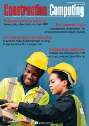
OpenRoads Designer<br />
Bentley's OpenRoads Designer provides a federated model that encompasses all disciplines in<br />
roadway design from conception to completion, writes David Chadwick<br />
You will hear the term 'scalable'<br />
used a lot in describing Bentley<br />
OpenRoads Designer, which is<br />
currently being released as a complete<br />
concept through a set of construction<br />
applications for the design of roads<br />
and associated infrastructure.<br />
Scalable relates here both to the<br />
number of different disciplines that<br />
OpenRoads Designer can reference<br />
and incorporate information from within<br />
the design model, and also to the<br />
unlimited size of the models it is able to<br />
handle. Operating as a Bentley<br />
CONNECT Edition, OpenRoads<br />
Designer is a 3D modelling application<br />
that helps to deliver roadway design<br />
from conception through to<br />
completion. It enables project<br />
managers to develop a federated<br />
model incorporating survey data,<br />
terrain modelling, drainage, subsurface<br />
utilities, the road itself and road<br />
furniture. It is also able to consume<br />
data in all formats, including reality<br />
meshes, aerial imagery and point<br />
clouds to place the road in context. It<br />
includes 3D parametric modelling to<br />
facilitate the creation of a design,<br />
together with traditional engineering<br />
workflows, to produce plans, profiles<br />
and cross sections, plus other<br />
deliverables.<br />
With a federated modelling<br />
environment, OpenRoads Designer<br />
provides engineers and contractors<br />
across all disciplines full access to<br />
their data, maintaining full collaboration<br />
through design and model updates,<br />
and can incorporate references to<br />
associated files in other applications.<br />
All of this is managed under the aegis<br />
of Bentley's ProjectWise.<br />
Because it offers multi-discipline<br />
support, OpenRoads Designer allows<br />
users to switch discipline perspectives,<br />
for instance from road alignment<br />
designer to subsurface utility engineer.<br />
This allows road designers access to<br />
gINT databases and to connect directly<br />
to geotechnical information and<br />
borehole data, to aid and improve<br />
design decisions.<br />
By bringing in subsurface information<br />
and generating subsurface terrains<br />
based on borehole information, these<br />
can be projected in road and drainage<br />
profiles, sections and plans. Users can<br />
then select utility and drainage<br />
components from catalogues of<br />
Composite image showing different stages of the development of the OpenRoads model<br />
10<br />
March/April 2017
SOFTWAREreview<br />
All Bentley applications can be appropriated. Descartes CONNECT Edition simplifies<br />
the extraction of existing ground surfaces from point clouds and reality meshes<br />
functional components to model<br />
underground drainage networks. These<br />
can even be optimised for water flow<br />
using integrated water analysis tools,<br />
showing the results in data tables or<br />
visually in profile views.<br />
ROADWAY DESIGN<br />
OpenRoads Designer - which you<br />
could say is the culmination of the<br />
development of InRoads, GEOPAK, MX<br />
and PowerCivil - is used for the rapid<br />
development of roadway designs. Its<br />
parametric capabilities enables<br />
changes made to any aspect of the<br />
design to be reflected through the<br />
model, and to modify those elements<br />
affected by the change.<br />
This, in effect, means that changing<br />
the radius of a bend in the road would<br />
automatically re-route the subsurface<br />
drainage to maintain its relationship<br />
with the road edges. To give further<br />
examples of this, Bentley demonstrated<br />
OpenRoads Designer's modelling<br />
capabilities at a recent press event,<br />
focusing on the design of a two-lane<br />
highway. On a section of a proposed<br />
roadway, previously positioned using<br />
terrain modelling and reality modelling<br />
to provide its context, the road was run<br />
along the proposed corridor.<br />
Using OpenRoads ConceptStation<br />
(which we covered in the Sept/Oct<br />
2016 issue of the magazine) the road<br />
was modelled in situ with engineering<br />
precision, preserving all work and data<br />
for use when detailing the road for<br />
construction purposes. Virtual<br />
presentations at this point can place<br />
the road in a visual context for planning<br />
and publicity purposes.<br />
The road type was specified by<br />
incorporating the appropriate<br />
templates, and the result was able to<br />
be viewed and assessed immediately<br />
in a rendered 3D view. Slices can be<br />
taken at any location along the road to<br />
provide, in real time, a view of the road<br />
components at that point, or repeated<br />
at regular intervals. Design models can<br />
be viewed in all modes - plan, profile,<br />
cross-section and 3D - and changes<br />
made in one view dynamically update<br />
all views.<br />
The software is also able to show cut<br />
and fill requirements at each slice -<br />
however, because of the parametric<br />
and federated nature of the model<br />
users are now able to calculate and<br />
extract volumetric quantities of earth<br />
movements over specified sections,<br />
directly from the 3D model.<br />
Horizontal representations of sections<br />
of the road can also be taken from the<br />
model, then placed showing gradients<br />
and inclines on the road, and to<br />
provide annotated plan, plan and<br />
profile, or cross section drawings<br />
showing each discipline.<br />
Multiple sheets can also be created,<br />
each with a different set of annotations<br />
pertaining to the associated task or<br />
discipline. Subsequent modifications to<br />
the design model, roadway gradient, or<br />
other elements will also automatically<br />
update any ruled annotation attached<br />
to the model within the plan, profile<br />
and/or section.<br />
The demonstration showed how easy<br />
and quick it is to make changes to a<br />
model, enabling engineers to layout<br />
roads more rapidly, or to run a series of<br />
iterations to test route alternatives. With<br />
all disciplines working on the same<br />
federated model, design conflicts are<br />
more readily seen and resolved earlier<br />
in the process, and, during the<br />
construction phases, office-to-field<br />
collaboration is immeasurably<br />
improved.<br />
DELIVERABLES<br />
Deliverables can range from traditional<br />
sets of drawings to animations and<br />
digital construction models, and can<br />
even be used for automated machine<br />
control and field positioning systems,<br />
including excavation, grading, piling<br />
and paving. Plan generation is<br />
dynamically updated - it's no longer a<br />
separate process - and views are<br />
saved with specific display rules and<br />
sheet indexes embedded, making it<br />
easy to navigate between the model<br />
and the drawings.<br />
And, as we have also seen with<br />
OpenRoads ConceptStation, the<br />
software integrates directly with Bentley<br />
LumenRT to produce cinematic quality<br />
visualisations, adding vegetation,<br />
climate and time display and traffic<br />
simulation using VISSIM. Designs<br />
created using OpenRoads Designer<br />
can be checked for BIM status using<br />
OpenRoads Navigator, which facilitates<br />
the visualisation and review of 3D<br />
designs as well as their status, giving<br />
dispersed teams the ability to check<br />
progress approvals and other issues.<br />
CONCLUSION<br />
We would be hard-pressed to point to<br />
any element of the whole design and<br />
construction process that was missing<br />
or could be improved upon in<br />
OpenRoads Designer, but as we have<br />
seen in the past Bentley will no doubt<br />
find a way to scale beyond even our<br />
wildest expectations in time.<br />
www.bentley.com/openroads<br />
March/April 2017 11
CASEstudy<br />
Designing Reality<br />
An inspired design, created and developed by architects at ArchiRADAR, won first prize in<br />
Graphisoft's 'Algorithmic Design meets BIM' competition<br />
Architects Michele Calvano, a<br />
Rhino & Grasshopper expert, and<br />
Mario Sacco, an ARCHICAD &<br />
GDL expert, both from ArchiRADAR,<br />
have used an architectural design<br />
workflow, using ARCHICAD, Rhinoceros<br />
and Grasshopper to create responsive<br />
and optimised shading panels on a<br />
free-form high-rise project. The project<br />
won first prize in the 'Algorithmic<br />
Design Meets BIM' competition<br />
sponsored by Graphisoft.<br />
The Software used in the project,<br />
besides Graphisoft’s ARCHICAD,<br />
Rhinoceros and Grasshopper, included<br />
Solibri Model Viewer and Tekla<br />
Structures. "Using ARCHICAD, our first<br />
aim was always to reduce time in<br />
managing projects; using GDL gave us<br />
a lot of flexibility in personalising<br />
schedules and controlling quantities.<br />
Grasshopper gave us an opportunity to<br />
further improve this capability,"<br />
explained Mario Sacco.<br />
The initial, free-form conceptual shape<br />
and geometry of the building was<br />
created using Rhinoceros, which<br />
provided all of the tools they needed to<br />
efficiently create the double-curved<br />
NURBS surfaces that are a feature of<br />
the model, setting graphic controlpoints,<br />
and enabling convenient, realtime<br />
3D editing.<br />
Grasshopper was used to overlay a<br />
mesh surface on the previously<br />
constructed NURBs. As a result, the<br />
complexity of the double-curved surface<br />
was reduced to evenly distributed planar<br />
squad panels grouped in clusters. In<br />
practice, this ensured that most of the<br />
panels have a similar geometry. The<br />
building skin, therefore, is covered by a<br />
series of equal element groups, designed<br />
to increase manufacturing efficiency and<br />
reduce construction costs.<br />
A great advantage of Grasshopper and<br />
Rhino is that all design updates and<br />
changes are handled in real-time, so<br />
that any change in the NURBs in Rhino<br />
causes an instant update of the mesh<br />
surface generated by Grasshopper. This<br />
way, the number and size of the planar<br />
panels could be easily adjusted.<br />
A triangulated grid structure was drawn<br />
in Rhino under the principal surface<br />
using only 3D lines, not solid shapes.<br />
As a consequence, the 3D definition<br />
could be kept very light and was easily<br />
adjustable. The Grasshopper file<br />
generated was a mere 200kb in size.<br />
3D modelling is viewed as 'the ideal<br />
tool' for conceptualising, creating and<br />
visualising a building. The connection<br />
between Grasshopper and ARCHICAD<br />
allows us to take the process further,<br />
making it capable of creating a direct<br />
link between creation and production.<br />
This frees us from following a strictly<br />
linear process, and gives us the<br />
freedom to explore designs in a<br />
dynamic, light multi-model.<br />
Generating the ARCHICAD BIM Lines,<br />
polylines and points, thanks to the AC-<br />
GH Connection, enables them to<br />
become ARCHICAD objects; so the next<br />
step was to convert the previously<br />
generated mesh surfaces and structural<br />
grid elements to parametric ARCHICAD<br />
elements. In this case, the main element<br />
of the building skin was a special, smart,<br />
parametric sun shading screen object<br />
(brise soleil element) written in GDL.<br />
Thanks to the live, bi-directional<br />
Grasshopper-ARCHICAD connection,<br />
such sun shading elements were<br />
created from the mesh surfaces,<br />
enabling the conceptual model to be<br />
transferred into a BIM model.<br />
GENERATIVE DISTRIBUTION AND<br />
POSITIONING OF PARAMETRIC<br />
ARCHICAD SHADING COMPONENTS<br />
This robust, live, two-way connection<br />
was available throughout the entire<br />
design development project phase. Any<br />
changes made in the ARCHICAD<br />
building information model would be<br />
reflected in Rhino, and any changes<br />
initiated in Grasshopper or Rhino would,<br />
similarly, be instantly reflected in the BIM<br />
project as well. As the design evolved,<br />
the GDL elements were able to be<br />
refined with details, and further elements<br />
were able to be added later when<br />
appropriate. The architectural<br />
documentation, including quantity takeoffs<br />
and schedules, were able to be<br />
created easily during any phase of the<br />
design process.<br />
12<br />
March/April 2017
CASEstudy<br />
The draft structural grid drawn in Rhinoceros<br />
Model checking in Solibri Model Checker<br />
Simplified structural elements generated with the<br />
Grasshopper ARCHICAD add-on<br />
Grasshopper - Rhino - ARCHICAD live bi-directional design<br />
envionments<br />
As the design evolved, the custommade,<br />
parametric solar panels were<br />
refined with parametric object subcomponents<br />
(spiders, nodes, etc.) and<br />
parametric configuration options. Thus,<br />
these location and orientation-sensitive<br />
solar panels could individually change<br />
their inclination on the building,<br />
reacting to specific, external criteria like<br />
actual sky and sun conditions.<br />
The structural design of the building<br />
was modelled with the help of IFC. The<br />
simplified, load-bearing structure was<br />
created automatically during the<br />
Grasshopper-ARCHICAD import using<br />
native ARCHICAD Beam elements.<br />
Exporting a native beam (not BREP) in<br />
IFC allowed Michele and Mario at<br />
ArchiRADAR to list, for example, the<br />
exact element length when they were<br />
exported to structural software using<br />
IFC protocols.<br />
The structural building scheme was<br />
created in Tekla Structures and the<br />
completed structural model was<br />
merged back into the architectural<br />
model, again using the IFC format. In<br />
Tekla, the use of native ARCHICAD<br />
Beams allowed engineers to redefine<br />
the beam type without needing to<br />
redraw the entire structure.<br />
Thanks to the small, parametric<br />
elements the ARCHICAD file size of the<br />
project was still only 13MB, ensuring an<br />
extremely responsive design<br />
environment even on average hardware.<br />
The model was also able to be used for<br />
reference, model checking, clash<br />
detection with the MEP systems, and for<br />
further collaboration purposes. Solibri<br />
Model Viewer was used to check if the<br />
IFC model complied with the standards.<br />
BUILDING ENERGY ANALYSIS<br />
Building energy analysis tools enabled<br />
the ArchiRADAR team to simulate<br />
algorithmic design scenarios<br />
throughout the entire design workflow<br />
and we used it, not only to create<br />
astonishing forms, but also to develop<br />
an energy-conscious design<br />
responsive to its environment, and to<br />
its microclimate as well.<br />
The Rhinoceros model could also be<br />
used for a more scientific building<br />
energy analysis. Using the Ladybug<br />
and Honeybee Rhino add-ons, the<br />
design could be analysed using Energy<br />
Plus. ARCHICAD also offers various<br />
energy evaluation functionalities out of<br />
the box, and provides a number of<br />
project export capabilities for other<br />
applications including PHPP, iSBEM,<br />
VIP-Energy, gbXML, as well as a<br />
dedicated 'green' IFC translator.<br />
ABOUT ARCHIRADAR<br />
This was an imaginative project for<br />
ArchiRADAR, but well within the scope<br />
of the company. which provides BIM<br />
services that span all stages of<br />
planning, design, construction and<br />
management across the AEC Industry.<br />
ArchiRADAR delivers customised<br />
services and solutions to suit all BIM<br />
requirements, regardless of the type<br />
and size of a project.<br />
www.graphisoft.com<br />
March/April 2017 13
CASEstudy<br />
Reclaiming Brownfields<br />
ContextCapture underpins the City of Coatesville's largest brownfield redevelopment, producing an<br />
accurate 3D terrain model, eliminating the need for costly on-site surveys of a constrained footprint<br />
The need for more building land is<br />
pushing demands to open up<br />
green spaces to the builders -<br />
countered by those who say that we<br />
already have vast acres of brownfield<br />
sites lying unused. The reuse of derelict<br />
wasteland, though, comes with an<br />
entirely new set of issues, as<br />
Coatesville community in Pennsylvania,<br />
America have discovered.<br />
Coatesville, the poorest community in<br />
Chester County, Pennsylvania's<br />
wealthiest province, has suffered from<br />
the exportation of manufacturing and<br />
industrial jobs, leaving a once thriving<br />
steel-producing city struggling to<br />
prosper amid a degrading<br />
infrastructure. To facilitate economic<br />
development, the Coatesville<br />
Redevelopment Authority (RDA) is<br />
working to rehabilitate commercial,<br />
residential, and industrial facilities that<br />
are now brownfield sites.<br />
To promote community redevelopment<br />
and sustainable growth, CEDARVILLE<br />
Engineering Group (CEDARVILLE) has<br />
provided at no cost to the city or RDA,<br />
conceptual design and planning<br />
services for a large brownfield<br />
redevelopment project known as "The<br />
Flats."<br />
To deliver 3D conceptual design<br />
plans, CEDARVILLE needed to survey<br />
the existing site conditions at the former<br />
steel-mill location. Spanning 30 acres,<br />
"The Flats" encompasses abandoned<br />
foundations from demolished industrial<br />
structures, hazardous materials, and<br />
soil contamination, and is subject to<br />
railroad intrusions and floodplain<br />
vulnerability. These conditions made it<br />
expensive and potentially dangerous to<br />
perform a traditional on-site survey and<br />
required the project team to consider<br />
alternative solutions to address the<br />
survey restraints. With special<br />
procedures and permits needed to<br />
enter the site, they estimated that it<br />
would "Cost about USD 40,000 to<br />
commission a traditional survey,"<br />
commented April Barkasi, founder and<br />
president of CEDARVILLE. Given the<br />
restricted site access and detailed<br />
analysis necessary amid a modest<br />
budget, CEDARVILLE needed accurate,<br />
scalable software to safely and costefficiently<br />
capture a 3D model of the<br />
existing terrain conditions for effective<br />
redevelopment planning of "The Flats."<br />
REALITY MODELLING PROVIDES<br />
AN OPTIMAL SOLUTION<br />
Challenging cost-prohibitive and risky<br />
conventional survey methods,<br />
CEDARVILLE explored numerous<br />
options to safely survey the existing<br />
terrain and accurately model the site.<br />
The team compiled various disparate<br />
data forms which were already<br />
available, determined additional data<br />
needs, and ultimately decided that<br />
photogrammetric reality modelling<br />
provided an optimal, cost-effective<br />
solution. This new technology allowed<br />
CEDARVILLE to survey the site using<br />
unmanned aerial vehicles (UAVs) to<br />
capture simple photographs,<br />
eliminating the need for on-site surveys,<br />
and create an accurate model as a<br />
texturised mesh.<br />
Numerous reality modelling<br />
applications are available, but<br />
CEDARVILLE required an interoperable<br />
technology that could handle the<br />
capacity of the 30-acre brownfield site,<br />
the high-resolution images, and the<br />
existing data and metadata, which<br />
could then generate an accurate 3D<br />
mesh needed to work with design cross<br />
sections and analysis profiles. Based<br />
on these requirements, CEDARVILLE<br />
determined that Bentley's<br />
ContextCapture met the scalability,<br />
engineering precision, interoperability,<br />
and modelling criteria for the project.<br />
"We wanted to generate topographic<br />
data as efficiently as we could,"<br />
explained Barkasi. Using<br />
ContextCapture for reality modelling<br />
provided the flexibility and precision<br />
necessary for the team to rapidly, and<br />
cost-effectively, deliver its conceptual<br />
planning assessment and designs for<br />
the redevelopment of the former steelmill<br />
site to the RDA.<br />
AUTOMATED TECHNOLOGY<br />
Using a drone, CEDARVILLE captured<br />
more than 750 aerial photos in a mere<br />
20 minutes, and with ContextCapture,<br />
the team incorporated base imagery<br />
from four perimeter ground-control<br />
points (GCP). The interoperability and<br />
photogrammetric reconstruction<br />
capabilities of ContextCapture allowed<br />
CEDARVILLE to leverage information<br />
and images from the drone, a handheld<br />
camera, the ground control points,<br />
existing survey data, and old photos to<br />
build a precise reality model -<br />
eliminating the need for an on-site<br />
inspection altogether.<br />
"There are parts of the property that<br />
were difficult to access, but Bentley<br />
technology made it almost like having<br />
boots on the ground - without having<br />
boots on the ground," stated<br />
Coatesville's City Manager Michael Trio.<br />
Furthermore, the flexibility and<br />
interoperability of ContextCapture made<br />
it much faster for CEDARVILLE to<br />
collect the data, and to visually present<br />
the data to the city of Coatesville. The<br />
software automated the reconstruction<br />
of the site model in a matter of hours.<br />
14<br />
March/April 2017
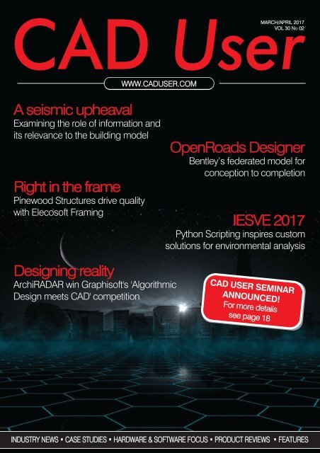
CASEstudy<br />
ContextCapture was instrumental in allowing local municipalities<br />
to visualize the state of "The Flats," and the conceptual<br />
design plans for the brownfield redevelopment.<br />
CEDARVILLE captured more than 750 aerial photos via a<br />
drone in a matter of 20 minutes, and using<br />
ContextCapture, incorporated base imagery to build a<br />
precise reality model.<br />
No manual modelling of the structures<br />
or the terrain of the project site was<br />
necessary. Using Bentley's reality<br />
modeling application to automatically<br />
produce a geo-referenced 3D model<br />
reduced risk, ensured safety, enhanced<br />
decision making, and accelerated buyin<br />
from local municipalities.<br />
The project team was able to quickly<br />
and accurately document the current<br />
conditions of "The Flats" and then<br />
present conceptual plans to<br />
demonstrate the type of reuse<br />
envisioned for the brownfield site,<br />
resulting in a significant time savings<br />
for the city.<br />
ACCURATE 3D REALITY MESH<br />
With ContextCapture, CEDARVILLE<br />
produced a multi-resolution 3D reality<br />
model in a file size nearly 30 percent<br />
smaller than a point cloud, which<br />
enhanced the overall processing power<br />
and responsiveness of the data when<br />
manipulating the model. Project<br />
designers could interactively move<br />
within the model to achieve the desired<br />
grading for drainage and permit<br />
compliance for optimal planning and<br />
redevelopment. CEDARVILLE were able<br />
to show a highly realistic and accurate<br />
surface model to support its<br />
recommendations and findings for<br />
design options, grading, and<br />
infrastructure planning. The texturised<br />
mesh provided a complete visual<br />
rendition of the project, easily<br />
recognised and usable by the team, the<br />
client, and the stakeholders.<br />
More specifically, the 3D terrain model<br />
generated by ContextCapture enabled<br />
CEDARVILLE to extract volumetric<br />
calculations very simply to determine<br />
the amount of fill required to complete<br />
a two-foot overfill cap for the mitigation<br />
of the brownfield area. Using the<br />
model, city planners and project<br />
engineers accurately calculated the<br />
presence of 22,400 cubic yards of<br />
stockpiled clean fill, demonstrating that<br />
enough stockpiled material existed, onsite,<br />
to cap over seven acres of the 26<br />
acres within the city boundary, an<br />
amount that exceeds required zoning<br />
provisions for the parcel. Barkasi<br />
commented, "Bulk clean fill ranges from<br />
USD 8 to USD 20 per cubic yard, which<br />
represents a huge cost benefit."<br />
Finally, the reality model provided<br />
CEDARVILLE designers with excellent<br />
information to establish the stream<br />
alignment and profile necessary prior to<br />
extracting and exporting cross sections<br />
to HEC-RAS to perform the required<br />
floodway analysis. Structural details<br />
from the abandoned mill foundations<br />
and bridge structures were clearly<br />
illustrated in the extracted cross<br />
sections, enabling CEDARVILLE<br />
engineers to optimise analysis,<br />
minimising the impact of the new<br />
grading over the floodway, and overall,<br />
to determine viable options for<br />
redevelopment.<br />
DRIVING THE FUTURE OF REALITY<br />
MODELLING<br />
Initiating the use of ContextCapture<br />
reality modelling technology on "The<br />
Flats" brownfield redevelopment project<br />
proved successful for CEDARVILLE and<br />
Coatesville. Not only did this approach<br />
save significant time and money, the<br />
visually realistic, dimensionally<br />
accurate, highly detailed 3D model<br />
facilitated engineering, enhanced<br />
decision making, and accelerated<br />
stakeholder buy-in, critical for effective<br />
economic redevelopment of the land.<br />
The reality model presents a<br />
comprehensive birds-eye view of the<br />
property, with reliable field data,<br />
providing a strategic advantage in<br />
developing a prospectus for potential<br />
investors, and will continue to provide<br />
value to the city throughout planning<br />
and design on related economic<br />
development projects. Using the model<br />
has already secured additional grants<br />
and funding from various agencies for<br />
the intersection and roadways aligned<br />
with the "The Flats" redevelopment.<br />
Based on its successful launch of<br />
reality modelling in Coatesville,<br />
CEDARVILLE already has expanded the<br />
role of the new technology, using it to<br />
address community drainage problems<br />
and plan sidewalks along rural<br />
roadways. With several upcoming<br />
projects, CEDARVILLE plans on using<br />
ContextCapture hoping to achieve<br />
similar results.<br />
"Using the most innovative tools in<br />
technology, we have developed a<br />
process that efficiently creates 3D<br />
scalable models with precision and<br />
accuracy. Reality modelling is where<br />
infrastructure of the future begins,"<br />
stated Barkasi.<br />
www.bentley.com<br />
March/April 2017 15
SOFTWAREreview<br />
The complete works<br />
Concept planning for infrastructure projects is simplified using Autodesk's InfraWorks 360<br />
The true art of an expert is to be able<br />
to present something that appears<br />
to be simple, but which hides the<br />
vast amount of skill required to achieve<br />
that aim. This is as true of a painter as it<br />
a piece of software. InfraWorks 360 from<br />
Autodesk falls into this category, as it<br />
provides a range of tools for quickly and<br />
easily laying out infrastructure scenarios<br />
with compelling graphics, but which<br />
need sophisticated software techniques<br />
to do so.<br />
The software is used to bring together a<br />
range of infrastructure planning and design<br />
tools to lay out road, rail and other building<br />
projects, but, in order to create valid<br />
concepts, the rules that govern the<br />
sketched elements have to operate within<br />
the same building constraints as the<br />
construction models. Horizontal curves in<br />
roads and yield lines and aprons on<br />
roundabouts must have the proper radii<br />
and other dimensions, but all that aside,<br />
InfraWorks 360 is not your run of the mill<br />
3D modelling application.<br />
The software has been designed as an<br />
alternative to full scale civil design<br />
applications traditionally used for planning<br />
and presenting designs to clients - a<br />
longwinded process that typically<br />
originates from a couple of informal<br />
sketches, which are then worked up into a<br />
full CAD 2D drawing that have to be<br />
converted into 3D visualisations so that<br />
they can be understood by the client.<br />
These take a lot of time and energy to<br />
produce, and if the client is not happy and<br />
suggests changes then it's back to the old<br />
drawing board, extending the project by<br />
another couple of weeks.<br />
Hence InfraWorks 360, which provides a<br />
mixture of civil design and 2D schematic<br />
GIS in a pared down CAD application that<br />
nevertheless retains the crucial civil<br />
engineering constraints while also<br />
delivering 3D infrastructure models for<br />
concept project planning. It fulfils its main<br />
aim admirably, which is to allow designers<br />
to present their designs in real-time to their<br />
clients or stakeholders, and to incorporate<br />
suggestions from them at the same<br />
meeting, allowing designers and clients to<br />
explore alternative scenarios in real-time.<br />
InfraWorks 360 contains all of the<br />
elements required to define the project,<br />
from basic building blocks and terrain<br />
development, to the laying out of complex<br />
road and rail networks, and then present it<br />
in a visual 3D environment so that clients<br />
can readily relate it to their requirements,<br />
all accomplished within the same design<br />
environment.<br />
DESIGNING FROM SCRATCH<br />
Starting from raw 3D terrain models or<br />
GIS survey data, designers can 'build'<br />
complete 3D models, applying grading to<br />
level sites, digging cuttings, adding<br />
buildings, bridges and water features - a<br />
full range of hydrology, hydraulic and<br />
drainage tools are included - and<br />
populating the model with street furniture,<br />
lighting, people, cars and plants to create<br />
fully simulated scenes.<br />
They can bring in files to support the<br />
modelling from a variety of sources,<br />
including Esri shapefiles, SketchUp,<br />
Autodesk SDF and SWG and Revit. Once<br />
a design has been approved, it can then<br />
by exported directly into AutoCAD CIVIL<br />
3D to produce construction documents<br />
and models. Traditionally, this final step<br />
would have seen the approved concept<br />
model scrapped, and the construction<br />
models developed from scratch.<br />
It's not necessary to be face to face with<br />
the client either. The software includes<br />
collaboration tools that enable teams to<br />
participate in the design process<br />
wherever they may be based, and<br />
because the software is optimised for<br />
development of the project, preliminary<br />
engineering work can be commenced<br />
while the finer details of a project are<br />
being sorted out.<br />
16<br />
March/April 2017
SOFTWAREreview<br />
INFRAWORKS 360 IN ACTION<br />
Terrain models can be developed in<br />
minutes using the Model Builder tool,<br />
which defines the area to be covered by<br />
the project, and you can import GIS<br />
information which is often freely available<br />
from many sources. The model is then<br />
populated with elements imported in any of<br />
the formats listed above, or developed<br />
from scratch using AutoCAD Civil 3D<br />
The model is then developed using rulesbased<br />
design, working to a set of rules and<br />
calculations but retaining its very visual fully<br />
rendered format. Users can click on each<br />
of the model elements to display its<br />
context, which is useful for exploring<br />
different solutions - such as whether to<br />
place a roundabout or junction where<br />
roads cross, or where to place bridges,<br />
cuttings and embankments.<br />
The software goes much further than that,<br />
though. If you have picked points to define<br />
a road then the software knows that<br />
horizontal curves need to have a certain<br />
radius, or that vertical curves need a<br />
certain length. Points of vertical intersection<br />
and vertical curves can be adjusted in realtime,<br />
whilst the software chips in to point<br />
out where the design violates engineering<br />
rules or fixes it itself - the software can be<br />
primed to do either.<br />
Similarly, when a bridge is placed in a<br />
project, the user can specify the type of<br />
structure to be used and the number of<br />
piers, or allow the software to choose a<br />
suitable standard structural shape based<br />
on the length and type of span.<br />
Other tools allow users to convert GIS<br />
roads to design roads or to send elements<br />
of the design to more detailed design tools<br />
- a bridge between InfraWorks 360 and<br />
Civil3D - or even to further structural design<br />
by exporting the model to Revit.<br />
BOMS AND QUANTITIES<br />
Infrastructure projects have more<br />
complex needs when it comes to<br />
estimating material quantities. It's not just<br />
a question of how much concrete you are<br />
going to pour into a site, but also how<br />
much earth you have to shift to create the<br />
cuttings and embankments, build the<br />
correct road gradients, flatten the<br />
proposed car park. InfraWorks 360<br />
includes tools that do the calculations for<br />
you, working out the cut and fill required<br />
for each bit of grading. It can even help<br />
you specify the size of culvert required to<br />
accommodate a stream.<br />
AN INFRASTRUCTURAL BIM MODEL<br />
An InfraWorks 360 model is a true 3D BIM<br />
model, containing aggregated information<br />
in every element, enabling it to be used for<br />
any type of analysis, from workflow/labour<br />
costs to road and rail sight lines to road<br />
signs and signals. As we pointed out<br />
earlier, there's a lot of intelligence and<br />
processing behind the seemingly simple<br />
application - which is why some of the<br />
more power-hungry processes it utilises<br />
are handled in the cloud.<br />
GETTING MOBILE<br />
InfraWorks 360 is not just a concept<br />
planning tool. It is extremely useful for<br />
presenting the same projects to the public<br />
- and for that it needs to populate the<br />
models with people and transport, to make<br />
it available on viewing platforms and the<br />
web, and even to allow the public to<br />
navigate through the models.<br />
Hence the release of Mobility Simulation<br />
last year, which allows designers to<br />
populate models with different modes of<br />
transportation, animate them and even to<br />
highlight hotspots showing potential traffic<br />
congestion using coloured bars.<br />
Mobility Simulation will feature widely in<br />
Autodesk's plans to develop Smart Cities,<br />
used as a multi-mode transportation<br />
analysis and design tool - everything from<br />
cycle lanes to taxis, buses, private cars to<br />
trains and the airport.<br />
It offers tools to generate drive-through<br />
animations, and to capture views at<br />
particular angles - a driver’s eye view as<br />
they approach a complex road junction, for<br />
example - or to give an idea of how a new<br />
bridge would impact upon the views from<br />
an adjacent building. Adding date and time<br />
information to a model which already<br />
knows your location adds increased<br />
accuracy to model visualisations, showing<br />
what they would look like at any time of the<br />
year - day or night. And one of the most<br />
recent features allows users to build terrain<br />
surfaces directly from point cloud data<br />
directly in InfraWorks 360.<br />
PROJECT OPTIMISATION<br />
The main benefit of using tools like<br />
InfraWorks to plan infrastructure projects is<br />
that they give all parties the time, means<br />
and incentive to explore many variations,<br />
test hypotheses, and visualise the impact<br />
of new technologies and techniques - all<br />
things that are inconceivable using<br />
traditional planning methods.<br />
www.autodesk.com<br />
March/April 2017 17
EVENTpreview<br />
A seismic upheaval<br />
David Chadwick considers the role of information in a future society and its relevance to the<br />
building model, and looks ahead to the CAD User COBie Seminar in May<br />
How many Internet connected<br />
devices do you currently use?<br />
That's quite apart from your home<br />
computer and smartphones. Perhaps you<br />
have had a smart meter installed to record<br />
your electricity usage in real time, or you<br />
have smart controls to turn lights on and<br />
off while you're away from home, or<br />
control burglar alarms and CCTV. If you<br />
upgraded your car recently, you will have<br />
anything up to full Wi-Fi capabilities so that<br />
the kids can Google or play games while<br />
you drive. You might even be thinking<br />
about installing a smart fridge that will<br />
reorder essentials when you get a bit low.<br />
This article isn't about the perils of being<br />
hacked - although that becomes a distinct<br />
possibility when each new device comes<br />
with a unique access code - but rather the<br />
way the in which the information that<br />
underpins the Internet of Things is going<br />
to change the way we live, work and<br />
breathe, a seismic upheaval that will<br />
eclipse the replacement of the horse with<br />
the car.<br />
The attachment of information to a<br />
building model provides more than a<br />
means of sharing building models with<br />
fellow project members and with those<br />
responsible for maintaining the building<br />
after it has been erected. It places it within<br />
a context that can be used for many other<br />
purposes. The information that is supplied<br />
with the Building Information Model will, in<br />
future, be used for more than just<br />
providing details of how to service, fix or<br />
replace a building's central heating<br />
system. It will incorporate multiple sensors<br />
that will record all consumable items used<br />
within a building unit for either analysis or<br />
billing purposes. We are halfway there on<br />
that already.<br />
With links to other government<br />
departments, local authorities will have<br />
access to occupancy levels of houses and<br />
apartments, and will be able to analyse<br />
and predict such levels and equate it to<br />
the building's dimensions, assisting them<br />
in planning the local infrastructure, vehicle<br />
access (if we are still allowed to drive our<br />
own cars in the future) and the provision of<br />
schools, local shops, health facilities and<br />
other public amenities.<br />
Fanciful nonsense you might think, but<br />
it's already in progress in some forwardthinking<br />
cities. Helsinki 3D, for example, is<br />
a 3D model of the entire city that does<br />
indeed match housing units with<br />
occupancy numbers. Singapore, as you<br />
would expect, is also aiming to become<br />
the world's first 'Smart City'.<br />
INFORMATION IN THE BUILDING<br />
MODEL<br />
The information that underpins the Smart<br />
City is not there merely to promote the<br />
technical efficiency of those forward<br />
thinking communities, but to enable them<br />
to cope with the other pressing demands<br />
that will dominate the planet throughout<br />
the remainder of this century - and more<br />
than likely into the next as well, if we<br />
haven't cracked the problem by 2099!<br />
The most urgent of these issues are<br />
increasing urbanisation as fast growing<br />
populations migrate to the cities, and<br />
the declining of the Earth's resources.<br />
Increased populations in limited space<br />
increases the density of housing<br />
occupancy, pressurises private and<br />
public transport systems, and raises<br />
problems with the supply and removal<br />
of the necessities of life - food and<br />
human waste.<br />
Any government faced with these issues<br />
will want to keep tabs on and leverage the<br />
information available within Smart<br />
communities, and, 'in extremis', legislate to<br />
control excesses or wastage in any area.<br />
That is already happening as well, with<br />
excess charges being levied on users who<br />
put out overfull bins, or need to dispose of<br />
building rubble at the local tip.<br />
COBIE OR NOT COBIE?<br />
Perhaps you were thinking that BIM could<br />
pass you by, as you only build single<br />
housing units, and at most a small terrace<br />
of houses or block of flats? You might<br />
have to produce an Energy Certificate<br />
when the building is sold, but that can be<br />
achieved without all this rigmarole of<br />
providing a full 3D model with building<br />
materials and components specified<br />
together with their performance<br />
capabilities and lifetime energy usage<br />
costs. Well think again!<br />
It might take some time for rural<br />
18<br />
March/April 2017
EVENTpreview<br />
architects to catch up as the pressures<br />
there aren't so great, but any construction<br />
in an urban environment - London or<br />
Manchester, for instance - will come under<br />
stricter rules and regulations about how<br />
the building model will be delivered, and<br />
how it will address local environmental<br />
and infrastructure concerns. It will need to<br />
come fully topped up with the sort of<br />
information that is not only geared towards<br />
making efficiencies during its design and<br />
construction, but which can be addressed<br />
many years into the future by local<br />
planning authorities.<br />
To raise awareness of the many, often<br />
complex issues involved we are holding a<br />
CAD User COBie Seminar this May in<br />
association with Vectorworks. The subject<br />
matter and the points that will be<br />
discussed don't just apply to<br />
architects and building contractors<br />
however - they will affect everyone from<br />
landscape modellers and town planners<br />
right through to construction teams and<br />
asset managers.<br />
The COBie Seminar will look at the role of<br />
information in the building model; what it<br />
is, how it is attached to the model and<br />
what does, or indeed does not need to be<br />
included for other users of the model. That<br />
will be followed by presentations outlining<br />
different methods of delivering that<br />
information to other users, in the form of a<br />
federated model that combines models<br />
from all of the disciplines involved with the<br />
design and construction of the building.<br />
This can then be viewed on any number<br />
of devices, or as COBie data, promoted<br />
by the UK Government, which addresses<br />
a number of critical needs - in particular<br />
providing asset managers with an easily<br />
digested inventory of all of the<br />
components of a building with associated<br />
files to facilitate its maintenance. Each<br />
method of delivery has its pros and cons.<br />
The seminar is taking place at the<br />
London Transport Museum, and we have<br />
the happy situation where one of our<br />
speakers on the day will be Andy Stanton,<br />
Infrastructure and Sustainability Manager<br />
at Transport for London. You can find<br />
more details of all of the seminar<br />
speakerson the seminar website at the<br />
end of this article.<br />
COBie or not COBie: that's a convenient<br />
tag to grab your attention. The real<br />
purpose of the event is to get you thinking<br />
more seriously about the role of<br />
information in society. The seminar's<br />
afternoon's session will begin with a look<br />
at the future of information within the<br />
industry - or more specifically, within our<br />
lives - and the issues that address long<br />
term ownership and retention of up to date<br />
building information. Attendees will then<br />
have their opportunity to question the<br />
experts in an open forum.<br />
Companies will soon need to make<br />
some important decisions about how they<br />
handle their data - either as developers or<br />
users - and the CAD User COBie Seminar<br />
will give them an opportunity to clarify their<br />
BIM and COBie knowledge and thereby<br />
make some informed decisions about<br />
their role in the future.<br />
At the outset of this article I said that we<br />
are heading towards a seismic change in<br />
the way we handle information. Why not<br />
come along to the seminar and see if you<br />
can challenge that statement!<br />
www.caduser.com/seminars<br />
COBIE SEMINAR AGENDA<br />
9:00 Registration and coffee<br />
10:00 Introduction by David Chadwick – COBie or Not COBie – That is the question.<br />
10:10 Information is the Key to BIM. But what information, how do we save it, why and how much?<br />
10:40 Why can’t we use a Federated Building Model as an Information Delivery System?<br />
11:10 Coffee Break<br />
11:30 Learning to Love COBie – It’s the best and most effective solution we have.<br />
12:00 What information do I need for managing my assets, and how do I want it?<br />
12:30 Lunch break<br />
13:30 When Theory meets Practice. Unanswered questions about COBie and the FBM<br />
14:00 Questions and Answers. Your chance to put the panel of experts under pressure<br />
15:30 Close<br />
March/April 2017 19
SOFTWAREreview<br />
Tekla 2017<br />
Trimble has released the latest<br />
version of Tekla's structural<br />
engineering design and<br />
analysis suite of tools<br />
Enhanced communication and<br />
modelling, together with some<br />
completely new tools to expand<br />
working processes and collaboration are<br />
the main themes of the latest releases from<br />
Trimble of its structural engineering,<br />
fabrication and construction software, Tekla<br />
2017, which incorporates Tekla Structures<br />
2017, Tekla Structural Designer 2017 and<br />
Tekla TEDDS 2017.<br />
This latest release demonstrates Trimble's<br />
commitment to the development of Tekla<br />
Building Information Modelling solutions,<br />
and to innovations in structural engineering,<br />
off-site prefabrication and on-site efficiency.<br />
Placing the release in perspective, Jari<br />
Heino, general manager of Trimble's<br />
Structures Division said: "In these new Tekla<br />
versions, we focus on improving<br />
communication and modelling methods, as<br />
these are directly tied to the productivity of<br />
core tasks within large workgroups and<br />
projects. The software provides a variety of<br />
completely new tools for users to expand<br />
their scope of work and collaborate with<br />
project stakeholders to ensure that the<br />
entire team is on the same page."<br />
TEKLA STRUCTURES 2017<br />
Tekla Structures 2017 comes with next<br />
generation tools that include a new<br />
customisable user interface and contextual<br />
toolbar. Combined with other<br />
enhancements they make modelling<br />
quicker and easier and design<br />
communication more effective. More<br />
control is also provided for Direct<br />
Modification, enabling users to create an<br />
accurate structural model quicker and<br />
easier. A faster Organizer facilitates<br />
speedier finding and fixing of parts, and the<br />
general arrangement and detailed drawings<br />
functions have also been improved.<br />
With this basepoint, engineers and<br />
architects can now work together in a BIM<br />
Tekla Structures 2017 - model UI<br />
workflow with correct common coordinates.<br />
Architects can also take advantage of a<br />
new plugin that provides algorithmic<br />
modelling for Tekla Structures using the<br />
popular Rhino/Grasshopper combination.<br />
For concrete, Tekla Structures 2017<br />
introduces next-generation reinforcement<br />
methods that give users more flexibility to<br />
create and modify reinforcements for<br />
different types of concrete geometries. With<br />
the unique pour unit feature, managing and<br />
reporting all pour-specific information is<br />
made more effective and easier to<br />
implement.<br />
Precast concrete fabrication comes with<br />
improved information exchange between<br />
detailing and production with new data<br />
transfer links direct to production<br />
management. Elsewhere, the new palletiser<br />
tool improves model-based production<br />
planning. Not only do these additions save<br />
time in the planning process, but they also<br />
prevent human errors in information transfer<br />
between detailing and production.<br />
For steel detailing, the new release<br />
improves modelling of steel bent plates with<br />
full support for direct modification. Now,<br />
editing and working with even the most<br />
complex bent plates is simple and intuitive.<br />
Users can create anything from simple bent<br />
gussets to folded profiles, spiral stringer<br />
plates, transitional duct sections, complex<br />
folded panels and more.<br />
Enhancements in drawing production<br />
enable easier and more flexible shaping of<br />
drawings, and help to ensure clear<br />
communication of design intent and fewer<br />
requests for information. The new 2D<br />
Library is a productivity tool for replacing<br />
repetitive work. A nice new addition is that<br />
3D graphics have a new look about them -<br />
they now come with shadows.<br />
Tekla Structures 2017 is further enhanced<br />
for general structural design. Structural<br />
engineering offices can reduce their risks<br />
and add value by minimising the<br />
uncertainty that arises from incomplete and<br />
uncoordinated construction documents,<br />
hence the latest version is specifically<br />
developed for their needs, providing<br />
productivity and workflow improvements for<br />
all structural materials and project types.<br />
With the new release, users can create<br />
documentation that is better coordinated<br />
and thus more reliable, and communicate<br />
structural design more effectively. Fewer<br />
requests for information (RFIs) and postdesign<br />
project management issues help<br />
improve structural engineering office<br />
business performance.<br />
STRUCTURAL DESIGNER 2017:<br />
FOUNDATION DESIGN AND WIND<br />
LOADING EFFICIENCY<br />
Tekla Structural Designer (TSD) is an<br />
analysis and design (A&D) application that<br />
shortens design time, providing an efficient<br />
way to quickly establish optimum structural<br />
solutions. The new version delivers<br />
significant new features and enhancements<br />
focused on A&D workflow productivity,<br />
combining to contribute significantly to the<br />
overall workflow for both steel and concrete<br />
code compliant structural design.<br />
20<br />
March/April 2017
From design<br />
to reality<br />
Woonzorgcentrum De Polbeek (Holland)<br />
Tekla Structures is intelligent 3D modelling software designed to help you<br />
deliver all types of precast concrete elements at the right time to the right place.<br />
Integrating design and detailing with manufacture, project management and<br />
efficient information sharing Tekla Structures can do it all.<br />
Together we are shaping a smarter future for construction.<br />
www.tekla.com/uk/solutions<br />
TRANSFORMING THE WAY THE WORLD WORKS
SOFTWAREreview<br />
Tekla Structural Designer 2017 - foundation design<br />
Tekla wall and floor layout<br />
Comprehensive design functionalities<br />
have been provided for all of the common<br />
foundation types required in steel and<br />
concrete structures. It makes foundation<br />
design more efficient by automating some<br />
functions, such as calculating the number<br />
of piles required in a structure, together<br />
with comprehensive calculations and<br />
material take-offs within a single model. In<br />
addition, new wind load processes have<br />
been added which speed the application<br />
of wind loading.<br />
The new tools allow easy application of<br />
horizontal and wind loading, helping<br />
engineers assess the lateral strength<br />
requirements of their structure. Besides<br />
making the process faster, wind loading is<br />
more flexible, making it especially suitable<br />
for structures with challenging geometries.<br />
In practice, wind loading can now be<br />
applied easily on all types of buildings,<br />
either manually or automatically, to comply<br />
with your chosen code of practice.<br />
Engineers can also choose rigid or flexible<br />
diaphragm action to provide complete<br />
control of lateral forces and how they are<br />
distributed throughout the building.<br />
Tekla Structural Designer is a vital tool in<br />
all areas of concrete structural design.<br />
Enhancements to slab design have<br />
revolutionised the design of concrete slabs,<br />
and now include slab splitting tools,<br />
graphical control of panel patches and the<br />
introduction of pass/fail contour diagrams.<br />
Piled mat design efficiency is also<br />
improved thanks to the expansion of TSD's<br />
foundation design capabilities - not a<br />
separate program, but part of the single<br />
modelling environment. Engineers can now<br />
choose between pad, pile cap, mat and<br />
piled mat foundations all within the<br />
same model.<br />
Other features that have been enhanced<br />
include automated pile layout with<br />
comprehensive calculations and material<br />
take off for foundations, and automated<br />
load transfers to foundation - again, part of<br />
the single modelling environment.<br />
Foundation design is now comprehensive<br />
and complete with all the main foundation<br />
types catered for (pad, strip, pile cap mats<br />
and piled mats) for both steel and concrete<br />
structures. With regard to complex<br />
constructions, Tekla Structural Designer<br />
2017 facilitates the analysis of bending on<br />
composite steel and concrete<br />
constructions, enabling engineers to<br />
assess the benefits of composite floor<br />
construction on the overall frame deflection.<br />
The software also provides engineers<br />
with more control and improved design<br />
capabilities, as well as a greater<br />
understanding of a number of more<br />
uncommon structural elements, such as<br />
cambered beams, shear rails, which they<br />
can design to either US or Eurocodes,<br />
bending angles and tee sections - which<br />
can also be designed to comply with US<br />
codes. Punching shear design is a<br />
tedious task, which becomes easier with<br />
this new feature.<br />
TEKLA TEDDS 2017: MORE<br />
CALCULATIONS TO IMPROVE<br />
PRODUCTIVITY<br />
Developed to improve engineering<br />
productivity and quality, Tekla TEDDs<br />
automates repetitive and error prone<br />
structural and civil calculations. In the face<br />
of ever more aggressive deadlines and<br />
demands, Tekla TEDDs enables users to<br />
streamline engineering design by replacing<br />
tedious manual calculations and<br />
spreadsheets with professional and<br />
consistent output. In version 2017, Trimble<br />
has added a large number of new<br />
calculations and enhancements to existing<br />
calculations across various design codes.<br />
Integrated with Microsoft Word, engineers<br />
can now quickly create and customise<br />
calculations and professional<br />
documentation that includes those<br />
calculations, together with sketches and<br />
notes. The new version of TEDDs also<br />
includes a large number of new<br />
calculations and enhancements to existing<br />
calculations across Eurocode, British<br />
Standards, US, Australia & Canadian<br />
codes. These include:<br />
Eurocodes: New steel column and<br />
base plate design, new RC corbel<br />
design, enhanced retaining Wall A&D<br />
and more<br />
British Standard Codes: Update<br />
retaining wall calculations, enhanced<br />
masonry wall panel design and other<br />
calculations<br />
US Codes: RC column design has<br />
been enhanced to display more<br />
accurate profiles, enhanced steel 2D<br />
Member A&D and improved user<br />
experience for wood shear wall design,<br />
to name a few<br />
Australian Codes: New Gabion<br />
retaining wall A&D, enhanced 2D<br />
analysis frame wizard and more<br />
New and enhanced calculations: These<br />
have been added each month since<br />
the September release of TEDDS 2017<br />
www.tekla.com/2017<br />
22<br />
March/April 2017
COBie or not COBie?<br />
That is the Question<br />
Join us on the 16th May at this CAD User seminar to explore, amongst other issues:<br />
Is COBie still a practical solution<br />
for delivering building information<br />
to the people who need to use it?<br />
<br />
Why can't we just give the client<br />
the 3D model instead?<br />
What information does the<br />
building owner need, and how<br />
would they prefer it to be<br />
delivered?<br />
<br />
What happens when theory<br />
comes up against practice?<br />
Who owns the building model,<br />
and who will maintain it through<br />
the life of the building?<br />
<br />
Learn the power, importance and<br />
the why's and how's of leveraging<br />
the information you are accruing<br />
in your 3D model<br />
Hear presentations from industry<br />
experts discussing the pros and<br />
cons of each solution<br />
<br />
Put your questions to the panel<br />
Network with your peers<br />
In Association with:<br />
Supported By:<br />
For the day’s agenda visit:<br />
www.caduser.com/seminars<br />
Follow us: @CCMagAndAwards<br />
The London Transport Museum,<br />
Covent Garden, WC2E 7BB<br />
FREE TOUR<br />
INCLUDED<br />
COMPLIMENTARY COPY<br />
of Innovative Vectorwoks BIM by<br />
Jonathan Reeves<br />
An inspiring read for Architects getting<br />
started with BIM or who want to be<br />
level 2 BIM compliant.<br />
OFFER<br />
£49 EXCL VAT.<br />
HURRY LIMITED<br />
SEATING AVAILABLE.<br />
GROUP DISCOUNTS<br />
ALSO AVAILABLE.<br />
Seats are just £95 excl. VAT and<br />
include refreshments and lunch.<br />
For more information and to<br />
book your place please visit:<br />
www.caduser.com/seminars<br />
call 01689 616000 or email<br />
seminars@caduser.com
CASE study<br />
Assured quality<br />
Solibri gives Multiplex Construction Europe quality assurance, enabling them to validate the<br />
robustness of design and constructability<br />
Multiplex Construction Europe<br />
Limited are a leading global<br />
contractor with a Head Office<br />
in London and bases in Europe,<br />
Canada, the Middle East, Australia and<br />
India. Established in 1962, the<br />
company has a strong reputation for<br />
the delivery of highly complex projects,<br />
which include some of the tallest<br />
residential and commercial towers in<br />
London and the largest hospital<br />
complex in the UK.<br />
With high profile clients it was<br />
imperative that the company took<br />
steps to improve the way it designed,<br />
delivered and managed its projects. To<br />
this end it implemented the rule-based<br />
model checker, Solibri, to validate its<br />
designs. Nick Leach, Head of BIM at<br />
Multiplex, first encountered Solibri<br />
whilst working for a previous employer<br />
at Helsinki over 5 years ago.<br />
Having been developed some years<br />
previously, it is fundamentally used as<br />
the software of choice across the<br />
Nordic countries. The software is now<br />
used at Multiplex for clash detection,<br />
model validation, change control,<br />
reporting and information take-off,<br />
including COBie.<br />
SOLIBRI UPDATE<br />
When Solibri won an Editors' Choice<br />
Award at the Construction Computing<br />
in 2013 it was described as an<br />
"Application waiting for a problem." In<br />
fact it was not until BIM reared its head<br />
that the real capabilities of the software<br />
became apparent, and it is now being<br />
used by many contractors in the<br />
construction industry.<br />
Besides having to cope with the<br />
wholesale adoption of BIM Level 2,<br />
conforming to the Government<br />
Mandate, there have been a lot of<br />
changes at Solibri over the last year or<br />
two. After being acquired by<br />
Nemetschek at the end of 2015 and<br />
added to their ever increasing list of<br />
impressive brands there had been an<br />
investment in the UK presence with a<br />
physical office established, a change<br />
in management and additional team<br />
members added.<br />
Solibri actually started life 17 years<br />
ago, having been developed as a<br />
quantity take off and cost estimation<br />
tool. To provide an accurate estimation<br />
of building quantities you need an<br />
accurate model, and Solibri very<br />
quickly understood that there were<br />
many problems with the quality of the<br />
models being produced. There was<br />
nothing available on the market to<br />
perform a preliminary check before the<br />
estimation could take place, so Solibri<br />
set out to fill the gap in the market<br />
itself with Solibri Model Checker.<br />
Taking an OpenBIM approach to their<br />
development using the industry<br />
standard IFC (Industry Foundation<br />
Class) format meant that Solibri could<br />
help raise quality and have a positive<br />
impact on every project. As the<br />
industry understanding of BIM<br />
requirements, Government mandates<br />
and a general drive for improved<br />
geometric and data quality grows,<br />
Solibri has come into its own.<br />
Nowadays Solibri is providing a Quality<br />
Assurance and Quality Control process<br />
to thousands of models on a daily<br />
basis around the globe.<br />
Clash detection has been around for<br />
many years and is something that<br />
Solibri Model Checker does very well,<br />
but that is only around 5% of the<br />
capabilities of the software, the real<br />
power lie in the rules provided and the<br />
ability for users to write their own<br />
logical rules.<br />
Solibri has also recently added some<br />
complimentary offerings to aid and<br />
improve BIM workflows and processes.<br />
Solibri Model Viewer Pro adds a low<br />
cost version of the popular free Viewer<br />
with added functionality to connect to<br />
BCF (BIM Collaboration Format)<br />
Management tools, giving it the ability<br />
to participate in advanced BIM<br />
workflows, manage reported issues<br />
with improved tools and a few other<br />
benefits. AutoRun enables users to<br />
automate many of the basic checks<br />
and facilitate BCF report generation,<br />
run on a regular basis on multiple<br />
models. Solibri can now also provide<br />
optional private cloud functionality for<br />
managing and sharing customised<br />
rulesets, classifications and information<br />
reports in a secure environment<br />
throughout an organisation.<br />
THE VALUE OF SOLIBRI<br />
"The real value of Solibri," said Nick, "Is<br />
the ability to allow us to check a model<br />
based on custom rules. The software<br />
enables us to go much further than<br />
basic clash detection though - from<br />
something simple like clash analysis<br />
against door swings, to clearance void<br />
allowances where we have exposed<br />
MEP services."<br />
"'Solibri allows us to check both the<br />
geometry and the data within models,"<br />
he added, "meaning that our project's<br />
24<br />
March/April 2017
CASEstudy<br />
Solibri - Asset inclusion-exclusion definitions and COBie output<br />
models can be validated for<br />
compliance autonomously, and the<br />
results published through Solibri's<br />
intuitive report presentation function."<br />
Nick explained that the adoption of<br />
Solibri was still in its infancy at<br />
Multiplex, but they could already see<br />
the benefits that the software has<br />
achieved in improving working<br />
efficiencies both for themselves, and<br />
also for consultant design teams. The<br />
company is supporting its greater<br />
utilisation by personnel in key roles<br />
across its project teams. From work<br />
completed to date, it is evident that<br />
Solibri could provide significant<br />
savings in both time and costs.<br />
When it comes to quality assurance,<br />
the speed at which the robustness of<br />
the model and the quality of the data it<br />
produces can be attained, helps to<br />
enhance the deliverables that Multiplex<br />
Construction Europe receive.<br />
SOLIBRI WITH IFC<br />
Multiplex uses the IFC format, a policy<br />
that the company has stipulated for all<br />
its design teams and supply chain as a<br />
standard deliverable. It allows them to<br />
share files and communicate issues<br />
with other software products through<br />
the BCF file exchange. This means that<br />
such issues can also be flagged up in<br />
Solibri and sent to the right person to<br />
correct in their native authoring<br />
software, and then be issued back to<br />
be verified and closed out.<br />
IFC had a lot of negativity for a while<br />
because of interoperability issues, but<br />
with improved versions from Building<br />
Smart and native authorising, the<br />
software has improved its capability to<br />
export and share files. Consequently, its<br />
uptake is increasing, and is of particular<br />
significance with the increase in opensource<br />
products in the marketplace that<br />
rely on it for file sharing.<br />
When asked about how he sees the<br />
future of BIM, IFC and, in particular,<br />
Solibri, Nick said that "With software<br />
developing at a rapid rate, it's<br />
imperative to define why you are using<br />
it, to establish how you intend to<br />
manage it, and to understand what<br />
advantages it will provide and what<br />
you want to achieve with it." He added<br />
that "Before long we will have new<br />
roles in the industry, people who can<br />
make best use of the digital<br />
environment that's changing around us<br />
- such as application developers and<br />
data analysts."<br />
Nick admitted that there is still an<br />
educational exercise required to<br />
change the mindset of companies into<br />
investing in technology and adopting<br />
digital methods of working - and more<br />
initiatives to support the cost burden<br />
that it lays on companies in the outset.<br />
"Multiplex is doing its bit, he says, "to<br />
demystify the deliverables set out by<br />
our clients into plain language,<br />
conducting face-to-face workshops<br />
and providing education where<br />
required, explaining what is required<br />
and what is specific to particular<br />
organisations with regard to delivery,<br />
and what information we expect to be<br />
handed back to us. Using products<br />
such as Solibri helps us to validate the<br />
quality of our information, and provide<br />
assurances for the designs received<br />
from our supply chain."<br />
www.solibri.com<br />
March/April 2017 25
CASE study<br />
Redefining project efficiency<br />
Bluebeam Revu 2017 has become the industry standard PDF solution for workflow automation and<br />
collaboration, a statement that Hilson Moran would certainly corroborate<br />
Since the launch of Bluebeam in<br />
2002, Bluebeam Revu has<br />
become the industry-leading<br />
markup and collaboration software for<br />
increasing efficiency throughout an<br />
entire project lifecycle. This focus on<br />
streamlining project workflows, means<br />
that Bluebeam continuously strives to<br />
ensure that each version of Revu<br />
released is bigger and better than the<br />
last. Containing feature suggestions<br />
from existing clients and expert<br />
software engineers, Revu 2017 is no<br />
exception.<br />
The new ‘wow' feature of the latest<br />
version is the Dynamic Fill tool, which<br />
makes it easier to markup and measure<br />
complex regions in PDF plans. The tool<br />
allows the user to click on the area they<br />
want to measure, depicted by different<br />
colours, to show the measurements for<br />
more accurate takeoffs.<br />
In addition Quantity Link, found in the<br />
Revu eXtreme version, will make<br />
creating project bids even faster. It<br />
allows the user to link multiple PDFs to<br />
Excel worksheets so that bid<br />
calculations are updated in real time, as<br />
measurements are changed or added<br />
in Revu. Other new features of Revu<br />
2017 include the ability to embed<br />
panoramic images, Automatic Form<br />
Creation (eXtreme only) and<br />
enhancements to the measurements<br />
tool and count tool.<br />
For those involved in the world of BIM,<br />
the enhancements to the 3D PDF tools<br />
are of particular interest. The newly reengineered<br />
model data tree allows the<br />
user to view and manage expansive 3D<br />
model metadata, enabling increased<br />
access to object metadata across the<br />
whole construction supply chain.<br />
Combined with Bluebeam Revu's<br />
existing Studio collaboration tools, an<br />
environment for easy, streamlined<br />
sharing and collaborative working in<br />
real time is more than just a possibility.<br />
Project stakeholders from around the<br />
world can view, chat and comment on<br />
the same PDFs together in real time or<br />
on their own time with all activity<br />
tracked in a full audit trail of all session<br />
attendees' changes.<br />
The following case study provides an<br />
insight into how Revu has been readily<br />
adopted and used within a global<br />
company:<br />
HILSON MORAN REDEFINES<br />
PROJECT EFFICIENCY<br />
With 40 years of experience within the<br />
built environment, Hilson Moran* has<br />
embarked on a digital strategy to<br />
completely transform its workflows. A<br />
key tool in this initiative is Bluebeam<br />
Revu, which has provided the<br />
engineering consultancy instant timesaving<br />
dividends when handling<br />
contractor drawing and technical<br />
submittal reviews, whilst converting the<br />
firm's paper-based traditional worklows<br />
into digital solutions.<br />
WHY GO DIGITAL AFTER 40<br />
YEARS?<br />
"There is no doubt the digital revolution<br />
has now arrived in the construction<br />
industry and it is starting to make a real<br />
impact. User-friendly software like<br />
Bluebeam Revu is at the forefront of<br />
this change," observes Hilson Moran's<br />
digital champion, Director Vince<br />
Ugarow.<br />
"Our users actually see the benefit of<br />
Revu," explains Finance Director Roger<br />
Waters-Duke. "Our engineers say it<br />
actually makes their life easier, and<br />
that's part of why the product is the<br />
quickest software to ever be adopted at<br />
Hilson Moran. We went from 10<br />
licences a year ago to 229 licences now<br />
across the whole company."<br />
26<br />
March/April 2017
CASEstudy<br />
ROLLING OUT REVU<br />
The forward-thinking management<br />
team at Hilson Moran first introduced<br />
Revu to a small innovation team and<br />
implemented the software on PCs,<br />
laptops and Wacom tablets. The same<br />
design and construction information<br />
previously found on sheets of drawing<br />
paper could now be seen on screens<br />
and tablets, giving this group of<br />
employees the degree of familiarity to<br />
explore and innovate new workflows,<br />
before actually trialling it on a sample<br />
project. After finding first-time success<br />
in using Revu on a peer review for a<br />
very large residential development in<br />
South London, Hilson Moran began<br />
implementing the software across the<br />
company.<br />
TRAINING TIME<br />
Hilson Moran organised a tutorial with<br />
an external trainer for first-time users to<br />
help them become familiar with the<br />
features. After a few larger overview<br />
sessions, the staff broke out into<br />
groups of five. These groups were<br />
trained extensively, and eventually<br />
colleagues began teaching each other<br />
Revu features and shortcuts.<br />
"I used it experimenting with the<br />
different tools and features just to get<br />
an idea of how the different things<br />
worked," says Mechanical Design<br />
Engineer Stephen Atemie.<br />
WORKFLOW INNOVATIONS<br />
One of the unique features Hilson<br />
Moran credits to the quick success of<br />
implementing Bluebeam Revu is the<br />
ability to make customised tool sets<br />
within the program. "Each department<br />
has their own tool sets, so mechanical<br />
and electrical engineers can each drop<br />
their respective drawing symbols into<br />
drawings, which makes marking up and<br />
sketching much, much quicker,"<br />
declares Mechanical Design Engineer<br />
Will Major.<br />
"We have actually created some<br />
custom tool sets which are considered<br />
Hilson Moran tool sets for specific<br />
tasks. These can range from very simple<br />
line types to detailed engineering<br />
symbols that we all use, ensuring<br />
consistency and quality," adds Ugarow.<br />
A popular workflow that Revu makes<br />
easy for Hilson Moran is the design<br />
review process. Atemie explains the<br />
early workflow: "Before, you would get<br />
sent the drawing - say from an architect<br />
or a client - and you would print it out,<br />
make your markup in your sketches on<br />
the drawing, and then scan that back<br />
onto the system which, depending on<br />
the quality of the scan, might not<br />
necessarily show all the details that you<br />
want Then, if you needed to make<br />
changes again, you would print off the<br />
scanned version, draw on that, and<br />
then scan that back into the system,<br />
which, each time you do it, would<br />
reduce the quality of the drawing, and<br />
use a lot more paper." Atemie, and the<br />
whole firm, now prefers the paperless way.<br />
"Bluebeam Revu has massively<br />
helped my project work. It has made<br />
me much quicker and more efficient,<br />
and I think a step towards a paper-free<br />
office is definitely a good thing," said<br />
Hilson Moran Mechanical Design<br />
Engineer Will Major. Revu features like<br />
Batch Overlay, which allows multiple<br />
pairs of file revisions to be easily<br />
compared, are popular, while markups<br />
and custom tool sets round out Revu<br />
feature favourites.<br />
Waters-Duke remains optimistic in<br />
how much further digital solutions will<br />
take the company, saying "We are<br />
looking to use Bluebeam Studio to<br />
allow us to collaborate between our<br />
UK, Abu Dhabi and Qatar offices for<br />
much more seamless collaboration."<br />
MEASURING SUCCESS<br />
Waters-Duke has seen the positive side<br />
of implementing digital solutions for the<br />
engineering consultancy. "When I first<br />
joined Hilson Moran ten years ago,<br />
there were drawing boards<br />
everywhere," he says with a laugh.<br />
"Everybody still did everything on large<br />
printers, and our printers were slow.<br />
Therefore, it took a lot of time to print<br />
out drawings, mark them up, scan them<br />
and then return them to an architect.<br />
Today with Revu, we are now able to<br />
streamline that process, and it allows<br />
us to electronically mark the drawings<br />
and return them to the architect without<br />
ever having to print them, which also<br />
not only improves our efficiency, but<br />
also improves the environment."<br />
*Hilson Moran is located in the United<br />
Kingdom and purchased Bluebeam<br />
products through Design Software<br />
Solutions, a Bluebeam Platinum<br />
Reseller.<br />
www.designsoftwaresolutions.co.uk<br />
March/April 2017 27
SOFTWARE review<br />
IESVE 2017<br />
Python Scripting and an Interoperability Navigator simplify the use of IESVE for Building<br />
Performance Analysis<br />
Python Scripting within IESVE<br />
Interoperability Navigator<br />
If you are capable of configuring a<br />
logical flowchart to resolve a<br />
complex problem, or to run a<br />
number of calculations and come up<br />
with a quantifiable result, then you will<br />
be able to write a couple of Python<br />
scripts. In practical terms, if you want<br />
to combine the energy requirements of<br />
a variety of heating devices, and weigh<br />
that against the effects of an expanse<br />
of glazing in each room, then you could<br />
use Python Scripting to lay out the<br />
problem in a logical manner, and run it<br />
using the performance levels of each<br />
device and the geometry and materials<br />
of each of the rooms.<br />
It's an ideal tool for anyone who wants<br />
to create custom routines on a regular<br />
basis, but who doesn't have the<br />
software skills to write code-based<br />
algorithms. It is also becoming popular<br />
with designers, architects and other<br />
users who want to add a touch of<br />
originality to their efforts. That includes<br />
architects who want to run their designs<br />
through environmental software to<br />
obtain verification that they have<br />
complied with appropriate standards<br />
and regulations.<br />
To assist them, IES has added Python<br />
Scripting as a new API to the IES Virtual<br />
Environment (IESVE), replacing the<br />
outdated APSFILE.DLL<br />
Besides enabling users to create their<br />
own scripts, this innovative approach<br />
for building performance monitoring<br />
and analysis provides automation and<br />
reportage functions, which can be<br />
easily shared through their own IES<br />
navigator. It allows analysis routines,<br />
dependent on a lot of iteration, to be set<br />
up, automating both the data imports<br />
and the sensor inputs, and then to set<br />
up and produce documentary or visual<br />
outputs or reports.<br />
The Python Scripting API consists of<br />
two main features, the Python Console<br />
or Integrated Development<br />
Environment (IDE) and the Python<br />
Navigator. The Console IDE is used for<br />
putting together user's own scripts and<br />
promoting them to the Navigator while<br />
the Python Navigator allows access to<br />
the resultant 'program'. The Python<br />
Navigator is not to be confused with the<br />
Interoperability Navigator, which takes<br />
users through the process of importing<br />
data and running the analysis routines.<br />
Python Scripting's versatility makes it<br />
popular with architects, designers and<br />
others who value its custom scripting<br />
capabilities, so much so that it is<br />
integrated with two of the leading<br />
architectural design applications. It is<br />
used to create custom geometry, some<br />
of the complex designs that are not<br />
feasible to produce unless you bend<br />
the use of standard modelling tools,<br />
input some ingenuity and spend an<br />
awful lot of effort.<br />
If you are a bit wary of creating your<br />
own scripts, however, IES is creating its<br />
28<br />
March/April 2017
SOFTWAREreview<br />
own Script Store, enabling users to<br />
purchase ready-made scripts, or to<br />
submit their own scripts for sale.<br />
INTEROPERABILITY NAVIGATOR<br />
The Interoperability Navigator, like<br />
Python Scripting, is an entirely new<br />
feature of IESVE, and is used to get the<br />
building model ready for analysis. It<br />
enables users to set up data import<br />
settings, providing modelling guidance<br />
that indicates the type of input data it<br />
can handle, and how it is used. It lists<br />
the functionality available and guides<br />
you through a step by step process<br />
that shows you how to import your<br />
model, from whichever modelling tool<br />
you are using, into IESVE,<br />
The Interoperability Navigator<br />
provides all of the tools and guidance<br />
that architects need to run complete<br />
analyses in one application, then adds<br />
refinements to some of IESVE's earlier<br />
features, or new functionality that<br />
further streamlines building<br />
performance simulations.<br />
A feature already implemented in IESVE<br />
and improved in the new version is Shell<br />
Correction (room geometry healing).<br />
Some imported drawings have geometry<br />
imperfections that need to be fixed<br />
before they can be used for analysis - not<br />
always successfully. Now the process<br />
goes through a second correction phase<br />
that has an improved success rate at<br />
fixing defective geometry.<br />
These Geometry Errors can be<br />
viewed at any time in the new<br />
'Quarantine Zone' from the model tree<br />
and the model viewer. The model<br />
viewer also allows for the visible<br />
checking of surface orientations that<br />
were previously only listed in a report,<br />
which still remains available for those<br />
who would prefer it in that format.<br />
Capping resolves an issue that occurs<br />
when the source model file is not<br />
available. The capping functionality<br />
allows multiple zones to be capped<br />
that have some of their geometry<br />
extending beyond the volumes set up<br />
for the simulation.<br />
One of the most common issues of<br />
importing models are gaps in the<br />
geometry where rooms in the<br />
originating source models have not<br />
been accounted for, for example<br />
ceiling voids, risers and stair access<br />
areas. Gap Filling will add in a volume<br />
to the model, removing the necessity<br />
of returning to the originating model to<br />
rectify the ommission.<br />
EXPANSIONS IN DATA IMPORT<br />
Different levels of data are required for<br />
different simulations, and to this end<br />
IES has provided a filter to limit data<br />
import where applicable. Options<br />
include Room Data only, Geometry<br />
only, Geometry & Assigned Data or<br />
Geometry & All Data. There is also an<br />
Import Wizard that compares an<br />
existing, imported and simulated<br />
model to newly imported model<br />
geometry and data.<br />
The new Interoperability Navigator<br />
forms the standard model import<br />
workflow for all users beginner to<br />
advanced - but that's only the start.<br />
IESVE has more advanced utilities that<br />
enhance the workflow, enabling fluid<br />
interoperability with Revit. Users can<br />
build up their expertise using the<br />
Interoperability Navigator, and then<br />
build on that by watching the IES<br />
Faculty on YouTube which, amongst a<br />
whole series of valuable tutorials, gives<br />
an overview of the steps to achieving<br />
bi-directional interoperability between<br />
Revit and IES. The bi-directional<br />
function syncs data between the two<br />
platforms - update in one and it<br />
automatically updates in the other.<br />
PERFORMANCE ENHANCEMENTS<br />
There are also a couple of<br />
performance enhancements which<br />
current users of IESVE will probably<br />
appreciate, one of which, the<br />
Parametric Tool and Home<br />
optimisation, was requested by an IES<br />
customer. This is a standalone tool that<br />
references a VE model instead of<br />
being part of a Virtual Environment,<br />
which could potentially 'lock up' the VE.<br />
VE can still be used whilst the software<br />
is performing a parametric study, or<br />
whilst optimisation tools are employed.<br />
Another performance enhancement is<br />
provided by the Parallel Simulation<br />
Manager, which significantly speeds up<br />
simulations. This is one of the most<br />
exciting feature for users in terms of<br />
productivity, producing approx. 75%<br />
faster simulation times. It’s a new tool<br />
that is intended to manage all<br />
simulations within the Virtual<br />
Environment. It separates the<br />
simulations from the VE interface,<br />
enabling users to continue to work on<br />
a model, or set up a new simulation<br />
whilst their current model is<br />
undergoing analysis.<br />
AFFORDABLE PERFORMANCE<br />
IESVE is not, as I thought, an expensive<br />
application to run, despite its reputation<br />
in the market of being a top of the<br />
range environmental analysis tool. In<br />
fact IES were quite taken aback when I<br />
suggested it, saying that the cost of<br />
running individual simulations was very<br />
favourable compared to their<br />
competitors.<br />
www.iesve.com<br />
March/April 2017 29
CASEstudy<br />
Right in the frame<br />
Pinewood Structures drives quality with Elecosoft Framing<br />
Pinewood Structures has been<br />
operating at the heart of the<br />
growing UK timber frame<br />
manufacturing market since 1981. It<br />
has experienced ongoing<br />
transformation which has already seen<br />
it grow significantly, embrace<br />
automation and digitise many<br />
traditional processes.<br />
Its use of software has been a<br />
fundamental part of this change.<br />
Framing software from Elecosoft has<br />
played an increasing role in helping the<br />
company achieve the quality production<br />
for which the company is renowned.<br />
Nick Worboys is Quality Manager at<br />
Pinewood. He outlined his role as "To<br />
make us the best we can possibly be,<br />
and link all processes and systems<br />
together," something he believes is<br />
underpinned by software. He has been<br />
involved throughout the company's<br />
digitisation of its scheduling process: "It<br />
was a journey that began by our<br />
developing a piece of software to cut<br />
panels for us, but then we realised<br />
there were other systems that could do<br />
that, and possibly more. We found<br />
Framing, and have worked with<br />
Elecosoft to help evolve the software<br />
over time, to the point we are at today.<br />
"Now, if you want to design for us you<br />
have to use the Framing application. It<br />
controls our design quality because we<br />
can give them templates and materials<br />
databases. It gives us a standardised<br />
input to our factory - and, if you have<br />
that, you get a standardised output."<br />
PRODUCTION PRECISION AND<br />
CONSISTENCY<br />
Pinewood uses Framing software to<br />
manage all the scheduling of its timber<br />
frame wall outputs, and drive the<br />
manufacturing process. The software<br />
controls the generation of design<br />
drawings, delivery tickets, bills of<br />
materials and files for the cutting saws.<br />
The use of Framing enables Pinewood<br />
to deliver a completely consistent and<br />
standardised product, including their<br />
proprietary Quantum high<br />
performance timber frame, since<br />
everything is built in a controlled<br />
environment.<br />
Framing software supports the<br />
production process from initial design<br />
through to production, helping to turn<br />
30<br />
March/April 2017
CASEstudy<br />
architects' design ideas into fully<br />
calculated, actionable designs that can<br />
drive production.<br />
Nick outlined the role that software<br />
plays in the process: "Framing from<br />
Elecosoft is the design platform that<br />
enables us to standardise our input to<br />
the factory. Everything is object-based,<br />
so if we put a window in a wall the<br />
software can automatically cut all the<br />
studs back, and put in every element<br />
you need to form that window. We don't<br />
have to make any manual changes to<br />
the wall, because the system already<br />
knows how."<br />
The system plays a significant role in<br />
helping Nick manage both quality and<br />
information associated with the design<br />
and production process, as he<br />
outlined: "The Framing software is not<br />
just for designing; it's a databasedriven<br />
system so I can draw in costings<br />
for materials, cost labour in, which<br />
helps create the job costing that we are<br />
now importing into our financial<br />
systems. The benefit it brings is not just<br />
using that data itself but linking it<br />
everywhere in the business. What<br />
comes out is not just a drawing - it's all<br />
the information we need to run our<br />
business. It can help us order, track<br />
costs, and be so much more than<br />
people imagine a drawing can be."<br />
UNLOCKING BUSINESS BENEFITS<br />
Today's standards for precision production<br />
quality, as well as design and production<br />
speed, could not be achieved without<br />
software support. Framing software plays a<br />
key role in automating what used to be an<br />
intensely manual process requiring<br />
numerous highly trained people. Having<br />
been with Pinewood since 1999, Nick<br />
recalls the old days very well: "I started at<br />
this company aged 18, and I had to write<br />
every single cutting list up by hand, for<br />
every piece of wood. I feel the benefits<br />
Framing software gives us keenly, because<br />
of how time consuming it used to be, how<br />
error ridden, and how useless the<br />
information was after you wrote it. The<br />
Framing software gives us a massive<br />
speed benefit between getting the drawing<br />
signed off to getting the information to the<br />
shop floor."<br />
IN TUNE WITH CONSTRUCTION<br />
TRENDS<br />
The UK market has been slowly increasing<br />
its use of timber frame for many years,<br />
while offsite manufacturing in general has<br />
been growing rapidly of late. Alongside pinpoint<br />
precision in terms of exact<br />
dimensions, timber framing brings a<br />
valuable element of predictability to<br />
aspects of the construction timeline. The<br />
sector is also increasingly concerned about<br />
the labour markets and shortage of key<br />
skills. Nick explained: "Many of our<br />
customers are suffering with skills<br />
shortages, but they still need to produce on<br />
schedule. Timber frame and other offsite<br />
manufacturers help them with that: we take<br />
some of the skills out of the mix on site, and<br />
into our factory, where we also have a more<br />
controlled environment which can give<br />
them a higher quality product than making<br />
it on site."<br />
LOWERING THE COST OF QUALITY<br />
Timber frame offers real opportunity for<br />
construction customers to lower the cost of<br />
quality, as well as assure the quality of key<br />
elements of their builds. Nick believes that<br />
the fact timber frame experts are<br />
sometimes brought in after the design<br />
stage means customers may be missing a<br />
trick: "In my opinion, especially with BIM,<br />
you need to get all the stakeholders in<br />
place before you start designing - yet we<br />
often get brought in to review completed<br />
designs that have assumed brickwork or<br />
other method apart from timber frame. You<br />
could get the timber frame provider to<br />
design the timber frame elements. We<br />
measure our quality carefully - and the<br />
information transaction between the<br />
customer and ourselves is where much of<br />
the cost of quality lies."<br />
DIGITAL CONSTRUCTION CHANGE<br />
BIM is an increasingly common process<br />
across UK construction and the Framing<br />
software enables Pinewood to deliver BIMready<br />
data objects in a format that can be<br />
easily integrated into an IFC model. Nick<br />
said that "The challenge for our customers<br />
is the performance of wall structures, and<br />
ensuring everything is the exact size they<br />
need it to be. BIM will help connect what<br />
architects and manufacturers do, see the<br />
materials used, click on elements and see<br />
the exact sizes of everything."<br />
As BIM emerged, the company never<br />
considered changing their design software.<br />
Nick told us: "We already work in an objectbased<br />
world of design, and have seen the<br />
benefit that gives us. It should be an easy<br />
transition for us. The Framing software is<br />
fundamental to our manufacturing process<br />
because it creates the files that drive our<br />
saws. Changing design software would<br />
mean building our processes all over<br />
again. Elecosoft has written the software for<br />
us, so that any drawing we create now we<br />
can already output in IFC."<br />
LOOKING TO THE FUTURE<br />
Pinewood is now looking to extend the<br />
benefits of the Framing software into the<br />
production of flooring. He said: "Elecosoft<br />
have just released a new floor software<br />
module, so now we're looking to automate<br />
our floor scheduling process to get the<br />
same benefits of speed and quality as we<br />
have with walls." He sees few challenges in<br />
doing so, and concluded: "I haven't<br />
scheduled a floor for at least 10 years - but<br />
with this I'll be able to schedule a job at the<br />
same quality as the best floor scheduler."<br />
He is hoping that introducing the flooring<br />
modules will be a smooth process, but is<br />
confident enough in the relationship with<br />
Elecosoft to anticipate a strong level of<br />
support: "We did a lot of work to fine-tune<br />
exactly how we wanted to present<br />
information to the shop floor. Elecosoft<br />
have been very helpful in adding pieces of<br />
software for us to produce that, and it's now<br />
embedded in our manufacturing process. It<br />
does our job costing, works out our labour<br />
rates, produces the files our saws read,<br />
and does everything we need with a press<br />
of about 20 buttons."<br />
Pinewood Structures has become<br />
accustomed to running at full production<br />
capacity. As the demand for offsite<br />
manufacturing in the UK construction<br />
market grows, it is now hoping timber<br />
frame will even more popular to achieve<br />
speedier house-building. Accelerated<br />
Construction has been proactively<br />
supported by government funding and<br />
policy for house-building in 2017, and<br />
timber frame is likely to become an<br />
essential choice on some contracts.<br />
March/April 2017 31
YOUR GUIDE TO<br />
4<br />
5<br />
6/10<br />
9<br />
7<br />
8<br />
1<br />
2<br />
12<br />
14<br />
15<br />
17 11/13<br />
35<br />
41<br />
40<br />
16<br />
18<br />
20<br />
33<br />
32<br />
29<br />
23/42<br />
21<br />
25 26<br />
24/27<br />
19/30<br />
22 28<br />
3<br />
31<br />
42<br />
*location guide<br />
not 100% accurate<br />
SCOTLAND<br />
GLASGOW 6<br />
CADASSIST<br />
Contact:<br />
Gordon McGlathery<br />
Tel: 0141 354 8993<br />
Fax: 0141 353 9315<br />
training@cadassist.co.uk<br />
www.cadassist.co.uk<br />
ACDEGHIJKLMNOPQTX<br />
FIFE 7<br />
GlenCo Development<br />
Solutions<br />
Contact: Jack Meldrum<br />
Tel: 01592 223300<br />
Fax: 01592 223301<br />
jackm@glenco.org<br />
www.glenco.org<br />
A C M K<br />
ABERDEENSHIRE 8<br />
Symetri<br />
Contact: Craig Snell<br />
Tel: 01467 629900<br />
training@symetri.co.uk<br />
www.symetri.co.uk<br />
A B D H I J K M N O P S X<br />
ABERDEEN 1<br />
TMS CADcentre<br />
Contact: Craig Hamilton<br />
Tel: 01224 224421<br />
info@thom-micro.com<br />
www.tmscadcentre.com<br />
A C E L H O<br />
LARBERT 9<br />
TMS CADcentre<br />
Contact: Craig Hamilton<br />
Tel: 01324-550760<br />
info@thom-micro.com<br />
www.tmscadcentre.com<br />
A C E L H O<br />
GLASGOW 10<br />
Excitech Ltd<br />
Contact: Alan Skipp<br />
Tel: 01992 807500<br />
Fax: 01992 807574<br />
info@excitech.co.uk<br />
www.excitech.co.uk/cut2015<br />
A B C D E H K L M N Q S X<br />
IRELAND<br />
DUBLIN 4<br />
Paradigm Technology Ltd<br />
Contact: Des McGrane<br />
Tel: +353-1-2960155<br />
Fax: +353-1-2960080<br />
dmcgrane@paradigm.ie<br />
www.paradigm.ie<br />
A C M G K L<br />
SOUTHWEST<br />
BRISTOL 2<br />
Excitech Ltd<br />
Contact: Alan Skipp<br />
Tel: 01992 807500<br />
Fax: 01992 807574<br />
info@excitech.co.uk<br />
www.excitech.co.uk/cut2015<br />
A B C D E H K L M N Q S X<br />
NEWBURY 3<br />
RWTC Ltd<br />
Contact: Richard Willis<br />
Tel: 01488 689005<br />
Fax: 01635 32718<br />
richard@rwtc.co.uk<br />
www.rwtc.co.uk<br />
A M<br />
Bristol 12<br />
Micro Concepts Ltd<br />
Contact: Peter Hurst<br />
Tel: +44 (0) 8432 898162<br />
training@microconcepts.co.uk<br />
www.microconcepts.co.uk<br />
A B D I J K M N O P S T X<br />
N.I<br />
BELFAST 5<br />
Pentagon Solutions Ltd<br />
Contact: Tony Dalton – Training<br />
Services Manager<br />
Tel: +44 (0) 2890 455 355<br />
Fax: +44 (0) 2890 456 355<br />
tony@pentagonsolutions.com<br />
www.pentagonsolutions.com<br />
A C D E G K L<br />
TRAINING COURSES OFFERED KEY:<br />
AUTOCAD AND LT :<br />
AUTOCAD P&ID TRAINING:<br />
AEC/BUILDING SOLUTIONS :<br />
3D MODELLING & ANIMATION:<br />
AUTOCAD ARCHITECTURE:<br />
FM DESKTOP:<br />
GIS/MAPPING :<br />
REVIT:<br />
VAULT FUNDAMENTALS<br />
AUTODESK VAULT FOR INVENTOR USERS<br />
A<br />
B<br />
C<br />
D<br />
E<br />
F<br />
G<br />
H<br />
I<br />
J<br />
VISUALISATION :<br />
AUTODESK CIVIL :<br />
INVENTOR SERIES/MECHANICAL :<br />
NAVISWORKS TRAINING :<br />
PRODUCT UPDATE COURSES<br />
INVENTOR PUBLISHER :<br />
GOOGLE SKETCHUP<br />
CHARACTER ANIMATION :<br />
AUTODESK SIMULATION :<br />
FACTORY DESIGN SUITE :<br />
AUTOCAD ELECTRICAL :<br />
K<br />
L<br />
M<br />
N<br />
O<br />
P<br />
Q<br />
R<br />
S<br />
T<br />
X<br />
For further information about authorised CAD training or to advertise on these pages please contact:<br />
Josh Boulton on 01689 616 000 or email: josh.boulton@btc.co.uk
SOUTH/EAST<br />
GUILDFORD 22<br />
Blue Graphics Ltd<br />
Contact: Matt Allen<br />
Tel: 01483 467 200<br />
Fax: 01483 467 201<br />
matta@bluegfx.com<br />
www.bluegfx.com<br />
A D R K<br />
HERTFORDSHIRE 23<br />
Computer Aided<br />
Business Systems Ltd<br />
Contact: Gillian Haynes<br />
Tel: 01707 258 338<br />
Fax: 01707 258 339<br />
training@cabs-cad.com<br />
A C D E K H<br />
BUCKINGHAMSHIRE 42<br />
Causeway<br />
Technologies Ltd<br />
Contact: Sue Farnfield<br />
Tel: +44 (0)1628 552134<br />
Sue.Farnfield<br />
@causeway.com<br />
www.causeway.com<br />
A C D E K<br />
LONDON 24<br />
CADASSIST<br />
Contact:<br />
Gordon McGlathery<br />
Tel: +44 (0)208 622 3027<br />
Fax: +44 (0)208 622 3200<br />
training@cadassist.co.uk<br />
www.cadassist.co.uk<br />
ACDEGHIJKLMNOPQTX<br />
BERKSHIRE 26<br />
Cadpoint<br />
Contact: Clare Keston<br />
Tel: 01344 751300<br />
Fax: 01344 779700<br />
sales@cadpoint.co.uk<br />
www.cadpoint.co.uk<br />
A C D E K<br />
CENTRAL LONDON 27<br />
Excitech Ltd<br />
Contact: Alan Skipp<br />
Tel: 01992 807500<br />
Fax: 01992 807574<br />
info@excitech.co.uk<br />
www.excitech.co.uk/cut2015<br />
A B C D E H K L M N Q S X<br />
SOUTHHAMPTON 42<br />
TRAINING<br />
NORTH LONDON 28<br />
Excitech Ltd<br />
Contact: Alan Skipp<br />
Tel: 01992 807500<br />
Fax: 01992 807574<br />
info@excitech.co.uk<br />
www.excitech.co.uk/cut2015<br />
A B C D E H K L M N Q S X<br />
OXFORDSHIRE 25<br />
Man and Machine<br />
Contact: Robert Kenny<br />
Tel: 01844 263700<br />
Fax: 01844 216761<br />
training@manandmachine.co.uk<br />
www.manandmachine.co.uk<br />
A D I J M N O P Q X<br />
BERKSHIRE 30<br />
Mass Systems Ltd<br />
Contact: Luke Bolt<br />
Tel: 01344 304 000<br />
Fax: 01344 304 010<br />
info@mass-plc.com<br />
www.mass-plc.com<br />
A E F<br />
HAMPSHIRE 31<br />
Universal CAD Ltd<br />
Contact: Nick Lambden<br />
Tel: [44] 01256 352700<br />
Fax: [44] 01256 352927<br />
sales@universalcad.co.uk<br />
www.universalcad.co.uk<br />
A C M E K H<br />
MILTON KEYNES 21<br />
MicroCAD - Milton Keynes<br />
Contact: David Huke<br />
Tel: 01908 410026<br />
training@microcad.co.uk<br />
www.microcad.co.uk<br />
A B C D E G H I J K L M N O P Q S T X<br />
High Wycombe 19<br />
Micro Concepts Ltd<br />
Contact: Kerrie Braybrook<br />
Tel: +44 (0) 8432 898162<br />
training@microconcepts.co.uk<br />
www.microconcepts.co.uk<br />
A B D I J K M N O P S T X<br />
Cambridge 29<br />
THE NORTH<br />
MIDLANDS<br />
MANCHESTER 11<br />
CADASSIST<br />
Contact:<br />
Gordon McGlathery<br />
Tel: 0161 440 8122<br />
Fax: 0161 439 9635<br />
training@cadassist.co.uk<br />
www.cadassist.co.uk<br />
ACDEGHIJKLMNOPQTX<br />
MANCHESTER 13<br />
Excitech Ltd<br />
Contact: Alan Skipp<br />
Tel: 01992 807500<br />
Fax: 01992 807574<br />
info@excitech.co.uk<br />
www.excitech.co.uk/cut2015<br />
A B C D E H K L M N Q S X<br />
NORTH EAST 14<br />
Symetri<br />
Contact: Craig Snell<br />
Tel: 0191 213 5555<br />
training@symetri.co.uk<br />
www.symetri.co.uk<br />
A B D H I J K M N O P S X<br />
YORKSHIRE 15<br />
MicroCAD - Bradford<br />
Contact: Darren I’Anson<br />
Tel: 01274 532919<br />
training@microcad.co.uk<br />
www.microcad.co.uk<br />
A B C D E G H I J K L M N O P Q S T X<br />
NOTTINGHAM 33<br />
MicroCAD - Nottingham<br />
Contact: George Gubas<br />
Tel: 0115 969 1114<br />
training@microcad.co.uk<br />
www.microcad.co.uk<br />
A B C D E G H I J K L M N O P Q S T X<br />
NORTHAMPTONSHIRE 32<br />
AIT Spatial Ltd<br />
Contact: Philip Madeley<br />
Tel: 01933 303034<br />
Fax: 01933 303001<br />
training@aitspatial.co.uk<br />
www.aitspatial.co.uk<br />
A C D E F G K L<br />
BIRMINGHAM 35<br />
NORTH EAST 16<br />
MicroCAD - Durham<br />
Contact: Chris Swinhoe<br />
Tel: 0191 374 2020<br />
training@microcad.co.uk<br />
www.microcad.co.uk<br />
A B C D E G H I J K L M N O P Q S T X<br />
LANCASHIRE 17<br />
QUADRA SOLUTIONS<br />
Contact: Simon Dobson<br />
Tel: 01254 301 888<br />
Fax: 01254 301 323<br />
training@quadrasol.co.uk<br />
www.quadrasol.co.uk<br />
A C M K<br />
YORKSHIRE 18<br />
Symetri<br />
Contact: Craig Snell<br />
Tel: 01924 266262<br />
training@symetri.co.uk<br />
www.symetri.co.uk<br />
A B D H I J K M N O P S X<br />
SOUTH YORKSHIRE 20<br />
THE JUICE GROUP LTD<br />
Contact: Sarah Thorpe<br />
Tel: 0800 018 1501<br />
Fax: 0114 275 5888<br />
training@thejuice.co.uk<br />
www.thejuicetraining.com<br />
A C D E K R<br />
CHESHIRE 41<br />
Excelat CAD Ltd<br />
Contact: Vaughn Markey<br />
Tel: 0161 926 3609<br />
Fax: 0870 051 1537<br />
Vaughn.markey@ExcelatCAD.com<br />
www.ExcelatCAD.com<br />
B N<br />
Excitech Ltd<br />
Contact: Alan Skipp<br />
Tel: 01992 807500<br />
Fax: 01992 807574<br />
info@excitech.co.uk<br />
www.excitech.co.uk/cut2015<br />
A B C D E H K L M N Q S X<br />
Head Office<br />
Riverside House<br />
Brunel Road<br />
Southampton<br />
Hants<br />
SO40 3WX<br />
A B C D E G H I J K L M N O P Q S T X<br />
Micro Concepts Ltd<br />
Contact: Emily Howe<br />
Tel: +44 (0) 1223 716200<br />
training@microconcepts.co.uk<br />
www.microconcepts.co.uk<br />
A B D I J K M N O P S T X<br />
Armada Autodesk<br />
Training Centre<br />
Contact: Steven Smith<br />
Tel: 01527 834783<br />
Fax: 01527 834785<br />
training@armadaonline.co.uk<br />
www.armadaonline.co.uk<br />
A D E M K H
TECHNOLOGY focus<br />
Visualising the future<br />
3D Repo bring their cloud expertise to a UK<br />
government-funded smart infrastructure project<br />
Designing, furnishing and<br />
maintaining a building is the<br />
ultimate in custom design.<br />
What's more, the processes are shared<br />
by any number of stakeholders who all<br />
need visual access to the model and<br />
the wealth of information that lies<br />
behind it. The happy coincidence is<br />
that the technology at our disposal is<br />
both keeping up with our needs and<br />
facilitating their evolution - something<br />
of a chicken and egg situation.<br />
As they did with their promotion of<br />
BIM, the government is again leading<br />
from the front, this time with its<br />
promotion of the smart infrastructure<br />
project, VISUALISE. Bringing its<br />
expertise to the project is 3D Repo, a<br />
spinout from University College<br />
London, and a developer of multiaward<br />
winning open source software<br />
for BIM in the cloud. They are actively<br />
promoting the technology of the future<br />
for visualising building information -<br />
and they are using cloud-based<br />
services to do it.<br />
Instead of architects, consultants and<br />
contractors sharing massive proprietary<br />
files in a costly and time consuming<br />
manner, 3D Repo has provided the<br />
tools they need to simply point their<br />
web browser to an encrypted online<br />
repository to examine each project<br />
stage virtually, even on mobile devices.<br />
With 3D Repo users can then manage<br />
model revisions and mark up issues<br />
using live collaboration tools, which<br />
allow the whole project team to work<br />
from a single source of truth. More than<br />
40 different 3D file formats are<br />
decomposed and federated in the<br />
company's big data repository.<br />
3D Repo is applying its expertise to<br />
the VISUALISE project, which is funded<br />
by the UK government's Innovate<br />
agency. Working alongside project lead<br />
Skanska and project partners Building<br />
Research Establishment (BRE), UNIT9<br />
and CartoConsult, 3D Repo will help<br />
develop a single, integrated and<br />
accessible platform where data relating<br />
to every aspect of an infrastructure<br />
project can be visualised and analysed.<br />
The VISUALISE project will also allow<br />
for the sharing of information, bringing<br />
together data from BIM, Geographical<br />
Information Systems (GIS) and other<br />
asset databases.<br />
Organisations such as Skanska are<br />
responsible for building, maintaining<br />
and managing multiple infrastructure<br />
assets on behalf of local authorities,<br />
transport operators, utility companies<br />
and other facilities such as schools and<br />
hospitals. Assets can be distributed<br />
over wide geographic areas, and the<br />
management of different assets is<br />
traditionally isolated within 'closed'<br />
systems. Whilst geographical, asset,<br />
live monitoring and other data may be<br />
available, it is not effectively shared or<br />
used to evaluate large scale data<br />
patterns. This can mean that trends<br />
between different asset types, for<br />
example by ownership, location or<br />
other shared classification, may not<br />
always be identified.<br />
The VISUALISE project will develop a<br />
data integration, visualisation and<br />
analytics solution for smart<br />
infrastructure. Providing better<br />
intelligence and functionality for asset<br />
managers, VISUALISE will enable<br />
better asset management, reduce the<br />
risk of failure and improve lifetime<br />
performance. The additional<br />
intelligence will also lead to<br />
productivity improvements, costs<br />
savings and improved business<br />
offerings to asset owners.<br />
"VISUALISE will utilise a cloud based<br />
Software-as-a-Service environment,<br />
something the company specialises in,<br />
to accept data from multiple sources,<br />
bringing together the previously<br />
disparate fields of BIM, GIS and asset<br />
management," commented Dr Jozef<br />
Dobos, CEO of 3D Repo.<br />
"By working in partnership with other<br />
specialists, such as Skanska, BRE,<br />
UNIT9 and CartoConsult, and with<br />
funding from Innovate UK, we can<br />
develop, assess and commercialise a<br />
unique collaborative solution that<br />
aligns with the requirements of the<br />
major players in the infrastructure<br />
asset design, construction and<br />
management sectors."<br />
The VISUALISE project was awarded<br />
funding by Innovate UK, the<br />
government's innovation agency under<br />
the project theme of 'Smart, resilient,<br />
integrated infrastructure'. The<br />
commercial research project will run for<br />
18 months from spring 2017, and will<br />
develop and demonstrate a Proof of<br />
Concept version of the VISUALISE<br />
solution which will be evaluated with<br />
real world project partners.<br />
www.3drepo.org<br />
34<br />
March/April 2017
DATE FOR YOUR DIARY<br />
16th November 2017, London<br />
www.constructioncomputingawards.co.uk<br />
For more information or to get involved in the leading<br />
industry event please contact::<br />
josh.boulton@btc.co.uk or call: 01689 616 000<br />
@CCMagAndAwards<br />
Sponsored by:<br />
Champagne Reception Sponsors: