Seals Specification Guide - Timken
Seals Specification Guide - Timken
Seals Specification Guide - Timken

You also want an ePaper? Increase the reach of your titles
YUMPU automatically turns print PDFs into web optimized ePapers that Google loves.
SHAFT RECOMMENDATIONS<br />
Shafts<br />
Seal and shaft compatibility is dependent on four conditions:<br />
shaft tolerance, lead-in chamfer, finish and hardness. Proper<br />
consideration of these conditions will assist in providing<br />
optimal seal performance.<br />
• SHAFT HARDNESS is an important factor to prevent<br />
excessive wear, deformation, scratches or nicks, and to<br />
allow for easy machining for proper roughness. Under<br />
normal conditions, the seal contact area of the shaft<br />
should be Rockwell C45 minimum.<br />
• SHAFT SURFACE ROUGHNESS is very important as this<br />
greatly influences the amount of lip wear. The recommended<br />
roughness is as follows:<br />
– Rotating 10 to 20 µ inch Ra (.25 µM to .50 µM Ra):<br />
RMAX=31-126 µ inch (0.8-3.2 µM)<br />
– Reciprocating 5 to 10 µ inch Ra (.13 µM to .25 µM<br />
Ra)The method of achieving this finish should not be<br />
overlooked.<br />
• PLUNGE GRINDING is recommended for rotating shaft<br />
applications. For reciprocating applications, centerless<br />
grinding is acceptable. Rotating shaft applications require a<br />
surface with no machine lead, as machine lead may actually<br />
pump fluid from under the seal lip. Also, hard chrome<br />
plating is suggested for any cast iron or stainless steel<br />
shafts for rotating applications and for steel shafts with<br />
reciprocating applications.<br />
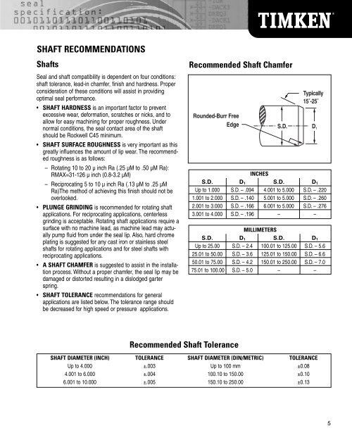
• A SHAFT CHAMFER is suggested to assist in the installation<br />
process. Without a proper chamfer, the seal lip may be<br />
damaged or distorted resulting in a dislodged garter<br />
spring.<br />
• SHAFT TOLERANCE recommendations for general<br />
applications are listed below. The tolerance range should<br />
be decreased for high speed or pressure applications.<br />
Rounded-Burr Free<br />
Edge<br />
Recommended Shaft Tolerance<br />
Recommended Shaft Chamfer<br />
Typically<br />
15˚-25˚<br />
S.D. D 1<br />
INCHES<br />
S.D. D1 S.D. D1<br />
Up to 1.000 S.D. – .094 4.001 to 5.000 S.D. – .220<br />
1.001 to 2.000 S.D. – .140 5.001 to 5.000 S.D. – .260<br />
2.001 to 3.000 S.D. – .166 6.001 to 5.000 S.D. – .276<br />
3.001 to 4.000 S.D. – .196 – –<br />
MILLIMETERS<br />
S.D. D1 S.D. D1<br />
Up to 25.00 S.D. – 2.4 100.01 to 125.00 S.D. – 5.6<br />
25.01 to 50.00 S.D. – 3.6 125.01 to 150.00 S.D. – 6.6<br />
50.01 to 75.00 S.D. – 4.2 150.01 to 250.00 S.D. – 7.0<br />
75.01 to 100.00 S.D. – 5.0 – –<br />
SHAFT DIAMETER (INCH) TOLERANCE SHAFT DIAMETER (DIN/METRIC) TOLERANCE<br />
Up to 4.000 ±.003 Up to 100 mm ±0.08<br />
4.001 to 6.000 ±.004 100.10 to 150.00 ±0.10<br />
6.001 to 10.000 ±.005 150.10 to 250.00 ±0.13<br />
5