
Create successful ePaper yourself
Turn your PDF publications into a flip-book with our unique Google optimized e-Paper software.
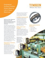
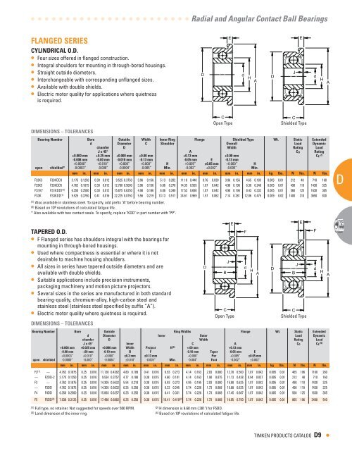
FLANGED SERIES<br />
CYLINDRICAL O.D.<br />
• Four sizes offered in flanged construction.<br />
• Integral shoulders for mounting in through-bored housings.<br />
• Straight outside diameters.<br />
• Interchangeable with corresponding unflanged sizes.<br />
• Available with double shields.<br />
• Electric motor quality for applications where quietness<br />
is required.<br />
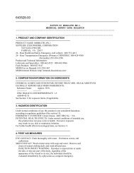
DIMENSIONS – TOLERANCES<br />
TAPERED O.D.<br />
• F Flanged series has shoulders integral with the bearings for<br />
mounting in through-bored housings.<br />
• Used where compactness is essential or where it is not<br />
desirable to machine housing shoulders.<br />
• All sizes in series have tapered outside diameters and are<br />
available with double shields.<br />
• Suitable applications include precision instruments,<br />
packaging machinery and motion picture projectors.<br />
• Several sizes in the series are manufactured in both standard<br />
bearing-quality, chromium-alloy, high-carbon steel and<br />
stainless steel (stainless steel specified by suffix “A”).<br />
• Electric motor quality where quietness is required.<br />
Radial and Angular Contact <strong>Ball</strong> <strong>Bearings</strong><br />
C<br />
C<br />
Open Type Shielded Type<br />
Bearing Number Bore Outside Width Inner Ring Flange Shielded Type Wt. Static Extended<br />
d Diameter C Shoulder Overall Load Dynamic<br />
chamfer D Width Rating Load<br />
J x ° A CO Rating<br />
+0.000 mm<br />
-0.008 mm<br />
+0. mm<br />
-0.00 mm<br />
+0.000 mm<br />
-0.010 mm<br />
+0.00 mm<br />
-0.1 mm<br />
+0.1 mm<br />
-0.0 mm E<br />
+0.00 mm<br />
-0.1 mm<br />
CE ( )<br />
+0.0000” +0.010” +0.000” +0.000” h +0.005” ±0.0 mm +0.000” h<br />
open shielded* -0.0003” -0.000” -0.0004" -0.005” Min. -0.002” ±0.002” -0.005” Min.<br />
mm in. mm in. mm in. mm in. mm in. mm in. mm in. mm in. mm in. kg lbs. N lbs. N lbs.<br />
F33K3 F33KDD3 3.175 0.1250 0.30 0.012 9.525 0.3750 3.96 0.156 5.13 0.202 11.18 0.440 0.76 0.030 3.96 0.156 4.65 0.183 0.005 0.01 212 48 710 160<br />
F33K5 F33KDD5 4.762 0.1875 0.30 0.012 12.700 0.5000 3.96 0.156 6.86 0.270 14.35 0.565 1.07 0.042 4.98 0.196 6.30 0.248 0.005 0.01 490 110 1430 325<br />
FS1K7 FS1KDD7 (1) 6.350 0.2500 0.30 0.012 15.875 0.6250 4.98 0.196 8.86 0.349 17.53 0.690 1.07 0.042 4.98 0.196 8.43 0.332 0.005 0.01 560 125 1630 365<br />
FS3K FS3KDD (1) 9.525 0.3750 0.41 0.016 22.225 0.8750 5.56 0.219 13.13 0.517 24.61 0.969 1.57 0.062 7.14 0.281 12.06 0.475 0.009 0.02 1400 310 3650 830<br />
(1) Also available in stainless steel. To specify, add prefix "A" before bearing number.<br />
(2) Based on 10 6 revolutions of calculated fatigue life.<br />
* Also available with two contact seals. To specify, replace "KDD" in part number with "PP".<br />
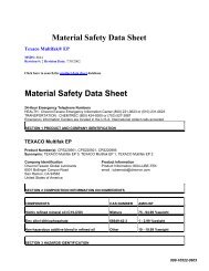
DIMENSIONS – TOLERANCES<br />
C<br />
C<br />
Open Type Shielded Type<br />
Bearing Number Bore Outside Ring Widths Flange Wt. Static Extended<br />
d Diameter Inner Outer Load Dynamic<br />
chamfer D Width Rating Load<br />
J x ° Inner C A CO CE<br />
( )<br />
+0.008 mm +0.0 mm +0.000 mm Width Project h ( ) +.00 mm +0.1 mm<br />
-0.00 mm -.00 mm -0.10 mm B F -0.10 mm Taper -0.0 mm E<br />
+0.0003” +0.010” +0.000” ±0. mm ±0.1 mm +0.000" Per +0.005” ±0.0 mm<br />
open shielded -0.0000” -0.000” -0.0004" ±0.010" -0.005” Min. -0.004” Foot -0.002” ±0.002"<br />
mm in. mm in. mm in. mm in. mm in. mm in. mm in. mm in. mm in. mm in. kg lbs. N lbs. N lbs.<br />
F2 (1) — 4.762 0.1875 0.25 0.010 11.130 0.4382 4.80 0.189 0.41 0.016 6.93 0.273 4.14 0.163 2.03 0.080 12.70 0.500 1.07 0.042 0.005 0.01 465 106 1160 260<br />
— F2DD-2 3.175 0.1250 0.25 0.010 9.534 0.3757 4.77 0.188 0.38 0.015 4.60 0.181 4.14 0.163 1.90 0.075 11.13 0.438 0.94 0.037 0.005 0.01 212 48 710 160<br />
F3 — 4.762 0.1875 0.25 0.010 14.305 0.5632 5.54 0.218 0.38 0.015 6.93 0.273 4.95 0.195 2.03 0.080 15.88 0.625 1.07 0.042 0.005 0.01 490 110 1430 325<br />
— F3DD 4.762 0.1875 0.25 0.010 14.305 0.5632 6.35 0.250 0.38 0.015 6.22 0.245 5.74 0.226 1.73 0.068 15.88 0.625 1.07 0.042 0.005 0.01 490 110 1430 325<br />
F4 F4DD 6.350 0.2500 0.25 0.010 15.893 0.6257 6.35 0.250 0.38 0.015 8.41 0.331 5.74 0.226 1.73 0.068 17.45 0.687 1.07 0.042 0.005 0.01 560 125 1630 365<br />
F5 F5DD (2) 7.938 0.3125 0.25 0.010 17.480 0.6882 6.35 0.250 0.38 0.015 10.41 0.410 (2) 5.74 0.226 1.73 0.068 19.05 0.750 1.07 0.042 0.005 0.01 865 196 2400 540<br />
(1) Full type, no retainer. Not suggested for speeds over 500 RPM.<br />
(2) H dimension is 9.68 mm (.381") for F5DD.<br />
(3) Land dimension of the inner ring. (4) Based on 106 revolutions of calculated fatigue life.<br />
D<br />
D<br />
B<br />
J<br />
E<br />
E<br />
d<br />
F<br />
d<br />
H A<br />
H A<br />
D<br />
D<br />
TIMKEN PRODUCTS CATALOG D<br />
J<br />
B<br />
J<br />
E<br />
E<br />
d<br />
F<br />
d<br />
H A<br />
H A<br />
•<br />
AD<br />
A<br />
A<br />
A<br />
A<br />
A