remko pww4000
remko pww4000
remko pww4000

Create successful ePaper yourself
Turn your PDF publications into a flip-book with our unique Google optimized e-Paper software.
Unit Assembly<br />
Brackets<br />
Brackets for wall and ceiling assembly (2 per unit) are<br />
inserted into the openings at the back of the unit and attached<br />
with the supplied screws.<br />
Components that are attached directly to the units,<br />
such as mixed-air boxes or filter boxes, are equipped<br />
with a bracket adapter.<br />
When using customer-installed bracket constructions,<br />
the minimum distance to the wall (dimension "e") must<br />
be observed!<br />
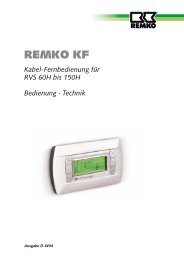
KO bracket<br />
For wall and ceiling assembly<br />
PWW<br />
KO<br />
Dimension<br />
e c<br />
a b c d<br />
4030-3 / 4 560 430 510 155 270<br />
4050-3 / 4 640 505 590 192 270<br />
4080-3 / 4 800 620 750 250 270<br />
4100-3 / 4 880 730 830 305 340<br />
The brackets must be current-free and screwed on<br />
� to the unit and the wall/ceiling.<br />
Cu / Al heat-exchangers<br />
The heat-exchangers are made of copper pipes with aluminium<br />
plate fins pressed onto the outside. The plate fin<br />
package is surrounded by a galvanized, zinc-plated steel<br />
frame.<br />
The collector and the distributor are made of steel.<br />
Please observe the following for the heat-exchangers:<br />
◊ The heating medium connection is made via<br />
threaded connectors.<br />
◊ The maximum operating temperature is 130 °C.<br />
◊ The maximum operating pressure is 16 bar.<br />
◊ The heat-exchangers are not suitable for operation<br />
with steam or thermal oil.<br />
d<br />
d<br />
Ø12.5<br />
a<br />
e<br />
b<br />
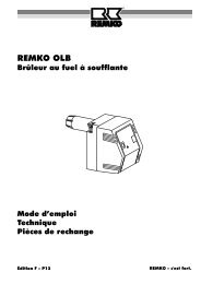
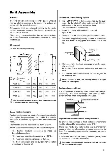
Connection to the heating system<br />
◊ The REMKO PWW is to be connected by the customer<br />
via the shut-off valve, automatic air bleeder<br />
and screws in the supply and return lines.<br />
Use compensators if necessary.<br />
◊ It does not matter which side is connected.<br />
Right or left.<br />
◊ The units operate on the principle of counter-current.<br />
◊ The water (supply line) usually comes in at the bottom.<br />
The water usually goes out (return line) at the<br />
top.<br />
Outgoing air<br />
Draining in case of frost<br />
It is not possible to statically drain the heat-exchanger<br />
completely. The heat-exchanger can only be completely<br />
drained when compressed air is used.<br />
Ventilation Frost protection thermostat<br />
Drainage<br />
Screws<br />
Incoming air<br />
Outgoing water<br />
Incoming water<br />
◊ After assembly, the heat-exchanger must be carefully<br />
ventilated.<br />
Air pockets in the register reduce the unit performance.<br />
◊ You can find the thread sizes of the heat register in<br />
the technical data.<br />
�<br />
When the fan is idle, the heating medium supply<br />
must be interrupted.<br />
Important information about frost protection!<br />
To prevent frost damage, a frost protection mechanism<br />
must be attached for temperatures below 0 °C.<br />
There may not be any water in the heat-exchanger for<br />
systems taken out of operation in rooms susceptible to<br />
frost. The remaining water must be blown out with compressed<br />
air.<br />
If this is not possible, the heating medium (water) must<br />
be mixed with a suitable anti-freeze.<br />
�<br />
No guarantee claims can be made for frost damage<br />
on the heat-exchanger!<br />
5